1 CS6710 Tool Suite Synopsys Synthesis Cadence Encounter Digital Impl. Cadence Composer Schematic Cadence Virtuoso Layout AutoRouter Your Library Verilog Sim Verilog sim Behavioral Verilog Structural Verilog Circuit Layout LVS Layout-XL Verilog is the Key Tool Behavioral Verilog is synthesized into Structural Verilog Structural Verilog represents net-lists From Behavioral From Schematics High-level (Synthesizer will flatten these) Verilog is used for testing all designs Behavioral & Structural & Schematic & High-level NC_Verilog, vcs (Synopsys Verilog simulator), modelSim (Mentor Verilog simulator)

Welcome message from author
This document is posted to help you gain knowledge. Please leave a comment to let me know what you think about it! Share it to your friends and learn new things together.
Transcript

1
CS6710 Tool Suite
Synopsys Synthesis
Cadence Encounter
Digital Impl.
Cadence Composer Schematic
Cadence Virtuoso Layout
AutoRouter
Your Library
Verilog Sim
Verilog sim
Behavioral Verilog
Structural Verilog
Circuit Layout
LVS
Layout-XL
Verilog is the Key Tool Behavioral Verilog is synthesized into
Structural Verilog Structural Verilog represents net-lists
From Behavioral From Schematics High-level (Synthesizer will flatten these)
Verilog is used for testing all designs Behavioral & Structural & Schematic & High-level NC_Verilog, vcs (Synopsys Verilog simulator),
modelSim (Mentor Verilog simulator)

2
Verilog has a Split Personality Hardware Description Language (HDL)
Reliably & Readably Create hardware Document hardware
Testbench creation language Create external test environment
Time & Voltage Files & messages
Are these two tasks Related? Compatible?
Verilog as HDL Want high level modeling
unification at all levels from fast functional simulation, accurate device simulation
support simulation based validation (verification?) How could we do this?
behavioral model mapped to transistors pragmas: throughput, latency, cycle time, power…
Reality we rely on designers to do most of these xforms therefore:
different algorithms => try before you buy… use only a subset of the language. RTL and schematic design used to support Verilog System-C and other HLD models for co-simulation, etc.

3
Synthesis
This lecture is only about synthesis...
Quick Review Module name (args…);
begin parameter ...; // define parameters input …; // define inputs output …; // define outputs wire … ; // internal wires reg …; // internal regs, possibly output
// the parts of the module body are // executed concurrently
<primitive instantiations> <continuous assignments> <always blocks> endmodule

4
Quick Review Continuous assignments to wire vars
assign variable = exp; Results in combinational logic
Procedural assignment to reg vars Always inside procedural blocks
(always blocks in particular for synthesis) blocking
variable = exp;
non-blocking variable <= exp;
Can result in combinational or sequential logic
Verilog Description Styles Verilog supports a variety of description
styles Structural
explicit structure of the circuit e.g., each logic gate instantiated and connected
to others Behavioral
program describes input/output behavior of circuit many structural implementations could have
same behavior e.g., different implementation of one Boolean
function

5
Synthesis: Data Types Possible Values (wire and reg):
0: logic 0, false 1: logic 1, true Z: High impedance Note: no X in synthesis…
Digital Hardware: The domain of Verilog Either logic (gates)
outputs represented by wire variables Or storage (registers & latches)
outputs represented by reg variables
Synthesis: Data Types Register declarations
reg a; \\ a scalar register reg [3:0] b; \\ a 4-bit vector register output g; \\ an output can be a reg
reg g; output reg g; \\ Verilog 2001 syntax
Wire declarations wire d; \\ a scalar wire wire [3:0] e; \\ a 4-bit vector wire output f; \\ an output can be a wire

6
Parameters Used to define constants
parameter size = 16, foo = 8; wire [size-1:0] bus; \\ defines a 15:0 bus
Synthesis: Assign Statement The assign statement creates
combinational logic assign LHS = expression;
LHS can only be wire type expression can contain either wire or reg type
mixed with operators wire a,c; reg b; output out;
assign a = b & c; assign out = ~(a & b); \\ output as wire
wire [15:0] sum, a, b; wire cin, cout; assign {cout,sum} = a + b + cin;

7
Synthesis: Basic Operators Bit-Wise Logical
~ (not), & (and), | (or), ^ (xor), ^~ or ~^ (xnor) Simple Arithmetic Operators
Binary: +, - Unary: - Negative numbers stored as 2’s complement
Relational Operators <, >, <=, >=, ==, !=
Logical Operators ! (not), && (and), || (or) assign a = (b > ‘b0110) && (c <= 4’d5); assign a = (b > ‘b0110) && !(c > 4’d5);
Synthesis: Operand Length When operands are of unequal bit length,
the shorter operator is zero-filled in the most significant bit position
wire [3:0] sum, a, b; wire cin, cout, d, e, f, g;
assign sum = f & a; assign sum = f | a; assign sum = {d, e, f, g} & a; assign sum = {4{f}} | b; assign sum = {4{f == g}} & (a + b);
assign sum[0] = g & a[2]; assign sum[2:0] = {3{g}} & a[3:1];

8
Synthesis: More Operators Concatenation
{a,b} {4{a==b}} { a,b,4’b1001,{4{a==b}} }
Shift (logical shift) << left shift >> right shift assign a = b >> 2; // shift right 2, division by 4 assign a = b << 1; // shift left 1, multiply by 2
Arithmetic assign a = b * c; // multiply b times c assign a = b * ‘d2; // multiply b times constant (=2) assign a = b / ‘b10; // divide by 2 (constant only) assign a = b % ‘h3; // b modulo 3 (constant only)
Synthesis: Operand Length Operator length is set to the longest member
(both RHS & LHS are considered). Be careful.
wire [3:0] sum, a, b; wire cin, cout, d, e, f, g; wire[4:0]sum1;
assign {cout,sum} = a + b + cin; assign {cout,sum} = a + b + {4’b0,cin};
assign sum1 = a + b; assign sum = (a + b) >> 1; // what is wrong?

9
Synthesis: Extra Operators
Funky Conditional cond_exp ? true_expr : false_expr wire [3:0] a,b,c; wire d; assign a = (b == c) ? (c + ‘d1): ‘o5; // good luck
Reduction Logical Named for impact on your recreational time Unary operators that perform bit-wise operations on
a single operand, reduce it to one bit &, ~&, |, ~|, ^, ~^, ^~ assign d = &a || ~^b ^ ^~c;
Synthesis: Assign Statement The assign statement is sufficient to
create all combinational logic What about this:
assign a = ~(b & c); assign c = ~(d & a);

10
Synthesis: Assign Statement The assign statement is sufficient to
create all combinational logic What about this:
assign a = ~(b & c); assign c = ~(d & a);
A
C
B
D
Simple Behavioral Module
// Behavioral model of NAND gate module NAND (out, in1, in2);
output out; input in1, in2; assign out = ~(in1 & in2);
endmodule

11
Simple Behavioral Module // Behavioral model of NAND gate module NAND (out, in1, in2);
output out; input in1, in2;
// Uses Verilog builtin nand function // syntax is func id (args); nand i0(out, in1, in2); endmodule
Simple Structural Module // Structural Module for NAND gate
module NAND (out, in1, in2); output out;
input in1, in2; wire w1; // call existing modules by name // module-name ID (signal-list); AND2X1 u1(w1, in1, in2); INVX1 u2(out,w1);
endmodule

12
Simple Structural Module // Structural Module for NAND gate
module NAND (out, in1, in2); output out;
input in1, in2; wire w1; // call existing modules by name // module-name ID (signal-list); // can connect ports by name... AND2X1 u1(.Q(w1), .A(in1), .B(in2)); INVX1 u2(.A(w1), .Q(out));
endmodule
Primitive Gates Multiple input gates
<gatename> [delay] [id] (out, in1, in2, in3...); and, or, nand, nor, xor, xnor
Multiple output gates <gatename> [delay] [id] (out1, out2, ... outn, in);
buf, not Tristate gates
<gatename> [delay] [id] (out, in, ctrl); bufif1, bufif0, notif1, notif0

13
Primitive Gates Delay: three types for gates
#(delaytime) same delay for all transitions #(rise,fall) different delay for rise and fall #(rise, fall, turnoff) for tristate gates
Each delay number can be: single number i.e. #(2) or #(2,3) min/typ/max triple i.e. #(2:3:4) or
#(2:3:4, 3:2:5)
Primitive Gates and (out, a, b); nand i0 (out a b c d e f g); xor #(2,3) (out a b c); buf (Y A); buf #(2:3:4, 3:4;5) _i1 (y, a); bufif1 (out, in, ctl); notif0 #(1, 2, 3) (Y, A, S);

14
Primitive Gates OR – you can skip the delays on each
gate, and use a specify block for the whole module Specifies from module input to module
outputs Outputs must be driven by a primitive gate The syntax defines the delay for each path
from input to output
Simple Behavioral Module // Behavioral model of NAND gate module NAND (out, in1, in2);
output out; input in1, in2;
nand _i0(out, in1, in2);
// include specify block for timing specify (in1 => out) = (1.0, 1.0); (in2 => out) = (1.0, 1.0); endspecify
endmodule

15
Specify Block Types Parallel Connection (one to one)
Full Connection (one to many)
Parallel Specify module A ( q, a, b, c, d )
input a, b, c, d; output q;wire e, f;
// specify block containing delay statementsspecify ( a => q ) = 6; // delay from a to q ( b => q ) = 7; // delay from b to q ( c => q ) = 7; // delay form c to q ( d => q ) = 6; // delay from d to qendspecify
// module definitionor o1( e, a, b );or o2( f, c, d );exor ex1( q, e, f );
endmodule

16
Full Specify module A ( q, a, b, c, d )
input a, b, c, d;output q;wire e, f;
// specify block containing full connectionsspecify ( a, d *> q ) = 6; // delay from a and d to q ( b, c *> q ) = 7; // delay from b and c to qendspecify
// module definitionor o1( e, a, b );or o2( f, c, d );exor ex1( q, e, f );
endmodule
Full Specify // a[63:0] is a 64 bit input register and // q[7:0] is an 8 bit output register // this would require 64 x 8 = 512 parallel // connections, but only 1 full
specify ( a *> q ) = 8; // eqivalent to 512 parallel connections endspecify

17
Specify needs a gate! module DCX1 (CLR, D, CLK, Q); input CLR, D, CLK; output Q; reg Q_i;
always @(posedge CLK or negedge CLR) if (CLR == 0) Q_i = 1'b0;
else Q_i = D;
buf _i0 (Q, Q_i);
specify (CLK => Q) = (1.0, 1.0); (CLR => Q) = (1.0, 1.0); $setuphold(posedge CLK, D, 0.1, 0.0);
$recovery(negedge CLR, posedge CLK, 0.0); endspecify endmodule
Simple Behavioral Module // Behavioral model of NAND gate module NAND (out, in1, in2);
output out; input in1, in2;
nand _i0(out, in1, in2);
// include specify block for timing specify (in1 => out) = (1.0, 1.0); (in2 => out) = (1.0, 1.0); endspecify
endmodule
18
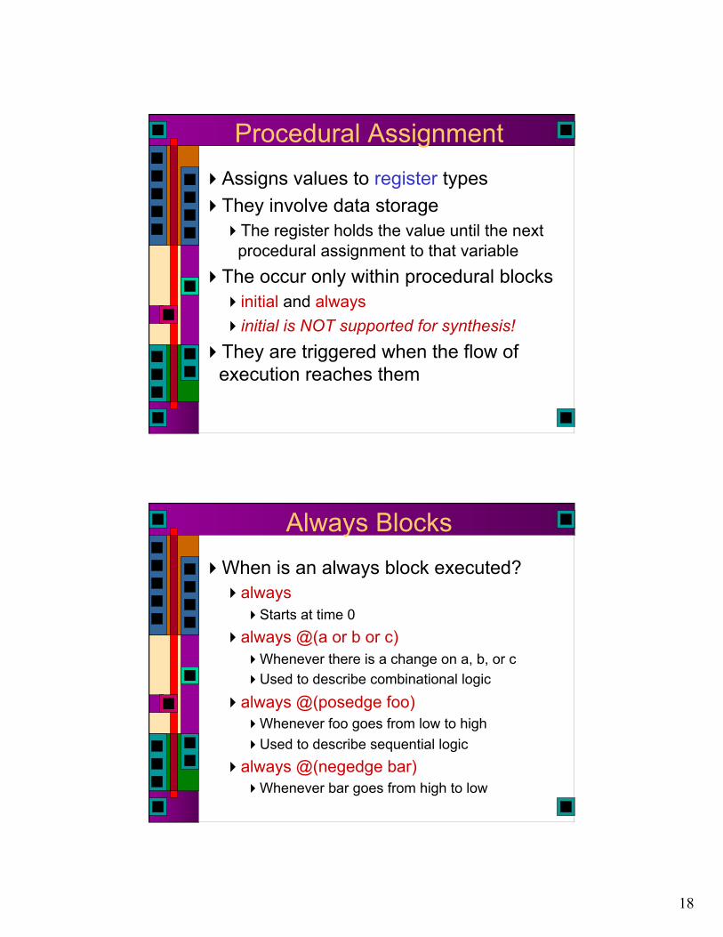
Procedural Assignment Assigns values to register types They involve data storage
The register holds the value until the next procedural assignment to that variable
The occur only within procedural blocks initial and always initial is NOT supported for synthesis!
They are triggered when the flow of execution reaches them
Always Blocks When is an always block executed?
always Starts at time 0
always @(a or b or c) Whenever there is a change on a, b, or c Used to describe combinational logic
always @(posedge foo) Whenever foo goes from low to high Used to describe sequential logic
always @(negedge bar) Whenever bar goes from high to low

19
Synthesis: Always Statement The always statement creates…
always @sensitivity LHS = expression; @sensitivity controls when LHS can only be reg type expression can contain either wire or reg type mixed with
operators Logic reg c, b; wire a;
always @(a, b) c = ~(a & b); always @* c = ~(a & b); Storage reg Q; wire clk;
always @(posedge clk) Q <= D;
Procedural Control Statements Conditional Statement
if ( <expression> ) <statement> if ( <expression> ) <statement>
else <statement> “else” is always associated with the closest
previous if that lacks an else. You can use begin-end blocks to make it more
clear if (index >0)
if (rega > regb) result = rega; else result = regb;

20
Multi-Way Decisions Standard if-else-if syntax
If ( <expression> ) <statement>
else if ( <expression> ) <statement>
else if ( <expression> ) <statement>
else <statement>
Procedural NAND gate // Procedural model of NAND gate
module NAND (out, in1, in2); output out; reg out; input in1, in2; // always executes when in1 or in2 // change value always @(in1 or in2) begin out = ~(in1 & in2); end
endmodule

21
Procedural NAND gate // Procedural model of NAND gate
module NAND (out, in1, in2); output out;
reg out; input in1, in2;
// always executes when in1 or in2 // change value always @(in1 or in2) begin out <= ~(in1 & in2); end
endmodule Is out combinational?
Synthesis: NAND gate input in1, in2;
reg n1, n2; // is this a flip-flop? wire n3, n4;
always @(in1 or in2) n1 = ~(in1 & in2); always @* n2 = ~(in1 & in2); assign n3 = ~(in1 & in2); nand u1(n4, in1, in2);
Notice always block for combinational logic Full sensitivity list, but @* works (2001 syntax) Can then use the always goodies Is this a good coding style?

22
Procedural Assignments Assigns values to reg types
Only useable inside a procedural block Usually synthesizes to a register But, under the right conditions, can also result in
combinational circuits
Blocking procedural assignment LHS = timing-control exp a = #10 1; Must be executed before any assignments that
follow (timing control is optional) Assignments proceed in order even if no timing is
given Non-Blocking procedural assignment
LHS <= timing-control exp b <= 2; Evaluated simultaneously when block starts Assignment occurs at the end of the
(optional) time-control
Procedural Synthesis Synthesis ignores all that timing stuff So, what does it mean to have blocking
vs. non-blocking assignment for synthesis?
begin begin A=B; A<=B; B=A; B<=A; end end
begin begin A=Y; A<=Y; B=A; B<=A; end end
?
?

23
Synthesized Circuits begin
A = Y; B = A;
end
begin A <= Y; B <= A;
end begin
B = A; A = Y;
end
D Q
clk
D Q
clk
D Q
clk
D Q
clk
A
B
A B Y
Y
A B
A
B
Synthesized Circuits D Q
clk
D Q
clk
D Q
clk
D Q
clk
A
B
A B Y
Y
A B
A
B
always @(posedge clk) begin A = Y; B = A; end
always @(posedge clk) begin B = A; A = Y; end
always @(posedge clk) begin A <= Y; B <= A; end
always @(posedge clk) begin B <= A; A <= Y end
clk
clk

24
Assignments and Synthesis Note that different circuit structures result
from different types of procedural assignments Therefore you can’t mix assignment types in
the same always block Non-blocking is often a better model for
hardware Real hardware is often concurrent…
Blocking is often better for setting subsets of signals Set them to defaults at beginning, then reset only
the ones that change
Comparator Example Using continuous assignment
Concurrent execution of assignments
Module comp (a, b, Cgt, Clt, Cne); parameter n = 4; input [n-1:0] a, b; output Cgt, Clt, Cne; assign Cgt = (a > b); assign Clt = (a < b); assign Cne = (a != b); endmodule

25
Comparator Example Using procedural assignment
Non-blocking assignment implies concurrent
Module comp (a, b, Cgt, Clt, Cne); parameter n = 4; input [n-1:0] a, b; output Cgt, Clt, Cne; reg Cgt, Clt, Cne; always @(a or b) begin Cgt <= (a > a);
Clt <= (a < b); Cne <= (a != b);
end endmodule
Modeling a Flip Flop Use an always block to wait for clock
edge
Module dff (clk, d, q); input clk, d; output q; reg q; always @(posedge clk) d = q;
endmodule

26
Synthesis: Always Statement This is a simple D Flip-Flop
reg Q; always @(posedge clk) Q <= D;
@(posedge clk) is the sensitivity list The Q <= D; is the block part The block part is always “entered” whenever
the sensitivity list becomes true (positive edge of clk)
The LHS of the <= must be of data type reg The RHS of the <= may use reg or wire
Synthesis: Always Statement This is an asynchronous clear D Flip-Flop
reg Q; always @(posedge clk, posedge rst) if (rst) Q <= ‘b0; else Q <= D;
Notice , instead of or Verilog 2001…
Positive reset

27
Synthesis: Always Statement reg Q;
always @(posedge clk, posedge rst, posedge set) if (rst) Q <= ‘b0;
else if (set) Q <= ‘b1; else Q <= D;
What is this? What is synthesized?
> beh2str foo.v foo_str.v UofU_Digital.db
Synthesis: Always Statement reg Q;
always @(posedge clk, posedge rst, posedge set) if (rst) Q <= ‘b0;
else if (set) Q <= ‘b1; else Q <= D;
What is this? What is synthesized?

28
Synthesis: Always Statement reg Q;
always @(posedge clk, posedge rst, posedge set) if (rst) Q <= ‘b0;
else if (set) Q <= ‘b1; else Q <= D;
What is this? What is synthesized?
Synthesis: Always Statement reg Q;
always @(posedge clk) if (rst) Q <= ‘b0;
else if (set) Q <= ‘b1; else Q <= D;
What is this?

29
Synthesis: Always Statement reg Q;
always @(posedge clk) if (rst) Q <= ‘b0;
else if (set) Q <= ‘b1; else Q <= D;
What is this?
Inferred memory devices in process in routine set line 5 in file '/home/elb/IC_CAD/syn-f06/set.v'. =============================================================================== | Register Name | Type | Width | Bus | MB | AR | AS | SR | SS | ST | ====================================================== | Q_reg | Flip-flop | 1 | N | N | N | N | N | N | N | ===============================================================================
module foo ( clk, rst, set, D, Q ); input clk, rst, set, D; output Q; wire N3, n2, n4;
dff Q_reg ( .D(N3), .G(clk), .CLR(n2), .Q(Q) ); tiehi U6 ( .Y(n2) ); nor2 U7 ( .A(rst), .B(n4), .Y(N3) ); nor2 U8 ( .A(D), .B(set), .Y(n4) ); endmodule

30
module foo ( clk, rst, set, D, Q ); input clk, rst, set, D; output Q; wire N3, n2, n4;
dff Q_reg ( .D(N3), .G(clk), .CLR(n2), .Q(Q) ); tiehi U6 ( .Y(n2) ); nor2 U7 ( .A(rst), .B(n4), .Y(N3) ); nor2 U8 ( .A(D), .B(set), .Y(n4) ); endmodule
D
clk
Q n4
N3
set
rst clr
D
A B Out 0 0 1 0 1 0 1 0 0 1 1 0
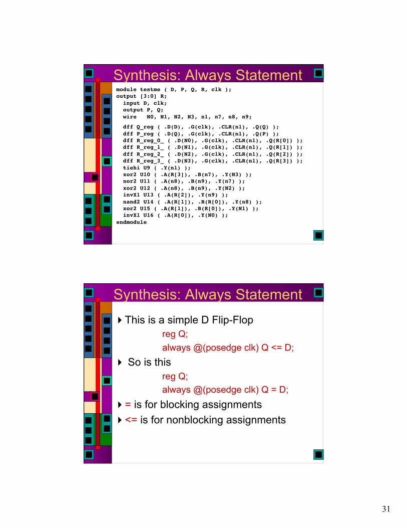
Synthesis: Always Statement reg P,Q; reg [3:0] R;
always @(posedge clk) begin
Q <= D; P <= Q; R <= R + ‘h1;
end
What is this? Will it synthesize? Simulate?
31
Synthesis: Always Statement module testme ( D, P, Q, R, clk ); output [3:0] R; input D, clk; output P, Q; wire N0, N1, N2, N3, n1, n7, n8, n9;"
dff Q_reg ( .D(D), .G(clk), .CLR(n1), .Q(Q) ); dff P_reg ( .D(Q), .G(clk), .CLR(n1), .Q(P) ); dff R_reg_0_ ( .D(N0), .G(clk), .CLR(n1), .Q(R[0]) ); dff R_reg_1_ ( .D(N1), .G(clk), .CLR(n1), .Q(R[1]) ); dff R_reg_2_ ( .D(N2), .G(clk), .CLR(n1), .Q(R[2]) ); dff R_reg_3_ ( .D(N3), .G(clk), .CLR(n1), .Q(R[3]) ); tiehi U9 ( .Y(n1) ); xor2 U10 ( .A(R[3]), .B(n7), .Y(N3) ); nor2 U11 ( .A(n8), .B(n9), .Y(n7) ); xor2 U12 ( .A(n8), .B(n9), .Y(N2) ); invX1 U13 ( .A(R[2]), .Y(n9) ); nand2 U14 ( .A(R[1]), .B(R[0]), .Y(n8) ); xor2 U15 ( .A(R[1]), .B(R[0]), .Y(N1) ); invX1 U16 ( .A(R[0]), .Y(N0) ); endmodule"
Synthesis: Always Statement This is a simple D Flip-Flop
reg Q; always @(posedge clk) Q <= D;
So is this reg Q; always @(posedge clk) Q = D;
= is for blocking assignments <= is for nonblocking assignments

32
Constants parameter used to define constants
parameter size = 16, foo = 8; wire [size-1:0] bus; \\ defines a 15:0 bus externally modifiable scope is local to module
localparam not externally modifiable localparam width = size * foo;
̀ define macro definition ̀ define value 7’d53 assign a = (sel == `value) & b; scope is from here on out
Example: Counter module counter (clk, clr, load, in, count);
parameter width=8; input clk, clr, load; input [width-1 : 0] in; output [width-1 : 0] count; reg [width-1 : 0] tmp;
always @(posedge clk or negedge clr) begin if (!clr) tmp = 0; else if (load) tmp = in; else tmp = tmp + 1; end assign count = tmp; endmodule
33
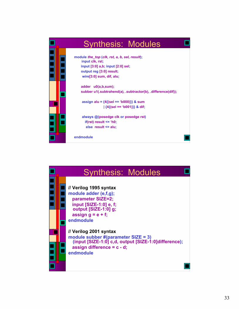
Synthesis: Modules module the_top (clk, rst, a, b, sel, result);
input clk, rst; input [3:0] a,b; input [2:0] sel; output reg [3:0] result;
wire[3:0] sum, dif, alu;
adder u0(a,b,sum); subber u1(.subtrahend(a), .subtractor(b), .difference(dif));
assign alu = {4{(sel == ‘b000)}} & sum | {4{(sel == ‘b001)}} & dif;
always @(posedge clk or posedge rst) if(rst) result <= ‘h0; else result <= alu;
endmodule
Synthesis: Modules // Verilog 1995 syntax module adder (e,f,g); parameter SIZE=2; input [SIZE-1:0] e, f;
output [SIZE-1:0] g; assign g = e + f; endmodule
// Verilog 2001 syntax module subber #(parameter SIZE = 3)
(input [SIZE-1:0] c,d, output [SIZE-1:0]difference); assign difference = c - d; endmodule

34
Synthesis: Modules module the_top (clk, rst, a, b, sel, result);
parameter SIZE = 4; input clk, rst; input [SIZE-1:0] a,b;
input [2:0] sel; output reg [SIZE-1:0] result;
wire[SIZE-1:0] sum, dif, alu;
adder #(.SIZE(SIZE)) u0(a,b,sum); subber #(4) u1(.c(a), .d(b), .difference(dif));
assign alu = {SIZE{sel == ‘b000}} & sum | {SIZE{sel == ‘b001}} & dif;
always @(posedge clk or posedge rst) if(rst) result <= ‘h0; else result <= alu; endmodule
Multi-Way Decisions Standard if-else-if syntax
If ( <expression> ) <statement>
else if ( <expression> ) <statement>
else if ( <expression> ) <statement>
else <statement>
35
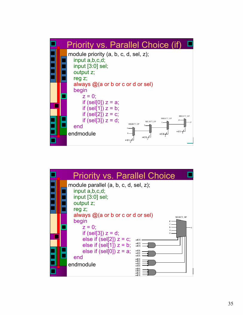
Priority vs. Parallel Choice (if) module priority (a, b, c, d, sel, z);
input a,b,c,d; input [3:0] sel; output z; reg z; always @(a or b or c or d or sel) begin
z = 0; if (sel[0]) z = a; if (sel[1]) z = b; if (sel[2]) z = c; if (sel[3]) z = d;
end endmodule
Priority vs. Parallel Choice module parallel (a, b, c, d, sel, z);
input a,b,c,d; input [3:0] sel; output z; reg z; always @(a or b or c or d or sel) begin
z = 0; if (sel[3]) z = d; else if (sel[2]) z = c; else if (sel[1]) z = b; else if (sel[0]) z = a;
end endmodule

36
Priority Encoders
Priority Encoders

37
Case Statements Multi-way decision on a single expression
case ( <expresion> ) <expression>: <statement> <expression>, <expression>: <statement> <expression>: <statement> default: <statement>
endcase
Case Example reg [1:0] sel; reg [15:0] in0, in1, in2, in3, out; case (sel)
2’b00: out = in0; 2’b01: out = in1; 2’b10: out = in2; 2’b11: out = in3;
endcase

38
Another Case Example // simple counter next-state logic
// one-hot state encoding… parameter [2:0] s0=3’h1, s1=3’h2, s2=3’h4; reg[2:0] state, next_state; always @(input or state) begin
case (state) s0: if (input) next_state = s1; else next_state = s0;
s1: next_state = s2; s2: next_state = s0;
endcase end
input
state
next_state
001 010 100
Weird Case Example Verilog allows you to put a value in the case
slot, and test which variable currently has that value…
reg [ 2:0] curr_state, next_state; parameter s1=3’b001, s2=3’b010, s3=3’b100 case (1)
curr_state[0] : next_state = s2; curr_state[1] : next_state = s3; curr_state[2] : next_state = s1;
endcase

39
Latch Inference Incompletely specified if and case
statements cause the synthesizer to infer latches
always @(cond) begin
if (cond) data_out <= data_in; end This infers a latch because it doesn’t
specify what to do when cond = 0 Fix by adding an else In a case, fix by including default:
Full vs. Parallel Case statements check each case in
sequence A case statement is full if all possible
outcomes are accounted for A case statement is parallel if the stated
alternatives are mutually exclusive These distinctions make a difference in
how cases are translated to circuits… Similar to the if statements previously
described

40
Case full-par example // full and parallel = combinational logic module full-par (slct, a, b, c, d, out);
input [1:0] slct; input a, b, c, d; output out; reg out; // optimized away in this example always @(slct or a or b or c or d)
case (slct) 2’b11 : out <= a; 2’b10 : out <= b; 2’b01 : out <= c; default : out <= d; // really 2’b10 endcase
endmodule
Synthesis Result Note that full-par results in combinational
logic
41
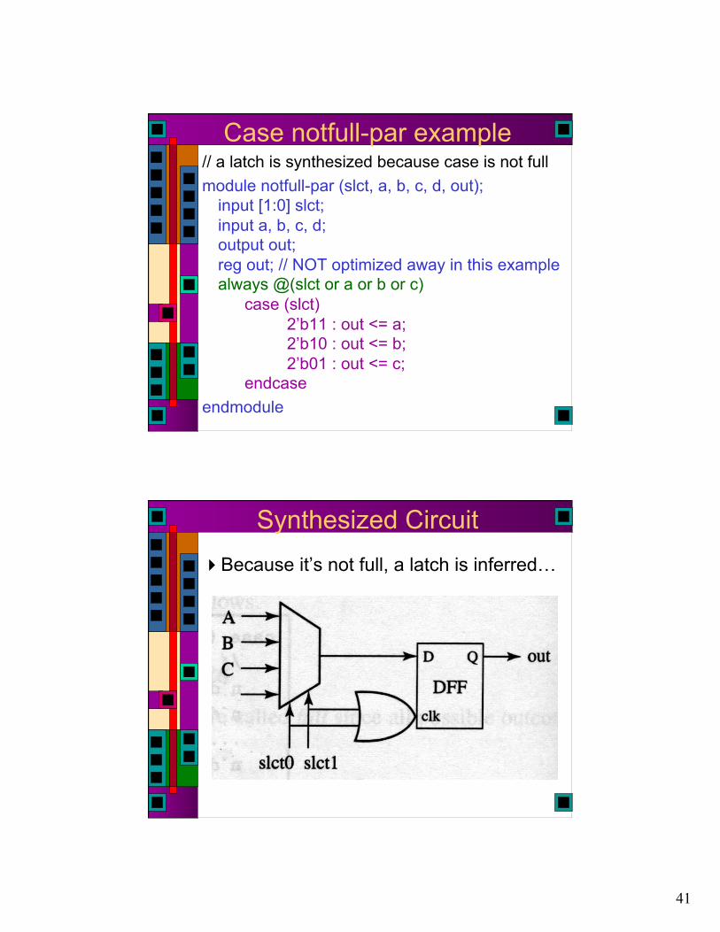
Case notfull-par example // a latch is synthesized because case is not full module notfull-par (slct, a, b, c, d, out);
input [1:0] slct; input a, b, c, d; output out; reg out; // NOT optimized away in this example always @(slct or a or b or c)
case (slct) 2’b11 : out <= a; 2’b10 : out <= b; 2’b01 : out <= c; endcase
endmodule
Synthesized Circuit Because it’s not full, a latch is inferred…

42
Case full-notpar example // because case is not parallel - priority encoding // but it is still full, so no latch… // this uses a casez which treats ? as don’t-care module full-notpar (slct, a, b, c, out);
... always @(slct or a or b or c)
casez (slct) 2’b1? : out <= a; 2’b?1 : out <= b; default : out <= c; endcase
endmodule
Synthesized Circuit It’s full, so it’s combinational, but it’s
not parallel so it’s a priority circuit instead of a “check all in parallel” circuit

43
Case notfull-notpar example // because case is not parallel - priority encoding // because case is not full - latch is inferred // uses a casez which treats ? as don’t-care module full-notpar (slct, a, b, c, out);
... always @(slct or a or b or c)
casez (slct) 2’b1? : out <= a; 2’b?1 : out <= b; endcase
endmodule
Synthesized Circuit Not full and not parallel, infer a latch

44
Verification CASE matches all (works like ===) CASEX uses “z”, “x”, “?” as don’t care CASEZ uses “z”, “?” as don’t care Beware: Matches first valid case
Synthesis CASE works like == CASEX uses “?” as don’t care CASEZ uses “?” as don’t care
Get off my Case
Get off my Case
Order Matters

45
Get off my Case
FSM Description One simple way: break it up like a
schematic A combinational block for next_state
generation A combinational block for output generation A sequential block to store the current state
Nex
t sta
te
Logi
c
Stat
e
in
clk
Next_state current State outputs
Logi
c ou
tput
Mealy only

46
Modeling State Machines // General view module FSM (clk, in, out);
input clk, in; output out; reg out; // state variables reg [1:0] state; // next state variable reg [1:0] next_state; always @posedge(clk) // state register
state = next_state; always @(state or in); // next-state logic
// compute next state and output logic // make sure every local variable has an // assignment in this block
endmodule
Nex
t sta
te
Logi
c
Stat
e
in
clk
Next_state
State
FSM Desciption

47
Verilog Version module moore (clk, clr, insig, outsig);
input clk, clr, insig; output outsig;
// define state encodings as parameters parameter [1:0] s0 = 2'b00, s1 = 2'b01,s2 = 2'b10, s3 = 2'b11;
// define reg vars for state register // and next_state logic
reg [1:0] state, next_state; //define state register (with //synchronous active-high clear)
always @(posedge clk) begin if (clr) state = s0; else state = next_state; end
// define combinational logic for // next_state
always @(insig or state) begin case (state) s0: if (insig) next_state = s1; else next_state = s0; s1: if (insig) next_state = s2; else next_state = s1; s2: if (insig) next_state = s3; else next_state = s2; s3: if (insig) next_state = s1; else next_state = s0; endcase end
// assign outsig as continuous assign assign outsig =
((state == s1) || (state == s3)); endmodule
Verilog Version module moore (clk, clr, insig, outsig);
input clk, clr, insig; output outsig;
// define state encodings as parameters parameter [1:0] s0 = 2'b00, s1 = 2'b01, s2 = 2'b10, s3 = 2'b11;
// define reg vars for state register and next_state logic reg [1:0] state, next_state;
//define state register (with synchronous active-high clear) always @(posedge clk) begin if (clr) state = s0; else state = next_state; end

48
Verilog Version Continued... // define combinational logic for next_state
always @(insig or state) begin case (state) s0: if (insig) next_state = s1; else next_state = s0; s1: if (insig) next_state = s2; else next_state = s1; s2: if (insig) next_state = s3; else next_state = s2; s3: if (insig) next_state = s1; else next_state = s0; endcase end
Verilog Version Continued... // now set the outsig. This could also be done in an always // block... but in that case, outsig would have to be // defined as a reg. assign outsig = ((state == s1) || (state == s3)); endmodule
49
Unsupported for Synthesis Delay (Synopsys will ignore #’s) initial blocks (use explicit resets) repeat wait fork event deassign force release
More Unsupported Stuff You cannot assign the same reg variable
in more than one procedural block
// don’t do this… always @(posedge a)
out = in1; always @(posedge b)
out = in2;

50
Combinational Always Blocks Be careful…
always @(sel) always @(sel or in1 or in2) if (sel == 1) if (sel == 1) out = in1; out = in1; else out = in2; else out = in2;
Which one is a good mux?
Combinational Always Blocks Be careful…
always @(sel) always @(sel or in1 or in2) if (sel == 1) if (sel == 1) out = in1; out = in1; else out = in2; else out = in2;
Which one is a good mux? Always @*
if (sel == 1) out = in1; else out = in2;

51
Sync vs. Async Register Reset // synchronous reset (active-high reset)
always @(posedge clk) if (reset) state = s0; else state = s1;
// async reset (active-low reset) always @(posedge clk or negedge reset)
if (reset == 0) state = s0; else state = s1;
Finite State Machine
S1
S0 1
0
S2
1
S3
1
S4
1
1
0
0
0
Four in a Row
0

52
Textbook FSM
Textbook FSM
Polarity?
Always use <= for FF?
Comments

53
Documented FSM
Waveform Test Bench

54
Waveform
Pay attention to first few cycles...
FSM

55
FSM
FSM

56
One-Hot FSM
One-Hot FSM Counting

57
Oops
No Asynchronous Sets

58
That’s better
Synchronous Clear

59
Synchronous Clear
Synchronous Clear
Is asynchronous clear really asynchronous?
What about set-up & hold with respect to clock edge?

60
ROM vs. Verilog
ROM vs. Verilog

61
ROM vs. Verilog
ROM vs. Verilog

62
ROM vs. Verilog
ROM vs. Verilog
63
ROM vs. Verilog
Related Documents