K5PA Design Concepts 7/3/2020, Rev-20 CS520 & W720 WIRELESS HEADSET CABLE ADAPTERS FOR AMATEUR RADIO TRANSCEIVERS Catalog of Electrical Schematic Diagrams Created by Gene Hinkle, K5PA https://www.k5pa.com All drawings, materials, manufacturers, part numbers, assumptions were derived from manufacturers' equipment manuals and following best engineering practice. However, there is no implied warranty that the information present is free from error and the user of this information should validate its accuracy and usage in their intended applications. Document is Copyright © 2017-2020 by Gene Hinkle, K5PA

Welcome message from author
This document is posted to help you gain knowledge. Please leave a comment to let me know what you think about it! Share it to your friends and learn new things together.
Transcript

K5PA Design Concepts 7/3/2020, Rev-20
CS520 & W720 WIRELESS HEADSET
CABLE ADAPTERS
FOR AMATEUR RADIO TRANSCEIVERS
Catalog of Electrical Schematic Diagrams
Created by Gene Hinkle, K5PA
https://www.k5pa.com
All drawings, materials, manufacturers, part numbers, assumptions were derived from manufacturers' equipment manuals
and following best engineering practice. However, there is no implied warranty that the information present is free from
error and the user of this information should validate its accuracy and usage in their intended applications.
Document is Copyright © 2017-2020 by Gene Hinkle, K5PA
K5PA Design Concepts 7/3/2020, Rev-20
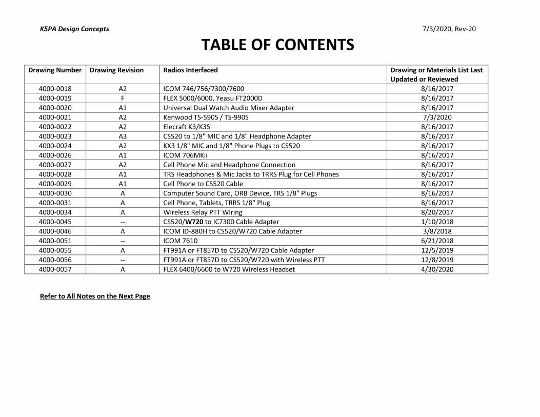
TABLE OF CONTENTS
Drawing Number Drawing Revision Radios Interfaced Drawing or Materials List Last Updated or Reviewed
4000-0018 A2 ICOM 746/756/7300/7600 8/16/2017
4000-0019 F FLEX 5000/6000, Yeasu FT2000D 8/16/2017
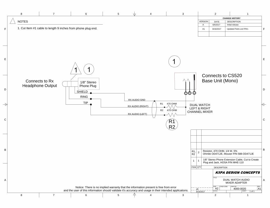
4000-0020 A1 Universal Dual Watch Audio Mixer Adapter 8/16/2017
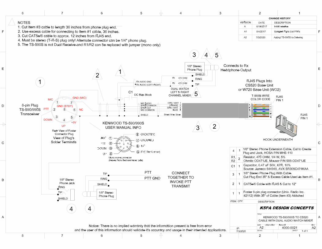
4000-0021 A2 Kenwood TS-590S / TS-990S 7/3/2020
4000-0022 A2 Elecraft K3/K3S 8/16/2017
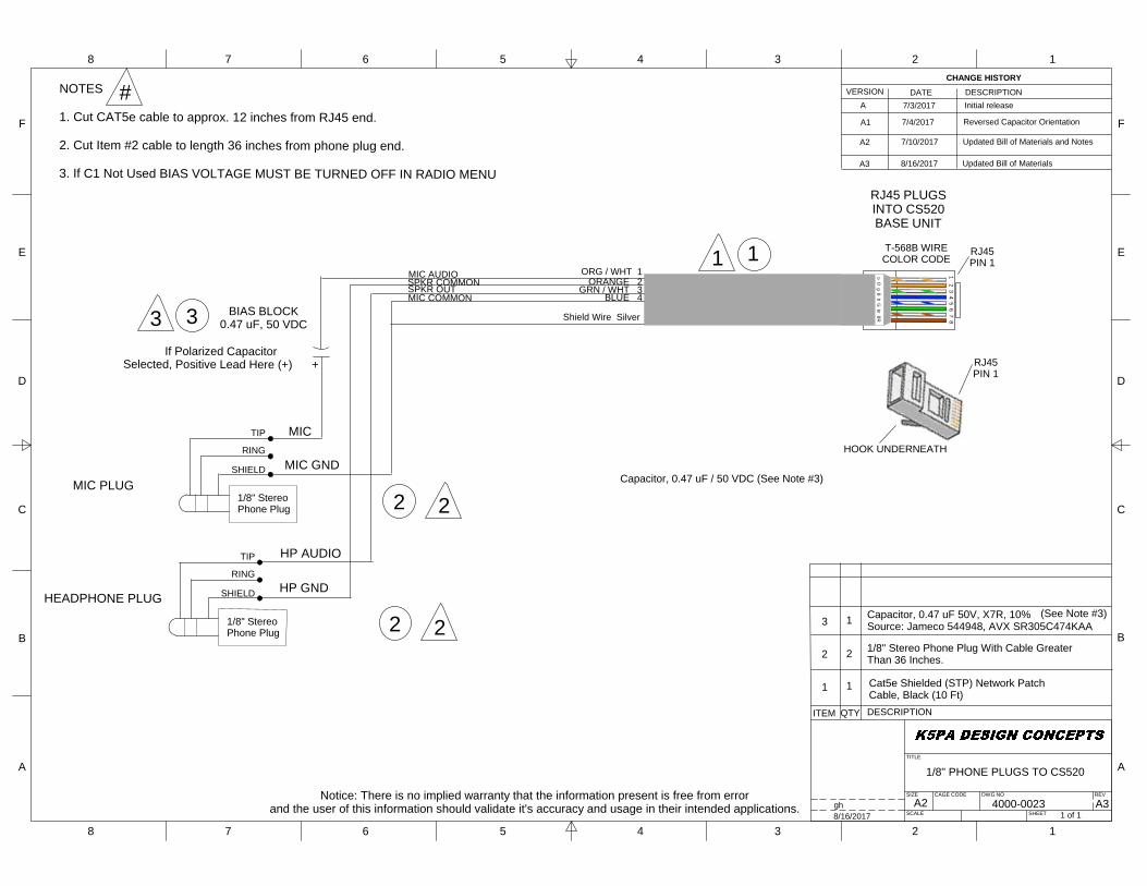
4000-0023 A3 CS520 to 1/8" MIC and 1/8" Headphone Adapter 8/16/2017
4000-0024 A2 KX3 1/8" MIC and 1/8" Phone Plugs to CS520 8/16/2017
4000-0026 A1 ICOM 706MKii 8/16/2017
4000-0027 A2 Cell Phone Mic and Headphone Connection 8/16/2017
4000-0028 A1 TRS Headphones & Mic Jacks to TRRS Plug for Cell Phones 8/16/2017
4000-0029 A1 Cell Phone to CS520 Cable 8/16/2017
4000-0030 A Computer Sound Card, ORB Device, TRS 1/8" Plugs 8/16/2017
4000-0031 A Cell Phone, Tablets, TRRS 1/8" Plug 8/16/2017
4000-0034 A Wireless Relay PTT Wiring 8/20/2017
4000-0045 -- CS520/W720 to IC7300 Cable Adapter 1/10/2018
4000-0046 A ICOM ID-880H to CS520/W720 Cable Adapter 3/8/2018
4000-0051 -- ICOM 7610 6/21/2018
4000-0055 A FT991A or FT857D to CS520/W720 Cable Adapter 12/5/2019
4000-0056 -- FT991A or FT857D to CS520/W720 with Wireless PTT 12/8/2019
4000-0057 A FLEX 6400/6600 to W720 Wireless Headset 4/30/2020
Refer to All Notes on the Next Page
K5PA Design Concepts 7/3/2020, Rev-20
TABLE NOTES
Note 1, Suitability to Applications. All drawings, materials, manufacturers, part numbers, assumptions were derived from manufacturers' equipment
manuals and following best engineering practice. However, there is no implied warranty that the information present is free from error and the user of this
information should validate its accuracy and usage in their intended applications.
Note 2, Adaptability. Different radio manufacturers sometimes use similar microphone and headphone interfaces, especially for the common microphone
connections, push-to-talk (PTT), and ground. Some manufacturers also bring the audio output line(s) out the microphone connector. Therefore, it is worth
looking at a new radio requirement to see if any of the existing drawings match the pins of the microphone connector. In that case, if the other pin
functions are not needed, then the current drawing can be adapted.
Note 3, Dual Watch Operation. Many advanced transceivers have dual receiver capabilities or dual watch that permits listening on two different radio
frequencies at the same time. This is used to monitor a 2nd channel or to work split when working a DX pileup. Each of the audio channels will be
connected to its own output connector or a common connector with multiple pins. Commonly used is the Tip-Ring-Sleeve (TRS) 1/4" or 1/8" phone plug to
route these two receiver audio output paths. The CS520 is only a mono audio wireless headset so a dual channel mixer is needed to combine the two audio
channels into one. This is the purpose of the summing circuit using the two resistors in the audio path. There is also a separate audio cable that combines
the two channels into one (refer to Drawing 4000-0020).
Note 4, Bias Voltage. A small DC bias voltage is necessary to provide power to an electret microphone element. Since the CS520 does not require this bias
voltage, each of the drawings use a DC blocking capacitor in series with the microphone audio lead. This effectively and safely blocks the DC component
(depending on the radio manufacturer, normally between 3 and 8 VDC). Radio setup menus sometimes allow a setting to remove the bias voltage for
instances where a dynamic microphone element is used that would create a short circuit condition. It is necessary to deselect the bias voltage option if the
DC blocking capacitor is not used in the adapter. My belief is the circuit should be robustly designed for the case when the operator inadvertently leaves the
DC bias option turned on in the radio's setup menu.
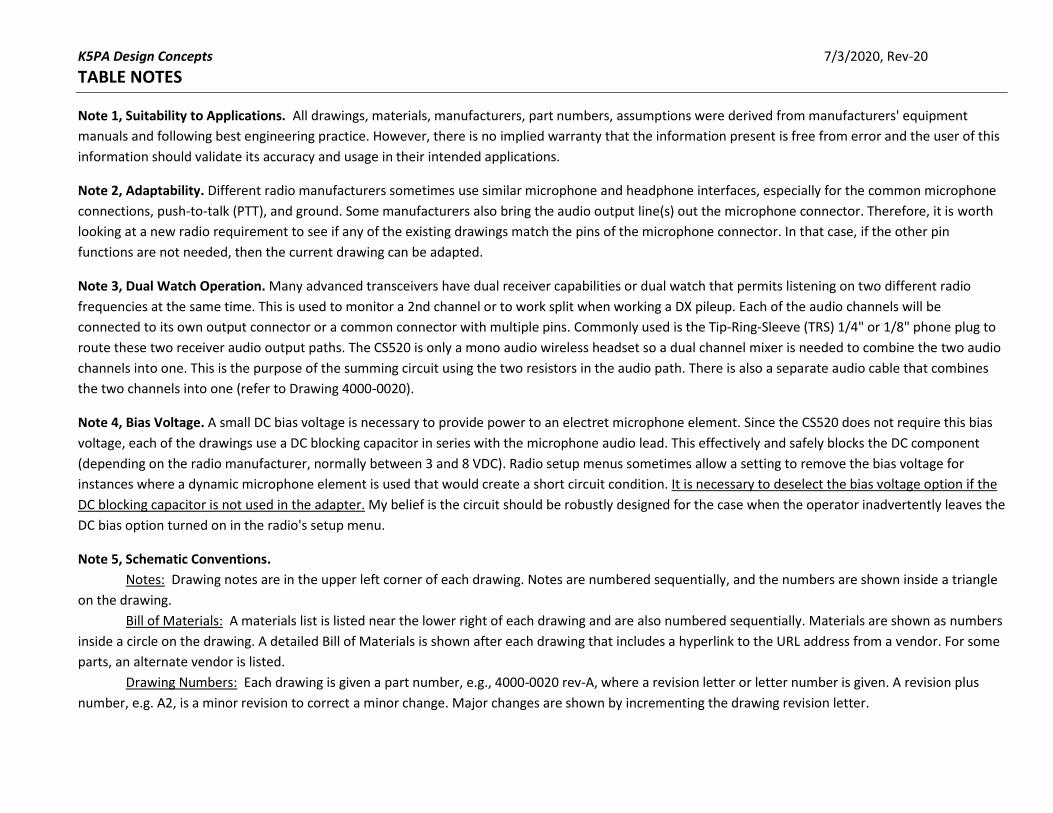
Note 5, Schematic Conventions.
Notes: Drawing notes are in the upper left corner of each drawing. Notes are numbered sequentially, and the numbers are shown inside a triangle
on the drawing.
Bill of Materials: A materials list is listed near the lower right of each drawing and are also numbered sequentially. Materials are shown as numbers
inside a circle on the drawing. A detailed Bill of Materials is shown after each drawing that includes a hyperlink to the URL address from a vendor. For some
parts, an alternate vendor is listed.
Drawing Numbers: Each drawing is given a part number, e.g., 4000-0020 rev-A, where a revision letter or letter number is given. A revision plus
number, e.g. A2, is a minor revision to correct a minor change. Major changes are shown by incrementing the drawing revision letter.

Drawing Notes
Materials Item #
Notes #
Revision History
Drawing # and Revision #
Materials List
Detailed Bill of Materials Follows Each Drawing
DRAWING CONVENTIONS
A2
F
E
D
C
B
A
F
E
D
C
B
A
8 7 6 5 4 3 2 1
8 7 6 5 4 3 2 1
TITLE
REV
SHEET
DWG NOCAGE CODESIZE
SCALE
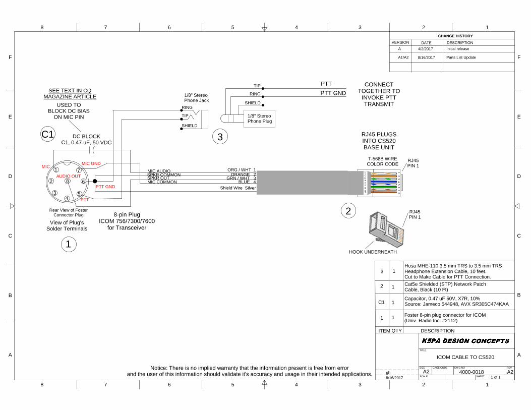
ICOM CABLE TO CS520
4000-00181 of 1
A2gh8/16/2017
ITEM QTY DESCRIPTION
1
3
CHANGE HISTORYVERSION DATE DESCRIPTION
A
1
1
Foster 8-pin plug connector for ICOM(Univ. Radio Inc. #2112)
1
4/2/2017 Initial release
SPKR OUT
Shield Wire Silver
MIC AUDIO
8-pin PlugICOM 756/7300/7600
for TransceiverView of Plug's
Solder Terminals
USED TOBLOCK DC BIAS
ON MIC PIN TIP
RING
SHIELD
1/8" StereoPhone Jack
RJ45PIN 1
HOOK UNDERNEATH
1 2 3 4 5 6 7 8
o O g B
b G br B
R
T-568B WIRECOLOR CODE
RJ45PIN 1
Rear View of FosterConnector Plug
MIC 1
2
34
5
6
7
8
PTT
PTT GND
MIC GND
AUDIO OUTMIC COMMON
SPKR COMMONORG / WHT 1
ORANGE 2GRN / WHT 3
BLUE 4
DC BLOCKC1, 0.47 uF, 50 VDC
CONNECTTOGETHER TO
INVOKE PTTTRANSMIT
RJ45 PLUGSINTO CS520BASE UNIT
PTTPTT GND
1/8" StereoPhone Plug
TIP
RING
SHIELD
SEE TEXT IN CQMAGAZINE ARTICLE
C1Capacitor, 0.47 uF 50V, X7R, 10%Source: Jameco 544948, AVX SR305C474KAA
A1/A2 8/16/2017 Parts List Update
Notice: There is no implied warranty that the information present is free from errorand the user of this information should validate it's accuracy and usage in their intended applications.
Hosa MHE-110 3.5 mm TRS to 3.5 mm TRSHeadphone Extension Cable, 10 feet.Cut to Make Cable for PTT Connection.
1
3C1
1
2 Cat5e Shielded (STP) Network PatchCable, Black (10 Ft)
2

Date: 8/16/2017
Bill of Materials Drawing 4000-0018 rev-A2Item Part Description Mfgr Part No. Vendor URL of Vendor P/N Qty
1 Foster 8-pin plug connector for ICOM Foster 2112
Univ. Radio Inc.
(http://www.universal-
radio.com/)2112 1
C1 0.47 uF 50V, X7R, 10% AVX SR305C474KAA Mouser 581-SR305C474KAA 1
ALTERNATE SOURCE:
0.47 uF 50V, X7R, 10%JVP
SR305C474KAA Jameco 544948
2Cat5e Molded Shielded (STP) Network Patch Cable,
Black (10 Feet/3.04 Meters)C2G/Cables to Go 28693 Amazon 28693 1
3Hosa MHE-110 3.5 mm TRS to 3.5 mm TRS
Headphone Extension Cable, 10 feetHOSA MHE-110 Amazon MHE-110 1

A2
F
E
D
C
B
A
F
E
D
C
B
A
8 7 6 5 4 3 2 1
8 7 6 5 4 3 2 1
TITLE
REV
SHEET
DWG NOCAGE CODESIZE
SCALE
FLEX 6000/5000 SERIES OR FT2000DCABLE TO CS520 WITH
DUAL AUDIO WATCH MIXER
4000-00191 of 1
Fgh8/16/2017
ITEM QTY DESCRIPTION
1
2
3
C1
CHANGE HISTORYVERSION DATE DESCRIPTION
A
1
1
Foster 8-pin plug connector (Univ. Radio Inc.#2112) With 36" of Cable (Item #3) Attached
1
5/19/2017 Initial release
1/8" Stereo Phone Plug With Cable.Cut Plug End 36" & Excess Cable Used With Item #1.
SPKR OUT
Shield Wire Silver
MIC AUDIO8-pin PlugFlex 6000
Series or FT2000DTransceiver
View of Plug'sSolder Terminals
RJ45PIN 1
HOOK UNDERNEATH
1 2 3 4 5 6 7 8
o O g B
b G br B
R
T-568B WIRECOLOR CODE
RJ45PIN 1
Rear View of FosterConnector Plug
UP1
2
34
5
6
7
8PTT
MIC -
MIC COMMON
SPKR COMMONORG / WHT 1
ORANGE 2GRN / WHT 3
BLUE 4
DC Bias Block
RJ45 Plugs IntoCS520 Base Unit
+5V
DOWN
FASTGND
MIC+
RX AUDIO (LEFT+RIGHT)RX AUDIO GND
Connects to RxHeadphone Output
(1/8" to 1/4" Stereo Adapter Required!)
1/8" StereoPhone Plug
TIP
RING
SHIELD
FLEX 6000 SERIESUSER MANUAL INFO
1
3
2
SHIELD
NOTES
1. Cut Item #3 cable to length 36 inches from phone plug end.
2. Use excess cable for connecting to Item #1 cable, 36 inches.
3. Cut CAT5e cable to approx. 12 inches from RJ45 end.
4. Must be stereo (T-R-S) plug only! Shown as 1/8" but can use 1/4" plug instead. Reference Flex 6000 Series User Manual (ver Version 1.4.11, pg. 30)
5. FT-2000D Operating Manual, Filename: FT-2000D_OM_ENG_EH025H142.pdf
6. FLEX 5000 Radio Manual, Version 2.0 1
3
2
1
C1
B 5/21/2017 Redesign and cable lengths
4
R1 470 OHM
R2 470 OHM
DUAL WATCHLEFT & RIGHT
CHANNEL MIXER
R1,R2 2
C 6/2/2017 Added Left/Right CH Mixer
FT2000DUSER MANUAL INFO
D 6/20/2017 Added FT2000D References
4 1 1/8" jack to 1/4" plug Stereo Adapter (See Note #4)
4
FLEX 5000 SERIESUSER MANUAL INFO
E 6/23/2017 Added FLEX 5000 References
Resistor, 470 OHM, 1/4 W, 5%Ohmite OD471JE, Mouser P/N 588-OD471JECapacitor, 0.47 uF 50V, X7R, 10%Source: Jameco 544948, AVX SR305C474KAA
E1/F 8/16/2017 rev-E1: Parts List Update.rev-F: Added PTT Circuit.
Notice: There is no implied warranty that the information present is free from errorand the user of this information should validate it's accuracy and usage in their intended applications.
TIP
RING
SHIELD
1/8" StereoPhone Jack
CONNECTTOGETHER TO
INVOKE PTTTRANSMIT
PTTPTT GND
1/8" StereoPhone Plug
TIP
RING
SHIELD
5 5#
5 1 1/8" Stereo Phone Extension Cable, Cut to CreatePlug and Jack, HOSA P/N MHE-110
Cat5e Shielded (STP) Network PatchCable, Black (10 Ft)

Date: 8/16/2017
Bill of Materials Drawing 4000-0019 rev-FItem Part Description Mfgr Part No. Vendor URL of Vendor P/N Qty
1 Foster 8-pin plug connector for ICOM Foster 2112
Univ. Radio Inc.
(http://www.universal-
radio.com/)
2112 1
2Cat5e Molded Shielded (STP) Network Patch Cable,
Black (10 Feet/3.04 Meters)C2G/Cables to Go 28693 Amazon 28693 1
3Hosa CMM-110 3.5 mm TRS to 3.5 mm TRS Stereo
Interconnect Cable, 10 feetHOSA CMM-110 Amazon CMM-110 1
R1,R2 Resistor, 470 Ohms, 1/4W, 5% Ohmite OD471JE Mouser 588-OD471JE 2
C1 0.47 uF 50V, X7R, 10% AVX SR305C474KAA Mouser 581-SR305C474KAA 1
ALTERNATE SOURCE:
0.47 uF 50V, X7R, 10%JVP SR305C474KAA Jameco
544948
45-Pack, Gold Plated 6.3mm (1/4 inch) to 3.5 mm
Male to Female Stereo AdapterCable Matters 501003X5 Amazon 501003X5 1
5Hosa MHE-110 3.5 mm TRS to 3.5 mm TRS
Headphone Extension Cable, 10 feetHOSA MHE-110 Amazon MHE-110 1
A2
F
E
D
C
B
A
F
E
D
C
B
A
8 7 6 5 4 3 2 1
8 7 6 5 4 3 2 1
TITLE
REV
SHEET
DWG NOCAGE CODESIZE
SCALE
DUAL WATCH AUDIOMIXER ADAPTER
4000-00201 of 1
A1gh8/16/2017
ITEM QTY DESCRIPTION
1
CHANGE HISTORYVERSION DATE DESCRIPTION
A
1
6/5/2017 Initial releaseNOTES
1. Cut Item #1 cable to length 9 inches from phone plug end.
R1,R2
2
RX AUDIO (LEFT)
RX AUDIO GND
Connects to RxHeadphone Output
1/8" StereoPhone Plug
TIP
RING
SHIELD
R1 470 OHM
R2 470 OHM
DUAL WATCHLEFT & RIGHT
CHANNEL MIXER
ST R
Connects to CS520Base Unit (Mono)
RX AUDIO (RIGHT)
Resistor, 470 OHM, 1/4 W, 5%Ohmite OD471JE, Mouser P/N 588-OD471JE
A1 8/16/2017 Updated Parts List P/N's
Notice: There is no implied warranty that the information present is free from errorand the user of this information should validate it's accuracy and usage in their intended applications.
1/8" Stereo Phone Extension Cable, Cut to CreatePlug and Jack, HOSA P/N MHE-110
R1R2

Date: 8/16/2017
Bill of Materials Drawing 4000-0020 rev-A1Item Part Description Mfgr Part No. Vendor URL of Vendor P/N Qty
1Hosa MHE-110 3.5 mm TRS to 3.5 mm TRS
Headphone Extension Cable, 10 feetHOSA MHE-110 Amazon MHE-110 1
R1,R2 Resistor, 470 Ohms, 1/4W, 5% Ohmite OD471JE Mouser 588-OD471JE 2

Date: 8/10/2017
Bill of Materials Drawing 4000-0021 rev-A1Item Part Description Mfgr Part No. Vendor URL of Vendor P/N Qty
1 Foster 8-pin plug connector for ICOM Foster 2112
Univ. Radio Inc.
(http://www.universal-
radio.com/)
2112 1
2Cat5e Molded Shielded (STP) Network Patch Cable, Black
(10 Feet/3.04 Meters)C2G/Cables to Go 28693 Amazon 28693 1
3Hosa CMM-110 3.5 mm TRS to 3.5 mm TRS Stereo
Interconnect Cable, 10 feetHOSA CMM-110 Amazon CMM-110 1
C1 0.47 uF 50V, X7R, 10% AVX SR305C474KAA Mouser 581-SR305C474KAA 1
ALTERNATE SOURCE:
0.47 uF 50V, X7R, 10%JVP SR305C474KAA Jameco
544948
R1,R2 Resistor, 470 Ohms, 1/4W, 5% Ohmite OD471JE Mouser 588-OD471JE 2
4Hosa MHE-110 3.5 mm TRS to 3.5 mm TRS Headphone
Extension Cable, 10 feetHOSA MHE-110 Amazon MHE-110 1

A2
F
E
D
C
B
A
F
E
D
C
B
A
8 7 6 5 4 3 2 1
8 7 6 5 4 3 2 1
TITLE
REV
SHEET
DWG NOCAGE CODESIZE
SCALE
ELECRAFT K3 TO CS520 CABLEWITH DUAL AUDIO WATCH MIXER
4000-00221 of 1
A2gh8/16/2017
ITEM QTY DESCRIPTION
1
2
3
C1
CHANGE HISTORYVERSION DATE DESCRIPTION
A
1
1
Foster 8-pin plug connector (Univ. Radio Inc.#2112) With 36" of Cable (Item #3) Attached
1
6/30/2017 Initial release
1/8" Stereo Phone Plug With Cable. (See Note #4)Cut Plug End 36" & Excess Cable Used as Item #1.
SPKR OUT
Shield Wire Silver
MIC AUDIO8-pin PlugELECRAFT K3
Transceiver
View of Plug'sSolder Terminals
RJ45PIN 1
HOOK UNDERNEATH
1 2 3 4 5 6 7 8
o O g B
b G br B
R
T-568B WIRECOLOR CODE
RJ45PIN 1
Rear View of FosterConnector Plug
UP
1
2
34
5
6
7
8PTT
GND
MIC COMMON
SPKR COMMONORG / WHT 1
ORANGE 2GRN / WHT 3
BLUE 4
DC Bias Block
RJ45 Plugs IntoCS520 Base Unit
FUNCTIONDOWN
+8VDC
MIC
RX AUDIO (LEFT+RIGHT)RX AUDIO GND
Connects to RxHeadphone Output
1/8" StereoPhone Plug
TIP
RING
SHIELD
ELECRAFT K3 USERMANUAL INFO
1
3
2
SHIELD
NOTES
1. Cut Item #3 cable to length 36 inches from phone plug end.
2. Use excess cable for connecting to Item #1 cable, 36 inches.
3. Cut CAT5e cable to approx. 12 inches from RJ45 end.
4. Must be stereo (T-R-S) plug only! Alternate connector can be 1/4" phone plug.
5. If C1 Not Used BIAS VOLTAGE MUST BE TURNED OFF IN K3 MENU
1
3
2
1 (See Note #5)
C1 (See Note #5)
4
R1 470 OHM
R2 470 OHM
DUAL WATCHLEFT & RIGHT
CHANNEL MIXER
R1,R2 2
GND
TIP
RING
SHIELD
1/8" StereoPhone Jack
CONNECTTOGETHER TO
INVOKE PTTTRANSMIT
PTTPTT GND
1/8" StereoPhone Plug
TIP
RING
SHIELD
5
Resistor, 470 OHM, 1/4 W, 5%Ohmite OD471JE, Mouser P/N 588-OD471JECapacitor, 0.47 uF 50V, X7R, 10%Source: Jameco 544948, AVX SR305C474KAA
A1/A2 8/16/2017 Updated Parts List P/N's
Notice: There is no implied warranty that the information present is free from errorand the user of this information should validate it's accuracy and usage in their intended applications.
4 1 1/8" Stereo Phone Extension Cable, Cut to CreatePlug and Jack, HOSA P/N MHE-110
4 4
Cat5e Shielded (STP) Network PatchCable, Black (10 Ft)

Date: 8/16/2017
Bill of Materials Drawing 4000-0022 rev-A2Item Part Description Mfgr Part No. Vendor URL of Vendor P/N Qty
1 Foster 8-pin plug connector for ICOM Foster 2112
Univ. Radio Inc.
(http://www.univers
al-radio.com/)
2112 1
2Cat5e Molded Shielded (STP) Network Patch Cable, Black
(10 Feet/3.04 Meters)C2G/Cables to Go 28693 Amazon 28693 1
3Hosa CMM-110 3.5 mm TRS to 3.5 mm TRS Stereo
Interconnect Cable, 10 feetHOSA CMM-110 Amazon CMM-110 1
C1 0.47 uF 50V, X7R, 10% AVX SR305C474KAA Mouser 581-SR305C474KAA 1
R1,R2 Resistor, 470 Ohms, 1/4W, 5% Ohmite OD471JE Mouser 588-OD471JE 2
ALTERNATE SOURCE:
0.47 uF 50V, X7R, 10%JVP SR305C474KAA Jameco
544948
4Hosa MHE-110 3.5 mm TRS to 3.5 mm TRS Headphone
Extension Cable, 10 feetHOSA MHE-110 Amazon MHE-110 1
A2
F
E
D
C
B
A
F
E
D
C
B
A
8 7 6 5 4 3 2 1
8 7 6 5 4 3 2 1
TITLE
REV
SHEET
DWG NOCAGE CODESIZE
SCALE
1/8" PHONE PLUGS TO CS520
4000-00231 of 1
A3gh8/16/2017
ITEM QTY DESCRIPTION
1
2
3
CHANGE HISTORYVERSION DATE DESCRIPTION
A
1
2
1
7/3/2017 Initial release
SPKR OUT
Shield Wire Silver
MIC AUDIO
RJ45PIN 1
HOOK UNDERNEATH
1 2 3 4 5 6 7 8
o O g B
b G br B
R
T-568B WIRECOLOR CODE
RJ45PIN 1
MIC COMMON
SPKR COMMONORG / WHT 1
ORANGE 2GRN / WHT 3
BLUE 4BIAS BLOCK
0.47 uF, 50 VDC
MIC PLUG
HEADPHONE PLUG
RJ45 PLUGSINTO CS520BASE UNIT
MIC
MIC GND
1/8" StereoPhone Plug
TIP
RING
SHIELD
HP AUDIO
HP GND
1/8" StereoPhone Plug
TIP
RING
SHIELD
A1 7/4/2017 Reversed Capacitor Orientation
If Polarized CapacitorSelected, Positive Lead Here (+) +
1/8" Stereo Phone Plug With Cable GreaterThan 36 Inches.
Capacitor, 0.47 uF / 50 VDC (See Note #3)
NOTES
1. Cut CAT5e cable to approx. 12 inches from RJ45 end.
2. Cut Item #2 cable to length 36 inches from phone plug end.
3. If C1 Not Used BIAS VOLTAGE MUST BE TURNED OFF IN RADIO MENU
1
2
3 3
1
#
2
2 2
A2 7/10/2017 Updated Bill of Materials and Notes
(See Note #3)Capacitor, 0.47 uF 50V, X7R, 10%Source: Jameco 544948, AVX SR305C474KAA
A3 8/16/2017 Updated Bill of Materials
Notice: There is no implied warranty that the information present is free from errorand the user of this information should validate it's accuracy and usage in their intended applications.
Cat5e Shielded (STP) Network PatchCable, Black (10 Ft)
Date: 8/16/2017
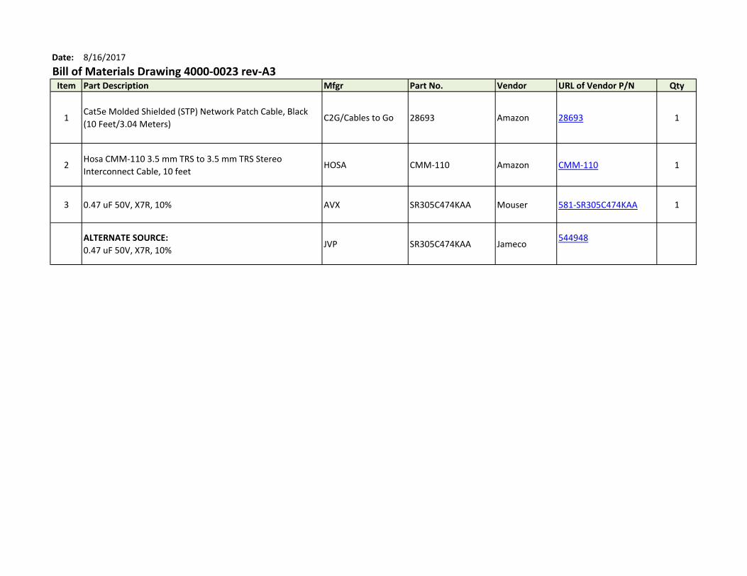
Bill of Materials Drawing 4000-0023 rev-A3Item Part Description Mfgr Part No. Vendor URL of Vendor P/N Qty
1Cat5e Molded Shielded (STP) Network Patch Cable, Black
(10 Feet/3.04 Meters)C2G/Cables to Go 28693 Amazon 28693 1
2Hosa CMM-110 3.5 mm TRS to 3.5 mm TRS Stereo
Interconnect Cable, 10 feetHOSA CMM-110 Amazon CMM-110 1
3 0.47 uF 50V, X7R, 10% AVX SR305C474KAA Mouser 581-SR305C474KAA 1
ALTERNATE SOURCE:
0.47 uF 50V, X7R, 10%JVP SR305C474KAA Jameco
544948
A2
F
E
D
C
B
A
F
E
D
C
B
A
8 7 6 5 4 3 2 1
8 7 6 5 4 3 2 1
TITLE
REV
SHEET
DWG NOCAGE CODESIZE
SCALE
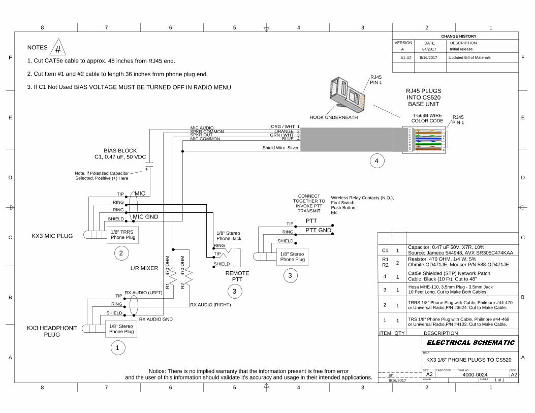
KX3 1/8" PHONE PLUGS TO CS520
4000-00241 of 1
A2gh8/16/2017
ITEM QTY DESCRIPTION
1
2
3
4
CHANGE HISTORYVERSION DATE DESCRIPTION
A
1
1
1
7/4/2017 Initial release
SPKR OUT
Shield Wire Silver
MIC AUDIO
RJ45PIN 1
HOOK UNDERNEATH
1 2 3 4 5 6 7 8
o O g B
b G br B
R
T-568B WIRECOLOR CODE
RJ45PIN 1
MIC COMMON
SPKR COMMONORG / WHT 1
ORANGE 2GRN / WHT 3
BLUE 4
BIAS BLOCKC1, 0.47 uF, 50 VDC
KX3 MIC PLUG
KX3 HEADPHONEPLUG
RJ45 PLUGSINTO CS520BASE UNIT
MIC
MIC GND
1/8" StereoPhone Plug
TIP
RING
SHIELD
1/8" TRRSPhone Plug
TIP
RING
SHIELD
RING
TIP
RING
SHIELD
1/8" StereoPhone Jack
CONNECTTOGETHER TO
INVOKE PTTTRANSMIT
PTTPTT GND
1/8" StereoPhone Plug
TIP
RING
SHIELD
RX AUDIO (LEFT)
RX AUDIO GND
R1
4
70 O
HM
R2
4
70 O
HM
RX AUDIO (RIGHT)
REMOTEPTT
Wireless Relay Contacts (N.O.),Foot Switch,Push Button,Etc.
+Note, if Polarized CapacitorSelected, Positive (+) Here
L/R MIXER
Hosa MHE-110, 3.5mm Plug - 3.5mm Jack10 Feet Long, Cut to Make Both Cables
TRRS 1/8" Phone Plug with Cable, Philmore #44-470or Universal Radio,P/N #3624. Cut to Make Cable.
1Cat5e Shielded (STP) Network PatchCable, Black (10 Ft), Cut to 48"
TRS 1/8" Phone Plug with Cable, Philmore #44-468or Universal Radio,P/N #4103. Cut to Make Cable.
1
2
4
3
3
R1R2 2
C1 1
Resistor, 470 OHM, 1/4 W, 5%Ohmite OD471JE, Mouser P/N 588-OD471JE
Capacitor, 0.47 uF 50V, X7R, 10%Source: Jameco 544948, AVX SR305C474KAA
A1-A2 8/16/2017 Updated Bill of Materials
Notice: There is no implied warranty that the information present is free from errorand the user of this information should validate it's accuracy and usage in their intended applications.
NOTES
1. Cut CAT5e cable to approx. 48 inches from RJ45 end.
2. Cut Item #1 and #2 cable to length 36 inches from phone plug end.
3. If C1 Not Used BIAS VOLTAGE MUST BE TURNED OFF IN RADIO MENU
#
Date: 8/16/2017
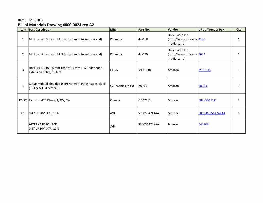
Bill of Materials Drawing 4000-0024 rev-A2Item Part Description Mfgr Part No. Vendor URL of Vendor P/N Qty
1 Mini to mini 3 cond cbl, 6 ft. (cut and discard one end) Philmore 44-468
Univ. Radio Inc.
(http://www.universa
l-radio.com/)
4103 1
2 Mini to mini 4 cond cbl, 3 ft. (cut and discard one end) Philmore 44-470
Univ. Radio Inc.
(http://www.universa
l-radio.com/)
3624 1
3Hosa MHE-110 3.5 mm TRS to 3.5 mm TRS Headphone
Extension Cable, 10 feetHOSA MHE-110 Amazon MHE-110 1
4Cat5e Molded Shielded (STP) Network Patch Cable, Black
(10 Feet/3.04 Meters)C2G/Cables to Go 28693 Amazon 28693 1
R1,R2 Resistor, 470 Ohms, 1/4W, 5% Ohmite OD471JE Mouser 588-OD471JE 2
C1 0.47 uF 50V, X7R, 10% AVX SR305C474KAA Mouser 581-SR305C474KAA 1
ALTERNATE SOURCE:
0.47 uF 50V, X7R, 10%JVP
SR305C474KAA Jameco 544948
A2
F
E
D
C
B
A
F
E
D
C
B
A
8 7 6 5 4 3 2 1
8 7 6 5 4 3 2 1
TITLE
REV
SHEET
DWG NOCAGE CODESIZE
SCALE
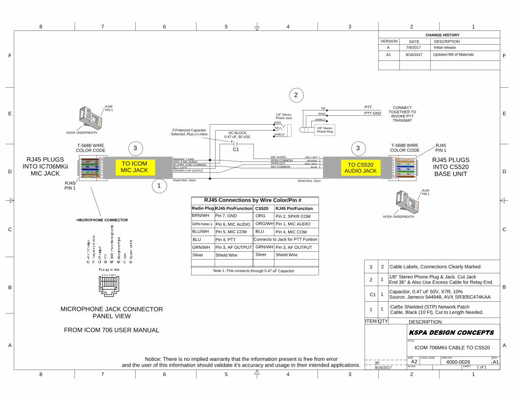
ICOM 706MKii CABLE TO CS520
4000-00261 of 1
A1gh8/16/2017
ITEM QTY DESCRIPTION
1
C1
2
3
CHANGE HISTORYVERSION DATE DESCRIPTION
A
1
1
1
7/9/2017 Initial release
SPKR OUT
Shield Wire Silver
MIC AUDIO
TIP
RING
SHIELD
1/8" StereoPhone Jack
RJ45PIN 1
HOOK UNDERNEATH
RJ45PIN 1
MIC COMMON
SPKR COMMONORG / WHT 1
ORANGE 2GRN / WHT 3
BLUE 4
DC BLOCK0.47 uF, 50 VDC
CONNECTTOGETHER TO
INVOKE PTTTRANSMIT
RJ45 PLUGSINTO CS520BASE UNIT
PTTPTT GND
1/8" StereoPhone Plug
TIP
RING
SHIELD
Shield Wire Silver
GRN/WH 3 AF OUTPUT
GRN 6 MIC AUDIOBLU/WH 5 MIC COMMON
BRN/WH 7 GND
BLU 4 PTT
1 2
3 4
5 6
7 8
o O
g B
b G
br
BR
T-568B WIRECOLOR CODE
RJ45PIN 1
T-568B WIRECOLOR CODE
1 2 3 4 5 6 7 8
o O g B
b G br B
R
RJ45 PLUGSINTO IC706MKii
MIC JACK
RJ45PIN 1
HOOK UNDERNEATH
C1
1/8" Stereo Phone Plug & Jack. Cut JackEnd 36" & Also Use Excess Cable for Relay End.
1
2
MICROPHONE JACK CONNECTORPANEL VIEW
FROM ICOM 706 USER MANUAL
TO ICOMMIC JACK
TO CS520AUDIO JACK
3 3+
If Polarized CapacitorSelected, Plus (+) Here
Cable Labels, Connections Clearly Marked2
RJ45 Connections by Wire Color/Pin #
Pin 7, GND
CS520
GRN/WH
GRN Note-1
BLU/WH
BRN/WH
BLU
Silver
Radio Plug
Pin 6, MIC AUDIO
Pin 3, AF OUTPUT
Pin 5, MIC COM
Pin 4, PTT
Shield Wire
Pin 2, SPKR COMORG
ORG/WH Pin 1, MIC AUDIO
BLU Pin 4, MIC COM
Pin 3, AF OUTPUTSilver Shield Wire
RJ45 Pin/Function RJ45 Pin/Function
Connects to Jack for PTT Funtion
GRN/WH
Note 1 -This connects through 0.47 uF Capacitor
A1 8/16/2017 Updated Bill of Materials
Capacitor, 0.47 uF 50V, X7R, 10%Source: Jameco 544948, AVX SR305C474KAA
Notice: There is no implied warranty that the information present is free from errorand the user of this information should validate it's accuracy and usage in their intended applications.
Cat5e Shielded (STP) Network PatchCable, Black (10 Ft), Cut to Length Needed.
Date: 8/16/2017
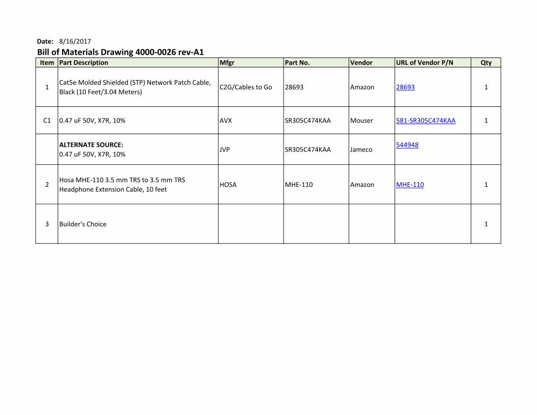
Bill of Materials Drawing 4000-0026 rev-A1Item Part Description Mfgr Part No. Vendor URL of Vendor P/N Qty
1Cat5e Molded Shielded (STP) Network Patch Cable,
Black (10 Feet/3.04 Meters)C2G/Cables to Go 28693 Amazon 28693 1
C1 0.47 uF 50V, X7R, 10% AVX SR305C474KAA Mouser 581-SR305C474KAA 1
ALTERNATE SOURCE:
0.47 uF 50V, X7R, 10%JVP SR305C474KAA Jameco
544948
2Hosa MHE-110 3.5 mm TRS to 3.5 mm TRS
Headphone Extension Cable, 10 feetHOSA MHE-110 Amazon MHE-110 1
3 Builder's Choice 1
A2
F
E
D
C
B
A
F
E
D
C
B
A
8 7 6 5 4 3 2 1
8 7 6 5 4 3 2 1
TITLE
REV
SHEET
DWG NOCAGE CODESIZE
SCALE
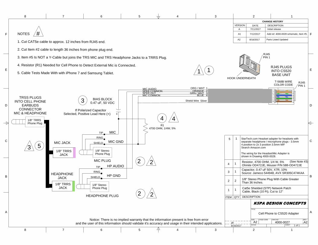
Cell Phone to CS520 Adapter
4000-00271 of 1
A2gh8/16/2017
ITEM QTY DESCRIPTION
1
2
3
CHANGE HISTORYVERSION DATE DESCRIPTION
A
1
2
1
7/11/2017 Initial release
SPKR OUT
Shield Wire Silver
MIC AUDIO
RJ45PIN 1
HOOK UNDERNEATH
1 2 3 4 5 6 7 8
o O g B
b G br B
R
T-568B WIRECOLOR CODE
RJ45PIN 1
MIC COMMON
SPKR COMMONORG / WHT 1
ORANGE 2GRN / WHT 3
BLUE 4BIAS BLOCK
0.47 uF, 50 VDC
MIC PLUG
HEADPHONE PLUG
RJ45 PLUGSINTO CS520BASE UNIT
MIC
MIC GND
1/8" StereoPhone Plug
TIP
RING
SHIELD
HP AUDIO
HP GND
1/8" StereoPhone Plug
TIP
RING
SHIELD
If Polarized CapacitorSelected, Positive Lead Here (+) +
1/8" Stereo Phone Plug With Cable GreaterThan 36 Inches.
(See Note #3)
NOTES
1. Cut CAT5e cable to approx. 12 inches from RJ45 end.
2. Cut Item #2 cable to length 36 inches from phone plug end.
3. Item #5 Is NOT a Y-Cable but joins the TRS MIC and TRS Headphone Jacks to a TRRS Plug.
4. Resistor (R1) Needed for Cell Phone to Detect External Mic is Connected.
5. Cable Tests Made With with iPhone 7 and Samsung Tablet. 1
2
3
3
1
#
2 4 1
5 1 StarTech.com Headset adapter for headsets withseparate headphone / microphone plugs - 3.5mm4 position to 2x 3 position 3.5mm M/FSearch Amazon.com
The wiring for the Headset/Mic Adapter isshown in Drawing 4000-0028.
1/8" TRRSPhone Plug
MIC JACK
HEADPHONEJACK
51/8" TRRS
JACK
1/8" TRRSJACK
TRSS PLUGSINTO CELL PHONE
EARBUDSCONNECTOR
MIC & HEADPHONE
R14700 OHM, 1/4W, 5%
4 4
2 2
A1 7/12/2017 Add ref. 4000-0028 schematic, Item #5.
Resistor, 4700 OHM, 1/4 W, 5%Ohmite OD472JE, Mouser P/N 588-OD472JECapacitor, 0.47 uF 50V, X7R, 10%Source: Jameco 544948, AVX SR305C474KAA
A2 8/16/2017 Parts Listed Updated
Notice: There is no implied warranty that the information present is free from errorand the user of this information should validate it's accuracy and usage in their intended applications.
Cat5e Shielded (STP) Network PatchCable, Black (10 Ft), Cut to 12"
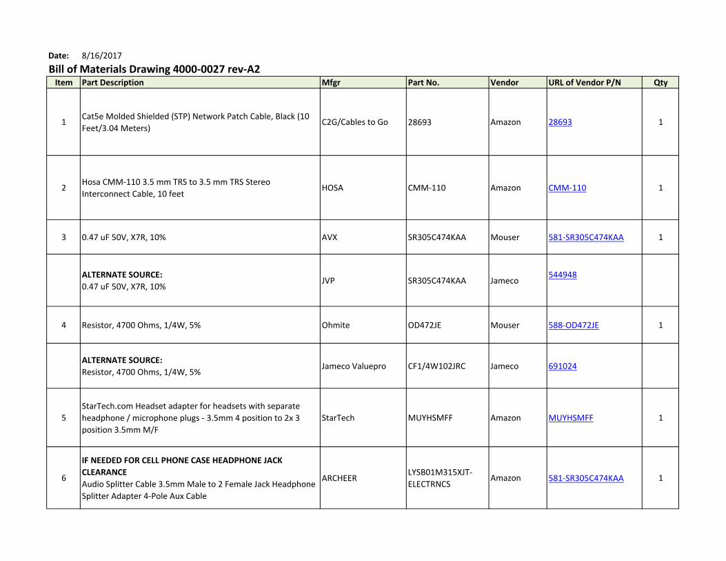
Date: 8/16/2017
Bill of Materials Drawing 4000-0027 rev-A2Item Part Description Mfgr Part No. Vendor URL of Vendor P/N Qty
1Cat5e Molded Shielded (STP) Network Patch Cable, Black (10
Feet/3.04 Meters)C2G/Cables to Go 28693 Amazon 28693 1
2Hosa CMM-110 3.5 mm TRS to 3.5 mm TRS Stereo
Interconnect Cable, 10 feetHOSA CMM-110 Amazon CMM-110 1
3 0.47 uF 50V, X7R, 10% AVX SR305C474KAA Mouser 581-SR305C474KAA 1
ALTERNATE SOURCE:
0.47 uF 50V, X7R, 10%JVP SR305C474KAA Jameco
544948
4 Resistor, 4700 Ohms, 1/4W, 5% Ohmite OD472JE Mouser 588-OD472JE 1
ALTERNATE SOURCE:
Resistor, 4700 Ohms, 1/4W, 5%Jameco Valuepro CF1/4W102JRC Jameco 691024
5
StarTech.com Headset adapter for headsets with separate
headphone / microphone plugs - 3.5mm 4 position to 2x 3
position 3.5mm M/F
StarTech MUYHSMFF Amazon MUYHSMFF 1
6
IF NEEDED FOR CELL PHONE CASE HEADPHONE JACK
CLEARANCE
Audio Splitter Cable 3.5mm Male to 2 Female Jack Headphone
Splitter Adapter 4-Pole Aux Cable
ARCHEER LYSB01M315XJT-
ELECTRNCSAmazon 581-SR305C474KAA 1
A2
F
E
D
C
B
A
F
E
D
C
B
A
8 7 6 5 4 3 2 1
8 7 6 5 4 3 2 1
TITLE
REV
SHEET
DWG NOCAGE CODESIZE
SCALE
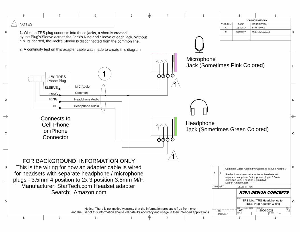
TRS Mic / TRS Headphones toTRRS Plug Adapter Wiring
4000-00281 of 1
A1gh8/16/2017
ITEM QTY DESCRIPTION
CHANGE HISTORYVERSION DATE DESCRIPTION
A 7/17/2017 Initial releaseNOTES
1. When a TRS plug connects into these jacks, a short is createdby the Plug's Sleeve across the Jack's Ring and Sleeve of each jack. Withouta plug inserted, the Jack's Sleeve is disconnected from the common line.
2. A continuity test on this adapter cable was made to create this diagram.
MIC Audio
Connects toCell Phoneor iPhoneConnector
MicrophoneJack (Sometimes Pink Colored)
Common
1/8" TRRSPhone Plug
TIP
RINGRING
SLEEVE
Headphone Audio
Headphone Audio
Headphone Jack (Sometimes Green Colored)
SRT R
SRT R
FOR BACKGROUND INFORMATION ONLYThis is the wiring for how an adapter cable is wired
for headsets with separate headphone / microphoneplugs - 3.5mm 4 position to 2x 3 position 3.5mm M/F.
Manufacturer: StarTech.com Headset adapterSearch: Amazon.com
Complete Cable Assembly Purchased as One Adapter.
StarTech.com Headset adapter for headsets withseparate headphone / microphone plugs - 3.5mm4 position to 2x 3 position 3.5mm M/FSearch Amazon.com
1 1
Notice: There is no implied warranty that the information present is free from errorand the user of this information should validate it's accuracy and usage in their intended applications.
A1 8/16/2017 Materials Updated
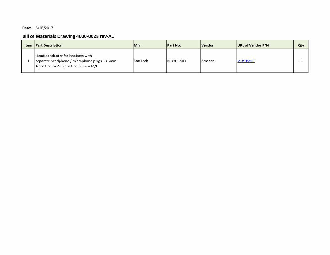
Date: 8/16/2017
Bill of Materials Drawing 4000-0028 rev-A1
Item Part Description Mfgr Part No. Vendor URL of Vendor P/N Qty
1
Headset adapter for headsets with
separate headphone / microphone plugs - 3.5mm
4 position to 2x 3 position 3.5mm M/F
StarTech MUYHSMFF Amazon MUYHSMFF 1
A2
F
E
D
C
B
A
F
E
D
C
B
A
8 7 6 5 4 3 2 1
8 7 6 5 4 3 2 1
TITLE
REV
SHEET
DWG NOCAGE CODESIZE
SCALE
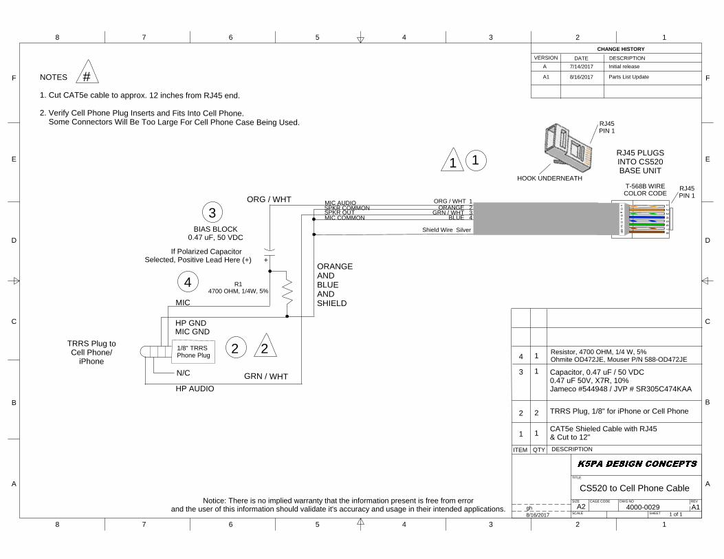
CS520 to Cell Phone Cable
4000-00291 of 1
A1gh8/16/2017
ITEM QTY DESCRIPTION
1
2
3
CHANGE HISTORYVERSION DATE DESCRIPTION
A
1
2
1
7/14/2017 Initial release
SPKR OUT
Shield Wire Silver
MIC AUDIO
RJ45PIN 1
HOOK UNDERNEATH
1 2 3 4 5 6 7 8
o O g B
b G br B
R
T-568B WIRECOLOR CODE
RJ45PIN 1
MIC COMMON
SPKR COMMONORG / WHT 1
ORANGE 2GRN / WHT 3
BLUE 4
BIAS BLOCK0.47 uF, 50 VDC
TRRS Plug toCell Phone/
iPhone
RJ45 PLUGSINTO CS520BASE UNIT
MIC
MIC GND
HP AUDIO
HP GND
If Polarized CapacitorSelected, Positive Lead Here (+) +
CAT5e Shieled Cable with RJ45& Cut to 12"
TRRS Plug, 1/8" for iPhone or Cell Phone
Capacitor, 0.47 uF / 50 VDC0.47 uF 50V, X7R, 10%Jameco #544948 / JVP # SR305C474KAA
NOTES
1. Cut CAT5e cable to approx. 12 inches from RJ45 end.
2. Verify Cell Phone Plug Inserts and Fits Into Cell Phone. Some Connectors Will Be Too Large For Cell Phone Case Being Used.
1
2
3
1
#
4 11/8" TRRSPhone Plug
R14700 OHM, 1/4W, 5%
4
N/C
ORG / WHT
GRN / WHT
ORANGEANDBLUEANDSHIELD
2 Resistor, 4700 OHM, 1/4 W, 5%Ohmite OD472JE, Mouser P/N 588-OD472JE
A1 8/16/2017 Parts List Update
Notice: There is no implied warranty that the information present is free from errorand the user of this information should validate it's accuracy and usage in their intended applications.

Date: 8/16/2017
Bill of Materials Drawing 4000-0029 rev-A1
Item Part Description Mfgr Part No. Vendor URL of Vendor P/N Qty
1Cat5e Molded Shielded (STP) Network Patch Cable,
Black (10 Feet/3.04 Meters)C2G/Cables to Go 28693 Amazon 28693 1
2Mini to mini 4 cond cbl, 3 ft. (cut and discard one
end)Philmore 44-470
Univ. Radio Inc.
(http://www.univers
al-radio.com/)3624 1
3 0.47 uF 50V, X7R, 10% AVX SR305C474KAA Mouser 581-SR305C474KAA 1
ALTERNATE SOURCE:
0.47 uF 50V, X7R, 10%JVP SR305C474KAA Jameco 544948
4 Resistor, 4700 Ohms, 1/4W, 5% Ohmite OD472JE Mouser 588-OD472JE 1
ALTERNATE SOURCE:
Resistor, 4700 Ohms, 1/4W, 5%Jameco Valuepro CF1/4W102JRC Jameco 691024
5
IF NEEDED FOR CELL PHONE CASE HEADPHONE
JACK CLEARANCE
Audio Splitter Cable 3.5mm Male to 2 Female Jack
Headphone Splitter Adapter 4-Pole Aux Cable
ARCHEER LYSB01M315XJT-
ELECTRNCSAmazon LYSB01M315XJT-ELECTRNCS 1
A2
F
E
D
C
B
A
F
E
D
C
B
A
8 7 6 5 4 3 2 1
8 7 6 5 4 3 2 1
TITLE
REV
SHEET
DWG NOCAGE CODESIZE
SCALE
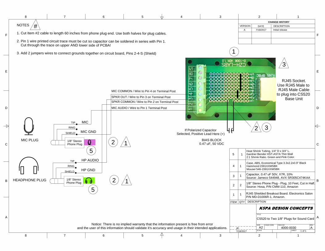
CS520 to Two 1/8" Plugs for Sound Card
4000-00301 of 1
Agh7/18/2017
ITEM QTY DESCRIPTION
1
2
3
CHANGE HISTORYVERSION DATE DESCRIPTION
A
1
2
1
7/18/2017 Initial release
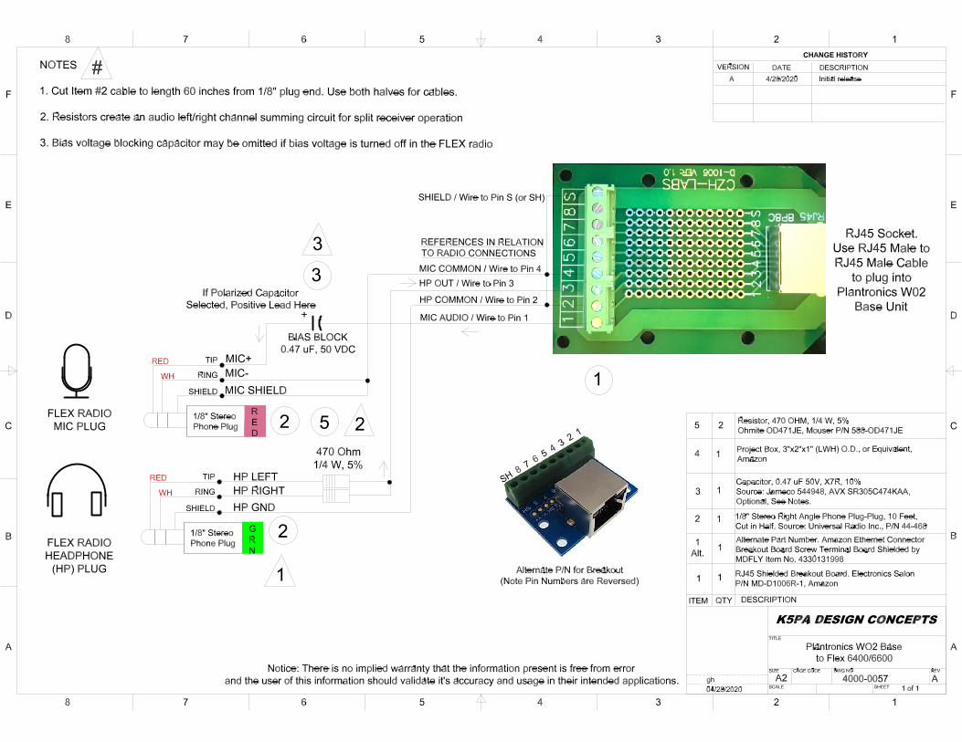
SPKR OUT / Wire to Pin 3 on Terminal Post
MIC AUDIO / Wire to Pin 1 Terminal Post
MIC COMMON / Wire to Pin 4 on Terminal Post
SPKR COMMON / Wire to Pin 2 on Terminal Post
BIAS BLOCK0.47 uF, 50 VDC
MIC PLUG
HEADPHONE PLUG
RJ45 Socket.Use RJ45 Male to RJ45 Male Cable
to plug into CS520 Base Unit
MIC
MIC GND
1/8" StereoPhone Plug
TIP
RING
SHIELD
HP AUDIO
HP GND
1/8" StereoPhone Plug
TIP
RING
SHIELD
If Polarized CapacitorSelected, Positive Lead Here (+)
RJ45 Shielded Breakout Board. Electronics SalonP/N MD-D1006R-1, Amazon.
1/8" Stereo Phone Plug - Plug, 10 Feet, Cut in Half.Source: Hosa, P/N CMM-110, Amazon
Capacitor, 0.47 uF 50V, X7R, 10%Source: Jameco 544948, AVX SR305C474KAA
NOTES
1. Cut Item #2 cable to length 60 inches from phone plug end. Use both halves for plug cables.
2. Pin 1 wire printed circuit trace must be cut so capacitor can be soldered in series with Pin 1. Cut through the trace on upper AND lower side of PCBA!
3. Add 2 jumpers wires to connect grounds together on circuit board, Pins 2-4-S (Shield) 1
2
2 3
#
1
2 1
3
4 1Case, ABS, Economical Type 3.3x2.2x0.9" BlackHammond 1591XXMSBKMouser 546-1591XXMSBK
5 1Heat Shrink Tubing, 1/4" D x 3/4" L.Gardner Bender HST-ASTA Thin Wall2:1 Shrink Ratio. Green and Pink Color.
5
5
Notice: There is no implied warranty that the information present is free from errorand the user of this information should validate it's accuracy and usage in their intended applications.
Date: 8/16/2017
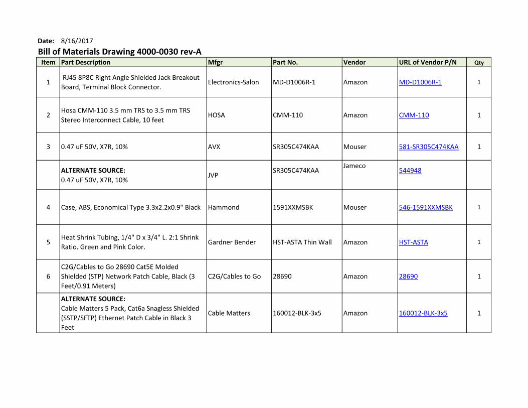
Bill of Materials Drawing 4000-0030 rev-AItem Part Description Mfgr Part No. Vendor URL of Vendor P/N Qty
1 RJ45 8P8C Right Angle Shielded Jack Breakout
Board, Terminal Block Connector.Electronics-Salon MD-D1006R-1 Amazon MD-D1006R-1 1
2Hosa CMM-110 3.5 mm TRS to 3.5 mm TRS
Stereo Interconnect Cable, 10 feetHOSA CMM-110 Amazon CMM-110 1
3 0.47 uF 50V, X7R, 10% AVX SR305C474KAA Mouser 581-SR305C474KAA 1
ALTERNATE SOURCE:
0.47 uF 50V, X7R, 10%JVP
SR305C474KAAJameco
544948
4 Case, ABS, Economical Type 3.3x2.2x0.9" Black Hammond 1591XXMSBK Mouser 546-1591XXMSBK 1
5Heat Shrink Tubing, 1/4" D x 3/4" L. 2:1 Shrink
Ratio. Green and Pink Color.Gardner Bender HST-ASTA Thin Wall Amazon HST-ASTA 1
6
C2G/Cables to Go 28690 Cat5E Molded
Shielded (STP) Network Patch Cable, Black (3
Feet/0.91 Meters)
C2G/Cables to Go 28690 Amazon 28690 1
ALTERNATE SOURCE:
Cable Matters 5 Pack, Cat6a Snagless Shielded
(SSTP/SFTP) Ethernet Patch Cable in Black 3
Feet
Cable Matters 160012-BLK-3x5 Amazon 160012-BLK-3x5 1
A2
F
E
D
C
B
A
F
E
D
C
B
A
8 7 6 5 4 3 2 1
8 7 6 5 4 3 2 1
TITLE
REV
SHEET
DWG NOCAGE CODESIZE
SCALE
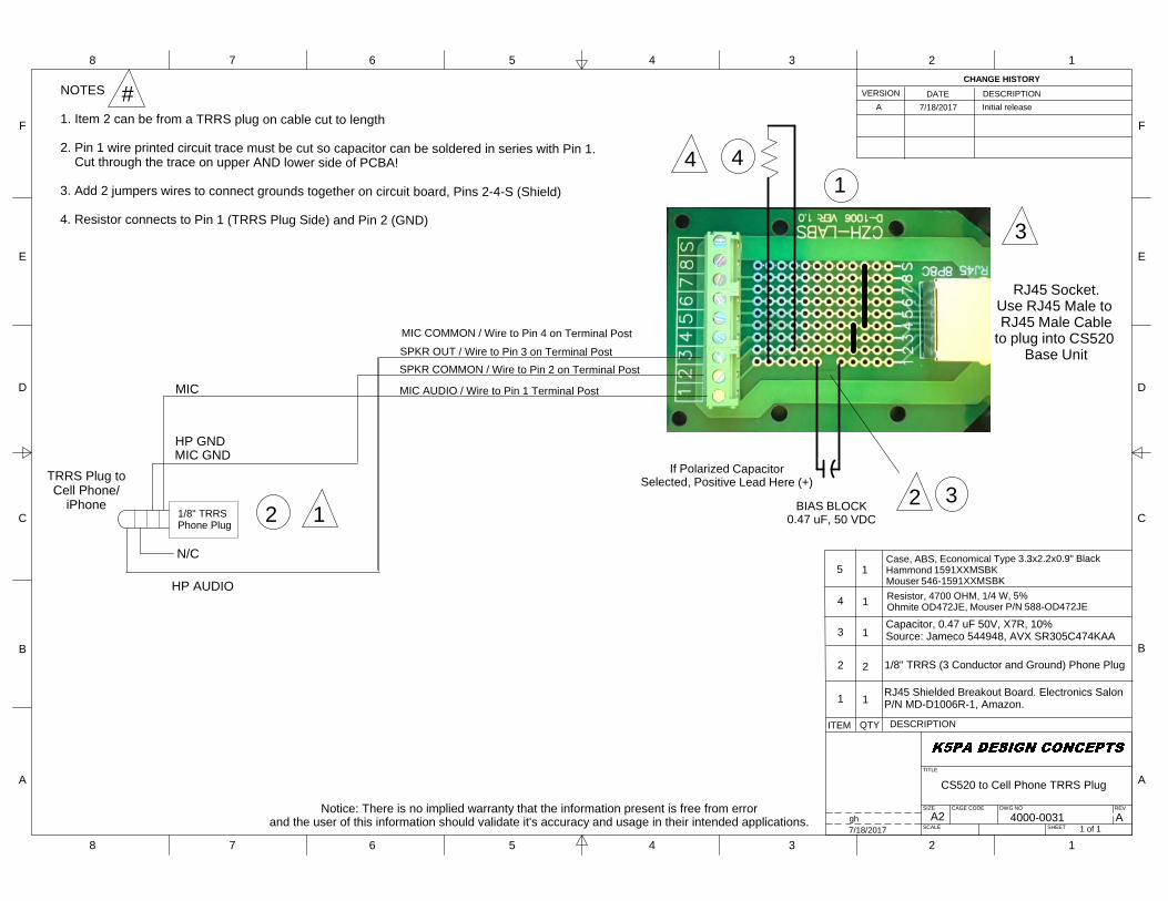
CS520 to Cell Phone TRRS Plug
4000-00311 of 1
Agh7/18/2017
ITEM QTY DESCRIPTION
1
2
3
CHANGE HISTORYVERSION DATE DESCRIPTION
A
1
2
1
7/18/2017 Initial release
SPKR OUT / Wire to Pin 3 on Terminal Post
MIC AUDIO / Wire to Pin 1 Terminal Post
MIC COMMON / Wire to Pin 4 on Terminal Post
SPKR COMMON / Wire to Pin 2 on Terminal Post
BIAS BLOCK0.47 uF, 50 VDC
RJ45 Socket.Use RJ45 Male to RJ45 Male Cable
to plug into CS520 Base Unit
If Polarized CapacitorSelected, Positive Lead Here (+)
1/8" TRRS (3 Conductor and Ground) Phone Plug
NOTES
1. Item 2 can be from a TRRS plug on cable cut to length
2. Pin 1 wire printed circuit trace must be cut so capacitor can be soldered in series with Pin 1. Cut through the trace on upper AND lower side of PCBA!
3. Add 2 jumpers wires to connect grounds together on circuit board, Pins 2-4-S (Shield)
4. Resistor connects to Pin 1 (TRRS Plug Side) and Pin 2 (GND)
14
2 3
#
3
TRRS Plug toCell Phone/
iPhone
MIC
MIC GND
HP AUDIO
HP GND
21/8" TRRSPhone Plug
Resistor, 4700 OHM, 1/4 W, 5%Ohmite OD472JE, Mouser P/N 588-OD472JE
N/C
1
4 1
4
RJ45 Shielded Breakout Board. Electronics SalonP/N MD-D1006R-1, Amazon.
Capacitor, 0.47 uF 50V, X7R, 10%Source: Jameco 544948, AVX SR305C474KAA
5 1Case, ABS, Economical Type 3.3x2.2x0.9" BlackHammond 1591XXMSBKMouser 546-1591XXMSBK
Notice: There is no implied warranty that the information present is free from errorand the user of this information should validate it's accuracy and usage in their intended applications.

Date: 8/16/2017
Bill of Materials Drawing 4000-0031 rev-AItem Part Description Mfgr Part No. Vendor URL of Vendor P/N Qty
1 RJ45 8P8C Right Angle Shielded Jack Breakout Board,
Terminal Block Connector.Electronics-Salon MD-D1006R-1 Amazon MD-D1006R-1 1
2 Mini to mini 4 cond cbl, 3 ft. (cut and discard one end) Philmore 44-470
Univ. Radio Inc.
(http://www.universal-
radio.com/)3624 1
3 0.47 uF 50V, X7R, 10% AVX SR305C474KAA Mouser 581-SR305C474KAA 1
ALTERNATE SOURCE:
0.47 uF 50V, X7R, 10%JVP SR305C474KAA Jameco
544948
4 Resistor, 4700 Ohms, 1/4W, 5% Ohmite OD472JE Mouser 588-OD472JE 1
ALTERNATE SOURCE:
Resistor, 4700 Ohms, 1/4W, 5%Jameco Valuepro CF1/4W102JRC Jameco 691024
5 Case, ABS, Economical Type 3.3x2.2x0.9" Black Hammond 1591XXMSBK Mouser 546-1591XXMSBK 1
6C2G/Cables to Go 28690 Cat5E Molded Shielded (STP)
Network Patch Cable, Black (3 Feet/0.91 Meters)C2G/Cables to Go 28690 Amazon 28690 1
ALTERNATE SOURCE:
Cable Matters 5 Pack, Cat6a Snagless Shielded
(SSTP/SFTP) Ethernet Patch Cable in Black 3 Feet
Cable Matters 160012-BLK-3x5 Amazon 160012-BLK-3x5 1
7
IF NEEDED FOR CELL PHONE CASE HEADPHONE JACK
CLEARANCE
Audio Splitter Cable 3.5mm Male to 2 Female Jack
Headphone Splitter Adapter 4-Pole Aux Cable
ARCHEER LYSB01M315XJT-
ELECTRNCSAmazon 581-SR305C474KAA 1
A2
F
E
D
C
B
A
F
E
D
C
B
A
8 7 6 5 4 3 2 1
8 7 6 5 4 3 2 1
TITLE
REV
SHEET
DWG NOCAGE CODESIZE
SCALE
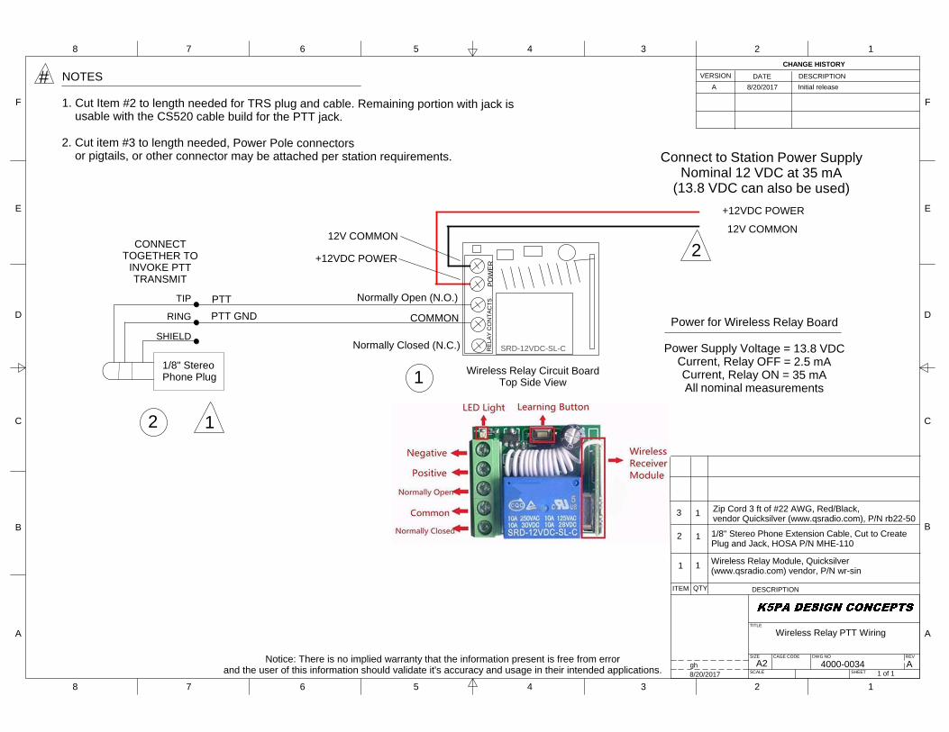
Wireless Relay PTT Wiring
4000-00341 of 1
Agh8/20/2017
ITEM QTY DESCRIPTION
1
CHANGE HISTORYVERSION DATE DESCRIPTION
A
1
8/20/2017 Initial releaseNOTES
1. Cut Item #2 to length needed for TRS plug and cable. Remaining portion with jack is usable with the CS520 cable build for the PTT jack.
2. Cut item #3 to length needed, Power Pole connectors or pigtails, or other connector may be attached per station requirements.
2 1
Wireless Relay Module, Quicksilver(www.qsradio.com) vendor, P/N wr-sin
Notice: There is no implied warranty that the information present is free from errorand the user of this information should validate it's accuracy and usage in their intended applications.
CONNECTTOGETHER TO
INVOKE PTTTRANSMIT
PTTPTT GND
1/8" StereoPhone Plug
TIP
RING
SHIELD
3 1 Zip Cord 3 ft of #22 AWG, Red/Black,vendor Quicksilver (www.qsradio.com), P/N rb22-50
2 1
Normally Open (N.O.)
COMMON
12V COMMON
+12VDC POWER
1
12V COMMON
+12VDC POWER
Connect to Station Power SupplyNominal 12 VDC at 35 mA
(13.8 VDC can also be used)
2
#
Power for Wireless Relay Board
Power Supply Voltage = 13.8 VDCCurrent, Relay OFF = 2.5 mACurrent, Relay ON = 35 mAAll nominal measurements
PO
WE
RR
ELAY
CO
NTA
CTS
Normally Closed (N.C.)
1/8" Stereo Phone Extension Cable, Cut to CreatePlug and Jack, HOSA P/N MHE-110
SRD-12VDC-SL-C
Wireless Relay Circuit BoardTop Side View

Date: 8/20/2017
Bill of Materials Drawing 4000-0034 rev-A Wireless Relay PTT Wiring
Item Part Description Mfgr Part No. Vendor Quick Link URLs and Instructions Qty
1 Wireless Relay Module Quicksilver wr-sin Quicksilver: Click This First --> Quicksilver 1
Then on their webpage select:
Meters, USB, & Test Equipment and then
Wireless Relay Single
2Red/Black Zip Cord 50 ft of #22. Use only 3 feet
from roll of 50 feet for EACH relay wired.Quicksilver rb22-50 Quicksilver: Click This First --> Quicksilver 3 Ft.
Then on their webpage select:
DC Power Cables & Connectors
and then Red/Black Zip Cord 50 ft of #22
3Hosa MHE-110 3.5 mm TRS to 3.5 mm TRS
Headphone Extension Cable, 10 feetHOSA MHE-110 Amazon MHE-110 1

A2
F
E
D
C
B
A
F
E
D
C
B
A
8 7 6 5 4 3 2 1
8 7 6 5 4 3 2 1
TITLE
REV
SHEET
DWG NOCAGE CODESIZE
SCALE
CS520 / W720 to IC7300Cable Adapter
4000-00451 of 1
--gh1/10/2018
ITEM QTY DESCRIPTION
#
SPKR OUT (3)
MIC AUDIO (1)
MIC COMMON (4)
SPKR COMMON (2)
BIAS BLOCK0.47 uF, 50 VDC
RJ45 Socket.Use RJ45 Male to RJ45 Male Cable
to plug into CS520 or W720 Base Unit
1
1
#
2
Notice: There is no implied warranty that the information present is free from errorand the user of this information should validate it's accuracy and usage in their intended applications.
NOTES
1. Pin 1, 5, 6, 7 and 8 printed wire circuit traces must be cut to isolate those traces from RJ45 pins. Cut through these traces on upper AND lower side of PCBA!2. Add 3 jumpers wires to connect grounds together on circuit board, Pins 2-4-6-S (Shield).3. Resistor 470 ohm connects Pin 8 to Pin 3. Other Resistor 470 ohm connects Pin 7 to Pin 3. The 2 resistors allow for a dual watch receiver audio summing circuit for future expansion.4. Cut Item #6 to create 1/8" jack and plug sections for PTT relay.
HP Audio Left (8)
HP Audio Right (7)
Common (6)
L/R SUMMING CIRCUIT
PTT Terminal (5)
View of Plug'sSolder TerminalsRear View of Foster
Connector Plug
AFoutput
1
2
34
5
6
7
8
PTT
MIC GND -
+8V DC Out
Freq up/dwnSquelchline out
PTT GND
MIC input +
TIP
RING
SHIELD
1/8" StereoPhone Jack
CONNECTTOGETHER TO
INVOKE PTTTRANSMIT
PTT
PTT GND
1/8" StereoPhone Plug
TIP
RING
SHIELD
REMOTE PTT JACK1 These Refer to Item Numbers Found Listed in
the Attached Bill of Materials (BoM)
MIC AUDIO (1)
MIC COMMON (4)
PTT Terminal (5)
Common (6)
Common (6) (5) PTT Terminal
PCBA TERMINALS
PCBA TERMINALS
PCBA TERMINALS
REMOTE PTT PLUG
7
3
6 6
5
2
3
CHANGE HISTORYVERSION DATE DESCRIPTION
-- 1/10/2018 Initial release
S1
Push-To-Talk(PTT)
n.o.
4
HP Audio Right (7)
From ICOM IC-7300 Manual
N/CN/C
N/C
4
Printed on 1/16/2018 1:22 PM BoM 4000-00XX Drawings.xlsx 4000-0045
Date: 1/12/2018
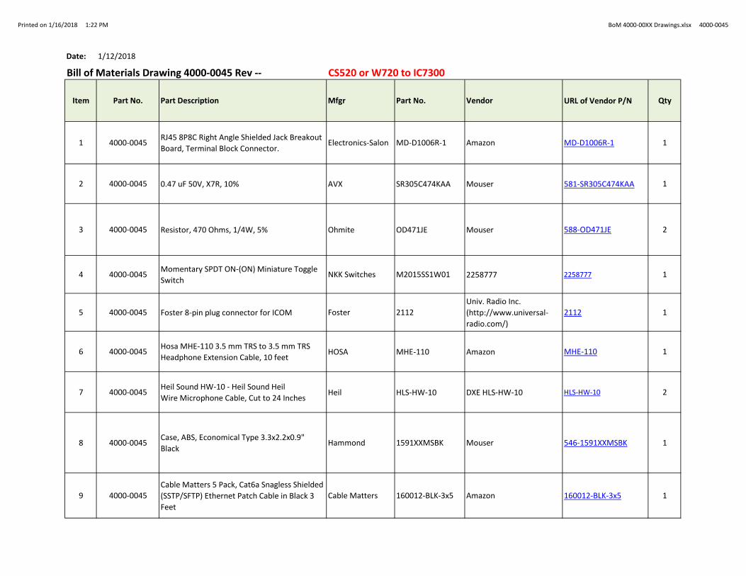
Bill of Materials Drawing 4000-0045 Rev -- CS520 or W720 to IC7300
Item Part No. Part Description Mfgr Part No. Vendor URL of Vendor P/N Qty
1 4000-0045RJ45 8P8C Right Angle Shielded Jack Breakout
Board, Terminal Block Connector.Electronics-Salon MD-D1006R-1 Amazon MD-D1006R-1 1
2 4000-0045 0.47 uF 50V, X7R, 10% AVX SR305C474KAA Mouser 581-SR305C474KAA 1
3 4000-0045 Resistor, 470 Ohms, 1/4W, 5% Ohmite OD471JE Mouser 588-OD471JE 2
4 4000-0045Momentary SPDT ON-(ON) Miniature Toggle
SwitchNKK Switches M2015SS1W01 2258777 2258777 1
5 4000-0045 Foster 8-pin plug connector for ICOM Foster 2112
Univ. Radio Inc.
(http://www.universal-
radio.com/)
2112 1
6 4000-0045Hosa MHE-110 3.5 mm TRS to 3.5 mm TRS
Headphone Extension Cable, 10 feetHOSA MHE-110 Amazon MHE-110 1
7 4000-0045Heil Sound HW-10 - Heil Sound Heil
Wire Microphone Cable, Cut to 24 InchesHeil HLS-HW-10 DXE HLS-HW-10 HLS-HW-10 2
8 4000-0045Case, ABS, Economical Type 3.3x2.2x0.9"
BlackHammond 1591XXMSBK Mouser 546-1591XXMSBK 1
9 4000-0045
Cable Matters 5 Pack, Cat6a Snagless Shielded
(SSTP/SFTP) Ethernet Patch Cable in Black 3
Feet
Cable Matters 160012-BLK-3x5 Amazon 160012-BLK-3x5 1
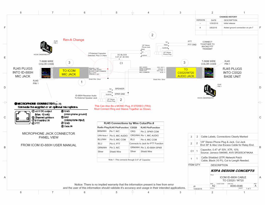

Date: 1/30/2018
Bill of Materials Drawing 4000-0046 rev--Item Part Description Mfgr Part No. Vendor URL of Vendor P/N Qty
1Cat5e Molded Shielded (STP) Network Patch Cable,
Black (10 Feet/3.04 Meters)C2G/Cables to Go 28693 Amazon 28693 1
C1 0.47 uF 50V, X7R, 10% AVX SR305C474KAA Mouser 581-SR305C474KAA 1
ALTERNATE SOURCE:
0.47 uF 50V, X7R, 10%JVP SR305C474KAA Jameco
544948
2Hosa MHE-110 3.5 mm TRS to 3.5 mm TRS
Headphone Extension Cable, 10 feetHOSA MHE-110 Amazon MHE-110 2
3 Builder's Choice 1

A2
F
E
D
C
B
A
F
E
D
C
B
A
8 7 6 5 4 3 2 1
8 7 6 5 4 3 2 1
TITLE
REV
SHEET
DWG NOCAGE CODESIZE
SCALE
CS520 / W720 to IC7610Cable Adapter
4000-00511 of 1
--gh6/21/2018
ITEM QTY DESCRIPTION
#
SPKR OUT (3)
MIC AUDIO (1)
MIC COMMON (4)
SPKR COMMON (2)
BIAS BLOCK0.47 uF, 50 VDC
RJ45 Socket.Use RJ45 Male to RJ45 Male Cable
to plug into CS520 or W720 Base Unit
1
1
#
2
Notice: There is no implied warranty that the information present is free from errorand the user of this information should validate it's accuracy and usage in their intended applications.
NOTES
1. Pin 1, 5, 6, 7 and 8 printed wire circuit traces must be cut to isolate those traces from RJ45 pins. Cut through these traces on upper AND lower side of PCBA!2. Add 3 jumpers wires to connect grounds together on circuit board, Pins 2-4-6-S (Shield).3. Resistor 470 ohm connects Pin 8 to Pin 3. Other Resistor 470 ohm connects Pin 7 to Pin 3. The 2 resistors allow for a dual watch receiver audio summing circuit.4. Cut Item #6 to create 1/8" jack and plug sections for PTT relay.
HP Audio Left (8)
HP Audio Right (7)
Common (6)
L/R SUMMING CIRCUIT
PTT Terminal (5)
View of Plug'sSolder TerminalsRear View of Foster
Connector Plug
AFoutput
1
2
34
5
6
7
8
PTT
MIC GND -
+8V DC Out
Freq up/dwnSquelchline out
PTT GND
MIC input +
TIP
RING
SHIELD
1/8" StereoPhone Jack
1/8" StereoPhone Plug
TIP
RING
SHIELD
REMOTE PTT JACK
1 These Refer to Item Numbers Found Listed inthe Attached Bill of Materials (BoM)
MIC AUDIO (1)
MIC COMMON (4)
PTT Terminal (5)
Common (6)
Common (6) (5) PTT Terminal
PCBA TERMINALS
PCBA TERMINALS
PCBA TERMINALS
7
3
6
5
2
3
CHANGE HISTORYVERSION DATE DESCRIPTION
-- 6/21/2018 Initial release
S1
Push-To-Talk(PTT)
n.o.
4
N/C
From ICOM IC-7610 Manual
N/CN/C
4
1/8" StereoPhone Plug
TIP
RING
SHIELD
HP Audio Left (8)
Common (6)
HP Audio Right (7)
Common (6)
EXT-SP A, Main BandRear Panel, IC-7610
EXT-SP B, Sub BandRear Panel, IC-7610
CONNECTTOGETHER TO
INVOKE PTTTRANSMIT
PTT
PTT GND
1/8" StereoPhone Plug
TIP
RING
SHIELD
REMOTE PTT PLUG
6
Printed on 6/21/2018 6:59 AM BoM 4000-00XX Drawings.xlsx 4000-0051
Date: 6/21/2018
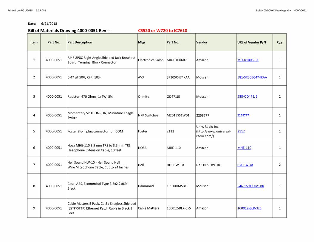
Bill of Materials Drawing 4000-0051 Rev -- CS520 or W720 to IC7610
Item Part No. Part Description Mfgr Part No. Vendor URL of Vendor P/N Qty
1 4000-0051RJ45 8P8C Right Angle Shielded Jack Breakout
Board, Terminal Block Connector.Electronics-Salon MD-D1006R-1 Amazon MD-D1006R-1 1
2 4000-0051 0.47 uF 50V, X7R, 10% AVX SR305C474KAA Mouser 581-SR305C474KAA 1
3 4000-0051 Resistor, 470 Ohms, 1/4W, 5% Ohmite OD471JE Mouser 588-OD471JE 2
4 4000-0051Momentary SPDT ON-(ON) Miniature Toggle
SwitchNKK Switches M2015SS1W01 2258777 2258777 1
5 4000-0051 Foster 8-pin plug connector for ICOM Foster 2112
Univ. Radio Inc.
(http://www.universal-
radio.com/)
2112 1
6 4000-0051Hosa MHE-110 3.5 mm TRS to 3.5 mm TRS
Headphone Extension Cable, 10 feetHOSA MHE-110 Amazon MHE-110 1
7 4000-0051Heil Sound HW-10 - Heil Sound Heil
Wire Microphone Cable, Cut to 24 InchesHeil HLS-HW-10 DXE HLS-HW-10 HLS-HW-10 2
8 4000-0051Case, ABS, Economical Type 3.3x2.2x0.9"
BlackHammond 1591XXMSBK Mouser 546-1591XXMSBK 1
9 4000-0051
Cable Matters 5 Pack, Cat6a Snagless Shielded
(SSTP/SFTP) Ethernet Patch Cable in Black 3
Feet
Cable Matters 160012-BLK-3x5 Amazon 160012-BLK-3x5 1

Printed on 12/5/2019 10:38 AM BoM 4000-00XX Drawings.xlsx 4000-0055
Date: 12/5/2019
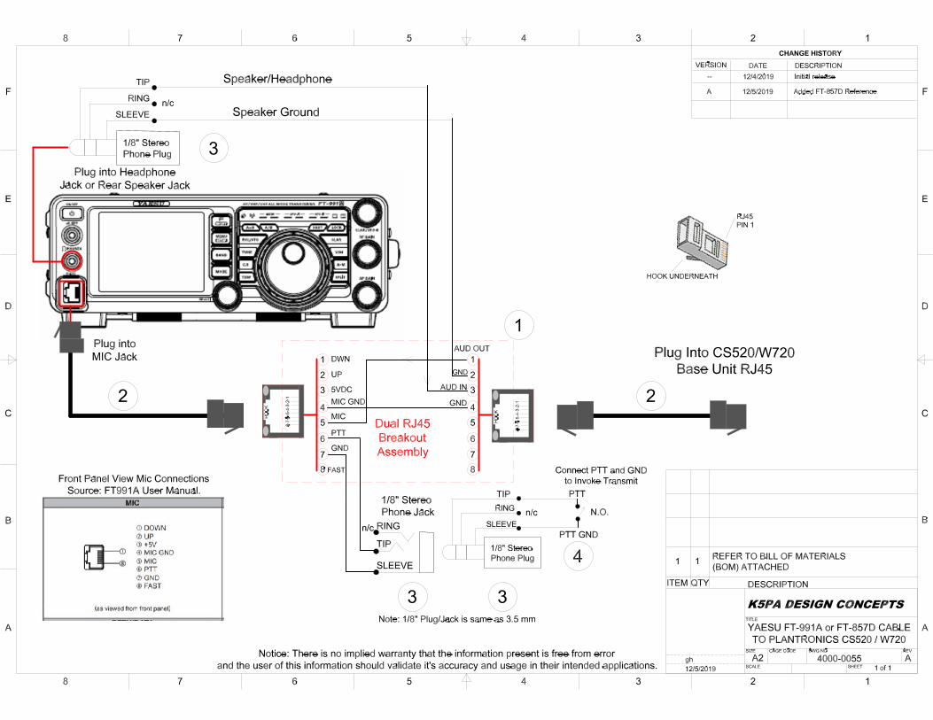
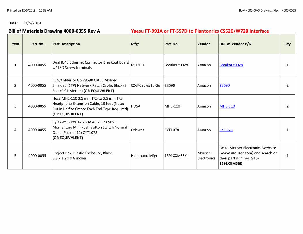
Bill of Materials Drawing 4000-0055 Rev A Yaesu FT-991A or FT-557D to Plantonrics CS520/W720 Interface
Item Part No. Part Description Mfgr Part No. Vendor URL of Vendor P/N Qty
1 4000-0055Dual RJ45 Ethernet Connector Breakout Board
w/ LED Screw terminalsMFDFLY Breakout0028 Amazon Breakout0028 1
2 4000-0055
C2G/Cables to Go 28690 Cat5E Molded
Shielded (STP) Network Patch Cable, Black (3
Feet/0.91 Meters) (OR EQUIVALENT)
C2G/Cables to Go 28690 Amazon 28690 2
3 4000-0055
Hosa MHE-110 3.5 mm TRS to 3.5 mm TRS
Headphone Extension Cable, 10 feet (Note:
Cut in Half to Create Each End Type Required)
(OR EQUIVALENT)
HOSA MHE-110 Amazon MHE-110 2
4 4000-0055
Cylewet 12Pcs 1A 250V AC 2 Pins SPST
Momentary Mini Push Button Switch Normal
Open (Pack of 12) CYT1078
(OR EQUIVALENT)
Cylewet CYT1078 Amazon CYT1078 1
5 4000-0055Project Box, Plastic Enclosure, Black,
3.3 x 2.2 x 0.8 inchesHammond Mfgr 1591XXMSBK
Mouser
Electronics
Go to Mouser Electronics Website
(www.mouser.com) and search on
their part number: 546-
1591XXMSBK
1
Printed on 12/5/2019 10:38 AM BoM 4000-00XX Drawings.xlsx 4000-0055
Date: 12/5/2019
Bill of Materials Drawing 4000-0055 Rev A Yaesu FT-991A or FT-557D to Plantonrics CS520/W720 Interface
Item Part No. Part Description Mfgr Part No. Vendor URL of Vendor P/N Qty
1 4000-0055Dual RJ45 Ethernet Connector Breakout Board
w/ LED Screw terminalsMFDFLY Breakout0028 Amazon Breakout0028 1
2 4000-0055
C2G/Cables to Go 28690 Cat5E Molded
Shielded (STP) Network Patch Cable, Black (3
Feet/0.91 Meters) (OR EQUIVALENT)
C2G/Cables to Go 28690 Amazon 28690 2
3 4000-0055
Hosa MHE-110 3.5 mm TRS to 3.5 mm TRS
Headphone Extension Cable, 10 feet (Note:
Cut in Half to Create Each End Type Required)
(OR EQUIVALENT)
HOSA MHE-110 Amazon MHE-110 2
4 4000-0055
Cylewet 12Pcs 1A 250V AC 2 Pins SPST
Momentary Mini Push Button Switch Normal
Open (Pack of 12) CYT1078
(OR EQUIVALENT)
Cylewet CYT1078 Amazon CYT1078 1
5 4000-0055Project Box, Plastic Enclosure, Black,
3.3 x 2.2 x 0.8 inchesHammond Mfgr 1591XXMSBK
Mouser
Electronics
Go to Mouser Electronics Website
(www.mouser.com) and search on
their part number: 546-
1591XXMSBK
1
Printed on 12/9/2019 5:59 AM BoM 4000-00XX Drawings.xlsx 4000-0056
Date: 12/8/2019
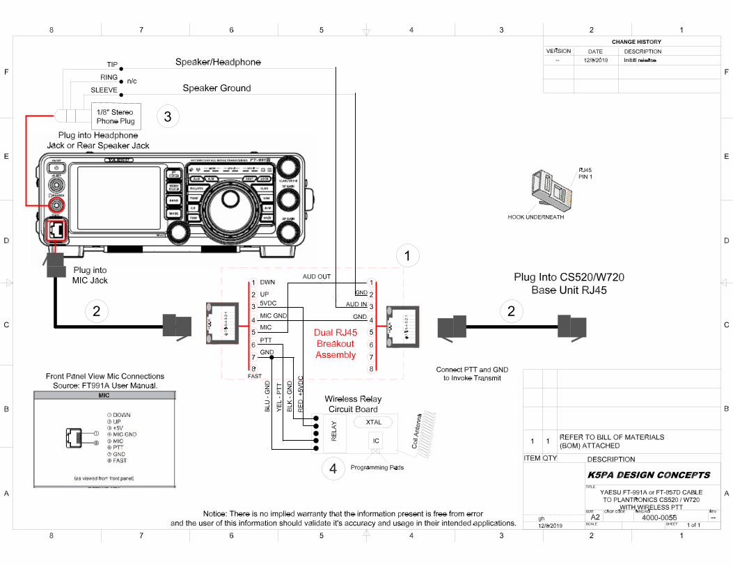
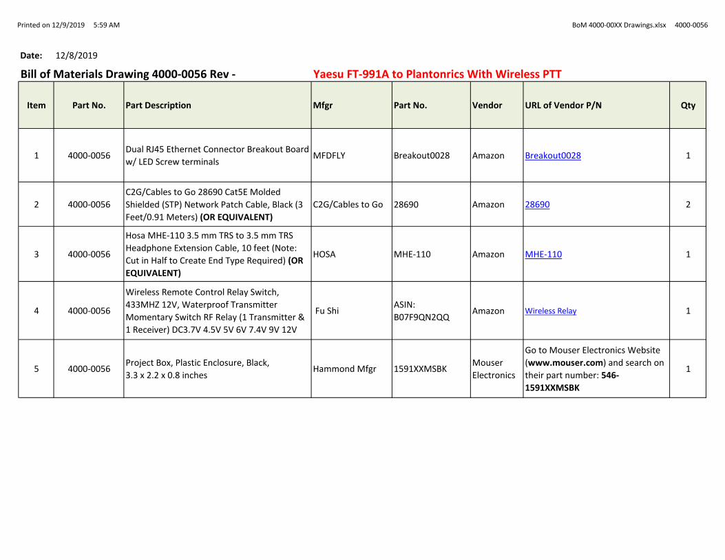
Bill of Materials Drawing 4000-0056 Rev - Yaesu FT-991A to Plantonrics With Wireless PTT
Item Part No. Part Description Mfgr Part No. Vendor URL of Vendor P/N Qty
1 4000-0056Dual RJ45 Ethernet Connector Breakout Board
w/ LED Screw terminalsMFDFLY Breakout0028 Amazon Breakout0028 1
2 4000-0056
C2G/Cables to Go 28690 Cat5E Molded
Shielded (STP) Network Patch Cable, Black (3
Feet/0.91 Meters) (OR EQUIVALENT)
C2G/Cables to Go 28690 Amazon 28690 2
3 4000-0056
Hosa MHE-110 3.5 mm TRS to 3.5 mm TRS
Headphone Extension Cable, 10 feet (Note:
Cut in Half to Create End Type Required) (OR
EQUIVALENT)
HOSA MHE-110 Amazon MHE-110 1
4 4000-0056
Wireless Remote Control Relay Switch,
433MHZ 12V, Waterproof Transmitter
Momentary Switch RF Relay (1 Transmitter &
1 Receiver) DC3.7V 4.5V 5V 6V 7.4V 9V 12V
Fu ShiASIN:
B07F9QN2QQAmazon Wireless Relay 1
5 4000-0056Project Box, Plastic Enclosure, Black,
3.3 x 2.2 x 0.8 inchesHammond Mfgr 1591XXMSBK
Mouser
Electronics
Go to Mouser Electronics Website
(www.mouser.com) and search on
their part number: 546-
1591XXMSBK
1

Printed on 4/30/2020 5:24 AM BoM 4000-0057A Drawings.xlsx 4000-0057
Date: 4/30/2020
Bill of Materials Drawing 4000-0057 Rev A FLEX 6400/6600 to Plantronics W720
Item Part No. Part Description Mfgr Part No. Vendor URL of Vendor P/N Qty
1 4000-0057RJ45 Shielded Breakout Board. Electronics
SalonElectronics Salon 43237-2 Amazon RJ45 8P8C Jack 1
1
Alternate4000-0057
Ethernet Connector Breadout Board Screw
Terminal Board ShieldedMDFLY 4330131998 Amazon MDFLY Breakout 1
2 4000-0057Mini to mini 3 cond cbl, 6 ft. (cut and discard
both ends, need cable only for Foster cable)Philmore 44-468
Univ. Radio Inc.
(http://www.universal-
radio.com/)
4103 2
3 4000-0057 0.47 uF 50V, X7R, 10% AVX SR305C474KAA Mouser 581-SR305C474KAA 1
4 4000-0057Project Box, Plastic Enclosure, Black,
3"x2"x1" (LWH) O.D., (OR EQUIVALENT)Amazon 1
5 4000-0057 Resistor, 470 Ohms, 1/4W, 5% Ohmite OD471JE Mouser 588-OD471JE 2
6 4000-0057
C2G/Cables to Go 28690 Cat5E Molded
Shielded (STP) Network Patch Cable, Black (3
Feet/0.91 Meters) (OR EQUIVALENT)
C2G/Cables to Go 28690 Amazon 28690 1
Related Documents