<ISD-MASP-S03054> Yokogawa Electric Corporation Copyright © by Yokogawa Electric Corporation <June 22, 2007> CS3000 Operations YOKOGAWA TRAINING CENTRE TRAINING CENTRE YOKOGAWA INDIA LIMITED

Welcome message from author
This document is posted to help you gain knowledge. Please leave a comment to let me know what you think about it! Share it to your friends and learn new things together.
Transcript
Yokogawa Electric Corporation
2-9-32 Nakacho, Musashino-shiTokyo, 180-8750JAPAN
<ISD-MASP-S03054> Yokogawa Electric CorporationCopyright © by Yokogawa Electric Corporation<June 22, 2007>
CS3000 Operations
YOKOGAWA
TRAINING CENTRE
TRAINING CENTRE
YOKOGAWA INDIA LIMITED
<ISD-MASP-S03054> Yokogawa Electric CorporationCopyright © by Yokogawa Electric Corporation<June 22, 2007>
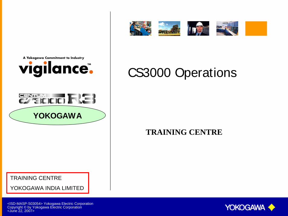
Basic Control Loop
Basic Loop
Controller
I/P
Transmitter
I/P Convertor
PV MVSV
4-20 mA
4-20 mA
Pneumatic Signal(0.2 to 1 Kg/cm2 or 3 to 15 psi)
Final Control Element

<ISD-MASP-S03054> Yokogawa Electric CorporationCopyright © by Yokogawa Electric Corporation<June 22, 2007>
Process Control Systems
A process control system comprises of multiple simple and complex control loops.
Process control systems are primarily classified into
Analog Control Systems Analog control system uses Operational amplifiers to do the control function.
Digital Control SystemsDigital Control system uses microprocessors to do the control function. Digital control systems are preferred over analog control systems since it is easy to interface with Computers for data analysis.

<ISD-MASP-S03054> Yokogawa Electric CorporationCopyright © by Yokogawa Electric Corporation<June 22, 2007>
Analog Control System
Analog Control System
Signal Conversion
I/P4-20 mA DC
1 to 5V DC
Operational Amplifier
Set Point
Final Control Element
Transmitter
<ISD-MASP-S03054> Yokogawa Electric CorporationCopyright © by Yokogawa Electric Corporation<June 22, 2007>
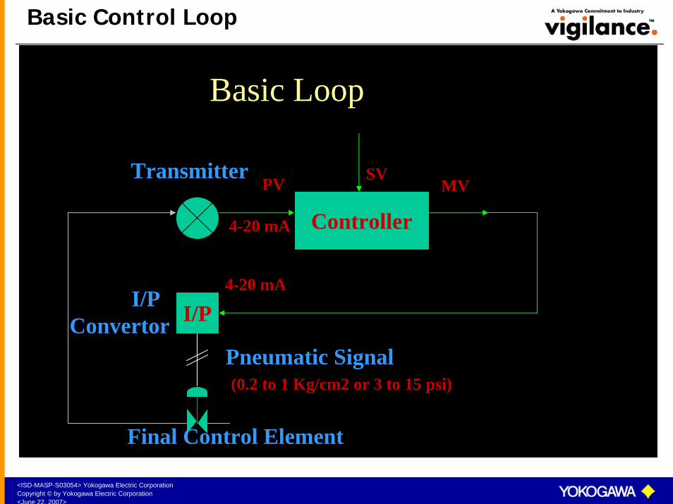
Digital Control System
Digital Control System
I/P4-20 mA DC
Signal Conversion&A / D
D / A
DigitalOutput
Unit
Input Unit
Memory Unit
ControlUnit
ArithmeticUnit
Set Point
Processor

<ISD-MASP-S03054> Yokogawa Electric CorporationCopyright © by Yokogawa Electric Corporation<June 22, 2007>
Digital Control System
Digital Control Systems are further classified into
Centralized Control Systems (CCS)
Distributed Control Systems (DCS)
Let us understand the basics of CCS and DCS, their merits and demerits.
<ISD-MASP-S03054> Yokogawa Electric CorporationCopyright © by Yokogawa Electric Corporation<June 22, 2007>
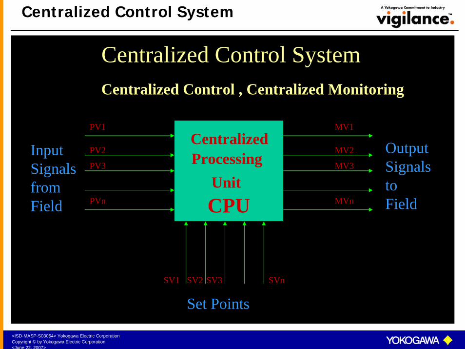
Centralized Control System
Centralized Processing
UnitCPU
Centralized Control System
Input Signals from Field
Set Points
OutputSignals to Field
Centralized Control , Centralized Monitoring
PV1
PV2
PVn
PV3
MV1
MV2
MVn
MV3
SV1 SV2 SV3 SVn

<ISD-MASP-S03054> Yokogawa Electric CorporationCopyright © by Yokogawa Electric Corporation<June 22, 2007>
Distributed Control System
Distributed Control System
Input Signals from Field
Distributed Control Centralized Monitoring
Set Points
Communication Bus
Output Signals to Field
MV1
MV8FCS
PV1
PV8SV1 SV8
MV9
MV16FCS
PV9
PV16
SV9 SV16
MV17
MVnFCS
PV17
PVn
SV17 SVn
OPS
OPS

<ISD-MASP-S03054> Yokogawa Electric CorporationCopyright © by Yokogawa Electric Corporation<June 22, 2007>
Basic Components of DCS
Communication BusCommunication Bus
ooo
Communication BusCommunication Bus
FCSFCS
OPSOPS

<ISD-MASP-S03054> Yokogawa Electric CorporationCopyright © by Yokogawa Electric Corporation<June 22, 2007>
Advantages of DCS
Control function is distributed among multiple CPUs (Field Control Stations). Hence failure of one FCS does not affect the entire plant.
Redundancy is available at various levels.
Instruments and interlocks are created by software.
Generation and modifications of the interlocks are very flexibleand simple.
Information regarding the process is presented to the user in various formats.
Field wiring is considerably less.
Maintenance and trouble shooting becomes very easy.
Cost effective in the long run.
<ISD-MASP-S03054> Yokogawa Electric CorporationCopyright © by Yokogawa Electric Corporation<June 22, 2007>
DCS Evolution
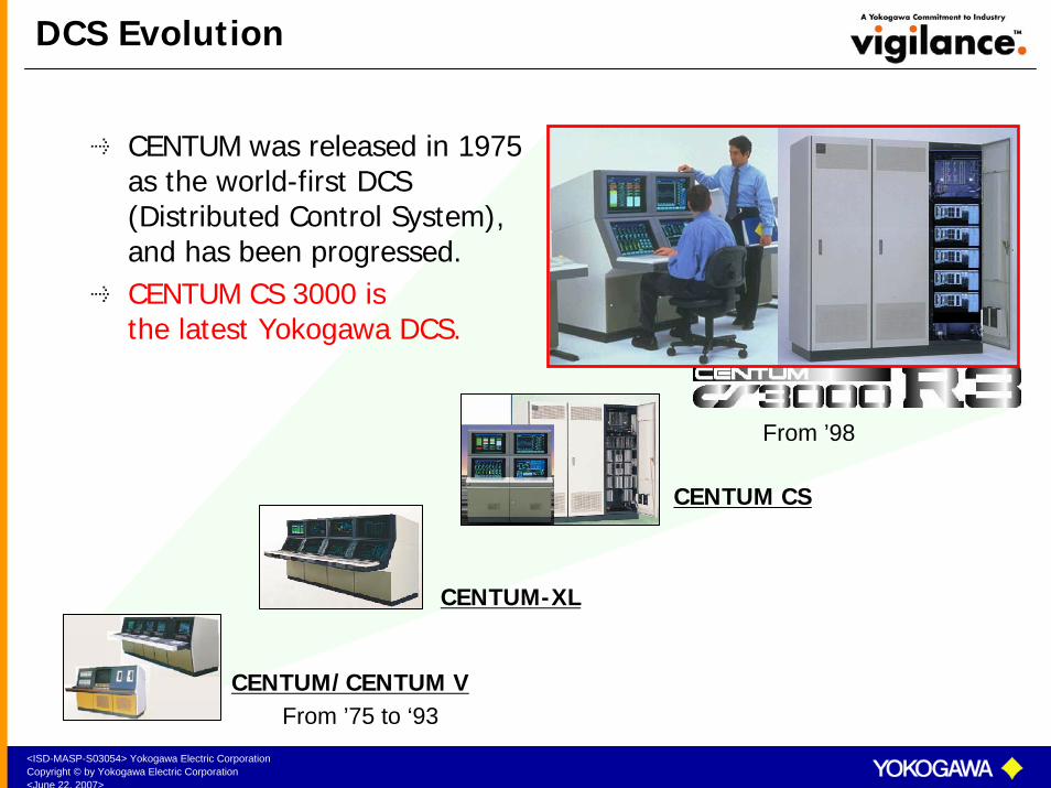
CENTUM was released in 1975 as the world-first DCS (Distributed Control System), and has been progressed.CENTUM CS 3000 is the latest Yokogawa DCS.
From ’98
CENTUM/CENTUM V
CENTUM-XL
CENTUM CS
From ’75 to ‘93
<ISD-MASP-S03054> Yokogawa Electric CorporationCopyright © by Yokogawa Electric Corporation<June 22, 2007>
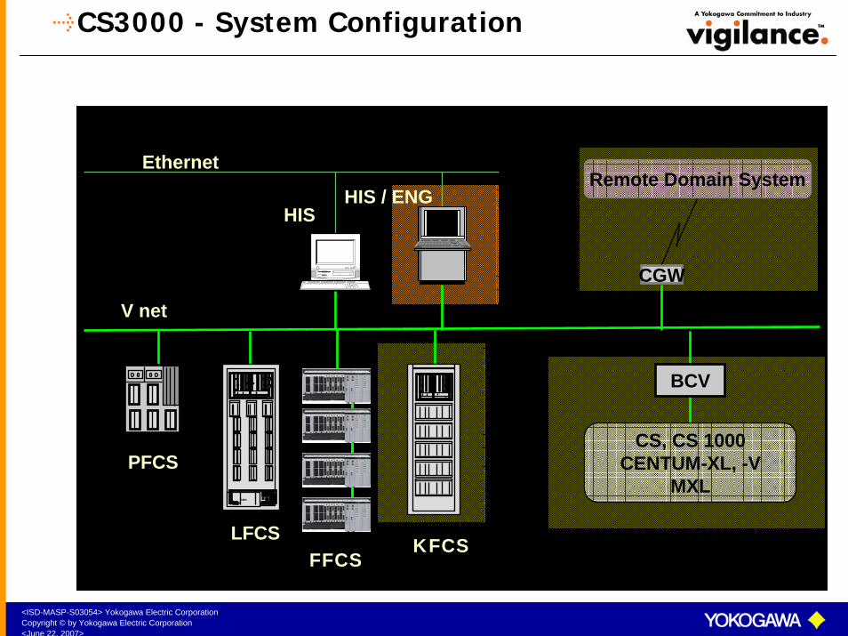
CS3000 - System Configuration
CS, CS 1000CENTUM-XL, -V
MXL
BCV
CGW
Remote Domain System
V net
HIS
ooo
PFCS
LFCS
Ethernet
HIS / ENG
FFCSKFCS
<ISD-MASP-S03054> Yokogawa Electric CorporationCopyright © by Yokogawa Electric Corporation<June 22, 2007>
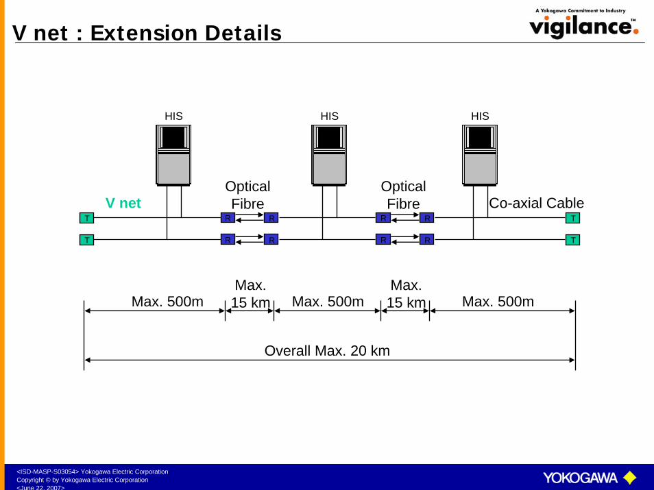
V net : Extension Details
HIS HISHIS
OpticalFibre
R
R R
RT
T
OpticalFibre
R
R R
R T
T
Max. 500m Max. 500mMax. 500mMax.15 km
Max.15 km
Overall Max. 20 km
Co-axial CableV net

<ISD-MASP-S03054> Yokogawa Electric CorporationCopyright © by Yokogawa Electric Corporation<June 22, 2007>
Domain Concept
Domains are group of stations connected on the V-net. Maximum 64 stations can be connected per domain. Bus Convertor (BCV) is used to link two domains.
Multiple Domains are used when there are more than 64 stations to be connected when there are multiple sections in a plant to reduce the load on the V net.
V NET
FCS FCS
HIS
ooo
BCV
ooo ooo
Domain 2
HIS
V-NET
ETHERNET
Domain 1
ooo
ETHERNET

<ISD-MASP-S03054> Yokogawa Electric CorporationCopyright © by Yokogawa Electric Corporation<June 22, 2007>
Bus Convertor
HF BUS
EFCD FCS
HIS
ooo
BCV
ooo ooo
EOPS
V-NET
ETHERNET
Domain 1 Domain 2
CENTUM-XL SYSTEM CS3000 SYSTEM
Bus Convertor (BCV) is used to link two domains. Different types of Bus Convertorsare available.
V net to V net Bus Convertor is used to connect CS3000 or Centum CS to CS3000 system.
HF Bus to V net Convertor is used to connect Centum V or Centum-XL to CS3000 system or Centum CS to CS3000 system.
RL Bus to V net Convertor is used to connect Micro-XL to CS3000 system.
<ISD-MASP-S03054> Yokogawa Electric CorporationCopyright © by Yokogawa Electric Corporation<June 22, 2007>
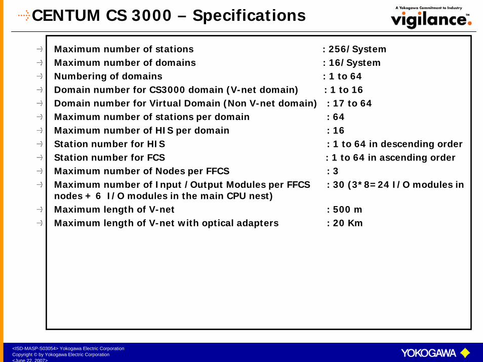
CENTUM CS 3000 – Specifications
Maximum number of stations : 256/SystemMaximum number of domains : 16/SystemNumbering of domains : 1 to 64Domain number for CS3000 domain (V-net domain) : 1 to 16Domain number for Virtual Domain (Non V-net domain) : 17 to 64Maximum number of stations per domain : 64Maximum number of HIS per domain : 16Station number for HIS : 1 to 64 in descending orderStation number for FCS : 1 to 64 in ascending orderMaximum number of Nodes per FFCS : 3Maximum number of Input /Output Modules per FFCS : 30 (3*8=24 I/O modules in nodes + 6 I/O modules in the main CPU nest) Maximum length of V-net : 500 m Maximum length of V-net with optical adapters : 20 Km
<ISD-MASP-S03054> Yokogawa Electric CorporationCopyright © by Yokogawa Electric Corporation<June 22, 2007>
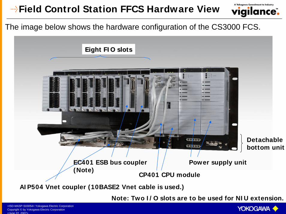
Field Control Station FFCS Hardware View
The image below shows the hardware configuration of the CS3000 FCS.
Power supply unit
CP401 CPU module
Eight FIO slotsEight FIO slots
Detachable bottom unit
EC401 ESB bus coupler(Note)
AIP504 Vnet coupler (10BASE2 Vnet cable is used.)
Note: Two I/O slots are to be used for NIU extension.

<ISD-MASP-S03054> Yokogawa Electric CorporationCopyright © by Yokogawa Electric Corporation<June 22, 2007>
Hardware Configuration- Local Node
Local node Max. 3
V netV net
FIO: Max. 8ESB busESB bus
Up to 6 I/O Modules
Up to 8I/O Modules
CP40
1CP
401
PW48
X
PW48
X
FFCSFFCS
CP40
1CP
401
PW48
X
PW48
X
EC40
1EC
401
SB40
1
PW48
X
PW48
X
SB40
1SB
401
PW48
X
PW48
X
SB40
1SB
401
PW48
X
PW48
X
SB40
1
FFCSFFCS
Minimum ConfigurationMinimum Configuration
Maximum ConfigurationMaximum Configuration
FFCS Supports maximum of 3 Local nodes and 3
Remote nodes

<ISD-MASP-S03054> Yokogawa Electric CorporationCopyright © by Yokogawa Electric Corporation<June 22, 2007>
Hardware Configuration – Remote Node
V netV net
FFCSFFCS
Remote nodeRemote node
EB40
1EB
401
EB40
1EB
401
EB40
1EB
401
EB40
1CP
401
CP40
1PW
48X
PW48
X
EB50
1
PW48
X
PW48
X
EB50
1
ER busER bus
Expanded Remote node up to 3
Remote nodeRemote node Remote nodeRemote node
EB50
1
PW48
X
PW48
X
EB50
1
EB50
1
PW48
X
PW48
X
EB50
1
Optical Repeater can be usedOptical Repeater can be used
<ISD-MASP-S03054> Yokogawa Electric CorporationCopyright © by Yokogawa Electric Corporation<June 22, 2007>
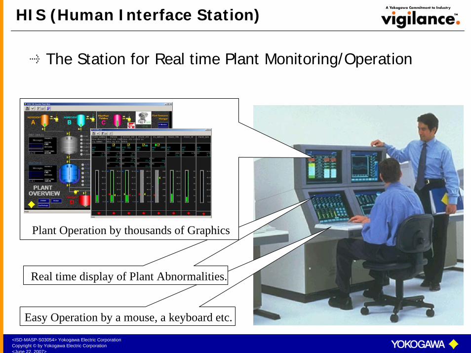
HIS (Human Interface Station)
The Station for Real time Plant Monitoring/Operation
Plant Operation by thousands of Graphics
Real time display of Plant Abnormalities.
Easy Operation by a mouse, a keyboard etc.

<ISD-MASP-S03054> Yokogawa Electric CorporationCopyright © by Yokogawa Electric Corporation<June 22, 2007>
Types of HIS
DESKTOP HIS:A IBM PC/AT compatible machine is generally used. Apart from the general PC, the Yokogawa PC is also supported. Specifications of the PC HIS Desktop are as follows:CPU : Pentium IV ProcessorMain Memory : 256 MB (Minimum)Hard Disk : 20 GB or moreVideo Display : 1024 x 768 or more, 256 coloursCRT Monitor : Multi Scan 17” monitor or largerSerial Port : RS232C one port or moreParallel Port : One port or moreExtension Slot : PCI slot for V/VL net card, ISA slot for Ethernet cardPower Supply : 200-240V ACBasic Software : Windows NT with Service Pack ,Windows 2000 or
Windows XPOperation keyboard can also be connected to the Desk Top HIS.
CONSOLE HISThe floor mounted console type HIS comes with 21” monitor which has a touch panel operation. It has an operation keyboard and an engineering keyboard.

<ISD-MASP-S03054> Yokogawa Electric CorporationCopyright © by Yokogawa Electric Corporation<June 22, 2007>
HIS Models : CRT/LCD
Dual Stack CRT/LCD Consoles
Ethernet
V net
Enclosed display style console HIS
Open display style console
HISPC
With/Without Touch screen
Generic PC
Console Single Stack
VL net
Open display style console HIS
PC
The figure below indicates the different models of HIS supported by CS3000.
<ISD-MASP-S03054> Yokogawa Electric CorporationCopyright © by Yokogawa Electric Corporation<June 22, 2007>
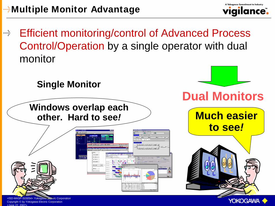
Multiple Monitor Advantage
Efficient monitoring/control of Advanced Process Control/Operation by a single operator with dual monitor
Dual MonitorsMuch easier
to see!
Single Monitor
Windows overlap each other. Hard to see!
<ISD-MASP-S03054> Yokogawa Electric CorporationCopyright © by Yokogawa Electric Corporation<June 22, 2007>
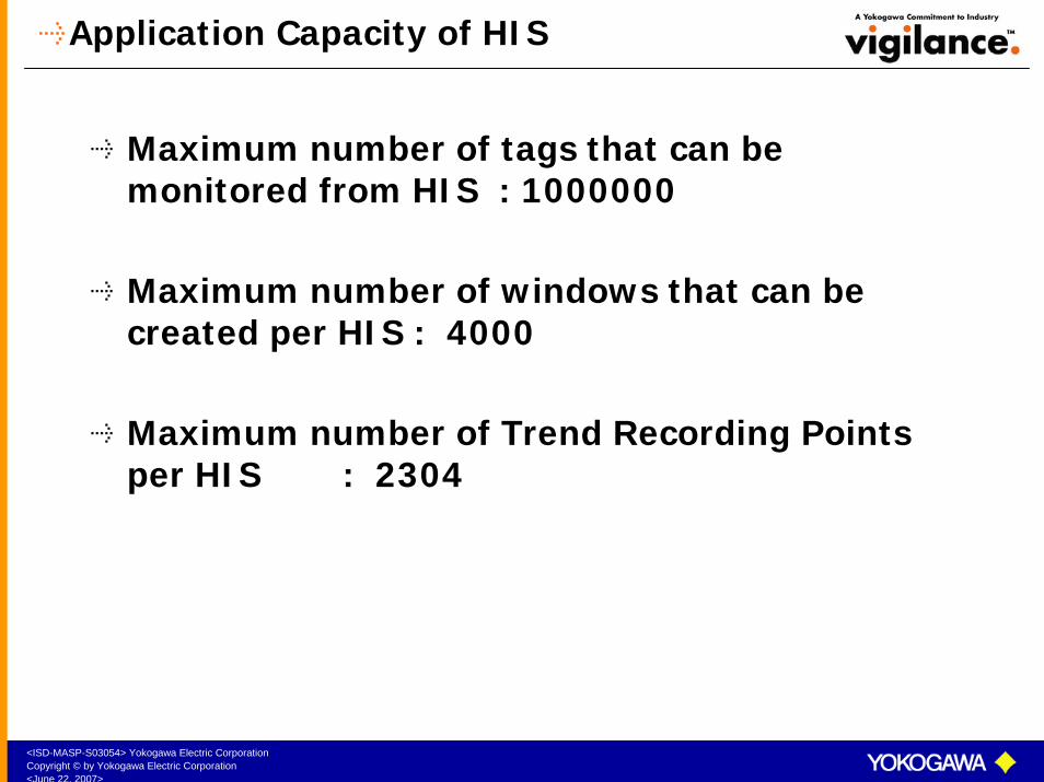
Application Capacity of HIS
Maximum number of tags that can be monitored from HIS : 1000000
Maximum number of windows that can be created per HIS : 4000
Maximum number of Trend Recording Points per HIS : 2304
<ISD-MASP-S03054> Yokogawa Electric CorporationCopyright © by Yokogawa Electric Corporation<June 22, 2007>
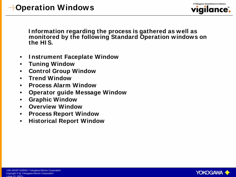
Operation Windows
Information regarding the process is gathered as well as monitored by the following Standard Operation windows on the HIS.
• Instrument Faceplate Window• Tuning Window• Control Group Window• Trend Window• Process Alarm Window• Operator guide Message Window• Graphic Window• Overview Window • Process Report Window• Historical Report Window

<ISD-MASP-S03054> Yokogawa Electric CorporationCopyright © by Yokogawa Electric Corporation<June 22, 2007>
Operation Windows
TOOL BOX
SYSTEM MESSAGE AREA
WINDOW CALL
All operation windows can be calledfrom the System Message Area icons.
The windows can be called by using NAME icon TOOL BOX icon WINDOW CALL iconNAVIGATOR icon
The windows can also be called usingthe keys on the operator keyboard.
NAME
OPERATION WINDOW AREA
NAVIGATOR
<ISD-MASP-S03054> Yokogawa Electric CorporationCopyright © by Yokogawa Electric Corporation<June 22, 2007>
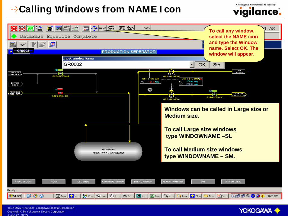
Calling Windows from NAME Icon
To call any window, select the NAME icon and type the Window name. Select OK. The window will appear.
GR0002
Windows can be called in Large size or Medium size.
To call Large size windows type WINDOWNAME –SL
To call Medium size windowstype WINDOWNAME – SM.
<ISD-MASP-S03054> Yokogawa Electric CorporationCopyright © by Yokogawa Electric Corporation<June 22, 2007>
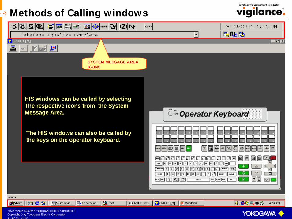
Methods of Calling windows
HIS windows can be called by selecting The respective icons from the System Message Area.
The HIS windows can also be called bythe keys on the operator keyboard.
SYSTEM MESSAGE AREA ICONS
<ISD-MASP-S03054> Yokogawa Electric CorporationCopyright © by Yokogawa Electric Corporation<June 22, 2007>
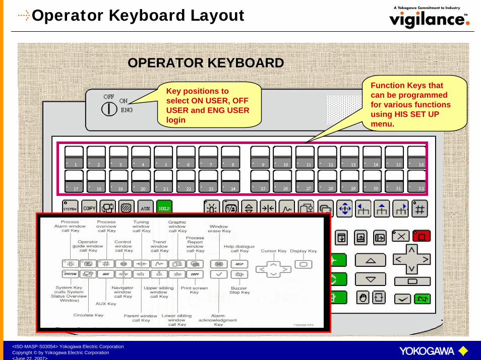
Operator Keyboard Layout
OPERATOR KEYBOARD
Key positions to select ON USER, OFF USER and ENG USER login
Function Keys that can be programmed for various functions using HIS SET UP menu.
<ISD-MASP-S03054> Yokogawa Electric CorporationCopyright © by Yokogawa Electric Corporation<June 22, 2007>
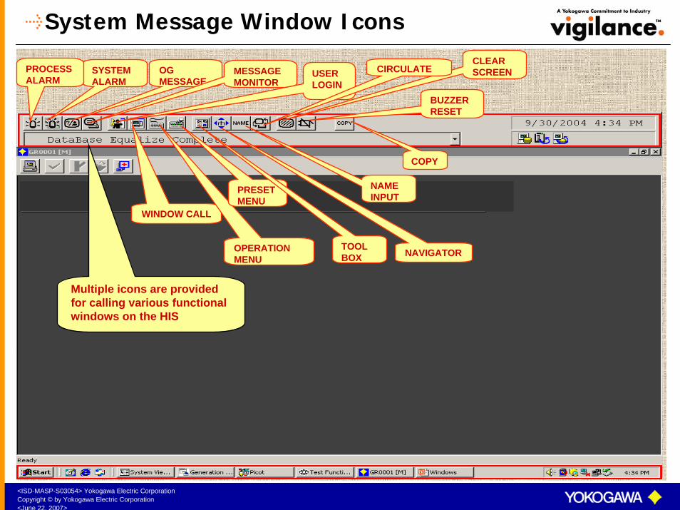
System Message Window Icons
SYSTEM ALARM
PROCESSALARM
OG MESSAGE
MESSAGE MONITOR
USER LOGIN
COPY
BUZZER RESET
CLEAR SCREENCIRCULATE
WINDOW CALL
OPERATION MENU
PRESET MENU
TOOL BOX NAVIGATOR
NAME INPUT
Multiple icons are provided for calling various functional windows on the HIS
<ISD-MASP-S03054> Yokogawa Electric CorporationCopyright © by Yokogawa Electric Corporation<June 22, 2007>
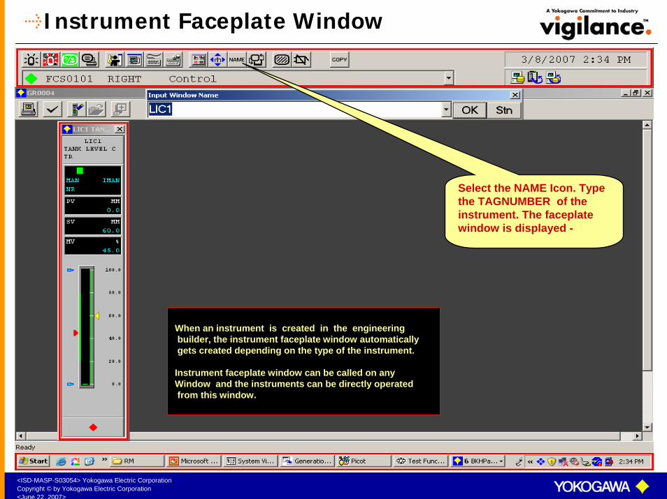
Instrument Faceplate Window
Select the NAME Icon. Type the TAGNUMBER of the instrument. The faceplate window is displayed -
When an instrument is created in the engineeringbuilder, the instrument faceplate window automaticallygets created depending on the type of the instrument.
Instrument faceplate window can be called on anyWindow and the instruments can be directly operatedfrom this window.

<ISD-MASP-S03054> Yokogawa Electric CorporationCopyright © by Yokogawa Electric Corporation<June 22, 2007>
Instrument Faceplate Window Details
Tag Mark signifies the Importance of the instrument.
Mode Status indicates the mode of operation of the instrument viz. MAN/ AUT/CAS/PRD etc..
Alarm Status indicates the current alarm status of the instrument viz. NR/HH/HI/LO/LL Set by HH/PH/PL/LL etc…
MV high Limit set by parameter MH in Tuning Window
Output Low Limit index pointer set by parameter OPLO in Tuning Window
Scale High of the instrument indicated by parameter SH in the Tuning window
Tag Number is used to identify and call an instrument.
Output High Limit index pointer set by parameter OPHI in Tuning Window
Scale Low of the instrument indicated by parameter SL in the Tuning Window
Cascade mark indicates that the instrument is receiving its set point from another instrument.
Tag Comment is used to indicate the service of the instrument.
MV low Limit set by parameter ML in Tuning Window
<ISD-MASP-S03054> Yokogawa Electric CorporationCopyright © by Yokogawa Electric Corporation<June 22, 2007>
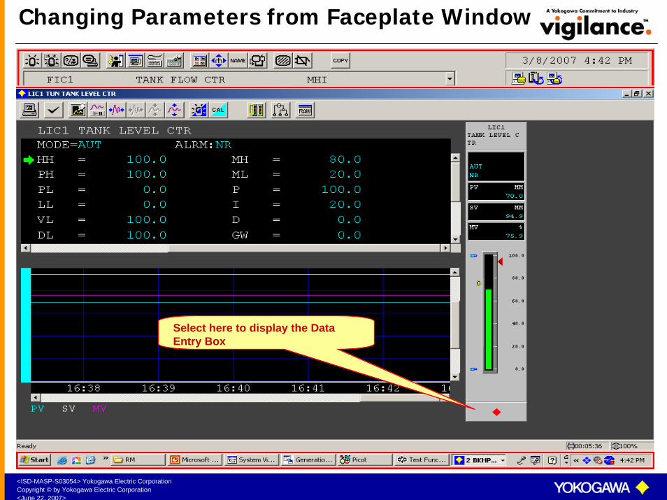
Changing Parameters from Faceplate Window
Select here to display the Data Entry Box
<ISD-MASP-S03054> Yokogawa Electric CorporationCopyright © by Yokogawa Electric Corporation<June 22, 2007>
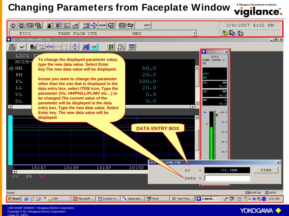
Changing Parameters from Faceplate Window
To change the displayed parameter value, type the new data value. Select Enter key.The new data value will be displayed.
Incase you want to change the parameter other than the one that is displayed in the data entry box, select ITEM icon. Type the parameter (Viz. HH/PH/LL/PL/MV etc…) to be changed.The current value of the parameter will be displayed in the data entry box. Type the new data value. Select Enter key. The new data value will be displayed.
DATA ENTRY BOX

<ISD-MASP-S03054> Yokogawa Electric CorporationCopyright © by Yokogawa Electric Corporation<June 22, 2007>
Tuning Window
Select this icon to display the Tuning Window
Select NAME icon. Type the TAGNAME
Select this icon to display the Tool box
<ISD-MASP-S03054> Yokogawa Electric CorporationCopyright © by Yokogawa Electric Corporation<June 22, 2007>
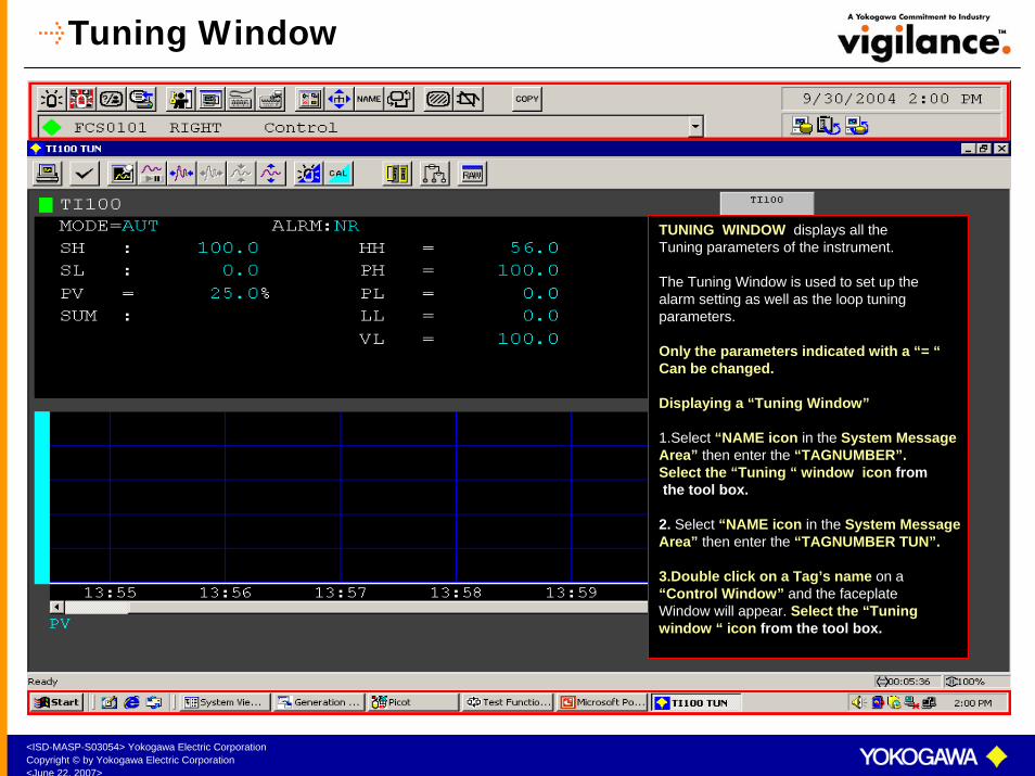
Tuning Window
TUNING WINDOW displays all the Tuning parameters of the instrument.
The Tuning Window is used to set up the alarm setting as well as the loop tuning parameters.
Only the parameters indicated with a “= “Can be changed.
Displaying a “Tuning Window”
1.Select “NAME icon in the System Message Area” then enter the “TAGNUMBER”. Select the “Tuning “ window icon fromthe tool box.
2. Select “NAME icon in the System Message Area” then enter the “TAGNUMBER TUN”.
3.Double click on a Tag’s name on a “Control Window” and the faceplate Window will appear. Select the “Tuningwindow “ icon from the tool box.
<ISD-MASP-S03054> Yokogawa Electric CorporationCopyright © by Yokogawa Electric Corporation<June 22, 2007>
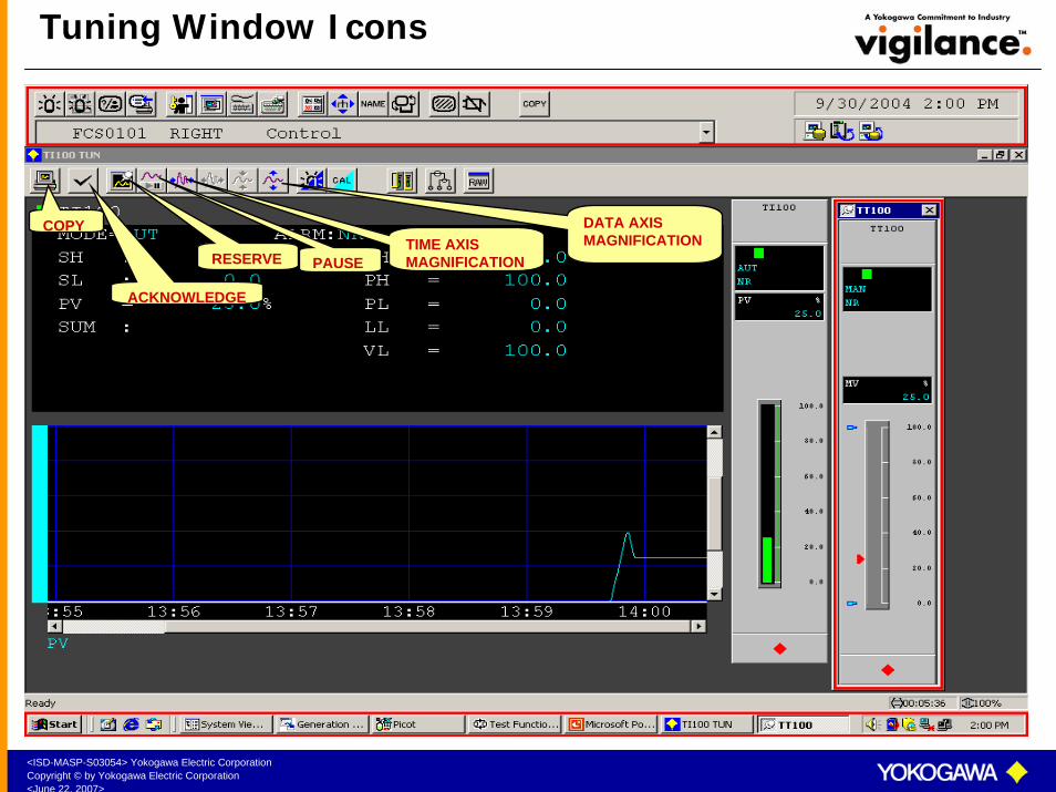
Tuning Window Icons
ACKNOWLEDGE
COPY DATA AXIS MAGNIFICATION
PAUSERESERVETIME AXIS MAGNIFICATION

<ISD-MASP-S03054> Yokogawa Electric CorporationCopyright © by Yokogawa Electric Corporation<June 22, 2007>
Tuning Window Icons
AOF
CALIBRATION
OPERATION MARK
DRAW RAW
<ISD-MASP-S03054> Yokogawa Electric CorporationCopyright © by Yokogawa Electric Corporation<June 22, 2007>
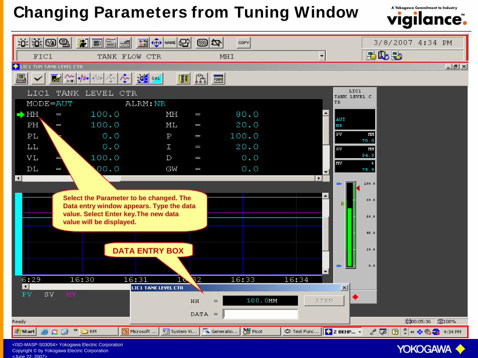
Changing Parameters from Tuning Window
Select the Parameter to be changed. The Data entry window appears. Type the data value. Select Enter key.The new data value will be displayed.
DATA ENTRY BOX

<ISD-MASP-S03054> Yokogawa Electric CorporationCopyright © by Yokogawa Electric Corporation<June 22, 2007>
Mode Status
MAN (Manual)
AUT (Auto)
CAS (Cascade)
PRD (Primary Direct)

<ISD-MASP-S03054> Yokogawa Electric CorporationCopyright © by Yokogawa Electric Corporation<June 22, 2007>
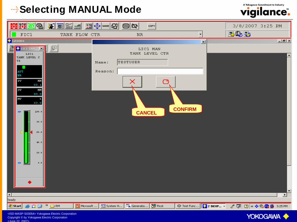
Selecting MANUAL Mode
Select the MANUAL mode icon. Confirm. The instrument will go the MANUAL mode.
Select here to display the mode status window.
<ISD-MASP-S03054> Yokogawa Electric CorporationCopyright © by Yokogawa Electric Corporation<June 22, 2007>
Selecting MANUAL Mode
CONFIRMCANCEL
<ISD-MASP-S03054> Yokogawa Electric CorporationCopyright © by Yokogawa Electric Corporation<June 22, 2007>
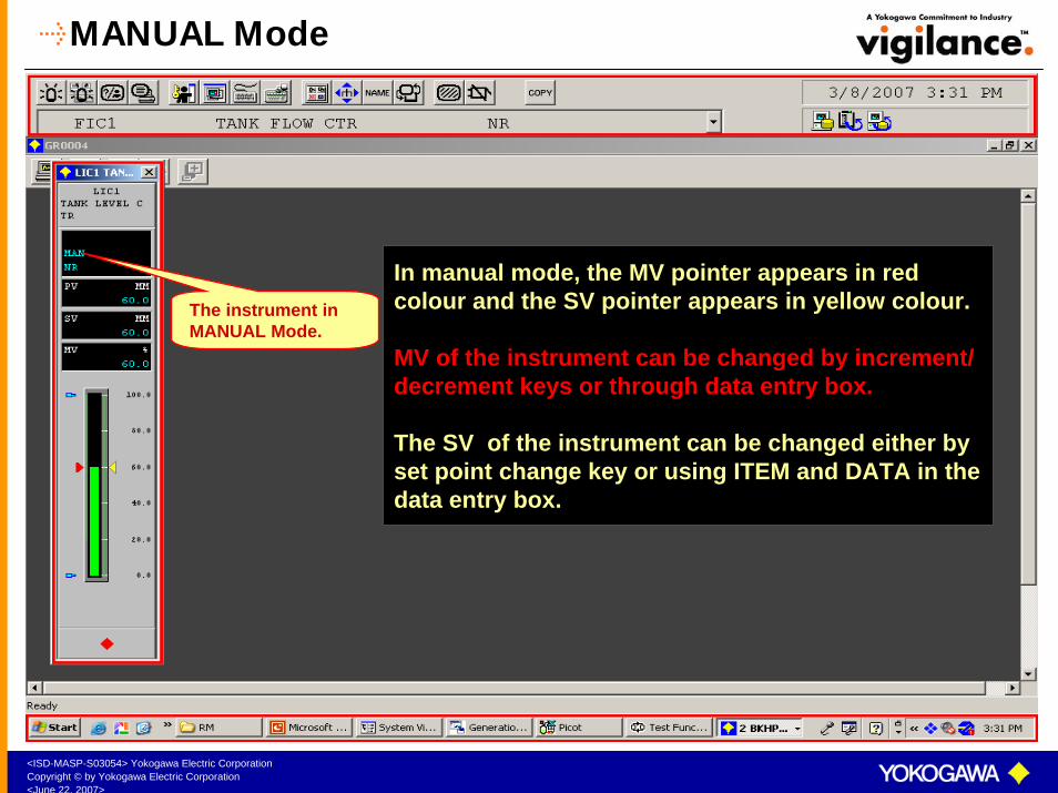
MANUAL Mode
The instrument in MANUAL Mode.
In manual mode, the MV pointer appears in red colour and the SV pointer appears in yellow colour.
MV of the instrument can be changed by increment/ decrement keys or through data entry box.
The SV of the instrument can be changed either by set point change key or using ITEM and DATA in the data entry box.
<ISD-MASP-S03054> Yokogawa Electric CorporationCopyright © by Yokogawa Electric Corporation<June 22, 2007>
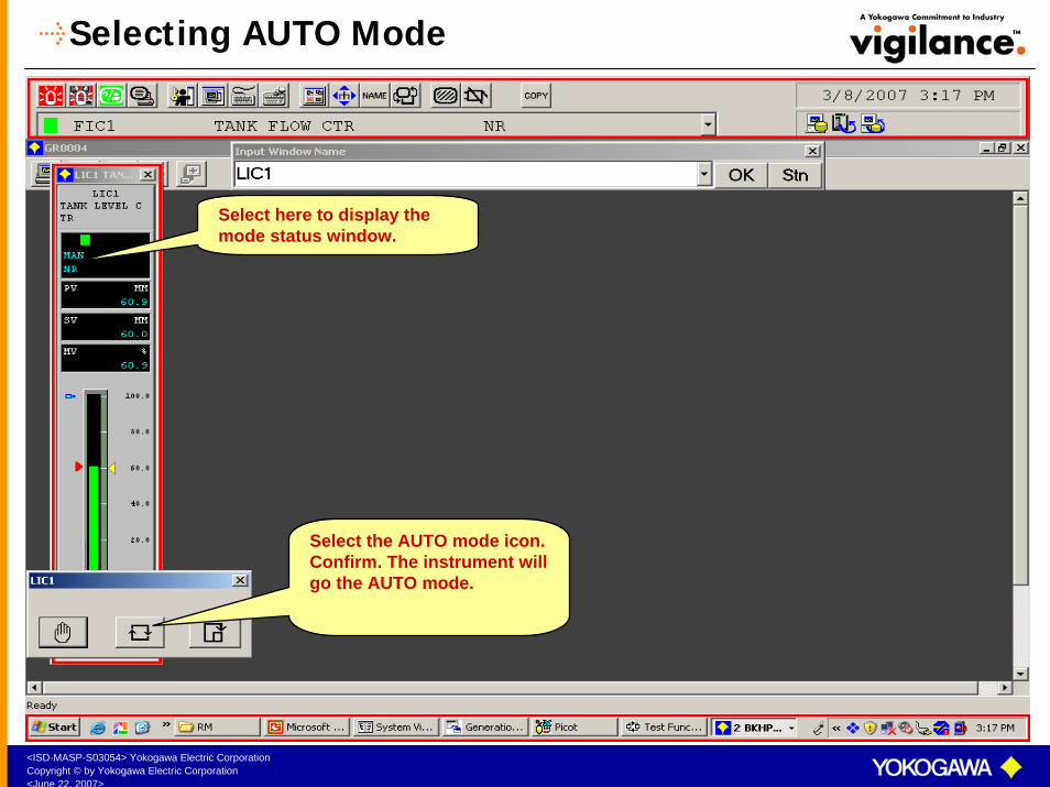
Selecting AUTO Mode
Select the AUTO mode icon. Confirm. The instrument will go the AUTO mode.
Select here to display the mode status window.

<ISD-MASP-S03054> Yokogawa Electric CorporationCopyright © by Yokogawa Electric Corporation<June 22, 2007>
Selecting AUTO Mode
CONFIRM

<ISD-MASP-S03054> Yokogawa Electric CorporationCopyright © by Yokogawa Electric Corporation<June 22, 2007>
AUTO Mode
The instrument in AUTO Mode.
In Auto mode, the SV pointer appears in red colour and the MV pointer appears in yellow colour.
SV of the instrument can be changed by increment/ decrement keys or through data entry box.
The MV of the instrument cannot be changed byany method.
<ISD-MASP-S03054> Yokogawa Electric CorporationCopyright © by Yokogawa Electric Corporation<June 22, 2007>
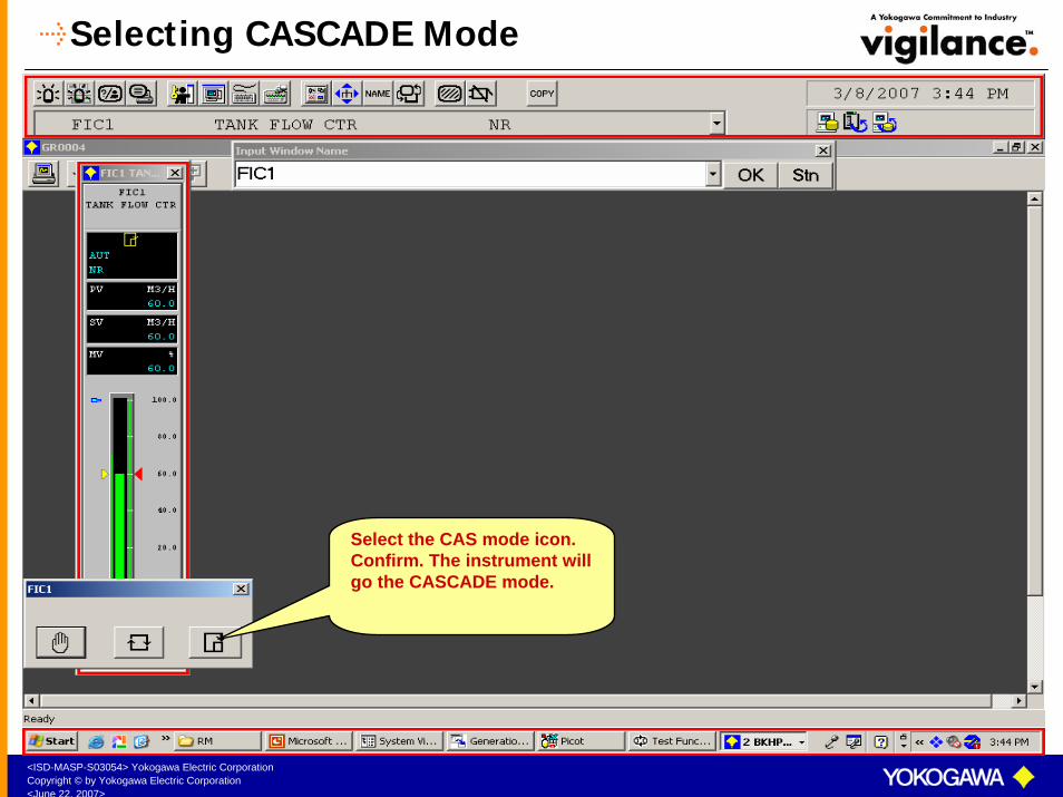
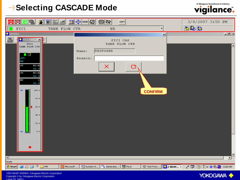
Selecting CASCADE Mode
Select the CAS mode icon. Confirm. The instrument will go the CASCADE mode.
<ISD-MASP-S03054> Yokogawa Electric CorporationCopyright © by Yokogawa Electric Corporation<June 22, 2007>
Selecting CASCADE Mode
CONFIRM

<ISD-MASP-S03054> Yokogawa Electric CorporationCopyright © by Yokogawa Electric Corporation<June 22, 2007>
CASCADE Mode
The instrument in CASCADE Mode.
In a cascade loop the output of the primary controller(MV1) goes as set point of the secondary controller
(SV2). The output of the secondary controller (MV2) goes to the final control element. For a cascade loop, the primary controller can be in AUT or MAN mode, but the secondary controller has to be in CAS mode.
In cascade mode both the SV and MV pointers appearin yellow colour.
The SV and MV of the instrument cannot be changed.
<ISD-MASP-S03054> Yokogawa Electric CorporationCopyright © by Yokogawa Electric Corporation<June 22, 2007>
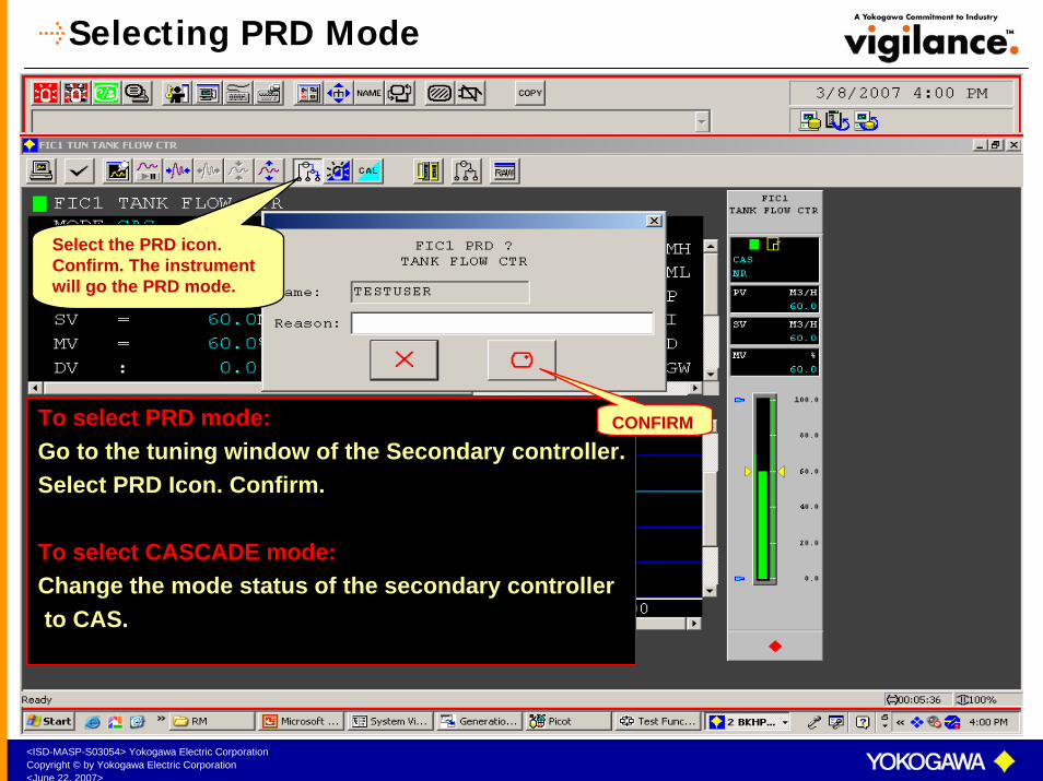
Selecting PRD Mode
Select the PRD icon. Confirm. The instrument will go the PRD mode.
To select PRD mode:Go to the tuning window of the Secondary controller.Select PRD Icon. Confirm.
To select CASCADE mode:Change the mode status of the secondary controllerto CAS.
CONFIRM
<ISD-MASP-S03054> Yokogawa Electric CorporationCopyright © by Yokogawa Electric Corporation<June 22, 2007>
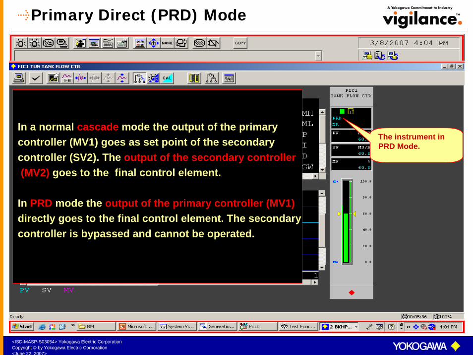
Primary Direct (PRD) Mode
The instrument in PRD Mode.
In a normal cascade mode the output of the primary controller (MV1) goes as set point of the secondary controller (SV2). The output of the secondary controller(MV2) goes to the final control element.
In PRD mode the output of the primary controller (MV1)directly goes to the final control element. The secondary controller is bypassed and cannot be operated.

<ISD-MASP-S03054> Yokogawa Electric CorporationCopyright © by Yokogawa Electric Corporation<June 22, 2007>
Initialization Manual (IMAN) Mode
In a cascade loop, if the cascade is broken by taking the secondary controller from CASto either AUT or MAN mode, IMAN appearsas the mode sub status of the primary controller.
IMAN indicates that–Cascade loop is broken–Primary controller is bypassed –Primary controller cannot be operated due to– SV tracking.
SV tracking:The output of the primary controller (MV1) automatically tracks the set point of the secondary controller (SV2)to have bump less transfer to CAS mode.
To bring the primary controller out of IMAN modeChange the mode status of the secondary controller to CAS. The primary controller will automatically come out of IMANmode.
The instrument in IMAN Mode.
<ISD-MASP-S03054> Yokogawa Electric CorporationCopyright © by Yokogawa Electric Corporation<June 22, 2007>
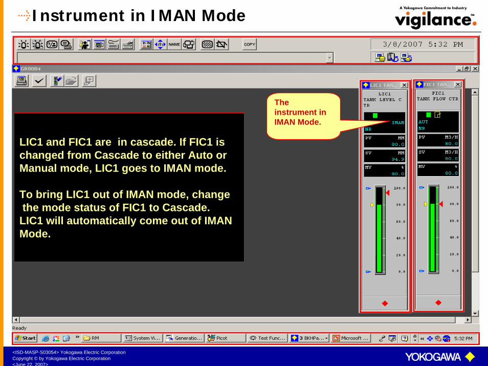
Instrument in IMAN Mode
LIC1 and FIC1 are in cascade. If FIC1 ischanged from Cascade to either Auto orManual mode, LIC1 goes to IMAN mode.
To bring LIC1 out of IMAN mode, changethe mode status of FIC1 to Cascade.
LIC1 will automatically come out of IMAN Mode.
The instrument in IMAN Mode.

<ISD-MASP-S03054> Yokogawa Electric CorporationCopyright © by Yokogawa Electric Corporation<June 22, 2007>
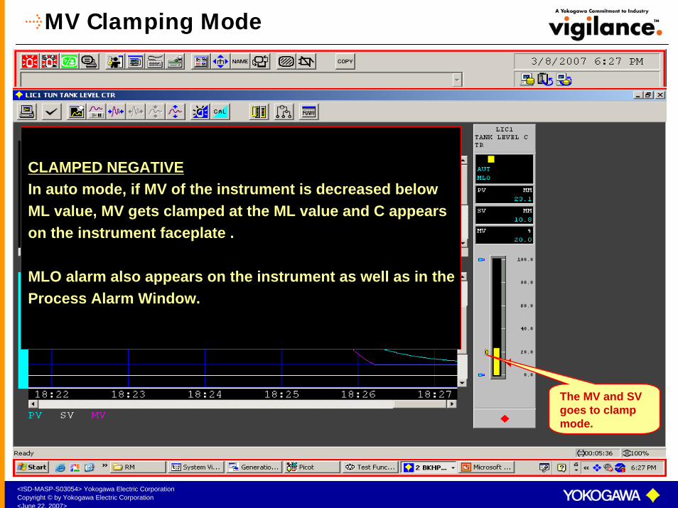
MV Clamping Mode
The MV and SV goes to clamp mode.
CLAMPED POSITIVEIn auto mode, if MV of the instrument is increased beyond MH value, MV gets clamped at the MH value and C appears on the instrument faceplate .
MHI alarm also appears on the instrument as well as in theProcess Alarm Window.
<ISD-MASP-S03054> Yokogawa Electric CorporationCopyright © by Yokogawa Electric Corporation<June 22, 2007>
MV Clamping Mode
The MV and SV goes to clamp mode.
CLAMPED NEGATIVEIn auto mode, if MV of the instrument is decreased belowML value, MV gets clamped at the ML value and C appears on the instrument faceplate .
MLO alarm also appears on the instrument as well as in theProcess Alarm Window.

<ISD-MASP-S03054> Yokogawa Electric CorporationCopyright © by Yokogawa Electric Corporation<June 22, 2007>
Process Alarm StatusALARM STATUS PROCESS
STATUSALARM
SETTINGS
ITEM TO BE SET IN THE TUNING
PANEL
PV BAR COLOUR
TAG MARK COLOUR
REMARKS
NR PROCESS NORMAL
---------- ---------- GREEN GREEN ----------
HH PV VERY HIGH
PV > HH HH RED RED ----------
HI PV HIGH PV > PH PH RED RED ----------
LL PV VERY LOW
PV < LL LL RED RED ----------
LO PV LOW PV < PL PL RED RED ----------
DV+ / - DEVIATION ALARM
DV > DL DV = PV - SV
DL DEVIATION LIMIT
YELLOW YELLOW
VEL + / - VELOCITY ALARM
VEL = PV/ T VLVELOCITY LIMIT
YELLOW YELLOW
IOP + / - INPUT OPEN
INPUT IS OUT OF RANGE
CHECK RAW VALUE IN TUNING WINDOW
RED RED RAW IS ACTUAL INPUT INTERMS OF %
OOP OUTPUT OPEN
OUTPUT LINE IS OPEN
RED RED
<ISD-MASP-S03054> Yokogawa Electric CorporationCopyright © by Yokogawa Electric Corporation<June 22, 2007>
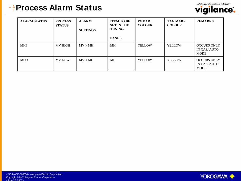
Process Alarm StatusALARM STATUS PROCESS
STATUSALARM
SETTINGS
ITEM TO BE SET IN THE TUNING
PANEL
PV BAR COLOUR
TAG MARK COLOUR
REMARKS
MHI MV HIGH MV > MH MH YELLOW YELLOW OCCURS ONLY IN CAS/ AUTO MODE
MLO MV LOW MV < ML ML YELLOW YELLOW OCCURS ONLY IN CAS/ AUTO MODE
<ISD-MASP-S03054> Yokogawa Electric CorporationCopyright © by Yokogawa Electric Corporation<June 22, 2007>
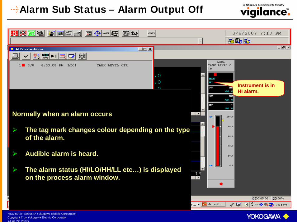
Alarm Sub Status – Alarm Output Off
Instrument is in HI alarm.
Normally when an alarm occurs
The tag mark changes colour depending on the typeof the alarm.
Audible alarm is heard.
The alarm status (HI/LO/HH/LL etc…) is displayedon the process alarm window.

<ISD-MASP-S03054> Yokogawa Electric CorporationCopyright © by Yokogawa Electric Corporation<June 22, 2007>
Selecting / Deselecting AOF
To put the instrument to AOF mode:Go to the tuning window of the instrument.Select AOF icon. Confirm.
To bring the instrument back to normal mode:Go to the tuning window of the instrument.Select AOF icon once again. Confirm.
AOF
CONFIRM

<ISD-MASP-S03054> Yokogawa Electric CorporationCopyright © by Yokogawa Electric Corporation<June 22, 2007>
Alarm Sub Status – Alarm Output Off
HI alarm appears only on the instrument faceplate.
In AOF mode:
The tag mark changes to dark blue colour irrespectiveof the alarm.
Audible alarm is put off.
The alarm status is displayed only on the instrument faceplate.
All the alarms status except IOP & OOP on the Instrument are not displayed on the process alarm window.
<ISD-MASP-S03054> Yokogawa Electric CorporationCopyright © by Yokogawa Electric Corporation<June 22, 2007>
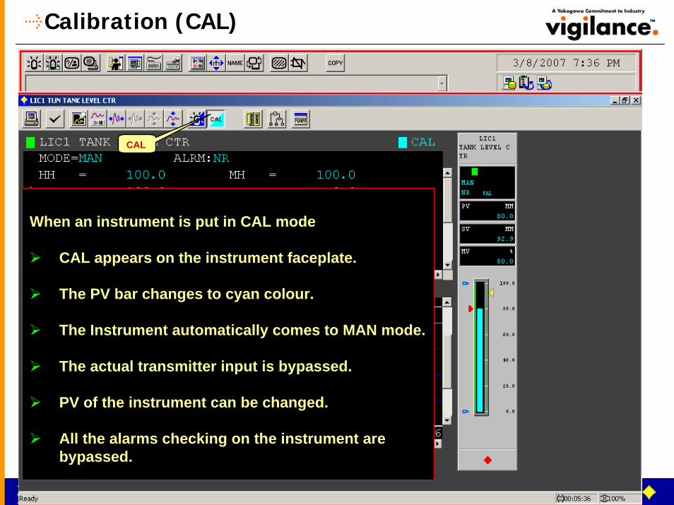
Calibration (CAL)
When an instrument is put in CAL mode
CAL appears on the instrument faceplate.
The PV bar changes to cyan colour.
The Instrument automatically comes to MAN mode.
The actual transmitter input is bypassed.
PV of the instrument can be changed.
All the alarms checking on the instrument arebypassed.
CAL
<ISD-MASP-S03054> Yokogawa Electric CorporationCopyright © by Yokogawa Electric Corporation<June 22, 2007>
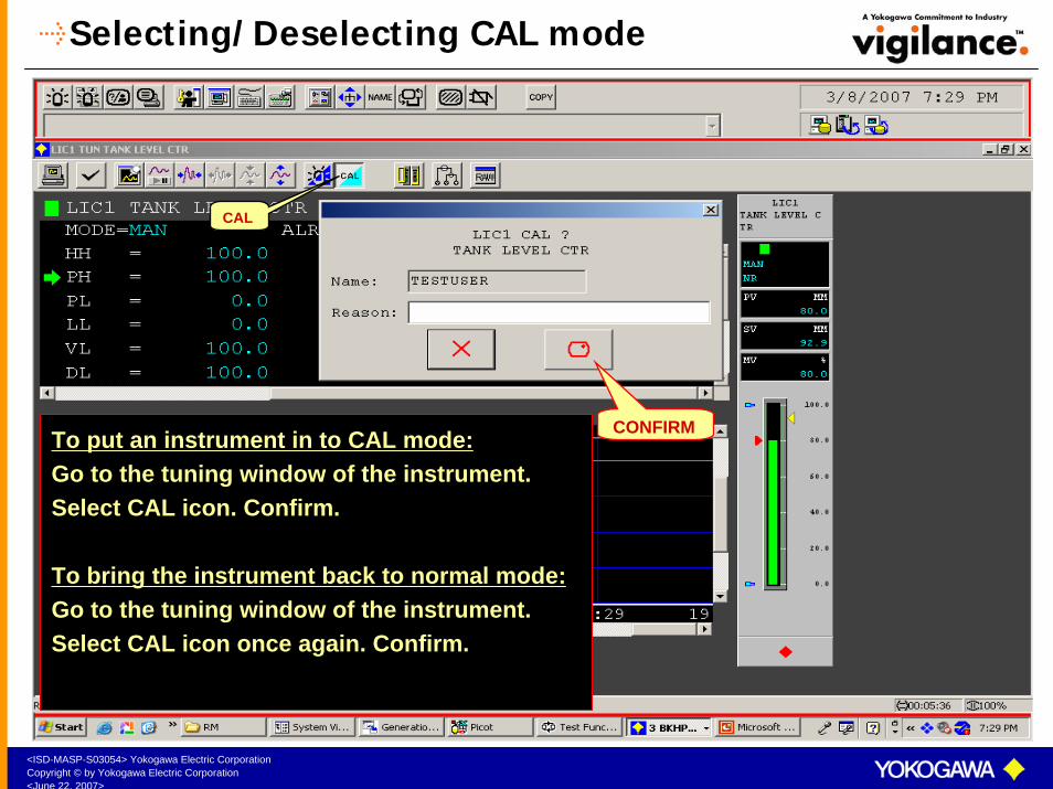
Selecting/Deselecting CAL mode
To put an instrument in to CAL mode:Go to the tuning window of the instrument.Select CAL icon. Confirm.
To bring the instrument back to normal mode:Go to the tuning window of the instrument.Select CAL icon once again. Confirm.
CAL
CONFIRM

<ISD-MASP-S03054> Yokogawa Electric CorporationCopyright © by Yokogawa Electric Corporation<June 22, 2007>
Importance Level
Importance level is assigned to an instrument when it is created in the engineeringbuilder. There are 8 importance levels.
1 - Important tag with confirmation 5 - Important tag without confirmation 2 - General tag without confirmation 6 - General tag with confirmation3 - Auxillary tag –I without Confirmation 7 - Auxillary tag –I with Confirmation4 - Auxillary tag –II without Confirmation 8 - Auxillary tag –II with Confirmation

<ISD-MASP-S03054> Yokogawa Electric CorporationCopyright © by Yokogawa Electric Corporation<June 22, 2007>
Tag with confirmation
CONFIRM
For tags with confirmation, any parameter to bechanged would request for a confirmation. On selecting the confirm key, the new data will beaccepted.
<ISD-MASP-S03054> Yokogawa Electric CorporationCopyright © by Yokogawa Electric Corporation<June 22, 2007>
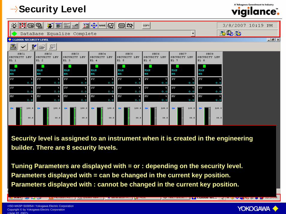
Security Level
Security level is assigned to an instrument when it is created in the engineering builder. There are 8 security levels.
Tuning Parameters are displayed with = or : depending on the security level. Parameters displayed with = can be changed in the current key position.Parameters displayed with : cannot be changed in the current key position.
<ISD-MASP-S03054> Yokogawa Electric CorporationCopyright © by Yokogawa Electric Corporation<June 22, 2007>
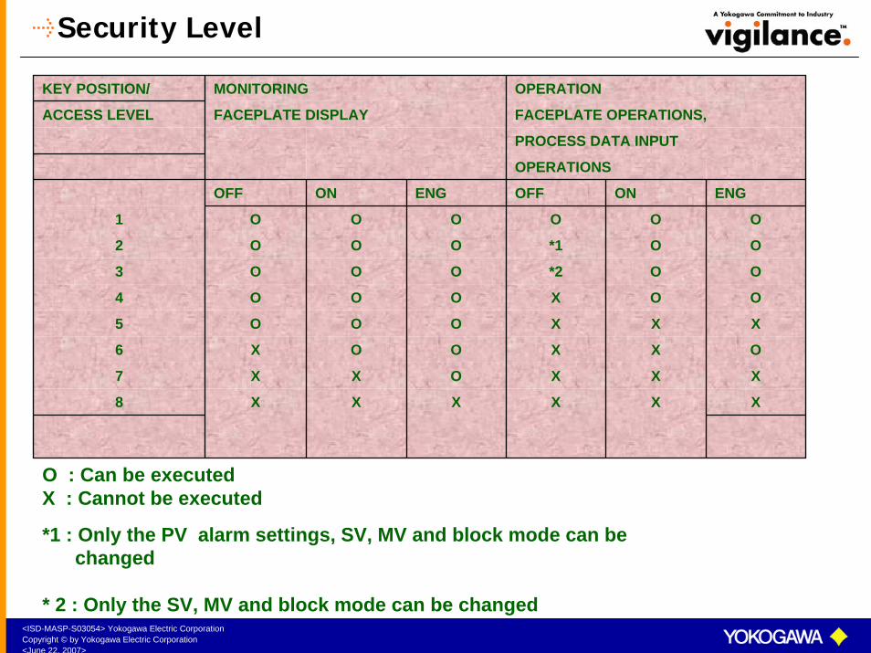
Security Level
KEY POSITION/ MONITORING OPERATION
ACCESS LEVEL FACEPLATE DISPLAY FACEPLATE OPERATIONS,
PROCESS DATA INPUT
OPERATIONS
OFF ON ENG OFF ON ENG
1 O O O O O O
2 O O O *1 O O
3 O O O *2 O O
4 O O O X O O
5 O O O X X X
6 X O O X X O
7 X X O X X X
8 X X X X X X
O : Can be executed X : Cannot be executed
*1 : Only the PV alarm settings, SV, MV and block mode can be changed
* 2 : Only the SV, MV and block mode can be changed

<ISD-MASP-S03054> Yokogawa Electric CorporationCopyright © by Yokogawa Electric Corporation<June 22, 2007>
Security Function
Select this icon to call the user login window
User Login Window to change the users
Error Message prompt
When you have logged inas an OFF USER , and ifthe security level of theinstrument is high, an
error message prompt asindicated in the screenwill be displayed.
<ISD-MASP-S03054> Yokogawa Electric CorporationCopyright © by Yokogawa Electric Corporation<June 22, 2007>
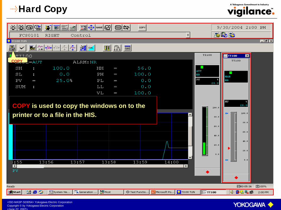
Hard Copy
COPY
COPY is used to copy the windows on to theprinter or to a file in the HIS.
<ISD-MASP-S03054> Yokogawa Electric CorporationCopyright © by Yokogawa Electric Corporation<June 22, 2007>
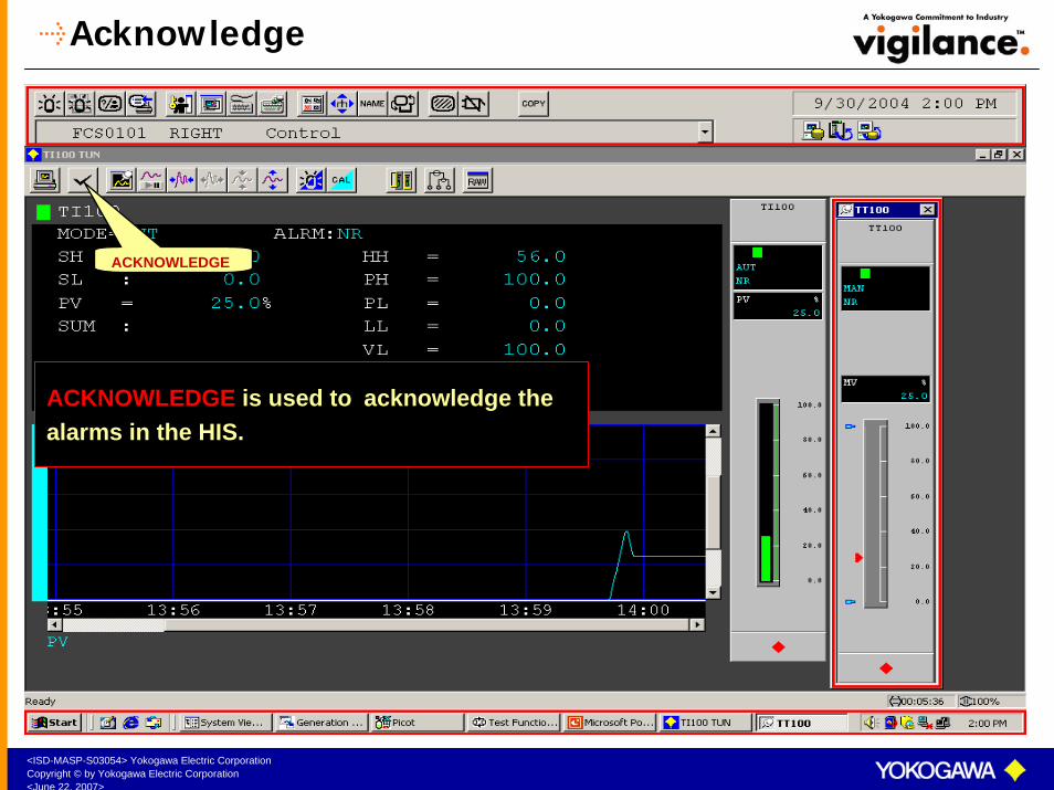
Acknowledge
ACKNOWLEDGE
ACKNOWLEDGE is used to acknowledge the alarms in the HIS.
<ISD-MASP-S03054> Yokogawa Electric CorporationCopyright © by Yokogawa Electric Corporation<June 22, 2007>
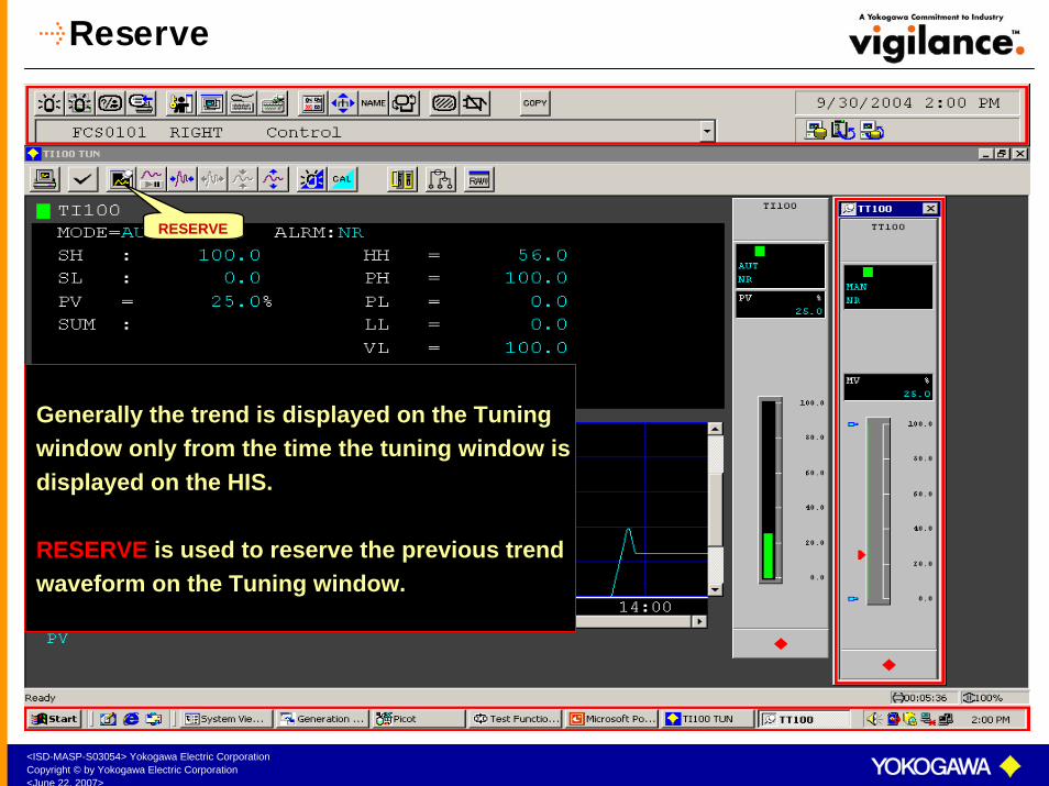
Reserve
RESERVE
Generally the trend is displayed on the Tuning window only from the time the tuning window isdisplayed on the HIS.
RESERVE is used to reserve the previous trendwaveform on the Tuning window.

<ISD-MASP-S03054> Yokogawa Electric CorporationCopyright © by Yokogawa Electric Corporation<June 22, 2007>
Tuning Window Icons
DATA AXIS MAGNIFICATION
PAUSETIME AXIS MAGNIFICATION
PAUSE is used to freeze the Tuningtrend display. The recording would
continue.
TIME AXIS MAGNIFICATION is used tomagnify or reduce the time axis in the
Tuning trend.
DATA AXIS MAGNIFICATION is used to magnify or reduce the data axis in the Tuning trend.

<ISD-MASP-S03054> Yokogawa Electric CorporationCopyright © by Yokogawa Electric Corporation<June 22, 2007>
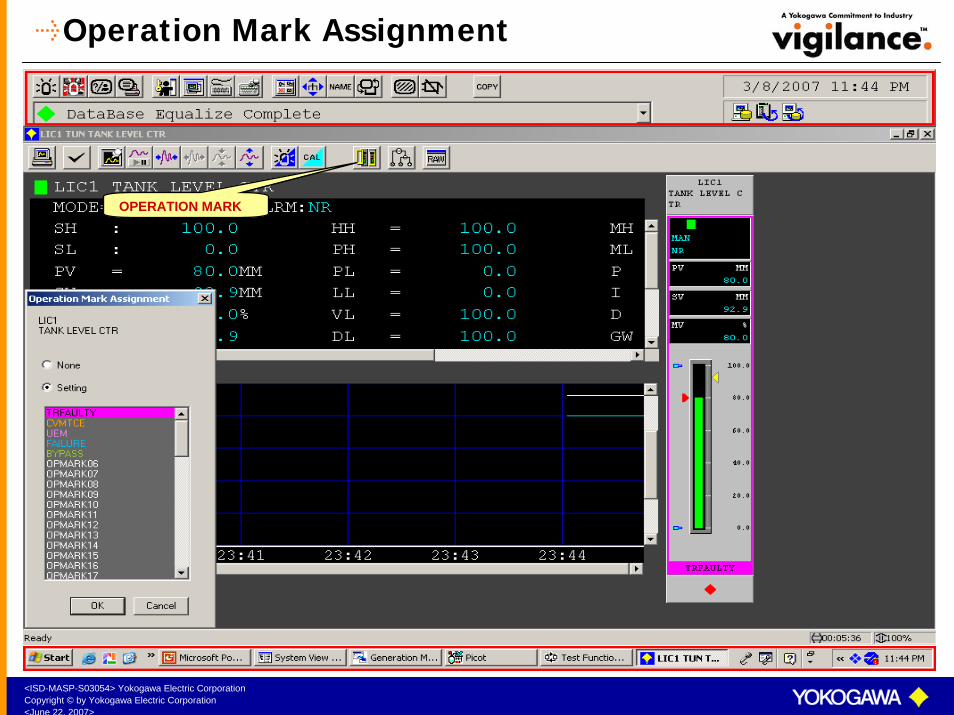
Operation Mark
OPERATION MARKS are labels that can be fixed on various instruments.
Operation Marks are created in the HIS Set up Window.
64 Operations marks can be defined for one HIS.
One operation mark can be assigned tomany instruments.
One instrument can have only one operation mark at a time.
<ISD-MASP-S03054> Yokogawa Electric CorporationCopyright © by Yokogawa Electric Corporation<June 22, 2007>
Operation Mark Assignment
OPERATION MARK

<ISD-MASP-S03054> Yokogawa Electric CorporationCopyright © by Yokogawa Electric Corporation<June 22, 2007>
Control Drawing Display
DRAW
DRAW is used to display the control drawing related to the instrument. The same can also be called by typing TAGNO DRAW on selecting theNAME icon
<ISD-MASP-S03054> Yokogawa Electric CorporationCopyright © by Yokogawa Electric Corporation<June 22, 2007>
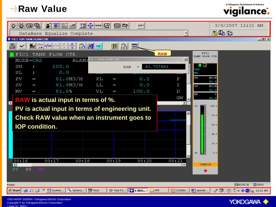
Raw Value
RAW
RAW is actual input in terms of %. PV is actual input in terms of engineering unit. Check RAW value when an instrument goes toIOP condition.
<ISD-MASP-S03054> Yokogawa Electric CorporationCopyright © by Yokogawa Electric Corporation<June 22, 2007>
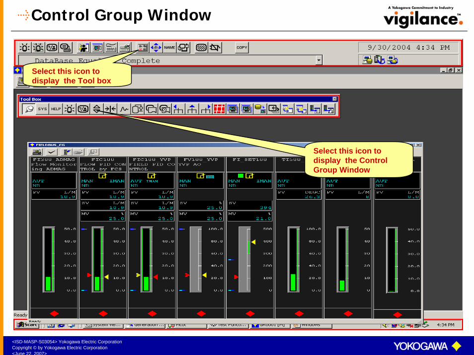
Control Group Window
Select this icon to display the Tool box
Select this icon to display the Control Group Window

<ISD-MASP-S03054> Yokogawa Electric CorporationCopyright © by Yokogawa Electric Corporation<June 22, 2007>
Control Group Window – 8 Instruments
Control group windows are used to display multiple instrument faceplates.
Maximum 8 or 16 instrument faceplatescan be displayed in one Control Group Window
Normally the instruments are monitored and operated from this window.
Double click on the instrument TAGNUMBER to display the Faceplate window of the instrument.
.

<ISD-MASP-S03054> Yokogawa Electric CorporationCopyright © by Yokogawa Electric Corporation<June 22, 2007>
8 Instrument Control Group operation
Select the instrument soft key to display the Data Entry Box
Data Entry Box is used to do the data entry.

<ISD-MASP-S03054> Yokogawa Electric CorporationCopyright © by Yokogawa Electric Corporation<June 22, 2007>
Control Group Window – 16 Instruments
16 instruments can also be displayed in a Control Group Window.

<ISD-MASP-S03054> Yokogawa Electric CorporationCopyright © by Yokogawa Electric Corporation<June 22, 2007>
16 Instruments Control Group Operation
To operate instruments from this window, Double click on the instrument TAGNAME to display the faceplate window of the instrument.
Operate the instrument from the instrument faceplate window..
<ISD-MASP-S03054> Yokogawa Electric CorporationCopyright © by Yokogawa Electric Corporation<June 22, 2007>
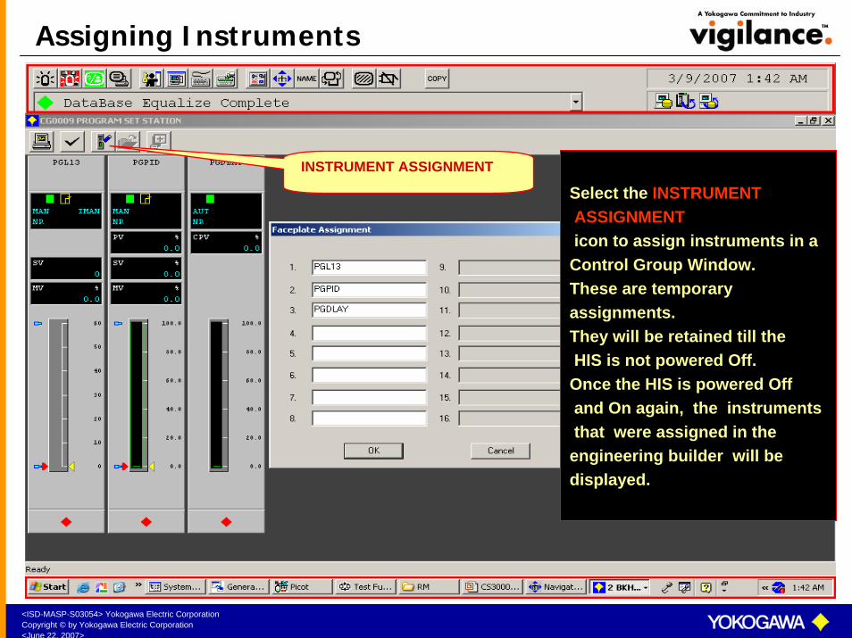
Assigning Instruments
INSTRUMENT ASSIGNMENT
Select the INSTRUMENTASSIGNMENTicon to assign instruments in a
Control Group Window.These are temporary assignments.They will be retained till theHIS is not powered Off.
Once the HIS is powered Offand On again, the instruments that were assigned in the
engineering builder will be displayed.
<ISD-MASP-S03054> Yokogawa Electric CorporationCopyright © by Yokogawa Electric Corporation<June 22, 2007>
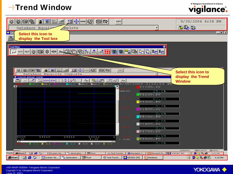
Trend Window
Select this icon to display the Tool box
Select this icon to display the Trend Window

<ISD-MASP-S03054> Yokogawa Electric CorporationCopyright © by Yokogawa Electric Corporation<June 22, 2007>
Trend Window
TREND WINDOW records the PV, SV and MV of various instruments.
Trend can be displayed in Trend GroupFormat or in Trend Point Format.
Maximum 8 pens can be assigned in one Trend Group Window

<ISD-MASP-S03054> Yokogawa Electric CorporationCopyright © by Yokogawa Electric Corporation<June 22, 2007>
Trend Recording Format
Rotary Trend:
Trend is recorded continuously in a rotary buffer. When the storage buffer becomes full, old trend data is overwritten by the new trend data. The trend is recorded continuously, once the pens are assigned.
Batch Trend:
Batch trend is used for a Batch Process. The trend has to be started and stopped whenever required, through an external command. Whenever start command is given, it erases the old recorded trend completely and starts recording the new trend.

<ISD-MASP-S03054> Yokogawa Electric CorporationCopyright © by Yokogawa Electric Corporation<June 22, 2007>
Trend Recording Span
The total trend recording period in a trend window depends on the sampling period and number of samples collected per pen.
Sampling Period: The time difference between two consecutive samples recorded.
SAMPLING PERIOD TOTAL RECORDING TIME
(2880 Samples/Pen)
1 sec. 48 mins.
10 secs. 480 mins. (8 hours )
1 min. 48 hours ( 2 days)
2 mins. 96 hours (4 days)
5 mins. 240 hours (10 days)
10 mins. 480 hours (20 days)
<ISD-MASP-S03054> Yokogawa Electric CorporationCopyright © by Yokogawa Electric Corporation<June 22, 2007>
Trend Blocks
TREND BLOCKS:
Trend Windows are divided into 20 trend blocks. Each trend block consists of 16 trend groups. 50 Trend Blocks are available per HIS.
20 Blocks – Used for self HIS (Out of 20 blocks , 18 Blocks can be
used for trend recording)
50 Blocks
30 Blocks – Used to view the trend recorded on other HIS
The trend recorded on one HIS can be viewed on other HIS if both the HIS are connected using the Ethernet cable.
Each trend window is called by the trend block number followed by trend group number.
Syntax for calling Trend Windows
TGbbgg bb-Trend Block number, gg – Trend Group number
(e.g. TG0101 Represents Trend Block 01 Trend Group 01 &
TG2014 represents Trend Block 20 Trend Group 14)

<ISD-MASP-S03054> Yokogawa Electric CorporationCopyright © by Yokogawa Electric Corporation<June 22, 2007>
Trend Group Window
COPY DATA AXIS MAGNIFICATION
PAUSEPEN ASSIGNMENT
TIME AXIS MAGNIFICATION
DISPLAY INTIALIZATION

<ISD-MASP-S03054> Yokogawa Electric CorporationCopyright © by Yokogawa Electric Corporation<June 22, 2007>
Trend Point Window
Double click here to call the Trend Point Window
Trend Point Window

<ISD-MASP-S03054> Yokogawa Electric CorporationCopyright © by Yokogawa Electric Corporation<June 22, 2007>
Trend Pen Assignment
Select the PEN ASSIGNMENT icon to assign pens in a Trend Window.These are temporary assignments.They will be retained till the HIS is not powered Off. Once the HIS is powered Off and Onagain, the trend pens that were assigned in the engineering builderwill be displayed.
PEN ASSIGNMENT

<ISD-MASP-S03054> Yokogawa Electric CorporationCopyright © by Yokogawa Electric Corporation<June 22, 2007>
Trend Save
TREND SAVE
Call the Trend window to be saved. Select TREND SAVE icon. Specify the file name.Confirm. The trend window will be saved.
<ISD-MASP-S03054> Yokogawa Electric CorporationCopyright © by Yokogawa Electric Corporation<June 22, 2007>
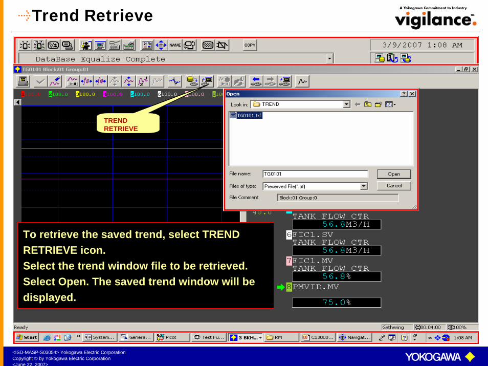
Trend Retrieve
TREND RETRIEVE
To retrieve the saved trend, select TRENDRETRIEVE icon.Select the trend window file to be retrieved. Select Open. The saved trend window will be displayed.
<ISD-MASP-S03054> Yokogawa Electric CorporationCopyright © by Yokogawa Electric Corporation<June 22, 2007>
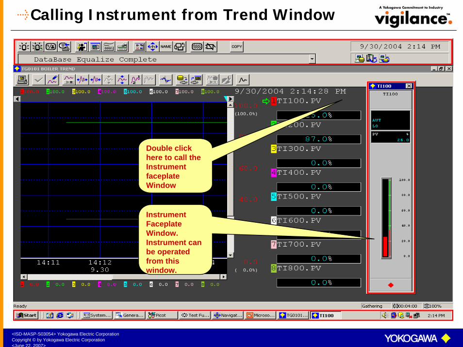
Calling Instrument from Trend Window
Double click here to call the Instrument faceplate Window
Instrument Faceplate Window. Instrument can be operated from this window.

<ISD-MASP-S03054> Yokogawa Electric CorporationCopyright © by Yokogawa Electric Corporation<June 22, 2007>
Process Alarm Window
PROCESS ALARM WINDOW displays the latest 200 process alarms.
Alarms can be acknowledged either as a Group or as Individual alarm.
When the number of alarms exceed 200, old alarms are overwritten by new alarms.
Select this icon to call the Process Alarm Window
<ISD-MASP-S03054> Yokogawa Electric CorporationCopyright © by Yokogawa Electric Corporation<June 22, 2007>
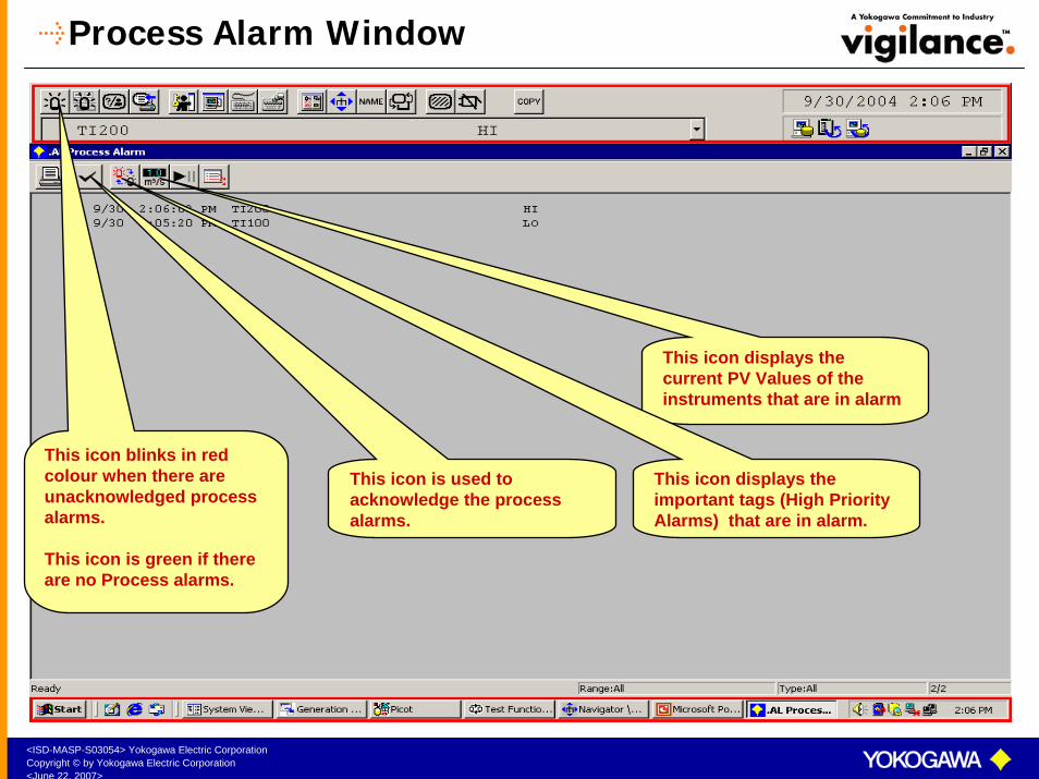
Process Alarm Window
This icon displays the current PV Values of the instruments that are in alarm
This icon displays the important tags (High Priority Alarms) that are in alarm.
This icon is used to acknowledge the process alarms.
This icon blinks in red colour when there are unacknowledged process alarms.
This icon is green if there are no Process alarms.

<ISD-MASP-S03054> Yokogawa Electric CorporationCopyright © by Yokogawa Electric Corporation<June 22, 2007>
Alarm Occurrence
When an alarm occurs
The tag mark changes colour depending on the alarm and starts flashing.
The Process alarm window icon starts flashing in the System Message Area.
Audible alarm is activated.
The LED on the Process Alarm Window Key on the Operator Keyboard starts flashing.
The alarm status is displayed on the instrument faceplate as well as on the Process AlarmWindow.
The alarm is printed on the printer connected to the HIS.
The alarm is also stored in the History.
Select this icon to call the Process Alarm Window
<ISD-MASP-S03054> Yokogawa Electric CorporationCopyright © by Yokogawa Electric Corporation<June 22, 2007>
Operator Action
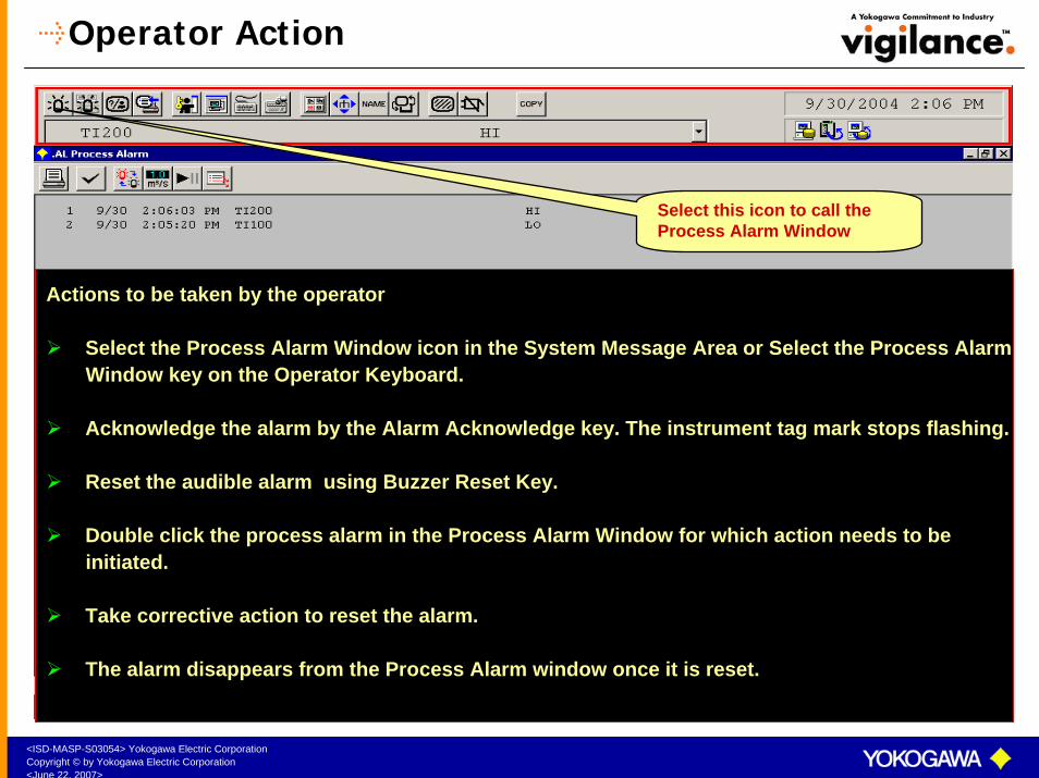
Actions to be taken by the operator
Select the Process Alarm Window icon in the System Message Area or Select the Process Alarm Window key on the Operator Keyboard.
Acknowledge the alarm by the Alarm Acknowledge key. The instrument tag mark stops flashing.
Reset the audible alarm using Buzzer Reset Key.
Double click the process alarm in the Process Alarm Window for which action needs to beinitiated.
Take corrective action to reset the alarm.
The alarm disappears from the Process Alarm window once it is reset.
Select this icon to call the Process Alarm Window
<ISD-MASP-S03054> Yokogawa Electric CorporationCopyright © by Yokogawa Electric Corporation<June 22, 2007>
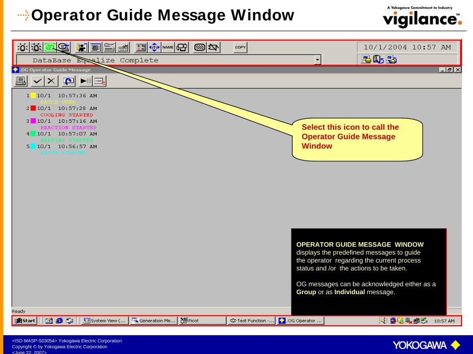
Operator Guide Message Window
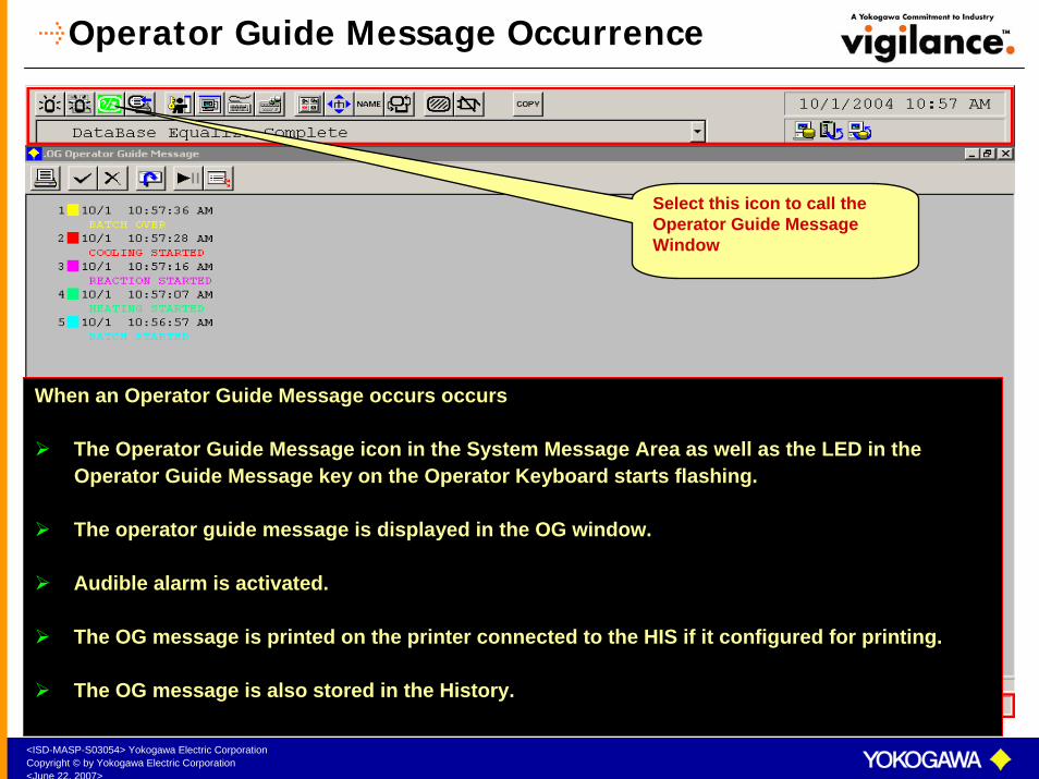
Select this icon to call the Operator Guide Message Window
OPERATOR GUIDE MESSAGE WINDOWdisplays the predefined messages to guide the operator regarding the current processstatus and /or the actions to be taken.
OG messages can be acknowledged either as a Group or as Individual message.
<ISD-MASP-S03054> Yokogawa Electric CorporationCopyright © by Yokogawa Electric Corporation<June 22, 2007>
Operator Guide Message Occurrence
When an Operator Guide Message occurs occurs
The Operator Guide Message icon in the System Message Area as well as the LED in the Operator Guide Message key on the Operator Keyboard starts flashing.
The operator guide message is displayed in the OG window.
Audible alarm is activated.
The OG message is printed on the printer connected to the HIS if it configured for printing.
The OG message is also stored in the History.
Select this icon to call the Operator Guide Message Window

<ISD-MASP-S03054> Yokogawa Electric CorporationCopyright © by Yokogawa Electric Corporation<June 22, 2007>
Operator Action
Actions to be taken by the operator
Select the OG Message icon in the System Message Area or Select the OG key on the OperatorKeyboard.
Acknowledge the message by the Alarm Acknowledge key. The head mark on the OG message stops flashing.
Reset the audible alarm using Buzzer Reset Key.
Double click the OG message on the OG Window for which action needs to be initiated. The related window will appear as per the setting done in the HIS Setup menu.
Take the necessary action.
Delete the OG message by the Delete key in the OG window. OG messages cannot be deleted if they are not acknowledged.
Select this icon to call the Operator Guide Message Window
<ISD-MASP-S03054> Yokogawa Electric CorporationCopyright © by Yokogawa Electric Corporation<June 22, 2007>
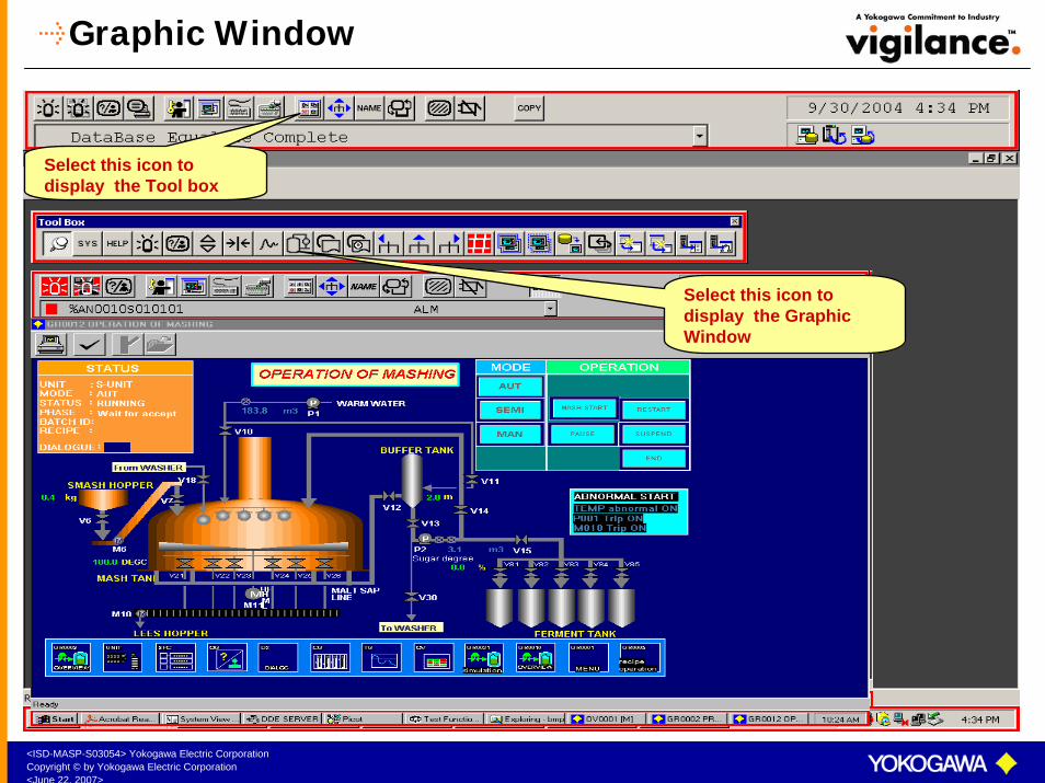
Graphic Window
Select this icon to display the Tool box
Select this icon to display the Graphic Window
<ISD-MASP-S03054> Yokogawa Electric CorporationCopyright © by Yokogawa Electric Corporation<June 22, 2007>
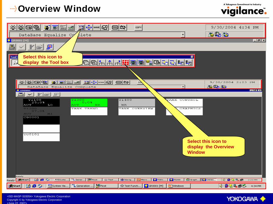
Overview Window
Select this icon to display the Tool box
Select this icon to display the Overview Window
<ISD-MASP-S03054> Yokogawa Electric CorporationCopyright © by Yokogawa Electric Corporation<June 22, 2007>
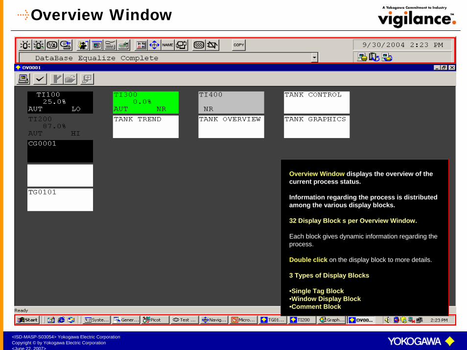
Overview Window
Overview Window displays the overview of the current process status.
Information regarding the process is distributed among the various display blocks.
32 Display Block s per Overview Window.
Each block gives dynamic information regarding the process.
Double click on the display block to more details.
3 Types of Display Blocks
•Single Tag Block•Window Display Block•Comment Block
<ISD-MASP-S03054> Yokogawa Electric CorporationCopyright © by Yokogawa Electric Corporation<June 22, 2007>
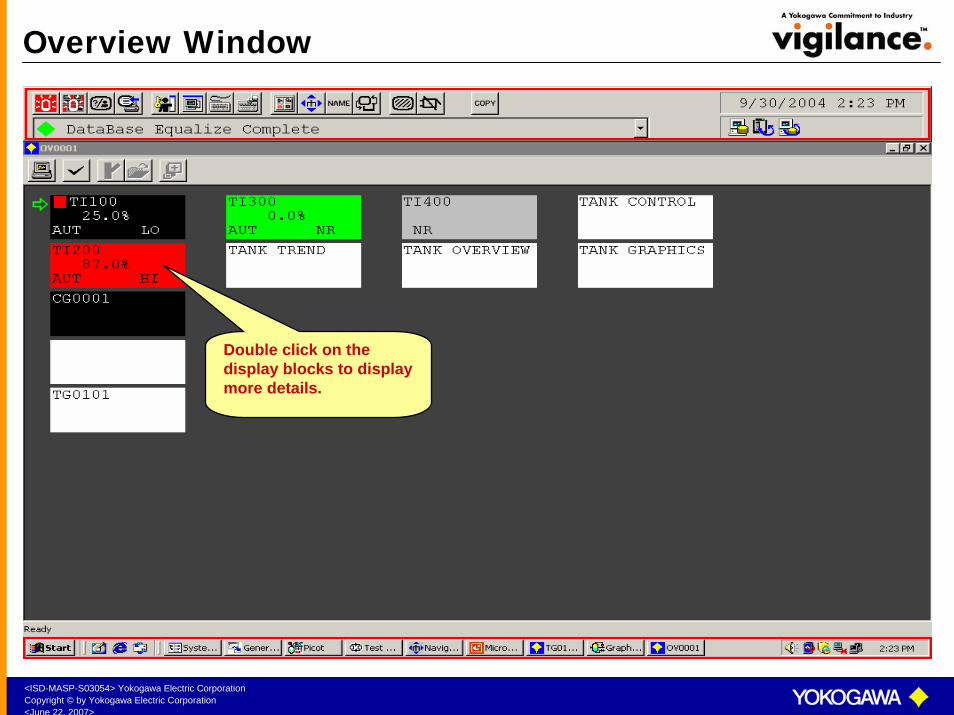
Overview Window
Double click on the display blocks to display more details.

<ISD-MASP-S03054> Yokogawa Electric CorporationCopyright © by Yokogawa Electric Corporation<June 22, 2007>
Process Report Window
Process Report displays the current status of all the instruments
<ISD-MASP-S03054> Yokogawa Electric CorporationCopyright © by Yokogawa Electric Corporation<June 22, 2007>
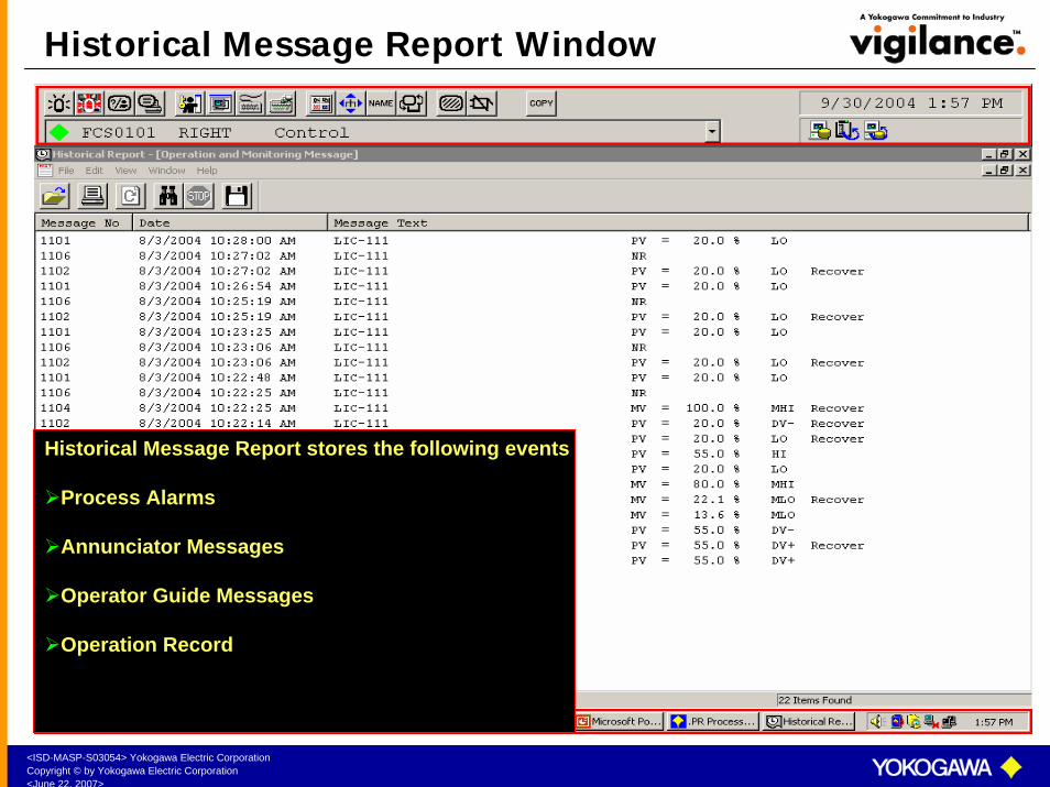
Historical Message Report Window
Historical Message Report stores the following events
Process Alarms
Annunciator Messages
Operator Guide Messages
Operation Record

<ISD-MASP-S03054> Yokogawa Electric CorporationCopyright © by Yokogawa Electric Corporation<June 22, 2007>
Navigator Window
Select this icon to display the Navigator Window
Navigator window displays the index of allthe System defined windows and user
defined windows along with their dynamic status. Any window can be called from the
Navigator Window.

<ISD-MASP-S03054> Yokogawa Electric CorporationCopyright © by Yokogawa Electric Corporation<June 22, 2007>
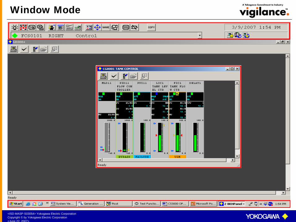
Screen Mode (Window or Full Screen)
The windows can be viewed in
Full screen mode or in
Window Mode
FULL SCREEN MODEWINDOW MODE
<ISD-MASP-S03054> Yokogawa Electric CorporationCopyright © by Yokogawa Electric Corporation<June 22, 2007>
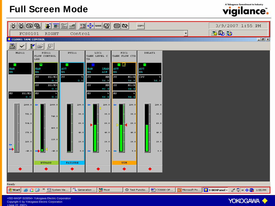
Full Screen Mode
<ISD-MASP-S03054> Yokogawa Electric CorporationCopyright © by Yokogawa Electric Corporation<June 22, 2007>
Window Mode

<ISD-MASP-S03054> Yokogawa Electric CorporationCopyright © by Yokogawa Electric Corporation<June 22, 2007>
Panel Set
Panel Set is automatic setting of predefined windows on the HIS.200 panel sets can be programmed for one HIS.
Each panel set can set up to 5 Windows.
Panel sets are created in HIS Engineering Builder.
Panel Sets can be activated byPreset Menu
Function Key on the Operator Keyboard
Touch Target or Push Button in Graphic Window
Sequence Table through Sequence Message Request

<ISD-MASP-S03054> Yokogawa Electric CorporationCopyright © by Yokogawa Electric Corporation<June 22, 2007>
Panel Set

<ISD-MASP-S03054> Yokogawa Electric CorporationCopyright © by Yokogawa Electric Corporation<June 22, 2007>
Calling Panel Set through Preset Menu
Select PANEL SET from the PRESET MENU Icon.
Select PRESET MENU
<ISD-MASP-S03054> Yokogawa Electric CorporationCopyright © by Yokogawa Electric Corporation<June 22, 2007>
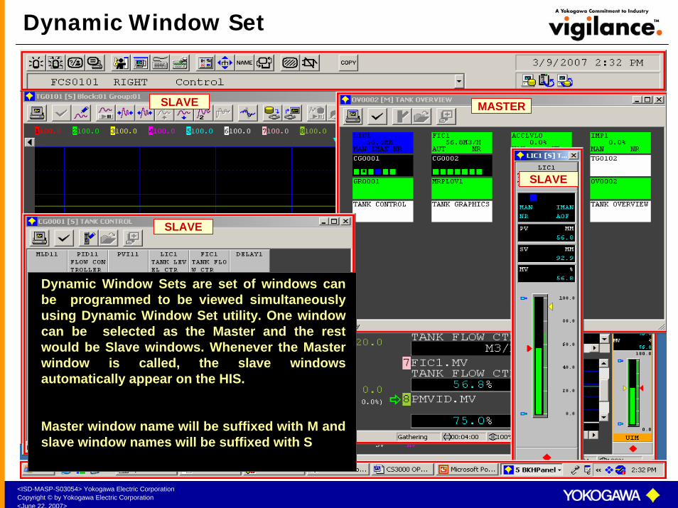
Dynamic Window Set
Dynamic Window Sets are set of windows can be programmed to be viewed simultaneously using Dynamic Window Set utility. One window can be selected as the Master and the rest would be Slave windows. Whenever the Master window is called, the slave windows automatically appear on the HIS.
Master window name will be suffixed with M and slave window names will be suffixed with S
MASTER
SLAVE
SLAVE
SLAVE

<ISD-MASP-S03054> Yokogawa Electric CorporationCopyright © by Yokogawa Electric Corporation<June 22, 2007>
Save / Delete Window Set
To save Dynamic Window SetCall the windows to be set on the HIS. Select the Master Window. Select the Dynamic Window Set Key.The windows will be saved as a dynamic window set.
To delete Dynamic Window SetCall the windows to be set on the HIS. Select the Master Window. Select the Dynamic Window delete Key.
SAVE DYNAMIC WINDOW SET
DELETE DYNAMIC WINDOW SET

<ISD-MASP-S03054> Yokogawa Electric CorporationCopyright © by Yokogawa Electric Corporation<June 22, 2007>
Digital Inputs (DI)
System Code : %ZnnusccSddss
%Z - Process Input/Output S - Station
nn - node number dd - Domain number
u - I/O unit number ss - Station number
s - Slot number
cc - Channel number
Digital Inputs are contact inputs from field to CS3000.
Digital Inputs are used to indicate the
i) ON / OFF status of pumps, motors, heaters, etc.
ii) OPEN / CLOSE status of on-off valves.
<ISD-MASP-S03054> Yokogawa Electric CorporationCopyright © by Yokogawa Electric Corporation<June 22, 2007>
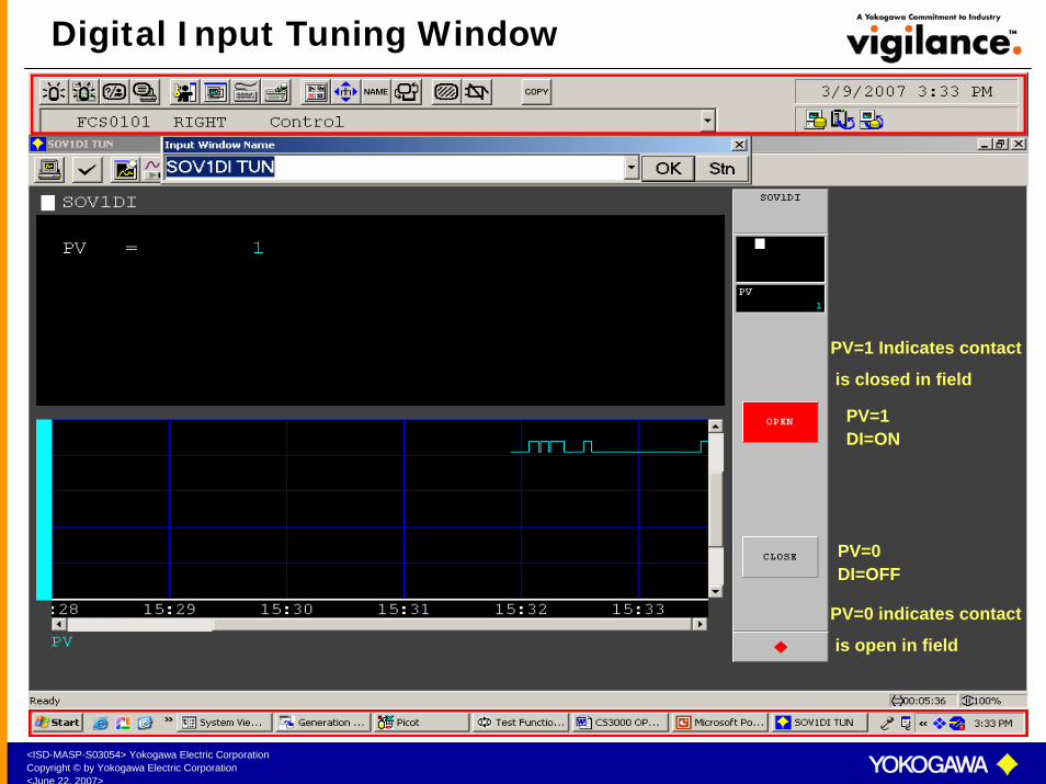
Digital Input Tuning Window
PV=1DI=ON
PV=0DI=OFF
PV=1 Indicates contact
is closed in field
PV=0 indicates contact
is open in field

<ISD-MASP-S03054> Yokogawa Electric CorporationCopyright © by Yokogawa Electric Corporation<June 22, 2007>
Digital Outputs (DO)
System Code : %ZnnusccSddss
%Z - Process Input/Output S - Station
nn - node number dd - Domain number
u - I/O unit number ss - Station number
s - Slot number
cc - Channel number
Digital Outputs are contact outputs from CS3000 to field.Digital Outputs are used to i) Switch ON / OFF pumps, motors, heaters etcii) OPEN / CLOSE on-off Valves.
<ISD-MASP-S03054> Yokogawa Electric CorporationCopyright © by Yokogawa Electric Corporation<June 22, 2007>
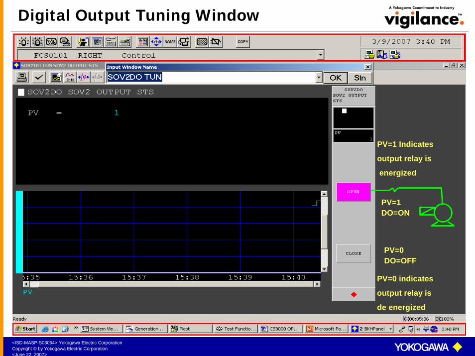
Digital Output Tuning Window
PV=1DO=ON
PV=0DO=OFF
PV=1 Indicates
output relay is
energized
PV=0 indicates
output relay is
de energized
<ISD-MASP-S03054> Yokogawa Electric CorporationCopyright © by Yokogawa Electric Corporation<June 22, 2007>
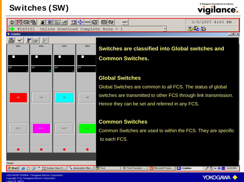
Switches (SW)
Switches are classified into Global switches and
Common Switches.
Global SwitchesGlobal Switches are common to all FCS. The status of global
switches are transmitted to other FCS through link transmission.
Hence they can be set and referred in any FCS.
Common SwitchesCommon Switches are used to within the FCS. They are specific
to each FCS.
<ISD-MASP-S03054> Yokogawa Electric CorporationCopyright © by Yokogawa Electric Corporation<June 22, 2007>
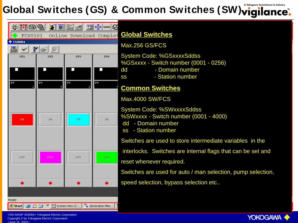
Global Switches (GS) & Common Switches (SW)
Global SwitchesMax.256 GS/FCS
System Code: %GSxxxxSddss%GSxxxx - Switch number (0001 - 0256)dd - Domain numberss - Station number
Common SwitchesMax.4000 SW/FCS
System Code: %SWxxxxSddss%SWxxxx - Switch number (0001 - 4000)dd - Domain numberss - Station number
Switches are used to store intermediate variables in the
interlocks. Switches are internal flags that can be set and
reset whenever required.
Switches are used for auto / man selection, pump selection,
speed selection, bypass selection etc..

<ISD-MASP-S03054> Yokogawa Electric CorporationCopyright © by Yokogawa Electric Corporation<June 22, 2007>
Switches Tuning Window
PV=1SW=ON
PV=0SW=OFF

<ISD-MASP-S03054> Yokogawa Electric CorporationCopyright © by Yokogawa Electric Corporation<June 22, 2007>
Timer (TM)
Timers are used to introduce time delays in Sequence Table.
Second timer
Timer Types
Minute timer
PH = Maximum time the timer should count
PV = Actual time the timer has counted
DV = PH-PV i.e.the time left to finish counting
DL = Deviation limit

<ISD-MASP-S03054> Yokogawa Electric CorporationCopyright © by Yokogawa Electric Corporation<June 22, 2007>
Timer Tuning Window
Timer Operation1. When the timer is started, PV starts incrementing automatically • Alarm status is NR2. When the timer has finished timing, i.e. when PV = PH
Block status is CTUP3. When the timer is stopped while timing Block status is STOP4. When the timer is paused while timing Block Status is PAUS5. When the DV < DL Block status is PALMAny of the alarm status can be referred in sequence table as a condition signal.
START STOPPAUSE
RESUME

<ISD-MASP-S03054> Yokogawa Electric CorporationCopyright © by Yokogawa Electric Corporation<June 22, 2007>
Counter (CTS/CTP)
Counter is used to count internal events or external
pulses. Counter PV updates by one every time the
counter is started
CTS – Internal Counter
Counter types
CTP - Pulse counter
Counter operation is same as timer except that
pause option is not available.
<ISD-MASP-S03054> Yokogawa Electric CorporationCopyright © by Yokogawa Electric Corporation<June 22, 2007>
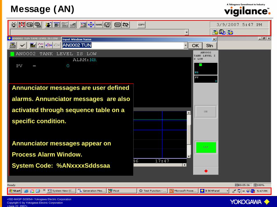
Message (AN)
Annunciator messages are user defined
alarms. Annunciator messages are also
activated through sequence table on a
specific condition.
Annunciator messages appear on
Process Alarm Window.
System Code: %ANxxxxSddssaa

<ISD-MASP-S03054> Yokogawa Electric CorporationCopyright © by Yokogawa Electric Corporation<June 22, 2007>
Annunciator Tuning Window
When an annunciator is activated, the annunciator messages appear on the System Message Area as well as on the Process Alarm Window. Once acknowledged it disappears from the System Message Area.
When the annunciator resets, the annunciator messages disappear from Process Alarm Window.
ANNUNCIATOR MESSAGE
ANNUNCIATOR MESSAGE

<ISD-MASP-S03054> Yokogawa Electric CorporationCopyright © by Yokogawa Electric Corporation<June 22, 2007>
Sequence Instruments (SIO)
Sequence instruments (or) status input
output instruments are used to
i) Switch ON/OFF motors, pumps, heater etc..
ii) OPEN / CLOSE on-off valves
iii) Indicate the ON/OFF status of motors, pumps,
heaters etc.
iv) Indicate the OPEN/CLOSE status of on-off valves.
<ISD-MASP-S03054> Yokogawa Electric CorporationCopyright © by Yokogawa Electric Corporation<June 22, 2007>
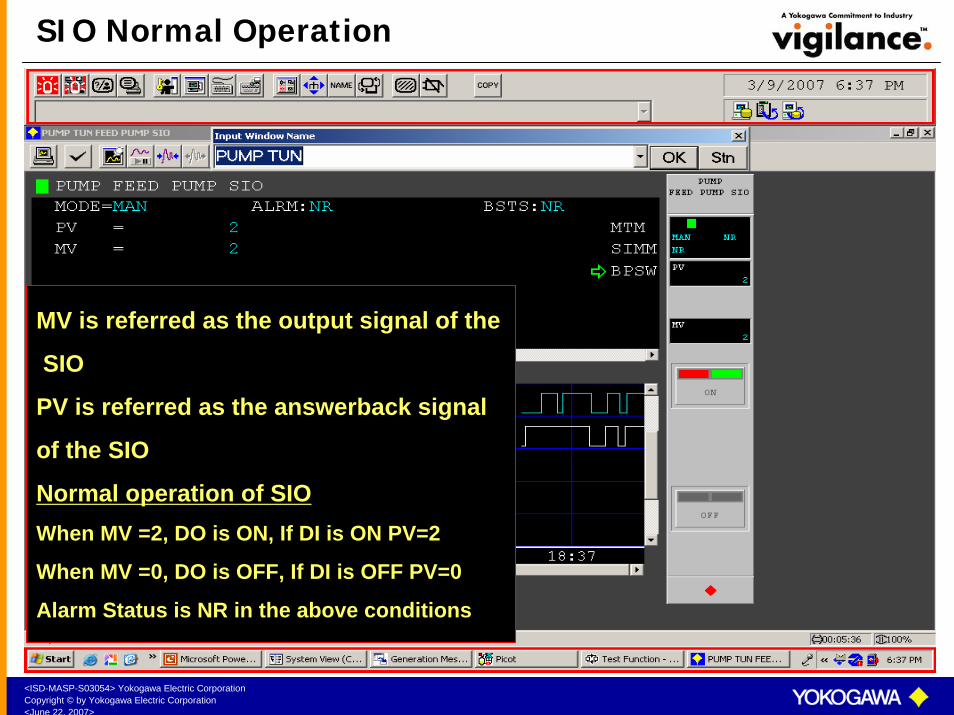
SIO Normal Operation
MV is referred as the output signal of the
SIO
PV is referred as the answerback signal
of the SIO
Normal operation of SIOWhen MV =2, DO is ON, If DI is ON PV=2
When MV =0, DO is OFF, If DI is OFF PV=0
Alarm Status is NR in the above conditions

<ISD-MASP-S03054> Yokogawa Electric CorporationCopyright © by Yokogawa Electric Corporation<June 22, 2007>
SIO Abnormal Operation – ANS+ Alarm
Abnormal operation of SIOWhen MV =2, DO is ON, If DI is OFF then PV=0
Alarm Status is ANS+ in the above conditions
<ISD-MASP-S03054> Yokogawa Electric CorporationCopyright © by Yokogawa Electric Corporation<June 22, 2007>
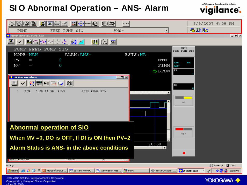
SIO Abnormal Operation – ANS- Alarm
Abnormal operation of SIOWhen MV =0, DO is OFF, If DI is ON then PV=2
Alarm Status is ANS- in the above conditions
<ISD-MASP-S03054> Yokogawa Electric CorporationCopyright © by Yokogawa Electric Corporation<June 22, 2007>
Interlocks
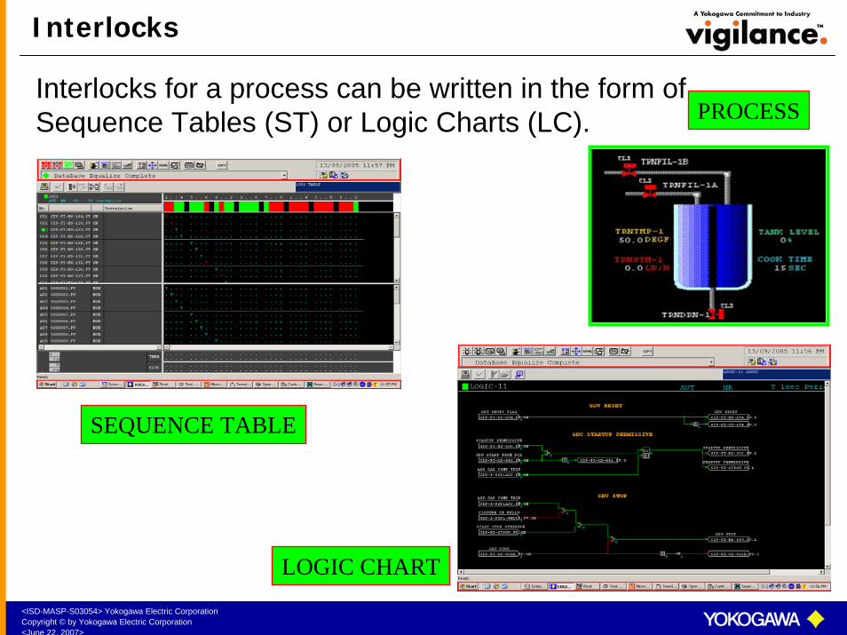
Interlocks for a process can be written in the form of Sequence Tables (ST) or Logic Charts (LC).
SEQUENCE TABLE
LOGIC CHART
PROCESS

<ISD-MASP-S03054> Yokogawa Electric CorporationCopyright © by Yokogawa Electric Corporation<June 22, 2007>
Sequence Tables
CONDITIONS
ACTIONS
RULESCOLOUR BAND

<ISD-MASP-S03054> Yokogawa Electric CorporationCopyright © by Yokogawa Electric Corporation<June 22, 2007>
Calling Sequence Table from Tuning Window
Select this icon to display the Sequence Table
<ISD-MASP-S03054> Yokogawa Electric CorporationCopyright © by Yokogawa Electric Corporation<June 22, 2007>
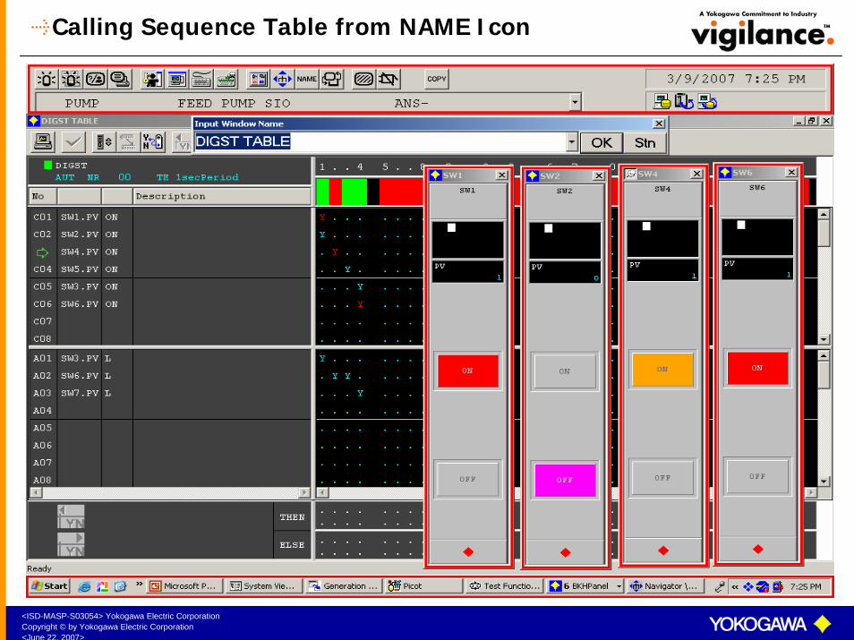
Calling Sequence Table from NAME Icon

<ISD-MASP-S03054> Yokogawa Electric CorporationCopyright © by Yokogawa Electric Corporation<June 22, 2007>
Logic Charts
<ISD-MASP-S03054> Yokogawa Electric CorporationCopyright © by Yokogawa Electric Corporation<June 22, 2007>
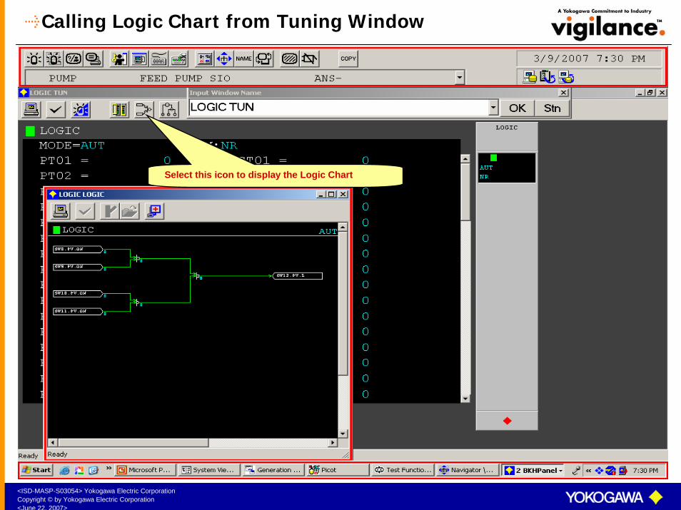
Calling Logic Chart from Tuning Window
Select this icon to display the Logic Chart

<ISD-MASP-S03054> Yokogawa Electric CorporationCopyright © by Yokogawa Electric Corporation<June 22, 2007>
Calling Logic Chart from NAME Icon

<ISD-MASP-S03054> Yokogawa Electric CorporationCopyright © by Yokogawa Electric Corporation<June 22, 2007>
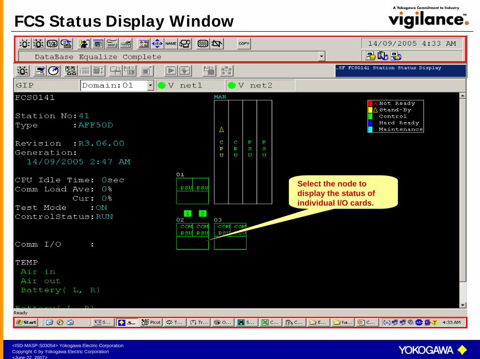
System Status Window
Select the individual FCS icon to display the FCS card Status Window.
Select this icon to Display the System Alarm Message Window.
Select this icon to Display the System Status Overview Window.
<ISD-MASP-S03054> Yokogawa Electric CorporationCopyright © by Yokogawa Electric Corporation<June 22, 2007>
FCS Status Display Window
Select the node to display the status of individual I/O cards.

<ISD-MASP-S03054> Yokogawa Electric CorporationCopyright © by Yokogawa Electric Corporation<June 22, 2007>
Time Setting Window
Select this icon to display the Time Setting Window.

<ISD-MASP-S03054> Yokogawa Electric CorporationCopyright © by Yokogawa Electric Corporation<June 22, 2007>
System Alarm Window
SYSTEM ALARM WINDOW displays the latest 100 system alarms.
Alarms can be acknowledged either as a Group or as Individual alarm.
Select this icon to display the System Alarm Window
<ISD-MASP-S03054> Yokogawa Electric CorporationCopyright © by Yokogawa Electric Corporation<June 22, 2007>
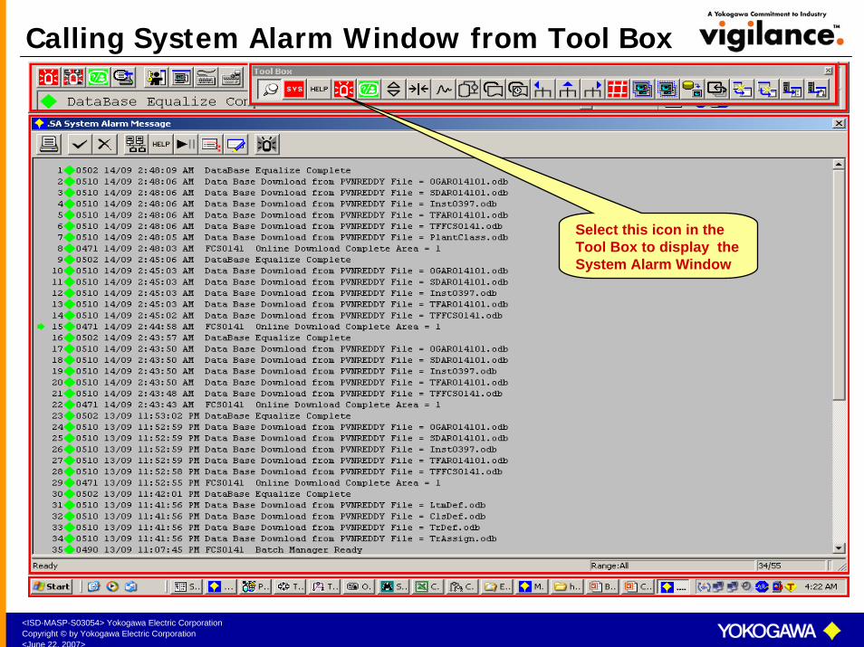
Calling System Alarm Window from Tool Box
Select this icon in the Tool Box to display the System Alarm Window
<ISD-MASP-S03054> Yokogawa Electric CorporationCopyright © by Yokogawa Electric Corporation<June 22, 2007>
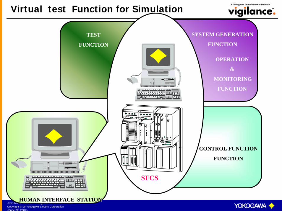
SYSTEM GENERATION
FUNCTION
OPERATION
&
MONITORING
FUNCTION
CONTROL FUNCTION
FUNCTION
TEST
FUNCTION
HUMAN INTERFACE STATIONHUMAN INTERFACE STATION
Virtual test Function for Simulation
SFCS
<ISD-MASP-S03054> Yokogawa Electric CorporationCopyright © by Yokogawa Electric Corporation<June 22, 2007>
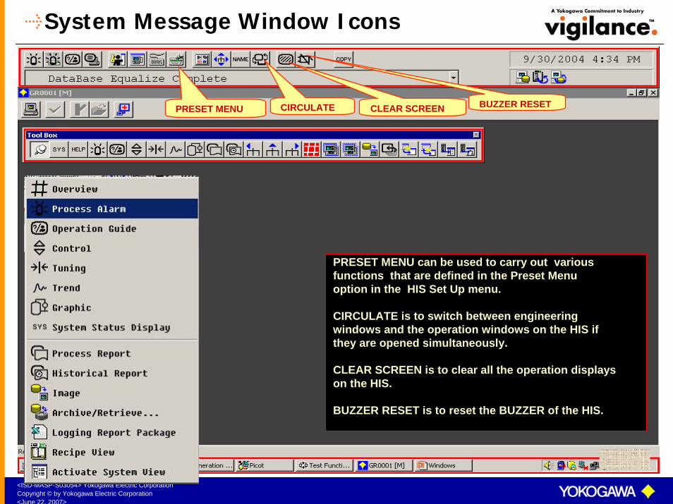
System Message Window Icons
CIRCULATEPRESET MENU
PRESET MENU can be used to carry out various functions that are defined in the Preset Menuoption in the HIS Set Up menu.
CIRCULATE is to switch between engineering windows and the operation windows on the HIS ifthey are opened simultaneously.
CLEAR SCREEN is to clear all the operation displays on the HIS.
BUZZER RESET is to reset the BUZZER of the HIS.
CLEAR SCREEN BUZZER RESET

<ISD-MASP-S03054> Yokogawa Electric CorporationCopyright © by Yokogawa Electric Corporation<June 22, 2007>
Message Monitor Window
Select this icon to display the MESSAGE MONITOR window
MESSAGE MONITOR WINDOW displays the latest 100 messages as configured
in the Message Registration Window. Messages canalso be filtered using the filter option.
Specific colours can be chosen for eachtype of message.
<ISD-MASP-S03054> Yokogawa Electric CorporationCopyright © by Yokogawa Electric Corporation<June 22, 2007>
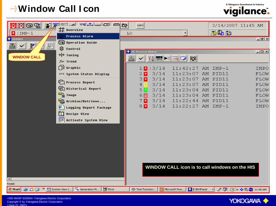
Window Call Icon
WINDOW CALL
WINDOW CALL icon is to call windows on the HIS

<ISD-MASP-S03054> Yokogawa Electric CorporationCopyright © by Yokogawa Electric Corporation<June 22, 2007>
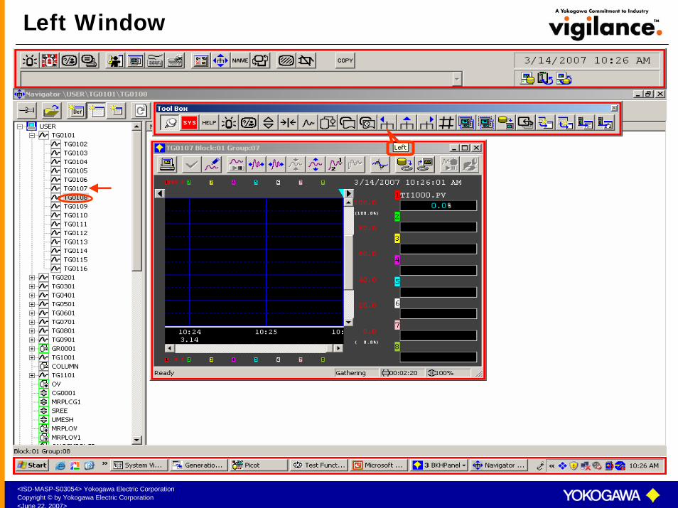
Operation Menu Icon
OPERATION MENU
OPERATION MENU KEY is to call Left window, Right Window, Upper Window, Recall windows backwards and Recall windows forward
NAME input window can also be called fromthis window.

<ISD-MASP-S03054> Yokogawa Electric CorporationCopyright © by Yokogawa Electric Corporation<June 22, 2007>
Tool Box Icons
ROTATEHELP WINDOWPINNING A WINDOW
PINNING A WINDOW icon is to pin the windows on the HIS. When a window is pinned, the window will be displayedon the HIS even if multiple windows are called. The window can be closed only by selecting the window close button.
HELP window displays system defined help messages as well as user defined help messages. User defined help messages are created in the engineering builder and they can be linked to individual windows. When a help messageis linked to a window, the help message shall be displayed when you call the window and select the HELP key.
ROTATE will rotate the windows if multiple windows are viewed simultaneously.
TOOL BOX
<ISD-MASP-S03054> Yokogawa Electric CorporationCopyright © by Yokogawa Electric Corporation<June 22, 2007>
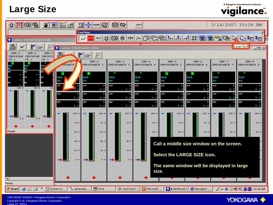
Large Size
Call a middle size window on the screen.
Select the LARGE SIZE icon.
The same window will be displayed in large size.
<ISD-MASP-S03054> Yokogawa Electric CorporationCopyright © by Yokogawa Electric Corporation<June 22, 2007>
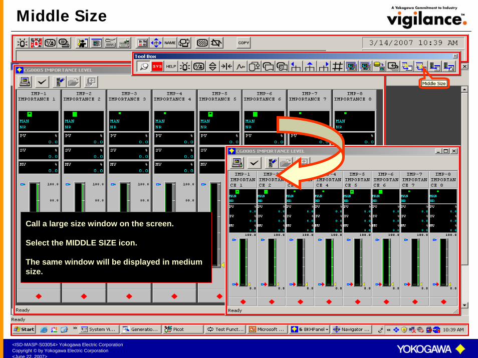
Middle Size
Call a large size window on the screen.
Select the MIDDLE SIZE icon.
The same window will be displayed in medium size.
<ISD-MASP-S03054> Yokogawa Electric CorporationCopyright © by Yokogawa Electric Corporation<June 22, 2007>
Left Window

<ISD-MASP-S03054> Yokogawa Electric CorporationCopyright © by Yokogawa Electric Corporation<June 22, 2007>
Right Window
<ISD-MASP-S03054> Yokogawa Electric CorporationCopyright © by Yokogawa Electric Corporation<June 22, 2007>
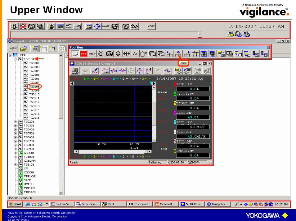
Upper Window
<ISD-MASP-S03054> Yokogawa Electric CorporationCopyright © by Yokogawa Electric Corporation<June 22, 2007>
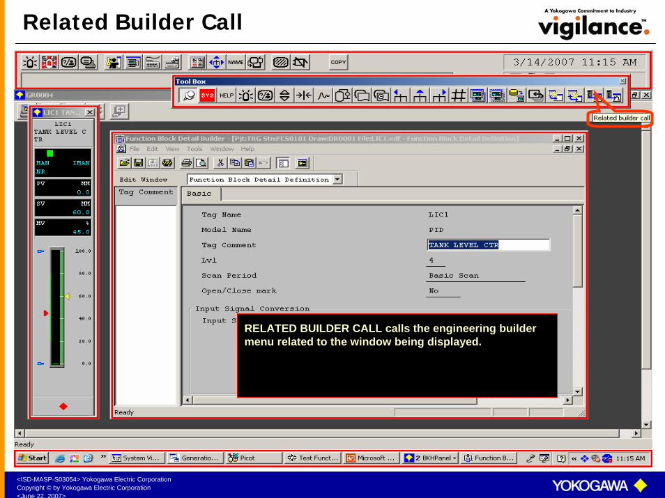
Related Builder Call
RELATED BUILDER CALL calls the engineering builder menu related to the window being displayed.
<ISD-MASP-S03054> Yokogawa Electric CorporationCopyright © by Yokogawa Electric Corporation<June 22, 2007>
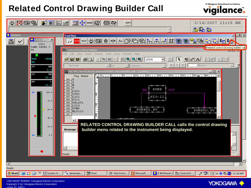
Related Control Drawing Builder Call
RELATED CONTROL DRAWING BUILDER CALL calls the control drawing builder menu related to the instrument being displayed.
<ISD-MASP-S03054> Yokogawa Electric CorporationCopyright © by Yokogawa Electric Corporation<June 22, 2007>
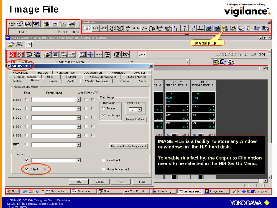
Image File
IMAGE FILE
IMAGE FILE is a facility to store any windowor windows in the HIS hard disk.
To enable this facility, the Output to File option needs to be selected in the HIS Set Up Menu.

<ISD-MASP-S03054> Yokogawa Electric CorporationCopyright © by Yokogawa Electric Corporation<June 22, 2007>
Storing the Image
COPY
To store an image, call the windows to be stored.
Select COPY icon. The image will be stored inthe hard disk.
<ISD-MASP-S03054> Yokogawa Electric CorporationCopyright © by Yokogawa Electric Corporation<June 22, 2007>
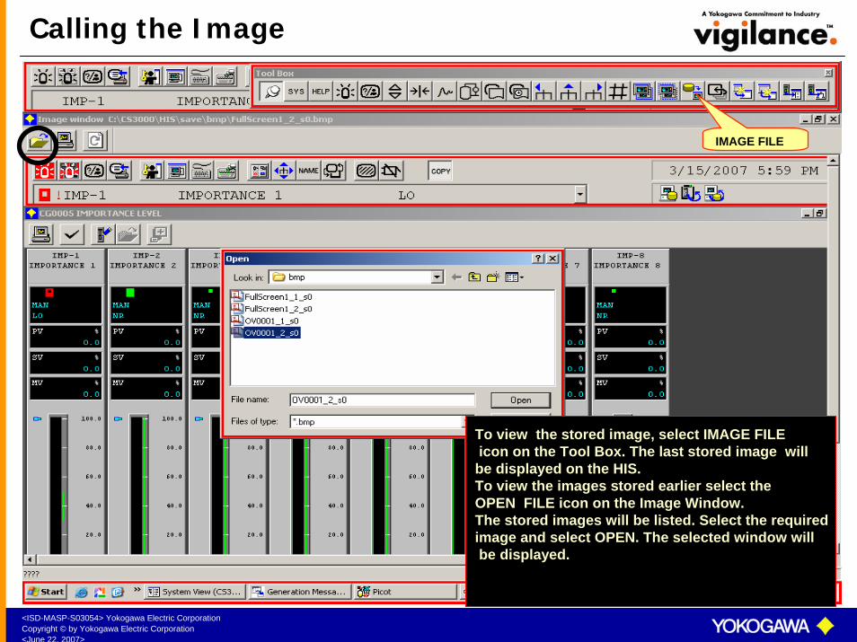
Calling the Image
To view the stored image, select IMAGE FILEicon on the Tool Box. The last stored image will
be displayed on the HIS. To view the images stored earlier select the OPEN FILE icon on the Image Window. The stored images will be listed. Select the required image and select OPEN. The selected window willbe displayed.
IMAGE FILE

<ISD-MASP-S03054> Yokogawa Electric CorporationCopyright © by Yokogawa Electric Corporation<June 22, 2007>
Training – A Helping Hand
Related Documents