CS2302-Computer Networks 1.1 Vijai Anand cseannauniv.blogspot.com Define computer network. Computer network is a connect ion of autonomous computers and network devices for: Resource sharing (data/devices) in an efficient manner Communication amongst them. Compare simplex and duplex communication with example. In simplex mode, the c ommunication is unidirectional (Eg: keyboard, monitor). In half -duplex mode, each station can both tran smi t and receive, but not simul taneously (Eg. walkie-talkie). In full-duplex (also called duplex), both stations can transmit and receive simultaneously (Eg. telephone network). List the criteria based on which a network can be assessed. Performance is based on its throughput (no. of packets de li vered) and delay. Reliability is how much the networ k is faul t tolerant. Security includes preventing unauthorized access and reco very from breaches. What are the two types of line configuration? A point-to-point connection provides a dedicated link between two nodes. In a multipoint connection, more than two nodes share a single link, i.e., bandwidth is shared amongst the nodes. State any two topologies in which a network can be organized . Mesh Star Bus Ring Mesh: Each device has a dedicated point-to-point link to every other device. It is robust and secure. Installation is difficult and expensive n(n-1) link for n no de. Star : Each device has a dedicated point-to-point link only to a central controller called a hub. All communication goes via the hub. It is less expensive and robust. A failure in the hub makes the network non-functional . Eg; LAN Bus: It is multi-point and signal gets weak as it travels through the long cable that acts as backbone. A fault in the bus stops the entire transmi ssion

Welcome message from author
This document is posted to help you gain knowledge. Please leave a comment to let me know what you think about it! Share it to your friends and learn new things together.
Transcript
8/11/2019 CS2302U1
http://slidepdf.com/reader/full/cs2302u1 1/22
CS2302-Computer Networks 1.1
Vijai Anand cseannauniv.blogspot.com
Define computer network.Computer network is a connection of autonomous computers and network devices for:
Resource sharing (data/devices) in an efficient manner Communication amongst them.
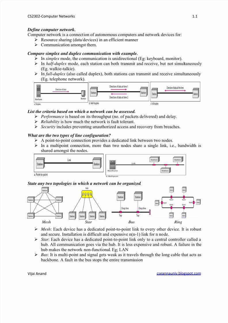
Compare simplex and duplex communication with example.
In simplex mode, the communication is unidirectional (Eg: keyboard, monitor). In half -duplex mode, each station can both transmit and receive, but not simultaneously
(Eg. walkie-talkie). In full-duplex (also called duplex), both stations can transmit and receive simultaneously
(Eg. telephone network).
List the criteria based on which a network can be assessed. Performance is based on its throughput (no. of packets delivered) and delay.
Reliability is how much the network is fault tolerant. Security includes preventing unauthorized access and recovery from breaches.
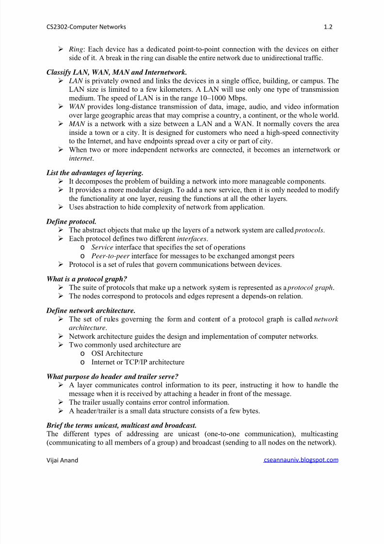
What are the two types of line configuration? A point-to-point connection provides a dedicated link between two nodes.
In a multipoint connection, more than two nodes share a single link, i.e., bandwidth isshared amongst the nodes.
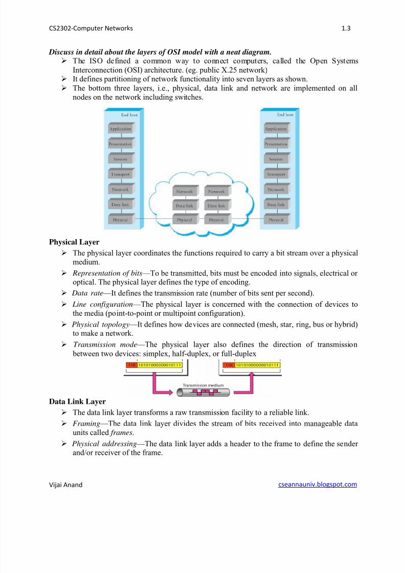
State any two topologies in which a network can be organized .
Mesh Star Bus Ring
Mesh: Each device has a dedicated point-to-point link to every other device. It is robustand secure. Installation is difficult and expensive n(n-1) link for n node.
Star : Each device has a dedicated point-to-point link only to a central controller called ahub. All communication goes via the hub. It is less expensive and robust. A failure in the
hub makes the network non-functional. Eg; LAN Bus: It is multi-point and signal gets weak as it travels through the long cable that acts as
backbone. A fault in the bus stops the entire transmission
8/11/2019 CS2302U1
http://slidepdf.com/reader/full/cs2302u1 2/22
CS2302-Computer Networks 1.2
Vijai Anand cseannauniv.blogspot.com
Ring: Each device has a dedicated point-to-point connection with the devices on either side of it. A break in the ring can disable the entire network due to unidirectional traffic.
Classify LAN, WAN, MAN and Internetwork. LAN is privately owned and links the devices in a single office, building, or campus. The
LAN size is limited to a few kilometers. A LAN will use only one type of transmission
medium. The speed of LAN is in the range 10–1000 Mbps. WAN provides long-distance transmission of data, image, audio, and video information
over large geographic areas that may comprise a country, a continent, or the whole world. MAN is a network with a size between a LAN and a WAN. It normally covers the area
inside a town or a city. It is designed for customers who need a high-speed connectivityto the Internet, and have endpoints spread over a city or part of city.
When two or more independent networks are connected, it becomes an internetwork or internet .
List the advantages of layering. It decomposes the problem of building a network into more manageable components.
It provides a more modular design. To add a new service, then it is only needed to modifythe functionality at one layer, reusing the functions at all the other layers.
Uses abstraction to hide complexity of network from application.
Define protocol. The abstract objects that make up the layers of a network system are called protocols.
Each protocol defines two different interfaces.o Service interface that specifies the set of operations
o Peer-to-peer interface for messages to be exchanged amongst peers Protocol is a set of rules that govern communications between devices.
What is a protocol graph?
The suite of protocols that make up a network system is represented as a protocol graph. The nodes correspond to protocols and edges represent a depends-on relation.
Define network architecture. The set of rules governing the form and content of a protocol graph is called network
architecture.
Network architecture guides the design and implementation of computer networks. Two commonly used architecture are
o OSI Architecture
o Internet or TCP/IP architecture
What purpose do header and trailer serve? A layer communicates control information to its peer, instructing it how to handle the
message when it is received by attaching a header in front of the message. The trailer usually contains error control information.
A header/trailer is a small data structure consists of a few bytes.
Brief the terms unicast, multicast and broadcast.The different types of addressing are unicast (one-to-one communication), multicasting
(communicating to all members of a group) and broadcast (sending to all nodes on the network).
8/11/2019 CS2302U1
http://slidepdf.com/reader/full/cs2302u1 3/22
CS2302-Computer Networks 1.3
Vijai Anand cseannauniv.blogspot.com
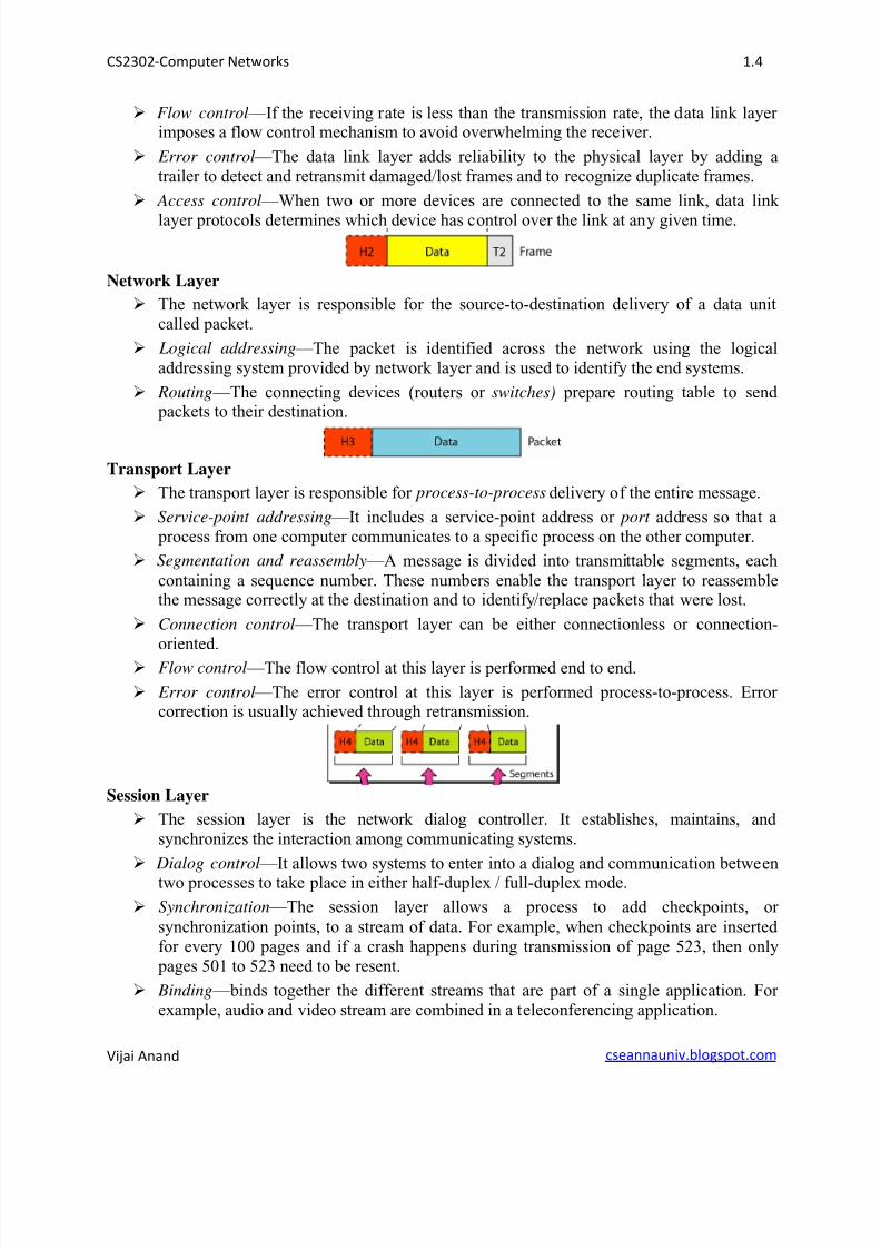
Discuss in detail about the layers of OSI model with a neat diagram. The ISO defined a common way to connect computers, called the Open Systems
Interconnection (OSI) architecture. (eg. public X.25 network) It defines partitioning of network functionality into seven layers as shown.
The bottom three layers, i.e., physical, data link and network are implemented on all
nodes on the network including switches.
Physical Layer
The physical layer coordinates the functions required to carry a bit stream over a physicalmedium.
Representation of bits —To be transmitted, bits must be encoded into signals, electrical or optical. The physical layer defines the type of encoding.
Data rate —It defines the transmission rate (number of bits sent per second).
Line configuration —The physical layer is concerned with the connection of devices tothe media (point-to-point or multipoint configuration).
Physical topology —It defines how devices are connected (mesh, star, ring, bus or hybrid)to make a network.
Transmission mode —The physical layer also defines the direction of transmission
between two devices: simplex, half-duplex, or full-duplex
Data Link Layer The data link layer transforms a raw transmission facility to a reliable link.
Framing —The data link layer divides the stream of bits received into manageable dataunits called frames.
Physical addressing —The data link layer adds a header to the frame to define the sender and/or receiver of the frame.
8/11/2019 CS2302U1
http://slidepdf.com/reader/full/cs2302u1 4/22
CS2302-Computer Networks 1.4
Vijai Anand cseannauniv.blogspot.com
Flow control —If the receiving rate is less than the transmission rate, the data link layer imposes a flow control mechanism to avoid overwhelming the receiver.
Error control —The data link layer adds reliability to the physical layer by adding atrailer to detect and retransmit damaged/lost frames and to recognize duplicate frames.
Access control —When two or more devices are connected to the same link, data link
layer protocols determines which device has control over the link at any given time.
Network Layer
The network layer is responsible for the source-to-destination delivery of a data unitcalled packet.
Logical addressing —The packet is identified across the network using the logicaladdressing system provided by network layer and is used to identify the end systems.
Routing —The connecting devices (routers or switches) prepare routing table to send packets to their destination.
Transport Layer
The transport layer is responsible for process-to-process delivery of the entire message.
Service-point addressing —It includes a service-point address or port address so that a process from one computer communicates to a specific process on the other computer.
Segmentation and reassembly —A message is divided into transmittable segments, each
containing a sequence number. These numbers enable the transport layer to reassemblethe message correctly at the destination and to identify/replace packets that were lost.
Connection control —The transport layer can be either connectionless or connection-oriented.
Flow control —The flow control at this layer is performed end to end.
Error control —The error control at this layer is performed process-to-process. Error correction is usually achieved through retransmission.
Session Layer
The session layer is the network dialog controller. It establishes, maintains, and synchronizes the interaction among communicating systems.
Dialog control —It allows two systems to enter into a dialog and communication betweentwo processes to take place in either half-duplex / full-duplex mode.
Synchronization —The session layer allows a process to add checkpoints, or
synchronization points, to a stream of data. For example, when checkpoints are inserted for every 100 pages and if a crash happens during transmission of page 523, then only pages 501 to 523 need to be resent.
Binding —binds together the different streams that are part of a single application. For example, audio and video stream are combined in a teleconferencing application.
8/11/2019 CS2302U1
http://slidepdf.com/reader/full/cs2302u1 5/22
CS2302-Computer Networks 1.5
Vijai Anand cseannauniv.blogspot.com
Presentation Layer
The presentation layer is concerned with the syntax and semantics of the information
exchanged between peers.
Translation —Because different computers use different encoding systems, the presentation layer is responsible for interoperability between these encoding methods.
Encryption —To carry sensitive information, a system ensures privacy by encrypting themessage before sending and decrypting at the receiver end.
Compression —Data compression reduces the number of bits contained in theinformation. It is particularly important in multimedia transmission.
Application Layer
The application layer enables the user, whether human or software, to access the network.
It provides user interface and support for services such as electronic mail, remote file
access and transfer, shared database management and several types of distributed information services.
Network virtual terminal —A network virtual terminal is a software version of a physicalterminal, and it allows a user to log on to a remote host.
File transfer, access, and management —This application allows a user to access/retrievefiles in a remote host, and to manage or control files in a remote computer locally.
Mail services —This application provides the basis for e-mail forwarding and storage.
Directory services —This application provides distributed database sources and access for
global information about various objects and services.
Define encapsulation.
As data passes through a layer, it attaches its header and then passes it to the next layer.
For the next layer, the data and header of the previous layer is encapsulated as a unit.
It then attaches its header and passes to the next layer and so on.
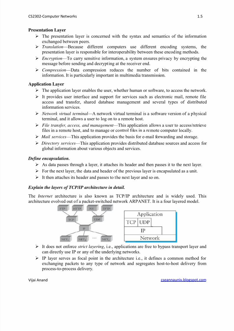
Explain the layers of TCP/IP architecture in detail.
The Internet architecture is also known as TCP/IP architecture and is widely used. This
architecture evolved out of a packet-switched network ARPANET. It is a four layered model.
It does not enforce strict layering, i.e., applications are free to bypass transport layer and
can directly use IP or any of the underlying networks.
IP layer serves as focal point in the architecture i.e., it defines a common method for
exchanging packets to any type of network and segregates host-to-host delivery from process-to-process delivery.
8/11/2019 CS2302U1
http://slidepdf.com/reader/full/cs2302u1 6/22
CS2302-Computer Networks 1.6
Vijai Anand cseannauniv.blogspot.com
For any protocol to be added to the architecture, it must also be accompanied by at leastone working implementation of the specification. Thus efficiency is ensured.
TCP/IP does not define any specific protocol for the lowest level (physical/data link
layers of OSI).o All standard and proprietary protocols such as Ethernet, FDDI, etc are supported.
o The protocols are generally implemented by a combination of hardware/software. Network layer consists of a major protocol, the Internetworking Protocol (IP).
o It supports the interconnection of multiple networking technologies into a logical
internetwork.o It is an unreliable and connectionless protocol.
o IP sends data in packets called datagrams, each of which is transported separatelyand independently.
o The other protocols supported in this layer are ARP, RARP, ICMP and IGMP.
Transport layer is responsible for delivery of a message from one process to another
process. The two protocols supported in this layer are:
o Transmission Control Protocol (TCP) for connection-oriented reliable byte-
stream channel.o User Datagram Protocol (UDP) for connectionless unreliable datagram delivery
channel.
Application layer supports a wide range of protocols such as FTP, TFTP, Telnet (remote
login), SMTP, etc., that enable the interoperation of popular applications. This layer isequivalent to combined session, presentation, and application layers in the OSI model.
Classify the various physical medium and highlight their merits and demerits.
Network links are implemented on media that is either guided (wired) or unguided (wireless).
GUIDED MEDIA
The guided media is broadly classified into Twisted - pair , Coaxial and Fiber -optic cable
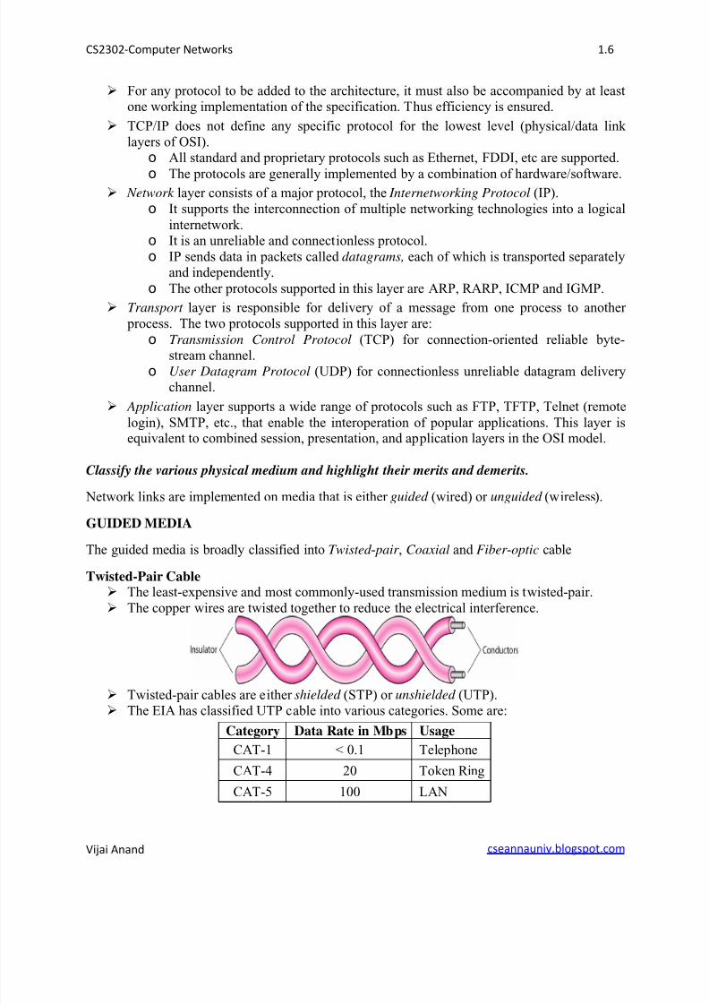
Twisted-Pair Cable The least-expensive and most commonly-used transmission medium is twisted-pair.
The copper wires are twisted together to reduce the electrical interference.
Twisted-pair cables are either shielded (STP) or unshielded (UTP). The EIA has classified UTP cable into various categories. Some are:
Category Data Rate in Mbps Usage
CAT-1 < 0.1 Telephone
CAT-4 20 Token Ring
CAT-5 100 LAN
8/11/2019 CS2302U1
http://slidepdf.com/reader/full/cs2302u1 7/22
CS2302-Computer Networks 1.7
Vijai Anand cseannauniv.blogspot.com
UTP cable is commonly used for LANs such as 10Base-T and 100Base-T. The mostcommon UTP connector is RJ45.
UTP cable suffers from attenuation and need repeaters for long distance transmission
(every 100m in case of CAT-5).
Twisted-pair cables are also used in telephone lines to provide voice and data channels.
DSL lines also use the high-bandwidth capability of UTP cables.
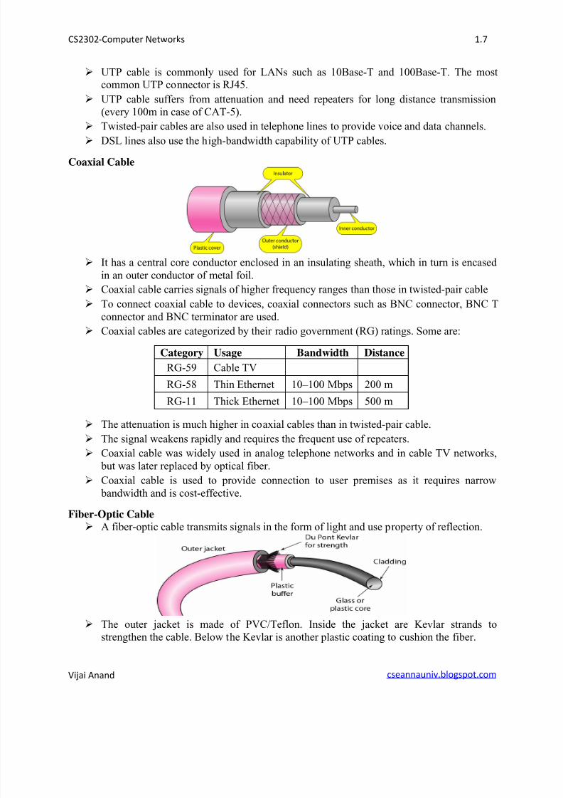
Coaxial Cable
It has a central core conductor enclosed in an insulating sheath, which in turn is encased
in an outer conductor of metal foil. Coaxial cable carries signals of higher frequency ranges than those in twisted-pair cable
To connect coaxial cable to devices, coaxial connectors such as BNC connector, BNC T
connector and BNC terminator are used.
Coaxial cables are categorized by their radio government (RG) ratings. Some are:
Category Usage Bandwidth Distance
RG-59 Cable TV
RG-58 Thin Ethernet 10–100 Mbps 200 m
RG-11 Thick Ethernet 10–100 Mbps 500 m
The attenuation is much higher in coaxial cables than in twisted-pair cable.
The signal weakens rapidly and requires the frequent use of repeaters.
Coaxial cable was widely used in analog telephone networks and in cable TV networks,
but was later replaced by optical fiber.
Coaxial cable is used to provide connection to user premises as it requires narrow
bandwidth and is cost-effective.
Fiber-Optic Cable
A fiber-optic cable transmits signals in the form of light and use property of reflection.
The outer jacket is made of PVC/Teflon. Inside the jacket are Kevlar strands to
strengthen the cable. Below the Kevlar is another plastic coating to cushion the fiber.
8/11/2019 CS2302U1
http://slidepdf.com/reader/full/cs2302u1 8/22
CS2302-Computer Networks 1.8
Vijai Anand cseannauniv.blogspot.com
Fiber-optic supports two modes: multimode and single mode.
Cable Bandwidth Distance
Multimode fiber 100 Mbps 2 km
Single-mode fiber 100–2400 Mbps 40 km
The attenuation is much lesser and few (10 times less) repeaters are required.
Supports higher bandwidth and longer transmission distance.
Fiber-optic cables are immune to interference and corrosive-resistant.
Installation and maintenance require expertise and fiber-optic cables are more expensive.
Two fiber-optic cables are required for duplex communication (light is unidirectional)
Cable TV companies use optical fiber to provide the backbone structure. LANs such as
100Base-FX network and 1000Base-X also use fiber-optic cable.
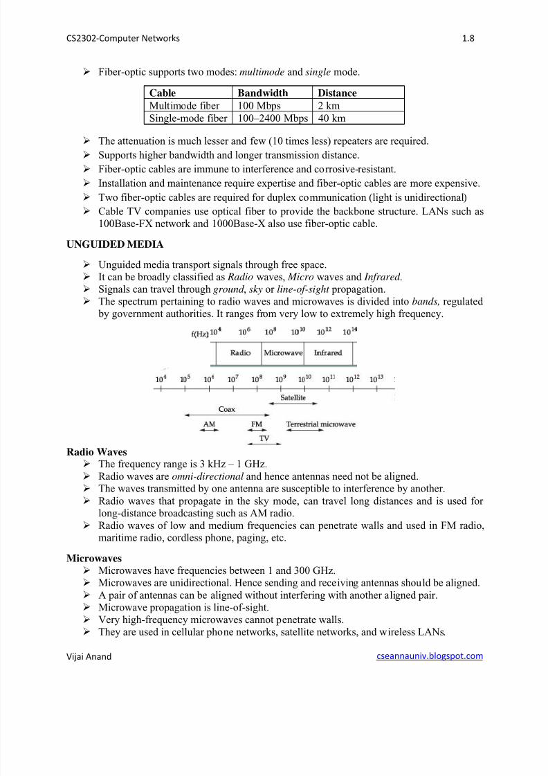
UNGUIDED MEDIA
Unguided media transport signals through free space. It can be broadly classified as Radio waves, Micro waves and Infrared .
Signals can travel through ground , sky or line-of-sight propagation. The spectrum pertaining to radio waves and microwaves is divided into bands, regulated
by government authorities. It ranges from very low to extremely high frequency.
Radio Waves The frequency range is 3 kHz – 1 GHz.
Radio waves are omni-directional and hence antennas need not be aligned. The waves transmitted by one antenna are susceptible to interference by another.
Radio waves that propagate in the sky mode, can travel long distances and is used for long-distance broadcasting such as AM radio.
Radio waves of low and medium frequencies can penetrate walls and used in FM radio,maritime radio, cordless phone, paging, etc.
Microwaves
Microwaves have frequencies between 1 and 300 GHz. Microwaves are unidirectional. Hence sending and receiving antennas should be aligned.
A pair of antennas can be aligned without interfering with another aligned pair. Microwave propagation is line-of-sight.
Very high-frequency microwaves cannot penetrate walls. They are used in cellular phone networks, satellite networks, and wireless LANs.
8/11/2019 CS2302U1
http://slidepdf.com/reader/full/cs2302u1 9/22
CS2302-Computer Networks 1.9
Vijai Anand cseannauniv.blogspot.com
Infrared Infrared waves frequencies ranges from 300 GHz to 400 THz.
It can be used for short-range communication only within a closed space. Infrared waves have high frequencies and cannot penetrate walls.
IrDA has established standards for communication between devices such as keyboards,
mouse, PCs, and printers. Infrared signals transmit through line of sight with very high data rate of transmission.
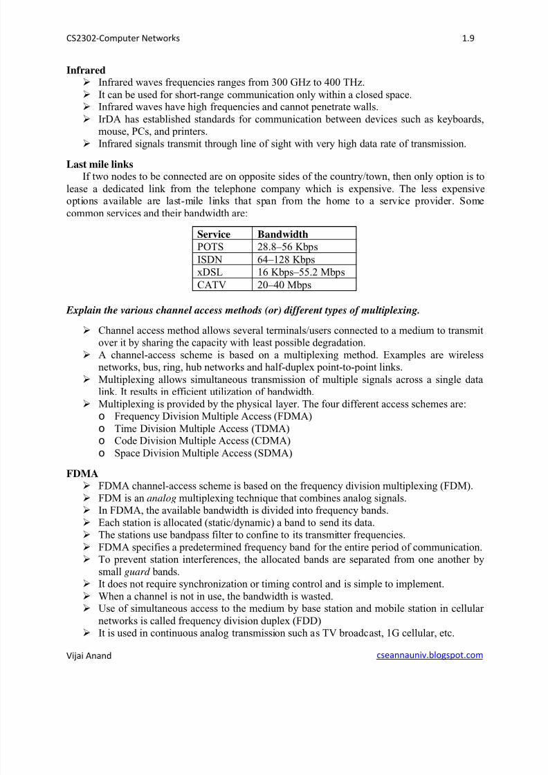
Last mile linksIf two nodes to be connected are on opposite sides of the country/town, then only option is to
lease a dedicated link from the telephone company which is expensive. The less expensiveoptions available are last-mile links that span from the home to a service provider. Some
common services and their bandwidth are:
Service Bandwidth
POTS 28.8–56 Kbps
ISDN 64–128 Kbps
xDSL 16 Kbps–55.2 MbpsCATV 20–40 Mbps
Explain the various channel access methods (or) different types of multiplexing.
Channel access method allows several terminals/users connected to a medium to transmitover it by sharing the capacity with least possible degradation.
A channel-access scheme is based on a multiplexing method. Examples are wirelessnetworks, bus, ring, hub networks and half-duplex point-to-point links.
Multiplexing allows simultaneous transmission of multiple signals across a single datalink. It results in efficient utilization of bandwidth.
Multiplexing is provided by the physical layer. The four different access schemes are:o Frequency Division Multiple Access (FDMA)
o Time Division Multiple Access (TDMA)o Code Division Multiple Access (CDMA)
o Space Division Multiple Access (SDMA)
FDMA FDMA channel-access scheme is based on the frequency division multiplexing (FDM).
FDM is an analog multiplexing technique that combines analog signals. In FDMA, the available bandwidth is divided into frequency bands.
Each station is allocated (static/dynamic) a band to send its data. The stations use bandpass filter to confine to its transmitter frequencies.
FDMA specifies a predetermined frequency band for the entire period of communication. To prevent station interferences, the allocated bands are separated from one another by
small guard bands. It does not require synchronization or timing control and is simple to implement.
When a channel is not in use, the bandwidth is wasted. Use of simultaneous access to the medium by base station and mobile station in cellular
networks is called frequency division duplex (FDD) It is used in continuous analog transmission such as TV broadcast, 1G cellular, etc.
8/11/2019 CS2302U1
http://slidepdf.com/reader/full/cs2302u1 10/22
CS2302-Computer Networks 1.10
Vijai Anand cseannauniv.blogspot.com
TDMA TDMA channel-access scheme is based on the time-division multiplex (TDM).
TDM is a digital multiplexing technique for combining several low-rate channels into ahigh-rate one.
In TDMA, the stations use the entire bandwidth with time-sharing.
Each station is allocated a time slot of fixed length for data transmission. Each station needs to know the beginning of its slot and the location of its slot. The main problem lies in achieving synchronization between different stations.
Synchronization is done by having some preamble bits at the beginning of each slot To compensate for the delays, guard times are inserted.
For example, node1 may use time slot1, node2 time slot2, etc. in rounds. The unused slots go idle.
In Dynamic TDMA (DTDMA), stations may not be allotted the same slot in next round. Assigning different slots for uplink and downlink using the same frequency is called time
division duplex (TDD). GSM uses TDMA technique.
CDMA CDMA differs from FDMA because channel uses entire bandwidth of the link. CDMA differs from TDMA because all stations can send data simultaneously.
In CDMA, the channel carries all transmissions simultaneously. CDMA scheme is based on spread spectrum technique, i.e., a wider spectrum is used than
the data rate of each of the transferred bit streams. Spreading is done in two ways namely Direct Sequence spread spectrum (DS-CDMA)
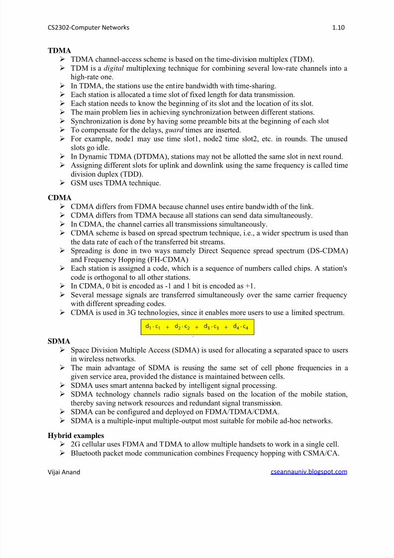
and Frequency Hopping (FH-CDMA) Each station is assigned a code, which is a sequence of numbers called chips. A station's
code is orthogonal to all other stations. In CDMA, 0 bit is encoded as -1 and 1 bit is encoded as +1.
Several message signals are transferred simultaneously over the same carrier frequencywith different spreading codes.
CDMA is used in 3G technologies, since it enables more users to use a limited spectrum.
SDMA
Space Division Multiple Access (SDMA) is used for allocating a separated space to usersin wireless networks.
The main advantage of SDMA is reusing the same set of cell phone frequencies in agiven service area, provided the distance is maintained between cells.
SDMA uses smart antenna backed by intelligent signal processing.
SDMA technology channels radio signals based on the location of the mobile station,
thereby saving network resources and redundant signal transmission. SDMA can be configured and deployed on FDMA/TDMA/CDMA.
SDMA is a multiple-input multiple-output most suitable for mobile ad-hoc networks.
Hybrid examples 2G cellular uses FDMA and TDMA to allow multiple handsets to work in a single cell.
Bluetooth packet mode communication combines Frequency hopping with CSMA/CA.
8/11/2019 CS2302U1
http://slidepdf.com/reader/full/cs2302u1 11/22
CS2302-Computer Networks 1.11
Vijai Anand cseannauniv.blogspot.com
The GPRS packet switched service combines FDMA with slotted Aloha for reservationinquiries and DTDMA scheme for transferring data.
WLANs based on FDMA and DS-CDMA is combined with CSMA/CA for multipleaccesses within the cell.
HIPERLAN/2 wireless networks combine FDMA with dynamic TDMA, to achieve
resource reservation by packet scheduling.
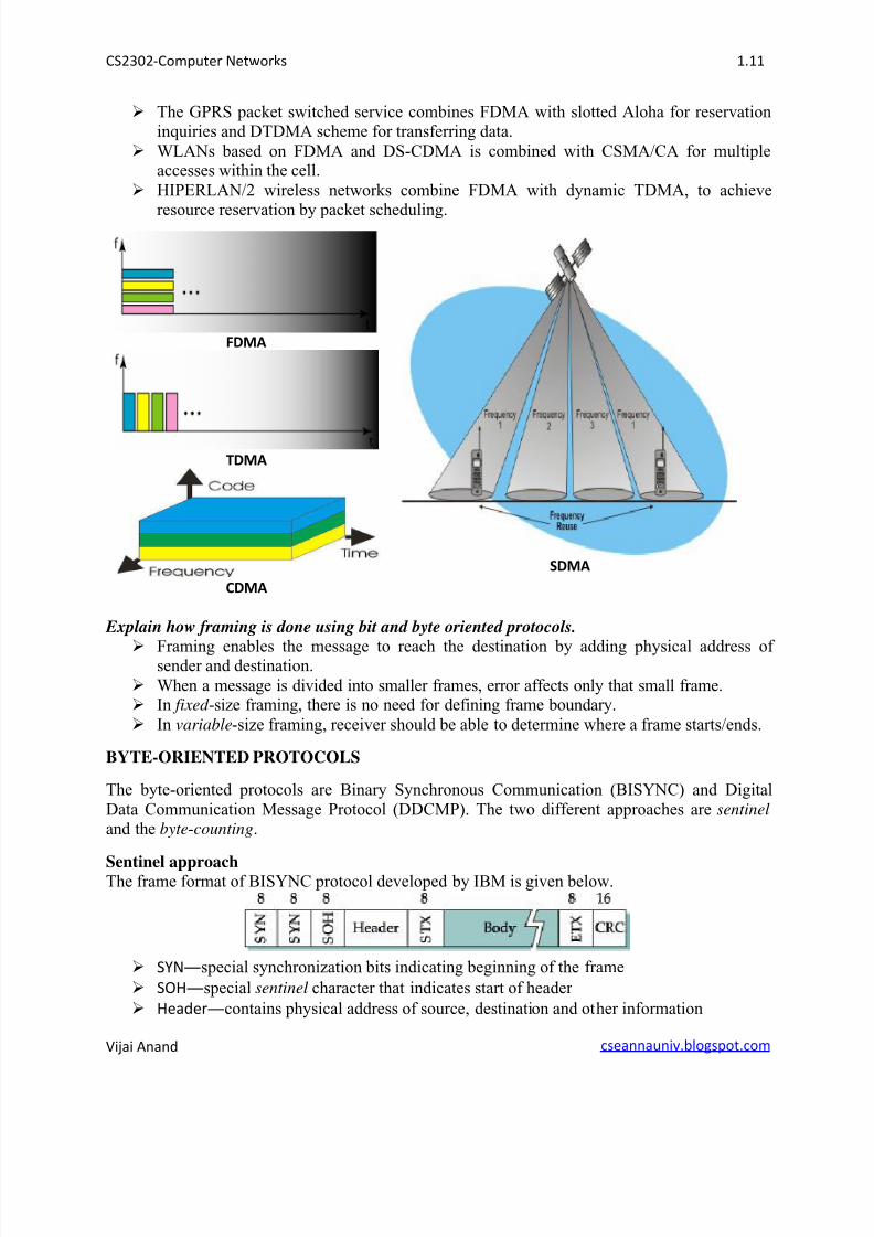
FDMA
SDMA
TDMA
CDMA
Explain how framing is done using bit and byte oriented protocols.
Framing enables the message to reach the destination by adding physical address of sender and destination.
When a message is divided into smaller frames, error affects only that small frame. In fixed -size framing, there is no need for defining frame boundary.
In variable-size framing, receiver should be able to determine where a frame starts/ends.
BYTE-ORIENTED PROTOCOLS
The byte-oriented protocols are Binary Synchronous Communication (BISYNC) and Digital
Data Communication Message Protocol (DDCMP). The two different approaches are sentinel
and the byte-counting.
Sentinel approachThe frame format of BISYNC protocol developed by IBM is given below.
SYNspecial synchronization bits indicating beginning of the frame
SOHspecial sentinel character that indicates start of header
Headercontains physical address of source, destination and other information
8/11/2019 CS2302U1
http://slidepdf.com/reader/full/cs2302u1 12/22
CS2302-Computer Networks 1.12
Vijai Anand cseannauniv.blogspot.com
STXspecial sentinel character that indicates start of text/body
ETXspecial sentinel character that indicates end of text/body
CRC16-bit CRC code used to detect transmission error
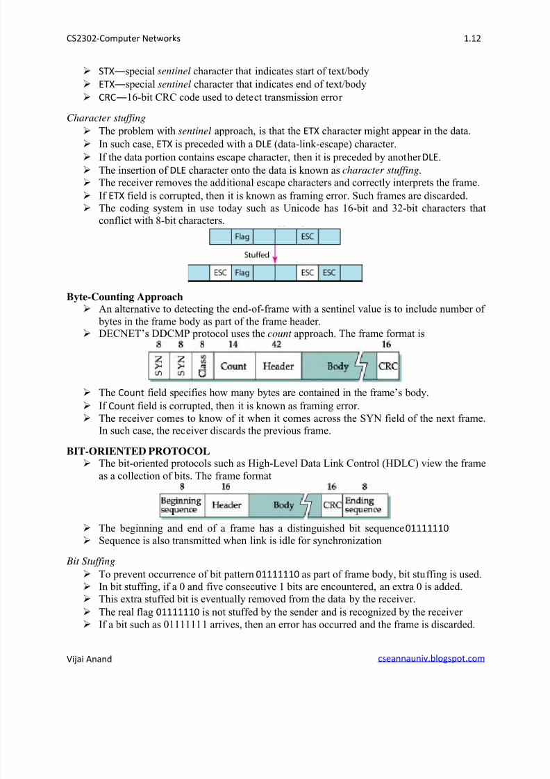
Character stuffing
The problem with sentinel approach, is that the
ETX character might appear in the data. In such case, ETX is preceded with a DLE (data-link-escape) character.
If the data portion contains escape character, then it is preceded by another DLE.
The insertion of DLE character onto the data is known as character stuffing.
The receiver removes the additional escape characters and correctly interprets the frame.
If ETX field is corrupted, then it is known as framing error. Such frames are discarded.
The coding system in use today such as Unicode has 16-bit and 32-bit characters thatconflict with 8-bit characters.
Byte-Counting Approach An alternative to detecting the end-of-frame with a sentinel value is to include number of
bytes in the frame body as part of the frame header. DECNET’s DDCMP protocol uses the count approach. The frame format is
The Count field specifies how many bytes are contained in the frame’s body.
If Count field is corrupted, then it is known as framing error.
The receiver comes to know of it when it comes across the SYN field of the next frame.In such case, the receiver discards the previous frame.
BIT-ORIENTED PROTOCOL The bit-oriented protocols such as High-Level Data Link Control (HDLC) view the frame
as a collection of bits. The frame format
The beginning and end of a frame has a distinguished bit sequence 01111110
Sequence is also transmitted when link is idle for synchronization
Bit Stuffing
To prevent occurrence of bit pattern 01111110 as part of frame body, bit stuffing is used.
In bit stuffing, if a 0 and five consecutive 1 bits are encountered, an extra 0 is added. This extra stuffed bit is eventually removed from the data by the receiver.
The real flag 01111110 is not stuffed by the sender and is recognized by the receiver
If a bit such as 01111111 arrives, then an error has occurred and the frame is discarded.
8/11/2019 CS2302U1
http://slidepdf.com/reader/full/cs2302u1 13/22
CS2302-Computer Networks 1.13
Vijai Anand cseannauniv.blogspot.com
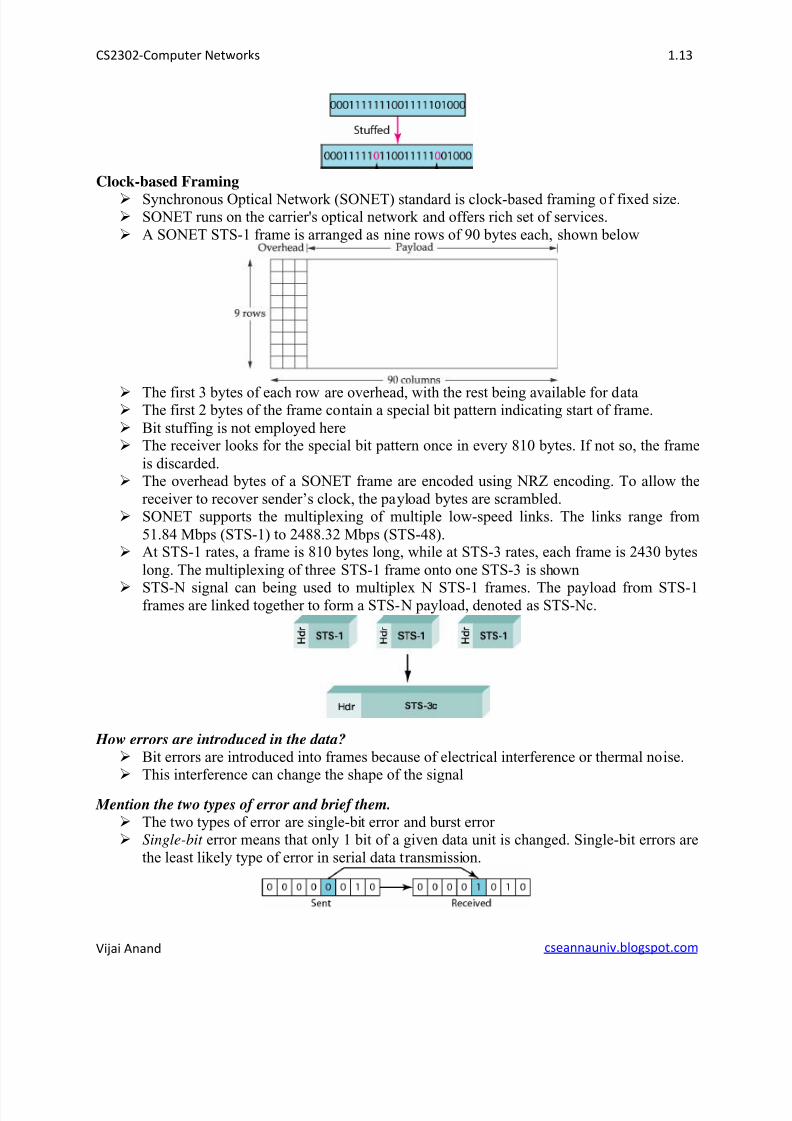
Clock-based Framing
Synchronous Optical Network (SONET) standard is clock-based framing of fixed size. SONET runs on the carrier's optical network and offers rich set of services.
A SONET STS-1 frame is arranged as nine rows of 90 bytes each, shown below
The first 3 bytes of each row are overhead, with the rest being available for data The first 2 bytes of the frame contain a special bit pattern indicating start of frame.
Bit stuffing is not employed here The receiver looks for the special bit pattern once in every 810 bytes. If not so, the frame
is discarded. The overhead bytes of a SONET frame are encoded using NRZ encoding. To allow the
receiver to recover sender’s clock, the payload bytes are scrambled. SONET supports the multiplexing of multiple low-speed links. The links range from
51.84 Mbps (STS-1) to 2488.32 Mbps (STS-48). At STS-1 rates, a frame is 810 bytes long, while at STS-3 rates, each frame is 2430 bytes
long. The multiplexing of three STS-1 frame onto one STS-3 is shown
STS-N signal can being used to multiplex N STS-1 frames. The payload from STS-1frames are linked together to form a STS-N payload, denoted as STS-Nc.
How errors are introduced in the data? Bit errors are introduced into frames because of electrical interference or thermal noise. This interference can change the shape of the signal
Mention the two types of error and brief them. The two types of error are single-bit error and burst error Single-bit error means that only 1 bit of a given data unit is changed. Single-bit errors are
the least likely type of error in serial data transmission.
8/11/2019 CS2302U1
http://slidepdf.com/reader/full/cs2302u1 14/22
CS2302-Computer Networks 1.14
Vijai Anand cseannauniv.blogspot.com
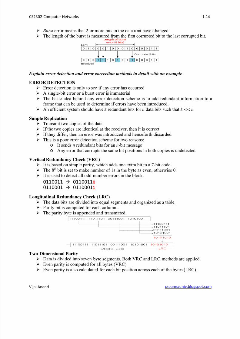
Burst error means that 2 or more bits in the data unit have changed The length of the burst is measured from the first corrupted bit to the last corrupted bit.
Explain error detection and error correction methods in detail with an example
ERROR DETECTION
Error detection is only to see if any error has occurred A single-bit error or a burst error is immaterial
The basic idea behind any error detection scheme is to add redundant information to aframe that can be used to determine if errors have been introduced.
An efficient system should have k redundant bits for n data bits such that k << n
Simple Replication Transmit two copies of the data
If the two copies are identical at the receiver, then it is correct If they differ, then an error was introduced and henceforth discarded
This is a poor error detection scheme for two reasons:o It sends n redundant bits for an n-bit message
o Any error that corrupts the same bit positions in both copies is undetected
Vertical Redundancy Check (VRC) It is based on simple parity, which adds one extra bit to a 7-bit code.
The 8th bit is set to make number of 1s in the byte as even, otherwise 0. It is used to detect all odd-number errors in the block.
0110011 01100110
0110001 01100011
Longitudinal Redundancy Check (LRC)
The data bits are divided into equal segments and organized as a table. Parity bit is computed for each column.
The parity byte is appended and transmitted.
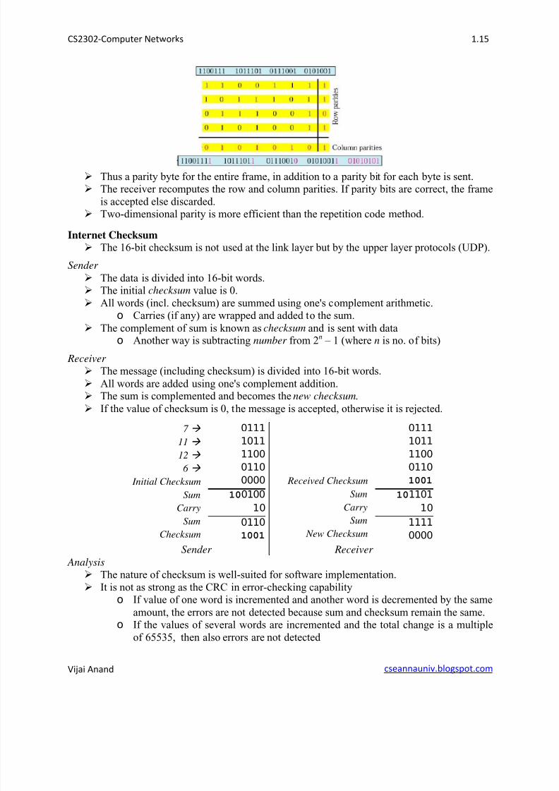
Two-Dimensional Parity
Data is divided into seven byte segments. Both VRC and LRC methods are applied. Even parity is computed for all bytes (VRC).
Even parity is also calculated for each bit position across each of the bytes (LRC).
8/11/2019 CS2302U1
http://slidepdf.com/reader/full/cs2302u1 15/22
CS2302-Computer Networks 1.15
Vijai Anand cseannauniv.blogspot.com
Thus a parity byte for the entire frame, in addition to a parity bit for each byte is sent. The receiver recomputes the row and column parities. If parity bits are correct, the frame
is accepted else discarded. Two-dimensional parity is more efficient than the repetition code method.
Internet Checksum
The 16-bit checksum is not used at the link layer but by the upper layer protocols (UDP).
Sender
The data is divided into 16-bit words. The initial checksum value is 0.
All words (incl. checksum) are summed using one's complement arithmetic.o Carries (if any) are wrapped and added to the sum.
The complement of sum is known as checksum and is sent with datao Another way is subtracting number from 2n – 1 (where n is no. of bits)
Receiver
The message (including checksum) is divided into 16-bit words.
All words are added using one's complement addition. The sum is complemented and becomes the new checksum.
If the value of checksum is 0, the message is accepted, otherwise it is rejected.
7
11
12
6
Initial Checksum
Sum
Carry
Sum
Checksum
0111
1011
1100
0110
0000
100100
10
0110
1001
Received Checksum
Sum
Carry
Sum
New Checksum
0111
1011
1100
0110
1001
101101
10
1111
0000
Sender Receiver Analysis
The nature of checksum is well-suited for software implementation.
It is not as strong as the CRC in error-checking capabilityo If value of one word is incremented and another word is decremented by the same
amount, the errors are not detected because sum and checksum remain the same.o If the values of several words are incremented and the total change is a multiple
of 65535, then also errors are not detected
8/11/2019 CS2302U1
http://slidepdf.com/reader/full/cs2302u1 16/22
CS2302-Computer Networks 1.16
Vijai Anand cseannauniv.blogspot.com
Cyclic Redundancy Check (CRC) Cyclic redundancy check uses the concept of finite fields. CRC was developed by IBM.
A n bit message is represented as a polynomial of degree n - 1.
The message M( x) is represented as a polynomial by using the value of each bit in the
message as coefficient for each term. For eg., 10011010 represents x7 + x
4 + x
3+ x
For calculating a CRC, a sender and receiver have to agree on a divisor polynomial, C ( x)of degree k such that k n – 1
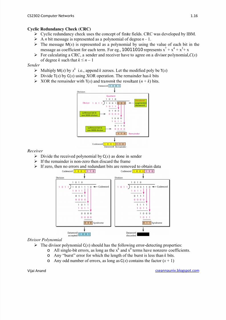
Sender
Multiply M( x) by xk i.e., append k zeroes. Let the modified poly be T( x)
Divide T( x) by C( x) using XOR operation. The remainder has k bits
XOR the remainder with T( x) and transmit the resultant (n + k ) bits.
Receiver
Divide the received polynomial by C( x) as done in sender
If the remainder is non-zero then discard the frame
If zero, then no errors and redundant bits are removed to obtain data
Divisor Polynomial
The divisor polynomial C( x) should has the following error-detecting properties:
o All single-bit errors, as long as the xk and x
0 terms have nonzero coefficients.
o Any “burst” error for which the length of the burst is less than k bits.
o Any odd number of errors, as long as C( x) contains the factor ( x + 1)
8/11/2019 CS2302U1
http://slidepdf.com/reader/full/cs2302u1 17/22
CS2302-Computer Networks 1.17
Vijai Anand cseannauniv.blogspot.com
The versions of C( x) widely used in link-level protocols are CRC-8, CRC-10, CRC-12,
CRC-16, CRC-CCITT and CRC-32.
CRC algorithm is implemented in hardware using a k -bit shift register and XOR gates. CRC is widely used in networks such as LANs and WANs
ERROR-CORRECTION Error correcting codes determine the corrupted bits and correct it
Allows the recipient to reconstruct the correct message even after it has been corrupted Hamming code is used to correct single bit error
Reed Solomon code is used to correct burst errors The use of error-correcting codes is often referred to as forward error correction
Hamming code Hamming codes are code words formed by adding redundant check bits, or parity bits, to
a data word A frame consists of m data (i.e., message) bits and r redundant or parity bits.
An n-bit unit containing data and parity bits is known as an n-bit codeword.
The error-detecting & error-correcting properties of a code depend on Hamming distance. To design a code with m message bits and r parity bits, that will allow all single errors to
be corrected, then 2r m + r + 1.
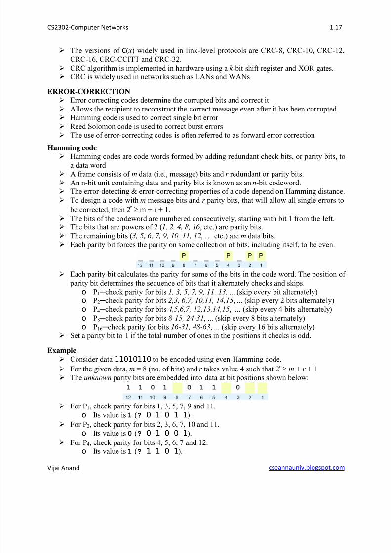
The bits of the codeword are numbered consecutively, starting with bit 1 from the left. The bits that are powers of 2 (1, 2, 4, 8, 16 , etc.) are parity bits.
The remaining bits (3, 5, 6, 7, 9, 10, 11, 12, … etc.) are m data bits. Each parity bit forces the parity on some collection of bits, including itself, to be even.
Each parity bit calculates the parity for some of the bits in the code word. The position of
parity bit determines the sequence of bits that it alternately checks and skips.
o P1 check parity for bits 1, 3, 5, 7, 9, 11, 13, ... (skip every bit alternately)o P2 check parity for bits 2,3, 6,7, 10,11, 14,15, ... (skip every 2 bits alternately)o P4 check parity for bits 4,5,6,7, 12,13,14,15, ... (skip every 4 bits alternately)
o P8 check parity for bits 8-15, 24-31, ... (skip every 8 bits alternately)o P16 check parity for bits 16-31, 48-63, ... (skip every 16 bits alternately)
Set a parity bit to 1 if the total number of ones in the positions it checks is odd.
Example
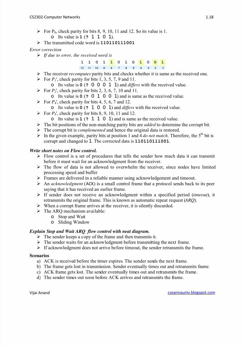
Consider data 11010110 to be encoded using even-Hamming code.
For the given data, m = 8 (no. of bits) and r takes value 4 such that 2r m + r + 1
The unknown parity bits are embedded into data at bit positions shown below:
For P1, check parity for bits 1, 3, 5, 7, 9 and 11.
o Its value is 1 (? 0 1 0 1 1).
For P2, check parity for bits 2, 3, 6, 7, 10 and 11.
o Its value is 0 (? 0 1 0 0 1).
For P4, check parity for bits 4, 5, 6, 7 and 12.
o Its value is 1 (? 1 1 0 1).
8/11/2019 CS2302U1
http://slidepdf.com/reader/full/cs2302u1 18/22
CS2302-Computer Networks 1.18
Vijai Anand cseannauniv.blogspot.com
For P8, check parity for bits 8, 9, 10, 11 and 12. So its value is 1.
o Its value is 1 (? 1 1 0 1).
The transmitted code word is 110110111001
Error correction
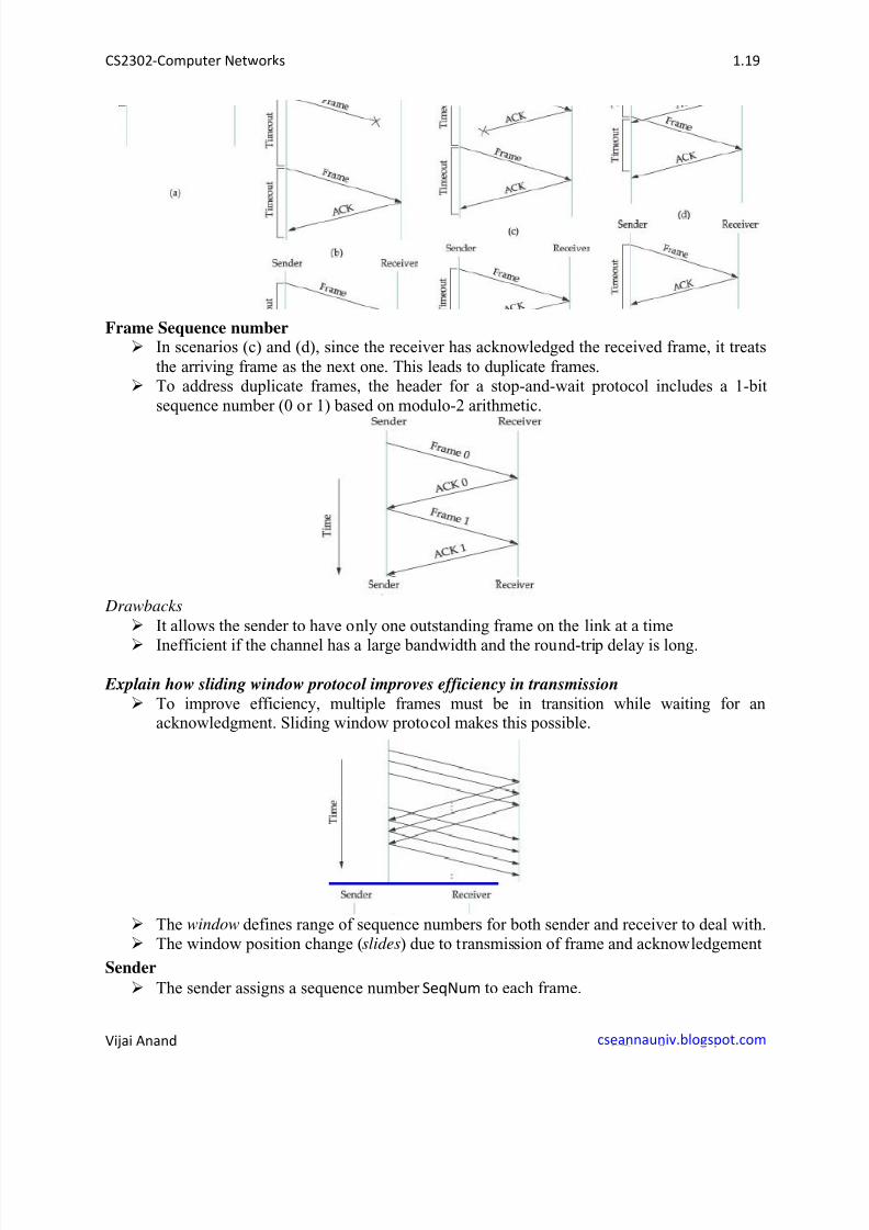
If due to error, the received word is
The receiver recomputes parity bits and checks whether it is same as the received one. For P1', check parity for bits 1, 3, 5, 7, 9 and 11.
o Its value is 0 (? 0 0 0 1 1) and differs with the received value.
For P2', check parity for bits 2, 3, 6, 7, 10 and 11.
o Its value is 0 (? 0 1 0 0 1) and is same as the received value.
For P4', check parity for bits 4, 5, 6, 7 and 12.
o Its value is 0 (? 1 0 0 1) and differs with the received value.
For P8 ', check parity for bits 8, 9, 10, 11 and 12.
oIts value is
1
(? 1 1 0 1
) and is same as the received value. The bit positions of the non-matching parity bits are added to determine the corrupt bit. The corrupt bit is complemented and hence the original data is restored.
In the given example, parity bits at position 1 and 4 do not match. Therefore, the 5th bit is
corrupt and changed to 1. The corrected data is 110110111001.
Write short notes on Flow control. Flow control is a set of procedures that tells the sender how much data it can transmit
before it must wait for an acknowledgment from the receiver.
The flow of data is not allowed to overwhelm the receiver, since nodes have limited processing speed and buffer
Frames are delivered in a reliable manner using acknowledgement and timeout.
An acknowledgment (ACK) is a small control frame that a protocol sends back to its peer
saying that it has received an earlier frame.
If sender does not receive an acknowledgment within a specified period ( timeout ), itretransmits the original frame. This is known as automatic repeat request ( ARQ).
When a corrupt frame arrives at the receiver, it is silently discarded. The ARQ mechanism available:
o Stop and Waito Sliding Window
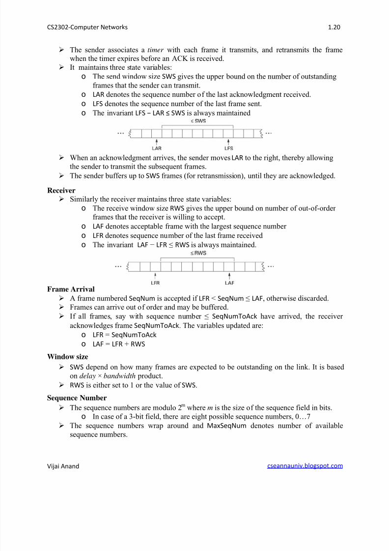
Explain Stop and Wait ARQ flow control with neat diagram. The sender keeps a copy of the frame and then transmits it.
The sender waits for an acknowledgment before transmitting the next frame. If acknowledgment does not arrive before timeout, the sender retransmits the frame.
Scenarios
a) ACK is received before the timer expires. The sender sends the next frame. b) The frame gets lost in transmission. Sender eventually times out and retransmits frame.
c) ACK frame gets lost. The sender eventually times out and retransmits the frame.d) The sender times out soon before ACK arrives and retransmits the frame.
8/11/2019 CS2302U1
http://slidepdf.com/reader/full/cs2302u1 19/22
CS2302-Computer Networks 1.19
Vijai Anand cseannauniv.blogspot.com
Frame Sequence number In scenarios (c) and (d), since the receiver has acknowledged the received frame, it treats
the arriving frame as the next one. This leads to duplicate frames. To address duplicate frames, the header for a stop-and-wait protocol includes a 1-bit
sequence number (0 or 1) based on modulo-2 arithmetic.
Drawbacks
It allows the sender to have only one outstanding frame on the link at a time
Inefficient if the channel has a large bandwidth and the round-trip delay is long.
Explain how sliding window protocol improves efficiency in transmission To improve efficiency, multiple frames must be in transition while waiting for an
acknowledgment. Sliding window protocol makes this possible.
The window defines range of sequence numbers for both sender and receiver to deal with. The window position change (slides) due to transmission of frame and acknowledgement
Sender
The sender assigns a sequence number SeqNum to each frame.
8/11/2019 CS2302U1
http://slidepdf.com/reader/full/cs2302u1 20/22
CS2302-Computer Networks 1.20
Vijai Anand cseannauniv.blogspot.com
The sender associates a timer with each frame it transmits, and retransmits the framewhen the timer expires before an ACK is received.
It maintains three state variables:
o The send window size SWS gives the upper bound on the number of outstanding
frames that the sender can transmit.
o LAR denotes the sequence number of the last acknowledgment received.o LFS denotes the sequence number of the last frame sent.
o The invariant LFS LAR SWS is always maintained
When an acknowledgment arrives, the sender moves LAR to the right, thereby allowing
the sender to transmit the subsequent frames.
The sender buffers up to SWS frames (for retransmission), until they are acknowledged.
Receiver Similarly the receiver maintains three state variables:
o The receive window size RWS gives the upper bound on number of out-of-order
frames that the receiver is willing to accept.
o LAF denotes acceptable frame with the largest sequence number
o LFR denotes sequence number of the last frame received
o The invariant LAF LFR RWS is always maintained.
Frame Arrival A frame numbered SeqNum is accepted if LFR < SeqNum LAF, otherwise discarded.
Frames can arrive out of order and may be buffered.
If all frames, say with sequence number SeqNumToAck have arrived, the receiver
acknowledges frame SeqNumToAck. The variables updated are:
o LFR = SeqNumToAck
o LAF = LFR + RWS
Window size
SWS depend on how many frames are expected to be outstanding on the link. It is based
on delay × bandwidth product.
RWS is either set to 1 or the value of SWS.
Sequence Number
The sequence numbers are modulo 2m where m is the size of the sequence field in bits.
o In case of a 3-bit field, there are eight possible sequence numbers, 0…7
The sequence numbers wrap around and MaxSeqNum denotes number of available
sequence numbers.
8/11/2019 CS2302U1
http://slidepdf.com/reader/full/cs2302u1 21/22
CS2302-Computer Networks 1.21
Vijai Anand cseannauniv.blogspot.com
To avoid the issue of identifying sequence numbers of different sets, SWS is defined as
SWS < (MaxSeqNum + 1)/2
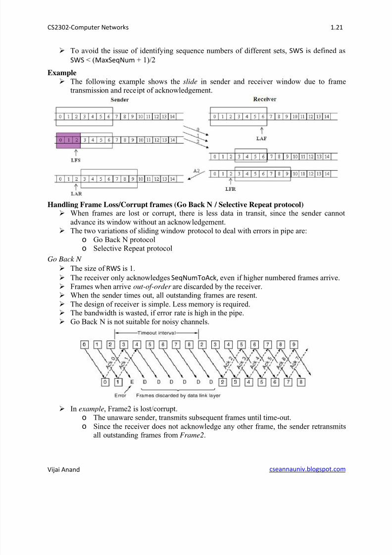
Example
The following example shows the slide in sender and receiver window due to frametransmission and receipt of acknowledgement.
Handling Frame Loss/Corrupt frames (Go Back N / Selective Repeat protocol) When frames are lost or corrupt, there is less data in transit, since the sender cannot
advance its window without an acknowledgement. The two variations of sliding window protocol to deal with errors in pipe are:
o Go Back N protocolo Selective Repeat protocol
Go Back N
The size of RWS is 1.
The receiver only acknowledges SeqNumToAck, even if higher numbered frames arrive.
Frames when arrive out-of-order are discarded by the receiver. When the sender times out, all outstanding frames are resent.
The design of receiver is simple. Less memory is required. The bandwidth is wasted, if error rate is high in the pipe.
Go Back N is not suitable for noisy channels.
In example, Frame2 is lost/corrupt.o The unaware sender, transmits subsequent frames until time-out.
o Since the receiver does not acknowledge any other frame, the sender retransmitsall outstanding frames from Frame2.
8/11/2019 CS2302U1
http://slidepdf.com/reader/full/cs2302u1 22/22
CS2302-Computer Networks 1.22
Vijai Anand cseannauniv.blogspot.com
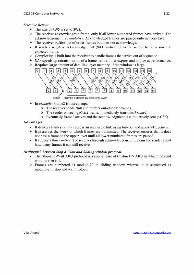
Selective Repeat
The size of RWS is set to SWS.
The receiver acknowledges a frame, only if all lower numbered frames have arrived. Theacknowledgement is cumulative. Acknowledged frames are passed onto network layer.
The receiver buffers out of order frames but does not acknowledge.
It sends a negative acknowledgement (NAK) indicating to the sender to retransmit theexpected frame.
Complexity is built into the receiver to handle frames that arrive out of sequence.
NAK speeds up retransmission of a frame before timer expires and improves performance.
Requires large amount of data link layer memory, if the window is large.
In example, Frame2 is lost/corrupt.
o The receiver sends NAK and buffers out-of-order frames.
o The sender on seeing NAK2 frame, immediately transmits Frame2.
o Eventually frame2 arrives and the acknowledgment is cumulatively sent ( ACK5).
Advantages
It delivers frames reliably across an unreliable link using timeout and acknowledgement. It preserves the order in which frames are transmitted. The receiver ensures that it does
not pass a frame to the upper layer until all lower numbered frames are passed. It supports flow control. The receiver through acknowledgement informs the sender about
how many frames it can still receive.
Distinguish between Stop & Wait and Sliding window protocol. The Stop-and-Wait ARQ protocol is a special case of Go-Back-N ARQ in which the send
window size is 1. Frames are numbered as modulo-2m in sliding window whereas it is sequenced as
modulo-2 in stop and wait protocol.