CS-ETSO (Amendment 8)

Welcome message from author
This document is posted to help you gain knowledge. Please leave a comment to let me know what you think about it! Share it to your friends and learn new things together.
Transcript
CS-
ETSO
(Am
en
dm
en
t 8
)

Powered by EASA eRules Page 2 of 611| Nov 2018
Easy Access Rules for European Technical Standard Orders (CS-ETSO) (Amendment 8)
EASA eRules: aviation rules for the 21st century
Rules and regulations are the core of the European Union civil aviation system. The aim of the EASA eRules project is to make them accessible in an efficient and reliable way to stakeholders.
EASA eRules will be a comprehensive, single system for the drafting, sharing and storing of rules. It
will be the single source for all aviation safety rules applicable to European airspace users. It will offer easy (online) access to all rules and regulations as well as new and innovative applications such as
rulemaking process automation, stakeholder consultation, cross-referencing, and comparison with ICAO and third countries’ standards.
To achieve these ambitious objectives, the EASA eRules project is structured in ten modules to cover
all aviation rules and innovative functionalities.
The EASA eRules system is developed and implemented in close cooperation with Member States and
aviation industry to ensure that all its capabilities are relevant and effective.
Published November 20181
1 The published date represents the date when the consolidated version of the document was generated.

Easy Access Rules for European Technical Standard
Orders (CS-ETSO) (Amendment 8)
Disclaimer
Powered by EASA eRules Page 3 of 611| Nov 2018
DISCLAIMER This version is issued by the European Aviation Safety Agency (EASA) in order to provide its stakeholders with an updated and easy-to-read publication. It has been prepared by putting together all applicable certification specifications (CS). However, this is not an official publication and EASA accepts no liability for damage of any kind resulting from the risks inherent in the use of this document.

Easy Access Rules for European Technical Standard
Orders (CS-ETSO) (Amendment 8)
Note from the editor
Powered by EASA eRules Page 4 of 611| Nov 2018
NOTE FROM THE EDITOR
CS paragraph titles are colour-coded and can be identified according to the illustration below. The EASA Executive Director (ED) decision through which the paragraph was introduced or last amended is indicated below the paragraph title(s) in italics.
The format of this document has been adjusted to make it user-friendly and for reference purposes. Any comments should be sent to [email protected].

Easy Access Rules for European Technical Standard
Orders (CS-ETSO) (Amendment 8)
Incorporated amendments
Powered by EASA eRules Page 5 of 611| Nov 2018
INCORPORATED AMENDMENTS
CS (ED DECISIONS)
Incorporated ED Decision CS Issue No, Amendment No Applicability date
ED Decision 2003/10/RM CS-ETSO/ Initial issue 24/10/2003
ED Decision 2006/004/R CS-ETSO/ Amendment 1 18/7/2006
ED Decision 2007/017/R CS-ETSO/ Amendment 2 25/12/2007
ED Decision 2008/012/R CS-ETSO/ Amendment 3 18/11/2008
ED Decision 2009/014/R CS-ETSO/ Amendment 4 21/10/2009
ED Decision 2009/015/R CS-ETSO/ Amendment 5 8/12/2009
ED Decision 2010/010/R CS-ETSO/ Amendment 6 21/12/2010
ED Decision 2012/009/R CS-ETSO/ Amendment 7 5/7/20121
ED Decision 2013/012/R CS-ETSO/ Amendment 8 15/7/20132
Note: To access the official versions, please click on the hyperlinks provided above.
1 This is the main applicability date defined in the ED Decision. However, the decision allowed that this CS was not applied to applications
received until 31 December 2012, if so requested by the applicant and providing that in such a case the applicant could demonstrate that the process of development of the relevant part or appliance started before the entry into force of the ED Decision (5 July 2012), in accordance with the specifications applicable at that time.
2 This is the main applicability date defined in the ED Decision. However, the decision allowed that this CS was not applied to applications received until 31 December 2013, if so requested by the applicant and providing that in such a case the applicant could demonstrate that the process of development of the relevant part or appliance started before the entry into force of the ED Decision (15 July 2013), in accordance with the specifications applicable at that time.

Easy Access Rules for European Technical Standard
Orders (CS-ETSO) (Amendment 8)
Table of contents
Powered by EASA eRules Page 6 of 611| Nov 2018
TABLE OF CONTENTS
Disclaimer ............................................................................................ 3
Note from the editor ........................................................................... 4
Incorporated amendments ................................................................. 5
Table of contents ................................................................................. 6
Preamble ........................................................................................... 16
SUBPART A – GENERAL ..................................................................... 20
SUBPART B – LIST OF ETSOs .............................................................. 23
INDEX 1 European Technical Standard Orders ................................................................24
ETSO-C1c ..........................................................................................................24 Cargo Compartment Fire Detection Instruments .............................................................................. 24
ETSO-C2d..........................................................................................................25 Airspeed Instruments........................................................................................................................... 25
ETSO-C3d..........................................................................................................26 Turn and Slip Instruments ................................................................................................................... 26
ETSO-C4c ..........................................................................................................27 Bank and Pitch Instruments ................................................................................................................ 27
ETSO-C5e..........................................................................................................29 Direction Instrument, Non-magnetic (Gyroscopically Stabilized) .................................................... 29
ETSO-C6e..........................................................................................................30 Direction Instrument, Magnetic (Gyroscopically Stabilized)............................................................. 30
Appendix 1 to ETSO-C6e – Modification to MPS for Direction Instrument, Magnetic (Gyroscopically Stabilized) ....................................................................................................... 32
ETSO-C7d..........................................................................................................33 Direction Instrument, Magnetic Non-stabilized Type (Magnetic Compass) .................................... 33
ETSO-C8e..........................................................................................................35 Vertical Velocity Instrument (Rate-of-Climb)..................................................................................... 35
ETSO-C10b ........................................................................................................36 Aircraft Altimeter, Pressure Actuated, Sensitive Type ...................................................................... 36
ETSO-C13f.........................................................................................................38 Life Preservers ...................................................................................................................................... 38
Appendix 1 to ETSO-C13f – Minimum Performance Standard for Life Preservers ............. 39
ETSO-C14b ........................................................................................................49 Aircraft Fabric, Intermediate Grade.................................................................................................... 49
Easy Access Rules for European Technical Standard
Orders (CS-ETSO) (Amendment 8)
Table of contents
Powered by EASA eRules Page 7 of 611| Nov 2018
ETSO-C15d ........................................................................................................51 Aircraft Fabric, Grade A ....................................................................................................................... 51
ETSO-C16a ........................................................................................................53 Electrically Heated Pitot and Pitot-Static Tubes ................................................................................ 53
Appendix 1 to ETSO-C16a – Minimum Performance Standard for Electrically Heated Pitot and Pitot-Static Tubes .............................................................................................................. 55
ETSO-C20..........................................................................................................57 Combustion Heaters ............................................................................................................................ 57
ETSO-C21b ........................................................................................................58 Aircraft Turnbuckle Assemblies and/or Turnbuckle Safetying Devices............................................ 58
ETSO-C22g ........................................................................................................60 Safety Belts ........................................................................................................................................... 60
ETSO-C23d ........................................................................................................62 Personnel Parachute Assemblies ........................................................................................................ 62
ETSO-C25a ........................................................................................................63 Aircraft Seats and Berths (Type I Transport 6g Forward Load)......................................................... 63
ETSO-C26c ........................................................................................................65 Aircraft Wheels and Wheel-Brake Assemblies (CS-23, -27 and -29 aircraft) .................................. 65
Appendix 1 to ETSO-C26c – Federal Aviation Administration Standard for Aircraft Wheels and Wheel-brake Assemblies dated May 18, 1984................................................................ 66
ETSO-C27..........................................................................................................73 Twin Seaplane Floats ........................................................................................................................... 73
ETSO-C28..........................................................................................................74 Aircraft Skis ........................................................................................................................................... 74
ETSO-C30c ........................................................................................................75 Aircraft Position Lights ......................................................................................................................... 75
ETSO-C39c ........................................................................................................76 Aircraft Seats and Berths Certified by Static Testing only................................................................. 76
Appendix 1 to ETSO-C39c – Modification to AS 8049 Rev. A ................................................ 78
ETSO-C42..........................................................................................................79 Propeller Feathering Hose Assemblies ............................................................................................... 79
ETSO-C43c ........................................................................................................82 Temperature Instruments ................................................................................................................... 82
ETSO-C44c A1....................................................................................................83 Fuel Flowmeters ................................................................................................................................... 83
Appendix 1 to ETSO-C44c A1 – Minimum Performance Standard for Fuel Flowmeters.... 85
ETSO-C45b A1 ...................................................................................................87 Manifold Pressure Instruments........................................................................................................... 87
Appendix 1 to ETSO-C45b A1 – Minimum Performance Standard for Manifold Pressure Instruments............................................................................................................................... 89
ETSO-C46a ........................................................................................................90 Maximum Allowable Airspeed Indicator Systems ............................................................................. 90
Appendix 1 to ETSO-C46a – Federal Aviation Administration Standard, Maximum Allowable Airspeed Indicator Systems ..................................................................................................... 92

Easy Access Rules for European Technical Standard
Orders (CS-ETSO) (Amendment 8)
Table of contents
Powered by EASA eRules Page 8 of 611| Nov 2018
ETSO-C47a A1 ...................................................................................................97 Pressure Instruments – Fuel, Oil and Hydraulic ................................................................................. 97
Appendix 1 to ETSO-C47a A1 – Minimum Performance Standards (MPSs) for Pressure Instruments - Fuel, Oil and Hydraulic...................................................................................... 99
ETSO-C49b ...................................................................................................... 100 Electric Tachometer: Magnetic Drag (Indicator and Generator) ....................................................100
ETSO-C53a ...................................................................................................... 102 Fuel and Engine Oil System Hose Assemblies ..................................................................................102
ETSO-C54........................................................................................................ 105 Stall Warning Instruments .................................................................................................................105
ETSO-C55a ...................................................................................................... 107 Fuel and Oil Quantity Instruments....................................................................................................107
ETSO-C56b A1 ................................................................................................. 109 Engine-driven Direct Current Generators/Starter-generators........................................................109
ETSO-C59........................................................................................................ 111 Airborne Selective Calling Equipment ..............................................................................................111
ETSO-C62e ...................................................................................................... 112 Aircraft Tyres ......................................................................................................................................112
Appendix 1 to ETSO-C62e – FAA Standard for Aircraft Tires...............................................114
ETSO-C64a ...................................................................................................... 122 Oxygen Mask Assembly, Continuous Flow, Passenger....................................................................122
ETSO-C65a ...................................................................................................... 123 Airborne Doppler Radar Ground Speed and/or Drift Angle Measuring Equipment (for Air Carrier Aircraft) ...............................................................................................................................................123
ETSO-C68a ...................................................................................................... 124 Airborne Automatic Dead Reckoning Computer Equipment Utilizing Aircraft Heading and Doppler Ground Speed and Drift Angle Data (for Air Carrier Aircraft) .........................................................124
ETSO-C69c ...................................................................................................... 125 Emergency Evacuation Slides, Ramps, Ramp/Slides and Slide/Rafts .............................................125
Appendix 1 to ETSO-C69c – Federal Aviation Administration Minimum Performance Standard for Emergency Evacuation Slides, Ramps, Ramp/Slides, and Slide/Rafts ..........127 Appendix 2 to ETSO-C69c – Glossary of Terms ....................................................................160 Appendix 3 to ETSO-C69c – Measurement of loads on the attachment(s) to the airplane .................................................................................................................................................161 Appendix 4 to ETSO-C69c – Calorimeter Specification and Calibration Procedure..........162
ETSO-C71........................................................................................................ 165 Airborne Static (‘DC to DC’) Electrical Power Converter (for Air Carrier Aircraft).........................165
FAA Standard associated with ETSO-C71 for Airborne Static („DC to DC“) Electrical Power Converter ................................................................................................................................166 FAA Standard associated with ETSO-C71 – Appendix A - Test Procedures Airborne Static („DC to DC“) Electrical Power Converter ..............................................................................170
ETSO-72c ........................................................................................................ 173 Individual Flotation Devices ..............................................................................................................173
Federal Aviation Administration Standard - Individual Flotation Devices.........................174
ETSO-C73........................................................................................................ 178 Static Electrical Power Inverter .........................................................................................................178
FAA Standard associated with ETSO-C73..............................................................................179

Easy Access Rules for European Technical Standard
Orders (CS-ETSO) (Amendment 8)
Table of contents
Powered by EASA eRules Page 9 of 611| Nov 2018
ETSO-C76........................................................................................................ 187 Fuel Drain Valves ................................................................................................................................187
Appendix 1 to ETSO-C76 – Federal Aviation Administration Standard, Fuel Drain Valves188
ETSO-C79........................................................................................................ 191 Fire Detectors (Radiation Sensing Type)...........................................................................................191
Federal Aviation Administration Standard associated with ETSO-C79 – Fire Detectors-Radiation Sensing Type ..........................................................................................................192
ETSO-C80........................................................................................................ 204 Flexible Fuel and Oil Cell Material.....................................................................................................204
Appendix 1 to ETSO-C80 – Federal Aviation Administration Standard for Flexible Fuel and Oil Cell Material ......................................................................................................................205
ETSO-C85a ...................................................................................................... 211 Survivor Locator Lights.......................................................................................................................211
ETSO-C87a ...................................................................................................... 212 Airborne Low-Range Radio Altimeter ...............................................................................................212
Appendix 1 to ETSO-C87a – Modifications and Additions to EUROCAE ED-30 for Minumum Performance Standards for Low-Range Radio Altimeters ...................................................214
ETSO-C88a ...................................................................................................... 215 Automatic Pressure Altitude Reporting Code Generating Equipment...........................................215
ETSO-C89........................................................................................................ 216 Oxygen Regulators, Demand .............................................................................................................216
Federal Aviation Administration Standard associated with ETSO-C89 – Oxygen Regulators, Demand ...................................................................................................................................217
ETSO-C90d ...................................................................................................... 222 Cargo Pallets, Nets and Containers (Unit Load Devices) .................................................................222
ETSO-C92c ...................................................................................................... 224 Ground Proximity Warning-Glide Slope Deviation Alerting Equipment ........................................224
ETSO-C95a ...................................................................................................... 226 Mach Meters ......................................................................................................................................226
ETSO-C96a ...................................................................................................... 227 Anticollision Light Systems ................................................................................................................227
ETSO-C97........................................................................................................ 228 Lithium Sulfur Dioxide Batteries .......................................................................................................228
Federal Aviation Administration Standard associated with ETSO-C97 – Lithium Sulfur Dioxide Batteries ....................................................................................................................229
ETSO-C99........................................................................................................ 235 Protective Breathing Equipment.......................................................................................................235
ETSO-C100b .................................................................................................... 236 Child Restraint System (CRS) .............................................................................................................236
Appendix 1 to ETSO-C100b – Minimum Performance Standard (MPS) for Child Restraint System (CRS) ...........................................................................................................................237 Appendix 2 to ETSO-C100b – Test conditions ......................................................................240
ETSO-C101 ...................................................................................................... 241 Overspeed Warning Instruments......................................................................................................241
ETSO-C102 ...................................................................................................... 242 Airborne Radar Approach and Beacon Systems for Helicopters ....................................................242

Easy Access Rules for European Technical Standard
Orders (CS-ETSO) (Amendment 8)
Table of contents
Powered by EASA eRules Page 10 of 611| Nov 2018
ETSO-C103 ...................................................................................................... 243 Continuous Flow Oxygen Mask Assembly (for Non-transport Category Aircraft)........................243
ETSO-C105 ...................................................................................................... 244 Optional Display Equipment for Weather and Ground Mapping Radar Indicators ......................244
ETSO-C106 A1 ................................................................................................. 245 Air Data Computer .............................................................................................................................245
ETSO-C109 ...................................................................................................... 247 Airborne Navigation Data Storage System .......................................................................................247
ETSO-C110a .................................................................................................... 248 Airborne Passive Thunderstorm Detection Systems .......................................................................248
ETSO-C113 ...................................................................................................... 249 Airborne Multipurpose Electronic Displays......................................................................................249
ETSO-C112d .................................................................................................... 251 Secondary Surveillance Radar Mode S Transponder.......................................................................251
ETSO-C114 A1 ................................................................................................. 253 Torso Restraint Systems ....................................................................................................................253
ETSO-C115c..................................................................................................... 255 Airborne Area Navigation Equipment Flight Management Systems (FMS) using Multi-Sensor Inputs .............................................................................................................................................................255
ETSO-C116 ...................................................................................................... 257 Crewmember Protective Breathing Equipment...............................................................................257
Appendix 1 to ETSO-C116 – Federal Aviation Administration Standard for Crewmember Protective Breathing Equipment ...........................................................................................258
ETSO-C117a .................................................................................................... 262 Airborne Windshear Warning and Escape Guidance Systems (Reactive Type) for Transport Aeroplanes..........................................................................................................................................262
Appendix 1 to ETSO-C117a ....................................................................................................286 Appendix 2 to ETSO-C117a ....................................................................................................301 Appendix 3 to ETSO-C117a – Shear Intensity .......................................................................303 Appendix 4 to ETSO-C117a ....................................................................................................304
ETSO-C118 ...................................................................................................... 305 Traffic Alert and Collision Avoidance System (TCAS) Airborne Equipment, TCAS I.......................305
ETSO-C119c..................................................................................................... 306 Traffic Alert and Collision Avoidance System (TCAS) Airborne Equipment, TCAS II......................306
Appendix 1 to ETSO-C119c ....................................................................................................308
ETSO-C121b .................................................................................................... 312 Underwater Locating Devices (Acoustic) (Self-powered)................................................................312
ETSO-C123b .................................................................................................... 314 Cockpit Voice Recorder Systems .......................................................................................................314
Appendix 1 to ETSO-C123b – Standards for Crash Protected Enclosure ...........................316
ETSO-C124b .................................................................................................... 318 Flight Data Recorder Systems............................................................................................................318
Appendix 1 to ETSO-C124b – Standards for Crash Protected Enclosure ...........................320
ETSO-C126a .................................................................................................... 322 406 MHz Emergency Locator Transmitter........................................................................................322

Easy Access Rules for European Technical Standard
Orders (CS-ETSO) (Amendment 8)
Table of contents
Powered by EASA eRules Page 11 of 611| Nov 2018
ETSO-C127a .................................................................................................... 324 Rotorcraft, Transport Aeroplane, and Normal and Utility Aeroplane Seating Systems................324
Appendix 1 to ETSO-C127a – Transport Aeroplane, and Normal and Utility Aeroplane Seating Systems ......................................................................................................................326 Appendix 2 to ETSO-C127a – Test conditions.......................................................................329
ETSO-C132 ...................................................................................................... 330 Geosynchronous Orbit Aeronautical Mobile Satellite Services Aircraft Earth Station Equipment .............................................................................................................................................................330
ETSO-C135a .................................................................................................... 331 Large Aeroplane Wheels and Wheel and Brake Assemblies...........................................................331
Appendix 1 to ETSO-C135a – Minimum Performance Specification for Large Aeroplane Wheels, Brakes, and Wheel and Brake Assemblies .............................................................333 Appendix 2 to ETSO-C135a – MPS for Large Wheel and Brake Assemblies for Electrically Actuated Brakes......................................................................................................................351
ETSO-C139 ...................................................................................................... 365 ETSO-C139 Aircraft Audio System and Equipment ..........................................................................365
ETSO-C141 ...................................................................................................... 367 Aircraft Fluorescent Lighting Ballast/Fixture Equipment ................................................................367
ETSO-C142a .................................................................................................... 368 Non-Rechargeable Lithium Cells and Batteries................................................................................368
Appendix 1 to ETSO-C142a – Minimum Performance Standard for Lithium Batteries ....369
ETSO-C144a .................................................................................................... 375 Passive Airborne Global Navigation Satellite System (GNSS) Antenna ..........................................375
ETSO-C145c..................................................................................................... 377 Airborne Navigation Sensors Using the Global Positioning System Augmented by the Satellite Based Augmentation System ............................................................................................................377
Appendix 1 to ETSO-C145c – MPS for airborne navigation sensors using GPS augmented by SBAS.........................................................................................................................................379
ETSO-C146c..................................................................................................... 381 Stand Alone Airborne Navigation Equipment Using the Global Positioning System Augmented by the Satellite Based Augmentation System .......................................................................................381
Appendix 1 to ETSO-C146c – MPS for stand-alone airborne navigation equipment using GPS augmented by SBAS ...............................................................................................................383
ETSO-C147 ...................................................................................................... 385 Traffic Advisory System (TAS) Airborne Equipment ........................................................................385
Appendix 1 to ETSO-C147 – Changes to RTCA/DO-197A, “Minimum Operational Performance Standards for an Active Traffic Alert and Collision Avoidance System I (Active TCAS I)” applicable to Traffic Advisory System (TAS) airborne equipment........................387
ETSO-C151b .................................................................................................... 396 Terrain Awareness and Warning System (TAWS) ............................................................................396
Appendix 1 to ETSO-C151b – Federal Aviation Administration Minimum Performance Standard (MPS) for a Terrain Awareness and Warning System, as amended by EASA ....398 Appendix 2 to ETSO-C151b – Standards applicable to Environmental Test Procedures .411 Appendix 3 to ETSO-C151b – Test conditions ......................................................................412 Appendix 4 to ETSO-C151b – Federal Aviation Administration Minimum Performance Standard (MPS) for a Terrain Awareness and Warning System for Class C, as amended by EASA.........................................................................................................................................421

Easy Access Rules for European Technical Standard
Orders (CS-ETSO) (Amendment 8)
Table of contents
Powered by EASA eRules Page 12 of 611| Nov 2018
ETSO-C154c..................................................................................................... 427 Universal Access Transceiver (UAT) Automatic Dependent Surveillance - Broadcast (ADS-B) Equipment Operating on the Frequency of 978 MHz......................................................................427
ETSO-C155a .................................................................................................... 429 Recorder Independent Power Supply...............................................................................................429
ETSO-C157a .................................................................................................... 431 Aircraft Flight Information Services-Broadcast (FIS-B) Data Link Systems and Equipment ..........431
Appendix 1 to ETSO-C157a – Amendments to the Minimum Performance Standard for Equipment Providing FIS-B via the Universal Access Transceiver.......................................433
ETSO-C158 ...................................................................................................... 437 Aeronautical Mobile High Frequency Data Link (HFDL) Equipment...............................................437
ETSO-C159a .................................................................................................... 439 Avionics Supporting Next Generation Satellite Systems (NGSS) = Airborne Iridium Satellite Transceiver for Voice or Data ............................................................................................................439
ETSO-C160a .................................................................................................... 441 VDL Mode 2 Communications equipment .......................................................................................441
ETSO-C161a .................................................................................................... 443 Ground Based Augmentation System Positioning and Navigation Equipment .............................443
Appendix 1 to ETSO-C161a – Minimum Performance Specification for Ground Based Augmentation System Positioning and Navigation Equipment ..........................................445 Appendix 2 to ETSO-C161a – Minimum Performance Specification for GNSS-Based Precision Approach Local Area Augmentation System (LAAS) Signal-in-Space Interface Control Document (ICD) ......................................................................................................................447
ETSO-C162a .................................................................................................... 449 Ground Based Augmentation System Very High Frequency Data Broadcast Equipment ............449
ETSO-C164 ...................................................................................................... 451 Night Vision Goggles (NVG) ...............................................................................................................451
ETSO-C165 ...................................................................................................... 453 Electronic Map Display Equipment for Graphical Depiction of Aircraft Position ..........................453
ETSO-C166b A1................................................................................................ 455 Extended Squitter Automatic Dependent Surveillance-Broadcast (ADS-B) and Traffic Information Services-Broadcast (TIS-B) Equipment Operating on the Radio Frequency of 1090 Megahertz (MHz) .............................................................................................................................................................455
ETSO-C170 ...................................................................................................... 457 High Frequency (HF) Radio Communications Transceiver Equipment Operating Within the Radio Frequency 1.5 to 30 Megahertz ........................................................................................................457
ETSO-C172 ...................................................................................................... 459 Cargo Restraint Strap Assemblies .....................................................................................................459
Appendix 1 to ETSO-C172 – Minimum Performance Standard for Cargo Restraint Strap Assemblies ..............................................................................................................................461
ETSO-C173 ...................................................................................................... 462 Nickel-Cadmium and Lead-Acid Batteries ........................................................................................462
ETSO-C174 A1 ................................................................................................. 463 Battery-based Emergency Power Unit (BEPU) .................................................................................463
Appendix 1 to ETSO-C174 A1 – Minimum Performance Standard for Battery-based Emergency Power Unit (BEPU) ..............................................................................................465
Easy Access Rules for European Technical Standard
Orders (CS-ETSO) (Amendment 8)
Table of contents
Powered by EASA eRules Page 13 of 611| Nov 2018
ETSO-C175 ...................................................................................................... 472 Galley Cart, Containers and Associated Components .....................................................................472
Appendix 1 to ETSO-C175 – MPS for Galley Cart, Containers and Associated Components .................................................................................................................................................473
ETSO-C176 ...................................................................................................... 475 Aircraft Cockpit Image Recorder Systems ........................................................................................475
ETSO-C177 ...................................................................................................... 477 Data Link Recorder System................................................................................................................477
ETSO-C178 ...................................................................................................... 479 Single Phase 115 VAC, 400 Hz Arc Fault Circuit Breakers................................................................479
ETSO-C179a .................................................................................................... 481 Permanently Installed Rechargeable Lithium Cells, Batteries, and Battery Systems....................481
ETSO-C184 ...................................................................................................... 483 Airplane Galley Insert Equipment, Electrical/Pressurised...............................................................483
Appendix 1 to ETSO-C184 – Minimum Performance Standard for Airplane Galley Insert Equipment, Electrical/Pressurized ........................................................................................485
ETSO-C190 ...................................................................................................... 491 Active Airborne Global Navigation Satellite System (GNSS) ...........................................................491
ETSO-C194 ...................................................................................................... 493 Helicopter Terrain Awareness and Warning System (HTAWS) .......................................................493
ETSO-C195a .................................................................................................... 495 Avionics Supporting Automatic Dependent Surveillance - Broadcast (ADS-B) Aircraft Surveillance Applications (ASA) ..............................................................................................................................495
ETSO-C196a .................................................................................................... 498 Airborne Supplemental Navigation Sensors for Global Positioning System Equipment Using Aircraft-Based Augmentation............................................................................................................498
ETSO-C198 ...................................................................................................... 500 Automatic Flight Guidance and Control System (AFGCS) Equipment ............................................500
ETSO-C200 ...................................................................................................... 502 Low-Frequency Underwater Locating Devices (Acoustic) (Self-Powered)....................................502
INDEX 2 European Technical Standard Orders .............................................................. 504
ETSO-2C11e .................................................................................................... 504 Powerplant Fire Detection Instruments (Thermal and Flame Contact Types) ..............................504
ETSO-2C19b .................................................................................................... 505 Portable Water-solution Type Fire Extinguishers ............................................................................505
ETSO-2C34f ..................................................................................................... 507 ILS Glide Slope Receiving Equipment Operating within the Radio Frequency Range of 328.6-335.4 Megahertz (MHz) ...............................................................................................................................507
ETSO-2C35d .................................................................................................... 508 Radar Marker Receiving Equipment .................................................................................................508
ETSO-2C36f ..................................................................................................... 509 Airborne ILS Localizer Receiving Equipment Operating within the Radio Frequency Range 108-112 Megahertz...........................................................................................................................................509
Easy Access Rules for European Technical Standard
Orders (CS-ETSO) (Amendment 8)
Table of contents
Powered by EASA eRules Page 14 of 611| Nov 2018
ETSO-2C40c..................................................................................................... 510 VOR Receiving Equipment Operating Within the Radio Frequency Range 108-117.95 Megahertz .............................................................................................................................................................510
ETSO-2C41d .................................................................................................... 511 Airborne Automatic Direction Finding (ADF) Equipment ................................................................511
ETSO-2C48a .................................................................................................... 512 Carbon Monoxide Detector Instruments .........................................................................................512
Appendix 1 to ETSO-2C48a – Minimum Performance Standard.........................................514 Appendix 2 to ETSO-2C48a – Additional Tests .....................................................................518
ETSO-2C63c..................................................................................................... 519 Airborne Weather and Ground Mapping Pulsed Radars.................................................................519
ETSO-2C66b .................................................................................................... 520 Distance Measuring Equipment (DME) Operating Within the Radio Frequency Range of 960-1215 Megahertz...........................................................................................................................................520
ETSO-2C70b .................................................................................................... 521 Liferafts (reversible and nonreversible) ...........................................................................................521
Appendix 1 to ETSO-2C70b – Standard for Liferafts (reversible and nonreversible) .......523
ETSO-2C75 ...................................................................................................... 532 Hydraulic Hoses Assembly .................................................................................................................532
Appendix 1 to ETSO-2C75 – Federal Aviation Administration Standard for Hydraulic Hose Assemblies ..............................................................................................................................534
ETSO-2C78 ...................................................................................................... 541 Crewmember Oxygen Mask ..............................................................................................................541
Appendix 1 to ETSO-2C78 – Standard for Crewmember Demand Oxygen Mask ..............543
ETSO-2C93b .................................................................................................... 547 Airborne Interim Standard Microwave Landing System Converter Equipment ............................547
ETSO-2C104a................................................................................................... 548 Microwave Landing System (MLS) Airborne Receiving Equipment................................................548
ETSO-2C122 .................................................................................................... 549 Devices That Prevent Blocked Channels Used in Two-Way Radio Communications Due to Simultaneous Transmissions .............................................................................................................549
ETSO-2C128 .................................................................................................... 550 Devices That Prevent Blocked Channels used in Two-Way Radio Communications Due to Unintentional Transmissions .............................................................................................................550
ETSO-2C169a................................................................................................... 551 VHF Radio Communications Transceiver Equipment Operating within the Radio Frequency Range 117.975 to 137.000 Megahertz.........................................................................................................551
ETSO-2C197 .................................................................................................... 553 Information Collection and Monitoring Systems.............................................................................553
ETSO-2C500a................................................................................................... 555 Multi-mode Receiver (ILS/MLS/GPS) ................................................................................................555
ETSO-2C501 .................................................................................................... 556 Mode S Aircraft Data Link Processor ................................................................................................556
ETSO-2C502 .................................................................................................... 557 Helicopter Crew and Passenger Integrated Immersion Suits .........................................................557
Easy Access Rules for European Technical Standard
Orders (CS-ETSO) (Amendment 8)
Table of contents
Powered by EASA eRules Page 15 of 611| Nov 2018
Appendix 1 to ETSO-2C502 – EASA Standard for Helicopter Crew and Passenger Integrated Immersion Suits ......................................................................................................................558 Appendix 2 to ETSO-2C502 – Integrated Immersion Suit System Performance Testing...564
ETSO-2C503 .................................................................................................... 566 Helicopter Crew and Passenger Integrated Immersion Suits for Operations to or from Helidecks Located in a Hostile Sea Area ............................................................................................................566
Appendix 1 to ETSO-2C503 – EASA Standard for Helicopter Crew and Passenger Integrated Immersion Suits for Operations to or from Helidecks Located in a Hostile Sea Area .......567 Appendix 2 to ETSO-2C503 – Immersion Suit / Lifejacket System Performance Testing..571
ETSO-2C504 .................................................................................................... 573 Helicopter Constant-Wear Lifejackets for Operations to or from Helidecks Located in a Hostile Sea Area .....................................................................................................................................................573
Appendix 1 to ETSO-2C504 – EASA Standard for Helicopter Constant-Wear Lifejackets for Operations to or from Helidecks Located in a Hostile Sea Area .........................................574 Appendix 2 to ETSO-2C504 – Immersion Suit / Lifejacket System Performance Testing..579
ETSO-2C505 .................................................................................................... 581 Helicopter Liferafts for Operations to or from Helidecks Located in a Hostile Sea Area..............581
Appendix 1 to ETSO-2C505 – EASA Standard for Helicopter Liferafts for Operations to or from Helidecks Located in a Hostile Sea Area ......................................................................582
ETSO-2C509 .................................................................................................... 592 Light Aviation Secondary Surveillance Transponder (LAST)............................................................592
ETSO-2C512 .................................................................................................... 594 Portable Gaseous Oxygen Supply (PGOS) ........................................................................................594
ETSO-2C513 .................................................................................................... 595 Tow Release........................................................................................................................................595
Appendix 1 to ETSO-2C513 – Tow Release ...........................................................................596
ETSO-2C514 .................................................................................................... 606 Airborne Systems for Non Required Telecommunication Services (in Non Aeronautical Frequency Bands) (ASNRT)...................................................................................................................................606
Appendix 1 to ETSO-2C514 – Airborne Systems for Non Required Telecommunication Services (in Non Aeronautical Frequency Bands) (ASNRT)..................................................607

Easy Access Rules for European Technical Standard
Orders (CS-ETSO) (Amendment 8)
Preamble
Powered by EASA eRules Page 16 of 611| Nov 2018
PREAMBLE ED Decision 2013/012/R
Amendment 8
The following is a list of paragraphs affected by this amendment:
Subpart A Amended (NPA 2012-16)
INDEX 1
ETSO-C9c Deleted (NPA 2012-16)
ETS0-C44c Replaced by ETS0-C44c A1 (NPA 2012-16)
ETS0-C45b Replaced by ETS0-C45b A1 (NPA 2012-16)
ETS0-C47a Replaced by ETS0-C47a A1 (NPA 2012-16)
ETSO-C52b Deleted (NPA 2012-16)
ETS0-C56b Replaced by ETS0-C56b A1 (NPA 2012-16)
ETSO-C60b Deleted (NPA 2012-16)
ETSO-C74d Deleted (NPA 2012-16)
ETSO-C87a Newly introduced (NPA 2012-16) replacing 2C87
ETS0-C106 Replaced by ETS0-C106 A1 (NPA 2012-16)
ETSO-C112c Replaced by ETSO-C112d (NPA 2012-16)
ETS0-C114 Replaced by ETS0-C114 A1 (NPA 2012-16)
ETSO-C115b Replaced by ETSO-C115c (NPA 2012-16)
ETSO-C121a Replaced by ETSO-C121b (NPA 2012-16)
ETSO-C155 Replaced by ETSO-C155a (NPA 2012-16)
ETSO-C160a Newly introduced (NPA 2012-16)
ETSO-C164 Newly introduced (NPA 2012-16)
ETS0-C166b Replaced by ETS0-C166b A1 (NPA 2012-16)
ETS0-C174 Replaced by ETS0-C174 A1 (NPA 2012-16)
ETSO-C178 Newly introduced (NPA 2012-16)
ETSO-C198 Newly introduced (NPA 2012-16)
ETSO-C200 Newly introduced (NPA 2012-16)
INDEX 2
ETSO-2C87 Deleted (NPA 2012-16)
ETSO-2C91a Deleted (NPA 2012-16)
ED Decision 2012/009/R
Amendment 7
The following is a list of paragraphs affected by this amendment:
Subpart A Amended (NPA 2011-12)
INDEX 1
ETSO-C31d Deleted (NPA 2011-12)
ETSO-C32d Deleted (NPA 2011-12)
ETSO-C55 Replaced by ETSO-C55a (NPA 2011-12)
ETSO-C62d Replaced by ETSO-C62e (NPA 2011-12)
ETSO-C90c Replaced by ETSO-C90d (NPA 2011-12)
ETSO-C95 Replaced by ETSO-C95a (NPA 2011-12)
ETSO-C126a Newly introduced (NPA 2011-12)
Easy Access Rules for European Technical Standard
Orders (CS-ETSO) (Amendment 8)
Preamble
Powered by EASA eRules Page 17 of 611| Nov 2018
ETSO-C129a Deleted (NPA 2011-12)
ETSO-C154c Newly introduced (NPA 2011-12)
ETSO-C157a Newly introduced (NPA 2011-12)
ETSO-C158 Newly introduced (NPA 2011-12)
ETSO-C159a Newly introduced (NPA 2011-12)
ETSO-C161 Replaced by ETSO-C161a (NPA 2011-12)
ETSO-C162a Newly introduced (NPA 2011-12)
ETSO-C166a Replaced by ETSO-C166b (NPA 2011-12)
ETSO-C170 Newly introduced (NPA 2011-12)
ETSO-C172 Newly introduced (NPA 2011-12)
ETSO-C179a Newly introduced (NPA 2011-12)
ETSO-C184 Newly introduced (NPA 2011-12)
ETSO-C194 Newly introduced (NPA 2011-12)
ETSO-C195a Newly introduced (NPA 2011-12)
ETSO-C196a Newly introduced (NPA 2011-12)
INDEX 2
ETSO-2C70a Replaced by ETSO-2C70b (NPA 2011-12)
ETSO-2C126 Deleted (NPA 2011-12)
ETSO-2C197 Newly introduced (NPA 2011-12)
ED Decision 2010/010/R
Amendment 6
The following is a list of paragraphs affected by this amendment:
Subpart A Amended (NPA 2009-11)
INDEX 1
ETSO-C6d Replaced by ETSO-C6e (NPA 2009-11)
ETSO-C8d Replaced by ETSO-C8e (NPA 2009-11)
ETSO-C39b Replaced by ETSO-C39c (NPA 2009-11)
ETSO-C48 Deleted (NPA 2009-11)
ETSO-C50c Deleted (NPA 2009-11)
ETSO-57a Deleted (NPA 2009-11)
ETSO-C58a Deleted (NPA 2009-11)
ETSO-C112c Newly introduced (NPA 2009-11)
ETSO-C123a Replaced by ETSO-C123b (NPA 2009-11)
ETSO-C124a Replaced by ETSO-C124b (NPA 2009-11)
ETSO-C135 Replaced by ETSO-C135a (NPA 2009-11)
ETSO-C139 Newly introduced (NPA 2009-11)
ETSO-C144 Replaced by ETSO-C144a (NPA 2009-11)
ETSO-C145 Replaced by ETSO-C145c (NPA 2009-11)
ETSO-C146 Replaced by ETSO-C146c (NPA 2009-11)
ETSO-C155 Newly introduced (NPA 2009-11)
ETSO-C165 Newly introduced (NPA 2009-11)
ETSO-C176 Newly introduced (NPA 2009-11)
ETSO-C177 Newly introduced (NPA 2009-11)
ETSO-C190 Newly introduced (NPA 2009-11)

Easy Access Rules for European Technical Standard
Orders (CS-ETSO) (Amendment 8)
Preamble
Powered by EASA eRules Page 18 of 611| Nov 2018
INDEX 2
ETSO-2C37e Deleted (NPA 2009-11)
ETSO-2C38e Deleted (NPA 2009-11)
ETSO-2C48a Newly introduced (NPA 2009-11)
ETSO-2C112b Replaced by ETSO-C112b (NPA 2009-11)
ETSO-2C169a Newly introduced (NPA 2009-11)
ED Decision 2009/015/R
Amendment 5
The following is a list of paragraphs affected by this amendment:
INDEX 1
ETSO-C119b Replaced by ETSO-C119c (NPA 2009-03)
ED Decision 2009/014/R
Amendment 4
The following is a list of paragraphs affected by this amendment:
INDEX 1
ETSO-C16 Replaced by ETSO-C16a (NPA 2009-08)
ED Decision 2008/012/R
Amendment 3
The following is a list of paragraphs affected by this amendment:
Subpart A Amended (NPA 2007-14)
INDEX 1
ETSO-C44b Replaced by ETSO-C44c (NPA 2007-14)
ETSO-C45a Replaced by ETSO-C45b (NPA 2007-14)
ETSO-C47 Replaced by ETSO-C47a (NPA 2007-14)
ETSO-C56a Replaced by ETSO-C56b (NPA 2007-14)
ETSO-C78 Deleted (NPA 2007-10)
ETSO-C100b Newly introduced (NPA 2007-10)
ETSO-C121 Replaced by ETSO-C121a (NPA 2007-14)
ETSO-C132 Newly introduced (NPA 2007-10)
ETSO-C142a Newly introduced (NPA 2007-14)
ETSO-C161 Newly introduced (NPA 2007-14)
ETSO-C166a Newly introduced (NPA 2007-14)
ETSO-173 Newly introduced (NPA 2007-14)
ETSO-174 Newly introduced (NPA 2007-14)
ETSO-175 Newly introduced (NPA 2007-14)
INDEX 2
ETSO-2C78 Newly introduced (NPA 2007-10)
ETSO-2C512 Newly introduced (NPA 2007-10)
ETSO-2C513 Newly introduced (NPA 2007-10)
ETSO-2C514 Newly introduced (NPA 2007-10)

Easy Access Rules for European Technical Standard
Orders (CS-ETSO) (Amendment 8)
Preamble
Powered by EASA eRules Page 19 of 611| Nov 2018
ED Decision 2007/017/R
Amendment 2
The following is a list of paragraphs affected by this amendment:
INDEX 1
ETSO-C151a Replaced by ETSO-C151b (NPA 14-2005)
INDEX 2
ETSO-2C509 Newly introduced (NPA 14-2005)
ED Decision 2006/004/R
Amendment 1
The following is a list of paragraphs affected by this amendment:
Subpart B - List of ETSOs Amended
INDEX 1
ETSO-C13f Newly introduced
INDEX 2
ETSO-2C70a Newly introduced
ETSO-2C112a Replaced by ETSO-2C112b
ETSO-2C502 Newly introduced
ETSO-2C503 Newly introduced
ETSO-2C504 Newly introduced
ETSO-2C505 Newly introduced

Easy Access Rules for European Technical Standard
Orders (CS-ETSO) (Amendment 8)
SUBPART A – GENERAL
Powered by EASA eRules Page 20 of 611| Nov 2018
SUBPART A – GENERAL ED Decision 2013/012/R
1. APPLICABILITY
1.1 Requirements for the issue of European Technical Standard Order (ETSO) authorisations are found in Part-21, Section A, Subpart O.
1.2. Marking requirements for the issue of European Technical Standard Order authorisations are found in Part-21, Section A, Subpart Q.
2. ENVIRONMENTAL AND SOFTWARE STANDARDS TO MEET TECHNICAL CONDITIONS
2.1 Environmental standards:
Unless otherwise stated in the paragraph 3.1.2 of the specific ETSO, the applicable environmental standards are contained in EUROCAE/RTCA document ED-14D change 3/DO-160D change 3 “Environmental Conditions and Test Procedures for Airborne Equipment”, dated December 2002, or ED-14E/DO-160E dated March 2005 or ED-14F/DO-160F dated March 2008 or ED-14G/RTCA-160G dated December 2010.
It is not permissible to mix versions within a given qualification programme.
2.2 Software standards
When the equipment includes airborne software
Unless otherwise stated in paragraph 3.1.3 of the specific ETSO, one acceptable means of compliance for the development of the airborne software is outlined in the latest revision of AMC 20-115 on software considerations in Airborne Systems and Equipment Certification.
Software level also called Item Development Assurance Level (IDAL) may be determined by using the guidance proposed in section 2.4. The applicant must declare the software level(s) to which the software has been developed and verified.
2.3 Airborne electronic hardware (AEH)
If the article contains a complex Application-Specific Integrated Circuit (ASIC) or complex programmable logic (e.g. Programmable Array Logic components (PAL), Field-Programmable Gate Array components (FPGA), General Array Logic components (GAL), or Erasable Programmable Logic Devices) summarised as complex electronic hardware to accomplish the function, develop the component according to EUROCAE/RTCA document ED-80/DO-254 “Design Assurance Guidance for Airborne Electronic Hardware”, dated April 2000.
Supplemental guidance material for all other Airborne Electronic hardware (including boards, SEH, use of COTS devices) included in the ETSO article may be found in ‘EASA CM-SWCEH-001 Development Assurance of Airborne Electronic Hardware’ Issue 01 revision 01, dated March 2012.
Design Assurance Level also called Item Development Assurance Level (IDAL) for Airborne Electronic Hardware (AEH) may be determined by using the guidance proposed in section 2.4. The applicant must declare the Design Assurance level(s) to which the AEH has been developed and verified.

Easy Access Rules for European Technical Standard
Orders (CS-ETSO) (Amendment 8)
SUBPART A – GENERAL
Powered by EASA eRules Page 21 of 611| Nov 2018
2.4 Failure conditions classification and development assurance
During the development of equipment, consideration should be given to failure conditions, the equipment should then be developed in accordance with their possible effects at system and aircraft level (see AMC CSxx.1309 for further guidance).
Where the effects at system or aircraft level are not known, due to non-availability of aircraft or system design data, assumed failure classifications may be used but at a minimum to the level required in the ETSO.
Classification of failure conditions at equipment level may change as a result of particular aircraft installation architecture and characteristics.
EUROCAE/SAE document ED-79A/ARP 4754A ‘Guidelines for development of civil Aircraft and Systems’ dated December 2010 may be used to assign the Development Assurance Level of the equipment, software and AEH. The document may be used as well as guidance to ensure a proper development, validation and verification of the ETSO and the functional equipment requirements.
The equipment shall be developed according to, at least, the development assurance level appropriate to the failure condition classifications.
For system development assurance, including guidance for failure condition classifications, the applicant may use EUROCAE/SAE document ED-79A/ARP 4754A “Guidelines for development of civil Aircraft and Systems” dated December 2010.
3. ADDITIONAL INFORMATION
3.1 In some ETSO's, reference is made to an associated FAA standard and in these cases the FAA standard is attached to the ETSO. Where in the associated “FAA” standard, reference is made to “FAA” of “FAR”, it should be substituted by the equivalent reference, “Agency” or “Part/CS”.
3.2 The following addresses are provided below:
EUROCAE documents may be purchased from:
European Organisation for Civil Aviation Equipment 102 rue Etienne Dolet, 92240 Malakoff, France. Telephone: +33 1 40 92 79 30; Fax +33 1 46 55 62 65 (E-mail: [email protected], website: www.eurocae.net)
RTCA documents may be purchased from:
Radio Technical Commission for Aeronautics, Inc. 1828 L Street NW, Suite 805, Washington DC 20036, USA (Website: www.rtca.org)
SAE documents may be purchased from:
Society of Automotive Engineers, Inc. 400 Commonwealth Drive, WARRENDALE, PA 15096-001, USA (Website: www.sae.org)
NAS specifications may be obtained from:
Aerospace Industries Association (AIA) 1327 Jones Drive, Ann Arbor, MI 48105, USA (Website: www.techstreet.com)

Easy Access Rules for European Technical Standard
Orders (CS-ETSO) (Amendment 8)
SUBPART A – GENERAL
Powered by EASA eRules Page 22 of 611| Nov 2018
FAA Standards may be purchased from:
Superintendent of Documents, Government Printing Office 732N Capitol Street NW, Washington DC 20401, USA (Website: www.gpoaccess.gov)
MIL Specifications may be obtained from:
DODSSP, Standardization Documents Order Desk Building 4D, 700 Robbins Avenue, PHILADELPHIA, PA 19111-5094, USA (Website: http://dodssp.daps.mil/)
ASTM documents may be purchased from:
American Society for Testing and Materials, ASTM International, 100 Barr Harbor Drive, PO Box C700, West Conshohocken, Pennsylvania 19428-2959, USA. (Website: www.astm.org)
[Amdt ETSO/3] [Amdt ETSO/6] [Amdt ETSO/7] [Amdt ETSO/8]

Easy Access Rules for European Technical Standard
Orders (CS-ETSO) (Amendment 8)
SUBPART B – LIST OF ETSOs
Powered by EASA eRules Page 23 of 611| Nov 2018
SUBPART B – LIST OF ETSOS ED Decision 2006/004/R
This Subpart contains two Indexes:
1 INDEX 1
1.1 Index 1 lists all those ETSOs which are technically similar to FAA-TSOs.
1.2 When an article has been approved by the Agency to a ETSO listed in Index 1 the article is to be permanently marked with the appropriate ETSO number. Also, all documentation associated with Certification and Release for installation on an aeroplane must record this ETSO number. The ‘E’ Symbol signifies that the article has been certified to the relevant ETSO by the Agency.
1.3 It should be noted that some FAA-TSO numbers have not been listed in Index 1 because they have not been published by the Agency and cannot therefore be certified or identified by a ETSO number.
1.4 Index 1 will be updated from time to time, to reflect the latest edition of a ETSO, for example ETSO-C1b to ETSO-C1c. However, this does not mean that previous editions cannot still be used; it merely means that for new applications it would be the general rule to certificate to the latest edition. Exceptions to this rule would be subject to negotiation with the Agency.
1.5 The ETSO numbering system is explained as follows:
ETSO-C5e means: European TSO-Number and revision letter, and so
ETSO-C95 with no revision letter means initial issue.
NOTE: Copies of ETSOs are listed in Index 1.
2 INDEX 2
2.1 Index 2 lists all those ETSOs which are not technically similar to FAA-TSOs; examples are:
(a) Deviations from an FAA-TSO; or
(b) When an FAA-TSO does not exist for a particular application.
2.2 Index 2 ETSOs will be numbered as follows:
ETSO-2C41d, in which the 2 denotes that it is from Index 2.
NOTE: Copies of ETSOs are listed in Index 2.
2.3 Index 2 will be updated from time to time, to reflect the latest edition of an ETSO, for example ETSO-2C11b to ETSO-2C11c. However, this does not mean that previous editions cannot still be used; it merely means that for new applications it would be the general rule to certificate to the latest edition. Exceptions to this rule would be subject to negotiation with the Agency.
[Amdt ETSO/1]

Easy Access Rules for European Technical Standard
Orders (CS-ETSO) (Amendment 8)
SUBPART B – LIST OF ETSOs
ETSO-C1c
Powered by EASA eRules Page 24 of 611| Nov 2018
INDEX 1 EUROPEAN TECHNICAL STANDARD ORDERS
ETSO-C1c ED Decision 2003/10/RM (applicable from 24.10.2003)
Cargo Compartment Fire Detection Instruments
1 Applicability
This ETSO gives the requirements which cargo compartment fire detection instruments that are manufactured on or after the date of this ETSO must meet in order to be identified with the applicable ETSO marking.
2 Procedures
2.1 General
Applicable procedures are detailed in CS-ETSO Subpart A.
2.2 Specific
None.
3 Technical Conditions
3.1 Basic
3.1.1 Minimum Performance Standard
Standards set forth in the SAE Aerospace Standard (AS) 8036 „Cargo Compartment Fire Detection Instruments“, dated April 1, 1985.
3.1.2 Environmental Standard
See CS-ETSO Subpart A paragraph 2.1.
3.1.3 Computer Software
See CS-ETSO Subpart A paragraph 2.2.
3.2 Specific
None.
4 Marking
4.1 General
Marking is detailed in CS-ETSO Subpart A paragraph 1.2.
4.2 Specific
None.
5 Availability of Referenced Document
See CS-ETSO Subpart A paragraph 3.

Easy Access Rules for European Technical Standard
Orders (CS-ETSO) (Amendment 8)
SUBPART B – LIST OF ETSOs
ETSO-C2d
Powered by EASA eRules Page 25 of 611| Nov 2018
ETSO-C2d ED Decision 2003/10/RM (applicable from 24.10.2003)
Airspeed Instruments
1 Applicability
This ETSO gives the requirements which new models of airspeed instruments that are manufactured on or after the date of this ETSO must meet in order to be identified with the applicable ETSO marking.
2 Procedures
2.1 General
Applicable procedures are detailed in CS-ETSO Subpart A.
2.2 Specific
None.
3 Technical Conditions
3.1 Basic
3.1.1 Minimum Performance Standard
Standards set forth in the SAE Aerospace Standard (AS) 8019 „Airspeed Instruments“, dated March 30, 1981.
3.1.2 Environmental Standard
See CS-ETSO Subpart A paragraph 2.1
3.1.3 Computer Software
See CS-ETSO Subpart A paragraph 2.2
3.2 Specific
None.
4 Marking
4.1 General
Marking is detailed in CS-ETSO Subpart A paragraph 1.2.
4.2 Specific
None.
5 Availability of Referenced Document
See CS-ETSO Subpart A paragraph 3.

Easy Access Rules for European Technical Standard
Orders (CS-ETSO) (Amendment 8)
SUBPART B – LIST OF ETSOs
ETSO-C3d
Powered by EASA eRules Page 26 of 611| Nov 2018
ETSO-C3d ED Decision 2003/10/RM (applicable from 24.10.2003)
Turn and Slip Instruments
1 Applicability
This ETSO gives the requirements which new models of turn and slip instruments that are manufactured on or after the date of this ETSO must meet in order to be identified with the applicable ETSO marking.
2 Procedures
2.1 General
Applicable procedures are detailed in CS-ETSO Subpart A.
2.2 Specific
None.
3 Technical Conditions
3.1 Basic
3.1.1 Minimum Performance Standard
Standards set forth in the SAE Aerospace Standard (AS) 8004 „Turn and Slip Instruments“, dated September 1975.
3.1.2 Environmental Standard
See CS-ETSO Subpart A paragraph 2.1.
3.1.3 Computer Software
See CS-ETSO Subpart A paragraph 2.2.
3.2 Specific
None.
4 Marking
4.1 General
Marking is detailed in CS-ETSO Subpart A paragraph 1.2.
4.2 Specific
None.
5 Availability of Referenced Document
See CS-ETSO Subpart A paragraph 3.

Easy Access Rules for European Technical Standard
Orders (CS-ETSO) (Amendment 8)
SUBPART B – LIST OF ETSOs
ETSO-C4c
Powered by EASA eRules Page 27 of 611| Nov 2018
ETSO-C4c ED Decision 2003/10/RM (applicable from 24.10.2003)
Bank and Pitch Instruments
1 Applicability
This ETSO gives the requirements which bank and pitch instruments that are manufactured on or after the date of this ETSO must meet in order to be identified with the applicable ETSO marking.
2 Procedures
2.1 General
Applicable procedures are detailed in CS-ETSO Subpart A.
2.2 Specific
None.
3 Technical Conditions
3.1 Basic
3.1.1 Minimum Performance Standard
Standards set forth in the SAE Aerospace Standard (AS) document: AS-396B, „Bank and Pitch Instruments“, dated July 15, 1958, as amended and supplemented by this ETSO:
(i) Conformance with the following paragraphs of AS-396B is not required: 3.1; 3.1.2; 3.2; 4.3.5.
(ii) Substitute the following for paragraph 7. of AS-396B : „Performance tests: The following tests in addition to any other deemed necessary by the manufacturer, shall be the basis for determining compliance with the performance requirements of this standard.“
3.1.2 Environmental Standard
As specified in SAE document: AS-396B.
3.1.3 Computer Software
None
3.2 Specific
None
4 Marking
4.1 General
Marking is detailed in CS-ETSO Subpart A paragraph 1.2.
In addition the following information shall be legibly and permanently marked on the equipment: Nominal power input rating (electrical voltage and frequency, vacuum or air pressure).
4.2 Specific
None.

Easy Access Rules for European Technical Standard
Orders (CS-ETSO) (Amendment 8)
SUBPART B – LIST OF ETSOs
ETSO-C4c
Powered by EASA eRules Page 28 of 611| Nov 2018
5 Availability of Referenced Document
See CS-ETSO Subpart A paragraph 3.

Easy Access Rules for European Technical Standard
Orders (CS-ETSO) (Amendment 8)
SUBPART B – LIST OF ETSOs
ETSO-C5e
Powered by EASA eRules Page 29 of 611| Nov 2018
ETSO-C5e ED Decision 2003/10/RM (applicable from 24.10.2003)
Direction Instrument, Non-magnetic (Gyroscopically Stabilized)
1 Applicability
This ETSO gives the requirements which new models of direction instruments, non-magnetic (gyroscopically stabilized) that are manufactured on or after the date of this ETSO must meet in order to be identified with the applicable ETSO marking.
2 Procedures
2.1 General
Applicable procedures are detailed in CS-ETSO Subpart A.
2.2 Specific
None.
3 Technical Conditions
3.1 Basic
3.1.1 Minimum Performance Standard
Standards set forth in the SAE Aerospace Standard (AS) document: AS 8021 „Direction Instrument, Non-Magnetic (Gyroscopically Stabilized)“, dated March 16, 1981.
3.1.2 Environmental Standard
See CE-ETSO Subpart A paragraph 2.1.
3.1.3 Computer Software
See CS-ETSO Subpart A paragraph 2.2.
3.2 Specific
None
4 Marking
4.1 General
Marking is detailed in CS-ETSO Subpart A paragraph 1.2.
4.2 Specific
None.
5 Availability of Referenced Document
See CS-ETSO Subpart A paragraph 3.

Easy Access Rules for European Technical Standard
Orders (CS-ETSO) (Amendment 8)
SUBPART B – LIST OF ETSOs
ETSO-C6e
Powered by EASA eRules Page 30 of 611| Nov 2018
ETSO-C6e ED Decision 2010/010/R (applicable from 21.12.2010)
Direction Instrument, Magnetic (Gyroscopically Stabilized)
1 Applicability
This ETSO gives the requirements which new models of direction instruments, magnetic (gyroscopically stabilized) that are manufactured on or after the date of this ETSO must meet in order to be identified with the applicable ETSO marking.
2 Procedures
2.1 General
Applicable procedures are detailed in CS-ETSO Subpart A.
2.2 Specific
None.
3 Technical Conditions
3.1 Basic
3.1.1 Minimum Performance Standard
Standards set forth in the SAE Aerospace Standard (AS) document: AS-8013A, “Direction Instrument, Magnetic (Gyroscopically Stabilized)”, dated September 1996, as modified by Appendix 1 of this ETSO.
3.1.2 Environmental Standard
See CS-ETSO Subpart A paragraph 2.1
3.1.3 Computer Software
See CS-ETSO Subpart A paragraph 2.2
3.1.4 Electronic Hardware Qualification
See CS-ETSO Subpart A paragraph 2.3
3.2 Specific
3.2.1 Failure Condition Classification
See CS-ETSO Subpart A paragraph 2.4
Failure of the function defined in paragraph 3.1.1 of this ETSO has been determined to be a major failure condition.
4 Marking
4.1 General
Marking is detailed in CS-ETSO Subpart A paragraph 1.2.
4.2 Specific
None. Clarification: SAE AS 8013A paragraph 3.15 is not applicable.

Easy Access Rules for European Technical Standard
Orders (CS-ETSO) (Amendment 8)
SUBPART B – LIST OF ETSOs
ETSO-C6e
Powered by EASA eRules Page 31 of 611| Nov 2018
5 Availability of Referenced Document
See CS-ETSO Subpart A paragraph 3.
[Amdt ETSO/6]
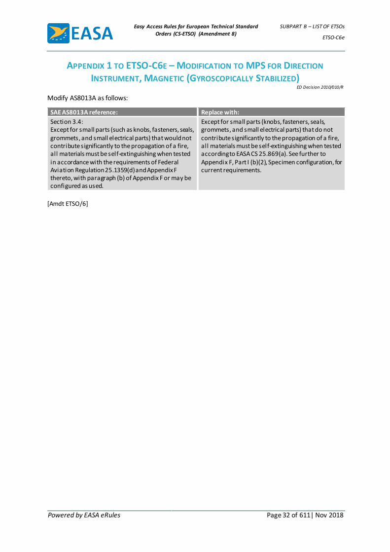
Easy Access Rules for European Technical Standard
Orders (CS-ETSO) (Amendment 8)
SUBPART B – LIST OF ETSOs
ETSO-C6e
Powered by EASA eRules Page 32 of 611| Nov 2018
APPENDIX 1 TO ETSO-C6E – MODIFICATION TO MPS FOR DIRECTION
INSTRUMENT, MAGNETIC (GYROSCOPICALLY STABILIZED) ED Decision 2010/010/R
Modify AS8013A as follows:
SAE AS8013A reference: Replace with:
Section 3.4: Except for small parts (such as knobs, fasteners, seals, grommets, and small electrical parts) that would not contribute significantly to the propagation of a fire, all materials must be self-extinguishing when tested in accordance with the requirements of Federal Aviation Regulation 25.1359(d) and Appendix F thereto, with paragraph (b) of Appendix F or may be configured as used.
Except for small parts (knobs, fasteners, seals, grommets, and small electrical parts) that do not contribute significantly to the propagation of a fire, all materials must be self-extinguishing when tested according to EASA CS 25.869(a). See further to Appendix F, Part I (b)(2), Specimen configuration, for current requirements.
[Amdt ETSO/6]
Easy Access Rules for European Technical Standard
Orders (CS-ETSO) (Amendment 8)
SUBPART B – LIST OF ETSOs
ETSO-C7d
Powered by EASA eRules Page 33 of 611| Nov 2018
ETSO-C7d ED Decision 2003/10/RM (applicable from 24.10.2003)
Direction Instrument, Magnetic Non-stabilized Type (Magnetic Compass)
1 Applicability
This ETSO gives the requirements which new models of direction instruments, magnetic non- stabilized type (magnetic compass) that are manufactured on or after the date of this ETSO must meet in order to be identified with the applicable ETSO marking.
2 Procedures
2.1 General
Applicable procedures are detailed in CS-ETSO Subpart A.
2.2 Specific
None.
3 Technical Conditions
3.1 Basic
3.1.1 Minimum Performance Standard
Standards set forth in the SAE Aerospace Standard (AS) document: AS 398A „Direction Instrument, Magnetic Non-Stabilized Type (Magnetic Compass)“, dated July 15, 1958 „reaffirmed October 1984“ (if TSO) except as amended and supplemented by this ETSO:
(i) Conformance with the following paragraphs of AS 398A is not required: 3.1; 3.1.1; 3.1.2; 3.2.
(ii) Substitute the following for paragraph 7 of AS 398A:
„Performance tests: the following tests in addition to any others deemed necessary by the manufacturers, shall be the basis for determining compliance with the performance requirements of this standard.“
3.1.2 Environmental Standard
The environmental conditions and test procedures in SAE AS 398A are to be used.
3.1.3 Computer Software
None
3.2 Specific
None
4 Marking
4.1 General
Marking is detailed in CS-ETSO Subpart A.
4.2 Specific
None.
5 Availability of Referenced Document

Easy Access Rules for European Technical Standard
Orders (CS-ETSO) (Amendment 8)
SUBPART B – LIST OF ETSOs
ETSO-C7d
Powered by EASA eRules Page 34 of 611| Nov 2018
See CS-ETSO Subpart A paragraph 3.

Easy Access Rules for European Technical Standard
Orders (CS-ETSO) (Amendment 8)
SUBPART B – LIST OF ETSOs
ETSO-C8e
Powered by EASA eRules Page 35 of 611| Nov 2018
ETSO-C8e ED Decision 2010/010/R (applicable from 21.12.2010)
Vertical Velocity Instrument (Rate-of-Climb)
1 Applicability
This ETSO gives the requirements which new models of vertical velocity instruments that are manufactured on or after the date of this ETSO must meet in order to be identified with the applicable ETSO marking.
2 Procedures
2.1 General
Applicable procedures are detailed in CS-ETSO Subpart A.
2.2 Specific
None.
3 Technical Conditions
3.1 Basic
3.1.1 Minimum Performance Standard
Standards set forth in the SAE Aerospace Standard (AS) document: AS 8016A “Vertical Velocity Instruments (Rate-of-climb)”, dated September 1996.
3.1.2 Environmental Standard
See CS-ETSO Subpart A paragraph 2.1.
3.1.3 Computer Software
See CS-ETSO Subpart A paragraph 2.2.
3.1.4 Electronic Hardware Qualification
See CS-ETSO Subpart A paragraph 2.3.
3.2 Specific
3.2.1 Failure Condition Classification
See CS-ETSO Subpart A paragraph 2.4
Failure of the function defined in paragraph 3.1.1 of this ETSO has been determined to be a minor failure condition.
4 Marking
4.1 General
Marking is detailed in CS-ETSO Subpart A paragraph 1.2.
4.2 Specific
See SAE AS 8016 paragraph 1.2
5 Availability of Referenced Document
See CS-ETSO Subpart A paragraph 3.
[Amdt ETSO/6]

Easy Access Rules for European Technical Standard
Orders (CS-ETSO) (Amendment 8)
SUBPART B – LIST OF ETSOs
ETSO-C10b
Powered by EASA eRules Page 36 of 611| Nov 2018
ETSO-C10b ED Decision 2003/10/RM (applicable from 24.10.2003)
Aircraft Altimeter, Pressure Actuated, Sensitive Type
1 Applicability
This ETSO gives the requirements which altimeters pressure actuated that are manufactured on or after the date of this ETSO must meet in order to be identified with the applicable ETSO marking.
2 Procedures
2.1 General
Applicable procedures are detailed in CS-ETSO Subpart A.
2.2 Specific
None.
3 Technical Conditions
3.1 Basic
3.1.1 Minimum Performance Standard
Standards set forth in the SAE Aerospace Standard (AS) document: AS 392C, „Altimeter, Pressure Actuated Sensitive Type“, revision date February, 1959 with the following exceptions, and as amended and supplemented by this ETSO:
Exceptions
(i) The following specifically numbered paragraphs in AS 392C do not concern minimum performance and therefore are not essential to compliance with this paragraph: 3.1, 3.1.1, 3.1.2, 3.2, 3.2(a)(b)(c)(d)(e)(f).
(ii) In lieu of Section 7. in AS 392C, it is a requirement that the altimeters covered by this section be capable of successfully passing the test in paragraphs 7.1 through 7.5 and an External Case Pressure Test which is as follows:
External Case Pressure Test The static pressure source of the instrument shall be sealed when an ambient temperature of 25°C and an ambient pressure of 29.92 inches (absolute) of mercury have been achieved. The ambient pressure shall then be increased at a rate of 20 inches of mercury in two seconds to 50 inches (absolute) of mercury and held at that pressure for three minutes. There shall be no adverse effect on the instrument or its accuracy.
(iii) The „Reference Section“ under Table II of AS 392C is not applicable.
3.1.2 Computer Software
None
3.2 Specific
None
4 Marking

Easy Access Rules for European Technical Standard
Orders (CS-ETSO) (Amendment 8)
SUBPART B – LIST OF ETSOs
ETSO-C10b
Powered by EASA eRules Page 37 of 611| Nov 2018
4.1 General
Marking is detailed in CS-ETSO Subpart A Paragraph 1.2. In addition, the maximum altitude for which altimeter is qualified to operate shall be legibly and permanently marked.
4.2 Specific
None.
5 Availability of Referenced Document
See CS-ETSO Subpart A paragraph 3.
Easy Access Rules for European Technical Standard
Orders (CS-ETSO) (Amendment 8)
SUBPART B – LIST OF ETSOs
ETSO-C13f
Powered by EASA eRules Page 38 of 611| Nov 2018
ETSO-C13f ED Decision 2006/004/R (applicable from 18.7.2006)
Life Preservers
1 Applicability
This ETSO gives the requirements which life preservers that are manufactured on or after the date of this ETSO, must meet in order to be identified with the applicable ETSO marking.
2 Procedures
2.1 General
Applicable procedures are detailed in CS-ETSO Subpart A.
2.2 Specific
None
3 Technical Conditions
3.1 Basic
3.1.1 Minimum Performance Standard
Standards set forth in the appendix 1 to this ETSO.
3.1.2 Environmental Standard
None
3.2 Specific
None
4 Marking
4.1 General
Marking is detailed in CS-ETSO Subpart A paragraph 1.2.
4.2 Specific
As given in Appendix 1.
5 Availability of Referenced Document
See CS-ETSO Subpart A paragraph 3.
Federal Test Method Standards No 191A may be obtained (or purchased) from the General Service Administration, Business Service Center, Region 3, 7th and D Streets, S.W., Washington DC 20407.
[Amdt ETSO/1]

Easy Access Rules for European Technical Standard
Orders (CS-ETSO) (Amendment 8)
SUBPART B – LIST OF ETSOs
ETSO-C13f
Powered by EASA eRules Page 39 of 611| Nov 2018
APPENDIX 1 TO ETSO-C13F – MINIMUM PERFORMANCE STANDARD FOR LIFE PRESERVERS
ED Decision 2006/004/R
1. Purpose. This standard provides the minimum performance standards for life preservers.
2. Scope. This standard covers inflatable (Type I) and non-inflatable (Type II) life preservers. Both Type I and Type II life preservers are divided into the following four categories: “Adult,” “Adult -Child,” “Child,” and “Infant-Small Child.”
3. Materials. The materials used must be of a quality which experience and/or tests have demonstrated to be suitable for use in life preservers.
3.1 Non-metallic Materials.
3.1.1 The finished device must be clean and free from any defects that might affect its function.
3.1.2 Coated fabrics and other items, such as webbing, subject to deterioration must have been manufactured not more than 18 months prior to the date of delivery of the finished product or requalified per paragraph 5.1 Material Tests of this standard.
3.1.3 The materials must not support fungal growth.
3.1.4 Coated fabrics, including seams, subject to deterioration used in the manufacture of the devices must retain at least 90 percent of their original physical properties after these fabrics have been subjected to accelerated ageing test specified in paragraph 5.1 Material Tests of this standard.
3.1.4.1 Strength. Coated fabrics used for these applications must conform to the following minimum strengths after ageing:
Tensile Strength (Grab Test)
Warp 37 N/mm (210 pounds/inch)
Fil l 32 N/mm (180 pounds/inch)
Tear Strength
1.8 x 1.8 N/mm (10 x 10 pounds/inch) (Tongue Test) or
1.8 x 1.4 N/mm (10 x 8 pounds/inch) (Trapezoid Test)
3.1.4.2 Adhesion. In addition to the requirements of 3.1.4.1, coated fabrics
must meet the following minimum strength after ageing:
Coat Adhesion
1.8 N/mm width at 21 ± 3°C at a separation rate of 50 to 65 mm/minute
(10 pounds/inch width at 70 ± 5 degrees F at a separation rate of 2.0 to 2.5 inches/minute).
3.1.4.3 Permeability. For coated fabrics used in the manufacture of inflation chambers, the maximum permeability to helium may not exceed 5 liters/square meter in 24 hours at 25°C (77 degrees F) or its equivalent using hydrogen. The permeameter must be calibrated for the gas used. In lieu of this permeability test, an alternate test may be used

Easy Access Rules for European Technical Standard
Orders (CS-ETSO) (Amendment 8)
SUBPART B – LIST OF ETSOs
ETSO-C13f
Powered by EASA eRules Page 40 of 611| Nov 2018
provided the alternate test has been approved as an equivalent to this permeability test by the Agency
3.1.5 Seam Strength and Adhesives. Cemented or heat sealable seams used in the manufacture of the device must meet the following minimum strength requirements.
3.1.5.1 Cemented Seams. Seams using adhesive on coated fabrics must be sealed with tape having a minimum width of 30 mm (1 3/16 inches). Devices manufactured with cemented seams must meet the following minimum strength requirements:
Seam Shear Strength (Grab Test)
30.6 N/mm width at 24°C (175 pounds/inch width at 75 degrees F)
7.0 N/mm width at 60°C (40 pounds/inch width at 140 degrees F)
Peel Strength (Peel Test)
1.8 N/mm width at 21°C (10 pounds/inch width at 70 degrees F)
3.1.5.2 Heat Sealed Seams. The application of tape over heat sealed seams is optional. Devices manufactured with heat sealed seams used in the manufacture of the device must meet the following minimum strength requirements:
Seam Strength (Grab Test)
7.9 N/mm width at 21°C (45 pounds/inch width at 70 degrees F)
5.3 N/mm width at 60°C (30 pounds/inch width at 140 degrees F)
3.1.6 Seam Tape. If tape is used, the fabric used for the seam tape must have a minimum breaking strength (Grab Test) of not less than 8.8 N/mm (50 pounds/inch) width in both the warp and fill directions. When applied to the seam area, the adhesion strength characteristics must meet the seam strength requirements in paragraph 3.1.5.
3.1.7 Materials Other Than Coated Fabrics.
3.1.7.1 Webbing. Webbing used to attach the life preserver to the wearer must have a minimum tensile strength of 1023 N (230 pounds).
3.1.7.2 Thread. Thread used in the life preserver must be Size E nylon or equivalent with a minimum tensile strength of 38 N (8.5 pounds).
3.1.8 Flammability. The device (including packaging) must be constructed of materials which are in compliance with CS-25.853(a) [Appendix F, Part I (a)(1)(iv)].
3.1.9 Molded Nonmetallic Fittings. Molded nonmetallic fittings must retain their physical characteristics when subjected to temperatures of –51 to +71°C (- 60 to +160 degrees F).
3.2 Metallic Parts. All metallic parts must be made of corrosion resistant material or must be suitably protected against corrosion.
4. Detail Requirements.
4.1 Design and Construction.
Easy Access Rules for European Technical Standard
Orders (CS-ETSO) (Amendment 8)
SUBPART B – LIST OF ETSOs
ETSO-C13f
Powered by EASA eRules Page 41 of 611| Nov 2018
4.1.1 Reversibility. The life preserver must perform its intended function when reversed, unless the design of the preserver precludes the probability of improper donning.
4.1.2 Compartmentation, Type I Life Preserver. An inflatable life preserver may have one or more separate gas tight flotation chambers. Each separate flotation chamber must meet the inflation requirements of paragraph 4.1.4.
4.1.3 Protection Against Abrasion and Chafing, Type I Life Preserver. The flotation chambers must be protected in such a manner that metallic or nonmetallic parts do not cause chafing or abrasion of the material in either the packed or inflated condition.
4.1.4 Inflation, Type I Life Preserver.
4.1.4.1 Oral Inflation. A means must be provided by which the wearer, excluding child and infant-small child wearers who would require adult assistance, without previous instruction, may inflate each flotation chamber by blowing into a mouthpiece. The mouthpiece for oral inflation must be readily available to the wearer without interfering with the wearer’s face or body. For infant-small child and child life preservers, the oral inflation means must be readily available to assisting persons.
4.1.4.2 Oral Inflation Valve. The opening pressure of the oral inflation valve, with no back pressure applied to the valve, may not exceed 3 kN/m2 (0.44 pounds per square inch gage (psig)). The oral inflation valve may not leak when back pressure throughout the range from 0 – 69 kN/m2 (0 psig through 10 psig) is applied. The joint between the oral inflation valve and the flotation chamber may not fail when a 445 N (100-pound) tensile load is applied for at least 3 seconds outwardly from and perpendicular to the surface of the flotation chamber at the point of valve attachment. To support the flotation chamber fabric during load application, an adapter having an inside diameter at least 19 mm (3/4 inch) larger than the outside diameter of the valve at the point of attachment must be used.
4.1.4.3 Manual Mechanical Inflation. A means must be provided by which the wearer, or person assisting a child or infant-small child wearer who would require adult assistance, without previous instruction, may inflate each flotation chamber of the life preserver by manual operation.
4.1.4.3.1 Gas Reservoir. A reservoir containing a suitable compressed gas must be provided to inflate each flotation chamber of the life preserver. If carbon dioxide (CO2) cylinders are used, the standards of MIL-C-601G Amendment 1 dated August 31, 1972 or the equivalent are acceptable not withstanding any size or weight limitations.
4.1.4.3.2 Pull Cord Assembly. The mechanical inflation means must have a pull cord assembly for each gas reservoir. The pull cords must be identical in length, clearly visible, and extend between 38 to 76 mm (1 1/2 to 3 inches) below the edge of the life preserver. The end of each pull cord assembly must be attached to a red pull knob or tab having rounded edges.

Easy Access Rules for European Technical Standard
Orders (CS-ETSO) (Amendment 8)
SUBPART B – LIST OF ETSOs
ETSO-C13f
Powered by EASA eRules Page 42 of 611| Nov 2018
4.1.5 Deflation, Type I Life Preserver. A means by which the wearer or the person assisting a child or infant-small child wearer who would require adult assistance, may quickly deflate each flotation chamber must be provided. Use of the deflation means may not preclude subsequent re-inflation of the flotation chamber by either oral or mechanical inflation means. Inadvertent deflation of the flotation chamber must be precluded. In particular, inadvertent deflation from movement of a child or infant-small child and deliberate deflation by a child or small child must be precluded.
4.1.6 Functional Temperature Range. The life preserver must be capable of satisfactory inflation after exposure for a minimum period of five minutes to the temperature range from –40 to +60°C (-40 to +140 degrees F).
4.1.7 Overpressure Protection. Type I Life Preserver. A flotation chamber, when orally inflated to a operating pressure not less than 7 kN/m2 (1 psig), must not burst upon subsequent discharge of the mechanical inflation system.
4.1.8 Buoyancy. The life preserver must provide a buoyant force not less than that shown in Table I, Minimum Buoyant Force. The buoyant force of the life preserver is equal to the weight of the volume of fresh water displaced by the life preserver when totally submerged. Buoyancy must be demonstrated using the standard gas reservoirs described in 4.1.4.3.1 without further oral inflation, starting from a vacuumed flat unit.
TABLE I, MINIMUM BUOYANT FORCE
Category of preserver Weight of wearer (kg / pounds)
Minimum buoyant force in fresh water at 21 ± 3°C (70 ± 5 degrees F)
(N / pounds)
Adult Above 41kg (90 pounds) 156N (35 pounds)
Adult - Child Combination 16kg (35 pounds) and above 156N (35 pounds)
Child 16kg (35 pounds) to 41kg (90 pounds) 111N (25 pounds)
Infant - Small Child Under 16kg (35 pounds) 89N (20 pounds)
4.1.9 Flotation Attitude.
4.1.9.1 Adult, Adult-Child, and Child Life Preservers. The life preserver must, within 5 seconds, right the wearer, who is in the water in a face-down attitude. The life preserver must provide lateral and rear support to the wearer’s head such that the mouth and nose of a completely relaxed wearer is held clear of the water line with the trunk of the body inclined backward from the vertical position at an angle of 30 degrees minimum.
4.1.9.2 Infant-Small Child Life Preservers. The life preserver must prevent contact of the wearer’s upper torso (i.e., from the waist up) with the water. There must be a means to confine the wearer in the proper position for utilization of the life preserver and prevent the wearer from releasing the confining means. With the wearer in the most adverse condition of weight and position attainable when the confining means are properly used, there must be no tendency of the life preserver to capsize or become unstable, take on water, or allow contact of the upper torso with water. Means must be provided to prevent the entrapment of rain or choppy water.

Easy Access Rules for European Technical Standard
Orders (CS-ETSO) (Amendment 8)
SUBPART B – LIST OF ETSOs
ETSO-C13f
Powered by EASA eRules Page 43 of 611| Nov 2018
4.1.10 Tether Infant-Small Child Category Life Preserver. A tether not less than 2.83 m (72 inches) in length, must be attached to the infant-small child life preserver. The attach point must be located such that the flotation attitude specified in paragraph 4.1.9.2 is maintained when the line is under sufficient tension to remove the slack as when held by an adult in the water. With the life preserver on the infant-small child, there must be provisions for stowing or securing the tether in a manner that it remains readily accessible and will not dangle loosely so as to pose a hazard during an emergency evacuation.
4.1.11 Life Preserver Retention and Donning Characteristics. The means of retaining the life preserver on the wearer, excluding infant-small child wearers, must require that the wearer secure no more than one attachment and make no more than one adjustment for fit. It must be demonstrated, in accordance with the donning tests specified in paragraph 5.9, that at least 75% of the total number of test subjects and at least 60% of the test subjects in each age group specified in paragraph 5.9 can don the life preserver within 25 seconds unassisted, starting with the life preserver in its storage package. Percentage calculations may not be increased when rounded off. It must be demonstrated that an adult unassisted can install an appropriate life preserver on another adult or a child within 30 seconds. It also must be demonstrated, in accordance with the donning tests specified in paragraph 5.9, that 60% of the adult test subjects can install an infant-small child dummy in an infant-small child life preserver within 90 seconds.
4.1.12 Comfort, Fit, and Adaptability. The design of the life preserver must be such that:
4.1.12.1 After donning, inadvertent release by the wearer is not likely.
4.1.12.2 Adjustment may be made by the wearer, or the person assisting a child or infant-small child wearer, while in the water.
4.1.12.3 Unobstructed view by the wearer, excluding infant-small child wearers, is allowed in both the forward and sideward directions. An observation window must be provided for viewing of an infant-small child wearer by the assisting person if the life preserver is enclosed.
4.1.12.4 Blood circulation of the wearer is not restricted.
4.1.12.5 The wearer’s breathing is not restricted.
4.1.13 Survivor Locator Light. The life preserver must be equipped with a survivor locator light which meets the requirements of ETSO-C85a. The light must be automatically activated. This can be accomplished upon contact with water, upon inflation or by any other means not requiring additional user action.
4.1.14 Life Preserver Package. A package must be provided for the life preserver for storage of the life preserver on board the aircraft. The means of opening the package must be simple and obvious, and must be accomplished in one operation without the use of any tool or excessive physical force.
4.1.15 Color. The color of the life preserver must be an approved international orange-yellow or similar high visibility color. The color of the flight crew life preservers may be an approved red-orange or similar high visibility contrasting color.
4.2 Marking. The following information and instructions must be shown:

Easy Access Rules for European Technical Standard
Orders (CS-ETSO) (Amendment 8)
SUBPART B – LIST OF ETSOs
ETSO-C13f
Powered by EASA eRules Page 44 of 611| Nov 2018
4.2.1 Pictorial Presentation. The proper donning procedure and other operational instructions on the use of the life preserver must be simple, obvious, and presented primarily pictorially with minimum use of words.
4.2.1.1 Orientation of Instructions. Instructions pertaining to operations which would normally be accomplished after the life preserver has been donned must be oriented so that the wearer, or the person assisting a child or an infant-small child wearer, may read them while in the water.
4.2.1.2 Readability in Emergency Lighting Conditions. Size, position, and contrast of instructions must be such that the pictorial descriptions and written instructions are easily distinguishable and readable in low level illumination. The markings and instructions must be readable by a person having 20/20 vision at a minimum viewing distance of 610 mm (24 inches) with illumination no greater than 0.54 lx (0.05 foot-candle). For written instructions, an acceptable means of complying with this requirement is by use of bold lettering approximately 5.6 mm (0.22 inch) high with a stroke width of 1.2 mm (0.047 inch).
4.2.3 Date of manufacture of fabric (month and year).
4.2.4 Size category: “Adult,” “Adult-Child,” “Child,” or “Infant-Small Child,” as appropriate and weight limitation of each category.
4.2.5 The life preserver package must clearly indicate that it contains a life preserver, the size category and the weight limitation of the life preserver. The package also must be marked with the life preserver ETSO and part number or the information must be visible through the package.
5. Tests.
5.1 Material Tests. The material properties specified in paragraph 3 of this standard must be conducted in accordance with the following test methods or other approved equivalent methods:
Accelerated AgeMethod 5850 Per Note (9)(1)
Tensile Strength (Grab Test) Method 5100 Per Note (9)(7)
Tear Strength (Trapezoid Test) Method 5136 Per Note (9)(5) (Alternate to Trapezoid Test see 3.1.4.1)
Ply Adhesion Method 5960 Per Note (9)(3)
Coat Adhesion Method 5970 Per Note (9)(8)
Permeability Method 5460 Per Note (5)(6)
Seam Shear Strength Per Note (9)(2)
Seam Peel Strength Method 5960 Per Note (9)(3)
Flammability CS-25, Appendix F, Part I(b)(5), Horizontal Burn Rate Per Note (4)
NOTES:
(1) Samples of coated fabric and seams for the accelerated ageing tests must be exposed to a temperature of 70 ± 3°C (158 ± 5 degrees F) for not less than 168 hours. After exposure, the samples must be allowed to cool to 21 ± 1°C (70 ± 2 degrees F) for neither less than 16 hours nor more than 96 hours before

Easy Access Rules for European Technical Standard
Orders (CS-ETSO) (Amendment 8)
SUBPART B – LIST OF ETSOs
ETSO-C13f
Powered by EASA eRules Page 45 of 611| Nov 2018
determining their physical properties in accordance with paragraph 3.1 of this standard.
(2) Samples must consist of two strips of material 50mm (2 inches) maximum width by 127 mm (5 inches) maximum length. Strips must be bonded or heat sealed together along the width with an overlap of 19 mm (3/4 inch) maximum. Heat sealed seams must have a 3.2 ± 0.8 mm (1/8 ± 1/32) inch width minimum heat seal bead with the heat seal 6.3 mm (1/4 inch) from each end. The free ends must be placed in the testing machine described in FTMS 191A, Method 5100 and separated at a rate of 305 ± 13 mm/minute (12 ± 0.5 inches/minute). The average value of two samples must be reported. Samples may be multilayered to ensure against premature material failure. Samples may be gripped across the full 50 mm (two inches) of width.
(3) Separation rate must be 50 to 65 mm/minute (2.0 to 2.5 inches/minute). Sample shall be 25 mm (one inch).
(4) The material must meet the flammability requirements of CS-25.853(a) [Appendix F, Part I (a)(1)(iv)]
(5) Federal Test Method Standard No. 191 in effect December 31, 1968.
(6) ASTM Method D1434-82, Procedure V, approved July 30, 1982, is an acceptable alternate method.
(7) Use of pneumatic grips, for holding test samples, is an acceptable alternate to the mechanical grips described in Method 5100.
(8) The sample shall be prepared using the adhesive and construction methods used to manufacture the life preserver. Separation rate must be 50 to 65 mm/minute (2.0 to 2.5 inches/minute).
(9) Federal Test Method Standard No. 191A dated July 20, 1978.
5.2 Leakage Test, Type I Life Preserver. The life preserver may not lose more than 3.5 kN/m2 (1/2 psig) per flotation chamber after each flotation chamber has been inflated to not less than 13.8 kN/m2 (2 psig) and hung in a rack for at least 12 hours.
5.3 Overpressure Test, Type I Life Preserver. Each flotation chamber of the life preserver must withstand an inflation pressure of not less than 69 kN/m2 (10 psig) for at least 5 minutes.
5.4 Submersion Test. The life preserver must be submerged in fresh water at 22 ± 3°C (72 ± 5 degrees F) so that no part of it is less than 610 mm (24 inches) below the surface. The buoyancy of the preserver must not be less than the value specified in paragraph 4.1.8 of this standard. Submersion must continue for at least 8 hours, except that the test may be discontinued in less than 8 hours if buoyancy measurements taken at four successive 30-minute intervals show that the buoyancy of the preserver has stabilized at a value at least equal to the value specified in paragraph 4.1.8 of this standard.
5.5 Salt Spray Test.
5.5.1 Salt Spray Test Procedure. All metal parts must be placed in an atomized salt solution spray for a period of not less than 100 hours. The solution must be atomized in the chamber at a rate of 10 litres per cubic metre of chamber volume (3 quarts per 10 cubic feet of chamber volume) per each 24-hour period. The

Easy Access Rules for European Technical Standard
Orders (CS-ETSO) (Amendment 8)
SUBPART B – LIST OF ETSOs
ETSO-C13f
Powered by EASA eRules Page 46 of 611| Nov 2018
temperature in the chamber must be maintained at 35 ± 1°C (95 ± 2 degrees F) throughout the test.
5.5.2 Salt Spray Solution. The salt used must be sodium chloride or equivalent containing not more than 0.2 percent of impurities on the dry weight basis. The spray solution must be prepared by dissolving 20 ± 2 parts by weight of salt in 80 ± 2 parts by weight of water containing not more than 200 parts per million of solids. The spray solution must be kept from exceeding this level of solids throughout the test. The spray solution must be maintained at a specific gravity of from 1.126 to 1.157 and a pH between 6.5 and 7.2 when measured at 35 ± 1°C (95 ± 2 degrees F).
5.6 Inflator Test, Type I Life Preserver.
5.6.1 Operating Force. The force necessary to operate the mechanical inflation means may not exceed 67 N (15 pounds) when applied through the pull cord.
5.6.2 Pull Cord Strength. The pull cord may not fail or separate from the mechanical inflation means when a minimum tension load of 267 N (60 pounds) is applied to the cord for at least 3 seconds. If the pull cord is designed to separate from the mechanical inflation means when operated, the pull cord shall be capable of withstanding a minimum tension load of 133 N (30 pounds) for 3 seconds without failure.
5.6.3 Proof Pressure. The mechanical inflation means must withstand a hydrostatic pressure of not less than 10.3 MN/m2 (1,500 psig) without deformation or leakage. The mechanical inflation means may not leak when subjected to 13.8 kN/m2 (2 psig) air pressure and may not lose more than 3.4 kN/m2 (0.5 psig) when subjected to 276 kN/m2 (40 psig) air pressure. Each test pressure must be applied for not less than 30 seconds.
5.6.4 Mechanical Inflation Valve. The mechanical inflation valve must allow a minimum flow of 4 liters of air per minute at 276 kN/m2 (40 psig) inlet pressure. The valve may not leak when subjected to a vacuum of 3 kN/m2 (12 inches of water) applied so as to reduce the seating spring pressure and with atmospheric pressure on the opposite side. The joint between the valve and the flotation chamber may not fail when a 1112 N (250-pound) load is applied, for at least 3 seconds, outwardly from and perpendicular to the surface of the flotation chamber at the point of valve attachment. To secure the joint during application of the load, an adapter having an inside diameter at least 19 mm (3/4 inch) larger than the outside diameter of the valve at the point of attachment must be used.
5.7 Jump Test.
5.7.1 Adult, Adult-Child or Child. An inflated adult, adult-child, or child Type I or Type II life preserver, excluding infant-small child life preservers, must remain attached and not cause injury to the wearer when the wearer jumps into the water at any attitude from a height above the water of at least 1.5 m (5 feet). There must not be any damage to the preserver following the jump. Minor skin chafing is not considered an injury in this respect.
5.7.2 Infant-Small Child. An infant-small child life preserver must remain inflated and undamaged and the infant-small child dummy, specified in paragraph 5.9.1, must remain properly secured when an adult holding the dummy, with the preserver installed on the dummy, jumps into the water from a height above the water of at
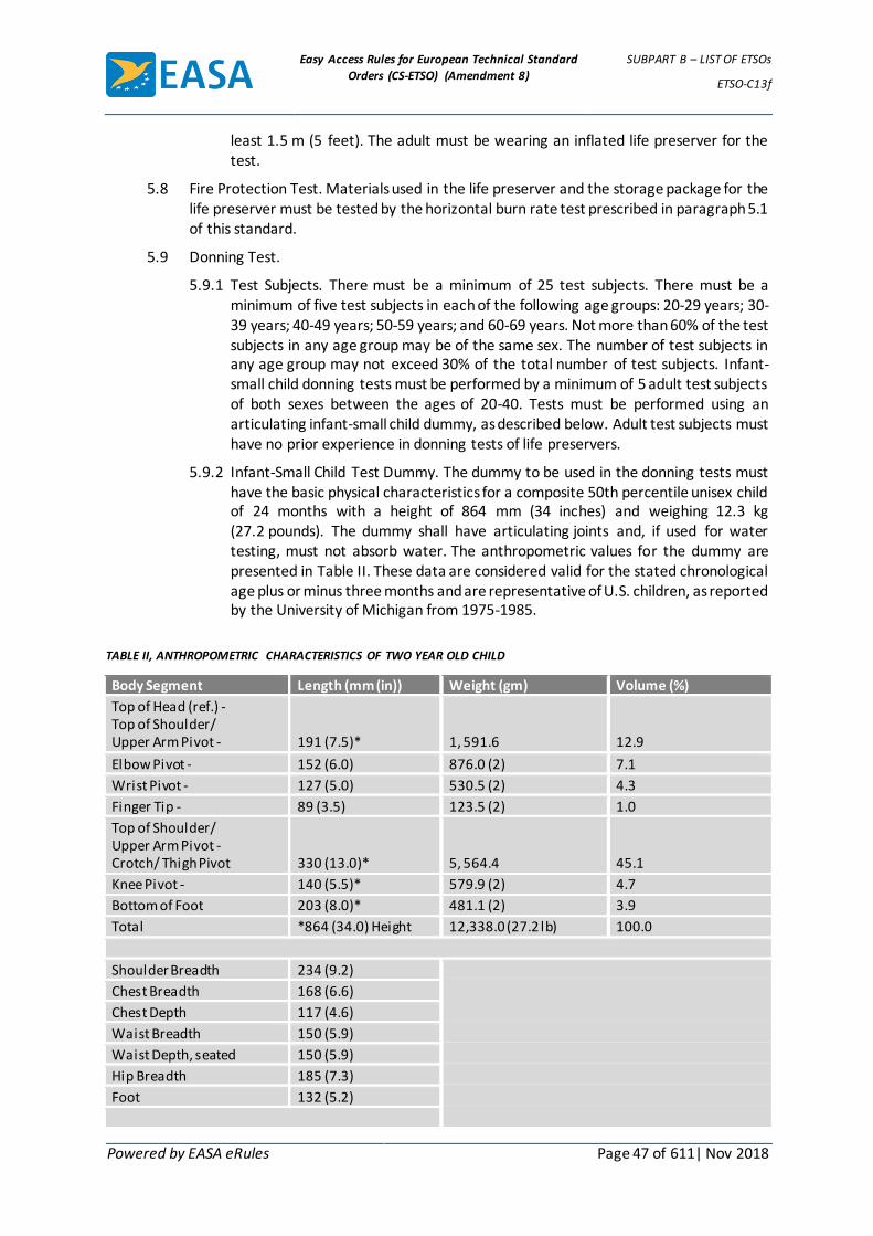
Easy Access Rules for European Technical Standard
Orders (CS-ETSO) (Amendment 8)
SUBPART B – LIST OF ETSOs
ETSO-C13f
Powered by EASA eRules Page 47 of 611| Nov 2018
least 1.5 m (5 feet). The adult must be wearing an inflated life preserver for the test.
5.8 Fire Protection Test. Materials used in the life preserver and the storage package for the life preserver must be tested by the horizontal burn rate test prescribed in paragraph 5.1 of this standard.
5.9 Donning Test.
5.9.1 Test Subjects. There must be a minimum of 25 test subjects. There must be a minimum of five test subjects in each of the following age groups: 20-29 years; 30-39 years; 40-49 years; 50-59 years; and 60-69 years. Not more than 60% of the test subjects in any age group may be of the same sex. The number of test subjects in any age group may not exceed 30% of the total number of test subjects. Infant-small child donning tests must be performed by a minimum of 5 adult test subjects of both sexes between the ages of 20-40. Tests must be performed using an articulating infant-small child dummy, as described below. Adult test subjects must have no prior experience in donning tests of life preservers.
5.9.2 Infant-Small Child Test Dummy. The dummy to be used in the donning tests must have the basic physical characteristics for a composite 50th percentile unisex child of 24 months with a height of 864 mm (34 inches) and weighing 12.3 kg (27.2 pounds). The dummy shall have articulating joints and, if used for water testing, must not absorb water. The anthropometric values for the dummy are presented in Table II. These data are considered valid for the stated chronological age plus or minus three months and are representative of U.S. children, as reported by the University of Michigan from 1975-1985.
TABLE II, ANTHROPOMETRIC CHARACTERISTICS OF TWO YEAR OLD CHILD
Body Segment Length (mm (in)) Weight (gm) Volume (%)
Top of Head (ref.) - Top of Shoulder/ Upper Arm Pivot -
191 (7.5)*
1, 591.6
12.9
Elbow Pivot - 152 (6.0) 876.0 (2) 7.1
Wrist Pivot - 127 (5.0) 530.5 (2) 4.3
Finger Tip - 89 (3.5) 123.5 (2) 1.0
Top of Shoulder/ Upper Arm Pivot - Crotch/ Thigh Pivot
330 (13.0)*
5, 564.4
45.1
Knee Pivot - 140 (5.5)* 579.9 (2) 4.7
Bottom of Foot 203 (8.0)* 481.1 (2) 3.9
Total *864 (34.0) Height 12,338.0 (27.2 lb) 100.0
Shoulder Breadth 234 (9.2)
Chest Breadth 168 (6.6)
Chest Depth 117 (4.6)
Waist Breadth 150 (5.9)
Waist Depth, seated 150 (5.9)
Hip Breadth 185 (7.3)
Foot 132 (5.2)

Easy Access Rules for European Technical Standard
Orders (CS-ETSO) (Amendment 8)
SUBPART B – LIST OF ETSOs
ETSO-C13f
Powered by EASA eRules Page 48 of 611| Nov 2018
Circumferences
Head 488 (19.2)
Neck 234 (9.2)
Chest 488 (19.2)
Waist 460 (18.1)
Hip 470 (18.5)
Mid-Thigh 251 (9.9)
Calf 196 (7.7)
Ankle 135 (5.3)
Upper Arm 150 (5.9)
Forearm 147 (5.8)
Wrist 130 (5.1)
5.9.3 Test Arrangement. Subjects must be seated in actual or simulated air carrier coach class seating with a seat row in front of the subjects creating a seat row pitch not exceeding 31 inches. Each subject must have the seat belt fastened. Subjects may be tested singularly or in groups seated side by side. Infant-small child life preserver donning tests must be performed with adults in adjacent seats who must not assist or hamper the adult performing the donning test. Subjects must receive no donning information other than a typical preflight briefing and donning demonstration on the use of life preservers.
5.9.4 Test Procedure. The donning test must be begun with the life preserver contained in the storage package required by paragraph 4.1.14, and the package held in the test subject’s hand. Separate timing must be kept for each test subject. Timing starts on signal when the test subject has both hands on the packaged life preserver and stops when the life preserver is properly donned, secured, and adjusted for fit. During the test, the test subject may release the seat belt and rise from the seat but may not move to any extent from the area immediately in front of the seat.
[Amdt ETSO/1]
Easy Access Rules for European Technical Standard
Orders (CS-ETSO) (Amendment 8)
SUBPART B – LIST OF ETSOs
ETSO-C14b
Powered by EASA eRules Page 49 of 611| Nov 2018
ETSO-C14b ED Decision 2003/10/RM (applicable from 24.10.2003)
Aircraft Fabric, Intermediate Grade
1 Applicability
This ETSO gives the requirements which new models of aircraft fabric, intermediate grade that is manufactured on or after the date of this ETSO must meet in order to be identified with the applicable ETSO marking.
2 Procedures
2.1 General
Applicable procedures are detailed in CS-ETSO Subpart A.
2.2 Specific
None.
3 Technical Conditions
3.1 Basic
3.1.1 Minimum Performance Standard
Standards set forth in the SAE Aerospace Material Specification (AMS) 3804c „Cloth Airplane Cotton Mercerized 65lb (290N) Breaking Strength“, dated January 1, 1984 as amended and supplemented by this ETSO:
Exceptions:
(i) Delete from paragraph 2 of SAE AMS 3804c the following: „the latest issue of Aerospace Material Specification (AMS) shall apply.“
(ii) Compliance with paragraphs 4.2.2.1, 5.2.4, and 8.3 of SAEAMS 3804c is not required.
Additions:
(i) Paragraph 1.1 of SAEAMS 3804c shall read as follows: Form: This specification covers one strength and one weave of mercerized cotton cloth known as „airplane cloth“. However, synthetic fabric material, in particular polyester in the greige condition, also may be identified and used as „airplane cloth“ if the fabric is shown to have certain equivalent properties as cotton cloth.
(ii) Paragraph 1.2 of SAEAMS 3804c shall read as follows: Application. Aircraft with wing loading less than 9 pounds per square foot (psf) and never-exceed speeds 160 miles per hour (mph). Primarily for the external covering of aircraft surfaces, such as wings, fuselage, ailerons, elevators and other airfoil surfaces.
(iii) Replace the word cotton with cotton cloth in paragraph 3.1.1 of SAE AMS 3804c.
(iv) Paragraph 3.1.2 of SAEAMS 3804c shall read as follows: Yarn: The cloth shall be woven from 2-ply combed cotton yarn or synthetic continuous filament yarn.
Easy Access Rules for European Technical Standard
Orders (CS-ETSO) (Amendment 8)
SUBPART B – LIST OF ETSOs
ETSO-C14b
Powered by EASA eRules Page 50 of 611| Nov 2018
(v) Paragraph 3.1.4 of SAEAMS 3804c shall read as follows: Finishing: The cloth shall be uniformly finished in accordance with the best practice for high grade airplane cloth. Finishing of cotton cloth shall consist of washing, framing and calendaring. The calendaring shall be sufficient to lay any nap present and shall provide a smooth even surface. Nap may be removed by singeing. Synthetic cloth shall remain unfinished (greige).
(vi) In addition to the requirements of paragraphs 3.2.1, 3.2.2 and 3.2.5 of SAEAMS 3804c, include the following after each title: (cotton cloth only).
(vii) The first sentence of paragraphs 3.3 of SAEAMS 3804c, shall read as follows: Quality: The cotton fibers and synthetic filament shall be evenly spun into yarns of proper and uniform yarn count, twist and diameter to produce the texture and weight required.
(viii) In addition to the requirements of paragraphs 4.6.1, 4.6.2 and 5.2.2 of SAEAMS 3804c, replace reference to AMS 3804c with ETSO-C14b.
3.2 Specific
None.
4 Marking
4.1 General
Requirements for marking are specified in paragraph 5.1 of SAE AMS 3804c.
4.2 Specific
None.
5 Availability of Referenced Document
See CS-ETSO Subpart A paragraph 3.
Easy Access Rules for European Technical Standard
Orders (CS-ETSO) (Amendment 8)
SUBPART B – LIST OF ETSOs
ETSO-C15d
Powered by EASA eRules Page 51 of 611| Nov 2018
ETSO-C15d ED Decision 2003/10/RM (applicable from 24.10.2003)
Aircraft Fabric, Grade A
1 Applicability
This ETSO gives the requirements which new models of aircraft fabric, grade A that is manufactured on or after the date of this ETSO must meet in order to be identified with the applicable ETSO marking.
2 Procedures
2.1 General
Applicable procedures are detailed in CS-ETSO Subpart A.
2.2 Specific
None.
3 Technical Conditions
3.1 Basic
3.1.1 Minimum Performance Standard
Standards set forth in the SAE Aerospace Material Specification (AMS) 3806d „Cloth Airplane Cotton Mercerized 80lb (355N) Breaking Strength“, [dated April 15, 1980] as amended and supplemented by this ETSO:
Exceptions:
(i) Delete from paragraph 2 of SAE AMS 3806d the following: „the latest issue of Aerospace Material Specification (AMS) shall apply.“
(ii) Compliance with paragraphs 4.2.2.1, 5.2.4, and 8.3 of SAEAMS 3806d is not required.
Additions:
(i) Paragraph 1.1 of SAEAMS 3806d shall read as follows: Form: This specification covers one strength and one weave of mercerized cotton cloth known as „airplane cloth“. However, synthetic fabric material, in particular polyester in the greige condition, also may be identified and used as „airplane cloth“ if the fabric is shown to have certain equivalent properties as cotton cloth.
(ii) Paragraph 1.2 of SAEAMS 3806d shall read as follows: Application. Aircraft with wing loading less than 9 pounds per square foot (psf) and never-exceed speeds 160 miles per hour (mph) or greater. Primarily for the external covering of aircraft surfaces, such as wings, fuselage, ailerons, elevators and other airfoil surfaces.
(iii) Replace the word cotton with cotton cloth in paragraph 3.1.1 of SAE AMS 3806d.
(iv) Paragraph 3.1.2 of SAEAMS 3806d shall read as follows: Yarn: The cloth shall be woven from 2-ply combed cotton yarn or synthetic continuous filament yarn.

Easy Access Rules for European Technical Standard
Orders (CS-ETSO) (Amendment 8)
SUBPART B – LIST OF ETSOs
ETSO-C15d
Powered by EASA eRules Page 52 of 611| Nov 2018
(v) Paragraph 3.1.4 of SAEAMS 3806d shall read as follows: Finishing: The cloth shall be uniformly finished in accordance with the best practice for high grade airplane cloth. Finishing of cotton cloth shall consist of washing, framing and calendaring. The calendaring shall be sufficient to lay any nap present and shall provide a smooth even surface. Nap may be removed by singeing. Synthetic cloth shall remain unfinished (greige).
(vi) In addition to the requirements of paragraphs 3.2.1, 3.2.2 and 3.2.6 of SAEAMS 3806d, include the following after each title: (cotton cloth only).
(vii) The first sentence of paragraphs 3.3 of SAEAMS 3806d, shall read as follows:
Quality: The cotton fibers and synthetic filament shall be evenly spun into yarns of proper and uniform yarn count, twist and diameter to produce the texture and weight required.
(viii) In addition to the requirements of paragraph 4.6.1, 4.6.2, 5.1 and 5.2.2 of SAEAMS 3806d, replace reference to AMS 3806d with ETSO-C15d.
3.2 Specific
None.
4 Marking
4.1 General
Requirements for marking are specified in paragraph 5.1 of SAE AMS 3806[d].
4.2 Specific
None.
5 Availability of Referenced Document
See CS-ETSO Subpart A paragraph 3.

Easy Access Rules for European Technical Standard
Orders (CS-ETSO) (Amendment 8)
SUBPART B – LIST OF ETSOs
ETSO-C16a
Powered by EASA eRules Page 53 of 611| Nov 2018
ETSO-C16a ED Decision 2009/014/R (applicable from 21.10.2009)
Electrically Heated Pitot and Pitot-Static Tubes
1 Applicability
This ETSO gives the requirements which electrically heated pitot and pitot-static tubes, heated by aircraft electrical power, that are manufactured on or after the date of this ETSO must meet in order to be identified with the applicable ETSO marking.
The standards apply to the following basic types:
1. Type I - Pitot pressure, straight and L-shaped, electrically heated.
2. Type II - Pitot and static pressures, straight and L-shaped, electrically heated.
2 Procedures
2.1 General
Applicable procedures are detailed in CS-ETSO Subpart A.
2.2 Specific
None.
3 Technical Conditions
3.1 Basic
3.1.1 Minimum Performance Standard
Standards set forth in SAE International’s Aerospace Standard AS8006, Minimum Performance Standard for Pitot and Pitot-Static Tubes, dated April 28, 1988, Sections 1, 2, 3, 4, and 5, as amended by appendix 1 of this ETSO.
3.1.2 Environmental Standard
See CS-ETSO Subpart A paragraph 2.1.
Replace all references of RTCA/DO-160B in AS8006 with the standard revision as provided in CS-ETSO Subpart A paragraph 2.1.
3.1.3 Computer Software
None
3.2 Specific
None
4 Marking
4.1 General
Marking is detailed in CS-ETSO Subpart A paragraph 1.2.
4.2 Specific
In addition, the following identification information must be permanently and legibly marked:
identification information required in SAE AS8006,
“Type I” or “Type II” of the pitot and pitot-static tube,

Easy Access Rules for European Technical Standard
Orders (CS-ETSO) (Amendment 8)
SUBPART B – LIST OF ETSOs
ETSO-C16a
Powered by EASA eRules Page 54 of 611| Nov 2018
mark the following elements with at least the name of the manufacturer, manufacturer’s sub-assembly part number, and the ETSO number:
(1) Each component that is easily removable (without hand tools),
(2) Each interchangeable element, and
(3) Each separate sub-assembly of the article that the manufacturer determines may be interchangeable.
5 Availability of Referenced Document
See CS-ETSO Subpart A paragraph 3.
[Amdt ETSO/4]

Easy Access Rules for European Technical Standard
Orders (CS-ETSO) (Amendment 8)
SUBPART B – LIST OF ETSOs
ETSO-C16a
Powered by EASA eRules Page 55 of 611| Nov 2018
APPENDIX 1 TO ETSO-C16A – MINIMUM PERFORMANCE STANDARD FOR
ELECTRICALLY HEATED PITOT AND PITOT-STATIC TUBES ED Decision 2009/014/R
1. This ETSO modifies SAE AS8006, Sections 3, 4 and 5 as follows:
AS8006 EASA Modification
Section 3.3 Replace “Materials shall be corrosion–resistant and suitably treated to resist corrosion due to atmospheric conditions and salt spray. Non-magnetic materials shall be used for all parts except where magnetic materials are essential. Non-ferrous materials shall be used for all parts except where ferrous materials are essential.” Substitute: “Materials must be shown by experience or tests to be suitable and dependable. Materials must be corrosion–resistant and suitably treated to resist corrosion due to atmospheric conditions and salt spray.”
Section 3.4.2 Delete “The minimum drain hole size is 0.029 in (0.74mm).”
Section 3.4.5 Delete Section 3.4.5 of AS8006, and renumber the remaining paragraphs in section 3 of AS8006 accordingly.
Section 3.4.9 Delete Section 3.4.9 of AS8006, and renumber the remaining paragraphs in section 3 of AS8006 accordingly.
Section 3.4.10 Delete “The heater shall be regulated automatically in such a manner that the power dissipation through the heater will be an inverse function of the heating element temperature.”
Section 3.5.7 Delete “Initial power surge shall not exceed four times the rated power under deicing conditions.”
Section 3.5.7 Add at the end of Section 3.5.7 of AS8006: “Provide instructions for installation limitations in component maintenance manual (CMM). Require the use of properly rated circuit breaker for the sensor installation.”
Section 3.7 Replace “Pitot and static pressure tube lines shall be identified by the letters “P” and “S”, respectively, which shall be stamped, edged, or engraved on the fittings or couplings.” Substitute: “Identify pitot pressure and static pressure tube lines by the letters “P” and “S” respectively. Stamp, edge or engrave the letters on the lines or fittings.”
Section 4.5 Replace “After the 5 min period, the power shall be measured and shall not exceed 60 % of rated power for operation under deicing conditions specified in 5.4.” Substitute: “After the 5-minute period, measure the power. The heater will operate according to the conditions specified on the probe’s specification control drawing.”
Section 5 Replace “Representative samples shall be subjected to whatever tests the manufacturer deems necessary to demonstrating compliance with the requirements of this specification, but as a minimum must include the following tests on at least one sample.” Substitute: “Manufacturers must subject representative samples to whatever tests they deem necessary to demonstrate compliance with this specification. As a minimum they must include the following tests.”
Section 5.4 Replace “At the conclusion of the tests, any moisture accumulating in the pitot connection l ine shall be removed and measured and shall not exceed 1 gram.” Substitute: “Any moisture accumulating inside the probe must not freeze or affect the pressure measurements.”
Section 5.4 Use the following for the de-icing and anti-icing tests in place of the temperature and liquid water content requirements of Section 5.4 of SAE AS8006: “Use test conditions defined in CS-25, Appendix C, Part I,(b) Intermittent maximum icing, for the icing test conditions. Specifically, three conditions should be accomplished at a drop diameter of 20 micron: a liquid water content of 2.2 grams per cubic meter at an ambient temperature of -10 degrees C or colder, a liquid water content of 1.7 grams per cubic meter at an ambient temperature of -20 degrees C or colder, and a l iquid water content of 1.0

Easy Access Rules for European Technical Standard
Orders (CS-ETSO) (Amendment 8)
SUBPART B – LIST OF ETSOs
ETSO-C16a
Powered by EASA eRules Page 56 of 611| Nov 2018
grams per cubic meter at an ambient temperature of -30 degrees C or colder. Accomplish the icing test at a voltage 10 % below the nominal rated voltage. In addition, use the liquid water content tests of the supercooled liquid water test No.1 of paragraph 8.7.2(1), and test No.2 of paragraph 8.7.2(2) of the British Standards Institution (BSI) 2G 135, Electrically-Heated Pitot and Pitot-Static Pressure Heads, dated 1 January 1967, Section 8.7, and Amendment 1, dated 31 July 1973 (R 1998). Accomplish this icing test at a voltage 10 % below the nominal rated voltage.”
Section 5.5 Delete “Initial power surge shall not exceed four times the deicing rated power.”
Section 5.11 Add: “Section 5.11 Magnetic Effect: Determine the magnetic effect of the tube in terms of the deflection of a free magnet approximately 1-1/2 inches long in a magnetic field with a horizontal intensity of 0.18 ± 0.01 gauss, when the tube is held in various positions and with rated voltage applied on an east-west l ine with its nearest part 12 inches from the centre of the magnet. (An aircraft compass with the compensating magnets removed may be used as the free magnet for this test.) The maximum deflection for the free magnet must not exceed 5 degrees from any indication or reference position.”
[Amdt ETSO/4]

Easy Access Rules for European Technical Standard
Orders (CS-ETSO) (Amendment 8)
SUBPART B – LIST OF ETSOs
ETSO-C20
Powered by EASA eRules Page 57 of 611| Nov 2018
ETSO-C20 ED Decision 2003/10/RM (applicable from 24.10.2003)
Combustion Heaters
1 Applicability
This ETSO gives the requirements which combustion heaters that are manufactured on or after the date of this ETSO, must meet in order to be identified with the applicable ETSO marking.
2 Procedures
2.1 General
Applicable procedures are detailed in CS-ETSO Subpart A.
2.2 Specific
None.
3 Technical Conditions
3.1 Basic
3.1.1 Minimum Performance Standard
Standards set forth in the Society of Automotive Engineers, Inc., (SAE) Aerospace Standard AS 143B „HEATERS, AIRPLANE, INTERNAL COMBUSTION HEAT EXCHANGER TYPE“, issued January 11, 1943, revised January 1949.
3.1.2 Environmental Standard
As indicated in AS 143B.
3.1.3 Computer Software
None
3.2 Specific
None
4 Marking
4.1 General
Marking is detailed in CS-ETSO Subpart A paragraph 1.2.
4.2 Specific
None.
5 Availability of Referenced Document
See CS-ETSO Subpart A paragraph 3.

Easy Access Rules for European Technical Standard
Orders (CS-ETSO) (Amendment 8)
SUBPART B – LIST OF ETSOs
ETSO-C21b
Powered by EASA eRules Page 58 of 611| Nov 2018
ETSO-C21b ED Decision 2003/10/RM (applicable from 24.10.2003)
Aircraft Turnbuckle Assemblies and/or Turnbuckle Safetying Devices
1 Applicability
This ETSO gives the requirements which new models of aircraft turnbuckle assemblies and/or turnbuckle safetying devices that are manufactured on or after the date of this ETSO must meet in order to be identified with the applicable ETSO marking.
2 Procedures
2.1 General
Applicable procedures are detailed in CS-ETSO Subpart A.
2.2 Specific
None.
3 Technical Conditions
3.1 Basic
3.1.1 Minimum Performance Standard
Standards set forth in Sections 3 and 4 of Military Specifications MIL-T-5685A, dated April 6, 1950 with the additional tests, when applicable, listed below and as amended and supplemented by this ETSO:
Tests The following tests, when applicable, are required in addition to those set forth in MIL-T-5685A, and shall be conducted to substantiate the strength and reliability of special turnbuckle assemblies and/or safetying devices. A minimum of six samples each shall be used in conducting the tests for torsion, tension, fatigue (tensile), and fatigue (torsion).
(i) Torsion. At least one sample of each size turnbuckle assembly and safetying device shall be tested in torsion to determine that the torque necessary to overcome the turnbuckle thread friction and break the safetying device is equal to or greater than that required when the conventional safety wire is used in accordance with the safetying procedure recommended in Civil Aeronautics Manual 4b.329-2.
(ii) Tension. At least one sample of each size turnbuckle and safetying device assembly shall be tested to determine that the turbuckle assembly (including safetying device) will not fail at any tensile load under the maximum (ultimate) tensile strength for which the comparable standard MIL or NAS turnbuckle is rated. For this test, the sample shall consist of the turnbuckle assembly (including safetying device) with a two (2) foot length of cable appropriately attached to each terminal (end) of the turnbuckle. In making the determination, the sample shall be tested for tensile strength in accordance with Federal Test Method Std. N° 151.3. If the sample does not fail under the specified maximum load, it need not be tested further to destruction.
(iii) Vibration. At least one sample of each of 3 representative sizes of turnbuckle assemblies, i.e., the smallest, the largest, and an intermediate size, shall be vibrated to determine that the lock wire, or other safetying device which

Easy Access Rules for European Technical Standard
Orders (CS-ETSO) (Amendment 8)
SUBPART B – LIST OF ETSOs
ETSO-C21b
Powered by EASA eRules Page 59 of 611| Nov 2018
relies upon spring action or clamping to safety the turnbuckle, can be depended upon not to jump out of place or otherwise lose its safetying properties, under vibratory conditions apt to be encountered in aircraft service. It is suggested that a cable tension load equal to 25 percent of rated ultimate cable strength and a frequency of 3600 cpm with an overall amplitude of 1/8 inch (parallel to the axis of the hole through the barrel) for 25 hours, be used for this determination.
(iv) Fatigue (Tensile). At least one sample of each size turnbuckle assembly shall be given a repeated load test, in which a load equal to 2/3 the ultimate tensile strength requirement is applied repeatedly in tension for 300 applications of the load without failure of any component part. For this test, the sample shall consist of the turnbuckle assembly (including safetying device) with a two (2) foot length of cable appropriately attached to each terminal (end) of the turnbuckle.
(v) Fatigue (Bending). The safety wire used in the conventional lock wire safetying procedure recommended in CAM 4b.329-2 is not considered to be re-usable. If the safety device used with the special aircraft turnbuckle assembly is to be considered re-usable, at least three (3) samples of the shortest formed non-standard safety wire (or other finished safetying device) shall be tested by alternate fastening and unfastening of the wire (or other safetying device), to determine that the device will not break after repeated applications of the bending loads involved. 200 on and off cycles, simulating rough treatment apt to be experienced during maintenance should substantiate a reasonable service life. It is felt that the shortest safety wire (or other safetying device) will be subjected to the greatest bending stresses. However, if the stresses may be greater in a longer wire (or other safetying device) intended for a larger size turnbuckle, the larger size turnbuckle and the longer wire (or other safetying device) shall be used for this test.
(vi) Fatigue (Torsion). At least one sample of each size turnbuckle assembly and/or safetying device shall be given a repeated load test in which a load equal to 2/3 the torque (determined in test No 1 above) required to overcome the turnbuckle thread friction and break the conventional safety wire (CAM 4b.329-2) is applied in torsion first in one direction and then reversed for 3000 complete cycles of reversal without failure of any component part.
3.2 Specific
None
4 Marking
4.1 General
Marking is detailed in CS-ETSO Subpart A paragraph 1.2.
4.2 Specific
None.
5 Availability of Referenced Document
See CS-ETSO Subpart A paragraph 3.

Easy Access Rules for European Technical Standard
Orders (CS-ETSO) (Amendment 8)
SUBPART B – LIST OF ETSOs
ETSO-C22g
Powered by EASA eRules Page 60 of 611| Nov 2018
ETSO-C22g ED Decision 2003/10/RM (applicable from 24.10.2003)
Safety Belts
1 Applicability
This ETSO gives the requirements that safety belts which are manufactured on or after the date of this ETSO, must meet in order to be identified with the applicable ETSO marking.
2 Procedures
2.1 General
Applicable procedures are detailed in CS-ETSO Subpart A.
2.2 Specific
None.
3 Technical Conditions
3.1 General
3.1.1 Minimum Performance Standard
Standards set forth in Society of Automotive Engineers, Inc. (SAE) Aerospace Standard (AS) Document No. AS 8043, „Torso Restraint Systems,“ dated March 1986, with the exceptions and revisions covered in subparagraphs 3.1.1.(3) and 3.1.1.(4) of this ETSO. Through these exceptions and additions, this ETSO only uses those paragraphs of SAE AS 8043 applicable to the pelvic restraint (seat belt) portion of the torso restraint system.
(1) Exceptions.
(i) Wherever SAE AS 8043 refers to torso restraint system(s) or pelvic restraint it shall be considered to be applicable to safety-belt restraint system(s).
(ii) The information contained in Sections 1., 2.1, 2.3, and 2.9 of SAE AS 8043 is not relevant to safety belt restraint systems and shall be disregarded.
(iii) Compliance with Sections 3.2, 3.2.2, 3.8, 5.9, 6.1, 6.1.2, 8.9, 9.3 and 9.4 of SAE AS 8043 is not required.
(iv) Disregard references to breaking strength of upper torso restraint webbing and attachment hardware specified in Sections 4.2, 4.4, and 5.3 of SAE AS 8043 respectively.
(2) Additions.
(i) The definition in Section 2.2 of SAE AS 8043 shall read as follows: Safety Belt Restraint System: Consists of any webbing or similar device including all buckles or other fasteners, and all integral hardware designed to restrain movement of the pelvis, commonly referred to as a lap belt or safety belt.
(ii) The requirements of Section 3.2.1 of SAE AS 8043 shall read as follows: Safety Belt Restraint System: A safety belt restraint system shall

Easy Access Rules for European Technical Standard
Orders (CS-ETSO) (Amendment 8)
SUBPART B – LIST OF ETSOs
ETSO-C22g
Powered by EASA eRules Page 61 of 611| Nov 2018
provide pelvic restraint and shall not incorporate emergency locking retractors (inertia reels).
(iii) Section 9.1 of SAE AS 8043 is revised and shall read as follows: Installation: All components of three seat belt restraint systems shall be tested using a rigid test block, as shown in Figures 2 and 3, or a modified test block incorporating only the first 6 inches of the test block shown in Figure 3, or the equivalent, using the procedures in paragraph 9.2, as appropriate. Install the seat belt restraint system on the test block, as shown in Figure 2 and adjust to a length of 1220-1270 mm (48-50 inches), or as near as possible. An automatic locking retractor should be locked at the start of the test with a force on the webbing just sufficient to keep the retractor locked.
(3) Environmental Standards. SAE AS 8043 incorporates as reference the following environmental standards, for which a more recent version of these standards may be substituted, if approved by the Agency.
(i) American Society for Testing Materials (ASTM) G23-81, Standard Practice for Operating Light-Exposure Apparatus (Carbon-Arc Type) With and Without Water for Exposure of Nonmetallic Materials.
(ii) ASTM B117-73, Standard Method of Salt Spray (Fog) Testing.
(iii) ASTM D756-78, Standard Practice for Determination of Weight and Shape Changes of Plastics Under Accelerated Service Conditions.
(4) Test Methods. SAE AS 8043 incorporates as a reference the following test standards, for which a more recent version of these standards may be substituted, if approved by the Agency.
(i) American Association of Textile Chemist and Colorists (AATCC) Standard Test Method 8- 1981, Colorfastness to Crocking.
(ii) AATCC Standard Test Method 107-1981, Colorfastness to Water.
(iii) Federal Test Method Standard 191, Method 5906.
(iv) AATCC Chart for Measuring Transference of Color.
4 Marking
4.1 General
Marking is detailed in CS-ETSO Subpart A paragraph 1.2.
4.2 Specific
None.
5 Availability of Referenced Document
1. See CS-ETSO Subpart A paragraph 3.
2. Copies of AATCC 8-1981 and 107-1981 may be purchased from the American Association of Textile Chemists and Colorists, PO Box 12215, Research Triangle Park, NC 27709, USA.
3. Copies of Federal Test Method Standard 191 Method 5906 may be purchased from the Commanding Officer, Naval Publications and Forms Center, 5801 Tabor Avenue, Philadelphia, PA 19120, USA.

Easy Access Rules for European Technical Standard
Orders (CS-ETSO) (Amendment 8)
SUBPART B – LIST OF ETSOs
ETSO-C23d
Powered by EASA eRules Page 62 of 611| Nov 2018
ETSO-C23d ED Decision 2003/10/RM (applicable from 24.10.2003)
Personnel Parachute Assemblies
1 Applicability
This ETSO gives the requirements which personnel parachutes assemblies that are manufactured on or after the date of this ETSO must meet in order to be identified with the applicable ETSO marking.
2 Procedures
2.1 General
Applicable procedures are detailed in CS-ETSO Subpart A.
2.2 Specific
None.
3 Technical Conditions
3.1 Basic
3.1.1 Minimum Performance Standard
Standards set forth in the Society of Automotive Engineers, Inc., (SAE) Aerospace Standard (AS) Document: AS 8015B „Parachute Assemblies and Components, Personnel“, dated July 7, 1992.
3.1.2 Environmental Standard None.
3.1.3 Computer Software
None
3.2 Specific
None.
4 Marking
4.1 General
Marking is detailed in CS-ETSO Subpart A paragraph 1.2.
4.2 Specific
None.
5 Availability of Referenced Document
See CS-ETSO Subpart A paragraph 3.
Easy Access Rules for European Technical Standard
Orders (CS-ETSO) (Amendment 8)
SUBPART B – LIST OF ETSOs
ETSO-C25a
Powered by EASA eRules Page 63 of 611| Nov 2018
ETSO-C25a ED Decision 2003/10/RM (applicable from 24.10.2003)
Aircraft Seats and Berths (Type I Transport 6g Forward Load)
1 Applicability
This ETSO gives the requirements which seats, used in transport category aircraft for which an application for type certificate was made prior to March 5, 1952, that are manufactured on or after the date of this ETSO must meet in order to be identified with the applicable ETSO marking.
2 Procedures
2.1 General
Applicable procedures are detailed in CS-ETSO Subpart A.
2.2 Specific
None.
3 Technical Conditions
3.1 Basic
3.1.1 Minimum Performance Standard
Standards set forth in National Aircraft Standard Specification 806, revised January 1, 1956, as amended and supplemented by this ETSO:
Exceptions
(i) The ultimate loads corresponding to the aircraft reduced weight gust load factor or the airplane designer’s special requirements may exceed the ultimate down loads for Type I seats specified in subparagraph 4.1.2 of NAS 806. For the purpose of this order, in order to provide for such loading conditions, the ultimate down loads specified in table 1 of 4.1.2 for Type I seats shall be 1,000 pounds (6g) instead of 765 pounds.
(ii) To insure that pilot and copilot seats will provide for the rearwards loads resulting from the application of pilot forces to the flight controls, such seats shall withstand a rearward load of 450 pounds. The load shall be applied 8 inches above the intersection of the seat back with the seat bottom.
(iii) The weight of the seat or berth times the appropriate „g“ value shall be added to the design ultimate load specified in subdivision (i) and in subparagraph 4.1.2 of NAS 806.
(iv) For the purpose of this order, 4.3(c) of NAS 806 should read: „that the structure is capable of supporting without failure for at least 3 seconds the ultimate loads specified in this order when applied separately.“
3.1.2 Environmental Standard None.
3.1.3 Computer Software
None
3.2 Specific
None.

Easy Access Rules for European Technical Standard
Orders (CS-ETSO) (Amendment 8)
SUBPART B – LIST OF ETSOs
ETSO-C25a
Powered by EASA eRules Page 64 of 611| Nov 2018
4 Marking
4.1 General
Marking is detailed in CS-ETSO Subpart A paragraph 1.2.
4.2 Specific
None.
5 Availability of Referenced Document
See CS-ETSO Subpart A paragraph 3.

Easy Access Rules for European Technical Standard
Orders (CS-ETSO) (Amendment 8)
SUBPART B – LIST OF ETSOs
ETSO-C26c
Powered by EASA eRules Page 65 of 611| Nov 2018
ETSO-C26c ED Decision 2003/10/RM (applicable from 24.10.2003)
Aircraft Wheels and Wheel-Brake Assemblies (CS-23, -27 and -29 aircraft)
1 Applicability
This ETSO gives the requirements which aircraft wheels and wheel-brake assemblies for CS-23, CS-27 and CS-29 aircraft that are manufactured on or after the date of this ETSO must meet in order to be identified with applicable ETSO marking. The requirements which transport aeroplane wheels and wheel-brake assemblies (CS-25 aircraft) must meet are contained in ETSO-C135.
2 Procedures
2.1 General
Applicable procedures are detailed in CS-ETSO Subpart A.
2.2 Specific
None.
3 Technical Conditions
3.1 Basic
3.1.1 Minimum Performance Standard
Standards set forth in the appendix 1 to this ETSO.
Where applicable, instead of the referenced FAA documents/paragraph the corresponding Part, CS or ETSO document/paragraph shall be used, when available.
3.2 Specific
None.
4 Marking
4.1 General
Marking is detailed in CS-ETSO Subpart A paragraph 1.2. In addition, the wheels must be legibly and permanently marked with the size of the wheel.
4.2 Specific
None.
5 Availability of Referenced Document
See CS-ETSO Subpart A paragraph 3.

Easy Access Rules for European Technical Standard
Orders (CS-ETSO) (Amendment 8)
SUBPART B – LIST OF ETSOs
ETSO-C26c
Powered by EASA eRules Page 66 of 611| Nov 2018
APPENDIX 1 TO ETSO-C26C – FEDERAL AVIATION ADMINISTRATION STANDARD
FOR AIRCRAFT WHEELS AND WHEEL-BRAKE ASSEMBLIES DATED MAY 18, 1984 ED Decision 2003/10/RM
1. Purpose.
This document contains minimum performance standards for aircraft landing wheels and wheel-brake assemblies.
2. Design and Construction.
(a) Design.
(1) Lubricant retainers. Lubricant retainers must retain the lubricant under all operating conditions, prevent the lubricant from reaching braking surfaces, and prevent foreign matter from entering the bearings.
(2) Removable flanges. All removable flanges must be assembled onto the wheel in a manner that will prevent the removable flange and retaining device from leaving the wheel if a tire should deflate while the wheel is rolling.
(3) Adjustment. When necessary to assure safe performance, the brake mechanism must be equipped with suitable adjustment devices.
(4) Water seal. Wheels intended for use on amphibious aircraft must be sealed to prevent entrance of water into the wheel bearings or other portions of the wheel or brake, unless the design is such that brake action and service life will not be impaired by the presence of sea water or fresh water.
(5) Explosion prevention. Unless determined to be unnecessary, means must be provided to minimize the probability of wheel and tire explosions which result from elevated brake temperatures.
(b) Construction.
(1) Castings. Castings must be of high quality, clean, sound and free from blowholes, porosity, or surface defects caused by inclusions, except that loose sand or entrapped gases may be allowed when the serviceability of the casting has not been impaired.
(2) Forgings. Forgings must be of uniform condition and free from blisters, fins, folds, seams, laps, cracks, segregation, and other defects. If strength and serviceability are not impaired, imperfections may be removed.
(3) Rim surfaces. For wheels designed for use with a tire and inner tube combination, the surface of the rim between bead seats must be free from defects which would be injurious to the inner tube while mounting the tire or while in service.
(4) Rim joints. For wheels designed for use with a tire and inner tube combination, joints in the rim surface and joints between rim surfaces and demountable flanges must be smooth, close fitting, and noninjurious to the inner tube while mounting the tire or while in service.
(5) Rivets and bolts. When rivets are used, they must be well beaded over, and rivets and bolts coming in contact with the casing or tube must be smooth enough not to damage the tube or casing during normal operation.

Easy Access Rules for European Technical Standard
Orders (CS-ETSO) (Amendment 8)
SUBPART B – LIST OF ETSOs
ETSO-C26c
Powered by EASA eRules Page 67 of 611| Nov 2018
(6) Bolts and studs. When bolts and studs are used for fastening together sections of a wheel, the length of the threads for the nut extending into and bearing against the sections must be held to a minimum and there must be sufficient unthreaded bearing area to carry the required load.
(7) Steel parts. All steel parts, except braking surfaces and those parts fabricated from corrosion- resistant steel must be cadmium plated or zinc plated or have equivalent protection from corrosion.
(8) Aluminium parts. All aluminium alloy parts must be anodized or have equivalent protection from corrosion. This protection must include protection for fuse plug holes, valve stem holes, and other passages.
(9) Magnesium parts. All magnesium alloy parts must receive a suitable dichromate treatment or have equivalent protection from corrosion. This protection must include protection for fuse plug holes, valve stem holes, and other passages.
(10) Bearing and braking surfaces. The bearing and braking surfaces must be protected during the application of finish to the wheels and brakes.
(11) Fatigue. The construction of the wheel must take into account techniques used to improve fatigue resistance of critical areas of the wheels.
3. Rating.
(a) Each wheel design must be rated for the following:
(1) S = Maximum static load in pounds (ref. FAR §§ 23.731(b), 27.731(b), and 29.731(b) of Title 14 Chapter 1).
(2) L = Maximum limit load in pounds (ref. FAR §§ 23.731(c), 27.731(c), and 29.731(c) of Title 14 Chapter 1).
(b) Each wheel-brake assembly design must be rated for the following:
(1) KEDL = Kinetic energy capacity in foot-pounds per wheel-brake assembly at the design landing rate of absorption.
4. Qualification Tests
The aircraft wheels and wheel-brake assemblies required by the TSO must be tested as follows and the test data included in the applicant’s test report required by the TSO.
4.1 Wheel tests. To establish the S and L ratings for a wheel, test a standard sample in accordance with the following radial, combined, and static load tests:
(a) Maximum radial load test. Test the wheel for yield and ultimate loads as follows:
(1) Test method. Mount the wheel with a suitable tire of proper fit installed, on its axle, and position it against a flat nondeflecting surface. The wheel axle must have the same angular orientation to the nondeflecting surface that it will have to the runway when it is mounted on the aircraft and is under the maximum limit load. Inflate the tire to the pressure recommended for the S load with air or water. If water inflation is used, water must be bled off to obtain the same tire deflection that would result if air inflation were used. Water pressure may not exceed the pressure which would develop if air inflation were used and the tire deflected to its maximum extent. Load the wheel through its axle perpendicular to the flat nondeflecting surface.

Easy Access Rules for European Technical Standard
Orders (CS-ETSO) (Amendment 8)
SUBPART B – LIST OF ETSOs
ETSO-C26c
Powered by EASA eRules Page 68 of 611| Nov 2018
Deflection readings must be taken at suitable points to indicate deflection and permanent set of the wheel rim at the bead seat.
(2) Yield load. Apply to the wheel a load not less than 1.15 times the maximum radial limit load, determined under FAR §§ 23.471 through 23.511, or FAR §§ 27.471 through 27.505, or FAR §§ 29.471 through 29.511 of Title 14 Chapter 1, as appropriate. Apply the load with the wheel positioned against the nondeflecting surface, and the valve hole positioned at 90 degrees with respect to the line between the center of the wheel and the point of contact, then with the valve hole positioned at 180 degrees, 270 degrees, and 0 degrees from the nondeflecting surface. The 90 degree increments must be altered to other positions if the other positions are more critical. Three successive loadings at the 0 degree position may not cause permanent set increments of increasing magnitude. The permanent set increment caused by the last loading at the 0 degree position may not exceed 5 percent of the deflection caused by that loading or 0.005 inches, whichever is greater. The bearing cups, cones, and rollers used in operation must be used for these loadings. There must be no yielding of the wheel such as would result in loose bearing cups, air, or water leakage through the wheel or past the wheel seal, or interference in any critical areas.
(3) Ultimate load. Apply to the wheel a load not less than 2 times the maximum radial limit load for castings and 1.5 times the maximum radial limit load for forgings, determined under FAR §§ 23.471 through 23.511, or FAR §§ 27.471 through 27.505 or FAR §§ 29.471 through 29.511 of Title 14 Chapter 1, as appropriate. Apply the load with the same wheel positioned against the nondeflecting surface and the valve hole positioned at 0 degrees with respect to the line between the center of the wheel and the point of contact. The wheel must be able to support the load without failure for at least 3 seconds. The bearing cones may be replaced with conical bushings, but the cups used in operation must be used for this loading. If, at a point of loading during the test, it is shown that the tire will not successfully maintain pressure or if bottoming of the tire on the nondeflecting surface occurs, the tire pressure may be increased to no more than 2 times the rated inflation pressure. If bottoming of the tire continues to occur with this increased pressure, a loading block which fits between the rim flanges and simulates the load transfer of the inflated tire may be used. The arc of wheel supported by the loading block must be no greater than 60 degrees.
(4) If the radial limit load in paragraph 4.1(b) is equal to or greater than the maximum radial limit in paragraphs 4.1(a)(2) and (3), the test specified in paragraph 4.1(a)(2) and (3) may be omitted.
(b) Combined radial and side load test. Test the wheel for the yield and ultimate loads as follows:
(1) Test method. Mount the wheel, with a suitable tire of proper fit installed, on its axle, and position it against a flat nondeflecting surface. The wheel axle must have the same angular orientation to the nondeflecting surface that it will have to the runway when it is mounted on the aircraft and is under the combined radial and side load. Inflate the tire to the pressure recommended for the maximum static load with air or water. If water inflation is used, the water must be bled off to obtain the same tire deflection that would result
Easy Access Rules for European Technical Standard
Orders (CS-ETSO) (Amendment 8)
SUBPART B – LIST OF ETSOs
ETSO-C26c
Powered by EASA eRules Page 69 of 611| Nov 2018
if air inflation were used. Water pressure may not exceed the pressure which would develop if air inflation were used and the tire deflected to its maximum extent. For the radial load component, load the wheel through its axle perpendicular to the flat nondeflecting surface. For the side load component, load the wheel through its axle parallel to the flat nondeflecting surface. The side load reaction must arise from the friction of the tire or the loading block on the nondeflecting surface. Apply the two loads simultaneously, increasing them either continuously or in increments no larger than 10 percent of the loads to be applied. Alternatively, a resultant load equivalent to the radial and side loads may be applied to the axle. Deflection readings must be taken at suitable points to indicate deflection and permanent set of the wheel rim at the bead seat.
(2) Yield load. Apply to the wheel radial and side loads not less than 1.15 times the respective ground loads determined under FAR §§ 23.485, 23.497, and 23.499, or FAR §§ 27.485 and 27.497, or FAR §§ 29.485 and 29.497 of Title 14 Chapter 1, as appropriate. Apply these loads with the wheels positioned against the nondeflecting surface and the valve hole positioned at 90 degrees with respect to the line between the center of the wheel and the point of contact, then with valve hole positioned at 180 degrees, 270 degrees, and 0 degrees from the nondeflecting surface. The 90 degree increments must be altered to other positions if the other positions are more critical. Three successive loadings at the 0 degree positions may not cause permanent set increments of increasing magnitude. The permanent set increment caused by the last loading at the 0 degree position may not exceed 5 percent of the deflection caused by that loading, or 0.005 inches, whichever is greater. The bearing cups, cones, and rollers used in operation must be used in this test. There must be no yielding of the wheel such as would result in loose bearing cups, air or water leakage through the wheel or past the wheel seal, or interference in any critical areas. A tire and tube may be used when testing a tubeless wheel only when it has been demonstrated that pressure will be lost due to the inability of a tire bead to remain properly positioned under the load. The wheel must be tested for the most critical inboard and outboard side loads.
(3) Ultimate loads. Apply to the wheel radial and side load not less than 2 times for castings and 1.5 times for forgings the respective ground loads determined under FAR §§ 23.485, 23.497, and 23.499, or FAR §§ 27.485 and 27.497, or FAR §§ 29.485 and 29.497 of Title 14 Chapter 1 as appropriate. Apply these loads with the same wheel positioned against the nondeflecting surface and the valve hole positioned at 0 degrees with respect to the center of the wheel and the point of contact. The wheel must be able to support the load without failure for at least 3 seconds. The bearing cones may be replaced with conical bushings, but the cups used in operation must be used for this loading. If, at a point of loading during the test, it is shown that the tire will not successfully maintain pressure or if bottoming of the tire on the nondeflecting surface occurs, the tire pressure may be increased to no more than 2 times the rated inflated pressure. If bottoming of the tire continues to occur with this increased pressure, a loading block which fits between the rim flanges and simulates the load transfer of the inflated tire may be used.

Easy Access Rules for European Technical Standard
Orders (CS-ETSO) (Amendment 8)
SUBPART B – LIST OF ETSOs
ETSO-C26c
Powered by EASA eRules Page 70 of 611| Nov 2018
The arc of wheel supported by the loading block must be no greater than 60 degrees.
(c) Maximum static load test. Test the wheel for the maximum static load test as follows:
(1) Test method. Mount the wheel, with a suitable tire of proper fit installed, on its axle, and position it against a flat nondeflecting surface or a flywheel. The wheel axle must have the same angular orientation to the load surface that it will have to the runway when it is mounted on the aircraft and is under the maximum static load. Inflate the tire to the pressure recommended for the maximum static load „S“. The radial load must he applied to the wheel through the axle and perpendicular to the load surface. The side load, when required, must be applied through the wheel axle and parallel to the load surface. For the side load, the wheel axle must be rotated or yawed to the angle which will produce a side load component equal to 0.15 „S“ while the wheel is being roll tested.
(2) Roll test. The wheel must be tested under the loads and for the distance shown in Table I. At the end of the test there must be no cracks on the wheel and no leakage through the wheel or past the wheel seal, and the bearing cups may not be loosened in the hub.
TABLE I
Category of Aircraft Load Conditions Roll Distance (miles)
Part 23 Maximum static load, „S“ 1000
Parts 27 and 29 Maximum static load, „S“ 250
(3) Reserved TABLE II - Reserved
(d) Pressure test. Pressure test the wheel in accordance with the following:
(1) Overpressure test. The wheel must be hydrostatically tested to withstand without failure for at least 3 seconds application of an overpressure factor not less than 3.5 for Part 23 airplanes, and 3.0 for rotorcraft, times the rated inflation pressure determined by the applicant.
(2) Diffusion test. The tubeless tire and wheel assembly must hold the rated inflation pressure for 24 hours with no greater pressure drop than 5 percent. This test must be performed after the tire growth has stabilized.
4.2 Wheel-brake assembly test. A sample of a wheel-brake assembly design, with a suitable tire of proper fit installed, must meet the following tests to qualify the design for its kinetic energy ratings. The wheel of a wheel-brake assembly must be separately tested under paragraph 4.1. The wheel-brake assembly must be tested with the operating medium specified by the manufacturer.
(a) Dynamic torque tests. Test the wheel-brake assembly on the suitable inertial brake testing machine in accordance with the following:
(1) Speed and weight values. For airplanes, select either Method I or Method II below to calculate the kinetic energy level which a single wheel and wheel-brake assembly will be required to absorb. For rotorcraft, use Method I.
(i) Method I. Calculate the kinetic energy level to be used in the brake testing machine by using the equation:
Easy Access Rules for European Technical Standard
Orders (CS-ETSO) (Amendment 8)
SUBPART B – LIST OF ETSOs
ETSO-C26c
Powered by EASA eRules Page 71 of 611| Nov 2018
𝐾𝐸 =0.0443𝑊𝑉2
N
where:
KE = Kinetic energy per wheel-brake assembly (ft.-lbs.);
W = Design landing weight (lbs.);
V = Aircraft speed in knots. V must be not less than VSO the poweroff stalling speed of the aircraft at sea level, at the design landing weight, and the landing configuration.;
N = Number of wheels with brakes. For rotorcraft, the manufacturer must calculate the most critical combination of takeoff weight and brake application speed to be used in the above equation.
(ii) Method II. The speed and weight values may be determined by other equations based on rational analysis of the sequence of events expected to occur during an accelerate-stop condition or an operational landing at maximum landing weight. The analysis must include rational or conservative valves for braking coefficients of friction between the tire and runway, aerodynamic drag, propeller drag, powerplant forward thrust, and, if critical, loss of drag credit for the most adverse single engine or propeller due to malfunction. Do not consider the decelerating effects of propeller reverse pitch, drag parachutes, and powerplant thrust reversers.
(2) Test requirements. The wheel-brake assembly must bring the inertial testing machine to a stop at the average deceleration, and for the number of repetitions specified in Table III without failure, impairment of operation, or replacement of parts except as permitted in paragraph 4.2(a)(3).
TABLE III
Category of Aircraft Test
Parts 23 KEDL: 100 design landing stops at a deceleration selected by manufacturer but not less than 10 ft/sec.2
Parts 27 and 29 REDL: 20 design landing stops at a deceleration selected by manufacturer but not less than 6 ft./sec.2
(3) General Conditions.
(i) During landing stop tests (KEDL), one change of brake lining is permissible. The remainder of the brake assembly parts must withstand the 100 KEDL stops without failure or impairment of operations.
(b) Brake structural torque test. Apply load S and a torque load specified in paragraphs 4.2(b)(1) or (2), as applicable, for at lest 3 seconds. Rotation of the wheel must be resisted by a reaction force transmitted through the brake or brakes by an application of at least maximum brake line pressure or brake cable tension in the case of a nonhydraulic brake. If such pressure of tension is insufficient to prevent rotation, the friction surface may be clamped, bolted, or otherwise restrained while applying the pressure or tension.

Easy Access Rules for European Technical Standard
Orders (CS-ETSO) (Amendment 8)
SUBPART B – LIST OF ETSOs
ETSO-C26c
Powered by EASA eRules Page 72 of 611| Nov 2018
(1) For landing gears with only one wheel per landing gear strut, the torque load is 1.2 SR where R is the normal loaded radius of the tire at rated inflation pressure under load S.
(2) For landing gears with multiple wheels per landing gear strut, the torque load is 1.44 SR where R is the normal loaded radius of the tire at rated inflation pressure under load S.
(c) Overpressure-hydraulic brakes. The brake with actuator piston extended to simulate a maximum worn condition must withstand hydraulic pressure for at least 3 seconds, equal to the following:
(1) For airplanes, 2 times the maximum brake line pressure available to the brakes.
(2) For rotorcraft, 2 times the pressure required to hold the rotorcraft on a 20 degree slope at design takeoff weight.
(d) Endurance tests-hydraulic brakes. The hydraulic brake assembly must be subjected to an endurance test during which the total leakage may not exceed 5cc and no malfunction may occur during or upon completion of the test. Minimum piston travel during the test may not be less than the maximum allowable piston travel in operation. The tests must be conducted by subjecting the hydraulic brake assembly to:
(1) 100,000 cycles for airplanes, and 50,000 cycles for rotorcraft, of application and release of the average hydraulic pressure needed in the KEDL tests specified in paragraph 4.2(a)(2) except that manufacturers using Method II in conducting the tests specified in paragraph 4.2(a)(2) must subject the wheel-brake assembly to the average of the maximum pressure needed in those tests. The piston must be adjusted so that 25,000 cycles for airplanes, and 12,500 cycles for rotorcraft are performed at each of the four positions where the piston would be at rest when adjusted for 25, 50, 75, and 100 percent of the wear limit; and
(2) 5,000 cycles for airplanes, and 2,500 cycles for rotorcraft at the maximum system pressure available to the brakes.

Easy Access Rules for European Technical Standard
Orders (CS-ETSO) (Amendment 8)
SUBPART B – LIST OF ETSOs
ETSO-C27
Powered by EASA eRules Page 73 of 611| Nov 2018
ETSO-C27 ED Decision 2003/10/RM (applicable from 24.10.2003)
Twin Seaplane Floats
1 Applicability
This ETSO gives the requirements which twin seaplanes floats that are manufactured on or after the date of this ETSO must meet in order to be identified with the applicable ETSO marking.
2 Procedures
2.1 General
Applicable procedures are detailed in CS-ETSO Subpart A.
2.2 Specific
None.
3 Technical Conditions
3.1 Basic
3.1.1 Minimum Performance Standard
Standards set forth in the National Aircraft Standards Specification NAS 807, dated June 1, 1951 as amended and supplemented by this ETSO:
(i) Section 4.3.3.4 Unsymmetrical Landing. Two-Float Landing with Drift.
Third sentence:
„The side load shall be tanb/4 times the step landing load of 4.3.3.1.“
(ii) Section 4.3.3. Limit Load Factors for General Structure Design. Definition of symbols following subpart (b):
„Vso = airplane design stalling speed at design landing weight with zero thrust and landing flaps or other high lift devices in position for landing.
W = one half the airplane design landing weight.“
3.1.2 Environmental Standard None.
3.1.3 Computer Software
None
3.2 Specific
None.
4 Marking
4.1 General
Marking is detailed in CS-ETSO Subpart A paragraph 1.2.
4.2 Specific None.
5 Availability of Referenced Document
See CS-ETSO Subpart A paragraph 3.
Easy Access Rules for European Technical Standard
Orders (CS-ETSO) (Amendment 8)
SUBPART B – LIST OF ETSOs
ETSO-C28
Powered by EASA eRules Page 74 of 611| Nov 2018
ETSO-C28 ED Decision 2003/10/RM (applicable from 24.10.2003)
Aircraft Skis
1 Applicability
This ETSO gives the requirements which aircraft skis that are manufactured on or after the date of this ETSO must meet in order to be identified with the applicable ETSO marking.
2 Procedures
2.1 General
Applicable procedures are detailed in CS-ETSO Subpart A.
2.2 Specific
None.
3 Technical Conditions
3.1 Basic
3.1.1 Minimum Performance Standard
Standards set forth in the National Aircraft Standards Specification NAS 808, dated December 15, 1951.
3.1.2 Environmental Standard None.
3.1.3 Computer Software
None
3.2 Specific
None.
4 Marking
4.1 General
Marking is detailed in CS-ETSO Subpart A paragraph 1.2.
4.2 Specific
None.
5 Availability of Referenced Document
See CS-ETSO Subpart A paragraph 3.

Easy Access Rules for European Technical Standard
Orders (CS-ETSO) (Amendment 8)
SUBPART B – LIST OF ETSOs
ETSO-C30c
Powered by EASA eRules Page 75 of 611| Nov 2018
ETSO-C30c ED Decision 2003/10/RM (applicable from 24.10.2003)
Aircraft Position Lights
1 Applicability
This ETSO gives the requirements which new models of aircraft position lights that are manufactured on or after the date of this ETSO must meet in order to be identified with the applicable ETSO marking.
2 Procedures
2.1 General
Applicable procedures are detailed in CS-ETSO Subpart A.
2.2 Specific
None.
3 Technical Conditions
3.1 Basic
3.1.1 Minimum Performance Standard
Standards set forth in the Society of Automotive Engineers, Inc., (SAE) Aerospace Standard (AS) Document AS 8037 „Minimum Performance Standard for Aircraft Position Lights“ dated January 1986.
3.1.2 Environmental Standard
See CS-ETSO Subpart A paragraph 2.1
3.1.3 Computer Software
None
3.2 Specific
None.
4 Marking
4.1 General
In lieu of the marking detailed in CS-ETSO Subpart A paragraph 1.2, the minimum lamp candle power or lamp part number shall be shown.
4.2 Specific
None.
5 Availability of Referenced Document
See CS-ETSO Subpart A paragraph 3.

Easy Access Rules for European Technical Standard
Orders (CS-ETSO) (Amendment 8)
SUBPART B – LIST OF ETSOs
ETSO-C39c
Powered by EASA eRules Page 76 of 611| Nov 2018
ETSO-C39c ED Decision 2010/010/R (applicable from 21.12.2010)
Aircraft Seats and Berths Certified by Static Testing only
1 Applicability
This ETSO gives the requirements which aircraft seats and berths that are manufactured on or after the date of this ETSO must meet in order to be identified with the applicable ETSO marking for the following types:
Type A – Large Aeroplane (9g forward load seats only)
Type I – Large Aeroplane (berths only)
Type II – Normal, Utility and Commuter
Type III – Aerobatic
Type IV – Rotorcraft
2 Procedures
2.1 General
Applicable procedures are detailed in CS-ETSO Subpart A.
2.2 Specific
None.
3 Technical Conditions
3.1 Basic
3.1.1 Minimum Performance Standard
3.1.1.2 Type A
Standards set forth in sections 3.1.4, 3.1.8, 3.1.11, 3.1.14, 3.1.15, 3.1.17, 3.1.18, 3.1.19, 3.1.20, 3.2, 3.3, 3.4 (except 3.4.2), 3.5, 4 (except 4.2), 5 (except 5.3 and 5.4) of SAE Aerospace Standard (AS) document AS 8049 Rev. A, “Performance Standard for Seats in Civil Rotorcraft, Transport Aircraft, and General Aviation Aircraft” dated September 1997, as modified by Appendix 1 of this ETSO.
Seat cushions, when included, for large aeroplane passenger, flight attendant, and observer seats shall meet the fire protection provisions of Appendix F, Part II of EASA CS 25, as required by CS 25.853(c).
3.1.1.3 Type I, II, III and IV
Standards set forth in the National Aerospace Standard (NAS) Specification 809, dated January 1, 1956 with the following exception:
(i) The sideward loads as specified in 4.1.2. Table I of NAS 809 need not exceed the requirements of the applicable Certification Specification (CS).
(ii) Materials in Type I berths must comply with the fire protection provisions of CS 25.853(a).
3.1.2 Environmental Standard

Easy Access Rules for European Technical Standard
Orders (CS-ETSO) (Amendment 8)
SUBPART B – LIST OF ETSOs
ETSO-C39c
Powered by EASA eRules Page 77 of 611| Nov 2018
None
3.1.3 Computer Software
None
3.1.4 Electronic Hardware Qualification
None
3.2 Specific
None.
4 Marking
4.1 General
Marking as detailed in CS-ETSO Subpart A paragraph 1.2.
4.2 Specific
4.2.1 The marking must also include the applicable seat type: “Type A-”, “Type I-”, “Type II-”, “Type III-”, or “Type IV-” followed by the appropriate seat facing direction designation: “FF” – forward; “RF”- rearward; or “SF” – sideward
4.2.2 Each passenger, flight attendant and observer seat cushion required for qualification of the seating system must be marked with “Complies with CS 25.853(c)” when tested in accordance with the requirements of CS 25.853(c)
5 Availability of Referenced Document
See CS-ETSO Subpart A paragraph 3.
[Amdt ETSO/6]

Easy Access Rules for European Technical Standard
Orders (CS-ETSO) (Amendment 8)
SUBPART B – LIST OF ETSOs
ETSO-C39c
Powered by EASA eRules Page 78 of 611| Nov 2018
APPENDIX 1 TO ETSO-C39C – MODIFICATION TO AS 8049 REV. A ED Decision 2010/010/R
Modify SAE AS8049 Rev. A as follows:
(1) Disregard first paragraph in section 3.2 Requirements.
(2) Revise Section 3.2.1 as follows:
Seat systems shall be designed to provide protection for the occupant at seat adjustment positions, orientations, and locations allowed to be occupied during takeoff and landing.
(3) Revise Section 3.2.2 as follows:
Seat elements shall be designed so that, when evaluated under the static test conditions of this document, they do not leave hazardous projections that could significantly contribute to occupant injury or impede rapid evacuation.
(4) Revise Section 3.2.6 as follows:
Adjustable features (seat swivel, back recline, and stowage of movable tables, armrests, footrests, etc.) shall be designed to permit the seat occupant access to those features to adjust to the positions required for takeoff and landing without releasing the occupant’s restraints.
(5) Revise Section 3.2.7 as follows:
When an under-seat baggage restraint is incorporated in a passenger seat, it shall be designed to restrain at least 9.1 kg (20 lb) or the placard weight of stowed items per passenger place, under the static test conditions of this document in a manner that will not significantly impede rapid egress from the seat.
(6) Revise Section 3.5 as follows:
Allowable permanent deformations sustained by a seat subjected to the ultimate static tests of this document are specified below. Permanent seat deformations shall be measured on the critically loaded seat after static tests. Significant measuring points shall be identified and marked on the test seat, and their positions measured in the lateral, vertical, and longitudinal directions relative to fixed points on the test fixture. Measurement of the selected points shall be recorded before and after the tests. Post test deformations shall be recorded and reported.
(7) Revise Section 4 as follows:
STRENGTH: All seats qualified for occupancy during takeoff and landing shall be capable of withstanding, within the criteria defined below, statically applied loading.
(8) Revise Section 5 as follows:
QUALIFICATION TESTS: Initial qualification of a seat shall be performed by static tests. Subsequent qualifications related to design changes to seats of a similar type may be performed by rational analysis based on existing qualification test data.
(9) Revise Section 3.1.11 as follows:
Restraint system anchorages should provide self-aligning features. If self-aligning features are not provided, the static tests in this document should be conducted with the restraints and anchorages positioned in the most adverse configuration allowed by the design. The anchorage system should minimise the possibility of incorrect installation or inadvertent disconnection of the restraints.
[Amdt ETSO/6]

Easy Access Rules for European Technical Standard
Orders (CS-ETSO) (Amendment 8)
SUBPART B – LIST OF ETSOs
ETSO-C42
Powered by EASA eRules Page 79 of 611| Nov 2018
ETSO-C42 ED Decision 2003/10/RM (applicable from 24.10.2003)
Propeller Feathering Hose Assemblies
1 Applicability
This ETSO gives the requirements which propeller feathering hoses assemblies of the following types that are manufactured on or after the date of this ETSO must meet in order to be identified with the applicable ETSO marking:
(i) Type 1 (pressure line) hose assemblies which are intended to be used in the line connecting the feathering pump outlet to the propeller governor.
(ii) Type 2 (supply line „fire resistant“) hose assemblies which are intended to be used in the line connecting the oil supply to the feathering pump where this entire line is located aft of the firewall.
(iii) Type 3 (supply line „fire proof’) hose assemblies which are intended to be used in the line connecting the oil supply to the feathering pump where this entire line is located wholly or in part forward of the firewall.
2 Procedures
2.1 General
Applicable procedures are detailed in CS-ETSO Subpart A.
2.2 Specific
None.
3 Technical Conditions
3.1 Basic
3.1.1 Minimum Performance Standard
Standards set forth in Sections 3 and 4 of Military Specifications MIL-H-8795D, dated October 14, 1985, or MIL-H-8790D dated December 30, 1981 with the following exception and shall also meet the appropriate fire test requirements listed below:
Test Methods
a Exception: the hydraulic impulse test requirements in MIL-H-8795D and MIL-H-8790 need not be met for the purposes of this paragraph.
b Pressure line (type 1) hose assembly fire test
(i) Test set up and flame requirements
(a) For the purpose of this test, a length of hose five times the outside diameter or longer shall be subjected to a flame of the size and temperature specified in (d) and (e) of this subdivision while the hose is in a horizontal position. The entire end fitting shall also be subjected to this flame.
(b) The hose assembly shall be installed horizontally in the test setup in such a manner that it includes at least one full 90° bend so that the pressure existing inside the hose will exert an axial

Easy Access Rules for European Technical Standard
Orders (CS-ETSO) (Amendment 8)
SUBPART B – LIST OF ETSOs
ETSO-C42
Powered by EASA eRules Page 80 of 611| Nov 2018
force on the end fitting equal to the inside area of the hose multiplied by the internal pressure.
(c) During the test the end fitting which is subjected to flame shall be vibrated at the rate of 33 hertz through a total amplitude of not less than 3.2 mm i.e. a displacement of 1.6 mm on each side of the neutral position.
(d) The flame temperature shall be 1100°C plus or minus 30°C as measured within 6.35 mm of the surface of the hose and end fitting at the point nearest the flame. Suitable shielded thermocouples or equivalent temperature measuring devices shall be used for measuring the flame temperature. A sufficient number of these shall be used to assure that the specified temperature exists at least along the entire end fitting and along the hose for a distance of not less than three times its outside diameter.
(e) The flame diameter shall not be less than three times the maximum diameter of the hose or three times the maximum diameter of the end fitting (whichever is the greater). The length of the flame shall be such that it extends beyond the end fitting and hose when they are in place during the test, for a distance of not less than three times the maximum diameter of the hose or three times the maximum diameter of the end fitting (whichever is the greater).
(f) During the test SAE 20 oil or equivalent shall be circulated through the hose assembly and the oil shall enter the hose assembly at a temperature of not less than 93°C.
(ii) Fire test procedure
(a) Part I
Pressure: 1034kPa (150 psi) (minimum).
Oil flow rate: 1.23dm3 (1.3quart)/minute (maximum). Duration: 4 minutes, 30 seconds.
(b) Part II (which shall immediately follow Part I) Pressure: 11378kPa (1650 psi) (minimum).
Oil flow rate: 13.2dm3 (14 quarts)/minute) (maximum); any lower flow rate is acceptable).
Duration: 30 seconds.
(iii) Criteria for acceptability
The hose assembly under test shall be considered acceptable if it complies with these tests conditions without evidence of leakage.
c Supply line „fire-resistant“ (type 2) hose assembly fire test
(i) Test set up and flame requirements
Same as paragraph (b)(i) of this paragraph.
(ii) Fire test procedure
Easy Access Rules for European Technical Standard
Orders (CS-ETSO) (Amendment 8)
SUBPART B – LIST OF ETSOs
ETSO-C42
Powered by EASA eRules Page 81 of 611| Nov 2018
Pressure: 207kPa (30 psi) (minimum).
Oil flow rate: 13.2dm3 (14 quarts)/minute (maximum). Duration: 5 minutes.
(iii) Criteria for acceptability
Same as paragraph (b)(iii) of this paragraph.
d Supply line „fire proof“ (type 3) hose assembly fire test
(i) Test set up and flame requirements
Same as paragraph (b)(i) of this paragraph.
(ii) Fire test procedure
Pressure: 207 lkPa (30 psi) (minimum).
Oil flow rate: 13.2dm3/minute (14 quarts/minute,) (maximum). Duration: 15 minutes.
(iii) Criteria for acceptability
Same as paragraph (b)(iii) of this paragraph.
3.2 Specific
None
4 Marking
4.1 General
Marking is detailed in CS-ETSO Subpart A paragraph 1.2.
4.2 Specific
None.
5 Availability of Referenced Document
See CS-ETSO Subpart A paragraph 3.

Easy Access Rules for European Technical Standard
Orders (CS-ETSO) (Amendment 8)
SUBPART B – LIST OF ETSOs
ETSO-C43c
Powered by EASA eRules Page 82 of 611| Nov 2018
ETSO-C43c ED Decision 2003/10/RM (applicable from 24.10.2003)
Temperature Instruments
1 Applicability
This ETSO gives the requirements which new models of temperature instruments that are manufactured on or after the date of this ETSO must meet in order to be identified with the applicable ETSO marking.
2 Procedures
2.1 General
Applicable procedures are detailed in CS-ETSO Subpart A.
2.2 Specific
None.
3 Technical Conditions
3.1 Basic
3.1.1 Minimum Performance Standard
Standards set forth in the SAE Aerospace Standard (AS) 8005 „Minimum Performance Standard for Temperature Instruments“, reaffirmed October, 1984 as amended and supplemented by this ETSO:
Exceptions:
(i) In the friction error test SAE AS 8005, paragraph 4.8, the vibration (to minimize friction) provisions of paragraph 4.3 do not apply.
(ii) For clarification, the vibration test of SAE AS 8005, paragraph 5.8, shall be conducted in accordance with the test procedure of RTCA document DO-160D, paragraph 8.5.1.
3.1.2 Environmental Standard
See CS-ETSO Subpart A paragraph 2.1.
3.1.3 Computer Software
See CS-ETSO Subpart A paragraph 2.2.
3.2 Specific
None.
4 Marking
4.1 General
Marking is detailed in CS-ETSO Subpart A paragraph 1.2.
4.2 Specific
None.
5 Availability of Referenced Document
See CS-ETSO Subpart A paragraph 3.

Easy Access Rules for European Technical Standard
Orders (CS-ETSO) (Amendment 8)
SUBPART B – LIST OF ETSOs
ETSO-C44c A1
Powered by EASA eRules Page 83 of 611| Nov 2018
ETSO-C44c A1 ED Decision 2013/012/R (applicable from 15.7.2013)
Fuel Flowmeters
1 Applicability
This ETSO gives the requirements which fuel flowmeters that are manufactured on or after the date of this ETSO must meet in order to be identified with the applicable ETSO marking.
2 Procedures
2.1 General
Applicable procedures are detailed in CS-ETSO Subpart A.
2.2 Specific
None.
3 Technical conditions
3.1 Basic
3.1.1 Minimum performance standard
Standards set forth in Appendix 1.
3.1.2 Environmental standard
The Fuel Flowmeter must be tested in accordance with SAE AS407C “Fuel Flowmeters” from July 1, 2001, unless otherwise specified by Appendix 1 to this ETSO, SAE AS1055D “Fire Testing of Flexible Hose, Tube Assemblies, Coils, Fittings, and Similar System Components” (sections 4 and 5) from June 1997, and the applicable environmental test procedure as specified by paragraph 2.1 of CS-ETSO, Subpart A, unless otherwise specified by Appendix 1 to this ETSO.
3.1.3 Software
If the equipment design includes a digital computer, see CS-ETSO, Subpart A, paragraph 2.2, for software development.
3.1.4 Airborne Electronic hardware
See CS-ETSO, Subpart A, paragraph 2.3.
3.2 Specific
3.2.1 Failure condition classification
See CS-ETSO, Subpart A, paragraph 2.4.
4 Marking
4.1 General
Marking is detailed in CS-ETSO, Subpart A, paragraph 1.2.
4.2 Specific
None.
5 Availability of referenced document
See CS-ETSO, Subpart A, paragraph 3.

Easy Access Rules for European Technical Standard
Orders (CS-ETSO) (Amendment 8)
SUBPART B – LIST OF ETSOs
ETSO-C44c A1
Powered by EASA eRules Page 84 of 611| Nov 2018
[Amdt ETSO/3] [Amdt ETSO/7] [Amdt ETSO/8]
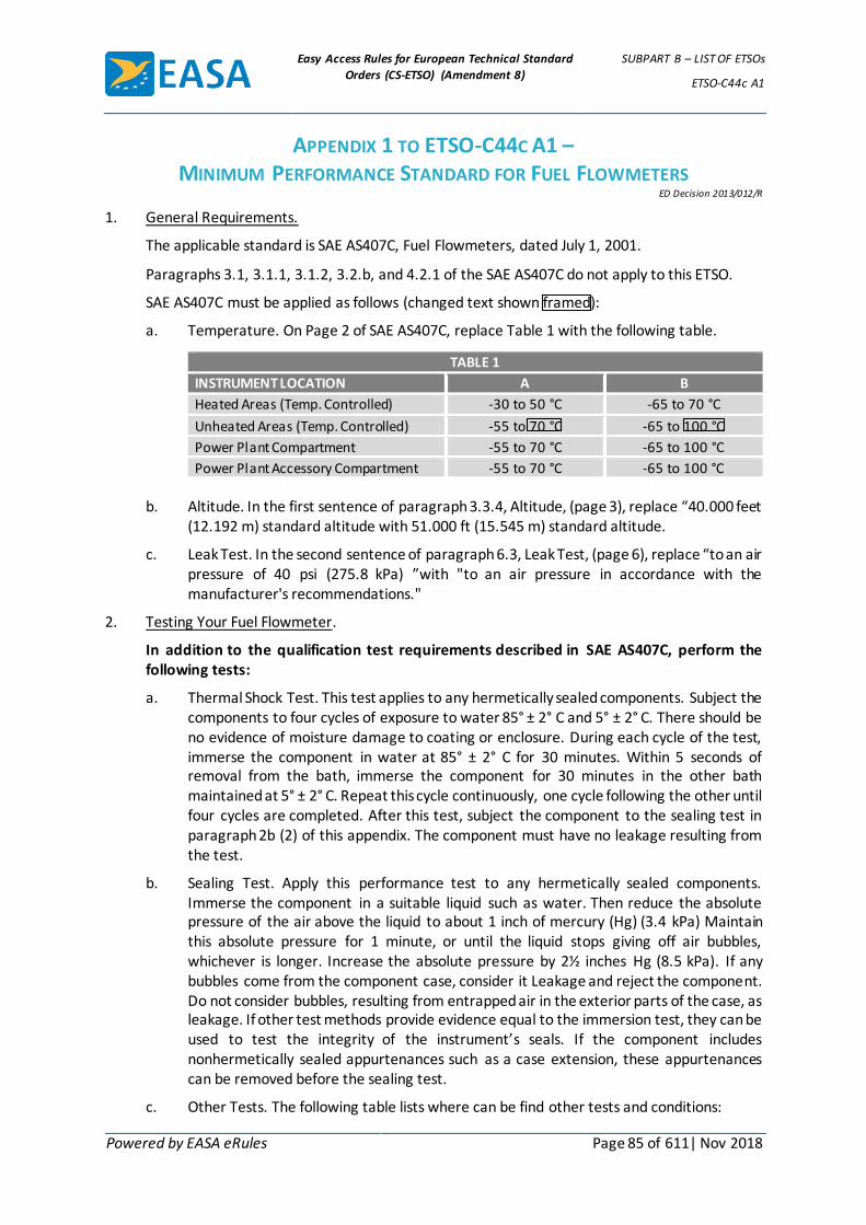
Easy Access Rules for European Technical Standard
Orders (CS-ETSO) (Amendment 8)
SUBPART B – LIST OF ETSOs
ETSO-C44c A1
Powered by EASA eRules Page 85 of 611| Nov 2018
APPENDIX 1 TO ETSO-C44C A1 – MINIMUM PERFORMANCE STANDARD FOR FUEL FLOWMETERS
ED Decision 2013/012/R
1. General Requirements.
The applicable standard is SAE AS407C, Fuel Flowmeters, dated July 1, 2001.
Paragraphs 3.1, 3.1.1, 3.1.2, 3.2.b, and 4.2.1 of the SAE AS407C do not apply to this ETSO.
SAE AS407C must be applied as follows (changed text shown framed):
a. Temperature. On Page 2 of SAE AS407C, replace Table 1 with the following table.
TABLE 1
INSTRUMENT LOCATION A B
Heated Areas (Temp. Controlled) -30 to 50 °C -65 to 70 °C
Unheated Areas (Temp. Controlled) -55 to 70 °C -65 to 100 °C
Power Plant Compartment -55 to 70 °C -65 to 100 °C
Power Plant Accessory Compartment -55 to 70 °C -65 to 100 °C
b. Altitude. In the first sentence of paragraph 3.3.4, Altitude, (page 3), replace “40.000 feet
(12.192 m) standard altitude with 51.000 ft (15.545 m) standard altitude.
c. Leak Test. In the second sentence of paragraph 6.3, Leak Test, (page 6), replace “to an air pressure of 40 psi (275.8 kPa) ”with "to an air pressure in accordance with the manufacturer's recommendations."
2. Testing Your Fuel Flowmeter.
In addition to the qualification test requirements described in SAE AS407C, perform the following tests:
a. Thermal Shock Test. This test applies to any hermetically sealed components. Subject the components to four cycles of exposure to water 85° ± 2° C and 5° ± 2° C. There should be no evidence of moisture damage to coating or enclosure. During each cycle of the test, immerse the component in water at 85° ± 2° C for 30 minutes. Within 5 seconds of removal from the bath, immerse the component for 30 minutes in the other bath maintained at 5° ± 2° C. Repeat this cycle continuously, one cycle following the other until four cycles are completed. After this test, subject the component to the sealing test in paragraph 2b (2) of this appendix. The component must have no leakage resulting from the test.
b. Sealing Test. Apply this performance test to any hermetically sealed components. Immerse the component in a suitable liquid such as water. Then reduce the absolute pressure of the air above the liquid to about 1 inch of mercury (Hg) (3.4 kPa) Maintain this absolute pressure for 1 minute, or until the liquid stops giving off air bubbles, whichever is longer. Increase the absolute pressure by 2½ inches Hg (8.5 kPa). If any bubbles come from the component case, consider it Leakage and reject the component. Do not consider bubbles, resulting from entrapped air in the exterior parts of the case, as leakage. If other test methods provide evidence equal to the immersion test, they can be used to test the integrity of the instrument’s seals. If the component includes nonhermetically sealed appurtenances such as a case extension, these appurtenances can be removed before the sealing test.
c. Other Tests. The following table lists where can be find other tests and conditions:

Easy Access Rules for European Technical Standard
Orders (CS-ETSO) (Amendment 8)
SUBPART B – LIST OF ETSOs
ETSO-C44c A1
Powered by EASA eRules Page 86 of 611| Nov 2018
For: Use the test conditions in:
Fire-resistant or fireproof test SAE AS 1055, Rev. D, , dated June 1997, Sections 4 and 5
The following sections of the environmental standards mentioned in paragraph 3.1.2 above.
Explosion proofness test Section 9
Power input test Section 16
Voltage spike test Section 17
Audio frequency conducted susceptibility test
Section 18
Induced signal susceptibility test Section 19
Radio frequency susceptibility test Section 20
[Amdt ETSO/3] [Amdt ETSO/8]

Easy Access Rules for European Technical Standard
Orders (CS-ETSO) (Amendment 8)
SUBPART B – LIST OF ETSOs
ETSO-C45b A1
Powered by EASA eRules Page 87 of 611| Nov 2018
ETSO-C45b A1 ED Decision 2013/012/R (applicable from 15.7.2013)
Manifold Pressure Instruments
1 Applicability
This ETSO gives the requirements which manifold pressure instruments that are manufactured on or after the date of this ETSO must meet in order to be identified with the applicable ETSO marking.
2 Procedures
2.1 General
Applicable procedures are detailed in CS-ETSO, Subpart A.
2.2 Specific
None.
3 Technical conditions
3.1 Basic
3.1.1 Minimum performance standard
Standard set forth in the SAE Aerospace Standard (AS) document: SAE AS 8042 from December 1, 1985, unless otherwise specified by Appendix 1 to this ETSO.
3.1.2 Environmental standard
The Manifold Pressure Instruments must be tested according to Section 7 of SAE AS 8042 and the environmental test procedures as defined in CS-ETSO, Subpart A, paragraph 2.1.
3.1.3 Computer software
If the Manifold Pressure Instruments includes a digital computer, see CS-ETSO, Subpart A, paragraph 2.2, for software development.
3.1.4 Airborne electronic hardware
See CS-ETSO, Subpart A, paragraph 2.3.
3.2 Specific
3.2.1 Failure condition classification
See CS-ETSO, Subpart A, paragraph 2.4.
Failure of the function defined in paragraph 3.1.1 of this ETSO has been determined to be a major failure condition. The applicant must develop the system to at least the design assurance level commensurate with this failure condition.
4 Marking
4.1 General
Marking is detailed in CS-ETSO, Subpart A, paragraph 1.2.
4.2 Specific
None.

Easy Access Rules for European Technical Standard
Orders (CS-ETSO) (Amendment 8)
SUBPART B – LIST OF ETSOs
ETSO-C45b A1
Powered by EASA eRules Page 88 of 611| Nov 2018
5 Availability of referenced document
See CS-ETSO, Subpart A, paragraph 3.
[Amdt ETSO/3] [Amdt ETSO/8]

Easy Access Rules for European Technical Standard
Orders (CS-ETSO) (Amendment 8)
SUBPART B – LIST OF ETSOs
ETSO-C45b A1
Powered by EASA eRules Page 89 of 611| Nov 2018
APPENDIX 1 TO ETSO-C45B A1 – MINIMUM PERFORMANCE STANDARD FOR
MANIFOLD PRESSURE INSTRUMENTS ED Decision 2013/012/R
This appendix lists EASA modifications to the MPS for Manifold Pressure Instruments.
The applicable standard is SAE AS 8042, Manifold Pressure Instruments, dated December 1, 1985.
1. Manifold Pressure Instruments are not required to meet the requirements in SAE AS 8042 paragraphs 3.1, 3.2, and 3.3.
2. Replacement of SAE AS 8042 paragraph 3.24.2 (Fire Hazards) by:
“Except for small parts (such as fasteners, grommets, knobs, seals, and small electrical parts) that would not contribute significantly to the propagation of a fire, all material used must be self-extinguishing when tested in accordance with the requirements of CS 25.869(a)(4) and the applicable portions of Part I, Appendix F.”
[Amdt ETSO/3] [Amdt ETSO/8]

Easy Access Rules for European Technical Standard
Orders (CS-ETSO) (Amendment 8)
SUBPART B – LIST OF ETSOs
ETSO-C46a
Powered by EASA eRules Page 90 of 611| Nov 2018
ETSO-C46a ED Decision 2003/10/RM (applicable from 24.10.2003)
Maximum Allowable Airspeed Indicator Systems
1 Applicability
This ETSO gives the requirements which maximum allowable airspeed indicator systems that are manufactured on or after the date of this ETSO must meet in order to be identified with the applicable ETSO marking.
2 Procedures
2.1 General
Applicable procedures are detailed in CS-ETSO Subpart A.
2.2 Specific
None.
3 Technical Conditions
3.1 Basic
3.1.1 Minimum Performance Standard
Standards set forth in the attached „Federal Aviation Administration Standard, Maximum Allowable Airspeed Indicator Systems“ as amended and supplemented by this ETSO:
a. Tests procedures set forth in Society of Automotive Engineers (SAE) Aeronautical Standard (AS) 418A dated May 15, 1961, „Maximum Allowable Airspeed Instrument, Reciprocating Engine Powered Aircraft“, or SAE AS 437 dated April 15, 1963, „Maximum Allowable Airspeed Instrument, Turbine Powered Aircraft“, may be used for the purpose of showing compliance with related standards in this ETSO. However, environmental limits, or other limits, specified in these procedures must be adjusted if necessary to agree with those specified in this ETSO.
b. Other test procedure may also be adequate and valid for the purpose.
c. Where applicable, instead of the referenced FAA documents/paragraph the corresponding IR, CS or ETSO document/paragraph shall be used, when available.
3.1.2 Environmental Standard
As stated in the „Federal Aviation Administration Standard, Maximum Allowable Airspeed Indicator Systems“.
3.1.3 Computer Software
None
3.2 Specific
None.

Easy Access Rules for European Technical Standard
Orders (CS-ETSO) (Amendment 8)
SUBPART B – LIST OF ETSOs
ETSO-C46a
Powered by EASA eRules Page 91 of 611| Nov 2018
4 Marking
4.1 General
Marking is detailed in CS-ETSO Subpart A paragraph 1.2; in addition to the markings required by this paragraph, the instrument must be marked to indicate its range in knots and, if applicable, to identify the calibration employed to control the movement of the maximum allowable airspeed pointer in the Vmo and Mmo ranges, or to identify the particular aircraft type design on which the instrument is intended to be used.
4.2 Specific
None.
5 Availability of Referenced Document
See CS-ETSO Subpart A paragraph 3.

Easy Access Rules for European Technical Standard
Orders (CS-ETSO) (Amendment 8)
SUBPART B – LIST OF ETSOs
ETSO-C46a
Powered by EASA eRules Page 92 of 611| Nov 2018
APPENDIX 1 TO ETSO-C46A – FEDERAL AVIATION ADMINISTRATION
STANDARD, MAXIMUM ALLOWABLE AIRSPEED INDICATOR SYSTEMS ED Decision 2003/10/RM
1. Purpose.
This document specifies minimum performance standards for pitot-static type, maximum allowable airspeed indicator systems which indicate continuously both indicated airspeed and maximum allowable airspeed.
2. Performance Requirements.
2.1 General
(a) Materials. Materials must be of a quality demonstrated to be suitable and dependable for use in aircraft instruments.
(b) Environmental conditions. The instrument must be capable of performing its intended function and not be adversely affected during or following prolonged exposure to the environmental conditions stated under section 3. Where optional environments conditions are set forth, the conditions selected must be declared as equipment limitations.
2.2 Detail requirements.
(a) Indicating means. Indicated airspeed and maximum allowable airspeed must be displayed in such a manner that the numerical values on the scale increase in a clockwise, left to right, or bottom to top direction.
(b) Case markings. The outlets in the case must be marked with „P“ for the pitot pressure connection, and with „S“ for the static pressure connection.
2.3 Design requirements.
(a) Adjustable settings.
(1) Maximum allowable airspeed pointer. An adjustable stop may be provided in the instrument for limiting the movement of the maximum allowable airspeed pointer. If included, the design of this adjustment must be such that it will not affect the indication of the pointer when the altitude pressure conditions and Mach Number setting are such that the limiting speed will be lower than that set by the adjustable stop.
(2) Mach Number. If a readily accessible means is provided for setting the instrument to any desired Mach Number, the value of the setting must be visible from the front of the instrument. When the instrument does not contain an external Mach Number setting adjustment, the value of the permanent Mach Number setting need not be visible from the front of the instrument.
(b) Visibility. The indicating means and all markings must be visible from any point within the frustum of a cone, the side of which makes an angle of at least 30° with the perpendicular to the dial and the small diameter of which is the aperture of the instrument case. The distance between the dial and the cover glass must be a practical minimum.
(c) Calibration.

Easy Access Rules for European Technical Standard
Orders (CS-ETSO) (Amendment 8)
SUBPART B – LIST OF ETSOs
ETSO-C46a
Powered by EASA eRules Page 93 of 611| Nov 2018
(1) Indicated air-speed pointer. The indicated airspeed pointer must indicate airspeed in accordance with the values contained in Table I.
(2) Maximum allowable airspeed pointer. The maximum allowable airspeed pointer must indicate maximum allowable airspeed values in the Vmo and Mmo limit ranges which -
(i) Follow the standard fundamental relationships of subsonic compressible flow gas dynamics which are stated in appendix A; or
(ii) Are adjusted to account for design factors that are characteristic of a particular aircraft type design such as, but not limited to, static source pressure error variations and variable speed limitations with altitude.
(d) Scale error.
(1) Instruments with permanent Mach Number setting. The indicated airspeed scale error and the maximum allowable airspeed scale error must not exceed the tolerances specified in Tables I and II, respectively, with the instrument set at its permanent Mach Number.
(2) Instruments with means for external Each Number setting adjustment.
(i) The indicated airspeed scale error must not exceed the tolerances specified in Table I with the instrument set at the lowest Mach number.
(ii) The maximum allowable airspeed scale error must not exceed the tolerances specified in Table II with the instrument set at the lowest Mach Number and at increasing Mach Number setting of not more than 0.10 to and including the maximum Mach Number.
(e) Hysteresis. The reading of the maximum allowable airspeed pointer first at 30,000 feet altitude and then at 10,000 feet altitude must not differ by more then 2 knots from the corresponding readings obtained for increasing altitudes during tests to assure the instrument complies with the scale error requirements of section 2.3(d)(2)(ii) of this TSO.
(f) After effect. To assure the instrument complies with the scale error requirements of section 2.3 (d) (2) (ii) of this TSO, the maximum allowable airspeed pointer must return to its original readings, corrected for any change in atmospheric pressure, within 3 knots, after not less than 1 or more than 5 minutes have elapsed following completion of performance tests.
(g) Friction.
(1) Maximum allowable airspeed pointer. The friction of the pointer must not produce an error exceeding 4 knots at each point indicated by an asterisk in Table II.
(2) Indicated airspeed pointer. The friction on the pointer must not produce an error exceeding 3 knots at each point indicated by an asterisk in Table I.
(h) Leak.
(1) Case leak. When subjected to a static pressure differential of 15 inches of mercury between the inside and outside of the case, the internal pressure must not increase because of case leaks more than 0.05 inches of mercury

Easy Access Rules for European Technical Standard
Orders (CS-ETSO) (Amendment 8)
SUBPART B – LIST OF ETSOs
ETSO-C46a
Powered by EASA eRules Page 94 of 611| Nov 2018
at the end of 1 minute time following first application of the differential pressure.
(2) Airspeed diaphragm leak. There must not be any apparent movement of the indicated airspeed pointer for 1 minute after a sequence of events in which pressure sufficient to produce full scale deflection of the indicated airspeed pointer is applied to the pitot connection (static pressure connection open to atmosphere), the pressure source is stopped, and the connection tubing pinched.
3. Environmental Conditions.
3.1 Temperature. The instrument must perform its intended function over the range of ambient temperature from -30° to 50° C. With the instrument temperature stabilized at the limits of the range, the scale error must not exceed by more than 4.5 knots the tolerances specified in Tables I and II at the points marked with an asterisk. The instrument must not be adversely affected by exposure to the range of ambient temperature from -65° to 70° C.
3.2 Altitude. The instrument must perform its intended function and must not be adversely affected when operating in the pressure range from -1,000 feet and the maximum altitude of intended operation. The instrument must withstand an external case pressure of 50“ Hg. absolute when installed properly and vented to an atmospheric pressure of approximately 29.92“ Hg. absolute.
3.3 Vibration. The instrument must perform its intended function and must not be adversely affected when subjected to vibrations of the following characteristics:
Instrument panel mounted (vibration isolated)
Frequency cycles per second
Maximum double amplitude (inches)
Maximum acceleration
Reciprocating engine powered aircraft – –
5-50 0.020 1.5
Turbine engine powered aircraft – –
5-55 0.020 – – – – –
55-1000 – – – – – 0.25g
3.4 Humidity. The instrument must perform its intended function and must not be adversely
affected following exposure to the extreme condition of relative humidity in the range from 0 to 95 percent at a temperature of approximately 70° C. for a period of 10 hours.
4. Compliance Tests.
As evidence of compliance with this standard, the manufacturer must perform evaluation tests on proto- type instruments to demonstrate proper design, reliability in performance of its intended functions, and conformity with the performance standards of section 2. Tests must also be performed to demonstrate compliance with the environmental condition requirements specified in section 3.
5. Individual Performance Tests.
The manufacturer must conduct such tests as may be necessary on each instrument to assure that it will meet the minimum performance requirements of sections 2.3 (b) through 2.3 (h).
TABLE I
Speed knots Impact pressure (qc) inches Hg at 25°C Tolerance knots
50 0.1198 ±4.0
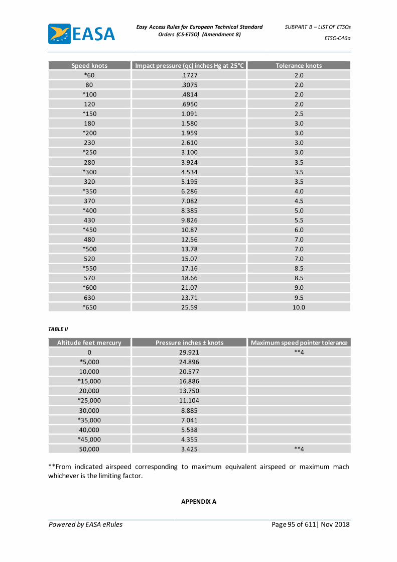
Easy Access Rules for European Technical Standard
Orders (CS-ETSO) (Amendment 8)
SUBPART B – LIST OF ETSOs
ETSO-C46a
Powered by EASA eRules Page 95 of 611| Nov 2018
Speed knots Impact pressure (qc) inches Hg at 25°C Tolerance knots
*60 .1727 2.0
80 .3075 2.0
*100 .4814 2.0
120 .6950 2.0
*150 1.091 2.5
180 1.580 3.0
*200 1.959 3.0
230 2.610 3.0
*250 3.100 3.0
280 3.924 3.5
*300 4.534 3.5
320 5.195 3.5
*350 6.286 4.0
370 7.082 4.5
*400 8.385 5.0
430 9.826 5.5
*450 10.87 6.0
480 12.56 7.0
*500 13.78 7.0
520 15.07 7.0
*550 17.16 8.5
570 18.66 8.5
*600 21.07 9.0
630 23.71 9.5
*650 25.59 10.0
TABLE II
Altitude feet mercury Pressure inches ± knots Maximum speed pointer tolerance
0 29.921 **4
*5,000 24.896
10,000 20.577
*15,000 16.886
20,000 13.750
*25,000 11.104
30,000 8.885
*35,000 7.041
40,000 5.538
*45,000 4.355
50,000 3.425 **4
**From indicated airspeed corresponding to maximum equivalent airspeed or maximum mach whichever is the limiting factor.
APPENDIX A

Easy Access Rules for European Technical Standard
Orders (CS-ETSO) (Amendment 8)
SUBPART B – LIST OF ETSOs
ETSO-C46a
Powered by EASA eRules Page 96 of 611| Nov 2018
Relationships For Calibrating Maximum Allowable Airspeed Pointer
(1) For altitudes from sea level to altitude where
(2) For altitudes where MMO is limited factor:
Where:
Vmo = Maximum allowable indicated airspeed in knots.
Mmo= Maximum allowable mach.
K = Ratio of specific heats=1.40 for air.
Po = Pressure at sea level in inches of Hg.
P = Ambient static pressure in inches of Hg.
Cso = Speed of sound at sea level=661.48 knots.
a = Density ratio at altitude.
Vm = Maximum equivalent airspeed in knots

Easy Access Rules for European Technical Standard
Orders (CS-ETSO) (Amendment 8)
SUBPART B – LIST OF ETSOs
ETSO-C47a A1
Powered by EASA eRules Page 97 of 611| Nov 2018
ETSO-C47a A1 ED Decision 2013/012/R (applicable from 15.7.2013)
Pressure Instruments – Fuel, Oil and Hydraulic
1 Applicability
This ETSO gives the requirements which fuel, oil and hydraulic pressure instruments that are manufactured on or after the date of this ETSO must meet in order to be identified with the applicable ETSO marking.
2 Procedures
2.1 General
Applicable procedures are detailed in CS-ETSO, Subpart A.
2.2 Specific
None.
3 Technical conditions
3.1 Basic
3.1.1 Minimum performance standard
Standards set forth in the SAE Aerospace Standard (AS) document: SAE AS 408C “Pressure Instruments - Fuel, Oil and Hydraulic” from July 1, 2001 unless otherwise specified by Appendix 1 to this ETSO.
3.1.2 Environmental standard
Testing fuel, oil, and hydraulic pressure instruments must be in accordance with SAE AS408C section 7 and see CS-ETSO, Subpart A, paragraph 2.1, for environmental test procedures.
3.1.3 Software
If fuel, oil, and hydraulic pressure instrument includes a digital computer, see CS-ETSO, Subpart A, paragraph 2.2, for software development.
3.1.4 Airborne electronic hardware
See CS-ETSO, Subpart A, paragraph 2.4.
3.2 Specific
3.2.1 Failure condition classification
See CS-ETSO, Subpart A, paragraph 2.4.
Failure of the function defined in paragraph 3.1.1 of this ETSO has been determined to be a major failure condition. The applicant must develop the system to at least the design assurance level commensurate with this failure condition.
4 Marking
4.1 General
Marking is detailed in CS-ETSO, Subpart A, paragraph 1.2.
4.2 Specific
Easy Access Rules for European Technical Standard
Orders (CS-ETSO) (Amendment 8)
SUBPART B – LIST OF ETSOs
ETSO-C47a A1
Powered by EASA eRules Page 98 of 611| Nov 2018
a) At least one major component of the fuel, oil, and hydraulic pressure instrument shall be marked permanently and legibly with all the information as provided for in SAE AS408C, Section 3.2 (except paragraph 3.2.b).
b) Mark “Fire resistant” or “Fireproof” information legibly and permanently
5 Availability of referenced document
See CS-ETSO, Subpart A, paragraph 3.
[Amdt ETSO/3] [Amdt ETSO/8]
Easy Access Rules for European Technical Standard
Orders (CS-ETSO) (Amendment 8)
SUBPART B – LIST OF ETSOs
ETSO-C47a A1
Powered by EASA eRules Page 99 of 611| Nov 2018
APPENDIX 1 TO ETSO-C47A A1 – MINIMUM PERFORMANCE STANDARDS
(MPSS) FOR PRESSURE INSTRUMENTS - FUEL, OIL AND HYDRAULIC ED Decision 2013/012/R
1. The MPSs applying to this ETSO are provided in SAE AS408C, Pressure Instruments - Fuel, Oil, and Hydraulic, dated July 1, 2001, except for paragraphs 3.1, 3.1.1, 3.1.2, and 3.2.b.
Here are provided the modifications to be applied to the referenced SAE document:
AS408C modification:
Title Replace “Pressure Instruments – Fuel, Oil, and Hydraulic (Reciprocating Engine Powered Aircraft)” Substitute: “Pressure Instruments – Fuel, Oil, and Hydraulic”
Section 1.1 Replace “…primarily for use with reciprocating engine powered transport aircraft, …” Substitute: “…for use with civil aircraft,...”
AS408C section 7 modification:
Para 7.13 Use test conditions in SAE AS1055 Rev D, “Fire Testing of Flexible Hose, Tube Assemblies, Coils, Fittings, and Similar System Components”, dated June 1, 1997, Sections 4 and 5.
The following test conditions from the environmental standards mentioned in paragraph 3.1.2 above are added.
Para 7.14 Section 16, Power Input.
Para 7.15 Section 17, Voltage Spike.
Para 7.16 Section 18, Audio Frequency Conducted Susceptibility – Power Inputs.
Para 7.17 Section 19, Induced Signal Susceptibility
Para 7.18 Section 20, Radio Frequency Susceptibility.
2. The performance of fuel, oil and hydraulic pressure instruments can be enhanced or made
superior to this specification, depending on intended application and configuration.
[Amdt ETSO/3] [Amdt ETSO/8]
Easy Access Rules for European Technical Standard
Orders (CS-ETSO) (Amendment 8)
SUBPART B – LIST OF ETSOs
ETSO-C49b
Powered by EASA eRules Page 100 of 611| Nov 2018
ETSO-C49b ED Decision 2003/10/RM (applicable from 24.10.2003)
Electric Tachometer: Magnetic Drag (Indicator and Generator)
1 Applicability
This ETSO gives the requirements which electric tachometers: magnetic drag (indicator and generator) that are manufactured on or after the date of this ETSO must meet in order to be identified with the applicable ETSO marking.
2 Procedures
2.1 General
Applicable procedures are detailed in CS-ETSO Subpart A.
2.2 Specific
None.
3 Technical Conditions
3.1 Basic
3.1.1 Minimum Performance Standard
Standards set forth in the SAE Aerospace Standard (AS) document: AS 404B dated February 1, 1959, and reconfirmed May 1991, as amended and supplemented by this ETSO:
Exceptions.
(i) The following specifically numbered parts in AS-404B do not concern minimum performance and therefore are not essential to compliance with this paragraph: Parts 3.1, 3.1.1, 3.1.2, 3.2, 3.2(a)(b)(c)(d)(e)(f), 4.1.3.1, 4.1.3.2, 4.1.3.3, 4.1.3.4, and 4.1.3.5.
(ii) In lieu of part 7 in AS-404B, it is a requirement that tachometers covered by this paragraph be capable of successfully passing the tests in parts 7.1 through 7.8.
3.1.2 Environmental Standard
As prescribed in AS 404B.
3.1.3 Computer Software
See CS-ETSO Subpart A paragraph 2.2
3.2 Specific
None.
4 Marking
4.1 General
Marking is detailed in CS-ETSO Subpart A paragraph 1.2; in addition, range and rating shall be shown.
4.2 Specific
None.

Easy Access Rules for European Technical Standard
Orders (CS-ETSO) (Amendment 8)
SUBPART B – LIST OF ETSOs
ETSO-C49b
Powered by EASA eRules Page 101 of 611| Nov 2018
5 Availability of Referenced Document
See CS-ETSO Subpart A paragraph 3.

Easy Access Rules for European Technical Standard
Orders (CS-ETSO) (Amendment 8)
SUBPART B – LIST OF ETSOs
ETSO-C53a
Powered by EASA eRules Page 102 of 611| Nov 2018
ETSO-C53a ED Decision 2003/10/RM (applicable from 24.10.2003)
Fuel and Engine Oil System Hose Assemblies
1 Applicability
This ETSO gives the requirements which fuel and engine oil system hose assemblies that are manufactured on or after the date of this ETSO must meet in order to be identified with the applicable ETSO marking.
2 Procedures
2.1 General
Applicable procedures are detailed in CS-ETSO Subpart A.
2.2 Specific
None.
3 Technical Conditions
3.1 Basic
3.1.1 Minimum Performance Standard
(1) Minimum performance standards are hereby established for the following types of fuel and engine oil system hose assemblies:
(i) Type A. Non-fire-resistant „normal“ temperature hose assemblies which are intended to be used in locations outside fire zones where the fluid and ambient air temperatures do not exceed 121°C.
(ii) Type B. Non-fire-resistant „high“ temperature hose assemblies which are intended to be used in locations outside fire zones where the fluid and ambient air temperatures do not exceed 232°C.
(iii) Type C. Fire-resistant „normal“ temperature hose assemblies which are intended to be used in locations within fire zones where the fluid and ambient air temperatures do not exceed 121°C.
(iv) Type D. Fire-resistant „high“ temperature hose assemblies which are intended to be used in locations within fire zones where the fluid and ambient air temperatures do not exceed 232°C.
Each type shall comply with the following requirements. Three samples of each size shall be tested.
(1) Type A hose assemblies shall comply with the „3.3 Performance“ paragraph requirements of Specification MIL-H-8795A, dated July 25, 1958, except as noted in sub-paragraph (2) of this paragraph. The hose incorporated therein shall conform to „3.6 Performance“ paragraph of Specification MIL-H-8794A, dated July 25, 1958, except as noted in sub-paragraph (2) of this paragraph.
(2) Type B hose assemblies shall comply with the „3.6 Performance“ paragraph requirements of Specification MIL-H-

Easy Access Rules for European Technical Standard
Orders (CS-ETSO) (Amendment 8)
SUBPART B – LIST OF ETSOs
ETSO-C53a
Powered by EASA eRules Page 103 of 611| Nov 2018
25579 (USAF), dated March 19, 1959, except as noted in sub-paragraph (2) of this paragraph.
(3) Type C hose assemblies shall comply with the above requirements for type A hose assemblies and in addition shall pass the fire test described in sub-paragraph (3) of this paragraph.
(4) Type D hose assemblies shall comply with the above requirements for Type B hose assemblies and in addition shall pass the fire test described in sub-paragraph (3) of this paragraph.
(2) Exceptions.
(i) Type A hose assemblies are not required to comply with paragraphs 3.6.1.2 and 3.6.2.7 of Specification MIL-H-8794A. The operating and proof pressures referred to in Table 1 of that specification shall be those values listed in the „Fuel“ column thereof. The burst pressures to be utilized shall be twice the proof pressures listed in the „Fuel“ column in Table 1. The foregoing shall likewise apply in showing compliance with Specification MIL-H-8795A.
(ii) Type B hose assemblies are not required to comply with paragraphs 3.6.5, 3.6.7 and 3.6.10 of Specification MIL-H-25579 (USAF). The burst pressures to be utilized shall be twice the proof pressures listed in Table 1 of that specification.
(3) Fire test procedure and requirements. A description of the standard fire test apparatus and its use is in FAA „Standard Fire Test Apparatus and Procedure“ (Power Plant Engineering Report N°3). The use of a protective sleeve over the hose and/or end fittings is permitted to facilitate compliance with the fire test requirements. Sleeves or covers shall be secured to the hose assembly so fire-resistant properties will be maintained.
(i) Oil pressure during fire test: Type C hose assemblies - the operating pressure specified in the „Fuel“ column of Table 1 in Specification MIL-H-8795A. Type D hose assemblies - the operating pressure specified in Table 1 of Specification MIL-H- 25579 (USAF).
(ii) Oil flow rate: 5X(Hose assembly actual ID in inches)2. (Example: Flow rate for -16 size =5X(7/8)2=3.8GPM)
(iii) Duration: 5 minutes.
(iv) Criteria for acceptability: The hose assembly shall be considered acceptable if it complies with these test conditions without evidence of leakage.
3.1.2 Environmental Standard
As per paragraph 3.1.1 above.
3.1.3 Computer Software
None
3.2 Specific

Easy Access Rules for European Technical Standard
Orders (CS-ETSO) (Amendment 8)
SUBPART B – LIST OF ETSOs
ETSO-C53a
Powered by EASA eRules Page 104 of 611| Nov 2018
None.
4 Marking
4.1 General
Marking is detailed in CS-ETSO Subpart A paragraph 1.2.
4.2 Specific
None.
5 Availability of Referenced Document
See CS-ETSO Subpart A paragraph 3.

Easy Access Rules for European Technical Standard
Orders (CS-ETSO) (Amendment 8)
SUBPART B – LIST OF ETSOs
ETSO-C54
Powered by EASA eRules Page 105 of 611| Nov 2018
ETSO-C54 ED Decision 2003/10/RM (applicable from 24.10.2003)
Stall Warning Instruments
1 Applicability
This ETSO gives the requirements which stall warning instruments that are manufactured on or after the date of this ETSO must meet in order to be identified with the applicable ETSO marking.
2 Procedures
2.1 General
Applicable procedures are detailed in CS-ETSO Subpart A.
2.2 Specific
None.
3 Technical Conditions
3.1 Basic
3.1.1 Minimum Performance Standard
Standards set forth in the SAE Aeronautical Standard AS 403A issued 15/10/1952. revised 15/7/1958 with exceptions and additions to the standard listed in the following sub-paragraph:
Exceptions and additions
(i) The following specifically numbered parts in AS 403A do not concern minimum performance and therefore are not essential to compliance with this paragraph: Parts 3.1; 3.1.1.; 3.1.2; 3.2(a), (b), (c) (d), (e), and (f).
(ii) In lieu of Part 7 of AS 403A, it is a requirement that stall warning instruments covered by this paragraph be capable of successfully passing the tests in Parts 7.1 through 7.7 of AS 403A.
(iii) Thermal shock: This test shall apply to any hermetically sealed component. The component shall be subjected to four cycles of exposure to water at 85°±2°C and 5°±2°C without evidence of moisture penetration or damage to coating or enclosure. Each cycle of the test shall consist of immersing the component in water at 85°±2°C for a period of 30 minutes and then within 5 seconds of removal from the bath, the component shall be immersed for a period of 30 minutes in the other bath maintained at 5°±2°C. This cycle shall be repeated continuously, one cycle following the other until four cycles have been completed. Following this test, the indicator shall be subjected to the Sealing test specified in (iv). No leakage shall occur as a result of this test.
(iv) Sealing: This performance test shall apply to each hermetically sealed instrument. The instrument shall be immersed in a suitable liquid such as water. The absolute pressure of the air above the liquid shall then be reduced to approximately 34 hPA (1 inch of mercury (Hg)) and maintained for 1 minute or until air bubbles cease to be given off by the liquid, whichever is longer. The absolute pressure shall then be increased by 85 hPa (2 1/2 inches Hg). Any bubbles coming from within the indicator case shall be considered as a leakage and shall be cause for rejection. Bubbles which are
Easy Access Rules for European Technical Standard
Orders (CS-ETSO) (Amendment 8)
SUBPART B – LIST OF ETSOs
ETSO-C54
Powered by EASA eRules Page 106 of 611| Nov 2018
the result of entrapped air in the various exterior parts of the case shall not be considered as a leakage. Other tests methods which provide evidence equal to the immersion test of the integrity of the instrument’s seals may be used. If the instrument incorporates non hermetically sealed appurtenances such as a case extension, these appurtenances may be removed prior to the sealing test.
(v) Power malfunction indication: Means shall be incorporated in the instrument to indicate when adequate power (voltage and/or current) is not being made available to all phases required for the proper operation of the instrument. The indicating means shall indicate a failure or a malfunction in a positive manner, and be readily discernible under any lighting condition normally encountered in aircraft.
3.1.2 Environment Standard
As indicated in AS 403A document.
3.1.3 Computer Software
None
3.2 Specific
None
4 Marking
4.1 General
Marking is detailed in CS-ETSO Subpart A paragraph 1.2.
4.2 Specific
None.
5 Availability of Referenced Document
See CS-ETSO Subpart A paragraph 3.

Easy Access Rules for European Technical Standard
Orders (CS-ETSO) (Amendment 8)
SUBPART B – LIST OF ETSOs
ETSO-C55a
Powered by EASA eRules Page 107 of 611| Nov 2018
ETSO-C55a ED Decision 2012/009/R (applicable from 5.7.2012)
Fuel and Oil Quantity Instruments
1 Applicability
This ETSO gives the requirements which fuel and oil quantity instruments that are manufactured on or after the date of this ETSO must meet in order to be identified with the applicable ETSO marking.
2 Procedures
2.1 General
Applicable procedures are detailed in CS-ETSO Subpart A.
2.2 Specific
None.
3 Technical Conditions
3.1 Basic
3.1.1 Minimum Performance Standard
Standards set forth in the SAE Aerospace Standard (AS) 405C „Fuel and oil quantity Instruments“, dated July 15, 1958 as amended and supplemented by this ETSO:
(i) Conformance with the following paragraphs of AS 405C is not required: 3.1; 3.1.1, 3.1.2, 3.2 and 4.2.1.
(ii) Substitute the following for paragraph 7: „Performance tests: The following tests, in addition to any others deemed necessary by the manufacturer, shall be the basis for determining compliance with the performance requirements of this standard“.
3.1.2 Environmental Standard
See CS-ETSO Subpart A paragraph 2.1.
As specified in the SAE Aerospace Standard AS 405C.
3.1.3 Computer Software
See CS-ETSO Subpart A paragraph 2.2.
3.1.4 Electronic Hardware Qualification
See CS-ETSO Subpart A paragraph 2.3.
3.2 Specific
3.2.1 Failure Condition Classification
See CS-ETSO Subpart A paragraph 2.4.
The failure condition classification will depend on the system on which the fuel and oil quantity instrument is installed. The classification must be determined by the safety assessment conducted as part of the installation approval. Develop each fuel and oil quantity instrument to at least the design assurance level assigned to the system on which the fuel and oil quantity instrument is installed.
Easy Access Rules for European Technical Standard
Orders (CS-ETSO) (Amendment 8)
SUBPART B – LIST OF ETSOs
ETSO-C55a
Powered by EASA eRules Page 108 of 611| Nov 2018
4 Marking
4.1 General
Marking is detailed in CS-ETSO Subpart A paragraph 1.2.
4.2 Specific
a. Mark at least one major component permanently and legibly with all the information in SAE AS405C, Section 3.2 (except paragraph 3.2.b). Also, mark the component with the following information:
(1) The basic type and accuracy classification, and
(2) The fluids for which the instrument is substantiated
b. If the fuel and oil quantity instrument includes a digital computer, then the part number must include hardware and software identification. Or, you can use a separate part number for hardware and software. Either way, you must include a means to show the modification status.
NOTE: Similar software versions, approved for different software levels, must be differentiated by part number.
5 Availability of Referenced Document
See CS-ETSO Subpart A paragraph 3.
[Amdt ETSO/7]

Easy Access Rules for European Technical Standard
Orders (CS-ETSO) (Amendment 8)
SUBPART B – LIST OF ETSOs
ETSO-C56b A1
Powered by EASA eRules Page 109 of 611| Nov 2018
ETSO-C56b A1 ED Decision 2013/012/R (applicable from 15.7.2013)
Engine-driven Direct Current Generators/Starter-generators
1 Applicability
This ETSO gives the requirements which engine-driven direct current generators/starter-generators that are manufactured on or after the date of this ETSO must meet in order to be identified with the applicable ETSO marking.
2 Procedures
2.1 General
Applicable procedures are detailed in CS-ETSO, Subpart A.
2.2 Specific
None.
3 Technical conditions
3.1 Basic
3.1.1 Minimum performance standard
Standards set forth in the SAE Aerospace Standard (AS) document: AS8020, "Engine Driven D.C. Generators/Starter-Generators and Associated Voltage Regulators", dated January 1980 (and reaffirmed by SAE in August 1991).
3.1.2 Environmental standard
See CS-ETSO, Subpart A, paragraph 2.1.
3.1.3 Software
If the Engine Driven Direct Current Generator / Starter Generator and the associated voltage regulators include a digital computer, see CS-ETSO, Subpart A, Paragraph 2.2, for software development.
3.1.4 Airborne electronic hardware
See CS-ETSO, Subpart A, paragraph 2.3.
3.2 Specific
None.
4 Marking
4.1 General
Marking is detailed in CS-ETSO, Subpart A, paragraph 1.2.
4.2 Specific
In addition to the information specified in §4.1, the following information is required:
(1) Means of indicating if the article is a D.C. generator or a D.C. starter-generator;
(2) Nominal power output (electrical voltage and watts);
(3) Mechanical power input requirements (pad requirements).
5 Availability of referenced document

Easy Access Rules for European Technical Standard
Orders (CS-ETSO) (Amendment 8)
SUBPART B – LIST OF ETSOs
ETSO-C56b A1
Powered by EASA eRules Page 110 of 611| Nov 2018
See CS-ETSO, Subpart A, paragraph 3.
[Amdt ETSO/3] [Amdt ETSO/8]

Easy Access Rules for European Technical Standard
Orders (CS-ETSO) (Amendment 8)
SUBPART B – LIST OF ETSOs
ETSO-C59
Powered by EASA eRules Page 111 of 611| Nov 2018
ETSO-C59 ED Decision 2003/10/RM (applicable from 24.10.2003)
Airborne Selective Calling Equipment
1 Applicability
This ETSO gives the requirements which airborne selective calling equipment that is manufactured on or after the date of this ETSO must meet in order to be identified with the applicable ETSO marking.
2 Procedures
2.1 General
Applicable procedures are detailed in CS-ETSO Subpart A.
2.2 Specific
None.
3 Technical Conditions
3.1 Basic
3.1.1 Minimum Performance Standard
Standards set forth in RTCA document DO-93 „Minimum Performance Standards - Airborne Selective Calling Equipment“ dated February 10, 1959.
3.1.2 Environmental Standard
See CS-ETSO Subpart A paragraph 2.1.
3.2 Specific
None.
4 Marking
4.1 General
Marking is detailed in CS-ETSO Subpart A paragraph 1.2.
4.2 Specific
None.
5 Availability of Referenced Document
See CS-ETSO Subpart A paragraph 3.

Easy Access Rules for European Technical Standard
Orders (CS-ETSO) (Amendment 8)
SUBPART B – LIST OF ETSOs
ETSO-C62e
Powered by EASA eRules Page 112 of 611| Nov 2018
ETSO-C62e ED Decision 2012/009/R (applicable from 5.7.2012)
Aircraft Tyres
1 Applicability
This ETSO gives the requirements which tyres excluding tailwheel tyres that are manufactured on or after the date of this ETSO must meet in order to be identified with the applicable ETSO marking.
2 Procedures
2.1 General
Applicable procedures are detailed in CS-ETSO Subpart A.
2.2 Specific
None.
3 Technical Conditions
3.1 Basic
3.1.1 Minimum Performance Standard
Standards set forth in the attached Appendix 1: „Federal Aviation Administration Standard for Aircraft Tyres“ dated 29/09/2006.
3.1.2 Environmental Standard
As stated in the Federal Aviation Administration Standard.
3.1.3 Computer Software
None
3.1.4 Electronic Hardware Qualification
None
3.2 Specific
None.
3.2.1 Failure Condition Classification
N/A
4 Marking
4.1 General
Marking as detailed in CS-ETSO Subpart A paragraph 1.2.
4.2 Specific
1. Balance marker, consisting of a red dot, on the sidewall of the tire immediately above the bead to indicate the lightweight point of the tire.
2. Production date code (may be included in the established serial number).
3. Ply rating must be established. Submit these ratings to the Tire and Rim Association, Inc. (TRA) or European Tyre and Rim Technical Organization (ETRTO).

Easy Access Rules for European Technical Standard
Orders (CS-ETSO) (Amendment 8)
SUBPART B – LIST OF ETSOs
ETSO-C62e
Powered by EASA eRules Page 113 of 611| Nov 2018
If the ply rating is marked on the tire, the load rating marked on the tire must be consistent with the ply rating established.
NOTE:for a new programme aircraft, define new tire dimensions and submit them to ETRTO for publication in the ETRTO Data Book. You do not have to wait until your submitted dimensions are incorporated into the Data Book before applying for the ETSO.
4. Serial number: the plant code and production date code may be included.
5. Size and load ratings, established and identified in a timely manner in the TRA Aircraft Year Book, latest edition or in the ETRTO Aircraft Tyre and Rim Data Book, latest revision. See the NOTE at paragraph g.
6. Skid depth, marked in inches to the nearest one-hundredth as defined in appendix 1.
7. Speed rating, in MPH and as identified in appendix 1, paragraph 4.b that is equal to or less than the speed at which the tire has been qualified.
8. Tire type. Mark tires requiring a tube with the words “Tube type.”
9. Non-re-treadable tires must be marked accordingly.
5 Availability of Referenced Document
See CS-ETSO Subpart A paragraph 3.
[Amdt ETSO/7]

Easy Access Rules for European Technical Standard
Orders (CS-ETSO) (Amendment 8)
SUBPART B – LIST OF ETSOs
ETSO-C62e
Powered by EASA eRules Page 114 of 611| Nov 2018
APPENDIX 1 TO ETSO-C62E – FAA STANDARD FOR AIRCRAFT TIRES ED Decision 2012/009/R
1. PURPOSE. Minimum performance standards for new and re-qualified radial and bias tires, excluding tailwheel tires, to be identified as meeting the standards of ETSO-C62e.
2. SCOPE. Minimum performance standards apply to aircraft tires having speed and load ratings based on the speeds and loads to which the tires have been tested.
3. DEFINITIONS.
Bias tire: a pneumatic tire whose ply cords extend to the beads and are laid at alternate angles substantially less than 90º to the centerline of the tread. May also have a bias belted tire with a circumferential belt.
Radial tire: a pneumatic tire whose ply cords extend to the beads and are laid approximately at 90º to the centerline of the tread, the carcass being stabilised by an essentially inextensible circumferential belt.
Load rating: maximum permissible static load at a specific inflation pressure. Use the rated load combined with the rated inflation pressure when selecting tires for application to an aircraft, and for testing to the performance requirements of this ETSO.
Rated inflation pressure: specified unloaded inflation pressure which will result in the tire deflecting to the specified static loaded radius when loaded to its rated load against a flat surface.
Static loaded radius (SLR): perpendicular distance between the axle centerline and a flat surface for a tire initially inflated to the unloaded rated inflation pressure and then loaded to its rated load.
Ply rating: an index of tire strength from which a rated inflation pressure and its corresponding maximum load rating are determined for a specific tire size.
Speed rating: maximum ground speed at which the tire has been tested in accordance with this ETSO.
Skid depth: distance between the tread surface and the bottom of the deepest groove as measured in the mold.
4. DESIGN AND CONSTRUCTION.
a. General Standards. Tires selected for use on a specific aircraft must demonstrate suitability through appropriate laboratory simulations described in paragraphs 5.a or 5.b of this appendix, as appropriate. Determine material suitability by:
(1) Temperature: show by tests or analysis that the physical properties of the tire materials are not degraded by exposure to temperature extremes of -40°C (-40°F) and +71,1°C (+160°F) for a period of not less than 24 hours at each extreme.
(2) Wheel rim heat: substantiate by the applicable tests or show by analysis that the physical properties of the tire materials have not been degraded by exposure of the tire to a wheel-bead seat temperature of not lower that 148,9°C (300°F) for at least 1 hour, except that low-speed tires or nose-wheel tires may be tested or analysed at the highest wheel-bead seat temperatures expected to be encountered during normal operations.
b. Speed Rating. See Table 1 below for applicable dynamometer test speeds for corresponding maximum takeoff ground speeds. For takeoff speeds over 245 mph, the
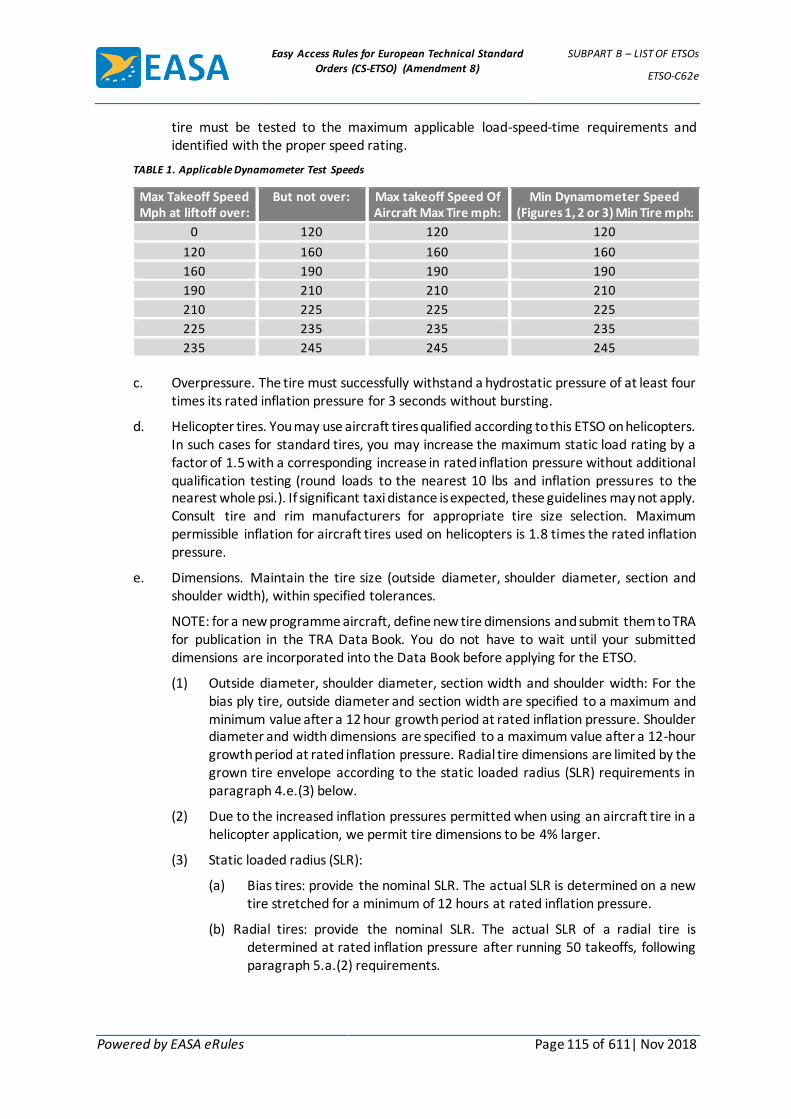
Easy Access Rules for European Technical Standard
Orders (CS-ETSO) (Amendment 8)
SUBPART B – LIST OF ETSOs
ETSO-C62e
Powered by EASA eRules Page 115 of 611| Nov 2018
tire must be tested to the maximum applicable load-speed-time requirements and identified with the proper speed rating.
TABLE 1. Applicable Dynamometer Test Speeds
Max Takeoff Speed Mph at liftoff over:
But not over: Max takeoff Speed Of Aircraft Max Tire mph:
Min Dynamometer Speed (Figures 1, 2 or 3) Min Tire mph:
0 120 120 120
120 160 160 160
160 190 190 190
190 210 210 210
210 225 225 225
225 235 235 235
235 245 245 245
c. Overpressure. The tire must successfully withstand a hydrostatic pressure of at least four
times its rated inflation pressure for 3 seconds without bursting.
d. Helicopter tires. You may use aircraft tires qualified according to this ETSO on helicopters. In such cases for standard tires, you may increase the maximum static load rating by a factor of 1.5 with a corresponding increase in rated inflation pressure without additional qualification testing (round loads to the nearest 10 lbs and inflation pressures to the nearest whole psi.). If significant taxi distance is expected, these guidelines may not apply. Consult tire and rim manufacturers for appropriate tire size selection. Maximum permissible inflation for aircraft tires used on helicopters is 1.8 times the rated inflation pressure.
e. Dimensions. Maintain the tire size (outside diameter, shoulder diameter, section and shoulder width), within specified tolerances.
NOTE: for a new programme aircraft, define new tire dimensions and submit them to TRA for publication in the TRA Data Book. You do not have to wait until your submitted dimensions are incorporated into the Data Book before applying for the ETSO.
(1) Outside diameter, shoulder diameter, section width and shoulder width: For the bias ply tire, outside diameter and section width are specified to a maximum and minimum value after a 12 hour growth period at rated inflation pressure. Shoulder diameter and width dimensions are specified to a maximum value after a 12-hour growth period at rated inflation pressure. Radial tire dimensions are limited by the grown tire envelope according to the static loaded radius (SLR) requirements in paragraph 4.e.(3) below.
(2) Due to the increased inflation pressures permitted when using an aircraft tire in a helicopter application, we permit tire dimensions to be 4% larger.
(3) Static loaded radius (SLR):
(a) Bias tires: provide the nominal SLR. The actual SLR is determined on a new tire stretched for a minimum of 12 hours at rated inflation pressure.
(b) Radial tires: provide the nominal SLR. The actual SLR of a radial tire is determined at rated inflation pressure after running 50 takeoffs, following paragraph 5.a.(2) requirements.

Easy Access Rules for European Technical Standard
Orders (CS-ETSO) (Amendment 8)
SUBPART B – LIST OF ETSOs
ETSO-C62e
Powered by EASA eRules Page 116 of 611| Nov 2018
(4) Helicopter tires: maximum dimensions for new tires used on helicopters are 4% larger than maximum aircraft tire dimensions. (In calculating maximum overall and shoulder diameters, rim diameter should be deducted before applying 4%.)
f. Inflation retention. After an initial 12-hour minimum stabilisation period at rated inflation pressure, the tire must retain the inflation pressure with a loss of pressure not exceeding 5% of the initial pressure for 24 hours. Measure the ambient temperature at the start and finish of the test to ensure that any pressure change was not caused by an ambient temperature change.
g. Balance. Test all tires for static unbalance. A balance marker, consisting of a red dot, must be affixed on the sidewall of the tire immediately above the bead to indicate the lightweight point of the tire. The dot must remain for any period of storage plus the original tread life of the tire.
(1) Auxiliary tires (not main or tailwheel tires): the moment of static unbalance (M) for auxiliary tires shall not be greater than the value determined using this equation:
𝑀 = 0.025𝐷2
Round the computed equation values to the next lower whole number where M is in inch-ounces and D is the standardised maximum new tire inflated outside diameter in inches. Your design must include requirements to measure the level of unbalance on each tire, and approved procedures to correct the unbalance within the above limits if necessary.
(2) All main tires and all tires with 46-inch and larger outside diameter: the moment of static unbalance (M) for main tires shall not be greater than the value determined using this equation:
𝑀 = 0.035𝐷2
Round the computed equation values to the next lower whole number where M is in inch-ounces and D is the standardised maximum new tire inflated outside diameter in inches. Your design must include requirements to measure the level of unbalance on each tire, and approved procedures to correct the unbalance within the above limits if necessary.
5. TIRE TEST REQUIREMENTS.
a. Use a single test specimen for a qualification test. The tire must withstand the following dynamometer cycles without detectable signs of deterioration, other than normal expected tread surface abrasion, except when the overload takeoff condition is run last (see paragraph 5.a.(8) below).
(1) Dynamometer cycle requirements: all aircraft tires must satisfactorily withstand 58 dynamometer cycles as a demonstration of overall performance, plus 3 overload dynamometer cycles as a demonstration of the casing’s capability under overload. The 58 dynamometer cycles consists of 50 takeoff cycles, per 5.a.(2), and 8 taxi cycles, per 5.a.(7). The overload cycles consist of 2 taxi cycles, per 5.a.(7) at 1.2 times rated load and 1 overload takeoff cycle per 5.a.(8) starting at 1.5 times rated load. Run the dynamometer cycles in any order. However, if the overload takeoff cycle is not run last, the tire must not show detectable signs of deterioration after the cycle completion, other than normal expected tread surface abrasion.
(2) Takeoff cycles: the 50 takeoff cycles shall realistically simulate tire performance during runway operations for the most critical combination of takeoff weight and
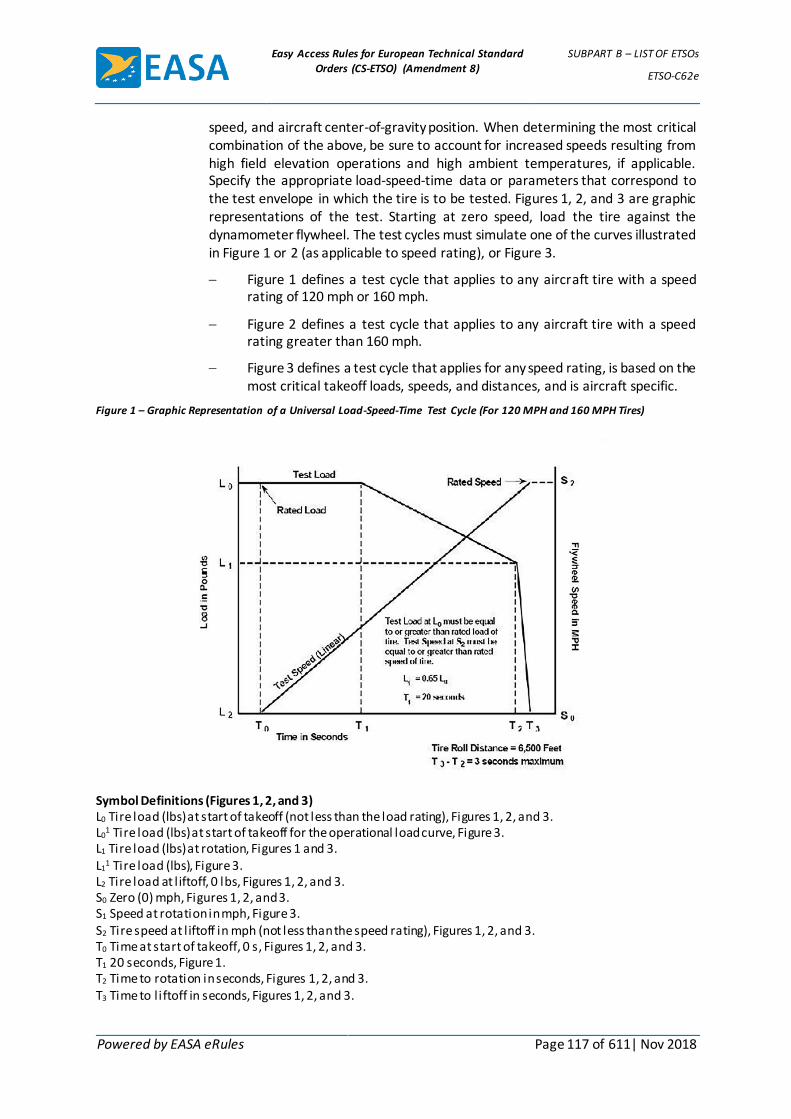
Easy Access Rules for European Technical Standard
Orders (CS-ETSO) (Amendment 8)
SUBPART B – LIST OF ETSOs
ETSO-C62e
Powered by EASA eRules Page 117 of 611| Nov 2018
speed, and aircraft center-of-gravity position. When determining the most critical combination of the above, be sure to account for increased speeds resulting from high field elevation operations and high ambient temperatures, if applicable. Specify the appropriate load-speed-time data or parameters that correspond to the test envelope in which the tire is to be tested. Figures 1, 2, and 3 are graphic representations of the test. Starting at zero speed, load the tire against the dynamometer flywheel. The test cycles must simulate one of the curves illustrated in Figure 1 or 2 (as applicable to speed rating), or Figure 3.
Figure 1 defines a test cycle that applies to any aircraft tire with a speed rating of 120 mph or 160 mph.
Figure 2 defines a test cycle that applies to any aircraft tire with a speed rating greater than 160 mph.
Figure 3 defines a test cycle that applies for any speed rating, is based on the most critical takeoff loads, speeds, and distances, and is aircraft specific.
Figure 1 – Graphic Representation of a Universal Load-Speed-Time Test Cycle (For 120 MPH and 160 MPH Tires)
Symbol Definitions (Figures 1, 2, and 3) L0 Tire load (lbs) at start of takeoff (not less than the load rating), Figures 1, 2, and 3. L0
1 Tire load (lbs) at start of takeoff for the operational load curve, Figure 3. L1 Tire load (lbs) at rotation, Figures 1 and 3. L1
1 Tire load (lbs), Figure 3. L2 Tire load at l iftoff, 0 lbs, Figures 1, 2, and 3. S0 Zero (0) mph, Figures 1, 2, and 3. S1 Speed at rotation in mph, Figure 3. S2 Tire speed at l iftoff in mph (not less than the speed rating), Figures 1, 2, and 3. T0 Time at start of takeoff, 0 s, Figures 1, 2, and 3. T1 20 seconds, Figure 1. T2 Time to rotation in seconds, Figures 1, 2, and 3. T3 Time to l iftoff in seconds, Figures 1, 2, and 3.

Easy Access Rules for European Technical Standard
Orders (CS-ETSO) (Amendment 8)
SUBPART B – LIST OF ETSOs
ETSO-C62e
Powered by EASA eRules Page 118 of 611| Nov 2018
Figure 2 – Graphic Representation of a Typical Universal Load-Speed-Time Test Cycle (For Tires Rated above 160 MPH)
Figure 3 – Graphic Representation of a Typical Rational Load-Speed-Time Test Cycle

Easy Access Rules for European Technical Standard
Orders (CS-ETSO) (Amendment 8)
SUBPART B – LIST OF ETSOs
ETSO-C62e
Powered by EASA eRules Page 119 of 611| Nov 2018
(3) Test load: the minimum allowable load at the start of the test is the rated load of the tire. The test loads must conform to Figures 1 or 2 (as applicable), or Figure 3. Figures 1 and 2 define a test cycle generally applicable to any aircraft. If you use Figure 3 to define the test cycle, select the loads based on the most critical takeoff conditions you established. At any speed throughout the test cycle, the ratio of the test load to the operational load must be the same as, or greater than, the ratio at the start of the test.
(4) Test inflation pressure: the pressure needed to provide the same loaded radius on the flywheel as was obtained on a flat surface at the rated tire load and inflation pressure. Make both determinations at the same ambient temperature. Do not adjust the test inflation pressure to compensate for changes created by temperature variations during the test.
(5) Test temperatures and cycle interval: the temperature of the gas in the tire or the casing temperature measured at the hottest point of the tire may not be:
(a) Lower than 40,6°C (105ºF) at the start of the overload takeoff cycle and at the start of at least 45 of the 50 takeoff cycles, and
(b) Lower than 48,9°C (120ºF) at the start of at least 9 of the 10 taxi cycles.
For the remaining cycles, the contained gas or casing temperature may not be lower than 26,7°C (80ºF) at the start of each cycle. Rolling the tire on the dynamometer flywheel is an acceptable method for obtaining the minimum starting temperature.
(6) Dynamometer takeoff cycle speeds: see Table 1 for the dynamometer test speeds for the corresponding maximum aircraft takeoff speeds.
(7) Taxi cycles: tire must withstand 10 taxi cycles on a dynamometer under the test conditions in Table 2 below.
TABLE 2. Test Conditions
Number of Taxi Runs
Min Tire Load (lbs)
Min Speed (mph)
Tire speed rating 120/160 mph
Min Rolling Distance (ft)
Tire speed rating Over 160 mph
Min Rolling Distance (ft)
8 Rated 40 25,000 35,000
2 1.2 x Rated 40 25,000 35,000
(8) Overload takeoff cycle: the overload takeoff cycle shall duplicate the test described
in paragraph 5.a.(2) with the test load increased by a factor of 1.5 throughout. Good condition of the tire tread is not required after completion of this test cycle, if you run this test last. If the overload takeoff cycle is not run last, the tire must withstand the cycle without detectable signs of deterioration, other than normal expected tread surface abrasion.
(9) Diffusion test: after completing the 61 test cycles, the tire must retain the inflation pressure to within 10% of the initial test pressure for a period of 24 hours. Measure the ambient temperature at the start and finish of this test to ensure that any pressure change was not caused by an ambient temperature change.
(10) Tire/wheel slippage: tires should not slip on the wheel rim during the first five dynamometer cycles. Any slippage that subsequently occurs must not damage the tube valve of tube type tires, or the gas seal of the tire bead of tubeless tires.

Easy Access Rules for European Technical Standard
Orders (CS-ETSO) (Amendment 8)
SUBPART B – LIST OF ETSOs
ETSO-C62e
Powered by EASA eRules Page 120 of 611| Nov 2018
b. Alternate qualification procedures: 120 mph rated tires. For 120 mph speed rating tires, you may use the following variable mass flywheel procedure:
(1) Test load: load must meet or exceed the tire rated load throughout the entire test roll distance.
(2) Test inflation pressure: pressure needed to provide the same loaded radius on the flywheel as was obtained on a flat surface at the rated tire load and inflation pressure. Make both determinations at the same ambient temperature. Do not adjust the test inflation pressure to compensate for changes created by temperature variations during the test.
(3) Temperature and cycle interval: the temperature of the gas in the tire, or the casing temperature measured at the hottest point of the tire, may not be lower than 40,6°C (105°F) at the start of at least 180 of the 200 landing cycles. For the remaining cycles, the contained gas or casing temperature may not be lower than 26,7°C (80°F) at the start of each cycle. Rolling the tire on the dynamometer is an acceptable method for obtaining the minimum starting temperature.
(4) Kinetic energy: calculate the kinetic energy of the flywheel to be absorbed by the tire using this equation:
𝐾𝐸 = 𝐶𝑊(𝑉2) = 𝐾𝑖𝑛𝑒𝑡𝑖𝑐 𝑒𝑛𝑒𝑟𝑔𝑦 (𝑓𝑡 − 𝑙𝑏𝑠)
where
C = 0.0113
W = Load rating of the tire (lbs)
V = 120 mph
(5) Dynamometer cycle requirements: tire must satisfactorily withstand 200 landing cycles on a variable mass dynamometer flywheel. If you cannot use the exact number of flywheel plates to obtain the calculated kinetic energy value, select a greater number of plates and adjust the dynamometer speed to obtain the required kinetic energy. Divide the total number of dynamometer landings into two equal parts having the speed ranges provided in paragraphs 5.b.(5)(a) and 5.b.(5)(b).
(a) Low speed landings: in the first series of 100 landings, the maximum landing speed is 90 mph and the minimum unlanding speed is 0 mph. Adjust the landing speed so the tire will absorb 56% of the kinetic energy calculated using the equation in paragraph 5.b.(4) above. If the adjusted landing speed is calculated to be less than 80 mph, then determine the landing speed by adding 28% of the calculated kinetic energy (see paragraph 5.b.(4) above) to the flywheel kinetic energy at 64 mph, and determine the unlanding speed by subtracting 28% of the calculated kinetic energy from the flywheel kinetic energy at 64 mph.
(b) High speed landings: in the second series of 100 landings, the minimum landing speed is 120 mph and the nominal unlanding speed is 90 mph. Adjust the unlanding speed as needed to ensure that the tire will absorb 44% of the calculated kinetic energy (see paragraph 5.b.(4) above).
6. REQUALIFICATION TESTS.

Easy Access Rules for European Technical Standard
Orders (CS-ETSO) (Amendment 8)
SUBPART B – LIST OF ETSOs
ETSO-C62e
Powered by EASA eRules Page 121 of 611| Nov 2018
a. Re-qualify altered tires, with changes in materials, design and/or manufacturing processes that could adversely affect the performance and reliability, to the dynamometer tests described under paragraph 5. Some examples include (1) or (2) below, or both:
(1) Changes in casing construction, such as the number of plies and/or bead bundles, ply cord makeup (material, denier, number of strands) and configuration (radial and bias).
(2) Changes in tread construction, such as number or composition of tread reinforcing and/or protector plies, tread compound formulations, number and location of tread grooves, and an increase in skid depth.
b. Re-qualification by similarity (based on load rating). Re-qualifying a given load rated tire due to a change in material or tread design, automatically qualifies the same changes in a lesser load tire of the same size, speed rating, and skid depth, if:
(1) The lesser load rated tire was qualified to the applicable requirements specified in this ETSO, and
(2) The ratio of qualification test load to rated load for the lesser load rated tire does not exceed the same ratio to the higher load rated tire at any given test condition.
c. Re-qualification by similarity (blanket change). You can gain re-qualification of any change that affects all sizes by similarity, if:
(1) Five representative sizes, including tires of the highest load rating, speed rating and angular velocity, were qualified to the minimum performance standard with the change, and
(2) You submit data supporting the change in the listed sizes to EASA.
(Amdt ETSO/7]

Easy Access Rules for European Technical Standard
Orders (CS-ETSO) (Amendment 8)
SUBPART B – LIST OF ETSOs
ETSO-C64a
Powered by EASA eRules Page 122 of 611| Nov 2018
ETSO-C64a ED Decision 2003/10/RM (applicable from 24.10.2003)
Oxygen Mask Assembly, Continuous Flow, Passenger
1 Applicability
This ETSO gives the requirements which new models of oxygen mask, continuous flow, passenger, that is manufactured on or after the date of this ETSO must meet in order to be identified with the applicable ETSO marking.
2 Procedures
2.1 General
Applicable procedures are detailed in CS-ETSO Subpart A.
2.2 Specific
None.
3- Technical Conditions
3.1- Minimum Performance Standard
Standards set forth in the Society of Automotive Engineers (SAE), Inc, Document Aerospace Standard (AS) no AS 8025, „Passenger Oxygen Mask“ dated 24 February 1988.
3.2 Specific
None.
4 Marking
4.1 General
Marking is detailed in CS-ETSO Subpart A paragraph 1.2.
4.2 Specific
The markings for each mask must, in addition to the requirement in the CS-TSO Subpart A, be marked with the performance classification number as specified in SAEAS 8025 Paragraph 2.3.
5 Availability of Referenced Document
See CS-ETSO Subpart A paragraph 3.
Easy Access Rules for European Technical Standard
Orders (CS-ETSO) (Amendment 8)
SUBPART B – LIST OF ETSOs
ETSO-C65a
Powered by EASA eRules Page 123 of 611| Nov 2018
ETSO-C65a ED Decision 2003/10/RM (applicable from 24.10.2003)
Airborne Doppler Radar Ground Speed and/or Drift Angle Measuring Equipment (for Air Carrier Aircraft)
1 Applicability
This ETSO gives the requirements which airborne doppler radar ground speed and/or drift angle measuring equipment that is manufactured on or after the date of this ETSO must meet in order to be identified with the applicable ETSO marking.
2 Procedures
2.1 General
Applicable procedures are detailed in CS-ETSO Subpart A.
2.2 Specific
None.
3 Technical Conditions
3.1 Basic
3.1.1 Minimum Performance Standard
Standards set forth in EUROCAE document MPS/WG7C/1-74 (RTCA DO-158), as amended and supplemented by this ETSO:
In addition to paragraph 1.0, General Standards, of RTCA DO-158, all materials used except small parts (such as knobs, fasteners, seals, grommets and small electrical parts) that would not contribute significantly to the propagation of a fire, must be self-extinguishing when tested in accordance with applicable requirements of CS 25 Appendix F.
3.1.2 Environmental Standard
See CS-ETSO Subpart A paragraph 2.1.
3.1.3 Computer Software
See CS-ETSO Subpart A paragraph 2.2.
3.2 Specific
None
4 Marking
4.1 General
Marking is detailed in CS-ETSO Subpart A paragraph 1.2.
4.2 Specific
None.
5 Availability of Referenced Document
See CS-ETSO Subpart A paragraph 3.

Easy Access Rules for European Technical Standard
Orders (CS-ETSO) (Amendment 8)
SUBPART B – LIST OF ETSOs
ETSO-C68a
Powered by EASA eRules Page 124 of 611| Nov 2018
ETSO-C68a ED Decision 2003/10/RM (applicable from 24.10.2003)
Airborne Automatic Dead Reckoning Computer Equipment Utilizing Aircraft Heading and Doppler Ground Speed and Drift Angle Data (for Air Carrier Aircraft)
1 Applicability
This ETSO gives the requirements which airborne automatic dead reckoning computer equipment utilizing aircraft heading and doppler ground speed and drift angle data that are manufactured on or after the date of this ETSO must meet in order to be identified with the applicable ETSO marking.
2 Procedures
2.1 General
Applicable procedures are detailed in CS-ETSO Subpart A.
2.2 Specific
None.
3 Technical Conditions
3.1 Basic
3.1.1 Minimum Performance Standard
Standards set forth in EUROCAE document MPS/WG7C/2-74, dated August 1974, „Airborne Automatic Dead Reckoning Computer Equipment Utilizing Aircraft Heading and Doppler Obtained Velocity Vector Data“.
In addition to Chapter 4 of EUROCAE document MPS/WG7C/2-74, all materials used except small parts (such as knobs, fasteners, seals, grommets and small electrical parts) that would not contribute significantly to the propagation of a fire, must be self-extinguishing when tested in accordance with applicable requirements of CS 25 Appendix F.
3.1.2 Environmental Standard
See CS-ETSO Subpart A paragraph 2.1.
3.1.3 Computer Software
See CS-ETSO Subpart A paragraph 2.2.
3.2 Specific
None
4 Marking
4.1 General
Marking is detailed in CS-ETSO Subpart A paragraph 1.2.
4.2 Specific
None.
5 Availability of Referenced Document
See CS-ETSO Subpart A paragraph 3.

Easy Access Rules for European Technical Standard
Orders (CS-ETSO) (Amendment 8)
SUBPART B – LIST OF ETSOs
ETSO-C69c
Powered by EASA eRules Page 125 of 611| Nov 2018
ETSO-C69c ED Decision 2003/10/RM (applicable from 24.10.2003)
Emergency Evacuation Slides, Ramps, Ramp/Slides and Slide/Rafts
1 Applicability
This ETSO gives the requirements that new models of emergency evacuation slides, ramps, ramp/slides, and slide/rafts that are manufactured on or after the date of this ETSO must meet in order to be identified with applicable ETSO marking.
Type I- Inflatable Slide
Type II- Inflatable Slide/Raft
Type III- Inflatable Exit Ramp
Type IV- Inflatable Exit Ramp/Slide
2 Procedures
2.1 General
Applicable procedures are detailed in CS-ETSO Subpart A.
2.2 Specific
None.
3 Technical Conditions
3.1 Basic
3.1.1 Minimum Performance Standard
Standards set forth in Appendix 1, Federal Aviation Administration Standards for emergency evacuation slides, ramps, ramp/slides, and slide/rafts, as amended and supplemented by this ETSO.
Where applicable, instead of the referenced FAA documents/paragraph the corresponding IR, CS or ETSO document/paragraph shall be used, when available.
3.1.2 Environmental Standard
See CS-ETSO Subpart A paragraph 2.1.
3.1.3 Computer Software
None.
3.2 Specific
None
4 Marking
4.1 General
Marking is detailed in CS-ETSO Subpart A paragraph 1.2.
4.2 Specific
The component also must be marked with the applicable emergency evacuation device type: "Type I, Type II, Type III, or Type IV." Type II devices shall also be marked with the

Easy Access Rules for European Technical Standard
Orders (CS-ETSO) (Amendment 8)
SUBPART B – LIST OF ETSOs
ETSO-C69c
Powered by EASA eRules Page 126 of 611| Nov 2018
rated and overload capacities and the weight of the device including any accessories required by this ETSO.
5 Availability of Referenced Document
See CS-ETSO Subpart A paragraph 3.

Easy Access Rules for European Technical Standard
Orders (CS-ETSO) (Amendment 8)
SUBPART B – LIST OF ETSOs
ETSO-C69c
Powered by EASA eRules Page 127 of 611| Nov 2018
APPENDIX 1 TO ETSO-C69C – FEDERAL AVIATION ADMINISTRATION MINIMUM
PERFORMANCE STANDARD FOR EMERGENCY EVACUATION SLIDES, RAMPS, RAMP/SLIDES, AND SLIDE/RAFTS
ED Decision 2003/10/RM
Note: Any reference made to US standards, regulations and organisations are for information purpose only and may be replaced, if applicable, by the European equivalent when acceptable to the Agency.
1. Purpose. This standard provides the minimum performance standards for inflatable emergency
evacuation slides, overwing exit ramps, ramp/slides, and slide/rafts. However, the deployment and erection characteristics for these devices, as installed on the aircraft, are specified in Title 14 of the Code of Federal Regulations (14 CFR) § 25.810 and must be complied with along with the requirements in this TSO.
2. Scope. This performance standard provides for the following types of emergency evacuat ion devices:
Type I - Inflatable slide suitable for assisting occupants in descending from a floor-level aircraft exit or from an aircraft wing.
Type II - Inflatable slide also designed to be used as a life raft, i.e. a slide/raft.
Type III - Inflatable exit ramp suitable for assisting occupants in descending to an aircraft wing from certain overwing exits.
Type IV - Combination inflatable exit ramp and wing-to-ground slide.
Further definitions of terms used in this TSO are given in appendix 2.
3. Materials. The materials used must be of a quality, which experience and/or tests have demonstrated to be suitable for use in emergency evacuation slides, ramps, ramp/slides and slide/rafts, i.e. emergency evacuation devices.
3.1 Nonmetallic Materials.
3.1.1 The finished device must be clean and free from any defects that might affect its function.
3.1.2 Coated fabrics and other items, such as webbing, which are subject to deterioration must have been manufactured not more than 18 months prior to the date of manufacture of the finished product. However, these materials may be re-qualified for an additional 18 months if they pass the requirements of paragraph 5.1 of this appendix.
3.1.3 The materials must not support fungus growth.
3.1.4 Materials used in the construction of flotation chambers and decks for Type II devices must be capable of withstanding the detrimental effects of exposure to fuels, oils, hydraulic fluids, and sea water.
3.1.5 Coated Fabric. Coated fabrics, including seams, which are subject to deterioration and used in the manufacture of the devices, must retain at least 90 percent of their original physical properties after these fabrics have been subjected to the accelerated aging test specified in paragraph 5.1 of this appendix.
3.1.5.1 Strength. Coated fabrics used for these applications must conform to the following minimum strengths after aging:

Easy Access Rules for European Technical Standard
Orders (CS-ETSO) (Amendment 8)
SUBPART B – LIST OF ETSOs
ETSO-C69c
Powered by EASA eRules Page 128 of 611| Nov 2018
Tensile Strength (Grab Test)
Warp 190 pounds/inch Fil l 190 pounds/inch
Tear Strength (Trapezoid Test or Tongue Test)
Non walking/sliding surface: 13 x 13 pounds/inch (minimum) Walking/Sliding surface: 50 x 50 pounds/inch (minimum)
Puncture Strength
Walking/Sliding surface: 67 pounds force
3.1.5.2 Adhesion. In addition to the strength requirements of paragraph 3.1.5.1 above, coated fabrics must meet the following minimum strengths after aging:
Ply Adhesion
5 pounds/inch width at 70 + 2 degrees F at a separation rate of 2.0 to 2.5 inches/minute
Coat Adhesion
5 pounds/inch width at 70 + 2 degrees F at a separation rate of 2.0 to 2.5 inches/minute
3.1.5.3 Permeability. For coated fabrics used in the manufacture of inflation
chambers, the maximum permeability to helium may not exceed 10 liters per square meter in 24 hours at 77 degrees F, or its equivalent using hydrogen, using either of the permeability test methods specified in paragraph 5.1 of this appendix. The permeameter must be calibrated for the gas used. In lieu of either of these permeability tests, an alternate test may be used provided the alternate test has been approved as an equivalent to this permeability test by the manager of the FAA office having purview of the manufacturer's facilities, as required in paragraphs 3b, Deviations and 5a, Application Data, of this TSO.
3.1.5.4 Hydrolysis. Pressure holding coated fabrics, including seams, must be shown to be resistant to hydrolysis. It must be shown by tests specified in paragraph 5.1 of this appendix that the porosity of the basic pressure holding material is not increased as a result of the material being subjected to hydrolysis conditioning. Seam strength and coat adhesion must not be reduced more than 20 percent and still must not fall below the minimums prescribed in paragraphs 3.1.5.2 and 3.1.6 of this appendix as a result of hydrolysis conditioning.
3.1.6 Seam Strength and Adhesives. Seams used in the manufacture of the device must meet the following minimum strength requirements:
Shear Strength (Grab Test)
175 pounds/inch width at 75 degrees F 40 pounds/inch width at 140 degrees F
Peel Strength (Peel Test)

Easy Access Rules for European Technical Standard
Orders (CS-ETSO) (Amendment 8)
SUBPART B – LIST OF ETSOs
ETSO-C69c
Powered by EASA eRules Page 129 of 611| Nov 2018
5 pounds/inch width at 70 degrees F
3.1.7 Seam Tape. If tape is used for seam reinforcement or abrasion protection of seams or both, the fabric used for the seam tape must have a minimum breaking strength (Grab Test) of 40 pounds/inch width in both the warp and fill directions. When applied to the seam area, the adhesion strength characteristics must meet the seam strength requirements in paragraph 3.1.6 above.
3.1.8 Canopy. Fabrics used for this purpose on Type II slide/rafts must be waterproof and resistant to sun penetration, must not affect the potability of collected water, and must meet the following minimum requirements in the applicable tests prescribed in paragraph 5.1 of this appendix, except that in lieu of meeting the tensile strength requirements, a fabricated canopy erected on the device may be demonstrated to withstand sustained wind velocities of 35 knots and 52-knot gusts:
Tensile Strength (Grab Test)
Warp 75 pounds/inch Fil l 75 pounds/inch
Tear Strength (Tongue or Trapezoid Test)
4 x 4 pounds/inch
Coat Adhesion of Coated Fabrics
3.5 pounds/inch width at 70±2 degrees F at a separation rate of 2.0 to 2.5 inches/minute 3.1.9 Flammability. The device (including carrying case or stowage container) must be
constructed of materials which comply with the requirements of 14 CFR § 25.853(a), Appendix F, part I (a)(1)(ii) in effect on March 6, 1995.
3.1.10 Radiant Heat Resistance. The pressure holding materials in the device must meet the 90-second minimum time to failure requirement and the 180-second average time to failure requirement of the radiant heat resistance test specified in paragraph 5.3 of this appendix.
3.1.11 Molded Nonmetallic Fittings. Molded nonmetallic fittings must retain their physical characteristics when subjected to temperatures of -65 to +160 degrees F.
3.2 Metallic Parts. All metallic parts must be made of corrosion-resistant material or must be suitably protected against corrosion.
3.3 Protection. All inflation chambers and load carrying fabrics must be protected in such manner that non-fabric parts do not cause chafing or abrasion of the material in either the packed or the inflated condition.
4. Detail Requirements.
4.1 Operation. The operation of the device must be simple enough so that brief, easily understood, posted instructions can be followed by the user.
4.2 Function. The device, including its inflation system, must be demonstrated to be capable of fully functioning when subjected to temperatures from -40 to +160 degrees F. If the device is intended for installation outside the pressurized cabin, the device must be capable of functioning after being stowed at -65 degrees F. The function of the device must be demonstrated in accordance with the hot and cold soak test procedures described in paragraph 5.9 of this appendix.

Easy Access Rules for European Technical Standard
Orders (CS-ETSO) (Amendment 8)
SUBPART B – LIST OF ETSOs
ETSO-C69c
Powered by EASA eRules Page 130 of 611| Nov 2018
4.3 Strength.
4.3.1 Beam Strength-Type I, II, & IV Devices. The structural integrity of the device during and after the dynamic challenge of multiple sand bag loading of the device (to simulate loading by three, tightly-bunched evacuees entering each lane of the device) must be shown by test to be adequate, as described in paragraph 5.5 of this appendix.
4.3.2 Attachment Means Strength. The means by which the device is attached to the aircraft, typically the girt, must not fail and must remain intact and suitably attached to both the aircraft and the device during and after the severe loading tests simulating normal evacuation. The device must withstand the static tensile load tests defined in this appendix in paragraphs 5.6, for girts, or 5.7, for non-girts, and 5.8, as appropriate, for evacuees inadvertently entering pontoon areas. Separate girt specimens may be used in the two tests required in paragraph 5.6 of this appendix.
4.4 Elimination of Static. The device and its fastening must be so constructed that static electricity will not be generated in sufficient quantity to cause a spark which would create a hazard if there is any fuel spillage nearby.
4.5 Damage Resistance and Usage.
4.5.1 The device must be capable of resisting puncture and tear of the sliding and walking surfaces and supporting structure from objects normally carried or worn by passengers that could result in collapse of the device, prevent the device from performing its intended function, or both.
4.5.2 Type I, II & IV devices must be so constructed as to permit their use with ground personnel assistance as a noninflatable device in the event of puncture or tear which may render the device incapable of holding air and sustaining inflation.
4.5.3 If the device is of a multiple-inflatable compartment construction, loss of any one of these compartments must not render the device totally unusable.
4.6 Length. Type I, II & IV devices must be of such length after full deployment that the lower end is self-supporting on the ground. The device must provide safe evacuation of occupants to the ground when the aircraft is on the ground with the landing gear extended and after collapse of one or more legs of the landing gear.
4.7 Elimination of Encumbrances. Encumbrances which might be grabbed by evacuees must be kept to a minimum consistent with good design for maximum operational efficiency.
4.8 Hardware and Attaching Means Strength. All hardware, webbing and straps used to attach the device to the aircraft and all straps, grips, and handholds not associated with attachment to the aircraft must have a strength not less than 1.5 times the highest design load imposed in showing compliance with the strength requirements of paragraph 4.3 of this appendix and for Type II devices, in establishing the rated capacity under paragraph 4.26.1 of this appendix.
4.9 Use as Re-entry Device. If the device is designed with provisions for use as a means of re-entering the aircraft, these additional provisions must not interfere with the use of the device for evacuation.
4.10 Evacuation Rate.

Easy Access Rules for European Technical Standard
Orders (CS-ETSO) (Amendment 8)
SUBPART B – LIST OF ETSOs
ETSO-C69c
Powered by EASA eRules Page 131 of 611| Nov 2018
4.10.1 The device must be shown, by tests conducted under the conditions described in paragraph 5.4.1 of this appendix, to be capable of safely accommodating evacuees at a rate of at least 70 evacuees per minute per lane. The evacuees must exit the device without assistance.
4.10.2 Evacuation capability under the test conditions shown in paragraph 5.4.3 of this appendix must be demonstrated in order to confirm the acceptability of the device and it’s and/or the associated airplane's emergency lighting system for use by evacuees under dark-of-night conditions. An evacuation rate based upon the rating of the exit (see paragraph 5.4.3.10 of this appendix) to which the device will be attached must be achieved. A detailed test plan to meet these requirements should be submitted at least 60 days prior to the test to the FAA aircraft certification office having purview of the manufacturer's facilities. The test plan shall include, but not be limited to, the test protocol, a description of the test facilities, a description of the measurement and recording equipment and procedures, and the safety provisions for protecting test participants. The test plan must be approved by the manager of that FAA office prior to conduct of the test.
4.11 Inflation.
4.11.1 The device must be demonstrated to meet the applicable automatic inflation requirements of 14 CFR § 25.810 (a)(1)(ii), (b), and/or (d)(4). See paragraph 4.12 below.
4.11.2 The device shall be designed to prevent its inflation out of proper sequence.
4.11.3 A manual means of actuating inflation must be provided. The manual means of actuation of the inflation system may be mechanical or electrical. However, the manual inflation actuating means must be neither visible nor presented for use until the device has been deployed. If the means is not an integral part of the device, details of its connection must be included in the installation limitations required in paragraph 5a, Application Data.
4.12 Inflation Time.
4.12.1 Type I floor-level exit slides and Type III devices must be fully erected in 6 seconds after actuation of the inflation controls has begun.
4.12.2 Type II devices must meet the requirements in paragraph 4.12.1 above and, if there are actions required to convert usage from slide mode to raft mode, the time required to complete those actions must not exceed 10 seconds after actuation of the conversion means.
4.12.3 Type IV devices and Type I wing-to-ground slides must be automatically erected in not more than 10 seconds after actuation of the inflation controls.
4.13 Device Length Extensions.
4.13.1 The device extension must be capable of being inflated at any time after inflation of the basic device has been initiated. The time required to complete extension of the device must not exceed 4 seconds beyond the time required to inflate the basic device.
4.13.2 Inflation of the extension must be initiated by separate controls from those for the basic device. The controls must be clearly identified and must be located separately from the manual inflation actuation controls to minimize the possibility of inadvertent actuation.
Easy Access Rules for European Technical Standard
Orders (CS-ETSO) (Amendment 8)
SUBPART B – LIST OF ETSOs
ETSO-C69c
Powered by EASA eRules Page 132 of 611| Nov 2018
4.13.3 The junction of the basic device and the extension must not impede evacuation.
4.14 Manual Inflation Actuation Controls.
4.14.1 Inflation controls must be equipped with a rigid cross member as an actuation handle. The handle must be red in color, marked with the word "PULL" (or other appropriate instruction) in high visibility reflective letters at least 1/2-inch high and of a contrasting color. In addition, there must be a placard with the words "PULL TO INFLATE" (or other appropriate instruction) located as close to the handle as possible.
4.14.2 When the inflation actuation controls are exposed for use, they must be visible to an aircraft occupant, standing at the doorsill, under the minimum emergency lighting conditions specified in 14 CFR § 25.812 in effect at the time of application.
4.14.3 Unless a rational analysis is provided to locate them elsewhere, or if there is no girt attachment, inflation actuation controls must be on the right side of the girt as seen by an aircraft occupant looking out of the aircraft door.
4.14.4 Inflation actuation controls must be so designed that the maximum required pulling force will not pull the deployed device back into the doorway. The pulling force required must not exceed 30 pounds.
4.14.5 Inflation actuation controls must be constructed so they cannot trip or entangle evacuees.
4.14.6 When actuated, the manual inflation actuation controls must function in a manner which will not cause rotation or twist of the deployed assist means.
4.15 Inflation System.
4.15.1 The inflation system must be connected to the evacuation device and ready for instant use. The inflation system must minimize leakage due to backpressure after inflation.
4.15.2 If an air aspirator system is used, the system must be constructed to prevent the ingestion of small foreign objects or to prevent failure or malfunction of the system as a result of ingestion of the small foreign objects.
4.15.3 Components must meet Department of Transportation (DOT) Specifications 3AA (49 CFR 178.37) or 3HT (49 CFR 178.44) in effect May 30, 1976, FRP-1 (49 CFR 178.AA) in effect February 1987, CFFC (49 CFR 178) in effect November 1996, or an equivalent specification approved by the manager of the FAA office having purview of the manufacturer's facilities, as required in paragraphs 3b, Deviations and 5a, Application Data of this TSO.
4.15.4 Inflation systems for Type II devices, in addition to meeting the above requirements of paragraph 4.15 of this appendix, shall be arranged so that failure of one inflatable chamber or manifold will not result in loss of gas from the other chamber. The inflation equipment shall be located so as not to interfere with boarding operations.
4.16 Multiple Lane Devices.
4.16.1 A multiple lane device must provide space for evacuees sliding simultaneously in each lane. Each sliding surface, if separated by a raised divider not considered to be a part of the sliding surface, must be at least 20 inches wide. The combined width of two sliding surfaces not separated by a raised divider must be at least 42

Easy Access Rules for European Technical Standard
Orders (CS-ETSO) (Amendment 8)
SUBPART B – LIST OF ETSOs
ETSO-C69c
Powered by EASA eRules Page 133 of 611| Nov 2018
inches. The width of a multiple lane device with no raised lane divider must be sufficient to enable evacuees to jump side-by-side into each slide lane simultaneously and reach the ground safely.
4.16.2 A multiple lane device must resist adverse twisting or deflecting when subjected to maximum asymmetrical loading represented by evacuees traversing each lane of the device individually at the evacuation rate prescribed in paragraph 4.10 of this appendix. Test conditions shall be as specified in paragraph 5.4 of this appendix except that only the normal sill height and nominal pressure shall be tested.
4.16.3 Where used, a raised divider or center median must be constructed so as to prevent injury to evacuees and not to throw from the device evacuees who jumped into it astraddle or partly astraddle the divider or median. Multiple lane devices, if canted, must provide for the avoidance of cross-flow effects due to the canting.
4.17 Side Guards. A single or multiple lane inflatable device must be equipped with side guards or other means to prevent evacuees from accidentally missing or falling from the device. The means must provide protection for an evacuee who crosses the aircraft emergency exit threshold at a horizontal velocity of approximately 6 feet per second and contacts the device installed at its steepest design angle.
4.18 Emergency Knife Location. If an emergency knife is provided, it must be so installed that it cannot injure persons using the evacuation device in a normal manner. For Type II devices, the knife must also meet the requirements of paragraph 4.39 of this appendix.
4.19 Device Illumination.
4.19.1 Integral device illumination must be designed so the illumination means is activated automatically during deployment or inflation and the level of illumination meets the appropriate requirements in 14 CFR § 25.812 in effect at the time of application.
4.19.2 The illumination means must not interfere with the safe evacuation of persons using the device in a normal manner.
4.20 Wind. The device must be shown, in 25-knot winds directed from the most critical angle, to deploy and, with the assistance of only one person who has evacuated down the device, to remain usable after full deployment to evacuate occupants safely to the ground. The device shall be tested while it is properly attached to the exit or location on the airplane on which installation is intended or on an equivalent mock-up.
4.20.1 To determine the most critical angle, the wind shall be directed at the device from at least the following directions: aft along the centerline of the aircraft (0 degrees position) and then every 45 degrees on the same side of the fuselage as the device is intended for installation.
4.20.2 If the straight section of the descent portion of the device forms an angle greater than 10 degrees to a line perpendicular to the aircraft centerline, the wind shall be applied to the device from directions perpendicular to both sides (i.e., the edges of the device parallel to the straight section of the descent portion) and from every 45 degrees between these two directions on the same side of the fuselage as the device is intended for installation. For directions which are not tested, a rational analysis shall be presented to show why those directions are less critical than those tested.
4.21 Device Surface.

Easy Access Rules for European Technical Standard
Orders (CS-ETSO) (Amendment 8)
SUBPART B – LIST OF ETSOs
ETSO-C69c
Powered by EASA eRules Page 134 of 611| Nov 2018
4.21.1 The surfaces of the device, including its coating, must be suitable and safe for use in any weather condition, including a rainfall of 1 inch per hour. The evacuation rate achieved in demonstrating suitability and safety of the device sliding surface under rainfall conditions shall be no less than that shown in paragraph 5.4.3.10. Evacuees shall meet the requirements of paragraph 5.4.1.5 of this appendix.
4.21.2 Each device sliding lane, including its coating, must provide safe and rapid evacuation without detrimental erosion or deterioration for at least 200 adult persons without any rework of the surface.
4.22 Device Performance. At least five consecutive deployment and erection tests must be demonstrated without failure. At least three tests must be conducted using a single representative sample of the device.
4.23 Dynamic Pressure Retention Test. The device must maintain adequate pressure to satisfactorily accomplish its intended function throughout an emergency evacuation in which:
4.23.1 The device is installed at its critical angle (with respect to buckling);
4.23.2 The device is inflated by the inflation system designed for that purpose, the initial pressure of which is at the minimum of its design range;
4.23.3 The pressure relief valve(s), if installed, is unrestricted; and
4.23.4 At least 200 persons in no more than 10 separate demonstrations use each slide lane of the device at an average rate of not less than one person per second per lane.
4.24 Overpressure Tests. The device must be shown to withstand the overpressure test requirements of paragraph 5.2.2 of this appendix without damage.
4.25 Static Pressure Retention Test. The device must be shown to meet the pressure retention test requirements of paragraph 5.2.1 of this appendix.
4.26 Raft Capacity-Type II Devices.
4.26.1 Rated Capacity. The rated capacity shall be the usable seating area on the deck/sliding surface of not less than 3.6 ft2/person.
4.26.2 Overload Capacity. The overload capacity shall be the usable seating area on the deck/sliding surface of not less than 2.4 ft2/person.
4.26.3 Capacity. Alternate Rating Methods. In lieu of the rated capacity prescribed in paragraph 4.26.1 above, one of the following methods may be used:
4.26.3.1 The rated capacity of a Type II device may be determined by the number of seating spaces which can be accommodated within the occupiable area exclusive of the perimeter structure (such as inflation/buoyancy tubes) without overlapping of the occupant seating spaces. The occupant seating spaces may not be less than the following size unless an equivalent size has been approved by the manager of the FAA office having purview of the manufacturer's facilities.
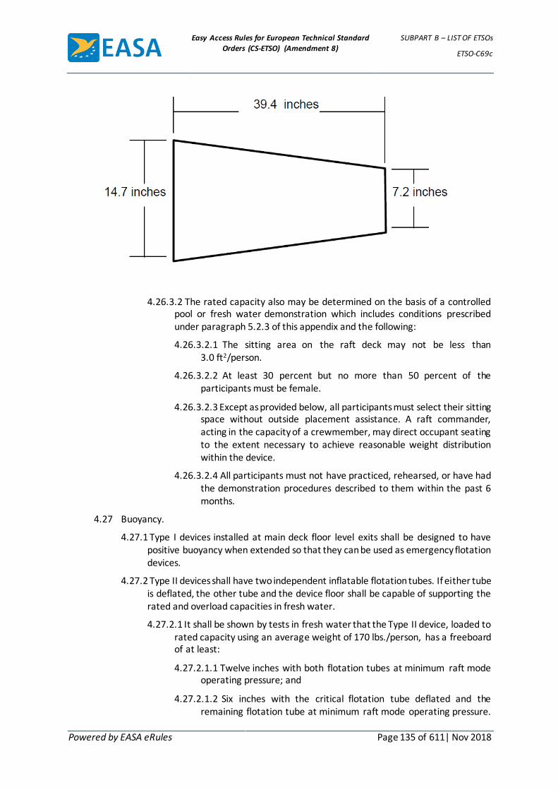
Easy Access Rules for European Technical Standard
Orders (CS-ETSO) (Amendment 8)
SUBPART B – LIST OF ETSOs
ETSO-C69c
Powered by EASA eRules Page 135 of 611| Nov 2018
4.26.3.2 The rated capacity also may be determined on the basis of a controlled pool or fresh water demonstration which includes conditions prescribed under paragraph 5.2.3 of this appendix and the following:
4.26.3.2.1 The sitting area on the raft deck may not be less than 3.0 ft2/person.
4.26.3.2.2 At least 30 percent but no more than 50 percent of the participants must be female.
4.26.3.2.3 Except as provided below, all participants must select their sitting space without outside placement assistance. A raft commander, acting in the capacity of a crewmember, may direct occupant seating to the extent necessary to achieve reasonable weight distribution within the device.
4.26.3.2.4 All participants must not have practiced, rehearsed, or have had the demonstration procedures described to them within the past 6 months.
4.27 Buoyancy.
4.27.1 Type I devices installed at main deck floor level exits shall be designed to have positive buoyancy when extended so that they can be used as emergency flotation devices.
4.27.2 Type II devices shall have two independent inflatable flotation tubes. If either tube is deflated, the other tube and the device floor shall be capable of supporting the rated and overload capacities in fresh water.
4.27.2.1 It shall be shown by tests in fresh water that the Type II device, loaded to rated capacity using an average weight of 170 lbs./person, has a freeboard of at least:
4.27.2.1.1 Twelve inches with both flotation tubes at minimum raft mode operating pressure; and
4.27.2.1.2 Six inches with the critical flotation tube deflated and the remaining flotation tube at minimum raft mode operating pressure.

Easy Access Rules for European Technical Standard
Orders (CS-ETSO) (Amendment 8)
SUBPART B – LIST OF ETSOs
ETSO-C69c
Powered by EASA eRules Page 136 of 611| Nov 2018
In lieu of meeting the 6-inch freeboard requirement of this paragraph, the buoyancy provided by the tubes only (disregarding buoyancy derived from the floor and inflatable floor support) shall be capable of supporting the rated capacity based on an average weight of at least 200 lbs./person.
4.27.2.2 It shall be shown by tests in fresh water that the Type II device loaded to its overload capacity and using an average weight of 170 lbs./person has a measurable freeboard with the critical flotation tube deflated.
Ballast in the form of sandbags or the equivalent may be used to achieve the 170-lb weight, provided the appropriate distribution within the device is maintained.
4.28 Disconnect Means.
4.28.1 Type I devices’ disconnect means must be a readily apparent, flexible cloth/webbing loop capable of being operated by untrained persons and covered until ready for use. The method of disconnecting the device from the aircraft must be conspicuously and clearly indicated by brief instruction placards.
4.28.2 Type II device release from an aircraft, whether by automatic or manual means, shall not be restricted by the critical conditions of: (a) floor sill height above the water, (b) wind velocity and direction, or (c) occupant load. Devices having aircraft mounted inflation systems shall have means for quick detachment from the inflation system so that separation cannot cause loss of raft buoyancy. Release means shall be a readily apparent flexible cloth/webbing loop capable of being operated by untrained persons and covered until ready for use. The method of disconnecting the device from the aircraft must be conspicuously and clearly indicated by brief instruction placards.
4.29 Mooring Line.
4.29.1 Type I devices must be equipped with a nonrotting mooring line so that the deployed device automatically will remain secured to the aircraft when it is used as an emergency flotation platform. The mooring line shall not endanger the device, cause the device to spill occupants if the aircraft sinks, or interfere with the operation of the device. The mooring line shall have a minimum length of 20 feet and have a knotted breaking strength of not less than 500 lbs. The attachment to the evacuation device shall be stronger than the mooring line. The moored device shall be quickly and easily disconnected from the aircraft. The mooring release means shall be readily apparent and operable by untrained evacuees.
4.29.2 Type II devices, in addition to meeting the requirements of paragraph 4.29.1, shall have a mooring line capable of keeping the device, loaded to rated capacity, attached to a floating aircraft. The line may be equipped with a mechanical release linkage. The breaking strength of the line shall be 500 – 1000 pounds.
4.30 Lifeline. Type I and Type II devices shall be equipped with a nonrotting lifeline of a size greater than or equal to 3/8-inch diameter or ½-inch width, .060 minimum thickness and of a color that contrasts with the device. The lifeline shall be attached along at least 80 percent of the length of both sides of the device. The lifeline shall not adversely compromise the use of the device as a slide. The lifeline and its attachment must be capable of withstanding a minimum load of 500 lbs. and must not interfere with the device's inflation.

Easy Access Rules for European Technical Standard
Orders (CS-ETSO) (Amendment 8)
SUBPART B – LIST OF ETSOs
ETSO-C69c
Powered by EASA eRules Page 137 of 611| Nov 2018
4.31 Capsize Resistance-Type II Devices. There shall be water pockets or other means to provide ballast to resist capsizing an empty or lightly loaded raft.
4.32 Righting-Type II Devices. Unless it is shown that there is no tendency for the device to become inverted during loading and release from the aircraft, the slide/raft must comply with the righting tests specified in paragraph 5.2.3.5 of this appendix.
4.33 Boarding Aids-Type II Devices. Boarding aids shall be provided at two opposing positions on the raft. Boarding aids shall permit unassisted entry from the water into the unoccupied raft and shall not at any time impair either the rigidity or the inflation characteristics of the raft. Puncturing of inflatable boarding aids shall not affect the buoyancy of the raft flotation chambers. Boarding handles and/or stirrups used in conjunction with the boarding aids shall withstand a pull of 500 pounds. Boarding aids must be shown to comply with the test requirements of paragraph 5.2.3.6 of this appendix.
4.34 Heaving-Trailing Line-Type II Devices. At least one, floating, heaving-trailing line, not less than 75 ft in length and at least 250 lbs. strength, shall be located on the main flotation tube near the sea anchor attachment. The attachment point of the line shall withstand a pull force of not less than 1.5 times the line rated strength without damage to the device.
4.35 Canopy-Type II Devices. A canopy shall be packed with or attached to the device. The erected canopy shall be capable of withstanding sustained wind velocities of 35 knots and 52-knot gusts in open water. The canopy shall provide adequate headroom, minimum 1 inch clearance, for the 95th percentile male (seated height) and shall provide openings 180 degrees apart. Means shall be provided to make the openings weather tight. If the canopy is not integral with the raft, it shall be capable of being erected by occupants following conspicuously posted, simple instructions. It shall be capable of being erected by one occupant of an otherwise empty raft and by occupants of a raft filled to rated capacity.
4.36 Color-Type II Devices. Except surfaces which have been treated for the purpose of reflecting radiant heat, the color of the device surfaces, including the canopy surface, visible from the air shall be an International Orange-Yellow or an equivalent high visibility color.
4.37 Sea Anchor-Type II Devices. A sea anchor, or anchors, or other equivalent means must be provided to maintain the raft, with rated capacity and canopy installed, on a substantially constant heading relative to the wind and must have the ability to reduce the drift to 2 knots when subjected to winds of 17 to 27 knots. Unless analysis and/or test data substantiating the adequacy of a lower breaking strength is approved by the manager of the FAA office having purview of the manufacturer's facilities as required in paragraphs 3b, Deviations, and 5a, Application Data, the line securing a sea anchor to the device shall have a breaking strength of 500 pounds or 40 pounds times the rated capacity of the raft, whichever is greater. The attachment of the line to the raft shall be capable of withstanding a load of 1.5 times the line-rated strength without damaging the device. The line shall be at least 25 feet in length and shall be protected to prevent it from being inadvertently cut by raft occupants.
4.38 Emergency Inflation Equipment-Type II Devices. A means readily accessible to occupants of the device shall be provided to manually inflate the device and maintain the raft mode minimum operating pressure. The emergency inflation means must have a displacement of at least 32 cubic inches per full stroke. Manual inflation valves, with a non-return opening adequate for the size and capacity of the inflation means, shall be located to

Easy Access Rules for European Technical Standard
Orders (CS-ETSO) (Amendment 8)
SUBPART B – LIST OF ETSOs
ETSO-C69c
Powered by EASA eRules Page 138 of 611| Nov 2018
permit inflation of all chambers. The inflation means and valves shall have provisions to prevent inadvertent removal and loss when either stowed or in use.
4.39 Knife-Type II Devices. A hook-type knife secured by a retaining line shall be sheathed and attached to the device adjacent to the point of mooring line attachment. This knife must also meet the requirements of paragraph 4.18 of this appendix.
4.40 Placards- Type II Devices. Suitable placards shall be provided in contrasting colors in waterproof paint which is not detrimental to the fabric, that denote use and location of the inflation systems, raft equipment, boarding aids, and righting aids. The letters used for such placarding shall be at least 2 inches high, except the details and miscellaneous instructions may be of smaller lettering. Applicable placarding shall take into account persons boarding or righting the raft from the water.
4.41 Emergency Lights-Type II Devices. At least one TSO-C85a, or the latest revision, approved survivor locator light shall be provided. The light shall be automatically activated upon device inflation in the water and shall be visible from any direction by persons in the water. The light shall be located at or near a boarding station.
4.42 Actuation Means-Type II Devices. If the device as a slide requires an additional operation to make it usable as a raft, the means for initiating the additional operation shall be designed to preclude inadvertent actuation but be readily available for use. If a pull motion is used, the force required must not be more than 30 pounds.
4.43 Sea Performance-Type II Devices. The device shall meet the seaworthiness requirements in paragraph 5.2.4 of this appendix and shall be capable with its equipment of withstanding a saltwater marine environment for a period of at least 15 days.
5. Tests.
5.1 Material Tests. Testing the material properties specified in paragraph 3, Materials, of this appendix must be conducted in accordance with the following test methods or other approved equivalent methods:
Test Method
Tests Required Federal Test Method Standard Other Test Method
Accelerated Age (1.) - Method 5850 Per Note (2.)
Tensile Strength (Grab Test) (1.) - Method 5100 Per Note (8.)
Tear Strength (Trapezoid Test) (6) Method 5136
Tear Strength (Tongue Test) (1.) Method 5134 (Alternate to Trapezoid Test paragraph 3.1.5.1)
Ply Adhesion (1.) - Method 5960 Per Note (4.)
Coat Adhesion (1.) - Method 5970 Per Note (9.)
Permeability (6.) - Method 5460 Per Note (7.)
Seam Shear Strength (1.) Per Notes (3.) (8.)
Seam Peel Strength (1.) - Method 5960 Per Note (4.)
Puncture Strength Per Note(10.)
Hydrolysis Conditioning Per Note (11.)
Porosity Test (Hydrolysis) Per Note (12.)
Flammability (Vertical Burn Rate) Per Note (5.)
NOTES:

Easy Access Rules for European Technical Standard
Orders (CS-ETSO) (Amendment 8)
SUBPART B – LIST OF ETSOs
ETSO-C69c
Powered by EASA eRules Page 139 of 611| Nov 2018
(1) Federal Test Method Standard (FTMS) No. 191A dated July 20, 1978.
(2) Samples for the accelerated aging tests must be exposed to a temperature of 158 ± 5 degrees F for not less than 168 hours. After exposure, the samples must be allowed to cool to 70 ± 2 degrees F for neither less than 16 hours nor more than 96 hours before determining their physical properties in accordance with paragraph 3.1 of this appendix.
(3) Each sample shall consist of two strips 2 inches maximum width by 5 inches maximum length bonded together with an overlap of 3/4 inches maximum. The free ends must be placed in the testing machine described in FTMS 191A, Method 5100 and separated at a rate of 12 ± 0.5 inches/minute. The average value of a minimum of three samples must be reported. Samples may be multilayered to ensure against premature material failure. Samples may be gripped across the full two inches of width.
(4) Separation rate must be 2.0 to 2.5 inches/minute. Sample width shall be one inch.
(5) The material must meet the flammability requirements of 14 CFR § 25.853(a), Appendix F, part I (a)(1)(ii) in effect March 6, 1995.
(6) FTMS No. 191 in effect December 31, 1968.
(7) ASTM Method D1434-82, Procedure V, approved July 30, 1982, is an acceptable alternate method.
(8) Use of pneumatic grips for holding test samples is an acceptable alternate to the mechanical grips described in Method 5100.
(9) The sample shall be prepared using the adhesive and construction methods used to manufacture the evacuation device. Separation rate must be 2.0 to 2.5 inches/minute.
(10) The fabric shall be tested in a specimen holder constructed in accordance with figure 1. The fabric shall be clamped tightly in the specimen holder to present a wrinkle-free surface and prevent slippage during the test. A piercing instrument with its end conforming to figure 1 shall be forced against the fabric at approximately the center of the area enclosed by the specimen holder. The force required to puncture the specimen shall not be less than the specified 67 pounds. The test shall be run using a crosshead speed of 12 inches/minute.
(11) Each sample shall be exposed to a temperature of 136 ± 4 degrees F and a relative humidity of 95 ± 4 percent for a period of 50 days.
(12) Porosity testing conducted for hydrolysis resistance shall be conducted with the test apparatus specified in paragraph 5.3 or an equivalent test method approved by the manager of the FAA having purview of the manufacturer's facilities, as required in paragraphs 3b, Deviations and 5a, Application Data, of this TSO. Note specimen size and mounting information of paragraphs 5.3.3.1 and 5.3.4.5 of this appendix. Tests should be conducted at the devices nominal operating pressure for a duration of 30 minutes. Porosity is indicated by a loss in chamber pressure during testing. Pressure loss for material specimens after hydrolysis conditioning shall not be greater than the pressure loss for the material before conditioning.

Easy Access Rules for European Technical Standard
Orders (CS-ETSO) (Amendment 8)
SUBPART B – LIST OF ETSOs
ETSO-C69c
Powered by EASA eRules Page 140 of 611| Nov 2018
FIGURE 1. PIERCING INSTRUMENT AND SPECIMEN HOLDER
5.2 Functional Tests.
5.2.1 Pressure Retention. Under static conditions and when inflated and stabilized at the nominal operating pressure, the pressure in each inflatable chamber of a Type II device must not fall below the minimum raft mode operating pressure in less than 24 hours. For Type I, III & IV devices, the pressure in each inflatable chamber must not fall below 50 percent of the nominal operating pressure in less than 12 hours.

Easy Access Rules for European Technical Standard
Orders (CS-ETSO) (Amendment 8)
SUBPART B – LIST OF ETSOs
ETSO-C69c
Powered by EASA eRules Page 141 of 611| Nov 2018
5.2.2 Overpressure Tests.
5.2.2.1 The device must withstand a pressure at least 1.5 times the maximum operating pressure for at least 5 minutes without sustaining damage.
5.2.2.2 At least one specimen of the inflatable device model must be shown by test to withstand a pressure at least 2 times the maximum operating pressure without failure for at least 1 minute. Devices so tested must be clearly identified.
5.2.3 Water Tests-Type II Devices. In either a controlled pool or fresh water the capacity and buoyancy of the device must be demonstrated as follows:
5.2.3.1 Both rated and overload capacities established in accordance with the requirements of paragraph 4.26 of this appendix must be demonstrated with inflation tubes at minimum raft mode operating pressure and with the critical buoyancy chamber deflated. The resultant freeboard in each case must meet the requirements of paragraph 4.27.2 of this appendix.
5.2.3.2 Persons used in the demonstration must have an average weight of not less that 170 pounds. Ballast in the form of sand bags or equivalent may be used to achieve proper loading provided the appropriate weight distribution within the device is maintained.
5.2.3.3 Persons used in the demonstration must wear FAA approved life preservers with at least one chamber inflated.
5.2.3.4 The raft equipment required by this TSO, plus one emergency locator transmitter or a weight simulating a transmitter, must be aboard the device.
5.2.3.5 Unless it can be shown that there is no tendency for the device to become inverted during loading and release from the airplane, it must be demonstrated that the device is self-righting or that it can be righted by one person in the water, or that while inverted it can be boarded and provide flotation for the normal rated capacity.
5.2.3.6 It must be demonstrated that the boarding aids are adequate for the purpose intended and that it is possible for male and female adults wearing inflated life preservers to board the raft unassisted.
5.2.4 Sea Trials – Type II Devices. The device must be demonstrated by tests or analysis, or a combination of both, to be seaworthy in an open sea condition with maximum sustained winds of 17 to 27 knots and waves of 6 to 10 feet. In tests, ballast in the form of sand bags or equivalent may be used to achieve proper loading provided the appropriate weight distribution within the raft is maintained. If analysis is used, the analysis must be approved by the manager of the FAA office having purview of the manufacturer's facilities as required in paragraph 5a, Application Data of this TSO. For this seaworthiness demonstration, the following apply -
5.2.4.1 The raft must be boarded by the rated number of occupants to demonstrate the method of loading from a simulated aircraft sill installation.
5.2.4.2 The proper functioning of the means to separate the raft from the simulated aircraft installation must be demonstrated.
5.2.4.3 All equipment required by this TSO must be aboard and the proper functioning of each item of equipment must be demonstrated.
Easy Access Rules for European Technical Standard
Orders (CS-ETSO) (Amendment 8)
SUBPART B – LIST OF ETSOs
ETSO-C69c
Powered by EASA eRules Page 142 of 611| Nov 2018
5.2.4.4 The canopy must be erected for a sufficient time to assess its resistance to tearing and the protection it affords. The method of erection must be shown to be accomplished by one occupant of an otherwise empty raft and by occupants of a raft filled to rated capacity.
5.2.4.5 The stability of the raft must be demonstrated when occupied at normal rated capacity and at 50 percent rated capacity.
5.3 Radiant Heat Test. The pressure holding materials in the emergency evacuation inflatable device shall be tested for resistance to radiant heat in accordance with this standard. If any of the outer surface of the pressure holding material is altered by marking, by lettering, by affixed overlay or underlying material, or in any other manner which affects radiant heat resistance, the altered material shall also be tested.
5.3.1 Criteria for Acceptance. For each material which requires testing, at least three specimens shall be tested at 1.5 Btu/ft2-sec (1.7 W/cm2), and the resulting times to failure averaged. The average time to failure may not be less than 180 seconds with no value less than 90 seconds. Time to failure is the time between first application of heat to the specimen and first drop in pressure below the maximum pressure attained in the test cylinder during the test.
5.3.2 Test Apparatus. The tests shall be conducted using the FAA Slide Material Radiant Heat Apparatus, or another equivalent test apparatus and test method approved by the manager of the FAA office having purview of the manufacturer's facilities as required in paragraphs 3b, Deviations, and 5a, Application Data of this TSO. The apparatus consists of a horizontally mounted cylinder closed at one end and fitted with a source of air pressure and pressure measurement. A specimen holder clamped over the open end seals the cylinder air tight with the material specimen acting as a pressure holding diaphragm. The cylinder and specimen holder are mounted on a pivot and slide bar, and can be positioned at varying distances from a 3-inch (76mm) diameter electric radiant heat furnace and a calorimeter. The test apparatus is described in figures 2 through 5 and paragraphs 5.3.2.1 through 5.3.2.6 of this appendix.
5.3.2.1 The pressure cylinder and specimen holder, as shown in figures 2, 3, and 4 of this appendix, consist of a 7-inch (178 mm) outside diameter (O.D.) by 6 1/2-inch (165 mm) inside diameter (I.D.) by 12 3/8-inch (314 mm) long aluminum tube. On one end of the tube is welded a 1/2-inch (13 mm) thick aluminum plate, drilled and tapped for a 1/4-inch American national pipe taper thread to facilitate air pressure and pressure recording hookups. On the other end of the tube is welded a 7-inch (178 mm) O.D. by 5 1/2-inch (140 mm) I.D. ring of 1/2-inch (13 mm) thick aluminum. This ring is drilled and tapped for 10-32 by 7/8-inch (22 mm) long studs. Another 6 3/4-inch (171 mm) O.D. by 5 1/2-inch (140 mm) I.D. by 1/2-inch (13 mm) thick aluminum ring and two neoprene rubber gaskets with matching clearance holes to fit over the studs provide a means for clamping and sealing the test specimen in place. Hinges and adjustable stops are welded to the sides of the cylinder, shown in figures 2, 3, and 4.
5.3.2.2 The electric furnace meeting the requirements of the FAA Fire Test Handbook is shown in figure 5 of this appendix. It has a 3-inch (76 mm) diameter opening to provide a constant irradiance on the specimen surface. An acceptable furnace, part number 680860025700, is available from

Easy Access Rules for European Technical Standard
Orders (CS-ETSO) (Amendment 8)
SUBPART B – LIST OF ETSOs
ETSO-C69c
Powered by EASA eRules Page 143 of 611| Nov 2018
Newport Scientific, Inc., 8246-E Sandy Court, Jessup, Maryland 20794-9632. Another acceptable furnace, part number 680860380000, is also available from Newport Scientific, Inc.
5.3.2.3 A 0-5 Btu/ft2-sec (5 W/cm2) calorimeter meeting the requirements of the FAA Fire Test Handbook is required. (Vatell thermogage calorimeter no. 1000-1B, available from Vatell, P.O. Box 66, Christiansbury, Virginia 24073, is acceptable.) The calorimeter is mounted in a 4 1/2-inch diameter by 3/4-inch insulating block and is hinged to one of the sliding bars of the framework. The surface of the calorimeter is flush with the surface of the insulating block and centered with the furnace. See figure 4 of this appendix. The calorimeter must be calibrated to a primary standard by NIST or calibrated per the requirements of appendix 4.
5.3.2.4 The pressure cylinder, calorimeter, and furnace are mounted on a framework as detailed in figure 4 of this appendix. Adjustable sliding stops are located on each of the bars for setting the cylinder and calorimeter at the desired distance from the opening of the furnace.
5.3.2.5 Compressed air is connected to the cylinder through a needle valve attached to the end of the framework. A tee on the outlet side of the valve provides for a 0-5 psig pressure gauge, transducer, and flexible tube to supply air to the rear plate of the pressure cylinder, as shown in figure 2 of this appendix.
5.3.2.6 The outputs of the calorimeter and pressure transducer are measured and recorded using a recording potentiometer or other suitable instrument capable of measurement over the range required.

Easy Access Rules for European Technical Standard
Orders (CS-ETSO) (Amendment 8)
SUBPART B – LIST OF ETSOs
ETSO-C69c
Powered by EASA eRules Page 144 of 611| Nov 2018
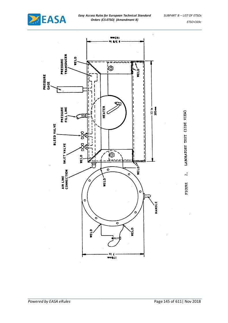
Easy Access Rules for European Technical Standard
Orders (CS-ETSO) (Amendment 8)
SUBPART B – LIST OF ETSOs
ETSO-C69c
Powered by EASA eRules Page 145 of 611| Nov 2018

Easy Access Rules for European Technical Standard
Orders (CS-ETSO) (Amendment 8)
SUBPART B – LIST OF ETSOs
ETSO-C69c
Powered by EASA eRules Page 146 of 611| Nov 2018

Easy Access Rules for European Technical Standard
Orders (CS-ETSO) (Amendment 8)
SUBPART B – LIST OF ETSOs
ETSO-C69c
Powered by EASA eRules Page 147 of 611| Nov 2018
5.3.3 Test Specimens.
5.3.3.1 Test specimens 7 inches (178mm) in diameter with 1/4-inch (6mm) holes punched in the material to match the studs in the pressure cylinder must be cut from the material to be tested.
5.3.3.2 Test specimens must be conditioned at 70 ± 3 degrees F (21±3 degrees C) and 50 ±5 percent relative humidity for at least 24 hours prior to testing.
5.3.4 Test Procedures.
5.3.4.1 All tests must be conducted in a draft free room or enclosed space.
5.3.4.2 After turning on the radiant heat furnace and other required instrumentation, allow 1/2 to 3/4 hour to stabilize heat output and for instrumentation warm-up.
5.3.4.3 Adjust transformer to produce a radiant heat flux of 2 Btu/ft2-sec (2.3 W/cm2) when the calorimeter is positioned 1 1/2 inches (38mm) in front of the radiant heat furnace.
Easy Access Rules for European Technical Standard
Orders (CS-ETSO) (Amendment 8)
SUBPART B – LIST OF ETSOs
ETSO-C69c
Powered by EASA eRules Page 148 of 611| Nov 2018
5.3.4.4 Find the location in front of the furnace for the test heat flux of 1.5 Btu/ft2-sec (1.7 W/cm2) by sliding the calorimeter on the horizontal bar and fixing the position with the sliding stop. Swing the calorimeter out of position.
5.3.4.5 Mount the specimen on the open end of the cylinder with a neoprene gasket on each side of the specimen with the reflective surface of the material facing the furnace. Place the aluminum ring on the studs and tighten the nuts so that an airtight seal made.
5.3.4.6 Pressurize the cylinder to the device nominal operating pressure. Check for leakage.
5.3.4.7 Check the distance from the radiant heat furnace to the surface of the test specimen. This distance is the same as the distance to the surface of the calorimeter.
5.3.4.8 Place the calorimeter in front of the radiant heat furnace and record the heat flux. An acceptable heat flux is 1.5 Btu/ft2-sec (1.7 W/cm2). Remove calorimeter.
5.3.4.9 Place the pressure cylinder and test specimen in front of the radiant heat furnace. Start timer or note starting time on the recorder.
5.3.4.10 Pressure is monitored from the time the specimen is placed in front of the furnace until initial pressure loss is observed.
5.4 Evacuation Rate Tests.
5.4.1 Basic Test Conditions. The following test conditions shall be applicable to tests run for showing compliance with paragraph 4.10.1 of this appendix:
5.4.1.1 The device shall be tested at normal sill height.
5.4.1.2 The device shall be tested at three different inflation pressures: minimum operating, maximum operating, and the nominal operating pressure.
5.4.1.3 The surface of the device shall be dry.
5.4.1.4 The test area may be illuminated to any level suitable for safe conduct of the test.
5.4.1.5 The evacuees may be of any age, gender, weight, or experience level suitable for safe conduct of the test, but each evacuee group must average a minimum of 170 pounds per person. Evacuees may participate in more than one test run.
5.4.1.6 Each device lane shall be traversed by a minimum of 20 evacuees per lane for each test run.
5.4.1.7 All test runs shall be on the same test article.
5.4.1.8 Each test run must have a rate of 60 evacuees/minute per lane or higher.
5.4.1.9 The combined average rate of all test runs must be 70 evacuees/minute per lane or higher. If different numbers of evacuees are used among the different test runs, the rates for each test run shall be mathematically weighted to ensure proper averaging.

Easy Access Rules for European Technical Standard
Orders (CS-ETSO) (Amendment 8)
SUBPART B – LIST OF ETSOs
ETSO-C69c
Powered by EASA eRules Page 149 of 611| Nov 2018
5.4.2 Maximum and Minimum Sill Height Conditions. In addition to the tests in paragraph 5.4.1 above, the device shall be tested at the maximum and minimum sill heights. Three test runs shall be conducted on the same test article for both sill heights, one each at minimum operating, maximum operating, and the nominal operating pressure of the normal conditions pressure range. At maximum sill height, a minimum of five evacuees per lane per run shall use the device and be conveyed safely to the ground. At minimum sill height, a minimum of 20 evacuees per lane per run shall use the device. The evacuees shall meet the same requirements as in paragraph 5.4.1.5 of this appendix. No specific evacuation rate is required for the maximum sill height tests. However, at minimum sill height the rate shall be no less than that shown in paragraph 5.4.3.10.
5.4.3 Emergency Lighting Test Conditions. The following test conditions shall be applicable to tests run for showing compliance with paragraph 4.10.2 of this appendix:
5.4.3.1 The test shall be run on the airplane on which installation is intended or an approved, representative mock-up of the relevant section of the airplane.
5.4.3.2 The sill height used shall represent normal conditions for the airplane with all landing gear extended.
5.4.3.3 When using a mock-up, the exit cutout and the door (if necessary) shall be representative of the airplane. The passageway to the exit should be no greater than the minimum specified for that exit in 14 CFR § 25.813, e.g., 36 inches wide for a Type A or B exit, or 20 inches wide for a Type I, II or C exit. The assist space shall be per current FAA guidance contained in AC 25-17. Cabin features such as doors, cabinets, monuments, door hinges, or other impediments intruding into the exit path which may influence the evacuation rate shall be realistically simulated along the length of the passageway.
5.4.3.4 The device shall be installed, inflated to its nominal operating pressure and ready for use. Note: Emergency lights mounted on the device shall not be illuminated until test initiation, and shall be powered by batteries conditioned per 14 CFR § 25.812(i), or an equivalent power supply.
5.4.3.5 The surface of the device shall be dry.
5.4.3.6 The device shall be hidden from view of the evacuees prior to test initiation.
5.4.3.7 For a period of 5 minutes prior to the initiation of the test, the area holding the evacuees, i.e., the "cabin interior", shall be illuminated to a minimum level of 5 foot-candles, or the level which is representative of typical cabin lighting as measured on the centerline of the passageway floor, one foot inboard of the exit sill. The ambient illumination in the test area outside of the airplane or mock-up shall not exceed 0.005 foot-candles; measurements should be made at the ground end of the assisting means and at the exit, just outside of the fuselage. Provisions shall be made, where necessary, to prevent light reflecting off of surfaces in the outside test area, e.g., hangar walls, from providing visual references to the test participants. All illumination measurements shall be made with a light meter in current calibration, with an accuracy/resolution of at least 2 percent and 0.001 foot-candles.

Easy Access Rules for European Technical Standard
Orders (CS-ETSO) (Amendment 8)
SUBPART B – LIST OF ETSOs
ETSO-C69c
Powered by EASA eRules Page 150 of 611| Nov 2018
5.4.3.8 Upon test initiation, the illumination of the "cabin interior" shall be reduced to the nominal light level provided by the airplane emergency lighting system (with batteries conditioned per 14 CFR § 25.812(i)) as measured as incident light on the centerline of the passageway floor, one foot inboard of the exit sill. The assist means lighting system(s) will be activated.
5.4.3.9 The evacuees shall not have participated in any test or demonstration involving airplane evacuation devices within the past year.
5.4.3.10 The evacuee group size shall be per the following table:
Exit type Rating Evacuees Pass/fail criterion
(in seconds)***
A 110 44 (22 per lane) 30 +Tt****
B 75 45 (22/23 per lane) 45 +Tt
C 55 22 30 +Tt
I 45 27 45 +Tt
II 40 24 45 +Tt
III 35 21 45 +Tt
III (dual*) 70 42 (21 per III) 45 +Tt
III (dual**) 70 39 (19/20 per III) 45 +Tt
* Dual separated by >= 3 seat rows.
** Dual separated by < 3 seat rows.
*** The total time allowed from the start of the test, when the light level changes, as described in 5.4.3.8, until the last evacuee reaches the ground.
**** Tt = Transit time (Tt), determined by averaging the times required by five or more evacuees tested one at a time to traverse the descent route in factory ambient lighting conditions. Evacuees must meet the conditions in 5.4.3.9 and 5.4.3.11.
5.4.3.11 The age/gender mix of the evacuee group shall be as defined in the current version of Appendix J of 14 CFR part 25.
5.4.3.12 For floor level exits, a person trained to give verbal commands shall direct the evacuation from an assist space provided for the aircraft and may stop the test if conditions warrant. He/she should use procedures or techniques approved by the manager of the ACO having purview of the device manufacturer’s facilities. These procedures and techniques shall not include physically assisting hesitant evacuees through the doorway.
5.4.3.13 The following information may be given to participants and the following procedures may occur during the briefings identified below:
5.4.3.13.1 Recruiting briefing:
Describe purpose of the test.
Identify possible hazards of the test.
Identify benefits for test participants.
Identify benefits to airline passengers.

Easy Access Rules for European Technical Standard
Orders (CS-ETSO) (Amendment 8)
SUBPART B – LIST OF ETSOs
ETSO-C69c
Powered by EASA eRules Page 151 of 611| Nov 2018
Describe types of clothing/footwear required.
5.4.3.13.2 Orientation briefing:
Get subject characteristics.
Check for appropriate clothing and footwear.
Prepare paperwork (medical forms, etc.).
Give building safety information (fire evacuation plan, etc.).
Describe test and procedures.
Show pictures of the device from ground level in daylight.
Describe how to enter the device using pictures from ground level, if desired.
Get informed consent.
5.4.3.13.3 Final briefing:
Escort to test area.
Escort into test mock-up (also known as test module) to prepare for test.
Describe test procedures again.
Line up (position) evacuees at the exit(s) in single or dual lanes, as appropriate, for the test.
Begin test protocol.
5.5 Beam Strength Tests-Except Type III Devices.
5.5.1 Basic Test Conditions. The following test conditions shall be applicable to tests run to show compliance with paragraph 4.3.1 of this appendix.
5.5.1.1 Sand Bags.
5.5.1.1.1 Three sand bags, each weighing a minimum of 170 pounds, connected in series, are required for each and every lane of the device.
5.5.1.1.2 All sand bags shall be equal to each other in weight within 5.0 lbs.
5.5.1.1.3 A single 170-pound sand bag may be assembled from two or more smaller bags for ease of handling. The smaller bags need not be of equal weight.
5.5.1.1.4 The outer covering of the sand bag shall be a material having a coefficient of friction of at least 0.4 when tested per ASTM Standard D 1894-95. (This value is typical of some cotton and polyester/cotton material blends. Test data for the material used shall be included with the final test report.)
5.5.1.1.5 Filler materials other than sand may be used, however, liquids are not acceptable unless they are sufficiently constrained to prevent shifting within the bag.

Easy Access Rules for European Technical Standard
Orders (CS-ETSO) (Amendment 8)
SUBPART B – LIST OF ETSOs
ETSO-C69c
Powered by EASA eRules Page 152 of 611| Nov 2018
5.5.1.1.6 The basic shape of a sand bag should be a rectangular solid with rounded corners and a minimum contact surface width of 15 inches. The bag should be longer than it is wide and the height should be less than the width.
5.5.1.1.7 Provisions to securely connect the three sand bags to each other shall be included on each bag. The interconnection provisions shall be designed to minimize any tendency for the bags to roll or tumble.
5.5.1.1.8 When connected, the three sand bags shall occupy an area not to exceed 7.5 feet by 2 feet.
5.5.1.2 Delivery System.
5.5.1.2.1 A delivery system shall be used to convey the sand bags to the beginning of the down-slide portion of the device and to release them so that they may slide down the device. The vertical offset of the end of the delivery system and the device at the point of delivery should be minimized to minimize tumbling of the sandbags.
5.5.1.2.2 The delivery system shall consist of a flat, rigid plane a maximum of 8 feet in length covered with material similar to that used on the sliding surface of the device.
5.5.1.2.3 The delivery system shall incorporate provisions for slowly elevating the rear portion of the plane until the sand bags will begin to move downward onto the sliding surface solely by the effect of gravity or until the plane is at the same angle as the sliding surface and acts as a seamless extension to it. Angles between these two points are acceptable, but in no case shall the angle of the plane exceed the angle of the sliding surface. The sand bags should be restrained until test initiation.
5.5.1.2.4 Where a straight delivery system design cannot be used because the device has a ramp or porch or is more than 20 degrees from being perpendicular to the fuselage, an alternate delivery system design may be used if approved in advance by the manager of the ACO having purview of the manufacturer’s facilities.
5.5.1.3 Device Configuration and Installation.
5.5.1.3.1 The device shall be in its production-deliverable configuration with all required equipment installed.
5.5.1.3.2 The sliding surface of the device shall be dry and new (i.e. never having been subjected to persons or sand bags sliding on its surface prior to the tests).
5.5.1.3.3 The pressure in each and every chamber of the device shall be its nominal operating pressure.
5.5.1.3.4 The device shall be installed at its normal sill height and with its normal attachment means. If the device is intended for use at more than one exit pair, it shall be tested at the normal sill height for each exit pair.

Easy Access Rules for European Technical Standard
Orders (CS-ETSO) (Amendment 8)
SUBPART B – LIST OF ETSOs
ETSO-C69c
Powered by EASA eRules Page 153 of 611| Nov 2018
5.5.1.3.5 The width of the exit through which the sand bags are delivered shall be representative of the airplane exit to which the device will normally be attached and where the evacuees would normally enter the device. For devices not mounted at the exit sill, only the airplane structure which would control evacuee flow onto the device needs to be simulated.
5.5.2 Testing.
5.5.2.1 For a multi-lane device, the sand bags for all lanes shall be launched simultaneously or as nearly so as possible. A single mechanism which will provide simultaneous release of all bags is recommended. In no case shall the sand bags be launched with an offset of more than one sand bag length difference among all the lanes. A case not conforming to this requirement shall be considered a non-test.
5.5.2.2 Sand bags shall not overlap or lie atop one another at test initiation.
5.5.2.3 Sand bags shall not roll or tumble more than 180 degrees either by force of launch or through action of movement down the device. Some tumbling of the sand bags at the bottom of the device due to the effects of the deceleration means is acceptable.
5.5.2.4 Sand bags shall not depart the device except at the bottom end where evacuee contact with the ground is intended.
5.5.2.5 Cross-over of the sand bags from one lane to another on a multiple lane device is acceptable.
5.5.3 Success Criteria.
5.5.3.1 For the test article to be deemed acceptable, the test shall be completed successfully three consecutive times. (Tests which are aborted or considered non-tests, e.g., there is more than one sand bag offset between lanes during the start of a multiple lane device test, do not count against the goal of three consecutive successful tests.)
5.5.3.2 All sand bags in all lanes shall completely depart the end of the device, or shall be deemed to be likely to exit the device if not obstructed by bags which are partially on the ground and partially on the device.
5.5.3.3 The bottom of the sliding surface shall not contact the ground at any time.
5.5.3.4 The device, without repair, shall meet the requirements of paragraph 4.10.1 of this appendix after being subjected to this test.
5.5.4 Alternative Test Method. As an alternative to the test method (using sand bags) described in paragraph 5.5.1, a test using human subjects may be conducted as follows:
5.5.4.1 Test Subjects. Prior to testing, all test subjects shall be briefed on safety and test issues per paragraph 5.4.3.13 of this TSO. The briefing shall include instructions for required behavior while participating in the test. While test subjects may be experienced, they shall not behave in a prohibited manner. Prohibited behavior includes shifting

Easy Access Rules for European Technical Standard
Orders (CS-ETSO) (Amendment 8)
SUBPART B – LIST OF ETSOs
ETSO-C69c
Powered by EASA eRules Page 154 of 611| Nov 2018
of body weight and/or use of hands and/or feet to “propel oneself’ along the slide surface in order to depart the end of the device.
5.5.4.2 Device Configuration and Installation.
5.5.4.2.1 The device shall be in its production-deliverable configuration with all required equipment installed.
5.5.4.2.2 The sliding surface of the device shall be dry and new (i.e. never having been subjected to persons or sand bags sliding on its surface prior to the tests).
5.5.4.2.3 The pressure in each and every chamber of the device shall be its nominal operating pressure.
5.5.4.2.4 The device shall be installed at its normal sill height and with its normal attachment means. If the device is intended for use at more than one exit pair, it shall be tested at the normal sill height for each exit pair.
5.5.4.2.5 The width of the exit through which the test subjects would pass before entering the device shall be representative of the airplane exit where the device will normally be attached and where the evacuees would normally enter the device. For devices not mounted at the exit sill, only the airplane structure which would control evacuee flow onto the device needs to be simulated.
5.5.4.3 Test Protocol. The following test protocol, which is applicable for single or multiple lane devices, shall be used:
5.5.4.3.1 The test subjects’ clothing which contacts the device surface shall be made of material with a coefficient of friction of at least 0.4 per ASTM Standard D1894-90 (typical of cotton or polyester/cotton blend).
5.5.4.3.2 Each test subject shall weigh at least 170 pounds.
5.5.4.3.3 For each lane of the device, three test subjects shall be seated “toboggan” style. The legs of the second and third person in each group shall straddle the person ahead. The first and second persons in the group shall grasp the legs of the person behind them.
5.5.4.3.4 The first person in the group should be located entirely on the downward portion of the device, i.e., he/she would slide if not holding onto the legs of the person behind. The second person in the group should be located either entirely on the downward portion of the device or at the transition point between the door sill or device ramp and the downward portion of the device. The third person should be on the door sill or device ramp, i.e., would not slide if not holding onto anything or being held by the legs by the second person in the group.
5.5.4.3.5 For each group, the distance from the front of the first test subject’s torso to the back of the third test subject’s torso shall
Easy Access Rules for European Technical Standard
Orders (CS-ETSO) (Amendment 8)
SUBPART B – LIST OF ETSOs
ETSO-C69c
Powered by EASA eRules Page 155 of 611| Nov 2018
not exceed 7.5 feet at the initiation of sliding by the third (last) person in the group.
5.5.4.3.6 At the test conductor’s word “go”, the test subjects in each lane will proceed down the slide together. For multiple lane devices, simultaneous push-off is required for all lanes, i.e., no more than a one-person offset is permissible among all lanes. Minor pushing off, particularly by the second and third persons in each group, is allowed to start the group sliding. Additional persons are allowed to gently push the last person in each group to start the sliding process.
5.5.4.3.7 After the third person in each group has started to slide, that person may signal the two others in the group to let go of the legs by yelling “OK” or “Let go.”
5.5.4.3.8 Upon hearing that signal, the first two persons in the group should let go of the others’ legs in order to provide freedom of movement for exiting the device and moving out of the way. After releasing the legs, the test subjects shall not engage in pushing, scooting or shifting of weight in order to exit the device. As soon as foot contact with the ground is made, the test subjects may stand immediately and move away quickly.
5.5.4.3.9 The first and second persons in the group are to stand and move away quickly when exiting the device to prevent blocking the person behind them.
5.5.4.3.10 As an alternative to paragraph 5.5.4.3.4, a delivery system can be used to convey the test subjects to the beginning of the down-slide portion of the device. See paragraph 5.5.1.2.2 through 5.5.1.2.4 for description of the delivery system.
5.5.4.4 Success Criteria.
5.5.4.4.1 For the device to be deemed acceptable, the test must be completed successfully three consecutive times. (Tests which are aborted or considered non-tests, e.g., there is more than a one person offset between lanes during the start of a multiple lane device, do not count against the goal of three consecutive successful tests.)
5.5.4.4.2 The first two test subjects in each and every lane shall exit the end of the device with continuous motion. The third person should also exit the device with continuous motion, but may stay on the device if his/her motion was stopped by the person in front of him/her. Crossover of persons from one lane to another on a multiple lane device is acceptable; however, no more than one person may remain on the device in any lane.
5.5.4.4.3 The underside of the sliding surface shall not contact the ground at any time.
5.5.4.4.4 None of the test subjects shall perform prohibited movements (as described above).

Easy Access Rules for European Technical Standard
Orders (CS-ETSO) (Amendment 8)
SUBPART B – LIST OF ETSOs
ETSO-C69c
Powered by EASA eRules Page 156 of 611| Nov 2018
5.5.4.4.5 The device, without repair, shall meet the requirements of paragraph 4.10.1 of this appendix after being subjected to this test.
5.6 Attachment Means Tests - Girt (See figure 6 of this appendix.).
5.6.1 Symmetric Girt Tensile Load Test. A representative production configuration girt including attachments to the device and the aircraft shall be installed to produce a symmetric load in a tensile test machine. The girt shall be attached on one end using the girt bar, or equivalent, and on the other end to the normal girt attachment means to the inflatable device. The slide fabric to which the girt attachment is bonded shall be fastened to a steel plate or around a cylinder designed to represent the inflatable to which the girt is attached (See figure 6 of this appendix). The girt shall be able to withstand a test load which is equal to the maximum expected in-use load multiplied by a factor of 1.5 (as required by paragraph 4.8 of this appendix). The in-use load is a combination of all the loads acting on the girt attachments during any individual test run. The loads shall be established by instrumenting the girt attachment(s) to a test module simulating the aircraft fuselage and measuring the forces transmitted to the attachment(s) during deployment and use of the device. (The means for measuring the peak loads must be shown to be reliable, accurate, in calibration, and appropriate for the type of testing. If the means is a data acquisition system utilizing an analog-to-digital converter, see appendix 3 of this TSO for guidance.) The use conditions shall include, but not be limited to, those encountered in demonstrating compliance with the requirements of paragraphs 4.3.1, 4.10, 4.11, 4.12, 4.13, 4.20, 4.21, 4.22, 4.23, 4.28, 5.2.4 and 5.8 of this appendix. The test load shall be applied to the girt for 60 seconds. During the test, tearing of the girt is not acceptable. Deformation of the girt is acceptable if it would not prevent continued safe use of the device in an actual evacuation.
5.6.2 Asymmetric Girt Tensile Load Test. A representative production configuration girt shall be installed to produce an asymmetric load in a tensile test machine and an asymmetric load shall be applied. The girt shall be attached on one end using the girt bar, or equivalent, and on the other end to the normal girt attachment means to the inflatable device. The slide fabric to which the girt attachment is bonded shall be fastened to a steel plate designed to represent the inflatable to which the girt is attached (See figure 6 of this appendix). The girt shall be able to withstand a test load applied asymmetrically by pulling the steel plate away from the secured girt bar at a point even with the edge of the girt. The test shall be repeated for each side of the device girt. The test load(s) is equal to the maximum expected in-use load multiplied by a factor of 1.5 (as required by paragraph 4.8 of this appendix). The in-use load shall be established by instrumenting each girt attachment to the aircraft and measuring the forces transmitted to the attachment during deployment and use of the device. (The means for measuring the peak loads must be shown to be reliable, accurate, in calibration, and appropriate for the type of testing. If the means utilizes an analog to digital converter, see appendix 3 of this TSO for guidance.) The use conditions shall include, but not be limited to, those encountered in demonstrating compliance with the requirements of paragraphs 4.20, 4.21, 4.28, 5.2.4 and 5.8 of this appendix. The test load shall be applied to the edge of the girt for 60 seconds. During the test, tearing of the girt is not acceptable. Deformation of the girt is acceptable if it would not prevent continued safe use of the device in an actual evacuation.

Easy Access Rules for European Technical Standard
Orders (CS-ETSO) (Amendment 8)
SUBPART B – LIST OF ETSOs
ETSO-C69c
Powered by EASA eRules Page 157 of 611| Nov 2018
* DRUM SHALL RETAIN ITS SHAPE THROUGHOUT TEST LOADING AND SHALL BE OF SUFFICIENT DIAMETER TO ALLOW SIMULATION OF THE GIRT ATTACHMENT ANGLE, A.
Figure 6. Typical Girt Loading Test Set-Up
5.7 Attachment Means Tests - Other Than a Girt. When the attachment means is other than a girt, e.g., a number of narrow straps attached at different locations on the aircraft, only the straight tensile test is necessary for each of the straps. A representative production configuration of each of the straps, including its attachment to the device and to the airplane, shall be individually installed to produce a symmetric load in a tensile test machine. Each strap shall be able to withstand a test load which is equal to the maximum

Easy Access Rules for European Technical Standard
Orders (CS-ETSO) (Amendment 8)
SUBPART B – LIST OF ETSOs
ETSO-C69c
Powered by EASA eRules Page 158 of 611| Nov 2018
expected in-use load multiplied by a factor of 1.5 (as required by paragraph 4.8 of this appendix). The in-use load shall be established by instrumenting each strap attachment to a test module simulating the aircraft fuselage and measuring the forces transmitted to that attachment during deployment and use of the device. The use conditions shall include, but not be limited to, those encountered in demonstrating compliance with the requirements of paragraphs 4.3.1, 4.10, 4.11, 4.12, 4.13, 4.20, 4.21, 4.22, 4.23, 4.28, 5.2.4 and 5.8 of this appendix. The test load shall be applied to the strap for 60 seconds. During the test, tearing of the strap is not acceptable. Deformation of the strap is acceptable, if it would not prevent continued safe use of the device in an actual evacuation.
5.8 Attachment Means - Pontoon Loading Tests. If the device is equipped with outrigger pontoons (also known as sponsons) which can be inadvertently entered by evacuees during an emergency evacuation, the following test shall be conducted on each side:
5.8.1 The device shall be installed at normal sill height and inflated to the minimum value of the normal conditions pressure range.
5.8.2 Weights that represent 170 pound individuals shall be placed in the pontoon(s) at the bottom outside area on one side of the device. The number of individuals to be simulated shall be based on the length, in feet, of the occupiable portion of the pontoon divided by 4.5. Any remainder from the division may be discarded.
5.8.3 An evacuee group of twenty persons shall jump into the device at an average rate of 70 per minute (after the first jumper, the last 19 have 16 seconds to jump into the device). The evacuee group shall average at least 170 pounds per person. In the case of multi-lane devices, the evacuees will jump only into the lane adjacent to the loaded pontoon. The evacuees may be of any age, gender, and experience level.
5.8.4 To pass this test, the means of attachment to the aircraft shall not tear or rip, and no evacuee shall enter the pontoon area or fall off the device.
5.9 Hot & Cold Soak Test Protocol.
5.9.1 Stabilize the normally charged stored gas bottle to a temperature of 70 ± 5 degrees F, then, for the cold test only, reduce the stored gas bottle pressure to the minimum dispatch pressure. As an alternate, the bottle may be charged directly to the minimum dispatch pressure for the cold test. However, for mixed-gas systems, the ratio of the gas mix must be maintained.
5.9.2 Thermally condition the device for at least 16 hours according to the following table:
Condition Temperature (degrees F)
Hot Soak = 160 (for all devices)
Cold Soak = -40 (for devices installed in the pressurized cabin)
Cold Soak = -65 (for devices installed outside the pressurized cabin)
5.9.3 Deploy the device into ambient temperature conditions (typically defined as
between 65 and 85 degrees F) from the appropriate airplane door or a suitable airplane door mock-up or module, within 10 minutes after removal from the conditioning chamber.
5.9.4 To be considered acceptable, the unit should deploy and inflate into a useable attitude and achieve minimum operating pressure in all inflation chambers but

Easy Access Rules for European Technical Standard
Orders (CS-ETSO) (Amendment 8)
SUBPART B – LIST OF ETSOs
ETSO-C69c
Powered by EASA eRules Page 159 of 611| Nov 2018
should not exceed the specified maximum operating pressure. The pressure reading should be taken as soon as possible but no later than one minute after deployment.

Easy Access Rules for European Technical Standard
Orders (CS-ETSO) (Amendment 8)
SUBPART B – LIST OF ETSOs
ETSO-C69c
Powered by EASA eRules Page 160 of 611| Nov 2018
APPENDIX 2 TO ETSO-C69C – GLOSSARY OF TERMS ED Decision 2003/10/RM
critical angle (with respect to buckling) - the angle which the device makes with the ground at which the maximum vertical load will be applied to the device by evacuees using it. The angle chosen should be sufficient to permit attaining an evacuation rate of one person per second per lane, but may not exceed 30 degrees from horizontal.
dark of night conditions - exterior lighting conditions in which the illumination measured normal to the direction of the incident light does not exceed 0.005 foot-candles.
girt - the typical means by which a device is attached to an airplane. It consists of a strong fabric wrapped around a girt bar which is usually installed at the sill of the exit. The girt may be attached to more than one of the device inflatable chambers.
high visibility color - international orange-yellow or a bright orange-yellow color similar to color numbers 28915 or 38903 of table X in Federal Standard 595, Colors.
maximum operating pressure - maximum pressure (in each/every chamber) that may be reached after the device has reached a usable attitude. Typically, this pressure is determined during the device developmental process when evaluating all test conditions.
maximum sill height - the maximum height above the ground of the exit sill with the collapse of one or more of the aircraft landing gear legs. Typically this is calculated using rational analysis.
minimum dispatch pressure - minimum actual pressure required in the inflation system for dispatch of the airplane. This inflation system pressure will inflate the device to at least minimum operating pressure under the cold soak conditions described in paragraph 5.9.2 of appendix 1 of this TSO.
minimum operating pressure - minimum pressure (in each/every chamber) at which the evacuation rate requirement of paragraph 4.10.1 of appendix 1 of this TSO can be met.
minimum raft mode operating pressure - minimum pressure required to meet the minimum design buoyancy requirements of paragraph 4.27.2 of appendix 1 of this TSO.
minimum sill height - lowest height above the ground of the exit sill with the collapse of one or more of the aircraft landing gear legs. Typically this is calculated using rational analysis.
most critical angle (wind) - the angle at which winds have the greatest adverse effect upon the device's ability to convey evacuees safely to the ground, e.g., where there is the greatest lateral and/or torsional displacement or buckling.
nominal operating pressure - the mid-point of the normal conditions pressure range.
normal conditions pressure range - the range of pressures attained during typical deployments conducted in accordance with paragraph 5b(1) of this TSO. The lower limit must not be lower than the minimum operating pressure. The upper limit must not be more than the maximum operating pressure.
normal sill height - the height of the exit sill above the ground with all aircraft landing gear extended.

Easy Access Rules for European Technical Standard
Orders (CS-ETSO) (Amendment 8)
SUBPART B – LIST OF ETSOs
ETSO-C69c
Powered by EASA eRules Page 161 of 611| Nov 2018
APPENDIX 3 TO ETSO-C69C – MEASUREMENT OF LOADS ON THE ATTACHMENT(S) TO THE AIRPLANE
ED Decision 2003/10/RM
Data acquisition systems which utilize an analog-to-digital (A/D) converter to process the electronic signals from load cells must be configured to accurately record loads during a test. The following parameters are recommended for recording with an A/D converter system:
1. Sample Rate 20 Hz minimum
2. Resolution 12 bits minimum
3. Anti-aliasing pre-filter 5 Hz low pass (0 to -4 dB at 5 HZ),
-20 dB/decade rolloff at frequencies above 10 Hz
The signal amplifier should provide sufficient gain so that the expected full-scale, or highest anticipated value to be recorded, is at least 70 percent of the maximum input range of the analog-to-digital converter (A/D). No post acquisition digital filter, smoothing, or averaging algorithm may be applied to the data.

Easy Access Rules for European Technical Standard
Orders (CS-ETSO) (Amendment 8)
SUBPART B – LIST OF ETSOs
ETSO-C69c
Powered by EASA eRules Page 162 of 611| Nov 2018
APPENDIX 4 TO ETSO-C69C – CALORIMETER SPECIFICATION AND CALIBRATION PROCEDURE
ED Decision 2003/10/RM
1. Scope. This procedure shall be used to calibrate all circular foil heat flux transducers (Gardon gauges). Calibration establishes the value of this product to the user.
2. Terminology. For definitions of general terms, refer to ASTM Standard C168. Definitions specific to this procedure are:
a. Sensor Scale Factor – the ratio between the incident heat flux and the transducer output signal produced at the heat flux, expressed in W/cm²/mV or BTU/ft²-sec/mV.
b. Sensor Sensitivity – the ratio between the transducer output signal and the incident heat flux, expressed in mV/W/cm² or mV/BTU/ft²-sec.
c. Calibrated Heat Flux Level – the maximum heat flux reached during the calibration cycle.
d. Calibration Standard Scale Factor – the sensor scale factor for the reference standard transducer used in calibration, expressed in W/cm²/mV or BTU/ft²-sec/mV.
e. Emissivity – the ratio between total radiant energy absorbed by a plane surface and total radiant energy incident on that surface, expressed as a value between 0.0 and 1.0.
3. Calorimeter Specifications.
a. One inch diameter, cylindrical, water-cooled, Gardon gauge.
b. Calibration range approximately 0 - 5 watts.
c. Foil diameter shall be 0.25 in. +/- 0.005.
d. Foil thickness shall be 0.0005 in. +/- 0.0001.
e. Foil material shall be thermocouple grade constantan.
f. Temperature measurement shall be a copper-constantan thermocouple.
g. Copper center wire diameter of 0.0005 in. +/- 0.0001.
h. The entire face of the calorimeter shall be lightly coated with high temperature paint having an emissivity of 0.94 or higher.
4. Equipment and Supplies. Calibrations shall be performed using a 50 kW flat plate heater furnace. The furnace shall be equipped with transducer mountings, water cooling lines and an exhaust system of sufficient capacity to remove the heat of calibrations at 50 kW input power to the plate. The heater shall be a graphite plate 0.125”±0.0625 thick, and 1.50” minimum width by 1.50” minimum length. Electric current shall be conducted through the longest dimension of the plate. An X-Y recorder with adjustable gains that has been calibrated against NIST standards shall be mounted on a shelf on the front of the furnace. A reference transducer of approximately the same full scale range as the test transducer shall be prepared and calibrated against a NIST calibrated transducer. The coating on the surface of the reference transducer shall be high temperature paint, applied and cured according to the standard coating procedure for an emissivity of 0.94 or higher.
5. Preparations for Calibration. The flat plate heater shall be prepared for calibrations as follows:
a. pyrolytic graphite transitions shall be attached to both ends of the flat plate heater with rubber cement and the heater shall be centered and clamped evenly in the furnace;
b. the exhaust fan shall be turned on;

Easy Access Rules for European Technical Standard
Orders (CS-ETSO) (Amendment 8)
SUBPART B – LIST OF ETSOs
ETSO-C69c
Powered by EASA eRules Page 163 of 611| Nov 2018
c. the heater shall be gradually heated electrically until all rubber cement burns away and a good bond is achieved at both ends;
d. the heater shall be energized with sufficient electric current to produce a dull red heat; and
e. uniformity of the flat plate temperature from side to side and top to bottom shall be observed on both sides.
If the flat plate temperature is non-uniform, clamping forces shall be adjusted and, if necessary the transitions reattached to achieve uniformity. The reference transducer shall be mounted on one side of the flat plate heater, centered over the face of the heater and 1/8” to 3/8” from the heater surface. The distance shall be set with a thickness gauge. Water cooling lines shall be connected. The test transducer shall be coated with high temperature paint cured for an emissivity of 0.94 or higher. It shall be mounted on the other side of the flat plate heater, centered over the face of the heater and an equal distance from the heater surface. The distance shall be verified with the same thickness gauge. Water cooling lines shall be connected. The water supply system shall be leak tested and reconnected if necessary. The output signal of the reference transducer shall be connected to the Y-axis input of the X-Y recorder. The output signal of the test transducer shall be connected to the X-axis input. Recorder gains shall both be set to 1.00.
6. Calibration Procedure.
a. A fresh sheet of graph paper shall be mounted in the X-Y recorder. X and Y zeros shall be adjusted. The cooling water pump shall be turned on, but not the exhaust fan.
b. If the full scale range of the test transducer is 50 BTU/ft²-sec or less, the potentiometer control of the furnace shall be adjusted to approximately 150 percent of the full scale heat flux value for the test transducer. After a few seconds to stabilize temperatures, the pen shall be dropped on the recorder, and the heat flux gradually reduced to zero. A straight line trace from the upper right quadrant of the graph to the zero for both X and Y should be recorded.
c. If the full scale range of the test transducer is greater than 50 BTU/ft2-sec the recorder pen shall be dropped and then the control of the furnace shall be slowly adjusted to approximately 150 percent of the full scale value for the test transducer. After this the pen shall be lifted and the furnace control quickly reduced to zero. A straight line trace from the zero for both X and Y to the upper right quadrant should be recorded.
7. Analysis.
a. The analysis will relate the sensitivity and scale factor of the test transducer to those of the reference transducer, based on the slope of the graph recorded in step 6.
b. A straight line shall be drawn from X=0, Y=0 on the graph to fit the recorded trace. If this line intercepts the right-hand edge of the graph, the test transducer scale factor shall be calculated by multiplying the intercept by the reference transducer scale factor. If the line intercepts the top edge of the graph, the test transducer scale factor shall be calculated by multiplying the reference transducer scale factor by 7 (the graph is 7 units high) and dividing that result by the intercept.
c. The test transducer sensitivity shall be obtained by inverting the test transducer scale factor.
d. The maximum heat flux level used in calibration shall be calculated from the X-axis excursion on the graph. The scale factor of the reference transducer shall also be

Easy Access Rules for European Technical Standard
Orders (CS-ETSO) (Amendment 8)
SUBPART B – LIST OF ETSOs
ETSO-C69c
Powered by EASA eRules Page 164 of 611| Nov 2018
recorded. The reference transducer measures incident heat flux, so the calibration will always be in terms of incident heat flux.
Easy Access Rules for European Technical Standard
Orders (CS-ETSO) (Amendment 8)
SUBPART B – LIST OF ETSOs
ETSO-C71
Powered by EASA eRules Page 165 of 611| Nov 2018
ETSO-C71 ED Decision 2003/10/RM (applicable from 24.10.2003)
Airborne Static (‘DC to DC’) Electrical Power Converter (for Air Carrier Aircraft)
1 Applicability
This ETSO gives the requirements which airborne static („DC to DC“) electrical power converters that are manufactured on or after the date of this ETSO must meet in order to be identified with the applicable ETSO marking.
2 Procedures
2.1 General
Applicable procedures are detailed in CS-ETSO Subpart A.
2.2 Specific
None.
3 Technical Conditions
3.1 Basic
3.1.1 Minimum Performance Standard
Standards set forth in the attached FAA Standard for „Airborne Static („DC to DC“) Electrical Power Converter“, dated April 15, 1961.
3.1.2 Environmental Standard
See CS-ETSO Subpart A paragraph 2.1.
3.1.3 Computer Software
None
3.2 Specific
None
4 Marking
4.1 General
Marking is detailed in CS-ETSO Subpart A paragraph 1.2.
4.2 Specific
None.
5 Availability of Referenced Document
See CS-ETSO Subpart A paragraph 3.

Easy Access Rules for European Technical Standard
Orders (CS-ETSO) (Amendment 8)
SUBPART B – LIST OF ETSOs
ETSO-C71
Powered by EASA eRules Page 166 of 611| Nov 2018
FAA STANDARD ASSOCIATED WITH ETSO-C71 FOR AIRBORNE STATIC („DC TO DC“) ELECTRICAL POWER CONVERTER
ED Decision 2003/10/RM
INTRODUCTION
This paper sets forth the minimum performance standards for airborne static („DC to DC“) electrical power converter equipment then used as a part of a navigation or communication system.
Compliance with these standards is required as a means of assuring that the equipment will satisfactorily perform its intended function under all conditions normally encounted in routine aeronautical operations.
Inasmuch as the measured values of a radio equipment performance characteristics may be a function of the method of measurement, standard test conditions and methods of test are also recommended in this paper.
MINIMUM PERFORMANCE STANDARDS FOR AIRBORNE STATIC („DC TO DC“) ELECTRICAL POWER CONVERTER
1.0 GENERAL STANDARDS
1.1 Ratings of Components
The equipment shall not incorporate its design any component of such rating that, when the equipment is operated throughout the range of the specified environmental test, the ratings established by the manufacturer of the component is exceeded.
1.2 Effects of Test
The design of the equipment shall be such that the application of the specified test produces no discernable condition which would be detrimental to the reliability of equipment manufactured in accordance with such design.
2.0 MINIMUM PERFORMANCE STANDARDS UNDER STANDARD TEST CONDITIONS
The test procedures applicable to a determination of the performances of the airborne static („DC to DC“) electrical power converter equipment are set forth in Appendix „A“ of this paper.
2.1 Nominal Output Voltage and Current
The nominal output voltage and current shall not be less than that specified by the manufactuer’s ratings. Further, the equipment shall be capable of delivering at least 10% more output power than the manufacturers specified rating for a period of two (2) hours.
2.2 Regulation
Regulation under standard conditions shall not exceed 12%. For the purpose of this standard, regulation is defined as:
% 𝑅𝑒𝑔 =(Voltage at 20% of load) − (Voltage at maximum rated load)
𝑉𝑜𝑙𝑡𝑎𝑔𝑒 𝑎𝑡 𝑚𝑎𝑥𝑖𝑚𝑢𝑚 𝑟𝑎𝑡𝑒𝑑 𝑙𝑜𝑎𝑑 × (100%)
2.3 Ripple
Ripple in the output DC voltage at maximum rated output load shall not exceed 1/10% of the output voltage when shunted by a 2 mfd capacitor and the ripple on the DC input leads is equal to 2 volts peak to peak at a frequency of 400 cps. For equipment designed for operation on 13.75 volts DC, the ripple on the input leads need not exceed 1 volt peak to peak.
Easy Access Rules for European Technical Standard
Orders (CS-ETSO) (Amendment 8)
SUBPART B – LIST OF ETSOs
ETSO-C71
Powered by EASA eRules Page 167 of 611| Nov 2018
2.4 Over Voltage
There shall be no permanent damage to any of the solid state devices (transistors) or the components when the power converter is delivering full rated output power and is subjected to the following over voltage conditions:
(a) The input DC voltage is increased to 50% above the standard operating voltage for a duration of not less than five minutes.
2.5 Short Circuit Conditions
There shall be no degradation of the power converter or its components as a result of a sustained short circuit applied separately to each output of a multiple output power converter, or simultaneously to all DC outputs for a period of not less than one minute. Within five minutes after removal of the short circuit condition, the equipment shall be capable of continuous operation at the manufacturer’s rated output load for a period of eight hours without, degradation of performance.
2.6 Emission of Radio Frequency Energy
The emission of radio frequency energy at discreet frequencies within the range of 90 kc to 1500 Mc shall not exceed 200 microvolts between any cable terminal to ground.
Note: It is recognized that the radio frequency emissions having a level considerably less than the maximum permitted by the above standard are capable off interfering with the operation of other electronic equipment in an aircraft installation. It is also recognized that the method of reducing the level of emission of radio frequency energy to much lower values are known. However, at the present state of the art, large and expensive filters are often required in addition to the exercise of care in the mechanical and electrical design of equipment. The end result is often a compromise between what is desired and cost.
In view of the above, the emission standards were set at a level which can be met by the exercise of reasonable care in design and yet effect the reduction in the present overall interference problem. Lower emission levels are desirable and it is, therefore, recommended that the equipment manufacturers make a determined effort to reduce the level of emission from electronic equipment, to the lowest practicable value below that specified above.
2.7 Dielectric Strength
The equipment shall withstand without evidence of damage the application of a sinusoidal voltage between each transformer output winding and frame for a period of five seconds. The RMS value of the sinusoidal voltage applied shall be either five times the maximum operating voltage existing across that winding during operation when delivering full rated output, or 500 volts, whichever is greater. During the application of this test, all diodes, transistors, and capacitors may be disconnected.
3.0 MINIMUM PERFORMANCE STAND ARDS UNDER ENVIRONMENTAL TEST CONDITIONS
The test procedure applicable to a determination of the performance of radio equipment under environmental test conditions are set, forth in RTCA Paper 100-54/D0-60,
„Environmental Test Procedures-Airborne Radio Equipment,“ and amendment Paper 256- 58/ EC-366 dated November 13, 1958. This paper outlines environmental test procedures for equipment designed to operate under three environmental test conditions as specified therein under Procedures A, B, and C. Only airborne static („DC to DC’) electrical power converter
Easy Access Rules for European Technical Standard
Orders (CS-ETSO) (Amendment 8)
SUBPART B – LIST OF ETSOs
ETSO-C71
Powered by EASA eRules Page 168 of 611| Nov 2018
equipment which meets the operating requirements outlined under Procedure A or Procedure B of this paper, as amended, is applicable under this standard.
The applicable electrical test procedures are set forth in Appendix „A“ of this standard.
3.1 Low Temperature Test
When the equipment is subjected to the low temperature test and, with primary power voltage 10% less than standard test voltage applied, the following requirements shall be met:
(a) The output voltage shall not vary more than 121/2% from that obtained at standard test conditions.
(b) The requirements of paragraph 2.3 shall be met.
3.2 Altitude Test
When the equipment is subjected to the altitude test, the requirements of paragraphs 2.1, 2.2, and 2.3 shall be met.
3.3 Humidity Test
After subjection to humidity and within fifteen (15) minutes from the time primary power is applied, the requirements of 2.1, 2.2, and 2.3 shall be met.
3.4 High Temperature Test
When the equipment is subjected to the high temperature test and with primary power voltage 10% higher than standard test voltage applied, the following requirements shall be met:
(a) The output voltage shall not vary more than 121/2% from that obtained at standard test conditions.
(b) The requirements of paragraphs 2.1, 2.2, and 2.3 shall be met.
3.5 Temperature Variation Test
When the equipment is subjected to the temperature variation tests, the requirements of paragraphs 2.2 and 2.3 shall be met.
3.6 Vibration Test
When the equipment is subjected to the vibration test, the requirements of paragraphs 2.2 and 2.3 shall be met.
3.7 Shock Test
(a) Following the application of 15 G shocks, the requirements of paragraphs 2.2 and 2.3 shall be met.
(b) Following the application of 30 G shocks, the power converter shall have remained in its mounting by its intended means and no parts of the equipment or its mounting shall have become detached and free from the equipment.*
3.8 Low Voltage Test
(a) When the primary power voltage(s) is 80% of the standard test, voltage(s), the equipment shall operate electrically.
Easy Access Rules for European Technical Standard
Orders (CS-ETSO) (Amendment 8)
SUBPART B – LIST OF ETSOs
ETSO-C71
Powered by EASA eRules Page 169 of 611| Nov 2018
(b) Gradual reduction of the primary voltage(s) from 80% to 50% of standard test voltage(s) shall produce no condition detrimental to the reliability of the equipment.
(c) Gradual reduction of the primary power voltage(s) from 50% to 0%, of standard test, voltage(s) shall produce no evidence external to the equipment of the presence of fire or smoke.*
* Test tests may be conducted after other tests are completed.

Easy Access Rules for European Technical Standard
Orders (CS-ETSO) (Amendment 8)
SUBPART B – LIST OF ETSOs
ETSO-C71
Powered by EASA eRules Page 170 of 611| Nov 2018
FAA STANDARD ASSOCIATED WITH ETSO-C71 – APPENDIX A - TEST
PROCEDURES AIRBORNE STATIC („DC TO DC“) ELECTRICAL POWER CONVERTER ED Decision 2003/10/RM
A. Power Input Voltage Unless otherwise specified, all tests shall be conducted with the power input voltage adjusted to the design voltage within ±2%. The input voltage shall be measured at the power converter input terminals.
Note: Design voltages in use as of the date of this report are 13.75 VDC and 27.5 VDC and defined as standard condition.
B. Adjustment of Equipment. The equipment under test shall be properly adjusted in accordance with the manufacturer’s recommended practices prior to the application of the specified tests.
C. Test Equipment Precautions. Due precautions shall be taken during the conduct of these tests to prevent the introduction of error resulting from the improper connection of voltmeters, oscilloscopes and other test instruments across the input and output impedances of the equipment under test.
D. Ambient Conditions. Unless otherwise specified, all its shall be conducted under conditions of ambient room temperature, pressure and humidity. However, the room temperature shall not be lower than 10° C.
E. Warm-up Period. Unless otherwise specified, all tests shall be conducted after a warm-up period of not less than fifteen (15) minutes.
F. Connected Loads. Unless otherwise specified, all tests shall be performed with the equipment connected to loads having the impedance value for which it is desired.
TEST PROCEDURES
The test procedures set forth below are satisfactory for use in determining the performance of airborne static („DC to DC“) electrical power converter equipment. Test procedure’s which provide equivalent information may also be used.
T-1 Power Output
EQUIPMENT REQUIRED
Voltmeter – Weston Model 931 or equivalent.
Ammeter – Weston Model 931 or equivalent.
MEASUREMENT PROCEDURE
Connect the power converter to the appropriate input power source with the ammeter in series with the output and the voltmeter connected across the output. The manufacturer’s specified load shall be connected across the output(s). The output load impedance should be adjusted to the manufacturer’s specified rating.
Determine that the nominal output voltage and current is at least that specified by the manufacturer and that the equipment is capable of delivering at least 10% more output power than the manufacturer’s specified rating for a period of two (2) hours.
T-2 Regulation
EQUIPMENT REQUIRED
Voltmeter – Weston Model 931 or equivalent.
Ammeter – Weston Model 931 or equivalent.
Easy Access Rules for European Technical Standard
Orders (CS-ETSO) (Amendment 8)
SUBPART B – LIST OF ETSOs
ETSO-C71
Powered by EASA eRules Page 171 of 611| Nov 2018
MEASUREMENT PROCEDURE
Connect the power converter to the appropriate input power source with the ammeter in series with the output and the voltmeter connected across the output. The manufacturer’s rated load should be connected across the output(s).
Vary the load impedance from maximum rated load to 20% of maximum rated load and note the output voltage(s) at these two load settings. Calculate the percent regulation using the formula specified in paragraph 2.2.
T-3 Ripple
EQUIPMENT REQUIRED
Hewlett Packard Oscilloscope Model 150A or equivalent.
MEASUREMENT PROCEDURE
Connect the power converter to the appropriate input power source with the power converter delivering maximum rated load. Also connect a two (2) microfarad capacitor of the proper DC working voltage across the output under test.
Using the oscilloscope as a peak to peak voltage indicating device, measure the ripple on the output power source and all output voltage(s) when ripple on the DC input leads is equal to 2 volts peak to peak at a frequency of 400 cps or 1 volt peak to peak, whichever is applicable.
T-4 Overvoltage
EQUIPMENT REQUIRED
Perkins Power Supply Model MR 1040- 30A or equivalent.
MEASUREMENT PROCEDURE
(a) Connect the equipment to the Perkins Model MR 1040-30A power supply with the equipment delivering full rated output power. Increase the output voltage from the Model MR 1040-30A power supply to 50% greater than the input voltage for which the equipment is designed for a duration of five (5) minutes.
(b) Following this, determine that the output voltage and current is the same as that prior to the application of the overvoltage.
T5 Short Circuit Conditions
EQUIPMENT REQUIRED
Voltmeter – Weston Model 931 or equivalent.
Ammeter – Weston Model 931 or equivalent.
MEASUREMENT PROCEDURE
With the power converter connected to the appropriate input power source and the equipment delivering full rated output power, apply a sustained short circuit separately to each output of multiple output power converters or simultaneously to all DC outputs for a period of not less than one (1) minute.
Following this, determine that the equipment is capable of delivering the manufacturer’s rated output power for a period of at least eight (8) hours.
This test shall be conducted after the overvoltage test specified in T-4, Overvoltage, is completed.
Easy Access Rules for European Technical Standard
Orders (CS-ETSO) (Amendment 8)
SUBPART B – LIST OF ETSOs
ETSO-C71
Powered by EASA eRules Page 172 of 611| Nov 2018
T-6 Emission of Radio Frequency Energy
EQUIPMENT REQUIRED
Noise and Field Strength Meters as follows:
Stoddard models NM-20B, NM-5A, AM-10A, and NM-50A or equivalent.
MEASUREMENT PROCEDURE
Connect the power converter to the appropriate input power source with the equipment delivering full rated output power. The input power leads shall be from 10 to 12 feet in length, normally terminated and cabled, and shall not be enclosed in conduit.
With the noise meter, measure the rf voltage developed between ground and each of the primary input and power output leads, tuning the noise meter throughout the range of frequencies from 90 kc to 1500 Mc.
T-7 Dielectric Strength
EQUIPMENT REQUIRED
Variable AC power source.
MEASUREMENT PROCEDURE
(a) Apply an a-c voltage, at the frequency used in normal operation, between each transformer output winding and frame for a period of five (5) seconds. The RMS value of the sinusoidal voltage applied shall be either five (5) times the maximum operating voltage existing across that winding during operation voltage delivering full rated output, or 500 volts, whichever is greater.
(b) Following this, determine that the output voltage and current under full load conditions is the same as that prior to the application of the tests.

Easy Access Rules for European Technical Standard
Orders (CS-ETSO) (Amendment 8)
SUBPART B – LIST OF ETSOs
ETSO-72c
Powered by EASA eRules Page 173 of 611| Nov 2018
ETSO-72c ED Decision 2003/10/RM (applicable from 24.10.2003)
Individual Flotation Devices
1 Applicability
This ETSO gives the requirements which individual flotation devices that are manufactured on or after the date of this ETSO must meet in order to be identified with the applicable ETSO marking.
2 Procedures
2.1 General
Applicable procedures are detailed in CS-ETSO Subpart A.
2.2 Specific
None.
3 Technical Conditions
3.1 Basic
3.1.1 Minimum Performance Standard
Standards set forth in the attached Federal Aviation Administration Standard „Individual Flotation Devices“.
Where applicable, instead of the referenced FAA documents/paragraph the corresponding IR, CS or ETSO document/paragraph shall be used, when available.
3.1.2 Environmental Standard
As given in the FAA Standard.
3.1.3 Computer Software
None
3.2 Specific
None
4 Marking
4.1 General
Marking is detailed in CS-ETSO Subpart A paragraph 1.2.
4.2 Specific
None.
5 Availability of Referenced Document
See CS-ETSO Subpart A paragraph 3.

Easy Access Rules for European Technical Standard
Orders (CS-ETSO) (Amendment 8)
SUBPART B – LIST OF ETSOs
ETSO-72c
Powered by EASA eRules Page 174 of 611| Nov 2018
FEDERAL AVIATION ADMINISTRATION STANDARD - INDIVIDUAL FLOTATION DEVICES
ED Decision 2003/10/RM
1.0 Purpose.
To specify minimum performance standards for individual flotation devices other than life preservers defined in the TSO-C13 Series.
2.0 Types and Description of Devices.
This standard provides for the following two categories of individual flotation devices:
a. Inflatable types (compressed gas inflation).
b. Noninflatable types.
2.0.1 Description of Inflatable Types. Inflation must be accomplished by release of a compressed gas contained in a cartridge into the inflation chamber. The cartridge must be activated by a means readily accessible and clearly marked for its intended purpose. The flotation chamber must also be capable of oral inflation in the event of failure of the gas cartridge.
2.0.2 Description of Noninflatable Types. Seat cushions, head rests, arm rests, pillows, or similar aircraft equipment are eligible as flotation devices under this standard provided they fulfil minimum requirements for safety and performance. Compression through extended service use, perspiration and periodic cleaning must not reduce the buoyancy characteristics of these devices below the minimum level prescribed in this standard.
2.1 Instructions for Use. Where the design features of the device relative to its purpose and proper use are not obvious to the user, clear instructions must be visible under conditions of emergency lighting.
3.0 Definitions.
The following are definitions of terms used throughout the standard:
a. Buoyancy. The amount of weight a device can support in fresh water at 85°F.
b. Flame Resistant. Not susceptible to combustion to the point of propagating a flame beyond safe limits after the ignition source is removed.
c. Corrosion Resistant. Not subject to deterioration or loss of strength as a result of prolonged exposure to a humid atmosphere.
4.0 General Requirements.
4.0.1 Materials and Processes. Materials used in the finished product must be of the quality which experience and tests have demonstrated to be suitable for the use intended throughout the service life of the device. The materials and process must conform to specifications selected or prepared by the manufacturer which will insure that the performance strength and durability incorporated in the prototype are continued or exceeded in subsequently produced articles.
4.0.2 Fungus Protection. Materials used in the finished product must contain no nutrient which will support fungus growth unless such materials are suitably treated to prevent such growth.

Easy Access Rules for European Technical Standard
Orders (CS-ETSO) (Amendment 8)
SUBPART B – LIST OF ETSOs
ETSO-72c
Powered by EASA eRules Page 175 of 611| Nov 2018
4.0.3 Corrosion Protection. Metallic parts exposed to the atmosphere must be corrosion resistant or protected against corrosion.
4.0.4 Fire Protection. If the device is not used as part of a seat or berth, materials used in the device, including any covering, must meet Paragraph 6.0.2 of this standard. If the device is to be used as part of a seat or berth, all materials used in the device must meet Paragraph 7.0.3 of this standard.
4.0.5 Temperature Range. Materials used in the construction of the device must be suitable for the intended purpose following extended exposures through a range of operating temperatures from -40°F. to +140°F.
4.1 Design and Construction.
4.1.1 General. The design of the device, the inflation means if provided, and straps or other accessories provided for the purpose of donning by the user must be simple and obvious thereby making its purpose and actual use immediately evident to the user.
4.1.2 Miscellaneous Design Features. The devices must be adaptable for children as well as adults. The devices must have features which enable the users to retain them when jumping into water from a height of at least 5 feet. Attachment straps must not pass between the user’s leg for retention or restrict breathing or blood circulation.
5.0 Performance Characteristics.
5.0.1 Buoyancy Standard. The device must be shown by the tests specified in paragraph 7.0.1 to be capable of providing not less than 14 pounds of buoyancy in fresh water at 85° F. for a period of 8 hours.
5.0.2 Utilization. The device must be capable of being utilized by the intended user with ease.
5.0.3 Function Under Temperature Limits. The device must function from -40°F. to +140°F.
6.0 Standard Tests.
6.0.1 Salt Spray Test Solution. The salt used must be sodium chloride or equivalent containing on the dry basis not more than 0.1 percent of sodium iodide and not more than 0.2 percent of impurities. The solution must be prepared by dissolving 20 ±2 parts by weight of salt in 80 parts by weight of distilled or other water containing not more than 200 parts per million of total solids. The solution must be kept free from iron solids by filtration decantation, or any other suitable means. The solution must be adjusted to be maintained at a specific gravity of from 1.126 to 1.157 and a PH of between 6.5 and 7.2 when measured at a temperature in the exposure zone maintained at 95°F.
6.0.2 Flame Resistance. Except for devices required to be tested in accordance with 7.0.3 the following applies: Three specimens approximately 4 inches wide and 14 inches long must be tested. Each specimen must be clamped in a metal frame so that the two long edges and one end are held securely. The frame must be such that the exposed area of the specimen is at least 2 inches wide and 13 inches long with the free end at least 1/2 inch from the end of the frame for ignition purposes. In case of fabrics, the direction of the weave corresponding to the most critical burn rate must be parallel to the 14-inch dimension. A minimum of 10 inches of the specimen

Easy Access Rules for European Technical Standard
Orders (CS-ETSO) (Amendment 8)
SUBPART B – LIST OF ETSOs
ETSO-72c
Powered by EASA eRules Page 176 of 611| Nov 2018
must be used for timing purposes, and approximately 1 1/2 inches must burn before the burning front reaches the timing zone. The specimen must be long enough so that the timing is stopped at least 1 inch before the burning front reaches the end of the exposed area.
The specimens must be supported horizontally and tested in draft free conditions. The surface that will be exposed when installed in the aircraft must face down for the test. The specimens must be ignited by the Bunsen or Tirrell burner. To be acceptable, the average burn rate of the 3 specimens must not exceed 4 inches per minute. Alternatively, if the specimens do not support combustion after the ignition flame is applied for 15 seconds or if the flame extinguishes itself and any subsequent burning without a flame does not extend into the undamaged areas, the material is also acceptable.
7.0 Test Requirements.
7.0.1 Buoyancy Testing. The flotation device, including all dress covers, fire blocking layer (if used) and straps that would normally be used by a survivor in an emergency, must be tested in accordance with either sub-paragraph (a) or (b) of this paragraph, as applicable, or an equivalent test procedure. The test may be conducted using nonfresh water, or at a temperature other than 85° F., or both, provided the result can be converted to the standard water condition specified in Paragraph 5.0.1. The test may be conducted in open (ocean or lake) or restricted (swimming pool) water. The test specimen of noninflatable devices, such as pillows or seat cushions, must either be preconditioned to simulate any detrimental effects on buoyancy resulting from extended service or an increment must be added to buoyancy standard in Paragraph 5.0.1 sufficient of offset any reduction in buoyancy which would result from extended service use.
a. Test Procedures Applicable to Inflatable Device and to Noninflatable Devices made from Closed Cell Material. The device must be tested by submerging it in water so that no part of it is less than 24 inches below the surface. It must be shown that the buoyancy of the device is at least equal to the value specified in paragraph 5.0.1 after submersion for at least 8 hours, except that the test may be discontinued in less than 8 hours if buoyancy measurements taken at 4 successive 30 minutes intervals show that the buoyancy of the device has stabilized at a value at least equal to the value specified in Paragraph 5.0.1.
b. Test Procedure Applicable to Noninflatable Devices made from Cell Material. The device must be completely submerged and must either support a human subject or be attached to a mechanical apparatus that simulates the movements characteristic of a nonswimmer. During the test, the device must be subjected to a squeezing action comparable to that caused by the movements characteristic of a nonswimmer. It must be shown that the buoyancy of the device is at least equal to the value specified in Paragraph 5.0.1 after testing for at least 8 hours, except that the test may be discontinued in less than 8 hours if the buoyancy measurements taken at 4 successive 30-minute intervals show that the buoyancy of the device has stabilized at a value at least equal to the value specified in Paragraph 5.0.1.
7.0.2 Salt Spray Testing. All metallic operating parts must be placed in an enclosed chamber and sprayed with an atomized salt solution for a period of 24 hours. The

Easy Access Rules for European Technical Standard
Orders (CS-ETSO) (Amendment 8)
SUBPART B – LIST OF ETSOs
ETSO-72c
Powered by EASA eRules Page 177 of 611| Nov 2018
solution must be atomized in the chamber at a rate of 3 quarts per 10 cubic feet of chamber volume per 24-hour period. At the end of the test period, it must be demonstrated that the parts operate properly.
7.0.3 Test for Fire Protection of Materials. Materials used in flotation devices that are to be used as part of a transport category aircraft seat or berth must comply with the self-extinguishing fire protection provisions of § 25.853(b) of FAR Part 25. In all other applications, the materials in the flotation devices must be tested in accordance with Paragraph 6.0.2 of this standard to substantiate adequate flame resistant properties.
7.0.3.1 Test for Fire Blocking of Seat Cushions. Tests must be conducted in accordance with Appendix F, Part II of FAR Part 25.
7.0.4 Extreme Temperature Testing. Tests must be performed to demonstrate that the device is operable throughout the temperature range specified in Paragraph 5.0.3. In performing these tests, preconditioning of test specimens must be accomplished to simulate conditions of immediate use of the device following an aircraft takeoff.
Note: An acceptable procedure for preconditioning may involve storage of the device for 8 hours at the extreme temperatures specified, followed by exposure to room temperature conditions for a period of time not to exceed 10 minutes.

Easy Access Rules for European Technical Standard
Orders (CS-ETSO) (Amendment 8)
SUBPART B – LIST OF ETSOs
ETSO-C73
Powered by EASA eRules Page 178 of 611| Nov 2018
ETSO-C73 ED Decision 2003/10/RM (applicable from 24.10.2003)
Static Electrical Power Inverter
1 Applicability
This ETSO gives the requirements which static electrical power inverters that are manufactured on or after the date of this ETSO must meet in order to be identified with the applicable ETSO marking.
2 Procedures
2.1 General
Applicable procedures are detailed in CS-ETSO Subpart A.
2.2 Specific
None.
3 Technical Conditions
3.1 Basic
3.1.1 Minimum Performance Standard
Standards set forth in the attached Federal Aviation Administration Standard, „Airborne Static Electrical Power Inverters“dated July 25, 1963.
3.1.2 Environmental Standard
See CS-ETSO Subpart A paragraph 2.1.
3.1.3 Computer Software
None
3.2 Specific
None
4 Marking
4.1 General
Marking is detailed in CS-ETSO Subpart A paragraph 1.2; in addition to the markings required by this paragraph, the instrument must be marked to indicate:
rated terminal voltage, frequency and number of phases
rated power in volts amperes
output load power factor
maximum operating altitude.
4.2 Specific
None.
5 Availability of Referenced Document
See CS-ETSO Subpart A paragraph 3.

Easy Access Rules for European Technical Standard
Orders (CS-ETSO) (Amendment 8)
SUBPART B – LIST OF ETSOs
ETSO-C73
Powered by EASA eRules Page 179 of 611| Nov 2018
FAA STANDARD ASSOCIATED WITH ETSO-C73 ED Decision 2003/10/RM
MINIMUM PERFORMANCE STANDARDS FOR AIRBORNE STATIC ELECTRICAL POWER INVERTERS
JULY 25, 1963 TABLE OF CONTENTS
1.0 GENERAL STANDARDS 1.1 Purpose 1.2 Scope1 1.3 Types of Inverters 1.4 Definitions 1.5 Ratings of Components 1.6 Proof of Reliability
2.0 REQUIRED PERFORMANCE UNDER ENVIRONMENTAL TEST CONDITIONS 2.1 Power Output 2.2 Voltage Input 2.3 Frequency 2.4 Voltage Output 2.5 Waveform 2.6 Phase Balance 2.7 Overload Capacity 2.8 Input Overvoltage 2.9 Short Circuit Condition 2.1 0Dielectric Strength 2.11 Altitude 2.12 Emission of Spurious Radio Frequency Energy
APPENDIX A ENVIRONMENTAL TEST PROCEDURES: Electrical Equipment Electrical Power Inverters A. TEST EQUIPMENT STANDARDS
1. Test Facilities 2. Measurement Tolerances 3. Temperature Stabilization 4. Deterioration
B. TEST PROCEDURES 1. High Temperature Test 2. Low Temperature Tests
(a) Method I (b) Method II
3. Temperature Shock Tests (a) Method I (b) Method II
4. Humidity Tests (a) Method I (b) Method II
5. Altitude Test 6. Vibration Tests
(a) Method I Table I – Vibration Test Schedule (I) Resonance (II) Cycling
(b) Method II 7. Shock Test

Easy Access Rules for European Technical Standard
Orders (CS-ETSO) (Amendment 8)
SUBPART B – LIST OF ETSOs
ETSO-C73
Powered by EASA eRules Page 180 of 611| Nov 2018
MINIMUM PERFORMANCE STANDARDS FOR AIRBORNE STATIC ELECTRICAL POWER INVERTERS
1.0 GENERAL STANDARDS
1.1 Purpose: To specify the minimum requirements for airborne static electrical power inverters.
1.2 Scope: This standard provides the minimum performance criteria under environmental test conditions for static electrical power inverters intended to be used as a source of continuous or emergency alternating current power.
1.3 Types of Inverters: This standard applies to static electrical power inverters with a nominal input of 28 volts d.c. and an output of 115 volts, 400 cycles per second.
1.4 Definitions: The following are definitions of terms used throughout this standard:
a. Static electrical power inverter - An equipment made of solid state electrical components which produces an alternating current from a direct current source.
1.5 Ratings of Components. The equipment shall not incorporate in its design any components of such rating that when the equipment is operated throughout the range of the specified test, the ratings established by the manufacturer of the component are exceeded.
1.6 Proof of Reliability. The design of the equipment shall be such that the application of the specified test produces no condition which would be detrimental to the reliability of equipment manufactured in accordance with such design.
2.0 REQUIRED PERFORMANCE UNDER ENVIRONMENTAL TEST CONDITIONS
The environmental test procedures applicable to a determination of the performance of the airborne static electrical power inverter are set forth in Appendix A of this standard.
2.1 Power Output: With rated input voltage, the power output shall not be less than that specified in the manufacturer’s rating. In specifying the equipment rating the manufacturer shall establish the following:
a. Minimum output load power factor.
b. Any special temperature control requirements.
c. Conditions of electrical loading including tolerance limits.
The inverter shall be capable of delivering at least 10 percent more output than the specified rating for a period of two hours without damage.
The inverter under the conditions of paragraph 2.2b. shall deliver 90 percent of the rated load for a period of 5 minutes.
2.2 Voltage Input: The rated input voltage, as measured at the inverter input terminals, shall be 28 volts d.c. The inverter shall:
a. Be capable of continuous operation under full load without degradation of performance over an input voltage range of ±2 volts.
b. Operate electrically at an input voltage of 20 volts.
c. Withstand, without damage, input voltage transients of 88 volts for a time period of 1 millisecond.
Easy Access Rules for European Technical Standard
Orders (CS-ETSO) (Amendment 8)
SUBPART B – LIST OF ETSOs
ETSO-C73
Powered by EASA eRules Page 181 of 611| Nov 2018
NOTE: For complex electrical systems the specified transient overvoltage can rise to much higher values over the time period of 1 mill isecond or longer. For such applications conservative values of transient overvoltage are recommended.
2.3 Frequency: The frequency of the inverter under all conditions of load and test environment shall be 400 cycles per second ±1 percent at the input voltages specified in 2.2a. and 2.2b.
2.4 Voltage Output: The average phase output voltage, under the conditions of input specified in 2.2a. and 2.2b. and under all conditions of test environment, shall be 115 volts a.c. +5 percent -7 percent
2.5 Waveform: The output waveform shall be substantially sinusoidal and contain less than 7 percent harmonic distortion under all load conditions not exceeding 110 percent rated output
2.6 Phase Balance: Output phase voltages, for three phase units, shall not be unbalanced by more than ±5 percent when applied to balanced loads within a power factor range of 0.80. Displacement between phases shall be within the limits of 120° ±5°.
2.7 Overload Capacity: The inverter shall be capable of withstanding, without damage, a current overload of at least 150 percent for a time duration of 5 minutes.
2.8 Input Overvoltage: The inverter shall be capable of withstanding, without damage, input overvoltage up to 130 percent of the rated input voltage for a time period of 5 minutes while supplying full rated output power.
2.9 Short Circuit Conditions: The inverter shall be capable of withstanding, without damage, an output short circuit applied separately to each phase or simultaneously to all phases for a time period of one minute. Within 5 minutes after removal of the short circuit condition, the unit shall be energized and run continuously for a period of at least 20 hours. During this period the unit shall, without degradation of performance, deliver the specified output.
2.10 Dielectric Strength: The equipment shall withstand, without damage, the application of 1,500 volts r.m.s. 60 cycles between windings and between each winding and frame for a time period of 1 minute.
NOTE : If this method of testing is not feasible, dielectric tests may be conducted on components prior to final assembly or with the critical components disconnected.
2.11 Altitude: The inverter shall provide continuous rated power, voltage, and frequency at the maximum declared operating altitude for a period of 24 hours. Inverters intended for locations in pressurized cabin areas also shall provide rated performance at an altitude of 40,000 ft. for a time
2.12 Emission of Spurious Radio Frequency Energy: The levels of conducted and radiated spurious radio frequency energy emitted by the inverter shall not exceed those levels specified in Appendix A of RTCA Paper 120-61/DO-108- Environmental Test Procedures-Airborne Electronic Equipment dated July 13, 1961, for Category A equipment.1 period of two minutes without damage.
a. For inverters intended to be installed in pressurized areas, the minimum acceptable declared operating altitude is 10,000 feet.

Easy Access Rules for European Technical Standard
Orders (CS-ETSO) (Amendment 8)
SUBPART B – LIST OF ETSOs
ETSO-C73
Powered by EASA eRules Page 182 of 611| Nov 2018
b. For inverters intended to be installed in unpressurized areas, the minimum acceptable declared operating altitude is 30,000 feet.1
APPENDIX a
ENVIRONMENTAL TEST PROCEDURES: ELECTRICAL EQUIPMENT ELECTRICAL POWER INVERTERS
A. TEST EQUIPMENT STANDARDS
1. Test Facilities: The apparatus used in conducting the tests described in this Appendix should be capable of producing the specified environmental conditions. The equipment under test should not occupy more than 50 percent of the volume of the test chamber. Heat sources should be disposed so that radiant heat does not fall directly on the equipment under test.
2. Measurement Tolerances: Allowable tolerances on test condition measurements are as follows:
a. Temperature: Plus or minus 4° F.
b. Altitude: Plus or minus 5 percent.
c. Humidity: Plus or minus 5 percent relative.
d. Vibration Amplitude: Plus or minus 5 percent.
e. Vibration Frequency: Plus or minus 2 percent.
3. Temperature stabilization: Temperature stabilization may be checked by a temperature sensing device in good thermal contact with the largest centrally-located internal mass in the equipment under test.
4. Deterioration: Deterioration or corrosion of any internal or external components which could in any manner prevent the continued safe operation of the equipment during its service life will constitute failure to meet the environmental test to which the equipment was subjected.
B. TEST PROCEDURES
1. High Temperature Test: The equipment shall be placed within the test chamber and the internal temperature of the chamber raised to 160°F. with an internal relative humidity of not more than 5 percent. The item of equipment shall be maintained at 160° F. for a period of 50 hours. While still at this temperature, the equipment shall be operated to determine compliance with the requirements of paragraphs 2.1 through 2.10. The temperature shall then be reduced to prevailing room conditions and a visual examination conducted in accordance with paragraph A.4.
2. Low Temperature Tests:
a. Method I - The item of equipment shall be placed within the test chamber and the chamber cooled to and maintained at a temperature of -65°F. until temperature stabilization (See paragraph A.3) or the equipment is reached. While at this temperature, the equipment shall be operated to determine compliance with the requirements of paragraphs 2.1 through 2.10.
1 Copies of this paper may be obtained from the RTCA Secretariat, ‘Room 1072, T-5 Building 16th and Constitution Avenue, N.W.,
Washington, D.C., at a cost of 75 cents per copy.

Easy Access Rules for European Technical Standard
Orders (CS-ETSO) (Amendment 8)
SUBPART B – LIST OF ETSOs
ETSO-C73
Powered by EASA eRules Page 183 of 611| Nov 2018
b. Method II (alternate to Method I) - The equipment shall be placed within the test chamber and the chamber cooled to and maintained at a temperature of -80°F. for a period of 48 hours, at which time the equipment shall be examined in accordance with paragraph A.4. The temperature of the chamber shall then be raised to 65° F. and maintained for an additional 24-hour period, or until temperature stabilization is reached (See paragraph A.3), whichever is the longer. At the conclusion of this exposure period, while at this temperature, the equipment shall be operated to determine compliance with the requirements of paragraphs 2.1 through 2.10 and visually examined in accordance with paragraph A.4.
3. Temperature shock Tests -
a. Method I - The equipment shall be placed within a test chamber wherein a temperature of 185°F. is maintained. The equipment shall be subjected to this temperature for a period of 4 hours, at the conclusion of which, and within 5 minutes, the equipment shall be transferred to a chamber having an internal temperature of -40° F. The equipment shall be subjected to this temperature for a period of 4 hours. This completes one cycle. The equipment may be restored to room temperature before starting the next cycle. The number of complete cycles shall be three. At the conclusion of the third cycle, the equipment shall be removed from the test chamber and a within a period of one hour shall be operated to determine compliance with the requirements of paragraphs 2.1 through 2.10. A visual examination shall then be completed in accordance with paragraph A.4.
b. Method II (alternate to Method I) - The equipment shall be placed within the test chamber and maintained for a period of at least one hour or until the equipment performance stabilizes at a temperature of 77° ±27°F. The chamber temperature shall then be reduced to -67°F. and maintained at this condition for at least one hour or until the equipment performance stabilizes. The internal temperature of the chamber shall then be increased to l60° F. and maintained at this condition for at least one hour or until the equipment performance stabilizes. The internal temperature shall then be returned to 77° ± 27°F. The equipment shall then be operated to determine compliance with the requirements of paragraphs 2.1 through 2.10.
4. Humidity Tests -
a. Method I - The equipment shall be placed in the test chamber and set up to simulate installed conditions. The chamber temperature shall be between 68°F. and 100°F. with uncontrolled humidity. During the first 2-hour period the temperature shall be gradually raised to 160°F. The 160°F. temperature shall be maintained during the next 6-hour period. During the following l6-hour period, the temperature in the chamber shall be gradually reduced to between 68°F. and 100°F, which constitutes one cycle. The relative humidity throughout the cycle shall be not less than 95 percent. The cycle shall be repeated a sufficient number of times to extend the total time of the test to 240 hours (10 cycles). At the conclusion of the 240-hour period, the equipment shall be operated to determine compliance with the requirements of paragraphs 2.1 through 2.10 and a visual examination made in accordance with paragraph A.4. Distilled or demineralized water having a pH value of between 6.5 and 7.5 at 77°F. shall be used to obtain the desired humidity. The velocity of the air throughout the test area shall not exceed 150 feet per minute.
b. Method II (alternate to Method I) - The equipment shall be placed in the test chamber and set up to simulate installed conditions. The temperature in the chamber shall be 120°

Easy Access Rules for European Technical Standard
Orders (CS-ETSO) (Amendment 8)
SUBPART B – LIST OF ETSOs
ETSO-C73
Powered by EASA eRules Page 184 of 611| Nov 2018
F. and the relative humidity not less than 95 percent. The test conditions shall be maintained for 360 hours. At the conclusion of this period, the equipment shall be operated to determine compliance with the requirements of paragraphs 2.1 through 2.10. An examination in accordance with paragraph A.4 shall then be made.
5. Altitude Test: The equipment shall be placed within the test chamber and the internal pressure reduced to the manufacturer’s declared operated altitude. The ambient temperature in the chamber (irrespective of the test altitude) shall be -65°F. The equipment shall be maintained at this condition until the temperature stabilizes (See paragraph A.3). while at this condition, the equipment shall be operated to determine compliance with the requirements of paragraphs 2.1 through 2.10.
6. Vibration Tests:
a. Method I - (Applies to equipment which mounts directly on the structure of aircraft powered by reciprocating, turbo-jet or turbo-propeller engines and to equipment which mounts directly on gas turbine engines) - The test specimen shall be mounted on the apparatus in a manner which is dynamically similar to the most severe condition likely to be encountered in service. The test specimen shall be performing its function during the entire test period whenever practicable. At the end of the test period, the test specimen shall be inspected thoroughly for damage or defects resulting from the vibration tests. The amplitude or acceleration for the frequency cycling test shall be within ±10 percent of the specified values. Vibration tests shall be conducted under both resonant and cycling conditions according to the following vibration test schedule (Table I):
TABLE 1 - VIBRATION TEST SCHEDULE
Types
Vibration at
Room Temp. (Minutes) 160°F (Minutes) -65°F (Minutes)
Resonance 60 15 15
Cycling 60 15 15
(i) Resonance - Resonant frequencies of the test specimen shall be determined by
varying the frequency of applied vibration slowly through the specified range of frequencies at vibratory accelerations not exceeding those shown in Figure I. Individual resonant frequency surveys shall be conducted with vibration applied along each of any set of three mutually perpendicular axes of the test specimen.
Whenever practicable, functioning of the test specimen should be checked against the requirements of paragraphs 2.1 through 2.10 concurrently with the operation of scanning the frequency range for resonant frequencies. The test specimen shall be vibrated at the indicated resonant conditions for the periods shown in the vibrations test schedule (Table I) and with the applied double amplitude or vibratory acceleration specified in Figure I. These periods of vibration shall be accomplished with vibration applied along each of three mutually perpendicular axes of vibrations. When more than one resonant frequency is encountered with vibration applied along any one axis, the test period may be accomplished at the most severe resonance or the period may be divided among the resonant frequencies, whichever is considered most likely to produce failure. However, in no instance shall the specimen be vibrated on any resonant mode for periods less than half as long as those shown for resonance in the vibration test schedule. When resonant frequencies are not apparent within the specified frequency range, the specimen shall be vibrated for periods twice as long as those shown for resonance

Easy Access Rules for European Technical Standard
Orders (CS-ETSO) (Amendment 8)
SUBPART B – LIST OF ETSOs
ETSO-C73
Powered by EASA eRules Page 185 of 611| Nov 2018
in the vibration test schedule (Table I) at a frequency of 55 c.p.s. and an applied double amplitude of 0.060 inch.
(ii) Cycling - For test specimens mounted on vibration isolators, a vibration test shall be conducted with a constant applied double amplitude of 0.060 inch and the frequency cycling between 10 and 55 c.p.s. in one-minute cycles. Vibration shall be applied along each of three mutually perpendicular axes according to the vibration test schedule (Table I). For specimens which are to be installed in aircraft without vibration isolators, a vibration test shall be conducted with the frequency cycling between 10 and 500 c.p.s. in l5-minute cycles at an applied double amplitude of 0.036 inch or an applied acceleration of ± 10 g, whichever is the limiting value. Vibration shall be applied along each of three mutually perpendicular axes according to the vibration test schedule (Table I).
b Method II - (Apply to equipment which mounts directly to reciprocating engines) - The test specimen shall be mounted on the apparatus in a position dynamically similar to the most severe mounting likely to be used in service. Resonant frequencies of the test specimen shall be determined by varying the frequency of applied vibration slowly through the specified frequency range at vibratory accelerations not exceeding those shown in Figure I. Individual resonant frequency surveys shall be conducted with vibration applied along each of any set of three perpendicular axes of the test specimen. Whenever practicable, the functioning of the test specimen should be checked against the requirements of paragraphs 2.1 through 2.10 concurrent with the operation of scanning the frequency range resonant frequencies. If resonant frequencies are encountered, the test specimen shall be vibrated successively along each of three mutually perpendicular axes for four hours at the resonant conditions with the applied double amplitude or vibratory acceleration shown in Figure I. When more than one resonant frequency is encountered with vibration applied along any one axis, the test period may be carried out at the most likely severe resonance, or the period may be divided uniformly among the resonant frequencies, whichever procedure is considered most likely to produce failure. When clearly defined resonant frequencies are not encountered with the specified frequency range, the test specimen shall be vibrated for 12 hours along each of its mutually perpendicular axes at an applied double amplitude or 0.018 inch and a frequency of 150 cycles per second.
The test specimen shall be performing its function during the entire test period whenever practicable. At the end of the test period the test specimen shall be inspected thoroughly for damage or defects resulting from the vibration tests.
7. Shock Test: The equipment shall be subjected to the shock conditions as normally used in service, including any shock mount assembly. A Shock Testing Machine conforming to Military Specification MIL-S-4456 is suitable for this test.
The test specimen should be subjected to 18 impact shocks of 10 g, each shock impulse having a time duration of 11 ± 1 milliseconds. The intensity should be within ±10 percent when measured with a filter having a band width of 5 to 100 cycles per second. The maximum g should be reached in approximately 51/2 milliseconds. The shock should be applied in the following directions:
a. Vertically, 3 shocks in each direction.
b. Parallel to the major horizontal axis, 3 shocks in each direction.
c. Parallel to the minor horizontal axis, 3 shocks in each direction.

Easy Access Rules for European Technical Standard
Orders (CS-ETSO) (Amendment 8)
SUBPART B – LIST OF ETSOs
ETSO-C73
Powered by EASA eRules Page 186 of 611| Nov 2018
The test specimen should not suffer damage.
The equipment shall be operated to determine compliance with the requirements of paragraphs 2.1 through 2.10.
Figure I – Range Curves for Vibration Tests

Easy Access Rules for European Technical Standard
Orders (CS-ETSO) (Amendment 8)
SUBPART B – LIST OF ETSOs
ETSO-C76
Powered by EASA eRules Page 187 of 611| Nov 2018
ETSO-C76 ED Decision 2003/10/RM (applicable from 24.10.2003)
Fuel Drain Valves
1 Applicability
This ETSO gives the requirements which fuel drain valves that are manufactured on or after the date of this ETSO, must meet in order to be identified with the applicable ETSO marking.
2 Procedures
2.1 General
Applicable procedures are detailed in CS-ETSO Subpart A.
2.2 Specific
None.
3 Technical Conditions
3.1 Basic
3.1.1 Minimum Performance Standard
Standards set forth in the attached „Federal Aviation Administration Standard, Fuel Drain Valves“ dated October 1, 1962.
3.1.2 Environmental Standard
As stated in the Federal Aviation Administration Standard.
3.1.3 Computer Software
None
3.2 Specific
None.
4 Marking
4.1 General
Marking is detailed in CS-ETSO Subpart A paragraph 1.2.
4.2 Specific
None.
5 Availability of Referenced Document
See CS-ETSO Subpart A paragraph 3.
Easy Access Rules for European Technical Standard
Orders (CS-ETSO) (Amendment 8)
SUBPART B – LIST OF ETSOs
ETSO-C76
Powered by EASA eRules Page 188 of 611| Nov 2018
APPENDIX 1 TO ETSO-C76 – FEDERAL AVIATION ADMINISTRATION STANDARD, FUEL DRAIN VALVES
ED Decision 2003/10/RM
1. PURPOSE: To specify minimum requirements for fuel drain valves that are intended to drain fuel or water from low points in aircraft fuel systems. Fluid discharge from the valve is intended to be drained to a container for inspection.
2. SCOPE: This standard covers the requirements for acceptance of fuel drain valves used as a quick means of draining fuel or water from aircraft fuel systems. These valves are intended to be used in fuel tank sumps, strainers and gascolators.
3. GENERAL REQUIREMENTS:
3.1 Materials. Materials shall be of a high quality which experience and/or tests have demonstrated to be suitable for use with aviation fuels having an aromatic content from 0 to 30 percent. Synthetic rubber parts shall be age dated in accordance with ANA Bulletin No. 438. All metals used in the construction of fuel drain valves shall be of corrosion resisting type or shall be suitably protected to resist corrosion during the normal service life of the valve.
3.2 Design and Construction.
3.2.1 Fuel Spillage. The drain valve shall be designed to permit operation without spillage or leakage of fuel on operating personnel.
3.2.2 Position Indication. Indication shall be provided for the open and closed position of valves. The valve shall utilize detents or other suitable means to retain the valve in the full-closed position. When manually released from the open position, the valve shall automatically return to the closed position.
3.2.3 Self-locking. The valve shall be provided with a means to prevent accidental opening or opening due to vibration or air loads.
3.2.4 Seals. The valve shall be designed so that the inlet pressure does not tend to open the valve, and so that the inlet pressure keeps the valve in the closed and sealed condition.
3.2.5 Loss of Parts. Fuel drain valves shall be designed to preclude the loss of parts. Design consideration shall be given so that the main seal will remain in place and prevent fuel leakage in the event of possible damage to or loss of the valve stem from operational loads to be anticipated in service. If threaded fittings are employed to support the valve, positive design provisions shall be included to prevent operational loads from rotating the valve body out of its boss.
3.2.6 Screens. The design of the valve shall include no features, such as screens or baffles, which could impair the valves effectiveness in draining fuel containing water and other contaminants.
4. TEST CONDITIONS:
4.1 Atmospheric Conditions. Unless otherwise specified, all tests required by this standard shall be conducted at an atmospheric pressure of approximately 29.92 inches of mercury and at an ambient temperature of approximately 25° C.
4.2 Fluids. Unless otherwise specified, commercial grade aviation fuels shall be used for all tests.

Easy Access Rules for European Technical Standard
Orders (CS-ETSO) (Amendment 8)
SUBPART B – LIST OF ETSOs
ETSO-C76
Powered by EASA eRules Page 189 of 611| Nov 2018
5. TEST METHODS AND PERFORMANCE REQUIREMENTS:
5.1 Functional. This test shall demonstrate the ability of the valve to meet the design requirements specified in Sections 3.2.1, 3.2.2, 3.2.3, 3.2.4, and 3.2.5.
5.2 Flow Test. The drain valve shall be connected to a suitable container and the time required to pass a 1 quart quantity of fuel shall be determined when conducted with a maximum head of six inches of fuel. The time to flow 1 quart shall not take longer than 1 minute.
5.3 Leakage Tests.
5.3.1 Fuel Leakage. The fuel leakage test shall be conducted at pressures of four inches of fuel, one p.s.i., 20 p.s.i., and 60 p.s.i. The pressure shall be applied to the drain valve inlet with the valve in the closed position; there shall be no leakage.
5.3.2 Air Leakage. The air leakage test shall be conducted with the valve installed in a suitable test setup so that the valve inlet port is covered by fuel. Air pressure varying from 0 to five p.s.i. shall be applied to the valve outlet port with the valve in the closed position. There shall be no air leakage evident.
5.4 Fuel Resistance and Extreme Temperature. The fuel resistance and extreme temperature tests shall be conducted in accordance with the following table:
Fuel Resistance and Extreme Temperature Test Schedule
Test Fuel Resistance
Period 1/ Phase I Soak Phase I Dry Low Temperature
Component configuration
2/ Drained and blown dry, normal condition as would be expected under service conditions, ports open.
Mounted as would be expected under normal service conditions 2/
Test Fluid MIL-S-3136, type III None MIL-S-3136, type I
Period duration 96 hours (4 days) 24 hours 18 hours
Ambient and test fluid temperature.
158° ±2° F. or the normal operating temperature of the system in which the component is used, whichever is higher.
Circulating air at 158° ±2°F. or the normal operating temperature of the system in which the component is used, whichever is higher.
Lower the fluid temperature to maintain - 67° ±2°F, then maintain the fluid temperature at - 67° ±2°F. for a minimum of of 18 hours.
Operation or tests during period
Actuate component at least 4 cycles per day in a normal manner.
None None
Operation or tests immediately after period
Conduct leakage test, using MIL-S-3136, type III fluid. 3/
(a) Actuate components for 5 cycles. (b) Conduct functional and leakage tests, using MIL-S-3136, type I fluid. 3/
With temperature not higher than -65°F., conduct functional and leakage tests, using MIL-S-3136, type I fluid. 3/
1) Each period shall follow immediately after the preceding one in the order noted.
2) The component shall be maintained in such a manner as to insure complete contact of all nonmetallic parts with the test fluid as would be expected under normal service conditions
3) No leakage is allowed at any time during the test except for the first 15 minutes of the leakage test of the dry cycle.

Easy Access Rules for European Technical Standard
Orders (CS-ETSO) (Amendment 8)
SUBPART B – LIST OF ETSOs
ETSO-C76
Powered by EASA eRules Page 190 of 611| Nov 2018
5.5 Vibration.
5.5.1 Resonance. The valve shall be subjected to a resonant frequency survey of the range specified in the following table in order to determine if there exists any resonant frequencies of the parts. If resonance is encountered, the valve shall be successively vibrated along the three axes for four hours at the critical frequency.
5.5.2 Cycling. The valve, in the closed positions shall be mounted on a vibration device, fluid pressure shall be applied to the inlet port. The valve shall be subjected to the three vibration scanning cycle tests contained in the following table:
Vibration Test
Scanning cycle 1 2 3
Axis of vibration X Y Z
Fluid pressure 60 p.s.i. 60 p.s.i. 60 p.s.i.
Scanning cycle 15 min. 15 min 15 min.
Number of scanning cycles per test
2 2 2
Procedure The vibration test shall be conducted on the valve along three mutually perpendicular axes herein referred to as the X, Y, and Z axes; the X axis being defined as lying along center lines of the valve. The frequency shall be uniformly increased with respect to time through a frequency range from 10 to 500 c.p.s. with an applied double amplitude of 0.036 inch up to 75 c.p.s. and from there an applied vibration acceleration not less than ±10g. The frequency shall be similarly decreased such that the complete cycle is accomplished in the specified cycle time.
The test shall also be conducted at pressures of 1/2 p.s.i. and five p.s.i. There shall be no fluid leakage during the test.
The test shall also be conducted with air pressure varying from 0-5 p.s.i. gage at the outlet port. Air leakage shall not exceed 10 cc. per minute of free air during the five p.s.i. air suction test.
There shall be no evidence of damage to the valve or loosening of parts as a result of the test.
5.6 Proof Pressure. The valve shall be in the closed position and shall be subjected to a fuel pressure of 100 ±2 p.s.i. for a period of one minute at the inlet port, with the outlet port open to atmospheric pressure. There shall be no evidence of permanent distortion or other damage to the valve. There shall be no external leakage when the pressure is reduced to 60 p.s.i.
5.7 Reliability Tests. (Cycling Operations)
5.7.1 Dry. The valve shall be dried in an oven at 158° ±2° F. for four hours and then, in the dry condition, be subjected to 2,000 complete cycles of operation.
5.7.2 Wet. The valve shall be moistened with fuel, supplied with a six inch head of fuel and then be subjected to 6,000 complete cycles of operation.
5.7.3 Post Reliability Test. Upon completion of the cycling operations, the valve shall be subjected to the Leakage Test. There shall be no leakage from any portion of the valve as the result of the Reliability Test.

Easy Access Rules for European Technical Standard
Orders (CS-ETSO) (Amendment 8)
SUBPART B – LIST OF ETSOs
ETSO-C79
Powered by EASA eRules Page 191 of 611| Nov 2018
ETSO-C79 ED Decision 2003/10/RM (applicable from 24.10.2003)
Fire Detectors (Radiation Sensing Type)
1 Applicability
This ETSO gives the requirements which fire detectors (radiation sensing type) that are manufactured on or after the date of this ETSO must meet in order to be identified with the applicable ETSO marking.
2 Procedures
2.1 General
Applicable procedures are detailed in CS-ETSO Subpart A.
2.2 Specific
None.
3 Technical Conditions
3.1 Basic
3.1.1 Minimum Performance Standard
Standards set forth in the attached Federal Aviation Administration Standard “Fire Detectors - Radiation Sensing Type”, dated May 15, 1963.
3.1.2 Environmental Standard
As specified in Federal Aviation Administration Standard: “Fire Detectors - Radiation Sensing Type”.
3.1.3 Computer Software
None
3.2 Specific
None.
4 Marking
4.1 General
Marking is detailed in CS-ETSO Subpart A paragraph 1.2; in addition, the operating voltage for the detector shall be shown and the compliance of the detector with the piston or turbine engine requirements or both shall be designated by -P, -T or -PT respectively, as a suffix following the ETSO designation as ETSO-C79-P.
4.2 Specific
None.
5 Availability of Referenced Document
See CS-ETSO Subpart A paragraph 3.

Easy Access Rules for European Technical Standard
Orders (CS-ETSO) (Amendment 8)
SUBPART B – LIST OF ETSOs
ETSO-C79
Powered by EASA eRules Page 192 of 611| Nov 2018
FEDERAL AVIATION ADMINISTRATION STANDARD ASSOCIATED WITH ETSO-C79
– FIRE DETECTORS-RADIATION SENSING TYPE ED Decision 2003/10/RM
1.0 Purpose. To specify minimum requirements for powerplant fire detection instruments for use in piston and turbine engine-powered aircraft, the operation of which subjects the instrument to environmental conditions specified in paragraph 3.3.
2.0 Scope. This standard covers the requirements for acceptance of radiation sensing “surveillance” type fire detectors, intended for use in protecting aircraft powerplant installations, auxiliary powerplants, combustion heaters, and other installations where fires may occur. For purposes of this document, the “instrument” shall be considered as the fire warning system and all components thereof.
2.1 Definition. Radiation sensing type fire detector is an instrument which will initiate an alarm signal when exposed to radiant energy emitted by a flame. The detector and associated circuitry may be designed to be selective with respect to such factors as spectral sensitivity, irradiance level at the detector, rate of rise of irradiance, or frequency charcteristics of the fluctuations of irradiance (flicker) or other flame characteristics.
3.0 General Requirements.
3.1 Materials and Workmanship.
3.1.1 Materials. Materials shall be of a quality which experience and/or tests have demonstrated to be suitable and dependable for use in aircraft instruments.
3.1.2 Workmanship. Workmanship shall be consistent with high-grade aircraft instrument manufacturing practice.
3.2 Blank.
3.3 Environmental Conditions. The following conditions have been established as design minimum requirements. Tests shall be conducted as specified in paragraphs 5, 6 and 7.
3.3.1 Temperature. When installed in accordance with the manufacturer’s recommendations, the instrument shall function over the range of ambient temperatures shown in column A.
Instrument Location A
Powerplant Compartment (Piston) -30 to 130 C
Powerplant Compartment (Turbine) -30 to 150 C
Pressurized Areas (Both types of engine)
-30 to 50 C
Nonpressurized or External Areas -55 to 70 C
If the instrument is intended for use in compartments where the maximum ambient temperature is higher than 130° C for piston engines and 150° C. for turbine engines or if ambient temperatures lower than those specified in column A are anticipated, appropriate special limits shall be selected and specified by the manufacturer.
3.3.2 Humidity. The instrument shall function without adverse effect and shall not be adversely affected when exposed to an atmosphere having any relative humidity in the range from 0 to 95 percent at a temperature of approximately 70° C.

Easy Access Rules for European Technical Standard
Orders (CS-ETSO) (Amendment 8)
SUBPART B – LIST OF ETSOs
ETSO-C79
Powered by EASA eRules Page 193 of 611| Nov 2018
3.3.3 Altitude. When installed in accordance with the instrument manufacturer’s instructions, the instrument shall function and shall not be adversely affected by pressure conditions equivalent to those experienced over an altitude range of -1,000 feet to 50,000 feet. Altitude pressures are to be per NACA Report 1235.
3.3.4 Vibration. When installed in accordance with the instrument manufacturer’s instructions, the instrument shall function without adverse effect and shall not be adversely affected when subjected to vibrations having the following characteristics:
Frequency Cycles Per Sec
Max. Double Amplitude in Inches
Maximum Acceleration
Piston Engines
Airframe Structure Mounted
5- 500 0.050 10 g.
Shock-Mounted Panel 5- 50 0.020 1.5 g.
Powerplant Mounted 5- 500 0.100 20 g.
Turbine Engines
Nacelle and Nacelle Mounts, Wings, Empenage and Wheel Wells
5- 1000 0.036 10 g
Fuselage
Forward of Spar Area 5- 500 0.036 2 g
Center of Spar Area 5- 1000 0.036 4 g
Aft of Spar Area 5- 500 0.036 7 g
500- 1000 – – – – 5 g
Vibration Isolated 5- 50 0.020 1.5 g
Racks 50- 500 – – – – 0.5 g
Instrument Panel 5- 500 0.030 1.0 g
3.3.5 Fluids and Sand. The instrument shall not be adversely affected by exposure to rain,
fuel, salt spray, oil, or sand.
3.4 Radio Interference. The installation limitations imposed as a result of radio frequency emissions shall be determined and specified.
3.5 Magnetic Effect. The installation limitations imposed as the result of a magnetic field shall be determined and specified.
4.0 Detail Requirements.
4.1 Indication Means. The instrument shall be capable of actuating visual and/or aural alarm indicators.
4.2 Reliability. The instrument shall be designed to withstand the mechanical and thermal shocks, and stresses incident to its use in aircraft. False alarm signals shall not result from variations in voltage encountered during operation of the aircraft, abnormal altitudes, contaminants in the atmosphere, ambient light conditions, acceleration forces encountered during flight, landing and take-off. The fire detector shall not false alarm and the detector sensitivity shall not be appreciably affected by the ambient light in the aircraft compartment in which the sensor is installed, under any combination of normal
Easy Access Rules for European Technical Standard
Orders (CS-ETSO) (Amendment 8)
SUBPART B – LIST OF ETSOs
ETSO-C79
Powered by EASA eRules Page 194 of 611| Nov 2018
aircraft operating conditions and atmospheric conditions. Tests aimed at determining the effects of the foregoing factors on detector reliability are described in paragraph 7.3.
4.3 Integrity Test Means. The instrument shall be designed to provide a means for testing the continuity and functioning of the electrical circuits inflight.
4.4 Calibration Means. The instrument shall be designed so that all calibration means are provided with tamper-proof seals.
4.4.1 Adjustable Detector Systems. Instruments which incorporate an adjustment means shall be tested to prove compliance with this standard, particularly paragraphs 7.1, 7.1.1 and 7.3 throughout the range of adjustability.
5.0 Test Conditions.
5.1 Atmospheric Conditions. Unless otherwise specified, all tests required by this standard, shall be conducted at an atmospheric pressure of approximately 29.92 inches of mercury and at an ambient temperature of approximately 25 C. and at a relative humidity of not greater than 85 percent.
5.2 Vibration (To minimize friction): Unless otherwise specified, all tests for performance may be conducted with the instrument subjected to a vibration of 0.002 to 0.005 inch double amplitude at a frequency of 1,500 to 2,000 cycles per minute. The term double amplitude as used herein indicates the total displacement from positive maximum to negative maximum.
5.3 Vibration Equipment. Vibration equipment shall be such as to allow vibration to be applied along each of three mutually perpendicular axis of the instrument at frequencies and amplitudes consistent with the requirements of paragraph 3.3.4.
5.4 Power Conditions. Unless otherwise specified, all tests shall be conducted at a power rating recommended by the manufacturer, and the instrument shall be in actual operation.
5.5 Test Position. Unless otherwise specified, the instrument shall be mounted and tested in its normal operating position.
6.0 Individual Performance Requirements. All instruments or components of such shall be subjected to tests by the manufacturer to demonstrate specific compliance with this standard including the following requirements where applicable.
6.1 Sensitivity and Calibration. The sensor shall be tested as specified in paragraph 7.1, to determine the response sensitivity and calibration.
6.2 Dielectric. Each instrument shall be tested by the methods of inspection listed in paragraphs 6.2.1 and 6.2.2.
6.2.1 Insulation Resistance. The insulation resistance between all electrical circuits connected together and the metallic case shall not be less than 5 megohms when 200 volts d.c. is applied for five seconds. Insulation resistance measurements shall not be made to circuits where the potential will appear across elements such as windings, resistors, capacitors, etc., since this measurement is intended only to determine adequacy of insulation.
6.2.2 Overpotential Tests. Equipment shall not be damaged by the application of a test potential between electrical circuits, and between electrical circuits and the metallic case. The test potential shall be a sinusoidal voltage, of a commercial frequency, with an r.m.s. value of five times the maximum circuit voltage or per

Easy Access Rules for European Technical Standard
Orders (CS-ETSO) (Amendment 8)
SUBPART B – LIST OF ETSOs
ETSO-C79
Powered by EASA eRules Page 195 of 611| Nov 2018
paragraphs 6.2.2.1 or 6.2.2.2, which ever applies. The potential shall start from zero and be increased at a uniform rate to its test value. It shall be maintained at this value for five seconds, and then reduced at a uniform rate to zero.
Since these tests are intended to insure proper electrical isolation of the circuit components in question, these tests shall not be applied to circuits when the potential will appear across elements such as windings, resistors, capacitors, etc.
6.2.2.1 Hermetically sealed instruments shall be tested at 200 volts r.m.s.
6.2.2.2 Circuits that operate at potentials below 15 volts are not to be subjected to overpotential tests.
7.0 Qualification Performance Requirements. As many instruments as deemed necessary to demonstrate that all instruments will comply with the requirements of this section shall be tested in accordancewiththemanufacturer’s recommendations. The tests on each instrument shall be conducted consecutively in the order listed, and after the tests have been initiated, further adjustments to the instrument shall not be permitted. A false alarm signal occurring during any of the tests shall disqualify the instrument. A response time test per paragraph 7.1 shall be conducted after each test, except paragraphs 7.2, 7.2.1, 7.2.3, and 7.14. In conducting the test of paragraph 7.14, the instrument(s) tested need not be the same instrument(s) being subjected to the entire series of qualification tests.
7.1 Response Time. The sensor of the instrument shall be exposed, at a distance of four feet to a test flame produced by burning gasoline in a flat pan five inches in diameter and with a flow of air of ten feet per second maximum. The temperature of the gasoline and the pan at the start of each test shall not exceed 85° F. A nonleaded white gasoline shall be used. The response time shall not exceed five seconds.
7.1.1 Saturation Test. The sensor shall be mounted facing downward approximately three inches above the center of a flat pan, two feet in diameter, containing gasoline to a level of 1/8-inch from the bottom. The gasoline shall be ignited by a source that cannot be detected by the sensor.. The response time shall not exceed five seconds, and the system shall not clear the alarm while exposed to this test for a period of one minute.
7.1.2 Repeat Response Time. The sensor of the fire detector shall be exposed to the flame as described in 7.1 for a period of one minute. It shall then be prevented from sensing the flame. Within five seconds after the alarm has cleared, the sensor shall again be exposed to the flame. An alarm shall be signalled within five seconds.
7.2 False Alarm Due to Rate of Temperature Rise. The tests described in 7.2.1 and 7.2.2 shall be conducted in a temperature-controlled airflow moving at a velocity of 250 feet per minute plus or minus 25 feet per minute. The instrument for this test shall consist of a control unit complete with the maximum number of sensors to be used with a single control unit. An alarm signal shall occur.
7.2.1 Local Temperature Rise. One sensor shall be subjected to various combinations of rates of temperature rise and duration of those rates of rise shown in the shaded area of Figure 3(a). The other sensors in the system shall be maintained at ambient room temperature. This test shall be conducted simulating conditions due to local overheating. No alarm signal shall occur.
7.2.2 General Temperature Rise. The test described in 7.2.1 shall be repeated using Figure 3(b) except that all the sensors shall be subjected to the temperature variations simultaneously. The test shall be conducted simulating conditions due

Easy Access Rules for European Technical Standard
Orders (CS-ETSO) (Amendment 8)
SUBPART B – LIST OF ETSOs
ETSO-C79
Powered by EASA eRules Page 196 of 611| Nov 2018
to a general temperature rise throughout the compartment where the sensors are located. No alarm signal shall occur.
7.2.3 False Clearing of Alarm Due to Partial Extinguishment of Fire. With the instrument arranged to test the response time, in accordance with 7.1, the test flame shall be applied for 30 seconds. The test flame shall then be masked so as to reduce its effective area by approximately 50 percent. The alarm signal shall not clear. After an additional 30 seconds, the flame shall be removed entirely, and the alarm signal shall clear within 10 seconds.
7.3 Test Procedures to Establish Detector Reliability Under Special Environmental Conditions. The following test procedures shall apply to establish detector system reliability under various adverse conditions. In conducting the tests, the system shall contain the critical number of sensors for specific test conditions.
7.3.1 Blank.
7.3.2 Magnesium Flame. Using the test apparatus and setup given in paragraph 7.1 place a 6 inch length of magnesium ribbon, approximately 1⁄8 inch wide and 0.005 inch thick, at a point midway between the sensor element and the fire and in line with the sensor. Ignite the gasoline and while the alarm light is on, ignite the magnesium. The alarm shall not clear while either the magnesium, the gasoline, or both are burning.
7.3.3 Sunlight. The test shall be made with sunlight shining directly on the detector (not through a closed window) and the sun shall be within 45° of the zenith so that the slant path through the atmosphere will not be too long. The illumination shall be 5,000 foot-candles or greater, with the light meter probe facing the sun. The detector shall be exposed to sunlight for 30 seconds without actuating the alarm.
7.3.4 Chopped Sunlight. In this test, the sunlight (see 7.3.3) shall be modulated by a shutter blade system over a frequency range of 100 cycles per second to 0 cycles per second. This frequency range shall be swept out over a sufficient duration so that there will be a dwell time of a few seconds in any frequency band over the range. A satisfactory chopping arrangement would be a four-bladed shutter on the shaft of a small universal wound motor operating from a Variac or other source of adjustable voltage. The shutter blades must be large enough to obscure the sun completely from the detector when they are in front of the detector, and blades should be not more than 1 inch away from the detector so that the light from the sky itself will also be modulated. No alarms shall result from the above testing.
7.3.5 Sunsets and Signal Lights. An array of colored, incandescent light bulbs shall be used to simulate the colorimetric properties of sunsets at several stages. (This test would also take care of identification and marker lights, and red side of a beacon light, and the anticollision light that flicks past the powerplants). The bulbs shall be 40-watt yellow, orange, and red ones such as General Electric Nos. 40 A/Y, 40 A/O, and 40 A/R, or equivalent. The test is to be conducted in subdued room illumination of not more than one-foot candle on the detector (too dim to read fine print). The test shall comprise an exposure of the detector to each of the three lamps, at 3 feet, for 30 seconds each, without causing an alarm.
7.3.6 Restricted Light. The effect of sunlight and incandescent light on the instrument when viewed through apertures of varying sizes shall be determined. The aperture sizes may be chosen arbitrarily but should be representative of openings that might
Easy Access Rules for European Technical Standard
Orders (CS-ETSO) (Amendment 8)
SUBPART B – LIST OF ETSOs
ETSO-C79
Powered by EASA eRules Page 197 of 611| Nov 2018
be encountered in an aircraft installation (e.g. vents, scoops, and drains in engine cowling, etc.)
NOTE. If the instrument false alarms during ambient light test requirements of paragraphs 7.3.3, 7.3.4, 7.3.5, and 7.3.5, but otherwise qualifies, installation limitations shall be determined and imposed. These limitations shall be clearly and explicitly stated as part of the required data.
7.4 Vibration.
Resonance: The instrument, while operating, shall be subjected to a resonant frequency survey of the appropriate range specified in paragraph 3.3.4 in order to determine if there exists any resonant frequencies of the parts. The amplitude used may be any convenient value that does not exceed the maximum double amplitude or the maximum acceleration specified in paragraph 3.3.4.
The instrument shall than be subjected to vibration at the appropriate maximum double amplitude or maximum acceleration specified in paragraph 3.3.4 at the resonant frequency for a period of one hour in each axis.
When more than one resonant frequency is encountered with vibration applied along any axis, a test period may be accomplished at the most severe resonance or the period may be divided along the resonant frequencies, whichever shall be considered most likely to produce failure. The test period shall not be less than one-half hour at major resonant mode.
When resonant frequencies are not apparent within the specified frequency range, the instrument shall be vibrated for two hours in accordance with the vibration requirements schedule (paragraph 3.3.4) at the maximum double amplitude and the frequency to provide the maximum acceleration.
Cycling: The instrument, while operating, shall be tested with the frequency varied between limits specified in paragraph 3.3.4 in 15-minute cycles for a period of one hour in each axis at an applied double amplitude specified in paragraph 3.3.4 or an acceleration specified in 3.3.4 whichever is the limiting value.
7.5 Water Spray. The instrument components which are to be located outside the pressurized area of the aircraft shall be subjected to the following tests:
7.5.1 Simulated Rain. The component shall be subjected to a spray of water to simulate rain for a period of three hours. The component shall not be dried prior to testing, per paragraph 7.1.
7.5.2 Salt Spray. The instrument components which are to be installed in exposed portions of the aircraft shall be subjected to a finely atomized spray of 20 percent sodium chloride solution for 50 hours. At the end of this period, the component shall be allowed to dry and shall be tested per paragraph 7.1.
7.6 Humidity. The instrument shall be mounted in a chamber maintained at a temperature of 70±2 C. and a relative humidity of 95±5% for a period of six hours. After this period, the heat shall be shut off and the instrument shall be allowed to cool for a period of 18 hours in this atmosphere in which the humidity rises to 100% as the temperature decreases to not more than 38 C. This complete cycle shall be conducted five times. Immediately after this cycling, there shall be no evidence of damage or corrosion which affects performance.

Easy Access Rules for European Technical Standard
Orders (CS-ETSO) (Amendment 8)
SUBPART B – LIST OF ETSOs
ETSO-C79
Powered by EASA eRules Page 198 of 611| Nov 2018
7.7 Fuel and Oil Immersion. The instrument components which are to be installed in engine compartments or other locations in the aircraft where they may be contaminated by fuel or oil shall be subjected to the following tests:
7.7.1 Fuel Immersion. The component shall be immersed in normally leaded grade 100/130 gasoline or turbine engine fuel as appropriate, at room temperatare and then allocated to drain for one (1) minute before being tested, per paragraph 7.1. No cleaning shall be accomplished prior to conducting subsequent tests.
7.7.2 Oil Immersion. The test procedures outlined in paragraph 7.7.1 shall be conducted with MIL-O-7808 oil (turbine engine oil) or SAE #50 (piston engine oil) as appropriate.
7.8 Sand. The instrument components which are to be located in externally exposed portions of the aircraft (such as in nacelles, wheel wells, etc.) shall be subjected to a sand-laden airstream flowing at a constant rate of 21⁄2 pounds of sand per hour for four hours. The airstream shall contain sand that has been sifted through a 150-mesh screen and the particles shall come in contact with all external parts of the component being tested. The test chamber shall be equivalent to that shown in Figure 1.
7.9 High Temperature Operation. The instrument shall be subjected to the applicable higher ambient temperature listed in Column A of table in paragraph 3.3.1 Temperature, for a period of 48 hours (electrical equipment energized). Where the highest recommended operating temperature exceeds those of Column A, this higher temperature shall be used. The instrument shall meet, while at that temperature(s), the performance tests described in paragraphs 7.1 and 7.1.1.
7.10 Low Temperature Operation. Same as requirement 7.9, except substitute “lower” for “higher”. The instrument shall then meet, at that temperature, the performance tests described in paragraphs 7.1 and 7.1.1.
7.11 Altitude Effects.
7.11.1 High Altitude and Rate of Climb. The instrument shall be subjected to a pressure that is varied from normal atmospheric pressure to an altitude pressure equivalent to 50,000 feet at a rate of not less than 3,000 feet per minute. The instrument shall be maintained at the altitude pressure equivalent to 50,000 feet for a period of 48 hours. The instrument shall then be tested per paragraphs 7.1 and 7.1.1 under the conditions specified in the first sentence. Sealed components shall not leak as a result of exposure to the pressures stated herein. This shall be demonstrated by immersion of sealed components in water or equivalent and by performing a leak test.
7.11.2 Low Altitude. The instrument shall be subjected to the same test as outlined in paragraph 7.11.1, except that the pressure shall be maintained at an altitude pressure equivalent to -1,000 feet and the rate or pressure variation need not be as specified therein.
7.11.3 Depressurization Test. The components which are to be located in a pressurized area shall be subjected to a pressure of 22 inches of mercury absolute for a period of 15 minutes. The pressure shall then be reduced to 3 inches of mercury. This reduction in pressure shall be effected in a time period not to exceed 10 seconds. The instrument shall not false alarm while being subjected to this test.
7.12 Voltage Variation. The instrument shall be operated with the voltage varied between 75 and 110 percent of the rated voltage. The instrument shall then be tested per paragraph
Easy Access Rules for European Technical Standard
Orders (CS-ETSO) (Amendment 8)
SUBPART B – LIST OF ETSOs
ETSO-C79
Powered by EASA eRules Page 199 of 611| Nov 2018
7.1 under these conditions. Compliance with the provisions of paragraph 4.2 shall also be demonstrated.
7.13 Clearance Time. The instrument shall be exposed to the flame as described in paragraph 7.1 and three determinations made of the time required for the signal to clear. This shall be accomplished by obtaining a response, and immediately turning the instrument so that it ceases to sense (view) the fire, and the time required for the signal to disappear obtained. This time duration is the “clearance time”. It shall not exceed 10 seconds. During this test, the sensor shall be subjected to the most critical vibration (frequency and amplitude conditions as determined in 7.4).
7.14 Fire Resistance. For instrument sensing components, including detectors and connecting electrical wire, which are to be installed in a fire zone, tests shall be conducted to show resistance to a completely enveloping flame of 1,100° C. minimum for two periods of one minute each. The flame shall be as specified in Figure 2. The sensor shall be cooled to room temperature after each exposure to flame. The instrument shall then be exposed to the same flame for a third time. An alarm shall be signalled in not more than five seconds after each of the exposures. The instrument shall produce alarm clearance in not more than 45 seconds after the flame has been removed in the first two cases. Artificial means of cooling the instrument shall not be used until after the alarm has cleared.
If the instrument does not comply with the fire resistance test requirements, but otherwise qualifies, the instrument can be subjected for installation in locations where it would not be subjected to flame. In this case, however, the instrument would be restricted to this type of installation and any other limitations involved.
7.15 Radio Interference. Using Stoddard Models M-20B, NM-5A, NM-10A, NM-50A or equivalent noise and field strength meters, measure the RF voltage developed in the various circuitry, tuning the noise meter throughout the range of frequencies from 90 kc. to 1,500 mc. Peak readings in microvolts shall be recorded. When the peak reading is in excess of 200 microvolts, then all readings above 200 microvolts shall be tabulated and installation limits imposed accordingly.
7.16 Magnetic Effect. Using a Kueffel and Esser Type 5600 or equipment magnetic compass, determine the minimum distance between the instrument and compass without causing a compass deflection of more than 5 degrees. In substantiating the minimum distance, compact readings shall be taken in each of the four quadrants of a plane passing through the component’s axis.

Easy Access Rules for European Technical Standard
Orders (CS-ETSO) (Amendment 8)
SUBPART B – LIST OF ETSOs
ETSO-C79
Powered by EASA eRules Page 200 of 611| Nov 2018
Figure 1. Schematic Sand Test Arrangement (Ref. Section 7.8)
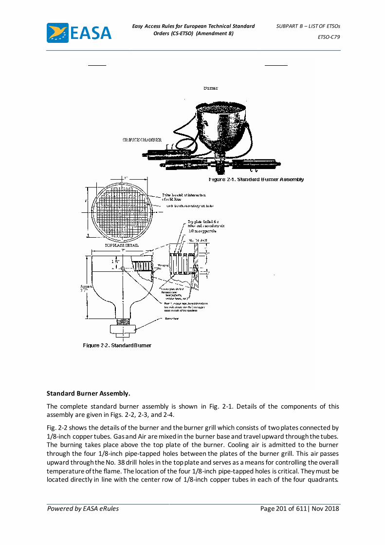
Easy Access Rules for European Technical Standard
Orders (CS-ETSO) (Amendment 8)
SUBPART B – LIST OF ETSOs
ETSO-C79
Powered by EASA eRules Page 201 of 611| Nov 2018
Standard Burner Assembly.
The complete standard burner assembly is shown in Fig. 2-1. Details of the components of this assembly are given in Figs. 2-2, 2-3, and 2-4.
Fig. 2-2 shows the details of the burner and the burner grill which consists of two plates connected by 1/8-inch copper tubes. Gas and Air are mixed in the burner base and travel upward through the tubes. The burning takes place above the top plate of the burner. Cooling air is admitted to the burner through the four 1/8-inch pipe-tapped holes between the plates of the burner grill. This air passes upward through the No. 38 drill holes in the top plate and serves as a means for controlling the overall temperature of the flame. The location of the four 1/8-inch pipe-tapped holes is critical. They must be located directly in line with the center row of 1/8-inch copper tubes in each of the four quadrants.

Easy Access Rules for European Technical Standard
Orders (CS-ETSO) (Amendment 8)
SUBPART B – LIST OF ETSOs
ETSO-C79
Powered by EASA eRules Page 202 of 611| Nov 2018
Improper location of these connections will result in an unequal radial distribution of cooling air and will affect the distribution of the flame temperature in a like manner.
Fig. 2-3 shows the details of the burner base. When the two 11/32-inch-diameter holes in the burner plug are drilled, care should be taken that the center line connecting these holes will be at right angles to the center line connecting the two 19/64-inch diameter holes in the base. When these 11/32-inch diameter holes are properly located the 19/64-inch-diameter holes cannot be seen when one looks vertically downward into the burner base. This misalignment of holes aids in the mixing of the gas and air before they ascend to the burner grill.
Fig. 2-4 shows the details of an orifice and of an orifice chamber. Three are required. Two of these orifice chambers have end plates with the 3/8-inch Parker thread fittings on both ends and are fastened directly into the burner base. The third orifice chamber has an end plate with a Parker thread fitting on one end and the plate with four 1/4-inch diameter holes in the other end. This end of the chamber is connected to the burner by four copper tubes, each 1/4 inch in outside diameter (OD) and 13 1/2 inches long. One of the orifice chambers connected to the base is for measuring the gas supplied to the burner and has an orifice 5/32 (0.01625) inch in diameter. The other orifice chamber connected to the base is for measuring the mixing air supplied to the burner and has an orifice 1/4 (0.25) inch in diameter. The third orifice chamber connected to the burner by four 1/4-inch OD copper tubes is for measuring cooling air supplied to the burner and has an orifice 5/16 (0.3125) inch in diameter. The gas should deliver approximately 2500 British thermal units (BTU) per cubic foot. The burner should consume 26 cubic feet of gas per hour for the 2000°F (1100°C) flame. The flame produced should be uniform and steady with no yellow tips.
The differential manometer readings of the pressure drops across the orifice should be:
1. Gas orifice (5/32-inch diameter), 0.99 inch of water.
2. Mixing-air orifice (1/4-inch diameter), 9.25 inch of water.
Easy Access Rules for European Technical Standard
Orders (CS-ETSO) (Amendment 8)
SUBPART B – LIST OF ETSOs
ETSO-C79
Powered by EASA eRules Page 203 of 611| Nov 2018
3. Cooling-air orifice (5/16-inch diameter), 11.0 inches of water.
In order that the burner might produce the right amount of heat, the differential pressure for the gas and the mixing air should be accurately controlled. A slight variation in the cooling air may be necessary in order to obtain the proper temperature.

Easy Access Rules for European Technical Standard
Orders (CS-ETSO) (Amendment 8)
SUBPART B – LIST OF ETSOs
ETSO-C80
Powered by EASA eRules Page 204 of 611| Nov 2018
ETSO-C80 ED Decision 2003/10/RM (applicable from 24.10.2003)
Flexible Fuel and Oil Cell Material
1 Applicability
This ETSO gives the requirements that flexible fuel and oil cell material which are manufactured on or after the date of this ETSO must meet in order to be identified with the applicable ETSO marking.
2 Procedures
2.1 General
Applicable procedures are detailed in CS-ETSO Subpart A.
2.2 Specific
None.
3 Technical Conditions
3.1 General
3.1.1 Minimum Performance Standard
Standards set forth in Federal Aviation Agency Standard, "Flexible Fuel and Oil Cell Material", dated August 1, 1963 (see Appendix 1).
3.1.2 Environmental Standard
See CS-ETSO Subpart A paragraph 2.1
3.1.3 Computer Software
None
4 Marking
4.1 General
Marking is detailed in CS-ETSO Subpart A paragraph 1.2; in addition, each flexible fuel and oil cell material shall be legibly and permanently marked with the following information:
(i) Type of fluid for which approved, i.e. fuel, or MIL-L-6082 oil, or MIL-L-7808 oil,
(ii) For oil cell material, the minimum and maximum temperature limit,
(iii) For oil cell material, the oil-dilution suitability.
4.2 Specific
None.
5 Availability of referenced documents
See CS-ETSO Subpart A paragraph 3.

Easy Access Rules for European Technical Standard
Orders (CS-ETSO) (Amendment 8)
SUBPART B – LIST OF ETSOs
ETSO-C80
Powered by EASA eRules Page 205 of 611| Nov 2018
APPENDIX 1 TO ETSO-C80 – FEDERAL AVIATION ADMINISTRATION STANDARD
FOR FLEXIBLE FUEL AND OIL CELL MATERIAL ED Decision 2003/10/RM
1.0 Purpose. To specify minimum requirements for flexible fuel and oil cell material intended for use in fuel and oil tanks of aircraft.
2.0 Scope. This standard covers the requirements of fuel and oil cell material in which hydrostatic loads are resisted by the structure of the cavity or tank and not by the cell material itself.
3.0 General Requirements.
3.1 Materials. Samples of flexible fuel and oil cell materials and construction techniques shall be subjected to and satisfy the following tests prescribed under paragraph 4.0
4.0 Tests. The applicable tests for substantiating flexible fuel and oil cell material and construction techniques are indexed below in Table I.
TABLE I
Tests Par. No. Oil Fuel
Leakage1 5.0 X X
Aging 6.0 X -
Slosh 7.0 X X
Stand 8.0 X X
Humidity 9.0 X X
Fluid Resistance of Exterior Surfaces 10.0 X X
Permeability 11.0 - X
Fuel Contamination2 12.0 - X
Oil Dilution Resistance 13.0 X -
Inner Liner Strength 14.0 X X
Seam Adhesion 15.0 X X
Puncture Resistance 16.0 X X
Low Temperature Leakage 17.0 X X
4.1 Test Samples. Test samples shall consist of the following:
a. Two cells with outside dimensions of 24x30x30 inches containing fittings representative of those used in tank construction for airframe installation. One cell to be used for stand test (par. 8.0), the other for all other cell tests.
b. Two 12x12 inch samples of composite cell construction. One for humidity test (par. 9.0), the other for puncture test (par. 16.0).
c. One sample of inner layer ply, without barrier, approximately 900 square inches in area including seam for inner liner strength test (par. 14.0) and seam adhesion test (par. 15.1).
d. One sample 6x6 inch inner layer ply, without barrier for all other inner layer tests.
e. Two permeability samples as specified in paragraph 11.0. None of these samples shall be preplasticized with fluid prior to testing.
4.2 Test Fluids. Unless otherwise specified, the following test fluids shall be used in testing the different tanks.

Easy Access Rules for European Technical Standard
Orders (CS-ETSO) (Amendment 8)
SUBPART B – LIST OF ETSOs
ETSO-C80
Powered by EASA eRules Page 206 of 611| Nov 2018
a. Fuel Tank: Test fluid conforming to MIL. Spec. MIL-S-3136, Type III.
b. Oil Tank: Oil conforming to MIL. Spec. MIL-L-6082, Grade 1100.
c. Oil Tank: Oil conforming to MIL. Spec. MIL-L-7808.
5.0 Leakage. Each cell, with all openings sealed and with the minimum of external support necessary to maintain the cell shape, shall be subjected to an internal air pressure of 2.0 p.s.i. The cell shall then be completely submerged in water or completely covered with soapy water. Leakage indicated by air bubbles in the water or soapy water solution shall be cause for rejection. Alternate methods of checking leakage may be used if approved by the Authority.
6.0 Aging.
6.1 Test Conditions. The maximum temperature capability of oil cell material shall be selected by the manufacturer and stated as a limitation under § 514.86(c) (2). During the tests, the test fluid temperature shall be uniformly maintained throughout the cell.
6.1.1 Test Duration. This test shall be conducted for period of 200 hours.
6.1.2 Test Procedure. The cell shall be filled with 80 gallons of either test fluid 4.2b. or c. as applicable. At the end of the test period, the cell shall show no sins of deterioration or other unsatisfactory conditions.
7.0 Slosh.
7.1 Test Conditions. The following test conditions shall prevail during slosh test.
7.1.1 Rocking Angle. The slosh rocking angle shall be 30 degrees total, approximately 15 degrees on either side of' the horizontal position.
7.1.2 Mounting Axis. The cell shall be mounted in such a manner that the 24 inch dimension is vertical. This position shall be known as the horizontal position.
7.1.3 Fluid Temperatures. The temperature of the fluid during the slosh test shall be as shown in the table below:
Test Fluid Temperatures Test Fluid Temperatures
Fuel 135°±10° F.
Oil Maximum temperature (±10° F.) selected by manufacturer and stated as a l imitation
7.14 Test Duration. This test shall be run as follows:
a. Slosh for 25 hours at 16 to 20 c.p.m., or
b. Slosh for 40 hours at 10 to 16 c.p.m.
7.15 Test Procedure. The test cell complete with filler cap, vents, and typical outlet fittings shall be installed in a suitable mounting structure, then mounted on the support jig and rocker assembly. Sections of flexible hose shall be connected to the vent and outlet fittings. The other end of each of these sections shall be rigidly attached to the support jig. The hoses shall be installed and supported in a manner representative of an actual installation in an aircraft.
The tank mounting structure is to be representative of an actual aircraft fuel cell compartment. Recommendations of' the cell manufacturer for supporting or mounting the fuel cell in the aircraft fuel cell compartment are to be incorporated.

Easy Access Rules for European Technical Standard
Orders (CS-ETSO) (Amendment 8)
SUBPART B – LIST OF ETSOs
ETSO-C80
Powered by EASA eRules Page 207 of 611| Nov 2018
The interior of the support jig shall be completely lined with brown paper held in place by a suitable adhesive.
The test specimen shall be filled two-thirds full with the applicable test fluid containing a suitable dye. For fuel cells, one-half' gallon of' water shall also be added. For oil cells intended for use in aircraft using an oil dilution system, 30 percent by volume of' fluid 4.2a. shall be added to the test fluid. At the conclusion of this test, the test specimen shall be completely filled with the applicable test fluid and thoroughly inspected for leakage or other evidence of' failure.
8.0 Stand Test. This test shall be conducted on the second test cell as provided for in paragraph 4.1a. The test cell may be installed in the support structure used for the slosh test or a similar structure which is lined with brown paper. The cell shall be filled with the appropriate test fluid containing a satisfactory staining agent. There should be no leakage or evidence of other failure at the end of 90 days under these conditions.
9.0 Humidity. A 12x12 inch sample of the composite cell construction shall be subjected for a total period of 15 days to the following 24-hour test cycle.
a. 8 hours at 130°±3°F. and 100 percent relative humidity
b. 4 hours cooling to approximately 70°±3°F.
c. 8 hours at 70°±3°F. and 100 percent relative humidity.
d. 4 hours heating to 130°±3°F. There shall be no corrosion, peeling, cracking, warping, blistering, delamination or discoloration of the cell after this period.
10.0 Fluid Resistance of Exterior Surfaces. The cell shall be placed in a container sufficiently large to permit immersion to one-half the depth of the cell in the applicable test fluid. The cell shall be immersed for 24 hours at ambient temperature, after which it will be removed and examined. The exterior surface of the cell construction shall show no unsatisfactory swelling, blistering, dissolution, or other deterioration.
11.0 Permeability.
11.1 Test Apparatus. The test apparatus shall consist of' the following:
a. Two permeability cups and rings constructed in accordance with Figure 1.
b. A nylon solution shall be used for sealing the test disk to the permeability cup.
11.1.1Preparation of Test Specimens. The uncured inner liner shall be applied to a 10x10 inch piece of corrugated fiberboard coated on one side with a suitable water soluble breakaway agent. The exposed surface of the inner liner shall be coated with prime cement and barrier resin (if required) in accordance with applicable manufacturing specifications. The assembly shall be wrapped with cellophane and covered with a suitable waterproof bag.
The assembly shall be vulcanized as in normal production. After vulcanizing, the waterproof bag and cellophane shall be removed and the inner liner shall be removed from the fiberboard using water as necessary. Free moisture shall be wiped from the assembly and it shall be conditioned 24 hours at a constant temperature of 77°±5° F. and a relative humidity of 40±5 percent. Two 2.5 inch diameter disks shall be cut from the vulcanized panel. One hundred ml. of test fluid specified in paragraph 4.2a. shall be placed in each of the permeability cups. Nylon solution shall be applied to the face of the cup flanges covering the area inside the bolt circle. The nylon solution shall be allowed to come almost to dryness, then the
Easy Access Rules for European Technical Standard
Orders (CS-ETSO) (Amendment 8)
SUBPART B – LIST OF ETSOs
ETSO-C80
Powered by EASA eRules Page 208 of 611| Nov 2018
test disks shall be applied to the cups with the barrier, if any, facing outward. The assemblies shall be completed by attaching the bolting rings and tightening the bolts in accordance with the following schedule:
Inner Liner Type Bolt Torque
Gum stock 5to 10 in.-lb.
Coated fabrics 15 to 20 in.-lb.
Unsupported plastic films 20 to 25 in.-lb.
11.1.2Test Procedure. Permeability cups prepared as specified above shall be placed in a
suitable rack in a constant temperature of 77°±5° F. and a relative humidity of 40±5 percent.
After allowing 1 hour for equilibrium, the cups shall be weighed to the nearest 0.005 gram and placed in the rack with the faces of the cups facing upward (test disks up). The cups shall be kept at the above constant temperature for 24 hours, then weighed to check for seal integrity. The bolts shall be retorqued if necessary. The cups shall then be inverted (test disks down) in a rack that permits free access of air to the test disks.
Cups shall be weighed at the end of the third, fifth, and eighth day after inverting. Defective films or leaks caused by faulty assembly will usually be found when making the weighing on the third day. The diffusion rate calculation shall be made on the fifth day to eighth day period and expressed as fluid ounces per square foot per 24 hours. The permeability shall be less than 0.025 fluid ounces per square foot per 24 hours for each sample tested.
NOTE.—Diffusion expressed in fluid ounces per square foot per 24 hours equals the gram loss of the test specimen per 24 hours multiplied by a factor K which is defined as follows:
𝐾 =144
(𝑆𝑝. 𝑔𝑟. )(29.573)(3.142)𝑅2
Where
sp.gr. = Specific gravity of test fluid at 77° F.
R = Inside radius of test cup expressed in inches.
12.0 Fuel Contamination.
12.1 Nonvolatile Gum Residue. A five gram sample of the inner layers up to the barrier, shall be diced up into approximately 0.062 inch squares and placed in a flash containing 250 ml. of test fluid as specified in paragraph 4.2a. and allowed to stand for 48 hours at 77°±5°F.
The contaminated test fluid shall be decanted off, and the nonvolatile gum residue determined by Method 3302 of Federal Test Method Standard No. 791,4 ASTM D381-54T, except that the total evaporation time shall be 45 minutes. The nonvolatile material shall not exceed 60 milligrams per 100 ml. of the contaminated fluid.
12.1.1 Stoved Gum Residue. The beakers containing the nonvolatile material shall be placed in an appropriate bath maintained constantly at a temperature of 572°±9°F. for 30 minutes. After cooling in a closed container, the beakers shall be weighed. The staved gum residue shall not exceed 20 milligrams per 100 ml. of the

Easy Access Rules for European Technical Standard
Orders (CS-ETSO) (Amendment 8)
SUBPART B – LIST OF ETSOs
ETSO-C80
Powered by EASA eRules Page 209 of 611| Nov 2018
contaminated fluid, after necessary corrections have been made for preformed gums originally present in the test fluid.
13.0 Oil Dilution Resistance. Tensile and elongation tests shall be made on the inner layer ply according to the methods described in Federal Test Method Standard No. 601,5 Methods 4111 and 4121, respectively. Before and after the tests the test specimens shall be immersed for 48 hours at room temperature in the appropriate oil diluted 30 percent by volume with test fluid specified in paragraph 4.2a. The tensile properties shall not be reduced more than 40 percent from the original values, and the Shore A durometer hardness shall not vary more than 15 points from the original value.
14.0 Inner Liner Strength.
14.1 Gum Inner Liner Strength. The strength of the gum inner layer ply, without barrier, shall be determined in accordance with Federal Test Method Standard No. 601,5 Method 4111 before and after immersion in the test fluid specified in paragraph 4.2a. for 72 hours at a temperature of 135°±3° F. The tensile strength shall also be determined before and after immersion in water for 72 hours at a temperature of 135°±3° F. The tensile strength shall not be reduced more than 50 percent for fuel immersion and 20 percent for water immersion calculated on the basis of the original cross-sectional area.
14.2 Fabric Inner Liner Strength. The tensile strength of the fabric inner layer ply, without barrier, shall be determined in accordance with Specification CCC-T-191,5 Method 5100 before and after immersion in test fluid specified in paragraph 4.2a. for 72 hours at a temperature of 135°±3° F. The tensile strength shall also be determined before and after immersion in water for 72 hours at a temperature of 135°±3° F. The tensile strength shall not be reduced more than 20 percent for fuel immersion and 50 percent for water immersion calculated on the basis of the original cross-sectional area.
15.0 Seam Adhesion. The seam adhesion of the inner layer ply to itself before and after immersion in the test fluid specified in paragraph 4.2a for 72 hours at a temperature of 135°±3° F. shall be tested within 4 hours along the length of the seam by the strip back method using a jaw separation rate of 2 inches per minute in accordance with Federal Test Method Standard No. 601,5 Method 8011. Where the adhesion of the seam is less than the strength of the material, the adhesion shall be a minimum of 6 pounds per inch.
15.1 Seam Adhesion (Alternate Procedure). As an alternate procedure to the above, the seam adhesions of the inner-layer ply to itself may be tested by cutting a strip of inner-layer material one inch wide having a seam made in the same manner as is used in the tanks submitted under paragraph 4.1a. This seam shall be perpendicular to and midway in the length of the strip. When a tensile load has been applied of sufficient magnitude to break the strip, there shall be no failure of the seam.
16.0 Puncture Resistance. A cell wall shall be fastened in a specimen holder in accordance with Figure 2. A piercing instrument with its end conforming to Figure 2 shall be forced against the cell wall at approximately the centre of the area enclosed by the specimen holder. The force required to puncture the cell shall not be less than 15 pounds.
17.0 Low Temperature Leakage. The cell supporting structure cavity shall be lined with brown paper and the cell installed in the structure. The cell shall be completely filled with the appropriate test fluid containing a staining agent and allowed to stand for seven days at 135°±10° F. The cell shall then be emptied and subjected to an air dry out at 155°±5° F for seven days. The cell shall then be completely refilled with the appropriate test fluid containing a straining agent, cooled to -65°±5° F. and allowed to stand a this temperature a minimum of three days. The test fluid in contact with the cell inner liner shall have reached -65° F. prior to the start of the three-day

Easy Access Rules for European Technical Standard
Orders (CS-ETSO) (Amendment 8)
SUBPART B – LIST OF ETSOs
ETSO-C80
Powered by EASA eRules Page 210 of 611| Nov 2018
period. The cell shall be instrumented by placing thermo-couples against the inside surface of the cell liner, one with six inches of the top surface on one side panel and the other within six inches of the bottom surface on the opposite side panel. At the end of the three-day period, the cell shall be brought back to room temperature, drained and examined internally and externally for fluid leakage or other evidence of failure. Any indication of failure shall be cause for rejection.

Easy Access Rules for European Technical Standard
Orders (CS-ETSO) (Amendment 8)
SUBPART B – LIST OF ETSOs
ETSO-C85a
Powered by EASA eRules Page 211 of 611| Nov 2018
ETSO-C85a ED Decision 2003/10/RM (applicable from 24.10.2003)
Survivor Locator Lights
1 Applicability
This ETSO gives the requirements which survivor locator lights that are manufactured on or after the date of this ETSO must meet in order to be identified with the applicable ETSO marking.
2 Procedures
2.1 General
Applicable procedures are detailed in CS-ETSO Subpart A.
2.2 Specific
None.
3 Technical Conditions
3.1 Basic
3.1.1 Minimum Performance Standard
Standards set forth in Society of Automotive Engineers, Inc. (SAE), Aerospace Standard (AS) 4492,
„Survivor Locator Lights,“ dated January 1995.
3.1.2 Environmental Standard
See CS-ETSO Subpart A paragraph 2.1
3.1.3 Computer Software
None
3.2 Specific
None.
4 Marking
4.1 General
Marking is detailed in CS-ETSO Subpart A paragraph 1.2.
4.2 Specific
None.
5 Availability of Referenced Document
See CS-ETSO Subpart A paragraph 3.

Easy Access Rules for European Technical Standard
Orders (CS-ETSO) (Amendment 8)
SUBPART B – LIST OF ETSOs
ETSO-C87a
Powered by EASA eRules Page 212 of 611| Nov 2018
ETSO-C87a ED Decision 2013/12/R (applicable from 15.7.2013)
Airborne Low-Range Radio Altimeter
1 Applicability
This ETSO gives the requirements which Airborne Low-range Radio Altimeters that are manufactured on or after the date of this ETSO must meet in order to be identified with the applicable ETSO marking.
2 Procedures
2.1 General
Applicable procedures are detailed in CS-ETSO, Subpart A.
2.2 Specific
None.
3 Technical conditions
3.1 Basic
3.1.1 Minimum performance standard
Standards set forth in EUROCAE document ED-30 Minimum Performance Standards for Airborne Low-Range Radar Altimeter Equipment, dated March 1980 as modified by Appendix 1 to this ETSO.
The applicable Chapter 2 and Chapter 3 requirements are defined in Table 1 for the appropriate functional class.
Table 1
Low-Range Radio Altimeter Functional Class
Low-Range Radio Altimeter Class Description
Applicable requirements in ED-30
A Approach and landing 2.1-2.8, 3.1.1, 3.2.1 (all), 3.3.1
B Terrain Avoidance (ground proximity warning systems)
2.1-2.8, 3.1.2, 3.2.3 (all), 3.3.2
Note: It is possible for a radio altimeter to meet both functional classes.
3.1.2 Environmental standard
See CS-ETSO, Subpart A, paragraph 2.1
3.1.3 Software
See CS-ETSO, Subpart A, paragraph 2.2
3.1.4 Airborne electronic hardware
See CS-ETSO, Subpart A, paragraph 2.3.
3.2 Specific
3.2.1 Failure condition classification
There is no standard minimum failure condition classification for this TSO. The failure condition classification appropriate for the equipment will depend on the intended use of the equipment in a specific aircraft.

Easy Access Rules for European Technical Standard
Orders (CS-ETSO) (Amendment 8)
SUBPART B – LIST OF ETSOs
ETSO-C87a
Powered by EASA eRules Page 213 of 611| Nov 2018
4 Marking
4.1 General
Marking is detailed in CS-ETSO, Subpart A, paragraph 1.2.
4.2 Specific
None.
5 Availability of referenced document
See CS-ETSO, Subpart A, paragraph 3.
[Amdt ETSO/8]

Easy Access Rules for European Technical Standard
Orders (CS-ETSO) (Amendment 8)
SUBPART B – LIST OF ETSOs
ETSO-C87a
Powered by EASA eRules Page 214 of 611| Nov 2018
APPENDIX 1 TO ETSO-C87A – MODIFICATIONS AND ADDITIONS TO EUROCAE ED-30 FOR MINUMUM
PERFORMANCE STANDARDS FOR LOW-RANGE RADIO ALTIMETERS ED Decision 2013/012/R
1.0. ED-30 REQUIREMENT MODIFICATIONS
1.1. ED-30 Paragraph 1.3 (Radio Altimeters with Auto-Surveillance). ETSO-C87a does not include a separate category for monitoring. Design the radio altimeter to support the failure condition classification of the intended installation.
1.2. ED-30 Paragraph 2.2 (Transmitter Operating Frequency). Add the following requirement to ED-30, paragraph 2.2: The radio altimeter shall meet the International Telecommunication Union (ITU) regulations, if applicable.
1.3. ED-30 Paragraph 2.5 (Failure Warning). Add the following sentence to the beginning of ED-30, paragraph 2.5, to clarify that a failure detection system is required: ‘A failure detection system must be incorporated in the equipment to indicate to the pilot, and to any systems utilizing the radio altimeter data, of a failure of the radio altimeter to accomplish its intended function because of the following conditions: (1) Loss of power, and (2) Loss of signal or altitude sensing capability when within the manufacturer’s stated operating altitude range.’
1.4. ED-30 Paragraph 3.2.2 (Category A2). ETSO-C87a does not include Category A2. If alternate accuracy requirements not meeting the requirements of paragraph 3.2.1 are desired, the applicant should apply for a deviation in accordance with paragraph 3.g. of this ETSO.
1.5. ED-30 Paragraph 3.2.4 (Category C). ETSO-C87a does not include Category C. If the radio altimeter has been designed and tested to tighter accuracy requirements, include the design information, test results, and limitations with the application for ETSO and document the performance in the installation manual.
1.6. ED-30 (Appendix). The ED-30 appendix references TSO-C87 and RTCA/DO-123 for external loop loss standards. As TSO-C87 and DO-123 are no longer current, reference RTCA/DO-155, Minimum Performance Standards Airborne Low-Range Radar Altimeters, Appendix B, for external loop loss standards instead.
2.0. REQUIREMENT ADDITIONS to ED-30: Rate Data. The equipment need not provide a rate data output as a condition of compliance with this minimum performance standard. Altimeters with rate outputs must meet the following accuracy requirements for at least 95 percent of all observations for heights from the terrain to the antenna:
RATE DATA
Height (ft) Range (ft/sec) Accuracy (ft/sec)
3–100 0–15 ± (1.5 ft.+ 0.01 h + 0.1 /r/)
100–200 0–20 ± (2.0 ft.+ 0.01 h + 0.1 /r/)
Where: h = altitude in feet; and /r/ = absolute value of rate (feet/sec.)
[Amdt ETSO/8]

Easy Access Rules for European Technical Standard
Orders (CS-ETSO) (Amendment 8)
SUBPART B – LIST OF ETSOs
ETSO-C88a
Powered by EASA eRules Page 215 of 611| Nov 2018
ETSO-C88a ED Decision 2003/10/RM (applicable from 24.10.2003)
Automatic Pressure Altitude Reporting Code Generating Equipment
1 Applicability
This ETSO gives the requirements which automatic pressure altitude reporting code generating equipment that are manufactured on or after the date of this ETSO must meet in order to be identified with the applicable ETSO marking.
2 Procedures
2.1 General
Applicable procedures are detailed in CS-ETSO Subpart A.
2.2 Specific
None.
3 Technical Conditions
3.1 Basic
3.1.1 Minimum Performance Standard
Standards set forth in the Society of Automotive Engineers, Inc., (SAE) Aerospace Standard (AS) 8003 „Automatic Pressure Altitude Reporting Code Generating Equipment“, dated July, 1974.
3.1.2 Environmental Standard
See CS-ETSO Subpart A paragraph 2.1
3.1.3 Computer Software
See CS-ETSO Subpart A paragraph 2.2
3.2 Specific
None.
4 Marking
4.1 General
Marking is detailed in CS-ETSO Subpart A paragraph 1.2.
4.2 Specific
None.
5 Availability of Referenced Document
See CS-ETSO Subpart A paragraph 3.

Easy Access Rules for European Technical Standard
Orders (CS-ETSO) (Amendment 8)
SUBPART B – LIST OF ETSOs
ETSO-C89
Powered by EASA eRules Page 216 of 611| Nov 2018
ETSO-C89 ED Decision 2003/10/RM (applicable from 24.10.2003)
Oxygen Regulators, Demand
1 Applicability
This ETSO gives the requirements which oxygen regulators, demand type that are manufactured on or after the date of this ETSO must meet in order to be identified with the applicable ETSO marking.
2 Procedures
2.1 General
Applicable procedures are detailed in CS-ETSO Subpart A.
2.2 Specific
None.
3 Technical Conditions
3.1 Basic
3.1.1 Minimum Performance Standard
Standards set forth in the attached Federal Aviation Administration Standard „Oxygen Regulators, Demand“.
3.1.2 Environmental Standard
As specified in Federal Aviation Administration Standard „Oxygen Regulators, Demand“.
3.1.3 Computer Software
None
3.2 Specific
None.
4 Marking
4.1 General
Marking is detailed in CS-ETSO Subpart A paragraph 1.2.
4.2 Specific
None.
5 Availability of Referenced Document
See CS-ETSO Subpart A paragraph 3.

Easy Access Rules for European Technical Standard
Orders (CS-ETSO) (Amendment 8)
SUBPART B – LIST OF ETSOs
ETSO-C89
Powered by EASA eRules Page 217 of 611| Nov 2018
FEDERAL AVIATION ADMINISTRATION STANDARD ASSOCIATED WITH ETSO-C89
– OXYGEN REGULATORS, DEMAND ED Decision 2003/10/RM
1. Purpose.
This standard contains minimum performance and quality control standards for the manufacture of demand oxygen system regulators.
2. Classification.
The term „demand regulator“ includes all of the following classes of regulators:
(a) Straight demand regulators designed to deliver oxygen only.
(b) Diluter demand regulators designed to deliver a mixture of oxygen and air, and oxygen only.
(c) Straight demand pressure breathing regulators (straight demand regulations designed to deliver undiluted oxygen under positive pressure).
(d) Diluter demand pressure breathing regulators (diluter demand regulators designed to deliver undiluted oxygen under positive pressure).
3. Design and Construction of Regulator.
To be eligible for approval under a TSO authorization, the regulator must possess the following design and construction characteristics:
3.1 Demand regulators designed to be mounted directly upon an oxygen mask or the crewmember’s clothing or safety harness must include a flexible oxygen supply tube connecting the regulator inlet with the oxygen supply system.
3.2 Demand regulators must be constructed of materials that -
(a) Do not contaminate air or oxygen;
(b) Are not adversely affected by continuous contact with oxygen; and
(c) Are at least flame resistant.
3.3 (a) Demand regulators must be equipped with a 200 mesh screen, or equivalent filter, at the oxygen inlet port or at the oxygen inlet hose assembly.
(b) Diluter demand and diluter demand pressure regulators must be equipped with screening or not more than 100 mesh and not less than 30 mesh, or equivalent filter, at the air inlet port.
3.4 Diluter demand and diluter demand pressure breathing regulators must be provided with a means for manually selecting a delivery of undiluted oxygen. If the selection means is controlled by a rotating handle or lever, the travel must be limited to not more than 180 degrees from the „normal oxygen“ position to the „100 percent oxygen“ position. The dilution position of the selection means must be designated „normal oxygen“ and the nondilution position must be designated „100 percent oxygen.“ The selection means must be such that it will not assume a position between the „normal oxygen“ and „100 percent oxygen“ positions.
3.5 Straight demand pressure breathing and diluter demand pressure breathing regulations must be designed to provide oxygen at a positive pressure of 11.0 ±3.0 inches H2O to determine mask peripheral leakage at altitudes below which positive pressures are

Easy Access Rules for European Technical Standard
Orders (CS-ETSO) (Amendment 8)
SUBPART B – LIST OF ETSOs
ETSO-C89
Powered by EASA eRules Page 218 of 611| Nov 2018
hereinafter required. The means of obtaining this pressure must be by push, pull, or toggle control appropriately marked to indicate its purpose.
3.6 Diluter demand and diluter demand pressure breathing regulators must incorporate means to indicate when oxygen is and is not flowing from the regulator outlet. This requirement does not apply to mask mounted regulators.
4. Performance.
Two demand regulators of each class for which approval is sought must be shown to comply with the minimum performance standards set forth in paragraphs 4.1 through 4.10 in any position which the regulators can be mounted. Tests must be conducted at ambient atmospheric conditions of approximately 30 inches Hg and 70°F., except as otherwise specified. It is permissible to correct gas flow rates and pressures to STPD conditions by computation.
4.1 (a) Demand regulators must supply the following oxygen or oxygen-air flows at not more than the specified outlet pressures. These characteristics must be displayed at all altitudes, with the oxygen supply pressure at all values within the design inlet pressure range, and with the diluter valve open and closed.
MAXIMUM OUTLET FLOW, SUCTION PRESSURE,
LPM, ATPD: INCHES OF WATER
20 0.40
70 .80
100 1.00
(b) Demand regulators must not flow more than 0.01 LPM, STPD, when the outlet
suction pressure is reduced to 0 inches of H2O under the conditions specified in subparagraph (a) of this paragraph.
4.2 (a) Diluter demand and diluter demand pressure breathing regulators must supply the following percentages of cylinder oxygen, by volume, at the specified atmospheric pressures and corresponding altitudes. These oxygen percentages must be delivered at regulator outlet gas flows of 20, 70, and 100 LPM ATPD, with the oxygen supply pressure at all values within the design inlet pressure range.
Minimum percent oxygen
Pressure mm Hg Altitude feet Diluter demand Diluter demand pressure breathing
760 0 0 40
632.4 5,000 0 40
522.8 10,000 6 40
429.1 15,000 14 40
349.5 20,000 25 40
282.4 25,000 40 40
226.1 30,000 61 61
179.3 35,000 91 91
178.5 35,100 98 98
141.2 40,000 98 98
111.1 45,000 Not applicable 98

Easy Access Rules for European Technical Standard
Orders (CS-ETSO) (Amendment 8)
SUBPART B – LIST OF ETSOs
ETSO-C89
Powered by EASA eRules Page 219 of 611| Nov 2018
(b) Straight demand and straight demand pressure breathing regulators must supply not less than 98 percent oxygen, by volume, at all altitudes under the conditions specified in subparagraph (a) of this paragraph.
4.3 (a) Diluter demand pressure breathing regulators with the diluter valve open or closed, and straight demand pressure breathing regulators, must provide positive breathing pressure at a flow of 20 LPM, ATPD, in accordance with the following table:
ALTITUDE 1,000 FEET POSITIVE OUTLET PRESSURE-H2O
30 0.0 +3.5 -0.0
40 2.5 ±2.5
42 6.0 ±1.5
44 10.0 ±1.0
45 12.0 ±1.0
(b) The positive pressure at 100 LPM, ATPD, must not increase by more than 0.8 inches
H2O from the positive pressure at 20 LPN, ATPD.
(c) The positive pressure at 0.01 LPM, ATPD, must not decrease by more than 0.8 inches H2O from the positive pressure at 20 LPM, ATPD.
4.4 (a) The inward leakage of air through the regulator at sea level must not exceed 0.1 LPM, STPD, with a suction pressure of 1.0 inches H2O applied to the outlet port, the oxygen supply inlet port sealed, and the diluter valve closed.
(b) The outward leakage of air through the regulator at sea level must not exceed 0.1 LPM, STPD, with a positive pressure of 12 inches H2O applied to the outlet port, the oxygen supply inlet port sealed, and the diluter valve open and closed.
(c) The regulator outlet leakage must not exceed 0.01 LPM, STPD, with the regulator outlet port open and any oxygen supply pressure within the specified operating range applied at the regulator inlet port.
(d) The regulator overall leakage must not exceed 0.01 LPM, STPD, with the regulator outlet port sealed and the regulator inlet port pressurized to a value equal to the maximum specified oxygen supply pressure.
4.5 (a) Straight demand pressure breathing and diluter demand pressure breathing regulators must comply with paragraphs 4.1 through 4.4 after a negative pressure of 29 inches H2O and a positive pressure of 24 inches H2O are applied to the outlet port for a period of 2 minutes. The diluter valve and the regulator inlet port must be closed during these two pressure tests.
(b) Straight demand and diluter demand regulators must comply with paragraphs 4.1 through 4.4 after a negative pressure of 29 inches H2O and a positive pressure of 12 inches H2O are applied to the outlet port for a period of 2 minutes. The diluter valve and the regulator inlet port must be closed during these two pressure tests.
(c) Demand regulators must comply with paragraphs 4.1 through 4.4 after a positive pressure of 1.5 times the maximum oxygen supply pressure is applied to the inlet port, or to the inlet of the oxygen supply in the case of mask mounted regulators, for a period of 2 minutes. The positive pressure must be applied rapidly to simulate

Easy Access Rules for European Technical Standard
Orders (CS-ETSO) (Amendment 8)
SUBPART B – LIST OF ETSOs
ETSO-C89
Powered by EASA eRules Page 220 of 611| Nov 2018
rapid opening of the supply valve. The diluter valve must be closed and the outlet port must be sealed during the test.
4.6 (a) Straight demand and diluter demand regulators must comply with paragraphs 4.1 through 4.4 after being subjected to a change in pressure from not less than 12.2 p.s.i.a. to not less than 2.7 p.s.i.a. in not more than one second.
(b) Straight demand pressure breathing and diluter demand pressure breathing regulators must comply with paragraphs 4.1 through 4.4 after beings subjected to a change in pressure from not less than 12.2 p.s.i.a. to not less than 2.1 p.s.i.a. in not more than one second.
4.7 Demand regulators must comply with paragraphs 4.1 through 4.4 under each condition specified in subparagraphs (a) through (d) of this paragraph with the maximum oxygen supply pressure applied to the regulator inlet:
(a) At a temperature of approximately 70°F. after being stored at a temperature of not less than 100° F. for 12 hours
(b) At a temperature of 70°F. after being stored at a temperature of not warmer than -67°F. for 2 hours.
(c) At a temperature of not less than 130°F.
(d) At a temperature of not more than 20°F.
4.8 Demand regulators must comply with paragraphs 4.1 through 4.4 after being subjected to the tests specified in sub-paragraphs (a) and (b) of this paragraph.
(a) The regulator must be vibrated along each mutually perpendicular axis for one hour (three hours total), at a frequency of 5 to 500 cps, and at a double amplitude of 0.036 inches or an acceleration of 2 „g,“ whichever occurs first. Mask mounted regulators need not be subjected to this vibration test.
(b) The regulator must be subjected to an endurance test of a total of 250,000 breathing cycles.
The peak breathing rate must be 30 LPM, STPD, for 200,000 cycles, and 70 LPM, STPD, for 50,000 cycles. The dilution valve must be open during one half of the 200,000 cycles and one half of the 50,000 cycles, and it must be closed during the remaining cycles. During the nonflow portion of the 30 LPM and 70 LPM breathing cycles, a back pressure of 0.5 and 1.0 inches H2O, respectively, must be applied to the regulator outlet.
4.9 Demand regulators must be free of vibration, flutter, or chatter that will prevent compliance with paragraphs 4.1 through 4.3 when subjected to the following simulated flow conditions:
Cycles Peak flow per cycle
LPM, STPD Back pressure at 0 LPM,
inches H2O Diluter valve
5,000 100 1.5 Closed
5,000 100 1.5 Open
4.10 Demand regulators, when subject to accelerations up to 3 „g“ in any position, must
comply with paragraph 4.1(a) except that the specified suction pressures may be exceeded by not more than 0.6 inches H2O.
5. Maximum Environmental (Cabin) Altitude.
Easy Access Rules for European Technical Standard
Orders (CS-ETSO) (Amendment 8)
SUBPART B – LIST OF ETSOs
ETSO-C89
Powered by EASA eRules Page 221 of 611| Nov 2018
The minimum pressure to which the regulator has been shown to comply under paragraph 4.6(a) or (b) of this standard determines the maximum environmental (cabin) altitude of the regulator, except that the maximum environmental (cabin) altitude must not exceed the value shown in the following table:
CLASSFEET
Straight or diluter-demand 40,000
Pressure demand 45,000
6. Quality Control.
6.1 Each production regulator must be shown to comply with paragraphs 4.1 through 4.4.
6.2 One regulator selected at random from each lot must be shown to comply with paragraphs 4.1 through 4.10. The lot size may be selected by the applicant subject to the approval of the Federal Aviation Administration on the basis of evaluation of the quality control system of the applicant (see FAR, §37.5).
7. Abbreviations and Definitions.
LPM Liters per minute.
STPD. Standard temperature and pressure, dry (0° C., 760 mm Hg., PH20=0).
ATPD Ambient temperature and pressure, dry (70° F.; ambient pressure; PH20=0).
c.p.s. Cycles per second.
p.s.i.a. Pounds per square inch absolute.
g Acceleration of gravity, 32 feet/second/ second.

Easy Access Rules for European Technical Standard
Orders (CS-ETSO) (Amendment 8)
SUBPART B – LIST OF ETSOs
ETSO-C90d
Powered by EASA eRules Page 222 of 611| Nov 2018
ETSO-C90d ED Decision 2012/009/R (applicable from 5.7.2012)
Cargo Pallets, Nets and Containers (Unit Load Devices)
1 Applicability
This ETSO gives the requirements which cargo unit load devices that are manufactured on or after the date of this ETSO must meet in order to be identified with the applicable ETSO marking.
2 Procedures
2.1 General
Applicable procedures are detailed in CS-ETSO Subpart A.
2.2 Specific
None.
3 Technical Conditions
3.1 Basic
3.1.1 Minimum Performance Standard
For new models of Type I ULDs standards set forth in standard of Aerospace Industries Association of America, Inc. (AIA), National Aerospace Standard, NAS 3610, „Cargo Unit Load Devices.- Specification for,“ Revision 10, dated November 1, 1990
When using NAS 3610 Revision 10, the following errors must be corrected:
in lieu of Figure 31, sheet 87, substitute Figure 31, sheet 88;
in lieu of Figure 31, sheet 88, substitute Figure 32, sheet 87 of NAS 3610 Revision 8 dated April 1987
For new models of Type II ULDs standards set forth in the Society of Automotive Engineers, Inc. (SAE) Aerospace Standard (AS) 36100, “Air Cargo Unit Load Devices - Performance Requirements and Test Parameters”, Revision A, dated April 2006.
For Type I and II ULDs, the standards set forth in SAE AS 36102, Air Cargo Unit Load Devices - Testing Methods, dated March 2005 are applicable.
3.1.2 Environmental Standard
See CS-ETSO Subpart A paragraph 2.1.
3.1.3 Computer Software
None
3.1.4 Electronic Hardware Qualification
None
3.2 Specific
Environmental degradation due to ageing, ultra-violet (UV)-exposure, weathering, etc. for any non-metallic materials used in the construction of pallets, nets and containers must be considered.

Easy Access Rules for European Technical Standard
Orders (CS-ETSO) (Amendment 8)
SUBPART B – LIST OF ETSOs
ETSO-C90d
Powered by EASA eRules Page 223 of 611| Nov 2018
In lieu of NAS 3610 Rev. 10, paragraph 3.7 and SAE AS 36100 Rev. A, paragraph 4.7 use the following paragraph which provides the fire protection requirements for ULDs:
The materials used in the construction of pallets, nets and containers must meet the appropriate provisions in CS-25, Appendix F, Part I, paragraph (a)(2)(iv).
Textile Performance: See SAE Aerospace Information Report (AIR) 1490B, Environmental Degradation of Textiles, dated December 2007, for available data for textile performance when exposed to environmental factors. These data shall be taken into account for consideration of the effects of environmental degradation on nets commensurate with the expected storage and service life to satisfy SAE AS 36100 Rev. A, paragraph 4.11.
NOTE: Environmental degradation data other than that documented in AIR1490B may be used if substantiated by the applicant and approved by EASA.
3.2.1 Failure Condition Classification
N/A
4 Marking
4.1 General
Marking is detailed in CS-ETSO Subpart A paragraph 1.2.
4.2 Specific
In addition, the following information shall be legibly and permanently marked on the ULD:
1. The identification of the article in the code system explained in
a. NAS 3610, Revision 10, paragraph 1.2.1, for Type I ULDs.
b. SAE AS 36100, Rev. A, paragraph 3.5 for Type II ULDs.
2. The nominal weight of the article in kilogram and pound in the format: Weight: …kg (…lb)
3. If the article is not omni-directional, the words “FORWARD”, “AFT”, and “SIDE” must be conspicuously and appropriately placed.
4. The manufacturer’s serial number of the article, with the option to add the date of manufacture.
5. The burning rate determined for the article under paragraph 3.2 of this ETSO.
6. If applicable, the expiration date in the format “EXP YYYY-MM” must be marked on the ULD.
5 Availability of Referenced Document
See CS-ETSO Subpart A paragraph 3.
[Amdt ETSO/7]
Easy Access Rules for European Technical Standard
Orders (CS-ETSO) (Amendment 8)
SUBPART B – LIST OF ETSOs
ETSO-C92c
Powered by EASA eRules Page 224 of 611| Nov 2018
ETSO-C92c ED Decision 2003/10/RM (applicable from 24.10.2003)
Ground Proximity Warning-Glide Slope Deviation Alerting Equipment
1 Applicability
This ETSO gives the requirements which ground proximity warning-glide slope deviation alerting equipment that is manufactured on or after the date of this ETSO, must meet in order to be identified with the applicable ETSO marking.
2 Procedures
2.1 General
Applicable procedures are detailed in CS-ETSO Subpart A.
2.2 Specific
None.
3 Technical Conditions
3.1 General
3.1.1 Minimum Performance Standard
Standards set forth in paragraph 2.0 of Radio Technical Commission for Aeronautics (RTCA) Document DO-161A revised May 27, 1976.
3.1.2 Environmental Standard
See CS-ETSO Subpart A paragraph 2.1
3.1.3 Computer Software
See CS-ETSO Subpart A paragraph 2.2
3.2 Specific
3.2.1 Fire Protection. All materials used except small parts (such as knobs, fasteners, seals, grommets and small electrical parts) that would not contribute significantly to the propagation of a fire, must be self-extinguishing when tested in accordance with applicable requirements of CS 25.853 and Appendix F.
3.2.2 Aural and Visual Warnings. The required aural and visual warnings must initiate simultaneously. Each aural warning shall identify the reason for the warning such as „terrain,“ „too low,“ „glide slope,“ or other acceptable annunciation.
3.2.3 Deactivation Control. If the equipment incorporates a deactivation control other than a circuit breaker, the control must be a switch with a protective cover. The cover must be safety wired so that the wire must be broken in order to gain access to the switch. A frangible lock or similar device may also be used to perform this function.
3.2.4 Mode 4 Flap Warning Inhibition. A separate guarded control may be provided to inhibit Mode 4 warnings based on flaps being in other than the landing configuration.
3.2.5 Speed shall be included in the logic that determines GPWS warning time for Modes 2 and 4 to allow additional time for the aircrew to react and take corrective action.

Easy Access Rules for European Technical Standard
Orders (CS-ETSO) (Amendment 8)
SUBPART B – LIST OF ETSOs
ETSO-C92c
Powered by EASA eRules Page 225 of 611| Nov 2018
3.2.6 Smart Callouts. Smart callouts of altitude above the terrain shall be provided during nonprecision approaches. These advisories are normally, but are not limited to 500 feet above the terrain or the height above airport (HAA) used in the terminal (approach) procedures.
3.3 Exceptions.
3.3.1 An alternate means, with demonstrated equal or better accuracy, may be used in lieu of barometric altitude rate (accuracy specified in ETSO-C10b, Altimeter, Pressure Actuated, Sensitive Type, or later ETSO-C92c revisions) and/or radio altimeter altitude (accuracy specified in ETSO-2C87, Low range radio altimeters) to meet the warning requirements described in RTCA Document No. DO-161A.
3.3.2 In RTCA Document No. DO-161A, paragraph 2.3, the complete cycle of two tone sweeps plus annunciation is extended from „1.4“ to „2“ seconds.
4 Marking
4.1 General
Marking is detailed in CS-ETSO Subpart A paragraph 1.2.
4.2 Specific
None.
5 Availability of Referenced Document
See CS-ETSO Subpart A paragraph 3.

Easy Access Rules for European Technical Standard
Orders (CS-ETSO) (Amendment 8)
SUBPART B – LIST OF ETSOs
ETSO-C95a
Powered by EASA eRules Page 226 of 611| Nov 2018
ETSO-C95a ED Decision 2012/009/R (applicable from 5.7.2012)
Mach Meters
1 Applicability
This ETSO gives the requirements which mach meters that are manufactured on or after the date of this ETSO must meet in order to be identified with the applicable ETSO marking.
2 Procedures
2.1 General
Applicable procedures are detailed in CS-ETSO Subpart A.
2.2 Specific
None.
3 Technical Conditions
3.1 Basic
3.1.1 Minimum Performance Standard
Standards set forth in the Society of Automotive Engineers Inc, (SAE) Aerospace Standard (AS) 8018A „Mach Meters“, dated 01/09/1996.
3.1.2 Environmental Standard
See CS-ETSO Subpart A paragraph 2.1
3.1.3 Computer Software
See CS-ETSO Subpart A paragraph 2.2
3.1.4 Electronic Hardware Qualification
See CS-ETSO Subpart A paragraph 2.3.
3.2 Specific
3.2.1 Failure Condition Classification
See CS-ETSO Subpart A paragraph 2.4.
Failure of the function defined in paragraph 3.1.1 of this ETSO has been determined to be a major failure condition.
4 Marking
4.1 General
Marking is detailed in CS-ETSO Subpart A paragraph 1.2.
4.2 Specific
None, marking in accordance with AS 8018A addendum 1 section 2 is optional.
5 Availability of Referenced Document
See CS-ETSO Subpart A paragraph 3.
[Amdt ETSO/7]

Easy Access Rules for European Technical Standard
Orders (CS-ETSO) (Amendment 8)
SUBPART B – LIST OF ETSOs
ETSO-C96a
Powered by EASA eRules Page 227 of 611| Nov 2018
ETSO-C96a ED Decision 2003/10/RM (applicable from 24.10.2003)
Anticollision Light Systems
1 Applicability
This ETSO gives the requirements which new models of anticollision light systems that are manufactured on or after the date of this ETSO must meet in order to be identified with the applicable ETSO marking.
2 Procedures
2.1 General
Procedures are detailed in CS-ETSO Subpart A.
2.2 Specific
None.
3 Technical Conditions
3.1 Basic
3.1.1 Minimum Performance Standard
Standards set forth in the Society of Automotive Engineers, Inc., (SAE) Aerospace Standard (AS) 8017A „Minimum Performance Standard for Anticollision Light Systems“, dated January 30, 1986.
In addition to Chapter 3 General Standard of AS-8017A, all materials used except small parts (such as knobs, fasteners, seals, grommets and small electrical parts) that would not contribute significantly to the propagation of a fire, must be self-extinguishing when tested in accordance with applicable requirements of CS 25.869(a)(4) and Appx F at Change 14.
3.1.2 Environmental Standard
See CS-ETSO Subpart A paragraph 2.1
3.1.3 Computer Software
None
3.2 Specific
None.
4 Marking
4.1 General
Marking is detailed in CS-ETSO Subpart A paragraph 1.2.
4.2 Specific
None.
5 Availability of Referenced Document
See CS-ETSO Subpart A paragraph 3.

Easy Access Rules for European Technical Standard
Orders (CS-ETSO) (Amendment 8)
SUBPART B – LIST OF ETSOs
ETSO-C97
Powered by EASA eRules Page 228 of 611| Nov 2018
ETSO-C97 ED Decision 2003/10/RM (applicable from 24.10.2003)
Lithium Sulfur Dioxide Batteries
1 Applicability
This ETSO gives the requirements which lithium sulfur dioxide batteries that are manufactured on or after the date of this ETSO must meet in order to be identified with the applicable ETSO marking.
2 Procedures
2.1 General
Procedures are detailed in CS-ETSO Subpart A.
2.2 Specific
None.
3 Technical Conditions
3.1 Basic
3.1.1 Minimum Performance Standard
Standards set forth in the attached Federal Aviation Administration Standard „Lithium Sulfur Dioxide Batteries.
3.1.2 Environmental Standard
As stated in the Federal Aviation Administration Standard.
3.1.3 Computer Software
None
3.2 Specific
None
4 Marking
4.1 General
Marking is detailed in CS-ETSO Subpart A paragraph 1.2; in addition to the markings required by this paragraph, each battery must be marked with the month and year of manufacture and the date on which it must be replaced. In addition, each cell and battery must be marked with the phrase:
„LiSO2 BATTERY CAUTION: PRESSURIZED CONTENTS; NEVER RECHARGE, SHORT CIRCUIT OR EXPOSE TO TEMPERATURES ABOVE 70°C“.
4.2 Specific
None.
5 Availability of Referenced Document
See CS-ETSO Subpart A paragraph 3.

Easy Access Rules for European Technical Standard
Orders (CS-ETSO) (Amendment 8)
SUBPART B – LIST OF ETSOs
ETSO-C97
Powered by EASA eRules Page 229 of 611| Nov 2018
FEDERAL AVIATION ADMINISTRATION STANDARD ASSOCIATED WITH ETSO-C97
– LITHIUM SULFUR DIOXIDE BATTERIES ED Decision 2003/10/RM
1.0 General.
1.1 This standard applies to cells and batteries of a nonaguous LiSO2 type. Batteries may consist of a single cell, cells connected in series or in parallel, or both, to obtain the necessary output for the intended application. Definitions for terms used in this standard are set forth in Appendix A of this standard.
2.0 Minimum Performance Under Standard Conditions.
2.1 Cell Isolation. Cells in a multi-cell battery or packs of more than one battery may not be connected in parallel unless provisions are made to prevent individual cells from being exposed to charging voltages greater than the cell’s nominal open circuit voltage. When five or more cells are reconnected in series, each cell must be protected by a shunt diode.
2.2 Cell connection. All electrical connections between cells in a battery must be soldered, welded, or brazed in accordance with an approved process specification.
2.3 Safety Relief
2.3.1 Safety Relief Mechanism. Each cell used in the battery must incorporate a safety relief mechanism that will relieve internal pressure at a value and rate which will preclude venting violently, or explosion. The safety relief must operate at a temperature below 130°C in accordance with §T-l of Appendix B of this standard.
2.3.2 Discharge Materials. If a cell vents during any of the tests required by §§3.2, 3.3, 3.4, 3.5, 3.6, 3.7, 3.8, 3.9, and 3.10, the data requirements of §37.209 (d)(2) must be met.
2.4 Encapsulation. Encapsulation of the battery may not be used unless it is demonstrated, in accordance with §§T-2 and T-3 of Appendix B of this standard, that encapsulation does not inhibit the functioning of the safety release mechanism or cause the battery to overheat.
2.5 Seal. Each cell must be hermetically sealed. The seal must be tested in accordance with §T-4 of Appendix B of this standard. The difference in the weight of the cell before and after this test must be less than 50 milligrams.
2.6 Current Limiting Protection. The battery must have a current limiting device. This device must limit the current that can be drawn from the battery to a value lower than that which it was subjected to in §§3.8, 3.9, and 3.10 of this standard, and must be an integral part of the battery and not susceptible to shorting or any failure causing the device to be bypassed.
2.7 Useful life. The useful life of the battery may not exceed 4 years unless demonstrated. The useful life must be demonstrated at a minimum temperature of 40°C. When tested at periods in excess of 4 years, the battery must retain 80 percent of its ampere-hour capacity as demonstrated in accordance with §T-5 of Appendix B of this standard, and meet the requirements of §§2.9, 2.10, and all sections under §3.0 of this standard.
2.8 Examination of Product. When required, subsequent to a test required by §3.0 of this standard, each of the cells must be visually examined. Special emphasis must be placed on observing signs of leakage and overall appearance of the safety relief feature.

Easy Access Rules for European Technical Standard
Orders (CS-ETSO) (Amendment 8)
SUBPART B – LIST OF ETSOs
ETSO-C97
Powered by EASA eRules Page 230 of 611| Nov 2018
2.9 Open Circuit Voltage. Open circuit voltage of the battery must be measured and be within ±5 percent of its specified value, and the polarity must be correct.
2.10 Capacity. The variation in battery capacity may not vary more than ±10 percent when compared with the capacity as demonstrated in accordance with §T-6 of Appendix B of this standard.
3.0 Minimum Performance Standards Under Environmental Conditions.
3.1 General. Except as provided in §§3.6, 3.7, 3.8, 3.9, and 3.10 of this standard, the design of the battery must be such that subsequent to the application of the specified tests, no condition may exist that would be detrimental to the continued performance of the battery. The same battery must be used for the following tests and these tests must be performed in this order: §§3.2, 3.3, 3.4, 3.5, and 3.6.
3.2 Shock Test. The battery must be secured to a shock table by a mechanically secure device. The shock test machine must be capable of imparting to the battery a series of calibrated shock impulses. The shock impulse waveform must be a half sine pulse whose distortion at any point on the waveform may not be greater than 15 percent of the peak value of the shock pulse. For the purposes of this section, duration of the shock impulse is specified with reference to the zero points of the half sine wave, and shock forces are specified in terms of peak amplitude G values. The shock impulse must be measured using a calibrated accelerometer and associated instrumentation having a 3dB response over a range of at least 5 to 250 Hertz. The shock test must be conducted as follows:
(a) Mount the battery on the shock test machine in such a manner that it can be subjected to shock impulses in each direction successively along the three mutually orthogonal axes of the battery.
(b) Apply a 100G shock impulse of duration 23±2 milliseconds to the battery in a direction coincident with the first orthogonal axis.
(c) Reset the activation mechanism.
(d) Repeat the procedures specified in §§3-2(b) and (c) applying an impulse shock in the remaining 5 axial directions.
3.3 Vibration Test. The battery must be secured to a vibration table so that sinusoidal vibratory motion can be exerted parallel to one of the three major orthogonal axes of the battery. The battery must be affixed to the vibration table by the means specified by the equipment manufacturer for service installations. The vibration frequency must be varied at a rate not to exceed 1.0 octave per minute. The vibration must exhibit a constant total excursion of 2.5mm from 5 Hertz to the frequency at which an acceleration of 7G (zero-to-peak) is reached and from that frequency to 2,000 Hertz at a constant acceleration of 7G. Continue the vibration for a minimum of 1 hour. The tests described in this section must be repeated with the vibratory motion being applied along each of the other major axes of the cell.
3.4 Temperature Cycle Test. The battery must be subjected to a temperature not greater than -65°C for a period of 20 hours. The test chamber temperature must then be raised at a rate of 5° ± 2°C per minute to a temperature of at least +71°C, and this temperature maintained for a period of 4 hours. After the 4-hour period, the test chamber temperature must be returned, at a rate of 5° ± 2°C per minute, to a temperature not greater than -65°C, and this temperature must be maintained for 20 hours. The temperature cycle must be repeated 5 times. After completion of the temperature cycle, the battery must be returned to room temperature.

Easy Access Rules for European Technical Standard
Orders (CS-ETSO) (Amendment 8)
SUBPART B – LIST OF ETSOs
ETSO-C97
Powered by EASA eRules Page 231 of 611| Nov 2018
3.5 Altitude Test. The battery must be stored for 6 hours at an atmospheric pressure corresponding to an altitude of 15,000 meters at 24° ± 4°C. The pressure must then be increased to sea level pressure.
3.6 Immersion Test – Salt Water. After being immersed in salt water (3.5 ± 0.1 percent sodium chloride), with terminals insulated, for a period of at least 15 hours, the battery must be tested for leakage in accordance with §T-4 of Appendix B of this standard, and meet the requirements of §§2.8, 2.9, and 2.10 of this standard.
3.7 High Temperature Battery Capacity Test. After 30 days of storage at a temperature of 71° ± 2°C, the battery must be returned to room temperature and must be capable of delivering 90 percent of its rated capacity with no more than ± 10 percent variation in cell capacity. The test must be performed in accordance with §T-6 of Appendix B of this standard.
3.8 Reverse Discharge Test. The cell must not be fuse protected. The cell must be discharged in series with an external power supply at a current equal to that of the rating of the fuse used in the battery at a temperature of 24° ± 3°C. The discharge must be maintained for a time corresponding to the rated capacity of the battery that the cell will be used in or until the cell has vented. The cell condition must be monitored for 24 hours after termination of reverse discharge.
3.9 Forced Discharge Test. The battery must be operative and have the fuse removed for purposes of this test. The test must be conducted on (1) a battery that has not been discharged, and (2) a battery that has completed the high temperature battery capacity test of §3.7. A battery must be forced discharged at a current load equal to that of the rating of the fuse used in the battery at a temperature not greater than - 20°C isothermally for a period corresponding to the rated capacity of the battery. The battery condition must be monitored for 24 hours after the rated capacity of the battery has been reached.
3.10 Total discharge Test. The battery must be operative and have the fuse removed for purposes of this test. The battery must be discharged at a temperature of 24° ± 3°C at a current level equal to that of the rating of the fuse used in the battery for a period corresponding to the rated capacity of the battery. Immediately thereafter, a direct short must be placed and left across the battery terminals. The battery condition must be monitored for 24 hours after the direct short has been applied.
APPENDIX A
The following definitions of terms are applicable to the Lithium Sulfur Dioxide Batteries Standard.
1.0 Definitions.For purposes of this standard, the following definitions apply:
„Battery“ means an electrical energy source made up of one or more cells, arranged in electrical series or parallel or in a series-parallel combinations.
„Capacity“ means the total amount of electrical energy, measured in ampere hours, that a cell can generate.
„Cell“ means an individual electrochemical unit.
„Hermetic sealed cells“ means that each cell is sealed in such a manner that over the useful life of the cell there is no loss of gaseous or solid material from the cell.
Easy Access Rules for European Technical Standard
Orders (CS-ETSO) (Amendment 8)
SUBPART B – LIST OF ETSOs
ETSO-C97
Powered by EASA eRules Page 232 of 611| Nov 2018
„Venting“ means the controlled release of the electrolyte or any chemical reactant products, or both, from a cell.
„Venting violently“ means the rapid uncontrolled discharge of either harmful gases or liquid, or both, from a cell accompanied by the generation of heat.
APPENDIX B
The following test procedures give details for demonstrating that the requirements of the Lithium Sulfur Dioxide Batteries Standard are met.
T-1 Verification of safety relief mechanism (§2.3.1).
Equipment Required:
Calibrated iron constantan thermocouple, accurate to within ± 1° C.
Electric heating tape. Recording potentiometer.
Test Procedure:
a. Attach a thermocouple to the surface of the metal cell case under test and attach the thermocouple to the recording potentiometer.
b. Wrap the circumference of the cell, not covering the ends, with the electric heating tape.
c. Increase the temperature of the cell at a linear rate of 10° ± 3°C per minute.
d. Continuously monitor the temperature of the cell case and record the temperature at which the cell(s) vent.
T-2 Operation of safety relief in encapsulating material (§2.4).
a. Expose the battery to environmental conditions which will cause the battery to vent (e.g., high temperature or direct short with the current limiting device inoperative).
b. The operation of the safety relief mechanisms and the encapsulation should be observed.
c. Determine that the encapsulation material does not cause the battery to vent in a manner different than that of the cell tested in §T-1.
T-3 Heat transfer properties of the encapsulation material (§2.4).
Equipment Required:
Two calibrated thermocouples accurate to ± 1° C. Two recording potentiometers.
Test Procedure:
a Attach a load to an encapsulated battery with the fuse removed which will draw a current equal to the ampere rating of the fuse used in the battery.
b. Attach a load to an identical battery without encapsulation and with the fuse removed which will draw a current equal to the ampere rating of the fuse used in the battery.
c. Continuously monitor the temperature of both batteries. The room ambient temperature should be 24° ± 3°C.
d. Continue the test until the ampere hour rating of the cell is reached.
T-4 Hermetic Seal test (§2.5).
Equipment Required

Easy Access Rules for European Technical Standard
Orders (CS-ETSO) (Amendment 8)
SUBPART B – LIST OF ETSOs
ETSO-C97
Powered by EASA eRules Page 233 of 611| Nov 2018
Temperature controlled oven. Scale (accurate to 1 milligram).
Test Procedure:
a. Weigh each cell under test.
b. Place each cell in the temperature controlled oven.
c. Raise the temperature to 71°C.
d. Maintain this temperature for 30 days.
e. Lower the temperature to ambient.
f. Remove the cells and weigh each cell.
g. Compare the weight of each cell with the weight before the test.
T-5 Useful life (§2.7).
Equipment Required:
Temperature controlled oven.
Test Procedure:
a. Place each battery in the temperature controlled oven, seals pointed down so that the seal is covered by the electrolyte.
b. Raise the temperature to at least 40°C.
c. Maintain this temperature for 4 years plus the additional time for which useful life is desired to be demonstrated.
d. Lower the temperature and remove each battery.
e. Measure the remaining capacity of the cell in accordance with §T-6 of this Appendix.
T-6 Battery Capacity (§2.10).
Equipment Required:
Resistive load.
Data recorder.
Digital printer.
Digital voltmeter.
Test Procedure:
a. Attach a resistive load to the battery under test which will initially draw a current equivalent to the value of the fuse used in the battery in which the cell under test is to be used.
b. Monitor the voltage time until the end- voltage of the battery reaches 0.5 volts.
c. Calculate the cell capacity using the timed averaged voltage method. The formula for this method is
𝑉 =1
𝑡𝑐𝑜∑
(𝑉𝑖 + 𝑉𝑖+1)
2(𝑡𝑖+1 − 𝑡𝑖)
𝑛 −1
𝑖=1

Easy Access Rules for European Technical Standard
Orders (CS-ETSO) (Amendment 8)
SUBPART B – LIST OF ETSOs
ETSO-C97
Powered by EASA eRules Page 234 of 611| Nov 2018
𝐴𝐻 = 𝑉 𝑡𝑐𝑜
𝑅𝐿
where:
V = Time averaged voltage
tco = Elapsed discharge time to cutoff in hours
Vi = Voltage at time ti
Vi+1 = Voltage at time ti+1
ti = Time in hours at which Vi was measured
ti+1 = Time in hours at which Vi+1 was measured
AH = Discharged capacity
RL = Load resistance in ohms

Easy Access Rules for European Technical Standard
Orders (CS-ETSO) (Amendment 8)
SUBPART B – LIST OF ETSOs
ETSO-C99
Powered by EASA eRules Page 235 of 611| Nov 2018
ETSO-C99 ED Decision 2003/10/RM (applicable from 24.10.2003)
Protective Breathing Equipment
1 Applicability
This ETSO gives the requirements which protective breathing equipment that is manufactured on or after the date of this ETSO must meet in order to be identified with the applicable ETSO marking.
2 Procedures
2.1 General
Procedures are detailed in CS-ETSO Subpart A.
2.2 Specific
None.
3 Technical Conditions
3.1 Basic
3.1.1 Minimum Performance Standard
Standards set forth in the Society of Automotive Engineers, Inc., (SAE) Aerospace Standard (AS) 8031 „Personal Protective Devices for Toxic and Irritating Atmospheres, Air Transport Crew Members“, dated June 1980.
3.1.2 Environmental Standard
As given in AS 8031, Section 8.
3.1.3 Computer Software
None
3.2 Specific
None.
4 Marking
4.1 General
Marking is detailed in CS-ETSO Subpart A paragraph 1.2.
4.2 Specific
(1) Each component of equipment having multiple facial sizes must be marked to indicate its relative size and whether it will seal on beards e. g. „Beards will not seal“.
(2) Each smoke goggle/oxygen mask component, full-face mask and hood must be marked to indicate the average oxygen usage rate measured during contaminant leakage testing for each combination or full-face mask.
5 Availability of Referenced Document
1. See CS-ETSO Subpart A paragraph 3.
2. FAA report N°FAA-AM-78-41 may be obtained from the National Technical Information Service (NTIS), Springfield, VA 22161 Catalogue N°ADA064678.

Easy Access Rules for European Technical Standard
Orders (CS-ETSO) (Amendment 8)
SUBPART B – LIST OF ETSOs
ETSO-C100b
Powered by EASA eRules Page 236 of 611| Nov 2018
ETSO-C100b ED Decision 2008/012/R (applicable from 18.11.2008)
Child Restraint System (CRS)
1 Applicability
This ETSO gives the requirements which Child Restraint System (CRS) that is manufactured on or after the date of this ETSO, must meet in order to be identified with the applicable ETSO marking.
2 Procedures
2.1 General
Applicable procedures are detailed in CS-ETSO Subpart A.
2.2 Specific
None.
3 Technical Conditions
3.1 Basic
3.1.1 Minimum Performance Standard
Standards set forth in applicable standard is SAE AS5276/1, “Child Restraint Systems in Transport Category Airplanes” dated October 2000, as modified, in attached APPENDIX 1 “MINIMUM PERFORMANCE STANDARD FOR CRS” and APPENDIX 2 “TEST CONDITIONS”.
3.1.2 Environmental Standard
See CS-ETSO Subpart A paragraph 2.1
3.1.3 Computer Software
See CS-ETSO Subpart A paragraph 2.2
3.2 Specific
None.
4 Marking
4.1 General
Marking is detailed in CS-ETSO Subpart A paragraph 1.2.
4.2 Specific
None.
5 Availability of Referenced Document
See CS-ETSO Subpart A paragraph 3.
49CFR571 and 49CFR572 may be obtained from U.S. Government Printing Office (web-site: www.gpoaccess.gov).
[Amdt ETSO/3]

Easy Access Rules for European Technical Standard
Orders (CS-ETSO) (Amendment 8)
SUBPART B – LIST OF ETSOs
ETSO-C100b
Powered by EASA eRules Page 237 of 611| Nov 2018
APPENDIX 1 TO ETSO-C100B – MINIMUM PERFORMANCE STANDARD (MPS)
FOR CHILD RESTRAINT SYSTEM (CRS) ED Decision 2008/012/R
This appendix prescribes the MPS for CRS, modified by the Agency in this ETSO. The applicable standard is SAE AS5276/1, “Performances Standard for Child Restraint Systems in Transport Category Airplanes” dated November 2000, and is modified with additions in bold italics, as follows:
1. Page 1, paragraphs 1. (SCOPE), 1.1 (PURPOSE), and 1.2 (APPLICABILITY), page 2, paragraph 2. (REFERENCES), 2.1 and 2.1.1. Disregard these paragraphs as similar text appears in TSO.
2. Page 2, paragraph 2.1.2 reads as follows:
ETSO C22g, Safety Belts
DOT/FAA/AAM/-94/19, The Performance of Child Restraint Devices in:
Transportation Category Seats. Gowdy and DeWeese, FAA Office of Aviation Medicine Report, September 1994
3. Page 4, replace paragraph 3.2 as follows:
To secure a CRS in an airplane passenger seat, the device shall rely upon the passenger seat lap belt (pelvic
restraint) or possibly rigid bar lower anchorages if the airplane seat is so equipped, as prescribed by 49 CFR §
571.225 S9. The latter would require the CRS to be equipped with lower anchorage hardware per 49 CFR § 571.213 S5.9(a), that is, adjustable webbing attachments or retractable/stowable rigid prongs.
4. Page 5, paragraph 3.2.5 reads as follows:
3.2.5 Where a CRS is equipped with prongs that attach the CRS to a rigid bar anchorage system in automobiles, as referenced in 49 CFR § 571.225 those prongs shall be retractable, in order to ensure proper positioning of the CRS in the airplane passenger seat and to avoid damage to the airplane seat.
5. Page 5, paragraph 3.3, Fire Protection, with modification reads as follows:
3.3 Cushions, upholstery, and all other exposed materials except small parts (knobs, triggers, fasteners,
seals and electrical parts) that would not contribute significantly to the propagation of a fire shall meet the fire protection provisions of CS 25.853(a)
[Appendix F, Part I (a)(1)(ii)]. Seat belts and shoulder harnesses shall meet [Appendix F, Part I (a)(iv)]
6. Page 5, replace paragraph 4, Performance Test Specifications, as follows:
The dynamic test described in this section is used to evaluate the performance of the CRS in a horizontal impact where the force is applied against the longitudinal axis of a forward facing airplane passenger seat that holds the CRS. The structural adequacy of the CRS, the effectiveness of the CRS attachments and the adequacy of restraint of the child occupant, as prescribed in 4.1, are the issues evaluated. One dynamic impact test shall be performed, with the CRS
secured using the passenger seat lap belt, for each category of child-occupant, as defined in paragraph 2.3 of this
AS, for which the CRS is intended for use. In addition, CRS that are equipped with lower anchorage attachment
hardware per 49 CFR § 571.213 S5.9(a) may be tested with each category of child-occupant when secured using the rigid bar lower anchorages.
7. Page 6, paragraph 4.2, Test Fixtures, reads as follows:
4.2 The fixture on which the CRS is installed for the dynamic test is based on the seat fixture defined in 49 CFR § 571.213. s61.1(a)(1), (FMVSS-213) or a fixture that has been modified to accept the
rigid bar lower anchorages per 49 CFR § 571.225 S9 . For the test specified by this AS, the back cushion, seat cushion, lap belts and belt anchor points are different from the standard FMVSS-213 seat

Easy Access Rules for European Technical Standard
Orders (CS-ETSO) (Amendment 8)
SUBPART B – LIST OF ETSOs
ETSO-C100b
Powered by EASA eRules Page 238 of 611| Nov 2018
configuration. Appendix A of this AS presents the locations, dimensions, and materials used to configure the FMVSS-213 fixture for the test specified by this AS.
8. Page 6, paragraph 4.2.1 reads as follows:
4.2.1 Passenger Seat Restraints: Airplane passenger seat lap belts shall be installed on the test fixture as the primary means of attaching the CRS to the seat fixture depicted in Appendix A of this AS . The buckle shall be a lift latch type release mechanism. The belts shall meet the requirements of ETSO-C22g and conform to the length dimensions shown in Appendix A, Figure A5 of this AS. The webbing shall be made of nylon or any suitable material that has been shown to be equivalent.
9. Page 6, new paragraph 4.2.2 reads as follows:
4.2.2 Rigid Bar Lower Anchorages: Alternatively, CRS equipped with lower anchorage attachment hardware may
be tested using the aforementioned modified test procedure.
10. Page 7, the last sentence of paragraph 4.5, Photometric Instrumentation, reads as follows:
The resolution of the images shall be sufficient to enable accurate measurements of the maximum excursion of the head and knee of the ATD in Type III CRS tests, or the maximum rotation of the CRS in Type I and aft facing Type II CRS tests.
11. Page 7, new paragraph heading 5.1.1 reads as follows:
5.1.1 Passenger Seat Restraint: The CRS shall be installed in the test fixture and secured using the passenger seat lap belt in the manner specified by the manufacturer’s instructions provided with the CRS. The maximum force applied to the free end of the lap belt webbing being pulled through the belt buckle tension retention mechanism shall not exceed 67 N (15lb) and the maximum force shall be applied for a period no longer than 3s. No other force may be applied to the CRS during the adjustment of the passenger seat lap belt. The CRS shall not be repositioned after the passenger seat lap belt has been tightened.
12. Page 7, new paragraph 5.1.2 reads as follows:
5.1.2 Rigid Bar Lower Anchorages: The CRS may be installed in the modified test fixture and secured to the rigid bar lower anchorages as follows:
13. Page 7, new paragraph 5.1.2.1 reads as follows:
5.1.2.1 Flexible Lower Anchorage CRS Attachment: CRS equipped with adjustable webbing and latch plates may be
secured to the rigid bar lower anchorages on the passenger seat. The maximum force applied to the free ends of the CRS’s lower anchorage attachment webbing when pulled through the tension retention mechanism shall be
the same as paragraph 5.1 of this AS. These types of CRS may also be secured to the passenger seat by attaching
them to the passenger seat lap belt anchorage in the manner specified by the manufacturer’s instructions provided with the CRS.
14. Page 7, new paragraph 5.1.2.2 reads as follows:
5.1.2.2 Rigid Lower CRS Attachment: CRS equipped with rigid prongs may be secured to the rigid bar lower
anchorages in the manner specified by the manufacturer’s instructions provided with the CRS.
15. Page 9, new second paragraph 6.1.2 reads as follows:
All portions of the Anthropophic Test Dummy (ATD) torso shall be retained within the CRS. The centre point of the target points on either side of the ATD head shall pass through the transverse orthogonal planes whose intersection contains the forward-most and top-most points on the CRS surfaces.

Easy Access Rules for European Technical Standard
Orders (CS-ETSO) (Amendment 8)
SUBPART B – LIST OF ETSOs
ETSO-C100b
Powered by EASA eRules Page 239 of 611| Nov 2018
16. Page 10, new paragraph 6.5.1 reads as follows:
6.5.1 Post Test Release of Integral Restraints on the CRS: The force to release the buckle on the CRS integral restraints (see 5.4) shall not exceed 7,3 kg (16 pounds).
17. Page 10, disregard paragraphs 7.1a through e. Marking of the article shall be in accordance with paragraphs 7.1f through 7.1h, and the paragraph 4 of this ETSO.
18. Page 11, disregard paragraphs 7.1h through m. New paragraph 7.1h reads as follows:
h. The following statement on yellow background with black text, regarding the installation and use of CRS:
“WARNING! DEATH OR SERIOUS INJURY CAN OCCUR. Follow all instructions on this child restraint and in the manufacturer’s written instructions located ____________.
Do not place this device behind any wall or seat back in an airplane that has an airbag.
Do not use in any passenger seat that has an inflatable seat belt.
Use only in a forward facing seat. Do not use in a rear facing seat or a side facing seat.
Attach this child restraint with the airplane passenger seat lap belt or rigid bar anchorage system if so equipped. This child restraint is not designed to be used with a shoulder strap or any other tether strap to the seat or airplane.
Snugly adjust the belts provided with this child restraint around your child.
19. Page 12, paragraph 7.1l. Disregard this paragraph, as it has been included in the new paragraph 7.1h.
20 Page 16, Figure A6. Disregard this Figure, as it no longer applies. The substance of this warning is now in paragraph 7.1h.
[Amdt ETSO/3]

Easy Access Rules for European Technical Standard
Orders (CS-ETSO) (Amendment 8)
SUBPART B – LIST OF ETSOs
ETSO-C100b
Powered by EASA eRules Page 240 of 611| Nov 2018
APPENDIX 2 TO ETSO-C100B – TEST CONDITIONS ED Decision 2008/012/R
SAE AS 5276/1 incorporates, as references, the following test standards:
SAE RP J211, Instrumentation for Impact Tests;
SAE AS8049A, Performance Standard for Seats in Civil Rotorcraft, Transport Aircraft and General Aviation Aircraft;
SAE ARP4466, Dimensional Compatibility of Child Restraint Systems and Passenger Seat Systems in Civil Transport Airplanes;
49 CFR Part 572, Anthropomorphic Test Dummies;
CS 25.853(a) [Appendix F, Part I(a)(iv)].
[Amdt ETSO/3]

Easy Access Rules for European Technical Standard
Orders (CS-ETSO) (Amendment 8)
SUBPART B – LIST OF ETSOs
ETSO-C101
Powered by EASA eRules Page 241 of 611| Nov 2018
ETSO-C101 ED Decision 2003/10/RM (applicable from 24.10.2003)
Overspeed Warning Instruments
1 Applicability
This ETSO gives the requirements which overspeed warning instruments, that are manufactured on or after the date of this ETSO must meet in order to be identified with the applicable ETSO marking.
2 Procedures
2.1 General
Procedures are detailed in CS-ETSO Subpart A.
2.2 Specific
None.
3 Technical Conditions
3.1 Basic
3.1.1 Minimum Performance Standard
Standards set forth in the Society of Automotive Engineers, Inc., (SAE) Aerospace Standard (AS) 8007 „Overspeed Warning Instruments“ dated February 1978.
3.1.2 Environmental Standard
See CS-ETSO Subpart A paragraph 2.1
3.1.3 Computer Software
See CS-ETSO Subpart A paragraph 2.2
3.2 Specific
None.
4 Marking
4.1 General
Marking is detailed in CS-ETSO Subpart A paragraph 1.2.
4.2 Specific
None.
5 Availability of Referenced Document
See CS-ETSO Subpart A paragraph 3.

Easy Access Rules for European Technical Standard
Orders (CS-ETSO) (Amendment 8)
SUBPART B – LIST OF ETSOs
ETSO-C102
Powered by EASA eRules Page 242 of 611| Nov 2018
ETSO-C102 ED Decision 2003/10/RM (applicable from 24.10.2003)
Airborne Radar Approach and Beacon Systems for Helicopters
1 Applicability
This ETSO gives the requirements which airborne radar approach and beacon systems for helicopters that are manufactured on or after the date of this ETSO, must meet in order to be identified with the applicable ETSO marking.
2 Procedures
2.1 General
Procedures are detailed in CS-ETSO Subpart A.
2.2 Specific
None.
3 Technical Conditions
3.1 General
3.1.1 Minimum Performance Standard
Standards set forth in Radio Technical Commission for Aeronautics (RTCA) Document DO-172 change 1 dated March 25, 1983 as amended and supplemented by this ETSO:
Exceptions
The provisions of paragraph 3.0, Beacon Requirements of paragraph 3 of RTCA document DO-172 pertain to ground based equipment and, therefore, are excluded from this ETSO.
3.1.2 Environmental Standard
See CS-ETSO Subpart A paragraph 2.1
3.1.3 Computer Software
See CS-ETSO Subpart A paragraph 2.2
3.2 Specific
None.
4 Marking
4.1 General
Marking is detailed in CS-ETSO Subpart A paragraph 1.2.
4.2 Specific
None.
5 Availability of Referenced Document
See CS-ETSO Subpart A paragraph 3.
Easy Access Rules for European Technical Standard
Orders (CS-ETSO) (Amendment 8)
SUBPART B – LIST OF ETSOs
ETSO-C103
Powered by EASA eRules Page 243 of 611| Nov 2018
ETSO-C103 ED Decision 2003/10/RM (applicable from 24.10.2003)
Continuous Flow Oxygen Mask Assembly (for Non-transport Category Aircraft)
1 Applicability
This ETSO gives the requirements which continuous flow aviation oxygen masks that are manufactured on or after the date of this ETSO must meet in order to be identified with the applicable ETSO marking.
2 Procedures
2.1 General
Procedures are detailed in CS-ETSO Subpart A.
2.2 Specific
None.
3 Technical Conditions
3.1 Basic
3.1.1 Minimum Performance Standard
Standards set forth in the Society of Automotive Engineers, Inc., (SAE) Aerospace Standard (AS) 1224A „Continuous Flow Aviation Oxygen Masks„ dated September 15, 1971, revised January 15, 1978, as amended and supplemented by this ETSO:
Exception. Masks defined as open-port or restrictive-dilution masks without rebreathing or reservoir bag as defined by Aerospace Standard AS 1224A, paragraph 1.4(d) are not eligible for approval under this ETSO.
3.1.2 Environmental Standard
As per Aerospace Standard AS 1224A, paragraph 3.4.1.
3.1.3 Computer Software
None
3.2 Specific
None.
4 Marking
4.1 General
Marking is detailed in CS-ETSO Subpart A paragraph 1.2.
4.2 Specific
None.
5 Availability of Referenced Document
See CS-ETSO Subpart A paragraph 3.

Easy Access Rules for European Technical Standard
Orders (CS-ETSO) (Amendment 8)
SUBPART B – LIST OF ETSOs
ETSO-C105
Powered by EASA eRules Page 244 of 611| Nov 2018
ETSO-C105 ED Decision 2003/10/RM (applicable from 24.10.2003)
Optional Display Equipment for Weather and Ground Mapping Radar Indicators
1 Applicability
This ETSO gives the requirements which optional display equipment for weather and ground mapping radar indicators that are manufactured on or after the date of this ETSO must meet in order to be identified with the applicable ETSO marking.
2 Procedures
2.1 General
Applicable Procedures are detailed in CS-ETSO Subpart A.
2.2 Specific
None.
3 Technical Conditions
3.1 Basic
3.1.1 Minimum Performance Standard
Standards set forth in the Radio Technical Commission for Aeronautics (RTCA) document DO-174 „Minimum Operational Performances Standard for Optional Equipment which Displays Non-Radar Derived Data on Weather and Ground Mapping Indicators“, dated March 1981.
3.1.2 Environmental Standard
See CS-ETSO Subpart A paragraph 2.1.
3.1.3 Computer Software
See CS-ETSO Subpart A paragraph 2.2.
3.2 Specific.
None.
4 Marking
4.1 General
Marking is detailed in CS-ETSO Subpart A paragraph 1.2.
4.2 Specific
None.
5 Availability of Referenced Document
See CS-ETSO Subpart A paragraph 3.
Easy Access Rules for European Technical Standard
Orders (CS-ETSO) (Amendment 8)
SUBPART B – LIST OF ETSOs
ETSO-C106 A1
Powered by EASA eRules Page 245 of 611| Nov 2018
ETSO-C106 A1 ED Decision 2013/012/R (applicable from 15.7.2013)
Air Data Computer
1 Applicability
This ETSO gives the requirements which air data computers that are manufactured on or after the date of this ETSO must meet in order to be identified with the applicable ETSO marking.
2 Procedures
2.1 General
Applicable procedures are detailed in CS-ETSO, Subpart A.
2.2 Specific
None.
3 Technical conditions
3.1 Basic
3.1.1 Minimum performance standards set forth in the SAE Aerospace Standard (AS) AS 8002 „Air Data Computer“, dated April 1, 1985, as amended by this ETSO:
Paragraph 4.2 of document AS 8002 shall be deleted and replaced by the following:
Static source error correction (if applicable)
Unless otherwise noted. outputs may be corrected for static source errors of the specific aircraft model in which the computer is intended to be used.
The tolerance of correction value produced from the correction profile (correction curve) residing in the computer shall be the sum of the following:
A ±15% of theoretical value of correction or equivalent of ±8.44 Pa (.0025 inch Hg) static pressure, whichever is greater.
B Value of correction curve slope times the tolerance of independent variable programming the correction curve.
When testing corrected parameters (altitude, airspeed or Mach) the nominal value of the parameter at each test point indicated in Tables 1, 3 or 4 shall be adjusted to include the correction value with tolerance limits set per A and B above.
Exception TABLE 3, CALIBRATED AIRSPEED: A looser tolerance of ± 6.5 km/h (3.5 knots) may be used at the 148 km/h (80 knots) reference point.
3.1.2 Environmental Standard
See Subpart A, paragraph 2.1.
3.1.3 Software
See Subpart A, paragraph 2.2.
3.1.4 Airborne electronic hardware
See CS-ETSO, Subpart A, paragraph 2.3

Easy Access Rules for European Technical Standard
Orders (CS-ETSO) (Amendment 8)
SUBPART B – LIST OF ETSOs
ETSO-C106 A1
Powered by EASA eRules Page 246 of 611| Nov 2018
3.2 Specific
None.
4 Marking
4.1 General
Marking is detailed in CS-ETSO, Subpart A, paragraph 1.2.
4.2 Specific
None.
5 Availability of referenced document
See CS-ETSO, Subpart A, paragraph 3.
[Amdt ETSO/8]

Easy Access Rules for European Technical Standard
Orders (CS-ETSO) (Amendment 8)
SUBPART B – LIST OF ETSOs
ETSO-C109
Powered by EASA eRules Page 247 of 611| Nov 2018
ETSO-C109 ED Decision 2003/10/RM (applicable from 24.10.2003)
Airborne Navigation Data Storage System
1 Applicability
This ETSO gives the requirements which airborne navigation data storage systems that are manufactured on or after the date of this ETSO must meet in order to be identified with the applicable ETSO marking.
2 Procedures
2.1 General
Applicable procedures are detailed in CS-ETSO Subpart A.
2.2 Specific
None.
3 Technical Conditions
3.1 Basic
3.1.1 Minimum Performance Standard
Standards set forth in the Global Systems, Inc., document „Minimum Performance Standard for the Airborne Navigation Data Storage Systems“, dated March 31 1983.
3.1.2 Environmental Standard
See CS-ETSO Subpart A paragraph 2.1.
3.1.3 Computer Software
See CS-ETSO Subpart A paragraph 2.2.
3.2 Specific
None
4 Marking
4.1 General
Marking is detailed in CS-ETSO Subpart A paragraph 1.2.
4.2 Specific
None
5 Availability of Referenced Document
See CS-ETSO Subpart A paragraph 3.

Easy Access Rules for European Technical Standard
Orders (CS-ETSO) (Amendment 8)
SUBPART B – LIST OF ETSOs
ETSO-C110a
Powered by EASA eRules Page 248 of 611| Nov 2018
ETSO-C110a ED Decision 2003/10/RM (applicable from 24.10.2003)
Airborne Passive Thunderstorm Detection Systems
1 Applicability
This ETSO gives the requirements which new models of airborne passive thunderstorm detection systems that are manufactured on or after the date of this ETSO must meet in order to be identified with the applicable ETSO marking.
2 Procedures
2.1 General
Applicable procedures are detailed in CS-ETSO Subpart A.
2.2 Specific
None.
3 Technical Conditions
3.1 Basic
3.1.1 Minimum Performance Standard
Standards set forth in Radio Technical Commission for Aeronautics (RTCA) Document No. DO-191, document „Minimum Operational Performances Standard for an Airborne Thunderstorm Detection Equipment“, dated May 1986.
3.1.2 Environmental Standard
See CS-ETSO Subpart A paragraph 2.1.
3.1.3 Computer Software
See CS-ETSO Subpart A paragraph 2.2.
3.2 Specific
None
4 Marking
4.1 General
Marking is detailed in CS-ETSO Subpart A paragraph 1.2.
4.2 Specific
None
5 Availability of Referenced Document
See CS-ETSO Subpart A paragraph 3.

Easy Access Rules for European Technical Standard
Orders (CS-ETSO) (Amendment 8)
SUBPART B – LIST OF ETSOs
ETSO-C113
Powered by EASA eRules Page 249 of 611| Nov 2018
ETSO-C113 ED Decision 2003/10/RM (applicable from 24.10.2003)
Airborne Multipurpose Electronic Displays
1 Applicability
This ETSO gives the requirements which airborne multipurpose electronic displays that are manufactured on or after the date of this ETSO must meet in order to be identified with the applicable ETSO marking.
2 Procedures
2.1 General
Applicable Procedures are detailed in CS-ETSO Subpart A.
2.2 Specific
None.
3 Technical Conditions
3.1 Basic
3.1.1 Minimum Performance Standard
Standards set forth in the SAE Aerospace Standard (AS) document: AS 8034 „Airborne Multipurpose Electronic Displays“, dated December 30, 1982 as amended by this ETSO in particular, add the following information to paragraph 4.3.3 of AS 8034:
„the following depicts acceptable display colours related to their functional meaning for electronic display systems:
(a) Display feature should be colour coded as follows:
Warnings Red
Flight envelope and system limits Red
Cautions, abnormal sources Amber/Yellow
Earth Tan/Brown
Scales and associated figures White
Engaged modes Green
Sky Cyan/Blue
(b) Precipitations and turbulence areas should be coded as follows:
Precipitation up to 4 millimeter per hour (mm/h) Green
" 4 -12 mm/h Amber/Yellow
" 12 -50 mm/h Red
" above 50 mm/h Magenta
Turbulence White or Magenta
(c) Background colour (Grey or other shade)
Background colour may be used to enhance display presentation
Colours must track brightness so that chrominance and relative chrominance separation are maintained as much as possible during day-night operations.“

Easy Access Rules for European Technical Standard
Orders (CS-ETSO) (Amendment 8)
SUBPART B – LIST OF ETSOs
ETSO-C113
Powered by EASA eRules Page 250 of 611| Nov 2018
3.1.2 Environmental Standard
See CS-ETSO Subpart A paragraph 2.1.
3.1.3 Computer Software
See CS-ETSO Subpart A paragraph 2.2.
3.2 Specific
None
4 Marking
4.1 General
Marking is detailed in CS-ETSO Subpart A paragraph 1.2.
4.2 Specific
None
5 Availability of Referenced Document
See CS-ETSO Subpart A paragraph 3.

Easy Access Rules for European Technical Standard
Orders (CS-ETSO) (Amendment 8)
SUBPART B – LIST OF ETSOs
ETSO-C112d
Powered by EASA eRules Page 251 of 611| Nov 2018
ETSO-C112d ED Decision 2013/012/R (applicable from 15.7.2013)
Secondary Surveillance Radar Mode S Transponder
1 Applicability
This ETSO gives the requirements which Secondary Surveillance Radar Mode S Transponder equipment that is manufactured on or after the date of this ETSO, must meet in order to be identified with the applicable ETSO marking.
2 Procedures
2.1 General
Applicable procedures are detailed in CS-ETSO, Subpart A.
2.2 Specific
None.
3 Technical Conditions
3.1 General
3.1.1 Minimum performance standard
Standards set forth in EUROCAE document ED-73E, 'Minimum Operational Performance Specification for Secondary Surveillance Radar Mode S Transponders', dated May 2011.
3.1.2 Environmental standard
See CS-ETSO, Subpart A, paragraph 2.1
3.1.3 Software
See CS-ETSO, Subpart A, paragraph 2.2
3.1.4 Airborne electronic hardware
See CS-ETSO, Subpart A, paragraph 2.3
3.2 Specific
3.2.1 Failure condition classification
Failure of the function defined in paragraph 3.1.1 of this ETSO has been determined to be a major failure condition. The applicant must develop the system to at least the design assurance level commensurate with this failure condition.
4 Marking
4.1 General
Marking is detailed in CS-ETSO, Subpart A, paragraph 1.2.
4.2 Specific
The marking must also include the transponder’s functional level and optional additional features as provided in ED-73E section 1.4.2.2, as well as minimum peak output power identified by the transponder class as defined in ED-73E section 1.4.2.4.
5 Availability of referenced document

Easy Access Rules for European Technical Standard
Orders (CS-ETSO) (Amendment 8)
SUBPART B – LIST OF ETSOs
ETSO-C112d
Powered by EASA eRules Page 252 of 611| Nov 2018
See CS-ETSO, Subpart A, paragraph 3.
[Amdt ETSO/1] [Amdt ETSO/6] [Amdt ETSO/8]
Easy Access Rules for European Technical Standard
Orders (CS-ETSO) (Amendment 8)
SUBPART B – LIST OF ETSOs
ETSO-C114 A1
Powered by EASA eRules Page 253 of 611| Nov 2018
ETSO-C114 A1 ED Decision 2013/012/R (applicable from 15.7.2013)
Torso Restraint Systems
1 Applicability
This ETSO gives the requirements which torso restraint systems that are manufactured on or after the date of this ETSO must meet in order to be identified with the applicable ETSO marking.
2 Procedures
2.1 General
Applicable procedures are detailed in CS-ETSO, Subpart A.
2.2 Specific
None.
3 Technical conditions
3.1 Basic
3.1.1 Minimum performance standard
Standards set forth in the SAE Aerospace Standard (AS) document: AS 8043 ‘Aircraft Torso Restraint System’, dated March, 1986.
3.1.2 Environmental standards
(i) American Society for Testing Materials (ASTM) G23-81, Standard Practice for Operating Light-Exposure Apparatus (Carbon-Arc Type) With and Without Water for Exposure of Nonmetallic Materials.
(ii) ASTM Bl17-73, Standard Method of Salt Spray (Fog) Testing.
(iii) ASTM D756-78, Standard Practice for Determination of Weight and Shape Changes of Plastics Under Accelerated Service Conditions.
3.1.3 Tests methods
(i) American Association of Textile Chemists and Colorists (AATCC) Standard Test Method 8-1981, Colorfastness to Crocking.
(ii) AATCC Standard Test Method 107-l 981, Colorfastness to Water.
(iii) Federal Test Method Standard 191 Method 5906.
(iv) AATCC Chart for Measuring Transference of Color.
3.1.4 Software
None.
3.2 Specific
None.
4 Marking
4.1 General
Marking is detailed in CS-ETSO, Subpart A, paragraph 1.2.
4.2 Specific
Easy Access Rules for European Technical Standard
Orders (CS-ETSO) (Amendment 8)
SUBPART B – LIST OF ETSOs
ETSO-C114 A1
Powered by EASA eRules Page 254 of 611| Nov 2018
None.
5 Availability of referenced document
1. See CS-ETSO, Subpart A, paragraph 3.
2. AATCC Chart for Measuring Transference of Color and Standard Test Materials 8-1981 and 107-1981 may be purchased from the American Association of Textile Chemists and Colorists, P.O. Box 12215, Research Triangle Park, NC 27709.
3. Federal Test Method Standard 191 Method 5906 may be purchased from the Commanding Officer, Naval Publications and Forms Center, 5801 Tabor Avenue, Philadelphia, PA 19120.
[Amdt ETSO/8]

Easy Access Rules for European Technical Standard
Orders (CS-ETSO) (Amendment 8)
SUBPART B – LIST OF ETSOs
ETSO-C115c
Powered by EASA eRules Page 255 of 611| Nov 2018
ETSO-C115c ED Decision 2013/012/R (applicable from 15.7.2013)
Airborne Area Navigation Equipment Flight Management Systems (FMS) using Multi-Sensor Inputs
1 Applicability
This ETSO gives the requirements which Flight Management Systems (FMS) using Multi-Sensor Inputs that are manufactured on or after the date of this ETSO must meet in order to be identified with the applicable ETSO marking.
2 Procedures
2.1 General
Applicable procedures are detailed in CS-ETSO, Subpart A.
2.2 Specific
None.
3 Technical conditions
3.1 Basic
3.1.1 Minimum performance standard
Standards set forth in the RTCA DO-283A, Minimum Operational Performance Standards for Required Navigation Performance for Area Navigation, dated 28/10/2003.
3.1.2 Environmental standard
See CS-ETSO, Subpart A, paragraph 2.1.
3.1.3 Software
See CS-ETSO, Subpart A, paragraph 2.2.
3.1.4 Airborne electronic hardware
See CS-ETSO, Subpart A, paragraph 2.3.
3.2 Specific
Add the following system performance requirement, consistent with the desired RNP capability, to DO-283A, paragraph 2.2.5.2:
When using GNSS, the aircraft navigation system shall provide an alert when the probability of signal-in-space errors causing a lateral position error greater than two times the desired RNP (2 × RNP) exceeds 1 × 10⁻⁷ per hour.
Note: This exception supports international harmonisation of requirements for RNAV and RNP. The exception is comparable to the ETSO-C115b exception that invoked ETSO-C129a system performance requirements when integrating GNSS as part of a multi-sensor navigation solution.
3.2.1 Failure condition classification
See CS-ETSO, Subpart A, paragraph 2.4.

Easy Access Rules for European Technical Standard
Orders (CS-ETSO) (Amendment 8)
SUBPART B – LIST OF ETSOs
ETSO-C115c
Powered by EASA eRules Page 256 of 611| Nov 2018
Design the system to the appropriate failure condition classification(s) as detailed in further guidance material dedicated to the different navigation specification (for instance RNP1, LPV, RNPAR…).
4 Marking
4.1 General
Marking is detailed in CS-ETSO, Subpart A, paragraph 1.2.
4.2 Specific
None.
5 Availability of referenced document
See CS-ETSO, Subpart A, paragraph 3.
[Amdt ETSO/8]

Easy Access Rules for European Technical Standard
Orders (CS-ETSO) (Amendment 8)
SUBPART B – LIST OF ETSOs
ETSO-C116
Powered by EASA eRules Page 257 of 611| Nov 2018
ETSO-C116 ED Decision 2003/10/RM (applicable from 24.10.2003)
Crewmember Protective Breathing Equipment
1 Applicability
This ETSO gives the requirements that new models of crewmember protective breathing equipment must meet in order to be identified with applicable ETSO marking.
2 Procedures
2.1 General
Applicable procedures are detailed in CS-ETSO Subpart A.
3 Technical Conditions
3.1 General
3.1.1 Minimum Performance Standard
Standards set forth in the attached „Federal Aviation Administration Standard for Crewmember Protective Breathing Equipment“.
3.1.2 Environmental Standard
See CS-ETSO Subpart A paragraph 2.1.
3.1.3 Computer Software
None
3.2 Specific
None
4 Marking
4.1 General
Marking is detailed in CS-ETSO Subpart A paragraph 1.2.
4.2 Specific
None
5 Availability of Referenced Document
See CS-ETSO Subpart A paragraph 3.

Easy Access Rules for European Technical Standard
Orders (CS-ETSO) (Amendment 8)
SUBPART B – LIST OF ETSOs
ETSO-C116
Powered by EASA eRules Page 258 of 611| Nov 2018
APPENDIX 1 TO ETSO-C116 – FEDERAL AVIATION ADMINISTRATION STANDARD
FOR CREWMEMBER PROTECTIVE BREATHING EQUIPMENT ED Decision 2003/10/RM
1.0 Purpose. This appendix provides minimum standards for crewmembers protective breathing equipment.
2.0 Scope. These standards apply to protective breathing equipment that provides any crewmember with the ability to locate and combat a fire within the airplane cabin or any other accessible compartment at normal cabin altitudes (up to 8000 feet equivalent).
3.0 Minimum Performance Standards.
3.1 The PBE unit must contain a supply of breathable gas (allows the use of any breathable gas instead of requiring only oxygen and does allow the use of a chemical oxygen generator).
3.2 The unit shall adequately protect any adult, within the 5th percentile female (neck size circumference 11.1 inches) and 95th percentile male (neck size circumference 16.4 inches) body dimensions (including spectacle users). Any recommendations addressing long hair and/or beards shall be included in the instructions furnished with the manufactured units.
3.3 The unit shall have a means for any crewmember to determine the serviceability of the unit in its stowed condition.
3.4 Failure of the unit to operate or to cease operation shall be readily apparent to the user.
3.5 The supply of breathable gas shall meet the applicable SAE gas standard for purity.
3.6 The unit shall not result in a hazard when stored, in use, or during an inadvertent operation.
3.7 The stowed unit shall not be adversely affected by environmental extremes. The applicable sections of RTCA DO-160C shall be used to demonstrate unit compliance.
3.8 The unit shall have a stated reliability with an appropriate confidence level to establish any shelf life, operational limit and/or maintenance interval.
3.9 The unit shall wear comfortably in use leaving both hands free. It shall not be displaced during the normal tasks of locating and combating a fire (i.e., crawling, kneeling, running actions, etc.).
3.10 The unit shall provide adequate vision capability for its intended use, including the consideration of fogging and/or condensation.
3.11 The unit must allow intelligible two-way communication, including the use of airplane interphone and megaphone. The user must be able to communicate with a user or nonuser at a distance of at least four meters. A background noise of 65db and a user communication sound level of 85db or equivalent method is recommended.
3.12 The unit shall be capable of being easily donned and activated, after gaining access to the stowed unit within 15 seconds. It must be easy to doff.
4.0 Performance Requirements. The following shall apply to the approval of any crewmember PBE design to be identified and manufactured to this TSO:

Easy Access Rules for European Technical Standard
Orders (CS-ETSO) (Amendment 8)
SUBPART B – LIST OF ETSOs
ETSO-C116
Powered by EASA eRules Page 259 of 611| Nov 2018
4.1 The unit shall provide the required protection for the following work load profile, at an ambient temperature of 21°C for adults within the 5th percentile female (107 lbs) and 95th percentile male (220 lbs) body weight, at sea level and 8000 feet altitude:
0 to 05 minutes at 0.33 watts per lb. body weight.
5 to 07 minutes at 0.66 watts per lb. body weight.
7 to 12 minutes at 0.50 watts per lb. body weight.
12 to 14 minutes at 0.66 watts per lb. body weight.
14 to 15 minutes at 0.33 watts per lb. body weight.
NOTE: This test is to be performed in sequence.
4.2 The mean inspiratory values shall be within the following limits:
4.2.1 The carbon dioxide concentration level at mouth/nose shall not exceed 4 percent at sea level. The concentration may increase to 5 percent at sea level for a period not to exceed 2 minutes.
4.2.2 The carbon monoxide level shall not exceed 50 ppm, time weighted average.
4.2.3 The chloride level shall not exceed 1 ppm, time weighted average.
4.3 Upon donning, the unit shall be self purging by a sufficient supply of breathable gas to ensure one complete dead volume displacement within 20 seconds of initial operation.
4.4 The unit shall protect the user against toxic fumes and smoke. The eyes, nose, and mouth must be protected to 0.05 mean contaminant protection factor during the work profile stated as item 1 of this paragraph. Aerospace Standards (AS) 8031 and 8047 (Class 1) may be used as references, as applicable. AS 8031, states that the test contaminant must be n- pentane or similar gas having a molecular weight less than 100. The use of sulphur hexafluoride (SF6) is an acceptable alternative. The use of aerosols such as sodium chloride (NaC1) or corn oil are not considered acceptable as an alternative for a challenge gas. Component sensitivity to particle size and the potential to precipitate on the unit surface are considerations that make aerosols unacceptable to measure a contaminant protection factor.
4.5 The internal temperature of the unit shall not exceed 40° wet bulb at an ambient temperature of 21°C.
4.6 The internal temperature of the unit shall not exceed 50°C wet bulb. for a 2 minute exposure, at an ambient temperature of 100°C.
4.7 Breathing inspiration/expiration resistance shall not exceed 3 1/2 inches of water from sea level to 8000 feet altitude, as measured at the mouth.
4.8 The unit shall operate at a mean positive pressure and shall incorporate relief valve(s) to prevent overpressure of the unit.
4.9 The unit shall be designed for peak breathing flows of 250 liters per minutes (LPM) and shall be capable of 80 liter-minute volume for a 30 second period at any time throughout its operation.
NOTE:
The test protocol to establish the combined performance requirement of the work load profile and contaminant levels shall be based upon the testing of 24 persons representative of the stated population range.

Easy Access Rules for European Technical Standard
Orders (CS-ETSO) (Amendment 8)
SUBPART B – LIST OF ETSOs
ETSO-C116
Powered by EASA eRules Page 260 of 611| Nov 2018
5.0 Construction Requirements. The following shall apply to the approval of any subject PBE design to be identified and manufactured to this TSO:
5.1 The unit and any stowage container/case shall be constructed of materials that are flame resistant that satisfy the requirements of FAR Section 25.853 and tested in accordance with Appendix F Part I (a) through (d) Vertical Test.
5.2 Any exposed portions of the unit and stowage case shall withstand and remain functional when exposed to a radiant heat flux of 1.0 BTU/ft2 per second for 60 seconds. The unit shall also protect the head and neck of the user from dripping 200°C plastic materials and withstand a 1000°C flame for 5 seconds without material penetration while operational.
NOTE:
(1) The 1.0 BTU/ft2 per second for 60 seconds criteria. A radiant heat source of sufficient size to expose the stowage case containing a PBE unit and any exposed portions of the unit in a manner to obtain the stated heat flux at the case surfaces, in a typical as installed arrangement, will be acceptable.
(2) Protection from dripping 200°C plastic material may be accomplished by a number of methods. One method is to ignite a polypropylene rod and allow the drops to impinge on the various external materials, seams, transparency, etc. The drop height should be adjusted so that the drop contact temperature is at least 200°C.
(3) The 5 second 1000°C test. This test is meant to protect a crewmember wearing the PBE from an unexpected flame lick. The two main concerns are failure of the unit that would injure the wearer and any leakage of the breathable atmosphere that could produce an explosion or hazard. The test rig shall expose the unit, while operating, to a 1000°C flame envelope. One company has used German Teklu burners with a flow rate of about 21 liters per minute. The flow rate and distance of the burner to the surface of the PBE unit being tested will need to be adjusted to obtain the required temperature. In most cases the flame plume developed will not expose the complete unit. A segment may be passed through the flame plume to obtain the 5 seconds exposure period and then rotated to the next segment and passed through the flame plume, etc., until the complete unit has been tested. A visual (i.e., videotape) record to this test might be useful documentation, in addition to the measured parameters.
5.3 The size of the PBE unit when donned shall allow the wearer to pass through any access appropriate to the airplane type for which approval is requested, to investigate and/or combat an inflight fire. As a generic standard, the wearer must be able to pass through 460X460 mm2 opening.
5.4 The material and fabrication of the unit shall cause the unit to be puncture/tear resistant. See ASTM references for suggested methods.
6.0 References. The following may be helpful in developing a PBE design and/or obtaining FAA approval of the basic design, they are not of themselves FAA requirements and may differ from the TSO requirements, which take precedence:
SAE AS 8047 (Class 1) Performance Standard for Cabin Crew Portable Protective Breathing Equipment for Use During Aircraft Emergencies.
SAE AS 8031 Personal Protective Devices for Toxic and Irritating Atmospheres. Air Transport Crew Member.

Easy Access Rules for European Technical Standard
Orders (CS-ETSO) (Amendment 8)
SUBPART B – LIST OF ETSOs
ETSO-C116
Powered by EASA eRules Page 261 of 611| Nov 2018
SAE AS 8010 Aviators Breathing Oxygen Purity Standard.
FAA-AM-78-41 A Study of Workload and Oxygen Consumption for Airline Cabin Crew Member During a Simulated Inflight Smoke/Fire Emergency.
ASTM D1149 Accelerate Ozone Cracking of Vulcanized Rubber.
ASTM D624 Rubber Property-Tear Resistance.
ASTM D750 Rubber Deterioration.
ASTM D228 Abrasion Resistance.
ASTM D1922-67 Standard Test Method for Propagation Tear Resistance of Plastic Film and Thin Sheeting by Pendulum Method.
ASTM D1004-86 Standard Test Method for Initial Tear Resistance of Plastic Film and Sheeting.
ASTM D2582-67 Standard Test Method for Puncture-Propagation Tear Resistance of Plastic Film and Thin Sheeting
Easy Access Rules for European Technical Standard
Orders (CS-ETSO) (Amendment 8)
SUBPART B – LIST OF ETSOs
ETSO-C117a
Powered by EASA eRules Page 262 of 611| Nov 2018
ETSO-C117a ED Decision 2003/10/RM (applicable from 24.10.2003)
Airborne Windshear Warning and Escape Guidance Systems (Reactive Type) for Transport Aeroplanes
1 Applicability
This ETSO gives the requirements that airborne windshear warning and escape guidance systems (reactive type) for transport aeroplanes which are manufactured on or after the date of this ETSO, must meet in order to be identified with the applicable ETSO marking. It is not applicable to systems that look ahead to sense windshear conditions before the phenomenon is encountered nor to systems that use atmospheric and/or other data to predict the likelihood of a windshear alert.
2 Procedures
2.1 General
Applicable procedures are detailed in CS-ETSO Subpart A.
2.2 Specific
None.
3 Technical Conditions
3.1- General
3.1.1 Minimum Performance Standard
a. Purpose and Scope.
(1) Introduction. This ETSO prescribes the minimum performance standards for airborne windshear warning and escape guidance systems for transport category aeroplanes. This document defines performance, functions, and features for systems providing windshear warning and escape guidance commands based upon sensing the aeroplane’s encounter of such phenomena. Airborne windshear warning and escape guidance systems that are to be identified with ETSO identification and that are manufactured on or after the date of this ETSO must meet the minimum performance standard specified herein.
(2) Scope. This ETSO applies only to windshear warning systems which identify windshear phenomenon by sensing the encounter of conditions exceeding the threshold values contained in this ETSO. In addition to windshear warning criteria, this ETSO provides criteria applicable to systems that provide optional windshear caution alert capability. Windshear escape guidance is provided to assist the pilot in obtaining the desired flight path during such an encounter.
(3) Applicable Documents. The following documents shall form a part of this ETSO to the extent specified herein. Should conflicting requirements exist, the contents of this ETSO shall be followed.
(i)EUROCAE/RTCA Document ED-14D/DO-160D, „Environmental Conditions and Test Procedures for Airborne Equipment“

Easy Access Rules for European Technical Standard
Orders (CS-ETSO) (Amendment 8)
SUBPART B – LIST OF ETSOs
ETSO-C117a
Powered by EASA eRules Page 263 of 611| Nov 2018
change 3, dated December 2002 respectively subsequent revisions, see CS-ETSO Subpart A § 2.
(ii) EUROCAE/RTCA Document ED-12B/DO-178B, „Software Considerations in Airborne Systems and Equipment Certification,“ dated December 1992 respectively subsequent revisions, see CS-ETSO Subpart A § 2.
(iii) Society of Automotive Engineers, Inc. (SAE) Aerospace Recommended Practice (ARP) 4102/11, „Airborne Windshear Systems,“ dated July 1988.
(4) Definitions of Terms.
(i) Airborne Windshear Warning System. A device or system which uses various sensor inputs to identify the presence of windshear once the phenomena is encountered and provides the pilot with timely warning. The system may include both windshear warning and windshear caution alerts. A warning device of this type does not provide escape guidance information to the pilot to satisfy the criteria for warning and flight guidance systems.
(ii) Airborne Windshear Warning and Escape Guidance System. A device or system which uses various sensor inputs to identify the presence of windshear once the phenomenon is encountered and provides the pilot with timely warning and adequate flight guidance to improve the probability of recovery from the windshear encounter. This system may include both windshear warning and windshear caution alerts.
(iii) Airborne Windshear Auto Recovery System. A device or system which integrates or couples autopilot and/or autothrottle systems of the aircraft with an airborne windshear flight guidance system.
(iv) Airborne Windshear Escape Guidance System. A system which provides the crew with flight guidance information to improve the recovery probability once encountering a windshear phenomenon.
(v) Failure. The inability of a system, subsystem, unit, or part to perform within previously specified limits.
(vi) False Warning or Caution. A warning or caution which occurs when the design windshear warning or caution threshold of the system is not exceeded.
(vii) Nuisance Warning or Caution. A warning or caution which occurs when a phenomenon is encountered, such as turbulence, which does not, in fact, endanger the aircraft because of the duration of subsequent change of the windshear magnitude.

Easy Access Rules for European Technical Standard
Orders (CS-ETSO) (Amendment 8)
SUBPART B – LIST OF ETSOs
ETSO-C117a
Powered by EASA eRules Page 264 of 611| Nov 2018
(viii) Recovery Procedure. A vertical flight path control technique used to maximize recovery potential from an inadvertent encounter with windshear.
(ix) Severe Windshear. A windshear of such intensity and duration which would exceed the performance capability of a particular aircraft type, and likely cause inadvertent loss of control or ground contact if the pilot did not have information available from an airborne windshear warning and escape guidance system which meets the criteria of this ETSO.
(x) Windshear Caution Alert. An alert triggered by increasing performance conditions which is set at a windshear level requiring immediate crew awareness and likely subsequent corrective action.
(xi) Windshear Warning Alert. An alert triggered by decreasing performance conditions which is set at a windshear level requiring immediate corrective action by the pilot.
b. General Standards. The following general requirements shall be met by all windshear warning and escape guidance systems:
(1) Airworthiness. Design and manufacture of the airborne equipment must provide for installation so as not to impair the airworthiness of the aircraft. Material shall be of a quality which experience and/or tests have demonstrated to be suitable and dependable for use in aircraft systems. Workmanship shall be consistent with high quality aircraft electromechanical and electronic component manufacturing practices.
(2) General Performance. The equipment must perform its intended function, as defined by the manufacturer.
(3) Fire Resistance. Except for small parts (such as knobs, fasteners, seals, grommets, and small electrical parts) that would not significantly contribute to the propagation of fire, all materials used must be self-extinguishing. One means for showing compliance with this requirement is contained in CS 25.853 and Appendix F.
(4) Operation of Controls. Controls intended for use during flight shall be designed to minimize errors, and when operated in all possible combinations and sequences, shall not result in a condition whose presence or continuation would be detrimental to the continued performance of the equipment.
(5) Accessibility of Controls. Controls that are not normally adjusted in flight shall not be readily accessible to the operator.
(6) Interfaces. The interfaces with other aircraft equipment must be designed such that normal or abnormal windshear warning and escape guidance equipment operation shall not adversely affect the operation of other equipment.
(7) Compatibility of Components. If a system component is individually acceptable but requires calibration adjustments or matching to other
Easy Access Rules for European Technical Standard
Orders (CS-ETSO) (Amendment 8)
SUBPART B – LIST OF ETSOs
ETSO-C117a
Powered by EASA eRules Page 265 of 611| Nov 2018
components in the aircraft for proper operation, it shall be identified in a manner that will ensure performance to the requirements specified in this ETSO.
(8) Interchangeability. System components which are identified with the same manufactured part number shall be completely interchangeable.
(9) Control/Display Capability. A suitable interface shall be provided to allow data input, data output, and control of equipment operation. The control/display shall be operable by one person with the use of only one hand.
(10) Control/Display Readability. The equipment shall be designed so that all displays and controls shall be readable under all cockpit ambient light conditions ranging from total darkness to reflected sunlight and arranged to facilitate equipment usage. Limitations on equipment installations to ensure display readability should be included in the installation instructions.
(11) Effects of Test. The design of the equipment shall be such that the application of the specified test procedures shall not produce a condition detrimental to the performance of the equipment except as specifically allowed.
(12) Equipment Computational Response Time. The equipment shall employ suitable update rates for computation and display of detection and guidance information.
(13) Supplemental Heating or Cooling. If supplemental heating or cooling is required by system components to ensures that the requirements of this ETSO are met, they shall be specified by the equipment manufacturer in the installation instructions.
(14) Self-Test Capability. The equipment shall employ a self-test capability to verify proper system operation.
(i) Any manually initiated self-test mode of operation shall automatically return the system to the normal operating mode upon completion of a successful test.
(ii) Any automatically activated self-test feature must annunciate this mode of operation to the pilot if this feature activates annunciation lights, aural messages, or displaces the guidance commands in any way.
(iii) Conduct of the system self-test feature must not adversely affect the performance of operation of other aircraft systems.
(iv) Failure of the system to successfully pass the self-test shall be annunciated.
(15) Independence of Warning and Escape Guidance Functions. Irrespective of whether the warning and escape guidance functions are in a combined system or are separate systems, they should be sufficiently independent such that a failure of either system does not necessarily preclude or inhibit the presentation of information from
Easy Access Rules for European Technical Standard
Orders (CS-ETSO) (Amendment 8)
SUBPART B – LIST OF ETSOs
ETSO-C117a
Powered by EASA eRules Page 266 of 611| Nov 2018
the other. A warning system failure shall not result in ambiguous or erroneous guidance system mode annunciation.
(16) System Reliability.
(i) The probability of a false warning being generated within the windshear warning system or the windshear warning and escape guidance system shall be 1 x 10⁻⁴ or less per flight hour.
(ii) The probability of an unannunciated failure of the windshear warning system or the windshear warning and escape guidance system shall be 1 x 10⁻⁵ or less per flight hour (reserved).
c. Equipment Functional Requirements - Standard Conditions.The equipment shall meet the following functional requirements.
(1) Mode Annunciation. The windshear escape guidance display mode of operation shall be annunciated to the pilot upon escape guidance activation during a windshear encounter and upon reversion to a different flight guidance mode.
(2) Malfunction/Failure Indications. The equipment shall indicate:
(i) Inadequate or absence of primary power.
(ii) Equipment failures.
(iii) Inadequate or invalid warning or guidance displays or output signals.
(iv) Inadequate or invalid sensor signals or sources.
These malfunction/failure indications shall occur independently of any operator action. The lack of adequate warning displays, escape guidance information, or sensor signals or sources shall be annunciated when compliance with the requirements of this ETSO cannot be assured.
(3) Windshear Caution Alert. If the equipment includes a windshear caution alert:
(i) It shall provide an annunciation of increasing performance shear (updraft, increasing headwind, or decreasing tailwind) in accordance with the shear intensity curve shown in figure 1.
(ii) This caution alert shall display or provide an appropriate output for display of an amber caution annunciation dedicated for this purpose. An aural alert may be provided as an option. The caution display (or output) should remain until the threshold windshear condition no longer exists (not less than a minimum of 3 seconds) or a windshear warning alert occurs.
(iii) Gust conditions shall not cause a nuisance caution alert. Turbulence shall not cause more than one nuisance caution alert per 250 hours (or 3,000 flight cycles based on 1 hour/flight cycle) of system operation.
(4) Windshear Warning Alert.

Easy Access Rules for European Technical Standard
Orders (CS-ETSO) (Amendment 8)
SUBPART B – LIST OF ETSOs
ETSO-C117a
Powered by EASA eRules Page 267 of 611| Nov 2018
(i) A windshear warning alert shall provide an annunciation of decreasing performance shear (downdraft, decreasing headwind, or increasing tailwind) with a magnitude equal or greater than that shown in the shear intensity curve shown in figure 1.
(ii) This warning alert shall display or provide an appropriate output for display of a red warning annunciation labeled „windshear“ dedicated for this purpose. The visual alert should remain at least until the threshold windshear condition no longer exists or a minimum of 3 seconds, whichever is greater. An aural alert shall be provided that annunciates „windshear“ for three aural cycles. The aural alert need not be repeated for subsequent windshear warning alerts within the same mode of operation.
(iii) Gust conditions shall not cause a nuisance warning alert. Turbulence shall not cause more than one nuisance warning alert per 250 hours (or 3,000 flight cycles based on 1 hour/flight) of system operation.
(5) Operating Altitude Range. The system shall be designed to function from at least 50 feet above ground level (AGL) to at least 1000 feet AGL.
(6) Windshear Escape Guidance. Flight guidance algorithms shall incorporate the following design considerations:
(i) At the point of system warning threshold, the available energy of the aeroplane must be properly managed through a representative number of windfield conditions. These conditions must take into account significant shear components in both the horizontal and vertical axes, individually and in combination.
(ii) The flight path guidance commands must be suitable to the dynamic response of aircraft of the type on which the system is intended for installation.
(iii) If the magnitude of the shear components are such as to overcome the performance capability of the aeroplane, guidance commands must be such that ground impact will occur in the absence of ability to produce additional lift, absence of excessive kinetic energy, and without putting the aircraft into a stalled condition.
(iv) Flight guidance command information shall be provided for presentation on the primary flight display/attitude direction indicator (PFD/ADI) and any available Head Up Display (HUD).
(v) Flight guidance displays which command flight path and pitch attitude should be limited to an angle-of-attack equivalent to onset of stall warning or maximum pitch command of 27°, whichever is less.

Easy Access Rules for European Technical Standard
Orders (CS-ETSO) (Amendment 8)
SUBPART B – LIST OF ETSOs
ETSO-C117a
Powered by EASA eRules Page 268 of 611| Nov 2018
(vi) Flight guidance commands and any auto recovery mode (if included) may be automatically activated concurrent with or after the windshear warning alert occurs or may be manually selected. If manual selection is utilized, it shall only be via the takeoff-go around (TOGA) switch or equivalent means (i.e., a function of throttle position, other engine parameters, etc.).
(vii) Manual deselection of windshear flight guidance and any auto recovery mode (if included) shall be possible by means other than the TOGA switches.
(viii) Systems incorporating automatic reversion of flight guidance commands from windshear escape guidance to another flight guidance mode should provide a smooth transition between modes. Flight guidance commands shall not be removed from the flight guidance display until either manually deselected or until the aircraft, following exit of the warning conditions, has maintained a positive rate of climb and speed above 1.3 Vs1 for at least 30 seconds.
FIGURE 1
SHEAR INTENSITY CURVE

Easy Access Rules for European Technical Standard
Orders (CS-ETSO) (Amendment 8)
SUBPART B – LIST OF ETSOs
ETSO-C117a
Powered by EASA eRules Page 269 of 611| Nov 2018
fav,x = average shear intensity to cause a warning at time tx (resulting in a 20 knot windspeed change, bounded as shown; applies to horizontal, vertical, and combination shear intensities)
=∫ 𝑓(𝑡)𝑑𝑡
𝑡𝑥𝑜
𝑡𝑥 whereby f(t) = instantaneous shear intensity at time t
1 A nuisance warning test utilizing the Dryden turbulence model and discrete gust model are conducted independently from alert threshold tests to verify the acceptability of potential nuisance warnings due to turbulence or gusts.
d. Equipment Performance - Environmental Conditions. The environmental tests and performance requirements described in this subparagraph are intended to provide a laboratory means of determining the overall performance characteristics of the equipment under conditions representative of those that may be encountered in actual operations. Some of the environmental tests contained in this subparagraph need not be performed unless the manufacturer wishes to qualify the equipment for that particular environmental condition. These tests are identified by the phrase „When Required.“ If the manufacturer wishes to qualify the equipment to these additional environmental conditions, then these „When Required“ tests shall be performed.
Unless otherwise specified, the test procedures applicable to a determination of equipment performance under environmental test conditions are set forth in EUROCAE/RTCA Document ED-14D/DO-160D,
„Environmental Conditions and Test Procedures for Airborne Equipment.“ Performance tests which must be
made after subjection to test environments may be conducted after exposure to several environmental conditions.
(1) Temperature and Altitude Tests (ED-14D/DO-160D, Section 4.0). EUROCAE/RTCA Document ED-14D/DO-160D contains several temperature and altitude test procedures which are specified according to the category for which the equipment will be used. These categories are included in paragraph 4.2 of ED-14D/DO-160D. The following subparagraphs contain the applicable test conditions specified in Section 4.0 of ED-14D/DO-160D.
(i) Low Operating Temperature Test. The equipment shall be subjected to the test conditions as specified in EUROCAE/RTCA Document ED-14D/DO-160D, paragraph 4.5.1, and the following requirements of this standard shall be met:
(a) Section 3.1.1(c)(1) - Mode Annunciation
(b) Section 3.1.1(c)(2) - Malfunction/Failure Indications
(c) Section 3.1.1(c)(3) - Windshear Caution Alert
(d) Section 3.1.1(c)(4) - Windshear Warning Alert
(e) Section 3.1.1(c)(6) - Windshear Escape Guidance

Easy Access Rules for European Technical Standard
Orders (CS-ETSO) (Amendment 8)
SUBPART B – LIST OF ETSOs
ETSO-C117a
Powered by EASA eRules Page 270 of 611| Nov 2018
Additionally, all system controls, displays, inputs, and outputs shall perform their intended functions.
(ii) High Short-Time Operating Temperature Test. The equipment shall be subjected to the test conditions as specified in EUROCAE/RTCA Document ED-14D/DO-160D, paragraph 4.5.2, and the following requirements of this standard shall be met:
(a) Section 3.1.1(c)(1) - Mode Annunciation
(b) Section 3.1.1(c)(2) - Malfunction/Failure Indications
(c) Section 3.1.1(c)(3) - Windshear Caution Alert
(d) Section 3.1.1(c)(4) - Windshear Warning Alert
(e) Section 3.1.1(c)(6) - Windshear Escape Guidance
Additionally, all system controls, displays, inputs, and outputs shall perform their intended functions.
(iii) High Operating Temperature Test. The equipment shall be subjected to the test conditions as specified in EUROCAE/RTCA Document ED-14D/DO-160D, paragraph 4.5.3, and the following requirements of this standard shall be met:
(a) Section 3.1.1(c)(1) - Mode Annunciation
(b) Section 3.1.1(c)(2) - Malfunction/Failure Indications
(c) Section 3.1.1(c)(3) - Windshear Caution Alert
(d) Section 3.1.1(c)(4) - Windshear Warning Alert
(e) Section 3.1.1(c)(6) - Windshear Escape Guidance
Additionally, all system controls, displays, inputs, and outputs shall perform their intended functions.
(iv) In-Flight Loss of Cooling Test (When Required). The equipment shall be subjected to the test conditions as specified in EUROCAE/RTCA Document ED-14D/DO-160D, paragraph 4.5.4, and the following requirements of this standard shall be met:
(a) Section 3.1.1(c)(1) - Mode Annunciation
(b) Section 3.1.1(c)(2) - Malfunction/Failure Indications
(c) Section 3.1.1(c)(3) - Windshear Caution Alert
(d) Section 3.1.1(c)(4) - Windshear Warning Alert
(e) Section 3.1.1(c)(6) - Windshear Escape Guidance
Additionally, all system controls, displays, inputs, and outputs shall perform their intended functions.
(v) Altitude Test. The equipment shall be subjected to the test conditions as specified in EUROCAE/RTCA Document ED-14D/DO-160D, paragraph 4.6.1, and the following requirements of this standard shall be met:
(a) Section 3.1.1(c)(1) - Mode Annunciation

Easy Access Rules for European Technical Standard
Orders (CS-ETSO) (Amendment 8)
SUBPART B – LIST OF ETSOs
ETSO-C117a
Powered by EASA eRules Page 271 of 611| Nov 2018
(b) Section 3.1.1(c)(2) - Malfunction/Failure Indications
(c) Section 3.1.1(c)(3) - Windshear Caution Alert
(d) Section 3.1.1(c)(4) - Windshear Warning Alert
(e) Section 3.1.1(c)(6) - Windshear Escape Guidance
Additionally, all system controls, displays, inputs, and outputs shall perform their intended functions.
(vi) Decompression Test (When Required). The equipment shall be subjected to the test conditions as specified in EUROCAE/RTCA Document ED-14D/DO-160D, paragraph 4.6.2, and the following requirements of this standard shall be met:
(a) Section 3.1.1(c)(1) - Mode Annunciation
(b) Section 3.1.1(c)(2) - Malfunction/Failure Indications
(c) Section 3.1.1(c)(3) - Windshear Caution Alert
(d) Section 3.1.1(c)(4) - Windshear Warning Alert
(e) Section 3.1.1(c)(6) - Windshear Escape Guidance
Additionally, all system controls, displays, inputs, and outputs shall perform their intended functions.
(vii) Overpressure Test (When Required). The equipment shall be subjected to the test conditions as specified in EUROCAE/RTCA Document ED-14D/DO-160D, paragraph 4.6.3, and the following requirements of this standard shall be met:
(a) Section 3.1.1(c)(1) - Mode Annunciation
(b) Section 3.1.1(c)(2) - Malfunction/Failure Indications
(c) Section 3.1.1(c)(3) - Windshear Caution Alert
(d) Section 3.1.1(c)(4) - Windshear Warning Alert
(e) Section 3.1.1(c)(6) - Windshear Escape Guidance
Additionally, all system controls, displays, inputs, and outputs shall perform their intended functions.
(2) Temperature Variation Test (ED-14D/DO-160D, Section 5.0). The equipment shall be subjected to the test conditions as specified in EUROCAE/RTCA Document ED-14D/DO-160D, Section 5.0, and the following requirements of this standard shall be met:
(i) Section 3.1.1(c)(1) - Mode Annunciation
(ii) Section 3.1.1(c)(2) - Malfunction/Failure Indications
(iii) Section 3.1.1(c)(3) - Windshear Caution Alert
(iv) Section 3.1.1(c)(4) - Windshear Warning Alert
(v) Section 3.1.1(c)(6) - Windshear Escape Guidance
Additionally, all system controls, displays, inputs, and outputs shall perform their intended functions.
Easy Access Rules for European Technical Standard
Orders (CS-ETSO) (Amendment 8)
SUBPART B – LIST OF ETSOs
ETSO-C117a
Powered by EASA eRules Page 272 of 611| Nov 2018
(3) Humidity Test (ED-14D/DO-160D, Section 6.0). The equipment shall be subjected to the test conditions as specified in EUROCAE/RTCA Document ED-14D/DO-160D, Section 6.0, and the following requirements of this standard shall be met:
(i) Section 3.1.1(c)(1) - Mode Annunciation
(ii) Section 3.1.1(c)(2) - Malfunction/Failure Indications
(iii) Section 3.1.1(c)(3) - Windshear Caution Alert
(iv) Section 3.1.1(c)(4) - Windshear Warning Alert
(v) Section 3.1.1(c)(6) - Windshear Escape Guidance
Additionally, all system controls, displays, inputs, and outputs shall perform their intended functions.
(4) Shock tests (ED-14D/DO-160D, Section 7.0).
(i) Operational Shocks. The equipment shall be subjected to the test conditions as specified in EUROCAE/RTCA Document ED-14D/DO-160D, paragraph 7.2, and the following requirements of this standard shall be met:
(a) Section 3.1.1(c)(1) - Mode Annunciation
(b) Section 3.1.1(c)(2) - Malfunction/Failure Indications
(c) Section 3.1.1(c)(3) - Windshear Caution Alert
(d) Section 3.1.1(c)(4) - Windshear Warning Alert
(e) Section 3.1.1(c)(6) - Windshear Escape Guidance
Additionally, all system controls, displays, inputs, and outputs shall perform their intended functions.
(ii) Crash Safety Shocks. The application of the crash safety shock tests may result in damage to the equipment under test. Therefore, this test may be conducted after the other tests have been competed. In this case, paragraph 3.1.1 (b)(11), „Effects of Test,“ of this standard does not apply. The equipment shall be subjected to the test conditions as specified in EUROCAE/RTCA Document ED-14D/DO- 160D, paragraph 7.3, and shall meet the requirements specified therein.
(5) Vibration Test (ED-14D/DO-160D, Section 8.0). The equipment shall be subjected to the test conditions as specified in EUROCAE/RTCA Document ED-14D/DO-160D, Section 8.0, and the following requirements of this standard shall be met:
(i) Section 3.1.1(c)(1) - Mode Annunciation
(ii) Section 3.1.1(c)(2) - Malfunction/Failure Indications
(iii) Section 3.1.1(c)(3) - Windshear Caution Alert
(iv) Section 3.1.1(c)(4) - Windshear Warning Alert
(v) Section 3.1.1(c)(6) - Windshear Escape Guidance

Easy Access Rules for European Technical Standard
Orders (CS-ETSO) (Amendment 8)
SUBPART B – LIST OF ETSOs
ETSO-C117a
Powered by EASA eRules Page 273 of 611| Nov 2018
Additionally, all system controls, displays, inputs, and outputs shall perform their intended functions.
(6) Explosion Proofness Test (ED-14D/DO-160D, Section 9.0) (When Required). The equipment shall be subjected to the test conditions as specified in EUROCAE/RTCA Document ED-14D/DO- 160D , Section 9.0. During these tests, the equipment shall not cause detonation of the explosive mixture within the test chamber.
(7) Waterproofness Tests (ED-14D/DO-160D, Section 10.0).
(i) Drip Proof Test (When Required). The equipment shall be subjected to the test conditions as specified in EUROCAE/RTCA Document ED-14D/DO-160D, paragraph 10.3.1, and the following requirements of this standard shall be met:
(a) Section 3.1.1(c)(1) - Mode Annunciation
(b) Section 3.1.1(c)(2) - Malfunction/Failure Indications
(c) Section 3.1.1(c)(3) - Windshear Caution Alert
(d) Section 3.1.1(c)(4) - Windshear Warning Alert
(e) Section 3.1.1(c)(6) - Windshear Escape Guidance
Additionally, all system controls, displays, inputs, and outputs shall perform their intended functions.
(ii) Spray Proof Test (When Required). The equipment shall be subjected to the test conditions as specified in EUROCAE/RTCA Document ED-14D/DO-160D, paragraph 10.3.2, and the following requirements of this standard shall be met:
NOTE: This test shall be conducted with the spray directed perpendicular to the most vulnerable area(s) as determined by the equipment manufacturer.
(a) Section 3.1.1(c)(1) - Mode Annunciation
(b) Section 3.1.1(c)(2) - Malfunction/Failure Indications
(c) Section 3.1.1(c)(3) - Windshear Caution Alert
(d) Section 3.1.1(c)(4) - Windshear Warning Alert
(e) Section 3.1.1(c)(6) - Windshear Escape Guidance
Additionally, all system controls, displays, inputs, and outputs shall perform their intended functions.
(iii) Continuous Stream Proof Test (When Required). The equipment shall be subjected to the test conditions as specified in EUROCAE/RTCA Document ED-14D/DO-160D, paragraph 10.3.3, and the following requirements of this standard shall be met:
(a) Section 3.1.1(c)(1) - Mode Annunciation
(b) Section 3.1.1(c)(2) - Malfunction/Failure Indications
(c) Section 3.1.1(c)(3) - Windshear Caution Alert

Easy Access Rules for European Technical Standard
Orders (CS-ETSO) (Amendment 8)
SUBPART B – LIST OF ETSOs
ETSO-C117a
Powered by EASA eRules Page 274 of 611| Nov 2018
(d) Section 3.1.1(c)(4) - Windshear Warning Alert
(e) Section 3.1.1(c)(6) - Windshear Escape Guidance
Additionally, all system controls, displays, inputs, and outputs shall perform their intended functions.
(8) Fluids Susceptibility Tests (ED-14D/DO-160D, Section 11.0).
(i) Spray Test (When Required). The equipment shall be subjected to the test conditions as specified in EUROCAE/RTCA Document ED-14D/DO-160D, paragraph 11.4.1, and the following requirements of this standard shall be met:
At the end of the 24-hour exposure period, the equipment shall operate at a level of performance that indicates that no significant failures of components or circuitry have occurred. Following the two-hour operational period at ambient temperature, after the 160-hour exposure period at elevated temperature, the following requirements of this standard shall be met:
(a) Section 3.1.1(c)(1) - Mode Annunciation
(b) Section 3.1.1(c)(2) - Malfunction/Failure Indications
(c) Section 3.1.1(c)(3) - Windshear Caution Alert
(d) Section 3.1.1(c)(4) - Windshear Warning Alert
(e) Section 3.1.1(c)(6) - Windshear Escape Guidance
Additionally, all system controls, displays, inputs, and outputs shall perform their intended functions.
(ii) Immersion Test (When Required). The equipment shall be subjected to the test conditions as specified in EUROCAE/RTCA Document ED-14D/DO-160D, paragraph 11.4.2, and the following requirements of this standard shall be met:
At the end of the 24-hour immersion period specified in ED-14D/DO-160D, paragraph 11.4.2, the equipment shall operate at a level of performance that indicates that no significant failures of components or circuitry have occurred. Following the two-hour operational period at ambient temperature, after the 160-hour exposure period at elevated temperature, the following requirements of this standard shall be met:
(a) Section 3.1.1(c)(1) - Mode Annunciation
(b) Section 3.1.1(c)(2) - Malfunction/Failure Indications
(c) Section 3.1.1(c)(3) - Windshear Caution Alert
(d) Section 3.1.1(c)(4) - Windshear Warning Alert
(e) Section 3.1.1(c)(6) - Windshear Escape Guidance
Additionally, all system controls, displays, inputs, and outputs shall perform their

Easy Access Rules for European Technical Standard
Orders (CS-ETSO) (Amendment 8)
SUBPART B – LIST OF ETSOs
ETSO-C117a
Powered by EASA eRules Page 275 of 611| Nov 2018
intended functions.
(9) Sand and Dust Test (ED-14D/DO-160D, Section 12.0) (When Required). The equipment shall be subjected to the test conditions as specified in EUROCAE/RTCA Document ED-14D/DO-160D, Section 12.0, and the following requirements of this standard shall be met:
(i) Section 3.1.1(c)(1) - Mode Annunciation
(ii) Section 3.1.1(c)(2) - Malfunction/Failure Indications
(iii) Section 3.1.1(c)(3) - Windshear Caution Alert
(iv) Section 3.1.1(c)(4) - Windshear Warning Alert
(v) Section 3.1.1(c)(6) - Windshear Escape Guidance
Additionally, all system controls, displays, inputs, and outputs shall perform their intended functions.
(10) Fungus Resistance Test (ED-14D/DO-160D, Section 13.0) (When Required). The equipment shall be subjected to the test conditions as specified in EUROCAE/RTCA Document ED-14D/DO- 160D, Section 13.0, and the following requirements of this standard shall be met:
(i) Section 3.1.1(c)(1) - Mode Annunciation
(ii) Section 3.1.1(c)(2) - Malfunction/Failure Indications
(iii) Section 3.1.1(c)(3) - Windshear Caution Alert
(iv) Section 3.1.1(c)(4) - Windshear Warning Alert
(v) Section 3.1.1(c)(6) - Windshear Escape Guidance
Additionally, all system controls, displays, inputs, and outputs shall perform their
intended functions.
(11) Salt Spray Test (ED-14D/DO-160D, Section 14.0) (When Required). The equipment shall be subjected to the test conditions as specified in EUROCAE/RTCA Document ED-14D/DO-160D, Section 14.0, and the following requirements of this standard shall be met:
(i) Section 3.1.1(c)(1) - Mode Annunciation
(ii) Section 3.1.1(c)(2) - Malfunction/Failure Indications
(iii) Section 3.1.1(c)(3) - Windshear Caution Alert
(iv) Section 3.1.1(c)(4) - Windshear Warning Alert
(v) Section 3.1.1(c)(6) - Windshear Escape Guidance
Additionally, all system controls, displays, inputs, and outputs shall perform their intended functions.
(12) Magnetic Effect Test (ED-14D/DO-160D, Section 15.0). The equipment shall be subject to the test conditions as specified in EUROCAE/RTCA Document ED-14D/DO-160D, Section 15.0, and the equipment shall meet the requirements of the appropriate instrument or equipment class specified therein.

Easy Access Rules for European Technical Standard
Orders (CS-ETSO) (Amendment 8)
SUBPART B – LIST OF ETSOs
ETSO-C117a
Powered by EASA eRules Page 276 of 611| Nov 2018
(13) Power Input Tests (ED-14D/DO-160D, Section 16.0).
(i) Normal Operating Conditions. The equipment shall be subjected to the test conditions as specified in EUROCAE/RTCA Document ED-14D/DO-160D, paragraphs 16.5.1 and 16.5.2, as appropriate, and the following requirements of this standard shall be met:
(a) Section 3.1.1(c)(1) - Mode Annunciation
(b) Section 3.1.1(c)(2) - Malfunction/Failure Indications
(c) Section 3.1.1(c)(3) - Windshear Caution Alert
(d) Section 3.1.1(c)(4) - Windshear Warning Alert
(e) Section 3.1.1(c)(6) - Windshear Escape Guidance
Additionally, all system controls, displays, inputs, and outputs shall perform their
intended functions.
(ii) Abnormal Operating Conditions. The application of the low voltage conditions (DC) (Category B equipment) test may result in damage to the equipment under test. Therefore, this test may be conducted after the other tests have been completed. Section 3.1.1(b)(11), „Effects of Test,“ does not apply. The equipment shall be subjected to the test conditions as specified in EUROCAE/RTCA Document ED-14D/DO- 160D, paragraphs 16.5.3 and 16.5.4, as appropriate, and the following requirements of this standard shall be met:
(a) Section 3.1.1(c)(1) - Mode Annunciation
(b) Section 3.1.1(c)(2) - Malfunction/Failure Indications
(c) Section 3.1.1(c)(3) - Windshear Caution Alert
(d) Section 3.1.1(c)(4) - Windshear Warning Alert
(e) Section 3.1.1(c)(6) - Windshear Escape Guidance
Additionally, all system controls, displays, inputs, and outputs shall perform their intended functions.
(14) Voltage Spike Conducted Test (ED-14D/DO-160D, Section 17.0).
The equipment shall be subjected to the test conditions as specified in EUROCAE/RTCA Document ED- 14D/DO-160D, Section 17.0, and the following requirements of this standard shall be met:
(a) Section 3.1.1(c)(1) - Mode Annunciation
(b) Section 3.1.1(c)(2) - Malfunction/Failure Indications
(c) Section 3.1.1(c)(3) - Windshear Caution Alert
(d) Section 3.1.1(c)(4) - Windshear Warning Alert
(e) Section 3.1.1(c)(6) - Windshear Escape Guidance

Easy Access Rules for European Technical Standard
Orders (CS-ETSO) (Amendment 8)
SUBPART B – LIST OF ETSOs
ETSO-C117a
Powered by EASA eRules Page 277 of 611| Nov 2018
Additionally, all system controls, displays, inputs, and outputs shall perform their intended functions.
(15) Audio Frequency Conducted Susceptibility Test (ED-14D/DO-160D, Section 18.0). The equipment shall be subjected to the test conditions as specified in EUROCAE/RTCA Document ED-14D/DO- 160D, Section 18.0, and the following requirements of this standard shall be met:
(i) Section 3.1.1(c)(1) - Mode Annunciation
(ii) Section 3.1.1(c)(2) - Malfunction/Failure Indications
(iii) Section 3.1.1(c)(3) - Windshear Caution Alert
(iv) Section 3.1.1(c)(4) - Windshear Warning Alert
(v) Section 3.1.1(c)(6) - Windshear Escape Guidance
Additionally, all system controls, displays, inputs, and outputs shall perform their intended functions.
(16) Induced Signal Susceptibility Test (ED-14D/DO-160D, Section 19.0). The equipment shall be subjected to the test conditions as specified in EUROCAE/RTCA Document ED-14D/DO-160D, Section 19.0, and the following requirements of this standard shall be met:
(i) Section 3.1.1(c)(1) - Mode Annunciation
(ii) Section 3.1.1(c)(2) - Malfunction/Failure Indications
(iii) Section 3.1.1(c)(3) - Windshear Caution Alert
(iv) Section 3.1.1(c)(4) - Windshear Warning Alert
(v) Section 3.1.1(c)(6) - Windshear Escape Guidance
Additionally, all system controls, displays, inputs, and outputs shall perform their intended functions.
(17) Radio Frequency Susceptibility Test (Radiated and Conducted) (ED-14D/DO-160D, Section 20.0). The equipment shall be subjected to the test conditions as specified in EUROCAE/RTCA Document ED-14D/DO-160D, Section 20.0, and the following requirements of this standard shall be met:
(i) Section 3.1.1(c)(1) - Mode Annunciation
(ii) Section 3.1.1(c)(2) - Malfunction/Failure Indications
(iii) Section 3.1.1(c)(3) - Windshear Caution Alert
(iv) Section 3.1.1(c)(4) - Windshear Warning Alert
(v) Section 3.1.1(c)(6) - Windshear Escape Guidance
Additionally, all system controls, displays, inputs, and outputs shall perform their intended functions.
(18) Emission of Radio Frequency Energy Test (ED-14D/DO-160D, Section 21.0). The equipment shall be subjected to the test conditions as specified in EUROCAE/RTCA Document ED-14D/DO- 160D, Section 21.0, and the requirements specified therein shall be met.

Easy Access Rules for European Technical Standard
Orders (CS-ETSO) (Amendment 8)
SUBPART B – LIST OF ETSOs
ETSO-C117a
Powered by EASA eRules Page 278 of 611| Nov 2018
(19) Lightning Induced Transient Susceptibility (ED-14D/DO-160D, Section 22.0). The equipment shall be subjected to the test conditions as specified in EUROCAE/RTCA Document ED-14D/DO- 160D, Section 22.0, and the requirements specified therein shall be met:
Additionally, all system controls, displays, inputs, and outputs shall perform their intended functions.
e. Equipment Test Procedures.
(1) Definitions of Terms and conditions of Tests. The following definitions of terms and conditions of tests are applicable to the equipment tests specified herein:
(i) Power Input Voltage. Unless otherwise specified, all tests shall be conducted with the power input voltage adjusted to design voltage ±2 percent. The input voltage shall be measured at the input terminals of the equipment under test.
(ii) Power Input Frequency.
(a) In the case of equipment designed for operation from an AC power source of essentially constant frequency (e.g., 400 Hz), the input frequency shall be adjusted to design frequency ±2 percent.
(b) In the case of equipment designed for operation from an AC power source of variable frequency (e.g., 300 to 1000 Hz), unless otherwise specified, test shall be conducted with the input frequency adjusted to within 5 percent of a selected frequency and within the range for which the equipment is designed.
(iii) Windfield Models. Unless otherwise specified, the windfield models used for tests shall be those specified in appendix 1 of this ETSO.
(iv) Adjustment of Equipment. The circuits of the equipment under test shall be aligned and adjusted in accordance with the manufacturer’s recommended practices prior to the application of the specified tests.
(v) Test Instrument Precautions. Due precautions shall be taken during the conduct of the tests to prevent the introduction of errors resulting from the connection of voltmeters, oscilloscopes, and other test instruments across the input and output impedances of the equipment under test.
(vi) Ambient Conditions. Unless otherwise specified, all tests shall be conducted under conditions of ambient room temperature, pressure, and humidity. However, the room temperature shall be not lower than 10° C.
(vii) Warm-up Period. Unless otherwise specified, all tests shall be conducted after the manufacturer’s specified warm-up period.

Easy Access Rules for European Technical Standard
Orders (CS-ETSO) (Amendment 8)
SUBPART B – LIST OF ETSOs
ETSO-C117a
Powered by EASA eRules Page 279 of 611| Nov 2018
(viii) Connected Loads. Unless otherwise specified, all tests shall be performed with the equipment connected to loads which have the impedance values for which it is designed.
(2) Test Procedures. The equipment shall be tested in all modes of operation that allow different combinations of sensor inputs to show that it meets both functional and accuracy criteria.
Dynamic testing provides quantitative data regarding windshear warning and escape guidance equipment performance using a simplified simulation of flight conditions. This testing, when properly performed and documented, may serve to minimize the flight test requirements.
It shall be the responsibility of the equipment manufacturer to determine that the sensor inputs, when presented to the windshear warning and escape guidance equipment, will produce performance commensurate with the requirements of this standard. Additional sensor inputs may be optionally provided to enhance equipment capability and/or performance.
The equipment required to perform these tests shall be defined by the equipment manufacturer as a function of the specific sensor configuration of his equipment. Since these tests may be accomplished more that one way, alternative test equipment setups may be used where equivalent test function can be accomplished. Combinations of tests may be used wherever appropriate.
The test equipment signal sources shall provide the appropriate signal format for input to the specific system under test without contributing to the error values being measured. Tests need only be done once unless otherwise indicated.
The scenarios established for testing windshear warning and escape guidance systems represent realistic operating environments to properly evaluate such systems. The windfield models contained in appendix 1 of this ETSO should be used to evaluate the performance of the windshear warning and escape guidance system. The manufacturer may propose different windfield models provided it is shown that they represent conditions at least as severe as those contained in this ETSO.
(3) Test Setup. Simulator tests shall be used to demonstrate the performance capability of the windshear warning and escape guidance equipment. A suitable equipment interface shall be provided for recording relevant parameters necessary to evaluate the particular system under test. The aircraft simulator shall be capable of appropriate dynamic modeling of a representative aircraft and of the windfield and turbulence conditions contained in appendices 1 and 2 of this ETSO or other windfield/turbulence models found acceptable by the Administrator.
(4) Functional Performance (paragraphs (c)(1) through (c)(6)). Each of the functional capabilities identified in paragraphs (c)(1)

Easy Access Rules for European Technical Standard
Orders (CS-ETSO) (Amendment 8)
SUBPART B – LIST OF ETSOs
ETSO-C117a
Powered by EASA eRules Page 280 of 611| Nov 2018
through (c)(6) shall be demonstrated with the windshear warning and escape guidance equipment powered. These capabilities shall be evaluated either by inspection or in conjunction with the tests described in paragraphs (e)(5) through (e)(11).
(5) Mode Annunciation (paragraph (c)(1)). With the equipment operating, verify the windshear escape guidance display mode of operation is annunciated to the pilot upon escape guidance activation and upon reversion to a different flight guidance mode.
(6) Malfunction/Failure Indications (paragraph (c)(2)). Configure the equipment for simulation tests as defined in paragraph (e)(3).
(i) With the system active (within the operating altitude range) and inactive (outside the operating altitude range), remove one at a time each required electrical power input to the equipment. There shall be a failure indication by the equipment of each simulated failure condition.
(ii) With the system active (within the operating altitude range) and inactive (outside the operating altitude range), cause each sensor or other signal input to become inadequate or invalid. There shall be a failure indication by the equipment of each simulated failure condition.
(7) Windshear Caution Alert (paragraph (c)(3)). For equipment incorporating a windshear caution alert function, accomplish the following tests:
(i) Configure the equipment for simulation test as defined in paragraph (e)(3). Subject the equipment to acceleration waveform values meeting the following conditions (reference figure 2). The system shall generate an appropriate caution alert (or no alert) within the time intervals specified when subjected to the following average shear intensity (fav,x) values:
fav,x (1) Time of Exposure (t) (sec) Result
0.02 20 no alert
0.04 20 no alert
0.105 10 alert within 10 sec
1.049/t t alert within t sec (2)
0.21 5 alert within 5 sec
=0.270 5 alert within 5 sec
Notes: (1) The average shear intensity which must result in a caution alert after a time tx or less meets the definition of fav,x
in figure 1. The maximum instantaneous shear intensity of the test waveform is restricted to 0.075 or 100 percent of fav,x above

Easy Access Rules for European Technical Standard
Orders (CS-ETSO) (Amendment 8)
SUBPART B – LIST OF ETSOs
ETSO-C117a
Powered by EASA eRules Page 281 of 611| Nov 2018
the average shear value fav,x, whichever is less. The minimum instantaneous shear intensity of the test waveform is zero. Test waveform rise and fall rates shall be limited to a maximum of 0.1 per second. The shear intensity before time 0 is zero for a sufficiently long time to allow the system to settle to stable conditions.
(2) t = 6, 7, 8, 9
The test conditions specified above shall be repeated 5 times. A different waveform for fav,x will be utilized for each of the 5 runs. An appropriate alert (or no alert) must be generated for each test condition.
Verify the system displays or provides an appropriate output for display of an amber caution annunciation dedicated for this purpose. Verify the visual caution display (or output) remains at least until the threshold windshear condition no longer exists or a minimum of 3 seconds (whichever is greater), or until a windshear warning occurs.
(ii) Subject the equipment to windspeeds defined by the Dryden turbulence model contained in appendix 2. The system shall be exposed to these conditions for a minimum of 50 hours (or 600 flight cycles) at each altitude specified in appendix 2 for a minimum total test duration of 250 hours (or 3,000 flight cycles based on 1 hour/flight cycle). No more than one nuisance caution shall be generated during this test.
(iii) Subject the equipment to windspeeds defined by the discrete gust rejection model contained in appendix 2. No alert shall be generated as a result of this test.
(8) Windshear Warning Alert (paragraph (c)(4)).
(i) Configure the equipment for simulation tests as defined in paragraph (e)(3). Subject the equipment to acceleration waveform values meeting the following conditions (reference figure 2). The system shall generate an appropriate warning alert (or no alert) within the time intervals specified when subjected to the following average shear intensity (fav,x) values:
fav,x (1) Time of Exposure (t) (sec) Result
0.02 20 no alert
0.04 20 no alert
0.105 10 alert within 10 sec
1.049/t t alert within t sec (2)
0.21 5 alert within 5 sec
=0.270 5 alert within 5 sec
Notes: (1) The average shear intensity which must result in a warning alert after a time tx or less meets the definition of fav,x
in figure 1. The maximum instantaneous shear intensity of the
Easy Access Rules for European Technical Standard
Orders (CS-ETSO) (Amendment 8)
SUBPART B – LIST OF ETSOs
ETSO-C117a
Powered by EASA eRules Page 282 of 611| Nov 2018
test waveform is restricted to 0.075 or 100 percent of fav,x above the average shear value
fav,x, whichever is less. The minimum instantaneous shear intensity of the test waveform is zero. Test waveform rise and fall rates shall be limited to a maximum of 0.1 per second. The shear intensity before time 0 is zero for a sufficiently long time to allow the system to settle to stable conditions.
(2) t = 6, 7, 8, 9
The test conditions specified above shall be repeated 5 times. A different waveform for fav,x will be utilized for each of the 5 runs. An appropriate alert (or no alert) must be generated for each test condition.
Verify the system displays or provides an appropriate output for display of a red warning annunciation labeled „windshear“ dedicated for this purpose. Verify the visual warning display (or output) remains until the threshold windshear condition no longer exists or a minimum of 3 seconds, whichever is greater. Verify an aural alert is provided that annunciates „windshear“ for three aural cycles.
(ii) Subject the equipment to windspeeds defined by the Dryden turbulence model contained in appendix 2. The system shall be exposed to these conditions for a minimum of 50 hours (or 600 flight cycles) at each altitude specified in appendix 2 for a minimum total test duration of 250 hours (or 3,000 flight cycles based on 1 hour/flight cycle). No more than one nuisance warning shall be generated during this test
FIGURE 2 WINDSHEAR ALERT TEST
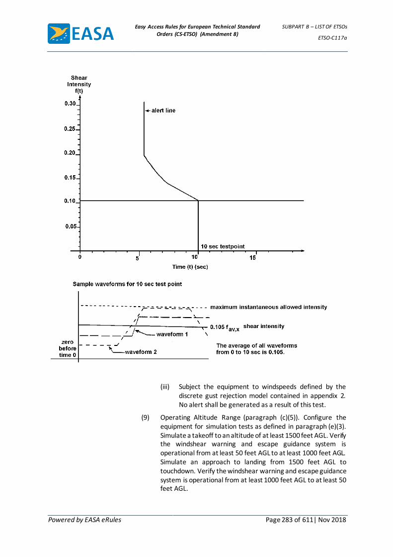
Easy Access Rules for European Technical Standard
Orders (CS-ETSO) (Amendment 8)
SUBPART B – LIST OF ETSOs
ETSO-C117a
Powered by EASA eRules Page 283 of 611| Nov 2018
(iii) Subject the equipment to windspeeds defined by the discrete gust rejection model contained in appendix 2. No alert shall be generated as a result of this test.
(9) Operating Altitude Range (paragraph (c)(5)). Configure the equipment for simulation tests as defined in paragraph (e)(3). Simulate a takeoff to an altitude of at least 1500 feet AGL. Verify the windshear warning and escape guidance system is operational from at least 50 feet AGL to at least 1000 feet AGL. Simulate an approach to landing from 1500 feet AGL to touchdown. Verify the windshear warning and escape guidance system is operational from at least 1000 feet AGL to at least 50 feet AGL.
Easy Access Rules for European Technical Standard
Orders (CS-ETSO) (Amendment 8)
SUBPART B – LIST OF ETSOs
ETSO-C117a
Powered by EASA eRules Page 284 of 611| Nov 2018
(10) Windshear Escape Guidance (paragraph (c)(6)). Configure the equipment for simulation tests as defined in paragraph (e)(3). Subject the equipment to each of the windfield conditions contained in appendix 1 for each operating mode (takeoff, approach, landing, etc.) available. Each test condition shall be repeated 5 times. Recovery actions for the fixed pitch method comparison shall be initiated immediately upon entering the shear condition.
(i) Verify the flight path guidance commands manage the available energy of the aircraft to achieve the desired trajectory through the shear encounter. These tests shall be performed with vertical only, horizontal only, and combination vertical and horizontal shear conditions.
(a) For the takeoff case, verify the flight guidance commands produce a trajectory that provides a resultant flight path at least as good (when considered over the entire spectrum of test cases) as that obtained by establishing a 15° pitch attitude (at an approximate rate of 1.5° per second) until onset of stall warning and then reducing pitch attitude to remain at the onset of stall warning until exiting the shear condition. Evidence of a significant decrement (considered over the entire spectrum of test cases) below the flight path provided by the fixed pitch method that results from use of the guidance commands provided by the system must be adequately substantiated.
(b) For the approach/landing case, verify the flight guidance commands produce a trajectory that provides a resultant flight path at least as good (when considered over the entire spectrum of test cases) as that obtained by establishing maximum available thrust and a 15° pitch attitude (at an approximate rate of 1.5° per second) until onset of stall warning and then reducing pitch attitude to remain at the onset of stall warning until exiting the shear condition. Evidence of a significant decrement (considered over the entire spectrum of test cases) below the flight path provided by the fixed pitch method that results from use of the guidance commands provided by the system must be adequately substantiated.
(c) For shear conditions exceeding the available performance capability of the aircraft, verify the flight guidance commands result in ground impact in the absence of ability to produce additional lift, absence of excessive kinetic energy, and without putting the aircraft into a stalled condition.
(ii) Verify the flight guidance command outputs are capable of display on associated flight displays. Interface specifications shall be verified and determined to be
Easy Access Rules for European Technical Standard
Orders (CS-ETSO) (Amendment 8)
SUBPART B – LIST OF ETSOs
ETSO-C117a
Powered by EASA eRules Page 285 of 611| Nov 2018
appropriate for the systems identified in the equipment installation instructions.
(iii) Verify that pitch attitude commands do not result in an angle-of-attack exceeding the onset of stall warning or a maximum pitch command of 27°, whichever is less.
(iv) For systems incorporating manual activation of recovery flight guidance commands, verify the system is activated only by the TOGA switches (or equivalent means). For systems providing automatic activation of recovery guidance, verify the system is activated concurrent with the windshear warning alert.
(v) Verify that windshear recovery guidance commands and any automatic recovery mode can be deselected by a means other than the TOGA switches.
(vi) For systems incorporating automatic reversion of flight guidance commands from windshear escape guidance to another flight guidance mode, verify that the transition between flight guidance modes provides smooth guidance information.
(vii) Verify flight guidance commands are not removed from the flight guidance display until either manually deselected or until the aircraft, following exit of the warning conditions, has maintained a positive rate of climb and speed above 1.3 Vs1 for at least 30 seconds.
3.1.2 Environmental Standard
See CS-ETSO Subpart A paragraph 2.1
3.1.3 Computer Software
See CS-ETSO Subpart A paragraph 2.2. In addition, the software for windshear warning and escape guidance functions must be verified and validated to at least Level C. An installation safety analysis for a particular aircraft installation should be accomplished to determine if software must be verified and validated to the more stringent Level B requirements.
4 Marking
4.1 General
Marking is detailed in CS-ETSO Subpart A paragraph 1.2.
4.2 Specific
None.
5 Availability of Referenced Document
See CS-ETSO Subpart A paragraph 3.

Easy Access Rules for European Technical Standard
Orders (CS-ETSO) (Amendment 8)
SUBPART B – LIST OF ETSOs
ETSO-C117a
Powered by EASA eRules Page 286 of 611| Nov 2018
APPENDIX 1 TO ETSO-C117A ED Decision 2003/010/RM
This appendix contains data that defines the windfield models to be used in conducting the tests specified in paragraph (e)(10) of this TSO. This material was developed by the National Aeronautics And Space Administration (NASA), reference NASA Technical Memorandum 100632.
The downburst model parameters below provide the variables to be used to obtain the representative test conditions: (1)(2)
Radius of Downdraft (ft) Maximum Outflow (ft/s) Altitude of Max.
Outflow (ft) Distance From Starting
Point (3) (ft)
920 37 98 20000 (-9000)
1180 47.6 98 15000 (-14000)
2070 58.4 131 25000 (-4000)
4430 68.9 164 30000 (1000)
9010 72.2 262 30000 (1000)
3450 88.2 197 25000 (-4000)
3180 53.1 262 30000 (1000)
1640 46 164 25000 (-4000)
5250 81.3 197 30000 (1000)
1250 67.6 100 25000 (-4000)
(1) From analytic microburst model documented in NASA TM-100632. These parameters are based
on data from Proctor’s TASS model.
(2) For the takeoff case, the downburst center is positioned at the point the aircraft lifts off the runway for all test cases.
(3) For the approach/landing case, the downburst center is positioned as stated. The test is begun with the aircraft at an initial altitude of 1500 feet on a 3° glideslope (touchdown point approximately 29000 feet away). Distance from starting point indicates where the center of the downburst shaft is located relative to the starting point. The number in parenthesis next to it indicates the relative distance of the microburst center from the touchdown point (not the end of the runway). A negative number indicates that the microburst center is located before the touchdown point, positive indicates it is past the touchdown point.
SUMMARY
A simple downburst model has been developed for use in batch and real-time piloted simulation studies of guidance strategies for terminal area transport aircraft operations in wind shear conditions. The model represents an axisymmetric stagnation point flow, based on velocity profiles from the Terminal Area Simulation System (TASS) model developed by Proctor [ref. 3,4] and satisfies the mass continuity equation in cylindrical coordinates. Altitude dependence, including boundary layer effects near the ground, closely matches real-world measurements, as do the increase, peak, and decay of outflow and downflow with increasing distance form the downburst center. Equations for horizontal and vertical winds were derived, and found to be infinitely differentiable, with no singular points existent in the flow field. In addition, a simple relationship exists among the ratio of maximum horizontal to vertical velocities, the down draft radius, depth of outflow, and altitude of maximum outflow. In use, a microburst can be modeled by specifying four characteristic parameters. Velocity components in the x, y, and z directions, and the corresponding nine partial derivatives are obtained easily from the velocity equations.

Easy Access Rules for European Technical Standard
Orders (CS-ETSO) (Amendment 8)
SUBPART B – LIST OF ETSOs
ETSO-C117a
Powered by EASA eRules Page 287 of 611| Nov 2018
INTRODUCTION
Terminal area operation of transport aircraft in a windshear environment has been recognized as a serious problem. Studies of aircraft trajectories through downbursts show that specific guidance strategies are needed for aircraft to survive inadvertent downburst encounters. In order for guidance strategies to perform in simulations as in actual encounters, a realistic set of conditions must be present during development of the strategies. Thus, aeroplane and wind models that closely simulate real-world conditions are essential in obtaining useful information from the studies.
Wind models for use on personal computers, or for simulators with limited memory space availability, have been difficult to obtain because variability of downburst characteristics makes analytical models unrealistic, and large memory requirements make use of numerical models impossible on any except very large capacity computers.
Bray [ref. 1] developed a method for analytic modeling of windshear conditions in flight simulators, and applied his method in modeling a multiple downburst scenario from Joint Airport Weather Studies (JAWS) data. However, the altitude dependence of his model is not consistent with observed data, and, although flexibility in sizing the downbursts is built into the model, it does not maintain the physical relationships which are seen in real-world data among the sizing parameters. In particular, boundary layer effects should cause radial velocity to decay vertically to zero at the ground, as does the vertical velocity.
In a study conducted at NASA Langley Research Center, three different guidance strategies for a Boeing 737-100 aeroplane encountering a microburst on takeoff were developed [ref. 2]. These strategies were first developed using a personal computer, and then implemented in a pilot-in-the-loop simulation using a very simple wind model in both efforts [fig. 1]. This model consisted of a constant outflow outside of the downburst radius and a constant slope headwind to tailwind shear across the diameter of the downburst. It was recognized that a more realistic wind model could significantly alter the outcome of the trajectory. For the subsequent part of this study, which involves altering the aeroplane model to simulate approach to landing and escape maneuvers and additional takeoff cases, a more realistic wind model was preferred. The simple analytical model outlined in this report was developed for this purpose.
SYMBOLS
JAWS Joint Airport Weather Studies
NIMROD Northern Illinois Meteorological Research on Downbursts
R radius of downburst shaft (ft)
r radial coordinate (distance from downburst center) (ft)
TASS Terminal Area Simulation System
u velocity in r-direction (or x-direction) (kts)
v velocity in y-direction (kts)
w velocity in z-direction (kts)
wmax magnitude of maximum vertical velocity (kts)
umax magnitude of maximum horizontal velocity (kts)
x horizontal (runway) distance, aeroplane to downburst center (ft)
y horizontal (side) distance, aeroplane to downburst center (ft)
z aeroplane altitude above ground level (ft)

Easy Access Rules for European Technical Standard
Orders (CS-ETSO) (Amendment 8)
SUBPART B – LIST OF ETSOs
ETSO-C117a
Powered by EASA eRules Page 288 of 611| Nov 2018
zh depth of outflow (ft)
zm height of maximum U-velocity (ft)
zm2 height of half maximum U-velocity (ft)
z* characteristic height, out of boundary layer (ft)
e characteristic height, in boundary layer (ft)
λ scaling factor (s-1)
DEVELOPMENT OF VELOCITY EQUATIONS
Beginning with the full set of Euler and mass continuity equations, some simplifying assumptions about the down burst flow conditions were made. Effects of viscosity were parameterized explicitly, and the flow was assumed to be invariant with time. The downburst is axisymmetric in cylindrical coordinates, and characterized by a stagnation point at the ground along the axis of the downflow column. The flow is incompressible, with no external forces or moments acting on it.
The resulting mass conservation equation is
∇ ∙ 𝑣 = 0. (1)
Written out in full, equation 2 is
𝜕𝑢
𝜕𝑟+
𝜕𝑤
𝜕𝑧+
𝑢
𝑟= 0. (2)
This equation is satisfied by solutions of the form
𝑤 = 𝑔(𝑟 2)𝑞(𝑧) (3a)
𝑢 =𝑓(𝑟2 )
𝑟𝑝(𝑧) (3b)
provided that
𝑓′ (𝑟2) =𝜆
2𝑔(𝑟2) (4a)
𝑞 ′(𝑧) = 𝜆𝑝(𝑧). (4b)
Note that 𝑓′ (𝑟2) =𝜕𝑓(𝑟2 )
𝜕𝑟2 . To solve this system of equations, solutions were assumed for two of the
functions and the other two were obtained from equations 4a and 4b.
It was desired that the velocity profiles of this analytic model exhibit the altitude and radial dependence shown in the large-scale numerical weather model TASS (Terminal Area Simulation System) [ref. 3,4]. The TASS model is based on data from the Joint Airport Weather Studies (JAWS) [ref. 5], and provides a three- dimensional velocity field, frozen in time, for given locations of an aeroplane within the shear [ref. 6]. Figure 2 shows dimensionless vertical profiles of horizontal velocity, u, for TASS data, laboratory data obtained by impingement of a jet on a flat plate, and data from NIMROD (Northern Illinois Meteorological Research on Downbursts) [ref. 7]. Specific points of interest are the maximum horizontal velocity (located 100 - 200 meters above the ground), below which is a decay region due to boundary layer effects, zero velocity at the stagnation point on the ground, and an exponential decay with altitude above the maximum velocity altitude. Vertical velocity profiles from TASS data are shown in figure 3, also exhibiting a decay to zero at the stagnation point.

Easy Access Rules for European Technical Standard
Orders (CS-ETSO) (Amendment 8)
SUBPART B – LIST OF ETSOs
ETSO-C117a
Powered by EASA eRules Page 289 of 611| Nov 2018
The radially varying characteristics desired for the horizontal wind were two peaks of equal magnitude and opposite direction located at a given radius, with a smooth, nearly linear transition between the two. Beyond the peaks, the velocity should show an exponential decay to zero. The vertical velocity was required to have a peak along the axis of symmetry (r = 0), and decay exponentially at increasing radius.
A pair of shaping functions that gave velocity profiles matching TASS data as required are given below.
𝑔(𝑟 2) = 𝑒−(𝑟/𝑅)2
𝑝(𝑧) = 𝑒−𝑧/𝑧∗− 𝑒−𝑧/ℇ
The remaining solutions were found by integrating equations 4a and 4b, yielding:
𝑓′ (𝑟2) =𝜆𝑅2
2[1 − 𝑒−(𝑟/𝑅)2
]
𝑞(𝑧) = −𝜆{ℇ(𝑒−𝑧/ℇ − 1) − 𝑧 ∗ (𝑒−𝑧/𝑧∗ − 1)}
Figures 4 and 5 show plots of these shaping functions.
Combining the functions as in equation 3, the horizontal and vertical velocities are expressed as
𝑢 =𝜆𝑅2
2𝑟[1 − 𝑒−(𝑟/𝑅)2
](𝑒−𝑧/𝑧∗ − 𝑒−𝑧/ℇ) (5)
𝑤 = −𝜆𝑒−(𝑟/𝑅)2[휀(𝑒−𝑧/ℇ − 1) − 𝑧 ∗ (𝑒−𝑧/𝑧∗ − 1)] (6)
By taking derivatives of equations 5 and 6 with respect to r and z, respectively, and substituting in equation 2, it can be shown that the velocity distributions satisfy continuity.
The parameters z* and ε were defined as characteristic scale lengths associated with „out of boundary layer“ and „in boundary layer“ behavior, respectively. Analysis of TASS data indicated that z* = z m2, the altitude at which the magnitude of the horizontal velocity is half the maximum value.
It was also noted that the ratio
𝑧𝑚
𝑧 ∗= 0.22
To determine the location of the maximum horizontal velocity, the partial derivatives of u with respect to r and z where set equal to zero. The resulting equation for the r- derivative is
2 (𝑟
𝑅)
2
= 𝑒−(𝑟/𝑅)2− 1
The resulting equation for the z-derivative is
𝑧𝑚
𝑧 ∗=
1
(𝑧 ∗/휀) − 1 1𝑛(𝑧 ∗/휀)
Recalling that zm/z* = 0.22, the values 1.1212 and 12.5 were obtained from iteration for the ratios r/R and z*/ε, respectively.
Using these values, the maximum horizontal velocity can be expressed as umax = 0.2357 λ R. The maximum vertical wind is located at r = 0 and z = zh, by definition, and is given by

Easy Access Rules for European Technical Standard
Orders (CS-ETSO) (Amendment 8)
SUBPART B – LIST OF ETSOs
ETSO-C117a
Powered by EASA eRules Page 290 of 611| Nov 2018
𝑊𝑚𝑎𝑥 = 𝜆𝑧 ∗ (𝑒−(𝑧ℎ/𝑧∗) − 0.92)
A ratio of maximum outflow and downflow velocities can be formed
𝑢𝑚
𝑤𝑚=
0.2357𝑅
𝑧 ∗ (𝑒−(𝑧ℎ/𝑧∗) − 0.92)
The Scaling factor, λ, was determined by using either of equations 5 or 6 for horizontal or vertical velocity, and setting it equal to the maximum velocity, umax or wmax, respectively. Solving for λ resulting in:
𝜆 =𝑤𝑚
𝑧 ∗ (𝑒−(𝑧ℎ/𝑧∗) − 0.92)=
𝑢𝑚
0.2357𝑅
The velocity equations were easily converted to rectangular coordinates, as shown in the Appendix. Partial derivatives with respect to x, y, and z were obtained by differentiating the velocity equations, and are also listed in the Appendix.
DISCUSSION AND RESULTS
Vertical and horizontal velocity profiles for u and w are shown in figures 6 and 7. Four profiles are shown for each component. The horizontal wind profiles in figure 6 were taken at the radios of peak outflow (r = 1.1212 R) and at about one-fourth that radius (r = 0.3 R), where the maximum outflow is approximately half the value at the peak outflow radius. The vertical wind profiles were taken at the radius of peak downflow (r = 0) and at r = 0.3 R. Horizontal wind and vertical wind profiles in figure 7 were taken at altitudes of h = zm (maximum outflow), h = z* (half-maximum outflow), and h = zh (depth of outflow).
This analytical model is compared with TASS, laboratory, and NIMROD data in figure 8. The figure shows that, when nondimensionalized by the altitude of half-maximum outflow (z*) and by the maximum outflow (u = umax), the analytical model agrees closely with the other data.
Different shears can be modeled by specifying four parameters, and the location of downburst center relative to the aeroplane flying through it. The four parameters are: 1) a characteristic horizontal dimension; 2) maximum wind velocity; 3) altitude of maximum outflow; and 4) depth of outflow. The characteristic horizontal dimension specified is the radius of the downdraft column, noting that this is about 89 percent of the radius of peak outflow. The maximum wind velocity can be either horizontal or vertical.
CONCLUDING REMARKS
The analytic micorburst model developed for use in real-time and batch simulation studies was shown to agree well with real-world measurements for the cases studied. The functions chosen for the model showed boundary-layer effects near the ground, as well as the peak and decay of outflow at increasing altitudes, and increasing downflow with altitude. The exponential increase and decay of downflow and outflow (in the radial direction) are also characterized by the model. Equations for horizontal and vertical winds are simple and continuously differentiable, and partial derivatives in rectangular or cylindrical coordinates can be easily obtained by direct differentiation of the velocity equations. The governing equation for this system is the mass conservation law, and the analytic velocity functions developed here satisfied this condition. The model is sustained by a strong physical basis and yields high fidelity results, within the limitations of maintaining simplicity in the model, and variability of the microburst phenomenon. Parameterization of some of the characteristic dimensions allows flexibility in selecting the size and intensity of the microburst.

Easy Access Rules for European Technical Standard
Orders (CS-ETSO) (Amendment 8)
SUBPART B – LIST OF ETSOs
ETSO-C117a
Powered by EASA eRules Page 291 of 611| Nov 2018
REFERENCES
1 Bray, R. S.: Application of Data to Piloted Simulations. Wind Shear/Turbulence Inputs To Flight Simulation and Systems Certification, NASA CP-2474, 1987, pp. 97-115.
2. Hinton, D. A.: Aircraft Trajectory Guidance During Wind Shear Encounters. Master’s Thesis, George Washington University, January 1988.
3. Proctor, F.H.: The Terminal Area Simulation System, Volume I: Theoretical Formulation, NASA Contractor Report 4046, April 1987.
4. Proctor, F.H.: The Terminal Area Simulation System, Volume II: Verification Cases. NASA Contractor Report 4047, April 1987.
5. Frost, W.: Modeling and Implementation of Wind Shear Data. Wind Shear/ Turbulence Inputs to Flight Simulation and Systems Verification, NASA CP-2474, 1987, pp. 49-66.
6. Proctor, F. H.: NASA Wind Shear Model -- Summary of Model Analysis. Airborne Wind Shear Detection and Warning Systems, NASA CP-10006, 1988, pp. 29-66.
7. Fujita, T. T.: Tornadoes and Downbursts in the Context of Generalized Planetary Scales. Journal of Atmospheric Sciences, vol. 38, no. 8, August 1981, pp. 1511-1534.
APPENDIX
Define intermediate variables to simplify written equations:
𝑒𝑟 = 𝑒−(𝑟/𝑅)2 𝑒𝑑 = 𝑒𝑧 − 𝑒𝑒
𝑒𝑒 = 𝑒−(ℎ/𝜀) 𝑒𝑐 = 𝑧∗(1− 𝑒𝑧) − 휀(1 − 𝑒𝑒)
𝑒𝑧 = 𝑒−(ℎ/𝑧∗)
Horizontal and Vertical Velocities
𝑊𝑋 =𝜆𝑅2
2𝑟2 (1 − 𝑒𝑟)𝑒𝑑𝑥𝑎𝑑
𝑊𝑦 =𝜆𝑅2
2𝑟2 (1 − 𝑒𝑟)𝑒𝑑𝑦𝑎𝑑
𝑊ℎ = −𝜆𝑒𝑟𝑒𝑐
Partial Derivatives
𝜕𝑤𝑥
𝜕𝑥=
𝜆𝑅2𝑒𝑑
2𝑟2[𝑒𝑟 (
2𝑥𝑎𝑑2
𝑅2+
2𝑥𝑎𝑑2
𝑟 2− 1) −
2𝑥𝑎𝑑2
𝑟 2+ 1]
𝜕𝑤𝑥
𝜕𝑦=
𝜆𝑅2𝑥𝑎𝑑𝑦𝑎𝑑𝑒𝑑
𝑟 2[𝑒𝑟 (
1
𝑅2 +1
𝑟 2) −
1
𝑟 2]
𝜕𝑤𝑥
𝜕ℎ=
𝜆𝑅2𝑥𝑎𝑑
2𝑟 2(1 − 𝑒𝑟) [
𝑒𝑒
휀−
𝑒𝑧
𝑧∗ ]

Easy Access Rules for European Technical Standard
Orders (CS-ETSO) (Amendment 8)
SUBPART B – LIST OF ETSOs
ETSO-C117a
Powered by EASA eRules Page 292 of 611| Nov 2018
𝜕𝑤𝑦
𝜕𝑥=
𝜆𝑅2𝑥𝑎𝑑𝑦𝑎𝑑𝑒𝑑
𝑟 2[𝑒𝑟 (
1
𝑅2 +1
𝑟 2)−
1
𝑟 2]
𝜕𝑤𝑦
𝜕𝑦=
𝜆𝑅2𝑒𝑑
2𝑟2[𝑒𝑟 (
2𝑦𝑎𝑑2
𝑅2 +2𝑦𝑎𝑑
2
𝑟 2 − 1) −2𝑦𝑎𝑑
2
𝑟 2 + 1]
𝜕𝑤𝑦
𝜕ℎ=
𝜆𝑅2𝑦𝑎𝑑
2𝑟 2(1 − 𝑒𝑟) [
𝑒𝑒
휀−
𝑒𝑧
𝑧∗ ]
𝜕𝑤ℎ
𝜕𝑥=
2𝜆𝑥𝑎𝑑𝑒𝑟𝑒𝑐
𝑅2
𝜕𝑤ℎ
𝜕𝑦=
2𝜆𝑦𝑎𝑑𝑒𝑟𝑒𝑐
𝑅2
𝜕𝑤ℎ
𝜕ℎ= −𝜆𝑒𝑟𝑒𝑑
Other Relationships
From TASS 𝑍𝑚
𝑍∗ = 0.22 𝑍∗
𝜀= 12.5
Maximums 𝑊𝑥𝑚𝑎𝑥
= 0.2357𝜆𝑅
𝑊𝑦𝑚𝑎𝑥= 𝑊𝑥𝑚𝑎𝑥
𝑊ℎ𝑚𝑎𝑥= 𝜆𝑧∗(𝑒−(𝑧ℎ/𝑧∗) − 0.92)
(λ is determined from the above relationships)
𝑊𝑥𝑚𝑎𝑥
𝑊ℎ𝑚𝑎𝑥
=0.2357𝑅
𝑧∗(𝑒−(𝑧ℎ/𝑧∗) − 0.92)
Variable List
z* = altitude where wx is half the value of wx max (ft)
ε = characteristic height of boundary layer effects (ft)
zh = depth of outflow (ft)
zm = altitude of maximum outflow (ft)
λ = scaling parameter (s-1)
r = radial distance from aeroplane to downburst (ft)
h = altitude of aeroplane (ft)
R = radius of downdraft (ft)
xad, yad = x, y coordinates, aeroplane to microburst (ft)
wx max, wy max, wh max maximum winds, x, y, and h directions

Easy Access Rules for European Technical Standard
Orders (CS-ETSO) (Amendment 8)
SUBPART B – LIST OF ETSOs
ETSO-C117a
Powered by EASA eRules Page 293 of 611| Nov 2018
Figure 1 Wind Model Used In Guidance Studies

Easy Access Rules for European Technical Standard
Orders (CS-ETSO) (Amendment 8)
SUBPART B – LIST OF ETSOs
ETSO-C117a
Powered by EASA eRules Page 294 of 611| Nov 2018
Figure 2 Vertical Profile of Microburst Outflow (Nondimensional)

Easy Access Rules for European Technical Standard
Orders (CS-ETSO) (Amendment 8)
SUBPART B – LIST OF ETSOs
ETSO-C117a
Powered by EASA eRules Page 295 of 611| Nov 2018
VERTICAL PROFILES OF VERTICAL VELOCITY FOR 30 JUN 82 CASE:
SENSITIVITY TO RADIUS OF PRECIPITATION SHAFT
Figure 3 Vertical Profile of Microburst Downflow
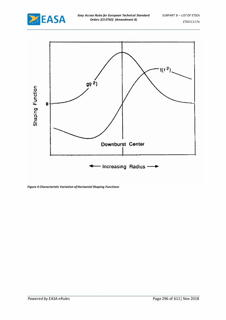
Easy Access Rules for European Technical Standard
Orders (CS-ETSO) (Amendment 8)
SUBPART B – LIST OF ETSOs
ETSO-C117a
Powered by EASA eRules Page 296 of 611| Nov 2018
Figure 4 Characteristic Variation of Horizontal Shaping Functions

Easy Access Rules for European Technical Standard
Orders (CS-ETSO) (Amendment 8)
SUBPART B – LIST OF ETSOs
ETSO-C117a
Powered by EASA eRules Page 297 of 611| Nov 2018
Figure 5 Characteristic Variation of Vertical Shaping Functions

Easy Access Rules for European Technical Standard
Orders (CS-ETSO) (Amendment 8)
SUBPART B – LIST OF ETSOs
ETSO-C117a
Powered by EASA eRules Page 298 of 611| Nov 2018
Figure 6 Vertical Velocity Profiles For Analytical Model

Easy Access Rules for European Technical Standard
Orders (CS-ETSO) (Amendment 8)
SUBPART B – LIST OF ETSOs
ETSO-C117a
Powered by EASA eRules Page 299 of 611| Nov 2018
Figure 7 Radial Velocity Profiles For Analytical Model
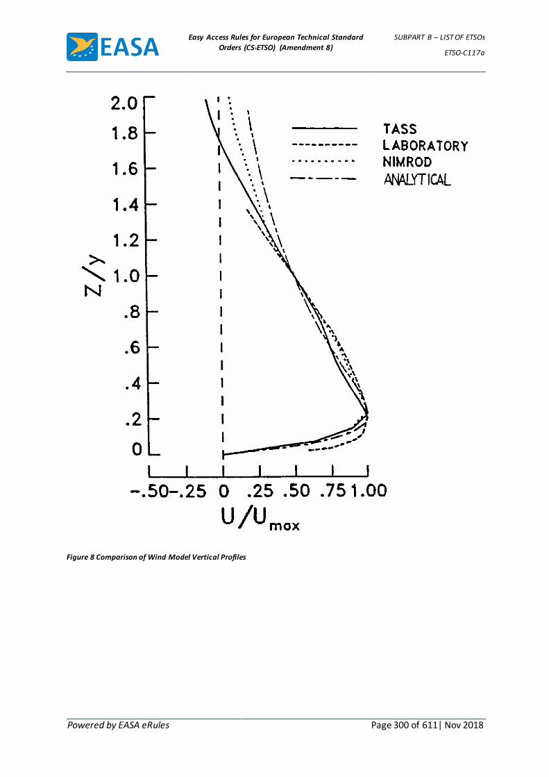
Easy Access Rules for European Technical Standard
Orders (CS-ETSO) (Amendment 8)
SUBPART B – LIST OF ETSOs
ETSO-C117a
Powered by EASA eRules Page 300 of 611| Nov 2018
Figure 8 Comparison of Wind Model Vertical Profiles
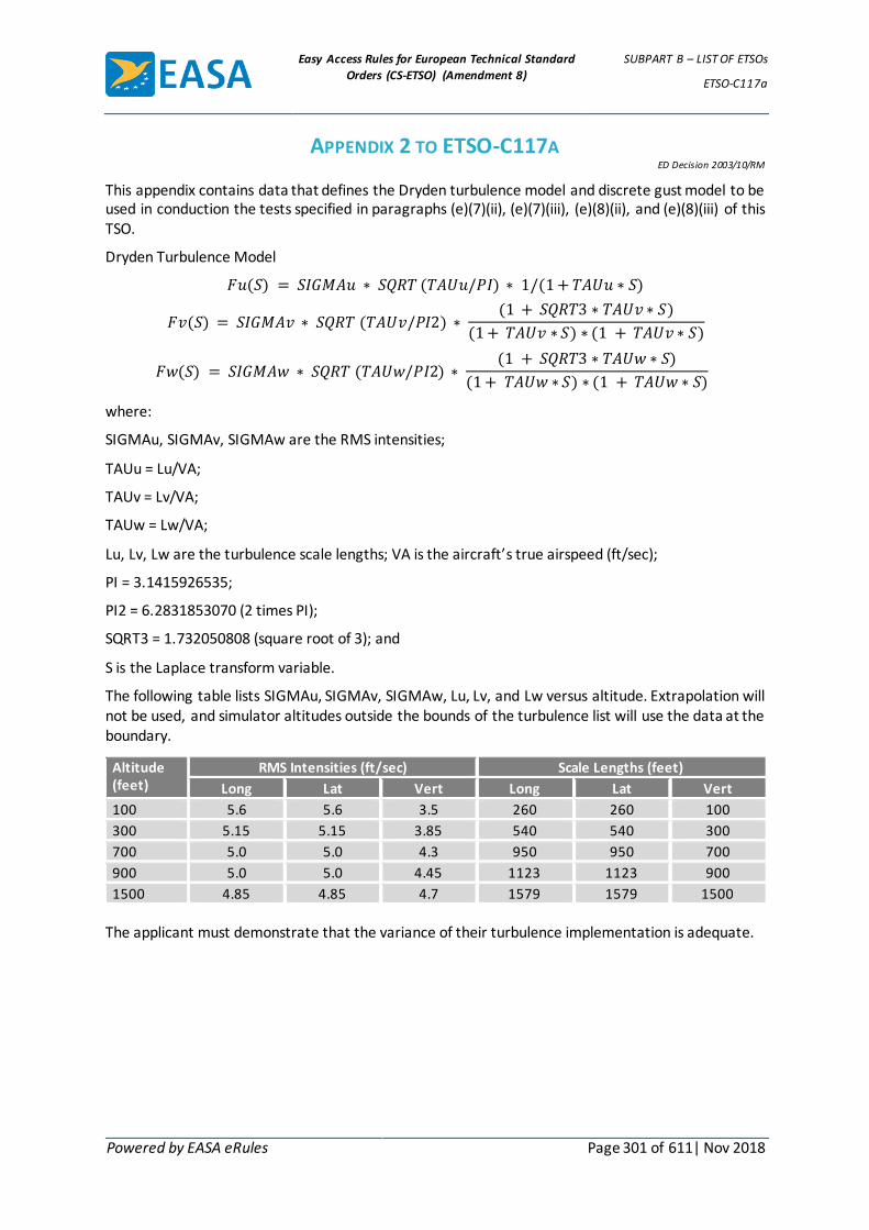
Easy Access Rules for European Technical Standard
Orders (CS-ETSO) (Amendment 8)
SUBPART B – LIST OF ETSOs
ETSO-C117a
Powered by EASA eRules Page 301 of 611| Nov 2018
APPENDIX 2 TO ETSO-C117A ED Decision 2003/10/RM
This appendix contains data that defines the Dryden turbulence model and discrete gust model to be used in conduction the tests specified in paragraphs (e)(7)(ii), (e)(7)(iii), (e)(8)(ii), and (e)(8)(iii) of this TSO.
Dryden Turbulence Model
𝐹𝑢(𝑆) = 𝑆𝐼𝐺𝑀𝐴𝑢 ∗ 𝑆𝑄𝑅𝑇 (𝑇𝐴𝑈𝑢/𝑃𝐼) ∗ 1/(1 + 𝑇𝐴𝑈𝑢 ∗ 𝑆)
𝐹𝑣(𝑆) = 𝑆𝐼𝐺𝑀𝐴𝑣 ∗ 𝑆𝑄𝑅𝑇 (𝑇𝐴𝑈𝑣/𝑃𝐼2) ∗ (1 + 𝑆𝑄𝑅𝑇3 ∗ 𝑇𝐴𝑈𝑣 ∗ 𝑆)
(1 + 𝑇𝐴𝑈𝑣 ∗ 𝑆) ∗ (1 + 𝑇𝐴𝑈𝑣 ∗ 𝑆)
𝐹𝑤(𝑆) = 𝑆𝐼𝐺𝑀𝐴𝑤 ∗ 𝑆𝑄𝑅𝑇 (𝑇𝐴𝑈𝑤/𝑃𝐼2) ∗ (1 + 𝑆𝑄𝑅𝑇3 ∗ 𝑇𝐴𝑈𝑤 ∗ 𝑆)
(1 + 𝑇𝐴𝑈𝑤 ∗ 𝑆) ∗ (1 + 𝑇𝐴𝑈𝑤 ∗ 𝑆)
where:
SIGMAu, SIGMAv, SIGMAw are the RMS intensities;
TAUu = Lu/VA;
TAUv = Lv/VA;
TAUw = Lw/VA;
Lu, Lv, Lw are the turbulence scale lengths; VA is the aircraft’s true airspeed (ft/sec);
PI = 3.1415926535;
PI2 = 6.2831853070 (2 times PI);
SQRT3 = 1.732050808 (square root of 3); and
S is the Laplace transform variable.
The following table lists SIGMAu, SIGMAv, SIGMAw, Lu, Lv, and Lw versus altitude. Extrapolation will not be used, and simulator altitudes outside the bounds of the turbulence list will use the data at the boundary.
Altitude (feet)
RMS Intensities (ft/sec) Scale Lengths (feet)
Long Lat Vert Long Lat Vert
100 5.6 5.6 3.5 260 260 100
300 5.15 5.15 3.85 540 540 300
700 5.0 5.0 4.3 950 950 700
900 5.0 5.0 4.45 1123 1123 900
1500 4.85 4.85 4.7 1579 1579 1500
The applicant must demonstrate that the variance of their turbulence implementation is adequate.

Easy Access Rules for European Technical Standard
Orders (CS-ETSO) (Amendment 8)
SUBPART B – LIST OF ETSOs
ETSO-C117a
Powered by EASA eRules Page 302 of 611| Nov 2018
Discrete Gust Rejection
Discrete gusts (in the horizontal axis) with ranges of amplitude and frequency (A and OMEGA) of the form [A(1 − cos OMEGAt)] shall be used. The following table lists the values of A and OMEGA to be used (simulates an approximate 15 knot gust condition):
A OMEGA (rad/sec) Approx. Gust Duration (sec)
7.5 2.10 3
7.5 1.26 5
7.5 0.78 8
7.5 0.63 10
7.5 0.52 12
7.5 0.42 15
7.5 0.31 20
Easy Access Rules for European Technical Standard
Orders (CS-ETSO) (Amendment 8)
SUBPART B – LIST OF ETSOs
ETSO-C117a
Powered by EASA eRules Page 303 of 611| Nov 2018
APPENDIX 3 TO ETSO-C117A – SHEAR INTENSITY ED Decision 2003/10/RM
𝑓(𝑡) =𝑊𝑥
𝑔−
𝑊ℎ
𝑉
where
wx = Horizontal component of the wind rate of change expressed in g units (1.91 kts/sec = 0.1 g) (positive for increasing headwind).
Wh = Vertical component of the wind vector w (ft/sec) (positive for downdraft).
V = True airspeed (ft/sec).
G = Gravitational acceleration (ft/sec2).
Easy Access Rules for European Technical Standard
Orders (CS-ETSO) (Amendment 8)
SUBPART B – LIST OF ETSOs
ETSO-C117a
Powered by EASA eRules Page 304 of 611| Nov 2018
APPENDIX 4 TO ETSO-C117A ED Decision 2003/10/RM
The following computer listing (written in QuickBasic) provides a simplified aircraft simulation model for evaluating the effectiveness of various guidance schemes. This simulation runs on a personal computer, and the results obtained using it have been found to be comparable to those obtained on a full six degree of freedom simulator. This model was developed by J. Rene Barrios of the Honeywell Company.
The Wind Shear Simulation Model (WSSM) is a point mass three-degree of freedom mathematical model which simulates the motion of an aircraft in a vertical plane. The equations of motion, which are described in the wind axes, include the wind components of velocity and acceleration so that the aircraft dynamics during a windshear encounter are accurately modeled. This model has been used by several investigators to study the behavior of an aircraft during windshear encounters.
(Copies of that listing may be may be purchased from the Superintendent of Documents, Government Printing Office, Washington, DC 20402-9325, USA.)

Easy Access Rules for European Technical Standard
Orders (CS-ETSO) (Amendment 8)
SUBPART B – LIST OF ETSOs
ETSO-C118
Powered by EASA eRules Page 305 of 611| Nov 2018
ETSO-C118 ED Decision 2003/10/RM (applicable from 24.10.2003)
Traffic Alert and Collision Avoidance System (TCAS) Airborne Equipment, TCAS I
1 Applicability
This ETSO gives the requirements which new models of active traffic alert and collision avoidance system airborne equipment must meet in order to be identified with the applicable ETSO marking.
2 Procedures
2.1 General
Applicable procedures are detailed in CS-ETSO Subpart A.
2.2 Specific
None.
3 Technical Conditions
3.1 General
3.1.1 Minimum Performance Standard
Standards set forth in Radio Technical Commission for Aeronautics (RTCA) Document DO-197 Section 2, dated March 20, 1987, as amended and supplemented by this ETSO.
3.1.2 Environmental Standard
See CS-ETSO Subpart A paragraph 2.1
3.1.3 Computer Software
See CS-ETSO Subpart A paragraph 2.2
3.2 Specific
None
4 Marking
4.1 General
Marking is detailed in CS-ETSO Subpart A paragraph 1.2.
4.2 Specific
None
5 Availability of Referenced Document
See CS-ETSO Subpart A paragraph 3.

Easy Access Rules for European Technical Standard
Orders (CS-ETSO) (Amendment 8)
SUBPART B – LIST OF ETSOs
ETSO-C119c
Powered by EASA eRules Page 306 of 611| Nov 2018
ETSO-C119c ED Decision 2009/015/R (applicable from 8.12.2009)
Traffic Alert and Collision Avoidance System (TCAS) Airborne Equipment, TCAS II
1 Applicability
This ETSO gives the requirements that new models of traffic alert and collision avoidance system airborne equipment must meet in order to be identified with the applicable ETSO marking.
2 Procedures
2.1 General
Applicable procedures are detailed in CS-ETSO Subpart A.
2.2 Specific
None.
3 Technical Conditions
3.1 General
3.1.1 Minimum Performance Standard
Standards set forth in EUROCAE Document ED-143 Minimum Operational Performance Standards for Traffic Alert and Collision Avoidance System II (TCAS II) dated September 2008 as modified by Appendix 1 of this ETSO.
The optional functionality set forth in RTCA, Inc. Document DO-300, Minimum Operational Performance Standards for Traffic Alert and Collision Avoidance System II (TCAS II) Hybrid Surveillance, dated December 13, 2006, Sections 2 and 3, as modified by RTCA, Inc. Document DO-300 change 1 dated 1 July 2009 may be included.
3.1.2 Environmental Standard
See CS-ETSO Subpart A paragraph 2.1.
3.1.3 Computer Software
See CS-ETSO Subpart A paragraph 2.2.
3.1.4 - Electronic Hardware Qualification
If the article includes a complex custom micro-coded component, the component must be developed according to EUROCAE ED-80 Design Assurance Guidance for Airborne Electronic Hardware, dated April 2000. Those articles containing hardware upgraded from an original product developed before EUROCAE ED-80 (RTCA DO-254) were published (April 2000), need only apply the requirements in EUROCAE ED-80(RTCA/DO-254) to the changed hardware and all hardware affected by the change.
3.2 Specific
3.2.1 Failure Condition Classification
Failure of the function defined in paragraph 3.1.1 of this ETSO has been determined to be a hazardous/severe-major failure condition. The applicant must develop the system to at least the design assurance level commensurate with this failure condition classification.

Easy Access Rules for European Technical Standard
Orders (CS-ETSO) (Amendment 8)
SUBPART B – LIST OF ETSOs
ETSO-C119c
Powered by EASA eRules Page 307 of 611| Nov 2018
4 Marking
4.1 General
Marking is detailed in CS-ETSO Subpart A paragraph 1.2.
4.2 Specific
None.
5 Availability of Referenced Document
See CS-ETSO Subpart A paragraph 3.
[Amdt ETSO/5]

Easy Access Rules for European Technical Standard
Orders (CS-ETSO) (Amendment 8)
SUBPART B – LIST OF ETSOs
ETSO-C119c
Powered by EASA eRules Page 308 of 611| Nov 2018
APPENDIX 1 TO ETSO-C119C ED Decision 2009/015/R
HIGH-LEVEL PSEUDOCODE
Replace ED-143 Volume II Attachment A page 8-P16 with the following:
PROCESS Set_up_display_outputs;
<Determine advisory annunciation precedence> IF (an RA is to be displayed this cycle) THEN IF (increase rate RA issued) THEN CLEAR reversal, maintain rate, and altitude crossing flags; IF (increase rate RA was not present last cycle) THEN indicate that RA changed to increase rate this cycle; ELSE CLEAR indication that increase rate RA was present last cycle; IF (RA requires maintenance of rate) THEN SET maintain rate indication; CLEAR sense reversal indication, if any; <announce maintain> ELSE IF (previous cycle’s RA was dual negative AND current RA is either single negative or positive) THEN CLEAR maintain rate indication; IF (sense of previously displayed RA has been reversed) THEN CLEAR altitude crossing flag; <Reversal needs to be announced even if the reversed RA is altitude crossing> CLEAR maintain rate indication; <If reversing maintain RA> IF (RA is preventive) <Initial preventive neg. or VSL RA or weakening> <Note: All positive RAs are now corrective> THEN IF (RA is dual negative) <Don’t Climb/Don’t Descend> THEN SET maintain rate indication; <announce maintain> ELSE CLEAR maintain rate indication; IF ((positive Climb is weakening to negative Don't Descend OR (positive Descend is weakening to negative Don't Climb AND not weakening due to extreme low altitude condition)) AND not weakening due to multiaircraft “sandwich” encounter with both up-sense and down-sense VSLs) THEN indicate that weakened RA is corrective; <Results in green "fly-to" arc plus corrective aural annunciation for initial weakening> Set displayed-model-goal rate to 0 fpm; <RA display device will use prescribed vertical rates for neg. & VSL RAs> ELSE IF (RA is corrective negative or VSL) THEN CLEAR maintain rate indication; Set displayed-model-goal rate to 0 fpm; CLEAR clear of conflict flag; ELSE CLEAR maintain rate indication; <no RA is to be displayed this cycle> Set displayed-model-goal rate to 0 fpm; IF (an altitude-reporting threat became non-altitude-reporting during preceding RA) THEN CLEAR track drop and clear of conflict flags; ELSE IF (a threat's track was dropped during preceding RA) THEN CLEAR clear of conflict flag; PERFORM Load_display_and_aural_info; <Load display information to be sent to the RA display, TA display and aural annunciation subsystem.> END Set_up_display_outputs;
Easy Access Rules for European Technical Standard
Orders (CS-ETSO) (Amendment 8)
SUBPART B – LIST OF ETSOs
ETSO-C119c
Powered by EASA eRules Page 309 of 611| Nov 2018
LOW-LEVEL PSEUDOCODE
Replace ED-143 Volume II Attachment A page 8-P17 with the following:
PROCESS Set_up_display_outputs;
IF (any bit in G.RA(1–10) EQ $TRUE) THEN IF (G.ANYINCREASE EQ $TRUE) THEN CLEAR G.ANYREVERSE, G.MAINTAIN, G.ANYCROSS; IF (G.PREVINCREASE EQ $FALSE) THEN SET G.ANYCORCHANG, G.PREVINCREASE; ELSE CLEAR G.PREVINCREASE; IF ((G.RA(1) EQ $TRUE AND G.ZDMODEL GT P.CLMRT AND G.ZDOWN GT P.CLMRT) OR (G.RA(6) EQ $TRUE AND G.ZDMODEL LT P.DESRT AND G.ZDOWN LT P.DESRT)) THEN SET G.MAINTAIN; CLEAR G.ANYREVERSE; ELSE IF ((G.CLSTROLD EQ 4 AND G.DESTROLD EQ 4) AND (G.CLSTRONG EQ 0 OR G.DESTRONG EQ 0)) THEN CLEAR G.MAINTAIN; IF (G.ANYREVERSE EQ $TRUE) THEN CLEAR G.ANYCROSS; CLEAR G.MAINTAIN; IF (G.CORRECTIVE_CLM EQ $FALSE AND G.CORRECTIVE_DES EQ $FALSE) THEN IF (G.RA(2) EQ $TRUE AND G.RA(7) EQ $TRUE) THEN SET G.MAINTAIN; ELSE CLEAR G.MAINTAIN; IF (G.CLSTRONG EQ 4 AND G.CLSTROLD EQ 8 AND G.DESTRONG EQ 0) THEN SET G.CORRECTIVE_CLM, G.ANYPRECOR; ELSE IF (G.DESTRONG EQ 4 AND G.DESTROLD EQ 8 AND G.CLSTRONG EQ 0 AND G.EXTALT EQ $FALSE) THEN SET G.CORRECTIVE_DES, G.ANYPRECOR; G.ZDMODEL = 0; ELSE IF (G.RA(1 and 6) EQ $FALSE) THEN CLEAR G.MAINTAIN; G.ZDMODEL = 0; CLEAR G.ALLCLEAR; ELSE CLEAR G.MAINTAIN, G.ANYINCREASE; G.ZDMODEL = 0; IF (ANYALTLOST EQ $TRUE) THEN CLEAR ANYTRACKDROP, G.ALLCLEAR; ELSE IF (ANYTRACKDROP EQ $TRUE) THEN CLEAR G.ALLCLEAR; PERFORM Load_display_and_aural_info END Set_up_display_outputs;

Easy Access Rules for European Technical Standard
Orders (CS-ETSO) (Amendment 8)
SUBPART B – LIST OF ETSOs
ETSO-C119c
Powered by EASA eRules Page 310 of 611| Nov 2018
STATECHARTS
Replace ED-143, Volume II, page 125, Section 2.1.11.2, State Corrective_Climb with the following:
Transition(s): Yes No
Location: Advisory_Statuss-261 Corrective_Climbs-123
Trigger Event: Composite_RA_Evaluated_Evente-C2
Condition:
OR
Climb_RA_Weakenedm-374 T T . T
Climb_Goalf-467 = 0 ft/min F T . T
Own_Tracked_Alt_Ratef-564 > Climb_Goalf-467 T . . .
AND Own_Tracked_Alt_Ratef-564 > –300 ft/min(HYSTERCOR) . T . T
Own_Tracked_Alt_Ratef-564 300 ft/min(HYSTERCOR) . T . .
Descend_Goalf-473 = 0 ft/min . T . .
Not_Meeting_Descend_Goalm-411 . . T .
Descend_Goal f-473 < 100,000 ft/min(HUGE) . . . T
Output Action: Corrective_Climb_Evaluated_Evente-C2
Notes:
1. Description: Transition out of corrective climb occurs for a weakened climb RA condition when either the own aircraft altitude rate exceeds a non-zero climb goal or the aircraft is considered level (i.e., within hysteresis) for a zero climb and descend goal. This transition also occurs whenever the aircraft is not meeting the current descend goal or there is a simultaneous opposite-sense VSL due to a multiaircraft encounter.
2. Pseudocode Reference: Corrective_preventive_test, Set_up_display_outputs.
Easy Access Rules for European Technical Standard
Orders (CS-ETSO) (Amendment 8)
SUBPART B – LIST OF ETSOs
ETSO-C119c
Powered by EASA eRules Page 311 of 611| Nov 2018
Replace ED-143 Volume II, page 127, Section 2.1.11.3, State Corrective_Descend with the following:
Transition(s): Yes No
Location: Advisory_Statuss-261 Corrective_Descends-229
Trigger Event: Corrective_Climb_Evaluated_Evente-C2
Condition:
OR
Descend_RA_Weakenedm-378 T T . T T
Descend_Goalf-473 = 0 ft/min F T . T T
Own_Tracked_Alt_Ratef-564 < Descend_Goalf-473 T . . . .
Own_Tracked_Alt_Ratef-564 < 300 ft/min(HYSTERCOR) . T . T T
AND Own_Tracked_Alt_Ratef-564 300 ft/min(HYSTERCOR) . T . . .
Climb_Goalf-467 = 0 ft/min . T . . .
Not_Meeting_Climb_Goalm-410 . . T . .
Extreme_Alt_Checkm-378 . . . T .
Multiple_Threatsm-403 . . . F .
Climb_Goalf-467 > 100,000 ft/min(HUGE) . . . . T
Output Action: Corrective_Descend_Evaluated_Evente-C2
Notes:
1. Description: Transition out of corrective descend occurs for a weakened descend RA condition when (1) the own aircraft altitude rate is less than a non-zero descend goal, or (2) the aircraft is considered level (i.e., within hysteresis) for a zero climb and descend goal, or (3) the aircraft is not meeting the current climb goal, or (4) a descend RA is weakened to a zero climb rate goal under extreme low altitude against a single threat aircraft, or (5) there is a simultaneous opposite-sense VSL due to a multi aircraft encounter.
2. Pseudocode Reference: Corrective_preventive_test, Set_up_display_outputs, Extreme_altitude_check.
[Amdt ETSO/5]
Easy Access Rules for European Technical Standard
Orders (CS-ETSO) (Amendment 8)
SUBPART B – LIST OF ETSOs
ETSO-C121b
Powered by EASA eRules Page 312 of 611| Nov 2018
ETSO-C121b ED Decision 2013/012/R (applicable from 15.7.2013)
Underwater Locating Devices (Acoustic) (Self-powered)
1 Applicability
This ETSO gives the requirements that new models of underwater locating devices (acoustic) (self-powered) that are manufactured on or after the date of this ETSO must meet in order to be identified with applicable ETSO marking.
2 Procedures
2.1 General
Applicable procedures are detailed in CS-ETSO, Subpart A.
2.2 Specific
None.
3 Technical conditions
3.1 Basic
3.1.1 Minimum performance standard
Standards set forth in the SAE AS8045A, Minimum Performance Standard for Underwater Locating Devices (Acoustic) (Self-Powered), dated August 2011.
3.1.2 Environmental standard
See CS-ETSO, Subpart A, paragraph 2.1.
3.1.3 Software
See CS-ETSO, Subpart A, paragraph 2.2.
3.1.4 Airborne electronic hardware
See CS-ETSO, Subpart A, paragraph 2.3.
3.2 Specific
The battery used in the underwater locating device authorized under this ETSO must be appropriate for the intended operational environment, not pose a hazard to the aircraft and meet the requirements of acceptable battery standards. If non-rechargeable lithium batteries are used to power the underwater locating device, ETSO-C142a “Lithium Batteries” provides MPS for such lithium batteries.
Demonstrate the saltwater immersion tests in SAE Document AS8045A, section 5.13, using a seawater solution meeting the requirements of ASTM D1141-98, Standard Practice for the Preparation of Substitute Ocean Water, dated 2008.
3.2.1 Failure condition classification
See CS-ETSO, Subpart A, paragraph 2.4.
Failure or loss of the function defined in paragraph 3.1.1 of this ETSO has been determined to be a minor failure condition.
4 Marking
4.1 General

Easy Access Rules for European Technical Standard
Orders (CS-ETSO) (Amendment 8)
SUBPART B – LIST OF ETSOs
ETSO-C121b
Powered by EASA eRules Page 313 of 611| Nov 2018
Marking is detailed in CS-ETSO, Subpart A, paragraph 1.2.
4.2 Specific
None.
5 Availability of referenced document
See CS-ETSO, Subpart A, paragraph 3.
[Amdt ETSO/3] [Amdt ETSO/8]

Easy Access Rules for European Technical Standard
Orders (CS-ETSO) (Amendment 8)
SUBPART B – LIST OF ETSOs
ETSO-C123b
Powered by EASA eRules Page 314 of 611| Nov 2018
ETSO-C123b ED Decision 2010/010/R (applicable from 21.12.2010)
Cockpit Voice Recorder Systems
1 Applicability
This ETSO gives the requirements that new models of cockpit voice recorder systems that are manufactured on or after the date of this ETSO must meet in order to be identified with applicable ETSO marking.
2 Procedures
2.1 General
Applicable procedures are detailed in CS-ETSO Subpart A.
2.2 Specific
None.
3 Technical Conditions
3.1 Basic
3.1.1 Minimum Performance Standard
Standards set forth in the applicable sections of EUROCAE document ED-112, dated March 2003 that pertain to the CVR type, as modified by Appendix 1 of this ETSO, except:
a) Recorder start and stop times, Section 2-1.5: Start and stop times must comply with applicable operational regulations.
b) Recorder location, Section 2-5.4.1: Recorder location must comply with applicable EASA Certification Specifications.
c) Equipment Installation and Installed Performance (Deployable recorders) Section 3-4.
d) Equipment Installation and Installed Performance, Part I-6.
e) Other ED-112 requirements for installation, flight testing, aircraft maintenance, and others that do not pertain to MPS specific criteria.
The first two exceptions above to ED-112 are related to compliance with the operational regulations and certification specifications. The last three items are exceptions to requirements for installation, flight testing, aircraft maintenance, and others that do not pertain to MPS criteria specific to the ETSO equipment.
Table 1 below lists recorder types and the ED-112 Section and Part containing the MPS for each type:
Table 1. Recorder MPS Requirements
Recorder Type ED-112 Reference
Single CVR Section 2 and Part I
CVR function in a deployable recorder Section 2, Section 3 and Part I
CVR function in a combined recorder Section 2, Section 4, and Part I

Easy Access Rules for European Technical Standard
Orders (CS-ETSO) (Amendment 8)
SUBPART B – LIST OF ETSOs
ETSO-C123b
Powered by EASA eRules Page 315 of 611| Nov 2018
See Appendix 1 for size, shape, and identification standards for crash protected enclosures.
3.1.2 Environmental Standard
See CS-ETSO Subpart A paragraph 2.1.
3.1.3 Computer Software
See CS-ETSO Subpart A paragraph 2.2.
3.1.4 Electronic Hardware Qualification
See CS-ETSO Subpart A paragraph 2.3.
3.2 Specific
3.2.1 Failure Condition Classification
Failure of the function defined in paragraph 3.1.1 of this ETSO has been determined to be a minor failure condition. The applicant must develop the system to be at least the design assurance level commensurate with this failure condition.
Note: The failure classification is driven by the accident investigation need.
4 Marking
4.1 General
Marking is detailed in CS-ETSO Subpart A paragraph 1.2.
4.2 Specific
4.2.1 Lettering
EUROCAE ED112-Section 2-1 paragraph 2-1.16.3 requires the lettering on the recorder to be at least 25 mm in height. Where it is considered impractical to incorporate lettering of this height due to the size of the recorder case, the applicant may propose an alternative height provided that the size is adequate in relation to the size of the unit and allows easy readability.
4.2.2 Marking recommendation
Marking in French: “ENREGISTREUR DE VOL NE PAS OUVRIR” is optional.
5 Availability of Referenced Document
See CS-ETSO Subpart A paragraph 3.
[Amdt ETSO/6]

Easy Access Rules for European Technical Standard
Orders (CS-ETSO) (Amendment 8)
SUBPART B – LIST OF ETSOs
ETSO-C123b
Powered by EASA eRules Page 316 of 611| Nov 2018
APPENDIX 1 TO ETSO-C123B – STANDARDS FOR CRASH PROTECTED ENCLOSURE
ED Decision 2010/010/R
1 Physical Size.
As technology allows for increased miniaturisation, manufacturers continue to shrink the crash enclosure. Now, the enclosure can be very difficult to find in wreckage. The sum of the height (a), width (b), and depth (c) of the crash enclosure must be 23 cm (9 inches) or greater. Each of these major dimensions must be 5 cm (2 inches) or greater. Here are five examples of a crash enclosure and the minimum required dimensions:
NOTE:The dimensions of the crash protected enclosure shall not include the underwater locator beacon (ULB) or its attachment hardware.
2 Identification.
Paint the crash enclosure according to CS 23.1457(g), 25.1457(g), 27.1457(g), or 29.1457(g) and mark in accordance with paragraph 4 of this ETSO.
a, b, c >= 5 cm (2 inches)
a+b+c >= 23 cm (9 inches)
Figure 1. Crash enclosure shaped like a rectangular prism.
Apply minimum dimensions to the major axis (a), minor axis (b), and length (c) of the enclosure.
a, b, c >= 5 cm (2 inches)
a+b+c >= 23 cm (9 inches)
Figure 2. Crash enclosure shaped like an elliptical cylinder.
Height, width, and depth are all equal to the diameter of the sphere which must be equal to or greater than 7.7 cm
(3.0 inches) because of the, a + b + c >= 23 cm (9 inches), requirement.

Easy Access Rules for European Technical Standard
Orders (CS-ETSO) (Amendment 8)
SUBPART B – LIST OF ETSOs
ETSO-C123b
Powered by EASA eRules Page 317 of 611| Nov 2018
di >= 7.7 cm (3 inches)
d1+d2+d3>= 23 cm (9 inches)
Figure 3. Crash enclosure shaped like a sphere.
Dimensions a, b, and c are not necessarily equal
a, b, c >= 5 cm (2 inches)
a+b+c >= 23 cm (9 inches)
Figure 4. Crash enclosure shaped like an ellipsoid hemisphere.
Width (a) is the largest width of the enclosure, depth (b) is the largest depth of the enclosure and height (c) is the
largest height of the enclosure. Take each of these major dimensions from the outer surface of the enclosure. Do not
include any protrusions such as mounting flanges or plates.
a, b, c >= 5 cm (2 inches)
a+b+c>= 23 cm (9 inches)
Figure 5. Crash enclosure is generically shaped.
[Amdt ETSO/6]

Easy Access Rules for European Technical Standard
Orders (CS-ETSO) (Amendment 8)
SUBPART B – LIST OF ETSOs
ETSO-C124b
Powered by EASA eRules Page 318 of 611| Nov 2018
ETSO-C124b ED Decision 2010/010/R (applicable from 21.12.2010)
Flight Data Recorder Systems
1 Applicability
This ETSO gives the requirements that new models of flight data recorder systems that are manufactured on or after the date of this ETSO must meet in order to be identified with applicable ETSO marking.
2 Procedures
2.1 General
Applicable procedures are detailed in CS-ETSO Subpart A.
2.2 Specific
None.
3 Technical Conditions
3.1 Basic
3.1.1 Minimum Performance Standard
Standards set forth in the applicable sections of EUROCAE document ED-112, dated March 2003 that pertain to the FDR type, as modified by Appendix 1 of this ETSO, except:
The ED-112 exceptions below are due to conflicts with operational regulations and EASA Certification specifications. The following are exceptions to the ED-112 part and to the sections in table 1 below.
As part of this ETSO, compliance is not required for:
a) Recorder start and stop times, Section 2-1.5. Start and stop times must comply with applicable operational regulations.
b) Recorder location, Section 2-5.4.1. Recorder location must comply with applicable EASA Certification Specifications.
c) Recorder parameters, Annex II-A. Recorder parameters must comply with applicable operational regulations.
d) All ED-112 requirements for aircraft level equipment installation, test, and maintenance.
Table 1 below lists recorder types and the ED-112 Section and Part containing the MPS for each type:
Table 1. Recorder MPS Requirements
Recorder Type ED-112 Reference
Single FDR Section 2 and Part II
FDR function in a deployable recorder Section 2, Section 3 and Part II
FDR function in a combined recorder Section 2, Section 4, and Part II
See Appendix 1 for size, shape, and identification standards for crash protected enclosures.
3.1.2 Environmental Standard
Easy Access Rules for European Technical Standard
Orders (CS-ETSO) (Amendment 8)
SUBPART B – LIST OF ETSOs
ETSO-C124b
Powered by EASA eRules Page 319 of 611| Nov 2018
See CS-ETSO Subpart A paragraph 2.1.
3.1.3 Computer Software
See CS-ETSO Subpart A paragraph 2.2.
3.1.4 Electronic Hardware Qualification
See CS-ETSO Subpart A paragraph 2.3.
3.2 Specific
3.2.1 Failure Condition Classification
Failure of the function defined in paragraph 3.1.1 of this ETSO has been determined to be a minor failure condition. The applicant must develop the system to be at least the design assurance level commensurate with this failure condition.
Note: The failure classification is driven by the accident investigation need.
4 Marking
4.1 General
Marking is detailed in CS-ETSO Subpart A paragraph 1.2.
4.2 Specific
4.2.1 Lettering
EUROCAE ED112-Section 2-1 paragraph 2-1.16.3 requires the lettering on the recorder to be at least 25 mm in height. Where it is considered impractical to incorporate lettering of this height due to the size of the recorder case, the applicant may propose an alternative height provided that the size is adequate in relation to the size of the unit and allows easy readability.
4.2.2 Marking recommendation
Marking in French: “ENREGISTREUR DE VOL NE PAS OUVRIR” is optional.
5 Availability of Referenced Document
See CS-ETSO Subpart A paragraph 3.
[Amdt ETSO/6]

Easy Access Rules for European Technical Standard
Orders (CS-ETSO) (Amendment 8)
SUBPART B – LIST OF ETSOs
ETSO-C124b
Powered by EASA eRules Page 320 of 611| Nov 2018
APPENDIX 1 TO ETSO-C124B – STANDARDS FOR CRASH PROTECTED ENCLOSURE
ED Decision 2010/010/R
1 Physical Size.
As technology allows for increased miniaturisation, manufacturers continue to shrink the crash enclosure. Now, the enclosure can be very difficult to find in wreckage. The sum of the height (a), width (b), and depth (c) of the crash enclosure must be 23 cm (9 inches) or greater. Each of these major dimensions must be 5 cm (2 inches) or larger. Here are five examples of a crash enclosure and the minimum required dimensions:
NOTE:The dimensions of the crash protected enclosure shall not include the underwater locator beacon (ULB) or its attachment hardware.
2 Identification.
Paint the crash enclosure according to CS 23.1459(g), 25.1459(g), 27.1459(g), or 29.1459(g) and mark in accordance with paragraph 4 of this ETSO.
a, b, c >= 5 cm (2 inches)
a+b+c >= 23 cm (9 inches)
Figure 1. Crash enclosure shaped like a rectangular prism.
Apply minimum dimensions to the major axis (a), minor axis (b), and length (c) of the enclosure.
a, b, c >= 5 cm (2 inches)
a+b+c >= 23 cm (9 inches)
Figure 2. Crash enclosure shaped like an elliptical cylinder.
Height, width, and depth are all equal to the diameter of the sphere which must be equal to or greater than 7.7 cm
(3.0 inches) because of the, a + b + c >= 23 cm (9 inches), requirement.
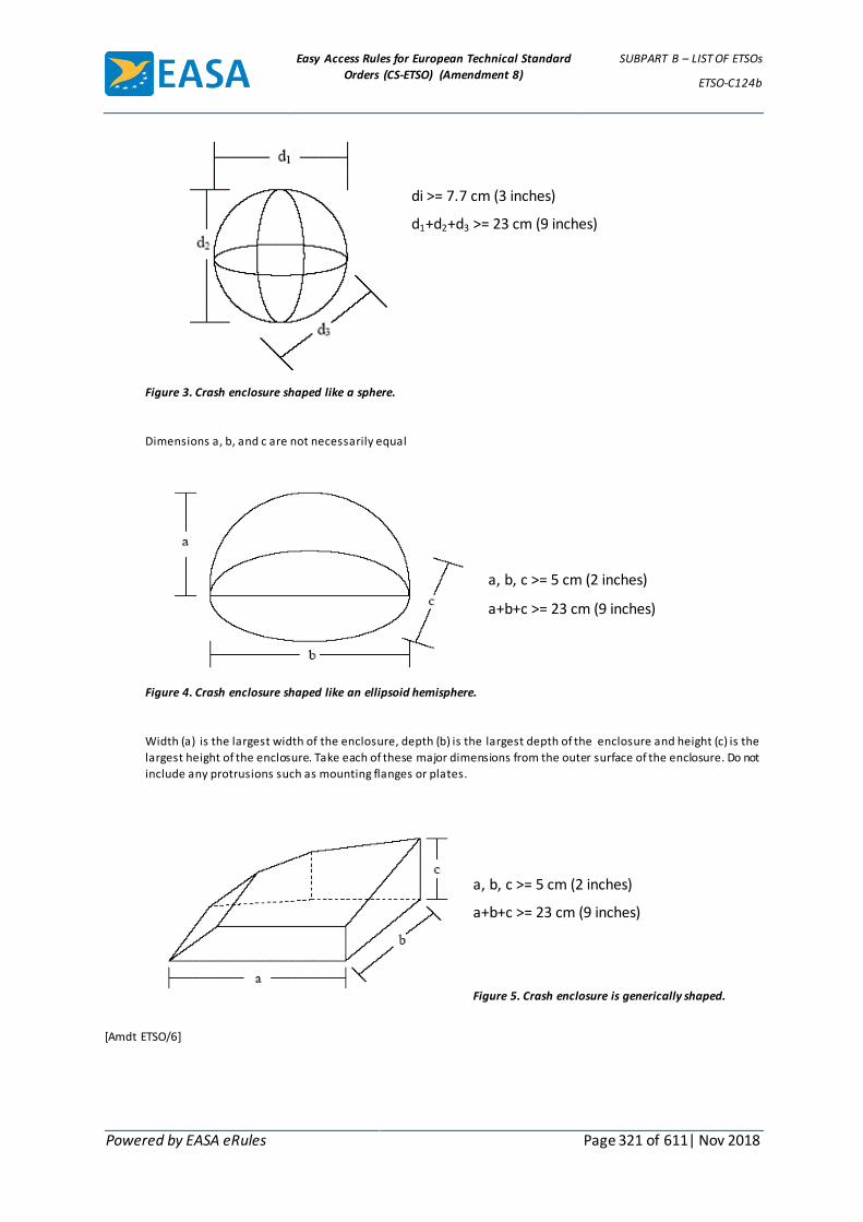
Easy Access Rules for European Technical Standard
Orders (CS-ETSO) (Amendment 8)
SUBPART B – LIST OF ETSOs
ETSO-C124b
Powered by EASA eRules Page 321 of 611| Nov 2018
di >= 7.7 cm (3 inches)
d1+d2+d3 >= 23 cm (9 inches)
Figure 3. Crash enclosure shaped like a sphere.
Dimensions a, b, and c are not necessarily equal
a, b, c >= 5 cm (2 inches)
a+b+c >= 23 cm (9 inches)
Figure 4. Crash enclosure shaped like an ellipsoid hemisphere.
Width (a) is the largest width of the enclosure, depth (b) is the largest depth of the enclosure and height (c) is the
largest height of the enclosure. Take each of these major dimensions from the outer surface of the enclosure. Do not
include any protrusions such as mounting flanges or plates.
a, b, c >= 5 cm (2 inches)
a+b+c >= 23 cm (9 inches)
Figure 5. Crash enclosure is generically shaped.
[Amdt ETSO/6]

Easy Access Rules for European Technical Standard
Orders (CS-ETSO) (Amendment 8)
SUBPART B – LIST OF ETSOs
ETSO-C126a
Powered by EASA eRules Page 322 of 611| Nov 2018
ETSO-C126a ED Decision 2012/009/R (applicable from 5.7.2012)
406 MHz Emergency Locator Transmitter
1 Applicability
This ETSO gives the requirements which 406MHz Emergency Locator Transmitter that are manufactured on or after the date of this ETSO must meet in order to be identified with the applicable ETSO marking.
2 Procedures
2.1 General
Applicable procedures are detailed in CS-ETSO Subpart A.
2.2 Specific
None.
3 Technical Conditions
3.1 Basic
3.1.1 Minimum Performance Standard
Standards set forth in the EUROCAE document ED-62A, Minimal Operational Performance Specification for Aircraft Emergency Locator Transmitters 406 MHz and 121.5 MHz (Optional 243 MHz), dated February 2009.
3.1.2 Environmental Standard
See CS-ETSO Subpart A paragraph 2.1
3.1.3 Computer Software
See CS-ETSO Subpart A paragraph 2.2
3.1.4 Electronic Hardware Qualification
See CS-ETSO Subpart A paragraph 2.3
3.2 Specific
3.2.1 Failure Condition Classification
See CS-ETSO Subpart A paragraph 2.4.
Failure of the function defined in paragraph 3.1.1 of this ETSO has been determined to be a minor failure condition.
4 Marking
4.1 General
Marking is detailed in CS-ETSO Subpart A paragraph 1.2.
4.2 Specific
See EUROCAE ED-62A paragraph 2.7.3.
5 Availability of Referenced Document
See CS-ETSO Subpart A paragraph 3.

Easy Access Rules for European Technical Standard
Orders (CS-ETSO) (Amendment 8)
SUBPART B – LIST OF ETSOs
ETSO-C126a
Powered by EASA eRules Page 323 of 611| Nov 2018
[Amdt ETSO/7]

Easy Access Rules for European Technical Standard
Orders (CS-ETSO) (Amendment 8)
SUBPART B – LIST OF ETSOs
ETSO-C127a
Powered by EASA eRules Page 324 of 611| Nov 2018
ETSO-C127a ED Decision 2003/10/RM (applicable from 24.10.2003)
Rotorcraft, Transport Aeroplane, and Normal and Utility Aeroplane Seating Systems
1 Applicability
This ETSO prescribes the minimum performance standards (MPS) that rotorcraft, transport aeroplane, and normal and utility aeroplane seating systems of the following designated types that are manufactured on or after the date of this ETSO, must meet in order to be identified with the applicable ETSO marking.
Type A – Transport Aeroplane
Type B – Rotorcraft
Type C1 – Normal & Utility Aeroplane - Crew Seats
Type C2 – Normal & Utility Aeroplane - Passenger Seats
2 Procedures
2.1 General
Applicable procedures are detailed in CS-ETSO Subpart A.
2.2 Specific
None.
3 Technical Conditions
3.1 General
3.1.1 Minimum Performance Standard
Standards set forth in Society of Automotive Engineers, Inc. (SAE), Aerospace Standard (AS), Document No. AS 8049A, „Performance Standards for Seats in Civil Rotorcraft and Transport Airplanes“, dated September, 1997, as amended by Appendix 1 of this ETSO.
Additions:
Additional information on the dynamic testing of seating systems is contained in Advisory Circular (AC) 20-137, „Dynamic Evaluation of Seat Restraint Systems & Occupant Restraint for Rotorcraft (Normal & Transport)“, AC 23.562-1, „Dynamic Testing of Part 23 Airplane Restraint/Systems and Occupant Protection“, and AC 25.562-1A, „Dynamic Evaluation of Seat Restraint Systems & Occupant Protection on Transport Airplanes“. Compliance with these AC’s is not necessary to receive a ETSO authorization under this ETSO. However, the applicant for a seat installation approval should be aware that any seating system may be required to meet the criteria contained in these AC’s in order to qualify for installation in an aircraft.
3.1.2 Environmental Standard
None.
3.1.3 Computer Software
None
3.2 Specific

Easy Access Rules for European Technical Standard
Orders (CS-ETSO) (Amendment 8)
SUBPART B – LIST OF ETSOs
ETSO-C127a
Powered by EASA eRules Page 325 of 611| Nov 2018
None
4 Marking
4.1 General
Marking is detailed in CS-ETSO Subpart A paragraph 1.2. In addition, each seating system shall be legibly and permanently marked with the following:
(i) the applicable seat type : „Type A-“, „Type B-“, „Type C1-“, or „Type C2-“ followed by the appropriate seat facing direction designation : „FF“-forward; „RF“-rearward; or „SF“-sideward,
(ii) for Type A passenger seating systems, the approved seat pitch necessary to maintain clearance to assure an effective emergency evacuation, as defined in AC 25.562-1A, Appendix 2. Use appropriate statement as follows: „See installation limitations in component maintenance manual (CMM) or drawing number (insert number)“ or „Minimum or Allowable range (if applicable) seat pitch (insert number/range).“,
(iii) each separate component that is easily removable (without hand tools, except those components that are ETSO articles), each interchangeable element, and each separate sub-assembly of the article that the manufacturer determines may be interchangeable with other seating systems must be permanently and legibly marked with at least the name of the manufacturer, manufacturer’s sub-assembly part number, and the ETSO number,
(iv) for Type A and Type B transport passenger, flight attendant, and observer seating systems, each seat cushion required for qualification of the seating system must be marked with „Complies with CS 25.853(c), or CS 29.853(b), as applicable“ when tested in accordance with the requirements of Section 3.4.2 of SAE AS 8049A, as revised by subparagraph 2.2.3 of Appendix 1 of this ETSO.
4.2 Specific
None.
5 Availability of Referenced Document
See CS-ETSO Subpart A paragraph 3.

Easy Access Rules for European Technical Standard
Orders (CS-ETSO) (Amendment 8)
SUBPART B – LIST OF ETSOs
ETSO-C127a
Powered by EASA eRules Page 326 of 611| Nov 2018
APPENDIX 1 TO ETSO-C127A – TRANSPORT AEROPLANE, AND NORMAL AND
UTILITY AEROPLANE SEATING SYSTEMS ED Decision 2003/10/RM
1. Purpose. This appendix prescribes the MPS for seating systems, as modified by the FAA for reference in this TSO.
2. Requirements. The standards applicable to this TSO are set forth in the industry standard specified in paragraph 3 of this TSO. SAE AS 8049A, „Performance Standards for Seats in Civil Rotorcraft and Transport Airplanes,“ dated September 1997, which is the applicable standard is modified as follows:
2.1 Exceptions.
2.1.1 The information contained in Section 1. SCOPE: and Section 2. REFERENCES: of SAE AS 8049A is duplicative and shall be disregarded.
2.1.2 Compliance with Section 3.1 Guidance: of SAE AS 8049A is not required, except for Subsections 3.1.4, 3.1.8, 3.1.11, 3.1.14 (passenger seats only), 3.1.15 and 3.1.17 through 3.1.20.
2.1.3 Compliance with the dynamic test procedures and documentation of Subsection 5.3.1 Dynamic Impact Test Parameters: through Subsection 5.3.9.2 Impact Pulse Shape: of SAE AS 8049A may be demonstrated by equivalent procedures such as those described in either AC 23.562-1 or 25.562-1A. The simplified procedures for head injury criteria (HIC) outlined in policy letter TAD-96-002 dated February 16, 1996 also may be used in lieu of the selection of test conditions described in Subsection 5.3.6.2 of SAE AS 8049A. The use of any equivalent procedures must be established by the applicant and accepted in advance by the Manager, Aircraft Certification Office (ACO), Federal Aviation Administration (FAA), having geographic purview of the applicant’s facility (See subparagraph 2.2.1 of this Appendix).
2.1.4 Compliance with the dynamic impact test pass/fail criteria of Subsections 5.4.3, 5.4.4, and 5.4.9 of SAE AS 8049A for permanent deformation limits, HIC, and femur loads, respectively, is not required. However, the data must be reported, as required by subparagraph 5.a(12) of this TSO.
2.1.5 Disregard the marking requirements specified in Section 6. MARKINGS: of SAE AS 8049A. Marking of the article shall be in accordance with paragraph 4 of this TSO.
2.2 Additions.
2.2.1 As applicable, at least 30 days prior to conducting any required TSO testing and prior to submitting an application for TSO authorization per 14 CFR 21.605(a), the applicant shall submit, to the FAA ACO manager, a proposed plan for demonstrating compliance with the requirements of this TSO for the following:
2.2.1.1 Any procedures that the applicant has identified in consideration of the design guidance in the SAE AS 8049A Subsections identified in subparagraph 2.1.2 of this Appendix; and
2.2.1.2 Those equivalent procedures the applicant has proposed to use to demonstrate compliance with dynamic test requirements of subparagraph 2.1.3 of this Appendix.

Easy Access Rules for European Technical Standard
Orders (CS-ETSO) (Amendment 8)
SUBPART B – LIST OF ETSOs
ETSO-C127a
Powered by EASA eRules Page 327 of 611| Nov 2018
2.2.2 Under Section 3.2 Requirements: of SAE AS 8049A, add a new Subsection 3.2.15 to read as follows: Except for rearward facing seats, the pelvic restraint system shall be designed such that the vertical angle subtended by the projection of the pelvic restraint centerline and the seat reference point (SRP) water line shall not be greater than 55 degrees. The SRP water line is a line/plane passing through the SRP parallel to the horizon. The pelvic restraint centerline is formed by a line from the pelvic restraint anchorage to a point located 9.75 inches forward of the SRP and 7.00 inches above the SRP water line. In addition, the pelvic restraint anchorage point(s) must be located no further than 2.0 inches forward of the SRP (ref Figure 1A of SAE AS 8049A).
2.2.3 Replace Subsection 3.4.2 of SAE AS 8049A with the following: Type A-Transport Airplane and Type B-Transport Rotorcraft passenger, flight attendant, and observer seat cushion systems shall be tested and shall meet the fire protection provisions of Appendix F, Part II of 14 CFR Part 25, as required in 14 CFR 25.853(c) effective February 2, 1995 and 14 CFR 29.853(b) effective October 26, 1984 respectively, or the equivalent shall be demonstrated by analysis (similarity) to provide equivalent protection. Type B- Normal Rotorcraft upholstery shall be self extinguishing when tested to meet the fire protection provisions of 14 CFR 27.853(b) effective February 4, 1980. Type C1- and C2- Normal & Utility Airplane seat cushions shall be self extinguishing when tested to meet the fire protection provisions of paragraph (c) of Appendix F of 14 CFR Part 23, as required in 14 CFR 23.853(d)(3)(ii) effective February 9, 1995.
2.2.4 The following two items shall be included in Subsection 5.3.10.3 Test Data: of SAE AS 8049A: o. Post test retrieval of life preserver; and p. Evaluation of seat egress (See adjustable features in Subsection 3.2.6 and baggage stowed under seat in Subsection 3.2.7 of SAE AS 8049A. These two items will be part of the data submittal required by subparagraph 5.a(12)(iv) of this TSO.
2.2.5 Under APPENDIX A PROCEDURES FOR EVALUATING PULSE SHAPES, revise Subsection A.6 STEP 5 (REFERENCE FIGURE 5A): of SAE AS 8049A to read: Construct a line parallel to the ideal (minimum regulatory requirement) pulse and offset by 2 g in magnitude less than the ideal during the time interval between T1 and T3. Likewise construct a line parallel to the ideal pulse and offset by 2 g in magnitude less than the ideal (minimum regulatory requirement) pulse on the trailing side of the pulse from:
𝑇3 < 𝑡 < 𝑇1 + 1.33(𝑇3 − 𝑇1)
If the magnitude of the acquired pulse is 2 g less than the ideal pulse shape at any point along the acquired pulse shape during the period T1 < t < T1 + 1.33( T3- T1), the pulse is unacceptable.

Easy Access Rules for European Technical Standard
Orders (CS-ETSO) (Amendment 8)
SUBPART B – LIST OF ETSOs
ETSO-C127a
Powered by EASA eRules Page 328 of 611| Nov 2018
FIGURE 5A

Easy Access Rules for European Technical Standard
Orders (CS-ETSO) (Amendment 8)
SUBPART B – LIST OF ETSOs
ETSO-C127a
Powered by EASA eRules Page 329 of 611| Nov 2018
APPENDIX 2 TO ETSO-C127A – TEST CONDITIONS ED Decision 2003/10/RM
SAE AS 8049A incorporates, as a reference, the following test standards for which a more recent version of these standards may be substituted, if approved by the FAA ACO manager having geographical purview over the manufacturer’s facilities.
1. SAE J211- Instrumentation for Impact Tests.
2. Code of Federal Regulations, Title 49, Part 572, Anthropomorphic Test Dummies.

Easy Access Rules for European Technical Standard
Orders (CS-ETSO) (Amendment 8)
SUBPART B – LIST OF ETSOs
ETSO-C132
Powered by EASA eRules Page 330 of 611| Nov 2018
ETSO-C132 ED Decision 2008/012/R (applicable from 18.11.2008)
Geosynchronous Orbit Aeronautical Mobile Satellite Services Aircraft Earth Station Equipment
1 Applicability
This ETSO gives the requirements which Geosynchronous Orbit Aeronautical Mobile Satellite Services (AMSS) aircraft earth station equipment that is manufactured on or after the date of this ETSO, must meet in order to be identified with the applicable ETSO marking.
2 Procedures
2.1- General
Applicable procedures are detailed in CS-ETSO Subpart A.
2.2- Specific
None.
3 Technical Conditions
3.1 Basic
3.1.1 Minimum Performance Standard
Standards set forth in the Federal Aviation Administration standard “Geosynchronous Orbit Aeronautical Mobile Satellite Services Aircraft Earth Station Equipment”.
This standard is based on RTCA document DO 210D “MOPS for Geosynchronous Orbit Aeronautical Mobile Satellite Services (AMSS) avionics” Section 2.0 dated April 19, 2000 including Change 1, dated December 14, 2000, and change 2, dated November 28, 2001.
3.1.2 Environmental Standard
See CS-ETSO Subpart A paragraph 2.1.
3.1.3 Computer Software
See CS-ETSO Subpart A paragraph 2.2.
3.2 Specific
None.
4 Marking
4.1 General
Marking is detailed in CS-ETSO Subpart A paragraph 1.2.
4.2 Specific
None.
5 Availability of Referenced Document
See CS-ETSO Subpart A paragraph 3.
[Amdt ETSO/3]

Easy Access Rules for European Technical Standard
Orders (CS-ETSO) (Amendment 8)
SUBPART B – LIST OF ETSOs
ETSO-C135a
Powered by EASA eRules Page 331 of 611| Nov 2018
ETSO-C135a ED Decision 2010/010/R (applicable from 21.12.2010)
Large Aeroplane Wheels and Wheel and Brake Assemblies
1 Applicability
This ETSO prescribes the minimum performance standard that large aeroplane wheels, and wheel and brake assemblies must meet to be identified with the applicable ETSO marking. Brakes and associated wheels are to be considered as an assembly for ETSO authorisation purposes.
2 Procedures
2.1 General
Applicable procedures are detailed in CS-ETSO Subpart A.
2.2 Specific
2.2.1 Data Requirements.
2.2.1.1 In addition to the data specified in CS-ETSO Subpart A, the manufacturer must furnish one copy each of the following to the Agency:
2.2.1.2 The applicable limitations pertaining to installation of wheels or wheel and brake assemblies on aeroplane(s), including the data requirements of paragraph 4.1 of Appendix 1 or Appendix 2 of this ETSO.
2.2.1.3 The manufacturer’s ETSO qualification test report.
2.2.2 Data to be Furnished with Manufactured Articles.
2.2.2.1 Prior to entry into service use, the manufacturer must make available to the Agency all applicable maintenance instructions and data necessary for continued airworthiness.
2.2.2.2 The manufacturer must provide the applicable maintenance instructions and data necessary for continued airworthiness to each organisation or person receiving one or more articles manufactured under this ETSO. In addition, a note with the following statement must be included:
“The existence of ETSO approval of the article displaying the required marking does not automatically constitute the authority to install and use the article on an aeroplane. The conditions and tests required for ETSO approval of this article are minimum performance standards. It is the responsibility of those desiring to install this article either on or within a specific type or class of aeroplane to determine that the aeroplane operating conditions are within the ETSO standards. The article may be installed only if further evaluation by the user/installer documents an acceptable installation and the installation is approved by the Agency.
Additional requirements may be imposed based on aeroplane specifications, wheel and brake design, and quality control specifications. In-service maintenance, modifications, and use of replacement components must be in compliance with the performance standards of this ETSO, as well as any additional specific aeroplane requirements.”
3 Technical Conditions

Easy Access Rules for European Technical Standard
Orders (CS-ETSO) (Amendment 8)
SUBPART B – LIST OF ETSOs
ETSO-C135a
Powered by EASA eRules Page 332 of 611| Nov 2018
3.1 Basic
3.1.1 Minimum Performance Standard
3.1.1.1 Hydraulically actuated brakes and wheels
Standards set forth in Appendix 1.
3.1.1.2 Electrically actuated brakes and wheels
Standards set forth in Appendix 2 for the brakes plus the applicable requirements of Appendix 1 for the wheels.
3.1.2 Environmental Standard
None.
3.1.3 Computer Software
None
3.2 Specific
None
4 Marking
4.1 General
In addition to the marking specified in CS-ETSO Subpart A paragraph 1.2; the following information shall be legibly and permanently marked on the major equipment components:
(i) Size (this marking applies to wheels only).
(ii) Hydraulic fluid type (this marking applies to hydraulic brakes only).
(iii) Serial Number.
4.1.1 All stamped, etched, or embossed markings must be located in non-critical areas.
4.2 Specific
None.
5 Availability of Referenced Document
See CS-ETSO Subpart A paragraph 3.
[Amdt ETSO/6]

Easy Access Rules for European Technical Standard
Orders (CS-ETSO) (Amendment 8)
SUBPART B – LIST OF ETSOs
ETSO-C135a
Powered by EASA eRules Page 333 of 611| Nov 2018
APPENDIX 1 TO ETSO-C135A – MINIMUM PERFORMANCE SPECIFICATION FOR LARGE AEROPLANE WHEELS,
BRAKES, AND WHEEL AND BRAKE ASSEMBLIES ED Decision 2010/010/R
CHAPTER 1
INTRODUCTION
1.1 PURPOSE AND SCOPE.
This Minimum Performance Specification defines the minimum performance standards for wheels, brakes, and wheel and brake assemblies to be used on aeroplanes certificated under CS-25. Compliance with this specification is not considered approval for installation on any large aeroplane.
1.2 APPLICATION.
Compliance with this minimum specification by the applicant is required as a means of assuring that the equipment will have the capability to satisfactorily perform its intended function(s).
Note: Certain performance capabilities may be affected by aeroplane operational characteristics and other external influences. Consequently, anticipated aeroplane braking performance should be verified by aeroplane testing.
1.3 COMPOSITION OF EQUIPMENT.
The words “equipment” or “brake assembly” or “wheel assembly,” as used in this document, include all components that form part of the particular unit.
For example, a wheel assembly typically includes a hub or hubs, bearings, flanges, drive bars, heat shields, and fuse plugs. A brake assembly typically includes a backing plate, torque tube, cylinder assemblies, pressure plate, heat sink, and temperature sensor.
It should not be inferred from these examples that each wheel assembly and brake assembly will necessarily include either all or any of the above example components; the actual assembly will depend on the specific design chosen by the applicant.
1.4 DEFINITIONS AND ABBREVIATIONS.
1.4.1 Brake Lining.
Brake lining is individual blocks of wearable material, discs that have wearable material integrally bonded to them, or discs in which the wearable material is an integral part of the disc structure.
1.4.2 BROPMAX - Brake Rated Maximum Operating Pressure.
BROPMAX is the maximum design metered pressure that is available to the brake to meet aeroplane stopping performance requirements.
1.4.3 BRPMAX - Brake Rated Maximum Pressure.
BRPMAX is the maximum pressure to which the brake is designed to be subjected (typically aeroplane nominal maximum system pressure).
1.4.4 BRPRET - Brake Rated Retraction Pressure.
BRPRET is the pressure to which the brake inlet pressure must be reduced to cause full piston retraction after a brake is sufficiently pressurised to extend all pistons.
Easy Access Rules for European Technical Standard
Orders (CS-ETSO) (Amendment 8)
SUBPART B – LIST OF ETSOs
ETSO-C135a
Powered by EASA eRules Page 334 of 611| Nov 2018
1.4.5 BRPPMAX - Brake Rated Maximum Parking Pressure.
BRPPMAX is the maximum parking pressure available to the brake.
1.4.6 BRWL - Brake Rated Wear Limit.
BRWL is the brake maximum wear limit to ensure compliance with paragraph 3.3.3, and, if applicable, paragraph 3.3.4 of this Appendix 1.
1.4.7 D - Distance Averaged Deceleration.
D = ( (Initial brakes-on speed)2- (Final brakes-on speed)2)/(2 (braked flywheel distance)).
D is the distance averaged deceleration to be used in all deceleration calculations.
1.4.8 DDL - Rated Design Landing Deceleration.
DDL is the minimum of the distance averaged decelerations demonstrated by the wheel, brake and tyre assembly during the 100 KEDL stops in paragraph 3.3.2 of this Appendix 1.
1.4.9 DRT - Rated Accelerate-Stop Deceleration.
DRT is the minimum of the distance averaged decelerations demonstrated by the wheel, brake, and tyre assembly during the KERT stops in paragraph 3.3.3 of this Appendix 1.
1.4.10 DSS - Rated Most Severe Landing Stop Deceleration.
DSS is the distance averaged deceleration demonstrated by the wheel, brake and tyre assembly during the KESS Stop in paragraph 3.3.4 of this Appendix 1.
1.4.11 Heat Sink.
The heat sink is the mass of the brake that is primarily responsible for absorbing energy during a stop.
For a typical brake, this would consist of the stationary and rotating disc assemblies.
1.4.12 KEDL - Wheel/Brake Rated Design Landing Stop Energy.
KEDL is the minimum energy absorbed by the wheel/brake/tyre assembly during every stop of the 100 stop design landing stop test. (paragraph 3.3.2 of this Appendix 1).
1.4.13 KERT - Wheel/Brake Rated Accelerate-Stop Energy.
KERT is the energy absorbed by the wheel/brake/tyre assembly demonstrated in accordance with the accelerate-stop test in paragraph 3.3.3 of this Appendix 1.
1.4.14 KESS - Wheel/Brake Rated Most Severe Landing Stop Energy.
KESS is the energy absorbed by the wheel/brake/tyre assembly demonstrated in accordance with paragraph 3.3.4 of this Appendix 1.
1.4.15 L - Wheel Rated Radial Limit Load.
L is the wheel rated maximum radial limit load (paragraph 3.2.1 of this Appendix 1).
1.4.16 R - Wheel Rated Tyre Loaded Radius.
R is the static radius at load “S” for the wheel rated tyre size at WRP. The static radius is defined as the minimum distance from the axle centreline to the tyre/ground contact interface.
1.4.17 S -Wheel Rated Static Load.
S is the maximum static load (Reference CS 25.731(b)).

Easy Access Rules for European Technical Standard
Orders (CS-ETSO) (Amendment 8)
SUBPART B – LIST OF ETSOs
ETSO-C135a
Powered by EASA eRules Page 335 of 611| Nov 2018
1.4.18 STR - Wheel/Brake Rated Structural Torque.
STR is the maximum structural torque demonstrated (paragraph 3.3.5 of this Appendix 1).
1.4.19 TSBR - Brake Rated Tyre Type(s) and Size(s).
TSBR is the tyre type(s) and size(s) used to achieve the KEDL, KERT, and KESS brake ratings.
TSBR must be a tyre type and size approved for installation on the wheel (TSWR).
1.4.20 TSWR - Wheel Rated Tyre Type(s) and Size(s).
TSWR is the wheel rated tyre type(s) and Size(s) defined for use and approved by the aeroplane manufacturer for installation on the wheel.
1.4.21 TTBT - Suitable Tyre for Brake Tests.
TTBT is the rated tyre type and size.
TTBT is the tyre type and size that has been determined as being the most critical for brake performance and/or energy absorption tests. The TTBT must be a tyre type and size approved for installation on the wheel (TSWR). The suitable tyre may be different for different tests.
1.4.22 TTWT - Suitable Tyre for Wheel Test.
TTWT is the wheel rated tyre type and size for wheel test.
TTWT is the tyre type and size determined as being the most appropriate to introduce loads and/or pressure that would induce the most severe stresses in the wheel.
TTWT must be a tyre type and size approved for installation on the wheel (TSWR). The suitable tyre may be different for different tests.
1.4.23 VDL - Wheel/Brake Design Landing Stop Speed.
VDL is the initial brakes-on speed for a design landing stop (paragraph 3.3.2 of this Appendix 1).
1.4.24 VR - Aeroplane Maximum Rotation Speed.
1.4.25 VRT - Wheel/Brake Accelerate-Stop Speed.
VRT is the initial brakes-on speed used to demonstrate KERT (paragraph 3.3.3 of this Appendix 1).
1.4.26 VSS - Wheel/Brake Most Severe Landing Stop Speed.
VSS is the initial brakes-on speed used to demonstrate KESS (paragraph 3.3.4 of this Appendix 1).
1.4.27 WRP - Wheel Rated Inflation Pressure.
WRP is the wheel rated inflation pressure (wheel unloaded).
CHAPTER 2
GENERAL DESIGN SPECIFICATION
2.1 AIRWORTHINESS.
The continued airworthiness of the wheels and wheel and brake assemblies must be considered. See paragraph 4 of this Appendix 1, titled “DATA REQUIREMENTS.”

Easy Access Rules for European Technical Standard
Orders (CS-ETSO) (Amendment 8)
SUBPART B – LIST OF ETSOs
ETSO-C135a
Powered by EASA eRules Page 336 of 611| Nov 2018
2.2 FIRE PROTECTION.
Except for small parts (such as fasteners, seals, grommets, and small electrical parts) that would not contribute significantly to the propagation of a fire, all solid materials used must be self-extinguishing. See also paragraphs 2.4.5, 3.3.3.5 and 3.3.4.5 of this Appendix 1.
2.3 DESIGN.
Unless shown to be unnecessary by test or analysis, the equipment must comply with the following:
2.3.1 Lubricant Retainers.
Lubricant retainers must retain the lubricant under all operating condit ions, prevent the lubricant from reaching braking surfaces, and prevent foreign matter from entering the lubricated cavity.
2.3.2 Removable Flanges.
All removable flanges must be assembled onto the wheel in a manner that will prevent the removable flanges and retaining devices from leaving the wheel if a tyre deflates while the wheel is rolling.
2.3.3 Adjustment.
The brake mechanism must be equipped with suitable adjustment devices to maintain appropriate running clearance when subjected to BRPRET.
2.3.4 Water Seal.
Wheels intended for use on amphibious aircraft must be sealed to prevent entrance of water into the wheel bearings or other portions of the wheel or brake, unless the design is such that brake action and service life will not be impaired by the presence of sea water or fresh water.
2.3.5 Burst Prevention.
Means must be provided to prevent wheel failure and tyre burst that might result from over- pressurisation or from elevated brake temperatures. The means must take into account the pressure and the temperature gradients over the full operating range.
2.3.6 Wheel Rim and Inflation Valve.
Tyre and Rim Association (Reference: Aircraft Year Book-Tyre and Rim Association Inc.) or, alternatively, The European Tyre and Rim Technical Organisation (Reference: Aircraft Tyre and Rim Data Book) approval of the rim dimensions and inflation valve is encouraged.
2.3.7 Brake Piston Retention.
The brake must incorporate means to ensure that the actuation system does not allow hydraulic fluid to escape if the limits of piston travel are reached.
2.3.8 Wear Indicator.
A reliable method must be provided for determining when the heat sink is worn to its permissible limit.
2.3.9 Wheel Bearings.
Means should be incorporated to avoid mis-assembly of wheel bearings.

Easy Access Rules for European Technical Standard
Orders (CS-ETSO) (Amendment 8)
SUBPART B – LIST OF ETSOs
ETSO-C135a
Powered by EASA eRules Page 337 of 611| Nov 2018
2.3.10 Fatigue.
The design of the wheel must incorporate techniques to improve fatigue resistance of critical areas of the wheel and minimise the effects of the expected corrosion and temperature environment. The wheel must include design provisions to minimise the probability of fatigue failures that could lead to flange separation or other wheel burst failures.
2.3.11 Dissimilar Materials.
When dissimilar materials are used in the construction and the galvanic potential between the materials indicate galvanic corrosion is likely, effective means to prevent the corrosion must be incorporated in the design. In addition, differential thermal expansion must not unduly affect the functioning, load capability, and the fatigue life of the components.
2.4 CONSTRUCTION.
The suitability and durability of the materials used for components must be established on the basis of experience or tests. In addition, the materials must conform to approved specifications that ensure the strength and other properties are those that were assumed in the design.
2.4.1 Castings.
Castings must be of high quality, clean, sound, and free from blowholes, porosity, or surface defects caused by inclusions, except that loose sand or entrapped gases may be allowed when serviceability is not impaired.
2.4.2 Forgings.
Forgings must be of uniform condition, free from blisters, fins, folds, seams, laps, cracks, segregation, and other defects. Imperfections may be removed if strength and serviceability would not be impaired as a result.
2.4.3 Bolts and Studs.
When bolts or studs are used for fastening together sections of a wheel or brake, the length of the threads must be sufficient to fully engage the nut, including its locking feature, and there must be sufficient unthreaded bearing area to carry the required load.
2.4.4 Environmental Protection.
All the components used must be suitably protected against deterioration or loss of strength in service due to any environmental cause, such as weathering, corrosion, and abrasion.
2.4.5 Magnesium Parts.
Magnesium and alloys having magnesium as a major constituent must not be used on brakes or braked wheels.
CHAPTER 3
MINIMUM PERFORMANCE UNDER STANDARD TEST CONDITIONS.
3.1 INTRODUCTION.
The test conditions and performance criteria described in this chapter provide a laboratory means of demonstrating compliance with this ETSO minimum performance standard. The aeroplane manufacturer normally defines all relevant test parameter values.

Easy Access Rules for European Technical Standard
Orders (CS-ETSO) (Amendment 8)
SUBPART B – LIST OF ETSOs
ETSO-C135a
Powered by EASA eRules Page 338 of 611| Nov 2018
3.2 WHEEL TESTS.
To establish the ratings for a wheel, it must be substantiated that standard production wheel samples will meet the following radial load, combined load, roll load, roll-on-rim (if applicable) and overpressure test requirements.
For all tests, except the roll-on-rim test in paragraph 3.2.4 of this Appendix 1, the wheel must be fitted with a suitable tyre, TTWT, and wheel loads must be applied through the tyre. The ultimate load tests in paragraphs 3.2.1.3 and 3.2.2.3 of this Appendix 1 provide for an alternative method of loading if it is not possible to conduct these tests with the tyre mounted.
3.2.1 Radial Load Test.
If the radial limit load of paragraph 3.2.2 of this Appendix 1 is equal to or greater than the radial limit load in this paragraph, the test specified in this paragraph may be omitted.
Test the wheel for yield and ultimate loads as follows:
3.2.1.1 Test method.
With a suitable tyre, TTWT, installed, mount the wheel on its axle, and position it against a flat, non-deflecting surface. The wheel axle must have the same angular orientation to the non-deflecting surface that it will have to a flat runway when it is mounted on an aeroplane and is under the maximum radial limit load, L. Inflate the tyre to the pressure recommended for the Wheel Rated Static Load, S, with gas and/or liquid.
If liquid inflation is used, liquid must be bled off to obtain the same tyre deflection that would result if gas inflation were used.
Liquid pressure must not exceed the pressure that would develop if gas inflation were used and the tyre were deflected to its maximum extent. Load the wheel through its axle with the load applied perpendicular to the flat, non-deflecting surface. Deflection readings must be taken at suitable points to indicate deflection and permanent set of the wheel rim at the bead seat.
3.2.1.2 Yield Load.
Apply to the wheel and tyre assembly a load not less than 1·15 times the maximum radial limit load, L, reference CS 25.471 through 25.511, as appropriate.
Determine the most critical wheel orientation with respect to the non-deflecting surface. Apply the load with the tyre loaded against the non-deflecting surface, and with the wheel rotated 90 degrees with respect to the most critical orientation. Repeat the loading with the wheel 180, 270, and 0 degrees from the most critical orientation. The bearing cups, cones, and rollers used in operation must be used for these loadings. If at a point of loading during the test bottoming of the tyre occurs, then the tyre pressure may be increased an amount sufficient only to prevent bottoming.
Three successive loadings at the 0 degree position must not cause permanent set increments of increasing magnitude. The permanent set increment caused by the last loading at the 0 degree position may not exceed 5 percent of the deflection caused by that loading or 0·005 inches (0·125mm), whichever is greater. There must be no yielding of the wheel such as would result in loose bearing cups, liquid or gas leakage through the wheel or past the wheel seal.
3.2.1.3 Ultimate Load.
Easy Access Rules for European Technical Standard
Orders (CS-ETSO) (Amendment 8)
SUBPART B – LIST OF ETSOs
ETSO-C135a
Powered by EASA eRules Page 339 of 611| Nov 2018
Apply to the wheel used in the yield test in paragraph 3.2.1.2 of this Appendix 1, and the tyre assembly, a load not less than 2 times the maximum radial limit load, L, for castings, and 1.5 times the maximum radial limit load, L, for forgings. Reference CS 25.471 through 25.511, as appropriate.
Apply the load with the tyre and wheel against the non-deflecting surface and the wheel positioned at 0 degree orientation (paragraph 3.2.1.2 of this Appendix 1). The bearing cones may be replaced with conical bushings, but the cups used in operation must be used for this loading. If, at a point of loading during the test, it is shown that the tyre will not successfully maintain pressure or if bottoming of the tyre occurs, the tyre pressure may be increased. If bottoming of the tyre continues to occur with increased pressure, then a loading block that fits between the rim flanges and simulates the load transfer of the inflated tyre may be used. The arc of the wheel supported by the loading block must be no greater than 60 degrees.
The wheel must support the load without failure for at least 3 seconds. Abrupt loss of load-carrying capability or fragmentation during the test constitutes failure.
3.2.2 Combined Radial and Side Load Test.
Test the wheel for the yield and ultimate loads as follows:
3.2.2.1 Test Method.
With a suitable tyre, TTWT, installed, mount the wheel on its axle and position it against a flat, non-deflecting surface. The wheel axle must have the same angular orientation to the non-deflecting surface that it will have to a flat runway when it is mounted on an aeroplane and is under the combined radial and side limit loads. Inflate the tyre to the pressure recommended for the maximum static load with gas and/or liquid.
If liquid inflation is used, liquid must be bled off to obtain the same tyre deflection that would result if gas inflation were used.
Liquid pressure must not exceed the pressure that would develop if gas inflation were used and the tyre were deflected to its maximum extent. For the radial load component, load the wheel through its axle with load applied perpendicular to the flat non-deflecting surface. Apply the two loads simultaneously, increasing them either continuously or in increments no greater than 10 percent of the total loads to be applied.
If it is impossible to generate the side load because of friction limitations, the radial load may be increased, or a portion of the side load may be applied directly to the tyre/wheel. In such circumstances it must be demonstrated that the moment resulting from the side load is no less severe than would otherwise have occurred.
Alternatively, the vector resultant of the radial and side loads may be applied to the axle.
Deflection readings must be taken at suitable points to indicate deflection and permanent set of the wheel rim at the bead seat.
3.2.2.2 Combined Yield Load.
Apply to the wheel and tyre assembly radial and side loads not less than 1.15 times the respective ground limit loads, reference CS 25.485, 25.495, 25.497, and 25.499, as appropriate. If at a point of loading during the test bottoming of the tyre occurs,
Easy Access Rules for European Technical Standard
Orders (CS-ETSO) (Amendment 8)
SUBPART B – LIST OF ETSOs
ETSO-C135a
Powered by EASA eRules Page 340 of 611| Nov 2018
then the tyre pressure may be increased an amount sufficient only to prevent bottoming.
Determine the most critical wheel orientation with respect to the non-deflected surface.
Apply the load with the tyre loaded against the non-deflecting surface, and with the wheel rotated 90 degrees with respect to the most critical orientation. Repeat the loading with the wheel 180, 270, and 0 degrees from the most critical orientation.
The bearing cups, cones, and rollers used in operation must be used in this test.
A tube may be used in a tubeless tyre only when it has been demonstrated that pressure will be lost due to the inability of a tyre bead to remain properly positioned under the load. The wheel must be tested for the most critical inboard and outboard side loads.
Three successive loadings at the 0 degree position must not cause permanent set increments of increasing magnitude. The permanent set increment caused by the last loadings at the 0 degree position must not exceed 5 percent of the deflection caused by the loading, or .005 inches (.125mm), whichever is greater. There must be no yielding of the wheel such as would result in loose bearing cups, gas or liquid leakage through the wheel or past the wheel seal.
3.2.2.3 Combined Ultimate Load.
Apply to the wheel, used in the yield test of paragraph 3.2.2.2 of this Appendix 1, radial and side loads not less than 2 times for castings and 1.5 times for forgings, the respective ground limit loads reference CS 25.485, 25.495, 25.497, and 25.499, as appropriate.
Apply these loads with a tyre and wheel against the non-deflecting surface and the wheel oriented at the 0 degree position (paragraph 3.2.2.2 of this Appendix 1). The bearing cones may be replaced with conical bushings, but the cups used in operation must be used for this loading.
If at any point of loading during the test it is shown that the tyre will not successfully maintain pressure, or if bottoming of the tyre on the non-deflecting surface occurs, the tyre pressure may be increased. If bottoming of the tyre continues to occur with this increased pressure, then a loading block that fits between the rim flanges and simulates the load transfer of the inflated tyre may be used. The arc of wheel supported by the loading block must be no greater than 60 degrees.
The wheel must support the loads without failure for at least 3 seconds. Abrupt loss of load-carrying capability or fragmentation during the test constitutes failure.
3.2.3 Wheel Roll Test.
3.2.3.1 Test Method.
With a suitable tyre, TTWT, installed, mount the wheel on its axle and position it against a flat non-deflecting surface or a flywheel. The wheel axle must have the same angular orientation to the non-deflecting surface that it will have to a flat runway when it is mounted on an aeroplane and is under the Wheel Rated Static Load, S. During the roll test, the tyre pressure must not be less than 1.14 times the
Easy Access Rules for European Technical Standard
Orders (CS-ETSO) (Amendment 8)
SUBPART B – LIST OF ETSOs
ETSO-C135a
Powered by EASA eRules Page 341 of 611| Nov 2018
Wheel Rated Inflation Pressure, WRP, (0.10 to account for temperature rise and 0.04 to account for loaded tyre pressure). For side load conditions, the wheel axle must be yawed to the angle that will produce a wheel side load component equal to 0.15 S while the wheel is being roll tested.
3.2.3.2 Roll Test.
The wheel must be tested under the loads and for the distances shown in Table 3-1.
TABLE 3-1 Load Conditions and Roll Distances for Roll Test
Load Conditions Roll Distance Miles (km)
Wheel Rated Static Load, S 2 000 (3 220)
Wheel Rated Static Load, S, plus a 0.15xS side load applied in the outboard direction
100 (161)
Wheel Rated Static Load, S, plus a 0.15xS side load applied in the inboard direction
100 (161)
At the end of the test, the wheel must not be cracked, there must be no leakage through the wheel or past the wheel seal(s), and the bearing cups must not be loose.
3.2.4 Roll-on-Rim Test (not applicable to nose wheels).
The wheel assembly without a tyre must be tested at a speed of no less than 10 mph (4.6 m/s) under a load equal to the Wheel Rated Static Load, S. The test roll distance (in feet) must be determined as 0.5VR
2 but need not exceed 15 000 feet (4 572 meters). The test axle angular orientation with the load surface must represent that of the aeroplane axle to the runway under the static load S.
The wheel assembly must support the load for the distance defined above. During the test, no fragmentation of the wheel is permitted; cracks are allowed.
3.2.5 Overpressure Test.
The wheel assembly, with a suitable tyre, TTWT, installed, must be tested to demonstrate that it can withstand the application of 4.0 times the wheel rated inflation pressure, WRP. The wheel must retain the pressure for at least 3 seconds. Abrupt loss of pressure containment capability or fragmentation during the test constitutes failure. Plugs may be used in place of over-pressurisation protection device(s) to conduct this test (reference CS 25.731(d)).
3.2.6 Diffusion Test.
A tubeless tyre and wheel assembly must hold its rated inflation pressure, WRP, for 24 hours with a pressure drop no greater than 5 percent. This test must be performed after the tyre growth has stabilised.
3.3 WHEEL AND BRAKE ASSEMBLY TESTS.
3.3.1 General.
3.3.1.1 The wheel and brake assembly, with a suitable tyre, TTBT, installed, must be tested on a testing machine in accordance with the following, as well as paragraphs 3.3.2, 3.3.3, 3.3.5 and, if applicable, 3.3.4 of this Appendix 1.
Easy Access Rules for European Technical Standard
Orders (CS-ETSO) (Amendment 8)
SUBPART B – LIST OF ETSOs
ETSO-C135a
Powered by EASA eRules Page 342 of 611| Nov 2018
3.3.1.2 For tests detailed in paragraphs 3.3.2, 3.3.3, and 3.3.4 of this Appendix 1, the test energies KEDL, KERT, and KESS and brake application speeds VDL, VRT, and VSS are as normally defined by the aeroplane manufacturer.
3.3.1.3 For tests detailed in paragraphs 3.3.2, 3.3.3, and 3.3.4 of this Appendix 1, the initial brake application speed must be as close as practicable to, but not greater than, the speed established in accordance with paragraph 3.3.1.2 of this Appendix 1, with the exception that marginal speed increases are allowed to compensate for brake pressure release permitted in paragraphs 3.3.3.4 and 3.3.4.4 of this Appendix 1. An increase in the initial brake application speed is not a permissible method of accounting for a reduced (i.e., lower than ideal) dynamometer mass. This method is not permissible because, for a target test deceleration, a reduction in the energy absorption rate would result, and could produce performance different from that which would be achieved with the correct brake application speed. The energy to be absorbed during any stop must not be less than that established in accordance with paragraph 3.3.1.2 of this Appendix 1. Additionally, forced air or other artificial cooling means are not permitted during these stops.
3.3.1.4 The brake assembly must be tested using the fluid (or other actuating means) specified for use with the brake on the aeroplane.
3.3.2 Design Landing Stop Test.
3.3.2.1 The wheel and brake assembly under test must complete 100 stops at the KEDL energy, each at the mean distance averaged deceleration, D, normally defined by the aeroplane manufacturer, but not less than 10 ft/s2 (3.05 m/s2). (Reference CS 25.735(f)(1)).
3.3.2.2 During the design landing stop test, the disc support structure must not be changed if it is intended for reuse, or if the wearable material is integral to the structure of the disc. One change of individual blocks or integrally bonded wearable material is permitted. For discs using integrally bonded wearable material, one change is permitted, provided that the disc support structure is not intended for reuse. The remainder of the wheel/brake assembly parts must withstand the 100 KEDL stops without failure or impairment of operation.
3.3.3 Accelerate-Stop Test.
3.3.3.1 The wheel and brake assembly under test must complete the accelerate-stop test at the mean distance averaged deceleration, D, normally defined by the aeroplane manufacturer, but not less than 6 ft/s2 (1.83 m/s2). (Reference CS 25.735(f)(2)).
This test establishes the maximum accelerate-stop energy rating, KERT, of the wheel and brake assembly using:
a. The Brake Rated Maximum Operating Pressure, BROPMAX; or
b. The maximum brake pressure consistent with the aeroplane’s braking pressure limitations (e.g., tyre/runway drag capability based on substantiated data).
3.3.3.2 For the accelerate-stop test, the tyre, wheel, and brake assembly must be tested at KERT for both a new brake and a fully worn brake.
a. A new brake is defined as a brake on which less than 5 percent of the usable wear range of the heat sink has been consumed.
Easy Access Rules for European Technical Standard
Orders (CS-ETSO) (Amendment 8)
SUBPART B – LIST OF ETSOs
ETSO-C135a
Powered by EASA eRules Page 343 of 611| Nov 2018
b. A worn brake is defined as a brake on which the usable wear range of the heat sink has already been fully consumed to BRWL.
The proportioning of wear through the brake for the various friction pairs for this test must be based on service wear experience or wear test data of an equivalent or similar brake. Either operationally worn or mechanically worn brake components may be used. If mechanically worn components are used, it must be shown that they can be expected to provide similar results to operationally worn components. The test brake must be subjected to a sufficient number and type of stops to ensure that the brake’s performance is representative of in-service use; at least one of these stops, with the brake near the fully worn condition, must be a design landing stop.
3.3.3.3 At the time of brake application, the temperatures of the tyre, wheel, and brake, particularly the heat sink, must, as closely as practicable, be representative of a typical in-service condition. Preheating by taxi stops is an acceptable means.
These temperatures must be based on a rational analysis of a braking cycle, taking into account a typical brake temperature at which an aeroplane may be dispatched from the ramp, plus a conservative estimate of heat sink temperature change during subsequent taxiing and takeoff acceleration, as appropriate.
Alternatively, in the absence of a rational analysis, the starting heat sink temperature must be that resulting from the application of 10 percent KERT to the tyre, wheel and brake assembly, initially at not less than normal ambient temperature (59°F/15°C).
3.3.3.4 A full stop demonstration is not required for the accelerate-stop test. The test brake pressure may be released at a test speed of up to 23 mph (10 m/s). In this case, the initial brakes-on speed must be adjusted such that the energy absorbed by the tyre, wheel and brake assembly during the test is not less than the energy absorbed if the test had commenced at the specified speed and continued to zero ground speed.
3.3.3.5 Within 20 seconds of completion of the stop, or of the brake pressure release in accordance with paragraph 3.3.3.4 of this Appendix 1, the brake pressure must be adjusted to the Brake Rated Maximum Parking Pressure, BRPPMAX, and maintained for at least 3 minutes (Reference CS 25.735(g)).
No sustained fire that extends above the level of the highest point of the tyre is allowed before 5 minutes have elapsed after application of parking brake pressure; until this time has elapsed, neither fire fighting means nor coolants may be applied.
The time of initiation of tyre pressure release (e.g., by wheel fuse plug), if applicable, is to be recorded. The sequence of events described in paragraphs 3.3.3.4 and 3.3.3.5 of this Appendix 1 is illustrated in figure 3-1.
3.3.4 Most Severe Landing Stop Test.
3.3.4.1 The wheel and brake assembly under test must complete the most severe landing braking condition expected on the aeroplane as normally defined by the aeroplane manufacturer. This test is not required if the testing required in paragraph 3.3.3 of this Appendix 1 is more severe or the condition is shown to be extremely improbable by the aeroplane manufacturer.

Easy Access Rules for European Technical Standard
Orders (CS-ETSO) (Amendment 8)
SUBPART B – LIST OF ETSOs
ETSO-C135a
Powered by EASA eRules Page 344 of 611| Nov 2018
This test establishes, if required, the maximum energy rating, KESS, of the wheel/brake assembly for landings under abnormal conditions using:
a. The Brake Rated Maximum Operating Pressure, BROPMAX; or
b. The maximum brake pressure consistent with an airline’s braking pressure limitations (e.g., tyre/runway drag capability based on substantiated data).
3.3.4.2 For the most severe landing stop test, the tyre, wheel and brake assembly must be capable of absorbing the test energy, KESS, with a brake on which the usable wear range of the heat sink has already been fully consumed to BRWL (Reference CS 25.735(f)(3)).
The proportioning of wear through the brake for the various friction pairs for this test must be based on service wear experience or wear test data of an equivalent or similar brake. Either operationally worn or mechanically worn brake components may be used. If mechanically worn components are used, it must be shown that they can be expected to provide similar results to operationally worn components. The test brake must be subjected to a sufficient number and type of stops to ensure that the brake’s performance is representative of in-service use; at least one of these stops, with the brake near the fully worn condition, must be a design landing stop.
3.3.4.3 At the time of brake application, the temperatures of the tyre, wheel, and brake, particularly the heat sink, must, as closely as practicable, be representat ive of a typical in-service condition. Preheating by taxi stops is an acceptable means.
These temperatures must be based on a rational analysis of a braking cycle, taking into account a typical brake temperature at which the aeroplane may be dispatched from the ramp, plus a conservative estimate of heat sink temperature change during taxi, takeoff, and flight, as appropriate.
Alternatively, in the absence of a rational analysis, the starting heat sink temperature must be that resulting from the application of 5 percent KERT to the tyre, wheel and brake assembly initially at not less than normal ambient temperature (59°F/15°C).
3.3.4.4 A full stop demonstration is not required for the most severe landing-stop test. The test brake pressure may be released at a test speed of up to 20 knots. In this case, the initial brakes-on speed must be adjusted such that the energy absorbed by the tyre, wheel, and brake assembly during the test is not less than the energy absorbed if the test had commenced at the specified speed and continued to zero ground speed.
3.3.4.5 Within 20 seconds of completion of the stop, or of the brake pressure release in accordance with paragraph 3.3.4.4 of this Appendix 1, the brake pressure must be adjusted to the Brake Rated Maximum Parking Pressure, BRPPMAX, and maintained for at least 3 minutes.
No sustained fire that extends above the level of the highest point of the tyre is allowed before 5 minutes have elapsed after application of parking brake pressure; until this time has elapsed, neither fire fighting means nor coolants may be applied.
The time of initiation of tyre pressure release (e.g., by wheel fuse plug), if applicable, is to be recorded. The sequence of events described in paragraphs 3.3.4.4 and 3.3.4.5 of this Appendix 1 is illustrated in Figure 3-2.
Easy Access Rules for European Technical Standard
Orders (CS-ETSO) (Amendment 8)
SUBPART B – LIST OF ETSOs
ETSO-C135a
Powered by EASA eRules Page 345 of 611| Nov 2018
3.3.5 Structural Torque Test.
The Wheel/Brake Rated Structural Torque, STR, is equal to the torque demonstrated in the test defined in 3.3.5.1 of this Appendix 1.
3.3.5.1 Apply to the wheel, brake and tyre assembly, the radial load S and the drag load corresponding to the torque specified in paragraph 3.3.5.2 or 3.3.5.3 of this Appendix 1, as applicable, for at least 3 seconds. Rotation of the wheel must be resisted by a reaction force transmitted through the brake, or brakes, by the application of at least Brake Rated Maximum Operating Pressure, BROPMAX, or equivalent. If such pressure or its equivalent is insufficient to prevent rotation, the friction surface may be clamped, bolted, or otherwise restrained while applying the pressure. A fully worn brake configuration, BRWL, must be used for this test. The proportioning of wear through the brake for the various friction pairs for this test must be based on service wear experience of an equivalent or similar brake or test machine wear test data. Either operationally worn or mechanically worn brake components may be used. An actuating fluid other than that specified for use on the aeroplane may be used for the structural torque test.
3.3.5.2 For landing gear with one wheel per landing gear strut, the torque is 1.2 (SxR).
3.3.5.3 For landing gear with more than one wheel per landing gear strut, the torque is 1.44 (SxR).
3.3.5.4 The wheel and brake assembly must support the loads without failure for at least 3 seconds.
3.3.6 Wheel to Brake Clearance
There must be no interference in any critical areas between the wheel and brake assembly (with fittings) up to limit load conditions, taking into account the axle angular orientation. Lack of interference can be established by analyses and/or tests. If chosen, testing shall be conducted per the following methods:
3.3.6.1 Radial Limit Load Wheel and Brake Clearance Test.
With a suitable tyre, TTWT, installed, mount the wheel and brake on a suitable axle, and position it against a flat, non-deflecting surface. The wheel axle must have the same angular orientation to the non-deflecting surface that it will have to a flat runway when it is mounted on an airplane and is under the maximum radial limit load, L.
Inflate the tyre to the pressure recommended for the Wheel Rated Static Load, S, with gas and/or liquid. If liquid inflation is used, liquid must be bled off to obtain the same tire deflection that would result if gas inflation were used. Liquid pressure must not exceed the pressure that would develop if gas inflation were used and the tyre was deflected to its maximum extent. Load the wheel through its axle with the load applied perpendicular to the flat, non-deflecting surface. Reference CS 25.471 through 25.511, as appropriate. If the radial limit load of paragraph 3.3.6.2 of this Appendix 1 is equal or greater than the radial limit load specified in this paragraph, the test specified in this paragraph may be omitted.
Determine the most critical wheel orientation with respect to the non-deflecting surface. Apply the load with the tire loaded against the non-deflecting surface. If multiple critical orientations are determined, repeat the testing for each critical orientation. The bearing cups, cones, and rollers used in operation must be used
Easy Access Rules for European Technical Standard
Orders (CS-ETSO) (Amendment 8)
SUBPART B – LIST OF ETSOs
ETSO-C135a
Powered by EASA eRules Page 346 of 611| Nov 2018
for this loading. If at a point of loading during the test bottoming of the tire occurs, then the tire pressure may be increased an amount sufficient only to prevent bottoming.
3.3.6.2 Combined Limit Load Wheel and Brake Clearance Test.
With a suitable tyre, TTWT, installed, mount the wheel and brake on a suitable axle, and position it against a flat, non-deflecting surface. The wheel axle must have the same angular orientation to the non-deflecting surface that it will have to a flat runway when it is mounted on an airplane and is under the maximum radial limit load, L. Apply to the wheel and tyre assembly radial and side loads not less than the respective ground limit loads. Reference, CS 25.485, 25.495, 25.497, and 25.499, as appropriate.
If at a point of loading during the test bottoming of the tyre occurs, then the tyre pressure may be increased an amount sufficient only to prevent bottoming.
Determine the most critical wheel orientation with respect to the nondeflected surface.
Apply the load with the tyre loaded against the non-deflecting surface with the wheel in the most critical orientation.
The bearing cups, cones, and rollers used in operation must be used in this test.
A tube may be used in a tubeless tire only when it has been demonstrated that pressure will be lost due to the inability of a tyre bead to remain properly positioned under the load. The wheel must be tested for the most critical inboard and outboard side loads. If multiple critical orientations are determined to apply, repeat the testing for each critical orientation.
3.4 BRAKE TESTS.
The brake assembly must be tested using the fluid (or other actuating means) specified for use with the brake on the aeroplane. It must be substantiated that standard production samples of the brake will pass the following tests:
3.4.1 Yield & Overpressure Test.
The brake must withstand a pressure equal to 1.5 times BRPMAX for at least 5 minutes without permanent deformation of the structural components under test.
The brake, with actuator piston(s) extended to simulate a maximum worn condition, must, for at least 3 seconds, withstand hydraulic pressure equal to 2·0 times the Brake Rated Maximum Pressure, BRPMAX, available to the brakes. If necessary, piston extension must be adjusted to prevent contact with retention devices during this test.
3.4.2 Endurance Test.
A brake assembly must be subjected to an endurance test during which structural failure or malfunction must not occur. If desired, the heat sink components may be replaced by a reasonably representative dummy mass for this test.
The test must be conducted by subjecting the brake assembly to 100 000 cycles of an application of the average of the peak brake pressures needed in the design landing stop test (paragraph 3.3.2 of this Appendix 1) and release to a pressure not exceeding the Brake Rated Retraction Pressure, BRPRET. The pistons must be adjusted so that 25 000 cycles are performed at each of the four positions where the pistons would be at rest

Easy Access Rules for European Technical Standard
Orders (CS-ETSO) (Amendment 8)
SUBPART B – LIST OF ETSOs
ETSO-C135a
Powered by EASA eRules Page 347 of 611| Nov 2018
when adjusted to nominally 25, 50, 75, and 100 percent of the wear limit, BRWL. The brake must then be subjected to 5 000 cycles of application of pressure to BRPMAX and release to BRPRET at the 100 percent wear limit.
Hydraulic brakes must meet the leakage requirements of paragraph 3.4.5 of this Appendix 1 at the completion of the test.
3.4.3 Piston Retention.
The hydraulic pistons must be positively retained without leakage at 1·5 times BRPMAX for at least 10 seconds with the heat sink removed.
3.4.4 Extreme Temperature Soak Test.
The brake actuation system must comply with the dynamic leakage limits in paragraph 3.4.5.2 of this Appendix 1 for the following tests.
Subject the brake to at least a 24-hour hot soak at the maximum piston housing fluid temperature experienced during a design landing stop test (paragraph 3.3.2 of this Appendix 1), conducted without forced air cooling. While at the hot soak temperature, the brake must be subjected to the application of the average of the peak brake pressures required during the 100 design landing stops and release to a pressure not exceeding BRPRET for 1 000 cycles, followed by 25 cycles of BROPMAX and release to a pressure not exceeding BRPRET.
The brake must then be cooled from the hot soak temperature to a cold soak temperature of - 40°F (-40°C) and maintained at this temperature for at least 24 hours. While at the cold soak temperature, the brake must be subjected to the application of the average of the peak brake pressures required during the KEDL stops and release to a pressure not exceeding BRPRET, for 25 cycles, followed by 5 cycles of BROPMAX and release to a pressure not exceeding BRPRET.
3.4.5 Leakage Tests (Hydraulic Brakes).
3.4.5.1 Static Leakage Test.
The brake must be subjected to a pressure equal to 1·5 times BRPMAX for at least 5 minutes. The brake pressure must then be adjusted to an operating pressure of 5 psig (35 kPa) for at least 5 minutes. There must be no measurable leakage (less than one drop) during this test.
3.4.5.2 Dynamic Leakage Test.
The brake must be subjected to 25 applications of BRPMAX, each followed by the release to a pressure not exceeding BRPRET. Leakage at static seals must not exceed a trace. Leakage at moving seals must not exceed one drop of fluid per each 3 inches (76mm) of peripheral seal length.
CHAPTER 4
DATA REQUIREMENTS.
4.1 The applicant must provide the following data with any application for approval of equipment.
4.1.1 The following wheel and brake assembly ratings:
a. Wheel Ratings.
Wheel Rated Static Load, S,

Easy Access Rules for European Technical Standard
Orders (CS-ETSO) (Amendment 8)
SUBPART B – LIST OF ETSOs
ETSO-C135a
Powered by EASA eRules Page 348 of 611| Nov 2018
Wheel Rated Inflation Pressure, WRP,
Wheel Rated Tyre Loaded Radius, R.
Wheel Rated Maximum Limit Load, L,
Wheel Rated Tyre Size, TSWR.
b. Wheel/Brake and Brake Ratings.
Wheel/Brake Rated Design Landing Energy, KEDL, and associated brakes-on-speed, VDL,
Wheel/Brake Rated Accelerate-Stop Energy, KERT, and associated brakes-on-speed, VRT,
Wheel/Brake Rated Most Severe Landing Stop Energy, KESS, and associated brakes- on-speed, VSS (if applicable),
Brake Rated Maximum Operating Pressure, BROPMAX,
Brake Rated Maximum Pressure, BRPMAX,
Brake Rated Retraction Pressure, BRPRET,
Wheel/Brake Rated Structural Torque, STR,
Rated Design Landing Deceleration, DDL,
Rated Accelerate-Stop Deceleration, DRT,
Rated Most Severe Landing Stop Deceleration, DSS (if applicable),
Brake Rated Tyre Size, TSBR,
Brake Rated Wear Limit, BRWL.
4.1.2 The weight of the wheel or brake, as applicable.
4.1.3 Specification of hydraulic fluid used, as applicable.
4.1.4 One copy of the test report showing compliance with the test requirements.
NOTE:When test results are being recorded for incorporation in the compliance test report, it is not sufficient to note merely that the specified performance was achieved. The actual numerical values obtained for each of the parameters tested must be recorded, except where tests are pass/fail in character.
4.2 Prior to entry into service, a component maintenance manual (CMM), covering periodic maintenance, calibration, and repair, for the continued airworthiness of installed wheels and wheel and brake assemblies, including recommended inspection intervals and service life.

Easy Access Rules for European Technical Standard
Orders (CS-ETSO) (Amendment 8)
SUBPART B – LIST OF ETSOs
ETSO-C135a
Powered by EASA eRules Page 349 of 611| Nov 2018
Figure 3-1. Taxi, Accelerate-Stop, Park Test Sequence
Figure 3-2. Most Severe Landing-Stop, Park Test Sequence
[Amdt ETSO/6]

Easy Access Rules for European Technical Standard
Orders (CS-ETSO) (Amendment 8)
SUBPART B – LIST OF ETSOs
ETSO-C135a
Powered by EASA eRules Page 350 of 611| Nov 2018

Easy Access Rules for European Technical Standard
Orders (CS-ETSO) (Amendment 8)
SUBPART B – LIST OF ETSOs
ETSO-C135a
Powered by EASA eRules Page 351 of 611| Nov 2018
APPENDIX 2 TO ETSO-C135A – MPS FOR LARGE WHEEL AND BRAKE
ASSEMBLIES FOR ELECTRICALLY ACTUATED BRAKES ED Decision 2010/010/R
CHAPTER 1
INTRODUCTION
1.1 PURPOSE AND SCOPE.
This Minimum Performance Specification defines the minimum performance standards for wheels, brakes, and wheel and brake assemblies to be used on aeroplanes certificated under CS-25. Compliance with this specification is not considered approval for installation on any Large Aeroplane.
1.2 APPLICATION.
Compliance with this minimum specification by the applicant is required as a means of assuring that the equipment will have the capability to satisfactorily perform its intended function(s).
Note: Certain performance capabilities may be affected by aeroplane operational characteristics and other external influences. Consequently, anticipated aeroplane braking performance should be verified by aeroplane testing.
1.3 COMPOSITION OF EQUIPMENT.
The words “equipment” or “brake assembly” or “wheel assembly,” as used in this document, include all components that form part of the particular unit.
For example, a wheel assembly typically includes a hub or hubs, bearings, flanges, drive bars, heat shields, and fuse plugs. A brake assembly typically includes a backing plate, torque tube, electro-mechanical actuators, pressure plate, heat sink, temperature sensor, and other axle mounted components integral to the braking activity.
For the purpose of this specification, the interface boundaries of the equipment are the wheel and brake attachments to the landing gear and the electrical connectors to the aircraft brake control system.
It should not be inferred from these examples that each wheel assembly and brake assembly will necessarily include either all or any of the above example components; the actual assembly will depend on the specific design chosen by the applicant.
1.4 DEFINITIONS AND ABBREVIATIONS.
1.4.1 Brake Lining.
Brake lining is individual blocks of wearable material, discs that have wearable material integrally bonded to them, or discs in which the wearable material is an integral part of the disc structure.
1.4.2 BOP – Brake Off Position
BOP is a retracted EMA position that permits free rotation of the wheel and brake assembly after a brake application and release cycle.
1.4.3 BRWL - Brake Rated Wear Limit.
BRWL is the brake maximum wear limit to ensure compliance with paragraph 3.3.3, and, if applicable, paragraph 3.3.4 of this Appendix 2.
1.4.4 D - Distance Averaged Deceleration.

Easy Access Rules for European Technical Standard
Orders (CS-ETSO) (Amendment 8)
SUBPART B – LIST OF ETSOs
ETSO-C135a
Powered by EASA eRules Page 352 of 611| Nov 2018
D = (Initial brakes-on speed)2 - (Final brakes-on speed)2)/(2(braked flywheel distance))
D is the distance averaged deceleration to be used in all deceleration calculations.
1.4.5 DDL - Rated Design Landing Deceleration.
DDL is the minimum of the distance averaged decelerations demonstrated by the wheel, brake and tire assembly during the 100 KEDL stops in paragraph 3.3.2 of this Appendix 2.
1.4.6 DRT - Rated Accelerate-Stop Deceleration.
DRT is the minimum of the distance averaged decelerations demonstrated by the wheel, brake, and tire assembly during the KERT stops in paragraph 3.3.3 of this Appendix 2.
1.4.7 DSS - Rated Most Severe Landing Stop Deceleration.
DSS is the distance averaged deceleration demonstrated by the wheel, brake and tire assembly during the KESS Stop in paragraph 3.3.4 of this Appendix 2.
1.4.8 EMA – Electro-Mechanical Actuator
The EMA is the brake subassembly, typically comprised of but not limited to, the ball screw or roller screw, electric motor, and gear train that converts electrical power to brake clamping force.
1.4.9 Heat Sink.
The heat sink is the mass of the brake that is primarily responsible for absorbing energy during a stop. For a typical brake, this would consist of the stationary and rotating disc assemblies.
1.4.10 IBMAX - Maximum Brake Current
IBMAX is the maximum current drawn by the brake in the most critical of the dynamic tests of paragraph 3.3.3 or 3.3.4 of this Appendix 2.as determined by test or analysis of test results.
1.4.11 ISMAX – Maximum Brake System Current
ISMAX is the maximum current the aircraft brake control system can deliver to the brake assembly in normal operation.
1.4.12 KEDL - Wheel/Brake Rated Design Landing Stop Energy.
KEDL is the minimum energy absorbed by the wheel/brake/tire assembly during every stop of the 100 stop design landing stop test in paragraph 3.3.2 of this Appendix 2.
1.4.13 KERT - Wheel/Brake Rated Accelerate-Stop Energy.
KERT is the energy absorbed by the wheel/brake/tire assembly demonstrated in accordance with the accelerate-stop test in paragraph 3.3.3 of this Appendix 2.
1.4.14 KESS - Wheel/Brake Rated Most Severe Landing Stop Energy.
KESS is the energy absorbed by the wheel/brake/tire assembly demonstrated in accordance with paragraph 3.3.4 of this Appendix 2.
1.4.15 LBMAX - Maximum Brake Load
LBMAX is the nominal maximum clamping load the brake is designed to generate with maximum brake control system command under normal conditions established by analysis or test.

Easy Access Rules for European Technical Standard
Orders (CS-ETSO) (Amendment 8)
SUBPART B – LIST OF ETSOs
ETSO-C135a
Powered by EASA eRules Page 353 of 611| Nov 2018
1.4.16 LDL - Brake Design Landing Load
LDL is the average of the 100 peak clamping loads generated in the brake assembly during the KEDL stop test of paragraph 3.3.2 of this Appendix 2 as determined by test or analysis of test results.
1.4.17 LLMT - Brake Limit Load
LLMT is the maximum clamping load the brake structure may be subjected to in its operation which would not result in permanent deformation that would prevent it from performing its intended function.
1.4.18 PBMAX - Maximum EMA Brake Power
PBMAX is the maximum power supplied to the brake during the most critical of the dynamic tests of Section 3 of this Appendix 2 as determined by test or analysis of test results.
1.4.19 PSMAX - Maximum Brake System Power
PSMAX is the maximum power that is available to the brake assembly from the aircraft brake control system.
1.4.20 PBC – Parking Brake Command
PBC is the configuration to which the EMAs are commanded following a high energy stop as normally defined by the aeroplane manufacturer associated with the parking brake applications in paragraphs 3.3.3.5 and 3.3.4.5 of this Appendix 2.
1.4.21 R - Wheel Rated Tyre Loaded Radius.
R is the static radius at load “S” for the wheel rated tyre size at WRP. The static radius is defined as the minimum distance from the axle centreline to the tyre/ground contact interface.
1.4.22 S -Wheel Rated Static Load.
S is the maximum static load (Reference CS 25.731(b)).
1.4.23 STR - Wheel/Brake Rated Structural Torque.
STR is the maximum structural torque demonstrated in paragraph 3.3.5 of this Appendix 2.
1.4.24 TSBR - Brake Rated Tyre Type(s) and Size(s).
TSBR is the tyre type(s) and size(s) used to achieve the KEDL, KERT, and KESS brake ratings. TSBR must be a tyre type and size approved for installation on the wheel (TSWR).
1.4.25 TSWR - Wheel Rated Tyre Type(s) and Size(s).
TSWR is the wheel rated tyre type(s) and Size(s) defined for use and approved for installation on the wheel (TSWR), normally by the aeroplane manufacturer.
1.4.26 TTBT - Suitable Tire for Brake Tests.
TTBT is the rated tire type and size.
TTBT is the tyre type and size that has been determined as being the most critical for brake performance and/or energy absorption tests. The TTBT must be a tyre type and size approved for installation on the wheel (TSWR), normally by the aeroplane manufacturer. The suitable tyre may be different for different tests.
1.4.27 VBMAX - Maximum EMA Brake Voltage

Easy Access Rules for European Technical Standard
Orders (CS-ETSO) (Amendment 8)
SUBPART B – LIST OF ETSOs
ETSO-C135a
Powered by EASA eRules Page 354 of 611| Nov 2018
VBMAX is the maximum voltage applied to the brake assembly during the most critical of the dynamic tests of Section 3 of this Appendix 2 as determined by test or analysis of test results.
1.4.28 VSMAX – Maximum Brake System Voltage
VSMAX is the maximum voltage that is available to the brake assembly from the aircraft brake control system.
1.4.29 VDL - Wheel/Brake Design Landing Stop Speed
VDL is the initial brakes-on speed for a design-landing stop in paragraph 3.3.2 of this Appendix 2.
1.4.30 VRT – wheel/brake accelerate-stop speed
VRT is the initial brakes-on speed used to demonstrate KERT in paragraph 3.3.3 of this Appendix 2.
1.4.31 VSS - wheel/brake most severe landing stop speed
VSS is the initial brakes-on speed used to demonstrate KESS in paragraph 3.3.4 of this Appendix 2.
CHAPTER 2
GENERAL DESIGN SPECIFICATIONS
2.1 AIRWORTHINESS
The continued airworthiness of the wheels and wheel and brake assemblies must be considered. See paragraph 4 of this Appendix 2 titled “DATA REQUIREMENTS”.
2.2 FIRE PROTECTION
Except for small parts such as fasteners, seals, grommets, and small electrical parts that would not contribute significantly to the propagation of a fire, all solid materials used must be self-extinguishing. See also paragraphs 2.4.5, 3.3.3.5 and 3.3.4.5 of this Appendix 2.
2.3 DESIGN
Unless shown to be unnecessary by test or analysis, the equipment must comply with the following:
2.3.1 Lubricant Retainers
Lubricant retainers must retain the lubricant under all operating conditions, prevent the lubricant from reaching braking surfaces, and prevent foreign matter from entering the lubricated cavity.
2.3.2 Brake Release And Wear Adjustment
The brake assembly and its control system must provide a suitable means to maintain an appropriate running clearance throughout the entire heat sink wear and thermal range when no braking is commanded.
2.3.3 Wear Indicator
A reliable method must be provided for determining when the heat sink is worn to its permissible limit.
2.3.4 Dissimilar Materials
Easy Access Rules for European Technical Standard
Orders (CS-ETSO) (Amendment 8)
SUBPART B – LIST OF ETSOs
ETSO-C135a
Powered by EASA eRules Page 355 of 611| Nov 2018
When dissimilar materials are used in the construction and the galvanic potential between the materials indicate galvanic corrosion is likely, effective means to prevent the corrosion must be incorporated in the design. In addition, differential thermal expansion must not unduly affect the functioning, load capability, and the fatigue life of the components.
2.3.5 Insulation Resistance
The equipment shall have an adequate insulation resistance level to ensure the design is robust to leakage current paths in accordance with established industry standards.
2.3.6 Dielectric Strength
The equipment shall have a suitable dielectric withstanding capability for the voltages and voltage surges to which it will be subjected in accordance with established industry standards.
2.3.7 Bonding, Grounding
The equipment shall employ suitable electrical bonding and grounding techniques in its design to protect ground personnel and the equipment, from fault currents and from the potentially high voltages that may be present, in accordance with established industry standards.
2.4 CONSTRUCTION
The suitability and durability of the materials used for components must be established on the basis of experience or tests. In addition, the materials must conform to approved specifications that ensure the strength and other properties are those that were assumed in the design.
2.4.1 Castings
Castings must be of high quality, clean, sound, and free from blowholes, porosity, or surface defects caused by inclusions, except that loose sand or entrapped gases may be allowed when serviceability is not impaired.
2.4.2 Forgings
Forgings must be of uniform condition, free from blisters, fins, folds, seams, laps, cracks, segregation, and other defects. Imperfections may be removed if strength and serviceability would not be impaired as a result.
2.4.3 Bolts and Studs
When bolts or studs are used for fastening together sections of a wheel or brake, the length of the threads must be sufficient to fully engage the nut, including its locking feature, and there must be sufficient unthreaded bearing area to carry the required load.
2.4.4 Environmental Protection
All the components used must be suitably protected against deterioration or loss of strength in service due to any environmental cause, such as weathering, corrosion, and abrasion.
2.4.5 Magnesium Parts
Magnesium and alloys having magnesium, as a major constituent, must not be used on brakes or braked wheels.
CHAPTER 3

Easy Access Rules for European Technical Standard
Orders (CS-ETSO) (Amendment 8)
SUBPART B – LIST OF ETSOs
ETSO-C135a
Powered by EASA eRules Page 356 of 611| Nov 2018
MINIMUM PERFORMANCE UNDER STANDARD TEST CONDITIONS
3.1 INTRODUCTION
The test conditions and performance criteria described in this chapter provide a laboratory means of demonstrating compliance with this ETSO minimum performance standard. The aeroplane manufacturer normally defines relevant test parameter values, however these may also be derived from published aircraft data for applicants for supplementary type certificates (STC).
3.2 WHEEL TESTS
The wheel should be tested, results documented, and reported per Appendix 1, paragraphs 3.2, 4.1.1(a) and 4.1.4.
3.3 WHEEL AND BRAKE ASSEMBLY TESTS.
3.3.1 General
3.3.1.1 The wheel and brake assembly, with a suitable tyre, TTBT, installed, must be tested on a testing machine in accordance with the following, as well as paragraphs 3.3.2, 3.3.3, 3.3.5 and, if applicable, 3.3.4 of this Appendix 2.
3.3.1.2 For tests detailed in paragraphs 3.2.2, 3.3.3, and 3.3.4 of this Appendix 2 the test energies KEDL, KERT, and KESS and brake application speeds VDL, VRT and VSS are as normally defined by the aeroplane manufacturer.
3.3.1.3 For tests detailed in paragraphs 3.3.2, 3.3.3, and 3.3.4 of this Appendix 2 the initial brake application speed must be as close as practicable to, but not greater than the speed established in accordance with paragraph 3.3.1.2 of this Appendix 2, with the exception that marginal speed increases are allowed to compensate for brake clamping force release permitted in paragraphs 3.3.3.4 and 3.3.44 of this Appendix 2. An increase in the initial brake application speed is not a permissible method of accounting for a reduced (that is, lower than ideal) dynamometer mass. This method is not permissible because, for a target test deceleration, a reduction in the energy absorption rate would result, and could produce performance different from that which would be achieved with the correct brake application speed. The energy to be absorbed during any stop must not be less than that established in accordance with paragraph 3.3.1.2 of this Appendix 2. Additionally, forced air or other artificial cooling means are not permitted during these stops.
3.3.1.4 For brake stopping performance tests, the brake assembly must be tested using a control system and electrical power source providing representative characteristics of the actuating means to the EMAs, including limitations, specified for the aircraft braking system. IBMAX, VBMAX and PBMAX shall not exceed the capabilities of the aircraft brake control system, ISMAX, VSMAX and PSMAX, for which the equipment is intended.
3.3.1.5 For brake structural tests, the brake assembly may be tested with an alternate control system to that required for the brake stopping performance tests. The control system must be capable of structurally loading the EMA load path and brake structure to the static values required by the test conditions.
3.3.2 Design Landing Stop Test
3.3.2.1 The wheel and brake assembly under test must complete 100 stops at the KEDL energy, each at the mean distance averaged deceleration, D, normally defined by

Easy Access Rules for European Technical Standard
Orders (CS-ETSO) (Amendment 8)
SUBPART B – LIST OF ETSOs
ETSO-C135a
Powered by EASA eRules Page 357 of 611| Nov 2018
the aeroplane manufacturer, but not less than 10 ft/s2 (3.05 m/s2). (Reference CS 25.735(f)(1)).
3.3.2.2 During the design landing stop test, the disc support structure must not be changed if it is intended for reuse, or if the wearable material is integral to the structure of the disc. One change of individual blocks or integrally bonded wearable material is permitted. For discs using integrally bonded wearable material, one change is permitted, provided that the disc support structure is not intended for reuse. The remainder of the wheel/brake assembly parts must withstand the 100 KEDL stops without failure or impairment of operation.
3.3.3 Accelerate-Stop Test
3.3.3.1 The wheel and brake assembly under test must complete the accelerate-stop test at the mean distance averaged deceleration, D, normally defined by the aeroplane manufacturer, but not less than 6 ft/s2 (1.83 m/s2). (Reference CS 25.735(f)(2)).
This test establishes the maximum accelerate-stop energy rating, KERT, of the wheel and brake assembly using:
a. ISMAX, VSMAX and PSMAX; or
b. The maximum brake current, voltage and power inputs consistent with the airplane's braking force limitations (tyre/runway drag capability based on substantiated data).
3.3.3.2 For the accelerate-stop test, the tyre, wheel, and brake assembly must be tested at KERT for both a new brake and a fully worn brake.
a. A new brake is defined as a brake on which less than 5 percent of the usable wear range of the heat sink has been consumed.
b. A worn brake is defined as a brake on which the usable wear range of the heat sink has already been fully consumed to BRWL.
The proportioning of wear through the brake for the various friction pairs for this test must be based on service wear experience or wear test data of an equivalent or similar brake. Either operationally worn or mechanically worn brake components may be used. If mechanically worn components are used, it must be shown that they can be expected to provide similar results to operationally worn components. The test brake must be subjected to a sufficient number and type of stops to ensure that the brake’s performance is representative of in-service use; at least one of these stops, with the brake near the fully worn condition, must be a design landing stop.
3.3.3.3 At the time of brake application, the temperatures of the tyre, wheel, and brake assembly, particularly the heat sink and EMAs, must, as closely as practicable, be representative of a typical in-service condition. Preheating by taxi stops is an acceptable means.
These temperatures must be based on a rational analysis of a braking cycle, taking into account a typical brake temperature at which an airplane may be dispatched from the ramp, plus a conservative estimate of heat sink temperature change during subsequent taxiing and takeoff acceleration, as appropriate.
Alternatively, in the absence of a rational analysis, the starting heat sink and EMA temperatures must be that resulting from the application of 10 percent KERT to the

Easy Access Rules for European Technical Standard
Orders (CS-ETSO) (Amendment 8)
SUBPART B – LIST OF ETSOs
ETSO-C135a
Powered by EASA eRules Page 358 of 611| Nov 2018
tire, wheel and brake assembly, initially at not less than normal ambient temperature (59°F/15°C).
3.3.3.4 A full stop demonstration is not required for the accelerate-stop test. The test brake clamping force may be released at a test speed of up to 23 mph (10 m/s). In this case, the initial brakes-on speed must be adjusted such that the energy absorbed by the tyre, wheel and brake assembly during the test is not less than the energy absorbed if the test had commenced at the specified speed and continued to zero ground speed.
3.3.3.5 Within 20 seconds of completion of the stop, or of the brake clamping force release in accordance with paragraph 3.3.3.4 of this Appendix 2, apply the Parking Brake Command (PBC) and maintain for at least 3 minutes (reference CS 25.735(g)).
No sustained fire that extends above the level of the highest point of the tire is allowed before 5 minutes have elapsed after application of brake clamping force; until this time has elapsed, neither fire fighting means nor coolants may be applied.
The time of initiation of tyre pressure release (for example, by wheel fuse plug), if applicable, is to be recorded. The sequence of events described in paragraphs 3.3.3.4 and 3.3.3.5 is illustrated in Figure 3-1 of this Appendix 2.
3.3.4 Most Severe Landing Stop Test
3.3.4.1 The wheel and brake assembly under test must complete the most severe landing braking condition expected on the aeroplane as normally defined by the aeroplane manufacturer. This test is not required if the testing required in paragraph 3.3.3 of this Appendix 2 is more severe or the condition is shown to be extremely improbable, normally by the aeroplane manufacturer.
This test establishes if required, the maximum energy rating, KESS, of the wheel/brake assembly for landings under abnormal conditions using:
a. ISMAX, VSMAX and PSMAX; or
b. The maximum brake current, voltage and power inputs consistent with the airplane's braking force limitations (for example, tyre/runway drag capability based on substantiated data).
3.3.4.2 For the most severe landing stop test, the tyre, wheel, and brake assembly must be capable of absorbing the test energy, KESS, with a brake on which the usable wear range of the heat sink has already been fully consumed to BRWL (reference CS 25.735(f)(3)).
The proportioning of wear through the brake for the various friction pairs for this test must be based on service wear experience or wear test data of an equivalent or similar brake. Either operationally worn or mechanically worn brake components may be used. If mechanically worn components are used, it must be shown that they can be expected to provide similar results to operationally worn components. The test brake must be subjected to a sufficient number and type of stops to ensure that the brake’s performance is representative of in-service use; at least one of these stops, with the brake near the fully worn condition, must be a design landing stop.
3.3.4.3 At the time of brake application, the temperatures of the tyre, wheel, and brake, particularly the heat sink and EMA, must, as closely as practicable, be
Easy Access Rules for European Technical Standard
Orders (CS-ETSO) (Amendment 8)
SUBPART B – LIST OF ETSOs
ETSO-C135a
Powered by EASA eRules Page 359 of 611| Nov 2018
representative of a typical in service condition. Preheating by taxi stops is an acceptable means.
These temperatures must be based on a rational analysis of a braking cycle, taking into account a typical brake temperature at which the airplane may be dispatched from the ramp, plus a conservative estimate of heat sink temperature change during taxi, takeoff, and flight, as appropriate.
Alternatively, in the absence of a rational analysis, the starting heat sink and EMA temperatures must be that resulting from the application of 5 percent KERT to the tyre, wheel and brake assembly initially at not less than normal ambient temperature (59°F/15°C).
3.3.4.4 A full stop demonstration is not required for the most severe landing-stop test. The test brake clamping force may be released at a test speed of up to 23 mph (10 m/s). In this case, the initial brakes-on speed must be adjusted such that the energy absorbed by the tyre, wheel, and brake assembly during the test is not less than the energy absorbed if the test had commenced at the specified speed and continued to zero ground speed.
3.3.4.5 Within 20 seconds of completion of the stop, or of the brake clamping force release in accordance with paragraph 3.3.4.4 of this Appendix 2, apply the Parking Brake Command (PBC) and maintain for at least 3 minutes (reference CS 25.735(g)).
No sustained fire that extends above the level of the highest point of the tire is allowed before 5 minutes have elapsed after application of brake clamping force; until this time has elapsed, neither fire fighting means nor coolants may be applied.
The time of initiation of tyre pressure release (for example by wheel fuse plug), if applicable, is to be recorded. The sequence of events described in paragraphs 3.3.4.4 and 3.3.4.5 is illustrated in Figure 3-2 of this Appendix 2.
3.3.5 Structural Torque Test
The Wheel/Brake Rated Structural Torque, STR, is equal to the torque demonstrated in the test defined in paragraph 3.3.5.1 of this Appendix 2.
3.3.5.1 Apply to the wheel, brake and tyre assembly, the radial load S and the drag load corresponding to the torque specified in paragraphs 3.3.5.2 or 3.3.5.3 of this Appendix 2, as applicable, for at least 3 seconds. Rotation of the wheel must be resisted by a reaction force transmitted through the brake, or brakes, by the application of at least LBMAX, or equivalent. If such clamping force or its equivalent is insufficient to prevent rotation, the friction surface may be clamped, bolted, or otherwise restrained while applying the clamping force. A fully worn brake configuration, BRWL, must be used for this test. The proportioning of wear through the brake for the various friction pairs for this test must be based on service wear experience of an equivalent or similar brake or test machine wear test data. Either operationally worn or mechanically worn brake components may be used. The EMA may be cooled and/or restrained at the source of electromotive force generation after initial application of LBMAX in lieu of maintaining application of electrical current throughout the test.
3.3.5.2 For landing gear with one wheel per landing gear strut, the torque is 1.2(SxR).
3.3.5.3 For landing gear with more than one wheel per landing gear strut, the torque is 1.44(SxR).

Easy Access Rules for European Technical Standard
Orders (CS-ETSO) (Amendment 8)
SUBPART B – LIST OF ETSOs
ETSO-C135a
Powered by EASA eRules Page 360 of 611| Nov 2018
3.3.5.4 The wheel and brake assembly must support the loads without failure for at least 3 seconds. Abrupt loss of load-carrying capability or fragmentation during the test constitutes failure.
3.3.6 Wheel to Brake Clearance
There must be no interference in any critical areas between the wheel and brake assembly (with fittings) up to limit load conditions, taking into account the axle angular orientation. Lack of interference can be established by analyses and/or tests. If chosen, testing shall be conducted per the following methods:
3.3.6.1 Radial Limit Load Wheel and Brake Clearance Test.
With a suitable tyre, TTWT, installed, mount the wheel and brake on a suitable axle, and position it against a flat, non-deflecting surface. The wheel axle must have the same angular orientation to the non-deflecting surface that it will have to a flat runway when it is mounted on an airplane and is under the maximum radial limit load, L.
Inflate the tyre to the pressure recommended for the Wheel Rated Static Load, S, with gas and/or liquid. If liquid inflation is used, liquid must be bled off to obtain the same tire deflection that would result if gas inflation were used. Liquid pressure must not exceed the pressure that would develop if gas inflation were used and the tyre was deflected to its maximum extent. Load the wheel through its axle with the load applied perpendicular to the flat, non-deflecting surface. Reference CS 25.471 through 25.511, as appropriate. If the radial limit load of paragraph 3.3.6.2 of this Appendix 2 is equal to or greater than the radial limit load specified in this paragraph, the test specified in this paragraph may be omitted.
Determine the most critical wheel orientation with respect to the non-deflecting surface. Apply the load with the tyre loaded against the non-deflecting surface. If multiple critical orientations are determined, repeat the testing for each critical orientation. The bearing cups, cones, and rollers used in operation must be used for this loading. If at a point of loading during the test bottoming of the tyre occurs, then the tyre pressure may be increased an amount sufficient only to prevent bottoming.
3.3.6.2 Combined Limit Load Wheel and Brake Clearance Test.
With a suitable tyre, TTWT, installed, mount the wheel and brake on a suitable axle, and position it against a flat, non-deflecting surface. The wheel axle must have the same angular orientation to the non-deflecting surface that it will have to a flat runway when it is mounted on an aeroplane and is under the maximum radial limit load, L. Apply to the wheel and tyre assembly radial and side loads not less than the respective ground limit loads. Reference CS 25.485, 25.495, 25.497, and 25.499, as appropriate. If at a point of loading during the test bottoming of the tyre occurs, then the tyre pressure may be increased an amount sufficient only to prevent bottoming.
Determine the most critical wheel orientation with respect to the non-deflected surface.
Apply the load with the tyre loaded against the non-deflecting surface with the wheel in the most critical orientation.
The bearing cups, cones, and rollers used in operation must be used in this test.

Easy Access Rules for European Technical Standard
Orders (CS-ETSO) (Amendment 8)
SUBPART B – LIST OF ETSOs
ETSO-C135a
Powered by EASA eRules Page 361 of 611| Nov 2018
A tube may be used in a tubeless tyre only when it has been demonstrated that pressure will be lost due to the inability of a tyre bead to remain properly positioned under the load. The wheel must be tested for the most critical inboard and outboard side loads. If multiple critical orientations are determined to apply, repeat the testing for each critical orientation.
3.4 BRAKE TESTS
It must be substantiated that standard production samples of the brake will pass the following tests:
3.4.1 Limit and Ultimate Load Test
Alternative control systems and artificial cooling of the electromotive devices may be used for the following tests if needed to generate and maintain the required clamping forces.
Limit Load: The brake must withstand for at least 5 seconds a force equal to the Brake Limit Load (LLMT) without permanent deformation that would prevent it from performing its intended function after the test.
Ultimate Load: The brake, with EMAs extended to simulate a maximum worn condition, must for at least 3 seconds withstand a force equal to 1.5 times LLMT. If necessary, EMA extension may be adjusted to prevent interaction with any retention means during this test.
3.4.2 Endurance Test
A brake assembly must be subjected to an endurance test during which structural failure or malfunction must not occur. If desired, the heat sink components may be replaced by a reasonably representative dummy mass for this test.
The test must be conducted by subjecting the brake assembly to 100,000 cycles of an application of the Brake Design Landing Load (LDL) in the design landing stop test (paragraph 3.3.2 of this Appendix 2) and release to the Brake Off Position (BOP). The EMAs must be adjusted so that the cycles are equally divided among at least five or more equally incremented wear positions, including the new and fully worn positions, BRWL.
The brake must then be subjected to 5000 cycles of application of force to the Maximum Brake Load (LBMAX) and release to BOP. The EMAs must be adjusted so that the cycles are equally divided between at least five or more equally incremented, wear positions including the new and fully worn positions, BRWL.
The brake assembly must meet the integrity requirements of paragraph 3.4.4 of this Appendix 2 at the completion of this test.
3.4.3 Extreme Temperature Soak Test
Subject the brake to at least a 24-hour hot soak at the maximum actuator housing temperature experienced during a design landing stop test (paragraph 3.3.2 of this Appendix 2), conducted without forced air cooling. While at the hot soak temperature, the brake must be subjected to the application of the Brake Design Landing Load (LDL) required during the 100 design landing stops and release to BOP for 1000 cycles, followed by 25 cycles of Maximum Brake Load (LBMAX) and release to BOP.
The brake must then be cooled from the hot soak temperature to a cold soak temperature of -40°F (-40°C) and maintained at this temperature for at least 24 hours. While at the cold soak temperature, the brake must be subjected to the application of

Easy Access Rules for European Technical Standard
Orders (CS-ETSO) (Amendment 8)
SUBPART B – LIST OF ETSOs
ETSO-C135a
Powered by EASA eRules Page 362 of 611| Nov 2018
the Brake Design Landing Load (LDL) required during the KEDL stops and release to BOP, for 25 cycles, followed by 5 cycles of Maximum Brake Load (LBMAX) and release to BOP.
The brake assembly must meet the integrity requirements of paragraph 3.4.4 of this Appendix 2 at the completion of this test.
3.4.4 Brake Assembly Integrity
The brake assembly shall meet the functional test requirements (acceptance tests) established to assure continued airworthiness.
CHAPTER 4
DATA REQUIREMENTS
4.1 The applicant must provide the following data with any application for approval of equipment:
4.1.1 The following wheel and brake assembly ratings:
a. Wheel Ratings
See Appendix 1, paragraph 4.1.1a.
b. Wheel/Brake and Brake Ratings
Wheel/Brake Rated Design Landing Energy, KEDL, and associated brakes-on-speed, VDL Wheel/Brake Rated Accelerate-Stop Energy, KERT, and associated brakes-on-speed, VRT Wheel/Brake Rated Most Severe Landing Stop Energy, KESS, and associated brakes-on speed, VSS (if applicable) Maximum Brake Load, LBMAX Brake Limit Load, LLMT Wheel/Brake Rated Structural Torque, STR Rated Design Landing Deceleration, DDL Rated Accelerate-Stop Deceleration, DRT Rated Most Severe Landing Stop Deceleration, DSS (if applicable) Brake Rated Tire Size, TSBR Brake Rated Wear Limit, BRWL Maximum EMA Brake Voltage, VBMAX Maximum EMA Brake Current, IBMAX Maximum EMA Brake Power, PBMAX Maximum System Voltage, VSMAX Maximum System Current, ISMAX Maximum System Power, PSMAX
4.1.2 The weight of the wheel and brake assemblies, as applicable.
4.1.3 Specification of the voltage and current supply limitations used during the tests.
4.1.4 Analysis and/or data substantiating IBMAX, LBMAX, LDL, LLMT, PBMAX and VBMAX, as appropriate.
4.1.5 One copy of the test report showing compliance with the test requirements.
NOTE: When test results are being recorded for incorporation in the compliance test report, it is not sufficient to note merely that the specified performance was achieved. The actual numerical values obtained for each of the parameters tested must be recorded, except where tests are pass/fail in character.
4.2 Prior to entry into service, a component maintenance manual (CMM), covering periodic maintenance, calibration, and repair, for the continued airworthiness of installed wheels and wheel and brake assemblies, including recommended inspection intervals and service life.

Easy Access Rules for European Technical Standard
Orders (CS-ETSO) (Amendment 8)
SUBPART B – LIST OF ETSOs
ETSO-C135a
Powered by EASA eRules Page 363 of 611| Nov 2018
Figure 3-1 - Taxi, Accelerate-Stop, Park Test Sequence

Easy Access Rules for European Technical Standard
Orders (CS-ETSO) (Amendment 8)
SUBPART B – LIST OF ETSOs
ETSO-C135a
Powered by EASA eRules Page 364 of 611| Nov 2018
Figure 3-2 - Most Severe Landing-Stop, Park Test Sequence
[Amdt ETSO/6]
Easy Access Rules for European Technical Standard
Orders (CS-ETSO) (Amendment 8)
SUBPART B – LIST OF ETSOs
ETSO-C139
Powered by EASA eRules Page 365 of 611| Nov 2018
ETSO-C139 ED Decision 2010/010/R (applicable from 21.12.2010)
ETSO-C139 Aircraft Audio System and Equipment
1 Applicability
This ETSO gives the requirements which new models of aircraft audio systems and associated equipment that are manufactured on or after the date of this ETSO must meet in order to be identified with the applicable ETSO marking.
This ETSO cancels ETSO-C50c “Audio Selector Panels and Amplifiers”, ETSO-C57a “Headsets and Speakers” and ETSO-C58a “Aircraft Microphones”.
2 Procedures
2.1 General
Applicable procedures are detailed in CS-ETSO Subpart A.
2.2 Specific
None
3 Technical Conditions
3.1 Basic
3.1.1 Minimum Performance Standard
Standards set forth in section 2 of the RTCA document DO-214 “Audio Systems Characteristics and Minimum Performance Standards for Aircraft Audio Systems and Equipment” dated March 2, 1993, with the following clarifications:
In sub-paragraph 2.8.2.7.1 Input-to-Output Crosstalk and Bleed-Through Levels: Vref will be defined as the rated output level of the monitored output in lieu of the rated input.
In sub-paragraph 2.8.2.7.2 Input-to-Input Crosstalk: Vref will be defined as the rated input level of the monitored input.
3.1.2 Environmental Standard
See CS-ETSO Subpart A paragraph 2.1
3.1.3 Computer Software
See CS-ETSO Subpart A paragraph 2.2
3.1.4 Electronic Hardware Qualification.
See CS-ETSO Subpart A paragraph 2.3
3.2 Specific
3.2.1 Failure Condition Classification
See CS-ETSO Subpart A paragraph 2.4
Failure of the function defined in paragraph 3.1.1 of this ETSO has been determined to be a major failure condition.
4 Marking
4.1 General
Easy Access Rules for European Technical Standard
Orders (CS-ETSO) (Amendment 8)
SUBPART B – LIST OF ETSOs
ETSO-C139
Powered by EASA eRules Page 366 of 611| Nov 2018
Marking is detailed in CS-ETSO Subpart A paragraph 1.2
4.2 Specific
None
5 Availability of Referenced Document
See CS-ETSO Subpart A paragraph 3
[Amdt ETSO/6]

Easy Access Rules for European Technical Standard
Orders (CS-ETSO) (Amendment 8)
SUBPART B – LIST OF ETSOs
ETSO-C141
Powered by EASA eRules Page 367 of 611| Nov 2018
ETSO-C141 ED Decision 2003/10/RM (applicable from 24.10.2003)
Aircraft Fluorescent Lighting Ballast/Fixture Equipment
1 Applicability
This ETSO gives the requirements that fluorescent lighting ballast/fixture equipment that are manufactured on or after the date of this ETSO must meet in order to be identified with applicable ETSO marking.
2 Procedures
2.1 General
Applicable procedures are detailed in CS-ETSO Subpart A.
2.2 Specific
None.
3 Technical Conditions
3.1 Basic
3.1.1 Minimum Performance Standard
Standards set forth in the Society of Automotive Engineers, Inc. (SAE), Aerospace Standard (AS) 4914, Revision A “Aircraft Fluorescent Lighting Ballast/Fixture Safety Design Standard,” dated May 1999.
3.1.2 Environmental Standard
See CS-ETSO Subpart A paragraph 2.1.
3.1.3 Computer Software None
3.2 Specific
None
4 Marking
4.1 General
Marking is detailed in CS-ETSO Subpart A paragraph 1.2.
4.2 Specific
None
5 Availability of Referenced Document
See CS-ETSO Subpart A paragraph 3.

Easy Access Rules for European Technical Standard
Orders (CS-ETSO) (Amendment 8)
SUBPART B – LIST OF ETSOs
ETSO-C142a
Powered by EASA eRules Page 368 of 611| Nov 2018
ETSO-C142a ED Decision 2008/012/R (applicable from 18.11.2008)
Non-Rechargeable Lithium Cells and Batteries
1 Applicability
This ETSO gives the requirements which Non-Rechargeable Lithium Cells and Batteries that are manufactured on or after the effective date of this ETSO must meet in order to be identified with the applicable ETSO marking.
Note: Lithium sulphur dioxide (LiSO2) batteries approved under ETSO-C97 “Lithium Sulphur Dioxide Batteries” dated 24/10/2003 may still be manufactured under the provisions of their original approval, but new applications for non-rechargeable lithium sulphur dioxide batteries must meet the MPS of this new ETSO. If there are major design changes to lithium cells and batteries approved under current version of ETSO-C97, they must comply with this ETSO-C142a.
2 Procedures
2.1 General
Applicable procedures are detailed in CS-ETSO Subpart A.
2.2 Specific
None
3 Technical Conditions
3.1 Basic
3.1.1 Minimum Performance Standard
RTCA DO-227 “Minimum Operational Performance Standard for Lithium Batteries” from June 1995 unless otherwise specified by Appendix 1 of this ETSO
3.1.2 Environmental Standard
Non-Rechargeable Lithium Cells and Batteries must be tested according to RTCA DO-227 Section 2.3 unless otherwise specified by Appendix 1 of this ETSO
3.2 Specific
None
4 Marking
4.1 General
Marking is detailed in CS-ETSO Subpart A paragraph 1.2.
4.2 Specific
Each lithium cell or battery must be marked in accordance with RTCA DO-227, Section 1.4.6.
5 Availability of Referenced Document
See CS-ETSO Subpart A paragraph 3.
[Amdt ETSO/3]

Easy Access Rules for European Technical Standard
Orders (CS-ETSO) (Amendment 8)
SUBPART B – LIST OF ETSOs
ETSO-C142a
Powered by EASA eRules Page 369 of 611| Nov 2018
APPENDIX 1 TO ETSO-C142A – MINIMUM PERFORMANCE STANDARD FOR LITHIUM BATTERIES
ED Decision 2008/012/R
PURPOSE.
This appendix prescribes the MPS for lithium batteries as modified by this ETSO.
REQUIREMENTS.
The standards applicable to this ETSO are set forth in the industry standard, RTCA/DO-227 “Minimum Operational Performance Standard for Lithium Batteries” dated June 23, 1995.
The standard is modified as follows:
Table 1. Modifications to RTCA/DO-227
RTCA/DO-227 section and title: Required modification:
1.5.11, Design Life TO ADD at the end of the paragraph “Equipment manufacturers are responsible for ensuring that the integrity of date coding systems used by the cell/battery supplier(s) will support design life criteria.”
1.7.3, Lot Acceptance Test Goals TO ADD at the end of the paragraph “It is recommended that the manufacture's lot acceptance testing include the discharge tests described by paragraph 2.4.1.1 Capacity-Verification Test.”
2.1.2 b, Performance Requirements
TO ADD at the end of the paragraph “If the battery is required to operate in temperatures outside this envelope, test the battery using the more severe temperatures.”
Table 2-1, Cell evaluation criteria
TO DELETE the superscript "4" on the Internal Short-Circuit Test row under the "FIRE" column. The superscript "4" is only used under the Forced-Discharge, External Short-Circuit, and Charging tests, and then only under the "LEAK" and "VENT" columns.
2.1.8.2, Test Tolerances TO ADD new paragraphs after 2.1.8.2 Rated Capacity and Current Except as otherwise specified in the test methods in subsections 2.3 and 2.4, the rated capacity and current must be the same for all testing in this standard.
Warning - Hazards of Testing When subjected to electrical testing specified in this document, cells or batteries may leak or vent hazardous materials, burn, or in exceptional cases, vent violently.
2.3.1, Vibration Test TO REPLACE Figure 2-3 with the modified Figure 2-3 STANDARD RANDOM VIBRATION Figure 2-3 in appendix 1 of this ETSO. This revised figure depicts different l imit l ines.
2.3.1, Vibration Test TO REPLACE Figure 2-4 with the modified Figure 2-4 STANDARD RANDOM VIBRATION Figure 2-4 in appendix 1 of this ETSO.. This revised figure depicts different l imit l ines.
2.3.1, Vibration Test TO ADD before the last sentence in the eighth paragraph “Measure the open circuit voltage (OCV) before, during, and after the tests.”
2.3.2, Shock Test TO REPLACE the wording with “For the battery shock test, mount samples in the equipment in which they will be used. Perform this test using undischarged sample cells or batteries. Secure the sample to a shock table by a mechanically secured device. The shock test machine must be capable of imparting a series of calibrated shock impulses to the sample. The shock i mpulse waveform

Easy Access Rules for European Technical Standard
Orders (CS-ETSO) (Amendment 8)
SUBPART B – LIST OF ETSOs
ETSO-C142a
Powered by EASA eRules Page 370 of 611| Nov 2018
distortion at any point on the waveform may not be greater than 15 percent of the peak value of the shock pulse. The duration of the shock pulse is specified with reference to the zero points of the wave. The shock forces are specified in terms of peak amplitude g values. Measure the shock impulse using a calibrated accelerometer and associated instrumentation having a 3db response over a range of at least 5 to 250 Hz. Mount the sample on the shock test machine so that the shock impulses can be applied in both directions of the three orthogonal axes. For general purposes, use the following test parameters. Apply a 75 g saw tooth wave shock impulse with a duration of 11 +2 ms in both directions of the three orthogonal axes. Measure the open circuit voltage before and after the test. Examine each sample to determine if it meets the requirements of Table 2-1 and 2-2. For applications with shock requirements in excess of the general test (that is, where crashworthiness, ELTs, or survivability is an issue), use the following more stringent requirements. Apply a 100 g half sine wave shock impulse with a duration of 23 +2 ms in both directions of the three orthogonal axes. Measure the open circuit voltage (OCV) before, during and after the test. Examine each sample to determine if it meets the requirements of Table 2-1 or Table 2-2.”
2.3.3, Temperature Cycling Test TO CHANGE 10 times to 9 times
2.3.3, Temperature Cycling Test TO ADD to the end of the paragraph, “…for either method.”
2.4.1.2, Discharge Test TO ADD after the second sentence in the first paragraph, “Set the DC power supply to a voltage limit equal to the number of cells per series string in the battery times the OCV of an individual cell.”
2.4.1.2, Discharge Test TO ADD to the end of the first paragraph “If the sample contains one or more protective devices, set the test current to just below (by no more than 10 percent) the current at which any protective device will activate during the forced discharge test.”
2.4.1.3, Forced Discharge Test TO DELETE the fourth sentence: If the sample contains one or more protective devices, the test current is just below (by no more than 10%) that at which any protective device will activate during the forced discharge test.
2.4.1.3, Forced Discharge Test TO ADD to the end of the paragraph “This test is not required for single cell batteries. Test the cells up to and (possibly) including the maximum rate of discharge specified by the manufacturer. Rate any protective device at or below the di scharge rate specified by the manufacturer. Perform all testing according to this rating.”
2.4.2.1, Internal Short-circuit Test
TO REPLACE the first paragraph with “This test is designed to determine the effects of an internal short circuit in undischarged cells. At 24°C, deform the sample between a rod with a hard insulating surface and an insulated plate. Each cell is deformed until the open circuit voltage drops abruptly or is reduced to at least one third. At the point where the cell voltage drops, remove the applied force. Allow the sample to cool to 24°C and then hold for a minimum of 24 hours. Examine each sample to determine if it meets the requirements of Table 2-1”
3.4, Test Procedures for Installed Equipment Performance
TO ADD new paragraph after 3.4. Toxic Gas Venting Precautions Do not install or use batteries that can vent toxic gases in the aircraft cockpit, because of an increased probability of immediate fl ight crew
Easy Access Rules for European Technical Standard
Orders (CS-ETSO) (Amendment 8)
SUBPART B – LIST OF ETSOs
ETSO-C142a
Powered by EASA eRules Page 371 of 611| Nov 2018
impairment. Batteries that can vent toxic gases may be installed or used in an aircraft passenger compartment, if the installer shows that this would not create a safety hazard. You can prevent a safety hazard by: a. Installing a system for overboard venting, absorption, or
containment, or
b. Showing that, if venting occurs, permissible exposure limits do not exceed those maintained by safety-standard organizations (Occupational Safety and Health Administration and the American Conference of Governmental Industrial Hygienists, Inc.).
3.4, Test Procedures for Installed Equipment Performance
TO ADD new paragraph after 3.4 (a) Because lithium batteries have ignited, vented gas or exploded, we
require additional performance standards governing the use of l ithium batteries or equipment incorporating l ithium cells or batteries on airplanes.
Airplane and equipment manufacturers incorporating lithium cells or batteries must ensure that if there is a fire within a single cell of the battery, the equipment unit will contain the fragments and debris (but not smoke/gases/vapors) from a battery explosion and fire. Fire within the equipment, such as from wires and electrical components, must self-extinguish.
(b) See Table 2, appendix 1 of this ETSO. for tests to ensure that the manufacturer has met the fire safety requirements for equipment incorporating l ithium cells or batteries.

Easy Access Rules for European Technical Standard
Orders (CS-ETSO) (Amendment 8)
SUBPART B – LIST OF ETSOs
ETSO-C142a
Powered by EASA eRules Page 372 of 611| Nov 2018
Figure 2-3. Standard Random Vibration Test Curves for Equipment Installed in Fixed Wing Aircraft with Turbojet Engines
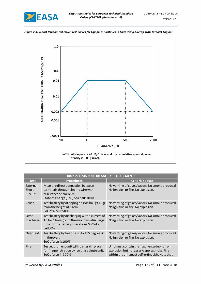
Easy Access Rules for European Technical Standard
Orders (CS-ETSO) (Amendment 8)
SUBPART B – LIST OF ETSOs
ETSO-C142a
Powered by EASA eRules Page 373 of 611| Nov 2018
Figure 2-4. Robust Random Vibration Test Curves for Equipment Installed in Fixed Wing Aircraft with Turbojet Engines
Table 2. TESTS FOR FIRE SAFETY REQUIREMENTS
Test Procedures Criteria to Pass
External Short Circuit
Measure direct connection between terminals through electric wire with resistance of 2m-ohm. State of Charge (SoC) of a cell: 100%
No venting of gases/vapors. No smoke produced. No ignition or fire. No explosion.
Crush Test battery by dropping an iron ball (9.1 kg) from the height of 61cm SoC of a cell: 50%
No venting of gases/vapors. No smoke produced. No ignition or fire. No explosion.
Over discharge
Test battery by discharging with a current of 1C for 1 hour (or to the maximum discharge time for the battery operation). SoC of a cell: 0%
No venting of gases/vapors. No smoke produced. No ignition or fire. No explosion.
Overheat Test battery by heating up to 115 degrees C in the oven. SoC of a cell: 100%
No venting of gases/vapors. No smoke produced. No ignition or fire. No explosion.
Fire Test equipment unit with battery in place for fire penetration by igniting a single unit. SoC of a cell : 100%
Unit must contain the fragments/debris from explosion but not gases/vapors/smoke. Fire within the unit must self-extinguish. Note that
Easy Access Rules for European Technical Standard
Orders (CS-ETSO) (Amendment 8)
SUBPART B – LIST OF ETSOs
ETSO-C142a
Powered by EASA eRules Page 374 of 611| Nov 2018
Table 2. TESTS FOR FIRE SAFETY REQUIREMENTS
Test Procedures Criteria to Pass
the presence of a fire extinguishing or suppression system outside the battery (such as in the equipment compartment) may be used to provide this feature if the system is designed to handle this fire threat.
[Amdt ETSO/3]
Easy Access Rules for European Technical Standard
Orders (CS-ETSO) (Amendment 8)
SUBPART B – LIST OF ETSOs
ETSO-C144a
Powered by EASA eRules Page 375 of 611| Nov 2018
ETSO-C144a ED Decision 2010/010/R (applicable from 21.12.2010)
Passive Airborne Global Navigation Satellite System (GNSS) Antenna
1 Applicability
This ETSO gives the requirements which new models of passive airborne Global Navigation Satellite System (GNSS) Antenna that are manufactured on or after the date of this ETSO must meet in order to be identified with applicable ETSO marking.
2 Procedures
2.1 General
Applicable procedures are detailed in CS-ETSO Subpart A.
2.2 Specific
None.
3 Technical Conditions
3.1 Basic
3.1.1 Minimum Performance Standard
Standards set forth in RTCA document DO-228, “Minimum Operational Performance Standards for Global Navigation Satellite System (GNSS) Airborne Antenna Equipment” dated October 20, 1995, Section 2 (excluding Sections 2.2.2 and 2.4.3) and Change 1 to DO-228.
Note 1: For Active Airborne Global Navigation Satellite System (GNSS) Antenna, see ETSO-C190
Note 2: The ETSO standards herein apply to equipment intended to receive and provide signals to a global positioning system (GPS)/satellite based augmentation system (SBAS) operational Class 1, or GPS, sensor or system that will provide flight path deviation commands to the pilot or autopilot. These standards do not address the use of the signals received through this antenna for other applications. GPS/SBAS operational classes are defined in RTCA document DO-229D “Minimum Operational Performance Standards for Global Positioning System/Wide Area Augmentation System Airborne Equipment”, dated December 13, 2006, Section 1.4.2.
3.1.2 Environmental Standard
See CS-ETSO Subpart A paragraph 2.1.
3.1.3 Computer Software
See CS-ETSO Subpart A paragraph 2.2.
3.1.4 Electronic Hardware Qualification
See CS-ETSO Subpart A paragraph 2.3.
3.2 Specific
3.2.1 Failure Condition Classification
See CS-ETSO Subpart A paragraph 2.4

Easy Access Rules for European Technical Standard
Orders (CS-ETSO) (Amendment 8)
SUBPART B – LIST OF ETSOs
ETSO-C144a
Powered by EASA eRules Page 376 of 611| Nov 2018
Failure of the function defined in paragraph 3.1.1 of this ETSO has been determined to be a major failure condition.
4 Marking
4.1 General
Marking is detailed in CS-ETSO Subpart A paragraph 1.2.
4.2 Specific
None
5 Availability of Referenced Document
See CS-ETSO Subpart A paragraph 3.
[Amdt ETSO/6]

Easy Access Rules for European Technical Standard
Orders (CS-ETSO) (Amendment 8)
SUBPART B – LIST OF ETSOs
ETSO-C145c
Powered by EASA eRules Page 377 of 611| Nov 2018
ETSO-C145c ED Decision 2010/010/R (applicable from 21.12.2010)
Airborne Navigation Sensors Using the Global Positioning System Augmented by the Satellite Based Augmentation System
1 Applicability
This ETSO gives the requirements which new models of airborne navigation sensors using the Global Positioning System (GPS) augmented by the Satellite Based Augmentation System (SBAS) that are manufactured on or after the date of this ETSO must meet in order to be identified with the applicable ETSO marking.
The standards of this ETSO apply to equipment intended to provide position information to a navigation management unit that outputs deviation commands referenced to a desired flight path, pilots or autopilots will use these deviations to guide the aircraft.
2 Procedures
2.1 General
Applicable procedures are detailed in CS-ETSO Subpart A.
2.2 Specific
None.
3 Technical Conditions
3.1 Basic
3.1.1 Minimum Performance Standard
Standards set forth for functional equipment Class Beta in RTCA document DO-229D, Minimum Operational Performance Standards for Global Positioning System/Wide Area Augmentation System Airborne Equipment dated December 13, 2006, Section 2, except as modified in Appendix 1 of this ETSO.
Class Beta equipment is defined in DO-229D, Section 1.4.
3.1.2 Environmental Standard
See CS-ETSO Subpart A paragraph 2.1.
3.1.3 Computer Software
See CS-ETSO Subpart A paragraph 2.2.
3.1.4 Electronic Hardware Qualification.
See CS-ETSO Subpart A paragraph 2.3
3.2 Specific
3.2.1 Failure Condition Classification
See CS-ETSO Subpart A paragraph 2.4
Failure of the function defined in paragraph 3.1.1 of this ETSO is a:
Major failure condition for loss of function and malfunction of en route, terminal, approach lateral navigation (LNAV), and approach LNAV/vertical navigation (VNAV) position data,

Easy Access Rules for European Technical Standard
Orders (CS-ETSO) (Amendment 8)
SUBPART B – LIST OF ETSOs
ETSO-C145c
Powered by EASA eRules Page 378 of 611| Nov 2018
Major failure condition for loss of function of approach localiser performance without vertical guidance (LP), and approach localiser performance with vertical guidance (LPV) position data, and
Hazardous failure condition for malfunction of approach (LP and LPV) position data.
3.3 Functional qualifications.
None
4 Marking
4.1 General
Marking is detailed in CS-ETSO Subpart A paragraph 1.2.
4.2 Specific
At least one major component must be permanently and legibly marked with the operational equipment class as defined in Section 1.4.2 of RTCA document DO-229D (e.g., Class 2). A marking of Class 4 indicates compliance to Delta-4 requirements. The functional equipment class defined in Section 1.4.1 of RTCA document DO-229D (e.g. Gamma, Delta) is not required to be marked.
It is sufficient to declare the proper functional equipment class in the DDP.
5 Availability of Referenced Document
See CS-ETSO Subpart A paragraph 3.
[Amdt ETSO/6]

Easy Access Rules for European Technical Standard
Orders (CS-ETSO) (Amendment 8)
SUBPART B – LIST OF ETSOs
ETSO-C145c
Powered by EASA eRules Page 379 of 611| Nov 2018
APPENDIX 1 TO ETSO-C145C – MPS FOR AIRBORNE NAVIGATION SENSORS
USING GPS AUGMENTED BY SBAS ED Decision 2010/010/R
1. This appendix prescribes EASA modifications to the MPS for functional equipment Class Beta in RTCA document DO-229D, Section 2. Operational Class 3 equipment already complies with the MPS changes below. These MPS changes apply for operational Class 1 or Class 2 equipment only.
a Section 2.5
Section 2.5.6.1, Scenario #1, Step 3)
Change step 3) to read: “Broadband external interference noise (I Ext, Test) of spectral density equal to -170.5 dBm/Hz at the antenna port.”
Section 2.5.6.1, Scenario #2, Step 4)
Change step 4) to read: “Broadband external interference noise (I Ext, Test) of spectral density equal to -170.5 dBm/Hz at the antenna port.”
Section 2.5.8.2, Requirement 1), Item a)
Change item a) to read: “The broadband external interference noise (I Ext, Test) of spectral density equal to -170.5 dBm/Hz at the antenna port.”
b Appendix C, Figure C-2, In-Band and Near-Band Interference Environments
Replace Figure C-2 with the following:
c Appendix C, Section C.2.2
Change the first paragraph to read:
The baseline in-band and near-band interference environments apply to steady-state operation. For initial acquisition of the GPS and SBAS signals prior to steady-state navigation, the in-band and near-band interference levels are 6 dB less than those for steady-state operation. The interference bandwidth is the 3 dB bandwidth.

Easy Access Rules for European Technical Standard
Orders (CS-ETSO) (Amendment 8)
SUBPART B – LIST OF ETSOs
ETSO-C145c
Powered by EASA eRules Page 380 of 611| Nov 2018
Delete the last paragraph in the section (as shown below).
The in-band and near-band interference levels for the LNAV approach steady-state navigation operations are 3 dB less than those for LNAV/VNAV, LP, and LPV approach steady-state navigation operations. For terminal area and en route steady-state navigation operations, and for initial acquisition of the GPS and WAAS signals prior to steady-state navigation for all flight phase operations, the in-band and near-band interference levels are 6 dB less than those for LNAV, LNAV/VNAV, and LPV approach steady-state navigation operations.
[Amdt ETSO/6]

Easy Access Rules for European Technical Standard
Orders (CS-ETSO) (Amendment 8)
SUBPART B – LIST OF ETSOs
ETSO-C146c
Powered by EASA eRules Page 381 of 611| Nov 2018
ETSO-C146c ED Decision 2010/010/R (applicable from 21.12.2010)
Stand Alone Airborne Navigation Equipment Using the Global Positioning System Augmented by the Satellite Based Augmentation System
1 Applicability
This ETSO gives the requirements which new models of stand-alone airborne navigation equipment using the Global Positioning System (GPS) augmented by the Satellite Based Augmentation System (SBAS) that are manufactured on or after the date of this ETSO must meet in order to be identified with applicable ETSO marking.
2 Procedures
2.1 General
Applicable procedures are detailed in CS-ETSO Subpart A.
2.2 Specific
None.
3 Technical Conditions
3.1 Basic
3.1.1 Minimum Performance Standard
Standards set forth for functional equipment Class Gamma or Delta in RTCA document DO-229D, Minimum Operational Performance Standards for Global Positioning System/Wide Area Augmentation System Airborne Equipment, dated December 13 2006, Section 2, except as modified by Appendix 1 of this ETSO.
Classes Gamma and Delta equipment are defined in DO-229D, Section 1.4.
3.1.2 Environmental Standard
See CS-ETSO Subpart A paragraph 2.1.
3.1.3 Computer Software
See CS-ETSO Subpart A paragraph 2.2.
3.1.4 Electronic Hardware Qualification.
See CS-ETSO Subpart A paragraph 2.3.
3.2 Specific
3.2.1 Failure Condition Classification
See CS-ETSO Subpart A paragraph 2.4.
Failure of the function defined in paragraph 3.1.1 of this ETSO is a:
Major failure condition for loss of function and malfunction of en route, terminal, approach lateral navigation (LNAV), and approach LNAV/vertical navigation (VNAV) position data,
Major failure condition for loss of function of approach localiser performance without vertical guidance (LP), and approach localiser performance with vertical guidance (LPV) position data, and
Easy Access Rules for European Technical Standard
Orders (CS-ETSO) (Amendment 8)
SUBPART B – LIST OF ETSOs
ETSO-C146c
Powered by EASA eRules Page 382 of 611| Nov 2018
Hazardous failure condition for the malfunction of approach (LP and LPV) position data.
3.3. Functional qualifications.
None
4 Marking
4.1 General
Marking is detailed in CS-ETSO Subpart A paragraph 1.2.
4.2 Specific
At least one major component must be permanently and legibly marked with the operational equipment class as defined in Section 1.4.2 of RTCA document DO-229D (e.g., Class 2). A marking of Class 4 indicates compliance to Delta-4 requirements. The functional equipment class defined in Section 1.4.1 of RTCA document DO-229D (e.g. Gamma, Delta) is not required to be marked.
It is sufficient to declare the proper functional equipment class in the DDP.
5 Availability of Referenced Document
See CS-ETSO Subpart A paragraph 3.
[Amdt ETSO/6]

Easy Access Rules for European Technical Standard
Orders (CS-ETSO) (Amendment 8)
SUBPART B – LIST OF ETSOs
ETSO-C146c
Powered by EASA eRules Page 383 of 611| Nov 2018
APPENDIX 1 TO ETSO-C146C – MPS FOR STAND-ALONE AIRBORNE
NAVIGATION EQUIPMENT USING GPS AUGMENTED BY SBAS ED Decision 2010/010/R
1. This appendix prescribes modifications to the MPS for functional equipment class Gamma found in RTCA document DO-229D, Section 2. Gamma operational Class 3 and Delta operational Class 4 equipment already complies with the MPS changes below. These MPS changes apply for operational Class 1 or Class 2 equipment only.
a Section 2.5
Section 2.5.6.1, Scenario #1, Step 3)
Change step 3) to read: “Broadband external interference noise (I Ext, Test) of spectral density equal to -170.5 dBm/Hz at the antenna port.”
Section 2.5.6.1, Scenario #2, Step 4)
Change step 4) to read: “Broadband external interference noise (IExt, Test) of spectral density equal to -170.5 dBm/Hz at the antenna port.”
Section 2.5.8.2, Requirement 1), Item a)
Change item a) to read: “The broadband external interference noise (I Ext, Test) of spectral density equal to -170.5 dBm/Hz at the antenna port.”
b Appendix C, Figure C-2, In-Band and Near-Band Interference Environments
Replace Figure C-2 with the following:
c Appendix C, Section C.2.2
Change the first paragraph to read:

Easy Access Rules for European Technical Standard
Orders (CS-ETSO) (Amendment 8)
SUBPART B – LIST OF ETSOs
ETSO-C146c
Powered by EASA eRules Page 384 of 611| Nov 2018
The baseline in-band and near-band interference environments apply to steady-state operation. For initial acquisition of the GPS and SBAS signals prior to steady-state navigation, the in-band and near-band interference levels are 6 dB less than those for steady-state operation. The interference bandwidth is the 3 dB bandwidth.
Delete the last paragraph in the section (as shown below).
The in-band and near-band interference levels for the LNAV approach steady-state navigation operations are 3 dB less than those for LNAV/VNAV, LP, and LPV approach steady-state navigation operations. For terminal area and en route steady-state navigation operations, and for initial acquisition of the GPS and WAAS signals prior to steady-state navigation for all flight phase operations, the in-band and near-band interference levels are 6 dB less than those for LNAV, LNAV/VNAV, and LPV approach steady-state navigation operations.
[Amdt ETSO/6]

Easy Access Rules for European Technical Standard
Orders (CS-ETSO) (Amendment 8)
SUBPART B – LIST OF ETSOs
ETSO-C147
Powered by EASA eRules Page 385 of 611| Nov 2018
ETSO-C147 ED Decision 2003/10/RM (applicable from 24.10.2003)
Traffic Advisory System (TAS) Airborne Equipment
1 Applicability
This ETSO gives the requirements that new models of active traffic advisory system (TAS) airborne equipment that are manufactured on or after the date of this ETSO must meet in order to be identified with applicable ETSO marking.
Equipment Classes are:
1. Class A. Equipment incorporating a horizontal situation display that indicates the presence and relative location of intruder aircraft, and an aural alert informing the crew of a Traffic Advisory (TA).
2. Class B. Equipment incorporating an aural alert and a visual annunciation informing the crew of a TA.
2 Procedures
2.1 General
Applicable procedures are detailed in CS-ETSO Subpart A.
2.2 Specific
None.
3 Technical Conditions
3.1 Basic
3.1.1 Minimum Performance Standard
Standards set forth in RTCA Document No. RTCA/DO-197A, “Minimum Operational Performance Standards for An Active Traffic Alert and Collision Avoidance System I (ACTIVE TCAS 1),” Section Two (2) September 12, 1994, with the exceptions listed in appendix 1 of this document.
3.1.2 Environmental Standard
See CS-ETSO Subpart A paragraph 2.1.
3.1.3 Computer Software
See CS-ETSO Subpart A paragraph 2.2.
3.2 Specific
None
4 Marking
4.1 General
Marking is detailed in CS-ETSO Subpart A paragraph 1.2.
4.2 Specific
The equipment class, as defined in paragraph 1, shall be marked.
5 Availability of Referenced Document

Easy Access Rules for European Technical Standard
Orders (CS-ETSO) (Amendment 8)
SUBPART B – LIST OF ETSOs
ETSO-C147
Powered by EASA eRules Page 386 of 611| Nov 2018
See CS-ETSO Subpart A paragraph 3.

Easy Access Rules for European Technical Standard
Orders (CS-ETSO) (Amendment 8)
SUBPART B – LIST OF ETSOs
ETSO-C147
Powered by EASA eRules Page 387 of 611| Nov 2018
APPENDIX 1 TO ETSO-C147 – CHANGES TO RTCA/DO-197A, “MINIMUM
OPERATIONAL PERFORMANCE STANDARDS FOR AN ACTIVE TRAFFIC ALERT AND
COLLISION AVOIDANCE SYSTEM I (ACTIVE TCAS I)” APPLICABLE TO TRAFFIC
ADVISORY SYSTEM (TAS) AIRBORNE EQUIPMENT ED Decision 2003/10/RM
1.0 Changes Applicable to Both Class A and Class B Equipment.
1.1 Receiver Characteristics.
1.1.1 In-band Acceptance.In lieu of paragraph 2.2.2.1 of RTCA DO-197A, substitute the following requirement:
Given a valid transponder reply signal in the absence of interference or overloads, the minimum trigger level (MTL) is defined as the input power level that results in a 90% ratio of decoded to received replies.
The MTL over the frequency range of 1,087 to 1,093 MHz shall be no greater than -70 dBm.
1.1.2 In-band Acceptance. In paragraph 2.4.2.2.1 of RTCA DO-197A, eliminate the following:
under Intruder Aircraft eliminate the last line: “Scenario C and D ≥ -78 dBm.
under Test Description Success:, eliminate the last sentence: For scenarios C and D, the ratio of correctly decoded intruder replies to total input replies shall not exceed 10%.
1.2 Transmission Frequency. In lieu of paragraph 2.2.3.1 of RTCA/DO-197A, substitute the following requirement:
“The transmission frequency of Mode C interrogations shall be 1,030 ±0.2 MHz.”
1.3 Transmitter RF Output Power.In lieu of paragraph 2.2.3.2 of RTCA/DO-197A, substitute the following requirement:
When transmitting at full (unattenuated) output power, the peak RF output power delivered to a quarter wave stub antenna shall be within the following limits:
Maximum RF Power: 54 dBm (250W)
Minimum RF Power: 50 dBm (100W)
In the event that antenna gain differs from that of a quarter wave stub antenna (3 dBi), the power limits shall be adjusted accordingly. These limits are based upon range and interference limiting requirements.
Note: When transmitting at full (unattenuated) power, the RF power radiated at the pattern peak shall be within the following limits:
Maximum EIRP: 57 dBm (500W)
Minimum EIRP: 53 dBm (200W)
It is assumed that the peak gain of a typical quarter wave stub antenna is 3 dBi. EIRP = Effective Isotropic Radiated Power.
Note: As an alternative to the above, an active TAS may chose to operate as a low power system at a fixed rate power product limit of 42 Watts per second, in which case the peak

Easy Access Rules for European Technical Standard
Orders (CS-ETSO) (Amendment 8)
SUBPART B – LIST OF ETSOs
ETSO-C147
Powered by EASA eRules Page 388 of 611| Nov 2018
RF output power delivered to a quarter wave stub antenna shall not exceed 46 dBm (40W).
1.4 Transmitter Pulse Characteristics. In lieu of paragraph 2.2.3.5 of RTCA/DO-197A, substitute the following requirement:
ATCRBS interrogations from active TAS shall employ the Mode C format illustrated in Figure 2-1.
The rise and decay times may be less than shown in the following table, provided the sideband radiation does not exceed the spectral limits tabulated in this standard. The amplitude of P3 shall be within 0.5 dB of the amplitude of P1.
ACTIVE TAS MODE PULSE SHAPES (All values in Microseconds)
Pulse Designator Pulse Duration Duration Tolerance Rise Time Decay Time
P1, P3 0.8 ± 0.075
Min Max Min Max
0.05 0.1 0.05 0.2
The pulse spacing tolerances shall be as follows: P1 to P3: 21 ± 0.10 microseconds
1.5 Mode S Broadcast Reception. In lieu of paragraph 2.2.4.2 of RTCA/DO-197A, substitute the following requirement:
The Active TAS shall have the capability to receive 1,030 MHz Mode S broadcast signals for the purpose of obtaining a count of TCAS interrogators in its vicinity. Mode S reception may reside in an associated Mode S transponder, or may by integral to the Active TAS equipment, in which case those functions necessary to receive and process Mode S broadcast signals for a TCAS count shall be implemented and tested in accordance with RTCA/DO-181A.
Note: As an alternative to the above, an active TAS may chose to operate at a fixed rate power product limit of 42W/sec, in which case the requirement to obtain a count of TCAS interrogators for the purpose of interference limiting is eliminated.
1.6 Interference Limiting.In lieu of paragraph 2.2.6 of RTCA/DO-197A, substitute the following requirement:
To assure that all interference effects from Active TAS equipment are kept to a low level, Active TAS equipment shall control its interrogation rate or power or both to conform to the following limits.
These limits are given in terms of
RR = the Mode A/C reply rate of own transponder
NT = the number of airborne TCAS interrogators detected via Mode S broadcast receptions with a receiver threshold of -74 dBm.
The Minimum Active TCAS shall have the capability to monitor RR and NT and to use this information in interference limiting. Once each scan period, NT shall be updated as the number of distinct TCAS addresses received within the previous 20 second period.
The limits are as follows:
NT K Upper Limit for Σ P(k) If RR < 240 If RR > 240
0 250 118

Easy Access Rules for European Technical Standard
Orders (CS-ETSO) (Amendment 8)
SUBPART B – LIST OF ETSOs
ETSO-C147
Powered by EASA eRules Page 389 of 611| Nov 2018
NT K Upper Limit for Σ P(k) If RR < 240 If RR > 240
1 250 113
2 250 108
3 250 103
4 250 98
5 250 94
6 250 89
7 250 84
8 250 79
9 250 74
10 245 70
11 228 65
12 210 60
13 193 55
14 175 50
15 158 45
16 144 41
17 126 36
18 109 31
19 91 26
20 74 21
21 60 17
≥22 42 12
P(k) = power (watts) of the kth interrogation each second. This is the total radiated power (after all losses in cabling and antenna). If the set of powers is not the same in each 1 second period, then Σ P(k) represents the average value.
K = total number of interrogations in a 1 second period.
Note 1: RR = the Mode A/C interrogation reception rate of own transponder may be used instead of RR = the Mode A/C reply rate of own transponder.
Note 2: As an alternative to the above, an active TAS may chose to operate as a low power system at a fixed rate power product limit of 42W/sec, in which case the requirement to further interference limit based on RR or IR is eliminated.
In lieu of paragraph 2.4.2.5 of RTCA/DO-197A, substitute the following:
This test verifies that Active TAS is able to monitor its own transponder reply rate and to derive a count of TCAS aircraft by listening to TCAS broadcast interrogations and, based on these values, adjust its transmit power-rate product to conform to the Active TAS interference limits.
Inputs:
Active TAS Aircraft
Altitude = 8000 ft.
Altitude Rate = 0 FPM
Intruder Aircraft 1-22
Easy Access Rules for European Technical Standard
Orders (CS-ETSO) (Amendment 8)
SUBPART B – LIST OF ETSOs
ETSO-C147
Powered by EASA eRules Page 390 of 611| Nov 2018
Equipage = Active TCAS II
Range = Not Applicable
Relative Speed = Not Applicable
Altitude = Not Applicable
Altitude Rate = Not Applicable
TCAS Broadcast Interrogation Power = -50 dBm
ATCRBS Interrogation
Frequency = 1030 MHz
Type = ATCRBS Mode C
Power = -50 dBm
Rate
Scenario A = 230 per second
Scenario B = 250 per second
Conditions:
Active TAS initialized and operating at T = 0 seconds. Each of the 22 intruders is assigned a discrete address and transmits only TCAS broadcast interrogations and only at the following times and rates:
Intruders 1-10 every 10 sec starting at T = 30 sec.
Intruders 11-15 every 20 sec starting at T = 70 sec.
Intruders 16-22 every 20 sec starting at T = 130 sec.
The timing of the TCAS broadcast interrogations and the ATCRBS interrogations are controlled to prevent overlap of each other.
Scenario Description
The test involves use of an ATCRBS transponder which supplies reply rate information to Active TAS. The transponder is interrogated in Mode C at a 230 per second rate in Scenario A and at a 250 per second rate in Scenario B. During each scenario, the value of Total Radiated Power per second from Active TAS is measured by summing the transmitter output powers of each Active TAS interrogation over a scan period, determining the average per second value and accounting for cable and antenna losses.
Success: The Total Radiated Power per second shall not exceed the following values:
Scenario A
250 watts/sec measured at T = 20 sec
245 watts/sec measured at T = 60 sec
158 watts/sec measured at T = 120 sec
42 watts/sec measured at T = 180 sec
Scenario B
118 watts/sec measured at T = 20 sec

Easy Access Rules for European Technical Standard
Orders (CS-ETSO) (Amendment 8)
SUBPART B – LIST OF ETSOs
ETSO-C147
Powered by EASA eRules Page 391 of 611| Nov 2018
70 watts/sec measured at T = 60 sec
45 watts/sec measured at T = 120 sec
12 watts/sec measured at T = 180 sec
Note: For fixed rate power systems, total radiated power is constant and shall not exceed 42 watts/sec.
1.7 Active TAS Antenna System. In lieu of paragraph 2.2.10 of RTCA/DO-197A, substitute the following requirement:
The equipment shall transmit interrogations and receive replies from at least one directional antenna mounted on the top or bottom of the aircraft.
1.8 Pilot Advisory Functions. In lieu of paragraph 2.1.5 of RTCA/DO-197A, substitute the following requirement:
The interface between Active TAS and the pilot shall be based on the FAA Advisory Circular entitled “Airworthiness Approval of Traffic Alert and Collision Avoidance Systems (Active TCAS I)”. It shall however be acceptable for the TAS system to use shape as the only discriminate for traffic threat levels. This will allow the use of a monochrome display representation of the TCAS symbology. It shall also be acceptable to provide a blinking TA symbol to allow further discrimination of the traffic alert symbol.
2.0 Changes Applicable Only to Class A Equipment.
2.1 Pilot Advisory Functions, Active TCAS I Pilot Interface and Aural Alert. In lieu of paragraphs 2.1.5, 2.2.12 and 2.2.15 of RTCA/DO-197A, substitute the following requirements:
1. A traffic display shall be provided to indicate the presence and location of intruder aircraft. The traffic display may be combined with other aircraft displays. The traffic display shall provide the crew with the intruder’s range, bearing, and, for altitude reporting intruders, relative altitude and vertical trend.
2. Two levels of intruder aircraft shall be displayed; those causing a TA, and other traffic. Other traffic is defined as any traffic within the selected display range and not a TA.
Note: The use of TCAS threat levels as defined in DO-197A is an acceptable alternative to the requirements defined in this section.
3. As a minimum, the traffic display shall depict the following information to aid in the visual acquisition of traffic and assist in determining the relative importance of each aircraft shown:
Note: TCAS I symbology as defined in the FAA Advisory Circular entitled “Airworthiness Approval of Traffic and Collision Avoidance Systems (Active TCAS I)” is an acceptable alternative to the symbology requirements defined in this section. In addition, the use of TCAS symbology with a monochrome display is also an acceptable means of depicting traffic information.
a. Symbolic differentiation among traffic of different relative importance. TA, other traffic (see i, j, k, l, & m below).
b. Bearing
c. Relative altitude (for altitude reporting aircraft only)
(1) Above or below own aircraft (+ and - signs)
Easy Access Rules for European Technical Standard
Orders (CS-ETSO) (Amendment 8)
SUBPART B – LIST OF ETSOs
ETSO-C147
Powered by EASA eRules Page 392 of 611| Nov 2018
(2) Numerical value
d. Vertical trend of intruder aircraft (for altitude reporting aircraft only).
e. Range. The selected range shall be depicted.
f. The display must be easily readable under all normal cockpit conditions and all expected ambient light conditions from total darkness to bright reflected sunlight.
g. The display shall contain a symbol to represent own aircraft. The symbol shall be different from those used to indicate TA and other traffic. The display shall be oriented such that own aircraft heading is always up (12 o’clock).
h. A ring shall be placed at a range of 2 NM from own aircraft symbol when a display range of 10 NM or less is selected. The ring shall have discrete markings at each of the twelve clock positions. The markings shall be of a size and shape that does not clutter the display.
i. Symbol fill shall be used to discriminate traffic by threat levels
j. The symbol for a TA is a filled rectangle, and, when appropriate, a data field and vertical trend arrow as described in m. & n. below.
k. The symbol for other traffic shall be an open rectangle, and, when appropriate, a data field and vertical trend arrow as described in m. below.
l. Overlapping traffic symbols should be displayed with the appropriate information overlapped. The highest priority traffic symbol should appear on top of other traffic symbols. Priority order is; 1) TA traffic in order of increasing tau, i.e., the time to closest approach and the time to coaltitude, 2) other traffic in order of increasing range.
M .A data field shall indicate the relative altitude, if available, of the intruder aircraft and shall consist of two digits indicating the altitude difference in hundreds of feet. For an intruder above own aircraft, the data field shall be preceded by a “+” character. For an intruder below own aircraft, the data field shall be preceded by a “-” character. For coaltitude intruders, the data field shall contain the digits “00”, with no preceding “+” or “-” character. The data field shall be wholly contained within the boundaries of the rectangular traffic symbol. For TA traffic, (filled symbol), the data characters shall be depicted in a color that contrasts with the filled symbol color. For other traffic, the data field shall be the same color as the symbol. The height of the relative altitude data characters shall be no less than 0.15 inches.
n. A vertical arrow should be placed to the immediate right of the traffic symbol if the vertical speed of the intruder is equal to or greater than 500 fpm, with the arrow pointing up for climbing traffic and down for descending traffic. The color of the arrow shall be the same as the symbol.
o. Neither a data field nor a vertical arrow shall be associated with a symbol for traffic which is not reporting altitude.
p. The display shall be capable of depicting a minimum of three intruder aircraft simultaneously. As a minimum, the display shall be capable of displaying aircraft that are within 5 NM of own aircraft.

Easy Access Rules for European Technical Standard
Orders (CS-ETSO) (Amendment 8)
SUBPART B – LIST OF ETSOs
ETSO-C147
Powered by EASA eRules Page 393 of 611| Nov 2018
q. The display may provide for multiple crew-selectable display ranges.
r. When the range of the intruder causing a traffic advisory to be displayed is greater than the maximum range of the display, this shall be indicated by placing no less than one quarter of the traffic advisory symbol at the edge of the display at the proper bearing. The data field and vertical trend arrow shall be shown in their normal positions relative to the traffic symbol.
s. The size of the traffic symbol shall be no less than 0.2” High.
4. “No bearing” advisories shall be presented for an intruder generating a TA when the intruder’s relative bearing cannot be derived. The “no bearing” advisory shall be an alphanumeric display shown in tabular form. The display shall be in the form of “TA 3.6 -05”, which translates to a TA at 3.6 nautical miles, 500 feet below. “No bearing” TA’s against non-altitude reporting intruders shall include the range only, e.g. “TA 2.2”, which translates to a non-altitude reporting, no bearing TA at 2.2 nautical miles. The advisory shall be centered on the display below the own aircraft symbol. The display shall include provisions to display at least two “no bearing” TA’s.
5. Aural Alerts. Each TAS aural alert shall be announced in a high-fidelity, distinguishable voice.
a. The aural alert message “Traffic-Traffic”, spoken once, shall be used to inform the crew of a TA.
b. All TAS aural alerts should be inhibited using the following order of precedence;
(1) Below 400 ±100 feet AGL when TAS is installed on an aircraft equipped with a radio altimeter.
(2) For aircraft without a radio altimeter, the aural annunciations shall be inhibited when the landing gear is extended.
Note: When the TAS is installed on a fixed gear aircraft without a radio altimeter, the aural annunciations will never be inhibited.
2.2 Traffic Advisory Criteria. Replace the second section in paragraph 2.2.14 of RTCA/DO-197A, with the following text:
The TAS equipment shall provide two levels of advisories: Other Traffic (OT), and Traffic Advisories (TA). TAs are issued based on either tau, i.e., the time to closest approach and the time to coaltitude, or proximity to an intruder aircraft. The range tau is defined as the range divided by range rate and the vertical tau is defined as the relative altitude divided by the altitude rate.
2.3 Display Overload. In lieu of paragraph 2.2.17 of RTCA/DO-197A, substitute the following requirements:
If the number of targets exceeds the display capability, excess targets shall be deleted in the following order:
a. Other traffic beginning with the intruder at the greatest range.
b. TAs beginning with the intruder having the largest tau. Once a TA has been generated against an intruder, it cannot be removed as a TA until the TA criteria are no longer satisfied even though it may be dropped from the display.

Easy Access Rules for European Technical Standard
Orders (CS-ETSO) (Amendment 8)
SUBPART B – LIST OF ETSOs
ETSO-C147
Powered by EASA eRules Page 394 of 611| Nov 2018
Note: This exception does not apply when TCAS I symbology and threat levels are used.
3.0 Changes Applicable Only to Class B Equipment.
3.1 Pilot Advisory Functions, Active TCAS I Pilot Interface, and Aural Alert. In lieu of paragraph 2.1.5, 2.2.12, and 2.2.15 of RTCA/DO-197A, substitute the following requirements:
1. A visual “Traffic” annunciation, shall be provided for the duration of the TA.
2. Aural Alerts. For aircraft without a radio altimeter, the aural annunciations shall be inhibited when the landing gear is extended.
Note: When the TAS is installed on afixed gear aircraft with a radio altimeter, the aural annunciation will never be inhibited.
a. Aural alert messages shall be annunciated in threat priority sequence, greatest threat first.
(1) Initial aural traffic advisories shall be spontaneous and unsolicited. The unsolicited annunciations shall be as follows: “Traffic-<X>O’Clock”, spoken once, (where <X> is the clock position of the intruder, such as 1 o’clock, etc.). If surveillance bearing information is not available on the intruder, “Traffic, No Bearing”, shall be annunciated.
(2) The current relative bearing to intruder aircraft shall be annunciated as a traffic advisory update upon crew command. Additional information such as relative altitude, range of intruder, and vertical trend (i.e. climbing, descending) may also be annunciated.
(3) The acceptability of these aural annunciations must be reviewed during flight test. The following factors, at a minimum, must be evaluated for acceptability: quantity of unsolicited annunciations, duration of annunciations, annunciation clarity, and volume. This evaluation shall occur under normal cockpit workload conditions during departure, cruise, and approach and landing phases of flight and should include evaluation of suitability in a normal air traffic control voice communication environment.
(4) Control means shall be provided to request a traffic advisory update, mute a current aural advisory, and cancel/restore aural advisories (turning the equipment off is an acceptable means of providing the cancel aural advisories function). The default condition of the equipment at power on shall be aural advisories active.
b. All TAS aural alerts should be inhibited using the following order of precedence;
(1) Below 400 ±100 feet AGL when TAS is installed on an aircraft equipped with a radio altimeter.
(2) For aircraft without a radio altimeter, the aural annunciations will never be inhibited in flight but may be inhibited on the ground when the aircraft is equipped with a weight-on-wheels system.
3.2 Traffic Advisory Criteria. Replace the first and second sections in paragraph 2.2.14 of RTCA/DO-197A, with the following text:

Easy Access Rules for European Technical Standard
Orders (CS-ETSO) (Amendment 8)
SUBPART B – LIST OF ETSOs
ETSO-C147
Powered by EASA eRules Page 395 of 611| Nov 2018
The Active TAS equipment shall provide two levels of advisories: Other Traffic (OT), and Traffic Advisories (TA). Other traffic is defined as any traffic within the selected display range and not a TA. TAs are issued based on either tau, i.e., the time to closest approach and the time to coaltitude, or proximity to an intruder aircraft. The range tau is defined as the range divided by range rate and the vertical tau is defined as the relative altitude divided by the altitude rate.
3.3 Display of intruders on the ground. In lieu of paragraph 2.2.16 of RTCA/DO-197A, substitute the following requirements:
The Active TAS equipment shall provide logic to inhibit TAs of altitude reporting intruders which are on the ground. This logic shall be used when the TAS-equipped aircraft is below 1,700 feet AGL. The 1,700 foot threshold shall include hysteresis of + 50 feet.
Note: This represents a requirement for a capability within the Active TAS avionics. When Active TAS is installed on an aircraft which does not have a radio altimeter, there is not a requirement for this logic to function.
3.4 Display overload. In lieu of paragraph 2.2.17 of RTCA/DO-197A, substitute the following requirements:
If the number of intruders exceeds aural memory storage capacity, excess intruders shall be deleted in the following order:
a. Other traffic beginning with the intruder at the greatest range.
b. TAs beginning with the intruder having the largest tau. Once a TA has been generated against an intruder, it cannot be removed as a TA until the TA criteria is no longer satisfied even though it has been dropped from the list of aural warnings.

Easy Access Rules for European Technical Standard
Orders (CS-ETSO) (Amendment 8)
SUBPART B – LIST OF ETSOs
ETSO-C151b
Powered by EASA eRules Page 396 of 611| Nov 2018
ETSO-C151b ED Decision 2007/017/R (applicable from 25.12.2007)
Terrain Awareness and Warning System (TAWS)
1 Applicability
This ETSO gives the requirements which Terrain awareness and Warning System (TAWS) equipment that is manufactured on or after the date of this ETSO, must meet in order to be identified with the applicable ETSO marking.
2 Procedures
2.1 General
Applicable procedures are detailed in CS-ETSO Subpart A.
2.2 Specific
None.
3 Technical Conditions
3.1 General
3.1.1 Minimum Performance Standard
Standards set forth in this paragraph and the attached Federal Aviation Administration Technical Standard Order “TERRAIN AWARENESS AND WARNING SYSTEM (TAWS)” appendices 1 through 4.
3.1.2 Environmental Standard
See CS-ETSO Subpart A paragraph 2.1
3.1.3 Computer Software
See CS-ETSO Subpart A paragraph 2.2. In addition:
Software implementing the functions defined in this ETSO must be developed to Level C as defined in ED-12B/DO-178B. Monitoring software required by appendix 1 of this ETSO must be developed to Level C. Software in the TAWS other than the software implementing the function and monitoring requirements defined in the ETSO, such as maintenance software, should be developed to Level C also unless the applicant can demonstrate that the ETSO functional software and monitoring software is protected from failure of the other software by means such as developed to the highest level commensurate with its functionality and its most severe failure condition categories as determined by a system safety assessment.
3.2 Specific
3.2.1 Failure Condition Classification. A minimum level of reliability and integrity must be built into the TAWS computer for warning functions. Therefore, the presentation of hazardously misleading information (HMI), as defined in paragraph 2.8 of appendix 1, on the terrain display, or the unannunciated loss of the terrain warning functions as a result of TAWS Computer failure is also considered a major failure condition.
A false terrain warning as a result of a TAWS computer failure is also considered a major failure condition. False sensor inputs (erroneous altitude, terrain data,

Easy Access Rules for European Technical Standard
Orders (CS-ETSO) (Amendment 8)
SUBPART B – LIST OF ETSOs
ETSO-C151b
Powered by EASA eRules Page 397 of 611| Nov 2018
airport data, etc) to the TAWS computer need not be considered for compliance to these failure condition classifications.
3.2.2 Functional Qualifications. The required performance shall be demonstrated under the test conditions specified in appendixes 1 through 4.
3.2.3 Fire Protection. All material used shall be self-extinguishing except for small parts (such as knobs, fasteners, seals, grommets, and small electrical parts) that would not contribute significantly to the propagation of a fire.
4 Marking
4.1 General
Marking is detailed in CS-ETSO Subpart A paragraph 1.2.
4.2 Specific
a. At least one major component must be permanently and legibly marked with all of the information listed in Part 21 Section A Subpart Q § 21A.807(a). In addition to this information the applicable Class A, B or C must be permanently and legibly marked.
From the marking options in Part 21 Section A Subpart Q § 21A.807(a)(2), the name, type and part number must be used in lieu of the optional model number; and in Part 21 Section A Subpart Q § 21A.807(a)(3), the date of manufacture must be used in lieu of the serial number.
b. In addition to the requirements of Part 21 Section A Subpart Q § 21A.807(a), each separate component that is easily removable (without hand tools), each interchangeable element, and each separate sub-assembly of the article that the manufacturer determines may be interchangeable must be permanently and legibly marked with at least the name of the manufacturer, manufacturer's sub-assembly part number, and ETSO number.
c. If the component includes a digital computer, the part number must include hardware and software identification, or a separate part number may be utilized for hardware and software. Either approach must include a means for showing the modification status. Note that similar software versions, which have been approved to different software levels, must be differentiated by part number.None.
5 Availability of Referenced Document
See CS-ETSO Subpart A paragraph 3.
[Amdt ETSO/2]

Easy Access Rules for European Technical Standard
Orders (CS-ETSO) (Amendment 8)
SUBPART B – LIST OF ETSOs
ETSO-C151b
Powered by EASA eRules Page 398 of 611| Nov 2018
APPENDIX 1 TO ETSO-C151B – FEDERAL AVIATION ADMINISTRATION
MINIMUM PERFORMANCE STANDARD (MPS) FOR A TERRAIN AWARENESS AND
WARNING SYSTEM, AS AMENDED BY EASA ED Decision 2007/017/R
1.0 Introduction.
1.1 Purpose. This standard provides the MPS for a Terrain Awareness and Warning System (TAWS).
1.2 Scope. This appendix sets forth the standard for two Classes of TAWS equipment, Class A and Class B.
1.3 System Function and Overview. The system shall provide the flight crew with sufficient information and alerting to detect a potentially hazardous terrain situation that would permit the flight crew to take effective action to prevent a controlled flight into terrain (CFIT) event. The basic TAWS functions for all ETSO approved systems include the following:
a. A Forward Looking Terrain Avoidance (FLTA) function. The FLTA function looks ahead of the aeroplane along and below the aeroplane’s lateral and vertical flight path and provides suitable alerts if a potential CFIT threat exists.
b. A Premature Descent Alert (PDA) function. The PDA function of the TAWS uses the aeroplane’s current position and flight path information as determined from a suitable navigation source and airport database to determine if the aeroplane is hazardously below the normal (typically 3 degree) approach path for the nearest runway as defined by the alerting algorithm.
c. An appropriate visual and aural discrete signal for both caution and warning alerts.
d. Class A TAWS equipment must provide terrain information to be presented on a display system.
e. Class A TAWS equipment must provide indications of imminent contact with the ground for the following conditions as further defined in DO-161A, Minimum Performance Standards - Airborne Ground Proximity Warning Equipment, dated May 27, 1976, and Section 3.3 of this appendix. Deviations from DO-161A are acceptable providing the nuisance alert rate is minimized while an equivalent level of safety for the following conditions is provided.
(1) Excessive Rates of Descent
(2) Excessive Closure Rate to Terrain.
(3) Negative Climb Rate or Altitude Loss After Take-off
(4) Flight Into Terrain When Not in Landing Configuration
(5) Excessive Downward Deviation From an ILS Glideslope.
(6) Voice callout „Five Hundred“ when the aeroplane descends to 500 feet above the terrain or nearest runway elevation.
NOTE: Class A equipment will be entitled to a ETSO-C92c authorization approval for the purpose of complying with the mandatory GPWS requirements in JAR-OPS 1.665/ EU-OPS 1.665, until such time that those rules are superseded by TAWS rules.

Easy Access Rules for European Technical Standard
Orders (CS-ETSO) (Amendment 8)
SUBPART B – LIST OF ETSOs
ETSO-C151b
Powered by EASA eRules Page 399 of 611| Nov 2018
f. Class B equipment must provide indications of imminent contact with the ground during the following aeroplane operations as defined in Section 3.4 of this appendix.
(1) Excessive Rates of Descent
(2) Negative Climb Rate or Altitude Loss After Takeoff
(3) A voice callout „Five Hundred“ when the aeroplane descends to 500 feet above the nearest runway elevation.
1.4 Added Features. If the manufacturer elects to add features to the TAWS equipment, those features shall at least meet the same qualification testing and software verification and validation requirements as provided under this ETSO. Additional information such as „human-made“ obstacles may be added as long as they do not adversely alter the terrain functions.
1.5 Other Technologies. Although this ETSO envisions a TAWS based on the use of an onboard terrain and airport data base, other technologies such as the use of radar are not excluded. Other concepts and technologies may be approved under this ETSO using IR 21A.610, Approval for Deviation.
2.0 Definitions.
2.1 Alert. A visual, aural, or tactile stimulus presented to attract attention and convey information regarding system status or condition.
2.2 Aural Alert. A discrete sound, tone, or verbal statement used to annunciate a condition, situation, or event.
2.3 Caution Alert. An alert requiring immediate crew awareness. Subsequent corrective action will normally be necessary.
2.4 Controlled Flight Into Terrain (CFIT). An accident or incident in which an aeroplane, under the full control of the pilot, is flown into terrain, obstacles, or water.
2.5 Failure. The inability of the equipment or any sub-part of that equipment to perform within previously specified limits.
2.6 False Alert. An inappropriate alert that occurs as a result of a failure within the TAWS or when the design alerting thresholds of the TAWS are not exceeded.
2.7 Hazard. A hazard is a state or set of conditions that together with other conditions in the environment could lead to an accident.
2.8 Misleading Information (MI). An incorrect depiction of the terrain threat relative to the aeroplane during an alert condition (excluding source data).
2.9 Nuisance Alert. An inappropriate alert, occurring during normal safe procedures, that occurs as a result of a design performance limitation of TAWS.
2.10 Search Volume. A volume of airspace around the aeroplane’s current and projected path that is used to define a TAWS alert condition.
2.11 Visual Alert. The use of projected or displayed information to present a condition, situation, or event.
2.12 Warning Alert. An alert for a detected terrain threat that requires immediate crew action.
3.0 Required TAWS Functions.

Easy Access Rules for European Technical Standard
Orders (CS-ETSO) (Amendment 8)
SUBPART B – LIST OF ETSOs
ETSO-C151b
Powered by EASA eRules Page 400 of 611| Nov 2018
3.1 Class A and Class B Requirements for Forward Looking Terrain Avoidance (FLTA). The majority of CFIT accidents have occurred because the flight crews did not have adequate situational information regarding the terrain in the vicinity of the aeroplane and its projected flight path. Class A and Class B Equipment will be required to look ahead of the aeroplane, within their design search volume and provide timely alerts in the event terrain is predicted to penetrate the search volume. The FLTA function should be available during all airborne phases of flight including turning flight. The search volume consists of a computed look ahead distance, a lateral distance on both sides of the aeroplane’s flight path, and a specified look down distance based upon the aeroplane’s vertical flight path. This search volume should vary as a function of phase of flight, distance from runway, and the required obstacle clearance (ROC) in order to perform its intended function and to minimize nuisance alerts. The lateral search volume should expand as necessary to accommodate turning flight. The TAWS search volumes should consider the accuracy of the TAWS navigation source. The TAWS lateral search area should be less than the protected area defined by the United States Standard for Terminal Instrument Procedures (TERPS), FAA Handbook 8260.3B and ICAO PANOPS 8168, volume 2 to prevent nuisance alerts.
3.1.1 Reduced Required Terrain Clearance (RTC). Class A and Class B equipment shall provide suitable alerts when the aeroplane is currently above the terrain in the aeroplane’s projected flight path but the projected amount of terrain clearance is considered unsafe for the particular phase of flight. The required obstacle (terrain) clearance (ROC) as specified in TERPS and the Aeronautical Information Manual (AIM) have been used to define the minimum requirements for obstacle/terrain clearance (RTC) appropriate to the FLTA function. These requirements are specified in Table 3.1. The FLTA function must be tested to verify the alerting algorithms meet the test conditions specified in Appendix 3, Tables A, B, C, D, E, and F.
TABLE 3.1 TAWS REQUIRED TERRAIN CLEARANCE (RTC) BY PHASE OF FLIGHT
Phase of Flight TERPS (ROC) TAWS (RTC) Level Flight
TAWS (RTC) Descending
Enroute 1000 Feet 700 Feet 500 Feet
Terminal (Intermediate Segment)
500 Feet 350 Feet 300 Feet
Approach 250 Feet 150 Feet 100 Feet
Departure (See Note 1) 48 Feet/NM 100 Feet 100 Feet
NOTE 1: During the Departure Phase of Flight, the FLTA function of Class A and B equipment must alert if the aeroplane is projected to be within 100 feet vertically of terrain. However, Class A and Class B equipment should not alert if the aeroplane is projected to be more than 400 feet above the terrain.
NOTE 2: As an alternate to the stepped down reduction from the terminal to approach phase in Table 3.1, a linear reduction of the RTC as the aircraft comes closer to the nearest runway is allowed, providing the requirements of Table 3.1 are met.
NOTE 3: During the visual segment of a normal instrument approach (typically about 1 NM from the runway threshold), the RTC should be defined/reduced to minimize nuisance alerts. Below a certain altitude or distance from the runway threshold, logic may be incorporated to inhibit the FLTA function. Typical operations below Minimum Descent Altitude (MDA), Decision Height (DH), or the Visual Descent Point (VDP) should not generate nuisance alerts.

Easy Access Rules for European Technical Standard
Orders (CS-ETSO) (Amendment 8)
SUBPART B – LIST OF ETSOs
ETSO-C151b
Powered by EASA eRules Page 401 of 611| Nov 2018
NOTE 4: The specified RTC values are reduced slightly for descending flight conditions to accommodate the dynamic conditions and pilot response times.
3.1.2 Imminent Terrain Impact. Class A and Class B equipment shall provide suitable alerts when the aeroplane is currently below the elevation of a terrain cell along the aeroplane’s lateral projected flight path and, based upon the vertical projected flight path, the equipment predicts that the terrain clearance will be less than the value given in the RTC column of Table 3.1. See appendix 3 for test conditions that must be conducted (Table G).
3.1.3 FLTA Turning Flight. Class A and Class B equipment shall provide suitable alerts for the functions specified in 3.1.1 and 3.1.2 above when the aeroplane is in turning flight.
3.2 Class A and Class B Equipment Safety Agency for Detection and Alerting for Premature Descents Along the Final Approach Segment. Class A and Class B equipment shall provide a suitable alert when it determines that the aeroplane is significantly below the normal approach flight path to a runway. Approximately one third of all CFIT accidents occur during the final approach phase of flight, when the aeroplane is properly configured for landing and descending at a normal rate. For a variety of reasons which include poor visibility, night time operations, loss of situational awareness, operating below minimums without adequate visual references and deviations from the published approach procedures, many aeroplanes have crashed into the ground short of the runway. A means to detect and alert the flight crew to this condition is an essential safety requirement of this ETSO. There are numerous ways to accomplish the overall objectives of this requirement. Alerting criteria may be based upon height above runway elevation and distance to the runway. It may be based upon height above terrain and distance to runway or other suitable means. This ETSO will not define the surfaces for which alerting is required. It will specify some general requirements for alerting and some cases when alerting is inappropriate. See appendix 3 Table H for test requirements.
a. The PDA function should be available for all types of instrument approaches. This includes both straight- in approaches and circling approaches. This includes approaches that are not aligned within 30 degrees of the runway heading.
b. The TAWS equipment should not generate PDA alerts for normal VFR operations in the airport area. Aeroplanes routinely operate at traffic pattern altitudes of 800 feet above field/runway elevation for traffic pattern operations within 5NM of the airport.
c. Aeroplanes routinely operate in VFR conditions at 1000 feet AGL within 10-15 NM of the nearest airport and these operations should not generate alerts.
d. Aeroplanes routinely operate in the visual segment of a circling approach within 2 NM of the airport/runway of intended landing with 300 feet of obstacle clearance. Operations at circling minimums should not cause PDA alerts or FLTA alerts.
3.3 Class A Requirements for GPWS Alerting. In addition to the TAWS Forward Looking Terrain Avoidance and PDA functions, the equipment shall provide the GPWS functions listed below in accordance with ETSO-C92c. Some GPWS alerting thresholds may be adjusted or modified to be more compatible with the FLTA alerting functions and to minimize GPWS nuisance alerts. However, it is essential to retain the independent protective features provided by both the GPWS and FLTA functions. In each case, all the following situations must be covered. The failure of the ETSO C92c equipment functions,
Easy Access Rules for European Technical Standard
Orders (CS-ETSO) (Amendment 8)
SUBPART B – LIST OF ETSOs
ETSO-C151b
Powered by EASA eRules Page 402 of 611| Nov 2018
except for power supply failure, input sensor failure, or failure of other common portions of the equipment, shall not cause a loss of the FLTA, PDA, or Terrain Display.
The functions described in ETSO-C92c and the referenced document DO-161A include:
(1) Excessive Rates of Descent
(2) Excessive Closure Rate to Terrain
(3) Negative Climb Rate or Altitude Loss After Take-Off
(4) Flight Into Terrain When Not in Landing Configuration
(5) Excessive Downward Deviation From an ILS Glideslope
a. Flap Alerting Inhibition. A separate guarded control may be provided to inhibit
GPWS alerts based on flaps being other than the landing configuration.
b. Speed. Airspeed or groundspeed shall be included in the logic that determines basic GPWS alerting time for „Excessive Closure Rate to Terrain“ and „Flight Into Terrain When Not in Landing Configuration“ to allow maximum time for the flight crew to react and take corrective action.
c. Voice Callouts. Voice callouts of altitude above the terrain shall be provided during non precision approaches per ETSO-C92c but are recommended for all approaches. These advisories are normally, but are not limited to 500 feet above the terrain or the height above the nearest runway threshold elevation.
d. Barometric Altitude Rate. Class A and Class B equipment may compute Barometric Altitude Rate using an Instantaneous Vertical Speed Indicator (IVSI) or an inertial smoothed vertical speed indicator. An alternative means, with demonstrated equal or better accuracy, may be used in lieu of barometric altitude rate (accuracy specified in ETSO-C10b, Altimeter, Pressure Actuated, Sensitive Type, or later revisions) and/or altimeter altitude (accuracy specified in ETSO-2C87 (Low range radio altimeters) - for air carrier aircraft, or later revisions) to meet the warning requirements described in RTCA Document No. DO-161A. In addition, ETSO-C106 for Air Data Computers may be used as an alternative means of compliance with this provision.
e. Sweep Tones „Whoop-Whoop“. If a two tone sweep is used to comply with RTCA Document No. DO-161A, paragraph 2.3, the complete cycle of two tone sweeps plus annunciation may be extended from „1.4“ to „2“ seconds.
NOTE: Class A equipment will be entitled to a ETSO-C92c authorization approval for the purpose of complying with the mandatory GPWS requirements in JAR-OPS 1.665/ EU-OPS 1.665 until such time that those rules are superseded by TAWS rules.
3.4 Class B Requirements for GPWS Alerting
a. Class B equipment must provide alerts for excessive descent rates. The alerting envelope of DO-161A has been modified to accommodate a larger envelope for both caution and warning alerts. Height above Terrain may be determined by using the Terrain Data Base elevation and subtracting it from QNH barometric altitude (or equivalent). In addition, since the envelopes are not limited by a radio alt itude measurement to a maximum of 2500 feet AGL, the envelopes are expanded to include higher vertical speeds. The equipment shall meet either the requirements set forth in appendix 3, Section 7.0 or that specified in DO-161A.
Easy Access Rules for European Technical Standard
Orders (CS-ETSO) (Amendment 8)
SUBPART B – LIST OF ETSOs
ETSO-C151b
Powered by EASA eRules Page 403 of 611| Nov 2018
b. Class B equipment must provide alerts for „Negative Climb Rate After Takeoff or Missed Approach“ or „Altitude Loss After Takeoff“ as specified in DO-161A. The alerting is identical to the alerting envelope in DO-161A except that Height above Terrain is based upon Height above Runway threshold elevation instead of radio altitude.
c. Class B equipment must provide a voice callout „Five Hundred“ during descents for landing. This feature is primarily intended to provide situational awareness to the flight crew when the aeroplane is being operated properly per normal procedures. During a normal approach, it is useful to provide the flight crew with a 500 foot voice callout referenced to the runway threshold elevation for the runway of intended landing. This feature also has an important CFIT protection function. In the event the aeroplane is operated unintentionally close to terrain when not in the airport area or the area for which PDA protection is provided, a 500 foot voice callout referenced to Height above Terrain will alert the flight crew to a hazardous condition.
The equipment shall meet the requirements specified in appendix 3, Section 9.0.
NOTE 1: Class B equipment will not require a radio altimeter. Height above Terrain may be determined by subtracting the elevation of the current position terrain cell from the current barometric altitude (or equivalent).
NOTE 2: Class B equipment should compute the voice callout for five hundred feet based upon barometric height above runway elevation. The nearest runway elevation may be used for this purpose.
3.5 Class A Equipment Requirements for a Terrain Display. Class A equipment shall be designed to interface with a Terrain Display, either color or monochromatic. Class A equipment for TAWS shall be capable of providing the following terrain related information to a display system.
a. The terrain shall be depicted relative to the aeroplane’s position such that the pilot may estimate the relative bearing to the terrain of interest.
b. The terrain shall be depicted relative to the aeroplane’s position such that the pilot may estimate the distance to the terrain of interest.
c. The terrain depicted shall be oriented to either the heading or track of the aeroplane. In addition, a North- up orientation may be added as a selectable format.
d. Variations in terrain elevation depicted relative to the aeroplane’s elevation (above and below) shall be visually distinct. Terrain that is more than 2000 feet below the aeroplane’s elevation need not be depicted.
e. Terrain that generates alerts shall be displayed in a manner to distinguish it from non-hazardous terrain, consistent with the caution and warning alert level.
3.6 Class B Equipment Requirements for a Terrain Display. Operators required to install Class B equipment are not required to include a Terrain Display. However, Class B TAWS equipment shall be capable of driving a terrain display function in the event the installer wants to include the terrain display function.
NOTE: This ETSO does not include requirements for the display system/hardware.
4.0 Aural and Visual Alerts.
Easy Access Rules for European Technical Standard
Orders (CS-ETSO) (Amendment 8)
SUBPART B – LIST OF ETSOs
ETSO-C151b
Powered by EASA eRules Page 404 of 611| Nov 2018
4.1 The TAWS is required to provide aural alerts and visual alerts for each of the functions described in Section 3.0 of this appendix.
4.2 The required aural and visual alerts must initiate from the TAWS system simultaneously, except when suppression of aural alerts are necessary to protect pilots from nuisance aural alerting.
4.3 Each aural alert shall identify the reason for the alert such as „too low terrain“ and „Glideslope,“ or other acceptable annunciation.
4.4 The system shall remove the visual and aural alert once the situation has been resolved.
4.5 The system shall be capable of accepting and processing aeroplane performance related data or aeroplane dynamic data and providing the capability to update aural and visual alerts at least once per second.
4.6 The aural and visual outputs as defined in Table 4-1 shall be compatible with the standard cockpit displays and auditory systems.
4.7 The aural and visual alerts should be selectable to accommodate operational commonality among fleets of aeroplanes.
4.8 The visual display of alerting information shall be immediately and continuously displayed until the situation is no longer valid.
4.9 As a minimum the TAWS shall be capable of providing aural alert messages described in Table 4-1. In addition to this minimum set, other voice alerts may be provided.
TABLE 4 – 1
STANDARD SET OF VISUAL AND AURAL ALERTS
Alert Condition Caution Warning
Reduced Required Terrain Clearance Class A & Class B
Visual Alert Amber text message that is obvious, concise, and must be consistent with the Aural message. Aural Alert Minimum Selectable Voice Alerts: „Caution, Terrain; Caution, Terrain“ and „Terrain Ahead; Terrain Ahead“
Visual Alert Red text message that is obvious, concise and must be consistent with the Aural message. Aural Alert Minimum Selectable Voice Alerts: „Terrain, Terrain; Pull-Up, Pull-up“ and „Terrain Ahead, Pull-up; Terrain Ahead, Pull-Up“
Imminent Impact with Terrain Class A & Class B
Visual Alert Amber text message that is obvious, concise, and must be consistent with the Aural message. Aural Alert Minimum Selectable Voice Alerts: „Caution, Terrain; Caution, Terrain“ and „Terrain Ahead; Terrain Ahead“
Visual Alert Red text message that is obvious, concise and must be consistent with the Aural message. Aural Alert Minimum Selectable Voice Alerts: „Terrain, Terrain; Pull-Up, Pull-up“ and „Terrain Ahead, Pull-up; Terrain Ahead, Pull-Up“
Premature Descent Alert (PDA) Class A & Class B
Visual Alert Amber text message that is obvious, concise and must be consistent with the Aural message. Aural Alert „Too Low Terrain“
Visual Alert None Required Aural Alert None Required

Easy Access Rules for European Technical Standard
Orders (CS-ETSO) (Amendment 8)
SUBPART B – LIST OF ETSOs
ETSO-C151b
Powered by EASA eRules Page 405 of 611| Nov 2018
STANDARD SET OF VISUAL AND AURAL ALERTS
Alert Condition Caution Warning
Ground Proximity Envelope 1, 2 or 3 Excessive Descent Rate Class A & Class B
Visual Alert Amber text message that is obvious, concise, and must be consistent with the Aural message. Aural Alert „Sink Rate“
Visual Alert Red text message that is obvious, concise and must be consistent with the Aural message. Aural Alert „Pull-Up“
Ground Proximity Excessive Closure Rate (Flaps not in Landing Configuration) Class A
Visual Alert Amber text message that is obvious, concise, and must be consistent with the Aural message. Aural Alert „Terrain-Terrain“
Visual Alert Red text message that is obvious, concise, and must be consistent with the Aural message. Aural Alert „Pull-Up“
Ground Proximity Excessive Closure Rate (Landing Configuration) Class A
Visual Alert Amber text message that is obvious, concise, and must be consistent with the Aural message. Aural Alert „Terrain-Terrain“
Visual Alert None Required. Aural Alert „Pull-Up“ – for gear up None Required – for gear down
Ground Proximity Altitude Loss after Take-off Class A & Class B
Visual Alert Amber text message that is obvious, concise, and must be consistent with the Aural message. Aural Alert „Don’t Sink“ and „Too Low-Terrain“
Visual Alert None Required. Aural Alert None Required.
Ground Proximity Envelope 1 (Not in Landing Configuration) Class A
Visual Alert Amber text message that is obvious, concise, and must be consistent with the Aural message. Aural Alert „Too Low Terrain“ and „Too Low Gear“
Visual Alert None Required. Aural Alert None Required.
Ground Proximity Envelope 2 Insufficient Terrain Clearance (Landing and Go-around configuration) Class A
Visual Alert Amber text message that is obvious, concise, and must be consistent with the Aural message. Aural Alert „Too Low Terrain“ and „Too Low Flaps“
Visual Alert None Required. Aural Alert None Required.
Ground Proximity Envelope 3 Insufficient Terrain Clearance (Take-off configuration) Class A
Visual Alert Amber text message that is obvious, concise, and must be consistent with the Aural message. Aural Alert „Too Low Terrain“
Visual Alert None Required. Aural Alert None Required.
Ground Proximity Excessive Glide Slope Deviation Class A
Visual Alert Amber text message that is obvious, concise, and must be consistent with the Aural message. Aural Alert „Glide Slope“
Visual Alert None Required. Aural Alert None Required.

Easy Access Rules for European Technical Standard
Orders (CS-ETSO) (Amendment 8)
SUBPART B – LIST OF ETSOs
ETSO-C151b
Powered by EASA eRules Page 406 of 611| Nov 2018
STANDARD SET OF VISUAL AND AURAL ALERTS
Alert Condition Caution Warning
Ground Proximity Voice Call Out (See Note 1) Class A & Class B
Visual Alert None Required Aural Alert „Five Hundred“
Visual Alert None Required. Aural Alert None Required.
NOTE 1: The aural alert for Ground Proximity Voice Call Out is considered advisory.
NOTE 2: Visual alerts may be put on the terrain situational awareness display, if this fits with the overall human factors alerting scheme for the flight deck.
This does not eliminate the visual alert color requirements, even in the case of a monochromatic display. Typically in such a scenario adjacent colored annunciator lamps meet the alerting color requirements.
4.10 Prioritization
a. Class A Equipment. Class A Equipment shall have an interactive capability with other external alerting systems so an alerting priority can be automatically executed for the purpose of not causing confusion or chaos on the flight deck during multiply alerts from different alerting systems. Typical alerting systems that may be interactive with TAWS include Predictive Windshear (PWS), Reactive Windshear (RWS), and possibly in the future Airborne Collision Avoidance System (ACAS). Table 4 - 2 includes an alert prioritization scheme. If the PWS, RWS and/or ACAS functions are provided within the TAWS, Table 4 - 2 also applies. The Agency will consider alert prioritization schemes other than the one included in Table 4 - 2.
b. Class B Equipment. Class B Equipment does not require prioritization with external systems such as ACAS, RWS, PWS. If prioritization with those functions is provided, the prioritization scheme shall be in accordance with the Table 4 - 2. The Agency will consider alert prioritization schemes other than the one included in Table 4 - 2.
c. Class B Equipment. Class B equipment shall establish an internal priority alerting system (scheme) for each of the functions. The priority scheme shall ensure that more critical alerts override the presentation of any alert of lesser priority. Table 4 - 3 is the internal priority scheme of the system. Class B equipment need only consider the TAWS functions required for Class B equipment.
Table 4 - 2
ALERT PRIORITIZATION SCHEME
Priority Description Alert Level
b Comments
1 Reactive Windshear Warning W
2 Sink Rate Pull-Up Warning W continuous
3 Excessive Closure Pull-Up Warning W continuous
4 RTC Terrain Warning W
5 V1 Callout I
6 Engine Fail Callout W
7 FLTA Pull-Up warning W continuous
8 PWS Warning W
9 RTC Terrain Caution C continuous

Easy Access Rules for European Technical Standard
Orders (CS-ETSO) (Amendment 8)
SUBPART B – LIST OF ETSOs
ETSO-C151b
Powered by EASA eRules Page 407 of 611| Nov 2018
ALERT PRIORITIZATION SCHEME
Priority Description Alert Level
b Comments
10 Minimums I
11 FLTA Caution C 7 s period
12 Too Low Terrain C
13 PDA („Too Low Terrain“)Caution C
14 Altitude Callouts I
15 Too Low Gear C
16 Too Low Flaps C
17 Sink Rate C
18 Don't Sink C
19 Glideslope C 3 s period
20 PWS Caution C
21 Approaching Minimums I
22 Bank Angle C
23 Reactive Windshear Caution C
Mode 6 a ACAS RA ("Climb", "Descend", etc.) W Continuous
Mode 6 a ACAS TA ("Traffic, Traffic") C Continuous
NOTE 1: These alerts can occur simultaneously with TAWS voice callout alerts. NOTE 2: W = Warning, C = Caution, A = Advisory, I = Informational
Table 4 – 3
TAWS INTERNAL ALERT PRIORITIZATION SCHEME
Priority Description
1. Sink Rate Pull-Up Warning
2. Terrain Awareness Pull-Up warning
3. Terrain Awareness Caution
4. PDA ("Too Low Terrain") Caution
5. Altitude Callouts „500“
6. Sink Rate
7. Don't Sink (Mode 3)
4.11 During ILS or other localizer-based approach operations, TAWS should not cause an alert
for a terrain/obstacle located outside the TERPS protected airspace. Special design considerations may be necessary to address this issue.
NOTE 1: Non-GPS RNAV/FMC Systems that are used for the TAWS aeroplane horizontal aeroplane information may be „Localizer Updated“ to remove cross track errors. In addition, the alerting envelope may be modified to account for the higher accuracy and closer obstacles associated with ILS conditions.
NOTE 2: GPS-based Systems that are used for the TAWS aeroplane horizontal aeroplane position information should be able to meet the minimum criteria found in Appendix 1, Section 5.0.
NOTE 3: The level off initiation height of 20 percent of the vertical speed was chosen (as a minimum standard for nuisance alarm-free operations) because it is similar to typical autopilot or flight director level off (altitude capture) algorithms whereas the technique

Easy Access Rules for European Technical Standard
Orders (CS-ETSO) (Amendment 8)
SUBPART B – LIST OF ETSOs
ETSO-C151b
Powered by EASA eRules Page 408 of 611| Nov 2018
of using 10 percent of the existing vertical speed as a level off initiation point is usually considered as a minimum appropriate only to manual operations of smaller general aviation aeroplanes. With high rates of descent, experienced pilots often use a manual technique of reducing the vertical speed by one half when reaching 1000 feet above/below the level off altitude. This technique will significantly reduce the likelihood of nuisance alerts. In the event that use of the 20 percent of vertical speed as a minimum standard for nuisance free operations is shown not to be compatible with the installed autopilot or flight director level off (altitude capture) algorithms, consideration should be given to setting the alert logic closer to the 10 percent vertical speed criteria to minimize nuisance alerts.
5.0 Aeroplane Horizontal Position Determination for Source Data.
5.1 Class A equipment. Class A equipment that uses the on-board aeroplane navigation system for horizontal position information for the TAWS and that meets ETSO-C115b or follow AC90-45A for approved RNAV systems, ETSO-C129a for GPS, TSO-C145 for WAAS, or that follow the recommendations in AC 20-130a or AC-138 are considered acceptable. See note below.
5.2 Class B equipment. Class B equipment will be required to interface with an approved GPS for horizontal position information as specified in 5.1. See note below.
NOTE: Experience with these systems to date and analysis support that, as position accuracy decreases, a larger area must be considered for alerts in order for the system to perform its intended function. As the area of consideration is expanded and position accuracy is decreased the system tends to become more prone to nuisance alerts. In order to keep the system nuisance free, the TAWS must be inhibited or its operation degraded to accommodate certain types of operations. Therefore designers should be aware that at the present time only systems that use position information which provides GPS accuracy will be considered to meet this ETSO except for aircraft operated under JAR-OPS 1/ EU-OPS 1. Operations under JAR-OPS 1/ EU-OPS 1 provide factors that compensate for the decreased accuracy. These factors include type of operation, route structure analysis, flight crew training, route proving requirements, continued surveillance, and extensive operations into a limited number of airports.
5.3 Internal GPS Navigator Function. Class A and Class B equipment that use a GPS internal to the TAWS for horizontal position information and are capable of detecting a positional error that exceeds the appropriate alarm limit for the existing phase of flight in accordance with ETSO-C129a/ ED-72A, or equivalent are considered acceptable. When this alarm limit is activated, the GPS computed position is considered unsuitable for the TAWS function, and an indication should be provided to the flight crew that the TAWS functions that require GPS for operation are no longer available.
6.0 Class A and Class B Requirements for a Terrain and Airport Database.
6.1 Minimum Geographical Considerations As a minimum, terrain and airport information shall be provided for the expected areas of operation, airports and routes to be flown.
6.2 Development and Methodology. The manufacturer shall present the development and methodology used to validate and verify the terrain and airport information. RTCA DO-200A/EUROCAE ED 76, Standards for Processing Aeronautical Data, should be used as a guideline.
6.3 Resolution. Terrain and airport information shall be of the accuracy and resolution suitable for the system to perform its intended function. Terrain data should be gridded

Easy Access Rules for European Technical Standard
Orders (CS-ETSO) (Amendment 8)
SUBPART B – LIST OF ETSOs
ETSO-C151b
Powered by EASA eRules Page 409 of 611| Nov 2018
at 30 arc seconds with 100 foot resolution within 30 nautical miles of all airports with runway lengths of 3500 feet or greater and whenever necessary (particularly in mountainous environments) 15 arc seconds with 100 foot resolution (or even 6 arc seconds) within 6 nautical miles of the closest runway. It is acceptable to have terrain data gridded in larger segments over oceanic and remote areas around the world.
Note: Class B equipment may require information relative to airports with runways less than 3500 feet whether public or private. Small airplane owners and operators probably will be the largest market for Class B equipment. Such operators frequently use airports of less than 3500 feet. Those TAWS manufacturers who desire to sell to this market must be willing to customize their terrain databases to include selected airports used by their customers.
6.4 Updates and Continued Airworthiness. The system shall be capable of accepting updated terrain and airport information.
7.0 Class A and Class B Failure Indication. Class A and Class B equipment shall include a failure monitor function that provides reliable indications of equipment condition during operation. It shall monitor the equipment itself, input power, input signals, and aural and visual outputs. A means shall be provided to inform the flight crew whenever the system has failed or can no longer perform the intended function.
8.0 Class A and Class B Requirements for Self-Test. Class A and Class B equipment shall have a self-test function to verify system operation and integrity. It shall monitor the equipment itself, input power, input signals, and aural and visual outputs. Failure of the system to successfully pass the self-test shall be annunciated.
NOTE: Flight crew verification of the aural and visual outputs during a self-test is an acceptable method for monitoring aural and visual outputs.
9.0 Class A Equipment Requirements for a Terrain Awareness Inhibit for the FLTA function, the Premature Descent Alert function and Terrain Display.
9.1 Manual Inhibit. Class A equipment shall have the capability, via a control switch to the flight crew, to inhibit only the FLTA function, the Premature Descent Alert function, and Terrain Display. This is required in the event of a navigational system failure or other failures that would adversely affect FLTA, the Premature Descent Alert function or the Terrain Display. The basic TAWS required functions shall remain active when the inhibit function is utilized.
9.2 Automatic Inhibit. The capability of automatically inhibiting Class A functions within TAWS equipment is acceptable utilizing the conditions described in paragraph 7.0. If auto inhibit capability is provided, the „inhibit status“ must be annunciated to the flight crew.
10.0 Phase of Flight Definitions. The TAWS equipment search volumes and alerting thresholds should vary as necessary to be compatible with TERPS and other operational considerations. For that reason, a set of definitions is offered for Enroute, Terminal, Approach and Departure Phases of Flight. Other definitions for enroute, terminal and approach may be used by TAWS provided they are compatible with TERPS and standard instrument approach procedures and will comply with the test criteria specified in Appendix 3.
10.1 Enroute Phase. The Enroute Phase exists anytime the aeroplane is more than 15 NM from the nearest airport or whenever the conditions for Terminal, Approach and Departure Phases are not met.

Easy Access Rules for European Technical Standard
Orders (CS-ETSO) (Amendment 8)
SUBPART B – LIST OF ETSOs
ETSO-C151b
Powered by EASA eRules Page 410 of 611| Nov 2018
10.2 Terminal Phase. The Terminal Phase exists when the aeroplane is 15 NM or less from the nearest runway while the range to the nearest runway threshold is decreasing and the aeroplane is at or below (lower than) a straight line drawn between the two points specified in Table 10-1 relative to the nearest runway.
TABLE 10-1 HEIGHT ABOVE RUNWAY VERSUS DISTANCE TO RUNWAY
Distance to Runway Height above Runway
15 NM 3500 Feet
5 NM 1900 Feet
10.3 Approach Phase. Distance to nearest runway threshold is equal to, or less than 5 NM; and
height above the nearest runway threshold location and elevation is equal to, or less than 1900 feet; and distance to the nearest runway threshold is decreasing.
10.4 Departure Phase. The Departure Phase should be defined by some reliable parameter that initially determines that the aeroplane is on the ground upon initial power-up. If, for example, the equipment can determine that the aeroplane is „on the ground“ by using some logic such as ground speed less than 35 knots and altitude within +/- 75 feet of field elevation or nearest runway elevation and „airborne“ by using some logic such as ground speed greater than 50 knots and altitude 100 feet greater than field elevation, then the equipment can reliably determine that it is in the „Departure Phase.“ Other parameters to consider are climb state, and distance from departure runway. Once the aeroplane reaches 1500 feet above the departure runway, the Departure Phase is ended.
11.0 Class A and Class B Summary Requirements. (Reserved)
TABLE 11-1 (RESERVED)
[Amdt ETSO/2]

Easy Access Rules for European Technical Standard
Orders (CS-ETSO) (Amendment 8)
SUBPART B – LIST OF ETSOs
ETSO-C151b
Powered by EASA eRules Page 411 of 611| Nov 2018
APPENDIX 2 TO ETSO-C151B – STANDARDS APPLICABLE TO ENVIRONMENTAL TEST PROCEDURES
ED Decision 2003/10/RM
RESERVED FOR MODIFICATIONS OF OR ADDITIONAL REQUIREMENTS BEYOND THE TEST PROCEDURES CONTAINED IN EUROCAE/RTCA DOCUMENT ED-14D/DO-160D.

Easy Access Rules for European Technical Standard
Orders (CS-ETSO) (Amendment 8)
SUBPART B – LIST OF ETSOs
ETSO-C151b
Powered by EASA eRules Page 412 of 611| Nov 2018
APPENDIX 3 TO ETSO-C151B – TEST CONDITIONS ED Decision 2003/10/RM
1.0 Forward looking Terrain Avoidance - Reduced Required Terrain Clearance (RRTC) Test Conditions. This condition exists, when the aeroplane is currently above the terrain but the combination of current altitude, height above terrain, and projected flight path indicates that there is a significant reduction in the Required Terrain Clearance (RTC).
1.1 Phase of Flight Definitions. For the following test conditions, refer to appendix 1, paragraph 10.0 for an expanded discussion on the definitions of the phases of flight.
1.2 Enroute Descent Requirement. A terrain alert shall be provided in time so as to assure that the aeroplane can level off (L/O) with a minimum of 500 feet altitude clearance over the terrain/obstacle when descending toward the terrain/obstacle at any speed within the operational flight envelope of the aeroplane. The test conditions assume a descent along a flight path that has terrain that is 1000 feet below the expected level off altitude. If the pilot initiates the level off at the proper altitude, no TAWS alert would be expected. However, if the pilot is distracted or otherwise delays the level off, a TAWS alert is required to permit the pilot to recover to level flight in a safe manner.
a. See Table A. Column A represents the test condition. Columns B, C, and D are for information purposes only. Column E represents the Minimum Altitude for which TAWS alerts must be posted to perform their intended function. Column F represents the Maximum altitude for which TAWS alerts may be provided in order to meet the nuisance alert criteria. See appendix 3, Section 4.0
b. For each of the Descent rates specified below, recovery to level flight at or above 500 feet terrain clearance is required.
c. Test Conditions for 1.2:
Assumed Pilot response time: 3.0 seconds minimum
Assumed constant G pull-up: 0.25 g’s
Minimum Allowed Terrain Clearance: 500 feet AGL
Descent rates: 1000, 2000, 4000, and 6000 fpm
Assumed Pilot Task for Column F: Level off at 1000 feet above the terrain per TERPS Required Obstacle Clearance (ROC).
NOTE 1: The actual values for the aeroplane altitude, distance and time from the terrain cell when caution and warning alerts are posted and the minimum terrain clearance altitude must be recorded.
NOTE 2: Enroute operations are considered to exist beyond 15 NM from the departure runway until 15 NM from the destination airport. Use of the nearest runway logic is permissible provided suitable logic is incorporated to ensure that the transitions to the terminal logic will typically occur only when the aeroplane is in terminal airspace.
NOTE 3: The values shown in column E may be reduced by 100 feet (to permit a level off to occur at 400 feet above the obstacle) provided that it can be demonstrated that the basic TAWS Mode 1 alert (sink rate) is issued at, or above, the altitude specified in column E for typical terrain topographies.

Easy Access Rules for European Technical Standard
Orders (CS-ETSO) (Amendment 8)
SUBPART B – LIST OF ETSOs
ETSO-C151b
Powered by EASA eRules Page 413 of 611| Nov 2018
NOTE 4: Class B Equipment Considerations. The values shown in Column F are appropriate for Autopilot or Flight Director operations with an Altitude Capture function typical of many CS-25 certificated aeroplanes (Large Aeroplanes). The values are based upon 20 percent of the aeroplanes vertical velocity. If TAWS is installed on an aeroplane without such an Autopilot or Flight Director function, consideration should be given to computing the alerts based upon 10 percent of the vertical velocity which is more appropriate to manual flight and small general aviation aeroplane operations.
TABLE A
Enroute Descent Alerting Criteria
A B C D E F
VERT SPEED (FPM)
ALT LOST WITH 3 SEC
PILOT DELAY
ALT REQ’D TO L/O WITH
0.25G
TOTAL ALT LOST DUE TO
RECOVERY MANEUVER
MINIMUM TAWS WARNING ALERT
HEIGHT (ABOVE TERRAIN)
MAXIMUM CAUTION ALERT
HEIGHT (ABOVE TERRAIN)
1000 50 17 67 567 1200
2000 100 69 169 669 1400
4000 200 278 478 978 1800
1.3 Enroute Level Flight Requirement. During level flight operations (vertical speed is +/- 500
feet per minute), a terrain alert should be posted when the aeroplane is within 700 feet of the terrain and is predicted to be equal to or less than 700 feet within the prescribed alerting time or distance. See Table B for Test Criteria.
NOTE 1: The actual values for the aeroplane altitude, distance and time from the terrain cell when caution and warning alerts are posted must be recorded.
TABLE B
Enroute Level Flight Alerting Criteria
GROUND SPEED (KT)
HEIGHT OF TERRAIN CELL (MSL)
TEST RUN ALTITUDE (MSL)
ALERT CRITERIA
200 5000 6000 NO ALERT
250 5000 5800 NO ALERT
300 5000 5800 NO ALERT
200 5000 5700 (+0/-100) MUST ALERT
250 5000 5700 (+0/-100) MUST ALERT
300 5000 5700 (+0/-100) MUST ALERT
400 5000 5700 (+0/-100) MUST ALERT
500 5000 5700 (+0/-100) MUST ALERT
1.4 Terminal Area (Intermediate Segment) Descent Requirement. A terrain alert shall be
provided in time so as to assure that the aeroplane can level off (L/O) with a minimum of 300 feet altitude clearance over the terrain/obstacle when descending toward the terrain/obstacle at any speed within the operational flight envelope of the aeroplane. The test conditions assume a descent along a flight path that has terrain that is 500 feet below the expected level off altitude. If the pilot initiates the level off at the proper altitude, no TAWS alert would be expected. However, if the pilot is distracted or otherwise delays the level off, a TAWS alert is required to permit the pilot to recover to level flight in a safe manner.

Easy Access Rules for European Technical Standard
Orders (CS-ETSO) (Amendment 8)
SUBPART B – LIST OF ETSOs
ETSO-C151b
Powered by EASA eRules Page 414 of 611| Nov 2018
a. See Table C: Column A represents the test condition. Columns B, C, and D are for information purposes only. Column E represents the Minimum Altitude for which TAWS alerts must be posted to perform their intended function. Column F represents the Maximum altitude for which TAWS alerts may be provided in order to meet the nuisance alert criteria. See appendix 3, Section 4.0.
b. For each of the Descent rates specified below, recovery to level flight at or above 300 feet terrain clearance is required.
c. Test Conditions for 1.4:
Assumed Pilot response time: 1.0 second minimum
Assumed constant G pull-up: 0.25 g’s
Minimum Allowed Terrain Clearance: 300 feet AGL
Descent rates: 1000, 2000, and 3000 fpm
Assumed Pilot Task for Column F: Level off at 500 feet above the terrain per TERPS Required Obstacle Clearance (ROC).
NOTE 1: The actual values for the aeroplane altitude, distance and time from the terrain cell when caution and warning alerts are posted and the minimum terrain clearance altitude must be recorded.
NOTE 2: For Class B Equipment Considerations. The values shown in Column F are appropriate for Autopilot or Flight Director operations with an Altitude Capture function typical of many CS-25 certificated aeroplanes (Large Aeroplanes). The values are based upon 20 percent of the aeroplanes vertical velocity. If TAWS is installed on an aeroplane without such an Autopilot or Flight Director function, consideration should be given to computing the alerts upon 10 percent of the vertical velocity which is more appropriate to manual flight and small general aviation aeroplane operations.
TABLE C
Terminal Descent Area Alerting Criteria
A B C D E F
VERT SPEED (FPM)
ALT LOST WITH 1 SEC
PILOT DELAY
ALT REQ’D TO L/O WITH
0.25G
TOTAL ALT LOST DUE TO
RECOVERY MANEUVER
MINIMUM TAWS WARNING ALERT
HEIGHT (ABOVE TERRAIN)
MAXIMUM TAWS CAUTION ALERT
HEIGHT (ABOVE TERRAIN)
1000 17 17 34 334 700
2000 33 69 102 402 900
3000 50 156 206 506 1100
1.5 Terminal Area (Intermediate Segment) Level Flight Requirement. During level flight
operations (vertical speed less than +/-500 feet per minute), a terrain alert should be posted when the aeroplane is less than 350 above the terrain and is predicted to be within less than 350 feet within the prescribed alerting time or distance. See Table D for Test Criteria.
NOTE 1: The actual values for the aeroplane altitude, distance and time from the terrain cell when caution and warning alerts are posted must be recorded.
TABLE D

Easy Access Rules for European Technical Standard
Orders (CS-ETSO) (Amendment 8)
SUBPART B – LIST OF ETSOs
ETSO-C151b
Powered by EASA eRules Page 415 of 611| Nov 2018
Terminal Area Level Flight Alerting Criteria
GROUND SPEED (KT) HEIGHT OF TERRAIN
CELL (MSL) TEST RUN ALTITUDE
(MSL) ALERT CRITERIA:
150 1000 1500 NO ALERT
200 1000 1500 NO ALERT
250 1000 1500 NO ALERT
100 1000 1350 MUST ALERT
150 1000 1350 MUST ALERT
200 1000 1350 MUST ALERT
250 1000 1350 MUST ALERT
1.6 Final Approach Segment Descent Requirement. A terrain alert shall be provided in time
to assure that the aeroplane can level off (L/O) with a minimum of 100 feet altitude clearance over the terrain/obstacle when descending toward the terrain/obstacle at any speed within the operational flight envelope of the aeroplane.
a. See Table E. Column A represents the test condition. Columns B, C, and D are for information purposes only. Column E represents the Minimum Altitude for which TAWS alerts must be posted to perform their intended function. Column F represents the Maximum altitude for which TAWS alerts may be provided in order to meet the nuisance alert criteria. See appendix 3, Section 4.0.
b. For each of the Descent rates specified below, recovery to level flight at or above 100 feet terrain clearance is required.
c. Test Conditions for 1.6:
Assumed Pilot response time: 1.0 seconds minimum
Assumed constant G pull-up: 0.25 g’s
Minimum Allowed Terrain Clearance: 100 feet AGL
Descent rates: 500, 750, 1000, and 1500 fpm
Assumed Pilot Task for Column F: Level off at 250 feet above the terrain per TERPS Required Obstacle Clearance (ROC).
NOTE 1: The actual values for the aeroplane altitude, distance and time from the terrain cell when caution and warning alerts are posted and the minimum terrain clearance altitude must be recorded.
NOTE 2: For Class B equipment Considerations. The values shown in Column F are appropriate for Autopilot or Flight Director operations with an Alt itude Capture function typical of many CS-25 certificated aeroplanes (Large Aeroplanes). The values are based upon 20 percent of the aeroplanes vertical velocity. If TAWS is installed on an aeroplane without such an Autopilot or Flight Director function, consideration should be given to computing the alerts based upon 10 percent of the vertical velocity which is more appropriate to manual flight and small general aviation aeroplane operations.
TABLE E
Final Approach Descent Alerting Criteria
A B C D E F

Easy Access Rules for European Technical Standard
Orders (CS-ETSO) (Amendment 8)
SUBPART B – LIST OF ETSOs
ETSO-C151b
Powered by EASA eRules Page 416 of 611| Nov 2018
VERT SPEED (FPM)
ALT LOST WITH 1 SEC
PILOT DELAY
ALT REQ’D TO L/O WITH
0.25G
TOTAL ALT LOST DUE TO
RECOVERY MANEUVER
MINIMUM TAWS WARNING ALERT
HEIGHT (ABOVE TERRAIN)
MAXIMUM TAWS CAUTION ALERT
HEIGHT (ABOVE TERRAIN)
500 8 4 12 112 350
750 12 10 22 122 400
1000 17 18 35 135 450
1500 25 39 64 164 550
1.7 Final Approach Level Flight Requirement. During level flight operations at the Minimum
Descent Altitude (MDA), a terrain alert should be posted when the aeroplane is within 150 feet of the terrain and is predicted to be within less than 150 feet within the prescribed alerting time or distance. See Table F for test criteria.
NOTE 1: The actual values for the aeroplane altitude, distance and time from the terrain cell when caution and warning alerts are posted must be recorded.
TABLE F
Final Approach Level Flight Alerting Criteria
GROUND SPEED (KT)
HEIGHT OF TERRAIN CELL (MSL)
DISTANCE TERRAIN FROM RWY (NM)
TEST RUN ALTI-TUDE (MSL)
ALERT CRITERIA
120 400 2.0 650 NO ALERT
140 400 2.0 650 NO ALERT
160 400 2.0 650 NO ALERT
120 400 2.0 600 MAY ALERT
140 400 2.0 600 MAY ALERT
160 400 2.0 600 MAY ALERT
100 400 2.0 550 MUST ALERT
120 400 2.0 550 MUST ALERT
140 400 2.0 550 MUST ALERT
160 400 2.0 550 MUST ALERT
160 400 2.0 650 NO ALERT
2.0 Forward Looking Terrain Avoidance Imminent Terrain Impact Test Conditions. The following test
conditions must be conducted to evaluate level flight performance during all phases of flight:
NOTE 1: The actual values for the aeroplane altitude, distance and time from the terrain cell when caution and warning alerts are posted must be recorded.
NOTE 2: Based upon a one second pilot delay and a 0.25 g incremental pull to constant 6.0 degree climb gradient, compute and record the aeroplane altitude at the terrain cell, the positive (or negative) clearance altitude, and the aeroplane position and time (after the alert), when the alert envelope is cleared.
2.1 Test Criteria. For each of the test cases below, a positive clearance of the terrain cell of interest is required.
2.2 Additional Test Criteria. Repeat each of the test cases below with the altitude error (-100 feet or -200 feet). A positive clearance of the terrain cell of interest is required.
Easy Access Rules for European Technical Standard
Orders (CS-ETSO) (Amendment 8)
SUBPART B – LIST OF ETSOs
ETSO-C151b
Powered by EASA eRules Page 417 of 611| Nov 2018
TABLE G
Imminent Terrain Impact Alerting Criteria
GROUND SPEED (KT)
HEIGHT OF TERRAIN CELL
(MSL)
DISTANCE TERRAIN FROM
RWY (NM)
TEST RUN ALTITUDE (MSL)
ALERT CRITERIA
200 10000 30 9000 MUST ALERT
250 10000 30 9000 MUST ALERT
300 10000 30 9000 MUST ALERT
400 10000 30 8000 MUST ALERT
500 10000 30 8000 MUST ALERT
150 2000 10 1500 MUST ALERT
200 2000 10 1500 MUST ALERT
250 2000 10 1500 MUST ALERT
100 600 5 500 MUST ALERT
120 600 5 500 MUST ALERT
140 600 5 500 MUST ALERT
100 600 4 200 MUST ALERT
120 600 4 200 MUST ALERT
140 600 4 200 MUST ALERT
160 600 4 200 MUST ALERT
160 600 5 500 MUST ALERT
3.0 Premature Descent Alert Test Conditions. The purpose of this test is to verify that the pilot will
be alerted to a „low altitude condition“ at an altitude that is defined by the specific design PDA Alert surface. This ETSO will not define specific pass/fail criteria since, as stated in paragraph 3.2 of appendix 1, it does not define the surfaces for which alerting is required. The applicant must provide its proposed pass/fail criteria along with the proposed recovery procedures for the specific alerting criteria proposed by the applicant. In developing its test plan, the applicant should refer to paragraph 3.2 of appendix 1 that contain some general requirements for alerting and some cases when alerting is inappropriate. The applicant also may want to consider the recovery procedures specified in paragraphs 1.2, 1.4, and 1.6 of paragraph 1 of appendix 3. The following test conditions must be conducted to evaluate PDA performance.
3.1 Test Conditions for 3.0 Premature Descent Alerts.
Descent rates: 750, 1500, 2000, 3000 FPM
Assumed Runway Elevation: Sea Level, Level Terrain
NOTE: For each test condition listed in Table H, compute and record the PDA alert altitude and the recovery altitude to level flight.
TABLE H
Premature Descent Alerting Criteria
GROUND SPEED (KT)
VERT. SPEED (FPM)
DISTANCE FROM RWY THRESHOLD (Touchdown) (NM)
PDA ALERT HEIGHT (MSL)
RECOVERY ALTITUDE (MSL)
80 750 15
100 1500 15
120 750 15
140 1500 15

Easy Access Rules for European Technical Standard
Orders (CS-ETSO) (Amendment 8)
SUBPART B – LIST OF ETSOs
ETSO-C151b
Powered by EASA eRules Page 418 of 611| Nov 2018
Premature Descent Alerting Criteria
GROUND SPEED (KT)
VERT. SPEED (FPM)
DISTANCE FROM RWY THRESHOLD (Touchdown) (NM)
PDA ALERT HEIGHT (MSL)
RECOVERY ALTITUDE (MSL)
160 750 15
200 1500 15
250 2000 15
80 750 12
100 1500 12
120 750 12
140 1500 12
160 750 12
80 750 4
100 1500 4
120 750 4
140 1500 4
80 750 2
100 1500 2
120 750 2
140 1500 2
4.0 Nuisance Alert Test Conditions - General. The following test conditions must be conducted to
evaluate TAWS performance during all phases of flight. The following general criteria apply:
4.1 4000FPM. It must be possible to descend at 4000 FPM in the enroute airspace and level off 1000 feet above the terrain using a normal level off procedure (leading the level off by 20 percent of the vertical speed) without a caution or warning alert. See Table A.
4.2 2000FPM. It must be possible to descend at 2000 FPM in the Terminal area and level off 500 feet above the terrain using the normal level off procedure described in 4.1 above, without a caution or warning alert. See Table C.
4.3 1000FPM. It must be possible to descend at 1000 FPM in the Final Approach Segment and level off at the Minimum Descent Altitude (MDA) using the normal level off procedure described in 4.1 above, without a caution or warning alert. See Table E.
5.0 Nuisance Test Conditions for Horizontal and Vertical Flight Technical Errors. It shall be shown, by analysis, simulation or flight testing, that the system will not produce nuisance alerts when the aeroplane is conducting normal flight operations in accordance with published instrument approach procedure. This assumes the normal range in variation of input parameters.
5.1 Test Cases. As a minimum, the following cases (1 –9) shall be tested twice; one set of runs will be conducted with no lateral or vertical errors while another set of runs will be conducted with both lateral and vertical Flight Technical Errors (FTE). A lateral FTE of 0.3 NM and a vertical FTE of -100 feet (aircraft is closer to terrain) up to the FAF and a lateral FTE of 0.3 NM and a vertical FTE of -50 feet from the FAF to the Missed Approach Point (MAP) shall be simulated. For all listed VOR, VOR/DME and Localizer based approaches, from the FAF to the MAP the aeroplane will descend at 1000 FPM until reaching either MDA (run #1) or MDA-50 feet (run #2). The aeroplane will then level off and fly level until reaching the MAP. Localizer updating of lateral position errors (if provided) may be simulated.
TABLE I

Easy Access Rules for European Technical Standard
Orders (CS-ETSO) (Amendment 8)
SUBPART B – LIST OF ETSOs
ETSO-C151b
Powered by EASA eRules Page 419 of 611| Nov 2018
Nuisance Alert Test Conditions for Horizontal and Vertical Flight Technical Errors
Case Location Operation
1 Quito, Ecuador VOR ‘QIT’-ILS Rwy 35
2 Katmandu, Nepal VOR-DME Rwy 2
3 Windsor Locks, CN VOR Rwy 15
4 Calvi, France LOC DME Rwy 18 / Circle
5 Tegucigalpa, Honduras VOR DME Rwy 1 / Circle
6 Eagle, CO LOC DME-C
7 Monterey, CA LOC DME Rwy 28L
8 Juneau, AK LDA-1 Rwy 8
9 Chambery, France ILS Rwy 18
6.0 Test Conditions Using Known Accident Cases. The aircraft configuration and flight trajectory for
each case may be obtained from the Operations Assessment Division, DTS-43, Volpe National Transportation Systems Center, Cambridge, Massachusetts or at the FAA web page at the following address: http://www.faa.gov/avr/air/airhome.htm or http://www.faa.gov and then select „Regulation and Certification“, select „Aircraft Certification“.
6.1 Test Report. The test report should include as many of the following parameters use to recreate the events. They are (1) latitude; (2) longitude; (3) altitude; (4) time from terrain at caution and warning alerts; (5) distance from terrain at caution and warning alerts; (6) ground speed; (7) true track; (8) true heading; (9) radio altitude; (height above terrain) (10) gear position; and (11) flap position.
6.2 Computation and Recording. In addition to the above when the warning is posted, for each test case, based upon a one second pilot delay and a 0.25 g incremental pull to a constant 6.0 degree climb gradient, do the following. Compute and record the aeroplane altitude at the terrain cell, the positive (or negative) clearance altitude, and the aeroplane position and time (after the alert), when the alert envelope is cleared.
NOTE: The terrain cell of interest is the one associated with the accident and not necessarily the terrain cell that caused the warning.
6.3 Test Criteria. In each of the test cases below, it shall be necessary to demonstrate that the aeroplane profile clears the terrain cell of interest.
TABLE J
Known Accident Cases
LOCATION IATA CODE DATE AIRCRAFT REGISTRATION NUMBER
La Paz, Bolivia
1/1/85 N819EA
Flat Rock, NC
8/23/85 N600CM
Windsor, MA
12/10/86 N65TD
Eagle, CO
3/27/87 N31SK
Tegucigalpa, Honduras
10/21/89 N88705
Halawa Point, HI
10/28/89 N707PV
San Diego, CA
3/16/91 N831LC
Rome, GA
12/11/91 N25BR
Gabriels, NY
1/3/92 N55000
Alamogordo, NM
6/24/92 N108SC
E. Granby, CT
11/12/95 N566AA

Easy Access Rules for European Technical Standard
Orders (CS-ETSO) (Amendment 8)
SUBPART B – LIST OF ETSOs
ETSO-C151b
Powered by EASA eRules Page 420 of 611| Nov 2018
Known Accident Cases
LOCATION IATA CODE DATE AIRCRAFT REGISTRATION NUMBER
Buga, Columbia
12/20/95 N651AA
Nimitz Hill , Guam
8/6/97 H7468
7.0 Class B Equipment Test Requirements for Excessive Descent Rate: Use the following
performance envelopes down to a „Height above Terrain“ value of 100 feet . Instead of using Height of Terrain as determined by a radio altimeter, determine „Height above Terrain“ as determined by subtracting the Terrain Elevation (from the Terrain Data Base) from the current QNH barometric altitude (or equivalent). The curve represents the minimum heights at which alerting must occur.
NOTE: Class B equipment may be designed to meet the requirements of DO-161A for Excessive Descent Rate in lieu of the requirements of 7.0
8.0 Class B Equipment Test Requirements for Negative Climb Rate or Altitude Loss After Takeoff.
Use the existing performance envelopes specified in DO-161A based upon a „Height above Runway“ using barometric altitude (or equivalent) and runway elevation in lieu of radio altimeter inputs.
9.0 Class B Equipment Test Requirements for the Altitude Callouts. Instead of using Height of Terrain as determined by a radio altimeter, determine Height above runway as determined by subtracting the Runway Elevation (from the Airport Data Base) from the current barometric altitude (or equivalent). When the Height above Terrain value first reaches 500 feet a single voice alert („Five Hundred “) or equivalent shall be provided.

Easy Access Rules for European Technical Standard
Orders (CS-ETSO) (Amendment 8)
SUBPART B – LIST OF ETSOs
ETSO-C151b
Powered by EASA eRules Page 421 of 611| Nov 2018
APPENDIX 4 TO ETSO-C151B – FEDERAL AVIATION ADMINISTRATION
MINIMUM PERFORMANCE STANDARD (MPS) FOR A TERRAIN AWARENESS AND
WARNING SYSTEM FOR CLASS C, AS AMENDED BY EASA ED Decision 2007/017/R
1.0 Introduction.
1.1 This appendix describes modifications to this ETSO for TAWS Class C equipment.
1.2 This appendix contains only modifications to existing requirements in this ETSO. It is intended that Class C meet all Class B requirements that are not modified or addressed here. The paragraph numbers below relate directly to the paragraphs in appendices 1 and 3.
2.0 CLASS C.
Class C TAWS equipment must meet all the requirements of a Class B TAWS with the small aircraft modifications described herein. If the equipment is designed only to function as Class C, per these modifications, it should be appropriately marked as Class C as prescribed in paragraph 4.2 of this ETSO, so that it can be uniquely distinguished from the Class A and B TAWS equipment.
Modifications to Appendix 1
Minimum performance Standards, MPS
1.1 Phase of Flight Definitions. For appendix 4, the terms “takeoff,” “cruise,” and “landing” are used instead of “departure,” “enroute,” and “approach” because they are more suitable to the GA environment.
Takeoff – positive required obstacle clearance (ROC), inside traffic area, distance to nearest runway threshold is increasing, and aeroplane is below 1,000 feet.
Cruise – anytime the aeroplane is outside the airport traffic control area.
Landing – inside traffic area and distance to nearest runway threshold is decreasing, and aeroplane is below 1,000 feet.
1.2 Altitude Accuracy. A means must be provided to compute an actual MSL aircraft altitude value that is immune to temperature errors and manual correction mis-sets that would otherwise prevent the TAWS from performing its intended function. If the TAWS includes a terrain display output, this reference altitude value used for the TAWS alerts should also be output for display. Since the altitude value is necessarily based upon GPS derived MSL altitude, which is required for horizontal position in all class B & C TAWS, the displayed value must be labelled MSL/G or MSL-G, or other obvious acronym that relates to the pilot that altitude is GPS derived MSL altitude.
1.3(f)(3) System Function and Overview. This data is pilot selectable for both “altitude” and “inhibit.”
3.1.1 Reduced Required Terrain Clearance (RTC). The required terrain clearance in the Altered Table 3.1 applies to small aircraft flying visually, and the TERPS criteria need not apply to TAWS. Thus, ROC numbers more appropriate to low level visual flight have been chosen.
Alternate Table 3.1 is shown below.

Easy Access Rules for European Technical Standard
Orders (CS-ETSO) (Amendment 8)
SUBPART B – LIST OF ETSOs
ETSO-C151b
Powered by EASA eRules Page 422 of 611| Nov 2018
TABLE 3.1
TAWS REQUIRED TERRAIN CLEARANCE (RTC) BY PHASE OF FLIGHT
Phase of Flight Small Aircraft ROC TAWS (RTC) Level Flight TAWS (RTC) Descending
Cruise 500 Feet 250 Feet 200 Feet
Takeoff 48 Feet/NM 100 Feet 100 Feet
Landing (See Note 1) 250 Feet 150 Feet 100 Feet
Note 1: During the Takeoff Phase of Flight, the FLTA function must alert if the aircraft is projected to be within 100 feet vertically of terrain. However, the equipment should not alert if the aircraft is projected to be more than 250 feet above the terrain.
3.3.c Voice Callouts. This data is pilot selectable for both “altitude” and “inhibit.”
4.0 Aural and Visual Alerts
TABLE 4 – 1
Standard Set of Visual and Aural Alerts
Alert Condition Caution Warning
Terrain Awareness Reduced Required Terrain Clearance
Visual Alert Amber text message that is obvious, concise, and must be consistent with the Aural message. Aural Alert Minimum Selectable Voice Alert: “Caution, Terrain; Caution, Terrain”
Visual Alert Red text message that is obvious, concise and must be consistent with the Aural message. Aural Alert Minimum Selectable Voice Alert: “Terrain; Terrain”
Terrain Awareness Imminent Impact with Terrain
Visual Alert Amber text message that is obvious, concise, and must be consistent with the Aural message. Aural Alert Minimum Selectable Voice Alert: “Caution, Terrain; Caution, Terrain”
Visual Alert Red text message that is obvious, concise and must be consistent with the Aural message. Aural Alert Minimum Selectable Voice Alert: “Terrain; Terrain”
Terrain Awareness Premature Descent Alert (PDA)
Visual Alert Amber text message that is obvious, concise and must be consistent with the Aural message. Aural Alert “Too Low; Too Low”
Visual Alert None Required Aural Alert None Required
Ground Proximity Excessive Descent Rate
Visual Alert Amber text message that is obvious, concise, and must be consistent with the Aural message. Aural Alert “Sink Rate”
Visual Alert Red text message that is obvious, concise and must be consistent with the Aural message. Aural Alert “Pull-Up”
Ground Proximity Altitude Loss after Take-off
Visual Alert Amber text message that is obvious, concise, and must be consistent with the Aural message. Aural Alert “Don’t Sink”
Visual Alert None Required. Aural Alert None Required.
Ground Proximity Voice Call Out (See Note 1)
Visual Alert None Required Aural Alert “Five Hundred” or selected altitude
Visual Alert None Required. Aural Alert None Required
NOTE 1: The aural alert for Ground Proximity Voice Call Out is considered advisory.

Easy Access Rules for European Technical Standard
Orders (CS-ETSO) (Amendment 8)
SUBPART B – LIST OF ETSOs
ETSO-C151b
Powered by EASA eRules Page 423 of 611| Nov 2018
NOTE 2: Visual alerts may be put on the terrain situational awareness display, if this fits with the overall human factors alerting scheme for the flight deck. This does not eliminate the visual alert color requirements, even in the case of a monochromatic display. Typically in such a scenario, adjacent colored enunciator lamps meet the alerting color requirements. Audio alerts are still required regardless of terrain display visual alerts.
Modifications to Appendix 3, Test Conditions.
NOTE 1: Paragraph 1.1 of the ETSO is not applicable; for small aircraft only three phases of flight are considered, take-off, cruise, and final approach to landing
NOTE 2: Paragraph 1.2 of the ETSO is changed to specify altitude levels, test speeds and pull-ups more appropriate for small aircraft:
1.2 Cruise Descent Requirements. A terrain alert must be provided in time so as to assure that the aeroplane can level off (L/O) with a minimum of 200 feet altitude clearance over the terrain/obstacle when descending toward the terrain/obstacle at any speed within the operational flight envelope of the aeroplane. The test conditions assume a descent along a flight path that has terrain that is 500 feet below the expected level off altitude. If the pilot initiates the level off at the proper altitude, no TAWS alert would be expected. However, if the pilot is distracted or otherwise delays the level off, a TAWS alert is required to permit the pilot to recover to level flight in a safe manner.
a. See Table A. Column A represents the test condition. Columns B, C, and D are for information purposes only. Column E represents the Minimum Altitude for which TAWS alerts must be posted to perform their intended function. Column F represents the Maximum altitude for which TAWS alerts may be provided in order to meet the nuisance alert criteria. See appendix 3, section 4.0
b. For each of the Descent rates specified below, recovery to level flight at or above 200 feet terrain clearance is required.
c. Test Conditions for 1.2:
Assumed Pilot response time: 3.0 seconds minimum
Assumed constant G pull-up: 1.0 g
Minimum Allowed Terrain Clearance: 200 feet AGL
Descent rates: 500, 1000, and 2000 fpm
Assumed Pilot Task for Column F: Level off at 500 feet above the terrain per Appendix 4 Table 3–1 Required Obstacle Clearance (ROC).
NOTE 1: The actual values for the aeroplane altitude, distance and time from the terrain cell when caution and warning alerts are posted and the minimum terrain clearance altitude must be recorded.
NOTE 2: Cruise operations are considered to exist beyond the airport control area until inside the destination airport control area for VFR operations. Distances may extend to 10 NM from the airport (takeoff and landing) for IFR operations. Use of the nearest runway logic is permissible provided suitable logic is incorporated to ensure that the transitions to the terminal logic will typically occur only when the aeroplane is in terminal airspace.

Easy Access Rules for European Technical Standard
Orders (CS-ETSO) (Amendment 8)
SUBPART B – LIST OF ETSOs
ETSO-C151b
Powered by EASA eRules Page 424 of 611| Nov 2018
NOTE 3: The values shown in column E may be reduced by 50 feet (to permit a level off to occur at 150 feet above the obstacle) provided that it can be demonstrated that the basic TAWS Mode 1 alert (sink rate) is issued at, or above, the altitude specified in column E for typical terrain topographies.
NOTE 4: The values shown in Column F are appropriate for an aeroplane without an Autopilot or Flight Director function, and are based upon 10-15 percent of the vertical velocity, which is appropriate to manual flight and small general aviation aeroplane operations.
TABLE A
Enroute Descent Alerting Criteria
Alerting for Premature Descent during Cruise
A B C D E F
VERT SPEED (FPM)
ALT LOST WITH 3 SEC
PILOT DELAY
ALT REQ’D TO L/O WITH 1 G PULLUP
TOTAL ALT LOST DUE TO
RECOVERY MANEUVER
MINIMUM TAWS WARNING ALERT
HEIGHT (ABOVE TERRAIN)
MAXIMUM CAUTION ALERT
HEIGHT (ABOVE TERRAIN)
500 25 1 26 226 550
1000 50 4 54 254 600
2000 100 17 117 317 800
ETSO Note: Paragraph 1.3 in the ETSO is changed to specify altitude levels, test speeds and pull-ups more appropriate to small aircraft:
1.3 Cruise Level Flight Requirement. During level flight operations (vertical speed is ± 200 feet per minute), a terrain alert should be posted when the aeroplane is within 250 feet of the terrain and is predicted to be equal to or less than 200 feet within the prescribed test criteria. See Table B for Test Criteria.
NOTE 1: The actual values for the aeroplane altitude, distance and time from the terrain cell when caution and warning alerts are posted must be recorded.
TABLE B
Level Cruise Flight Alerting Criteria
GROUND SPEED (KT) HEIGHT OF TERRAIN CELL (MSL) TEST RUN ALTITUDE (MSL) ALERT CRITERIA
100 5000 5340 (+0/-50) No alert
150 5000 5340 (+0/-50) No alert
200 5000 5340 (+0/-50) No alert
100 5000 5240 (+0/-50) Must alert
150 5000 5240 (+0/-50) Must alert
200 5000 5240 (+0/-50) Must alert
1.4 Terminal Area (Intermediate Segment) Descent Requirement.
Not applicable.
1.5 Terminal Area (Intermediate Segment) Level Flight Requirement.
Not applicable.
1.6 Final Approach Descent Requirements.
Revised to specify altitude levels, test speeds and pull-ups more appropriate to small aircraft:

Easy Access Rules for European Technical Standard
Orders (CS-ETSO) (Amendment 8)
SUBPART B – LIST OF ETSOs
ETSO-C151b
Powered by EASA eRules Page 425 of 611| Nov 2018
a. See Table E. Column A represents the test condition. Columns B, C, and D are for information purposes only. Column E represents the Minimum Altitude for which TAWS alerts must be posted to perform their intended function. Column F represents the Maximum altitude for which TAWS alerts may be provided in order to meet the nuisance alert criteria. See appendix 3, section 4.0.
b. For each of the Descent rates specified below, recovery to level flight at or above 100 feet terrain clearance is required.
c. Test Conditions for 1.6:
Assumed Pilot response time: 1.0 seconds minimum
Assumed constant G pull-up: 1.0 g
Minimum Allowed Terrain Clearance: 100 feet AGL
Descent rates: 500, 750, and 1000 fpm
Assumed Pilot Task for Column F: Level off at 250 feet above the terrain per Appendix 4, Table 3–1 Required Obstacle Clearance (ROC).
NOTE 1: The actual values for the aeroplane altitude, distance and time from the terrain cell when caution and warning alerts are posted and the minimum terrain clearance altitude must be recorded.
NOTE 2: The values shown in Column F are appropriate for an aeroplane without an Autopilot or Flight Director function, and are based upon 10 percent of the vertical velocity that is appropriate to manual flight and small general aviation aeroplane operations.
TABLE E
Approach Descent Alerting Criteria
A B C D E F
VERT SPEED (FPM)
ALT LOST WITH 1 SEC
PILOT DELAY
ALT REQ’D TO L/O WITH 1 G
PULLUP
TOTAL ALT LOST DUE TO
RECOVERY MANEUVER
MINIMUM TAWS WARNING ALERT
HEIGHT (ABOVE TERRAIN)
MAXIMUM CAUTION ALERT
HEIGHT (ABOVE TERRAIN)
500 8 1 9 109 300
750 12 2 14 114 325
1000 17 4 21 121 350
1.7 Landing Flight Requirement.
Applies as written.
2.0 through 2.2. Forward Looking Terrain Avoidance Imminent Impact Test Conditions.
Apply using Table G for speed cases of 100 through 250 knots, however change the incremental pull from 0.25g to 1.0g in Note 2.
3.0 and 3.1 Premature Descent Alert Test Conditions.
Apply as written.
4.0 Nuisance Alert Test Conditions - General.
Apply as written.
4.1 4000 FPM.
Not applicable.

Easy Access Rules for European Technical Standard
Orders (CS-ETSO) (Amendment 8)
SUBPART B – LIST OF ETSOs
ETSO-C151b
Powered by EASA eRules Page 426 of 611| Nov 2018
4.2 2000 FPM. It must be possible to descend at 2000 FPM and level off 500 feet above the terrain using a normal level off procedure (leading the level off by 10 percent of the vertical speed), without a caution or warning alert.
4.3 1000 FPM. It must be possible to descend at 1000 FPM in the Final Approach Segment and level off at 250 feet using the normal level off procedure described in 4.2 above, without a caution or warning alert.
5.0 Nuisance Test Conditions for Horizontal and Vertical Flight Technical Errors.
Applicable as written.
5.1 Test Cases.
Is applicable as written however, test cases are limited to locations 3, 6, 7, and 8 in Table I.
6.0 Test Conditions Using Known Accident Cases.
Paragraphs 6.0 through 6.3 are to be determined by the applicant using actual NTSB GA accidents. Since detailed data is usually not available, reasonable constructed scenarios matching the actual known accident data may be demonstrated. Pulls of up to 1.0g may be used instead of the 0.25g as specified in 6.2, computation and Recording.
7.0 Class C Equipment Test Requirements for Excessive Descent Rate.
Apply Class B as written.
8.0 Class C Equipment Test Requirements for Negative Climb Rate or Altitude Lo ss After Takeoff.
Apply Class B as written.
9.0 Class C Equipment Test Requirements for the Altitude Callouts.
Apply Class B as written.
[Amdt ETSO/2]
Easy Access Rules for European Technical Standard
Orders (CS-ETSO) (Amendment 8)
SUBPART B – LIST OF ETSOs
ETSO-C154c
Powered by EASA eRules Page 427 of 611| Nov 2018
ETSO-C154c ED Decision 2012/009/R (applicable from 5.7.2012)
Universal Access Transceiver (UAT) Automatic Dependent Surveillance - Broadcast (ADS-B) Equipment Operating on the Frequency of 978 MHz
1 Applicability
This ETSO gives the requirements which Universal Access Transceiver (UAT) Automatic Dependent Surveillance - Broadcast (ADS-B) Equipment Operating on the Frequency of 978 MHz that are manufactured on or after the date of this ETSO must meet in order to be identified with the applicable ETSO marking.
2 Procedures
2.1 General
Applicable procedures are detailed in CS-ETSO Subpart A.
2.2 Specific
None.
3 Technical Conditions
3.1 Basic
3.1.1 Minimum Performance Standard
Standards set forth in the Radio Technical Commission for Aeronautics (RTCA) Document DO-282B, Minimum Operational Performance Standards for Universal Access Transceiver (UAT) Automatic Dependent Surveillance Broadcast (ADS-B), dated 02/12/2009.
3.1.2 Environmental Standard
See CS-ETSO Subpart A paragraph 2.1.
3.1.3 Computer Software
See CS-ETSO Subpart A paragraph 2.2.
3.1.4 Electronic Hardware Qualification
See CS-ETSO Subpart A paragraph 2.3.
3.2 Specific
3.2.1 Failure Condition Classification
See CS-ETSO Subpart A paragraph 2.4.
Failure of the function defined in paragraph 3.1.1 of this ETSO has been determined to be a major failure condition.
4 Marking
4.1 General
Marking as detailed in CS-ETSO Subpart A paragraph 1.2.
4.2 Specific

Easy Access Rules for European Technical Standard
Orders (CS-ETSO) (Amendment 8)
SUBPART B – LIST OF ETSOs
ETSO-C154c
Powered by EASA eRules Page 428 of 611| Nov 2018
Transmitting and receiving components must be permanently and legibly marked. The following table explains how to mark components. Find the equipment class in RTCA/DO-282B, Section 2.1.11.
If component can: Mark it with: Sample marking pattern:
Transmit and receive Equipment class it supports Class A1H or Class A3
Transmit, but not receive Equipment class it supports Class B1 or Class A3 - Transmit Only
Receive, but not transmit Equipment class it supports Class A2 - Receive Only
Perform the optional frequency diplexer function developed under this ETSO
The words “UAT Diplexer,” Maximum amplitude attenuation between the antenna port (A) and UAT port (U) of the diplexer, and Maximum amplitude attenuation between the antenna port (A) and transponder port (T) of the diplexer
UAT Diplexer
A/U -0.x dB
A/T -0.x dB
5 Availability of Referenced Document
See CS-ETSO Subpart A paragraph 3.
[Amdt ETSO/7]
Easy Access Rules for European Technical Standard
Orders (CS-ETSO) (Amendment 8)
SUBPART B – LIST OF ETSOs
ETSO-C155a
Powered by EASA eRules Page 429 of 611| Nov 2018
ETSO-C155a ED Decision 2013/012/R (applicable from 15.7.2013)
Recorder Independent Power Supply
1 Applicability
This ETSO gives the requirements which new models of recorder independent power supply equipment, that are manufactured on or after the date of this ETSO must meet in order to be identified with the applicable ETSO marking.
ETSOs that may be used in conjunction with this ETSO are those covering:
rechargeable lithium cells and lithium batteries,
digital flight data recorder,
cockpit voice recorder,
data link recorder,
cockpit image recorder.
2 Procedures
2.1 General
Applicable procedures are detailed in CS-ETSO, Subpart A.
2.2 Specific
None
3 Technical conditions
3.1 Basic
3.1.1 Minimum performance standard
Standards set forth in Section 5 of EUROCAE ED-112, Minimum Operational Performance Specification for Crash Protected Airborne Recorder Systems, dated March 2003.
3.1.2 Environmental standard
See CS-ETSO, Subpart A, paragraph 2.1.
3.1.3 Software
See CS-ETSO, Subpart A, paragraph 2.2
3.1.4 Airborne electronic hardware
See CS-ETSO, Subpart A, paragraph 2.3
3.2 Specific
Exceptions to ED-112. We make the following first two exceptions to ED-112 to comply with EASA requirements. The third item is an exception to requirements for installation, flight testing, aircraft maintenance, and others that do not pertain to MPS criteria specific to the ETSO equipment.
RIPS location, Chapter 2-5.3.10: We don’t require Chapter 2-5.3.10 as part of this ETSO. RIPS location must comply with applicable EASA requirements.
Easy Access Rules for European Technical Standard
Orders (CS-ETSO) (Amendment 8)
SUBPART B – LIST OF ETSOs
ETSO-C155a
Powered by EASA eRules Page 430 of 611| Nov 2018
Equipment Installation and Installed Performance (RIPS) Chapter 5-6.
Other ED-112 requirements for installation, flight testing, aircraft maintenance, and others that do not pertain to MPS specific criteria.
3.2.1 Failure condition classification
See CS-ETSO, Subpart A, paragraph 2.4.
Failure of the function defined in paragraph 3.1.1 of this ETSO has been determined to be a minor failure condition.
4 Marking
4.1 General
Marking is detailed in CS-ETSO, Subpart A, paragraph 1.2
4.2 Specific
None.
5 Availability of referenced document
See CS-ETSO Subpart A paragraph 3.
[Amdt ETSO/6] [Amdt ETSO/8]

Easy Access Rules for European Technical Standard
Orders (CS-ETSO) (Amendment 8)
SUBPART B – LIST OF ETSOs
ETSO-C157a
Powered by EASA eRules Page 431 of 611| Nov 2018
ETSO-C157a ED Decision 2012/009/R (applicable from 5.7.2012)
Aircraft Flight Information Services-Broadcast (FIS-B) Data Link Systems and Equipment
1 Applicability
This ETSO gives the requirements which Aircraft Flight Information Services-Broadcast (FIS-B) Data Link Systems and Equipment that are manufactured on or after the date of this ETSO must meet in order to be identified with the applicable ETSO marking.
2 Procedures
2.1 General
Applicable procedures are detailed in CS-ETSO Subpart A.
2.2 Specific
None.
3 Technical Conditions
3.1 Basic
3.1.1 Minimum Performance Standard
This standard apply to equipment intended to display weather and other non-control flight advisory information to pilots in a manner that will enhance their awareness of the flight conditions.
Standards set forth in the Radio Technical Commission for Aeronautics (RTCA) Document DO-267A, Minimum Aviation System Performance Standards (MASPS) for Flight Information Services-Broadcast (FIS-B) Data Link, Rev. A dated 29 April 2004. The standard applies to the equipment classes as defined in the following table 1. Demonstrate the required functional performance under the test conditions specified in RTCA/DO-267A Section 4.
Equipment Class Equipment Name Functionality
1 FIS-B Equipment using Universal Access Transceiver (UAT) and Interoperable with the Surveillance and Broadcast Services (SBS) Provider
RTCA/DO-267A Sections 2 and 3, with amendments per Appendix 1 of this ETSO.
2 FIS-B Equipment not Interoperable with the SBS Provider
RTCA/DO-267A Section 2 (except 2.1.4; 2.2.12; and 2.2.13) and Section 3.8.
Table 1. Equipment Classes for FIS-B
3.1.2 Environmental Standard
See CS-ETSO Subpart A paragraph 2.1.
3.1.3 Computer Software
See CS-ETSO Subpart A paragraph 2.2.
3.1.4 Electronic Hardware Qualification
See CS-ETSO Subpart A paragraph 2.3.

Easy Access Rules for European Technical Standard
Orders (CS-ETSO) (Amendment 8)
SUBPART B – LIST OF ETSOs
ETSO-C157a
Powered by EASA eRules Page 432 of 611| Nov 2018
3.2 Specific
3.2.1 Failure Condition Classification
See CS-ETSO Subpart A paragraph 2.4.
Loss or malfunction of the function defined in paragraph 3.1.1 of this ETSO has been determined to be a minor failure condition.
4 Marking
4.1 General
Marking as detailed in CS-ETSO Subpart A paragraph 1.2.
4.2 Specific
None
5 Availability of Referenced Document
See CS-ETSO Subpart A paragraph 3.
[Amdt ETSO/7]

Easy Access Rules for European Technical Standard
Orders (CS-ETSO) (Amendment 8)
SUBPART B – LIST OF ETSOs
ETSO-C157a
Powered by EASA eRules Page 433 of 611| Nov 2018
APPENDIX 1 TO ETSO-C157A – AMENDMENTS TO THE MINIMUM
PERFORMANCE STANDARD FOR EQUIPMENT PROVIDING FIS-B VIA THE
UNIVERSAL ACCESS TRANSCEIVER ED Decision 2012/009/R
This Appendix prescribes addendums to the MPS for aircraft FIS-B systems and equipment when using the Surveillance Broadcast Services system.
1.1 RTCA/DO-267A. The applicable standard is RTCA/DO-267A Sections 2 and 3. We modified it as follows:
1.1.1 Page 19, 3.6.2.3, Reassembly of Linked Application Protocol Data Units (APDU) to Form an FIS-B Product File, Paragraph 3, Sentence 1, reads as follows:
Change from:
… Separate APDU sequences are maintained for each Product and ground station combination for which linked APDUs are transmitted.
To:
… Separate APDU sequences are maintained for each Product and each Product File ID or ground station combination for which linked APDUs are transmitted.
1.1.2 Appendix D, Page D-1, Paragraph 2, Sentence 1:
Change from:
… The APDU structure shall begin with an APDU Header consisting of data fields as shown in Table D-1.
To:
… The APDU structure shall begin with an APDU Header consisting of data fields as shown in Table D-1, except the UAT transmission of the APDU header does not include the 16-bit FIS-B APDU ID field.
1.1.3 Appendix D, Page D-1, Table D-1 FIS-B APDU Header Format, replace Header. Time rows as follows:
Change From:
Head Time 22 – 37 bits Section D.4
Time Option Bits 2 bits
Date (optional) 9 bits (if included)
Month of Year 4 bits
Day of month 5 bits
UTC Time Hours 5 bits
Time Minutes 6 bits
Time Seconds (optional) 6 bits (if included)
To:
Head Time 22 – 37 bits Section D.4
Time Option Bits 2 bits
Month of Year (optional) 4 bits (if included)
Day of month (optional) 5 bits (if included)
UTC Time Hours 5 bits
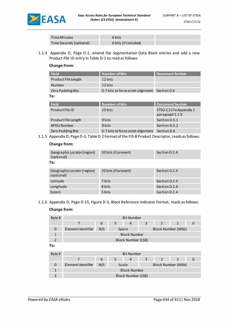
Easy Access Rules for European Technical Standard
Orders (CS-ETSO) (Amendment 8)
SUBPART B – LIST OF ETSOs
ETSO-C157a
Powered by EASA eRules Page 434 of 611| Nov 2018
Time Minutes 6 bits
Time Seconds (optional) 6 bits (if included)
1.1.4 Appendix D, Page D-1, amend the Segmentation Data Block entries and add a new
Product File ID entry in Table D-1 to read as follows:
Change From:
Field Number of Bits Document Section
Product File Length 12 bits
Number 12 bits
Zero Padding Bits 0-7 bits to force octet-alignment Section D.6
To:
Field Number of Bits Document Section
Product File ID 10 bits ETSO-C157a Appendix 1 paragraph 1.1.9
Product File Length 9 bits Section D.5.1
APDU Number 9 bits Section D.5.2
Zero Padding Bits 0-7 bits to force octet-alignment Section D.6
1.1.5 Appendix D, Page D-3, Table D-2 Format of the FIS-B Product Descriptor, reads as follows:
Change from:
Geographic Locator (region) (optional)
20 bits (if present) Section D.2.4
To:
Geographic Locator (region) (optional)
20 bits (if present) Section D.2.4
Latitude 7 bits Section D.2.4
Longitude 8 bits Section D.2.4
Extent 5 bits Section D.2.4
1.1.6 Appendix D, Page D-15, Figure D-3, Block Reference Indicator Format, reads as follows:
Change from:
Byte # Bit Number
7 6 5 4 3 2 1 0
0 Element Identifier N/S Spare Block Number (MSb)
1 Block Number
2 Block Number (LSB)
To:
Byte # Bit Number
7 6 5 4 3 2 1 0
0 Element Identifier N/S Scale Block Number (MSb)
1 Block Number
2 Block Number (LSB)
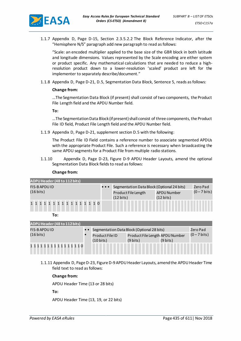
Easy Access Rules for European Technical Standard
Orders (CS-ETSO) (Amendment 8)
SUBPART B – LIST OF ETSOs
ETSO-C157a
Powered by EASA eRules Page 435 of 611| Nov 2018
1.1.7 Appendix D, Page D-15, Section 2.3.5.2.2 The Block Reference Indicator, after the “Hemisphere N/S” paragraph add new paragraph to read as follows:
“Scale: an encoded multiplier applied to the base size of the GBR block in both latitude and longitude dimensions. Values represented by the Scale encoding are either system or product specific. Any mathematical calculations that are needed to reduce a high-resolution product down to a lower-resolution ‘scaled’ product are left for the implementer to separately describe/document.”
1.1.8 Appendix D, Page D-21, D.5, Segmentation Data Block, Sentence 5, reads as follows:
Change from:
…The Segmentation Data Block (if present) shall consist of two components, the Product File Length field and the APDU Number field.
To:
…The Segmentation Data Block (if present) shall consist of three components, the Product File ID field, Product File Length field and the APDU Number field.
1.1.9 Appendix D, Page D-21, supplement section D.5 with the following:
The Product File ID Field contains a reference number to associate segmented APDUs with the appropriate Product File. Such a reference is necessary when broadcasting the same APDU segments for a Product File from multiple radio stations.
1.1.10 Appendix D, Page D-23, Figure D-9 APDU Header Layouts, amend the optional Segmentation Data Block fields to read as follows:
Change from:
ADPU Header (48 to 112 bits)
FIS-B APDU ID (16 bits)
• • • Segmentation Data Block (Optional 24 bits) Zero Pad (0 – 7 bits) Product File Length
(12 bits) APDU Number (12 bits)
1 1 1 1 1 1 1 1 1 1 1 1 1 1 1 0
To:
ADPU Header (48 to 112 bits)
FIS-B APDU ID (16 bits)
• • •
Segmentation Data Block (Optional 28 bits) Zero Pad (0 – 7 bits) Product File ID
(10 bits) Product File Length (9 bits)
APDU Number (9 bits)
1 1 1 1 1 1 1 1 1 1 1 1 1 1 1 0
1.1.11 Appendix D, Page D-23, Figure D-9 APDU Header Layouts, amend the APDU Header Time
field text to read as follows:
Change from:
APDU Header Time (13 or 28 bits)
To:
APDU Header Time (13, 19, or 22 bits)

Easy Access Rules for European Technical Standard
Orders (CS-ETSO) (Amendment 8)
SUBPART B – LIST OF ETSOs
ETSO-C157a
Powered by EASA eRules Page 436 of 611| Nov 2018
1.1.12 Appendix D, Page D-23, Figure D-9, APDU Header Layouts, add note to Option Flags table to read as follows:
“Note: A given APDU shall not have Time Flag #1 and Time Flag #2 set to one (1) within the same APDU Header.”
1.1.13 Appendix K, Page K-1, the last entry in Table K-1, reads as follows:
Change from:
The last entry in Table K-1 shows the encoding of the CC (Change Cipher) character as “011111.”
To:
The last entry in Table K-1 shows the encoding of the ”|” character as “011111.”
1.1.14 Appendix K, Page K-1, new note at the bottom of the table, reads as follows:
“| = The change cipher character is not used by FIS-B (per MASPS), so there is no expected impact on legacy users.”
[Amdt ETSO/7]

Easy Access Rules for European Technical Standard
Orders (CS-ETSO) (Amendment 8)
SUBPART B – LIST OF ETSOs
ETSO-C158
Powered by EASA eRules Page 437 of 611| Nov 2018
ETSO-C158 ED Decision 2012/009/R (applicable from 5.7.2012)
Aeronautical Mobile High Frequency Data Link (HFDL) Equipment
1 Applicability
This ETSO gives the requirements which Aeronautical Mobile High Frequency Data Link (HFDL) Equipment that are manufactured on or after the date of this ETSO must meet in order to be identified with the applicable ETSO marking.
2 Procedures
2.1 General
Applicable procedures are detailed in CS-ETSO Subpart A.
2.2 Specific
None.
3 Technical Conditions
3.1 Basic
3.1.1 Minimum Performance Standard
Standards set forth in the Radio Technical Commission for Aeronautics (RTCA) Document DO-265, Minimum Operational Performance Standards for Aeronautical Mobile High Frequency Data Link (HFDL)”, dated 14/12/2000.
3.1.2 Environmental Standard
See CS-ETSO Subpart A paragraph 2.1.
3.1.3 Computer Software
See CS-ETSO Subpart A paragraph 2.2.
3.1.4 Electronic Hardware Qualification
See CS-ETSO Subpart A paragraph 2.3.
3.2 Specific
3.2.1 Failure Condition Classification
See CS-ETSO Subpart A paragraph 2.4.
Failure of the function defined in paragraph 3.1.1 of this ETSO has been determined to be a minor failure condition.
4 Marking
4.1 General
Marking as detailed in CS-ETSO Subpart A paragraph 1.2.
4.2 Specific
None.
5 Availability of Referenced Document
See CS-ETSO Subpart A paragraph 3.

Easy Access Rules for European Technical Standard
Orders (CS-ETSO) (Amendment 8)
SUBPART B – LIST OF ETSOs
ETSO-C158
Powered by EASA eRules Page 438 of 611| Nov 2018
[Amdt ETSO/7]

Easy Access Rules for European Technical Standard
Orders (CS-ETSO) (Amendment 8)
SUBPART B – LIST OF ETSOs
ETSO-C159a
Powered by EASA eRules Page 439 of 611| Nov 2018
ETSO-C159a ED Decision 2012/009/R (applicable from 5.7.2012)
Avionics Supporting Next Generation Satellite Systems (NGSS) = Airborne Iridium Satellite Transceiver for Voice or Data
1 Applicability
This ETSO gives the requirements which Avionics Supporting Next Generation Satellite Systems (NGSS) = Airborne Iridium Satellite Transceiver for Voice or Data that are manufactured on or after the date of this ETSO must meet in order to be identified with the applicable ETSO marking.
The ETSO Authorisation does not include the verification of aspects (e.g. quality and continuity of electric power) which shall be assessed at aircraft level, but it includes verification of the system behaviour in presence of such failure conditions.
2 Procedures
2.1 General
Applicable procedures are detailed in CS-ETSO Subpart A.
2.2 Specific
None.
3 Technical Conditions
3.1 Basic
3.1.1 Minimum Performance Standard
Standards set forth in the Radio Technical Commission for Aeronautics (RTCA) Document DO-262A, Minimum Operational Performance Standards for Avionics Supporting Next Generation Satellite Systems (NGSS), dated 16/12/2008.
3.1.2 Environmental Standard
See CS-ETSO Subpart A paragraph 2.1.
3.1.3 Computer Software
See CS-ETSO Subpart A paragraph 2.2.
3.1.4 Electronic Hardware Qualification
See CS-ETSO Subpart A paragraph 2.3.
3.2 Specific
3.2.1 Failure Condition Classification
See CS-ETSO Subpart A paragraph 2.4.
Failure of the function defined in paragraph 3.1.1 of this ETSO has been determined to be a minor failure condition.
4 Marking
4.1 General
Marking as detailed in CS-ETSO Subpart A paragraph 1.2.
4.2 Specific
Easy Access Rules for European Technical Standard
Orders (CS-ETSO) (Amendment 8)
SUBPART B – LIST OF ETSOs
ETSO-C159a
Powered by EASA eRules Page 440 of 611| Nov 2018
None.
5 Availability of Referenced Document
See CS-ETSO Subpart A paragraph 3.
[Amdt ETSO/7]

Easy Access Rules for European Technical Standard
Orders (CS-ETSO) (Amendment 8)
SUBPART B – LIST OF ETSOs
ETSO-C160a
Powered by EASA eRules Page 441 of 611| Nov 2018
ETSO-C160a ED Decision 2013/012/R (applicable from 15.7.2013)
VDL Mode 2 Communications equipment
1 Applicability
This ETSO gives the requirements which VDL Mode 2 Communications equipment that are manufactured on or after the date of this ETSO must meet in order to be identified with the applicable ETSO marking.
2 Procedures
2.1 General
Applicable procedures are detailed in CS-ETSO, Subpart A.
2.2 Specific
None.
3 Technical conditions
3.1 Basic
3.1.1 Minimum performance standard
Standards set forth in the EUROCAE ED-92B, Minimum Operational Performance Standards for Aircraft VDL Mode 2 Physical, Link, and Network Layer, dated 21/03/2012. ED-92B is identical to RTCA DO-281B.
3.1.2 Environmental standard
See CS-ETSO, Subpart A, paragraph 2.1.
3.1.3 Software
See CS-ETSO, Subpart A, paragraph 2.2.
3.1.4 Airborne electronic hardware
See CS-ETSO, Subpart A, paragraph 2.3.
3.2 Specific
3.2.1 Failure condition classification
See CS-ETSO, Subpart A, paragraph 2.4.
Failure of the function defined in paragraph 3.1.1 of this ETSO has been determined to be a minor failure condition.
4 Marking
4.1 General
Marking as detailed in CS-ETSO, Subpart A, paragraph 1.2.
4.2 Specific
None.
5 Availability of referenced document
See CS-ETSO, Subpart A, paragraph 3.

Easy Access Rules for European Technical Standard
Orders (CS-ETSO) (Amendment 8)
SUBPART B – LIST OF ETSOs
ETSO-C160a
Powered by EASA eRules Page 442 of 611| Nov 2018
[Amdt ETSO/8]

Easy Access Rules for European Technical Standard
Orders (CS-ETSO) (Amendment 8)
SUBPART B – LIST OF ETSOs
ETSO-C161a
Powered by EASA eRules Page 443 of 611| Nov 2018
ETSO-C161a ED Decision 2012/009/R (applicable from 5.7.2012)
Ground Based Augmentation System Positioning and Navigation Equipment
1 Applicability
This ETSO gives the requirements which that are manufactured on or after the date of this ETSO must meet in order to be identified with the applicable ETSO marking.
2 Procedures
2.1 General
Applicable procedures are detailed in CS-ETSO Subpart A.
2.2 Specific
None
3 Technical Conditions
3.1 Basic
3.1.1 Minimum Performance Standard
Standards set forth in the Radio Technical Commission for Aeronautics (RTCA) Document DO-253C, Minimum Operational Performance Standards for GPS Local Area Augmentation System Airborne Equipment, dated 16/12/2008, section 2 as modified by appendices 1 and 2 of this ETSO for airborne equipment class (AEC) C to support Category I precision approach. These standards also apply to equipment that implements the optional GBAS positioning service. This ETSO does not apply to AEC D equipment as the additional requirements to support the GBAS Approach Service Type D and Category III precision approaches have not been validated. A new ETSO or a revision to this ETSO for AEC D equipment will be issued once these additional requirements are validated.
This TSO’s standards apply to equipment intended to output deviations relative to a precision approach path using GBAS, and to provide position information to an ETSO-C161a navigation management unit that outputs deviation commands referenced to a desired flight path. These standards do not address integration issues with other avionics except for automatic dependent surveillance. The positioning and navigation functions are defined in section 2.3 of RTCA/DO-253C. In accordance with section 2.1 of RTCA/DO-253C, equipment obtaining this ETSOA must also comply with the position, velocity and time (PVT) output requirements of either, ETSO-C145c, ETSO-C146c or ETSO-C196a.
Note: ETSO-C196a, which is based on RTCA/DO-316, Minimum Operational Performance Standards for Global Positioning System/Aircraft Based Augmentation System Airborne Equipment, is not referenced in RTCA DO-253C. RTCA/DO-316 was published after the publication of DO-253C. ETSO-C129a is not applicable to this ETSO.
3.1.2 Environmental Standard
See CS-ETSO Subpart A paragraph 2.1. The required performance is defined in RTCA/DO253C section 2.4.
3.1.3 Computer Software

Easy Access Rules for European Technical Standard
Orders (CS-ETSO) (Amendment 8)
SUBPART B – LIST OF ETSOs
ETSO-C161a
Powered by EASA eRules Page 444 of 611| Nov 2018
See CS-ETSO Subpart A paragraph 2.2.
3.1.4 - Electronic Hardware Qualification
See CS-ETSO Subpart A paragraph 2.3.
3.2 Specific
3.2.1 Failure Condition Classification
See CS-ETSO Subpart A paragraph 2.4.
Failure of the function defined in paragraph 3.1.1 of this ETSO has been determined to be a major failure condition for the malfunction of position data and a hazardous failure condition for the malfunction of precision approach navigation data.
Failure of the function defined in paragraph 3.1.1 of this ETSO has been determined to be a minor failure condition for the loss of position data and a minor failure condition for the loss of precision approach navigation data.
4 Marking
4.1 General
Marking is detailed in CS-ETSO Subpart A paragraph 1.2.
4.2 Specific
None
5 Availability of Referenced Document
See CS-ETSO Subpart A paragraph 3
[Amdt ETSO/3] [Amdt ETSO/7]
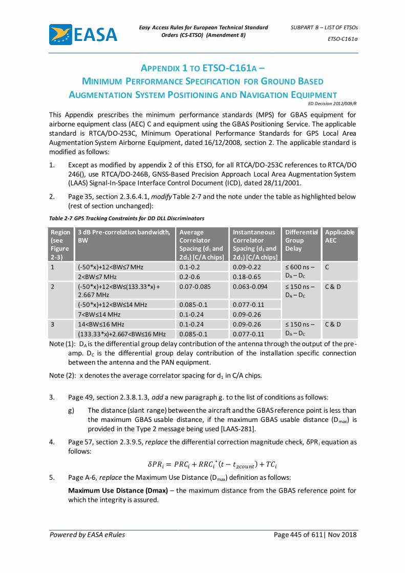
Easy Access Rules for European Technical Standard
Orders (CS-ETSO) (Amendment 8)
SUBPART B – LIST OF ETSOs
ETSO-C161a
Powered by EASA eRules Page 445 of 611| Nov 2018
APPENDIX 1 TO ETSO-C161A – MINIMUM PERFORMANCE SPECIFICATION FOR GROUND BASED
AUGMENTATION SYSTEM POSITIONING AND NAVIGATION EQUIPMENT ED Decision 2012/009/R
This Appendix prescribes the minimum performance standards (MPS) for GBAS equipment for airborne equipment class (AEC) C and equipment using the GBAS Positioning Service. The applicable standard is RTCA/DO-253C, Minimum Operational Performance Standards for GPS Local Area Augmentation System Airborne Equipment, dated 16/12/2008, section 2. The applicable standard is modified as follows:
1. Except as modified by appendix 2 of this ETSO, for all RTCA/DO-253C references to RTCA/DO 246(), use RTCA/DO-246B, GNSS-Based Precision Approach Local Area Augmentation System (LAAS) Signal-In-Space Interface Control Document (ICD), dated 28/11/2001.
2. Page 35, section 2.3.6.4.1, modify Table 2-7 and the note under the table as highlighted below (rest of section unchanged):
Table 2-7 GPS Tracking Constraints for DD DLL Discriminators
Region (see Figure 2-3)
3 dB Pre-correlation bandwidth, BW
Average Correlator Spacing (d1 and 2d1) [C/A chips]
Instantaneous Correlator Spacing (d1 and 2d1) [C/A chips]
Differential Group Delay
Applicable AEC
1 (-50*x)+12<BW≤7 MHz 0.1-0.2 0.09-0.22 ≤ 600 ns –DA – DC
C
2<BW≤7 MHz 0.2-0.6 0.18-0.65
2 (-50*x)+12<BW≤(133.33*x) + 2.667 MHz
0.07-0.085 0.063-0.094 ≤ 150 ns –DA – DC
C & D
(-50*x)+12<BW≤14 MHz 0.085-0.1 0.077-0.11
7<BW≤14 MHz 0.1-0.24 0.09-0.26
3 14<BW≤16 MHz 0.1-0.24 0.09-0.26 ≤ 150 ns –DA – DC
C & D
(133.33*x)+2.667<BW≤16 MHz 0.085-0.1 0.077-0.11
Note (1): DA is the differential group delay contribution of the antenna through the output of the pre-amp. DC is the differential group delay contribution of the installation specific connection between the antenna and the PAN equipment.
Note (2): x denotes the average correlator spacing for d1 in C/A chips.
3. Page 49, section 2.3.8.1.3, add a new paragraph g. to the list of conditions as follows:
g) The distance (slant range) between the aircraft and the GBAS reference point is less than the maximum GBAS usable distance, if the maximum GBAS usable distance (Dmax) is provided in the Type 2 message being used [LAAS-281].
4. Page 57, section 2.3.9.5, replace the differential correction magnitude check, δPR i equation as follows:
𝛿𝑃𝑅𝑖 = 𝑃𝑅𝐶𝑖 + 𝑅𝑅𝐶𝑖∗(𝑡 − 𝑡𝑧𝑐𝑜𝑢𝑛𝑡) + 𝑇𝐶𝑖
5. Page A-6, replace the Maximum Use Distance (Dmax) definition as follows:
Maximum Use Distance (Dmax) – the maximum distance from the GBAS reference point for which the integrity is assured.

Easy Access Rules for European Technical Standard
Orders (CS-ETSO) (Amendment 8)
SUBPART B – LIST OF ETSOs
ETSO-C161a
Powered by EASA eRules Page 446 of 611| Nov 2018
6. If a manufacturer elects to provide the authentication capability in its equipment as specified in section 2.3.7.3 of RTCA/DO-253C, the equipment shall also perform the differential correction magnitude check in section 2.3.9.5.
NOTE: There are additional sections of RTCA DO-246D that are applicable when VDB authentication is implemented. These are specified in appendix 2.
7. Summary of ETSO changes relative to DO-253C.
LAAS Requirement Designator [LAAS-xxx] Change Status from DO-253C
093 Changed
123 Changed
281 Added
351 and 352 New application (see item 6 above)
[Amdt ETSO/7]

Easy Access Rules for European Technical Standard
Orders (CS-ETSO) (Amendment 8)
SUBPART B – LIST OF ETSOs
ETSO-C161a
Powered by EASA eRules Page 447 of 611| Nov 2018
APPENDIX 2 TO ETSO-C161A – MINIMUM PERFORMANCE SPECIFICATION FOR
GNSS-BASED PRECISION APPROACH LOCAL AREA AUGMENTATION SYSTEM
(LAAS) SIGNAL-IN-SPACE INTERFACE CONTROL DOCUMENT (ICD) ED Decision 2012/009/R
This Appendix prescribes the interface control document for GBAS as it applies to AEC C for this ETSO. The applicable standard is RTCA/DO-246B, GNSS-Based Precision Approach Local Area Augmentation System (LAAS) Signal-in-Space Interface Control Document, dated 28 November 2001. The applicable standard is modified as follows:
1. Page 22, replace the ephemeris CRC bit order of transmission in section 2.4.3.2. Message Type 1 parameters, with the updated definition in the latest revision, RTCA/DO-246D, dated December 16, 2008, section 2.4.3.2.
NOTE: This change reorders the bits of the ephemeris CRC from their previous transmission order of r1, r2, r3, r4 … r16, where r1 is the least significant bit and bit r16 is the most significant bit, to r9, r10, r11 … r16, followed by r1, r2, … r8, where r9 and r1 are the first bits of each bite into the bit scrambler. This change is not backwards compatible with the existing standard. The change was adopted for compatibility with a significant number of current implementations of ground equipment and avionics. This change affects [LAAS-107], [LAAS-117], [LAAS-118], and [LAAS-214]. Other changes to RTCA/DO-246B, reflected in RTCA/DO-246D, to support the newly incorporated GBAS Approach Service Type D are not relevant for this ETSO and should not be implemented.
2. Appendix A, replace appendix A, Cyclic Redundancy Checks (CRCs), with RTCA/DO-246D, Appendix A.
3. Page B-2, replace Table B-1 Example of Type 1 Message, with RTCA/DO-246D, Table B-1.
4. Page B-4, replace Table B-2 Example of Type 1 and Type 2 Messages in One Burst with RTCA/DO-246D, Table B-2.
5. Page B-7, replace Table B-3 Example of Type 4 Message with RTCA/DO-246D, Table B-4 as modified below for the runway number valid range.
The valid range for runway number is 1-36.
6. Page B-10, replace Table B-4 Example of Type 5 Message with RTCA/DO-246D, appendix B, Table B-6, Example of Type 5 Message.
7. If a manufacturer elects to provide the authentication capability in its equipment as specified in section 2.3.7.3 of RTCA/DO-253C, the following paragraphs from RTCA/DO-246D, dated 16/12/2008 are applicable:
a. Message Type 2, Additional Data Block 4, VDB Authentication Parameters description and Table 2-16 in DO-246D, section 2.4.4.1, pages 33 and 35.
b. Message Type 3 – Null Message and Table 2-17 Format of Message Type 3 in DO-246D, section 2.4.5, page 37.
c. Reference Path Identifier in DO-246D, section 2.4.6.4, page 53.
8. Summary of RTCA/DO-253C requirements affected by these modifications to DO-246B.
Appendix 2 Item number LAAS Requirement Designator [LAAS-xxx]
1 107, 117, 118, 214
2 Editorial

Easy Access Rules for European Technical Standard
Orders (CS-ETSO) (Amendment 8)
SUBPART B – LIST OF ETSOs
ETSO-C161a
Powered by EASA eRules Page 448 of 611| Nov 2018
3 Editorial
4 Editorial
5 Editorial
6 Editorial
7 328, 329, 330 and 331
[Amdt ETSO/7]

Easy Access Rules for European Technical Standard
Orders (CS-ETSO) (Amendment 8)
SUBPART B – LIST OF ETSOs
ETSO-C162a
Powered by EASA eRules Page 449 of 611| Nov 2018
ETSO-C162a ED Decision 2012/009/R (applicable from 5.7.2012)
Ground Based Augmentation System Very High Frequency Data Broadcast Equipment
1 Applicability
This ETSO gives the requirements which Ground Based Augmentation System Very High Frequency Data Broadcast Equipment that are manufactured on or after the date of this ETSO must meet in order to be identified with the applicable ETSO marking.
2 Procedures
2.1 General
Applicable procedures are detailed in CS-ETSO Subpart A.
2.2 Specific
None.
3 Technical Conditions
3.1 Basic
3.1.1 Minimum Performance Standard
Standards set forth in the Radio Technical Commission for Aeronautics (RTCA) Document DO-253C, Minimum Operational Performance Standards for GPS Local Area Augmentation System Airborne Equipment, dated 16/12/2008.
NOTE:All RTCA/DO-253C references to RTCA/DO 246() apply to RTCA/DO-246B, GNSS-Based Precision Approach Local Area Augmentation System (LAAS) Signal-In-Space Interface Control Document (ICD), dated November 28, 2001. Modifications to these references are noted in appendix 2 of ETSO-C161a.
3.1.2 Environmental Standard
See CS-ETSO Subpart A paragraph 2.1.
3.1.3 Computer Software
See CS-ETSO Subpart A paragraph 2.2.
3.1.4 Electronic Hardware Qualification
See CS-ETSO Subpart A paragraph 2.3.
3.2 Specific
3.2.1 Failure Condition Classification
See CS-ETSO Subpart A paragraph 2.4.
Failure or loss of the function defined in paragraph 3.1.1 of this ETSO has been determined to be a minor failure condition.
4 Marking
4.1 General
Marking as detailed in CS-ETSO Subpart A paragraph 1.2.
4.2 Specific

Easy Access Rules for European Technical Standard
Orders (CS-ETSO) (Amendment 8)
SUBPART B – LIST OF ETSOs
ETSO-C162a
Powered by EASA eRules Page 450 of 611| Nov 2018
None.
5 Availability of Referenced Document
See CS-ETSO Subpart A paragraph 3.
[Amdt ETSO/7]

Easy Access Rules for European Technical Standard
Orders (CS-ETSO) (Amendment 8)
SUBPART B – LIST OF ETSOs
ETSO-C164
Powered by EASA eRules Page 451 of 611| Nov 2018
ETSO-C164 ED Decision 2013/012/R (applicable from 15.7.2013)
Night Vision Goggles (NVG)
1 Applicability
This ETSO gives the requirements which Night Vision Goggles (NVG) that are manufactured on or after the date of this ETSO must meet in order to be identified with the applicable ETSO marking.
2 Procedures
2.1 General
Applicable procedures are detailed in CS-ETSO, Subpart A.
2.2 Specific
None.
3 Technical conditions
3.1 Basic
3.1.1 Minimum performance standard
Standards set forth in the RTCA DO-275, Minimum Operational Performance Standards for Integrated Night Vision Imaging System Equipment, dated 12/10/2001.
3.1.2 Environmental standard
See CS-ETSO, Subpart A, paragraph 2.1.
3.1.3 Software
See CS-ETSO, Subpart A, paragraph 2.2.
3.1.4 Airborne electronic hardware
See CS-ETSO, Subpart A, paragraph 2.3.
3.2 Specific
3.2.1 Failure condition classification
See CS-ETSO, Subpart A, paragraph 2.4.
Failure of the function defined in paragraph 3.1.1 of this ETSO has been determined to be a major failure condition.
4 Marking
4.1 General
Marking as detailed in CS-ETSO, Subpart A, paragraph 1.2.
4.2 Specific
If the night vision goggle includes airborne software, then the part number must include hardware and software identification. Or, you can use a separate part number for hardware and software. Either way, you must include a means for showing the modification status.

Easy Access Rules for European Technical Standard
Orders (CS-ETSO) (Amendment 8)
SUBPART B – LIST OF ETSOs
ETSO-C164
Powered by EASA eRules Page 452 of 611| Nov 2018
5 Availability of referenced document
See CS-ETSO, Subpart A, paragraph 3.
[Amdt ETSO/8]

Easy Access Rules for European Technical Standard
Orders (CS-ETSO) (Amendment 8)
SUBPART B – LIST OF ETSOs
ETSO-C165
Powered by EASA eRules Page 453 of 611| Nov 2018
ETSO-C165 ED Decision 2010/010/R (applicable from 21.12.2010)
Electronic Map Display Equipment for Graphical Depiction of Aircraft Position
1 Applicability
This ETSO gives the requirements which new models of Electronic Map Display Equipment for Graphical Depiction of Aircraft Position, that are manufactured on or after the date of this ETSO, must meet in order to be identified with the applicable ETSO marking.
2 Procedures
2.1 General
Applicable procedures are detailed in CS-ETSO Subpart A.
2.2 Specific
None
3 Technical Conditions
3.1 Basic
3.1.1 Minimum Performance Standard
New models of Electronic Map Displays that are to be so identified and that are manufactured on or after the effective date of this ETSO must meet the standards set forth for moving map equipment in Section 2 of RTCA document DO-257A, “Minimum Operational Performance Standards for the Depiction of Navigational Information on Electronic Maps,” dated June, 25, 2003.
Electronic Map Displays for use in flight must meet the MPS in Sections 2.1 and 2.2 of DO-257A.
Electronic Map Displays for use on the airport surface must meet the MPS in Sections 2.1, 2.2, and 2.3 of DO-257A, and Electronic Map Displays including Vertical Situation Displays (VSD) for use in facilitating pilot ’s awareness of the aircraft’s vertical flight path must meet the MPS in Sections 2.1, 2.2, and 2.4 of DO-257A.
3.1.2 Environmental Standard
See CS-ETSO Subpart A paragraph 2.1.
3.1.3 Computer Software
See CS-ETSO Subpart A paragraph 2.2
3.1.4 Electronic Hardware Qualification.
See CS-ETSO Subpart A paragraph 2.3
3.2 Specific
3.2.1 Failure Condition Classification
See CS-ETSO Subpart A paragraph 2.4
Failure of the functions defined in paragraph 3.1.1 of this ETSO for Electronic Map Displays used in flight and VSD equipment (airborne applications) have been

Easy Access Rules for European Technical Standard
Orders (CS-ETSO) (Amendment 8)
SUBPART B – LIST OF ETSOs
ETSO-C165
Powered by EASA eRules Page 454 of 611| Nov 2018
determined to be a major failure condition for malfunctions causing the display of misleading information.
Loss of function for Electronic Map Displays used in flight and VSD equipment (airborne applications) have been determined to be a minor failure condition.
Failure of the function defined in paragraph 3.1.1 of this ETSO for Electronic Map Displays used on the airport surface (ground applications) have been determined to be a minor failure condition for malfunctions causing the display of misleading information.
Loss of function for Electronic Map Displays used on the airport surface (ground applications) is determined to be a no safety effect failure condition.
4 Marking
4.1 General
Marking is detailed in CS-ETSO Subpart A paragraph 1.2
4.2 Specific
None
5 Availability of Referenced Document
See CS-ETSO Subpart A paragraph 3
[Amdt ETSO/6]
Easy Access Rules for European Technical Standard
Orders (CS-ETSO) (Amendment 8)
SUBPART B – LIST OF ETSOs
ETSO-C166b A1
Powered by EASA eRules Page 455 of 611| Nov 2018
ETSO-C166b A1 ED Decision 2013/012/R (applicable from 15.7.2013)
Extended Squitter Automatic Dependent Surveillance-Broadcast (ADS-B) and Traffic Information Services-Broadcast (TIS-B) Equipment Operating on the Radio Frequency of
1090 Megahertz (MHz)
1 Applicability
This ETSO gives the requirements which Extended Squitter Automatic Dependent Surveillance - Broadcast (ADS-B) and Traffic Information Services - Broadcast (TIS-B) Equipment Operating on the Radio Frequency of 1090 Megahertz (MHz) that are manufactured on or after the date of this ETSO must meet in order to be identified with the applicable ETSO marking.
2 Procedures
2.1 General
Applicable procedures are detailed in CS-ETSO, Subpart A.
2.2 Specific
None
3 Technical conditions
3.1 Basic
3.1.1 Minimum performance standard
Standards set forth in the EUROCAE ED-102A, Minimum Operational Performance Standards for 1090 MHz Extended Squitter Automatic Dependent Surveillance - Broadcast (ADS-B) and Traffic Information Services - Broadcast (TIS-B), dated December 2009, section 2.
This ETSO supports two major classes of 1090 MHz ADS-B and TIS-B equipment:
(a) Class A equipment, consisting of transmit and receive subsystems; and
(b) Class B equipment, containing a transmit subsystem only.
Class A equipment includes Classes A0, A1, A1S, A2 and A3. This standard requires 1090 MHz airborne Class A equipment to include the capability of receiving both ADS-B and TIS-B messages and delivering both ADS-B and TIS-B reports, as well as transmitting ADS-B messages. A receive-only Class of equipment is allowed.
Class B equipment includes Classes B0, B1, and B1S. Classes B0, B1, and B1S are the same as A0, A1, and A1S, except they do not have receive subsystems. Note that Classes B2 and B3 are not for aircraft use.
3.1.2 Environmental standard
See CS-ETSO, Subpart A, paragraph 2.1. The required performance under test conditions is defined in RTCA/DO-260B, section 2.4.
3.1.3 Software
See CS-ETSO, Subpart A, paragraph 2.2.
3.1.4 Airborne electronic hardware
See CS-ETSO, Subpart A, paragraph 2.3.

Easy Access Rules for European Technical Standard
Orders (CS-ETSO) (Amendment 8)
SUBPART B – LIST OF ETSOs
ETSO-C166b A1
Powered by EASA eRules Page 456 of 611| Nov 2018
3.2 Specific
3.2.1 Failure condition classification
See CS-ETSO, Subpart A, paragraph 2.4.
Failure of the function defined in paragraph 3.1.1 of this ETSO has been determined to be a major failure condition.
NOTE: The major failure condition for transmission of incorrect ADS-B messages is based on use of the data by other aircraft or Air Traffic Control for separation services.
4 Marking
4.1 General
Marking is detailed in CS-ETSO, Subpart A, paragraph 1.2.
4.2 Specific
Transmitting and receiving components must be permanently and legibly marked.
The following table explains how to mark components.
RTCA/DO-260B provides the equipment class in Section 2.1.11, and the receiving equipment type in Section 2.2.6.
If component can: Mark it with: Sample marking pattern:
Transmit and receive Equipment class it supports, and Receiving equipment type
Class A0/Type 1
Transmit, but not receive Equipment class it supports Class B1, or Class A3-Transmitting Only
Receive, but not transmit Equipment class it supports, and Receiving equipment type
Class A2/Type 2-Receiving Only
5 Availability of referenced document
See CS-ETSO, Subpart A, paragraph 3
[Amdt ETSO/3] [Amdt ETSO/7] [Amdt ETSO/8]

Easy Access Rules for European Technical Standard
Orders (CS-ETSO) (Amendment 8)
SUBPART B – LIST OF ETSOs
ETSO-C170
Powered by EASA eRules Page 457 of 611| Nov 2018
ETSO-C170 ED Decision 2012/009/R (applicable from 5.7.2012)
High Frequency (HF) Radio Communications Transceiver Equipment Operating Within the Radio Frequency 1.5 to 30 Megahertz
1 Applicability
This ETSO gives the requirements which High Frequency (HF) Radio Communications Transceiver Equipment Operating Within the Radio Frequency 1.5 to 30 Megahertz that are manufactured on or after the date of this ETSO must meet in order to be identified with the applicable ETSO marking.
This ETSO cancels ETSO-C31d “High Frequency (HF) Radio Communications Transmitting Equipment Operating within the Radio Frequency Range 1.5-30 Megahertz” and ETSO-C32d “High Frequency (HF) Radio Communications Receiving Equipment Operating within the Radio Frequency Range 1.5-30 Megahertz”.
2 Procedures
2.1 General
Applicable procedures are detailed in CS-ETSO Subpart A.
2.2 Specific
None.
3 Technical Conditions
3.1 Basic
3.1.1 Minimum Performance Standard
Standards set forth in the Radio Technical Commission for Aeronautics (RTCA) Document DO-163, Minimum Operational Performance Standards - Airborne HF Radio Communications Transmitting and Receiving Equipment Operating within the Radio-Frequency Range of 1.5 to 30 MHz, dated 09/03/1976.
3.1.2 Environmental Standard
See CS-ETSO Subpart A paragraph 2.1.
3.1.3 Computer Software
See CS-ETSO Subpart A paragraph 2.2.
3.1.4 Electronic Hardware Qualification
See CS-ETSO Subpart A paragraph 2.3.
3.2 Specific
3.2.1 Failure Condition Classification
See CS-ETSO Subpart A paragraph 2.4.
Failure of the function defined in paragraph 3.1.1 of this ETSO has been determined to be a minor failure condition.
4 Marking
4.1 General

Easy Access Rules for European Technical Standard
Orders (CS-ETSO) (Amendment 8)
SUBPART B – LIST OF ETSOs
ETSO-C170
Powered by EASA eRules Page 458 of 611| Nov 2018
Marking as detailed in CS-ETSO Subpart A paragraph 1.2.
4.2 Specific
None
5 Availability of Referenced Document
See CS-ETSO Subpart A paragraph 3.
[Amdt ETSO/7]

Easy Access Rules for European Technical Standard
Orders (CS-ETSO) (Amendment 8)
SUBPART B – LIST OF ETSOs
ETSO-C172
Powered by EASA eRules Page 459 of 611| Nov 2018
ETSO-C172 ED Decision 2012/009/R (applicable from 5.7.2012)
Cargo Restraint Strap Assemblies
1 Applicability
This ETSO gives the requirements which Cargo Restraint Strap Assemblies that are manufactured on or after the date of this ETSO must meet in order to be identified with the applicable ETSO marking.
2 Procedures
2.1 General
Applicable procedures are detailed in CS-ETSO Subpart A.
2.2 Specific
None.
3 Technical Conditions
3.1 Basic
3.1.1 Minimum Performance Standard
Standards set forth in the SAE AS 5385C, Cargo Restraint Straps - Design Criteria and Testing Methods, dated January 2007, as amended by Appendix 1 of this ETSO.
3.1.2 Environmental Standard
See Section 4 of SAE AS 5385C.
3.1.3 Computer Software
None.
3.1.4 Electronic Hardware Qualification
None.
3.2 Specific
3.2.1 Failure Condition Classification
N/A
4 Marking
4.1 General
Marking as detailed in CS-ETSO Subpart A paragraph 1.2. In addition, each Cargo Restraint Strap Assemblies shall be legibly and permanently marked in accordance with SAE AS 5385C, section 7.3 with the following:
(i) dates of manufacture and expiration per SAE AS 5385C, section 4.5.2. Format the dates per SAE AS 5385C, section 7.2.
(ii) the rated ultimate load in daN and lbf.
(iii) a unique identifier if required by SAE AS 5385C, section 4.5.2(b).
Also mark permanently and legibly, with at least the manufacturer’s name, subassembly part number, and the ETSO number:

Easy Access Rules for European Technical Standard
Orders (CS-ETSO) (Amendment 8)
SUBPART B – LIST OF ETSOs
ETSO-C172
Powered by EASA eRules Page 460 of 611| Nov 2018
(1) each component that is easily removable (without hand tool), and
(2) each subassembly of the article that may be interchangeable.
NOTE 1: any extra information listed in SAE AS 5385C, section 7, not specifically required in this paragraph, may be marked.
NOTE 2: Compliance with this ETSO does not necessarily indicate compliance with SAE AS 5385C. To make the cargo strap assembly as complying with SAE AS 5385C, the cargo strap assembly must be shown to meet the requirements of SAE AS 5385C in conformance with SAE AS 5385C, Para 7.1 and Note 8.
4.2 Specific
None
5 Availability of Referenced Document
See CS-ETSO Subpart A paragraph 3.
[Amdt ETSO/7]

Easy Access Rules for European Technical Standard
Orders (CS-ETSO) (Amendment 8)
SUBPART B – LIST OF ETSOs
ETSO-C172
Powered by EASA eRules Page 461 of 611| Nov 2018
APPENDIX 1 TO ETSO-C172 – MINIMUM PERFORMANCE STANDARD FOR
CARGO RESTRAINT STRAP ASSEMBLIES ED Decision 2012/009/R
This Appendix prescribes the MPS for cargo restraint strap assemblies. The applicable standard is SAE AS 5385C “Cargo Restraint Straps – Design Criteria and Testing Methods”, dated January 2007 modified as follows:
AS5385C Section Action
1 Disregard
2 Modify Paragraph 2. “REFERENCES” by disregarding the last sentence.
3 Disregard 3.14
4 Disregard 4.5.4 and 4.9.1 Modify 4.5.1 by adding the following note: “NOTE: Environmental degradation data other than that documented in AIR490B may be used if substantiated by the Applicant and approved by the Agency.”
5 Disregard 5.9, 5.10 and 5.11 Modify 5.1 by adding the following note: “NOTE: Equivalent alternate methods must be approved by the Agency”.
6 Disregard
7 Apply per Paragraph 4 of this ETSO
8 Disregard
9 Disregard
10 Disregard
[Amdt ETSO/7]

Easy Access Rules for European Technical Standard
Orders (CS-ETSO) (Amendment 8)
SUBPART B – LIST OF ETSOs
ETSO-C173
Powered by EASA eRules Page 462 of 611| Nov 2018
ETSO-C173 ED Decision 2008/012/R (applicable from 18.11.2008)
Nickel-Cadmium and Lead-Acid Batteries
1 Applicability
This ETSO gives the requirements which Nickel-Cadmium and Lead-Acid Batteries that are manufactured on or after the effective date of this ETSO must meet in order to be identified with the applicable ETSO marking.
2 Procedures
2.1 General
Applicable procedures are detailed in CS-ETSO Subpart A.
2.2 Specific
None
3 Technical Conditions
3.1 Basic
3.1.1 Minimum Performance Standard
RTCA standard DO-293 “Minimum Operational Performance Standards (MPS) for Nickel-Cadmium and Lead-Acid Batteries” (from 29 July 2004).
3.1.2 Environmental Standard
Nickel-cadmium and lead-acid batteries must be tested according to the conditions specified in RTCA/DO-293.
Were in RTCA/DO-293, the information references to ED-14D (RTCA DO-160D) "Environmental Conditions and Test Procedures for Airborne Equipment", from July 29, 1997, ED-14E (RTCA DO-160E) from March 2005 must be used instead of ED-14D (RTCA DO-160D).
3.1.3 Computer Software
None
3.2 Specific
None
4 Marking
4.1 General
Marking is detailed in CS-ETSO Subpart A paragraph 1.2.
4.2 Specific
Each Nickel-Cadmium and Lead-Acid Battery must be permanently and legibly marked according to information provided in RTCA/DO-293, Section 1.10.
5 Availability of Referenced Document
See CS-ETSO Subpart A paragraph 3
[Amdt ETSO/3]

Easy Access Rules for European Technical Standard
Orders (CS-ETSO) (Amendment 8)
SUBPART B – LIST OF ETSOs
ETSO-C174 A1
Powered by EASA eRules Page 463 of 611| Nov 2018
ETSO-C174 A1 ED Decision 2013/012/R (applicable from 15.7.2013)
Battery-based Emergency Power Unit (BEPU)
1 Applicability
This ETSO gives the requirements which Battery based Emergency Power Units (BEPU) that are manufactured on or after the date of this ETSO must meet in order to be identified with applicable ETSO marking.
2 Procedures
2.1 General
Applicable procedures are detailed in CS-ETSO, Subpart A.
2.2 Specific
None.
3 Technical conditions
3.1 Basic
3.1.1 Minimum performance standard
Standards are given in Appendix 1.
Note: The battery used in the BEPU must meet the requirements of ETSO-C173 "Nickel-Cadmium and Lead Acid Batteries" or any other battery standards acceptable to the Agency.
3.1.2 Environmental standard
As stated in Appendix 1, chapter 2, of this ETSO.
3.1.3 Software
See CS-ETSO, Subpart A, paragraph 2.2.
3.1.4 Airborne electronic hardware
See CS-ETSO, Subpart A, paragraph 2.3.
3.2 Specific
3.2.1 Failure condition classification
See CS-ETSO, Subpart A, paragraph 2.4.
4 Marking
4.1 General
Marking is detailed in CS-ETSO, Subpart A, paragraph 1.2.
4.2 Specific
Product label shall indicate:
battery capacity (e.g. 20 Amp-Hour (Ah)),
nominal voltage,
battery chemistry.

Easy Access Rules for European Technical Standard
Orders (CS-ETSO) (Amendment 8)
SUBPART B – LIST OF ETSOs
ETSO-C174 A1
Powered by EASA eRules Page 464 of 611| Nov 2018
5 Availability of referenced document
See CS-ETSO, Subpart A, paragraph 3
[Amdt ETSO/3] [Amdt ETSO/8]

Easy Access Rules for European Technical Standard
Orders (CS-ETSO) (Amendment 8)
SUBPART B – LIST OF ETSOs
ETSO-C174 A1
Powered by EASA eRules Page 465 of 611| Nov 2018
APPENDIX 1 TO ETSO-C174 A1 – MINIMUM PERFORMANCE STANDARD FOR
BATTERY-BASED EMERGENCY POWER UNIT (BEPU) ED Decision 2013/012/R
CHAPTER 1: MINIMUM PERFORMANCE STANDARD UNDER STANDARD CONDITIONS
1 PURPOSE
These are the requirements under standard conditions for a Battery-based Emergency Power Units (BEPU) to meet the Minimum Performance Standard for this ETSO. The performance of specific equipment may be enhanced, depending on its intended application and configuration.
2 GENERAL REQUIREMENTS
The BEPU must meet the power quality requirements of MIL-STD-704F, Aircraft Electrical Power Characteristics, dated March 12, 2004, and maintain the rated values and functionality according to its specification data sheet, unless otherwise specified in this ETSO.
(a) Design the BEPU to minimize the risk of causing or spreading a fire.
(b) Storage batteries must be designed and installed as follows: Safe cell temperatures and pressures must be maintained during any probable charging or discharging condition. No uncontrolled increase in cell temperature may result when the battery is recharged (after previous complete discharge):
at maximum regulated voltage or power,
during a flight of maximum duration, and,
under the most adverse cooling condition likely to occur in service.
(c) Demonstrate the above conditions by test, unless your experience with similar batteries and installations has shown that maintaining safe cell temperatures and pressures do not present a problem.
(d) Systems like electronic circuits installed in the BEPU must be compatible with the battery chemistry.
(e) During a failure of the normal power source to the emergency electrical bus, the BEPU supplies emergency electrical bus loads without intervention by the flight crew. After re-establishment of the normal power source, the emergency bus loads revert automatically from the BEPU to the normal power source, and the BEPU automatically returns to charging mode. To prevent inadvertent recharging of the BEPU from the aircraft battery when a normal power source is not available, the BEPU shall not enter the recharge mode when the BEPU input (source) voltage is below 24VDC.
(f) Specify the value of voltage spikes occurring when the BEPU is switched on and off and between modes (if applicable).
(g) Any single component failure within the BEPU (either open or short) cannot result in an over voltage condition on the battery.
(h) The BEPU will not have any protection/provision that results in automatic removal of power from the emergency load.
(i) The BEPU will not discharge through the input side of the BEPU.
(j) If the BEPU provides backup power to multiple loads, equip the BEPU with protection provisions that allow for the isolation and removal of excess load on any of its output

Easy Access Rules for European Technical Standard
Orders (CS-ETSO) (Amendment 8)
SUBPART B – LIST OF ETSOs
ETSO-C174 A1
Powered by EASA eRules Page 466 of 611| Nov 2018
feeders that draw more than its pre-determined maximum current. This will protect remaining loads in case of a load short circuit.
(k) The BEPU should not drain its battery power when the aircraft power is off.
(l) Charge fully the battery before installation. Charge the battery every time the aircraft is powered up, regardless of cockpit switch position.
(m) The charging time from 20 % to 80 % capacity will be less than 3 hours.
(n) Specify the nominal current and the short time maximum current.
(o) Design the BEPU in such a way so that separation devices placed between input, output, and battery will enable the current flow from input to output, even when there is a malfunction with other BEPU components. The separation devices will prevent current flow in the direction from output (respectively the battery) to input, and from output to battery. See Figure A-2 at the end of this appendix. The minimum current rating of the separation devices must be greater than three times the continuous rated output current of the BEPU. Unless provided in the aircraft, design the BEPU to prevent output current greater than 30 milliamperes (mA) from flowing back to battery. The loss (breakdown) of voltage of such separation devices will exceed three times the BEPU rated voltage.
(p) The maximum output voltage ripple cannot exceed the limits stated in MIL- STD-704F. Note this limit does not include the ripple already on the input line into the BEPU. (See Figure A-3 at the end of this appendix.)
(q) To preclude catastrophic effects of excess temperature, the BEPU will monitor battery temperature during battery-charging cycles, and remove power when over temperature limits are reached. Applications where excessive battery temperature cannot cause catastrophic events do not require monitoring.
(r) If the BEPU contains a battery heater device, a single-fault failure redundancy protection is required to prevent heater runaway.
3 CAPACITY AND RELATED PARAMETERS
The parameters listed in this section under environmentally benign and ground benign conditions at 25°C must be provided. Considered nominal conditions follow.
(a) BEPU capacity. Specify the value for the nominal capacity in Amp-Hours (Ah) based on a constant discharge current for 1.0 hour. During capacity testing the output voltage cannot degrade below 20VDC.
(b) BEPU output voltage excursions. Provide graphs of output voltage versus time for the following conditions:
complete discharge to low voltage dropout point after being fully charged;
complete discharge to low voltage dropout point after being charged to 72% capacity. This (72% capacity) represents a BEPU at the end of its life and 90% state of charge.
(c) BEPU life. Declare the expected battery life based on the number of 100% discharge cycles on the battery nameplate. Battery life is expired when 80% of the capacity stated on the nameplate is reached.
(d) BEPU maximum current consumption. Specify the maximum current consumption (excluding external loads) of the BEPU. Maximum current includes charging, heating, and other functionalities performed by electronic circuits.

Easy Access Rules for European Technical Standard
Orders (CS-ETSO) (Amendment 8)
SUBPART B – LIST OF ETSOs
ETSO-C174 A1
Powered by EASA eRules Page 467 of 611| Nov 2018
(e) BEPU output current. Specify the nominal current that can be delivered by the BEPU related to the nominal Ah rating specified in paragraph 3.a of this Chapter 1 "CAPACITY AND RELATED PARAMETERS", and the short time maximum current versus time, if necessary.
4 MONITOR AND CONTROL
(a) Instrumentation, data read-outs, and controls can be provided by support equipment instead of the BEPU.
(b) Design all instrumentation and data read-outs for easy interpretation to avoid misunderstandings.
(c) The BEPU can have (but is not limited to) the following optional controls:
BEPU Off: Battery power is disconnected from all loads;
BEPU Arm: Ready to engage power to the loads if aircraft power is lost. The BEPU should be in “charging mode” unless there is a failure of the emergency bus;
BEPU On/Engage: Causes the battery to be applied to the loads. The BEPU should be in “charging code” unless during failure of the emergency bus.
(d) Provide a test function for pre-flight check, showing the system function and battery status. The battery is considered good with 80% state of charge. We recommend an in-flight low battery warning indication. Perform a lamp test where the checked segments are lighted.
CHAPTER 2: MINIMUM PERFORMANCE STANDARD UNDER ENVIRONMENTAL TEST CONDITIONS
1 GENERAL
Unless otherwise specified, applicable test procedures are defined in CS-ETSO, Subpart A paragraph 2.1.
2 PERFORMANCE TESTS
The following environmental tests verify BEPU operations based on manufacturer specifications and requirements under extreme environmental conditions. If the manufacturer’s specifications during these tests are different than those recorded under benign environmental conditions as specified in paragraph 3 of Chapter 1 of this Appendix, the manufacturer will specify the modified rating and under what condition such ratings would occur. For the following tests, determine compliance of the BEPU with the manufacturer’s nominal ratings (unless otherwise specified) as referenced in paragraph 3 of Chapter 1 of this Appendix except when otherwise noted, charge the batteries to at least 80 % of manufacturers rated capacity before conducting these tests:
1. BEPU capacity using nominal current discharge;
2. BEPU output voltage excursion;
3. BEPU current consumption.
For the applicable environmental test requirements see ETSO, Subpart A, paragraph 2.1:
(a) Section 4, Temperature and Altitude.
Operating Low Temperature Test. You may use an internal battery heater for this test.
Easy Access Rules for European Technical Standard
Orders (CS-ETSO) (Amendment 8)
SUBPART B – LIST OF ETSOs
ETSO-C174 A1
Powered by EASA eRules Page 468 of 611| Nov 2018
Operating High Temperature Test
Altitude Test
Decompression Test
Overpressure Test
(b) Section 5, Temperature Variation. Combine this test with Section 4 Testing Requirements.
(c) Section 6, Humidity.
(d) Section 7, Operational Shocks and Crash Safety. After this test, the equipment must remain in its mounting with no part of the equipment or its mounting becoming detached and free on the shock test table. Measure and record the BEPU capacity after completion.
Note: These tests may damage the equipment. Therefore, these tests may be conducted last.
(e) Section 8, Vibration. While the equipment is subjected to this test, ensure that all mechanical devices operate satisfactorily and that the mechanical construction remains undamaged.
(f) Section 9, Explosion Proofness. Required only if the BEPU contains components that are known to cause inductive arcing.
(g) Section 10, Water Proofness (if required).
(h) Section 11 Fluids Susceptibility (if required). Not mandatory for ETSO approval.
(i) Section 12, Sand and Dust (if required).
(j) Section 13, Fungus Resistance (if required). Compliance by analysis is acceptable.
(k) Section 15, Magnetic Effect.
(l) Section 16, Power Input.
(m) Section 17, Voltage Spike. During and after this test, no failed parts must exist, including any degradation on component voltage and current ratings. No parasitic or transient mode switching can result from this test.
(n) Section 18, Audio Frequency Conducted Susceptibility – Power Inputs. Conduct by charging the BEPU when its capacity is between 0% and 75%. No parasitic or transient mode switching can result from this test.
(o) Section 19, Induced Signal Susceptibility. No parasitic or transient mode switching can result from this test.
(p) Section 20, RF Susceptibility. No parasitic or transient mode switching can result from this test.
(q) Section 21, Emission of RF Energy. Conduct while BEPU is being charged. Charge must be between 0% and 75% of capacity during this test.
(r) Section 22, Lightning Induced Transient Susceptibility. No parasitic or transient mode switching can result from this test.
(s) Section 23, Lightning Direct Effects. Not mandatory for this ETSO approval. If you conduct this test, no failed parts may exist during and after the test. Failed parts include any degradation on component voltage and current ratings. No parasitic or transient mode switching should result during this test.

Easy Access Rules for European Technical Standard
Orders (CS-ETSO) (Amendment 8)
SUBPART B – LIST OF ETSOs
ETSO-C174 A1
Powered by EASA eRules Page 469 of 611| Nov 2018
(t) Section 24, Icing. Not mandatory for this ETSO approval. If you conduct this test, no failed parts may exist during and after the test. Failed parts include any degradation on component voltage and current ratings.
(u) Section 25, Electrical Discharge.
CHAPTER 3: ELECTRICAL TEST PROCEDURES
1 GENERAL
Electrical test procedures covered under environmental test conditions in Chapter 2 of this Appendix are conducted according to the test procedures are outlined below.
2 GENERAL TEST CONDITIONS
Unless otherwise specified, the following test conditions apply:
(a) Conduct all tests under conditions of ambient room temperature (except sections 4, 5 and 6) and ambient pressure and humidity as outlined in Section 1, Paragraph 3.
(b) Unless otherwise specified, the input supply voltage will be within 10 % of the nominal value the BEPU is designed to operate.
(c) A reasonable warm–up period for stabilization is permissible. Battery nominal capacity is defined at 25 °C.
3 SPECIFIC TEST CONDITIONS
(Per paragraph 4 “MONITOR and CONTROL” of the Chapter 1 of this document)
(a) Lamp test: All segments lighted.
(b) Check load segment on when load is applied.
4 ALIGNMENT, ADJUSTMENT AND CALIBRATION PRIOR TO TEST
If necessary, perform alignment, adjustment and calibration before testing.
5 TEST EQUIPMENT
Calibrate the test equipment you use to verify final test results traceable to the National Bureau of Standards. Test equipment accuracy will be at least 2 %.
CHAPTER 4: DESCRIPTION OF A BEPU
1 GENERAL
A BEPU supplies power for a specified time period to an emergency power bus (output) in case of main or emergency bus failure.
2 PARTS OF A BEPU
The BEPU consists of a remote unit or panel-mounted device containing a rechargeable battery pack (accumulator) and means for providing charging, monitoring of battery temperature, battery state, current, as well as system testing and related functions. The batteries are kept fully charged during normal operation regardless of surrounding temperature.
(a) An indicator/test switch gives information on the battery status of the BEPU before commencing flight.

Easy Access Rules for European Technical Standard
Orders (CS-ETSO) (Amendment 8)
SUBPART B – LIST OF ETSOs
ETSO-C174 A1
Powered by EASA eRules Page 470 of 611| Nov 2018
(b) Figure A-1 block diagram illustrates the description of the BEPU functionality. It does not define a requirement.
(c) Figure A-2 depicts an example BEPU current flow.
(d) Figure A-3 depicts a recommended measurement of BEPU output voltage ripple.
Figure A-1: BEPU Block Diagram
Figure A-2: An example BEPU Current Flow

Easy Access Rules for European Technical Standard
Orders (CS-ETSO) (Amendment 8)
SUBPART B – LIST OF ETSOs
ETSO-C174 A1
Powered by EASA eRules Page 471 of 611| Nov 2018
Figure A-3: Recommended Measurement of BEPU Output Voltage Ripple
[Amdt ETSO/3]
[Amdt ETSO/8]

Easy Access Rules for European Technical Standard
Orders (CS-ETSO) (Amendment 8)
SUBPART B – LIST OF ETSOs
ETSO-C175
Powered by EASA eRules Page 472 of 611| Nov 2018
ETSO-C175 ED Decision 2008/012/R (applicable from 18.11.2008)
Galley Cart, Containers and Associated Components
1 Applicability
This ETSO gives the requirements which Galley Cart, Containers and Associated Components that are manufactured on or after the effective date of this ETSO must meet in order to be identified with the applicable ETSO marking.
2 Procedures
2.1 General
Applicable procedures are detailed in CS-ETSO Subpart A.
2.2 Specific
None
3 Technical Conditions
3.1 Basic
3.1.1 Minimum Performance Standard
SAE AS 8056 "Minimum Design and Performance of Airplane Galley In-Flight Carts, Containers, and Associated Components" from November 2004, as amended by Appendix 1 of this ETSO.
3.2 Specific
None
4 Marking
4.1 General
Marking is detailed in CS-ETSO Subpart A paragraph 1.2.
4.2 Specific
Each manufactured Galley Cart, Containers and Associated Components must be permanently and legibly marked according to information provided in SAE AS 8056 paragraph 3.7
5 Availability of Referenced Document
Refer to CS-ETSO Subpart A paragraph 3.
[Amdt ETSO/3]

Easy Access Rules for European Technical Standard
Orders (CS-ETSO) (Amendment 8)
SUBPART B – LIST OF ETSOs
ETSO-C175
Powered by EASA eRules Page 473 of 611| Nov 2018
APPENDIX 1 TO ETSO-C175 – MPS FOR GALLEY CART, CONTAINERS AND
ASSOCIATED COMPONENTS ED Decision 2008/012/R
This ETSO’s standards are set forth in the industry standard, SAE AS 8056, Minimum Design and Performance of Airplane Galley In-Flight Carts, Containers, and Associated Components, dated November 2004 modified as follows:
Modifications to SAE AS 8056
AS 8056 section: Action:
3.2.1, Materials and Materials Control TO DELETE “…or experience.”
3.2.1.2, Materials TO CHANGE ALL TO: “Each batch, roll or sheet of non-metallic materials or finished metal (including finishes or decorative surfaces applied to the materials) shall meet the applicable test criteria prescribed in 14 CFR part 25, Appendix F, parts I, IV, V and VI.”
3.2.5, Interface Clearances TO ADD AT END: “…and shall account for the equipment and aircraft tolerances.”
3.3.5, Material Strength Properties and Material Variability
TO ADD after first paragraph: “The applicable specifications are Metallic Materials Process Development and Standardization (MMPDS, formerly MIL Handbook-5) and MIL Handbook- 17.”
3.5, Fire Properties TO ADD new sub section after 3.5.2: “Flame Propagation: thermal /acoustic insulation material installed on the equipment shall meet the flame propagation requirements of 14 CFR § 25.856(a) when tested per Appendix F, part VI or other Agency approved equivalent test requirements. This requirement does not apply to “small parts” as defined in 14 CFR part25, Appendix F part I.”
3.6, Fire Containment TO CHANGE 14 CFR 25.853 to 14 CFR § 25.853(h).
4.1, General ADD after 1st paragraph: “ETSO Applicants are encouraged to validate finite element models based on critical testing when such an approach is taken to substantiate design changes to ensure compliance with 14 CFR § 25.307.”
4.2, Structural TO ADD between the 2nd and 3rd paragraph: “In order to maintain a maximum door deflection of 50 mm, the allowable retaining device envelope and the minimum retaining device engagement area shown in Figures 4 and 5 shall be developed by testing for both the primary and secondary retaining devices acting independently.”
4.5, Fire Properties TO ADD new subsection after 4.5.2, Flame Propagation: “Thermal/Acoustic insulation materials shall be demonstrated to comply with the flame propagation requirements of 3.5.”
AS 8056 section: Action:
4.6, Fire Containment TO ADD between the 6th and 7th paragraph: “For air chilled carts, the test procedure step that reads “Place the cart into the galley structure so that it is connected or attached to the chilled air distribution ducts with the designed airflow volume. Circulate air through the cart at the designated airflow rate” may be substituted as follows: “Simulate the galley seal at the cart/galley interface and circulate air through one of the cart air openings at a flow rate of 30.7 l/s (+0/ - 4.72) (65 (+0, -10) cf/m) and ambient temperature of 22.22deg C (+5.55 / -5.55) (72 deg F (+10, - 10)). It is acceptable to
Easy Access Rules for European Technical Standard
Orders (CS-ETSO) (Amendment 8)
SUBPART B – LIST OF ETSOs
ETSO-C175
Powered by EASA eRules Page 474 of 611| Nov 2018
increase the airflow rate as necessary to meet a manufacturer's requirements.”
5.1, Interface Control Drawing TO ADD AT END: “For air-chilled carts, identify the flow rate of air (e.g., 47.2 l/s or 100 cf/m) circulated through the cart during the fire containment test.”
[Amdt ETSO/3]

Easy Access Rules for European Technical Standard
Orders (CS-ETSO) (Amendment 8)
SUBPART B – LIST OF ETSOs
ETSO-C176
Powered by EASA eRules Page 475 of 611| Nov 2018
ETSO-C176 ED Decision 2010/010/R (applicable from 21.12.2010)
Aircraft Cockpit Image Recorder Systems
1 Applicability
This ETSO gives the requirements that new models of aircraft cockpit image recorder systems that are manufactured on or after the date of this ETSO must meet in order to be identified with the applicable ETSO marking.
2 Procedures
2.1 General
Applicable procedures are detailed in CS-ETSO Subpart A.
2.2 Specific
None
3 Technical Conditions
3.1 Basic
3.1.1 Minimum Performance Standard
Standards set forth in the applicable sections of EUROCAE document ED-112, Minimum Operational Performance Specification for Crash Protected Airborne Recorder Systems, dated March 2003 including amendment 1 dated 25 July 2003 and amendment 2 dated 22 September 2003 that pertain to the Cockpit Image Recorder (CIR) type, except that compliance with ED-112 chapters 2-5, 3-4, 5-6, and all ED-112 requirements for installation, flight testing, aircraft maintenance, and others that do not pertain to MPS specific criteria are not required for this ETSO.
The table below lists recorder types and the ED-112 section or part with the MPS for each:
Recorder MPS Requirements
Recorder Type ED-112 Reference
Single CIR Section 2 and Part III
CIR function in deployable recorder Section 2, Part III, and Section 3
CIR function in combined recorder Section 2, Part III, and Section 4
3.1.2 Environmental Standard
See CS-ETSO Subpart A paragraph 2.1
3.1.3 Computer Software
See CS-ETSO Subpart A paragraph 2.2
3.1.4 Electronic Hardware Qualification.
See CS-ETSO Subpart A paragraph 2.3
3.2 Specific
3.2.1 Failure Condition Classification

Easy Access Rules for European Technical Standard
Orders (CS-ETSO) (Amendment 8)
SUBPART B – LIST OF ETSOs
ETSO-C176
Powered by EASA eRules Page 476 of 611| Nov 2018
Failure of the function defined in paragraph 3.1.1 of this ETSO depends on the aircraft installation. The applicant must develop the system to at least the design assurance level commensurate with the failure condition classification in the table below:
Classifications of Failure Conditions for Recorders
Recorder type Failure Classification
Single CIR Minor
CIR function in deployable recorder Major
CIR function in combined recorder function: Aeroplane or rotorcraft with two recorders
Rotorcraft with one combined recorder
Minor
Major
Note: The failure classification is driven by the accident investigation need.
4 Marking
4.1 General
Marking is detailed in CS-ETSO Subpart A paragraph 1.2
4.2 Specific
4.2.1 Lettering
ED112-Chapter 2-1 paragraph 2-1.16.3 requires the lettering on the recorder be at least 25 mm in height. Where it is considered impractical to incorporate lettering of this height due to the size of the recorder case, the applicant may propose an alternative height provided that the size is adequate in relation to the size of the unit and allows easy readability.
4.2.2 Marking recommendation
Marking in French: “ENREGISTREUR DE VOL NE PAS OUVRIR” is optional.
5 Availability of Referenced Document
See CS-ETSO Subpart A paragraph 3
[Amdt ETSO/6]

Easy Access Rules for European Technical Standard
Orders (CS-ETSO) (Amendment 8)
SUBPART B – LIST OF ETSOs
ETSO-C177
Powered by EASA eRules Page 477 of 611| Nov 2018
ETSO-C177 ED Decision 2010/010/R (applicable from 21.12.2010)
Data Link Recorder System
1 Applicability
This ETSO gives the requirements that new models of data link recorder systems that are manufactured on or after the date of this ETSO must meet in order to be identified with the applicable ETSO marking.
2 Procedures
2.1 General
Applicable procedures are detailed in CS-ETSO Subpart A.
2.2 Specific
None
3 Technical Conditions
3.1 Basic
3.1.1 Minimum Performance Standard
Standards set forth in the applicable sections of EUROCAE document ED-112 “Minimum Operational Performance Specification for Crash Protected Airborne Recorder Systems” dated March 2003 that pertain to the data link recorder types, except that compliance with ED-112 chapters 2-5, 3-4, 5-6, and all ED-112 requirements for installation, flight testing, aircraft maintenance are not required for this ETSO.
The table below lists recorder types and the ED-112 chapter and part containing the Minimum Performance Specification for each:
Recorder MPS Requirements, Excluding Aircraft Level Requirements
Recorder Type ED-112 Reference
Single DLR Section 2 and Part IV
DLR function in a deployable recorder Section 2, Section 3 and Part IV
DLR function in a combined recorder Section 2, Section 4 and Part IV
3.1.2 Environmental Standard
See CS-ETSO Subpart A paragraph 2.1
3.1.3 Computer Software
See CS-ETSO Subpart A paragraph 2.2
3.1.4 Electronic Hardware Qualification.
See CS-ETSO Subpart A paragraph 2.3
3.2 Specific
3.2.1 Failure Condition Classification

Easy Access Rules for European Technical Standard
Orders (CS-ETSO) (Amendment 8)
SUBPART B – LIST OF ETSOs
ETSO-C177
Powered by EASA eRules Page 478 of 611| Nov 2018
Failure of the function defined in paragraph 3.1.1 of this ETSO has been determined to be a minor failure condition. The applicant must develop the system to at least the design assurance level commensurate with this failure condition.
Note: The failure classification is driven by the accident investigation need.
4 Marking
4.1 General
Marking is detailed in CS-ETSO Subpart A paragraph 1.2
4.2 Specific
4.2.1 Lettering
ED112-Chapter 2-1 paragraph 2-1.16.3 requires the lettering on the recorder be at least 25 mm in height. Where it is considered impractical to incorporate lettering of this height due to the size of the recorder case, the applicant may propose an alternative height provided that the size is adequate in relation to the size of the unit and allows easy readability.
4.2.2 Marking recommendation
Marking in French: “ENREGISTREUR DE VOL NE PAS OUVRIR” is optional.
5 Availability of Referenced Document
See CS-ETSO Subpart A paragraph 3
[Amdt ETSO/6]
Easy Access Rules for European Technical Standard
Orders (CS-ETSO) (Amendment 8)
SUBPART B – LIST OF ETSOs
ETSO-C178
Powered by EASA eRules Page 479 of 611| Nov 2018
ETSO-C178 ED Decision 2013/012/R (applicable from 15.7.2013)
Single Phase 115 VAC, 400 Hz Arc Fault Circuit Breakers
1 Applicability
This ETSO gives the requirements which Single Phase 115 VAC, 400 Hz Arc Fault Circuit Breakers that are manufactured on or after the date of this ETSO must meet in order to be identified with the applicable ETSO marking.
2 Procedures
2.1 General
Applicable procedures are detailed in CS-ETSO, Subpart A.
2.2 Specific
None.
3 Technical conditions
3.1 Basic
3.1.1 Minimum performance standard
Standards set forth in the SAE AS 5692, Arc Fault Circuit Breaker (AFCB), Aircraft, Trip-Free Single Phase 115 Vac, 400 Hz – Constant Frequency, dated October 2004. AFCBs may have separate indication of thermal and arcing faults to assist in fault isolation and performing proper repairs.
3.1.2 Environmental standard
See CS-ETSO, Subpart A, paragraph 2.1.
3.1.3 Software
See CS-ETSO, Subpart A, paragraph 2.2.
3.1.4 Airborne electronic hardware
See CS-ETSO, Subpart A, paragraph 2.3.
3.2 Specific
3.2.1 Failure condition classification
See CS-ETSO, Subpart A, paragraph 2.4.
Failure of the function defined in paragraph 3.1.1 of this ETSO has been determined to be a major failure condition.
4 Marking
4.1 General
Marking is detailed in CS-ETSO, Subpart A, paragraph 1.2.
4.2 Specific
None.
5 Availability of referenced document
See CS-ETSO, Subpart A, paragraph 3.

Easy Access Rules for European Technical Standard
Orders (CS-ETSO) (Amendment 8)
SUBPART B – LIST OF ETSOs
ETSO-C178
Powered by EASA eRules Page 480 of 611| Nov 2018
[Amdt ETSO/8]

Easy Access Rules for European Technical Standard
Orders (CS-ETSO) (Amendment 8)
SUBPART B – LIST OF ETSOs
ETSO-C179a
Powered by EASA eRules Page 481 of 611| Nov 2018
ETSO-C179a ED Decision 2012/009/R (applicable from 5.7.2012)
Permanently Installed Rechargeable Lithium Cells, Batteries, and Battery Systems
1 Applicability
This ETSO gives the requirements which permanently installed rechargeable lithium cells, batteries, and battery systems that are manufactured on or after the date of this ETSO must meet in order to be identified with the applicable ETSO marking.
2 Procedures
2.1 General
Applicable procedures are detailed in CS-ETSO Subpart A.
2.2 Specific
None.
3 Technical Conditions
3.1 Basic
3.1.1 Minimum Performance Standard
For permanently installed rechargeable lithium cells, batteries and lithium battery systems intended to provide power for aircraft equipment Standards set forth in Sections 2 and 3 of Radio Technical Commission for Aeronautics (RTCA) Document DO-311, Minimum Operational Performance Standards for Rechargeable Lithium Battery Systems, dated March 13, 2008. Refer to Table 4-1 of DO-311 for test schedule information.
3.1.2 Environmental Standard
Test the equipment according to Section 3 of RTCA/DO-311, Minimum Operational Performance Standards for Rechargeable Lithium Battery Systems document dated March 13, 2008.
3.1.3 Computer Software
See CS-ETSO Subpart A paragraph 2.2.
3.1.4 Electronic Hardware Qualification
See CS-ETSO Subpart A paragraph 2.3.
3.2 Specific
3.2.1 Failure Condition Classification
See CS-ETSO Subpart A paragraph 2.4.
Failure of the function defined in paragraph 3.1.1 of this ETSO has been determined to be a major failure condition.
4 Marking
4.1 General
Marking as detailed in CS-ETSO Subpart A paragraph 1.2.
4.2 Specific

Easy Access Rules for European Technical Standard
Orders (CS-ETSO) (Amendment 8)
SUBPART B – LIST OF ETSOs
ETSO-C179a
Powered by EASA eRules Page 482 of 611| Nov 2018
Specific marking requirements are detailed in Section 1.9.7 of RTCA/DO-311, Minimum Operational Performance Standards for Rechargeable Lithium Battery Systems document, dated March 13, 2008.
5 Availability of Referenced Document
See CS-ETSO Subpart A paragraph 3.
[Amdt ETSO/7]

Easy Access Rules for European Technical Standard
Orders (CS-ETSO) (Amendment 8)
SUBPART B – LIST OF ETSOs
ETSO-C184
Powered by EASA eRules Page 483 of 611| Nov 2018
ETSO-C184 ED Decision 2012/009/R (applicable from 5.7.2012)
Airplane Galley Insert Equipment, Electrical/Pressurised
1 Applicability
This ETSO gives the requirements which Airplane Galley Insert Equipment, Electrical/Pressurised that is manufactured on or after the date of this ETSO must meet in order to be identified with the applicable ETSO marking.
2 Procedures
2.1 General
Applicable procedures are detailed in CS-ETSO Subpart A.
2.2 Specific
None.
3 Technical Conditions
3.1 Basic
3.1.1 Minimum Performance Standard
Standards set forth in the Society of Automotive Engineers (SAE) Aerospace Standard (AS) 8057, Minimum Design and Performance of Airplane Galley Insert Equipment, Electrical/Pressurized, issued July, 2008 as modified by Appendix 1 of this document.
3.1.2 Environmental Standard
See AS 8057, paragraph 3.17 as modified by appendix 1 of this document.
3.1.3 Computer Software
See CS-ETSO Subpart A paragraph 2.2.
3.1.4 Electronic Hardware Qualification
See CS-ETSO Subpart A paragraph 2.3.
3.2 Specific
3.2.1 Failure Condition Classification
See CS-ETSO Subpart A paragraph 2.4.
Failure of the function defined in paragraph 3.1.1 of this ETSO has been determined to be a minor failure condition.
4 Marking
4.1 General
Marking as detailed in CS-ETSO Subpart A paragraph 1.2.
4.2 Specific
None.
5 Availability of Referenced Document
See CS-ETSO Subpart A paragraph 3.

Easy Access Rules for European Technical Standard
Orders (CS-ETSO) (Amendment 8)
SUBPART B – LIST OF ETSOs
ETSO-C184
Powered by EASA eRules Page 484 of 611| Nov 2018
[Amdt ETSO/7]

Easy Access Rules for European Technical Standard
Orders (CS-ETSO) (Amendment 8)
SUBPART B – LIST OF ETSOs
ETSO-C184
Powered by EASA eRules Page 485 of 611| Nov 2018
APPENDIX 1 TO ETSO-C184 – MINIMUM PERFORMANCE STANDARD FOR
AIRPLANE GALLEY INSERT EQUIPMENT, ELECTRICAL/PRESSURIZED ED Decision 2012/009/R
This Appendix prescribes the minimum performance standards (MPS) for airplane galley insert equipment. The applicable standard is SAE AS 8057, Minimum Design and Performance of Airplane Galley Insert Equipment, Electrical/Pressurized, issued July, 2008. EASA did revise it as follows:
1. Page 5, replace paragraph 1.3.b. with:
“The word “should” indicates a criterion for which an alternative, including non-compliance, may be applied.”
2. Page 8, disregard paragraph 2.2 Definitions: “ACCEPTANCE TEST”, “ASSOCIATED COMPONENTS”, “DETRIMENTAL PERMANENT DEFORMATION”, and “FAILSAFE”.
3. Page 8, replace paragraph 2.2 Definitions: “FAILURE” with: “FAILURE: is a failure to meet the Minimum Performance Standard of the ETSO. The standard ensures a level of safety that is acceptable.
4. Page 9, replace paragraph 2.2 Definitions: INTERCHANGEABILITY with:
“INTERCHANGEABILITY: That quality which allows an assembly or part to substitute or be substituted for another and to meet all physical, functional, and structural requirements of the original.”
5. Page 9, replace paragraph 2.2 Definitions: MAXIMUM NORMAL OPERATING
PRESSURE (MNOP) with: “MAXIMUM NORMAL OPERATING PRESSURE (MNOP):
The maximum attainable pressure of the equipment’s pressure system when all the equipment’s components are functioning normally.”
6. Page 9, replace paragraph 2.2 Definitions: OPTION with
“OPTION: A function capable of being included as part of equipment. It shall be fully developed and able to be incorporated without adverse effects to meeting the performance requirements of this AS included in this ETSO.”
7. Page 9, disregard paragraph 2.2 Definitions: “PERIODIC TESTING”.
8. Page 10, disregard paragraph 2.2 Definitions: “PROCESS SPECIFICATION”
9. Page 10, replace paragraph 3.1 with:
“Table 1 identifies applicable requirements for typical galley insert equipment designs. Novel designs may require compliance to additional requirements, or requirements in Table 1 not identified by a bullet. To use the table, find the equipment in question along the top row, and then read down that column; the row in which a bullet appears indicates requirements that shall be addressed. A bullet in brackets indicates that the requirements are applicable for only a part of the equipment in question.”
10. Page 11, disregard paragraphs 3.2.1 and 3.2.1.1.
11. Page 12, disregard paragraph 3.2.1.2.a.
12. Page 12, replace paragraph 3.2.1.2.c with:
“Aluminium honeycomb core shall be finished for corrosion resistance.”
13. Page 12, disregard paragraphs 3.2.1.4. through 3.2.1.6.

Easy Access Rules for European Technical Standard
Orders (CS-ETSO) (Amendment 8)
SUBPART B – LIST OF ETSOs
ETSO-C184
Powered by EASA eRules Page 486 of 611| Nov 2018
14. Page 12, replace paragraph 3.2.1.8 with:
“Components shall be protected against deterioration or loss of strength in service due to environmental causes. Selection and finishing of material (including fasteners), where dissimilar metals may be placed in contact, shall be per MIL-STD-889 or equivalent. Material not inherently corrosion resistant shall be finished with a protective treatment or coating. Magnesium alloys shall not be used.”
15. Page 13, disregard paragraphs 3.2.1.9. through 3.2.2.3.
16. Page 14, replace paragraph 3.2.2.4 with:
“Bonded joints shall not be loaded primarily in tension”
Disregard paragraphs 3.2.2.4.a through d.
17. Page 14, disregard paragraph 3.2.2.5.
18. Page 14, replace paragraph 3.2.3 with:
“Construction for Trash Compactors
Trash compactors shall be constructed of fire-resistant materials capable of containing fire (see 3.10) under the conditions expected to result in service.”
Note: Fire-resistant, with respect to sheet or structural members, means the capacity to withstand the heat associated with fire at least as well as aluminium alloy in dimensions appropriate for the purpose for which they are used.
19. Page 15, disregard paragraph 3.2.4.
20. Page 15, replace paragraph 3.2.5 with:
“Interface clearances between equipment and the surrounding galley or structure required for ventilation, heat dissipation, installation, loading, etc. shall be clearly defined and included in the application data for this ETSO.”
21. Page 15, replace paragraph 3.2.6 with:
“Equipment shall comply with US Food and Drug Administration (FDA) requirements for sanitary construction in Sections 1, 2, 4, and 6 of Attachment 3 Guidelines for Sanitary Construction of Aircraft Galleys and Galley Equipment, to FDA document, Guide to Inspections of Interstate Carriers and Support Facilities, (Reference 2.1.5).”
22. Page 15, disregard paragraph 3.2.7.
23. Page 16, disregard paragraph 3.2.8.
24. Page 16, replace paragraph 3.3.1.a. with:
“Equipment shall be designed to meet the structural loading as specified in 4.2.1.”
25. Page 16, replace paragraph 3.3.2.a. with:
“The structure of equipment shall address the load case in each direction and be verified according to 4.2.1.”
26. Page 16, replace paragraph 3.3.2.b with:
“The loading conditions shall be determined by assuming installation of equipment around the z-axis of the airplane (see Figure 1).”
27. Page 16, disregard paragraph 3.3.2.c.

Easy Access Rules for European Technical Standard
Orders (CS-ETSO) (Amendment 8)
SUBPART B – LIST OF ETSOs
ETSO-C184
Powered by EASA eRules Page 487 of 611| Nov 2018
28. Page 16, replace paragraph 3.3.2.d. with:
“Failure shall not occur under ultimate load cases. All permanent deformation that occurs under ultimate or limit load cases shall be reported in the data furnished with each article.”
Disregard “NOTE” following paragraph 3.3.2.d.
29. Page 16, replace paragraph 3.3.3 with:
“A local attachment factor of 1.33 shall be applied in addition to the design load factors for attachments (such as door hinges, latches and retaining devices).”
30. Page 16, replace paragraph 3.3.4 with:
“Material strength properties shall be based on tests of material meeting industry specifications to establish design values on a statistical basis. Design values shall be chosen to minimize the probability of structural failure due to material variability. The applicable specifications are Metallic Materials Process Development and Standardization (MMPDS, formerly MIL-Handbook-5) and the Composite Materials Handbook (CMH-17, formerly MIL-Handbook-17).
Analytical substantiation of material strength shall be based on material design values shown to be statistically reliable by repeated structural testing. Strength substantiation shown by full scale testing shall account for the variability of the materials and processes used to fabricate the parts by applying an appropriate overload factor. See chapter 2 in General Aviation Manufacturer's Association (GAMA) document Publication 13 for guidance in determining the appropriate overload factor.”
31. Page 18, replace paragraph 3.3.5.i. with:
“Forces generated by the conditions tested in 3.17, 4.2.1., or the weight of the retaining device itself, shall not cause the retaining device to release.”
32. Page 18, replace paragraph 3.3.5.m. with:
“Equipment with a stowage compartment (e.g., trash compactors, ovens, refrigerators and freezers, wine chillers) shall be designed such that the stowage compartment completely encloses its contents.”
33. Page 18, correct 3.3.6.b.2. to read:
“maximum wet weight, including associated components used for normal operation of the equipment (with the exception of attached hoses, tubes, pipes and/or electrical conduit), maximum amount of water in the equipment plumbing system and including water in tank, beverage in server, soaked pillow pack (if applicable).”
34. Page 19, disregard paragraph 3.3.8.
35. Page 19, disregard paragraph 3.3.9.
36. Page 19, replace paragraph 3.4.1.a. with:
“Equipment shall be designed for the primary power levels typically found in aircraft (e.g., 28VDC, and/or 115 VAC (Constant frequency (CF) or Wide variable frequency (WF), or 230 VAC (CF) or (WF)).”
37. Page 20, replace paragraph 3.4.4 with:
“Equipment shall be designed to be capable of withstanding over-voltage events without arcing, sparking, smoke or fire. Equipment shall be designed to pass the following dielectric tests: (Note: Components (filters, protection diodes) normally not capable of withstanding the dielectric withstanding voltage test without damage may be disconnected or individually

Easy Access Rules for European Technical Standard
Orders (CS-ETSO) (Amendment 8)
SUBPART B – LIST OF ETSOs
ETSO-C184
Powered by EASA eRules Page 488 of 611| Nov 2018
disabled (e.g., short circuited) for these tests. The dielectric withstanding voltage test shall be run prior to the insulation resistance test.)” Paragraphs 3.4.4.a and b. remain unchanged.
38. Page 21, replace paragraph 3.4.7. with:
“In addition to the requirements of this document, microwave ovens shall meet the provisions of the U.S.A. Code of Federal Regulation 21 CFR § 1030.10, Performance Standards for Microwave and Radio Frequency Emitting Products.”
39. Page 21, replace paragraph 3.4.8.a. with:
“Equipment shall be designed to minimize the generation of or susceptibility to electromagnetic interference.”
40. Page 21, disregard paragraph 3.4.8.b.
41. Page 22, replace paragraph 3.4.9.b. with:
“Hidden installed equipment (e.g., remote water heater, air chiller) may have a separate control module capable of being installed on the front of the galley for the following functions:” Information in bullets remains unchanged.
42. Page 23, replace paragraph 3.6.2.a. with:
“Show the complete equipment plumbing interface in the application data for this ETSO.”
43. Page 23, disregard paragraphs 3.6.2.c and 3.6.2.d.
44. Page 23, replace paragraph 3.6.3 with:
“Equipment, capable of being connected to the potable water system of an airplane, that heats and stores water shall incorporate a feature for sensing a low water condition. Indication of low water shall both illuminate a warning light and interrupt power to the equipment heating elements.”
45. Page 23, replace paragraph 3.6.4.a. with:
“Equipment capable of being connected to an airplane potable water system shall incorporate a self-venting device.”
46. Page 23, replace paragraph 3.6.4.b. with:
“Equipment capable of being connected to an airplane potable water system shall be self-draining.”
47. Page 24, replace paragraph 3.6.6.a. with:
“Demonstrate equipment proof and burst pressure values by test and provide pressure values in the application data for this ETSO.”
48. Page 25, replace paragraph 3.6.7.b. with:
“Water taps/faucets shall be self-closing unless the application data for this ETSO specify this equipment is intended for installation above a sink in the galley monument.”
49. Page 25, revise paragraph 3.8.c. first sentence with:
“External surfaces that have to be heated directly to meet the equipment purpose (e.g., toaster slot, skillet surface, heating plates of a sandwich press, warmer pad for beverage server) are excluded from 3.8.a. and 3.8.b.
50. Page 25, replace paragraph 3.9 with:

Easy Access Rules for European Technical Standard
Orders (CS-ETSO) (Amendment 8)
SUBPART B – LIST OF ETSOs
ETSO-C184
Powered by EASA eRules Page 489 of 611| Nov 2018
“Materials (including finishes or decorative surfaces applied to the materials) shall comply with the appropriate paragraphs of CS-25, App. F, as follows:”
51. Page 25, replace paragraph 3.9.1.a. with:
“Equipment shall comply with the appropriate flammability requirements of CS-25 when tested per Appendix F, Part I.”
52. Page 25, replace paragraph 3.9.1.b. with:
“Thermal and acoustic insulation material and components (batting, cover foil, foam, etc.) shall comply with the flame propagation requirements of CS-25, Appendix F, Part
VI. Consult Advisory Circular AC 25.856-1, Thermal/AcousticInsulation Flame Propagation Test Method Details, for appropriate guidance.”
53. Page 26, replace paragraph 3.9.2. with:
“Exposed surfaces of equipment, when stowed, shall meet the heat release and smoke density requirements of CS-25, Appendix F, Parts IV and V.”
54. Page 26, replace paragraph 3.10.a. with:
“Equipment dedicated to, or that may be used for, waste stowage (e.g., trash compactors) shall meet AC 25-17A Transport Airplane Cabin Interiors Crashworthiness Handbook Appendix 8 Fire Containment Test Methods, Sections 4.2 CARTS and 5.2 ACCEPTANCE CRITERIA.”
55. Page 26, replace paragraph 3.11. with:
“Equipment shall be marked using materials and/or processes that will ensure legibility during its lifespan. Markings shall be conspicuous and worded in mandatory “command” English. Non-English language marking is acceptable, in addition to English. Non-English marking may be used alone when airworthiness requirements are not involved. Marking location, style and wording should be consistent. Weight placards shall include both English and metric units. The location and wording of placards shall be shown in the application data for this ETSO.”
56. Page 26, replace paragraph 3.11.3.a. with:
““No Cigarette Disposal” shall be placed on or near each waste receptacle disposal door (e.g., the waste disposal flap of a trash compactor).”
57. Page 27, disregard paragraphs 3.14.a, 3.14.b, and 3.14.c.
58. Page 27, disregard paragraph 3.17 Note #1 on Pass/Fail criteria at bottom of Table 2 and replace Note #2 with:
“(2) Equipment shall comply with the performance requirements of this ETSO in each instance RTCA/DO-160 reads ‘DETERMINE COMPLIANCE WITH APPLICABLE EQUIPMENT PERFORMANCE STANDARDS’. The equipment shall also comply with the performance standards of this ETSO after DO-160 testing.
59. Page 30, replace paragraph 3.18.1 with:
“The power consumption of the equipment shall be defined in the application data for this ETSO.”
60. Page 32, replace paragraph 3.19. with:
“A Failure Mode and Effects Analysis (FMEA) shall be performed at the equipment level independent of the aircraft. The analysis shall include typical and hidden failure modes throughout the entire operating range and include the effects of mishandling.”

Easy Access Rules for European Technical Standard
Orders (CS-ETSO) (Amendment 8)
SUBPART B – LIST OF ETSOs
ETSO-C184
Powered by EASA eRules Page 490 of 611| Nov 2018
61. Page 33, replace paragraph 4.2.1 Table 3 Note (2) with:
“(2) Load factors may be increased to meet aircraft flight and ground cases. If increased factors are used, they shall be provided in a manual, containing operating instructions and equipment limitations sufficient to describe the equipment’s operational capability, as part of the application data for this ETSO.”
62. Page 33, replace paragraph 4.2.1 Table 3 Note (5) with:
“(5) For equipment with a stowage compartment, maximum door deflect ions shall meet 3.3.5.n.
63. Page 34, replace paragraph 4.2.4.a. with:
“Proof Pressure Test: The qualification unit shall have its pressurized components tested to the required proof pressure; this pressure shall be held for five minutes. The equipment shall not be damaged nor leak as a result of the test.”
64. Page 35, replace paragraph 4.2.6.2.b. with:
“The top, sides and front surfaces of equipment shall be tested per CS-25, Appendix F, Parts IV and V.”
65. Page 35, correct 4.2.7. to read:
“Trash compactors used to receive combustible material shall comply with the fire containment requirements of 3.10, when substantiated per AS 8056, 4.6.”
66. Page 35, disregard section 4.2.9.
67. Page 37, replace paragraph 4.2.15. with:
“Conduct and prepare the FMEA in accordance with ARP 4761 at the equipment level independent from the aircraft.”
68. Page 38, disregard section 4.3.
69. Page 39, replace paragraph 5.1.b.12 with:
“Maximum amount of discharge air emitted by equipment, if applicable.”
70. Page 40, disregard section 5.2.
71. Page 41, disregard section 6.
[Amdt ETSO/7]

Easy Access Rules for European Technical Standard
Orders (CS-ETSO) (Amendment 8)
SUBPART B – LIST OF ETSOs
ETSO-C190
Powered by EASA eRules Page 491 of 611| Nov 2018
ETSO-C190 ED Decision 2010/010/R (applicable from 21.12.2010)
Active Airborne Global Navigation Satellite System (GNSS)
1 Applicability
This ETSO gives the requirements for new models of Active Airborne Global Navigation Satellite System (GNSS) Antenna that are manufactured on or after the date of this ETSO must meet in order to be identified with the applicable ETSO marking.
This ETSO apply to equipment intended to receive and provide signals to global positioning system (GPS)/satellite based augmentation system (SBAS) sensors or systems of all operational classes, and GPS/ground based augmentation system (GBAS) sensors or systems that will provide flight path deviation commands to the pilot or autopilot. These standards do not address the use of the signals received through this antenna for other applications. GPS/SBAS receiver operational classes are defined in RTCA document DO-229D “Minimum Operational Performance Standards for Global Positioning System/Wide Area Augmentation System Airborne Equipment” dated December 13, 2006, Section 1.4.2.
Note: For Passive Airborne Global Navigation Satellite System (GNSS) Antenna, see ETSO-C144a
2 Procedures
2.1 General
Applicable procedures are detailed in CS-ETSO Subpart A.
2.2 Specific
None
3 Technical Conditions
3.1 Basic
3.1.1 Minimum Performance Standard
Standards set forth in the RTCA document DO-301 “Minimum Operational Performance Standards for Global Navigation Satellite System (GNSS) Airborne Active Antenna Equipment for the L1 Frequency Band” dated December 13, 2006, Section 2.
3.1.2 Environmental Standard
See CS-ETSO Subpart A paragraph 2.1
3.1.3 Computer Software
See CS-ETSO Subpart A paragraph 2.2
3.1.4 Electronic Hardware Qualification.
See CS-ETSO Subpart A paragraph 2.3
3.2 Specific
3.2.1 Failure Condition Classification
See CS-ETSO Subpart A paragraph 2.4
Failure of the function defined in paragraphs 3.1.1 of this ETSO constitutes a loss of navigation which is a major failure condition.
Easy Access Rules for European Technical Standard
Orders (CS-ETSO) (Amendment 8)
SUBPART B – LIST OF ETSOs
ETSO-C190
Powered by EASA eRules Page 492 of 611| Nov 2018
4 Marking
4.1 General
Marking is detailed in CS-ETSO Subpart A paragraph 1.2
4.2 Specific
None
5 Availability of Referenced Document
See CS-ETSO Subpart A paragraph 3
[Amdt ETSO/6]

Easy Access Rules for European Technical Standard
Orders (CS-ETSO) (Amendment 8)
SUBPART B – LIST OF ETSOs
ETSO-C194
Powered by EASA eRules Page 493 of 611| Nov 2018
ETSO-C194 ED Decision 2012/009/R (applicable from 5.7.2012)
Helicopter Terrain Awareness and Warning System (HTAWS)
1 Applicability
This ETSO gives the requirements which Helicopter Terrain Awareness and Warning System (HTAWS) that are manufactured on or after the date of this ETSO must meet in order to be identified with the applicable ETSO marking.
2 Procedures
2.1 General
Applicable procedures are detailed in CS-ETSO Subpart A.
2.2 Specific
None.
3 Technical Conditions
3.1 Basic
3.1.1 Minimum Performance Standard
Standards set forth in the Radio Technical Commission for Aeronautics (RTCA) Document DO-309, Minimum Operational Performance Standards (MOPS) for Helicopter Terrain Awareness and Warning System (HTAWS) Airborne Equipment, dated 13/03/2008.
3.1.2 Environmental Standard
See CS-ETSO Subpart A paragraph 2.1.
3.1.3 Computer Software
See CS-ETSO Subpart A paragraph 2.2.
3.1.4 Electronic Hardware Qualification
See CS-ETSO Subpart A paragraph 2.3.
3.2 Specific
3.2.1 Failure Condition Classification
See CS-ETSO Subpart A paragraph 2.4.
Failure of the function defined in paragraph 3.1.1 of this ETSO has been determined to be a major failure condition.
4 Marking
4.1 General
Marking as detailed in CS-ETSO Subpart A paragraph 1.2.
4.2 Specific
None.
5 Availability of Referenced Document
See CS-ETSO Subpart A paragraph 3.

Easy Access Rules for European Technical Standard
Orders (CS-ETSO) (Amendment 8)
SUBPART B – LIST OF ETSOs
ETSO-C194
Powered by EASA eRules Page 494 of 611| Nov 2018
[Amdt ETSO/7]

Easy Access Rules for European Technical Standard
Orders (CS-ETSO) (Amendment 8)
SUBPART B – LIST OF ETSOs
ETSO-C195a
Powered by EASA eRules Page 495 of 611| Nov 2018
ETSO-C195a ED Decision 2012/009/R (applicable from 5.7.2012)
Avionics Supporting Automatic Dependent Surveillance - Broadcast (ADS-B) Aircraft Surveillance Applications (ASA)
1 Applicability
This ETSO gives the requirements which Avionics Supporting Automatic Dependent Surveillance - Broadcast (ADS-B) Aircraft Surveillance Applications (ASA) that are manufactured on or after the date of this ETSO must meet in order to be identified with the applicable ETSO marking.
2 Procedures
2.1 General
Applicable procedures are detailed in CS-ETSO Subpart A.
2.2 Specific
None.
3 Technical Conditions
3.1 Basic
3.1.1 Minimum Performance Standard
Standards set forth in Section 2 of EUROCAE ED-194, dated January 2012/ Radio Technical Commission for Aeronautics (RTCA) DO-317A, dated December 13, 2011, Minimum Operational Performance Standards for Aircraft Surveillance Applications System.
Functional equipment classes for this ETSO are defined by the avionics equipment functionality they provide for one or more of the applications listed in Table 1. The three equipment functionalities are Cockpit Display of Traffic Information (CDTI) (Surface Only), CDTI, and Airborne Surveillance and Separation Assurance Processing (ASSAP). Applicable performance standards for these classes are identified per equipment class in Appendix L of ED-194/DO-317A and are based on Section 2 of ED-194/ED-317A. The functional equipment classes are shown in the following table.
Equipment Classes
Application Criticality Level
CDTI (Surface Only)
(A)
CDTI (B)
ASSAP (C)
Enhanced Visual Acquisition (EVAcq) Major Not Permitted B1 C1
2 Basic Surface (Runways)
Major (> 80 Knots) Minor (< 80 Knots)
A2 B2 C2
3 Basic Surface (Runways + Taxiways)
Major (> 80 Knots) Minor (< 80 Knots)
A3 B3 C3
Visual Separation on Approach (VSA) Major Not Permitted B4 C4
Basic Airborne (AIRB) Major Not Permitted B5 C5
In-Trail Procedures (ITP) Major Not Permitted B6 C6
Table 1 – ASA Functional Equipment Classes
Class A and B equipment authorized under this ETSO must comply with ETSO-C165() when implementing Surface Applications. This ETSO shall take precedence

Easy Access Rules for European Technical Standard
Orders (CS-ETSO) (Amendment 8)
SUBPART B – LIST OF ETSOs
ETSO-C195a
Powered by EASA eRules Page 496 of 611| Nov 2018
where it differs from ETSO-C165(). Databases used to support moving maps integrated with the SURF application must meet at least 5 meter accuracy and 1 meter resolution. Databases used to support moving maps integrated with the SURF application must meet EUROCAE ED-76/RTCA DO-200A Data Process Assurance Level 2 for state-provided data with Essential Integrity as defined in RTCA DO-272B.
Equipment authorized under this TSO may include or interface with airborne multipurpose electronic display equipment complying with ETSO-C113().
Equipment authorized under this ETSO must contain or support an interface to position sources that meet one of the following ETSOs: ETSO-C129(), ETSO-C145(), ETSO-C146(), ETSO-C196() or equivalent.
3.1.2 Environmental Standard
See CS-ETSO Subpart A paragraph 2.1. The system performance to be demonstrated during the environmental testing is defined in EUROCAE ED-194/RTCADO-317A section 2.4.
Explosion testing in accordance with EUROCAE ED-14( )/RTCA DO-160( ) section 9 is considered optional.
Electrostatic Discharge testing in accordance with EUROCAE ED-14( )/RTCA DO-160( ) section 25 is required for all equipment having control elements and are expected to be touched during operation.
3.1.3 Computer Software
See CS-ETSO Subpart A paragraph 2.2.
3.1.4 Electronic Hardware Qualification
See CS-ETSO Subpart A paragraph 2.3.
3.2 Specific
3.2.1 Failure Condition Classification
See CS-ETSO Subpart A paragraph 2.4.
Failure of the function defined in paragraph 3.1.1 of this ETSO has been determined to be a major failure condition for malfunctions causing the display of hazardously misleading information in airborne aircraft and aircraft on the ground greater than 80 knots. Failure of the function defined in paragraph 3.1.1 of this ETSO has been determined to be a minor failure condition for malfunctions causing the display of hazardously misleading information in aircraft on the ground less than 80 knots groundspeed. Loss of function has been determined to be a minor failure condition.
4 Marking
4.1 General
Marking as detailed in CS-ETSO Subpart A paragraph 1.2.
4.2 Specific
None.
5 Availability of Referenced Document

Easy Access Rules for European Technical Standard
Orders (CS-ETSO) (Amendment 8)
SUBPART B – LIST OF ETSOs
ETSO-C195a
Powered by EASA eRules Page 497 of 611| Nov 2018
See CS-ETSO Subpart A paragraph 3.
[Amdt ETSO/7]

Easy Access Rules for European Technical Standard
Orders (CS-ETSO) (Amendment 8)
SUBPART B – LIST OF ETSOs
ETSO-C196a
Powered by EASA eRules Page 498 of 611| Nov 2018
ETSO-C196a ED Decision 2012/009/R (applicable from 5.7.2012)
Airborne Supplemental Navigation Sensors for Global Positioning System Equipment Using Aircraft-Based Augmentation
1 Applicability
This ETSO gives the requirements which Airborne Supplemental Navigation Sensors for Global Positioning System Equipment Using Aircraft-Based Augmentation that are manufactured on or after the date of this ETSO must meet in order to be identified with the applicable ETSO marking.
This ETSO cancels ETSO-C129a Airborne Supplemental Navigation Equipment Using Global Positioning System (GPS)
2 Procedures
2.1 General
Applicable procedures are detailed in CS-ETSO Subpart A.
2.2 Specific
None.
3 Technical Conditions
3.1 Basic
3.1.1 Minimum Performance Standard
Standards set forth in the Radio Technical Commission for Aeronautics (RTCA) document DO-316, Minimum Operational Performance Standards (MOPS) for Global Positioning System/Aircraft Based Augmentation System Airborne Equipment, dated 14/04/2009, Section 2.
3.1.2 Environmental Standard
See CS-ETSO Subpart A paragraph 2.1.
Test to EUROCAE ED-14( ) section9 and 26 are considered optional. Test to section 10, 11, 12, 13, and 14 are required only, when the component is installed on the outside of the aircraft, like the antenna.
3.1.3 Computer Software
See CS-ETSO Subpart A paragraph 2.2.
3.1.4 Electronic Hardware Qualification
See CS-ETSO Subpart A paragraph 2.3.
3.2 Specific
3.2.1 Failure Condition Classification
See CS-ETSO Subpart A paragraph 2.4.
Failure of the function defined in paragraph 3.1.1 of this ETSO has been determined to be a major failure condition for malfunction of oceanic/remote, en route and terminal navigation and lateral navigation (LNAV) approaches.

Easy Access Rules for European Technical Standard
Orders (CS-ETSO) (Amendment 8)
SUBPART B – LIST OF ETSOs
ETSO-C196a
Powered by EASA eRules Page 499 of 611| Nov 2018
Failure of the function defined in paragraph 3.1.1 of this ETSO has been determined to be a minor failure condition for loss of navigation of oceanic/remote, en route and terminal navigation and lateral navigation (LNAV) approaches.
3.2.2 Barometric-aided Fault Detection and Exclusion (FDE). If the equipment uses barometric-aiding to enhance FDE availability, then the equipment must meet the requirements in RTCA/DO-316, Appendix G.
4 Marking
4.1 General
Marking as detailed in CS-ETSO Subpart A paragraph 1.2.
4.2 Specific
None.
5 Availability of Referenced Document
See CS-ETSO Subpart A paragraph 3.
[Amdt ETSO/7]

Easy Access Rules for European Technical Standard
Orders (CS-ETSO) (Amendment 8)
SUBPART B – LIST OF ETSOs
ETSO-C198
Powered by EASA eRules Page 500 of 611| Nov 2018
ETSO-C198 ED Decision 2013/012/R (applicable from 15.7.2013)
Automatic Flight Guidance and Control System (AFGCS) Equipment
1 Applicability
This ETSO gives the requirements which Automatic Flight Guidance and Control System (AFGCS) Equipment that are manufactured on or after the date of this ETSO must meet in order to be identified with the applicable ETSO marking.
2 Procedures
2.1 General
Applicable procedures are detailed in CS-ETSO, Subpart A.
2.2 Specific
None.
3 Technical conditions
3.1 Basic
3.1.1 Minimum performance standard
Standards set forth in the RTCA DO-325, Automatic Flight Guidance and Control Systems and Equipment, dated 08/12/2010.
3.1.2 Environmental standard
See CS-ETSO, Subpart A, paragraph 2.1.
3.1.3 Software
See CS-ETSO, Subpart A, paragraph 2.2.
3.1.4 Airborne electronic hardware
See CS-ETSO, Subpart A, paragraph 2.3.
3.2 Specific
3.2.1 Failure condition classification
See CS-ETSO, Subpart A, paragraph 2.4.
There is no standard minimum failure condition classification for this ETSO. The failure condition classification appropriate to the equipment will depend on the intended use of the equipment in a specific aircraft.
4 Marking
4.1 General
Marking as detailed in CS-ETSO, Subpart A, paragraph 1.2.
4.2 Specific
None.
5 Availability of referenced document
See CS-ETSO, Subpart A, paragraph 3.
Easy Access Rules for European Technical Standard
Orders (CS-ETSO) (Amendment 8)
SUBPART B – LIST OF ETSOs
ETSO-C198
Powered by EASA eRules Page 501 of 611| Nov 2018
[Amdt ETSO/8]
Easy Access Rules for European Technical Standard
Orders (CS-ETSO) (Amendment 8)
SUBPART B – LIST OF ETSOs
ETSO-C200
Powered by EASA eRules Page 502 of 611| Nov 2018
ETSO-C200 ED Decision 2013/012/R (applicable from 15.7.2013)
Low-Frequency Underwater Locating Devices (Acoustic) (Self-Powered)
1 Applicability
This ETSO gives the requirements which Low-Frequency Underwater Locating Devices (Acoustic) (Self-Powered) that are manufactured on or after the date of this ETSO must meet in order to be identified with the applicable ETSO marking.
2 Procedures
2.1 General
Applicable procedures are detailed in CS-ETSO, Subpart A.
2.2 Specific
None.
3 Technical conditions
3.1 Basic
3.1.1 Minimum performance standard
Standards set forth in the SAE document AS6254 Minimum Performance Standard for Low-Frequency Underwater Locating Devices (Acoustic) (Self-Powered), dated February 2012.
3.1.2 Environmental standard
See CS-ETSO, Subpart A, paragraph 2.1.
3.1.3 Software
See CS-ETSO, Subpart A, paragraph 2.2.
3.1.4 Airborne electronic hardware
See CS-ETSO, Subpart A, paragraph 2.3.
3.2 Specific
3.2.1 Failure condition classification
See CS-ETSO, Subpart A, paragraph 2.4.
Failure or loss of the function defined in paragraph 3.1.1 of this ETSO has been determined to be a minor failure condition.
4 Marking
4.1 General
Marking as detailed in CS-ETSO, Subpart A, paragraph 1.2.
4.2 Specific
None.

Easy Access Rules for European Technical Standard
Orders (CS-ETSO) (Amendment 8)
SUBPART B – LIST OF ETSOs
ETSO-C200
Powered by EASA eRules Page 503 of 611| Nov 2018
5 Availability of referenced document
See CS-ETSO, Subpart A, paragraph 3.
[Amdt ETSO/8]
Easy Access Rules for European Technical Standard
Orders (CS-ETSO) (Amendment 8)
SUBPART B – LIST OF ETSOs
ETSO-2C11e
Powered by EASA eRules Page 504 of 611| Nov 2018
INDEX 2 EUROPEAN TECHNICAL STANDARD ORDERS
ETSO-2C11e ED Decision 2003/10/RM (applicable from 24.10.2003)
Powerplant Fire Detection Instruments (Thermal and Flame Contact Types)
1 Applicability
This ETSO gives the requirements which powerplant fire detection instruments that are manufactured on or after the date of this ETSO must meet in order to be identified with the applicable ETSO marking.
2 Procedures
2.1 General
Applicable procedures are detailed in CS-ETSO Subpart A.
2.2 Specific
None.
3 Technical Conditions
3.1 Basic
3.1.1 Minimum Performance Standard
Standards set forth in the SAE Aerospace Standard (AS) 8028 „Powerplant Fire Detection Instruments Thermal and Flame Contact Types“, dated April, 1980.
3.1.2 Environmental Standard
See CS-ETSO Subpart A paragraph 2.1.
3.1.3 Computer Software
See CS-ETSO Subpart A paragraph 2.2.
3.2 Specific
None
4 Marking
4.1 General
Marking is detailed in CS-ETSO Subpart A paragraph 1.2.
4.2 Specific
None.
5 Availability of Referenced Document
See CS-ETSO Subpart A paragraph 3.

Easy Access Rules for European Technical Standard
Orders (CS-ETSO) (Amendment 8)
SUBPART B – LIST OF ETSOs
ETSO-2C19b
Powered by EASA eRules Page 505 of 611| Nov 2018
ETSO-2C19b ED Decision 2003/10/RM (applicable from 24.10.2003)
Portable Water-solution Type Fire Extinguishers
1 Applicability
This ETSO gives the requirements which new models of portable water-solution type fire extinguishers that are manufactured on or after the date of this ETSO must meet in order to be identified with the applicable ETSO marking.
2 Procedures
2.1 General
Applicable procedures are detailed in CS-ETSO Subpart A.
2.2 Specific
None.
3 Technical Conditions
3.1 Basic
3.1.1 Minimum Performance Standard
Standards set forth in the SAE Aerospace Standard document: AS-245A, „Water Solution Type Hand Fire extinguisher“, dated November 1, 1948, revised December 15, 1956 and supplemented by this ETSO.
3.1.2 Environmental Standard
See CS-ETSO Subpart A paragraph 2.1
3.1.3 Computer Software:
None.
3.2 Specific
Following AS-245A paragraphs are supplemented as indicated:
§ 4.1.1: For both types, minimum tank capacity is one (1) liter.
§ 4.1.2: Burst pressure must be equal or greater than „b“ times Design pressure (see following table).
Design pressure is compatible with maximum pressure encountered in use of extinguisher and ensures a long service of equipment when charged.
§ 4.3.1: In case of water spray extinguishers, minimum discharge duration is of fifteen (15) seconds.
§ 4.3.2: In case of water spray extinguishers, minimum discharge horizontal distance is of one and half (1.5) metre.
§ 5.2: Proof pressure must be equal or greater than „p“ times Design pressure (see following table).
Easy Access Rules for European Technical Standard
Orders (CS-ETSO) (Amendment 8)
SUBPART B – LIST OF ETSOs
ETSO-2C19b
Powered by EASA eRules Page 506 of 611| Nov 2018
Table: „b“ and „p“ factors indicated depend on extinguisher type:
b p
Type I 2,7 1,5
Type II 2,4 1,2
4 Marking
4.1 General
Marking is detailed in CS-ETSO Subpart A paragraph 1.2.
4.2 Specific
As specified in the SAE Aerospace Standard document: AS-245A.
5 Availability of Referenced Document
See CS-ETSO Subpart A paragraph 3

Easy Access Rules for European Technical Standard
Orders (CS-ETSO) (Amendment 8)
SUBPART B – LIST OF ETSOs
ETSO-2C34f
Powered by EASA eRules Page 507 of 611| Nov 2018
ETSO-2C34f ED Decision 2003/10/RM (applicable from 24.10.2003)
ILS Glide Slope Receiving Equipment Operating within the Radio Frequency Range of 328.6-335.4 Megahertz (MHz)
1 Applicability
This ETSO gives the requirements which airborne ILS glide slope receiving equipment operating within the radio frequency range of 328.6-335.4 MHz that is manufactured on or after the date of this ETSO must meet in order to be identified with the applicable ETSO marking.
2 Procedures
2.1 General
Applicable procedures are detailed in CS-ETSO Subpart A.
2.2 Specific
None.
3 Technical Conditions
3.1 Basic
3.1.1 Minimum Performance Standard
Standards set forth in EUROCAE documents ED-47B dated September 1995 with amendment 1 dated 15 July 1997.
3.1.2 Environmental Standard
See CS-ETSO Subpart A paragraph 2.1
3.1.3 Computer Software
See CS-ETSO Subpart A paragraph 2.2
3.2 Specific
None.
4 Marking
4.1 General
Marking is detailed in CS-ETSO Subpart A paragraph 1.2.
4.2 Specific
None.
5 Availability of Referenced Document
See CS-ETSO Subpart A paragraph 3.

Easy Access Rules for European Technical Standard
Orders (CS-ETSO) (Amendment 8)
SUBPART B – LIST OF ETSOs
ETSO-2C35d
Powered by EASA eRules Page 508 of 611| Nov 2018
ETSO-2C35d ED Decision 2003/10/RM (applicable from 24.10.2003)
Radar Marker Receiving Equipment
1 Applicability
This ETSO gives the requirements which radio marker receiving equipment must meet in order to be identified with applicable ETSO marking.
2 Procedures
2.1 General
Applicable procedures are detailed in CS-ETSO Subpart A.
2.2 Specific
None.
3 Technical Conditions
3.1 General
3.1.1 Minimum Performance Standard
Standards set forth in EUROCAE document 1/WG7.
3.1.2 Environmental Standard
See CS-ETSO Subpart A paragraph 2.1
3.1.3 Computer Software
See CS-ETSO Subpart A paragraph 2.2
3.2 Specific
None
4 Marking
4.1 General
Marking is detailed in CS-ETSO Subpart A paragraph 1.2.
4.2 Specific
None.
5 Availability of Referenced Document
See CS-ETSO Subpart A paragraph 3.
Easy Access Rules for European Technical Standard
Orders (CS-ETSO) (Amendment 8)
SUBPART B – LIST OF ETSOs
ETSO-2C36f
Powered by EASA eRules Page 509 of 611| Nov 2018
ETSO-2C36f ED Decision 2003/10/RM (applicable from 24.10.2003)
Airborne ILS Localizer Receiving Equipment Operating within the Radio Frequency Range 108-112 Megahertz
1 Applicability
This ETSO gives the requirements which airborne ILS localizer receiving equipment operating within 108-112 MHz that are manufactured on or after the date of this ETSO must meet in order to be identified with applicable ETSO marking.
2 Procedures
2.1 General
Applicable procedures are detailed in CS-ETSO Subpart A.
2.2 Specific
None.
3 Technical Conditions
3.1 Basic
3.1.1 Minimum Performance Standard
Standards set forth in EUROCAE documents ED-46B dated September 1995 with amendment 1 dated 2 July 1997.
3.1.2 Environmental Standard
See CS-ETSO Subpart A paragraph 2.1
3.1.3 Computer Software
See CS-ETSO Subpart A paragraph 2.2
3.2 Specific
None
4 Marking
4.1 General
Marking is detailed in CS-ETSO Subpart A paragraph 1.2.
4.2 Specific
None.
5 Availability of Referenced Document
See CS-TSO Subpart A paragraph 3.
Easy Access Rules for European Technical Standard
Orders (CS-ETSO) (Amendment 8)
SUBPART B – LIST OF ETSOs
ETSO-2C40c
Powered by EASA eRules Page 510 of 611| Nov 2018
ETSO-2C40c ED Decision 2003/10/RM (applicable from 24.10.2003)
VOR Receiving Equipment Operating Within the Radio Frequency Range 108-117.95 Megahertz
1 Applicability
This ETSO gives the requirements which VOR receiving equipment operating within 108-117.95 MHz that is manufactured on or after the date of this ETSO, must meet in order to be identified with the applicable ETSO marking.
2 Procedures
2.1 General
Applicable procedures are detailed in CS-ETSO Subpart A.
2.2 Specific
None.
3 Technical Conditions
3.1 Basic
3.1.1 Minimum Performance Standard
Standards set forth in EUROCAE document ED-22B (1988) or RTCA DO-196 plus additions shown paragraph 3.2 below.
3.1.2 Environmental Standard
See CS-ETSO Subpart A paragraph 2.1
3.1.3 Computer Software
See CS-ETSO Subpart A paragraph 2.2
3.2 Specific
Radio Technical Commission for Aeronautics (RTCA) Document DO-196, used in US TSO-C40c differs from EUROCAE document ED-22B as follows:
ED-22B demands greater minimum bearing accuracy (±2.7° Vs±3.0°).
ED-22B contain requirements and tests for operation with ASB Doppler VOR ground stations (ASB Doppler VORs are used in Europe and other parts of Europe but not in CONUS)
4 Marking
4.1 General
Marking is detailed in CS-ETSO Subpart A paragraph 1.2.
4.2 Specific
None.
5 Availability of Referenced Document
See CS-ETSO Subpart A paragraph 3.

Easy Access Rules for European Technical Standard
Orders (CS-ETSO) (Amendment 8)
SUBPART B – LIST OF ETSOs
ETSO-2C41d
Powered by EASA eRules Page 511 of 611| Nov 2018
ETSO-2C41d ED Decision 2003/10/RM (applicable from 24.10.2003)
Airborne Automatic Direction Finding (ADF) Equipment
1 Applicability
This ETSO gives the requirements which airborne automatic direction finding equipment that is manufactured on or after the date of this ETSO must meet in order to be identified with the applicable ETSO marking
2 Procedures
2.1 General
Applicable procedures are detailed in CS-ETSO Subpart A.
2.2 Specific
None.
3 Technical Conditions
3.1 Basic
3.1.1 Minimum Performance Standard
Standards set forth in EUROCAE document ED-51 (1983 rev. 1987) or RTCA DO-179 plus additions shown paragraph 3.2 below.
3.1.2 Environmental Standard
See CS-ETSO Subpart A paragraph 2.1
3.1.3 Computer Software
See CS-ETSO Subpart A paragraph 2.2
3.2 Specific
Radio Technical Commission for Aeronautics (RTCA) Document DO-179 (1982), used in US TSO-C41d differs from EUROCAE document ED-51 as follows:
ED-51 demands tuning increments of 0.5 kHz or less to match the European NDB frequency scheme (500 Hz channels), DO-179 demands increments of 1 kHz.
4 Marking
4.1 General
Marking is detailed in CS-ETSO Subpart A paragraph 1.2.
4.2 Specific
None.
5 Availability of Referenced Document
See CS-ETSO Subpart A paragraph 3.

Easy Access Rules for European Technical Standard
Orders (CS-ETSO) (Amendment 8)
SUBPART B – LIST OF ETSOs
ETSO-2C48a
Powered by EASA eRules Page 512 of 611| Nov 2018
ETSO-2C48a ED Decision 2010/010/R (applicable from 21.12.2010)
Carbon Monoxide Detector Instruments
1 Applicability
1.1 General
This ETSO gives the requirements for new models of carbon monoxide detector instruments, which are manufactured on or after the date of this ETSO, must meet in order to be identified with the applicable ETSO marking.
1.2 Specific
This ETSO refers to two basic types of detector instruments:
TYPE A instruments are completely self-contained and carry their own power source and warning system.
TYPE B instruments are powered by the aircraft power supplies including the alarm system.
2 Procedures
2.1 General
Applicable procedures are detailed in CS-ETSO Subpart A.
2.2 Specific
None
3 Technical Conditions
3.1 Basic
3.1.1 Minimum Performance Standard
See Appendix 1
3.1.2 Environmental Standard
See CS-ETSO Subpart A paragraph 2.1 and Appendix 2
3.1.3 Computer Software
See CS-ETSO Subpart A paragraph 2.2
3.1.4 Electronic Hardware Qualification
See CS-ETSO Subpart A paragraph 2.3
3.2 Specific
3.2.1 Failure Condition Classification
See CS-ETSO Subpart A paragraph 2.4
Failure of the function defined in paragraph 3.1.1 of this ETSO has been determined to be a minor failure condition.
4. Marking
4.1 General
Easy Access Rules for European Technical Standard
Orders (CS-ETSO) (Amendment 8)
SUBPART B – LIST OF ETSOs
ETSO-2C48a
Powered by EASA eRules Page 513 of 611| Nov 2018
Marking is detailed in CS-ETSO Subpart A paragraph 1.2
4.2 Specific
The component must be permanently and legibly marked with the equipment class as defined in paragraph 1.2 of this ETSO.
5 Availability of Referenced Document
See CS-ETSO Subpart A paragraph 3
[Amdt ETSO/6]

Easy Access Rules for European Technical Standard
Orders (CS-ETSO) (Amendment 8)
SUBPART B – LIST OF ETSOs
ETSO-2C48a
Powered by EASA eRules Page 514 of 611| Nov 2018
APPENDIX 1 TO ETSO-2C48A – MINIMUM PERFORMANCE STANDARD ED Decision 2010/010/R
The following requirements apply to both TYPE A & B unless otherwise stated.
1 Performance Standard
a. The Instrument shall trigger visual and aural alarm when CO is detected.
b. The concentration against time characteristic of the alarm activation shall meet the requirements of Table 1 below:
c. The instrument may provide a readout of actual detected CO concentration level in parts per million (ppm) by volume.
d. The probability of false alarms should be shown by the manufacturer to be sufficiently remote so as not to encourage the flight crew to distrust the instrument.
e. The warm-up time of the instrument should not exceed 5 minutes.
CONCENTRATION (ppm by volume)
NO ALARM BEFORE (minutes)
ALARM BEFORE (minutes)
Less than or equal to 30 DO NOT ALARM DO NOT ALARM
More than 30 120 180
More that 50 60 90
More than 100 10 40
More than 300 No delay 3 Table 1: Alarm Activation Concentration
2 Alarm Operation
a. There shall be a flashing AMBER indication, visible within the angle shown in Figure 1 below, whenever any of the criteria, described in Table 1, are met.
Figure 1 Plan View of Instrument showing Minimum Viewing Angle
b. The flashing visual caution light shall be accompanied by an intermittent aural alarm of a
distinctive characteristic that cannot be confused with other aural alarms or indications that are typically found in the aircraft.
c. The aural alarm shall be of such a characteristic that the attenuation by an Automatic Noise Reduction Headset will be kept to a minimum.

Easy Access Rules for European Technical Standard
Orders (CS-ETSO) (Amendment 8)
SUBPART B – LIST OF ETSOs
ETSO-2C48a
Powered by EASA eRules Page 515 of 611| Nov 2018
d. In order to mitigate any distraction at critical stages of the flight, the aural alarm should initially alarm at a low intensity. At each cycle of the alarm the intensity should be increased until it is at least 85dBA at a range of 3 metres.
e. It shall be possible for the pilot to cancel the alarms. Once cancelled the instrument should re-set within 2 minutes. At this point, the instrument should continue to monitor the air and re-warn if the criteria of paragraph 1b are met.
3 Function/Power Indications
a. Self test:
Both types of unit should have a function indicator which illuminates showing that a self test of the instrument has been successfully completed. The test should confirm as many of the functions as possible.
b. Battery Power test. TYPE A only
The TYPE A unit shall provide the pilot with a steady visual indication that there is 5 hours or less of useful battery power remaining. If there is less than 2 hours left, the visual indication should be made to flash.
4 Standard Performance Test
The following is a detailed test requirement to be carried out when specified. During all tests the detector should be mounted in its normal operating orientation.
a. Test gases for Alarm Operation: the following concentrations should be used to check the alarm operation.
REF CO TEST GAS
(ppm by volume) NO ALARM BEFORE
(minutes) ALARM BEFORE
(minutes)
A 20-25 240 -
B 31-37 120 180
C 51-61 60 90
D 101-121 10 40
E 301-361 - 3
F 5000-5500 - 3
b. The test conditions for the standard test are:
Temperature: 15 to 25°C
Humidity: Between 30% and 70% Relative humidity.
Pressure: 980 to 1050 hPa
c. Standard Test procedure: the following is required:
Switch on instrument and allow to warm up for 5 minutes
Purge with clean air for 15 minutes
Test Gas B and check alarm between 120 to 180 minutes
Purge with clean air for 15 minutes
Test Gas C and check alarm between 60 to 90 minutes
Purge with clean air for 15 minutes

Easy Access Rules for European Technical Standard
Orders (CS-ETSO) (Amendment 8)
SUBPART B – LIST OF ETSOs
ETSO-2C48a
Powered by EASA eRules Page 516 of 611| Nov 2018
Test Gas D and check alarm between 10 to 40 minutes
Purge with clean air for 15 minutes
Test Gas E and check alarm before 3 minutes
d. Digital Display
If a digital display is featured on the equipment then it should be checked that it reads in the band ± 10% of the actual value for each of the conditions above.
5 Low CO concentration test.
To ensure that nuisance warnings do not occur at low concentrations, carry out the following test exposing the instrument to the following gases:
1. Clean air for 15 min
2. Test gas A for 240 min or more
3. Check that the alarm is not triggered
4. Test gas B and ensure that alarm is triggered between 120 and 180 min
6 High CO concentration test.
To ensure that the instrument is capable of reacting to extremely high concentrations, carry out the following test exposing the instrument to the following gases:
5. Pass clean air for 15 min
6. Pass test gas F.
7. Check that the alarm is triggered within 3 min.
8. Pass clean air for 10 min
9. Pass test gas B.
10. Check that the alarm triggers between 120 and 180 min.
7 Documentation
The supplier shall provide written guidance in the following areas:
7.1 Operation
General description including the principle of operation including;
Details of and interpretation of warnings.
Details of and interpretation of test indications.
Limitations.
Battery changing procedure if applicable.
Action in the event of receiving a warning
Suggest generic actions helping the installer defining appropriate AFM procedures.
7.2 Installation
The installation instruction must make it clear which categories of aircraft the instrument is suitable for and any restrictions in its use must also be clearly stated.
A general description of

Easy Access Rules for European Technical Standard
Orders (CS-ETSO) (Amendment 8)
SUBPART B – LIST OF ETSOs
ETSO-2C48a
Powered by EASA eRules Page 517 of 611| Nov 2018
the optimum position for the instrument in different aircraft types and
the positions to be avoided to ensure reliable air sampling and to avoid compass interference.
7.3 Continued Airworthiness
Cleaning and other instructions as required.
[Amdt ETSO/6]

Easy Access Rules for European Technical Standard
Orders (CS-ETSO) (Amendment 8)
SUBPART B – LIST OF ETSOs
ETSO-2C48a
Powered by EASA eRules Page 518 of 611| Nov 2018
APPENDIX 2 TO ETSO-2C48A – ADDITIONAL TESTS ED Decision 2010/010/R
The following additional tests are required.
a Effect of Fuel contaminated air.
i Air contaminated with 1,000 ppm by volume of 100LL fuel is to be passed through the instrument for 2 hours
ii Verify that there are no false alarms during that period
iii Pass test sample D through the instrument and ensure that the alarm is triggered between 10 and 40 minutes
iv Repeat 2.2-a, 2.2-b and 2.2-c using JET A1 fuel.
v Repeat 2.2-a, 2.2-b and 2.2-c using MOGAS Leaded fuel to BS:4040:1988.
vi Repeat 2.2-a, 2.2-b and 2.2-c using MOGAS Unleaded fuel to BS:7070 or EN228:1995.
vii Repeat 2.2-a, 2.2-b and 2.2-c using diesel fuel
[Amdt ETSO/6]
Easy Access Rules for European Technical Standard
Orders (CS-ETSO) (Amendment 8)
SUBPART B – LIST OF ETSOs
ETSO-2C63c
Powered by EASA eRules Page 519 of 611| Nov 2018
ETSO-2C63c ED Decision 2003/10/RM (applicable from 24.10.2003)
Airborne Weather and Ground Mapping Pulsed Radars
1 Applicability
This ETSO gives the requirements which airborne weather and ground mapping pulsed radars that are manufactured on or after the date of this ETSO must meet in order to be identified with the applicable ETSO marking.
2 Procedures
2.1 General
Applicable procedures are detailed in CS-ETSO Subpart A.
2.2 Specific
None.
3 Technical Conditions
3.1 Basic
3.1.1 Minimum Performance Standard
Standards set forth in EUROCAE document ED-38.
In addition to requirements of EUROCAE document ED-38, all materials used except small parts (such as knobs, fasteners, seals, grommets and small electrical parts) that would not contribute significantly to the propagation of a fire, must be self-extinguishing when tested in accordance with applicable requirements of CS 25 Appendix F.
3.1.2 Environmental Standard
See CS-ETSO Subpart A paragraph 2.1
3.1.3 Computer Software
See CS-ETSO Subpart A paragraph 2.2
3.2 Specific
None
4 Marking
4.1 General
Marking is detailed in CS-ETSO Subpart A paragraph 1.2.
4.2 Specific
None.
5 Availability of Referenced Document
See CS-ETSO Subpart A paragraph 3.

Easy Access Rules for European Technical Standard
Orders (CS-ETSO) (Amendment 8)
SUBPART B – LIST OF ETSOs
ETSO-2C66b
Powered by EASA eRules Page 520 of 611| Nov 2018
ETSO-2C66b ED Decision 2003/010/RM (applicable from 24.10.2003)
Distance Measuring Equipment (DME) Operating Within the Radio Frequency Range of 960-1215 Megahertz
1 Applicability
This ETSO gives the requirements which distance measuring equipment that is manufactured on or after the date of this ETSO must meet in order to be identified with the applicable ETSO marking.
2 Procedures
2.1 General
Applicable procedures are detailed in CS-ETSO Subpart A.
2.2 Specific
None.
3 Technical Conditions
3.1 Basic
3.1.1 Minimum Performance Standard
Standards set forth in EUROCAE document ED-54 (1987).
In addition to Chapter 5 of EUROCAE document ED-54, all materials used except small parts (such as knobs, fasteners, seals, grommets and small electrical parts) that would not contribute significantly to the propagation of a fire, must be self-extinguishing when tested in accordance with applicable requirements of CS 25 Appendix F.
3.1.2 Environmental Standard
See CS-ETSO Subpart A paragraph 2.1
Addition: equipment manufactured in accordance with this ETSO shall be compatible with 50 kHz VOR equipment.
3.1.3 Computer Software
See CS-ETSO Subpart A paragraph 2.2
3.2 Specific
None
4 Marking
4.1 General
Marking is detailed in CS-ETSO Subpart A paragraph 1.2.
4.2 Specific
None.
5 Availability of Referenced Document
See CS-ETSO Subpart A paragraph 3.

Easy Access Rules for European Technical Standard
Orders (CS-ETSO) (Amendment 8)
SUBPART B – LIST OF ETSOs
ETSO-2C70b
Powered by EASA eRules Page 521 of 611| Nov 2018
ETSO-2C70b ED Decision 2012/009/R (applicable from 5.7.2012)
Liferafts (reversible and nonreversible)
1 Applicability
This ETSO gives the requirements which liferafts that are manufactured on or after the date of this ETSO, must meet in order to be identified with the applicable ETSO marking.
2 Procedures
2.1 General
Applicable procedures are detailed in CS-ETSO Subpart A.
2.2 Specific
None.
3 Technical Conditions
3.1 Basic
3.1.1 Minimum Performance Standard
Standards set forth in the appendix 1 to this ETSO.
Additions:
(i) Retro-reflective materials shall be fitted around the canopy of the liferaft. The material shall be sufficiently wide and long to give a minimum area of 0.15m2 (250in2) and be spaced at suitable intervals (approximately 0.8m (30in) from centre to centre) at a suitable height above the waterline, doorways included, if suitable. Retro-reflective materials shall also be fitted to the underside of the floor, cross-shaped in the centre. The dimension of the cross shall be half the diameter of the liferaft and a similar cross shall be applied to the top of the canopy. The retro-reflective materials shall comply with the Technical Specification for Retro-Reflective Material for use on Life-Saving Appliances (IMO Resolution 658(16) Annex 2), or equivalent.
3.1.2 Environmental Standard
None.
3.2 Specific
None.
4 Marking
4.1 General
Marking is detailed in CS-ETSO Subpart A paragraph 1.2.
4.2 Specific
In addition, weight and rated and overload capacities of the liferaft must be shown also. The weight of the liferaft includes any accessories required in this ETSO.
5 Availability of Referenced Document
See CS-ETSO Subpart A paragraph 3.

Easy Access Rules for European Technical Standard
Orders (CS-ETSO) (Amendment 8)
SUBPART B – LIST OF ETSOs
ETSO-2C70b
Powered by EASA eRules Page 522 of 611| Nov 2018
Federal Test Method Standard No. 191A may be obtained (or purchased) from the General Services Administration, Business Service Center, Region 3, 7th and D Streets, S.W., Washington, D.C. 20407.
The Specification 3AA (49 CFR 178.37) or Specification 3HT (49 CFR 178.44) can be obtained from the USA Department of Transportation. (www.dot.gov)
Technical Specification for Retro Reflective Material in accordance with IMO Resolutions can be obtained from the US Coast Guard. (www.uscg.mil)
[Amdt ETSO/1] [Amdt ETSO/7]

Easy Access Rules for European Technical Standard
Orders (CS-ETSO) (Amendment 8)
SUBPART B – LIST OF ETSOs
ETSO-2C70b
Powered by EASA eRules Page 523 of 611| Nov 2018
APPENDIX 1 TO ETSO-2C70B – STANDARD FOR LIFERAFTS (REVERSIBLE AND NONREVERSIBLE)
ED Decision 2012/009/R
1. Purpose. This standard provides the minimum performance standards for liferafts.
2. Scope. This standard covers the following types of liferafts:
TYPE I For use in any aircraft.
TYPE II For use in any aircraft except for large aeroplanes (CS-25) and large rotorcraft (CS-29).
3. Material and Workmanship.
3.1 Nonmetallic Materials.
3.1.1 The finished device must be clean and free from any defects that might affect its function.
3.1.2 Coated fabrics and other items, such as webbing, subject to deterioration must have been manufactured not more than 18 months prior to the date of delivery of the finished product.
3.1.3 The materials must not support fungus growth.
3.1.4 Coated fabrics - General. Coated fabrics, including seams, subject to deterioration used in the manufacture of the devices must possess at least 90 percent of their original physical properties after these fabrics have been subjected to the accelerated ageing test specified in paragraph 6.1 of this standard. Material used in the construction of flotation chambers and decks must be capable of withstanding the detrimental effects of exposure to fuels, oils and hydraulic fluids.
3.1.4.1 Strength. Coated fabrics used for these applications must conform to the following minimum strengths after ageing:
Tensile Strength (Grab Test)
Warp 33 N/mm (190 pounds/inch)
Fill 33 N/mm (190 pounds/inch)
Tear Strength
Trapezoid Test: 2.3 x 2.3 N/mm minimum (13 x 13 pounds/inch); or
Tongue Test: 2.3 x 2.3 N/mm minimum (13 x 13 pounds/inch)
3.1.4.2 Adhesion. In addition to the requirements of 3.1.4.1, coated fabrics must meet the following minimum strengths after ageing:
Ply Adhesion –
0.9 N/mm width at 21 ± 1°C at a pull of 50 to 65 mm/minute
(5 pounds/inch width at 70 ± 2 degrees F at a pull of 2.0 to 2.5 inches/minute)
Coat Adhesion –
0.9 N/mm width at 21 ± 1°C at a pull of 50 to 65 mm/minute
(5 pounds/inch width at 70 ± 2 degrees F at 2.0 to 2.5 inches/minute)
Easy Access Rules for European Technical Standard
Orders (CS-ETSO) (Amendment 8)
SUBPART B – LIST OF ETSOs
ETSO-2C70b
Powered by EASA eRules Page 524 of 611| Nov 2018
3.1.4.3 Permeability. For coated fabrics used in the manufacture of inflation chambers, the maximum permeability to helium (Permeability Test Method) may not exceed 10 liters per square meter in 24 hours at 25°C (77 degrees F), or its equivalent using hydrogen. The permeameter must be calibrated for the gas used. In lieu of this permeability test, an alternate test may be used provided the alternate test has been approved by the Agency.
3.1.5 Seam Strength and Adhesives. Cemented or heat sealable seams used in the manufacture of the device must meet the following minimum strength requirements:
Shear Strength (Seam Shear Test Method) -
30.6 N/mm width at 24°C (175 pounds/inch width at 75 degrees F);
7.0 N/mm width at 60°C (40 pounds/inch width at 140 degrees F)
Peel Strength (Peel Test Method) -
0.9 N/mm width at 21°C (5 pounds/inch width at 70 degrees F)
3.1.6 Seam Tape. If tape is used for seam reinforcement or abrasion protection of seams or both, the tape must have minimum breaking strength (Grab Test Method) of 7 N/mm width (40 pounds/inch width) in both the warp and fill directions. When applied to the seam area, the adhesion strength characteristics must meet the seam strength requirements in paragraph 3.1.5.
3.1.7 Canopy. Fabrics used for this purpose must be waterproof and resistant to sun penetration, and must not affect the potability of collected water, and must meet the following minimum requirements in the applicable tests prescribed in paragraph 6.1 of this standard, except that in lieu of meeting the tensile strength requirements, a fabricated canopy may be demonstrated to withstand 65 km/h (35-knot) winds and 96 km/h (52-knot) gusts:
Tensile Strength (Grab Test)
Warp 13 N/mm (75 pounds/inch)
Fill 13 N/mm (75 pounds/inch)
Tear Strength
Trapezoid Test: 0.7 x 0.7 N/mm (4 x 4 pounds/inch); or
Tongue Test: 0.7 x 0.7 N/mm (4 x 4 pounds/inch)
Coat Adhesion of Coated Fabrics
0.6 N/mm width at 21 ± 1°C at a separation rate of 50 to 65 mm/minute
(3.5 pounds/inch width at 70 ± 2 degrees F at a separation rate of 2.0 to 2.5 inches/minute)
3.1.8 Flammability. The device (including carrying case or stowage container) must be constructed of materials which meet CS 25.853, as follows:
Type I rafts must meet CS 25 Appendix F Part 1 (a)(1)(ii)
Type II rafts must meet CS 25 Appendix F Part 1 (a)(1)(v)
3.2 Metallic Parts. All metallic parts must be made of corrosion-resistant material or must be suitably protected against corrosion.
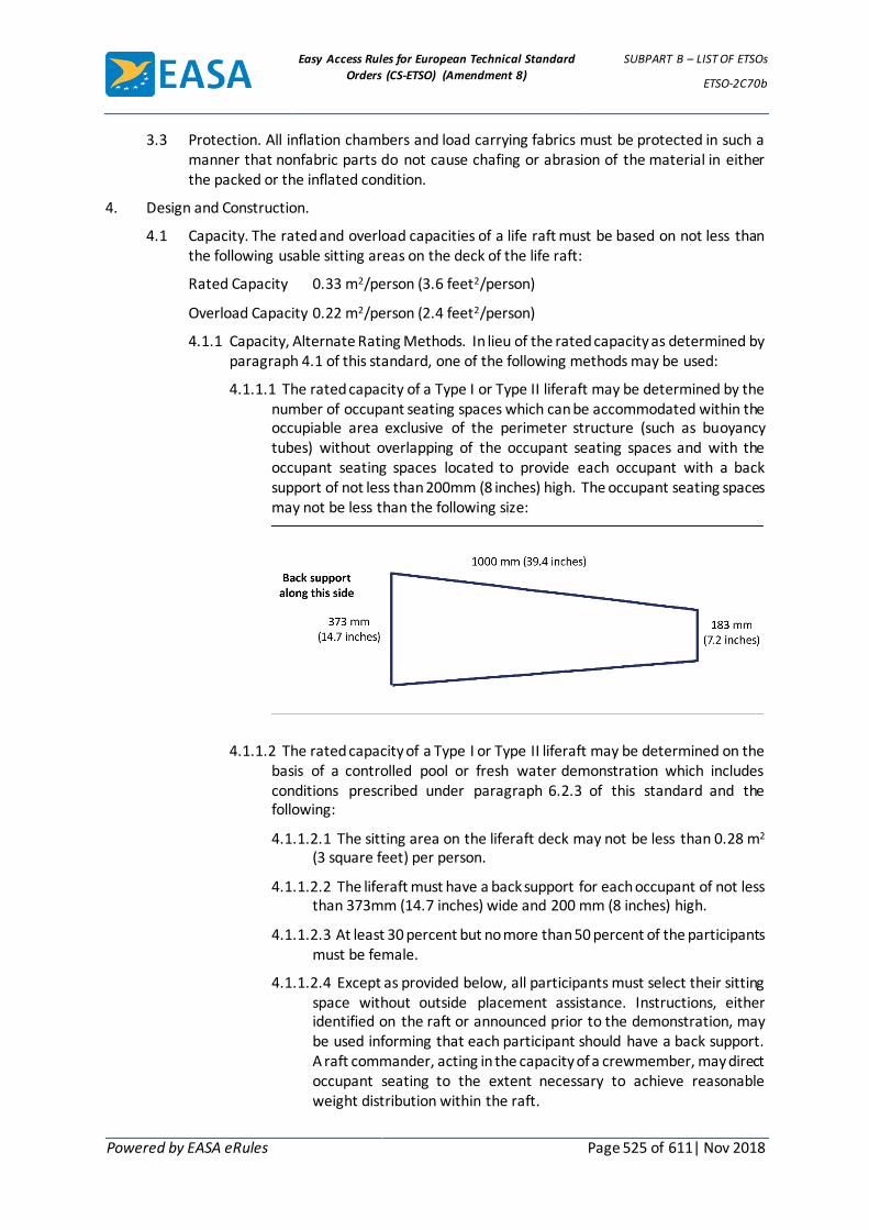
Easy Access Rules for European Technical Standard
Orders (CS-ETSO) (Amendment 8)
SUBPART B – LIST OF ETSOs
ETSO-2C70b
Powered by EASA eRules Page 525 of 611| Nov 2018
3.3 Protection. All inflation chambers and load carrying fabrics must be protected in such a manner that nonfabric parts do not cause chafing or abrasion of the material in either the packed or the inflated condition.
4. Design and Construction.
4.1 Capacity. The rated and overload capacities of a life raft must be based on not less than the following usable sitting areas on the deck of the life raft:
Rated Capacity 0.33 m2/person (3.6 feet2/person)
Overload Capacity 0.22 m2/person (2.4 feet2/person)
4.1.1 Capacity, Alternate Rating Methods. In lieu of the rated capacity as determined by paragraph 4.1 of this standard, one of the following methods may be used:
4.1.1.1 The rated capacity of a Type I or Type II liferaft may be determined by the number of occupant seating spaces which can be accommodated within the occupiable area exclusive of the perimeter structure (such as buoyancy tubes) without overlapping of the occupant seating spaces and with the occupant seating spaces located to provide each occupant with a back support of not less than 200mm (8 inches) high. The occupant seating spaces may not be less than the following size:
4.1.1.2 The rated capacity of a Type I or Type II liferaft may be determined on the
basis of a controlled pool or fresh water demonstration which includes conditions prescribed under paragraph 6.2.3 of this standard and the following:
4.1.1.2.1 The sitting area on the liferaft deck may not be less than 0.28 m2 (3 square feet) per person.
4.1.1.2.2 The liferaft must have a back support for each occupant of not less than 373mm (14.7 inches) wide and 200 mm (8 inches) high.
4.1.1.2.3 At least 30 percent but no more than 50 percent of the participants must be female.
4.1.1.2.4 Except as provided below, all participants must select their sitting space without outside placement assistance. Instructions, either identified on the raft or announced prior to the demonstration, may be used informing that each participant should have a back support. A raft commander, acting in the capacity of a crewmember, may direct occupant seating to the extent necessary to achieve reasonable weight distribution within the raft.

Easy Access Rules for European Technical Standard
Orders (CS-ETSO) (Amendment 8)
SUBPART B – LIST OF ETSOs
ETSO-2C70b
Powered by EASA eRules Page 526 of 611| Nov 2018
4.1.1.2.5 All participants must not have practiced, rehearsed, or have had the demonstration procedures described to them within the past 6 months.
4.2 Buoyancy. An average occupant weight of not less than 77 kg (170 pounds) must be used in all applicable calculations and tests specified herein. In tests, ballast in the form of sand bags or equivalent may be used to achieve the 77 kg (170 pound) average, provided the appropriate weight distribution within the raft is maintained.
4.2.1 Type I Liferaft. Buoyancy must be provided by two independent buoyancy tubes each of which, including the raft floor, must be capable of supporting the rated and overload capacities in fresh water if the other tube is deflated. The liferaft loaded to its rated capacity must have a freeboard of at least 300 mm (12 inches) with both buoyancy tubes at minimum operating pressure. The liferaft loaded to its rated capacity with the critical tube deflated and the remaining tube at minimum operating pressure must have a freeboard of at least 150 mm (6 inches). The liferaft loaded to its overload capacity with the critical tube deflated must have a measurable freeboard.
4.2.2 Type II Liferaft. When single tube construction is used to provide the buoyancy, internal bulkheads must divide the flotation tube into at least two separate chambers such that the liferaft will be capable of supporting the rated number of occupants out of fresh water in the event that one chamber is deflated. The complete liferaft loaded to its rated capacity must have a freeboard of at least 150 mm (6 inches).
4.3 Inflation. The inflation system must be arranged so that failure of one inflatable chamber or manifold will not result in loss of gas from the other chambers. The inflation equipment must be located so as not to interfere with boarding operation. Components of the inflation system must meet the USA Department of Transportation Specification 3AA (49 CFR 178.37) or Specification 3HT (49 CFR 178.44) in effect May 30, 1976, as applicable, or an equivalent approved by the Agency. The inflation system must be constructed to minimize leakage due to back pressure after inflation. If an air aspirator system is used, the system must be constructed either to prevent the ingestion of foreign objects or to prevent failure or malfunction as a result of ingestion of small foreign objects. For Type I liferafts, there must be an independent inflation source for each primary flotation tube, except that there may be a single inflation source for all flotation tubes if data substantiating the reliability of the single inflation source is approved by the Agency.
4.4 Liferaft Canopy. A canopy must be packed with or attached to the raft. The erected canopy must be capable of withstanding 65 km/h (35-knot winds) and 96 km/h (52-knot) gusts in open water. The canopy must provide adequate headroom and must have provision for openings 180 degrees apart. Means must be provided to make the openings weathertight. If the canopy is not integral with the raft, it must be capable of being erected by occupants following conspicuously posted, simple instructions. It must be capable of being erected by one occupant of an otherwise empty raft and by occupants of a raft filled to rated capacity. For a reversible raft, attachment provisions must be installed to permit the canopy to be installed on either side of the raft.
4.5 Capsize Resistance. There must be water pockets or other means to provide capsize resistance for an empty or lightly loaded raft.
4.6 Boarding Aids. For Type I liferafts, boarding aids must be provided at two opposing positions on the raft. One boarding aid is sufficient for a Type II liferaft. Boarding aids

Easy Access Rules for European Technical Standard
Orders (CS-ETSO) (Amendment 8)
SUBPART B – LIST OF ETSOs
ETSO-2C70b
Powered by EASA eRules Page 527 of 611| Nov 2018
must permit unassisted entry from the water into the unoccupied raft and must not at any time impair either the rigidity or the inflation characteristics of the raft. Puncturing of inflatable boarding aids must not affect the buoyancy of the raft buoyancy chambers. Boarding handles and/or stirrups used in conjunction with the boarding aids must withstand a pull of 2200 N (500 pounds).
4.7 Righting Aids. Means must be provided to right a nonreversible liferaft if it inflates in an inverted position. The means provided for righting must be such that they may be used by one person in the water.
4.8 Lifeline. A nonrotting lifeline of contrasting color and at least 9.5 mm (3/8-inch) diameter or 19mm (3/4-inch) width must encircle the liferaft on the outside periphery so that it can be easily grasped by persons in the water. The lifeline and its attachments must be capable of withstanding a minimum load of 2200 N (500 pounds) and must not interfere with the liferaft inflation.
4.9 Grasp Line. A grasp line, meeting the size and strength requirements for the lifeline, must be provided with sufficient slack for use by liferaft occupants to steady themselves when seated on the liferaft deck with their backs to the main flotation tube(s).
4.10 Color. The color of the liferaft’s surfaces, including the canopy surface, visible from the air must be an International Orange-Yellow or an equivalent high visibility color.
4.11 Placards. Suitable placarding must be provided in contrasting colors in waterproof paint which is not detrimental to the fabric, that denotes use and location of the inflation systems, raft equipment, boarding aids, and righting aids. For reversible rafts, placement of the placarding must take into account usage of either side of the raft. The letters used for such placarding must be at least 50 mm (2 inches) high except that details and miscellaneous instructions may be of smaller lettering. Applicable placarding must take into account persons boarding or righting the raft from the water.
4.12 Lights. One or more survivor locator lights must be provided that are approved under ETSO-C85a. The lights must be automatically activated upon raft inflation in the water, and visible from any direction by persons in the water.
4.13 Raft Sea Performance. The raft must meet the seaworthiness requirements in 6.2.3.2 and must be capable with its equipment of withstanding a saltwater marine environment for a period of at least 15 days.
5. Liferaft Equipment. All lines must be suitably stowed and secured to prevent entanglement during launching/inflation of a liferaft.
5.1 Mooring Line. A nonrotting mooring line at least 6m (20 feet) in length must be attached at one end to the raft, with the remainder of the line held flaked to the carrying case (See 5.2). The mooring line must be capable of keeping the raft, loaded to maximum rated capacity, attached to a floating aircraft, and not endanger the raft or cause the raft to spill occupants if the aircraft sinks. The line may be equipped with a mechanical release linkage. The breaking strength of the line must be at least 2200 N (500 pounds), or 40 times the rated capacity of the raft, whichever is greater, but need not exceed 4450 N (1,000 pounds).
5.2 Liferaft Launching Equipment. A parachute ripcord grip and retaining pocket must form the primary inflation control. The ripcord grip or the attached static mooring line must be provided with means for attachment to the aircraft. If the ripcord grip is designed to attach to the aircraft, its strength may not be less than that of the static mooring line. The position of the ripcord grip must be standardized. When facing the release end of the

Easy Access Rules for European Technical Standard
Orders (CS-ETSO) (Amendment 8)
SUBPART B – LIST OF ETSOs
ETSO-2C70b
Powered by EASA eRules Page 528 of 611| Nov 2018
carrying case, the center line of the ripcord grip retaining pocket must lie at 45 degrees in the right upper quadrant of the end section. The outermost extremity of the ripcord grip may not extend beyond the outer margin of the carrying case. The line attached to the ripcord grip must serve both to retain the liferaft and to actuate the gas release(s). The tension required to withdraw the static mooring line and to actuate the gas release mechanism(s) must be between 90 N and 135 N (20 and 30 pounds). The strength of the gas release mechanism(s), its fittings, and its attachments may not be less than 445 N (100 pounds).
5.3 Sea Anchor. A sea anchor, or anchors, or other equivalent means must be provided to maintain the raft, with rated capacity and canopy installed, on a substantially constant heading relative to the wind and have the ability to reduce the drift to 4 km/h (2 knots) in 31 to 50 km/h (17 to 27-knot) winds. Unless analysis and/or test data substantiating the adequacy of a lower breaking strength is approved by the Agency, the line securing a sea anchor to the raft must have a breaking strength of 2200 N (500 pounds) or 40 pounds time the rated capacity of the raft, whichever is greater. The attachment of the line to the raft must be capable of withstanding a load of 1.5 times the line-rated strength without damaging the raft. The line must be at least 7.6 m (25 feet) in length and must be protected to prevent it from being cut inadvertently by raft occupants.
5.4 Heaving-Trailing Line. At least one floating heaving-trailing line not less than 23 m (75 feet) in length for Type I rafts and not less than 10.6 m (35 feet) in length for Type II rafts, and at least 1100 N (250 pounds) strength, must be located on the main flotation tube near the sea anchor attachment. The attach point of the line must withstand a pull of not less than 1.5 times the line rated strength without damage to the raft. A heaving-trailing line must be accessible in any inflated position of a reversible liferaft.
5.5 Emergency Inflation. Means readily accessible to occupants of the raft, and having a displacement of at least 0.5 litres (32 cubic inches) per full stroke, must be provided to manually inflate and maintain chambers at minimum operating pressure. Manual inflation valves, with a nonreturn opening adequate for the size and capacity of the inflation means, must be located to permit inflation of all chambers. The location must take into consideration occupancy of each side of reversible raft. The inflation means and valves must have provisions to prevent inadvertent removal and loss when either stowed or in use.
5.6 Accessory Case Tiedowns. Provisions must be made for tiedowns to hold any accessory case. Each accessory case tiedown must withstand a pull of 1100 N (250 pounds).
5.7 Carrying Case. A carrying case which meets the flammability requirement of this standard and which properly fits the packed liferaft must be provided. Carrying case materials must be of a highly visible color, be fungus proof, and be resistant to aircraft fuels and other fluids. The carrying case must provide chafe protection to the liferaft. The carrying case must be provided with easily distinguishable handles so that it may be carried by one person, carried by two persons in tandem, or dragged by either end; none of these carrying operations must tend to pull the carrying case open. Each handle must be easily grasped and its strength must be at least four time the total weight of the liferaft and case. Conventional zippers may not be employed for closure. Location of and instructions for use of the inflation handle must be clearly identified and marked on the carrying case surface.
5.8 Knife. A hook type knife secured by a retaining line must be sheathed and attached to the raft adjacent to the point of mooring line attachment.

Easy Access Rules for European Technical Standard
Orders (CS-ETSO) (Amendment 8)
SUBPART B – LIST OF ETSOs
ETSO-2C70b
Powered by EASA eRules Page 529 of 611| Nov 2018
6 Tests.
6.1 Material Tests. The material tests required in paragraph 3.0 of this standard must be determined in accordance with the following test method or other approved equivalent methods:
Test Method
Tests Required Federal Test Method Standard No. 191A dated July 20, 1978 Notes
Accelerated Age Method 5850 Per Note (1)
Tensile Strength (Grab Test) Method 5100
Tear Strength(Trapezoid Test) Method 5136 (4)
Tear Strength (Tongue Test) Method 5134 (Alternate to Trapezoid Test See 3.1.4.1)
Ply Adhesion Method 5960
Coat Adhesion Method 5970
Permeability Method 5460 (4)
Seam Shear Strength Per Note (2)
Seam Peel Strength Method 5960 Per Note (3)
NOTES:
(1) Samples for the accelerated aging tests must be exposed to a temperature of 70 ± 3°C (158 ± 5 degrees Fahrenheit) for not less than 168 hours. After exposure, the samples must be allowed to cool to 21 ± 1°C (70 ± 2 degrees Fahrenheit) for neither less than 16 hours nor more than 96 hours before determining their physical properties in accordance with 3.1 of this standard.
(2) Each sample shall consist of two strips 50 mm (2 inches) maximum width by 127 mm (5 inches) maximum length bonded together with an overlap 19 mm (3/4 inches) maximum. The free ends must be placed in the testing machine described in Method 5100 and separated at a rate of 305 ± 13 mm/min (12 ± 0.5 inches per minute). The average value of two samples must be reported. Samples may be multilayered as required to provide adequate strength to ensure against premature material failure.
(3) Separation rate must be 50 to 65 mm/minute (2.0 to 2.5 inches per minute).
(4) Federal Test Method Standard No. 191 in effect December 31, 1968.
6.2 Liferaft Tests.
6.2.1 Pressure Retention. Under static conditions and when inflated and stabilized at the nominal operating pressure, the pressure in each inflatable chamber must not fall below the minimum operating pressure in less than 24 hours. The minimum operating pressure is the pressure required to meet the minimum design buoyancy requirements of paragraph 4.2 of this standard.
6.2.2 Overpressure Tests.
6.2.2.1 The device must be shown by test to withstand a pressure at least 1.5 times the maximum operating pressure for at least 5 minutes without sustaining damage.
6.2.2.2 At least one specimen of the inflatable device model must be shown by test to withstand a pressure at least 2 times the maximum operating pressure without failure. Devices so tested must be clearly identified.

Easy Access Rules for European Technical Standard
Orders (CS-ETSO) (Amendment 8)
SUBPART B – LIST OF ETSOs
ETSO-2C70b
Powered by EASA eRules Page 530 of 611| Nov 2018
6.2.3 Functional Tests. Each liferaft model must pass the following tests:
6.2.3.1 Water Tests. In either a controlled pool or fresh water, the liferaft capacity and buoyancy must be demonstrated as follows:
6.2.3.1.1 Both rated and overload capacities established in accordance with the requirements of paragraph 4.1 of this standard must be demonstrated with inflation tubes at minimum operating pressure and with the critical buoyancy chamber deflated. The resultant freeboard in each case must meet the requirements of paragraph 4.2 of this standard.
6.2.3.1.2 Persons used in the demonstration must have an average weight of not less than 77 kg (170 pounds). Ballast in the form of sand bags or equivalent may be used to achieve proper loading provided the appropriate weight distribution within the raft is maintained.
6.2.3.1.3 Persons used in the demonstration must wear life preservers with at least one chamber inflated.
6.2.3.1.4 The required liferaft equipment, including one emergency locator transmitter or a weight simulating a transmitter, must be aboard the liferaft.
6.2.3.1.5 It must be demonstrated that the raft is self-righting, or can be righted by one person in water, or while inverted can be boarded and provide flotation for the normal rated capacity.
6.2.3.1.6 It must be demonstrated that the boarding aids are adequate for the purpose intended and that it is possible for an adult wearing an inflated life preserver to board the raft unassisted.
6.2.3.2 Sea Trials. The liferaft must be demonstrated by tests or analysis, or a combination of both, to be seaworthy in an open sea condition of 31 to 50 km/h (17 to 27-knot) winds and waves of 1.8 m to 3 m (6 to 10 feet). In tests, ballast in the form of sand bags or equivalent may be used to achieve proper loading provided the appropriate weight distribution within the raft is maintained. If analysis is used, the analysis must be approved by the Agency. For this seaworthiness demonstration, the following apply:
6.2.3.2.1 The liferaft must be deployed to simulate deployment from an aircraft under the most adverse wind direction and wave condition. If the liferaft is an aspirated inflated type, it must be demonstrated that water ingested during inflation will not cause the raft to fail to meet the requirement for buoyancy under rated capacity in 4.2.
6.2.3.2.2 All required equipment must be aboard and the proper functioning of each item of equipment must be demonstrated.
6.2.3.2.3 The canopy must be erected for a sufficient time to assess its resistance to tearing and the protection it affords. The method of erection must be shown to be accomplished by one occupant of an otherwise empty raft, and by occupants of a raft filled to rated capacity.
6.2.3.2.4 The stability of the raft must be demonstrated when occupied at normal rated capacity and at 50 percent rated capacity.

Easy Access Rules for European Technical Standard
Orders (CS-ETSO) (Amendment 8)
SUBPART B – LIST OF ETSOs
ETSO-2C70b
Powered by EASA eRules Page 531 of 611| Nov 2018
6.2.3.3 Liferaft Drop Test. A complete liferaft package must be dropped or thrown from a height of 1.5 m (5 feet) onto a hard surface floor after which it must be inflated and meet the pressure retention requirements of paragraph 6.2.1 of this standard.
6.2.3.4 Portability Test. If the liferaft is to be manually deployed, it must be demonstrated that the complete liferaft package can be moved from a typical stowage installation by no more that two persons and then deployed at another suitable exit.
6.2.3.5 Carrying Case. It must be demonstrated at least 10 times that the carrying case will open satisfactorily and cause no delay in the deployment and inflation of the liferaft.
6.2.3.6 Gas Cylinder Releases. It must be demonstrated that pulling the ripcord grip from any position will actuate the primary gas release(s).
6.2.5 Temperature Exposure and Inflation. The manufacturer shall determine the minimum temperature at which the complete liferaft assembly with its inflation bottles, will be “rounded out” (i.e., attain its design shape and approximate dimension) so that the liferaft will be able to receive and to support the first occupant within one minute after the start of inflation. Thereafter, the rate of inflation must progress in such a manner and rate as to ensure a serviceable and rigid liferaft for boarding by the remainder of the occupants. Similarly, a maximum environmental temperature to which the liferaft assembly may be exposed and still remain in a seaworthy condition upon inflation must be determined. The temperature limitations must be submitted to the Agency and liferaft purchaser in accordance with the data requirements of this ETSO.
6.2.5.1 Test Procedure. The packed liferaft assembly with its inflation bottles installed must be exposed to each of the above temperatures for not less than 24 hours and must be inflated within 5 minutes after removal from such temperatures. The liferaft must be allowed to return to a temperature of approximately 21 ± 3°C (70 ± 5 degrees Fahrenheit) before being deflated, repacked, and subjected to a second exposure. After the above tests have been completed, the liferaft must be able to pass tests required by paragraphs 6.2.1 and 6.2.2 of this standard.
[Amdt ETSO/1] [Amdt ETSO/7]
Easy Access Rules for European Technical Standard
Orders (CS-ETSO) (Amendment 8)
SUBPART B – LIST OF ETSOs
ETSO-2C75
Powered by EASA eRules Page 532 of 611| Nov 2018
ETSO-2C75 ED Decision 2003/10/RM (applicable from 24.10.2003)
Hydraulic Hoses Assembly
1 Applicability
This ETSO gives the requirements which static hydraulic hoses assembly that is manufactured on or after the date of this ETSO must meet in order to be identified with the applicable ETSO marking.
2 Procedures
2.1 General
Applicable procedures are detailed in CS-TSO Subpart A.
2.2 Specific
None.
3 Technical Conditions
3.1 Basic
3.1.1 Minimum Performance Standard
Standards set forth in the attached „Federal Aviation Administration Standard, Hydraulic Hoses Assemblies“dated December 15, 1962, except as mentioned in paragraph 3.2 below.
3.1.2 Environmental Standard
As stated in the Federal Aviation Administration Standard.
3.1.3 Computer Software
None
3.2 Specific
Proof of pressure: 2Pw as specified in CS-25 Appendix J.
4 Marking
4.1 General
Marking is detailed in CS-ETSO Subpart A paragraph 1.2; in addition to the markings required by this paragraph, the hoses must be marked:
if suitable for use with synthetic base fluids: letter „S“ immediately following the type designation.
if suitable for use with petroleum base fluids: letter „P“ immediately following the type designation.
if suitable for use with both synthetic base and petroleum base fluids: letters „S/P“ immediately following the type designation.
if complying with the fire resistant requirements: letter „F“ immediately following the type and fluid designation.
4.2 Specific
None.

Easy Access Rules for European Technical Standard
Orders (CS-ETSO) (Amendment 8)
SUBPART B – LIST OF ETSOs
ETSO-2C75
Powered by EASA eRules Page 533 of 611| Nov 2018
5 Availability of Referenced Document
See CS-ETSO Subpart A paragraph 3

Easy Access Rules for European Technical Standard
Orders (CS-ETSO) (Amendment 8)
SUBPART B – LIST OF ETSOs
ETSO-2C75
Powered by EASA eRules Page 534 of 611| Nov 2018
APPENDIX 1 TO ETSO-2C75 – FEDERAL AVIATION ADMINISTRATION STANDARD
FOR HYDRAULIC HOSE ASSEMBLIES ED Decision 2003/10/RM
1.0 Purpose. To specify minimum airworthiness requirements for hydraulic hose assemblies intended for use on civil transport category aircraft.
2.0 Scope. This specification covers minimum airworthiness requirements for the following types of hydraulic hose assemblies:
Type Pressure Temperature
IA Medium1 11160° F.
IB High2 22160° F.
IIA Medium 275° F.
IIB High 275° F.
IIIA Medium 400° F.
IIIB High 400° F.
3.0 General Requirements.
3.1 Materials. Materials shall be uniform in quality and suitable for the purpose intended. The suitability of the materials shall be determined on the basis of satisfactory service experience or substantiating qualification test.
3.2 Workmanship. Workmanship shall be of the quality necessary to produce hose assemblies free from all defects which may adversely affect proper functioning in service.
3.3 Qualification Tests, General.
3.3.1 Performance. There shall be no evidence of leakage, wicking, imperfections or damage of the hose or end fittings when the assembly is subjected to the tests specified herein.
3.3.2 Test Assemblies. A sufficient number of each type and size hose assembly to be qualified shall be selected at random and satisfactorily tested to the applicable provisions specified herein.
3.3.3 Fluid Aging. In all the tests involving fluid aged assemblies, the assemblies shall be filled with a suitable test fluid3 and soaked for 7 days in an air oven at the applicable temperature specified in paragraph 2.0.
3.3.4 Air Aging. In all the tests involving air aged assemblies, the assembly shall be aged for 7 days in air at the applicable temperature specified in paragraph 2.0.
3.3.5 Test Pressures. Unless otherwise noted, all pressures specified herein are hydraulic pressures and shall not be less than the applicable pressure shown in paragraph 7.1.
3.3.6 Test Temperatures. Unless otherwise specified, the fluid and ambient temperatures shall be room temperatures.
1 The term „medium“ is used herein to mean anominal operating pressure of 1,500 p.s.i. or less.
2 The term „high“ pressure means a nominal operating pressure greater than 1,500 p-s.i. and up to and including 3,000 p.s.i.
3 A suitable test fluid is one which is representative of that to be used with the applicable hose assembly in civil transport category aircraft operation.

Easy Access Rules for European Technical Standard
Orders (CS-ETSO) (Amendment 8)
SUBPART B – LIST OF ETSOs
ETSO-2C75
Powered by EASA eRules Page 535 of 611| Nov 2018
3.3.7 End Fitting Design. If an end fitting incorporates a minor variation from the design of a similar fitting in a previously qualified hose assembly of the same type, then the hose assembly need not be retested. It is the responsibility of the manufacturer to determine that such a variation will not adversely affect the airworthiness of the hose assembly.
3.3.8 Corrosion. The design and manufacture of the hose assemblies shall be such that corrosive tendencies in any component part shall be effectively minimized.
4.0 Test Requirements, Type IA, IIA, IB, and IIB Hose Assemblies.
4.1 Proof Pressure. Hose assemblies shall be subjected, for at least 30 seconds, to a proof pressure test of at least 1.5 times the applicable pressure shown in paragraph 7.1.
4.2 Bending and Vacuum. A hose assembly shall be fluid aged in accordance with paragraph 3.3.3. It shall then be proof pressure tested in accordance with paragraph 4.1. The unfilled assembly shall then be bent over a form so that the radius and length shall conforrn to Table I except that, for –16 and larger size hoses, the length shall be 30 inches. The hose shall not flatten or deform at any section to an amount greater than 10 percent of the outside diameter of the hose. While still bent in this radius, a vacuum of 28 inches of mercury shall be applied and held for 5 minutes during which time the hose shall be checked for additional flattening. Application of the 28-inch Hg vacuum shall not result in more than a 20 percent reduction in OD at any section for all sizes up to and including -24 and a 35 percent reduction for size -32. After the vacuum is released, and the hose is dissected longitudinally, there shall be no evidence of ply separation, blistering, collapse, or other damage.
4.3 Hydraulic Leakage. An unaged hose assembly, not less than 12 inches in length, shall be subjected to 70 percent of the hydraulic burst pressure specified in paragraph 4.4 for 5 minutes. The pressure shall then be reduced to zero, after which it shall be raised to 70 percent of the specified burst pressure for another 5-minute period. The outer surface of the hose assembly shall be carefully checked after this period for conformance with paragraph 3.3.1. After completion of the hydraulic leakage test, the hose assembly shall be subjected to the Room Temperature Burst Pressure test specified in paragraph 4.4.
4.4 Room Temperature Burst Pressure. An unaged hose assembly of the applicable length specified in Table I shall be subjected to a burst pressure of 4.0 times the applicable pressure shown in paragraph 7.1. The rate of pressure rise shall be 20,000±5,000 p.s.i. per minute until the burst pressure is obtained.
4.5 Hydraulic Impulses. A fluid aged, air aged, and unaged hose assembly of lengths not less than those applicable lengths specified in Table I shall be proof pressure tested in accordance with paragraph 4.1 and then be connected to a manifold installed in an impulse test machine. The temperature of the test fluid shall be measured at the test manifold and shall be maintained at 120°±10° F. Hose assemblies of the -3 through -12 sizes shall be installed with the applicable bend radius shown in Table I and both ends shall be connected to a rigid support. Size -16 through -32 hose assemblies shall be installed straight with one end left free. Electronic measuring devices shall be used to measure the impulse pressures in the inlet manifold. Impulse cycling in accordance with Figure I shall be as follows:
Type Size No of Cycles
IA and IIA -3 through -16 100,000
IA and IIA -20 through -32 50,000

Easy Access Rules for European Technical Standard
Orders (CS-ETSO) (Amendment 8)
SUBPART B – LIST OF ETSOs
ETSO-2C75
Powered by EASA eRules Page 536 of 611| Nov 2018
Type Size No of Cycles
IB and IIB -4 through -6 100,000
IB and IIB -8 75,000
IB and IIB -10 50,000
IB and IIB -12 35,000
IB and IIB -16 45,000
IIIA all sizes 100,000
IIIB all sizes through -8 250,000
IIIB sizes -10 and -12 100,000
IIIB -16 45,000
The following assemblies need not be subjected to any peak pressure greater than the applicable operating pressure:
Type Size
IA and IIA -20 through -32
IB, IIB and IIIB -16
IIIA -20 and -24
4.6 Cold Temperature Flexing. A fluid aged and an air aged hose assembly (reference
paragraphs 3.3.3 and 3.3.4 respectively) shall be filled with a suitable test fluid and placed, for a 72-hour period in a cold chamber which is controlled to -65° to -70° F. While at this temperature, the assemblies shall be bent through 180°, in opposite directions, to the applicable radius specified in Table I, within a 4- second period. After removal from the cold chamber, the assemblies shall be subjected to the applicable proof pressure test. Dash 16 and larger size assemblies may be tested at -40° F. in lieu of the above specified temperature.
5.0 Test Requirements, Type III A Hose Assemblies.
5.1 Room Temperature Burst Pressure. Same as paragraph 4.4.
5.2 Bending and Vacuum.
a. An unaged assembly shall be filled with test fluid and cold soaked at -65° to -70°F. for 24 hours and then bent to the applicable bend radius, through 180°, in opposite directions. Five complete cycles shall be conducted at the rate of approximately one cycle in 4 seconds. The assembly shall then be subjected to the applicable proof pressure test while still at -65° to -70°F.
b. The assembly shall be emptied and heat soaked at 400°±10° F. for 4 hours while bent to the applicable bend radius and while being subjected to the following negative pressure:
28 inches of mercury for the -4 through -12 size.
18 inches of mercury for the -16 and -20 size.
14 inches of mercury for the -24 size.
The assembly shall then be cooled to room temperature while the negative pressure is maintained.
c. After this test and after the hose is dissected longitudinally and inspected, there shall be no evidence of damage or breakdown.

Easy Access Rules for European Technical Standard
Orders (CS-ETSO) (Amendment 8)
SUBPART B – LIST OF ETSOs
ETSO-2C75
Powered by EASA eRules Page 537 of 611| Nov 2018
5.3 Hydraulic Leakage. A hose assembly of the applicable length specified in Table I shall be subjected to the hydraulic leakage test specified in paragraph 4.3 after it has been pressurized, while at room temperature, to 25 p.s.i. for at least 5 minutes.
5.4 High Temperature Burst Pressure. An assembly, of the applicable length specified in Table I shall be filled with test fluid at 50 p.s.i. and heat soaked for l-hour wherein ambient and fluid temperatures are 400°±10°F. The pressure shall then be increased to the rated operating pressure and held for 5 minutes. The pressure shall then be raised to three times the applicable pressure shown in paragraph 7.1 at a rate of 20,000±5,000 p.s.i.. During this test, one end of the assembly shall be free.
5.5 Hydraulic Impulses. Same as paragraph 4.5 except that the fluid and ambient temperatures shall be at 400°±10° F.
6.0 Test Requirements, Type IIIB Hose Assemblies.
6.1 Hydraulic Leakage. Same as paragraph 5.3.
6.2 Hydraulic Impulse. Same as paragraph 4.5 except that, in addition, the assembly shall be temperature cycled from room temperature to the specified ambient and fluid temperature, and back to room temperature, for at least 2 cycles. This test shall be programmed so that at least 80 percent of the impulses shall be at 400° F. ambient and fluid temperatures.
6.3 Thermal Shocks.
a. The test assembly shall be air aged in accordance with paragraph 3.3.4 and after aging shall be subjected to the applicable proof pressure for a minimum of 5 minutes.
b. The test assemblies shall then be mounted, empty, in a controlled temperature test set-up (typical set-up shown in Figure II) and the ambient temperature reduced to -67°±2° F. for a minimum of 2 hours. At the end of this period, while still at this temperature, high temperature test fluid at a temperature of 400°F. shall be suddenly introduced at a minimum pressure of 50 p.s.i. Immediately after the hot fluid has filled the assembly, the pressure shall be raised to the applicable proof pressure for a minimum of 5 minutes. Not more than 15 seconds shall elapse between the introduction of the high temperature fluid at 50 p.s.i. and the raising of the pressure to proof pressure.
c. The assembly shall then be subjected to the High Temperature Burst Pressure test specified in paragraph 5.4.
6.4 Flexing. The assembly shall be mounted in the flex set-up as illustrated in Figure III, shall be filled with test fluid and subjected to the following test sequence. The temperatures indicated are both fluid and ambient. Flexing shall occur at a rate of 70±10 cycles per minute during portions c. d. and e.
a. The test assemblies shall be soaked, with no pressure or flexing at a temperature of -67°±2° F. for a minimum of one hour.
b. With no flexing, the test assemblies shall be pressurized to the proof pressure with the temperature still at -67° F. for a minimum of 5 minutes (first cycle only).
c. Flexing shall begin while the test assemblies are pressurized to the operating pressure with the temperature still at -67° F. for a minimum of 4,000 cycles.

Easy Access Rules for European Technical Standard
Orders (CS-ETSO) (Amendment 8)
SUBPART B – LIST OF ETSOs
ETSO-2C75
Powered by EASA eRules Page 538 of 611| Nov 2018
d. With the pressure reduced to zero p.s.i., flexing shall continue for 1,000 cycles at -67° F.
e. Increase the temperature to 400°F. and flex for 1,000 cycles with the pressure at zero p.s.i. The pressure shall then be increased to the operating pressure with the temperature held at 400°F. Flexing shall continue until an accumulated total of 80,000 cycles is reached.
f. Steps a. c. d. and e. shall be repeated for a total of 5 test sequences, i.e., 400,000 flexing cycles.
g. After completion of step f. and with no flexing, the test assemblies shall be pressurized to the proof pressure with the temperature still at 400° F. for a minimum of 5 minutes (last cycle only).
7.0 Fire-Resistant Hose Assemblies. Fireresistant hose assemblies which are intended to be used in locations within fire zones shall comply with the applicable requirements specified herein and in addition shall also comply with the fire test described in FAA report entitled, „Standard Fire Test Apparatus and Procedure“ revised March 1961. The use of a protective sleeve over the hose and/or end fittings is permitted to facilitate compliance with the fire test requirements. Sleeve or protective covers shall be secured to the hose assembly so that fire-resistant properties will be maintained.
7.1 Fire Test Parameters.
Type Hose Assembly Hoze Size Maximum Operating
Pressure Flow Rate GPM
IA and IIA -3 1,500 7 x (ID)2
-4 1,500 "
-5 1,500 "
-6 1,500 "
-8 1,500 "
-10 1,500 "
-12 1,000 "
-16 800 "
-20 600 3 x (ID)2
-24 500 1 x (ID)2
IB and IIB All 3,000 1 x (ID)2
IIIA -3 t o-10 1,500 1 x (ID)2
-12 1,000 "
-16 1,250 "
-20 1,000 "
-24 750 "
IIIB All 3,000 "
7.2 Criteria for Acceptability. The hose assembly shall be considered acceptable if it
successfully withstands the applicable fire test for a period of 5 minutes without evidence of leakage.
TEST LENGTH AND MINIMUM BEND RADIUS

Easy Access Rules for European Technical Standard
Orders (CS-ETSO) (Amendment 8)
SUBPART B – LIST OF ETSOs
ETSO-2C75
Powered by EASA eRules Page 539 of 611| Nov 2018
SIZE NUMBER
LENGTH OF TEST ASSEMBLY INCHES
MINIMUM BEND RADIUS AT INSIDE OF BEND INCHES
Type Hose Assemblies Type Hose Assemblies
IA and IIA
IB and IIB
IIIA IIIB IA
and IIA IB
and IIB IIIA IIIB
-3 14 — — — 3 — — —
-4 14 16 14 16 3 3 2 3
-5 16 18 16 — 3? 3? 2 —
-6 18 21 18 21 4 5 4 5
-8 21 24 21 24 4? 5¾ 4? 5¾
-10 23½ 30 23½ 30 5½ 6½ 5½ 6½
-12 27½ 33 27½ 33 6½ 7¾ 6½ 7¾
-16 18 24 18 24 7? 9? 7? 9?
-20 18 — 18 — 9 — 11 —
-24 18 — 18 — 11 — 14 —
-32 18 — — — 13¼ — — — TABLE I
The curve shown above is the approximate pressure-time cycle determined to be of proper severity for impulse testing of hose assemblies. The pressure-time curve shall be confined to the shaded area indicated.
NOTE: Cycling tolerance = 35±5 or 70±10 cycles per minute.
FIGURE I
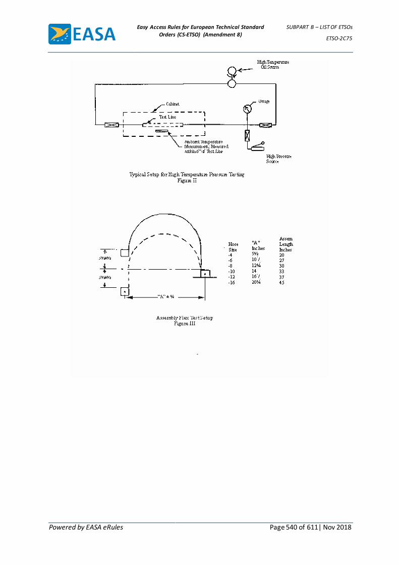
Easy Access Rules for European Technical Standard
Orders (CS-ETSO) (Amendment 8)
SUBPART B – LIST OF ETSOs
ETSO-2C75
Powered by EASA eRules Page 540 of 611| Nov 2018
Easy Access Rules for European Technical Standard
Orders (CS-ETSO) (Amendment 8)
SUBPART B – LIST OF ETSOs
ETSO-2C78
Powered by EASA eRules Page 541 of 611| Nov 2018
ETSO-2C78 ED Decision 2008/012/R (applicable from 18.11.2008)
Crewmember Oxygen Mask
1 Applicability
This ETSO gives the requirements which the crewmember constant flow mask or crewmember demand oxygen masks that are manufactured on or after the date of this ETSO must meet in order to be identified with the applicable ETSO marking.
2 Procedures
2.1 General
Applicable procedures are detailed in CS-ETSO Subpart A.
2.2 Specific
None.
3 Technical Conditions
3.1 Basic
3.1.1 Minimum Performance Standard
Both crewmember constant flow mask and crewmember demand oxygen masks must meet the standards set forth in the attached Appendix 1: “Standard for Crewmember Demand Oxygen Masks” and, when applicable, additional specific requirements as described here after in paragraph 3.2 – Specific.
3.1.2 Environmental Standard
None
3.1.3 Computer Software
None
3.2 Specific
3.2.1 Breathing Bag Volume
If a breathing bag is installed it shall meet the requirements of the Society of Automotive Engineers Inc (SAE) Aerospace Standard (AS) N° AS 8025, “Passenger Oxygen Mask”, Rev. A, dated January 1999, paragraphs 4.3 (volume) and 5.5.1 (strength).
3.2.2 Oxygen Flow Indicators
If an oxygen flow indicator is installed it shall meet the requirements of the Society of Automotive Engineers Inc (SAE) Aerospace Standard (AS) N° AS 916, “Oxygen Flow Indicators”, Rev. B, dated July 1996, paragraph 3.2 (Low pressure continuous flow type).
3.2.3 Flammability
For flammability the applicable paragraphs of CS 25, Appendix F shall apply.
4 Marking
4.1 General

Easy Access Rules for European Technical Standard
Orders (CS-ETSO) (Amendment 8)
SUBPART B – LIST OF ETSOs
ETSO-2C78
Powered by EASA eRules Page 542 of 611| Nov 2018
Marking is detailed in CS-ETSO Subpart A paragraph 1.2.
4.2 Specific
4.2.1 Each constant flow mask shall be marked with:
(i) the term “Constant Flow Mask”;
(ii) the maximum environmental (cabin) altitude the mask is qualified for.
4.2.2 Each demand flow mask shall be marked to indicate:
(i) whether it is a “non-pressure demand” or a “pressure demand” mask;
(ii) the maximum environmental (cabin) altitude for which it is qualified.
5 Availability of Referenced Document
See CS-ETSO Subpart A paragraph 3.
[Amdt ETSO/3]

Easy Access Rules for European Technical Standard
Orders (CS-ETSO) (Amendment 8)
SUBPART B – LIST OF ETSOs
ETSO-2C78
Powered by EASA eRules Page 543 of 611| Nov 2018
APPENDIX 1 TO ETSO-2C78 – STANDARD FOR CREWMEMBER DEMAND
OXYGEN MASK ED Decision 2008/012/R
1.0 Purpose.
This Standard contains minimum performance standards for the manufacture of demand type oxygen masks for use with non-pressure demand (straight-demand and diluter-demand) and pressure-demand oxygen systems. It is based on the equivalent FAA standard for crewmember demand oxygen masks and the Agency has added values that are in imperial units also in SI units
2.0 Design and Construction of Mask.
To be eligible for approval under a European Technical Standard Order Authorisation, the oxygen mask must possess the following design and construction characteristics.
2.1 Masks designed for use with a remotely located oxygen flow regulator must include a flexible oxygen supply tube fixed or detachable at the mask or at the regulator or at both. Oxygen supply tubes used in conjunction with mask-mounted oxygen flow regulators are not subject to this paragraph.
2.2 The mask must be designed for respiration through the nose and mouth (oronasal). The mask may also include integral goggles designed to protect the eyes from smoke and harmful gases (fullface).
2.3 The mask must be constructed of materials that –
(a) do not contaminate air or oxygen:
(b) are not adversely affected by continuous contact with oxygen; and
(c) are at least flame resistant.
2.4 The mask must be designed to prevent the accumulation of hazardous quantities of expiratory gases within the facepiece chamber.
2.5 The mask must be designed to prevent the formation of accumulation of frost which would interfere with the function of the exhalation valve, unless it can be shown that the frost can be removed by external manipulation without removing the mask from the face of the user.
2.6 The full-face mask must be designed to include means for the prevention or the removal of condensation from the inside surfaces of the goggle lenses.
2.7 Masks equipped with oxygen supply tubes designed for quick disconnection at the mask or at the regulator must incorporate means to alert the user when his oxygen supply tube has become disconnected. Such means must not restrict the flow of ambient air through the oxygen supply tube by an amount exceeding 25 percent. This section does not apply if the quick disconnect device incorporates means to prevent inadvertent separation.
3.0 Performance.
Five masks of each kind for which approval is sought must be shown to comply with the minimum performance standards set forth in paragraphs 3.1 through 3.12, except that only one mask of each kind is required to comply with the provisions of paragraphs 3.6, 3.8, 3.9, and 3.11. Tests must be conducted at ambient atmospheric conditions of approximately 102 KPa (30" hg.) and 21 °C (70°F.), except as otherwise specified. Gas flow rates and pressures must be corrected to STPD.
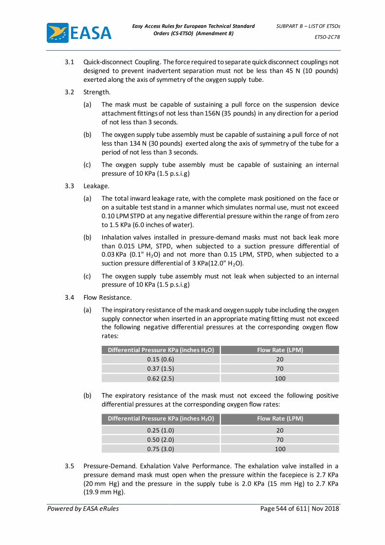
Easy Access Rules for European Technical Standard
Orders (CS-ETSO) (Amendment 8)
SUBPART B – LIST OF ETSOs
ETSO-2C78
Powered by EASA eRules Page 544 of 611| Nov 2018
3.1 Quick-disconnect Coupling. The force required to separate quick disconnect couplings not designed to prevent inadvertent separation must not be less than 45 N (10 pounds) exerted along the axis of symmetry of the oxygen supply tube.
3.2 Strength.
(a) The mask must be capable of sustaining a pull force on the suspension device attachment fittings of not less than 156N (35 pounds) in any direction for a period of not less than 3 seconds.
(b) The oxygen supply tube assembly must be capable of sustaining a pull force of not less than 134 N (30 pounds) exerted along the axis of symmetry of the tube for a period of not less than 3 seconds.
(c) The oxygen supply tube assembly must be capable of sustaining an internal pressure of 10 KPa (1.5 p.s.i.g)
3.3 Leakage.
(a) The total inward leakage rate, with the complete mask positioned on the face or on a suitable test stand in a manner which simulates normal use, must not exceed 0.10 LPM STPD at any negative differential pressure within the range of from zero to 1.5 KPa (6.0 inches of water).
(b) Inhalation valves installed in pressure-demand masks must not back leak more than 0.015 LPM, STPD, when subjected to a suction pressure differential of 0.03 KPa (0.1" H2O) and not more than 0.15 LPM, STPD, when subjected to a suction pressure differential of 3 KPa(12.0" H2O).
(c) The oxygen supply tube assembly must not leak when subjected to an internal pressure of 10 KPa (1.5 p.s.i.g)
3.4 Flow Resistance.
(a) The inspiratory resistance of the mask and oxygen supply tube including the oxygen supply connector when inserted in an appropriate mating fitting must not exceed the following negative differential pressures at the corresponding oxygen flow rates:
Differential Pressure KPa (inches H2O) Flow Rate (LPM)
0.15 (0.6) 20
0.37 (1.5) 70
0.62 (2.5) 100
(b) The expiratory resistance of the mask must not exceed the following positive
differential pressures at the corresponding oxygen flow rates:
Differential Pressure KPa (inches H2O) Flow Rate (LPM)
0.25 (1.0) 20
0.50 (2.0) 70
0.75 (3.0) 100
3.5 Pressure-Demand. Exhalation Valve Performance. The exhalation valve installed in a
pressure demand mask must open when the pressure within the facepiece is 2.7 KPa (20 mm Hg) and the pressure in the supply tube is 2.0 KPa (15 mm Hg) to 2.7 KPa (19.9 mm Hg).

Easy Access Rules for European Technical Standard
Orders (CS-ETSO) (Amendment 8)
SUBPART B – LIST OF ETSOs
ETSO-2C78
Powered by EASA eRules Page 545 of 611| Nov 2018
3.6 Vibration. The flow of gases during the respiratory process must not cause vibration, flutter, or chatter which would interfere with the satisfactory operation of the mask.
3.7 Acceleration Load. The exhalation valve must not inadvertently operate under a 3g load applied in any direction.
3.8 Extreme Temperature. The mask must comply with paragraphs 3.3 through 3.5 in an ambient temperature of 21°C (70°F.) within 15 minutes after being stored at a temperature of 71°C (160°F.) for 12 hours, and within 15 minutes after being stored at -18°C (0°F.) for 2 hours. The relative humidity during storage must vary from 5 to 95 percent. The mask facepiece must not be gummy or sticky and must provide a normal seal after the high temperature exposure.
3.9 Low Temperature Test Delay.
(a) The mask must function properly, without apparent delay, at a temperature of 21°C (70°F.) after being stored at a temperature of -7°C (20°F.) for not less than 2 hours.
(b) The mask must function properly, without apparent delay, and continue for a period of not less than 15 minutes when tested at a temperature of -7°C (20°F) after being stored at a temperature of 21°C (70° F.) for not less than 12 hours.
3.10 Decompression.
(a) A mask not equipped with a pressure relief valve must not suffer damage and must comply with paragraphs 3.3 through 3.5 after being subjected to a decrease in ambient pressure from 83 KPa (12 p.s.i.a.) to not less than 19 KPa (2.7 p.s.i.a.) for a straight or diluter-demand kind, or to not less than 14 KPa (2.1 p.s.i.a.) for a pressure demand kind, within a period of not more than 1 second. This decompression test must simulate the condition that could be imposed on a mask being worn by a crewmember during the specified decompression.
(b) A mask equipped with a pressure relief value must be subjected to the decompression specified in subparagraph (a) of this section during which the pressure relief valve must open at a differential pressure of 4.2 KPa (17" H2O) and must relieve the differential pressure to a value not exceeding 4 KPa (16" H2O) within 5 seconds. During the 5 second interval, the pressure differentialmust not exceed a value of 5 KPa (20" H2O). The pressure relief valve must close at a differential pressure of 3.5 KPa (14" H2O).
3.11 Cycling. The mask must comply with paragraphs 3.3 through 3.5 after being subjected to the following simulated breathing schedule for a total of 50,000 cycles:
Respiratory Cycles
Minute Flow Rate LPM, STPD
Volume, Tidal Liters
20,000 20 1.0
25,000 30 1.5
5,000 70 2.0
A constant time interval must be maintained between respiratory cycles.
3.12 Microphone. If the mask is designed to include a microphone, the installation of the microphone must not interfere with the operation of the mask.
4.0 Quality Control.

Easy Access Rules for European Technical Standard
Orders (CS-ETSO) (Amendment 8)
SUBPART B – LIST OF ETSOs
ETSO-2C78
Powered by EASA eRules Page 546 of 611| Nov 2018
4.1 Production Tests. Each mask must be shown to comply with the provisions of paragraph 3.3(a), total leakage.
4.2 Random Tests. One mask must be selected at random from each lot and must be shown to comply with paragraph 3.1 through 3.12. The lot size must be selected by the applicant, subject to the approval of the Agency, on the basis of evaluation of the applicant’s quality control systems (see 21A.139b).
5.0 Maximum Environmental (cabin) Altitude.
The minimum pressure to which the mask has been shown to decompress satisfactorily in accordance with paragraphs 3.10(a) or (b) of this standard determines the maximum environmental altitude of the mask, except that it shall not exceed the value shown in the following table:
Maximum Environmental (Cabin) Altitude Kind of Mask
40,000 feet Straight or Diluted-Demand
45,000 feet Pressure-Demand
6.0 Abbreviations and Definitions.
LPM Liters per minute.
STPD Standard temperature and pressure, dry (0°C. 760 mm.Hg.)
p.s.i.g. Pounds per square inch, gage.
p.s.i.a. Pounds per square inch, absolute.
g Acceleration or gravity, 9.81 m/second2 (32.2 feet/ second2).
Tidal volume Volume of air inspired per breath.
[Amdt ETSO/3]

Easy Access Rules for European Technical Standard
Orders (CS-ETSO) (Amendment 8)
SUBPART B – LIST OF ETSOs
ETSO-2C93b
Powered by EASA eRules Page 547 of 611| Nov 2018
ETSO-2C93b ED Decision 2003/10/RM (applicable from 24.10.2003)
Airborne Interim Standard Microwave Landing System Converter Equipment
1 Applicability
This ETSO gives the requirements which airborne interim standard microwave landing system converter equipment that is manufactured on or after the date of this ETSO must meet, in order to be identified with the applicable ETSO marking.
2 Procedures
2.1 General
Applicable procedures are detailed in CS-ETSO Subpart A.
2.2 Specific
None.
3 Technical Conditions
3.1 Basic
3.1.1 Minimum Performance Standard
Standards set forth in the EUROCAE document ED 36A, „MOPS for Microwave Landing System (MLS) Airborne Receiving Equipment“, dated February 1995.
3.1.2 Environmental Standard
See CS-ETSO Subpart A paragraph 2.1
3.1.3 Computer Software
See CS-ETSO Subpart A paragraph 2.2
3.2 Specific
None.
4 Marking
4.1 General
Marking is detailed in CS-ETSO Subpart A.
4.2 Specific
None.
5 Availability of Referenced Document
See CS-ETSO Subpart A paragraph 3.

Easy Access Rules for European Technical Standard
Orders (CS-ETSO) (Amendment 8)
SUBPART B – LIST OF ETSOs
ETSO-2C104a
Powered by EASA eRules Page 548 of 611| Nov 2018
ETSO-2C104a ED Decision 2003/10/RM (applicable from 24.10.2003)
Microwave Landing System (MLS) Airborne Receiving Equipment
1 Applicability
This ETSO gives the requirements which microwave landing system (MLS) airborne receiving equipment that is manufactured on or after the date of this ETSO must meet in order to be identified with the applicable ETSO marking.
2 Procedures
2.1 General
Applicable procedures are detailed in CS-ETSO Subpart A.
2.2 Specific
None.
3 Technical Conditions
3.1 General
3.1.1 Minimum Performance Standard
Standards set forth in EUROCAE document ED-36A dated February 1995 including amendment 1 of July 1997 and amendment 2 of September 1997).
3.1.2 Environmental Standard
See CS-ETSO Subpart A paragraph 2.1
3.1.3 Computer Software
See CS-ETSO Subpart A paragraph 2.2
3.2 Specific
Radio Technical Commission for Aeronautics (RTCA) Document DO-177 (1981), used in US TSO-C104 differs from EUROCAE document ED-36A in signal acquisition warning generation and test procedures.
4 Marking
4.1 General
Marking is detailed in CS-TSO Subpart A paragraph 1.2.
4.2 Specific
None.
5 Availability of Referenced Document
See CS-ETSO Subpart A paragraph 3.
Easy Access Rules for European Technical Standard
Orders (CS-ETSO) (Amendment 8)
SUBPART B – LIST OF ETSOs
ETSO-2C122
Powered by EASA eRules Page 549 of 611| Nov 2018
ETSO-2C122 ED Decision 2003/10/RM (applicable from 24.10.2003)
Devices That Prevent Blocked Channels Used in Two-Way Radio Communications Due to Simultaneous Transmissions
1 Applicability
This ETSO gives the requirements which devices that prevent blocked channels used in two-way radio communications due to simultaneous transmissions, that are manufactured on or after the date of this ETSO must meet, in order to be identified with the applicable ETSO marking.
2 Procedures
2.1 General
Applicable procedures are detailed in CS-ETSO Subpart A.
2.2 Specific
None.
3 Technical Conditions
3.1 Basic
3.1.1 Minimum Performance Standard
Standards set forth in the EUROCAE document ED-68, „MOPS for Devices that prevent Simultaneous Transmissions“, dated April 1992.
3.1.2 Environmental Standard
See CS-ETSO Subpart A paragraph 2.1
3.1.3 Computer Software
See CS-ETSO Subpart A paragraph 2.2
3.2 Specific
None
4 Marking
4.1 General
Marking is detailed in CS-ETSO Subpart A.
4.2 Specific
None.
5 Availability of Referenced Document
See CS-ETSO Subpart A paragraph 3

Easy Access Rules for European Technical Standard
Orders (CS-ETSO) (Amendment 8)
SUBPART B – LIST OF ETSOs
ETSO-2C128
Powered by EASA eRules Page 550 of 611| Nov 2018
ETSO-2C128 ED Decision 2003/10/RM (applicable from 24.10.2003)
Devices That Prevent Blocked Channels used in Two-Way Radio Communications Due to Unintentional Transmissions
1 Applicability
This ETSO gives the requirements which devices that prevent blocked channels used in two-way radio communications due to unintentional transmissions, that are manufactured on or after the date of this ETSO must meet, in order to be identified with the applicable ETSO marking.
2 Procedures
2.1 General
Applicable procedures are detailed in CS-ETSO Subpart A.
2.2 Specific
None.
3 Technical Conditions
3.1 Basic
3.1.1 Minimum Performance Standard
Standards set forth in the EUROCAE document ED-67, „MOPS for Devices that prevent Unintentional or Continuous Transmissions“, dated April 1991.
3.1.2 Environmental Standard
See CS-ETSO Subpart A paragraph 2.1
3.1.3 Computer Software
See CS-ETSO Subpart A paragraph 2.2
3.2 Specific
None
4 Marking
4.1 General
Marking is detailed in CS-ETSO Subpart A paragraph .
4.2 Specific
None.
5 Availability of Referenced Document
See CS-ETSO Subpart A paragraph 3.

Easy Access Rules for European Technical Standard
Orders (CS-ETSO) (Amendment 8)
SUBPART B – LIST OF ETSOs
ETSO-2C169a
Powered by EASA eRules Page 551 of 611| Nov 2018
ETSO-2C169a ED Decision 2010/010/R (applicable from 21.12.2010)
VHF Radio Communications Transceiver Equipment Operating within the Radio Frequency Range 117.975 to 137.000 Megahertz
1 Applicability
This ETSO gives the requirements which new models of VHF Radio Communications Transceiver Equipment Operating within the Radio Frequency Range 117.975 to 137.000 Megahertz that are manufactured on or after the date of this ETSO must meet in order to be identified with the applicable ETSO marking.
This ETSO cancels ETSO-2C37e “VHF Radio Communication Transmitting Equipment Operating within the Radio Frequency Range 117.975-137.000 Megahertz” and ETSO-2C38e “VHF Radio communication Receiving Equipment Operating within the Radio Frequency Range 117.975-137.000 Megahertz”.
2 Procedures
2.1 General
Applicable procedures are detailed in CS-ETSO Subpart A.
2.2 Specific
This ETSO applies to equipment intended for aircraft VHF amplitude modulated (AM) communications operating within 117.975 to 137.000 MHz. This includes 25 and 8.33 kHz channel spacing capabilities. VHF communication equipment covered by this ETSO is primarily intended for aeronautical operational control (AOC) and air traffic services (ATS) safety communications.
3 Technical Conditions
3.1 Basic
3.1.1 Minimum Performance Standard
Standards set forth in EUROCAE document ED-23C “Minimum Operational Performance Standards for Airborne VHF Receiver-Transmitter Operating within the Radio Frequency Range 117.975-137.000 MHz”, dated June 2009 for the equipment classes defined in the following table.
Table of Equipment Classes for VHF Communication Equipment
Equipment Class Description
C Receiver used in a 25 kHz channel separation environment having off-set carrier operation
D Receiver used in a 25 kHz channel separation environment not having off-set carrier operation
E Receiver used in an 8.33 kHz channel separation environment not having off-set carrier operation
H1 and H2 Receivers which are to be used in a 8,33 kHz channel separation environment and intended for off-set carrier operation with only two carriers.
3 Transmitter used in a 25 kHz channel separation environment and intended to operate with a range of 200 nautical miles.

Easy Access Rules for European Technical Standard
Orders (CS-ETSO) (Amendment 8)
SUBPART B – LIST OF ETSOs
ETSO-2C169a
Powered by EASA eRules Page 552 of 611| Nov 2018
Equipment Class Description
4 Transmitter used in a 25 kHz channel separation environment and intended to operate with a range of 100 nautical miles.
5 Transmitter used in an 8.33 kHz channel separation environment and intended to operate with a range of 200 nautical miles.
6 Transmitter used in an 8.33 kHz channel separation environment and intended to operate with a range of 100 nautical miles.
It is recommended that, when applying for ETSO-2C169a authorisation, the applicant also applies for ETSO-2C128 “Devices that Prevent Blocked Channels Used in Two-Way Radio Communications due to Unintentional Transmission” authorisation.
3.1.2 Environmental Standard
See CS-ETSO Subpart A paragraph 2.1.
3.1.3 Computer Software
See CS-ETSO Subpart A paragraph 2.2
3.1.4 Electronic Hardware Qualification.
See CS-ETSO Subpart A paragraph 2.3
3.2 Specific
3.2.1 Failure Condition Classification
See CS-ETSO Subpart A paragraph 2.4
Failure of the function defined in paragraph 3.1.1 of this ETSO has been determined to be a major failure condition.
4 Marking
4.1 General
Marking is detailed in CS-ETSO Subpart A paragraph 1.2
4.2 Specific
None
5 Availability of Referenced Document
See CS-ETSO Subpart A paragraph 3
[Amdt ETSO/6]

Easy Access Rules for European Technical Standard
Orders (CS-ETSO) (Amendment 8)
SUBPART B – LIST OF ETSOs
ETSO-2C197
Powered by EASA eRules Page 553 of 611| Nov 2018
ETSO-2C197 ED Decision 2012/009/R (applicable from 5.7.2012)
Information Collection and Monitoring Systems
1 Applicability
This ETSO gives the requirements which Information Collection and Monitoring Systems that record cockpit audio, aircraft data, airborne images, or data link communications and that are manufactured on or after the date of this ETSO must meet in order to be identified with the applicable ETSO marking.
2 Procedures
2.1 General
Applicable procedures are detailed in CS-ETSO Subpart A.
2.2 Specific
None.
3 Technical Conditions
3.1 Basic
3.1.1 Minimum Performance Standard
Standards set forth in the EUROCAE ED-155, Minimum Operational Performance Specification for Lightweight Flight Recording Systems, dated July 2009.
All ICMS must meet the requirements in ED-155 Chapters 2-1, 2-2, 2-3 and 2-4 of Section 2. All deployable ICMS must also meet the requirements in ED-155 Chapters 3-1, 3-2, 3-3 and 3-4 of Section 3. Additionally, each Type of ICMS must meet the requirements of ED-155 listed in the table below.
ICMS Type
Your design must also meet the following requirements in ED-155
Your design does not need to meet the following requirements in ED-155
I Part I, Cockpit Audio Recording System I-2.1.7 and I-6
II Part II, Aircraft Data Recording System II-2.1.7, II-2.1.9, II-2.1.12, and II-6
III Part III, Airborne Image Recording System
III-2.2 and III-6
IV Part IV, Data-link Recording System IV-2.1.6, IV-2.1.11, and IV-6
3.1.2 Environmental Standard
See CS-ETSO Subpart A paragraph 2.1.
3.1.3 Computer Software
See CS-ETSO Subpart A paragraph 2.2.
3.1.4 Electronic Hardware Qualification
See CS-ETSO Subpart A paragraph 2.3.
3.2 Specific
3.2.1 The height (a), width (b), and depth (c) of the crash enclosure must each be 4 cm (1.5 inches) or greater.
3.2.2 Failure Condition Classification
Easy Access Rules for European Technical Standard
Orders (CS-ETSO) (Amendment 8)
SUBPART B – LIST OF ETSOs
ETSO-2C197
Powered by EASA eRules Page 554 of 611| Nov 2018
See CS-ETSO Subpart A paragraph 2.4
Failure of the function defined in paragraph 3.1.1 of this ETSO has been determined to be a minor failure condition. Loss of the function defined in paragraph 3.1.1 of this ETSO has been determined to be a minor failure condition.
Note: The failure classification is driven by the accident investigation need.
4 Marking
4.1 General
Marking as detailed in CS-ETSO Subpart A paragraph 1.2.
4.2 Specific
None.
5 Availability of Referenced Document
See CS-ETSO Subpart A paragraph 3.
[Amdt ETSO/7]

Easy Access Rules for European Technical Standard
Orders (CS-ETSO) (Amendment 8)
SUBPART B – LIST OF ETSOs
ETSO-2C500a
Powered by EASA eRules Page 555 of 611| Nov 2018
ETSO-2C500a ED Decision 2003/10/RM (applicable from 24.10.2003)
Multi-mode Receiver (ILS/MLS/GPS)
1 Applicability
This ETSO gives the requirements which multi-mode receivers (ILS/MLS/GPS) that are manufactured on or after the date of this ETSO must meet in order to be identified with applicable ETSO marking.
2 Procedures
2.1 General
Applicable procedures are detailed in CS-ETSO Subpart A.
2.2 Specific
None.
3 Technical Conditions
3.1 Basic
3.1.1 Minimum Performance Standard
Standards set forth in EUROCAE document ED-88 dated August 1997.
3.1.2 Environmental Standard
See CS-ETSO Subpart A paragraph 2.1
3.1.3 Computer Software
See CS-ETSO Subpart A paragraph 2.2
3.2 Specific
None
4 Marking
4.1 General
Marking is detailed in CS-ETSO Subpart A paragraph 1.2
4.2 Specific
None.
5 Availability of Referenced Document
See CS-ETSO Subpart A paragraph 3.

Easy Access Rules for European Technical Standard
Orders (CS-ETSO) (Amendment 8)
SUBPART B – LIST OF ETSOs
ETSO-2C501
Powered by EASA eRules Page 556 of 611| Nov 2018
ETSO-2C501 ED Decision 2003/10/RM (applicable from 24.10.2003)
Mode S Aircraft Data Link Processor
1 Applicability
This ETSO gives the requirements which Mode S Aircraft Data Link Processors that are manufactured on or after the date of this ETSO must meet in order to be identified with applicable ETSO marking.
2 Procedures
2.1 General
Applicable procedures are detailed in CS-ETSO Subpart A.
2.2 Specific
None
3 Technical Conditions
3.1 Basic
3.1.1 Minimum Performance Standard
Standards set forth in EUROCAE document ED-82A dated November 1999.
3.1.2 Environmental Standard
See CS-ETSO Subpart A paragraph 2.1
3.1.3 Computer Software
See CS-ETSO Subpart A paragraph 2.2
3.2 Specific
None
4 Marking
4.1 General
Marking is detailed in CS-ETSO Subpart A paragraph 1.2.
4.2 Specific
None.
5 Availability of Referenced Document
See CS-ETSO Subpart A paragraph 3

Easy Access Rules for European Technical Standard
Orders (CS-ETSO) (Amendment 8)
SUBPART B – LIST OF ETSOs
ETSO-2C502
Powered by EASA eRules Page 557 of 611| Nov 2018
ETSO-2C502 ED Decision 2006/004/R (applicable from 18.7.2006)
Helicopter Crew and Passenger Integrated Immersion Suits
1 Applicability
This ETSO gives the requirements which integrated immersion suits for use on helicopters, that are manufactured on or after the date of this ETSO, must meet in order to be identified with the applicable ETSO marking.
2 Procedures
2.1 General
Applicable procedures are detailed in CS-ETSO Subpart A.
2.2 Specific
None.
3 Technical Conditions
3.1 Basic
3.1.1 Minimum Performance Standard
Standards set forth in Appendix 1 to this ETSO.
3.1.2 Environmental Standard
None.
3.2 Specific
None.
4 Marking
4.1 General
Marking is detailed in CS-ETSO Subpart A paragraph 1.2.
4.2 Specific
As given in Appendix 1.
5 Availability of Referenced Document
See CS-ETSO Subpart A paragraph 3.
EN documents may be purchased from the European Committee for Standardisation (CEN), Rue de Stassart 36, B-1050 Brussels, Belgium or any CEN member.
[Amdt ETSO/1]
Easy Access Rules for European Technical Standard
Orders (CS-ETSO) (Amendment 8)
SUBPART B – LIST OF ETSOs
ETSO-2C502
Powered by EASA eRules Page 558 of 611| Nov 2018
APPENDIX 1 TO ETSO-2C502 – EASA STANDARD FOR HELICOPTER CREW AND
PASSENGER INTEGRATED IMMERSION SUITS ED Decision 2006/004/R
1. Purpose
1.1 This specification prescribes the minimum standard of design and performance for helicopter crew and passenger integrated immersion suits.
1.2 An integrated immersion suit is defined as an immersion suit which incorporates the functionality of a lifejacket. The wearing of a separate lifejacket is not required.
2. Scope
2.1 This standard covers integrated immersion suits for use on helicopters.
2.2 The integrated suit shall comprise at least the following:-
a) A dry coverall
b) Hand and head coverings
2.3 Where applicable any additional or optional items designed to be used with the suit e.g. thermal liner, shall be considered as part of the integrated immersion suit as far as this specification is concerned.
3. Donning
3.1 It is assumed for the purpose of this specification that the suit is donned prior to boarding the aircraft.
3.2 The integrated suit and any attached equipment shall be capable of being donned without assistance and shall be capable of being sealed and adjusted by the wearer without assistance prior to boarding the aircraft.
3.3 Air retained inside the suit after donning which could adversely affect egress, the manoeuvrability or flotation attitude, shall be capable of being exhausted, either automatically or by the wearer.
3.4 It must be possible to complete all actions required to don the head covering required by paragraph 2.2(b) and seal the suit within 10 seconds. These actions shall be possible both when seated with harness fastened and when in the water with the suit inflated.
3.5 The wearer shall be able to complete all actions required to don the hand covering required by paragraph 2.2(b) when tested in accordance with paragraph 3.11.6.5 of EN ISO 15027-3:2002 except that this shall be demonstrated by each subject after immersion in water at a temperature no higher than 10°C (50°F) for a period of 3 minutes.
4. Freedom of movement
4.1 The integrated suit shall be designed to a standard which will allow the wearer to carry out all normal and emergency functions and movements necessary for the operation of a helicopter and its equipment.
4.2 The design of the integrated suit shall allow tailoring to fit the individual wearer or, where suits are not individually tailored, the size range must be satisfactory for all wearers whose significant body dimensions range from the 5th percentile female to the 95th percentile male, and adequate for most of the 5% at each extreme.
Easy Access Rules for European Technical Standard
Orders (CS-ETSO) (Amendment 8)
SUBPART B – LIST OF ETSOs
ETSO-2C502
Powered by EASA eRules Page 559 of 611| Nov 2018
4.3 The inflated suit shall not significantly hinder the boarding of a liferaft with the sprayhood deployed. This shall be demonstrated by testing to paragraph 3.4 of Appendix 2.
4.4 The wearing of the integrated suit, inflated or uninflated, shall not prevent the wearer from assisting others while in the water nor from assisting them to board a liferaft from the water.
4.5 The integrated suit, when correctly donned and adjusted, shall not prevent the wearer from having an acceptable field of vision. This shall be demonstrated by testing to paragraph 3.7 of Appendix 2.
5. Comfort
5.1 The design of the integrated suit shall minimise any discomfort to the wearer so as to avoid jeopardising safety. Particular attention should be given to the level of thermal comfort afforded the wearer on long into-sun flights in summer.
6. Compatibility
6.1 The integrated suit shall be designed, and the materials used in its construction chosen, to have no features which would be likely to have any detrimental effect on the operation of any helicopter or its equipment. In particular any part of the suit which might pose a snagging hazard during flight, emergency egress or recovery, shall be suitably covered, protected or restrained. All materials used shall be compatible with materials used in the construction of approved liferafts.
6.2 Any attached equipment shall not compromise the basic survival function of the suit by causing puncturing, fretting or distortion of the material, or changes in its mechanical properties.
7. Materials
7.1 All materials used shall be to an acceptable specification which shows the material to be suitable for its intended application. The materials used shall meet the requirements of paragraph 4.14 of EN ISO 15027-1:2002, with the exception of paragraph 4.14.3 of EN ISO 15027-3:2002 Resistance to Illumination Test.
7.2 The integrated suit and its equipment shall be so designed and constructed as to remain serviceable for the period between scheduled inspections. The choice of materials used shall be such that, when stowed in accordance with the relevant instructions, neither the suit nor its attached equipment shall be liable to become unserviceable through material deterioration or chafing, or from any other cause. Due consideration shall be taken of the possible temperature variations during stowage which may range between -30°C and +65°C (-22°F and +149°F). This shall be demonstrated by testing to paragraph 3.9 of EN ISO 15027-3:2002. The normal operating temperatures for the immersion suit shall be -5°C to +40°C (23°F to 104°F).
7.3 The outer fabric used in the construction of the suit shall be of low flammability. It shall not have a burn rate greater than 100mm/min (4in/min) when tested in accordance with the horizontal test of CS-25 Book 1 Appendix F Part 1 (b)(5)or other approved equivalent method.
8. Evacuation
8.1 A person wearing the uninflated suit shall be able to exit the helicopter through any Emergency Exit or Push-out Window down to the minimum acceptable size of 430mm x

Easy Access Rules for European Technical Standard
Orders (CS-ETSO) (Amendment 8)
SUBPART B – LIST OF ETSOs
ETSO-2C502
Powered by EASA eRules Page 560 of 611| Nov 2018
355mm (17in x 14in). This action shall be possible in air or under water. This shall be demonstrated by testing to paragraph 3.3 of Appendix 2.
9. Buoyancy and floating position
9.1 The trapped buoyancy due to the suit and recommended clothing, with the suit fully vented, shall be no more than 150N (33.7lbf) when measured in accordance with paragraph 3.11.7.2 of EN ISO 15027-3:2002.
9.2 The buoyancy of the inflated suit shall be sufficient to ensure that a person wearing clothing and the integrated suit shall have a floating position such that the angle between the body and the horizontal is not greater than 60°. This shall be demonstrated by testing to paragraph 3.6 of Appendix 2.
9.3 The mouth must be at least 120mm (4.7in) above the waterline (mouth freeboard) and the nose freeboard shall not be less than the mouth freeboard, even when the wearer is incapacitated. This shall be demonstrated by testing to paragraph 3.5 of Appendix 2.
9.4 The inflated suit shall allow the wearer to turn from a face down position into a stable face up floating position within 5 seconds. This shall be demonstrated by testing to paragraph 3.2 of Appendix 2.
10. Breathing protection
10.1 A sprayhood shall be fitted.
10.1.1 The wearer shall be able to deploy the sprayhood within 20 seconds when wearing the inflated suit in or out of the water.
10.1.2 The sprayhood will not be considered suitable if it can in any way retain water when deployed.
10.1.3 The angles of vision shall not be unduly restricted, and the ability to swim and manoeuvre shall not be impaired with the sprayhood deployed.
10.1.4 The suit's light source shall not be masked by the presence of the sprayhood.
10.1.5 The materials used in the sprayhood's construction shall be compatible with those of the suit and shall in no way be able to cause damage to the buoyancy chambers or fabric of the suit or liferaft.
10.1.6 The sprayhood, whether stowed or deployed, should not cause inconvenience during winching or other rescue and recovery operations.
10.1.7 Means shall be provided to ensure that the level of carbon dioxide in the deployed sprayhood is within safe limits. This shall be demonstrated by testing to paragraph 6.10 of EN 396:1993 or equivalent.
11. Thermal protection
11.1 The suit shall provide the user with thermal protection in the water that at least satisfies the test requirements of paragraph 3.8 of EN ISO 15027-3:2002 as a class B suit system.
12. Water ingress
12.1 The integrated suit shall be so constructed that not more than 200g (7oz) of water shall leak into the suit when measured in accordance with paragraph 3.7 of EN ISO 15027-3:2002.
13. Conspicuity and location aids

Easy Access Rules for European Technical Standard
Orders (CS-ETSO) (Amendment 8)
SUBPART B – LIST OF ETSOs
ETSO-2C502
Powered by EASA eRules Page 561 of 611| Nov 2018
13.1 Passenger Integrated Immersion Suits
To facilitate search and rescue operations, those parts of the suit which will be visible when in the water shall be of a highly conspicuous colour and comply with paragraph 4.5 of EN ISO 15027-1:2002.
13.2 Crew Integrated Immersion Suits
Where possible integrated suits for crew use shall meet the requirements of 13.1. However, the choice of suit colour may vary to minimise the risk of the suit reflecting on surfaces within the flight deck.
13.3 A passive light system of retro-reflective material shall be provided. This shall conform to the technical specification detailed in IMO SOLAS 83, Chapter III, Resolution A.658(16), Annex 2 or equivalent. A minimum area of 300cm2 (46in2) shall be provided, distributed in accordance with paragraph 4.12 of EN ISO 15027-1:2002.
13.4 The integrated suit shall be fitted with a flashing survivor locator light that meets the requirements of ETSO-C85a. The light shall flash at a rate between 50 and 70 flashes per minute. The location of the light shall be such that maximum practical conspicuity is achieved when in the water with the suit inflated. The light shall activate automatically and have a manually operated on/off switch.
13.5 A whistle shall be provided which complies with the requirements of paragraph 4.3 of EN394:1994 or equivalent.
14. Recoverability
14.1 The integrated suit must be fitted with a lifting becket which complies with the requirements of paragraph 4.15 of EN396:1993 or equivalent.
14.2 The inflated or uninflated suit shall not adversely affect recovery of the wearer by the use of a rescue strop with a circumference of 180cm (70in).
15. Group help
15.1 The integrated suit shall be equipped with a buddy line which complies with the requirements of paragraph 4.6 of EN394:1994 or equivalent.
16. Inflation system. The integrated suit must comply with this section unless it can, without additional inflation, meet the requirements of paragraphs 9.2 and 9.3 and maintain them for the duration of the test period of paragraph 17.2.
16.1 General
16.1.1The integrated suit shall have two separate means of inflation. The primary means shall be a manually-initiated stored gas system together with a standby oral inflation system capable of repeated use. The required buoyancy shall be obtainable by either method.
16.1.2A means of releasing the pressure in the suit is required and shall be of a type capable of repeated use. Protection shall be provided against inadvertent deflation.
16.1.3After inflation by either method, it shall be possible to deflate the suit and then to reinflate it by using the standby system. The standby inflation system shall be readily accessible, simple and obvious in operation and it shall be impossible for any valve which may be used to be inadvertently left open. It shall be possible to "top up" the suit orally whilst in use and without loss of inflation pressure.

Easy Access Rules for European Technical Standard
Orders (CS-ETSO) (Amendment 8)
SUBPART B – LIST OF ETSOs
ETSO-2C502
Powered by EASA eRules Page 562 of 611| Nov 2018
16.2 Stored Gas System
16.2.1Location of the actuating means of this type of system shall be such that it can be operated by either hand, in or out of the water. The method of releasing the stored gas into the suit shall be obvious; however, suitable marking shall be provided to advise the user.
16.2.2The amount of stored gas provided shall be capable of inflating the suit to achieve the correct buoyancy as specified in paragraph 9.3 within 5 seconds of actuation at +20°C (68°F).
16.2.3Adequate protection shall be provided to guard against any inadvertent initiation of an inflation when the wearer is passing through an emergency exit or when the suit is dropped from a height of 1.5m (5 feet).
16.2.4The force required to manually initiate inflation must be a minimum of 20N (4.5lbf) and a maximum of 120N (27lbf) when tested in accordance with paragraph 6.8.4 of EN396:1993 or equivalent.
16.3 Oral Inflation System
16.3.1The oral inflation tube shall comply with the requirements of paragraph 4.5 of EN396:1993 or equivalent.
16.3.2It shall be positioned such that it can readily be used in and out of the water. After use, the device shall return to a position such that it will not produce facial injuries during a jump into the water as specified in paragraph 3.1 of Appendix 2.
17. Testing
17.1 Strength Pressure Test
The integrated suit shall have proof and ultimate factors of not less than 3 and 5 respectively on the pressure at which it is designed to be inflated by the primary means, at a stabilised ambient temperature of +45°C (113°F), and in no case shall the proof and ultimate pressures be less than 15kPa (2lbf/in2) and 25kPa (3.3lbf/in2) respectively.
17.2 Buoyancy
The integrated suit shall retain buoyancy after use of the primary inflation system to such an extent that after a period of 12 hours the requirements of paragraphs 3.5 and 3.6 of Appendix 2 are still met.
17.3 Performance Tests
The performance of all integrated suits shall be tested in accordance with Appendix 2.
18. Inspection Testing and Repair
18.1 The procedure for inspecting, testing and repairing integrated suits shall be established by the manufacturer and shall be capable of ensuring that all suits satisfy the requirements of this specification throughout their service lives. As part of the procedure, suits shall be inspected at intervals to ensure they are always ready for immediate and effective use in the water. Special attention shall be paid to seals and fasteners. Suits shall be required to be immediately removed from service for repair or replacement if damage or deterioration is discovered that may lead to the suit failing to satisfy a routine leak test when one is next carried out.
18.2 The procedures for servicing, inspection, repair and testing shall be described in the manufacturer's manual.

Easy Access Rules for European Technical Standard
Orders (CS-ETSO) (Amendment 8)
SUBPART B – LIST OF ETSOs
ETSO-2C502
Powered by EASA eRules Page 563 of 611| Nov 2018
18.3 The frequency of servicing and inspections shall be agreed with the manufacturer holding design approval for the suit.
19. Marking
19.1 Each detachable part of the integrated suit assembly shall, where reasonably practicable, be marked with:-
(a) The manufacturer's approved inspection stamp.
(b) The part number.
(c) Date of manufacture or batch record.
(d) Serial number
19.2 In the case of passenger integrated suits, the suit shall be marked with:-
(a) Suit model designation
(b) The manufacturer's name and address
(c) Date of manufacture and Serial Number
(d) Date at which next scheduled service and overhaul are due
(e) Modification standard
19.3 In the case of crew integrated suits, the suit shall be marked with:-
(a) The name of the crew member to whom it has been allocated
(b) Rank of crew member marked externally, e.g. epaulettes.
(c) Suit model designation
(d) The manufacturer's name and address
(e) Date of manufacture and Serial Number
(f) Date at which next scheduled service and overhaul are due
(g) Modification standard
19.4 The charged inflation cylinder shall be marked in accordance with paragraph 8.2 of EN396:1993 or equivalent, and include its date of manufacture.
19.5 When marking is not practicable alternative means must be agreed.
[Amdt ETSO/1]

Easy Access Rules for European Technical Standard
Orders (CS-ETSO) (Amendment 8)
SUBPART B – LIST OF ETSOs
ETSO-2C502
Powered by EASA eRules Page 564 of 611| Nov 2018
APPENDIX 2 TO ETSO-2C502 – INTEGRATED IMMERSION SUIT SYSTEM
PERFORMANCE TESTING ED Decision 2006/004/R
1. Purpose
1.1 These tests are to demonstrate satisfactory performance of the integrated immersion suit system.
2. Test conditions
2.1 The following tests shall be conducted in calm water. The water temperature shall be 25±2°C (77±4°F).
2.2 Pass/fail criteria
All samples shall pass all objective tests to meet the requirements of ETSO-2C502 Integrated Immersion Suits. However, due to the high variability between subjects and the difficulty in assessing some subjective measures, it is permitted that an integrated immersion suit does not completely meet the requirements of the following subjective tests in a single example and in no more than in one test subject. In these circumstances, two other subjects within the same weight category and with the same sex should be subjected to the same test. If this additional test is still not clearly passed then the integrated immersion suit shall be deemed to have failed, whilst if it is clearly passed then it may be deemed to have passed the test overall.
3. Performance tests
3.1 Jump Test.
Each test subject shall perform a jump test in accordance with paragraph 3.11.6.1 of EN ISO 15027-3:2002.
3.2 Turning Test
Each test subject shall perform a turning test in accordance with paragraph 3.11.6.3 of EN ISO 15027-3:2002.
3.3 Escape Test Underwater
Each test subject shall be required to swim through an opening not greater than 430mm x 355mm (17in x 14in) (minimum acceptable size of helicopter escape window) positioned with the top of the opening at least 300mm (12in) below the surface of the water with the suit uninflated. At least one of the subjects for this test shall be required to have a shoulder width measurement of at least 500mm (19.7in).
3.4 Swim Test
Each test subject wearing the integrated suit and clothing shall swim on their back for 20 minutes. The hands and arms shall be kept in the water even if not being used for propulsion. Each test subject shall then board a liferaft fitted with boarding facilities, without undue effort and without assistance, with the suit sealed, inflated and the sprayhood deployed. The pool used shall be of sufficient size and depth to prevent the subject gaining assistance by "pushing off" from the side or bottom while performing this test.
3.5 Freeboard

Easy Access Rules for European Technical Standard
Orders (CS-ETSO) (Amendment 8)
SUBPART B – LIST OF ETSOs
ETSO-2C502
Powered by EASA eRules Page 565 of 611| Nov 2018
Immediately following the swim test, the clearance of each test subject's face above the water shall be measured, with the subject behaving normally and when simulating unconsciousness. The clearance of the mouth (mouth freeboard) shall be a minimum of 120mm (4.7in) above the waterline in both cases. It shall be established that the nose freeboard is not less than the mouth freeboard.
3.6 Floating position
The angle of the test subject's body shall be measured by an appropriate method. The angle between the body and the horizontal shall be recorded and shall not be greater than 60°.
3.7 Field of vision
The wearer's field of vision shall not be unduly restricted when tested in accordance with paragraph 3.11.6.6 of EN ISO 15027-3:2002
[Amdt ETSO/1]

Easy Access Rules for European Technical Standard
Orders (CS-ETSO) (Amendment 8)
SUBPART B – LIST OF ETSOs
ETSO-2C503
Powered by EASA eRules Page 566 of 611| Nov 2018
ETSO-2C503 ED Decision 2006/004/R (applicable from 18.7.2006)
Helicopter Crew and Passenger Integrated Immersion Suits for Operations to or from Helidecks Located in a Hostile Sea Area
1 Applicability
This ETSO gives the requirements which immersion suits for use on helicopters operating to or from helidecks located in a hostile sea area (as defined in JAR-OPS 3.480(a)(12)(ii)(a)), that are manufactured on or after the date of this ETSO, must meet in order to be identified with the applicable ETSO marking.
2 Procedures
2.1 General
Applicable procedures are detailed in CS-ETSO Subpart A.
2.2 Specific
This ETSO and the appendices refer to JAR-OPS 3 at Amendment 2 dated 1 January 2002.
3 Technical Conditions
3.1 Basic
3.1.1 Minimum Performance Standard
Standards set forth in Appendix 1 to this ETSO.
3.1.2 Environmental Standard
None.
3.2 Specific
None.
4 Marking
4.1 General
Marking is detailed in CS-ETSO Subpart A paragraph 1.2.
4.2 Specific
As given in Appendix 1.
5 Availability of Referenced Document
See CS-ETSO Subpart A paragraph 3.
EN documents may be purchased from the European Committee for Standardisation (CEN), Rue de Stassart 36, B-1050 Brussels, Belgium or any CEN member.
JAA documents may be purchased through Information Handling Services. Addresses of the worldwide IHS offices are listed on the JAA website (www.jaa.nl) and IHS’s website (www.global.ihs.com)
[Amdt ETSO/1]

Easy Access Rules for European Technical Standard
Orders (CS-ETSO) (Amendment 8)
SUBPART B – LIST OF ETSOs
ETSO-2C503
Powered by EASA eRules Page 567 of 611| Nov 2018
APPENDIX 1 TO ETSO-2C503 – EASA STANDARD FOR HELICOPTER CREW AND
PASSENGER INTEGRATED IMMERSION SUITS FOR OPERATIONS TO OR FROM
HELIDECKS LOCATED IN A HOSTILE SEA AREA ED Decision 2006/004/R
1. Purpose
1.1 This specification prescribes the minimum standard of design and performance for helicopter crew and passenger immersion suits that are designed to be used with an approved lifejacket.
2. Scope
2.1 This standard covers immersion suits for use on helicopters operating to or from helidecks located in a hostile sea area (as defined in JAR-OPS 3.480(a)(12)(ii)(a)).
2.2 The immersion suit shall comprise at least the following:-
a) A dry coverall
b) Hand and head coverings
2.3 Where applicable any additional or optional items designed to be used with the suit (but excluding the lifejacket) e.g. thermal liner, shall be considered as part of the immersion suit as far as this specification is concerned.
3. Donning
3.1 It is assumed for the purpose of this specification that the suit is donned prior to boarding the aircraft and is worn with an approved lifejacket.
3.2 The immersion suit and any attached equipment shall be capable of being donned without assistance and shall be capable of being sealed and adjusted by the wearer without assistance prior to boarding the aircraft.
3.3 Air retained inside the suit after donning which could adversely affect egress, the manoeuvrability or flotation attitude, shall be capable of being exhausted, either automatically or by the wearer.
3.4 It must be possible to complete all actions required to don the head covering required by paragraph 2.2(b) and seal the suit within 10 seconds. These actions shall be possible both when seated with harness fastened and wearing the uninflated lifejacket and when in the water while wearing the inflated lifejacket.
3.5 The wearer shall be able to complete all actions required to don the hand covering required by paragraph 2.2(b) when tested in accordance with paragraph 3.11.6.5 of EN ISO 15027-3:2002 except that this shall be demonstrated by each subject after immersion in water at a temperature no higher than 10°C (50°F) for a period of 3 minutes.
4. Freedom of movement
4.1 The immersion suit shall be designed to a standard which will allow the wearer to carry out all normal and emergency functions and movements necessary for the operation of a helicopter and its equipment.
4.2 The design of the immersion suit shall allow tailoring to fit the individual wearer or, where suits are not individually tailored, the size range must be satisfactory for all wearers whose significant body dimensions range from the 5th percentile female to the 95th percentile male, and adequate for most of the 5% at each extreme.

Easy Access Rules for European Technical Standard
Orders (CS-ETSO) (Amendment 8)
SUBPART B – LIST OF ETSOs
ETSO-2C503
Powered by EASA eRules Page 568 of 611| Nov 2018
4.3 The immersion suit, when correctly donned and adjusted, shall not prevent the wearer from having an acceptable field of vision. This shall be demonstrated by testing to paragraph 3.7 of Appendix 2.
4.4 The immersion suit when worn with the inflated lifejacket shall allow the wearer to turn from a face down position into a stable face up floating position within 5 seconds. This shall be demonstrated by testing to paragraph 3.2 of Appendix 2.
5. Comfort
5.1 The design of the immersion suit shall minimise any discomfort to the wearer so as to avoid jeopardising safety. Particular attention should be given to the level of thermal comfort afforded the wearer on long into-sun flights in summer.
6. Compatibility
6.1 Approval of an immersion suit to this specification shall take into account the compatibility between the suit and any approved lifejacket and sprayhood that is intended to be worn with it. The performance of the suit and lifejacket combination shall be tested in accordance with Appendix 2 of this specification.
6.2 The immersion suit shall be tested with each type of lifejacket that the suit is designed to be compatible with. If it is to be approved for use with more than one type of lifejacket, the performance testing of Appendix 2 shall be repeated with each additional type of lifejacket.
6.3 The immersion suit shall be designed, and the materials used in its construction chosen, to have no features which would be likely to have any detrimental effect on the operation of any helicopter or its equipment. In particular any part of the suit which might pose a snagging hazard during flight, emergency egress or recovery, shall be suitably covered, protected or restrained. All materials used shall be compatible with materials used in the construction of the appropriate approved lifejacket, sprayhood or liferaft.
6.4 Any attached equipment shall not compromise the basic survival function of the immersion suit by causing puncturing, fretting or distortion of the material, or changes in its mechanical properties.
7. Materials
7.1 All materials used shall be to an acceptable specification which shows the material to be suitable for its intended application. The materials used shall meet the requirements of paragraph 4.14 of EN ISO 15027-1:2002, with the exception of paragraph 4.14.3 of EN ISO 15027-3:2002 Resistance to illumination test.
7.2 The immersion suit and its equipment shall be so designed and constructed as to remain serviceable for the period between scheduled inspections. The choice of materials used shall be such that, when stowed in accordance with the relevant instructions, neither the immersion suit nor its attached equipment shall be liable to become unserviceable through material deterioration or chafing, or from any other cause. Due consideration shall be taken of the possible temperature variations during stowage which may range between -30°C and +65°C (-22°F and +149°F). This shall be demonstrated by testing to paragraph 3.9 of EN ISO 15027-3:2002. The normal operating temperatures for the immersion suit shall be -5°C to +40°C (23°F to 104°F).
7.3 The outer fabric used in the construction of the suit shall be of low flammability. It shall not have a burn rate greater than 100mm/min (4in/min) when tested in accordance with the horizontal test of JAR-25 Appendix F Part 1 or other approved equivalent method.

Easy Access Rules for European Technical Standard
Orders (CS-ETSO) (Amendment 8)
SUBPART B – LIST OF ETSOs
ETSO-2C503
Powered by EASA eRules Page 569 of 611| Nov 2018
8. Buoyancy
8.1 The trapped buoyancy due to the suit and recommended clothing, with the suit fully vented, shall be no more than 150N (33.7lbf) when measured in accordance with paragraph 3.11.7.2 of EN ISO 15027-3:2002.
9. Thermal protection
9.1 The suit shall provide the user with thermal protection in the water that at least satisfies the test requirements of paragraph 3.8 of EN ISO 15027-3:2002 as a class B suit system.
10. Water ingress
10.1 The immersion suit shall be so constructed that not more than 200g (7oz) of water shall leak into the suit when measured in accordance with paragraph 3.7 of EN ISO 15027-3:2002.
11. Conspicuity
11.1 Passenger Immersion Suits
To facilitate search and rescue operations, those parts of the suit which will be visible when in the water shall be of a highly conspicuous colour and comply with paragraph 4.5 of EN ISO 15027-1:2002.
11.2 Crew Immersion Suits
Where possible immersion suits for crew use shall meet the requirements of 11.1. However, the choice of suit colour may vary to minimise the risk of the suit reflecting on surfaces within the flight deck.
11.3 A passive light system of retro-reflective material shall be provided. This shall conform to the technical specification detailed in IMO SOLAS 83, Chapter III, Resolution A.658(16), Annex 2 or equivalent. A minimum area of 300cm2 (46in2) shall be provided, distributed in accordance with paragraph 4.12 of EN ISO 15027-1:2002.
12. Inspection Testing and Repair
12.1 The procedure for inspecting, testing and repairing immersion suits shall be established by the manufacturer and shall be capable of ensuring that all suits satisfy the requirements of this specification throughout their service lives.
As part of the procedure, suits shall be inspected at intervals to ensure they are always ready for immediate and effective use in the water. Special attention shall be paid to seals and fasteners. Suits shall be required to be immediately removed from service for repair or replacement if damage or deterioration is discovered that may lead to the suit failing to satisfy a routine leak test when one is next carried out.
12.2 The procedures for servicing, inspection, repair and testing shall be described in the manufacturer's manual.
12.3 The frequency of servicing and inspections shall be agreed with the manufacturer holding design approval for the suit.
13. Marking
13.1 Each detachable part of the immersion suit assembly shall, where reasonably practicable, be marked with:-
(a) The manufacturer's approved inspection stamp.

Easy Access Rules for European Technical Standard
Orders (CS-ETSO) (Amendment 8)
SUBPART B – LIST OF ETSOs
ETSO-2C503
Powered by EASA eRules Page 570 of 611| Nov 2018
(b) The part number.
(c) Date of manufacture or batch record.
(d) Serial number
13.2 In the case of passenger immersion suits, the immersion suit shall be marked with:-
(a) Suit model designation
(b) The manufacturer's name and address
(c) Date of manufacture and Serial Number
(d) Date at which next scheduled service and overhaul are due
(e) Modification standard
13.3 In the case of crew immersion suits, the immersion suit shall be marked with:-
(a) The name of the crew member to whom it has been allocated
(b) Rank of crew member marked externally, e.g. epaulettes.
(c) Suit model designation
(d) The manufacturer's name and address
(e) Date of manufacture and Serial Number
(f) Date at which next scheduled service and overhaul are due
(g) Modification standard
13.4 When marking is not practicable alternative means must be agreed.
[Amdt ETSO/1]

Easy Access Rules for European Technical Standard
Orders (CS-ETSO) (Amendment 8)
SUBPART B – LIST OF ETSOs
ETSO-2C503
Powered by EASA eRules Page 571 of 611| Nov 2018
APPENDIX 2 TO ETSO-2C503 – IMMERSION SUIT / LIFEJACKET SYSTEM
PERFORMANCE TESTING ED Decision 2006/004/R
1. Purpose
1.1 These tests are to demonstrate satisfactory performance of the specified immersion suit/lifejacket combination which together make a unique safety system. They shall be carried out for every immersion suit/lifejacket combination for which approval is required to ensure compatibility for that combination.
2. Test conditions
2.1 The following tests shall be conducted in calm water. The water temperature shall be 25±2°C (77±4°F).
2.2 Pass/fail criteria
All samples shall pass all objective tests for the entire system to meet the requirements of ETSO-2C503 Immersion Suits and ETSO-2C504 Lifejackets. However, due to the high variability between subjects and the difficulty in assessing some subjective measures, it is permitted that an immersion suit / lifejacket combination does not completely meet the requirements of the following subjective tests in a single example and in no more than in one test subject. In these circumstances, two other subjects within the same weight category and with the same sex, should be subjected to the same test. If this additional test is still not clearly passed then the immersion suit / lifejacket combination shall be deemed to have failed, whilst if it is clearly passed then both items may be deemed to have passed the test overall when used in the tested combination.
3. Performance tests
3.1 Jump Test.
Each test subject shall perform a jump test in accordance with paragraph 3.11.6.1 of EN ISO 15027-3:2002.
3.2 Turning Test
Each test subject shall perform a turning test in accordance with paragraph 3.11.6.3 of EN ISO 15027-3:2002.
3.3 Escape Test Underwater
Each test subject shall be required to swim through an opening not greater than 430mm x 355mm (17in x 14in) (minimum acceptable size of helicopter escape window) positioned with the top of the opening at least 300mm (12in) below the surface of the water wearing the uninflated lifejacket. At least one of the subjects for this test shall be required to have a shoulder width measurement of at least 500mm (19.7in).
3.4 Swim Test
Each test subject wearing the immersion suit, clothing and inflated lifejacket shall swim on their back for 20 minutes. The hands and arms shall be kept in the water even if not being used for propulsion. Each test subject shall then board a liferaft fitted with boarding facilities, without undue effort and without assistance, with the suit sealed, the lifejacket inflated and the sprayhood deployed. The pool used shall be of sufficient size and depth to prevent the subject gaining assistance by "pushing off" from the side or bottom while performing this test.

Easy Access Rules for European Technical Standard
Orders (CS-ETSO) (Amendment 8)
SUBPART B – LIST OF ETSOs
ETSO-2C503
Powered by EASA eRules Page 572 of 611| Nov 2018
3.5 Freeboard
Immediately following the swim test, the clearance of each test subject's face above the water shall be measured, with the subject behaving normally and when simulating unconsciousness. The clearance of the mouth (mouth freeboard) shall be a minimum of 120mm (4.7in) above the waterline in both cases. It shall be established that the nose freeboard is not less than the mouth freeboard.
3.6 Floating position
The angle of the test subject's body shall be measured by an appropriate method. The angle between the body and the horizontal shall be recorded and shall not be greater than 60°.
3.7 Field of vision
The wearer's field of vision shall not be unduly restricted when tested in accordance with paragraph 3.11.6.6 of EN ISO 15027-3:2002.
[Amdt ETSO/1]

Easy Access Rules for European Technical Standard
Orders (CS-ETSO) (Amendment 8)
SUBPART B – LIST OF ETSOs
ETSO-2C504
Powered by EASA eRules Page 573 of 611| Nov 2018
ETSO-2C504 ED Decision 2006/004/R (applicable from 18.7.2006)
Helicopter Constant-Wear Lifejackets for Operations to or from Helidecks Located in a Hostile Sea Area
1 Applicability
This ETSO gives the requirements which adult constant-wear lifejackets for use on helicopters operating to or from helidecks located in a hostile sea area (as defined in JAR -OPS 3.480(a)(12)(ii)(a)), that are manufactured on or after the date of this ETSO, must meet in order to be identified with the applicable ETSO marking.
2 Procedures
2.1 General
Applicable procedures are detailed in CS-ETSO Subpart A.
2.2 Specific
This ETSO and the appendices refer to JAR-OPS 3 at Amendment 2 dated 1 January 2002.
3 Technical Conditions
3.1 Basic
3.1.1 Minimum Performance Standard
Standards set forth in Appendix 1 to this ETSO.
3.1.2 Environmental Standard
None.
3.2 Specific
None.
4 Marking
4.1 General
Marking is detailed in CS-ETSO Subpart A paragraph 1.2.
4.2 Specific
As given in Appendix 1.
5 Availability of Referenced Document
See CS-ETSO Subpart A paragraph 3.
EN documents may be purchased from the European Committee for Standardisation (CEN), Rue de Stassart 36, B-1050 Brussels, Belgium or any CEN member.
JAA documents may be purchased through Information Handling Services. Addresses of the worldwide IHS offices are listed on the JAA website (www.jaa.nl) and IHS’s website (www.global.ihs.com)
[Amdt ETSO/1]

Easy Access Rules for European Technical Standard
Orders (CS-ETSO) (Amendment 8)
SUBPART B – LIST OF ETSOs
ETSO-2C504
Powered by EASA eRules Page 574 of 611| Nov 2018
APPENDIX 1 TO ETSO-2C504 – EASA STANDARD FOR HELICOPTER CONSTANT-WEAR LIFEJACKETS FOR OPERATIONS TO OR FROM HELIDECKS LOCATED IN A
HOSTILE SEA AREA ED Decision 2006/004/R
1. Purpose
1.1 This specification prescribes the minimum standard of design and performance for helicopter constant-wear lifejackets.
2. Scope
2.1 This standard covers adult constant-wear lifejackets for use on helicopters operating to or from helidecks located in a hostile sea area (as defined in JAR-OPS 3.480(a)(12)(ii)(a)). Such lifejackets may therefore be designed to be worn with or without an approved immersion suit.
3. Donning
3.1 The correct method of donning the lifejacket shall be self-evident and means shall be provided to indicate that the lifejacket lobe(s) are correctly oriented. The lifejacket should be fully adjustable for all likely wearers whose significant body dimensions range from the 5th percentile female to the 95th percentile male, and adequate for most of the 5% at each extreme. A means of adjustment to make the lifejacket fit securely shall be provided. The wearer shall be able to make any re-adjustment without removing the lifejacket.
3.2 Subsequent to proper donning, inadvertent release or loosening of the lifejacket such that its flotation characteristics are unacceptably altered, shall be prevented.
3.3 Means shall be provided as necessary in the design of the lifejacket, whether it is worn with or without an approved immersion suit, to prevent it from riding up the body of the wearer.
4. Freedom of movement
4.1 The uninflated lifejacket shall allow the wearer to carry out all normal and emergency functions and movements necessary for the operation of a helicopter and its equipment.
4.2 The wearing of the lifejacket inflated or uninflated shall not prevent the wearer from assisting others while in the water nor from assisting them to board a liferaft from the water.
4.3 The inflated lifejacket shall not significantly hinder the boarding of a liferaft with the sprayhood deployed. This shall be demonstrated by testing to paragraph 3.4 of Appendix 2.
5. Compatibility
5.1 Approval of a lifejacket and sprayhood to this specification shall take into account the compatibility between the lifejacket and any approved immersion suit that is intended to be worn with it. The performance of the lifejacket and immersion suit combination shall be tested in accordance with Appendix 2 of this specification.
5.2 Where a lifejacket is to be approved for use with an immersion suit(s) then it shall be tested with each type of immersion suit that the lifejacket is designed to be compatible with. If it is to be approved for use with more than one type of immersion suit, the

Easy Access Rules for European Technical Standard
Orders (CS-ETSO) (Amendment 8)
SUBPART B – LIST OF ETSOs
ETSO-2C504
Powered by EASA eRules Page 575 of 611| Nov 2018
performance testing of Appendix 2 shall be repeated with each additional type of immersion suit.
5.3 The lifejacket and its attached equipment, including the sprayhood, shall be designed and the materials used in their construction chosen to have no features which would be likely to have any detrimental effect on the operation of any helicopter or its equipment. In particular any part of the lifejacket which might pose a snagging hazard during flight, emergency egress or recovery, shall be suitably covered, protected or restrained. All materials used shall be compatible with materials used in the construction of any approved immersion suit, or liferaft.
5.4 Any other attached equipment shall be demonstrated as having no adverse effects on the operation, life and performance of the lifejacket.
6. Materials
6.1 All materials used shall be to an acceptable specification which shows the material to be suitable for its intended application. Textile and fabric materials and components shall pass the test requirements of paragraph 4.3 of EN396:1993 or equivalent. Metal components shall pass the test requirements of paragraph 4.4 of EN396:1993 or equivalent.
6.2 The lifejacket and its equipment shall be so designed and constructed as to remain serviceable for the period between scheduled inspections. The choice of materials used shall be such that, when stowed in accordance with the relevant instructions, neither the lifejacket nor its attached equipment shall be liable to become unserviceable through material deterioration or chafing, or from any other likely cause. Due consideration shall be taken of the possible temperature variations during stowage which may range between -30°C and +65°C (-22°F and +149°F). This shall be demonstrated by testing to paragraph 6.1 of EN396:1993 or equivalent. The normal operating temperatures for the lifejacket shall be -5°C to +40°C (23°F to 104°F).
6.3 The materials used for the lifejacket's outer cover and its means of retention on the wearer shall be of low flammability. These materials shall not have a burn rate greater than 100mm/min (4in/min) when tested in accordance with the horizontal test of JAR 25 Appendix F Part 1 or other approved equivalent method.
7. Evacuation
7.1 A person wearing the uninflated lifejacket shall be able to exit the helicopter through any Emergency Exit or Push-out Window down to the minimum acceptable size of 430mm x 355mm (17in x 14in). This action shall be possible in air or under water. This shall be demonstrated by testing to paragraph 3.3 of Appendix 2.
8. Buoyancy and floating position
8.1 The buoyancy of the inflated lifejacket shall be sufficient to ensure that a person wearing clothing and the inflated lifejacket shall have a floating position such that the angle between the body and the horizontal is not greater than 60°. This shall be demonstrated by testing to paragraph 3.6 of Appendix 2.
8.2 The mouth must be at least 120mm (4.7in) above the waterline (mouth freeboard) and the nose freeboard shall not be less than the mouth freeboard, even when the wearer is incapacitated. This shall be demonstrated by testing to paragraph 3.5 of Appendix 2.
Easy Access Rules for European Technical Standard
Orders (CS-ETSO) (Amendment 8)
SUBPART B – LIST OF ETSOs
ETSO-2C504
Powered by EASA eRules Page 576 of 611| Nov 2018
8.3 The inflated lifejacket shall automatically turn an unconscious wearer from a face down position into the position required by paragraph 8.1 within 5 seconds. This shall be demonstrated by testing to paragraph 6.7.7 of EN 396:1993 or equivalent.
9. Breathing protection
9.1 The shape of the lifejacket shall not restrict breathing. When in the water the lifejacket shall not tend to channel water or spray into the wearer's face.
9.2 A sprayhood shall be fitted.
9.2.1 The wearer shall be able to deploy the sprayhood within 20 seconds when wearing the inflated lifejacket in or out of the water.
9.2.2 The sprayhood will not be considered suitable if it can in any way retain water when deployed.
9.2.3 The angles of vision shall not be unduly restricted, and the ability to swim and manoeuvre shall not be impaired by the lifejacket with the sprayhood deployed.
9.2.4 The lifejacket's light source shall not be masked by the presence of the sprayhood.
9.2.5 The materials used in the hood's construction shall be compatible with those of the lifejacket and shall in no way be able to cause damage to the buoyancy chambers or fabric of the lifejacket or liferaft.
9.2.6 The lifejacket and its sprayhood, whether stowed or deployed, should not cause inconvenience during winching or other rescue and recovery operations.
9.2.7 Means shall be provided to ensure that the level of carbon dioxide in the deployed sprayhood is within safe limits. This shall be demonstrated by testing to paragraph 6.10 of EN 396:1993 or equivalent.
10. Location aids
10.1 A passive light system of retro-reflective material shall be provided. This shall conform to the technical specification detailed in IMO SOLAS 83, Chapter III, Resolution A.658(16), Annex 2 or equivalent. A minimum area of 300cm2 (46in2) shall be provided. This material shall be placed on surfaces which are normally above the water when the lifejacket is in use.
10.2 Each lifejacket shall be fitted with a flashing survivor locator light that meets the requirements of ETSO-C85a. The light shall flash at a rate between 50 and 70 flashes per minute. The location of the light shall be such that maximum practical conspicuity is achieved with the lifejacket worn in the normal manner when in the water. The light shall activate automatically and have a manually operated on/off switch.
10.3 A whistle shall be provided which complies with the requirements of paragraph 4.3 of EN394:1994 or equivalent.
11. Recoverability
11.1 The lifejacket must be fitted with a lifting becket which complies with the requirements of paragraph 4.15 of EN396:1993 or equivalent.
11.2 The inflated or uninflated lifejacket shall not adversely affect recovery of the wearer by the use of a rescue strop with a circumference of 180cm (70in).
12. Group help

Easy Access Rules for European Technical Standard
Orders (CS-ETSO) (Amendment 8)
SUBPART B – LIST OF ETSOs
ETSO-2C504
Powered by EASA eRules Page 577 of 611| Nov 2018
12.1 The lifejacket shall be equipped with a buddy line which complies with the requirements of paragraph 4.6 of EN394:1994 or equivalent.
13. Inflation system
13.1 General
13.1.1 The lifejacket shall have two separate means of inflation, the primary means being a manually-initiated stored gas system and a standby oral inflation system capable of repeated use. The required buoyancy shall be obtainable by either method.
13.1.2 A means of releasing the pressure in the lifejacket is required and shall be of a type capable of repeated use. Protection shall be provided against inadvertent deflation.
13.1.3 After inflation by either method, it shall be possible to deflate the lifejacket and then to reinflate it by using the standby system. The standby inflation system shall be readily accessible, simple and obvious in operation and it shall be impossible for any valve which may be used to be inadvertently left open. It shall be possible to "top up" the lifejacket orally whilst in use and without loss of inflation pressure.
13.2 Stored Gas System
13.2.1 Location of the actuating means of this type of system shall be such that it can be operated by either hand, in or out of the water. The method of releasing the stored gas into the lifejacket shall be obvious; however, suitable marking shall be provided to advise the user.
13.2.2 The amount of stored gas provided shall be capable of inflating the lifejacket to achieve the correct buoyancy as specified in paragraph 8.2 within 5 seconds of actuation at +20°C (68°F).
13.2.3 Adequate protection shall be provided to guard against any inadvertent initiation of an inflation when the wearer is passing through an emergency exit or when the lifejacket is dropped from a height of 1.5m (5 feet).
13.2.4 The force required to manually initiate inflation must be a minimum of 20N (4.5lbf) and a maximum of 120N (27lbf) when tested in accordance with paragraph 6.8.4 of EN396:1993 or equivalent.
13.3 Oral Inflation System
13.3.1 The oral inflation tube shall comply with the requirements of paragraph 4.5 of EN396:1993 or equivalent.
13.3.2 It shall be positioned such that it can readily be used in and out of the water. After use, the device shall return to a position such that it will not produce facial injuries during a jump into the water as specified in paragraph 3.1 of Appendix 2.
14. Testing
14.1 Strength Pressure Test
The lifejacket shall have proof and ultimate factors of not less than 3 and 5 respectively on the pressure at which it is designed to be inflated by the primary means, at a stabilised ambient temperature of +45°C (113°F), and in no case shall the proof and ultimate pressures be less than 15kPa (2lbf/in2) and 25kPa (3.3lbf/in2) respectively.
14.2 Buoyancy

Easy Access Rules for European Technical Standard
Orders (CS-ETSO) (Amendment 8)
SUBPART B – LIST OF ETSOs
ETSO-2C504
Powered by EASA eRules Page 578 of 611| Nov 2018
The lifejacket shall retain buoyancy after use of the primary inflation system to such an extent that after a period of 12 hours the requirements of paragraphs 3.5 and 3.6 of Appendix 2 are still met.
14.3 Performance Tests
All lifejackets shall be tested in accordance with Appendix 2. For lifejackets not designed to be used with an immersion suit, the tests shall be carried out with the test subjects wearing only the stipulated clothing.
15. Inspection Testing and Repair
15.1 The procedure for inspecting, testing and repairing lifejackets shall be established by the manufacturer and shall be capable of ensuring that all lifejackets satisfy the requirements of this specification throughout their service lives.
15.2 The procedures for servicing, inspection, repair and testing shall be described in the manufacturer's manual.
15.3 The frequency of servicing and inspections shall be agreed with the manufacturer holding design approval for the lifejacket.
16. Markings
16.1 If lifejackets are designed or manufactured specifically for crew use or passenger use then they shall be marked accordingly.
16.2 Each detachable part of the lifejacket shall where practicable be marked with:-
(a) The manufacturer's approved inspection stamp
(b) The part number
(c) Date of manufacture or batch record
N.B. Where marking is not practicable alternative means shall be agreed.
16.3 The lifejacket assembly shall be clearly marked with:-
(a) The lifejacket model designation
(b) The manufacturer's name and address
(c) Date of manufacture
(d) Serial number
(e) Date at which next service and overhaul are due.
16.4 The charged inflation cylinder shall be marked in accordance with paragraph 8.2 of EN396:1993 or equivalent, and include its date of manufacture.
[Amdt ETSO/1]

Easy Access Rules for European Technical Standard
Orders (CS-ETSO) (Amendment 8)
SUBPART B – LIST OF ETSOs
ETSO-2C504
Powered by EASA eRules Page 579 of 611| Nov 2018
APPENDIX 2 TO ETSO-2C504 – IMMERSION SUIT / LIFEJACKET SYSTEM
PERFORMANCE TESTING ED Decision 2006/004/R
1. Purpose
1.1 These tests are to demonstrate satisfactory performance of the specified immersion suit/lifejacket combination which together make a unique safety system. They shall be carried out for every immersion suit/lifejacket combination for which approval is required to ensure compatibility for that combination.
2. Test conditions
2.1 The following tests shall be conducted in calm water. The water temperature shall be 25±2°C (77±4°F).
2.2 Pass/fail criteria
All samples shall pass all objective tests for the entire system to meet the requirements of ETSO-2C503 Immersion Suits and ETSO-2C504 Lifejackets. However, due to the high variability between subjects and the difficulty in assessing some subjective measures, it is permitted that an immersion suit / lifejacket combination does not completely meet the requirements of the following subjective tests in a single example and in no more than in one test subject. In these circumstances, two other subjects within the same weight category and with the same sex, should be subjected to the same test. If this additional test is still not clearly passed then the immersion suit / lifejacket combination shall be deemed to have failed, whilst if it is clearly passed then both items may be deemed to have passed the test overall when used in the tested combination.
3. Performance tests
3.1 Jump Test.
Each test subject shall perform a jump test in accordance with paragraph 3.11.6.1 of EN ISO 15027-3:2002.
3.2 Turning Test
Each test subject shall perform a turning test in accordance with paragraph 3.11.6.3 of EN ISO 15027-3:2002.
3.3 Escape Test Underwater
Each test subject shall be required to swim through an opening not greater than 430mm x 355mm (17in x 14in) (minimum acceptable size of helicopter escape window) positioned with the top of the opening at least 300mm (12in) below the surface of the water wearing the uninflated lifejacket. At least one of the subjects for this test shall be required to have a shoulder width measurement of at least 500mm (19.7in).
3.4 Swim Test
Each test subject wearing the immersion suit, clothing and inflated lifejacket shall swim on their back for 20 minutes. The hands and arms shall be kept in the water even if not being used for propulsion. Each test subject shall then board a liferaft fitted with boarding facilities, without undue effort and without assistance, with the suit sealed, the lifejacket inflated and the sprayhood deployed. The pool used shall be of sufficient size and depth to prevent the subject gaining assistance by "pushing off" from the side or bottom while performing this test.

Easy Access Rules for European Technical Standard
Orders (CS-ETSO) (Amendment 8)
SUBPART B – LIST OF ETSOs
ETSO-2C504
Powered by EASA eRules Page 580 of 611| Nov 2018
3.5 Freeboard
Immediately following the swim test, the clearance of each test subject's face above the water shall be measured, with the subject behaving normally and when simulating unconsciousness. The clearance of the mouth (mouth freeboard) shall be a minimum of 120mm (4.7in) above the waterline in both cases. It shall be established that the nose freeboard is not less than the mouth freeboard.
3.6 Floating position
The angle of the test subject's body shall be measured by an appropriate method. The angle between the body and the horizontal shall be recorded and shall not be greater than 60°.
3.7 Field of vision
The wearer's field of vision shall not be unduly restricted when tested in accordance with paragraph 3.11.6.6 of EN ISO 15027-3:2002
[Amdt ETSO/1]

Easy Access Rules for European Technical Standard
Orders (CS-ETSO) (Amendment 8)
SUBPART B – LIST OF ETSOs
ETSO-2C505
Powered by EASA eRules Page 581 of 611| Nov 2018
ETSO-2C505 ED Decision 2006/004/R (applicable from 18.7.2006)
Helicopter Liferafts for Operations to or from Helidecks Located in a Hostile Sea Area
1 Applicability
This ETSO gives the requirements which liferafts required to be carried on helicopters operating to or from helidecks located in a hostile sea area (as defined in JAR-OPS 3.480(a)(12)(ii)(a)), that are manufactured on or after the date of this ETSO, must meet in order to be identified with the applicable ETSO marking.
2 Procedures
2.1 General
Applicable procedures are detailed in CS-ETSO Subpart A.
2.2 Specific
This ETSO and the appendices refer to JAR-OPS 3 at Amendment 2 dated 1 January 2002.
3 Technical Conditions
3.1 Basic
3.1.1 Minimum Performance Standard
Standards set forth in Appendix 1 to this ETSO.
3.1.2 Environmental Standard
None.
3.2 Specific
None.
4 Marking
4.1 General
Marking is detailed in CS-ETSO Subpart A paragraph 1.2.
4.2 Specific
As given in Appendix 1.
5 Availability of Referenced Document
See CS-ETSO Subpart A paragraph 3.
JAA documents may be purchased through Information Handling Services. Addresses of the worldwide IHS offices are listed on the JAA website (www.jaa.nl) and IHS’s website (www.global.ihs.com)
[Amdt ETSO/1]

Easy Access Rules for European Technical Standard
Orders (CS-ETSO) (Amendment 8)
SUBPART B – LIST OF ETSOs
ETSO-2C505
Powered by EASA eRules Page 582 of 611| Nov 2018
APPENDIX 1 TO ETSO-2C505 – EASA STANDARD FOR HELICOPTER LIFERAFTS
FOR OPERATIONS TO OR FROM HELIDECKS LOCATED IN A HOSTILE SEA AREA ED Decision 2006/004/R
1. Purpose
1.1 This standard provides the minimum performance standards for helicopter liferafts.
2. Scope
2.1 This standard covers liferafts required to be carried on helicopters operating to or from helidecks located in a hostile sea area (as defined in JAR-OPS 3.480(a)(12)(ii)(a)).
3. General
3.1 Approval of a liferaft in accordance with this Specification shall take into account the valise or container, the liferaft itself, and any attached or stowed equipment. The liferaft and its associated equipment shall be seaworthy and designed to maximise occupant survivability in all operating conditions.
3.2 With the exception of its floor diaphragm, full inflation of the liferaft shall be achieved by the operation of a single device with the liferaft initially in any attitude. The operation to initiate the automatic inflation of the liferaft shall be within the capability of one person, either in or out of the water.
3.3 Secondary inflatable compartments, e.g. canopy supports, boarding ramps and floor, shall be so designed and arranged that damage to them will not significantly affect the primary buoyancy of the liferaft.
3.4 Provision shall be made to insulate those areas of the floor diaphragm that are in contact with the occupants of the liferaft. The insulation shall be at least equal to that given by a 25mm (1in) air cushion.
N.B. Where the insulation is provided by inflation of the floor diaphragm this Specification takes no account of its buoyancy.
3.5 The attachment of all lines and equipment to the liferaft shall be such that failure or tearing off of the attachment will not damage any inflated compartment or the canopy.
3.6 Retro-reflective Surfaces
3.6.1 The liferaft shall be provided with flexible retro-reflective external surfaces, of a minimum total area of 0.15m2 (250in2), for increased conspicuity and to enhance the effectiveness of search lights, during search and rescue operation.
3.6.2 The arranged pattern of the retro-reflective material shall be generally as shown in Figure 1.
3.6.3 The retro-reflective materials shall comply with the Technical Specification for Retro-Reflective Material for use on Life-Saving Appliances (IMO Resolution 658 (16) Annex 2), or equivalent.
3.7 The requirements of this Specification, insofar as they are applicable, should be met for the normal and overload occupancy ratings of the liferaft.
4. Operation and Environment
4.1 The packed liferaft shall be suitable for fitment in an aircraft in accordance with the applicable aircraft installation requirements.

Easy Access Rules for European Technical Standard
Orders (CS-ETSO) (Amendment 8)
SUBPART B – LIST OF ETSOs
ETSO-2C505
Powered by EASA eRules Page 583 of 611| Nov 2018
4.2 The method of packing the liferaft into its valise or container shall be such that the liferaft will successfully deploy in the correct attitude for boarding with a probability of not less than 0.90 under the conditions described in paragraph 16.
4.3 The packed liferaft shall be designed to inflate by means of its primary inflation system and be suitable for boarding in respect of buoyancy and stability within 30 seconds of the start of inflation, when soaked at all temperatures between -30C and +65°C (-22°F and +149°F).
4.4 The liferaft, when packed in its valise or container shall be capable of withstanding
temperatures of -30C to +65°C (-22°F to +149°F) without any adverse effects for at least the period between inspections.
4.5 The liferaft in its container shall be capable of withstanding without significant deterioration such fluids and greases as it might come into contact with for at least the period between inspections. The liferaft when inflated shall withstand those fluids likely to be spread on the surface of the water in the event of an aircraft ditching. All materials used in construction of the liferaft and its equipment shall be suitably resistant to corrosion and fungus growth.
5. Buoyancy
5.1 The liferaft shall incorporate a minimum of two independent primary buoyancy chambers. With all chambers inflated to minimum design pressure the liferaft shall be capable of supporting its occupants up to the normal and overload rated occupancy in fresh water. The following minimum amount of freeboard shall be available: -
(a) 300mm (12in) at normal rated occupancy.
(b) 150mm (6in) at normal rated occupancy with the most critical chamber deflated.
(c) A positive freeboard at overload rated occupancy with the most critical chamber deflated.
5.2 The liferaft shall have a high level of tolerance to such accidental damage that may be incurred from contact with the exterior of the helicopter while the liferaft is on the water adjacent to the helicopter. This may be achieved by providing adequate redundancy or damage tolerance. To demonstrate adequate damage tolerance, the liferaft shall withstand puncture when subjected to a 0.794mm (1/32 inch) diameter, flat end metal point under a load of 45N (10lbf).
6. Occupancy Ratings
6.1 An average occupant weight of 90kg (200lb) shall be assumed to take account of the weight of the occupant’s clothing with water saturation.
6.2 The normal rated capacity of the liferaft shall be taken as the number of occupants that can be accommodated when each occupant is provided with a minimum width of back support of 460mm (18ins) and a minimum of 0.33m2 (3.6ft2) of floor area.
6.3 The minimum overload rating for the liferaft shall be the nearest whole number of occupants to the normal rated capacity times 1.50 with a minimum floor area of 0.22m2 (2.4ft2).
7. Inflation Systems and Hand Pump
7.1 The primary inflation system shall meet all applicable equipment Specifications and shall be capable of meeting all performance and environmental criteria contained in this

Easy Access Rules for European Technical Standard
Orders (CS-ETSO) (Amendment 8)
SUBPART B – LIST OF ETSOs
ETSO-2C505
Powered by EASA eRules Page 584 of 611| Nov 2018
Specification. The primary inflation system shall be fully automatic subsequent to initiation. Aspirators shall be protected and designed to preclude ingestion of objects which may prevent the seating of the gas seal. Any water ingested via the aspirator, if used, shall not prejudice the operation of the inflation system and the liferaft's performance.
7.2 The inflation system shall be designed to prevent gas flow-back from a primary chamber or between primary chambers.
7.3 Protection shall be provided against chamber overpressure. Where this is by means of a relief valve the maximum hysteresis shall not exceed 20% of the valve's cracking pressure.
7.4 The means of activating the primary inflation system(s) shall be such that proper inflation of the liferaft can be achieved, even when the liferaft in its valise is submerged, by operating a single mechanism by the application of a force of 110 ± 20N (25 ± 5lbf).
7.5 Each inflation chamber shall also be provided with a means to enable inflation using a hand operated pump.
7.6 The function of every valve fitted in the surface of the liferaft shall be clearly marked in the vicinity of the valve. All such valves shall be located to enable their operation and observation to be carried out by occupants in the liferaft.
7.7 The method of operation and positioning of valves shall be such that they will not be operated inadvertently, and such as to minimise the risk of injury to occupants when boarding the liferaft.
7.8 Inflation valves to be used with hand operated pumps shall be of the non-metallic friction fit type with a minimum inside diameter of 16mm (5/8in). They shall be fitted with a non-return valve, be located so as to facilitate inflation by hand pump, and shall not interfere with the comfort of the occupants.
7.9 Hand-operated inflation pumps shall be capable of easy connection to and disconnection from each inflation valve and of maintaining each inflated compartment at the minimum design pressure.
7.10 Hand pumps shall have a minimum displacement of air of 0.5litres (32in3) for each complete cycle of operation, and shall have a means of being attached to the liferaft when stowed and during operation at each inflation point.
8. Strength
8.1 All materials, compartments, valves, attached equipment, and seams shall be of sufficient strength and durability to preclude premature failure during operation.
8.2 All inflated fabric compartments shall have minimum proof and ultimate strength factors of 2.0 and 3.0 respectively based on the maximum relief value of the pressure relief valves fitted to the primary buoyancy chambers. The design condition shall be assessed at a temperature of +45C (113°F) and in no case should the proof pressure be less than 20kN/m2 (3lbf/in2).
8.3 It shall be demonstrated that all fabricated material joints are of sufficient strength and integrity to achieve a declared absolute life. Guidance shall be given in the appropriate manuals regarding the inspection, maintenance and repair information necessary to maintain the serviceability of the liferaft between servicing.
9. Attached Equipment

Easy Access Rules for European Technical Standard
Orders (CS-ETSO) (Amendment 8)
SUBPART B – LIST OF ETSOs
ETSO-2C505
Powered by EASA eRules Page 585 of 611| Nov 2018
9.1 General.
Any equipment attached to the liferaft (including that required by JAR-OPS 3) shall be of such design and location that it will not interfere with the liferaft's operation and performance in any way. The attachment shall be such that the equipment will be retained if liferaft inflation occurs in the upright or inverted position.
9.2 Painter Line
9.2.1 A painter line which can be easily attached to the aircraft shall be provided. The line shall be of a length which is compatible with the operation and inflation of the liferaft, but shall be not less than 6m (20ft) nor greater than 20m (65ft) with the inflation initiation point at least 4.5m (15ft) from the free end of the line. The painter line shall be distinctly coloured to indicate to the person inflating the liferaft the position of the inflation initiation point within 3m (10ft).
N.B. The painter line should be a minimum of 9.5mm (3/8in) diameter under load to provide satisfactory graspability.
9.2.2 The painter line shall be manufactured from a material that will float, has resistance to rotting, and has a minimum breaking strength of 5300N (1200lbf). The attachment of the line to the liferaft shall be designed to release the liferaft without damage in the event of either the line being loaded to or beyond its ultimate strength value or the line being loaded to 0.75 times the load required to submerge the liferaft with the critical chamber deflated, whichever is the lower.
9.2.3 The location of the painter line attachment to the liferaft shall be such that it is readily accessible to the occupants of the liferaft and can be easily severed with the knife provided.
9.3 Sea Anchor
9.3.1 A sea anchor, which is permanently attached to the liferaft and is readily accessible to the occupants under all conditions, shall be provided.
9.3.2 Where the sea anchor is a trailing anchor device it must comply with the following:
(a) The anchor shall have a minimum effective area equivalent to 0.8m2 (1200in2).
(b) The anchor shall be attached to the liferaft by a line of 10.5m (35ft) minimum length with a minimum breaking strength of 2200N (500lbf). Attachment of the sea anchor to the liferaft shall be so designed that the liferaft will be released without damage in the event of the line being loaded to or beyond its ultimate strength.
(c) The anchor attachment line assembly shall include a swivel link with a strength at least equal to the strength of the anchor attachment line.
(d) The anchor shall be arranged to minimise the risk of entanglement.
9.3.3 The location of the sea anchor attachment point on the liferaft shall be such that the deployed line does not interfere with boarding or with the operation and manipulation of the painter line.
9.4 Rescue Line and 'Quoit'
9.4.1 At least one rot-resistant rescue line, which will float and of not less than 23m (75ft) in length, shall be provided to enable a survivor to be hauled to the boarding

Easy Access Rules for European Technical Standard
Orders (CS-ETSO) (Amendment 8)
SUBPART B – LIST OF ETSOs
ETSO-2C505
Powered by EASA eRules Page 586 of 611| Nov 2018
point. It shall be attached to the liferaft in the vicinity of, and accessible from, the primary boarding point. Attached to the free end of the line shall be a floatable device (quoit) of suitable size to be grasped by a survivor in the water.
9.4.2 The rescue line facility shall have a minimum breaking strength of 1300N (300lbf). The line attachment to the liferaft shall withstand 1.5 times the line's minimum breaking strength.
9.5 Lights
The liferaft shall be fitted with an internal and external light source.
9.5.1 Internal Light
9.5.1.1 The internal light shall have an output sufficient to enable all printed instructions on the liferaft's internal surfaces or attached equipment to be read in the hours of darkness by a person with normal eyesight. The internal light source shall have an effective output of at least 1.0 lumen for a continuous period of not less than 12 hours.
9.5.1.2 The light shall be capable of being switched on and off by the occupants of the liferaft in all appropriate environmental conditions.
9.5.2 External Light
9.5.2.1 The light shall be fitted to the canopy in such a way as to provide maximum practical conspicuity for search and rescue operations and shall have:
(i) a vertical light beam with a divergence of at least 5º above the vertical axis of the light fitting; and
(ii) a horizontal light beam that is radially continuous and have an emission angle of at least 5º above the horizontal plane of the light bulb element.
9.5.2.2 The light shall be switched on automatically as soon as the liferaft is inflated on water.
9.5.2.3 The light shall be capable of being switched on and off by the occupants of the liferaft in all appropriate environmental conditions.
9.5.2.4 Output of the light shall be such that it is visible at night in clear atmospheric conditions at a distance of not less than 2 nautical miles, for a continuous period of not less than 12 hours.
9.5.2.5 If the light is a flashing beacon, the flash rate shall be between 50 and 70 flashes per minute, with an interval between flashes of 1.0 ± 0.15 second.
9.6 Knife
9.6.1 A knife which will float shall be provided and located in a position inside the liferaft to enable it to be readily used for cutting the painter line. The knife shall be suitably sheathed and attached to the liferaft by a line of sufficient length to facilitate its use without difficulty.
9.6.2 The shape of the knife shall be such that it will not damage the liferaft's fabric if dropped inside the liferaft.
10. Canopy

Easy Access Rules for European Technical Standard
Orders (CS-ETSO) (Amendment 8)
SUBPART B – LIST OF ETSOs
ETSO-2C505
Powered by EASA eRules Page 587 of 611| Nov 2018
10.1 A canopy, covering the total occupiable area of the liferaft, and supported above the heads of seated occupants shall be provided. If the primary inflation system is used to deploy the canopy via a primary buoyancy chamber the canopy support system shall remain inflated in the event of damage to the buoyancy chamber. The canopy support system shall include a facility for inflation by means of the hand operated pump provided.
10.2 The canopy fitted to liferafts with a normal rated occupancy of more than 10 persons shall include a minimum of 2 entry points. Liferafts with a normal occupancy rating of 10 persons or less need only be provided with 1 entry point. The size and positioning of liferaft entry facilities shall be agreed with the Authority.
10.3 Each canopy entry point shall have a closing flap which can easily be closed or opened by the occupants. The flap shall be capable of being secured in a fully open or closed position or in intermediate positions. Where two entry facilities are provided they shall be positioned 180 apart. The painter line attachment and location of the knife shall be adjacent to one entry point.
10.4 The canopy, with the flaps open or closed, shall be capable of withstanding winds of 60 km/h (40 mph) with gusts of 90 km/h (60 mph). With the flaps closed the occupants shall be adequately protected from wind, rain, spray and breaking waves.
10.5 A facility should be provided for the erection of a radio transmitting aerial.
10.6 The deployed canopy shall be able to withstand without damage or permanent collapse the impact of a jump by a person of weight 90kg (200lb) from a height of 3m (10ft) above water level on to the top of the canopy.
10.7 The canopy should remain usable in the event of deflation of the most critical buoyancy chamber.
11. Life Lines and Grab Lines
11.1 Life lines of a colour contrasting to that of the liferaft shall be provided around the external periphery of the buoyancy chambers. The lines shall be easily identified and readily available to support survivors in the water.
11.2 Grab lines of a colour contrasting to that of the liferaft shall be provided around the internal periphery of the buoyancy chambers. The lines shall facilitate use by the occupants to support themselves.
11.3 Life lines, grab lines and their attachments shall be capable of withstanding a minimum load of 2200N (500lbf).
12. Boarding Facilities
12.1 A boarding facility shall be provided at each entry point, which is self-erecting during the inflation of the liferaft and remains continuously available.
12.2 The design of the boarding aid(s) shall be such that a 90kg (200lb) fully clothed person wearing a fully inflated lifejacket can board the liferaft without assistance. It shall also be possible for the liferaft occupants to retrieve unconscious survivors from the water with the aid of the boarding facility.
12.3 The strength of attachment of an inflated boarding facility to the liferaft's structure shall be such that excessive load on the facility will not prejudice the integrity of the primary buoyancy chamber.

Easy Access Rules for European Technical Standard
Orders (CS-ETSO) (Amendment 8)
SUBPART B – LIST OF ETSOs
ETSO-2C505
Powered by EASA eRules Page 588 of 611| Nov 2018
12.4 Markings shall be provided on the external surfaces of the liferaft to indicate to survivors in the water the location of the boarding facility and, if appropriate, the best method of use.
13. Righting
13.1 The liferaft shall be fully reversible unless it can be demonstrated that it is self righting in the fully inflated condition.
14. Valise or Container
14.1 The liferaft shall be packed into a valise or container which in turn will be stowed and restrained on board the aircraft. The material used for the construction of the valise or container shall be of low flammability and have a burn rate not greater than 100mm/min (4in/min) when tested in accordance with the horizontal test of JAR 25 Appendix F Part 1 or other approved equivalent method. It shall be durable and chafe resistant. The liferaft packed and ready for stowage shall not support combustion, nor shall it be likely to be rendered unserviceable by inadvertent contact with a lighted match or cigarette.
14.2 The packed liferaft shall be capable of being dropped from a height of 3m (10ft) on to a hard surface without adversely affecting the performance of the liferaft as prescribed by this Specification.
14.3 The valise or container shall include suitable lifting handles so the packed liferaft can be moved within the aircraft.
14.4 The packed liferaft shall have a positive buoyancy in fresh water at a temperature of
+20C (68°F). This shall be demonstrated and the buoyancy value established.
14.5 The external dimensions of the packed valise/container shall be established.
14.6 Closing of the valise or container shall be by lacing with cord of a minimum breaking strength of 220N (50lbf) or by equivalent means.
14.7 Where automatic launching of liferafts is not possible, the weight and dimensions of the packed valise or container shall be such that it can be easily moved to, and launched from, any prescribed ditching emergency exit by one person (male or female).
N.B. It is recommended that the maximum weight should not exceed 36kg (80lb).
15. Materials and Processes
15.1 All materials used shall be to an acceptable Specification which shows the material to be suitable for its intended application and compatible with other materials used in the liferaft's construction.
15.2 The choice of materials and protective treatments shall be such that, during the period between inspections, corrosion or deterioration will not render the liferaft unserviceable.
15.3 The liferaft when fully equipped and stowed in the aircraft shall not cause more than 1° deflection of an aircraft compass reading at a distance of 300mm (1ft).
16. Seaworthiness
16.1 The liferaft and its equipment shall be capable of withstanding a marine environment in accordance with this Specification for a minimum period of 14 days when occupied to its prescribed maximum overload rating.

Easy Access Rules for European Technical Standard
Orders (CS-ETSO) (Amendment 8)
SUBPART B – LIST OF ETSOs
ETSO-2C505
Powered by EASA eRules Page 589 of 611| Nov 2018
N.B. A shorter time may be agreed between the operator and the Authority for operations within helicopter SAR coverage and where all aircraft occupants wear survival suits.
16.2 The liferaft and equipment shall be capable of withstanding, without malfunction, sea and wind conditions of at least Sea State 6 and 60km/h (40mph) respectively.
16.3 The design of the liferaft shall be such that the possibility of the liferaft overturning in any sea or wind condition up to the maximum of paragraph 16.2 is minimised. Any stabilising equipment, e.g. stabilising keels or equivalent, shall be effective by the time the liferaft is ready for boarding, and shall remain automatically effective all the time the liferaft is floating.
16.4 Means shall be provided to enable the occupants (wearing cover-all immersion suits and inflated lifejackets) to propel the liferaft over short distances.
17. Tests
17.1 A liferaft of the type for which approval is sought shall be tested in both calm and disturbed water (e.g. in a swimming pool and in choppy sea or simulated choppy sea conditions). The Manufacturer's evaluation schedule for the liferaft to show compliance with this Specification shall be agreed with the Authority and shall include the following tests or demonstrations.
17.1.1 Inflation Tests
With the valised liferaft floating in the water, operation of the primary inflation system shall be demonstrated as being in compliance with paragraph 7 by a person in the water wearing a lifejacket. A sufficient number of tests shall be carried out to show compliance with paragraph 4.2. Connection, disconnection and satisfactory operation of the hand operated pump shall also be demonstrated.
17.1.2 Freeboard Measurement (Buoyancy)
The liferaft shall be demonstrated to comply with paragraphs 5 and 6 for all prescribed conditions of occupancy and inflation appropriate to the intended application of the liferaft.
17.1.3 Boarding
Compliance with the requirements of paragraph 12 shall be demonstrated by male and female subjects for each boarding facility fitted to the liferaft.
17.1.4 Propulsion
With the liferaft fully inflated and overloaded to the prescribed rating the practicability of its propulsion over short distances, using the paddles or other equipment provided, shall be demonstrated.
17.1.5 Jump Test
Tests shall be made in accordance with the requirements of paragraph 10.7. This test can be simulated by using a weighted bag or equivalent weight.
17.1.6 Righting
Righting of the liferaft shall be demonstrated both fully inflated and with the most critical primary buoyancy chamber deflated in accordance with paragraph 5.1(b).
17.1.7 Strength Test (Refer to paragraph 8.2).

Easy Access Rules for European Technical Standard
Orders (CS-ETSO) (Amendment 8)
SUBPART B – LIST OF ETSOs
ETSO-2C505
Powered by EASA eRules Page 590 of 611| Nov 2018
17.1.7.1 A proof pressure test shall be carried out on all inflated fabric components.
17.1.7.2 An ultimate pressure test shall be carried out on the most critical section of all primary buoyancy chambers.
17.1.8 Seaworthiness
Sufficient tests shall be completed to demonstrate that the liferaft can provide a survival capability when subjected to the most adverse combination of temperature, sea and wind states defined in this Specification.
18. Colour, Operational Markings, and Packaging
18.1 The predominant colour of the liferaft shall be highly conspicuous.
18.2 The valise or container in which the liferaft is to be kept whilst on board the aircraft shall be approved as part of the liferaft's general assembly. The valise or container shall be clearly marked to the effect that a liferaft is contained therein. The method of operating and any precautionary information shall be clearly marked.
18.3 Instructions relating to boarding and operation of all equipment shall be provided with the liferaft, shall be bold and readable in low levels of illumination, and shall be kept to a minimum with the purpose of achieving speed of correct operation with minimum confusion.
19. Marking
19.1 Each detachable part of the liferaft shall where practicable be marked with:
(a) The manufacturer's approved inspection stamp.
(b) The part number.
(c) Date of manufacture or batch record.
N.B. Where marking is not practicable alternative means may be agreed with the Authority.
19.2 The liferaft assembly shall be marked with:
(a) The liferaft model designation.
(b) The manufacturer's name and address.
(c) Date of manufacture.
(d) Serial Number.
(e) Date at which next service and overhaul are due.
19.3 The charged inflation cylinder shall be marked with its weight and the weight of charge.
19.4 All markings prescribed in 7.6, 12.4, 18.2, 18.3, 19.1, 19.2 and 19.3 shall be made such that they remain legible.

Easy Access Rules for European Technical Standard
Orders (CS-ETSO) (Amendment 8)
SUBPART B – LIST OF ETSOs
ETSO-2C505
Powered by EASA eRules Page 591 of 611| Nov 2018
Figure 1 TYPICAL LIFERAFT - ARRANGEMENT OF RETRO-REFLECTIVE TAPE
[Amdt ETSO/1]

Easy Access Rules for European Technical Standard
Orders (CS-ETSO) (Amendment 8)
SUBPART B – LIST OF ETSOs
ETSO-2C509
Powered by EASA eRules Page 592 of 611| Nov 2018
ETSO-2C509 ED Decision 2007/017/R
Light Aviation Secondary Surveillance Transponder (LAST)
1 Applicability
This ETSO gives the requirements which light aviation secondary surveillance transponders (LAST) that are manufactured on or after the date of this ETSO must meet in order to be identified with applicable ETSO marking. The use of those transponders is restricted to cruising speed up to 175 kts, altitude up to 15000 ft and non diversity operation.
2 Procedures
2.1 General
Applicable procedures are detailed in CS-ETSO Subpart A.
2.2 Specific
None.
3 Technical Conditions
3.1 Basic
3.1.1 Minimum Performance Standard
Standard given in EUROCAE ED-115: „Minimum Performance Specification for Light Aviation Secondary Surveillance Transponders”.
The following functionalities, capabilities, variants and options specified in ED-115 are not applicable for an ETSO authorised LAST:
1.1 Note 2 (low power, non ICAO compliant)
1.4.2.1 Transponder Functionality
a) Level 1 Surveillance only
2.11.1 LAST Capabilities
a) Lc0 Mode A/C only transponder
2.11.2 LAST Variants
a) V1 (Self-contained removable LAST)
Paragraph 1.2 of ED-115 is not a requirement (guidance only).
3.1.2 Environmental Standard
See CS-ETSO Subpart A paragraph 2.1.
3.1.3 Computer Software
See CS-ETSO Subpart A paragraph 2.2.
3.2 Specific
None.
4 Marking
4.1 General
Easy Access Rules for European Technical Standard
Orders (CS-ETSO) (Amendment 8)
SUBPART B – LIST OF ETSOs
ETSO-2C509
Powered by EASA eRules Page 593 of 611| Nov 2018
Marking is detailed in CS-ETSO Subpart A paragraph 1.2.
4.2 Specific
Additional requirements for labeling are given in EUROCAE ED-115 paragraph 1.4.2.2.
5 Availability of Referenced Document
See CS-ETSO Subpart A paragraph 3.
[Amdt ETSO/2]

Easy Access Rules for European Technical Standard
Orders (CS-ETSO) (Amendment 8)
SUBPART B – LIST OF ETSOs
ETSO-2C512
Powered by EASA eRules Page 594 of 611| Nov 2018
ETSO-2C512 ED Decision 2008/012/R (applicable from 18.11.2008)
Portable Gaseous Oxygen Supply (PGOS)
1 Applicability
This ETSO gives the requirements which the Portable Gaseous Oxygen Supply that are manufactured on or after the date of this ETSO must meet in order to be identified with applicable ETSO marking.
2 Procedures
2.1 General
Applicable procedures are detailed in CS-ETSO Subpart A.
2.2 Specific
None.
3 Technical Conditions
3.1 Basic
3.1.1 Minimum Performance Standard
Standards set forth in the Society of Automotive Engineers (SAE), Inc, Document Aerospace Standard (AS) no AS 1046, “Minimum Standard for Portable Gaseous Oxygen Equipment”, Rev. B, dated 13 September 1989.
3.1.2 Environmental Standard
The equipment must be tested according to the applicable environmental standards contained in EUROCAE ED-14E (RTCA/DO-160E) “Environmental Conditions and Test Procedures for Airborne Equipment” from March 2005.
3.1.3 Computer Software
None.
3.2 Specific
3.2.1 Proof and Ultimate Strength Factors
For proof and ultimate strength factors CS 25.1453(a) shall apply.
4 Marking
4.1 General
Marking is detailed in CS-ETSO Subpart A paragraph 1.2.
4.2 Specific
As per AS 1046 Rev. B, dated 13 September 1989.
5 Availability of Referenced Document
See CS-ETSO Subpart A paragraph 3
[Amdt ETSO/3]

Easy Access Rules for European Technical Standard
Orders (CS-ETSO) (Amendment 8)
SUBPART B – LIST OF ETSOs
ETSO-2C513
Powered by EASA eRules Page 595 of 611| Nov 2018
ETSO-2C513 ED Decision 2008/012/R (applicable from 18.11.2008)
Tow Release
1 Applicability
This ETSO specifies the requirements which Tow Releases that are manufactured on or after the date of this ETSO must meet in order to be identified with the applicable ETSO marking.
2 Procedures
2.1 General
Applicable procedures are detailed in CS-ETSO Subpart A.
2.2 Specific
None.
3 Technical Conditions
3.1 Basic
3.1.1 Minimum Performance Standard
Standard given in the Minimum Performance Standard for Tow Release is given in the Appendix 1.
3.1.2 Environmental Standard
The equipment must be tested according to the applicable environmental standards contained in EUROCAE ED-14E (RTCA/DO-160E) “Environmental Conditions and Test Procedures for Airborne Equipment” from March 2005.
3.1.3 Computer Software
See CS-ETSO Subpart A paragraph 2.2
3.2 Specific
None.
4 Marking
4.1 General
Marking is detailed in CS-ETSO Subpart A paragraph 1.2.
4.2 Specific
None.
5 Availability of Referenced Document
See CS-ETSO Subpart A paragraph 3.
A copy of the reference LN (Luftfahrt-Norm) may be obtained from the web-site: www.normung.din.de
[Amdt ETSO/3]

Easy Access Rules for European Technical Standard
Orders (CS-ETSO) (Amendment 8)
SUBPART B – LIST OF ETSOs
ETSO-2C513
Powered by EASA eRules Page 596 of 611| Nov 2018
APPENDIX 1 TO ETSO-2C513 – TOW RELEASE ED Decision 2008/012/R
1 GENERAL
1.1 Type and applicability of airworthiness requirements
These airworthiness requirements for tow releases (ETSO-2C513) are valid for proof of airworthiness of tow releases that are used for:
a) towing steerable or non-steerable tow or built into such tow;
b) or for towing by winch or motor vehicle.
Note: Gliders and powered gliders are examples of steerable tows.
Banners are examples of non-steerable tows.
All the individual specifications listed below for ensuring the airworthiness of tow releases are minimum requirements that have been derived from operating experience and have been quantified as practical numerical values.
Deviations from these requirements may be approved or requested by the Agency, if justified by new findings or safety considerations.
1.2 Type approval
1.2.1. A tow release type can be approved on application in the form of an ETSO entitlement, provided that the airworthiness requirements are fully met, or, in the event of non-compliance of one or more requirements, if proof is provided that an equivalent safety level is achieved.
The decision of the Agency is final.
1.2.2. The burden of proof is borne by the applicant, who also has to compile the type documentation.
1.2.3. The type documentation includes all the documentation necessary for the design specification of the tow release and all its design features that are subject matters of this ETSO.
2. DESIGN AND CONSTRUCTION
2.1 Materials
The suitability and reliability of the materials used must be shown based on operating experience or materials testing.
All materials used for stressed parts must correspond to descriptions and specifications recognized by the Agency.
2.2 Protection of parts
Each part of the load transmitting assembly must
a) be protected as fully as possible against influences that could cause damage or diminish strength during operation, including corrosion and wear;
b) and designed in such a way that:
no water can be collected and that;
any dirt inside the tow release can be removed without disassembly.
Easy Access Rules for European Technical Standard
Orders (CS-ETSO) (Amendment 8)
SUBPART B – LIST OF ETSOs
ETSO-2C513
Powered by EASA eRules Page 597 of 611| Nov 2018
2.3 Securing connecting elements
Accepted security devices must be used for all non permanent connecting elements of the tow release.
2.4 Connecting ring pair
For each tow release with a hook, a connecting ring pair according to LN (Luftfahrt-Norm) 65091 in the current valid version must be used.
2.5 Attachment to the aircraft
The tow release must be designed to be attached to the aircraft using non permanent connecting elements.
2.6 Special requirements
2.6.1 Tow releases with a moveable or fixed ring jaw must be designed in such a way that it is impossible to hook up the large oval ring of the connecting ring pair. It must be also impossible for the connecting ring pair to jam behind or either side of the hook.
2.6.2 It must not be possible, in any operating state, for the connecting ring pair to jam in the tow release jaw and thus inhibit the release.
2.6.3 Tow releases installed near the centre of gravity of the aircraft must have a mean for automatic release.
2.7 Long-term performance
The documentation must include proof of at least 10,000 actuations of the tow release under operating conditions. No damage should occur during this time.
3. STRENGTH
3.1 Strength calculations
Load tests according to § 4.2.5 and § 4.2.6 must show that the strength of the tow release is adequate to withstand any loads that may be put on it in any operating state that experience has shown may occur.
3.2 Criteria for sufficient dimensioning and safety factor
3.2.1 The strength requirements are specified by the safe test load (the maximum expected cable load during operation) and the calculated breaking load (the maximum cable load multiplied by the specified safety factor) defined in § 3.3.
These loads are specified as limiting values in the test schedules for the functional tests.
3.2.2 A safety factor of 1.5 is specified.
The unit must be able to:
a) accept the safe test load without permanent damage in the form of deformation, notches, cracks, etc.;
b) withstand the calculated breaking load without failure for at least 3 seconds.
3.3 Safe test load
Tow releases used for the purposes as listed in § 1.1 must be designed for a safe test load Lmax N that is derived as follows from CS 22.581 and CS 22.583:

Easy Access Rules for European Technical Standard
Orders (CS-ETSO) (Amendment 8)
SUBPART B – LIST OF ETSOs
ETSO-2C513
Powered by EASA eRules Page 598 of 611| Nov 2018
Lmax = 1.2 x 1.3 x m x 9.81 [N]
where
1.2 and 1.3: safety factors
m: max. take-off weight
9.81 m/s²: gravitational acceleration/conversion to Newton
Note: For a maximum towed mass of, for instance, 850 kg the safe test load is thus:
Lmax = 1.2 x 1.3 x 850 x 9.81 = 13,008 N = Lmax
In-line weak links are ignored when determining the safe test load.
4. OPERATING BEHAVIOUR
4.1 Performance under load
4.1.1 Safe operating range
Within the limits of cable loads and cable angles specified in § 5.1, every tow release must be able both to withstand the resultant load without impairing operational reliability and to release reliably.
4.1.2 Automatic release angle
For tow releases for installation in gliders or powered gliders for towing by winch or motor vehicle the tow cable must release reliably at the automatic release angle specified in § 5.1.
4.1.3 Release force
When loading the hook of the tow release within the limits specified for cable loads and cable angles, the maximum permissible release FK measured at the release lever with a reference length l of 68 mm (see Fig. 1) must lie between 60 and 140 N.
4.2 Functional tests
4.2.1 Type of tests
The aim of the functional tests using a suitable test rig is to prove that the tow release for which type approval is to be granted meets the requirements as listed above in § 4.1.1 to § 4.1.3.
The available restoring force after releasing the tow cable must be measured according to § 4.2.4.
Note: Type testing of a tow release should include its use in actual flight operations in order to gain more information on its operating performance.
4.2.2 Load schedule
Test loads must be applied according to the load schedule in Fig. 1

Easy Access Rules for European Technical Standard
Orders (CS-ETSO) (Amendment 8)
SUBPART B – LIST OF ETSOs
ETSO-2C513
Powered by EASA eRules Page 599 of 611| Nov 2018
Fig. 1: Load schedule
x-axis = Longitudinal axis (in flight direction) y-axis = Lateral axis (in wing span direction) z-axis = Vertical axis L = Cable load in N l = Original lever length of type in mm FK = Release force of release lever in N FR = Restoring force in N α = Angle between L and x-y plane a = Travel of release lever β = Angle between L and x-z plane between stops in mm
The normal or 0-degrees cable angle is parallel to the x-y plane
4.2.3 Test rig
Using only the bore holes and bearing surface provided for installation in the aircraft, mount the tow release in a suitable test rig in such a way that the cable loads can be applied via the connecting ring pair for all specified load angles and that in each case the required release force FK can be measured at the release lever.
In addition, for tow releases with automatic release (so-called safety tow releases), the cable angle and the magnitude of the cable load that results in automatic release must be measured.
4.2.4 Measurement of the restoring force

Easy Access Rules for European Technical Standard
Orders (CS-ETSO) (Amendment 8)
SUBPART B – LIST OF ETSOs
ETSO-2C513
Powered by EASA eRules Page 600 of 611| Nov 2018
Measure the restoring force as follows prior to the start of the actual functional tests:
a) Fully open the unloaded tow release mounted in the test rig using the release lever (lever length l = 68 mm).
b) Measure the restoring force between the release lever stops, in relation to the release travel a.
Enter the measurement results in a diagram.
The restoring force FR must not be greater than 100 N nor less than 60 N.
4.2.5 Test schedules and determination of the load diagram:
Tow releases for aero tow of steerable and non-steerable tows (use according to § 1.1.a)
a) Test up to safe test load
With the tow release mounted in the test rig, load the hook via the connecting ring pair according to the cable (test) load schedule in Table 1.
Apply the load at a rate of 300 N/s.
Apply the load for 5 seconds at each load stage and measure the release force FK using a reference release lever length of l = 68 mm.
Disassembly test
Disassemble the tow release completely on completion of the load test. Inspect the tow release to ensure that
no part of it is permanently deformed and that no notches, cracks, etc., have appeared and that
on reassembly the tow release is once again fully functional.
Table 1
Cable
(test) Load
L
Cable
angle
α
±β
Cable
(test) Load
L
Cable
angle
α
±β
N Degress Degrees N Degress Degrees
1500 -45 0 1500 +30 0
6000 -45 0 6000 +30 0
7500 -45 0 7500 +30 0
9000 -45 0 9000 +30 0
11700 -45 0
0,80 Lmax +30 0
Lmax -45 0 0,60 Lmax +30 30
0,60 Lmax -45 30 0,80 Lmax +30 30
0,80 Lmax -45 30 0,60 Lmax +30 45
0,60 Lmax -45 45 0,80 Lmax +30 45
0,80 Lmax -45 45 1500 +45 0
6000 +45 0
1500 -30 0 7500 +45 0
Easy Access Rules for European Technical Standard
Orders (CS-ETSO) (Amendment 8)
SUBPART B – LIST OF ETSOs
ETSO-2C513
Powered by EASA eRules Page 601 of 611| Nov 2018
6000 -30 0 9000 +45 0
7500 -30 0 11700 +45 0
9000 -30 0
Lmax +45 0
0,80 Lmax -30 0 0,60 Lmax +45 30
0,60 Lmax -30 30 0,80 Lmax +45 30
0,80 Lmax -30 30 0,60 Lmax +45 45
0,60 Lmax -30 45 0,80 Lmax +45 45
0,80 Lmax -30 45 0,80 Lmax +30 60
0,80 Lmax +30 75
1500 0 0 0,80 Lmax +45 60
6000 0 0 0,80 Lmax +45 75
7500 0 0 0,80 Lmax +60 0
9000 0 0 0,80 Lmax +60 30
11700 0 0 0,80 Lmax +60 45
Lmax 0 0 0,80 Lmax +60 60
0,80 Lmax +60 75
1500 0 30
6000 0 30 9000 +60 87
7500 0 30 11700 +60 87
9000 0 30 Lmax +60 87
11700 0 30 0,40 Lmax +120 0
Lmax 0 30 0,40 Lmax -120 0
1500 0 45
6000 0 45
7500 0 45
9000 0 45
11700 0 45
Lmax 0 45
0,60 Lmax 0 90
0,80 Lmax 0 90
b) Test to calculated breaking load
Subsequent to the disassembly test and with the tow release remounted in the test rig, load the hook via the connecting ring pair up to the calculated breaking load with cable angles
α = 0 degrees and β = 0 degrees.
Maintain the calculated breaking load for 3 seconds. Then release and measure the release force FK. Then disassemble the tow release completely and inspect it for any permanent deformation, notches, cracks, etc.
4.2.6 Test schedules and determination of the load diagram:
Tow release for installation in gliders or powered gliders for towing by winch or motor vehicle (use according to § 1.1.b)
a) Test up to safe test load

Easy Access Rules for European Technical Standard
Orders (CS-ETSO) (Amendment 8)
SUBPART B – LIST OF ETSOs
ETSO-2C513
Powered by EASA eRules Page 602 of 611| Nov 2018
With the tow release mounted in the test rig, load the hook via the connecting ring pair according to the cable (test) load schedule in Table 2.
Apply the load at a rate of 300 N/s.
Apply the load for 5 seconds at each load stage and measure the release force FK using a reference release lever length of l = 68 mm.
Automatic release of the tow release is not allowed during this test schedule.
Table 2
Cable
(test) Load
L
Cable
angle
α
±β
Cable
(test) Load
L
Cable
angle
α
±β
N Degress Degrees N Degress Degrees
1500 0 0 1500 +45 0
6000 0 0 6000 +45 0
7500 0 0 7500 +45 0
9000 0 0 9000 +45 0
11700 0 0
Lmax 0 0 0,80 Lmax +45 0
1500 0 30 1500 +45 30
6000 0 30 6000 +45 30
7500 0 30 7500 +45 30
9000 0 30 9000 +45 30
11700 0 30 11700 +45 30
Lmax +45 30
Lmax 0 30
1500 +45 45
1500 0 45 6000 +45 45
6000 0 45 7500 +45 45
7500 0 45 9000 +45 45
9000 0 45 0,80 Lmax +45 45
11700 0 45
1500 +45 60
Lmax 0 45 6000 +45 60
7500 +45 60
1500 +30 0 9000 +45 60
6000 +30 0 11700 +45 60
7500 +30 0 Lmax +45 60
9000 +30 0
0,80 Lmax +30 0 1500 +45 75
6000 +45 75
1500 +30 30 7500 +45 75
6000 +30 30 9000 +45 75
7500 +30 30 11700 +45 75
9000 +30 30 Lmax +45 75
11700 +30 30 0,60 Lmax +60 0
Lmax +30 30 0,80 Lmax +60 0

Easy Access Rules for European Technical Standard
Orders (CS-ETSO) (Amendment 8)
SUBPART B – LIST OF ETSOs
ETSO-2C513
Powered by EASA eRules Page 603 of 611| Nov 2018
0,60 Lmax +60 30
0,60 Lmax +30 45 0,80 Lmax +60 30
0,80 Lmax +30 45
0,60 Lmax +30 60 1500 +60 45
0,80 Lmax +30 60 6000 +60 45
7500 +60 45
1500 +30 75 9000 +60 45
6000 +30 75 11700 +60 45
7500 +30 75 Lmax +60 45
9000 +30 75
11700 +30 75
Lmax +30 75
Table 2 (cont.)
Cable
(test) load L
Cable
angle α
±β
N Degress Degrees
0,60 Lmax +60 60
0,80 Lmax +60 60
1500 +60 75
6000 +60 75
7500 +60 75
9000 +60 75
11700 +60 75
Lmax +60 75
11700 +60 87
Lmax +60 87
1500 +75 0
6000 +75 0
7500 +75 0
9000 +75 0
11700 +75 0
Lmax +75 0
0,60 Lmax +75 30
0,80 Lmax +75 30
0,60 Lmax +75 45
0,80 Lmax +75 45
0,60 Lmax +75 60
0,80 Lmax +75 60
0,80 Lmax 0 75

Easy Access Rules for European Technical Standard
Orders (CS-ETSO) (Amendment 8)
SUBPART B – LIST OF ETSOs
ETSO-2C513
Powered by EASA eRules Page 604 of 611| Nov 2018
1500 0 87
6000 0 87
7500 0 87
9000 0 87
11700 0 87
Lmax 0 87
Disassembly test
Disassemble the tow release completely on completion of the load test. Inspection the tow release to ensure that
no part of it is permanently deformed and that no notches, cracks, etc., have appeared and that
on reassembly the tow release is once again fully functional.
b) Determining the angle for automatic release
With the tow release mounted in the test rig, load the hook via the connecting ring pair according to the cable (test) load schedule in Table 3.
automatically.
Table 3
Cable (test) load L
Cable angle β
Cable (test) load
L Cable angle
α
N Degress N Degress
20 0 100 75
20 45 150 0
20 75 150 45
30 0 150 75
30 45 500 0
30 75 500 30
40 0 500 45
40 45 500 60
40 75 500 75
50 0 1000 0
50 45 1000 0
50 75 2000 0
100 0 2000 60
100 45 3000 0 3000 80
c) Test to calculated breaking load
On completion of the load test according to a) with subsequent disassembly test and the determination of the angle at which automatic release occurs according to b), remount the tow release in the test rig and load the hook

Easy Access Rules for European Technical Standard
Orders (CS-ETSO) (Amendment 8)
SUBPART B – LIST OF ETSOs
ETSO-2C513
Powered by EASA eRules Page 605 of 611| Nov 2018
via the connecting ring pair up to the calculated breaking load with cable angles α = 0 degrees and β = 0 degrees.
Maintain the calculated breaking load for 3 seconds. Then release and measure the release force FK. Then disassemble the tow release completely and inspect it for any permanent deformation, notches, cracks, etc.
5. OPERATING LIMITS, MARKINGS AND DOCUMENTATION
5.1 Operating limits
5.1.1 The operating limits listed in § 4.2.5 and § 4.2.6 must be specified for every tow release and be provided to the holder of the aircraft in which a tow release of the type in question is being installed (see also Table 4).
Table 4
Tow release according to § 1.1.a) 1.1.b)
Cable angle at which the tow cable can be reliably released
α (upwards) -90° -,-
α (downwards) +90° +75°
β (to either side) 0-87° 0-87°
Maximum permissible cable load at which the tow cable can be reliably released
Lmax Cable load Cable load
Automatic release angle
αs -,- 75°-90°
5.2 Operating and maintenance documentation
5.2.1 On delivery, each tow release must be accompanied by operating and maintenance documentation. This documentation must contain all the information necessary to maintain the tow release in a fully operational condition.
5.2.2 A copy of the service and maintenance documentation must be shown to the Agency.
5.2.3 All the information in § 5.1 and any further information necessary for safe and reliable operation of the tow release must be included in the operating documentation.
5.2.4 As a minimum, the maintenance documentation must cover the following:
a) Installation of the tow release in the aircraft
b) Set-up data necessary for the safe and reliable functioning of the tow release
c) Checks and tests to be carried out after installation
d) Cleaning and care of the tow release
e) Detailed description and frequency of maintenance work (inspection schedules)
[Amdt ETSO/3]

Easy Access Rules for European Technical Standard
Orders (CS-ETSO) (Amendment 8)
SUBPART B – LIST OF ETSOs
ETSO-2C514
Powered by EASA eRules Page 606 of 611| Nov 2018
ETSO-2C514 ED Decision 2008/012/R (applicable from 18.11.2008)
Airborne Systems for Non Required Telecommunication Services (in Non Aeronautical Frequency Bands) (ASNRT)
1 Applicability
This ETSO gives the requirements which Airborne Systems to be installed on Aircraft for Non Required Telecommunication Services (in Non Aeronautical Frequency Bands) (ASNRT) that are manufactured on or after the date of this ETSO must meet in order to be identified with applicable ETSO marking.
2 Procedures
2.1 General
Applicable procedures are detailed in CS-ETSO Subpart A.
2.2 Specific
None.
3 Technical Conditions
3.1 Basic
3.1.1 Minimum Performance Standard
Standards set forth in the Appendix 1.
3.1.2 Environmental Standard
The equipment must be tested according to the applicable environmental standards contained in EUROCAE ED-14E (RTCA/DO-160E) “Environmental Conditions and Test Procedures for Airborne Equipment” from March 2005.
3.1.3- Computer Software
See CS-ETSO Subpart A paragraph 2.2.
3.2 Specific
None.
4 Marking
4.1 General
Marking is detailed in CS-ETSO Subpart A paragraph 1.2.
4.2 Specific
The label shall indicate the communication system or network used.
5 Availability of Referenced Document
See CS-ETSO Subpart A paragraph 3.
[Amdt ETSO/3]

Easy Access Rules for European Technical Standard
Orders (CS-ETSO) (Amendment 8)
SUBPART B – LIST OF ETSOs
ETSO-2C514
Powered by EASA eRules Page 607 of 611| Nov 2018
APPENDIX 1 TO ETSO-2C514 – AIRBORNE SYSTEMS FOR NON REQUIRED
TELECOMMUNICATION SERVICES (IN NON AERONAUTICAL FREQUENCY BANDS)
(ASNRT) ED Decision 2008/012/R
1. GENERAL
PURPOSE AND SCOPE
This minimum operational performance specification defines the minimum performance expected from an Airborne System to be installed on Aircraft for Non Required Telecommunication Services in Non Aeronautical Frequency Bands (ASNRT). The performance of specific equipment may be enhanced or superior to this specification depending on the intended application and configuration.
Chapter 1 describes typical equipment applications and operational objectives and is the basis for the performance criteria specified in Chapter 2 and Chapter 3. Definitions essential to proper understanding of this document are also provided in Chapter 1.
Chapter 2 contains general design requirements.
Chapter 3 contains the minimum performance specification for the equipment, defining performance under standard operating conditions.
Chapter 4 prescribes the environmental test conditions which provide a laboratory means of determining the performance characteristics of the equipment under conditions representative of those which may be encountered in actual operations.
Chapter 5 specifies the performance of the equipment and gives guidance for the installation.
APPLICATION
Compliance with this minimum operational performance specification by manufacturers, installers and users is recommended as a means of ensuring that the equipment will satisfactorily perform its intended functions under the conditions normally encountered in routine aircraft operations.
This specification does not cover telecommunication aspects. It is the responsibility of the manufacturer as well as the operator to obtain the necessary approvals from the responsible telecommunication authority and from the network provider, if applicable.
DESCRIPTION OF SYSTEM
The purpose of the Airborne System for Non-Required Telecommunication Services (ASNRT) is to provide flight crew and passengers with additional air- ground / air-air voice and data communication service. The system does not support safety related applications like Air Traffic Service (ATS).
It consists of electronic on board equipment which is not required for any phase of flight by any aviation rule. It is normally not connected to nor interacted with any aircraft system except the intercom, electrical power and mechanical mounting. In special cases it may be useful to establish additional interfaces to other systems. Examples are communication management Systems for transmission of data such as position, heading, etc. as well as company data. Furthermore it might be useful to connect the ASNRT to devices serving as antenna steering units.

Easy Access Rules for European Technical Standard
Orders (CS-ETSO) (Amendment 8)
SUBPART B – LIST OF ETSOs
ETSO-2C514
Powered by EASA eRules Page 608 of 611| Nov 2018
The following drawing shows an example of such a system utilising Iridium satellite network. It does not define a requirement.
Example Block Diagram: Airborne System for Non-Required Communication Services using the IRIDIUM satellite
network
2. GENERAL DESIGN REQUIREMENTS
AIRWORTHINESS
The equipment shall not, under either normal or failure conditions; impair the airworthiness of the aircraft in which it is installed.
OPERATION OF CONTROLS
The operation of controls intended for use during flight, in all possible positions, combinations and sequences, shall not result in a condition whose presence or continuation would be detrimental to the continued safe operation of the aircraft.
Operating the system shall not significantly affect the workload of the air crew.
DESIGN OF CONTROLS
Controls and indicators intended for use by flight crew shall be of suitable design for the intended cockpit environment / philosophy (e.g. size, readability, illumination).
EFFECTS OF TESTS
Unless otherwise provided, the design of the equipment shall be such that, subsequent to the application of the specific tests, no condition exists which would be detrimental to the continued safe operation of the aircraft.
3. MINIMUM PERFORMANCE SPECIFICATION UNDER STANDARD CONDITIONS
GENERAL

Easy Access Rules for European Technical Standard
Orders (CS-ETSO) (Amendment 8)
SUBPART B – LIST OF ETSOs
ETSO-2C514
Powered by EASA eRules Page 609 of 611| Nov 2018
The Aeronautical System for Non-Required Telecommunication Services (ASNRT) must meet the basic requirement not to interfere with on-board systems.
It must be ensured that the equipment can neither become a source of danger in them nor threaten the proper functioning of any essential system or service.
Note: It is assumed that the manufacturer also consults the telecommunication administration and (if applicable) the network provider as early as possible for approval of the technical parameters and requirements for the usage of the equipment.
SYSTEM SPECIFIC PARAMETERS
If appropriate, the manufacturer shall define details to show compliance with “GENERAL” subpart of this document.
A set of technical parameters showing that the system performs its intended functions shall be declared by the manufacturer. This set of data should include the quality, availability and reliability of the information channel and all the requirements which may be defined by the telecommunication administration or network provider for such equipment. However, when agreed by EASA, compliance demonstration is only necessary for a very basic requirement like “communication link established“.
If the system interfaces to other on board equipment, compliance with the interface related requirements for that equipment has to be shown in order to exclude adverse effects on connected systems and the aircraft itself. In case of the intercom system electrical interface related parts of RTCA DO-214 (Audio Systems Characteristics and Minimum Operational Performance Standards for Aircraft Audio Systems and Equipment) Section 2.4 apply.
Means to disconnect the equipment from power bus or other systems (if applicable) shall be provided (i.e. Master Switch) for the case of unexpected interference, fire, smoke or other hazards.
Note: Compliance with this requirement can be achieved by the design of the equipment itself or measures described in the Installation Manual.
CLASSES OF EQUIPMENT
There are two classes defined in accordance with technical means to ensure the proper operation of the equipment. There may be additional operational requirements which are not covered by this specification.
1. Class 1: Equipment with the operation restriction to parked and (air-) taxiing aircraft:
Technical means shall be provided to ensure that the equipment cannot be operated during other phases of flight (eg. by connection to sensors for airspeed, weight on wheels, etc.).
Note: Equipment which can, due to interference problems, only be allowed to operate in a parked aircraft with engines and other systems switched of, is not in the scope of this specification.
2. Class 2: Equipment for operation during all phases of flight:
The manufacturer shall obtain concurrence for the intended operation from the telecommunication authority or network provider (if applicable) before applying for an airworthiness approval.
4. MINIMUM PERFORMANCE SPECIFICATION UNDER ENVIRONMENTAL TEST CONDITIONS
INTRODUCTION

Easy Access Rules for European Technical Standard
Orders (CS-ETSO) (Amendment 8)
SUBPART B – LIST OF ETSOs
ETSO-2C514
Powered by EASA eRules Page 610 of 611| Nov 2018
The environmental tests and performance requirements described in this chapter provide a laboratory means of determining the performance characteristics of the equipment under conditions representative of those which may be encountered in actual operations.
The Airborne System for Non-Required Telecommunication Services in Non Aeronautical Frequency Bands (ASNRT) needs to comply with environmental tests so far as it is necessary to ensure that the equipment cannot become a source of danger under environmental conditions.
Some of the tests contained in this chapter are identified with the phrase “if required“. They do not have to be performed unless the manufacturer wishes to qualify the equipment to these additional environmental conditions or if requested by EASA.
Unless otherwise specified, the test procedures applicable to a determination of equipment performance under environmental test conditions are specified in ETSO-2C514 § 3.1.2
EQUIPMENT PERFORMANCE COMPLIANCE
The performance requirements as defined in chapter 3 are not required to be tested under all of the conditions specified in CS-ETSO Subpart A paragraph 2.1.
When exposed to high temperature and/or pressure as well as power input and voltage spike test, it shall be ensured that there is no risk of fire, smoke or similar induced by the equipment.
During all shock and vibration tests the equipment shall remain in its mounting and no part of the equipment or its mounting shall have become detached and free of the shock test table.
Direct lightning tests for antennas or other equipment to be mounted outside the aircraft are only intended to ensure that a lightning strike is already blocked at the antenna itself and cannot influence other installations or the aircraft itself.
PERFORMANCE TESTS
The equipment is sorted in two categories. Category 1 is for devices which are to be installed inside the aircraft, e.g. in the avionics bay. Category 2 covers subsystems to be installed outside, especially antennas.
EUROCAEED-14/RTCA-DO160 Test Section Category 1 Category 2
Temperature and Altitude 4 + +
Temperature Variation 5.0 - -
Humidity 6.0 - -
Operational Shocks and Crash Safety 7.0 + +
Vibration 8.0 + +
Explosion Proofness 9.0 - -
Water proofness 10.0 - -
Fluids Susceptibility 11.0 - -
Sand and Dust 12.0 - -
Fungus Resistance 13.0 - -
Salt Spray 14.0 - -
Magnetic Effect 15.0 + +(1)
Power Input 16.0 + -
Voltage Spike 17.0 + -
Audio Frequency Cond. Susceptibility 18.0 - -
Induced Signal Susceptibility 19.0 - -
Radio Frequency Susceptibility 20.0 - -
Emission of Radio Frequency Energy 21.0 + +(1),(3)

Easy Access Rules for European Technical Standard
Orders (CS-ETSO) (Amendment 8)
SUBPART B – LIST OF ETSOs
ETSO-2C514
Powered by EASA eRules Page 611 of 611| Nov 2018
Lightning Induced Transient Susceptibility 22.0 - -
Lightning Direct Effects 23.0 - +(2)
Icing 24.0 - -
Electrostatic Discharge 25.0 + +
+ mandatory test
- if required
(1) active antenna only
(2) This test can be omitted if compliance with the requirement is ensured by other means
(3) non intended radiation
The tests marked with “if required“ may become mandatory in case of specific technical reasons. This shall be agreed with EASA.
Note: the above table is based on ED-14E / DO-160E and test conditions should be revaluated should the CS-ETSO require compliance with a later revision.
5. INSTALLED EQUIPMENT PERFORMANCE
The material contained in the following paragraphs is intended as guidance material only and does not have direct significance in the type certification of the equipment concerned. The aircraft installation must comply with the applicable airworthiness requirements and needs to be agreed by EASA.
EQUIPMENT INSTALLATION
General guidance on installation which can be found in FAA AC 25-10, 25-16, 43.13-1b (or later editions) should be applied. Special care should be taken in selecting the antenna installation location in relation to other receiving and transmitting RF systems. Non interference tests are required. Aircraft lightning zones and system lightning protection has to be determined. Additionally, for satellite systems a free sight to the sky is necessary for good system performance. Covering the antenna by structural elements will directly influence the installed communication performance. The interface to the on board intercom or other systems shall be installed in a manner so that a malfunction of the communication system does not cause conditions which prevent the safe continuation of the flight. The equipment shall be installed in accordance with the manufacturer’s installation instructions.
OPERATING RESTRICTIONS
All operation restrictions which are defined e.g. by the rules of telecommunication authority and/or network provider should be enforced by technical provisions and procedures stated in Installation Manual as well as Operation Manual.
[Amdt ETSO/3]
Related Documents