1 Features 2 2 Functions 3 2.1. Remote Control 3 2.2. Indoor Unit 4 2.3. Outdoor Unit 5 3 Product Specifications 6 3.1. CS-E15DTEW CU-E15DBE 6 3.2. CS-E18DTEW CU-E18DBE 8 3.3. CS-E21DTES CU-E21DBE 10 4 Dimensions 12 4.1. Indoor Unit & Remote Control 12 4.2. Outdoor Unit 13 © 2005 Panasonic HA Air-Conditioning (M) Sdn Bhd (11969-T). All rights reserved. Unauthorized copying and distribution is a violation of law. CS-E15DTEW CU-E15DBE CS-E18DTEW CU-E18DBE CS-E21DTES CU-E21DBE 5 Refrigeration Cycle Diagram 14 6 Block Diagram 15 7 Wiring Diagram 16 8 Operation Details 17 8.1. Basic Operation 17 8.2. Protection Control Features 27 9 Operating Instructions 33 10 Installation And Servicing Air Conditioner Using R410A 41 10.1. Outline 41 10.2. Tools For Installing/Servicing Refrigerant Piping 42 10.3. Refrigerant Piping Work 46 10.4. Installation, Transferring, Servicing 48 Air Conditioner CONTENTS Page Page Order No. MAC0502042C8

Welcome message from author
This document is posted to help you gain knowledge. Please leave a comment to let me know what you think about it! Share it to your friends and learn new things together.
Transcript
1 Features 2
2 Functions 3
2.1. Remote Control 3
2.2. Indoor Unit 4
2.3. Outdoor Unit 5
3 Product Specifications 6
3.1. CS-E15DTEW CU-E15DBE 6
3.2. CS-E18DTEW CU-E18DBE 8
3.3. CS-E21DTES CU-E21DBE 10
4 Dimensions 12
4.1. Indoor Unit & Remote Control 12
4.2. Outdoor Unit 13
© 2005 Panasonic HA Air-Conditioning (M) Sdn Bhd(11969-T). All rights reserved. Unauthorized copyingand distribution is a violation of law.
CS-E15DTEW CU-E15DBECS-E18DTEW CU-E18DBECS-E21DTES CU-E21DBE
5 Refrigeration Cycle Diagram 14
6 Block Diagram 15
7 Wiring Diagram 16
8 Operation Details 17
8.1. Basic Operation 17
8.2. Protection Control Features 27
9 Operating Instructions 33
10 Installation And Servicing Air Conditioner Using R410A 41
10.1. Outline 41
10.2. Tools For Installing/Servicing Refrigerant Piping 42
10.3. Refrigerant Piping Work 46
10.4. Installation, Transferring, Servicing 48
Air Conditioner
CONTENTS Page Page
Order No. MAC0502042C8
11 Installation Instructions 52
11.1. Safety Precautions 52
11.2. Indoor Unit 55
11.3. Outdoor Unit 58
12 Servicing Information 63
12.1. Troubleshooting 63
12.2. Breakdown Self Diagnosis Function 65
12.3. Remote Control 67
12.4. Auto OFF/ON Button 68
12.5. Disassembly of Parts 69
13 Technical Data 72
13.1. Operation Characteristics 72
13.2. Sensible Capacity Chart 75
14 Exploded View (Indoor Unit) 76
• Product
− Four modes of operation selection
− Powerful Mode operation
− 24-Hour Real Time Timer Control
− Quiet Mode Operation
− Discharged air can be swung automatically or manuallyby remote control
− Air filter with function to reduce dust and smoke
14.1. CS-E15DTEW CS-E18DTEW CS-E21DTES 76
15 Replacement Parts List (Indoor Unit) 77
15.1. CS-E15DTEW CS-E18DTEW CS-E21DTES 77
16 Exploded View (Outdoor Unit) 78
16.1. CU-E15DBE CU-E18DBE CU-E21DBE 78
17 Replacement Parts List (Outdoor Unit) 79
17.1. CU-E15DBE CU-E18DBE CU-E21DBE 79
18 Electronic Circuit Diagram 80
18.1. Indoor Unit 80
18.2. Outdoor Unit 83
18.3. Remote Control 88
18.4. Print PatternIndoor Unit Printed Circuit Board 89
18.5. Print PatternOutdoor Unit Printed Circuit Board View 90
• Serviceability Improvement
− Removable and washable Intake Grille
− Breakdown Self Diagnosis function
• Environmental Protection
− Non-ozone-depletion substances refrigerant (R410A)
• Quality Improvement
− Gas leakage detection
− Deice operation
− Auto restart control
1 Features
2
CS-E15DTEW CU-E15DBE / CS-E18DTEW CU-E18DBE / CS-E21DTES CU-E21DBE
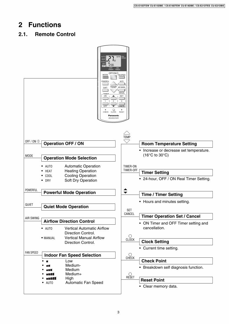
2 Functions2.1. Remote Control
Operation OFF / ON Room Temperature Setting
TEMP
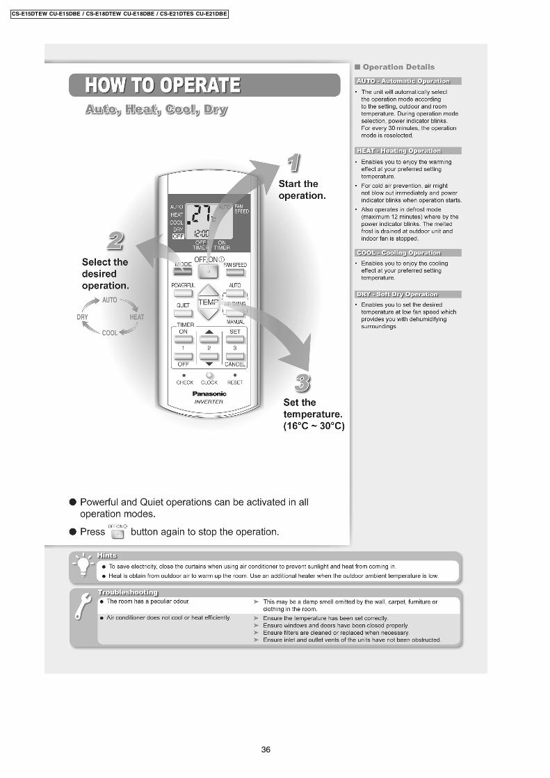
Operation Mode Selection
• AUTO Automatic Operation• HEAT Heating Operation• COOL Cooling Operation• DRY Soft Dry Operation
Time / Timer Setting
• Hours and minutes setting.
Clock Setting• Current time setting.
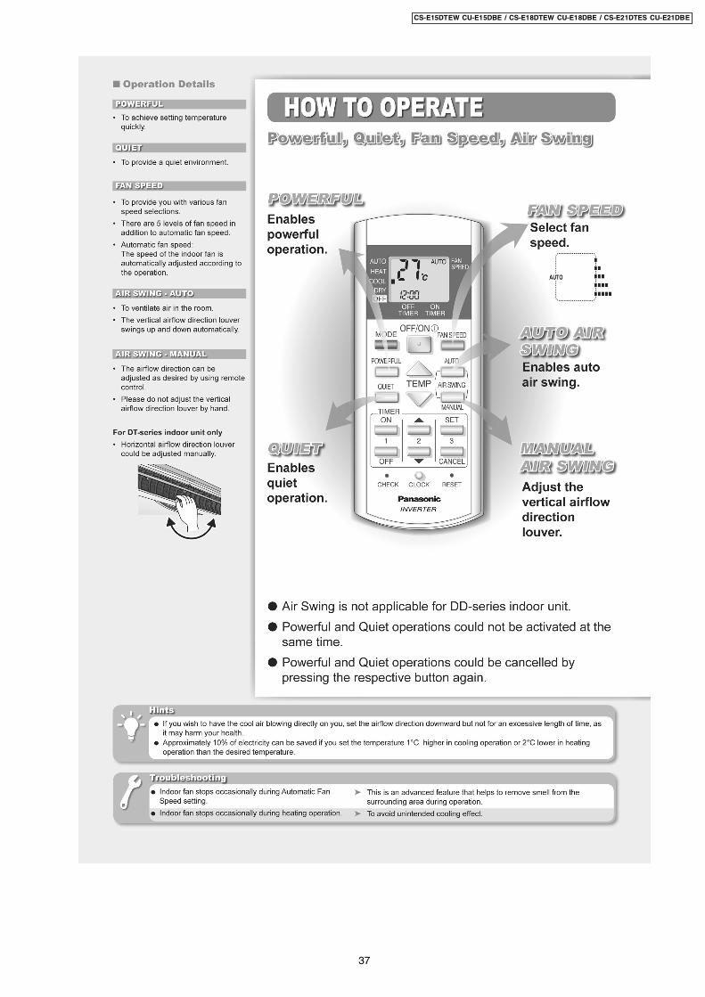
Quiet Mode OperationQUIET
Airflow Direction Control
• 24-hour, OFF / ON Real Timer Setting.
Timer Setting
Timer Operation Set / Cancel
• ON Timer and OFF Timer setting andcancellation.
CLOCK
Powerful Mode OperationPOWERFUL
• Increase or decrease set temperature.(16°C to 30°C)
• AUTO Vertical Automatic AirflowDirection Control.
• MANUAL Vertical Manual AirflowDirection Control.
FAN SPEED
Check Point
Reset PointRESET
CHECK
AIR SWING
• Breakdown self diagnosis function.
• Clear memory data.
CANCEL
OFFTIMER
ONTIMER
FANSPEED
AUTO
HEAT
DRYCOOL
OFF
MODE
TIMERON
1 2 3
OFF
CLOCK RESET
SET
CANCEL
TEMP
POWERFUL
FAN SPEED
AIR SWING
OFF/ON
QUIET
AUTO
MANUAL
CHECK
INVENTER
OFF / ON I
MODE
Indoor Fan Speed Selection• Low• Medium-• Medium• Medium+• High• AUTO Automatic Fan Speed
TIMER-ONTIMER-OFF
SETCANCEL
3
CS-E15DTEW CU-E15DBE / CS-E18DTEW CU-E18DBE / CS-E21DTES CU-E21DBE
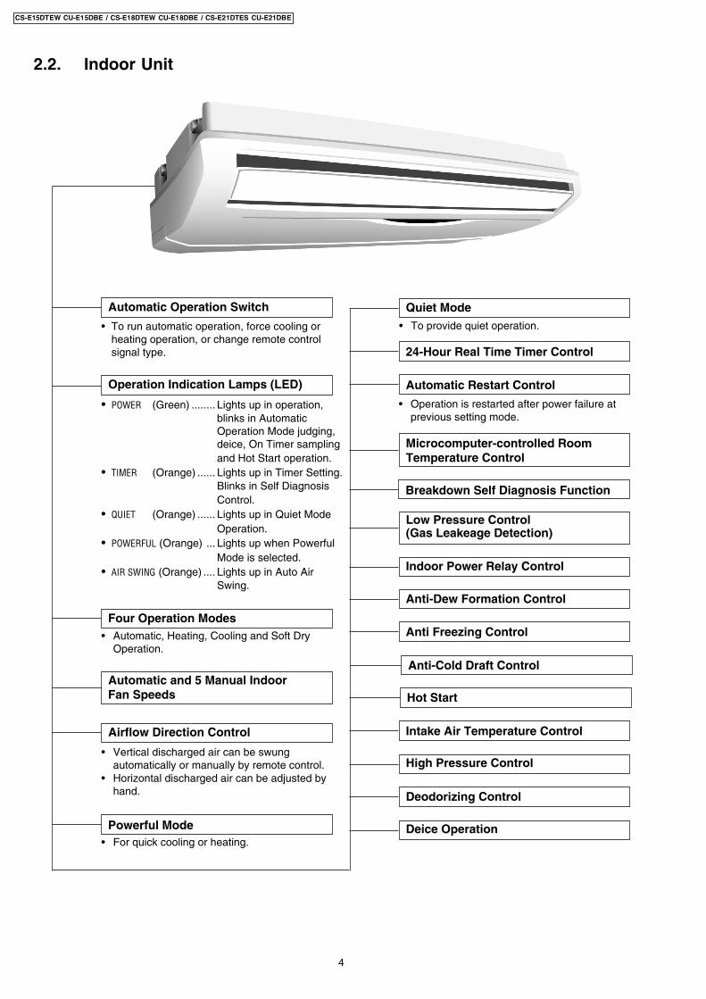
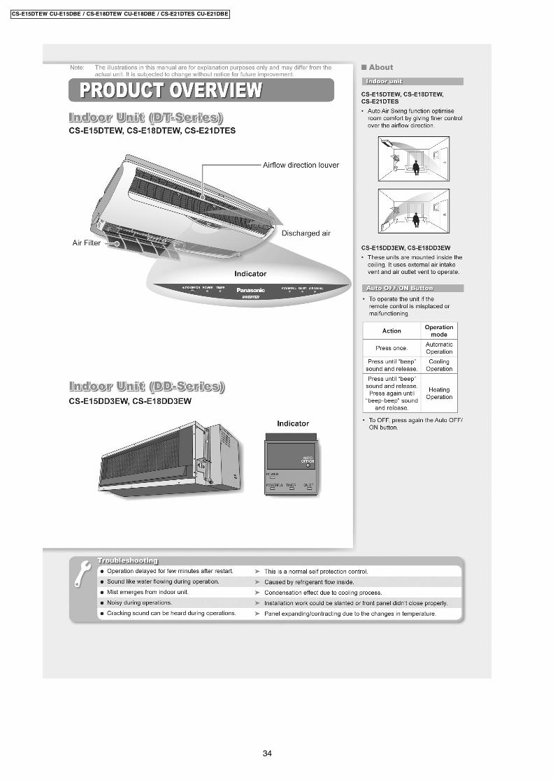
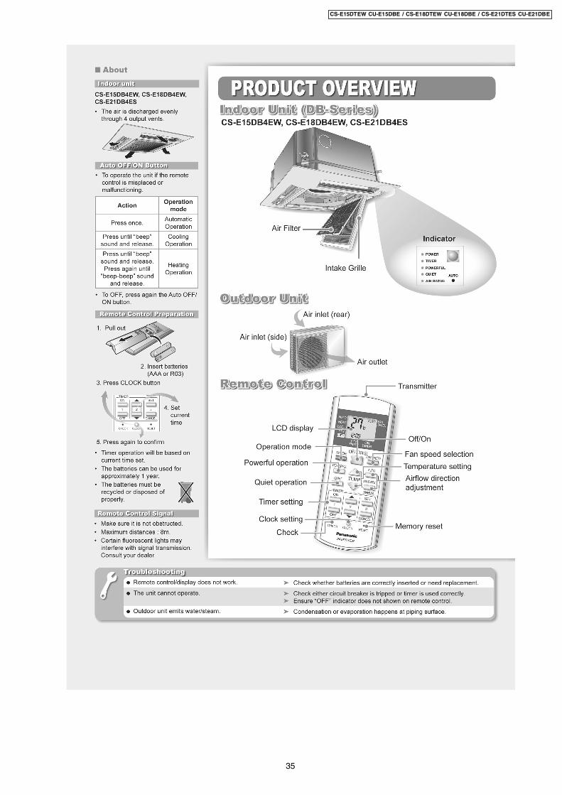
2.2. Indoor Unit
Automatic and 5 Manual IndoorFan Speeds
Powerful Mode• For quick cooling or heating.
24-Hour Real Time Timer Control
Microcomputer-controlled RoomTemperature Control
Breakdown Self Diagnosis Function
Indoor Power Relay Control
Anti-Dew Formation Control
Anti Freezing Control
Anti-Cold Draft Control
Hot Start
Intake Air Temperature Control
Quiet Mode• To provide quiet operation.
Automatic Restart Control
• Operation is restarted after power failure atprevious setting mode.
Low Pressure Control(Gas Leakeage Detection)
Deodorizing Control
Four Operation Modes• Automatic, Heating, Cooling and Soft Dry
Operation.
Operation Indication Lamps (LED)
• POWER (Green) ........ Lights up in operation,blinks in AutomaticOperation Mode judging,deice, On Timer samplingand Hot Start operation.
• TIMER (Orange) ...... Lights up in Timer Setting.Blinks in Self DiagnosisControl.
• QUIET (Orange) ...... Lights up in Quiet ModeOperation.
• POWERFUL (Orange) ... Lights up when PowerfulMode is selected.
• AIR SWING (Orange) .... Lights up in Auto AirSwing.
Airflow Direction Control
• Vertical discharged air can be swungautomatically or manually by remote control.
• Horizontal discharged air can be adjusted byhand.
Automatic Operation Switch
• To run automatic operation, force cooling orheating operation, or change remote controlsignal type.
High Pressure Control
Deice Operation
4
CS-E15DTEW CU-E15DBE / CS-E18DTEW CU-E18DBE / CS-E21DTES CU-E21DBE
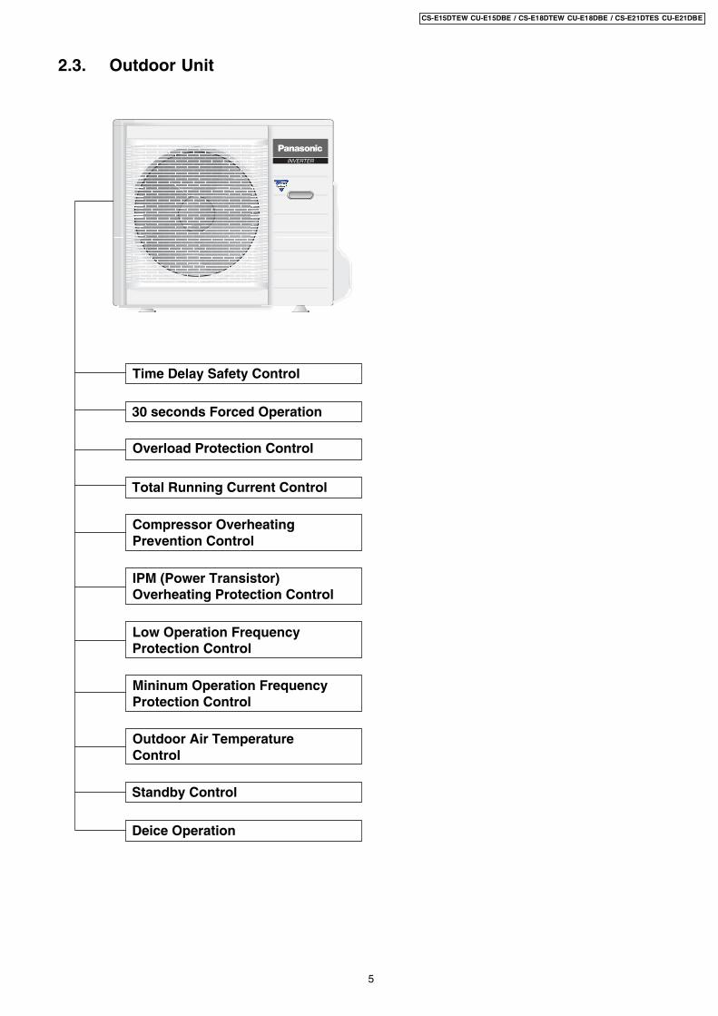
2.3. Outdoor Unit
30 seconds Forced Operation
Time Delay Safety Control
Overload Protection Control
Deice Operation
Standby Control
Compressor OverheatingPrevention Control
IPM (Power Transistor)Overheating Protection Control
Total Running Current Control
Mininum Operation FrequencyProtection Control
Low Operation FrequencyProtection Control
Outdoor Air TemperatureControl
5
CS-E15DTEW CU-E15DBE / CS-E18DTEW CU-E18DBE / CS-E21DTES CU-E21DBE
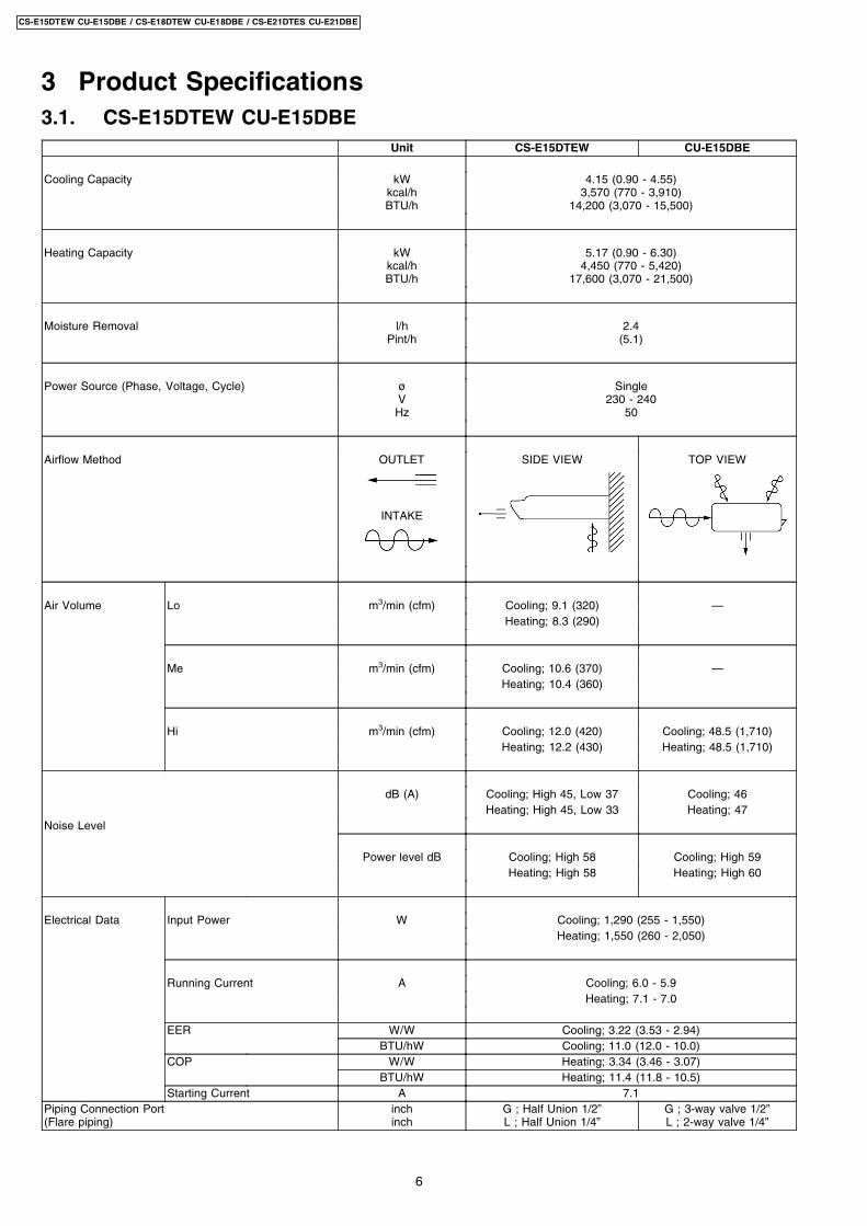
3.1. CS-E15DTEW CU-E15DBE
3 Product Specifications
Unit CS-E15DTEW CU-E15DBE
Cooling Capacity kWkcal/hBTU/h
4.15 (0.90 - 4.55)3,570 (770 - 3,910)
14,200 (3,070 - 15,500)
Heating Capacity kWkcal/hBTU/h
5.17 (0.90 - 6.30)4,450 (770 - 5,420)
17,600 (3,070 - 21,500)
Moisture Removal l/hPint/h
2.4(5.1)
Power Source (Phase, Voltage, Cycle) øVHz
Single230 - 240
50
Airflow Method OUTLET
INTAKE
SIDE VIEW TOP VIEW
Air Volume Lo m3/min (cfm) Cooling; 9.1 (320) —Heating; 8.3 (290)
Me m3/min (cfm) Cooling; 10.6 (370) —Heating; 10.4 (360)
Hi m3/min (cfm) Cooling; 12.0 (420) Cooling; 48.5 (1,710)Heating; 12.2 (430) Heating; 48.5 (1,710)
dB (A) Cooling; High 45, Low 37 Cooling; 46Heating; High 45, Low 33 Heating; 47
Noise Level
Power level dB Cooling; High 58 Cooling; High 59Heating; High 58 Heating; High 60
Electrical Data Input Power W Cooling; 1,290 (255 - 1,550)Heating; 1,550 (260 - 2,050)
Running Current A Cooling; 6.0 - 5.9Heating; 7.1 - 7.0
EER W/W Cooling; 3.22 (3.53 - 2.94)BTU/hW Cooling; 11.0 (12.0 - 10.0)
COP W/W Heating; 3.34 (3.46 - 3.07)BTU/hW Heating; 11.4 (11.8 - 10.5)
Starting Current A 7.1Piping Connection Port(Flare piping)
inchinch
G ; Half Union 1/2”L ; Half Union 1/4”
G ; 3-way valve 1/2”L ; 2-way valve 1/4”
6
CS-E15DTEW CU-E15DBE / CS-E18DTEW CU-E18DBE / CS-E21DTES CU-E21DBE
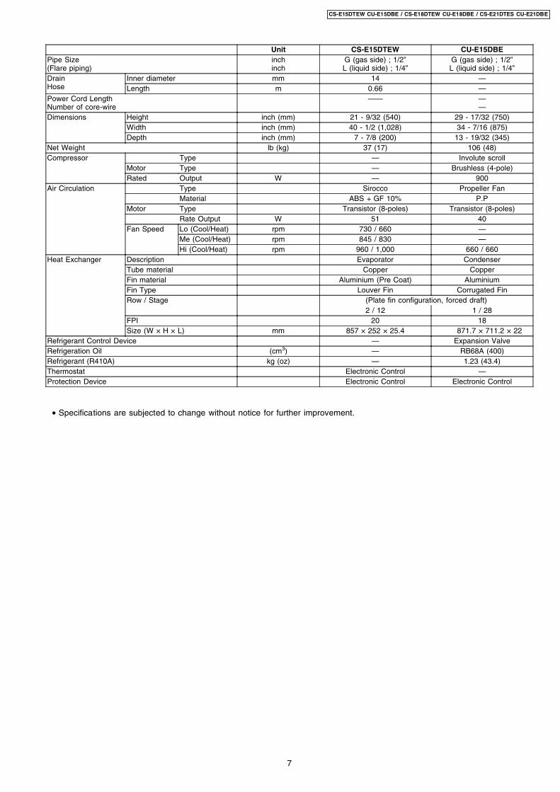
Unit CS-E15DTEW CU-E15DBEPipe Size(Flare piping)
inchinch
G (gas side) ; 1/2”L (liquid side) ; 1/4”
G (gas side) ; 1/2”L (liquid side) ; 1/4”
DrainHose
Inner diameter mm 14 —Length m 0.66 —
Power Cord LengthNumber of core-wire
—— ——
Dimensions Height inch (mm) 21 - 9/32 (540) 29 - 17/32 (750)Width inch (mm) 40 - 1/2 (1,028) 34 - 7/16 (875)Depth inch (mm) 7 - 7/8 (200) 13 - 19/32 (345)
Net Weight lb (kg) 37 (17) 106 (48)Compressor Type — Involute scroll
Motor Type — Brushless (4-pole)Rated Output W — 900
Air Circulation Type Sirocco Propeller FanMaterial ABS + GF 10% P.P
Motor Type Transistor (8-poles) Transistor (8-poles)Rate Output W 51 40
Fan Speed Lo (Cool/Heat) rpm 730 / 660 —Me (Cool/Heat) rpm 845 / 830 —Hi (Cool/Heat) rpm 960 / 1,000 660 / 660
Heat Exchanger Description Evaporator CondenserTube material Copper CopperFin material Aluminium (Pre Coat) AluminiumFin Type Louver Fin Corrugated FinRow / Stage (Plate fin configuration, forced draft)
2 / 12 1 / 28FPI 20 18Size (W × H × L) mm 857 × 252 × 25.4 871.7 × 711.2 × 22
Refrigerant Control Device — Expansion ValveRefrigeration Oil (cm3) — RB68A (400)Refrigerant (R410A) kg (oz) — 1.23 (43.4)Thermostat Electronic Control —Protection Device Electronic Control Electronic Control
• Specifications are subjected to change without notice for further improvement.
7
CS-E15DTEW CU-E15DBE / CS-E18DTEW CU-E18DBE / CS-E21DTES CU-E21DBE

3.2. CS-E18DTEW CU-E18DBEUnit CS-E18DTEW CU-E18DBE
Cooling Capacity kWkcal/hBTU/h
5.00 (0.90 - 5.40)4,300 (770 - 4,640)
17,100 (3,070 - 18,400)
Heating Capacity kWkcal/hBTU/h
6.10 (0.90 - 7.60)5,250 (770 - 6,540)
20,800 (3,070 - 25,900)
Moisture Removal l/hPint/h
2.8(5.9)
Power Source (Phase, Voltage, Cycle) øVHz
Single230 - 240
50
Airflow Method OUTLET
INTAKE
SIDE VIEW TOP VIEW
Air Volume Lo m3/min (cfm) Cooling; 9.8 (350) —Heating; 8.6 (300)
Me m3/min (cfm) Cooling; 11.2 (390) —Heating; 10.7 (380)
Hi m3/min (cfm) Cooling; 12.5 (440) 40.0 (1,410)Heating; 12.7 (450)
dB (A) Cooling; High 46, Low 39 Cooling; 47Heating; High 47, Low 35 Heating; 48
Noise Level
Power level dB Cooling; High 59 Cooling; High 60Heating; High 60 Heating; High 61
Electrical Data Input Power W Cooling; 1,660 (255 - 1,890)Heating; 1,820 (260 - 2,380)
Running Current A Cooling; 7.5 - 7.4Heating; 8.2 - 8.1
EER W/W Cooling; 3.01 (3.53 - 2.86)BTU/hW Cooling; 10.3 (12.0 - 9.7)
COP W/W Heating; 3.35 (3.46 - 3.19)BTU/hW Heating; 11.4 (11.8 - 10.9)
Starting Current A 8.2Piping Connection Port(Flare piping)
inchinch
G ; Half Union 1/2”L ; Half Union 1/4”
G ; 3-way valve 1/2”L ; 2-way valve 1/4”
Pipe Size(Flare piping)
inchinch
G (gas side) ; 1/2”L (liquid side) ; 1/4”
G (gas side) ; 1/2”L (liquid side) ; 1/4”
8
CS-E15DTEW CU-E15DBE / CS-E18DTEW CU-E18DBE / CS-E21DTES CU-E21DBE

Unit CS-E18DTEW CU-E18DBEDrainHose
Inner diameter mm 14 —Length m 0.66 —
Power Cord LengthNumber of core-wire
—— ——
Dimensions Height inch (mm) 21 - 9/32 (540) 29 - 17/32 (750)Width inch (mm) 40 - 1/2 (1,028) 34 - 7/16 (875)Depth inch (mm) 7 - 7/8 (200) 13 - 19/32 (345)
Net Weight lb (kg) 40 (18) 106 (48)Compressor Type — Involute scroll
Motor Type — Brushless (4-pole)Rated Output W — 900
Air Circulation Type Sirocco Propeller FanMaterial ABS + GF 10% P.P
Motor Type Transistor (8-poles) Transistor (8-poles)Rate Output W 51 40
Fan Speed Lo (Cool/Heat) rpm 800 / 700 —Me (Cool/Heat) rpm 910 / 875 —Hi (Cool/Heat) rpm 1,020 / 1,050 660 / 660
Heat Exchanger Description Evaporator CondenserTube material Copper CopperFin material Aluminium (Pre Coat) AluminiumFin Type Louver Fin Corrugated FinRow / Stage (Plate fin configuration, forced draft)
2 / 12 2 / 34FPI 20 16Size (W × H × L) mm 857 × 252 × 25.4 849.3
878× 714 × 36.4
Refrigerant Control Device — Expansion ValveRefrigeration Oil (cm3) — RB68A (400)Refrigerant (R410A) kg (oz) — 1.06 (37.4)Thermostat Electronic Control —Protection Device Electronic Control Electronic Control
• Specifications are subjected to change without notice for further improvement.
9
CS-E15DTEW CU-E15DBE / CS-E18DTEW CU-E18DBE / CS-E21DTES CU-E21DBE
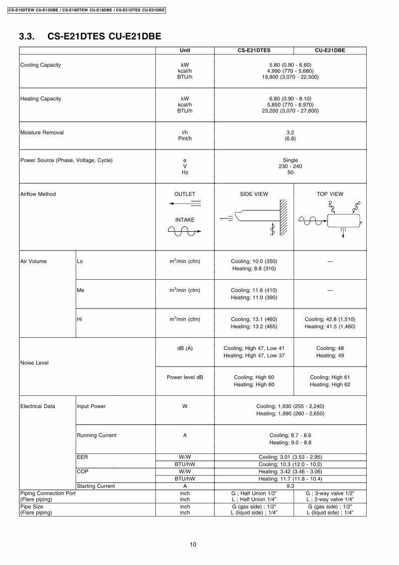
3.3. CS-E21DTES CU-E21DBEUnit CS-E21DTES CU-E21DBE
Cooling Capacity kWkcal/hBTU/h
5.80 (0.90 - 6.60)4,990 (770 - 5,680)
19,800 (3,070 - 22,500)
Heating Capacity kWkcal/hBTU/h
6.80 (0.90 - 8.10)5,850 (770 - 6,970)
23,200 (3,070 - 27,600)
Moisture Removal l/hPint/h
3.2(6.8)
Power Source (Phase, Voltage, Cycle) øVHz
Single230 - 240
50
Airflow Method OUTLET
INTAKE
SIDE VIEW TOP VIEW
Air Volume Lo m3/min (cfm) Cooling; 10.0 (350) —Heating; 8.8 (310)
Me m3/min (cfm) Cooling; 11.6 (410) —Heating; 11.0 (390)
Hi m3/min (cfm) Cooling; 13.1 (460) Cooling; 42.8 (1,510)Heating; 13.2 (465) Heating; 41.5 (1,460)
dB (A) Cooling; High 47, Low 41 Cooling; 48Heating; High 47, Low 37 Heating; 49
Noise Level
Power level dB Cooling; High 60 Cooling; High 61Heating; High 60 Heating; High 62
Electrical Data Input Power W Cooling; 1,930 (255 - 2,240)Heating; 1,990 (260 - 2,650)
Running Current A Cooling; 8.7 - 8.6Heating; 9.0 - 8.8
EER W/W Cooling; 3.01 (3.53 - 2.95)BTU/hW Cooling; 10.3 (12.0 - 10.0)
COP W/W Heating; 3.42 (3.46 - 3.06)BTU/hW Heating; 11.7 (11.8 - 10.4)
Starting Current A 9.3Piping Connection Port(Flare piping)
inchinch
G ; Half Union 1/2”L ; Half Union 1/4”
G ; 3-way valve 1/2”L ; 2-way valve 1/4”
Pipe Size(Flare piping)
inchinch
G (gas side) ; 1/2”L (liquid side) ; 1/4”
G (gas side) ; 1/2”L (liquid side) ; 1/4”
10
CS-E15DTEW CU-E15DBE / CS-E18DTEW CU-E18DBE / CS-E21DTES CU-E21DBE
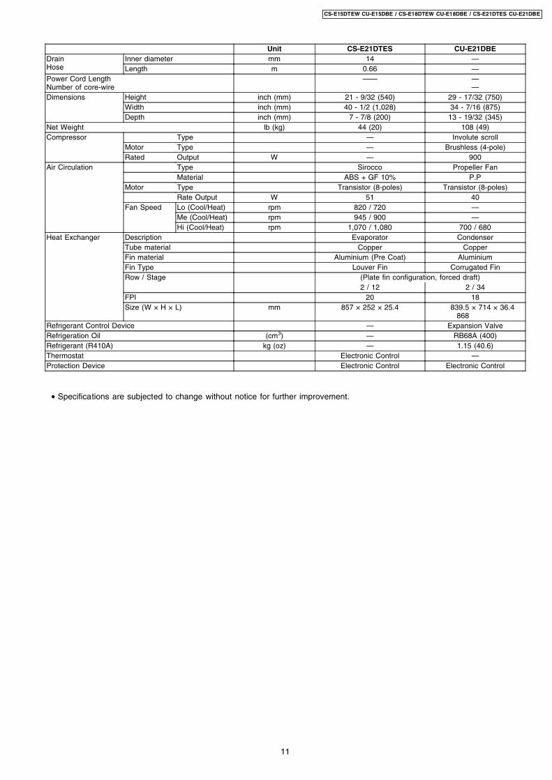
Unit CS-E21DTES CU-E21DBEDrainHose
Inner diameter mm 14 —Length m 0.66 —
Power Cord LengthNumber of core-wire
—— ——
Dimensions Height inch (mm) 21 - 9/32 (540) 29 - 17/32 (750)Width inch (mm) 40 - 1/2 (1,028) 34 - 7/16 (875)Depth inch (mm) 7 - 7/8 (200) 13 - 19/32 (345)
Net Weight lb (kg) 44 (20) 108 (49)Compressor Type — Involute scroll
Motor Type — Brushless (4-pole)Rated Output W — 900
Air Circulation Type Sirocco Propeller FanMaterial ABS + GF 10% P.P
Motor Type Transistor (8-poles) Transistor (8-poles)Rate Output W 51 40
Fan Speed Lo (Cool/Heat) rpm 820 / 720 —Me (Cool/Heat) rpm 945 / 900 —Hi (Cool/Heat) rpm 1,070 / 1,080 700 / 680
Heat Exchanger Description Evaporator CondenserTube material Copper CopperFin material Aluminium (Pre Coat) AluminiumFin Type Louver Fin Corrugated FinRow / Stage (Plate fin configuration, forced draft)
2 / 12 2 / 34FPI 20 18Size (W × H × L) mm 857 × 252 × 25.4 839.5
868× 714 × 36.4
Refrigerant Control Device — Expansion ValveRefrigeration Oil (cm3) — RB68A (400)Refrigerant (R410A) kg (oz) — 1.15 (40.6)Thermostat Electronic Control —Protection Device Electronic Control Electronic Control
• Specifications are subjected to change without notice for further improvement.
11
CS-E15DTEW CU-E15DBE / CS-E18DTEW CU-E18DBE / CS-E21DTES CU-E21DBE
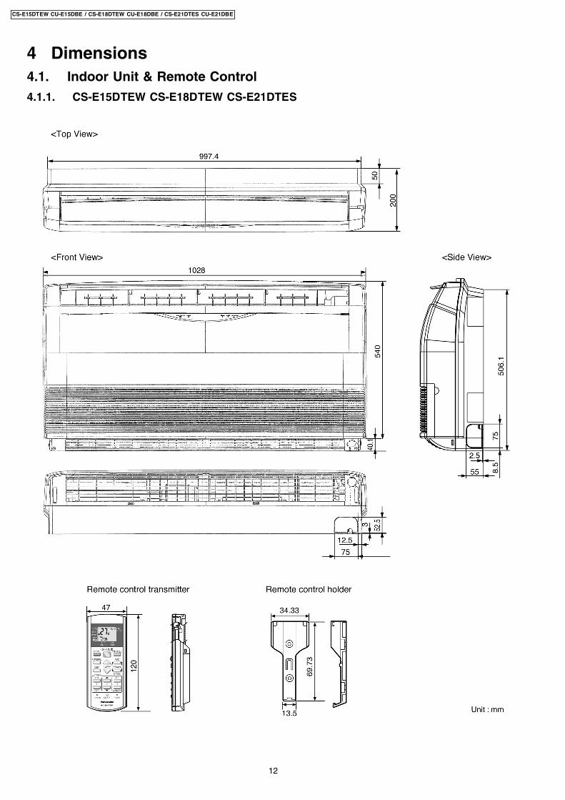
4 Dimensions4.1. Indoor Unit & Remote Control
4.1.1. CS-E15DTEW CS-E18DTEW CS-E21DTES
12
CS-E15DTEW CU-E15DBE / CS-E18DTEW CU-E18DBE / CS-E21DTES CU-E21DBE
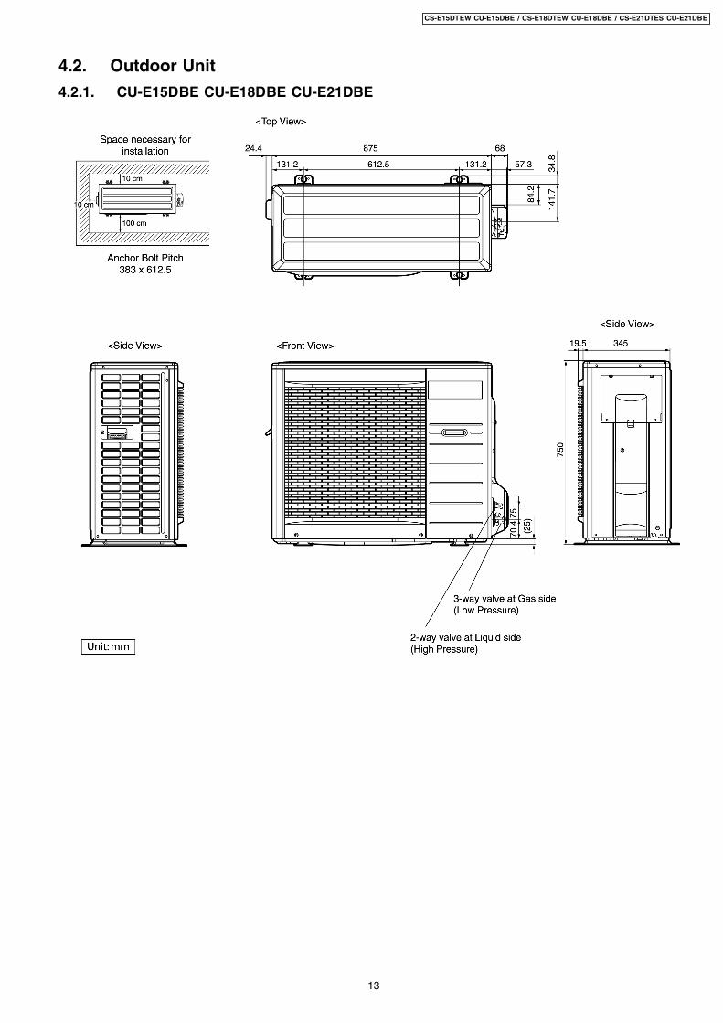
4.2. Outdoor Unit
4.2.1. CU-E15DBE CU-E18DBE CU-E21DBE
13
CS-E15DTEW CU-E15DBE / CS-E18DTEW CU-E18DBE / CS-E21DTES CU-E21DBE
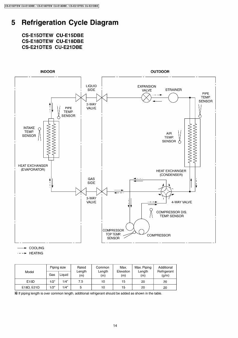
5 Refrigeration Cycle Diagram
14
CS-E15DTEW CU-E15DBE / CS-E18DTEW CU-E18DBE / CS-E21DTES CU-E21DBE
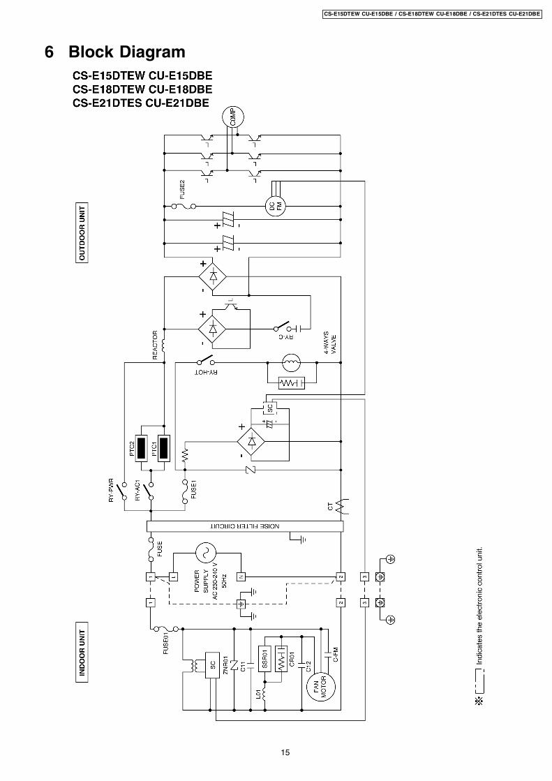
6 Block Diagram
15
CS-E15DTEW CU-E15DBE / CS-E18DTEW CU-E18DBE / CS-E21DTES CU-E21DBE
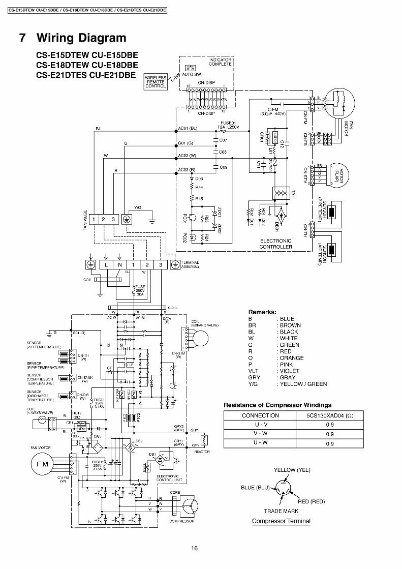
7 Wiring Diagram
16
CS-E15DTEW CU-E15DBE / CS-E18DTEW CU-E18DBE / CS-E21DTES CU-E21DBE
8 Operation Details
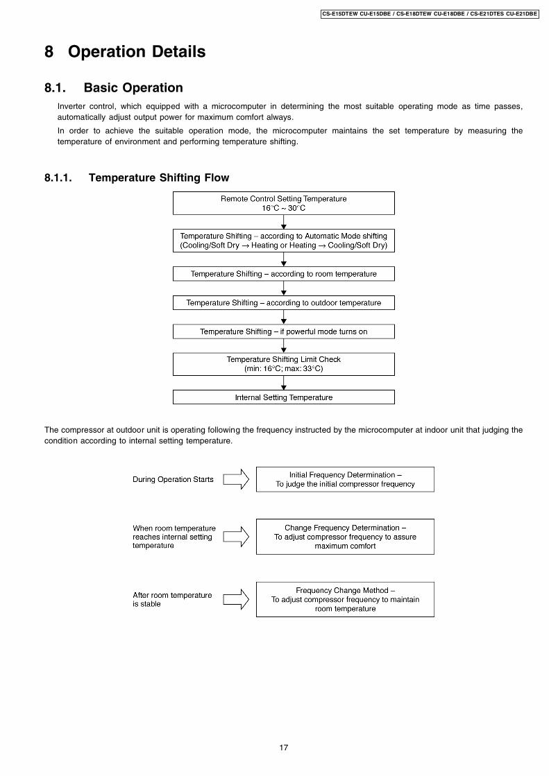
8.1. Basic OperationInverter control, which equipped with a microcomputer in determining the most suitable operating mode as time passes,automatically adjust output power for maximum comfort always.
In order to achieve the suitable operation mode, the microcomputer maintains the set temperature by measuring thetemperature of environment and performing temperature shifting.
8.1.1. Temperature Shifting Flow
The compressor at outdoor unit is operating following the frequency instructed by the microcomputer at indoor unit that judging thecondition according to internal setting temperature.
17
CS-E15DTEW CU-E15DBE / CS-E18DTEW CU-E18DBE / CS-E21DTES CU-E21DBE
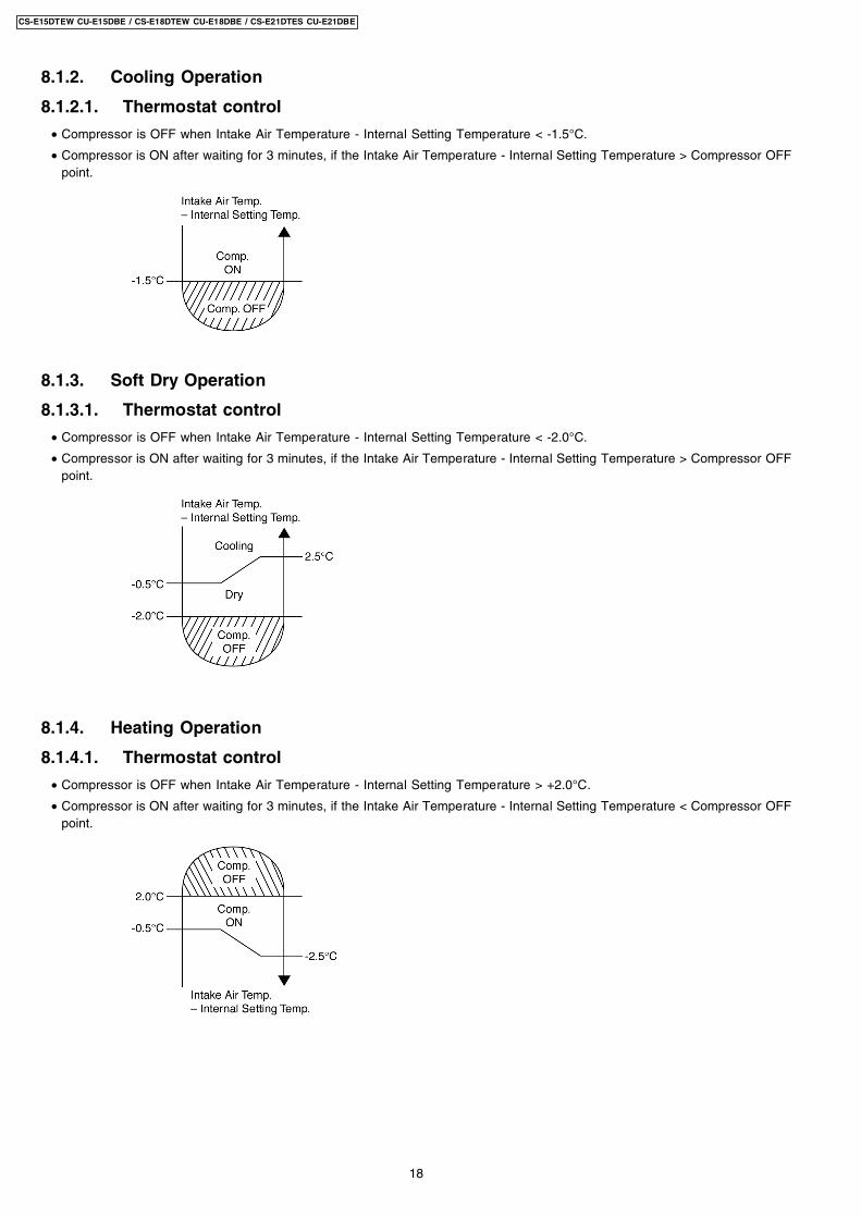
8.1.2. Cooling Operation
8.1.2.1. Thermostat control
• Compressor is OFF when Intake Air Temperature - Internal Setting Temperature < -1.5°C.
• Compressor is ON after waiting for 3 minutes, if the Intake Air Temperature - Internal Setting Temperature > Compressor OFFpoint.
8.1.3. Soft Dry Operation
8.1.3.1. Thermostat control
• Compressor is OFF when Intake Air Temperature - Internal Setting Temperature < -2.0°C.
• Compressor is ON after waiting for 3 minutes, if the Intake Air Temperature - Internal Setting Temperature > Compressor OFFpoint.
8.1.4. Heating Operation
8.1.4.1. Thermostat control
• Compressor is OFF when Intake Air Temperature - Internal Setting Temperature > +2.0°C.
• Compressor is ON after waiting for 3 minutes, if the Intake Air Temperature - Internal Setting Temperature < Compressor OFFpoint.
18
CS-E15DTEW CU-E15DBE / CS-E18DTEW CU-E18DBE / CS-E21DTES CU-E21DBE
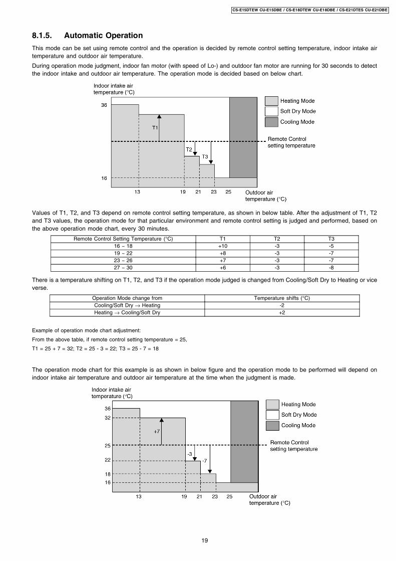
8.1.5. Automatic Operation
This mode can be set using remote control and the operation is decided by remote control setting temperature, indoor intake airtemperature and outdoor air temperature.
During operation mode judgment, indoor fan motor (with speed of Lo-) and outdoor fan motor are running for 30 seconds to detectthe indoor intake and outdoor air temperature. The operation mode is decided based on below chart.
Values of T1, T2, and T3 depend on remote control setting temperature, as shown in below table. After the adjustment of T1, T2and T3 values, the operation mode for that particular environment and remote control setting is judged and performed, based onthe above operation mode chart, every 30 minutes.
Remote Control Setting Temperature (°C) T1 T2 T316 ~ 18 +10 -3 -519 ~ 22 +8 -3 -723 ~ 26 +7 -3 -727 ~ 30 +6 -3 -8
There is a temperature shifting on T1, T2, and T3 if the operation mode judged is changed from Cooling/Soft Dry to Heating or viceverse.
Operation Mode change from Temperature shifts (°C)Cooling/Soft Dry → Heating -2Heating → Cooling/Soft Dry +2
Example of operation mode chart adjustment:
From the above table, if remote control setting temperature = 25,
T1 = 25 + 7 = 32; T2 = 25 - 3 = 22; T3 = 25 - 7 = 18
The operation mode chart for this example is as shown in below figure and the operation mode to be performed will depend onindoor intake air temperature and outdoor air temperature at the time when the judgment is made.
19
CS-E15DTEW CU-E15DBE / CS-E18DTEW CU-E18DBE / CS-E21DTES CU-E21DBE
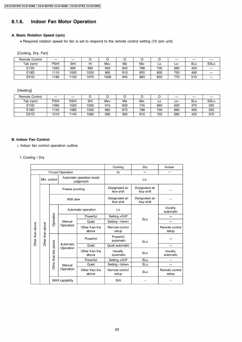
8.1.6. Indoor Fan Motor Operation
A. Basic Rotation Speed (rpm)
• Required rotation speed for fan is set to respond to the remote control setting (10 rpm unit)
[Cooling, Dry, Fan]
Remote Control — — O O O O O — — —Tab (rpm) PSHI SHI Hi Me+ Me Me- Lo Lo- SLo SSLo
E15D 1050 990 960 903 845 788 730 680 420 —E18D 1110 1050 1020 965 910 855 800 750 490 —E21D 1180 1120 1070 1008 945 883 820 770 510 —
[Heating]
Remote Control — — O O O O O — — —Tab (rpm) PSHi SSHi SHi Me+ Me Me- Lo Lo- SLo SSLo
E15D 1090 1020 1000 915 830 745 660 620 370 320E18D 1150 1080 1050 962 875 788 700 660 400 350E21D 1210 1140 1080 990 900 810 720 680 420 370
B. Indoor Fan Control
i. Indoor fan control operation outline
1. Cooling / Dry
20
CS-E15DTEW CU-E15DBE / CS-E18DTEW CU-E18DBE / CS-E21DTES CU-E21DBE
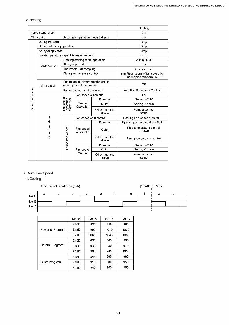
2. Heating
ii. Auto Fan Speed
1. Cooling
21
CS-E15DTEW CU-E15DBE / CS-E18DTEW CU-E18DBE / CS-E21DTES CU-E21DBE
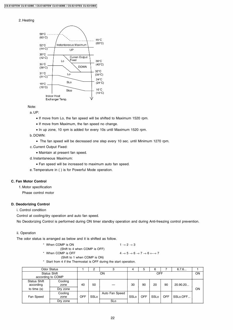
2. Heating
Note:
a. UP:
• If move from Lo, the fan speed will be shifted to Maximum 1520 rpm.
• If move from Maximum, the fan speed no change.
• In up zone, 10 rpm is added for every 10s until Maximum 1520 rpm.
b. DOWN:
• The fan speed will be decreased one step every 10 sec. until Minimum 1270 rpm.
c. Current Output Fixed:
• Maintain at present fan speed.
d. Instantaneous Maximum:
• Fan speed will be increased to maximum auto fan speed.
e. Temperature in ( ) is for Powerful Mode operation.
C. Fan Motor Control
1. Motor specification
Phase control motor
D. Deodorizing Control
i. Control condition
Control at cooling/dry operation and auto fan speed.
No Deodorizing Control is performed during ON timer standby operation and during Anti-freezing control prevention.
ii. Operation
The odor status is arranged as below and it is shifted as follow.
* When COMP is ON 1 → 2 → 3(Shift to 4 when COMP is OFF)
* When COMP is OFF 4 → 5 → 6 → 7 → 6 ←→ 7(Shift to 1 when COMP is ON)
* Start from 4 if the Thermostat is OFF during the start operation.
Odor Status 1 2 3 4 5 6 7 6.7.6... 1Status Shift
according to COMPON OFF ON
Status Shiftaccording
Coolingzone 40 50 — 30 90 20 90 20.90.20...
to time (s) Dry zone ON
Fan SpeedCooling
zone OFF SSLoAuto Fan Speed
SSLo OFF SSLo OFF SSLo.OFF...Dry zone SLo
22
CS-E15DTEW CU-E15DBE / CS-E18DTEW CU-E18DBE / CS-E21DTES CU-E21DBE
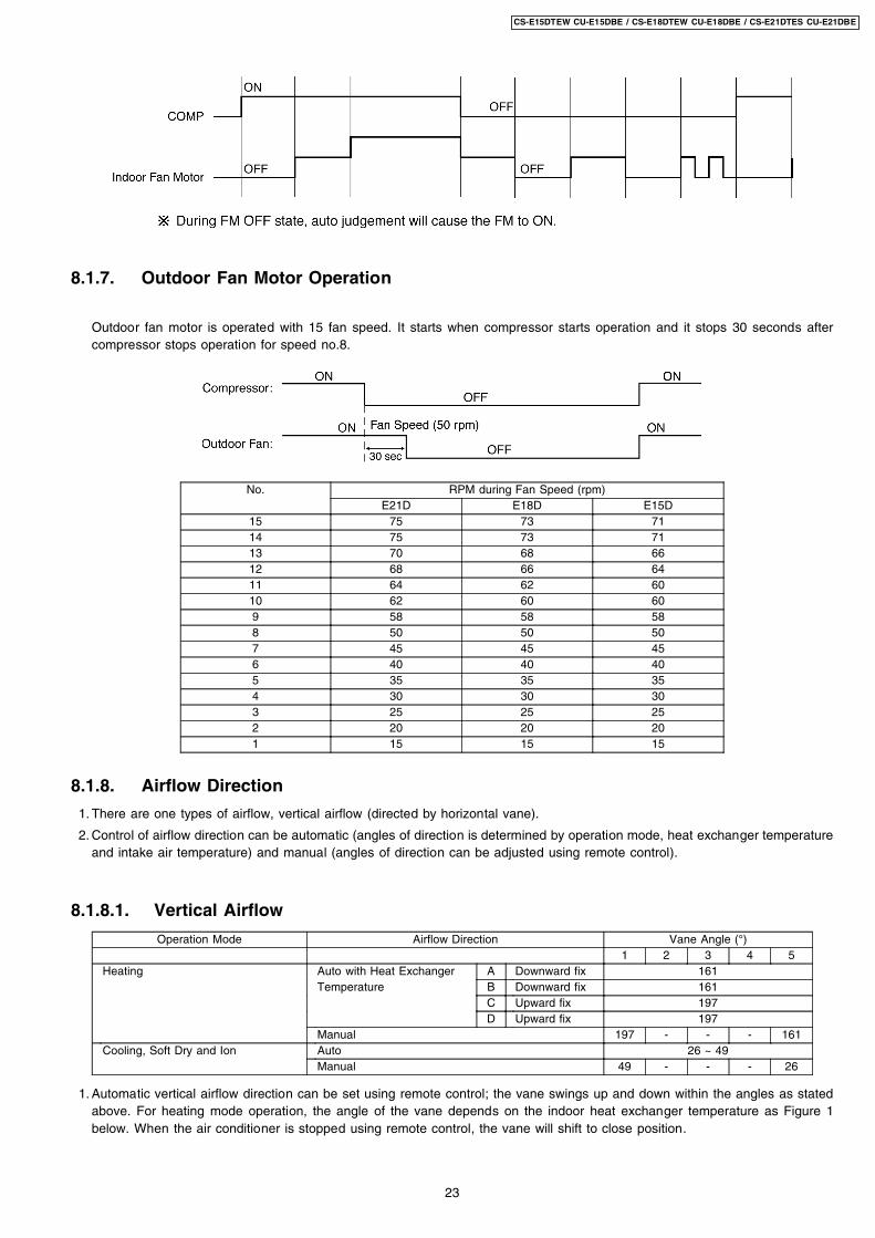
8.1.7. Outdoor Fan Motor Operation
Outdoor fan motor is operated with 15 fan speed. It starts when compressor starts operation and it stops 30 seconds aftercompressor stops operation for speed no.8.
No. RPM during Fan Speed (rpm)E21D E18D E15D
15 75 73 7114 75 73 7113 70 68 6612 68 66 6411 64 62 6010 62 60 609 58 58 588 50 50 507 45 45 456 40 40 405 35 35 354 30 30 303 25 25 252 20 20 201 15 15 15
8.1.8. Airflow Direction
1. There are one types of airflow, vertical airflow (directed by horizontal vane).
2. Control of airflow direction can be automatic (angles of direction is determined by operation mode, heat exchanger temperatureand intake air temperature) and manual (angles of direction can be adjusted using remote control).
8.1.8.1. Vertical Airflow
Operation Mode Airflow Direction Vane Angle (°)1 2 3 4 5
Heating Auto with Heat Exchanger A Downward fix 161Temperature B Downward fix 161
C Upward fix 197D Upward fix 197
Manual 197 - - - 161Cooling, Soft Dry and Ion Auto 26 ~ 49
Manual 49 - - - 26
1. Automatic vertical airflow direction can be set using remote control; the vane swings up and down within the angles as statedabove. For heating mode operation, the angle of the vane depends on the indoor heat exchanger temperature as Figure 1below. When the air conditioner is stopped using remote control, the vane will shift to close position.
23
CS-E15DTEW CU-E15DBE / CS-E18DTEW CU-E18DBE / CS-E21DTES CU-E21DBE
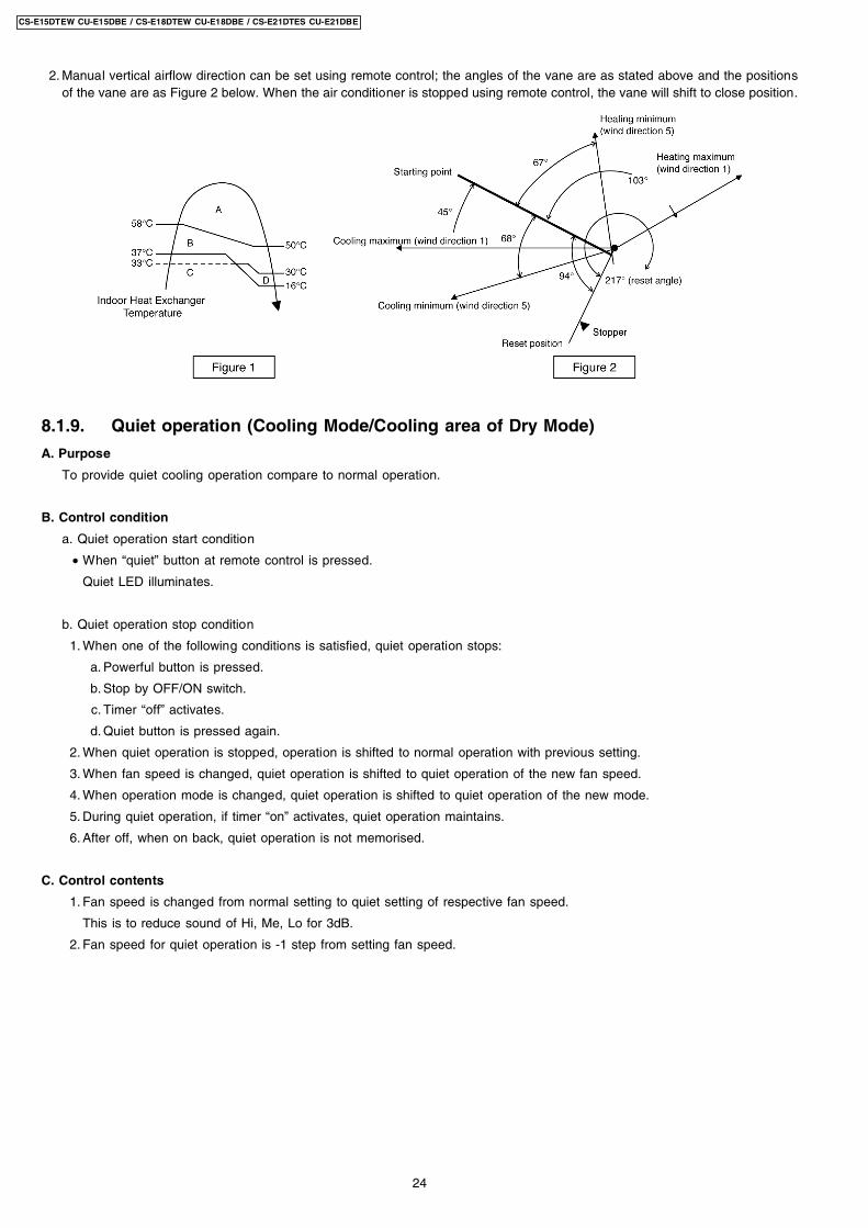
2. Manual vertical airflow direction can be set using remote control; the angles of the vane are as stated above and the positionsof the vane are as Figure 2 below. When the air conditioner is stopped using remote control, the vane will shift to close position.
8.1.9. Quiet operation (Cooling Mode/Cooling area of Dry Mode)
A. Purpose
To provide quiet cooling operation compare to normal operation.
B. Control condition
a. Quiet operation start condition
• When “quiet” button at remote control is pressed.
Quiet LED illuminates.
b. Quiet operation stop condition
1. When one of the following conditions is satisfied, quiet operation stops:
a. Powerful button is pressed.
b. Stop by OFF/ON switch.
c. Timer “off” activates.
d. Quiet button is pressed again.
2. When quiet operation is stopped, operation is shifted to normal operation with previous setting.
3. When fan speed is changed, quiet operation is shifted to quiet operation of the new fan speed.
4. When operation mode is changed, quiet operation is shifted to quiet operation of the new mode.
5. During quiet operation, if timer “on” activates, quiet operation maintains.
6. After off, when on back, quiet operation is not memorised.
C. Control contents
1. Fan speed is changed from normal setting to quiet setting of respective fan speed.
This is to reduce sound of Hi, Me, Lo for 3dB.
2. Fan speed for quiet operation is -1 step from setting fan speed.
24
CS-E15DTEW CU-E15DBE / CS-E18DTEW CU-E18DBE / CS-E21DTES CU-E21DBE
8.1.9.1. Quiet operation (Heating)
A. Purpose
To provide quiet heating operation compare to normal operation.
B. Control condition
a. Quiet operation start condition
• When “quiet” button at remote control is pressed.
Quiet LED illuminates.
b. Quiet operation stop condition
1. When one of the following conditions is satisfied, quiet operation stops:
a. Powerful button is pressed.
b. Stop by OFF/ON switch.
c. Timer “off” activates.
d. Quiet button is pressed again.
2. When quiet operation is stopped, operation is shifted to normal operation with previous setting.
3. When fan speed is changed, quiet operation is shifted to quiet operation of the new fan speed.
4. When operation mode is changed, quiet operation is shifted to quiet operation of the new mode, except fan only mode.
5. During quiet operation, if timer “on” activates, quiet operation maintains.
6. After off, when on back, quiet operation is not memorised.
C. Control contents
a. Fan Speed manual
1. Fan speed is changed from normal setting to quiet setting of respective fan speed.
This is to reduce sound of Hi, Me, Lo for 3dB.
2. Fan speed for quiet operation is -1 step from setting fan speed.
3. Fan Speed Auto
Indoor FM RPM depends on pipe temp sensor of indoor heat exchanger.
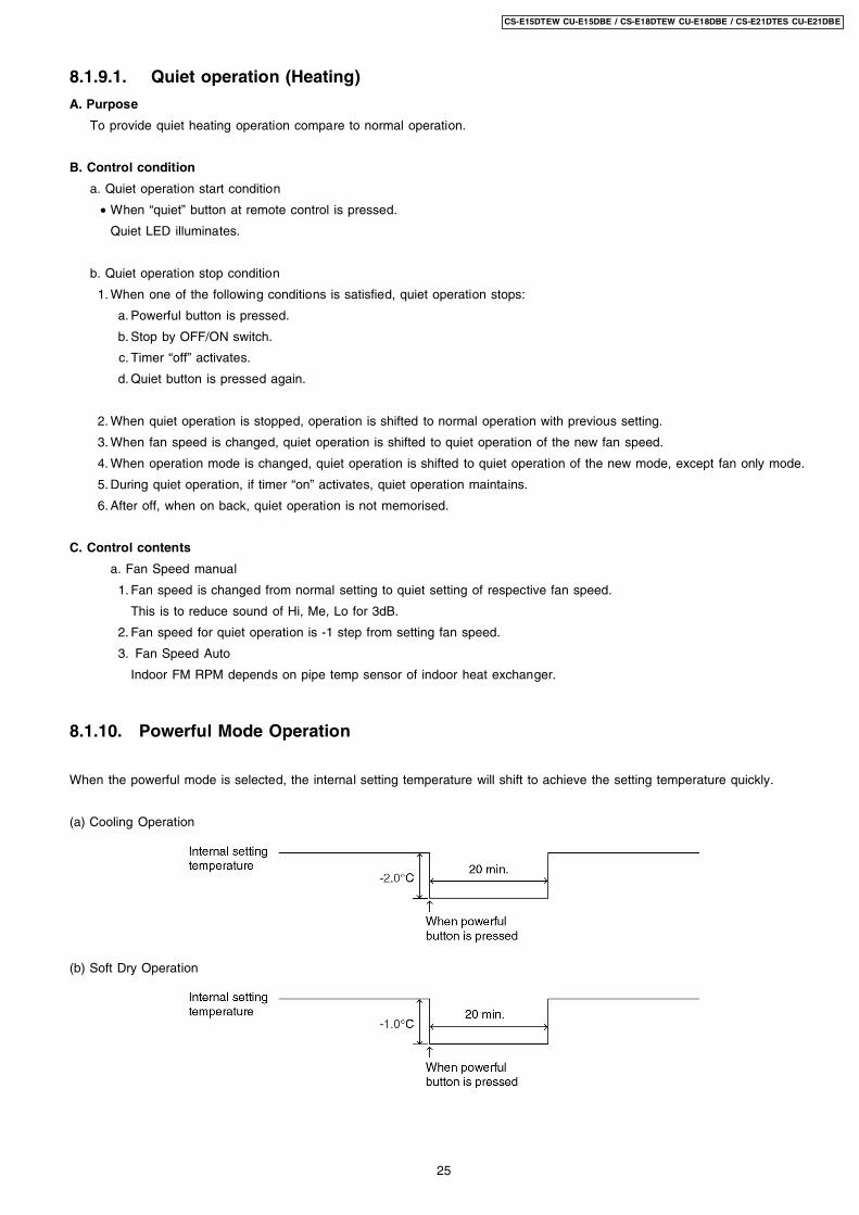
8.1.10. Powerful Mode Operation
When the powerful mode is selected, the internal setting temperature will shift to achieve the setting temperature quickly.
(a) Cooling Operation
(b) Soft Dry Operation
25
CS-E15DTEW CU-E15DBE / CS-E18DTEW CU-E18DBE / CS-E21DTES CU-E21DBE
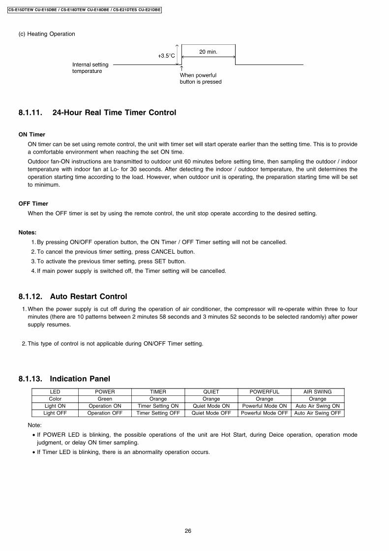
(c) Heating Operation
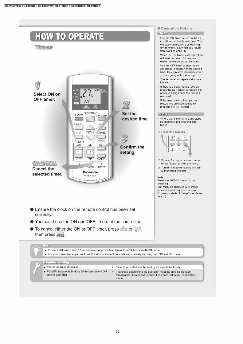
8.1.11. 24-Hour Real Time Timer Control
ON Timer
ON timer can be set using remote control, the unit with timer set will start operate earlier than the setting time. This is to providea comfortable environment when reaching the set ON time.
Outdoor fan-ON instructions are transmitted to outdoor unit 60 minutes before setting time, then sampling the outdoor / indoortemperature with indoor fan at Lo- for 30 seconds. After detecting the indoor / outdoor temperature, the unit determines theoperation starting time according to the load. However, when outdoor unit is operating, the preparation starting time will be setto minimum.
OFF Timer
When the OFF timer is set by using the remote control, the unit stop operate according to the desired setting.
Notes:
1. By pressing ON/OFF operation button, the ON Timer / OFF Timer setting will not be cancelled.
2. To cancel the previous timer setting, press CANCEL button.
3. To activate the previous timer setting, press SET button.
4. If main power supply is switched off, the Timer setting will be cancelled.
8.1.12. Auto Restart Control
1. When the power supply is cut off during the operation of air conditioner, the compressor will re-operate within three to fourminutes (there are 10 patterns between 2 minutes 58 seconds and 3 minutes 52 seconds to be selected randomly) after powersupply resumes.
2. This type of control is not applicable during ON/OFF Timer setting.
8.1.13. Indication Panel
LED POWER TIMER QUIET POWERFUL AIR SWINGColor Green Orange Orange Orange Orange
Light ON Operation ON Timer Setting ON Quiet Mode ON Powerful Mode ON Auto Air Swing ONLight OFF Operation OFF Timer Setting OFF Quiet Mode OFF Powerful Mode OFF Auto Air Swing OFF
Note:
• If POWER LED is blinking, the possible operations of the unit are Hot Start, during Deice operation, operation modejudgment, or delay ON timer sampling.
• If Timer LED is blinking, there is an abnormality operation occurs.
26
CS-E15DTEW CU-E15DBE / CS-E18DTEW CU-E18DBE / CS-E21DTES CU-E21DBE
8.2. Protection Control Features
8.2.1. Protection Control For All Operations
8.2.1.1. Time Delay Safety Control
1. The compressor will not start for three minutes after stop of operation.
2. This control is not applicable if the power supply is cut off for 20 seconds and on again or after 4-way valve deices condition.
8.2.1.2. 30 Seconds Forced Operation
1. Once the compressor starts operation, it will not stop its operation for 30 seconds.
2. However, it can be stopped using remote control or Auto Switch at indoor unit.
8.2.1.3. Total Running Current Control
1. When the outdoor unit total running current (AC) exceeds X value, the frequency instructed for compressor operation will bedecreased.
2. If the running current does not exceed X value for five seconds, the frequency instructed will be increased.
3. However, if total outdoor unit running current exceeds Y value, compressor will be stopped immediately for 2 minutes.
Model E15D E18D E21DOperation Mode X (A) Y (A) X (A) Y (A) X (A) Y (A)
Cooling/Soft Dry (A) 7.20 17 8.74 17 11.02 17Cooling/Soft Dry (B) & (C) 6.30 17 7.70 17 9.59 17Heating 8.60 17 10.71 17 11.53 17
4. The first 30 minutes of cooling operation, (A) will be applied.
8.2.1.4. IPM (Power transistor) Prevention Control
A. Overheating Prevention Control
1. When the IPM temperature rises to 100°C, compressor operation will stop immediately.
2. Compressor operation restarts after three minutes the temperature decreases to 95°C.
B. DC Peak Current Control
1. When electric current to IPM exceeds set value of 22.33 A, the compressor will stop operate. Then, operation will restartafter three minutes.
2. If the set value is exceeded again more than 30 seconds after the compressor starts, the operation will restart after 1 minute.
3. If the set value is exceeded again within 30 seconds after the compressor starts, the operation will restart after one minute.If this condition repeats continuously for seven times, all indoor and outdoor relays will be cut off.
27
CS-E15DTEW CU-E15DBE / CS-E18DTEW CU-E18DBE / CS-E21DTES CU-E21DBE
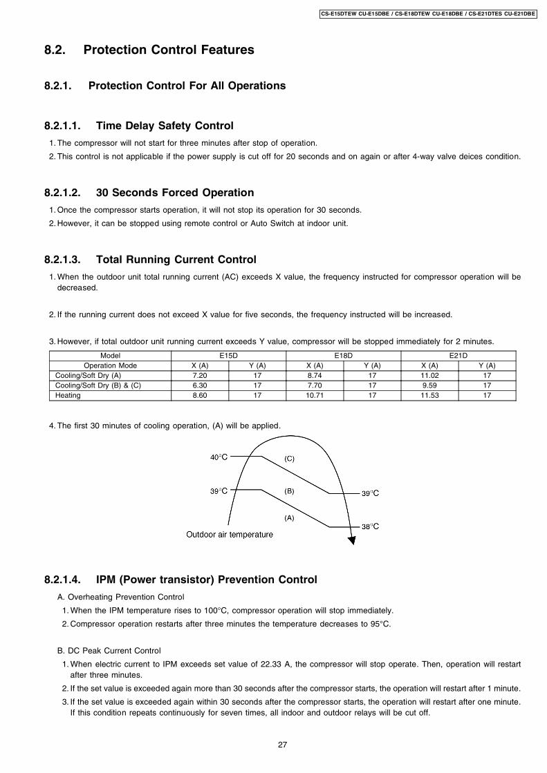
8.2.1.5. Compressor Overheating Prevention Control
Instructed frequency for compressor operation will be regulated by compressor discharge temperature. The changes of frequencyare as below figure.
8.2.1.6. Low Pressure Prevention Control (Gas Leakage Detection)
a. Control start conditions
Control will perform when (1) - (3) condition continues operation for 5 minute and (4) is fulfill.
1. During cooling and dry operation: Frequency more than normal Fcmax 78 Hz (E15D), 86 Hz (E18D), 102 Hz (E21D).
During heating operation: Frequency more than normal Fh 71 Hz (E15D), 86 Hz (E18D), 92 Hz (E21D).
2. Outdoor total current I cooling: Ib I Ia
Heating: Ib I Ic
Ic = Ia = 1.65 A
Ib = 0.65 A
3. It is not during deice operation.
4. During cooling and dry operation: indoor suction-indoor piping temperature is below 4°C.
During of heating operation: Indoor piping temperature-indoor suction is under 5°C.
Control contents:
• compressor stops (restart after 3 minutes)
• if happen 2 times within (20 minutes), perform the following operation
1) Unit stop operation
2) Timer LED blink and “F91” indicated
8.2.1.7. Low Frequency Protection Control 1
When the compressor operate at frequency lower than 25 Hz continued for 20 minutes, the operation frequency will be increasedto 24 Hz for two minutes.
8.2.1.8. Low Frequency Protection Control 2
When all the below conditions occur, minimum value (Freq. MIN) for the frequency instructed to compressor will change to 30 Hzfor cooling mode operation and 20 Hz for heating mode operation.
Temperature, T, for: Cooling/Soft Dry HeatingIndoor intake air (°C) T 14 or T 30 T 14 or T 28Outdoor air (°C) T 13 or T 38 T 4 or T 24Indoor heat exchanger (°C) T 30 T 0
28
CS-E15DTEW CU-E15DBE / CS-E18DTEW CU-E18DBE / CS-E21DTES CU-E21DBE
8.2.2. Protection Control For Cooling & Soft Dry Operation
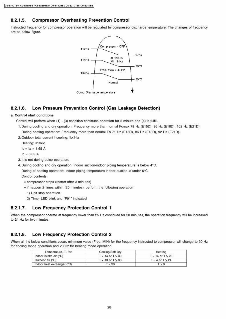
8.2.2.1. Outdoor Air Temperature Control
The compressor operating frequency is regulated in accordance to the outdoor air temperature as shown in the diagram below.
This control will begin one minute after the compressor starts.
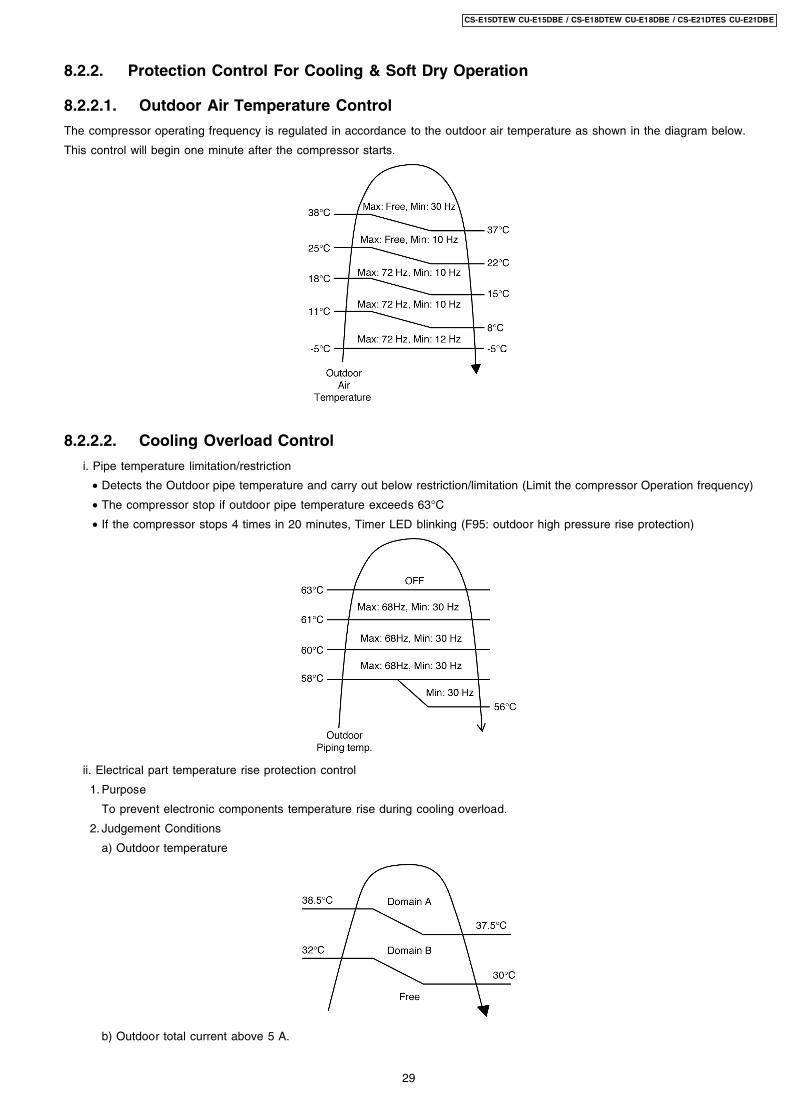
8.2.2.2. Cooling Overload Control
i. Pipe temperature limitation/restriction
• Detects the Outdoor pipe temperature and carry out below restriction/limitation (Limit the compressor Operation frequency)
• The compressor stop if outdoor pipe temperature exceeds 63°C
• If the compressor stops 4 times in 20 minutes, Timer LED blinking (F95: outdoor high pressure rise protection)
ii. Electrical part temperature rise protection control
1. Purpose
To prevent electronic components temperature rise during cooling overload.
2. Judgement Conditions
a) Outdoor temperature
b) Outdoor total current above 5 A.
29
CS-E15DTEW CU-E15DBE / CS-E18DTEW CU-E18DBE / CS-E21DTES CU-E21DBE
3. Control contents
In the outdoor fan speed no.
i) In protectorate Domain A is referred to as min 660 rpm.
ii) In protectorate Domain B, it is referred to as min 600 rpm.
4. Condition resolutive
It is canceled when it stops satisfying all of the above-mentioned.
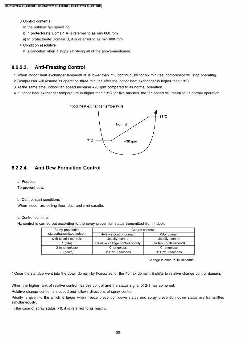
8.2.2.3. Anti-Freezing Control
1. When indoor heat exchanger temperature is lower than 7°C continuously for six minutes, compressor will stop operating.
2. Compressor will resume its operation three minutes after the indoor heat exchanger is higher than 13°C.
3. At the same time, indoor fan speed increase +20 rpm compared to its normal operation.
4. If indoor heat exchanger temperature is higher than 13°C for five minutes, the fan speed will return to its normal operation.
8.2.2.4. Anti-Dew Formation Control
a. Purpose
To prevent dew.
b. Control start conditions
When indoor are ceiling floor, duct and mini casette.
c. Control contents
Hz control is carried out according to the spray prevention status transmitted from indoor.
Spray preventionstatus(transmitted indoor)
Control contentsRelative control domain MAX domain
0 (it usually controls Usually, control Usually, control1 (rise) Relative change control priority On tap up/10 seconds
2 (changeless) Changeless Changeless3 (down) -2 Hz/10 seconds -2 Hz/10 seconds
Change is once to 10 seconds.
* Once the standup went into the down domain by Fcmax as for the Fcmax domain, it shifts to relative change control domain.
When the higher rank of relative control has this control and the status signal of 2-3 has come out.
Relative change control is stopped and follows directions of spray control.
Priority is given to the which is larger when freeze prevention down status and spray prevention down status are transmittedsimultaneously.
In the case of spray status 0, it is referred to as maxFc.
30
CS-E15DTEW CU-E15DBE / CS-E18DTEW CU-E18DBE / CS-E21DTES CU-E21DBE
8.2.3. Protection Control For Heating Operation
8.2.3.1. Intake Air Temperature Control
Compressor will operate at Max freq 94 (E15D), 128 (E18D, E21D) Hz if either one of the below conditions occur:
1. When the indoor intake air temperature is less than 21°C and remote control setting fan speed is lower Me-.
2. When the indoor intake air temperature is 35°C or above.
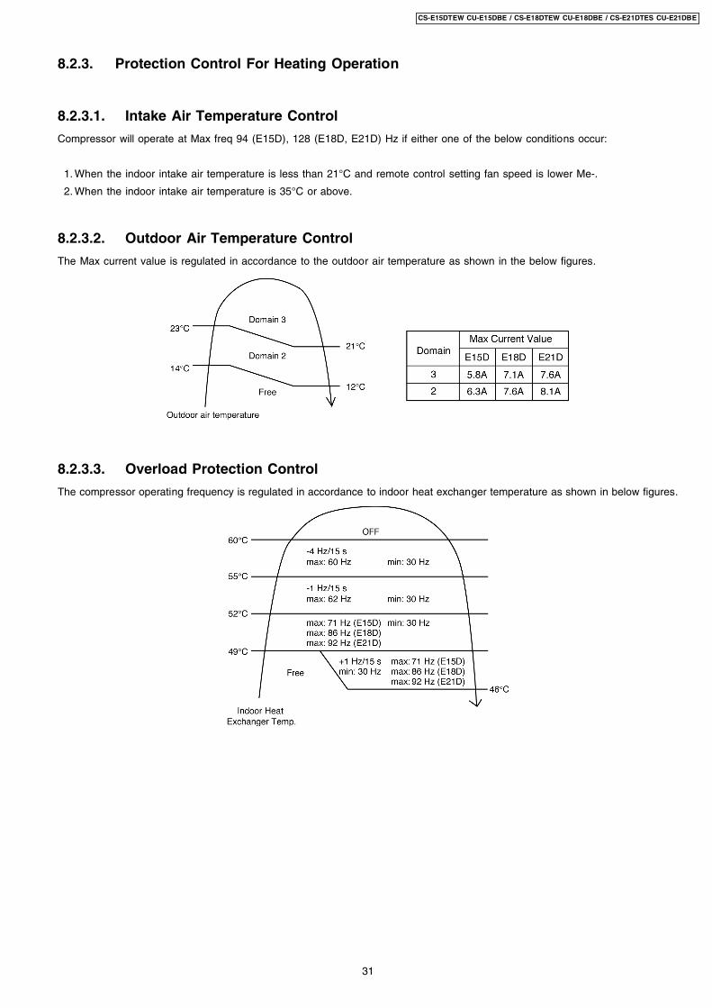
8.2.3.2. Outdoor Air Temperature Control
The Max current value is regulated in accordance to the outdoor air temperature as shown in the below figures.
8.2.3.3. Overload Protection Control
The compressor operating frequency is regulated in accordance to indoor heat exchanger temperature as shown in below figures.
31
CS-E15DTEW CU-E15DBE / CS-E18DTEW CU-E18DBE / CS-E21DTES CU-E21DBE
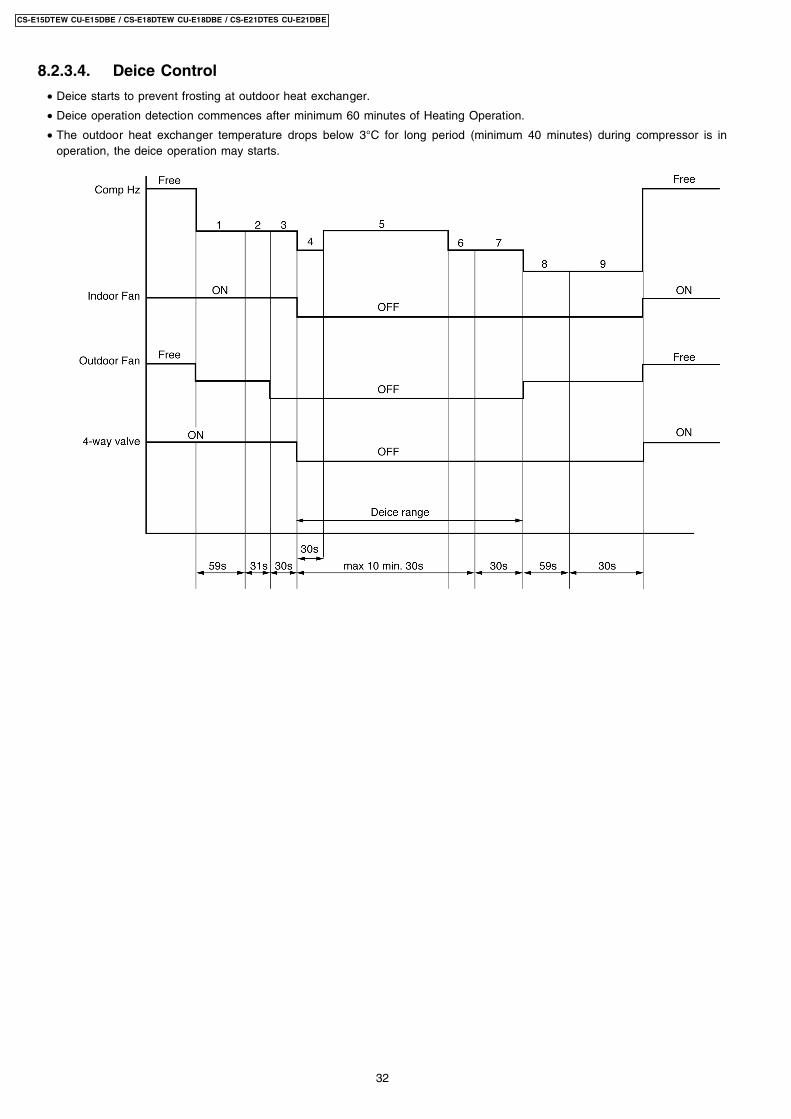
8.2.3.4. Deice Control
• Deice starts to prevent frosting at outdoor heat exchanger.
• Deice operation detection commences after minimum 60 minutes of Heating Operation.
• The outdoor heat exchanger temperature drops below 3°C for long period (minimum 40 minutes) during compressor is inoperation, the deice operation may starts.
32
CS-E15DTEW CU-E15DBE / CS-E18DTEW CU-E18DBE / CS-E21DTES CU-E21DBE
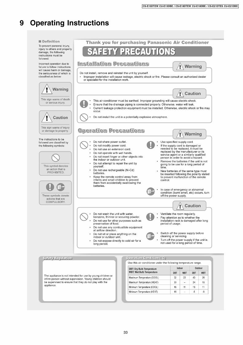
9 Operating Instructions
33
CS-E15DTEW CU-E15DBE / CS-E18DTEW CU-E18DBE / CS-E21DTES CU-E21DBE
34
CS-E15DTEW CU-E15DBE / CS-E18DTEW CU-E18DBE / CS-E21DTES CU-E21DBE
35
CS-E15DTEW CU-E15DBE / CS-E18DTEW CU-E18DBE / CS-E21DTES CU-E21DBE
36
CS-E15DTEW CU-E15DBE / CS-E18DTEW CU-E18DBE / CS-E21DTES CU-E21DBE
37
CS-E15DTEW CU-E15DBE / CS-E18DTEW CU-E18DBE / CS-E21DTES CU-E21DBE
38
CS-E15DTEW CU-E15DBE / CS-E18DTEW CU-E18DBE / CS-E21DTES CU-E21DBE
39
CS-E15DTEW CU-E15DBE / CS-E18DTEW CU-E18DBE / CS-E21DTES CU-E21DBE
40
CS-E15DTEW CU-E15DBE / CS-E18DTEW CU-E18DBE / CS-E21DTES CU-E21DBE
10 Installation And Servicing Air Conditioner Using R410A
10.1. Outline
10.1.1. About R410A Refrigerant
1. Converting air conditioners to R410ASince it was declared in1974 that chlorofluorocarbons (CFC), hydro chlorofluorocarbons (HCFC) and other substances pose adestructive danger to the ozone layer in the earth´s upper stratosphere (20 to 40 km above the earth), measures have beentaken around the world to prevent this destruction.The R22 refrigerant which has conventionally been used in ACs is an HCFC refrigerant and, therefore, possesses this ozone-destroying potential. International regulations (the Montreal Protocol on Ozone-Damaging Substances) and the domestic lawsof various countries call for the early substitution of R22 by a refrigerant which will not harm the ozone layer.
• In ACs, the HFC refrigerant which has become the mainstream alternative is called R410A.Compared with R22, thepressure of R410A is approximately 1.6 times as high at the same refrigerant temperature, but the energy efficiency is aboutthe same. Consisting of hydrogen (H), fluorine (F) and carbon (C), R410A is an HFC refrigerant. Another typical HFCrefrigerant is R407C. While the energy efficiency of R407C is somewhat inferior to that of R410A, it offers the advantageof having pressure characteristics which are about the same as those of R22, and is used mainly in packaged ACs.
2. The characteristics of HFC (R410A) refrigerants
a. Chemical characteristicsThe chemical characteristics of R410A are similar to those of R22 in that both are chemically stable, non-flammablerefrigerants with low toxicity.However, just like R22, the specific gravity of R410A gas is heavier than that of air. Because of this, it can cause an oxygendeficiency if it leaks into a closed room since it collects in the lower area of the room. It also generates toxic gas when it isdirectly exposed to a flame, so it must be used in a well ventilated environment where it will not collect.
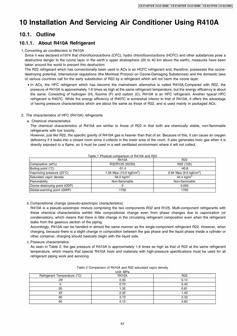
Table 1 Physical comparison of R410A and R22R410A R22
Composition (wt%) R32/R125 (50/50) R22 (100)Boiling point (°C) -51.4 -40.8Vaporizing pressure (25°C) 1.56 Mpa (15.9 kgf/cm2) 0.94 Mpa (9.6 kgf/cm2)Saturated vapor density 64.0 kg/m3 44.4 kg/m3
Flammability Non-flammable Non-flammableOzone-destroying point (ODP) 0 0.055Global-warming point (GWP) 1730 1700
b. Compositional change (pseudo-azeotropic characteristics)R410A is a pseudo-azeotropic mixture comprising the two components R32 and R125. Multi-component refrigerants withthese chemical characteristics exhibit little compositional change even from phase changes due to vaporization (orcondensation), which means that there is little change in the circulating refrigerant composition even when the refrigerantleaks from the gaseous section of the piping.Accordingly, R410A can be handled in almost the same manner as the single-component refrigerant R22. However, whencharging, because there is a slight change in composition between the gas phase and the liquid phase inside a cylinder orother container, charging should basically begin with the liquid side.
c. Pressure characteristicsAs seen in Table 2, the gas pressure of R410A is approximately 1.6 times as high as that of R22 at the same refrigeranttemperature, which means that special R410A tools and materials with high-pressure specifications must be used for allrefrigerant piping work and servicing.
Table 2 Comparison of R410A and R22 saturated vapor densityUnit: MPa
Refrigerant Temperature (°C) R410A R22-20 0.30 0.140 0.70 0.40
20 1.35 0.8140 2.32 1.4360 3.73 2.3365 4.15 2.60
41
CS-E15DTEW CU-E15DBE / CS-E18DTEW CU-E18DBE / CS-E21DTES CU-E21DBE
d. R410A refrigerating machine oilConventionally, mineral oil or a synthetic oil such as alkylbenzene has been used for R22 refrigerating machine oil. Becauseof the poor compatibility between R410A and conventional oils like mineral oil, however, there is a tendency for therefrigerating machine oil to collect in the refrigerating cycle. For this reason, polyester and other synthetic oils which havea high compatibility with R410A are used as refrigerating machine oil.Because of the high hygroscopic property of synthetic oil, more care must be taken in its handling than was necessary withconventional refrigerating machine oils. Also, these synthetic oils will degrade if mixed with mineral oil or alkylbenzene,causing clogging in capillary tubes or compressor malfunction. Do not mix them under any circumstances.
10.1.2. Safety Measures When Installing/Servicing Refrigerant Piping
Cause the gas pressure of R410A is approximately 1.6 times as high as that of R22, a mistake in installation or servicing couldresult in a major accident. It is essential that you use R410A tools and materials, and that you observe the following precautionsto ensure safety.
1. Do not use any refrigerant other than R410A in ACs that have been used with R410A.
2. If any refrigerant gas leaks while you are working, ventilate the room. Toxic gas may be generated if refrigerant gas is exposedto a direct flame.
3. When installing or transferring an AC, do not allow any air or substance other than R410A to mix into the refrigeration cycle. Ifit does, the pressure in the refrigeration cycle can become abnormally high, possibly causing an explosion and/or injury.
4. After finishing the installation, check to make sure there is no refrigerant gas leaking.
5. When installing or transferring an AC, follow the instructions in the installation instructions carefully. Incorrect installation canresult in an abnormal refrigeration cycle or water leakage, electric shock, fire, etc.
6. Do not perform any alterations on the AC unit under any circumstances. Have all repair work done by a specialist. Incorrectrepairs can result in an water leakage, electric shock, fire, etc.
10.2. Tools For Installing/Servicing Refrigerant Piping
10.2.1. Necessary Tools
In order to prevent an R410A AC from mistakenly being charged with any other refrigerant, the diameter of the 3-way valve serviceport on the outdoor unit has been changed. Also, to increase its ability to withstand pressure, the opposing dimensions have beenchanged for the refrigerant pipe flaring size and flare nut. Accordingly, when installing or servicing refrigerant piping, you must haveboth the R410A and ordinary tools listed below.
Table 3 Tools for installation, transferring or replacementType of work Ordinary tools R410A tools
Flaring Flaring tool (clutch type), pipe cutter,reamer
Copper pipe gauge for clearanceAdjustment, flaring tool (clutch type)*1)
Bending, connecting pipes Torque wrench (nominal diameter 1/4,3/8,1/2). Fixed spanner (opposing sides12 mm, 17 mm, 19 mm). Adjustablewrench, Spring bender
Air purging Vacuum pump. Hexagonal wrench(opposing sides 4 mm)
Manifold gauge, charging hose, vacuumpump adaptor
Gas leak inspection Gas leak inspection fluid or soapy water Electric gas leak detector for HFCrefrigerant*2)
*1) You can use the conventional (R22) flaring tool. If you need to buy a new tool, buy the R410A type.
*2) Use when it is necessary to detect small gas leaks.
For other installation work, you should have the usual tools, such as screwdrivers (+,-), a metal-cutting saw, an electrical drill, a holecore drill (65 or 70 dia.), a tape measure, a level, a thermometer, a clamp meter, an insulation tester, a voltmeter, etc.
Table 4 Tools for servingType of work Ordinary tools R410A tools
Refrigerant charging Electronic scale for refrigerant charging.Refrigerant cylinder. Charging orifice andpacking for refrigerant cylinder
Brazing (Replacing refrigerating cyclepart*1)
Nitrogen blow set (be sure to use nitrogenblowing for all brazing), and brazingmachine
*1) Always replace the dryer of the outdoor unit at the same time. The replacement dryer is wrapped in a vacuum pack. Replaceit last among the refrigerating cycle parts. Start brazing as soon as you have opened the vacuum pack, and begin the vacuumingoperation within 2 hours.
42
CS-E15DTEW CU-E15DBE / CS-E18DTEW CU-E18DBE / CS-E21DTES CU-E21DBE
10.2.2. R410A Tools
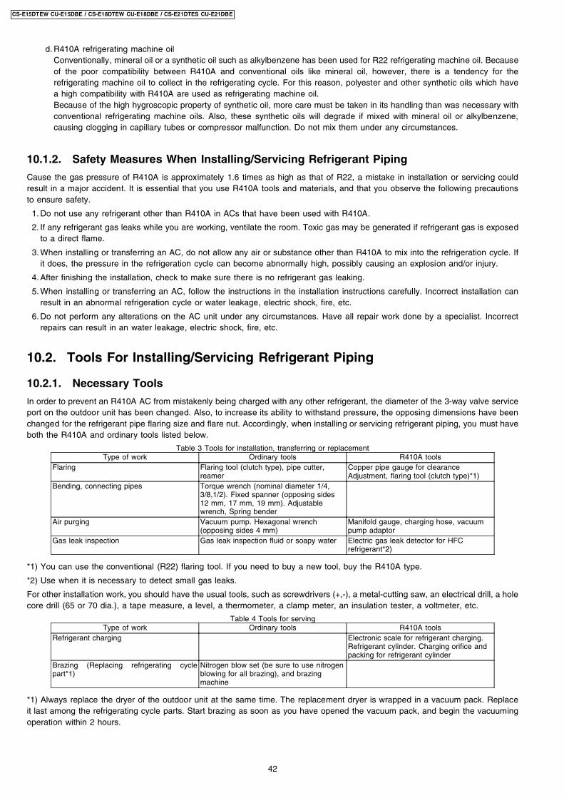
1. Copper tube gauge for clearance adjustment(used when flaring with the conventional flaring tool (clutchtype))
• This gauge makes it easy to set the clearance for thecopper tube to 1.0-1.5 mm from the clamp bar of theflaring tool.
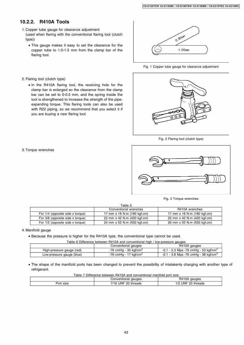
2. Flaring tool (clutch type)
• In the R410A flaring tool, the receiving hole for theclamp bar is enlarged so the clearance from the clampbar can be set to 0-0.5 mm, and the spring inside thetool is strengthened to increase the strength of the pipe-expanding torque. This flaring tools can also be usedwith R22 piping, so we recommend that you select it ifyou are buying a new flaring tool.
3. Torque wrenches
4. Manifold gauge
Fig. 1 Copper tube gauge for clearance adjustment
Fig. 2 Flaring tool (clutch type)
Fig. 3 Torque wrenches
Table 5Conventional wrenches R410A wrenches
For 1/4 (opposite side x torque) 17 mm x 18 N.m (180 kgf.cm) 17 mm x 18 N.m (180 kgf.cm)For 3/8 (opposite side x torque) 22 mm x 42 N.m (420 kgf.cm) 22 mm x 42 N.m (420 kgf.cm)For 1/2 (opposite side x torque) 24 mm x 55 N.m (550 kgf.cm) 26 mm x 55 N.m (550 kgf.cm)
• Because the pressure is higher for the R410A type, the conventional type cannot be used.
Table 6 Difference between R410A and conventional high / low-pressure gaugesConventional gauges R410A gauges
High-pressure gauge (red) -76 cmHg - 35 kgf/cm3 -0.1 - 5.3 Mpa -76 cmHg - 53 kgf/cm3
Low-pressure gauge (blue) -76 cmHg - 17 kgf/cm3 -0.1 - 3.8 Mpa -76 cmHg - 38 kgf/cm3
• The shape of the manifold ports has been changed to prevent the possibility of mistakenly charging with another type ofrefrigerant.
Table 7 Difference between R410A and conventional manifold port sizeConventional gauges R410A gauges
Port size 7/16 UNF 20 threads 1/2 UNF 20 threads
43
CS-E15DTEW CU-E15DBE / CS-E18DTEW CU-E18DBE / CS-E21DTES CU-E21DBE
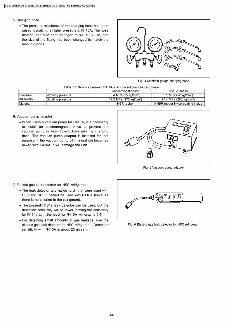
5. Charging hose
• The pressure resistance of the charging hose has beenraised to match the higher pressure of R410A. The hosematerial has also been changed to suit HFC use, andthe size of the fitting has been changed to match themanifold ports.
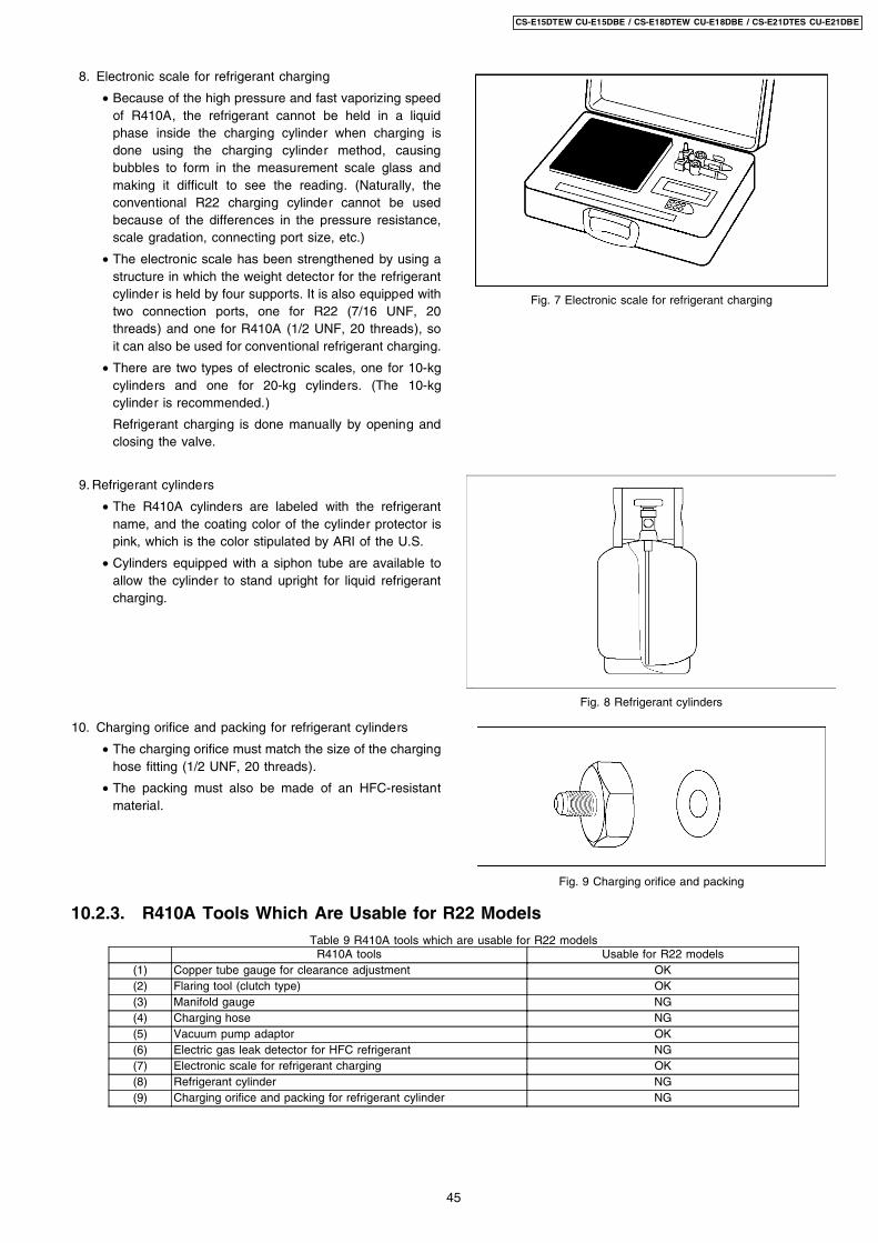
6. Vacuum pump adaptor
• When using a vacuum pump for R410A, it is necessaryto install an electromagnetic valve to prevent thevacuum pump oil from flowing back into the charginghose. The vacuum pump adaptor is installed for thatpurpose. if the vacuum pump oil (mineral oil) becomesmixed with R410A, it will damage the unit.
7. Electric gas leak detector for HFC refrigerant
• The leak detector and halide torch that were used withCFC and HCFC cannot be used with R410A (becausethere is no chlorine in the refrigerant).
• The present R134a leak detector can be used, but thedetection sensitivity will be lower (setting the sensitivityfor R134a at 1, the level for R410A will drop to 0.6).
• For detecting small amounts of gas leakage, use theelectric gas leak detector for HFC refrigerant. (Detectionsensitivity with R410A is about 23 g/year).
Fig. 4 Manifold gauge charging hose
Fig. 5 Vacuum pump adaptor
Fig. 6 Electric gas leak detector for HFC refrigerant
Table 8 Difference between R410A and conventional charging hosesConventional hoses R410A hoses
Pressureresistance
Working pressure 3.4 MPa (35 kgf/cm3) 5.1 MPa (52 kgf/cm3)Bursting pressure 17.2 MPa (175 kgf/cm3) 27.4 MPa (280 kgf/cm3)
Material NBR rubber HNBR rubber Nylon coating inside
44
CS-E15DTEW CU-E15DBE / CS-E18DTEW CU-E18DBE / CS-E21DTES CU-E21DBE
8. Electronic scale for refrigerant charging
• Because of the high pressure and fast vaporizing speedof R410A, the refrigerant cannot be held in a liquidphase inside the charging cylinder when charging isdone using the charging cylinder method, causingbubbles to form in the measurement scale glass andmaking it difficult to see the reading. (Naturally, theconventional R22 charging cylinder cannot be usedbecause of the differences in the pressure resistance,scale gradation, connecting port size, etc.)
• The electronic scale has been strengthened by using astructure in which the weight detector for the refrigerantcylinder is held by four supports. It is also equipped withtwo connection ports, one for R22 (7/16 UNF, 20threads) and one for R410A (1/2 UNF, 20 threads), soit can also be used for conventional refrigerant charging.
• There are two types of electronic scales, one for 10-kgcylinders and one for 20-kg cylinders. (The 10-kgcylinder is recommended.)
Refrigerant charging is done manually by opening andclosing the valve.
9. Refrigerant cylinders
• The R410A cylinders are labeled with the refrigerantname, and the coating color of the cylinder protector ispink, which is the color stipulated by ARI of the U.S.
• Cylinders equipped with a siphon tube are available toallow the cylinder to stand upright for liquid refrigerantcharging.
10. Charging orifice and packing for refrigerant cylinders
• The charging orifice must match the size of the charginghose fitting (1/2 UNF, 20 threads).
• The packing must also be made of an HFC-resistantmaterial.
Fig. 7 Electronic scale for refrigerant charging
Fig. 8 Refrigerant cylinders
Fig. 9 Charging orifice and packing
10.2.3. R410A Tools Which Are Usable for R22 ModelsTable 9 R410A tools which are usable for R22 models
R410A tools Usable for R22 models(1) Copper tube gauge for clearance adjustment OK(2) Flaring tool (clutch type) OK(3) Manifold gauge NG(4) Charging hose NG(5) Vacuum pump adaptor OK(6) Electric gas leak detector for HFC refrigerant NG(7) Electronic scale for refrigerant charging OK(8) Refrigerant cylinder NG(9) Charging orifice and packing for refrigerant cylinder NG
45
CS-E15DTEW CU-E15DBE / CS-E18DTEW CU-E18DBE / CS-E21DTES CU-E21DBE
10.3. Refrigerant Piping Work
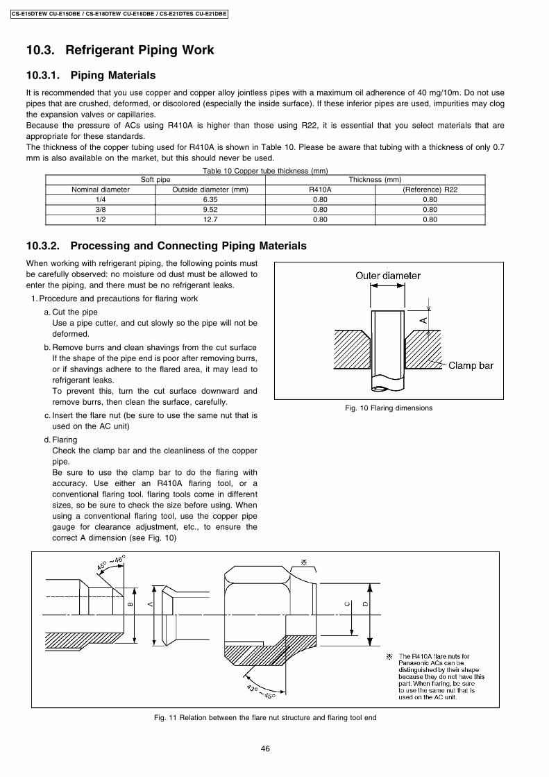
When working with refrigerant piping, the following points mustbe carefully observed: no moisture od dust must be allowed toenter the piping, and there must be no refrigerant leaks.
1. Procedure and precautions for flaring work
a. Cut the pipeUse a pipe cutter, and cut slowly so the pipe will not bedeformed.
b. Remove burrs and clean shavings from the cut surfaceIf the shape of the pipe end is poor after removing burrs,or if shavings adhere to the flared area, it may lead torefrigerant leaks.To prevent this, turn the cut surface downward andremove burrs, then clean the surface, carefully.
c. Insert the flare nut (be sure to use the same nut that isused on the AC unit)
d. FlaringCheck the clamp bar and the cleanliness of the copperpipe.Be sure to use the clamp bar to do the flaring withaccuracy. Use either an R410A flaring tool, or aconventional flaring tool. flaring tools come in differentsizes, so be sure to check the size before using. Whenusing a conventional flaring tool, use the copper pipegauge for clearance adjustment, etc., to ensure thecorrect A dimension (see Fig. 10)
Fig. 10 Flaring dimensions
10.3.1. Piping Materials
It is recommended that you use copper and copper alloy jointless pipes with a maximum oil adherence of 40 mg/10m. Do not usepipes that are crushed, deformed, or discolored (especially the inside surface). If these inferior pipes are used, impurities may clogthe expansion valves or capillaries.Because the pressure of ACs using R410A is higher than those using R22, it is essential that you select materials that areappropriate for these standards.The thickness of the copper tubing used for R410A is shown in Table 10. Please be aware that tubing with a thickness of only 0.7mm is also available on the market, but this should never be used.
Table 10 Copper tube thickness (mm)Soft pipe Thickness (mm)
Nominal diameter Outside diameter (mm) R410A (Reference) R221/4 6.35 0.80 0.803/8 9.52 0.80 0.801/2 12.7 0.80 0.80
10.3.2. Processing and Connecting Piping Materials
Fig. 11 Relation between the flare nut structure and flaring tool end
46
CS-E15DTEW CU-E15DBE / CS-E18DTEW CU-E18DBE / CS-E21DTES CU-E21DBE
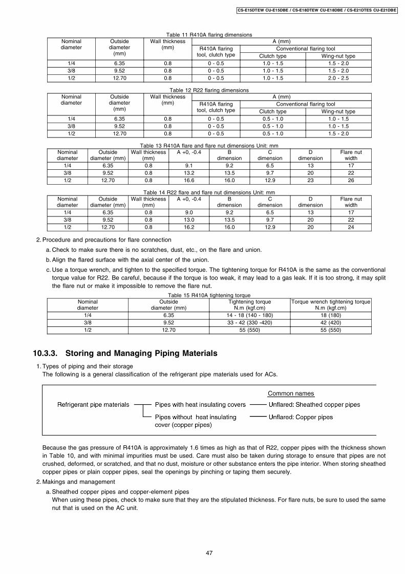
2. Procedure and precautions for flare connection
Table 11 R410A flaring dimensionsNominaldiameter
Outsidediameter
(mm)
Wall thickness(mm)
A (mm)R410A flaring
tool, clutch typeConventional flaring tool
Clutch type Wing-nut type1/4 6.35 0.8 0 - 0.5 1.0 - 1.5 1.5 - 2.03/8 9.52 0.8 0 - 0.5 1.0 - 1.5 1.5 - 2.01/2 12.70 0.8 0 - 0.5 1.0 - 1.5 2.0 - 2.5
Table 12 R22 flaring dimensionsNominaldiameter
Outsidediameter
(mm)
Wall thickness(mm)
A (mm)R410A flaring
tool, clutch typeConventional flaring tool
Clutch type Wing-nut type1/4 6.35 0.8 0 - 0.5 0.5 - 1.0 1.0 - 1.53/8 9.52 0.8 0 - 0.5 0.5 - 1.0 1.0 - 1.51/2 12.70 0.8 0 - 0.5 0.5 - 1.0 1.5 - 2.0
Table 13 R410A flare and flare nut dimensions Unit: mmNominaldiameter
Outsidediameter (mm)
Wall thickness(mm)
A +0, -0.4 Bdimension
Cdimension
Ddimension
Flare nutwidth
1/4 6.35 0.8 9.1 9.2 6.5 13 173/8 9.52 0.8 13.2 13.5 9.7 20 221/2 12.70 0.8 16.6 16.0 12.9 23 26
Table 14 R22 flare and flare nut dimensions Unit: mmNominaldiameter
Outsidediameter (mm)
Wall thickness(mm)
A +0, -0.4 Bdimension
Cdimension
Ddimension
Flare nutwidth
1/4 6.35 0.8 9.0 9.2 6.5 13 173/8 9.52 0.8 13.0 13.5 9.7 20 221/2 12.70 0.8 16.2 16.0 12.9 20 24
a. Check to make sure there is no scratches, dust, etc., on the flare and union.
b. Align the flared surface with the axial center of the union.
c. Use a torque wrench, and tighten to the specified torque. The tightening torque for R410A is the same as the conventionaltorque value for R22. Be careful, because if the torque is too weak, it may lead to a gas leak. If it is too strong, it may splitthe flare nut or make it impossible to remove the flare nut.
Table 15 R410A tightening torqueNominaldiameter
Outsidediameter (mm)
Tightening torqueN.m (kgf.cm)
Torque wrench tightening torqueN.m (kgf.cm)
1/4 6.35 14 - 18 (140 - 180) 18 (180)3/8 9.52 33 - 42 (330 -420) 42 (420)1/2 12.70 55 (550) 55 (550)
10.3.3. Storing and Managing Piping Materials
1. Types of piping and their storageThe following is a general classification of the refrigerant pipe materials used for ACs.
Because the gas pressure of R410A is approximately 1.6 times as high as that of R22, copper pipes with the thickness shownin Table 10, and with minimal impurities must be used. Care must also be taken during storage to ensure that pipes are notcrushed, deformed, or scratched, and that no dust, moisture or other substance enters the pipe interior. When storing sheathedcopper pipes or plain copper pipes, seal the openings by pinching or taping them securely.
2. Makings and management
a. Sheathed copper pipes and copper-element pipesWhen using these pipes, check to make sure that they are the stipulated thickness. For flare nuts, be sure to used the samenut that is used on the AC unit.
47
CS-E15DTEW CU-E15DBE / CS-E18DTEW CU-E18DBE / CS-E21DTES CU-E21DBE
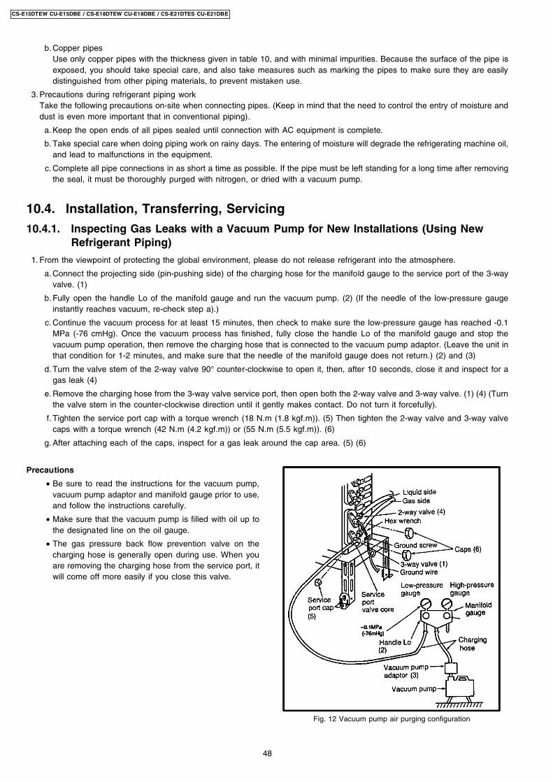
Precautions
• Be sure to read the instructions for the vacuum pump,vacuum pump adaptor and manifold gauge prior to use,and follow the instructions carefully.
• Make sure that the vacuum pump is filled with oil up tothe designated line on the oil gauge.
• The gas pressure back flow prevention valve on thecharging hose is generally open during use. When youare removing the charging hose from the service port, itwill come off more easily if you close this valve.
Fig. 12 Vacuum pump air purging configuration
b. Copper pipesUse only copper pipes with the thickness given in table 10, and with minimal impurities. Because the surface of the pipe isexposed, you should take special care, and also take measures such as marking the pipes to make sure they are easilydistinguished from other piping materials, to prevent mistaken use.
3. Precautions during refrigerant piping workTake the following precautions on-site when connecting pipes. (Keep in mind that the need to control the entry of moisture anddust is even more important that in conventional piping).
a. Keep the open ends of all pipes sealed until connection with AC equipment is complete.
b. Take special care when doing piping work on rainy days. The entering of moisture will degrade the refrigerating machine oil,and lead to malfunctions in the equipment.
c. Complete all pipe connections in as short a time as possible. If the pipe must be left standing for a long time after removingthe seal, it must be thoroughly purged with nitrogen, or dried with a vacuum pump.
10.4. Installation, Transferring, Servicing
10.4.1. Inspecting Gas Leaks with a Vacuum Pump for New Installations (Using NewRefrigerant Piping)
1. From the viewpoint of protecting the global environment, please do not release refrigerant into the atmosphere.
a. Connect the projecting side (pin-pushing side) of the charging hose for the manifold gauge to the service port of the 3-wayvalve. (1)
b. Fully open the handle Lo of the manifold gauge and run the vacuum pump. (2) (If the needle of the low-pressure gaugeinstantly reaches vacuum, re-check step a).)
c. Continue the vacuum process for at least 15 minutes, then check to make sure the low-pressure gauge has reached -0.1MPa (-76 cmHg). Once the vacuum process has finished, fully close the handle Lo of the manifold gauge and stop thevacuum pump operation, then remove the charging hose that is connected to the vacuum pump adaptor. (Leave the unit inthat condition for 1-2 minutes, and make sure that the needle of the manifold gauge does not return.) (2) and (3)
d. Turn the valve stem of the 2-way valve 90° counter-clockwise to open it, then, after 10 seconds, close it and inspect for agas leak (4)
e. Remove the charging hose from the 3-way valve service port, then open both the 2-way valve and 3-way valve. (1) (4) (Turnthe valve stem in the counter-clockwise direction until it gently makes contact. Do not turn it forcefully).
f. Tighten the service port cap with a torque wrench (18 N.m (1.8 kgf.m)). (5) Then tighten the 2-way valve and 3-way valvecaps with a torque wrench (42 N.m (4.2 kgf.m)) or (55 N.m (5.5 kgf.m)). (6)
g. After attaching each of the caps, inspect for a gas leak around the cap area. (5) (6)
48
CS-E15DTEW CU-E15DBE / CS-E18DTEW CU-E18DBE / CS-E21DTES CU-E21DBE
10.4.2. Transferring (Using New Refrigerant Piping)
1. Removing the unit
a. Collecting the refrigerant into the outdoor unit by pumping downThe refrigerant can be collected into the outdoor unit (pumping down) by pressing the TEST RUN button, even when thetemperature of the room is low.
• Check to make sure that the valve stems of the 2-way valve and 3-way valve have been opened by turning them counter-clockwise. (Remove the valve stem caps and check to see that the valve stems are fully opened position. Always usea hex wrench (with 4-mm opposing sides) to operate the valve stems.)
• Press the TEST RUN button on the indoor unit, and allow preliminary operation for 5-6 minutes. (TEST RUN mode)
• After stopping the operation, let the unit sit for about 3 minutes, then close the 2-way valve by turning the valve stem inthe clockwise direction.
• Press the TEST RUN button on the indoor unit again, and after 2-3 minutes of operation, turn the valve stem of the 3-way valve quickly in the clockwise direction to close it, then stop the operation.
• Tighten the caps of the 2-way valve and 3-way valve to the stipulated torque.
• Remove the connection pipes (liquid side and gas side).
b. Removing the indoor and outdoor units.
• Disconnect the pipes and connecting electric cables from between the indoor and outdoor units.
• Put capped flare nuts onto all of the pipe connections of the indoor and outdoor units, to make sure no dust or otherforeign matter enters.
• Remove the indoor and outdoor units.
2. Installing the unitInstall the unit using new refrigerant piping. Follow the instructions in section 4.1 to evacuate the pipes connecting the indoorand outdoor units, and the pipes of the indoor unit, and check for gas leaks.
10.4.3. AC Units Replacement (Using Existing Refrigerant Piping)
When replacing an R410A AC unit with another R410A AC unit, you should re-flare the refrigerant piping. Even though thereplacement AC unit uses the R410A, problems occur when, for example, either the AC unit maker or the refrigerating machine oilis different.When replacing an R22 AC unit with an R410A AC unit, the following checks and cleaning procedures are necessary but aredifficult to do because of the chemical characteristics of the refrigerating machine oil (as described in items c) and d) of sectionAbout R410A Refrigerant). In this case, you should use new refrigerant piping rather than the existing piping.
1. Piping checkBecause of the different pressure characteristics of R22 and R410A, the design pressure for the equipment is 1.6 timesdifferent. the wall thickness of the piping must comply with that shown in Table 10, but this is not easy to check. Also, even ifthe thickness is correct, there may be flattened or bent portions midway through the piping due to sharp curves. Buried sectionsof the piping also cannot be checked.
2. Pipe cleaningA large quantity of refrigerating machine oil (mineral oil) adheres to existing pipes due to the refrigeration cycle circulation. If thepipes are used just as they are for the R410A cycle, the capacity will be lowered due to the incompatibility of this oil with theR410A, or irregularities may occur in the refrigeration cycle. For this reason, the piping must be thoroughly cleaned, but this isdifficult with the present technology.
10.4.4. Refrigerant Compatibility (Using R410A Refrigerant in R22 ACs and Vice Versa)
Do not operate an existing R22 AC with the new R410A refrigerant. Doing so would result in improper functioning of the equipmentor malfunction, and might lead to a major accident such as an explosion in the refrigeration cycle. Similarly, do not operate anR410A AC with R22 refrigerant. The chemical reaction between the refrigerating machine oil used in R410A ACs and the chlorinethat is contained in R22 would cause the refrigerating machine oil to degrade and lead to malfunction.
49
CS-E15DTEW CU-E15DBE / CS-E18DTEW CU-E18DBE / CS-E21DTES CU-E21DBE
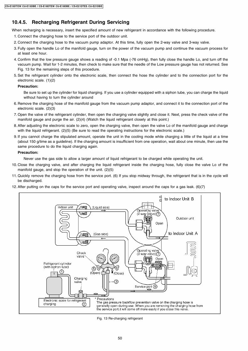
10.4.5. Recharging Refrigerant During Servicing
When recharging is necessary, insert the specified amount of new refrigerant in accordance with the following procedure.
1. Connect the charging hose to the service port of the outdoor unit.
2. Connect the charging hose to the vacuum pump adaptor. At this time, fully open the 2-way valve and 3-way valve.
3. Fully open the handle Lo of the manifold gauge, turn on the power of the vacuum pump and continue the vacuum process forat least one hour.
4. Confirm that the low pressure gauge shows a reading of -0.1 Mpa (-76 cmHg), then fully close the handle Lo, and turn off thevacuum pump. Wait for 1-2 minutes, then check to make sure that the needle of the Low pressure gauge has not returned. SeeFig. 13 for the remaining steps of this procedure.
5. Set the refrigerant cylinder onto the electronic scale, then connect the hose the cylinder and to the connection port for theelectronic scale. (1)(2)
Precaution:
Be sure to set up the cylinder for liquid charging. If you use a cylinder equipped with a siphon tube, you can charge the liquidwithout having to turn the cylinder around
6. Remove the charging hose of the manifold gauge from the vacuum pump adaptor, and connect it to the connection port of theelectronic scale. (2)(3)
7. Open the valve of the refrigerant cylinder, then open the charging valve slightly and close it. Next, press the check valve of themanifold gauge and purge the air. (2)(4) (Watch the liquid refrigerant closely at this point.)
8. After adjusting the electronic scale to zero, open the charging valve, then open the valve Lo of the manifold gauge and chargewith the liquid refrigerant. (2)(5) (Be sure to read the operating instructions for the electronic scale.)
9. If you cannot charge the stipulated amount, operate the unit in the cooling mode while charging a little of the liquid at a time(about 150 g/time as a guideline). If the charging amount is insufficient from one operation, wait about one minute, then use thesame procedure to do the liquid charging again.
Precaution:
Never use the gas side to allow a larger amount of liquid refrigerant to be charged while operating the unit.
10. Close the charging valve, and after charging the liquid refrigerant inside the charging hose, fully close the valve Lo of themanifold gauge, and stop the operation of the unit. (2)(5)
11. Quickly remove the charging hose from the service port. (6) If you stop midway through, the refrigerant that is in the cycle willbe discharged.
12. After putting on the caps for the service port and operating valve, inspect around the caps for a gas leak. (6)(7)
Fig. 13 Re-charging refrigerant
50
CS-E15DTEW CU-E15DBE / CS-E18DTEW CU-E18DBE / CS-E21DTES CU-E21DBE
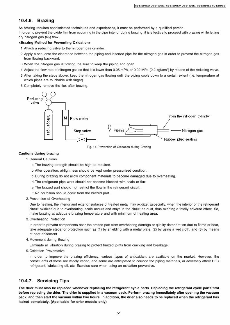
10.4.6. Brazing
As brazing requires sophisticated techniques and experiences, it must be performed by a qualified person.In order to prevent the oxide film from occurring in the pipe interior during brazing, it is effective to proceed with brazing while lettingdry nitrogen gas (N2) flow.
<Brazing Method for Preventing Oxidation>
1. Attach a reducing valve to the nitrogen gas cylinder.
2. Apply a seal onto the clearance between the piping and inserted pipe for the nitrogen gas in order to prevent the nitrogen gasfrom flowing backward.
3. When the nitrogen gas is flowing, be sure to keep the piping end open.
4. Adjust the flow rate of nitrogen gas so that it is lower than 0.05 m3/h, or 0.02 MPa (0.2 kgf/cm2) by means of the reducing valve.
5. After taking the steps above, keep the nitrogen gas flowing until the piping cools down to a certain extent (i.e. temperature atwhich pipes are touchable with finger).
6. Completely remove the flux after brazing.
Fig. 14 Prevention of Oxidation during Brazing
Cautions during brazing
1. General Cautions
a. The brazing strength should be high as required.
b. After operation, airtightness should be kept under pressurized condition.
c. During brazing do not allow component materials to become damaged due to overheating.
d. The refrigerant pipe work should not become blocked with scale or flux.
e. The brazed part should not restrict the flow in the refrigerant circuit.
f. No corrosion should occur from the brazed part.
2. Prevention of Overheating
Due to heating, the interior and exterior surfaces of treated metal may oxidize. Especially, when the interior of the refrigerantcircuit oxidizes due to overheating, scale occurs and stays in the circuit as dust, thus exerting a fatally adverse effect. So,make brazing at adequate brazing temperature and with minimum of heating area.
3. Overheating Protection
In order to prevent components near the brazed part from overheating damage or quality deterioration due to flame or heat,take adequate steps for protection such as (1) by shielding with a metal plate, (2) by using a wet cloth, and (3) by meansof heat absorbent.
4. Movement during Brazing
Eliminate all vibration during brazing to protect brazed joints from cracking and breakage.
5. Oxidation Preventative
In order to improve the brazing efficiency, various types of antioxidant are available on the market. However, theconstituents of these are widely varied, and some are anticipated to corrode the piping materials, or adversely affect HFCrefrigerant, lubricating oil, etc. Exercise care when using an oxidation preventive.
10.4.7. Servicing Tips
The drier must also be replaced whenever replacing the refrigerant cycle parts. Replacing the refrigerant cycle parts firstbefore replacing the drier. The drier is supplied in a vacuum pack. Perform brazing immediately after opening the vacuumpack, and then start the vacuum within two hours. In addition, the drier also needs to be replaced when the refrigerant hasleaked completely. (Applicable for drier models only)
51
CS-E15DTEW CU-E15DBE / CS-E18DTEW CU-E18DBE / CS-E21DTES CU-E21DBE
11 Installation InstructionsRequired tools for Installation Works
1. Philips screw driver 5. Spanner 9. Gas leak detector 13. Multimeter2. Level gauge 6. Pipe cutter 10. Measuring tape 14. Torque wrench
18 N.m (1.8 kgf.m)55 N.m (5.5 kgf.m)
3. Electric drill, hole core drill(ø70 mm)
7. Reamer 11. Thermometer 15. Vacuum Pump
4. Hexagonal wrench (4 mm) 8. Knife 12. Megameter 16. Gauge manifold set
11.1. Safety Precautions • Read the following “SAFETY PRECAUTIONS” carefully before installation.
• Electrical work must be installed by a licensed electrician. Be sure to use the correct rating of the power plug and main circuitfor the model to be installed.
• The caution items stated here must be followed because these important contents are related to safety. The meaning of eachindication used is as below.
Incorrect installation due to ignoring of the instruction will cause harm or damage, and the seriousness is classified by thefollowing indications.
WARNING This indication shows the possibility of causing death or serious injury.CAUTION This indication shows the possibility of causing injury or damage to properties only.
The items to be followed are classified by the symbols:
Symbol with background white denotes item that is PROHIBITED from doing.
• Carry out test running to confirm that no abnormality occurs after the installation. Then, explain to user the operation, care andmaintenance as stated in instructions. Please remind the customer to keep the operating instructions for future reference.
WARNING1. Engage dealer or specialist for installation. If installation done by the user is defective, it will cause water leakage, electrical shock or fire.2. Install according to this installation instructions strictly. If installation is defective, it will cause water leakage, electrical shock or fire.3. Use the attached accessories parts and specified parts for installation. Otherwise, it will cause the set to fall, water leakage, fire or
electrical shock.4. Install at a strong and firm location which is able to withstand the set’s weight. If the strength is not enough or installation is not properly
done, unit will drop and cause injury.5. For electrical work, please follow the local national wiring standard & regulation and this installation instructions. An independent circuit
and single outlet must be used. If electrical circuit capacity is not enough or defect found in electrical work, it will cause electrical shockor fire.
6. Use the specified cable and connect tightly for indoor/outdoor connection. Please clamp the cable firmly so that no external force will beacted on the terminal. If connection or fixing is not perfect, it will cause heat-up or fire at the connection.
7. Wire routing must be properly arranged so that control board cover is fixed properly. If control board cover is not fixed perfectly, it willcause heat-up at connection point of terminal, fire or electrical shock.
8. When carrying out piping connection, please take care not to let air or other substances other than the specified refrigerant go intorefrigeration cycle. Otherwise, it will cause lower capacity, abnormal high pressure in the refrigeration cycle, explosion and injury.
9. When connecting the piping, do not allow air or any substances other than the specified refrigerant (R410A) to enter therefrigeration cycle. Otherwise, this may lower the capacity, cause abnormally high pressure in the refrigeration cycle, andpossibly result in explosion and injury.
10. • When connecting the piping, do not use any existing (R22) pipes and flare nuts. Using such same may causeabnormally high pressure in the refrigeration cycle (piping), and possibly result in explosion and injury. Use onlyR410A materials.
• Thickness of copper pipes used with R410A must be more than 0.8 mm. Never use copper pipes thinner than 0.8mm.
• It is desirable that the amount of residual oil is less than 40 mg/10 m.11. Do not modify the length of the power supply cord or use of the extension cord, and do not share the single outlet with
other electrical appliances. Otherwise, it will cause fire or electrical shock.
52
CS-E15DTEW CU-E15DBE / CS-E18DTEW CU-E18DBE / CS-E21DTES CU-E21DBE
CAUTION1. This equipment must be earthed. It may cause electrical shock if grounding is not perfect.2. Do not install the unit at place where leakage of flammable gas may occur. In case gas leaks and accumulates at
surrounding of the unit, it may cause fire.
3. Carry out drainage piping as mentioned in installation instructions. If drainage is not perfect, water may enter the room and damage thefurniture.
ATTENTION1. Selection of the installation location and installation.
Select an installation location which is rigid and strong enough to support or hold the unit, and select a location for easy maintenance.2. Power supply connection to the room air conditioner.
Connect the power supply cord of the room air conditioner to the mains using one of the following method.Power supply point shall be the place where there is ease for access for the power disconnection in case of emergency.In some countries, permanent connection of this room air conditioner to the power supply is prohibited. 1. Power supply connection to the socket using a power plug.
Use an approved 15A power plug with earth pin for the connection to the socket.
2. Power supply connection to a circuit breaker for the permanent connection. Use an approved 16A circuit breaker for the permanentconnection. It must be a double pole switch with a minimum 3.5 mm contact gap.
3. Do not release refrigerant.Do not release refrigerant during piping work for installation, re-installation and during repairing a refrigeration parts. Take care of theliquid refrigerant, it may cause frostbite.
4. Installation work.It may need two people to carry out the installation work.
5. Do not install this appliance in a laundry room or other location where water may drip from the ceiling, etc.
53
CS-E15DTEW CU-E15DBE / CS-E18DTEW CU-E18DBE / CS-E21DTES CU-E21DBE
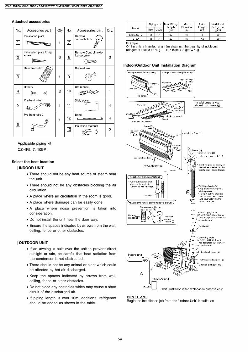
Attached accessories
Applicable piping kit
CZ-4F5, 7, 10BP
Select the best location
INDOOR UNIT
• There should not be any heat source or steam nearthe unit.
• There should not be any obstacles blocking the aircirculation.
• A place where air circulation in the room is good.
• A place where drainage can be easily done.
• A place where noise prevention is taken intoconsideration.
• Do not install the unit near the door way.
• Ensure the spaces indicated by arrows from the wall,ceiling, fence or other obstacles.
OUTDOOR UNIT
• If an awning is built over the unit to prevent directsunlight or rain, be careful that heat radiation fromthe condenser is not obstructed.
• There should not be any animal or plant which couldbe affected by hot air discharged.
• Keep the spaces indicated by arrows from wall,ceiling, fence or other obstacles.
• Do not place any obstacles which may cause a shortcircuit of the discharged air.
• If piping length is over 10m, additional refrigerantshould be added as shown in the table.
Indoor/Outdoor Unit Installation Diagram
54
CS-E15DTEW CU-E15DBE / CS-E18DTEW CU-E18DBE / CS-E21DTES CU-E21DBE
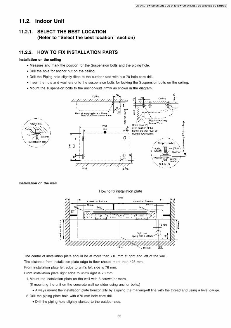
11.2. Indoor Unit
11.2.1. SELECT THE BEST LOCATION(Refer to “Select the best location” section)
11.2.2. HOW TO FIX INSTALLATION PARTS
Installation on the ceiling
• Measure and mark the position for the Suspension bolts and the piping hole.
• Drill the hole for anchor nut on the ceiling.
• Drill the Piping hole slightly tilted to the outdoor side with a ø 70 hole-core drill.
• Insert the nuts and washers onto the suspension bolts for locking the Suspension bolts on the ceiling.
• Mount the suspension bolts to the anchor-nuts firmly as shown in the diagram.
Installation on the wall
The centre of installation plate should be at more than 710 mm at right and left of the wall.
The distance from installation plate edge to floor should more than 425 mm.
From installation plate left edge to unit’s left side is 76 mm.
From installation plate right edge to unit’s right is 76 mm.
1. Mount the installation plate on the wall with 3 screws or more.
(If mounting the unit on the concrete wall consider using anchor bolts.)
• Always mount the installation plate horizontally by aligning the marking-off line with the thread and using a level gauge.
2. Drill the piping plate hole with ø70 mm hole-core drill.
• Drill the piping hole slightly slanted to the outdoor side.
55
CS-E15DTEW CU-E15DBE / CS-E18DTEW CU-E18DBE / CS-E21DTES CU-E21DBE
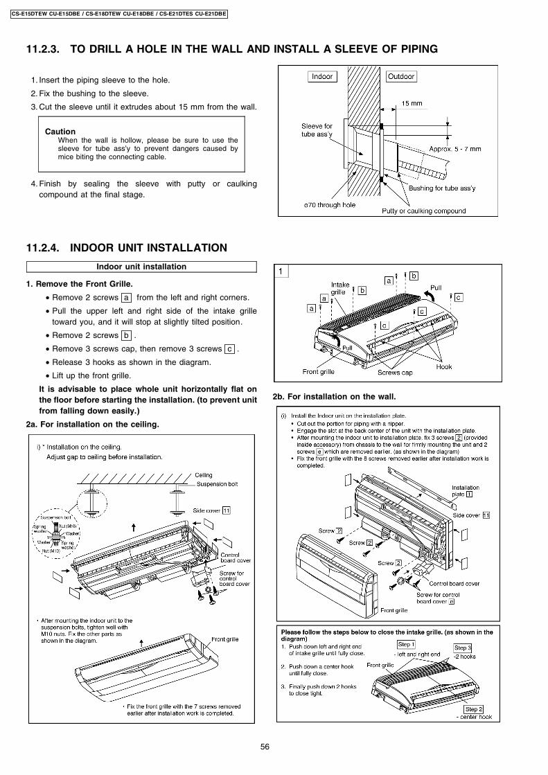
1. Insert the piping sleeve to the hole.
2. Fix the bushing to the sleeve.
3. Cut the sleeve until it extrudes about 15 mm from the wall.
CautionWhen the wall is hollow, please be sure to use thesleeve for tube ass’y to prevent dangers caused bymice biting the connecting cable.
4. Finish by sealing the sleeve with putty or caulkingcompound at the final stage.
Indoor unit installation
1. Remove the Front Grille.
• Remove 2 screws a from the left and right corners.
• Pull the upper left and right side of the intake grilletoward you, and it will stop at slightly tilted position.
• Remove 2 screws b .
• Remove 3 screws cap, then remove 3 screws c .
• Release 3 hooks as shown in the diagram.
• Lift up the front grille.
It is advisable to place whole unit horizontally flat onthe floor before starting the installation. (to prevent unitfrom falling down easily.)
2a. For installation on the ceiling.
2b. For installation on the wall.
11.2.3. TO DRILL A HOLE IN THE WALL AND INSTALL A SLEEVE OF PIPING
11.2.4. INDOOR UNIT INSTALLATION
56
CS-E15DTEW CU-E15DBE / CS-E18DTEW CU-E18DBE / CS-E21DTES CU-E21DBE
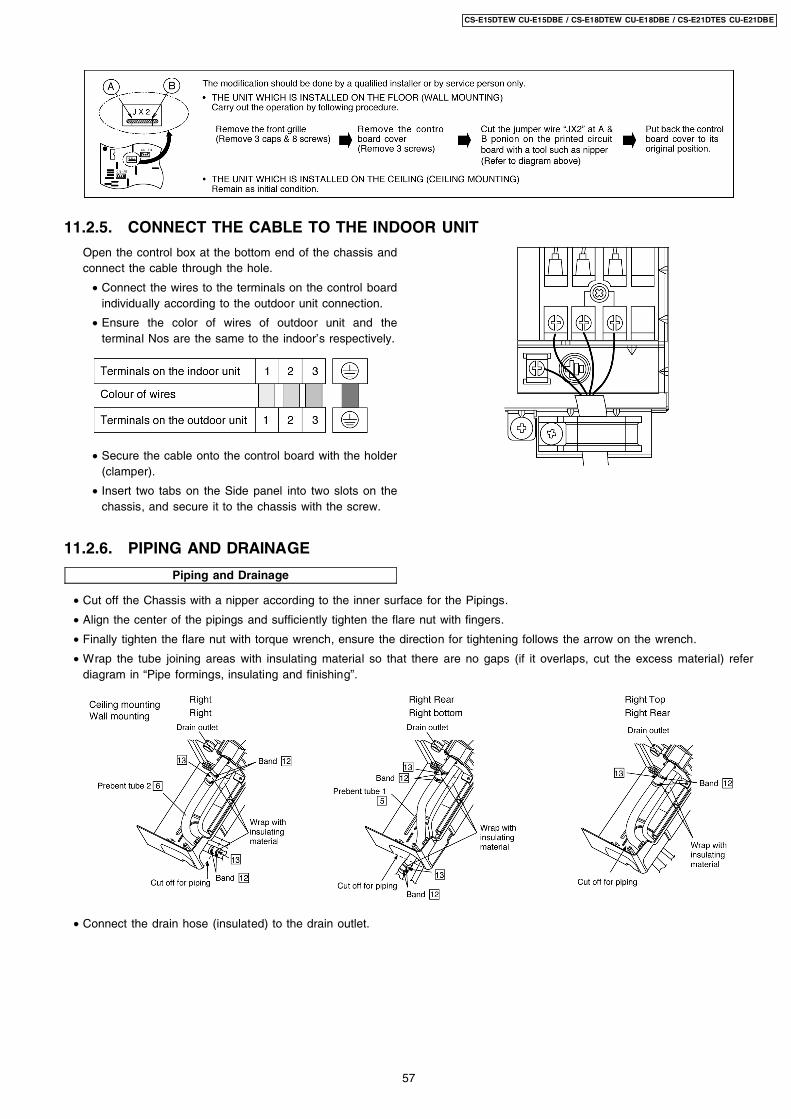
Open the control box at the bottom end of the chassis andconnect the cable through the hole.
• Connect the wires to the terminals on the control boardindividually according to the outdoor unit connection.
• Ensure the color of wires of outdoor unit and theterminal Nos are the same to the indoor’s respectively.
• Secure the cable onto the control board with the holder(clamper).
• Insert two tabs on the Side panel into two slots on thechassis, and secure it to the chassis with the screw.
Piping and Drainage
11.2.5. CONNECT THE CABLE TO THE INDOOR UNIT
11.2.6. PIPING AND DRAINAGE
• Cut off the Chassis with a nipper according to the inner surface for the Pipings.
• Align the center of the pipings and sufficiently tighten the flare nut with fingers.
• Finally tighten the flare nut with torque wrench, ensure the direction for tightening follows the arrow on the wrench.
• Wrap the tube joining areas with insulating material so that there are no gaps (if it overlaps, cut the excess material) referdiagram in “Pipe formings, insulating and finishing”.
• Connect the drain hose (insulated) to the drain outlet.
57
CS-E15DTEW CU-E15DBE / CS-E18DTEW CU-E18DBE / CS-E21DTES CU-E21DBE
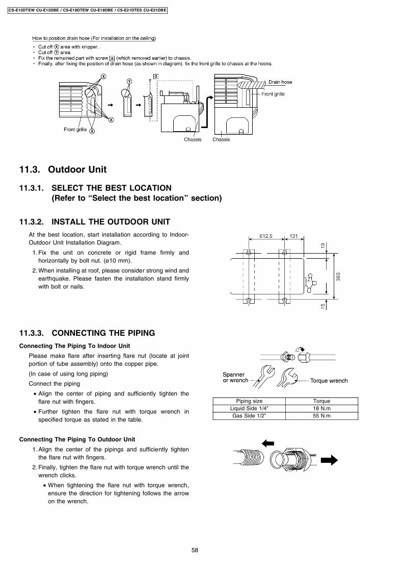
At the best location, start installation according to Indoor-Outdoor Unit Installation Diagram.
1. Fix the unit on concrete or rigid frame firmly andhorizontally by bolt nut. (ø10 mm).
2. When installing at roof, please consider strong wind andearthquake. Please fasten the installation stand firmlywith bolt or nails.
Connecting The Piping To Indoor Unit
Please make flare after inserting flare nut (locate at jointportion of tube assembly) onto the copper pipe.
(In case of using long piping)
Connect the piping
• Align the center of piping and sufficiently tighten theflare nut with fingers.
• Further tighten the flare nut with torque wrench inspecified torque as stated in the table.
Connecting The Piping To Outdoor Unit
1. Align the center of the pipings and sufficiently tightenthe flare nut with fingers.
2. Finally, tighten the flare nut with torque wrench until thewrench clicks.
• When tightening the flare nut with torque wrench,ensure the direction for tightening follows the arrowon the wrench.
Piping size TorqueLiquid Side 1/4” 18 N.mGas Side 1/2” 55 N.m
11.3. Outdoor Unit
11.3.1. SELECT THE BEST LOCATION(Refer to “Select the best location” section)
11.3.2. INSTALL THE OUTDOOR UNIT
11.3.3. CONNECTING THE PIPING
58
CS-E15DTEW CU-E15DBE / CS-E18DTEW CU-E18DBE / CS-E21DTES CU-E21DBE
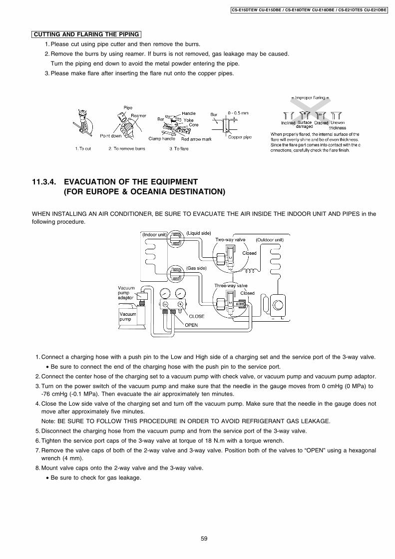
CUTTING AND FLARING THE PIPING
1. Please cut using pipe cutter and then remove the burrs.
2. Remove the burrs by using reamer. If burrs is not removed, gas leakage may be caused.
Turn the piping end down to avoid the metal powder entering the pipe.
3. Please make flare after inserting the flare nut onto the copper pipes.
11.3.4. EVACUATION OF THE EQUIPMENT(FOR EUROPE & OCEANIA DESTINATION)
WHEN INSTALLING AN AIR CONDITIONER, BE SURE TO EVACUATE THE AIR INSIDE THE INDOOR UNIT AND PIPES in thefollowing procedure.
1. Connect a charging hose with a push pin to the Low and High side of a charging set and the service port of the 3-way valve.
• Be sure to connect the end of the charging hose with the push pin to the service port.
2. Connect the center hose of the charging set to a vacuum pump with check valve, or vacuum pump and vacuum pump adaptor.
3. Turn on the power switch of the vacuum pump and make sure that the needle in the gauge moves from 0 cmHg (0 MPa) to-76 cmHg (-0.1 MPa). Then evacuate the air approximately ten minutes.
4. Close the Low side valve of the charging set and turn off the vacuum pump. Make sure that the needle in the gauge does notmove after approximately five minutes.
Note: BE SURE TO FOLLOW THIS PROCEDURE IN ORDER TO AVOID REFRIGERANT GAS LEAKAGE.
5. Disconnect the charging hose from the vacuum pump and from the service port of the 3-way valve.
6. Tighten the service port caps of the 3-way valve at torque of 18 N.m with a torque wrench.
7. Remove the valve caps of both of the 2-way valve and 3-way valve. Position both of the valves to “OPEN” using a hexagonalwrench (4 mm).
8. Mount valve caps onto the 2-way valve and the 3-way valve.
• Be sure to check for gas leakage.
59
CS-E15DTEW CU-E15DBE / CS-E18DTEW CU-E18DBE / CS-E21DTES CU-E21DBE
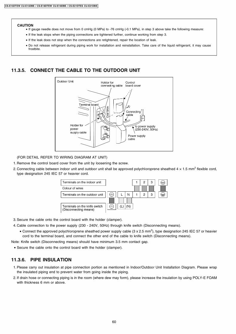
CAUTION • If gauge needle does not move from 0 cmHg (0 MPa) to -76 cmHg (-0.1 MPa), in step 3 above take the following measure:
• If the leak stops when the piping connections are tightened further, continue working from step 3.
• If the leak does not stop when the connections are retightened, repair the location of leak.
• Do not release refrigerant during piping work for installation and reinstallation. Take care of the liquid refrigerant, it may causefrostbite.
11.3.5. CONNECT THE CABLE TO THE OUTDOOR UNIT
(FOR DETAIL REFER TO WIRING DIAGRAM AT UNIT)
1. Remove the control board cover from the unit by loosening the screw.
2. Connecting cable between indoor unit and outdoor unit shall be approved polychloroprene sheathed 4 × 1.5 mm2 flexible cord,type designation 245 IEC 57 or heavier cord.
3. Secure the cable onto the control board with the holder (clamper).
4. Cable connection to the power supply (230 - 240V, 50Hz) through knife switch (Disconnecting means).
• Connect the approved polychloroprene sheathed power supply cable (3 x 2.5 mm2), type designation 245 IEC 57 or heaviercord to the terminal board, and connect the other end of the cable to knife switch (Disconnecting means).
Note: Knife switch (Disconnecting means) should have minimum 3.5 mm contact gap.
• Secure the cable onto the control board with the holder (clamper).
11.3.6. PIPE INSULATION
1. Please carry out insulation at pipe connection portion as mentioned in Indoor/Outdoor Unit Installation Diagram. Please wrapthe insulated piping end to prevent water from going inside the piping.
2. If drain hose or connecting piping is in the room (where dew may form), please increase the insulation by using POLY-E FOAMwith thickness 6 mm or above.
60
CS-E15DTEW CU-E15DBE / CS-E18DTEW CU-E18DBE / CS-E21DTES CU-E21DBE
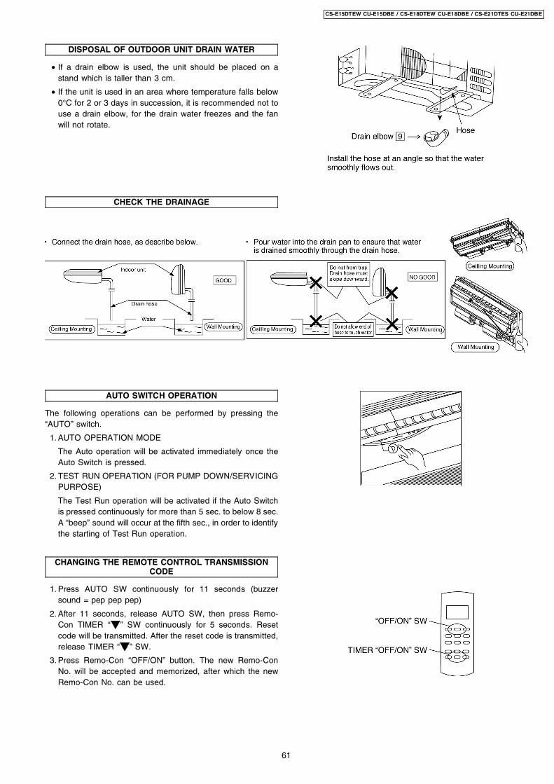
DISPOSAL OF OUTDOOR UNIT DRAIN WATER
• If a drain elbow is used, the unit should be placed on astand which is taller than 3 cm.
• If the unit is used in an area where temperature falls below0°C for 2 or 3 days in succession, it is recommended not touse a drain elbow, for the drain water freezes and the fanwill not rotate.
CHECK THE DRAINAGE
AUTO SWITCH OPERATION
The following operations can be performed by pressing the“AUTO” switch.
1. AUTO OPERATION MODE
The Auto operation will be activated immediately once theAuto Switch is pressed.
2. TEST RUN OPERATION (FOR PUMP DOWN/SERVICINGPURPOSE)
The Test Run operation will be activated if the Auto Switchis pressed continuously for more than 5 sec. to below 8 sec.A “beep” sound will occur at the fifth sec., in order to identifythe starting of Test Run operation.
CHANGING THE REMOTE CONTROL TRANSMISSIONCODE
1. Press AUTO SW continuously for 11 seconds (buzzersound = pep pep pep)
2. After 11 seconds, release AUTO SW, then press Remo-Con TIMER “ ” SW continuously for 5 seconds. Resetcode will be transmitted. After the reset code is transmitted,release TIMER “ ” SW.
3. Press Remo-Con “OFF/ON” button. The new Remo-ConNo. will be accepted and memorized, after which the newRemo-Con No. can be used.
61
CS-E15DTEW CU-E15DBE / CS-E18DTEW CU-E18DBE / CS-E21DTES CU-E21DBE
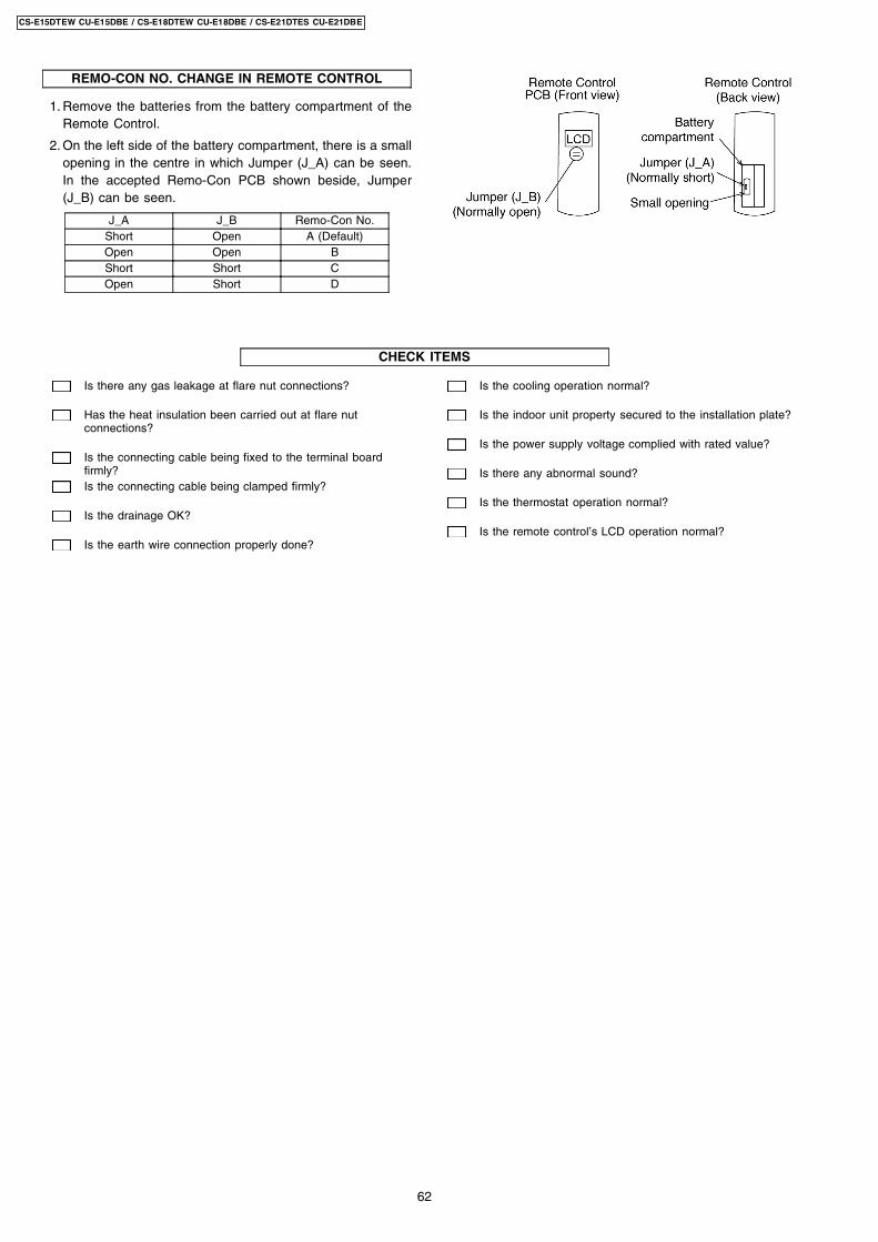
REMO-CON NO. CHANGE IN REMOTE CONTROL
1. Remove the batteries from the battery compartment of theRemote Control.
2. On the left side of the battery compartment, there is a smallopening in the centre in which Jumper (J_A) can be seen.In the accepted Remo-Con PCB shown beside, Jumper(J_B) can be seen.
J_A J_B Remo-Con No.Short Open A (Default)Open Open BShort Short COpen Short D
Is there any gas leakage at flare nut connections?
Has the heat insulation been carried out at flare nutconnections?
Is the connecting cable being fixed to the terminal boardfirmly?Is the connecting cable being clamped firmly?
Is the drainage OK?
Is the earth wire connection properly done?
Is the cooling operation normal?
Is the indoor unit property secured to the installation plate?
Is the power supply voltage complied with rated value?
Is there any abnormal sound?
Is the thermostat operation normal?
Is the remote control’s LCD operation normal?
CHECK ITEMS
62
CS-E15DTEW CU-E15DBE / CS-E18DTEW CU-E18DBE / CS-E21DTES CU-E21DBE
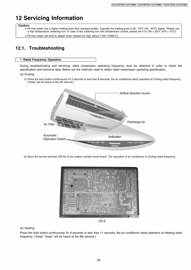
1. Rated Frequency Operation
12 Servicing InformationCaution:
• Pb free solder has a higher melting point than standard solder; Typically the melting point is 50 - 70°F (30 - 40°C) higher. Please usea high temperature soldering iron. In case of the soldering iron with temperature control, please set it to 700 ± 20°F (370 ± 10°C).
• Pb free solder will tend to splash when heated too high (about 1100° F/600°C).
12.1. Troubleshooting
During troubleshooting and servicing, rated compressor operating frequency must be obtained in order to check thespecification and technical data. Below are the methods used to obtain rated compressor operating specification.
(a) Cooling
(i) Press the Auto button continuously for 5 seconds or less than 8 seconds, the air conditioner starts operation at Cooling rated frequency.(“beep” will be heard at the 5th second.)
(ii) Short the service terminal (CN-S) of the outdoor printed circuit board. The operation of air conditioner is Cooling rated frequency.
(b) Heating
Press the Auto button continuously for 8 seconds or less than 11 seconds, the air conditioner starts operation at Heating ratedfrequency. (“beep” “beep” will be heard at the 8th second.)
63
CS-E15DTEW CU-E15DBE / CS-E18DTEW CU-E18DBE / CS-E21DTES CU-E21DBE
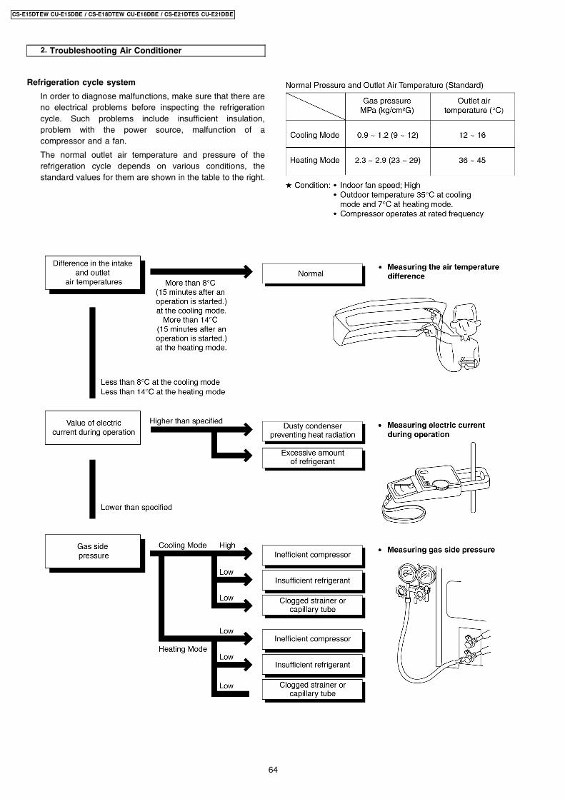
2. Troubleshooting Air Conditioner
Refrigeration cycle system
In order to diagnose malfunctions, make sure that there areno electrical problems before inspecting the refrigerationcycle. Such problems include insufficient insulation,problem with the power source, malfunction of acompressor and a fan.
The normal outlet air temperature and pressure of therefrigeration cycle depends on various conditions, thestandard values for them are shown in the table to the right.
64
CS-E15DTEW CU-E15DBE / CS-E18DTEW CU-E18DBE / CS-E21DTES CU-E21DBE
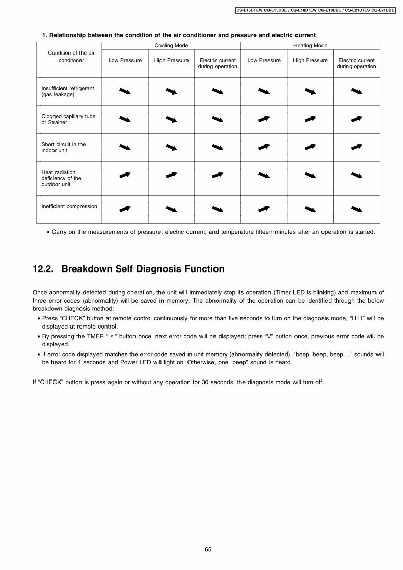
1. Relationship between the condition of the air conditioner and pressure and electric current
Cooling Mode Heating ModeCondition of the air
conditoner Low Pressure High Pressure Electric currentduring operation
Low Pressure High Pressure Electric currentduring operation
Insufficient refrigerant(gas leakage)
Clogged capillary tubeor Strainer
Short circuit in theindoor unit
Heat radiationdeficiency of theoutdoor unit
Inefficient compression
• Carry on the measurements of pressure, electric current, and temperature fifteen minutes after an operation is started.
12.2. Breakdown Self Diagnosis Function
Once abnormality detected during operation, the unit will immediately stop its operation (Timer LED is blinking) and maximum ofthree error codes (abnormality) will be saved in memory. The abnormality of the operation can be identified through the belowbreakdown diagnosis method:
• Press “CHECK” button at remote control continuously for more than five seconds to turn on the diagnosis mode, “H11” will bedisplayed at remote control.
• By pressing the TMER “ ” button once, next error code will be displayed; press “V” button once, previous error code will bedisplayed.
• If error code displayed matches the error code saved in unit memory (abnormality detected), “beep, beep, beep....” sounds willbe heard for 4 seconds and Power LED will light on. Otherwise, one “beep” sound is heard.
If “CHECK” button is press again or without any operation for 30 seconds, the diagnosis mode will turn off.
65
CS-E15DTEW CU-E15DBE / CS-E18DTEW CU-E18DBE / CS-E21DTES CU-E21DBE
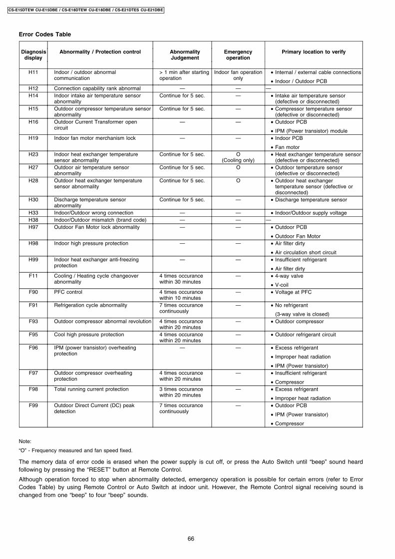
Error Codes Table
Diagnosisdisplay
Abnormality / Protection control AbnormalityJudgement
Emergencyoperation
Primary location to verify
H11 Indoor / outdoor abnormalcommunication
> 1 min after startingoperation
Indoor fan operationonly
• Internal / external cable connections
• Indoor / Outdoor PCBH12 Connection capability rank abnormal — — —H14 Indoor intake air temperature sensor
abnormalityContinue for 5 sec. — • Intake air temperature sensor
(defective or disconnected)H15 Outdoor compressor temperature sensor
abnormalityContinue for 5 sec. — • Compressor temperature sensor
(defective or disconnected)H16 Outdoor Current Transformer open
circuit— — • Outdoor PCB
• IPM (Power transistor) moduleH19 Indoor fan motor merchanism lock — — • Indoor PCB
• Fan motorH23 Indoor heat exchanger temperature
sensor abnormalityContinue for 5 sec. O
(Cooling only) • Heat exchanger temperature sensor
(defective or disconnected)H27 Outdoor air temperature sensor
abnormalityContinue for 5 sec. O • Outdoor temperature sensor
(defective or disconnected)H28 Outdoor heat exchanger temperature
sensor abnormalityContinue for 5 sec. O • Outdoor heat exchanger
temperature sensor (defective ordisconnected)
H30 Discharge temperature sensorabnormality
Continue for 5 sec. — • Discharge temperature sensor
H33 Indoor/Outdoor wrong connection — — • Indoor/Outdoor supply voltageH38 Indoor/Outdoor mismatch (brand code) — — —H97 Outdoor Fan Motor lock abnormality — — • Outdoor PCB
• Outdoor Fan MotorH98 Indoor high pressure protection — — • Air filter dirty
• Air circulation short circuitH99 Indoor heat exchanger anti-freezing
protection— — • Insufficient refrigerant
• Air filter dirtyF11 Cooling / Heating cycle changeover
abnormality4 times occurancewithin 30 minutes
— • 4-way valve
• V-coilF90 PFC control 4 times occurance
within 10 minutes— • Voltage at PFC
F91 Refrigeration cycle abnormality 7 times occurancecontinuously
— • No refrigerant
(3-way valve is closed)F93 Outdoor compressor abnormal revolution 4 times occurance
within 20 minutes— • Outdoor compressor
F95 Cool high pressure protection 4 times occurancewithin 20 minutes
— • Outdoor refrigerant circuit
F96 IPM (power transistor) overheatingprotection
— — • Excess refrigerant
• Improper heat radiation
• IPM (Power transistor)F97 Outdoor compressor overheating
protection4 times occurancewithin 20 minutes
— • Insufficient refrigerant
• CompressorF98 Total running current protection 3 times occurance
within 20 minutes— • Excess refrigerant
• Improper heat radiationF99 Outdoor Direct Current (DC) peak
detection7 times occurancecontinuously
— • Outdoor PCB
• IPM (Power transistor)
• Compressor
Note:
“O” - Frequency measured and fan speed fixed.
The memory data of error code is erased when the power supply is cut off, or press the Auto Switch until “beep” sound heardfollowing by pressing the “RESET” button at Remote Control.
Although operation forced to stop when abnormality detected, emergency operation is possible for certain errors (refer to ErrorCodes Table) by using Remote Control or Auto Switch at indoor unit. However, the Remote Control signal receiving sound ischanged from one “beep” to four “beep” sounds.
66
CS-E15DTEW CU-E15DBE / CS-E18DTEW CU-E18DBE / CS-E21DTES CU-E21DBE
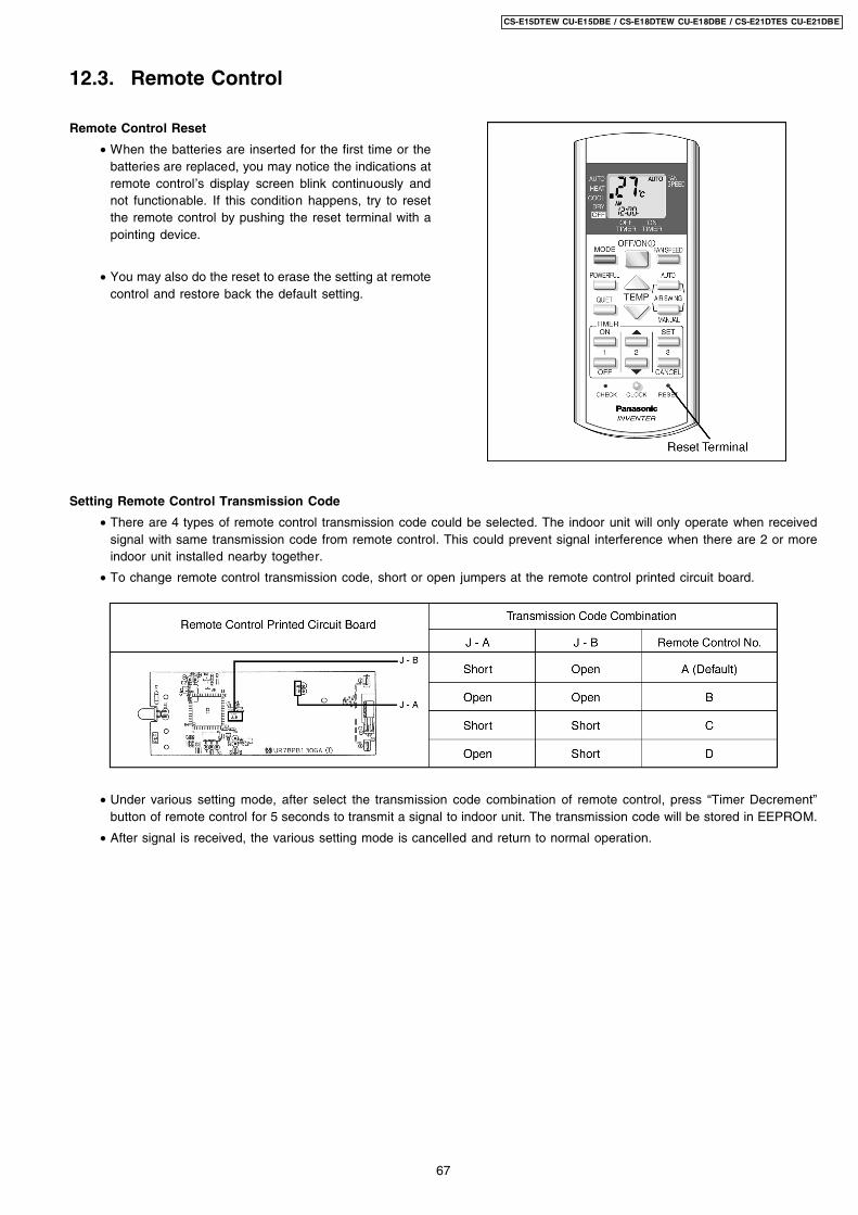
Remote Control Reset
• When the batteries are inserted for the first time or thebatteries are replaced, you may notice the indications atremote control’s display screen blink continuously andnot functionable. If this condition happens, try to resetthe remote control by pushing the reset terminal with apointing device.
• You may also do the reset to erase the setting at remotecontrol and restore back the default setting.
12.3. Remote Control
Setting Remote Control Transmission Code
• There are 4 types of remote control transmission code could be selected. The indoor unit will only operate when receivedsignal with same transmission code from remote control. This could prevent signal interference when there are 2 or moreindoor unit installed nearby together.
• To change remote control transmission code, short or open jumpers at the remote control printed circuit board.
• Under various setting mode, after select the transmission code combination of remote control, press “Timer Decrement”button of remote control for 5 seconds to transmit a signal to indoor unit. The transmission code will be stored in EEPROM.
• After signal is received, the various setting mode is cancelled and return to normal operation.
67
CS-E15DTEW CU-E15DBE / CS-E18DTEW CU-E18DBE / CS-E21DTES CU-E21DBE
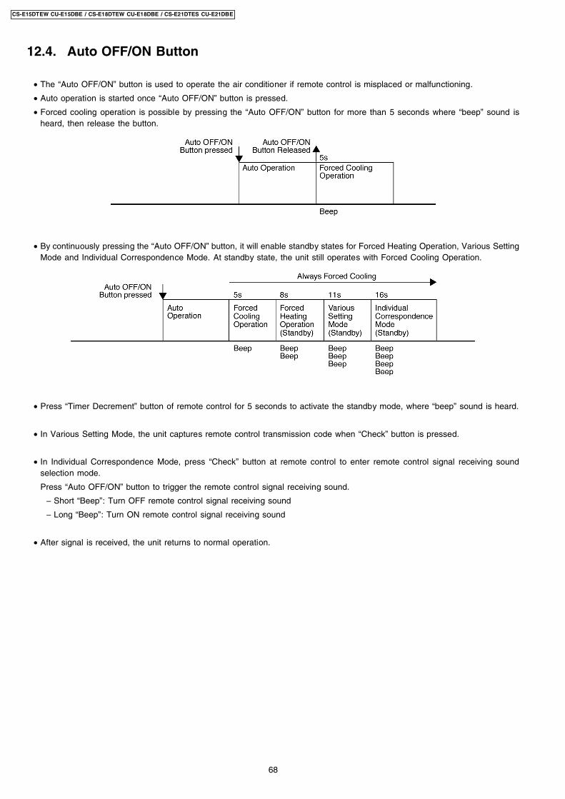
12.4. Auto OFF/ON Button
• The “Auto OFF/ON” button is used to operate the air conditioner if remote control is misplaced or malfunctioning.
• Auto operation is started once “Auto OFF/ON” button is pressed.
• Forced cooling operation is possible by pressing the “Auto OFF/ON” button for more than 5 seconds where “beep” sound isheard, then release the button.
• By continuously pressing the “Auto OFF/ON” button, it will enable standby states for Forced Heating Operation, Various SettingMode and Individual Correspondence Mode. At standby state, the unit still operates with Forced Cooling Operation.
• Press “Timer Decrement” button of remote control for 5 seconds to activate the standby mode, where “beep” sound is heard.
• In Various Setting Mode, the unit captures remote control transmission code when “Check” button is pressed.
• In Individual Correspondence Mode, press “Check” button at remote control to enter remote control signal receiving soundselection mode.
Press “Auto OFF/ON” button to trigger the remote control signal receiving sound.
− Short “Beep”: Turn OFF remote control signal receiving sound
− Long “Beep”: Turn ON remote control signal receiving sound
• After signal is received, the unit returns to normal operation.
68
CS-E15DTEW CU-E15DBE / CS-E18DTEW CU-E18DBE / CS-E21DTES CU-E21DBE
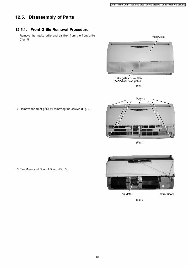
1. Remove the intake grille and air filter from the front grille(Fig. 1).
2. Remove the front grille by removing the screws (Fig. 2).
3. Fan Motor and Control Board (Fig. 3).
(Fig. 1)
(Fig. 2)
(Fig. 3)
12.5. Disassembly of Parts
12.5.1. Front Grille Removal Procedure
69
CS-E15DTEW CU-E15DBE / CS-E18DTEW CU-E18DBE / CS-E21DTES CU-E21DBE
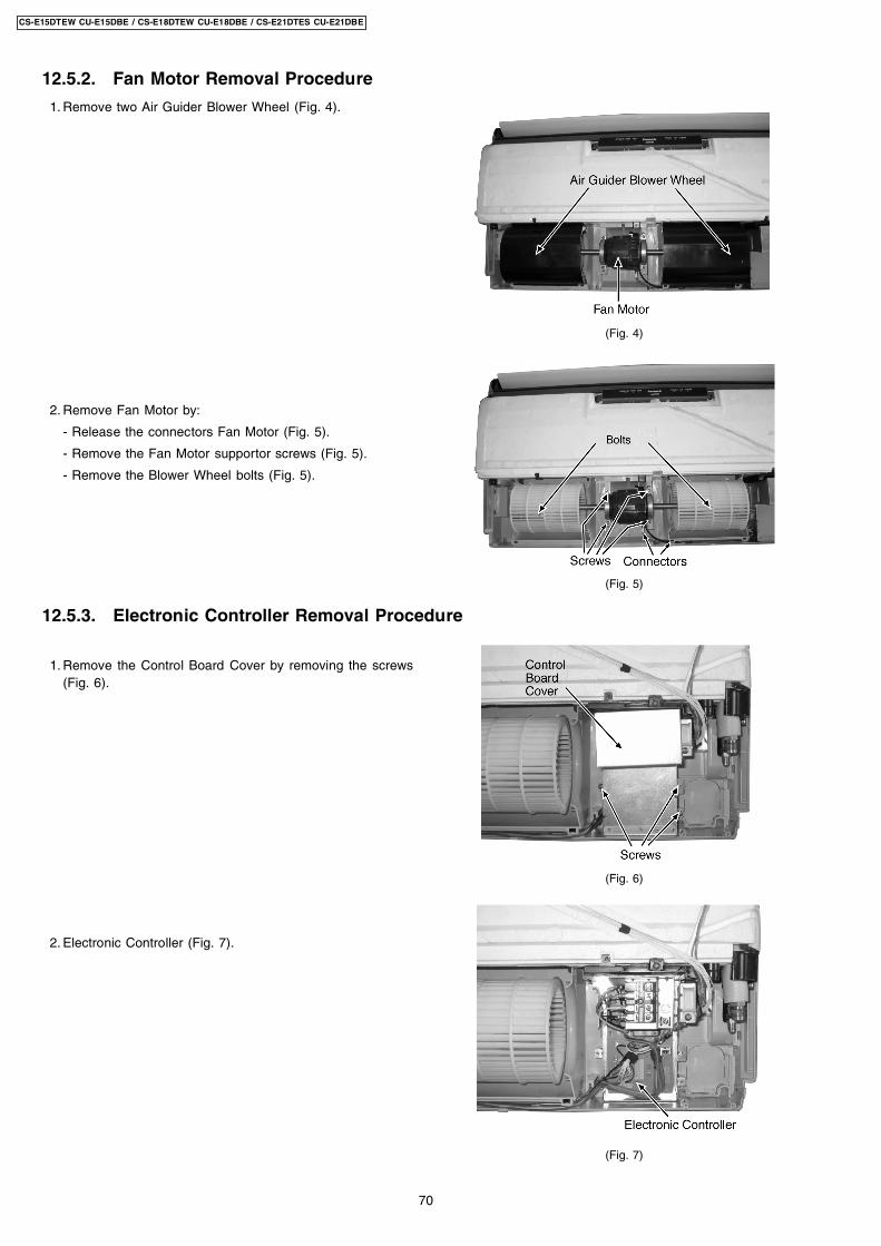
1. Remove two Air Guider Blower Wheel (Fig. 4).
2. Remove Fan Motor by:
- Release the connectors Fan Motor (Fig. 5).
- Remove the Fan Motor supportor screws (Fig. 5).
- Remove the Blower Wheel bolts (Fig. 5).
1. Remove the Control Board Cover by removing the screws(Fig. 6).
2. Electronic Controller (Fig. 7).
(Fig. 4)
(Fig. 5)
(Fig. 6)
(Fig. 7)
12.5.2. Fan Motor Removal Procedure
12.5.3. Electronic Controller Removal Procedure
70
CS-E15DTEW CU-E15DBE / CS-E18DTEW CU-E18DBE / CS-E21DTES CU-E21DBE
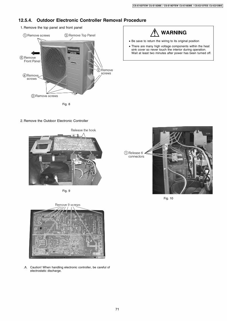
1. Remove the top panel and front panel
Fig. 8
2. Remove the Outdoor Electronic Controller
Fig. 9
Caution! When handling electronic controller, be careful ofelectrostatic discharge.
• Be save to return the wiring to its original position
• There are many high voltage components within the heatsink cover so never touch the interior during operation.Wait at least two minutes after power has been turned off.
Fig. 10
12.5.4. Outdoor Electronic Controller Removal Procedure
71
CS-E15DTEW CU-E15DBE / CS-E18DTEW CU-E18DBE / CS-E21DTES CU-E21DBE
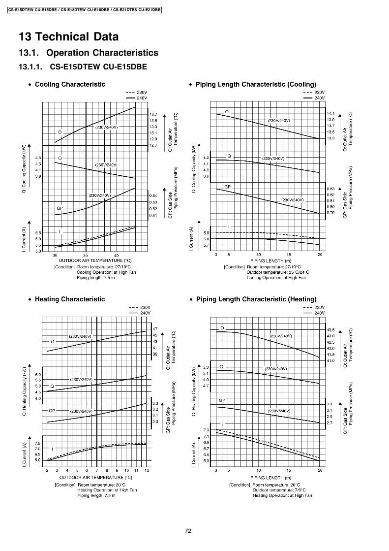
13 Technical Data13.1. Operation Characteristics
13.1.1. CS-E15DTEW CU-E15DBE
72
CS-E15DTEW CU-E15DBE / CS-E18DTEW CU-E18DBE / CS-E21DTES CU-E21DBE
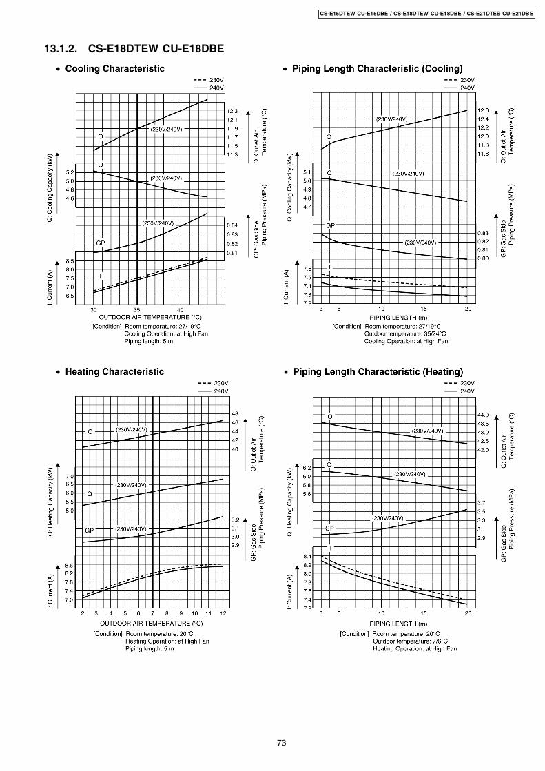
13.1.2. CS-E18DTEW CU-E18DBE
73
CS-E15DTEW CU-E15DBE / CS-E18DTEW CU-E18DBE / CS-E21DTES CU-E21DBE
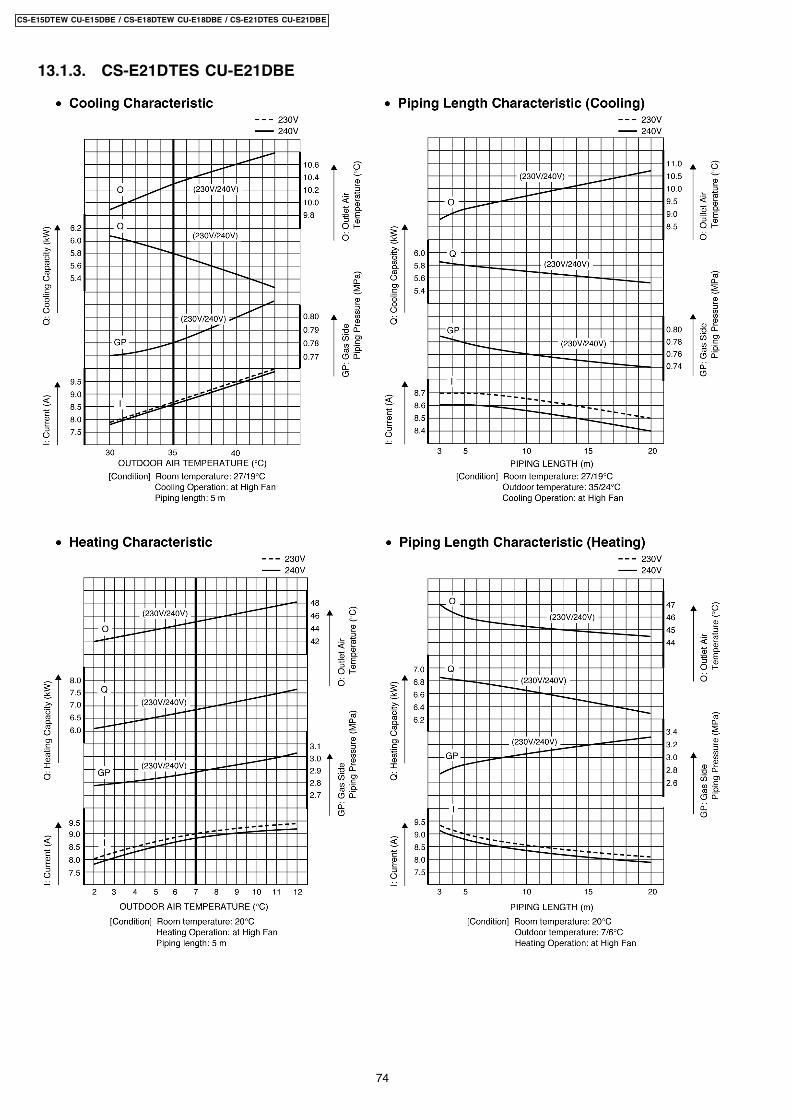
13.1.3. CS-E21DTES CU-E21DBE
74
CS-E15DTEW CU-E15DBE / CS-E18DTEW CU-E18DBE / CS-E21DTES CU-E21DBE
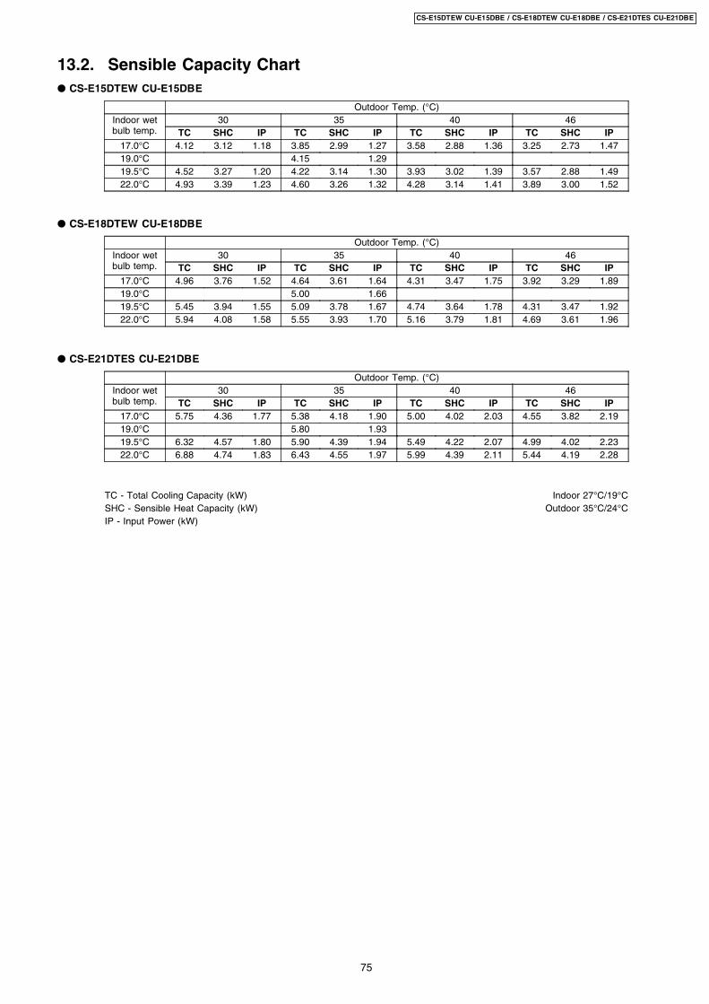
13.2. Sensible Capacity Chart CS-E15DTEW CU-E15DBE
Outdoor Temp. (°C)Indoor wetbulb temp.
30 35 40 46TC SHC IP TC SHC IP TC SHC IP TC SHC IP
17.0°C 4.12 3.12 1.18 3.85 2.99 1.27 3.58 2.88 1.36 3.25 2.73 1.4719.0°C 4.15 1.2919.5°C 4.52 3.27 1.20 4.22 3.14 1.30 3.93 3.02 1.39 3.57 2.88 1.4922.0°C 4.93 3.39 1.23 4.60 3.26 1.32 4.28 3.14 1.41 3.89 3.00 1.52
CS-E18DTEW CU-E18DBE
Outdoor Temp. (°C)Indoor wetbulb temp.
30 35 40 46TC SHC IP TC SHC IP TC SHC IP TC SHC IP
17.0°C 4.96 3.76 1.52 4.64 3.61 1.64 4.31 3.47 1.75 3.92 3.29 1.8919.0°C 5.00 1.6619.5°C 5.45 3.94 1.55 5.09 3.78 1.67 4.74 3.64 1.78 4.31 3.47 1.9222.0°C 5.94 4.08 1.58 5.55 3.93 1.70 5.16 3.79 1.81 4.69 3.61 1.96
CS-E21DTES CU-E21DBE
Outdoor Temp. (°C)Indoor wetbulb temp.
30 35 40 46TC SHC IP TC SHC IP TC SHC IP TC SHC IP
17.0°C 5.75 4.36 1.77 5.38 4.18 1.90 5.00 4.02 2.03 4.55 3.82 2.1919.0°C 5.80 1.9319.5°C 6.32 4.57 1.80 5.90 4.39 1.94 5.49 4.22 2.07 4.99 4.02 2.2322.0°C 6.88 4.74 1.83 6.43 4.55 1.97 5.99 4.39 2.11 5.44 4.19 2.28
TC - Total Cooling Capacity (kW) Indoor 27°C/19°CSHC - Sensible Heat Capacity (kW) Outdoor 35°C/24°CIP - Input Power (kW)
75
CS-E15DTEW CU-E15DBE / CS-E18DTEW CU-E18DBE / CS-E21DTES CU-E21DBE
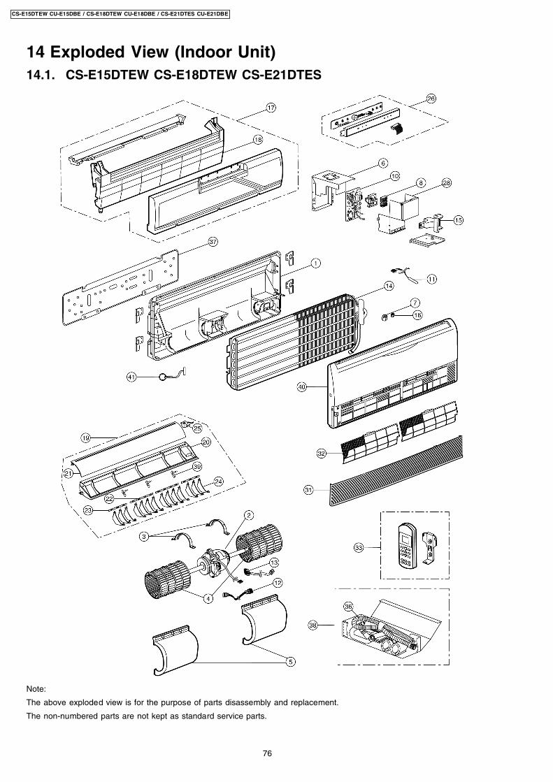
14 Exploded View (Indoor Unit)14.1. CS-E15DTEW CS-E18DTEW CS-E21DTES
Note:
The above exploded view is for the purpose of parts disassembly and replacement.
The non-numbered parts are not kept as standard service parts.
76
CS-E15DTEW CU-E15DBE / CS-E18DTEW CU-E18DBE / CS-E21DTES CU-E21DBE
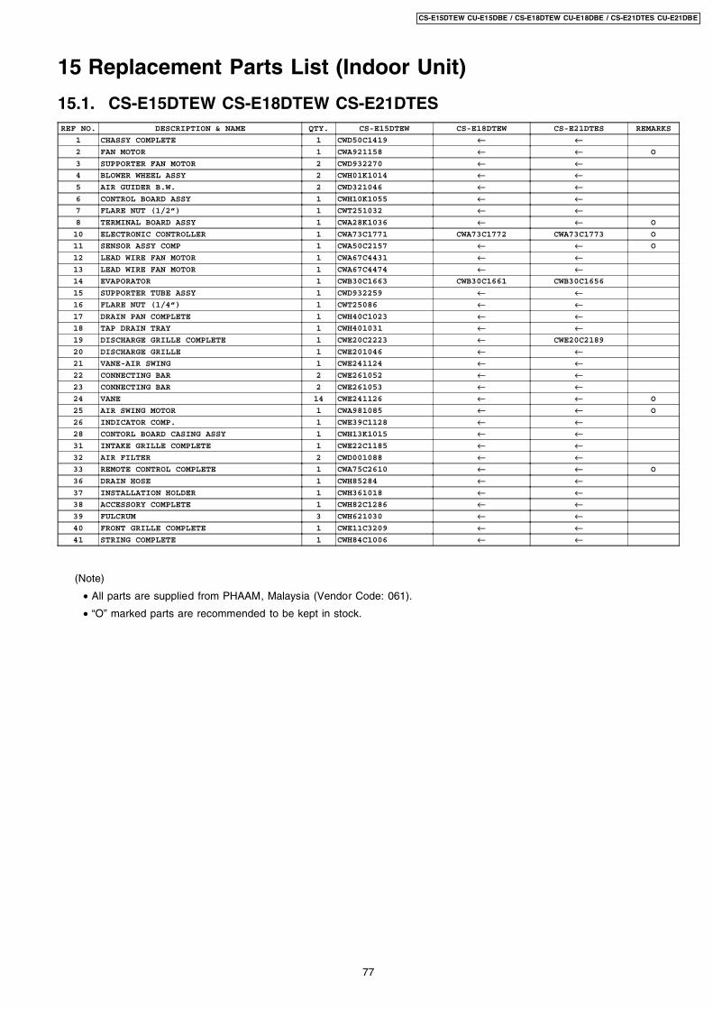
15 Replacement Parts List (Indoor Unit)
15.1. CS-E15DTEW CS-E18DTEW CS-E21DTESREF NO. DESCRIPTION & NAME QTY. CS-E15DTEW CS-E18DTEW CS-E21DTES REMARKS
1 CHASSY COMPLETE 1 CWD50C1419 ← ←2 FAN MOTOR 1 CWA921158 ← ← O
3 SUPPORTER FAN MOTOR 2 CWD932270 ← ←4 BLOWER WHEEL ASSY 2 CWH01K1014 ← ←5 AIR GUIDER B.W. 2 CWD321046 ← ←6 CONTROL BOARD ASSY 1 CWH10K1055 ← ←7 FLARE NUT (1/2”) 1 CWT251032 ← ←8 TERMINAL BOARD ASSY 1 CWA28K1036 ← ← O
10 ELECTRONIC CONTROLLER 1 CWA73C1771 CWA73C1772 CWA73C1773 O
11 SENSOR ASSY COMP 1 CWA50C2157 ← ← O
12 LEAD WIRE FAN MOTOR 1 CWA67C4431 ← ←13 LEAD WIRE FAN MOTOR 1 CWA67C4474 ← ←14 EVAPORATOR 1 CWB30C1663 CWB30C1661 CWB30C1656
15 SUPPORTER TUBE ASSY 1 CWD932259 ← ←16 FLARE NUT (1/4”) 1 CWT25086 ← ←17 DRAIN PAN COMPLETE 1 CWH40C1023 ← ←18 TAP DRAIN TRAY 1 CWH401031 ← ←19 DISCHARGE GRILLE COMPLETE 1 CWE20C2223 ← CWE20C2189
20 DISCHARGE GRILLE 1 CWE201046 ← ←21 VANE-AIR SWING 1 CWE241124 ← ←22 CONNECTING BAR 2 CWE261052 ← ←23 CONNECTING BAR 2 CWE261053 ← ←24 VANE 14 CWE241126 ← ← O
25 AIR SWING MOTOR 1 CWA981085 ← ← O
26 INDICATOR COMP. 1 CWE39C1128 ← ←28 CONTORL BOARD CASING ASSY 1 CWH13K1015 ← ←31 INTAKE GRILLE COMPLETE 1 CWE22C1185 ← ←32 AIR FILTER 2 CWD001088 ← ←33 REMOTE CONTROL COMPLETE 1 CWA75C2610 ← ← O
36 DRAIN HOSE 1 CWH85284 ← ←37 INSTALLATION HOLDER 1 CWH361018 ← ←38 ACCESSORY COMPLETE 1 CWH82C1286 ← ←39 FULCRUM 3 CWH621030 ← ←40 FRONT GRILLE COMPLETE 1 CWE11C3209 ← ←41 STRING COMPLETE 1 CWH84C1006 ← ←
(Note)
• All parts are supplied from PHAAM, Malaysia (Vendor Code: 061).
• “O” marked parts are recommended to be kept in stock.
77
CS-E15DTEW CU-E15DBE / CS-E18DTEW CU-E18DBE / CS-E21DTES CU-E21DBE
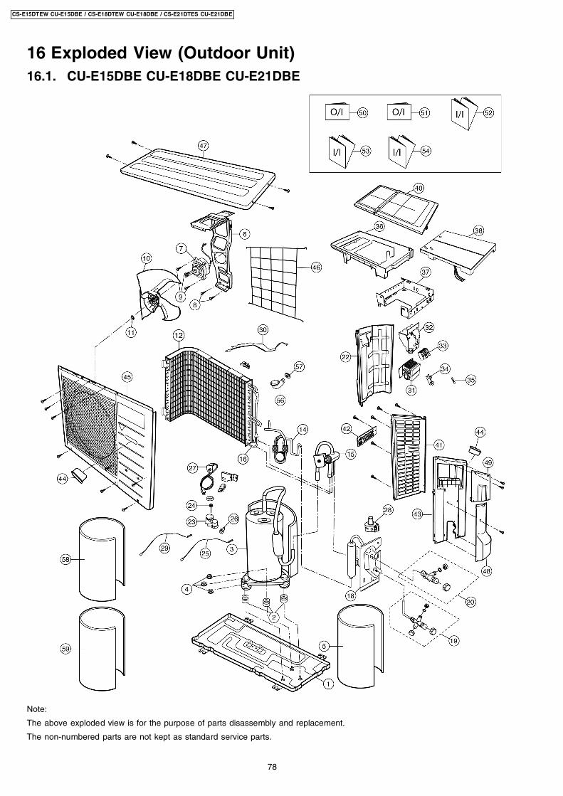
16 Exploded View (Outdoor Unit)16.1. CU-E15DBE CU-E18DBE CU-E21DBE
Note:
The above exploded view is for the purpose of parts disassembly and replacement.
The non-numbered parts are not kept as standard service parts.
78
CS-E15DTEW CU-E15DBE / CS-E18DTEW CU-E18DBE / CS-E21DTES CU-E21DBE
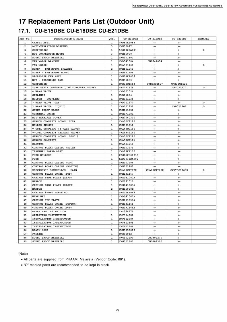
17 Replacement Parts List (Outdoor Unit)17.1. CU-E15DBE CU-E18DBE CU-E21DBEREF NO. DESCRIPTION & NAME QTY. CU-E15DBE CU-E18DBE CU-E21DBE REMARKS
1 CHASSY ASSY 1 CWD50K2085 ← ←2 ANTI-VIBRATION BUSHING 3 CWH50077 ← ←3 COMPRESSOR 1 5CS130XAD04 ← ← O
4 NUT-COMPRESSOR MOUNT 3 CWH56000 ← ←5 SOUND PROOF MATERIAL 1 CWG302302 ← ←6 FAN MOTOR BRACKET 1 CWD541084 CWD541054 ←7 FAN MOTOR 1 CWA981166 ← ← O
8 SCREW - FAN MOTOR BRACKET 2 CWH551060 ← ←9 SCREW - FAN MOTOR MOUNT 3 CWH551106 ← ←10 PROPELLER FAN ASSY 1 CWH03K1016 ← ←11 NUT - PROPELLER FAN 1 CWH56053 ← ←12 CONDENSER 1 CWB32C1583 CWB32C1527 CWB32C1526
14 TUBE ASS’Y COMPLETE (CAP TUBE/EXP.VALVE) 1 CWT023679 ← CWT023610 O
15 4 WAYS VALVE 1 CWB001026 ← ←16 STRAINER 1 CWB11094 ← ←18 HOLDER - COUPLING 1 CWH351035 ← ←19 3 WAYS VALVE (GAS) 1 CWB011170 ← ← O
20 2 WAYS VALVE (LIQUID) 1 CWB021292 ← CWB021306 O
22 SOUND PROOF BOARD 1 CWH151050 ← ←23 TERMINAL COVER 1 CWH171001 ← ←24 NUT-TERMINAL COVER 1 CWH7080300 ← ←25 SENSOR COMPLETE (COMP. TOP) 1 CWA50C2185 ← ←26 HOLDER SENSOR 1 CWH321010 ← ←27 V-COIL COMPLETE (4-WAYS VALVE) 1 CWA43C2168 ← ←28 V-COIL COMPLETE (EXPAND VALVE) 1 CWA43C2141 ← ←29 SENSOR COMPLETE (COMP. DISC.) 1 CWA50C2180 ← ←30 SENSOR COMPLETE 1 CWA50C2181 ← ←31 REACTOR 1 CWA421069 ← ←32 CONTROL BOARD CASING (SIDE) 1 CWH102273 ← ←33 TERMINAL BOARD ASSY 1 CWA28K1110 ← ←34 FUSE HOLDERS 1 K3GB1PH00016 ← ←35 FUSE 1 K5D303BBA002 ← ←36 CONTROL BOARD CASING (TOP) 1 CWH102204 ← ←37 CONTROL BOARD CASING (BOTTOM) 1 CWH102282 ← ←38 ELECTRONIC CONTROLLER - MAIN 1 CWA73C1767R CWA73C1768R CWA73C1769R O
40 CONTROL BOARD COVER (TOP) 1 CWH131167 ← ←41 CABINET SIDE PLATE (LEFT) 1 CWE041082A ← ←42 HANDLE 1 CWE161010 ← ←43 CABINET SIDE PLATE (RIGHT) 1 CWE041083A ← ←44 HANDLE 2 CWE16000E ← ←45 CABINET FRONT PLATE CO. 1 CWE06K1043 ← ←46 WIRE NET 1 CWD041041A ← ←47 CABINET TOP PLATE 1 CWE031031A ← ←48 CONTROL BOARD COVER (BOTTOM) 1 CWH131168 ← ←49 CONTROL BOARD COVER (TOP) 1 CWH131169A ← ←50 OPERATING INSTRUCTION 1 CWF564379 ← ←51 OPERATING INSTRUCTION 1 CWF564380 ← ←52 INSTALLATION INSTRUCTION 1 CWF612604 ← ←53 INSTALLATION INSTRUCTION 1 CWF612605 ← ←54 INSTALLATION INSTRUCTION 1 CWF612606 ← ←56 DRAIN HOSE 1 CWH5850080 ← ←57 PACKING 1 CWB81012 ← ←58 SOUND PROOF MATERIAL 1 CWG302290 CWG302270 ←59 SOUND PROOF MATERIAL 1 CWG302301 CWG302300 ←
(Note)
• All parts are supplied from PHAAM, Malaysia (Vendor Code: 061).
• “O” marked parts are recommended to be kept in stock.
79
CS-E15DTEW CU-E15DBE / CS-E18DTEW CU-E18DBE / CS-E21DTES CU-E21DBE
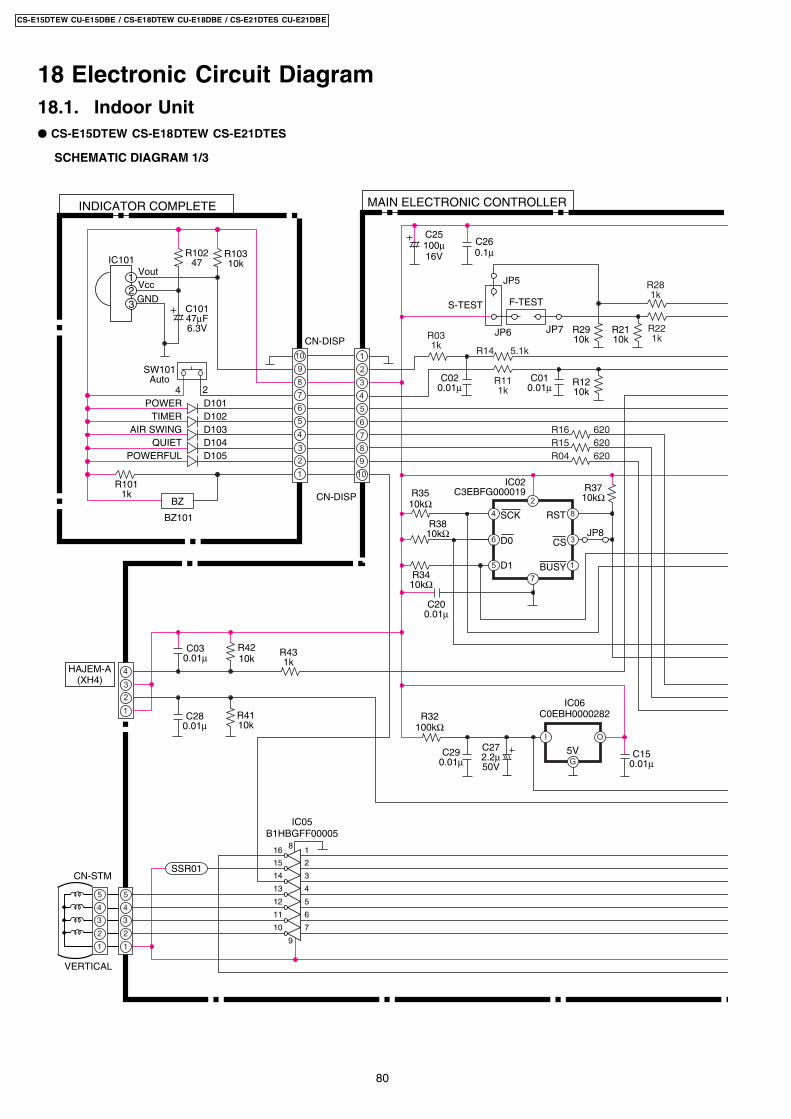
18.1. Indoor Unit
18 Electronic Circuit Diagram
CS-E15DTEW CS-E18DTEW CS-E21DTES
10
2
4
6
8
9
7
5
3
1
1
2
3
4
5
6
10
8
7
9
CN-DISP
R10310k
CN-DISP
HAJEM-A(XH4)
IC101
3
4
1
2
VoutVcc
GND2
R1011k
BZ
BZ101
R10247
D101POWER
SW101Auto
C10147µF6.3V
C030.01µ
D102TIMERD103AIR SWINGD104QUIETD105POWERFUL
INDICATOR COMPLETE MAIN ELECTRONIC CONTROLLER
R16 620R15 620
1
2
3
4
C280.01µ
R4210k
R4110k
R431k
C260.1µ
C020.01µ
C010.01µ
C25100µ16V
R031k R14 5.1k
R281k
R221k
R111k
R1210k
R2110k
R2910k
JP7JP6
F-TESTS-TEST
JP5
IC02C3EBFG000019
1
3
84
6
7
2
5
D0 CS
RSTSCK
BUSYD1
JP8
R3710kΩ
R3410kΩ
R32100kΩ
C200.01µ
R3810kΩ
R3510kΩ
5V
IC06C0EBH0000282
C272.2µ50V
I
G
O
C150.01µ
C290.01µ
IC05B1HBGFF00005
SSR01
1
2
3
4
5
6
7
16
15
14
13
12
11
10
9
8
VERTICAL
5
4
3
2
1
5
4
3
2
1
CN-STM
R04 620
SCHEMATIC DIAGRAM 1/3
80
CS-E15DTEW CU-E15DBE / CS-E18DTEW CU-E18DBE / CS-E21DTES CU-E21DBE
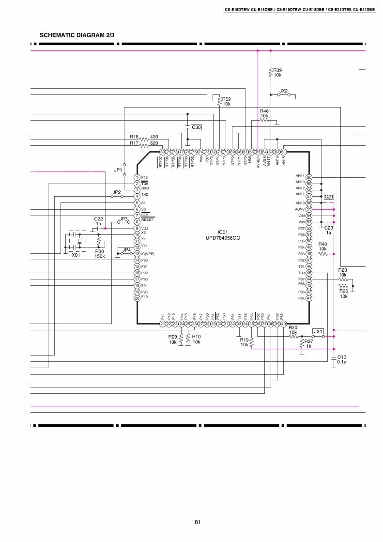
IC01UPD784956GC
1
2
3
4
5
6
7
8
9
21 22 23 24 25 26 27 28 29
52
53
54
55
56
57
58
59
60
727374757677787980
10 51
30
71
11 50
31
70
12 49
13 48
32
69
33
68
14 47
15 46
16 45
34
67
35
66
36
65
17 44
18 43
19 42
20 41
37
64
38
63
39
62
40
61
P16
T06RXD
TXD
S1
S0
SCKRESET
VddX2
X1
Vss
IC(VPP)
P90
P91
P92
P93
P94
P95P40
AN14
AN13
AN12
AN11
AN10
ADVV
Vdd
Vss
P37
P36
P35
P34
P33
P32
T01
T00
P67P66
P65
P64
RT
P07
RT
P06
RT
P05
RT
P04
RT
P03
RT
P02 Vss
P07
INT
P5
INT
P4
INT
P3
INT
P2
INT
P1
INT
P0
NM
I
AV
RE
F
AV
SS
AN
17
AN
16
AN
15
P41
P42
P43
P44
P45
P46
P47
P50
P51
P52
P53
P54
Vss
P55
P56
P57
P60
P61
P62
P63
R17 620R18 430
C30
R4610k
R5910k
R3910k
C221µ
C231µ
C21
X01R30150k
JP4
JP3
JP1
JP2
R0910k
R1010k
R2010k
R1910k
R4010k
JX1
R271k
C100.1µ
R2310k
R2610k
JX2
SCHEMATIC DIAGRAM 2/3
81
CS-E15DTEW CU-E15DBE / CS-E18DTEW CU-E18DBE / CS-E21DTES CU-E21DBE
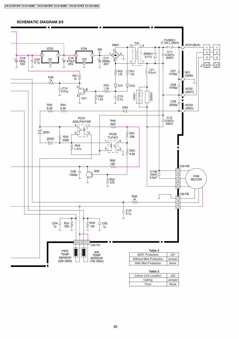
C041µ
CN-TH
PIPETEMP
SENSOR(20k 3950)
4 3 2 1
AIRTEMP
SENSOR(15k 3950)
R3120k
C051µ
C-FM440V3.0µF
C190.1µ
R3315k
2
3
4
5
7
4
1
1
B
E
C
NR
DB01 T01 AC01(BLK)
FUSE01(T 2A L 250V)
C173300µ35V
C110.047µ630VC16
470µF25V
C18220µ16V
12V
IC04
O
G
I
5V
IC03
O
G
I
G01(GRN)
C074700p
ZNR01511U
C084700p
C120.047µ630V
AC02(WHT)
AC03(RED)
C092200p
4 1
23
PC01A52LP421GR
41
2 3
PC02TLP421
R456.2k
R446.2k D03
Q02
ZD01
ZD02
R5010k
R49620
R5120kR25
330k
R241.21k R53
5.6k
R5247k
R361k
C061000p 2
4
5
3
1
CN-FM
FANMOTOR
2
3
1
CN-FB
1
2
1
2
33C240.1µ
C140.01µ
R0212k
R061.6k
R051.3k
R081k
R071k
D01
Q01
R0112k
L01125uH
D02
CR
01
SS
R01
C130.1µ
Table 2MIST Protection
Without Mist ProtectionWith Mist Protection
JX1JumperNone
Table 3Indoor Unit Location
CeilingFloor
JX2JumperNone
SCHEMATIC DIAGRAM 3/3
82
CS-E15DTEW CU-E15DBE / CS-E18DTEW CU-E18DBE / CS-E21DTES CU-E21DBE
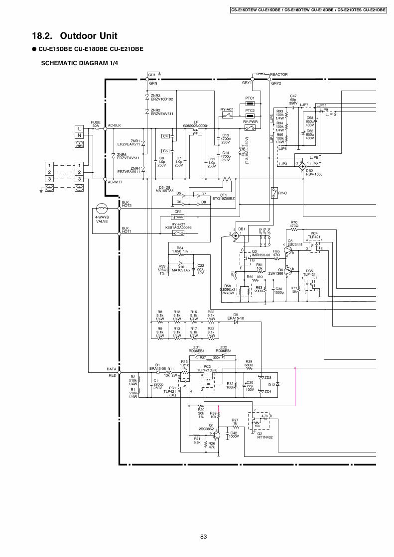
18.2. Outdoor Unit CU-E15DBE CU-E18DBE CU-E21DBE
12
12
33AC-WHT
AC-BLKFUSE 30A
ZNR3ERZV10D102
ZNR2ERZVEAV511
ZNR6 ERZVEAV511
DATAD1
ERA15-06
PC1TLP421
(BL)
PC2TLP421(GR)
RED
R11
R27 330k
R2 510k 1/4W
R1 510k 1/4W
ZD3
D12
ZD4
R151.21k1%
D9ERA15-10
1
43
213k 2W
GD1
GRN
ZNR1ERZVEAV511
ZNR4ERZVEAV511
LF G08902N00D01
C8 1.0µ 250V
C11 1.0µ 250V
C13 4700p 250V
C14 4700p 250V
C22 220µ 10V
RY-PWR
FU
SE
1(T
3.1
5A L
250
V)
PTC1
PTC2
CR1
RY-HOTK6B1AGA00096
R8 9.1k 1/4W
D5
D5~D8MA165TA5
D6
D7 CT1 ETQ19Z59BZ
D8
REACTOR
GRY2GRY1
R34 1.65k 1%
D10 MA165TA5
R33698Ω1%
R32 100k
R89 10k
R97 1k
cb
e
Q1 2SC3852
R215.6k
R20 20k 1%
R2647k
4
12
3
c
e
b
Q2RT1N432
10k
4.7k
R29 680Ω
R93100k 1/4WR94100k 1/4WR95100k 1/4W
1
23
4
C
E
G
1
2 3
4
1 LJP2LJP3
LJP
4LJ
P5
LJP6
LJP8
LJP9LJP10
RY-C
R61 10k
R65 47Ω
Q5 2SC3441
Q6 2SA1366
R58 0.839Ωx2 5W+5W
R60 10Ω
R63 200Ω C30
1500p
c
be
eb
c
4 1
23
4
32
PC5 TLP421
PC4TLP421
R70 470Ω
DB2 RBV-1506
DB1
Q3IMRH50-60
C1 2200p250V
4-WAYS VALVE
RY-AC1
BLKHOT2
BLKHOT1
C20 22µ
100V
LN
C7 1.0µ 250V
R12 9.1k 1/4W
R16 9.1k 1/4W
R22 9.1k 1/4W
R9 9.1k 1/4W
R13 9.1k 1/4W
R17 9.1k 1/4W
R23 9.1k 1/4W
C47 65µ
350V
C53 850µ 400V
C52 850µ 400V
JP2
JP1
JP3
JP4
R71 10k
ZD1 RD36EB1
ZD2 RD36EB1
C42 1000P
C4
C5
LJP7 LJP11
SCHEMATIC DIAGRAM 1/4
83
CS-E15DTEW CU-E15DBE / CS-E18DTEW CU-E18DBE / CS-E21DTES CU-E21DBE
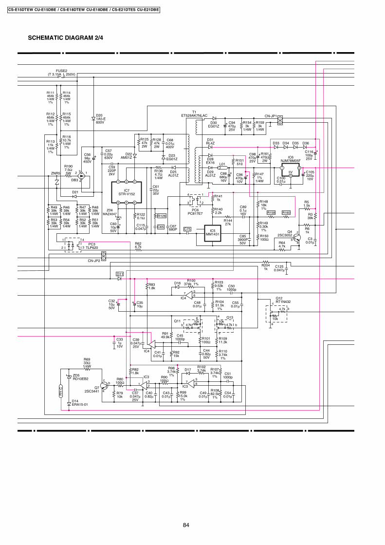
SCHEMATIC DIAGRAM 2/4
R190 7.5Ω 5W
R103 9.53k1%
R104 51.5k1%
C50 1000p
D17
C45 1000p R109
11.3k
R9149.9k
R110 3.74k1%
R92 15k
R83 1.8k
R100 374k 1%
ee
cc
bb
Q13Q11 10k
4.7k10k
4.7k
IC4
IC47
56
IC3
IC3
R82 1.8k
R7910k
Q7 2SC3441
C511000p
R10882.5k1%
R9915.0k1%
R983.74k1%
R1073.74k1%
R102 3.74k
cb
e
R80 100Ω
R101100Ω
RY
-C
D14ERA15-01
ZD5RD10EB2
R69 33Ω 1/4W
132
756
R90 100Ω
R111464k 1/4W1%
R112 464k 1/4W1%
R113 11k
1/4W1%
R12547k 2W
R128 47k 2W
R154 3k
1/4W
R114 464k 1/4W1%
R115 464k 1/4W1%
R116 10.7k 1/4W1%
D21
D20 1A5-E 600V
IC7 STR-V152
D22 AM01Z
D25 AL01Z
T1 ET529AK7NLAC
D23 EG01Z D28
EX16 L01
D31 RL4Z D33 D34
5V
IC6 NJM78M05F
D35
D30 EG01Z
D29 AL01Z
2 3
4
1
DB3
C56 56µ
450V
C60 10µ 50V
FUSE2(T 3.15A L 250V)
C57 0.22µ 630V
C61 22µ 35V
C89 0.1µ 16V
C48 0.01µ
C35 10µ
C39 0.047µ
25V
C41 0.01µ
C44 0.82µ 50V
C32 10µ 50V
C37 0.047µ
25V
C40 0.82µ
C55 0.01µ
C68 0.01µ 400V
C59 220P 2kV
321
6 5 4
ZD6 MAZ4047
C115 0.047µ C65
R126R122 0.1Ω
R47 39k
1/4W
R136 4.7Ω 1/4W
R158
C75C67 680P
C853900P
50V
D36
4 1
23
PC6PC817E7
IC5 MM1431
R1411k
R140 2.2k
R14427k
R150 100Ω
R64 4.7k
R149 3.30k 1%
R148 18k 1%
R204 1k
R6 1k
R5 1.5k
R3 39k
R160
R151 510
R147 1%
1/4WC100 0.01µ
C105 220µ 10V
C94 470µ 25V
C88 680µ 16V
C96 470µ 10V
C98 470µ 25V
R159 3k
1/4W
2
1CN-JP1
R161 470Ω 2W
C116 100µ 25V
I
G
O
1
2
CN-JP2
R62 4.7k
R48 39k
1/4W
R52 39k
1/4W
R51 39k
1/4W
R49 39k
1/4W
R46 39k
1/4W
R53 39k
1/4W
R54 39k
1/4W
1 4
32PC3
TLP620
ZNR5
D16
C43 0.01µ
C49 0.01µ
C54 0.01µ
C125 0.047µ
D11
Q4 2SC3052
c
be
C3 0.01µ
C33 1µ
10V
c
e
b
Q12RT1N432
10k
4.7k
84
CS-E15DTEW CU-E15DBE / CS-E18DTEW CU-E18DBE / CS-E21DTES CU-E21DBE

SCHEMATIC DIAGRAM 3/4
P70P71P72P73P74/IRQ00P75/IRQ01P76/IRQ02P77/IRQ03P80/ADIN00P81/ADIN01P82/ADIN10P83/ADIN11VSSVREF-P84/ADIN20VREF+VDDP85/ADIN21P86/ADIN22P87/ADIN23P90/ADIN24P91/ADIN25P92/ADIN26P93/ADIN27P94/ADIN28
P42/TM9A1P41/TM8810P40/TMA10P37/TM710P36/TM610P35/TM510
VDDP34/TM410
VSSP33/TM310P32/TM210P31/TM110P30/TM010
P27/SBI0P26/SBT0P25/SBO0P24/SBI1
P23/SBT1P22/SBO1P21/SBT2P20/SBT2P17/SBO2
P16P15
P14/ IRQ08
P95
/ A
DIN
29P
96/
AD
IN30
P97
/AD
IN31
TE
ST
3T
ES
T2
TE
ST
1V
DD
OS
CO
OS
CI
VS
SP
VS
ST
CP
OU
TP
VD
DV
DD
2V
OU
TV
OU
TV
DD
VD
DLO V
SS
P67
/NR
ST
P10
/IRQ
04P
11/IR
Q05
P12
/IRQ
06P
13/IR
Q07
P67
/PN
M15
P66
/PN
M14
P65
/PN
M13
P64
/PN
M12
P63
/PN
M11
P62
/PN
M10
P61
P60
P57
/NP
NM
02P
56/P
WN
02P
55/N
PN
M01
P54
/PN
M01
P53
/NP
MM
00P
52/P
MM
10V
DD
P51
/TM
1080
VS
SP
50/T
M10
10V
DD
2V
PP
P47
/TM
10B
1P
46/F
M10
A1
P45
/TM
9B0
P44
/ T
M91
0P
43/
TM
9B1
IC1 MN103S52G
C6 0.1µ16V
R10 1k
1
2
3
4
5
6
7
8
9
26 27 28 29 30 31 32 33 34
67
68
69
70
71
72
73
74
75
9293949596979899100
10 66
35
91
11 65
36
90
12 64
13 63
37
89
38
88
14 62
15 61
16 60
39
87
40
86
41
85
17 59
18 58
19 57
20 56
42
84
43
83
44
82
45
81
21 55
22 54
23 53
24 52
25 51
46
80
47
79
48
78
49
77
50
76
D2
R7 1k
C18 0.01µ
C113 0.1µ
C9 3900p
C15 3900p
D4
C21 0.1µ 16V
D13 HRU0103A2
D3
R38 47k
R44 10k
R24
JX1R25
R14 200k
C117 0.1µ
C12
C23 10µ 50V
C24 0.047µ
25V
R197 10k
R50 1k
R77 10k
R78 30k
R198 10k
R196 10k
R195 10k
12
CN-S2 13
CN-DIS
CN-CPU
R45 10k
R55 1k
R88 10k
R9610k
R74 10k
R81 1k
R84 10k
21
CN-STEST21
CN-FTEST
X1 R37 150k
R28 1k
R76 10k
R30 10k
R68 1k
R67 1k
C16 0.047µ
25V
C123 0.047µ
R56 470Ω
DISCHARGETEMP.
SENSOR (50kΩ 3950)
1 2
CN-TANK
TANKTEMP.SENSOR (50kΩ 3950)
3 2 14CN-TH
PIPE TEMP.
SENSOR (4.96kΩ 3800)
OUTDOOR TEMP.SENSOR (15kΩ 3950)
C114 220µ 10V
C2 1µ
10V
R203 1k
TH
TH D4CE35030002
R35
C124 0.047µ
C122 0.047µ
C19 1µ
18V
R18 15.8k
R19 15.0k
R31 4.99k
R40 10k
R41 10k
R75 1k
R66 1k
R202 1k
R200 1k
R201 1k
R4 4.99k 1%
C120 10µ 50V
C111 1µ
10V
C121 10µ 50V
C110 1µ
10V
C34 0.1µ 16V
C38 0.1µ 16V
C17 1µ
10V
C36 0.01µ
C118 0.047µ
C119 0.047µ
C112 0.1µ 16V
R199 1k
R36 12.1k
5
3
1
7
9
6
4
2
8
10
5
6
8
3
1 RS
DO
DI
R/B
CS
SK4
Vcc GND2 7
3 2 146 57
C116 220µ 10V
5V
IC2 BD4844G
I
G
O
SW1
CN-NMODE
ICX1
C27 100µ 6.3V
C29 0.1µ 16V
C28 0.1µ 16V
C31 0.047µ
25V
C26 0.047µ
25V
C25 10µ 50V
R43 10k
R72 2k
85
CS-E15DTEW CU-E15DBE / CS-E18DTEW CU-E18DBE / CS-E21DTES CU-E21DBE
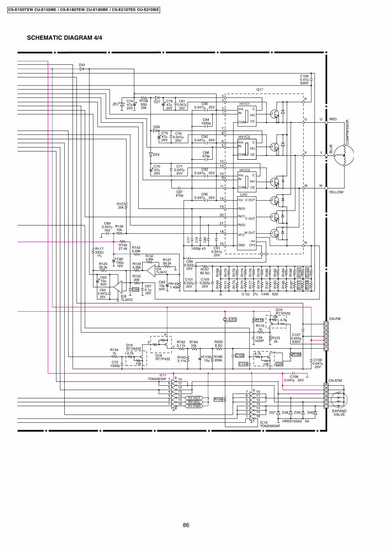
SCHEMATIC DIAGRAM 4/4
C
HO
CE
VccIN
COM
C
HO
CE
VccIN
COM
C
HO
CE
U OUT
V OUT
W OUT
rocCF0
VccIN
COM
Vcc
IN(X)
IN(Y)
IN(X)
VFO
GND
R19
4R
193
C106 0.47µ630V
D27
D41
D26
1000p x3
HV1C1
HV1C2
HV1C3
LVIC
Q17
P
U
3
21
78
65
1312
109
14
19
20
18
15
4
V
W
U
V
W
N
RED
BLU
E
YELLOW
CO
MP
RE
SS
OR
C81 0.047µ
25V
C78 47µ 25V
0.1Ω 2% 1/4W X20R
191
11
21
C76 0.047µ
25V
C90 0.047µ 25V
C84 1000p
C92 0.047µ 25V
C93 0.047µ 25V
C95 0.047µ 25V
C91 0.047µ
25V
C80
C79
C77
C86 470p
C74 47µ 25V
C73 47µ 25V
D24
C71 0.047µ
25V
C103 0.022µ
25V
C101 0.022µ
25V
C102 10µ
C108 0.047µ 25V
C99 0.022µ
25V
C63 0.047µ
25V
C107 0.022µ 630V
C109 0.047µ
25V
IC8 TL3472
IC8TL3472
C70 47µ 25V
C87 470p
R138 33Ω 2W
R127 20k
ZD7
R19
2
R18
6R
187
R18
4R
185
R18
2R
183
R18
0R
181
R17
8R
179
R17
6R
177
R17
4R
175
R17
2R
173
R17
0R
171
R16
8R
169
R135 10k
R129 4.99k
R152 20k
R142 2.49k
R146 27.4k
R132 4.99k R137
39.2k
R143 1.40k
R123 2k
C58 1000P
R166 200k
R119 1k
R124 39.2k
R167 82.5Ω
R205 8.0Ω
2
4
6
7
5
3
1
CN-FM
R1894.7k
10k
R164 10k
R163 5.11k
R162 5.11k
R134 1k
C72 1000p C104
Q19 RT1P432
Q18 RT1P432
Q16 RT1N432
c
e
b
4.7k10k
R118
IC10 TD620W3AF
IC11 TD620W3AF
7654321
8
9 10111213141516
EXPANDVALVE
1
2
3
4
5
6
CN-STM7654321
8
9 10111213141516
D37 D38 D39
HRD0103A2 X4
D40
C62 10µ 50V
C83 10µ 50V
C97 0.1µ 16V
C82 100µ 16V
C69 0.047µ
16V
C66
R117 332Ω 1%
4.7k
10k Q28
C126
LED
R156
RY-PWRRY-ACLRY-HOT
86
CS-E15DTEW CU-E15DBE / CS-E18DTEW CU-E18DBE / CS-E21DTES CU-E21DBE
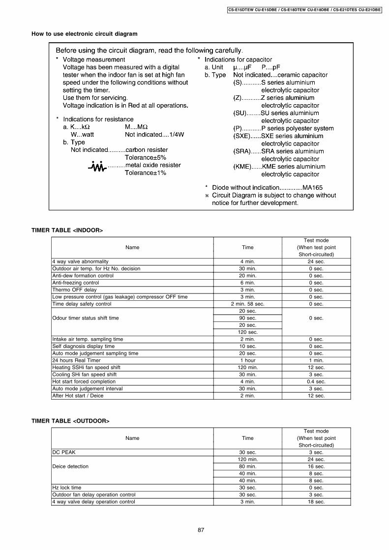
How to use electronic circuit diagram
TIMER TABLE <INDOOR>
Test modeName Time (When test point
Short-circuited)4 way valve abnormality 4 min. 24 sec.Outdoor air temp. for Hz No. decision 30 min. 0 sec.Anti-dew formation control 20 min. 0 sec.Anti-freezing control 6 min. 0 sec.Thermo OFF delay 3 min. 0 sec.Low pressure control (gas leakage) compressor OFF time 3 min. 0 sec.Time delay safety control 2 min. 58 sec. 0 sec.
20 sec.Odour timer status shift time 90 sec. 0 sec.
20 sec.120 sec.
Intake air temp. sampling time 2 min. 0 sec.Self diagnosis display time 10 sec. 0 sec.Auto mode judgement sampling time 20 sec. 0 sec.24 hours Real Timer 1 hour 1 min.Heating SSHi fan speed shift 120 min. 12 sec.Cooling SHi fan speed shift 30 min. 3 sec.Hot start forced completion 4 min. 0.4 sec.Auto mode judgement interval 30 min. 3 sec.After Hot start / Deice 2 min. 12 sec.
TIMER TABLE <OUTDOOR>
Test modeName Time (When test point
Short-circuited)DC PEAK 30 sec. 3 sec.
120 min. 24 sec.Deice detection 80 min. 16 sec.
40 min. 8 sec.40 min. 8 sec.
Hz lock time 30 sec. 0 sec.Outdoor fan delay operation control 30 sec. 3 sec.4 way valve delay operation control 3 min. 18 sec.
87
CS-E15DTEW CU-E15DBE / CS-E18DTEW CU-E18DBE / CS-E21DTES CU-E21DBE
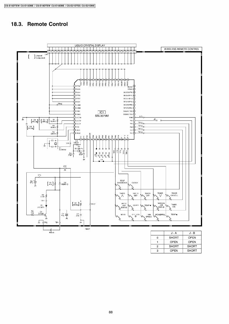
18.3. Remote Control
88
CS-E15DTEW CU-E15DBE / CS-E18DTEW CU-E18DBE / CS-E21DTES CU-E21DBE
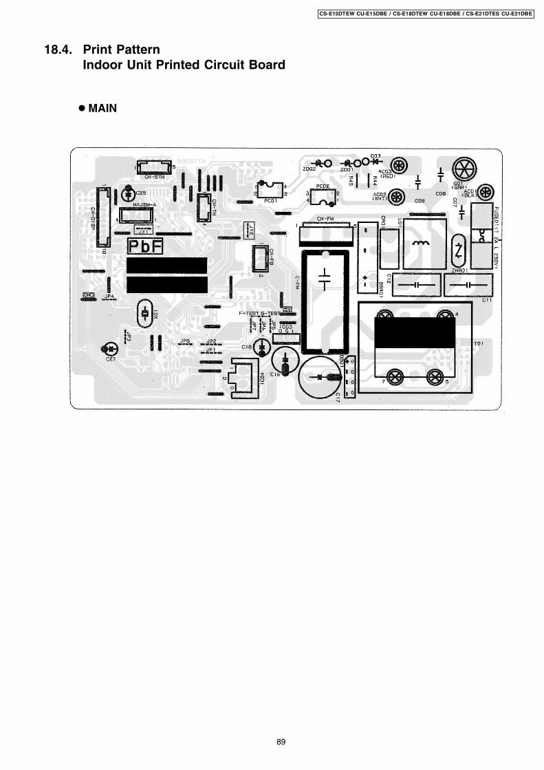
18.4. Print PatternIndoor Unit Printed Circuit Board
89
CS-E15DTEW CU-E15DBE / CS-E18DTEW CU-E18DBE / CS-E21DTES CU-E21DBE
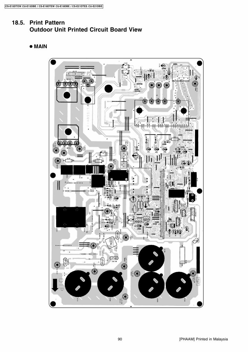
18.5. Print PatternOutdoor Unit Printed Circuit Board View
90
CS-E15DTEW CU-E15DBE / CS-E18DTEW CU-E18DBE / CS-E21DTES CU-E21DBE
[PHAAM] Printed in Malaysia
Related Documents