HAL Id: hal-02351519 https://hal.archives-ouvertes.fr/hal-02351519 Submitted on 14 Nov 2019 HAL is a multi-disciplinary open access archive for the deposit and dissemination of sci- entific research documents, whether they are pub- lished or not. The documents may come from teaching and research institutions in France or abroad, or from public or private research centers. L’archive ouverte pluridisciplinaire HAL, est destinée au dépôt et à la diffusion de documents scientifiques de niveau recherche, publiés ou non, émanant des établissements d’enseignement et de recherche français ou étrangers, des laboratoires publics ou privés. Crystal plasticity modeling of the effects of crystal orientation and grain-to-grain interactions on DSA-induced strain localization in Al–Li alloys Satyapriya Gupta, Vincent Taupin, Claude Fressengeas, Juliette Chevy To cite this version: Satyapriya Gupta, Vincent Taupin, Claude Fressengeas, Juliette Chevy. Crystal plasticity modeling of the effects of crystal orientation and grain-to-grain interactions on DSA-induced strain localization in Al–Li alloys. Materialia, Elsevier, 2019, 8, pp.100467. 10.1016/j.mtla.2019.100467. hal-02351519

Welcome message from author
This document is posted to help you gain knowledge. Please leave a comment to let me know what you think about it! Share it to your friends and learn new things together.
Transcript

HAL Id: hal-02351519https://hal.archives-ouvertes.fr/hal-02351519
Submitted on 14 Nov 2019
HAL is a multi-disciplinary open accessarchive for the deposit and dissemination of sci-entific research documents, whether they are pub-lished or not. The documents may come fromteaching and research institutions in France orabroad, or from public or private research centers.
L’archive ouverte pluridisciplinaire HAL, estdestinée au dépôt et à la diffusion de documentsscientifiques de niveau recherche, publiés ou non,émanant des établissements d’enseignement et derecherche français ou étrangers, des laboratoirespublics ou privés.
Crystal plasticity modeling of the effects of crystalorientation and grain-to-grain interactions on
DSA-induced strain localization in Al–Li alloysSatyapriya Gupta, Vincent Taupin, Claude Fressengeas, Juliette Chevy
To cite this version:Satyapriya Gupta, Vincent Taupin, Claude Fressengeas, Juliette Chevy. Crystal plasticity modelingof the effects of crystal orientation and grain-to-grain interactions on DSA-induced strain localizationin Al–Li alloys. Materialia, Elsevier, 2019, 8, pp.100467. 10.1016/j.mtla.2019.100467. hal-02351519
Crystal plasticity modeling of the effects of crystal orientation andgrain-to-grain interactions on DSA-induced strain localization in Al–Li
alloys
Satyapriya Guptaa,b,∗, Vincent Taupina,b, Claude Fressengeasa,b, Juliette Chevyc
aLaboratoire d’Etude des Microstructures et de Mecanique des Materiaux,LEM3, Universite de Lorraine/CNRS/Arts et Metiers ParisTech
7 rue Felix Savart, 57070 Metz, FrancebLaboratory of Excellence on Design of Alloy Metals for low-mAss Structures (DAMAS)
Universite de Lorraine, Nancy-Metz, FrancecC-TEC Constellium Technology Center, 725 Rue Aristide Berges, Voreppe 38341 cedex, France
Abstract
We develop a crystal plasticity model to investigate the coupled actions of crystal orien-tation, grain neighborhood and grain-to-grain elasto-plastic interactions on dynamic strainaging (DSA) and the onset and development of associated plastic strain localization in Al–Lialloys. Considering simple model multilayered microstructures with preferred orientationsrepresentative of rolled alloys, the aim is to identify grain orientation couples that can limitdynamic strain aging induced strain localization without compromising the flow stress andstrain hardening properties. To this end, a slip system-based formulation of dynamic strainaging is implemented in a crystal plasticity finite element framework. The model validity isfirst checked with the simulation of a tensile specimen loaded at quasi-static applied strainrate. The introduction of dynamic strain aging allows predicting complex propagation of in-tense plastic localization bands. We further investigate the influence of crystal orientations onearly strain localization in Al–Cu–Li–Mg alloys, by performing simulations representative ofthe early stage of a Kahn Tear test for single crystals and layered polycrystals. Using experi-mentally reported crystal orientations for rolled microstructures, the simulation results showthat in both single and multilayered crystals, there is a strong influence of dynamic strainaging on localization patterns, as well as a significant orientation dependence. In multilay-ered crystals, the nature of strain localization can be remarkably modified when stand-alonecrystals of a certain orientation are coupled with other orientations: strain localization mayintensify or fades away depending on the coupling with neighboring orientations.
Keywords: Dynamic strain aging; Al–Li alloys; strain localization; grain orientation;crystal plasticity finite element modeling.
1. Introduction1
This paper focuses on early plastic strain localization issues in Al–Cu–Li–Mg alloys used2
as light weight material solutions in the aerospace industry where the primary challenge is3
to reduce the overall weight of the aircrafts for enhanced fuel efficiency and reduced carbon4
emission [1–4]. In addition to their low density, these alloys offer an excellent resistance5
to corrosion and a combination of weldability, mechanical strength and damage tolerance6
not achieved in conventional alloys [5–7]. However, strain localization phenomena occurring7
in these alloys which can result into reduced toughness, and the limited understanding of8
∗Correspondence: [email protected]; Tel +15174889302Email addresses: [email protected] (Satyapriya Gupta ), [email protected] (Vincent
Taupin), [email protected] (Claude Fressengeas), [email protected](Juliette Chevy)
Preprint submitted to Elsevier September 9, 2019

the complex relationships between localization, damage and material properties such as so-9
lute/precipitate hardening/softening and crystallographic/morphological texture, still ham-10
per their widespread usage [8–10]. Extensive experimental and theoretical efforts have been11
made in the recent past for a better understanding of these relationships [11–15].12
13
In this work, focus is placed on the role of solute strengthening and dynamic strain ag-14
ing (DSA) induced Portevin–Le Chatelier (PLC) effect, which is thought to be the primary15
phenomena responsible for plastic strain localization in such alloys. In general, PLC effect16
is manifested as serrated stress-strain curve and visible strain localizations in the form of17
inclined deformation bands and caused by repeated interaction between the moving dislo-18
cations and diffusing solute atoms in dilute Al alloys. Although, in contrast to PLC effect,19
some precipitates, such as so-called T1 precipitates present in the AA-2198-T8 alloy, were20
experimentally suggested to favor homogenization of plastic deformation [16–19], the effect of21
precipitation is not considered here and it is left for a forthcoming study. Few experimental22
studies explored the role of DSA in the early strain localization processes leading to failure23
[20–24], and even fewer discussed the issue in Al–Cu–Li–Mg type alloys [25, 13, 26, 27]. Al-24
though such alloys usually do not display the typical serrated stress-strain curves commonly25
observed in monotonic uniaxial tensile loading of conventional Al–Mg alloys, recent experi-26
mental observations in the AA2024 and AA2139 alloys [28, 29] suggested that DSA could be27
activated during interrupted tensile tests, or after jumps in the loading strain rate. Thus, DSA28
cannot be ignored in complex forming operations, despite possibly evanescent manifestations29
in monotonic loading. Recent in-situ experimental studies combining X-ray laminography30
and 3D digital image correlation methods during Kahn tear tests on a AA-2198-T8 rolled31
material, and on other similar alloys, clearly evidenced the occurrence of early plastic strain32
localization [13, 30]. It was observed that intense plastic localization bands form away from33
the crack tip at the very beginning of deformation, and these bands are intermittent in time34
but not in space. This is very detrimental as plastic deformation will accumulate in bands,35
which inevitably leads to fracture of the specimens due to progressive void nucleation and36
coalescence at intermetallic particles in these slanted bands. By performing Kahn tear tests37
simulations using a finite element model that couples crystal plasticity, dynamic strain aging,38
damage and fracture, it was affirmative that dynamic strain aging is responsible for these39
early strain localization phenomena [26]. Localization bands intermittent in time but less40
in space were indeed predicted in good agreement with experimental data, which lead to41
damage and eventual fracture of the samples.42
43
Motivated by the above studies [13, 30, 26], present work contributes to further investiga-44
tion in terms of modeling the role of crystal orientations, plastic anisotropy, grain neighbor-45
hood, and grain-to-grain interactions on the intensity of dynamic strain aging effects. In a46
recent study, simple model lamellar grain structures representative of rolled microstructures47
were modeled, using experimentally reported preferred crystal orientations [31]. Plastic het-48
erogeneity and anisotropy was observed in the simulations. Such anisotropy and a significant49
soft-stiff grain-to-grain contrast was further reported both experimentally and theoretically50
in similar Al-Li rolled alloys [32–34], where in particular Brass and S orientations exhibit a51
strong stiff-soft behavior contrast. As such, with the eventual aim of minimizing or avoiding52
the detrimental effects of DSA on strain localization and the subsequent fracture process of53
Al–Cu–Li–Mg alloys through adequate material design, we strive to understand how DSA54
interacts with typical crystallographic and morphological orientation patterns. In the present55
work, we probe these interactions using a crystal plasticity finite element (CPFE) model. For56
capturing the key features of these interactions, a slip system-based dynamic strain aging57
module is added to the modeling framework. In studying the roles of grain morphology58
and orientation on strain localization, experimentally observed layered microstructures and59
dominant crystal orientations are employed. More precisely, we will perform simulations60
representative of the early stage deformation of a Kahn tear test, considering first, single61
2

Table 1: Grain orientations used in the simulations. The Euler angles (φ1, φ, φ2) (in ) provide the orientationof the crystal with respect to the rolling frame.
Orientation φ1 φ φ2Brass-b 35.26 45.0 0.0
S-d −121.02 143.3 26.57
Cube 0.0 0.0 0.0
Goss 0.0 45.0 0.0
TCX 72.9 22.6 36.9
crystals and specific orientations (see Table 1). In particular we have considered a variant of62
the Brass texture component (called Brass-b hereafter), a variant of the S texture compo-63
nent (presented as S-d hereafter), Cube and Goss texture components, as well as an unknown64
texture component X (will be called TCX hereafter).65
As we neglect precipitation here, the material modeled can be considered as a AA-2198-66
T3 type alloy instead of the AA-2198-T8 alloy, where strong nanosize precipitates have67
been formed during additional aging. The aim is not to fit as close as possible available68
experimental curves here, but rather to identify which orientations are better in terms of69
limiting plastic strain localization initiating at the crack tip and very quickly propagating70
through the material and in terms of flow stress and strain hardening. Second, based on71
lamellar structures typical of 2198, we will simulate the same test for model microstructures72
with two major grain orientations, for instance, stacks of alternate Brass-b and S-d lamellar73
grains will be modeled and simulated. This study tries to be useful in terms of materials74
design as it allows probing the effect of coupling a given orientation with other neighboring75
orientations on the plastic heterogeneity and anisotropy.76
The following sections of the paper are therefore organized as follows. The small strain77
crystal plasticity framework accounting for DSA is presented in Section 2. Proper working78
of the DSA-embedded CPFE model is numerically validated in Section 3. CPFE simulation79
results obtained for different crystal orientations and several layered morphologies of orien-80
tation couples are presented and discussed in Section 4 . Finally, conclusions of the work are81
listed in Section 5.82
2. DSA-enabled CPFE model83
The unknown field is the displacement field u in a body B subjected to displacement84
and/or traction boundary conditions. In the absence of inertial and body forces, the momen-85
tum balance equation and boundary conditions can be written as86
div T = 0 , (1)
T · n = t on St , (2)
u = u on Su , (3)
where T is the stress tensor and (t, u) are prescribed tractions and displacements at external87
boundaries of unit normal n, respectively. Homogeneous linear isotropic elasticity of the88
material is assumed:89
Tij = λεekkδij + 2µεeij . (4)
In this relation, λ and µ are the Lame constants, and εe the elastic strain tensor. In a small90
strain setting, εe = ε− εp , where ε and εp are the total and plastic strain tensors.91
3

2.1. Crystal plasticity module92
In the present crystal plasticity model, we follow the formulation used for aluminium93
crystals in [35]. The plastic velocity gradient Lp (whose symmetric part is the plastic strain94
rate tensor εp) is obtained in a classical manner from the summation of the shear rates arising95
from dislocation glide on all activated slip systems:96
Lp =∑s
γsPs =∑s
ρms bvsms ⊗ ns. (5)
In this relation, Ps = ms⊗ns is known as the orientation Schmid tensor of the slip system s97
with slip direction ms and unit normal ns. The shear rate γs on the slip system s is given by98
the Orowan relationship γs = ρms bvs, where b is the magnitude of the Burgers vector on all99
slip systems, ρms denotes the mobile dislocation density and vs is the dislocation velocity on100
slip system s. The plastic slip on system s is driven by the resolved shear stress τs = T : Ps101
through the power law relationship102
vs = v0
(|τs|
τhs + τ sols
)n
sgn(τs) (6)
reflecting hardening from thermally activated obstacle overcoming, where v0 is a reference103
velocity and n a power law exponent. The stress τhs reflects forest hardening on the slip104
system s, and is assumed to be of the following form:105
τhs = µb
√∑j
ajsρfj , (7)
where ajs is a latent hardening coefficient providing the contribution of the dislocation forest106
density ρfj on system j to the hardening of system s [36]. A mean value amean will be taken107
for all these coefficients, except for the collinear interactions where the (larger) value acol will108
be used. In the provisional absence of DSA, the rates of change of the mobile ρms and forest109
ρfs dislocation densities on slip system s are taken as110
ρmsρm0
=
Km −Kf +C1√ρm0
∑j
√ρfj −
C2
ρm0
∑j
√ρms ρ
fj
|γs|, (8)
ρfsρm0
=
Kf +C2
ρm0
∑j
√ρms ρ
fj −
C3
ρm0ρfs
|γs|. (9)
In the above, Km is connected with the multiplication and Kf with the immobilization of111
mobile dislocations on obstacles initially present in the crystal. C1 reflects the contribution112
of the forest dislocations to mobile dislocation sources. C2 accounts for the immobilization of113
mobile dislocations due to their interactions with the forest. C3 stands for dynamic recovery.114
ρm0 is a reference dislocation density value. By handling separately the dislocation densities115
on each slip system, these evolution laws are designed to account for the effects of crystal116
orientation on the flow stress and work hardening rate [35]. In addition, Eq.(8) is meant to117
reflect the quick increase and saturation of the mobile dislocation density on an activated118
slip system.119
120
2.2. Dynamic strain aging module121
In Eq.(6), τ sols is an additional hardening stress arising from DSA, i.e., from recurrent122
pinning by diffusing solute atoms and eventual breakaway of mobile dislocations arrested123
on their obstacles. Its evolution with the aging time of arrested dislocations and the solute124
4

concentration at these dislocations is now described, together with their effects on the dislo-125
cation density evolutions. A slip-system based Kubin Estrin McCormick (KEMC) model was126
recently applied to Al-Cu-Li-Mg alloys [26]. Here, as our crystal plasticity model couples the127
evolution of both mobile and forest dislocation densities, we consider another dynamic strain128
aging constitutive model that also distinguish the dynamics of mobile and sessile dislocation129
densities [37]. The chosen DSA module couples the time evolution of mobile and forest dis-130
location densities (ρms , ρfs ) with the variations of the aging time tas and solute concentration131
Csols at arrested dislocations on particular slip system s. To this aim, the equations (8,9) are132
augmented as follows:133
ρmsρm0
=
Km −Kf +C1√ρm0
∑j
√ρfj −
C2
ρm0
∑j
√ρms ρ
fj
|γs| − A1
tlsρms p(γs), (10)
ρfsρm0
=
Kf +C2
ρm0
∑j
√ρms ρ
fj −
C3
ρm0ρfs
|γs|+ A1
tlsρms p(γs). (11)
In Eqs.(10,11), the effects of DSA on the time evolution of the dislocation densities are takeninto account through the terms involving A1, as they effectively integrate the dynamics ofdislocations and solute atoms. These terms control the exchange of dislocations between ρmsand ρfs by arrest and breakaway of mobile dislocations in relation with solute diffusion. Thecharacteristic time tls (also called loading time) are defined from the elementary incrementalstrain Ωs and the overall loading strain rate εa:
tls =Ωs
εa=b ρms /
√ρfs
εa. (12)
The incremental strains Ωs depend only on the slow time scale evolutions of ρms and ρfs , asdetermined from Eqs.(8,9) and denoted (ρms , ρ
fs ), but the characteristic times tls set the time
scales for the fast dislocation dynamics associated with DSA. p(γs) represents the probabilitydensity for dislocations to get pinned at obstacles by clouds of solute atoms on slip systems. Expressed in terms of the plastic strain rate γs, it reflects the elastic dislocation-soluteinteractions on slip system s and can be taken as
p(γs) =2γs
ε02 exp(−(γs/ε0)
2) . (13)
where the reference strain rate ε0 is an input parameter regulating the type of serration134
achieved from the model. In the presence of DSA, a switch occurs repeatedly between low135
and high solute concentration Csols along the master curve described in Eq.(14) as a function136
of the dislocation aging time tas .137
Csols = 1− exp(−(
tastD
)2/3) (14)
In relation (14), tD is a time scale characterizing solute diffusion. The switch is therefore138
controlled by the aging time, which in turn primarily depends on the magnitude of the local139
plastic strain rate γs. In the model [37], this switch is achieved through a relaxation process,140
according to which the aging time tas follows the waiting time tws (mobile dislocations wait141
on their obstacles in slip system s) with some delay:142
dtasdt
= 1− tastws
(15)
tws =Ωs
|γs|. (16)
5

Hence, the PLC instability occurs when the waiting time tws , which indirectly depends on143
the flow stress, drops down to zero, reflecting the unpinning of dislocations from solute144
atmospheres. The solute-related resistance τ sols on slip system s is now taken as the product145
of the solute concentration Csols on arrested dislocations and a saturation stress level f reached146
at large aging times tas :147
τ sols = fCsols . (17)
Note that all the CP and DSA material parameters are listed in Table 2. The parameters148
for DSA and latent hardening are taken from previous works [38, 37, 35].149
2.3. Numerical strategy150
The standard Galerkin finite element method is used for the spatial discretization and151
numerical solution of the problem set out be Eqs.(3) through (17). Note that the differential152
equations and relations (10-17) presented above constitute a stiff differential system involving153
fast variables undergoing large changes in a small amount of time. An explicit time-marching154
scheme is employed with sufficiently small time steps, to ensure numerical stability of the155
solution. The choice of time step ∆t is chosen based on limited relative evolution of both Lp,156
tas and γs quantities. The model is implemented in the framework provided by Freefem++,157
a free software based on the finite element method having a high level integrated develop-158
ment environment for the numerical solution of partial differential equations in two or three159
dimensions [39].160
3. DSA endorsed strain localization in single crystal tension: validation of model161
Single crystal stretching simulations are performed using the above described DSA-162
enabled model to examine the proper working, capabilities and flexibility of the CPFE code.163
The simulation results are compared with conventional CP response to highlight the influ-164
ence of DSA on the mechanical response. A classical dog bone-shaped sample is simulated165
with uniaxial tension velocity driven boundary conditions in the X direction. Note that166
X,Y,Z in FE model correspond to RD,TD and ND. The FE domain (generated by the mesh167
module of Freefem++) is discretized with cubes composed of tetrahedral elements and the168
crystal lattice is assigned Euler angles characteristic of the cubic orientation, typically close169
to experimentally used orientations in tensile samples. The material properties and initial170
condition parameters used for the simulations are listed in Table 2. The applied strain rate171
is 10−4/s. In all forthcoming simulations, the mesh is chosen fine enough such that realis-172
tic plastic localization bands can develop. However, in a more realistic setup, one should173
consider strain gradient plasticity or field dislocation mechanics [40] approaches, where a174
characteristic internal length scale related to width of localization bands can be explicitly175
or inherently introduced to removes any mesh size dependence of the plastic bands [41]. In176
our simulations, there is no physical size introduced, only the effect of grain morphologies,177
its distribution and the ratio of lamellar grain thicknesses in our multilayered simulations is178
important.179
180
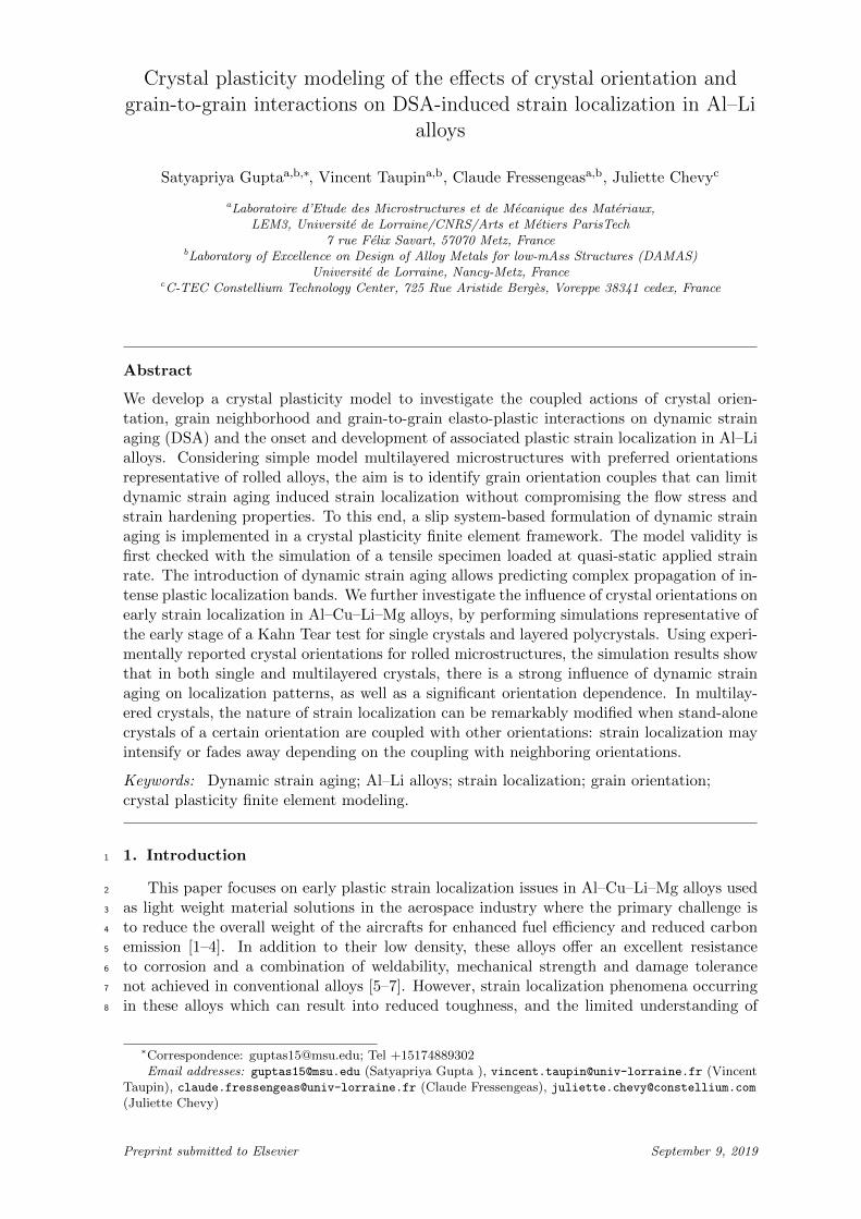
Two different regimes of plastic activity were observed. Fig. 1(a) shows a zoomed-in view181
of the macroscopic stress-strain curve obtained from the DSA-enabled model featuring a se-182
quence of irregular events, which can be compared with the very smooth curves obtained183
from conventional CP modeling in Fig. 1(b). The magnitude of the stress serrations is very184
small (which is realistic for Al–Cu–Li-Mg alloys) for the adopted DSA parameters. In ad-185
dition, a higher flow stress (an increase of the yield stress of about 50 MPa) together with186
larger yield drop is observed for DSA-enabled model as compared to the conventional CP187
model. This is due to the fact that, in the latter case, the yield point originates in a burst of188
the mobile dislocation density (due to very small initial mobile dislocation densities ρms (0)),189
6
whereas the former case also involves the breakaway of statically aged mobile dislocations.190
191
(a) (b)
Figure 1: Macroscopic deformation behavior of dogbone-shaped single crystal in tension, (a) with DSA enabledcrystal plasticity; (b) In the absence of DSA (crystal plasticity only).
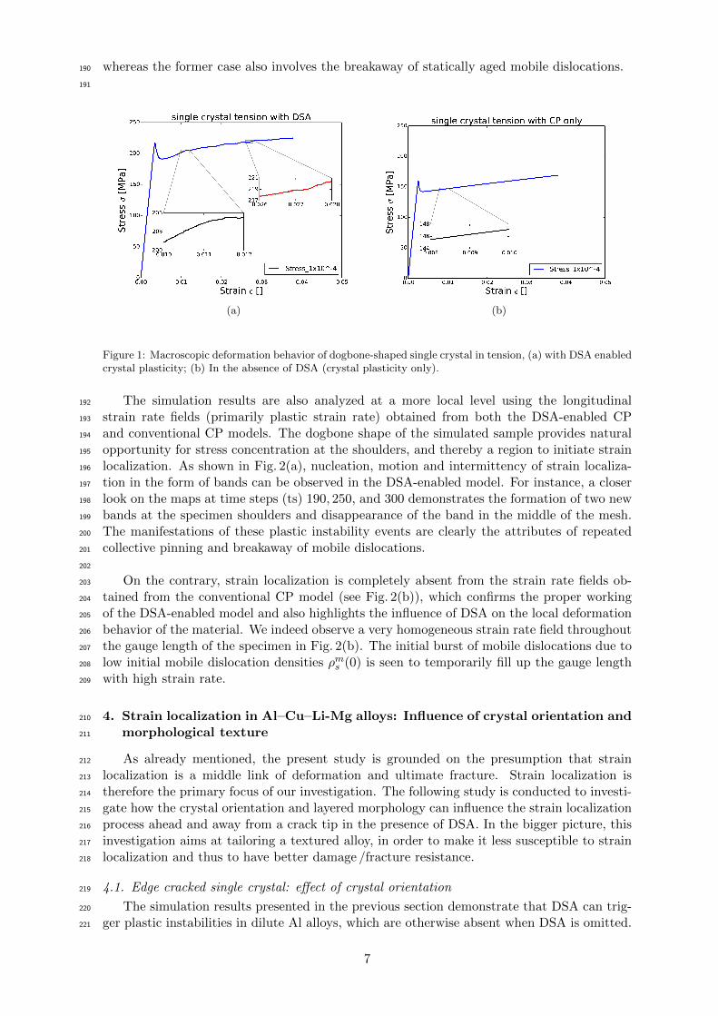
The simulation results are also analyzed at a more local level using the longitudinal192
strain rate fields (primarily plastic strain rate) obtained from both the DSA-enabled CP193
and conventional CP models. The dogbone shape of the simulated sample provides natural194
opportunity for stress concentration at the shoulders, and thereby a region to initiate strain195
localization. As shown in Fig. 2(a), nucleation, motion and intermittency of strain localiza-196
tion in the form of bands can be observed in the DSA-enabled model. For instance, a closer197
look on the maps at time steps (ts) 190, 250, and 300 demonstrates the formation of two new198
bands at the specimen shoulders and disappearance of the band in the middle of the mesh.199
The manifestations of these plastic instability events are clearly the attributes of repeated200
collective pinning and breakaway of mobile dislocations.201
202
On the contrary, strain localization is completely absent from the strain rate fields ob-203
tained from the conventional CP model (see Fig. 2(b)), which confirms the proper working204
of the DSA-enabled model and also highlights the influence of DSA on the local deformation205
behavior of the material. We indeed observe a very homogeneous strain rate field throughout206
the gauge length of the specimen in Fig. 2(b). The initial burst of mobile dislocations due to207
low initial mobile dislocation densities ρms (0) is seen to temporarily fill up the gauge length208
with high strain rate.209
4. Strain localization in Al–Cu–Li-Mg alloys: Influence of crystal orientation and210
morphological texture211
As already mentioned, the present study is grounded on the presumption that strain212
localization is a middle link of deformation and ultimate fracture. Strain localization is213
therefore the primary focus of our investigation. The following study is conducted to investi-214
gate how the crystal orientation and layered morphology can influence the strain localization215
process ahead and away from a crack tip in the presence of DSA. In the bigger picture, this216
investigation aims at tailoring a textured alloy, in order to make it less susceptible to strain217
localization and thus to have better damage /fracture resistance.218
4.1. Edge cracked single crystal: effect of crystal orientation219
The simulation results presented in the previous section demonstrate that DSA can trig-220
ger plastic instabilities in dilute Al alloys, which are otherwise absent when DSA is omitted.221
7

11ts=40 ts=58 ts=68 ts=120 ts=190 ts=250 ts=300 ts=400 ts=450 ts=520
ts=560 ts=570 ts=590 ts=630 ts=670 ts=715 ts=730 ts=745 ts=760 ts=830
0.0003
0.00025
0.0002
0.00015
0.0001
(a)
ts=20 ts=25 ts=27 ts=30 ts=32 ts=38 ts=48 ts=80 ts=120
ts=150 ts=180 ts=210 ts=240 ts=260
110.0003
0.00025
0.0002
0.00015
0.0001
(b)
Figure 2: Longitudinal strain rate field ε11 at gradually increasing simulation time steps for the dog bone-shaped single crystal (a) simulated with DSA enabled crystal plasticity where destabilizing influence of DSAis manifested in the form of the nucleation, motion and intermittency of localized deformation bands; (b)simulated with crystal plasticity in the absence of DSA (standard CP model) where the complete absence ofplastic instability and localized bands with a homogeneous strain rate field across the gauge section highlightsthe significant influence of DSA.
8
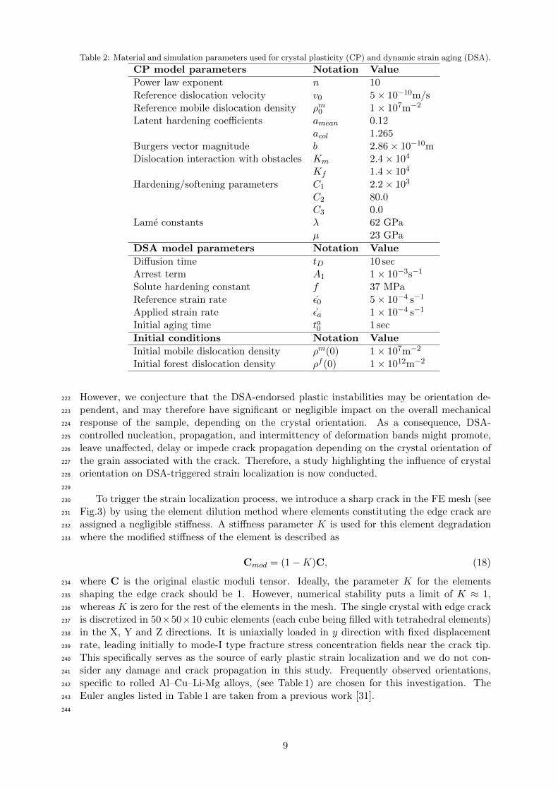
Table 2: Material and simulation parameters used for crystal plasticity (CP) and dynamic strain aging (DSA).
CP model parameters Notation Value
Power law exponent n 10Reference dislocation velocity v0 5× 10⁻¹⁰m/sReference mobile dislocation density ρm0 1× 10⁷m−2
Latent hardening coefficients amean 0.12acol 1.265
Burgers vector magnitude b 2.86× 10⁻¹⁰mDislocation interaction with obstacles Km 2.4× 10⁴
Kf 1.4× 10⁴
Hardening/softening parameters C1 2.2× 10³
C2 80.0C3 0.0
Lame constants λ 62 GPaµ 23 GPa
DSA model parameters Notation Value
Diffusion time tD 10 secArrest term A1 1× 10⁻³s−1
Solute hardening constant f 37 MPaReference strain rate ε0 5× 10⁻⁴ s−1
Applied strain rate εa 1× 10⁻⁴ s−1
Initial aging time ta0 1 sec
Initial conditions Notation Value
Initial mobile dislocation density ρm(0) 1× 10⁷m−2
Initial forest dislocation density ρf (0) 1× 10¹²m−2
However, we conjecture that the DSA-endorsed plastic instabilities may be orientation de-222
pendent, and may therefore have significant or negligible impact on the overall mechanical223
response of the sample, depending on the crystal orientation. As a consequence, DSA-224
controlled nucleation, propagation, and intermittency of deformation bands might promote,225
leave unaffected, delay or impede crack propagation depending on the crystal orientation of226
the grain associated with the crack. Therefore, a study highlighting the influence of crystal227
orientation on DSA-triggered strain localization is now conducted.228
229
To trigger the strain localization process, we introduce a sharp crack in the FE mesh (see230
Fig.3) by using the element dilution method where elements constituting the edge crack are231
assigned a negligible stiffness. A stiffness parameter K is used for this element degradation232
where the modified stiffness of the element is described as233
Cmod = (1−K)C, (18)
where C is the original elastic moduli tensor. Ideally, the parameter K for the elements234
shaping the edge crack should be 1. However, numerical stability puts a limit of K ≈ 1,235
whereas K is zero for the rest of the elements in the mesh. The single crystal with edge crack236
is discretized in 50×50×10 cubic elements (each cube being filled with tetrahedral elements)237
in the X, Y and Z directions. It is uniaxially loaded in y direction with fixed displacement238
rate, leading initially to mode-I type fracture stress concentration fields near the crack tip.239
This specifically serves as the source of early plastic strain localization and we do not con-240
sider any damage and crack propagation in this study. Frequently observed orientations,241
specific to rolled Al–Cu–Li-Mg alloys, (see Table 1) are chosen for this investigation. The242
Euler angles listed in Table 1 are taken from a previous work [31].243
244
9

0.02
1.0
Element Stiffness
Figure 3: Single crystal with edge crack and uniaxial tension boundary condition used for FE simulations.
(a) (b)
Figure 4: Orientation dependence of global deformation behavior of edge cracked single crystal loaded in frac-ture mode-I, (a) simulated with DSA-enabled crystal plasticity; (b) simulated with standard crystal plasticity(DSA absent).
10
As shown in Fig. 4, common to all crystal orientations and already observed in Fig.2,245
the average flow stress obtained from DSA-enabled CP is 50 to 100 MPa higher than from246
the standard CP model (absent DSA). As already discussed, higher flow stress and larger247
yield drop for the DSA-enabled CP model is the result of solute hardening and first solute-248
dislocation breakaway event, respectively. As expected, the DSA-enabled model captures the249
pinning and breakaway events manifested as stress serrations in the macroscopic stress strain250
curve (see Fig. 4(a)), as compared to smooth flow stress curves obtained from the CP only251
model in Fig. 4(b). Apart from the Brass-b orientation, which exhibits much higher strength,252
all other orientations fall into a category of approximately comparable flow stresses. How-253
ever, DSA alters the relative strength of the latter crystal orientations, if counterpart results254
obtained from standard CP are taken as reference.255
256
Brass-b TCX Cube Goss S-d eVMp0.0140.0120.010.0080.006
0.003
(a)
0.0460.040.0350.030.0250.02
0.011
(b)
0.0830.070.060.050.040.030.017
(c)
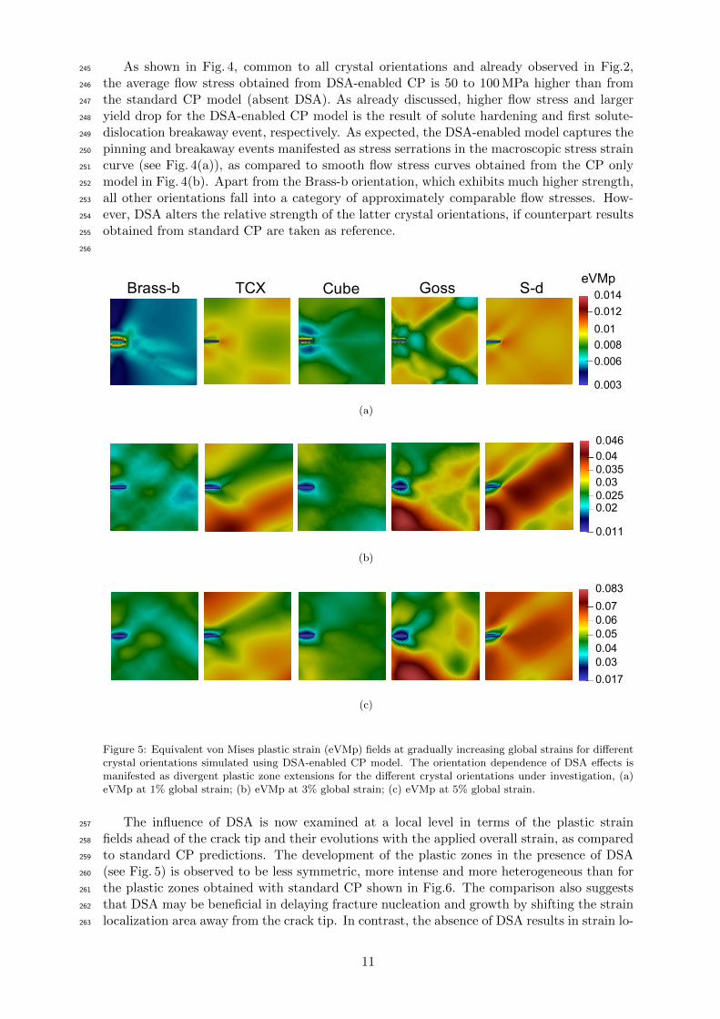
Figure 5: Equivalent von Mises plastic strain (eVMp) fields at gradually increasing global strains for differentcrystal orientations simulated using DSA-enabled CP model. The orientation dependence of DSA effects ismanifested as divergent plastic zone extensions for the different crystal orientations under investigation, (a)eVMp at 1% global strain; (b) eVMp at 3% global strain; (c) eVMp at 5% global strain.
The influence of DSA is now examined at a local level in terms of the plastic strain257
fields ahead of the crack tip and their evolutions with the applied overall strain, as compared258
to standard CP predictions. The development of the plastic zones in the presence of DSA259
(see Fig. 5) is observed to be less symmetric, more intense and more heterogeneous than for260
the plastic zones obtained with standard CP shown in Fig.6. The comparison also suggests261
that DSA may be beneficial in delaying fracture nucleation and growth by shifting the strain262
localization area away from the crack tip. In contrast, the absence of DSA results in strain lo-263
11

calization right ahead of the crack tip, while producing more homogeneous strain fields away264
from the crack. In addition, the above-mentioned influence of DSA is observed to be strongly265
orientation dependent. Fig. 5 shows indeed a prominent crystal orientation dependence of266
the DSA-triggered heterogeneous plastic zones (both ahead and away from the crack tip) at267
gradually increasing global strain. A closer look at the plastic zones of individual orienta-268
tions reveals that the Brass-b and Cubic orientations favor a relatively homogeneous plastic269
strain field, whereas Goss, S-d and TCX promote a more localized plastic strain field within270
the domain of simulation. Therefore, we may tentatively conclude that, while choosing the271
crystal orientations to tailor a sample configuration less susceptible to strain localization in272
the presence of DSA, the Brass-b and Cube orientations should be preferred over the S-d,273
Goss and TCX orientations. In particular, the Brass-b orientation further exhibits a strong274
increase of flow stress in the presence of DSA. However, forthcoming results for multilayered275
crystal will show that such a conclusion is only provisional. In addition to the plastic strain276
fields shown here, the reader may want to examine the nucleation, motion and intermittency277
of the localized deformation bands by means of the equivalent strain rate fields provided as278
videos in supplementary multimedia data. However, more details on the dynamics of strain279
localization and the intermittency of dislocation activity will be provided in the next Section280
(see Fig.11).281
282
Brass-b TCX Cube Goss S-d eVMp0.0140.0120.010.0080.006
0.003
(a)
0.0460.040.0350.030.0250.02
0.011
(b)
0.0830.070.060.050.040.030.017
(c)
Figure 6: Equivalent von Mises plastic strain (eVMp) fields at gradually increasing global strains for differentcrystal orientations simulated with standard CP (DSA module absent), (a) eVMp at 1% global strain; (b)eVMp at 3% global strain; (c) eVMp at 5% global strain.
12

4.2. Edge cracked multi-layered polycrystal: effect of orientation couples283
In the series of efforts made to generate a texture that is resistant to strain localization,284
investigating the contribution of individual orientations is necessary but not sufficient. Grain285
interactions may play a significant role, and the deformation behavior for a particular crystal286
orientation may substantially differ from that obtained in the presence of neighboring grains287
with different orientations. Therefore, we now conduct investigations using combinations of288
orientation couples.289
290
Figure 7: Edge-cracked multi-layered polycrystal with embedded orientation couples (here Cube-Goss) anduniaxial tension boundary conditions.
All of the C52 = 10 possible orientation couples obtained by considering the five frequently291
observed orientations: Brass-b–Goss, Cube–TCX, Goss–S-d,..etc., were simulated in uniaxial292
tension, both in presence and in absence of DSA. As before, the simulations performed with293
the CP only model (without DSA) are used as references highlighting the influence of DSA294
on the local fields and macroscopic stress-strain behavior. As shown in Fig. 7, a multi-layered295
FE mesh inspired from the experimental observation of rolled microstructures of Al–Cu–Li–296
Mg alloys is adopted to investigate the interaction of orientation couples.297
298
(a) (b)
Figure 8: Averaged flow stress of edge cracked layered orientation couples loaded in fracture mode-I, (a)simulated with DSA enabled crystal plasticity; (b) simulated with standard crystal plasticity (DSA absent).
13

Similar to single crystal results, the layered polycrystalline morphology exhibits promi-299
nent differences in the macroscopic stress-strain curves obtained from the DSA-enabled CP300
model as compared to standard CP calculations (see Fig. 8). As already found, higher flow301
stresses and larger yield drops obtained for the DSA-enabled model can be associated with302
the solute stress and first solute-dislocation breakaway event, respectively. The macroscopic303
stress-strain curves obtained from DSA-enabled CP can be relatively divided in two cat-304
egories: orientation couples containing Brass-b and others excluding Brass-b. Indeed, it is305
observed that coupling any orientation with the Brass-b orientation results in a 50 to 100 MPa306
boost in the macroscopic flow stress, with the notable exception of TCX–Brass-b. The in-307
fluence of DSA is also evident from small but crucial changes in the relative flow stresses for308
different orientation couples as compared to results obtained using standard CP.309
310
eVMpBrass-b-Goss TCX-Brass-b Cube-Brass-b Cube-TCX Cube-Goss
Cube-S-d Goss-TCX S-d-TCX S-d-Goss S-d-Brass-b
Z X
Y
0.0240.02
0.015
0.01
0.0050.0001
(a)
eVMpBrass-b-Goss TCX-Brass-b Cube-Brass-b Cube-TCX Cube-Goss
Cube-S-d Goss-TCX S-d-TCX S-d-Goss S-d-Brass-b
Z X
Y
0.092
0.070.060.050.040.030.02
0.0001
(b)
Figure 9: Equivalent plastic strain (eVMp) fields at gradually increasing global strains for different orientationcouples. DSA plays a significant role in changing the behavior of a particular orientation in the presence ofother crystal orientations, (a) eVMp at 0.6% global strain; (b) eVMp at 2% global strain.
The analysis of the predicted plastic strain fields is now conducted to investigate the311
joint influences of grain orientation couples and DSA on strain localization leading to failure.312
To this end, Fig. 9 presents the equivalent plastic strain (eVMp) fields predicted for the ten313
orientation couples at two distinct strain levels: 0.6%, which is close to the elasto-plastic314
14
transition, and 2%, that is in the hardening regime. For most of the orientation couples,315
the initiation of the plastic zone swiftly migrates away from the crack tip in the presence of316
DSA, which may have again a stabilizing influence on incoming crack propagation, and the317
high strain zones are found to be rather independent of the edge crack location. The plastic318
strain fields for the various orientation couples can be broadly divided into two categories:319
orientation couples exhibiting highly heterogeneous strain distributions, and orientation cou-320
ples displaying rather homogeneous strain distributions (see Fig. 9(b)). Most notably and321
in strong contrast with the beneficial properties of the Brass-b orientation for single crys-322
tal simulations, nearly all the orientations coupled with Brass-b now demonstrate strong323
strain localization and heterogeneous plastic strain fields as compared to other couplings, a324
property that can be detrimental with respect to strain localization leading to fracture. In325
particular, TCX–Brass-b shows the strongest strain localization trend, which can be related326
to its relatively low hardening rate in Fig.8. Such a result highlights the importance of con-327
sidering the effects of grain neighborhood and grain–to–grain interactions. On the contrary,328
mutual couplings of S-d, Goss and Cube orientations promote a rather homogeneous plastic329
strain distribution, and therefore could well be better candidates while choosing orientation330
distributions less prone to strain localization. Note that the simulations predict a strong331
anisotropy of plastic deformation in grains, with possible high contrast between grains, in332
particular for Brass-b/S-d couples, which is in good agreement with available experimental333
and modeling data [32–34].334
335
(a) (b)
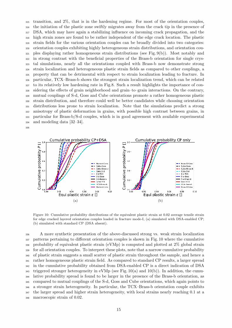
Figure 10: Cumulative probability distributions of the equivalent plastic strain at 0.02 average tensile strainfor edge cracked layered orientation couples loaded in fracture mode-I, (a) simulated with DSA-enabled CP;(b) simulated with standard CP (DSA absent).
A more synthetic presentation of the above-discussed strong vs. weak strain localization336
patterns pertaining to different orientation couples is shown in Fig. 10 where the cumulative337
probability of equivalent plastic strain (eVMp) is computed and plotted at 2% global strain338
for all orientation couples. To interpret these plots, note that a narrow cumulative probability339
of plastic strain suggests a small scatter of plastic strain throughout the sample, and hence a340
rather homogeneous plastic strain field. As compared to standard CP results, a larger spread341
in the cumulative probability obtained from DSA-enabled CP is a direct indication of DSA342
triggered stronger heterogeneity in eVMp (see Fig. 10(a) and 10(b)). In addition, the cumu-343
lative probability spread is found to be larger in the presence of the Brass-b orientation, as344
compared to mutual couplings of the S-d, Goss and Cube orientations, which again points to345
a stronger strain heterogeneity. In particular, the TCX–Brass-b orientation couple exhibits346
the larger spread and higher strain heterogeneity, with local strains nearly reaching 0.1 at a347
macroscopic strain of 0.02.348
15
349
(a)
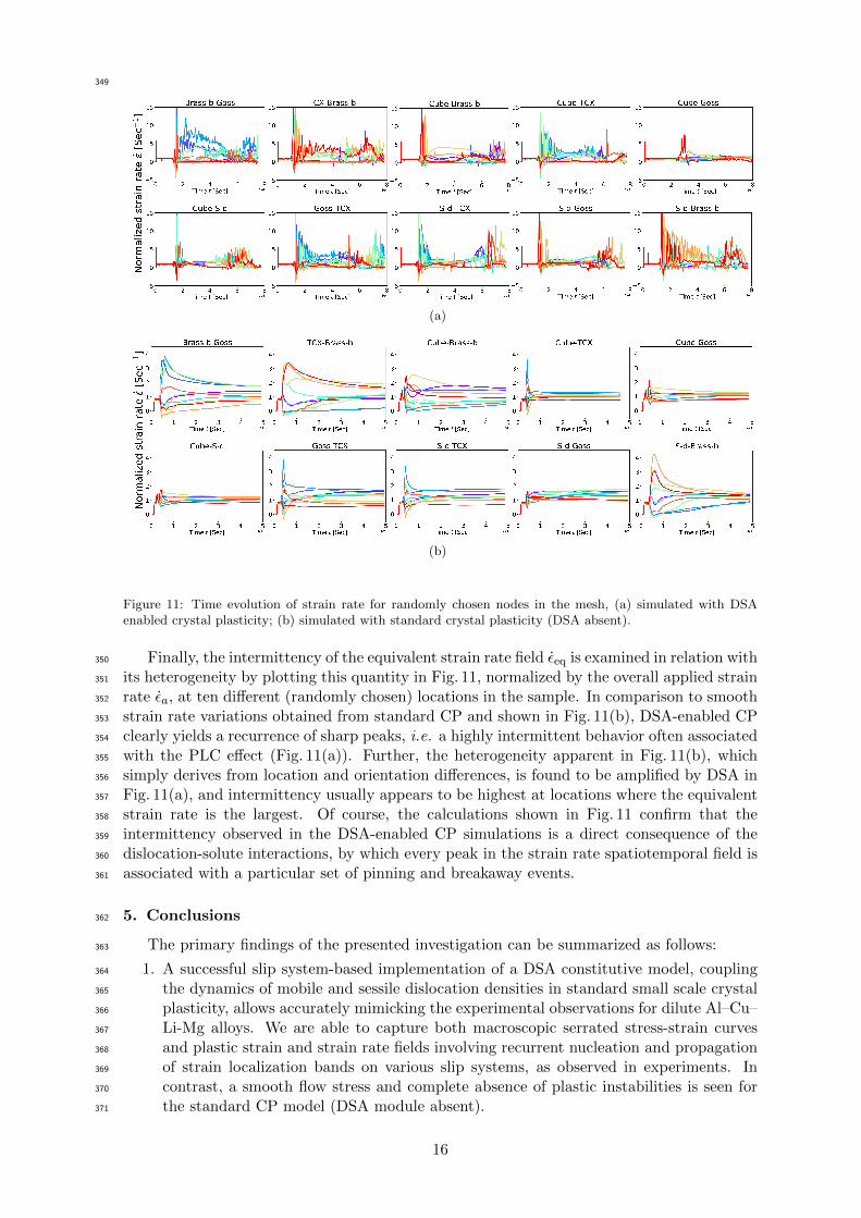
(b)
Figure 11: Time evolution of strain rate for randomly chosen nodes in the mesh, (a) simulated with DSAenabled crystal plasticity; (b) simulated with standard crystal plasticity (DSA absent).
Finally, the intermittency of the equivalent strain rate field εeq is examined in relation with350
its heterogeneity by plotting this quantity in Fig. 11, normalized by the overall applied strain351
rate εa, at ten different (randomly chosen) locations in the sample. In comparison to smooth352
strain rate variations obtained from standard CP and shown in Fig. 11(b), DSA-enabled CP353
clearly yields a recurrence of sharp peaks, i.e. a highly intermittent behavior often associated354
with the PLC effect (Fig. 11(a)). Further, the heterogeneity apparent in Fig. 11(b), which355
simply derives from location and orientation differences, is found to be amplified by DSA in356
Fig. 11(a), and intermittency usually appears to be highest at locations where the equivalent357
strain rate is the largest. Of course, the calculations shown in Fig. 11 confirm that the358
intermittency observed in the DSA-enabled CP simulations is a direct consequence of the359
dislocation-solute interactions, by which every peak in the strain rate spatiotemporal field is360
associated with a particular set of pinning and breakaway events.361
5. Conclusions362
The primary findings of the presented investigation can be summarized as follows:363
1. A successful slip system-based implementation of a DSA constitutive model, coupling364
the dynamics of mobile and sessile dislocation densities in standard small scale crystal365
plasticity, allows accurately mimicking the experimental observations for dilute Al–Cu–366
Li-Mg alloys. We are able to capture both macroscopic serrated stress-strain curves367
and plastic strain and strain rate fields involving recurrent nucleation and propagation368
of strain localization bands on various slip systems, as observed in experiments. In369
contrast, a smooth flow stress and complete absence of plastic instabilities is seen for370
the standard CP model (DSA module absent).371
16

2. Simulations of edge cracked single crystals loaded in fracture mode-I demonstrated a372
strong orientation dependence of the destabilizing effects of DSA. The development of373
a plastic strain localization area is observed to be quite localized for orientations such374
as Goss, S-d and TCX, whereas the Brass-b and Cube orientations favor a relatively375
homogeneous plastic strain field.376
3. The results obtained from investigating orientation couples highlight the strong influ-377
ence of the latter on the destabilizing effects of DSA. Nearly all the orientations in the378
presence of Brass-b demonstrate stronger strain localization patterns and more hetero-379
geneous plastic strain fields than the mutual couplings of S-d, Goss and Cube. The380
latter are therefore found to be beneficial in terms of homogeneous strain distribution.381
The rather opposite influences of the Brass-b orientation, paradoxically seen as a sta-382
bilizing factor in single crystal simulations and a destabilizing one when neighboring383
grains are taken into account, highlight the importance of grain neighborhood as well384
as grain–to–grain interactions in microstructures.385
It is important to note that above mentioned outcomes are true for solicitation in the trans-386
verse directions and propagation in the rolling direction. We expect a significant changes387
in conclusion for traction in the rolling direction and propagation in the transverse direc-388
tion, which could be a potential outlook for the present work. Further steps in this research389
involve the simulation of a more realistic Kahn tear test with a sample containing a large390
number of grains, such as to investigate in more details the role of texture and grain-to-grain391
interactions in the early localization phenomena. To this end, a numerical spectral method392
using Fast Fourier transforms (FFT) algorithms [42, 43] will be considered. Spectral CP-FFT393
methods are computationally much more efficient than the CP-FEA methods, which allows394
dealing with much larger polycrystalline samples, with foreseeable benefits in the prediction395
of textures at large strains. The only inherent rigidity attached to spectral methods, i.e.396
need of periodic boundary conditions can be averted by using buffer zones at the sample397
boundaries. Further, in AA-2198-T8 alloys, the beneficial role of nanosize T1 precipitates398
in terms of strength and strain homogenization will be investigated [16–19]. It was recently399
demonstrated that certainly such platelet precipitates, which form mostly on dislocation lines400
on 111 slip planes during an artificial heat treatment applied to T3 alloys, have a hetero-401
geneous spatial distribution and cannot be sheared twice by dislocation lines at the same402
location, which limits dislocation avalanches. While early strain localization is still observed403
in the Kahn tear tests of AA-2198-T8 alloys [13], the competition between T1 precipitates404
and dynamic strain aging on strain localization is thought to be important and a constitutive405
law accounting for precipitates will be developed, which will allow refining microstructure406
design in view of limiting strain localization phenomena.407
Acknowledgments408
Authors would like to acknowledge the support and funding from C-TEC Constellium409
Technology Center, by the French State through the National Research Agency (ANR) under410
the program Investment in the future (LabEx DAMAS referenced as ANR-11-LABX-0008-411
01) and from the Region Grand-Est.412
413
Declaration of interest414
None415
References416
[1] T. S. Srivatsan, T. Hoff, S. Sriram, A. Prakash, The effect of strain rate on flow stress,417
strength and ductility of an Al-Li-Mg alloy, Journal of Materials Science Letters 9 (3)418
(1990) 297–300. doi:10.1007/BF00725830.419
17

[2] T. Warner, Recently-developed aluminium solutions for aerospace applications, in: Alu-420
minium Alloys 2006 - ICAA10, Vol. 519 of Materials Science Forum, Trans Tech Publi-421
cations, 2006, pp. 1271–1278. doi:10.4028/www.scientific.net/MSF.519-521.1271.422
[3] J. Liu, Advanced Aluminium and Hybrid Aerostructures for Future Aircraft, Materials423
Science Forum 519-521 (2006) 1233–1238. doi:10.4028/www.scientific.net/MSF.424
519-521.1233.425
URL http://www.scientific.net/MSF.519-521.1233426
[4] R. Wanhill, Chapter 15 - aerospace applications of aluminum-lithium alloys,427
in: N. E. Prasad, A. A. Gokhale, R. Wanhill (Eds.), Aluminum-lithium Al-428
loys, Butterworth-Heinemann, Boston, 2014, pp. 503 – 535. doi:https:429
//doi.org/10.1016/B978-0-12-401698-9.00015-X.430
URL http://www.sciencedirect.com/science/article/pii/431
B978012401698900015X432
[5] R. J. Rioja, J. Liu, The evolution of Al-Li base products for aerospace and space appli-433
cations, Metallurgical and Materials Transactions A: Physical Metallurgy and Materials434
Science 43 (9) (2012) 3325–3337. doi:10.1007/s11661-012-1155-z.435
[6] N. D. Alexopoulos, E. Migklis, A. Stylianos, D. P. Myriounis, Fatigue behavior of the436
aeronautical Al-Li (2198) aluminum alloy under constant amplitude loading, Interna-437
tional Journal of Fatigue 56 (2013) 95–105. doi:10.1016/j.ijfatigue.2013.07.009.438
URL http://dx.doi.org/10.1016/j.ijfatigue.2013.07.009439
[7] A. Steuwer, M. Dumont, J. Altenkirch, S. Birosca, A. Deschamps, P. B. Prangnell, P. J.440
Withers, A combined approach to microstructure mapping of an Al-Li AA2199 friction441
stir weld, Acta Materialia 59 (8) (2011) 3002–3011. doi:10.1016/j.actamat.2011.01.442
040.443
URL http://dx.doi.org/10.1016/j.actamat.2011.01.040444
[8] S. Choi, F. Barlat, Prediction of macroscopic anisotropy in rolled aluminum-lithium445
sheet, Scripta Materialia 41 (9). doi:10.1016/S1359-6462(99)00241-9.446
[9] Y. Lin, Z. Zheng, S. Li, X. Kong, Y. Han, Microstructures and properties of 2099 Al-Li447
alloy, Materials Characterization 84 (2013) 88–99. doi:10.1016/j.matchar.2013.07.448
015.449
URL http://dx.doi.org/10.1016/j.matchar.2013.07.015450
[10] A. Bois-Brochu, C. Blais, F. A. T. Goma, D. Larouche, J. Boselli, M. Brochu, Charac-451
terization of Al-Li 2099 extrusions and the influence of fiber texture on the anisotropy452
of static mechanical properties, Materials Science and Engineering A 597 (2014) 62–69.453
doi:10.1016/j.msea.2013.12.060.454
URL http://dx.doi.org/10.1016/j.msea.2013.12.060455
[11] A. A. Csontos, E. A. Starke, The effect of inhomogeneous plastic deformation on the456
ductility and fracture behavior of age hardenable aluminum alloys, International Journal457
of Plasticity 21 (6) (2005) 1097–1118. doi:10.1016/j.ijplas.2004.03.003.458
[12] T. F. Morgeneyer, J. Besson, Flat to slant ductile fracture transition: Tomography459
examination and simulations using shear-controlled void nucleation, Scripta Materialia460
65 (11) (2011) 1002–1005. doi:10.1016/j.scriptamat.2011.09.004.461
URL http://dx.doi.org/10.1016/j.scriptamat.2011.09.004462
[13] T. F. Morgeneyer, T. Taillandier-Thomas, L. Helfen, T. Baumbach, I. Sinclair, S. Roux,463
F. Hild, In situ 3-D observation of early strain localization during failure of thin Al alloy464
(2198) sheet, Acta Materialia 69 (2014) 78–91. doi:10.1016/j.actamat.2014.01.033.465
18

[14] M. R. Joyce, M. J. Starink, I. Sinclair, Assessment of mixed mode loading on macroscopic466
fatigue crack paths in thick section Al-Cu-Li alloy plate, Materials and Design 93 (2016)467
379–387. doi:10.1016/j.matdes.2015.12.116.468
URL http://dx.doi.org/10.1016/j.matdes.2015.12.116469
[15] A. Abd El-Aty, Y. Xu, X. Guo, S. H. Zhang, Y. Ma, D. Chen, Strengthening mechanisms,470
deformation behavior, and anisotropic mechanical properties of Al-Li alloys: A review,471
Journal of Advanced Research 10 (2018) 49–67. doi:10.1016/j.jare.2017.12.004.472
URL https://doi.org/10.1016/j.jare.2017.12.004473
[16] P. Donnadieu, Y. Shao, F. D. Geuser, G. Botton, S. Lazar, M. Cheynet, M. de Boissieu,474
A. Deschamps, Atomic structure of t1 precipitates in al-li-cu alloys revisited with haadf-475
stem imaging and small-angle x-ray scattering, Acta Materialia 59 (2) (2011) 462 – 472.476
doi:https://doi.org/10.1016/j.actamat.2010.09.044.477
URL http://www.sciencedirect.com/science/article/pii/S135964541000621X478
[17] A. Deschamps, B. Decreus, F. D. Geuser, T. Dorin, M. Weyland, The influence of479
precipitation on plastic deformation of al-cu-li alloys, Acta Materialia 61 (11) (2013)480
4010 – 4021. doi:https://doi.org/10.1016/j.actamat.2013.03.015.481
URL http://www.sciencedirect.com/science/article/pii/S1359645413002255482
[18] V. Araullo-Peters, B. Gault, F. de Geuser, A. Deschamps, J. M. Cairney, Microstructural483
evolution during ageing of al-cu-li-x alloys, Acta Materialia 66 (2014) 199 – 208. doi:484
https://doi.org/10.1016/j.actamat.2013.12.001.485
URL http://www.sciencedirect.com/science/article/pii/S1359645413009361486
[19] T. Dorin, A. Deschamps, F. D. Geuser, F. Robaut, Impact of grain microstructure on487
the heterogeneity of precipitation strengthening in an al-li-cu alloy, Materials Science488
and Engineering: A 627 (2015) 51 – 55. doi:https://doi.org/10.1016/j.msea.2014.489
12.073.490
URL http://www.sciencedirect.com/science/article/pii/S0921509314015731491
[20] D. Delafosse, G. Lapasset, L. Kubin, Dynamic strain ageing and crack propagation in492
the 2091 Al-Li alloy, Scripta Metallurgica et Materialia 29 (11) (1993) 1379 – 1384.493
doi:https://doi.org/10.1016/0956-716X(93)90323-K.494
URL http://www.sciencedirect.com/science/article/pii/0956716X9390323K495
[21] L. Fournier, D. Delafosse, T. Magnin, Oxidation induced intergranular cracking and496
Portevin-Le Chatelier effect in nickel base superalloy 718, Materials Science and Engi-497
neering A 316 (1-2) (2001) 166–173. doi:10.1016/S0921-5093(01)01224-2.498
[22] H. Wang, C. Berdin, M. Maziere, S. Forest, C. Prioul, A. Parrot, P. Le-Delliou, Portevin-499
Le Chatelier (PLC) instabilities and slant fracture in C-Mn steel round tensile specimens,500
Scripta Materialia 64 (5) (2011) 430–433. doi:10.1016/j.scriptamat.2010.11.005.501
[23] A. R. Das, T. Chowdhury, S. Sivaprasad, H. N. Bar, N. Narasaiah, S. Tarafder, Influence502
of dynamic strain ageing on fracture behaviour and stretch zone formation of a reactor503
pressure vessel steel, International Journal of Fracture 202 (1) (2016) 79–91. doi:504
10.1007/s10704-016-0134-6.505
[24] V. Garat, J. M. Cloue, D. Poquillon, E. Andrieu, Influence of Portevin-Le Chatelier506
effect on rupture mode of alloy 718 specimens, Journal of Nuclear Materials 375 (1)507
(2008) 95–101. doi:10.1016/j.jnucmat.2007.10.009.508
[25] J. Chen, Y. Madi, T. F. Morgeneyer, J. Besson, Plastic flow and ductile rupture of a509
2198 Al-Cu-Li aluminum alloy, Computational Materials Science 50 (4) (2011) 1365–510
1371. doi:10.1016/j.commatsci.2010.06.029.511
URL http://dx.doi.org/10.1016/j.commatsci.2010.06.029512
19

[26] S. C. Ren, G. Rousselier, T. F. Morgeneyer, M. Maziere, S. Forest, Numerical investiga-513
tion of dynamic strain ageing and slant ductile fracture in a notched specimen and com-514
parison with synchrotron tomography 3D-DVC, Procedia Structural Integrity 2 (2016)515
3385–3392. doi:10.1016/j.prostr.2016.06.422.516
URL http://linkinghub.elsevier.com/retrieve/pii/S2452321616304413517
[27] A. F. Buljac, L. Helfen, F. Hild, T. F. Morgeneyer, Early strain localization in strong518
work hardening aluminum alloy (2198 T3): 3D laminography and DVC measurement,519
in: L. Lamberti, M.-T. Lin, C. Furlong, C. Sciammarella (Eds.), Advancement of optical520
methods in experimental mechanics, volume 3, Proceedings of the 2017 Annual Confer-521
ence on Experimental and Applied Mechanics, Springer, 2018, pp. 15–17.522
URL https://hal-mines-paristech.archives-ouvertes.fr/hal-01634158523
[28] S. Gupta, A. J. Beaudoin, J. Chevy, Strain rate jump induced negative strain rate524
sensitivity (NSRS) in aluminum alloy 2024: Experiments and constitutive modeling,525
Materials Science and Engineering: A 683 (September 2016) (2017) 143–152. doi:526
10.1016/j.msea.2016.12.010.527
URL http://linkinghub.elsevier.com/retrieve/pii/S0921509316314927528
[29] S. C. Ren, T. F. Morgeneyer, M. Maziere, S. Forest, G. Rousselier, Portevin-le chatelier529
effect triggered by complex loading paths in an al-cu aluminium alloy, Philosophical530
Magazine 99 (6) (2019) 659–678. arXiv:https://doi.org/10.1080/14786435.2018.531
1550296, doi:10.1080/14786435.2018.1550296.532
URL https://doi.org/10.1080/14786435.2018.1550296533
[30] T. F. Morgeneyer, T. Taillandier-Thomas, A. Buljac, L. Helfen, F. Hild, On strain and534
damage interactions during tearing: 3D in situ measurements and simulations for a535
ductile alloy (AA2139-T3), Journal of the Mechanics and Physics of Solids 96 (2016)536
550–571. doi:10.1016/j.jmps.2016.07.012.537
URL http://dx.doi.org/10.1016/j.jmps.2016.07.012538
[31] V. Taupin, J. Chevy, C. Fressengeas, Effects of grain-to-grain interactions on shear strain539
localization in Al-Cu-Li rolled sheets, International Journal of Solids and Structures 99540
(2016) 71–81. doi:10.1016/j.ijsolstr.2016.07.023.541
URL http://dx.doi.org/10.1016/j.ijsolstr.2016.07.023542
[32] A. Beaudoin, M. Obstalecki, W. Tayon, M. Hernquist, R. Mudrock, P. Kenesei,543
U. Lienert, In situ assessment of lattice strain in an al-li alloy, Acta Materialia 61 (9)544
(2013) 3456 – 3464. doi:https://doi.org/10.1016/j.actamat.2013.02.037.545
URL http://www.sciencedirect.com/science/article/pii/S1359645413001596546
[33] M. Messner, A. Beaudoin, R. Dodds, An interface compatibility/equilibrium mechanism547
for delamination fracture in aluminum-lithium alloys, Engineering Fracture Mechanics548
133 (2015) 70 – 84. doi:https://doi.org/10.1016/j.engfracmech.2014.11.003.549
URL http://www.sciencedirect.com/science/article/pii/S0013794414003658550
[34] M. C. Messner, A. J. Beaudoin, R. H. Dodds, Jr., Mesoscopic modeling of crack ar-551
restor delamination in Al-Li: primary crack shielding and T-stress effect, INTER-552
NATIONAL JOURNAL OF FRACTURE 188 (2) (2014) 229–249. doi:10.1007/553
s10704-014-9957-1.554
[35] T. Richeton, G. Wang, C. Fressengeas, Continuity constraints at interfaces and their555
consequences on the work hardening of metal–matrix composites, Journal of the Me-556
chanics and Physics of Solids 59 (10) (2011) 2023 – 2043. doi:https://doi.org/10.557
1016/j.jmps.2011.07.006.558
URL http://www.sciencedirect.com/science/article/pii/S0022509611001438559
20

[36] P. Franciosi, M. Berveiller, A. Zaoui, Latent hardening in copper and aluminium single560
crystals, Acta Metallurgica 28 (3) (1980) 273–283. doi:https://doi.org/10.1016/561
0001-6160(80)90162-5.562
URL http://www.sciencedirect.com/science/article/pii/0001616080901625563
[37] C. Fressengeas, A. J. Beaudoin, M. Lebyodkin, L. P. Kubin, Y. Estrin, Dynamic strain564
aging: A coupled dislocation-Solute dynamic model, Materials Science and Engineering565
A 400-401 (1-2 SUPPL.) (2005) 226–230. doi:10.1016/j.msea.2005.02.073.566
[38] S. Kok, M. Bharathi, A. Beaudoin, C. Fressengeas, G. Ananthakrishna, L. Kubin,567
M. Lebyodkin, Spatial coupling in jerky flow using polycrystal plasticity, Acta Materialia568
51 (13) (2003) 3651 – 3662. doi:https://doi.org/10.1016/S1359-6454(03)00114-9.569
URL http://www.sciencedirect.com/science/article/pii/S1359645403001149570
[39] H. F., New development in freefem++, J. Num. Math. 20 (2012) 251–266.571
[40] A. Acharya, A model of crystal plasticity based on the theory of continuously distributed572
dislocations, Journal of the Mechanics and Physics of Solids 49 (4) (2001) 761–784.573
doi:10.1016/S0022-5096(00)00060-0.574
[41] A. Marais, M. Maziere, S. Forest, A. Parrot, P. L. Delliou, Identification of a strain-aging575
model accounting for luders behavior in a c-mn steel, Philosophical Magazine 92 (2012)576
3589–3617. doi:10.1080/14786435.2012.699687.577
[42] K. S. Djaka, V. Taupin, S. Berbenni, C. Fressengeas, A numerical spectral approach to578
solve the dislocation density transport equation, Modelling and Simulation in Materials579
Science and Engineering 23 (6) (2015) 065008. doi:10.1088/0965-0393/23/6/065008.580
[43] K. S. Djaka, A. Villani, V. Taupin, L. Capolungo, S. Berbenni, Field dislocation me-581
chanics for heterogeneous elastic materials: A numerical spectral approach, Computer582
Methods in Applied Mechanics and Engineering 315 (2017) 921 – 942. doi:https:583
//doi.org/10.1016/j.cma.2016.11.036.584
URL http://www.sciencedirect.com/science/article/pii/S0045782516304741585
21
Related Documents


![Crystal Plasticity Finite Element Method[...]](https://static.cupdf.com/doc/110x72/5863704f1a28ab0e30907cbf/crystal-plasticity-finite-element-method.jpg)