PLEASE SCROLL DOWN FOR ARTICLE This article was downloaded by: [INFLIBNET India Order] On: 9 March 2011 Access details: Access Details: [subscription number 934171900] Publisher Taylor & Francis Informa Ltd Registered in England and Wales Registered Number: 1072954 Registered office: Mortimer House, 37- 41 Mortimer Street, London W1T 3JH, UK Materials and Manufacturing Processes Publication details, including instructions for authors and subscription information: http://www.informaworld.com/smpp/title~content=t713597284 Cryogenic Treatment of Tool Materials: A Review Nirmal S. Kalsi a ; Rakesh Sehgal b ; Vishal S. Sharma c a Department of Mechanical Engineering, Beant College of Engineering and Technology, Gurdaspur, Punjab, India b Department of Mechanical Engineering, National Institute of Technology, Hamirpur, Himachal Pradesh, India c Department of Industrial and Production Engineering, National Institute of Technology, Jalandhar, Punjab, India Online publication date: 13 December 2010 To cite this Article Kalsi, Nirmal S. , Sehgal, Rakesh and Sharma, Vishal S.(2010) 'Cryogenic Treatment of Tool Materials: A Review', Materials and Manufacturing Processes, 25: 10, 1077 — 1100 To link to this Article: DOI: 10.1080/10426911003720862 URL: http://dx.doi.org/10.1080/10426911003720862 Full terms and conditions of use: http://www.informaworld.com/terms-and-conditions-of-access.pdf This article may be used for research, teaching and private study purposes. Any substantial or systematic reproduction, re-distribution, re-selling, loan or sub-licensing, systematic supply or distribution in any form to anyone is expressly forbidden. The publisher does not give any warranty express or implied or make any representation that the contents will be complete or accurate or up to date. The accuracy of any instructions, formulae and drug doses should be independently verified with primary sources. The publisher shall not be liable for any loss, actions, claims, proceedings, demand or costs or damages whatsoever or howsoever caused arising directly or indirectly in connection with or arising out of the use of this material.

Welcome message from author
This document is posted to help you gain knowledge. Please leave a comment to let me know what you think about it! Share it to your friends and learn new things together.
Transcript
PLEASE SCROLL DOWN FOR ARTICLE
This article was downloaded by: [INFLIBNET India Order]On: 9 March 2011Access details: Access Details: [subscription number 934171900]Publisher Taylor & FrancisInforma Ltd Registered in England and Wales Registered Number: 1072954 Registered office: Mortimer House, 37-41 Mortimer Street, London W1T 3JH, UK
Materials and Manufacturing ProcessesPublication details, including instructions for authors and subscription information:http://www.informaworld.com/smpp/title~content=t713597284
Cryogenic Treatment of Tool Materials: A ReviewNirmal S. Kalsia; Rakesh Sehgalb; Vishal S. Sharmac
a Department of Mechanical Engineering, Beant College of Engineering and Technology, Gurdaspur,Punjab, India b Department of Mechanical Engineering, National Institute of Technology, Hamirpur,Himachal Pradesh, India c Department of Industrial and Production Engineering, National Institute ofTechnology, Jalandhar, Punjab, India
Online publication date: 13 December 2010
To cite this Article Kalsi, Nirmal S. , Sehgal, Rakesh and Sharma, Vishal S.(2010) 'Cryogenic Treatment of Tool Materials:A Review', Materials and Manufacturing Processes, 25: 10, 1077 — 1100To link to this Article: DOI: 10.1080/10426911003720862URL: http://dx.doi.org/10.1080/10426911003720862
Full terms and conditions of use: http://www.informaworld.com/terms-and-conditions-of-access.pdf
This article may be used for research, teaching and private study purposes. Any substantial orsystematic reproduction, re-distribution, re-selling, loan or sub-licensing, systematic supply ordistribution in any form to anyone is expressly forbidden.
The publisher does not give any warranty express or implied or make any representation that the contentswill be complete or accurate or up to date. The accuracy of any instructions, formulae and drug dosesshould be independently verified with primary sources. The publisher shall not be liable for any loss,actions, claims, proceedings, demand or costs or damages whatsoever or howsoever caused arising directlyor indirectly in connection with or arising out of the use of this material.
Materials and Manufacturing Processes, 25: 1077–1100, 2010Copyright © Taylor & Francis Group, LLCISSN: 1042-6914 print/1532-2475 onlineDOI: 10.1080/10426911003720862
Cryogenic Treatment of Tool Materials: A Review
Nirmal S. Kalsi1, Rakesh Sehgal
2, and Vishal S. Sharma
3
1Department of Mechanical Engineering, Beant College of Engineering and Technology, Gurdaspur, Punjab, India2Department of Mechanical Engineering, National Institute of Technology, Hamirpur, Himachal Pradesh, India
3Department of Industrial and Production Engineering, National Institute of Technology, Jalandhar, Punjab, India
Cryogenic treatment (CT) of materials has shown significant improvement in their properties. Various advantages like increase in wear resistance,reduced residual stresses, increase in hardness, fatigue resistance, toughness imparted by transformation of retained austenite to martensite,precipitation of carbides, eta-carbide formation, perfect distributed/homogenous crystal structure, better thermal conductivity, and reduced chemicaldegradation. Moreover, this technology is an eco-friendly, nontoxic, and nonexplosive. Different approaches have been applied for CT to studythe effect on different types of steel and other materials. In recent years, researchers have tried to evaluate the process to optimize the parameters.This paper brings out the comprehensive analysis of the strategies followed in CTs and their significant effects on properties of materials bydifferentiating CT from cryogenic conditioning of the process. The final part of the paper discusses the developments and outlines the trends forfurther research in this field.
Keywords Cryogenic treatment; Mechanical properties; Metallurgical behavior; Tempering.
Introduction
Steel is the most significant material used inmanufacturing industry in various forms. Tool steels arehigh-quality steels made to close compositional and physicaltolerances. These are used to make tools for cutting,forming, or shaping a material into a desired part orcomponent for a specific use. In service, most tool steelsare subjected to extremely high and fluctuating loads.The material must withstand those loads for long timeswithout breaking and without undergoing excessive wearor deformation. For a tool steel at a given hardness, wearresistance may vary widely depending on the heat treatmentused and wear mechanism involved in the process. Amongtool steels with widely differing compositions but identicalhardness, wear resistance may vary under identical wearconditions.There are many components in the manufacturing
process, but from a cost benefit approach to productivity,tooling technology is going to yield the biggest return.Facing the international competition and the rapid evolutionof the technological progress, enterprises must continuallyimprove their productivity as well as the quality oftheir products. Worldwide investment in metal-machiningmachine tools increasing continuously or holds steady anexception being in the worst of recessions. The mostemerging needs of the modern manufacturing industry is toincrease the productivity with higher accuracy and betterquality of the products [1, 2]. Low temperature treatment isone of the most promising methods to enhance performanceof the materials. The concept of metal working at less than
Received October 16, 2009; Accepted January 21, 2010Address correspondence to Nirmal S. Kalsi, Department of Mechanical
Engineering, Beant College of Engineering and Technology, Gurdaspur143 521, Punjab, India; E-mail: [email protected]
zero degrees Celsius is not new, but one that, if using correctprocedures, can bring substantial economic benefits. Thereis always difference between working at low temperatureand working at cryogenic conditions [3], keeping in viewthe strict controls of temperature in the treatment cycle.Depending upon the application of the temperature it maybe classified as
1. Cold treatment, which is also recognized as ShallowCryogenic Treatment (SCT), is to gradually cool thework piece in the range −84�C (189K);
2. CT or Cryotreatment may also be explored as DeepCryogenic Treatment (DCT) is carried out at about−195�C (78K).
Cryogenic Treatment (CT) and refrigerant-based coldtreatments are essentially an extension of standard heat-treatment processes, rather, a complementary process toheat-treatment that optimizes the material characteristics.CT is an inexpensive one-time treatment that influencesthe core properties of the component, unlike purely surfacetreatments [4–8]. CT process is needed to be identical inimplementation to the existing conventional heat-treatmentprocess, so that it can be applied to the materials toenhance mechanical properties as per requirement. Thiswould require a lot of research work to optimize the processfor various materials and to summarize the same on aplatform.The aim of this review is to summarize the most
significant findings till now in CT of steel by consideringvarious parameters, methods, metallurgical changes, andresults to better understand the process to improve it furtherfor maximum utilization of the same.
Brief history
Cold treatments or subzero temperature treatments havedocumented research from as far back as the 1930s, whn
1077
Downloaded By: [INFLIBNET India Order] At: 06:03 9 March 2011
1078 N. S. KALSI ET AL.
German companies used it on components of aircraftengines. Cryogenic processing had its U.S. origins in the1940s, but that was a very primitive process comparedto today’s procedures. During the 1950s, research relatedto CT was reported in the form of articles in magazineslike Tooling and Production, etc. The most notable andpersistent pioneer of cryogenics was Dr. Randall Barron ofLouisiana Technical University. Papers written by him arewidely cited in the cryogenics research and industry [9–11].Till around the 1960s, attempts have been done by direct
immersion into liquid nitrogen results cracking of manycomponents. Subsequently, the research about CT has beenvalidated during the 1980s by the first result in machine tools[4, 12]. Later, with research and development, computerizedtemperature control systems have been developed to getcrackles cryogenic treated components to achieve maximumbenefits [13–16].
Cryo-heat treatment process
The complete treatment process in case of steels consistsof Hardening (Austenitization + Quenching), CT, andTempering. CT is an add-on process to conventionalheat-treatment process (Hardening and Tempering). Manyauthors have attributed the effect of the CT, when carriedout after quenching and prior to tempering, to activationof the tempering transformations of the virgin martensitebecause of its high oversaturation attained at −196�C(77K). Because of this, the carbide precipitation occurswith higher activation energy, thus leading to a highernucleation rate and, in turn, to finer dimensions anda more homogeneous distribution. Untempered samples,when cryogenically treated, yield 3%, 10%, and 10.6% extralife over tempered and cryogenically treated T1, M2, andD3 steel samples. [17]. The best final properties can beachieved by CT immediately after quenching and before anelevated temperature tempering [4, 18, 19].Several researchers have reported that tempering
stabilizes the retained austenite, make it more difficultto transform [20–24]. CT after quenching and beforetempering, almost completely converts the retainedaustenite in AISI D2 steel to martensite [25–28]. Theseobservations are in agreement with the reported results forcryo-treated M2 steel [6, 8, 29, 31, 32], 52100 steel [33],and EN-31 steel [34]. It is also concluded that temperingafter CT onW18Cr4V andWOMoSCr4v2 steel can increasetheir impact toughness by 58% and 43%, respectively [4].Yun et al. [31] have also stated that the post-tempering DCTgives a remarkable increase of the ultimate tensile strengthby 11%.To achieve better structure of the steel to get most desired
properties, it is recommended by the most researchersto execute CT after completion of quenching and beforetempering in conventional heat-treatment cycle, as shown inFig. 1. The complete process consists of the steps discussedin the following subsections.
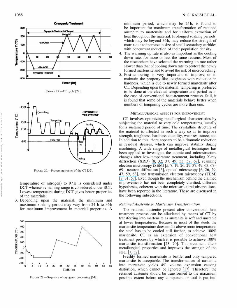
Figure 1.—Preferred heat treatment sequence.
Austenitization and QuenchingAustenitization involves heating of steel to its upper
critical temperature to form austenite steel. It is basicallyan alloy of iron and carbon with various other elements inthe solution that begin to dissolve and homogenize in theaustenitic solution by the process of diffusion. When thesteel is heated, the iron crystal changes to face centeredcubic (FCC), and the carbon atoms migrates into the centralposition formerly occupied by an iron atoms. This red-hot steel is called austenite. Moore and Colline [21] haveconcluded that optimum austenitization temperature variesfrom metal to metal. However, for D2 steel it lies between1075�C (1348K) and 1100�C (1373K).In the second step, it is cooled down to ambient
temperature rapidly in a suitable fluid-like oil, water, or air.Once the austenite is cooled below its critical temperature,it becomes unstable and will transform into martensite.Properties of formed steel will depend upon rate of cooling.If steel gets cooled slowly, the iron atoms move back intothe cube forcing the carbon atoms back-out, results soft steelcalled pearlite, and this process is known as annealing. If thesteel gets cooled quickly (quenched) by immersing into oilor water, the carbon atoms are trapped, which results in veryhard, brittle steel. This steel crystal structure is now a bodycentered tetragonal (BCT) called martensite. Reheatingthese crystallographic and microstructural changes resultsin the precipitation of finer carbides in the temperedmicrostructure, with consequent increase in both toughnessand wear resistance [5, 6, 8, 32]. After conventional heattreatment, there would always be some retained austenitein the steel which could be up to 20–30%. At higheraustenitization temperature of the steel maximum carbonand alloy elements goes into the solution. This results betterdistributed hardened martensite in the steel [21, 35].Collin and Dormer [27] have shown the behavior
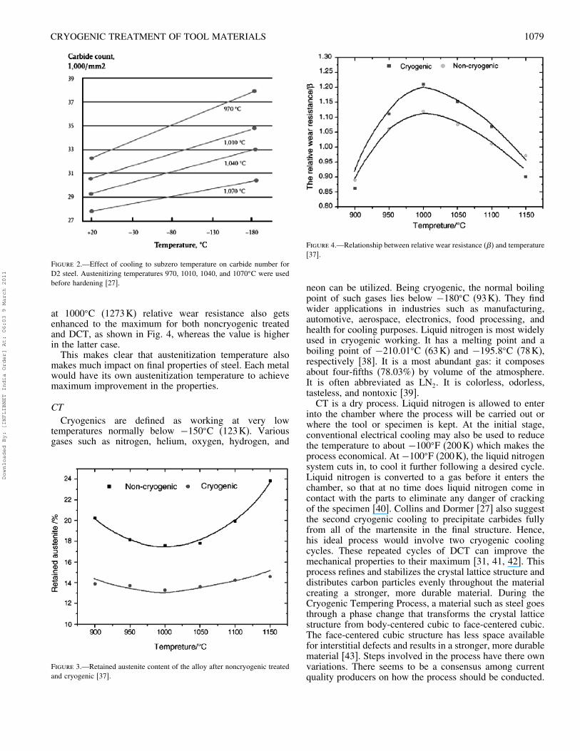
of change in austenitization temperature as in Fig. 2,which indicates more number of carbides present as theaustenitization temperature lowers from 1070�C (1343K) to970�C (1243K) in D2 steel. In soft annealed tool steel, mostof the alloying elements are bonded with carbon in carbides.When the steel is heated, the basic idea is to dissolvethe carbides to such a degree that the matrix acquires analloying content that gives the hardening effect withoutbecoming coarse grained and brittle. The possible reason isthat carbides are partially dissolved at low austenitizationtemperature [36]. Low temperature treatment stabilizes thecarbides partially, and because of this, an increase in carbidecount can be seen at lower temperatures.Yang et al. [37], in their study on 13Cr2Mn2V
high Chromium white iron, reported that transformationof retained austenite into martensite depends uponaustenitization temperature. They studied the process at900, 950, 1000, 1050, 1100, and 1150�C (1173, 1223,1273, 1323, 1373, and 1423K), respectively. Fig. 3 showsthe percentage change in retained austenite contents inconventionally treated and DCT with change in prioraustenitization temperature, which decreases when thetemperature rises up to 1000�C (1273K) and furtherincreases at high temperature values.They also studied the effect of same changes on relative
wear. They concluded that with minimum retained austenite
Downloaded By: [INFLIBNET India Order] At: 06:03 9 March 2011
CRYOGENIC TREATMENT OF TOOL MATERIALS 1079
Figure 2.—Effect of cooling to subzero temperature on carbide number forD2 steel. Austenitizing temperatures 970, 1010, 1040, and 1070�C were usedbefore hardening [27].
at 1000�C (1273K) relative wear resistance also getsenhanced to the maximum for both noncryogenic treatedand DCT, as shown in Fig. 4, whereas the value is higherin the latter case.This makes clear that austenitization temperature also
makes much impact on final properties of steel. Each metalwould have its own austenitization temperature to achievemaximum improvement in the properties.
CTCryogenics are defined as working at very low
temperatures normally below −150�C (123K). Variousgases such as nitrogen, helium, oxygen, hydrogen, and
Figure 3.—Retained austenite content of the alloy after noncryogenic treatedand cryogenic [37].
Figure 4.—Relationship between relative wear resistance (�) and temperature[37].
neon can be utilized. Being cryogenic, the normal boilingpoint of such gases lies below −180�C (93K). They findwider applications in industries such as manufacturing,automotive, aerospace, electronics, food processing, andhealth for cooling purposes. Liquid nitrogen is most widelyused in cryogenic working. It has a melting point and aboiling point of −210�01�C (63K) and −195�8�C (78K),respectively [38]. It is a most abundant gas: it composesabout four-fifths (78.03%) by volume of the atmosphere.It is often abbreviated as LN2. It is colorless, odorless,tasteless, and nontoxic [39].CT is a dry process. Liquid nitrogen is allowed to enter
into the chamber where the process will be carried out orwhere the tool or specimen is kept. At the initial stage,conventional electrical cooling may also be used to reducethe temperature to about −100�F (200K) which makes theprocess economical. At −100�F (200K), the liquid nitrogensystem cuts in, to cool it further following a desired cycle.Liquid nitrogen is converted to a gas before it enters thechamber, so that at no time does liquid nitrogen come incontact with the parts to eliminate any danger of crackingof the specimen [40]. Collins and Dormer [27] also suggestthe second cryogenic cooling to precipitate carbides fullyfrom all of the martensite in the final structure. Hence,his ideal process would involve two cryogenic coolingcycles. These repeated cycles of DCT can improve themechanical properties to their maximum [31, 41, 42]. Thisprocess refines and stabilizes the crystal lattice structure anddistributes carbon particles evenly throughout the materialcreating a stronger, more durable material. During theCryogenic Tempering Process, a material such as steel goesthrough a phase change that transforms the crystal latticestructure from body-centered cubic to face-centered cubic.The face-centered cubic structure has less space availablefor interstitial defects and results in a stronger, more durablematerial [43]. Steps involved in the process have there ownvariations. There seems to be a consensus among currentquality producers on how the process should be conducted.
Downloaded By: [INFLIBNET India Order] At: 06:03 9 March 2011
1080 N. S. KALSI ET AL.
A typical cryogenic cycle can be completed in the followingthree steps.
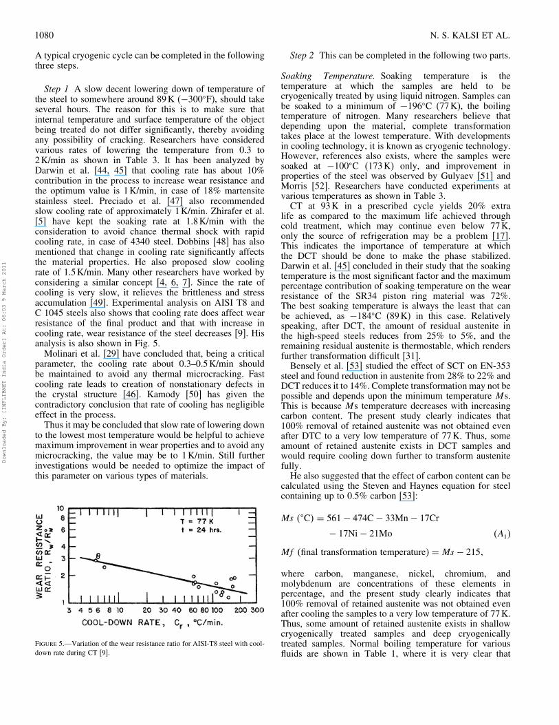
Step 1 A slow decent lowering down of temperature ofthe steel to somewhere around 89K (−300�F), should takeseveral hours. The reason for this is to make sure thatinternal temperature and surface temperature of the objectbeing treated do not differ significantly, thereby avoidingany possibility of cracking. Researchers have consideredvarious rates of lowering the temperature from 0.3 to2K/min as shown in Table 3. It has been analyzed byDarwin et al. [44, 45] that cooling rate has about 10%contribution in the process to increase wear resistance andthe optimum value is 1K/min, in case of 18% martensitestainless steel. Preciado et al. [47] also recommendedslow cooling rate of approximately 1K/min. Zhirafer et al.[5] have kept the soaking rate at 1.8K/min with theconsideration to avoid chance thermal shock with rapidcooling rate, in case of 4340 steel. Dobbins [48] has alsomentioned that change in cooling rate significantly affectsthe material properties. He also proposed slow coolingrate of 1.5K/min. Many other researchers have worked byconsidering a similar concept [4, 6, 7]. Since the rate ofcooling is very slow, it relieves the brittleness and stressaccumulation [49]. Experimental analysis on AISI T8 andC 1045 steels also shows that cooling rate does affect wearresistance of the final product and that with increase incooling rate, wear resistance of the steel decreases [9]. Hisanalysis is also shown in Fig. 5.Molinari et al. [29] have concluded that, being a critical
parameter, the cooling rate about 0.3–0.5K/min shouldbe maintained to avoid any thermal microcracking. Fastcooling rate leads to creation of nonstationary defects inthe crystal structure [46]. Kamody [50] has given thecontradictory conclusion that rate of cooling has negligibleeffect in the process.Thus it may be concluded that slow rate of lowering down
to the lowest most temperature would be helpful to achievemaximum improvement in wear properties and to avoid anymicrocracking, the value may be to 1K/min. Still furtherinvestigations would be needed to optimize the impact ofthis parameter on various types of materials.
Figure 5.—Variation of the wear resistance ratio for AISI-T8 steel with cool-down rate during CT [9].
Step 2 This can be completed in the following two parts.
Soaking Temperature. Soaking temperature is thetemperature at which the samples are held to becryogenically treated by using liquid nitrogen. Samples canbe soaked to a minimum of −196�C (77K), the boilingtemperature of nitrogen. Many researchers believe thatdepending upon the material, complete transformationtakes place at the lowest temperature. With developmentsin cooling technology, it is known as cryogenic technology.However, references also exists, where the samples weresoaked at −100�C (173K) only, and improvement inproperties of the steel was observed by Gulyaev [51] andMorris [52]. Researchers have conducted experiments atvarious temperatures as shown in Table 3.CT at 93K in a prescribed cycle yields 20% extra
life as compared to the maximum life achieved throughcold treatment, which may continue even below 77K,only the source of refrigeration may be a problem [17].This indicates the importance of temperature at whichthe DCT should be done to make the phase stabilized.Darwin et al. [45] concluded in their study that the soakingtemperature is the most significant factor and the maximumpercentage contribution of soaking temperature on the wearresistance of the SR34 piston ring material was 72%.The best soaking temperature is always the least that canbe achieved, as −184�C (89K) in this case. Relativelyspeaking, after DCT, the amount of residual austenite inthe high-speed steels reduces from 25% to 5%, and theremaining residual austenite is thermostable, which rendersfurther transformation difficult [31].Bensely et al. [53] studied the effect of SCT on EN-353
steel and found reduction in austenite from 28% to 22% andDCT reduces it to 14%. Complete transformation may not bepossible and depends upon the minimum temperature Ms.This is because Ms temperature decreases with increasingcarbon content. The present study clearly indicates that100% removal of retained austenite was not obtained evenafter DTC to a very low temperature of 77K. Thus, someamount of retained austenite exists in DCT samples andwould require cooling down further to transform austenitefully.He also suggested that the effect of carbon content can be
calculated using the Steven and Haynes equation for steelcontaining up to 0.5% carbon [53]:
Ms ��C� = 561− 474C− 33Mn− 17Cr
− 17Ni− 21Mo (A1)
Mf (final transformation temperature) = Ms − 215�
where carbon, manganese, nickel, chromium, andmolybdenum are concentrations of these elements inpercentage, and the present study clearly indicates that100% removal of retained austenite was not obtained evenafter cooling the samples to a very low temperature of 77K.Thus, some amount of retained austenite exists in shallowcryogenically treated samples and deep cryogenicallytreated samples. Normal boiling temperature for variousfluids are shown in Table 1, where it is very clear that
Downloaded By: [INFLIBNET India Order] At: 06:03 9 March 2011
CRYOGENIC TREATMENT OF TOOL MATERIALS 1081
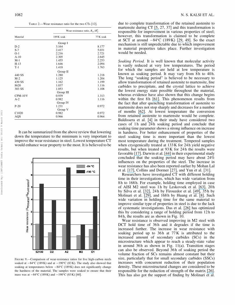
Table 1.—Normal boiling point of common cryogenic fluids [38].
Boiling temprature
(K) (�C) (�R) (�F)Cryogenicfluid
Methane 111�7 −161�5 201�1 −258�6Oxygen 90�2 −183�0 162�4 −297�3Nitrogen 77�4 −195�8 139�3 −320�4Hydrogen 20�3 −252�9 36�5 −423�2Helium 4�2 −269�0 7�6 −452�1Absolute zero 0 −273�15 D −459�67
application of hydrogen and helium may be helpful to takethe soaking temperature further below because of their lowerboiling point temperature 20.3K and 4.2K, respectively, ascompared to nitrogen, 77.4K. Some applications of heliumalso came up for CT, but still restricted because of very itsexpensive and highly volatile nature.Babu et al. [55] conducted experiments at various
temperatures from 0�C (273K) to -190�C (83K) on M1,H13, and EN 19 Steel and analyzed its effect on wearresistance of the steel. They concluded that with loweringdown of cryogenic soaking temperature wear properties ofthe steel improved as shown in Fig. 6. They found overallimprovement of about 3.2 to 3.8 times.Reddy et al. [56] have also concluded that the life of
P-30 tool insert increases by 9.58% when treated at −96�C(177K) and 21% when treated at −175�C (98K). Benselyet al. [6] in another study on EN 353 have comparedthe gain of wear resistance by conventionally heat treatedand cryogenically treated at 193K (SCT) and found thatimprovement was 85%. They also found that the wearresistance improved by 3.72 times in case of treatment at77K (DCT). On further comparison they concluded thatthere was improvement of 1.52 times in wear resistancewhen treated at 77K over the treatment done at 193K.Similar results have also come up concluding that lowestcryogenic cooling temperature improves the steel most[57–59].Collins and Dormer [27] in their experiments have studied
the influence of low temperature treatment and concluded
Figure 6.—Wear resistance analysis [55].
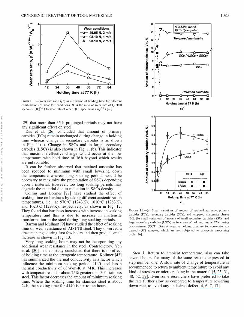
Figure 7.—Influence of temperature on wear rate for D2 steel [27].
that wear rate decreases with lowering the CT temperatureas presented in Fig. 7.Barron and Mulharn [9] have also shown the similar
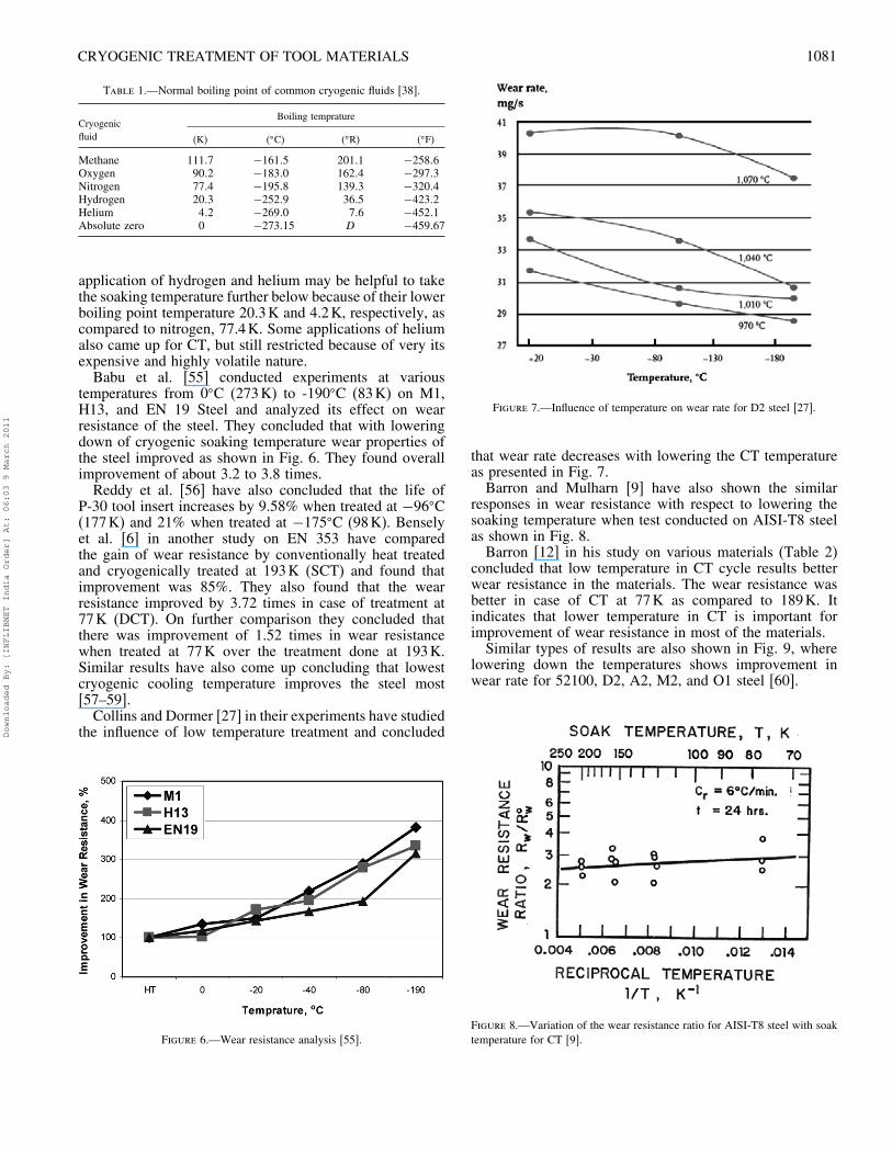
responses in wear resistance with respect to lowering thesoaking temperature when test conducted on AISI-T8 steelas shown in Fig. 8.Barron [12] in his study on various materials (Table 2)
concluded that low temperature in CT cycle results betterwear resistance in the materials. The wear resistance wasbetter in case of CT at 77K as compared to 189K. Itindicates that lower temperature in CT is important forimprovement of wear resistance in most of the materials.Similar types of results are also shown in Fig. 9, where
lowering down the temperatures shows improvement inwear rate for 52100, D2, A2, M2, and O1 steel [60].
Figure 8.—Variation of the wear resistance ratio for AISI-T8 steel with soaktemperature for CT [9].
Downloaded By: [INFLIBNET India Order] At: 06:03 9 March 2011
1082 N. S. KALSI ET AL.
Table 2.—Wear resistance ratio for the two CTs [12].
Wear resistance ratio, Rw/R0w
Material 189K soak 77K soak
Group ID-2 3.164 8.177S-7 2.417 5.031O-1 2.216 2.721A-10 2.305 2.645M-1 1.455 2.253H-13 1.646 2.094T-1 1.418 1.763
Group II440 SS 1.280 1.218M-2 1.125 1.204430 SS 1.162 1.1998620 1.037 1.116303 SS 1.053 1.108
Group IIICPM-10V 0.939 1.313A-2 0.982 1.116
Group IVP-20 1.231 0.972
Group VC1020 0.982 0.972AQS 0.966 0.964
It can be summarized from the above review that loweringdown the temperature to the minimum is very important toimprove the wear resistance in steel. Lowest temperature CTwould enhance wear property to the most. It is believed to be
Figure 9.—Comparison of wear-resistance ratios for five high-carbon steelssoaked at −84�C (189K) and at −190�C (83K). The study also showed thatsoaking at temperatures below −84�C (189K) does not significantly changethe hardness of the material. The samples were soaked to ensure that theirmass was at −84�C (189K) and −190�C (83K) [60].
due to complete transformation of the retained austenite tomartensite during CT [5, 27, 37] and this transformation isresponsible for improvement in various properties of steel;however, this transformation is claimed to be completeat SCT at around −84�C (189K) [29, 49]. So the exactmechanism is still unpredictable due to which improvementin material properties takes place. Further investigationwould be needed.
Soaking Period. It is well known that molecular activityis vastly reduced at very low temperatures. The periodfor which the samples are held at low temperature isknown as soaking period. It may vary from 8h to 40h.The long “soaking period” is believed to be necessary toallow transformation of retained austenite to martensite, finecarbides to precipitate, and the crystal lattice to achievethe lowest energy state possible throughout the material,whereas evidence have also shown that this change beginswithin the first 8h [61]. This phenomenon results fromthe fact that after quenching transformation of austenite tomartensite does not stop sharply and decreases for a numberof months [62]. At lowest temperature the conversionfrom retained austenite to martensite would be complete.Baldissera et al. [4] in their study have considered twocases of 1h and 24h soaking period and conclude thatsoaking time parameter shows a strong influence on increasein hardness. For better enhancement of properties of thesteel soaking time is more important than the lowestmost temperature during the treatment. Tempered sampleswhen cryogenically treated at 133K for 24h yield negativeresults, but when treated at 93K for 24h the results werefavorable [17]. Darwin et al. [44] in their experimental studyconcluded that the soaking period may have about 24%influences on the properties of the steel. The increase inwear resistance has also been reported earlier by Mohan Lalet al. [17], Collins and Dormer [27], and Yun et al. [31].Researchers have investigated CT with different holding
time in their investigations, which has wide variation from8h to 168h. For example, holding time employed in caseof AISI M2 steel was 1h by Leskovsek et al. [63], 20hby Silva et al. [32], 24h by Firouzdor et al. [49], 35h byMolinari et al. [29], and 168h by Huang et al. [8]. Suchwide variation in holding time for the same material toimprove similar type of properties in steel is due to the lackof systematic investigations. Das et al. [26] has optimizedthis by considering a range of holding period from 12h to84h, the results are as shown in Fig. 10.Wear resistance is observed improving in M2 steel with
DCT hold time of 36h and it degrades if the time isincreased further. The increase in wear resistance withsoaking period up to 36h at 77K is attributed to theincreased amount of secondary carbides (SCs) in themicrostructure which appear to reach a steady-state valuein around 36h as shown in Fig. 11(a). Transition stagescan also be observed. Beyond 36h of soaking period thevolume fraction of SCs remains almost constant but theirsize, particularly that for small secondary carbides (SSCs)increases with concurrent reduction of their populationdensity. These microstructural changes are considered to beresponsible for the reduction of strength of the matrix [26].This has also got the support of finding by Molinari et al.
Downloaded By: [INFLIBNET India Order] At: 06:03 9 March 2011
CRYOGENIC TREATMENT OF TOOL MATERIALS 1083
Figure 10.—Wear rate ratio (�′) as a function of holding time for differentcombinations of wear test conditions. �′ is the ratio of wear rate of QCT00specimen �W
QCTR � to wear rate of other QCT specimens �WQCT
R � [26].
[29] that more than 35 h prolonged periods may not haveany significant effect on steel.Das et al. [26] concluded that amount of primary
carbides (PCs) remain unchanged during change in holdingtime whereas change in secondary carbides is as shownin Fig. 11(a). Change in SSCs and in large secondarycarbides (LSCs) is also shown in Fig. 11(b). This indicatesthat maximum effective change would occur at the lowtemperature with hold time of 36h beyond which resultsare unfavorable.It can be further observed that retained austenite has
been reduced to minimum with small lowering downthe temperature whereas long soaking periods would benecessary to maximize the precipitation of SSCs dependingupon a material. However, too long soaking periods maydegrade the material due to reduction in SSCs density.Collins and Dormer [27] have studied the effect of
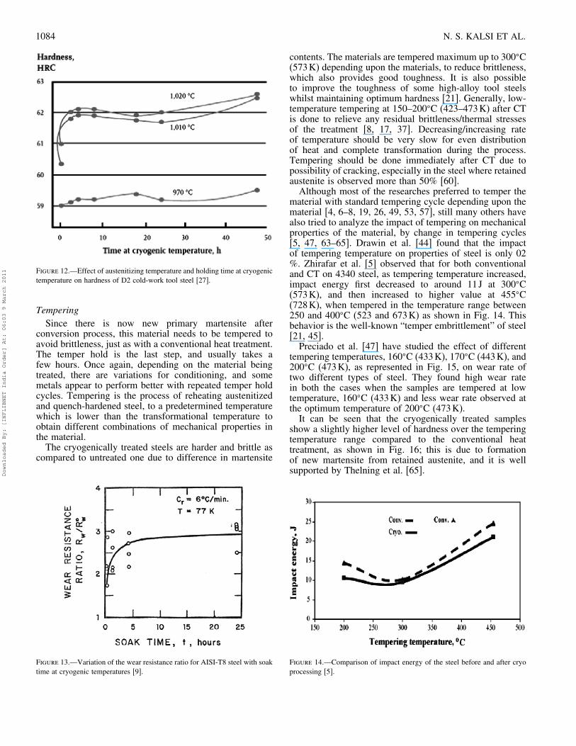
soaking time on hardness by taking different austenitizationtemperatures, i.e., at 970�C (1243K), 1010�C (1283K),and 1020�C (1293K), respectively, as shown in Fig. 12.They found that hardness increases with increase in soakingtemperature and this is due to increase in martensitetransformation in the steel during long soaking periods.Barron and Mulharn [9] have studied the effect of soaking
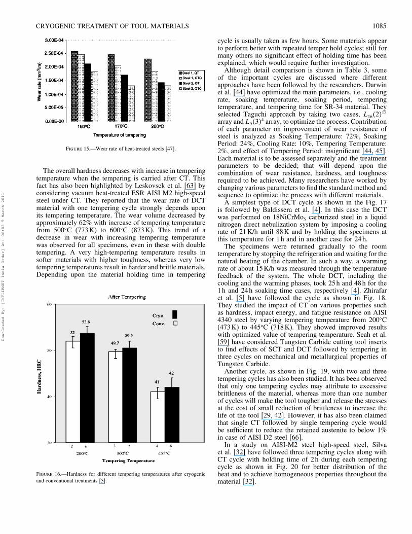
time on wear resistance of AISI-T8 steel. They observed adrastic change during first few hours and then gradual smallincrease as shown in Fig. 13.Very long soaking hours may not be incorporating any
additional wear resistance in the steel. Contradictory, Yenet al. [30] in their study concluded that there is no effectof holding time at the cryogenic temperature. Kollmer [43]has summarized the thermal conductivity as a factor whichinfluence the minimum soaking period. 4140 steel has athermal conductivity of 63W/m-K at 74K. This increaseswith temperature and is about 25% greater than 304 stainlesssteel. This factor decreases the amount of minimum soakingtime. Where the soaking time for stainless steel is about24h, the soaking time for 4140 is six to ten hours.
Figure 11.—(a) Small variations of amount of retained austenite, primarycarbides (PCs), secondary carbides (SCs), and tempered martensite phases[26]. (b) Small variations of amount of small secondary carbides (SSCs) andlarge secondary carbides (LSCs) as functions of holding time at 77K duringcryotreatment (QCT). Data at negative holding time are for conventionallytreated (QT) samples, which are not subjected to cryogenic processingcycle [26].
Step 3. Return to ambient temperature, also can takeseveral hours, for many of the same reasons expressed instep number one. A slow rate of change of temperature isrecommended to return to ambient temperature to avoid anykind of stresses or microcracking in the material [5, 25, 31,48, 52, 59]. Even some researchers have preferred to takethe rate further slow as compared to temperature loweringdown rate, to avoid any undesired defect [4, 6, 7, 17].
Downloaded By: [INFLIBNET India Order] At: 06:03 9 March 2011
1084 N. S. KALSI ET AL.
Figure 12.—Effect of austenitizing temperature and holding time at cryogenictemperature on hardness of D2 cold-work tool steel [27].
TemperingSince there is now new primary martensite after
conversion process, this material needs to be tempered toavoid brittleness, just as with a conventional heat treatment.The temper hold is the last step, and usually takes afew hours. Once again, depending on the material beingtreated, there are variations for conditioning, and somemetals appear to perform better with repeated temper holdcycles. Tempering is the process of reheating austenitizedand quench-hardened steel, to a predetermined temperaturewhich is lower than the transformational temperature toobtain different combinations of mechanical properties inthe material.The cryogenically treated steels are harder and brittle as
compared to untreated one due to difference in martensite
Figure 13.—Variation of the wear resistance ratio for AISI-T8 steel with soaktime at cryogenic temperatures [9].
contents. The materials are tempered maximum up to 300�C(573K) depending upon the materials, to reduce brittleness,which also provides good toughness. It is also possibleto improve the toughness of some high-alloy tool steelswhilst maintaining optimum hardness [21]. Generally, low-temperature tempering at 150–200�C (423–473K) after CTis done to relieve any residual brittleness/thermal stressesof the treatment [8, 17, 37]. Decreasing/increasing rateof temperature should be very slow for even distributionof heat and complete transformation during the process.Tempering should be done immediately after CT due topossibility of cracking, especially in the steel where retainedaustenite is observed more than 50% [60].Although most of the researches preferred to temper the
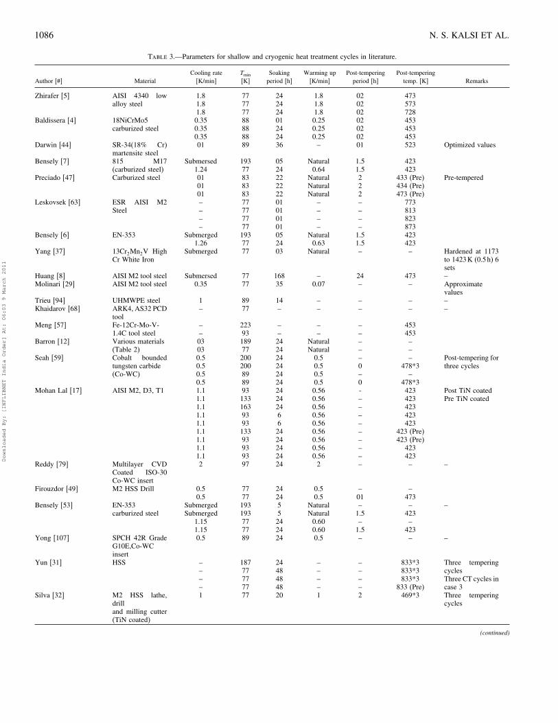
material with standard tempering cycle depending upon thematerial [4, 6–8, 19, 26, 49, 53, 57], still many others havealso tried to analyze the impact of tempering on mechanicalproperties of the material, by change in tempering cycles[5, 47, 63–65]. Drawin et al. [44] found that the impactof tempering temperature on properties of steel is only 02%. Zhirafar et al. [5] observed that for both conventionaland CT on 4340 steel, as tempering temperature increased,impact energy first decreased to around 11J at 300�C(573K), and then increased to higher value at 455�C(728K), when tempered in the temperature range between250 and 400�C (523 and 673K) as shown in Fig. 14. Thisbehavior is the well-known “temper embrittlement” of steel[21, 45].Preciado et al. [47] have studied the effect of different
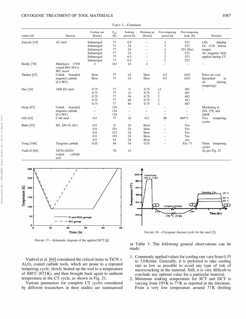
tempering temperatures, 160�C (433K), 170�C (443K), and200�C (473K), as represented in Fig. 15, on wear rate oftwo different types of steel. They found high wear ratein both the cases when the samples are tempered at lowtemperature, 160�C (433K) and less wear rate observed atthe optimum temperature of 200�C (473K).It can be seen that the cryogenically treated samples
show a slightly higher level of hardness over the temperingtemperature range compared to the conventional heattreatment, as shown in Fig. 16; this is due to formationof new martensite from retained austenite, and it is wellsupported by Thelning et al. [65].
Figure 14.—Comparison of impact energy of the steel before and after cryoprocessing [5].
Downloaded By: [INFLIBNET India Order] At: 06:03 9 March 2011
CRYOGENIC TREATMENT OF TOOL MATERIALS 1085
Figure 15.—Wear rate of heat-treated steels [47].
The overall hardness decreases with increase in temperingtemperature when the tempering is carried after CT. Thisfact has also been highlighted by Leskovsek et al. [63] byconsidering vacuum heat-treated ESR AISI M2 high-speedsteel under CT. They reported that the wear rate of DCTmaterial with one tempering cycle strongly depends uponits tempering temperature. The wear volume decreased byapproximately 62% with increase of tempering temperaturefrom 500�C (773K) to 600�C (873K). This trend of adecrease in wear with increasing tempering temperaturewas observed for all specimens, even in these with doubletempering. A very high-tempering temperature results insofter materials with higher toughness, whereas very lowtempering temperatures result in harder and brittle materials.Depending upon the material holding time in tempering
Figure 16.—Hardness for different tempering temperatures after cryogenicand conventional treatments [5].
cycle is usually taken as few hours. Some materials appearto perform better with repeated temper hold cycles; still formany others no significant effect of holding time has beenexplained, which would require further investigation.Although detail comparison is shown in Table 3, some
of the important cycles are discussed where differentapproaches have been followed by the researchers. Darwinet al. [44] have optimized the main parameters, i.e., coolingrate, soaking temperature, soaking period, temperingtemperature, and tempering time for SR-34 material. Theyselected Taguchi approach by taking two cases, L16�2�
15
array and L9�3�4 array, to optimize the process. Contribution
of each parameter on improvement of wear resistance ofsteel is analyzed as Soaking Temperature: 72%, SoakingPeriod: 24%, Cooling Rate: 10%, Tempering Temperature:2%, and effect of Tempering Period: insignificant [44, 45].Each material is to be assessed separately and the treatmentparameters to be decided; that will depend upon thecombination of wear resistance, hardness, and toughnessrequired to be achieved. Many researchers have worked bychanging various parameters to find the standard method andsequence to optimize the process with different materials.A simplest type of DCT cycle as shown in the Fig. 17
is followed by Baldissera et al. [4]. In this case the DCTwas performed on 18NiCrMo5 carburized steel in a liquidnitrogen direct nebulization system by imposing a coolingrate of 21K/h until 88K and by holding the specimens atthis temperature for 1h and in another case for 24h.The specimens were returned gradually to the room
temperature by stopping the refrigeration and waiting for thenatural heating of the chamber. In such a way, a warmingrate of about 15K/h was measured through the temperaturefeedback of the system. The whole DCT, including thecooling and the warming phases, took 25h and 48h for the1h and 24h soaking time cases, respectively [4]. Zhirafaret al. [5] have followed the cycle as shown in Fig. 18.They studied the impact of CT on various properties suchas hardness, impact energy, and fatigue resistance on AISI4340 steel by varying tempering temperature from 200�C(473K) to 445�C (718K). They showed improved resultswith optimized value of tempering temperature. Seah et al.[59] have considered Tungsten Carbide cutting tool insertsto find effects of SCT and DCT followed by tempering inthree cycles on mechanical and metallurgical properties ofTungsten Carbide.Another cycle, as shown in Fig. 19, with two and three
tempering cycles has also been studied. It has been observedthat only one tempering cycles may attribute to excessivebrittleness of the material, whereas more than one numberof cycles will make the tool tougher and release the stressesat the cost of small reduction of brittleness to increase thelife of the tool [29, 42]. However, it has also been claimedthat single CT followed by single tempering cycle wouldbe sufficient to reduce the retained austenite to below 1%in case of AISI D2 steel [66].In a study on AISI-M2 steel high-speed steel, Silva
et al. [32] have followed three tempering cycles along withCT cycle with holding time of 2h during each temperingcycle as shown in Fig. 20 for better distribution of theheat and to achieve homogeneous properties throughout thematerial [32].
Downloaded By: [INFLIBNET India Order] At: 06:03 9 March 2011
1086 N. S. KALSI ET AL.
Table 3.—Parameters for shallow and cryogenic heat treatment cycles in literature.
Author [#] MaterialCooling rate[K/min]
Tmin
[K]Soakingperiod [h]
Warming up[K/min]
Post-temperingperiod [h]
Post-temperingtemp. [K] Remarks
Zhirafer [5] AISI 4340 lowalloy steel
1.81.81.8
777777
242424
1.81.81.8
020202
473573728
Baldissera [4] 18NiCrMo5carburized steel
0.350.350.35
888888
012424
0.250.250.25
020202
453453453
Darwin [44] SR-34(18% Cr)martensite steel
01 89 36 – 01 523 Optimized values
Bensely [7] 815 M17(carburized steel)
Submersed1.24
19377
0524
Natural0.64
1.51.5
423423
Preciado [47] Carburized steel 010101
838383
222222
NaturalNaturalNatural
222
433 (Pre)434 (Pre)473 (Pre)
Pre-tempered
Leskovsek [63] ESR AISI M2Steel
––––
77777777
01010101
––––
––––
773813823873
Bensely [6] EN-353 Submerged1.26
19377
0524
Natural0.63
1.51.5
423423
Yang [37] 13Cr2Mn2V HighCr White Iron
Submerged 77 03 Natural – – Hardened at 1173to 1423K (0.5h) 6sets
Huang [8] AISI M2 tool steel Submersed 77 168 – 24 473 –Molinari [29] AISI M2 tool steel 0.35 77 35 0.07 – – Approximate
valuesTrieu [94] UHMWPE steel 1 89 14 – – – –Khaidarov [68] ARK4, AS32 PCD
tool– 77 – – – – –
Meng [57] Fe-12Cr-Mo-V-1.4C tool steel
––
22393
––
––
––
453453
Barron [12] Various materials(Table 2)
0303
18977
2424
NaturalNatural
––
––
Seah [59] Cobalt boundedtungsten carbide(Co-WC)
0.50.50.50.5
2002008989
24242424
0.50.50.50.5
–0–0
–478*3
–478*3
Post-tempering forthree cycles
Mohan Lal [17] AISI M2, D3, T1 1.11.11.11.11.11.11.11.11.1
931331639393133939393
2424246624242424
0.560.560.560.560.560.560.560.560.56
-––––––––
423423423423423
423 (Pre)423 (Pre)
423423
Post TiN coatedPre TiN coated
Reddy [79] Multilayer CVDCoated ISO-30Co-WC insert
2 97 24 2 – – –
Firouzdor [49] M2 HSS Drill 0.50.5
7777
2424
0.50.5
–01
–473
Bensely [53] EN-353carburized steel
SubmergedSubmerged
1.151.15
1931937777
552424
NaturalNatural0.600.60
–1.5–1.5
–423–423
–
Yong [107] SPCH 42R GradeG10E,Co-WCinsert
0.5 89 24 0.5 – – –
Yun [31] HSS ––––
187777777
24484848
––––
––––
833*3833*3833*3
833 (Pre)
Three temperingcyclesThree CT cycles incase 3
Silva [32] M2 HSS lathe,drilland milling cutter(TiN coated)
1 77 20 1 2 469*3 Three temperingcycles
(continued)
Downloaded By: [INFLIBNET India Order] At: 06:03 9 March 2011
CRYOGENIC TREATMENT OF TOOL MATERIALS 1087
Table 3.—Continued
Author [#] MaterialCooling rate[K/min]
Tmin
[K]Soakingperiod [h]
Warming up[K/min]
Post-temperingperiod [h]
Post-temperingtemp. [K] Remarks
Zurecki [19] A2 steel SubmergedSubmergedSubmergedSubmergedSubmergedSubmerged
777777777777
0.52424240.50.5
––––––
222222
523523
523 (Pre)523523523
LHe dippingfor 0.5h beforetemperAC magnetic fieldapplied during CT
Reddy [78] Multilayer CVDcoated ISO-30 Co-WC insert
2 163 24 2 – – –
Thakur [67] Cobalt boundedtungsten carbide(Co-WC)
SlowSlow
7777
2424
SlowSlow
0.50.5
10231023
Force air coolQuenched inoil (duringtempering)
Das [26] AISI D2 steel 0.750.750.750.750.75
7777777777
012366084
0.750.750.750.750.75
v22222
483483483483483
–
Gisip [97] Cobalt boundedtungsten carbide(Co-WC)
–––
124124124
–––
–––
–––
–––
Machining at294, 278, and266K
Gill [42] C-60 steel 0.5 77 24 0.5 00 469*2 Two temperingcycles
Babu [55] M1, EN-19, H13 0.90.90.90.90.9
025323319383
2424242424
SlowSlowSlowSlowSlow
–––––
YesYesYesYesyes
Yong [108] Tungsten carbide 0.55 89 18 0.55 – Yes *3 Three temperingcycles
Vadivel [64] TiCN+Al2O3coated carbidetool
78 12 As per Fig. 21
Figure 17.—Schematic diagram of the applied DCT [4].
Vadivel et al. [64] considered the critical items in TiCN+Al2O3 coated carbide tools, which are prone to a repeatedtempering cycle, slowly heated up the tool to a temperatureof 400�C (673K), and then brought back again to ambienttemperature in the CT cycle, as shown in Fig. 21.Various parameters for complete CT cycles considered
by different researchers in their studies are summarized
Figure 18.—Cryogenic thermal cycle for the steel [5].
in Table 3. The following general observations can bemade:
1. Commonly applied values for cooling rate vary from 0.35to 3.0K/min. Generally, it is preferred to take coolingrate as low as possible to avoid any type of risk ofmicrocracking in the material. Still, it is very difficult toconclude any optimal value for a particular material.
2. Minimum soaking temperature for SCT and DCT isvarying from 195K to 77K as reported in the literature.From a very low temperature around 77K (boiling
Downloaded By: [INFLIBNET India Order] At: 06:03 9 March 2011
1088 N. S. KALSI ET AL.
Figure 19.—CT cycle [29].
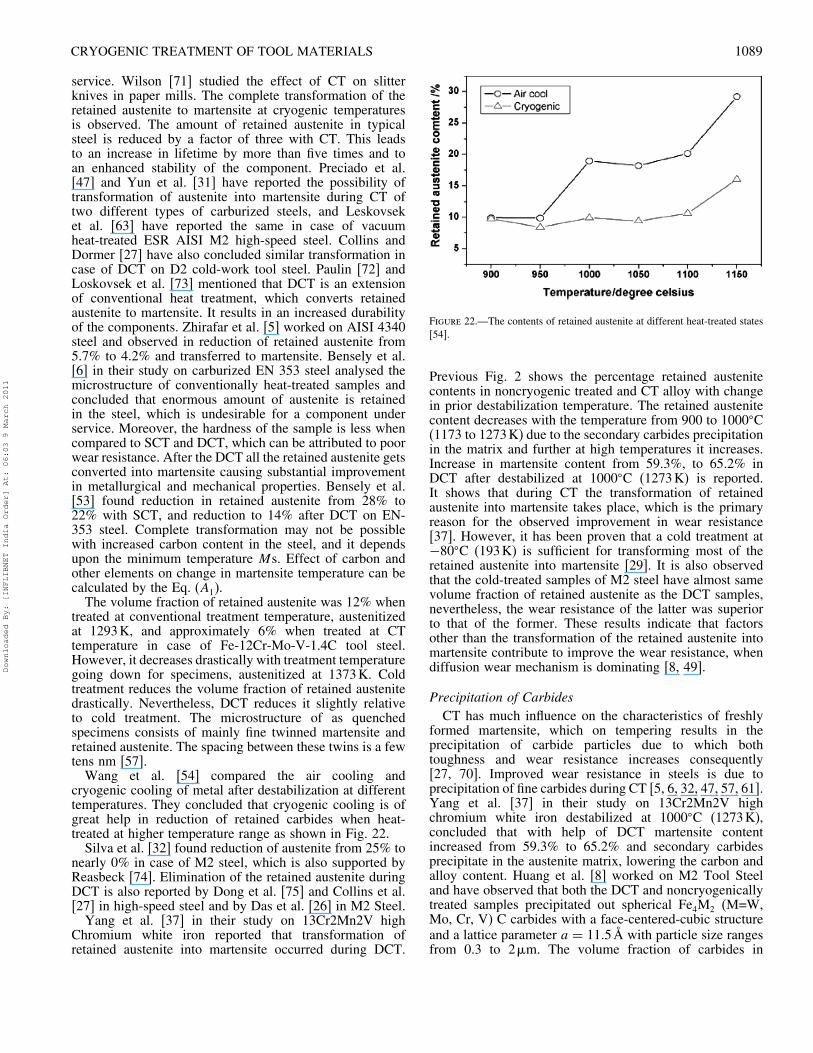
Figure 20.—Processing routes of the CT [32].
temperature of nitrogen) to 97K is considered underDCT whereas remaining range is considered under SCT.Lowest temperature during DCT gives better propertiesof the materials.
3. Depending upon the material, the minimum andmaximum soaking period may vary from 24 h to 36hfor maximum improvement in material properties. A
Figure 21.—Sequence of cryogenic processing [64].
minimum period, which may be 24h, is found tobe important for maximum transformation of retainedaustenite to martensite and for uniform extraction ofheat throughout the material. Prolonged soaking periods,which may be beyond 36h, may reduce the strength ofmatrix due to increase in size of small secondary carbideswith concurrent reduction of their population density.
4. The warming up rate is also as important as the coolingdown rate, for more or less the same reasons. Most ofthe researchers have selected the warming up rate ratherslower than that of cooling down rate to protect the newlyformed martensite and to avoid the risk of microcracking.
5. Post-tempering is very important to improve or tomaintain the property-like toughness with reduction inhardness, which is due to newly formed martensite afterCT. Depending upon the material, tempering is preferredto be done at the elevated temperature and period as inthe case of conventional heat-treatment process. Still, itis found that some of the materials behave better whennumbers of tempering cycles are more than one.
Metallurgical aspects for improvement
CT involves optimizing metallurgical characteristics bysubjecting the material to very cold temperatures, usuallyfor a sustained period of time. The crystalline structure ofthe material is affected in such a way so as to improvestrength, toughness, hardness, ductility, wear resistance, etc.In addition to this, there appears to be a dramatic reductionin residual stresses, which can improve stability duringmachining. A wide range of metallurgical techniques hasbeen applied to investigate the atomic and microstructurechanges after low-temperature treatment, including X-raydiffraction (XRD) [8, 32, 37, 49, 53, 57, 67], scanningelectron microscopy (SEM) [5, 7, 19, 26, 29, 37, 49, 63, 67–69], neutron diffraction [5], optical microscopy [6, 26, 29,47, 59, 63], and transmission electron microscopy (TEM)[8, 31, 57]. Even though the mechanism behind the claimedimprovements has not been completely clarified, differenthypotheses, coherent with the microstructural observations,have been reported in the literature. These are discussed inthe following subsections.
Retained Austenite to Martensite TransformationThe retained austenite present after conventional heat
treatment process can be alleviated by means of CT bytransferring into martensite as austenite is soft and unstableat lower temperatures. Because in most of the steels themartensite temperature does not lie above room temperature,the steel has to be cooled still further, to achieve 100%martensite. CT is an extension of conventional heattreatment process by which it is possible to achieve 100%martensite transformation [23, 70]. This treatment altersmetallurgical properties and improves the strength of thesteel [7, 32].Freshly formed martensite is brittle, and only tempered
martensite is acceptable. The transformation of austeniteinto martensite yields 4% volume expansion causingdistortion, which cannot be ignored [17]. Therefore, theretained austenite should be transformed to the maximumpossible extent before any component or tool is put into
Downloaded By: [INFLIBNET India Order] At: 06:03 9 March 2011
CRYOGENIC TREATMENT OF TOOL MATERIALS 1089
service. Wilson [71] studied the effect of CT on slitterknives in paper mills. The complete transformation of theretained austenite to martensite at cryogenic temperaturesis observed. The amount of retained austenite in typicalsteel is reduced by a factor of three with CT. This leadsto an increase in lifetime by more than five times and toan enhanced stability of the component. Preciado et al.[47] and Yun et al. [31] have reported the possibility oftransformation of austenite into martensite during CT oftwo different types of carburized steels, and Leskovseket al. [63] have reported the same in case of vacuumheat-treated ESR AISI M2 high-speed steel. Collins andDormer [27] have also concluded similar transformation incase of DCT on D2 cold-work tool steel. Paulin [72] andLoskovsek et al. [73] mentioned that DCT is an extensionof conventional heat treatment, which converts retainedaustenite to martensite. It results in an increased durabilityof the components. Zhirafar et al. [5] worked on AISI 4340steel and observed in reduction of retained austenite from5.7% to 4.2% and transferred to martensite. Bensely et al.[6] in their study on carburized EN 353 steel analysed themicrostructure of conventionally heat-treated samples andconcluded that enormous amount of austenite is retainedin the steel, which is undesirable for a component underservice. Moreover, the hardness of the sample is less whencompared to SCT and DCT, which can be attributed to poorwear resistance. After the DCT all the retained austenite getsconverted into martensite causing substantial improvementin metallurgical and mechanical properties. Bensely et al.[53] found reduction in retained austenite from 28% to22% with SCT, and reduction to 14% after DCT on EN-353 steel. Complete transformation may not be possiblewith increased carbon content in the steel, and it dependsupon the minimum temperature Ms. Effect of carbon andother elements on change in martensite temperature can becalculated by the Eq. (A1).The volume fraction of retained austenite was 12% when
treated at conventional treatment temperature, austenitizedat 1293K, and approximately 6% when treated at CTtemperature in case of Fe-12Cr-Mo-V-1.4C tool steel.However, it decreases drastically with treatment temperaturegoing down for specimens, austenitized at 1373K. Coldtreatment reduces the volume fraction of retained austenitedrastically. Nevertheless, DCT reduces it slightly relativeto cold treatment. The microstructure of as quenchedspecimens consists of mainly fine twinned martensite andretained austenite. The spacing between these twins is a fewtens nm [57].Wang et al. [54] compared the air cooling and
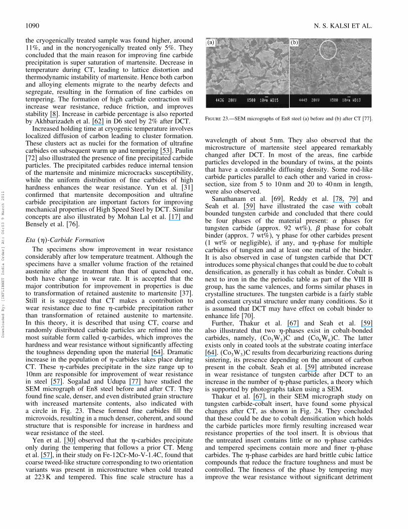
cryogenic cooling of metal after destabilization at differenttemperatures. They concluded that cryogenic cooling is ofgreat help in reduction of retained carbides when heat-treated at higher temperature range as shown in Fig. 22.Silva et al. [32] found reduction of austenite from 25% to
nearly 0% in case of M2 steel, which is also supported byReasbeck [74]. Elimination of the retained austenite duringDCT is also reported by Dong et al. [75] and Collins et al.[27] in high-speed steel and by Das et al. [26] in M2 Steel.Yang et al. [37] in their study on 13Cr2Mn2V high
Chromium white iron reported that transformation ofretained austenite into martensite occurred during DCT.
Figure 22.—The contents of retained austenite at different heat-treated states[54].
Previous Fig. 2 shows the percentage retained austenitecontents in noncryogenic treated and CT alloy with changein prior destabilization temperature. The retained austenitecontent decreases with the temperature from 900 to 1000�C(1173 to 1273K) due to the secondary carbides precipitationin the matrix and further at high temperatures it increases.Increase in martensite content from 59.3%, to 65.2% inDCT after destabilized at 1000�C (1273K) is reported.It shows that during CT the transformation of retainedaustenite into martensite takes place, which is the primaryreason for the observed improvement in wear resistance[37]. However, it has been proven that a cold treatment at−80�C (193K) is sufficient for transforming most of theretained austenite into martensite [29]. It is also observedthat the cold-treated samples of M2 steel have almost samevolume fraction of retained austenite as the DCT samples,nevertheless, the wear resistance of the latter was superiorto that of the former. These results indicate that factorsother than the transformation of the retained austenite intomartensite contribute to improve the wear resistance, whendiffusion wear mechanism is dominating [8, 49].
Precipitation of CarbidesCT has much influence on the characteristics of freshly
formed martensite, which on tempering results in theprecipitation of carbide particles due to which bothtoughness and wear resistance increases consequently[27, 70]. Improved wear resistance in steels is due toprecipitation of fine carbides during CT [5, 6, 32, 47, 57, 61].Yang et al. [37] in their study on 13Cr2Mn2V highchromium white iron destabilized at 1000�C (1273K),concluded that with help of DCT martensite contentincreased from 59.3% to 65.2% and secondary carbidesprecipitate in the austenite matrix, lowering the carbon andalloy content. Huang et al. [8] worked on M2 Tool Steeland have observed that both the DCT and noncryogenicallytreated samples precipitated out spherical Fe4M2 (M=W,Mo, Cr, V) C carbides with a face-centered-cubic structureand a lattice parameter a = 11�5Å with particle size rangesfrom 0.3 to 2�m. The volume fraction of carbides in
Downloaded By: [INFLIBNET India Order] At: 06:03 9 March 2011
1090 N. S. KALSI ET AL.
the cryogenically treated sample was found higher, around11%, and in the noncryogenically treated only 5%. Theyconcluded that the main reason for improving fine carbideprecipitation is super saturation of martensite. Decrease intemperature during CT, leading to lattice distortion andthermodynamic instability of martensite. Hence both carbonand alloying elements migrate to the nearby defects andsegregate, resulting in the formation of fine carbides ontempering. The formation of high carbide contraction willincrease wear resistance, reduce friction, and improvesstability [8]. Increase in carbide percentage is also reportedby Akhbarizadeh et al. [62] in D6 steel by 2% after DCT.Increased holding time at cryogenic temperature involves
localized diffusion of carbon leading to cluster formation.These clusters act as nuclei for the formation of ultrafinecarbides on subsequent warm up and tempering [53]. Paulin[72] also illustrated the presence of fine precipitated carbideparticles. The precipitated carbides reduce internal tensionof the martensite and minimize microcracks susceptibility,while the uniform distribution of fine carbides of highhardness enhances the wear resistance. Yun et al. [31]confirmed that martensite decomposition and ultrafinecarbide precipitation are important factors for improvingmechanical properties of High Speed Steel by DCT. Similarconcepts are also illustrated by Mohan Lal et al. [17] andBensely et al. [76].
Eta ���-Carbide FormationThe specimens show improvement in wear resistance
considerably after low temperature treatment. Although thespecimens have a smaller volume fraction of the retainedaustenite after the treatment than that of quenched one,both have change in wear rate. It is accepted that themajor contribution for improvement in properties is dueto transformation of retained austenite to martensite [37].Still it is suggested that CT makes a contribution towear resistance due to fine �-carbide precipitation ratherthan transformation of retained austenite to martensite.In this theory, it is described that using CT, coarse andrandomly distributed carbide particles are refined into themost suitable form called �-carbides, which improves thehardness and wear resistance without significantly affectingthe toughness depending upon the material [64]. Dramaticincrease in the population of �-carbides takes place duringCT. These �-carbides precipitate in the size range up to10nm are responsible for improvement of wear resistancein steel [57]. Sogalad and Udupa [77] have studied theSEM micrograph of En8 steel before and after CT. Theyfound fine scale, denser, and even distributed grain structurewith increased martensite contents, also indicated witha circle in Fig. 23. These formed fine carbides fill themicrovoids, resulting in a much denser, coherent, and soundstructure that is responsible for increase in hardness andwear resistance of the steel.Yen et al. [30] observed that the �-carbides precipitate
only during the tempering that follows a prior CT. Menget al. [57], in their study on Fe-12Cr-Mo-V-1.4C, found thatcoarse tweed-like structure corresponding to two orientationvariants was present in microstructure when cold treatedat 223K and tempered. This fine scale structure has a
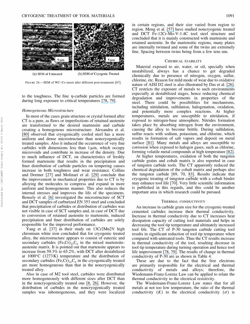
Figure 23.—SEM micrographs of En8 steel (a) before and (b) after CT [77].
wavelength of about 5nm. They also observed that themicrostructure of martensite steel appeared remarkablychanged after DCT. In most of the areas, fine carbideparticles developed in the boundary of twins, at the pointsthat have a considerable diffusing density. Some rod-likecarbide particles parallel to each other and varied in cross-section, size from 5 to 10nm and 20 to 40nm in length,were also observed.Sanathanam et al. [69], Reddy et al. [78, 79] and
Seah et al. [59] have illustrated the case with cobaltbounded tungsten carbide and concluded that there couldbe four phases of the material present: � phases fortungsten carbide (approx. 92 wt%), � phase for cobaltbinder (approx. 7 wt%), phase for other carbides present(1 wt% or negligible), if any, and �-phase for multiplecarbides of tungsten and at least one metal of the binder.It is also observed in case of tungsten carbide that DCTintroduces some physical changes that could be due to cobaltdensification, as generally it has cobalt as binder. Cobalt isnext to iron in the the periodic table as part of the VIII Bgroup, has the same valences, and forms similar phases incrystalline structures. The tungsten carbide is a fairly stableand constant crystal structure under many conditions. So itis assumed that DCT may have effect on cobalt binder toenhance life [70].Further, Thakur et al. [67] and Seah et al. [59]
also illustrated that two �-phases exist in cobalt-bondedcarbides, namely, �Co3W3�C and �Co6W6�C. The latterexists only in coated tools at the substrate coating interface[64]. �Co3W3�C results from decarburizing reactions duringsintering, its presence depending on the amount of carbonpresent in the cobalt. Seah et al. [59] attributed increasein wear resistance of tungsten carbide after DCT to anincrease in the number of �-phase particles, a theory whichis supported by photographs taken using a SEM.Thakur et al. [67], in their SEM micrograph study on
tungsten carbide-cobalt insert, have found some physicalchanges after CT, as shown in Fig. 24. They concludedthat these could be due to cobalt densification which holdsthe carbide particles more firmly resulting increased wearresistance properties of the tool insert. It is obvious thatthe untreated insert contains little or no �-phase carbidesand tempered specimens contain more and finer �-phasecarbides. The �-phase carbides are hard brittle cubic latticecompounds that reduce the fracture toughness and must becontrolled. The fineness of the phase by tempering mayimprove the wear resistance without significant detriment
Downloaded By: [INFLIBNET India Order] At: 06:03 9 March 2011
CRYOGENIC TREATMENT OF TOOL MATERIALS 1091
Figure 24.—SEM of WC–Co insert after different post-treatments [67].
to the toughness. The fine �-carbide particles are formedduring long exposure to critical temperatures [78, 79].
Homogeneous MicrostructureIn most of the cases grain structure or crystal formed after
CT is a pure, as flaws or imperfections of retained austeniteare transformed to the desired martensite and carbidecreating a homogenous microstructure. Alexandru et al.[80] observed that cryogenically cooled steel has a moreuniform and dense microstructure than noncryogenicallytreated samples. Also it induced the occurrence of very finecarbides with dimensions less than 1�m, which occupymicrovoids and contribute in increase of the density. Dueto much influence of DCT, on characteristics of freshlyformed martensite that results in the precipitation andfiner distribution of carbide particles on tempering causesincrease in both toughness and wear resistance. Collinsand Dormer [27] and Molinari et al. [29] conclude thatthe improvement in mechanical properties due to CT is byalloying the molecules to compress and expand in moreuniform and homogeneous manner. This also reduces theinternal stresses and improves the life of the specimens.Bensely et al. [6] investigated the microstructure of SCTand DCT samples of carburized EN 353 steel and concludedthat precipitation of carbides or distribution of carbides wasnot visible in case of SCT samples and, in case of DCT dueto conversion of retained austenite to martensite, inducedprecipitation and finer distribution of carbides are solelyresponsible for the improved performance.Yang et al. [37] in their study on 13Cr2Mn2V high
chromium white iron concluded that for cryogenic treatedalloy, the microstructure appears to consist of eutectic andsecondary carbides �Fe,Cr�23C6 in the mixed martensite-austenite matrix. It is pointed out that martensite appears toincrease from 59.3% to 65.2%, with DCT after destabilizedat 1000�C (1273K) temperature and the distribution ofsecondary carbides �Fe,Cr�23C6 in the cryogenically treatedare more homogeneous than that in the noncryogenicallytreated alloy.Also in case of M2 tool steel, carbides were distributed
more homogeneously with different sizes after DCT thanin the noncryogenically treated one [8, 26]. However, thedistribution of carbides in the noncryogenically treatedsamples was inhomogeneous, and they were localized
in certain regions, and their size varied from region toregion. Meng et al. [57] have studied noncryogenic treatedand DCT Fe-12Cr-Mo-V-1.4C tool steel structure andconcluded that it is mainly constructed with martensite andretained austenite. In the martensitic regions, many platesare internally twinned and some of the twins are extremelyfine. Spacing between twins being from a few tens nm.
Chemical stability
Material exposed to air, water, or oil, specially whenunstabilized, always has a chance to get degradedchemically due to presence of nitrogen, oxygen, sulfur,chlorine, etc. Reason for mild mode of wear due to oxidativenature of AISI D2 steel is also illustrated by Das et al. [26].CT restricts the exposure of metals to such environmentsespecially at destabilized stages, hence reducing chemicaldegradation and improvements in properties of thesteel. There could be possibilities for mechanisms,including nitridation, sulfidation, halogenation, oxidation,and potentially more complex reactions. At highertemperatures, metals are susceptible to nitridation, ifexposed to nitrogen-base atmosphere. Nitrides formationtakes place by absorbing nitrogen from the environment,causing the alloy to become brittle. During sulfidation,sulfur reacts with sodium, potassium, and chlorine, whichresults in formation of salt vapors and deposit on metalsurface [81]. Many metals and alloys are susceptible tocorrosion when exposed to halogen gases, such as chlorine,forming volatile metal compounds at high temperature [82].At higher temperatures, oxidation of both the tungsten
carbide grains and cobalt matrix is also reported in caseof tungsten carbide tools. The CT apparently reduced thechemical degradation of the cobalt matrix and perhaps alsothe tungsten carbide [69, 70, 83]. Results indicate thatcryogenic treating of tungsten carbide with a cobalt bindermay enhance tool life [70]. Very little scientific informationis published in this regards, and this could be anotherimportant area in which research could be pursued.
Thermal conductivity
An increase in carbide grain size for the cryogenic-treatedcemented carbides increase their thermal conductivity.Increase in thermal conductivity due to CT increases heatdissipation capacity of cutting tool materials and helps indecreasing the tool tip temperature and ultimately increasedtool life. The CT of P-30 tungsten carbide cutting toolresults in significant reduction of tool tip temperature whencompared with untreated tools. Thus the CT results increasein thermal conductivity of the tool, resulting decrease intool tip temperature during turning operation and hence toollife improvement [78, 79]. The results of change in thermalconductivity of P-30 are as shown in Table 4.These are due to the fact that the free electrons
are primarily responsible for the electrical and thermalconductivity of metals and alloys; therefore, theWiedemann-Franz-Lorenz Law can be applied to relate thethermal conductivity to the electrical resistivity.The Wiedemann-Franz-Lorenz Law states that for all
metals at not too low temperature, the ratio of the thermalconductivity �K� to the electrical conductivity �� is
Downloaded By: [INFLIBNET India Order] At: 06:03 9 March 2011
1092 N. S. KALSI ET AL.
Table 4.—The electrical resistivity and electrical conductivity of the P-30inserts [79].
Condition of cutting toolinsert (P-30)
Electrical resistivityohm-m
Electrical conductivity(ohm-m)−1
Un treated 2�0× 10−3 499.676Deep cryotreated 1�749× 10−3 571.62
directly proportional to the temperature �T � with thevalue of the constant of proportionality independent of theparticular metal [84], which is given as
K
= LT � (A2)
Theoretically, the proportionality constant number, knownas the Lorenz number, is equal to
L = K
T= 2�44× 10−8W�K−2�
Evidence of increase in thermal conductivity is also shownby Isaak and Reitz [85] in case of GRCop-84. Zhisheng etal. [86] in his study on DCT of spot welding electrodes,achieved approximately 3.25 times rise in productivity.This is basically due to precipitation of carbides and morecompact and homogenous structure of the steel during CT.
Improvement in mechanical properties
CT has been proved to be an effective method to improvethe properties of the steel and other materials. Variousmethods have been applied like pin and disk, wheel and pin,block on disk, ball and disk, wheel and block, machiningmethods, microhardness testing, surface roughness testing,etc., to analyze the improvements in mechanical properties[6, 7, 12, 17, 26, 29, 32, 47, 53, 57, 73, 85]. Some of theimportant properties are discussed below.
Residual StressesResidual stresses are result of temperature changes
that produce thermal expansion and phase changes, andconsequently, volume changes, and often contribute to partfailure. Under normal conditions, temperature gradientsproduce non-uniform dimensional and volume changes.Compressive stresses develop in the volume, which coolfirst in lower-volume areas, and tensile stresses developin greater volume, which is the last to cool. Shearstresses develop between the two areas [60]. When bothvolume and phase changes occur simultaneously, normalcontractions are opposed by transformation expansionduring cooling cycle and residual stresses are developed.These residual stresses will remain till the suitable methodfor relieving them is applied. During quenching, thesetypes of stresses develop most frequently in steels. In thiscase, top surface becomes martensitic before the inner one,and hence subsequent interior expansions due to austenitetransformation place the surface martensite under tension.Cracks in the steel arise from such stresses. Cold treating hasproved beneficial in such stress relief of the materials [60].
Baldissera and Delprete [4] in their study concluded thatpost-tempering DCT has given much beneficial effects onthe residual stress state. The transformation of austenite tomartensite would influence the compressive residual stress,which in turn would affect the behavior of the material[53]. In case of tungsten carbide tools, the carbide phaseis subjected to compressive stresses and the binder totensile ones during DCT. The magnitude of the stressesincreases with decreasing cobalt content. The increasingstresses generated by quenching may be expected to resultin decreased ductility of the cobalt phase. The tungstencarbide is subjected to compression from all sides, and anincrease of compressive stresses would lead to an increase inthe strength of the carbide matrix. CT also relieves stressesintroduced during the sintering process [67].Compressive residual stresses are beneficial in a material
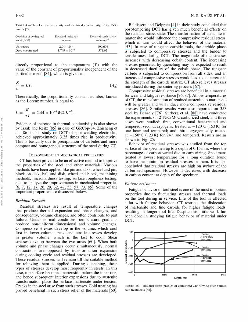
for wear and fatigue resistance [76, 87]. At low temperaturesof CT, the transformation of retained austenite to martensitewill be greater and will induce more compressive residualstresses [86]. Similar results were also reported on 353steel by Bensely [76]. Surberg et al. [88] have conductedthe experiments on 21NiCrMo2 carburized steel, and threecases were studied: first, conventional heat-treated andtempered; second, cryogenic treated at −120�C (153K) forone hour and tempered; and third, cryogenically treatedat −150�C (123K) for 24h and tempered. Results are asshown in Fig. 25:Behavior of residual stresses was studied from the top
surface of the specimen up to a depth of 0.15mm, where thepercentage of carbon varied due to carburizing. Specimenstreated at lowest temperature for a long duration foundto have the minimum residual stresses in them. It is alsoconcluded that residual stresses are high on surface of thecarburized specimen. However it decreases with decreasein carbon content at depth of the specimen.
Fatigue resistanceFatigue behavior of tool steel is one of the most important
properties due to fluctuating stresses and thermal loadson the tool during in service. Life of the tool is affecteda lot with fatigue behavior. CT restricts the dislocationof martensite and fine carbide for higher fatigue loads,resulting in longer tool life. Despite this, little work hasbeen done in studying fatigue behavior of material underDCT.
Figure 25.—Residual stress profiles of carburized 21NiCrMo2 after variouscold treatments [88].
Downloaded By: [INFLIBNET India Order] At: 06:03 9 March 2011
CRYOGENIC TREATMENT OF TOOL MATERIALS 1093
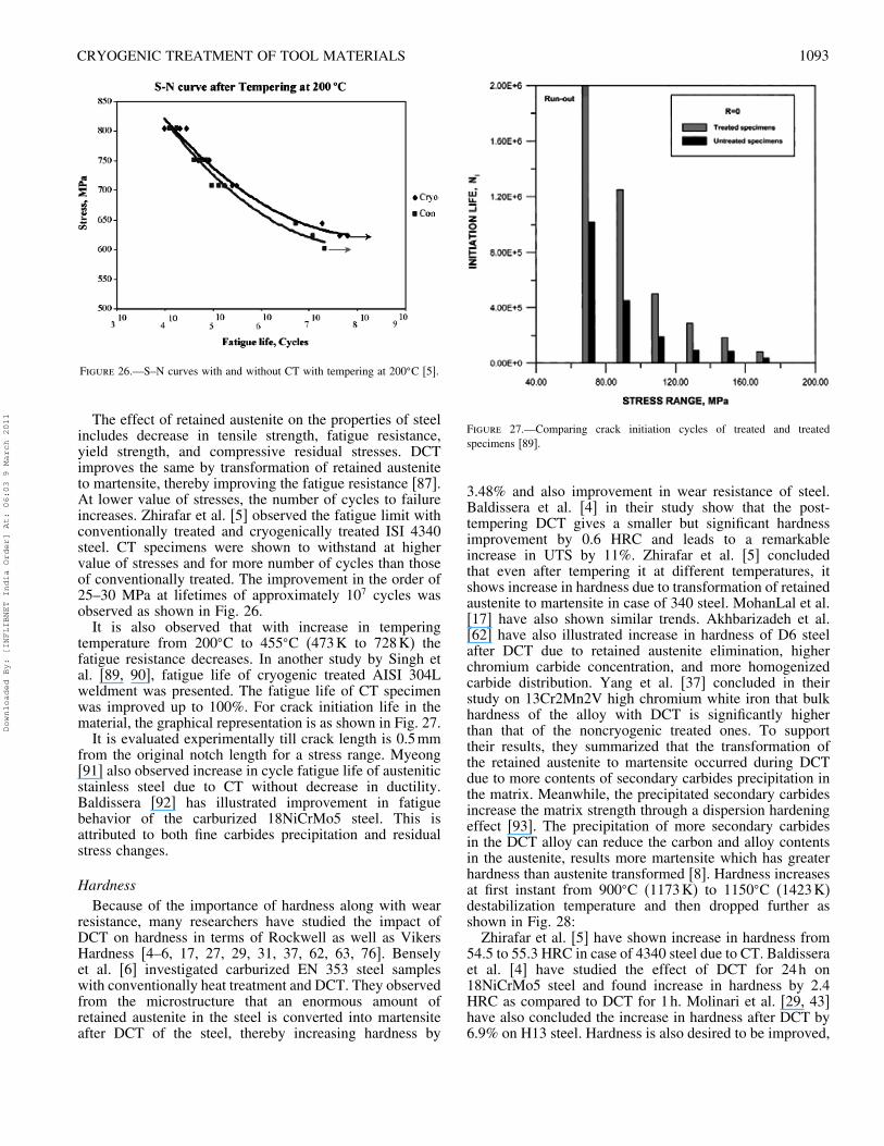
Figure 26.—S–N curves with and without CT with tempering at 200�C [5].
The effect of retained austenite on the properties of steelincludes decrease in tensile strength, fatigue resistance,yield strength, and compressive residual stresses. DCTimproves the same by transformation of retained austeniteto martensite, thereby improving the fatigue resistance [87].At lower value of stresses, the number of cycles to failureincreases. Zhirafar et al. [5] observed the fatigue limit withconventionally treated and cryogenically treated ISI 4340steel. CT specimens were shown to withstand at highervalue of stresses and for more number of cycles than thoseof conventionally treated. The improvement in the order of25–30 MPa at lifetimes of approximately 107 cycles wasobserved as shown in Fig. 26.It is also observed that with increase in tempering
temperature from 200�C to 455�C (473K to 728K) thefatigue resistance decreases. In another study by Singh etal. [89, 90], fatigue life of cryogenic treated AISI 304Lweldment was presented. The fatigue life of CT specimenwas improved up to 100%. For crack initiation life in thematerial, the graphical representation is as shown in Fig. 27.It is evaluated experimentally till crack length is 0.5mm
from the original notch length for a stress range. Myeong[91] also observed increase in cycle fatigue life of austeniticstainless steel due to CT without decrease in ductility.Baldissera [92] has illustrated improvement in fatiguebehavior of the carburized 18NiCrMo5 steel. This isattributed to both fine carbides precipitation and residualstress changes.
HardnessBecause of the importance of hardness along with wear
resistance, many researchers have studied the impact ofDCT on hardness in terms of Rockwell as well as VikersHardness [4–6, 17, 27, 29, 31, 37, 62, 63, 76]. Benselyet al. [6] investigated carburized EN 353 steel sampleswith conventionally heat treatment and DCT. They observedfrom the microstructure that an enormous amount ofretained austenite in the steel is converted into martensiteafter DCT of the steel, thereby increasing hardness by
Figure 27.—Comparing crack initiation cycles of treated and treatedspecimens [89].
3.48% and also improvement in wear resistance of steel.Baldissera et al. [4] in their study show that the post-tempering DCT gives a smaller but significant hardnessimprovement by 0.6 HRC and leads to a remarkableincrease in UTS by 11%. Zhirafar et al. [5] concludedthat even after tempering it at different temperatures, itshows increase in hardness due to transformation of retainedaustenite to martensite in case of 340 steel. MohanLal et al.[17] have also shown similar trends. Akhbarizadeh et al.[62] have also illustrated increase in hardness of D6 steelafter DCT due to retained austenite elimination, higherchromium carbide concentration, and more homogenizedcarbide distribution. Yang et al. [37] concluded in theirstudy on 13Cr2Mn2V high chromium white iron that bulkhardness of the alloy with DCT is significantly higherthan that of the noncryogenic treated ones. To supporttheir results, they summarized that the transformation ofthe retained austenite to martensite occurred during DCTdue to more contents of secondary carbides precipitation inthe matrix. Meanwhile, the precipitated secondary carbidesincrease the matrix strength through a dispersion hardeningeffect [93]. The precipitation of more secondary carbidesin the DCT alloy can reduce the carbon and alloy contentsin the austenite, results more martensite which has greaterhardness than austenite transformed [8]. Hardness increasesat first instant from 900�C (1173K) to 1150�C (1423K)destabilization temperature and then dropped further asshown in Fig. 28:Zhirafar et al. [5] have shown increase in hardness from
54.5 to 55.3 HRC in case of 4340 steel due to CT. Baldisseraet al. [4] have studied the effect of DCT for 24h on18NiCrMo5 steel and found increase in hardness by 2.4HRC as compared to DCT for 1h. Molinari et al. [29, 43]have also concluded the increase in hardness after DCT by6.9% on H13 steel. Hardness is also desired to be improved,
Downloaded By: [INFLIBNET India Order] At: 06:03 9 March 2011
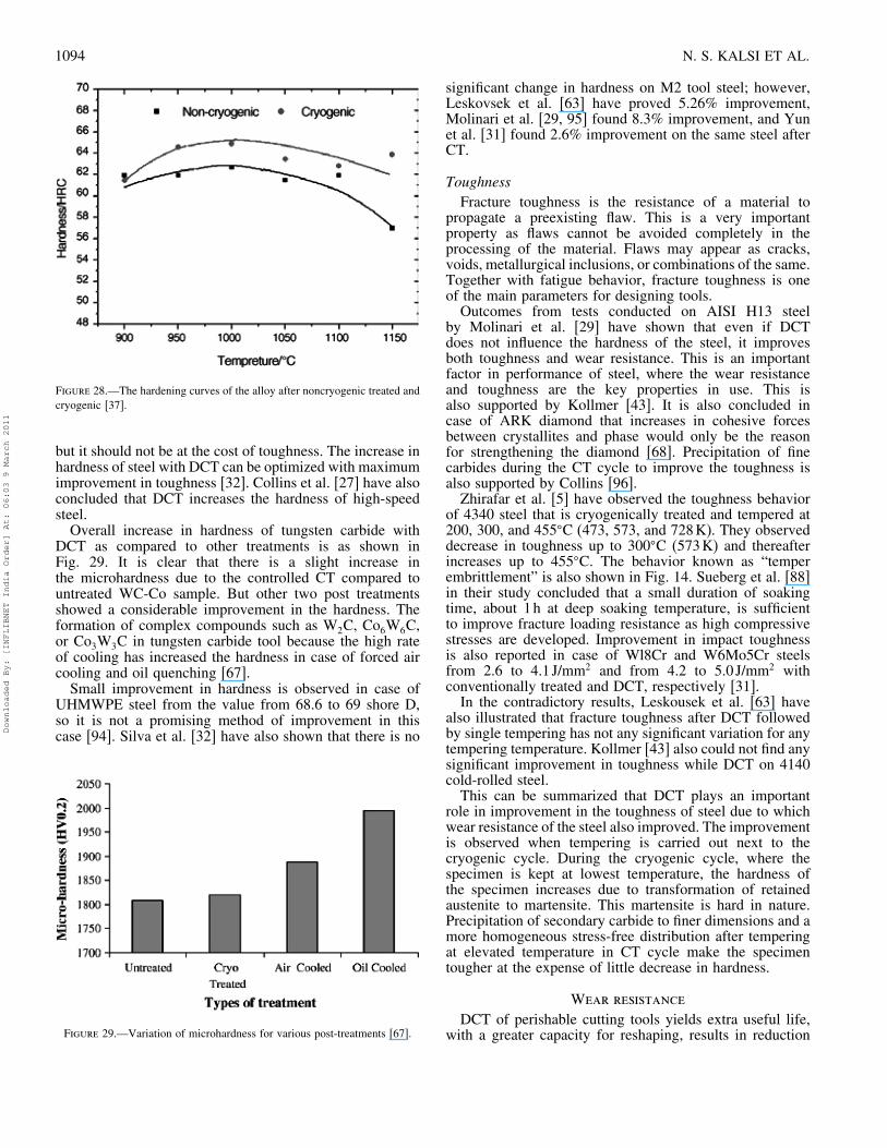
1094 N. S. KALSI ET AL.
Figure 28.—The hardening curves of the alloy after noncryogenic treated andcryogenic [37].
but it should not be at the cost of toughness. The increase inhardness of steel with DCT can be optimized with maximumimprovement in toughness [32]. Collins et al. [27] have alsoconcluded that DCT increases the hardness of high-speedsteel.Overall increase in hardness of tungsten carbide with
DCT as compared to other treatments is as shown inFig. 29. It is clear that there is a slight increase inthe microhardness due to the controlled CT compared tountreated WC-Co sample. But other two post treatmentsshowed a considerable improvement in the hardness. Theformation of complex compounds such as W2C, Co6W6C,or Co3W3C in tungsten carbide tool because the high rateof cooling has increased the hardness in case of forced aircooling and oil quenching [67].Small improvement in hardness is observed in case of
UHMWPE steel from the value from 68.6 to 69 shore D,so it is not a promising method of improvement in thiscase [94]. Silva et al. [32] have also shown that there is no
Figure 29.—Variation of microhardness for various post-treatments [67].
significant change in hardness on M2 tool steel; however,Leskovsek et al. [63] have proved 5.26% improvement,Molinari et al. [29, 95] found 8.3% improvement, and Yunet al. [31] found 2.6% improvement on the same steel afterCT.
ToughnessFracture toughness is the resistance of a material to
propagate a preexisting flaw. This is a very importantproperty as flaws cannot be avoided completely in theprocessing of the material. Flaws may appear as cracks,voids, metallurgical inclusions, or combinations of the same.Together with fatigue behavior, fracture toughness is oneof the main parameters for designing tools.Outcomes from tests conducted on AISI H13 steel
by Molinari et al. [29] have shown that even if DCTdoes not influence the hardness of the steel, it improvesboth toughness and wear resistance. This is an importantfactor in performance of steel, where the wear resistanceand toughness are the key properties in use. This isalso supported by Kollmer [43]. It is also concluded incase of ARK diamond that increases in cohesive forcesbetween crystallites and phase would only be the reasonfor strengthening the diamond [68]. Precipitation of finecarbides during the CT cycle to improve the toughness isalso supported by Collins [96].Zhirafar et al. [5] have observed the toughness behavior
of 4340 steel that is cryogenically treated and tempered at200, 300, and 455�C (473, 573, and 728K). They observeddecrease in toughness up to 300�C (573K) and thereafterincreases up to 455�C. The behavior known as “temperembrittlement” is also shown in Fig. 14. Sueberg et al. [88]in their study concluded that a small duration of soakingtime, about 1h at deep soaking temperature, is sufficientto improve fracture loading resistance as high compressivestresses are developed. Improvement in impact toughnessis also reported in case of Wl8Cr and W6Mo5Cr steelsfrom 2.6 to 4.1 J/mm2 and from 4.2 to 5.0 J/mm2 withconventionally treated and DCT, respectively [31].In the contradictory results, Leskousek et al. [63] have
also illustrated that fracture toughness after DCT followedby single tempering has not any significant variation for anytempering temperature. Kollmer [43] also could not find anysignificant improvement in toughness while DCT on 4140cold-rolled steel.This can be summarized that DCT plays an important
role in improvement in the toughness of steel due to whichwear resistance of the steel also improved. The improvementis observed when tempering is carried out next to thecryogenic cycle. During the cryogenic cycle, where thespecimen is kept at lowest temperature, the hardness ofthe specimen increases due to transformation of retainedaustenite to martensite. This martensite is hard in nature.Precipitation of secondary carbide to finer dimensions and amore homogeneous stress-free distribution after temperingat elevated temperature in CT cycle make the specimentougher at the expense of little decrease in hardness.
Wear resistance
DCT of perishable cutting tools yields extra useful life,with a greater capacity for reshaping, results in reduction
Downloaded By: [INFLIBNET India Order] At: 06:03 9 March 2011
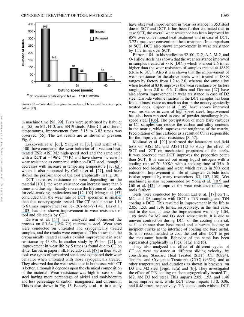
CRYOGENIC TREATMENT OF TOOL MATERIALS 1095
Figure 30.—Twist drill lives given in numbers of holes until the catastrophicfailure [27].
in machine time [98, 99]. Tests were performed by Babu etal. [55] on M1, H13, and EN19 steels. After CT at differenttemperatures, improvement from 3.15 to 3.82 times wasobserved [55]. The test results are as shown in previousFig. 6.Leskovsek et al. [63], Yang et al. [37], and Kalin et al.
[100] have compared the wear behavior of a vacuum heat-treated ESR AISI M2 high-speed steel and the same steelwith a DCT at −196�C (77K) and have shown increase inwear resistance as compared with non-DCT steel, though itdecreases with increase in tempering temperature [37, 63],which is also supported by Collins et al. [27], and haveshown the performance of the tool graphically in Fig. 30.DCT increases resistance to wear depending on the
material [101]; the wear resistance can increase more than 8times and thus significantly increase the lifetime of the toolsfor cold-working applications too [12, 102]. Meng et al. [57]concluded that the wear rate of DCT specimen is smallerthan that noncryogenic treated. The CT results show 1.10to 6 times improvement on Fe-12Cr-Mo-V-1.4C. Das et al.[103] has also shown improvement in wear resistance oftool and die steels by CT.Darwin et al. [44] have analyzed and optimized the
process on SR-34 (18% Cr) martensite steel. Wear testswere conducted on untreated and cryogenically treatedsamples, and the results were compared. This shows that thecryogenically treated samples exhibit improvement in wearresistance by 43.8%. In another study by Wilson [71], animprovement in wear life by 5 times is found due to CT onslitter knives in paper mill. Preciado et al. [47] in their studytook two types of carburized steels and compared their wearbehavior when untreated with those cryogenically treated.They observed that the wear resistance in both cases with CTis better, although it depends upon the chemical compositionof the material. Wear resistance was high in case of thesteel having more percentage of nickel and molybdenumand less percentage of carbon, manganese, and chromium.This is also shown in Fig. 15. Bensely et al. [6] in a study
have observed improvement in wear resistance in 353 steeldue to SCT and DCT. It has been further estimated that incase SCT, the overall wear resistance has been improved by85% over conventional heat treatment and in case of DCT,3.72 times over conventional heat treatment. In comparisonto SCT, DCT also shows improvement in wear resistanceby 1.52 times over SCT.Barron [104] in his studies on 52100, D-2, A-2, M-2, and
O-1 alloy steels has shown that the wear resistance improvedin samples treated at 83K (DCT) which is about 2.6 timeshigher than the wear resistance of samples treated at 188K(close to SCT). Also it was shown that the improvement ofwear resistance for the above steels when treated at 188Kranges by factors from 1.2 to 2.0, whereas the same alloywhen treated at 83K improves the wear resistance by factorsranging from 2.0 to 6.6. Collins and Dormer [27] havealso shown improvement in wear resistance in case of D2steel. Carbide volume fraction in the DCT samples has beenfound almost twice as much as that in the noncryogenicallytreated ones. Cajner et al. [105] have shown improvedwear resistance in case of high-speed steel. Improvementhas also been reported in case of powder-metallurgy high-speed steel [106]. The precipitation of more hard carbidesin CT samples can reduce the carbon and alloy contentsin the matrix, which improves the toughness of the matrix.Precipitation of fine carbides as a result of CT is responsiblefor the improved wear resistance [8, 57].Molinari et al. [29] performed the laboratory and field
tests on AISI M2 and AISI H13 to study the effect ofSCT and DCT on mechanical properties of the steels.It was observed that DCT improves the properties betterthan SCT. It is carried out using liquid nitrogen with acooling rate of 20–30K/h with a soaking time of 35h. Itreduces tool breakage and wear, which results in 50% costreduction. Improvement in life of tungsten carbide toolsis also reported by many researchers [83, 107, 108]. Wetmachining is also recommended by Yong et al. [107] andGill et al. [42] to improve the wear resistance of cuttingtools further.Tests were conducted by Mohan Lal et al. [17] on T1,
M2, and D3 samples with DCT + TiN coating and TiNcoating + DCT. This resulted in improvement in the life to2.05, 1.53, and 1.46 times, respectively, in the first case,and in the second case the improvement was only 1.04,1.09 times for M2 and D3 steel, respectively. It is due touneven contraction during DCT of the coating material,as it is thinner than base metal and substrate leading toincipient cracks at the interface of coating and base metal.So it is recommended to coat the tool after DCT to getthe maximum benefit. Behavior of the same has beenrepresented graphically in Figs. 31(a) and (b).They also analyzed the effect of different cycles of
CT on wear resistance at different sliding velocity, byconsidering Standard Heat Treated (SHT), CT (93/24),Temped and Cryogenic Treatment (CTC) (93/24), and atother temperatures and durations as shown in brackets, onD3 and M2 steel [Figs. 32(a) and (b)]. They investigatedthe effect of TiN coating on deep cryogenically treated T1,M2, and D3 tool steel. This imparts 2.05, 1.53, and 1.46times improvement, while DCT alone imparts 1.10, 0.06,and 0.48 times, respectively. TiN coated tools without DCT
Downloaded By: [INFLIBNET India Order] At: 06:03 9 March 2011
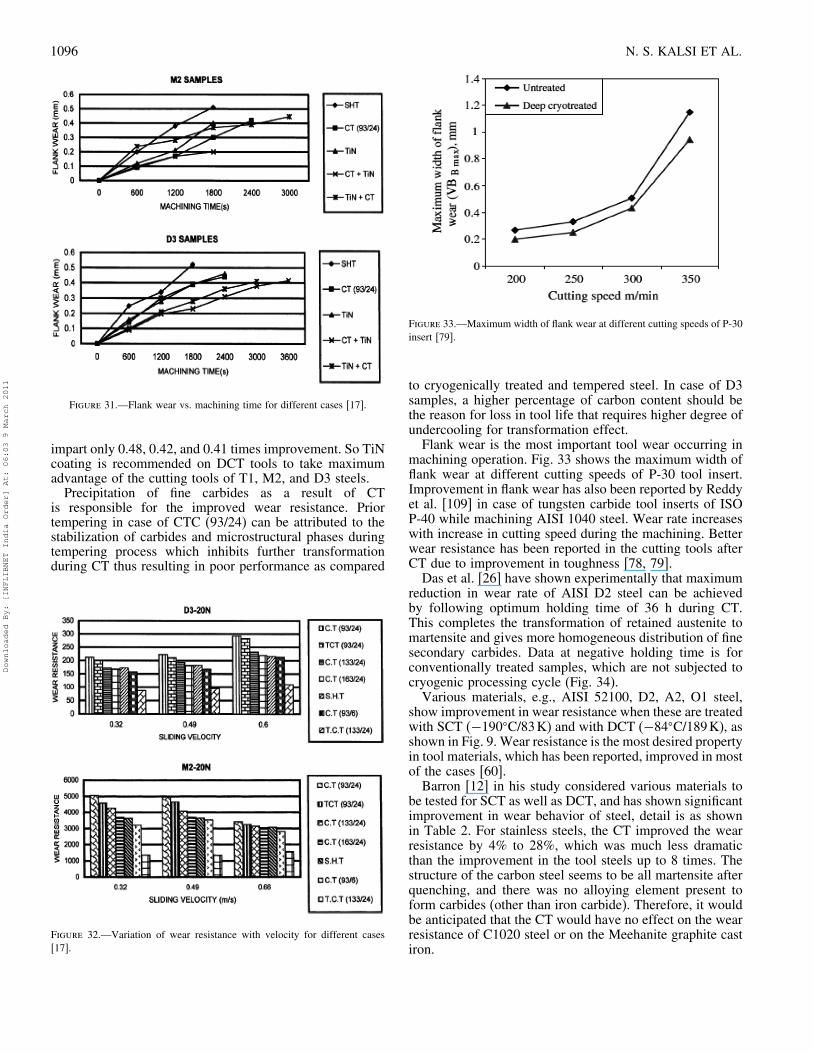
1096 N. S. KALSI ET AL.
Figure 31.—Flank wear vs. machining time for different cases [17].
impart only 0.48, 0.42, and 0.41 times improvement. So TiNcoating is recommended on DCT tools to take maximumadvantage of the cutting tools of T1, M2, and D3 steels.Precipitation of fine carbides as a result of CT
is responsible for the improved wear resistance. Priortempering in case of CTC (93/24) can be attributed to thestabilization of carbides and microstructural phases duringtempering process which inhibits further transformationduring CT thus resulting in poor performance as compared
Figure 32.—Variation of wear resistance with velocity for different cases[17].
Figure 33.—Maximum width of flank wear at different cutting speeds of P-30insert [79].
to cryogenically treated and tempered steel. In case of D3samples, a higher percentage of carbon content should bethe reason for loss in tool life that requires higher degree ofundercooling for transformation effect.Flank wear is the most important tool wear occurring in
machining operation. Fig. 33 shows the maximum width offlank wear at different cutting speeds of P-30 tool insert.Improvement in flank wear has also been reported by Reddyet al. [109] in case of tungsten carbide tool inserts of ISOP-40 while machining AISI 1040 steel. Wear rate increaseswith increase in cutting speed during the machining. Betterwear resistance has been reported in the cutting tools afterCT due to improvement in toughness [78, 79].Das et al. [26] have shown experimentally that maximum
reduction in wear rate of AISI D2 steel can be achievedby following optimum holding time of 36 h during CT.This completes the transformation of retained austenite tomartensite and gives more homogeneous distribution of finesecondary carbides. Data at negative holding time is forconventionally treated samples, which are not subjected tocryogenic processing cycle (Fig. 34).Various materials, e.g., AISI 52100, D2, A2, O1 steel,
show improvement in wear resistance when these are treatedwith SCT (−190�C/83K) and with DCT (−84�C/189K), asshown in Fig. 9. Wear resistance is the most desired propertyin tool materials, which has been reported, improved in mostof the cases [60].Barron [12] in his study considered various materials to
be tested for SCT as well as DCT, and has shown significantimprovement in wear behavior of steel, detail is as shownin Table 2. For stainless steels, the CT improved the wearresistance by 4% to 28%, which was much less dramaticthan the improvement in the tool steels up to 8 times. Thestructure of the carbon steel seems to be all martensite afterquenching, and there was no alloying element present toform carbides (other than iron carbide). Therefore, it wouldbe anticipated that the CT would have no effect on the wearresistance of C1020 steel or on the Meehanite graphite castiron.
Downloaded By: [INFLIBNET India Order] At: 06:03 9 March 2011
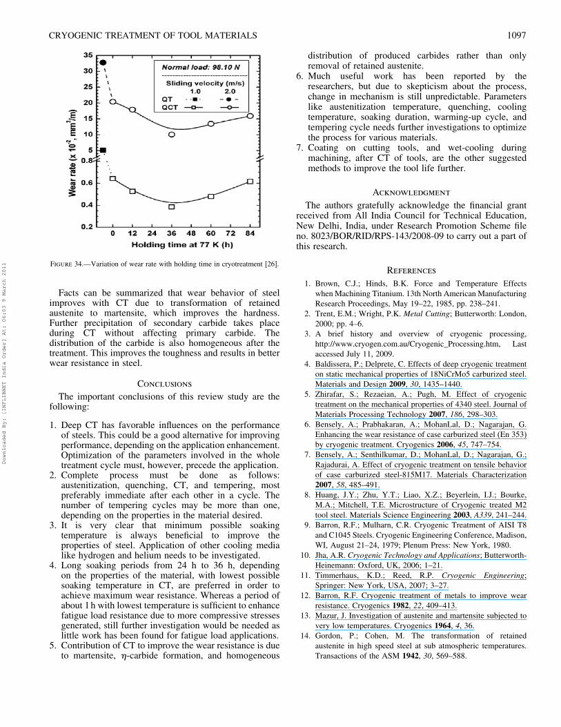
CRYOGENIC TREATMENT OF TOOL MATERIALS 1097
Figure 34.—Variation of wear rate with holding time in cryotreatment [26].
Facts can be summarized that wear behavior of steelimproves with CT due to transformation of retainedaustenite to martensite, which improves the hardness.Further precipitation of secondary carbide takes placeduring CT without affecting primary carbide. Thedistribution of the carbide is also homogeneous after thetreatment. This improves the toughness and results in betterwear resistance in steel.
Conclusions
The important conclusions of this review study are thefollowing:
1. Deep CT has favorable influences on the performanceof steels. This could be a good alternative for improvingperformance, depending on the application enhancement.Optimization of the parameters involved in the wholetreatment cycle must, however, precede the application.
2. Complete process must be done as follows:austenitization, quenching, CT, and tempering, mostpreferably immediate after each other in a cycle. Thenumber of tempering cycles may be more than one,depending on the properties in the material desired.
3. It is very clear that minimum possible soakingtemperature is always beneficial to improve theproperties of steel. Application of other cooling medialike hydrogen and helium needs to be investigated.
4. Long soaking periods from 24 h to 36 h, dependingon the properties of the material, with lowest possiblesoaking temperature in CT, are preferred in order toachieve maximum wear resistance. Whereas a period ofabout 1h with lowest temperature is sufficient to enhancefatigue load resistance due to more compressive stressesgenerated, still further investigation would be needed aslittle work has been found for fatigue load applications.
5. Contribution of CT to improve the wear resistance is dueto martensite, �-carbide formation, and homogeneous
distribution of produced carbides rather than onlyremoval of retained austenite.
6. Much useful work has been reported by theresearchers, but due to skepticism about the process,change in mechanism is still unpredictable. Parameterslike austenitization temperature, quenching, coolingtemperature, soaking duration, warming-up cycle, andtempering cycle needs further investigations to optimizethe process for various materials.
7. Coating on cutting tools, and wet-cooling duringmachining, after CT of tools, are the other suggestedmethods to improve the tool life further.
Acknowledgment
The authors gratefully acknowledge the financial grantreceived from All India Council for Technical Education,New Delhi, India, under Research Promotion Scheme fileno. 8023/BOR/RID/RPS-143/2008-09 to carry out a part ofthis research.
References
1. Brown, C.J.; Hinds, B.K. Force and Temperature Effectswhen Machining Titanium. 13th North American ManufacturingResearch Proceedings, May 19–22, 1985, pp. 238–241.
2. Trent, E.M.; Wright, P.K. Metal Cutting; Butterworth: London,2000; pp. 4–6.
3. A brief history and overview of cryogenic processing,http://www.cryogen.com.au/Cryogenic_Processing.htm, Lastaccessed July 11, 2009.
4. Baldissera, P.; Delprete, C. Effects of deep cryogenic treatmenton static mechanical properties of 18NiCrMo5 carburized steel.Materials and Design 2009, 30, 1435–1440.
5. Zhirafar, S.; Rezaeian, A.; Pugh, M. Effect of cryogenictreatment on the mechanical properties of 4340 steel. Journal ofMaterials Processing Technology 2007, 186, 298–303.
6. Bensely, A.; Prabhakaran, A.; MohanLal, D.; Nagarajan, G.Enhancing the wear resistance of case carburized steel (En 353)by cryogenic treatment. Cryogenics 2006, 45, 747–754.
7. Bensely, A.; Senthilkumar, D.; MohanLal, D.; Nagarajan, G.;Rajadurai, A. Effect of cryogenic treatment on tensile behaviorof case carburized steel-815M17. Materials Characterization2007, 58, 485–491.
8. Huang, J.Y.; Zhu, Y.T.; Liao, X.Z.; Beyerlein, I.J.; Bourke,M.A.; Mitchell, T.E. Microstructure of Cryogenic treated M2tool steel. Materials Science Engineering 2003, A339, 241–244.
9. Barron, R.F.; Mulharn, C.R. Cryogenic Treatment of AISI T8and C1045 Steels. Cryogenic Engineering Conference, Madison,WI, August 21–24, 1979; Plenum Press: New York, 1980.
10. Jha, A.R. Cryogenic Technology and Applications; Butterworth-Heinemann: Oxford, UK, 2006; 1–21.
11. Timmerhaus, K.D.; Reed, R.P. Cryogenic Engineering;Springer: New York, USA, 2007; 3–27.
12. Barron, R.F. Cryogenic treatment of metals to improve wearresistance. Cryogenics 1982, 22, 409–413.
13. Mazur, J. Investigation of austenite and martensite subjected tovery low temperatures. Cryogenics 1964, 4, 36.
14. Gordon, P.; Cohen, M. The transformation of retainedaustenite in high speed steel at sub atmospheric temperatures.Transactions of the ASM 1942, 30, 569–588.
Downloaded By: [INFLIBNET India Order] At: 06:03 9 March 2011
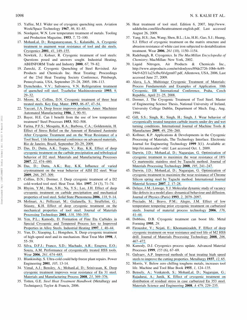
1098 N. S. KALSI ET AL.
15. Yaffee, M.J. Wider use of cryogenic quenching seen. AviationWeek/Space Technology 1967, 86, 81–85.
16. Nordquist, W.N. Low temperature treatment of metals. Toolingand Production Magazine, 1953, 7, 72–100.
17. MohanLal, D.; Renganarayanan, S.; Kalanidhi, A. Cryogenictreatment to augment wear resistance of tool and die steels.Cryogenics 2001, 41, 149–155.
18. Newkirk, J.; Kohser, R. Cryogenic treatment of tool steels:Questions posed and answers sought. Industrial Heating,ABI/INFORM Trade and Industry 2000, 67, 79–82.
19. Zurecki, Z. Cryogenic Quenching of Steel Revisited. AirProducts and Chemicals Inc. Heat Treating: Proceedingsof the 23rd Heat Treating Society Conference, Pittsburgh,Pennsylvania, USA, September 25–28, 2005, 106–113.
20. Dymchenko, V.V.; Safronova, V.N. Refrigeration treatmentof quenched roll steel. Tyazheloe Mashinostroenie 1993, 9,29–32.
21. Moore, K.; Collins, D.N. Cryogenic treatment of three heattreated steels. Key Eng. Mater. 1993, 86–87, 47–54.
22. Vaccari, J.A. Deep freeze improves products. Amer. MachinistAutomated Manufacturing 1986, 3, 90–91.
23. Bayer, H.E. Can I benefit from the use of low temperaturetreatment? Steel Processes 1953, 502–508.
24. Farina, P.F.S.; Mesquita, R.A.; Barbosa, C.A.; Goldenstein, H.Effect of Stress Relief on the Amount of Retained AusteniteAfter Cryogenic Treatment and on the Wear Resistance of aTool Steel, 11th International conference on advanced materials,Rio de Janeiro, Brazil, September 20–29, 2009.
25. Das, D.; Dutta, A.K.; Toppo, V.; Ray, K.K. Effect of deepcryogenic treatment on the carbide precipitation and tribologicalbehavior of D2 steel. Materials and Manufacturing Processes2007, 22, 474–480.
26. Das, D.; Dutta, A.K.; Ray, K.K. Influence of variedcryotreatment on the wear behavior of AISI D2 steel. Wear2009, 266, 297–309.
27. Collins, D.N.; Dormer, J. Deep cryogenic treatment of a D2cold-worked tool steel. Heat Treat. Met. 1997, 24 (3), 71–74.
28. Rhyim, Y.M.; Han, S.H.; Na, Y.S.; Lee, J.H. Effect of deepcryogenic treatment on carbide precipitation and mechanicalproperties of tool steel. Solid State Phenomena 2006, 118, 9–14.
29. Molinari, A.; Pellizzari, M.; Gialanella, S.; Straffelini, G.;Stiasny, K.H. Effect of deep cryogenic treatment on themechanical properties of tool steel. Journal of MaterialsProcessing Technology 2001, 118, 350–355.
30. Yen, P.L.; Kamody, D. Formation of Fine Eta Carbides inSpecial Cryogenic and Tempered Process key to ImprovedProperties in Alloy Steels. Industrial Heating 1997, 1, 40–44.
31. Yun, D.; Xiaoping, L.; Hongshen, X. Deep cryogenic treatmentof high-speed steel and its mechanism. Heat Treat Met 1998, 3,55–59.
32. Silva, D.F.J.; Franco, S.D.; Machado, A.R.; Ezugwu, E.O.;Souza, A.M. Performance of cryogenically treated HSS tools.Wear 2006, 261, 674–685.
33. Blankinship, S. Ultra-cold could help freeze plant repairs. PowerEngineering 2001, 105, 13-14.
34. Vimal, A.J.; Bensley, A.; MohanLal, D.; Srinivasan, K. Deepcryogenic treatment improves wear resistance of En 31 steel.Materials and Manufacturing Process 2008, 23, 369–376.
35. Totten, G.E. Steel Heat Treatment Handbook (Metallurgy andTechniques); Taylor & Francis, 2006.
36. Heat treatment of tool steel. Edition 6, 2007, http://www.uddeholm.com/files/heattreatment-english.pdf. Last accessedAugust 26, 2009.
37. Yang, H.S.; Jun, Wang; Shen, B.L.; Liu, H.H.; Gao, S.J.; Huang,S.J. Effect of cryogenic treatment on the matrix structure andabrasion resistance of white cast iron subjected to destabilizationtreatment. Wear 2006, 261 (10), 1150–1154.
38. Radebaugh, R. Cryogenics. In The MacMillan Encyclopedia ofChemistry; MacMillan: New York, 2002.
39. Liquid Nitrogen, Air Products & Chemicals Inc.,http://www.airproducts.com/nr/rdonlyres/89de2726-10bb-4e89-94e9-62f11a23cfbc/0/sfgrm07.pdf, Allentown, USA, 2006, Lastaccessed June 27, 2009.
40. Alava, L.A. Multistage Cryogenic Treatment of Materials:Process Fundamentals and Examples of Application. 10thCryogenic, IIR International Conference, Praha, CzechRepublic, April 21–25, 2008.
41. Dormer, J. The Cryogenic Treatment of Tool Steel. Masterof Engineering Science Thesis, National University of Ireland,University College Dublin, Department of Mech. Eng., Aug.1994.
42. Gill, S.S.; Singh, R.; Singh, H.; Singh, J. Wear behavior ofcryogenically treated tungsten carbide inserts under dry and wetturning conditions. International Journal of Machine Tools &Manufacture 2009, 49, 256–260.
43. Kollmer, K.P. Applications & Developments in the CryogenicProcessing of Materials, The Technology Interface. ElectronicJournal for Engineering Technology 1999 3(1). Available at:http://et.nmsu.edu/∼etti/. Last accessed Oct. 1, 2009.
44. Darwin, J.D.; MohanLal, D.; Nagarajan, G. Optimization ofcryogenic treatment to maximize the wear resistance of 18%Cr martensitic stainless steel by Taguchi method. Journal ofMaterials Processing Technology 2008, 195, 241–247.
45. Darwin, J.D.; MohanLal, D.; Nagarajan, G. Optimization ofcryogenic treatment to maximize the wear resistance of ChromeSilicon spring steel by Taguchi method. International JournalMaterial Science 2007, 2, 17–28.
46. Delaye, J.M.; Limoge, Y.J. Molecular dynamic study of vacancylike defects in a model glass: dynamical behaviour and diffusion.Journal of Physics (Paris) 1993, 2, 2079–2097.
47. Preciado, M.; Bravo, P.M.; Alegre, J.M. Effect of lowtemperature tempering prior cryogenic treatment on carburizedsteels. Journal of material process technology 2006, 176,41–44.
48. Dobbins, D.B. Cryogenic treatment can boost life. MetalForming 1995, 29.
49. Firouzdor, V.; Nejati, E.; Khomamizadeh, F. Effect of deepcryogenic treatment on wear resistance and tool life of M2 HSSdrill. Journal of Materials Processing Technology 2008, 206,467–472.
50. Kamody, D.J. Cryogenics process update. Advanced MaterialProcesses 1999, 155 (6), 67–69.
51. Gulyaev, A.P. Improved methods of heat treating high speedsteels to improve the cutting properties. Metallurgy 1937, 12, 65.
52. Morris, V. Below zero chilling toughens metals, increases toollife. Machine and Tool Blue Book 1955, 1, 124–135.
53. Bensely, A.; Venkatesh, S.; MohanLal, D.; Nagarajan, G.;Rajadurai, A.; Junik, K. Effect of cryogenic treatment ondistribution of residual stress in case carburized En 353 steel.Materials Science and Engineering 2008, A 479, 229–235.
Downloaded By: [INFLIBNET India Order] At: 06:03 9 March 2011
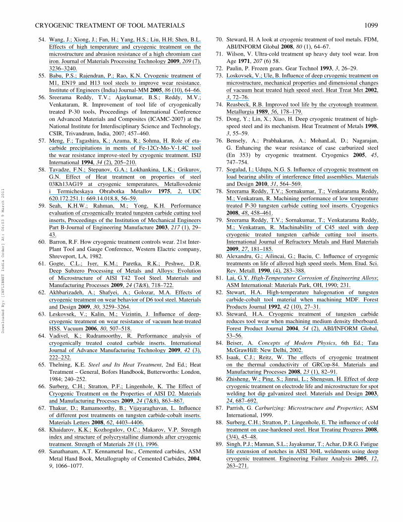
CRYOGENIC TREATMENT OF TOOL MATERIALS 1099
54. Wang, J.; Xiong, J.; Fan, H.; Yang, H.S.; Liu, H.H; Shen, B.L.Effects of high temperature and cryogenic treatment on themicrostructure and abrasion resistance of a high chromium castiron. Journal of Materials Processing Technology 2009, 209 (7),3236–3240.
55. Babu, P.S.; Rajendran, P.; Rao, K.N. Cryogenic treatment ofM1, EN19 and H13 tool steels to improve wear resistance.Institute of Engineers (India) Journal-MM 2005, 86 (10), 64–66.
56. Sreerama Reddy, T.V.; Ajaykumar, B.S.; Reddy, M.V.;Venkataram, R. Improvement of tool life of cryogenicallytreated P-30 tools, Proceedings of International Conferenceon Advanced Materials and Composites (ICAMC-2007) at theNational Institute for Interdisciplinary Science and Technology,CSIR, Trivandrum, India, 2007; 457–460.
57. Meng, F.; Tagashira, K.; Azuma, R.; Sohma, H. Role of eta-carbide precipitations in ments of Fe-12Cr-Mo-V-1.4C toolthe wear resistance improve-steel by cryogenic treatment. ISIJInternational 1994, 34 (2), 205–210.
58. Tavadze, F.N.; Stepanov, G.A.; Lokhankina, L.K.; Grikurov,G.N. Effect of Heat treatment on properties of steel03Kh13AG19 at cryogenic temperatures, Metallovedeniei Termicheskaya Obrabotka Metallov 1975, 2, UDC620.172.251.1: 669.14.018.8, 56–59.
59. Seah, K.H.W.; Rahman, M.; Yong, K.H. Performanceevaluation of cryogenically treated tungsten carbide cutting toolinserts, Proceedings of the Institution of Mechanical EngineersPart B-Journal of Engineering Manufacture 2003, 217 (1), 29–43.
60. Barron, R.F. How cryogenic treatment controls wear. 21st Inter-Plant Tool and Gauge Conference, Western Elactric company,Shreveport, LA, 1982.
61. Gogte, C.L.; Iyer, K.M.; Paretka, R.K.; Peshwe, D.R.Deep Subzero Processing of Metals and Alloys: Evolutionof Microstructure of AISI T42 Tool Steel. Materials andManufacturing Processes 2009, 24 (7&8), 718–722.
62. Akhbarizadeh, A.; Shafyei, A.; Golozar, M.A. Effects ofcryogenic treatment on wear behavior of D6 tool steel. Materialsand Design 2009, 30, 3259–3264.
63. Leskovsek, V.; Kalin, M.; Vizintin, J. Influence of deep-cryogenic treatment on wear resistance of vacuum heat-treatedHSS. Vacuum 2006, 80, 507–518.
64. Vadivel, K.; Rudramoorthy, R. Performance analysis ofcryogenically treated coated carbide inserts. InternationalJournal of Advance Manufacturing Technology 2009, 42 (3),222–232.
65. Thelning, K.E. Steel and Its Heat Treatment, 2nd Ed.; HeatTreatment – General, Bofors Handbook, Butterworths: London,1984; 240–252.
66. Surberg, C.H.; Stratton, P.F.; Lingenhole, K. The Effect ofCryogenic Treatment on the Properties of AISI D2. Materialsand Manufacturing Processes 2009, 24 (7&8), 863–867.
67. Thakur, D.; Ramamoorthy, B.; Vijayaraghavan, L. Influenceof different post treatments on tungsten carbide-cobalt inserts.Materials Letters 2008, 62, 4403–4406.
68. Khaidarov, K.K.; Kozhogulov, O.C.; Makarov, V.P. Strengthindex and structure of polycrystalline diamonds after cryogenictreatment. Strength of Materials 28 (1), 1996.
69. Sanathanam, A.T. Kennametal Inc., Cemented carbides, ASMMetal Hand Book, Metallography of Cemented Carbides, 2004,9, 1066–1077.
70. Steward, H. A look at cryogenic treatment of tool metals. FDM,ABI/INFORM Global 2008, 80 (1), 64–67.
71. Wilson, V. Ultra-cold treatment up heavy duty tool wear. IronAge 1971, 207 (6) 58.
72. Paulin, P. Frozen gears. Gear Technol 1993, 3, 26–29.73. Loskovsek, V.; Ule, B. Influence of deep cryogenic treatment on
microstructure, mechanical properties and dimensional changesof vacuum heat treated high speed steel. Heat Treat Met 2002,3, 72–76.
74. Reasbeck, R.B. Improved tool life by the cryotough treatment.Metallurgia 1989, 56, 178–179.
75. Dong, Y.; Lin, X.; Xiao, H. Deep cryogenic treatment of high-speed steel and its mechanism. Heat Treatment of Metals 1998,3, 55–59.
76. Bensely, A.; Prabhakaran, A.; MohanLal, D.; Nagarajan,G. Enhancing the wear resistance of case carburized steel(En 353) by cryogenic treatment. Cryogenics 2005, 45,747–754.
77. Sogalad, I.; Udupa, N.G. S. Influence of cryogenic treatment onload bearing ability of interference fitted assemblies. Materialsand Design 2010, 31, 564–569.
78. Sreerama Reddy, T.V.; Sornakumar, T.; Venkatarama Reddy,M.; Venkatram, R. Machining performance of low temperaturetreated P-30 tungsten carbide cutting tool inserts. Cryogenics2008, 48, 458–461.
79. Sreerama Reddy, T.V.; Sornakumar, T.; Venkatarama Reddy,M.; Venkatram, R. Machinability of C45 steel with deepcryogenic treated tungsten carbide cutting tool inserts.International Journal of Refractory Metals and Hard Materials2009, 27, 181–185.
80. Alexandru, G.; Ailincai, G.; Baciu, C. Influence of cryogenictreatments on life of alloyed high speed steels. Mem. Etud. Sci.Rev. Metall. 1990, (4), 283–388.
81. Lai, G.Y. High-Temperature Corrosion of Engineering Alloys;ASM International: Materials Park, OH, 1990; 231.
82. Stewart, H.A. High-temperature halogenation of tungstencarbide-cobalt tool material when machining MDF. ForestProducts Journal 1992, 42 (10), 27–31.
83. Steward, H.A. Cryogenic treatment of tungsten carbidereduces tool wear when machining medium density fiberboard.Forest Product Journal 2004, 54 (2), ABI/INFORM Global,53–56.
84. Beiser, A. Concepts of Modern Physics, 6th Ed.; TataMcGrawHill: New Delhi, 2002.
85. Isaak, C.J.; Reitz, W. The effects of cryogenic treatmenton the thermal conductivity of GRCop-84. Materials andManufacturing Processes 2008, 23 (1), 82–91.
86. Zhisheng, W.; Ping, S.; Jinrui, L.; Shengsun, H. Effect of deepcryogenic treatment on electrode life and microstructure for spotwelding hot dip galvanized steel. Materials and Design 2003,24, 687–692.
87. Parrish, G. Carburizing: Microstructure and Properties; ASMInternational, 1999.
88. Surberg, C.H.; Stratton, P.; Lingenhole, E. The influence of coldtreatment on case-hardened steel. Heat Treating Progress 2008,(3/4), 45–48.
89. Singh, P.J.; Mannan, S.L.; Jayakumar, T.; Achar, D.R.G. Fatiguelife extension of notches in AISI 304L weldments using deepcryogenic treatment. Engineering Failure Analysis 2005, 12,263–271.
Downloaded By: [INFLIBNET India Order] At: 06:03 9 March 2011
1100 N. S. KALSI ET AL.
90. Singh, P.J.; Guha, B.; Achar, D.R.G. Fatigue life improvementof AISI 304L cruciform welded joints by cryogenic treatment.Engineering Failure Analysis 2003, 10, 1–12.
91. Myeong, T.H.; Yamabayashi, Y.; Shimojo, M.; Higo, Y.A new life extension method for high cycle fatigue usingmicro-martensitic transformation in an austenitic stainless steel.International Journal Fatigue 1997, 19, 569–573.
92. Baldissera, P. Fatigue scatter reduction through deep cryogenictreatment on the 18NiCrMo5 carburized steel. Materials andDesign, 2009, 30, 3636–3642.
93. Tabrett, C.P.; Sare, I.R.; Ghomashchi, M.R. Microstructure-property relationship in high chromium white iron alloys. Int.Mater. 1996, 41 (2), 59.
94. Trieu, H.H.; Morris, L.H.; Kauhan, M.E. Investigation ofCryogenic Treatment of UHMWPE. IEEE 1997, (0-7803-3869-3/97 10.00), 90–91.
95. Molinari, A.; Pellizzari, M.; Gialanella, S.; Straffelini, G.;Stiasny, K.H. Effect of deep cryogenic treatment on themechanical properties of tool steel. Proceedings of Conference onAdvanced Materials Processes Technologies 1999, 1461–1469.
96. Collins, D.N. Deep cryogenic treatment of tool steels: A review.Heat Treat. Met. 1996 2, 40–42.
97. Gisipa, J.; Gazob, R.; Stewart, H.A. Effects of cryogenictreatment and refrigerated air on tool wear when machiningmedium density fiberboard. Journal of Materials ProcessingTechnology 2009, 209, 5117–5122.
98. Deep cryogenic treatment in-house, production; 1987, 99(12),ABI/INFORM Global, 27.
99. Reitz, W.; Pendray, J. Cryoprocessing of materials, A review ofcurrent status. Materials and Manufacturing Processes 2001, 16(6), 829–840.
100. Kalin, M.; Leskovsek, V.; Vizintin, J. Wear behavior of deep-cryogenic treated high-speed steels at different loads. Materialsand Manufacturing Processes 2006, 21 (8), 741–746.
101. Bourne, G.R.; Gregory, W.; Kaufman, M.J. Effects of CryogenicTreatment on Wear Resistance of AISI D2 Tool Steel, STLE –Annual Meeting 2003, Tribology Laboratory, Univ. of Florida,http://nersp.nerdc.ufl.edu/∼wsawyer/presentations/cryoSTLE2003.swf, Last accessed September 19, 2009.
102. Paulin, P. Cold cuts. Cutting Tool Eng. 5 (44), 1992.103. Das, D.; Dutta, A.K.; Ray, K.K. On the enhancement of wear
resistance of tool steels by cryogenic treatment. PhilosophicalMagazine Letters 2008, 88 (11), 801–811.
104. Barron, R.F. Do treatments at temperature below 120 F helpincrease the wear resistance of tool steels? Here are someresearch findings that they do. Heat Treating 1974, 5 (6),14–17.
105. Cajner, F.; Leskovsek, V.; Landek, D.; Cajner, H.Effect of Deep-Cryogenic Treatment on High Speed SteelProperties. Materials and Manufacturing Processes 2009, 24,743–746.
106. Podgornik, B.; Leskovsek, V.; Vizintin, J. Influence of deep-cryogenic treatment on tribological properties of P/M high-speedsteel. Materials and Manufacturing Processes 2009 24 (7&8),734–738.
107. Yong, A.Y.L.; Seah, K.H.W.; Rahman, M. Performanceof cryogenically treated tungsten carbide tools in millingoperations. International Journal of Advance ManufacturingTechnology 2007, 32, 638–643.
108. Yong, A.Y.L.; Seah, K.H.W.; Rahman, M. Performanceevaluation of cryogenically treated tungsten carbide tools inturning. International Journal of Machine Tools & Manufacture2006, 46, 2051–2056.
109. Sreerama Reddy, T.V.; Sornakumar, T.; Reddy,M.V.; Venkatram, R.; Senthilkumar, A. Turning Studies of deepcryogenic treated P-40 tungsten carbide cutting tool inserts-technical communication. Machining Science and Technology2009, 13 (2), 269–281.
Downloaded By: [INFLIBNET India Order] At: 06:03 9 March 2011
Related Documents