CIR ® CABLES CRUSH & IMPACT RESISTANT STANDARD & ARCTIC GRADE

Welcome message from author
This document is posted to help you gain knowledge. Please leave a comment to let me know what you think about it! Share it to your friends and learn new things together.
Transcript
CIR® CABLES CRUSH & IMPACT RESISTANT
STANDARD & ARCTIC GRADE
Index
Nexans AmerCable® believes the information presented throughout this catalog to bereliable and current. All information is subject to change without notice. The informationlisted is approximate, and is presented only as a guide for product selection. We make noclaims or warranties for the suitability of any product for any particular application.
AmerCable® and Gexol® are registered trademarks of AmerCable Incorporated. Registered in the U.S. Patent and Trademark Office. © 2016 AmerCable Incorporated
CIR Power Cables• Three & Four Conductor + Ground . . . . 2 - 3
CIR Control Cable• Multi-Conductor . . . . . . . . . . . . . . . . . . . . . 4
CIR Instrumentation Cables• Individually Shielded Pairs . . . . . . . . . . . . . . . 5• Individually Shielded Triads . . . . . . . . . . . . . . 5
CIR Type VFD Cable• Three Conductor . . . . . . . . . . . . . . . . . . 6 - 7
CIR AG Power Cables• Three & Four Conductor + Ground . . . . 8 - 9
CIR AG Control Cable• Multi-Conductor . . . . . . . . . . . . . . . . . . . . 10
CIR AG Instrumentation Cables• Individually Shielded Pairs . . . . . . . . . . . . . . 11• Individually Shielded Triads . . . . . . . . . . . . . 11
CIR AG Type VFD Cable• Three Conductor . . . . . . . . . . . . . . . . 12 - 13
Strand Profile/Cable Color Codes Back Cover
Installed Cost Comparison . . . . . Back Cover
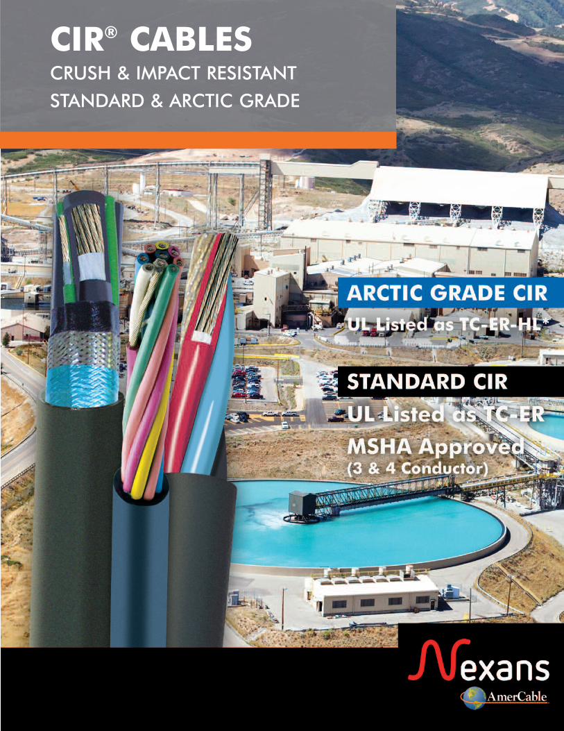
CIRGexol®
®
Crush and Impact Resistant Without External Armoring
Passes the same stringent crush and impact testing required by
UL 2225 for Type MC-HL
n Available in Standard andArctic Grade Jackets
n Highly flexible
Standard CIR • UL Listed Type TC-ER
Arctic CIR • UL Listed Type TC-ER-HL*
*cables up to 1” in diameter
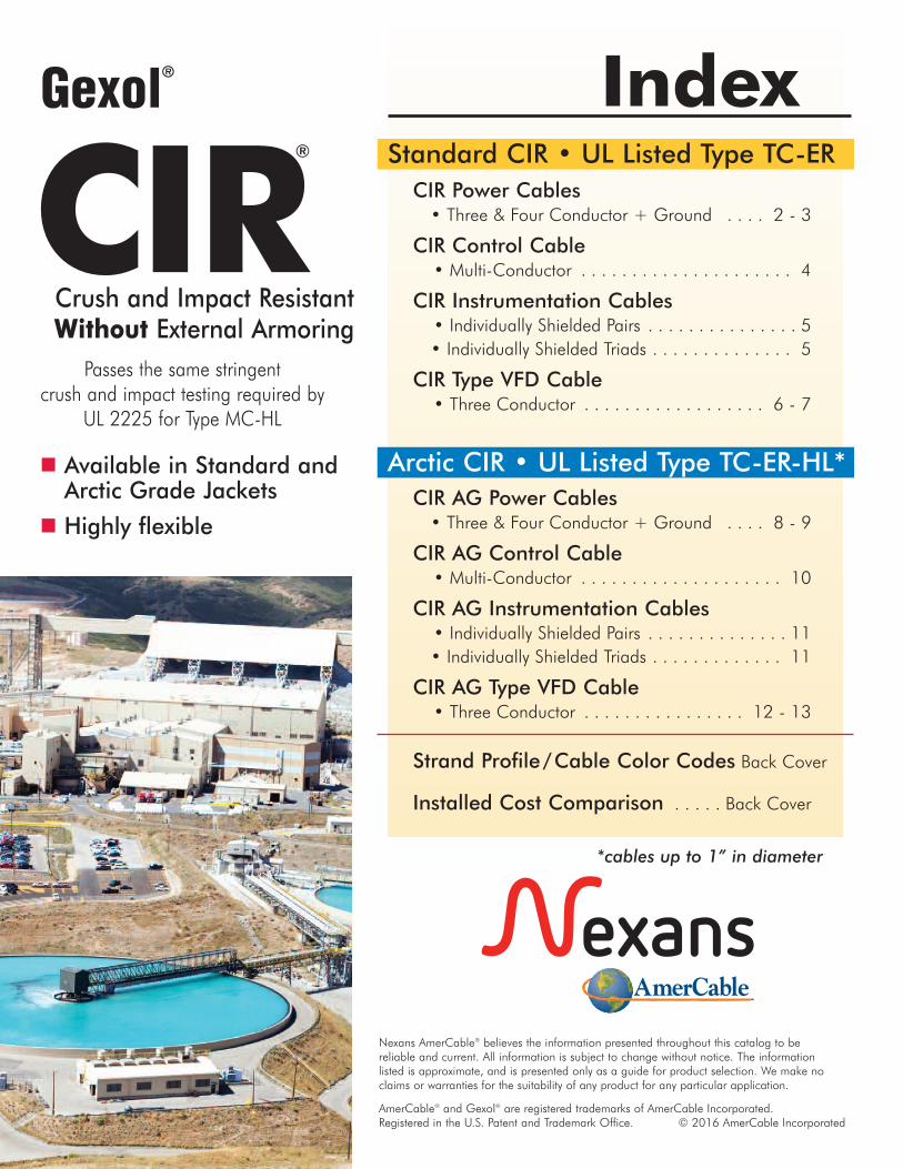
Faster andEasierto Install thanMetal CladCIR® is the fastest, safest crush-proof cableto install. Metal clad cable installationrequires an expensive box of tools and amulti-step procedurefor jacket removal.
ABOUT CIR® CABLES
See back cover forTotal InstalledCable Cost
Type CIR
IEEE 45 6X Diameter
NEC < 1" (25mm) 4X Diameter > 1" (25mm) < 2" (50mm) 5X Diameter > 2" (50mm) 6X Diameter
Bend Radius
1
Nexans AmerCable’s CIR is a next-generation cable designed to replace older-technology cables like Type MC.AmerCable CIR has been successfully used globally since 2002 for mission-critical equipment operating in harsh environments.CIR passes the same stringent crush and impact tests required by UL 2225 for Type MC-HL without the use of external armoring. This highly robust cable offers significant advantages over Type MC for many industrial and mining applications, including:n MSHA Approved (Standard CIR) – 3 & 4 conductor power cablesn UL Listed as Type TC-ER (Standard CIR) – suitable for a variety of uses,including those where tray cables are not practical or cost-prohibitive.
n UL Listed as Type TC-ER-HL (Arctic Grade CIR) – suitable for a variety of uses in Class 1, Div 1 and Zone 1environments including those where tray cables are not practical or cost-prohibitive. (Cables up to 1” in diameter)n Insulated with Gexol® – Nexans AmerCable’s exclusive insulating compound provides superior flexibility, dielectric properties and field proven performance in the most severe, isolated operating environments.
n Highly flexible – unlike Type MC, CIR is flexible for easier installation. The cable can also be reused during an upgrade or retrofit.
n Smaller bend radius – up to 40% smaller than Type MCn Reduced tray fill – up to 35% less compared to Type MCn Gas & vapor tight – impervious to water and airn Ergonomically Superior – from an ergonomic perspective, CIR is safer tohandle for workers and much simpler to prepare for termination.
JacketA black, flame retardant, oil, abrasion, chemical and sunlight resistant thermoplastic compoundmeeting UL 1309/CSA 245 and IEEE 1580.
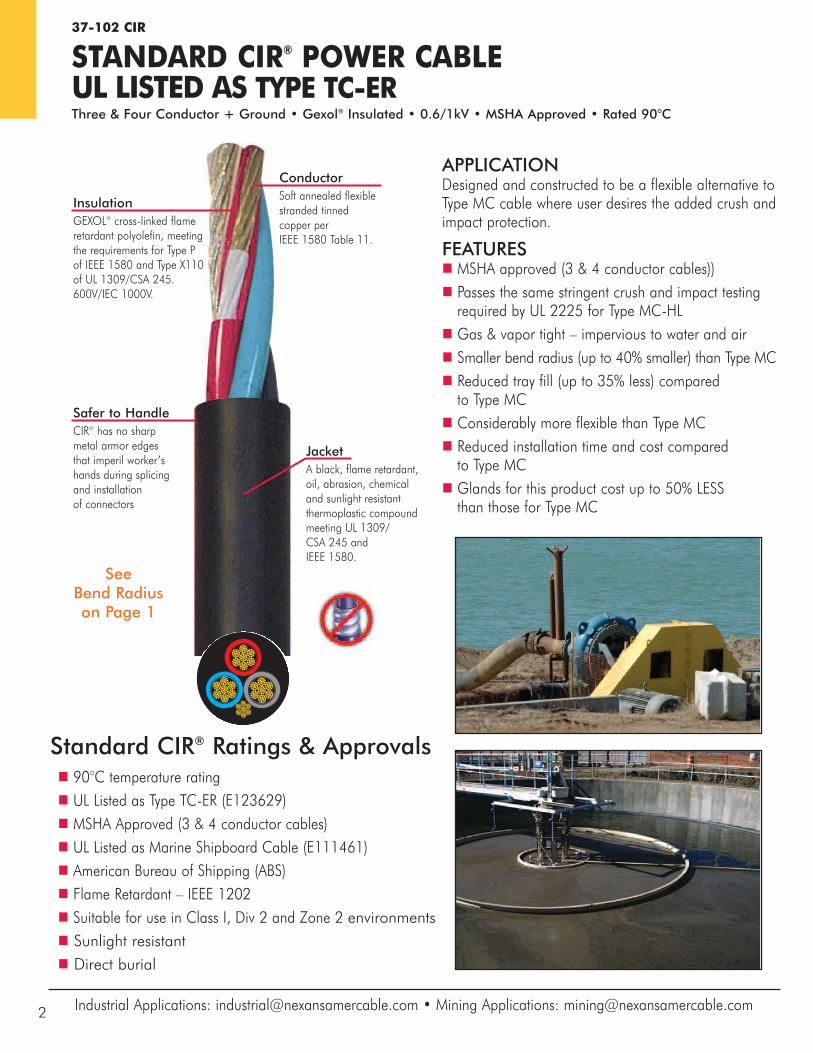
ConductorSoft annealed flexiblestranded tinned copper perIEEE 1580 Table 11.
InsulationGEXOL® cross-linked flameretardant polyolefin, meetingthe requirements for Type Pof IEEE 1580 and Type X110of UL 1309/CSA 245.600V/IEC 1000V.
APPLICATIONDesigned and constructed to be a flexible alternative toType MC cable where user desires the added crush andimpact protection.
FEATURESn MSHA approved (3 & 4 conductor cables))n Passes the same stringent crush and impact testingrequired by UL 2225 for Type MC-HL
n Gas & vapor tight – impervious to water and airn Smaller bend radius (up to 40% smaller) than Type MCn Reduced tray fill (up to 35% less) compared to Type MC
n Considerably more flexible than Type MCn Reduced installation time and cost compared to Type MC
n Glands for this product cost up to 50% LESS than those for Type MC
37-102 CIR
STANDARD CIR® POWER CABLEUL LISTED AS TYPE TC-ERThree & Four Conductor + Ground • Gexol® Insulated • 0.6/1kV • MSHA Approved • Rated 90°C
Safer to HandleCIR® has no sharp metal armor edges that imperil worker’s hands during splicing and installation of connectors
Industrial Applications: [email protected] • Mining Applications: [email protected]
Standard CIR® Ratings & Approvalsn 90°C temperature ratingn UL Listed as Type TC-ER (E123629)n MSHA Approved (3 & 4 conductor cables)n UL Listed as Marine Shipboard Cable (E111461)n American Bureau of Shipping (ABS) n Flame Retardant – IEEE 1202n Suitable for use in Class I, Div 2 and Zone 2 environmentsn Sunlight resistantn Direct burial
SeeBend Radiuson Page 1
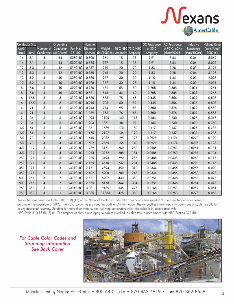
Ampacities are based on Table 310.15 (B) (16) of the National Electrical Code (NEC) for conductors rated 90°C, in a multi-conductor cable, atan ambient temperature of 30°C. The 75°C column is provided for additional information. The ampacities shown apply to open runs of cable, installationin any approved raceway. Derating for more than three current carrying conductors within the cable is in accordance with NEC Table 310.15 (B) (3) (a). The ampacities shown also apply to cables installed in cable tray in accordance with NEC Section 392.80.
Conductor Size Grounding Nominal DC Resistance AC Resistance Inductive Voltage Drop AWG/ Number of Conductor Part No. Diameter Weight 90°C NEC 75°C NEC at 25°C at 90°C, 60Hz Reactance (Volts/Amp/ kcmil mm2 Conductors AWG/kcmil 37-102 (inches) (lbs/1000 ft.) Ampacity Ampacity Ampacity (ohms/1000 ft.) (ohms/1000 ft.) 1000 ft.) 14 2.1 3 14 -508CIRG 0.500 161 15 15 2.91 3.64 0.04 5.069 14 2.1 4 14 -509CIRG 0.525 187 15 15 2.91 3.64 0.04 5.072 12 3.3 3 12 -516CIRG 0.537 210 20 20 1.83 2.28 0.03 3.195 12 3.3 4 12 -517CIRG 0.580 246 20 20 1.83 2.28 0.04 3.198 10 5.2 3 10 -308CIRG 0.580 277 30 30 1.15 1.44 0.03 2.028 10 5.2 4 10 -408CIRG 0.728 367 30 28 1.15 1.44 0.03 2.031 8 7.6 3 10 -309CIRG 0.760 431 55 50 0.708 0.885 0.034 1.261 8 7.6 4 10 -409CIRG 0.821 513 44 40 0.708 0.885 0.037 1.263 6 12.5 3 8 -310CIRG 0.860 585 75 65 0.445 0.556 0.032 0.803 6 12.5 4 8 -410CIRG 0.915 705 60 52 0.445 0.556 0.035 0.806 4 21 3 6 -312CIRG 0.944 774 95 85 0.300 0.376 0.029 0.550 4 21 4 6 -412CIRG 1.039 956 76 68 0.300 0.376 0.032 0.553 2 34 3 6 -314CIRG 1.094 1105 130 115 0.184 0.230 0.028 0.347 2 34 4 6 -414CIRG 1.203 1381 104 92 0.184 0.230 0.030 0.350 1/0 54 3 6 -316CIRG 1.331 1669 170 150 0.117 0.147 0.028 0.232 1/0 54 4 6 -416CIRG 1.475 2107 136 120 0.117 0.147 0.030 0.235 2/0 70 3 4 -317CIRG 1.445 2062 195 175 0.0929 0.1174 0.0270 0.190 2/0 70 4 4 -417CIRG 1.602 2585 156 140 0.0929 0.1174 0.0296 0.193 4/0 109 3 4 -319CIRG 1.769 3151 260 230 0.0585 0.0753 0.0261 0.131 4/0 109 4 4 -419CIRG 1.953 3972 208 184 0.0585 0.0753 0.0287 0.134 250 127 3 3 -330CIRG 1.925 3493 290 255 0.0488 0.0635 0.0263 0.115 250 127 4 3 -430CIRG 2.125 4510 232 204 0.0488 0.0635 0.0290 0.118 350 177 3 3 -331CIRG 2.171 4594 350 310 0.0344 0.0456 0.0256 0.090 350 177 4 3 -431CIRG 2.402 5900 280 248 0.0344 0.0456 0.0283 0.093 500 253 3 2 -333CIRG 2.521 6207 430 380 0.0251 0.0348 0.0258 0.075 500 253 4 2 -433CIRG 2.855 8178 344 304 0.0251 0.0348 0.0284 0.078 750 380 3 1 -334CIRG 3.081 9165 535 475 0.0166 0.0253 0.0252 0.061 750 380 4 1 -434CIRG 3.365 11883 428 380 0.0166 0.0253 0.0278 0.063
Manufactured by Nexans AmerCable • 800-643-1516 • 870-862-4919 • Fax: 870-862-8659 3
For Cable Color Codes andStranding Information
See Back Cover
37-102 CIR
STANDARD CIR® CONTROL CABLE UL LISTED AS TYPE TC-ERMulti-Conductor • Gexol® Insulated • 0.6/1kV • Rated 90°C
Gexol® and CIR® are registered trademarks of AmerCable Incorporated.
JacketA black, flame retardant, oil, abrasion, chemical and sunlight resistant thermoplastic compoundmeeting UL 1309/CSA 245 and IEEE 1580. Rated for directburial.
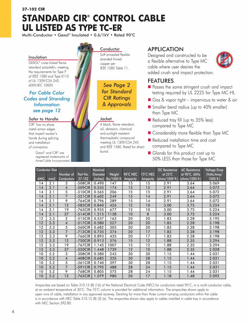
ConductorSoft annealed flexiblestranded tinned copper perIEEE 1580 Table 11.
InsulationGEXOL® cross-linked flameretardant polyolefin, meeting the requirements for Type P of IEEE 1580 and Type X110 of UL 1309/CSA 245. 600V/IEC 1000V.
Ampacities are based on Table 310.15 (B) (16) of the National Electrical Code (NEC) for conductors rated 90°C, in a multi-conductor cable, at an ambient temperature of 30°C. The 75°C column is provided for additional information. The ampacities shown apply to open runs of cable, installation in any approved raceway. Derating for more than three current carrying conductors within the cableis in accordance with NEC Table 310.15 (B) (3) (a). The ampacities shown also apply to cables installed in cable tray in accordancewith NEC Section 392.80.
Conductor Size Nominal DC Resistance AC Resistance Voltage Drop Number of Part No. Diameter Weight 90°C NEC 75°C NEC at 25°C at 90°C, 60Hz (Volts/Amp/ AWG mm2 Conductors 37-102 (inches) (lbs/1000 ft.) Ampacity Ampacity (ohms/1000 ft.) (ohms/1000 ft.) 1000 ft.) 14 2.1 3 -508CIR 0.490 147 15 15 2.91 3.64 5.069 14 2.1 4 -509CIR 0.535 174 15 15 2.91 3.64 5.072 14 2.1 5 -510CIR 0.565 206 15 15 2.91 3.64 5.072 14 2.1 7 -521CIR 0.602 249 15 14 2.91 3.64 5.072 14 2.1 9 -764CIR 0.796 289 15 14 2.91 3.64 5.072 14 2.1 12 -585CIR 0.840 426 12 10 3.00 3.75 5.224 14 2.1 19 -765CIR 0.955 677 12 10 3.00 3.75 5.224 14 2.1 37 -514CIR 1.315 1138 10 8 3.00 3.75 5.224 12 3.3 2 -515CIR 0.537 163 20 20 1.83 2.28 3.195 12 3.3 4 -517CIR 0.580 227 20 20 1.83 2.28 3.198 12 3.3 5 -560CIR 0.682 305 20 20 1.83 2.28 3.198 12 3.3 7 -712CIR 0.735 374 20 17 1.83 2.28 3.198 12 3.3 9 -766CIR 0.893 435 20 17 1.83 2.28 3.198 12 3.3 12 -750CIR 0.913 576 15 12 1.88 2.35 3.294 12 3.3 19 -767CIR 1.145 1007 15 12 1.88 2.35 3.294 12 3.3 37 -520CIR 1.448 1739 12 10 1.88 2.35 2.028 10 5.2 3 -308CIR 0.580 243 30 30 1.15 1.44 2.031 10 5.2 4 -408CIR 0.685 335 30 28 1.15 1.44 2.031 10 5.2 5 -561CIR 0.740 397 30 28 1.15 1.44 2.031 10 5.2 7 -591CIR 0.795 488 28 24 1.15 1.44 2.031 10 5.2 9 -768CIR 0.805 575 28 24 1.15 1.44 2.031 10 5.2 12 -762CIR 1.079 980 20 17 1.18 1.48 2.092
APPLICATIONDesigned and constructed to bea flexible alternative to Type MC cable where user desires the added crush and impact protection.
FEATURESn Passes the same stringent crush and impacttesting required by UL 2225 for Type MC-HL
n Gas & vapor tight – impervious to water & airn Smaller bend radius (up to 40% smaller) than Type MC
n Reduced tray fill (up to 35% less) compared to Type MC
n Considerably more flexible than Type MCn Reduced installation time and cost compared to Type MC
n Glands for this product cost up to 50% LESS than those for Type MC
For Cable Color Codes and Stranding
Informationsee page 12
Safer to HandleCIR® has no sharp metal armor edges that imperil worker’s hands during splicing and installation of connectors
4
See Page 2for StandardCIR Ratings& Approvals
Gexol® and CIR® are registered trademarksof AmerCable Incorporated.
JacketA black, flame retardant, oil, abrasion, chemical and sunlight resistant thermoplastic compoundmeeting UL 1309/CSA 245 and IEEE 1580.Rated for direct burial.
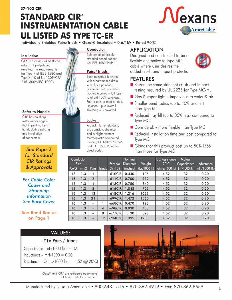
ConductorSoft annealed flexiblestranded tinned copper per IEEE 1580 Table 11.
InsulationGEXOL® cross-linked flameretardant polyolefin,meeting the requirementsfor Type P of IEEE 1580 andType X110 of UL 1309/CSA245. 600V/IEC 1000V.
Pairs/TriadsEach pair/triad is twisted with a bare tinned drain wire. Each pair/triad is shielded with polyester-backed aluminum foil tape to afford 100% coverage.Pair to pair, or triad to triad,isolation – plus overallshielding – is provided.
APPLICATIONDesigned and constructed to be a flexible alternative to Type MC cable where user desires the added crush and impact protection.
FEATURESn Passes the same stringent crush and impacttesting required by UL 2225 for Type MC-HL
n Gas & vapor tight – impervious to water & airn Smaller bend radius (up to 40% smaller) than Type MC
n Reduced tray fill (up to 35% less) compared toType MC
n Considerably more flexible than Type MCn Reduced installation time and cost compared toType MC
n Glands for this product cost up to 50% LESSthan those for Type MC
Conductor Nominal DC Resistance Mutual Size Part No. Diameter Weight 20°C Capacitance Inductance AWG mm2 Pairs Triads 37-102 (inches) (lbs/1000 ft.) (ohms/1000 ft.) (nF/1000 ft.) (mH/1000 ft.) 16 1.3 1 – -610CIR 0.440 106 4.52 32 0.20 16 1.3 2 – -611CIR 0.700 279 4.52 32 0.20 16 1.3 4 – -613CIR 0.750 340 4.52 32 0.20 16 1.3 8 – -616CIR 1.048 702 4.52 32 0.20 16 1.3 12 – -618CIR 1.216 1062 4.52 32 0.20 16 1.3 24 – -699CIR 1.472 1560 4.52 32 0.20 16 1.3 – 1 -668CIR 0.470 128 4.52 32 0.20 16 1.3 – 4 -698CIR 0.930 453 4.52 32 0.20 16 1.3 – 8 -677CIR 1.130 825 4.52 32 0.20 16 1.3 – 12 -734CIR 1.395 1235 4.52 32 0.20
#16 Pairs / Triads
Capacitance – nF/1000 feet = 32Inductance – mH/1000 = 0.20Resistance – Ohms/1000 feet = 4.52 (@ 20°C)
VALUES:
For Cable Color Codes and Stranding Information
See Back Cover
Safer to HandleCIR® has no sharp metal armor edges that imperil worker’s hands during splicing and installation of connectors
Manufactured by Nexans AmerCable • 800-643-1516 • 870-862-4919 • Fax: 870-862-8659 5
See Page 2for StandardCIR Ratings& Approvals
See Bend Radiuson Page 1
37-102 CIR
STANDARD CIR®INSTRUMENTATION CABLEUL LISTED AS TYPE TC-ERIndividually Shielded Pairs/Triads • Gexol® Insulated • 0.6/1kV • Rated 90°C
37-102 CIRVFD
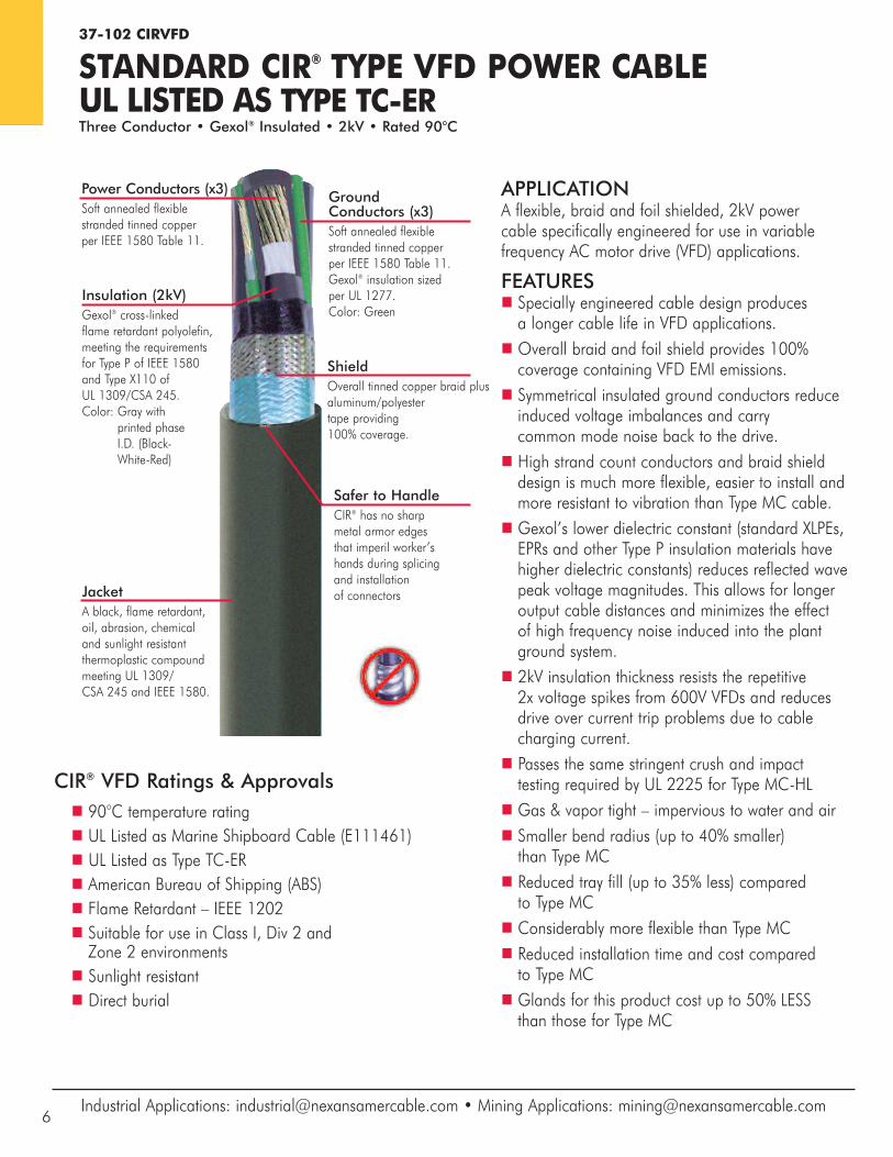
STANDARD CIR® TYPE VFD POWER CABLEUL LISTED AS TYPE TC-ERThree Conductor • Gexol® Insulated • 2kV • Rated 90°C
APPLICATIONA flexible, braid and foil shielded, 2kV power cable specifically engineered for use in variablefrequency AC motor drive (VFD) applications.
FEATURESn Specially engineered cable design produces a longer cable life in VFD applications.
n Overall braid and foil shield provides 100%coverage containing VFD EMI emissions.
n Symmetrical insulated ground conductors reduceinduced voltage imbalances and carry common mode noise back to the drive.
n High strand count conductors and braid shielddesign is much more flexible, easier to install andmore resistant to vibration than Type MC cable.
n Gexol’s lower dielectric constant (standard XLPEs,EPRs and other Type P insulation materials havehigher dielectric constants) reduces reflected wavepeak voltage magnitudes. This allows for longeroutput cable distances and minimizes the effect of high frequency noise induced into the plant ground system.
n 2kV insulation thickness resists the repetitive 2x voltage spikes from 600V VFDs and reduces drive over current trip problems due to cable charging current.
n Passes the same stringent crush and impact testing required by UL 2225 for Type MC-HL
n Gas & vapor tight – impervious to water and airn Smaller bend radius (up to 40% smaller) than Type MC
n Reduced tray fill (up to 35% less) comparedto Type MC
n Considerably more flexible than Type MCn Reduced installation time and cost comparedto Type MC
n Glands for this product cost up to 50% LESS than those for Type MC
Insulation (2kV)Gexol® cross-linked flame retardant polyolefin, meeting the requirements for Type P of IEEE 1580 and Type X110 of UL 1309/CSA 245. Color: Gray with
printed phase I.D. (Black-White-Red)
JacketA black, flame retardant, oil, abrasion, chemical and sunlight resistantthermoplastic compoundmeeting UL 1309/CSA 245 and IEEE 1580.
Power Conductors (x3)Soft annealed flexible stranded tinned copper per IEEE 1580 Table 11.
Ground Conductors (x3)Soft annealed flexible stranded tinned copper per IEEE 1580 Table 11. Gexol® insulation sized per UL 1277.Color: Green
ShieldOverall tinned copper braid plusaluminum/polyestertape providing100% coverage.
CIR® VFD Ratings & Approvalsn 90°C temperature ratingn UL Listed as Marine Shipboard Cable (E111461)n UL Listed as Type TC-ERn American Bureau of Shipping (ABS)n Flame Retardant – IEEE 1202n Suitable for use in Class I, Div 2 and Zone 2 environments
n Sunlight resistantn Direct burial
Industrial Applications: [email protected] • Mining Applications: [email protected]
Safer to HandleCIR® has no sharp metal armor edges that imperil worker’s hands during splicing and installation of connectors
6
Gexol® and CIR® are registered trademarks of AmerCable Incorporated.
Manufactured by Nexans AmerCable • 800-643-1516 • 870-862-4919 • Fax: 870-862-8659 7
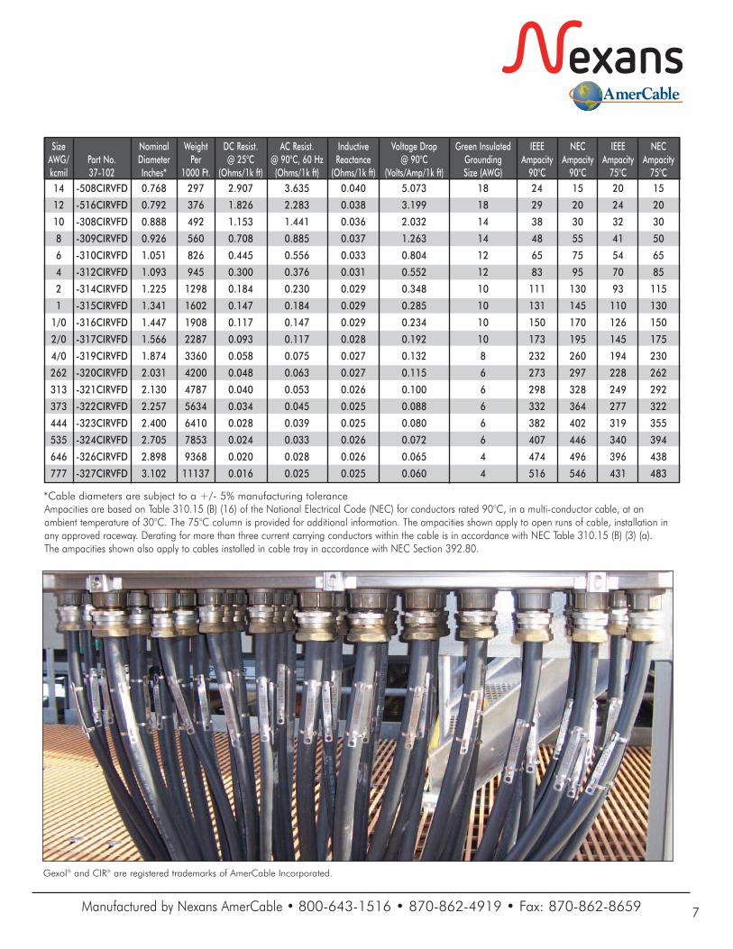
Ampacities are based on Table 310.15 (B) (16) of the National Electrical Code (NEC) for conductors rated 90°C, in a multi-conductor cable, at an ambient temperature of 30°C. The 75°C column is provided for additional information. The ampacities shown apply to open runs of cable, installation inany approved raceway. Derating for more than three current carrying conductors within the cable is in accordance with NEC Table 310.15 (B) (3) (a). The ampacities shown also apply to cables installed in cable tray in accordance with NEC Section 392.80.
Size Nominal Weight DC Resist. AC Resist. Inductive Voltage Drop Green Insulated IEEE NEC IEEE NECAWG/ Part No. Diameter Per @ 25°C @ 90°C, 60 Hz Reactance @ 90°C Grounding Ampacity Ampacity Ampacity Ampacity kcmil 37-102 Inches* 1000 Ft. (Ohms/1k ft) (Ohms/1k ft) (Ohms/1k ft) (Volts/Amp/1k ft) Size (AWG) 90°C 90°C 75°C 75°C 14 -508CIRVFD 0.768 297 2.907 3.635 0.040 5.073 18 24 15 20 15
12 -516CIRVFD 0.792 376 1.826 2.283 0.038 3.199 18 29 20 24 20
10 -308CIRVFD 0.888 492 1.153 1.441 0.036 2.032 14 38 30 32 30
8 -309CIRVFD 0.926 560 0.708 0.885 0.037 1.263 14 48 55 41 50
6 -310CIRVFD 1.051 826 0.445 0.556 0.033 0.804 12 65 75 54 65
4 -312CIRVFD 1.093 945 0.300 0.376 0.031 0.552 12 83 95 70 85
2 -314CIRVFD 1.225 1298 0.184 0.230 0.029 0.348 10 111 130 93 115
1 -315CIRVFD 1.341 1602 0.147 0.184 0.029 0.285 10 131 145 110 130
1/0 -316CIRVFD 1.447 1908 0.117 0.147 0.029 0.234 10 150 170 126 150
2/0 -317CIRVFD 1.566 2287 0.093 0.117 0.028 0.192 10 173 195 145 175
4/0 -319CIRVFD 1.874 3360 0.058 0.075 0.027 0.132 8 232 260 194 230
262 -320CIRVFD 2.031 4200 0.048 0.063 0.027 0.115 6 273 297 228 262
313 -321CIRVFD 2.130 4787 0.040 0.053 0.026 0.100 6 298 328 249 292
373 -322CIRVFD 2.257 5634 0.034 0.045 0.025 0.088 6 332 364 277 322
444 -323CIRVFD 2.400 6410 0.028 0.039 0.025 0.080 6 382 402 319 355
535 -324CIRVFD 2.705 7853 0.024 0.033 0.026 0.072 6 407 446 340 394
646 -326CIRVFD 2.898 9368 0.020 0.028 0.026 0.065 4 474 496 396 438
777 -327CIRVFD 3.102 11137 0.016 0.025 0.025 0.060 4 516 546 431 483
*Cable diameters are subject to a +/- 5% manufacturing tolerance
CIR® Arctic Grade Ratings & Approvals
n 90°C temperature rating
n UL Listed as Marine Shipboard Cable (E111461)
n UL Listed as Type TC-ERn UL Listed as TC-ER-HL*n American Bureau of Shipping (ABS)
n Flame Retardant – IEEE 1202
n Suitable for use in Class I, Div 2 and Zone 2 environments
n Suitable for Class 1, Div 1 and Zone 1 environments*
*Cables up to 1” in diameter
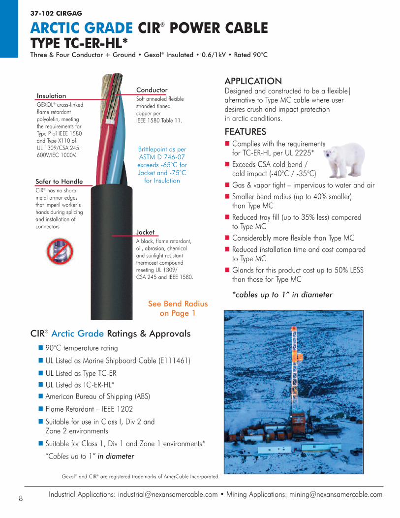
JacketA black, flame retardant, oil, abrasion, chemical and sunlight resistant thermoset compound meeting UL 1309/CSA 245 and IEEE 1580.
ConductorSoft annealed flexiblestranded tinned copper perIEEE 1580 Table 11.
InsulationGEXOL® cross-linked flame retardant polyolefin, meeting the requirements for Type P of IEEE 1580 and Type X110 of UL 1309/CSA 245.600V/IEC 1000V.
Gexol® and CIR® are registered trademarks of AmerCable Incorporated.
37-102 CIRGAG
ARCTIC GRADE CIR® POWER CABLETYPE TC-ER-HL*Three & Four Conductor + Ground • Gexol® Insulated • 0.6/1kV • Rated 90°C
Safer to HandleCIR® has no sharp metal armor edges that imperil worker’s hands during splicing and installation ofconnectors
Industrial Applications: [email protected] • Mining Applications: [email protected]
APPLICATIONDesigned and constructed to be a flexible|alternative to Type MC cable where user desires crush and impact protection in arctic conditions.
FEATURESn Complies with the requirements for TC-ER-HL per UL 2225*
n Exceeds CSA cold bend / cold impact (-40°C / -35°C)
n Gas & vapor tight – impervious to water and airn Smaller bend radius (up to 40% smaller) than Type MC
n Reduced tray fill (up to 35% less) comparedto Type MC
n Considerably more flexible than Type MCn Reduced installation time and cost compared to Type MC
n Glands for this product cost up to 50% LESSthan those for Type MC
*cables up to 1” in diameter
Brittlepoint as perASTM D 746-07exceeds -65°C forJacket and -75°C for Insulation
8
See Bend Radiuson Page 1
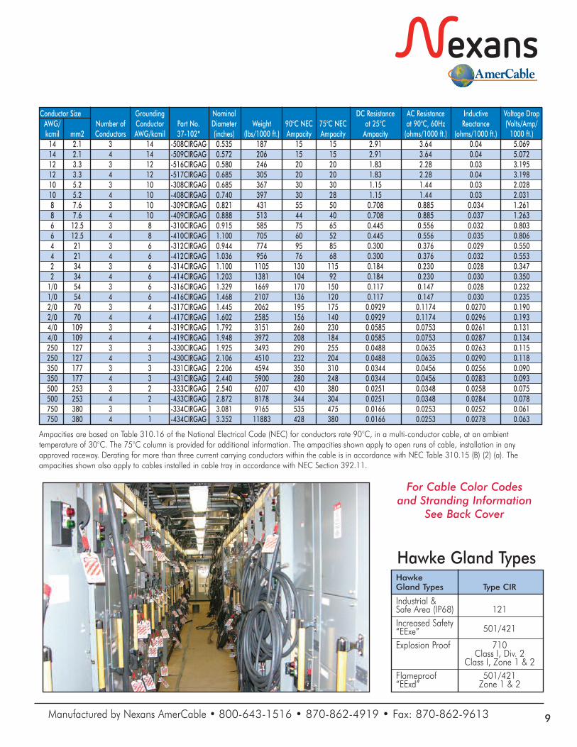
Ampacities are based on Table 310.16 of the National Electrical Code (NEC) for conductors rate 90°C, in a multi-conductor cable, at an ambienttemperature of 30°C. The 75°C column is provided for additional information. The ampacities shown apply to open runs of cable, installation in anyapproved raceway. Derating for more than three current carrying conductors within the cable is in accordance with NEC Table 310.15 (B) (2) (a). Theampacities shown also apply to cables installed in cable tray in accordance with NEC Section 392.11.
Conductor Size Grounding Nominal DC Resistance AC Resistance Inductive Voltage Drop AWG/ Number of Conductor Part No. Diameter Weight 90°C NEC 75°C NEC at 25°C at 90°C, 60Hz Reactance (Volts/Amp/ kcmil mm2 Conductors AWG/kcmil 37-102* (inches) (lbs/1000 ft.) Ampacity Ampacity Ampacity (ohms/1000 ft.) (ohms/1000 ft.) 1000 ft.) 14 2.1 3 14 -508CIRGAG 0.535 187 15 15 2.91 3.64 0.04 5.069 14 2.1 4 14 -509CIRGAG 0.572 206 15 15 2.91 3.64 0.04 5.072 12 3.3 3 12 -516CIRGAG 0.580 246 20 20 1.83 2.28 0.03 3.195 12 3.3 4 12 -517CIRGAG 0.685 305 20 20 1.83 2.28 0.04 3.198 10 5.2 3 10 -308CIRGAG 0.685 367 30 30 1.15 1.44 0.03 2.028 10 5.2 4 10 -408CIRGAG 0.740 397 30 28 1.15 1.44 0.03 2.031 8 7.6 3 10 -309CIRGAG 0.821 431 55 50 0.708 0.885 0.034 1.261 8 7.6 4 10 -409CIRGAG 0.888 513 44 40 0.708 0.885 0.037 1.263 6 12.5 3 8 -310CIRGAG 0.915 585 75 65 0.445 0.556 0.032 0.803 6 12.5 4 8 -410CIRGAG 1.100 705 60 52 0.445 0.556 0.035 0.806 4 21 3 6 -312CIRGAG 0.944 774 95 85 0.300 0.376 0.029 0.550 4 21 4 6 -412CIRGAG 1.036 956 76 68 0.300 0.376 0.032 0.553 2 34 3 6 -314CIRGAG 1.100 1105 130 115 0.184 0.230 0.028 0.347 2 34 4 6 -414CIRGAG 1.203 1381 104 92 0.184 0.230 0.030 0.350 1/0 54 3 6 -316CIRGAG 1.329 1669 170 150 0.117 0.147 0.028 0.232 1/0 54 4 6 -416CIRGAG 1.468 2107 136 120 0.117 0.147 0.030 0.235 2/0 70 3 4 -317CIRGAG 1.445 2062 195 175 0.0929 0.1174 0.0270 0.190 2/0 70 4 4 -417CIRGAG 1.602 2585 156 140 0.0929 0.1174 0.0296 0.193 4/0 109 3 4 -319CIRGAG 1.792 3151 260 230 0.0585 0.0753 0.0261 0.131 4/0 109 4 4 -419CIRGAG 1.948 3972 208 184 0.0585 0.0753 0.0287 0.134 250 127 3 3 -330CIRGAG 1.925 3493 290 255 0.0488 0.0635 0.0263 0.115 250 127 4 3 -430CIRGAG 2.106 4510 232 204 0.0488 0.0635 0.0290 0.118 350 177 3 3 -331CIRGAG 2.206 4594 350 310 0.0344 0.0456 0.0256 0.090 350 177 4 3 -431CIRGAG 2.440 5900 280 248 0.0344 0.0456 0.0283 0.093 500 253 3 2 -333CIRGAG 2.540 6207 430 380 0.0251 0.0348 0.0258 0.075 500 253 4 2 -433CIRGAG 2.872 8178 344 304 0.0251 0.0348 0.0284 0.078 750 380 3 1 -334CIRGAG 3.081 9165 535 475 0.0166 0.0253 0.0252 0.061 750 380 4 1 -434CIRGAG 3.352 11883 428 380 0.0166 0.0253 0.0278 0.063
Hawke Gland Types Type CIR
Industrial & Safe Area (IP68) 121 Increased Safety
501/421 “EExe” Explosion Proof 710 Class I, Div. 2 Class I, Zone 1 & 2 Flameproof 501/421 “EExd” Zone 1 & 2
Hawke Gland Types
Manufactured by Nexans AmerCable • 800-643-1516 • 870-862-4919 • Fax: 870-862-9613 9
For Cable Color Codesand Stranding Information
See Back Cover
37-102 CIRGAG
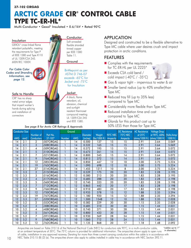
ARCTIC GRADE CIR® CONTROL CABLETYPE TC-ER-HL*Multi-Conductor • Gexol® Insulated • 0.6/1kV • Rated 90°C
JacketA black, flame retardant, oil, abrasion, chemical and sunlight resistant thermoset compound meeting UL 1309/CSA 245 and IEEE 1580.
ConductorSoft annealed flexible stranded tinned copper per IEEE 1580 Table 11.
Ground
InsulationGEXOL® cross-linked flameretardant polyolefin, meeting the requirements for Type P of IEEE 1580 and Type X110 of UL 1309/CSA 245. 600V/IEC 1000V.
Ampacities are based on Table 310.16 of the National Electrical Code (NEC) for conductors rate 90°C, in a multi-conductor cable, at an ambient temperature of 30°C. The 75°C column is provided for additional information. The ampacities shown apply to open runsof cable, installation in any approved raceway. Derating for more than three current carrying conductors within the cable is in accordance with NEC Table 310.15 (B) (2) (a). The ampacities shown also apply to cables installed in cable tray in accordance with NEC Section 392.11.
See page 8 for Arctic CIR Ratings & Approvals
For Cable ColorCodes and Stranding
Information, seepage 12.
Safe to HandleCIR® has no sharp metal armor edges that imperil worker’s hands during splicing and installation ofconnectors
APPLICATIONDesigned and constructed to be a flexible alternative toType MC cable where user desires crush and impactprotection in arctic conditions.
FEATURESn Complies with the requirements for TC-ER-HL per UL 2225*
n Exceeds CSA cold bend /cold impact (-40°C / -35°C)
n Gas & vapor tight – impervious to water & airn Smaller bend radius (up to 40% smaller)thanType MC
n Reduced tray fill (up to 35% less) compared to Type MC
n Considerably more flexible than Type MCn Reduced installation time and cost compared to Type MC
n Glands for this product cost up to 50% LESS than those for Type MC
Brittlepoint as perASTM D 746-07exceeds -65°C forJacket and -75°C for Insulation
10
Conductor Size Ground DC Resistance AC Resistance Voltage Drop Number of Part No. Diameter Weight 90°C NEC 75°C NEC at 25°C at 90°C, 60Hz (Volts/Amp/ AWG mm2 Conductors 37-102* Number AWG (inches) (lbs/1000 ft.) Ampacity Ampacity (ohms/1000 ft.) (ohms/1000 ft.) 1000 ft.) 14 2.1 2 -507CIRGAG 1 14 0.500 137 15 15 2.91 3.64 5.069 14 2.1 3 -508CIRGAG 1 14 0.532 165 15 15 2.91 3.64 5.069 14 2.1 4 -509CIRGAG 1 14 0.572 195 15 15 2.91 3.64 5.072 14 2.1 5 -510CIRGAG 1 14 0.673 261 15 15 2.91 3.64 5.072 14 2.1 7 -521CIRGAG 1 14 0.800 345 15 14 2.91 3.64 5.072 14 2.1 9 -764CIRGAG 1 14 0.813 372 15 14 2.91 3.64 5.072 14 2.1 12 -585CIRGAG 1 14 0.850 447 12 10 3.00 3.75 5.224 14 2.1 19 -765CIRGAG 1 14 1.090 698 12 10 3.00 3.75 5.224 14 2.1 37 -514CIRGAG 1 14 1.455 1211 10 8 3.00 3.75 5.224 12 3.3 2 -515CIRGAG 1 12 0.539 175 20 20 1.83 2.28 3.195 12 3.3 3 -516CIRGAG 1 12 0.580 213 20 20 1.83 2.28 3.195 12 3.3 4 -517CIRGAG 1 12 0.685 288 20 20 1.83 2.28 3.198 12 3.3 5 -560CIRGAG 1 12 0.740 333 20 20 1.83 2.28 3.198 12 3.3 7 -712CIRGAG 1 12 0.865 442 20 17 1.83 2.28 3.198 12 3.3 9 -766CIRGAG 1 12 0.910 483 20 17 1.83 2.28 3.198 12 3.3 12 -750CIRGAG 1 12 0.935 578 15 12 1.88 2.35 3.294 12 3.3 19 -767CIRGAG 1 12 1.180 920 15 12 1.88 2.35 3.294 12 3.3 37 -520CIRGAG 1 12 1.500 1548 12 10 1.88 2.35 2.028 10 5.2 2 -553CIRGAG 1 10 0.582 229 30 30 1.15 2.35 2.028 10 5.2 3 -308CIRGAG 1 10 0.685 310 30 30 1.15 1.44 2.031 10 5.2 4 -408CIRGAG 1 10 0.740 371 30 28 1.15 1.44 2.031 10 5.2 5 -561CIRGAG 1 10 0.800 433 30 28 1.15 1.44 2.031 10 5.2 7 -591CIRGAG 1 10 0.930 569 28 24 1.15 1.44 2.031 10 5.2 9 -768CIRGAG 1 10 1.060 712 28 24 1.15 1.44 2.031 10 5.2 12 -762CIRGAG 1 10 1.135 868 20 17 1.18 1.48 2.092
*cables up to 1”in diameter)
37-102 CIRAG
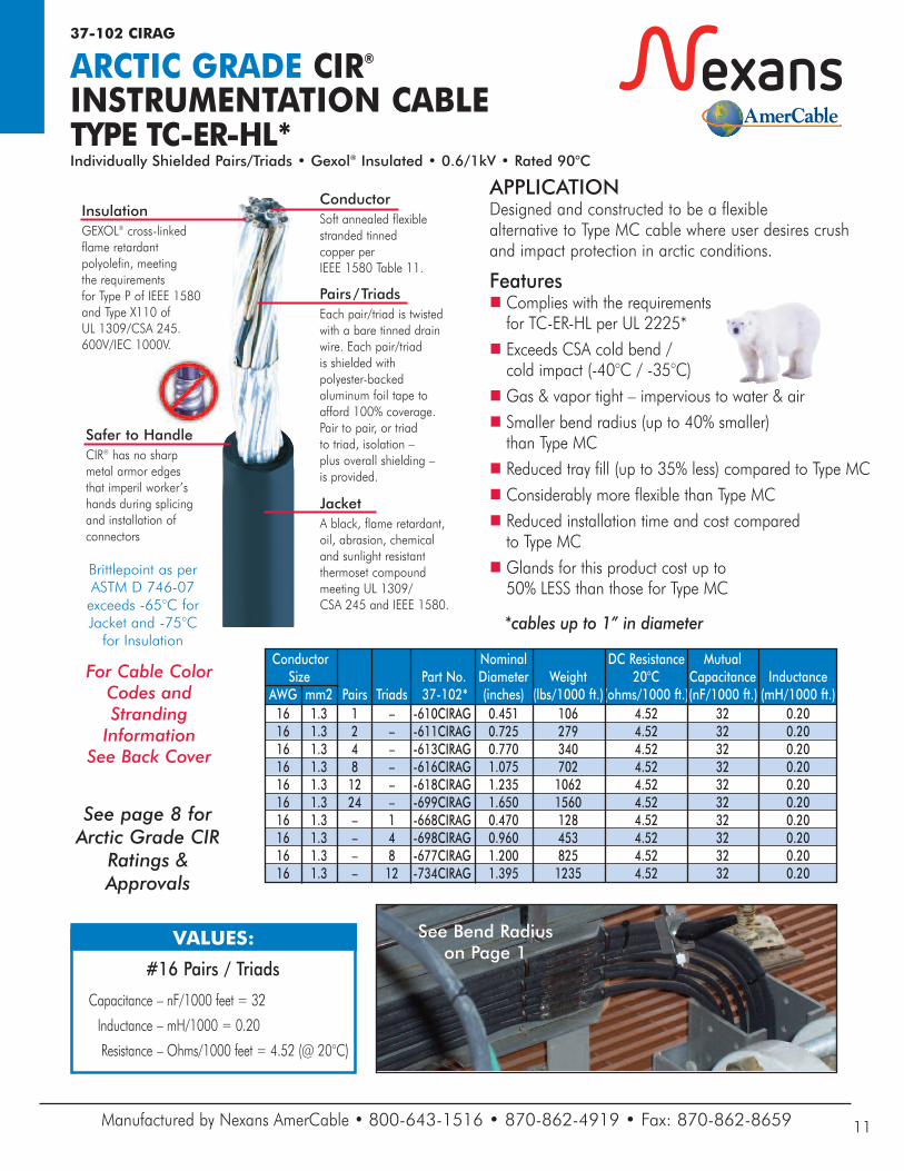
ARCTIC GRADE CIR®INSTRUMENTATION CABLETYPE TC-ER-HL*Individually Shielded Pairs/Triads • Gexol® Insulated • 0.6/1kV • Rated 90°C
JacketA black, flame retardant, oil, abrasion, chemical and sunlight resistant thermoset compound meeting UL 1309/CSA 245 and IEEE 1580.
ConductorSoft annealed flexiblestranded tinned copper perIEEE 1580 Table 11.
InsulationGEXOL® cross-linked flame retardant polyolefin, meeting the requirements for Type P of IEEE 1580 and Type X110 of UL 1309/CSA 245. 600V/IEC 1000V.
Pairs/TriadsEach pair/triad is twisted with a bare tinned drain wire. Each pair/triad is shielded with polyester-backed aluminum foil tape to afford 100% coverage. Pair to pair, or triad to triad, isolation – plus overall shielding – is provided.
Conductor Nominal DC Resistance Mutual Size Part No. Diameter Weight 20°C Capacitance InductanceAWG mm2 Pairs Triads 37-102* (inches) (lbs/1000 ft.)(ohms/1000 ft.)(nF/1000 ft.) (mH/1000 ft.) 16 1.3 1 – -610CIRAG 0.451 106 4.52 32 0.20 16 1.3 2 – -611CIRAG 0.725 279 4.52 32 0.20 16 1.3 4 – -613CIRAG 0.770 340 4.52 32 0.20 16 1.3 8 – -616CIRAG 1.075 702 4.52 32 0.20 16 1.3 12 – -618CIRAG 1.235 1062 4.52 32 0.20 16 1.3 24 – -699CIRAG 1.650 1560 4.52 32 0.20 16 1.3 – 1 -668CIRAG 0.470 128 4.52 32 0.20 16 1.3 – 4 -698CIRAG 0.960 453 4.52 32 0.20 16 1.3 – 8 -677CIRAG 1.200 825 4.52 32 0.20 16 1.3 – 12 -734CIRAG 1.395 1235 4.52 32 0.20
#16 Pairs / Triads
Capacitance – nF/1000 feet = 32
Inductance – mH/1000 = 0.20
Resistance – Ohms/1000 feet = 4.52 (@ 20°C)
VALUES:
See page 8 forArctic Grade CIR
Ratings &Approvals
For Cable Color Codes andStranding Information
See Back Cover
Safer to HandleCIR® has no sharp metal armor edges that imperil worker’s hands during splicing and installation ofconnectors
APPLICATIONDesigned and constructed to be a flexible alternative to Type MC cable where user desires crushand impact protection in arctic conditions.
Featuresn Complies with the requirementsfor TC-ER-HL per UL 2225*
n Exceeds CSA cold bend / cold impact (-40°C / -35°C)
n Gas & vapor tight – impervious to water & airn Smaller bend radius (up to 40% smaller) than Type MC
n Reduced tray fill (up to 35% less) compared to Type MCn Considerably more flexible than Type MCn Reduced installation time and cost compared to Type MC
n Glands for this product cost up to 50% LESS than those for Type MC
*cables up to 1” in diameter
Brittlepoint as perASTM D 746-07exceeds -65°C forJacket and -75°C for Insulation
Manufactured by Nexans AmerCable • 800-643-1516 • 870-862-4919 • Fax: 870-862-8659 11
See Bend Radiuson Page 1
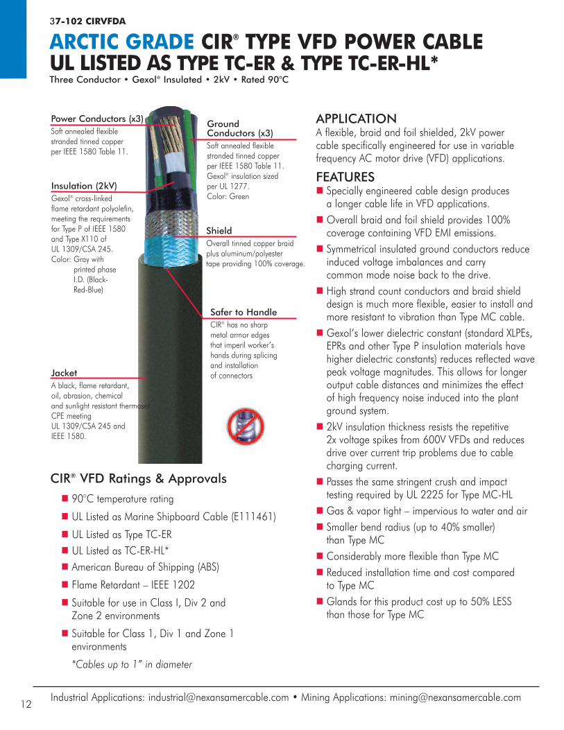
37-102 CIRVFDA
ARCTIC GRADE CIR® TYPE VFD POWER CABLEUL LISTED AS TYPE TC-ER & TYPE TC-ER-HL*Three Conductor • Gexol® Insulated • 2kV • Rated 90°C
APPLICATIONA flexible, braid and foil shielded, 2kV power cable specifically engineered for use in variablefrequency AC motor drive (VFD) applications.
FEATURESn Specially engineered cable design produces a longer cable life in VFD applications.
n Overall braid and foil shield provides 100%coverage containing VFD EMI emissions.
n Symmetrical insulated ground conductors reduceinduced voltage imbalances and carry common mode noise back to the drive.
n High strand count conductors and braid shielddesign is much more flexible, easier to install andmore resistant to vibration than Type MC cable.
n Gexol’s lower dielectric constant (standard XLPEs,EPRs and other Type P insulation materials havehigher dielectric constants) reduces reflected wavepeak voltage magnitudes. This allows for longeroutput cable distances and minimizes the effect of high frequency noise induced into the plant ground system.
n 2kV insulation thickness resists the repetitive 2x voltage spikes from 600V VFDs and reduces drive over current trip problems due to cable charging current.
n Passes the same stringent crush and impact testing required by UL 2225 for Type MC-HL
n Gas & vapor tight – impervious to water and airn Smaller bend radius (up to 40% smaller) than Type MC
n Considerably more flexible than Type MCn Reduced installation time and cost comparedto Type MC
n Glands for this product cost up to 50% LESS than those for Type MC
Insulation (2kV)Gexol® cross-linked flame retardant polyolefin, meeting the requirements for Type P of IEEE 1580 and Type X110 of UL 1309/CSA 245. Color: Gray with
printed phase I.D. (Black-Red-Blue)
JacketA black, flame retardant, oil, abrasion, chemical and sunlight resistant thermosetCPE meeting UL 1309/CSA 245 andIEEE 1580.
Power Conductors (x3)Soft annealed flexible stranded tinned copper per IEEE 1580 Table 11.
Ground Conductors (x3)Soft annealed flexible stranded tinned copper per IEEE 1580 Table 11. Gexol® insulation sized per UL 1277.Color: Green
ShieldOverall tinned copper braid plus aluminum/polyestertape providing 100% coverage.
CIR® VFD Ratings & Approvals
n 90°C temperature rating
n UL Listed as Marine Shipboard Cable (E111461)
n UL Listed as Type TC-ERn UL Listed as TC-ER-HL*n American Bureau of Shipping (ABS)
n Flame Retardant – IEEE 1202
n Suitable for use in Class I, Div 2 and Zone 2 environments
n Suitable for Class 1, Div 1 and Zone 1 environments
*Cables up to 1” in diameter
Industrial Applications: [email protected] • Mining Applications: [email protected]
Safer to HandleCIR® has no sharp metal armor edges that imperil worker’s hands during splicing and installation of connectors
12
Gexol® and CIR® are registered trademarks of AmerCable Incorporated.
Manufactured by Nexans AmerCable • 800-643-1516 • 870-862-4919 • Fax: 870-862-8659 13
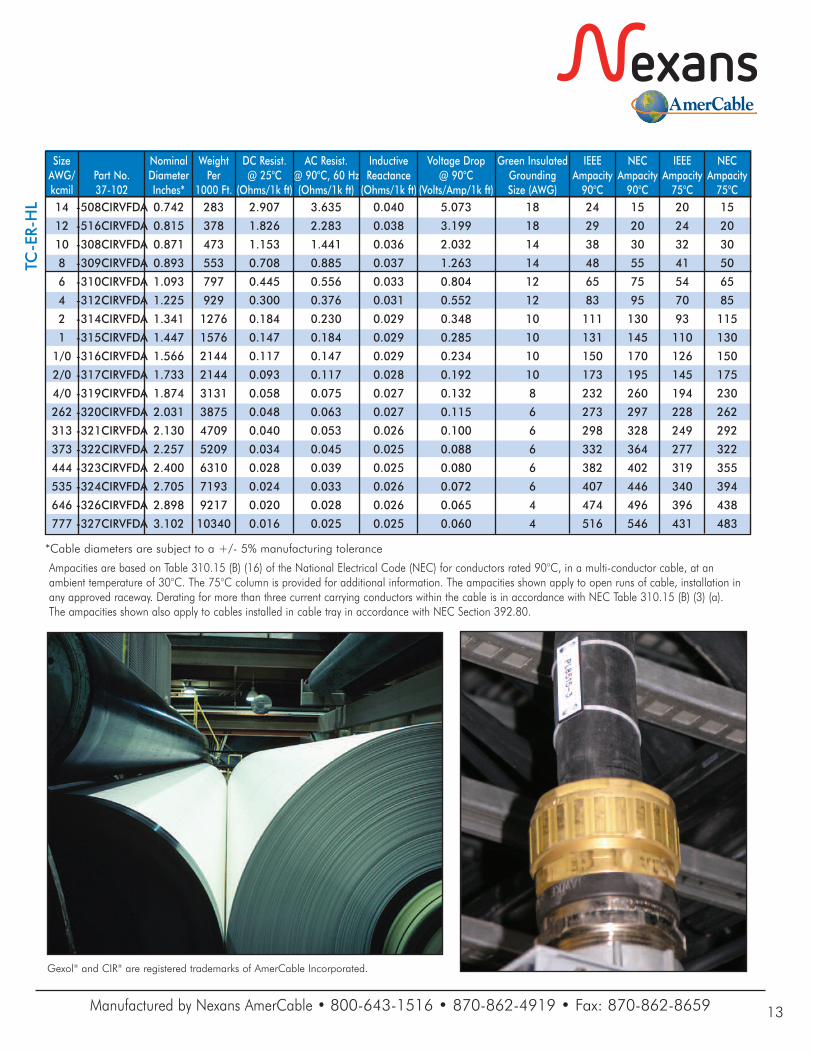
Ampacities are based on Table 310.15 (B) (16) of the National Electrical Code (NEC) for conductors rated 90°C, in a multi-conductor cable, at an ambient temperature of 30°C. The 75°C column is provided for additional information. The ampacities shown apply to open runs of cable, installation inany approved raceway. Derating for more than three current carrying conductors within the cable is in accordance with NEC Table 310.15 (B) (3) (a). The ampacities shown also apply to cables installed in cable tray in accordance with NEC Section 392.80.
Size Nominal Weight DC Resist. AC Resist. Inductive Voltage Drop Green Insulated IEEE NEC IEEE NECAWG/ Part No. Diameter Per @ 25°C @ 90°C, 60 Hz Reactance @ 90°C Grounding Ampacity Ampacity Ampacity Ampacitykcmil 37-102 Inches* 1000 Ft. (Ohms/1k ft) (Ohms/1k ft) (Ohms/1k ft) (Volts/Amp/1k ft) Size (AWG) 90°C 90°C 75°C 75°C 14 -508CIRVFDA 0.742 283 2.907 3.635 0.040 5.073 18 24 15 20 15
12 -516CIRVFDA 0.815 378 1.826 2.283 0.038 3.199 18 29 20 24 20
10 -308CIRVFDA 0.871 473 1.153 1.441 0.036 2.032 14 38 30 32 30
8 -309CIRVFDA 0.893 553 0.708 0.885 0.037 1.263 14 48 55 41 50
6 -310CIRVFDA 1.093 797 0.445 0.556 0.033 0.804 12 65 75 54 65
4 -312CIRVFDA 1.225 929 0.300 0.376 0.031 0.552 12 83 95 70 85
2 -314CIRVFDA 1.341 1276 0.184 0.230 0.029 0.348 10 111 130 93 115
1 -315CIRVFDA 1.447 1576 0.147 0.184 0.029 0.285 10 131 145 110 130
1/0 -316CIRVFDA 1.566 2144 0.117 0.147 0.029 0.234 10 150 170 126 150
2/0 -317CIRVFDA 1.733 2144 0.093 0.117 0.028 0.192 10 173 195 145 175
4/0 -319CIRVFDA 1.874 3131 0.058 0.075 0.027 0.132 8 232 260 194 230
262 -320CIRVFDA 2.031 3875 0.048 0.063 0.027 0.115 6 273 297 228 262
313 -321CIRVFDA 2.130 4709 0.040 0.053 0.026 0.100 6 298 328 249 292
373 -322CIRVFDA 2.257 5209 0.034 0.045 0.025 0.088 6 332 364 277 322
444 -323CIRVFDA 2.400 6310 0.028 0.039 0.025 0.080 6 382 402 319 355
535 -324CIRVFDA 2.705 7193 0.024 0.033 0.026 0.072 6 407 446 340 394
646 -326CIRVFDA 2.898 9217 0.020 0.028 0.026 0.065 4 474 496 396 438
777 -327CIRVFDA 3.102 10340 0.016 0.025 0.025 0.060 4 516 546 431 483
*Cable diameters are subject to a +/- 5% manufacturing tolerance
TC-ER-HL
5_16© 2016, AmerCable Incorporated www.NexansAmerCable.com
Industrial Applications:[email protected]
Mining Applications:[email protected]
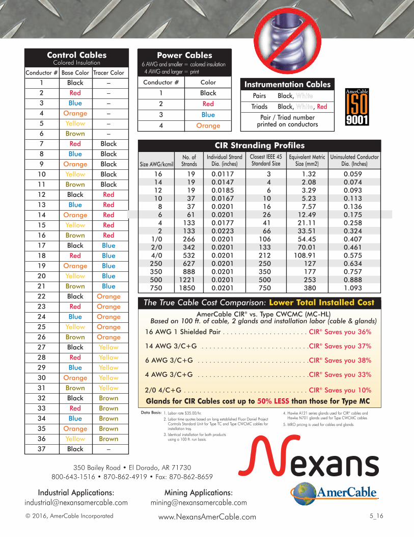
Power Cables 6 AWG and smaller = colored insulation 4 AWG and larger = print
Conductor # Color
1 Black
2 Red
3 Blue
4 Orange
Instrumentation Cables Pairs Black, White
Triads Black, White, Red
Pair / Triad numberprinted on conductors
Control CablesColored Insulation
Conductor # Base Color Tracer Color
1 Black –
2 Red –
3 Blue –
4 Orange –
5 Yellow –
6 Brown –
7 Red Black
8 Blue Black
9 Orange Black
10 Yellow Black
11 Brown Black
12 Black Red
13 Blue Red
14 Orange Red
15 Yellow Red
16 Brown Red
17 Black Blue
18 Red Blue
19 Orange Blue
20 Yellow Blue
21 Brown Blue
22 Black Orange
23 Red Orange
24 Blue Orange
25 Yellow Orange
26 Brown Orange
27 Black Yellow
28 Red Yellow
29 Blue Yellow
30 Orange Yellow
31 Brown Yellow
32 Black Brown
33 Red Brown
34 Blue Brown
35 Orange Brown
36 Yellow Brown
37 Black –
161412108642
1/02/04/0250350500750
19191937376113313326634253262788812211850
0.0117 0.0147 0.01850.01670.0201 0.0201 0.01770.0223 0.0201 0.0201 0.0201 0.0201 0.0201 0.0201 0.0201
3461016264166106133212250350500750
1.32 2.083.29 5.23 7.5712.49 21.11 33.51 54.45 70.01 108.91 127177253380
0.059 0.0740.093 0.113 0.1360.1750.2580.3240.4070.4610.5750.6340.7570.8881.093
CIR Stranding Profiles
Size AWG/kcmilNo. ofStrands
Individual StrandDia. (inches)
Closest IEEE 45Standard Size
Equivalent MetricSize (mm2)
Uninsulated ConductorDia. (Inches)
1. Labor rate $35.00/hr.2. Labor time quotes based on long established Fluor Daniel Project Controls Standard Unit for Type TC and Type CWCMC cables forinstallation tray.
3. Identical installation for both productsusing a 100 ft. run basis.
4. Hawke A121 series glands used for CIR® cables andHawke N701 glands used for Type CWCMC cables.
5. MRO pricing is used for cables and glands.
AmerCable CIR® vs. Type CWCMC (MC-HL)Based on 100 ft. of cable, 2 glands and installation labor (cable & glands)
16 AWG 1 Shielded Pair . . . . . . . . . . . . . . . . . . . . . . CIR® Saves you 36%
14 AWG 3/C+G . . . . . . . . . . . . . . . . . . . . . . . . . . . .CIR® Saves you 37%
6 AWG 3/C+G . . . . . . . . . . . . . . . . . . . . . . . . . . . . .CIR® Saves you 38%
4 AWG 3/C+G . . . . . . . . . . . . . . . . . . . . . . . . . . . . .CIR® Saves you 33%
2/0 4/C+G . . . . . . . . . . . . . . . . . . . . . . . . . . . . . . . . CIR® Saves you 10%
Glands for CIR Cables cost up to 50% LESS than those for Type MCData Basis:
The True Cable Cost Comparison: Lower Total Installed Cost
350 Bailey Road • El Dorado, AR 71730800-643-1516 • 870-862-4919 • Fax: 870-862-8659
Related Documents