IEEE Communications Surveys & Tutorials • 1st Quarter 2008 70 he continuing evolution of mobile communications has spawned several radio technologies (e.g., orthogonal frequency-division multiplexing [OFDM], code-division multiple access [CDMA]) and mobile network architectures (e.g., Third Generation Partnership Project [3GPP], 3GPP2) over the last few years. This technological proliferation has, in turn, brought on an unprecedented increase in the number of wireless access standards and their associated protocol stacks. The need for ever faster standardization cycles and the urgent demand to support access to the Internet by these mobile net- work architectures called for a “mix-and-match” approach to the definition of the associated protocol stacks. As individual protocols are typically specified with different assumptions in mind, the end-to-end performance of these protocol stacks in deployed mobile networks has not always been satisfactory. Stratification, the composition mechanism for protocol frameworks, renders each protocol layer impervious to the functionality embedded within other protocol layers. Inside a protocol stack, exchange of control and data information may take place only between adjacent protocol layers and is sup- ported by the concept of a service access point (SAP). A SAP provides access to a selected subset of protocol functionality via a precisely defined set of primitive operations. A particu- lar protocol layer may offer and/or use more than one SAP, depending on its function and the information it needs to exchange with its adjacent protocol layers. This black box paradigm lies at the heart of the standard open systems inter- connection (OSI) reference model and has been the prevalent design approach since the dawn of all modern networking architectures [1]. In this respect, any attempt to violate the OSI reference model is considered a cross-layer design. In the same context, in wireless networks any abstract model that rationalizes in a nontrivial manner the cross-layer interactions from the physical to the transport layer in order to allow information transfer across the layers’ stratification bound- aries is also considered a cross-layer design. In most cases cross-layer design jointly attunes a number of lower layers’ parameters (e.g., channel state information) to upper-layer functions like transport and routing [2]. Regarding the underlying motivation, cross-layer design addresses problems of wireless network performance whose cause can be traced back to the original design assumptions underpinning the architecture of the employed network archi- tectures and their protocol stacks (i.e., the black box paradigm). The well-known case of TCP’s performance over wireless links is one of the most commonly cited applications of cross-layer design, but it is not the only one. Recently, numerous research efforts from around the globe have used T SURVEYS IEEE COMMUNICATIONS The Electronic Magazine of Original Peer-Reviewed Survey Articles FOTIS FOUKALAS, V ANGELIS GAZIS, AND NANCY ALONISTIOTI, UNIVERSITY OF ATHENS ABSTRACT Third-generation (3G) and beyond 3G mobile communication systems must pro- vide interoperability with the Internet, increase throughput for mobile devices, and optimize their operation for multimedia applications. The limited ability of tradition- al layered architectures to exploit the unique nature of wireless communication has fostered the introduction of cross-layer design solutions that allow optimized opera- tion for mobile devices in the modern heterogeneous wireless environment. In this article we present the major cross-layer design solutions that handle such problems, and discuss cross-layer implementations with a focus on functional entities that sup- port cross-layer processes and the respective signaling. In addition, we consider the associated architectural complexity and communication overhead they introduce. Furthermore, we point out the major open technical challenges in the cross-layer design research area. Finally, we conclude our article with a summary of cross-layer approaches developed thus far and provide directions for future work. CROSS-LAYER DESIGN PROPOSALS FOR WIRELESS MOBILE NETWORKS: A SURVEY AND T AXONOMY 1ST QUARTER 2008, VOLUME 10, NO. 1 www.comsoc.org/pubs/surveys 1553-877X

Welcome message from author
This document is posted to help you gain knowledge. Please leave a comment to let me know what you think about it! Share it to your friends and learn new things together.
Transcript

IEEE Communications Surveys & Tutorials • 1st Quarter 200870
he continuing evolution of mobile communications hasspawned several radio technologies (e.g., orthogonalfrequency-division multiplexing [OFDM], code-division
multiple access [CDMA]) and mobile network architectures(e.g., Third Generation Partnership Project [3GPP], 3GPP2)over the last few years. This technological proliferation has, inturn, brought on an unprecedented increase in the number ofwireless access standards and their associated protocol stacks.The need for ever faster standardization cycles and the urgentdemand to support access to the Internet by these mobile net-work architectures called for a “mix-and-match” approach tothe definition of the associated protocol stacks. As individualprotocols are typically specified with different assumptions inmind, the end-to-end performance of these protocol stacks indeployed mobile networks has not always been satisfactory.
Stratification, the composition mechanism for protocolframeworks, renders each protocol layer impervious to thefunctionality embedded within other protocol layers. Inside aprotocol stack, exchange of control and data information maytake place only between adjacent protocol layers and is sup-ported by the concept of a service access point (SAP). A SAPprovides access to a selected subset of protocol functionalityvia a precisely defined set of primitive operations. A particu-lar protocol layer may offer and/or use more than one SAP,
depending on its function and the information it needs toexchange with its adjacent protocol layers. This black boxparadigm lies at the heart of the standard open systems inter-connection (OSI) reference model and has been the prevalentdesign approach since the dawn of all modern networkingarchitectures [1]. In this respect, any attempt to violate theOSI reference model is considered a cross-layer design. In thesame context, in wireless networks any abstract model thatrationalizes in a nontrivial manner the cross-layer interactionsfrom the physical to the transport layer in order to allowinformation transfer across the layers’ stratification bound-aries is also considered a cross-layer design. In most casescross-layer design jointly attunes a number of lower layers’parameters (e.g., channel state information) to upper-layerfunctions like transport and routing [2].
Regarding the underlying motivation, cross-layer designaddresses problems of wireless network performance whosecause can be traced back to the original design assumptionsunderpinning the architecture of the employed network archi-tectures and their protocol stacks (i.e., the black boxparadigm). The well-known case of TCP’s performance overwireless links is one of the most commonly cited applicationsof cross-layer design, but it is not the only one. Recently,numerous research efforts from around the globe have used
T
S U R V E Y SI E E EC O M M U N I C A T I O N S
T h e E l e c t r o n i c M a g a z i n e o fO r i g i n a l P e e r - R e v i e w e d S u r v e y A r t i c l e s
FOTIS FOUKALAS, VANGELIS GAZIS, AND NANCY ALONISTIOTI, UNIVERSITY OF ATHENS
ABSTRACT
Third-generation (3G) and beyond 3G mobile communication systems must pro-vide interoperability with the Internet, increase throughput for mobile devices, andoptimize their operation for multimedia applications. The limited ability of tradition-al layered architectures to exploit the unique nature of wireless communication hasfostered the introduction of cross-layer design solutions that allow optimized opera-tion for mobile devices in the modern heterogeneous wireless environment. In thisarticle we present the major cross-layer design solutions that handle such problems,and discuss cross-layer implementations with a focus on functional entities that sup-port cross-layer processes and the respective signaling. In addition, we consider theassociated architectural complexity and communication overhead they introduce.Furthermore, we point out the major open technical challenges in the cross-layerdesign research area. Finally, we conclude our article with a summary of cross-layerapproaches developed thus far and provide directions for future work.
CROSS-LAYER DESIGN PROPOSALS FOR
WIRELESS MOBILE NETWORKS: A SURVEY AND TAXONOMY
1ST QUARTER 2008, VOLUME 10, NO. 1
www.comsoc.org/pubs/surveys
1553-877X
IEEE Communications Surveys & Tutorials • 1st Quarter 2008 71
cross-layer solutions to improve the performance of wirelesscommunication systems and protocol stacks in selected appli-cation areas. These range from the case of TCP’s operationover wireless networks to more advanced topics such as maxi-mizing the amount of users per service area (i.e., per radiocell) and adapting the encoding of multimedia content accord-ing to the state of the wireless channel.
Nowadays, the potential of cross-layer design for improvingcritical performance aspects of modern wireless networks iswidely recognized, and the ability to support cross-layer inter-action patterns throughout the protocol stack is considered animportant property of beyond 3G mobile communication sys-tems. The present article surveys existing cross-layer designapplications and summarizes their key properties in a compre-hensive taxonomy of cross-layer design approaches. The restof the article is organized as follows. We present the architec-tures and models proposed so far within the concept of cross-layer design in wireless networks and identify key functionalentities in cross-layer management procedures. We present ataxonomy into which existing cross-layer design efforts areclassified and identify their salient functional properties. Wepresent and categorize cross-layer signaling approaches. Weidentify open technical challenges associated with cross-layerdesign proposals and provide a qualitative investigation. Weprovide a comparative discussion of cross-layer design solu-tions and a summary of the lessons learned from the survey.Finally, we conclude the article with directions for futurework.
CROSS-LAYER ARCHITECTURES, MODELS AND ENTITIES
As so eloquently stated in [3], it is architecture that facilitatesthe decomposition of a system’s functions into modular com-ponents that operate in unison to realize its purpose. Byemploying components optimized for specific purposes, amodular architecture allows for gains in performance andtransparent system upgrades. At a design level, modularity isachieved by abstracting the functionality offered by each mod-ule via appropriate interfaces [4]. For instance, the OSI refer-ence model encapsulates protocol functionalities into entities(i.e., protocol layers) that form the modules of the proposedarchitecture, while abstracting the internal details of eachmodule through the interfaces it exposes to its adjacent layers[1].
Cross-layer design (CLD) allows communication to takeplace even between nonadjacent layers through additionalentities introduced into the system’s architecture. However,
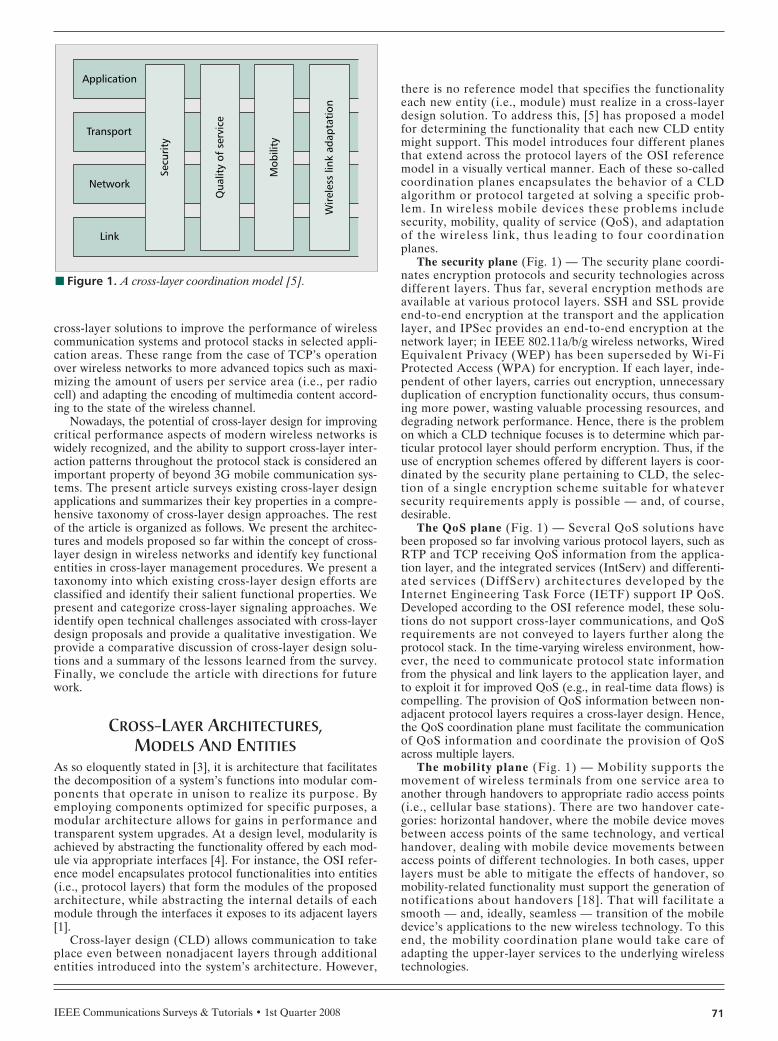
there is no reference model that specifies the functionalityeach new entity (i.e., module) must realize in a cross-layerdesign solution. To address this, [5] has proposed a modelfor determining the functionality that each new CLD entitymight support. This model introduces four different planesthat extend across the protocol layers of the OSI referencemodel in a visually vertical manner. Each of these so-calledcoordination planes encapsulates the behavior of a CLDalgorithm or protocol targeted at solving a specific prob-lem. In wireless mobile devices these problems includesecurity, mobility, quality of service (QoS), and adaptationof the wireless link, thus leading to four coordinationplanes.
The security plane (Fig. 1) — The security plane coordi-nates encryption protocols and security technologies acrossdifferent layers. Thus far, several encryption methods areavailable at various protocol layers. SSH and SSL provideend-to-end encryption at the transport and the applicationlayer, and IPSec provides an end-to-end encryption at thenetwork layer; in IEEE 802.11a/b/g wireless networks, WiredEquivalent Privacy (WEP) has been superseded by Wi-FiProtected Access (WPA) for encryption. If each layer, inde-pendent of other layers, carries out encryption, unnecessaryduplication of encryption functionality occurs, thus consum-ing more power, wasting valuable processing resources, anddegrading network performance. Hence, there is the problemon which a CLD technique focuses is to determine which par-ticular protocol layer should perform encryption. Thus, if theuse of encryption schemes offered by different layers is coor-dinated by the security plane pertaining to CLD, the selec-tion of a single encryption scheme suitable for whateversecurity requirements apply is possible — and, of course,desirable.
The QoS plane (Fig. 1) — Several QoS solutions havebeen proposed so far involving various protocol layers, such asRTP and TCP receiving QoS information from the applica-tion layer, and the integrated services (IntServ) and differenti-ated services (DiffServ) architectures developed by theInternet Engineering Task Force (IETF) support IP QoS.Developed according to the OSI reference model, these solu-tions do not support cross-layer communications, and QoSrequirements are not conveyed to layers further along theprotocol stack. In the time-varying wireless environment, how-ever, the need to communicate protocol state informationfrom the physical and link layers to the application layer, andto exploit it for improved QoS (e.g., in real-time data flows) iscompelling. The provision of QoS information between non-adjacent protocol layers requires a cross-layer design. Hence,the QoS coordination plane must facilitate the communicationof QoS information and coordinate the provision of QoSacross multiple layers.
The mobility plane (Fig. 1) — Mobility supports themovement of wireless terminals from one service area toanother through handovers to appropriate radio access points(i.e., cellular base stations). There are two handover cate-gories: horizontal handover, where the mobile device movesbetween access points of the same technology, and verticalhandover, dealing with mobile device movements betweenaccess points of different technologies. In both cases, upperlayers must be able to mitigate the effects of handover, somobility-related functionality must support the generation ofnotifications about handovers [18]. That will facilitate asmooth — and, ideally, seamless — transition of the mobiledevice’s applications to the new wireless technology. To thisend, the mobility coordination plane would take care ofadapting the upper-layer services to the underlying wirelesstechnologies.
■ Figure 1. A cross-layer coordination model [5].
Secu
rity
Mob
ility
Wir
eles
s lin
k ad
apta
tion
Qua
lity
of s
ervi
ce
Application
Transport
Network
Link

IEEE Communications Surveys & Tutorials • 1st Quarter 200872
The wireless link adaptation plane (Fig. 1) — This planeaddresses effects specific to the wireless link, i.e., channel fad-ing, bit error rate (BER) variations, and transmission delays.These properties can affect the performance of upper layers,particularly that of TCP, which erroneously considers packetlosses attributed to the instant state of the wireless channel asbeing caused by congestion in the end-to-end path. Severalcross-layer solutions to indicate the actual cause of packetlosses occurring at lower layers have been proposed thus far(e.g., the TCP-sleep protocol identifies losses related to chan-nel fading effects). In this case the automatic repeat request(ARQ) protocol at the data link layer tries retransmissions.Obviously, retransmission of lost packets from both TCP andARQ could halve the congestion window and, thus, the uti-lization of the wireless link. To avoid such rate degradations,the coordination between TCP and ARQ protocols is neces-sary [17].
Another important CLD aspect is the management ofcross-layer interactions in a way that can guarantee the sys-tem’s smooth operation. To this end, the aforementionedmanagement model specifies an interlayer coordination man-ager responsible for the central coordination of CLD process-es. In general, CLD introduces management entities thatoperate as either an optimizer of performance or a schedulerof some kind, depending on the problem at hand. Such anentity may reside within the protocol stack of the affected sys-tem, in which case it is considered an internal entity, or in anexternal network node. In the former case, the internal entitymay be either an interlayer entity that coordinates the opera-tion of all protocol stack layers or a set of intralayer entities,each of which is collocated with a protocol layer (Fig. 2). Inthe case of external entities, these may be centralized andhosted by a specific network node or distributed over severalnetwork nodes.
TYPES OF CROSS-LAYER MANAGEMENT ENTITIESInternal Interlayer Entities
Interlayer Cross-Layer Manager (Fig. 2) — Reference [5]proposed a central interlayer coordination manager thatapplies cross-layer algorithms in any protocol stack layer. Thecoordination manager receives notifications for events occur-ring at protocol layers and is thus aware of the specific stateany protocol layer is in. For instance, in the TCP case thecongestion window and BER threshold state variables areused to trigger the connection initiated and link lost events,respectively.
Interlayer Cross-Layer Optimizer (Fig. 2) — Reference [6]proposed a CLD architecture that jointly optimizes the opera-tional parameters of multiple layers via a cross-layer optimizer(CLO) entity responsible for optimizing N layers based onabstracted layer parameters. The abstraction of the layerparameters reduces the number of parameters the CLO needsin order to optimize the layer functionality. The benefit of thisapproach is that it provides a technology-independent way ofinteracting with each protocol layer. Consequently, the CLOcan be deployed in heterogeneous networks comprising differ-ent wireless technologies and access systems. Layer abstrac-tion identifies the parameters that expose the capabilities ofthe corresponding layer, thus enabling calculation of the prop-er values that optimize a specific objective function by theCLO. For instance, in the case of audiovisual transmission,the objective function to optimize may be the average peaksignal-to-noise ratio (PSNR) that translates to the video quali-ty perceived by a user. The performance criterion of the cross-layer optimization is the average PSNR between the encodedand displayed video stream, calculated through the rate dis-tortion (RD) factor. The CLO employs a reconfiguration pro-cedure to distribute the values of the abstracted parameters to
■ Figure 2. The different entities which (a, b) coordinate cross-layer management procedures in a protocol stack; and (c, d) which pro-cess cross-layer information in a network deployment.
Physical
a) Internal intralayer entities c) External centralized entities
b) Internal interlayer entities d) External decentralized entities
CLE
CLE
BS
Link
CLEMTMT
CLECLE
MT
CLE
BS BS
BS

IEEE Communications Surveys & Tutorials • 1st Quarter 2008 73
the corresponding protocol layers. Each protocol layer is thenresponsible for matching the abstracted parameters and valuesinto its own (i.e., internal) parameters that adapt its mode ofoperation. This approach incurs communication overhead dueto the cross-layer information (i.e., the RD information) beingconveyed from the video server to the CLO as well as someprocessing overhead during the reconfiguration process.
Internal Intralayer Entities
Intralayer Cross-Layer Optimizer (Fig. 2) — Reference [7]introduced a model for designing and implementing cross-layer feedback to allow direct communication between anypairs of layers in the protocol stack. This CLD model is calledÉCLAIR and consists of the following modules:• The tuning layer (TL) provides an interface for invoking
control information at a particular protocol layer. Ascontrol information specifies the behavior of protocols,the actual protocol behavior can be changed by properlymanipulating its control information.
• The optimizing subsystem (OSS) activates optimizationalgorithms. The OSS collects control information fromthe TL through the protocol optimizers and adapts theprotocol’s behavior during runtime. To this end, the OSScontains a set of protocol optimizer (PO) entities. A POimplements an algorithm that addresses a specific cross-layer optimization. Hence, several specialized PO entitiescan be implemented and deployed according to the opti-mization purposes.The ÉCLAIR architecture has been used in a feedback
loop to control the bandwidth of running applications by tun-ing the receiver window of each TCP connection. In theÉCLAIR architecture, applications set up the desired TCPwindow size to advertise their restrictions on network through-put. ÉCLAIR assigns a priority to each application and calcu-lates the appropriate receiver window based on that priority.More specifically, the TL for the TCP layer (TCPTL) uses thepriority to calculate the receiver window for each application.In this particular approach, changes in the protocol stack willonly affect TL entities and the functionality of PO entities;hence, a PO does not depend on protocol layer code. All thesame, the additional function calls between the OSS and theTL through the several POs incur internal overhead. Howev-er, ÉCLAIR achieves the following design goals:• Minimal or zero processing overhead within the protocol
stack since the OSS is executing concurrently with theprotocol stack.
• Several PO entities can be dynamically deployed andported to multiple technologies.
Intralayer Cross-Layer Scheduler (Fig. 2) — Reference [8]proposed a cross-layer adaptation framework for 802.16eorthogonal frequency-division multiple access (OFDMA) sys-tems. It strives to achieve the highest system performance byexploiting cross-layer information between the medium accesscontrol (MAC) and physical layers. The MAC layer consistsof the scheduling and resource allocation components thatcomprise a MAC scheduler and resource controller, respec-tively. The scheduler’s algorithm determines the number ofpackets that could be transmitted to each user. The resourcecontroller allocates the frequency bands for each user by usinga channel-aware subcarrier allocation algorithm. In addition, auser grouper organizes individual users into groups accordingto the subchannel type of the 802.16e OFDMA standard.
The scheduler works in conjunction with the resource con-troller to increase the achievable throughput of users basedon the channel quality information (CQI). Moreover, a hybrid
ARQ protocol is deployed for purposes of link adaptation.The use of HARQ aids in the selection of the modulation andthe coding scheme. Although the involvement of HARQincreases overall throughput, it also introduces a considerableamount of overhead when a large number of retransmissionsoccur. In 802.16e systems, retransmissions are associated tocertain control messages that allow a mobile terminal to iden-tify the correct packets in a data burst. However, these controlmessages can accrue up to 60 percent of the resources thatshould be allocated to mobile users. Consequently, allocationof channel resources should take into account in the amountof control messages and retransmissions.
External Entities
External Radio Scheduler (Fig. 2) — Reference [9] pro-posed a scheduling strategy for wideband CDMA (WCDMA)systems such as the Universal Mobile Telecommunication Sys-tem (UMTS). This strategy exploits cross-layer information toimprove system performance in terms of capacity and delay. Itassigns users to priorities based on short-term channel varia-tions instead of using only long-term ones. In a WCDMA sys-tem the radio base station (BS) provides each user with atransmission power Pi(t). The BS sets the available transmis-sion power PT and, using a downlink fast control mechanism,notifies each wireless device of the minimum transmissionpower. Due to the slowly varying radio channel conditions, thepower fluctuates around an average value.
By merging the rapid channel fluctuations of WCDMA, [9]proposed a scheduling scheme that prioritizes radio transmis-sions using a function that exploits these rapid channel fluctu-ations. This function takes into account not only the channelstate (e.g., as typical multiuser diversity does), but also thechannel variation experienced by each user. These prioritiesare evaluated for the downlink channel. To handle downlinkradio conditions, a radio scheduler located in the BS need notuse signaling to invoke power-related information since it usesfast power control information from the power control mecha-nism. Hence, in principle, the proposed scheme does notaffect system performance, and its deployment in UMTSmobile networks could increase the number of served users.Simulation results quantify the realistically achievable gain ofthis strategy as up to 30 percent in capacity and 35 percentreduction in average channel access times.
External Centralized Cross-Layer Optimizer (Fig. 2) —Reference [10] proposed a CLD solution to address QoS pro-visioning over IP-based CDMA networks. The authors pro-posed a centralized cross-layer scheduler located at the BSthat interacts with mobile terminals to exchange informationregarding its traffic, power level, etc.eteras. This cross-layerscheduler supports a Dynamic Weight Generalized ProcessorSharing (DWGPS) scheduling scheme according to which avideo frame from the application layer is compressed to sever-al batches of link layer (LL) packets according to its priority.To this end, the mobile terminal sends the batch class andbatch size to the BS. The BS is also aware of the maximumtolerable delay over the wireless link as denoted by the time-out value.
This proposal takes into account the multiuser diversitygain that denotes the ratio of average transmission power foran LL packet. A piece of information also considered is thegood/bad threshold F, since the bad channel state of a batchaffects the backoff probability. Consequently, this thresholdmust be carefully set to avoid degrading the effectiveness ofthe backoff functionality. Whether a channel is in a bad orgood state is a critical issue that must be estimated carefully,
IEEE Communications Surveys & Tutorials • 1st Quarter 200874
since in CDMA systems a mobile terminal does not transmitonly when it has the best channel quality but also when itschannel gain is no more than F dB less than the averagevalue. Hence, the backoff probability must be small when thetimer value for transmission is low, in which case the batchmust be transmitted urgently. Moreover, the channel fadingrate affects the backoff probability and consequently thetimer’s value.
Distributed Cross-Layer Optimizer — The majority ofcross-layer designs focus on single-hop wireless networks (i.e.,cellular networks). The aforementioned approaches concernthe conventional case where a single access point servesmobile devices using radio cells. On the other hand, cross-layer design for resource allocation has already been appliedin multihop wireless networks. Reference [11] discusses cross-layer design algorithms that operate in a distributed fashion.A decentralized scheduler is employed to schedule L linkssimultaneously satisfying the interference constraints imposedby the distributed network model and the associated generalinterference model. Such links are dominated by interference;consequently, they may suffer significant capacity losses inpacket transmission and reception. Naturally, the introductionof a distributed and decentralized scheduling scheme intro-duces additional signaling overhead that,ultimately dependson the actual network size and topology [2].
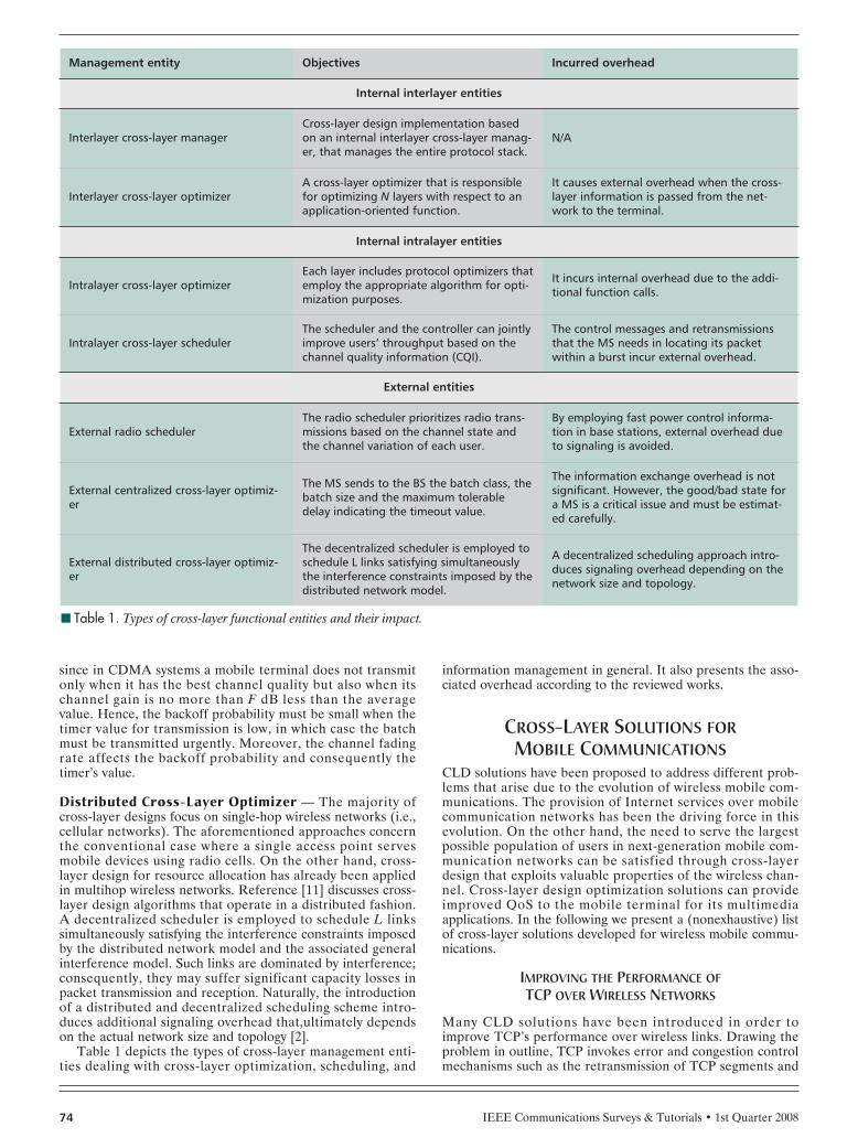
Table 1 depicts the types of cross-layer management enti-ties dealing with cross-layer optimization, scheduling, and
information management in general. It also presents the asso-ciated overhead according to the reviewed works.
CROSS-LAYER SOLUTIONS FORMOBILE COMMUNICATIONS
CLD solutions have been proposed to address different prob-lems that arise due to the evolution of wireless mobile com-munications. The provision of Internet services over mobilecommunication networks has been the driving force in thisevolution. On the other hand, the need to serve the largestpossible population of users in next-generation mobile com-munication networks can be satisfied through cross-layerdesign that exploits valuable properties of the wireless chan-nel. Cross-layer design optimization solutions can provideimproved QoS to the mobile terminal for its multimediaapplications. In the following we present a (nonexhaustive) listof cross-layer solutions developed for wireless mobile commu-nications.
IMPROVING THE PERFORMANCE OFTCP OVER WIRELESS NETWORKS
Many CLD solutions have been introduced in order toimprove TCP’s performance over wireless links. Drawing theproblem in outline, TCP invokes error and congestion controlmechanisms such as the retransmission of TCP segments and
■ Table 1. Types of cross-layer functional entities and their impact.
Management entity Objectives Incurred overhead
Internal interlayer entities
Interlayer cross-layer managerCross-layer design implementation basedon an internal interlayer cross-layer manag-er, that manages the entire protocol stack.
N/A
Interlayer cross-layer optimizerA cross-layer optimizer that is responsiblefor optimizing N layers with respect to anapplication-oriented function.
It causes external overhead when the cross-layer information is passed from the net-work to the terminal.
Internal intralayer entities
Intralayer cross-layer optimizerEach layer includes protocol optimizers thatemploy the appropriate algorithm for opti-mization purposes.
It incurs internal overhead due to the addi-tional function calls.
Intralayer cross-layer schedulerThe scheduler and the controller can jointlyimprove users’ throughput based on thechannel quality information (CQI).
The control messages and retransmissionsthat the MS needs in locating its packetwithin a burst incur external overhead.
External entities
External radio schedulerThe radio scheduler prioritizes radio trans-missions based on the channel state andthe channel variation of each user.
By employing fast power control informa-tion in base stations, external overhead dueto signaling is avoided.
External centralized cross-layer optimiz-er
The MS sends to the BS the batch class, thebatch size and the maximum tolerabledelay indicating the timeout value.
The information exchange overhead is notsignificant. However, the good/bad state fora MS is a critical issue and must be estimat-ed carefully.
External distributed cross-layer optimiz-er
The decentralized scheduler is employed toschedule L links satisfying simultaneouslythe interference constraints imposed by thedistributed network model.
A decentralized scheduling approach intro-duces signaling overhead depending on thenetwork size and topology.

IEEE Communications Surveys & Tutorials • 1st Quarter 2008 75
the reduction of the congestion window whenever losses aredetected, even though these may not be a result of congestion(i.e., losses caused by data corruption in the wireless medi-um). The inability of TCP to correctly identify the cause ofpacket losses is tackled by indicating explicitly either networkcongestion or transmission errors. In addition, the propertiesof underlying technologies mainly at the physical and MAClayers are exploited in an effort to improve TCP’s perfor-mance [2]. The following subsections present the relevantcross-layer solutions.
Indicating Network Congestion — Wireless link reliabilityis questionable due to transmission errors. Link-layer mecha-nisms that tackle this deficiency are forward error correction(FEC), ARQ, and HARQ. The FEC mechanism enables thereceiver to detect and correct errors [12]. As opposed to FEC,ARQ does not provide any error detection or correction, butsolely grants frame retransmission from transmitter to receiver[13]. HARQ, in general, is a combination of FEC and ARQ.Particularly, it corrects transmission errors; however, if thechannel quality is not at a good level, the receiver performserror detection before requesting retransmission. HARQ isrecently deployed in 3G wireless systems and, in conjunctionwith adaptive modulation and coding (AMC), improves theperformance of TCP over 3G wireless systems [14]. Nonethe-less, even though these mechanisms improve the wirelesschannel’s reliability, TCP will still treat all losses as conges-tion-related.
In wired networks, when congestion occurs, it is dealt withby the Adaptive Queue Management (AQM) mechanismoffered by network routers. Consequently, it prevents thepotential delays due to duplicate acknowldegments (ACKs)and packet retransmission. More specifically, router networkssupport Random Early Detection (RED) algorithms based onthe average queue length exceeding a threshold. Explicit Con-gestion Notification (ECN) notifies the receiver of congestionin the end-to-end communication path. The congestion isindicated using a 2-bit-long ECN field in the IP header. Onthe other hand, ECN-capable TCP contains two additionalfields in the TCP header for TCP-endpoint to TCP-endpointsignaling [15]. If the sending TCP entity is informed of con-gestion-related losses, it will avoid redundant retransmissionsand thus facilitate the proper operation of congestion controlat the TCP layer. However, as mentioned, the ECN mecha-nism was designed for a wired network and does not indicatethe transmission error on the wireless link [16].
Indicating Transmission Errors — The Explicit Loss Notifi-cation (ELN) scheme notifies the TCP sender of packet lossescaused by reasons unrelated to network congestion [19]. Asnoop agent located at the BS treats a packet loss as a corrup-tion in the wireless medium; however, this agent does not pro-vide local recovery through packet retransmissions as does theagent in the snoop protocol [16]. More specifically, it retains asequence block of ACKs indicating the successful transfer ofpackets from the sender to the receiver. It compares the pre-vious with the newly arrived ACK value. If there is a gap inthe sequence of received ACKs due to a packet loss, it setsthe ELN bit. The ELN bit is contained in the TCP checksumsince there is currently no specific bit in the TCP header forELN. Whenever an ACK is received successfully, the agentcleans up the old block and retains a new one. The notifica-tion is passed to the sender by using either TCP headeroptions in the packet header or Internet Control MessageProtocol (ICMP) messages.
ECN and ELN are technology-independent and do notrequire any particular wireless network architecture or radio
technology. There are, however, cases where the susceptibleperformance of TCP can be improved by exploiting the char-acteristic features of the underlying radio technology.
Exploiting Properties of Underlying Technologies — Dueto the nonorthogonal nature of signals in a CDMA system,the interference among a user’s substreams degrades the TCPperformance of each user. When TCP users demand substan-tial throughput, interference among the associated radio sig-nals downgrades the TCP transmission capacity [20]. Hence,in CDMA networks (e.g., multicarrier CDMA) where theavailable capacity is interference-limited, the objective is toimprove TCP’s performance with minimum impact on inter-ference. However, such a solution requires cooperationbetween link layer resource allocation and TCP. Therefore,TCP should exploit the wireless link layer properties in orderto achieve the target TCP throughput with the minimum pos-sible amount of resources. In [21] the required resourceamount depends on a resource vector denoted (M, Γ). The Mvalue denotes the packets that can be scheduled for transmis-sion in a slot, and the Γ value denotes the required bit-energy-to-interference-plus-noise density ratio (Eb/I0) for all Mpackets. In the transport layer in particular, Mi is the targetnumber of scheduled packets for TCP flow i, with a Γi valuefor the signal-to-interference-plus-noise ratio (SINR) level ofthe link layer unit (i.e., frame). The resource vector (Mi, Γi)determines the packet loss rate and transmission delay over awireless link.
AMC is a widely known technique that is pertinent tomatching the transmission rate to time-varying channel condi-tions [22]. It has been deployed in both WCDMA andWiMAX wireless broadband networks, and can realize severalbenefits for TCP’s performance over wireless links [23, 24].Reference [26] advocates a CLD approach that effectivelyconflates AMC with TCP in order to maximize TCP through-put. In particular, while sustaining a prescribed packet errorrate (PER) P0, better TCP performance can be achieved interms of throughput by maximizing the data rate the AMC isable to render. By selecting the channel-dependent parame-ters such as the average of the received signal-to-noise ratio(SNR) g, the mobility-induced Doppler spread fd, the fadingparameter m, and the number of packets K the data linklayer’s queue can serve as well, the TCP throughput isimproved for a prescribed P0.
INCREASING THE RATIO AND CAPACITY OF SERVED USERS
Increasing the Ratio of Served Users — In cellular net-works, multiple access methods have been used for the trans-port of voice data between BSs and mobile devices. Theseinclude time-/frequency-division multiple access (TDMA/FDMA) methods. Data transmission and telephony, however,create bursty traffic. In such a case, resources allocation likethe allocation of a fixed number of time slots by transmittersin the TDMA method leads to underutilization due to thenature of traffic. Thus, even if a user is not transmitting anydata (i.e., voice), the transmitters have already assigned thetime slot to him/her; hence, the dedicated voice channel aim-lessly consumes bandwidth [13]. The same problem is posed inFDMA-based communication systems. Consequently, the wayto handle bandwidth efficiently is to allocate it in a flexiblemanner by using cross-layer techniques.
Asynchronous CDMA uses spectrum more efficiently thanstatic allocation methods (TDMA/FDMA) when traffic isbursty in nature. More specifically, flexibility in spectrum allo-cation is provided by scheduling algorithms that decide whichusers are permitted to transmit during a specific time slot.
IEEE Communications Surveys & Tutorials • 1st Quarter 200876
The decision depends on channel state information (CSI) fedback from users to BSs and is known as channel-state-depen-dent scheduling. In this case mobile users send CSI feedbackto the access points indicating the effective received rate atwhich data can be transmitted. Such information is generallythe received SNR from a certain user [20]. Thus, there is noneed to continually reallocate time slots; on the contrary, onlyusers with a good level of BER consume time slots. The gainachieved by this mechanism is known as the multiuser diversi-ty gain [13].
Furthermore, 3G wireless systems have deployed cross-layer methods that exploit CSI in order to increase the servedusers and reduce undesired power radiation. These methodsconsist of policy scheduling algorithms that take into accountinformation related to the user’s channel state. As mentionedabove, [9] has proposed such a scheduling algorithm usingcross-layer information to provide more capacity and smallerdelays for each mobile user. This algorithm gives priorities toeach user based on short-term channel variations instead ofusing only long-term variations as was typically done inCDMA wireless networks. The short-term informationexpresses the knowledge of the transmission power variationat the frame level, while the long-term information implies theexpected future conditions, which include the expected futurevalue of the required transmission power for the next frame.The proposed algorithm has been simulated for UMTS down-link channels and could be applied in the current UMTSradio resource management (RRM) framework. The selectionof users in terms of transmission power allocation has beenmade with respect to the following priority rules:• Users with better channel conditions (i.e., requiring lower
transmission power in the downlink) should have higherpriority.
• Users with improving channels (i.e., the current needs interms of transmission power are lower than those neededin the last N frames) can be afforded higher priority.
• Users that experience bad channel conditions for a rathersmall number of consecutive frames should be providedwith a priority that compensates for their transmissiondelays.
Increasing the Capacity of Served Users — Reference [10]has also applied the multiuser diversity concept to real-timetraffic. Due to the time-varying feature of CDMA channels,multiuser diversity provides the opportunity to use channel-aware scheduling methods employing the good/bad thresholdvalue. More specifically, the data rate that can be achieved inCDMA channels is related to the SINR of one mobile station(MS). In CDMA the interference caused is intercell interfer-
ence. In the downlink, if the BS only transmits to the MS withthe highest SINR at time instant t, the maximum systemthroughput will be achieved. On the contrary, in the uplink, ifonly one MS transmits to the BS, the minimum intercell inter-ference will be achieved. In a multicell environment, channel-aware scheduling leads to an increase in total system capacity.However, in a CDMA system an MS does not transmit onlywhen it has the best channel quality, but also when its channelgain is not F db less than the average value. As mentionedabove, the F value implies the good/bad threshold.
Moreover, the capacity of served users is realized throughthe spectral efficiency. Reference [27] describes a CLDbetween physical and data link layers in order to achieve high-er spectral efficiency. This combination contains an AMCscheme and an ARQ mechanism at the data link layer. Giventhat the maximum number of retransmissions must be withindelay constraints, an optimal design of the AMC scheme atthe physical layer should be targeted to maximize the spectralefficiency. If the maximum number of retransmissions allowedper packet is Nr
max, the probability of packet loss after Nrmax
retransmissions must be no larger than an upper boundimposed by the application requirements (e.g., video transmis-sion). After that, the joint design consists of an AMC that sat-isfies a PER upper bound at the physical layer and an ARQthat grants the Nr
max upper bound at the data link layer. Theexperimental results of this approach show that a small num-ber of retransmissions in conjunction with the chosen modula-tion-coding pair (mode), the latter determining the SNR levelof the communication channel, can improve spectral efficiencyin terms of bits per transmitted symbol. Of course, an arbi-trary increase of retransmissions severely downgrades spectralefficiency.
In much the same concept, [28] combines AMC with anHARQ scheme against the truncated ARQ used in [27]. Morespecifically, [28] uses a type-I HARQ mechanism for packetretransmission and aims for maximum optimization under aprescribed delay constraint. The target PER determines thetarget BER for a transmission block and, in turn, the carrier-to-noise ratio (CNR) region of the AMC scheme can bedetermined. However, contrary to [27], which used a fixedpacket size, [28] takes into account a variable packet size L. Itis demonstrated that by adjusting the packet size in conjunc-tion with the CNR region’s level, a high spectral efficiency canbe achieved. Furthermore, [29] combines type-II HARQ withAMC against the pure ARQ mechanism. Moreover, it pre-sents a comparison between type-II and type-I HARQ mecha-nisms by numerical results. Particularly, the authors observedthat type-II HARQ improves spectrum efficiency more thantype-I HARQ does in the high CNR region specified by the
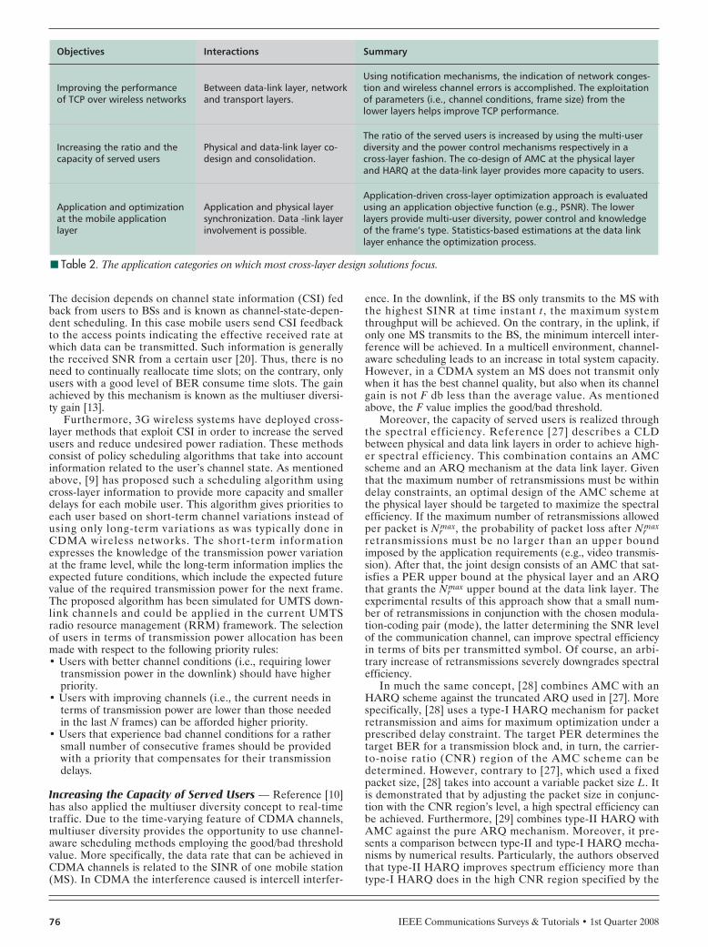
■ Table 2. The application categories on which most cross-layer design solutions focus.
Objectives Interactions Summary
Improving the performanceof TCP over wireless networks
Between data-link layer, networkand transport layers.
Using notification mechanisms, the indication of network conges-tion and wireless channel errors is accomplished. The exploitationof parameters (i.e., channel conditions, frame size) from thelower layers helps improve TCP performance.
Increasing the ratio and thecapacity of served users
Physical and data-link layer co-design and consolidation.
The ratio of the served users is increased by using the multi-userdiversity and the power control mechanisms respectively in across-layer fashion. The co-design of AMC at the physical layerand HARQ at the data-link layer provides more capacity to users.
Application and optimizationat the mobile applicationlayer
Application and physical layersynchronization. Data -link layerinvolvement is possible.
Application-driven cross-layer optimization approach is evaluatedusing an application objective function (e.g., PSNR). The lowerlayers provide multi-user diversity, power control and knowledgeof the frame’s type. Statistics-based estimations at the data linklayer enhance the optimization process.

IEEE Communications Surveys & Tutorials • 1st Quarter 2008 77
AMC scheme. On the other hand, the smallest packet size Lamplifies spectral efficiency.
Reference [30] also proposed a CLD methodology basedon an AMC scheme at the physical layer in conjunction with ascheduling mechanism at the MAC function of the data linklayer. It proposes a scheduler that considers the channel stateof the physical layer and the queue state of the data link layer.The queue is a finite-length buffer that is implemented at thegateway of the wireless access network. The adopted accessmechanism is the time-division multiplexing (TDM)/TDMA.For each user i the numbers of time slots that can actually bescheduled are assigned depending on both the channel stateand queue state. The reserved time slots are conditioned bythe prescribed QoS levels for each user.
ADAPTATION AND OPTIMIZATION AT THEMOBILE APPLICATION LAYER
Cross-layer optimization for wireless video streaming can off-set the end-to-end distortion caused in the received video atthe application layer [6]. Such a cross-layer solution is accom-plished by exchanging information between tje source andchannel coder in the application and physical layers, respec-tively. This cross-layer information is known as source signifi-cance information (SSI) [31]. Unequal Error Protection(UEP) is such a cross-layer approach that protects importantinformation from impairments caused by channel errors. Thisapproach is also known as Joint Source/Channel Coding(JSCC) [32]. In CDMA networks the use of power controlimproves the error probability by combating the negativeeffects of interference. More specifically, the power level isdetermined by the energy-per-bit to multiple access interfer-ence (MAI) density ratio γb = Eb/N0. Reference [32] presentsan evolutionary approach tp JSCC that proposes joint controlbetween the source coding and power control in terms of thesource rate Rs of the video codec and the average γb of thephysical layer, respectively. This approach is known as JointSource Coding-Power Control (JSCPC) and attempts toachieve an end user’s QoS level by adjusting the combinationof Rs and γb.
However, adaptation at the application layer such as videostreaming could benefit from link adaptation as well. Refer-ence [33] presents such a combined solution that improvesreal-time streaming video quality by adapting the video encod-ing rate at the application layer according to MAC layerstatistics-based information (e.g., throughput) in conjunctionwith the physical layer. Especially in the case of multiuseraccess, throughput predictions at the MAC layer give feed-back to the systems’ combination.
On the other hand, application layer optimization shouldbe based on a user-perceived video quality factor like thequantitative parameter PSNR that indicates video distortion.To this end, in JSCPC methodology the optimal operationaldistortion rate for a single user with effective bandwidthrequirement Weq in hertz is given as
PSNR(Weq) = max PSNR(Rs, γb). (1)
Reference [6] seeks to maximize the expected user-per-ceived video quality. This goal can be achieved by selectingthe optimal parameter values for each group of pictures(GOP). A GOP is a sequence of groups of consecutive framesof the video stream. The expected user-perceived video quali-ty implies that the video reconstruction quality at the user’sside is
D = Ds + DL. (2)
The Ds term is a source rate function and defines thereconstruction quality in the error-free case, called source dis-tortion. The DL term is a packet loss rate function and repre-sents the distortion derived from the transmission. The DL iscalled loss distortion. By combining the so-called distortionprofile information (i.e., the rate vector and distortion matrix)plus the transmission probabilities from the two-state Markovpacket burst loss model, the radio link parameters can be cho-sen. Using this approach, the expected quality can be achievedfor a particular application, and radio link layer parameterscan be set with respect to the desired objective function (i.e.,the PSNR) depending on the value of D.
Moreover, JSCC in conjunction with the multiuser diversitymethodology can improve the QoS in time-varying CDMAchannels. Reference [10] proposes such a cross-layer approachcalled multiuser adaptation, which exploits information in theapplication and physical layers. In previous sections we dis-cussed the LL units named batches as well as the class andarrival batch size that represent the crucial cross-layer infor-mation. In the transmission queue within the BS, each batchLL unit is managed according to its priority for the corre-sponding session. In order to exploit multiuser diversity incross-layer design, each batch i is determined as in bad chan-nel state when the channel fades fast, as mentioned above.Whether a batch is in a bad channel state depends on theaforementioned good/bad threshold F. Comparing the thresh-old values F = 10 dB and F = 5 dB, it is inferred that in thecase of F = 5 dB the service degradation in terms of LL unitlosses is greater than in the case of F = 10 dB. This is becausethe threshold F = 5 dB sustains the bad channel state proba-bility of one MS, and the corresponding batch is consideredidle for a longer period of time.
Thus far we have classified and discussed a representativelist of CLD proposals in terms of their objectives. Table 2 pre-sents the interactions between layers that are accomplished byeach of these solutions.
CROSS-LAYER SIGNALING
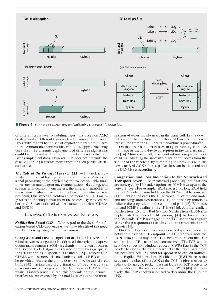
Given that there are no particular restrictions in the waycross-layer signaling takes place, various approaches havebeen adopted by the implementations thus far [34]:• An additional packet header carries forward or indicates
cross-layer information (CLI).• Header options report changes in lower layers.• Profiles and labels contain and indicate the meaningful
CLI, respectively.• A network service collects and distributes related CLI.
Inevitably, cross-layer signaling will incur some overhead;[34] points out the evaluation criteria of cross-layer signalingmethods and presents a representative comparison. All thesame, research in cross-layer signaling and notification mecha-nisms must strive to find efficient answers to a set of intrigu-ing questions: What is the best way of indicating CLI, aheader option or an additional header? Should cross-layer sig-naling be an in-band or an out-of-band one? In what format isCLI stored and conveyed? In which part of the networkshould an entity (i.e., server, router, manager etc.) be locatedfor collecting and managing CLI? What is the overhead intro-duced by signaling during the setup phase or throughout thesession?
To this end, next we extend the presentation of [34], point-ing out the different types of cross-layer signaling mechanismssuch as in-band and out-of-band signaling, the employed pro-tocols, the format of transport messages/files, and the distribu-tion of introduced overhead. We focus on the signaling
IEEE Communications Surveys & Tutorials • 1st Quarter 200878
protocol, the distribution pattern on network nodes (servers,routers, gateways, etc.) involved in it, and the potential over-heads it incurs. As the detailed investigation of CLD signalingoptions is still in progress [35], a detailed exhaustive presenta-tion is beyond the scope of this article.
SIGNALING MECHANISMS AND PROTOCOLS
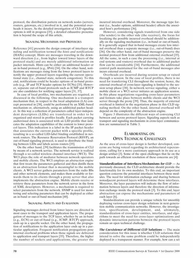
Reference [41] presents the design concept of interlayer sig-naling and notification termed the hints and notifications(HANs) concept. Hints are messages traveling in the down-ward direction (i.e., from higher toward lower layers of theprotocol stack) and are merely additional information onpacket internals. Hints can be either an additional header oran in-band protocol (e.g., IPv6) [34]. On the other hand, noti-fications are messages rising from the lower protocol layers tonotify the upper protocol layers regarding the current opera-tional state (i.e., channel state, network congestion). To thisend, notifications could be header options of in-band proto-cols (e.g., IP and TCP header options for ECNs) [35]. Howev-er, separate out-of-band protocols such as ICMP and RTCPare also candidates for notifying upper layers [31, 37].
In case of local profiles, two mechanisms are required, asdiscussed in the following. One mechanism is a transportmechanism that, in respect to the local adaptation (LA) con-cept presented in [38], could be performed by an XML-basedmechanism or, alternatively, using an additional packet head-er. In this way a collection of parameters called layer-indepen-dent descriptors (LIDs) are transferred in order to beorganized and stored in profiles locally. Each packet carryingaudiovisual data is associated with an LID profile that indi-cates the adaptation capabilities of the content to lower proto-col layers. This indication is a label in the IP packet headerthat associates the current packet with a specific profile,resulting in a so-called LID-label binding established in net-work routers. The Resource Reservation Protocol (RSVP), anout-of-band signaling protocol, is used to distribute the bind-ing between LIDs and labels across routers [35].
On the other hand, [39] facilitates the transmission of CLIby means of a network service. The network service is realizedthrough a so-called wireless channel interface (WCI). TheWCI plays the role of mediator between network operatorsand mobile clients. The WCI employs an abstraction enginethat first treats the parameters gathered and then distills themin an abstraction format that is meaningful to the mobileclients. A WCI server gathers parameters from the radio BSsand other network elements, and makes them available or for-wards them to its clients through a proxy server that alsoimplements the abstraction engine. Mobile clients receive orretrieve these parameters from the network server in the formof XML descriptors. However, a mechanism is required toselect parameters from the network. SNMP is used for moni-toring and selecting parameters that can be deployed as eitheran in-band or out-of-band mechanism [40].
SIGNALING ASPECTS AND EVALUATION
Signaling messages derived from lower layers are directed inmost cases to the transport and application layers. The propa-gation of messages to the TCP layer, whether by an in-band(e.g., ECN) or out-of-band (e.g., ICMP, RTCP) approach,ends up in a specific socket. On the other hand, the propaga-tion of notifications to the application layer ends up in a par-ticular application. Frequent notification propagations poseinternal overhead problems when those signals are deliveredto application and transport layers [35]. Therefore, the higherthe number of sockets and applications, the greater the
incurred internal overhead. Moreover, the message type for-mat (i.e., header options, additional header) affects the associ-ated host’s performance [36].
However, considering signals transferred from one side(the sender) to the other side (the receiver), the focus forlocalizing the possible incurred overhead should be addition-ally on the signaling mechanism (i.e., in-band or out-of-band).It is generally argued that in-band messages create less inter-nal overhead than a separate message (i.e., out-of-band) does[36]. On the other hand, out-of-band messages preserve thenormal protocol flow from additional external overhead [35].All the same, in such a case the processing (i.e., internal atend systems and routers) overhead due to additional packetflow can be considerable [34]. Furthermore, the additionalcontrol path maintained for the out-of-band messages alsoincurs external overhead.
Overheads are incurred during session setup or raisedthrough a session. In the case of local profiles, there is noneed for transferring CLI throughout the session; hence, theexternal overhead of cross-layer signaling is limited to the ses-sion setup phase [38]. In network service signaling, either amobile client or a WCI server initiates an application session.In this phase negotiations regarding cross-layer parametersand formats take place between mobile clients and the WCIserver through the proxy [39]. Thus, the majority of externaloverhead is limited in the negotiation phase in this CLD sig-naling method. On the other hand, internal overhead willdepend on the complexity of the abstraction engine.
Figure 3 illustrates the different ways of conveying CLIbetween and across protocol layers. Signaling aspects such astransport and signaling mechanisms in cross-layer communica-tion are summarized in Table 3.
ELABORATING ONOPEN TECHNICAL CHALLENGES
As the area of cross-layer design is further developed, con-cerns are being voiced regarding its architectural repercus-sions, calling for a more cautionary approach in its use as adesign artifact [3]. Some of the open challenges that lie on thepath towards an efficient resolution of these concerns are [4]:
Standardization of Interfaces/Mechanisms for CLD — Aspreviously discussed, the CLD architecture should provide thefunctionality for its own modules. To this end, an importantquestion concerns the potential interfaces between these mod-ules. The need for information exchange and sharing betweennonadjacent protocol layers will determine these interfaces.Moreover, the layer parameters will indicate the flow of infor-mation between layers and therefore the direction of informa-tion exchange inside the protocol stack [3]. To this end, layerabstraction can expose the mechanisms and parameters ofeach layer [6].
Standardization can provide a unique vehicle for smoothlydeploying various cross-layer design solutions in next-genera-tion mobile communication networks. However, the investiga-tion, specification, development, and, ultimately,standardization of cross-layer entities, interfaces, and algo-rithms to meet the need for cross-layer optimizations anddynamic interaction patterns between the protocol layersremain an open technical challenge.
The Coexistence of Different CLD Solutions — The mainconsideration for this issue is whether CLD solutions thatintend to solve the same problem could be independentlydeployed in a transparent manner. For example, how can a set
IEEE Communications Surveys & Tutorials • 1st Quarter 2008 79
of different cross-layer scheduling algorithms based on AMCbe deployed at different times without changing the physicallayer with regard to the set of exploited parameters? Arethere common mechanisms different CLD approaches mayuse? If so, the dynamic deployment of different algorithmscould be achieved with minimal impact on each individuallayer’s implementation. However, that does not preclude thecase of adopting a custom mechanism for each particular cir-cumstance.
The Role of the Physical Layer in CLD — In wireless net-works the physical layer plays an important role. Advancedsignal processing at the physical layer provides valuable func-tions such as rate adaptation, channel-aware scheduling, andsubcarrier allocation. Nonetheless, the inherent variability ofthe wireless medium may impact the function of network layerprotocols, thus affecting end-to-end performance. CLD main-ly relies on the unique features of the physical layer to achievebetter QoS over multicell wireless networks such as CDMAand OFDM.
IDENTIYING CLD MECHANISMS AND INTERFACES
Notification-Based CLD — With regard to the class of notifi-cation-based CLD approaches, we have identified the needfor the following categories of mechanisms.
Congestion and Loss Recognition at the Link Layer — Inwired networks congestion is addressed through an adaptivequeue management (AQM) mechanism in network routersthat support RED algorithms based on the average queuelength exceeding a specific threshold [15]. However, inCDMA wireless networks mechanisms such as RED cannotbe provided because the uplink does not provide any sharedbuffer [42]. In this case the estimation of load is used as aproxy measure of congestion. As the uplink in CDMA net-works is interference-limited, this depends on the intracellinterference experienced by one mobile user due to the trans-
mission of other mobile users in the same cell. In the down-link case the load estimation is estimated based on the powertransmitted from the BS since the downlink is power-limited.
On the other hand, ELN uses an agent running at the BSthat inspects the loss due to corruption in the wireless medi-um [16]. More specifically, the agent retains a sequence blockof ACKs indicating the successful transfer of packets from thesender to the receiver. By comparing the previous with thenewly arrived ACK value, a packet loss can be detected andthe ELN bit set accordingly.
Congestion and Loss Indication to the Network andTransport Layer — As mentioned previously, notificationsare conveyed by IP header options or ICMP messages at thenetwork layer. For example, ECN uses a 2-bit-long ECN fieldin the IP header. These fields are the ECN-capable transport(ECT), which indicates the ECN capability of the end node,and the congestion experienced (CE) field used by routers toindicate the congestion on the end-to-end path [15]. ELN usesin-band ICMP signaling at the IP layer [16]. Another explicitnotification, Explicit Bad Station Notification (EBSN), isimplemented as a type of ICMP message [43]. In this approachthe BS sends ICMP messages to the TCP sender to requesteither the postponement of timeouts or retransmission ofpackets [44].
On the other hand, to convey cross-layer informationbetween a pair of TCP endpoints, a TCP receiver adds theECN-Echo (ECE) flag in the TCP header to inform the TCPsender that a CE packet has been received. The TCP sendersets the congestion window reduced (CWR) flag in the TCPheader to inform the data receiver that the cwnd parameterhas been reduced [15]. Another approach to explicit notifica-tions, Explicit Wireless Loss Notification (EWLN), uses thesequence number of the ACK at the TCP header in order toindicate the specific packet loss sent from the TCP receiver tothe sender over the wireless link in the EWLN [45]. Alterna-tively, the TCP checksum is used to determine the ELN bit[16].
■ Figure 3. The ways of exchanging and indicating cross-layer information.
Header
XMLdescriptors
HTTP
Physical
LabelN LIDN
In-b
and
mes
sage
In-b
and
mes
sage
In-b
and
mes
sage
PayloadHeader
CLI
(a) Header options (c) Local profiles
(d) Network service
Label2 LID2
LID
Label1 LID1
Payload
(b) Additional header
Header
CLI
Out
-of-
band
mes
sage
Payload
PayloadHeader
Data link
Network
Abstractionengine
Client
Physical
Data link
Network
Abstractionengine
Client

IEEE Communications Surveys & Tutorials • 1st Quarter 200880
TCP Sender Reactions upon Receiving Notifications —In the ECN-capable TCP, cwnd reduction occurs upondetection of the CE field. However, the TCP sender shouldnot reduce its cwnd value more than once per window ofdata and must reset the retransmit timer when the cwnd is 1MSS (maximum segment size). If the sending TCP continuessending ECE messages while the cwnd is 1 MSS, the retrans-mission throughput drops to one packet per round-trip time(RTT) [15].
Contrary to ECN, an ELN-capable TCP sender is fullyaware of which segment is lost and retransmits it withoutreducing cwnd or any kind of congestion control action. TheTCP sender identifies the lost segment by the corruptedcounter field received in the TCP option field in conjunctionwith the checksum field (ELN bit) in the received ACK [16].In the same way as [44, 45], an ICMP-RETRANSMIT mes-sage and an EWLN bit request retransmission of the segmentby the TCP sender when the BS has failed to retransmit thatpacket and when the receiver detects errors in a TCP seg-ment, respectively. In EWLN, the ACK contains the sequencenumber of the corrupted packet that has been lost.
It is known that, in addition to the retransmissions at thetransport layer, the BS can initiate retransmissions at the linklayer. In such a case the BS must notify the TCP sender,which must undertake the following actions: hold the retrans-mit timeout (RTO) of the corresponding packet the link layertries to retransmit, and update the source timer based on theestimation of the RTT in order to prevent packet retransmis-sions [43][44].
User-Driven Notification — In certain cases, users maywant to control the download rate on their devices. To thisend, a priority parameter indicates the user’s requirements interms of bandwidth for each running application. Based onthis parameter, the TCP receiver can adjust its window foreach application [7]. The calculated receiver window is passedto the TCP sender through an ACK as the conventional TCPdoes. Thus, for each application, the TCP sender will notexceed a particular amount of sent data before it waits for anew ACK.
Cross-Layer Optimization and Scheduling — We dis-cussed notification-based mechanisms that improve TCP’sperformance by mitigating the undesired effects of TCPcongestion control. There are also CLD solutions thatimprove TCP’s performance or offer better QoS to upperprotocol layers by means of cross-layer optimization andscheduling mechanisms. In cross-layer optimization severalalternative combinations of protocol layer parameters canbe pursued [25]. To this end, such an optimization problemcan be formulated by combining several parameters fromdifferent layers across the protocol stack. The aim of thefollowing paragraphs is to identify and/or clarify some com-mon parameters to be combined in cross-layer optimizationprocedures.
Error Correction at the Data Link Layer — References[12, 46] propose a mechanism at the link layer dedicated tocorrecting packet errors instead of retransmitting them. Theyrely on adaptive FEC by which the sender is able to select theappropriate FEC taking into account an estimated PER calcu-lated at the link layer [12]. A link layer agent is placed at themobile node and the mobile host. At the mobile node the linklayer agent estimates the PER and RTT of the TCP session[46].
Adaptive Modulation and Coding Scheme at the PhysicalLayer — This approach deploys AMC at the physical layer toenhance TCP’s throughput performance [26]. The AMCscheme serves a finite-length queue of K packets at the datalink layer. The PER estimation at the link layer depends onmode n of the AMC scheme and the received γ. The channelfading is adjusted by the so-called Nakagami parameter m,and the channel state transition probabilities are modeled bya finite state Markov chain model. The latter is affected bythe mobility-induced Doppler spread. By changing the K, γ,and m parameter values, TCP’s throughput is adjusted tomatch the target PER.
Queuing Control at the Data Link Layer — In [21] TCP’sthroughput is enhanced by controlling the queue performanceand the packet loss event of TCP in the wireless link. In theproposed cross-layer optimization concept, link layer efficien-cy is determined by the number m of LL units to be transmit-ted by multicarrier CDMA (MC-CDMA) in a slot and theSINR Γ value for all m LL units. Taking into account thereceived power for an LL unit of flow i in a slot, the amountof resources in a slot is defined as a function of the resourcevector (m, Γ). In the link layer a RED-like buffer is used forretransmission of LL units. By calculating the mean queuingdelay for TCP packets in the wireless link using the REDqueuing mechanism, the target TCP throughput can be real-ized, keeping the resource vector (m, Γ) in optimal values.
Retransmissions at the Wireless Link — In [27] a CLDapproach that jointly combines AMC at the physical layerwith truncated ARQ at the data link layer enhances the aver-age spectral efficiency in terms of transmitted bits per symbol.The average RTT and packet length Np at the data link layermanifest delay constraints. On the other hand, the probabilityof packet loss after the maximum number of retransmissionsspecify the PER upper bound. Given the PER upper bound,the γ regions (i.e., the received SNR bounds) of the AMCscheme in conjunction with the Nr
max optimize system perfor-mance in terms of transmitted bits per symbol. The channelfading is adjusted by the Nakagami parameter m. On theother hand, the number of Nr
max can enhance or downgradethe PER in these γ regions.
In the same context, the CLD solution in [28] adopts type-IHARQ in order to minimize buffer size and augment spectralefficiency. The spectral efficiency optimization results rely on
■ Table 3. Signaling aspects in cross-layer communication.
Features Header options Packet header Local profiles Network service
Signaling mechanism In-band In-band or Out-of-band In-band (header optionsindicate labels)
In-band or out-of-band (dependson SNMP)
CLI transportmechanism
No transport(notification) Through packet header XML descriptors or packet
headersXML descriptors (access network)SNMP (core network)
Overhead type andlocalization
Internal (low)external (low)
Internal (low) external(medium)
Throughout the sessionset-up (deterministic)
Throughout the negotiationphase (occasional)

IEEE Communications Surveys & Tutorials • 1st Quarter 2008 81
both Nrmax and packet length L changes. Additionally, the
work presented in [29] optimizes the average spectral efficien-cy using type-II HARQ with rate-compatible punctured con-volutional (RCPC) codes. Changing the rates of RCPC codes,the spectral efficiency is improved in the range of γ regions.Moreover, changes in the packet length L improve the spec-tral efficiency for a specific γ region.
Estimation and Control of Power at the Physical Layer —Scheduling strategies and priorities in CDMA networks canbe relied on to provide the estimated required power for auser in the next transmission frame [9]. Moreover, given thereceived power strength inferred by fast power control infor-mation in BSs and the imposed packet delay threshold, pre-diction of the SINR parameter value for the next frame and,consequently, the BER and PER, can be calculated [47].Therefor, based on measured power from the power controlmechanism, predictions of the radio channel’s conditiondetermine the priorities of packet scheduling.
Video Reconstruction and Adaptation at the ApplicationLayer — An application-driven cross-layer optimizationapproach could be relied on to measure the video quality per-ceived by users. The PSNR is a quantitative parameter thatimplies the reconstruction quality of an image pertinent to theoriginal image at the receiver.
For video transmission over wireless links, the video recon-struction quality at the receiver is the sum of the source dis-tortion Ds and the expected loss distortion DL. The Dsexpresses the error-free image and should be sent along withthe video bitstream. On the other hand, the DL is related tothe packet loss rate caused during transmission [6]. The pack-et loss rate estimated at the data link layer results from infor-mation about the physical layer such as the modulationscheme (binary phase shift keying [BPSK], quaternary PSK[QPSK], etc.), channel coding, channel estimates (i.e., SNR),and transmit power.
In the same context a PSNR value is expressed as a func-tion of the video’s source and channel condition characteris-tics depicting the capability of video transmission over wirelesslinks when a JSCPC is deployed [32]. The video source andchannel condition characteristics are exposed by the videosource coding rate Rs and the power level in a CDMA net-work expressed as the energy-per-bit-to-interference-densityratio, respectively. The data rate at the application layer isadapted by changing the quantization step size of the encoder.Additionally, statistical parameters from the MAC layer (e.g.,throughput, spectral efficiency) allow smoother video adapta-tion at the application layer [33].
Multiuser Diversity at the Physical Layer — In [10] theapplication’s video frames are encapsulated into LL time-frames called batches. On each batch a weight is assigned thatindicates the video stream’s priority. The MS creates a trans-mission queue for each batch of the video frame and assigns atimer with a timeout value to each batch. The BS knows theclass number, remaining size, and timer value of each batch.At the link layer, batches are adapted to channel variationscaused by channel fading. The multi-user diversity (thegood/bad threshold) determines the batch’s timer value and,thus, the probability that an LL frame is kept idle (i.e., thebackoff probability). The faster the channel fades, the largerthe backoff probability and (intuitively) the timer value.
Co-Channel Interference Controller in Multicell Systems— In OFDM systems a mobile user experiences interferencefrom BSs using the same subcarrier. Hence, an optimization
problem that should be solved in OFDM systems is the sub-carrier allocation for each user. The work in [8] employs anoptimization algorithm that considers the maximum achiev-able rate of the kth user on the jth subcarrier. In addition, aresource controller at the MAC layer determines the properrate for each user based on channel quality feedback informa-tion such as the average SINR or MCS level. The SINRparameter is affected by the power received from the servingBS as well as that from its neighbor counterpart.
Furthermore, in multicell systems users served by the samesubcarrier in adjacent cells (i.e., co-channel users) form a set.Reference [48] deems a set of users feasible if the BER at allreceivers does not exceed a certain threshold. This feasibilitydepends on several factors, like the BS-user link gains, themodulation scheme that defines the SINR and BER capabili-ties, and the transmitting power from each BS, which are cru-cial for controlling the interference at the receivers. Byimposing transmit power constraints at each BS and control-ling the co-channel interference using a centralized controller,[48] achieves a large rate in each subcarier. One algorithmdetermines the allocation of users to subcarriers in an OFDMmulticell environment considering both the interferencecaused by BSs to a new user that enters the network and theinterference caused by the BS serving the new user to previ-ous users that have already joined the network. Another algo-rithm assumes a user as preferable when the increase in theSINR of the other users in the same subcarrier is minimal. Inthe last algorithm a subcarrier is allocated to the user with thelarger gain in the subcarrier; subsequently, the total powerbudget is allocated to subcarriers according to water filling,imposing a power constraint to approach the SINR for a setof subcarriers and remove subcarriers when the constraint isviolated.
Multiuser Scheduler at the MAC Sublayer — In [30] aCLD solution proposes a scheduling policy for a TDMA sys-tem served by AMC and a finite-length queue of K packetsper user at the physical and data link layers, respectively. Forany particular user, the maximum number of packets that canbe transmitted at time t depends on the AMC mode n and thenumber of time slots b reserved for one user. The key param-eters of this CLD approach consist of the channel conditionparameters such as Doppler spread fd, SNR γ, and Nakagamiparameter m as well as the resource management parameterssuch as time slots b, PER P0, and queue size K. The objectiveof this CLD solution is the minimization of radio resources, band K, while guaranteeing the prescribed QoS.
For OFDM systems, [8] provides scheduling for each userfor different modes by exploiting information from the physicallayer (i.e., channel matrix, SINR, MCS level, velocity, andlocation) as well as from the MAC layer (i.e., fairness and QoSin terms of packet delay and packet loss rate). The schedulerspecifies the scheduling of users and the number of packetsthat can be scheduled in the current frame. Variable channel-aware scheduling is applied by using the SINR reported by themobile terminals on the uplink control channels.
THE COEXISTENCE OF CLD SOLUTIONS
For different CLD solutions to harmoniously coexist, the com-monalities between them must be identified, including thecommon sets of layer parameters. Although the completeidentification of CLD commonalities is beyond the scope ofthis article, in the next paragraphs we discuss the most promi-nent ones.
For instance, notification-based CLD solutions employ theaforementioned mechanisms listed in Table 4. To identify

IEEE Communications Surveys & Tutorials • 1st Quarter 200882
congestion, a RED-like mechanism that relies on the averagequeue length at the link layer should be supported. On theother hand, to support notifications about packet losses, a linklayer agent that retains an ACK list is an appropriate solution.At the network layer, ICMP messages and IP header optionsrepresent the out-of band and in-band signaling, respectively.At the transport layer, the TCP header options and otherfields (e.g., checksum) may be used to indicate network con-gestion and packet loss. It is realized that upon receiving anotification about congestion or loss of a segment, the TCPsender will either reduce the cwnd or retransmit the segment,respectively. To avoid unnecessary retransmissions performedby the BS (local recovery) and the TCP sender as well, the lat-ter should postpone or reset the RTO for the particular lostpacket. Besides, in application-driven notification, the receiverwindow is calculated based on user preferences associatedwith each user’s open sockets.
To summarize the discussion, a clearly open issue lies inproperly choosing how to identify and signal congestion fromthe link layer in wireless networks. Physical layer characteris-tics (interference level, transmitting power budget, etc.) ininfrastructure networks (i.e., CDMA) as well as in ad hoc net-works (i.e., wireless LANs [WLANS]) can support this task, asmentioned previously. However, further investigation isrequired for an integrated end-to-end ECN solution in hetero-geneous networks [42].
Apart from identifying some generic mechanisms used bynotification-based CLD approaches, research should alsoinvestigate the coexistence of cross-layer optimization andscheduling approaches. One coexistence aspect is the deploy-ment of several algorithms/techniques that rely on the samecoupling between different layers [4]. For instance, solutionsthat combine the AMC at the physical layer and an ARQ-likeprotocol (e.g., type-I, type-II HARQ) at the data link layerconsider the same parameters, such as RTT, Np at the datalink layer, and the mode n and SNR γ at the physical layer(Table 5). A cross-layer optimizer that uses these parametersas input can activate different algorithms at different time
instants. This objective is undertaken by the co-channel interference controller operating in amulticell environment where the modulationscheme, interference level (SINR), transmitpower, and BS-user link gain serve as input todifferent subcarier allocation algorithms (Table5). With regard to the power control estimationat the physical layer, the received power strengthmeasurement (SINR) is a crucial parameter forscheduling strategies at the MAC layer alongwith cardinal parameters such as the time slots band queue size K at the data link layer (Table 5).
THE ROLE OF THE PHYSICAL LAYER
It is obvious that unique physical layer features,such as AMC, power control, subcarrier alloca-tion, and multiuser diversity, feature prominentlyin CLD applications. These features depend onparameters like the transmitted power from theBS, the modulation and coding scheme, the BERlevel induced by additive Gaussian noise and co-channel, intracell, and intercarrier interferencesaccording to the deployed multicell network, theBS-user link gain, as well as the velocity and loca-tion of the MS.
Similarly, while the estimation of SNR con-cerns the evaluation of modulated and codedwireless channels, the SINR is a good metric for
evaluating channel strength in multiple access wireless systemscharacterized by fading channels where intercell interferencemust be added to channel noise. It has been argued [27, 28]that in cross-layer optimization and scheduling the SINRshould be related to the PER in evaluating the effectivenessof a CLD proposal. Such mappings are important in simulat-ing and evaluating the performance of a CLD proposal at thephysical layer [8, 46].
However, SINR-PER mapping is not an easy task [46] asthe calculation of additive interference is affected by the actu-al network topology [2], and bit errors are correlated [27].Consequently, when topologies are different, the only parame-ter required to evaluate a CLD is the SINR-PER mappinggiven that the SINR is already well defined. Further investiga-tion of this mapping is a key aspect of cross-layer optimizationand scheduling approaches for PHY-MAC co-design andcoordination.
On the other hand, spatial processing via multiple-inputmultiple-output (MIMO) techniques is an advanced signalprocessing technique that alleviates cross-layer scheduling atthe data link layer [49]. Reference [50] proposes a solutionbased on MIMO and AMC at the physical layer to supportQoS guarantees at the data link layer in terms of effectivebandwidth and effective capacity. Such cross-layer modelingthat capitalizes on spatial diversity and spatial multiplexing ofMIMO systems is also an area for further investigation.
DISCUSSION AND LESSONS LEARNED
EVALUATION CRITERIA FOR CLD MODELS
Besides the need for cross-layer architecture, the relationbetween such architecture and the resulting performance isalso important. Cross-layer design architectures can lead toconsiderable improvements in throughput and delay perfor-mance. To this end, the following evaluation criteria shouldbe considered [3]:• Unintended interactions: A CLD architecture must figure
■ Table 4. Mechanisms and parameters involved in notification-based CLD.
Mechanism Parameters
Application layer User-driven notification Application priority
Transport layer
Congestion and loss indi-cation
TCP header checksum
TCP header options
Cwnd reduction Congestion window
Retransmissions SN of corrupted packet
Timeout reset or pause RTT estimation
Receiver window control Receiver window
Network layer Congestion and loss indi-cation
ICMP message
IP header options
Data link layerCongestion recognition RED (average queue length)
Loss recognition Agent (ACKs list block)
Physical layer Congestion recognitionLoad estimation (intra-cellinterference, BS transmitpower)
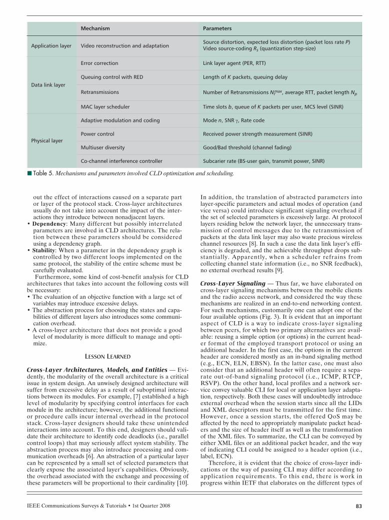
IEEE Communications Surveys & Tutorials • 1st Quarter 2008 83
out the effect of interactions caused on a separate partor layer of the protocol stack. Cross-layer architecturesusually do not take into account the impact of the inter-actions they introduce between nonadjacent layers.
• Dependency: Many different but possibly interrelatedparameters are involved in CLD architectures. The rela-tion between these parameters should be consideredusing a dependency graph.
• Stability: When a parameter in the dependency graph iscontrolled by two different loops implemented on thesame protocol, the stability of the entire scheme must becarefully evaluated.Furthermore, some kind of cost-benefit analysis for CLD
architectures that takes into account the following costs willbe necessary:• The evaluation of an objective function with a large set of
variables may introduce excessive delays.• The abstraction process for choosing the states and capa-
bilities of different layers also introduces some communi-cation overhead.
• A cross-layer architecture that does not provide a goodlevel of modularity is more difficult to manage and opti-mize.
LESSON LEARNED
Cross-Layer Architectures, Models, and Entities — Evi-dently, the modularity of the overall architecture is a criticalissue in system design. An unwisely designed architecture willsuffer from excessive delay as a result of suboptimal interac-tions between its modules. For example, [7] established a highlevel of modularity by specifying control interfaces for eachmodule in the architecture; however, the additional functionalor procedure calls incur internal overhead in the protocolstack. Cross-layer designers should take these unintendedinteractions into account. To this end, designers should vali-date their architecture to identify code deadlocks (i.e., parallelcontrol loops) that may seriously affect system stability. Theabstraction process may also introduce processing and com-munication overheads [6]. An abstraction of a particular layercan be represented by a small set of selected parameters thatclearly expose the associated layer’s capabilities. Obviously,the overhead associated with the exchange and processing ofthese parameters will be proportional to their cardinality [10].
In addition, the translation of abstracted parameters intolayer-specific parameters and actual modes of operation (andvice versa) could introduce significant signaling overhead ifthe set of selected parameters is excessively large. At protocollayers residing below the network layer, the unnecessary trans-mission of control messages due to the retransmission ofpackets at the data link layer may also waste precious wirelesschannel resources [8]. In such a case the data link layer’s effi-ciency is degraded, and the achievable throughput drops sub-stantially. Apparently, when a scheduler refrains fromcollecting channel state information (i.e., no SNR feedback),no external overhead results [9].
Cross-Layer Signaling — Thus far, we have elaborated oncross-layer signaling mechanisms between the mobile clientsand the radio access network, and considered the way thesemechanisms are realized in an end-to-end networking context.For such mechanisms, customarily one can adopt one of thefour available options (Fig. 3). It is evident that an importantaspect of CLD is a way to indicate cross-layer signalingbetween peers, for which two primary alternatives are avail-able: reusing a simple option (or options) in the current head-er format of the employed transport protocol or using anadditional header. In the first case, the options in the currentheader are considered mostly as an in-band signaling method(e.g., ECN, ELN, EBSN). In the latter case, one must alsoconsider that an additional header will often require a sepa-rate out-of-band signaling protocol (i.e., ICMP, RTCP,RSVP). On the other hand, local profiles and a network ser-vice convey valuable CLI for local or application layer adapta-tion, respectively. Both these cases will undoubtedly introduceexternal overhead when the session starts since all the LIDsand XML descriptors must be transmitted for the first time.However, once a session starts, the offered QoS may beaffected by the need to appropriately manipulate packet head-ers and the size of header itself as well as the transformationof the XML files. To summarize, the CLI can be conveyed byeither XML files or an additional packet header, and the wayof indicating CLI could be assigned to a header option (i.e.,label, ECN).
Therefore, it is evident that the choice of cross-layer indi-cations or the way of passing CLI may differ according toapplication requirements. To this end, there is work inprogress within IETF that elaborates on the different types of
■ Table 5. Mechanisms and parameters involved CLD optimization and scheduling.
Mechanism Parameters
Application layer Video reconstruction and adaptationSource distortion, expected loss distortion (packet loss rate P)Video source-coding Rs (quantization step-size)
Data link layer
Error correction Link layer agent (PER, RTT)
Queuing control with RED Length of K packets, queuing delay
Retransmissions Number of Retransmissions Nrmax, average RTT, packet length Np
MAC layer scheduler Time slots b, queue of K packets per user, MCS level (SINR)
Physical layer
Adaptive modulation and coding Mode n, SNR γ, Rate code
Power control Received power strength measurement (SINR)
Multiuser diversity Good/Bad threshold (channel fading)
Co-channel interference controller Subcarier rate (BS-user gain, transmit power, SINR)

IEEE Communications Surveys & Tutorials • 1st Quarter 200884
cross-layer signaling and notification [35]. In addition, [51]argues for an in-band mechanism when signaling QoS require-ments. In most cases, in-band signaling does not introduce anew header but uses selected options in the current headersuch as ECN, which is a well-known in-band solution [35].Finally, [36] outlines several aspects on cross-layer communi-cation to help CLD practitioners improve protocol perfor-mance.
CONCLUDING REMARKS
As the evolution of wireless communication technologies con-tinues, cross-layer approaches are being increasingly studiedas a design approach for confronting unintended performancedegradations as well as supporting new processes for beyond3G mobile communication networks. Not surprisingly, overthe last decade cross-layer design has developed into a hotresearch topic that is still growing. Currently, several researchefforts are seeking ways to integrate cross-layer design solu-tions into wireless communication standards for purposes ofallocating resources to mobile users, scheduling access toshared resources with higher throughput, and achieving betterquality of service for multimedia applications. Many of thesesolutions employ functional entities that support cross-layerprocesses for mobile devices. We envisage an evolutiontoward 4G networks based on these kinds of functional enti-ties, protocols, and processes that provide optimization andreconfiguration at both the terminal and the network.
REFERENCES
[1] H. Zimmermann, “OSI Reference Model — The ISO Model ofArchitecture for Open System Interconnection,” IEEE J. Trans.Commun., vol. 28, no. 4, Apr. 1980.
[2] L. Georgiadis, M. J. Neely and L. Tassiulas, Resource Allocationand Cross-Layer Control in Wireless Networks, Now PublishersInc., Apr. 24, 2006.
[3] V. Kawadia and P.R . Kumar, “A Cautionary Perspective onCross-Layer Design” IEEE Wireless Commun., vol. 12, no. 1,Feb. 2005, pp. 3–11.
[4] V. Srivastava and M. Motani, “Cross-Layer Design: A Surveyand The Road Ahead,” IEEE Commun. Mag., vol. 43, no. 12,Dec. 2005, pp. 112–19.
[5] G. Carneiro, J. Ruela, and M. Ricardo, “Cross-Layer Design in4G Wireless Terminals,” IEEE Wireless Commun., vol. 11, no. 2,Apr. 2004, pp. 7–13.
[6] S. Khan et al., “Application-Driven Cross-Layer Optimizationfor Video Streaming Over Wireless Networks,” IEEE Commun.Mag., vol. 44, no. 1, 2006, pp. 122–30.
[7] V.T. Raisinghani and S. Iyer, “Cross-Layer Feedback Architec-ture for Mobile Device Protocol Stacks,” IEEE Commun. Mag.,special issue on Cross-Layer Protocol Engineering, Jan 2006.
[8] T. Kwon et al., “Design and Implementation of a SimulatorBased on a Cross-layer Protocol between MAC and PHY Layersin a WiBro Compatible IEEE 802.16e OFDMA System,” IEEECommun. Mag., Dec. 2005, pp. 136–46.
[9] R. Ferrús et al., “Cross-Layer Scheduling Strategy for UMTSDownlink Enhancement,” IEEE Commun. Mag., vol. 43, no. 6,June 2005, pp. s24–28.
[10] H. Jiang, W. Zhuang, and X. Shen, “Cross-Layer Design forResource Allocation in 3G Wireless Networks and Beyond,”IEEE Commun. Mag., Dec. 2005.
[11] X. Lin, N. B. Shroff, and R. Srikant, “A Tutorial on Cross-LayerOptimization in Wireless Networks,” IEEE JSAC, Special Issueon Non-Linear Optimization of Communication Systems, 2006.
[12] M. Miyoshi, M. Sugano, and M. Murata, “Improving TCP Per-formance for Wireless Cellular Networks by Adaptive FEC Com-bined with Explicit Loss Notification,” IEICE Trans. Commun.,vol. E85-B, no. 10, Oct. 2002.
[13] S. Shakkottai, T.S. Rappaport, and P.C. Karlsson, “Cross-Layer
Design for Wireless Networks,” IEEE Commun. Mag., vol. 41,no. 10, Oct. 2003, pp. 74–80.
[14] H. Zheng and H. Viswanathan, “Optimizing TCP Performancewith Hybrid ARQ and Scheduler,” Proc. 14th Int’l. Symp. Pers.,Indoor, Mobile Radio Commun., vol. 2, Sep., 2003, pp. 1785–89.
[15] K. Ramakrishnan, S. Floyd, and D. Black “The Addition ofExplicit Congestion Notification (ECN) to IP,” RFC 3168, Sept.2001.
[16] H. Balakrishnan et al., “A Comparison of Mechanisms forImproving TCP Performance over Wireless Links,” IEEE ACMTrans. Networking, Dec. 1997.
[17] D. Kliazovich and F. Graneill, “A Cross-Layer Scheme for TCPPerformance Improvement in Wireless LANs,” IEEE GLOBECOM,vol. 2, no. 2, Dec. 2004, pp. 840–44.
[18] T. Goff et al., “Freeze-TCP: A True End-To-End TCP Enhance-ment Mechanism For Mobile Environments,” Proc. 19th INFO-COM, Sept. 2000, pp. 1537–45.
[19] H. Balakrishnan and R. H. Katz, “Explicit Loss Notification andWireless Web Performance,” Proc. GLOBECOM Internet Mini-Conf., Nov. 1998.
[20] P. Bender et al., QUALCOMM, Inc., “CDMA/HDR: A Band-width Efficient High-Speed Wireless Data Service for NomadicUsers,” IEEE Commun. Mag., July 2000.
[21] H. Jiang and W. Zhuang, “Cross-Layer Resource Allocation forIntegrated Voice/Data Traffic in Wireless Cellular Networks” IEEETrans. Wireless Commun., vol. 5, no. 2, Feb. 2006, pp. 457–68.
[22] Goldsmith and S. G. Chua, “Adaptive Coded Modulation forFading Channels,” IEEE Trans. Commun., vol. 46, no. 5, May1998, pp. 595–602.
[23] IEEE 802.16 Working Group, “IEEE Standard for Local andMetropolitan Area Networks Part 16: Air Interface for FixedBroadband Wireless Access Systems,” 2004.
[24] 3GPP TS 25.308 V6.4.0, “High Speed Downlink Packet Access(HSDPA); Overall Description; Stage 2,” rel. 6, 2007.
[25] M. van der Schaar and S. Shankar, “Cross-Layer Wireless Mul-timedia Transmission: Challenges, Princip les, and NewParadigms,” IEEE Wireless Commun., vol. 12, no. 4, Aug. 2005,pp. 50–58.
[26] Q. Liu, S. Zhou, and G. B. Giannakis, “TCP Performance inWireless Access With Adaptive Modulation and Coding,” Proc.IEEE ICC, June 20–24, 2004.
[27] Q. Liu, S. Zhou, and G.B. Giannakis, “Cross-Layer Combiningof Adaptive Modulation and Coding With Truncated ARQ OverWireless Links,” IEEE Trans. Wireless Commun., vol. 3, no. 5,Sept. 2004.
[28] D. Wu and S. Ci, “Cross-Layer Design for Combining AdaptiveModulation and Coding with Hybrid ARQ,” Proc. Int’l. Conf.Commun. and Mobile Comp., July 3–6, 2006, pp. 147–52.
[29] D. Wu and S. Ci , “Cross-Layer Combination of Hybrid ARQand Adaptive Modulation and Coding for QoS Provisioning inWireless Data Networks,” Proc. 3rd Int’l Conf. Quality of Ser-vice in Heterogeneous Wired/Wireless Networks, Aug. 7–9,2006, no. 47.
[30] Q. Liu, S. Zhou, and G.B. Giannakis, “Cross-Layer Schedulingwith Prescribed QoS Guarantees in Adaptive Wireless Net-works,” IEEE JSAC, vol. 23, no. 5, May 2005.
[31] S. Mérigeault and C.Lamy, “ Concepts for Exchanging Extra Infor-mation Between Protocol Layers Transparently for the StandardProtocol Stack,” Proc. IEEE ICT ’03, Feb. 23-Mar. 1, 2003.
[32] Y. S. Chan and J. W. Modestino, “A Joint Source Coding-Power Control Approach for Video Transmission over CDMANetworks,” IEEE JSAC, vol. 21, no. 10, Dec. 2003.
[33] I. Haratcherev et al., “Optimized Video-Streaming Over802.11 by Cross-Layer Signaling,” IEEE Commun. Mag. SpecialIssue on Cross-layer Protocol Engineering for Wireless MobileNetworks, vol. 44, no. 1, Jan. 2006.
[34] Q. Wang and M.A. Abu-Rgheff, “Cross-Layer Signalling for Next-Generation Wireless Systems,” IEEE Wireless Commun. and Net-working Conf., vol. 2, no. 16–20 Mar. 2003, pp. 1084–89.
[35] P. Sarolahti and S. Floyd, “Cross-Layer Indications for TransportProtocols,” Internet draft, IETF, Mar. 2007. work in progress.
[36] P. Sarolahti, S. Floyd, and M. Kojo, “Transport-Layer Consid-erations for Explicit Cross-Layer Indications,” Internet draft,IETF, Oct. 2006, informational.
[37] P. Sudame and B. R. Badrinath, “On Providing Support for

IEEE Communications Surveys & Tutorials • 1st Quarter 2008 85
Protocol Adaptation in Mobile Wireless Networks,” MobileNetworks and Apps., vol. 6, no. 1, Jan.–Feb. 2001, pp. 43–55.
[38] A. Takács et al., “The Layer-Independent Descriptor Concept,”J. Computers, vol. 1, no. 2, May 2006, pp. 23–32.
[39] B. Kim, “A Network Service Providing Wireless Channel Infor-mation for Adaptive Mobile Applications: Part I: Proposal,”Proc. IEEE ICC ’01, June 2001.
[40] J. Case et al., “A Simple Network Management Protocol,”RFC 1157, May 1, 1990.
[41] L. Larzon, U. Bodin, and O. Schelen, “Hints and Notifications,”Proc. Wireless Commun. and Networking Conf., Mar. 2002.
[42] V. A. Siris, “Resource Control for Elastic Traffic in CDMA Net-works,” Proc. ACM MOBICOM, Sept. 2002.
[43] B. S. Bakshi et al., “Improving Performance of TCP over Wire-less Networks,” Proc. IEEE ICDCS ’97, 365–73.
[44] S. Goel and D. Sanghi, “Improving TCP Performance overWireless Links,” Proc. TENCON ’98, Dec. 1998, pp. 332–35.
[45] B. Zhang and M.N. Shirazi, “Implementation of Explicit Wire-less Loss Notification Using MAC-Layer Information,” Proc. IEEEWireless Commun. and Networking Conf., vol. 2, Mar. 2003,pp.1339–43.
[46] B. Liu, D. L. Goeckel, and D. Towsley. TCP-Cognizant AdaptiveForward Error Correction in Wireless Networks,” Proc. IEEEGLOBECOM, Nov. 2002.
[47] M. Saied and A. El-Atty, “Efficient Packet Scheduling withPre-Defined QoS Using Cross-Layer Technique in Wireless Net-works,” Proc. IEEE ISCCC ’06.
[48] I. Koutsopoulos and L. Tassiulas, “Cross-Layer Adaptive Tech-niques for Throughput Enhancement in Wireless OFDM-BasedNetworks,” IEEE/ACM Trans. Net., vol. 14, no. 5, Oct. 2006.
[49] C. Antón-Haro et al., “Cross-Layer Scheduling for Multi-userMIMO Systems,” IEEE Commun. Mag., vol. 44, no. 9, Sept.2006, pp. 39–45.
[50] J. Tang and X. Zhang, “Cross-Layer-Based Modeling for Quali-ty of Service Guarantees in Mobile Wireless Networks,” IEEECommun. Mag., vol. 44, no. 1, Jan. 2006, pp. 100–06.
[51] J. Harper and P. McGeer, “Requirements for In-Band QoS Sig-nalling,” Internet draft, Network Working Group, Jan. 2007,work in progress.
BIOGRAPHIES
FOTIS FOUKALAS ([email protected]) received a Dipl.-Ing. degree inelectrical and computer engineering from Aristotle University ofThessalonica, Greece, in 2001. In 2003 he received an M.Sc.degree from the National Technical University of Athens. In May2003 he joined the Communication Networks Laboratory at theDepartment of Informatics and Telecommunications of the Univer-sity of Athens. Since December 2003 he has been working on hisPh.D. in the same department. His research interests are in thearea of physical and data link layer techniques enabling cross-layer optimization and reconfigurability.
VANGELIS GAZIS ([email protected]) holds B.Sc., M.Sc., and Ph.D.degrees from the Department of Informatics and Telecommunica-tions at the University of Athens, and an M.B.A. degree from theAthens University of Economics and Business). He is a seniorresearcher at the Department of Informatics and Telecommunica-tions ,and has participated in national (OTE-DECT, GUNet, GEANT-2) and European projects (MOBIVAS, ANWIRE). He specializes inreconfigurable mobile systems and protocol stacks for beyond 3Gmobile, ontology languages for autonomic systems, reflective andcomponent middleware, adaptable services, and open API frame-works for telecommunications.
NANCY ALONISTIOTI ([email protected]) has B.Sc. and Ph.D. degreesin informatics and telecommunications from the University ofAthens. She specializes in reconfigurable systems and networksfor beyond 3G, adaptable services, pervasive computing, and con-text awareness. She has participated in national and Europeanprojects, (CTS, SS#7, ACTS RAINBOW, EURESCOM, MOBIVAS,ANWIRE, E2R, LIAISON) and is co-editor of Software DefinedRadio, Architectures, Systems and Functions (Wiley Series on Soft-ware Radio).
Related Documents