1 Cross Layer Design of Wireless LAN for Telemedicine Application Considering QoS Provision Eko Supriyanto 1 , Emansa Hasri Putra 2 , Jafri bin Din 3 , Haikal Satria 4 and Hamid Azwar 5 1 Faculty of Biomedical Engineering and Health Science, Universiti Teknologi Malaysia, 2,5 Telecommunication Department, Politeknik Caltex Riau, 3,4 Faculty of Electrical Engineering, Universiti Teknologi Malaysia, 1,3,4 Malaysia, 2,5 Indonesia 1. Introduction Wireless Local Area Network (WLAN) have been widely utilized at this moment to support video-related applications such as video streaming, multimedia messaging, teleconference, voice over IP, and video telemedicine. This is due to WLAN constitutes a ubiquitous wireless standard solution and its implementation is not complex in terms of WLAN devices configuration and deployment. In addition, WLAN has superior characteristics compared with other wireless standard, including mobility fashions, high data rate, and low cost infrastructure. The video-related application transmission such as telemedicine video will experience challenges including low throughput, delays, jitter and packet lost during its transmission over wireless network. This is due to wireless network or WLAN has specific characteristics which can influence the transmission consisting of time-varying channel, transmission error, and fluctuating bit rate characterized by factors such as noise, interference, and multiple fading. Thus, a video coding system for the transmission is necessary to adapt to the WLAN characteristics. Recently, The Scalable Video Coding (SVC) standard as an extension of H.264/AVC have enabled a video bit stream to adapt to time-varying channel, transmission error, and fluctuating bit rate (Schierl et al. 2007). SVC also provides a scalability of receiver side receptions since receivers have possibly heterogeneous capabilities in terms of display resolution and processing power. In addition, SVC can support lower throughput and improve better coding efficiency compared with prior video coding techniques such as H.262/MPEG-2, H.263, MPEG-4, and H.264/AVC. Currently, a new IEEE standard called The IEEE 802.11e is available to support Quality of Service (QoS) in WLAN. Specifically, this standard introduces a new MAC layer coordination function called Hybrid Coordination Function (HCF). Although IEEE 802.11e is more reliable than the previous standard, it still refers to OSI protocol stack in which every layer does not cooperate with each other. While wireless environments have specific

Welcome message from author
This document is posted to help you gain knowledge. Please leave a comment to let me know what you think about it! Share it to your friends and learn new things together.
Transcript
1
Cross Layer Design of Wireless LAN for Telemedicine Application
Considering QoS Provision Eko Supriyanto1, Emansa Hasri Putra2, Jafri bin Din3,
Haikal Satria4 and Hamid Azwar5 1Faculty of Biomedical Engineering and Health Science, Universiti Teknologi Malaysia,
2,5Telecommunication Department, Politeknik Caltex Riau, 3,4Faculty of Electrical Engineering, Universiti Teknologi Malaysia,
1,3,4Malaysia, 2,5Indonesia
1. Introduction Wireless Local Area Network (WLAN) have been widely utilized at this moment to support video-related applications such as video streaming, multimedia messaging, teleconference, voice over IP, and video telemedicine. This is due to WLAN constitutes a ubiquitous wireless standard solution and its implementation is not complex in terms of WLAN devices configuration and deployment. In addition, WLAN has superior characteristics compared with other wireless standard, including mobility fashions, high data rate, and low cost infrastructure. The video-related application transmission such as telemedicine video will experience challenges including low throughput, delays, jitter and packet lost during its transmission over wireless network. This is due to wireless network or WLAN has specific characteristics which can influence the transmission consisting of time-varying channel, transmission error, and fluctuating bit rate characterized by factors such as noise, interference, and multiple fading. Thus, a video coding system for the transmission is necessary to adapt to the WLAN characteristics. Recently, The Scalable Video Coding (SVC) standard as an extension of H.264/AVC have enabled a video bit stream to adapt to time-varying channel, transmission error, and fluctuating bit rate (Schierl et al. 2007). SVC also provides a scalability of receiver side receptions since receivers have possibly heterogeneous capabilities in terms of display resolution and processing power. In addition, SVC can support lower throughput and improve better coding efficiency compared with prior video coding techniques such as H.262/MPEG-2, H.263, MPEG-4, and H.264/AVC. Currently, a new IEEE standard called The IEEE 802.11e is available to support Quality of Service (QoS) in WLAN. Specifically, this standard introduces a new MAC layer coordination function called Hybrid Coordination Function (HCF). Although IEEE 802.11e is more reliable than the previous standard, it still refers to OSI protocol stack in which every layer does not cooperate with each other. While wireless environments have specific
Advances in Telemedicine: Technologies, Enabling Factors and Scenarios
4
characteristics which may influence and degrade the quality level of the telemedicine application, namely time-varying bandwidth, delay, jitter and loss (Kim et al. 2006). There are previous works which concern with cross layer techniques in wireless network. In (Choi et al., 2006), the focus was on cross layer optimization between application, data link, and physical layers to obtain the end to end quality of wireless streaming video application. A cross layer scheduling algorithm was utilized in (Kim, 2006) for throughput improvement in WLAN considering scheduling method and physical layer information. The authors utilized a H.264/AVC video coding in application layer over IEEE 802.11e EDCA wireless networks (Ksentini et al., 2006). MPEG-4 FGS video coding and FEC were utilized in application layer to deliver video application over IEEE 802.11a WLAN in (Schaar et al., 2003). In (Schaar et al., 2006), the authors utilized a MCTF video coding in application layer over IEEE 802.11 a/e HCCA wireless networks. In this paper, a new approach in transmitting telemedicine video application over wireless LAN is performed to assign guaranteed bandwidth (QoS) for connection request of telemedicine video application. This approach utilizes a cross layer design technique based on H.264/SVC and IEEE 802.11e wireless network to optimize the existing wireless LAN protocol stack. From our results, an appropriate bandwidth could be achieved based on Quality of Service (QoS) provision for telemedicine video application during its transmission over wireless LAN. The rest of this paper is organized as follows. The overview of telemedicine system including Telemedicine, H.264/SVC, and IEEE 802.11e Wireless Network is explained in Section II. Section III explains our proposed cross layer design of wireless LAN for video telemedicine transmission. The prototype and simulation model is described in Section IV. Results and Analysis is explained in Section V. Then, we conclude this paper in Section VI.
2. Telemedicine system 2.1 Telemedicine Telemedicine constitutes healthcare services implemented through network infrastructures such as LAN, WLAN, ATM, MPLS, 3G, and others, to provide health care service quality especially in rural, urban, isolated areas, or mobile areas (Ng et al., 2006). Furthermore, telemedicine involves interactions between medical specialists at one station and patients at other stations and utilizes healthcare application which can be divided into video images, images, clinical equipments, and radiographic images. The authors in (Pavlopoulos et al., 1998) have presented an example of telemedicine advantage through implementation on ambulatory patient care at remote area. Another application has been done in (Sudhamony et al., 2008) for cancer care in rural area. High technology telemedicine application in surgery has already been developed in (Xiaohui et al., 2007). Currently, the telemedicine utilizes available wired and wireless infrastructures. Telemedicine infrastructures with wired network have been proposed using Integrated Service Digital Network (ISDN) (Al-Taei, 2005), Asynchronous Transfer Modes (ATM) (Cabral and Kim, 1996), Very Small Aperture Terminal (VSAT) (Pandian et al., 2007) and Asymmetric Digital Subscriber Line (ADSL) (Ling et al., 2005). Telemedicine has also been implemented in wireless network using Wireless LAN (WLAN) (Kugean et al., 2002), Worldwide Interoperability for Microwave Access (WIMAX) (Chorbev et al., 2008), Code Division Multiple Access (CDMA) 1X-EVDO (Yoo et al., 2005), and General Packet Radio Switch (GPRS) (Gibson et al., 2003).

Cross Layer Design of Wireless LAN for Telemedicine Application Considering QoS Provision
5
Every infrastructure has its own obstacle, in particularly when implemented in a remote area. For example, Asynchronous Transfer Mode (ATM) and Multi Protocol Label Switching (MPLS) have mobility and scalability limitations, although both networks provide high Quality of Service (QoS) and have stability on delivering data (Nanda and Fernandes, 2007). The fragility of 3G UMTS network for telemedicine has been explored in (Tan et al., 2006), where the implementation costs are high and does not provide QoS. There is a necessity of specific rule to define Quality of Services (QoS) provision of telemedicine application. In addition, parameterized QoS is a clear QoS bound expressed in terms of quantitative values such as data rate, delay bounds, jitter, and packet loss (Ni and Turletti, 2004). Thus, we refer to (Supriyanto et al., 2009) to obtain the parameterized QoS or QoS provision for telemedicine application. The desired output data rate for telemedicine system in seven medical devices can be seen in Table 1.
Devices Data Rates Good Excellent
ECG 2 kbps 12 kbps Doppler Instrument 40 kbps 160 kbps
Blood Pressure Monitor 1 kbps 1 kbps Ultrasound Machine 100 kbps 400 kbps
Camera 100 kbps 2,000 kbps Stethoscope 40 kbps 160 kbps Microphone 40 kbps 160 kbps
Total 323 kbps 2,893 kbps
Table 1. Desired output data rate (Supriyanto et al., 2009)
Table 2 shows QoS bounds required for telemedicine application, namely throughput, delay, jitter and packet loss.
Parameter Definition Requirement throughput packet arrival rate min 323 kbps
delay the time taken by a packet to reach its destination max 100 ms jitter time of arrival deviation between packets max 50 ms
packet loss percentage of non-received data packets max 5 %
Table 2. QoS bounds for telemedicine application (Supriyanto et al., 2009)
2.2 H.264/SVC Standard Recently, a video coding technique in wireless network has transformed into a way to optimize the video quality over a fluctuating bit rate instead of at a fixed bit rate. This due to wireless network or WLAN has specific characteristics which can influence video transmission consisting of time-varying channel, transmission error, and fluctuating bit rate characterized by factors such as noise, interference, and multiple fading. Thus, the video coding technique should adapt to fluctuating bit rate in wireless network and then reconstructing a video signal with the optimized quality at that bit rate. Figure 1 shows a characteristic of video coding techniques consisting of non-scalable and scalable video coding. The horizontal axis means the channel bit rate, while the vertical axis

Advances in Telemedicine: Technologies, Enabling Factors and Scenarios
6
means the received video quality. The distortion-rate curve constitutes an indicator of acceptable video quality for any coding techniques at fluctuating bit rate. If a video coding curve follows the movement of the distortion-rate curve, an optimal video quality will be acquired. The three staircase curves mean the performance of the non-scalable coding technique. On fluctuating bit rate conditions such as low, medium, or high bit rate, the non-scalable coding techniques try to follow the movement of the distortion-rate curve indicated by the upper corner of the staircase curve very close to the distortion-rate curve. The three staircase curves have different optimal video quality at each since every staircase curve can only achieve the distortion-rate curve either in low, medium or high bit rate. While a scalable video coding can follow the movement of the distortion-rate curve in which the scalable video coding has two layers, namely base layer and enhancement layer. Thus, the scalable video coding has the optimal video quality at each condition, either in low, medium, or high bit rate.
Fig. 1. A characteristic of video coding techniques consisting of non-scalable and scalable video coding (Li, 2001)
In the scalable coding technique, a video sequence is encoded into a base layer and an enhancement layer. The enhancement layer bit stream is similar to the base layer bit stream in which it is either completely received or it does not enhance the video quality at all. The base-layer bit rate constitutes the first stair while the enhancement layer bit rate constitutes the second stair as shown in Figure 1 (Li, 2001). A Scalable Video Coding (SVC) standard constitutes an extension of H.264/AVC widely utilized for video transmission such as multimedia messaging, video telephony, video conference, Mobile TV, and other mobile networks at this time. The SVC provides scalability capability to improve features of prior video coding systems such as H.262/MPEG-2, H.263, MPEG-4, and H.264/AVC. In addition, The SVC has an adaptation capability to time-varying bandwidth conditions in wireless network, and heterogeneous receiver requirements. The time-varying bandwidth will lead to throughput variations, varying delays or transmission errors. Then, the heterogeneous receiver conditions will influence acceptable video bit stream in receiver sides limited by display resolution and processing power.

Cross Layer Design of Wireless LAN for Telemedicine Application Considering QoS Provision
7
The common forms of scalability consist of temporal, spatial, and quality scalability. The spatial scalability constitutes a video coding technique in which picture size (spatial resolution) of video source is reduced. The temporal scalability means some parts of video bit stream reduced in term of frame rate (temporal resolution). Then, quality scalability constitutes a video coding technique in which the spatio-temporal resolution of video source is still the same as the complete bit stream, but fidelity is lower. The quality scalability is also commonly known as SNR scalability. Figure 2 shows a basic concept of SVC in which it combines temporal, spatial, and quality scalability.
Fig. 2. SVC encoder structure (Schwarz et al., 2007)
The SVC encoder structure is arranged in dependency layers in which every dependency layers has a definite spatial resolution. The dependency layers utilize motion-compensated and intra prediction as in H.264/AVC single-layer coding and include one or more quality layers. Then, each dependency layer corresponds to a video source for a time instant with a definite spatial resolution and a definite fidelity. For more complete overview of SVC concept is referred to (Schwarz et al., 2007).
2.3 IEEE 802.11e Wireless Network There are two different kinds of wireless network configuration. The first one is an infrastructure network, in which every communication between wireless stations is through an access point (AP). The second one is an ad hoc network, where communications between wireless stations are directly to each other, without a connection to an access point (AP). A group of stations arranged by an access point (AP) is called a basic service set (BSS), while for an ad hoc network is called independent BSS (IBSS). An area included by the BSS is referred as the basic service area (BSA), such as a cell in a cellular mobile network. The IEEE 802.11 WLAN standard includes both datalink and physical layers of the open system interconnection (OSI) network reference model. The datalink layer intends to arrange access control functions to the wireless medium such as access coordination, addressing or frame check sequence generation. Basically, there are two medium access coordination functions, namely the basic Distributed Coordination Function (DCF) and the optional Point Coordination Function (PCF).
Advances in Telemedicine: Technologies, Enabling Factors and Scenarios
8
Recently, IEEE 802.11e standard proposed a new MAC layer coordination function in the datalink layer to provide QoS support, namely HCF (Hybrid Coordination Function). HCF consists of two channel access method, namely The Enhanced Distributed Channel Access (EDCA) and The HCF Controlled Channel Access (HCCA). Access Points (APs) and wireless stations which have supported The IEEE 802.11e standard are called QoS-enhanced AP (QAP) and QoS-enhanced station (QSTA) respectively (Ni and Turletti, 2004).
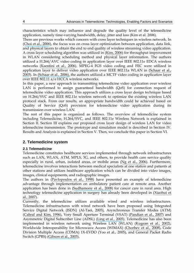
2.3.1 The Enhanced Distributed Channel Access (EDCA) The EDCA consists of four access categories and starts from the highest priority until the lowest priority for supporting traffics of voice (AC_VO), video (AC_VI), best effort (AC_BE), and background (AC_BK) respectively, as illustrated in Figure 3. Table 3 shows relations between user priorities and access categories starting from the lowest until the highest priority.
Fig. 3. The IEEE 802.11e EDCA model (Kim et al., 2006)
Priority User Priority
802.1D Designation
Access Category Designation
Lowest 1 BK AC_BK Background 2 - AC_BK Background 0 BE AC_BE Best Effort 3 EE AC_BE Video 4 CL AC_VI Video 5 VI AC_VI Video 6 VO AC_VO Voice
Highest 7 NC AC_VO Voice
Table 3. Relations between user priorities and access categories (Kim et al., 2006)
The IEEE 802.11 standard specifies four types of Interframe Spaces (IFS) utilized to define different priorities, namely Short Interframe Spaces (SIFS), Point Coordination IFS (PIFS),
Cross Layer Design of Wireless LAN for Telemedicine Application Considering QoS Provision
9
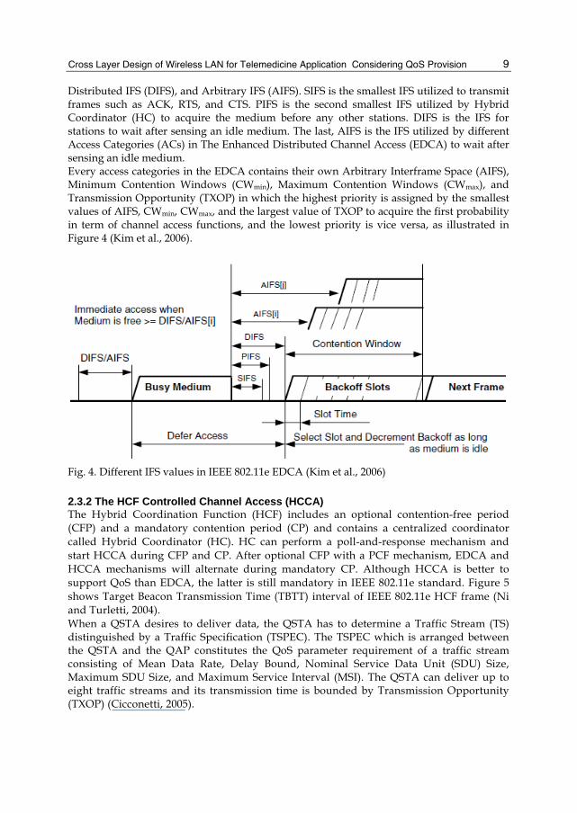
Distributed IFS (DIFS), and Arbitrary IFS (AIFS). SIFS is the smallest IFS utilized to transmit frames such as ACK, RTS, and CTS. PIFS is the second smallest IFS utilized by Hybrid Coordinator (HC) to acquire the medium before any other stations. DIFS is the IFS for stations to wait after sensing an idle medium. The last, AIFS is the IFS utilized by different Access Categories (ACs) in The Enhanced Distributed Channel Access (EDCA) to wait after sensing an idle medium. Every access categories in the EDCA contains their own Arbitrary Interframe Space (AIFS), Minimum Contention Windows (CWmin), Maximum Contention Windows (CWmax), and Transmission Opportunity (TXOP) in which the highest priority is assigned by the smallest values of AIFS, CWmin, CWmax, and the largest value of TXOP to acquire the first probability in term of channel access functions, and the lowest priority is vice versa, as illustrated in Figure 4 (Kim et al., 2006).
Fig. 4. Different IFS values in IEEE 802.11e EDCA (Kim et al., 2006)
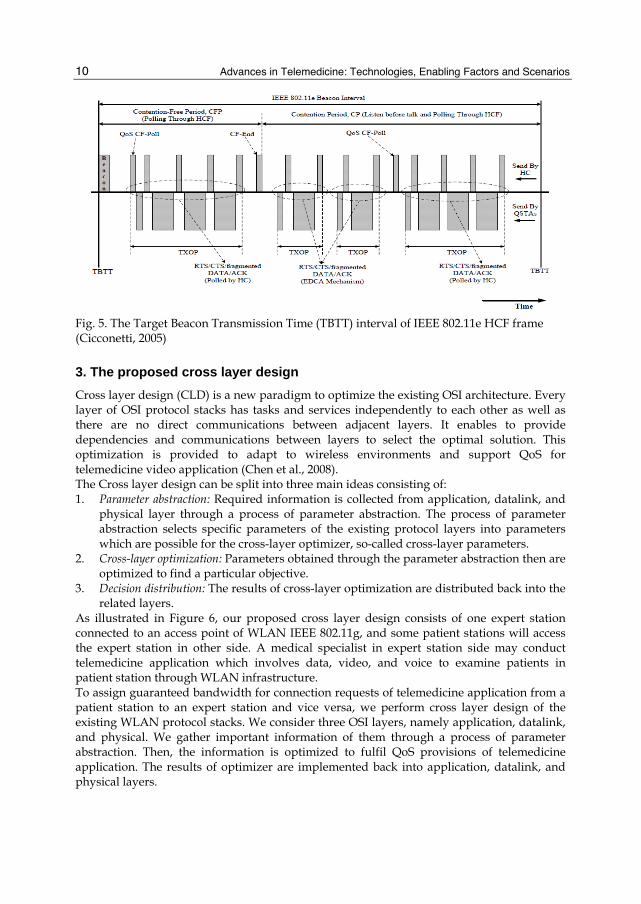
2.3.2 The HCF Controlled Channel Access (HCCA) The Hybrid Coordination Function (HCF) includes an optional contention-free period (CFP) and a mandatory contention period (CP) and contains a centralized coordinator called Hybrid Coordinator (HC). HC can perform a poll-and-response mechanism and start HCCA during CFP and CP. After optional CFP with a PCF mechanism, EDCA and HCCA mechanisms will alternate during mandatory CP. Although HCCA is better to support QoS than EDCA, the latter is still mandatory in IEEE 802.11e standard. Figure 5 shows Target Beacon Transmission Time (TBTT) interval of IEEE 802.11e HCF frame (Ni and Turletti, 2004). When a QSTA desires to deliver data, the QSTA has to determine a Traffic Stream (TS) distinguished by a Traffic Specification (TSPEC). The TSPEC which is arranged between the QSTA and the QAP constitutes the QoS parameter requirement of a traffic stream consisting of Mean Data Rate, Delay Bound, Nominal Service Data Unit (SDU) Size, Maximum SDU Size, and Maximum Service Interval (MSI). The QSTA can deliver up to eight traffic streams and its transmission time is bounded by Transmission Opportunity (TXOP) (Cicconetti, 2005).
Advances in Telemedicine: Technologies, Enabling Factors and Scenarios
10
Fig. 5. The Target Beacon Transmission Time (TBTT) interval of IEEE 802.11e HCF frame (Cicconetti, 2005)
3. The proposed cross layer design Cross layer design (CLD) is a new paradigm to optimize the existing OSI architecture. Every layer of OSI protocol stacks has tasks and services independently to each other as well as there are no direct communications between adjacent layers. It enables to provide dependencies and communications between layers to select the optimal solution. This optimization is provided to adapt to wireless environments and support QoS for telemedicine video application (Chen et al., 2008). The Cross layer design can be split into three main ideas consisting of: 1. Parameter abstraction: Required information is collected from application, datalink, and
physical layer through a process of parameter abstraction. The process of parameter abstraction selects specific parameters of the existing protocol layers into parameters which are possible for the cross-layer optimizer, so-called cross-layer parameters.
2. Cross-layer optimization: Parameters obtained through the parameter abstraction then are optimized to find a particular objective.
3. Decision distribution: The results of cross-layer optimization are distributed back into the related layers.
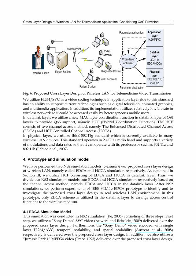
As illustrated in Figure 6, our proposed cross layer design consists of one expert station connected to an access point of WLAN IEEE 802.11g, and some patient stations will access the expert station in other side. A medical specialist in expert station side may conduct telemedicine application which involves data, video, and voice to examine patients in patient station through WLAN infrastructure. To assign guaranteed bandwidth for connection requests of telemedicine application from a patient station to an expert station and vice versa, we perform cross layer design of the existing WLAN protocol stacks. We consider three OSI layers, namely application, datalink, and physical. We gather important information of them through a process of parameter abstraction. Then, the information is optimized to fulfil QoS provisions of telemedicine application. The results of optimizer are implemented back into application, datalink, and physical layers.
Cross Layer Design of Wireless LAN for Telemedicine Application Considering QoS Provision
11
Fig. 6. Proposed Cross Layer Design of Wireless LAN for Telemedicine Video Transmission We utilize H.264/SVC as a video coding technique in application layer due to this standard has an ability to support current technologies such as digital television, animated graphics, and multimedia application. In addition, its implementation utilizes relatively low bit rate in wireless network so it could be accessed easily by heterogeneous mobile users. In datalink layer, we utilize a new MAC layer coordination function in datalink layer of OSI layers to provide QoS support, namely HCF (Hybrid Coordination Function). The HCF consists of two channel access method, namely The Enhanced Distributed Channel Access (EDCA) and HCF Controlled Channel Access (HCCA). In physical layer, we utilize IEEE 802.11g standard which is currently available in many wireless LAN devices. This standard operates in 2.4 GHz radio band and supports a variety of modulations and data rates so that it can operate with its predecessor such as 802.11a and 802.11b (Labiod et al., 2007).
4. Prototype and simulation model We have performed two NS2 simulation models to examine our proposed cross layer design of wireless LAN, namely called EDCA and HCCA simulation respectively. As explained in Section III, we utilize HCF consisting of EDCA and HCCA in datalink layer. Thus, we divide our NS2 simulation models into EDCA and HCCA simulation respectively based on the channel access method, namely EDCA and HCCA in the datalink layer. After NS2 simulations, we perform experiments of IEEE 802.11e EDCA prototype to identify and to investigate the proposed cross layer design in real wireless LAN environment. In this prototype, only EDCA scheme is utilized in the datalink layer to arrange access control functions to the wireless medium.
4.1 EDCA Simulation Model This simulation was conducted in NS2 simulation (Ke, 2006) consisting of three steps. First step, we utilize a “Sony Demo” SVC video (Auwera and Reisslein, 2009) delivered over the proposed cross layer design. Furthermore, the “Sony Demo” video encoded with single layer H.264/AVC, temporal scalability, and spatial scalability (Auwera et al., 2008) respectively is delivered over the proposed cross layer design. In addition, we also utilize a “Jurassic Park 1” MPEG4 video (Trace, 1993) delivered over the proposed cross layer design.
Advances in Telemedicine: Technologies, Enabling Factors and Scenarios
12
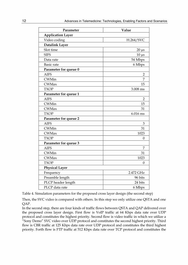
Parameter Value Application Layer Video coding H.264/SVC Datalink Layer Slot time 20 µs SIFS 10 µs Data rate 54 Mbps Basic rate 6 Mbps Parameter for queue 0 AIFS 2 CWMin 7 CWMax 15 TXOP 3.008 ms Parameter for queue 1 AIFS 2 CWMin 15 CWMax 31 TXOP 6.016 ms Parameter for queue 2 AIFS 3 CWMin 31 CWMax 1023 TXOP 0 Parameter for queue 3 AIFS 7 CWMin 31 CWMax 1023 TXOP 0 Physical Layer Frequency 2.472 GHz Preamble length 96 bits PLCP header length 24 bits PLCP data rate 6 Mbps
Table 4. Simulation parameters for the proposed cross layer design (the second step)
Then, the SVC video is compared with others. In this step we only utilize one QSTA and one QAP. In the second step, there are four kinds of traffic flows between QSTA and QAP delivered over the proposed cross layer design. First flow is VoIP traffic at 64 Kbps data rate over UDP protocol and constitutes the highest priority. Second flow is video traffic in which we utilize a “Sony Demo” SVC video over UDP protocol and constitutes the second highest priority. Third flow is CBR traffic at 125 Kbps data rate over UDP protocol and constitutes the third highest priority. Forth flow is FTP traffic at 512 Kbps data rate over TCP protocol and constitutes the
Cross Layer Design of Wireless LAN for Telemedicine Application Considering QoS Provision
13
lowest priority. The simulation parameters utilized in this step are shown in Table 4. In this step, we utilize five QSTAs and one QAP to increase traffic in the wireless LAN. Third step, four traffic flows are delivered over the original IEEE 802.11b wireless LAN. First flow is VoIP traffic at 64 Kbps data rate over UDP protocol. Second flow is video traffic in which we utilize a “Sony Demo” SVC video over UDP protocol. Third flow is CBR traffic at 125 Kbps data rate over UDP protocol. Forth flow is FTP traffic at 512 Kbps data rate over TCP protocol. In this step, we also utilize five QSTAs and one QAP to increase traffic in the wireless LAN.
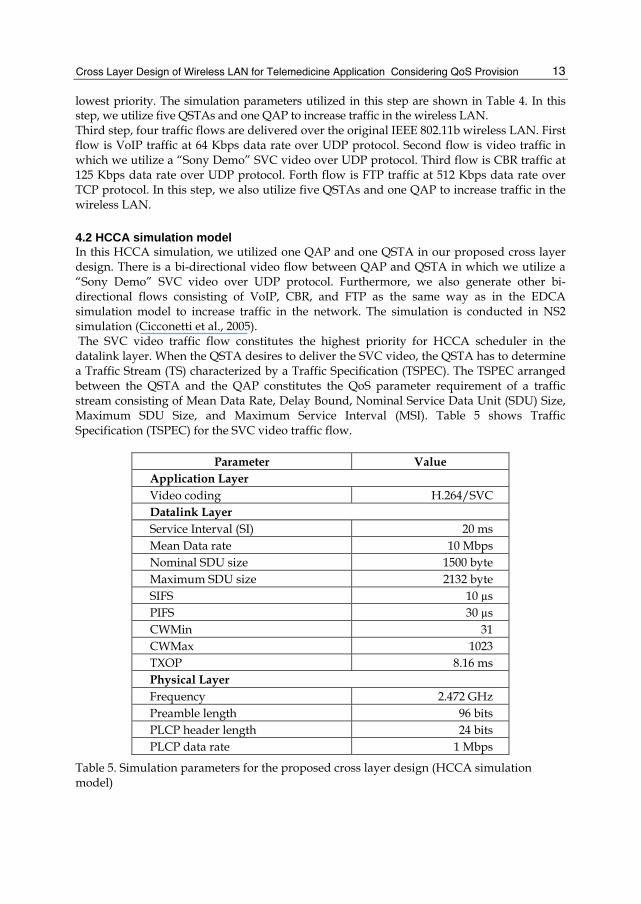
4.2 HCCA simulation model In this HCCA simulation, we utilized one QAP and one QSTA in our proposed cross layer design. There is a bi-directional video flow between QAP and QSTA in which we utilize a “Sony Demo” SVC video over UDP protocol. Furthermore, we also generate other bi-directional flows consisting of VoIP, CBR, and FTP as the same way as in the EDCA simulation model to increase traffic in the network. The simulation is conducted in NS2 simulation (Cicconetti et al., 2005). The SVC video traffic flow constitutes the highest priority for HCCA scheduler in the datalink layer. When the QSTA desires to deliver the SVC video, the QSTA has to determine a Traffic Stream (TS) characterized by a Traffic Specification (TSPEC). The TSPEC arranged between the QSTA and the QAP constitutes the QoS parameter requirement of a traffic stream consisting of Mean Data Rate, Delay Bound, Nominal Service Data Unit (SDU) Size, Maximum SDU Size, and Maximum Service Interval (MSI). Table 5 shows Traffic Specification (TSPEC) for the SVC video traffic flow.
Parameter Value Application Layer Video coding H.264/SVC Datalink Layer Service Interval (SI) 20 ms Mean Data rate 10 Mbps Nominal SDU size 1500 byte Maximum SDU size 2132 byte SIFS 10 µs PIFS 30 µs CWMin 31 CWMax 1023 TXOP 8.16 ms Physical Layer Frequency 2.472 GHz Preamble length 96 bits PLCP header length 24 bits PLCP data rate 1 Mbps
Table 5. Simulation parameters for the proposed cross layer design (HCCA simulation model)

Advances in Telemedicine: Technologies, Enabling Factors and Scenarios
14
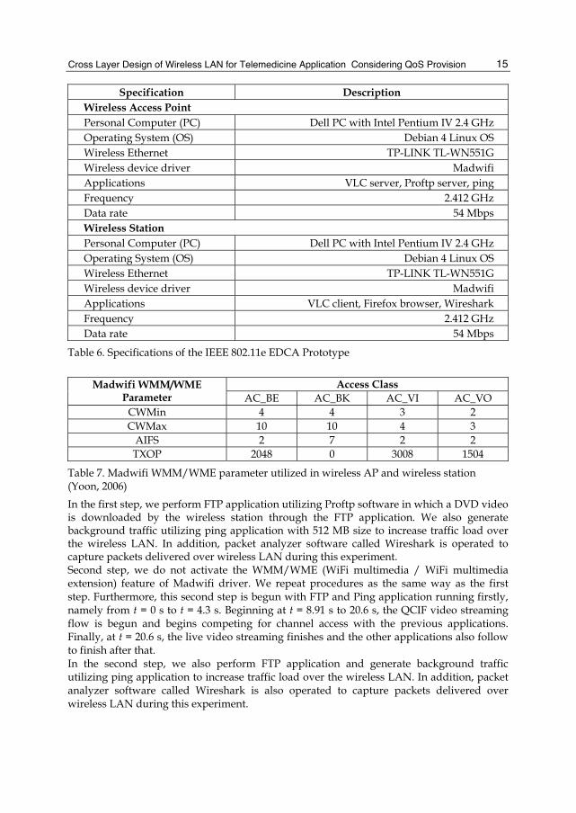
4.3 IEEE 802.11e EDCA prototype IEEE 802.11e EDCA prototype consists of a wireless Access Point (AP) and a wireless station (STA). A wireless Access Point (AP) constitutes a personal computer (PC) equipped with a wireless TP-LINK TL-WN551G card, and Debian 4 Linux OS, and configured as wireless Access Point (AP) through Madwifi software (Madwifi, 2009) in the PC. A wireless station is also a PC equipped with a wireless TP-LINK TL-WN551G card, and Debian 4 Linux OS, and configured as wireless station (STA) through Madwifi software in the PC. As shown in Figure 7, then the wireless Access Point (AP) is connected to the wireless station utilizing 2.4 GHz frequency with 54 Mbps data rate. The wireless station also functions as a wireless monitor to capture and analyze packets delivered over wireless LAN utilizing Wireshark software (Wireshark, 2009). Table 6 shows specifications of the IEEE 802.11e EDCA prototype.
Fig. 7. The IEEE 802.11e EDCA Prototype consists of Wireless AP and wireless station Table 7 shows Madwifi WMM/WME parameter [36] utilized in wireless AP and wireless station in which we can observe that video and voice traffic flows have smaller CWmin, CWmax, and AIFS values and higher TXOP values. Thus, the video and voice traffics will have greater probability of gaining access to the wireless medium. To perform live video streaming application during experiments, we assign the wireless AP as a streaming server utilizing VLC software (VLC, 2009). The VLC software is also installed in the wireless station to display the live video streaming application. Then, the Foreman QCIF video is delivered over wireless LAN and the wireless station will display the Foreman QCIF video streaming utilizing the VLC media player. All experiments performed consist of two steps. First step, we activate the WMM/WME (WiFi multimedia / WiFi multimedia extension) feature of Madwifi driver on the IEEE 802.11e EDCA prototype. Furthermore, this experiment is begun with FTP and Ping application running firstly, namely from t = 0 s to t = 4.3 s. Beginning at t = 4.3 s, the Foreman QCIF video streaming flow is begun and begins competing for channel access with the previous applications. Finally, at t = 16.46 s, the live video streaming finishes and the other applications also follow to finish after that.
Wireless Station (Sta)
Wireless Access Point (AP)
2.412 GHz, 54 Mbps, 8 meters
Cross Layer Design of Wireless LAN for Telemedicine Application Considering QoS Provision
15
Specification Description Wireless Access Point Personal Computer (PC) Dell PC with Intel Pentium IV 2.4 GHz Operating System (OS) Debian 4 Linux OS Wireless Ethernet TP-LINK TL-WN551G Wireless device driver Madwifi Applications VLC server, Proftp server, ping Frequency 2.412 GHz Data rate 54 Mbps Wireless Station Personal Computer (PC) Dell PC with Intel Pentium IV 2.4 GHz Operating System (OS) Debian 4 Linux OS Wireless Ethernet TP-LINK TL-WN551G Wireless device driver Madwifi Applications VLC client, Firefox browser, Wireshark Frequency 2.412 GHz Data rate 54 Mbps
Table 6. Specifications of the IEEE 802.11e EDCA Prototype
Access Class Madwifi WMM/WME Parameter AC_BE AC_BK AC_VI AC_VO
CWMin 4 4 3 2 CWMax 10 10 4 3
AIFS 2 7 2 2 TXOP 2048 0 3008 1504
Table 7. Madwifi WMM/WME parameter utilized in wireless AP and wireless station (Yoon, 2006) In the first step, we perform FTP application utilizing Proftp software in which a DVD video is downloaded by the wireless station through the FTP application. We also generate background traffic utilizing ping application with 512 MB size to increase traffic load over the wireless LAN. In addition, packet analyzer software called Wireshark is operated to capture packets delivered over wireless LAN during this experiment. Second step, we do not activate the WMM/WME (WiFi multimedia / WiFi multimedia extension) feature of Madwifi driver. We repeat procedures as the same way as the first step. Furthermore, this second step is begun with FTP and Ping application running firstly, namely from t = 0 s to t = 4.3 s. Beginning at t = 8.91 s to 20.6 s, the QCIF video streaming flow is begun and begins competing for channel access with the previous applications. Finally, at t = 20.6 s, the live video streaming finishes and the other applications also follow to finish after that. In the second step, we also perform FTP application and generate background traffic utilizing ping application to increase traffic load over the wireless LAN. In addition, packet analyzer software called Wireshark is also operated to capture packets delivered over wireless LAN during this experiment.

Advances in Telemedicine: Technologies, Enabling Factors and Scenarios
16
5. Results and analysis We analyze results of two NS2 simulation models, namely EDCA and HCCA Simulation, and experiments of IEEE 802.11e EDCA prototype respectively. Then, we investigate whether results of the NS2 simulation and the IEEE 802.11e EDCA prototype fulfill the QoS provision to support telemedicine application.
5.1 EDCA simulation analysis Figure 8 shows the throughput values of five different video flows over The IEEE 802.11e EDCA wireless network. We can observe that “Sony Demo” SVC video has the lowest throughput compared with the others. This indicates that the H.264/SVC has a capability to reduce the required bit rate for the same perceptual video quality since the others require higher throughput. This also means that the H.264/SVC can improve better coding efficiency.
Fig. 8. The throughput values of five different video flows over The IEEE 802.11e EDCA wireless network
Figure 9 shows the throughput values of four flows with different priorities over the proposed cross layer design. We can observe that the voice and video flows acquire the assigned throughput, namely 64.13 Kbps and 309.59 Kbps respectively. In the Figure 9, the high priority streams look stable during their transmission over wireless LAN. This can happen due to EDCA scheme associates voice and video packets with access category 1 (AC1) and access category 2 (AC2) respectively so it give more channel access opportunities. In the EDCA scheme, the AC1 and AC2 have higher priority and the AC1 and AC2 are assigned with smaller CWmin, CWmax, and AIFS and longer TXOP to influence the successful transmission probability.

Cross Layer Design of Wireless LAN for Telemedicine Application Considering QoS Provision
17
Fig. 9. The throughput values of four flows with different priorities over the proposed cross layer design.
Fig. 10. The throughput values of four flows over the conventional IEEE 802.11b wireless network
Advances in Telemedicine: Technologies, Enabling Factors and Scenarios
18
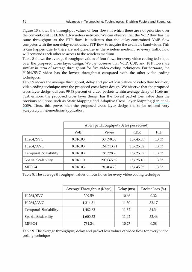
Figure 10 shows the throughput values of four flows in which there are not priorities over the conventional IEEE 802.11b wireless network. We can observe that the VoIP flow has the same throughput as the FTP flow. It indicates that the delay-constrained VoIP flow competes with the non-delay-constrained FTP flow to acquire the available bandwidth. This is can happen due to there are not priorities in the wireless medium, so every traffic flow will contends each other to access to the wireless medium. Table 8 shows the average throughput values of four flows for every video coding technique over the proposed cross layer design. We can observe that VoIP, CBR, and FTP flows are similar in term of average throughput for five video coding techniques. Furthermore, the H.264/SVC video has the lowest throughput compared with the other video coding techniques. Table 9 shows the average throughput, delay and packet loss values of video flow for every video coding technique over the proposed cross layer design. We observe that the proposed cross layer design delivers 99.68 percent of video packets within average delay of 10.66 ms. Furthermore, the proposed cross layer design has the lowest packet loss value than the previous solutions such as Static Mapping and Adaptive Cross Layer Mapping (Lin et al., 2009). Thus, this proves that the proposed cross layer design fits to be utilized very acceptably in telemedicine application.
Average Throughput (Bytes per second)
VoIP Video CBR FTP
H.264/SVC 8,016.03 38,698.35 15,645.05 13.33
H.264/AVC 8,016.03 164,313.91 15,625.02 13.33
Temporal Scalability 8,016.03 185,328.26 15,625.02 13.33
Spatial Scalability 8,016.10 200,065.69 15,625.16 13.33
MPEG4 8,016.03 91,404.70 15,645.05 13.33
Table 8. The average throughput values of four flows for every video coding technique
Average Throughput (Kbps) Delay (ms) Packet Loss (%)
H.264/SVC 309.59 10.66 0.32
H.264/AVC 1,314.51 11.30 52.17
Temporal Scalability 1,482.63 11.32 54.34
Spatial Scalability 1,600.53 11.42 52.46
MPEG4 731.24 10.27 0.38
Table 9. The average throughput, delay and packet loss values of video flow for every video coding technique

Cross Layer Design of Wireless LAN for Telemedicine Application Considering QoS Provision
19
Fig. 11. The throughput values of SVC video flow over HCCA downlink, HCCA uplink, and EDCA
Fig. 12. The delay values of SVC video flow over HCCA downlink, HCCA uplink, and EDCA

Advances in Telemedicine: Technologies, Enabling Factors and Scenarios
20
5.2 HCCA simulation analysis Throughput curve on Figure 11 shows that both downlink HCCA and uplink HCCA schemes succeed to acquire the required throughput for SVC video flow. In addition, SVC video flows over both HCCA downlink and HCCA uplink are more stable than SVC video flow over EDCA. This is mainly due to HCCA scheduler assigns a fixed TXOP for every SVC video traffic flow based on the required mean data rate during service interval (SI). It indicates that the reference scheduler of HCCA has a capability to support the SVC video flow with the QoS guarantee through a negotiation process of parameterized guarantee, namely Traffic Specification (TSPEC). Figure 12 shows the delay values of SVC video flow over HCCA downlink, HCCA uplink, and EDCA. We observe that HCCA delivers 96.25 percent of the SVC video packets within average delay of 18.58 ms from the QAP to the QSTA (downlink). In addition, HCCA delivers 99.99 percent of the SVC video packets within average delay of 907.94 ms from the QSTA to the QAP (uplink). The both average delays are still in QoS provision as shown in Table 2. Table 10 shows the throughput, delay and packet loss values of SVC video flow over HCCA downlink, HCCA uplink, and EDCA link. We can observe that throughputs of SVC/HCCA downlink, SVC/HCCA uplink, and SVC/EDCA fits to the QoS provision in Table 2. This also applies to delay and packet loss values which are suitable with the QoS provision. Furthermore, the delay values of SVC video flow over HCCA downlink, and EDCA link are lower than the delay values of the FHCF scheme (Ansel et al., 2006) and the SFS scheme (Bourawy, 2008). Moreover, the packet loss values of SVC video flow over HCCA downlink, HCCA uplink, and EDCA link are lower than the packet loss value of the SFS scheme. Thus, our proposed cross layer design fits to deliver very acceptably telemedicine application which contains delay sensitive data such as video and voice data.
Throughput (Kbps) Delay (ms) Packet Loss (%)
SVC/HCCA Downlink 1,539.76 18.58 3.75
SVC/HCCA Uplink 1,669.8 907.94 0.01
SVC/EDCA 309.59 10.66 0.32
Table 10. The throughput, delay and packet loss values of video flow over HCCA downlink, HCCA uplink, and EDCA link
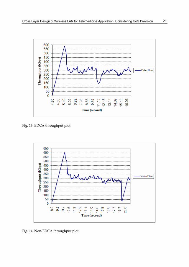
5.3 IEEE 802.11e EDCA prototype analysis Figure 13 shows throughput values of video streaming flow when the IEEE 802.11e EDCA prototype utilizes EDCA scheme in the datalink layer. From t = 4.3 s to t = 5.37 s, the throughput increase quickly, and after that decrease towards the average point at 292.27 Kbps. We can observe that the bit rate requirement does not vary widely over time for the video flow. Although the video flow constitutes Variable Bit Rate (VBR) flow, the video flow is more similar to Constant Bit Rate (CBR) flow. This is mainly due to the fact that the IEEE 802.11e EDCA prototype gives more channel access opportunities (transmission) to video
Cross Layer Design of Wireless LAN for Telemedicine Application Considering QoS Provision
21
Fig. 13. EDCA throughput plot
Fig. 14. Non-EDCA throughput plot
Advances in Telemedicine: Technologies, Enabling Factors and Scenarios
22
050
100150200250300350400450500
4.30
4.58
5.06
5.89
6.66
7.61
8.43
9.28
10.1
011
.41
12.3
7
13.2
314
.12
15.0
815
.96
Time (second)
Del
ay (m
s)
Video Flow
Fig. 15. EDCA delay plot
050
100150200250300350400450500550600650700750800850900950
1000
8.91 9.2
9.63
10.4
11.2 12
12.9
13.7
14.6
15.4
16.4
17.3
18.2
20.1
20.9
Time (second)
Del
ay (m
s)
Video Flow
Fig. 16. Non-EDCA delay plot
Cross Layer Design of Wireless LAN for Telemedicine Application Considering QoS Provision
23
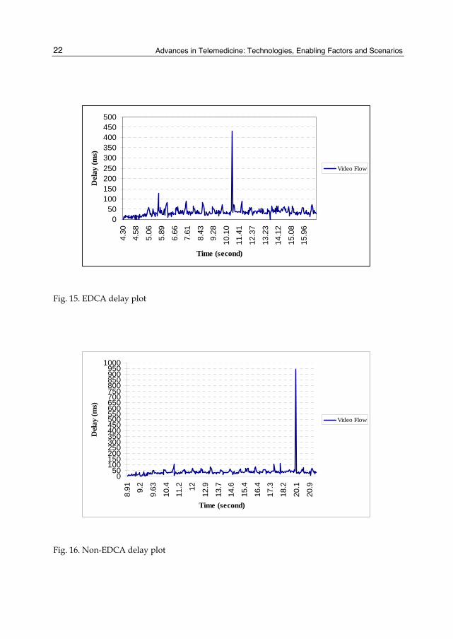
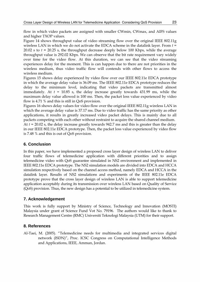
flow in which video packets are assigned with smaller CWmin, CWmax, and AIFS values and higher TXOP values. Figure 14 shows throughput value of video streaming flow over the original IEEE 802.11g wireless LAN in which we do not activate the EDCA scheme in the datalink layer. From t = 20.02 s to t = 20.25 s, the throughput decrease deeply below 100 Kbps, while the average throughput value is 292.02 Kbps. We can observe that the bit rate requirement vary widely over time for the video flow. At this duration, we can see that the video streaming experiences delay for the moment. This is can happen due to there are not priorities in the wireless medium, thus video traffic flow will contends with other flows to access the wireless medium. Figures 15 shows delay experienced by video flow over our IEEE 802.11e EDCA prototype in which the average delay value is 36.09 ms. The IEEE 802.11e EDCA prototype reduces the delay to the minimum level, indicating that video packets are transmitted almost immediately. At t = 10.85 s, the delay increase greatly towards 431.99 ms, while the maximum delay value allowed is 100 ms. Then, the packet loss value experienced by video flow is 4.71 % and this is still in QoS provision. Figures 16 shows delay values for video flow over the original IEEE 802.11g wireless LAN in which the average delay value is 37.17 ms. Due to video traffic has the same priority as other applications, it results in greatly increased video packet delays. This is mainly due to all packets competing with each other without restraint to acquire the shared channel medium. At t = 20.02 s, the delay increase greatly towards 942.7 ms and this is greater than the delay in our IEEE 802.11e EDCA prototype. Then, the packet loss value experienced by video flow is 7.48 % and this is out of QoS provision.
6. Conclusion In this paper, we have implemented a proposed cross layer design of wireless LAN to deliver four traffic flows of telemedicine application with different priorities and to assign telemedicine video with QoS guarantee simulated in NS2 environment and implemented in IEEE 802.11e EDCA prototype. The NS2 simulation models are divided into EDCA and HCCA simulation respectively based on the channel access method, namely EDCA and HCCA in the datalink layer. Results of NS2 simulations and experiments of the IEEE 802.11e EDCA prototype prove that the cross layer design of wireless LAN is able to support telemedicine application acceptably during its transmission over wireless LAN based on Quality of Service (QoS) provision. Thus, the new design has a potential to be utilized in telemedicine system.
7. Acknowledgement This work is fully support by Ministry of Science, Technology and Innovation (MOSTI) Malaysia under grant of Science Fund Vot No. 79196. The authors would like to thank to Research Management Centre (RMC) Universiti Teknologi Malaysia (UTM) for their support.
8. References Al-Taei, M. (2005). “Telemedicine needs for multimedia and integrated services digital
network (ISDN)”, Proc. ICSC Congress on Computational Intelligence Methods and Applications, IEEE, Amman, Jordan.
Advances in Telemedicine: Technologies, Enabling Factors and Scenarios
24
Ansel, P.; Ni, Q.; and Turletti, T. (2006). “ FHCF: A Simple and Efficient Scheduling Scheme for IEEE 802.11e Wireless LAN”, Mobile Networks and Applications, 11, 391-403, Springer Netherlands.
Auwera, G.; and Reisslein, M. (2009). “Implications of Smoothing on Statistical Multiplexing of H.264/AVC and SVC Video Streams” IEEE Transactions on Broadcasting, 55(3):541-558.
Auwera, G.; David, P. T.; and Reisslein, M. (2008). “Traffic and Quality Characterization of Single-Layer Video Streams Encoded with H.264/MPEG-4 Advanced Video Coding Standard and Scalable Video Coding Extension”. IEEE Transactions on Broadcasting, 54(3):698-718.
Bourawy, A. A. (2008). “Scheduling in IEEE 802.11e Networks with Quality of Service Assurance”, Master of Science, Queen’s University, Canada.
Cabral, J.J. and Kim, Y. (1996). “Multimedia systems for telemedicine and their communications requirements”, IEEE Communications Magazine.
Cicconetti, C.; Lenzini, L.; Mingozzi, E. Stea, G. (2005) “A Software Architecture for Simulating IEEE 802.11e HCCA”, Proc. 3rd Internet Performance, Simulation, Monitoring and Measurement IPS-MoMe 2005 March 14-15, Warsaw (Poland).
Chen, Y.; Feng, J.; Lo, K. T.; Zhang, X. (2008). “Wireless Multimedia Systems: Cross Layer Considerations”, Taylor & Francis Group, LLC.
Choi, L.U.; Kellerer, W.; Steinbach, E. (2006). “On Cross-Layer Design for Streaming Video Delivery in Multiuser Wireless Environments”, EURASIP Journal on Wireless Communications and Networking.
Chorbev, I.; Mihajlov, M.; Jolevski, I. (2008). “WiMAX supported telemedicine as part of an integrated system for e-medicine”. Proc. 30th International Conference on Information Technology Interfaces, IEEE, Dubrovnik.
Gibson, O.J.; Cobern, W.R. Hayton, P.M. and Tarassenko, L. (2003). “‘A GPRS mobile phone telemedicine system for self-management of type 1 diabetes”, Proc. 2nd IEEE EMBSS Conference on Biomedical Engineering and Medical Physics, Birmingham.
Ke, C. H. (2006). http://140.116.72.80/~smallko. Kim, H.; Hou, J. C.; Hu, C.; and Ge, Y. (2006) “QoS Provisionings in IEEE 802.11-complaint
Networks”, Elsevier. Kim, S. W. (2006). “Cross-Layer Scheduling Algorithm for WLAN Throughput
Improvement”, Springer-Verlag Berlin Heidelberg. Kim, H.; Hou, J. C.; Hu, C.; and Ge, Y. (2006) “QoS Provisionings in IEEE 802.11-complaint
Networks”, Elsevier. Ksentini, A.; Naimi, M.; and Gueroui, A. (2006). “Toward an Improvement of H.264 Video
Transmission over IEEE 802.11e through A Cross-Layer Architecture”, IEEE Comm. Magazine.
Kugean, C.; Krishnan, S. M.; Chutatape, O.; Swaminathan, S.; Srinivasan, N.; and Wang, P. (2002). “Design of a mobile telemedicine system with WLAN, Proc. Asia-Pacific Conference on Circuits and Systems’, IEEE, Singapore.
Labiod, H.; Afifi, H.; and Santis, C. (2007). “Wi-Fi Bluetooth Zigbee WiMAX”, Springer. Li, W. (2001). “Overview of Fine Granularity Scalability in MPEG-4 Video Standard”, IEEE
Transaction on Circuits and Systems for Video Technology.

Cross Layer Design of Wireless LAN for Telemedicine Application Considering QoS Provision
25
Lin, C.-H.; Shieh, C.-K.; Ke, C.-H.; Chilamkurti, N. K.; and Zeadally, S. (2009). “An adaptive cross-layer mapping algorithm for MPEG-4 video transmission over IEEE 802.11e WLAN”, Telecommunication Systems, 42, 223-234. Springer Netherlands.
Ling, L.; Dezhong, Y.; Jianqig, L.; Bin, L.; Ling, W. (2005). “A multimedia telemedicine system”, Proc. 27th Annual International Conference of the Engineering in Medicine and Biology Society, IEEE.
Madwifi Project, (2009). http://madwifi-project.org/ Nanda, P.; and Fernandes, R. (2007). “Quality of Service in Telemedicine”, Proc. First
International Conference on the Digital Society, IEEE. Ng, H S; Sim, M L; Tan, C M; and Wong, C C. (2006). “Wireless Technologies for
Telemedicine”, BT Technology Journal, Vol 24 No 2. Ni, Q.; Turletti, T. (2004). “QoS Support for IEEE 802.11 Wireless LAN”. http://www-
sop.inria.fr/planete/qni/ 802.11 QoS_qni.pdf Pandian, P. S.; Safeer, K. P.; Shakunthala, D. T.; Padaki, V. C. (2007). “Internet Protocol
Based Store and Forward Wireless Telemedicine System for VSAT and Wireless Local Area Network”, Proc. International Conference on Signal Processing, Communications and Networking, IEEE, Chennai.
Pavlopoulos, S.; Kyriacou, E.; Berler, A.; Dembeyiotis, S.; Koutsouris, D. (1998). “A novel emergency telemedicine system based on wireless communication technology-Ambulance”, IEEE Transactions on Technology in Biomedicine, vol.2, no.4, p.261 – 267.
Schaar, M. van der; Krishnamachari, S.; Choi, S.; and Xu, X. (2003). “Adaptive Cross-Layer Protection Strategies for Robust Scalable Video Transmission Over 802.11 WLANs”, IEEE Journal on Selected Areas in Communication.
Schaar, M. van der; Andreopoulus, Y.; and Hu, Z. (2006). “Optimized Scalable Video Streaming over IEEE 802.11a/e HCCA Wireless Networks under Delay Constraints”, IEEE Transaction on Mobile Computing.
Schierl, T.; Stockhammer, T.; and Wiegand, T. (2007). “Mobile Video Transmission Using Scalable Video Coding”, IEEE Transactions on Circuits and Systems for Video Technology, Vol 17 No 9.
Schwarz, H.; Marpe, D.; and Wiegand, T. (2007). “Overview of Scalable Video Coding Extension of The H.264/AVC Standard”, IEEE Transactions on Circuits and Systems for Video Technology, Vol 17 No 9.
Sudhamony, S.; Nandakumar, K.; Binu, P.; and Niwas, S. (2008). “Telemedicine and tele-health services for cancer-care delivery in India”, IET Communications, vol.2, no.2, p. 231 – 236.
Supriyanto, E.; Satria, H.; Mulyadi, I. H.; Putra, E. H. (2009). “A Novel Low Cost Telemedicine System Using Wireless Mesh Network”, 3rd SEATUC Symposium.
Tan, Y. E.; Istepanian, N.P. and R.S.H. (2006). “Fragility Issues of Medical Video Streaming over 802.11e-WLAN m-health Environments”, Proc. the 28th IEEE EMBS Annual International Conference.
Trace Files, (1993). http://trace.eas.asu.edu/TRACE/ltvt.html. VLC Media Player, (2009). http://www.videolan.org/vlc/
Advances in Telemedicine: Technologies, Enabling Factors and Scenarios
26
Xiaohui, X.; Ruxu, D.; Lining, S.; and Zhijiang, D. (2007). “Internet based telesurgery with a bone-setting system”, Proc. IEEE International Conference on Integration Technology, Shenzhen.
Yoo, S.K.; Jung, S. M.; Kim, B. S.; Yun, H. Y; Kim, S. R.; Kim, D. K. (2005). “Prototype Design of Mobile Emergency Telemedicine System”, Proc. Computational Science and Its Applications, Springer, Berlin.
Yoon, H. (2006). “Test of Madwifi-ng WMM/WME in WLANs, NML-technical report-UM group.
Wireshark, (2009) http://www.wireshark.org/download.html.
Related Documents