CROSBY J-SERIES DIRECT SPRING PRESSURE RELIEF VALVES J-Series valves provide high quality and dependable overpressure protection for air, gas, steam, vapor, liquid and two-phase applications in one simple design FEATURES • ASME/NB certified capacities for air, water and steam. • Full compliance with all major global pressure relief standards including ASME VIII, API 526/527, EN4126 and PED/CE. • Highly customizable to meet most applications. • Interchangeable parts to reduce maintenance costs. • Full nozzle configuration. • Simple and reliable design. • Easy maintenance. • Soft seat options for superior seat tightness. • Adjustable blowdown to reduce product loss. • Restricted Lift available. TECHNICAL DATA Sizes: 1" D 2" to 12" W 16" Orifices: 0.110 to 60.75 in 2 (71 to 39,193 mm 2 ) Inlet ratings: ANSI Classes 150, 300, 600, 900, 1500, 2500 Temperature range: -450°F to +1000°F (-268°C to +538°C) Set pressures JOS-E: 5 to 6000 psig (.034 to 413.79 barg) JLTJOS-E: 15 to 6000 psig (1.03 to 413.79 barg) JBS-E: 15 to 6000 psig (1.03 to 413.79 barg) JLTJBS-E: 25 to 6000 psig (1.72 to 413.79 barg) Code: ASME Section VIII (15 psig and above) VCTDS-00597-EN 17/06 © 2017 Emerson. All Rights Reserved. valves.emerson.com GENERAL APPLICATION The J-Series pressure relief valve provides overpressure protection from very basic to the most demanding applications. Backed by over 140 years of engineering and application experience, its versatile and rugged design make it a proven solution for oil and gas, process and power industry overpressure protection.

Welcome message from author
This document is posted to help you gain knowledge. Please leave a comment to let me know what you think about it! Share it to your friends and learn new things together.
Transcript

CROSBY J-SERIESDIRECT SPRING PRESSURE RELIEF VALVES
J-Series valves provide high quality and dependable overpressure protection for air, gas, steam, vapor, liquid and two-phase applications in one simple design
FEATURES
• ASME/NB certified capacities for air, water and steam.
• Full compliance with all major global pressure relief standards including ASME VIII, API 526/527, EN4126 and PED/CE.
• Highly customizable to meet most applications.
• Interchangeable parts to reduce maintenance costs.
• Full nozzle configuration.• Simple and reliable design.• Easy maintenance.• Soft seat options for superior seat tightness.• Adjustable blowdown to reduce product loss.• Restricted Lift available.
TECHNICAL DATA
Sizes: 1" D 2" to 12" W 16" Orifices: 0.110 to 60.75 in2
(71 to 39,193 mm2)Inlet ratings: ANSI Classes 150, 300,
600, 900, 1500, 2500Temperature range: -450°F to +1000°F
(-268°C to +538°C)Set pressuresJOS-E: 5 to 6000 psig
(.034 to 413.79 barg)JLTJOS-E: 15 to 6000 psig
(1.03 to 413.79 barg)JBS-E: 15 to 6000 psig
(1.03 to 413.79 barg)JLTJBS-E: 25 to 6000 psig
(1.72 to 413.79 barg)Code: ASME Section VIII
(15 psig and above)
VCTDS-00597-EN 17/06© 2017 Emerson. All Rights Reserved.valves.emerson.com
GENERAL APPLICATION
The J-Series pressure relief valve provides overpressure protection from very basic to the most demanding applications. Backed by over 140 years of engineering and application experience, its versatile and rugged design make it a proven solution for oil and gas, process and power industry overpressure protection.

2
CROSBY J-SERIESDIRECT SPRING PRESSURE RELIEF VALVES
PRODUCT RANGE
Series JOS-E and JLTJOS-E are the standard conventional relief valve designs for applications when the discharge is to the atmosphere or to a low pressure exhaust system designed to contain the process fluid.
Series JBS-E and JLTJBS-E pressure relief valves incorporate a bellows which is balanced to minimize the effects of variable back pressure on valve set pressure and can also handle applications involving high built-up back pressure.
For liquid service applications, Series JLTJOS-E and JLTJBS-E provide stable operating performance using our industry-recognized patented liquid trim design, which allows the valve to achieve full lift at 10% overpressure without valve chatter.
Series JOS-H-E are open bonnet pressure relief valves intended for ASME Code Section VIII steam service applications and are furnished with a regular lifting lever as standard.
Series JBSBP-E and JLTJBSBP-E are balanced bellows valves with a supplementary back pressure balancing piston.
Series JOS-E-B and JBS-E-B are BlockBody pressure relief valves that provide a cost-effective alternative to multiple high pressure smaller orifice valves.
Series JOS-E-RL and JBS-E-RL are restricted lift valves with a physical stop reducing the rated capacity to meet application requirements.
CONTENTS
Introduction/description ...........................................................................................................................2Models range ............................................................................................................................................5O-ring soft seats ....................................................................................................................................16Variations from standard materials ......................................................................................................17Caps and lifting levers ............................................................................................................................21Sizes, dimensions and pressure/temperature limits ...........................................................................24Capacity tables (U.S.C.S.) .......................................................................................................................58Equivalents and conversion factors .......................................................................................................71Capacity tables (metric) ..........................................................................................................................72Block body relief valves ..........................................................................................................................84Ordering information ..............................................................................................................................86Valve sizing ..............................................................................................................................................90
J-Series capacities are certified by the National Board of Boiler and Pressure Vessel Inspectors.
Their castings and forgings are procured to ASME/ASTM material specifications and are available in a number of material combinations such as Monel®, Hastelloy® and stainless steel in addition to a number of special material combinations such as titanium, duplex stainless steel and Inconel®, which are available on application.
Dimensions of flanges conform to current ASME Standards. All steel raised face flanges are spiral concentric serrated finish with 45 to 55 grooves per inch and a finish between 125 Ra and 200 Ra. Other flange facings, such as ring type joint, are available on request.

3
CROSBY J-SERIESDIRECT SPRING PRESSURE RELIEF VALVES
SEAT DESIGN
Series JOS-E and JBS-E relief valves are available with flat metal-to-metal or soft seats. Their two-piece disc holder/disc insert construction provides thermal balancing assuring maximum seat tightness and meets the requirements of API Standard 527, ‘Seat tightness of pressure relief valves’.
Where system operating conditions permit, soft or elastomer O-ring seat construction is available as an option. This two-seat design (Figure 1) has a metal-to-metal seat located downstream of the soft seat. The O-ring is the primary seal. The flat metal-to-metal seat controls the compression of the O-ring and also serves as a secondary seal should the O-ring be damaged. Elastomeric O-ring soft seat valves are tightness tested at 95% of set pressure, exceeding the requirements of API Standard 527.
Standard O-ring materials include FKM, Buna-N, EPR, TFE, silicone rubber and Kalrez® (see page 16). Other soft seat materials, their pressure and temperature limits are available on application.
FIGURE 1
FIGURE 2
FIGURE 3
DUAL CERTIFICATION
Series JLT pressure relief valves for liquid service were developed using our unique patented trim design. This contoured liquid trim design (Figure 2), with over 25 years of successful field experience, was patented prior to the issuance of ASME Code Section VIII requirements that became mandatory in 1985. The JLT trim offers a significant increase in capacity at 10% overpressure and, in many cases, results in selection of a smaller valve with an associated reduction in inlet and discharge piping costs. The JLT design is also capacity certified for gas and vapor service and can be applied in two-phase flow applications. The JLT design is a logical choice where the process fluid may be a liquid or gas depending on the overpressure condition.
BELLOWS AND TOP FLANGE
All standard JBS-E and JLTJBS-E valves feature a standard bellows and top flange (Figure 3) manufactured from Inconel® alloy 625, which is a fatigue-resistant material and provides improved corrosion resistance compared to 316L stainless steel. It is highly resistant to pitting, crevice corrosion and inter-granular attack. The standard bellows assembly threads onto the disc holder with a bellows tailpiece and gasket. A welded bellows attachment is available as an option.
BELLOWS CONVERTIBILITY
The flanged, spring operated pressure relief valve is designed and manufactured as a conventional valve and a balanced bellows valve. The conversion from conventional Series JOS-E or JLTJOS-E in sizes 1" D 2" through 8" T2 10" requires only the addition of a bellows assembly and bellows tail-piece gasket. No other parts are necessary.
NOTEFKM is a registered trademark of DuPont Performance Elastomers L.L.C.

4
CROSBY J-SERIESDIRECT SPRING PRESSURE RELIEF VALVES
CERTIFICATIONS AND TYPE APPROVALS
• ASME Boiler and Pressure Code Section VIII• National Board of Boiler and Pressure Vessel Inspectors Capacity Certifications• Canadian Registration Number• Pressure Equipment Directive (97/27/EC), (ISO-4126-1) (CE)• China Manufacturing License (TS)• United States Coast Guard (USCG)• Australia (AS-1271)
Contact your local sales representative for further details.
CAP, LIFTING LEVER AND SPINDLE INTERCHANGEABILITY
All JOS-E and JBS-E relief valves (except restricted height caps) use a threaded spindle and drilled and tapped bonnet which permits easy cap or lifting lever conversions, with maximum standardization and interchangeability of parts. In addition, standard cap and lifting lever designs can be used with in-line test devices.
FIGURE 4EASE OF MAINTENANCE AND COMPONENT INTERCHANGEABILITY
The JOS-E and JBS-E’s disc insert retention, disc holder and nozzle ring have been engineered to ensure ease of maintenance, minimize spare parts and provide a high degree of component part interchangeability (Figure 4).
The disc insert is held securely in place with a compressible retention clip. A ‘universal’ disc holder allows simple and cost effective conversions from conventional to balanced bellows design and enables cost-effective bellows replacement.
The nozzle ring encloses the adjustment slot at the bottom of the ring giving a rugged, durable design.
AVAILABLE OPTIONS
Materials• Special materials Alloy 20, duplex, titanium etc.• Xylan coating inside body/bonnet/cap• Spring coatings and platings• Materials of construction for applications above 1000°F (538°C)• Special gasket materials including graphite, Hastelloy®, PTFE etc.
Connections• 300# cosmetic or fully rated non-standard outlets• Special connections such as tri-clamp, Grayloc etc.• International flange standards• Flat face and RFSF flange options
Accessories• Position indicator, proximity switch, etc.• Steam jacketed bodies
Others• High pressure forged block body design• Special painting or coating• Special cleaning and testing• Welded disc holder• Lethal service construction

5
CROSBY J-SERIESDIRECT SPRING PRESSURE RELIEF VALVES
SERIES JOS-E/JLTJOS-E PRODUCT OVERVIEW
Series JOS-E and JLTJOS-E are the standard conventional relief valve designs for applications when the discharge is to the atmosphere or to a low pressure exhaust system designed to contain the process fluid.
Their exceptionally rugged design features a high guiding surface ratio and corrosion resistant trim.
For liquid service applications, Series JLTJOS-E provide stable operating performance using our industry-recognized patented liquid trim design, which allows the valve to achieve full lift at 10% overpressure without valve chatter.
Temperature rangeJOS-E and JLTJOS-E( )5: -20°F to 650°F (-29°C to 343°C)JOS-E and JLTJOS-E( )6: 651°F to 800°F (344°C to 427°C)JOS-E and JLTJOS-E( )7: 801°F to 1000°F (428°C to 538°C)
SERIES JLTJOS-E(with O-ring seat)
SERIES JOS-E(with metal-to-metal seat)

6
CROSBY J-SERIESDIRECT SPRING PRESSURE RELIEF VALVES
SERIES JOS-E AND JLTJOS-E STANDARD MATERIALS OF CONSTRUCTIONNo. Part name Standard material1 Body - JOS-E and JLTJOS-E ( )5 and ( )6 ASME SA216 Gr. WCB/WCC1 Body - JOS-E and JLTJOS-E ( )7 ASME SA217 Gr. WC62 Nozzle 316 SS3 Nozzle ring 316 SS4 Set screw 316 SS5 Disc holder 316L SS8 Disc insert[1] 316 SS9 Retention clip[2] Inconel® X75010 O-ring[1] Specify11 O-ring retainer 316 SS12 Retainer screw(s) 18-8 SS15 Guide ASTM A297 Gr. HE SST16 Spindle 416 SS17 Spindle cotter pin SS18 Spring - JOS-E and JLTJOS-E ( )5 Chrome Steel[3]
18 Spring - JOS-E and JLTJOS-E ( )6 and ( )7 Alloy Steel[3,4]
19 Spring washers CS20 Bonnet - JOS-E and JLTJOS-E ( )5 and ( )6 ASME SA216 Gr. WCB/WCC20 Bonnet - JOS-E and JLTJOS-E ( )7 ASME SA217 Gr. WC621 Bonnet stud ASME SA193 Gr. B722 Bonnet stud nut ASME SA194 CL 2H24 Adjusting bolt 316 SS[5]
25 Adjusting bolt nut 316 SS26 Nameplate (not shown) SS27 Set screw gasket[1] 316 SS28 Guide gasket[1] 316 SS30 Pipe plug (bonnet) CS34 Seal and wire Lead and SS35 Seal clip (not shown) SS40 Threaded cap CS41 Cap gasket[1] 316 SS
NOTES1. Recommended spare part.2. Furnished with disc insert.3. Corrosion resistant coating.4. Crosby may upgrade to Inconel® X750.5. Class 900#, 1500# and 2500# inlet ratings use 416 SS.

7
40
242534
19
20
18
19
21
22
15
5
34
3
4
8
27
1
2
41
30
16
17
28
9
12
11
10
CROSBY J-SERIESDIRECT SPRING PRESSURE RELIEF VALVES
SERIES JOS-E(with metal-to-metal seat)
SERIES JOS-E AND JLTJOS-E CONVENTIONAL PRESSURE RELIEF VALVES
SERIES JLTJOS-E(with O-ring seat)

8
CROSBY J-SERIESDIRECT SPRING PRESSURE RELIEF VALVES
SERIES JBS-E/JLTJBS-E PRODUCT OVERVIEW
Series JBS-E and JLTJBS-E pressure relief valves incorporate a bellows which is balanced to minimize the effects of variable back pressure on valve set pressure and can also handle applications involving high built-up back pressure.
Additionally, the bellows serves to isolate the guide, spindle, spring and other parts contained in the bonnet chamber from corrosive fluids or media such as a highly viscous fluid or slurry which could render the relief valve inoperative.
Their exceptionally rugged design features a high guiding surface ratio and corrosion resistant trim.
For liquid service applications, Series JLTJBS-E provides stable operating performance using our industry-recognized patented liquid trim design, which allows the valve to achieve full lift at 10% overpressure without valve chatter.
Temperature rangeJBS-E and JLTJBS-E( )5: -20°F to 650°F (-29°C to 343°C)JBS-E and JLTJBS-E( )6: 651°F to 800°F (344°C to 427°C)JBS-E and JLTJBS-E( )7: 801°F to 1000°F (428°C to 538°C)
SERIES JBS-E(with metal-to-metal seat)
SERIES JBS-E(with O-ring seat)

9
CROSBY J-SERIESDIRECT SPRING PRESSURE RELIEF VALVES
SERIES JBS-E AND JLTJBS-E MATERIALS OF CONSTRUCTIONNo. Part name Standard material1 Body - JBS-E and JLTJBS-E ( )5 and ( )6 ASME SA216 Gr. WCB/WCC1 Body - JBS-E and JLTJBS-E ( )7 ASME SA217 Gr. WC62 Nozzle 316 SS3 Nozzle ring 316 SS4 Set screw 316 SS5 Disc holder 316L SS6A Bellows tailpiece[1] 316L SS6B Bellows[1] Inconel® 6256C Bellows flange[1] Inconel® 6258 Disc insert[2] 316 SS9 Retention clip[3] Inconel® X75010 O-ring[2] Specify11 O-ring retainer 316 SS12 Retainer screw(s) 18-8 SS15 Guide ASTM A297 Gr. HE SST16 Spindle 416 SS17 Spindle cotter pin SS18 Spring - JBS-E and JLTJBS-E ( )5 Chrome steel[4]
18 Spring - JBS-E and JLTJBS-E ( )6 and ( )7 Alloy steel[4,5]
19 Spring washers CS20 Bonnet - JBS-E and JLTJBS-E ( )5 and ( )6 ASME SA216 Gr. WCB/WCC20 Bonnet - JBS-E and JLTJBS-E ( )7 ASME SA217 Gr. WC621 Bonnet stud ASME SA193 Gr. B722 Bonnet stud nut ASME SA194 CL 2H24 Adjusting bolt 316 SS[6]
25 Adjusting bolt nut 316 SS26 Nameplate (not shown) SS27 Set screw gasket[2] 316 SS28 Guide gasket[2] 316 SS29 Tailpiece gasket[2] 316 SS34 Seal and wire Lead and SS35 Seal clip (not shown) SS40 Threaded cap CS41 Cap gasket[2] 316 SS
NOTES1. Subassembly.2. Recommended spare part.3. Furnished with disc insert.4. Corrosion resistant coating.5. Crosby may upgrade to Inconel® X750.6. Class 900#, 1500# and 2500# inlet ratings use 416 SS.

10
12
11
10
40
242534
19
20
18
19
21
22
15
5
34
3
4
8
27
1
2
41
Note: This vent must remain open on JBS-E and JLT-JBS-E construction
16
17
28
29
9
6C6B6A
CROSBY J-SERIESDIRECT SPRING PRESSURE RELIEF VALVES
SERIES JBS-E AND JLTJBS-E BALANCED BELLOWS PRESSURE RELIEF VALVES
SERIES JBS-E(with metal-to-metal seat)
SERIES JBS-E(with O-ring seat)
Note: this vent must remain open on JBS-E and JLTJBS-E construction

11
-15 -10 -5 0 5 10 15 20 25 30
100
75
50
25
CROSBY J-SERIESDIRECT SPRING PRESSURE RELIEF VALVES
SERIES JLTJOS-E/JLTJBS-E LIQUID TRIM PRESSURE RELIEF VALVES
Series JLTJOS-E and JLTJBS-E pressure relief valves for liquid service were developed using our unique patented contoured trim design (Figure 5). The JLT trim offers a significant increase in capacity at 10% overpressure and in many cases, results in selection of a smaller valve with an associated reduction in inlet and discharge piping costs. It provides smooth and stable valve operation on liquid service applications.
OPERATION
When system pressure reaches the specified set pressure, a small stream of fluid begins to flow from the valve. Valve disc lift at this pressure is minimal.
As the system pressure increases into the range of 3% to 5% overpressure, the valve then opens with a pop type lift to the full lift position. At 10% overpressure, the JLT valve will have attained full lift and be flowing an amount equal or greater than the rated capacity (Figure 6).
As the system pressure begins to drop, flow through the valve decreases until the valve reseats with a clean positive closing action.
The JLT design is also capacity certified for gas and vapor service and can be applied in two-phase flow applications.
FIGURE 5 FIGURE 6TYPICAL FLOW CURVE - CONTOURED TRIM DESIGN (JLT)
Disc holder with patented contour
% M
axim
um ra
ted
capa
city
Pop lift
Clos
ed
Uniform increase in lift
Overpressure
Set point
Blow down

12
Disc Holder
Bushing
Disc Insert
CROSBY J-SERIESDIRECT SPRING PRESSURE RELIEF VALVES
SERIES JOS-H-E OPEN BONNET PRESSURE RELIEF VALVES
Series JOS-H-E relief valves (Figure 8) are intended for ASME Code Section VIII steam service applications and are furnished with a regular lifting lever as standard.
The standard chrome steel spring in the JOS-H-E open bonnet design is exposed for atmospheric cooling.
Optional accessories include a test rod as well as a weather hood. Materials of construction are identical to the standard closed bonnet JOS-E design.
The JOS-H-E has a maximum temperature rating of 800°F [427°C] using WCB/WCC.carbon steel body and bonnet and chrome steel spring.
Series JOS-H-E (and JOS-E) relief valves for steam service at set pressures above 450 psig use a 316L stainless steel disc holder with disc bushing and threaded 17-4 ph stainless steel disc insert (see Figure 7).
Steam service trim for set pressures greater than 450 psi
JOS-H-E conventional open bonnet
Disc holder
Bushing
Disc insert
FIGURE 7
FIGURE 8

13
CROSBY J-SERIESDIRECT SPRING PRESSURE RELIEF VALVES
VALVES
Crosby JOS-E and JLT-JOS-E pressure relief valves are available in a restricted lift version. All J Series variations including JBS and all service medias may be supplied in a restricted lift version. The purpose of a restricted lift valve is to more closely match the required capacity of the protected vessel or pipe with the actual and rated capacities of the relief valve providing over-pressure protection.
Restricted lift (RL) versions of the J series may be built by a certified Pentair manufacturing facility or by an ASME certified Assembler with the required certification Specific to the RL version (National Board certificates 01045 and 01382).
OPERATION
The restricted lift design adds a stainless steel washer to the top of the disc holder. The washer restricts the lift of the disc holder by creating a physical stop with the guide at a lower lift value than the disc holder and guide alone.
When system pressure reaches the specified set pressure, the valve begins to go into lift. As the system pressure increases the valve will exhibit a pop type lift at either set pressure or 3-5% overpressure depending on the trim type. At 10% overpressure the valve will have attained its restricted full lift.
As the system pressure begins to drop, flow through the valve decreases until the valve reseats identically to any other trim configuration.
The JOS-E-RL/JLTJOS-E-RL design is capacity certified on gas, liquid, and steam and can be used on any JOS-E/JLTJOS-E trim variant.
Disc holder with patented contour
Spacers
Spacers
SERIES JOS-E-RL TRIM JBS-E-RL TRIM
VALVES
Crosby JOS-E and JLT-JOS-E pressure relief valves are available in a restricted lift version. All J Series variations including JBS and all service medias may be supplied in a restricted lift version. The purpose of a restricted lift valve is to more closely match the required capacity of the protected vessel or pipe with the actual and rated capacities of the relief valve providing over-pressure protection.
Restricted lift (RL) versions of the J series may be built by a certified Emerson manufacturing facility or by an ASME certified Assembler with the required certification Specific to the RL version (National Board certificates 01045 and 01382).
OPERATION
The restricted lift design adds a stainless steel washer to the top of the disc holder. The washer restricts the lift of the disc holder by creating a physical stop with the guide at a lower lift value than the disc holder and guide alone.
When system pressure reaches the specified set pressure, the valve begins to go into lift. As the system pressure increases the valve will exhibit a pop type lift at either set pressure or 3-5% overpressure depending on the trim type. At 10% overpressure the valve will have attained its restricted full lift.
As the system pressure begins to drop, flow through the valve decreases until the valve reseats identically to any other trim configuration.
The JOS-E-RL/JLTJOS-E-RL design is capacity certified on gas, liquid, and steam and can be used on any JOS-E/JLTJOS-E trim variant.
Disc holder with patented contour
Spacers
Spacers
SERIES JOS-E-RL TRIM JBS-E-RL TRIM

14
40
2425
34
19
20
181921
2215
5
34
34
8
2712
41
30
1617
28
9
CROSBY J-SERIESDIRECT SPRING PRESSURE RELIEF VALVES
SERIES JOS-E AND JLTJOS-E MATERIALS OF CONSTRUCTION
No. Part nameStandard NACE materialLevel 2 (N2)
1 Body ASME SA216 Gr. WCB/WCC2 Nozzle 316 SS3 Nozzle ring 316 SS4 Set screw 316 SS5 Disc holder 316L SS8 Disc insert 316 SS9 Retention clip Inconel® X75015 Guide ASTM A297 Gr. HE SST16 Spindle 316 SS*17 Spindle cotter pin SS18 Spring Inconel® X750*19 Spring washer 316 SS*20 Bonnet ASME SA216 Gr. WCB/WCC21 Bonnet stud Alloy Steel[2]
22 Bonnet stud nut Alloy Steel[2]
24 Adjusting bolt 316 SS*25 Adjusting bolt nut 316 SS27 Set screw gasket 316 SS28 Guide gasket 316 SS30 Pipe plug (bonnet) CS34 Seal and wire Lead and SS35 Seal clip (not shown) SS40 Threaded cap CS41 Cap gasket 316 SS
NOTES1. Contact your sales representative for compliance to NACE MR0175 (2003 edition) or
NACE MR0175/ISO 15156 requirements.2. If the valve bolting could be directly exposed or in contact with the hydrogen sulfide environment, bonnet
studs can be ASME A193 Gr. B7M HRC-22 maximum and bonnet stud nuts can be ASME A194 Class 2HM HRC-22 maximum.
SERIES JOS-E
SERIES JOS-E AND JLTJOS-E PRESSURE RELIEF VALVES FOR SOUR GAS SERVICE PER NACE MR0175 (2002 EDITION)[1]
Level 1 - For applications where compliance with NACE MR0175 is required for wetted parts in the primary (upstream) pressure zone of the pressure relief valve. Materials of construction for Level 1 are standard and can be found on page 6.
Level 2 - For applications where compliance with NACE MR0175 is required for wetted parts in the primary (upstream) and secondary (downstream) pressure zones of the pressure relief valve (Designated as ‘N2’ in model number).
While the materials recommended for the Series JOS-E and JLTJOS-E sour gas valves are suitable for average service conditions, optional materials are available to provide additional resistance to corrosion beyond the minimum requirements of the standard.
* Variation from standard and NACE Level 1 product.

15
40
2425
34
19
20
1819
21
2215
5
34
34
8
2712
41
16
17
28
29
9
6C6B6A
CROSBY J-SERIESDIRECT SPRING PRESSURE RELIEF VALVES
SERIES JBS-E AND JLTJBS-E MATERIALS OF CONSTRUCTION
No. Part nameStandard NACE material Level 2 (N2)
1 Body ASME SA216 Gr. WCB/WCC2 Nozzle 316 SS3 Nozzle ring 316 SS4 Set screw 316 SS6C Bellows flange[2] Inconel® 6256B Bellows[2] Inconel® 6256A Bellows tailpiece[2] 316L SS5 Disc holder 316L SS8 Disc insert 316 SS9 Retention clip Inconel® X75015 Guide ASTM A297 Gr. HE SST16 Spindle 416 SS17 Spindle cotter pin SS18 Spring Chrome steel-aluminum metallized*19 Spring washer Steel20 Bonnet ASME SA216 Gr. WCB/WCC21 Bonnet stud Alloy steel[3]
22 Bonnet stud nut Steel[3]
24 Adjusting bolt 316 SS25 Adjusting bolt nut 316 SS27 Set screw gasket 316 SS28 Guide gasket 316 SS29 Tailpiece gasket 316 SS34 Seal and wire Lead and SS35 Seal clip (not shown) SS40 Threaded cap CS41 Cap gasket 316 SS
NOTES1. Contact your sales representative for compliance to NACE MR0175 (2003 edition) or
NACE MR0175/ISO 15156 requirements.2. Subassembly.3. If the valve bolting could be exposed directly to or in contact with the hydrogen sulfide environment, bonnet
studs can be ASME A193 Gr. B7M HRC-22 maximum and bonnet stud nuts can be ASME A194 Class 2HM HRC-22 maximum.
SERIES JBS-E(with bellows)
SERIES JBS-E AND JLTJBS-E PRESSURE RELIEF VALVES FOR SOUR GAS SERVICE PER NACE MR0175 (2002 EDITION)[1]
Level 1 - For applications where compliance with NACE MR0175 is required for wetted parts in the primary (upstream) pressure zone of the pressure relief valve. Materials of construction for Level 1 are standard and can be found on page 9.
Level 2 - For applications where compliance with NACE MR0175 is required for wetted parts in the primary (upstream) and secondary (downstream) pressure zones of the pressure relief valve. The Inconel® 625 bellows isolates the valve spring and other critical components above it from the process fluid (Designated as ‘N2’ in model number).
While the materials recommended for the Series JBS-E and JLTJBS-E sour gas valves are suitable for average service conditions, optional materials are available to provide additional resistance to corrosion beyond the minimum requirements of the standard.
* Variation from standard product; Crosby may upgrade to Inconel® X750.

16
5B
17
CROSBY J-SERIESDIRECT SPRING PRESSURE RELIEF VALVES
SERIES JBSBP-E AND JLTJBSBP-E BALANCED BELLOWS VALVES WITH SUPPLEMENTARY BACK PRESSURE BALANCING PISTON
Series JBSBP-E and JLTJBSBP-E are a modification to the standard bellows pressure relief valves which have been designed and tested in collaboration with engineers of one of the world’s leading petroleum companies. This adaptation provides additional assurance of safe performance in the event of bellows failure on installations with discharge manifold systems where constant or variable back pressures are present.
With the standard bellows pressure relief valve, if the bellows is broken or ruptured, the valve will perform in the manner of a standard valve without bellows. Introduction of the supplementary back pressure balancing piston assures full performance characteristics of the valve until necessary replacement of the bellows can be made, affording double protection.
Unless compensated for, the effects of back pressure may cause (1) a change in the opening pressure (2) a decrease in valve capacity and (3) valve performance to become unstable at higher back pressure.
Use of the bellows valve with supplementary balancing piston maintains the balancing effect even after bellows failure enabling the valve to function in essentially the same manner as with the bellows intact. However, the bonnet of the valve must be vented to ensure proper valve functioning. The vent also serves as a ‘tell-tale’ in case of a ruptured or broken bellows.
DesignThe auxiliary balancing piston is incorporated in the basic bellows valve, modified to include the piston (5B) and the cylinder (17) which is part of the disc holder.The guiding clearances are held to a minimum and, in addition, grooves in the piston form a labyrinth seal to reduce flow between the piston and cylinder. In the event of a bellows failure, the leakage of fluid to atmosphere is kept to a minimum.

17
500
400
300
200
100
50
0
-150
-50
Set Pressure, psigFigures in ( ) are Durometer Hardness
Specifications.
-101
-45
-17
93
204
260
15 100 200 300 400 500 600 700 800 900 1000 1200 1400
Inle
t Tem
pera
utur
e, °F
1480 or max. set pressurerating of the O-ring soft
seat valve.In
let T
empe
raut
ure,
°C
Kalrez® (90)TFE
TFE
Kalrez® (80)Silicone (80)Viton® (75)TFE
Kalrez® (90)Viton® (90)TFE
Buna-N (70)EPR (80) 325°F MaxKalrez® (80)Silicone (70)Viton® (75)TFE
Buna-N (60)EPR (70)Silicone (50)
Buna-N (90)EPR (90)Kalrez® (90)Viton® (90)TFE
Buna-N (70)EPR (70)
TFE TFE
Buna-N (90)EPR (90)
Silicone (80)TFE
Kalr
ez®
(80)
1.03 34.5 69.0 1026.90Set Pressure, barg
Silicone (70)TFE
Buna
-N (5
0)EP
R (7
0)Si
licon
e (5
0)Vi
ton®
(75)
Kalr
ez®
(80)
Silic
one
(50)
Vito
n® (7
5)
D 1480 102.0E 1480 102.0F 1480 102.0G 1480 102.0H 1480 102.0J 1480 102.0K 1480 102.0L 1000 68.9M 1100 75.8N 1000 68.9P 1000 68.9Q 600 41.3R 300 20.6T 300 20.6T2 300 20.6
CROSBY J-SERIESDIRECT SPRING PRESSURE RELIEF VALVES
NOTES1. Other soft seat materials are available on request.
For O-ring seats below -150°F (-101°C) consult your sales representative. For steam service, metal-to-metal seats are recommended; consult your sales representative if soft seats are required. Minimum cold differential test pressure for TFE seat is 100 psig.
2. Viton® is a registered trademark of DuPont Performance Elastomers L.L.C.
O-RING SOFT SEAT MATERIALS AND PRESSURE/TEMPERATURE LIMITS
MAXIMUM SET PRESSURE LIMITS
OrificeMaximum set pressure
psig barg
Inle
t tem
pera
ture
, °C
EPR Ethylene Propylene RubberTFE Tetrafluoroethylene
Set pressure, psigFigures in ( ) are durometer hardness specifications 1480 or max. set
pressure rating of the O-ring soft seat valve
Set pressure, barg
Inle
t tem
pera
ture
, °F
18
CROSBY J-SERIESDIRECT SPRING PRESSURE RELIEF VALVES
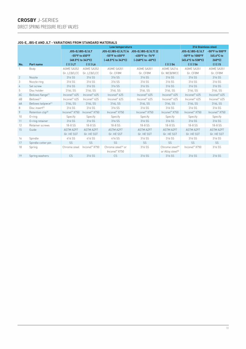
JOS-E, JBS-E AND JLT - VARIATIONS FROM STANDARD MATERIALS
No. Part name
Low temperature 316 Stainless steelJOS-E/JBS-E/JLT
-55°F to 650°F(48.5°C to 343°C)
JOS-E/JBS-E/JLT( )4-55°F to 650°F
(-48.5°C to 343°C)
JOS-E/JBS-E/JLT( )2-450°F to -76°F
(-268°C to -60°C)
JOS-E/JBS-E/JLT -50°F to 1000°F (45.6°C to 538°C)
-50°F to 500°F(45.6°C to
260°C)( ) ( ) LT ( ) ( ) L6 ( ) ( ) S4 ( ) ( ) S6 ( ) ( ) S
1 Body ASME SA352Gr. LCB/LCC
ASME SA352Gr. LCB/LCC
ASME SA351Gr. CF8M
ASME SA351Gr. CF8M
ASME SA216Gr. WCB/WCC
ASME SA351Gr. CF8M
ASME SA351Gr. CF8M
2 Nozzle 316 SS 316 SS 316 SS 316 SS 316 SS 316 SS 316 SS3 Nozzle ring 316 SS 316 SS 316 SS 316 SS 316 SS 316 SS 316 SS4 Set screw 316 SS 316 SS 316 SS 316 SS 316 SS 316 SS 316 SS5 Disc holder 316L SS 316L SS 316L SS 316L SS 316L SS 316L SS 316L SS6C Bellows flange[1] Inconel® 625 Inconel® 625 Inconel® 625 Inconel® 625 Inconel® 625 Inconel® 625 Inconel® 6256B Bellows[1] Inconel® 625 Inconel® 625 Inconel® 625 Inconel® 625 Inconel® 625 Inconel® 625 Inconel® 6256A Bellows tailpiece[1] 316L SS 316L SS 316L SS 316L SS 316L SS 316L SS 316L SS8 Disc insert[2] 316 SS 316 SS 316 SS 316 SS 316 SS 316 SS 316 SS9 Retention clip[3] Inconel® X750 Inconel® X750 Inconel® X750 Inconel® X750 Inconel® X750 Inconel® X750 Inconel® X75010 O-ring Specify Specify Specify Specify Specify Specify Specify11 O-ring retainer 316 SS 316 SS 316 SS 316 SS 316 SS 316 SS 316 SS12 Retainer screws 18-8 SS 18-8 SS 18-8 SS 18-8 SS 18-8 SS 18-8 SS 18-8 SS15 Guide ASTM A297
Gr. HE SSTASTM A297Gr. HE SST
ASTM A297Gr. HE SST
ASTM A297Gr. HE SST
ASTM A297Gr. HE SST
ASTM A297Gr. HE SST
ASTM A297Gr. HE SST
16 Spindle 416 SS 416 SS 416 SS 316 SS 316 SS 316 SS 316 SS17 Spindle cotter pin SS SS SS SS SS SS SS18 Spring Chrome steel Inconel® X750 Chrome steel[4] or
Inconel® X750316 SS Chrome steel[4]
or Alloy steel[5]
Inconel® X750 316 SS
19 Spring washers CS 316 SS CS 316 SS 316 SS 316 SS 316 SS

19
5
41
161728
9
402425
3419
20
181921
2215
3434
8
2712
30
12
11
1017
JLTO-ring soft seat
COTTER PINSUsed in L orifice and above only
JOS-E
CROSBY J-SERIESDIRECT SPRING PRESSURE RELIEF VALVES
JOS-E, JBS-E AND JLT - VARIATIONS FROM STANDARD MATERIALS (continued)
No. Part name
Low temperature 316 Stainless steelJOS-E/JBS-E/JLT
-55°F to 650°F(48.5°C to 343°C)
JOS-E/JBS-E/JLT( )4-55°F to 650°F
(-48.5°C to 343°C)
JOS-E/JBS-E/JLT( )2-450°F to -76°F
(-268°C to -60°C)
JOS-E/JBS-E/JLT -50°F to 1000°F (45.6°C to 538°C)
-50°F to 500°F(45.6°C to
260°C)( ) ( ) LT ( ) ( ) L6 ( ) ( ) S4 ( ) ( ) S6 ( ) ( ) S
20 Bonnet ASME SA352Gr. LCB/LCC
ASME SA352Gr. LCB/LCC
ASME SA351Gr. CF8M
ASME SA351Gr. CF8M
ASME SA216Gr. WCB/WCC
ASME SA351Gr. CF8M
ASME SA351Gr. CF8M
21 Bonnet stud ASME SA193Gr. B7
ASME SA193Gr. B7
ASME SA193Gr. B8
ASME SA320Gr. B8
ASME SA193Gr. B7
ASME SA193Gr. B8
ASME SA193Gr. B8
22 Bonnet stud nut ASME SA194CL. 2H
ASME SA194CL. 2H
ASME SA194Gr. 8
ASME SA194Gr. 8
ASME SA194CL. 2H
ASME SA194Gr. 8
ASME SA194Gr. 8
24 Adjusting bolt 316 SS 316 SS 316 SS 316 SS 316 SS[6] 316 SS 316 SS25 Adjusting bolt nut 316 SS 316 SS 316 SS 316 SS 316 SS 316 SS 316 SS26 Nameplate (not shown) SS SS SS SS SS SS SS27 Set screw gasket[2] 316 SS 316 SS 316 SS 316 SS 316 SS 316 SS 316 SS28 Guide gasket[2] 316 SS 316 SS 316 SS 316 SS 316 SS 316 SS 316 SS29 Tailpiece gasket[2] 316 SS 316 SS 316 SS 316 SS 316 SS 316 SS 316 SS30 Pipe plug (non-bellows) CS CS 316 SS 316 SS CS 316 SS 316 SS34 Seal and wire Lead and SS Lead and SS Lead and SS Lead and SS Lead and SS Lead and SS Lead and SS35 Seal clip (not shown) SS SS SS SS SS SS SS40 Threaded cap CS CS 316 SS 316 SS CS 316 SS 316 SS41 Cap gasket[2] 316 SS 316 SS 316 SS 316 SS 316 SS 316 SS 316 SS

20
CROSBY J-SERIESDIRECT SPRING PRESSURE RELIEF VALVES
NOTES1. Subassembly.2. Recommended spare part.3. Furnished with disc insert.4. Corrosion resistant coating.5. Crosby may upgrade to Inconel® X750.6. Class 900#,1500#, and 2500# inlet ratings use 416 SS.7. Temperature limit for 316 SS spring is +500°F [+260°C].8. For temperatures above +650°F [+343°C], Crosby will supply either alloy steel nickel plated or Inconel® X750.9. Permitted by ASME Code Case 1750.10. Minimum temperature for Inconel® X750 springs is -320°F [-196°C]
JOS-E, JBS-E AND JLT - VARIATIONS FROM STANDARD MATERIALS (continued)
No. Part nameMonel® Hastelloy®
( ) ( ) M1 ( ) ( ) M4 ( ) ( ) M5 ( ) ( ) M6 ( ) ( ) M ( ) ( ) H1 ( ) ( ) H4 ( ) ( ) H5 ( ) ( ) H6 ( ) ( ) H1 Body ASME SA216
Gr. WCB/WCCASME SA216
Gr. WCB/WCCASME SA494 Gr. M35-19
ASME SA494Gr. M35-1
ASME SA494 Gr. M35-19
ASME SA216 Gr. WCB/WCC
ASME SA216 Gr. WCB/WCC
ASME SA494 Gr. CW-12MW
ASME SA494Gr. CW-12MW
ASME SA494 Gr. CW-12MW
2 Nozzle Monel® Monel® Monel® Monel® Monel® Hastelloy® C Hastelloy® C Hastelloy® C Hastelloy® C Hastelloy® C3 Nozzle ring 316 SS Monel® Monel® Monel® Monel® 316 SS Hastelloy® C Hastelloy® C Hastelloy® C Hastelloy® C4 Set screw 316 SS Monel® Monel® Monel® Monel® 316 SS Monel® Hastelloy® C Hastelloy® C Hastelloy® C5 Disc holder 316L SS Monel® Monel® Monel® Monel® 316L SS Hastelloy® C Hastelloy® C Hastelloy® C Hastelloy® C6C Bellows flange[1] Inconel® 625 Monel® Monel® Monel® Monel® Inconel® 625 Hastelloy® C Hastelloy® C Hastelloy® C Hastelloy® C6B Bellows[1] Inconel® 625 Monel® Monel® Monel® Monel® Inconel® 625 Hastelloy® C Hastelloy® C Hastelloy® C Hastelloy® C6A Bellows tailpiece[1] 316L SS Monel® Monel® Monel® Monel® 316L SS Hastelloy® C Hastelloy® C Hastelloy® C Hastelloy® C8 Disc insert[2] Monel® Monel® Monel® Monel® Monel® Hastelloy® C Hastelloy® C Hastelloy® C Hastelloy® C Hastelloy® C9 Retention clip[3] Inconel®
X750Inconel®
X750Inconel®
X750Inconel®
X750Inconel®
X750Inconel®
X750Inconel®
X750Inconel®
X750Inconel®
X750Inconel®
X75010 O-ring Specify Specify Specify Specify Specify Specify Specify Specify Specify Specify11 O-ring retainer Monel® Monel® Monel® Monel® Monel® Hastelloy® C Hastelloy® C Hastelloy® C Hastelloy® C Hastelloy® C12 Retainer screws Monel® Monel® Monel® Monel® Monel® Hastelloy® C Hastelloy® C Hastelloy® C Hastelloy® C Hastelloy® C15 Guide ASTM A297
Gr. HE SSTMonel® Monel® Monel® Monel® ASTM A297
Gr. HE SSTHastelloy® C Hastelloy® C Hastelloy® C Hastelloy® C
16 Spindle 416 SS Monel® Monel® Monel® Monel® 416 SS Monel® Hastelloy® C Hastelloy® C Hastelloy® C17 Spindle cotter pin SS Monel® Monel® Monel® Monel® SS Monel® Hastelloy®
or Monel®
Hastelloy® Hastelloy® or Monel®
18 Spring Chrome steel[4] or
Alloy steel[4]
Chrome steel[5] or
Alloy steel[5]
Chrome steel[5] Nickel
plated[8]
Inconel® X750
Monel® or Inconel®
X750
Chrome steel[4] or
Alloy steel[4]
Chrome steel[5] or
Alloy steel[5]
Chrome steel[5] Nickel
plated[8]
Inconel® X750 Hastelloy® C or Inconel®
X75019 Spring washers CS 316 SS 316 SS Monel® Monel® CS 316 SS 316 SS Hastelloy® C Hastelloy® C

21
40242534
19
201819
212215
5
3434
8
2712
41
1617
28
29
96C
6B6A
JBS-E
Note: this vent must remain open on JBS-E and JLTJBS-E construction
CROSBY J-SERIESDIRECT SPRING PRESSURE RELIEF VALVES
NOTES1. Subassembly.2. Recommended spare part.3. Furnished with disc insert.4. Corrosion resistant coating.5. Crosby may upgrade to Inconel® X750.6. Class 900#,1500#, and 2500# inlet ratings use 416 SS.7. Temperature limit for 316 SS spring is +500°F [+260°C].8. For temperatures above +650°F [+343°C], Crosby will supply either alloy steel nickel plated or Inconel® X750.9. Permitted by ASME Code Case 1750.10. Minimum temperature for Inconel® X750 springs is -320°F [-196°C]
JOS-E, JBS-E AND JLT - VARIATIONS FROM STANDARD MATERIALS (continued)
No. Part nameMonel® Hastelloy®
( ) ( ) M1 ( ) ( ) M4 ( ) ( ) M5 ( ) ( ) M6 ( ) ( ) M ( ) ( ) H1 ( ) ( ) H4 ( ) ( ) H5 ( ) ( ) H6 ( ) ( ) H20 Bonnet ASME SA216
Gr. WCB/WCCASME SA216
Gr. WCB/WCCASME A494 Gr. M35-19
ASME A494Gr. M35-1
ASME A494 Gr. M35-19
ASME SA216 Gr. WCB/WCC
ASME SA216 Gr. WCB/WCC
ASME A494 Gr. CW-12MW
ASME A494Gr. CW-12MW
ASME A494 Gr. CW-12MW
21 Bonnet stud ASME SA193 ASME SA193 ASME SA193 ASME SA193 ASME SA193 ASME SA193 ASME SA193 Hastelloy® C Hastelloy® C Hastelloy® CGr. B7 Gr. B7 Gr. B8 Gr. B8 Gr. B8 Gr. B7 Gr. B7
22 Bonnet stud nut ASME SA194 ASME SA194 ASME SA194 ASME SA194 ASME SA194 ASME SA194 ASME SA194 Hastelloy® C Hastelloy® C Hastelloy® CCL. 2H CL. 2H Gr. 8 Gr. 8 Gr. 8 CL. 2H CL. 2H
24 Adjusting bolt 316 SS[6] Monel® Monel® Monel® Monel® 316 SS[6] Monel® Hastelloy® C Hastelloy® C Hastelloy® C25 Adjusting bolt nut 316 SS Monel® Monel® Monel® Monel® 316 SS Monel® Hastelloy® C Hastelloy® C Hastelloy® C26 Nameplate (not
shown)SS SS SS SS SS SS SS SS SS SS
27 Set screw gasket[2] 316 SS Monel® Monel® Monel® Monel® 316 SS Monel® Monel® Monel® Monel®
28 Guide gasket[2] 316 SS Monel® Monel® Monel® Monel® 316 SS Monel® Monel® Monel® Monel®
29 Tailpiece gasket[2] 316 SS Monel® Monel® Monel® Monel® 316 SS Monel® Monel® Monel® Monel®
30 Pipe plug (non-bellows) CS CS Monel® Monel® Monel® CS CS Hastelloy® C Hastelloy® C Hastelloy® C34 Seal and wire Lead and SS Lead and SS Lead and SS Lead and SS Lead and SS Lead and SS Lead and SS Lead and SS Lead and SS Lead and SS35 Seal clip (not shown) SS SS SS SS SS SS SS SS SS SS40 Threaded cap CS CS Monel® Monel® Monel® CS CS Hastelloy® C Hastelloy® C Hastelloy® C41 Cap gasket[2] 316 SS Monel® Monel® Monel® Monel® 316 SS Monel® Monel® Monel® Monel®

22
CROSBY J-SERIESDIRECT SPRING PRESSURE RELIEF VALVES
CAPS AND LIFTING LEVERS
Cap
Cap
Spindle
Spindle
Spindle
Seal and wire
Cap gasketThreaded cap
Type A Type J(standard)
Dog shaft
Lever nut lockwasher
Packing gland
Packing gland sleeve
Packed lifting leverType D
(Top view of packing gland construction used for special materials)
Cap and test rodType B - threaded capType E - packed lifting leverType H - bolted capType K - threadedcap (standard)Type M - bolted cap (standard)
Cap plug Test rod
Cap or cap top
Spindle
Cap plug gasket
Packed lifting leverType D
(top view)
Packed lifting leverType D
Regular lifting leverType C
Bolted capType G Type L
(standard)
Cap
Cap stud
Cap stud
Cap gasket
Cap stud nut
Cap stud nut
Cap
Lever nut
Lockwasher
Dog shaft bearing
Gasket
Lever
Dog shaft
Dog shaft
O-ring
Cap
Dog
Dog
Valve spindle
Spindle nut
Spindle nutForked lever
Cotter pin
Cap
Cap
Cotter pin
Cotter pin
Pin
Pin
Cap set screw
Seal and wire
Seal and wire
Lever
Cap top
Adjusting bolt
Adjusting bolt nut
Cap top gasket
PackingPacking gland nut
Lever nut
Lever
Dog shaft gasket
23
CROSBY J-SERIESDIRECT SPRING PRESSURE RELIEF VALVES
CAPS AND LIFTING LEVERS
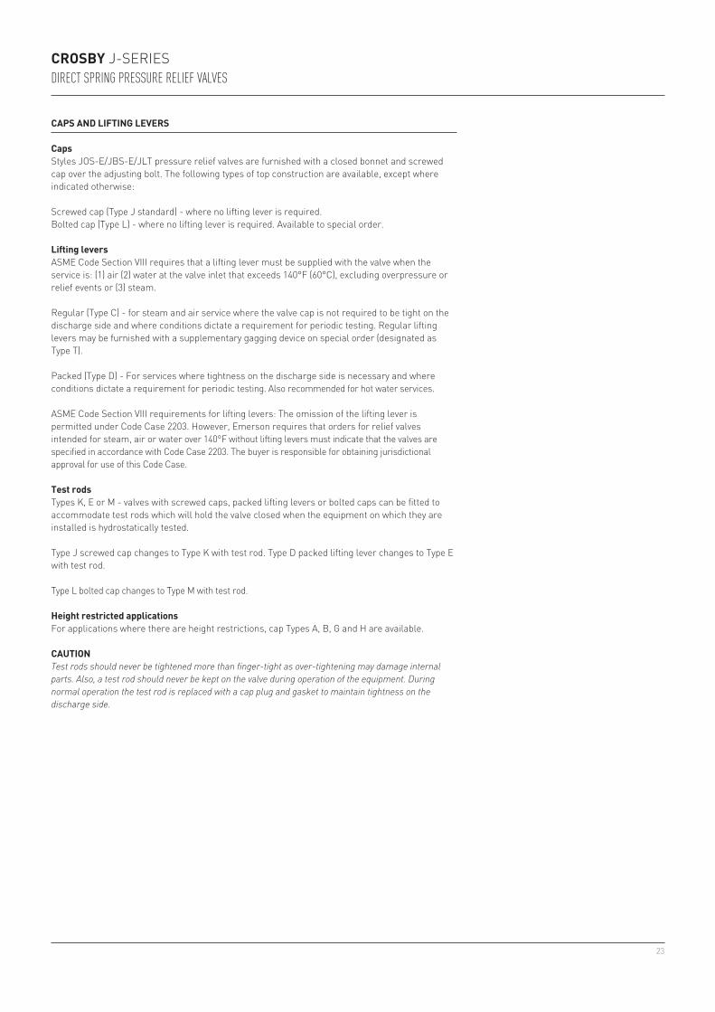
CapsStyles JOS-E/JBS-E/JLT pressure relief valves are furnished with a closed bonnet and screwed cap over the adjusting bolt. The following types of top construction are available, except where indicated otherwise:
Screwed cap (Type J standard) - where no lifting lever is required.Bolted cap (Type L) - where no lifting lever is required. Available to special order.
Lifting leversASME Code Section VIII requires that a lifting lever must be supplied with the valve when the service is: (1) air (2) water at the valve inlet that exceeds 140°F (60°C), excluding overpressure or relief events or (3) steam.
Regular (Type C) - for steam and air service where the valve cap is not required to be tight on the discharge side and where conditions dictate a requirement for periodic testing. Regular lifting levers may be furnished with a supplementary gagging device on special order (designated as Type T).
Packed (Type D) - For services where tightness on the discharge side is necessary and where conditions dictate a requirement for periodic testing. Also recommended for hot water services.
ASME Code Section VIII requirements for lifting levers: The omission of the lifting lever is permitted under Code Case 2203. However, Emerson requires that orders for relief valves intended for steam, air or water over 140°F without lifting levers must indicate that the valves are specified in accordance with Code Case 2203. The buyer is responsible for obtaining jurisdictional approval for use of this Code Case.
Test rodsTypes K, E or M - valves with screwed caps, packed lifting levers or bolted caps can be fitted to accommodate test rods which will hold the valve closed when the equipment on which they are installed is hydrostatically tested.
Type J screwed cap changes to Type K with test rod. Type D packed lifting lever changes to Type E with test rod.
Type L bolted cap changes to Type M with test rod.
Height restricted applicationsFor applications where there are height restrictions, cap Types A, B, G and H are available.
CAUTIONTest rods should never be tightened more than finger-tight as over-tightening may damage internal parts. Also, a test rod should never be kept on the valve during operation of the equipment. During normal operation the test rod is replaced with a cap plug and gasket to maintain tightness on the discharge side.

24
CROSBY J-SERIESDIRECT SPRING PRESSURE RELIEF VALVES
NOTES1. Special material valves ( )( )M1 and ( )( )H1 use caps and lifting gear of standard materials.2. Packing gland construction is standard for special material valves.3. Type C cap not available in M4, M5, M6, M, H4, H5, H6 or H material options.
Part name
Standard material Variations from standard materialsJOS/JBS-( )5,6,7-20°F to 1000°F(-29°C to 538°C)
JOS/JBS-( )4-75°F to -21°F
(-59°C to -30°C)
JOS/JBS-( )2-450°F to -76°F
(-268°C to -60°C) ( )( )S, S6 ( )( )S4( )( )M and
( )( )M5[1], M6( )( )M4 and
( ) ( )H4[1]
( )( )H and ( )( )H5[1], H6
Cap (J, K, D, E, L, M) CS 316 SS 316 SS 316 SS CS Monel® CS Hastelloy® CCap (C) Iron/steel Iron/steel 316 SS 316 SS Iron/steel [3] [3] [3]
Cap top (D, E) Steel 316 SS 316 SS 316 SS Steel Monel® Steel Hastelloy® CCap set screw (C) SS SS SS SS SS [3] [3] [3]
Cap stud Alloy steel 304 SS 304 SS 304 SS Alloy steel 304 SS Alloy steel Hastelloy® CCap stud nut Steel 304 SS 304 SS 304 SS Steel 304 SS Steel Hastelloy® CLever (D, E) Steel Steel 316 SS 316 SS Steel 316 SS Steel 316 SSLever (C) Malleable iron Malleable iron 316 SS 316 SS Malleable iron [3] [3] [3]
Forked lever (C) Malleable iron Malleable iron 316 SS 316 SS Malleable iron [3] [3] [3]
Pin (lever, forked lever) Steel Steel SS SS Steel [3] [3] [3]
Cotter Pins Steel Steel SS SS Steel SS Steel SSLever nut (D, E) Steel Steel 316 SS 316 SS 316 SS SS 316 SS 316 SSLever nut lockwasher Steel Steel SS SS Steel SS Steel SSSpindle nut Steel Steel 316 SS 316 SS 316 SS Monel® Monel® Hastelloy® CDog Steel Steel 316 SS 316 SS 316 SS Monel® Monel® Hastelloy® CDog shaft 416 SS 416 SS 316 SS 316 SS 316 SS Monel® Monel® Hastelloy® CDog shaftbearing 416 SS 416 SS [2] [2] [2] [2] [2] [2]
Dog shaft bearing O-ring FKM FKM [2] [2] [2] [2] [2] [2]
Packing gland [2] [2] 316 SS 316 SS 316 SS Monel® Monel® Monel®
Packing gland sleeve [2] [2] 316 SS 316 SS 416 SS Monel® 416 SS Monel®
Packing gland nut [2] [2] 316 SS 316 SS Steel Monel® Steel Monel®
Packing [2] [2] PTFE PTFE PTFE PTFE PTFE PTFETest rod (K, E, M) 416 SS 416 SS 416 SS 416 SS 416 SS 416 SS 416 SS 416 SSCap plug (K, E, M) 416 SS 416 SS 316 SS 316 SS 416 SS Monel® 416 SS Hastelloy® CGaskets 316SS 316SS 316SS 316SS 316SS Monel® Monel® Monel®
CAP AND LEVER MATERIALS

25
JOS-E-JBS-E-JLT-JOS-H-E-[1]
15 1D2 150 150 285 (19.6) 125 (8.62) 285 (19.6) 230 (15.8)25 1D2 300 150 285 (19.6) 285 (19.6) 285 (19.6) 230 (15.8)35 1D2 300 150 740 (51.0) 535 (36.8) 285 (19.6) 230 (15.8)45 1D2 600 150 1480 (102) 1075 (74.1) 285 (19.6) 230 (15.8)
JOS-E-JBS-E-JLT-
55 1½ D2 900 300 2220 (153) 1650 (111) 600 (41.3) 600 (41.3)65 1½ D2 1500 300 3705 (255) 2745 (185) 600 (41.3) 600 (41.3)75 1½ D3[5] 2500 300 6000 (413) 4475 (308) 740 (51.0) 600 (41.3)
JOS-E-JBS-E-JLT-
16 1D2 150 150 125 (8.62) 80 (5.51) 285 (19.6) 230 (15.8)26 1D2 300 150 285 (19.6) 285 (19.6) 285 (19.6) 230 (15.8)36 1D2 300 150 535 (36.8) 410 (28.2) 285 (19.6) 230 (15.8)46 1D2 600 150 1075 (74.1) 825 (56.8) 285 (19.6) 230 (15.8)
JOS-E-JBS-E-JLT-
56 1½ D2 900 300 1650 (111) 1235 (85.1) 600 (41.3) 600 (41.3)66 1½ D2 1500 300 2745 (185) 2060 (142) 600 (41.3) 600 (41.3)76 1½ D3[5] 2500 300 4475 (308) 3430 (236) 740 (51.0) 600 (41.3)
JOS-E-JBS-E-JLT-
37 1D2 300 150 510 (35.1) 215 (14.8) 285 (19.6) 230 (15.8)47 1D2 600 150 1015 (70) 430 (29.6) 285 (19.6) 230 (15.8)
JOS-E-JBS-E-JLT-
57 1½ D2 900 300 1525 (105) 650 (44.8) 600 (41.3) 600 (41.3)67 1½ D2 1500 300 2540 (175) 1080 (74.4) 600 (41.3) 600 (41.3)77 1½ D3[5] 2500 300 4230 (291) 1800 (124) 740 (51.0) 600 (41.3)
JOS-E-JBS-E-JLT-
14 1D2 150 150 275 (18.9) 275 (18.9) 230 (15.8)24 1D2 300 150 275 (18.9) 275 (18.9) 230 (15.8)34 1D2 300 150 720 (49.6) 275 (18.9) 230 (15.8)44 1D2 600 150 1440 (99.3) 275 (18.9) 230 (15.8)
JOS-E-JBS-E-JLT-
12 1D2 150 150 275 (18.9) 275 (18.9) 230 (15.8)22 1D2 300 150 275 (18.9) 275 (18.9) 230 (15.8)32 1D2 300 150 720 (49.6) 275 (18.9) 230 (15.8)42 1D2 600 150 1440 (99.3) 275 (18.9) 230 (15.8)
JOS-E-, JBS-E-, JLT-, JOS-H-E-12, 14, 15, 16, 22, 24, 25, 26
4⅛ (105) 4½ (114) 1 9/16 (40) 16¾ (426) 19¾ (502) 19 (483) 19½ (495) 36 (16)
32, 34, 35, 36, 37
4⅛ (105) 4½ (114) 1 9/16 (40) 16¾ (426) 19¾ (502) 19 (483) 19½ (495) 36 (16)
42, 44, 45, 46, 47
4⅛ (105) 4½ (114) 1 9/16 (40) 16¾ (426) 19¾ (502) 19 (483) 19½ (495) 36 (16)
JOS-E-, JBS-E-, JLT-55, 56, 57, 65, 66, 67
4⅛ (105) 5½ (140) 2 (51) 17½ (445) 20½ (521) 19¾ (502) 20¼ (514) 65 (29)
75, 76, 77[5] 5½ (140) 7 (178) 2½ (64) 18¾ (477) 21¾ (552) 21 (533) 21½ (546) 75 (34)
CROSBY J-SERIESDIRECT SPRING PRESSURE RELIEF VALVES
D ORIFICE, 0.110 sq.in. (71 sq.mm) API EFFECTIVE AREA
Valve series
Valve size Inlet X
Orifice X Outlet
Standard connections ANSI flanges raised face
Maximum set pressure psig (barg) Back press. limit at 100°F psig (38°C barg)
Inlet-450°F to -76°F
(-268°C to -60°C)-75°F to -21°F
(-59°C to -30°C)-20°F to +100°F(-29°C to +38°C)
+650°F[1]
(+343°C[1])+800°F
(+427°C)+1000°F(+538°C)Inlet Outlet JOS[2] JBS[2]
SIZES AND PRESSURE/TEMPERATURE LIMITS
NOTES1. Upper temperature limit of JOS-H-E-15, 25, 35 and 45 valves is +800°F (+427°C).2. Outlet pressure for temperatures above +100°F (+38°C) should not exceed the ANSI flange rating.3. Valves set below 15 psig (1.03 barg) cannot be stamped with the ASME Code Symbol. Only metal seated
valves may be set below 15 psig.4. Series designations: JLTJOS-E and JLTJBS-E signify Series JOS-E, JBS-E with liquid trim for liquid and
gas service.5. Optional 2½” outlet available. Contact the factory for dimensions.
LOW SET PRESSURE LIMITS
JOS-E 10 psig (0.68 barg)JBS-E 15 psig (1.72 barg)JLTJOS-E 15 psig (1.03 barg)JLTJBS-E 25 psig (1.72 barg)
Type J (Threaded Cap)Type C (Regular Lifting Lever) Also JOS-H-EType D (Packed Lifting Lever)Type L (Bolted Cap)
DIMENSIONS AND WEIGHTS
Valve series
Valve dimensions, inches (mm) Approx. weight lbs (kg)
TypeCenter to face Use to find
bolt lengthApproximate height
Inlet Outlet Valve (cap) typeE F X A and G J and L C D J
Valve height

26
36 46
12/22
443414/24
3515
32 42
25
45
26164737
-500
-400
-300
-200
-100
0
100
200
300
400
500
600
700
800
900
1000
0 200 400 600 800 1000 1200 1400
-100
0
100
200
300
400
500
600
700
800
900
1000
0 500 1000 1500 2000 2500 3000 3500 4000 4500 5000 5500 6000
57 67 77
766656
55 65 75
CROSBY J-SERIESDIRECT SPRING PRESSURE RELIEF VALVES
PRESSURE/TEMPERATURE LIMIT CHART - ANSI CLASS 900, CLASS 1500, CLASS 2500D Orifice, 0.110 sq.in. [71 sq.mm] API effective area
PRESSURE/TEMPERATURE LIMIT CHART - TO ANSI CLASS 600D Orifice, 0.110 sq.in. [71 sq.mm] API effective area
Inle
t tem
pera
ture
(°F)
Inle
t tem
pera
ture
(°F)
Set pressure (psig)
Set pressure (psig)

27
JOS-E-JBS-E-JLT-JOS-H-E-[1]
15 1E2 150 150 285 (19.6) 125 (8.62) 285 (19.6) 230 (15.8)25 1E2 300 150 285 (19.6) 285 (19.6) 285 (19.6) 230 (15.8)35 1E2 300 150 740 (51.0) 535 (36.8) 285 (19.6) 230 (15.8)45 1E2 600 150 1480 (102) 1075 (74.1) 285 (19.6) 230 (15.8)
JOS-E-JBS-E-JLT-
55 1½ E2 900 300 2220 (153) 1650 (111) 600 (41.3) 600 (41.3)65 1½ E2 1500 300 3705 (255) 2745 (185) 600 (41.3) 600 (41.3)75 1½ E3[5] 2500 300 6000 (413) 4475 (308) 740 (51.0) 600 (41.3)
JOS-E-JBS-E-JLT-
16 1E2 150 150 125 (8.62) 80 (5.51) 285 (19.6) 230 (15.8)26 1E2 300 150 285 (19.6) 285 (19.6) 285 (19.6) 230 (15.8)36 1E2 300 150 535 (36.8) 410 (28.2) 285 (19.6) 230 (15.8)46 1E2 600 150 1075 (74.1) 825 (56.8) 285 (19.6) 230 (15.8)
JOS-E-JBS-E-JLT-
56 1½ E2 900 300 1650 (111) 1235 (85.1) 600 (41.3) 600 (41.3)66 1½ E2 1500 300 2745 (185) 2060 (142) 600 (41.3) 600 (41.3)76 1½ E3[5] 2500 300 4475 (308) 3430 (236) 740 (51.0) 600 (41.3)
JOS-E-JBS-E-JLT-
37 1E2 300 150 510 (35.1) 215 (14.8) 285 (19.6) 230 (15.8)47 1E2 600 150 1015 (70) 430 (29.6) 285 (19.6) 230 (15.8)
JOS-E-JBS-E-JLT-
57 1½ E2 900 300 1525 (105) 650 (44.8) 600 (41.3) 600 (41.3)67 1½ E2 1500 300 2540 (175) 1080 (74.4) 600 (41.3) 600 (41.3)77 1½ E3[5] 2500 300 4230 (291) 1800 (124) 740 (51.0) 600 (41.3)
JOS-E-JBS-E-JLT-
14 1E2 150 150 275 (18.9) 275 (18.9) 230 (15.8)24 1E2 300 150 275 (18.9) 275 (18.9) 230 (15.8)34 1E2 300 150 720 (49.6) 275 (18.9) 230 (15.8)44 1E2 600 150 1440 (99.3) 275 (18.9) 230 (15.8)
JOS-E-JBS-E-JLT-
12 1E2 150 150 275 (18.9) 275 (18.9) 230 (15.8)22 1E2 300 150 275 (18.9) 275 (18.9) 230 (15.8)32 1E2 300 150 720 (49.6) 275 (18.9) 230 (15.8)42 1E2 600 150 1440 (99.3) 275 (18.9) 230 (15.8)
JOS-E-, JBS-E-, JLT-, JOS-H-E-12, 14, 15, 16, 22, 24, 25, 26
4⅛ (105) 4½ (114) 1 9/16 (40) 16¾ (426) 19¾ (502) 19 (483) 19½ (495) 36 (16)
32, 34, 35, 36, 37
4⅛ (105) 4½ (114) 1 9/16 (40) 16¾ (426) 19¾ (502) 19 (483) 19½ (495) 36 (16)
42, 44, 45, 46, 47
4⅛ (105) 4½ (114) 1 9/16 (40) 16¾ (426) 19¾ (502) 19 (483) 19½ (495) 36 (16)
JOS-E-, JBS-E-, JLT-55, 56, 57, 65, 66, 67
4⅛ (105) 5½ (140) 2 (51) 17½ (445) 20½ (521) 19¾ (502) 20¼ (514) 65 (29)
75, 76, 77[5] 5½ (140) 7 (178) 2½ (64) 18¾ (477) 21¾ (552) 21 (533) 21½ (546) 75 (34)
CROSBY J-SERIESDIRECT SPRING PRESSURE RELIEF VALVES
SIZES AND PRESSURE/TEMPERATURE LIMITS
NOTES1. Upper temperature limit of JOS-H-E-15, 25, 35 and 45 valves is +800°F (+427°C).2. Outlet pressure for temperatures above +100°F (+38°C) should not exceed the ANSI flange rating.3. Valves set below 15 psig (1.03 barg) cannot be stamped with the ASME Code Symbol. Only metal seated
valves may be set below 15 psig.4. Series designations: JLTJOS-E and JLTJBS-E signify Series JOS-E, JBS-E with liquid trim for liquid and gas
service.5. Optional 2½” outlet available. Contact the factory for dimensions.
E ORIFICE, 0.196 sq.in. (126 sq.mm) API EFFECTIVE AREA
Valve series
Valve size Inlet X
Orifice X Outlet
Standard connections ANSI
flanges raised face
Maximum set pressure psig (barg) Back press. limit at 100°F psig (38°C barg)
Inlet-450°F to -76°F
(-268°C to -60°C)-75°F to -21°F
(-59°C to -30°C)-20°F to +100°F(-29°C to +38°C)
+650°F[1]
(+343°C[1])+800°F
(+427°C)+1000°F(+538°C)Inlet Outlet JOS[2] JBS[2]
LOW SET PRESSURE LIMITS
JOS-E 8 psig (0.55 barg)JBS-E 15 psig (1.72 barg)JLTJOS-E 15 psig (1.03 barg)JLTJBS-E 25 psig (1.72 barg)
Type J (Threaded Cap)Type C (Regular Lifting Lever) Also JOS-H-EType D (Packed Lifting Lever)Type L (Bolted Cap)
DIMENSIONS AND WEIGHTS
Valve series
Valve dimensions, inches (mm) Approx. weight lbs (kg) type
Center to face Use to find bolt length
Approximate heightInlet Outlet Valve (cap) type
E F X A and G J and L C D J Valve height

28
12/22
443414/24
3515
32 42
2545
36 462616
4737
-500
-400
-300
-200
-100
0
100
200
300
400
500
600
700
800
900
1000
0 200 400 600 800 1000 1200 1400
-100
0
100
200
300
400
500
600
700
800
900
1000
0 500 1000 1500 2000 2500 3000 3500 4000 4500 5000 5500 6000
766656
776757
756555
CROSBY J-SERIESDIRECT SPRING PRESSURE RELIEF VALVES
PRESSURE/TEMPERATURE LIMIT CHART - TO ANSI CLASS 600E Orifice, 0.196 sq.in. (126 sq.mm) API effective area
PRESSURE/TEMPERATURE LIMIT CHART - ANSI CLASS 900, CLASS 1500, CLASS 2500E Orifice, 0.196 sq.in. (126 sq.mm) API effective area
Inle
t tem
pera
ture
(°F)
Inle
t tem
pera
ture
(°F)
Set pressure (psig)
Set pressure (psig)

29
JOS-E-JBS-E-JLT-JOS-H-E-[1]
15 1½ F2 150 150 285 (19.6) 125 (8.62) 285 (19.6) 230 (15.8)25 1½ F2 300 150 285 (19.6) 285 (19.6) 285 (19.6) 230 (15.8)35 1½ F2 300 150 740 (51.0) 535 (36.8) 285 (19.6) 230 (15.8)45 1½ F2 600 150 1480 (102) 1075 (74.1) 285 (19.6) 230 (15.8)
JOS-E-JBS-E-JLT-
55 1½ F3[5] 900 300 2220 (153) 1650 (111) 740 (51.0) 500 (34.4)65 1½ F3[5] 1500 300 3705 (255) 2745 (185) 740 (51.0) 500 (34.4)75 1½ F3[5] 2500 300 5000 (344) 4475 (308) 740 (51.0) 500 (34.4)
JOS-E-JBS-E-JLT-
16 1½ F2 150 150 125 (8.62) 80 (5.51) 285 (19.6) 230 (15.8)26 1½ F2 300 150 285 (19.6) 285 (19.6) 285 (19.6) 230 (15.8)36 1½ F2 300 150 535 (36.8) 410 (28.2) 285 (19.6) 230 (15.8)46 1½ F2 600 150 1075 (74.1) 825 (56.8) 285 (19.6) 230 (15.8)
JOS-E-JBS-E-JLT-
56 1½ F3[5] 900 300 1650 (111) 1235 (85.1) 740 (51.0) 500 (34.4)66 1½ F3[5] 1500 300 2745 (185) 2060 (142) 740 (51.0) 500 (34.4)76 1½ F3[5] 2500 300 4475 (308) 3430 (236) 740 (51.0) 500 (34.4)
JOS-E-JBS-E-JLT-
37 1½ F2 300 150 510 (35.1) 215 (14.8) 285 (19.6) 230 (15.8)47 1½ F2 600 150 1015 (70) 430 (29.6) 285 (19.6) 230 (15.8)
JOS-E-JBS-E-JLT-
57 1½ F3[5] 900 300 1525 (105) 650 (44.8) 740 (51.0) 500 (34.4)67 1½ F3[5] 1500 300 2540 (175) 1080 (74.4) 740 (51.0) 500 (34.4)77 1½ F3[5] 2500 300 4230 (291) 1800 (124) 740 (51.0) 500 (34.4)
JOS-E-JBS-E-JLT-
14 1½ F2 150 150 275 (18.9) 275 (18.9) 230 (15.8)24 1½ F2 300 150 275 (18.9) 275 (18.9) 230 (15.8)34 1½ F2 300 150 720 (49.6) 275 (18.9) 230 (15.8)44 1½ F2 600 150 1440 (99.3) 275 (18.9) 230 (15.8)
JOS-E-JBS-E-JLT-
12 1½ F2 150 150 275 (18.9) 275 (18.9) 230 (15.8)22 1½ F2 300 150 275 (18.9) 275 (18.9) 230 (15.8)32 1½ F2 300 150 720 (49.6) 275 (18.9) 230 (15.8)42 1½ F2 600 150 1440 (99.3) 275 (18.9) 230 (15.8)
JOS-E-, JBS-E-, JLT-, JOS-H-E-12, 14, 15, 16, 22, 24, 25, 26
4⅞ (124) 4¾ (121) 1¾ (44) 20¼ (515) 23¼ (591) 22½ (572) 23¼ (591) 50 (23)
32, 34, 35, 36, 37
4⅞ (124) 6 (152) 1¾ (44) 20¼ (515) 23¼ (591) 22½ (572) 23¼ (591) 50 (23)
42, 44, 45, 46, 47
4⅞ (124) 6 (152) 1¾ (44) 20¼ (515) 23¼ (591) 22½ (572) 23¼ (591) 50 (23)
55, 56, 57, 65, 66, 67
4⅞ (124) 6½ (165) 2 (51) 20 (508) 23 (584) 21¼ (540) 21¾ (552) 65 (29)
75, 76, 77[5] 5½ (140) 7 (178) 2½ (64) 23 (584) 26¾ (679) 26 (660) 26¾ (679) 85 (39)
CROSBY J-SERIESDIRECT SPRING PRESSURE RELIEF VALVES
NOTES1. Upper temperature limit of JOS-H-E-15, 25, 35 and 45 valves is +800°F (+427°C).2. Outlet pressure for temperatures above +100°F (+38°C) should not exceed the ANSI flange rating.3. Valves set below 15 psig (1.03 barg) cannot be stamped with the ASME Code Symbol. Only metal seated
valves may be set below 15 psig.4. Series designations: JLTJOS-E and JLTJBS-E signify Series JOS-E, JBS-E with liquid trim for liquid and gas
service.5. Optional 2½” outlet available. Contact the factory for dimensions.
SIZES AND PRESSURE/TEMPERATURE LIMITS
F ORIFICE, 0.307 sq.in. (198 sq.mm) API EFFECTIVE AREA
Valve series
Valve size Inlet X
Orifice X Outlet
Standard connections ANSI
flanges raised face
Maximum set pressure psig (barg) Back press. limit at100°F psig(38°C barg)
Inlet-450°F to -76°F
(-268°C to -60°C)-75°F to -21°F
(-59°C to -30°C)-20°F to +100°F(-29°C to +38°C)
+650°F[1]
(+343°C[1])+800°F
(+427°C)+1000°F(+538°C)Inlet Outlet JOS[2] JBS[2]
LOW SET PRESSURE LIMITS
JOS-E 5 psig (0.34 barg)JBS-E 10 psig (0.68 barg)JLTJOS-E 15 psig (1.03 barg)JLTJBS-E 25 psig (1.72 barg)
Type J (Threaded Cap)Type C (Regular Lifting Lever) Also JOS-H-EType D (Packed Lifting Lever)Type L (Bolted Cap)
DIMENSIONS AND WEIGHTS
Valve series
Valve dimensions, inches (mm) Approx. weight lbs (kg)
typeCenter to face Use to find
bolt lengthApproximate height
Inlet Outlet Valve (cap) type E F X A and G J and L C D J
Valve height

30
-500
-400
-300
-200
-100
0
100
200
300
400
500
600
700
800
900
1000
200 400 600 800 1000 1200 14000
12/22
443414/24
3515
32 42
25
36 462616
4737
45
500 1000 1500 2000 2500 3000 3500 4000 4500 5000-100
0
100
200
300
400
500
600
700
800
900
1000
0
766656
776757
756555
CROSBY J-SERIESDIRECT SPRING PRESSURE RELIEF VALVES
PRESSURE/TEMPERATURE LIMIT CHART - ANSI CLASS 900, CLASS 1500, CLASS 2500F Orifice, 0.307 sq.in. (198 sq.mm) API effective area
Inle
t tem
pera
ture
(°F)
Inle
t tem
pera
ture
(°F)
Set pressure (psig)
Set pressure (psig)
PRESSURE/TEMPERATURE LIMIT CHART - TO ANSI CLASS 600F Orifice, 0.307 sq.in. (198 sq.mm) API effective area

31
JOS-E-JBS-E-JLT-JOS-H-E-[1]
15 1½ G3[5] 150 150 285 (19.6) 125 (8.62) 285 (19.6) 230 (15.8)25 1½ G3[5] 300 150 285 (19.6) 285 (19.6) 285 (19.6) 230 (15.8)35 1½ G3[5] 300 150 740 (51.0) 535 (36.8) 285 (19.6) 230 (15.8)45 1½ G3[5] 600 150 1480 (102) 1075 (74.1) 285 (19.6) 230 (15.8)
JOS-E-JBS-E-JLT-
55 1½ G3[5] 900 300 2220 (153) 1650 (111) 740 (51.0) 470 (32.4)65 2G3 1500 300 3705 (255) 2745 (185) 740 (51.0) 470 (32.4)75 2G3 2500 300 3705 (255) 3705 (255) 740 (51.0) 470 (32.4)
JOS-E-JBS-E-JLT-
16 1½ G3[5] 150 150 125 (8.62) 80 (5.51) 285 (19.6) 230 (15.8)26 1½ G3[5] 300 150 285 (19.6) 285 (19.6) 285 (19.6) 230 (15.8)36 1½ G3[5] 300 150 535 (36.8) 410 (28.2) 285 (19.6) 230 (15.8)46 1½ G3[5] 600 150 1075 (74.1) 825 (56.8) 285 (19.6) 230 (15.8)
JOS-E-JBS-E-JLT-
56 1½ G3[5] 900 300 1650 (111) 1235 (85.1) 740 (51.0) 470 (32.4)66 2G3 1500 300 2745 (185) 2060 (142) 740 (51.0) 470 (32.4)76 2G3 2500 300 3705 (255) 3430 (236) 740 (51.0) 470 (32.4)
JOS-E-JBS-E-JLT-
37 1½ G3[5] 300 150 510 (35.1) 215 (14.8) 285 (19.6) 230 (15.8)47 1½ G3[5] 600 150 1015 (70) 430 (29.6) 285 (19.6) 230 (15.8)
JOS-E-JBS-E-JLT-
57 1½ G3[5] 900 300 1525 (105) 650 (44.8) 740 (51.0) 470 (32.4)67 2G3 1500 300 2540 (175) 1080 (74.4) 740 (51.0) 470 (32.4)77 2G3 2500 300 3750 (255) 1800 (124) 740 (51.0) 500 (32.4)
JOS-E-JBS-E-JLT-
14 1½ G3[5] 150 150 275 (18.9) 275 (18.9) 230 (15.8)24 1½ G3[5] 300 150 275 (18.9) 275 (18.9) 230 (15.8)34 1½ G3[5] 300 150 720 (49.6) 275 (18.9) 230 (15.8)44 1½ G3[5] 600 150 1440 (99.3) 275 (18.9) 230 (15.8)
JOS-E-JBS-E-JLT-
12 1½ G3[5] 150 150 275 (18.9) 275 (18.9) 230 (15.8)22 1½ G3[5] 300 150 275 (18.9) 275 (18.9) 230 (15.8)32 1½ G3[5] 300 150 720 (49.6) 275 (18.9) 230 (15.8)42 1½ G3[5] 600 150 1440 (99.3) 275 (18.9) 230 (15.8)
JOS-E, JBS-E, JLT-, JOS-H-E12, 14, 15, 16, 22, 24, 25, 26[5]
4⅞ (124) 4¾ (121) 1¾ (44) 20¼ (515) 23¼ (591) 22½ (572) 23¼ (591) 50 (23)
32, 34, 35, 36, 37, 47[5]
4⅞ (124) 6 (152) 1¾ (44) 20¼ (515) 23¼ (591) 22½ (572) 23¼ (591) 50 (23)
42, 44, 45, 46[5] 4⅞ (124) 6 (152) 1¾ (44) 20¼ (515) 23¼ (591) 22½ (572) 23¼ (591) 50 (23)55, 56, 57[5] 4⅞ (124) 6½ (165) 2 (51) 22¼ (566) 26 (660) 25¼ (641) 26 (660) 70 (32)65, 66, 67, 75, 76, 77
6⅛ (155) 6¾ (171) 2¾ (70) 23¼ (591) 27 (686) 26¼ (667) 27 (686) 90 (41)
CROSBY J-SERIESDIRECT SPRING PRESSURE RELIEF VALVES
SIZES AND PRESSURE/TEMPERATURE LIMITS
NOTES1. Upper temperature limit of JOS-H-E-15, 25, 35 and 45 valves is +800°F (+427°C).2. Outlet pressure for temperatures above +100°F (+38°C) should not exceed the ANSI flange rating.3. Valves set below 15 psig (1.03 barg) cannot be stamped with the ASME Code Symbol. Only metal seated
valves may be set below 15 psig.4. Series designations: JLTJOS-E and JLTJBS-E signify Series JOS-E, JBS-E with liquid trim for liquid and gas
service.5. Optional 2½” outlet available. Contact the factory for dimensions.
G ORIFICE, 0.503 sq.in. (325 sq.mm) API EFFECTIVE AREA
Valve series
Valve size Inlet X
Orifice X Outlet
Standard connections ANSI
flanges raised face
Maximum set pressure psig (barg) Back press. limit at100°F psig(38°C barg)
Inlet-450°F to -76°F
(-268°C to -60°C)-75°F to -21°F
(-59°C to -30°C)-20°F to +100°F(-29°C to +38°C)
+650°F[1]
(+343°C[1])+800°F
(+427°C)+1000°F(+538°C)Inlet Outlet JOS[2] JBS[2]
LOW SET PRESSURE LIMITS
JOS-E 5 psig (0.34 barg)JBS-E 15 psig (1.03 barg)JLTJOS-E 15 psig (1.03 barg)JLTJBS-E 25 psig (1.72 barg)
Type J (Threaded Cap)Type C (Regular Lifting Lever) Also JOS-H-EType D (Packed Lifting Lever)Type L (Bolted Cap)
Valve height
DIMENSIONS AND WEIGHTS
Valve series
Valve dimensions, inches (mm) Approx. weight lbs (kg)
typeCenter to face Use to find
bolt lengthApproximate height
Inlet Outlet Valve (cap) type E F X A and G J and L C D J

32
-500
-400
-300
-200
-100
0
100
200
300
400
500
600
700
800
900
1000
0 200 400 600 800 1000 1200 1400
12/22
443414/24
3515
32 42
25 45
3646
2616
4737
0 500 1000 1500 2000 2500 3000 3500 4000-100
0
100
200
300
400
500
600
700
800
900
1000
766656
776757
756555
CROSBY J-SERIESDIRECT SPRING PRESSURE RELIEF VALVES
PRESSURE/TEMPERATURE LIMIT CHART - TO ANSI CLASS 600G Orifice, 0.503 sq.in. (325 sq.mm) API effective area
PRESSURE/TEMPERATURE LIMIT CHART - ANSI CLASS 900, CLASS 1500, CLASS 2500G Orifice, 0.503 sq.in. (325 sq.mm) API effective area
Inle
t tem
pera
ture
(°F)
Inle
t tem
pera
ture
(°F)
Set pressure (psig)
Set pressure (psig)

33
JOS-E-JBS-E-JLT-JOS-H-E-[1]
15 1½ H3 150 150 285 (19.6) 125 (8.62) 285 (19.6) 230 (15.8)25 1½ H3 300 150 285 (19.6) 285 (19.6) 285 (19.6) 230 (15.8)35 2H3 300 150 740 (51.0) 535 (36.8) 285 (19.6) 230 (15.8)45 2H3 600 150 1480 (102) 1075 (74.1) 285 (19.6) 230 (15.8)
JOS-E-JBS-E-JLT-
55 2H3 900 150 2220 (153) 1650 (111) 285 (19.6) 230 (15.8)65 2H3 1500 300 2750 (189) 2685 (185) 740 (51.0) 415 (28.6)
JOS-E-JBS-E-JLT-
16 1½ H3 150 150 125 (8.62) 80 (5.51) 285 (19.6) 230 (15.8)26 1½ H3 300 150 285 (19.6) 285 (19.6) 285 (19.6) 230 (15.8)36 2H3 300 150 535 (36.8) 410 (28.2) 285 (19.6) 230 (15.8)46 2H3 600 150 1075 (74.1) 825 (56.8) 285 (19.6) 230 (15.8)
JOS-E-JBS-E-JLT-
56 2H3 900 150 1610 (111) 1235 (85.1) 285 (19.6) 230 (15.8)66 2H3 1500 300 2685 (185) 2060 (142) 740 (51.0) 415 (28.6)
JOS-E-JBS-E-JLT-
37 2H3 300 150 510 (35.1) 215 (14.8) 285 (19.6) 230 (15.8)47 2H3 600 150 815 (56.2) 430 (29.6) 285 (19.6) 230 (15.8)
JOS-E-JBS-E-JLT-
57 2H3 900 150 1225 (84.4) 650 (44.8) 285 (19.6) 230 (15.8)67 2H3 1500 300 2040 (140) 1080 (74.4) 740 (51.0) 415 (28.6)
JOS-E-JBS-E-JLT-
14 1½ H3 150 150 275 (18.9) 275 (18.9) 230 (15.8)24 1½ H3 300 150 275 (18.9) 275 (18.9) 230 (15.8)34 2H3 300 150 720 (49.6) 275 (18.9) 230 (15.8)44 2H3 600 150 1440 (99.3) 275 (18.9) 230 (15.8)
JOS-E-JBS-E-JLT-
12 1½ H3 150 150 275 (18.9) 275 (18.9) 230 (15.8)22 1½ H3 300 150 275 (18.9) 275 (18.9) 230 (15.8)32 2H3 300 150 720 (49.6) 275 (18.9) 230 (15.8)42 2H3 600 150 1440 (99.3) 275 (18.9) 230 (15.8)
JOS-E-, JBS-E-, JLT-, JOS-H-E-12, 14, 15, 16, 22, 24, 25, 26
5⅛ (130) 4⅞ (124) 1 11/16 (43) 20½ (521) 23½ (597) 22¾ (578) 23¼ (591) 55 (25)
32, 34, 35, 36, 37, 47
5⅛ (130) 4⅞ (124) 1 13/16 (46) 20½ (521) 23½ (597) 22¾ (578) 23¼ (591) 60 (27)
42, 44, 45, 46 6 1/16 (154) 6⅜ (162) 1 13/16 (46) 23 (585) 26¾ (679) 26 (660) 26¾ (679) 75 (34)55, 56, 57, 65, 66, 67
6 1/16 (154) 6⅜ (162) 2 5/16 (59) 24½ (623) 28¼ (718) 27½ (699) 28¼ (718) 100 (50)
CROSBY J-SERIESDIRECT SPRING PRESSURE RELIEF VALVES
SIZES AND PRESSURE/TEMPERATURE LIMITS
NOTES1. Upper temperature limit of JOS-H-E-15, 25, 35 and 45 valves is +800°F (+427°C).2. Outlet pressure for temperatures above +100°F (+38°C) should not exceed the ANSI flange rating.3. Valves set below 15 psig (1.03 barg) cannot be stamped with the ASME Code Symbol. Only metal seated
valves may be set below 15 psig.4. Series designations: JLTJOS-E and JLTJBS-E signify Series JOS-E, JBS-E with liquid trim for liquid and
gas service.
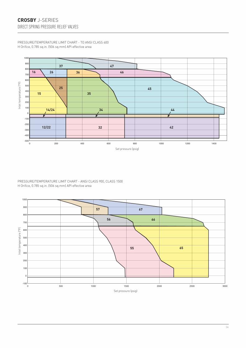
H ORIFICE, 0.785 sq.in. (506 sq.mm) API EFFECTIVE AREA
Valve series
Valve size Inlet X
Orifice X Outlet
Standard connections ANSI
flanges raised face
Maximum set pressure psig (barg) Back press. limit at100°F psig(38°C barg)
Inlet-450°F to -76°F
(-268°C to -60°C)-75°F to -21°F
(-59°C to -30°C)-20°F to +100°F(-29°C to +38°C)
+650°F[1]
(+343°C[1])+800°F
(+427°C)+1000°F(+538°C)Inlet Outlet JOS[2] JBS[2]
LOW SET PRESSURE LIMITS
JOS-E 5 psig (0.34 barg)JBS-E 10 psig (0.68 barg)JLTJOS-E 15 psig (1.03 barg)JLTJBS-E 25 psig (1.72 barg)
Valve height
Type J (Threaded Cap)Type C (Regular Lifting Lever) Also JOS-H-EType D (Packed Lifting Lever)Type L (Bolted Cap)
DIMENSIONS AND WEIGHTS
Valve series
Valve dimensions, inches (mm) Approx. weight lbs (kg)
type Center to face Use to find
bolt lengthApproximate height
Inlet Outlet Valve (cap) type E F X A and G J and L C D J
34
200 400 600 800 1000 1200 14000-500
-400
-300
-200
-100
0
100
200
300
400
500
600
700
800
900
1000
12/22
443414/24
3515
32 42
25 45
36 4626164737
-100
0
100
200
300
400
500
600
700
800
900
1000
0
6656
6757
6555
500 1000 1500 2000 2500 3000
CROSBY J-SERIESDIRECT SPRING PRESSURE RELIEF VALVES
PRESSURE/TEMPERATURE LIMIT CHART - TO ANSI CLASS 600H Orifice, 0.785 sq.in. (506 sq.mm) API effective area
PRESSURE/TEMPERATURE LIMIT CHART - ANSI CLASS 900, CLASS 1500H Orifice, 0.785 sq.in. (506 sq.mm) API effective area
Inle
t tem
pera
ture
(°F)
Inle
t tem
pera
ture
(°F)
Set pressure (psig)
Set pressure (psig)

35
JOS-E-JBS-E-JLT-JOS-H-E-[1]
15 2J3 150 150 285 (19.6) 125 (8.62) 285 (19.6) 230 (15.8)25 2J3 300 150 285 (19.6) 285 (19.6) 285 (19.6) 230 (15.8)35 3J4[5] 300 150 740 (51.0) 535 (36.8) 285 (19.6) 230 (15.8)45 3J4[5] 600 150 1480 (102) 1075 (74.1) 285 (19.6) 230 (15.8)
JOS-E-JBS-E-JLT-
55 3J4 900 150 2220 (153) 1650 (111) 285 (19.6) 230 (15.8)65 3J4 1500 300 2700 (186) 2685 (185) 600 (41.3) 230 (15.8)
JOS-E-JBS-E-JLT-
16 2J3 150 150 125 (8.62) 80 (5.51) 285 (19.6) 230 (15.8)26 2J3 300 150 285 (19.6) 285 (19.6) 285 (19.6) 230 (15.8)36 3J4[5] 300 150 535 (36.8) 410 (28.2) 285 (19.6) 230 (15.8)46 3J4[5] 600 150 1075 (74.1) 825 (56.8) 285 (19.6) 230 (15.8)
JOS-E-JBS-E-[5]
JLT-
56 3J4 900 150 1610 (111) 1235 (85.1) 285 (19.6) 230 (15.8)66 3J4 1500 300 2685 (186) 2060 (142) 600 (41.3) 230 (15.8)
JOS-E-JBS-E-JLT-
37 3J4[5] 300 150 510 (35.1) 215 (14.8) 285 (19.6) 230 (15.8)47 3J4 600 150 815 (56.2) 430 (29.6) 285 (19.6) 230 (15.8)
JOS-E-JBS-E-JLT-
57 3J4[5] 900 150 1225 (84.4) 650 (44.8) 285 (19.6) 230 (15.8)67 3J4 1500 300 2040 (140) 1080 (74.4) 600 (41.3) 230 (15.8)
JOS-E-JBS-E-JLT-
14 2J3 150 150 275 (18.9) 275 (18.9) 230 (15.8)24 2J3 300 150 275 (18.9) 275 (18.9) 230 (15.8)34 3J4[5] 300 150 720 (49.6) 275 (18.9) 230 (15.8)44 3J4[5] 600 150 1440 (99.3) 275 (18.9) 230 (15.8)
JOS-E-JBS-E-JLT-
12 2J3 150 150 275 (18.9) 275 (18.9) 230 (15.8)22 2J3 300 150 275 (18.9) 275 (18.9) 230 (15.8)32 3J4[5] 300 150 500 (34.4) 275 (18.9) 230 (15.8)42 3J4[5] 600 150 625 (43.1) 275 (18.9) 230 (15.8)
JOS-E-, JBS-E-, JLT-, JOS-H-E-12, 14, 15, 16, 22, 24, 25, 26
5⅜ (137) 4⅞ (124) 1 11/16 (43) 20¾ (527) 23¾ (603) 23¼ (591) 23¾ (603) 66 (30)
32, 34, 35, 36,37, 47
7¼ (184) 7⅛ (181) 2¼ (57) 24⅝ (632) 28⅝ (727) 27⅞ (703) 28⅝ (727) 100 (45)
42, 44, 45, 46 7¼ (184) 7⅛ (181) 2¼ (57) 26⅞ (683) 30⅝ (773) 29⅞ (759) 30⅝ (778) 128 (57)57 7¼ (184) 7⅛ (181) 2 11/16 (68) 26⅝ (683) 30⅝ (773) 29⅞ (759) 30⅝ (778) 151 (68)55, 56, 65, 66, 67 7¼ (184) 7⅛ (181) 2 11/16 (68) 28¾ (826) 32½ (826) 31¾ (806) 32½ (826) 155 (70)
CROSBY J-SERIESDIRECT SPRING PRESSURE RELIEF VALVES
SIZES AND PRESSURE/TEMPERATURE LIMITS
NOTES1. Upper temperature limit of JOS-H-E-15, 25, 35 and 45 valves is +800°F (+427°C).2. Outlet pressure for temperatures above +100°F (+38°C) should not exceed the ANSI flange rating.3. Valves set below 15 psig (1.03 barg) cannot be stamped with the ASME Code Symbol. Only metal seated
valves may be set below 15 psig.4. Series designations: JLTJOS-E and JLTJBS-E signify Series JOS-E, JBS-E with liquid trim for liquid and
gas service.5. Optional 2½” inlet available. Contact the factory for dimensions.
J ORIFICE, 1.287 sq.in. (830 sq.mm) API EFFECTIVE AREA
Valve series
Valve size Inlet X
Orifice X Outlet
Standard connections ANSI
flanges raised face
Maximum set pressure psig (barg) Back press. limit at100°F psig(38°C barg)
Inlet-450°F to -76°F
(-268°C to -60°C)-75°F to -21°F
(-59°C to -30°C)-20°F to +100°F(-29°C to +38°C)
+650°F[1]
(+343°C[1])+800°F
(+427°C)+1000°F(+538°C)Inlet Outlet JOS[2] JBS[2]
LOW SET PRESSURE LIMITS
JOS-E 5 psig (0.34 barg)JBS-E 9 psig (0.62 barg)JLTJOS-E 15 psig (1.03 barg)JLTJBS-E 25 psig (1.72 barg)
Type J (Threaded Cap)Type C (Regular Lifting Lever) Also JOS-H-EType D (Packed Lifting Lever)Type L (Bolted Cap)
DIMENSIONS AND WEIGHTS
Valve series
Valve dimensions, inches (mm) Approx. weight lbs (kg)
typeCenter to face Use to find
bolt lengthApproximate height
Inlet Outlet Valve (cap) type E F X A and G J and L C D J
Valve height

36
200 400 600 800 1000 1200 14000
0
100
200
300
400
500
600
700
800
900
1000
-100
-200
-300
-400
-500
12/22
443414/24
32 42
351525 45
36 4626164737
0 500 1000 1500 2000 2500 3000-100
0
100
200
300
400
500
600
700
800
900
1000
6656
6757
6555
CROSBY J-SERIESDIRECT SPRING PRESSURE RELIEF VALVES
PRESSURE/TEMPERATURE LIMIT CHART - TO ANSI CLASS 600J Orifice, 1.287 sq.in. (830 sq.mm) API effective area
PRESSURE/TEMPERATURE LIMIT CHART - ANSI CLASS 900, CLASS 1500J Orifice, 1.287 sq.in. (830 sq.mm) API effective area
Inle
t tem
pera
ture
(°F)
Inle
t tem
pera
ture
(°F)
Set pressure (psig)
Set pressure (psig)

37
JOS-E-JBS-E-JLT-JOS-H-E-[1]
15 3K4 150 150 285 (19.6) 125 (8.62) 285 (19.6) 150 (10.3)25 3K4 300 150 285 (19.6) 285 (19.6) 285 (19.6) 150 (10.3)35 3K4 300 150 740 (51.0) 535 (36.8) 285 (19.6) 150 (10.3)45 3K4 600 150 1480 (102) 1075 (74.1) 285 (19.6) 200 (13.7)
JOS-E-JBS-E-JLT-
55 3K6 900 150 2220 (153) 1610 (111) 285 (19.6) 200 (13.7)65 3K6 1500 300 2220 (153) 2220 (153) 600 (41.3) 200 (13.7)
JOS-E-JBS-E-JLT-
16 3K4 150 150 125 (8.62) 80 (5.51) 285 (19.6) 150 (10.3)26 3K4 300 150 285 (19.6) 285 (19.6) 285 (19.6) 150 (10.3)36 3K4 300 150 535 (36.8) 410 (28.2) 285 (19.6) 150 (10.3)46 3K4 600 150 1075 (74.1) 825 (56.8) 285 (19.6) 200 (13.7)
JOS-E-JBS-E-JLT-
56 3K6 900 150 1610 (127) 1235 (85.1) 285 (19.6) 200 (13.7)66 3K6 1500 300 2220 (153) 2060 (142) 600 (41.3) 200 (13.7)
JOS-E-JBS-E-JLT-
37 3K4 300 150 510 (35.1) 215 (14.8) 285 (19.6) 150 (10.3)47 3K4 600 150 815 (56.2) 430 (29.6) 285 (19.6) 200 (13.7)
JOS-E-JBS-E-JLT-
57 3K6 900 150 1225 (84.4) 650 (44.8) 285 (19.6) 200 (13.7)67 3K6 1500 300 2040 (140) 1080 (74.4) 600 (41.3) 200 (13.7)
JOS-E-JBS-E-JLT-
14 3K4 150 150 275 (18.9) 275 (18.9) 150 (10.3)24 3K4 300 150 275 (18.9) 275 (18.9) 150 (10.3)34 3K4 300 150 720 (49.6) 275 (18.9) 150 (10.3)44 3K4 600 150 1440 (99.3) 275 (18.9) 200 (13.7)
JOS-E-JBS-E-JLT-
12 3K4 150 150 275 (18.9) 275 (18.9) 150 (10.3)22 3K4 300 150 275 (18.9) 275 (18.9) 150 (10.3)32 3K4 300 150 525 (36.2) 275 (18.9) 150 (10.3)42 3K4 600 150 600 (41.3) 275 (18.9) 200 (13.7)
JOS-E-, JBS-E-, JLT-, JOS-H-E-12, 14, 15, 16, 22, 24, 25, 26
6⅛ (156) 6⅜ (162) 2⅛ (54) 26 (661) 29¾ (756) 29 (737) 29¾ (756) 116 (52)
32, 34, 35, 36, 37, 47
6⅛ (156) 6⅜ (162) 2⅛ (54) 26 (661) 29¾ (756) 29 (737) 29¾ (756) 117 (53)
42, 44, 45, 46 7¼ (184) 7⅛ (181) 2⅛ (54) 29¼ (743) 33 (838) 32½ (826) 33¼ (845) 160 (73)55, 56, 57 7 13/16 (198) 8½ (216) 2 11/16 (68) 33½ (851) 39 (991) 38 (965) 38¾ (984) 185 (84)65, 66, 67 7¾ (197) 8½ (216) 211/16 (68) 33½ (851) 39 (991) 38 (965) 38¾ (984) 195 (88)
CROSBY J-SERIESDIRECT SPRING PRESSURE RELIEF VALVES
SIZES AND PRESSURE/TEMPERATURE LIMITS
NOTES1. Upper temperature limit of JOS-H-E-15, 25, 35 and 45 valves is +800°F (+427°C).2. Outlet pressure for temperatures above +100°F (+38°C) should not exceed the ANSI flange rating.3. Valves set below 15 psig (1.03 barg) cannot be stamped with the ASME Code Symbol. Only metal seated
valves may be set below 15 psig.4. Series designations: JLTJOS-E and JLTJBS-E signify Series JOS-E, JBS-E with liquid trim for liquid and gas
service.
K ORIFICE, 1.838 sq.in. (1186 sq.mm) API EFFECTIVE AREA
Valve series
Valve size Inlet X
Orifice X Outlet
Standard connections ANSI
flanges raised face
Maximum set pressure psig (barg) Back press. limit at100°F psig(38°C barg)
Inlet-450°F to -76°F
(-268°C to -60°C)-75°F to -21°F
(-59°C to -30°C)-20°F to +100°F(-29°C to +38°C)
+650°F[1]
(+343°C[1])+800°F
(+427°C)+1000°F(+538°C)Inlet Outlet JOS[2] JBS[2]
LOW SET PRESSURE LIMITS
JOS-E 5 psig (0.34 barg)JBS-E 9 psig (0.62 barg)JLTJOS-E 15 psig (1.03 barg)JLTJBS-E 25 psig (1.72 barg)
Type J (Threaded Cap)Type C (Regular Lifting Lever) Also JOS-H-EType D (Packed Lifting Lever)Type L (Bolted Cap)
Valve heightDIMENSIONS AND WEIGHTS
Valve series
Valve dimensions, inches (mm) Approx. weight lbs (kg)
typeCenter to face Use to find
bolt lengthApproximate height
Inlet Outlet Valve (cap) type E F X A and G J and L C D J

38
0 200 400 600 800 1000 1200 1400 -500
-400
-300
-200
-100
0
100
200
300
400
500
600
700
800
900
1000
12/22
14/24
15
16
34
32 42
44
45
4647
35
3637
25
26
0 500 1000 1500 2000 -100
0
100
200
300
400
500
600
700
800
900
1000
6656
6757
65
55
CROSBY J-SERIESDIRECT SPRING PRESSURE RELIEF VALVES
PRESSURE/TEMPERATURE LIMIT CHART - TO ANSI CLASS 600K Orifice, 1.838 sq.in. (1186 sq.mm) API effective area
PRESSURE/TEMPERATURE LIMIT CHART - ANSI CLASS 900, CLASS 1500K Orifice, 1.838 sq.in. (1186 sq.mm) API effective area
Inle
t tem
pera
ture
(°F)
Inle
t tem
pera
ture
(°F)
Set pressure (psig)
Set pressure (psig)

39
JOS-E-JBS-E-JLT-JOS-H-E-[1]
15 3L4 150 150 285 (19.6) 125 (8.62) 285 (19.6) 100 (6.89)25 3L4 300 150 285 (19.6) 285 (19.6) 285 (19.6) 100 (6.89)35 4L6 300 150 740 (51.0) 535 (36.8) 285 (19.6) 170 (11.7)45 4L6 600 150 1000 (68.9) 1000 (68.9) 285 (19.6) 170 (11.7)
JOS-E-JBS-E-JLT-
55 4L6 900 150 1500 (103) 1500 (103) 285 (19.6) 170 (11.7)
JOS-E-JBS-E-JLT-
16 3L4 150 150 125 (8.62) 80 (5.51) 285 (19.6) 100 (6.89)26 3L4 300 150 285 (19.6) 285 (19.6) 285 (19.6) 100 (6.89)36 4L6 300 150 535 (36.8) 410 (28.2) 285 (19.6) 170 (11.7)46 4L6 600 150 1000 (68.9) 825 (56.8) 285 (19.6) 170 (11.7)
JOS-E-JBS-E-JLT-
56 4L6 900 150 1500 (103) 1235 (85.1) 285 (19.6) 170 (11.7)66 4L6 1500 150 1500 (103) 1500 (103) 285 (19.6) 170 (11.7)
JOS-E-JBS-E-JLT-
37 4L6 300 150 510 (35.1) 215 (14.8) 285 (19.6) 170 (11.7)47 4L6 600 150 1000 (68.9) 430 (29.6) 285 (19.6) 170 (11.7)
JOS-E-JBS-E-JLT-
57 4L6 900 150 1500 (103) 650 (44.8) 285 (19.6) 170 (11.7)67 4L6 1500 150 1500 (103) 1080 (74.4) 285 (19.6) 170 (11.7)
JOS-E-JBS-E-JLT-
14 3L4 150 150 275 (18.9) 275 (18.9) 100 (6.89)24 3L4 300 150 275 (18.9) 275 (18.9) 100 (6.89)34 4L6 300 150 720 (49.6) 275 (18.9) 170 (11.7)44 4L6 600 150 1000 (68.9) 275 (18.9) 170 (11.7)
JOS-E-JBS-E-JLT-
12 3L4 150 150 275 (18.9) 275 (18.9) 100 (6.89)22 3L4 300 150 275 (18.9) 275 (18.9) 100 (6.89)32 4L6 300 150 535 (36.8) 275 (18.9) 170 (11.7)42 4L6 600 150 535 (36.8) 275 (18.9) 170 (11.7)
JOS-E-, JBS-E-, JLT-, JOS-H-E-12, 14, 15, 16, 22, 24, 25, 26
6⅛ (156) 6½ (165) 2 (51) 30¼ (769) 34 (864) 33¼ (845) 34 (864) 152 (69)
32, 34, 35, 36, 37
7 1/16 (179) 7⅛ (181) 2⅛ (54) 30¼ (769) 34 (864) 34¼ (870) 34¼ (870) 192 (87)
42, 44, 45, 46, 47
7 1/16 (179) 8 (203) 2⅜ (60) 31½ (801) 35¼ (895) 34¾ (883) 35¼ (895) 226 (103)
55, 56, 57, 66, 67
7¾ (197) 8¾ (222) 2 15/16 (75) 34¼ (871) 39¾ (1010) 38¾ (984) 39½ (1003) 270 (122)
CROSBY J-SERIESDIRECT SPRING PRESSURE RELIEF VALVES
SIZES AND PRESSURE/TEMPERATURE LIMITS
NOTES1. Upper temperature limit of JOS-H-E-15, 25, 35 and 45 valves is +800°F (+427°C).2. Outlet pressure for temperatures above +100°F (+38°C) should not exceed the ANSI flange rating.3. Valves set below 15 psig (1.03 barg) cannot be stamped with the ASME Code Symbol. Only metal seated
valves may be set below 15 psig.4. Series designations: JLTJOS-E and JLTJBS-E signify Series JOS-E, JBS-E with liquid trim for liquid and
gas service.
L ORIFICE, 2.853 sq.in. (1841 sq.mm) API EFFECTIVE AREA
Valve series
Valve size Inlet X
Orifice X Outlet
Standard connections ANSI
flanges raised face
Maximum set pressure psig (barg) Back press. limit at100°F psig(38°C barg)
Inlet-450°F to -76°F
(-268°C to -60°C)-75°F to -21°F
(-59°C to -30°C)-20°F to +100°F(-29°C to +38°C)
+650°F[1]
(+343°C[1])+800°F
(+427°C)+1000°F(+538°C)Inlet Outlet JOS[2] JBS[2]
LOW SET PRESSURE LIMITS
JOS-E 6 psig (0.41 barg)JBS-E 8 psig (0.55 barg)JLTJOS-E 15 psig (1.03 barg)JLTJBS-E 25 psig (1.72 barg)
Type J (Threaded Cap)Type C (Regular Lifting Lever) Also JOS-H-EType D (Packed Lifting Lever)Type L (Bolted Cap)
Valve heightDIMENSIONS AND WEIGHTS
Valve series
Valve dimensions, inches (mm) Approx. weight lbs (kg)
typeCenter to face Use to find
bolt lengthApproximate height
Inlet Outlet Valve (cap) typeE F X A and G J and L C D J

40
200 400 600 800 1000 1200 1400 1600
5636 462616
574737
12/22
443414/24
3515
32/42
25
45 55
-5000
-400
-300
-200
-100
0
100
200
300
400
500
600
700
800
900
1000
66
CROSBY J-SERIESDIRECT SPRING PRESSURE RELIEF VALVES
PRESSURE/TEMPERATURE LIMIT CHART L Orifice, 2.853 sq.in. [1841 sq.mm] API effective area
Inle
t tem
pera
ture
(°F)
Set pressure (psig)

41
JOS-E-JBS-E-JLT-JOS-H-E-[1]
15 4M6 150 150 285 (19.6) 125 (8.62) 285 (19.6) 80 (5.51)25 4M6 300 150 285 (19.6) 285 (19.6) 285 (19.6) 80 (5.51)35 4M6 300 150 740 (51.0) 535 (36.8) 285 (19.6) 160 (11.0)45 4M6 600 150 1100 (75.8) 1075 (74.1) 285 (19.6) 160 (11.0)
JOS-E-JBS-E-JLT-
16 4M6 150 150 125 (8.62) 80 (5.51) 285 (19.6) 80 (5.51)26 4M6 300 150 285 (19.6) 285 (19.6) 285 (19.6) 80 (5.51)36 4M6 300 150 535 (36.8) 410 (28.2) 285 (19.6) 160 (11.0)46 4M6 600 150 1075 (74.1) 825 (56.8) 285 (19.6) 160 (11.0)
JOS-E-JBS-E-JLT-
56 4M6 900 150 1100 (75.8) 1100 (75.8) 285 (19.6) 160 (11.0)
JOS-E-JBS-E-JLT-
37 4M6 300 150 510 (35.1) 215 (14.8) 285 (19.6) 160 (11.0)47 4M6 600 150 1015 (70) 430 (29.6) 285 (19.6) 160 (11.0)
JOS-E-JBS-E-JLT-
57 4M6 900 1501100
(75.8)650 (44.8) 285 (19.6) 160 (11.0)
JOS-E-JBS-E-JLT-
14 4M6 150 150 275 (18.9) 275 (18.9) 80 (5.51)24 4M6 300 150 275 (18.9) 275 (18.9) 80 (5.51)34 4M6 300 150 720 (49.6) 275 (18.9) 160 (11.0)44 4M6 600 150 1100 (75.8) 275 (18.9) 160 (11.0)
JOS-E-JBS-E-JLT-
12 4M6 150 150 275 (18.9) 275 (18.9) 80 (5.51)22 4M6 300 150 275 (18.9) 275 (18.9) 80 (5.51)32 4M6 300 150 525 (36.2) 275 (18.9) 160 (11.0)42 4M6 600 150 600 (41.3) 275 (18.9) 160 (11.0)
JOS-E-, JBS-E-, JLT-, JOS-H-E-12, 14, 15, 16, 22, 24, 25, 26
7 (178) 7¼ (184) 2⅛ (54) 29¾(756)
33½(851)
33(838)
33¾(857)
201 (91)
32, 34, 35, 36, 37
7 (178) 7¼ (184) 2⅛ (54) 32¼(820)
36(914)
35½(902)
36(914)
222 (101)
42, 44, 45, 46, 47
7 (178) 8 (203) 2 7/16 (62) 36½(925)
42(1067)
41(1041)
41¾(1060)
265 (120)
56, 57 7¾ (197) 8¾ (222) 2 9/16 (65) 37¼(947)
42¾(1086)
41¾(1060)
42½(1080)
290 (132)
CROSBY J-SERIESDIRECT SPRING PRESSURE RELIEF VALVES
SIZES AND PRESSURE/TEMPERATURE LIMITS
NOTES1. Upper temperature limit of JOS-H-E-15, 25, 35 and 45 valves is +800°F (+427°C).2. Outlet pressure for temperatures above +100°F (+38°C) should not exceed the ANSI flange rating.3. Valves set below 15 psig (1.03 barg) cannot be stamped with the ASME Code Symbol. Only metal seated
valves may be set below 15 psig.4. Series designations: JLTJOS-E and JLTJBS-E signify Series JOS-E, JBS-E with liquid trim for liquid and
gas service.
M ORIFICE, 3.60 sq.in. (2323 sq.mm) API EFFECTIVE AREA
Valve series
Valve size Inlet X
Orifice X Outlet
Standard connections ANSI
flanges raised face
Maximum set pressure psig (barg) Back press. limit at100°F psig(38°C barg)
Inlet-450°F to -76°F
(-268°C to -60°C)-75°F to -21°F
(-59°C to -30°C)-20°F to +100°F(-29°C to +38°C)
+650°F[1]
(+343°C[1])+800°F
(+427°C)+1000°F(+538°C)Inlet Outlet JOS[2] JBS[2]
LOW SET PRESSURE LIMITS
JOS-E 8 psig (0.55 barg)JBS-E 10 psig (0.68 barg)JLTJOS-E 15 psig (1.03 barg)JLTJBS-E 25 psig (1.72 barg)
Type J (Threaded Cap)Type C (Regular Lifting Lever) Also JOS-H-EType D (Packed Lifting Lever)Type L (Bolted Cap)
DIMENSIONS AND WEIGHTS
Valve series
Valve dimensions, inches (mm) Approx. weight lbs (kg)
typeCenter to face Use to find
bolt lengthApproximate height
Inlet Outlet Valve (cap) typeE F X A and G J and L C D J
Valve height

42
200 400 600 800 1000 1200-500
-400
-300
-200
-100
0
100
200
300
400
500
600
700
800
900
1000
0
12/22
443414/24
15
32 42
35
25 45
5636 462616
574737
CROSBY J-SERIESDIRECT SPRING PRESSURE RELIEF VALVES
PRESSURE/TEMPERATURE LIMIT CHART M Orifice, 3.60 sq.in. (2323 sq.mm) API effective area
Inle
t tem
pera
ture
(°F)
Set pressure (psig)

43
JOS-E-JBS-E-JLT-JOS-H-E-[1]
15 4N6 150 150 285 (19.6) 125 (8.62) 285 (19.6) 80 (5.51)25 4N6 300 150 285 (19.6) 285 (19.6) 285 (19.6) 80 (5.51)35 4N6 300 150 740 (51.0) 535 (36.8) 285 (19.6) 160 (11.0)45 4N6 600 150 1000 (68.9) 1000 (68.9) 285 (19.6) 160 (11.0)
JOS-E-JBS-E-JLT-
16 4N6 150 150 125 (8.62) 80 (5.51) 285 (19.6) 80 (5.51)26 4N6 300 150 285 (19.6) 285 (19.6) 285 (19.6) 80 (5.51)36 4N6 300 150 535 (36.8) 410 (28.2) 285 (19.6) 160 (11.0)46 4N6 600 150 1000 (68.9) 825 (56.8) 285 (19.6) 160 (11.0)
JOS-E-JBS-E-JLT-
37 4N6 300 150 510 (35.1) 215 (14.8) 285 (19.6) 160 (11.0)47 4N6 600 150 1000 (68.9) 430 (29.6) 285 (19.6) 160 (11.0)
JOS-E-JBS-E-JLT-
14 4N6 150 150 275 (18.9) 275 (18.9) 80 (5.51)24 4N6 300 150 275 (18.9) 275 (18.9) 80 (5.51)34 4N6 300 150 720 (49.6) 275 (18.9) 160 (11.0)44 4N6 600 150 1000 (68.9) 275 (18.9) 160 (11.0)
JOS-E-JBS-E-JLT-
12 4N6 150 150 275 (18.9) 275 (18.9) 80 (5.51)22 4N6 300 150 275 (18.9) 275 (18.9) 80 (5.51)32 4N6 300 150 450 (31.0) 275 (18.9) 160 (11.0)42 4N6 600 150 500 (34.4) 275 (18.9) 160 (11.0)
JOS-E-, JBS-E-, JLT-, JOS-H-E-12, 14, 15, 16, 22, 24, 25, 26
7¾ (197) 8¼ (210) 2⅛ (54) 37¾(959)
43¼(1099)
42¼(1073)
43(1092)
260(118)
32, 34, 35, 36, 37
7¾ (197) 8¼ (210) 2⅛ (54) 37¾(959)
43¼(1099)
42¼(1073)
43(1092)
280(127)
42, 44, 45, 46, 47
7¾ (197) 8¾ (222) 2⅜ (60) 37¾(959)
43¼(1099)
42¼(1073)
43(1092)
297(135)
CROSBY J-SERIESDIRECT SPRING PRESSURE RELIEF VALVES
SIZES AND PRESSURE/TEMPERATURE LIMITS
NOTES1. Upper temperature limit of JOS-H-E-15, 25, 35 and 45 valves is +800°F (+427°C).2. Outlet pressure for temperatures above +100°F (+38°C) should not exceed the ANSI flange rating.3. Valves set below 15 psig (1.03 barg) cannot be stamped with the ASME Code Symbol. Only metal seated
valves may be set below 15 psig.4. Series designations: JLTJOS-E and JLTJBS-E signify Series JOS-E, JBS-E with liquid trim for liquid and
gas service.
N ORIFICE, 4.34 sq.in. (2800 sq.mm) API EFFECTIVE AREA
Valve series
Valve size Inlet X
Orifice X Outlet
Standard connections ANSI
flanges raised face
Maximum set pressure psig (barg) Back press. limit at100°F psig(38°C barg)
Inlet-450°F to -76°F
(-268°C to -60°C)-75°F to -21°F
(-59°C to -30°C)-20°F to +100°F(-29°C to +38°C)
+650°F[1]
(+343°C[1])+800°F
(+427°C)+1000°F(+538°C)Inlet Outlet JOS[2] JBS[2]
LOW SET PRESSURE LIMITS
JOS-E 8 psig (0.55 barg)JBS-E 10 psig (0.68 barg)JLTJOS-E 15 psig (1.03 barg)JLTJBS-E 25 psig (1.72 barg)
Type J (Threaded Cap)Type C (Regular Lifting Lever) Also JOS-H-EType D (Packed Lifting Lever)Type L (Bolted Cap)
DIMENSIONS AND WEIGHTS
Valve series
Valve dimensions, inches (mm) Approx. weight lbs (kg)
typeCenter to face Use to find
bolt lengthApproximate height
Inlet Outlet Valve (cap) typeE F X A and G J and L C D J
Valve height

44
200 400 600 800 1000 12000-500
-400
-300
-200
-100
0
100
200
300
400
500
600
700
800
900
1000
44
3515
25 45
36 462616
4737
3414/24
12/22 32 42
CROSBY J-SERIESDIRECT SPRING PRESSURE RELIEF VALVES
PRESSURE/TEMPERATURE LIMIT CHART N Orifice, 4.34 sq.in. (2800 sq.mm) API effective area
Inle
t tem
pera
ture
(°F)
Set pressure (psig)

45
JOS-E-JBS-E-JLT-JOS-H-E-[1]
15 4P6 150 150 285 (19.6) 125 (8.6) 285 (19.6) 80 (5.51)25 4P6 300 150 285 (19.6) 285 (19.6) 285 (19.6) 80 (5.51)35 4P6 300 150 525 (36.2) 525 (36.2) 285 (19.6) 150 (10.3)45 4P6 600 150 1000 (68.9) 1000 (68.9) 285 (19.6) 150 (10.3)55 4P6 900 150 1000 (68.9) 1000 (68.9) 285 (19.6) 150 (10.3)
JOS-E-JBS-E-JLT-
16 4P6 150 150 125 (8.6) 80 (5.5) 285 (19.6) 80 (5.51)26 4P6 300 150 285 (19.6) 285 (19.6) 285 (19.6) 80 (5.51)36 4P6 300 150 525 (36.2) 410 (28.3) 285 (19.6) 150 (10.3)46 4P6 600 150 1000 (68.9) 825 (56.9) 285 (19.6) 150 (10.3)56 4P6 900 150 1000 (68.9) 1000 (68.9) 285 (19.6) 150 (10.3)
JOS-E-JBS-E-JLT-
37 4P6 300 150 510 (35.1) 215 (14.8) 285 (19.6) 150 (10.3)47 4P6 600 150 1000 (68.9) 430 (29.6) 285 (19.6) 150 (10.3)57 4P6 900 150 1000 (68.9) 650 (44.8) 285 (19.6) 150 (10.3)
JOS-E-JBS-E-JLT-
14 4P6 150 150 275 (19.0) 275 (18.9) 80 (5.51)24 4P6 300 150 275 (19.0) 275 (18.9) 80 (5.51)34 4P6 300 150 525 (36.2) 275 (18.9) 150 (10.3)44 4P6 600 150 1000 (68.9) 275 (18.9) 150 (10.3)
JOS-E-JBS-E-JLT-
12 4P6 150 150 175 (12.1) 275 (18.9) 80 (5.51)22 4P6 300 150 175 (12.1) 275 (18.9) 80 (5.51)32 4P6 300 150 300 (20.7) 275 (18.9) 150 (10.3)42 4P6 600 150 480 (33.1) 275 (18.9) 150 (10.3)
JOS-E-, JBS-E-, JLT-, JOS-H-E-12, 14, 15, 16, 22, 24, 25, 26
7⅛(181)
9(229)
2⅛(54)
37(940)
42½(1080)
41½(1054)
42¼(1073)
270(122)
32, 34, 35, 36, 37
8⅞(225)
10(254)
2⅛(54)
38¾(984)
44¼(1124)
43¼(1099)
44(1118)
286(130)
42, 44, 45, 46, 47
8⅞(225)
10(254)
2 9/16
(65)41(1041)
46½(1181)
45½(1156)
46¼(1175)
401(182)
55, 56, 57 8⅞(225)
10(254)
2 ⅝(67)
41(1041)
46½(1181)
45½(1156)
46¼(1175)
416(189)
CROSBY J-SERIESDIRECT SPRING PRESSURE RELIEF VALVES
SIZES AND PRESSURE/TEMPERATURE LIMITS
NOTES1. Upper temperature limit of JOS-H-E-15, 25, 35, 45 and 55 valves is +800°F (+427°C).2. Outlet pressure for temperatures above +100°F (+38°C) should not exceed the ANSI flange rating.3. Valves set below 15 psig (1.03 barg) cannot be stamped with the ASME Code Symbol. Only metal seated
valves may be set below 15 psig.4. Series designations: JLTJOS-E and JLTJBS-E signify Series JOS-E, JBS-E with liquid trim for liquid and
gas service.
P ORIFICE, 6.38 sq.in. (4116 sq.mm) API EFFECTIVE AREA
Valve series
Valve size Inlet X
Orifice X Outlet
Standard connections ANSI
flanges raised face
Maximum set pressure psig (barg) Back press. limit at100°F psig(38°C barg)
Inlet-450°F to -76°F
(-268°C to -60°C)-75°F to -21°F
(-59°C to -30°C)-20°F to +100°F(-29°C to +38°C)
+650°F[1]
(+343°C[1])+800°F
(+427°C)+1000°F(+538°C)Inlet Outlet JOS[2] JBS[2]
LOW SET PRESSURE LIMITS
JOS-E 7 psig (0.48 barg)JBS-E 8 psig (0.55 barg)JLTJOS-E 15 psig (1.03 barg)JLTJBS-E 25 psig (1.72 barg)
Type J (Threaded Cap)Type C (Regular Lifting Lever) Also JOS-H-EType D (Packed Lifting Lever)Type L (Bolted Cap)
DIMENSIONS AND WEIGHTS
Valve series
Valve dimensions, inches (mm) Approx. weight lbs (kg)
typeCenter to face Use to find
bolt lengthApproximate height
Inlet Outlet Valve (cap) typeE F X A and G J and L C D J
Valve height

46
-450
-350
-250
-150
-50
50
150
250
350
450
550
650
750
850
950
0 200 400 600 800 1000
-36 -46
-44
-45 -55
-47 -57
-56
-34
-35
-14/-24
-15
-25
-26
-37
-16
-12-22
-32 -42
CROSBY J-SERIESDIRECT SPRING PRESSURE RELIEF VALVES
PRESSURE/TEMPERATURE LIMIT CHART P Orifice, 6.38 sq.in. (4116 sq.mm) API effective area
Inle
t tem
pera
ture
(°F)
Set pressure (psig)

47
JOS-E-JBS-E-JLT-JOS-H-E-[1]
15 6Q8 150 150 165 (11.3) 125 (8.62) 115 (7.92) 70 (4.82)25 6Q8 300 150 165 (11.3) 165 (11.3) 115 (7.92) 70 (4.82)35 6Q8 300 150 300 (20.6) 300 (20.6) 115 (7.92) 115 (7.92)45 6Q8 600 150 600 (41.3) 600 (41.3) 115 (7.92) 115 (7.92)
6Q8 (HP) 600 150 1000 (68.9) 1000 (68.9) 115 (7.92) 115 (7.92)JOS-E-JBS-E-JLT-
16 6Q8 150 150 125 (8.62) 80 (5.51) 115 (7.92) 70 (4.82)26 6Q8 300 150 165 (11.3) 165 (11.3) 115 (7.92) 70 (4.82)36 6Q8 300 150 300 (20.6) 300 (20.6) 115 (7.92) 115 (7.92)46 6Q8 600 150 600 (41.3) 600 (41.3) 115 (7.92) 115 (7.92)
6Q8 (HP) 600 150 1000 (68.9) 825 (56.9) 115 (7.92) 115 (7.92)JOS-E-JBS-E-JLT-
37 6Q8 300 150 165 (11.3) 165 (11.3) 115 (7.92) 115 (7.92)47 6Q8 600 150 600 (41.3) 430 (29.6) 115 (7.92) 115 (7.92)
6Q8 (HP) 600 150 1000 (68.9) 430 (29.6) 115 (7.92) 115 (7.92)JOS-E-JBS-E-JLT-
14 6Q8 150 150 165 (11.3) 115 (7.92) 70 (4.82)24 6Q8 300 150 165 (11.3) 115 (7.92) 70 (4.82)34 6Q8 300 150 300 (20.6) 115 (7.92) 115 (7.92)44 6Q8 600 150 600 (41.3) 115 (7.92) 115 (7.92)
6Q8 (HP) 600 150 1000 (68.9) 115 (7.92) 115 (7.92)JOS-E-JBS-E-JLT-
12 6Q8 150 150 165 (11.3) 115 (7.92) 70 (4.82)22 6Q8 300 150 165 (11.3) 115 (7.92) 70 (4.82)32 6Q8 300 150 250 (17.2) 115 (7.92) 115 (7.92)42 6Q8 600 150 300 (20.6 115 (7.92) 115 (7.92)
6Q8 (HP) 600 150 561 (38.7) 115 (7.92) 115 (7.92)JOS-HP-EJBS-HP-E
42 6Q8 600 150 561 (38.7) 115 (7.92) 115 (7.92)44 6Q8 600 150 1000 (68.9) 115 (7.92) 115 (7.92)45 6Q8 600 150 1000 (68.9) 1000 (68.9) 115 (7.92) 115 (7.92)46 6Q8 600 150 1000 (68.9) 825 (56.9) 115 (7.92) 115 (7.92)47 6Q8 600 150 1000 (68.9) 430 (29.6) 115 (7.92) 115 (7.92)
JOS-E-, JBS-E-, JLT-, JOS-H-E-12, 14, 15, 16, 22, 24, 25, 26
9 7/16
(240)9½(241)
2 5/16
(59)42¼(1073)
47¾(1213)
46¾(1187)
47½(1207)
481(218)
32, 34, 35, 36, 37
9 7/16
(240)9½(241)
2 5/16
(59)42¼(1073)
47¾(1213)
46¾(1187)
47½(1207)
492(223)
42, 44, 45, 46, 47
9 7/16
(240)9½(241)
2 15/16
(75)46¼(1175)
51¾(1314)
50¾(1289)
51½(1308)
565(256)
JOS-HP-E-, JBS-HP-E-42, 44, 45, 46, 47
9 7/16
(240)9½(241)
2 15/16
(75)49¼(1251)
54¾(1391)
53¾(1340)
54½(1384)
585(265)
CROSBY J-SERIESDIRECT SPRING PRESSURE RELIEF VALVES
SIZES AND PRESSURE/TEMPERATURE LIMITS
NOTES1. Upper temperature limit of JOS-H-E-15, 25, 35 and 45 valves is +800°F (+427°C).2. Outlet pressure for temperatures above +100°F (+38°C) should not exceed the ANSI flange rating.3. Valves set below 15 psig (1.03 barg) cannot be stamped with the ASME Code Symbol. Only metal seated
valves may be set below 15 psig.4. Series designations: JLTJOS-E and JLTJBS-E signify Series JOS-E, JBS-E with liquid trim for liquid and
gas service.
Q ORIFICE, 11.05 sq.in. (7129 sq.mm) API EFFECTIVE AREA
Valve series
Valve size Inlet X
Orifice X Outlet
Standard connections ANSI
flanges raised face
Maximum set pressure psig (barg) Back press. limit at100°F psig(38°C barg)
Inlet-450°F to -76°F
(-268°C to -60°C)-75°F to -21°F
(-59°C to -30°C)-20°F to +100°F(-29°C to +38°C)
+650°F[1]
(+343°C[1])+800°F
(+427°C)+1000°F(+538°C)Inlet Outlet JOS[2] JBS[2]
LOW SET PRESSURE LIMITS
JOS-E 7 psig (0.48 barg)JBS-E 8 psig (0.55 barg)JLTJOS-E 15 psig (1.03 barg)JLTJBS-E 25 psig (1.72 barg)
DIMENSIONS AND WEIGHTS
Valve series
Valve dimensions, inches (mm) Approx. weight lbs (kg)
typeCenter to face Use to find
bolt lengthApproximate height
Inlet Outlet Valve (cap) type E F X A and G J and L C D J
Type J (Threaded Cap)Type C (Regular Lifting Lever) Also JOS-H-EType D (Packed Lifting Lever)Type L (Bolted Cap)
Valve height

48
-450
-350
-250
-150
-50
50
150
250
350
450
550
650
750
850
950
1000
0 200100 400300 600500 800 900700 1000
HP-47
HP-46
-37
-46-26-16 -36
-47
-45HP-45
-35
-15-25
-44 HP-44
-12/-22 -32 -42 HP-42
-34-14/24
CROSBY J-SERIESDIRECT SPRING PRESSURE RELIEF VALVES
Inle
t tem
pera
ture
(°F)
Set pressure (psig)
PRESSURE/TEMPERATURE LIMIT CHART Q Orifice, 11.05 sq.in. (7129 sq.mm) API effective area

49
JOS-E-JBS-E-JLT-JOS-H-E-[1]
15 6R8 150 150 100 (6.89) 100 (6.89) 60 (4.13) 50 (3.44)25 6R8 300 150 100 (6.89) 100 (6.89) 60 (4.13) 50 (3.44)35 6R10 300 150 230 (15.8) 230 (15.8) 100 (6.89) 100 (6.89)45 6R10 600 150 300 (20.6) 300 (20.6) 100 (6.89) 100 (6.89)
6R10 (HP) 600 150 850 (58.6) 850 (58.6) 100 (6.89) 100 (6.89)JOS-E-JBS-E-JLT-
16 6R8 150 150 100 (6.89) 80 (5.51) 60 (4.13) 40 (2.75)26 6R8 300 150 100 (6.89) 100 (6.89) 60 (4.13) 50 (3.44)36 6R10 300 150 230 (15.8) 230 (15.8) 100 (6.89) 100 (6.89)46 6R10 600 150 300 (20.6) 300 (20.6) 100 (6.89) 100 (6.89)
6R10 (HP) 600 150 850 (58.6) 825 (56.9) 100 (6.89) 100 (6.89)JOS-E-JBS-E-JLT-
37 6R8 300 150 100 (6.89) 100 (6.89) 60 (4.13) 50 (4.13)47 6R10 600 150 300 (20.6) 300 (20.6) 100 (6.89) 100 (6.89)
6R10 (HP) 600 150 850 (58.6) 430 (29.65) 100 (6.89) 100 (6.89)JOS-E-JBS-E-JLT-
14 6R8 150 150 100 (6.89) 60 (4.13) 50 (3.44)24 6R8 300 150 100 (6.89) 60 (4.13) 50 (3.44)34 6R10 300 150 230 (15.8) 100 (6.89) 100 (6.89)44 6R10 600 150 300 (20.6) 100 (6.89) 100 (6.89)
6R10 (HP) 600 150 850 (58.6) 100 (6.89) 100 (6.89)JOS-E-JBS-E-JLT-
12 6R8 150 150 55 (3.79) 37 (2.55) 27.5 (1.89)22 6R8 300 150 55 (3.79) 37 (2.55) 27.5 (1.89)32 6R10 300 150 150 (10.3) 100 (6.89) 75 (5.17)42 6R10 600 150 200 (13.7) 100 (6.89) 100 (6.89)
6R10 (HP) 600 150 395 (27.2) 100 (6.89) 100 (6.89)JOS-HP-EJBS-HP-E
42 6R10 600 150 395 (27.2) 100 (6.89) 100 (6.89)44 6R10 600 150 850 (58.6) 100 (6.89) 100 (6.89)45 6R10 600 150 850 (58.6) 850 (58.6) 100 (6.89) 100 (6.89)46 6R10 600 150 850 (58.6) 825 (56.9) 100 (6.89) 100 (6.89)47 6R10 600 150 850 (58.6) 430 (29.6) 100 (6.89) 100 (6.89)
JOS-E-, JBS-E-, JLT-, JOS-H-E-12, 14, 15, 16, 22, 24, 25, 26, 37
9 7/16
(240)9½(241)
2 5/16
(59)47¾(1213)
53¼(1353)
52½(1334)
53¼(1353)
564(256)
32, 34, 35, 36 9 7/16
(240)10½(267)
2 5/16
(59)47¾(1213)
53¼(1353)
52½(1334)
53¼(1353)
602(273)
42, 44, 45, 46, 47
9 7/16
(240)10½(267)
2 ¾(70)
47¾(1213)
53¼(1353)
52½(1334)
53¼(1353)
631(286)
JOS-HP-E, JBS-HP-E42, 44, 45, 46, 47
9 7/16
(240)10½(267)
2 15/16
(75)50⅞(1292)
56⅜(1432)
55⅜(1407)
56⅛(1426)
831(377)
CROSBY J-SERIESDIRECT SPRING PRESSURE RELIEF VALVES
SIZES AND PRESSURE/TEMPERATURE LIMITS
NOTES1. Upper temperature limit of JOS-H-E-15, 25, 35 and 45 valves is +800°F (+427°C).2. Outlet pressure for temperatures above +100°F (+38°C) should not exceed the ANSI flange rating.3. Valves set below 15 psig (1.03 barg) cannot be stamped with the ASME Code Symbol. Only metal seated
valves may be set below 15 psig.4. Series designations: JLTJOS-E and JLTJBS-E signify Series JOS-E, JBS-E with liquid trim for liquid and gas
service.
R ORIFICE, 16.0 sq.in. (10323 sq.mm) API EFFECTIVE AREA
Valve series
Valve size Inlet X
Orifice X Outlet
Standard connections ANSI
flanges raised face
Maximum set pressure psig (barg) Back press. limit at100°F psig(38°C barg)
Inlet-450°F to -76°F
(-268°C to -60°C)-75°F to -21°F
(-59°C to -30°C)-20°F to +100°F(-29°C to +38°C)
+650°F[1]
(+343°C[1])+800°F
(+427°C)+1000°F(+538°C)Inlet Outlet JOS[2] JBS[2]
LOW SET PRESSURE LIMITS
JOS-E 8 psig (0.55 barg)JBS-E 8 psig (0.55 barg)JLTJOS-E 15 psig (1.03 barg)JLTJBS-E 25 psig (1.72 barg)
Type J (Threaded Cap)Type C (Regular Lifting Lever) Also JOS-H-EType D (Packed Lifting Lever)Type L (Bolted Cap)
DIMENSIONS AND WEIGHTS
Valve series
Valve dimensions, inches (mm) Approx. weight lbs (kg)
typeCenter to face Use to find
bolt lengthApproximate height
Inlet Outlet Valve (cap) typeE F X A and G J and L C D J
Valve height

50
0 50 100 150 200 250 300 350 400 450 500 550 600 650 700 750 800 850 900
-450
-350
-250
-150
-50
50
150
250
350
450
550
650
750
850
950
-15
-16 -26 -36 -46
-47-37
-25
-14/-24
-35
-34 -44 HP-44
HP-45
HP-47
HP-46
-45
HP-42 42 32 -12-22
CROSBY J-SERIESDIRECT SPRING PRESSURE RELIEF VALVES
PRESSURE/TEMPERATURE LIMIT CHARTR Orifice, 16.0 sq.in. (10,323 sq.mm) API Effective Area
Inle
t tem
pera
ture
(°F)
Set pressure (psig)

51
JOS-E-JBS-E-JLT-JOS-H-E-[1]
15 8T10 150 150 65 (4.48) 65 (4.48) 30 (2.06) 30 (2.06)25 8T10 300 150 65 (4.48) 65 (4.48) 30 (2.06) 30 (2.06)35 8T10 300 150 120 (8.27) 120 (8.27) 60 (4.13) 60 (4.13)45 8T10 300 150 300 (20.6) 300 (20.6) 100 (6.89) 100 (6.89)
JOS-E-JBS-E-JLT-
16 8T10 150 150 65 (4.48) 65 (4.48) 30 (2.06) 30 (2.06)26 8T10 300 150 65 (4.48) 65 (4.48) 30 (2.06) 30 (2.06)36 8T10 300 150 120 (8.27) 120 (8.27) 60 (4.13) 60 (4.13)46 8T10 300 150 300 (20.6) 300 (20.6) 100 (6.89) 100 (6.89)
JOS-E-JBS-E-JLT-
37 8T10 300 150 300 (20.6) 215 (14.8) 60 (4.13) 60 (4.13)
JOS-E-JBS-E-JLT-
14 8T10 150 150 65 (4.48) 30 (2.06) 30 (2.06)24 8T10 300 150 65 (4.48) 30 (2.06) 30 (2.06)34 8T10 300 150 120 (8.27) 60 (4.13) 60 (4.13)
JOS-E-JBS-E-JLT-
12 8T10 150 150 50 (3.44) 30 (2.06) 25 (1.72)22 8T10 300 150 50 (3.44) 30 (2.06) 25 (1.72)32 8T10 300 150 65 (4.48) 45 (3.10) 32.5 (2.24)
JOS-E-, JBS-E-, JLT-, JOS-H-E-12, 14, 15, 16, 22, 24, 25, 26
10⅞(276)
11(279)
2 9/16
(65)54(1372)
59½(1511)
58½(1486)
59¼(1505)
882(400)
32, 34, 35, 36, 37
10⅞(276)
11(279)
2 9/16
(65)54(1372)
59½(1511)
58½(1486)
59¼(1505)
902(409)
45, 46 10⅞(276)
11(279)
2 9/16
(65)54(1372)
59½(1511)
58½(1486)
59¼(1505)
930(422)
CROSBY J-SERIESDIRECT SPRING PRESSURE RELIEF VALVES
SIZES AND PRESSURE/TEMPERATURE LIMITS
NOTES1. Upper temperature limit of JOS-H-E-15, 25, 35 and 45 valves is +800°F (+427°C).2. Outlet pressure for temperatures above +100°F (+38°C) should not exceed the ANSI flange rating.3. Valves set below 15 psig (1.03 barg) cannot be stamped with the ASME Code Symbol. Only metal seated
valves may be set below 15 psig.4. Series designations: JLTJOS-E and JLTJBS-E signify Series JOS-E, JBS-E with liquid trim for liquid and
gas service.
T ORIFICE, 26.0 sq.in. (16774 sq.mm) API EFFECTIVE AREA
Valve series
Valve size Inlet X
Orifice XOutlet
Standard connections ANSI
flanges raised face
Maximum set pressure psig (barg) Back press. limit at100°F psig(38°C barg)
Inlet-450°F to -76°F
(-268°C to -60°C)-75°F to -21°F
(-59°C to -30°C)-20°F to +100°F(-29°C to +38°C)
+650°F[1]
(+343°C[1])+800°F
(+427°C)+1000°F(+538°C)Inlet Outlet JOS[2] JBS[2]
LOW SET PRESSURE LIMITS
JOS-E 8 psig (0.55 barg)JBS-E 8 psig (0.55 barg)JLTJOS-E 15 psig (1.03 barg)JLTJBS-E 25 psig (1.72 barg)
Type J (Threaded Cap)Type C (Regular Lifting Lever) Also JOS-H-EType D (Packed Lifting Lever)Type L (Bolted Cap)
Valve height
DIMENSIONS AND WEIGHTS
Valve series
Valve dimensions, inches (mm) Approx. weight lbs (kg)
typeCenter to face Use to find
bolt lengthApproximate height
Inlet Outlet Valve (cap) typeE F X A and G J and L C D J

52
36 4616/26
37
45
3414/24
3515/25
12/22 32
100 150 200 250 300 3500 50
-500
-400
-300
-200
-100
0
100
200
300
400
500
600
700
800
900
1000
CROSBY J-SERIESDIRECT SPRING PRESSURE RELIEF VALVES
PRESSURE/TEMPERATURE LIMIT CHARTT Orifice, 26.0 sq.in. (16,774 sq.mm) API effective area
Inle
t tem
pera
ture
(°F)
Set pressure (psig)

53
JOS-E-JBS-E-JOS-H-E-[1]
15 8T210 150 150 65 (4.48) 65 (4.48) 30 (2.06) 30 (2.06)25 8T210 300 150 65 (4.48) 65 (4.48) 30 (2.06) 30 (2.06)35 8T210 300 150 120 (8.27) 120 (8.27) 60 (4.13) 60 (4.13)45 8T210 300 150 300 (20.6) 300 (20.6) 100 (6.89) 100 (6.89)
JOS-E-JBS-E-
16 8T210 150 150 65 (4.48) 65 (4.48) 30 (2.06) 30 (2.06)26 8T210 300 150 65 (4.48) 65 (4.48) 30 (2.06) 30 (2.06)36 8T210 300 150 120 (8.27) 120 (8.27) 60 (4.13) 60 (4.13)46 8T210 300 150 300 (20.6) 300 (20.6) 100 (6.89) 100 (6.89)
JOS-E-JBS-E-
37 8T210 300 150 300 (20.6) 215 (14.8) 60 (4.13) 60 (4.13)
JOS-E-JBS-E-
14 8T210 150 150 65 (4.48) 30 (2.06) 30 (2.06)24 8T210 300 150 65 (4.48) 30 (2.06) 30 (2.06)34 8T210 300 150 120 (8.27) 60 (4.13) 60 (4.13)
JOS-E-JBS-E-
12 8T210 150 150 50 (3.44) 30 (2.06) 25 (1.72)22 8T210 300 150 50 (3.44) 30 (2.06) 25 (1.72)32 8T210 300 150 65 (4.48) 45 (3.10) 32.5 (2.24)
JOS-E-, JBS-E-, JOS-H-E-12, 14, 15, 16,22, 24, 25, 26
10⅞(276)
11(279)
2 9/16
(65)54(1372)
59½(1511)
58½(1486)
59¼(1505)
882(400)
32, 34, 35, 36, 37
10⅞(276)
11(279)
2 9/16
(65)54(1372)
59½(1511)
58½(1486)
59¼(1505)
902(409)
45, 46 10⅞(276)
11(279)
2 9/16
(65)54(1372)
59½(1511)
58½(1486)
59¼(1505)
930(422)
CROSBY J-SERIESDIRECT SPRING PRESSURE RELIEF VALVES
SIZES AND PRESSURE/TEMPERATURE LIMITS
NOTES1. Upper temperature limit of JOS-H-E-15, 25, 35 and 45 valves is +800°F (+427°C).2. Outlet pressure for temperatures above +100°F (+38°C) should not exceed the ANSI flange rating.3. Valves set below 15 psig (1.03 barg) cannot be stamped with the ASME Code Symbol. Only metal seated
valves may be set below 15 psig.
T2 ORIFICE, 27.872 sq.in. (17981 sq.mm) API EFFECTIVE AREA
Valve series
Valve size Inlet X
Orifice X Outlet
Standard connections ANSI
flanges raised face
Maximum set pressure psig (barg) Back press. limit at100°F psig(38°C barg)
Inlet-450°F to -76°F
(-268°C to -60°C)-75°F to -21°F
(-59°C to -30°C)-20°F to +100°F(-29°C to +38°C)
+650°F[1]
(+343°C[1])+800°F
(+427°C)+1000°F(+538°C)Inlet Outlet JOS[2] JBS[2]
Valve height
LOW SET PRESSURE LIMITS
JOS-E 8 psig (0.55 barg)JBS-E 8 psig (0.55 barg)
DIMENSIONS AND WEIGHTS
Valve series
Valve dimensions, inches (mm) Approx. height lbs (kg)
typeCenter to face Use to find
bolt lengthApproximate height
Inlet Outlet Valve (cap) typeE F X A and G J and L C D J
Type J (Threaded Cap)Type C (Regular Lifting Lever) Also JOS-H-EType D (Packed Lifting Lever)Type L (Bolted Cap)

54
36 4616/26
37
45
3414/24
3515/25
12/22 32
100 150 200 250 300 3500 50
-500
-400
-300
-200
-100
0
100
200
300
400
500
600
700
800
900
1000
CROSBY J-SERIESDIRECT SPRING PRESSURE RELIEF VALVES
PRESSURE/TEMPERATURE LIMIT CHARTT2 Orifice, 27.872 sq.in. (17,981 sq.mm) API effective area
Inle
t tem
pera
ture
(°F)
Set pressure (psig)

55
JOS-E-JBS-E-JOS-H-E-[1]
15 10V14 150 150 100 (6.9) 100 (6.9) 60 (4.1) 60 (4.1)25 10V14 300 150 100 (6.9) 100 (6.9) 60 (4.1) 60 (4.1)35 10V14 300 150 316 (21.8) 230 (15.9) 120 (8.3) 120 (8.3)
JOS-E-JBS-E-
16 10V14 150 150 100 (6.9) 80 60 (4.1) 60 (4.1)26 10V14 300 150 100 (6.9) 100 60 (4.1) 60 (4.1)
36 10V14 300150
(120) 230 (15.9) 230 120 (8.3) 120 (8.3)
JOS-EJBS-E
37 10V14 300 150 100 100 (6.9) 60 (4.1) 60 (4.1)
JOS-E-JBS-E-
14 10V14 150 150 100 (6.9) 60 (4.1) 60 (4.1)24 10V14 300 150 (60) 100 (6.9) 60 (4.1) 60 (4.1)34 10V14 300 150 316 (21.8) 120 (8.3) 120 (8.3)
JOS-E-JBS-E-
12 10V14 150 150 70 (4.8) 60 (4.1) 42 (2.9)22 10V14 300 150 (42) 70 (4.8) 60 (4.1) 42 (2.9)32 10V14 300 150 70 (4.8) 60 (4.1) 42 (2.9)
JOS-E-, JBS-E-, JOS-H-E-12, 14, 15, 16, 12
(305)16(406)
2.93(74)
75.2(1910)
75.2(1910)
75.2(1910)
2175(918)
22, 24, 25, 26, 32, 34, 35, 36, 37
12(305)
16(406)
2.93(74)
75.2(1910)
75.2(1910)
75.2(1910)
2248(930)
CROSBY J-SERIESDIRECT SPRING PRESSURE RELIEF VALVES
SIZES AND PRESSURE/TEMPERATURE LIMITS
NOTES1. Upper temperature limit of JOS-H-E-15, 25, 35 and 45 valves is +800°F (+427°C).2. Outlet pressure for temperatures above +100°F (+38°C) should not exceed the ANSI flange rating.3. Valves set below 15 psig (1.03 barg) cannot be stamped with the ASME Code Symbol. Only metal seated
valves may be set below 15 psig.
V ORIFICE, 42.19 sq.in. (27218 sq.mm) API EFFECTIVE AREA
Valve series
Valve size Inlet X
Orifice X Outlet
Standard connections ANSI
flanges raised face
Maximum set pressure psig (barg) Back press. limit at100°F psig(38°C barg)
Inlet-450°F to -76°F
(-268°C to -60°C)-75°F to -21°F
(-59°C to -30°C)-20°F to +100°F(-29°C to +38°C)
+650°F[1]
(+343°C[1])+800°F
(+427°C)+1000°F(+538°C)Inlet Outlet JOS[2] JBS[2]
LOW SET PRESSURE LIMITS
JOS-E 13 psig (0.89 barg)JBS-E 13 psig (0.89 barg)
Type J (Threaded Cap)Type C (Regular Lifting Lever) Also JOS-H-EType D (Packed Lifting Lever)Type L (Bolted Cap)
DIMENSIONS AND WEIGHTS
Valve series
Valve dimensions, inches (mm) Approx. weight lbs (kg)
typeCenter to face Use to find
bolt lengthApproximate height
Inlet Outlet Valve (cap) typeE F X J and L C D J
Valve height

56
004053003052002051001050-450
-350
-250
-150
-50
50
150
250
350
450
550
650
750
850
950
-26-16
-37
-36
-34
-35
-12-22
-14/-24
-15-25
-32
CROSBY J-SERIESDIRECT SPRING PRESSURE RELIEF VALVES
Inle
t tem
pera
ture
(°F)
Set pressure (psig)
PRESSURE/TEMPERATURE LIMIT CHARTV Orifice, 42.19 sq.in. (27,218 sq.mm) API effective area

57
JOS-E-JBS-E-JOS-H-E-[1]
15 12W16 150 150 100 (6.9) 100 (6.9) 60 (4.1) 60 (4.1)25 12W16 300 150 100 (6.9) 100 (6.9) 60 (4.1) 60 (4.1)35 12W16 300 150 316 (21.8) 230 (15.9) 120 (8.3) 175 (12.1)
JOS-E-JBS-E-
16 12W16 150 150 100 (6.9) 80 (5.5) 60 (4.1) 60 (4.1)26 12W16 300 150 100 (6.9) 100 (6.9) 60 (4.1) 60 (4.1)36 12W16 300 150 230 (15.9) 230 (15.9) 120 (8.3) 175 (12.1)
JOS-EJBS-E
37 12W16 300 150 100 (6.9) 100 (6.9) 60 (4.1) 60 (4.1)
JOS-E-JBS-E-
14 12W16 150 150 100 (6.9) 60 (4.1) 60 (4.1)24 12W16 300 150 100 (6.9) 60 (4.1) 60 (4.1)34 12W16 300 150 316 (21.8) 120 (8.3) 175 (12.1)
JOS-E-JBS-E-
12 12W16 150 150 70 (4.8) 60 (4.1) 42 (2.9)22 12W16 300 150 70 (4.8) 60 (4.1) 42 (2.9)32 12W16 300 150 154 (10.6) 120 (4.1) 80 (2.9)
JOS-E-, JBS-E-, JOS-H-E-12, 14, 15, 16 14
(356)16(406)
3.2(81)
88(2235)
88(2235)
88(2235)
33401515
22, 24, 25, 26, 32, 34, 35, 36, 37
14(356)
16(406)
3.2(81)
88(2235)
88(2235)
88(2235)
34001542
CROSBY J-SERIESDIRECT SPRING PRESSURE RELIEF VALVES
SIZES AND PRESSURE/TEMPERATURE LIMITS
NOTES1. Upper temperature limit of JOS-H-E-15, 25, 35 and 45 valves is +800°F (+427°C).2. Outlet pressure for temperatures above +100°F (+38°C) should not exceed the ANSI flange rating.3. Valves set below 15 psig (1.03 barg) cannot be stamped with the ASME Code Symbol. Only metal seated
valves may be set below 15 psig.
W ORIFICE, 60.75 sq.in. (39193 sq.mm) API EFFECTIVE AREA
Valve series
Valve size Inlet X
Orifice X Outlet
Standard connections ANSI
flanges raised face
Maximum set pressure psig (barg) Back press. limit at100°F psig(38°C barg)
Inlet-450°F to -76°F
(-268°C to -60°C)-75°F to -21°F
(-59°C to -30°C)-20°F to +100°F(-29°C to +38°C)
+650°F[1]
(+343°C[1])+800°F
(+427°C)+1000°F(+538°C)Inlet Outlet JOS[2] JBS[2]
LOW SET PRESSURE LIMITS
JOS-E 15 psig (1.03 barg)JBS-E 15 psig (1.03 barg)
Type J (Threaded Cap)Type C (Regular Lifting Lever) Also JOS-H-EType D (Packed Lifting Lever)Type L (Bolted Cap)
DIMENSIONS AND WEIGHTS
Valve series
Valve dimensions, inches (mm) Approx. weight lbs (kg)
typeCenter to face Use to find
bolt lengthApproximate height
Inlet Outlet Valve (cap) typeE F X J and L C D J
Valve height

58
004053003052002051001050-450
-350
-250
-150
-50
50
150
250
350
450
550
650
750
850
950
-26-16
-37
-36
-34
-35
-12-22
-14/-24
-15-25
-32
CROSBY J-SERIESDIRECT SPRING PRESSURE RELIEF VALVES
Inle
t tem
pera
ture
(°F)
Set pressure (psig)
PRESSURE/TEMPERATURE LIMIT CHARTW Orifice, 60.75 sq.in. (39193 sq.mm) API effective area

59
5 124 204 319 522 747 44896 130 213 333 546 780 1210 46867 135 222 347 569 813 1261 2821 48848 90.2 141 231 361 592 845 1312 1656 1996 2936 5082 7361 11964 128249 93.7 146 240 375 615 878 1363 1720 2074 3050 5280 7648 12429 1332310 54.6 97.2 152 249 389 638 911 1414 1785 2152 3164 5477 7934 12895 1382215 64.5 114.0 179 294 459 753 1076 1670 2107 2540 3735 6466 9366 15222 16317 24807 4048720 74.3 132.0 207 339 530 868 1240 1925 2429 2929 4307 7455 10798 17550 18812 28600 4667730 94.0 167.0 262 429 670 1098 1570 2436 3074 3706 5449 9433 13663 22205 23802 36187 5905940 115.0 206.0 322 528 825 1352 1932 2997 3783 4560 6706 11608 16814 27326 29291 44532 7267850 137.0 244.0 383 627 980 1605 2294 3559 4492 5415 7962 13783 19965 32447 34780 52877 8629860 159.0 283.0 444 726 1135 1859 2656 4121 5201 6270 9219 15959 23116 37567 40269 61222 9991770 180.0 321.0 504 825 1289 2112 3018 4683 5910 7124 10476 18134 26266 42688 45758 69567 11353780 202.0 360.0 565 923 1444 2366 3380 5245 6619 7979 11732 20309 29417 47809 51247 77912 12715790 224.0 399.0 625 1022 1599 2619 3742 5807 7328 8834 12989 22485 32568 52930 56736 86257 140776100 245.0 437.0 686 1121 1753 2872 4104 6368 8037 9688 14246 24660 35719 58051 62225 94603 154396120 289.0 515.0 807 1319 2063 3379 4829 7492 9455 11397 16759 29011 42021 68292 73203 111293 181635140 332.0 592.0 928 1517 2372 3886 5553 8616 10873 13107 19273 33362 48323 78534 84181 127983 208874160 376.0 669.0 1049 1715 2682 4393 6277 9739 12291 14816 21786 37712 54624 88775 95158 144673 236113180 419.0 746.0 1170 1913 2991 4900 7001 10863 13709 16525 24299 42063 60926 99017 106136 161363 263352200 462.0 823.0 1291 2111 3300 5407 7725 11986 15127 18235 26813 46414 67228 109258 117114 178054 290591220 506.0 901.0 1412 2309 3610 5914 8449 13110 16545 19944 29326 50764 73530 119500 128092 194744 317830240 549.0 978.0 1533 2507 3919 6421 9174 14234 17963 21653 31840 55115 79832 129741 139070 211434 345069260 593.0 1055.0 1654 2705 4229 6927 9898 15357 19381 23363 34353 59466 86133 139983 150048 228124 372308280 636.0 1132.0 1775 2903 4538 7434 10622 16481 20799 25072 36866 63817 92435 150225 161026 244814 399547300 679.0 1210.0 1896 3101 4848 7941 11346 17604 22217 26781 39380 68167 98737 160466 172004 261505 426786320 723.0 1287.0 2017 3299 5157 8448 12070 18728 23635 28491 41893 72518 105039340 766.0 1364.0 2138 3497 5466 8955 12795 19852 25054 30200 44406 76869 111340360 810.0 1441.0 2259 3695 5776 9462 13519 20975 26472 31909 46920 81220 117642380 853.0 1519.0 2380 3892 6085 9969 14243 22099 27890 33619 49433 85570 123944400 896.0 1596.0 2501 4090 6395 10475 14967 23222 29308 35328 51947 89921 130246420 940.0 1673.0 2622 4288 6704 10982 15691 24346 30726 37037 54460 94272 136548440 983.0 1750.0 2743 4486 7013 11489 16416 25470 32144 38746 56973 98622 142849460 1027.0 1827.0 2864 4684 7323 11996 17140 26593 33562 40456 59487 102973 149151480 1070.0 1905.0 2986 4882 7632 12503 17864 27717 34980 42165 62000 107324 155453
CROSBY J-SERIESDIRECT SPRING PRESSURE RELIEF VALVES
AIR CAPACITIES - Series JOS-E, JBS-E, JLTJOS-E AND JLTJBS-E, USCS Units[1] (United States Customary System) Set pressures 5 - 880 psig
Set pressure(psig)
Orifice letter designation and effective area, sq.in.D E F G H J K L M N P Q R T T2 V W
0.110 0.196 0.307 0.503 0.785 1.287 1.838 2.853 3.60 4.34 6.38 11.05 16.0 26.0 27.872 42.19 60.751 psi incr. 2.2 3.9 6.1 9.9 15.5 25.3 36.2 56.2 70.9 85.5 126 218 315 512 549 835 13625 psi incr. 10.8 19.3 30.3 49.5 77.4 127 181 281 355 427 628 1088 1575 2560 2744 4173 6810
NOTES1. For air capacities, USCS units are exact equivalents of Imperial units.2. Not valid below 30 psig set pressure.3. Capacities below 30 psig set pressure are calculated at 3 psi overpressure.
* Capacity in standard cubic feet per minute of air at 60°F and 10% overpressure. Valve discharging to atmospheric pressure.
Capacities at 15 psig and above are certified by the National Board of Boiler and Pressure Vessel Inspectors and in accordance with the ASME Boiler and Pressure Vessel Code, Section VIII.
* Numbers marked bold = JOS-E only.

60
500 1113 1982 3107 5080 7942 13010 18588 28841 36398 43874 64514 111675 161755520 1157 2059 3228 5278 8251 13517 19312 29964 37816 45584 67027 116025 168056540 1200 2136 3349 5476 8561 14023 20037 31088 39234 47293 69540 120376 174358560 1244 2214 3470 5674 8870 14530 20761 32211 40652 49002 72054 124727 180660580 1287 2291 3591 5872 9179 15037 21485 33335 42070 50712 74567 129077 186962600 1330 2368 3712 6070 9489 15544 22209 34459 43488 52421 77080 133428 193263620 1374 2445 3833 6268 9798 16051 22933 35582 44906 54130 79594 137779 199565640 1417 2523 3954 6466 10108 16558 23657 36706 46324 55840 82107 142130 205867660 1461 2600 4075 6663 10417 17065 24382 37829 47742 57549 84621 146480 212169680 1504 2677 4196 6861 10727 17572 25106 38953 49160 59258 87134 150831 218471700 1547 2754 4317 7059 11036 18078 25830 40077 50578 60968 89647 155182 224772720 1591 2831 4438 7257 11345 18585 26554 41200 51996 62677 92161 159532 231074740 1634 2909 4559 7455 11655 19092 27278 42324 53414 64386 94674 163883 237376760 1678 2986 4680 7653 11964 19599 28003 43447 54832 66095 97188 168234 243678780 1721 3063 4801 7851 12274 20106 28727 44571 56250 67805 99701 172585 249979800 1764 3140 4922 8049 12583 20613 29451 45695 57668 69514 102214 176935 256281820 1808 3218 5043 8247 12892 21120 30175 46818 59086 71223 104728 181286 262583840 1851 3295 5164 8445 13202 21626 30899 47942 60504 72933 107241 185637 268885860 1895 3372 5285 8643 13511 22133 31624 49066 61922 74642 109754 189987880 1938 3449 5406 8841 13821 22640 32348 50189 63340 76351 112268 194338
CROSBY J-SERIESDIRECT SPRING PRESSURE RELIEF VALVES
AIR CAPACITIES - Series JOS-E, JBS-E, JLTJOS-E AND JLTJBS-E, USCS Units[1] (United States Customary System) Set pressures 5 - 880 psig (Continued)
Set pressure(psig)
Orifice letter designation and effective area, sq.in.D E F G H J K L M N P Q R T T2 V W
0.110 0.196 0.307 0.503 0.785 1.287 1.838 2.853 3.60 4.34 6.38 11.05 16.0 26.0 27.872 42.19 60.751 psi incr. 2.2 3.9 6.1 9.9 15.5 25.3 36.2 56.2 70.9 85.5 126 218 315 512 549 835 13625 psi incr. 10.8 19.3 30.3 49.5 77.4 127 181 281 355 427 628 1088 1575 2560 2744 4173 6810
NOTES1. For air capacities, USCS units are exact equivalents of Imperial units.2. Not valid below 30 psig set pressure.3. Capacities below 30 psig set pressure are calculated at 3 psi overpressure.
* Capacity in standard cubic feet per minute of air at 60°F and 10% overpressure. Valve discharging to atmospheric pressure.
Capacities at 15 psig and above are certified by the National Board of Boiler and Pressure Vessel Inspectors and in accordance with the ASME Boiler and Pressure Vessel Code, Section VIII.

61
900 1981 3527 5528 9039 14130 23147 33072 51313 64758 78061 114781 198689920 2025 3604 5649 9237 14440 23654 33796 52436 66176 79770 117295 203040940 2068 3681 5770 9435 14749 24161 34520 53560 67594 81479 119808 207390960 2111 3758 5891 9632 15058 24668 35244 54684 69012 83189 122321 211741980 2155 3836 6012 9830 15368 25174 35969 55807 70430 84898 124835 2160921000 2198 3913 6133 10028 15677 25681 36693 56931 71849 86607 127348 2204431100 2415 4299 6738 11018 17224 28216 40314 62549 789391200 2632 4685 7343 12008 18771 30750 43935 681671300 2849 5071 7948 12997 20319 33284 47556 737851400 3066 5457 8554 13987 21866 35819 51177 794031480 3240 5766 9038 14779 23103 37846 54073 838971500 3283 5844 9159 14977 23413 38353 547981600 3500 6230 9764 15966 24960 40887 584191700 3717 6616 10369 16956 26507 43422 620401800 3934 7002 10975 17946 28054 45956 656601900 4151 7388 11580 18935 29601 48490 692812000 4368 7774 12185 19925 31148 51024 729022100 4585 8161 12790 20915 32695 53559 765232200 4802 8547 13396 21904 34242 56093 801442300 5019 8933 14001 22894 35790 586272400 5236 9319 14606 23883 37337 611622500 5453 9705 15211 24873 38884 636962600 5670 10091 15817 25863 40431 662302700 5887 10478 16422 26852 41978 687652800 6104 10864 17027 278422900 6321 11250 17632 288323000 6538 11636 18237 298213100 6755 12022 18843 308113200 6972 12408 19448 318013300 7189 12795 20053 327903400 7406 13181 20658 337803500 7623 13567 21264 347703600 7840 13953 21869 357593700 8057 14339 22474 367493800 8274 14725 230793900 8491 15112 236854000 8708 15498 242904200 9142 16270 255004400 9576 17042 267114600 10009 17815 279214800 10443 18587 291325000 10877 19359 303425200 11311 201325500 11962 212905600 12179 216765800 12613 224496000 13047 23221
CROSBY J-SERIESDIRECT SPRING PRESSURE RELIEF VALVES
AIR CAPACITIES - Series JOS-E, JBS-E, JLTJOS-E AND JLTJBS-E, USCS Units[1] (United States Customary System) Set pressures 900 - 6000 psig
Set pressure(psig)
Orifice letter designation and effective area, sq.in.D E F G H J K L M N P Q R T T2
0.110 0.196 0.307 0.503 0.785 1.287 1.838 2.853 3.60 4.34 6.38 11.05 16.0 26.0 27.8721 psi incr. 2.2 3.9 6.1 9.9 15.5 25.3 36.2 56.2 70.9 85.5 126 218 315 512 5495 psi incr. 10.8 19.3 30.3 49.5 77.4 127 181 281 355 427 628 1088 1575 2560 2744
NOTE1. For air capacities, USCS units are exact equivalents of Imperial units.
* Capacity in standard cubic feet per minute of air at 60°F and 10% overpressure. Valve discharging to atmospheric pressure.
Capacities certified by the National Board of Boiler and Pressure Vessel Inspectors and in accordance with the ASME Boiler and Pressure Vessel Code, Section VIII.

62
5 6.9 12.3 19.3 31.6 49.4 81 116 180 227 273 402 695 1007 163610 9.8 17.5 27.4 44.7 69.9 115 164 254 320 386 568 983 1424 231415 12.0 21.4 33.5 54.8 85.6 140 200 311 392 473 696 1204 1744 283420 13.9 24.7 38.7 63.3 98.9 162 231 359 453 546 803 1390 2014 327340 19.6 34.9 54.7 89.5 140.0 229 327 508 641 773 1136 1966 2848 462960 24.0 42.7 67.0 110.0 171.0 281 401 622 785 946 1391 2408 3488 566980 27.7 49.4 77.4 127.0 198.0 324 463 718 906 1092 1606 2781 4028 6546100 31.0 55.2 86.5 141.0 221.0 362 517 803 1013 1221 1796 3109 4503 7318120 34.0 60.5 94.8 155.0 242.0 397 567 880 1110 1338 1967 3406 4933 8017140 36.7 65.3 102.0 167.0 262.0 429 612 950 1199 1445 2125 3679 5328 8659160 39.2 69.8 109.0 179.0 280.0 458 655 1016 1282 1545 2272 3933 5696 9257180 41.6 74.0 116.0 190.0 297.0 486 694 1077 1359 1639 2410 4171 6042 9819200 43.9 78.0 122.0 200.0 313.0 512 732 1135 1433 1727 2540 4397 6368 10350220 46.0 81.9 128.0 210.0 328.0 537 768 1191 1503 1812 2664 4611 6679 10855240 48.0 85.5 134.0 219.0 343.0 561 802 1244 1570 1892 2782 4816 6976 11338260 50.0 89.0 139.0 228.0 357.0 584 834 1295 1634 1970 2896 5013 7261 11801280 51.9 92.3 145.0 237.0 370.0 606 866 1344 1696 2044 3005 5202 7535 12246300 53.7 95.6 150.0 245.0 383.0 627 896 1391 1755 2116 3111 5385 7800 12676320 55.5 98.7 155.0 253.0 396.0 648 926 1436 1813 2185 3213 5561 8055 13092340 57.2 102.0 159.0 261.0 408.0 668 954 1480 1868 2252 3312 5733 8303 13494360 58.8 105.0 164.0 268.0 420.0 687 982 1523 1923 2318 3408 5899 8544380 60.4 108.0 169.0 276.0 431.0 706 1009 1565 1975 2381 3501 6060 8778400 62.0 110.0 173.0 283.0 442.0 724 1035 1606 2027 2443 3592 6218 9006420 63.6 113.0 177.0 290.0 453.0 742 1061 1645 2077 2503 3681 6371 9229440 65.0 116.0 181.0 297.0 464.0 760 1085 1684 2125 2562 3767 6521 9446460 66.5 118.0 186.0 303.0 474.0 777 1110 1722 2173 2620 3852 6668 9658480 67.9 121.0 190.0 310.0 484.0 794 1134 1759 2220 2676 3935 6811 9866500 69.3 123.0 193.0 316.0 494.0 810 1157 1795 2266 2731 4016 6952 10069520 70.7 126.0 197.0 323.0 504.0 826 1180 1831 2311 2785 4096 7089 10269540 72.1 128.0 201.0 329.0 514.0 842 1203 1866 2355 2838 4174 7224 10464560 73.4 131.0 205.0 335.0 523.0 857 1225 1900 2398 2890 4250 7357 10656580 74.7 133.0 208.0 341.0 532.0 872 1246 1934 2440 2942 4325 7487 10845600 76.0 135.0 212.0 346.0 542.0 887 1268 1967 2482 2992 4399 7615 11030620 77.2 137.0 215.0 352.0 551.0 902 1289 1999 2523 3041 4472 7741 11213640 78.4 140.0 219.0 358.0 559.0 916 1309 2031 2563 3090 4544 7865 11392660 79.7 142.0 222.0 363.0 568.0 930 1329 2063 2603 3138 4614 7987 11569680 80.9 144.0 226.0 369.0 577.0 944 1349 2094 2642 3185 4683 8107 11743
CROSBY J-SERIESDIRECT SPRING PRESSURE RELIEF VALVES
WATER CAPACITIES - Series JLTJOS-E and JLTJBS-E, USCS Units[1] (United States Customary System)Differential pressures ∆P[2], 5 - 1040 psi[3]
Differential pressure∆ P - psi
Orifice letter designation and effective area, sq.in.D E F G H J K L M N P Q R T
0.110 0.196 0.307 0.503 0.785 1.287 1.838 2.853 3.60 4.34 6.38 11.05 16.0 26.0
* Capacity in U.S. gallons per minute of water at 70°F and 10% overpressure.
Capacities at 15 psig and above are certified by the National Board of Boiler and Pressure Vessel Inspectors and in accordance with the ASME Boiler and Pressure Vessel Code, Section VIII.
NOTES1. USCS units for water and liquids are U.S. gallons per minute (1 U.S. gallon equals 0.8327 Imperial gallon).2. Differential pressure (∆P) equals inlet pressure (set pressure plus overpressure) at flowing conditions minus
back pressure.3. See pages 22 to 55 for minimum and maximum set pressure limits.

63
700 82.0 146 229 374 585 958 1369 2124 2681 3232 4752 8225 11914720 83.2 148 232 380 593 972 1389 2154 2719 3277 4819 8342 12083740 84.4 150 235 385 601 985 1408 2184 2756 3323 4886 8457 12250760 85.5 152 238 390 610 998 1427 2213 2793 3367 4951 8571 12414780 86.6 154 242 395 618 1012 1445 2242 2830 3411 5016 8683 12576800 87.7 156 245 400 625 1024 1464 2271 2866 3455 5080 8793 12737820 88.8 158 248 405 633 1037 1482 2299 2902 3498 5143 8903 12895840 89.9 160 251 410 641 1050 1500 2327 2937 3540 5205 9011 13051860 90.9 162 254 415 648 1062 1518 2355 2972 3582 5267 9117880 92.0 164 257 420 656 1074 1535 2382 3006 3623 5328 9223900 93.0 166 259 424 663 1087 1552 2409 3040 3664 5388 9327920 94.1 167 262 429 671 1099 1570 2435 3073 3705 5448 9430940 95.1 169 265 434 678 1110 1587 2462 3107 3745 5506 9532960 96.1 171 268 438 685 1122 1603 2488 3140 3784 5565 9633980 97.1 173 271 443 692 1134 1620 2513 3172 3824 5622 97321000 98.1 175 274 447 699 1145 1636 2539 3204 3863 5679 98311020 99.0 176 276 452 706 1157 1653 2564 3236 3901 57361040 100.0 178 279 456 713 1168 1669 2589 3268 3939 5792
CROSBY J-SERIESDIRECT SPRING PRESSURE RELIEF VALVES
WATER CAPACITIES - Series JLTJOS-E and JLTJBS-E, USCS Units[1] (United States Customary System) (Continued)Differential pressures ∆P[2], 5 - 1040 psi[3]
Differential pressure∆ P - psi
Orifice letter designation and effective area, sq.in.D E F G H J K L M N P Q R T
0.110 0.196 0.307 0.503 0.785 1.287 1.838 2.853 3.60 4.34 6.38 11.05 16.0 26.0
* Capacity in U.S. gallons per minute of water at 70°F and 10% overpressure.
Capacities at 15 psig and above are certified by the National Board of Boiler and Pressure Vessel Inspectors and in accordance with the ASME Boiler and Pressure Vessel Code, Section VIII.
NOTES1. USCS units for water and liquids are U.S. gallons per minute (1 U.S. gallon equals 0.8327 Imperial gallon).2. Differential pressure (∆P) equals inlet pressure (set pressure plus overpressure) at flowing conditions minus
back pressure.3. See pages 22 to 55 for minimum and maximum set pressure limits.

64
1060 101 180 282 460 720 1179 1685 2614 3299 3977 58471080 102 181 284 465 727 1190 1701 2639 3330 4014 59021100 103 183 287 469 733 1201 1716 2663 3361 4051 59571120 104 185 289 473 740 1212 1732 2687 33911140 105 186 292 478 747 1223 1747 2711 34211160 106 188 295 482 753 1234 1763 2735 34511180 107 190 297 486 760 1244 1778 2758 34811200 107 191 300 490 766 1255 1793 2781 35101220 108 193 302 494 772 1265 1808 28041240 109 194 305 498 779 1275 1822 28271260 110 196 307 502 785 1286 1837 28501280 111 197 309 506 791 1296 1851 28731300 112 199 312 510 797 1306 1866 28951320 113 201 314 514 803 1316 1880 29171340 114 202 317 518 809 1326 1894 29391360 114 204 319 522 815 1336 1908 29611380 115 205 321 525 821 1345 1922 29831400 116 206 324 529 827 1355 1936 30041420 117 208 326 533 833 1365 1950 30261440 118 209 328 537 839 1374 1964 30471460 118 211 331 540 845 1384 1977 30681480 119 212 333 544 851 1393 1991 30891500 120 214 335 548 856 1403 2004 31101600 124 221 346 566 884 1449 2070 32121700 128 228 357 583 912 1493 21341800 132 234 367 600 938 1537 21961900 135 241 377 617 964 1579 22562000 139 247 387 633 989 1620 23142100 142 253 396 648 1013 1660 23712200 145 259 406 663 1037 1699 24272300 149 265 415 678 1060 1737 24822400 152 270 424 693 1083 1774 25352500 155 276 432 707 1106 18112600 158 281 441 721 1127 18472700 161 287 449 735 1149 18822800 164 292 458 748 1170 19172900 167 297 466 762 1191 1950
CROSBY J-SERIESDIRECT SPRING PRESSURE RELIEF VALVES
WATER CAPACITIES - Series JLTJOS-E and JLTJBS-E, USCS Units[1] (United States Customary System)Differential pressures ∆P[2], 1060 - 6600 psi[3]
Differential pressure∆ P - psi
Orifice letter designation and effective area, sq.in.D E F G H J K L M N P Q R T
0.110 0.196 0.307 0.503 0.785 1.287 1.838 2.853 3.60 4.34 6.38 11.05 16.0 26.0
* Capacity in U.S. gallons per minute of water at 70°F and 10% overpressure.
Capacities certified by the National Board of Boiler and Pressure Vessel Inspectors and in accordance with the ASME Boiler and Pressure Vessel Code, Section VIII.
NOTES1. USCS units for water and liquids are U.S. gallons per minute (1 U.S. gallon equals 0.8327 Imperial gallon).2. Differential pressure (∆P) equals inlet pressure (set pressure plus overpressure) at flowing conditions minus
back pressure.3. See pages 22 to 55 for minimum and maximum set pressure limits.

65
3000 170 302 474 775 1211 19843100 173 307 482 7873200 175 312 489 8003300 178 317 497 8123400 181 322 504 8253500 183 327 512 8373600 186 331 519 8493700 189 336 526 8603800 191 340 533 8723900 194 345 540 8834000 196 349 547 8954100 199 353 5544200 201 358 5614300 203 362 5674400 206 366 5744500 208 370 5804600 210 374 5874700 213 378 5934800 215 382 5994900 217 386 6055000 219 390 6125500 230 409 6416000 240 4276600 252 448
CROSBY J-SERIESDIRECT SPRING PRESSURE RELIEF VALVES
WATER CAPACITIES - Series JLTJOS-E and JLTJBS-E, USCS Units[1] (United States Customary System) (Continued)Differential pressures ∆P[2], 1060 - 6600 psi[3]
Differential pressure∆ P - psi
Orifice letter designation and effective area, sq.in.D E F G H J K L M N P Q R T
0.110 0.196 0.307 0.503 0.785 1.287 1.838 2.853 3.60 4.34 6.38 11.05 16.0 26.0
* Capacity in U.S. gallons per minute of water at 70°F and 10% overpressure.
Capacities certified by the National Board of Boiler and Pressure Vessel Inspectors and in accordance with the ASME Boiler and Pressure Vessel Code, Section VIII.
NOTES1. USCS units for water and liquids are U.S. gallons per minute (1 U.S. gallon equals 0.8327 Imperial gallon).2. Differential pressure (∆P) equals inlet pressure (set pressure plus overpressure) at flowing conditions minus
back pressure.3. See pages 22 to 55 for minimum and maximum set pressure limits.

66
5 350 573 896 1469 2099 126126 366 599 936 1534 2191 3400 131677 381 624 975 1598 2284 3544 7927 137238 253 397 649 1015 1663 2376 3687 4653 5609 8248 14278 20682 33612 360299 263 412 674 1055 1728 2469 3831 4834 5828 8569 14834 21486 34920 3743010 153 273 428 700 1094 1792 2561 3974 5016 6046 8890 15390 22291 36228 3883215 181 322 505 826 1292 2116 3024 4692 5921 7137 10495 18168 26315 42767 45842 69695 11374620 208 371 582 952 1489 2440 3486 5409 6826 8229 12100 20945 30339 49306 52852 80352 13113930 264 470 737 1205 1884 3087 4411 6844 8637 10412 15310 26501 38386 62385 66871 101666 16592440 325 578 907 1483 2319 3799 5428 8422 10629 12813 18840 32613 47238 76771 82292 125111 20418750 386 687 1077 1761 2754 4511 6445 10001 12621 15214 22371 38725 56091 91158 97713 148556 24245060 447 795 1247 2039 3188 5223 7463 11579 14613 17615 25901 44836 64943 105545 113134 172001 28071470 508 904 1417 2317 3623 5935 8480 13157 16605 20016 29432 50948 73795 119931 128555 195447 31897780 569 1012 1587 2595 4058 6647 9497 14736 18597 22417 32963 57059 82647 134318 143976 218892 35724190 630 1121 1757 2873 4492 7359 10515 16314 20589 24818 36493 63171 91500 148704 159397 242337 395504100 691 1229 1927 3151 4927 8071 11532 17892 22581 27219 40024 69282 100352 163091 174818 265782 433767110 752 1338 2097 3429 5361 8783 12549 19471 24573 29620 43554 75394 109204 177477 190239 289227 472031120 812 1446 2267 3708 5796 9495 13566 21049 26565 32022 47085 81505 118056 191864 205660 312672 510294130 873 1555 2437 3986 6231 10207 14584 22627 28557 34423 50616 87617 126909 206251 221081 336117 548558140 934 1663 2607 4264 6665 10919 15601 24206 30549 36824 54146 93729 135761 220637 236502 359562 586821150 995 1772 2777 4542 7100 11631 16618 25784 32541 39225 57677 99840 144613 235024 251923 383008 625084160 1056 1880 2947 4820 7535 12343 17636 27363 34533 41626 61207 105952 153465 249410 267344 406453 663348170 1117 1989 3117 5098 7969 13055 18653 28941 36524 44027 64738 112063 162318 263797 282765 429898 701611180 1178 2097 3287 5376 8404 13767 19670 30519 38516 46428 68269 118175 171170 278183 298186 453343 739875190 1239 2206 3457 5654 8839 14479 20687 32098 40508 48829 71799 124286 180022 292570 313607 476788 778138200 1300 2314 3627 5932 9273 15191 21705 33676 42500 51230 75330 130398 188874 306957 329028 500233 816401210 1361 2423 3798 6210 9708 15903 22722 35254 44492 53632 78861 136510 197727 321343 344449 523678 854665220 1422 2531 3968 6488 10143 16615 23739 36833 46484 56033 82391 142621 206579 335730 359870 547123 892928230 1483 2640 4138 6766 10577 17327 24757 38411 48476 58434 85922 148733 215431 350116 375291 570569 931192240 1544 2748 4308 7044 11012 18039 25774 39989 50468 60835 89452 154844 224283 364503 390712 594014 969455250 1605 2857 4478 7322 11447 18751 26791 41568 52460 63236 92983 160956 233136 378889 406133 617459 1007718260 1666 2965 4648 7600 11881 19463 27808 43146 54452 65637 96514 167067 241988 393276 421554 640904 1045982270 1727 3074 4818 7878 12316 20175 28826 44725 56444 68038 100044 173179 250840 407663 436975 664349 1084245280 1788 3182 4988 8156 12751 20887 29843 46303 58436 70439 103575 179290 259693 422049 452396 687794 1122509290 1849 3291 5158 8434 13185 21599 30860 47881 60428 72840 107105 185402 268545 436436 467817 711239 1160772
CROSBY J-SERIESDIRECT SPRING PRESSURE RELIEF VALVES
NOTES1. USCS - United States Customary System.2. Not valid below 30 psig set pressure.3. Capacities below 30 psig set pressure are calculated at 3 psig overpressure.
* Capacity in pounds per hour of steam at 10% overpressure. 3 Valve discharging to atmospheric pressure.
Capacities at 15 psig and above are certified by the National Board of Boiler and Pressure Vessel Inspectors and in accordance with the ASME Boiler and Pressure Vessel Code, Section VIII.
SATURATED STEAM CAPACITIES, UNFIRED PRESSURE VESSEL SERVICE - Series JOS-E and JBS-E, USCS Units[1]
Set pressures 5 - 570 psig
Set pressure(psig)
Orifice letter designation and effective area, sq.in.D E F G H J K L M N P Q R T T2 V W
0.11 0.196 0.307 0.503 0.785 1.287 1.838 2.853 3.6 4.34 6.38 11.05 16 26 27.872 42.19 60.751 psi incr. 6.1 10.8 17.0 27.8 43.5 71.2 102 158 199 240 353 611 885 1439 1542 2345 38265 psi incr. 30.5 54.2 85.0 139 217 356 509 789 996 1201 1765 3056 4426 7193 7711 11723 19132
* Numbers marked bold = JOS-E only.

67
300 1910 3399 5328 8712 13620 22311 31878 49460 62420 75242 110636 191514 277397 450822 483238 734685 1199036310 1971 3508 5498 8990 14054 23023 32895 51038 64412 77643 114167 197625 286249320 2032 3616 5668 9268 14489 23735 33912 52616 66404 80044 117697 203737 295102330 2093 3725 5838 9546 14924 24447 34929 54195 68396 82445 121228 209848 303954340 2154 3833 6008 9824 15358 25159 35947 55773 70387 84846 124758 215960 312806350 2215 3942 6178 10102 15793 25871 36964 57351 72379 87247 128289 222071 321658360 2275 4050 6348 10380 16228 26583 37981 58930 74371 89648 131820 228183 330511370 2336 4159 6518 10658 16662 27295 38999 60508 76363 92049 135350 234295 339363380 2397 4267 6688 10937 17097 28007 40016 62087 78355 94450 138881 240406 348215390 2458 4376 6858 11215 17532 28719 41033 63665 80347 96852 142412 246518 357067400 2519 4484 7028 11493 17966 29431 42050 65243 82339 99253 145942 252629 365920410 2580 4593 7198 11771 18401 30143 43068 66822 84331 101654 149473 258741 374772420 2641 4701 7368 12049 18836 30855 44085 68400 86323 104055 153003 264852 383624430 2702 4810 7538 12327 19270 31567 45102 69978 88315 106456 156534 270964 392476440 2763 4918 7708 12605 19705 32279 46120 71557 90307 108857 160065 277075 401329450 2824 5027 7878 12883 20140 32991 47137 73135 92299 111258 163595 283187 410181460 2885 5135 8048 13161 20574 33703 48154 74713 94291 113659 167126 289299 419033470 2946 5244 8219 13439 21009 34415 49171 76292 96283 116060 170656 295410 427885480 3007 5352 8389 13717 21444 35127 50189 77870 98275 118462 174187 301522 436738490 3068 5461 8559 13995 21878 35839 51206 79449 100267 120863 177718 307633 445590500 3129 5569 8729 14273 22313 36551 52223 81027 102259 123264 181248 313745 454442510 3190 5678 8899 14551 22747 37263 53241 82605 104250 125665 184779 319856 463294520 3251 5786 9069 14829 23182 37975 54258 84184 106242 128066 188310 325968 472147530 3312 5895 9239 15107 23617 38687 55275 85762 108234 130467 191840 332079 480999540 3373 6003 9409 15385 24051 39399 56292 87340 110226 132868 195371 338191 489851560 3495 6220 9749 15941 24921 40823 58327 90497 114210 137670 202432 350414 507556570 3556 6328 9919 16219 25355 41535 59344 92075 116202 140072 205963 356526 516408
CROSBY J-SERIESDIRECT SPRING PRESSURE RELIEF VALVES
SATURATED STEAM CAPACITIES, UNFIRED PRESSURE VESSEL SERVICE - Series JOS-E and JBS-E, USCS Units[1] (CONTINUED)Set pressures 5 - 570 psig
Set pressure(psig)
Orifice letter designation and effective area, sq.in.D E F G H J K L M N P Q R T T2 V W
0.11 0.196 0.307 0.503 0.785 1.287 1.838 2.853 3.6 4.34 6.38 11.05 16 26 27.872 42.19 60.751 psi incr. 6.1 10.8 17.0 27.8 43.5 71.2 102 158 199 240 353 611 885 1439 1542 2345 38265 psi incr. 30.5 54.2 85.0 139 217 356 509 789 996 1201 1765 3056 4426 7193 7711 11723 19132
NOTES1. USCS - United States Customary System.2. Not valid below 30 psig set pressure.3. Capacities below 30 psig set pressure are calculated at 3 psig overpressure.
* Capacity in pounds per hour of steam at 10% overpressure. 3 Valve discharging to atmospheric pressure.
Capacities at 15 psig and above are certified by the National Board of Boiler and Pressure Vessel Inspectors and in accordance with the ASME Boiler and Pressure Vessel Code, Section VIII.

68
580 3617 6437 10089 16497 25790 42247 60362 93654 118194 142473 209493 362637 525260590 3678 6545 10259 16775 26225 42959 61379 95232 120186 144874 213024 368749 534112600 3738 6654 10429 17053 26659 43671 62396 96811 122178 147275 216554 374860 542965620 3860 6871 10769 17609 27529 45095 64431 99967 126162 152077 223616 387084 560669640 3982 7088 11109 18166 28398 46519 66465 103124 130146 156879 230677 399307 578374660 4104 7305 11449 18722 29267 47943 68500 106281 134130 161682 237738 411530 596078680 4226 7522 11789 19278 30137 49367 70534 109437 138113 166484 244799 423753 613783700 4348 7739 12129 19834 31006 50791 72569 112594 142097 171286 251861 435976 631487720 4470 7956 12469 20390 31875 52215 74604 115751 146081 176088 258922 448199 649192740 4592 8173 12810 20946 32744 53639 76638 118908 150065 180890 265983 460422 666896760 4714 8390 13150 21502 33614 55063 78673 122064 154049 185693 273044 472645 684601780 4836 8607 13490 22058 34483 56487 80707 125221 158033 190495 280105 484868 702305800 4958 8824 13830 22614 35352 57911 82742 128378 162017 195297 287167 497092 720010820 5080 9041 14170 23170 36222 59335 84776 131534 166001 200099 294228 509315 737714840 5202 9258 14510 23726 37091 60759 86811 134691 169985 204902 301289 521538 755419860 5323 9475 14850 24282 37960 62183 88846 137848 173968 209704 308350 533761880 5445 9692 15190 24838 38830 63607 90880 141005 177952 214506 315412 545984900 5567 9909 15530 25395 39699 65031 92915 144161 181936 219308 322473 558207920 5689 10126 15870 25951 40568 66455 94949 147318 185920 224110 329534 570430940 5811 10343 16210 26507 41437 67879 96984 150475 189904 228913 336595 582653960 5933 10560 16550 27063 42307 69303 99018 153632 193888 233715 343656 594877980 6055 10777 16890 27619 43176 70727 101053 156788 197872 238517 350718 6071001000 6177 10994 17231 28175 44045 72151 103088 159945 201856 243319 357779 6193231020 6299 11211 17571 28731 44915 73575 105122 163102 2058391040 6421 11428 17911 29287 45784 74999 107157 166258 2098231060 6543 11645 18251 29843 46653 76423 109191 169415 2138071080 6665 11862 18591 30399 47523 77847 111226 172572 2177911100 6786 12078 18931 30955 48392 79271 113261 175729 2217751120 6908 12295 19271 31511 49261 80695 115295 1788851140 7030 12512 19611 32067 50130 82119 117330 1820421160 7152 12729 19951 32624 51000 83543 119364 1851991180 7274 12946 20291 33180 51869 84967 121399 1883561200 7396 13163 20631 33736 52738 86391 123433 1915121220 7518 13380 20971 34292 53608 87815 125468 1946691240 7640 13597 21311 34848 54477 89239 127503 1978261260 7762 13814 21651 35404 55346 90663 129537 2009821280 7884 14031 21992 35960 56216 92087 131572 204139
CROSBY J-SERIESDIRECT SPRING PRESSURE RELIEF VALVES
SATURATED STEAM CAPACITIES, UNFIRED PRESSURE VESSEL SERVICE - Series JOS-E and JBS-E, USCS Units[1]
Set pressures 580 - 1780 psig
Set pressure(psig)
Orifice letter designation and effective area, sq.in.D E F G H J K L M N P Q R T T2
0.110 0.196 0.307 0.503 0.785 1.287 1.838 2.853 3.60 4.34 6.38 11.05 16.0 26.0 27.8721 psi incr. 6.1 10.8 17.0 27.8 43.5 71.2 102 158 199 240 353 611 885 1439 15425 psi incr. 30.5 54.2 85.0 139 217 356 509 789 996 1201 1765 3056 4426 7193 7711
NOTE1. USCS - United States Customary System.
* Capacity in pounds per hour of steam at 10% overpressure. Valve discharging to atmospheric pressure.
Capacities certified by the National Board of Boiler and Pressure Vessel Inspectors and in accordance with the ASME Boiler and Pressure Vessel Code, Section VIII.

69
1300 8006 14248 22332 36516 57085 93511 133606 2072961320 8128 14465 22672 37072 57954 94935 135641 2104531340 8249 14682 23012 37628 58823 96359 137675 2136091360 8371 14899 23352 38184 59693 97783 139710 2167661380 8493 15116 23692 38740 60562 99207 141745 2199231400 8615 15333 24032 39296 61431 100631 143779 2230801420 8737 15550 24372 39853 62301 102055 145814 2262361440 8868 15783 24737 40449 63233 103583 147996 2296221460 8999 16016 25102 41047 64167 105113 150183 2330151480 9139 16266 25494 41687 65168 106753 152525 2366491500 9271 16500 25861 42287 66107 108290 154722 2400571520 9403 16735 26229 42889 67047 109830 1569221540 9535 16970 26597 43491 67989 111374 1591271560 9677 17223 26993 44139 69001 113032 1614961580 9810 17459 27364 44744 69948 114582 1637111600 9943 17696 27735 45351 70896 116135 1659301620 10086 17950 28134 46004 71917 117807 1683191640 10219 18188 28507 46613 72869 119368 1705491660 10363 18444 28908 47270 73896 121050 1729521680 10498 18683 29283 47882 74853 122617 1751921700 10642 18941 29687 48543 75886 124309 1776091720 10777 19181 30063 49158 76847 125884 1798591740 10923 19440 30469 49822 77886 127586 1822911760 11058 19681 30847 50440 78852 129168 1845511780 11205 19942 31256 51109 79897 130880 186997
CROSBY J-SERIESDIRECT SPRING PRESSURE RELIEF VALVES
SATURATED STEAM CAPACITIES, UNFIRED PRESSURE VESSEL SERVICE - Series JOS-E and JBS-E, USCS Units[1] (CONTINUED)Set pressures 580 - 1780 psig
Set pressure(psig)
Orifice letter designation and effective area, sq.in.D E F G H J K L M N P Q R T T2
0.110 0.196 0.307 0.503 0.785 1.287 1.838 2.853 3.60 4.34 6.38 11.05 16.0 26.0 27.8721 psi incr. 6.1 10.8 17.0 27.8 43.5 71.2 102 158 199 240 353 611 885 1439 15425 psi incr. 30.5 54.2 85.0 139 217 356 509 789 996 1201 1765 3056 4426 7193 7711
NOTE1. USCS - United States Customary System.
* Capacity in pounds per hour of steam at 10% overpressure. Valve discharging to atmospheric pressure.
Capacities certified by the National Board of Boiler and Pressure Vessel Inspectors and in accordance with the ASME Boiler and Pressure Vessel Code, Section VIII.

70
1800 11341 20184 31635 51729 80867 1324681820 11488 20447 32046 52401 81918 1341901840 11636 20710 32459 53076 82973 1359181860 11773 20954 32841 53701 83949 1375181880 11922 21219 33256 54380 85010 1392561900 12071 21484 33673 55060 86075 1410001920 12221 21751 34090 55743 87142 1427491940 12371 22018 34509 56429 88214 1445041960 12510 22265 34896 57061 89203 1461241980 12661 22534 35318 57751 90280 1478892000 12813 22804 35741 58442 91361 1496592020 12965 23074 36165 59136 92445 1514352040 13117 23346 36590 59831 93533 1532172060 13270 23618 37017 60529 94624 1550052080 13424 23892 37446 61230 95719 1567982100 13578 24166 37875 61932 96817 1585972120 13745 24464 38342 62696 98012 1605542140 13901 24740 38775 63404 99118 1623652160 14056 25017 39209 64114 100227 1641832180 14212 25295 39645 64826 101340 1660062200 14382 25597 40119 65601 102553 1679932220 14540 25877 40557 66318 103674 1698292240 14697 26158 40997 67037 104798 1716702260 14869 26464 41477 67822 106024 1736802280 15028 26746 41920 68546 107157 1755342300 15201 27055 42404 69337 108393 1775592320 15376 27365 42889 70131 109634 1795932340 15536 27651 43337 70863 110778 1814672360 15711 27963 43826 71663 112029 1835162380 15888 28276 44318 72467 113285 1855742400 16065 28591 44811 73274 114547 1876402420 16242 28907 45307 74084 115813 1897152440 16421 29225 45804 74897 117085 1917982460 16600 29543 46304 75714 1183622480 16779 29864 46805 76534 119644
CROSBY J-SERIESDIRECT SPRING PRESSURE RELIEF VALVES
SATURATED STEAM CAPACITIES, UNFIRED PRESSURE VESSEL SERVICE - Series JOS-E and JBS-E, USCS Units[1]
Set pressures 1800 - 2900 psig
Set pressure(psig)
Orifice letter designation and effective area, sq.in.D E F G H J K L M N P Q R T T2
0.110 0.196 0.307 0.503 0.785 1.287 1.838 2.853 3.60 4.34 6.38 11.05 16.0 26.0 27.8721 psi incr. 6.1 10.8 17.0 27.8 43.5 71.2 102 158 199 240 353 611 885 1439 15425 psi incr. 30.5 54.2 85.0 139 217 356 509 789 996 1201 1765 3056 4426 7193 7711
NOTE1. USCS - United States Customary System.
* Capacity in pounds per hour of steam at 10% overpressure. Valve discharging to atmospheric pressure.
Capacities certified by the National Board of Boiler and Pressure Vessel Inspectors and in accordance with the ASME Boiler and Pressure Vessel Code, Section VIII.

71
2500 16960 30185 47309 773582520 17141 30508 47815 781852540 17339 30859 48366 790862560 17522 31185 48876 799202580 17721 31540 49432 808302600 17906 31868 49947 816712620 18107 32226 50508 825892640 18309 32586 51072 835112660 18512 32948 51639 844382680 18717 33311 52208 853692700 18922 33676 52781 863052720 19128 34043 53356 872452740 19335 34411 53933 881902760 19560 34812 54561 892162780 19769 35184 55144 901702800 19996 35589 55778 912072820 20225 35995 56416 922492840 20455 36404 57057 932972860 20686 36815 57701 943502880 20935 37260 58398 954902900 21169 37675 59049 96555
CROSBY J-SERIESDIRECT SPRING PRESSURE RELIEF VALVES
SATURATED STEAM CAPACITIES, UNFIRED PRESSURE VESSEL SERVICE - Series JOS-E and JBS-E, USCS Units[1] (CONTINUED)Set pressures 1800 - 2900 psig
Set pressure(psig)
Orifice letter designation and effective area, sq.in.D E F G H J K L M N P Q R T T2
0.110 0.196 0.307 0.503 0.785 1.287 1.838 2.853 3.60 4.34 6.38 11.05 16.0 26.0 27.8721 psi incr. 6.1 10.8 17.0 27.8 43.5 71.2 102 158 199 240 353 611 885 1439 15425 psi incr. 30.5 54.2 85.0 139 217 356 509 789 996 1201 1765 3056 4426 7193 7711
NOTE1. USCS - United States Customary System.
* Capacity in pounds per hour of steam at 10% overpressure. Valve discharging to atmospheric pressure.
Capacities certified by the National Board of Boiler and Pressure Vessel Inspectors and in accordance with the ASME Boiler and Pressure Vessel Code, Section VIII.

72
CROSBY J-SERIESDIRECT SPRING PRESSURE RELIEF VALVES
Equivalents and conversion factorsAtmospheres 14.70 Pounds per square inchAtmospheres 1.033 Kilograms per sq. cmAtmospheres 29.92 Inches of mercuryAtmospheres 760.0 Millimeters of mercuryAtmospheres 407.2 Inches of waterAtmospheres 33.93 Feet of waterAtmospheres 1.013 BarsAtmospheres 101.3 KiloPascalsBarrels 42.00 Gallons (U.S.)Bars 14.50 Pounds per square inchBars 1.020 Kilograms per sq. cmBars 100.0 KiloPascalsCentimeters 0.3937 InchesCentimeters 0.03281 FeetCentimeters 0.010 MetersCentimeters 0.01094 YardsCubic centimeters 0.06102 Cubic inchesCubic feet 7.481 GallonsCubic feet 0.1781 BarrelsCubic feet per minute 0.02832 Cubic meters per minuteCubic feet per second 448.8 Gallons per minuteCubic inches 16.39 Cubic centimetersCubic inches 0.004329 GallonsCubic meters 264.2 GallonsCubic meters per hour 4.403 Gallons per minuteCubic meters per minute 35.31 Cubic feet per minuteStandard cubic feet per min. 60.00 Standard cubic ft. per hrStandard cubic feet per min. 1440 Standard cubic ft. per dayStandard cubic feet per min. 0.02716 Nm3/min.Standard cubic feet per min. 1.630 Nm3/hr.Standard cubic feet per min. 39.11 Nm3/dayStandard cubic feet per min. 0.02832 Sm3/min.Standard cubic feet per min. 1.699 Sm3/hr.Standard cubic feet per min. 40.78 Sm3/dayFeet 0.3048 MetersFeet 0.3333 YardsFeet 30.48 CentimetersFeet of water 0.8818 Inches of mercuryFeet of water 0.4335 Pounds per square inchGallons (U.S.) 3785 Cubic centimetersGallons (U.S.) 0.1337 Cubic feetGallons (U.S.) 231.0 Cubic inchesGallons (Imperial) 277.4 Cubic inchesGallons (U.S.) 0.8327 Gallons (Imperial)Gallons (U.S.) 3.785 LitersGallons of water 8.337 Pounds (at 60°F)Gallons of liquid per minute 500 x Sp. Gr. Pounds per hour liquid per minute (at 60°F)Gallons per minute 0.002228 Cubic feet per secondGallons per minute 227.0 x SG Kilograms per hourGallons per minute 0.06309 Liters per secondGallons per minute 3.785 Liters per minuteGallons per minute 0.2271 M3/hr.Grams 0.03527 OuncesInches 2.540 CentimetersInches 0.08333 FeetInches 0.0254 MetersInches 0.02778 YardsInches of mercury 1.133 Feet of waterInches of mercury 0.4912 Pounds per square inchInches of mercury 0.03342 AtmospheresInches of mercury 0.03453 Kilograms per sq. cmInches of water 0.03613 Pounds per sq. in.Inches of water 0.07355 Inches of mercury
Kilograms 2.205 PoundsKilograms 0.001102 Short tons (2000 lbs.)Kilograms 35.27 OuncesKilograms per minute 132.3 Pounds per hourKilograms per sq. cm 14.22 Pounds per sq. in.Kilograms per sq. cm 0.9678 AtmospheresKilograms per sq. cm 28.96 Inches of mercuryKilograms per cubic meter 16.018 Pounds per cubic footKiloPascals 0.1450 Pounds per sq. in.KiloPascals 0.0100 BarsKiloPascals 0.01020 Kilograms per sq. cmLiters 0.03532 Cubic feetLiters 1000 Cubic centimetersLiters 0.2642 GallonsLiters per hour 0.004403 Gallons per minuteMeters 3.281 FeetMeters 1.094 YardsMeters 100.0 CentimetersMeters 39.37 InchesPounds 0.1199 Gallons H2O at 60°F (U.S.)Pounds 453.6 GramsPounds 0.0005 Short tons (2000 lbs.)Pounds 0.4536 KilogramsPounds 0.0004536 Metric tonsPounds 16.00 OuncesPounds per hour 6.323/M.W. Cubic feet per minutePounds per hour 0.4536 Kilograms per hourPounds per hour liquid 0.002/Sp.Gr. Gallons per minute liquid (at 60°F)Pounds per sq. inch 27.68 Inches of waterPounds per sq. inch 2.307 Feet of waterPounds per sq. inch 2.036 Inches of mercuryPounds per sq. inch 0.07031 Kilograms per sq. cmPounds per sq. inch 0.0680 AtmospheresPounds per sq. inch 51.71 Millimeters of mercuryPounds per sq. inch 0.7032 Meters of waterPounds per sq. inch 0.06895 BarPounds per sq. inch 6.895 KiloPascalsSpecific gravity 28.97 Molecular weight (of gas or vapors) (of gas or vapors)Square centimeter 0.1550 Square inchSquare inch 6.4516 Square centimeterSquare inch 645.16 Square millimeterSSU 0.2205 x SG CentipoiseSSU 0.2162 CentistokeWater (cubic feet) 62.4 Pounds (at 60°F)Temperature:Centigrade = 5/9 (Fahrenheit - 32)Kelvin = Centigrade + 273Fahrenheit = 9/5 (Centigrade) + 32Fahrenheit +460° = RankineFahrenheit (°F+460) 5/9 = Kelvin

73
0.35 3.3 5.4 8.5 14.0 20.0 120 350.4 3.4 5.6 8.8 14.5 20.7 124 400.45 3.5 5.8 9.1 14.9 21.3 33.1 128 450.5 3.6 6.0 9.4 15.4 22.0 34.1 76.3 132 191 500.55 2.4 3.7 6.1 9.6 15.8 22.6 35.1 44.3 53.4 78.5 136 197 320 343 550.6 2.4 3.8 6.3 9.9 16.2 23.2 36.1 45.5 54.9 80.8 139 202 329 352 600.65 2.5 3.9 6.5 10.2 16.7 23.9 37.1 46.8 56.4 83.0 143 208 338 362 650.7 1.4 2.6 4.1 6.7 10.4 17.1 24.5 38.1 48.0 57.9 85.2 147 213 347 372 700.75 1.5 2.6 4.2 6.8 10.7 17.6 25.2 39.1 49.3 59.4 87.4 151 219 356 382 750.8 1.5 2.7 4.3 7.0 11.0 18.0 25.8 40.0 50.6 60.9 89.6 155 224 365 391 800.85 1.5 2.8 4.4 7.2 11.3 18.5 26.4 41.0 51.8 62.5 91.9 159 230 374 401 850.9 1.6 2.8 4.5 7.4 11.5 18.9 27.1 42.0 53.1 64.0 94.1 162 236 383 411 625 900.95 1.6 2.9 4.6 7.5 11.8 19.4 27.7 43.0 54.3 65.5 96.3 166 241 392 420 639 951 1.7 3.0 4.7 7.7 12.1 19.8 28.4 44.0 55.6 67.0 98.5 170 247 401 430 654 1002 2.4 4.3 6.8 11.2 17.5 28.8 41.1 63.9 80.6 97.2 142.0 247 358 582 624 949 1549 2004 4.1 7.3 11.5 18.9 29.5 48.4 69.2 107.0 135.0 163.0 240.0 415 602 979 1049 1595 2604 4006 5.8 10.3 16.2 26.6 41.6 68.1 97.3 151.0 190.0 229.0 337.0 585 847 1377 1476 2244 3662 6008 7.5 13.3 20.9 34.3 53.6 87.8 125.0 194.0 245.0 296.0 435.0 754 1092 1775 1902 2892 4721 80010 9.2 16.3 25.6 41.9 65.6 107.0 153.0 238.0 300.0 362.0 533.0 923 1337 2173 2329 3541 5779 100012 10.8 19.3 30.3 49.6 77.6 127.0 181.0 282.0 355.0 429.0 630.0 1092 1582 2571 2755 4189 6838 120014 12.5 22.3 35.0 57.3 89.7 146.0 209.0 325.0 411.0 495.0 728.0 1261 1826 2969 3182 4838 7896 140016 14.2 25.3 39.7 65.0 101.0 166.0 238.0 369.0 466.0 561.0 826.0 1430 2071 3367 3609 5487 8955 160018 15.9 28.3 44.4 72.7 113.0 186.0 266.0 413.0 521.0 628.0 923.0 1599 2316 3764 4035 6135 10013 180020 17.6 31.3 49.2 80.4 125.0 206.0 294.0 456.0 576.0 694.0 1021.0 1768 2561 4162 4462 6784 11071 200022 19.3 34.3 53.9 88.1 137.0 225.0 322.0 500.0 631.0 761.0 1119.0 1937 2806 220024 21.0 37.3 58.6 95.8 149.0 245.0 350.0 544.0 686.0 827.0 1216.0 2106 3051 240026 22.6 40.3 63.3 103.0 161.0 265.0 378.0 587.0 741.0 894.0 1314.0 2275 3296 260028 24.3 43.3 68.0 111.0 173.0 284.0 406.0 631.0 796.0 960.0 1412.0 2444 3540 280030 26.0 46.3 72.7 118.0 185.0 304.0 435.0 675.0 851.0 1026.0 1509.0 2613 3785 300032 27.7 49.3 77.4 126.0 197.0 324.0 463.0 718.0 906.0 1093.0 1607.0 2782 4030 320034 29.4 52.4 82.1 134.0 209.0 343.0 491.0 762.0 962.0 1159.0 1705.0 2951 4275 340036 31.1 55.4 86.8 141.0 221.0 363.0 519.0 806.0 1017.0 1226.0 1802.0 3120 4520 360038 32.8 58.4 91.5 149.0 233.0 383.0 547.0 849.0 1072.0 1292.0 1900.0 3289 4765 380040 34.5 61.4 96.2 157.0 246.0 402.0 575.0 893.0 1127.0 1358.0 1998.0 3459 5010 400042 36.1 64.4 100.0 165.0 258.0 422.0 603.0 936.0 1182.0 1425.0 2095.0 3628 5255 420044 37.8 67.4 105.0 172.0 270.0 442.0 632.0 980.0 1237.0 1491.0 2193.0 3797 5499 440046 39.5 70.4 110.0 180.0 282.0 462.0 660.0 1024.0 1292.0 1558.0 2291.0 3966 5744 460048 41.2 73.4 115.0 188.0 294.0 481.0 688.0 1067.0 1347.0 1624.0 2388.0 4135 5989 4800
CROSBY J-SERIESDIRECT SPRING PRESSURE RELIEF VALVES
AIR CAPACITIES - Series JOS-E, JBS-E, JLTJOS-E AND JLTJBS-E, Metric UnitsSet pressures 0.35 - 88 barg
Set pressure(barg)
Orifice letter designation and effective area, sq.mm.Set pressure
(kPag)D E F G H J K L M N P Q R T T2 V W71 126 198 325 506 830 1186 1841 2323 2800 4116 7129 10323 16774 17981 27218 39193
1 bar incr. 0.8 1.5 2.4 3.8 6 9.8 14.1 21.8 27.6 33.2 48.8 84.5 122.4 199 213.3 324.3 529.2 100 kPa incr.5 bar incr. 4.2 7.5 11.8 19.2 30.1 49.2 70.4 109.2 137.8 166 244.2 422.6 612.2 994.9 1066.4 1621.3 2646.1 500 kPa incr.
NOTE1. Capacities below 2.0 bar set pressure are calculated at 0.2 bar overpressure.
* Capacity in standard cubic meters per minute of air at 16°C and 10% overpressure. 1 Valve discharging to atmospheric pressure.
Capacities certified by the National Board of Boiler and Pressure Vessel Inspectors and in accordance with the ASME Boiler and Pressure Vessel Code, Section VIII.
* Numbers marked bold = JOS-E only.

74
50 42.9 76.4 119 195 306 501 716 1111 1402 1691 2486 4304 6234 500052 44.6 79.4 124 203 318 521 744 1155 1458 1757 2584 4473 6479 520054 46.3 82.4 129 211 330 540 772 1198 1513 1823 2681 4642 6724 540056 47.9 85.4 133 218 342 560 800 1242 1568 1890 2779 4811 6969 560058 49.6 88.4 138 226 354 580 829 1286 1623 1956 2877 4980 7214 580060 51.3 91.4 143 234 366 599 857 1329 1678 2023 2974 5149 600062 53.0 94.4 147 241 378 619 885 1373 1733 2089 3072 5318 620064 54.7 97.4 152 249 390 639 913 1417 1788 2156 3170 5487 640066 56.4 100.0 157 257 402 659 941 1460 1843 2222 3267 5656 660068 58.1 103.0 162 265 414 678 969 1504 1898 2288 3365 5825 680070 59.7 106.0 166 272 426 698 997 1548 1953 700072 61.4 109.0 171 280 438 718 1026 1591 2009 720074 63.1 112.0 176 288 450 737 1054 1635 2064 740076 64.8 115.0 180 295 462 757 1082 1679 760078 66.5 118.0 185 303 474 777 1110 1722 780080 68.2 121.0 190 311 486 796 1138 1766 800082 69.9 124.0 195 318 498 816 1166 1810 820084 71.5 127.0 199 326 510 836 1194 1853 840086 73.2 130.0 204 334 522 855 1222 1897 860088 74.9 133.0 209 341 534 875 1251 1941 8800
CROSBY J-SERIESDIRECT SPRING PRESSURE RELIEF VALVES
AIR CAPACITIES - Series JOS-E, JBS-E, JLTJOS-E AND JLTJBS-E, Metric Units (Continued)Set pressures 0.35 - 88 barg
Set pressure(barg)
Orifice letter designation and effective area, sq.mm.Set pressure
(kPag)D E F G H J K L M N P Q R T T2 V W71 126 198 325 506 830 1186 1841 2323 2800 4116 7129 10323 16774 17981 27218 39193
1 bar incr. 0.8 1.5 2.4 3.8 6 9.8 14.1 21.8 27.6 33.2 48.8 84.5 122.4 199 213.3 324.3 529.2 100 kPa incr.5 bar incr. 4.2 7.5 11.8 19.2 30.1 49.2 70.4 109.2 137.8 166 244.2 422.6 612.2 994.9 1066.4 1621.3 2646.1 500 kPa incr.
NOTE1. Capacities below 2.0 bar set pressure are calculated at 0.2 bar overpressure.
* Capacity in standard cubic meters per minute of air at 16°C and 10% overpressure. 1 Valve discharging to atmospheric pressure.
Capacities certified by the National Board of Boiler and Pressure Vessel Inspectors and in accordance with the ASME Boiler and Pressure Vessel Code, Section VIII.

75
90 76.6 136 213 349 546 895 1279 1984 900092 78.3 139 218 357 558 915 1307 2028 920094 80.0 142 223 365 570 934 1335 2072 940096 81.7 145 227 372 582 954 1363 2115 960098 83.4 148 232 380 594 974 1391 2159 9800100 85.0 151 237 388 606 993 1419 2203 10000102 86.7 154 242 395 618 1013 1448 2246 10200104 88.4 157 246 403 630 1033 1476 10400106 90.1 160 251 411 642 1052 1504 10600108 91.8 163 256 418 654 1072 1532 10800110 93.5 166 260 426 666 1092 1560 11000112 95.2 169 265 434 678 1112 1588 11200114 96.8 172 270 441 690 1131 1616 11400116 98.5 175 274 449 702 1151 1645 11600118 100.0 178 279 457 714 1171 1673 11800120 101.0 181 284 465 726 1190 1701 12000122 103.0 184 289 472 738 1210 1729 12200124 105.0 187 293 480 750 1230 1757 12400126 107.0 190 298 488 763 1249 1785 12600128 108.0 193 303 495 775 1269 1813 12800130 110.0 196 307 503 787 1289 1842 13000132 112.0 199 312 511 799 1308 1870 13200134 113.0 202 317 518 811 1328 1898 13400136 115.0 205 322 526 823 1348 1926 13600138 117.0 208 326 534 835 1368 1954 13800140 118.0 211 331 541 847 1387 1982 14000142 120.0 214 336 549 859 1407 2010 14200144 122.0 217 340 557 871 1427 2039 14400146 123.0 220 345 564 883 1446 2067 14600148 125.0 223 350 572 895 1466 2095 14800150 127.0 226 354 580 907 1486 2123 15000160 135.0 241 378 618 967 1584 16000170 144.0 256 401 657 1027 1683 17000180 152.0 271 425 695 1087 1781 18000190 160.0 286 449 734 1147 19000
CROSBY J-SERIESDIRECT SPRING PRESSURE RELIEF VALVES
* Capacity in standard cubic meters per minute of air at 16°C and 10% overpressure. 1 Valve discharging to atmospheric pressure.
AIR CAPACITIES - Series JOS-E, JBS-E, JLTJOS-E AND JLTJBS-E, Metric UnitsSet pressures 90 - 410 barg
Set pressure(barg)
Orifice letter designation and effective area, sq.mm.Set pressure
(kPag)D E F G H J K L M N P Q R T T2 V71 126 198 325 506 830 1186 1841 2323 2800 4116 7129 10323 16774 17981 27218
1 bar incr. 0.8 1.5 2.4 3.8 6 9.8 14.1 21.8 27.6 33.2 48.8 84.5 122.4 199 213.3 324.3 100 kPa incr.5 bar incr. 4.2 7.5 11.8 19.2 30.1 49.2 70.4 109.2 137.8 166 244.2 422.6 612.2 994.9 1066.4 1621.3 500 kPa incr.
Capacities certified by the National Board of Boiler and Pressure Vessel Inspectors and in accordance with the ASME Boiler and Pressure Vessel Code, Section VIII.

76
200 169 301 472 772 20000210 177 316 496 811 21000220 186 331 519 849 22000230 194 346 543 888 23000240 203 361 566 926 24000250 211 376 590 964 25000260 219 391 613 26000270 228 406 637 27000280 236 421 660 28000290 245 436 684 29000300 253 451 707 30000310 262 466 731 31000320 270 481 754 32000330 279 496 778 33000340 287 511 801 34000350 295 526 35000360 304 541 36000370 312 556 37000380 321 571 38000390 329 586 39000400 338 601 40000410 346 616 41000
CROSBY J-SERIESDIRECT SPRING PRESSURE RELIEF VALVES
AIR CAPACITIES - Series JOS-E, JBS-E, JLTJOS-E AND JLTJBS-E, Metric Units (Continued)Set pressures 90 - 410 barg
Set pressure(barg)
Orifice letter designation and effective area, sq.mm.Set pressure
(kPag)D E F G H J K L M N P Q R T T2 V71 126 198 325 506 830 1186 1841 2323 2800 4116 7129 10323 16774 17981 27218
1 bar incr. 0.8 1.5 2.4 3.8 6 9.8 14.1 21.8 27.6 33.2 48.8 84.5 122.4 199 213.3 324.3 100 kPa incr.5 bar incr. 4.2 7.5 11.8 19.2 30.1 49.2 70.4 109.2 137.8 166 244.2 422.6 612.2 994.9 1066.4 1621.3 500 kPa incr.
* Capacity in standard cubic meters per minute of air at 16°C and 10% overpressure. 1 Valve discharging to atmospheric pressure.
Capacities certified by the National Board of Boiler and Pressure Vessel Inspectors and in accordance with the ASME Boiler and Pressure Vessel Code, Section VIII.

77
1 45 80 124 203 318 522 746 1157 1460 1760 2589 4481 6491 10550 1002 63 112 176 288 450 738 1055 1636 2065 2490 3661 6338 9180 14920 2003 77 137 215 353 552 904 1292 2004 2530 3049 4484 7762 11244 18273 3004 89 159 249 407 637 1044 1492 2314 2921 3521 5178 8963 12983 21100 4005 100 177 278 455 712 1167 1668 2588 3266 3937 5789 10021 14516 23591 5006 109 194 305 499 780 1278 1827 2835 3578 4313 6342 10978 15901 25843 6007 118 210 329 539 843 1381 1973 3062 3864 4658 6850 11858 17175 27913 7008 126 225 352 576 901 1476 2110 3273 4131 4980 7323 12676 18361 29841 8009 134 238 374 611 956 1566 2238 3472 4382 5282 7767 13445 19475 31651 90010 141 251 394 644 1007 1651 2359 3660 4619 5568 8187 14173 20528 33363 100011 148 263 413 676 1057 1731 2474 3838 4844 5840 8587 14864 21530 34991 110012 154 275 431 706 1104 1808 2584 4009 5060 6099 8969 15525 22488 36547 120013 161 286 449 735 1149 1882 2689 4173 5266 6348 9335 16159 23406 38040 130014 167 297 466 762 1192 1953 2791 4330 5465 6588 9687 16769 24290 39475 140015 173 308 482 789 1234 2022 2889 4482 5657 6819 10027 17358 25142 40861 150016 178 318 498 815 1275 2088 2984 4629 5843 7043 10356 17927 25967 42201 160017 184 328 514 840 1314 2152 3075 4772 6022 7260 10675 18479 26766 43500 170018 189 337 529 865 1352 2215 3165 4910 6197 7470 10984 19015 27542 44761 180019 194 346 543 888 1389 2275 3251 5045 6367 7675 11285 19536 28297 45988 190020 199 355 557 911 1425 2335 3336 5176 6532 7874 11579 20043 29032 47182 200021 204 364 571 934 1460 2392 3418 5304 6694 8069 11865 20538 29749 48348 210022 209 373 584 956 1495 2449 3499 5429 6851 8259 12144 21022 30449 49485 220023 214 381 598 977 1528 2504 3577 5551 7005 8444 12417 21494 31133 50597 230024 219 389 610 998 1561 2557 3654 5670 7156 8626 12684 21956 31803 240025 223 397 623 1019 1593 2610 3730 5787 7303 8804 12945 22409 32459 250026 227 405 635 1039 1625 2662 3804 5902 7448 8978 13202 22853 33101 260027 232 413 647 1059 1656 2713 3876 6014 7590 9149 13453 23288 33732 270028 236 421 659 1078 1686 2762 3947 6124 7729 9317 13700 23716 34351 280029 240 428 671 1098 1716 2811 4017 6233 7866 9482 13943 24135 34959 290030 244 435 682 1116 1745 2859 4086 6339 8001 9644 14181 24548 35557 300031 248 442 694 1135 1774 2907 4153 6444 8133 9804 14415 24954 36144 310032 252 450 705 1153 1803 2953 4220 6547 8263 9960 14646 25353 36723 320033 256 457 716 1171 1831 2999 4285 6649 8391 10115 14873 25746 37292 330034 260 463 727 1188 1858 3044 4350 6749 8517 10267 15097 26133 37853 340035 264 470 737 1206 1885 3089 4413 6847 8642 10417 15317 26515 38406 350036 268 477 748 1223 1912 3132 4476 6944 8764 10565 15535 26891 38950 360037 271 483 758 1240 1938 3176 4537 7040 8885 10710 15749 27262 39488 370038 275 490 768 1256 1964 3218 4598 7135 9004 10854 15960 27628 40018 380039 279 496 778 1273 1990 3260 4658 7228 9122 10996 16169 27989 40541 3900
CROSBY J-SERIESDIRECT SPRING PRESSURE RELIEF VALVES
WATER CAPACITIES - Series JLTJOS-E and JLTJBS-E, Metric UnitsDifferential pressures ∆P[1], 1 - 80 bar[2]
Differential pressure∆P - bar
Orifice letter designation and effective area, sq.in. Differential pressure∆P - kPa
D E F G H J K L M N P Q R T71 126 198 325 506 830 1186 1841 2323 2800 4116 7129 10323 16774
* Capacity in liters per minute of water at 21°C and 10% overpressure.
Capacities certified by the National Board of Boiler and Pressure Vessel Inspectors and in accordance with the ASME Boiler and Pressure Vessel Code, Section VIII.
NOTES1. Differential pressure (∆P) equals inlet pressure (set pressure plus overpressure) at flowing conditions minus
back pressure.2. See pages 22 to 55 for minimum and maximum set pressure limits.

78
40 282 503 788 1289 2015 3302 4718 7320 9238 11136 16375 28346 41057 400041 286 509 798 1305 2041 3343 4776 7411 9353 11274 16578 28698 41567 410042 289 515 808 1321 2065 3383 4834 7501 9467 11411 16779 29046 42071 420043 293 521 817 1337 2090 3423 4892 7590 9579 11546 16978 29389 42569 430044 296 527 827 1352 2114 3463 4948 7677 9689 11680 17174 29729 43061 440045 299 533 836 1367 2138 3502 5004 7764 9799 11812 17368 30065 43548 450046 303 539 845 1382 2161 3541 5059 7850 9907 11942 17560 30397 44029 460047 306 545 854 1397 2185 3579 5114 7935 10014 12071 17750 30726 44505 470048 309 551 863 1412 2208 3617 5168 8019 10120 12199 17938 31051 44976 480049 312 556 872 1427 2231 3655 5222 8102 10225 12325 18124 31373 45442 490050 316 562 881 1441 2253 3692 5275 8184 10329 12451 18308 31691 45904 500052 322 573 899 1470 2298 3765 5379 8346 10533 12697 18670 32319 46813 520054 328 584 916 1498 2342 3836 5482 8505 10734 12939 19026 32935 47704 540056 334 595 933 1525 2385 3907 5582 8661 10931 13177 19375 33539 48580 560058 340 605 949 1552 2427 3976 5681 8815 11125 13410 19718 34133 49440 580060 346 616 965 1579 2469 4044 5778 8965 11315 13639 20055 34716 50285 600062 352 626 981 1605 2509 4111 5874 9114 11502 13864 20387 35290 620064 357 636 997 1631 2550 4177 5968 9259 11686 14086 20713 35855 640066 363 646 1013 1656 2589 4241 6060 9403 11867 14305 21034 36411 660068 368 656 1028 1681 2628 4305 6151 9544 12045 14520 21350 36958 680070 374 665 1043 1705 2666 4368 6241 9684 12221 14732 21662 37498 700072 379 675 1058 1730 2704 4430 6330 9821 12395 14941 21969 38030 720074 384 684 1072 1754 2741 4491 6417 9957 12566 15147 22272 38554 740076 389 693 1087 1777 2778 4551 6503 10090 12734 760078 394 702 1101 1800 2815 4611 6588 10222 12901 780080 399 711 1115 1823 2850 4670 6672 10352 13065 8000
CROSBY J-SERIESDIRECT SPRING PRESSURE RELIEF VALVES
WATER CAPACITIES - Series JLTJOS-E and JLTJBS-E, Metric Units (Continued)Differential pressures ∆P[1], 1 - 80 bar[2]
Differential pressure∆P - bar
Orifice letter designation and effective area, sq.in. Differential pressure∆P - kPa
D E F G H J K L M N P Q R T71 126 198 325 506 830 1186 1841 2323 2800 4116 7129 10323 16774
* Capacity in liters per minute of water at 21°C and 10% overpressure.
Capacities certified by the National Board of Boiler and Pressure Vessel Inspectors and in accordance with the ASME Boiler and Pressure Vessel Code, Section VIII.
NOTES1. Differential pressure (∆P) equals inlet pressure (set pressure plus overpressure) at flowing conditions minus
back pressure.2. See pages 22 to 55 for minimum and maximum set pressure limits.

79
82 404 720 1129 1846 2886 4728 6755 10481 13228 820084 409 729 1142 1868 2921 4785 6837 10608 13388 840086 414 737 1156 1890 2955 4842 6918 10734 860088 419 746 1169 1912 2990 4898 6998 10858 880090 424 754 1182 1934 3023 4953 7077 10980 900092 428 763 1196 1955 3057 5008 7155 11102 920094 433 771 1208 1976 3090 5062 7233 11222 940096 438 779 1221 1997 3123 5115 7309 11341 960098 442 787 1234 2018 3155 5168 7385 11458 9800100 447 795 1246 2038 3187 5221 7460 11574 10000102 451 803 1259 2059 3219 5273 7534 11690 10200104 455 811 1271 2079 3250 5324 7608 11804 10400106 460 819 1283 2099 3281 5375 7680 11917 10600108 464 826 1295 2118 3312 5426 7752 12029 10800110 468 834 1307 2138 3343 5476 7824 12139 11000112 473 842 1319 2157 3373 5525 7895 12249 11200114 477 849 1331 2177 3403 5575 7965 12358 11400116 481 856 1343 2196 3433 5623 8034 11600118 485 864 1354 2214 3462 5671 8103 11800120 489 871 1365 2233 3491 5719 8172 12000122 493 878 1377 2252 3520 5767 8240 12200124 497 885 1388 2270 3549 5814 8307 12400126 501 893 1399 2288 3577 5861 8374 12600128 505 900 1410 2306 3606 5907 8440 12800130 509 907 1421 2324 3634 5953 8506 13000132 513 914 1432 2342 3662 5999 8571 13200134 517 920 1443 2360 3689 6044 8635 13400136 521 927 1454 2377 3717 6089 8700 13600138 525 934 1464 2395 3744 6133 8763 13800140 528 941 1475 2412 3771 6178 8827 14000142 532 948 1485 2429 3798 6222 8889 14200144 536 954 1496 2446 3825 6265 8952 14400146 540 961 1506 2463 3851 6309 9014 14600148 543 967 1517 2480 3877 6352 9075 14800150 547 974 1527 2497 3903 6394 9136 15000160 565 1006 1577 2579 4031 6604 9436 16000170 582 1037 1625 2658 4156 6807 17000180 599 1067 1672 2735 4276 7005 18000190 616 1096 1718 2810 4393 7197 19000
CROSBY J-SERIESDIRECT SPRING PRESSURE RELIEF VALVES
* Capacity in liters per minute of water at 21°C and 10% overpressure.
WATER CAPACITIES - Series JLTJOS-E and JLTJBS-E, Metric UnitsDifferential pressures ∆P[1], 82 - 455 BAR[2]
Differential pressure∆P - bar
Orifice letter designation and effective area, sq.in. Differential pressure∆P - kPa
D E F G H J K L M N P Q R T71 126 198 325 506 830 1186 1841 2323 2800 4116 7129 10323 16774
Capacities certified by the National Board of Boiler and Pressure Vessel Inspectors and in accordance with the ASME Boiler and Pressure Vessel Code, Section VIII.
NOTES1. Differential pressure (∆P) equals inlet pressure (set pressure plus overpressure) at flowing conditions minus
back pressure.2. See pages 22 to 55 for minimum and maximum set pressure limits.

80
200 632 1125 1763 2883 4507 7384 20000210 647 1152 1807 2954 21000220 663 1180 1849 3024 22000230 677 1206 1891 3092 23000240 692 1232 1931 3158 24000250 706 1257 1971 3223 25000260 720 1282 2010 3287 26000270 734 1307 2048 3350 27000280 748 1331 2086 3411 28000290 761 1354 2123 29000300 774 1378 2159 30000310 787 1400 2195 31000320 799 1423 2230 32000330 812 1445 2265 33000340 824 1467 2299 34000350 836 1488 2332 35000360 848 1509 2365 36000370 859 1530 2398 37000380 871 1550 38000390 882 1571 39000400 894 1591 40000410 905 1611 41000420 916 1630 42000430 927 1649 43000440 937 1668 44000450 948 1687 45000455 953 1697 45500
CROSBY J-SERIESDIRECT SPRING PRESSURE RELIEF VALVES
WATER CAPACITIES - Series JLTJOS-E and JLTJBS-E, Metric Units (Continued)Differential pressures ∆P[1], 82 - 455 BAR[2]
Differential pressure∆P - bar
Orifice letter designation and effective area, sq.in. Differential pressure∆P - kPa
D E F G H J K L M N P Q R T71 126 198 325 506 830 1186 1841 2323 2800 4116 7129 10323 16774
* Capacity in liters per minute of water at 21°C and 10% overpressure.
Capacities certified by the National Board of Boiler and Pressure Vessel Inspectors and in accordance with the ASME Boiler and Pressure Vessel Code, Section VIII.
NOTES1. Differential pressure (∆P) equals inlet pressure (set pressure plus overpressure) at flowing conditions minus
back pressure.2. See pages 22 to 55 for minimum and maximum set pressure limits.

81
0.35 159 261 408 668 955 57390.4 164 269 421 690 985 59220.45 169 277 434 711 1016 1576 61050.5 174 286 447 732 1046 1623 3632 62880.55 114 180 294 460 753 1077 1671 2109 2542 3738 6470 9372 15232 163270.6 118 185 302 473 775 1107 1718 2168 2614 3843 6653 9637 15662 167890.65 121 190 311 486 796 1137 1765 2228 2685 3949 6836 9902 16093 172500.7 70.0 124 195 319 499 817 1168 1812 2287 2757 4054 7019 10167 16523 177110.75 71.8 127 200 327 512 839 1198 1859 2347 2829 4160 7202 10431 16953 181720.8 73.6 131 205 335 525 860 1229 1907 2406 2901 4266 7384 10696 17383 186330.85 75.4 134 210 344 538 881 1259 1954 2466 2973 4371 7567 10961 17813 190940.9 77.3 137 215 352 551 902 1290 2001 2526 3044 4477 7750 11225 18244 195550.95 79.1 140 220 360 564 924 1320 2048 2585 3116 4582 7933 11490 18674 200171 80.9 144 225 369 577 945 1350 2095 2645 3188 4688 8115 11755 19104 204782 117.0 208 327 535 837 1371 1959 3039 3836 4624 6800 11770 17049 27708 29701 45155 736953 157.0 279 438 717 1121 1836 2624 4071 5138 6194 9108 15766 22837 37114 39783 60483 987124 197.0 351 550 900 1407 2305 3293 5110 6449 7774 11431 19787 28660 46579 49928 75907 1238845 237.0 422 662 1083 1693 2773 3962 6148 7759 9353 13753 23807 34484 56043 60073 91332 1490576 277.0 494 774 1266 1979 3242 4632 7186 9070 10933 16076 27828 40308 65508 70218 106756 1742307 317.0 565 886 1448 2265 3710 5301 8225 10380 12512 18399 31849 46131 74973 80363 122180 1994038 357.0 636 997 1631 2551 4178 5970 9263 11691 14092 20721 35870 51955 84437 90509 137604 2245759 397.0 708 1109 1814 2836 4647 6639 10302 13001 15672 23044 39890 57779 93902 100654 153028 24974810 437.0 779 1221 1997 3122 5115 7309 11340 14312 17251 25367 43911 63603 103367 110799 168452 27492111 478.0 850 1333 2180 3408 5584 7978 12378 15622 18831 27690 47932 69426 112831 120944 183876 30009312 518.0 922 1445 2363 3694 6052 8647 13417 16932 20411 30012 51952 75250 122296 131089 199300 32526613 558.0 993 1557 2546 3980 6520 9316 14455 18243 21990 32335 55973 81074 131760 141234 214724 35043914 598.0 1065 1669 2729 4266 6989 9986 15493 19553 23570 34658 59994 86898 141225 151380 230148 37561215 638.0 1136 1781 2912 4552 7457 10655 16532 20864 25150 36980 64014 92721 150690 161525 245572 40078416 678.0 1207 1892 3095 4838 7926 11324 17570 22174 26729 39303 68035 98545 160154 171670 260996 42595717 718.0 1279 2004 3278 5124 8394 11993 18609 23485 28309 41626 72056 104369 169619 181815 276421 45113018 758.0 1350 2116 3461 5410 8863 12663 19647 24795 29889 43949 76076 110192 179084 191960 291845 47630319 798.0 1421 2228 3643 5696 9331 13332 20685 26106 31468 46271 80097 116016 188548 202105 307269 50147520 839.0 1493 2340 3826 5982 9799 14001 21724 27416 33048 48594 84118 121840 198013 212251 322693 52664822 919.0 1635 2564 4192 6554 10736 15340 23800 30037 36207 53239 92159 13348724 999.0 1778 2787 4558 7126 11673 16678 25877 32658 39366 57885 100200 14513526 1079.0 1921 3011 4924 7698 12610 18017 27954 35279 42526 62530 108242 15678228 1159.0 2064 3235 5290 8270 13547 19355 30031 37900 45685 67176 116283 16843030 1240.0 2206 3459 5656 8841 14483 20694 32107 40521 48844 71821 124324 18007732 1320.0 2349 3682 6021 9413 15420 22032 34184 43142 52004 76467 132366 19172534 1400.0 2492 3906 6387 9985 16357 23371 36261 45763 55163 81112 140407 20337236 1480.0 2635 4130 6753 10557 17294 24709 38338 48383 58322 85758 148448 21501938 1560.0 2777 4353 7119 11129 18231 26048 40414 51004 61481 90403 156490 226667
CROSBY J-SERIESDIRECT SPRING PRESSURE RELIEF VALVES
SATURATED STEAM CAPACITIES, UNFIRED PRESSURE VESSEL SERVICE - Series JOS-E and JBS-E, Metric Units - Set Pressures 0.35 - 76 barg
Set pressure(barg)
Orifice letter designation and effective area, sq.mm.D E F G H J K L M N P Q R T T2 V W71 126 198 325 506 830 1186 1841 2323 2800 4116 7129 10323 16774 17981 27218 39193
1 bar incr.2 40 71 112 183 286 468 669 1038 1310 1580 2323 4021 5824 9465 10145 15424 251735 bar incr.2 201 357 559 915 1430 2342 3346 5192 6552 7898 11614 20103 29119 47323 50726 77120 125864
NOTES1. Capacities below 2.0 bar set pressure are calculated at 0.2 at bar overpressure.2. Not valid below 2.0 bar set pressure.
* Capacity in kilograms per hour of steam at 10% overpressure. 1 Valve discharging to atmospheric pressure.
Capacities certified by the National Board of Boiler and Pressure Vessel Inspectors and in accordance with the ASME Boiler and Pressure Vessel Code, Section VIII.
* Numbers marked bold = JOS-E only.

82
40 1641 2920 4577 7485 11701 19168 27386 42491 53625 64641 95048 164531 23831442 1721 3063 4801 7851 12273 20104 28725 44568 56246 67800 99694 172572 24996244 1801 3206 5025 8216 12845 21041 30063 46645 58867 70959 104339 180614 26160946 1881 3348 5248 8582 13417 21978 31402 48721 61488 74119 108985 188655 27325748 1961 3491 5472 8948 13988 22915 32740 50798 64109 77278 113630 196696 28490450 2042 3634 5696 9314 14560 23852 34079 52875 66730 80437 118276 204738 29655252 2122 3777 5920 9680 15132 24789 35417 54952 69351 83596 122921 212779 30819954 2202 3919 6143 10046 15704 25725 36756 57028 71972 86756 127566 220821 31984656 2282 4062 6367 10411 16276 26662 38094 59105 74593 89915 132212 228862 33149458 2362 4205 6591 10777 16848 27599 39433 61182 77214 93074 136857 236903 34314160 2443 4348 6814 11143 17420 28536 40771 63259 79834 96234 141503 24494562 2523 4490 7038 11509 17992 29473 42110 65335 82455 99393 146148 25298664 2603 4633 7262 11875 18564 30409 43448 67412 85076 102552 150794 26102766 2683 4776 7486 12241 19136 31346 44787 69489 87697 105711 155439 26906968 2763 4919 7709 12606 19707 32283 46125 71566 90318 108871 160085 27711070 2844 5061 7933 12972 20279 33220 47464 73642 9293972 2924 5204 8157 13338 20851 34157 48802 75719 9556074 3004 5347 8381 13704 21423 35094 50141 77796 9818176 3084 5490 8604 14070 21995 36030 51479 79873
CROSBY J-SERIESDIRECT SPRING PRESSURE RELIEF VALVES
SATURATED STEAM CAPACITIES, UNFIRED PRESSURE VESSEL SERVICE - Series JOS-E and JBS-E, Metric Units - Set Pressures 0.35 - 76 barg (CONTINUED)
Set pressure(barg)
Orifice letter designation and effective area, sq.mm.D E F G H J K L M N P Q R T T2 V W71 126 198 325 506 830 1186 1841 2323 2800 4116 7129 10323 16774 17981 27218 39193
1 bar incr.2 40 71 112 183 286 468 669 1038 1310 1580 2323 4021 5824 9465 10145 15424 251735 bar incr.2 201 357 559 915 1430 2342 3346 5192 6552 7898 11614 20103 29119 47323 50726 77120 125864
NOTES1. Capacities below 2.0 bar set pressure are calculated at 0.2 at bar overpressure.2. Not valid below 2.0 bar set pressure.
* Capacity in kilograms per hour of steam at 10% overpressure. 1 Valve discharging to atmospheric pressure.
Capacities certified by the National Board of Boiler and Pressure Vessel Inspectors and in accordance with the ASME Boiler and Pressure Vessel Code, Section VIII.

83
78 3165 5632 8828 14435 22567 36967 52818 8194980 3245 5775 9052 14801 23139 37904 54156 8402682 3325 5918 9275 15167 23711 38841 55495 8610384 3405 6061 9499 15533 24283 39778 56833 8818086 3485 6203 9723 15899 24854 40715 58172 9025688 3566 6346 9947 16265 25426 41651 59510 9233390 3646 6489 10170 16630 25998 42588 60849 9441092 3726 6632 10394 16996 26570 43525 62187 9648794 3806 6774 10618 17362 27142 44462 63526 9856396 3886 6917 10842 17728 27714 45399 64864 10064098 3967 7060 11065 18094 28286 46336 66203 102717100 4055 7217 11312 18497 28915 47367 67676 105003102 4139 7367 11547 18882 29518 48354 69087 107191104 4228 7526 11795 19287 30152 49392 70570106 4317 7684 12044 19694 30787 50433 72058108 4407 7844 12294 20102 31426 51479 73551110 4497 8003 12544 20512 32066 52528 75051112 4587 8164 12796 20923 32709 53581 76555114 4677 8325 13048 21336 33354 54638 78065116 4768 8487 13301 21750 34001 55698 79580118 4864 8657 13569 22187 34685 56818 81180120 4956 8820 13824 22605 35337 57887 82707122 5047 8983 14080 23023 35992 58959 84239124 5140 9147 14337 23444 36649 60036 85777126 5237 9321 14609 23889 37345 61175 87405128 5330 9486 14868 24312 38007 62260 88955130 5428 9662 15143 24761 38709 63410 90598132 5522 9828 15404 25188 39376 64503 92160134 5621 10005 15681 25641 40085 65663136 5721 10183 15959 26097 40796 66829138 5816 10351 16224 26529 41472 67935140 5917 10530 16505 26988 42190 69111142 6018 10710 16787 27449 42911 70293144 6119 10891 17070 27913 43636 71480146 6222 11073 17355 28379 44364 72673148 6324 11256 17641 28847 45096 73872150 6433 11450 17946 29345 45874 75147152 6537 11634 18235 29817 46613 76357154 6647 11831 18543 30321 47400 77646156 6752 12017 18835 30798 48146 78869158 6864 12216 19146 31307 48942 80172
CROSBY J-SERIESDIRECT SPRING PRESSURE RELIEF VALVES
SATURATED STEAM CAPACITIES, UNFIRED PRESSURE VESSEL SERVICE - Series JOS-E and JBS-E, Metric Units - Set Pressures 78 - 200 barg
Set pressure(barg)
Orifice letter designation and effective area, sq.mm.D E F G H J K L M N P Q R T T271 126 198 325 506 830 1186 1841 2323 2800 4116 7129 10323 16774 17981
1 bar incr.2 40 71 112 183 286 468 669 1038 1310 1580 2323 4021 5824 9465 101455 bar incr.2 201 357 559 915 1430 2342 3346 5192 6552 7898 11641 20103 29119 47323 50726
* Capacity in kilograms per hour of steam at 10% overpressure. Valve discharging to atmospheric pressure.
Capacities certified by the National Board of Boiler and Pressure Vessel Inspectors and in accordance with the ASME Boiler and Pressure Vessel Code, Section VIII.

84
160 6976 12415 19459 31819 49742 81483162 7089 12616 19774 32334 50546 82801164 7202 12818 20090 32851 51356 84126166 7316 13021 20409 33372 52169 85459168 7431 13226 20729 33895 52988 86799170 7553 13443 21070 34453 53859172 7669 13650 21394 34982174 7793 13870 21739 35547176 7918 14092 22087 36115178 8043 14315 22436 36687180 8169 14540 22788 37263182 8304 14779 23163 37875184 8432 15006 23520 38459186 8568 15249 23899 39080188 8712 15506 24303 39740190 8851 15752 24689 40370192 8997 16014 25098 41040196 9295 16542 25927 42395200 9604 17093 26791 43808
CROSBY J-SERIESDIRECT SPRING PRESSURE RELIEF VALVES
SATURATED STEAM CAPACITIES, UNFIRED PRESSURE VESSEL SERVICE - Series JOS-E and JBS-E, Metric Units - Set Pressures 78 - 200 barg (CONTINUED)
Set pressure(barg)
Orifice letter designation and effective area, sq.mm.D E F G H J K L M N P Q R T T271 126 198 325 506 830 1186 1841 2323 2800 4116 7129 10323 16774 17981
1 bar incr.2 40 71 112 183 286 468 669 1038 1310 1580 2323 4021 5824 9465 101455 bar incr.2 201 357 559 915 1430 2342 3346 5192 6552 7898 11641 20103 29119 47323 50726
* Capacity in kilograms per hour of steam at 10% overpressure. Valve discharging to atmospheric pressure.
Capacities certified by the National Board of Boiler and Pressure Vessel Inspectors and in accordance with the ASME Boiler and Pressure Vessel Code, Section VIII.

85
CROSBY J-SERIESDIRECT SPRING PRESSURE RELIEF VALVES
FEATURES
• Geometrically designed body and bonnet eliminates the need for multiple, smaller orifice cast steel API Standard 526 pressure relief valves.
• Provides significant weight reduction when compared to multiple smaller orifice PRVs.
• Significantly reduces inlet and discharge piping costs.
• Reduced downtime and maintenance.• Fewer spare parts required.• Specific inlet/outlet flange configurations and
combinations available with unique center-to-face dimensions to meet existing systems.
• Forged body standard construction increases choice of materials available for harsh or corrosive service applications.
• Suitable for back pressure applications considerably beyond CI 300 service.
• Reliable and field proven design.
SERIES JOS-E-B/JBS-E-B PRODUCT OVERVIEW
Series JOS-E-B/JBS-E-B BlockBody valves provide greater capacity and can be set at pressures and temperatures significantly higher than the traditional design cast steel API Standard 526 relief valves. One single BlockBody installation has satisfied the capacity of twelve smaller valves.
The BlockBody design also adds significantly to the scope of materials that can be provided in accordance with ASME Code Section VIII by adding a wide array of wrought materials. Utilizing the BlockBody design, higher material integrity is offered which can minimize non-destructive examination (NDE) requirements.
BlockBody relief valves can be designed to unconventional sizes which can be an advantage when retrofitting to existing systems. Pressure relief valve outlet sizes can be increased beyond API standards to eliminate outlet piping reducers and mitigate built-up back pressure in the downstream piping.

86
JBS-E-B
CROSBY J-SERIESDIRECT SPRING PRESSURE RELIEF VALVES
TYPICAL MATERIALS OF CONSTRUCTION
Body, bonnet and cap• ASME SA105 carbon steel• ASME SA182 grade F5a alloy steel• ASME SA182 grade F9 alloy steel• ASME SA479 type 316 stainless steel• ASME SB348 grade 7 titanium• ASME SA182 grade F51 Duplex stainless steel• ASME SA479 UNS-S32550 super Duplex
stainless steel• ASME SA350 grade LF2 carbon steel• ASTM B348 grade 4 titanium
Trim• ASME SA479 type 316 stainless steel• ASME SB425 UNS N08825 Incoloy 825• ASME SB446 UNS N06625 Inconel 625• ASME SA479 UNS S31803 Duplex stainless
steel• ASTM B348 grade 4 titanium
Spring• High temperature alloy steel• Titanium• Inconel® X-750• Chrome steel• Type 316 stainless steel• Hastelloy® B• Hastelloy® C• Monel®
• Alloy 20
BLOCKBODY DESIGN
Typically, the valve housing (body, bonnet and cap) is manufactured from forged or other wrought materials. The body and/or bonnet are manufactured from a geometrically reduced block for additional weight reduction.Unless otherwise stated, all JOS-E/JBS-E BlockBody relief valves are supplied with a bolted cap to suit high pressure applications.BlockBody valves are manufactured to ASME Boiler and Pressure Code, Section VIII and relieving capacities are certified by the National Board of Boiler and Pressure Vessel Inspectors.
ACCESSORIES AND OPTIONAL CONSTRUCTION
Accessories• Lifting bracket• Limit switch• Actuator
Optional construction• O-ring soft seat• Special coating systems• Steam purge• Supplementary back pressure balancing
piston
Connections• Ring type joint inlet/outlet• API 6BX 10,000# inlet• Grayloc®
• Techlok®
NOTEInconel and Monel are registered trademarks of International Nickel Company. Hastelloy is a registered trademark of Haynes International. Grayloc is a registered trademark of Grayloc Products. Techlok is a registered trademark of Vector International.
THE BLOCKBODY™ SCOPE OF DESIGN
Valve superstructure (body, bonnet and cap)
manufactured from solid forged blocks
No welding used in construction
Full nozzle design for maximum tightness
Interference fitted inlet studs
Geometric reduced main valve block for additional weight saving
Fully rated outlets up to 2500 lb. available
Internals based on standard design
Eyebolts to facilitate installationBolted cap
construction

87
CROSBY J-SERIESDIRECT SPRING PRESSURE RELIEF VALVES
ORDERING INFORMATION
The primary purpose of Series JOS-E/JBS-E/JLT pressure relief valves is to protect lives and property. To enable us to help you in selecting the right valve for your application, please provide the information listed below. Details of the process fluid and conditions are especially important.If there is any doubt as to selection or application of valves or parts, please contact your local sales representative.For valve sizes 10" x 14" through 20" x 24", please refer to model JB datasheet VCTDS-00290.
Ordering information ExampleQuantity 5Nominal valve size (inlet x orifice x outlet) 4 x L x 6Valve series JOS-E-45Inlet connection rating and facing 600 RFOutlet connection rating and facing 150 RFService (liquid, gas or vapor) AirSet pressure (psig) 800 psigBack pressure (psig) if any and whether constant or variable AtmosphereMaximum service temperature (°F) ambient 60°FCap or lifting lever type Type CValve materials StandardSeat material Metal-to-metal standardCode requirements ASME Unfired Pressure Vessel Code, Section VIIIRequired capacity 45433 SCFMAccumulation (allowable overpressure) 10%Molecular weight - vapor - Specific gravity - gases and liquids 1.0Viscosity - liquids -
How to order examples1. To specify a G orifice (0.503 in2.) (325 mm2) Style JOS conventional valve with standard
materials for liquid service at 700 psig (48.2 barg) and at +700°F (+371°C) with a packed lifting lever, the following designation applies: 11/2 G 3 JLTJOS-E-46-D.
2. To specify an M orifice (3.60 in2.) (2323 mm2) Style JBS bellows valve with back pressure balancing piston, Monel® nozzle and disc insert, and Kalrez® O-ring soft seats for gas service at 200 psig (13.7 barg) and +400°F (+204°C) with threaded cap and test rod, the following designation applies: 4M6 JBSBP-E-OR-25-M1-K with Kalrez®.
3. To specify a K orifice (1.838 in2.) (1186 mm2) Style JOS conventional valve with open bonnet and standard materials for ASME Code Section VIII steam service at 600 psig (41.3 barg) and +600°F (+316°C) with a regular lifting lever, the following designation applies: 3K4 JOS-H-E-45-C.

88
CROSBY J-SERIESDIRECT SPRING PRESSURE RELIEF VALVES
SELECTION GUIDEExample: 6Q8 JLTJBS-E # OR 4 5 RInlet x orifice x outlet1D2To 12W16Valve seriesJOS-E ConventionalJBS-E BellowsJLTJOS-E Conventional with liquid trimJLTJBS-E Bellows with liquid trimJBSBP-E Bellows with balancing pistonJLTJBSBP-E Bellows with liquid trim and balancing pistonJOS-H-E Conventional with open bonnet for ASME Code Section VIII steam serviceHigh pressure Q and R orifice indicationNone Standard# 600# high pressure Q or R orificeSeat typeNone MetalOR O-Ring[1]
Inlet flange rating[4]
1 150#2 300# (Light)3 300#4 600#[2]
5 900#6 1500#7 2500#X OtherTemperature range[4]
2 -450°F to -76°F (-268°C to -60°C)4 -75°F to -21°F (-59°C to -30°C)5 -20°F to 650°F3 (-29°C to 343°C)6 651°F to 800°F (344°C to 427°C)7 801°F to 1000°F (428°C to 538°C)X OtherFlange facingNone (Standard) RF x RFR RTJ x RFT RTJ x RTJX Other
Model # Examples1D2JOS-E15J1D2JOS-E15LTJ1.5F2JBS-E25SJ4P6JLTJBS-E45SRD-PN23J4JBS-E75XXL-PBSPL6Q8JBS-EX5XXC-SPL
NOTES1. When ordering soft seats, specify material according to page 3.2. Except 'T' and 'T2' orifices. These have 300# inlet flange.3. JOS-H-E may be used up to 800°F (427°C).4. See pages 22-55 for appropriate maximum set pressures, temperatures and outlet flange.5. Refer to page 20 for ASME Code Section VIII requirements regarding lifting lever.6. Contact sales representative for compliance to NACE MR0175-2003 or later.7. More than one model number supplement can be used at once.8. Only applies to non-NACE applications.9. See pages 13 and 14 for NACE MR0175-2002 materials of construction.

89
CROSBY J-SERIESDIRECT SPRING PRESSURE RELIEF VALVES
SELECTION GUIDE (continued)Example L6 D - PN2Material variationsNone Standard materialsC6 CS body and bonnet and bonnet/316 SS trim/Inconel® X750 spring[8]
S4 CS body and bonnet/316 SS trim/Ctd. chrome steel springS6 SST body and bonnet/316 SS trim/Inconel® X750 springS SST body and bonnet/316 SS trim/316 springLT Low temp CS body and bonnet/SST trim/Ctd. chrome steel springL6 Low temp CS body and bonnet/SST trim/Inconel® X750 springM1 CS body and bonnet/SST and Monel® trim/Ctd. chrome steel springM4 CS body and bonnet/Monel® trim/Ctd. chrome steel springM5 Monel® body and bonnet/Monel® trim/Ctd. chrome steel springM6 Monel® body and bonnet/Monel® trim/Inconel® X750 springM Monel® body and bonnet/Monel® trim/Monel® springH1 CS body and bonnet/SST and Hastelloy® Trim/Ctd. chrome steel springH4 CS body and bonnet/Hastelloy® trim/Ctd. Chrome steel springH5 Hastelloy® body and bonnet/Hastelloy® trim/Ctd. chrome steel springH6 Hastelloy® body and bonnet/Hastelloy® trim/Inconel® X750 springH Hastelloy® body and bonnet/Hastelloy® trim/Hastelloy® springXX OtherCap and lifting lever type[5]
J (Standard) threaded capK Threaded cap with test rodC Regular lifting leverD Packed lifting leverE Packed lifting lever with test rodL Bolted capM Bolted cap with test rodA Threaded cap (restricted height)B Threaded cap with test rod (restricted height)G Bolted cap (restricted height)H Bolted cap with test rod (restricted height)T Regular lifting lever with test rod and Type K with test rodX OtherModel number supplement indicatorNone No model number supplement(s) if model number supplement is presentModel number supplements[7] P PED CertificationN2 NACE MR0175-2002 Edition[6,9]S Steam trim set pressure above 450 psigB Forged block body configurationSPL Non-standard option or configuration
NOTES1. When ordering soft seats, specify material according to page 3.2. Except 'T' and 'T2' orifices. These have 300# inlet flange.3. JOS-H-E may be used up to 800°F (427°C).4. See pages 22-55 for appropriate maximum set pressures, temperatures and outlet flange.5. Refer to page 20 for ASME Code Section VIII requirements regarding lifting lever.6. Contact sales representative for compliance to NACE MR0175-2003 or later.7. More than one model number supplement can be used at once.8. Only applies to non-NACE applications.9. See pages 13 and 14 for NACE MR0175-2002 materials of construction.

90
CROSBY J-SERIESDIRECT SPRING PRESSURE RELIEF VALVES
ORDERING INFORMATION - PARTS
To order parts, the following information should be included:1. Quantity2. Part name, i.e., disc insert3. Size, series and valve number4. Shop number (from valve nameplate)*5. Serial number (from valve nameplate)6. Original purchase order number (if shop number has been destroyed).* For valves manufactured in 2012 or earlier.
Emerson provides a special ‘fast response’ delivery service of spare parts to satisfy unplanned requirements which can be initiated by contacting your local representative.
Emergency delivery service is available direct from the factory, 24 hours a day, 7 days a week.
Springs with washersTo order springs with washers, in addition to the other information included for ‘parts’, the required valve set pressure must also be specified. If the spring is for a non-bellows valve and there is a constant back pressure condition, that should also be specified as should the spring material, if other than standard.
Replacement valvesTo replace a valve in service, the shop number, serial number, set pressure and previous order number should be specified.
SAMPLE NAMEPLATE(figures shown are for illustrative purposes only)

91
CROSBY J-SERIESDIRECT SPRING PRESSURE RELIEF VALVES
PRESSURE RELIEF DEVICE SIZING AND SELECTION SOFTWARE
Emerson PRV2SIZE incorporates over 135 years of experience and engineering expertise for anextensive array of Anderson Greenwood, Crosby and Varec pressure relief devices and relatedproducts in one software package. It enables you to address numerous applications in a single sizing and selection platform without the need to use two or more sizing programs.
Emerson PRV2SIZE features:• User-friendly interface - Sizing calculations can be saved at any point - Multiple tags can be opened at one time• Ability to sort data using a variety of parameters• Fully configured product selection• Industry standard sizing methodologies• Drop-down boxes allow instantaneous change of sizing methodology from API to ASME and
vice -versa• 2:1 elliptical head tanks for fire sizing applications• Catalog integration from existing product literature PDF’s• Detailed product specifications including cross sectional drawings with dimensions and weights - U.S. customary system and metric units• Advanced tools to export and import device tag numbers with the ability to mail files directly
from the software program• Flow curves for pressure relief valves• Individual capsule summaries of each product including an image of the selected product
Emerson PRV2SIZE website: valvesizing.emerson.com
Related Documents