Crop Cruiser Evolution MY13 Operators Manual

Welcome message from author
This document is posted to help you gain knowledge. Please leave a comment to let me know what you think about it! Share it to your friends and learn new things together.
Transcript

Crop Cruiser EvolutionMY13 Operators Manual

Revision number: 1.424-01-2017Part Number: GA5071140
For further information about any of the products shown please visit - www.goldacres.com.au.
© Goldacres Trading 2013 This publication and all designs are copyright.
No part, products or designs may be reproduced by any process except in accordance with the Copyright act 1968.
All information in this operator’s manual is based on the latest product information available at the time of printing. The policy of Goldacres is one of continuous improvement and as such, Goldacres reserve the right to alter any specifications and designs without notice and without incurring any obligation regarding such changes.
No part of this manual may be reproduced without written permission from Goldacres. All photographs and technical information remain the property of Goldacres.
Goldacres Trading Pty Ltd 3 Morang Crescent Mitchell Park Vic 3355
Ph: 03 5342 6399 Fax: 03 5342 6308
Contents
INTRODUCTION 1
Welcome 1
SAFETY 4
General 4The Operator 4Machine Orientation 4Safety Precautions 5
Notes 5Cautions 5Warnings 7
Safe use of chemicals 9Personal Protective Equipment (PPE) 10Safety Decals 10Parts Ordering 11Identification 11
GENERAL INFORMATION & SPECS
12
General 12Wheels and tyres 14Dimensions 14
DRIVETRAIN 17
Key features 17Engine 18Engine Monitor 19Differential 19Transmission 19Chain drive & droplegs 20Braking system 21Steering system 22Suspension system 23Transfer Case 24
CABIN 25
Key features 25Arm rest controls (Raven Controller) 26Joystick controls 27Operator seat 28
Steering wheel 29Multifunction switch 30Vehicle Information unit 30
Over Head Components 31Air Conditioning 31
Overview of controls 32Activating fully automatic operation 32Activating the manual fan 32Activating ECON mode 32Displaying the outside temperature 33Changing the temperature unit 33Adjusting the air conditioner air flow 33
AM/FM Radio 33UHF Two Way Radio 33Map Light 33Lighting 34Rear Corner Console 35Power Distribution Box 36CANtrak System (GEM) 40
Understanding GEM 40Getting started 41GEM’s soft keys 41The Tri Display or Main Engine Display (key 1) 42The Quad Display (key 2) 43Engine and transmission parametres monitored 44Active and Stored Alarm Lists 47Engine Fault Codes 48Configuration Menu 56Settings sub-menu (2nd level Config menu) 56System Sub-menu (2nd level config menu) 57Pop up messages and warnings 58Setting LCD lighting and contrast 58Preferred screen storage 59Key pad lock 59Maintenance and trouble shooting 59Software Development Options for CANtrak 60
Glossary 60Important safety and legal information 60
Pressure gauges 61
PRE-OPERATION 62
Preparing The Sprayer For Use 62Spray Calibration 63Maintenance 63Starting 64
CALIBRATION 65
General 65Control valve, speed sensor & flow meter locations 66Control valve 66Flowmeter Calibration 67Nozzle Calibration 67Speed sensors 68Raven SCS4070 console calibration 693TS (Boom Tier Programming) 75
OPERATION 79
Machine Key features 79EZ Control 80EZ Control key functions 81Joystick Control 82
Boom controls. 82Plumbing controls 83Cruise control 83
Arm rest controls 84Transmission 85Filling 86Agitation 87Spray Application 87Flushing 88Removing Suction Filter 88Decontamination 89End of day 89End of program 90
BOOM 91
General 91Boom key features 92Boom Overview 94
Centre Section 94
Hydraulic raise and lower 94Hydraulic fold 94Boom balance 94Boom cables 95Boom valves 95Nozzles 95Three dimensional breakaway 95Boom protection brackets 95Boom end protector 95
Boom options 96Fence line jets 96Hydraulic yaw suspension 96Bi-fold 96Ultraglide 96Hydraulic tilts 96Three tier system (3TS) 96Rapid Fire 97Boom Recirculation (Rapid Flow) 97
Boom operation 98Boom Operation 98Folding 98Un-folding 98
Boom adjustment 99Inner Steel Boom Alignment - Working Position 99Outer Boom Alignment - Working Position 100Outer Boom Alignment - Folded Position 101Vertical Boom Alignment - Working Position 102Vertical Boom Alignment - Folded Position 104
Three dimensional breakaway 105Initial Setup 105
Hydraulic Yaw Suspension 106About 106Setting the pressure reducing valve 106Charging the system 107
Bi-Fold 108Alignment of outer boom - Working position 108Alignment of outer boom - Folded position 109Hydraulic Adjustments 109
LUBRICATION & MAINTENANCE

111
Recommended lubricants 111Filters 111Wheels 112
Tyre changing 112Tyre maintenance 112Tyre pressures 112Wheel nut tension 112
Suspension 112Polyurethane bushes 113Parallel link 113Shock absorbers 113Panhard rods 113Sway bar 113Air bags 113Ride height valve adjustment. 114
Steering 114Camber 114Steering toe in. 114
Pneumatic System 115Air tanks 115Pressure relief valve 115
Braking system 116Rotors 116Callipers & pads 116Brake boosters 116Bleeding the brakes 116Pneumatic cylinders 116Quick release air coupling 116Park Brake 117
Drop Legs 118Drive chain testing procedure 118
Transmission 119Transmission Oil Cooler 119
Drive line 119Differential 119
Transfer Case (4WD only) 120Hydraulics 121
Main hydraulic systems 121Hydraulic pumps 121Front hydraulic system 121
Steering orbital 121Pressure filters 121Return filter 121Oil cooler 122Electric / hydraulic controls 122Unloader solenoid 122Raise/lower boom solenoid and cylinder 122Boom open/close solenoid and cylinder 123Tilt left and tilt right solenoid and cylinder 123Bi-fold circuit 123
Engine 124Opening the bonnet 124Fuel filters 124Hydraulic yaw 124Rear hydraulic system 124Liquid pump control manifold 124Liquid pump solenoid 124Liquid pump needle valve 124Hydraulic Fan Drive system 124Engine oil and filter 125Coolant 125Engine drive belt 125Air conditioner belt 125Engine fan hydraulic pump belt 125
Air conditioning system 126HVAC operation 126Compressor 127Condensor 127Receiver dryer 127Heating system 127
Electrical system 127Batteries 127Battery jumper 127Electrical components 127
Maintenance schedules 128Engine 128Transmission 129Tail shafts 129Axles and drop leg 129Hydraulic system 130
Pneumatic system 130Braking system 130Suspension system 130Wheels and tyres 131Air conditioning system 131Chassis 131Electrical system 132Spraying equipment 132
TROUBLESHOOTING 134
General 134Diaphragm pump 134Flow meter and controller 136
Instructions for testing flow meter cable 137Chem Probe 138Spray Nozzles 138Tri-Tech Boom 139Plumbing 139Induction hopper 140Brakes 140Hydraulic And Pneumatic 140Air Conditioning 140
Optional Accessories 142
General Information 142Chemical induction probe 143
Overview 143Key Features 143Operation 144
Vortex chemical induction hopper 145Overview 145Key Features 145Operation 146Rinsing 146
PH6 Chemical Transfer Pump 148Key Features 148Operation 148PH6 Chemical Transfer Pump - continued 149Maintenance 149
SEM-10 Flow meter 150Operation 150Maintenance 151
Trouble Shooting 152Direct Chemical Injection 153
Operation 153Raven SCS4400 DCI programming 154DCI Quick start Guide 159
Ultraglide 162Overview 162Key Features 162Operation 162Calibration 162Centre Rack Control Calibration 163Routine Operation 164Enabling AutoBoom via the SCS Console 164Boom Adjustments When Approaching Headlands (If Equipped with Gauge Wheels) 164Center Rack Control (AutoBoom Enabled and Center Rack Control On) 165Center Rack Control (AutoBoom Enabled and Center Rack Control Off) 165System Adjustments 165Operation - continued 166Speed 166Stability 166Min Press % 166Ultrasonic Sensor Height Offsets 167Resetting Defaults 167Trouble Shooting 168Node 168Pre Calibration Trouble Shooting 168Problem 168Possible Cause 168Corrective Action 168Problem 169Possible Cause 169Corrective Action 169Calibration Trouble Shooting 170Problem 170Possible Cause 170Corrective Action 170Problem 171

Possible Cause 171Corrective Action 171Operation Trouble Shooting 172Problem 172Possible Cause 172Corrective Action 172Problem 173Possible Cause 173Corrective Action 173Problem 174Possible Cause 174Corrective Action 174
Rapid Fire 175Overview 175Key Features 175
Rapid Flow (Boom Recirculation) 179Key Features 179Operation 179
Hydraulic fill pump 181Key Features 181Suction and delivery lines 181Setting pump RPM 181
70 Series Fill Flow Meter 182Ezi Test 186
Key Features 186Operation 186
Smart Boom 187Key Features 187Operation 187Initial Start Up 187SmartBoom Jobs. 188Standard job 188Job with field boundary 188Job with no spray zones 188Job with field boundary and no spray zones 189Additional Features 189Look ahead 189Percent coverage 189SmartBoom override 189Manual Control 189
Display Setup 189Manual Control Screen 191Left boom control 191Right boom control 191Manual control when stopped 191Field Boundary Menu 191Field Boundary Offset Screen 192Start Field Boundary Screen 192End Field Boundary Screen 192No Spray Zone Menu 192No Spray Zone Offset Screen 193Start No Spray Zone Screen 193End No Spray Zone Screen 193Configuration Screens 194Number Of Sections Screen 194Section Widths Screen 194F/A Offset Screen 195Autolocate Sections Screen 195Individual L/R Offset Screen 195Individual Fore/Aft Offset Screen 195Controller Configuration Menu 196Control All Sctns Screen 196Control Sections Screen 197On Look Ahead Screen 197Off Look Ahead Screen 197Percent Coverage Screen 197Override Time Screen 198Test Cycle Sections Screen 198System Configuration Menu 198LCD Backlight Screen 199LCD Contrast Screen 199Key Beep Screen 199Distance Unit Screen 199Baud Rate Screens 200Console Port Screen 200Master Switch Screen 200Receiver Remote Screen 201Lockout Settings Screen 201Language Settings Screen 201
Mode Selection Screen 201SmartBoom Troubleshooting 202Check The Installation 202Check For Power 202Check For GPS Connection 202Check For GPS Communication 202Check For Console Communication 202Clear NV Memory 202Error Messages 203Problem 203Solution 203Mechanical problems 204Problem 204Solution 204
Groeneveld Auto Greaser 205Dealer Contact Details 205Preface 206Introduction 206Definitions 206Overview 207Components 209Operation 215Maintenance, Filling & Testing 221Warnings & Cautions Summary 223Technical Data 224Fault Finding 225

Chapter 1
Chapter 1 - Introduction - 1
INTRODUCTION
WelcomeCongratulations on your purchase of a Goldacres sprayer. The Goldacres brand has been established through more than a quarter of a century of supplying Australian farmers with quality, innovative and technologically advanced spraying equipment - designed in Australia for Australian conditions.
Goldacres not only produce Australia’s finest range of spraying equipment - we value the relationship with the owners of our equipment. We are pleased to have you as a Goldacres owner and look forward to making your spray applications as efficient as possible.
Please use this comprehensive resource to gain a full understanding of your equipment, and don’t hesitate to contact your Goldacres dealer or Goldacres for further information.
Roger Richards General Manager
Interpretation1. In terms and conditions:(1) “Goldacres” or “Pathway” means Goldacres Trading Pty. Ltd. A.C.N. 061 306 732 trading as Goldacres Agricultural Equipment (its succes-
sors and assigns) which is the seller of the Goods;(2) “Purchaser” means the purchaser of the Goods;(3) “Goods” means the products and, if any, the services sold or provided by Goldacres/Pathway to the Purchaser;(4) “GST Act” and “GST” are given the meanings referred to in a New Tax System (Goods and Services Tax) Act 1999.(5) “PPSA” means the Personal Property Securities Act 2009 (Clth) (as amended); (6) Nothing in these terms and conditions shall be read or applied so as to exclude, restrict or modify or have the effect of excluding, restrict-
ing or modifying, any condition, warranty, guarantee, right or remedy implied by law (including the Competition and Consumer Act 2010) and which by law cannot be excluded, restricted or modified.
General2. (1) The Goods and all other products or services provided by Goldacres/Pathway are provided subject to these terms and conditions.
These terms and conditions and any terms and conditions incorporated herein by virtue of clause 3 hereto shall prevail over all other terms and conditions of the Purchaser or otherwise to the extent of any inconsistency.
(2) These terms and conditions may not be modified or amended without the expressed written consent of Goldacres/Pathway endorsed by the Managing Director of Goldacres Trading P/L.
Additional Terms and Conditions3. From time to time Goldacres/Pathway may provide additional or extended warranties in respect of certain goods and/or services. Where
such additional or extended warranties are provided to a Purchaser in writing they will be incorporated into these terms and conditions provided that in the event of any inconsistency between these terms and conditions and the terms of any additional or extended warranty, the provisions of the additional or extended warranty shall prevail.
Goldacres/Pathway quotations.4. Unless previously withdrawn, Goldacres/Pathway quotations are open for acceptance within the period stated therein or, when no period is
stated, with 14 days only of the quotation date. Goldacres/Pathway reserves the right to refuse any order based on any quotation within 7 days of receipt of the order.
Packing5. The cost of any special packing and packing materials used in relation to the Goods shall be at the Purchaser’s expense notwithstanding
that such cost may have been omitted from any quotation.Shortage6. The Purchaser waives any claim for shortage of any Goods delivered if a claim in respect thereof has not been lodged with Goldacres/
Pathway within (7) seven days from the date of receipt of the Goods by the Purchaser.Specifications, etc: Catalogues, etc: Quantities7. All specifications, (including but not limited to: drawings, particulars of weights, volumes, capacities, dimensions, load factors) are ap-
proximate only and any deviation shall not be taken to vitiate any contract with Goldacres/Pathway or form any claim against Goldacres/Pathway. The descriptions, illustrations, and performances contained in catalogues, price lists and other advertising matter do not form part of the contract of sale of the Goods. Where specifications, drawings or other particulars are supplied by the Purchaser, Goldacres/Pathway’ price is made on estimates of quantities required. Should there be any adjustments in quantities above or below the quantities estimated by Goldacres/Pathway and set out in a quotation, then any such increase or decrease shall be adjusted on a unit rate basis according to unit prices set out in the quotation.
Performance, Capacities, Chemicals, Liquids, Application Methods, Environmental Effects8. Any performance, volumes, and/or capacity figures given by Goldacres/Pathway are estimates only. Goldacres/Pathway shall be under
no liability for damages for failure to obtain such figures unless specifically guaranteed in writing and any such written guarantee shall be subject to the recognised tolerances applicable to such figures. The suitability of chemicals and other liquids for any application and the application methods and the environmental effects shall be the sole decision and responsibility of the Purchaser and the user of the Goods. Goldacres/Pathway gives no warranty as to the suitability of any chemicals or other liquids for any application, nor the application methods nor the environmental effects, which may result from the use of the Goods. Goldacres/Pathway shall be under no liability for damages arising out of the use of any chemicals, liquids, or mixtures in the Goods nor for any application, nor for the application methods nor for the environmental effects, which may result from the use of the Goods.
Delivery/Service Times9. The delivery times and service times made known to the Purchaser are estimates only and Goldacres/Pathway shall not be liable for late
delivery, non-delivery or delay and under no circumstances shall Goldacres/Pathway be liable for any loss, damage or delay occasioned by the Purchaser or its customers arising from the late or non-delivery or late installation of the Goods.
Loss or damage in transit10. Goldacres/Pathway is not responsible for any loss or damage to Goods in transit. Goldacres/Pathway shall render the Purchaser such
assistance as may be necessary to press claims on carriers provided that the Purchaser shall have notified Goldacres/Pathway and the carriers immediately the loss or damage is discovered on receipt of Goods and shall lodge a claim on the carrier within three days of the date of receipt of the Goods. Insurance of Goods in transit is the responsibility of the Purchaser.
Limit of Liability11. (1) Goldacres/Pathway liability for Goods manufactured by it is limited to:(a) where the law implies consumer guarantees into these terms and conditions pursuant to Part 3.2 Division 1 of Schedule 2 to the Competi-
tion and Consumer Act 2010 (C’th”) (“consumer guarantees”) which cannot be excluded and Goldacres/Pathway breaches a consumer guarantee, the loss and damage the Purchaser is entitled to at law which cannot be excluded by these terms and conditions;
and, in all other cases(b) making good any defects by repairing the same or at Goldacres/Pathway option by replacement within a period not exceeding either 1000
hours or twelve calendar months, whichever comes first, after the Goods have been dispatched provided that:(i) the defects have arisen solely from faulty materials or workmanship;(ii) the Goods have not received maltreatment inattention or interference;(iii) accessories of any kind used by the Purchaser are manufactured or approved by Goldacres/Pathway;(iv) where applicable, the seals on the Goods remain unbroken;(v) there has been no improper adjustment, calibration or operation;(vi) the use of accessories including consumables, hardware or software (not manufactured by Goldacres/Pathway) has been approved in
writing by Goldacres/Pathway;(vii) no contamination or leakage has been caused or induced;(viii) any modification to the Goods have been authorised in writing by Goldacres/Pathway;(ix) there has been no inadequate or incorrect use, storage, handling or application of the Goods;(x) there has been no use or operation of the Goods outside of the physical, electrical or environmental specifications of the Goods;(xi) there has been no inadequate or incorrect site preparations;(xii) there has been no inadequate or improper maintenance of the Goods;(xiii) it has not been caused by fair wear and tear; and(xiv) firstly the Goods have been thoroughly inspected and any damage (from whatever cause) to the Goods (and in particular – the structure,
welding, seams, bolts, booms) has been repaired prior to the Goods being operated, used driven or moved and on each occasion the tanks are filled; and
(xv) there has been no failure to comply with the requirements of all present or future laws or regulations relating to the Goods and/or the use and/or the operation of the Goods; and
(xvi) there has been no failure to maintain a record of hours of operation (which record shall contain full details of all inspections, repairs and maintenance) and produce same to Goldacres/Pathway at the time of the claim;
(xvii) the defective Goods or any damaged part of the Goods are promptly returned free of cost to Goldacres/Pathway or a representative of Goldacres/Pathway;
(xviii) all warranty related repairs have been carried out with the prior authorisation of Goldacres/Pathway;(2) If Goods or any part thereof are not manufactured by Goldacres/Pathway, in particular engines, engine accessories, transmissions,
transfer cases, differentials, tyres, tubes, batteries, radios and UHFs, the guarantee of the manufacturer thereof shall be accepted by the Purchaser and is the only guarantee given to the Purchaser in respect of the Goods or that part provided always that this clause does not seek to exclude the consumer guarantees;
(3) In the case of hydraulic systems, Goldacres/Pathway shall replace defective parts in accordance with clause 11(1) of these conditions, provided that the failure of the part was not related to contamination within the system, Goldacres/Pathway shall not be liable for labour in the case of repairing hydraulic system defects;
(4) Goldacres will not accept liability for damage attributed to fair wear and tear including but not limited to fair wear and tear to nozzles, chains, belts, filters, brake pads, polyethylene bushes and liquid pump valves, valve O-rings, diaphragms and seals;
(5) Goldacres/Pathway shall not be liable for and the Purchaser releases Goldacres/Pathway from any claims in respect of faulty or defective design of any Goods supplied unless such a design has been wholly prepared by Goldacres/Pathway and the responsibility for any claim has been specifically accepted by Goldacres/Pathway in writing and in any event Goldacres/Pathway liability hereunder shall be strictly limited to the replacement of defective parts in accordance with paragraph 11(1) of these conditions provided always that this clause does not seek to exclude the consumer guarantees;
(6) Except as provided herein, all express and implied warranties, guarantees and conditions under statute or general law as to the mer-chantability, description, quality, suitability or fitness of the Goods for any purpose or as to design, assembly, installation, materials or workmanship or otherwise are hereby expressly excluded and Goldacres/Pathway shall not be liable for physical or financial injury, loss or damage or for consequential loss or damage of any kind arising out of the supply, layout, assembly, installation or operation of the Goods or arising out of Goldacres/Pathway negligence or in any other way whatsoever;
(7) The benefit of any warranty provided under these terms and conditions shall only be available to the Purchaser and shall not be transfer-able by the Purchaser;
(8) The warranties provided under these terms and conditions do not extend to second hand or used Goods that may be sold by Goldacres/Pathway.
12. Goldacres/Pathway liability for breach of a consumer guarantee is hereby limited (in the case of goods and services not used for personal, domestic or household purposes) to:
(1) in the case of Goods, any one or more of the following:(a) the replacement of the Goods or the supply of equivalent Goods;(b) the repair of the Goods;(c) the payment of the cost of replacing the Goods or acquiring the equivalent Goods;(d) the payment of having the Goods repaired; or(2) in the case of services;(a) the supplying of the services again; or(b) the payment of the cost of having the services supplied again.Prices13. (1) Unless otherwise stated in writing by Goldacres/Pathway, all prices quoted by Goldacres/Pathway are inclusive of GST for supplies
within Australia and exclusive of GST for exports outside of Australia. Prices quoted are those ruling at the time of quotation or the date the price is given and are based on rates of freight, insurance, customs, duties, taxes, exchange, shipping expenses, sorting and stacking charges, cartage, cost of materials and other charges affecting the cost of production ruling on that date and any alterations thereto either before acceptance of or during currency of the contract shall be to the Purchaser’s account.
(2) For the purpose of 38-185 of the GST Act, the day upon which the seller gives the invoice for the supply shall be the date of the invoice.Payment14. (1) The purchase price in relation to the Goods and the cost of the service shall be payable without deduction and or set off and payment
thereof shall be made on or before the thirteenth day of the month following the delivery of the Goods or performance of the services unless other terms of payment are expressly stated in writing.
(2) A decreasing or increasing adjustment and or the issuing of an adjustment note, pursuant to Division 21 and Division 29-C of the GST Act,
shall not, in any way, constitute a release, waiver, and or forgiveness of the debt incurred by the Purchaser.Interest on overdue payments15. If Goldacres/Pathway is not paid for any Goods or services on the due date specified in this agreement without prejudice to any other right
or remedy, all outstanding money shall bear interest at the rate set, pursuant to the Penalty Interest Rates Act, Victoria, 1986, as such money, together with interest shall be recoverable forthwith from the Purchaser.
Rights in relation to Goods.16. (1) Title to the Goods supplied by Goldacres/Pathway to the Purchaser shall remain with Goldacres/Pathway until the total amount due
in respect of the Goods and all monies owing to Goldacres/Pathway have been paid in full (the “Debts”). Risk in the Goods shall pass to the Purchaser upon delivery. At all times until the Debts have been paid in full the Purchaser shall be responsible for any loss or damage occasioned to the supplied Goods howsoever occasioned on a strict liability basis and shall indemnify Goldacres/Pathway against any such loss or damage and shall insure and keep insured the Goods in the name of both the purchaser and Goldacres/Pathway against such loss or damage to the full extent of the purchase price and shall provide a copy of such Insurance Policy to Goldacres/Pathway.
(2) The Purchaser shall have the right to resell Goods but only as fiduciary agent and trustee for Goldacres/Pathway by way of bona fide sale at full market value and in the ordinary course of its business.
(3) Until all the Debts have been paid in full: (a) the Purchaser shall take custody of the Goods as trustee, fiduciary agent and bailee for Goldacres/Pathway; (b) the Purchaser shall keep the Goods separate from any other goods and properly marked, stored, protected and insured; (c) the Purchaser must hold all of the money it receives (“Proceeds”):(i) from the sale of any property into which Goods supplied have been incorporated; and(ii) from the sale of Goods or provision of services including the Goods supplied by the Goldacres/Pathway as bailee, fiduciary agent and
trustee for Goldacres/Pathway, but the Purchaser need not hold on trust any money exceeding the amount of the Debts at the time the money is received.
(d) The Purchaser expressly acknowledges that it is bound by the fiduciary obligation created in the preceding paragraph and acknowledges that:
(i) it must hold the Proceeds on trust for Goldacres/Pathway; (ii) it must place the whole of the Proceeds in an account separate from its own moneys (the “Proceeds Account”); (iii) it must maintain the Proceeds Account separate from its own moneys at all times. (iv) it must maintain proper records for the Proceeds Account. (v) it must not assign or encumber any book debts arising from sales made in circumstances set out in clauses 16(c)(i) and (ii) or do any
other act in derogation of Goldacres’/Pathway’s legal or beneficial interests; and (vi) it must account to Goldacres/Pathway on demand for all moneys standing to the credit of such account. (e) For the purposes of identification of different consignments of Goods purchased from Goldacres/Pathway and receipt of Proceeds, the
Purchaser agrees that the principle of “Last In, First Out” shall be applied to any items that cannot be distinguished. (f) Goldacres/Pathway may trace the Proceeds in equity.(4) Goldacres/Pathway may at any time, without notice to the Purchaser and without prejudice to any other rights which it may have against
the Purchaser, terminate any contract connected with the Goods and the bailment referred to in clause 16(3) and enter upon any premises owned or occupied by the Purchaser where Goldacres/Pathway reasonably believes the Goods may be stored, and repossess the Goods without liability for any damaged caused, and subsequently dispose of the Goods at Goldacres/Pathway’s discretion if:
(a) the Debts are not paid in accordance with these terms and conditions or any other contract or arrangement between Goldacres/Pathway and the Purchaser; or
(b) Goldacres/Pathway receives notice of or reasonably believes that:(i) a third person may attempt to levy execution against the Goods; or(ii) the Purchaser is insolvent (within the meaning of the Corporations Act 2001) or bankrupt; or(iii) the Purchaser has entered into any arrangement or composition with its creditors, gone into liquidation, or has appointed a receiver, a
receiver and manager or administrator.(5) If after repossession under clause 16(4) Goldacres/Pathway sells the Goods, Goldacres/Pathway shall account to the Purchaser for any
proceeds of sale (less expenses of repossession and sale) that exceeds the amount of the outstanding Debts.(6) If any Goods belonging to Goldacres/Pathway are disposed of by the Purchaser or an insurance claim is made in respect of them,
Goldacres/Pathway shall be entitled to trace the sale or insurance proceeds, which proceeds shall be held by the Purchaser in a separate bank account on trust for Goldacres/Pathway.
(7) The Purchaser agrees and acknowledges that in the event it sells Goods to a third party on account, it will include in its terms and conditions of sale a provision under which the Purchaser retains title to the Goods until such time that the total amount due in respect of the Goods and all monies owing to the Purchaser have been paid in full by that third party debtor. The Purchaser also agrees and acknowledges that in these instances, it will register its PMSI in accordance with the PPSA in respect of its security interest in the Goods.
PPSA provisions 17. (1) The Purchaser acknowledges that these terms and conditions constitute a security agreement for the purposes of section 20 of the
PPSA and that a security interest exists in all Goods (and any associated Proceeds from their sale) previously supplied by Goldacres/Pathway to the Purchaser (if any) and in all in future Goods (and any associated Proceeds from their sale) that may be supplied to the Purchaser by Goldacres/Pathway.
(2) The Purchaser acknowledges that Goldacres/Pathway has a first ranking purchase money security interest (“PMSI”) (as defined in section 14 of the PPSA) in the Goods and the Purchaser must not jeopardise such ranking (whether by act or omission).
(3) The Purchaser acknowledges that it has received value as at the date of first delivery of the Goods and has not agreed to postpone the time for attachment of the security interest (as defined in the PPSA) granted to Goldacres/Pathway under these terms and conditions.
(4) The Purchaser will execute documents and do such further acts as may be required by Goldacres/Pathway to register the security interest granted to Goldacres/Pathway under these terms and conditions under the PPSA.
(5) Until ownership of the Goods passes, the Purchaser must not give to Goldacres/Pathway a written demand or allow any other person to give Goldacres/Pathway a written demand requiring Goldacres/Pathway to register a financing change statement under the PPSA in respect of Goldacres/Pathway’s interest in the Goods.
(6) The Purchaser must indemnify Goldacres/Pathway and on demand reimburse Goldacres/Pathway for all costs and expenses incurred by Goldacres/Pathway in respect of these terms and conditions including but not limited to Goldacres/Pathway registering its security inter-est in the Goods, lodging, discharging or amending any financing statement or financing change statement, or otherwise complying with the PPSA.
(7) The Purchaser agrees (other than as provided in these terms and conditions) not to sell, lease, mortgage, deal with, dispose of or create or attempt to create any other security interest in or affecting the Goods unless and until the Purchaser’s Debts have been satisfied.
(8) The Purchaser waives its rights under the following provisions of Chapter 4 of the PPSA:(a) to receive a notice on enforcement action against liquid assets (section 121(4),(b) to receive a notice to seize collateral (section 123);(c) to receive a notice of disposal of Goods by Goldacres/Pathway purchasing the Goods (section 129);(d) to receive a notice to dispose of Goods (section 130);(e) to receive a statement of account following disposal of Goods (section 132(2));(f) to receive a statement of account if no disposal of Goods for each 6 month period (section 132(4));(g) to receive notice of any proposal of Goldacres/Pathway to retain Goods (section 135(2));(h) to object to any proposal of Goldacres/Pathway to either retain or dispose of Goods (section 137(2));(i) to redeem the Goods (section 142);(j) to reinstate the security agreement (section 143);(k) to receive a notice of any verification statement (section 157(1) and section 157(3);(9) The rights Goldacres/Pathway may have under the PPSA are supplementary and in addition to those set out in these terms and conditions
and do not derogate from the rights and remedies of Goldacres/Pathway under these terms and conditions or under any other statute or under general law.
(10) The Purchaser must give 10 business days prior written notice of any proposed change in the Purchaser’s name or other identifying characteristics and details.
Purchasers property18. Any property of the Purchaser under Goldacres/Pathway’s custody or control shall be entirely at the Purchaser’s risk as regards loss or
damage caused to the property or by it.Storage19. Goldacres/Pathway reserves the right to make a reasonable charge for storage if delivery instructions are not provided by the Purchaser
within (14) fourteen days of a request by Goldacres/Pathway for such information.Returned Goods20. Goldacres/Pathway shall not be under any obligation to accept Goods returned by the Purchaser and will do so only on terms to be agreed
in writing in each individual case.Goods sold21. All Goods to be supplied by Goldacres/Pathway shall be described on the purchase order agreed by Goldacres/Pathway and the Purchaser
and the description on such purchase order modified as so agreed shall prevail over other descriptions including any Purchaser’s specifica-tion or enquiry.
Cancellation22. No order may be cancelled except with the consent in writing and on terms, which will indemnify Goldacres/Pathway against all losses.No waiver23. The failure of any party to enforce the provisions of these terms and conditions or to exercise any rights expressed in these terms and
conditions shall not be a waiver of such provisions or rights and shall not affect the enforcement of this agreement. The exercise by any party of any of its rights expressed in this agreement shall not preclude or prejudice such party from exercising the same or any other rights it may have irrespective of any previous action taken by that party.
Force Majeure24. If by reason of any fact, circumstance, matter or thing beyond the reasonable control of Goldacres/Pathway is unable to perform in whole
or in part any obligation under these terms and conditions then Goldacres/Pathway shall be relieved of that obligation under these terms and conditions to the extent and for the period that it is so unable to perform and shall not be liable to the Purchaser in respect of such inability.
Passing of risk25. Risk in the Goods shall pass to the Purchaser upon delivery of the Goods to the Purchaser or collection of the Goods by the Purchaser’s
agent or carrier as the case may be.Exclusion of liability26. To the extent permitted by law Goldacres/Pathway shall not be liable to the Purchaser in contract or in tort arising out of, or in connection
with, or relating to, the performance of the Goods or any breach of these conditions or any fact, matter or thing relating to the Goods or error (whether or not it is negligent or a breach of contract) in information supplied to the Purchaser or a user before or after the date of the Purchaser’s or user’s use of the Goods and Goldacres/Pathway shall be under no liability for damages arising out of the use of any chemicals, liquids, or mixtures in the Goods, nor for any application, not for the application methods nor for the environmental effects, which may result therefrom or from the use of the Goods.
Exclusion of representations and arrangements27. To the extent permitted by law the terms and conditions supersede and exclude all prior and other discussions, representations (contrac-
tual or otherwise) and arrangements relating to the supply of the Goods or any part thereof including, but without limiting the generality of the foregoing, those relating to the performance of the Goods or any part thereof or the results that ought to be expected from using the Goods.
Place of contract28. The contract for sale of the Goods and the provision of the services is made in the State of Victoria and the Purchaser agrees to submit all
disputes arising with Goldacres/Pathway to the courts of such State and any court competent to hear appeals therefrom.
Terms and Conditions
(March 2013)

Chapter 1 - 1 Introduction - 3
Chapter 2
Chapter 2 - Safety - 4
B
C
D
1 2
A
321 4
B
A
5 6
UNLESS OTHERWISE SPECIFIED:DIMENSIONS ARE IN MILLIMETERSDEBUR ALL EDGES
MATERIAL:
DO NOT SCALE DRAWING
GOLDACRESTITLE:
DWG NO:
SCALE:1:150 SHEET 1 OF 1
A4
C
Complete Assembly 2WD - SP 2011 - Parts ManualREV NO CHANGE APPL DATE
DATE CREATED:
DRAWN:
Name
1-3 MORANG CRMITCHELL PARK 3352PH: 03 53426399 FAX: 03 53426308
17/03/2011
DATE EDITED:
25/05/2011Matt
SAFETY
General
All operators of this equipment should be adequately trained in the safe operation of this equipment. It is important that all operator’s have read and fully understand the operators manual prior to using this equipment.
All new operators should be trained in an area without bystanders or obstructions and become familiar with the sprayer prior to operation.
The following pages outline important safety information. At Goldacres safety is a high priority. These safety and warning instructions MUST be followed to ensure the safe operation of your Goldacres equipment.
Explanation of key terms used in this operator’s manual are:
The Operator
Danger
You will be killed or seriously hurt if you don’t follow instructions
Warning
You can be seriously hurt if you don’t follow instructions
Caution
You can be hurt if you don’t follow instructions
Note
Is used to notify people of installation, operation or maintenance information that is important but not hazard related.
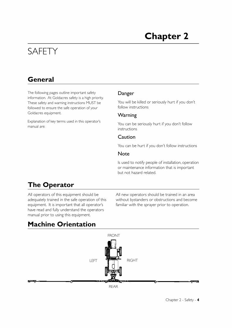
Machine Orientation
FRONT
REAR
LEFT RIGHT
Chapter 2 - Safety - 5
Safety Precautions
Notes• Goldacres Crop Cruiser Evolution’s mechanical
drive system delivers efficient, positive power to the ground for superior traction.
However, should your Crop Cruiser become bogged and the wheels subsequently locked, do not engage first gear and maximise engine revs.
With the wheel ‘locked’ in a bog situation, transmitting full power WILL DAMAGE the driveline.
Goldacres recommends that bog situations are addressed prudently by using the assistance of a tow vehicle. Doing otherwise can cause significant driveline damage and VOID WARRANTY
• Always read, and understand, the operator’s manual prior to operation of this equipment.
• It is the responsibility of the operator to ensure that there are no decals missing from the equipment and that any damaged, or missing, decals are replaced prior to operation.
• Goldacres equipment ordered, or operated, outside the guideline limitations may not be warranted by Goldacres for successful performance. Operators working outside these limitations do so at their own risk, unless specific advice has been sought from, and provided by, Goldacres in writing.
• Always read and follow the chemical manufacturer’s guidelines for safe application as per the chemical label. Particular attention should be given to the recommended target application
rate of the chemical being applied as per the chemical label.
• Inspect the equipment thoroughly for damage and wear before operation.
• Lubricate the equipment as per recommended requirements before operating.
• Flush chemicals from equipment immediately after use.
• Certain chemicals may be unsuitable for use with Goldacres standard plumbing designs. Consult your Goldacres dealer if in doubt.
• Do not operate the equipment while under the influence of any drugs, alcohol or if excessively tired.
• Make sure that the equipment complies with all relevant road regulations when transporting.
• Goldacres equipment uses several materials that may be harmful to the environment. Potentially harmful waste used with Goldacres equipment includes such items as oil, fuel, coolant, brake fluid and batteries. If these items are disposed of incorrectly the waste can threaten the surrounding environment and ecology. The waste products can leech into surrounding water sources and contaminate the area.
• When draining fluids from the equipment use appropriate, leak proof containers. Do not use food or beverage containers because someone may consume the contents by mistake.
• A supply of fresh water should be with the equipment at all times.
• Water tanks are not designed for use with diesel fuel or any flammable liquid.
• Do not use this machine in ambient temperatures exceeding 40 degrees Celsius.
• Each individual boom section has a maximum delivery of 35 litres per minute with clean filters fitted.
• The maximum combined flow of all boom sections is limited to 140 litres per minute, or 50% of the pump flow whichever is the lesser amount, with clean filters.
• Do not exceed the maximum spraying pressure of 8 Bar.
• Ensure that all bolts are tightened and secured before operation.
• Where fitted, care should be taken to never
Cautions
6 - Crop Cruiser Evolution MY13 Operators Manual - Rev 1.4
overfill the diaphragm pump with oil or operate at speeds exceeding 540 rpm.
• Always ensure that the boom is securely supported when travelling.
• Do not travel at excessive speeds over rough terrain. The superior ride characteristics of this machine can disguise the impact of rough terrain, on the driveline and suspension system on the machine. After impact with gutters, sinkholes, rocks etc. stop the machine and inspect for damage.
• Violent speed change WILL CAUSE boom damage. The high power to weight ratio and braking capacity (especially when empty) enables very high acceleration and decelerations of the machine. It is important during accelerating and braking that the effect on the spray boom in the open position is taken into account.
• When leaving the sprayer always isolate the batteries by turning the isolator key off and removing it.
Towing and transporting the sprayer
• A disabled sprayer is best transported on a drop deck trailer. Use chains to secure the sprayer via the tie down attachment point located under the front and rear axles.
• The machine must not be towed unless the engine is running (as the steering and brakes require engine power to operate). Before towing, the rear tail shaft should be disconnected, due to the risk of damage to the transmission. While towing do not travel at a speed greater than 10 km/h.
• An operator must steer and brake the sprayer under tow.
• Check the wheel nut tension on a regular basis. The torque and inspection frequency is outlined in the maintenance section.
• Brake pads should be inspected for wear regularly. The inspection frequency is outlined in the maintenance section.
Service cooling system safely
• At operating temperature the fluids in the cooling system are under pressure. Only remove the radiator cap when the engine is turned off and has cooled down.
• Loosen off the cap slowly to relieve the pressure, and then remove the cap completely.
• Coolant can be added when the engine is cool and turned off.
Maintaining Batteries
The battery electrolyte contains sulfuric acid; this is a highly dangerous liquid and should be handled with the greatest degree of care.
The acid can cause blindness, burn skin and dissolve clothing. Batteries also produce hydrogen gas (especially when charging), so do not place flames or sparks near the batteries.
A vigilant operator can avoid these hazards by:
1. Filling batteries in well-ventilated area.
2. Wearing the correct personal protective equipment.
3. Avoiding breathing fumes when electrolyte is added.
4. Avoid spilling or dripping electrolyte.
Emergency measures:
• If the electrolyte gets in your eyes, flush your eyes with clean water for at least 15 minutes, then get immediate medical assistance.
• Also thoroughly wash all other affected areas on your body with water and remove all clothing.
• If you swallow any electrolyte seek medical attention immediately.
SUPPORT MACHINE SAFELY Before raising the machine off the ground;
Ensure that the boom is in its closed position.
Park on a flat level, firm area and engage the park brake.
Cautions - continued
Chapter 2 - Safety - 7
Where possible before lifting the machine, empty the spray tank.
Chock all wheels that remain on the ground.
Securely lift the machine using a jack and support the machine on work stands.
Do not rely solely on the jack before working under the machine.
Do not support the sprayer using materials that may crumble.
Do not work under the machine when supported solely by a jack.
CHANGING WHEELS AND TYRES
Changing An experienced person with the correct equipment should mount the wheels on the sprayer.
When changing a wheel on the sprayer ensure that the sprayer is on firm level ground and the wheels are chocked.
Tyre maintenance Maintain correct tyre pressure at all times. Inflation of tyres above or below the recommended pressure exerts additional pressure on the tyre, which may result in tyre damage.
Extreme caution is required during the inflation of tyres. If the tyre is inflated at a rapid rate separation and/or explosion of the rim can occur. This event can inflict serious or fatal injuries to the operator.
Always use a tyre inflation gauge.
Do not weld, heat or modify the rim.
Be proactive and continually check the condition of your tyres.
MAINTENANCE WARNING (CRUSH HAZARD) Never attempt to maintain axles, wheels or components within the vicinity of the wheels with the engine running.
Cautions - continued
Warnings
• Any unauthorised modifications to this equipment may affect its function and create a serious safety risk.
• Keep clear of overhead obstructions – especially power lines as contact can be fatal.
• Never attempt to clean parts, or nozzles, by blowing with mouth.
• Never attempt to siphon chemicals, or substances, by sucking.
• It is imperative that the vehicle manufacturer’s specifications be checked and all instructions for use when transporting, or towing, be adhered to at all times.
• Care should be taken when transferring liquid into the tank to ensure that the gross weight of the equipment does not exceed the carrying and braking capacity of the vehicle to which as specified by the vehicle manufacturer.
NOTE: 1 LITRE WATER = 1 KG.
• Water weighs 1kg per litre, however conversion factors must be used when spraying liquids that are heavier or lighter than water. Example: liquid nitrogen has a density of 1.28 kg/L and will therefore be significantly heavier than water if the tank is filled completely. The total weight of a tank full of chemical, should not exceed that of a full tank of water. Machine damage can result if the machine is over weight. (See filling instructions in the Operations chapter for more information.)
• Suitable care should be taken when driving the vehicle. Consideration should be given to both the carrying capacity of the vehicle and the gradient of the terrain when determining the speed at which the vehicle can be driven safely.
• Ensure that the maximum speed of the vehicle, when loaded, is within the vehicle manufacturer’s limitations.
• Ensure equipment is securely fastened, or attached, to vehicle at all times.
• Never stand within the radius of boom wings.
8 - Crop Cruiser Evolution MY13 Operators Manual - Rev 1.4
Warnings (continued)
• Never work under any hydraulically raised boom.
PERSONAL PROTECTIVE EQUIPMENT (PPE)
Always wear close fitting clothing and safety equipment designed for the job.
• Exposure to loud noise over an extended period can cause impairment or loss of hearing. Be active in the conservation of your hearing and wear appropriate hearing protection at all times.
• Chemicals can be harmful to humans, appropriate PPE should be used when handling chemicals. Always refer to the chemical manufacturers label for guidelines on the appropriate PPE to use with the chemical/s you are using.
Goldacres also suggest that you read and understand the following Australian standards:
• Australian Standard for Chemical protective clothing AS3765
• Australian Standard for Respiratory protection devices AS1715
AIR BORNE PARTICLES
• Always stand well clear of equipment during operation.
• Any spray drift is dangerous and may be hazardous to humans.
• When heating and welding components, ensure that all paint and other such materials are removed. Often hazardous air borne particles and fumes are generated from welding and heating.
DO NOT HEAT PRESSURIZED FLUID LINES
When conducting any process on the machine that involves heat; be aware of pressurized fluid lines in the vicinity of your work area.
Pressurized lines can be easily cut when the heat over shoots the target object.
DO NOT CARRY PASSENGERS
Do not stand or carry passengers on the steps or platform when the equipment is in motion or when the booms are being folded or unfolded.
FLUIDS UNDER PRESSURE
Fluids escaping from high pressure lines can cause serious injury to skin. Hydraulic oil can easily penetrate human skin. This hazard can be avoided by relieving the pressure in the system.
Do not disconnect any hoses, nozzles or filters while equipment is operating. Disconnecting these components while under pressure may result in uncontrolled fluid discharge which may be hazardous.
When the repair is complete ensure that all fittings and lines are secured before re-applying pressure.
• High speed turning places severe stresses on the wheels and axles and should be avoided. It is essential to observe the effects of turning on the open spray boom. Excessive turning speeds transmit great stresses to the spray boom and WILL CAUSE boom damage.
• Modification of the machine to increase maximum speed is STRICTLY PROHIBITED. This machine is designed for a maximum speed of 47 km/h. This speed must only be used on suitable terrain conditions. All components i.e. tyres, brakes, suspension, steering and chassis are designed and built to this maximum speed.
• MAXIMUM SPEED WHEN CORNERING, TURNING AT AN ANGLE GREATER THAN 45º OR DRIVING ON A SLOPE OR UNEVEN TERRAIN IS 5KM/H. When fitted with narrow wheel track and with high centre of gravity, the Goldacres Crop Cruiser self-propelled sprayer may become unstable when turning at excessive speed or when operating on excessively steep terrain.
• The Goldacres Crop Cruiser is fitted with a roll-over protection structure (ROPS), incorporated into the frame of the cabin. To minimize the risk of injury in the event of an accident, the operator and anyone in the training seat must wear seat belts at all times.
• The Goldacres Crop Cruiser is equipped with one training seat. Any further passengers will not be protected by the ROPS and must be kept off the machine. Do not stand or carry passengers on the steps or platform when the sprayer is in
Chapter 2 - Safety - 9
The safe use of AgVet chemicals with this equipment is the responsibility of the owner/operators. All operators should be trained in the safe use of AgVet chemicals. Goldacres suggest that a relevant ChemCert course is completed by owners/operators prior to operation of this equipment as a spray unit.
ChemCert Course Overview:
The ChemCert course is aimed at providing the
level of training needed by producers to make sure that they understand the requirements to use agricultural and veterinary chemicals safely and effectively.
The course also encourages people to think about using alternatives to chemicals in their production systems by taking a risk management approach.
The ChemCert course has become the industry standard for AgVet chemical training. Satisfactory
Safe use of chemicals
motion or when the booms are being folded or unfolded.
• Before leaving the sprayer the engine must be shut off, the transmission placed in neutral and the park brake engaged. NEVER ENGAGE THE PARK BRAKE WHILE THE SPRAYER IS MOVING. DAMAGE TO THE TRANSMISSION MAY RESULT.
Re-Fuelling safety
• Handle fuel with extreme caution. Do not refuel the machine while smoking or near open flames or sparks.
• Always stop the engine before refueling the machine.
• To prevent fires always keep the machine clean of grease, debris and dirt.
• Do not use current emitting devices when re-fuelling.
Collision prevention and warning lights
• Before operating the machine check with the relevant road management authorities for information regarding safe and legal transport on public roads in the state where the machine is being operated.
• To assist in the prevention of collisions with other road users the GoldAcres Crop Cruiser self propelled sprayers, are fitted with warning lights and signs in accordance with Vic Roads regulations.
• The Crop Cruiser can only be driven on public roads during daylight hours.
• Keep lighting and signs in good order and replace any damaged or faulty fixtures.
Warnings (continued)
Dangers• Check area to be sprayed for overhead powerlines.
Contact between the machine and powerlines can result in serious injury or death. If there are powerlines in the spray area, exercise extreme caution when tilting boom wings.
• Do NOT walk on machine platform when near power lines.
• NEVER start the engine when standing on the ground. Only start the engine from the operator’s seat, with the transmission in neutral. Possible injury or death can occur by starting the machine through other methods.
• Diesel engine exhaust fumes are harmful and can cause severe sickness or death. If it is necessary to run the engine in an enclosed area use an exhaust pipe extension. If an exhaust pipe extension is unavailable ensure that all doors are fully open and the room is well ventilated.
ENTANGLEMENT IN ROTATING DRIVE LINES
• Rotating drives can cause serious injury or even death when entanglement occurs. Keep hands, feet, hair and clothing away from all moving parts to prevent injury. Never operate this machine with covers, shrouds, or guards removed.

10 - Crop Cruiser Evolution MY13 Operators Manual - Rev 1.4
completion of the ChemCert AgVet Chemical Users Course results in ChemCert registration and the award by the training provider of a Statement of Attainment for two nationally recognised competency standards:
RTC 3704A - Prepare and apply chemicals
RTC 3705A - Transport, handle and store chemicals.
The ChemCert course is generally delivered by trainers over two days, plus additional assessment activities.
Further information on ChemCert courses can be supplied by the ChemCert organisation in your state:
Victoria: www.chemcertvic.org.au
Ph: 03 5622 2055
South Australia: www.chemcertsa.com.au Ph: (08) 8842 4048
Queensland: www.chemcertqld.org.au Ph: (07) 5466 5850
Western Australia: www.chemcertwa.com.au Ph: (08) 9341 5325
New South Wales: www.chemcert.com.au Ph: (02) 9387 4714
Personal Protective Equipment (PPE)Always wear close fitting clothing and safety equipment designed for the job.
Chemicals can be harmful to humans, appropriate PPE should be used when handling chemicals. Always refer to the chemical manufacturers label for guidelines on the appropriate PPE to use with the chemicals you are using.
Goldacres also suggest that you read and understand the following Australian standards:
• Australian Standard for Chemical protective clothing AS3765
• Australian Standard for Respiratory protection devices AS1715
Air borne particles
Always stand well clear of equipment during operation. Any spray drift is dangerous and may be hazardous to humans and animals.
Fluids under pressure
DO NOT disconnect any hoses, nozzles or filters while equipment is operating. Disconnecting these components while under pressure may result in uncontrolled fluid discharge which may be hazardous.
When the repair is complete ensure that all fittings and lines are secured before re-applying pressure.
Safety DecalsUnderstanding safety decals and their purpose assists in the safe operation of your sprayer. Safety decals are there for your protection and it is the responsibility of the owner operator to replace damaged and/or missing safety decals.
Regularly review safety decals with operators. It is very important to ensure that all new machine components and replacement parts include
current hazard identification decals.
Replacement safety decals can be ordered from your Goldacres dealer or directly from Goldacres. Part numbers and descriptions of the decals on this machine can be found in the parts manual supplied.
Chapter 2 - Safety - 11
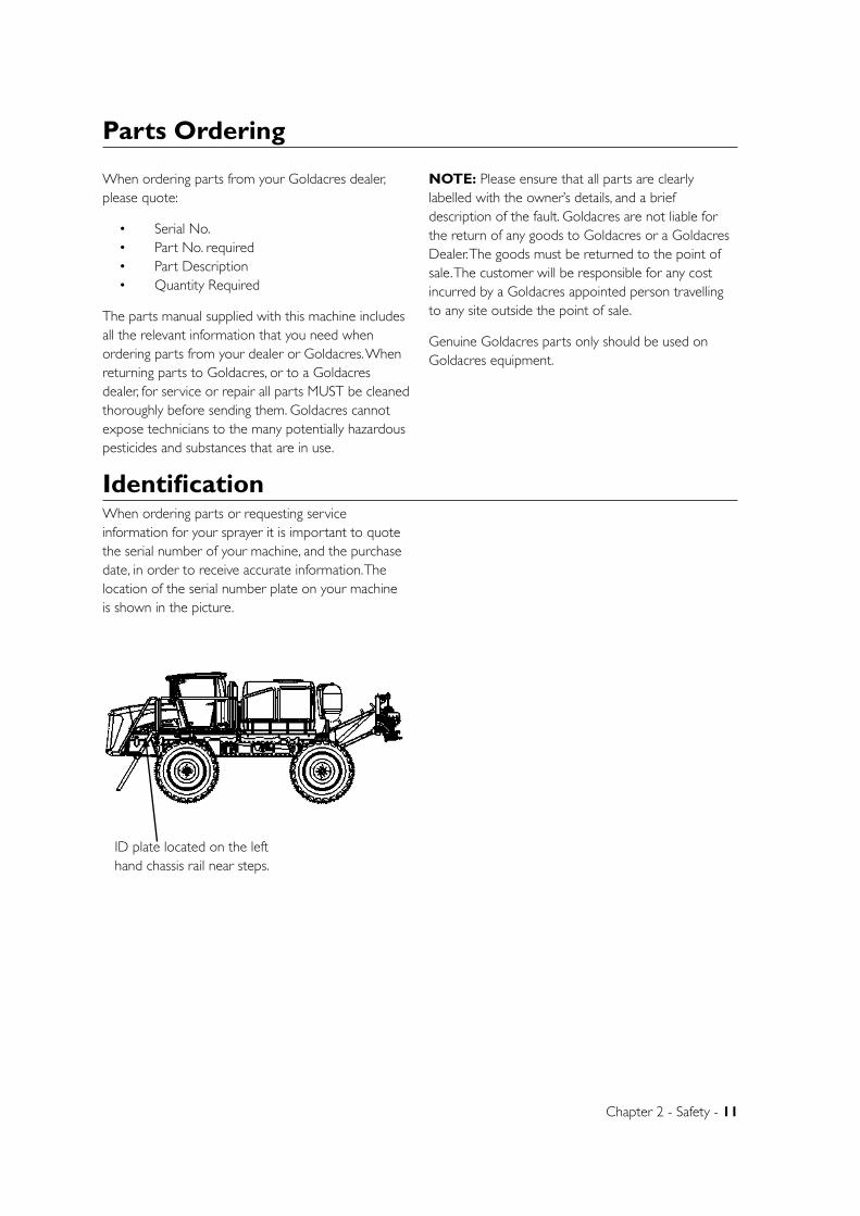
When ordering parts or requesting service information for your sprayer it is important to quote the serial number of your machine, and the purchase date, in order to receive accurate information. The location of the serial number plate on your machine is shown in the picture.
Identification
When ordering parts from your Goldacres dealer, please quote:
• Serial No. • Part No. required • Part Description • Quantity Required
The parts manual supplied with this machine includes all the relevant information that you need when ordering parts from your dealer or Goldacres. When returning parts to Goldacres, or to a Goldacres dealer, for service or repair all parts MUST be cleaned thoroughly before sending them. Goldacres cannot expose technicians to the many potentially hazardous pesticides and substances that are in use.
NOTE: Please ensure that all parts are clearly labelled with the owner’s details, and a brief description of the fault. Goldacres are not liable for the return of any goods to Goldacres or a Goldacres Dealer. The goods must be returned to the point of sale. The customer will be responsible for any cost incurred by a Goldacres appointed person travelling to any site outside the point of sale.
Genuine Goldacres parts only should be used on Goldacres equipment.
Parts Ordering
B
C
D
1 2
A
321 4
B
A
5 6
UNLESS OTHERWISE SPECIFIED:DIMENSIONS ARE IN MILLIMETERSDEBUR ALL EDGES
MATERIAL:
DO NOT SCALE DRAWING
GOLDACRESTITLE:
DWG NO:
SCALE:1:150 SHEET 1 OF 1
A4
C
Complete Assembly 2WD - SP 2011 - Parts ManualREV NO CHANGE APPL DATE
DATE CREATED:
DRAWN:
Name
1-3 MORANG CRMITCHELL PARK 3352PH: 03 53426399 FAX: 03 53426308
17/03/2011
DATE EDITED:
25/05/2011Matt
ID plate located on the left hand chassis rail near steps.
Chapter 3
Chapter 3 - General Information & Specs - 12
GENERAL INFORMATION & SPECS
General
Chassis: The chassis is an all steel construction, that is fully welded for superior strength. The chassis is grit blasted, primed and then protected by the Goldacres paint process for excellent chemical resistance and durability. Tank: All tanks are constructed from UV resistant polyethylene. Polyethylene tanks have a very high chemical resistance. Due to the rotomoulding process, there can be a variance in the overall dimensions of the tank which in turn results in variations to the tank capacity. For this reason, calibration markings should be used as a guide only.
Cabin: The cabin features panoramic views surrounding the sprayer and is customised to suit spraying applications. The rate controller and all key spraying functions are within easy reach of the operator
Further information on the cabin can be found in the “Cabin” chapter.
Agitation: The Supermix agitator is located at the back of the tank and is used to generate increased agitation within the tank. The pressure line to the Supermix agitator from the control manifold passes through a nozzle and then through the barrel into the tank. This causes extra agitation as flow around the agitator is sucked into the barrel and is then passed back into the tank. To increase this venturi effect, the bypass flow from the electric regulating valve also passes through the barrel, multiplying the agitation effect. The supermix agitator has an approximate capacity of 300 - 1300 l/min depending of the pump size and operating pressure. For further information refer to the “maintenance” chapter.
Boom Valves: Motorised boom valves, for control of boom section on/off, are fitted as standard. These are mounted on the boom centre section at the rear of the sprayer. The number fitted is dependent on the number of boom sections and number of boom lines. Controller: Crop Cruiser sprayers are supplied with either a Raven SCS4070 automatic rate controller or Goldacres Total Spray Control. Automatic rate controllers will maintain a user defined application rate automatically as the vehicle speed changes. In order to function, the automatic rate controller relies on a flow meter, speed sensor and control valve. For specific information on the Raven controller please refer to Raven operator’s manual supplied and “calibration” section of this manual. Filtration: Filtration is a critical part of the sprayer’s performance.
As standard Crop Cruiser sprayers are fitted with:
1 x Suction filter (30 mesh) 2 x Pressure filters (1 x 80 & 1 x 100 mesh) Nozzle strainers (50 mesh)
Pump: Udor, positive displacement, oil backed diaphragm pumps are fitted as standard on Goldacres equipment. The normal operating range is from 1 - 8 bar which is sufficient for efficient nozzle performance.
Chapter 3 - General Information & Specs - 13
Chemical Induction: The method of chemical induction into your sprayer is dependent on the optional chemical induction equipment fitted to your sprayer.
Goldacres chemical induction equipment available includes:
• Chemical Probe
• Chemical Induction Hopper
• 12 volt Chemical Transfer Pumps
• Direct Chemical Injection Modules
Booms:
The Crop Cruiser can be fitted with a variety of boom sizes up to 42 metres in width. Tri Tech booms (24 - 42 metres) feature hydraulic lift and fold, with control from the cabin. Individual wing tilt is available as an option.
Goldacres Tri Tech booms feature: pitch, roll and yaw suspension in order to provide a superior boom ride and assist in the efficient application of chemical to your target. Nozzles: As information regarding nozzles is specific to those being used in your application, no specific reference is made to nozzle application rates or nozzle types in this operator’s manual. Goldacres suggest the use of a current TeeJet nozzle selection catalogue for reference to nozzle sizes, outputs, spray patterns and general spraying information. For more technical information on the function of spray nozzles and factors affecting their performance you can also use the TeeJet “User’s guide to spray nozzles”.
The TeeJet nozzle selection catalogue and Users guide to spray nozzles are available from your Goldacres dealer, Goldacres, or as a free download from the TeeJet web site: www.teejet.com
Machine Limitations: All Goldacres equipment is subject to operating limitations, it is the operator’s responsibility to ensure that this equipment is being operated within these limitations and appropriately to the operating conditions at hand.
Goldacres do not endorse use of this machine for spraying at speeds greater than 20 km/hr and should not be used in ambient temperatures exceeding 40 degrees celsius.
Each individual boom section has a maximum delivery of 35 litres per minute with clean filters fitted. With clean filters fitted, the maximum combined flow of all boom sections is limited to 140 litres per minute, or 50% of the pump flow, whichever is the lesser amount.
Goldacres Crop Cruiser Evolution’s mechanical drive system delivers efficient, positive power to the ground for superior traction.
However, should your Crop Cruiser become bogged and the wheels subsequently locked, do not engage first gear and maximise engine revs.
With the wheel ‘locked’ in a bog situation, transmitting full power WILL DAMAGE the driveline.
Goldacres recommends that bog situations are addressed prudently by using the assistance of a tow vehicle. Doing otherwise can cause significant driveline damage and VOID WARRANTY
Custom built equipment: Where the owner of this sprayer has requested that custom built equipment or options be fitted to this sprayer it is necessary to understand that custom fabrication and engineering is subject to many variables. Goldacres cannot fully field test all custom built options prior to despatch, and owners of new sprayers fitted with custom built equipment or options need to understand that the functionality of these items may require refining in order to operate as desired.
Suspension The Crop Cruiser is fitted with 5 link airbag axle suspension to provide excellent ride and comfort.
Further information on the suspension can be found in the “lubrication and maintenance” chapter.
Air conditioning The cabin is climate controlled and a carbon filter is installed to ensure operator safety.
Further information can be found in the “lubrication and maintenance” chapter.
Hydraulics Electric over hydraulic valves are standard on Crop Cruiser models. The hydraulic functions are then controlled from electric switches in the cabin. The valve block is located at the rear of the sprayer above the boom valves.
14 - Crop Cruiser Evolution MY13 Operators Manual - Rev 1.4
Wheels and tyresThe tyre pressure needs to be checked regularly (check every 8 to 12 hours of operation) and maintained at the required tyre pressure.
There are many factors concerning the appropriate tyre pressure for a particular tyre and load. For example, the tyre size, rim type, tyre status (driven or free rolling), load, speed, haul length and ply rating all need to be considered when determining the tyre pressure.
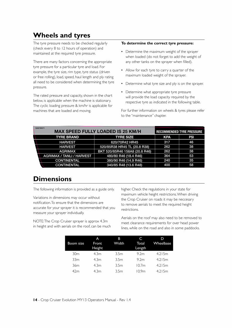
The rated pressure and capacity, shown in the chart below, is applicable when the machine is stationary. The cyclic loading pressure & km/hr is applicable for machines that are loaded and moving.
To determine the correct tyre pressure:
• Determine the maximum weight of the sprayer when loaded (do not forget to add the weight of any other tanks on the sprayer when filled).
• Allow for each tyre to carry a quarter of the maximum loaded weight of the sprayer.
• Determine what tyre size and ply is on the sprayer.
• Determine what appropriate tyre pressure will provide the load capacity required by the respective tyre as indicated in the following table.
For further information on wheels & tyres please refer to the “maintenance” chapter.
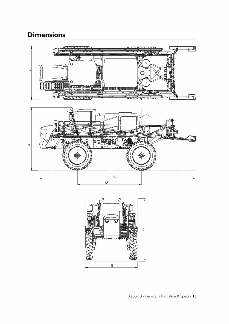
DimensionsThe following information is provided as a guide only.
Variations in dimensions may occur without notification. To ensure that the dimensions are accurate for your sprayer it is recommended that you measure your sprayer individually.
NOTE: The Crop Cruiser sprayer is approx 4.3m in height and with aerials on the roof, can be much
higher. Check the regulations in your state for maximum vehicle height restrictions. When driving the Crop Cruiser on roads it may be neccesary to remove aerials to meet the required height restrictions.
Aerials on the roof may also need to be removed to meet clearance requirements for over head power lines, while on the road and also in some paddocks.
Boom sizeA
Front Height
B Width
CTotal
Length
DWheelbase
30m 4.3m 3.5m 9.2m 4.215m
33m 4.3m 3.5m 9.2m 4.215m
36m 4.3m 3.5m 10.7m 4.215m
42m 4.3m 3.5m 10.9m 4.215m
PSIKPATYRE BRAND TYRE SIZE46317HARVEST 620/70R42 HR45
MAX SPEED FULLY LOADED IS 25 KM/H
38262HARVEST 520/85R38 HR45 TL (20.8 R38)38262AGRIMAX BKT 520/85R46 158A8 (20.8 R46)53364AGRIMAX / TANLI / HARVEST 480/80 R46 (18.4 R46)35240CONTINENTAL 380/90 R46 (14.9 R46)58400CONTINENTAL 340/85 R48 (13.6 R48)
RECOMMENDED TYRE PRESSUREGA8700071
Chapter 3 - General Information & Specs - 15
Dimensions
C
D
A
B
B
A
D
E
F
C
1 2 3 4
B
A
321 5
C
D
4 6 7 8
A
B
A3
SHEET 1 OF 1SCALE:1:50
DWG NO.
TITLE:
GOLDACRES
DO NOT SCALE DRAWING
MATERIAL:
DATE CREATED:
DRAWN:
1-3 MORANG CRMITCHELL PARK 3352PH: 03 53426399 FAX: 03 53426308
UNLESS OTHERWISE SPECIFIEDDIMENSIONS ARE IN MILLIMETERSDEBUR ALL EDGES Complete Assembly 2WD - SP 2011 - Parts ManualName
2/06/2011Matt
REV NO CHANGE DATE ECN NO.
DATE EDITED:
17/03/2011
C
D
A
B
B
A
D
E
F
C
1 2 3 4
B
A
321 5
C
D
4 6 7 8
A
B
A3
SHEET 1 OF 1SCALE:1:50
DWG NO.
TITLE:
GOLDACRES
DO NOT SCALE DRAWING
MATERIAL:
DATE CREATED:
DRAWN:
1-3 MORANG CRMITCHELL PARK 3352PH: 03 53426399 FAX: 03 53426308
UNLESS OTHERWISE SPECIFIEDDIMENSIONS ARE IN MILLIMETERSDEBUR ALL EDGES Complete Assembly 2WD - SP 2011 - Parts ManualName
2/06/2011Matt
REV NO CHANGE DATE ECN NO.
DATE EDITED:
17/03/2011

16 - Crop Cruiser Evolution MY13 Operators Manual - Rev 1.4
Chapter 4
Chapter 4 - Drivetrain - 17
B
C
D
1 2
A
321 4
B
A
5 6
UNLESS OTHERWISE SPECIFIED:DIMENSIONS ARE IN MILLIMETERSDEBUR ALL EDGES
MATERIAL:
DO NOT SCALE DRAWING
GOLDACRESTITLE:
DWG NO:
SCALE:1:35 SHEET 2 OF 2
A4
C
2WD Cab Chassis AssemblyREV NO CHANGE APPL DATE
DATE CREATED:
DRAWN:
1-3 MORANG CRMITCHELL PARK 3352PH: 03 53426399 FAX: 03 53426308
11/03/2011
DATE EDITED:
20/06/2011Matt
B
C
D
1 2
A
321 4
B
A
5 6
UNLESS OTHERWISE SPECIFIED:DIMENSIONS ARE IN MILLIMETERSDEBUR ALL EDGES
MATERIAL:
DO NOT SCALE DRAWING
GOLDACRESTITLE:
DWG NO:
SCALE:1:35 SHEET 1 OF 2
A4
C
2WD Cab Chassis AssemblyREV NO CHANGE APPL DATE
DATE CREATED:
DRAWN:
1-3 MORANG CRMITCHELL PARK 3352PH: 03 53426399 FAX: 03 53426308
11/03/2011
DATE EDITED:
20/06/2011Matt
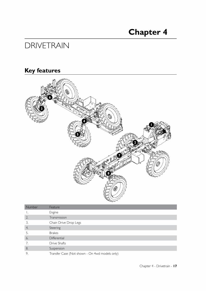
DRIVETRAIN
Key features
Number Feature
1. Engine
2. Transmission
3. Chain Drive Drop Legs
4. Steering
5. Brakes
6. Differential
7. Drive Shafts
8. Suspension
9. Transfer Case (Not shown - On 4wd models only)
1
2
3
4
5
6
7
8
18 - Crop Cruiser Evolution MY13 Operators Manual - Rev 1.4
B
C
D
1 2
A
321 4
B
A
5 6
UNLESS OTHERWISE SPECIFIED:DIMENSIONS ARE IN MILLIMETERSDEBUR ALL EDGES
MATERIAL:
DO NOT SCALE DRAWING
GOLDACRESTITLE:
DWG NO:
SCALE:1:20 SHEET 1 OF 1
A4
C
2011-C-W hyd fan driveCCSP-Engine-transmissionREV NO CHANGE APPL DATE
DATE CREATED:
DRAWN:
John Peel
1-3 MORANG CRMITCHELL PARK 3352PH: 03 53426399 FAX: 03 53426308
19/05/2005
DATE EDITED:
25/05/2011Matt
B
C
D
1 2
A
321 4
B
A
5 6
UNLESS OTHERWISE SPECIFIED:DIMENSIONS ARE IN MILLIMETERSDEBUR ALL EDGES
MATERIAL:
DO NOT SCALE DRAWING
GOLDACRESTITLE:
DWG NO:
SCALE:1:20 SHEET 1 OF 1
A4
C
2011-C-W hyd fan driveCCSP-Engine-transmissionREV NO CHANGE APPL DATE
DATE CREATED:
DRAWN:
John Peel
1-3 MORANG CRMITCHELL PARK 3352PH: 03 53426399 FAX: 03 53426308
19/05/2005
DATE EDITED:
25/05/2011Matt
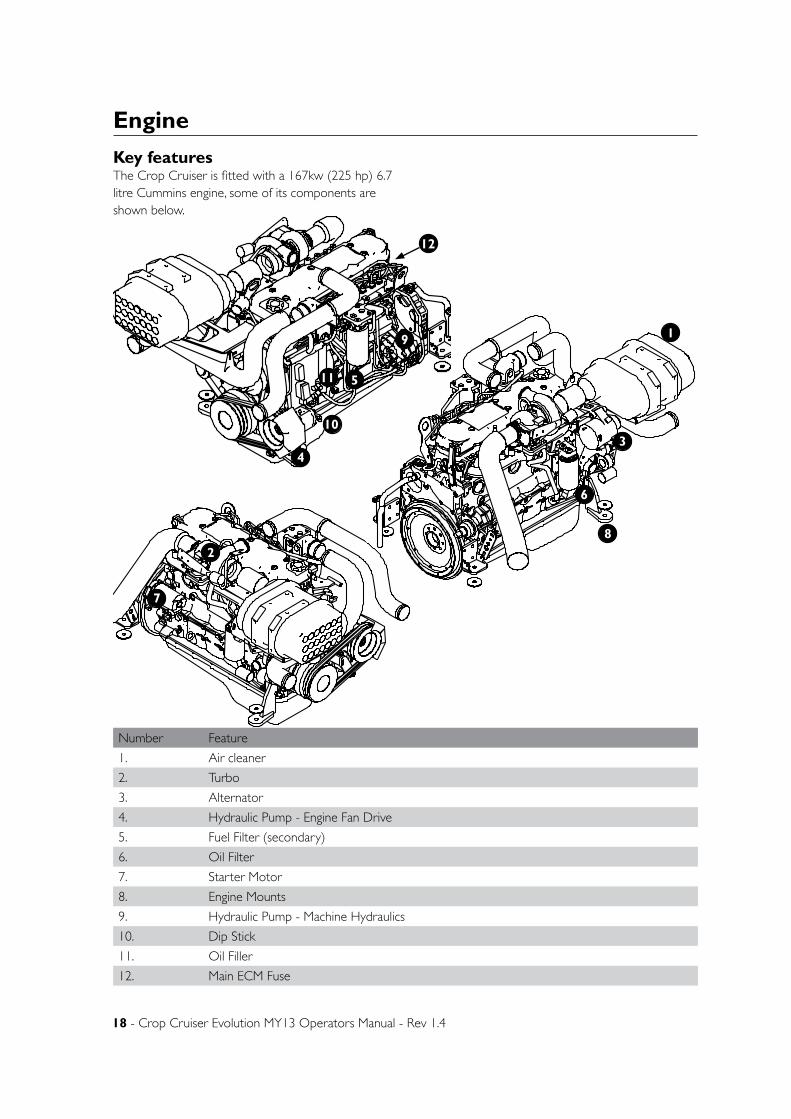
Engine
Number Feature
1. Air cleaner
2. Turbo
3. Alternator
4. Hydraulic Pump - Engine Fan Drive
5. Fuel Filter (secondary)
6. Oil Filter
7. Starter Motor
8. Engine Mounts
9. Hydraulic Pump - Machine Hydraulics
10. Dip Stick
11. Oil Filler
12. Main ECM Fuse
Key features
1
5
34
6
7
82
The Crop Cruiser is fitted with a 167kw (225 hp) 6.7 litre Cummins engine, some of its components are shown below.
9
10
11
12
Chapter 4 - Drivetrain - 19
Transmission
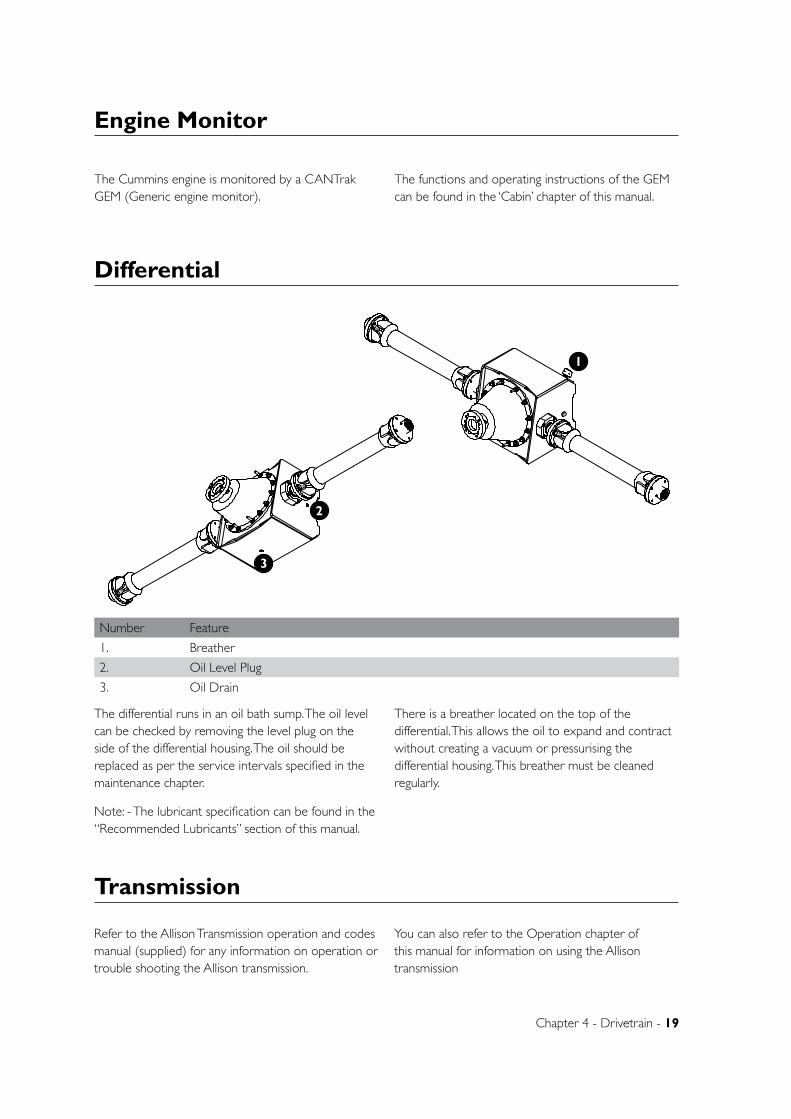
Differential
The differential runs in an oil bath sump. The oil level can be checked by removing the level plug on the side of the differential housing. The oil should be replaced as per the service intervals specified in the maintenance chapter.
Note: - The lubricant specification can be found in the “Recommended Lubricants” section of this manual.
There is a breather located on the top of the differential. This allows the oil to expand and contract without creating a vacuum or pressurising the differential housing. This breather must be cleaned regularly.
Refer to the Allison Transmission operation and codes manual (supplied) for any information on operation or trouble shooting the Allison transmission.
You can also refer to the Operation chapter of this manual for information on using the Allison transmission
Engine Monitor
The Cummins engine is monitored by a CANTrak GEM (Generic engine monitor).
The functions and operating instructions of the GEM can be found in the ‘Cabin’ chapter of this manual.
B
C
D
1 2
A
321 4
B
A
5 6
UNLESS OTHERWISE SPECIFIED:DIMENSIONS ARE IN MILLIMETERSDEBUR ALL EDGES
MATERIAL:
DO NOT SCALE DRAWING
GOLDACRESTITLE:
DWG NO:
SCALE:1:20 SHEET 1 OF 1
A4
C
GA4903026REV NO CHANGE APPL DATE
DATE CREATED:
DRAWN:
T.Watts
SP 3m 2WD MY11 Rear Axle Assembly
1-3 MORANG CRMITCHELL PARK 3352PH: 03 53426399 FAX: 03 53426308
23/04/2010
DATE EDITED:
25/05/2011Matt
B
C
D
1 2
A
321 4
B
A
5 6
UNLESS OTHERWISE SPECIFIED:DIMENSIONS ARE IN MILLIMETERSDEBUR ALL EDGES
MATERIAL:
DO NOT SCALE DRAWING
GOLDACRESTITLE:
DWG NO:
SCALE:1:20 SHEET 1 OF 1
A4
C
GA4903026REV NO CHANGE APPL DATE
DATE CREATED:
DRAWN:
T.Watts
SP 3m 2WD MY11 Rear Axle Assembly
1-3 MORANG CRMITCHELL PARK 3352PH: 03 53426399 FAX: 03 53426308
23/04/2010
DATE EDITED:
25/05/2011Matt
Number Feature
1. Breather
2. Oil Level Plug
3. Oil Drain
1
2
3
20 - Crop Cruiser Evolution MY13 Operators Manual - Rev 1.4
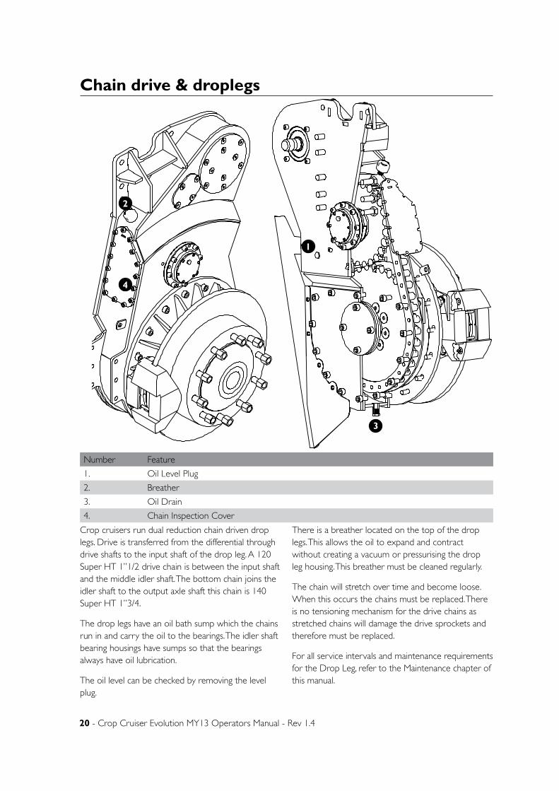
Chain drive & droplegs
Crop cruisers run dual reduction chain driven drop legs. Drive is transferred from the differential through drive shafts to the input shaft of the drop leg. A 120 Super HT 1”1/2 drive chain is between the input shaft and the middle idler shaft. The bottom chain joins the idler shaft to the output axle shaft this chain is 140 Super HT 1”3/4.
The drop legs have an oil bath sump which the chains run in and carry the oil to the bearings. The idler shaft bearing housings have sumps so that the bearings always have oil lubrication.
The oil level can be checked by removing the level plug.
There is a breather located on the top of the drop legs. This allows the oil to expand and contract without creating a vacuum or pressurising the drop leg housing. This breather must be cleaned regularly.
The chain will stretch over time and become loose. When this occurs the chains must be replaced. There is no tensioning mechanism for the drive chains as stretched chains will damage the drive sprockets and therefore must be replaced.
For all service intervals and maintenance requirements for the Drop Leg, refer to the Maintenance chapter of this manual.
B
C
D
1 2
A
321 4
B
A
5 6
UNLESS OTHERWISE SPECIFIED:DIMENSIONS ARE IN MILLIMETERSDEBUR ALL EDGES
MATERIAL:
DO NOT SCALE DRAWING
GOLDACRESTITLE:
DWG NO:
SCALE:1:10 SHEET 1 OF 1
A4
C
GA4902021REV NO CHANGE APPL DATE
DATE CREATED:
DRAWN:
DM
2011 model 2WD rear dropleg assembly - RH
1-3 MORANG CRMITCHELL PARK 3352PH: 03 53426399 FAX: 03 53426308
22/09/2005
DATE EDITED:
25/05/2011Matt
B
C
D
1 2
A
321 4
B
A
5 6
UNLESS OTHERWISE SPECIFIED:DIMENSIONS ARE IN MILLIMETERSDEBUR ALL EDGES
MATERIAL:
DO NOT SCALE DRAWING
GOLDACRESTITLE:
DWG NO:
SCALE:1:10 SHEET 1 OF 1
A4
C
GA4902021REV NO CHANGE APPL DATE
DATE CREATED:
DRAWN:
DM
2011 model 2WD rear dropleg assembly - RH
1-3 MORANG CRMITCHELL PARK 3352PH: 03 53426399 FAX: 03 53426308
22/09/2005
DATE EDITED:
25/05/2011Matt
1
2
3
4
Number Feature
1. Oil Level Plug
2. Breather
3. Oil Drain
4. Chain Inspection Cover
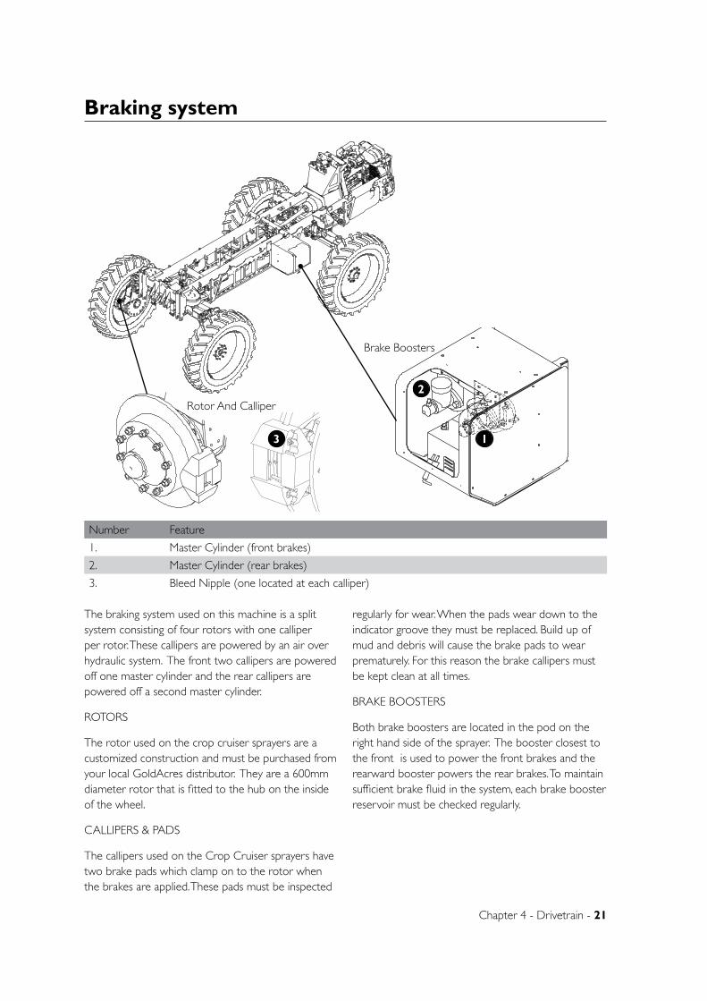
Chapter 4 - Drivetrain - 21
Braking system
The braking system used on this machine is a split system consisting of four rotors with one calliper per rotor. These callipers are powered by an air over hydraulic system. The front two callipers are powered off one master cylinder and the rear callipers are powered off a second master cylinder.
ROTORS
The rotor used on the crop cruiser sprayers are a customized construction and must be purchased from your local GoldAcres distributor. They are a 600mm diameter rotor that is fitted to the hub on the inside of the wheel.
CALLIPERS & PADS
The callipers used on the Crop Cruiser sprayers have two brake pads which clamp on to the rotor when the brakes are applied. These pads must be inspected
regularly for wear. When the pads wear down to the indicator groove they must be replaced. Build up of mud and debris will cause the brake pads to wear prematurely. For this reason the brake callipers must be kept clean at all times.
BRAKE BOOSTERS
Both brake boosters are located in the pod on the right hand side of the sprayer. The booster closest to the front is used to power the front brakes and the rearward booster powers the rear brakes. To maintain sufficient brake fluid in the system, each brake booster reservoir must be checked regularly.
B
C
D
1 2
A
321 4
B
A
5 6
UNLESS OTHERWISE SPECIFIED:DIMENSIONS ARE IN MILLIMETERSDEBUR ALL EDGES
MATERIAL:
DO NOT SCALE DRAWING
GOLDACRESTITLE:
DWG NO:
SCALE:1:7.5 SHEET 1 OF 1
A4
C
GA4902880-GA490885REV NO CHANGE APPL DATE
DATE CREATED:
DRAWN:
DM
Front dropleg assy complete
1-3 MORANG CRMITCHELL PARK 3352PH: 03 53426399 FAX: 03 53426308
1/07/2010
DATE EDITED:
25/05/2011Matt
B
C
D
1 2
A
321 4
B
A
5 6
UNLESS OTHERWISE SPECIFIED:DIMENSIONS ARE IN MILLIMETERSDEBUR ALL EDGES
MATERIAL:
DO NOT SCALE DRAWING
GOLDACRESTITLE:
DWG NO:
SCALE:1:35 SHEET 1 OF 2
A4
C
2WD Cab Chassis AssemblyREV NO CHANGE APPL DATE
DATE CREATED:
DRAWN:
1-3 MORANG CRMITCHELL PARK 3352PH: 03 53426399 FAX: 03 53426308
11/03/2011
DATE EDITED:
20/06/2011Matt
B
C
D
1 2
A
321 4
B
A
5 6
UNLESS OTHERWISE SPECIFIED:DIMENSIONS ARE IN MILLIMETERSDEBUR ALL EDGES
MATERIAL:
DO NOT SCALE DRAWING
GOLDACRESTITLE:
DWG NO:
SCALE:1:10 SHEET 1 OF 1
A4
C
brake-booster-tanksREV NO CHANGE APPL DATE
DATE CREATED:
DRAWN:
DM
Brake-AIR-Battery POD complete
1-3 MORANG CRMITCHELL PARK 3352PH: 03 53426399 FAX: 03 53426308
30/04/2010
DATE EDITED:
25/05/2011Matt
Rotor And Calliper
Brake Boosters
Number Feature
1. Master Cylinder (front brakes)
2. Master Cylinder (rear brakes)
3. Bleed Nipple (one located at each calliper)
D
E
F
C
1 2 3 4
B
A
321 5
C
D
4 6 7 8
A
B
A3
SHEET 1 OF 1SCALE:1:2.5
DWG NO.
TITLE:
GOLDACRES
DO NOT SCALE DRAWING
MATERIAL:
DATE CREATED:
DRAWN:
1-3 MORANG CRMITCHELL PARK 3352PH: 03 53426399 FAX: 03 53426308
UNLESS OTHERWISE SPECIFIEDDIMENSIONS ARE IN MILLIMETERSDEBUR ALL EDGES GA4902011
Bottom hub assembly suit crop cruiser 2011 on
20/06/2011Matt
REV NO CHANGE DATE ECN NO.
DATE EDITED:
12/04/2010
1
2
3
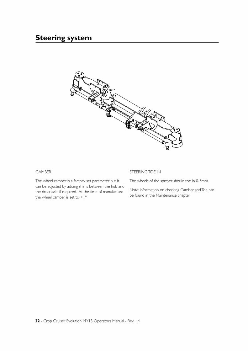
22 - Crop Cruiser Evolution MY13 Operators Manual - Rev 1.4
Steering system
CAMBER
The wheel camber is a factory set parameter but it can be adjusted by adding shims between the hub and the drop axle, if required. At the time of manufacture the wheel camber is set to +1°
STEERING TOE IN
The wheels of the sprayer should toe in 0-5mm.
Note: information on checking Camber and Toe can be found in the Maintenance chapter.
B
C
D
1 2
A
321 4
B
A
5 6
UNLESS OTHERWISE SPECIFIED:DIMENSIONS ARE IN MILLIMETERSDEBUR ALL EDGES
MATERIAL:
DO NOT SCALE DRAWING
GOLDACRESTITLE:
DWG NO:
SCALE:1:20 SHEET 1 OF 1
A4
C
GA4902980REV NO CHANGE APPL DATE
DATE CREATED:
DRAWN:
T.Watts
SP 3m 2WD MY11 Front Axle Assembly
1-3 MORANG CRMITCHELL PARK 3352PH: 03 53426399 FAX: 03 53426308
20/04/2010
DATE EDITED:
25/05/2011Matt
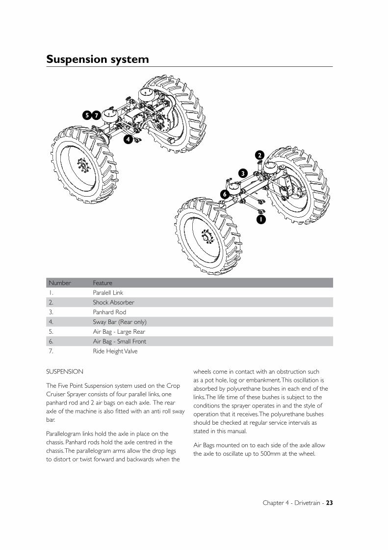
Chapter 4 - Drivetrain - 23
B
C
D
1 2
A
321 4
B
A
5 6
UNLESS OTHERWISE SPECIFIED:DIMENSIONS ARE IN MILLIMETERSDEBUR ALL EDGES
MATERIAL:
DO NOT SCALE DRAWING
GOLDACRESTITLE:
DWG NO:
SCALE:1:30 SHEET 1 OF 1
A4
C
2WD Cab Chassis AssemblyREV NO CHANGE APPL DATE
DATE CREATED:
DRAWN:
1-3 MORANG CRMITCHELL PARK 3352PH: 03 53426399 FAX: 03 53426308
11/03/2011
DATE EDITED:
20/06/2011Matt
Suspension system
1
3
2
4
5 7
Number Feature
1. Paralell Link
2. Shock Absorber
3. Panhard Rod
4. Sway Bar (Rear only)
5. Air Bag - Large Rear
6. Air Bag - Small Front
7. Ride Height Valve
SUSPENSION
The Five Point Suspension system used on the Crop Cruiser Sprayer consists of four parallel links, one panhard rod and 2 air bags on each axle. The rear axle of the machine is also fitted with an anti roll sway bar.
Parallelogram links hold the axle in place on the chassis. Panhard rods hold the axle centred in the chassis. The parallelogram arms allow the drop legs to distort or twist forward and backwards when the
wheels come in contact with an obstruction such as a pot hole, log or embankment. This oscillation is absorbed by polyurethane bushes in each end of the links. The life time of these bushes is subject to the conditions the sprayer operates in and the style of operation that it receives. The polyurethane bushes should be checked at regular service intervals as stated in this manual.
Air Bags mounted on to each side of the axle allow the axle to oscillate up to 500mm at the wheel.
6
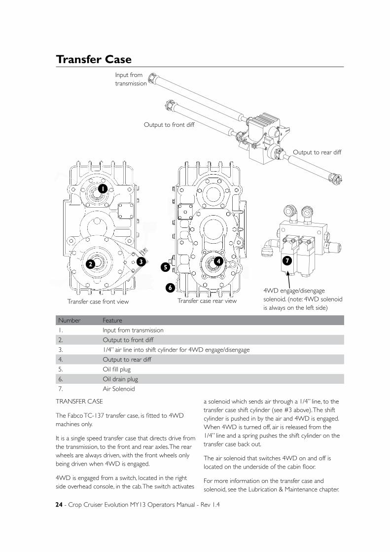
24 - Crop Cruiser Evolution MY13 Operators Manual - Rev 1.4
Transfer Case
TRANSFER CASE
The Fabco TC-137 transfer case, is fitted to 4WD machines only.
It is a single speed transfer case that directs drive from the transmission, to the front and rear axles. The rear wheels are always driven, with the front wheels only being driven when 4WD is engaged.
4WD is engaged from a switch, located in the right side overhead console, in the cab. The switch activates
a solenoid which sends air through a 1/4” line, to the transfer case shift cylinder (see #3 above). The shift cylinder is pushed in by the air and 4WD is engaged. When 4WD is turned off, air is released from the 1/4” line and a spring pushes the shift cylinder on the transfer case back out.
The air solenoid that switches 4WD on and off is located on the underside of the cabin floor.
For more information on the transfer case and solenoid, see the Lubrication & Maintenance chapter.
D
E
F
C
1 2 3 4
B
A
321 5
C
D
4 6 7 8
A
B
A3
SHEET 2 OF 2SCALE:1:50
DWG NO.
TITLE:
GOLDACRES
DO NOT SCALE DRAWING
MATERIAL:
DATE CREATED:
DRAWN:
1-3 MORANG CRMITCHELL PARK 3352PH: 03 53426399 FAX: 03 53426308
UNLESS OTHERWISE SPECIFIEDDIMENSIONS ARE IN MILLIMETERSDEBUR ALL EDGES Driveline_Assembly_4WD_ModelLuke M
13/03/2013Matt
REV NO CHANGE DATE ECN NO.
DATE EDITED:
24/06/2010
4
Transfer case front view Transfer case rear view
Input from transmission
Output to front diff
Output to rear diff
Number Feature
1. Input from transmission
2. Output to front diff
3. 1/4” air line into shift cylinder for 4WD engage/disengage
4. Output to rear diff
5. Oil fill plug
6. Oil drain plug
7. Air Solenoid
1
2 3 45
6
B
C
D
1 2
A
321 4
B
A
5 6
UNLESS OTHERWISE SPECIFIED:DIMENSIONS ARE IN MILLIMETERSDEBUR ALL EDGES
MATERIAL:
DO NOT SCALE DRAWING
GOLDACRESTITLE:
DWG NO:
SCALE:1:1 SHEET 1 OF 1
A4
C
GA5068804-modifiedREV NO CHANGE APPL DATE
DATE CREATED:
DRAWN:
Name
1-3 MORANG CRMITCHELL PARK 3352PH: 03 53426399 FAX: 03 53426308
14/03/2013
DATE EDITED:
14/03/2013Matt
7
4WD engage/disengage solenoid. (note: 4WD solenoid is always on the left side)
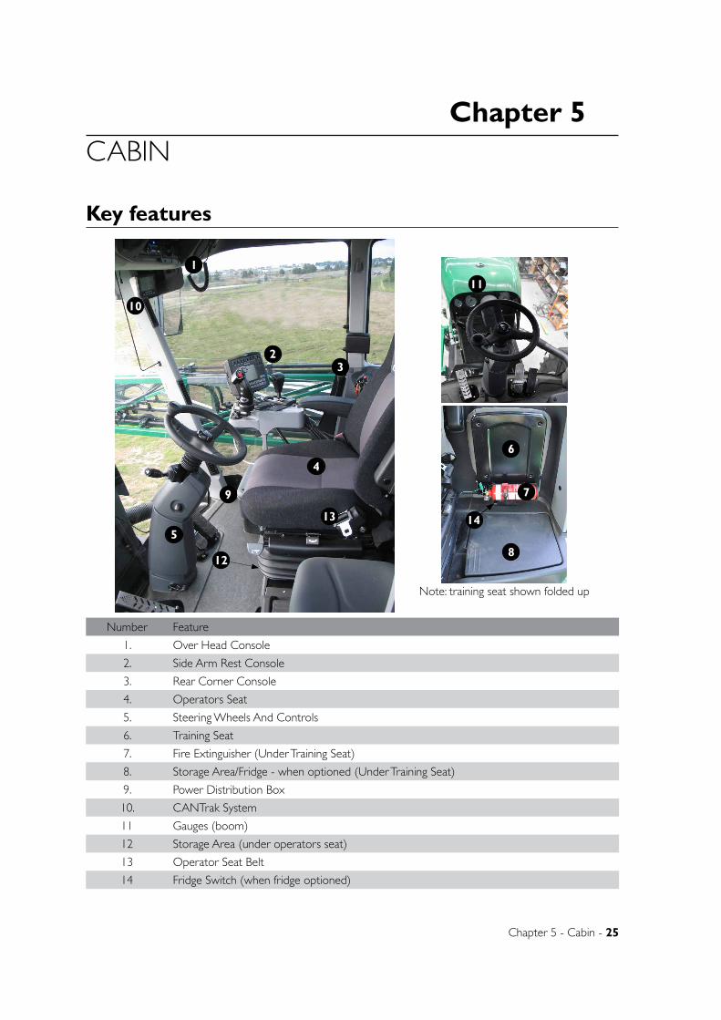
Chapter 5
Chapter 5 - Cabin - 25
CABIN
Key features
Number Feature
1. Over Head Console
2. Side Arm Rest Console
3. Rear Corner Console
4. Operators Seat
5. Steering Wheels And Controls
6. Training Seat
7. Fire Extinguisher (Under Training Seat)
8. Storage Area/Fridge - when optioned (Under Training Seat)
9. Power Distribution Box
10. CANTrak System
11 Gauges (boom)
12 Storage Area (under operators seat)
13 Operator Seat Belt
14 Fridge Switch (when fridge optioned)
2
4
3
5
1
10
9
6
7
8
Note: training seat shown folded up
11
12
13 14

26 - Crop Cruiser Evolution MY13 Operators Manual - Rev 1.4
Arm rest controls (Raven Controller)
2
1 3
Number Feature
1. Joystick Control
2. Rate Controller
3. GPS On/Off
4. Pump 1 On/Off
5. Pump 2 On/Off
6. Spare
7. Engine RPM Raise
8. Spray Pump Indication Light
9. Tilt Left Up & Down
10. Tilt Right Up & Down
11. Boom Up/Down
12. Boom Rest In/Out
13. Transmission Gear Selector
14. Spare
15. 4WD On/Off
16. Dual Product On/Off
17. Power/Econ Mode
18. Field/Road Mode
4 7
9
5 6
11 1213
14 15
8
10
16
1718

Chapter 5 - Cabin - 27
Joystick controls
Number Feature
1. Boom Open,Close/ Bi Fold
2. Cruise Control On/Off
3. Boom Tilt Left/Right
4. Fence Jets On/Off Left and Right
5. Spare
6. Boom Raise/Lower, Cruise Control Set/Resume
7. Boom Recirc/GPS - Auto steer resume
8. Pump On/Off
9. Spray Master. (On reverse side, not shown)
1
2
4
5
3
8
7
6
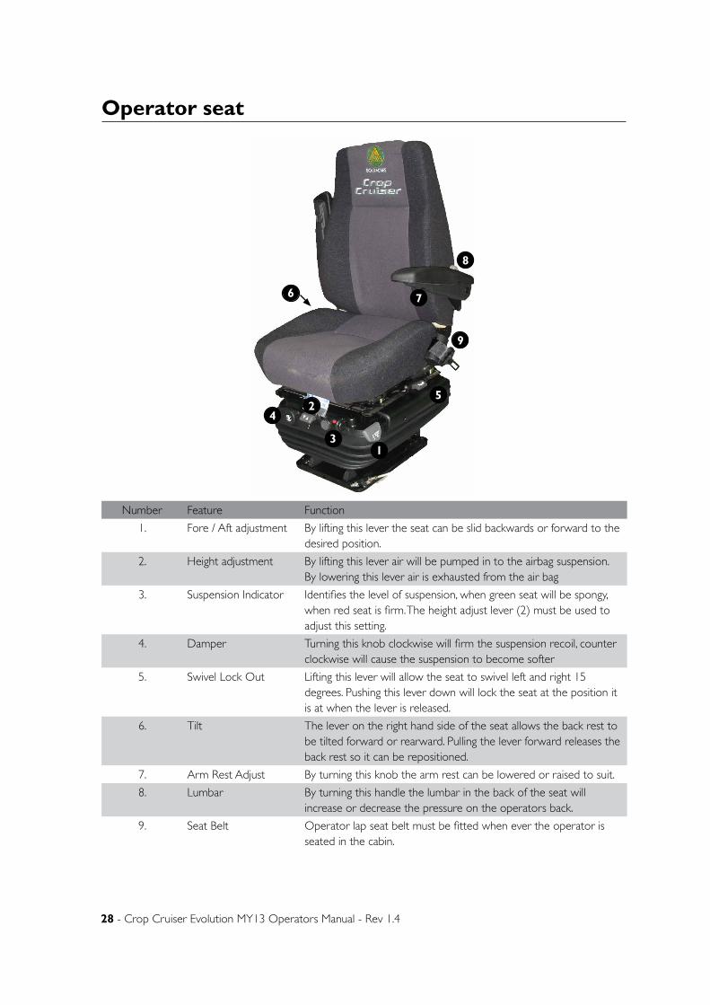
28 - Crop Cruiser Evolution MY13 Operators Manual - Rev 1.4
Operator seat
Number Feature Function
1. Fore / Aft adjustment By lifting this lever the seat can be slid backwards or forward to the desired position.
2. Height adjustment By lifting this lever air will be pumped in to the airbag suspension. By lowering this lever air is exhausted from the air bag
3. Suspension Indicator Identifies the level of suspension, when green seat will be spongy, when red seat is firm. The height adjust lever (2) must be used to adjust this setting.
4. Damper Turning this knob clockwise will firm the suspension recoil, counter clockwise will cause the suspension to become softer
5. Swivel Lock Out Lifting this lever will allow the seat to swivel left and right 15 degrees. Pushing this lever down will lock the seat at the position it is at when the lever is released.
6. Tilt The lever on the right hand side of the seat allows the back rest to be tilted forward or rearward. Pulling the lever forward releases the back rest so it can be repositioned.
7. Arm Rest Adjust By turning this knob the arm rest can be lowered or raised to suit.
8. Lumbar By turning this handle the lumbar in the back of the seat will increase or decrease the pressure on the operators back.
9. Seat Belt Operator lap seat belt must be fitted when ever the operator is seated in the cabin.
1
2
3
4
5
6 7
8
9
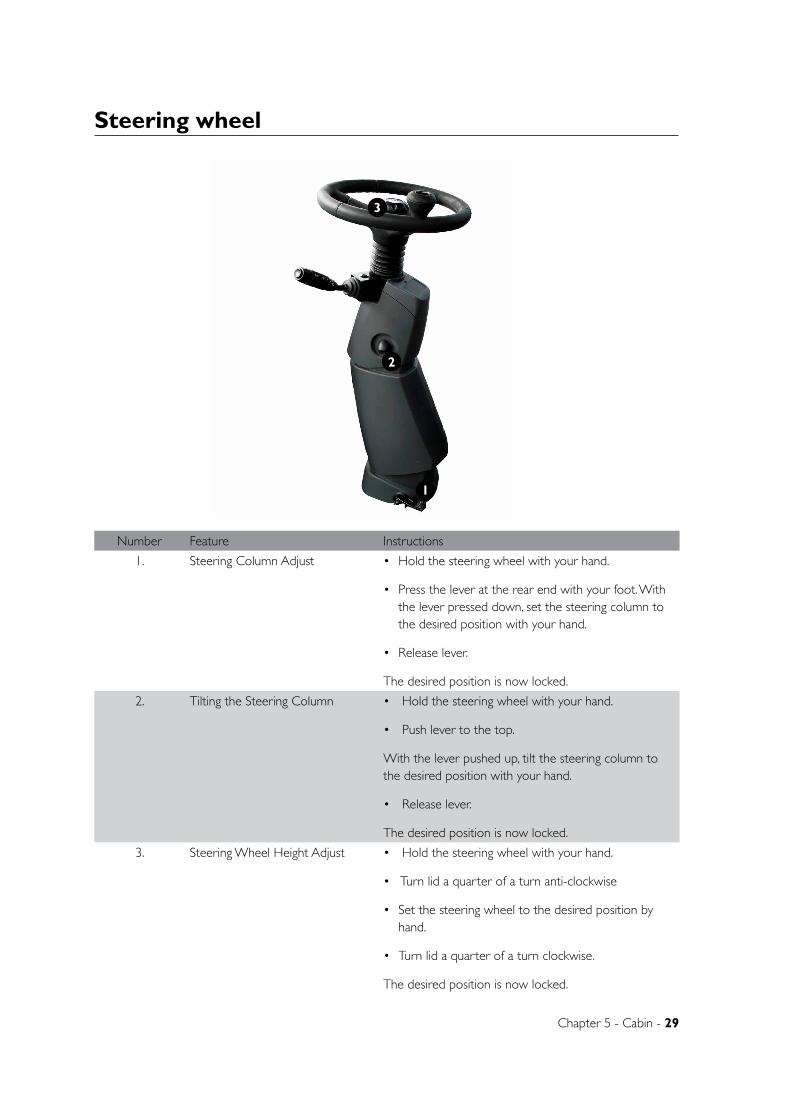
Chapter 5 - Cabin - 29
Steering wheel
1
2
3
Number Feature Instructions
1. Steering Column Adjust • Hold the steering wheel with your hand.
• Press the lever at the rear end with your foot. With the lever pressed down, set the steering column to the desired position with your hand.
• Release lever.
The desired position is now locked.
2. Tilting the Steering Column • Hold the steering wheel with your hand.
• Push lever to the top.
With the lever pushed up, tilt the steering column to the desired position with your hand.
• Release lever.
The desired position is now locked.
3. Steering Wheel Height Adjust • Hold the steering wheel with your hand.
• Turn lid a quarter of a turn anti-clockwise
• Set the steering wheel to the desired position by hand.
• Turn lid a quarter of a turn clockwise.
The desired position is now locked.
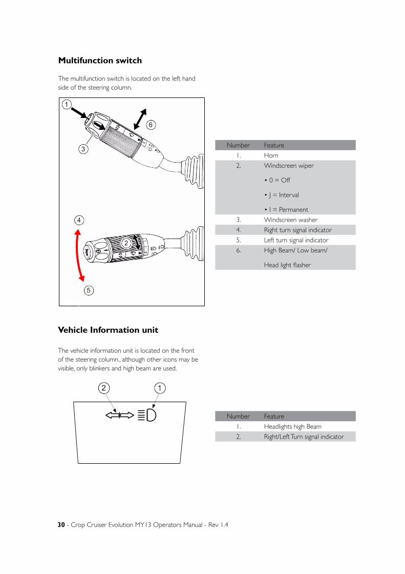
30 - Crop Cruiser Evolution MY13 Operators Manual - Rev 1.4
Multifunction switch
The multifunction switch is located on the left hand side of the steering column.
Vehicle Information unit
The vehicle information unit is located on the front of the steering column., although other icons may be visible, only blinkers and high beam are used.
Number Feature
1. Horn
2. Windscreen wiper
• 0 = Off
• J = Interval
• I = Permanent
3. Windscreen washer
4. Right turn signal indicator
5. Left turn signal indicator
6. High Beam/ Low beam/
Head light flasher
Number Feature
1. Headlights high Beam
2. Right/Left Turn signal indicator
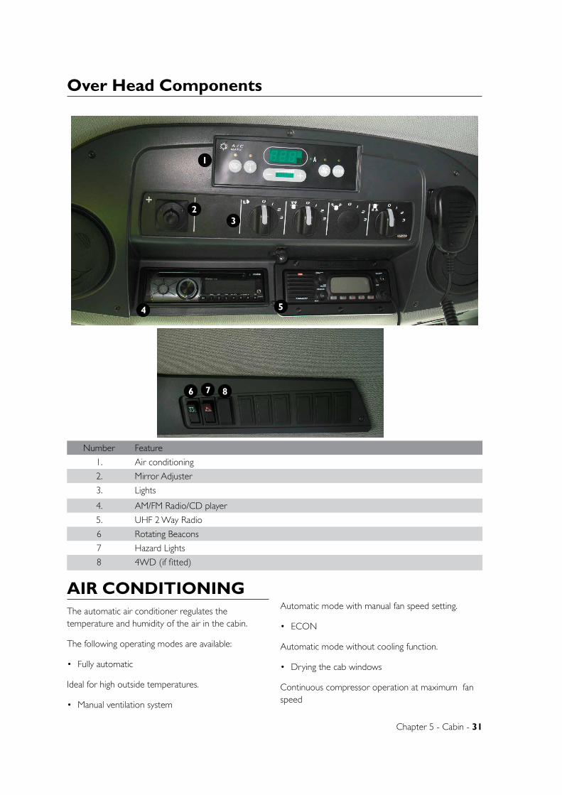
Chapter 5 - Cabin - 31
Over Head Components
1
23
4 5
Number Feature
1. Air conditioning
2. Mirror Adjuster
3. Lights
4. AM/FM Radio/CD player
5. UHF 2 Way Radio
6 Rotating Beacons
7 Hazard Lights
8 4WD (if fitted)
AIR CONDITIONINGThe automatic air conditioner regulates the temperature and humidity of the air in the cabin.
The following operating modes are available:
• Fully automatic
Ideal for high outside temperatures.
• Manual ventilation system
Automatic mode with manual fan speed setting.
• ECON
Automatic mode without cooling function.
• Drying the cab windows
Continuous compressor operation at maximum fan speed
6 7 8
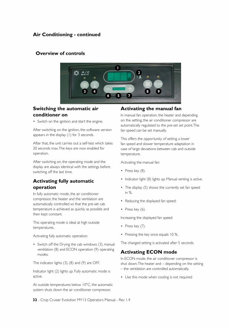
32 - Crop Cruiser Evolution MY13 Operators Manual - Rev 1.4
Switching the automatic air conditioner on• Switch on the ignition and start the engine.
After switching on the ignition, the software version appears in the display (1) for 3 seconds.
After that, the unit carries out a self-test which takes 20 seconds max. The keys are now enabled for operation.
After switching on, the operating mode and the display are always identical with the settings before switching off the last time.
Activating fully automatic operationIn fully automatic mode, the air conditioner compressor, the heater and the ventilation are automatically controlled so that the pre-set cab temperature is achieved as quickly as possible and then kept constant.
This operating mode is ideal at high outside temperatures.
Activating fully automatic operation:
• Switch off the Drying the cab windows (3), manual ventilation (8) and ECON operation (9) operating modes.
The indicator lights (3), (8) and (9) are OFF.
Indicator light (2) lights up. Fully automatic mode is active.
At outside temperatures below 10°C, the automatic system shuts down the air conditioner compressor.
Activating the manual fanIn manual fan operation, the heater and depending on the setting, the air conditioner compressor are automatically regulated to the pre-set set point. The fan speed can be set manually.
This offers the opportunity of setting a lower fan speed and slower temperature adaptation in case of large deviations between cab and outside temperature.
Activating the manual fan:
• Press key (8).
• Indicator light (8) lights up. Manual venting is active.
• The display (5) shows the currently set fan speed in %.
• Reducing the displayed fan speed:
• Press key (6).
Increasing the displayed fan speed:
• Press key (7).
• Pressing the key once equals 10 %.
The changed setting is activated after 5 seconds.
Activating ECON modeIn ECON mode, the air conditioner compressor is shut down. The heater and – depending on the setting – the ventilation are controlled automatically.
• Use this mode when cooling is not required
Overview of controls
43 8 96 5 7
12
Air Conditioning - continued
Chapter 5 - Cabin - 33
Activating the ECON mode
• Press key (9).
• Indicator light (9) lights up. Indicator light (2) goes out.
The ECON mode is active.
Drying the cab windows
For drying the cab windows, the compressor is On permanently at max. fan speed. The heater is set to the pre-set set value.
Drying the cab windows:
• Press key (3).
Indicator light (3) lights up. The drying mode is active. The fan is set to max. capacity.
• Changing the fan speed if required:
See Activating the manual fan.
Setting the cab temperature The display (1) shows the currently set temperature.
• Reducing the displayed temperature:
Press key (6).
• Increasing the displayed temperature:
Press key (7).
Pressing the key once equals 1°C.
The automatic air conditioner adjusts the cab temperature to the set value. In this process, the fan speed is slowly increased so that the cab temperature reaches the pre-set set point quicker. When the cab temperature approaches the set value, the fan speed is educed again..
Displaying the outside temperature• Press key (4). Indicator light (4) lights up. The
display (1) shows the outside temperature..
Changing the temperature unit• Keep keys (4) and (6) pressed simultaneously for 3
seconds.
The temperature display changes to °Fahrenheit.
• Repeat this process to return to °Centigrade.
Adjusting the air conditioner air flowThe air flow is distributed inside the cab by fully adjustable nozzles. Each nozzle can be adjusted directionally or turned on/off to suit the individual needs of the user.
Eg. To heat the leg area, close all upper vents and direct air flow from the lower vents to the floor.
AM/FM RadioThe entertainment radio is fitted to the panel in front of the operator on the roof. It consists of a radio tuner as well as single compact disc player. A blue tooth compatible phone system is installed in the unit.
Operational instructions can be found in the entertainment radio manual supplied with this manual.
UHF Two Way RadioThere is a UHF two way radio mounted on the roof cavity near the entertainment radio. This radio is powered up through the electrical panel and has a fused circuit.
Operational instructions can be found in the UHF Two Way Radio manual supplied with this manual.
Map LightThe map light has two seperate lights. that can be operated together or individually.
The switch on the left turns the front map light on and off. This light is fixed and cannot be aimed.
The switch on the right operates the rear map light. This light is directional and can be aimed as desired.
Note: The map lights wont operate unless the ignition key is in the ‘accesories’ or ‘run’ position.
Airconditioning - continued

34 - Crop Cruiser Evolution MY13 Operators Manual - Rev 1.4
Lighting
HEAD LIGHTS
0, Off
1, Cab interior lights, Tail Lights, Outer Boom Marker lights.
2, All of above and Head lights.
3, Not used
Note: The multi function stick is used to cycle between high and low beam while the head lights are turned on.
FRONT WORK LIGHTS
0, Off
1, Inner Front Work lights
2, Outer front work lights
3, Not used
REAR WORK LIGHTS
0, Off
1, Rear work lights
2, Not used
3, Not Used
Note: Front and rear work lights will not function unless the headlight switch is in position 1 or 2.
Number Feature
1. Head Lights
2. Front Work Lights
3. Rear Work Lights
1 32
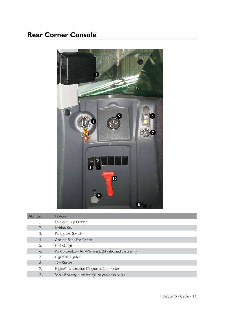
Chapter 5 - Cabin - 35
Rear Corner Console
2
1
43
65
8
7
Number Feature
1. Fold out Cup Holder
2. Ignition Key
3. Park Brake Switch
4. Carbon Filter Fan Switch
5. Fuel Gauge
6. Park Brake/Low Air Warning Light (also audible alarm)
7. Cigarette Lighter
8. 12V Socket
9. Engine/Transmission Diagnostic Connector
10. Glass Breaking Hammer (emergency use only)
9
10
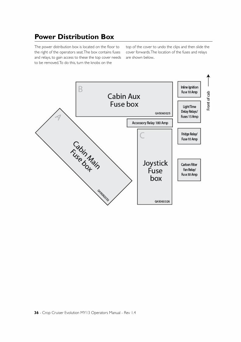
36 - Crop Cruiser Evolution MY13 Operators Manual - Rev 1.4
The power distribution box is located on the floor to the right of the operators seat. The box contains fuses and relays, to gain access to these the top cover needs to be removed. To do this, turn the knobs on the
top of the cover to undo the clips and then slide the cover forwards. The location of the fuses and relays are shown below..
Power Distribution Box
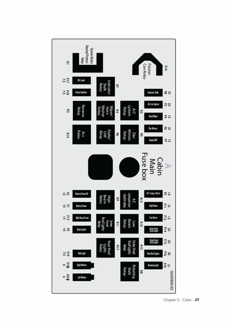
Chapter 5 - Cabin - 37
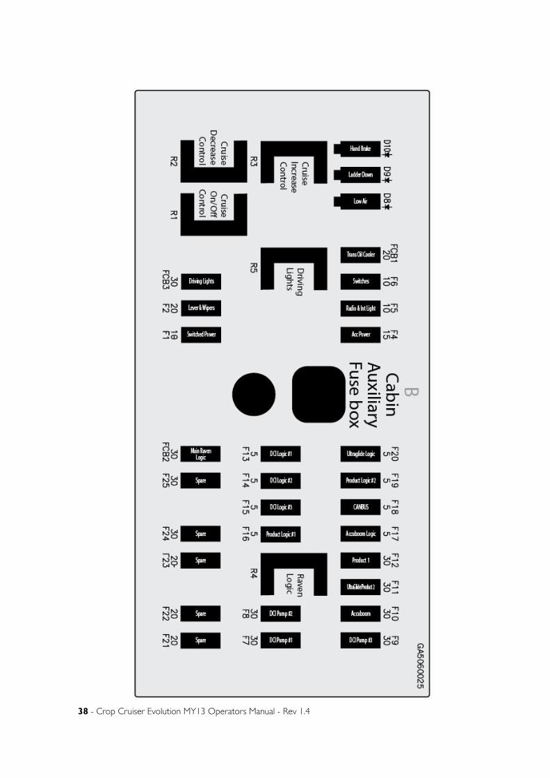
38 - Crop Cruiser Evolution MY13 Operators Manual - Rev 1.4
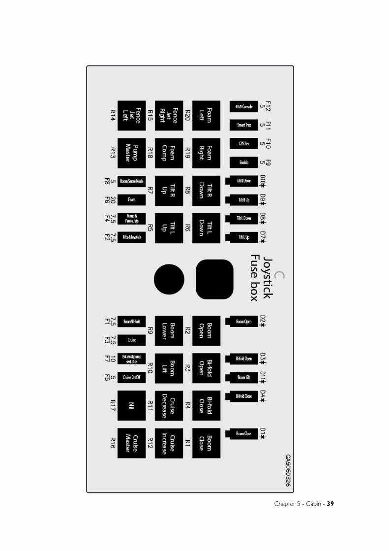
Chapter 5 - Cabin - 39

40 - Crop Cruiser Evolution MY13 Operators Manual - Rev 1.4
CANtrak System (Generic Engine Monitor)
Understanding GEMGEM software runs on a CANtrak display with five soft keys, providing a flexible and intuitive Human-Machine Interface (HMI). The 5 soft keys access a graphical menu structure that uses standard and easily-understood icons to indicate the key’s current function. This enables the operator to select the required engine and transmission data and display it in the following formats:
• Analogue gauges
• Digital values
• Multi-gauge/data (a combination of above)
• Historical trend graphs
• Current or stored alarm messages
Additionally, various diagnostic screens are available, allowing detailed investigation of the engine and transmission data stream. By accessing the Configuration menu, users can customise some of the displayed data to show, for example, metric or imperial units, and various parameters such as the full-scale reading of gauges.
Pressing any of the first 4 keys (GEM keys are numbered 1 to 5, from left to right) brings up the top level ‘button bar’ (navigation menu).
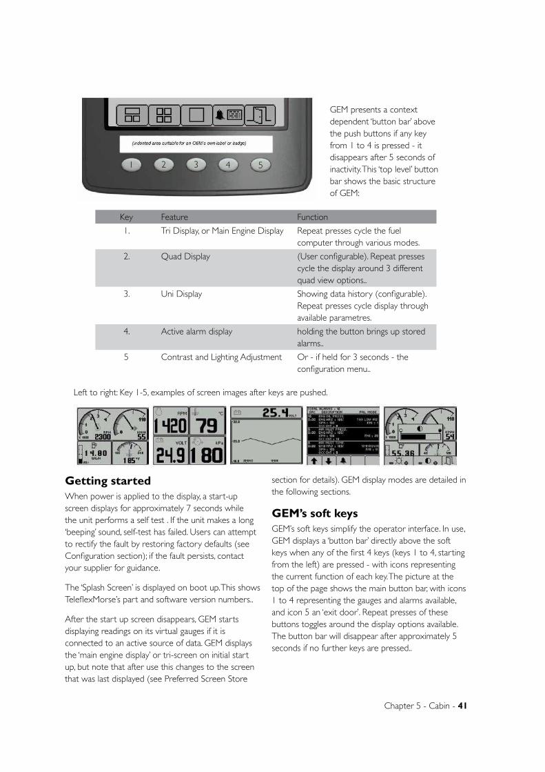
Chapter 5 - Cabin - 41
GEM presents a context dependent ‘button bar’ above the push buttons if any key from 1 to 4 is pressed - it disappears after 5 seconds of inactivity. This ‘top level’ button bar shows the basic structure of GEM:
Getting startedWhen power is applied to the display, a start-up screen displays for approximately 7 seconds while the unit performs a self test . If the unit makes a long ‘beeping’ sound, self-test has failed. Users can attempt to rectify the fault by restoring factory defaults (see Configuration section); if the fault persists, contact your supplier for guidance.
The ‘Splash Screen’ is displayed on boot up. This shows TeleflexMorse’s part and software version numbers..
After the start up screen disappears, GEM starts displaying readings on its virtual gauges if it is connected to an active source of data. GEM displays the ‘main engine display’ or tri-screen on initial start up, but note that after use this changes to the screen that was last displayed (see Preferred Screen Store
section for details). GEM display modes are detailed in the following sections.
GEM’s soft keysGEM’s soft keys simplify the operator interface. In use, GEM displays a ‘button bar’ directly above the soft keys when any of the first 4 keys (keys 1 to 4, starting from the left) are pressed - with icons representing the current function of each key. The picture at the top of the page shows the main button bar, with icons 1 to 4 representing the gauges and alarms available, and icon 5 an ‘exit door’. Repeat presses of these buttons toggles around the display options available. The button bar will disappear after approximately 5 seconds if no further keys are pressed..
Key Feature Function
1. Tri Display, or Main Engine Display Repeat presses cycle the fuel computer through various modes.
2. Quad Display (User configurable). Repeat presses cycle the display around 3 different quad view options..
3. Uni Display Showing data history (configurable). Repeat presses cycle display through available parametres.
4. Active alarm display holding the button brings up stored alarms..
5 Contrast and Lighting Adjustment Or - if held for 3 seconds - the configuration menu..
Left to right: Key 1-5, examples of screen images after keys are pushed.
1 2 3 4 5
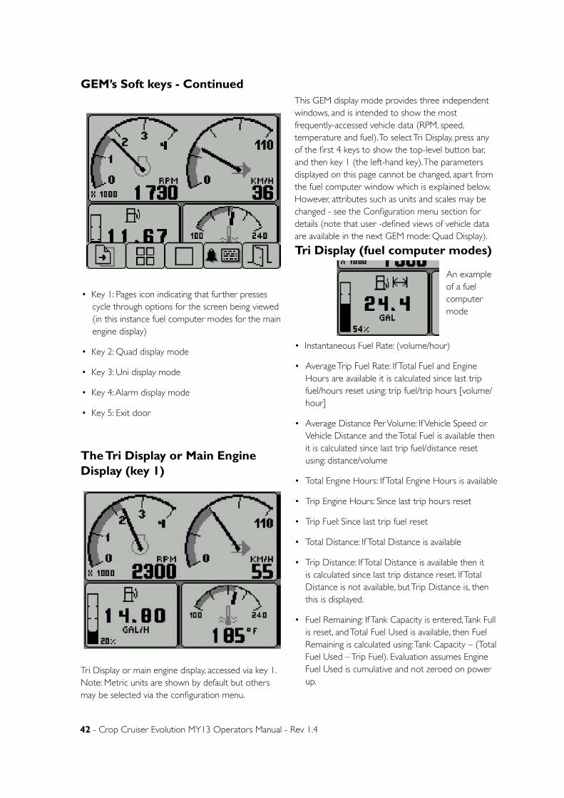
42 - Crop Cruiser Evolution MY13 Operators Manual - Rev 1.4
GEM’s Soft keys - Continued
• Key 1: Pages icon indicating that further presses cycle through options for the screen being viewed (in this instance fuel computer modes for the main engine display)
• Key 2: Quad display mode
• Key 3: Uni display mode
• Key 4: Alarm display mode
• Key 5: Exit door
The Tri Display or Main Engine Display (key 1)
Tri Display or main engine display, accessed via key 1. Note: Metric units are shown by default but others may be selected via the configuration menu.
This GEM display mode provides three independent windows, and is intended to show the most frequently-accessed vehicle data (RPM, speed, temperature and fuel). To select Tri Display, press any of the first 4 keys to show the top-level button bar, and then key 1 (the left-hand key). The parameters displayed on this page cannot be changed, apart from the fuel computer window which is explained below. However, attributes such as units and scales may be changed - see the Configuration menu section for details (note that user -defined views of vehicle data are available in the next GEM mode: Quad Display).
Tri Display (fuel computer modes)
• Instantaneous Fuel Rate: (volume/hour)
• Average Trip Fuel Rate: If Total Fuel and Engine Hours are available it is calculated since last trip fuel/hours reset using: trip fuel/trip hours [volume/hour]
• Average Distance Per Volume: If Vehicle Speed or Vehicle Distance and the Total Fuel is available then it is calculated since last trip fuel/distance reset using: distance/volume
• Total Engine Hours: If Total Engine Hours is available
• Trip Engine Hours: Since last trip hours reset
• Trip Fuel: Since last trip fuel reset
• Total Distance: If Total Distance is available
• Trip Distance: If Total Distance is available then it is calculated since last trip distance reset. If Total Distance is not available, but Trip Distance is, then this is displayed.
• Fuel Remaining: If Tank Capacity is entered, Tank Full is reset, and Total Fuel Used is available, then Fuel Remaining is calculated using: Tank Capacity – (Total Fuel Used – Trip Fuel). Evaluation assumes Engine Fuel Used is cumulative and not zeroed on power up.
An example of a fuel computer mode
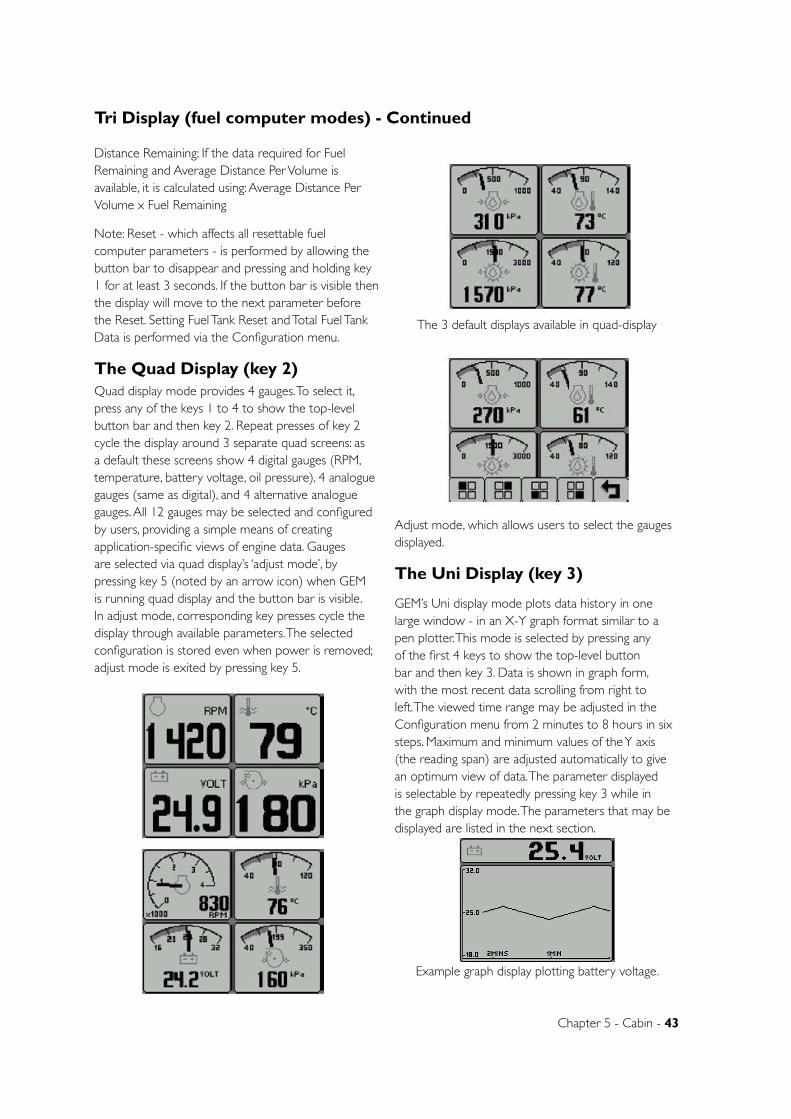
Chapter 5 - Cabin - 43
Tri Display (fuel computer modes) - Continued
Distance Remaining: If the data required for Fuel Remaining and Average Distance Per Volume is available, it is calculated using: Average Distance Per Volume x Fuel Remaining
Note: Reset - which affects all resettable fuel computer parameters - is performed by allowing the button bar to disappear and pressing and holding key 1 for at least 3 seconds. If the button bar is visible then the display will move to the next parameter before the Reset. Setting Fuel Tank Reset and Total Fuel Tank Data is performed via the Configuration menu.
The Quad Display (key 2)Quad display mode provides 4 gauges. To select it, press any of the keys 1 to 4 to show the top-level button bar and then key 2. Repeat presses of key 2 cycle the display around 3 separate quad screens: as a default these screens show 4 digital gauges (RPM, temperature, battery voltage, oil pressure), 4 analogue gauges (same as digital), and 4 alternative analogue gauges. All 12 gauges may be selected and configured by users, providing a simple means of creating application-specific views of engine data. Gauges are selected via quad display’s ‘adjust mode’, by pressing key 5 (noted by an arrow icon) when GEM is running quad display and the button bar is visible. In adjust mode, corresponding key presses cycle the display through available parameters. The selected configuration is stored even when power is removed; adjust mode is exited by pressing key 5.
The 3 default displays available in quad-display
Adjust mode, which allows users to select the gauges displayed.
The Uni Display (key 3)
GEM’s Uni display mode plots data history in one large window - in an X-Y graph format similar to a pen plotter. This mode is selected by pressing any of the first 4 keys to show the top-level button bar and then key 3. Data is shown in graph form, with the most recent data scrolling from right to left. The viewed time range may be adjusted in the Configuration menu from 2 minutes to 8 hours in six steps. Maximum and minimum values of the Y axis (the reading span) are adjusted automatically to give an optimum view of data. The parameter displayed is selectable by repeatedly pressing key 3 while in the graph display mode. The parameters that may be displayed are listed in the next section.
Example graph display plotting battery voltage.
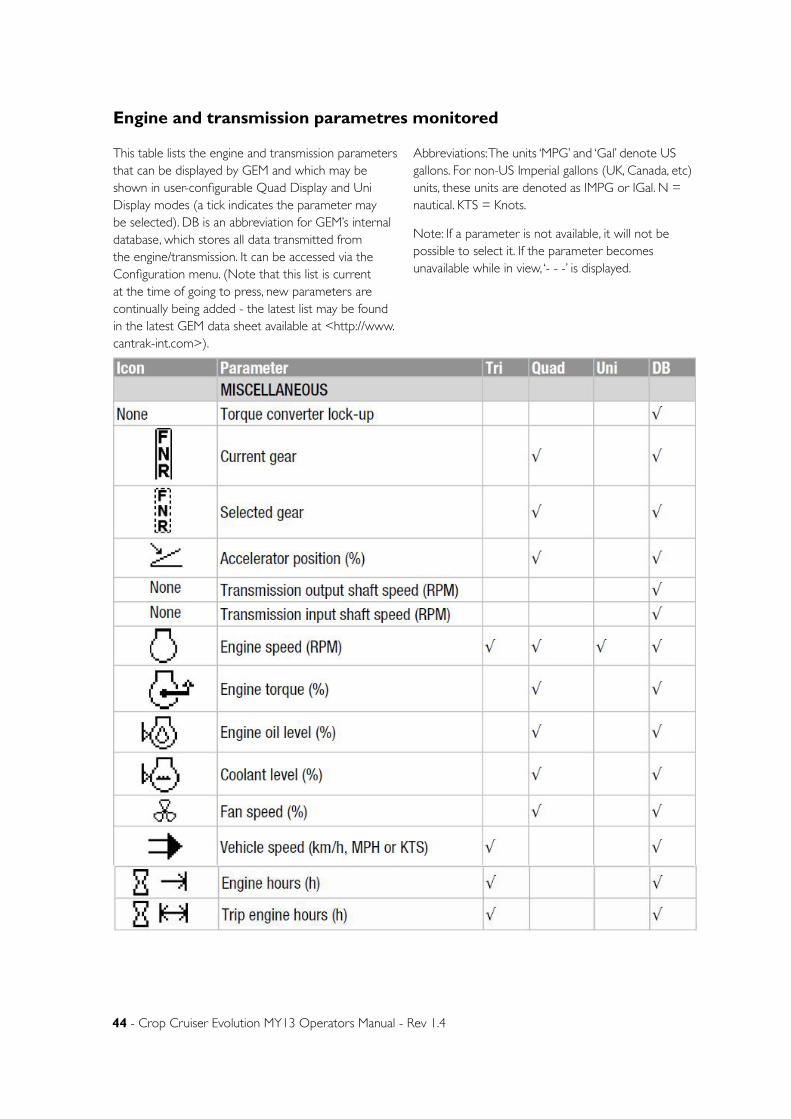
44 - Crop Cruiser Evolution MY13 Operators Manual - Rev 1.4
Engine and transmission parametres monitored
This table lists the engine and transmission parameters that can be displayed by GEM and which may be shown in user-configurable Quad Display and Uni Display modes (a tick indicates the parameter may be selected). DB is an abbreviation for GEM’s internal database, which stores all data transmitted from the engine/transmission. It can be accessed via the Configuration menu. (Note that this list is current at the time of going to press, new parameters are continually being added - the latest list may be found in the latest GEM data sheet available at <http://www.cantrak-int.com>).
Abbreviations: The units ‘MPG’ and ‘Gal’ denote US gallons. For non-US Imperial gallons (UK, Canada, etc) units, these units are denoted as IMPG or IGal. N = nautical. KTS = Knots.
Note: If a parameter is not available, it will not be possible to select it. If the parameter becomes unavailable while in view, ‘- - -’ is displayed.
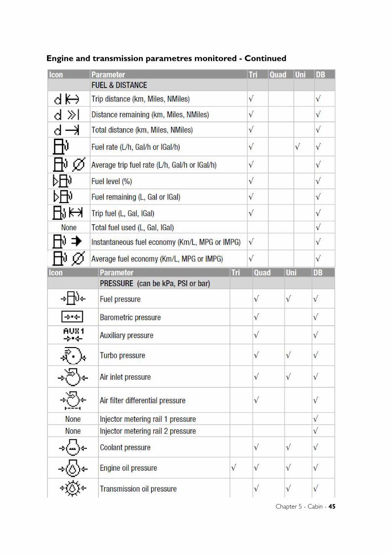
Chapter 5 - Cabin - 45
Engine and transmission parametres monitored - Continued

46 - Crop Cruiser Evolution MY13 Operators Manual - Rev 1.4
Engine and transmission parametres monitored - Continued
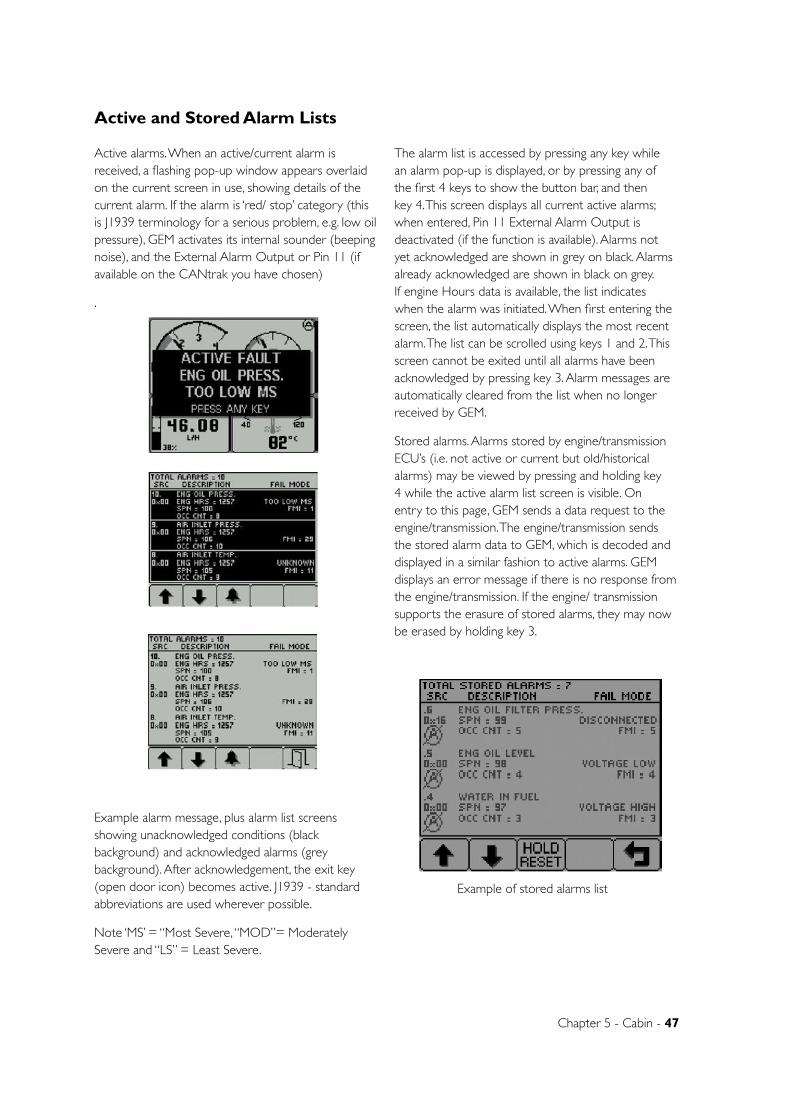
Chapter 5 - Cabin - 47
Active and Stored Alarm Lists
Active alarms. When an active/current alarm is received, a flashing pop-up window appears overlaid on the current screen in use, showing details of the current alarm. If the alarm is ‘red/ stop’ category (this is J1939 terminology for a serious problem, e.g. low oil pressure), GEM activates its internal sounder (beeping noise), and the External Alarm Output or Pin 11 (if available on the CANtrak you have chosen)
.
Example alarm message, plus alarm list screens showing unacknowledged conditions (black background) and acknowledged alarms (grey background). After acknowledgement, the exit key (open door icon) becomes active. J1939 - standard abbreviations are used wherever possible.
Note ‘MS’ = “Most Severe, “MOD”= Moderately Severe and “LS” = Least Severe.
The alarm list is accessed by pressing any key while an alarm pop-up is displayed, or by pressing any of the first 4 keys to show the button bar, and then key 4. This screen displays all current active alarms; when entered, Pin 11 External Alarm Output is deactivated (if the function is available). Alarms not yet acknowledged are shown in grey on black. Alarms already acknowledged are shown in black on grey. If engine Hours data is available, the list indicates when the alarm was initiated. When first entering the screen, the list automatically displays the most recent alarm. The list can be scrolled using keys 1 and 2. This screen cannot be exited until all alarms have been acknowledged by pressing key 3. Alarm messages are automatically cleared from the list when no longer received by GEM.
Stored alarms. Alarms stored by engine/transmission ECU’s (i.e. not active or current but old/historical alarms) may be viewed by pressing and holding key 4 while the active alarm list screen is visible. On entry to this page, GEM sends a data request to the engine/transmission. The engine/transmission sends the stored alarm data to GEM, which is decoded and displayed in a similar fashion to active alarms. GEM displays an error message if there is no response from the engine/transmission. If the engine/ transmission supports the erasure of stored alarms, they may now be erased by holding key 3.
Example of stored alarms list
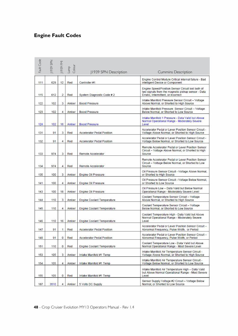
48 - Crop Cruiser Evolution MY13 Operators Manual - Rev 1.4
Engine Fault CodesFa
ult
Cod
e
J193
9 SP
N
J193
9 FM
I
Lam
p
Col
our
J1939 SPN Description Cummins Description
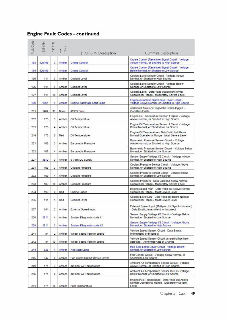
Chapter 5 - Cabin - 49
Engine Fault Codes - continuedFa
ult
Cod
e
J193
9 SP
N
J193
9 FM
I
Lam
p
Col
our
J1939 SPN Description Cummins Description
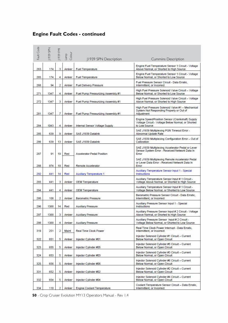
50 - Crop Cruiser Evolution MY13 Operators Manual - Rev 1.4
Engine Fault Codes - continuedFa
ult
Cod
e
J193
9 SP
N
J193
9 FM
I
Lam
p
Col
our
J1939 SPN Description Cummins Description
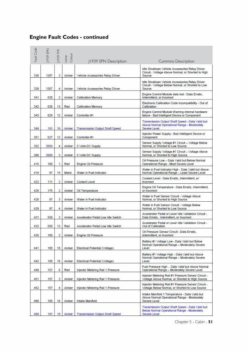
Chapter 5 - Cabin - 51
Engine Fault Codes - continuedFa
ult
Cod
e
J193
9 SP
N
J193
9 FM
I
Lam
p
Col
our
J1939 SPN Description Cummins Description
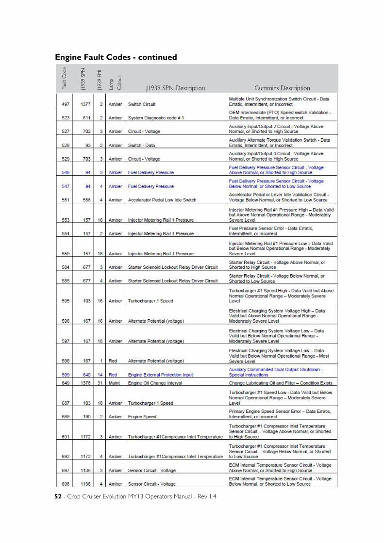
52 - Crop Cruiser Evolution MY13 Operators Manual - Rev 1.4
Engine Fault Codes - continuedFa
ult
Cod
e
J193
9 SP
N
J193
9 FM
I
Lam
p
Col
our
J1939 SPN Description Cummins Description
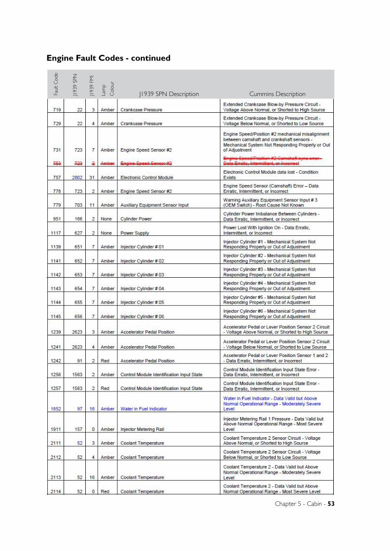
Chapter 5 - Cabin - 53
Engine Fault Codes - continuedFa
ult
Cod
e
J193
9 SP
N
J193
9 FM
I
Lam
p
Col
our
J1939 SPN Description Cummins Description
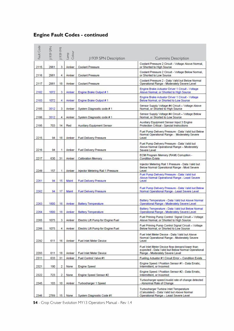
54 - Crop Cruiser Evolution MY13 Operators Manual - Rev 1.4
Engine Fault Codes - continuedFa
ult
Cod
e
J193
9 SP
N
J193
9 FM
I
Lam
p
Col
our
J1939 SPN Description Cummins Description
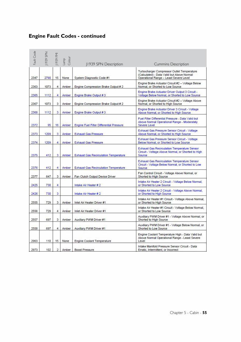
Chapter 5 - Cabin - 55
Engine Fault Codes - continuedFa
ult
Cod
e
J193
9 SP
N
J193
9 FM
I
Lam
p
Col
our
J1939 SPN Description Cummins Description
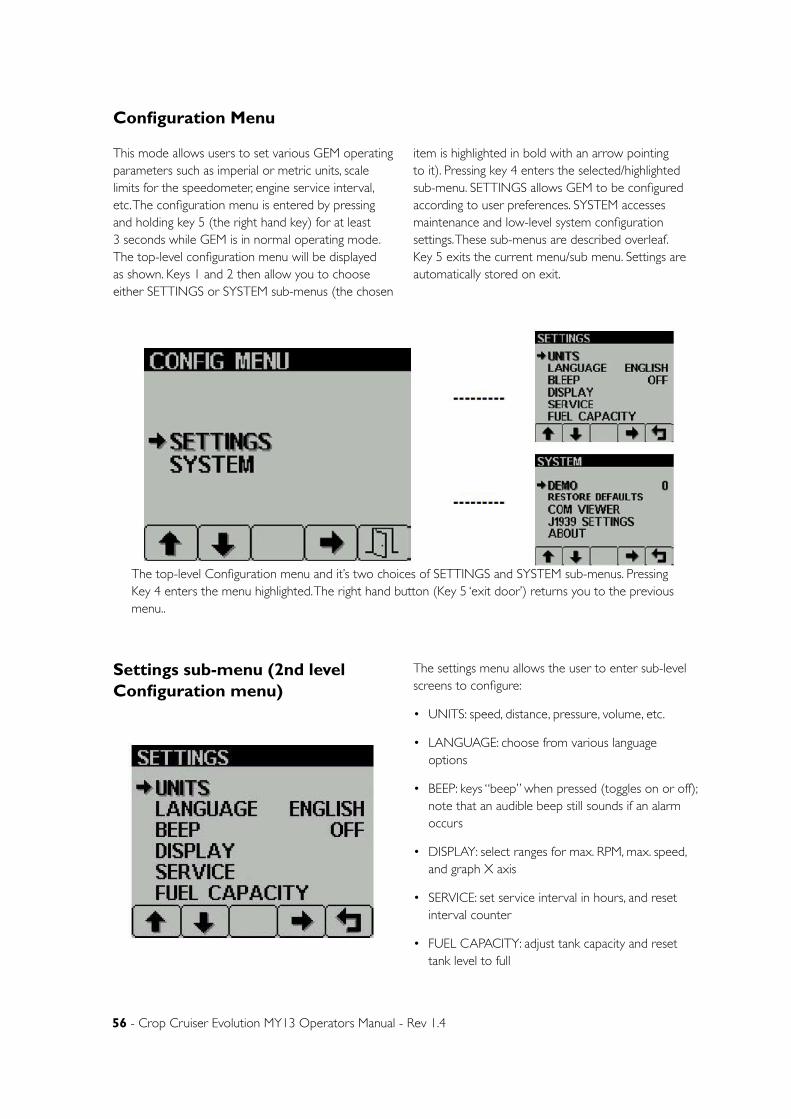
56 - Crop Cruiser Evolution MY13 Operators Manual - Rev 1.4
Configuration Menu
This mode allows users to set various GEM operating parameters such as imperial or metric units, scale limits for the speedometer, engine service interval, etc. The configuration menu is entered by pressing and holding key 5 (the right hand key) for at least 3 seconds while GEM is in normal operating mode. The top-level configuration menu will be displayed as shown. Keys 1 and 2 then allow you to choose either SETTINGS or SYSTEM sub-menus (the chosen
item is highlighted in bold with an arrow pointing to it). Pressing key 4 enters the selected/highlighted sub-menu. SETTINGS allows GEM to be configured according to user preferences. SYSTEM accesses maintenance and low-level system configuration settings. These sub-menus are described overleaf. Key 5 exits the current menu/sub menu. Settings are automatically stored on exit.
The top-level Configuration menu and it’s two choices of SETTINGS and SYSTEM sub-menus. Pressing Key 4 enters the menu highlighted. The right hand button (Key 5 ‘exit door’) returns you to the previous menu..
Settings sub-menu (2nd level Configuration menu)
The settings menu allows the user to enter sub-level screens to configure:
• UNITS: speed, distance, pressure, volume, etc.
• LANGUAGE: choose from various language options
• BEEP: keys “beep” when pressed (toggles on or off); note that an audible beep still sounds if an alarm occurs
• DISPLAY: select ranges for max. RPM, max. speed, and graph X axis
• SERVICE: set service interval in hours, and reset interval counter
• FUEL CAPACITY: adjust tank capacity and reset tank level to full

Chapter 5 - Cabin - 57
System Sub-menu (2nd level configuration menu)
The system menu allows the user to configure or view: DEMO: Switches between GEM’s demonstration mode and the normal mode of displaying live engine/ transmission data. Demo allows GEM to operate without live data and provides 3 levels of simulated data: 1 = Speed On; 2 = Speed Off; 3 = Alarms On. Demo is automatically set to OFF if live data is received. DEMO mode can be selected, allowing you to evaluate GEM without connecting an engine/ transmission (it is accessed via the Configuration menu described above). If the unit is in DEMO mode and live data from the engine/ transmission becomes active, DEMO mode will automatically be switched off.
RESTORE DEFAULTS:
Allows you to reset all configuration information to default metric or imperial values. The default settings are:
COM VIEWER: Displays last messages received on J1939 (CAN) and NMEA 0183 (GPS - derived speed over ground data) ports. You can also view GEM’s database (DB) which stores all data transmitted from the engine/transmission. Note: this is a diagnostic feature that may be helpful for OEMs/users diagnosing faults.
J1939 SETTINGS: J1939 configuration screen for engine and transmission source: 1 = engine 1 (port), 2 = engine 2 (Starboard); alarm filter (GLB (Global) = all alarm sources, SRC = selected engine/ transmission only); SPN version (4 is default but older engines will need to be set to 1, 2 or 3 as appropriate). Note. Consult your engine or vehicle supplier to establish which SPN version is appropriate if you have problems reading alarm data.
ABOUT: Displays the following product information:
• ID NO: Unique number of the display
• EEPROM: Number of write cycles
• PART No: Software part number
• VERS: Software version number
• CHK: Flash memory checksum
• SOURCE: The source of received data
• LIB1: Low level system library version
• LIB2: Low-level graphical display interface library version (if used).

58 - Crop Cruiser Evolution MY13 Operators Manual - Rev 1.4
• Engine service warning. In the Configuration menu, users can set the engine service interval in hours. When GEM determines an engine service is due, it displays SERVICE REQUIRED on the splash screen that appears at power-up.
• Data communications failure. If GEM cannot detect engine/ transmission data broadcasts , a pop-up window with a data communications failure warning icon will appear and fl ash. Once engine/transmission data is detected the warning disappears and normal data display resumes.
• CAN TX disable. If CAN TX (transmission) is disabled, then the status will be displayed, with a pop-up window flashing with a period of approximately 1 second on, 10 seconds off. Note that this function is a requirement of the J1939 specification and is not normally of importance for GEM applications.
• Data not supported. If the required data parameter is not available, the gauge will display “ - - - “ near the units and parameter icon (see centre picture for example) From top to bottom., pop up warnings of: Engine
service required, a data communications failure and CANTX is disabled.
Pop up messages and warnings
Setting LCD lighting and contrastPressing key 5 (the right-hand key) when the menu icons are not being displayed brings up the lighting and contrast menu. The LCD has a number of back-lighting levels that allow the display to be read in the dark. The appropriate level is selected by pressing keys 1 or 2 to decrease or increase illumination. Contrast is adjusted in the same manner, using keys 3 and 4 (Figure 12.1). Note that GEM monitors the temperature of the LCD and automatically adjusts display contrast as required, therefore it is not likely
that a user will need to make a manual contrast adjustment unless extreme climate changes occur. The menu is exited by pressing key 5. The lighting and contrast settings are retained after the unit is switched off. Note: resetting contrast. If the contrast has been adjusted poorly, you may restore the factory setting (a central value) by pressing keys 1 to 4 simultaneously. This action does not change other user-configured settings.
The lighting and adjust screen, showing a contrast level adjustment in progress.
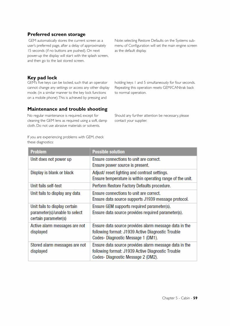
Chapter 5 - Cabin - 59
GEM automatically stores the current screen as a user’s preferred page, after a delay of approximately 15 seconds (if no buttons are pushed). On next power-up the display will start with the splash screen, and then go to the last stored screen.
Note: selecting Restore Defaults on the Systems sub-menu of Configuration will set the main engine screen as the default display.
Preferred screen storage
Key pad lockGEM’s five keys can be locked, such that an operator cannot change any settings or access any other display mode. (in a similar manner to the key lock functions on a mobile phone). This is achieved by pressing and
holding keys 1 and 5 simultaneously for four seconds. Repeating this operation resets GEM/CANtrak back to normal operation.
Maintenance and trouble shootingNo regular maintenance is required, except for cleaning the GEM lens as required using a soft, damp cloth. Do not use abrasive materials or solvents.
Should any further attention be necessary, please contact your supplier.
If you are experiencing problems with GEM, check these diagnostics:
60 - Crop Cruiser Evolution MY13 Operators Manual - Rev 1.4
Software Development Options for CANtrakCustomers have a range of options for creating user interfaces on CANtrak: Like a PC, a CANtrak needs application software to provide a useful function. GEM application software, written by TeleflexMorse, is just one example. CANtraks may be programmed to perform an infinite number of display, control and data logging tasks. To help modify existing software or write new application software TeleflexMorse has developed a software development kit (SDK). This is available for programming the micro-controller used in CANtrak - allowing complete control of the display hardware. Purchasers of a SDK and suitable compiler are given a number of hours of free technical support from Teleflex’s application engineering team - which may be used to write some or all of the customer-specified application software; alternatively the time may be used for training, trouble-shooting and advice.
As well as supplying and supporting the SDK, TeleflexMorse offers a fast-turnaround and cost effective software development service for CANtraks using the same SDK. These projects can range from something as simple as placing a customer’s logo on the splash screen, through additional pages of data on a branded version of GEM, to a full application with custom user interfaces, control programs, communication protocols, etc.
If you would like to discuss the purchase of an SDK, or obtain a quote for custom application software, please contact us.
More information is available via www.cantrak-int.com
Glossary• CAN: Controller Area Network (also referred to
as CANbus); serial communications protocol for automotive use
• CANtrak: Intelligent CAN-compatible LCD display module
• GEM: Generic Engine Monitor
• GPS: Global Positioning System
• HMI: Human-Machine Interface
• ISO: International Standard Organisation
• J1939: SAE engine data protocol using CAN 2.0B
• LCD: Liquid Crystal Display
• NMEA: National Marine Electronics Association; serial communications protocol for marine use
• PID: Parameter Identifier
• RS-232: Standard electrical interface for serial communications
• RS-485: Standard differential electrical interface for serial communications
• SAE: Society of Automotive Engineers Inc.
• SID: Subsystem Identifier
• Soft keys: Push-button keys whose function changes according to use
• SPN: Suspect Parameter Number: J1939-specifi c fault code ID number
Note: The messages, icons, error codes etc displayed by GEM conform to J1939 standards wherever possible.
Important safety and legal informationUnder no circumstances shall Teleflex or any of its subsidiary companies accept liability for any loss of data, income, incidental damage or consequential losses incurred as a result of the use of the product howsoever caused when used as a monitor for electronically-controlled engines/ transmissions or other systems.
• Reproduction, transfer, distribution or storage of part or all of the contents in this document in
any form without written permission of Teleflex is prohibited.
• TeleflexMorse operates a policy of continuous improvement. TeleflexMorse reserves the right to alter and improve the CANtrak displays and GEM software without prior notice.
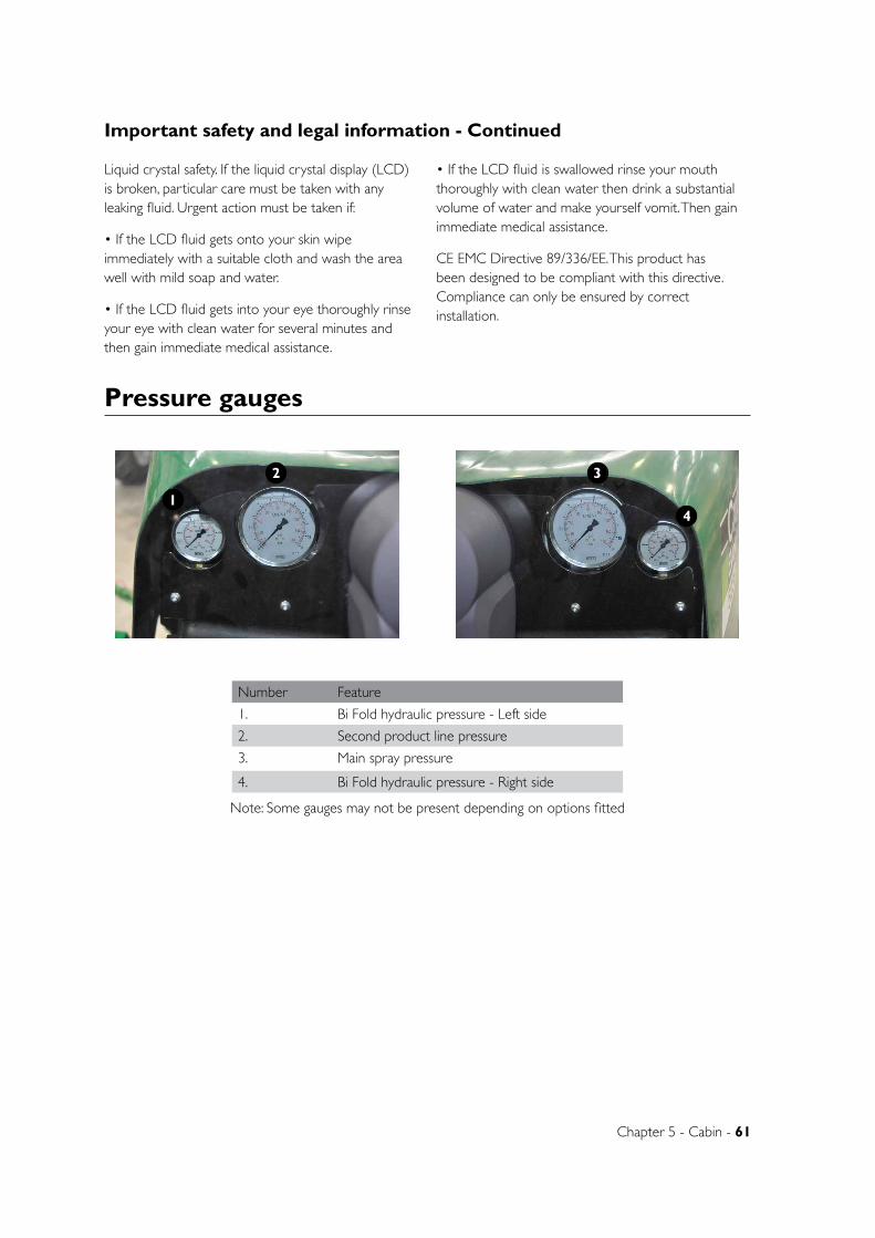
Chapter 5 - Cabin - 61
Liquid crystal safety. If the liquid crystal display (LCD) is broken, particular care must be taken with any leaking fluid. Urgent action must be taken if:
• If the LCD fluid gets onto your skin wipe immediately with a suitable cloth and wash the area well with mild soap and water.
• If the LCD fluid gets into your eye thoroughly rinse your eye with clean water for several minutes and then gain immediate medical assistance.
• If the LCD fluid is swallowed rinse your mouth thoroughly with clean water then drink a substantial volume of water and make yourself vomit. Then gain immediate medical assistance.
CE EMC Directive 89/336/EE. This product has been designed to be compliant with this directive. Compliance can only be ensured by correct installation.
Important safety and legal information - Continued
Pressure gauges
41
2 3
Number Feature
1. Bi Fold hydraulic pressure - Left side
2. Second product line pressure
3. Main spray pressure
4. Bi Fold hydraulic pressure - Right side
Note: Some gauges may not be present depending on options fitted
Chapter 6
Chapter 6 - Pre-Operation - 62
PRE-OPERATION
WARNING:
If spraying is to be done at night, ensure that adequate lighting is available around the sprayer and the area to be sprayed.
• The amount of lighting around the sprayer needs to be sufficient for all labels and warnings on the sprayer to be clearly visible to the operator.
• The amount of lighting in the area to be sprayed needs to be sufficient for obstacles in the path of the sprayer to be clearly visible to the operator.
BEFORE STARTING THE SPRAYER IN COLD CONDITIONS.
• If the sprayer has been in a cold environment, always check components to make sure that they have not been damaged and that there is no ice in the system before starting spraying. If the water has frozen in the pump and/or in the lines, wait until it has completely thawed before use.
• Inspect the sprayer to ensure there is no damage or wear which could lead to injury, further damage or reduced performance.
• Check all hoses and fittings for leaks or damage. Check the sprayer to ensure frosts and/or vermin have not damaged the machine, and that the tyres are correctly inflated.
• Check the engine oil, water and fuel.
• Check that all of the lights are working correctly.
• Check all bolts and nuts to make sure they are tight and secure.
• Complete the scheduled lubrication.
Note: Proper grease is essential for the sprayer to operate with maximum effectiveness and life-expectancy. It is important to keep the lubricant and lubricant applicator clean. Wipe all dirt from the
fittings before use. GoldAcres recommends that multi-purpose grease should be used for all lubrications. Make sure all open-end bearings are lubricated their full length by forcing lubricant into them until it begins to appear at the sides.
• Be sure to adequately clean and flush all chemical handling equipment.
• All spray equipment should be cleaned at the start and end of each spray season including all filters and nozzles.
• Test the pump with clean water. Switch on the pump at the lowest revs possible and then gradually increase revs until the pump reaches its operating speed. Do not exceed 540 R.P.M.
• Check nozzle patterns for irregularities. If there are irregularities, clean the nozzles and refit. If the problem persists they could be worn so remove and replace.
• Make sure there is a sufficient quantity of clean water in the rinse water tank in case of a chemical accident.
• Arrange communication with someone who can come to your aid if need be.
SPRAYER IN TRANSIT.
The Crop Cruiser sprayer is approx 4.3m in height and with aerials on the roof, can be much higher. Check the regulations in your state for maximum vehicle height restrictions. When driving the Crop Cruiser on roads it may be neccesary to remove aerials to meet the required height restrictions.
Aerials on the roof may also need to be removed to meet clearance requirements for over head power lines, while on the road and also in some paddocks.
OVER HEAD POWER LINES.
Check any areas to be sprayed for over head power lines. If there are any in the area, contact the relevant
Preparing The Sprayer For Use
Chapter 6 - Pre-Operation - 63
Spray CalibrationFlow meter and spray nozzle calibration should be checked regularly to ensure that correct application rates are maintained. Refer to the “Calibration”
chapter for procedures to check and alter calibration if required.
MaintenanceCorrect servicing and maintenance of the GoldAcres Crop Cruiser Sprayer will ensure the efficient safe operation of the sprayer. Servicing and maintenance should be carried out according to the schedule in the Lubrication & Maintenance section of this manual (Chapter 10)
DURING THE FIRST 8 HOURS OF OPERATION.
TORQUE SETTINGS
• Check the torque on retaining nuts frequently.
• The wheel nuts should be checked to ensure that 350 Nm is maintained.
ENGINE
• If the engine has been running, take extra care around hot engine parts such as the exhaust.
• Check the engine oil level frequently. Due to the “bedding in” of the engine components and additional friction between connecting parts, expect the oil usage to be higher than normal.
• Avoid excess engine idling.
• Inspect the air intake system and check for leaks.
LUBRICATING AND HYDRAULIC FLUIDS
• Maintain correct hydraulic oil levels and monitor
the oil temperature on a regular basis.
Check the transmission oil level and ensure that grease points are lubricated effectively. Crush Hazard Warning (Refer to Chapter 2, Safety)
• Inspect for leaks in the hydraulic system
TANK RETAINING STRAP BOLTS
• The tank retaining strap bolts should be checked to ensure that they have not become loose.
PUMP MOUNTING BOLTS
• The pump mounting bolts should be checked to ensure that they are not loose.
SUSPENSION BOLTS
• There are numerous suspension bolts located at each end of the parallel links and at each end of the pan hard rods and sway bars. These bolts should be checked to ensure that they have not become loose.
LIGHTS
• Check each light around the vehicle for correct operation.
energy provider for information on safe use of machinery near live lines.
DANGER: Check area to be sprayed for over head power lines. Contact between the machine and powerlines can result in serious injury or death.
If there are powerlines in the spray area, exercise extreme caution when tilting boom wings. Do NOT walk on machine platform when near power lines.
Preparing the sprayer for use - continued
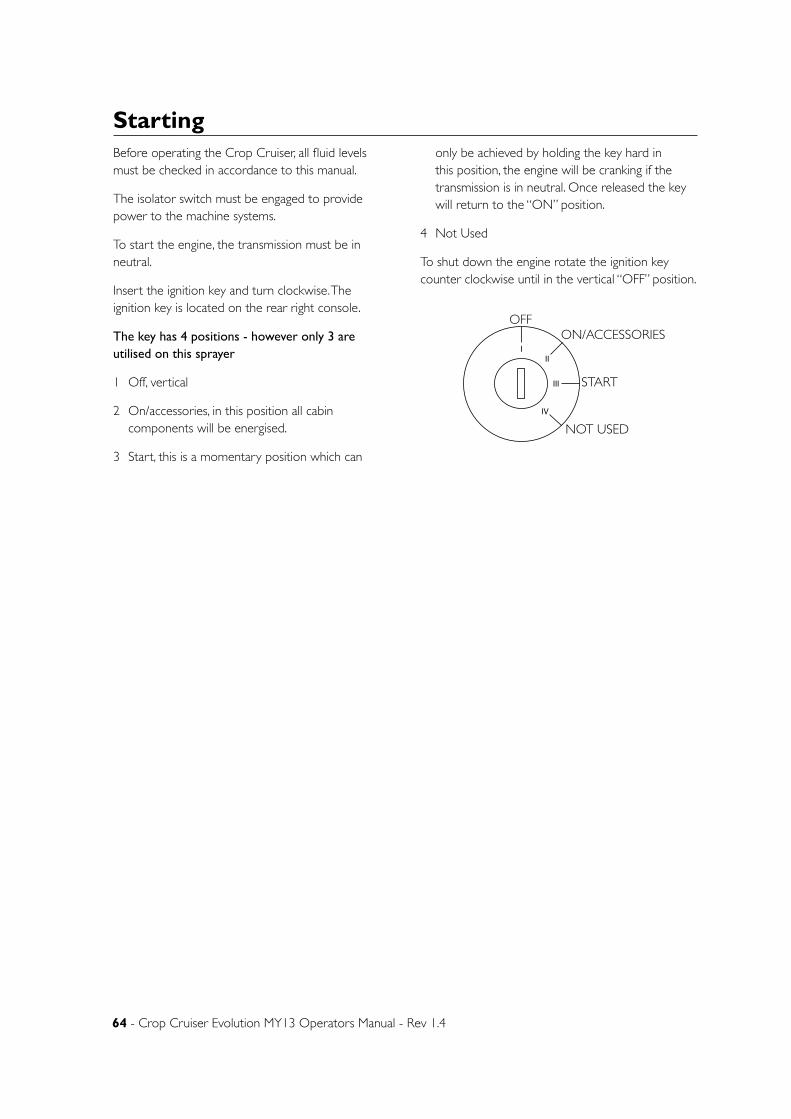
64 - Crop Cruiser Evolution MY13 Operators Manual - Rev 1.4
Before operating the Crop Cruiser, all fluid levels must be checked in accordance to this manual.
The isolator switch must be engaged to provide power to the machine systems.
To start the engine, the transmission must be in neutral.
Insert the ignition key and turn clockwise. The ignition key is located on the rear right console.
The key has 4 positions - however only 3 are utilised on this sprayer
1 Off, vertical
2 On/accessories, in this position all cabin components will be energised.
3 Start, this is a momentary position which can
only be achieved by holding the key hard in this position, the engine will be cranking if the transmission is in neutral. Once released the key will return to the “ON” position.
4 Not Used
To shut down the engine rotate the ignition key counter clockwise until in the vertical “OFF” position.
Starting
III
III
IV
OFFON/ACCESSORIES
START
NOT USED
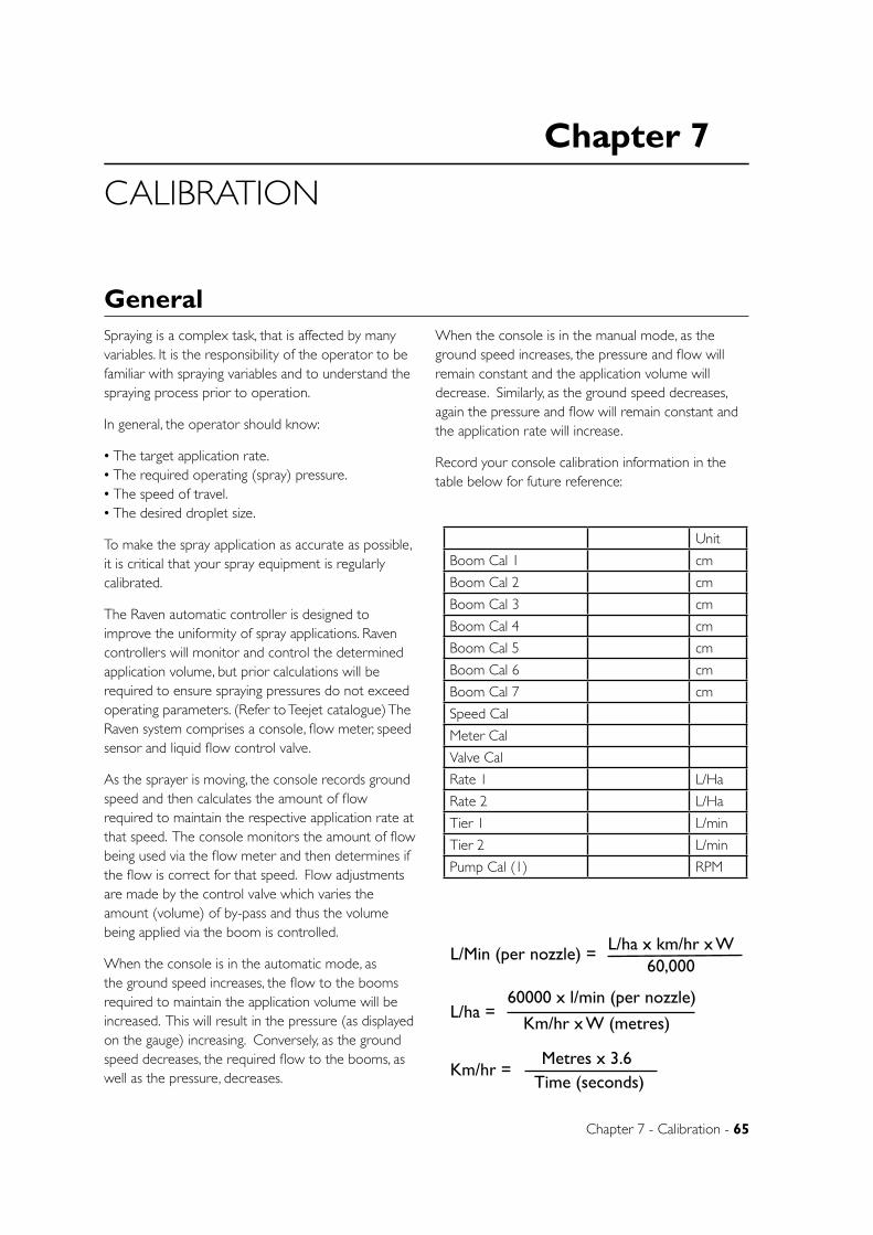
Chapter 7 - Calibration - 65
Chapter 7
CALIBRATION
GeneralSpraying is a complex task, that is affected by many variables. It is the responsibility of the operator to be familiar with spraying variables and to understand the spraying process prior to operation.
In general, the operator should know:
• The target application rate. • The required operating (spray) pressure. • The speed of travel. • The desired droplet size.
To make the spray application as accurate as possible, it is critical that your spray equipment is regularly calibrated.
The Raven automatic controller is designed to improve the uniformity of spray applications. Raven controllers will monitor and control the determined application volume, but prior calculations will be required to ensure spraying pressures do not exceed operating parameters. (Refer to Teejet catalogue) The Raven system comprises a console, flow meter, speed sensor and liquid flow control valve.
As the sprayer is moving, the console records ground speed and then calculates the amount of flow required to maintain the respective application rate at that speed. The console monitors the amount of flow being used via the flow meter and then determines if the flow is correct for that speed. Flow adjustments are made by the control valve which varies the amount (volume) of by-pass and thus the volume being applied via the boom is controlled.
When the console is in the automatic mode, as the ground speed increases, the flow to the booms required to maintain the application volume will be increased. This will result in the pressure (as displayed on the gauge) increasing. Conversely, as the ground speed decreases, the required flow to the booms, as well as the pressure, decreases.
When the console is in the manual mode, as the ground speed increases, the pressure and flow will remain constant and the application volume will decrease. Similarly, as the ground speed decreases, again the pressure and flow will remain constant and the application rate will increase.
Record your console calibration information in the table below for future reference:
L/Min (per nozzle) = L/ha x km/hr x W 60,000
L/ha = 60000 x l/min (per nozzle)
Km/hr x W (metres)
Km/hr =Metres x 3.6
Time (seconds)
Unit
Boom Cal 1 cm
Boom Cal 2 cm
Boom Cal 3 cm
Boom Cal 4 cm
Boom Cal 5 cm
Boom Cal 6 cm
Boom Cal 7 cm
Speed Cal
Meter Cal
Valve Cal
Rate 1 L/Ha
Rate 2 L/Ha
Tier 1 L/min
Tier 2 L/min
Pump Cal (1) RPM
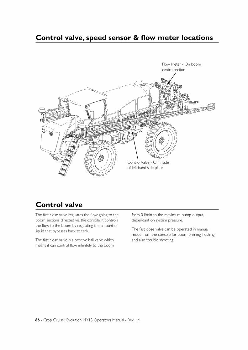
66 - Crop Cruiser Evolution MY13 Operators Manual - Rev 1.4
Control valve, speed sensor & flow meter locations
The fast close valve regulates the flow going to the boom sections directed via the console. It controls the flow to the boom by regulating the amount of liquid that bypasses back to tank.
The fast close valve is a positive ball valve which means it can control flow infinitely to the boom
from 0 l/min to the maximum pump output, dependant on system pressure.
The fast close valve can be operated in manual mode from the console for boom priming, flushing and also trouble shooting.
D
E
F
C
1 2 3 4
B
A
321 5
C
D
4 6 7 8
A
B
A3
SHEET 1 OF 1SCALE:1:25
DWG NO.
TITLE:
GOLDACRES
DO NOT SCALE DRAWING
MATERIAL:
DATE CREATED:
DRAWN:
1-3 MORANG CRMITCHELL PARK 3352PH: 03 53426399 FAX: 03 53426308
UNLESS OTHERWISE SPECIFIEDDIMENSIONS ARE IN MILLIMETERSDEBUR ALL EDGES Complete Assembly 2WD - SP 2011 - Parts ManualName
27/05/2011Matt
REV NO CHANGE DATE ECN NO.
DATE EDITED:
17/03/2011
Control valve
Control Valve - On inside of left hand side plate
Flow Meter - On boom centre section
Chapter 7 - Calibration - 67
• On the flow meter on the sprayer, there will be a calibration number attached to it on a white sticker. The number that is applicable is the one in square brackets, i.e. [185]. Note this number down as this is the number that should be entered as the Meter Cal. number.
• The Flow meter should be checked at the start of every spraying season and periodically during the season.
• The simplest way to check the accuracy of the flow meter is to fill the tank to a previously determined volume mark (usually top fill marking) and then empty the tank through the flow meter (i.e. via a self-test).
• Compare the reading from the flow meter with the previous known volume. If there is a relatively large discrepancy (i.e. more than 50 litres out of a 3000 litre tank), the flow meter should be removed from the sprayer, disassembled and the condition of the turbine checked and cleaned (make sure it spins freely).
• The flow meter should then be reassembled and replaced on the sprayer. Perform the volume check again and if there is still a discrepancy, the Meter Cal No. can be changed.
i.e.:If volume reads 3100 litres instead of 3000 litres and the original Meter Cal value is 185
New Meter Cal value = 185 x 3100 / 3000 = 191
Every sprayer should be calibrated regularly to ensure minimal error in the application rate. A nozzle selection chart indicates what application rates are to be expected but variations due to nozzle wear, ground speed error and pressure irregularities can result in large application rate errors.
Flowmeter Calibration
As part of your daily sprayer calibration, Goldacres recommends you carry out a simple “JUG TEST” to ensure the spray nozzles you are using are delivering the correct amount of chemical, as stated in your Nozzle Supplier’s “Rate Chart”.
The method of carrying out the “JUG TEST” is as follows;
1. You will need:
a. A calibrated measuring container that can measure the medium in litres, in 10 ml increments. e.g. 0.45 Lt.
b. A timing device showing seconds.
c. A pressure gauge mounted at the nozzle tip to verify the system pressure being delivered at the nozzle. Goldacres part numbers QJ4676-45-1/4-NYR & Q590-2-NY will mount a suitable gauge to the nozzle body bayonet fitting. (Not including gauge).
Procedure:
2. Check the plumbing system for kinked or
obstructed hoses and repair or replace any hoses that restrict the normal flow of the liquid.
3. Start your sprayer
• Initiate a ‘self test’ procedure and set the application rate and speed to the settings depicted in your “Rate Chart” at which you expect to spray.
4. Then place the jug under one of the nozzles, for 1minute (exactly) and record the volume of liquid collected.
5. Repeat the test over a representative sample of the jets in each boom section.
6. Compare the volume collected from each nozzle to the stated volume in your “Rate Chart”. It should be no more than plus or minus 10% of the volume stated in your Nozzle Supplier’s “Rate Chart”.
7. In the event that any of your nozzles do not deliver the required volume, a further investigation is required which may include, but not be limited to;
Nozzle Calibration
68 - Crop Cruiser Evolution MY13 Operators Manual - Rev 1.4
• Cleaning the nozzles, using the method recommended by the nozzle supplier.
• Replacing the nozzles. • TeeJet advise that nozzles that flow greater than +10% of their stated volume are ‘worn out’ and should be replaced.
• Cleaning nozzle filters.
UNEVEN VOLUMES FROM INDIVIDUAL NOZZLES WILL RESULT IN VARIATIONS IN THE APPLICATION RATE ACROSS THE WIDTH OF THE BOOM. SPRAY EFFICIENCY WILL BE REDUCED. CROP DAMAGE MAY RESULT.
If you have any further questions, Goldacres recommends you contact your nozzle supplier or your Goldacres dealer for additional information.
“Download your free copy of “A user’s guide to spray nozzles” from the TeeJet website, www.teejet.com”
Spray Calibration - continued
Raven automatic rate controllers can utilise a speed reading from:
Transmission Output
GPS receiver
Transmission Output
When the transmission output is used for speed the system must be set as if it were reading a radar sensor (SP2)
GPS receiver If a GPS unit is fitted, GPS ground speed can be
obtained and used in place of the transmission output.
To receive a speed reading from the GPS unit a pulsed niema string must be connected to the speed cable of the console. The console must then be set up to accept GPS speed. This is called radar in the console calibration settings. When using GPS the console speed cal figure is 200 initially and then can be fine tuned from this figure. See “calibration” chapter for further information on console setup.
Speed sensors
Chapter 7 - Calibration - 69
The following information is a condensed version of the Raven installation and service manual. It is designed to provide sufficient basic information to enable the new unit to be calibrated before spraying is commenced. For more detailed information about console features, consult the Raven installation and operational manual.
It is imperative that the Raven console is correctly programmed, as the system will only work as accurately as the programmed information entered. The Raven 4000 series consoles are very similar however there may be slight differences during calibration - for specific information please refer to the Raven operator’s manual supplied with the machine.
NOTE: While proceeding through the initial console programming write down all relevant calibration values for future reference.
The following steps are very important because the system will appear to function properly but be very inaccurate if values are incorrectly entered.
STEP 1: TURNING THE CONSOLE ON
1. Turn the console ‘ON’ by momentarily depressing the [POWER] key.
2. Instruction for adjusting the contrast should now be displayed
NOTE: If this is not displayed or if an incorrect entry is made during programming turn the console power switch ‘OFF’ depress and hold the [CE] key while turning the power switch back “ON”. This procedure resets the console.
3. Adjust the screen contrast as directed by depressing and holding the or keys.
4. When the desired contrast is achieved depress the [ENTER] key.
5. The display should now flash the word “CAL” and prompt for a “UNIT OF MEASURE” to be selected.
STEP 2: UNITS OF MEASURE
1. Momentarily depressing the [CE] key repeatable at this stage toggles the console through the “UNITS OF MEASURE” selection.
2. To operate in litres/hectare ensure “UNITS SI METRIC HECTARES” is display.
3. Then depress the [ENTER] key to lock it in.
4. The console will now prompt for a “PRODUCT TYPE” to be selected.
STEP 3: PRODUCT TYPE
1. Momentarily depressing the [CE] key repeatedly at this stage toggles the console between “LIQUID” and “GRANULAR” control selections.
2. Sprayers require the selection of “LIQUID CONTROL” to function correctly. (Granular control would be selected when using a fertilizer spreader or air seeders).
3. Ensure “LIQUID CONTROL” is displayed then depress the [ENTER] key to lock it in.
4. The console will now prompt for a “VALVE TYPE” to be selected.
STEP 4: VALVE TYPE To select the correct valve type: Labelling on the side of the flow control valves provides information on the “VALVE TYPE” (“VALVE CAL” information is also on the label and will be required in step 6 below).
Momentarily depressing the [CE] key repeatedly at this stage toggles the console through the various valve types.
1. Ensure correct “VALVE TYPE” is displayed as labelled on the valve then depress the [ENTER] key to lock it in.
2. The console will now prompt for a “METER CAL” value to be entered.
STEP 5: METER CAL All Raven flow meters are pre-calibrated. The calibration tag is attached to the transducer wire directly adjacent to the flow meter. The metric calibration number is the number in [square brackets] i.e. [185].
To enter the meter calibration figure first:
1. Depress the [ENTER] key.
2. The console will now display “E” enter symbol
Raven SCS4070 console calibration
70 - Crop Cruiser Evolution MY13 Operators Manual - Rev 1.4
on the bottom right hand side of the calibration screen.
3. Key in the correct calibration number (i.e. 185).
4. Depress the [ENTER] key again to lock it in.
5. The console will now prompt for a “VALVE CAL” value to be entered.
NOTE: When entering any calibration figures during the calibration process the [ENTER] key must first be depressed momentarily to display the “E” enter symbol. The “E” indicates the console is ready to accept a calibration figure. After keying in a figure the [ENTER] key must be depressed again to lock the new value in before moving on to the next step.
STEP 6: VALVE CAL The [VALVE CAL] value is located on the side of the flow control valve together with the “VALVE TYPE” “FAST CLOSE VALVES” have a value of [743].
To enter the value calibration figure:
1. Depress the [ENTER] key to display the “E” enter symbol.
2. Key in the appropriate [VALVE CAL] calibration number as printed on the side of the flow control valve.
3. After keying in the appropriate valve calibration number depress the [ENTER] key again to lock it in.
4. The console will now prompt for a [RATE CAL] number to be entered.
STEP 7: APPLICATION RATE [RATE CAL] is the rate (litres/hectare) desired for the particular application
NOTE: Before entering an application rate consult the nozzle application chart (in the operators manual or the Tee Jet catalogue) to ensure the rate is within the speed and pressure capabilities of the nozzles fitted to the boom.
To enter a [RATE CAL]:
1. Depress the [ENTER] key to display the “E” enter symbol.
2. Key in the desired application rate (i.e. 50 Lt/ha).
3. Depress [ENTER] again to lock it in.
4. The console will now prompt for a “SPEED SENSOR TYPE” to be entered
NOTE: If the console detects the presence of a 2nd product it will automatically interrupt the programming procedure at this point and request values be entered for PRODUCT TYPE, VALVE TYPE, METER CAL, VALVE CAL, and RATE for this 2nd product. The console will then revert back to STEP 8 if a 3rd product is not detected. If a 3rd is detected the console will automatically request the information be entered for this product before continuing no to STEP 8 below.
For SCS 4070 console connected to a chemical injection pump/s see separate section on SCS 4070 chemical injection pump programming, in the “DCI” chapter for further details.
STEP 8: SPEED SENSOR TYPE Before proceeding in this step first identify which type of speed sensor the console is connected to.
Transmission output or Raven GPS:
1. Momentarily depress the [CE] key repeatedly to toggle through the selection of “SPEED SENSOR TYPES” until “SPEED SENSOR RADAR SP-2” is displayed.
2. Depress the [ENTER] key to lock it in and the console will now prompt for a “SPEED CAL” number to be entered.
STEP 9: SPEED CAL Before a [SPEED CAL] figure can be entered a speed calibration value must first be ascertained. The method for calculating a speed calibration figure varies depending on the type of speed sensor the console is connected to
For consoles connected to a transmission output: Use an arbitrary [SPEED CAL] value of [200]
To enter this value:
1. Depress the [ENTER] key to display the “E” enter symbol.
2. Key in the appropriate [SPEED CAL] number.
3. Depress the [ENTER] key again to lock it in.
Raven SCS4070 console calibration - continued
Chapter 7 - Calibration - 71
4. The console will now prompt for a “BOOM CAL 1” number to be entered.
NOTE: This is an arbitrary value only and will require correcting; using the following procedure, once the remainder of the programming procedure is completed.
To recalibrate a [SPEED CAL] value once initial console programming is complete:
1. Accurately mark and measure 100 metres.
2. With the power switch “on” and all other switches “Off ”
3. Depress the [DISTANCE] key.
4. Depress the [ENTER] key to display the “E” enter symbol.
5. Key in a “0” value.
6. Then depress the [ENTER] key again to lock it in.
7. Drive the 100 metres, being careful not to accelerate or decelerate too suddenly.
8. Record the distance that the console displays once the 100 metres has been travelled.
9. The distance should read 100. If it reads between 99 or 101 this calibration value will be correct. If the distance reads any other valve perform the following procedure.
NEW [SPEED CAL] VALUE = OLD [SPEED CAL] VALUE X 100
RECORDED DISTANCE
NOTE: Redo the distance check again to confirm the new [SPEED CAL] value is correct.
For consoles connected to a Raven GPS:
Use a Speed Cal figure of [785] (standard speed cal figure for all Raven GPS units).
To enter this value:
1. Depress the [ENTER] key to display the “E” enter symbol.
2. Key in the appropriate [SPEED CAL] number.
3. Depress [ENTER] again to lock it in.
4. The console will now prompt of a “BOOM CAL 1” value to be entered.
This value can be checked once initial console programming is complete by using the same procedure for recalibrating a [SPEED CAL] value for a radar speed sensor above.
STEP 10: BOOM SECTIONS
The console needs to know the width of each section so it can calculate;
1. The total flow rate required.
2. The area applied.
As boom sections are turned on or off the console increases or decreases the theoretical width of the boom accordingly in order to calculate the correct flow rate (total Lt/min to the boom) and the total area sprayed.
To measure the width for each boom section, count the number of nozzles in each section and multiply by the nozzle spacing. i.e. 12 nozzles in one section at 50cm (½ metre) spacings = 12 x 0.5m = 6m
All Boom Sections must be entered in Centimetres (for example 6m = 600cm) so the correct Boom Cal in this example would be 600.
To enter a [BOOM CAL] figure for boom 1:
1. Ensure boom 1 is displayed.
2. Depress the [ENTER] key to display the “E” enter symbol.
3. Key in the boom width in centimetres for boom 1.
4. Depress the [ENTER] key to lock it in.
NOTE: At this point the console does not proceed automatically to boom 2.
5. To proceed to Boom 2 depress the [UP] key momentarily.
6. Depress [ENTER] and key in the calibration figure for boom 2.
7. Depress the [ENTER] key again to lock it in.
Depress the key and continue entering the [BOOM CAL]’s in the remaining boom sections. If a boom section is not utilised ensure “0” is entered in that
Raven SCS4070 console calibration - continued
72 - Crop Cruiser Evolution MY13 Operators Manual - Rev 1.4
section or the console will fail to function correctly.
INITIAL PROGRAMMING IS NOW COMPLETE.
If the sprayer is fitted with the 3TS option see the separate section on Raven SCS 4070 3TS dual boom operation and programming.
NOTE: Each time the console power switch is turned “on” the products automatically default to the “OFF” mode. Before commencing spraying the product must be changed to the “AUTO” mode.
To change to the “AUTO” mode:
1. Momentarily depress the [PRODUCT ON/OFF] key to turn the product “ON”. At this point the console should read “AUTO NOBM” (auto no boom).
2. If it reads “MAN NOBM” (manual no boom) momentarily depress the [AUTO/MANUAL] key to switch to the product to the auto mode.
The “NOBM” (no boom) component automatically disappears when the console senses the switching “on” of a boom section.
If you wish to change a calibration figure for Boom Cal, Speed Cal, Meter Cal, Valve Cal or Rate Cal (application rate) at any time simply depress the appropriate key i.e. [BOOM CAL], then the [ENTER] key to display the “E” enter symbol, key in the new calibration number and depress the [ENTER] key again to lock it in.
If you wish to view the Units of Measure, Product Type, Valve Type or Speed Sensor Type depress and hold down the [SELF TEST] key and the console will flash through the various values entered.
If you wish to change the Units of Measure, Product Type, Valve Type or Speed Sensor Type continue holding down the [SELF TEST] key for 20 seconds until the console stops on “UNITS OF MEASURE” and flashes “CAL”. Once “CAL” is displayed release the [SELF TEST] key.
At this point repeatedly depressing the [CE] key momentarily will toggle the console through the various options in each step and depressing the [ENTER] key will lock it in and/or move on to the next step. To exit this function at any time continue momentarily depressing the [ENTER] key until the
console reverts back to “SELF TEST” and discontinues flashing “CAL”.
STEP 11: PUMP RPM (Required if pump is hydraulically driven).
For RPM to be displayed on the console screen the sprayer must be fitted with a pump RPM sensor.
To activate the pump RPM display on the console screen:
1. Depress the [DATA MENU] key to display the data sub menu at the bottom of the screen. The word “SERIAL” will be highlighted.
2. Depress [DATA MENU] key again and the highlight will move down to “PRODUCT”.
3. Momentarily depress the [DOWN] key repeatedly to move the curser down until page 2 is displayed.
4. Continue momentarily depressing the [DOWN] key repeatedly until the curser is adjacent to “PUMP CAL”.
5. Depress the [ENTER] key to display the to display the “E” (enter symbol).
6. Key in a value of pulses per revolution (normally one)
7. RPM should now be displayed in the top right hand corner of the screen.
8. Depress a volume or area key to exit the data sub menu and return to the operational screen.
STEP 12: LOW FLOW LIMIT
This feature, when activated, stops the console controlling the flow rate below an assigned limit to prevent boom line pressure falling too low resulting in fan angle collapse or nozzle check valve closure.
This feature is particularly useful in row crop situations to prevent ‘under- application’ at the start and end of a row.
In this mode the console effectively defaults to an ‘over-application’ mode during periods when the sprayer is unable to maintain the minimum speed required for a particular application rate.
Raven SCS4070 console calibration - continued
Chapter 7 - Calibration - 73
NOTE: This feature must not be used with chemicals that have poor crop selectivity and will cause damage to the crop if ‘over-applied’. Check with your chemical supplier for more details on chemical/crop selectivity before using this feature.
The SCS 4070 also has the added ability to control to this minimum flow rate value. To activate this feature a minimum flow rate value must be calculated and entered into the console.
To calculate a minimum flow rate refer to the relevant nozzle chart for the nozzle type/size fitted to the sprayer. Nozzle charts can be found in the operator’s manual or the TeeJet catalogue.
From the nozzle chart determine the flow rate of the nozzle used at the minimum recommended operating pressure. Multiply this figure by the total number of nozzles fitted to the entire boom line to obtain the “LOW FLOW LIMIT” value.
NOTE: This minimum flow rate value is automatically proportioned as boom sections are turned on and off. Thus a minimum pressure will be maintained regardless of boom section status.
Entering a Low Flow Limit value:
1. Depress the [DATA] key to bring up the data submenu at the bottom of the screen. The word “SERIAL” will be highlighted.
2. Depress the [DATA] key again to highlight “PRODUCT”.
3. Momentarily depress the key repeatedly to move the curser adjacent to “LOW LIMIT”.
4. Depress the [ENTER] key to display the “E” (enter symbol).
5. Enter the “LOW FLOW LIMIT” value calculated.
6. Depress the [ENTER] key again to lock it in.
7. Depress a volume or area key to exit the data sub menu and return to the operational screen.
STEP 13: TO ZERO INFORMATION WHEN STARTING A NEW LOAD
When starting a new load, the previous Area and Volume data in the console can be reset using the following procedure;
“TANK VOLUME” gives the operator a reference as to the number of litres left in the tank as the load is progressively applied to the field. For this feature to function correctly the estimated volume in the tank must be entered before application of the new load is commenced. (A Raven Fill-flow meter can be WARNING: the [self test] feature should never be used with chemical in the tank used to more accurately determine tank volume particularly if using partial tank loads
1. Depress the [VOLUME TANK] key.
2. Depress the [ENTER] key to display the “E” enter symbol.
3. Enter the volume of liquid actually in the tank at the start of the load.
4. Depress [ENTER] again to lock it in.
NOTE: The console will subtract the litres used (count down) from this value as the load is applied to the field giving the operator a reference as to the number of litres left in the tank.
TO ZERO OUT DATA IN AREA AND VOLUME:
NOTE: Before resetting the Area and Volume functions record any previous data in the console that maybe applicable for future use.
To reset an Area or Volume value:
1. Depress the relevant key relating to the value to be reset. For example [TOTAL AREA], [TOTAL VOLUME], [FIELD AREA] or [FIELD VOLUME].
2. Depress the [ENTER] key to display the “E” enter symbol.
3. Enter a value of “0” to reset the particular function.
4. Depress the [ENTER] key again to lock it in.
The Area and Volume will now count up from zero for the new field.
[FIELD AREA] and [FIELD VOLUME] are generally use as sub-totals for [TOTAL AREA] and [TOTAL VOLUME].
For example if applying several tank loads to the one area [FIELD AREA] and [FIELD VOLUME] can be use to record data for the current tank load while the [TOTAL AREA] and [TOTAL VOLUME] can be used
Raven SCS4070 console calibration - continued
74 - Crop Cruiser Evolution MY13 Operators Manual - Rev 1.4
to record accumulative data for the whole area. If [TOTAL AREA] and [TOTAL VOLUME] are used to accumulate data do not reset them until starting a new area.
WARNING: The [self test] feature should never be used with chemical in the tank.
WARNING: Do not use the self test function with the booms in the transport position.
To simulate a speed:
1. Depress the [SELF TEST] key momentarily.
2. Depress [ENTER] key to display the “E” enter symbol.
3. Key in a desired test speed. Note this feature has a decimal point so a “0” needs to be added when entering a whole figure. For example 1, 6 and 0 for 16 Kph.
4. Depress the [ENTER] key again to lock it in.
A desired test speed should now be displayed in the speed window at the lower left corner of the display
Spraying can now be simulated by simply turning on the boom switches.
The [SELF TEST] feature will automatically clear itself when motion is detected from the speed sensor.
NOTE: Some radar and GPS units may sense motion when the sprayer is stationary thus continually clear this function. To counteract this simply unplug the speed sensor connection in the fuse box area whilst using this function.
Using the flow meter to calibrate the tank:
1. Enter in the Meter Cal value as given on the white Calibration sticker on the Flow meter.
2. Enter all the other calibration information needed to enable the console to work.
3. Fill the tank to the top mark with water (i.e. 2500 or 3000 etc.). Make sure the tank is level.
4. Make sure the Total Volume reads “0”
Press [TOTAL VOLUME] then [ENTER] Enter “0” then [ENTER]
5. Perform a self-test. (Choose a relatively high speed and high rate so that the tank will empty relatively quickly but make sure the pressure does not exceed 60 psi).
6. When the tank is empty press [TOTAL VOLUME] to read what the Raven Flow meter says the tank holds.
7. If there is a large discrepancy (i.e. the difference between theoretical tank volume and Flow meter volume is greater than 100 litres), alter the Meter Cal value accordingly. For example: If volume reads 3100 litres instead of 3000 litres and the original Meter Cal value is 185.
New Meter Cal value = 185 x 3100 * 3000 = 191
8. Enter in new Meter Cal value and repeat procedure (Step 3 to Step 6). Continue to re-iterate the Meter Cal value until the desired volume accuracy is achieved
9. Write down the appropriate Speed Cal value for future reference.
10. Re-fill the tank to the top mark and perform the self test again. Stop the self test after every 200 litres has been pumped out (read by pressing [TOTAL VOLUME] and check how the water level compares with the appropriate tank calibration mark.
(i.e. after 200 litres has been pumped out there is 2800 left in a 3000 litre tank). There may need to be extra marks put on the tank to indicate where the actual tank calibration levels are.
Raven SCS4070 console calibration - continued
Chapter 7 - Calibration - 75
3TS (Boom Tier Programming)NOTE: 3TS boom tier programming can only be carried out if initial console programming has been completed (see SCS 4070 console programming).
For boom tiering to operate flow rate values (litres/min) have to be entered into the console. The console automatically starts on the first tier when the boom master switch is turned “on” but it needs reference points entered to be able to determine when it should change to the second and third tiers. Thus to achieve the three tiers two flow rate value have to be entered.
Before these figures can be entered the maximum flow rate (litres/min in total to the boom) for each tier must be calculated.
Using a nozzle chart determine the flow rates (for a single nozzle) at which point you wish the console to change tiers. These points are best determined by ascertaining the minimum pressure and thus the corresponding flow rates at which point you wish the next nozzle to cut in. Care must be taken to ensure these minimum pressure/flow rate settings do not exceed the maximum recommended operating pressure of the preceding nozzle.
For example: If you had XR110015 and XR110025 nozzles fitted to the sprayer the minimum pressure that the XR110025’s can cut in at is 1.0 bar. The flow rate for an XR110025 nozzle at 1.0 bar is 0.57 Lt/min. The maximum operating pressure for an XR110015 is 4.0 bars at which point the flow rate is 0.68 Lt/min so this combination of nozzles overlaps nicely. In actual fact the XR110025 would cut in at slightly less than 3 bars if the first set point was programmed at the 0.57 Lt/min. (See table page 25).
To determine the second set point of the 3rd tier, first ascertaining the minimum pressure you wish the combination of the two nozzles to operate at. Then add the corresponding flow rates at this pressure for the two nozzles together to form the second set point.
For example: If you wanted the 3rd tier to cut in at one bar you would add the flow rates for the XR110015 and XR110025 at one bar together (0.34 + 0.57 = 0.91Lt/min) Again care must be taken to ensure this minimum pressure/flow rate setting does not exceed the maximum recommended operating pressure/flow rate of the preceding nozzle. At 0.91
Lt/min the preceding XR110025 nozzle would be operating at slightly over 2.5 bars before the 3rd tier would cut in. Again a nice overlap.
NOTE: The flow rate values entered into the console for the tier interchange points must be the sum total of all the nozzles on one entire boom line.
For example: A 30 metre boom with 50 cm nozzle spacings has 60 nozzles on one boom line, therefore 60 nozzles x 0.57 Lt/min = 34.2 Lt/min which would be the tier 1 max rate value for the example above.
The tier 2 max rate would be 60 x 0.91 Lt/min = 54.6 Lt/min.
NOTE: The above example is based on a 30 metre broad acre boom. Some booms may have different nozzle spacings or layout (i.e. row crop) so it’s important to count the total number of nozzles on the first line to ensure the correct Tier Value is calculated and entered.
The pressure figure of one bar is an example only. Other trigger point pressures may be selected.
NOTE: Care must be taken to ensure there is sufficient pressure overlap between the tiers otherwise spray drift or poor efficacy may result.
NOTE: The consoles won’t accept tier values containing decimal points so values calculated with decimal points require rounding off to the nearest whole figure before entering.
TO ENTER THE TIER VALUES:
1. Depress and hold down the [BOOM CAL] key for 5 seconds until “TIER 1 HIGH VOL PER MIN” is displayed.
2. Depress the [ENTER] key to display the “E” (enter symbol).
3. Key in the first tier interchange value and depress [ENTER] again to lock it in.
4. To enter the second tier interchange point depress the key and “TIER 2 HIGH VOL PER MIN” will be displayed.
5. Depress the [ENTER] key again to display the “E” (enter symbol).

76 - Crop Cruiser Evolution MY13 Operators Manual - Rev 1.4
6. Key in the second tier interchange value and depress [ENTER] again to lock it in.
7. Depress the key again and “PERCENTAGE TIER DISABLE” will be displayed.
The default setting for this function is “10” which means the tiers will overlap 10% above the entered tier values on the ‘up-change’ and 10% below on the ‘down-change’.
This function is useful if the sprayer is operated at a speed and/or rate that coincides with a tier change point. If this scenario occurs the console will tend to hunt between tiers unless a percentage overlap figure is entered. Maintaining the 10% tier disable value at this point will reduce this ‘hunting’ tendency.
Keep in mind that the pressures will rise over and fall under the set tier value by the percentage entered. For example if a value of 10% is entered the pressure will rise 10% above the set tier interchange point before a tier ‘up-change’ will occur and correspondingly fall 10% below the value before ‘down- changing’. If using this function ensure the tier interchange points are calculated with this expanded pressure range in mind otherwise the sprayer may operate outside the recommended operating pressure range of the nozzle.
If the nozzles or tier values selected allow for very little or no pressure overlap a “PERCENT TIER DISABLE” value of “0” must be selected:
1. To enter a “PERCENT TIER DISABLE” value depress the [ENTER] key to display the “E” (enter symbol).
2. Key in the desired percentage overlap and depress the [ENTER] again to lock it in.
3. Press a volume or area key to exit this function and return to the operational screen.
SCS 4070 and 2TS
The SCS 4070 3TS system can be set up to operate in a 2TS mode if the operator wishes to use the same size nozzles in both boom lines.
In the 2TS mode the console will start the sprayer on one line then turn the second line on in conjunction with the first at a predetermined point. It effectively does away with the first tier interchange point of
the 3TS system where one boom line is turned “on” whilst the other is turned “off ” (obviously this step is superfluous if the same size nozzles are fitted to both boom lines).
To set the console up in the 2TS mode:
1. Depress and hold down the [BOOM CAL] key for 5 seconds until “TIER 1 HIGH VOL PER MIN” is displayed.
2. Depress the [ENTER] key to display the “E” (enter symbol).
3. Key in a value of “1”.
4. Depress the [ENTER] key again to lock it in.
By entering a value of “1” the console will automatically proceed and start on the second tier.
To calculate the second tier interchange value: From the nozzle chart in the operator’s manual or the TeeJet catalogue locate the minimum recommended operating pressure and corresponding flow rate (Lt/min) for the nozzle size and type fitted to the sprayer.
NOTE: If operating the sprayer in the 2TS mode the same size and type of nozzles should be fitted to both boom lines.
Multiply this value by 2 then by the total number nozzle on one entire boom line.
For example: Using a 30 Mt broad acre boom fitted with XR11002 nozzles.
The minimum recommended pressure for an XR nozzle is 1 bar. The flow rate for an XR11002 nozzle at 1 bar is 0.46 Lt/min. Thus the second tier interchange value will be 0.46 X 2 X 60 (2 nozzles/meter) = 55.2.
NOTE: The console will not except tier values containing decimal points so round any values calculated with decimal points off to the nearest whole number before entering.
So the value entered in this example would be 55.
Continuing on from above to enter the second tier interchange point:
1. Depress the key and “TIER 2 HIGH VOL PER MIN” will be displayed.
3TS (Boom Tier Programming) - continued

Chapter 7 - Calibration - 77
2. Depress the [ENTER] key again to display the “E” (enter symbol).
3. Key in the second tier interchange value and depress [ENTER] again to lock it in.
4. Depressing the again will display “PERCENT TIER DISABLE” (see instruction above on setting this
value).
5. Depress and volume or area key to exit this function and return to the operational screen
NOTE: That if either tier value is set to zero then the boom valves will not open.
3TS (Boom Tier Programming) - continued

78 - Crop Cruiser Evolution MY13 Operators Manual - Rev 1.4
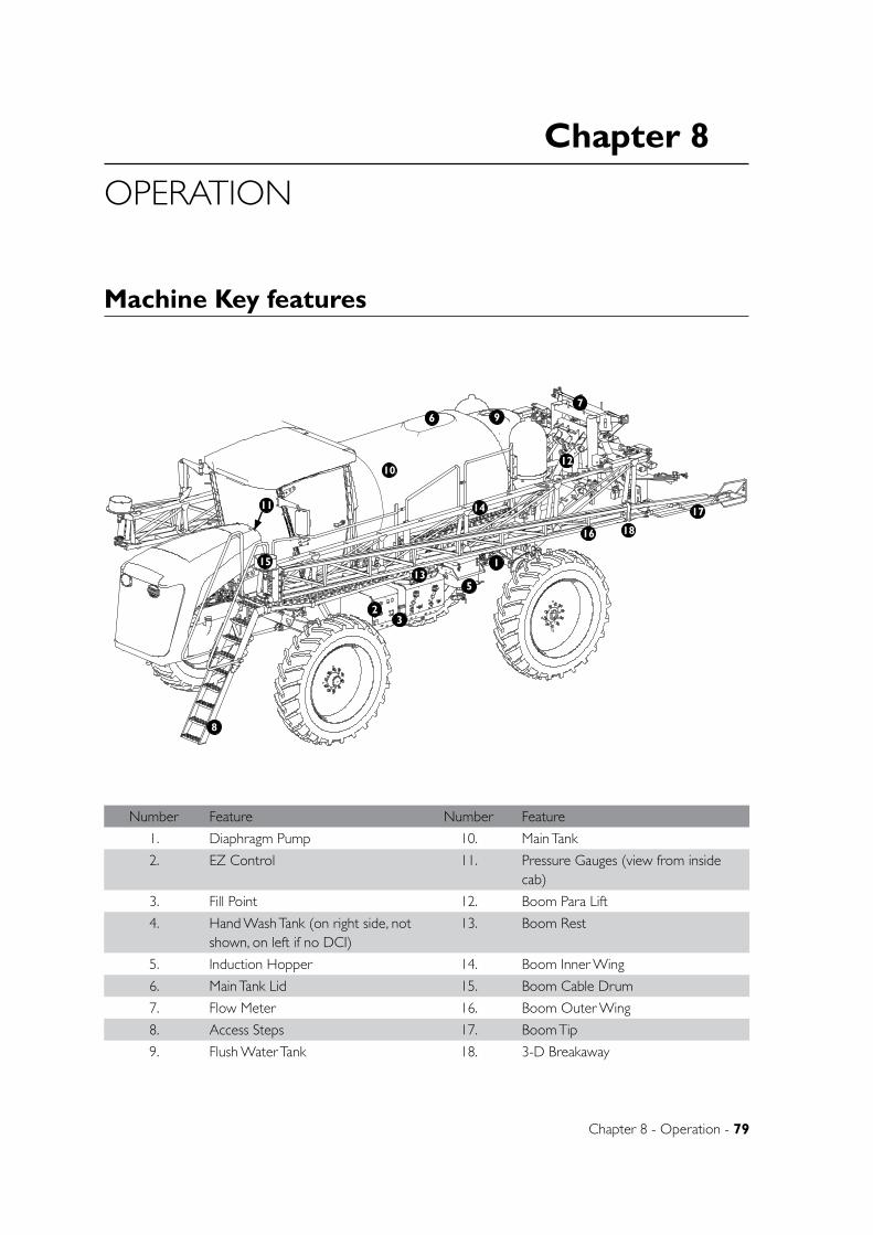
Chapter 8
Chapter 8 - Operation - 79
OPERATION
Machine Key features
Number Feature Number Feature
1. Diaphragm Pump 10. Main Tank
2. EZ Control 11. Pressure Gauges (view from inside cab)
3. Fill Point 12. Boom Para Lift
4. Hand Wash Tank (on right side, not shown, on left if no DCI)
13. Boom Rest
5. Induction Hopper 14. Boom Inner Wing
6. Main Tank Lid 15. Boom Cable Drum
7. Flow Meter 16. Boom Outer Wing
8. Access Steps 17. Boom Tip
9. Flush Water Tank 18. 3-D Breakaway
D
E
F
C
1 2 3 4
B
A
321 5
C
D
4 6 7 8
A
B
A3
SHEET 1 OF 1SCALE:1:25
DWG NO.
TITLE:
GOLDACRES
DO NOT SCALE DRAWING
MATERIAL:
DATE CREATED:
DRAWN:
1-3 MORANG CRMITCHELL PARK 3352PH: 03 53426399 FAX: 03 53426308
UNLESS OTHERWISE SPECIFIEDDIMENSIONS ARE IN MILLIMETERSDEBUR ALL EDGES Complete Assembly 2WD - SP 2011 - Parts ManualName
27/05/2011Matt
REV NO CHANGE DATE ECN NO.
DATE EDITED:
17/03/2011
1
23
5
67
8
9
10
11
12
13
14
15
16
17
18
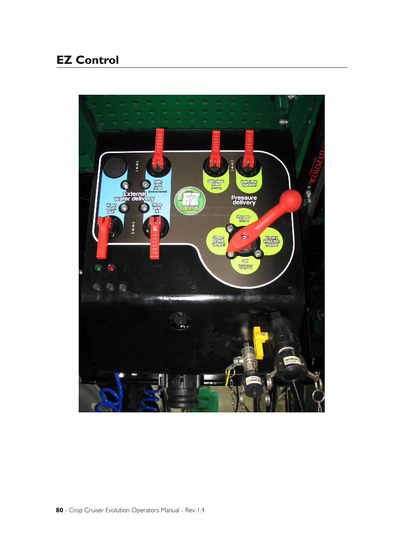
80 - Crop Cruiser Evolution Operators Manual - Rev 1.4
EZ Control
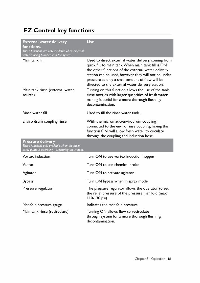
Chapter 8 - Operation - 81
EZ Control key functions
External water delivery functions. These functions are only available when external water is being pumped into the system.
Use
Main tank fill Used to direct external water delivery, coming from quick fill, to main tank. When main tank fill is ON the other functions of the external water delivery station can be used, however they will not be under pressure as only a small amount of flow will be directed to the external water delivery station.
Main tank rinse (external water source)
Turning on this function allows the use of the tank rinse nozzles with larger quantities of fresh water making it useful for a more thorough flushing/decontamination.
Rinse water fill Used to fill the rinse water tank.
Enviro drum coupling rinse With the micromatic/envirodrum coupling connected to the enviro rinse coupling, having this function ON, will allow fresh water to circulate through the coupling and induction hose.
Pressure deliveryThese functions only available when the main spray pump is operating - pressuring the system.
Vortex induction Turn ON to use vortex induction hopper
Venturi Turn ON to use chemical probe
Agitator Turn ON to activate agitator
Bypass Turn ON bypass when in spray mode
Pressure regulator The pressure regulator allows the operator to set the relief pressure of the pressure manifold (max 110-130 psi)
Manifold pressure gauge Indicates the manifold pressure
Main tank rinse (recirculate) Turning ON allows flow to recirculate through system for a more thorough flushing/decontamination.
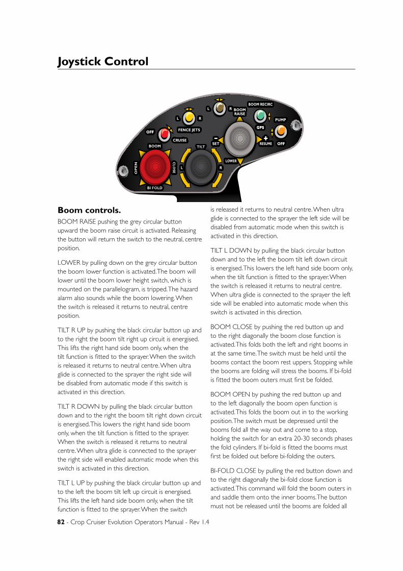
82 - Crop Cruiser Evolution Operators Manual - Rev 1.4
Joystick Control
Boom controls.BOOM RAISE pushing the grey circular button upward the boom raise circuit is activated. Releasing the button will return the switch to the neutral, centre position.
LOWER by pulling down on the grey circular button the boom lower function is activated. The boom will lower until the boom lower height switch, which is mounted on the parallelogram, is tripped. The hazard alarm also sounds while the boom lowering. When the switch is released it returns to neutral, centre position.
TILT R UP by pushing the black circular button up and to the right the boom tilt right up circuit is energised. This lifts the right hand side boom only, when the tilt function is fitted to the sprayer. When the switch is released it returns to neutral centre. When ultra glide is connected to the sprayer the right side will be disabled from automatic mode if this switch is activated in this direction.
TILT R DOWN by pulling the black circular button down and to the right the boom tilt right down circuit is energised. This lowers the right hand side boom only, when the tilt function is fitted to the sprayer. When the switch is released it returns to neutral centre. When ultra glide is connected to the sprayer the right side will enabled automatic mode when this switch is activated in this direction.
TILT L UP by pushing the black circular button up and to the left the boom tilt left up circuit is energised. This lifts the left hand side boom only, when the tilt function is fitted to the sprayer. When the switch
is released it returns to neutral centre. When ultra glide is connected to the sprayer the left side will be disabled from automatic mode when this switch is activated in this direction.
TILT L DOWN by pulling the black circular button down and to the left the boom tilt left down circuit is energised. This lowers the left hand side boom only, when the tilt function is fitted to the sprayer. When the switch is released it returns to neutral centre. When ultra glide is connected to the sprayer the left side will be enabled into automatic mode when this switch is activated in this direction.
BOOM CLOSE by pushing the red button up and to the right diagonally the boom close function is activated. This folds both the left and right booms in at the same time. The switch must be held until the booms contact the boom rest uppers. Stopping while the booms are folding will stress the booms. If bi-fold is fitted the boom outers must first be folded.
BOOM OPEN by pushing the red button up and to the left diagonally the boom open function is activated. This folds the boom out in to the working position. The switch must be depressed until the booms fold all the way out and come to a stop, holding the switch for an extra 20-30 seconds phases the fold cylinders. If bi-fold is fitted the booms must first be folded out before bi-folding the outers.
BI-FOLD CLOSE by pulling the red button down and to the right diagonally the bi-fold close function is activated. This command will fold the boom outers in and saddle them onto the inner booms. The button must not be released until the booms are folded all
Chapter 8 - Operation - 83
Joystick Control - continued
the way in or boom stress can occur. This function must be activated before the inner booms are folded. If bi-fold is not fitted to the boom depressing this red button in this direction will not activate any circuit.
BI-FOLD OPEN by pulling the red button down and to the left diagonally the bi-fold open function is activated. This command will fold the boom outers out in to the working position. The button must not be released until the booms are all the way out or boom stress can occur. When the booms are all the way out hold the button depressed until the bi-fold pressure gauges read 1700-1900 psi. This pressure maintains boom alignment while moving. This function must only be activated once the inner booms have been unfolded. If bi-fold is not fitted to the boom depressing this red button in this direction will not activate any circuit
Plumbing controlsPUMP by flicking this orange on / off switch upwards the product pump circuit is activated. When the pump is on the light on the arm rest will be illuminated. The pump will remain operating until the switch is returned to the lower OFF position. If dual product pumps are installed this switch must be first turned on to activate the pump circuit required.
FENCE LINE JETS “L” by flicking the yellow on /off/ on switch to the left the fence line nozzles on the left hand end of the boom are activated. This switch will remain in the on position until it is centred by the operator to OFF.
FENCE LINE JETS “R” by flicking the yellow on /off/ on switch to the right the fence line nozzles on the right hand end of the boom are activated. This switch will remain in the on position until it is centred by the operator to OFF.
FOAM by flicking this green on /off/ on momentary switch up wards the foam marker compressor is activated. While the switch is in the up position the compressor will continue to supply air flow until the operator returns this switch to the centre OFF position.
GPS by flicking this green on /off/ on momentary switch down the GPS resume wires are activated. If a GPS steering unit is fitted 12 volts will be supplied to the GPS auxiliary connector port “C” each time
this momentary switch is triggered down. This switch returns immediately to the centre OFF position once the operator releases it.
FOAM MARKER “L” by flicking the black on /off/ on switch to the left the foam marker on the left hand end of the boom is activated. Foam will generate out the accumulator to the consistency the foam marker controls have been set at. This switch will remain in the on position until it is centred by the operator to OFF.
FOAM MARKER “R” by flicking the black on /off/ on switch to the right the foam marker on the right hand end of the boom is activated. Foam will generate out the accumulator to the consistency the foam marker controls have been set at. This switch will remain in the on position until it is centred by the operator to OFF.
Cruise controlCRUISE This on / off / off red switch activates the cruise control circuit. When it is pulled down to the right diagonally the cruise control is activated,
The switch will remain in this position until the operator moves to another position. When the switch is in this position the cruise control can be set, resume, increased or decreased by using the grey button. To disable cruise control this switch can be cycled to the off position or the foot brake can be engaged.
CRUISE OFF When it is pushed up to the centre or up position the cruise control is OFF. The switch will remain in this position until the operator moves to another position. When the switch is in this position the cruise control CAN NOT be set, resume, increased or decreased. To disable cruise control this switch can be cycled to the off position or the foot brake can be engaged.
SET when the grey momentary button is depressed to left the ground speed that is currently maintained will be set as the cruise control speed. The red cruise switch must be in the ON position for this to engage and the foot brake must be released. Once cruise control is engaged depressing this button to the left will decrease ground speed. To disable cruise control the Cruise OFF switch can be cycled to the off position or the foot brake can be engaged.
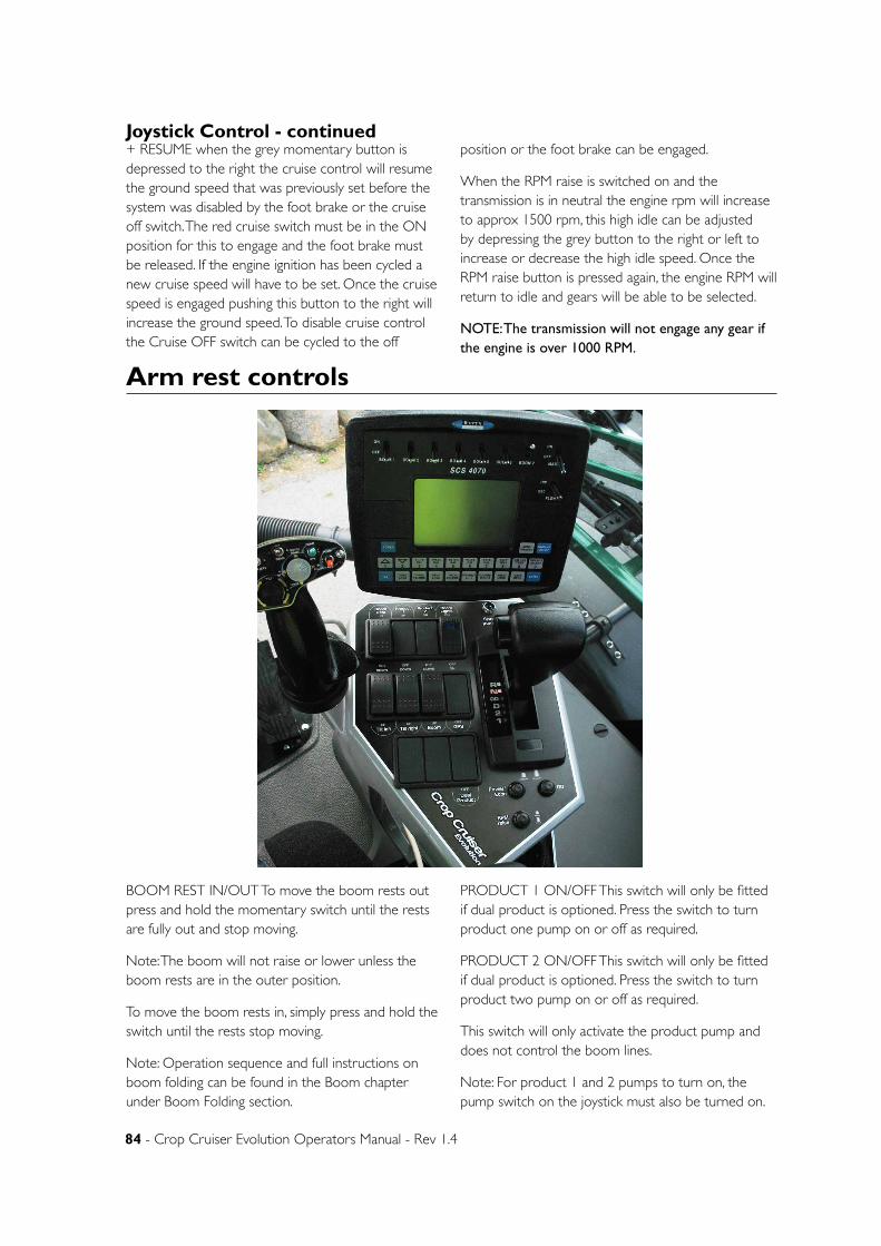
84 - Crop Cruiser Evolution Operators Manual - Rev 1.4
Arm rest controls
+ RESUME when the grey momentary button is depressed to the right the cruise control will resume the ground speed that was previously set before the system was disabled by the foot brake or the cruise off switch. The red cruise switch must be in the ON position for this to engage and the foot brake must be released. If the engine ignition has been cycled a new cruise speed will have to be set. Once the cruise speed is engaged pushing this button to the right will increase the ground speed. To disable cruise control the Cruise OFF switch can be cycled to the off
position or the foot brake can be engaged.
When the RPM raise is switched on and the transmission is in neutral the engine rpm will increase to approx 1500 rpm, this high idle can be adjusted by depressing the grey button to the right or left to increase or decrease the high idle speed. Once the RPM raise button is pressed again, the engine RPM will return to idle and gears will be able to be selected.
NOTE: The transmission will not engage any gear if the engine is over 1000 RPM.
Joystick Control - continued
BOOM REST IN/OUT To move the boom rests out press and hold the momentary switch until the rests are fully out and stop moving.
Note: The boom will not raise or lower unless the boom rests are in the outer position.
To move the boom rests in, simply press and hold the switch until the rests stop moving.
Note: Operation sequence and full instructions on boom folding can be found in the Boom chapter under Boom Folding section.
PRODUCT 1 ON/OFF This switch will only be fitted if dual product is optioned. Press the switch to turn product one pump on or off as required.
PRODUCT 2 ON/OFF This switch will only be fitted if dual product is optioned. Press the switch to turn product two pump on or off as required.
This switch will only activate the product pump and does not control the boom lines.
Note: For product 1 and 2 pumps to turn on, the pump switch on the joystick must also be turned on.
Chapter 8 - Operation - 85
BOOM LIGHTS ON/OFF If boom lights are optioned this switch will turn the lights on and off as desired.
TILT LEFT UP/DOWN This raises and lowers the left hand side boom only, when the tilt function is fitted to the sprayer. When the switch is released it returns to neutral centre. When ultra glide is connected to the sprayer the left side will be disabled from automatic mode when this switch is activated in this direction.
TILT RIGHT UP/DOWN This raises and lowers the right hand side boom only, when the tilt function is fitted to the sprayer. When the switch is released it returns to neutral centre. When ultra glide is connected to the sprayer the right side will be disabled from automatic mode when this switch is activated in this direction.
BOOM UP/DOWN Pushing the switch down will activate the boom raise circuit. Releasing the switch will return the boom to the neutral, centre position.
Pushing the switch up will lower the boom until the lower height switch, which is mounted on the parallelogram, is tripped. The hazard alarm also sounds while the boom is lowering. When the switch is released it returns to neutral, centre position.
NOTE: The switches that control boom tilt and raise/lower operate independently of the switches on the joystick.
GPS ON/OFF Switches power on and off to the 3 pin plug socket in the side of the arm rest controls. The plug is provided for the easy installation of aftermarket GPS units.
DUAL PRODUCT ON/OFF This switches the second spray line over to an additional line, usually for weedseeker operation.
Note: When dual product is fitted the Pump switch on the joystick will act as a pump master switch.
Arm Rest Controls - continued
TransmissionThe operator must wear the “Operator Safety Belt” at all times when seated in the cabin or when the machine is in motion. To engage a gear, first apply the service brake located on the right of the console, push the lock button on the gear selector inward and move the gear selector to the desired position.
R Reverse
N Neutral, the gear selector must be in this position for ignition.
OD Over drive, in this position all the forward gears are available and will be selected by the electronic control module (ECM) when required. The over drive disable switch can be used to lock out Over Drive.
D Drive, in this position 1st- 3rd gears are available and will be selected by the ECM when required. Overdrive and 4th gear not be engaged.
2 In this position 1st and 2nd gears are available and will be selected by the ECM when required. 2nd gear is the highest gear obtained.
1 In this position 1st gear is the highest gear that can be obtained.
OD Disable the button alongside the gear selector lever allows over drive to be locked out. When
the lever is in the OD position and the button is depressed the highest gear that can be obtained is 4th. This would be “in field” spraying mode. When the switch is raised over drive will be able to be selected by the transmission. This would be “Road” transport mode.
Once the desired gear is selected disengaged the park brake and release the foot service brake. If OD is selected the transmission electric control module will select the required gear as the engine revs are increased.
Power/Econ: This button cycles between Power and Economy mode. When in power mode the transmission will change gears at higher engine RPM. When in Econ mode, the transmission changes gears at a lower engine RPM.
RPM Raise: Pressing this button will raise the engine revs to 1500 RPM. The cruise control can still alter the engine RPM while this button is depressed. Pushing the button again will return the engine to idle.
Note: The transmission must be in neutral before pressing RPM raise.
Note: The transmission will not engage any gear if the engine is over 1000 RPM.
86 - Crop Cruiser Evolution Operators Manual - Rev 1.4
Filling
When filling the sprayer it is necessary to connect to an external water source.
The main tank should always be filled through the quick fill. This line fills through the top of the tank and then through a hose inside the tank so that the water is deposited in the centre of the tank. Water can then be pumped into the system from an external pump, or via a hydraulically driven fill pump mounted on the sprayer (for hydraulic fill pump information refer to chapter at the rear of this manual). If a fill flow meter has been fitted, refer to the operation chapter at the rear of this manual for further information.
The following steps should be used as a guide to filling the machine:
WARNING: Water weighs 1kg per litre. Conversion factors must be used when spraying liquids that are heavier than water. The total weight of the liquid being sprayed should not exceed the equivelant weight of a full tank of water. Exceeding this weight, can lead to sprayer damage. ie: Liquid nitrogen has a density of 1.28kg per litre. Tank size is 6500L
6500L / 1.28kg = 5078L
This means that the total volume of liquid Nitrogen allowed in a 6500L tank is 5078L.
This rule applies for all tanks sizes. If unsure about the density/weight of the chemicals being applied, contact your agronomist or chemical supplier. Main tank fill:
1. Connect the fill hose (not supplied) to quick fill cam lock coupling.
2. Make sure that the “main tank fill” handle on the EZ control is in the OFF position (so that there can be no flow coming out of the tank if it is not already empty) & that other fill functions are OFF.
3. Turn the fresh water pumping system on (make sure the pressure does not exceed 75psi)
4. Turn “main tank fill” handle on EZ control to ON. The main tank should now be filling.
5. When the required amount of water has been
transferred into the main tank, stop the flow by turning the “main tank fill” to OFF.
EZ Control
External water delivery station: The external water delivery station allows several filling functions of the sprayer to be performed simultaneously.
1. With fresh water coming into the system as per “Main tank fill” instructions, ensure that all ball valves, including the “main tank fill” ball valve, on the external water delivery station are turned to OFF.
2. Turn the desired function ON by selecting the appropriate ball valve as labelled.
3. When the required amount of water has been transferred, turn the appropriate valve to OFF.
4. When all functions have been performed, turn the fresh water pumping system OFF.
Adding chemical to the main tank: Where chemical induction equipment (chemical probe, induction hopper or DCI) has been fitted, please refer to the instructions on operating this equipment at the rear of this manual.
Rinse water tank fill:
The standard size rinse water tank holds approximately 300 litres. Make sure this tank always has sufficient water in it in case a chemical accident occurs and rinse water is need to wash chemical from any contaminated persons, clothing or components.
To fill the rinse water tank from the fresh water supply via the quick-fill and fill station:
1. Start by ensuring that all ball valves on the fill station are turned off.
2. Ensure that the red handle on the fill 3-way ball valve is horizontal. (on/off)
3. Connect the fresh water fill hose to the quick-fill coupling.
4. Operate the fresh water pumping system. (Make sure pressure does not exceed 75psi)
Chapter 8 - Operation - 87
Spray ApplicationAfter completing the filling process, you are now ready to start spraying. While travelling from the fill station to the field, the pump should be running at 400 - 540 rpm with the agitator running in order to ensure that the chemical mix is adequately agitated prior to spraying.
NOTE: The following information is provided as a guide only. It is the responsibility of the operator to assess the conditions in the field where the spray application is taking place
NOTE: The main pressure station ball valve must be in the bypass (spray mode) position.
1. Enter the field, unfold boom and set the boom to desired height above the target and have pump running.
2. Switch on the console and set to run in self test mode (while stationary). Information on running in self test mode can be found in the Raven operators manual supplied.
3. Turn on all boom sections
4. Remain stationary until all boom lines have been completely purged with product from the main tank.
5. Switch off all boom sections.
6. Commence travel on primary swath and engage boom master switch. Auto rate controller will now control application based on the calibration information entered by the operator.
7. To avoid overlap it is recommended that individual boom section switches are used to turn on/off sections as needed.
8. When you have completed the task at hand, please follow the flushing instructions to ensure that all plumbing is flushed.
AgitationTo achieve satisfactory agitation, the following guidelines are recommended.
1. Add 20 percent of the tanks volume of fresh water to the main tank.
2. Add all chemicals.
3. Add the remaining quantity of water required.
4. Turn the agitator on with the pump at operating speed.
NOTE: Check to ensure that the supermix agitator is working (there should be a visible circulation of water near the front of the tank near the agitator).
5. If the tank has been filled and the spray mixture has been allowed to settle, agitate for as long as it takes the pump to pump the quantity of water in the tank. For example: with 5000 litres in the tank with a 250l/min pump agitate for 5000/250 = 20 minutes.
To agitate while spraying: Have the bypass ball valve and agitator ball valves OPEN.
NOTE: The bypass ball valve must be open while spraying.
5. Flip the rinse water tank fill valve. (There should now be flow transferring to the rinse water tank)
6. When the required amount of water has been
transferred to the rinse water tank, shut the rinse water tank fill valve and stop the flow by turning the red handle to horizontal.
Filling - continued
88 - Crop Cruiser Evolution Operators Manual - Rev 1.4
FlushingThe following information is provided as a general guide for flushing your sprayer following a spray application.
For more specific information regarding flushing, and decontamination, specific to the products that you are applying, it is recommended that you consult the chemical label or your chemical supplier.
To use the flush water tank to flush pump & boom only:
1. Turn pump off
2. Turn 3 way ball valve to draw from flush water tank rather than main product tank.
3. Set Raven console into manual mode.
4. Switch all boom sections to ON
5. Hold increase button for 15-20 secs. This will ensure that fast close valve is fully open to direct all flow to booms (This will eliminate bypass from the booms to main tank).
6. Turn pump ON. The pump will now draw water from the flush water tank and direct all flow to the booms.
7. Keep boom switches on until the contents of the flush water tank has been run through the booms.
NOTE: If the pressure gauge increases dramatically, hold decrease to reduce.
This will allow rinse water back into the main spray tank.
To flush entire system (pump, boom & tank):
1. Drain the main tank.
2. Connect to external water source (to provide fresh water supply).
3. Turn main tank fill tap OFF to direct external water supply to the fill manifold under pressure.
4. Engage tank rinse nozzles with the ball valve on EZ control (if fitted) and allow rinsate to drain out through the main tank drain.
6. Add a quantity of fresh water (a minimum of approximately twice the pumps capacity) to the rinse water tank (as per instructions under filling).
7. Turn on pump with agitator and bypass open to allow fresh water to circulate.
8. Turn off all taps to allow the pressure relief valve to blow off and purge the “relief to tank” line.
9. Operate induction equipment (if fitted), with a quantity of fresh water in order to flush venturi system. If fitted lower the induction hopper and open drain valve while the agitation jet is running.
10. Now follow the instructions for boom flushing as above - keep ball valve drawing from rinse water tank.
Information specific to your circumstances, the spraying equipment being used and the chemicals being applied should be provided by your agronomist or chemical supplier. Always wear the recommended personal protective equipment and use caution while working with chemicals.
To remove the suction filter bowl, follow the steps below. A quantity of fresh water will need to be in the flush water tank.
1. Loosen the nut holding the filter bowl, only undo it halfway. Take care as some chemical may dribble out.
2. Stand clear of the filter and turn the 3 way suction tap to fresh water for 2 seconds, then turn the valve off again. Allow the chemical in the filter to dribble out. Be sure to catch any chemical coming out in a suitable container.
3. Once chemical has stopped coming out of the filter, unscrew the nut fully to remove the filter bowl. Be careful when removing the bowl as there may still be some chemical in it.
Removing Suction Filter
Chapter 8 - Operation - 89
End of dayAt the end of the spraying day: Follow the flushing and decontamination procedure as per previous instructions.
1. Unfold the boom in an area convenient to dispose of residual chemical (an area where chemical can not run-off into above ground or sub surface water courses).
2. Clean all filters.
3. Clean all nozzles.
4. Wash down unit
5. Drain main tank
NOTE: Store the sprayer in a suitable location to prevent freezing. If the sprayer is to be left where freezing may occur, cover the pump and flow meter with a material bag and empty pump and flow meter of all water (run the pump dry for 15-20 seconds). It is also suggested that a small quantity of anti freeze be added to the main tank and circulated through the sprayer to minimise the chance of freezing.
Make sure any ice has thawed before using sprayer.
DecontaminationDecontamination of your spraying equipment is important when changing chemicals or application methods. Information specific to your circumstances, the spraying equipment being used and the chemicals being applied should be provided by your agronomist or chemical supplier. Always wear the recommended personal protective equipment and use caution while working with chemicals.
Basic decontamination;
1. Fill the main spray tank with approx 1000L of fresh water.
2. Lower the induction hopper and put the appropiate amount of decontaminating agent into it.
3. Turn on the agitation jet on the hopper and allow it to fill the hopper to the top. Once full, turn the jet off and leave the hopper to sit for a few minutes. This is to ensure that the decontaminating agent fully neutralises any of the chemicals that were in the hopper.
4. Use the venturi to induct the contents of the hopper into the main spray tank.
5. Recirculate the decontaminating agent through the system while the main tank rinse nozzles are running. (pressure supplied from the main spray pump eg pressure delivery manifold.)
6. Turn off all taps to allow the pressure relief valve to blow off and purge the “relief to tank” line.
7. Operate induction equipment (if fitted), with a quantity of fresh water in order to flush venturi system.
8. Once complete, drain chemical induction hopper delivery hose externally.
Note: Lower the hopper and open the lid to allow it to drain completely
9. Open the boom section drain valves and empty the contents of the main tank through the boom.
DO NOT open the boom section drain valves while there is pressure in the boom lines.
10. Once the main tank has emptied, flush the system again using fresh water to ensure the decontaminating agent is removed from the system.
11. Once the main tank is empty, the hose between the tank and the 3 way suction valve also needs to be drained. The valve is located below the spray pump. Turn the 3 way valve off.
12. Remove the filter bowl. As per filter removal instructions.
13. Turn 3 way valve to main chemical tank. Stand clear of the filter when turning the valve to main chemical tank as chemical will be coming out. Catch all of the chemical in a suitable container so it can be disposed of in the correct manner.

90 - Crop Cruiser Evolution Operators Manual - Rev 1.4
End of programIf the sprayer is to be stored for a long period of time without use, there are several tasks that need to be performed.
• Clean the sprayer thoroughly as described under “END OF DAY” tasks.
• Carry out a thorough observation to determine if there is any damage to the sprayer.
• Park the sprayer in a position where it will not be affected by frosts, and preferably out of direct sunlight.
• Ensure the main tank and any other tanks fitted are empty.
If necessary, remove consoles from cabin and store in a safe and secure location. Protect hydraulic hoses and electrical connections.
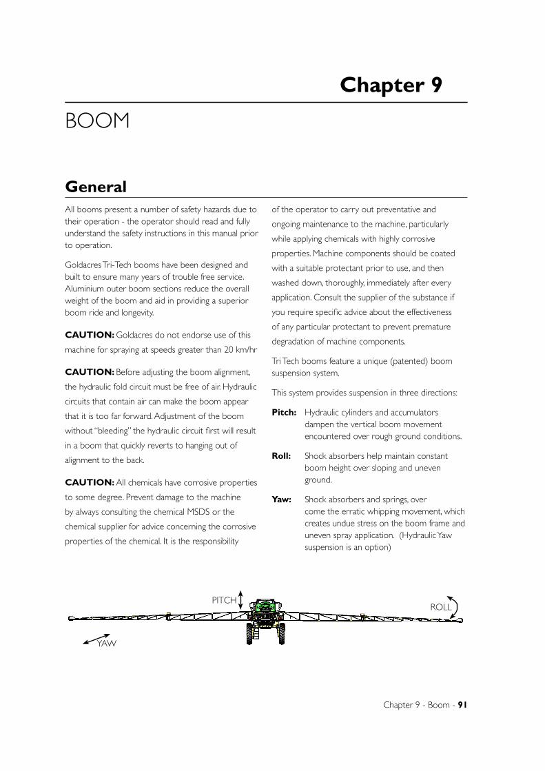
Chapter 9
Chapter 9 - Boom - 91
BOOM
GeneralAll booms present a number of safety hazards due to their operation - the operator should read and fully understand the safety instructions in this manual prior to operation.
Goldacres Tri-Tech booms have been designed and built to ensure many years of trouble free service. Aluminium outer boom sections reduce the overall weight of the boom and aid in providing a superior boom ride and longevity.
CAUTION: Goldacres do not endorse use of this
machine for spraying at speeds greater than 20 km/hr
CAUTION: Before adjusting the boom alignment,
the hydraulic fold circuit must be free of air. Hydraulic
circuits that contain air can make the boom appear
that it is too far forward. Adjustment of the boom
without “bleeding” the hydraulic circuit first will result
in a boom that quickly reverts to hanging out of
alignment to the back.
CAUTION: All chemicals have corrosive properties
to some degree. Prevent damage to the machine
by always consulting the chemical MSDS or the
chemical supplier for advice concerning the corrosive
properties of the chemical. It is the responsibility
of the operator to carry out preventative and
ongoing maintenance to the machine, particularly
while applying chemicals with highly corrosive
properties. Machine components should be coated
with a suitable protectant prior to use, and then
washed down, thoroughly, immediately after every
application. Consult the supplier of the substance if
you require specific advice about the effectiveness
of any particular protectant to prevent premature
degradation of machine components.
Tri Tech booms feature a unique (patented) boom suspension system.
This system provides suspension in three directions:
Pitch: Hydraulic cylinders and accumulators dampen the vertical boom movement encountered over rough ground conditions.
Roll: Shock absorbers help maintain constant boom height over sloping and uneven ground.
Yaw: Shock absorbers and springs, over come the erratic whipping movement, which creates undue stress on the boom frame and uneven spray application. (Hydraulic Yaw suspension is an option)
D
E
F
C
1 2 3 4
B
A
321 5
C
D
4 6 7 8
A
B
A3
SHEET 1 OF 1SCALE:1:100
DWG NO.
TITLE:
GOLDACRES
DO NOT SCALE DRAWING
MATERIAL:
DATE CREATED:
DRAWN:
1-3 MORANG CRMITCHELL PARK 3352PH: 03 53426399 FAX: 03 53426308
UNLESS OTHERWISE SPECIFIEDDIMENSIONS ARE IN MILLIMETERSDEBUR ALL EDGES Complete Assembly 2WD - SP 2011 - Parts ManualName
12/05/2011Matt
REV NO CHANGE DATE ECN NO.
DATE EDITED:
17/03/2011
PITCH
YAW
ROLL
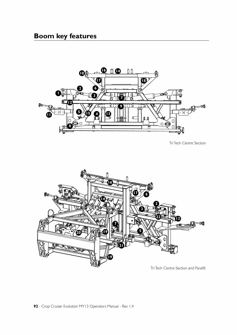
92 - Crop Cruiser Evolution MY13 Operators Manual - Rev 1.4
Boom key features
D
E
F
C
1 2 3 4
B
A
321 5
C
D
4 6 7 8
A
B
A3
SHEET 1 OF 1SCALE:1:20
DWG NO.
TITLE:
GOLDACRES
DO NOT SCALE DRAWING
MATERIAL:
DATE CREATED:
DRAWN:
1-3 MORANG CRMITCHELL PARK 3352PH: 03 53426399 FAX: 03 53426308
UNLESS OTHERWISE SPECIFIEDDIMENSIONS ARE IN MILLIMETERSDEBUR ALL EDGES Para, Centre, Boom
9/05/2011Matt
REV NO CHANGE DATE ECN NO.
DATE EDITED:
5/05/2011
D
E
F
C
1 2 3 4
B
A
321 5
C
D
4 6 7 8
A
B
A3
SHEET 1 OF 1SCALE:1:20
DWG NO.
TITLE:
GOLDACRES
DO NOT SCALE DRAWING
MATERIAL:
DATE CREATED:
DRAWN:
1-3 MORANG CRMITCHELL PARK 3352PH: 03 53426399 FAX: 03 53426308
UNLESS OTHERWISE SPECIFIEDDIMENSIONS ARE IN MILLIMETERSDEBUR ALL EDGES Para, Centre, Boom
9/05/2011Matt
REV NO CHANGE DATE ECN NO.
DATE EDITED:
5/05/2011
12
3
45
6
7
8
9
10
11
12
13
14
15
16
17 18
19
1920
21
22
16
14
17
127
5
3
6
2
Tri Tech Centre Section
Tri Tech Centre Section and Paralift
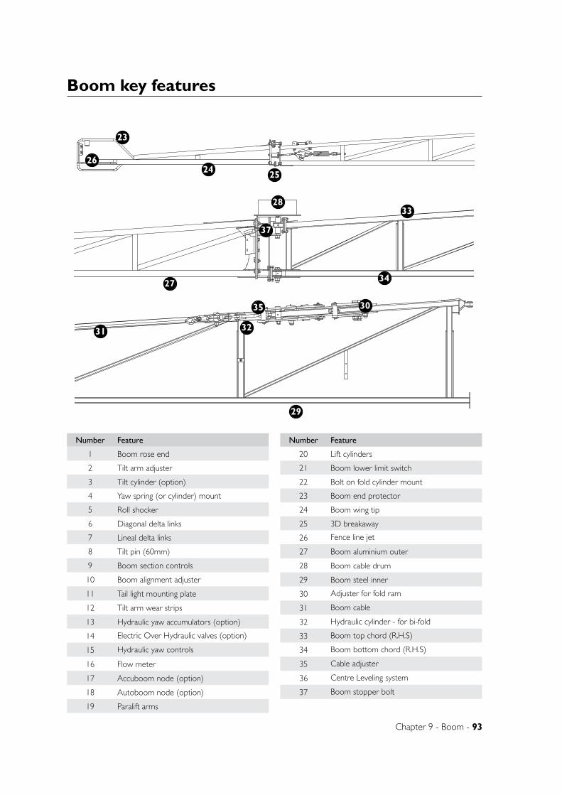
Chapter 9 - Boom - 93
Boom key features
Number Feature
1 Boom rose end
2 Tilt arm adjuster
3 Tilt cylinder (option)
4 Yaw spring (or cylinder) mount
5 Roll shocker
6 Diagonal delta links
7 Lineal delta links
8 Tilt pin (60mm)
9 Boom section controls
10 Boom alignment adjuster
11 Tail light mounting plate
12 Tilt arm wear strips
13 Hydraulic yaw accumulators (option)
14 Electric Over Hydraulic valves (option)
15 Hydraulic yaw controls
16 Flow meter
17 Accuboom node (option)
18 Autoboom node (option)
19 Paralift arms
Number Feature
20 Lift cylinders
21 Boom lower limit switch
22 Bolt on fold cylinder mount
23 Boom end protector
24 Boom wing tip
25 3D breakaway
26 Fence line jet
27 Boom aluminium outer
28 Boom cable drum
29 Boom steel inner
30 Adjuster for fold ram
31 Boom cable
32 Hydraulic cylinder - for bi-fold
33 Boom top chord (R.H.S)
34 Boom bottom chord (R.H.S)
35 Cable adjuster
36 Centre Leveling system
37 Boom stopper bolt
D
E
F
C
1 2 3 4
B
A
321 5
C
D
4 6 7 8
A
B
A3
SHEET 1 OF 1SCALE:1:10
DWG NO.
TITLE:
GOLDACRES
DO NOT SCALE DRAWING
MATERIAL:
DATE CREATED:
DRAWN:
1-3 MORANG CRMITCHELL PARK 3352PH: 03 53426399 FAX: 03 53426308
UNLESS OTHERWISE SPECIFIEDDIMENSIONS ARE IN MILLIMETERSDEBUR ALL EDGES Evo 2013 boom bI FOLD kitA. McAndrew
22/08/2012Matt
REV NO CHANGE DATE ECN NO.
DATE EDITED:
17/12/2003
D
E
F
C
1 2 3 4
B
A
321 5
C
D
4 6 7 8
A
B
A3
SHEET 1 OF 1SCALE:1:10
DWG NO.
TITLE:
GOLDACRES
DO NOT SCALE DRAWING
MATERIAL:
DATE CREATED:
DRAWN:
1-3 MORANG CRMITCHELL PARK 3352PH: 03 53426399 FAX: 03 53426308
UNLESS OTHERWISE SPECIFIEDDIMENSIONS ARE IN MILLIMETERSDEBUR ALL EDGES Cable drum suit 2013 EvoLuke M
22/08/2012Jono
REV NO CHANGE DATE ECN NO.
DATE EDITED:
23/02/2011
D
E
F
C
1 2 3 4
B
A
321 5
C
D
4 6 7 8
A
B
A3
SHEET 1 OF 1SCALE:1:12.5
DWG NO.
TITLE:
GOLDACRES
DO NOT SCALE DRAWING
MATERIAL:
DATE CREATED:
DRAWN:
1-3 MORANG CRMITCHELL PARK 3352PH: 03 53426399 FAX: 03 53426308
UNLESS OTHERWISE SPECIFIEDDIMENSIONS ARE IN MILLIMETERSDEBUR ALL EDGES breakaway assem with protector
Breakaway hinge 2006 complete
22/08/2012Matt
REV NO CHANGE DATE ECN NO.
DATE EDITED:
27/02/2006
23
24 25
26
27
28
29
30
31 32
33
34
35
37
94 - Crop Cruiser Evolution MY13 Operators Manual - Rev 1.4
Boom OverviewCentre SectionThe Tri Tech centre section is made up of two components, the paralift rear and the boom centre section. The two are held together by delta links. These links allow the boom to be suspended in order to provide roll and yaw suspension.
Roll suspension is when the boom pitches up and down at the tips. Yaw suspension is when the boom moves fore and aft at the tips. If the boom did not feature yaw suspension there would be excessive stresses exerted on the booms and centre section when cornering or corrections of line are made. The yaw suspension allows the chassis of the sprayer to move left and right without any movement being transferred to the boom. The paralift rear will move with the centre of the sprayer but the boom centre section will remain static or level as it rotates around the delta links connecting it to the paralift rear.
The boom yaw is dampened by 2 large springs (1 each side) and 2 dampener shockers to limit the recoil of the yaw springs. These springs must be tensioned all the way. If the springs are not tensioned correctly the boom will be able to yaw excessively and the springs may be damaged. If a spring is damaged, both opposing springs must be replaced at the same time.
The overall yaw travel is limited by rubber bumpers mounted to the paralift rear. If the boom centre section yaws excessively the centre section will contact these and cushion the travel by collapsing the block. If the block collapses totally the yaw travel will be stopped. If the boom is continually yawed excessively this block will wear out and require replacement.
Hydraulic raise and lowerThe paralift on a Tri Tech boom enables the boom to be raised and lowered to maintain a consistent boom height above the target.
Tri Tech booms feature a paralift rear which uses two hydraulic cylinders to perform the lift, while also acting as a component providing the vertical suspension. Each hydraulic cylinder has a nitrogen charged accumulator which also assists in improving the boom ride. The “boom limit” height switch allows
the operator to adjust the minimum ride height of the boom. Boom maintenance information can be found in the “maintenance” chapter of this manual.
The hydraulic lift also enables the boom to be raised prior to folding and then used to lower the boom onto the boom rests.
Hydraulic foldThe Tri Tech booms hydraulic fold feature, allows the boom to opened and closed from within the tractor cabin via the tractor hydraulic system.
Hydraulic phasing cylinders are used in the folding operation of the boom. This ensures that both sides of the boom are synchronised and open and close together so that the weight distribution is the same for both sides of the boom.
As hydraulic fluid enters one hydraulic cylinder, it acts upon the first ram and causes it to move. This motion results in an amount of fluid entering the second hydraulic cylinder which causes it to move an equivalent distance. There is also a flow restrictor for each cylinder so that the hydraulic fluid will enter and leave the respective cylinders at a controlled rate. This has the effect of slowing down the rate of fluid transfer and thus causes the boom to open and close more slowly - protecting the boom from damage. If the phasing cylinders do not fold together, information on re-phasing the rams can be found in the “maintenance” chapter.
Boom balanceThe Tri Tech boom suspension system causes the boom to adpot the same plane as the spray tanker. If one side is heavier than the other, the boom will tend to hang lower on the heavy side, so both sides need to be balanced for the boom ends to be of the same height.
To acheive this, a boom counterweight can be included on the boom and placed strategically so that it compensates and balances the boom. The counterweight can have more weight added and/or be moved to balance the boom correctly.
Before adding any boom weights, it is advised that the boom is adjusted correctly. As per the instructions following in this chapter.
Chapter 9 - Boom - 95
Boom overview - continuedBoom cablesBoom cables are a critical part of the Tri Tech boom and it is important to ensure that boom cables are correctly adjusted prior to operation.
Loose boom cables can cause boom damage by allowing the outer boom section to hang out of alignment or to ‘break away’ too easily. This can shorten the sprayers life by placing unnecessary stresses on the boom, lift and chassis.
The cable tension can be checked by inspecting the cable springs, Further information on boom adjustment and alignment can be found in this chapter.
Boom valvesMotorised boom valves are fitted as standard and are mounted on the boom centre section at the rear of the sprayer. Motorised boom valves feature a 12 volt motor that opens or closes a stainless steel plunger and thus opening or closing flow to the boom sections as required.
In the event of a valve failure, unscrew the top cap of valve then check that the fuse (3 amp) is ok.
NozzlesThe standard nozzle spacing on Goldacres booms is 500mm. Nozzles are mounted on brackets that are adjustable for different nozzle types. Nozzles are mounted so that they are protected from ground hits should the boom make contact with the ground, obstructions or crop.
As information regarding nozzles is specific to those being used in your application, no specific reference is made to nozzle application rates or types in this operator’s manual. Goldacres suggest the use of a current TeeJet nozzle selection catalogue for reference to nozzle sizes, outputs, spray patterns and general
spraying information. For more technical information on the function of spray nozzles and factors affecting their performance you can also use the TeeJet “User’s guide to spray nozzles”.
The TeeJet nozzle selection catalogue and Users guide to spray nozzles are available from Goldacres dealers, or as a free download from the TeeJet website: www.teejet.com
Three dimensional breakawayTri Tech booms feature the unique three dimensional breakaway hinge which allows the tip to “break” forward, backward and upward if an obstruction is hit. The 3D breakaway hinge aims to eliminate any further damage to the remainder of the boom should an obstruction be hit.
It is important that the 3D breakaway hinge is properly adjusted when in operation. Just tightening the spring will not help with the function of the breakaway. Instructions on how to properly adjust the breakaway can be found later in this chapter.
Boom protection bracketsStainless steel boom protectors are fitted on the boom to protect the boom when resting on the boom rests for transport. It is important to ensure that the boom protection brackets are fitted correctly.
Boom end protectorBoom end protectors are fitted to the breakaway tips to help prevent damage to the boom from ground strike or from hitting an obstruction. They also help to keep the boom from becoming entangled when spraying close to fence lines.
96 - Crop Cruiser Evolution MY13 Operators Manual - Rev 1.4
Boom optionsFence line jetsGoldacres offer manually and electrically operated fence line jets. The ‘fenceline’ jet is designed to enable the operator to spray right up to the boundary fence without having the boom too close to the fence.
The angle of the off-centre jet can be altered to suit particular applications but it should enable the boom to be inside the fence by about 1 metre and still be able to spray to the fence. This should prevent operators from putting the boom into the fence, especially important when the boom is relatively new and the operator is not familiar with the width of the boom. The fenceline jet should be turned off after the end of the first lap and this can be done either manually via a tap or remotely via an optional electric solenoid (controlled in the cabin).
Hydraulic yaw suspensionHydraulic yaw suspension is designed to control the yaw movement of the boom centre section. In place of the conventional system, which uses 4 springs and 4 dampers, the hydraulic yaw option uses 2 hydraulic cylinders and nitrogen filled accumulators to centre and dampen the yaw movement.
The two hydraulic cylinders and accumulators are charged with hydraulic pressure and then closed off to create a seperate circuit which acts as the yaw suspension.
For further information, refer to the hydraulic yaw suspension section in this chapter.
Bi-foldTri Tech booms can incorporate a hydraulic bi-fold option which allows the boom outer sections to be folded in to make the entire boom smaller.
For example a 36 metre Tri Tech boom fitted with the bi-fold option would fold back into 18 metres swath width for easier spraying in tight situations.
A centre leveling sytem is fitted as standard on machines with bi-fold. The centre leveling system holds the centre section level with the sprayer chassis when fold or bi-fold functions are activated. This helps with the even folding of the wings.
See the section at the end of this chapter for
information on adjusting booms fitted with bi-fold.
UltraglideThe Goldacres ultrasonic boom height levelling system allows you to spray more precisely by automatically adjusting the height of your boom as you travel across the paddock. The operator sets a desired height above the target
This means that you spend less time watching your booms and trying to prevent them from hitting the ground or crop. Ultraglide detects changes in target height and adjusts your boom accordingly.
The ultrasonic sensor detects the height of the target and adjusts the boom height with the hydraulic tilt cylinders to suit the preset height.
Further information on ultrasonic boom height levelling can be found in the “ultraglide” section at the rear of this manual.
Hydraulic tiltsTri Tech booms can incorporate a hydraulic tilt option, which allows the individual boom sides to be raised independently when in the working position. This serves to provide greater variability of boom height control to compensate for undulating ground conditions. Boom tilts are operated from a lever or switch in the cabin. (depending on hydraulic system fitted).
The use of tilt cylinders should be kept to a minimum as the the tilt operation affects the balance of the boom causing rocking of the whole boom assembly.
Where hydraulic tilts are not fitted, a manually adjustable link is placed in substitute for the tilt cylinder.
Three tier system (3TS) Three Tier System (3TS) consists of two complete and totally separate boom lines on the same boom frame. As an example a conventional 30 metre boom has one boom line with 60 nozzle outlets (2 per metre) across its width. A 3TS boom replicates this first line with a second line also consisting of 60 nozzles giving a total of 120 nozzles for both lines.
When a conventional boom starts spraying at low
Chapter 9 - Boom - 97
Boom options - continued
speeds, the pressure at the nozzle is correspondingly low. As the sprayer accelerates the pressure at the nozzles also increases as the Raven controller adjust the flow rate to maintain the correct application rate. As you may be aware, nozzles have a suggested maximum pressure range in which they should be operated. For example: The suggested minimum and maximum pressure range of an XR 11002 TeeJet nozzle is 100 kPa to 400 kPa. If the nozzle is operated above this range then the potential for spray drift is dramatically increased due to the excessive number of finer droplets produced. The rate of nozzle orifice wear also rises as the pressure extends outside the optimum range. The conventional boom therefore has a limitation as to the maximum speed it can operate before the nozzles start to work outside their optimum pressure range.
A 3TS utilises two different sized nozzles in each of its two lines. It starts off on the boom line with the smaller nozzles i.e. 110015’s in the same manner as the conventional boom. This is referred to as the first tier. As the sprayer accelerates the pressure at the nozzle increases to maintain the given spray rate, but at a predetermined flow rate (example 350 kPa) the Raven controller simultaneously turns off this first line whilst turning on the second boom line containing larger nozzles i.e. 110025’s. This is referred to as the second tier. If the sprayer continues to accelerate the pressure in this second line also increases to a second predetermined point and the Raven controller then turns both lines on i.e. 110025’s + 110015’s. This is referred to as the third tier. The combined flow rate of the two sets of nozzles 110025 + 110015 = 11004 allows scope for the sprayer to accelerate even further if required.
As the sprayer slows the reverse occurs. The Raven controller turns off the 110015’s leaving only the 110025 operating then turns off the 110025’s whilst simultaneously turning back on the 110015’s as the sprayer slows.
Not unlike automatic gear changes in a vehicle, where the transmission selects gears to maintain engine RPM’s in the optimum range, the 3TS automatically select nozzle sizes to maintain the pressure in the optimum range.
The whole system is controlled by the Raven SCS4400 which has 3TS compatibility as a standard feature. It’s simply a matter of programming into the SCS4400 console the two predetermined flow rates at which point you wish the tiers to change. Nothing else needs to be done by the operator, and it is a very simple system to operate.
For information on 3TS boom tier programming refer
to the “calibration” section of this manual.
Rapid FireThe Rapid fire system provides instantaneous, individual nozzle shut off that is controlled by air operated solenoids at each nozzle. This system replaces the boom valves and standard check valves that shut off the boom sections and nozzles. This provides greater flexibility in changing boom section widths and faster shut off at the nozzle.
The RapidFire system reduces the amount of plumbing on the sprayer and allows for the fitting of a boom recirculation system. The ability to have more boom sections also works perfectly in conjunction with autoboom shut off systems.
Boom Recirculation (Rapid Flow)In order to ensure that boom lines are charged and ready to spray, a standard sprayer plumbing system will require the boom lines to be purged with chemical mix prior to spraying. Rapidflow allows an agitated chemical mix to be run through the boom lines prior to spraying - pre-charging them and eliminating waste.
This option is not available unless rapid fire is also fitted.
98 - Crop Cruiser Evolution MY13 Operators Manual - Rev 1.4
Boom operationBoom Operation
FoldingThe boom fold sequence is as below:
1. Starting with the boom in the working position, use the lever/switch in cabin to raise the boom fully.
2. Use the lever/switch to fold the boom completely in.
3. Lower the boom until the boom just touches the rests
4. Then continue to lower the boom a further 100mm so as to put sufficient weight onto the rests.
5. Fold boom rests in.
6. Finally, press the boom fold switch momentarily to fold the booms tight on the rest.
NOTE: Booms must not be folded, or unfolded, while the sprayer is moving. When the boom is between fully open and fully closed , there can be large stresses placed on many boom components. If the sprayer is moving and hits a bump, severe damage to the boom can occur.
NOTE: The booms must be folded continuously
without stopping and starting during the sequence. Take care not to fold/unfold booms too fast, as damage can be caused.
CAUTION: Always check for power lines while folding and unfolding the boom, as contact with lines can be fatal.
Un-foldingThe boom unfold sequence is as below:
1. Fold boom rests out.
NOTE: Booms will not raise unless the rests are folded out first.
2. Raise the boom fully to clear the boom rests.
3. Use the lever/switch in the cabin to unfold the boom so that the boom is aligned with the centre section.
4. Lower the boom to the desired height above the target.
NOTE: The booms must be folded continuously without stopping and starting during the sequence.
NOTE: To re-phase the fold cylinders, continue holding the boom out button once the boom has fully unfolded.
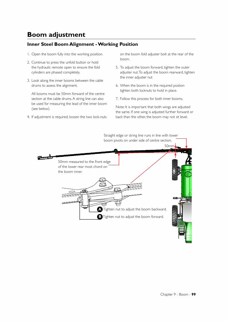
Chapter 9 - Boom - 99
D
E
F
C
1234
B
A
3 2 15
C
D
4678
A
B
A3
SHEET 1 OF 1 SCALE:1:100
DWG NO.
TITLE:
GOLDACRES
DO NOT SCALE DRAWING
MATERIAL:
DATE CREATED:
DRAWN:
1-3 MORANG CRMITCHELL PARK 3352PH: 03 53426399 FAX: 03 53426308
UNLESS OTHERWISE SPECIFIEDDIMENSIONS ARE IN MILLIMETERSDEBUR ALL EDGESPara, Centre, Boom
19/03/2013Matt
REV NOCHANGEDATEECN NO.
DATE EDITED:
5/05/2011
Boom adjustment
1. Open the boom fully into the working position.
2. Continue to press the unfold button or hold the hydraulic remote open to ensure the fold cylinders are phased completely.
3. Look along the inner booms between the cable drums to assess the alignment.
All booms must be 50mm forward of the centre section at the cable drums. A string line can also be used for measuring the lead of the inner boom (see below).
4. If adjustment is required, loosen the two lock-nuts
on the boom fold adjuster bolt at the rear of the boom.
5. To adjust the boom forward, tighten the outer adjuster nut. To adjust the boom rearward, tighten the inner adjuster nut
6. When the boom is in the required postion tighten both locknuts to hold in place.
7. Follow this process for both inner booms.
Note: It is important that both wings are adjusted the same. If one wing is adjusted further forward or back than the other, the boom may not sit level.
Tighten nut to adjust the boom forward.
A
B
Tighten nut to adjust the boom backward.
50mm measured to the front edge of the lower rear most chord on the boom inner.
Straight edge or string line runs in line with lower boom pivots on under side of centre section.
50mm
D E FC
12
34
BA
32
15
C D
46
78
A B
A3
SHEE
T 1 O
F 1
SCA
LE:1
:25
DW
G N
O.
TITLE
:
GO
LDA
CRE
S
DO
NO
T SC
ALE
DRA
WIN
G
MA
TERI
AL:
DA
TE C
REA
TED
:
DRA
WN
:
1-3
MO
RAN
G C
RM
ITCHE
LL P
ARK
335
2PH
: 03
5342
6399
FA
X: 0
3 53
4263
08
UNLE
SS O
THER
WIS
E SP
ECIF
IED
DIM
ENSI
ON
S A
RE IN
MILL
IMET
ERS
DEB
UR A
LL E
DG
ESC
ompl
ete
Ass
embl
y 2W
D -
SP 2
011
- Par
ts M
anua
lN
ame
19/0
3/20
13M
att
REV
NO
CHA
NG
ED
ATE
ECN
NO
.
DA
TE E
DITE
D:
17/0
3/20
11
Inner Steel Boom Alignment - Working Position
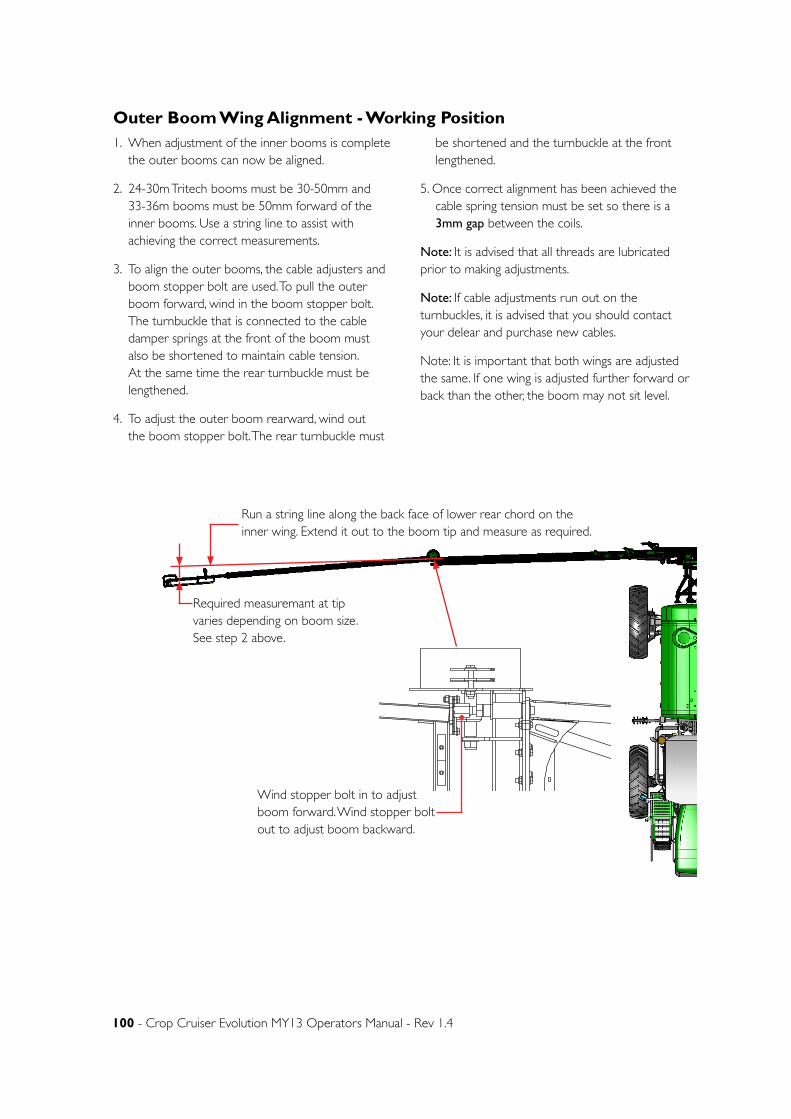
100 - Crop Cruiser Evolution MY13 Operators Manual - Rev 1.4
D
E
F
C
1234
B
A
3 2 15
C
D
4678
A
B
A3
SHEET 1 OF 1 SCALE:1:100
DWG NO.
TITLE:
GOLDACRES
DO NOT SCALE DRAWING
MATERIAL:
DATE CREATED:
DRAWN:
1-3 MORANG CRMITCHELL PARK 3352PH: 03 53426399 FAX: 03 53426308
UNLESS OTHERWISE SPECIFIEDDIMENSIONS ARE IN MILLIMETERSDEBUR ALL EDGESPara, Centre, Boom
19/03/2013Matt
REV NOCHANGEDATEECN NO.
DATE EDITED:
5/05/2011
D E FC
12
34
BA
32
15
C D
46
78
A B
A3
SHEE
T 1 O
F 1
SCA
LE:1
:25
DW
G N
O.
TITLE
:
GO
LDA
CRE
S
DO
NO
T SC
ALE
DRA
WIN
G
MA
TERI
AL:
DA
TE C
REA
TED
:
DRA
WN
:
1-3
MO
RAN
G C
RM
ITCHE
LL P
ARK
335
2PH
: 03
5342
6399
FA
X: 0
3 53
4263
08
UNLE
SS O
THER
WIS
E SP
ECIF
IED
DIM
ENSI
ON
S A
RE IN
MILL
IMET
ERS
DEB
UR A
LL E
DG
ESC
ompl
ete
Ass
embl
y 2W
D -
SP 2
011
- Par
ts M
anua
lN
ame
19/0
3/20
13M
att
REV
NO
CHA
NG
ED
ATE
ECN
NO
.
DA
TE E
DITE
D:
17/0
3/20
11
1. When adjustment of the inner booms is complete the outer booms can now be aligned.
2. 24-30m Tritech booms must be 30-50mm and 33-36m booms must be 50mm forward of the inner booms. Use a string line to assist with achieving the correct measurements.
3. To align the outer booms, the cable adjusters and boom stopper bolt are used. To pull the outer boom forward, wind in the boom stopper bolt. The turnbuckle that is connected to the cable damper springs at the front of the boom must also be shortened to maintain cable tension. At the same time the rear turnbuckle must be lengthened.
4. To adjust the outer boom rearward, wind out the boom stopper bolt. The rear turnbuckle must
be shortened and the turnbuckle at the front lengthened.
5. Once correct alignment has been achieved the cable spring tension must be set so there is a 3mm gap between the coils.
Note: It is advised that all threads are lubricated prior to making adjustments.
Note: If cable adjustments run out on the turnbuckles, it is advised that you should contact your delear and purchase new cables.
Note: It is important that both wings are adjusted the same. If one wing is adjusted further forward or back than the other, the boom may not sit level.
Required measuremant at tip varies depending on boom size. See step 2 above.
D
E
F
C
1 2 3 4
B
A
321 5
C
D
4 6 7 8
A
B
A3
SHEET 1 OF 1SCALE:1:7.5
DWG NO.
TITLE:
GOLDACRES
DO NOT SCALE DRAWING
MATERIAL:
DATE CREATED:
DRAWN:
1-3 MORANG CRMITCHELL PARK 3352PH: 03 53426399 FAX: 03 53426308
UNLESS OTHERWISE SPECIFIEDDIMENSIONS ARE IN MILLIMETERSDEBUR ALL EDGES Cable drum suit 2013 EvoLuke M
23/08/2012Matt
REV NO CHANGE DATE ECN NO.
DATE EDITED:
23/02/2011
Wind stopper bolt in to adjust boom forward. Wind stopper bolt out to adjust boom backward.
Run a string line along the back face of lower rear chord on the inner wing. Extend it out to the boom tip and measure as required.
Outer Boom Wing Alignment - Working Position
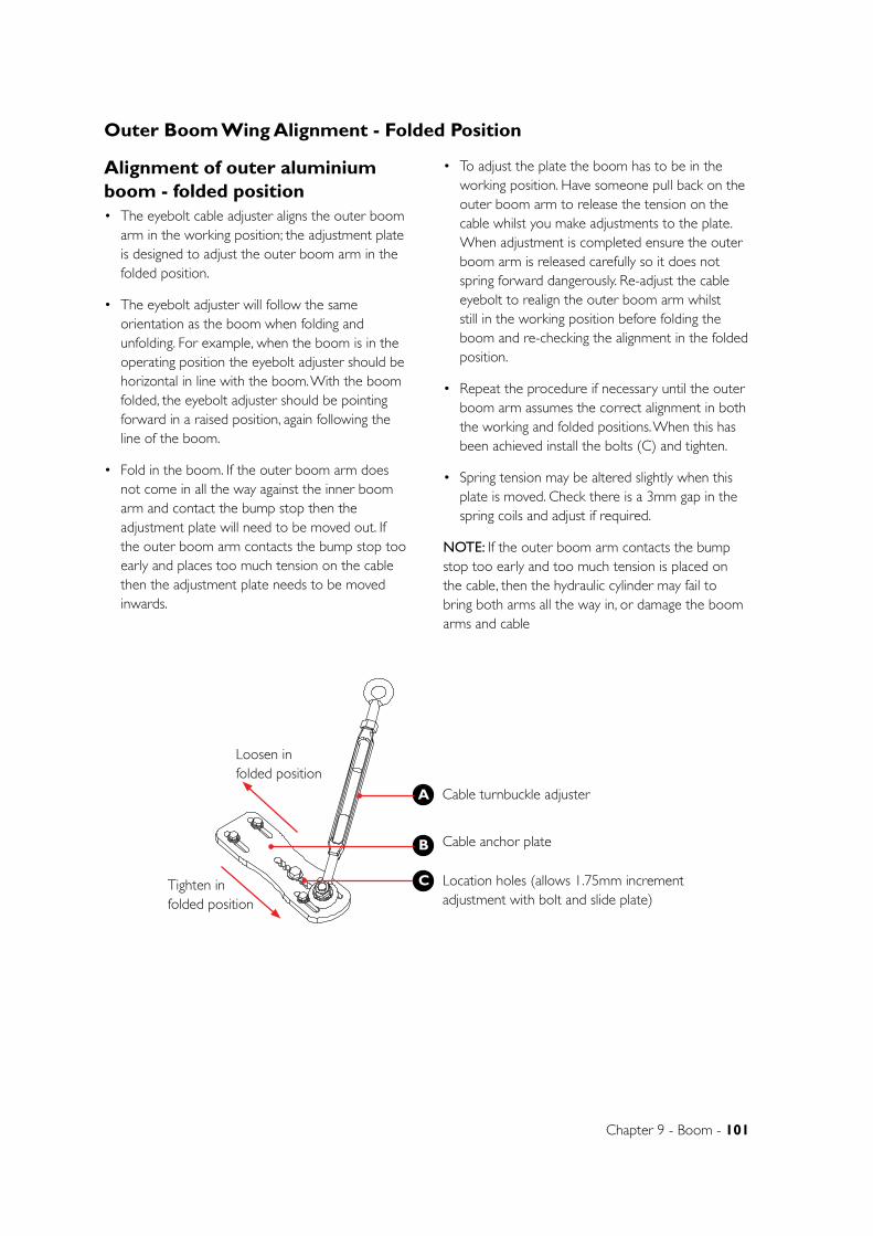
Chapter 9 - Boom - 101
B
C
D
1 2
A
321 4
B
A
5 6
UNLESS OTHERWISE SPECIFIED:DIMENSIONS ARE IN MILLIMETERSDEBUR ALL EDGES
GOLDACRESTITLE:
DWG NO:
SCALE:1:5 SHEET 1 OF 1
A4
C
GA4922220REV NO CHANGE APPL DATE
DATE CREATED:
DRAWN:
Rear cable mount 24-36m RH MY13
1-3 MORANG CRMITCHELL PARK 3352PH: 03 53426399 FAX: 03 53426308
21/06/2012
DATE EDITED:
23/08/2012Matt
UNTOL. DIMENSIONSOPEN DIM ± 0.20ONE DEC. PL. ± 0.10TWO DEC. PL. ± 0.05ANGULAR ± 0°30'
Luke M
DO NOT SCALE DRAWING
MATERIAL:
Alignment of outer aluminium boom - folded position• The eyebolt cable adjuster aligns the outer boom
arm in the working position; the adjustment plate is designed to adjust the outer boom arm in the folded position.
• The eyebolt adjuster will follow the same orientation as the boom when folding and unfolding. For example, when the boom is in the operating position the eyebolt adjuster should be horizontal in line with the boom. With the boom folded, the eyebolt adjuster should be pointing forward in a raised position, again following the line of the boom.
• Fold in the boom. If the outer boom arm does not come in all the way against the inner boom arm and contact the bump stop then the adjustment plate will need to be moved out. If the outer boom arm contacts the bump stop too early and places too much tension on the cable then the adjustment plate needs to be moved inwards.
• To adjust the plate the boom has to be in the working position. Have someone pull back on the outer boom arm to release the tension on the cable whilst you make adjustments to the plate. When adjustment is completed ensure the outer boom arm is released carefully so it does not spring forward dangerously. Re-adjust the cable eyebolt to realign the outer boom arm whilst still in the working position before folding the boom and re-checking the alignment in the folded position.
• Repeat the procedure if necessary until the outer boom arm assumes the correct alignment in both the working and folded positions. When this has been achieved install the bolts (C) and tighten.
• Spring tension may be altered slightly when this plate is moved. Check there is a 3mm gap in the spring coils and adjust if required.
NOTE: If the outer boom arm contacts the bump stop too early and too much tension is placed on the cable, then the hydraulic cylinder may fail to bring both arms all the way in, or damage the boom arms and cable
A Cable turnbuckle adjuster
Location holes (allows 1.75mm increment adjustment with bolt and slide plate)
Cable anchor plate
C
B
Tighten in folded position
Loosen in folded position
Outer Boom Wing Alignment - Folded Position
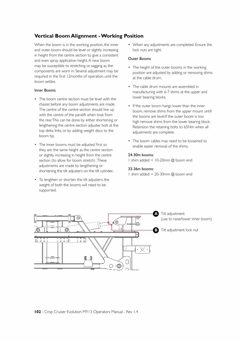
102 - Crop Cruiser Evolution MY13 Operators Manual - Rev 1.4
When the boom is in the working position, the inner and outer boom should be level or slightly increasing in height from the centre section to give a consistent and even spray application height. A new boom may be susceptible to stretching or sagging as the components are worn in. Several adjustment may be required in the first 12months of operation until the boom settles.
Inner Booms
• The boom centre section must be level with the chassis before any boom adjustments are made. The centre of the centre section should line up with the centre of the paralift when look from the rear. This can be done by either shortening or lengthening the centre section adjuster bolt at the top delta links, or by adding weight discs to the boom tip.
• The inner booms must be adjusted first so they are the same height as the centre section or slightly increasing in height from the centre section (to allow for boom stretch) .These adjustments are made by lengthening or shortening the tilt adjusters on the tilt cylinder..
• To lengthen or shorten the tilt adjusters, the weight of both the booms will need to be supported.
• When any adjustments are completed. Ensure the lock nuts are tight.
Outer Booms
• The height of the outer booms in the working position are adjusted by adding or removing shims at the cable drum.
• The cable drum mounts are assembled in manufacturing with 6-7 shims at the upper and lower bearing blocks.
• If the outer boom hangs lower than the inner boom, remove shims from the upper mount untill the booms are level.If the outer boom is too high remove shims from the lower bearing block.Retension the retaining bolts to 65Nm when all adjustments are complete.
• The boom cables may need to be loosened to enable easier removal of the shims.
24-30m booms: 1 shim added = 10-20mm @ boom end
33-36m booms: 1 shim added = 20-30mm @ boom end
A Tilt adjustment (use to raise/lower inner boom)
Tilt adjustment lock nut B
Vertical Boom Alignment - Working Position
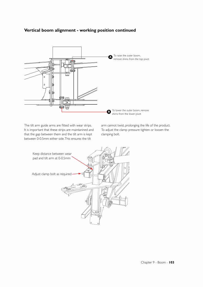
Chapter 9 - Boom - 103
B
A
To lower the outer boom, remove shims from the lower pivot
To raise the outer boom, remove shims from the top pivot
D
E
F
C
1 2 3 4
B
A
321 5
C
D
4 6 7 8
A
B
A3
SHEET 1 OF 1SCALE:1:7.5
DWG NO.
TITLE:
GOLDACRES
DO NOT SCALE DRAWING
MATERIAL:
DATE CREATED:
DRAWN:
1-3 MORANG CRMITCHELL PARK 3352PH: 03 53426399 FAX: 03 53426308
UNLESS OTHERWISE SPECIFIEDDIMENSIONS ARE IN MILLIMETERSDEBUR ALL EDGES Cable drum suit 2013 EvoLuke M
24/08/2012Matt
REV NO CHANGE DATE ECN NO.
DATE EDITED:
23/02/2011
The tilt arm guide arms are fitted with wear strips. It is important that these strips are maintanined and that the gap between them and the tilt arm is kept between 0-0.5mm either side. This ensures the tilt
arm cannot twist, prolonging the life of the product. To adjust the clamp pressure tighten or loosen the clamping bolt.
D
E
F
C
1 2 3 4
B
A
321 5
C
D
4 6 7 8
A
B
A3
SHEET 1 OF 1SCALE:1:5
DWG NO.
TITLE:
GOLDACRES
DO NOT SCALE DRAWING
MATERIAL:
DATE CREATED:
DRAWN:
1-3 MORANG CRMITCHELL PARK 3352PH: 03 53426399 FAX: 03 53426308
UNLESS OTHERWISE SPECIFIEDDIMENSIONS ARE IN MILLIMETERSDEBUR ALL EDGES GA4922195
Boom centre 2011 Base assembly
Luke Myers
12/10/2012Matt
REV NO CHANGE DATE ECN NO.
DATE EDITED:
23/03/2010
Keep distance between wear pad and tilt arm at 0-0.5mm
Adjust clamp bolt as required
Vertical boom alignment - working position continued
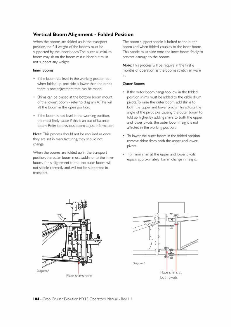
104 - Crop Cruiser Evolution MY13 Operators Manual - Rev 1.4
D
E
F
C
1 2 3 4
B
A
321 5
C
D
4 6 7 8
A
B
A3
SHEET 1 OF 1SCALE:1:20
DWG NO.
TITLE:
GOLDACRES
DO NOT SCALE DRAWING
MATERIAL:
DATE CREATED:
DRAWN:
1-3 MORANG CRMITCHELL PARK 3352PH: 03 53426399 FAX: 03 53426308
UNLESS OTHERWISE SPECIFIEDDIMENSIONS ARE IN MILLIMETERSDEBUR ALL EDGES Para, Centre, Boom
12/05/2011Matt
REV NO CHANGE DATE ECN NO.
DATE EDITED:
5/05/2011
When the booms are folded up in the transport position, the full weight of the booms must be supported by the inner boom. The outer aluminium boom may sit on the boom rest rubber but must not support any weight.
Inner Booms
• If the boom sits level in the working postion but when folded up, one side is lower than the other, there is one adjustment that can be made.
• Shims can be placed at the bottom boom mount of the lowest boom - refer to diagram A. This will lift the boom in the open position.
• If the boom is not level in the working position, the most likely cause if this is an out of balance boom. Refer to previous boom adjust information.
Note: This process should not be required as once they are set in manufacturing, they should not change
When the booms are folded up in the transport position, the outer boom must saddle onto the inner boom. If this alignement of out the outer boom will not saddle correctly and will not be supported in transport.
The boom support saddle is bolted to the outer boom and when folded, couples to the inner boom. This saddle must slide onto the inner boom freely to prevent damage to the booms.
Note: This process will be require in the first 6 months of operation as the booms stretch an ware in.
Outer Booms
• If the outer boom hangs too low in the folded position shims must be added to the cable drum pivots. To raise the outer boom, add shims to both the upper and lower pivots. This adjusts the angle of the pivot axis causing the outer boom to fold up higher. By adding shims to both the upper and lower pivots, the outer boom height is not affected in the working position.
• To lower the outer boom in the folded position, remove shims from both the upper and lower pivots.
• 1 x 1mm shim at the upper and lower pivots equals approximately 15mm change in height.
Place shims at both pivots
Diagram B
D
E
F
C
1 2 3 4
B
A
321 5
C
D
4 6 7 8
A
B
A3
SHEET 1 OF 1SCALE:1:7.5
DWG NO.
TITLE:
GOLDACRES
DO NOT SCALE DRAWING
MATERIAL:
DATE CREATED:
DRAWN:
1-3 MORANG CRMITCHELL PARK 3352PH: 03 53426399 FAX: 03 53426308
UNLESS OTHERWISE SPECIFIEDDIMENSIONS ARE IN MILLIMETERSDEBUR ALL EDGES Cable drum suit 2013 EvoLuke M
24/08/2012Matt
REV NO CHANGE DATE ECN NO.
DATE EDITED:
23/02/2011
Vertical Boom Alignment - Folded Position
Place shims hereDiagram A
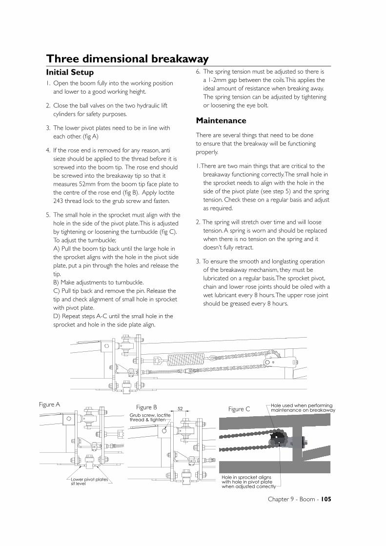
Chapter 9 - Boom - 105
Lower pivot platessit level
D
E
F
C
1 2 3 4
B
A
321 5
C
D
4 6 7 8
A
B
A3
SHEET 2 OF 2SCALE:1:3
DWG NO.
TITLE:
GOLDACRES
DO NOT SCALE DRAWING
MATERIAL:
DATE CREATED:
DRAWN:
1-3 MORANG CRMITCHELL PARK 3352PH: 03 53426399 FAX: 03 53426308
UNLESS OTHERWISE SPECIFIEDDIMENSIONS ARE IN MILLIMETERSDEBUR ALL EDGES GA4906305
7/08/2013Matt
REV NO CHANGE DATE ECN NO.
DATE EDITED:
22/10/2012
Three dimensional breakawayInitial Setup1. Open the boom fully into the working position
and lower to a good working height.
2. Close the ball valves on the two hydraulic lift cylinders for safety purposes.
3. The lower pivot plates need to be in line with each other. (fig A)
4. If the rose end is removed for any reason, anti sieze should be applied to the thread before it is screwed into the boom tip. The rose end should be screwed into the breakaway tip so that it measures 52mm from the boom tip face plate to the centre of the rose end (fig B). Apply loctite 243 thread lock to the grub screw and fasten.
5. The small hole in the sprocket must align with the hole in the side of the pivot plate. This is adjusted by tightening or loosening the turnbuckle (fig C). To adjust the turnbuckle; A) Pull the boom tip back until the large hole in the sprocket aligns with the hole in the pivot side plate, put a pin through the holes and release the tip. B) Make adjustments to turnbuckle. C) Pull tip back and remove the pin. Release the tip and check alignment of small hole in sprocket with pivot plate. D) Repeat steps A-C until the small hole in the sprocket and hole in the side plate align.
6. The spring tension must be adjusted so there is a 1-2mm gap between the coils. This applies the ideal amount of resistance when breaking away. The spring tension can be adjusted by tightening or loosening the eye bolt.
Maintenance
There are several things that need to be done to ensure that the breakway will be functioning properly.
1. There are two main things that are critical to the breakaway functioning correctly. The small hole in the sprocket needs to align with the hole in the side of the pivot plate (see step 5) and the spring tension. Check these on a regular basis and adjust as required.
2. The spring will stretch over time and will loose tension. A spring is worn and should be replaced when there is no tension on the spring and it doesn’t fully retract.
3. To ensure the smooth and longlasting operation of the breakaway mechanism, they must be lubricated on a regular basis. The sprocket pivot, chain and lower rose joints should be oiled with a wet lubricant every 8 hours. The upper rose joint should be greased every 8 hours.
Figure A52
Grub screw, loctitethread & tighten
D
E
F
C
1 2 3 4
B
A
321 5
C
D
4 6 7 8
A
B
A3
SHEET 2 OF 2SCALE:1:3
DWG NO.
TITLE:
GOLDACRES
DO NOT SCALE DRAWING
MATERIAL:
DATE CREATED:
DRAWN:
1-3 MORANG CRMITCHELL PARK 3352PH: 03 53426399 FAX: 03 53426308
UNLESS OTHERWISE SPECIFIEDDIMENSIONS ARE IN MILLIMETERSDEBUR ALL EDGES GA4906305
13/08/2013Matt
REV NO CHANGE DATE ECN NO.
DATE EDITED:
22/10/2012
Figure B
Hole in sprocket alignswith hole in pivot platewhen adjusted correctly
Hole used when performingmaintenance on breakaway
D
E
F
C
1 2 3 4
B
A
321 5
C
D
4 6 7 8
A
B
A3
SHEET 2 OF 2SCALE:1:3
DWG NO.
TITLE:
GOLDACRES
DO NOT SCALE DRAWING
MATERIAL:
DATE CREATED:
DRAWN:
1-3 MORANG CRMITCHELL PARK 3352PH: 03 53426399 FAX: 03 53426308
UNLESS OTHERWISE SPECIFIEDDIMENSIONS ARE IN MILLIMETERSDEBUR ALL EDGES GA4906305
13/08/2013Matt
REV NO CHANGE DATE ECN NO.
DATE EDITED:
22/10/2012
Figure C
D
E
F
C
1 2 3 4
B
A
321 5
C
D
4 6 7 8
A
B
A3
SHEET 2 OF 2SCALE:1:3
DWG NO.
TITLE:
GOLDACRES
DO NOT SCALE DRAWING
MATERIAL:
DATE CREATED:
DRAWN:
1-3 MORANG CRMITCHELL PARK 3352PH: 03 53426399 FAX: 03 53426308
UNLESS OTHERWISE SPECIFIEDDIMENSIONS ARE IN MILLIMETERSDEBUR ALL EDGES GA4906305
7/08/2013Matt
REV NO CHANGE DATE ECN NO.
DATE EDITED:
22/10/2012
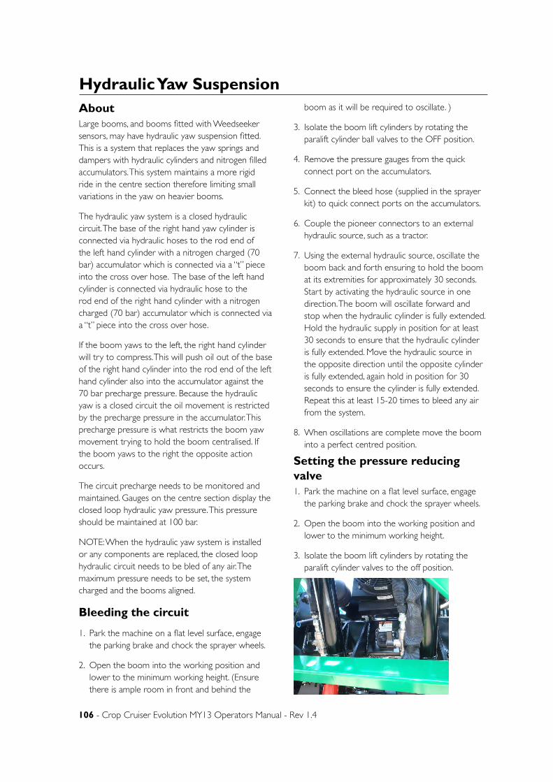
106 - Crop Cruiser Evolution MY13 Operators Manual - Rev 1.4
Hydraulic Yaw SuspensionAboutLarge booms, and booms fitted with Weedseeker sensors, may have hydraulic yaw suspension fitted. This is a system that replaces the yaw springs and dampers with hydraulic cylinders and nitrogen filled accumulators. This system maintains a more rigid ride in the centre section therefore limiting small variations in the yaw on heavier booms.
The hydraulic yaw system is a closed hydraulic circuit. The base of the right hand yaw cylinder is connected via hydraulic hoses to the rod end of the left hand cylinder with a nitrogen charged (70 bar) accumulator which is connected via a “t” piece into the cross over hose. The base of the left hand cylinder is connected via hydraulic hose to the rod end of the right hand cylinder with a nitrogen charged (70 bar) accumulator which is connected via a “t” piece into the cross over hose.
If the boom yaws to the left, the right hand cylinder will try to compress. This will push oil out of the base of the right hand cylinder into the rod end of the left hand cylinder also into the accumulator against the 70 bar precharge pressure. Because the hydraulic yaw is a closed circuit the oil movement is restricted by the precharge pressure in the accumulator. This precharge pressure is what restricts the boom yaw movement trying to hold the boom centralised. If the boom yaws to the right the opposite action occurs.
The circuit precharge needs to be monitored and maintained. Gauges on the centre section display the closed loop hydraulic yaw pressure. This pressure should be maintained at 100 bar.
NOTE: When the hydraulic yaw system is installed or any components are replaced, the closed loop hydraulic circuit needs to be bled of any air. The maximum pressure needs to be set, the system charged and the booms aligned.
Bleeding the circuit
1. Park the machine on a flat level surface, engage the parking brake and chock the sprayer wheels.
2. Open the boom into the working position and lower to the minimum working height. (Ensure there is ample room in front and behind the
boom as it will be required to oscillate. )
3. Isolate the boom lift cylinders by rotating the paralift cylinder ball valves to the OFF position.
4. Remove the pressure gauges from the quick connect port on the accumulators.
5. Connect the bleed hose (supplied in the sprayer kit) to quick connect ports on the accumulators.
6. Couple the pioneer connectors to an external hydraulic source, such as a tractor.
7. Using the external hydraulic source, oscillate the boom back and forth ensuring to hold the boom at its extremities for approximately 30 seconds. Start by activating the hydraulic source in one direction. The boom will oscillate forward and stop when the hydraulic cylinder is fully extended. Hold the hydraulic supply in position for at least 30 seconds to ensure that the hydraulic cylinder is fully extended. Move the hydraulic source in the opposite direction until the opposite cylinder is fully extended, again hold in position for 30 seconds to ensure the cylinder is fully extended. Repeat this at least 15-20 times to bleed any air from the system.
8. When oscillations are complete move the boom into a perfect centred position.
Setting the pressure reducing valve1. Park the machine on a flat level surface, engage
the parking brake and chock the sprayer wheels.
2. Open the boom into the working position and lower to the minimum working height.
3. Isolate the boom lift cylinders by rotating the paralift cylinder valves to the off position.
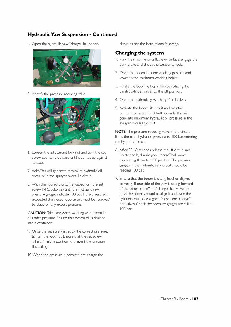
Chapter 9 - Boom - 107
4. Open the hydraulic yaw “charge” ball valves.
5. Identify the pressure reducing valve.
6. Loosen the adjustment lock nut and turn the set screw counter clockwise until it comes up against its stop.
7. WithThis will generate maximum hydraulic oil pressure in the sprayer hydraulic circuit.
8. With the hydraulic circuit engaged turn the set screw IN (clockwise) until the hydraulic yaw pressure gauges indicate 100 bar. If the pressure is exceeded the closed loop circuit must be “cracked” to bleed off any excess pressure.
CAUTION: Take care when working with hydraulic oil under pressure. Ensure that excess oil is drained into a container.
9. Once the set screw is set to the correct pressure, tighten the lock nut. Ensure that the set screw is held firmly in position to prevent the pressure fluctuating.
10. When the pressure is correctly set, charge the
circuit as per the instructions following.
Charging the system1. Park the machine on a flat level surface, engage the
park brake and chock the sprayer wheels.
2. Open the boom into the working position and lower to the minimum working height.
3. Isolate the boom left cylinders by rotating the paralift cylinder valves to the off position.
4. Open the hydraulic yaw “charge” ball valves.
5. Activate the boom lift circuit and maintain constant pressure for 30-60 seconds. This will generate maximum hydraulic oil pressure in the sprayer hydraulic circuit.
NOTE: The pressure reducing valve in the circuit limits the main hydraulic pressure to 100 bar entering the hydraulic circuit.
6. After 30-60 seconds release the lift circuit and isolate the hydraulic yaw “charge” ball valves by rotating them to OFF position. The pressure gauges in the hydraulic yaw circuit should be reading 100 bar.
7. Ensure that the boom is sitting level or aligned correctly. If one side of the yaw is sitting forward of the other “open” the “charge” ball valve and push the boom around to align it and even the cylinders out, once aligned “close” the “charge” ball valves. Check the pressure gauges are still at 100 bar.
Hydraulic Yaw Suspension - Continued
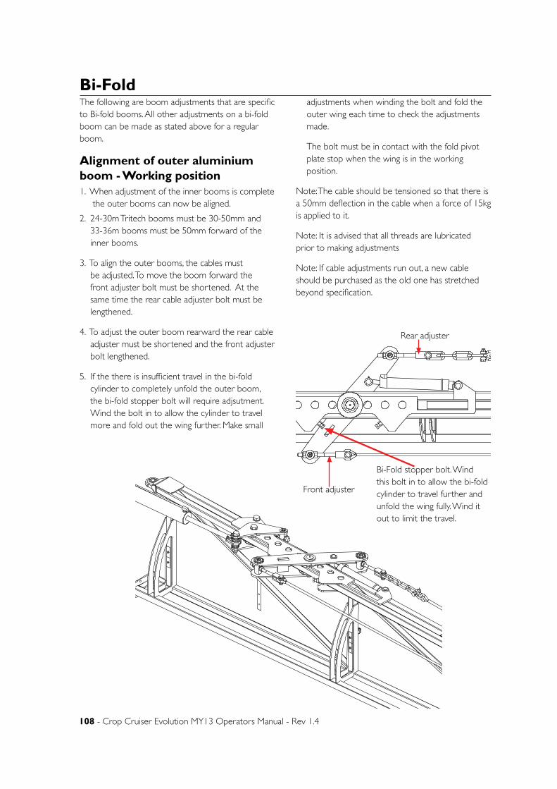
108 - Crop Cruiser Evolution MY13 Operators Manual - Rev 1.4
The following are boom adjustments that are specific to Bi-fold booms. All other adjustments on a bi-fold boom can be made as stated above for a regular boom.
Alignment of outer aluminium boom - Working position 1. When adjustment of the inner booms is complete the outer booms can now be aligned.
2. 24-30m Tritech booms must be 30-50mm and 33-36m booms must be 50mm forward of the inner booms.
3. To align the outer booms, the cables must be adjusted. To move the boom forward the front adjuster bolt must be shortened. At the same time the rear cable adjuster bolt must be lengthened.
4. To adjust the outer boom rearward the rear cable adjuster must be shortened and the front adjuster bolt lengthened.
5. If the there is insufficient travel in the bi-fold cylinder to completely unfold the outer boom, the bi-fold stopper bolt will require adjsutment. Wind the bolt in to allow the cylinder to travel more and fold out the wing further. Make small
adjustments when winding the bolt and fold the outer wing each time to check the adjustments made.
The bolt must be in contact with the fold pivot plate stop when the wing is in the working position.
Note: The cable should be tensioned so that there is a 50mm deflection in the cable when a force of 15kg is applied to it.
Note: It is advised that all threads are lubricated prior to making adjustments
Note: If cable adjustments run out, a new cable should be purchased as the old one has stretched beyond specification.
D
E
F
C
1 2 3 4
B
A
321 5
C
D
4 6 7 8
A
B
A3
SHEET 1 OF 1SCALE:1:10
DWG NO.
TITLE:
GOLDACRES
DO NOT SCALE DRAWING
MATERIAL:
DATE CREATED:
DRAWN:
1-3 MORANG CRMITCHELL PARK 3352PH: 03 53426399 FAX: 03 53426308
UNLESS OTHERWISE SPECIFIEDDIMENSIONS ARE IN MILLIMETERSDEBUR ALL EDGES Evo 2013 boom bI FOLD kitA. McAndrew
11/10/2012Matt
REV NO CHANGE DATE ECN NO.
DATE EDITED:
17/12/2003
D
E
F
C
1 2 3 4
B
A
321 5
C
D
4 6 7 8
A
B
A3
SHEET 1 OF 1SCALE:1:10
DWG NO.
TITLE:
GOLDACRES
DO NOT SCALE DRAWING
MATERIAL:
DATE CREATED:
DRAWN:
1-3 MORANG CRMITCHELL PARK 3352PH: 03 53426399 FAX: 03 53426308
UNLESS OTHERWISE SPECIFIEDDIMENSIONS ARE IN MILLIMETERSDEBUR ALL EDGES Evo 2013 boom bI FOLD kitA. McAndrew
11/10/2012Matt
REV NO CHANGE DATE ECN NO.
DATE EDITED:
17/12/2003
Bi-Fold stopper bolt. Wind this bolt in to allow the bi-fold cylinder to travel further and unfold the wing fully. Wind it out to limit the travel.
Front adjuster
Rear adjuster
Bi-Fold
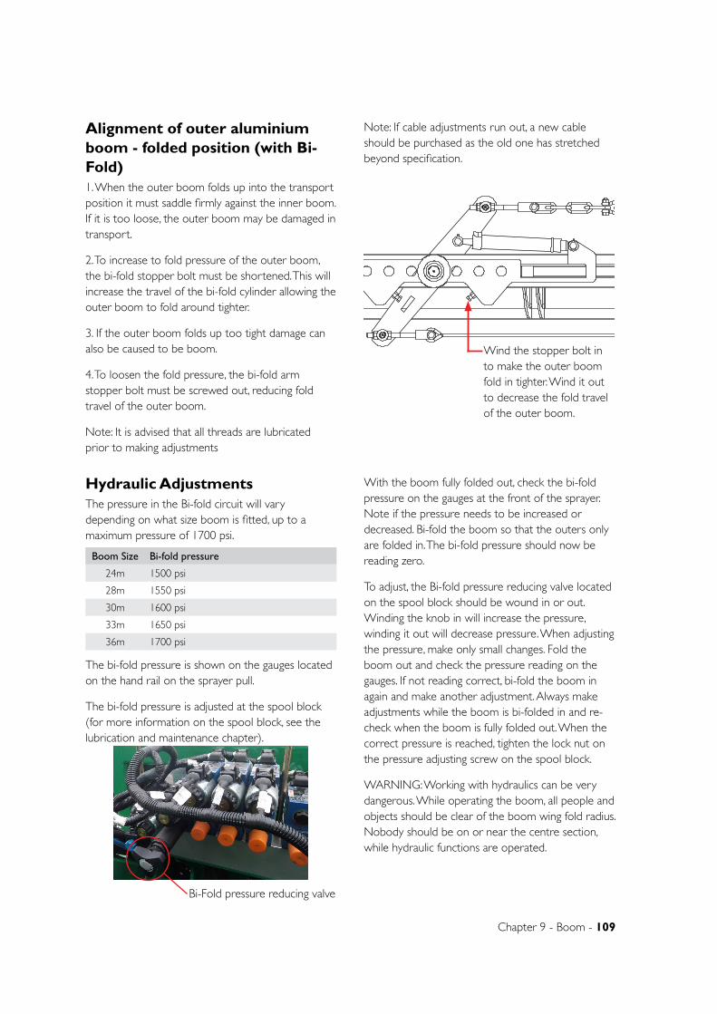
Chapter 9 - Boom - 109
Alignment of outer aluminium boom - folded position (with Bi-Fold)1. When the outer boom folds up into the transport position it must saddle firmly against the inner boom. If it is too loose, the outer boom may be damaged in transport.
2. To increase to fold pressure of the outer boom, the bi-fold stopper bolt must be shortened. This will increase the travel of the bi-fold cylinder allowing the outer boom to fold around tighter.
3. If the outer boom folds up too tight damage can also be caused to be boom.
4. To loosen the fold pressure, the bi-fold arm stopper bolt must be screwed out, reducing fold travel of the outer boom.
Note: It is advised that all threads are lubricated prior to making adjustments
Note: If cable adjustments run out, a new cable should be purchased as the old one has stretched beyond specification.
D
E
F
C
1 2 3 4
B
A
321 5
C
D
4 6 7 8
A
B
A3
SHEET 1 OF 1SCALE:1:10
DWG NO.
TITLE:
GOLDACRES
DO NOT SCALE DRAWING
MATERIAL:
DATE CREATED:
DRAWN:
1-3 MORANG CRMITCHELL PARK 3352PH: 03 53426399 FAX: 03 53426308
UNLESS OTHERWISE SPECIFIEDDIMENSIONS ARE IN MILLIMETERSDEBUR ALL EDGES Evo 2013 boom bI FOLD kitA. McAndrew
11/10/2012Matt
REV NO CHANGE DATE ECN NO.
DATE EDITED:
17/12/2003
Wind the stopper bolt in to make the outer boom fold in tighter. Wind it out to decrease the fold travel of the outer boom.
Hydraulic AdjustmentsThe pressure in the Bi-fold circuit will vary depending on what size boom is fitted, up to a maximum pressure of 1700 psi.
The bi-fold pressure is shown on the gauges located on the hand rail on the sprayer pull.
The bi-fold pressure is adjusted at the spool block (for more information on the spool block, see the lubrication and maintenance chapter).
With the boom fully folded out, check the bi-fold pressure on the gauges at the front of the sprayer. Note if the pressure needs to be increased or decreased. Bi-fold the boom so that the outers only are folded in. The bi-fold pressure should now be reading zero.
To adjust, the Bi-fold pressure reducing valve located on the spool block should be wound in or out. Winding the knob in will increase the pressure, winding it out will decrease pressure. When adjusting the pressure, make only small changes. Fold the boom out and check the pressure reading on the gauges. If not reading correct, bi-fold the boom in again and make another adjustment. Always make adjustments while the boom is bi-folded in and re-check when the boom is fully folded out. When the correct pressure is reached, tighten the lock nut on the pressure adjusting screw on the spool block.
WARNING: Working with hydraulics can be very dangerous. While operating the boom, all people and objects should be clear of the boom wing fold radius. Nobody should be on or near the centre section, while hydraulic functions are operated.
Boom Size Bi-fold pressure
24m 1500 psi
28m 1550 psi
30m 1600 psi
33m 1650 psi
36m 1700 psi
Bi-Fold pressure reducing valve
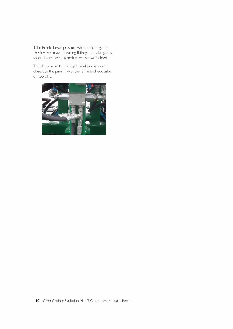
110 - Crop Cruiser Evolution MY13 Operators Manual - Rev 1.4
If the Bi-fold losses pressure while operating, the check valves may be leaking. If they are leaking, they should be replaced. (check valves shown below).
The check valve for the right hand side is located closest to the paralift, with the left side check valve on top of it.
Chapter 10
Chapter 10 - Lubrication & Maintenance - 111
LUBRICATION & MAINTENANCERecommended lubricants• For differing weather conditions consult your
Cummins operator’s manual to choose the suitable oil grade.
• Ensure that lubricants are stored in a place where the lubricants are protected from contamination (such as dirt and moisture). Always use clean
containers when handling lubricants.
• Do not mix lubricants. Proper lubrication may be affected by differences in chemical composition.
• Seek advice from your petroleum dealer on the correct use of lubricants and additives.
Filters
LOCATION TYPE OF LUBRICANT CAPACITY (L)
ENGINE OIL SAE 15W-40 Heavy Duty Engine Oil 15L
HYDRAULIC OIL Morris Super Farm SAE 10W/30 90L
TRANSMISSION 2000 SERIES 5 SPEED
CASTROL ALLISON TRANSYND (only available from Allison) - GA5006959
20L approx (dry)
TRANSFER CASE SAE 50 Synthetic 6L
DIFFERENTIALS 80W90 EP GEAR OIL 14L (fill to level hole)
DRIVE LEGS SAE 80W90 GEAR OIL 33L
GENERAL GREASE POINTS MULTI-PURPOSE GREASE -
STEERING PIVOT POINTS MOLYBDENUM BASED GREASE -
COOLANT TEC PG XL CUMMINS 39L approxBRAKE FLUID DOT 4 APPROX. 0.5L per Booster
DIAPHRAM SPRAY PUMP SAE 15W40 2.68L
AIR CONDITIONINGOIL, SANDEN SP20 571ml dry.GAS R134a 2kg
LOCATION GoldAcres P/# Generic NumbersHydraulic Pressure Filters GA5008721 x 2 Extended bowl filter – 0110-D-010-BH3HC
Hydraulic Return Filter GA5069056
A/C Carbon Filter GA5066740 P277
Air Cleaner Primary Element GA5069031 P608666
Air Cleaner Safety Element GA5069032 P601560
Engine Oil Filters GA5051755 LF3970
Transmission Oil FiltersGA5048281 spin on Series 2000 = 29539579 or HF35296
GA5048285 internal Series 2000 = 29537966 internal kit
Fuel filter (primary)GA5051760 or alternative FS1242 glass bowl or alternative
GA5069770 FS19732 no bowl
Fuel filter on engine GA5051765 FF5612 , FF5421
Fuel Filter inline GA5069895 W2153 3/8 tails
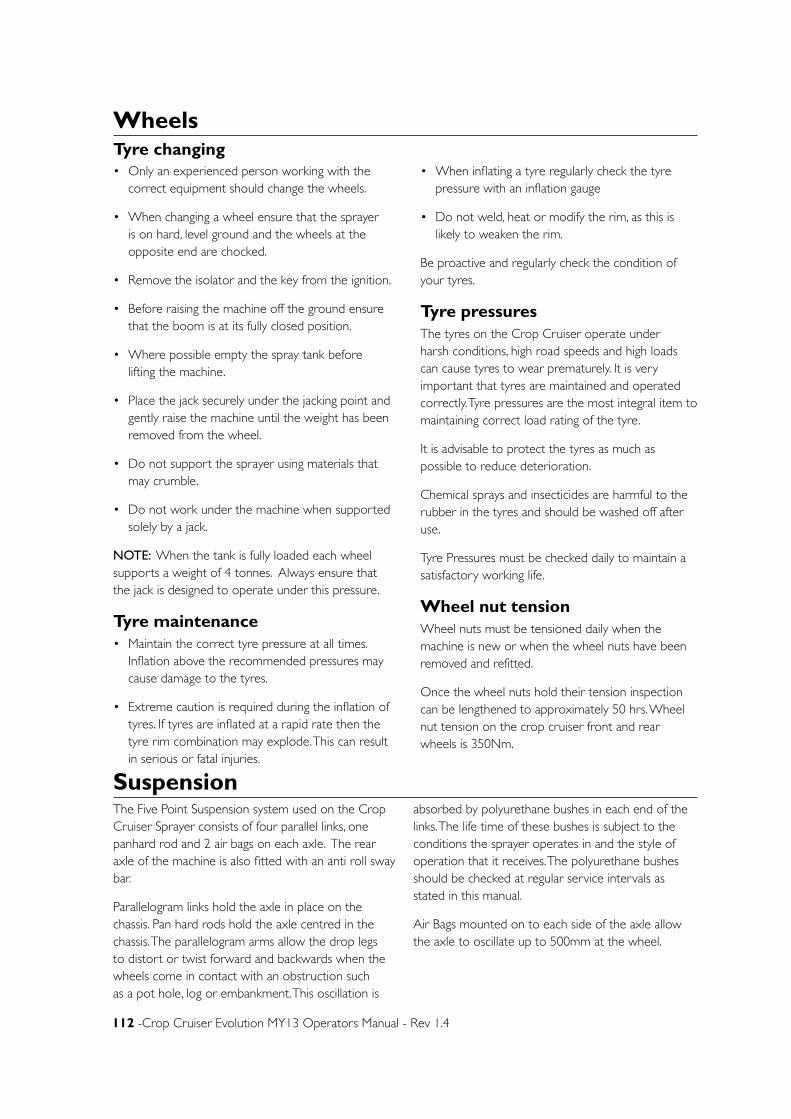
112 -Crop Cruiser Evolution MY13 Operators Manual - Rev 1.4
SuspensionThe Five Point Suspension system used on the Crop Cruiser Sprayer consists of four parallel links, one panhard rod and 2 air bags on each axle. The rear axle of the machine is also fitted with an anti roll sway bar.
Parallelogram links hold the axle in place on the chassis. Pan hard rods hold the axle centred in the chassis. The parallelogram arms allow the drop legs to distort or twist forward and backwards when the wheels come in contact with an obstruction such as a pot hole, log or embankment. This oscillation is
absorbed by polyurethane bushes in each end of the links. The life time of these bushes is subject to the conditions the sprayer operates in and the style of operation that it receives. The polyurethane bushes should be checked at regular service intervals as stated in this manual.
Air Bags mounted on to each side of the axle allow the axle to oscillate up to 500mm at the wheel.
WheelsTyre changing• Only an experienced person working with the
correct equipment should change the wheels.
• When changing a wheel ensure that the sprayer is on hard, level ground and the wheels at the opposite end are chocked.
• Remove the isolator and the key from the ignition.
• Before raising the machine off the ground ensure that the boom is at its fully closed position.
• Where possible empty the spray tank before lifting the machine.
• Place the jack securely under the jacking point and gently raise the machine until the weight has been removed from the wheel.
• Do not support the sprayer using materials that may crumble.
• Do not work under the machine when supported solely by a jack.
NOTE: When the tank is fully loaded each wheel supports a weight of 4 tonnes. Always ensure that the jack is designed to operate under this pressure.
Tyre maintenance• Maintain the correct tyre pressure at all times.
Inflation above the recommended pressures may cause damage to the tyres.
• Extreme caution is required during the inflation of tyres. If tyres are inflated at a rapid rate then the tyre rim combination may explode. This can result in serious or fatal injuries.
• When inflating a tyre regularly check the tyre pressure with an inflation gauge
• Do not weld, heat or modify the rim, as this is likely to weaken the rim.
Be proactive and regularly check the condition of your tyres.
Tyre pressuresThe tyres on the Crop Cruiser operate under harsh conditions, high road speeds and high loads can cause tyres to wear prematurely. It is very important that tyres are maintained and operated correctly. Tyre pressures are the most integral item to maintaining correct load rating of the tyre.
It is advisable to protect the tyres as much as possible to reduce deterioration.
Chemical sprays and insecticides are harmful to the rubber in the tyres and should be washed off after use.
Tyre Pressures must be checked daily to maintain a satisfactory working life.
Wheel nut tensionWheel nuts must be tensioned daily when the machine is new or when the wheel nuts have been removed and refitted.
Once the wheel nuts hold their tension inspection can be lengthened to approximately 50 hrs. Wheel nut tension on the crop cruiser front and rear wheels is 350Nm.
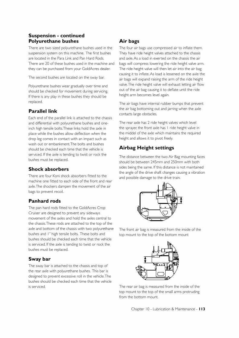
Chapter 10 - Lubrication & Maintenance - 113
Polyurethane bushesThere are two sized polyurethane bushes used in the suspension system on this machine. The first bushes are located in the Para Link and Pan Hard Rods. There are 20 of these bushes used in the machine and they can be purchased from your GoldAcres dealer.
The second bushes are located on the sway bar.
Polyurethane bushes wear gradually over time and should be checked for movement during servicing. If there is any play in these bushes they should be replaced.
Parallel linkEach end of the parallel link is attached to the chassis and differential with polyurethane bushes and one-inch high tensile bolts. These links hold the axle in place while the bushes allow deflection when the drop leg comes in contact with an impact such as wash out or embankment. The bolts and bushes should be checked each time that the vehicle is serviced. If the axle is tending to twist or rock the bushes must be replaced.
Shock absorbersThere are four Koni shock absorbers fitted to the machine one fitted to each side of the front and rear axle. The shockers dampen the movement of the air bags to prevent recoil.
Panhard rodsThe pan hard rods fitted to the GoldAcres Crop Cruiser are designed to prevent any sideways movement of the axles and hold the axles central to the chassis. These rods are attached to the top of the axle and bottom of the chassis with two polyurethane bushes and 1” high tensile bolts. These bolts and bushes should be checked each time that the vehicle is serviced. If the axle is tending to twist or rock the bushes must be replaced.
Sway barThe sway bar is attached to the chassis and top of the rear axle with polyurethane bushes. This bar is designed to prevent excessive roll in the vehicle. The bushes should be checked each time that the vehicle is serviced.
Air bagsThe four air bags use compressed air to inflate them. They have ride height valves attached to the chassis and axle. As a load in exerted on the chassis the air bags will compress lowering the ride height valve arm. The ride height valve will then let air into the air bag causing it to inflate. As load is lessened on the axle the air bags will expand raising the arm of the ride height valve. The ride height valve will exhaust letting air flow out of the air bag causing it to deflate until the ride height arm becomes level again.
The air bags have internal rubber bumps that prevent the air bag bottoming out and jarring when the axle contacts large obstacles.
The rear axle has 2 ride height valves which level the sprayer, the front axle has 1 ride height valve in the middel of the axle which maintains the required height and allows it to pivot freely.
Airbag Height settings
The distance between the two Air Bag mounting faces should be between 245mm and 250mm with both sides being the same. If this distance is not maintained the angle of the drive shaft changes causing a vibration and possible damage to the drive train.
The front air bag is measured from the inside of the top mount to the top of the bottom mount
The rear air bag is measured from the inside of the top mount to the top of the small arms protruding from the bottom mount.
A
DETAIL A SCALE 1 : 25
B
DETAIL B SCALE 1 : 25
B
C
D
1 2
A
321 4
B
A
5 6
UNLESS OTHERWISE SPECIFIED:DIMENSIONS ARE IN MILLIMETERSDEBUR ALL EDGES
MATERIAL:
DO NOT SCALE DRAWING
GOLDACRESTITLE:
DWG NO:
SCALE:1:50 SHEET 1 OF 1
A4
C
2WD Cab Chassis AssemblyREV NO CHANGE APPL DATE
DATE CREATED:
DRAWN:
1-3 MORANG CRMITCHELL PARK 3352PH: 03 53426399 FAX: 03 53426308
11/03/2011
DATE EDITED:
25/05/2011Matt
A
DETAIL A SCALE 1 : 25
B
DETAIL B SCALE 1 : 25
B
C
D
1 2
A
321 4
B
A
5 6
UNLESS OTHERWISE SPECIFIED:DIMENSIONS ARE IN MILLIMETERSDEBUR ALL EDGES
MATERIAL:
DO NOT SCALE DRAWING
GOLDACRESTITLE:
DWG NO:
SCALE:1:50 SHEET 1 OF 1
A4
C
2WD Cab Chassis AssemblyREV NO CHANGE APPL DATE
DATE CREATED:
DRAWN:
1-3 MORANG CRMITCHELL PARK 3352PH: 03 53426399 FAX: 03 53426308
11/03/2011
DATE EDITED:
25/05/2011Matt
Suspension - continued
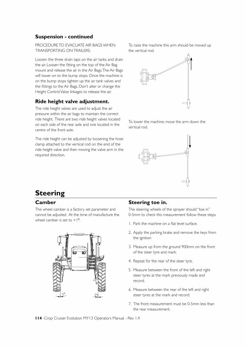
114 -Crop Cruiser Evolution MY13 Operators Manual - Rev 1.4
CamberThe wheel camber is a factory set parameter and cannot be adjusted. At the time of manufacture the wheel camber is set to +1º.
Steering toe in.The steering wheels of the sprayer should “toe in” 0-5mm to check this measurement follow these steps.
1. Park the machine on a flat level surface.
2. Apply the parking brake and remove the keys from the ignition
3. Measure up from the ground 900mm on the front of the steer tyre and mark.
4. Repeat for the rear of the steer tyre.
5. Measure between the front of the left and right steer tyres at the mark previously made and record.
6. Measure between the rear of the left and right steer tyres at the mark and record.
7. The front measurement must be 0-5mm less than the rear measurement.
Steering
1° 1°
B
C
D
1 2
A
321 4
B
A
5 6
UNLESS OTHERWISE SPECIFIED:DIMENSIONS ARE IN MILLIMETERSDEBUR ALL EDGES
MATERIAL:
DO NOT SCALE DRAWING
GOLDACRESTITLE:
DWG NO:
SCALE:1:50 SHEET 1 OF 1
A4
C
2WD Cab Chassis AssemblyREV NO CHANGE APPL DATE
DATE CREATED:
DRAWN:
1-3 MORANG CRMITCHELL PARK 3352PH: 03 53426399 FAX: 03 53426308
11/03/2011
DATE EDITED:
25/05/2011Matt
PROCEDURE TO EVACUATE AIR BAGS WHEN TRANSPORTING ON TRAILERS.
Loosen the three drain taps on the air tanks and drain the air. Loosen the fitting on the top of the Air Bag mount and release the air in the Air Bags. The Air Bags will lower on to the bump stops. Once the machine is on the bump stops tighten up the air tank valves and the fittings to the Air Bags. Don’t alter or change the Height Control Valve linkages to release the air.
Ride height valve adjustment.The ride height valves are used to adjust the air pressure within the air bags to maintain the correct ride height. There are two ride height valves located on each side of the rear axle and one located in the centre of the front axle.
The ride height can be adjusted by loosening the hose clamp attached to the vertical rod on the end of the ride height valve and then moving the valve arm in the required direction.
To raise the machine this arm should be moved up the vertical rod.
To lower the machine, move the arm down the vertical rod.
B
C
D
1 2
A
321 4
B
A
5 6
UNLESS OTHERWISE SPECIFIED:DIMENSIONS ARE IN MILLIMETERSDEBUR ALL EDGES
MATERIAL:
DO NOT SCALE DRAWING
GOLDACRESTITLE:
DWG NO:
SCALE:1:2.5 SHEET 1 OF 1
A4
C
rear left ride height valve - op manual - 2011 SPREV NO CHANGE APPL DATE
DATE CREATED:
DRAWN:
Name
1-3 MORANG CRMITCHELL PARK 3352PH: 03 53426399 FAX: 03 53426308
30/05/2011
DATE EDITED:
30/05/2011Matt
B
C
D
1 2
A
321 4
B
A
5 6
UNLESS OTHERWISE SPECIFIED:DIMENSIONS ARE IN MILLIMETERSDEBUR ALL EDGES
MATERIAL:
DO NOT SCALE DRAWING
GOLDACRESTITLE:
DWG NO:
SCALE:1:2.5 SHEET 1 OF 1
A4
C
rear left ride height valve - op manual - 2011 SPREV NO CHANGE APPL DATE
DATE CREATED:
DRAWN:
Name
1-3 MORANG CRMITCHELL PARK 3352PH: 03 53426399 FAX: 03 53426308
30/05/2011
DATE EDITED:
30/05/2011Matt
Suspension - continued
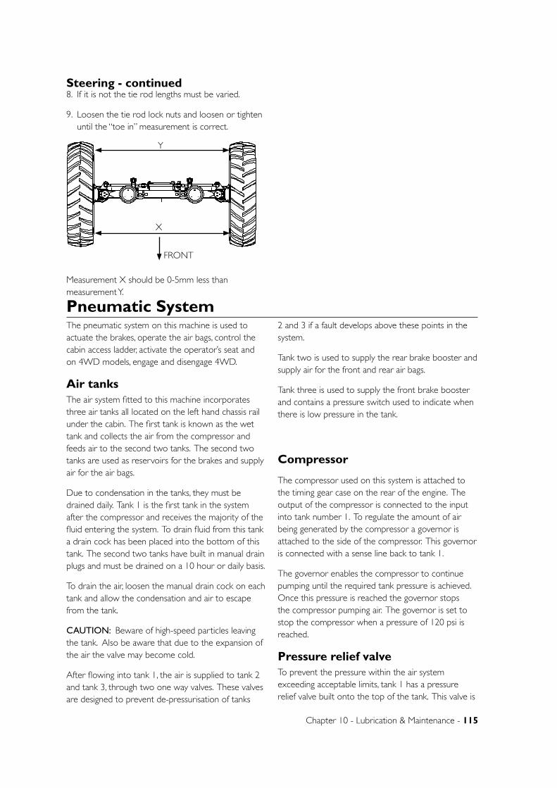
Chapter 10 - Lubrication & Maintenance - 115
Pneumatic SystemThe pneumatic system on this machine is used to actuate the brakes, operate the air bags, control the cabin access ladder, activate the operator’s seat and on 4WD models, engage and disengage 4WD.
Air tanksThe air system fitted to this machine incorporates three air tanks all located on the left hand chassis rail under the cabin. The first tank is known as the wet tank and collects the air from the compressor and feeds air to the second two tanks. The second two tanks are used as reservoirs for the brakes and supply air for the air bags.
Due to condensation in the tanks, they must be drained daily. Tank 1 is the first tank in the system after the compressor and receives the majority of the fluid entering the system. To drain fluid from this tank a drain cock has been placed into the bottom of this tank. The second two tanks have built in manual drain plugs and must be drained on a 10 hour or daily basis.
To drain the air, loosen the manual drain cock on each tank and allow the condensation and air to escape from the tank.
CAUTION: Beware of high-speed particles leaving the tank. Also be aware that due to the expansion of the air the valve may become cold.
After flowing into tank 1, the air is supplied to tank 2 and tank 3, through two one way valves. These valves are designed to prevent de-pressurisation of tanks
2 and 3 if a fault develops above these points in the system.
Tank two is used to supply the rear brake booster and supply air for the front and rear air bags.
Tank three is used to supply the front brake booster and contains a pressure switch used to indicate when there is low pressure in the tank.
Compressor
The compressor used on this system is attached to the timing gear case on the rear of the engine. The output of the compressor is connected to the input into tank number 1. To regulate the amount of air being generated by the compressor a governor is attached to the side of the compressor. This governor is connected with a sense line back to tank 1.
The governor enables the compressor to continue pumping until the required tank pressure is achieved. Once this pressure is reached the governor stops the compressor pumping air. The governor is set to stop the compressor when a pressure of 120 psi is reached.
Pressure relief valveTo prevent the pressure within the air system exceeding acceptable limits, tank 1 has a pressure relief valve built onto the top of the tank. This valve is
BCD
12
A
32
14
B A
56
UNLESS O
THERWISE SPEC
IFIED:
DIM
ENSIO
NS A
RE IN M
ILLIMETERS
DEBUR A
LL EDG
ES
MA
TERIAL:
DO
NO
T SCA
LE DRA
WIN
G
GO
LDA
CRES
TITLE:
DW
G N
O:
SCA
LE:1:50SHEET 1 O
F 1
A4
C
2WD
Cab C
hassis Assem
blyREV
NO
CHA
NG
EA
PPL DA
TE
DA
TE CREA
TED:
DRA
WN
:
1-3 MO
RAN
G C
RM
ITCHELL PA
RK 3352PH: 03 53426399 FA
X: 03 53426308
11/03/2011
DA
TE EDITED
:
26/05/2011M
att
X
Y
FRONT
8. If it is not the tie rod lengths must be varied.
9. Loosen the tie rod lock nuts and loosen or tighten until the “toe in” measurement is correct.
Measurement X should be 0-5mm less than measurement Y.
Steering - continued
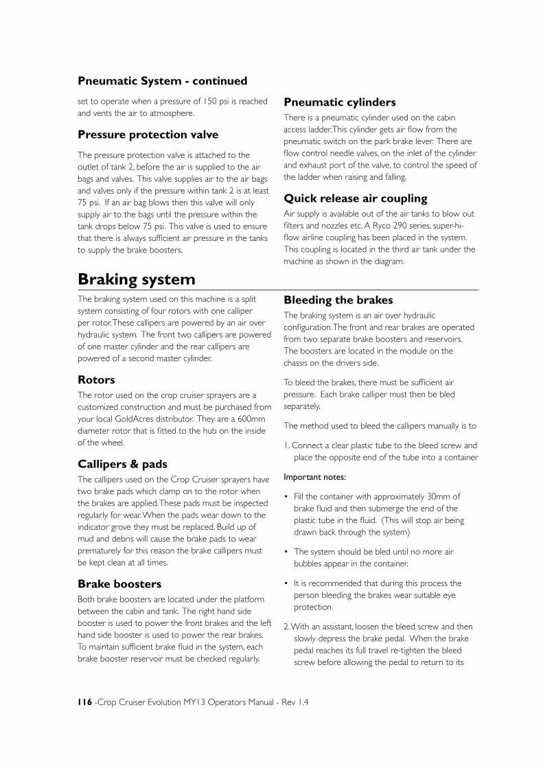
116 -Crop Cruiser Evolution MY13 Operators Manual - Rev 1.4
Braking systemThe braking system used on this machine is a split system consisting of four rotors with one calliper per rotor. These callipers are powered by an air over hydraulic system. The front two callipers are powered of one master cylinder and the rear callipers are powered of a second master cylinder.
RotorsThe rotor used on the crop cruiser sprayers are a customized construction and must be purchased from your local GoldAcres distributor. They are a 600mm diameter rotor that is fitted to the hub on the inside of the wheel.
Callipers & padsThe callipers used on the Crop Cruiser sprayers have two brake pads which clamp on to the rotor when the brakes are applied. These pads must be inspected regularly for wear. When the pads wear down to the indicator grove they must be replaced. Build up of mud and debris will cause the brake pads to wear prematurely for this reason the brake callipers must be kept clean at all times.
Brake boostersBoth brake boosters are located under the platform between the cabin and tank. The right hand side booster is used to power the front brakes and the left hand side booster is used to power the rear brakes. To maintain sufficient brake fluid in the system, each brake booster reservoir must be checked regularly.
Bleeding the brakesThe braking system is an air over hydraulic configuration. The front and rear brakes are operated from two separate brake boosters and reservoirs. The boosters are located in the module on the chassis on the drivers side.
To bleed the brakes, there must be sufficient air pressure. Each brake calliper must then be bled separately.
The method used to bleed the callipers manually is to
1. Connect a clear plastic tube to the bleed screw and place the opposite end of the tube into a container
Important notes:
• Fill the container with approximately 30mm of brake fluid and then submerge the end of the plastic tube in the fluid. (This will stop air being drawn back through the system)
• The system should be bled until no more air bubbles appear in the container.
• It is recommended that during this process the person bleeding the brakes wear suitable eye protection.
2. With an assistant, loosen the bleed screw and then slowly depress the brake pedal. When the brake pedal reaches its full travel re-tighten the bleed screw before allowing the pedal to return to its
Pneumatic System - continued
set to operate when a pressure of 150 psi is reached and vents the air to atmosphere.
Pressure protection valve
The pressure protection valve is attached to the outlet of tank 2, before the air is supplied to the air bags and valves. This valve supplies air to the air bags and valves only if the pressure within tank 2 is at least 75 psi. If an air bag blows then this valve will only supply air to the bags until the pressure within the tank drops below 75 psi. This valve is used to ensure that there is always sufficient air pressure in the tanks to supply the brake boosters.
Pneumatic cylindersThere is a pneumatic cylinder used on the cabin access ladder. This cylinder gets air flow from the pneumatic switch on the park brake lever. There are flow control needle valves, on the inlet of the cylinder and exhaust port of the valve, to control the speed of the ladder when raising and falling.
Quick release air couplingAir supply is available out of the air tanks to blow out filters and nozzles etc. A Ryco 290 series, super-hi-flow airline coupling has been placed in the system. This coupling is located in the third air tank under the machine as shown in the diagram.
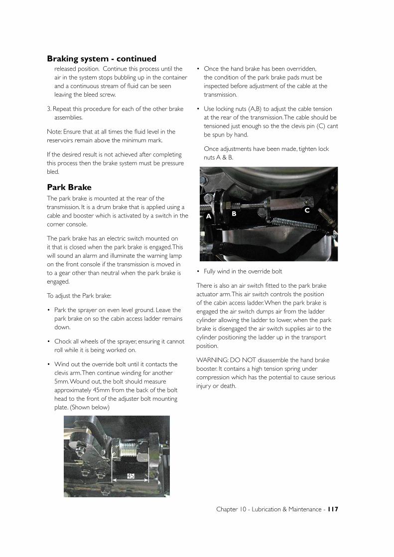
Chapter 10 - Lubrication & Maintenance - 117
released position. Continue this process until the air in the system stops bubbling up in the container and a continuous stream of fluid can be seen leaving the bleed screw.
3. Repeat this procedure for each of the other brake assemblies.
Note: Ensure that at all times the fluid level in the reservoirs remain above the minimum mark.
If the desired result is not achieved after completing this process then the brake system must be pressure bled.
Park BrakeThe park brake is mounted at the rear of the transmission. It is a drum brake that is applied using a cable and booster which is activated by a switch in the corner console.
The park brake has an electric switch mounted on it that is closed when the park brake is engaged. This will sound an alarm and illuminate the warning lamp on the front console if the transmission is moved in to a gear other than neutral when the park brake is engaged.
To adjust the Park brake:
• Park the sprayer on even level ground. Leave the park brake on so the cabin access ladder remains down.
• Chock all wheels of the sprayer, ensuring it cannot roll while it is being worked on.
• Wind out the override bolt until it contacts the clevis arm. Then continue winding for another 5mm. Wound out, the bolt should measure approximately 45mm from the back of the bolt head to the front of the adjuster bolt mounting plate. (Shown below)
• Once the hand brake has been overridden, the condition of the park brake pads must be inspected before adjustment of the cable at the transmission.
• Use locking nuts (A,B) to adjust the cable tension at the rear of the transmission. The cable should be tensioned just enough so the the clevis pin (C) cant be spun by hand.
Once adjustments have been made, tighten lock nuts A & B.
• Fully wind in the override bolt
There is also an air switch fitted to the park brake actuator arm. This air switch controls the position of the cabin access ladder. When the park brake is engaged the air switch dumps air from the ladder cylinder allowing the ladder to lower, when the park brake is disengaged the air switch supplies air to the cylinder positioning the ladder up in the transport position.
WARNING: DO NOT disassemble the hand brake booster. It contains a high tension spring under compression which has the potential to cause serious injury or death.
Braking system - continued
45
ACB
118 -Crop Cruiser Evolution MY13 Operators Manual - Rev 1.4
Drop Legs
Crop cruisers run a dual reduction chain driven drop legs. Drive is transferred from the differential through drive shafts to the input shaft of the drop leg. A 120 Super HT 1”1/2 drive chain is between the input shaft and the middle idler shaft. The bottom chain joins the idler shaft to the output axle shaft this chain is 140 Super HT 1”3/4.
The drop legs have an oil bath sump which the chains run in and carry the oil to the bearings. The idler shaft bearing housings have sumps so that the bearings always have oil lubrication.
The oil level can be checked by removing the level plug.
There is a breather located on the top of the drop legs. This allows the oil to expand and contract with creating a vacuum or pressurising the drop leg housing. This breather must be cleaned at regular service intervals.
The chain will stretch over time and become loose. When this occurs the chains must be replaced. There is no tensioning mechanism for the drive chains as stretched chains will damage the drive sprockets and therefore must be replaced.
Drive chain testing procedureCrop cruisers are fitted with two size quality Tusbaki drive chains to transmit power to the wheels. These chains are of the highest quality and are designed for a long trouble free life, however, proper care and maintenance of the drive system must be adhered to for maximum chain and sprocket life. The top chain is
120 Super HT chain while the bottom drive chain is 140 Super HT.
The chains service life is gauged by total stretch. When a chain stretches it does not align correctly with the drive cogs and therefore should be replaced, not tensioned, to prevent excessive wear on the teeth of the drive sprockets.
The maximum allowable chain stretch is 1.5%. The amount of chain stretch can be measured with the chain stretch tool supplied with the sprayer. There are two tools one for the top super HT120 chain and one for the bottom Super HT 140 chain.
To check the chains:
1. Apply hand brake and chock all wheels
2. Remove rear drive leg inspection cover.
3. Place a suitable strength jack under the drive leg and lift up until the wheel is just off the ground.
4. Rotate wheel so that the chain is tensioned on the inspection cover side.
5. Fit the outside of the chain gauge onto a chain roller and tilt the top up trying to slide it under the roller. If fits under easily the chain is stretched.
6. Using the supplied chain gauges, (0.5, 1.0 & 1.5%). Start with the 0.5% gauge and work up until the next largest gauge does not fit in. If the 1.5% chain gauge fits then the chain is outside the allowable limit and must be replaced. Always try the chain in at least three places.
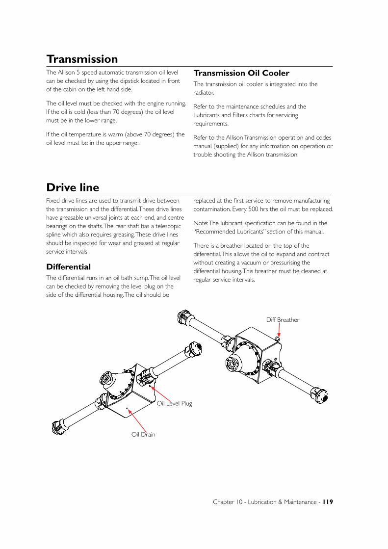
Chapter 10 - Lubrication & Maintenance - 119
Fixed drive lines are used to transmit drive between the transmission and the differential. These drive lines have greasable universal joints at each end, and centre bearings on the shafts. The rear shaft has a telescopic spline which also requires greasing. These drive lines should be inspected for wear and greased at regular service intervals
DifferentialThe differential runs in an oil bath sump. The oil level can be checked by removing the level plug on the side of the differential housing. The oil should be
replaced at the first service to remove manufacturing contamination. Every 500 hrs the oil must be replaced.
Note: The lubricant specification can be found in the “Recommended Lubricants” section of this manual.
There is a breather located on the top of the differential. This allows the oil to expand and contract without creating a vacuum or pressurising the differential housing. This breather must be cleaned at regular service intervals.
Drive line
The Allison 5 speed automatic transmission oil level can be checked by using the dipstick located in front of the cabin on the left hand side.
The oil level must be checked with the engine running. If the oil is cold (less than 70 degrees) the oil level must be in the lower range.
If the oil temperature is warm (above 70 degrees) the oil level must be in the upper range.
Transmission Oil CoolerThe transmission oil cooler is integrated into the radiator.
Refer to the maintenance schedules and the Lubricants and Filters charts for servicing requirements.
Refer to the Allison Transmission operation and codes manual (supplied) for any information on operation or trouble shooting the Allison transmission.
Transmission
B
C
D
1 2
A
321 4
B
A
5 6
UNLESS OTHERWISE SPECIFIED:DIMENSIONS ARE IN MILLIMETERSDEBUR ALL EDGES
MATERIAL:
DO NOT SCALE DRAWING
GOLDACRESTITLE:
DWG NO:
SCALE:1:20 SHEET 1 OF 1
A4
C
GA4903026REV NO CHANGE APPL DATE
DATE CREATED:
DRAWN:
T.Watts
SP 3m 2WD MY11 Rear Axle Assembly
1-3 MORANG CRMITCHELL PARK 3352PH: 03 53426399 FAX: 03 53426308
23/04/2010
DATE EDITED:
25/05/2011Matt
B
C
D
1 2
A
321 4
B
A
5 6
UNLESS OTHERWISE SPECIFIED:DIMENSIONS ARE IN MILLIMETERSDEBUR ALL EDGES
MATERIAL:
DO NOT SCALE DRAWING
GOLDACRESTITLE:
DWG NO:
SCALE:1:20 SHEET 1 OF 1
A4
C
GA4903026REV NO CHANGE APPL DATE
DATE CREATED:
DRAWN:
T.Watts
SP 3m 2WD MY11 Rear Axle Assembly
1-3 MORANG CRMITCHELL PARK 3352PH: 03 53426399 FAX: 03 53426308
23/04/2010
DATE EDITED:
25/05/2011Matt
Oil Drain
Oil Level Plug
Diff Breather
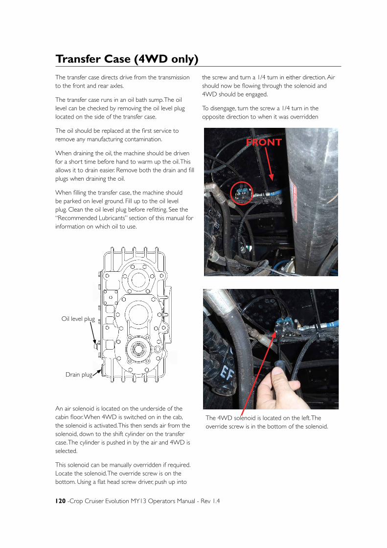
120 -Crop Cruiser Evolution MY13 Operators Manual - Rev 1.4
The transfer case directs drive from the transmission to the front and rear axles.
The transfer case runs in an oil bath sump. The oil level can be checked by removing the oil level plug located on the side of the transfer case.
The oil should be replaced at the first service to remove any manufacturing contamination.
When draining the oil, the machine should be driven for a short time before hand to warm up the oil. This allows it to drain easier. Remove both the drain and fill plugs when draining the oil.
When filling the transfer case, the machine should be parked on level ground. Fill up to the oil level plug. Clean the oil level plug before refitting. See the “Recommended Lubricants” section of this manual for information on which oil to use.
An air solenoid is located on the underside of the cabin floor. When 4WD is switched on in the cab, the solenoid is activated. This then sends air from the solenoid, down to the shift cylinder on the transfer case. The cylinder is pushed in by the air and 4WD is selected.
This solenoid can be manually overridden if required. Locate the solenoid. The override screw is on the bottom. Using a flat head screw driver, push up into
the screw and turn a 1/4 turn in either direction. Air should now be flowing through the solenoid and 4WD should be engaged.
To disengage, turn the screw a 1/4 turn in the opposite direction to when it was overridden
Transfer Case (4WD only)
Oil level plug
Drain plug
FRONT
The 4WD solenoid is located on the left. The override screw is in the bottom of the solenoid.
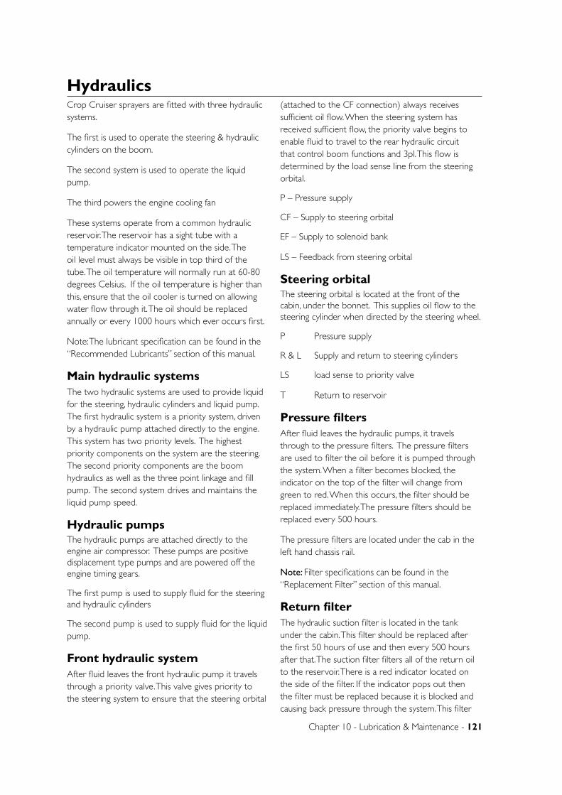
Chapter 10 - Lubrication & Maintenance - 121
HydraulicsCrop Cruiser sprayers are fitted with three hydraulic systems.
The first is used to operate the steering & hydraulic cylinders on the boom.
The second system is used to operate the liquid pump.
The third powers the engine cooling fan
These systems operate from a common hydraulic reservoir. The reservoir has a sight tube with a temperature indicator mounted on the side. The oil level must always be visible in top third of the tube. The oil temperature will normally run at 60-80 degrees Celsius. If the oil temperature is higher than this, ensure that the oil cooler is turned on allowing water flow through it. The oil should be replaced annually or every 1000 hours which ever occurs first.
Note: The lubricant specification can be found in the “Recommended Lubricants” section of this manual.
Main hydraulic systemsThe two hydraulic systems are used to provide liquid for the steering, hydraulic cylinders and liquid pump. The first hydraulic system is a priority system, driven by a hydraulic pump attached directly to the engine. This system has two priority levels. The highest priority components on the system are the steering. The second priority components are the boom hydraulics as well as the three point linkage and fill pump. The second system drives and maintains the liquid pump speed.
Hydraulic pumpsThe hydraulic pumps are attached directly to the engine air compressor. These pumps are positive displacement type pumps and are powered off the engine timing gears.
The first pump is used to supply fluid for the steering and hydraulic cylinders
The second pump is used to supply fluid for the liquid pump.
Front hydraulic systemAfter fluid leaves the front hydraulic pump it travels through a priority valve. This valve gives priority to the steering system to ensure that the steering orbital
(attached to the CF connection) always receives sufficient oil flow. When the steering system has received sufficient flow, the priority valve begins to enable fluid to travel to the rear hydraulic circuit that control boom functions and 3pl. This flow is determined by the load sense line from the steering orbital.
P – Pressure supply
CF – Supply to steering orbital
EF – Supply to solenoid bank
LS – Feedback from steering orbital
Steering orbitalThe steering orbital is located at the front of the cabin, under the bonnet. This supplies oil flow to the steering cylinder when directed by the steering wheel.
P Pressure supply
R & L Supply and return to steering cylinders
LS load sense to priority valve
T Return to reservoir
Pressure filtersAfter fluid leaves the hydraulic pumps, it travels through to the pressure filters. The pressure filters are used to filter the oil before it is pumped through the system. When a filter becomes blocked, the indicator on the top of the filter will change from green to red. When this occurs, the filter should be replaced immediately. The pressure filters should be replaced every 500 hours.
The pressure filters are located under the cab in the left hand chassis rail.
Note: Filter specifications can be found in the “Replacement Filter” section of this manual.
Return filterThe hydraulic suction filter is located in the tank under the cabin. This filter should be replaced after the first 50 hours of use and then every 500 hours after that. The suction filter filters all of the return oil to the reservoir. There is a red indicator located on the side of the filter. If the indicator pops out then the filter must be replaced because it is blocked and causing back pressure through the system. This filter
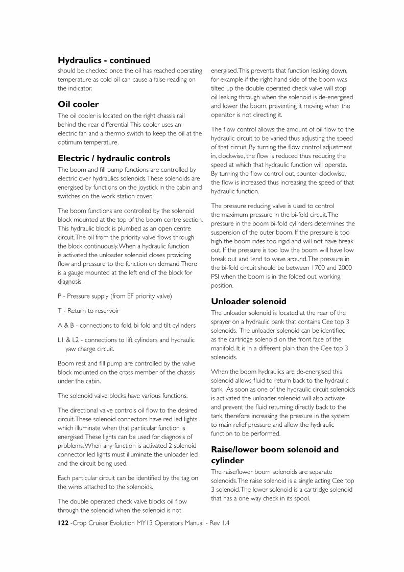
122 -Crop Cruiser Evolution MY13 Operators Manual - Rev 1.4
should be checked once the oil has reached operating temperature as cold oil can cause a false reading on the indicator.
Oil coolerThe oil cooler is located on the right chassis rail behind the rear differential. This cooler uses an electric fan and a thermo switch to keep the oil at the optimum temperature.
Electric / hydraulic controlsThe boom and fill pump functions are controlled by electric over hydraulics solenoids. These solenoids are energised by functions on the joystick in the cabin and switches on the work station cover.
The boom functions are controlled by the solenoid block mounted at the top of the boom centre section. This hydraulic block is plumbed as an open centre circuit. The oil from the priority valve flows through the block continuously. When a hydraulic function is activated the unloader solenoid closes providing flow and pressure to the function on demand. There is a gauge mounted at the left end of the block for diagnosis.
P - Pressure supply (from EF priority valve)
T - Return to reservoir
A & B - connections to fold, bi fold and tilt cylinders
L1 & L2 - connections to lift cylinders and hydraulic yaw charge circuit.
Boom rest and fill pump are controlled by the valve block mounted on the cross member of the chassis under the cabin.
The solenoid valve blocks have various functions.
The directional valve controls oil flow to the desired circuit. These solenoid connectors have red led lights which illuminate when that particular function is energised. These lights can be used for diagnosis of problems. When any function is activated 2 solenoid connector led lights must illuminate the unloader led and the circuit being used.
Each particular circuit can be identified by the tag on the wires attached to the solenoids.
The double operated check valve blocks oil flow through the solenoid when the solenoid is not
energised. This prevents that function leaking down, for example if the right hand side of the boom was tilted up the double operated check valve will stop oil leaking through when the solenoid is de-energised and lower the boom, preventing it moving when the operator is not directing it.
The flow control allows the amount of oil flow to the hydraulic circuit to be varied thus adjusting the speed of that circuit. By turning the flow control adjustment in, clockwise, the flow is reduced thus reducing the speed at which that hydraulic function will operate. By turning the flow control out, counter clockwise, the flow is increased thus increasing the speed of that hydraulic function.
The pressure reducing valve is used to control the maximum pressure in the bi-fold circuit. The pressure in the boom bi-fold cylinders determines the suspension of the outer boom. If the pressure is too high the boom rides too rigid and will not have break out. If the pressure is too low the boom will have low break out and tend to wave around. The pressure in the bi-fold circuit should be between 1700 and 2000 PSI when the boom is in the folded out, working, position.
Unloader solenoidThe unloader solenoid is located at the rear of the sprayer on a hydraulic bank that contains Cee top 3 solenoids. The unloader solenoid can be identified as the cartridge solenoid on the front face of the manifold. It is in a different plain than the Cee top 3 solenoids.
When the boom hydraulics are de-energised this solenoid allows fluid to return back to the hydraulic tank. As soon as one of the hydraulic circuit solenoids is activated the unloader solenoid will also activate and prevent the fluid returning directly back to the tank, therefore increasing the pressure in the system to main relief pressure and allow the hydraulic function to be performed.
Raise/lower boom solenoid and cylinderThe raise/lower boom solenoids are separate solenoids. The raise solenoid is a single acting Cee top 3 solenoid. The lower solenoid is a cartridge solenoid that has a one way check in its spool.
Hydraulics - continued
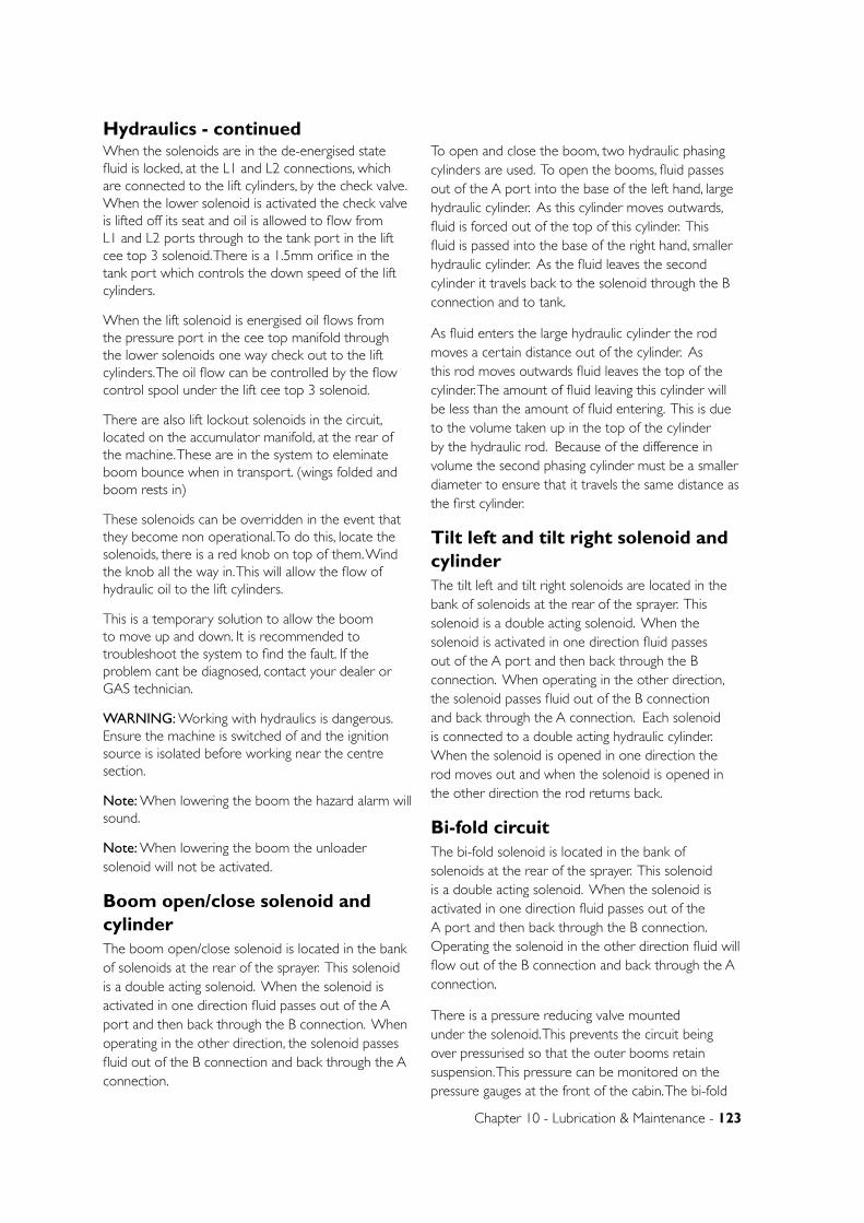
Chapter 10 - Lubrication & Maintenance - 123
When the solenoids are in the de-energised state fluid is locked, at the L1 and L2 connections, which are connected to the lift cylinders, by the check valve. When the lower solenoid is activated the check valve is lifted off its seat and oil is allowed to flow from L1 and L2 ports through to the tank port in the lift cee top 3 solenoid. There is a 1.5mm orifice in the tank port which controls the down speed of the lift cylinders.
When the lift solenoid is energised oil flows from the pressure port in the cee top manifold through the lower solenoids one way check out to the lift cylinders. The oil flow can be controlled by the flow control spool under the lift cee top 3 solenoid.
There are also lift lockout solenoids in the circuit, located on the accumulator manifold, at the rear of the machine. These are in the system to eleminate boom bounce when in transport. (wings folded and boom rests in)
These solenoids can be overridden in the event that they become non operational. To do this, locate the solenoids, there is a red knob on top of them. Wind the knob all the way in. This will allow the flow of hydraulic oil to the lift cylinders.
This is a temporary solution to allow the boom to move up and down. It is recommended to troubleshoot the system to find the fault. If the problem cant be diagnosed, contact your dealer or GAS technician.
WARNING: Working with hydraulics is dangerous. Ensure the machine is switched of and the ignition source is isolated before working near the centre section.
Note: When lowering the boom the hazard alarm will sound.
Note: When lowering the boom the unloader solenoid will not be activated.
Boom open/close solenoid and cylinderThe boom open/close solenoid is located in the bank of solenoids at the rear of the sprayer. This solenoid is a double acting solenoid. When the solenoid is activated in one direction fluid passes out of the A port and then back through the B connection. When operating in the other direction, the solenoid passes fluid out of the B connection and back through the A connection.
To open and close the boom, two hydraulic phasing cylinders are used. To open the booms, fluid passes out of the A port into the base of the left hand, large hydraulic cylinder. As this cylinder moves outwards, fluid is forced out of the top of this cylinder. This fluid is passed into the base of the right hand, smaller hydraulic cylinder. As the fluid leaves the second cylinder it travels back to the solenoid through the B connection and to tank.
As fluid enters the large hydraulic cylinder the rod moves a certain distance out of the cylinder. As this rod moves outwards fluid leaves the top of the cylinder. The amount of fluid leaving this cylinder will be less than the amount of fluid entering. This is due to the volume taken up in the top of the cylinder by the hydraulic rod. Because of the difference in volume the second phasing cylinder must be a smaller diameter to ensure that it travels the same distance as the first cylinder.
Tilt left and tilt right solenoid and cylinderThe tilt left and tilt right solenoids are located in the bank of solenoids at the rear of the sprayer. This solenoid is a double acting solenoid. When the solenoid is activated in one direction fluid passes out of the A port and then back through the B connection. When operating in the other direction, the solenoid passes fluid out of the B connection and back through the A connection. Each solenoid is connected to a double acting hydraulic cylinder. When the solenoid is opened in one direction the rod moves out and when the solenoid is opened in the other direction the rod returns back.
Bi-fold circuitThe bi-fold solenoid is located in the bank of solenoids at the rear of the sprayer. This solenoid is a double acting solenoid. When the solenoid is activated in one direction fluid passes out of the A port and then back through the B connection. Operating the solenoid in the other direction fluid will flow out of the B connection and back through the A connection.
There is a pressure reducing valve mounted under the solenoid. This prevents the circuit being over pressurised so that the outer booms retain suspension. This pressure can be monitored on the pressure gauges at the front of the cabin. The bi-fold
Hydraulics - continued
124 -Crop Cruiser Evolution MY13 Operators Manual - Rev 1.4
circuit has 2 double operated check valves in the system to maintain the pressure in the boom lines when it is folded out in the working position. The fold out or retract ports on the cylinder are connected to 4m of ½” hydraulic hose and pressure gauges. This hose acts as an accumulator if excess force is applied to the outer boom, rapid acceleration, deceleration or contacting an object.
Hydraulic yawHydraulic yaw cylinders that are fitted to the centre section get there oil supply from the lift circuit. When charging the yaw system the yaw ball valves are opened and the lift circuit is dead headed. Oil flows through the yaw pressure reducing valve, which limits the maximum pressure to 1500 PSI, charges the yaw cylinders and accumulators. The yaw ball valves must then be isolated as the hydraulic yaw circuit is closed loop. The pressure gauges on the hydraulic yaw accumulators must be inspected to maintain the correct operating pressure.
Rear hydraulic system
Liquid pump control manifoldThe liquid pump control manifold is located on the inside of the chassis, on the left-hand side of the sprayer. It is a pressure flow compensated valve. This means that the oil flow to the product pump can be maintained even if the pressure of the oil is increased or decreased. This allows the product pump RPM to remain constant even if engine RPM changes.
The valve has a built in pressure relief valve. This valve prevents excessive pressures within the hydraulic system. (This valve operates when a pressure of
2500PSI is reached) During normal operation this will prevent any fluid bypassing the system. If a fault develops in the system, this valve will enable fluid to return to the tank, without causing damage to the system.
P - Pressure supply
T - Return to reservoir
R - Supply to liquid pump drive
Liquid pump solenoidThe liquid pump solenoid is a single acting spring return solenoid and is built into the liquid pump control manifold. When this solenoid is activated, fluid is forced to travel to the needle valve before travelling to the hydraulic drive for the liquid pump.
Liquid pump needle valveThe liquid pump needle valve is built into the liquid pump control manifold. This valve enables the speed of the pump drive to be adjusted. Pump speed must never exceed 540rpm.
Hydraulic Fan Drive systemThe pump for the hydraulic fan is mounted to the engine and is belt driven from the engine crank shaft. The pump draws oil from the hydraulic oil tank and and powers the fan motor. The oil then returns from the fan back to the oil tank.
A pressure relief valve is included in the system incase the fan becomes obstructed or the system gets blocked in any way.
Hydraulics - continued
EngineOpening the bonnetThe bonnet is fastened down by a ‘T’ type latch
Once open, the bonnet is supported by over centre weight.
CAUTION: If the engine has been running, take extra care around hot engine parts such as the exhaust.
Fuel filtersThere are three fuel filters mounted on the left hand side of the engine.
The water separator or primary filter is mounted on the front of the left hand chassis rail. This filter is the first point from the fuel tank, it separates any water
from the fuel and also filters contaminants.
This filter has a sensor in the base of it which will alarm when excessive amounts of water is detected in the fuel.
This filter should be replaced with in the first 50 hours of use and then every 250 hours of engine operation.
The water trap at the base of the cylinder should be drained daily.
The Secondary filter is mounted on the left hand side of the engine. This filter is finer than the primary filter.
The third is an inline filter that is located on top of the fuel tank near the left hand chassis rail.
Chapter 10 - Lubrication & Maintenance - 125
Note: Filter specifications can be found in the “Replacement Filter” section of this manual.
Engine oil and filterCheck the engine oil level daily. The engine oil must be checked with the engine stopped. The engine oil dipstick must be removed from the engine tube, cleaned and then re-dipped to verify the correct engine oil level. The oil level must be between the “ADD” and “FULL” marks on the dipstick. If the oil level is below the “ADD” mark top up the engine with the appropriate fluid. The lubricant specification can be found in the “Recommended Lubricants” section of this manual.
The engine oil must be drained within the first 50 hours of engine use and then as per the maintenance schedule after that. To drain the engine oil place a container, at least 30 litre capacity, under the drain plug, located on the front on the left hand chassis rail, and then remove the plug. The engine oil filler cap can be loosened to allow the oil to drain easier.
Once drained refit the oil drain plug and fill though the rocker cover on the top of the engine or the filler located near the dipstick. The oil can be checked via the dipstick on the left of the engine.
When the engine oil is changed the engine oil filter must be replaced. The engine oil filter is located on the right side of the engine. The filter is a spin on element.
Note: filter specifications can be found in the “Replacement Filter” section of this manual.
CoolantCrop Cruiser radiators are fitted with a header tank. This allows for expansion of the coolant when the engine warms up. The radiator cap allows excess fluid to drain out of the over flow if the coolant expands too much. The coolant level must be visible from the lid of the header tank. The level will be 50mm below the lid when the engine is cool.
Coolant level must be checked DAILY.
NOTE: Never remove the radiator cap when the engine is hot.
The header tank is fitted with a level sensor. If the coolant drops below this sensor the engine controller will send an alarm through to the CanTrak console and shut the engine down.
Coolant must be checked at regular service intervals for the correct level of glycol and dca4. Test kits are available from Cummins to check this.
The coolant must be replaced every 2000 hours. Quantity and type can be found in the “Recommended Lubricant” section of this manual.
There are ball valves located on the heater hoses at the rear of the engine and also at the header tank. These ball valves can be isolated during hotter periods to allow the air conditioning system to operate more efficiently. When replacing the entire coolant system these ball valves must be opened so that all the air is bled from the coolant lines.
Engine drive beltThe engine drive belt is a serpentine belt that has a self tensioner on it. The belt requires inspection at regular service intervals. If the belt begins to slip the belt may require replacement as it can become laminated or slippery. If the tensioner looses its tension it can also cause the belt to slip and must be replaced. The belt should be replaced every 1000 hours.
To replace the engine drive belt insert a ½” drive into the tensioner arm and pull upwards.
Pull the belt off the pulleys and off the fan.
Fit the new belt in reverse, ensure all pulleys are aligned correctly with the belt before releasing the tensioner.
Air conditioner beltThe air conditioner compressor belt has a manual adjuster. To tension the belt the compressor mounting bolt and adjuster bolt must be loosened. To tighten the belt, use the lock nuts on the adjuster to pivot the compressor and pull the belt tight. When the belt is correctly tensioned tighten the retaining hardware.
There should be no more than 12mm deflection in the belt when it is tensioned correctly. The compressor belt should be replaced every 1000 hours.
Engine fan hydraulic pump beltThe engine fan hydraulic pump belt has a manual adjuster. To tension the belt, the pump mounting bolt and tensioner has to be loosened. Use the lock nuts
Engine - continued
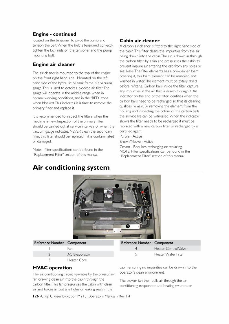
126 -Crop Cruiser Evolution MY13 Operators Manual - Rev 1.4
located on the tensioner to pivot the pump and tension the belt. When the belt is tensioned correctly, tighten the lock nuts on the tensioner and the pump mounting bolt.
Engine air cleaner
The air cleaner is mounted to the top of the engine on the front right hand side. Mounted on the left hand side of the hydraulic oil tank frame is a vacuum gauge. This is used to detect a blocked air filter. The gauge will operate in the middle range when in normal working conditions, and in the “RED” zone when blocked. This indicates it is time to remove the primary filter and replace it.
It is recommended to inspect the filters when the machine is new. Inspection of the primary filter should be carried out at service intervals or when the vacuum gauge indicates. NEVER clean the secondary filter, this filter should be replaced if it is contaminated or damaged.
Note: - filter specifications can be found in the “Replacement Filter” section of this manual.
Cabin air cleaner A carbon air cleaner is fitted to the right hand side of the cabin. This filter cleans the impurities from the air being drawn into the cabin. The air is drawn in through the carbon filter by a fan and pressurises the cabin to prevent impure air entering the cab from any holes or seal leaks. The filter elements has a pre-cleaner foam covering it, this foam element can be removed and washed in water. The element must be totally dried before refitting. Carbon balls inside the filter capture any impurities in the air that is drawn through it. An indicator on the end of the filter identifies when the carbon balls need to be recharged so that its cleaning qualities remain. By removing the element from the housing and inspecting the colour of the carbon balls the service life can be witnessed. When the indicator shows the filter needs to be recharged it must be replaced with a new carbon filter or recharged by a certified agent.Purple - Active Brown/Mauve - ActiveCream - Requires recharging or replacing NOTE: Filter specifications can be found in the “Replacement Filter” section of this manual.
Engine - continued
Air conditioning system
HVAC operationThe air conditioning circuit operates by the pressuriser fan drawing clean air into the cabin through the carbon filter. This fan pressurises the cabin with clean air and forces air out any holes or leaking seals in the
cabin ensuring no impurities can be drawn into the operator’s clean environment.
The blower fan then pulls air through the air conditioning evaporator and heating evaporator
1
2
3
4
5
Reference Number Component
1 Fan
2 AC Evaporator
3 Heater Core
Reference Number Component
4 Heater Control Valve
5 Heater Water Filter
Chapter 10 - Lubrication & Maintenance - 127
Electrical systemBatteriesThe electrical system operates on 12 volts. To provide a 12V supply with sufficient current two 12 volt batteries have been used in parallel. This means that the like polarity terminals have been joined.
• Before carrying out any repairs to the electrical system turn the battery isolator switch to the ‘off ’ position. The battery isolator is located on the bottom of the brake pod which is located on the right hand chassis rail.
• When welding connect the ground terminal directly to the part being welded and ensure that the batteries are disconnected. Disconnect any electronic controls such as the engine controller, transmission controller and the spray controller.
• When welding on the sprayer ensure, If Fitted, that all weed seeker controllers are totally removed from the sprayer.
Battery isolator
The battery isolator switches power flow from the batteries to the sprayer. The switch is a 250 amp
switch. The isolator switch cut all power to the sprayer except for the radio back up power. The isolator switch must be isolated when the sprayer is not in use to prevent battery leakage or power faults. The isolator switch is situated on the bottom of the brake pod which is located on the right hand chassis rail.
Battery jumperThe battery jumper points are located on the brake pod. These points are connected to the terminals on the battery. When charging the batteries or jump starting another vehicle:
• Switch the engine off.
• Switch off the battery isolator switch.
• Connect the positive jumper lead to the positive battery jumper point.
• Connect the negative jumper lead to the negative battery jumper point.
Electrical componentsThe Electrical control panels are located in the side console on the right of the operator’s seat. These
and pushes it to the demist and roof vents. If the air conditioning compressor is engaged the air conditioner evaporator will cool the air as it is drawn though it. If the heater thermostat is turned to heat, the air will warm again as it passes through. If the heater is off, the cool air passes through to the vents.
CompressorThe air conditioning compressor is located on the front side of the engine. This compressor is connected to the engine by a “V” belt. The compressor is engaged when ever the cabin blower fan switch is energised. The thermostat will cycle the air compressor if the evaporator gets to cold.
CondensorThe air conditioning system condenser is located in front of the engine radiator. The condenser is cooled by air being drawn through from the engine fan. The condenser requires regular cleaning of dust and any debris.
Note: Take care not to damage the condenser coils or fins when the condenser is cleaned.
Receiver dryerThe air conditioning receiver dryer is fitted to the right hand chassis rail under the cabin. This component captures any moisture that is circulating in the air condition system. Moisture in the air conditioning system freezes and causes blockages. The component must be replaced any time the air conditioning system is opened or serviced.
Heating systemThe heating core is warmed with hot water from the engine. The volume of the water travelling through the system (and therefore the heat supplied) may be adjusted by setting the temperature on the AC head unit. To enable the heating core to be isolated from the engine two taps have been installed. The first tap is located on the right hand side of the engine behind the radiator. The second tap is located at the header tank.
Note: If the heating is not working ensure that the isolating taps are on.
Air conditioning system - continued
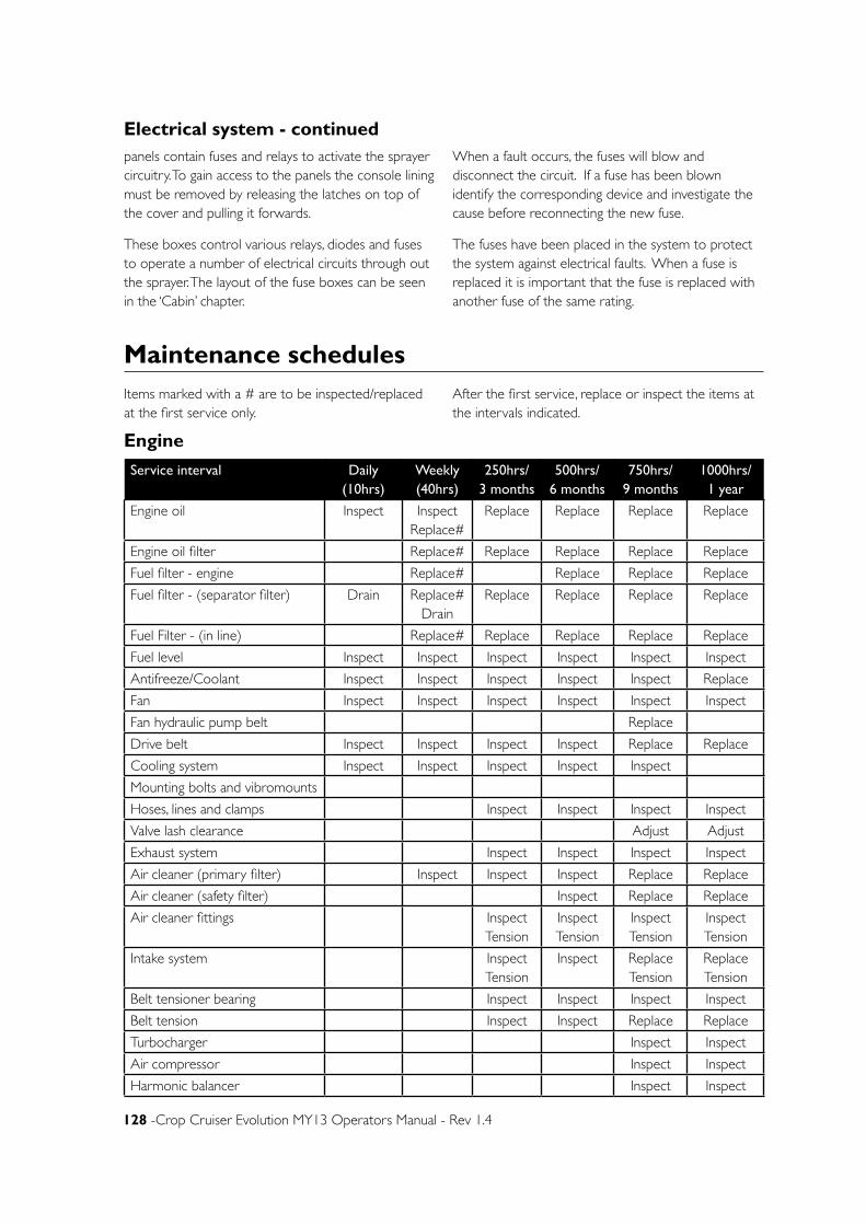
128 -Crop Cruiser Evolution MY13 Operators Manual - Rev 1.4
Maintenance schedules
Engine
Service interval Daily (10hrs)
Weekly (40hrs)
250hrs/ 3 months
500hrs/ 6 months
750hrs/ 9 months
1000hrs/ 1 year
Engine oil Inspect Inspect Replace#
Replace Replace Replace Replace
Engine oil filter Replace# Replace Replace Replace Replace
Fuel filter - engine Replace# Replace Replace Replace
Fuel filter - (separator filter) Drain Replace# Drain
Replace Replace Replace Replace
Fuel Filter - (in line) Replace# Replace Replace Replace Replace
Fuel level Inspect Inspect Inspect Inspect Inspect Inspect
Antifreeze/Coolant Inspect Inspect Inspect Inspect Inspect Replace
Fan Inspect Inspect Inspect Inspect Inspect Inspect
Fan hydraulic pump belt Replace
Drive belt Inspect Inspect Inspect Inspect Replace Replace
Cooling system Inspect Inspect Inspect Inspect Inspect
Mounting bolts and vibromounts
Hoses, lines and clamps Inspect Inspect Inspect Inspect
Valve lash clearance Adjust Adjust
Exhaust system Inspect Inspect Inspect Inspect
Air cleaner (primary filter) Inspect Inspect Inspect Replace Replace
Air cleaner (safety filter) Inspect Replace Replace
Air cleaner fittings Inspect Tension
Inspect Tension
Inspect Tension
Inspect Tension
Intake system Inspect Tension
Inspect Replace Tension
Replace Tension
Belt tensioner bearing Inspect Inspect Inspect Inspect
Belt tension Inspect Inspect Replace Replace
Turbocharger Inspect Inspect
Air compressor Inspect Inspect
Harmonic balancer Inspect Inspect
Items marked with a # are to be inspected/replaced at the first service only.
After the first service, replace or inspect the items at the intervals indicated.
panels contain fuses and relays to activate the sprayer circuitry. To gain access to the panels the console lining must be removed by releasing the latches on top of the cover and pulling it forwards.
These boxes control various relays, diodes and fuses to operate a number of electrical circuits through out the sprayer. The layout of the fuse boxes can be seen in the ‘Cabin’ chapter.
When a fault occurs, the fuses will blow and disconnect the circuit. If a fuse has been blown identify the corresponding device and investigate the cause before reconnecting the new fuse.
The fuses have been placed in the system to protect the system against electrical faults. When a fuse is replaced it is important that the fuse is replaced with another fuse of the same rating.
Electrical system - continued
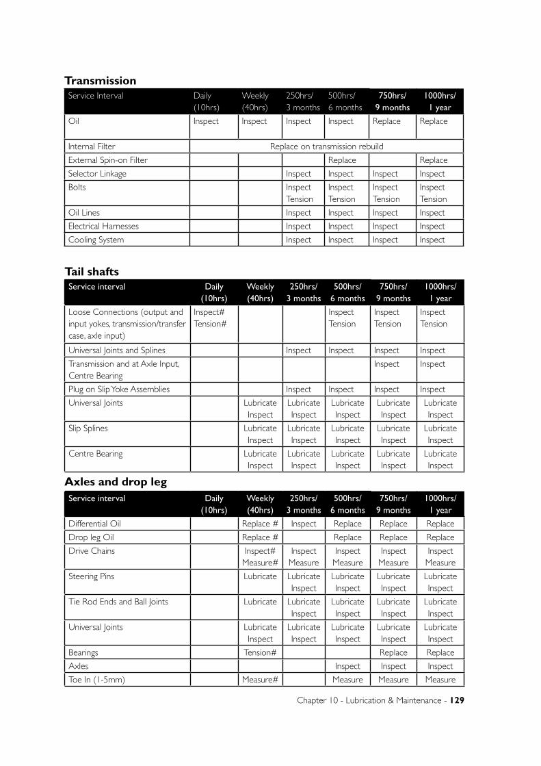
Chapter 10 - Lubrication & Maintenance - 129
Service interval Daily (10hrs)
Weekly (40hrs)
250hrs/ 3 months
500hrs/ 6 months
750hrs/ 9 months
1000hrs/ 1 year
Loose Connections (output and input yokes, transmission/transfer case, axle input)
Inspect# Tension#
Inspect Tension
Inspect Tension
Inspect Tension
Universal Joints and Splines Inspect Inspect Inspect Inspect
Transmission and at Axle Input, Centre Bearing
Inspect Inspect
Plug on Slip Yoke Assemblies Inspect Inspect Inspect Inspect
Universal Joints Lubricate Inspect
Lubricate Inspect
Lubricate Inspect
Lubricate Inspect
Lubricate Inspect
Slip Splines Lubricate Inspect
Lubricate Inspect
Lubricate Inspect
Lubricate Inspect
Lubricate Inspect
Centre Bearing Lubricate Inspect
Lubricate Inspect
Lubricate Inspect
Lubricate Inspect
Lubricate Inspect
Tail shafts
Service interval Daily (10hrs)
Weekly (40hrs)
250hrs/ 3 months
500hrs/ 6 months
750hrs/ 9 months
1000hrs/ 1 year
Differential Oil Replace # Inspect Replace Replace Replace
Drop leg Oil Replace # Replace Replace Replace
Drive Chains Inspect# Measure#
Inspect Measure
Inspect Measure
Inspect Measure
Inspect Measure
Steering Pins Lubricate Lubricate Inspect
Lubricate Inspect
Lubricate Inspect
Lubricate Inspect
Tie Rod Ends and Ball Joints Lubricate Lubricate Inspect
Lubricate Inspect
Lubricate Inspect
Lubricate Inspect
Universal Joints Lubricate Inspect
Lubricate Inspect
Lubricate Inspect
Lubricate Inspect
Lubricate Inspect
Bearings Tension# Replace Replace
Axles Inspect Inspect Inspect
Toe In (1-5mm) Measure# Measure Measure Measure
Axles and drop leg
Service Interval Daily (10hrs)
Weekly (40hrs)
250hrs/ 3 months
500hrs/ 6 months
750hrs/ 9 months
1000hrs/ 1 year
Oil Inspect Inspect Inspect Inspect Replace Replace
Internal Filter Replace on transmission rebuild
External Spin-on Filter Replace Replace
Selector Linkage Inspect Inspect Inspect Inspect
Bolts Inspect Tension
Inspect Tension
Inspect Tension
Inspect Tension
Oil Lines Inspect Inspect Inspect Inspect
Electrical Harnesses Inspect Inspect Inspect Inspect
Cooling System Inspect Inspect Inspect Inspect
Transmission
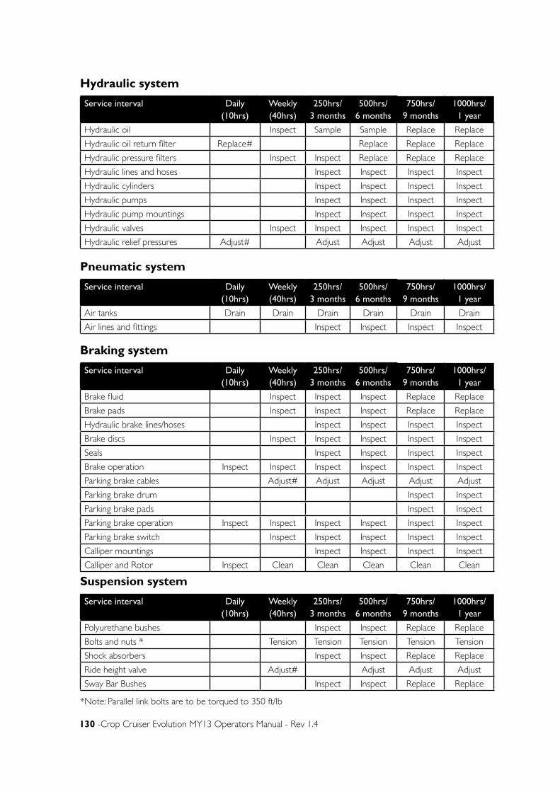
130 -Crop Cruiser Evolution MY13 Operators Manual - Rev 1.4
Service interval Daily (10hrs)
Weekly (40hrs)
250hrs/ 3 months
500hrs/ 6 months
750hrs/ 9 months
1000hrs/ 1 year
Hydraulic oil Inspect Sample Sample Replace Replace
Hydraulic oil return filter Replace# Replace Replace Replace
Hydraulic pressure filters Inspect Inspect Replace Replace Replace
Hydraulic lines and hoses Inspect Inspect Inspect Inspect
Hydraulic cylinders Inspect Inspect Inspect Inspect
Hydraulic pumps Inspect Inspect Inspect Inspect
Hydraulic pump mountings Inspect Inspect Inspect Inspect
Hydraulic valves Inspect Inspect Inspect Inspect Inspect
Hydraulic relief pressures Adjust# Adjust Adjust Adjust Adjust
Hydraulic system
Service interval Daily (10hrs)
Weekly (40hrs)
250hrs/ 3 months
500hrs/ 6 months
750hrs/ 9 months
1000hrs/ 1 year
Air tanks Drain Drain Drain Drain Drain Drain
Air lines and fittings Inspect Inspect Inspect Inspect
Pneumatic system
Service interval Daily (10hrs)
Weekly (40hrs)
250hrs/ 3 months
500hrs/ 6 months
750hrs/ 9 months
1000hrs/ 1 year
Brake fluid Inspect Inspect Inspect Replace Replace
Brake pads Inspect Inspect Inspect Replace Replace
Hydraulic brake lines/hoses Inspect Inspect Inspect Inspect
Brake discs Inspect Inspect Inspect Inspect Inspect
Seals Inspect Inspect Inspect Inspect
Brake operation Inspect Inspect Inspect Inspect Inspect Inspect
Parking brake cables Adjust# Adjust Adjust Adjust Adjust
Parking brake drum Inspect Inspect
Parking brake pads Inspect Inspect
Parking brake operation Inspect Inspect Inspect Inspect Inspect Inspect
Parking brake switch Inspect Inspect Inspect Inspect Inspect
Calliper mountings Inspect Inspect Inspect Inspect
Calliper and Rotor Inspect Clean Clean Clean Clean Clean
Braking system
Service interval Daily (10hrs)
Weekly (40hrs)
250hrs/ 3 months
500hrs/ 6 months
750hrs/ 9 months
1000hrs/ 1 year
Polyurethane bushes Inspect Inspect Replace Replace
Bolts and nuts * Tension Tension Tension Tension Tension
Shock absorbers Inspect Inspect Replace Replace
Ride height valve Adjust# Adjust Adjust Adjust
Sway Bar Bushes Inspect Inspect Replace Replace
Suspension system
*Note: Parallel link bolts are to be torqued to 350 ft/lb
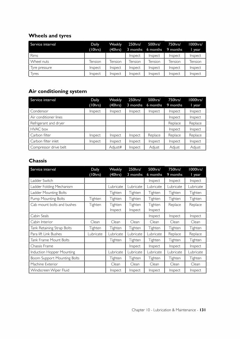
Chapter 10 - Lubrication & Maintenance - 131
Service interval Daily (10hrs)
Weekly (40hrs)
250hrs/ 3 months
500hrs/ 6 months
750hrs/ 9 months
1000hrs/ 1 year
Condensor Inspect Inspect Inspect Inspect Inspect Inspect
Air conditioner lines Inspect Inspect
Refrigerant and dryer Replace Replace
HVAC box Inspect Inspect
Carbon filter Inspect Inspect Inspect Replace Replace Replace
Carbon filter inlet Inspect Inspect Inspect Inspect Inspect Inspect
Compressor drive belt Adjust# Inspect Adjust Adjust Adjust
Air conditioning system
Service interval Daily (10hrs)
Weekly (40hrs)
250hrs/ 3 months
500hrs/ 6 months
750hrs/ 9 months
1000hrs/ 1 year
Ladder Switch Inspect Inspect Inspect
Ladder Folding Mechanism Lubricate Lubricate Lubricate Lubricate Lubricate
Ladder Mounting Bolts Tighten Tighten Tighten Tighten Tighten
Pump Mounting Bolts Tighten Tighten Tighten Tighten Tighten Tighten
Cab mount bolts and bushes Tighten Tighten Inspect
Tighten Inspect
Tighten Inspect
Replace Replace
Cabin Seals Inspect Inspect Inspect
Cabin Interior Clean Clean Clean Clean Clean Clean
Tank Retaining Strap Bolts Tighten Tighten Tighten Tighten Tighten Tighten
Para lift Link Bushes Lubricate Lubricate Lubricate Lubricate Replace Replace
Tank Frame Mount Bolts Tighten Tighten Tighten Tighten Tighten
Chassis Frame Inspect Inspect Inspect Inspect
Induction Hopper Mounting Lubricate Lubricate Lubricate Lubricate Lubricate
Boom Support Mounting Bolts Tighten Tighten Tighten Tighten Tighten
Machine Exterior Clean Clean Clean Clean Clean
Windscreen Wiper Fluid Inspect Inspect Inspect Inspect Inspect
Chassis
Service interval Daily (10hrs)
Weekly (40hrs)
250hrs/ 3 months
500hrs/ 6 months
750hrs/ 9 months
1000hrs/ 1 year
Rims Inspect Inspect Inspect Inspect
Wheel nuts Tension Tension Tension Tension Tension Tension
Tyre pressure Inspect Inspect Inspect Inspect Inspect Inspect
Tyres Inspect Inspect Inspect Inspect Inspect Inspect
Wheels and tyres
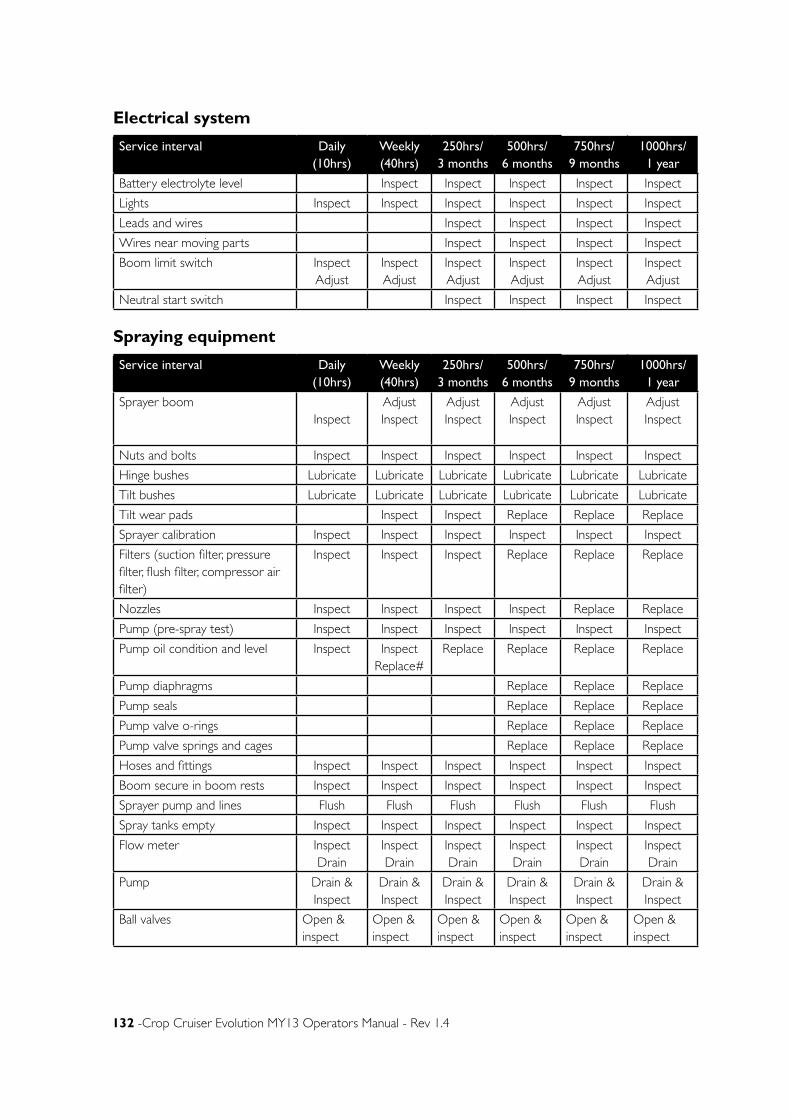
132 -Crop Cruiser Evolution MY13 Operators Manual - Rev 1.4
Service interval Daily (10hrs)
Weekly (40hrs)
250hrs/ 3 months
500hrs/ 6 months
750hrs/ 9 months
1000hrs/ 1 year
Battery electrolyte level Inspect Inspect Inspect Inspect Inspect
Lights Inspect Inspect Inspect Inspect Inspect Inspect
Leads and wires Inspect Inspect Inspect Inspect
Wires near moving parts Inspect Inspect Inspect Inspect
Boom limit switch Inspect Adjust
Inspect Adjust
Inspect Adjust
Inspect Adjust
Inspect Adjust
Inspect Adjust
Neutral start switch Inspect Inspect Inspect Inspect
Electrical system
Service interval Daily (10hrs)
Weekly (40hrs)
250hrs/ 3 months
500hrs/ 6 months
750hrs/ 9 months
1000hrs/ 1 year
Sprayer boom Inspect
Adjust Inspect
Adjust Inspect
Adjust Inspect
Adjust Inspect
Adjust Inspect
Nuts and bolts Inspect Inspect Inspect Inspect Inspect Inspect
Hinge bushes Lubricate Lubricate Lubricate Lubricate Lubricate Lubricate
Tilt bushes Lubricate Lubricate Lubricate Lubricate Lubricate Lubricate
Tilt wear pads Inspect Inspect Replace Replace Replace
Sprayer calibration Inspect Inspect Inspect Inspect Inspect Inspect
Filters (suction filter, pressure filter, flush filter, compressor air filter)
Inspect Inspect Inspect Replace Replace Replace
Nozzles Inspect Inspect Inspect Inspect Replace Replace
Pump (pre-spray test) Inspect Inspect Inspect Inspect Inspect Inspect
Pump oil condition and level Inspect Inspect Replace#
Replace Replace Replace Replace
Pump diaphragms Replace Replace Replace
Pump seals Replace Replace Replace
Pump valve o-rings Replace Replace Replace
Pump valve springs and cages Replace Replace Replace
Hoses and fittings Inspect Inspect Inspect Inspect Inspect Inspect
Boom secure in boom rests Inspect Inspect Inspect Inspect Inspect Inspect
Sprayer pump and lines Flush Flush Flush Flush Flush Flush
Spray tanks empty Inspect Inspect Inspect Inspect Inspect Inspect
Flow meter Inspect Drain
Inspect Drain
Inspect Drain
Inspect Drain
Inspect Drain
Inspect Drain
Pump Drain & Inspect
Drain & Inspect
Drain & Inspect
Drain & Inspect
Drain & Inspect
Drain & Inspect
Ball valves Open & inspect
Open & inspect
Open & inspect
Open & inspect
Open & inspect
Open & inspect
Spraying equipment

Chapter 10 - Lubrication & Maintenance - 133
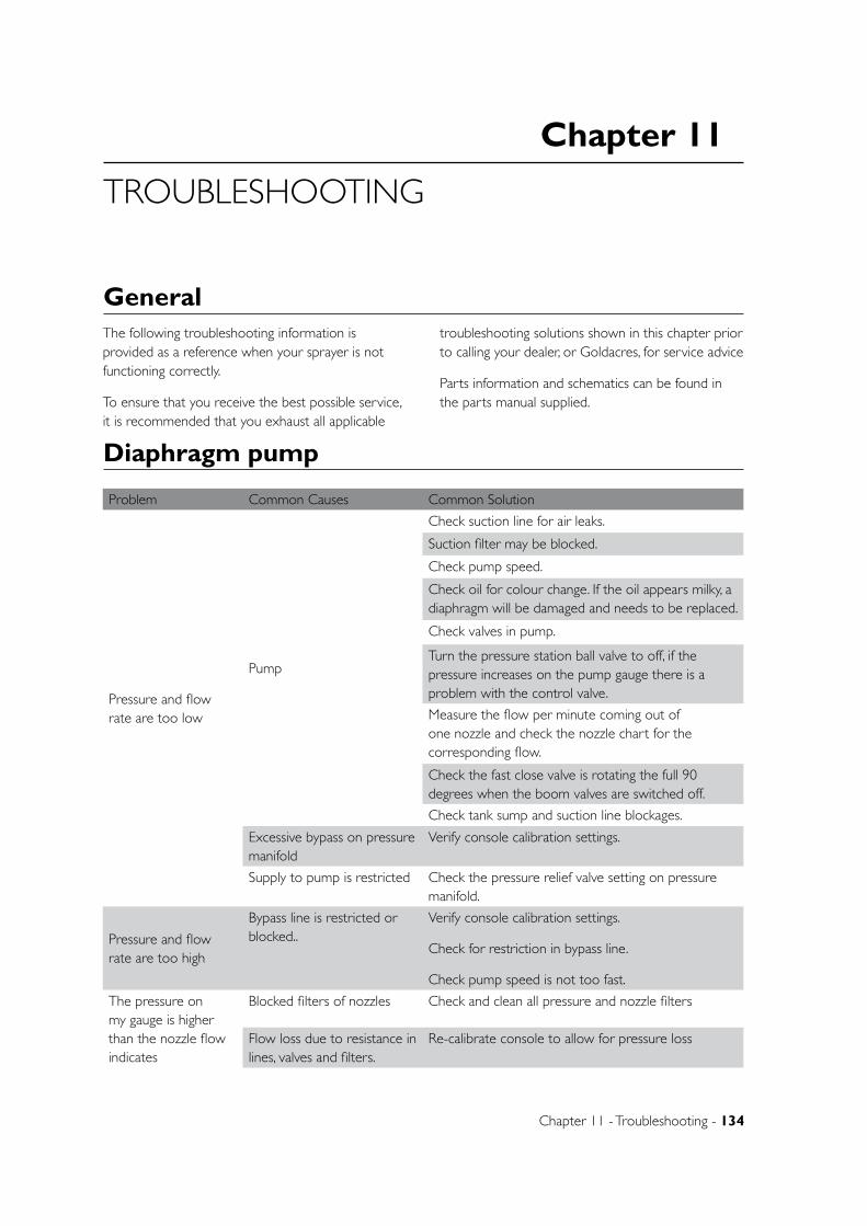
Chapter 11
Chapter 11 - Troubleshooting - 134
TROUBLESHOOTING
GeneralThe following troubleshooting information is provided as a reference when your sprayer is not functioning correctly.
To ensure that you receive the best possible service, it is recommended that you exhaust all applicable
troubleshooting solutions shown in this chapter prior to calling your dealer, or Goldacres, for service advice
Parts information and schematics can be found in the parts manual supplied.
Diaphragm pump
Problem Common Causes Common Solution
Pressure and flow rate are too low
Pump
Check suction line for air leaks.
Suction filter may be blocked.
Check pump speed.
Check oil for colour change. If the oil appears milky, a diaphragm will be damaged and needs to be replaced.
Check valves in pump.
Turn the pressure station ball valve to off, if the pressure increases on the pump gauge there is a problem with the control valve.
Measure the flow per minute coming out of one nozzle and check the nozzle chart for the corresponding flow.
Check the fast close valve is rotating the full 90 degrees when the boom valves are switched off.
Check tank sump and suction line blockages.
Excessive bypass on pressure manifold
Verify console calibration settings.
Supply to pump is restricted Check the pressure relief valve setting on pressure manifold.
Pressure and flow rate are too high
Bypass line is restricted or blocked..
Verify console calibration settings.
Check for restriction in bypass line.
Check pump speed is not too fast.
The pressure on my gauge is higher than the nozzle flow indicates
Blocked filters of nozzles Check and clean all pressure and nozzle filters
Flow loss due to resistance in lines, valves and filters.
Re-calibrate console to allow for pressure loss
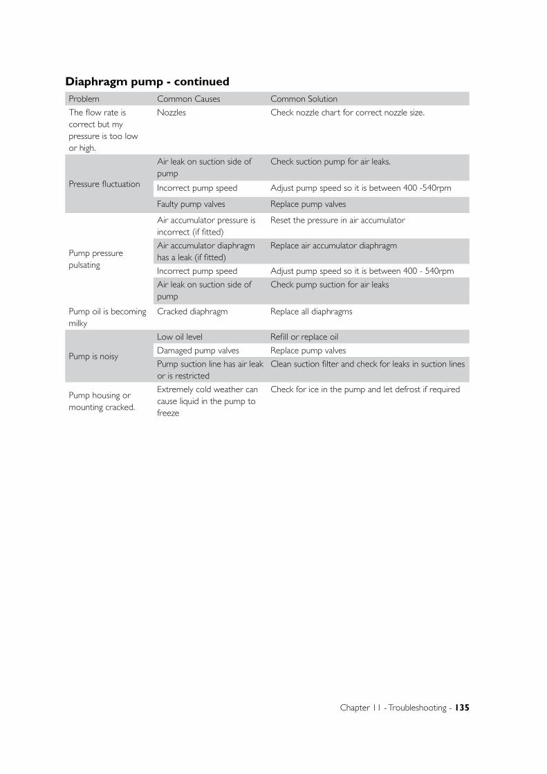
Chapter 11 - Troubleshooting - 135
Problem Common Causes Common Solution
The flow rate is correct but my pressure is too low or high.
Nozzles Check nozzle chart for correct nozzle size.
Pressure fluctuation
Air leak on suction side of pump
Check suction pump for air leaks.
Incorrect pump speed Adjust pump speed so it is between 400 -540rpm
Faulty pump valves Replace pump valves
Pump pressure pulsating
Air accumulator pressure is incorrect (if fitted)
Reset the pressure in air accumulator
Air accumulator diaphragm has a leak (if fitted)
Replace air accumulator diaphragm
Incorrect pump speed Adjust pump speed so it is between 400 - 540rpm
Air leak on suction side of pump
Check pump suction for air leaks
Pump oil is becoming milky
Cracked diaphragm Replace all diaphragms
Pump is noisy
Low oil level Refill or replace oil
Damaged pump valves Replace pump valves
Pump suction line has air leak or is restricted
Clean suction filter and check for leaks in suction lines
Pump housing or mounting cracked.
Extremely cold weather can cause liquid in the pump to freeze
Check for ice in the pump and let defrost if required
Diaphragm pump - continued
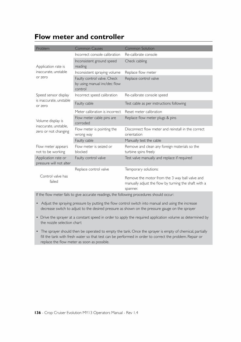
136 - Crop Cruiser Evolution MY13 Operators Manual - Rev 1.4
Flow meter and controller
Problem Common Causes Common Solution
Application rate is inaccurate, unstable or zero
Incorrect console calibration Re-calibrate console
Inconsistent ground speed reading
Check cabling
Inconsistent spraying volume Replace flow meter
Faulty control valve. Check by using manual inc/dec flow control
Replace control valve
Speed sensor display is inaccurate, unstable or zero
Incorrect speed calibration Re-calibrate console speed
Faulty cable Test cable as per instructions following
Volume display is inaccurate, unstable, zero or not changing
Meter calibration is incorrect Reset meter calibration
Flow meter cable pins are corroded
Replace flow meter plugs & pins
Flow meter is pointing the wrong way
Disconnect flow meter and reinstall in the correct orientation
Faulty cable Manually test the cable
Flow meter appears not to be working
Flow meter is seized or blocked
Remove and clean any foreign materials so the turbine spins freely
Application rate or pressure will not alter
Faulty control valve Test valve manually and replace if required
Control valve has failed
Replace control valve Temporary solutions:
Remove the motor from the 3 way ball valve and manually adjust the flow by turning the shaft with a spanner.
If the flow meter fails to give accurate readings, the following procedures should occur:
• Adjust the spraying pressure by putting the flow control switch into manual and using the increase decrease switch to adjust to the desired pressure as shown on the pressure gauge on the sprayer
• Drive the sprayer at a constant speed in order to apply the required application volume as determined by the nozzle selection chart
• The sprayer should then be operated to empty the tank. Once the sprayer is empty of chemical, partially fill the tank with fresh water so that test can be performed in order to correct the problem. Repair or replace the flow meter as soon as possible.
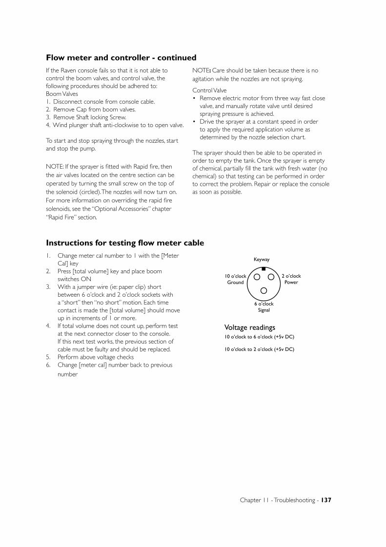
Chapter 11 - Troubleshooting - 137
Flow meter and controller - continued
If the Raven console fails so that it is not able to control the boom valves, and control valve, the following procedures should be adhered to:Boom Valves1. Disconnect console from console cable.2. Remove Cap from boom valves.3. Remove Shaft locking Screw.4. Wind plunger shaft anti-clockwise to to open valve.
To start and stop spraying through the nozzles, start and stop the pump.
NOTE: If the sprayer is fitted with Rapid fire, then the air valves located on the centre section can be operated by turning the small screw on the top of the solenoid (circled). The nozzles will now turn on. For more information on overriding the rapid fire solenoids, see the “Optional Accessories” chapter “Rapid Fire” section.
NOTE: Care should be taken because there is no agitation while the nozzles are not spraying.
Control Valve• Remove electric motor from three way fast close
valve, and manually rotate valve until desired spraying pressure is achieved.
• Drive the sprayer at a constant speed in order to apply the required application volume as determined by the nozzle selection chart.
The sprayer should then be able to be operated in order to empty the tank. Once the sprayer is empty of chemical, partially fill the tank with fresh water (no chemical) so that testing can be performed in order to correct the problem. Repair or replace the console as soon as possible.
Instructions for testing flow meter cable
1. Change meter cal number to 1 with the [Meter Cal] key
2. Press [total volume] key and place boom switches ON
3. With a jumper wire (ie: paper clip) short between 6 o’clock and 2 o’clock sockets with a “short” then “no short” motion. Each time contact is made the [total volume] should move up in increments of 1 or more.
4. If total volume does not count up, perform test at the next connector closer to the console. If this next test works, the previous section of cable must be faulty and should be replaced.
5. Perform above voltage checks6. Change [meter cal] number back to previous
number
Keyway
10 o’clockGround
6 o’clockSignal
2 o’clockPower
Voltage readings10 o’clock to 6 o’clock (+5v DC)
10 o’clock to 2 o’clock (+5v DC)
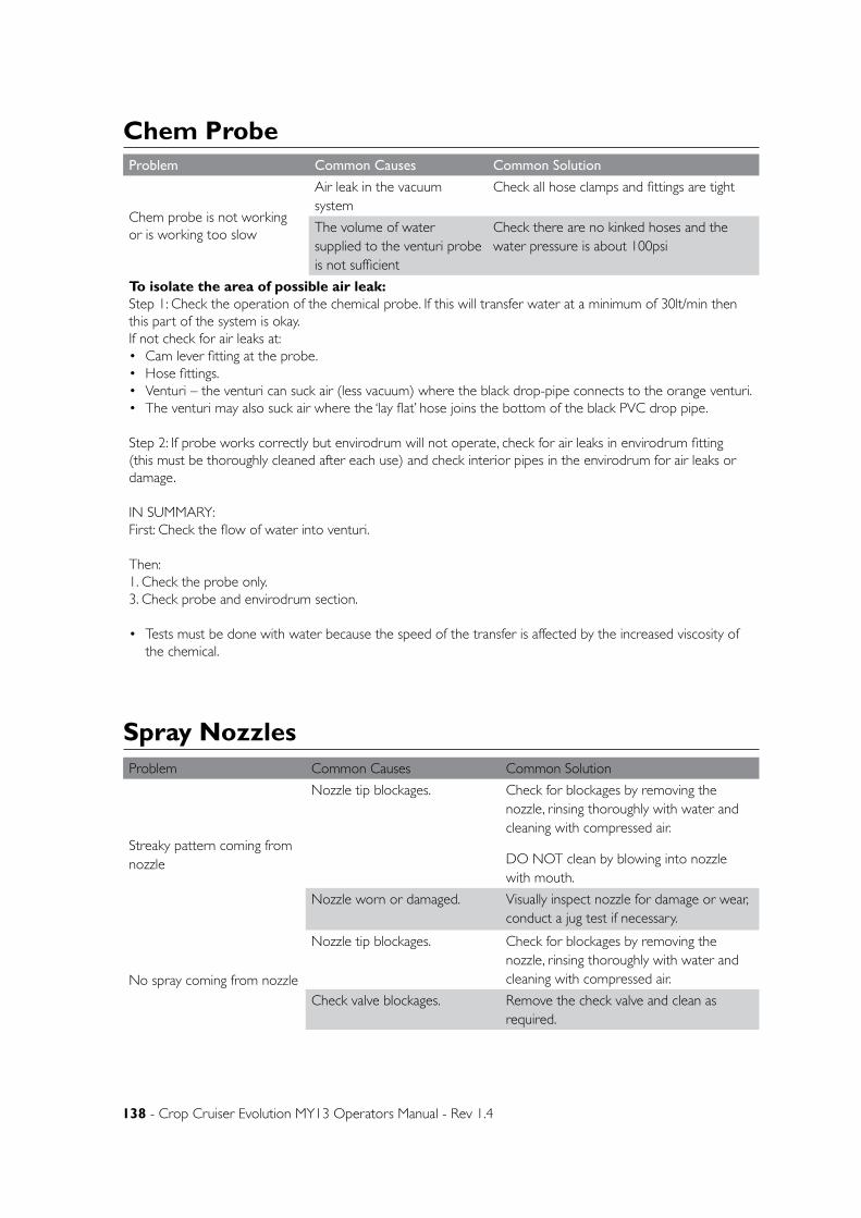
138 - Crop Cruiser Evolution MY13 Operators Manual - Rev 1.4
Chem ProbeProblem Common Causes Common Solution
Chem probe is not working or is working too slow
Air leak in the vacuum system
Check all hose clamps and fittings are tight
The volume of water supplied to the venturi probe is not sufficient
Check there are no kinked hoses and the water pressure is about 100psi
To isolate the area of possible air leak:Step 1: Check the operation of the chemical probe. If this will transfer water at a minimum of 30lt/min then this part of the system is okay.If not check for air leaks at:• Cam lever fitting at the probe.• Hose fittings.• Venturi – the venturi can suck air (less vacuum) where the black drop-pipe connects to the orange venturi.• The venturi may also suck air where the ‘lay flat’ hose joins the bottom of the black PVC drop pipe.
Step 2: If probe works correctly but envirodrum will not operate, check for air leaks in envirodrum fitting (this must be thoroughly cleaned after each use) and check interior pipes in the envirodrum for air leaks or damage.
IN SUMMARY:First: Check the flow of water into venturi.
Then: 1. Check the probe only.3. Check probe and envirodrum section.
• Tests must be done with water because the speed of the transfer is affected by the increased viscosity of the chemical.
Spray NozzlesProblem Common Causes Common Solution
Streaky pattern coming from nozzle
Nozzle tip blockages. Check for blockages by removing the nozzle, rinsing thoroughly with water and cleaning with compressed air.
DO NOT clean by blowing into nozzle with mouth.
Nozzle worn or damaged. Visually inspect nozzle for damage or wear, conduct a jug test if necessary.
No spray coming from nozzle
Nozzle tip blockages. Check for blockages by removing the nozzle, rinsing thoroughly with water and cleaning with compressed air.
Check valve blockages. Remove the check valve and clean as required.
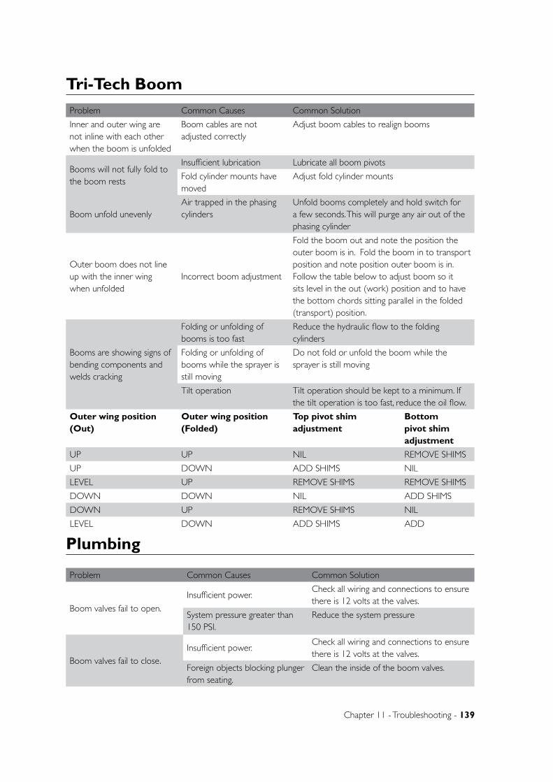
Chapter 11 - Troubleshooting - 139
Tri-Tech Boom
Problem Common Causes Common Solution
Inner and outer wing are not inline with each other when the boom is unfolded
Boom cables are not adjusted correctly
Adjust boom cables to realign booms
Booms will not fully fold to the boom rests
Insufficient lubrication Lubricate all boom pivots
Fold cylinder mounts have moved
Adjust fold cylinder mounts
Boom unfold unevenlyAir trapped in the phasing cylinders
Unfold booms completely and hold switch for a few seconds. This will purge any air out of the phasing cylinder
Outer boom does not line up with the inner wing when unfolded
Incorrect boom adjustment
Fold the boom out and note the position the outer boom is in. Fold the boom in to transport position and note position outer boom is in. Follow the table below to adjust boom so it sits level in the out (work) position and to have the bottom chords sitting parallel in the folded (transport) position.
Booms are showing signs of bending components and welds cracking
Folding or unfolding of booms is too fast
Reduce the hydraulic flow to the folding cylinders
Folding or unfolding of booms while the sprayer is still moving
Do not fold or unfold the boom while the sprayer is still moving
Tilt operation Tilt operation should be kept to a minimum. If the tilt operation is too fast, reduce the oil flow.
Outer wing position (Out)
Outer wing position (Folded)
Top pivot shim adjustment
Bottom pivot shim adjustment
UP UP NIL REMOVE SHIMS
UP DOWN ADD SHIMS NIL
LEVEL UP REMOVE SHIMS REMOVE SHIMS
DOWN DOWN NIL ADD SHIMS
DOWN UP REMOVE SHIMS NIL
LEVEL DOWN ADD SHIMS ADD
Plumbing
Problem Common Causes Common Solution
Boom valves fail to open.
Insufficient power.Check all wiring and connections to ensure there is 12 volts at the valves.
System pressure greater than 150 PSI.
Reduce the system pressure
Boom valves fail to close.Insufficient power.
Check all wiring and connections to ensure there is 12 volts at the valves.
Foreign objects blocking plunger from seating.
Clean the inside of the boom valves.
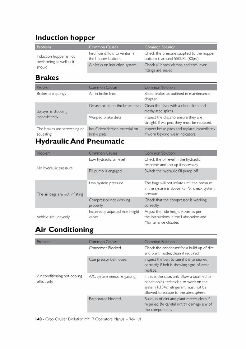
140 - Crop Cruiser Evolution MY13 Operators Manual - Rev 1.4
Problem Common Causes Common Solution
Induction hopper is not performing as well as it should
Insufficient flow to venturi in the hopper bottom
Check the pressure supplied to the hopper bottom is around 550KPa (80psi).
Air leaks on induction system Check all hoses, clamps, and cam lever fittings are sealed
Induction hopper
BrakesProblem Common Causes Common Solution
Brakes are spongy Air in brake lines Bleed brakes as outlined in maintenance chapter
Sprayer is stopping inconsistently
Grease or oil on the brake discs Clean the discs with a clean cloth and methylated spirits.
Warped brake discs Inspect the discs to ensure they are straight. If warped, they must be replaced.
The brakes are screeching or squealing.
Insufficient friction material on brake pads.
Inspect brake pads and replace immediately if worn beyond wear indicators.
Problem Common Causes Common Solution
No hydraulic pressure.
Low hydraulic oil level Check the oil level in the hydraulic reservoir and top up if necessary
Fill pump is engaged Switch the hydraulic fill pump off
The air bags are not inflating
Low system pressure The bags will not inflate until the pressure in the system is above 75 PSI, check system pressure.
Compressor not working properly
Check that the compressor is working correctly
Vehicle sits unevenlyIncorrectly adjusted ride height valves.
Adjust the ride height valves as per the instructions in the Lubrication and Maintenance chapter.
Hydraulic And Pneumatic
Air Conditioning
Problem Common Causes Common Solution
Air conditioning not cooling effectively.
Condenser Blocked Check the condenser for a build up of dirt and plant matter, clean if required.
Compressor belt loose. Inspect the belt to see if it is tensioned correctly. If belt is showing signs of wear, replace.
A/C system needs re-gassing If this is the case, only allow a qualified air conditioning technician to work on the system. R134a refrigerant must not be allowed to escape to the atmosphere.
Evaporator blocked Build up of dirt and plant matter, clean if required. Be careful not to damage any of the components.

Chapter 11 - Troubleshooting - 141

Chapter 12
Chapter 12 - Optional Accessories - 142
OPTIONAL ACCESSORIES
General InformationThe following pages provide information on Goldacres optional accessories available on this equipment.
Please note: These options may not be fitted to your equipment unless ordered.
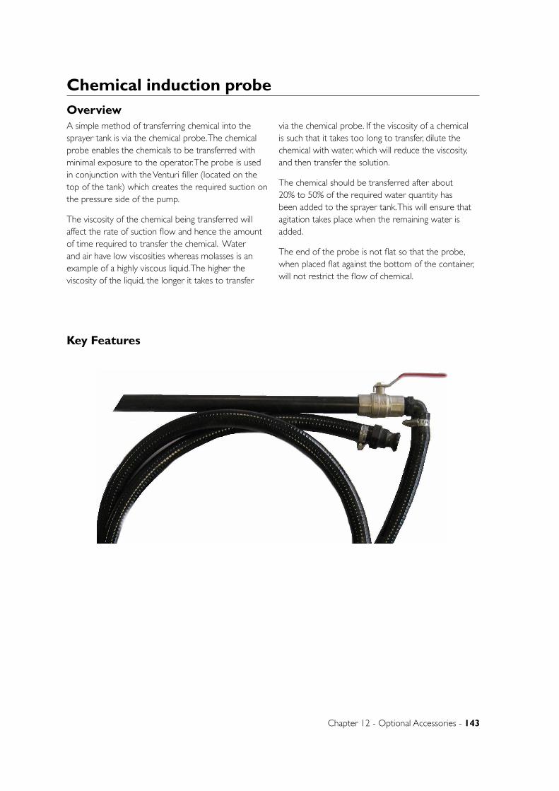
Chapter 12 - Optional Accessories - 143
Chemical induction probe
Key Features
OverviewA simple method of transferring chemical into the sprayer tank is via the chemical probe. The chemical probe enables the chemicals to be transferred with minimal exposure to the operator. The probe is used in conjunction with the Venturi filler (located on the top of the tank) which creates the required suction on the pressure side of the pump.
The viscosity of the chemical being transferred will affect the rate of suction flow and hence the amount of time required to transfer the chemical. Water and air have low viscosities whereas molasses is an example of a highly viscous liquid. The higher the viscosity of the liquid, the longer it takes to transfer
via the chemical probe. If the viscosity of a chemical is such that it takes too long to transfer, dilute the chemical with water, which will reduce the viscosity, and then transfer the solution.
The chemical should be transferred after about 20% to 50% of the required water quantity has been added to the sprayer tank. This will ensure that agitation takes place when the remaining water is added.
The end of the probe is not flat so that the probe, when placed flat against the bottom of the container, will not restrict the flow of chemical.
144 - Crop Cruiser Evolution Operators Manual - Rev 1.4
OperationWARNING: It is critical that the chemical probe venturi continues to operate for a minimum of 30 seconds following use. This will ensure that no chemical is left in the line prior to the probe being disconnected.
NOTE: This item is intended for the induction of liquid chemicals only.
To operate the chemical probe:
1. Add 20 percent of the tank’s volume of clean water to the main spray tank. Initially there needs to be a sufficient amount of water in the tank in order for the pump delivery to create the venturi effect via the venturi filler.
2. Ensure that the red handle on the pump 3-way valve is pointing towards the suction hose coming from the main tank sump.
3. Connect probe via cam lever fitting. Close all ball valves and set pressure to 110psi.
4. ‘OPEN’ the venturi and agitator valves.
5. Rotate the valve handle to venturi probe.
6. Operate the pump at the speed necessary to generate at least 100 psi delivery pressure. Do not run the pump faster than 500 RPM. The higher the pump delivery pressure, the greater the venturi suction and the quicker the probe
will transfer the chemical. The delivery pressure should not exceed 120 psi as determined by the pressure relief valve setting.
7. Place probe in chemical.
8. ‘OPEN’ the valve on the probe.
9. The chemical should be now transferring to the sprayer tank via the venturi filler.
10. When all of the chemical has been transferred, rinse the chemical container with water and transfer the rinsate to the sprayer tank via the probe. This should ensure that the entire chemical is transferred and that the probe, venturi filler and connecting suction hose are cleaned. Induct clean water to rinse probe vacuum hose.
11. When finished, rotate the valve to Bypass/Spray mode, keep the agitator valve ‘OPEN’ and disconnect the probe. Once chemical has been transferred into the main spray tank the sprayer should always be agitating until spraying begins.
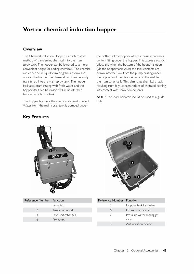
Chapter 12 - Optional Accessories - 145
Vortex chemical induction hopper
Key Features
Overview
The Chemical Induction Hopper is an alternative method of transferring chemical into the main spray tank. The hopper can be lowered to a more convenient height for adding chemicals. The chemical can either be in liquid form or granular form and once in the hopper the chemical can then be easily transferred into the main spray tank. The hopper facilitates drum rinsing with fresh water and the hopper itself can be rinsed and all rinsate then transferred into the tank.
The hopper transfers the chemical via venturi effect. Water from the main spray tank is pumped under
the bottom of the hopper where it passes through a venturi fitting under the hopper. This causes a suction effect and when the bottom of the hopper is open (via the hopper tank valve) the tank contents are drawn into the flow from the pump passing under the hopper and then transferred into the middle of the main spray tank. This eliminates chemical attack resulting from high concentrations of chemical coming into contact with spray components.
NOTE: The level indicator should be used as a guide only.
Reference Number Function
1 Rinse tap
2 Tank rinse nozzle
3 Level indicator 60L
4 Drain tap
Reference Number Function
5 Hopper tank ball valve
6 Drum rinse nozzle
7 Pressure water mixing jet valve
8 Anti aeration device
1
2
3
4
5
67 8
146 - Crop Cruiser Evolution Operators Manual - Rev 1.4
OperationTo operate the induction hopper:
1. Add at least 500 litres of clean water to the main spray tank. Initially there needs to be a sufficient amount of water in the tank in order for the pump delivery to create the venturi effect via the venturi fitting. This will also ensure that agitation takes place when the remaining water is added.
2. Lower the hopper for convenience. (Check that the delivery hose to the hopper is not restricted or kinked).
3. Ensure that the red handle on the pump three-way ball valve is pointing towards the main tank sump.
4. Turn the 4-way ball valve to induction hopper.
5. Operate the pump at the speed necessary to generate at least 80 psi delivery pressure (as displayed on the sprayer pressure gauge). Do not run faster than 500 RPM.
NOTE: The higher the pump delivery pressure, the greater the venturi suction and the quicker the hopper will transfer the chemical. The delivery pressure should not exceed 120 psi as determined by the pressure relief valve setting.
7. The wash down hose is also useful for ensuring all chemical is clear of the hopper (only available when fresh water coming into the fill station)
8. Put the required amount of chemical into the hopper (liquid or granular). Wear the necessary protective clothing and use the required safety equipment to avoid exposure to chemicals.
9. Open the hopper tank ball valve at the bottom of the hopper by turning the yellow handle up. The chemical should be now transferring to the main spray tank.
10. Rinse all chemical drums and the hopper as per the rinsing instructions.
When finished using the hopper:
• Close the hopper tank ball valve at the bottom of the hopper by turning the yellow handle so that it is horizontal.
• Rotate the 4-way valve from “hopper” to “bypass”
• Ensure that the agitator valve is ‘ON’. The sprayer should always be agitating until spraying begins.
• Raise the hopper to its transport position and replace the retaining pin and “R” clip in the mechanism.
RinsingTo rinse the Induction Hopper and chemical drums with fresh water from the external water delivery station:
Note: Spray pump must also be operating.
1. Lower the hopper. (Check that the delivery hose to the hopper is not restricted or kinked).
2. Make sure that all valves on the EZ control external water delivery station are ‘OFF’.
3. Make sure that the Hopper Rinse valve on the top of the hopper is ‘OFF’.
4. Connect the fresh water fill hose to the quick-fill coupling.
5. Operate the fresh water pumping system between 80 and 100 psi.
6. Turn the Induction Hopper valve on the Pressure delivery station ‘ON’.
7. Open the hopper tank valve at the bottom of the hopper by turning the yellow handle ‘UP’.
8. Ensure that the hopper drain tap, also located at the bottom of the hopper, remains ‘CLOSED’.
9. To rinse a drum, push the drum over the rinsing nozzle located in the top of the hopper.
10. To rinse the hopper, turn the Hopper Rinse valve on the top of the hopper ‘ON’. Close this valve when the hopper has been rinsed.
When the hopper is empty:
• Remove any chemical drums that have been rinsed from the hopper.
• Turn the hopper tank valve at the bottom of the hopper ‘OFF’ by turning the yellow handle so that it is horizontal.
• Turn the Induction hopper valve on the EZ control Pressure Delivery station to “Bypass”
Vortex chemical induction hopper - continued
Chapter 12 - Optional Accessories - 147
Induction hopper - Continued
Drain the hopper of any remaining liquid using the hopper drain tap at the bottom of the hopper.
The hopper can be rinsed and the rinsate emptied through the hopper drain ball valve rather than transferred into the main spray tank.
To do this:
1. Ensure the fresh water filling supply pump system is operating.
2. Open the hopper rinse valve on the top of the hopper.
3. ‘OPEN’ the hopper tank ball valve at the bottom of the hopper by turning up the yellow handle so that it is vertical, removing the rinsate from the hopper.
4. Open the hopper drain valve.
CAUTION: Do not have the sprayer pump operating.
NOTE:
• Take proper safety precautions to avoid any contact with rinsate when draining, as it may contain chemical residue.
• Be careful as to where the rinsate is being deposited as it may contain chemical residue.
• This procedure will not rinse the hose from the bottom of the hopper to the main tank.
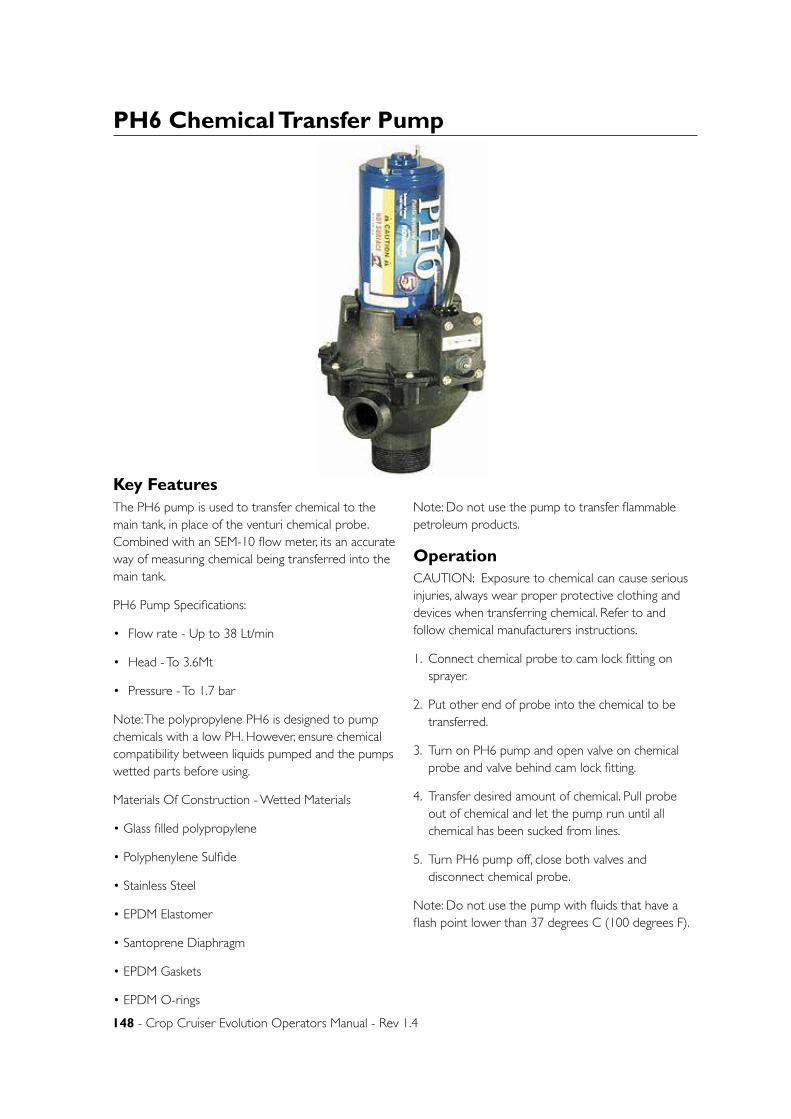
148 - Crop Cruiser Evolution Operators Manual - Rev 1.4
PH6 Chemical Transfer Pump
Key FeaturesThe PH6 pump is used to transfer chemical to the main tank, in place of the venturi chemical probe. Combined with an SEM-10 flow meter, its an accurate way of measuring chemical being transferred into the main tank.
PH6 Pump Specifications:
• Flow rate - Up to 38 Lt/min
• Head - To 3.6Mt
• Pressure - To 1.7 bar
Note: The polypropylene PH6 is designed to pump chemicals with a low PH. However, ensure chemical compatibility between liquids pumped and the pumps wetted parts before using.
Materials Of Construction - Wetted Materials
• Glass filled polypropylene
• Polyphenylene Sulfide
• Stainless Steel
• EPDM Elastomer
• Santoprene Diaphragm
• EPDM Gaskets
• EPDM O-rings
Note: Do not use the pump to transfer flammable petroleum products.
OperationCAUTION: Exposure to chemical can cause serious injuries, always wear proper protective clothing and devices when transferring chemical. Refer to and follow chemical manufacturers instructions.
1. Connect chemical probe to cam lock fitting on sprayer.
2. Put other end of probe into the chemical to be transferred.
3. Turn on PH6 pump and open valve on chemical probe and valve behind cam lock fitting.
4. Transfer desired amount of chemical. Pull probe out of chemical and let the pump run until all chemical has been sucked from lines.
5. Turn PH6 pump off, close both valves and disconnect chemical probe.
Note: Do not use the pump with fluids that have a flash point lower than 37 degrees C (100 degrees F).
Chapter 12 - Optional Accessories - 149
MaintenanceCAUTION: Exposure to chemicals can cause bodily harm. Thoroughly flush pump with water before disassembling. Gloves and proper eye protection should be worn.
Cartridge Removal:
1. Purge pump with clean water.
2. Disconnect 12-volt power source.
3. Remove motor by removing the 6 screws from the pump assembly.
4. Remove cartridge from the pump housing by placing a blunt object into the suction port of the pump housing and push the cartridge out of the pump housing. DO NOT pry the cartridge from the pump housing, damage to the o-ring area can occur.
Cartridge Installation:
1. Ensure bottom gasket is centred in the bottom of the pump housing.
2. Align flat surface on side of pump cartridge with discharge port on the pump housing.
3. Using a mallet, tap pump cartridge lightly on outside top surface into pump housing, until it is flush.
4. Replace motor assembly onto pump housing with cartridge in place.
5. Secure the 6 screws connecting the motor and pump housing to 2.5 ft/lb
Motor Assembly Removal:
1. Purge pump with clean water.
2. Disconnect 12-volt power source
3. Remove motor by removing the six screws from the pump assembly.
CAUTION: do not over tighten plastic connections, breakage can occur resulting in fluid exposure.
Note: On all pipe connections, teflon tape is the recommended pipe thread sealant.
PH6 Chemical Transfer Pump - continued

150 - Crop Cruiser Evolution Operators Manual - Rev 1.4
SEM-10 Flow meter
The SEM-10 Flow Meter is a positive displacement fluid metering unit.
• Accuracy: +-0.5%
• Flow Range: 9-136 L/min
• Maximum Pressure: 410 kPa (60 PSI)
• Maximum Total: 999,999.9
• Auto Shut Off: 40 Seconds
• Auto Wake Up: With Flow
OperationCAUTION: Exposure to chemical can cause serious injuries, always wear proper protective clothing and devices when transferring chemical. Refer to and follow chemical manufacturers instructions.
The SEM-10 flow meter will start working automatically when flow is detected.
To display the current total, press the “On” button.
To reset the current total to zero, press and hold the “Reset” button for 3 seconds while current total is displayed. Current total is reset to “.00” .
To display total 2, press and hold “Total 2” while the current amount is showing. Total 2 will display for as long as the button is pressed.
Note: Total 2 can’t be reset to zero.
The flow meter needs to be calibrated before the first use. For best results, calibrate at normal dispensing conditions ie flow rate and pressure. The 3 methods of calibration are below:
Calibration Mode 1:
This requires pumping exactly 5L of liquid into a calibrated container. The flow meter may read a different value so when the ‘CAL1’ button is pressed, the flow meter is programmed to adjust the flow meter calibration so that the display reads 5L.
Procedure:
1. Switch the pump on to prime the lines and remove any air from the system, then turn off.
2. Turn the flow meter on by pressing the ‘ON’ button.
3. Press and hold the ‘RESET’ button until .00 is displayed.
4. Press ‘CAL1’ button to enter calibration mode.
5. Turn the pump on and pump into a calibrated container until you measure exactly 5L in volume in the container.
NOTE: The display will blink as it is reading flow.
6. Press ‘CAL1’ to set the flow meter calibration.
Calibration Mode 2:
This requires pumping exactly 20L of liquid into a calibrated container. The flow meter may read a different value. This value must be manually adjusted by pressing the ‘Increase’ and ‘Decrease’ buttons until it reads 20L. This procedure is the most accurate. It is advised that this methods of calibration is used to calibrate the flow meter.
Procedure:
1. Switch the pump on to prime the lines and remove any air from the system, then turn off.

Chapter 12 - Optional Accessories - 151
2. Turn the flow meter on by pressing ‘ON’.
3. Press and hold ‘RESET’ button until .00 is displayed.
4. Press ‘CAL1’ then press the ‘CAL2’ button to enter calibration mode 2.
5. Pump exactly 20L of liquid into a calibrated container then switch the pump off.
6. Press ‘CAL1’ button
7. A reading will be displayed on the flow meter that may not equal the transferred amount. Adjust this reading by pressing the ‘CAL2’ (decrease) button or ‘CAL3’ (increase) button.
8. Press ‘CAL1’ to set the flow meter calibration.
Calibration Mode 3:
This mode is a trial and error calibration. It requires manually increasing or decreasing the calibration figure until the flow meter reading matched the actual transferred volume. This will need to be done several times to get the figure accurate. (Estimated figure for water is 600)
Procedure:
1. Switch the pump on to prime the lines and remove any air from the system, then turn off.
2. Turn the flow meter on by pressing the ‘ON’ button.
3. Press and hold the ‘RESET’ button until .00 is displayed.
4. Press ‘CAL1’ then the ‘CAL3’ button to enter calibration mode 3.
5. A number will be displayed. Increase or decrease this number so it reads 600.
6. Press ‘CAL1’ to set the calibration figure.
7. Pump 5L into a calibrated container to check if the flow meter reads the same.
8. Adjust the calibration figure manually (step 5) until the actual volume matches the flow meter reading.
MaintenanceChanging the battery.
If the LCD display becomes dim, the battery should be replaced. The meter electronics can be removed without exposure to the fluid inside the meter.
CAUTION: Open valve to relieve system pressure and do not pressurise system during this procedure.
SEM-10 flow meters are fitted with a 3Volt Lithium battery. CR2032.
To replace battery:
1. Remove the 8 retaining screws that hold the flow meter face on.
2. Remove foam tape from battery housing and lift battery out of holder.
CAUTION: Do not use NiCAD batteries as an explosion may occur. Use only alkaline batteries.
3. Install the new battery by sliding the battery under the retaining clips and press the right end down until it clips into place. Positive (+) side up.
4. Fit the foam tape to the top of the battery.
5. Remove the seal from the housing and apply a bead of sealant to the housing and place seal on top of the sealant.
6. Apply another bead of sealant on the other housing and place the face plate on top.
7. Fit the 8 retaining screws and tighten until firm.
SEM-10 Flow meter - continued
152 - Crop Cruiser Evolution Operators Manual - Rev 1.4
SEM-10 Flow meter - continuedMeter Chamber Removal.
CAUTION: Exposure to chemicals can cause bodily harm. Before dis-assembling, thoroughly flush the meter with water. Always wear gloves and eye protection while working with chemicals.
CAUTION: Ensure the meter is not under pressure before continuing.
Remove the eight screws to remove electronic assembly. Remove the four screws that secure the meter plate to the fluid housing. Remove the meter plate and o-ring. The meter chamber can now be removed for cleaning or replacement.
Meter Assembly
Ensure that the bottom o-Ring is in place. Insert the meter chamber into the fluid housing . Place o-Ring around the bottom of meter plate and place on top of the fluid housing. Secure with four, short screws. Torque the screws to 2 ft/lb. Install the gasket and the electronic assembly using the eight long screws. Torque to 2 ft/lb.
Trouble ShootingProblem: Meter reads high or low.
Solution:
1. Ensure the lines are full and there is no trapped air in the system before calibrating.
2. Pump may be sucking air due to low fluid level or bad pump inlet connection.
3. Calibrating at one flow rate and operating at a different rate. Or calibrating on one less viscous fluid while pumping a more viscous fluid.
Problem: Meter flashes ERR at the end of calibration procedures.
Solution:
1. Meter electronics are not sensing the rotation of the magnet. To verify no rotation, look at the CAL-1 or CAL-2 while fluid is being pumped through the meter, if it does not ‘blink’ then the electronics are not sensing rotation. Disassemble meter and clean out or replace the meter chamber.
2. Volume dispensed to calibrate is too small or too large. Must dispense a volume of at least 2 litres and no more than 265 litres.
Problem: No liquid will pass through the meter or the meter will not register the flow.
Solution: Foreign material is in the metering cartridge and is obstructing flow or preventing the nutating disk from moving freely. Remove the meter cartridge and clean.
Problem: The meter will not power up or the display appears dim.
Solution: Replace the battery.
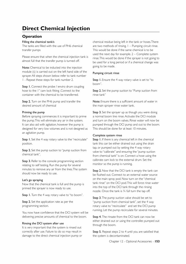
Chapter 12 - Optional Accessories - 153
Direct Chemical Injection OperationFilling the chemical tank/s The tanks are filled with the use of PH6 chemical transfer pumps
Please ensure that when the chemical injection tank is almost full that the transfer pump is turned off.
Note: Chemical to be inducted into the injection module (s) is carried out on the left hand side of the sprayer. All steps shown below refer to tank number 1 - Repeat these steps for tank number 2.
Step 1. Connect the probe / enviro drum coupling hose to the 1” cam lock fitting .Connect to the container with the chemical to be transferred.
Step 2. Turn on the PH6 pump and transfer the desired amount of chemical
Priming the pump Before spraying commences it is important to prime the pump. This will eliminate any air in the system. It can also aid with agitation, however the pump is designed for very low volumes and is not designed as an agitation pump.
Step 1. Set the 4 way rotary valve to the “recirculate” position.
Step 2. Set the pump suction to “pump suction from chemical tank”.
Step 3. Refer to the console programming section relating to self testing. Run the pump for several minutes to remove any air from the lines. The system should now be ready to use.
Let’s go spraying Now that the chemical tank is full and the pump is primed the sprayer is now ready to use.
Step 1. Turn the 4 way rotary valve to “to boom”.
Step 2. Set the application rate as per the programming section.
You now have confidence that the DCI system will be delivering precise amounts of chemical to the boom.
Rinsing the DCI system after use It is very important that the system is rinsed out correctly after use. Failure to do so may result in damage to the direct chemical injection pump or
chemical residue being left in the tank or hoses. There are two methods of rinsing. 1 – Pumping circuit rinse. This would be done if the same chemical is to be used the next day for example. 2 – Complete system rinse. This would be done if the sprayer is not going to be used for a long period or if a chemical change was going to be made.
Pumping circuit rinse
Step 1. Ensure the 4 way rotary valve is set to “to boom”.
Step 2. Set the pump suction to “Pump suction from rinse tank”
Note: Ensure there is a sufficient amount of water in the main sprayer rinse water tank.
Step 3. Set the sprayer up as though you were doing a normal boom line rinse. Activate the DCI module and turn on the boom valves. Rinse water will now be pumped through the DCI pump and out to the boom. This should be done for at least 10 minutes.
Complete system rinse Step 1. If there is any chemical left in the chemical tank this can be either drained out using the drain tap, or pumped out by setting the 4 way rotary valve to “calibrate” and ensuring the “pump suction from chemical tank” is on. Connect a hose using the calibrate cam lock to the external drum. Set the monitor so the pump is running.
Step 2. Now that the DCI tank is empty the tank can be flushed out. Connect to an external water source on the main spray pod. Now turn on the “chemical tank rinse” on the DCI pod. This will force rinse water into the top of the DCI tank through the rinsing nozzle. Once the tank is ¾ full turn the tap off.
Step 3. The pump suction valve should be set to “pump suction from chemical tank”, set the 4 way rotary valve to “recirculate” and set the DCI pump running. Let the pump recirculate for several minutes.
Step 4. The rinsate from the DCI tank can now be either drained out or using the controller, pumped out through the boom.
Step 5. Repeat steps 2 to 4 until you are satisfied that the system is decontaminated.

154 - Crop Cruiser Evolution Operators Manual - Rev 1.4
If the console detects the presence of a chemical injection pump during initial console programming it will automatically interrupt the programming procedure after the [RATE CAL] value has been entered for the initial product. At this point it will then request values be entered for the injection module: Product type, valve type, meter cal, value cal, rate cal before reverting back to [SPEED SENSOR TYPE] in the initial console programming.
If the console senses it is connected to two injection pumps it will subsequently request the information for the second unit be entered before reverting back to the initial console programming.
If a chemical injection module is connected to the console it will automatically highlight product 2 and display a prompt for “PRODUCT TYPE” to be selected after the [RATE CAL] value has been entered for the initial product (product 1)
CHEMICAL INJECTION PRODUCT TYPE Momentarily depressing the [CE] key repeatedly at this stage toggles the console between “LIQUID and “GRANULAR” control selections.
• Chemical injection pumps require selection of “LIQUID CONTROL” to function correctly
• Ensure “LIQUID CONTROL” is displayed then depress the [ENTER] key to lock it in.
• The console will now prompt for a “VALVE TYPE” value to be selected
CHEMICAL INJECTION VALVE TYPE Momentarily depressing the [CE] key repeatedly at this stage toggles the console through the various valve types
• Injection pumps require selection of “STANDARD VALVE” to function correctly.
• Ensure “STANDARD VALUE” is displayed then depress the [ENTER] key to lock it in
• The console will now prompt for a “METER CAL” value to be entered
CHEMICAL INJECTION METER CAL Raven chemical injection pumps are pre-calibrated. The pump may have a calibration tag attached quoting a value of 110. This is an imperial calibration value and must be ignored. The correct metric value is [372]
To enter this meter calibration figure
• Depress the [ENTER] key to display the “E” enter symbol.
• Key in the correct calibration figure [372]
• Depress the [ENTER] key again to lock it in.
• The console will now prompt for a “VALVE CAL” value to be entered.
NOTE: Once initial console programming is completed it is recommended that this value be checked using the following procedure.
NOTE: 10 decilitres = 1 litre.
• Fill the injection tank with water
• Place the 4-way tap on the outlet side of the pump to recirculate.
• Turn the console [POWER] switch “on”
• Momentarily depress the [PRODUCT SELECT] key repeatedly until the product corresponding to the relevant injection pump unit is highlighted
• Momentarily depress the [PRODUCT ON/OFF] key repeatedly to turn the product on
• Momentarily depress the [AUTO/MANUAL] key repeatedly until AUTO/NOBM is displayed
• Enter a [SELF TEST] value equivalent to the normal operating speed i.e. 16 kph (see “Self-Test section in SCS 4400 programming and operation section for further details)
• Depress the [RATE CAL] key to display the “E” enter symbol
• Key in a value of 10 decilitres (1 Lt)
• Depress [ENTER] again to lock it in
• Disconnect the recirculating hose at the top of the injection tank
• Turn the boom master and all the boom section switches “on”
NOTE: Main sprayer pump does not need to be engaged to perform this test function but all boom sectional switches need to be on to simulate the total width of the boom. With the main pump disengaged
Raven SCS4400 DCI programming

Chapter 12 - Optional Accessories - 155
and the injection pump on by-pass no liquid should exit the nozzles even though the boom valves are on.
• Ensure liquid is flowing from the re-circulation hose to indicate the pump is primed
• Turn off the boom master switch
• Depress the [TOTAL VOLUME] key
• Depress the [ENTER] key to display the “E” enter symbol
• Key in a value of [0] to reset this function
• Depress the [ENTER] key to lock it in
• Place a measuring flask under the end of the re-circulation hose
• Return the boom master switch “on” position
• Run the injection pump until 10 decilitres (1 Lt) [TOTAL VOLUME] is displayed then turn the master switch “off ”
• Inspect the measuring flask and note the volume of water collected
• If the [METER CAL] value is correct a litre of water should be collected in the measuring flask
• If not use the formula below to correct the [METER CAL] value
NEW [METER CAL] VALUE = OLD [METER CAL] VALUE X 10 VOLUME MEASURED IN FLASK
Repeat the above test procedure to confirm the new [METER CAL]
CHEMICAL INJECTION VALVE CAL
Chemical injection pumps use a standard valve cal of [123]
To enter the value calibration figure:
• Depress the [ENTER] key to display the “E” enter symbol
• Key in the appropriate [VALVE CAL] calibration number [123]
• After keying in the appropriate valve calibration figure depress [ENTER] again to lock it in.
• The console will now prompt for a [RATE CAL] value to be entered.
CHEMICAL INJECTION APPLICATION RATE
Raven Chemical Injection Modules operate in decilitres/hectare. 1 decilitre = 100 millilitres thus there are 10 decilitres to a litre
[RATE CAL] is the rate (decilitres/hectare) desired for the particular chemical application
To enter a [RATE CAL]
• Depress the [ENTER] key to display the “E” enter symbol
• Key in the desired application rate (i.e. 10 decilitres/ha)
• Depress [ENTER] again to lock it in
NOTE: At this point if the console detects a second injection pump it will revert back to [PRODUCT TYPE] for the second unit so begin the DCI programming procedure again.
If a second injection pump is not detected the console will revert back to the initial programming phase and prompt for a “SPEED SENSOR TYPE” to be entered. If this is the case revert back to step 8 in the initial console programming instructions
LOW FLOW LIMIT
A Low Flow Limit can be entered for the chemical injection pump independent of the main product (see initial console programming section for details).
To enter a Low Flow Limit value for the chemical injection pump:
• Ensure the correct product is highlighted on the screen. If not depress the [PRODUCT SELECT] key repeatedly until the relevant product is highlighted
• Momentarily depress the [DATA MENU] key to bring up the data submenu at the bottom of the screen. The word “SERIAL” will be highlighted.
• Depress the [DATA MENU] key again to highlight “PRODUCT”
• Depress the [DOWN] key repeatedly to move the
Raven SCS4400 DCI programming - continued
156 - Crop Cruiser Evolution Operators Manual - Rev 1.4
curser adjacent to “LOW LIMIT”
• Depress [ENTER] key to display the “E” (enter symbol)
• Enter the “LOW FLOW LIMIT” value calculated. Remember this figure needs to be entered in decilitres
• Depress the [ENTER] key again to lock it in
• Depress a volume or area key to exit the data sub menu and return to the operational screen.
When a low limit value is entered it is important that the zero speed shut off setting is turned off. The zero speed shut off setting will turn the regulating valve off when low or no speed is registered. With this setting turned on it is not possible to spray from a stationary position. To set the zero speed shut off to “OFF” the following steps must be followed.
To set “Zero Speed Shut-Off” to OFF.
• Ensure the correct product is highlighted on the screen. If not depress the [PRODUCT SELECT] key repeatedly until the relevant product is highlighted
• Momentarily depress the [DATA MENU] key to bring up the data submenu at the bottom of the screen. The word “SERIAL” will be highlighted.
• Depress the [DATA MENU] key until “CONSOLE” is highlighted.
• Depress the [DOWN] key repeatedly to move the curser adjacent to “ZERO SPEED”
• Depress [CE] key to change the display from “ON” to “OFF”.
Depress a volume or area key to exit the data sub menu and return to the operational screen
TO RESET AREA AND VOLUME INFORMATION FOR THE CHEMICAL INJECTION UNITS WHEN STARTING A NEW APPLICATION
The SCS 4400 has the ability to simultaneously store Area and Volume data for a chemical injection unit independently to that being recorded for the main tank
NOTE: Before resetting the Area and Volume
functions for a chemical injection unit record any previous data in the console that maybe applicable for future use.
The Area and Volume functions for the chemical injection units can be reset using the following procedure;
“TANK VOLUME” gives the operator a reference as to the number of decilitres left in the tank as the injected chemical is applied to the field. For this feature to function correctly the estimated volume in the chemical tank must be entered before application period is commenced.
To reset the chemical injection pump tank volume
• Ensure the correct product is highlighted on the screen. If not momentary depress the [PRODUCT SELECT] key repeatedly until the relevant product is highlighted
• Depress the [VOLUME TANK] key
• Depress the [ENTER] key to display the “E” enter symbol
• Enter the volume of chemical actually in the tank at the start of the application period. Remember this needs to be entered in decilitres
• Depress [ENTER] again to lock it in
NOTE: The console will subtract the decilitres used (count down) from this value as the load is applied to the field giving the operator a reference as to the number of decilitres left in the tank
TO ZERO OUT DATA IN AREA AND VOLUME:
To reset an Area or Volume values for a chemical injection pump:
• Ensure the correct product is highlighted on the screen. If not momentarily depress the [PRODUCT SELECT] key repeatedly until the relevant product is highlighted
• Depress the relevant key relating to the value to be reset. For example [TOTAL AREA], [TOTAL VOLUME], [FIELD AREA] or [FIELD VOLUME]
• Depress the [ENTER] key to display the “E” enter symbol
Raven SCS4400 DCI programming - continued

Chapter 12 - Optional Accessories - 157
• Enter a value of “0” to reset the particular function
• Depress [ENTER] key to lock it in
The Area and Volume will now count up from zero as the application is commenced.
[FIELD AREA] and [FIELD VOLUME] are generally use as sub-totals for [TOTAL AREA] and [TOTAL VOLUME].
For example: if applying several tank loads to the one area [FIELD AREA] and [FIELD VOLUME] can be use to record data for the current tank load while the [TOTAL AREA] and [TOTAL VOLUME] can be used to record accumulative data for the whole area. If [TOTAL AREA] and [TOTAL VOLUME] are used to accumulate data do not reset them until starting a new area.
SELF-TEST SIMULATION
The [SELF TEST] feature provides speed simulation for testing an injection unit in the “AUTO” mode whilst stationary.
CAUTION: The boom valves must be open when the injection pumps are switched on otherwise a deadhead situation will occur which may result in a burst delivery line.
Before using the [SELF TEST] feature ensure the individual products are in the “AUTO” mode.
The console automatically defaults all products to the “OFF” mode when the console power switch is turned “on”
To change a product to the “AUTO” mode;
• Ensure the correct product is highlighted on the screen. If not momentary depress the [PRODUCT SELECT] key repeatedly until the relevant product is highlighted
• Momentarily depress the [PRODUCT ON/OFF] key to turn the product “on”. At this point the console should read “AUTO NOBM” (auto no boom).
• If it reads “MAN NOBM” (manual no boom) momentarily depress the [AUTO/MANUAL] key to switch to the product to the auto mode.
The “NOBM” (no boom) component automatically disappears when the console senses the switching “on” of a boom section
The [SELF TEST] function should be used
• To help familiarize the operator with the Raven chemical injection system before spraying in the field is commenced.
• To test the sprayer after a period of non-use to ensure the system is operating correctly before filling the tanks with chemical
• To help familiarize any new operators with the Raven chemical injection system
THE [SELF TEST] FEATURE SHOULD NEVER BE USED WITH CHEMICAL IN THE TANK
DO NOT USE THIS FEATURE WITH THE BOOMS IN THE TRANSPORT POSITION
To simulate a speed
• Depress the [SELF TEST] key momentarily
• Depress [ENTER] key to display the “E” enter symbol
• Key in a desired test speed. Note this feature has a decimal point so a “0” needs to be added when entering a whole figure. For example 1, 6 and 0 for 16 Kph.
• Depress the [ENTER] key again to lock it in.
A desired test speed should now be displayed in the speed window at the lower left corner of the display, spraying can now be simulated by simply turning on the boom switches
The [SELF TEST] feature will automatically clear itself when motion is detected from the speed sensor
NOTE: Some radar and GPS units may sense motion when the sprayer is stationary thus continually clear this function. To counteract this simply unplug the speed sensor at the back of the console whilst using this function
Changing the order in which additional product appear on the console screen
If more than one injection unit is connected to the console the order in which they appear as the 2nd
Raven SCS4400 DCI programming - continued

158 - Crop Cruiser Evolution Operators Manual - Rev 1.4
and 3rd product on the console screen can be change to suit the operator using the following procedure;
NOTE: The console will automatically allocate the carrier product to the 1st position on the screen
• Momentarily depress the [DATA MENU] key to bring up the data submenu at the bottom of the screen. The word “SERIAL” will be highlighted.
• Momentarily depress the [DATA MENU] key repeatedly until “CAN” is highlighted
• Momentarily depress the key repeatedly to move the curser adjacent to the line “PRESS ENTER TO READRESS PROD NODES”
• Depress the [ENTER] key to begin the reboot process
• The console will now display “REBOOT NODES IN SEQNC, PRESS ENTER WHEN DONE”
• Disconnect the logic power to both injection pumps (the logic power is the smaller of the two sets of red and white wires leading to each pump. Disconnect by either uncoupling the plug or pulling out the 5 amp fuse)
• Wait a few seconds then reconnect the injection units in the order you wish them to assume the 2nd and 3rd position on the screen (note: position 1 will always be taken up by the carrier product)
• Depress the [ENTER] key again to resume normal operation
NOTE: If the console displays “check control node 2 or 3” when reconnecting an injection module at any stage;
• Momentarily depress the [DATA MENU] key to bring up the data submenu at the bottom of the screen. The word “SERIAL” will be highlighted.
• Momentarily depress the [DATA MENU] key repeatedly until “CAN” is highlighted.
• Momentarily depress the key repeatedly to move the curser adjacent to the particular product be it either 2 or 3.
• If the communication link is turned “off ” the console will display “PROD CONTROL NODE 2 OR 3 NOT INSTALLED”.
• At this point momentarily depressing the [CE] key will turn the communication link between the console and the injection pump unit either “on”.
• If properly connected and turned “on” a PGM and VER number should be displayed.
• Depress and volume or area key to resume normal operation.
Raven SCS4400 DCI programming - continued
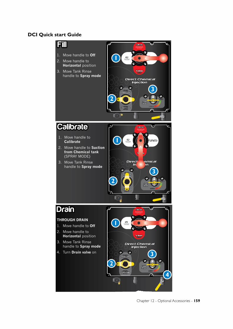
Chapter 12 - Optional Accessories - 159
DCI Quick start Guide
DCI quickstart guideDCI quickstart guide
1. Move handle to Off
2. Move handle to Horizontal position
3. Move Tank Rinse handle to Spray mode
Fill
Single DCI module shown. Up to 2
DCI modules can be added to
your sprayer
Do not run pump in thisposition unless camlock
cap is removed
OffOff RecirculateRecirculate
Calibrate
To BoomTo Boom
Do not run pumpin this position
Spray mode
Direct ChemicalInjection
Direct ChemicalInjection
Rinse Tank
Chem TankSpray mode
Suction from
Suction from
TankRinse
Spray mode
Rinse mode
1. Move handle to Calibrate
2. Move handle to Suction from Chemical tank (SPRAY MODE)
3. Move Tank Rinse handle to Spray mode
Calibrate Do not run pump in thisposition unless camlock
cap is removed
OffOff RecirculateRecirculate
Calibrate
To BoomTo Boom
Do not run pumpin this position
Spray mode
Direct ChemicalInjection
Direct ChemicalInjection
Rinse Tank
Chem TankSpray mode
Suction from
Suction from
TankRinse
Spray mode
Rinse mode
THROUGH CALIBRATION PROBE
1. Move handle to Calibrate
2. Move handle to Suction from Chemical tank (SPRAY MODE)
3. Move Tank Rinse handle to Spray mode
4. Connect hose to Calibration
Do not run pump in thisposition unless camlock
cap is removed
OffOff RecirculateRecirculate
Calibrate
To BoomTo Boom
Do not run pumpin this position
Spray mode
Direct ChemicalInjection
Direct ChemicalInjection
Rinse Tank
Chem TankSpray mode
Suction from
Suction from
TankRinse
Spray mode
Rinse mode
1. Move handle to Recirculate
2. Move handle to Suction from Chemical tank (SPRAY MODE)
3. Move Tank Rinse handle to Spray mode
Recirculating Do not run pump in thisposition unless camlock
cap is removed
OffOff RecirculateRecirculate
Calibrate
To BoomTo Boom
Do not run pumpin this position
Spray mode
Direct ChemicalInjection
Direct ChemicalInjection
Rinse Tank
Chem TankSpray mode
Suction from
Suction from
TankRinse
Spray mode
Rinse mode
PUMPING CIRCUIT
1. Move handle to To Boom (SPRAY MODE)
2. Move handle to Suction from Rinse tank
3. Move Tank Rinse handle to Spray mode
Flush FlushDo not run pump in thisposition unless camlock
cap is removed
OffOff RecirculateRecirculate
Calibrate
To BoomTo Boom
Do not run pumpin this position
Spray mode
Direct ChemicalInjection
Direct ChemicalInjection
Rinse Tank
Chem TankSpray mode
Suction from
Suction from
TankRinse
Spray mode
Rinse mode
THROUGH DRAIN
1. Move handle to Off
2. Move handle to Horizontal position
3. Move Tank Rinse handle to Spray mode
4. Turn Drain valve on
Drain DrainDo not run pump in thisposition unless camlock
cap is removed
OffOff RecirculateRecirculate
Calibrate
To BoomTo Boom
Do not run pumpin this position
Spray mode
Direct ChemicalInjection
Direct ChemicalInjection
Rinse Tank
Chem TankSpray mode
Suction from
Suction from
TankRinse
Spray mode
Rinse mode
1. Move handle to To Boom (SPRAY MODE)
2. Move handle to Suction from Chemical tank (SPRAY MODE)
3. Move Tank Rinse handle to Spray mode
Spray Do not run pump in thisposition unless camlock
cap is removed
OffOff RecirculateRecirculate
Calibrate
To BoomTo Boom
Do not run pumpin this position
Spray mode
Direct ChemicalInjection
Direct ChemicalInjection
Rinse Tank
Chem TankSpray mode
Suction from
Suction from
TankRinse
Spray mode
Rinse mode
COMPLETE SYSTEM RINSE
1. Move handle to Recirculte
2. Move handle to Suction from Rinse tank
3. Move Tank Rinse handle to Rinse mode
Do not run pump in thisposition unless camlock
cap is removed
OffOff RecirculateRecirculate
Calibrate
To BoomTo Boom
Do not run pumpin this position
Spray mode
Direct ChemicalInjection
Direct ChemicalInjection
Rinse Tank
Chem TankSpray mode
Suction from
Suction from
TankRinse
Spray mode
Rinse mode
1
23
1
23
1
23
1
23
1
23
1
23
1
23
1
23
4 4
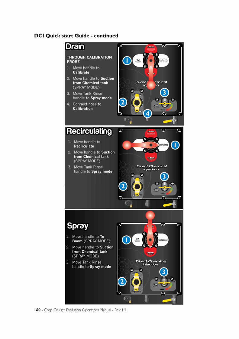
160 - Crop Cruiser Evolution Operators Manual - Rev 1.4
DCI Quick start Guide - continued
DCI quickstart guideDCI quickstart guide
1. Move handle to Off
2. Move handle to Horizontal position
3. Move Tank Rinse handle to Spray mode
Fill
Single DCI module shown. Up to 2
DCI modules can be added to
your sprayer
Do not run pump in thisposition unless camlock
cap is removed
OffOff RecirculateRecirculate
Calibrate
To BoomTo Boom
Do not run pumpin this position
Spray mode
Direct ChemicalInjection
Direct ChemicalInjection
Rinse Tank
Chem TankSpray mode
Suction from
Suction from
TankRinse
Spray mode
Rinse mode
1. Move handle to Calibrate
2. Move handle to Suction from Chemical tank (SPRAY MODE)
3. Move Tank Rinse handle to Spray mode
Calibrate Do not run pump in thisposition unless camlock
cap is removed
OffOff RecirculateRecirculate
Calibrate
To BoomTo Boom
Do not run pumpin this position
Spray mode
Direct ChemicalInjection
Direct ChemicalInjection
Rinse Tank
Chem TankSpray mode
Suction from
Suction from
TankRinse
Spray mode
Rinse mode
THROUGH CALIBRATION PROBE
1. Move handle to Calibrate
2. Move handle to Suction from Chemical tank (SPRAY MODE)
3. Move Tank Rinse handle to Spray mode
4. Connect hose to Calibration
Do not run pump in thisposition unless camlock
cap is removed
OffOff RecirculateRecirculate
Calibrate
To BoomTo Boom
Do not run pumpin this position
Spray mode
Direct ChemicalInjection
Direct ChemicalInjection
Rinse Tank
Chem TankSpray mode
Suction from
Suction from
TankRinse
Spray mode
Rinse mode
1. Move handle to Recirculate
2. Move handle to Suction from Chemical tank (SPRAY MODE)
3. Move Tank Rinse handle to Spray mode
Recirculating Do not run pump in thisposition unless camlock
cap is removed
OffOff RecirculateRecirculate
Calibrate
To BoomTo Boom
Do not run pumpin this position
Spray mode
Direct ChemicalInjection
Direct ChemicalInjection
Rinse Tank
Chem TankSpray mode
Suction from
Suction from
TankRinse
Spray mode
Rinse mode
PUMPING CIRCUIT
1. Move handle to To Boom (SPRAY MODE)
2. Move handle to Suction from Rinse tank
3. Move Tank Rinse handle to Spray mode
Flush FlushDo not run pump in thisposition unless camlock
cap is removed
OffOff RecirculateRecirculate
Calibrate
To BoomTo Boom
Do not run pumpin this position
Spray mode
Direct ChemicalInjection
Direct ChemicalInjection
Rinse Tank
Chem TankSpray mode
Suction from
Suction from
TankRinse
Spray mode
Rinse mode
THROUGH DRAIN
1. Move handle to Off
2. Move handle to Horizontal position
3. Move Tank Rinse handle to Spray mode
4. Turn Drain valve on
Drain DrainDo not run pump in thisposition unless camlock
cap is removed
OffOff RecirculateRecirculate
Calibrate
To BoomTo Boom
Do not run pumpin this position
Spray mode
Direct ChemicalInjection
Direct ChemicalInjection
Rinse Tank
Chem TankSpray mode
Suction from
Suction from
TankRinse
Spray mode
Rinse mode
1. Move handle to To Boom (SPRAY MODE)
2. Move handle to Suction from Chemical tank (SPRAY MODE)
3. Move Tank Rinse handle to Spray mode
Spray Do not run pump in thisposition unless camlock
cap is removed
OffOff RecirculateRecirculate
Calibrate
To BoomTo Boom
Do not run pumpin this position
Spray mode
Direct ChemicalInjection
Direct ChemicalInjection
Rinse Tank
Chem TankSpray mode
Suction from
Suction from
TankRinse
Spray mode
Rinse mode
COMPLETE SYSTEM RINSE
1. Move handle to Recirculte
2. Move handle to Suction from Rinse tank
3. Move Tank Rinse handle to Rinse mode
Do not run pump in thisposition unless camlock
cap is removed
OffOff RecirculateRecirculate
Calibrate
To BoomTo Boom
Do not run pumpin this position
Spray mode
Direct ChemicalInjection
Direct ChemicalInjection
Rinse Tank
Chem TankSpray mode
Suction from
Suction from
TankRinse
Spray mode
Rinse mode
1
23
1
23
1
23
1
23
1
23
1
23
1
23
1
23
4 4
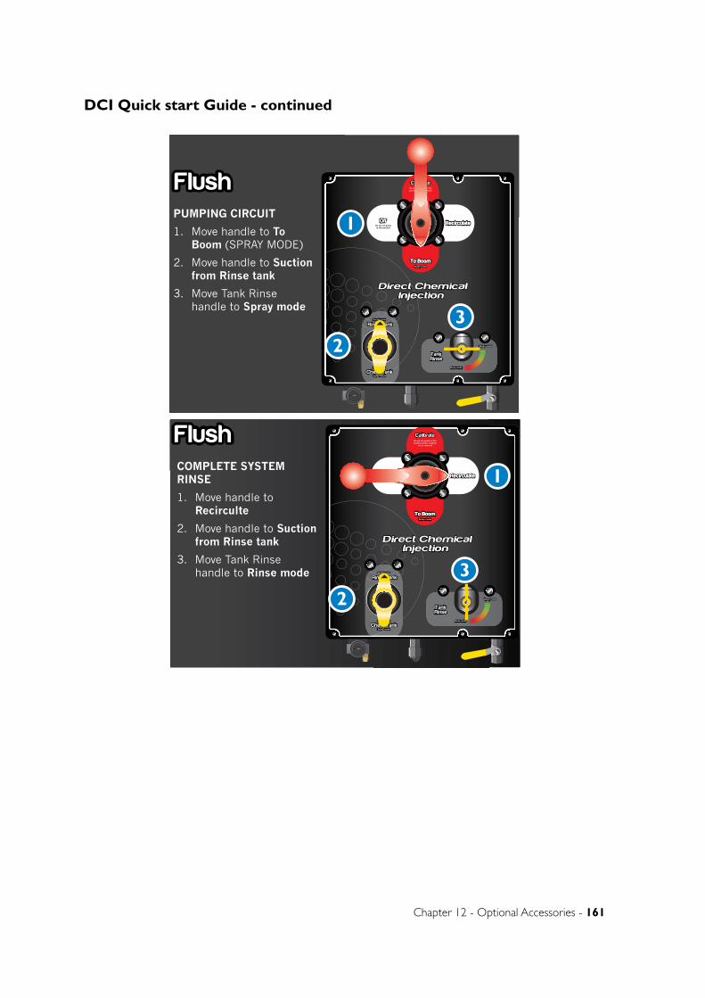
Chapter 12 - Optional Accessories - 161
DCI Quick start Guide - continued
DCI quickstart guideDCI quickstart guide
1. Move handle to Off
2. Move handle to Horizontal position
3. Move Tank Rinse handle to Spray mode
Fill
Single DCI module shown. Up to 2
DCI modules can be added to
your sprayer
Do not run pump in thisposition unless camlock
cap is removed
OffOff RecirculateRecirculate
Calibrate
To BoomTo Boom
Do not run pumpin this position
Spray mode
Direct ChemicalInjection
Direct ChemicalInjection
Rinse Tank
Chem TankSpray mode
Suction from
Suction from
TankRinse
Spray mode
Rinse mode
1. Move handle to Calibrate
2. Move handle to Suction from Chemical tank (SPRAY MODE)
3. Move Tank Rinse handle to Spray mode
Calibrate Do not run pump in thisposition unless camlock
cap is removed
OffOff RecirculateRecirculate
Calibrate
To BoomTo Boom
Do not run pumpin this position
Spray mode
Direct ChemicalInjection
Direct ChemicalInjection
Rinse Tank
Chem TankSpray mode
Suction from
Suction from
TankRinse
Spray mode
Rinse mode
THROUGH CALIBRATION PROBE
1. Move handle to Calibrate
2. Move handle to Suction from Chemical tank (SPRAY MODE)
3. Move Tank Rinse handle to Spray mode
4. Connect hose to Calibration
Do not run pump in thisposition unless camlock
cap is removed
OffOff RecirculateRecirculate
Calibrate
To BoomTo Boom
Do not run pumpin this position
Spray mode
Direct ChemicalInjection
Direct ChemicalInjection
Rinse Tank
Chem TankSpray mode
Suction from
Suction from
TankRinse
Spray mode
Rinse mode
1. Move handle to Recirculate
2. Move handle to Suction from Chemical tank (SPRAY MODE)
3. Move Tank Rinse handle to Spray mode
Recirculating Do not run pump in thisposition unless camlock
cap is removed
OffOff RecirculateRecirculate
Calibrate
To BoomTo Boom
Do not run pumpin this position
Spray mode
Direct ChemicalInjection
Direct ChemicalInjection
Rinse Tank
Chem TankSpray mode
Suction from
Suction from
TankRinse
Spray mode
Rinse mode
PUMPING CIRCUIT
1. Move handle to To Boom (SPRAY MODE)
2. Move handle to Suction from Rinse tank
3. Move Tank Rinse handle to Spray mode
Flush FlushDo not run pump in thisposition unless camlock
cap is removed
OffOff RecirculateRecirculate
Calibrate
To BoomTo Boom
Do not run pumpin this position
Spray mode
Direct ChemicalInjection
Direct ChemicalInjection
Rinse Tank
Chem TankSpray mode
Suction from
Suction from
TankRinse
Spray mode
Rinse mode
THROUGH DRAIN
1. Move handle to Off
2. Move handle to Horizontal position
3. Move Tank Rinse handle to Spray mode
4. Turn Drain valve on
Drain DrainDo not run pump in thisposition unless camlock
cap is removed
OffOff RecirculateRecirculate
Calibrate
To BoomTo Boom
Do not run pumpin this position
Spray mode
Direct ChemicalInjection
Direct ChemicalInjection
Rinse Tank
Chem TankSpray mode
Suction from
Suction from
TankRinse
Spray mode
Rinse mode
1. Move handle to To Boom (SPRAY MODE)
2. Move handle to Suction from Chemical tank (SPRAY MODE)
3. Move Tank Rinse handle to Spray mode
Spray Do not run pump in thisposition unless camlock
cap is removed
OffOff RecirculateRecirculate
Calibrate
To BoomTo Boom
Do not run pumpin this position
Spray mode
Direct ChemicalInjection
Direct ChemicalInjection
Rinse Tank
Chem TankSpray mode
Suction from
Suction from
TankRinse
Spray mode
Rinse mode
COMPLETE SYSTEM RINSE
1. Move handle to Recirculte
2. Move handle to Suction from Rinse tank
3. Move Tank Rinse handle to Rinse mode
Do not run pump in thisposition unless camlock
cap is removed
OffOff RecirculateRecirculate
Calibrate
To BoomTo Boom
Do not run pumpin this position
Spray mode
Direct ChemicalInjection
Direct ChemicalInjection
Rinse Tank
Chem TankSpray mode
Suction from
Suction from
TankRinse
Spray mode
Rinse mode
1
23
1
23
1
23
1
23
1
23
1
23
1
23
1
23
4 4
DCI quickstart guideDCI quickstart guide
1. Move handle to Off
2. Move handle to Horizontal position
3. Move Tank Rinse handle to Spray mode
Fill
Single DCI module shown. Up to 2
DCI modules can be added to
your sprayer
Do not run pump in thisposition unless camlock
cap is removed
OffOff RecirculateRecirculate
Calibrate
To BoomTo Boom
Do not run pumpin this position
Spray mode
Direct ChemicalInjection
Direct ChemicalInjection
Rinse Tank
Chem TankSpray mode
Suction from
Suction from
TankRinse
Spray mode
Rinse mode
1. Move handle to Calibrate
2. Move handle to Suction from Chemical tank (SPRAY MODE)
3. Move Tank Rinse handle to Spray mode
Calibrate Do not run pump in thisposition unless camlock
cap is removed
OffOff RecirculateRecirculate
Calibrate
To BoomTo Boom
Do not run pumpin this position
Spray mode
Direct ChemicalInjection
Direct ChemicalInjection
Rinse Tank
Chem TankSpray mode
Suction from
Suction from
TankRinse
Spray mode
Rinse mode
THROUGH CALIBRATION PROBE
1. Move handle to Calibrate
2. Move handle to Suction from Chemical tank (SPRAY MODE)
3. Move Tank Rinse handle to Spray mode
4. Connect hose to Calibration
Do not run pump in thisposition unless camlock
cap is removed
OffOff RecirculateRecirculate
Calibrate
To BoomTo Boom
Do not run pumpin this position
Spray mode
Direct ChemicalInjection
Direct ChemicalInjection
Rinse Tank
Chem TankSpray mode
Suction from
Suction from
TankRinse
Spray mode
Rinse mode
1. Move handle to Recirculate
2. Move handle to Suction from Chemical tank (SPRAY MODE)
3. Move Tank Rinse handle to Spray mode
Recirculating Do not run pump in thisposition unless camlock
cap is removed
OffOff RecirculateRecirculate
Calibrate
To BoomTo Boom
Do not run pumpin this position
Spray mode
Direct ChemicalInjection
Direct ChemicalInjection
Rinse Tank
Chem TankSpray mode
Suction from
Suction from
TankRinse
Spray mode
Rinse mode
PUMPING CIRCUIT
1. Move handle to To Boom (SPRAY MODE)
2. Move handle to Suction from Rinse tank
3. Move Tank Rinse handle to Spray mode
Flush FlushDo not run pump in thisposition unless camlock
cap is removed
OffOff RecirculateRecirculate
Calibrate
To BoomTo Boom
Do not run pumpin this position
Spray mode
Direct ChemicalInjection
Direct ChemicalInjection
Rinse Tank
Chem TankSpray mode
Suction from
Suction from
TankRinse
Spray mode
Rinse mode
THROUGH DRAIN
1. Move handle to Off
2. Move handle to Horizontal position
3. Move Tank Rinse handle to Spray mode
4. Turn Drain valve on
Drain DrainDo not run pump in thisposition unless camlock
cap is removed
OffOff RecirculateRecirculate
Calibrate
To BoomTo Boom
Do not run pumpin this position
Spray mode
Direct ChemicalInjection
Direct ChemicalInjection
Rinse Tank
Chem TankSpray mode
Suction from
Suction from
TankRinse
Spray mode
Rinse mode
1. Move handle to To Boom (SPRAY MODE)
2. Move handle to Suction from Chemical tank (SPRAY MODE)
3. Move Tank Rinse handle to Spray mode
Spray Do not run pump in thisposition unless camlock
cap is removed
OffOff RecirculateRecirculate
Calibrate
To BoomTo Boom
Do not run pumpin this position
Spray mode
Direct ChemicalInjection
Direct ChemicalInjection
Rinse Tank
Chem TankSpray mode
Suction from
Suction from
TankRinse
Spray mode
Rinse mode
COMPLETE SYSTEM RINSE
1. Move handle to Recirculte
2. Move handle to Suction from Rinse tank
3. Move Tank Rinse handle to Rinse mode
Do not run pump in thisposition unless camlock
cap is removed
OffOff RecirculateRecirculate
Calibrate
To BoomTo Boom
Do not run pumpin this position
Spray mode
Direct ChemicalInjection
Direct ChemicalInjection
Rinse Tank
Chem TankSpray mode
Suction from
Suction from
TankRinse
Spray mode
Rinse mode
1
23
1
23
1
23
1
23
1
23
1
23
1
23
1
23
4 4
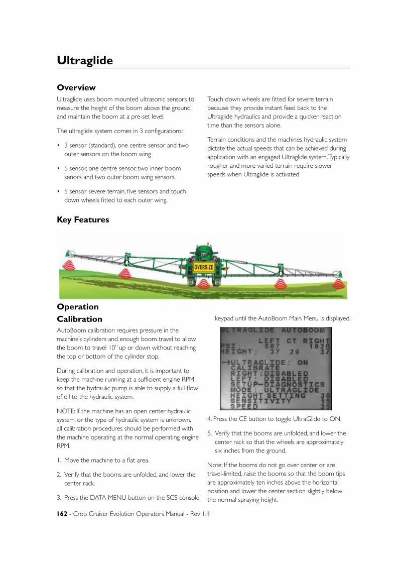
162 - Crop Cruiser Evolution Operators Manual - Rev 1.4
Ultraglide
Overview
Operation
Ultraglide uses boom mounted ultrasonic sensors to measure the height of the boom above the ground and maintain the boom at a pre-set level.
The ultraglide system comes in 3 configurations:
• 3 sensor (standard), one centre sensor and two outer sensors on the boom wing
• 5 sensor, one centre sensor, two inner boom senors and two outer boom wing sensors.
• 5 sensor severe terrain, five sensors and touch down wheels fitted to each outer wing.
Touch down wheels are fitted for severe terrain because they provide instant feed back to the Ultraglide hydraulics and provide a quicker reaction time than the sensors alone.
Terrain conditions and the machines hydraulic system dictate the actual speeds that can be achieved during application with an engaged Ultraglide system. Typically rougher and more varied terrain require slower speeds when Ultraglide is activated.
Key Features
CalibrationAutoBoom calibration requires pressure in the machine’s cylinders and enough boom travel to allow the boom to travel 10” up or down without reaching the top or bottom of the cylinder stop.
During calibration and operation, it is important to keep the machine running at a sufficient engine RPM so that the hydraulic pump is able to supply a full flow of oil to the hydraulic system.
NOTE: If the machine has an open center hydraulic system, or the type of hydraulic system is unknown, all calibration procedures should be performed with the machine operating at the normal operating engine RPM.
1. Move the machine to a flat area.
2. Verify that the booms are unfolded, and lower the center rack.
3. Press the DATA MENU button on the SCS console
keypad until the AutoBoom Main Menu is displayed.
4. Press the CE button to toggle UltraGlide to ON.
5. Verify that the booms are unfolded, and lower the center rack so that the wheels are approximately six inches from the ground.
Note: If the booms do not go over center or are travel-limited, raise the booms so that the boom tips are approximately ten inches above the horizontal position and lower the center section slightly below the normal spraying height.
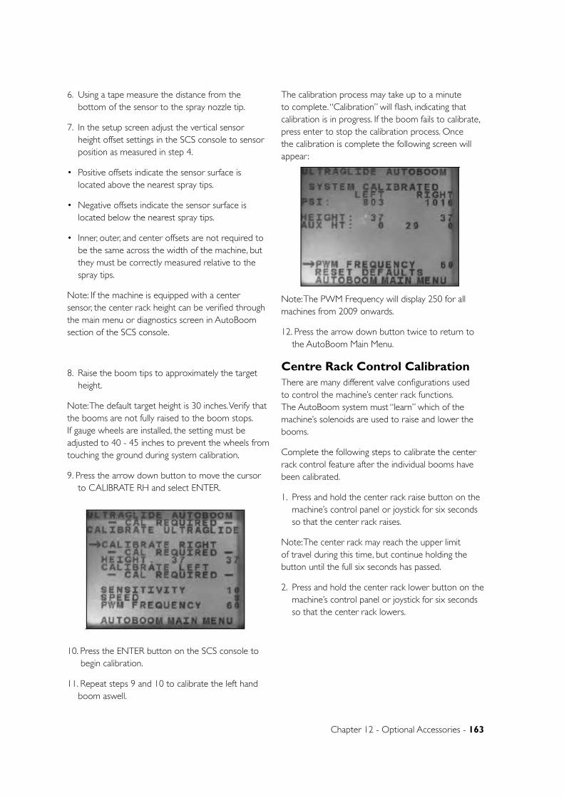
Chapter 12 - Optional Accessories - 163
6. Using a tape measure the distance from the bottom of the sensor to the spray nozzle tip.
7. In the setup screen adjust the vertical sensor height offset settings in the SCS console to sensor position as measured in step 4.
• Positive offsets indicate the sensor surface is located above the nearest spray tips.
• Negative offsets indicate the sensor surface is located below the nearest spray tips.
• Inner, outer, and center offsets are not required to be the same across the width of the machine, but they must be correctly measured relative to the spray tips.
Note: If the machine is equipped with a center sensor, the center rack height can be verified through the main menu or diagnostics screen in AutoBoom section of the SCS console.
8. Raise the boom tips to approximately the target height.
Note: The default target height is 30 inches. Verify that the booms are not fully raised to the boom stops. If gauge wheels are installed, the setting must be adjusted to 40 - 45 inches to prevent the wheels from touching the ground during system calibration.
9. Press the arrow down button to move the cursor to CALIBRATE RH and select ENTER.
10. Press the ENTER button on the SCS console to begin calibration.
11. Repeat steps 9 and 10 to calibrate the left hand boom aswell.
The calibration process may take up to a minute to complete. “Calibration” will flash, indicating that calibration is in progress. If the boom fails to calibrate, press enter to stop the calibration process. Once the calibration is complete the following screen will appear:
Note: The PWM Frequency will display 250 for all machines from 2009 onwards.
12. Press the arrow down button twice to return to the AutoBoom Main Menu.
Centre Rack Control CalibrationThere are many different valve configurations used to control the machine’s center rack functions. The AutoBoom system must “learn” which of the machine’s solenoids are used to raise and lower the booms.
Complete the following steps to calibrate the center rack control feature after the individual booms have been calibrated.
1. Press and hold the center rack raise button on the machine’s control panel or joystick for six seconds so that the center rack raises.
Note: The center rack may reach the upper limit of travel during this time, but continue holding the button until the full six seconds has passed.
2. Press and hold the center rack lower button on the machine’s control panel or joystick for six seconds so that the center rack lowers.
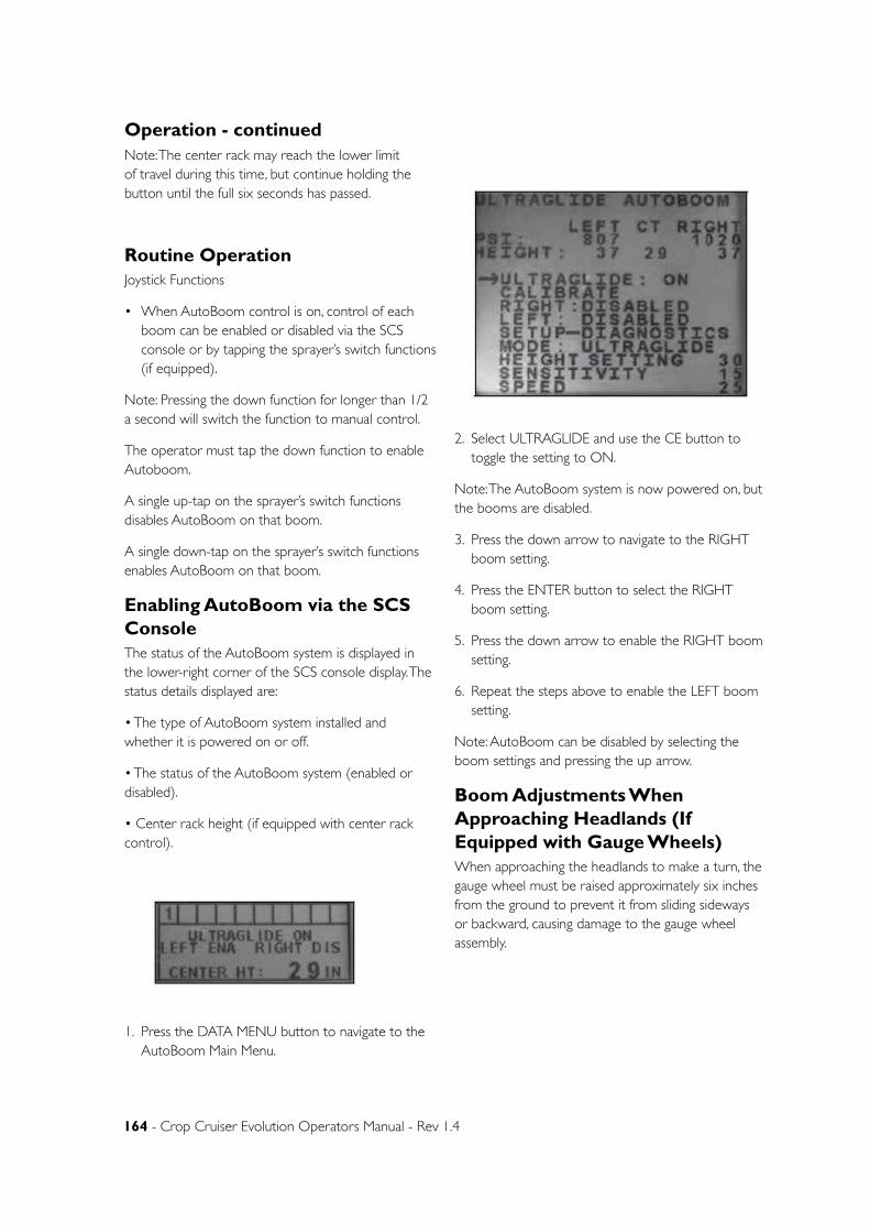
164 - Crop Cruiser Evolution Operators Manual - Rev 1.4
Operation - continuedNote: The center rack may reach the lower limit of travel during this time, but continue holding the button until the full six seconds has passed.
Routine OperationJoystick Functions
• When AutoBoom control is on, control of each boom can be enabled or disabled via the SCS console or by tapping the sprayer’s switch functions (if equipped).
Note: Pressing the down function for longer than 1/2 a second will switch the function to manual control.
The operator must tap the down function to enable Autoboom.
A single up-tap on the sprayer’s switch functions disables AutoBoom on that boom.
A single down-tap on the sprayer’s switch functions enables AutoBoom on that boom.
Enabling AutoBoom via the SCS ConsoleThe status of the AutoBoom system is displayed in the lower-right corner of the SCS console display. The status details displayed are:
• The type of AutoBoom system installed and whether it is powered on or off.
• The status of the AutoBoom system (enabled or disabled).
• Center rack height (if equipped with center rack control).
1. Press the DATA MENU button to navigate to the AutoBoom Main Menu.
2. Select ULTRAGLIDE and use the CE button to toggle the setting to ON.
Note: The AutoBoom system is now powered on, but the booms are disabled.
3. Press the down arrow to navigate to the RIGHT boom setting.
4. Press the ENTER button to select the RIGHT boom setting.
5. Press the down arrow to enable the RIGHT boom setting.
6. Repeat the steps above to enable the LEFT boom setting.
Note: AutoBoom can be disabled by selecting the boom settings and pressing the up arrow.
Boom Adjustments When Approaching Headlands (If Equipped with Gauge Wheels)When approaching the headlands to make a turn, the gauge wheel must be raised approximately six inches from the ground to prevent it from sliding sideways or backward, causing damage to the gauge wheel assembly.
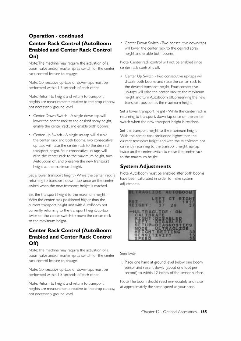
Chapter 12 - Optional Accessories - 165
Center Rack Control (AutoBoom Enabled and Center Rack Control On)Note: The machine may require the activation of a boom valve and/or master spray switch for the center rack control feature to engage.
Note: Consecutive up-taps or down-taps must be performed within 1.5 seconds of each other.
Note: Return to height and return to transport heights are measurements relative to the crop canopy, not necessarily ground level.
• Center Down Switch - A single down-tap will lower the center rack to the desired spray height, enable the center rack, and enable both booms.
• Center Up Switch - A single up-tap will disable the center rack and both booms. Two consecutive up-taps will raise the center rack to the desired transport height. Four consecutive up-taps will raise the center rack to the maximum height, turn AutoBoom off, and preserve the new transport height as the maximum height.
Set a lower transport height - While the center rack is returning to transport, down- tap once on the center switch when the new transport height is reached.
Set the transport height to the maximum height - With the center rack positioned higher than the current transport height and with AutoBoom not currently returning to the transport height, up-tap twice on the center switch to move the center rack to the maximum height.
Center Rack Control (AutoBoom Enabled and Center Rack Control Off)Note: The machine may require the activation of a boom valve and/or master spray switch for the center rack control feature to engage.
Note: Consecutive up-taps or down-taps must be performed within 1.5 seconds of each other.
Note: Return to height and return to transport heights are measurements relative to the crop canopy, not necessarily ground level.
• Center Down Switch - Two consecutive down-taps will lower the center rack to the desired spray height and enable both booms.
Note: Center rack control will not be enabled since center rack control is off.
• Center Up Switch - Two consecutive up-taps will disable both booms and raise the center rack to the desired transport height. Four consecutive up-taps will raise the center rack to the maximum height and turn AutoBoom off, preserving the new transport position as the maximum height.
Set a lower transport height - While the center rack is returning to transport, down-tap once on the center switch when the new transport height is reached.
Set the transport height to the maximum height - With the center rack positioned higher than the current transport height and with the AutoBoom not currently returning to the transport height, up-tap twice on the center switch to move the center rack to the maximum height.
System AdjustmentsNote: AutoBoom must be enabled after both booms have been calibrated in order to make system adjustments.
Sensitivity
1. Place one hand at ground level below one boom sensor and raise it slowly (about one foot per second) to within 12 inches of the sensor surface.
Note: The boom should react immediately and raise at approximately the same speed as your hand.
Operation - continued
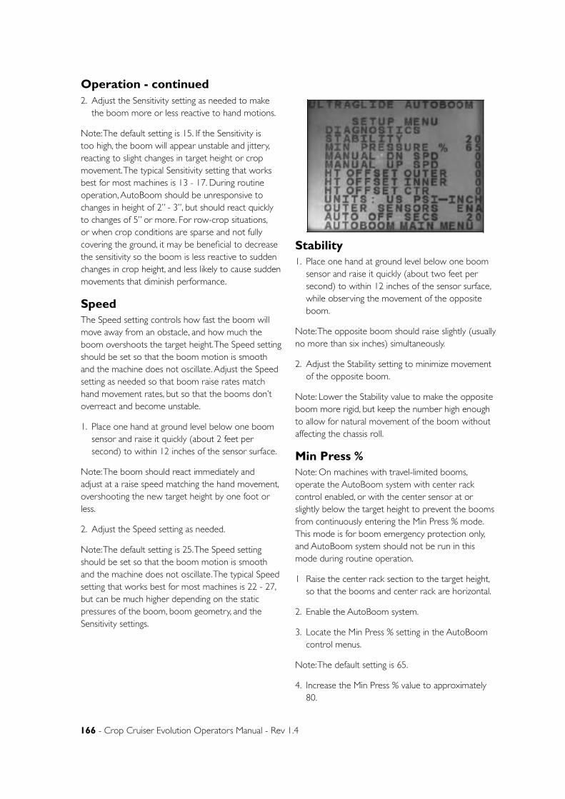
166 - Crop Cruiser Evolution Operators Manual - Rev 1.4
2. Adjust the Sensitivity setting as needed to make the boom more or less reactive to hand motions.
Note: The default setting is 15. If the Sensitivity is too high, the boom will appear unstable and jittery, reacting to slight changes in target height or crop movement. The typical Sensitivity setting that works best for most machines is 13 - 17. During routine operation, AutoBoom should be unresponsive to changes in height of 2” - 3”, but should react quickly to changes of 5” or more. For row-crop situations, or when crop conditions are sparse and not fully covering the ground, it may be beneficial to decrease the sensitivity so the boom is less reactive to sudden changes in crop height, and less likely to cause sudden movements that diminish performance.
SpeedThe Speed setting controls how fast the boom will move away from an obstacle, and how much the boom overshoots the target height. The Speed setting should be set so that the boom motion is smooth and the machine does not oscillate. Adjust the Speed setting as needed so that boom raise rates match hand movement rates, but so that the booms don’t overreact and become unstable.
1. Place one hand at ground level below one boom sensor and raise it quickly (about 2 feet per second) to within 12 inches of the sensor surface.
Note: The boom should react immediately and adjust at a raise speed matching the hand movement, overshooting the new target height by one foot or less.
2. Adjust the Speed setting as needed.
Note: The default setting is 25. The Speed setting should be set so that the boom motion is smooth and the machine does not oscillate. The typical Speed setting that works best for most machines is 22 - 27, but can be much higher depending on the static pressures of the boom, boom geometry, and the Sensitivity settings.
Stability1. Place one hand at ground level below one boom
sensor and raise it quickly (about two feet per second) to within 12 inches of the sensor surface, while observing the movement of the opposite boom.
Note: The opposite boom should raise slightly (usually no more than six inches) simultaneously.
2. Adjust the Stability setting to minimize movement of the opposite boom.
Note: Lower the Stability value to make the opposite boom more rigid, but keep the number high enough to allow for natural movement of the boom without affecting the chassis roll.
Min Press %Note: On machines with travel-limited booms, operate the AutoBoom system with center rack control enabled, or with the center sensor at or slightly below the target height to prevent the booms from continuously entering the Min Press % mode. This mode is for boom emergency protection only, and AutoBoom system should not be run in this mode during routine operation.
1 Raise the center rack section to the target height, so that the booms and center rack are horizontal.
2. Enable the AutoBoom system.
3. Locate the Min Press % setting in the AutoBoom control menus.
Note: The default setting is 65.
4. Increase the Min Press % value to approximately 80.
Operation - continued
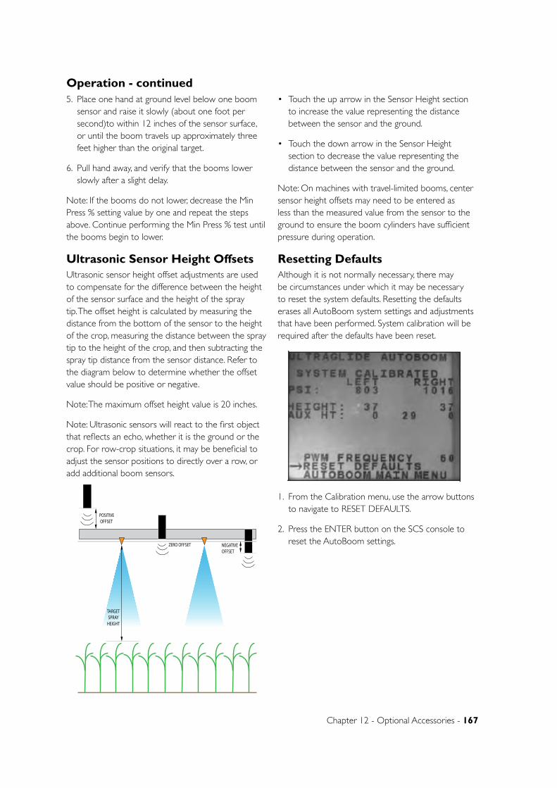
Chapter 12 - Optional Accessories - 167
5. Place one hand at ground level below one boom sensor and raise it slowly (about one foot per second)to within 12 inches of the sensor surface, or until the boom travels up approximately three feet higher than the original target.
6. Pull hand away, and verify that the booms lower slowly after a slight delay.
Note: If the booms do not lower, decrease the Min Press % setting value by one and repeat the steps above. Continue performing the Min Press % test until the booms begin to lower.
Ultrasonic Sensor Height OffsetsUltrasonic sensor height offset adjustments are used to compensate for the difference between the height of the sensor surface and the height of the spray tip. The offset height is calculated by measuring the distance from the bottom of the sensor to the height of the crop, measuring the distance between the spray tip to the height of the crop, and then subtracting the spray tip distance from the sensor distance. Refer to the diagram below to determine whether the offset value should be positive or negative.
Note: The maximum offset height value is 20 inches.
Note: Ultrasonic sensors will react to the first object that reflects an echo, whether it is the ground or the crop. For row-crop situations, it may be beneficial to adjust the sensor positions to directly over a row, or add additional boom sensors.
• Touch the up arrow in the Sensor Height section to increase the value representing the distance between the sensor and the ground.
• Touch the down arrow in the Sensor Height section to decrease the value representing the distance between the sensor and the ground.
Note: On machines with travel-limited booms, center sensor height offsets may need to be entered as less than the measured value from the sensor to the ground to ensure the boom cylinders have sufficient pressure during operation.
Resetting DefaultsAlthough it is not normally necessary, there may be circumstances under which it may be necessary to reset the system defaults. Resetting the defaults erases all AutoBoom system settings and adjustments that have been performed. System calibration will be required after the defaults have been reset.
1. From the Calibration menu, use the arrow buttons to navigate to RESET DEFAULTS.
2. Press the ENTER button on the SCS console to reset the AutoBoom settings.
Operation - continued
ZERO OFFSET
POSITIVE OFFSET
NEGATIVE OFFSET
TARGETSPRAY
HEIGHT
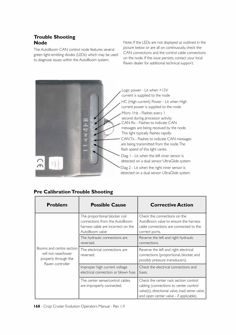
168 - Crop Cruiser Evolution Operators Manual - Rev 1.4
Trouble ShootingNodeThe AutoBoom CAN control node features several green light-emitting diodes (LEDs) which may be used to diagnose issues within the AutoBoom system.
Note: If the LEDs are not displayed as outlined in the picture below or are all on continuously, check the CAN connections and the control cable connections on the node. If the issue persists, contact your local Raven dealer for additional technical support.
Pre Calibration Trouble Shooting
Problem Possible Cause Corrective Action
Booms and centre section will not raise/lower
properly through the Raven controller
The proportional blocker coil connections from the AutoBoom harness cable are incorrect on the AutoBoom valve
Check the connections on the AutoBoom valve to ensure the harness cable connections are connected to the correct ports.
The hydraulic connections are reversed.
Reverse the left and right hydraulic connections.
The electrical connections are reversed.
Reverse the left and right electrical connections (proportional, blocker, and possibly pressure transducers).
Improper high current voltage electrical connection or blown fuse.
Check the electrical connections and fuses.
The center sense/control cables are improperly connected.
Check the center rack section control cabling (connections to center control valve(s), directional valve, load sense valve, and open center valve - if applicable).
Logic power - Lit when +12V current is supplied to the node
HC (High current) Power - Lit when High current power is supplied to the node
Micro 1Hz - Flashes every 1 second during processor activityCAN Rx - Flashes to indicate CAN messages are being received by the node. This light typically flashes rapidly.
CAN Tx - Flashes to indicate CAN messages are being transmitted from the node. The flash speed of this light varies.
Diag 1 - Lit when the left inner sensor is detected on a dual sensor UltraGlide system
Diag 2 - Lit when the right inner sensor is detected on a dual sensor UltraGlide system

Chapter 12 - Optional Accessories - 169
Problem Possible Cause Corrective Action
Pressures/heights are not being displayed in the correct units of measure.
The units of measure are set incorrectly in the AutoBoom system.
Change the units of measure in the controller being used in the AutoBoom system.
Pressures for the left and right boom are not displayed on the correct side.
The left and right pressure transducer connections are reversed.
Reverse the left and right transducer connections.
The left and right hose connections are reversed.
Reverse the left and right cylinder connections on the AutoBoom valve.
Ultrasonic sensor heights are displaying incorrect locations.
The left and right sensor connections are reversed.
Reverse the left and right outer sensor connections on the AutoBoom harness cable.
The outer sensors are connected to the inner sensor connectors.
Disconnect the sensors from the AutoBoom harness cable and connect the outer sensor connectors to the sensors.
Left, right, and center raise/lower functions are not sensed correctly when the machine’s functions are used.
The boom sense cables/connections are connected to the incorrect machine coils.
Check the connections to the machine’s coils and trace the wiring to ensure the connections are made to the correct cylinders.
Center section will not raise/lower manually with the machine’s functions.
The center rack boom sense cables are not connected to the correct center sense/control function.
Check the connections to the machine’s coils and trace the wiring to ensure the connections are made to the correct coils.
The AutoBoom node hardware does not support the center rack control function.
The node must be revision B or higher to support the center rack control function. Contact your Raven dealer.
Fold/unfold status does not change when booms are folded/unfolded (if equipped).
The fold/unfold sensors are not connected.
Check the electrical connections to the fold/unfold sensors.
Pre Calibration Trouble Shooting - continued
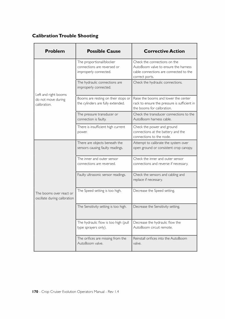
170 - Crop Cruiser Evolution Operators Manual - Rev 1.4
Calibration Trouble Shooting
Problem Possible Cause Corrective Action
Left and right booms do not move during calibration.
The proportional/blocker connections are reversed or improperly connected.
Check the connections on the AutoBoom valve to ensure the harness cable connections are connected to the correct ports.
The hydraulic connections are improperly connected.
Check the hydraulic connections.
Booms are resting on their stops or the cylinders are fully extended.
Raise the booms and lower the center rack to ensure the pressure is sufficient in the booms for calibration.
The pressure transducer or connection is faulty.
Check the transducer connections to the AutoBoom harness cable.
There is insufficient high current power.
Check the power and ground connections at the battery and the connections to the node.
The booms over react or oscillate during calibration
There are objects beneath the sensors causing faulty readings.
Attempt to calibrate the system over open ground or consistent crop canopy.
The inner and outer sensor connections are reversed.
Check the inner and outer sensor connections and reverse if necessary.
Faulty ultrasonic sensor readings. Check the sensors and cabling and replace if necessary.
The Speed setting is too high. Decrease the Speed setting.
The Sensitivity setting is too high. Decrease the Sensitivity setting.
The hydraulic flow is too high (pull type sprayers only).
Decrease the hydraulic flow the AutoBoom circuit remote.
The orifices are missing from the AutoBoom valve.
Reinstall orifices into the AutoBoom valve.
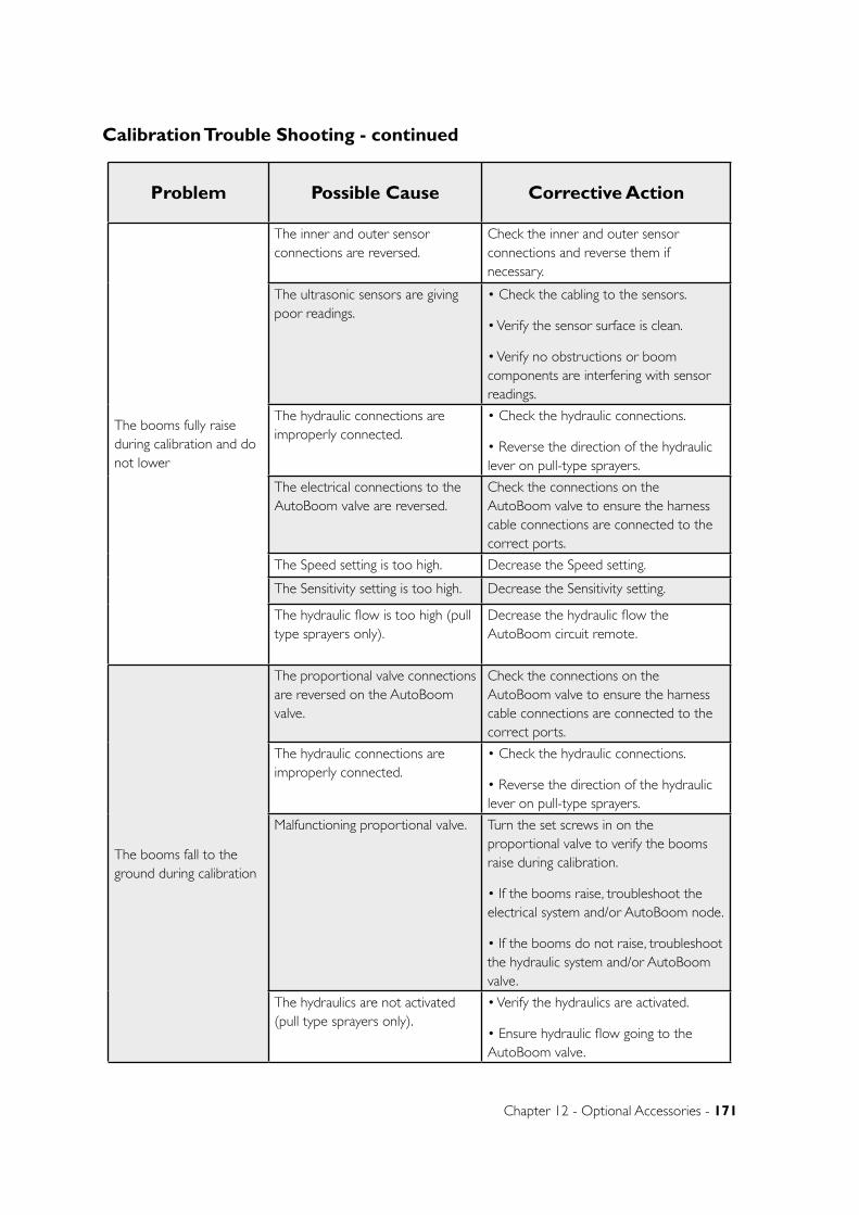
Chapter 12 - Optional Accessories - 171
Problem Possible Cause Corrective Action
The booms fully raise during calibration and do not lower
The inner and outer sensor connections are reversed.
Check the inner and outer sensor connections and reverse them if necessary.
The ultrasonic sensors are giving poor readings.
• Check the cabling to the sensors.
• Verify the sensor surface is clean.
• Verify no obstructions or boom components are interfering with sensor readings.
The hydraulic connections are improperly connected.
• Check the hydraulic connections.
• Reverse the direction of the hydraulic lever on pull-type sprayers.
The electrical connections to the AutoBoom valve are reversed.
Check the connections on the AutoBoom valve to ensure the harness cable connections are connected to the correct ports.
The Speed setting is too high. Decrease the Speed setting.
The Sensitivity setting is too high. Decrease the Sensitivity setting.
The hydraulic flow is too high (pull type sprayers only).
Decrease the hydraulic flow the AutoBoom circuit remote.
The booms fall to the ground during calibration
The proportional valve connections are reversed on the AutoBoom valve.
Check the connections on the AutoBoom valve to ensure the harness cable connections are connected to the correct ports.
The hydraulic connections are improperly connected.
• Check the hydraulic connections.
• Reverse the direction of the hydraulic lever on pull-type sprayers.
Malfunctioning proportional valve. Turn the set screws in on the proportional valve to verify the booms raise during calibration.
• If the booms raise, troubleshoot the electrical system and/or AutoBoom node.
• If the booms do not raise, troubleshoot the hydraulic system and/or AutoBoom valve.
The hydraulics are not activated (pull type sprayers only).
• Verify the hydraulics are activated.
• Ensure hydraulic flow going to the AutoBoom valve.
Calibration Trouble Shooting - continued
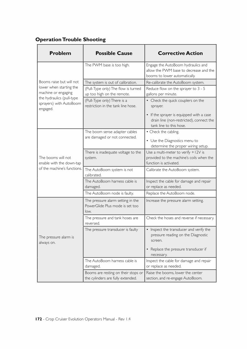
172 - Crop Cruiser Evolution Operators Manual - Rev 1.4
Problem Possible Cause Corrective Action
Booms raise but will not lower when starting the machine or engaging the hydraulics (pull-type sprayers) with AutoBoom engaged.
The PWM base is too high. Engage the AutoBoom hydraulics and allow the PWM base to decrease and the booms to lower automatically.
The system is out of calibration. Re-calibrate the AutoBoom system.
(Pull-Type only) The flow is turned up too high on the remote.
Reduce flow on the sprayer to 3 - 5 gallons per minute.
(Pull-Type only) There is a restriction in the tank line hose.
• Check the quick couplers on the sprayer.
• If the sprayer is equipped with a case drain line (non-restricted), connect the tank line to this hose.
The booms will not enable with the down-tap of the machine’s functions.
The boom sense adapter cables are damaged or not connected.
• Check the cabling.
• Use the Diagnostics menu to determine the proper wiring setup.
There is inadequate voltage to the system.
Use a multi-meter to verify +12V is provided to the machine’s coils when the function is activated.
The AutoBoom system is not calibrated.
Calibrate the AutoBoom system.
The AutoBoom harness cable is damaged.
Inspect the cable for damage and repair or replace as needed.
The AutoBoom node is faulty. Replace the AutoBoom node.
The pressure alarm is always on.
The pressure alarm setting in the PowerGlide Plus mode is set too low.
Increase the pressure alarm setting.
The pressure and tank hoses are reversed.
Check the hoses and reverse if necessary.
The pressure transducer is faulty • Inspect the transducer and verify the pressure reading on the Diagnostic screen.
• Replace the pressure transducer if necessary.
The AutoBoom harness cable is damaged.
Inspect the cable for damage and repair or replace as needed.
Booms are resting on their stops or the cylinders are fully extended.
Raise the booms, lower the center section, and re-engage AutoBoom.
Operation Trouble Shooting
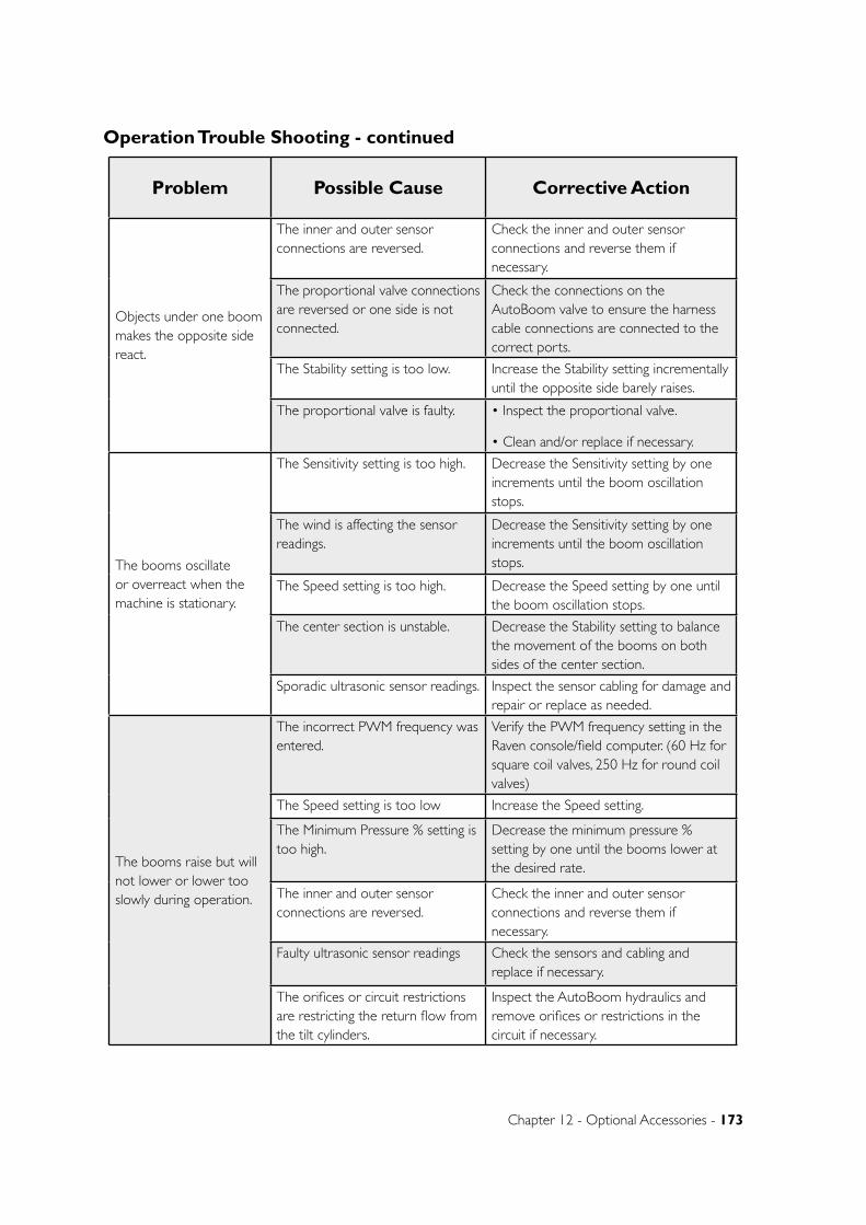
Chapter 12 - Optional Accessories - 173
Problem Possible Cause Corrective Action
Objects under one boom makes the opposite side react.
The inner and outer sensor connections are reversed.
Check the inner and outer sensor connections and reverse them if necessary.
The proportional valve connections are reversed or one side is not connected.
Check the connections on the AutoBoom valve to ensure the harness cable connections are connected to the correct ports.
The Stability setting is too low. Increase the Stability setting incrementally until the opposite side barely raises.
The proportional valve is faulty. • Inspect the proportional valve.
• Clean and/or replace if necessary.
The booms oscillate or overreact when the machine is stationary.
The Sensitivity setting is too high. Decrease the Sensitivity setting by one increments until the boom oscillation stops.
The wind is affecting the sensor readings.
Decrease the Sensitivity setting by one increments until the boom oscillation stops.
The Speed setting is too high. Decrease the Speed setting by one until the boom oscillation stops.
The center section is unstable. Decrease the Stability setting to balance the movement of the booms on both sides of the center section.
Sporadic ultrasonic sensor readings. Inspect the sensor cabling for damage and repair or replace as needed.
The booms raise but will not lower or lower too slowly during operation.
The incorrect PWM frequency was entered.
Verify the PWM frequency setting in the Raven console/field computer. (60 Hz for square coil valves, 250 Hz for round coil valves)
The Speed setting is too low Increase the Speed setting.
The Minimum Pressure % setting is too high.
Decrease the minimum pressure % setting by one until the booms lower at the desired rate.
The inner and outer sensor connections are reversed.
Check the inner and outer sensor connections and reverse them if necessary.
Faulty ultrasonic sensor readings Check the sensors and cabling and replace if necessary.
The orifices or circuit restrictions are restricting the return flow from the tilt cylinders.
Inspect the AutoBoom hydraulics and remove orifices or restrictions in the circuit if necessary.
Operation Trouble Shooting - continued
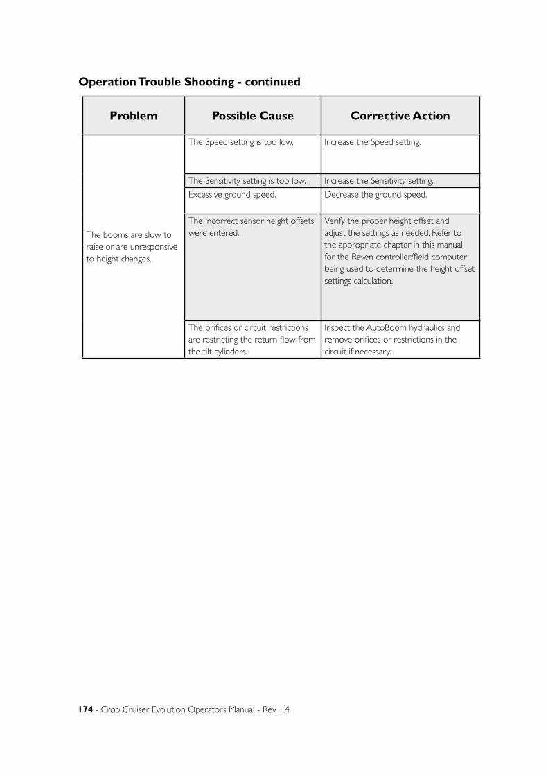
174 - Crop Cruiser Evolution Operators Manual - Rev 1.4
Operation Trouble Shooting - continued
Problem Possible Cause Corrective Action
The booms are slow to raise or are unresponsive to height changes.
The Speed setting is too low. Increase the Speed setting.
The Sensitivity setting is too low. Increase the Sensitivity setting.
Excessive ground speed. Decrease the ground speed.
The incorrect sensor height offsets were entered.
Verify the proper height offset and adjust the settings as needed. Refer to the appropriate chapter in this manual for the Raven controller/field computer being used to determine the height offset settings calculation.
The orifices or circuit restrictions are restricting the return flow from the tilt cylinders.
Inspect the AutoBoom hydraulics and remove orifices or restrictions in the circuit if necessary.
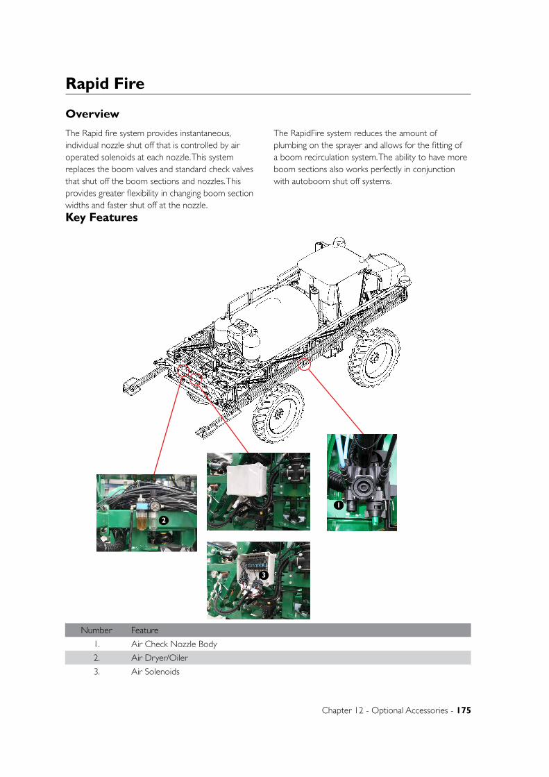
Chapter 12 - Optional Accessories - 175
D
E
F
C
1 2 3 4
B
A
321 5
C
D
4 6 7 8
A
B
A3
SHEET 1 OF 1SCALE:1:25
DWG NO.
TITLE:
GOLDACRES
DO NOT SCALE DRAWING
MATERIAL:
DATE CREATED:
DRAWN:
1-3 MORANG CRMITCHELL PARK 3352PH: 03 53426399 FAX: 03 53426308
UNLESS OTHERWISE SPECIFIEDDIMENSIONS ARE IN MILLIMETERSDEBUR ALL EDGES Complete Assembly 2WD - SP 2011 - Parts ManualName
3/06/2011Matt
REV NO CHANGE DATE ECN NO.
DATE EDITED:
17/03/2011
Rapid Fire
Key Features
Overview
Number Feature
1. Air Check Nozzle Body
2. Air Dryer/Oiler
3. Air Solenoids
The Rapid fire system provides instantaneous, individual nozzle shut off that is controlled by air operated solenoids at each nozzle. This system replaces the boom valves and standard check valves that shut off the boom sections and nozzles. This provides greater flexibility in changing boom section widths and faster shut off at the nozzle.
The RapidFire system reduces the amount of plumbing on the sprayer and allows for the fitting of a boom recirculation system. The ability to have more boom sections also works perfectly in conjunction with autoboom shut off systems.
3
1
2
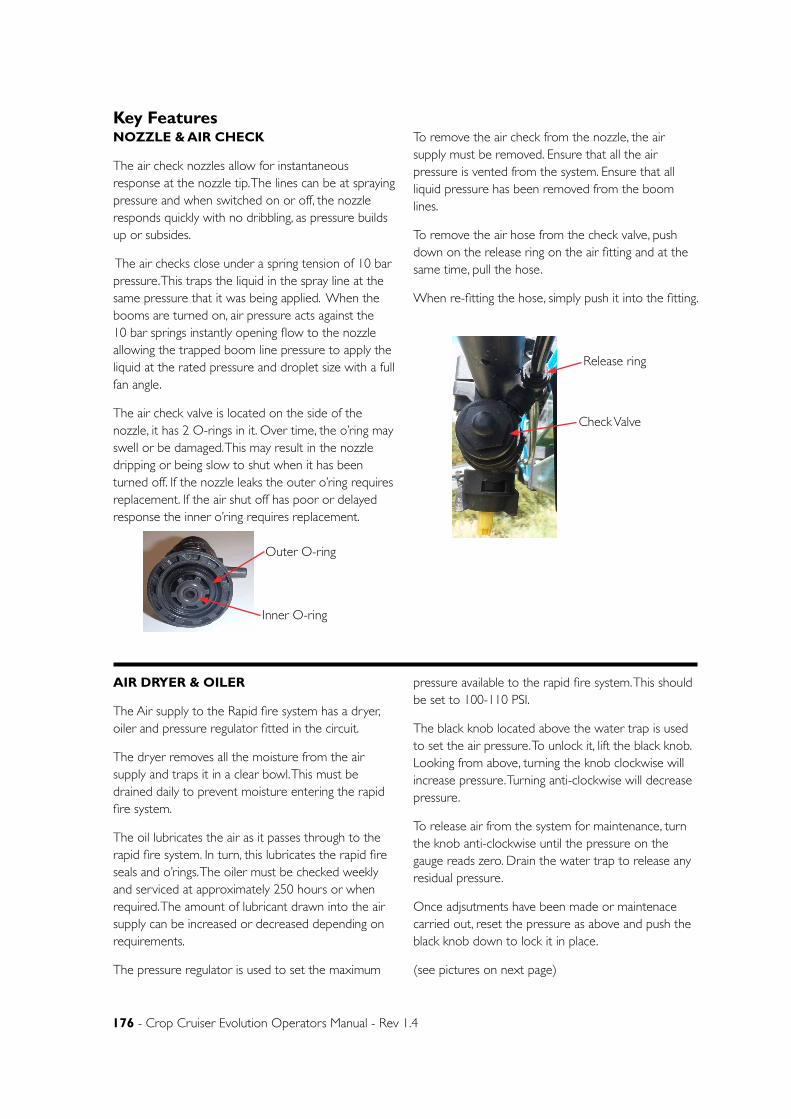
176 - Crop Cruiser Evolution Operators Manual - Rev 1.4
Key FeaturesNOZZLE & AIR CHECK
The air check nozzles allow for instantaneous response at the nozzle tip. The lines can be at spraying pressure and when switched on or off, the nozzle responds quickly with no dribbling, as pressure builds up or subsides.
The air checks close under a spring tension of 10 bar pressure. This traps the liquid in the spray line at the same pressure that it was being applied. When the booms are turned on, air pressure acts against the 10 bar springs instantly opening flow to the nozzle allowing the trapped boom line pressure to apply the liquid at the rated pressure and droplet size with a full fan angle.
The air check valve is located on the side of the nozzle, it has 2 O-rings in it. Over time, the o’ring may swell or be damaged. This may result in the nozzle dripping or being slow to shut when it has been turned off. If the nozzle leaks the outer o’ring requires replacement. If the air shut off has poor or delayed response the inner o’ring requires replacement.
To remove the air check from the nozzle, the air supply must be removed. Ensure that all the air pressure is vented from the system. Ensure that all liquid pressure has been removed from the boom lines.
To remove the air hose from the check valve, push down on the release ring on the air fitting and at the same time, pull the hose.
When re-fitting the hose, simply push it into the fitting.
AIR DRYER & OILER
The Air supply to the Rapid fire system has a dryer, oiler and pressure regulator fitted in the circuit.
The dryer removes all the moisture from the air supply and traps it in a clear bowl. This must be drained daily to prevent moisture entering the rapid fire system.
The oil lubricates the air as it passes through to the rapid fire system. In turn, this lubricates the rapid fire seals and o’rings. The oiler must be checked weekly and serviced at approximately 250 hours or when required. The amount of lubricant drawn into the air supply can be increased or decreased depending on requirements.
The pressure regulator is used to set the maximum
pressure available to the rapid fire system. This should be set to 100-110 PSI.
The black knob located above the water trap is used to set the air pressure. To unlock it, lift the black knob. Looking from above, turning the knob clockwise will increase pressure. Turning anti-clockwise will decrease pressure.
To release air from the system for maintenance, turn the knob anti-clockwise until the pressure on the gauge reads zero. Drain the water trap to release any residual pressure.
Once adjsutments have been made or maintenace carried out, reset the pressure as above and push the black knob down to lock it in place.
(see pictures on next page)
Inner O-ring
Outer O-ring
Release ring
Check Valve
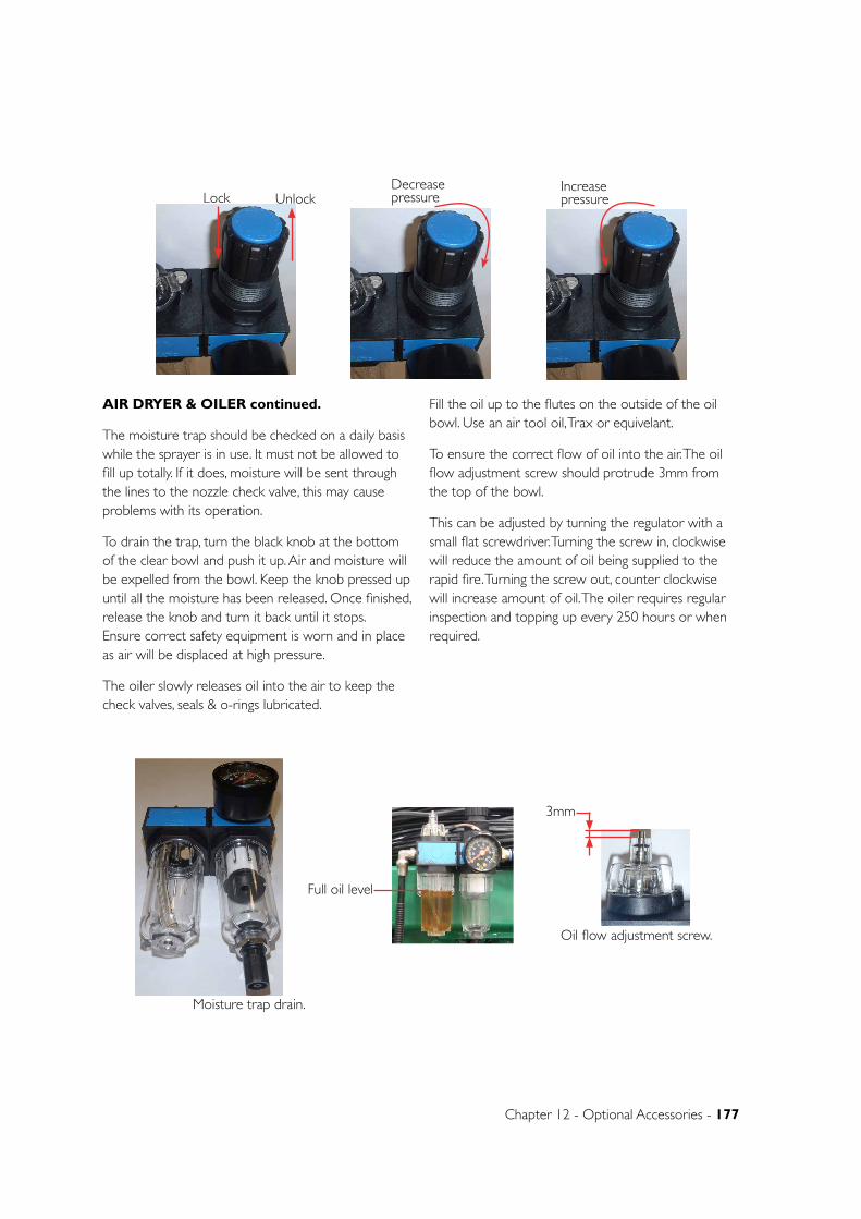
Chapter 12 - Optional Accessories - 177
3mm
AIR DRYER & OILER continued.
The moisture trap should be checked on a daily basis while the sprayer is in use. It must not be allowed to fill up totally. If it does, moisture will be sent through the lines to the nozzle check valve, this may cause problems with its operation.
To drain the trap, turn the black knob at the bottom of the clear bowl and push it up. Air and moisture will be expelled from the bowl. Keep the knob pressed up until all the moisture has been released. Once finished, release the knob and turn it back until it stops. Ensure correct safety equipment is worn and in place as air will be displaced at high pressure.
The oiler slowly releases oil into the air to keep the check valves, seals & o-rings lubricated.
Fill the oil up to the flutes on the outside of the oil bowl. Use an air tool oil, Trax or equivelant.
To ensure the correct flow of oil into the air. The oil flow adjustment screw should protrude 3mm from the top of the bowl.
This can be adjusted by turning the regulator with a small flat screwdriver. Turning the screw in, clockwise will reduce the amount of oil being supplied to the rapid fire. Turning the screw out, counter clockwise will increase amount of oil. The oiler requires regular inspection and topping up every 250 hours or when required.
Full oil level
Oil flow adjustment screw.
Moisture trap drain.
Lock UnlockDecrease pressure
Increase pressure
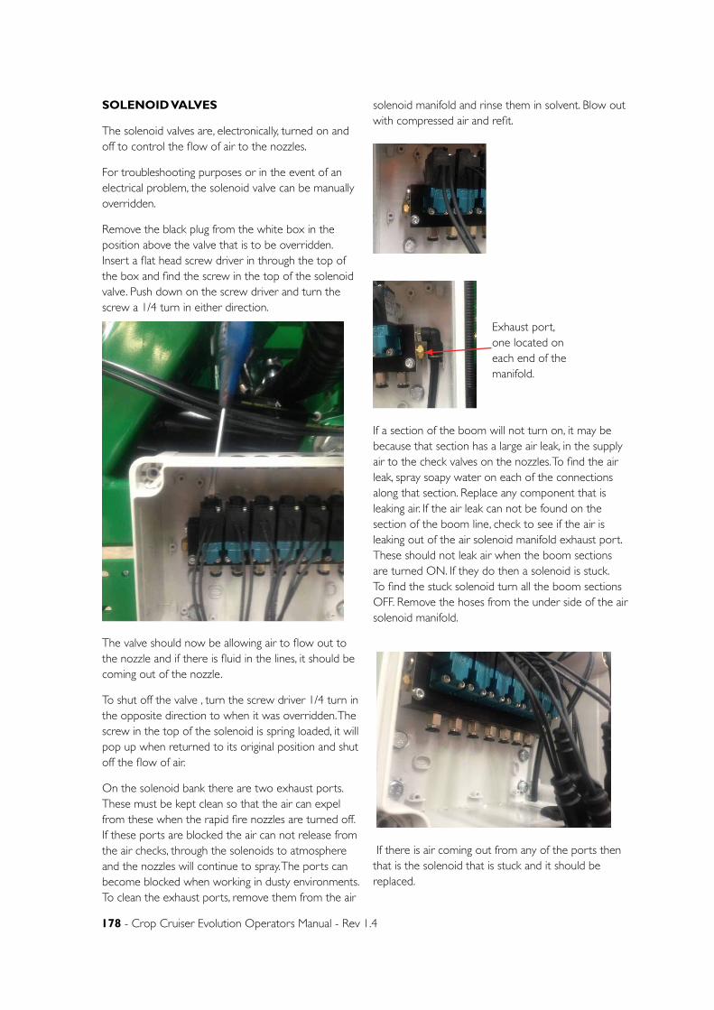
178 - Crop Cruiser Evolution Operators Manual - Rev 1.4
SOLENOID VALVES
The solenoid valves are, electronically, turned on and off to control the flow of air to the nozzles.
For troubleshooting purposes or in the event of an electrical problem, the solenoid valve can be manually overridden.
Remove the black plug from the white box in the position above the valve that is to be overridden. Insert a flat head screw driver in through the top of the box and find the screw in the top of the solenoid valve. Push down on the screw driver and turn the screw a 1/4 turn in either direction.
The valve should now be allowing air to flow out to the nozzle and if there is fluid in the lines, it should be coming out of the nozzle.
To shut off the valve , turn the screw driver 1/4 turn in the opposite direction to when it was overridden. The screw in the top of the solenoid is spring loaded, it will pop up when returned to its original position and shut off the flow of air.
On the solenoid bank there are two exhaust ports. These must be kept clean so that the air can expel from these when the rapid fire nozzles are turned off. If these ports are blocked the air can not release from the air checks, through the solenoids to atmosphere and the nozzles will continue to spray. The ports can become blocked when working in dusty environments. To clean the exhaust ports, remove them from the air
solenoid manifold and rinse them in solvent. Blow out with compressed air and refit.
If a section of the boom will not turn on, it may be because that section has a large air leak, in the supply air to the check valves on the nozzles. To find the air leak, spray soapy water on each of the connections along that section. Replace any component that is leaking air. If the air leak can not be found on the section of the boom line, check to see if the air is leaking out of the air solenoid manifold exhaust port. These should not leak air when the boom sections are turned ON. If they do then a solenoid is stuck. To find the stuck solenoid turn all the boom sections OFF. Remove the hoses from the under side of the air solenoid manifold.
If there is air coming out from any of the ports then that is the solenoid that is stuck and it should be replaced.
Exhaust port, one located on each end of the manifold.
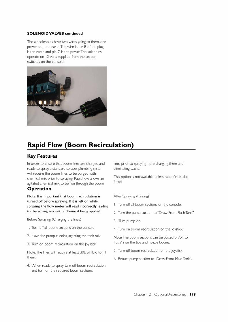
Chapter 12 - Optional Accessories - 179
SOLENOID VALVES continued
The air solenoids have two wires going to them, one power and one earth. The wire in pin B of the plug is the earth and pin C is the power. The solenoids operate on 12 volts supplied from the section switches on the console
AB
CRapid Flow (Boom Recirculation)
Key Features
Operation
Note: It is important that boom recirculation is turned off before spraying. If it is left on while spraying, the flow meter will read incorrectly leading to the wrong amount of chemical being applied.
Before Spraying (Charging the lines)
1. Turn off all boom sections on the console
2. Have the pump running agitating the tank mix.
3. Turn on boom recirculation on the Joystick
Note: The lines will require at least 30L of fluid to fill them.
4. When ready to spray turn off boom recirculation and turn on the required boom sections.
After Spraying (Rinsing)
1. Turn off all boom sections on the console.
2. Turn the pump suction to “Draw From Flush Tank”
3. Turn pump on.
4. Turn on boom recirculation on the joystick.
Note: The boom sections can be pulsed on/off to flush/rinse the tips and nozzle bodies.
5. Turn off boom recirculation on the joystick
6. Return pump suction to “Draw From Main Tank”.
In order to ensure that boom lines are charged and ready to spray, a standard sprayer plumbing system will require the boom lines to be purged with chemical mix prior to spraying. Rapidflow allows an agitated chemical mix to be run through the boom
lines prior to spraying - pre-charging them and eliminating waste.
This option is not available unless rapid fire is also fitted.
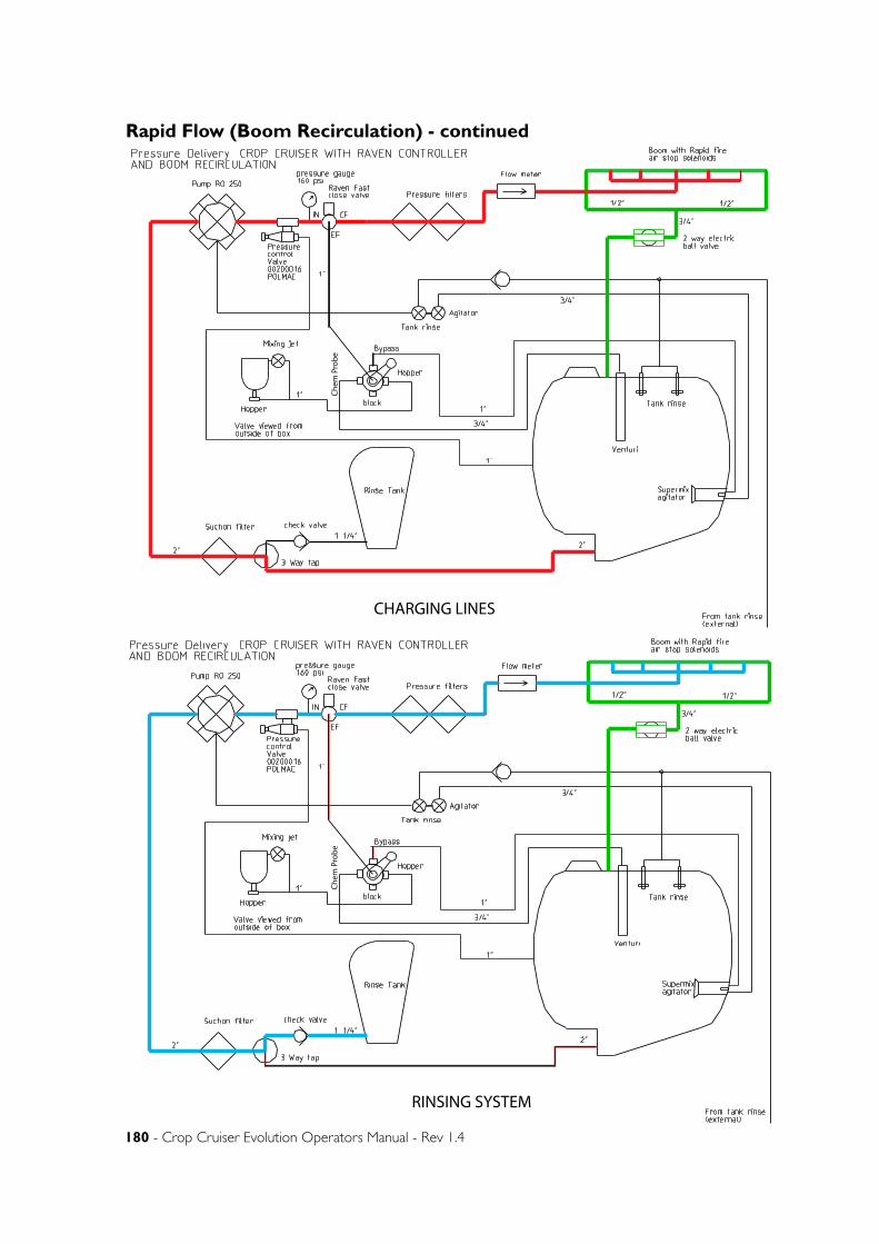
180 - Crop Cruiser Evolution Operators Manual - Rev 1.4
Rapid Flow (Boom Recirculation) - continued
Chem
Pro
be
CHARGING LINES
Chem
Pro
be
RINSING SYSTEM
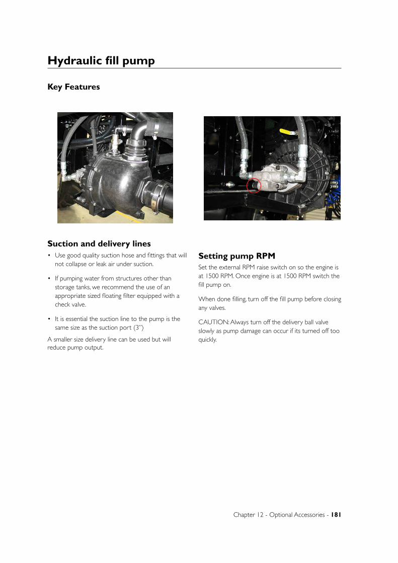
Chapter 12 - Optional Accessories - 181
Hydraulic fill pump
Key Features
Suction and delivery lines• Use good quality suction hose and fittings that will
not collapse or leak air under suction.
• If pumping water from structures other than storage tanks, we recommend the use of an appropriate sized floating filter equipped with a check valve.
• It is essential the suction line to the pump is the same size as the suction port (3”)
A smaller size delivery line can be used but will reduce pump output.
Setting pump RPMSet the external RPM raise switch on so the engine is at 1500 RPM. Once engine is at 1500 RPM switch the fill pump on.
When done filling, turn off the fill pump before closing any valves.
CAUTION: Always turn off the delivery ball valve slowly as pump damage can occur if its turned off too quickly.

182 - Crop Cruiser Evolution Operators Manual - Rev 1.4
70 series fill flow meter
Key Features
Operation
The Tee Jet monitor and flow meter system can be set up to measure the amount of flow entering the main spray system or it can be set up with a supplementary electronic ball valve that will shut off when a pre determined volume is reached preventing over filling of the sprayer.
When the flow meter system is connected without the ball valve the flow meter is not required to be turned on to fill the tank. However when the electronic ball valve is part of the system the console must be powered on and the target volume must be set to open the ball valve and allow liquid to flow through and fill the tank. If this is not done the ball valve will remain closed, blocking flow to the main tank and dead heading the fill pump.
The console can be programmed to reset to the maximum tank volume every time the filling process is activated. If a lesser amount is required then the maximum volume can be reduced to the required amount. When this amount is reached an alarm will sound. If the system has a ball valve, the valve will shut off stopping flow to the main tank. If the valve is not fitted the [CLR] button can be pressed to silence the alarm.
CLEAR
ONINCREASE
PRESS TOGETHER TO TURN OFF
DECREASE
Button Functions
Start Up Screen
SOFTWARE
VERSION
70 Series Fill Flow Meter

Chapter 12 - Optional Accessories - 183
Operating Screen
TARGET VOLUME
ACTUAL VOLUME
[L] LITER
Console Programming
1. Press ‘PRO’ to turn display screen on. (once turned on, numbers shown on screen may vary to those shown below)
2. The flow meter calibration number must be entered. This number is located on the flow meter ID label.

184 - Crop Cruiser Evolution Operators Manual - Rev 1.4
Console Programming - continued
6. Once all calibrations have been entered, press and hold ‘PRO’ for 3 seconds to go back to the fill screen. (shown below, numbers shown here may vary to what is displayed on your screen)
7. To set the target volume, press ‘PRO’ once so the target value flashes. Use the arrows to adjust the value. Press ‘PRO’ when value is reached.
8. Press up and down arrows simultaneously to turn off.
3. To do this, press ‘PRO’ and hold down for 3 seconds. Using the up and down arrows adjust the number so that it matches the flow meter calibration figure (pulses/liter).
5. When in this screen, the maximum target volume is set. This is used as a quick reset to the tanks maximum volume. Use the up and down arrows to set the required maximum tank volume.
4. Press the ‘PRO’ button once the correct calibration number has been entered. This will take you to the next screen but will also set the calibration figure that was just entered. (To save the flow meter cal figure, the ‘Pro’ button must be pressed once. Dont press and hold the ‘PRO’ button to exit from this screen or changes wont be saved. See step 6 for exiting calibration.)

Chapter 12 - Optional Accessories - 185
Flow Meter Operation - continued
3. Once the target volume has been reached, an alarm will activate. Stop water flow and press ‘CLR’ to silence the alarm.
4. To reset the actual volume, press and hold ‘CLR’
5. If at any stage the target volume becomes incorrect, press ‘CLR’ once. This will reset the target volume to the maximum value you programmed in when setting up the console.
6. When the operation is complete, press the up and down arrows simultaneously to turn the console off.
Flow Meter Operation1. Press ‘PRO’ to switch display screen on
2. To begin measuring flow into the sprayer tank, ensure ‘>L’ next to the target volume is flashing. You can now apply flow through the fill system. The actual volume on the bottom line should begin increasing.
Note: If ‘>L’ is not flashing when the TeeJet electric ball valve is fitted, the ‘Actual’ volume will not count
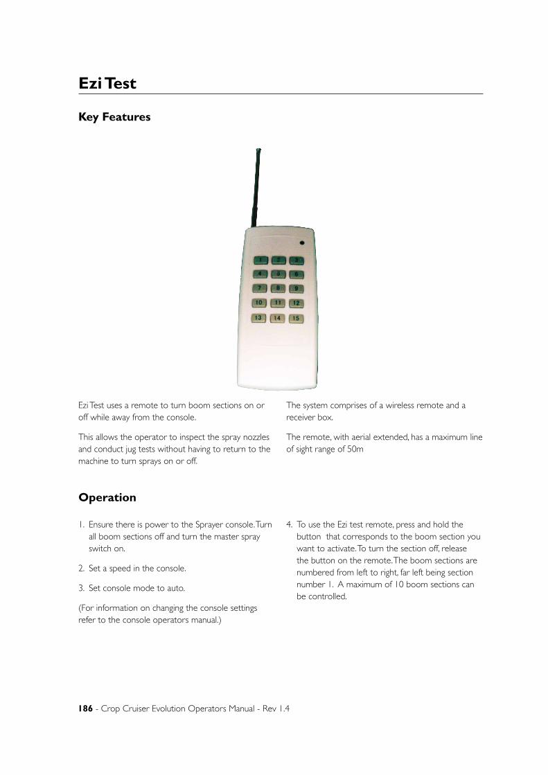
186 - Crop Cruiser Evolution Operators Manual - Rev 1.4
Ezi Test
Key Features
Operation
1. Ensure there is power to the Sprayer console. Turn all boom sections off and turn the master spray switch on.
2. Set a speed in the console.
3. Set console mode to auto.
(For information on changing the console settings refer to the console operators manual.)
4. To use the Ezi test remote, press and hold the button that corresponds to the boom section you want to activate. To turn the section off, release the button on the remote. The boom sections are numbered from left to right, far left being section number 1. A maximum of 10 boom sections can be controlled.
Ezi Test uses a remote to turn boom sections on or off while away from the console.
This allows the operator to inspect the spray nozzles and conduct jug tests without having to return to the machine to turn sprays on or off.
The system comprises of a wireless remote and a receiver box.
The remote, with aerial extended, has a maximum line of sight range of 50m

Chapter 12 - Optional Accessories - 187
Smart BoomKey Features
The SmartBoom system provides automatic control of the sprayer by turning on or turning off sections of the sprayer based on predefined spray zones and/or previous coverage.
The GPS supplies the instantaneous position of the vehicle while the SmartBoom continually monitors the information from the antenna to create an as applied map of activity. If the machine enters a previously sprayed area, SmartBoom determines that the sections should be turned off.
SmartBoom provides several modes of operation:
• Standard Job
• Job with field boundary
• Job with no spray zones
• Job with field boundary and no spray zones
Operation
Initial Start UpBefore beginning your first application, you need to configure SmartBoom for your sprayer. Refer to the following points to set up SmartBoom. This ensures that SmartBoom is configured for the specific equipment with which it will be operating.
1. Set up the GPS System - Refer to your GPS receiver operator’s manual to set up your GPS receiver to output a GPS signal to SmartBoom.
SmartBoom requires both GGA position and VTG speed messages from the receiver. Message output rates should be at least 4 Hz. An output rate of 10 Hz is recommended.
2. Set up the Product Controller- Ensure the baud rate for port C on the SmartBoom controller matches the baud rate for the serial port of the SCS console.
3. Select the Sprayer mode from the System Config menu.
4. Select Distance Units - Use the SmartBoom Section Configuration Menus to set up the units that SmartBoom will use to measure. You can select inches or centimeters.
5. Configure The Sections Widths - Use the SmartBoom Boom Configuration Menus to set up the number of section and the width of each section.
6. Orient the implement with respect to the GPS antenna - Use the SmartBoom Boom Configuration Menus to enter the location of the center of the implement with respect to the GPS Antenna.
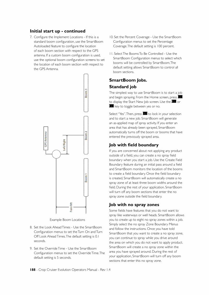
188 - Crop Cruiser Evolution Operators Manual - Rev 1.4
7. Configure the Implement Locations - If this is a standard boom configuration, use the SmartBoom Autoloaded feature to configure the location of each boom section with respect to the GPS antenna. If a custom boom configuration is used, use the optional boom configuration screens to set the location of each boom section with respect to the GPS Antenna.
Example Boom Locations
8. Set the Look Ahead Times - Use the SmartBoom Configuration menus to set the Turn On and Turn Off Look Ahead Times. The default setting is 0.1 seconds.
9. Set the Override Time - Use the SmartBoom Configuration menus to set the Override Time. The default setting is 5 seconds.
10. Set the Percent Coverage - Use the SmartBoom Configuration menus to set the Percentage Coverage. The default setting is 100 percent.
11. Select The Booms To Be Controlled - Use the SmartBoom Configuration menus to select which booms will be controlled by SmartBoom. The default setting allows SmartBoom to control all boom sections.
SmartBoom Jobs.
Standard jobThe simplest way to use SmartBoom is to start a job and begin spraying. From the Home screen, press to display the Start New Job screen. Use the or
key to toggle between yes or no.
Select “Yes”. Then, press to lock in your selection and to start a new job. SmartBoom will generate an as-applied map of spray activity. If you enter an area that has already been sprayed, SmartBoom automatically turns off the boom or booms that have entered the previously sprayed area.
Job with field boundaryIf you are concerned about not applying any product outside of a field, you can create a no spray field boundary when you start a job. Use the Create Field Boundary feature during an initial pass around a field and SmartBoom monitors the location of the booms to create a field boundary. Once the field boundary is created, SmartBoom will automatically create a no spray zone of at least three boom widths around the field. During the rest of your application, SmartBoom will turn off any boom sections that enter the no spray zone outside the field boundary.
Job with no spray zonesSome fields have features that you do not want to spray like waterways or well heads. SmartBoom allows you to create up to eight no spray zones within a job. Simply select the no spray Zone Boundary Menus and follow the instructions. Once you have told SmartBoom that you want to create a no spray zone, you can continue to spray while you drive around the area on which you do not want to apply product. SmartBoom will create a no spray zone within the area you have sprayed around. During the rest of your application, SmartBoom will turn off any boom sections that enter this no spray zone.
Initial start up - continued
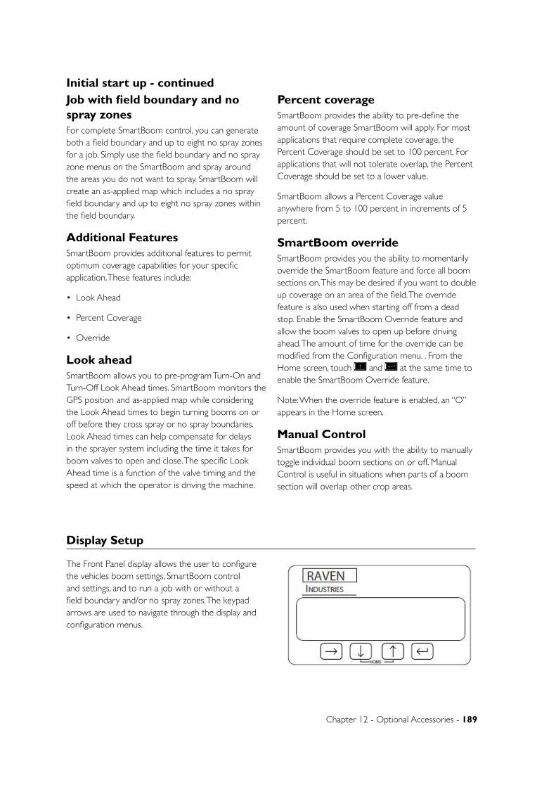
Chapter 12 - Optional Accessories - 189
Job with field boundary and no spray zonesFor complete SmartBoom control, you can generate both a field boundary and up to eight no spray zones for a job. Simply use the field boundary and no spray zone menus on the SmartBoom and spray around the areas you do not want to spray. SmartBoom will create an as-applied map which includes a no spray field boundary and up to eight no spray zones within the field boundary.
Additional FeaturesSmartBoom provides additional features to permit optimum coverage capabilities for your specific application. These features include:
• Look Ahead
• Percent Coverage
• Override
Look aheadSmartBoom allows you to pre-program Turn-On and Turn-Off Look Ahead times. SmartBoom monitors the GPS position and as-applied map while considering the Look Ahead times to begin turning booms on or off before they cross spray or no spray boundaries. Look Ahead times can help compensate for delays in the sprayer system including the time it takes for boom valves to open and close. The specific Look Ahead time is a function of the valve timing and the speed at which the operator is driving the machine.
Percent coverageSmartBoom provides the ability to pre-define the amount of coverage SmartBoom will apply. For most applications that require complete coverage, the Percent Coverage should be set to 100 percent. For applications that will not tolerate overlap, the Percent Coverage should be set to a lower value.
SmartBoom allows a Percent Coverage value anywhere from 5 to 100 percent in increments of 5 percent.
SmartBoom overrideSmartBoom provides you the ability to momentarily override the SmartBoom feature and force all boom sections on. This may be desired if you want to double up coverage on an area of the field. The override feature is also used when starting off from a dead stop. Enable the SmartBoom Override feature and allow the boom valves to open up before driving ahead. The amount of time for the override can be modified from the Configuration menu. . From the Home screen, touch and at the same time to enable the SmartBoom Override feature.
Note: When the override feature is enabled, an “O” appears in the Home screen.
Manual ControlSmartBoom provides you with the ability to manually toggle individual boom sections on or off. Manual Control is useful in situations when parts of a boom section will overlap other crop areas.
Initial start up - continued
Display Setup
The Front Panel display allows the user to configure the vehicles boom settings, SmartBoom control and settings, and to run a job with or without a field boundary and/or no spray zones. The keypad arrows are used to navigate through the display and configuration menus.
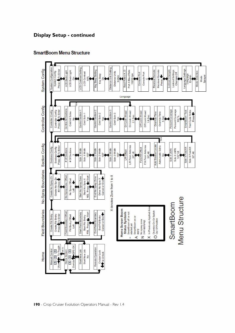
190 - Crop Cruiser Evolution Operators Manual - Rev 1.4
Display Setup - continued
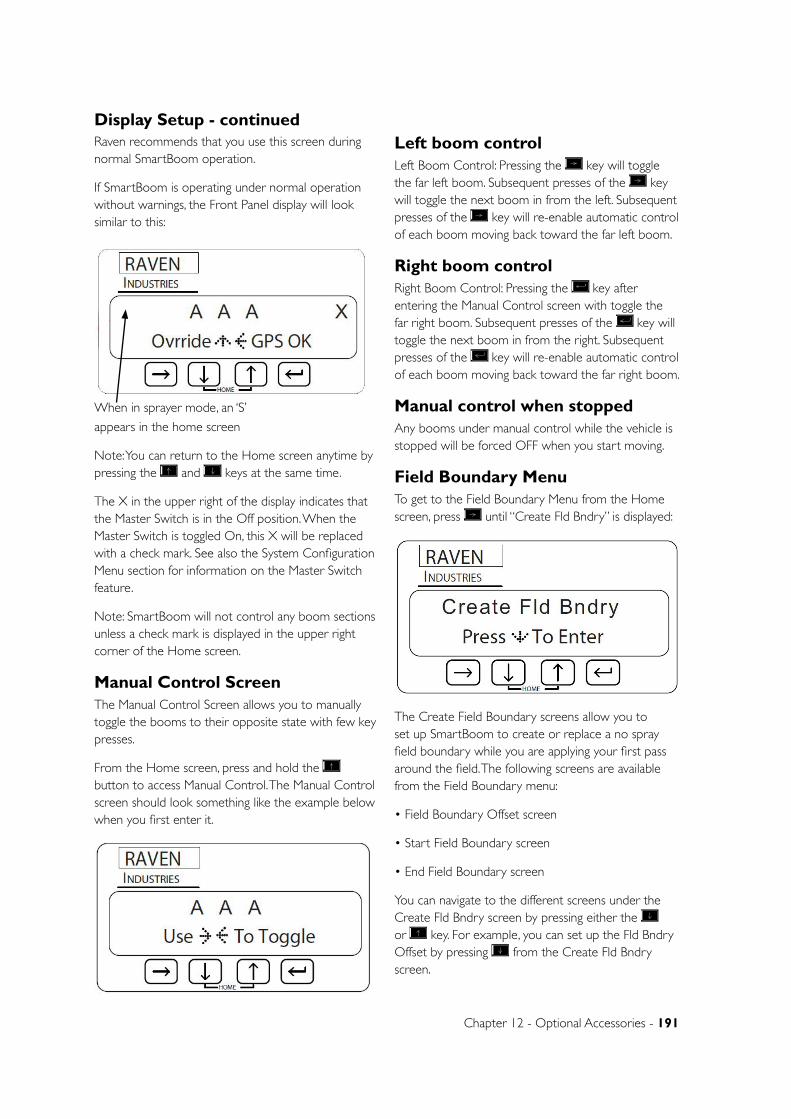
Chapter 12 - Optional Accessories - 191
Raven recommends that you use this screen during normal SmartBoom operation.
If SmartBoom is operating under normal operation without warnings, the Front Panel display will look similar to this:
When in sprayer mode, an ‘S’
appears in the home screen
Note: You can return to the Home screen anytime by pressing the and keys at the same time.
The X in the upper right of the display indicates that the Master Switch is in the Off position. When the Master Switch is toggled On, this X will be replaced with a check mark. See also the System Configuration Menu section for information on the Master Switch feature.
Note: SmartBoom will not control any boom sections unless a check mark is displayed in the upper right corner of the Home screen.
Manual Control ScreenThe Manual Control Screen allows you to manually toggle the booms to their opposite state with few key presses.
From the Home screen, press and hold the button to access Manual Control. The Manual Control screen should look something like the example below when you first enter it.
Left boom controlLeft Boom Control: Pressing the key will toggle the far left boom. Subsequent presses of the key will toggle the next boom in from the left. Subsequent presses of the key will re-enable automatic control of each boom moving back toward the far left boom.
Right boom controlRight Boom Control: Pressing the key after entering the Manual Control screen with toggle the far right boom. Subsequent presses of the key will toggle the next boom in from the right. Subsequent presses of the key will re-enable automatic control of each boom moving back toward the far right boom.
Manual control when stoppedAny booms under manual control while the vehicle is stopped will be forced OFF when you start moving.
Field Boundary MenuTo get to the Field Boundary Menu from the Home screen, press until “Create Fld Bndry” is displayed:
The Create Field Boundary screens allow you to set up SmartBoom to create or replace a no spray field boundary while you are applying your first pass around the field. The following screens are available from the Field Boundary menu:
• Field Boundary Offset screen
• Start Field Boundary screen
• End Field Boundary screen
You can navigate to the different screens under the Create Fld Bndry screen by pressing either the or key. For example, you can set up the Fld Bndry Offset by pressing from the Create Fld Bndry screen.
Display Setup - continued
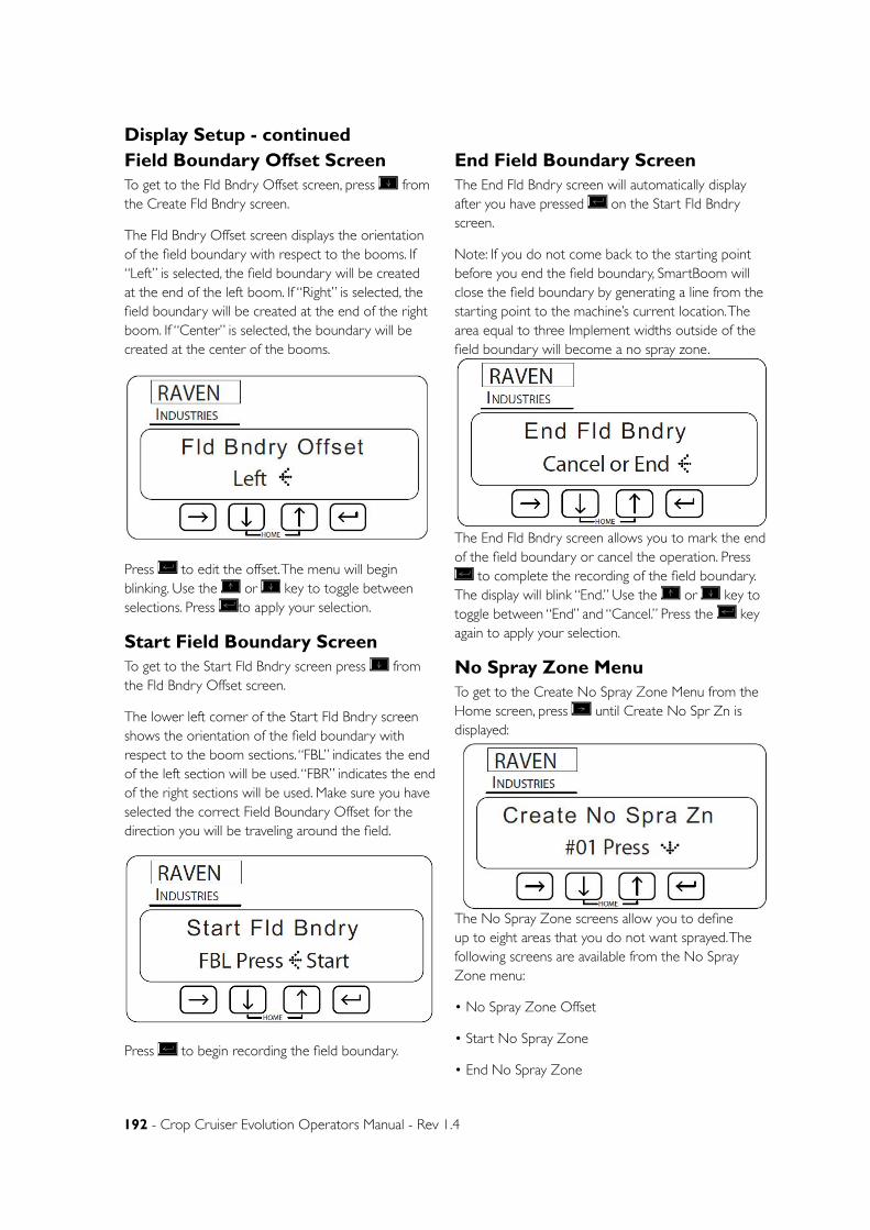
192 - Crop Cruiser Evolution Operators Manual - Rev 1.4
Display Setup - continuedField Boundary Offset ScreenTo get to the Fld Bndry Offset screen, press from the Create Fld Bndry screen.
The Fld Bndry Offset screen displays the orientation of the field boundary with respect to the booms. If “Left” is selected, the field boundary will be created at the end of the left boom. If “Right” is selected, the field boundary will be created at the end of the right boom. If “Center” is selected, the boundary will be created at the center of the booms.
Press to edit the offset. The menu will begin blinking. Use the or key to toggle between selections. Press to apply your selection.
Start Field Boundary ScreenTo get to the Start Fld Bndry screen press from the Fld Bndry Offset screen.
The lower left corner of the Start Fld Bndry screen shows the orientation of the field boundary with respect to the boom sections. “FBL” indicates the end of the left section will be used. “FBR” indicates the end of the right sections will be used. Make sure you have selected the correct Field Boundary Offset for the direction you will be traveling around the field.
Press to begin recording the field boundary.
End Field Boundary ScreenThe End Fld Bndry screen will automatically display after you have pressed on the Start Fld Bndry screen.
Note: If you do not come back to the starting point before you end the field boundary, SmartBoom will close the field boundary by generating a line from the starting point to the machine’s current location. The area equal to three Implement widths outside of the field boundary will become a no spray zone.
The End Fld Bndry screen allows you to mark the end of the field boundary or cancel the operation. Press
to complete the recording of the field boundary. The display will blink “End.” Use the or key to toggle between “End” and “Cancel.” Press the key again to apply your selection.
No Spray Zone MenuTo get to the Create No Spray Zone Menu from the Home screen, press until Create No Spr Zn is displayed:
The No Spray Zone screens allow you to define up to eight areas that you do not want sprayed. The following screens are available from the No Spray Zone menu:
• No Spray Zone Offset
• Start No Spray Zone
• End No Spray Zone
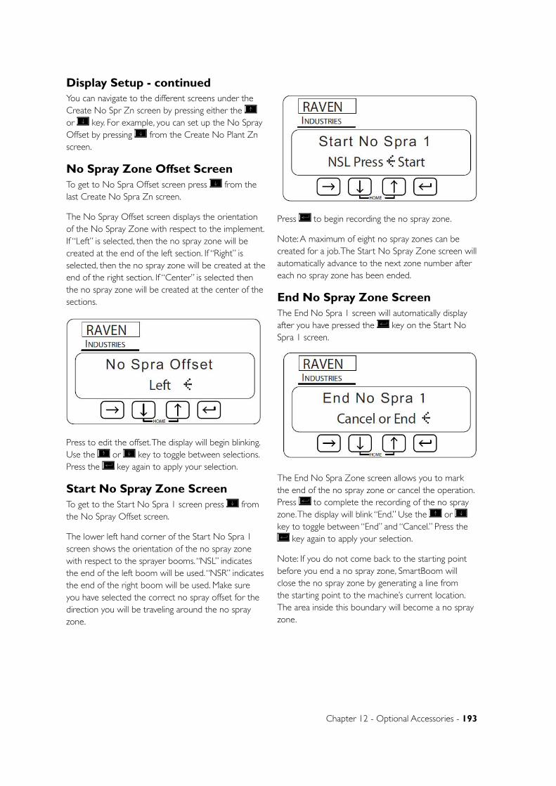
Chapter 12 - Optional Accessories - 193
You can navigate to the different screens under the Create No Spr Zn screen by pressing either the or key. For example, you can set up the No Spray Offset by pressing from the Create No Plant Zn screen.
No Spray Zone Offset ScreenTo get to No Spra Offset screen press from the last Create No Spra Zn screen.
The No Spray Offset screen displays the orientation of the No Spray Zone with respect to the implement. If “Left” is selected, then the no spray zone will be created at the end of the left section. If “Right” is selected, then the no spray zone will be created at the end of the right section. If “Center” is selected then the no spray zone will be created at the center of the sections.
Press to edit the offset. The display will begin blinking. Use the or key to toggle between selections. Press the key again to apply your selection.
Start No Spray Zone ScreenTo get to the Start No Spra 1 screen press from the No Spray Offset screen.
The lower left hand corner of the Start No Spra 1 screen shows the orientation of the no spray zone with respect to the sprayer booms. “NSL” indicates the end of the left boom will be used. “NSR” indicates the end of the right boom will be used. Make sure you have selected the correct no spray offset for the direction you will be traveling around the no spray zone.
Press to begin recording the no spray zone.
Note: A maximum of eight no spray zones can be created for a job. The Start No Spray Zone screen will automatically advance to the next zone number after each no spray zone has been ended.
End No Spray Zone ScreenThe End No Spra 1 screen will automatically display after you have pressed the key on the Start No Spra 1 screen.
The End No Spra Zone screen allows you to mark the end of the no spray zone or cancel the operation. Press to complete the recording of the no spray zone. The display will blink “End.” Use the or key to toggle between “End” and “Cancel.” Press the
key again to apply your selection.
Note: If you do not come back to the starting point before you end a no spray zone, SmartBoom will close the no spray zone by generating a line from the starting point to the machine’s current location. The area inside this boundary will become a no spray zone.
Display Setup - continued
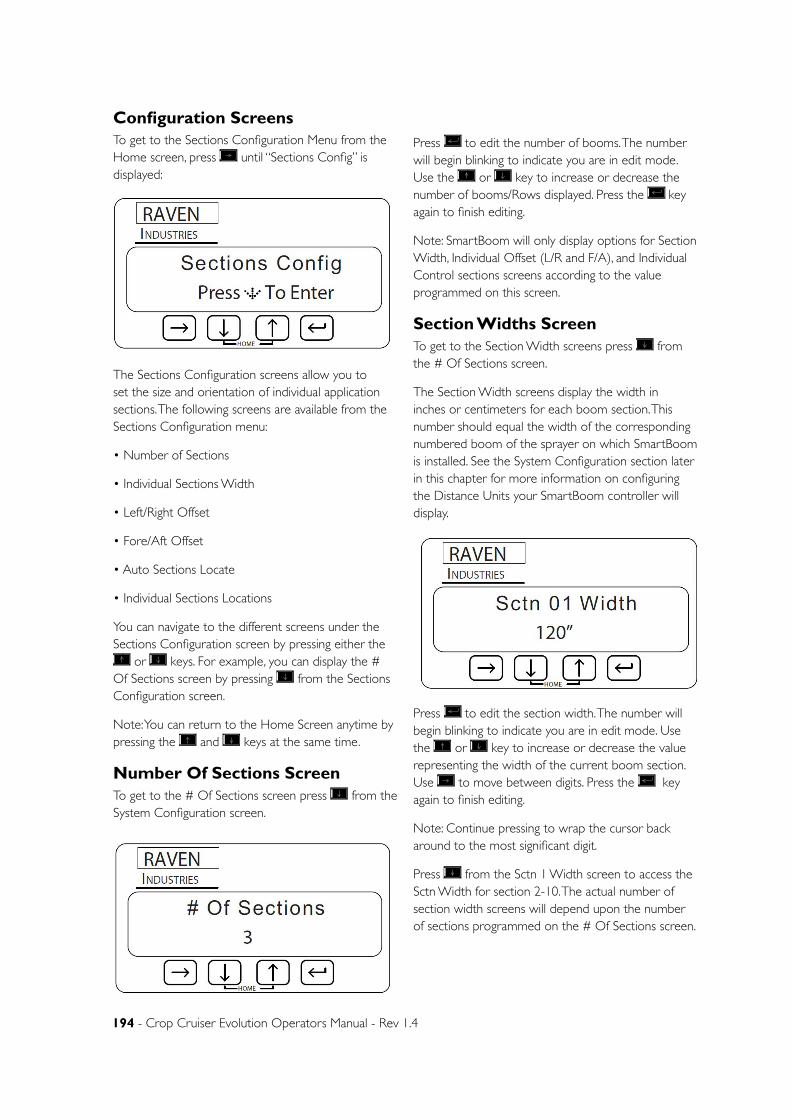
194 - Crop Cruiser Evolution Operators Manual - Rev 1.4
Configuration ScreensTo get to the Sections Configuration Menu from the Home screen, press until “Sections Config” is displayed:
The Sections Configuration screens allow you to set the size and orientation of individual application sections. The following screens are available from the Sections Configuration menu:
• Number of Sections
• Individual Sections Width
• Left/Right Offset
• Fore/Aft Offset
• Auto Sections Locate
• Individual Sections Locations
You can navigate to the different screens under the Sections Configuration screen by pressing either the
or keys. For example, you can display the # Of Sections screen by pressing from the Sections Configuration screen.
Note: You can return to the Home Screen anytime by pressing the and keys at the same time.
Number Of Sections ScreenTo get to the # Of Sections screen press from the System Configuration screen.
Press to edit the number of booms. The number will begin blinking to indicate you are in edit mode. Use the or key to increase or decrease the number of booms/Rows displayed. Press the key again to finish editing.
Note: SmartBoom will only display options for Section Width, Individual Offset (L/R and F/A), and Individual Control sections screens according to the value programmed on this screen.
Section Widths ScreenTo get to the Section Width screens press from the # Of Sections screen.
The Section Width screens display the width in inches or centimeters for each boom section. This number should equal the width of the corresponding numbered boom of the sprayer on which SmartBoom is installed. See the System Configuration section later in this chapter for more information on configuring the Distance Units your SmartBoom controller will display.
Press to edit the section width. The number will begin blinking to indicate you are in edit mode. Use the or key to increase or decrease the value representing the width of the current boom section. Use to move between digits. Press the key again to finish editing.
Note: Continue pressing to wrap the cursor back around to the most significant digit.
Press from the Sctn 1 Width screen to access the Sctn Width for section 2-10. The actual number of section width screens will depend upon the number of sections programmed on the # Of Sections screen.
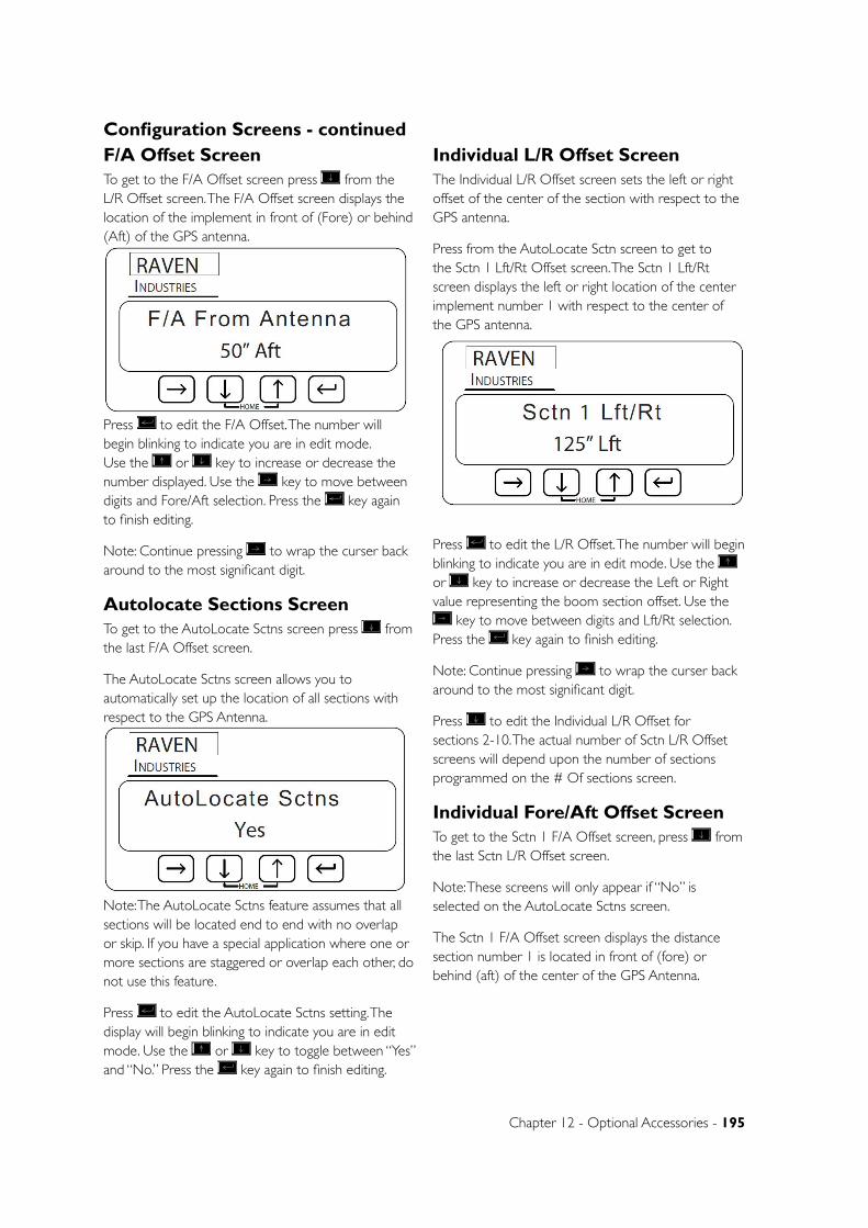
Chapter 12 - Optional Accessories - 195
Configuration Screens - continuedF/A Offset ScreenTo get to the F/A Offset screen press from the L/R Offset screen. The F/A Offset screen displays the location of the implement in front of (Fore) or behind (Aft) of the GPS antenna.
Press to edit the F/A Offset. The number will begin blinking to indicate you are in edit mode. Use the or key to increase or decrease the number displayed. Use the key to move between digits and Fore/Aft selection. Press the key again to finish editing.
Note: Continue pressing to wrap the curser back around to the most significant digit.
Autolocate Sections ScreenTo get to the AutoLocate Sctns screen press from the last F/A Offset screen.
The AutoLocate Sctns screen allows you to automatically set up the location of all sections with respect to the GPS Antenna.
Note: The AutoLocate Sctns feature assumes that all sections will be located end to end with no overlap or skip. If you have a special application where one or more sections are staggered or overlap each other, do not use this feature.
Press to edit the AutoLocate Sctns setting. The display will begin blinking to indicate you are in edit mode. Use the or key to toggle between “Yes” and “No.” Press the key again to finish editing.
Individual L/R Offset ScreenThe Individual L/R Offset screen sets the left or right offset of the center of the section with respect to the GPS antenna.
Press from the AutoLocate Sctn screen to get to the Sctn 1 Lft/Rt Offset screen. The Sctn 1 Lft/Rt screen displays the left or right location of the center implement number 1 with respect to the center of the GPS antenna.
Press to edit the L/R Offset. The number will begin blinking to indicate you are in edit mode. Use the or key to increase or decrease the Left or Right value representing the boom section offset. Use the
key to move between digits and Lft/Rt selection. Press the key again to finish editing.
Note: Continue pressing to wrap the curser back around to the most significant digit.
Press to edit the Individual L/R Offset for sections 2-10. The actual number of Sctn L/R Offset screens will depend upon the number of sections programmed on the # Of sections screen.
Individual Fore/Aft Offset ScreenTo get to the Sctn 1 F/A Offset screen, press from the last Sctn L/R Offset screen.
Note: These screens will only appear if “No” is selected on the AutoLocate Sctns screen.
The Sctn 1 F/A Offset screen displays the distance section number 1 is located in front of (fore) or behind (aft) of the center of the GPS Antenna.
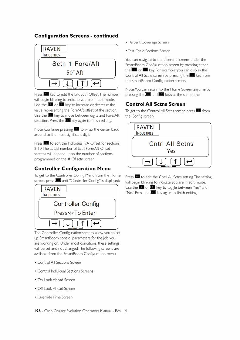
196 - Crop Cruiser Evolution Operators Manual - Rev 1.4
Press key to edit the L/R Sctn Offset. The number will begin blinking to indicate you are in edit mode. Use the or key to increase or decrease the value representing the Fore/Aft offset of the section. Use the key to move between digits and Fore/Aft selection. Press the key again to finish editing.
Note: Continue pressing to wrap the curser back around to the most significant digit.
Press to edit the Individual F/A Offset for sections 2-10. The actual number of Sctn Fore/Aft Offset screens will depend upon the number of sections programmed on the # Of sctn screen.
Controller Configuration MenuTo get to the Controller Config Menu from the Home screen, press until “Controller Config” is displayed:
The Controller Configuration screens allow you to set up SmartBoom control parameters for the job you are working on. Under most conditions, these settings will be set and not changed. The following screens are available from the SmartBoom Configuration menu:
• Control All Sections Screen
• Control Individual Sections Screens
• On Look Ahead Screen
• Off Look Ahead Screen
• Override Time Screen
• Percent Coverage Screen
• Test Cycle Sections Screen
You can navigate to the different screens under the SmartBoom Configuration screen by pressing either the or key. For example, you can display the Control All Sctns screen by pressing the key from the SmartBoom Configuration screen.
Note: You can return to the Home Screen anytime by pressing the and keys at the same time.
Control All Sctns ScreenTo get to the Control All Sctns screen press from the Config screen.
Press to edit the Cntrl All Sctns setting. The setting will begin blinking to indicate you are in edit mode. Use the or key to toggle between “Yes” and “No.” Press the key again to finish editing.
Configuration Screens - continued
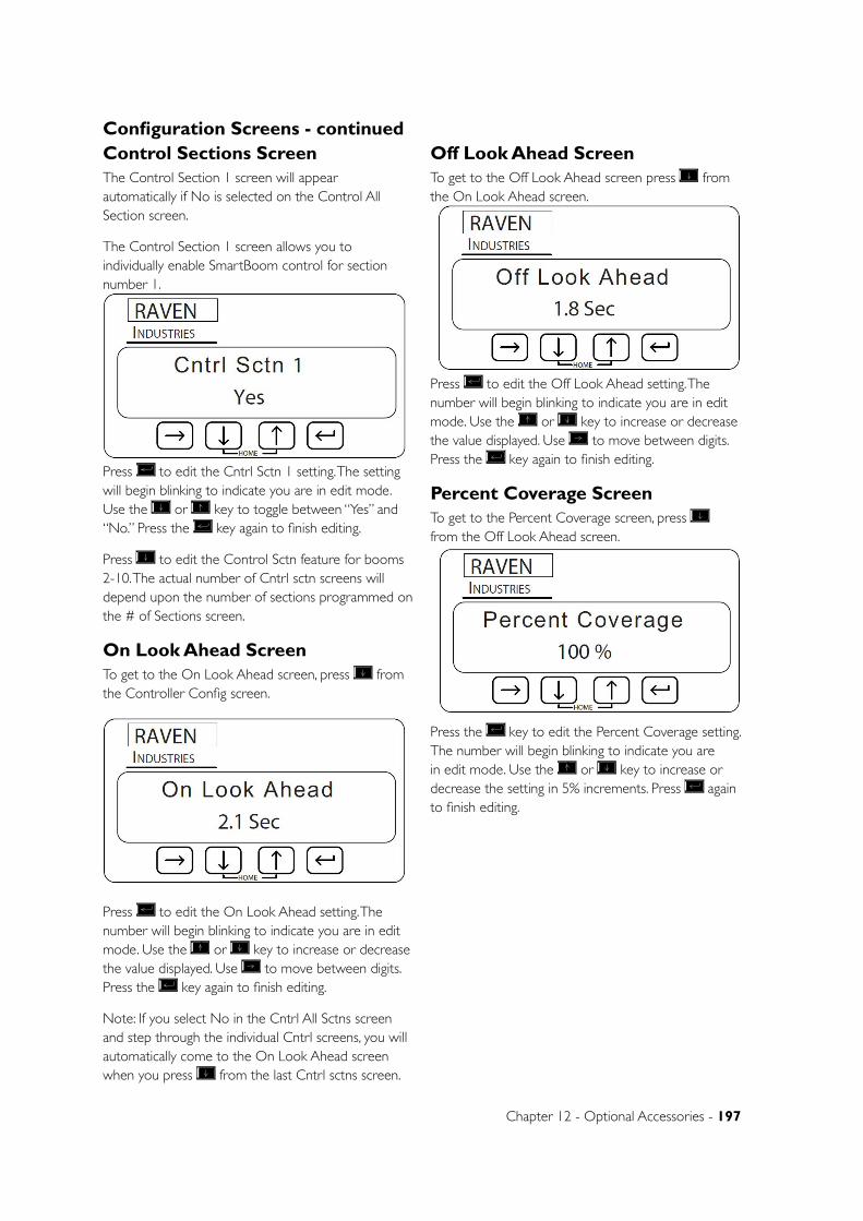
Chapter 12 - Optional Accessories - 197
Configuration Screens - continuedControl Sections ScreenThe Control Section 1 screen will appear automatically if No is selected on the Control All Section screen.
The Control Section 1 screen allows you to individually enable SmartBoom control for section number 1.
Press to edit the Cntrl Sctn 1 setting. The setting will begin blinking to indicate you are in edit mode. Use the or key to toggle between “Yes” and “No.” Press the key again to finish editing.
Press to edit the Control Sctn feature for booms 2-10. The actual number of Cntrl sctn screens will depend upon the number of sections programmed on the # of Sections screen.
On Look Ahead ScreenTo get to the On Look Ahead screen, press from the Controller Config screen.
Press to edit the On Look Ahead setting. The number will begin blinking to indicate you are in edit mode. Use the or key to increase or decrease the value displayed. Use to move between digits. Press the key again to finish editing.
Note: If you select No in the Cntrl All Sctns screen and step through the individual Cntrl screens, you will automatically come to the On Look Ahead screen when you press from the last Cntrl sctns screen.
Off Look Ahead ScreenTo get to the Off Look Ahead screen press from the On Look Ahead screen.
Press to edit the Off Look Ahead setting. The number will begin blinking to indicate you are in edit mode. Use the or key to increase or decrease the value displayed. Use to move between digits. Press the key again to finish editing.
Percent Coverage ScreenTo get to the Percent Coverage screen, press from the Off Look Ahead screen.
Press the key to edit the Percent Coverage setting. The number will begin blinking to indicate you are in edit mode. Use the or key to increase or decrease the setting in 5% increments. Press again to finish editing.
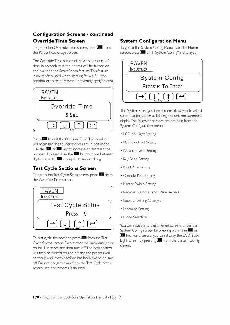
198 - Crop Cruiser Evolution Operators Manual - Rev 1.4
Configuration Screens - continuedOverride Time ScreenTo get to the Override Time screen, press from the Percent Coverage screen.
The Override Time screen displays the amount of time, in seconds, that the booms will be turned on and override the SmartBoom feature. This feature is most often used when starting from a full stop position or to reapply over a previously sprayed area.
Press to edit the Override Time. The number will begin blinking to indicate you are in edit mode. Use the or key to increase or decrease the number displayed. Use the key to move between digits. Press the key again to finish editing.
Test Cycle Sections ScreenTo get to the Test Cycle Sctns screen, press from the Override Time screen.
To test cycle the sections, press from the Test Cycle Sectns screen. Each section will individually turn on for 4 seconds and then turn off. The next section will then be turned on and off and the process will continue until every sections has been cycled on and off. Do not navigate away from the Test Cycle Sctns screen until the process is finished.
System Configuration MenuTo get to the System Config Menu from the Home screen, press until “System Config” is displayed:
The System Configuration screens allow you to adjust system settings, such as lighting and unit measurement display. The following screens are available from the System Configuration menu:
• LCD backlight Setting
• LCD Contrast Setting
• Distance Units Setting
• Key Beep Setting
• Baud Rate Setting
• Console Port Setting
• Master Switch Setting
• Receiver Remote Front Panel Access
• Lockout Setting Changes
• Language Setting
• Mode Selection
You can navigate to the different screens under the System Config screen by pressing either the or
key. For example, you can display the LCD Back Light screen by pressing from the System Config screen.

Chapter 12 - Optional Accessories - 199
Configuration Screens - continuedLCD Backlight ScreenTo get to the LCD Backlight screen press from the System Config screen.
Press to edit the LCD Back Light setting. The setting will begin blinking to indicate you are in edit mode. Use the or key to toggle between “On” and “Off.” Press the key again to finish editing.
LCD Contrast ScreenTo get to the LCD Contrast screen press from the LCD Backlight screen.
Press to edit the LCD Contrast. The number will begin blinking to indicate you are in edit mode. Use the or key to increase or decrease the number displayed. Press the key again to finish editing.
Note: Continue pressing to wrap the curser back around to the most significant digit.
Key Beep ScreenTo get to the Key Beep screen press from the LCD Contrast screen. The Key Beep Setting screen allows you to enable or disable key beeps and audible alarms.
Press to edit the Key Beep setting. The setting will begin blinking to indicate you are in edit mode. Use the or key to toggle between “On” and “Off.” Press the key again to finish editing.
Distance Unit ScreenTo get to the Distance Unit screen press from the Key Beep screen.
The distance Unit Setting screen allows you to set the distance measurement to display in either feet or metric measurement. You can set the distance to the following units:
• Inches (in)
• Centimeters (cm)
Press to edit the Distance Units setting. The setting will begin blinking to indicate you are in edit mode. Use the or key to toggle between “inches” and “cm.” Press the key again to finish editing.
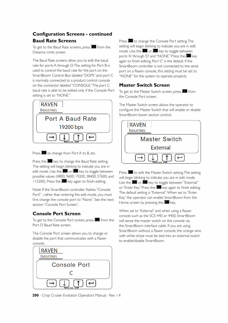
200 - Crop Cruiser Evolution Operators Manual - Rev 1.4
Baud Rate ScreensTo get to the Baud Rate screens, press from the Distance Units screen.
The Baud Rate screens allow you to edit the baud rate for ports A through D. The setting for Port B is used to control the baud rate for the port on the SmartBoom Control Box labeled “DGPS” and port C is normally connected to a product control console on the connector labeled “CONSOLE.” The port C baud rate is able to be edited only if the Console Port setting is set to “NONE.”
Press to change from Port A to B, etc.
Press the key to change the Baud Rate setting. The setting will begin blinking to indicate you are in edit mode. Use the or key to toggle between possible values (4800, 9600, 19200, 38400, 57600, and 115200). Press the key again to finish editing.
Note: If the SmartBoom controller flashes “Console Port!” , rather than entering the edit mode, you must first change the console port to “None”. See the next section “Console Port Screen”.
Console Port ScreenTo get to the Console Port screen, press from the Port D Baud Rate screen.
The Console Port screen allows you to change or disable the port that communicates with a Raven console.
Press to change the Console Port setting. The setting will begin blinking to indicate you are in edit mode. Use the or key to toggle between ports ‘A’ through ‘D’ and “NONE.” Press the key again to finish editing. Port ‘C’ is the default. If the SmartBoom controller is not connected to the serial port on a Raven console, this setting must be set to “NONE” for the system to operate properly.
Master Switch ScreenTo get to the Master Switch screen, press from the Console Port screen.
The Master Switch screen allows the operator to configure the Master Switch that will enable or disable SmartBoom boom section control.
Press to edit the Master Switch setting. The setting will begin blinking to indicate you are in edit mode. Use the or key to toggle between “External” or “Enter Key.” Press the key again to finish editing. The default setting is “External”. When set to “Enter Key,” the operator can enable SmartBoom from the Home screen by pressing the key.
When set to “External” and when using a Raven console such as the SCS 440 or 4400, SmartBoom will sense the master switch on the console via the SmartBoom interface cable. If you are using SmartBoom without a Raven console, the orange wire with white stripe must be tied into an external switch to enable/disable SmartBoom.
Configuration Screens - continued
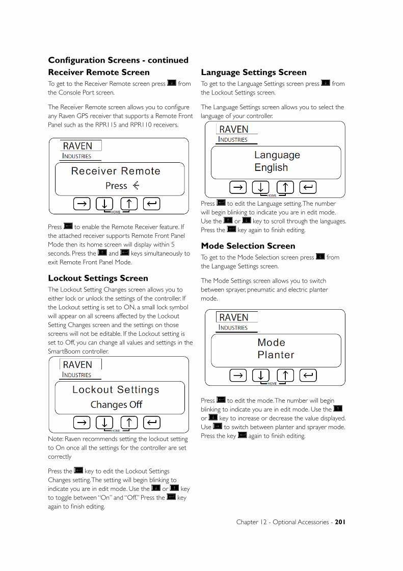
Chapter 12 - Optional Accessories - 201
Configuration Screens - continuedReceiver Remote ScreenTo get to the Receiver Remote screen press from the Console Port screen.
The Receiver Remote screen allows you to configure any Raven GPS receiver that supports a Remote Front Panel such as the RPR115 and RPR110 receivers.
Press to enable the Remote Receiver feature. If the attached receiver supports Remote Front Panel Mode then its home screen will display within 5 seconds. Press the and keys simultaneously to exit Remote Front Panel Mode.
Lockout Settings ScreenThe Lockout Setting Changes screen allows you to either lock or unlock the settings of the controller. If the Lockout setting is set to ON, a small lock symbol will appear on all screens affected by the Lockout Setting Changes screen and the settings on those screens will not be editable. If the Lockout setting is set to Off, you can change all values and settings in the SmartBoom controller.
Note: Raven recommends setting the lockout setting to On once all the settings for the controller are set correctly
Press the key to edit the Lockout Settings Changes setting. The setting will begin blinking to indicate you are in edit mode. Use the or key to toggle between “On” and “Off.” Press the key again to finish editing.
Language Settings ScreenTo get to the Language Settings screen press from the Lockout Settings screen.
The Language Settings screen allows you to select the language of your controller.
Press to edit the Language setting. The number will begin blinking to indicate you are in edit mode. Use the or key to scroll through the languages. Press the key again to finish editing.
Mode Selection ScreenTo get to the Mode Selection screen press from the Language Settings screen.
The Mode Settings screen allows you to switch between sprayer, pneumatic and electric planter mode.
Press to edit the mode. The number will begin blinking to indicate you are in edit mode. Use the or key to increase or decrease the value displayed. Use to switch between planter and sprayer mode. Press the key again to finish editing.
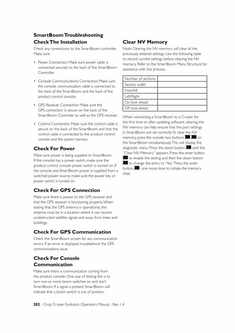
202 - Crop Cruiser Evolution Operators Manual - Rev 1.4
SmartBoom TroubleshootingCheck The InstallationCheck any connections to the SmartBoom controller. Make sure:
• Power Connection: Make sure power cable is connected securely to the back of the SmartBoom Controller.
• Console Communications Connection: Make sure the console communication cable is connected to the back of the SmartBoom and the back of the product control console.
• GPS Receiver Connection: Make sure the GPS connection is secure on the back of the SmartBoom Controller as well as the GPS receiver.
• Control Connection: Make sure the control cable is secure on the back of the SmartBoom and that the control cable is connected to the product control console and the system harness.
Check For PowerMake sure power is being supplied to SmartBoom. If the console has a power switch, make sure the product control console power switch is turned on. If the console and SmartBoom power is supplied from a switched power source, make sure the power key or power switch is turned on.
Check For GPS ConnectionMake sure there is power to the GPS receiver and that the GPS receiver is functioning properly. When testing that the GPS antenna is operational, the antenna must be in a location where it can receive unobstructed satellite signals and away from trees and buildings.
Check For GPS CommunicationCheck the SmartBoom screen for any communication errors. If an error is displayed, troubleshoot the GPS communications issue.
Check For Console CommunicationMake sure there is communication coming from the product console. One way of testing this is to turn one or more boom switches on and start SmartBoom. If a signal is present SmartBoom will indicate that a boom switch is out of position.
Clear NV MemoryNote: Clearing the NV memory will clear all the previously entered settings. Use the following table to record current settings before clearing the NV memory. Refer to the SmartBoom Menu Structure for assistance with this process.
Number of sections
Section width
Fore/Aft
Left/Right
On look ahead
Off look ahead
When connecting a SmartBoom to a Cruizer for the first time or after updating software, clearing the NV memory can help ensure that the port settings in SmartBoom are set correctly. To clear the NV memory, press the outside two buttons on the SmartBoom simultaneously. This will display the diagnostic menu. Press the down button until the “Clear NV Memory” appears. Press the enter button
to enable the setting and then the down button to change the entry to “Yes.” Press the enter
button one more time to initiate the memory clear.
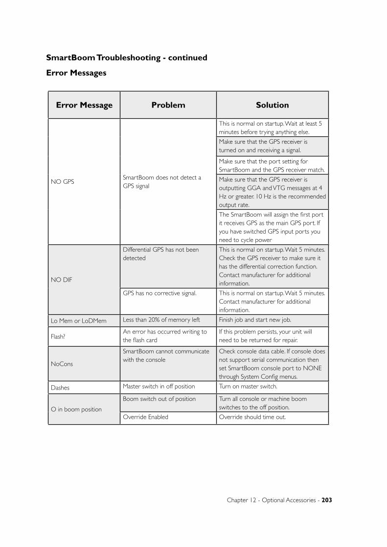
Chapter 12 - Optional Accessories - 203
SmartBoom Troubleshooting - continued
Error Message Problem Solution
NO GPSSmartBoom does not detect a GPS signal
This is normal on startup. Wait at least 5 minutes before trying anything else.
Make sure that the GPS receiver is turned on and receiving a signal.
Make sure that the port setting for SmartBoom and the GPS receiver match.
Make sure that the GPS receiver is outputting GGA and VTG messages at 4 Hz or greater. 10 Hz is the recommended output rate.
The SmartBoom will assign the first port it receives GPS as the main GPS port. If you have switched GPS input ports you need to cycle power
NO DIF
Differential GPS has not been detected
This is normal on startup. Wait 5 minutes. Check the GPS receiver to make sure it has the differential correction function. Contact manufacturer for additional information.
GPS has no corrective signal. This is normal on startup. Wait 5 minutes. Contact manufacturer for additional information.
Lo Mem or LoDMem Less than 20% of memory left Finish job and start new job.
Flash?An error has occurred writing to the flash card
If this problem persists, your unit will need to be returned for repair.
NoCons
SmartBoom cannot communicate with the console
Check console data cable. If console does not support serial communication then set SmartBoom console port to NONE through System Config menus.
Dashes Master switch in off position Turn on master switch.
O in boom position
Boom switch out of position Turn all console or machine boom switches to the off position.
Override Enabled Override should time out.
Error Messages
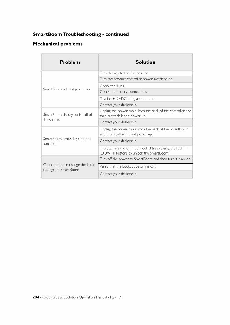
204 - Crop Cruiser Evolution Operators Manual - Rev 1.4
SmartBoom Troubleshooting - continued
Mechanical problems
Problem Solution
SmartBoom will not power up
Turn the key to the On position.
Turn the product controller power switch to on.
Check the fuses.
Check the battery connections.
Test for +12VDC using a voltmeter.
Contact your dealership.
SmartBoom displays only half of the screen.
Unplug the power cable from the back of the controller and then reattach it and power up.
Contact your dealership.
SmartBoom arrow keys do not function.
Unplug the power cable from the back of the SmartBoom and then reattach it and power up.
Contact your dealership.
If Cruizer was recently connected try pressing the [LEFT] [DOWN] buttons to unlock the SmartBoom.
Cannot enter or change the initial settings on SmartBoom
Turn off the power to SmartBoom and then turn it back on.
Verify that the Lockout Setting is Off.
Contact your dealership.

Chapter 12 - Optional Accessories - 205
Groeneveld Auto GreaserDealer Contact Details
Head office 268 Proximity Drive Sunshine West, Vic 3020 Tel: 03 8329 4333 Fax: 03 8329 4334
Perth Branch 8/28 Belmont Avenue Belmont, WA 6104 Tel: 08 9262 9800 Fax: 08 9477 2688
Adelaide Branch 5 George Street Wingfield, SA 5013 Tel: 08 8349 6322 Fax: 08 8262 1783
Groeneveld Tasmania 8 Devonport Road Devonport, TAS 7310 Tel: 03 6423 4256 Fax: 03 6424 9772
Brisbane Branch 1818 Ipswich Road Rocklea, QLD 4106 Tel: 07 3272 7975 Fax: 07 3272 7534
Groeneveld Central QLD 193-195 Wade Street Nth Rockhampton, QLD 4701 Tel: 07 4936 4833 Fax: 07 4936 4822
Sydney Branch 1/36 Lidco Street Arndell Park, NSW 2148 Tel: 02 9831 4933 Fax: 02 9831 4966
Townsville Branch Unit 10 72-78 Crocodile Crescent Townsville, QLD 4810 Tel: 07 4774 3056 Fax: 07 4774 3824
206 - Crop Cruiser Evolution Operators Manual - Rev 1.4
Goldacres prides itself on producing quality products for our primary producers. That is why we source out the best quality components to enhance our cutting edge spraying systems.
The Groeneveld Automatic Greasing System is cutting edge design encompassing robust components and precision engineering to bring the owner operator not only ease in operation and maintenance but also peace of mind that all moving systems are able to work at their peak.
To this end, Goldacres acknowledges that while we hold a high degree of knowledge in their product, we
would always recommend that owners and dealers contact their local Groeneveld dealer for technical advice and assistance. We also advise that you use only genuine Groeneveld parts and lubricants. After all, this system is your investment in your machines serviceability and longevity!
The information following, has been produced by using excerpts from the Groeneveld EG0101 Zero General Manual. Utilising text, tables and diagrams as well as text and photographs supplied by Goldacres.
The following information about the auto greaser system has been approved by Groeneveld.
GROENEVELD Automatic Greasing Systems ensure the daily maintenance of the moving parts attached to the system. They avoid unnecessary machinery wear and down-time and thus save cost and prevent exasperation.
GROENEVELD greasing systems are used by production companies, machinery used in service industries, agriculture, shipping, the offshore industry and the transport industry.
In the following list are the most important advantages:
• Increase of the service intervals, thus less unnecessary down-time;
• Less wear of the lubricated parts because of accurate and constant lubricating;
• Reduced repair and replacement costs;
• Reduced unexpected down-time;
• Fewer production losses.
With a Singleline Automatic Greasing System, all attached lubrication points of a vehicle or machine are automatically lubricated at the correct time with the correct dose. Moreover, optimum grease or lube-oil distribution over the whole lubricating surface is achieved, because the lubrication takes place while the machinery or vehicle is in operation. Every action is automatically carried out by the system. The user needs only to refill the reservoir periodically.
NOTE: Is used to notify people of installation, operation or maintenance information that is important but not hazard related.
CAUTION: Instructions that if ignored will cause damage to the system or machine.
WARNING: Instructions that if ignored will cause personal injury or death to the operator or bystanders.
Preface
Introduction
Definitions
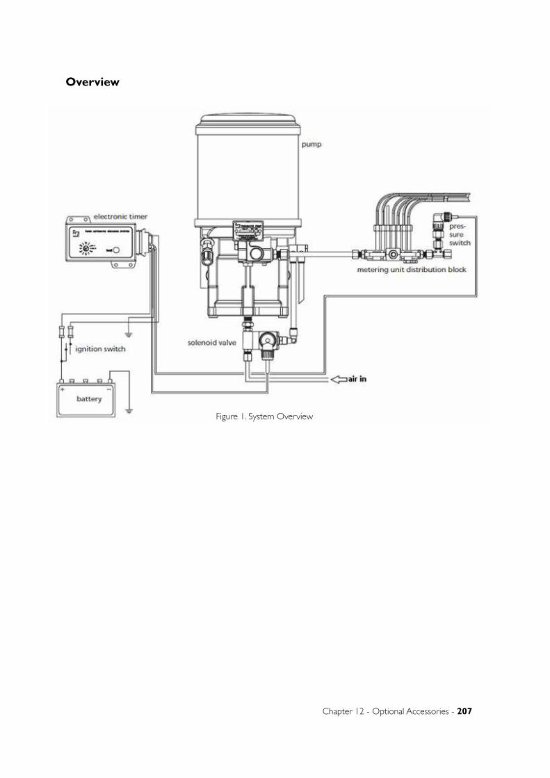
Chapter 12 - Optional Accessories - 207
Overview
Figure 1. System Overview
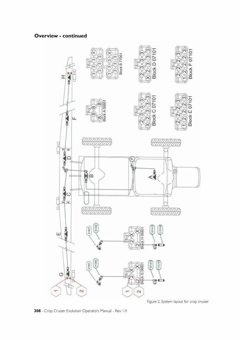
208 - Crop Cruiser Evolution Operators Manual - Rev 1.4
Overview - continued
Figure 2. System layout for crop cruiser
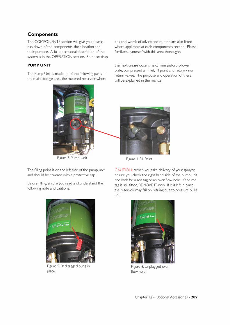
Chapter 12 - Optional Accessories - 209
PUMP UNIT
The Pump Unit is made up of the following parts – the main storage area, the metered reservoir where
the next grease dose is held, main piston, follower plate, compressed air inlet, fill point and return / non return valves. The purpose and operation of these will be explained in the manual.
Figure 3. Pump Unit Figure 4. Fill Point
Figure 5. Red tagged bung in place.
Figure 6. Unplugged over flow hole
The COMPONENTS section will give you a basic run down of the components, their location and their purpose. A full operational description of the system is in the OPERATION section. Some settings,
tips and words of advice and caution are also listed where applicable at each component’s section. Please familiarise yourself with this area thoroughly.
The filling point is on the left side of the pump unit and should be covered with a protective cap.
Before filling, ensure you read and understand the following note and cautions:
CAUTION: When you take delivery of your sprayer, ensure you check the right hand side of the pump unit and look for a red tag or an over flow hole. If the red tag is still fitted, REMOVE IT now. If it is left in place, the reservoir may fail on refilling due to pressure build up.
Components
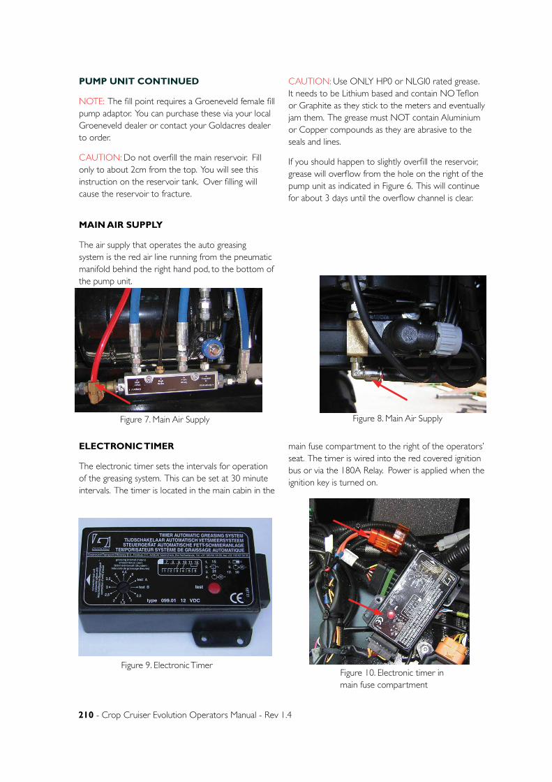
210 - Crop Cruiser Evolution Operators Manual - Rev 1.4
PUMP UNIT CONTINUED
NOTE: The fill point requires a Groeneveld female fill pump adaptor. You can purchase these via your local Groeneveld dealer or contact your Goldacres dealer to order.
CAUTION: Do not overfill the main reservoir. Fill only to about 2cm from the top. You will see this instruction on the reservoir tank. Over filling will cause the reservoir to fracture.
CAUTION: Use ONLY HP0 or NLGI0 rated grease. It needs to be Lithium based and contain NO Teflon or Graphite as they stick to the meters and eventually jam them. The grease must NOT contain Aluminium or Copper compounds as they are abrasive to the seals and lines.
If you should happen to slightly overfill the reservoir, grease will overflow from the hole on the right of the pump unit as indicated in Figure 6. This will continue for about 3 days until the overflow channel is clear.
MAIN AIR SUPPLY
The air supply that operates the auto greasing system is the red air line running from the pneumatic manifold behind the right hand pod, to the bottom of the pump unit.
Figure 7. Main Air Supply Figure 8. Main Air Supply
ELECTRONIC TIMER
The electronic timer sets the intervals for operation of the greasing system. This can be set at 30 minute intervals. The timer is located in the main cabin in the
main fuse compartment to the right of the operators’ seat. The timer is wired into the red covered ignition bus or via the 180A Relay. Power is applied when the ignition key is turned on.
Figure 9. Electronic TimerFigure 10. Electronic timer in main fuse compartment
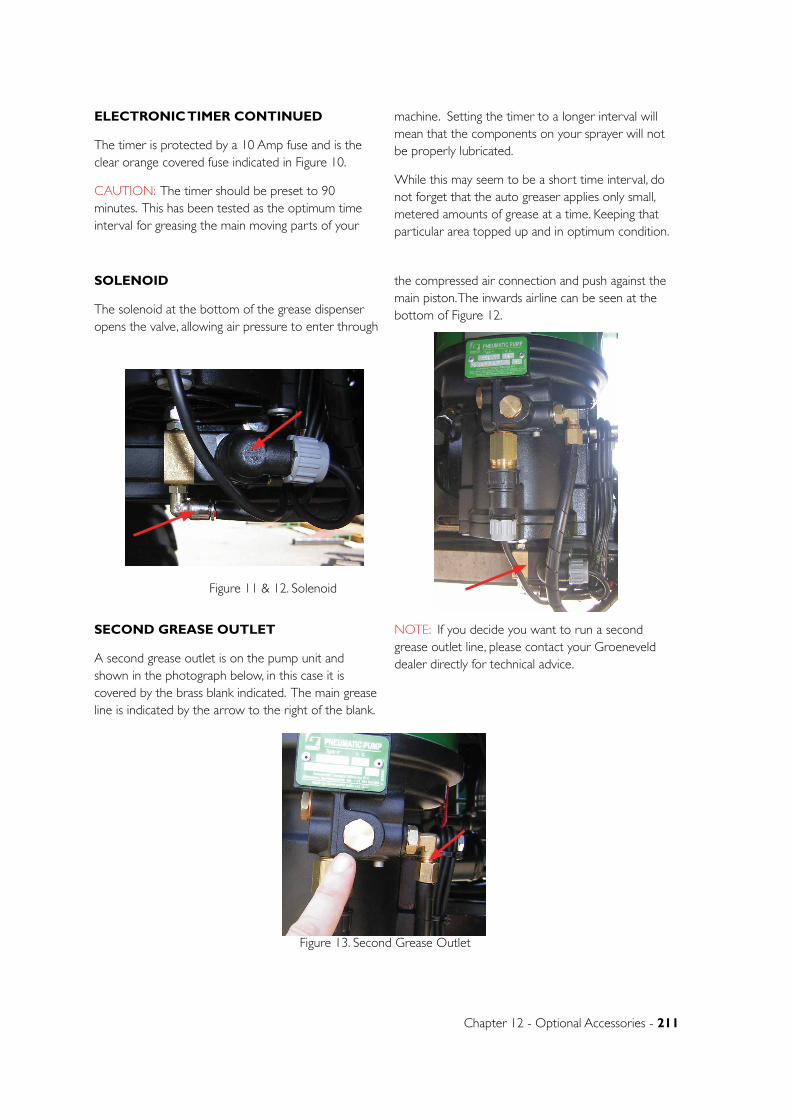
Chapter 12 - Optional Accessories - 211
ELECTRONIC TIMER CONTINUED
The timer is protected by a 10 Amp fuse and is the clear orange covered fuse indicated in Figure 10.
CAUTION: The timer should be preset to 90 minutes. This has been tested as the optimum time interval for greasing the main moving parts of your
machine. Setting the timer to a longer interval will mean that the components on your sprayer will not be properly lubricated.
While this may seem to be a short time interval, do not forget that the auto greaser applies only small, metered amounts of grease at a time. Keeping that particular area topped up and in optimum condition.
SOLENOID
The solenoid at the bottom of the grease dispenser opens the valve, allowing air pressure to enter through
the compressed air connection and push against the main piston. The inwards airline can be seen at the bottom of Figure 12.
Figure 11 & 12. Solenoid
SECOND GREASE OUTLET
A second grease outlet is on the pump unit and shown in the photograph below, in this case it is covered by the brass blank indicated. The main grease line is indicated by the arrow to the right of the blank.
NOTE: If you decide you want to run a second grease outlet line, please contact your Groeneveld dealer directly for technical advice.
Figure 13. Second Grease Outlet
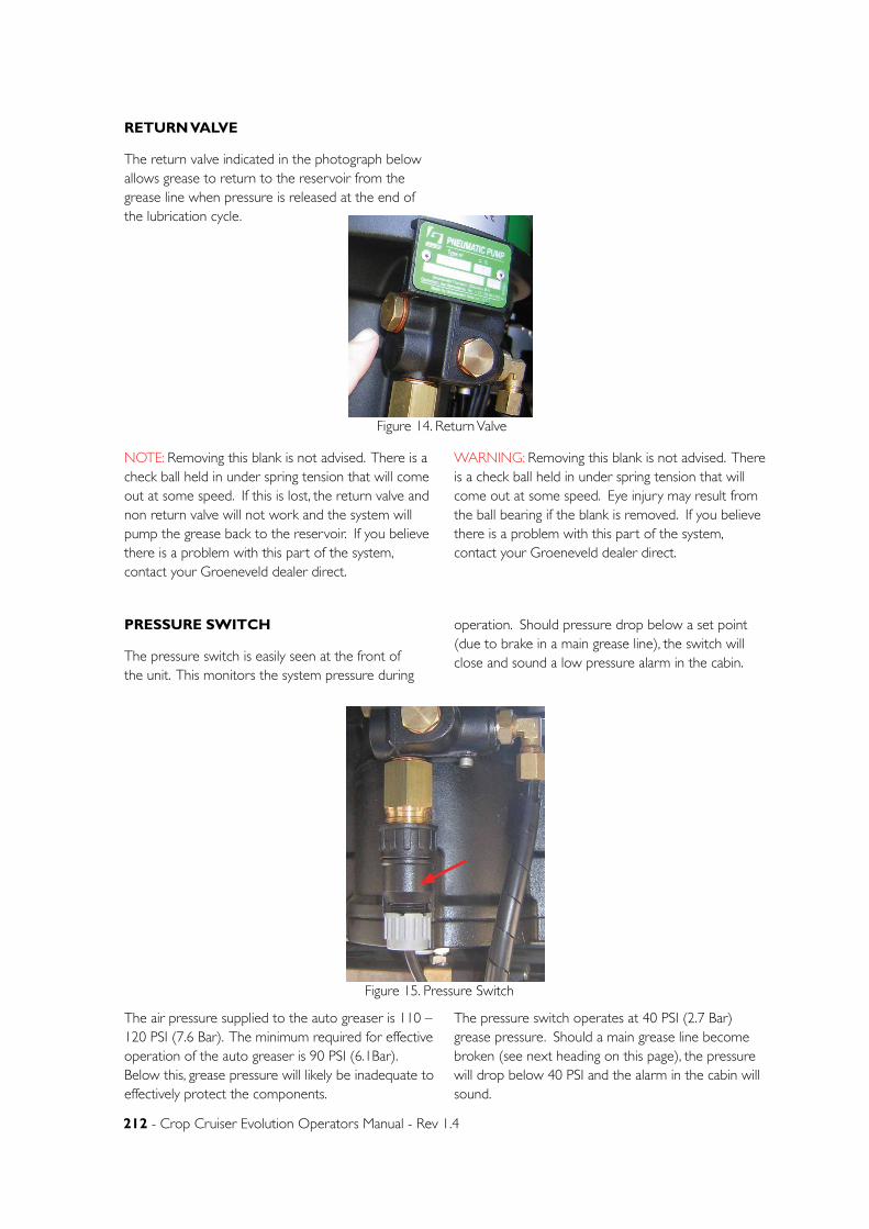
212 - Crop Cruiser Evolution Operators Manual - Rev 1.4
RETURN VALVE
The return valve indicated in the photograph below allows grease to return to the reservoir from the grease line when pressure is released at the end of the lubrication cycle.
Figure 14. Return Valve
NOTE: Removing this blank is not advised. There is a check ball held in under spring tension that will come out at some speed. If this is lost, the return valve and non return valve will not work and the system will pump the grease back to the reservoir. If you believe there is a problem with this part of the system, contact your Groeneveld dealer direct.
WARNING: Removing this blank is not advised. There is a check ball held in under spring tension that will come out at some speed. Eye injury may result from the ball bearing if the blank is removed. If you believe there is a problem with this part of the system, contact your Groeneveld dealer direct.
PRESSURE SWITCH
The pressure switch is easily seen at the front of the unit. This monitors the system pressure during
operation. Should pressure drop below a set point (due to brake in a main grease line), the switch will close and sound a low pressure alarm in the cabin.
The air pressure supplied to the auto greaser is 110 – 120 PSI (7.6 Bar). The minimum required for effective operation of the auto greaser is 90 PSI (6.1Bar). Below this, grease pressure will likely be inadequate to effectively protect the components.
The pressure switch operates at 40 PSI (2.7 Bar) grease pressure. Should a main grease line become broken (see next heading on this page), the pressure will drop below 40 PSI and the alarm in the cabin will sound.
Figure 15. Pressure Switch
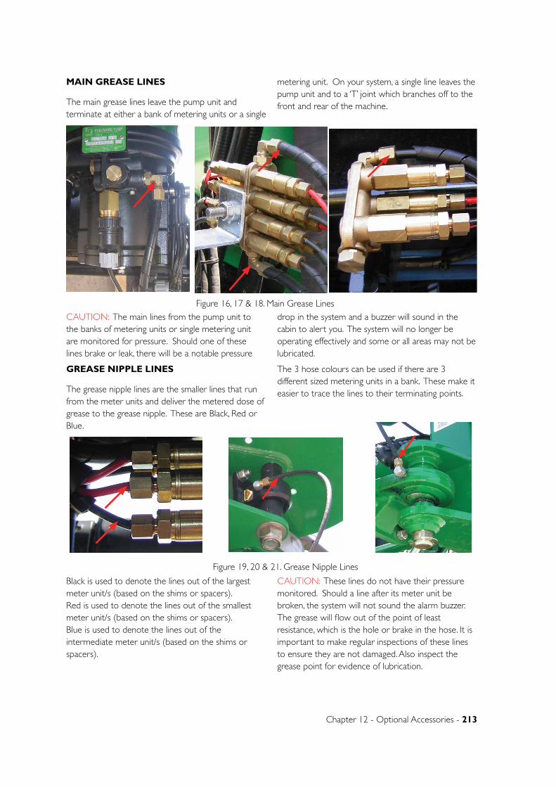
Chapter 12 - Optional Accessories - 213
MAIN GREASE LINES
The main grease lines leave the pump unit and terminate at either a bank of metering units or a single
metering unit. On your system, a single line leaves the pump unit and to a ‘T’ joint which branches off to the front and rear of the machine.
Figure 16, 17 & 18. Main Grease LinesCAUTION: The main lines from the pump unit to the banks of metering units or single metering unit are monitored for pressure. Should one of these lines brake or leak, there will be a notable pressure
drop in the system and a buzzer will sound in the cabin to alert you. The system will no longer be operating effectively and some or all areas may not be lubricated.
GREASE NIPPLE LINES
The grease nipple lines are the smaller lines that run from the meter units and deliver the metered dose of grease to the grease nipple. These are Black, Red or Blue.
The 3 hose colours can be used if there are 3 different sized metering units in a bank. These make it easier to trace the lines to their terminating points.
Figure 19, 20 & 21. Grease Nipple Lines
Black is used to denote the lines out of the largest meter unit/s (based on the shims or spacers). Red is used to denote the lines out of the smallest meter unit/s (based on the shims or spacers). Blue is used to denote the lines out of the intermediate meter unit/s (based on the shims or spacers).
CAUTION: These lines do not have their pressure monitored. Should a line after its meter unit be broken, the system will not sound the alarm buzzer. The grease will flow out of the point of least resistance, which is the hole or brake in the hose. It is important to make regular inspections of these lines to ensure they are not damaged. Also inspect the grease point for evidence of lubrication.
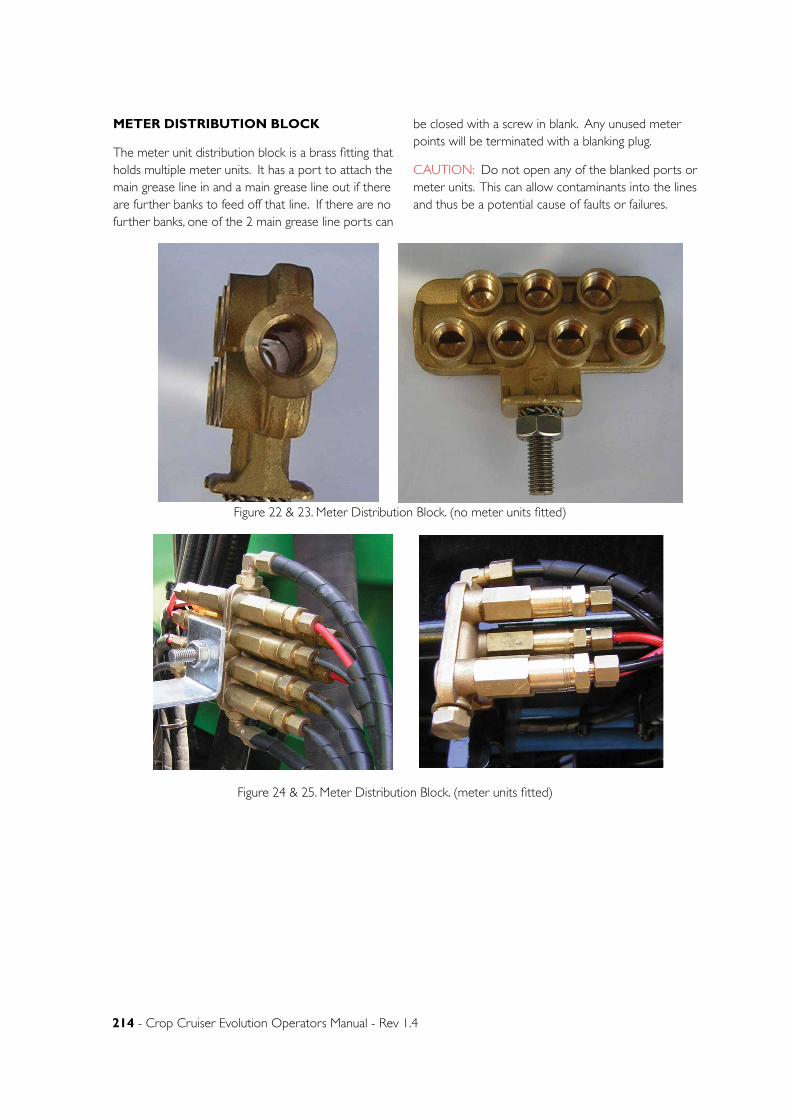
214 - Crop Cruiser Evolution Operators Manual - Rev 1.4
METER DISTRIBUTION BLOCK
The meter unit distribution block is a brass fitting that holds multiple meter units. It has a port to attach the main grease line in and a main grease line out if there are further banks to feed off that line. If there are no further banks, one of the 2 main grease line ports can
be closed with a screw in blank. Any unused meter points will be terminated with a blanking plug.
CAUTION: Do not open any of the blanked ports or meter units. This can allow contaminants into the lines and thus be a potential cause of faults or failures.
Figure 22 & 23. Meter Distribution Block. (no meter units fitted)
Figure 24 & 25. Meter Distribution Block. (meter units fitted)
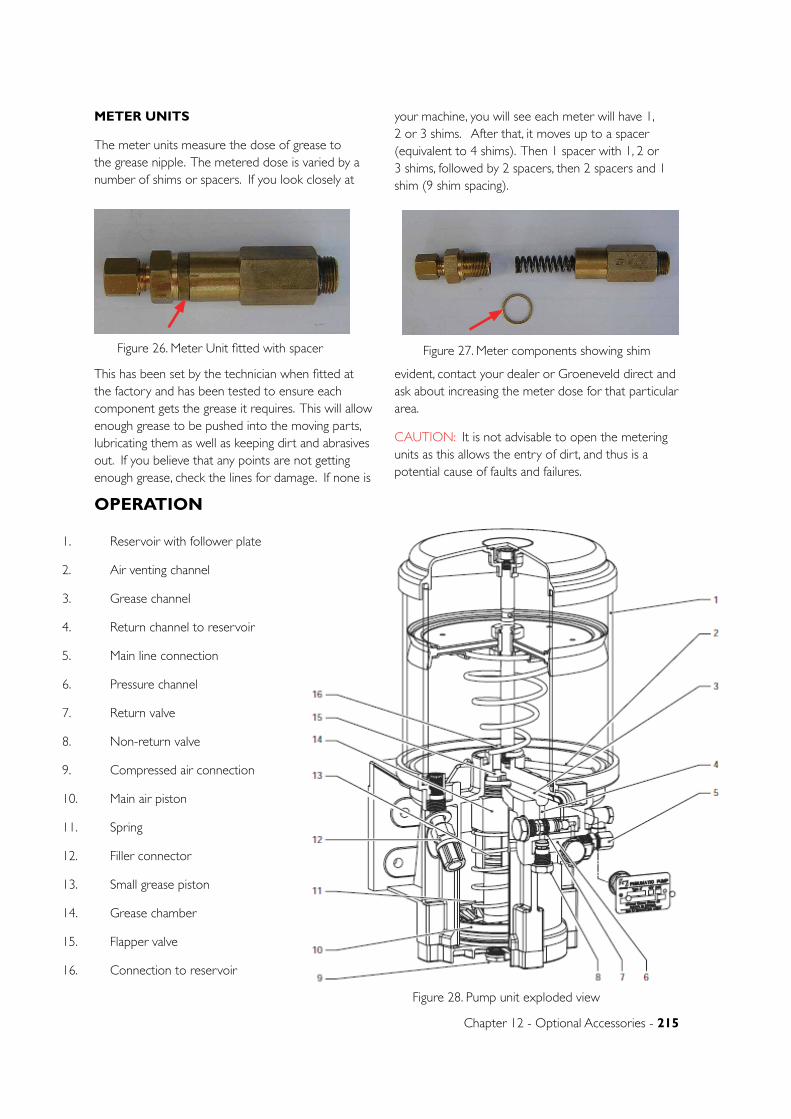
Chapter 12 - Optional Accessories - 215
METER UNITS
The meter units measure the dose of grease to the grease nipple. The metered dose is varied by a number of shims or spacers. If you look closely at
your machine, you will see each meter will have 1, 2 or 3 shims. After that, it moves up to a spacer (equivalent to 4 shims). Then 1 spacer with 1, 2 or 3 shims, followed by 2 spacers, then 2 spacers and 1 shim (9 shim spacing).
Figure 26. Meter Unit fitted with spacer Figure 27. Meter components showing shim
This has been set by the technician when fitted at the factory and has been tested to ensure each component gets the grease it requires. This will allow enough grease to be pushed into the moving parts, lubricating them as well as keeping dirt and abrasives out. If you believe that any points are not getting enough grease, check the lines for damage. If none is
evident, contact your dealer or Groeneveld direct and ask about increasing the meter dose for that particular area.
CAUTION: It is not advisable to open the metering units as this allows the entry of dirt, and thus is a potential cause of faults and failures.
OPERATION
1. Reservoir with follower plate
2. Air venting channel
3. Grease channel
4. Return channel to reservoir
5. Main line connection
6. Pressure channel
7. Return valve
8. Non-return valve
9. Compressed air connection
10. Main air piston
11. Spring
12. Filler connector
13. Small grease piston
14. Grease chamber
15. Flapper valve
16. Connection to reservoir
Figure 28. Pump unit exploded view
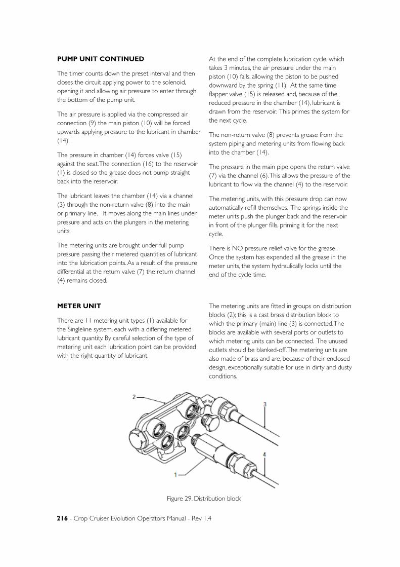
216 - Crop Cruiser Evolution Operators Manual - Rev 1.4
PUMP UNIT CONTINUED
The timer counts down the preset interval and then closes the circuit applying power to the solenoid, opening it and allowing air pressure to enter through the bottom of the pump unit.
The air pressure is applied via the compressed air connection (9) the main piston (10) will be forced upwards applying pressure to the lubricant in chamber (14).
The pressure in chamber (14) forces valve (15) against the seat. The connection (16) to the reservoir (1) is closed so the grease does not pump straight back into the reservoir.
The lubricant leaves the chamber (14) via a channel (3) through the non-return valve (8) into the main or primary line. It moves along the main lines under pressure and acts on the plungers in the metering units.
The metering units are brought under full pump pressure passing their metered quantities of lubricant into the lubrication points. As a result of the pressure differential at the return valve (7) the return channel (4) remains closed.
At the end of the complete lubrication cycle, which takes 3 minutes, the air pressure under the main piston (10) falls, allowing the piston to be pushed downward by the spring (11). At the same time flapper valve (15) is released and, because of the reduced pressure in the chamber (14), lubricant is drawn from the reservoir. This primes the system for the next cycle.
The non-return valve (8) prevents grease from the system piping and metering units from flowing back into the chamber (14).
The pressure in the main pipe opens the return valve (7) via the channel (6). This allows the pressure of the lubricant to flow via the channel (4) to the reservoir.
The metering units, with this pressure drop can now automatically refill themselves. The springs inside the meter units push the plunger back and the reservoir in front of the plunger fills, priming it for the next cycle.
There is NO pressure relief valve for the grease. Once the system has expended all the grease in the meter units, the system hydraulically locks until the end of the cycle time.
METER UNIT
There are 11 metering unit types (1) available for the Singleline system, each with a differing metered lubricant quantity. By careful selection of the type of metering unit each lubrication point can be provided with the right quantity of lubricant.
The metering units are fitted in groups on distribution blocks (2); this is a cast brass distribution block to which the primary (main) line (3) is connected. The blocks are available with several ports or outlets to which metering units can be connected. The unused outlets should be blanked-off. The metering units are also made of brass and are, because of their enclosed design, exceptionally suitable for use in dirty and dusty conditions.
Figure 29. Distribution block
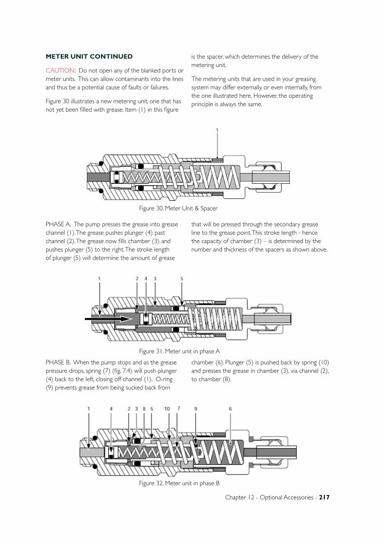
Chapter 12 - Optional Accessories - 217
METER UNIT CONTINUED
CAUTION: Do not open any of the blanked ports or meter units. This can allow contaminants into the lines and thus be a potential cause of faults or failures.
Figure 30 illustrates a new metering unit, one that has not yet been filled with grease. Item (1) in this figure
is the spacer, which determines the delivery of the metering unit.
The metering units that are used in your greasing system may differ externally, or even internally, from the one illustrated here. However, the operating principle is always the same.
Figure 30. Meter Unit & Spacer
PHASE A. The pump presses the grease into grease channel (1). The grease pushes plunger (4) past channel (2). The grease now fills chamber (3) and pushes plunger (5) to the right. The stroke length of plunger (5) will determine the amount of grease
that will be pressed through the secondary grease line to the grease point. This stroke length - hence the capacity of chamber (3) – is determined by the number and thickness of the spacers as shown above.
Figure 31. Meter unit in phase A
PHASE B. When the pump stops and as the grease pressure drops, spring (7) (fig. 7.4) will push plunger (4) back to the left, closing off channel (1). O-ring (9) prevents grease from being sucked back from
chamber (6). Plunger (5) is pushed back by spring (10) and presses the grease in chamber (3), via channel (2), to chamber (8).
Figure 32. Meter unit in phase B
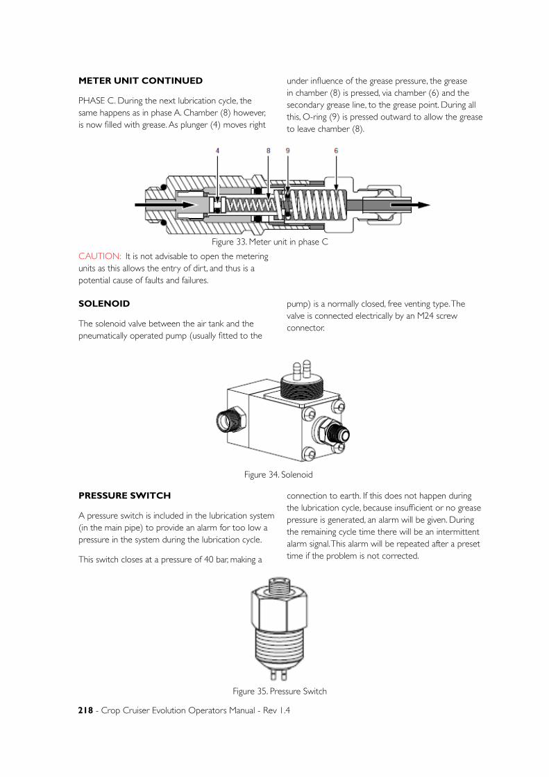
218 - Crop Cruiser Evolution Operators Manual - Rev 1.4
METER UNIT CONTINUED
PHASE C. During the next lubrication cycle, the same happens as in phase A. Chamber (8) however, is now filled with grease. As plunger (4) moves right
under influence of the grease pressure, the grease in chamber (8) is pressed, via chamber (6) and the secondary grease line, to the grease point. During all this, O-ring (9) is pressed outward to allow the grease to leave chamber (8).
Figure 33. Meter unit in phase C
CAUTION: It is not advisable to open the metering units as this allows the entry of dirt, and thus is a potential cause of faults and failures.
SOLENOID
The solenoid valve between the air tank and the pneumatically operated pump (usually fitted to the
pump) is a normally closed, free venting type. The valve is connected electrically by an M24 screw connector.
Figure 34. Solenoid
PRESSURE SWITCH
A pressure switch is included in the lubrication system (in the main pipe) to provide an alarm for too low a pressure in the system during the lubrication cycle.
This switch closes at a pressure of 40 bar, making a
connection to earth. If this does not happen during the lubrication cycle, because insufficient or no grease pressure is generated, an alarm will be given. During the remaining cycle time there will be an intermittent alarm signal. This alarm will be repeated after a preset time if the problem is not corrected.
Figure 35. Pressure Switch
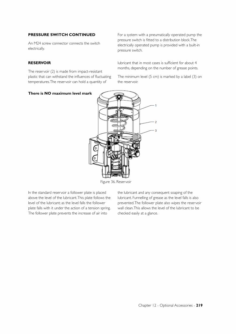
Chapter 12 - Optional Accessories - 219
PRESSURE SWITCH CONTINUED
An M24 screw connector connects the switch electrically.
For a system with a pneumatically operated pump the pressure switch is fitted to a distribution block. The electrically operated pump is provided with a built-in pressure switch.
RESERVOIR
The reservoir (2) is made from impact-resistant plastic that can withstand the influences of fluctuating temperatures. The reservoir can hold a quantity of
lubricant that in most cases is sufficient for about 4 months, depending on the number of grease points.
The minimum level (5 cm) is marked by a label (3) on the reservoir.
Figure 36. Reservoir
In the standard reservoir a follower plate is placed above the level of the lubricant. This plate follows the level of the lubricant; as the level falls the follower plate falls with it under the action of a tension spring. The follower plate prevents the increase of air into
the lubricant and any consequent soaping of the lubricant. Funnelling of grease as the level falls is also prevented. The follower plate also wipes the reservoir wall clean. This allows the level of the lubricant to be checked easily at a glance.
There is NO maximum level mark
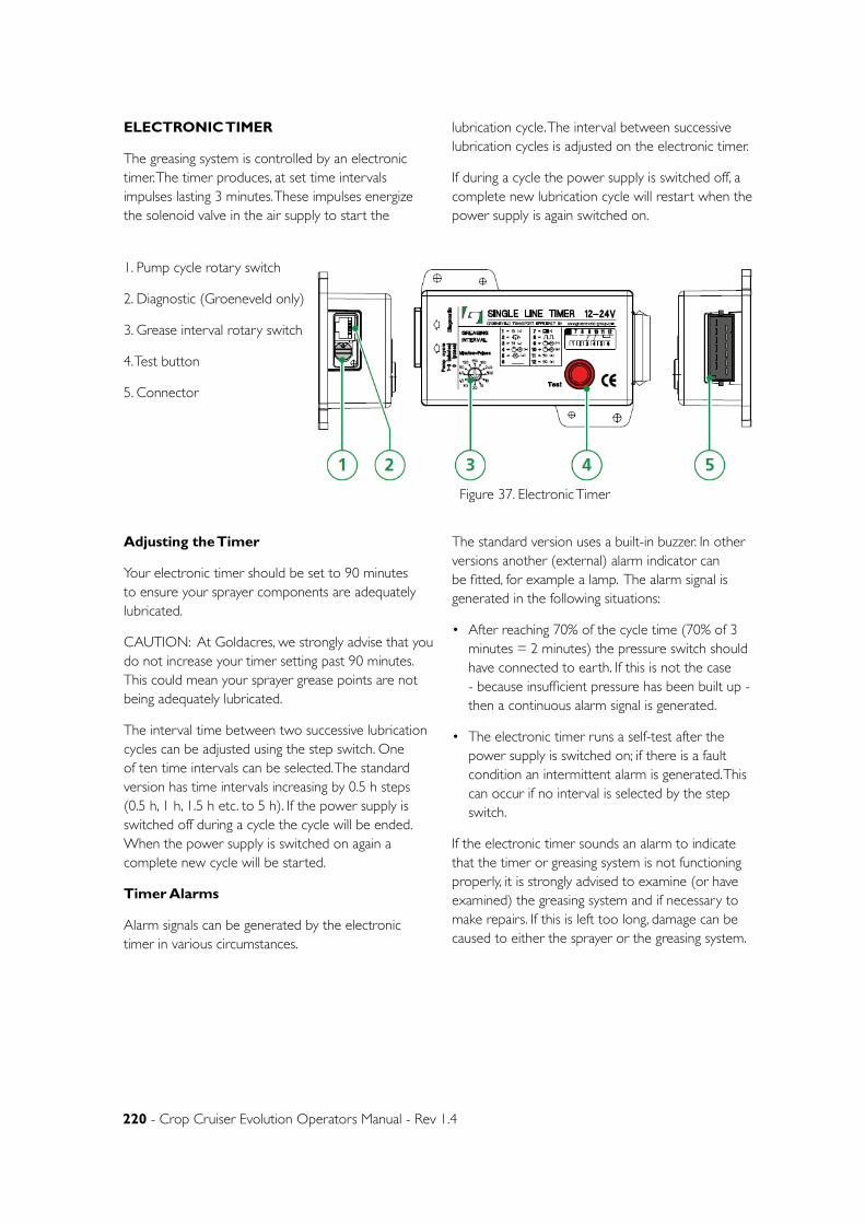
220 - Crop Cruiser Evolution Operators Manual - Rev 1.4
ELECTRONIC TIMER
The greasing system is controlled by an electronic timer. The timer produces, at set time intervals impulses lasting 3 minutes. These impulses energize the solenoid valve in the air supply to start the
lubrication cycle. The interval between successive lubrication cycles is adjusted on the electronic timer.
If during a cycle the power supply is switched off, a complete new lubrication cycle will restart when the power supply is again switched on.
Figure 37. Electronic Timer
1. Pump cycle rotary switch
2. Diagnostic (Groeneveld only)
3. Grease interval rotary switch
4. Test button
5. Connector
Adjusting the Timer
Your electronic timer should be set to 90 minutes to ensure your sprayer components are adequately lubricated.
CAUTION: At Goldacres, we strongly advise that you do not increase your timer setting past 90 minutes. This could mean your sprayer grease points are not being adequately lubricated.
The interval time between two successive lubrication cycles can be adjusted using the step switch. One of ten time intervals can be selected. The standard version has time intervals increasing by 0.5 h steps (0.5 h, 1 h, 1.5 h etc. to 5 h). If the power supply is switched off during a cycle the cycle will be ended. When the power supply is switched on again a complete new cycle will be started.
Timer Alarms
Alarm signals can be generated by the electronic timer in various circumstances.
The standard version uses a built-in buzzer. In other versions another (external) alarm indicator can be fitted, for example a lamp. The alarm signal is generated in the following situations:
• After reaching 70% of the cycle time (70% of 3 minutes = 2 minutes) the pressure switch should have connected to earth. If this is not the case - because insufficient pressure has been built up - then a continuous alarm signal is generated.
• The electronic timer runs a self-test after the power supply is switched on; if there is a fault condition an intermittent alarm is generated. This can occur if no interval is selected by the step switch.
If the electronic timer sounds an alarm to indicate that the timer or greasing system is not functioning properly, it is strongly advised to examine (or have examined) the greasing system and if necessary to make repairs. If this is left too long, damage can be caused to either the sprayer or the greasing system.
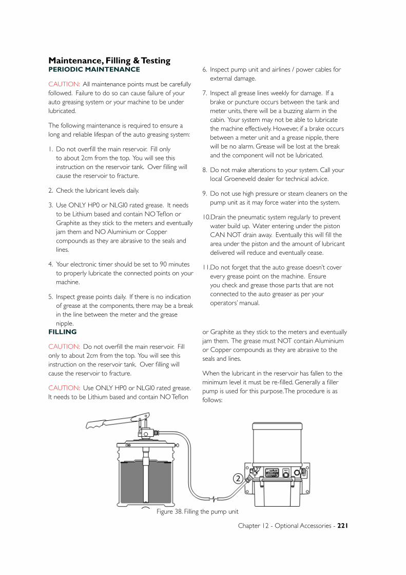
Chapter 12 - Optional Accessories - 221
PERIODIC MAINTENANCE
CAUTION: All maintenance points must be carefully followed. Failure to do so can cause failure of your auto greasing system or your machine to be under lubricated.
The following maintenance is required to ensure a long and reliable lifespan of the auto greasing system:
1. Do not overfill the main reservoir. Fill only to about 2cm from the top. You will see this instruction on the reservoir tank. Over filling will cause the reservoir to fracture.
2. Check the lubricant levels daily.
3. Use ONLY HP0 or NLGI0 rated grease. It needs to be Lithium based and contain NO Teflon or Graphite as they stick to the meters and eventually jam them and NO Aluminium or Copper compounds as they are abrasive to the seals and lines.
4. Your electronic timer should be set to 90 minutes to properly lubricate the connected points on your machine.
5. Inspect grease points daily. If there is no indication of grease at the components, there may be a break in the line between the meter and the grease nipple.
6. Inspect pump unit and airlines / power cables for external damage.
7. Inspect all grease lines weekly for damage. If a brake or puncture occurs between the tank and meter units, there will be a buzzing alarm in the cabin. Your system may not be able to lubricate the machine effectively. However, if a brake occurs between a meter unit and a grease nipple, there will be no alarm. Grease will be lost at the break and the component will not be lubricated.
8. Do not make alterations to your system. Call your local Groeneveld dealer for technical advice.
9. Do not use high pressure or steam cleaners on the pump unit as it may force water into the system.
10.Drain the pneumatic system regularly to prevent water build up. Water entering under the piston CAN NOT drain away. Eventually this will fill the area under the piston and the amount of lubricant delivered will reduce and eventually cease.
11. Do not forget that the auto grease doesn’t cover every grease point on the machine. Ensure you check and grease those parts that are not connected to the auto greaser as per your operators’ manual.
FILLING
CAUTION: Do not overfill the main reservoir. Fill only to about 2cm from the top. You will see this instruction on the reservoir tank. Over filling will cause the reservoir to fracture.
CAUTION: Use ONLY HP0 or NLGI0 rated grease. It needs to be Lithium based and contain NO Teflon
or Graphite as they stick to the meters and eventually jam them. The grease must NOT contain Aluminium or Copper compounds as they are abrasive to the seals and lines.
When the lubricant in the reservoir has fallen to the minimum level it must be re-filled. Generally a filler pump is used for this purpose. The procedure is as follows:
Figure 38. Filling the pump unit1
2
Maintenance, Filling & Testing
222 - Crop Cruiser Evolution Operators Manual - Rev 1.4
FILLING CONTINUED
1. Ensure there grease drain hole on the right of the pump unit is not blocked.
2. With a new filler pump (or filling hose) the hose should first be primed with lubricant. This avoids the pumping of air into the reservoir. For this the ball (1) in the snap-on connector on the filler hose should be depressed while pumping lubricant through the hose until it is filled with the lubricant.
3. Remove the dust cap from the filler connector.
4. Carefully clean the filler connector and the connector on the filler hose.
5. Secure the filler hose to the filler connector.
6. Fill the reservoir to not more than the maximum level (2 cm below the top of the reservoir) or until the follower plate meets its stop. If you slightly overfill, you will see grease flow from the drain hole on the right of the pump unit. This will take about 3 days to complete draining.
7. Replace the dust cap on the filler connector.
8. There is a filter within the filler connector in the reservoir. If pumping is very difficult, the filter could be blocked. In this case, dismantle and clean the filter.
TESTING THE ELECTRONIC TIMER
STEP SWITCH TEST.
This checks the step switch contacts in all positions.
1. Set the step switch to position ‘test A’.
2. Activate the electronic timer by switching on the ignition.
3. Press the ‘test’ button.
4. Wait for the audible alarm signal then release the ‘test’ button.
5. Within 5 seconds turn the step switch to the required interval time position. Each position produces a number of signals: position 1 gives one signal, position 2 two signals etc.
6. The switch can be set to all positions; positions ‘test A’ and ‘test B’ will not produce an alarm signal.
7. End the test by switching off the ignition.
ACCELERATED CYCLE TEST.
This allows you to test a timing cycle without waiting the full set time interval. It sets the time interval at 1/20 of its duration.
1. Set the step switch to position ‘test A’.
2. Press and hold the ‘test’ button.
3. Switch the ignition on while still keeping the ‘test’ button pressed in.
4. The alarm signal buzzer will now sound. The ‘test’ button must be pressed as long as the alarm signal continues.
5. Within 5 seconds of the end of the alarm signal turn the step switch to the required position.
6. The electronic timer is now fully operational; the time intervals are now 1/20 of their usual times.
7. End the test by switching off the power supply.
NORMAL SYSTEM TEST.
1. Switch the ignition on.
2. Press the ‘test’ button; a normal lubrication cycle will then follow. The switch can be set in any position except ‘test A’ or ‘test B’.
After this test the electronic timer will work at the interval set.
The ‘test B’ position is only for use with the test or read-out unit.
Chapter 12 - Optional Accessories - 223
NOTE: Instructions given to the operator to better enhance the system.
CAUTION: Instructions that if ignored will cause damage to the system or machine.
WARNING: Instructions that if ignored will cause personal injury or death to the operator or bystanders.
WARNING: Removing this blank is not advised. There is a check ball held in under spring tension that will come out at some speed. Eye injury may result from the ball bearing if the blank is removed. If you believe there is a problem with this part of the system, contact your Groeneveld dealer direct.
CAUTION: Do not overfill the main reservoir. Fill only to about 2cm from the top. You will see this instruction on the reservoir tank. Over filling will cause the reservoir to fracture.
CAUTION: When you take delivery of your sprayer, ensure you check the right hand side of the pump unit and look for a red tag or an over flow hole. If the red tag is still fitted, REMOVE IT now. If it is left in place, the reservoir may fail on refilling.
CAUTION: Use ONLY HP0 or NLGI0 rated grease. It needs to be Lithium based and contain NO Teflon or Graphite as they stick to the meters and eventually jam them. The grease must NOT contain Aluminium or Copper compounds as they are abrasive to the seals and lines.
CAUTION: The timer should be preset to 90 minutes. This has been tested as the optimum time interval for greasing the main moving parts of your machine. Setting the timer to a longer interval will mean that the components on your sprayer will not be properly lubricated.
CAUTION: The main lines from the pump unit to the banks of metering units or single metering unit are monitored for pressure. Should one of these lines brake or leak, there will be a notable pressure drop in the system and a buzzer will sound in the cabin to alert you. The system will no longer be operating effectively and some or all areas may not be lubricated.
CAUTION: These lines do not have their pressure monitored. Should a line after its meter unit be broken, the system will not sound the alarm buzzer. The grease will flow out of the point of least resistance, which is the hole or brake in the hose. It is important to make regular inspections of these lines to ensure they are not damaged and the grease point for evidence of lubrication.
CAUTION: Do not open any of the blanked ports on meter distribution blocks or the meter units. This can allow contaminants into the lines and thus be a potential cause of faults or failures.
CAUTION: It is not advisable to open the metering units as this allows the entry of dirt, and thus is a potential cause of faults and failures.
CAUTION: At Goldacres, we strongly advise that you do not increase your timer setting past 90 minutes. This could mean your sprayer grease points are not being adequately lubricated.
CAUTION: All maintenance points must be carefully followed. Failure to do so will can failure of your auto greasing system or your machine to be under lubricated.
NOTE: The fill point requires a Groeneveld female fill pump adaptor. You can purchase these via your local Groeneveld dealer or contact you Goldacres dealer to order.
NOTE: If you decide you want to run a second grease outlet line, please contact your Groeneveld outlet directly on technical advice.
NOTE: Removing this blank is not advised. There is a check ball held in under spring tension that will come out at some speed. If this is lost, the return valve and non return valve will not work and the system will pump the grease back to the reservoir. If you believe there is a problem with this part of the system, contact your Groeneveld dealer direct.
Warnings & Cautions Summary
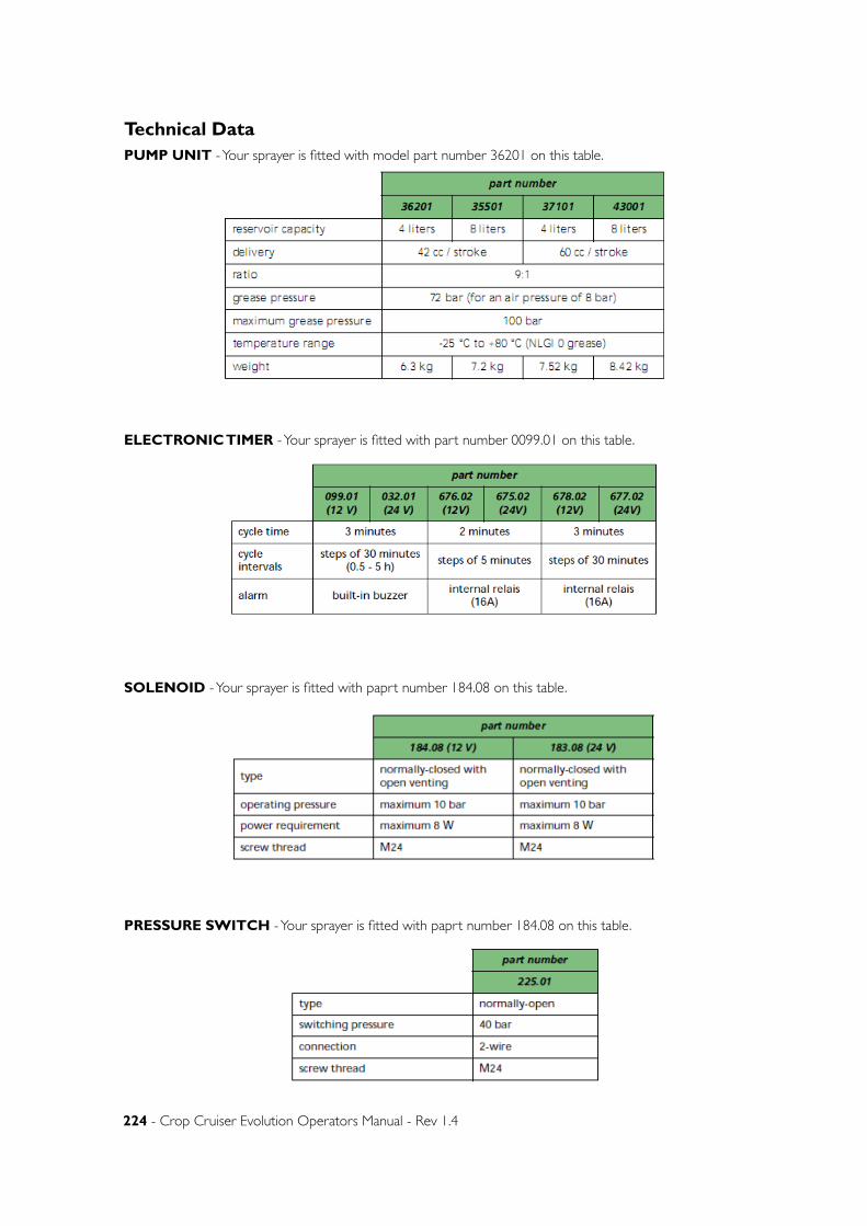
224 - Crop Cruiser Evolution Operators Manual - Rev 1.4
Technical DataPUMP UNIT - Your sprayer is fitted with model part number 36201 on this table.
ELECTRONIC TIMER - Your sprayer is fitted with part number 0099.01 on this table.
SOLENOID - Your sprayer is fitted with paprt number 184.08 on this table.
PRESSURE SWITCH - Your sprayer is fitted with paprt number 184.08 on this table.
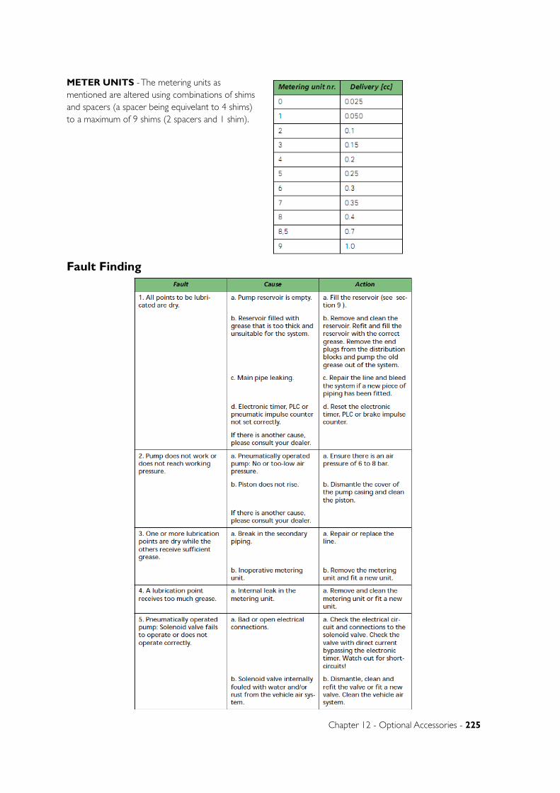
Chapter 12 - Optional Accessories - 225
METER UNITS - The metering units as mentioned are altered using combinations of shims and spacers (a spacer being equivelant to 4 shims) to a maximum of 9 shims (2 spacers and 1 shim).
Fault Finding
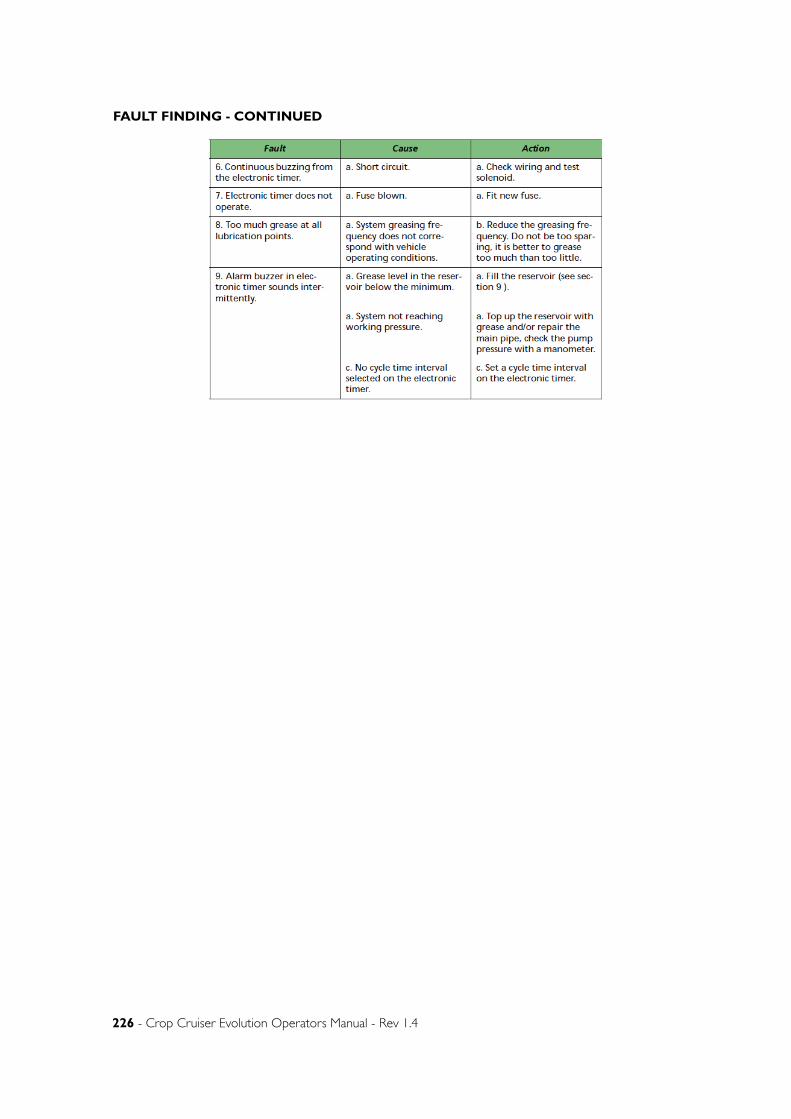
226 - Crop Cruiser Evolution Operators Manual - Rev 1.4
FAULT FINDING - CONTINUED

www.goldacres.com.au


www.goldacres.com.au
Related Documents