395 1. INTRODUCTION Reusable Launch Vehicles (RLVs) were first seriously studied with several feasible projects proposed in the 1960s. However, the advent of the rocket-based “Space Shuttle” concept and programme put an end to airbreathing design concepts.The first Space Shuttle failure in 1986 challenged mankind’s expanded presence in space. This led to a variety of airbreathing RLV designs from many countries. While most of them remained as design concepts, a few like NASP moved ahead with funded programmes. A few years later the NASP programme was closed down and the future of direct, airbreathing ascent from earth to orbit in a single stage was in doubt. But, new RLV design concepts based on rocket propulsion emerged. To date, however, none appear to be a replacement for the Shuttle. This paper reviews the evolution of RLV design concepts and sug- gests a method for comparing their techno-economic perform- ance. 2. THE CONCEPT OF SPACEPLANES IN 1980S Analysis of several RLV mass properties reveals why only a certain class of RLVs (characterized by Buffo [1] as “True Spaceplanes”) meet the requirements of revenue earning space applications like space solar power and space tourism. This paper identifies a critical conceptual design parameter, the “hydrogen fuel fraction (HFF) at take-off”, for a comparative assessment of performance and cost of emerging RLV design concepts. Buffo characterized “True Spaceplanes” as i. Horizontal take-off and landing systems. ii. Using conventional or slightly modified aircraft runways. iii. Reusable iv. Being Single-Stage-To-Orbit (SSTO) or Two-Stage-To- Orbit (TSTO) concepts with airbreathing propulsion. v. Using advanced materials. vi. Re-entering the atmosphere and landing with or without propulsion power. vii. Being either manned or unmanned. Using these seven criteria, Buffo compared spaceplane con- cepts from USA (NASP), UK (Hotol), Germany (Saenger), Japan (Hope), France (Hermes), Soviet Union (Buran) and India (Hyperplane). It is to be noted that Hope, Hermes and Buran are not fully reusable. Figure 1 illustrates the Avatar/ Hyperplane reusable spaceplane concept with In-Flight LOX Collection, from India. The non-orbital hypersonic transatmospheric spaceplane (RLV) technology demonstrator (HTV) of the Hyperplane concept of family of scalable spaceplanes is illustrated in Fig. 2. Reviewing the progress in spaceplane conceptual designs during the last 20 years, it is seen that except for the design concepts from UK (Skylon) and India (Avatar), no other spaceplane design concept was sustainable to date. This could be explained by the addition of two more attributes that may be added to Buffo’s seven criteria: a. All spaceplane engine and airframe technologies must be fully ground-testable. b. Spaceplanes should have relatively high HFF at take-off, essential for high techno-economic performance. The latter of the two above is at present hypothesis only, as experimental systems have not been flown yet. Nevertheless, it is shown to be a useful parameter in this study, to evaluate preliminary RLV system design concepts. The NASP programme was cancelled because its design demanded an airbreathing scramjet engine to operate at Mach JBIS, Vol. 63, pp.395-405, 2010 CRITICAL FACTORS IN CONCEPTUAL DESIGN AND TECHNO-ECONOMICS OF REUSUABLE SPACEPLANES R.GOPALASWAMI 53, Vayupuri, Secunderabad- 500094, India. Comparing advanced reusable spaceplane concepts and programmes, Buffo identified seven attributes to describe a true spaceplane. This paper adds two more attributes to clearly distinguish spaceplanes from rocketplanes. One of them is the hydrogen fuel fraction (HFF), the ratio of the mass of liquid hydrogen fuel to the take-off mass. Excellent correlation between HFF and spaceplane techno-economic performance is seen from regression trends arising from parametric analysis. A modified rocket equation, termed spaceplane equation, shows how high HFF, scalability and multi-stage rocket performance are feasible in single stage to orbit (SSTO) spaceplane by the combined use of fuel efficient airbreathing engines and in-flight LOX addition (FLOX). A LACE-FLOX aerocryogenic engine cycle with air liquefaction (using LACE engines) integrated with vortex/higee liquid oxygen separators may well provide both high HFF and a single combined-cycle engine from earth- to-orbit. The global status of aerocryogenic technologies is also provided. Keywords: Hydrogen fuel fraction, aerocryogenic, LACE-FLOX, spaceplane equation, scalability

Welcome message from author
This document is posted to help you gain knowledge. Please leave a comment to let me know what you think about it! Share it to your friends and learn new things together.
Transcript
395
Critical Factors in Conceptual Design and Techno-Economics of Reusable Spaceplaces
1. INTRODUCTION
Reusable Launch Vehicles (RLVs) were first seriously studiedwith several feasible projects proposed in the 1960s. However,the advent of the rocket-based “Space Shuttle” concept andprogramme put an end to airbreathing design concepts.The firstSpace Shuttle failure in 1986 challenged mankind’s expandedpresence in space. This led to a variety of airbreathing RLVdesigns from many countries. While most of them remained asdesign concepts, a few like NASP moved ahead with fundedprogrammes. A few years later the NASP programme wasclosed down and the future of direct, airbreathing ascent fromearth to orbit in a single stage was in doubt. But, new RLVdesign concepts based on rocket propulsion emerged. To date,however, none appear to be a replacement for the Shuttle. Thispaper reviews the evolution of RLV design concepts and sug-gests a method for comparing their techno-economic perform-ance.
2. THE CONCEPT OF SPACEPLANES IN 1980S
Analysis of several RLV mass properties reveals why only acertain class of RLVs (characterized by Buffo [1] as “TrueSpaceplanes”) meet the requirements of revenue earning spaceapplications like space solar power and space tourism. Thispaper identifies a critical conceptual design parameter, the“hydrogen fuel fraction (HFF) at take-off”, for a comparativeassessment of performance and cost of emerging RLV designconcepts.
Buffo characterized “True Spaceplanes” as
i. Horizontal take-off and landing systems.ii. Using conventional or slightly modified aircraft runways.iii. Reusableiv. Being Single-Stage-To-Orbit (SSTO) or Two-Stage-To-
Orbit (TSTO) concepts with airbreathing propulsion.
v. Using advanced materials.vi. Re-entering the atmosphere and landing with or without
propulsion power.vii.Being either manned or unmanned.
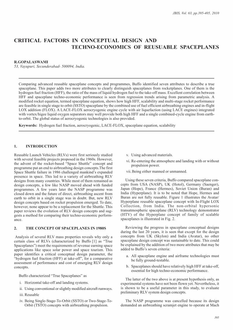
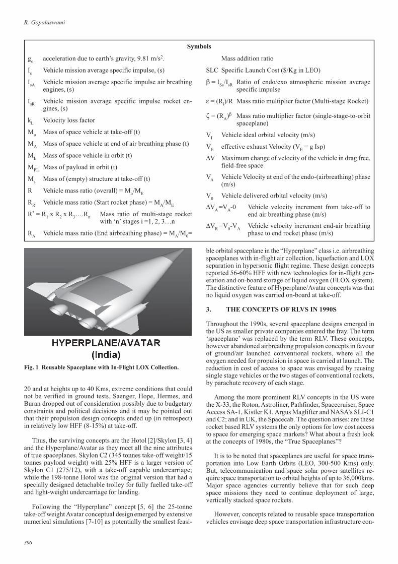
Using these seven criteria, Buffo compared spaceplane con-cepts from USA (NASP), UK (Hotol), Germany (Saenger),Japan (Hope), France (Hermes), Soviet Union (Buran) andIndia (Hyperplane). It is to be noted that Hope, Hermes andBuran are not fully reusable. Figure 1 illustrates the Avatar/Hyperplane reusable spaceplane concept with In-Flight LOXCollection, from India. The non-orbital hypersonictransatmospheric spaceplane (RLV) technology demonstrator(HTV) of the Hyperplane concept of family of scalablespaceplanes is illustrated in Fig. 2.
Reviewing the progress in spaceplane conceptual designsduring the last 20 years, it is seen that except for the designconcepts from UK (Skylon) and India (Avatar), no otherspaceplane design concept was sustainable to date. This couldbe explained by the addition of two more attributes that may beadded to Buffo’s seven criteria:
a. All spaceplane engine and airframe technologies mustbe fully ground-testable.
b. Spaceplanes should have relatively high HFF at take-off,essential for high techno-economic performance.
The latter of the two above is at present hypothesis only, asexperimental systems have not been flown yet. Nevertheless, itis shown to be a useful parameter in this study, to evaluatepreliminary RLV system design concepts.
The NASP programme was cancelled because its designdemanded an airbreathing scramjet engine to operate at Mach
JBIS, Vol. 63, pp.395-405, 2010
CRITICAL FACTORS IN CONCEPTUAL DESIGN ANDTECHNO-ECONOMICS OF REUSUABLE SPACEPLANES
R.GOPALASWAMI53, Vayupuri, Secunderabad- 500094, India.
Comparing advanced reusable spaceplane concepts and programmes, Buffo identified seven attributes to describe a truespaceplane. This paper adds two more attributes to clearly distinguish spaceplanes from rocketplanes. One of them is thehydrogen fuel fraction (HFF), the ratio of the mass of liquid hydrogen fuel to the take-off mass. Excellent correlation betweenHFF and spaceplane techno-economic performance is seen from regression trends arising from parametric analysis. Amodified rocket equation, termed spaceplane equation, shows how high HFF, scalability and multi-stage rocket performanceare feasible in single stage to orbit (SSTO) spaceplane by the combined use of fuel efficient airbreathing engines and in-flightLOX addition (FLOX). A LACE-FLOX aerocryogenic engine cycle with air liquefaction (using LACE engines) integratedwith vortex/higee liquid oxygen separators may well provide both high HFF and a single combined-cycle engine from earth-to-orbit. The global status of aerocryogenic technologies is also provided.
Keywords: Hydrogen fuel fraction, aerocryogenic, LACE-FLOX, spaceplane equation, scalability
396
R. Gopalaswami
go acceleration due to earth’s gravity, 9.81 m/s2.
Is Vehicle mission average specific impulse, (s)
IsA Vehicle mission average specific impulse air breathingengines, (s)
IsR Vehicle mission average specific impulse rocket en-gines, (s)
kL Velocity loss factor
Mo Mass of space vehicle at take-off (t)
MA Mass of space vehicle at end of air breathing phase (t)
ME Mass of space vehicle in orbit (t)
MPL Mass of payload in orbit (t)
Ms Mass of (empty) structure at take-off (t)
R Vehicle mass ratio (overall) = Mo/ME
RR Vehicle mass ratio (Start rocket phase) = MA/ME
R* = R1 x R2 x R3….Rn Mass ratio of multi-stage rocketwith ‘n’ stages i =1, 2, 3…n
RA Vehicle mass ratio (End airbreathing phase) = MA/M0=
Symbols
Mass addition ratio
SLC Specific Launch Cost ($/Kg in LEO)
β = ISa/IsR Ratio of endo/exo atmospheric mission averagespecific impulse
ε = (Ri)/R Mass ratio multiplier factor (Multi-stage Rocket)
ζ = (RA)β Mass ratio multiplier factor (single-stage-to-orbitspaceplane)
VI Vehicle ideal orbital velocity (m/s)
VE effective exhaust Velocity (VE = g Isp)
∆V Maximum change of velocity of the vehicle in drag free,field-free space
VA Vehicle Velocity at end of the endo-(airbreathing) phase(m/s)
V0 Vehicle delivered orbital velocity (m/s)
∆VA =VA-0 Vehicle velocity increment from take-off toend air breathing phase (m/s)
∆VR =V0-VA Vehicle velocity increment end-air breathingphase to end rocket phase (m/s)
20 and at heights up to 40 Kms, extreme conditions that couldnot be verified in ground tests. Saenger, Hope, Hermes, andBuran dropped out of consideration possibly due to budgetaryconstraints and political decisions and it may be pointed outthat their propulsion design concepts ended up (in retrospect)in relatively low HFF (8-15%) at take-off.
Thus, the surviving concepts are the Hotol [2]/Skylon [3, 4]and the Hyperplane/Avatar as they meet all the nine attributesof true spaceplanes. Skylon C2 (345 tonnes take-off weight/15tonnes payload weight) with 25% HFF is a larger version ofSkylon C1 (275/12), with a take-off capable undercarriage;while the 198-tonne Hotol was the original version that had aspecially designed detachable trolley for fully fuelled take-offand light-weight undercarriage for landing.
Following the “Hyperplane” concept [5, 6] the 25-tonnetake-off weight Avatar conceptual design emerged by extensivenumerical simulations [7-10] as potentially the smallest feasi-
ble orbital spaceplane in the “Hyperplane” class i.e. airbreathingspaceplanes with in-flight air collection, liquefaction and LOXseparation in hypersonic flight regime. These design conceptsreported 56-60% HFF with new technologies for in-flight gen-eration and on-board storage of liquid oxygen (FLOX system).The distinctive feature of Hyperplane/Avatar concepts was thatno liquid oxygen was carried on-board at take-off.
3. THE CONCEPTS OF RLVS IN 1990S
Throughout the 1990s, several spaceplane designs emerged inthe US as smaller private companies entered the fray. The term‘spaceplane’ was replaced by the term RLV. These concepts,however abandoned airbreathing propulsion concepts in favourof ground/air launched conventional rockets, where all theoxygen needed for propulsion in space is carried at launch. Thereduction in cost of access to space was envisaged by reusingsingle stage vehicles or the two stages of conventional rockets,by parachute recovery of each stage.
Among the more prominent RLV concepts in the US werethe X-33, the Roton, Astroliner, Pathfinder, Spacecruiser, SpaceAccess SA-1, Kistler K1, Argus Maglifter and NASA’s SLI-C1and C2; and in UK, the Spacecab. The question arises: are theserocket based RLV systems the only options for low cost accessto space for emerging space markets? What about a fresh lookat the concepts of 1980s, the “True Spaceplanes”?
It is to be noted that spaceplanes are useful for space trans-portation into Low Earth Orbits (LEO, 300-500 Kms) only.But, telecommunication and space solar power satellites re-quire space transportation to orbital heights of up to 36,000kms.Major space agencies currently believe that for such deepspace missions they need to continue deployment of large,vertically stacked space rockets.
However, concepts related to reusable space transportationvehicles envisage deep space transportation infrastructure con-
Fig. 1 Reusable Spaceplane with In-Flight LOX Collection.
397
Critical Factors in Conceptual Design and Techno-Economics of Reusable Spaceplaces
sisting of a space station node in LEO to which space trafficwould use reusable spaceplanes. Payloads from the spaceplaneswould be transferred to space station based multi-stage LOX/LH2 space rockets that return to the space station for reuse. TheLOX/LH2 propellants employed and spare parts/equipment forthe multi-stage rockets would also be brought up from earth inthe first instance. But closer to earth, what is optimal forrevenue earning space missions like space tourism and spacesolar power?
3.1 Importance of Hydrogen Fuel Fraction
The hydrogen Fuel Fraction (HFF) is defined as the ratio of themass of liquid hydrogen fuel to the take-off mass of a reusablelaunch vehicle. It is necessary to see why the HFF forairbreathing spaceplanes is an important attribute and why ithas not figured so far in the perceptions of spaceplane androcketplane designers. For aeroplane designers, fuel fraction isan important design parameter that they wish to maximize,whereas a rocket engineer wants to maximize the propellantfraction that includes oxidizer and fuel.
The spaceplane is basically an aeroplane with a capabil-ity to attain orbital height and speed. Jones and Donaldsonreported [11] airbreathing aircraft that ascend directly fromearth to orbit need at least 56% of take-off weight to behydrogen fuel, failing which enough kinetic and potentialenergies will not be available for it to be placed in the earthorbit. In addition to this fuel mass fraction, the aeroplaneneeds to have a distinct relationship between its propulsiveefficiency and the thrust to drag ratio. However, this impor-tant finding was overlooked by the aerospace vehicle designcommunity.
Aerospaceplane engineers see this differently. They look ata hypersonic aeroplane as if it were a 100-tonne conventionalrocket that would have a payload at best 2 tonnes. Good struc-
tural design could ensure an empty structure weight of 13tonnes while the remaining 85 tonnes would be for propellant.This 85 tonnes would consist of 25% hydrogen fuel (21 tonnes)and 75% oxygen/oxidizer (64 tonnes).
Consider an aerospaceplane that carries no oxygen on board.Its take off weight would be 100-64=36 tonnes, but still con-taining 21 tonnes, or 58% (21/36) of take-off mass of hydro-gen. Jones and Donaldson’s requirement of 56% would be met.This was the basis of the Hyperplane/Avatar design concepts.Not carrying LOX on-board at take-off but carrying out airliquefaction and oxygen separation while flying in a Mach 3.5to Mach 8 regime would result in high payload fractions,varying from 5% to 10% reported for Hyperplane/Avatar (Ta-ble 1). Other spaceplane concepts, such as Skylon considerdeep air pre-cooling stainless steel heat exchanger technologieswithout in-flight air and oxygen liquefaction. Hydrogen/airrocket engines designed on similar principles [12-15] are re-ported to achieve higher specific impulse (about 3500s). Theseare called Liquid Air Cycle Engines (LACE). Such LACEsusing refractory metal heat exchangers are said to enable theengines operate up to Mach 7/8 and steep, optimized trajectoryfrom earth to 80km altitude, after which the main engines areshut down and the vehicle coasts on a ballistic trajectory to a300 km LEO.
The feasibility of high payload fractions need not beviewed with scepticism and disbelief. Avery and Dugger[16] reported the difficulties of sub-sonic combustion atvery high speeds. This led to investigation of new types ofengines which can extend the speed of airbreathing vehiclesto orbital velocity and uses air collection, condensation andfractionation while the vehicle is flying in the Mach 5-8range on ramjet power with liquid hydrogen fuel. The oxy-gen enriched liquid obtained and stored on-board is thenburned with the hydrogen fuel in the rocket engine phase toaccelerate the vehicle to orbital speeds. The success of such
Fig. 2 The Hyperplane/Avatar transatmospheric hypersonic flight RLV technology demonstrator.
398
R. Gopalaswami
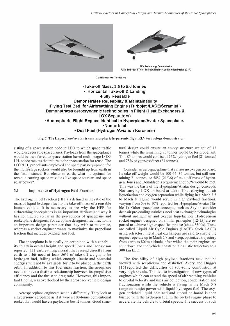
a system depends on development of lightweight air collec-tion and fractionation equipment. Extensive numerical simu-lation of trajectories and mass fractions of a family of reus-able spaceplanes based on the “Hyperplane” concept as afunction of launch mass was carried out and the results areshown in Fig. 3. It can be seen from the trend lines that forthe Hyperplane-type of spaceplane, the payload fractionincreases from about 1% to 10% as a function of launchmass as did the payload-to-structure ratio.
3.2 Structural and Cost Effectiveness Parameters
The parameters that characterise rocket based RLVs,airbreathing/rocket based spaceplanes and expendable rocketsare the payload fraction (payload mass/launch mass), propel-lant fraction (propellant mass/ launch mass) and structure massfraction (structure mass/launch mass). These three basic pa-rameters are then used to derive parameters as relevant to anaerospacecraft:
3.2.1 Structural Effectiveness Factor (SEF)
Structural Effectiveness Factor (SEF) is defined as the ratio ofpayload fraction to structure fraction. For any given vehicle:
SEF = (MPL/Mo) / (Ms/Mo) = (MPL)/(Ms) (1)
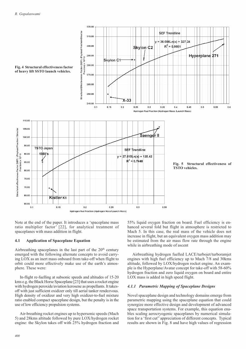
A good RLV/Spaceplane design would maximize the SEF.Values of SEF for various spaceplane design concepts arepresented in Table 1 and Figs. 4 & 5. It can be seen that higherthe HFF, higher is the SEF. This shows the importance of HFFas a critical factor in preliminary concept design.
3.2.2 Technology Effectiveness Index (TEI)
Technology Effectiveness Index (TEI) is defined as the SEF forunit mass of RLV at take-off. For any given vehicle, with anoperational life cycle fL, the TEI may be written as
TEI = fL x (SEF)/(Mo) (2)
In this analysis, since all the spaceplane concepts examinedare normalised to the same operational life cycle, this factor fLmay be ignored.
3.2.3 Cost Effectiveness Index.
The TEI is an element of the cost-effectiveness of a vehicle.For any given vehicle, Cost Effectiveness Index (CEI) = (SLC)x (TEI) where SLC is the specific launch cost.
3.2.4 Relative Technical Cost of Access to Space (RTCAS)
Relative Technical Cost of Access to Space (RTCAS) is ob-tained from the CEI by normalizing SSTO RLVs to estimatedSkylon C2 as reference vehicle at a SLCRef of $1300/Kg inLEO [17] (current prices). TSTO RLVs are normalized withrespect to Saengar as reference vehicle at a SLCRef of $3063/kgin LEO [18, 19].
RTCAS = (SLC)Ref x (TEI)Ref/(TEI) (3)
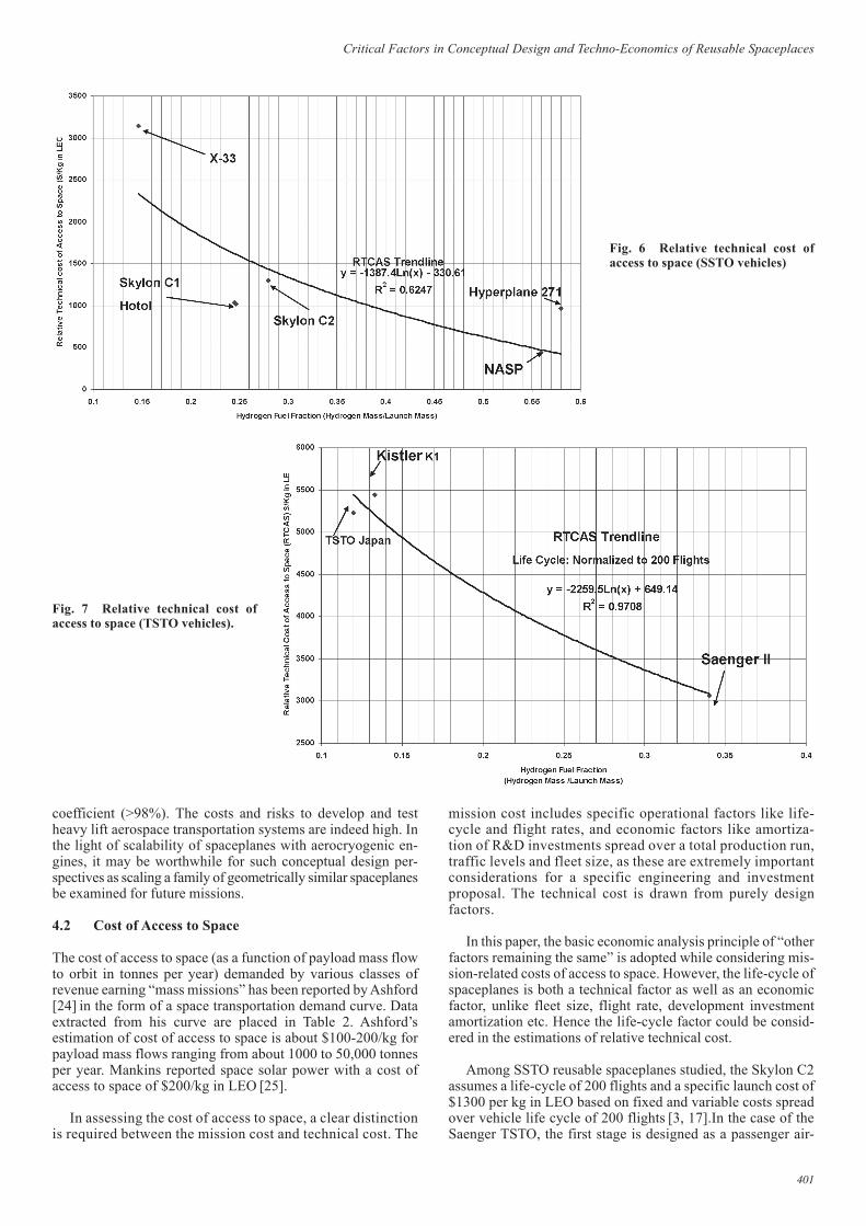
SEF, TEI and RTCAS values are computed for each vehicleand shown in Table 1 and Figs. 6 & 7. A clear trend of increas-ing SEF and decreasing RTCAS is seen with high regressioncoefficients and thus the importance of HFF being used as ameasure of comparative evaluation of different spaceplane/RLV designs is established.
4. MODIFYING THE TSIOLKOVSKYROCKET EQUATION FOR SPACEPLANES
WITH FLOX MASS ADDITION
The Tsiolkovsky (or Ideal) rocket equation relates the maxi-mum change of speed of the rocket (∆V) to the effectiveexhaust velocity (VE) and the initial (M0) and final (ME)masses of a rocket or a reaction engine. It considers rocketas a device that can apply acceleration (thrust) to it byexpelling part of its mass at high speed in the oppositedirection. For any such manoeuver (or flight involving anumber of such manoeuvers)
∆V = VE Ln Mo/ME (4)
The term Mo/ME =R is called the rocket mass ratio.
The Ideal Rocket Equation is strictly valid only for a con-stant effective exhaust velocity/specific impulse and in theabsence of external forces such as atmospheric drag or gravity
Fig. 3 Numerical simulation ofreusable airbreathing spaceplaneswith in-flight mass addition.
399
Critical Factors in Conceptual Design and Techno-Economics of Reusable Spaceplaces
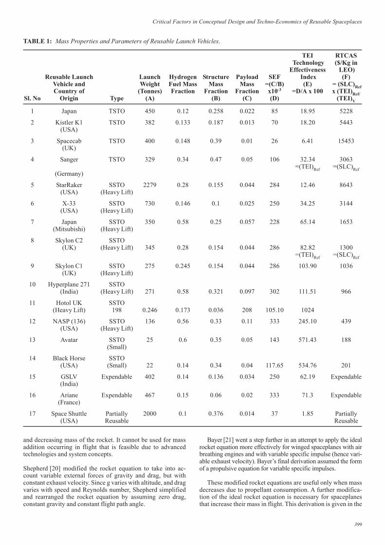
TABLE 1: Mass Properties and Parameters of Reusable Launch Vehicles.
TEI RTCAS Technology ($/Kg inEffectiveness LEO)
Reusable Launch Launch Hydrogen Structure Payload SEF Index (F)Vehicle and Weight Fuel Mass Mass Mass =(C/B) (E) = (SLC)RefCountry of (Tonnes) Fraction Fraction Fraction x10-3 =D/A x 100 x (TEI)Ref/
Sl. No Origin Type (A) (B) (C) (D) (TEI)V
1 Japan TSTO 450 0.12 0.258 0.022 85 18.95 5228
2 Kistler K1 TSTO 382 0.133 0.187 0.013 70 18.20 5443(USA)
3 Spacecab TSTO 400 0.148 0.39 0.01 26 6.41 15453(UK)
4 Sanger TSTO 329 0.34 0.47 0.05 106 32.34 3063=(TEI)Ref =(SLC)Ref
(Germany)
5 StarRaker SSTO 2279 0.28 0.155 0.044 284 12.46 8643(USA) (Heavy Lift)
6 X-33 SSTO 730 0.146 0.1 0.025 250 34.25 3144(USA) (Heavy Lift)
7 Japan SSTO 350 0.58 0.25 0.057 228 65.14 1653(Mitsubishi) (Heavy Lift)
8 Skylon C2 SSTO(UK) (Heavy Lift) 345 0.28 0.154 0.044 286 82.82 1300
=(TEI)Ref =(SLC)Ref
9 Skylon C1 SSTO 275 0.245 0.154 0.044 286 103.90 1036(UK) (Heavy Lift)
10 Hyperplane 271 SSTO(India) (Heavy Lift) 271 0.58 0.321 0.097 302 111.51 966
11 Hotol UK SSTO(Heavy Lift) 198 0.246 0.173 0.036 208 105.10 1024
12 NASP (136) SSTO 136 0.56 0.33 0.11 333 245.10 439(USA) (Heavy Lift)
13 Avatar SSTO 25 0.6 0.35 0.05 143 571.43 188(Small)
14 Black Horse SSTO(USA) (Small) 22 0.14 0.34 0.04 117.65 534.76 201
15 GSLV Expendable 402 0.14 0.136 0.034 250 62.19 Expendable(India)
16 Ariane Expendable 467 0.15 0.06 0.02 333 71.3 Expendable(France)
17 Space Shuttle Partially 2000 0.1 0.376 0.014 37 1.85 Partially(USA) Reusable Reusable
and decreasing mass of the rocket. It cannot be used for massaddition occurring in flight that is feasible due to advancedtechnologies and system concepts.
Shepherd [20] modified the rocket equation to take into ac-count variable external forces of gravity and drag, but withconstant exhaust velocity. Since g varies with altitude, and dragvaries with speed and Reynolds number, Shepherd simplifiedand rearranged the rocket equation by assuming zero drag,constant gravity and constant flight path angle.
Bayer [21] went a step further in an attempt to apply the idealrocket equation more effectively for winged spaceplanes with airbreathing engines and with variable specific impulse (hence vari-able exhaust velocity). Bayer’s final derivation assumed the formof a propulsive equation for variable specific impulses.
These modified rocket equations are useful only when massdecreases due to propellant consumption. A further modifica-tion of the ideal rocket equation is necessary for spaceplanesthat increase their mass in flight. This derivation is given in the
400
R. Gopalaswami
Note at the end of the paper. It introduces a ‘spaceplane massratio multiplier factor’ [22], for analytical treatment ofspaceplanes with mass addition in flight.
4.1 Application of Spaceplane Equation
Airbreathing spaceplanes in the last part of the 20th centuryemerged with the following alternate concepts to avoid carry-ing LOX as an inert mass onboard from take-off when flight toorbit could more effectively make use of the earth’s atmos-phere. These were:
In-flight re-fuelling at subsonic speeds and altitudes of 15-20kms e.g. the Black Horse Spaceplane [23] that uses a rocket enginewith hydrogen peroxide/aviation kerosene as propellants. It takes-off with just sufficient oxidizer only till aerial tanker rendezvous.High density of oxidizer and very high oxidizer-to-fuel mixtureratio enabled compact spaceplane design, but the penalty is in theuse of low efficiency propulsion systems.
Air-breathing rocket engines up to hypersonic speeds (Mach5) and 28kms altitude followed by pure LOX/hydrogen rocketengine: the Skylon takes off with 25% hydrogen fraction and
Fig. 4 Structural effectiveness factorof heavy lift SSTO launch vehicles.
Fig. 5 Structural effectiveness ofTSTO vehicles.
55% liquid oxygen fraction on board. Fuel efficiency is en-hanced several fold but flight in atmosphere is restricted toMach 5. In this case, the real mass of the vehicle does notincrease in flight, but an equivalent oxygen mass addition maybe estimated from the air mass flow rate through the enginewhile in airbreathing mode of ascent
Airbreathing hydrogen fuelled LACE/turbojet/turboramjetengines with high fuel efficiency up to Mach 7/8 and 30kmsaltitude, followed by LOX/hydrogen rocket engine. An exam-ple is the Hyperplane/Avatar concept for take-off with 58-60%hydrogen fraction and zero liquid oxygen on board and entireLOX mass is added in high speed flight.
4.1.1 Parametric Mapping of Spaceplane Designs
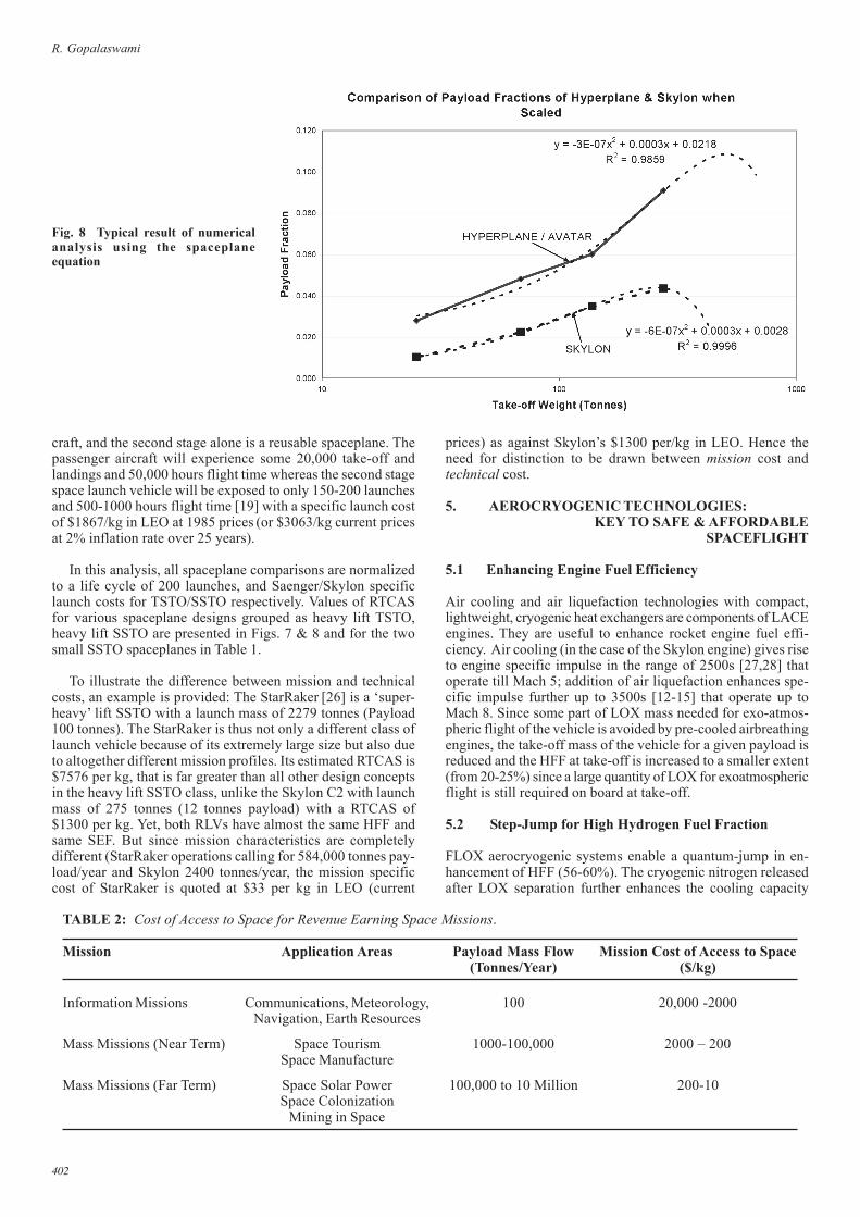
Novel spaceplane design and technology domains emerge fromparametric mapping using the spaceplane equation that couldsynergize more effective design and development of advancedspace transportation systems. For example, this equation ena-bles scaling aerocryogenic spaceplanes by numerical simula-tion for a ‘first cut” appreciation of different concepts. Typicalresults are shown in Fig. 8 and have high values of regression
401
Critical Factors in Conceptual Design and Techno-Economics of Reusable Spaceplaces
coefficient (>98%). The costs and risks to develop and testheavy lift aerospace transportation systems are indeed high. Inthe light of scalability of spaceplanes with aerocryogenic en-gines, it may be worthwhile for such conceptual design per-spectives as scaling a family of geometrically similar spaceplanesbe examined for future missions.
4.2 Cost of Access to Space
The cost of access to space (as a function of payload mass flowto orbit in tonnes per year) demanded by various classes ofrevenue earning “mass missions” has been reported by Ashford[24] in the form of a space transportation demand curve. Dataextracted from his curve are placed in Table 2. Ashford’sestimation of cost of access to space is about $100-200/kg forpayload mass flows ranging from about 1000 to 50,000 tonnesper year. Mankins reported space solar power with a cost ofaccess to space of $200/kg in LEO [25].
In assessing the cost of access to space, a clear distinctionis required between the mission cost and technical cost. The
Fig. 6 Relative technical cost ofaccess to space (SSTO vehicles)
Fig. 7 Relative technical cost ofaccess to space (TSTO vehicles).
mission cost includes specific operational factors like life-cycle and flight rates, and economic factors like amortiza-tion of R&D investments spread over a total production run,traffic levels and fleet size, as these are extremely importantconsiderations for a specific engineering and investmentproposal. The technical cost is drawn from purely designfactors.
In this paper, the basic economic analysis principle of “otherfactors remaining the same” is adopted while considering mis-sion-related costs of access to space. However, the life-cycle ofspaceplanes is both a technical factor as well as an economicfactor, unlike fleet size, flight rate, development investmentamortization etc. Hence the life-cycle factor could be consid-ered in the estimations of relative technical cost.
Among SSTO reusable spaceplanes studied, the Skylon C2assumes a life-cycle of 200 flights and a specific launch cost of$1300 per kg in LEO based on fixed and variable costs spreadover vehicle life cycle of 200 flights [3, 17].In the case of theSaenger TSTO, the first stage is designed as a passenger air-
402
R. Gopalaswami
craft, and the second stage alone is a reusable spaceplane. Thepassenger aircraft will experience some 20,000 take-off andlandings and 50,000 hours flight time whereas the second stagespace launch vehicle will be exposed to only 150-200 launchesand 500-1000 hours flight time [19] with a specific launch costof $1867/kg in LEO at 1985 prices (or $3063/kg current pricesat 2% inflation rate over 25 years).
In this analysis, all spaceplane comparisons are normalizedto a life cycle of 200 launches, and Saenger/Skylon specificlaunch costs for TSTO/SSTO respectively. Values of RTCASfor various spaceplane designs grouped as heavy lift TSTO,heavy lift SSTO are presented in Figs. 7 & 8 and for the twosmall SSTO spaceplanes in Table 1.
To illustrate the difference between mission and technicalcosts, an example is provided: The StarRaker [26] is a ‘super-heavy’ lift SSTO with a launch mass of 2279 tonnes (Payload100 tonnes). The StarRaker is thus not only a different class oflaunch vehicle because of its extremely large size but also dueto altogether different mission profiles. Its estimated RTCAS is$7576 per kg, that is far greater than all other design conceptsin the heavy lift SSTO class, unlike the Skylon C2 with launchmass of 275 tonnes (12 tonnes payload) with a RTCAS of$1300 per kg. Yet, both RLVs have almost the same HFF andsame SEF. But since mission characteristics are completelydifferent (StarRaker operations calling for 584,000 tonnes pay-load/year and Skylon 2400 tonnes/year, the mission specificcost of StarRaker is quoted at $33 per kg in LEO (current
prices) as against Skylon’s $1300 per/kg in LEO. Hence theneed for distinction to be drawn between mission cost andtechnical cost.
5. AEROCRYOGENIC TECHNOLOGIES:KEY TO SAFE & AFFORDABLE
SPACEFLIGHT
5.1 Enhancing Engine Fuel Efficiency
Air cooling and air liquefaction technologies with compact,lightweight, cryogenic heat exchangers are components of LACEengines. They are useful to enhance rocket engine fuel effi-ciency. Air cooling (in the case of the Skylon engine) gives riseto engine specific impulse in the range of 2500s [27,28] thatoperate till Mach 5; addition of air liquefaction enhances spe-cific impulse further up to 3500s [12-15] that operate up toMach 8. Since some part of LOX mass needed for exo-atmos-pheric flight of the vehicle is avoided by pre-cooled airbreathingengines, the take-off mass of the vehicle for a given payload isreduced and the HFF at take-off is increased to a smaller extent(from 20-25%) since a large quantity of LOX for exoatmosphericflight is still required on board at take-off.
5.2 Step-Jump for High Hydrogen Fuel Fraction
FLOX aerocryogenic systems enable a quantum-jump in en-hancement of HFF (56-60%). The cryogenic nitrogen releasedafter LOX separation further enhances the cooling capacity
Fig. 8 Typical result of numericalanalysis using the spaceplaneequation
TABLE 2: Cost of Access to Space for Revenue Earning Space Missions.
Mission Application Areas Payload Mass Flow Mission Cost of Access to Space(Tonnes/Year) ($/kg)
Information Missions Communications, Meteorology, 100 20,000 -2000Navigation, Earth Resources
Mass Missions (Near Term) Space Tourism 1000-100,000 2000 – 200Space Manufacture
Mass Missions (Far Term) Space Solar Power 100,000 to 10 Million 200-10Space Colonization
Mining in Space
403
Critical Factors in Conceptual Design and Techno-Economics of Reusable Spaceplaces
available from liquid hydrogen alone. The issues of liquefac-tion (momentum-loss) drag, purity of LOX after separationprocess and overall weight of the aerocryogenic system need tobe addressed comprehensively at the stage of spaceplane flightperformance and flight path design for which multi-variableoptimization techniques are essential.
A fair amount of design and experimental work has beencarried out in India [29-35] including numerical simulation oftrajectories for airbreathing SSTO vehicles with FLOX sys-tems; and system preliminary modelling, design and heat andmass balance optimization for a reusable hypersonictransatmospheric flight test vehicle to demonstrate in-flightoxygen liquefaction at 1kg/s with on-board storage. Detailedaero-thermo-kinematic optimization of a complete in-flight airliquefaction and oxygen separation system to minimize vehiclehydrogen fuel consumption in hypersonic flight has also beenstudied. Detailed in-flight performance FLOX process model-ling studies have been carried out. For FLOX systems prelimi-nary design, the specific weights, specific volume and specificfrontal areas of in-flight air liquefaction and oxygen separationsystems have also been reported. The term “FLOX” was alsoadopted by Russia (CIAM) [36] and a concept was presentedusing FLOX for Saenger.
5.3 Air Cooling
Remarkable progress in design, development and production ofstainless steel and inconel cryogenic heat exchangers for aircooling up to a speed of Mach 5, temperatures up to 1300K i.e.the precooler, has been accomplished in the UK through theSabre engine and Skylon vehicle concept [3,4, 27, 28]. Majorproblems like frosting of the heat exchanger during ascentflight in the atmosphere have also been successfully addressed.This trail-blazing, two-decade long commitment toaerocryogenic systems is continuing with increasing interestand support from the UK government and ESA.
5.3.1 Air Liquefaction Technologies
Complex aerocryogenic process flow systems and technolo-gies like hydrogen tank-return for cooled-air condenser stage,air compressor and air spray to improve efficiency are re-quired to maximize fuel efficiency. Mitsubishi has madesome progress in this technology for speeds up to Mach 7/8.Further, the LACE engines designed in Japan advocate morecomplex engineering by use of “slush” hydrogen with tank-return flow path to maximize the heat sink capacity in theliquid hydrogen tanks
5.3.2 LOX separation
Design and preliminary engineering studies were made to de-velop a flight-rated in-flight LOX collection system for use in aspaceplane hypersonic flight test bed [10]. Considerable theo-retical and experimental progress in vortex separator technol-ogy has been reported [32]. Some theoretical work on bothtypes of separators has also been carried out [33, 34]. This workhas been done with computer-aided multi-variable numericalsimulation studies on the flight performance of hypersonicreusable flight vehicles [35]. Substantial work on LOX separa-tors and air collection systems were carried out in Russia [36-38]. Pioneering work on air cooling, air liquefaction and LOXseparation technologies and alleviation of performance prob-lems of aerocryogenic technologies in flight, were done in theUS [39–42].
5.4 Evolution of Liquid Air Cycle Engines
The LACE propulsion system was first proposed by Marquardtin the early 1960s. The simple LACE engine exploits the lowtemperature and high specific heat of liquid hydrogen in orderto liquefy the captured airstream in a specially designed con-denser. Following liquefaction the air is relatively easily pumpedup to such high-pressures that it can be fed into a conventionalrocket combustion chamber. The main advantage of this ap-proach is that the airbreathing and rocket propulsion systemscan be combined with only a single nozzle required for bothmodes. This results in mass saving and a compact installationwith efficient base area utilization. Also, the engine is in princi-ple capable of operation from sea level static conditions up toperhaps Mach 5-6 [27].
Over the last two decades LACE development continued inthe UK and Japan at engine technology and experimental level.While JAXA had focused on LACE engines with high airliquefaction ratios using rhenium coated heat exchanger tubesfor use up to Mach 9 and more complex LACE cycles usingtank-return, air compressor and liquid air spray, the UK Reac-tion Engines focused on compact light weight stainless steelheat exchangers up to Mach 5 with air cooling. Experimentalwork in India was carried out on LOX liquefaction from flow-ing streams of liquid air using vortex separators.
The effectiveness of compact heat exchangers is a functionof the cooling capacity available in liquid hydrogen, both byway of enhancing its heat capacity in hydrogen tanks by use of‘slush hydrogen’ as well as novel design of finned heat ex-changer tubes to increase heat transfer rates. The cooling ca-pacity of liquid hydrogen is further enhanced by additional heatexchangers of the FLOX system using cryogenic nitrogen re-leased after lox is separated from the liquid airstream.
This brief review of LACE system and its aerocryogenictechnologies places key developments in perspective in thelight of the concept of increasing HFF. It can be seen that aLACE-FLOX engine cycle with LACE Heat Exchangers for airliquefaction integrated with LOX vortex/higee separators, bothoperating from Mach 3.5 to Mach 7/8 would yield spaceplaneconcept designs with very high payload fractions.
6. CONCLUSIONS
In comparing the spaceplane programmes, Buffo identifiedseven attributes to describe a spaceplane. Reviewing the criti-cal factors in conceptual designs of spaceplanes that emergedthereafter, this paper shows that two more attributes should beadded to clearly distinguish spaceplanes from rocketplanes.One of them is the hydrogen fuel fraction (HFF) at takeoff,while the other is ground testability of components and sys-tems.
Regression equations for trends in parameters of structuraleffectiveness and relative cost of access to space as a functionof HFF for different classes of spaceplanes are studied. Highvalues of regression coefficients are also obtained from HFFtrend lines, indicating increasing structural effectiveness anddecreasing relative cost of access to space as HFF increases.Similar high regression coefficients are obtained from numeri-cal simulation results from application of a spaceplane equa-tion indicate that spaceplanes with advanced aerocryogenicpropulsion systems (such as Skylon and Avatar) are scalable,enabling the least risk-least cost development strategy.
404
R. Gopalaswami
A global status assessment for aerocryogenic technologiesthat enables high hydrogen fuel fraction at take-off has beenprovided. International cooperation to develop LACE and FLOXtechnologies towards an integrated LACE-FLOX spaceplane issuggested, starting with small spaceplanes. A cooperative de-velopment strategy could emerge with the capability to providea combined-cycle engine from earth-to-orbit with air collectionand air liquefaction (LACE heat exchangers) integrated withliquid oxygen vortex/higee separators. An advanced LACE –FLOX engine development strategy may be blended gainfullywith the Ashford [43] strategy for developing the first orbitalspaceplane soon and at low cost and risk using an aviationapproach, starting with small, scaled down geometrically simi-lar spaceplanes with LACE-FLOX aerocryogenic propulsionsystems
1. M. Buffo “Technical Comparison of Seven Nations SpaceplanePrograms”, AIAA Space Programs and Technologies Conference,September, 1990. AIAA-90-3674-CP.
2. “HOTOL: Europe’s New Aerospace Plane: A Concept for the 21st
Century”, Chanakya Aerospace, pp.33-35, May 1985.3. R. Varvill and A. Bond, “The Skylon Spaceplane: Progress to
Realization”, JBIS, 61, pp.412-418, 2008.4. M. Hempsell and R. Longstaff, “Skylon Users Manual”, Reaction
Engines, Abingdon, UK, Document No. SKY-REL-MA-001, Revision:Version 1, September 2009.
5. R. Gopalaswami, S. Gollakota and P. Venugopalan “A Single-Stage to-Orbit Vehicle Hyperplane”, J. Aeronautical Society of India, 40, pp.1-14, 1988.
6. R. Gopalaswami et al., “Concept Definition and Design of a Single-Stage-To-Orbit Launch Vehicle “Hyperplane”, 39th InternationalAstronautical Congress, Bangalore, India, 1988.
7. R. Gopalaswami, S. Gollakota and P. Venugopalan “Avatar: AnAerospacevehicle Technology Demonstrator for Low Cost Access toSpace”, National Symposium on Low Cost Access to Space, AstronauticalSociety of India, Bangalore, India, September 1996.
8. R. Gopalaswami, “The ‘Avatar’ Mission: True Pathfinder from Mini-Aerospaceplane to Multi-Mission Hypersonic Mass Transportation”,Proceedings of the International Seminar on Futuristic AircraftTechnologies, Aeronautical Society of India, December 1996.
9. R. Gopalaswami, Prahlada, Satish Kumar & Y. Satyanarayana,“Spaceplanes with Aerobic Propulsion – Key to Low Cost access toSpace”, July 2001 and International Aerospace Abstracts (IAA) 2001.AIAA 3699-2001.
10. V.K. Saraswat, P. Venugopalan, Satish Kumar and R. Gopalaswami, “AMulti-role Flight Technology Demonstrator (HTV) for Advanced Airand Space Transportation Systems Development”, InternationalConference on High Speed Transatmospheric Air and SpaceTransportation, Hyderabad, India, June 2007.
11. R.A. Jones and C du P Donaldson, “From Earth to Orbit in a SingleStage”, J. Aerospace America, 25, pp.32-34, 1987.
12. H. Hirakose, T. Auki and T. Ito, “A Concept of LACE for Space Plane toEarth Orbit”, J.Hydrogen Energy, 13, pp.495-505, 1990.
13. A. Ogawara and T. Nishiwaki, “The Cycle Evaluation of AdvancedLACE Performance”, 40th International Astronautical Congress,Malaga,Spain, 7-12 October 1989. Paper No. IAF-89-313.
14. T. Aoki and A. Ogawara, “Study of LACE Cycle for SSTO SpacePlane”, 39th International Astronautical Congress, Bangalore, India,1988. Paper No. IAF-88-252.
15. H. Nouse, M. Minoda, R. Yanagi, T. Tamaki and T. Fujimura,“Conceptual Study of Turbo-Engines for Horizontal take-off and LandingSpace Plane”, 39th International Astronautical Congress, Bangalore,India, 1988. Paper No. IAF-88-253.
16. W. H. Avery and D. L. Dugger, Applied Physics Laboratory, JohnHopkins University, “Hypersonic Airbreathing Propulsion”, J.Astronautics & Aeronautics, pp.42-47, 1964.
17. Reaction Engines Ltd. United Kingdom, “Solar Power Satellites andSpaceplanes: The SKYLON Initiative” September 2008.
18. D.E. Koelle and C. Kukzera, “Saenger II – an Advanced LauncherSystem for Europe”, Acta Astronautica, 19, pp.63-72, 1989.
19. Saenger II Spaceplane, www.astronautix.com/lvs/saegerii.htm. (Date
REFERENCES
Accessed 4 July 2011)20. D.G. Shepherd, “Aerospace Propulsion”, American Elsevier, 1972.21. M. J. Bayer MJ “Analytic Performance Considerations for Lifting
Ascent Trajectories of Winged launch Vehicles”, Astra Astronautica,54, pp.713-721, 2004.
22. R. Gopalaswami, “The Spaceplane Equation”, Online Journal of SpaceCommunications, Issue 16, Solar Power Satellites, 2009, http://spacejournal.ohio.edu/issue16/gopal2.html. (Date Accessed 4 July 2011)
23. M.B. Clapp, “Black Horse: In-Flight Propellant Transfer SpaceplaneDesign and Testing Considerations”, Phillips Laboratory, Kirtland AFB,NM 87117, http://www.islandone.org/Launch/BlackHorse-PropTransfer.html. (Date Accessed 4 July 2011)
24. D.M. Ashford, “Spacecab II: Low Cost Small Shuttle for Britain”,Aerospace, February 1986.
25. J.C. Mankins, Statement before the Subcommittee on Space andAeronautics Committee on Science U.S. House of Representatives, 7September 2000.
26. StarRaker, http://www.astronautix.com/lvs/staraker.htm. (Date Accessed4 July 2011)
27. R. Varvill and A. Bond, “A Comparison of Propulsion Concepts forSSTO Reusable Launchers”, JBIS, 56, pp.108-117, 2003.
28. J. J. Murray, C. H. Hempsell and A. Bond, “An Experimental Pre-cooler for Airbreathing Rocket Engines”, JBIS, 54, pp.199-209, 2001.
29. R. Gopalaswami, “Aerothermokinematic Optimization to MinimizeFuel Consumption in Hypersonic Aerobic Flight”, InternationalConference on High Speed Transatmospheric Air and SpaceTransportation, Hyderabad, India, June 2007.
30. V. C. Madhav Rao, “Process Analysis and System Design of an In FlightOxygen Collection System for a Hypersonic Aerospace Vehicle”, Report,Department of Mechanical Engineering, JNTU College of Engineering,Hyderabad, 2002.
31. R. Gopalaswami and K. Srinivasan, “Systems Preliminary Design of anIn-flight Air Liquefaction and Oxygen Separation System for aHypersonic Flight Test Vehicle”, International Conference on HighSpeed Transatmospheric Air and Space Transportation, Hyderabad,India, June 2007.
32. S. Jacob et al., ”Design & Development of Vortex Tube Separator”,IISc, Bangalore, Report 28, May 2002.
33. D.P. Rao, A. Bhowal & N. Verma, “Design of Vortex Separator: AlternateMeans of Oxygen Liquefaction”, Department of Chemical Engineering,IIT (K), Report March 2001.
34. S. S. Bandhopadyay, “Conceptual Design of In-Flight Liquid OxygenSystem – Final Technical Report”, Separation Science Laboratory,Engineering Centre, IIT (Kgp.), October 2002.
35. Y. Satyanarayana, R. Srilakshmi and R. Gopalaswami, “NumericalSimulation Techniques for Group Concurrent Design of HypersonicTransatmospheric Vehicles”, International Conference on High SpeedTransatmospheric Air and Space Transportation, Hyderabad, India,June 2007.
36. V.V. Balepin et al., “Integrated Air Separation and Propulsion Systemfor Aerospaceplane with Atmospheric Collection”, SAE Technical SeriesPaper No. 920974, 1992.
37. V.V. Balepin et al., “Cryogenic Heat Exchange Key Technologies forPrecooled Turbojet Engine”, SAE Technical Series Paper No. 911183,22-26 April 1991.
ACKNOWLEDGEMENT
The author is deeply grateful to Dr R.Krishnan, former Director,Gas Turbine Research Establishment Bangalore for sharing hisscientific insights and valuable technical observations. He thanksMr. Keith Gottschalk, eminent RLV historian and academician atthe University of Western Cape, South Africa for his global RLVperspectives, moral-boosting reviews and stimulating comments.Sincere thanks are due to Mr. Richard Varvill, Technical Director& Chief Designer, Reaction Engines Ltd, UK, for his patientcounsel and frank comments related to hydrogen fuel fraction.Thanks are due to Mr. P.Venugopalan, Director DRDO for accord-ing permission to cite work done in DRDL on Hyperplane/Avatarconcepts and to Mr. M.Thirumurthi of DRDL for his dedicatedhelp in retrieving archival published work.
405
Critical Factors in Conceptual Design and Techno-Economics of Reusable Spaceplaces
38. V.V. Balepin, “Air Collection Systems” in Developments in High-Speed-Vehicle Propulsion Systems, AIAA Progress in Aeronautics &Astronautics, 165, pp.385-419, 1996.
39. C.F. Gottzmann et al., “Feasibility Study of a High Capacity DistillationSeparator for an air Enrichment System”, Union Carbide CorporationASD-7DR-63-665 Part II, February 1964.
40. Lourdes Q. Maurice, John L. Leingang and Louis R. Carreiro, “Airbreathing Space Boosters Using In-Flight Oxidizer Collection”,28th Joint Propulsion Conference and Exhibit, Nashville, TN, 6-8 July
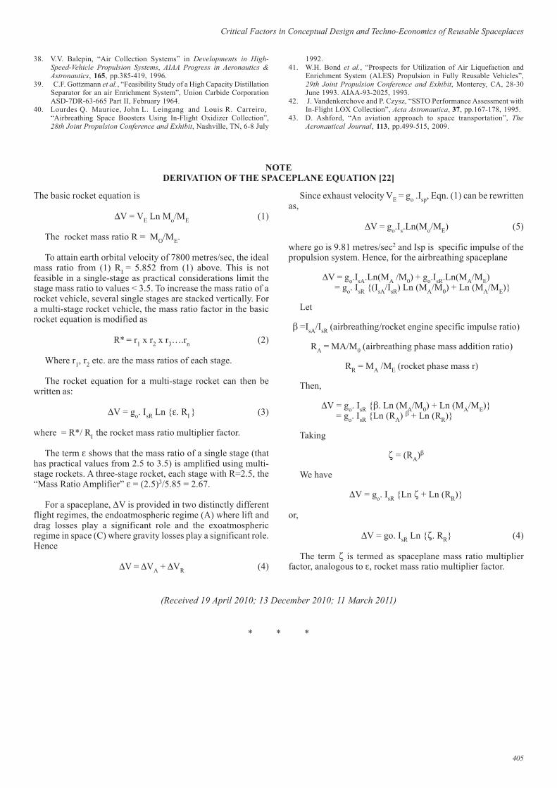
The basic rocket equation is
∆V = VE Ln Mo/ME (1)
The rocket mass ratio R = MO/ME.
To attain earth orbital velocity of 7800 metres/sec, the idealmass ratio from (1) RI = 5.852 from (1) above. This is notfeasible in a single-stage as practical considerations limit thestage mass ratio to values < 3.5. To increase the mass ratio of arocket vehicle, several single stages are stacked vertically. Fora multi-stage rocket vehicle, the mass ratio factor in the basicrocket equation is modified as
R* = r1 x r2 x r3….rn (2)
Where r1, r2 etc. are the mass ratios of each stage.
The rocket equation for a multi-stage rocket can then bewritten as:
∆V = go. IsR Ln {ε. RI } (3)
where = R*/ RI the rocket mass ratio multiplier factor.
The term ε shows that the mass ratio of a single stage (thathas practical values from 2.5 to 3.5) is amplified using multi-stage rockets. A three-stage rocket, each stage with R=2.5, the“Mass Ratio Amplifier” ε = (2.5)3/5.85 = 2.67.
For a spaceplane, ∆V is provided in two distinctly differentflight regimes, the endoatmospheric regime (A) where lift anddrag losses play a significant role and the exoatmosphericregime in space (C) where gravity losses play a significant role.Hence
∆V = ∆VA + ∆VR (4)
NOTEDERIVATION OF THE SPACEPLANE EQUATION [22]
Since exhaust velocity VE = go .Isp, Eqn. (1) can be rewrittenas,
∆V = go.Is.Ln(Mo/ME) (5)
where go is 9.81 metres/sec2 and Isp is specific impulse of thepropulsion system. Hence, for the airbreathing spaceplane
∆V = go.IsA.Ln(MA /M0) + go.IsR.Ln(MA/ME) = go. IsR {(IsA/IsR) Ln (MA/M0) + Ln (MA/ME)}
Let
β =IsA/IsR (airbreathing/rocket engine specific impulse ratio)
RA = MA/M0 (airbreathing phase mass addition ratio)
RR = MA /ME (rocket phase mass r)
Then,
∆V = go. IsR {β. Ln (MA/M0) + Ln (MA/ME)} = go. IsR {Ln (RA) β + Ln (RR)}
Taking
ζ = (RA)β
We have
∆V = go. IsR {Ln ζ + Ln (RR)}
or,
∆V = go. IsR Ln {ζ. RR} (4)
The term ζ is termed as spaceplane mass ratio multiplierfactor, analogous to ε, rocket mass ratio multiplier factor.
(Received 19 April 2010; 13 December 2010; 11 March 2011)
1992.41. W.H. Bond et al., “Prospects for Utilization of Air Liquefaction and
Enrichment System (ALES) Propulsion in Fully Reusable Vehicles”,29th Joint Propulsion Conference and Exhibit, Monterey, CA, 28-30June 1993. AIAA-93-2025, 1993.
42. J. Vandenkerchove and P. Czysz, “SSTO Performance Assessment withIn-Flight LOX Collection”, Acta Astronautica, 37, pp.167-178, 1995.
43. D. Ashford, “An aviation approach to space transportation”, TheAeronautical Journal, 113, pp.499-515, 2009.
* * *
Related Documents