Creep life prediction of a high strength steel plate R. Rajendran a, * , J.K. Paik b , J.M. Lee b , Y.H. Chae b , M.S. Lee c a BARC Facilities, Kalpakkam 603 102, India b Department of Naval Architecture and Ocean Engineering, Pusan National University, 30 Jaengjeon-Dong, Geumjeong-Gu, Busan 609-735, Republic of Korea c POSCO Engineering and Construction Corporation Limited, Pohang 790-704, Republic of Korea Received 23 June 2006; accepted 3 January 2007 Available online 18 January 2007 Abstract Creep life prediction of a high strength steel plate is important in the context of its application as a blast furnace structural element. Numerical analysis using ANSYS was carried out on a high strength steel plate that was simply supported at its one edge and subjected to an in plane constant tensile stress at the opposite edge. Material parameters were derived from the tensile test data and published literature. Bilinear material model and isotropic hardening along with Bailey–Norton time hardening formulation were employed. Sim- ulated creep tests were performed from ambient temperature to temperatures up to 773 K for varying stresses. At the highest operating temperature, it is safe to load the plate up to 55% of its room temperature yield strength but it can survive only nine and half years at 62% of its room temperature yield strength. Ó 2007 Elsevier Ltd. All rights reserved. Keywords: Room temperature creep; High temperature creep; Creep strain; Creep rupture life 1. Introduction The brick lining of the blast furnace is encased with high strength steel plate (SM490 in Korean specification) that undergoes thermal and mechanical stresses for a prolonged period of time, which causes time dependent deformation called creep. Due to thermal activation, the steel plate slowly and continuously deforms even under constant load (stress) and eventually fails [1]. Microscopically, there are three dominant mechanisms that cover the creep damage process [1,2]. At high stress (normal stress to shear modulus ratio less than 0.01), dislo- cation glide (involves dislocations moving along slip planes and overcoming barriers by thermal activation) occurs. At intermediate stress (normal stress to shear modulus ratio between 0.01 and 0.0001), dislocation creep (involves the movement of dislocations which overcome barriers by ther- mally assisted mechanisms involving the diffusion of vacan- cies or interstitials) occurs. At low stresses (normal stress to shear modulus ratio less than 0.0001), diffusion creep (involves the flow of vacancies and interstitials through a material under the influence of applied stress) occurs. The most important mechanism in most engineering structures is the dislocation creep [1]. For temperatures below 25% of the absolute melting temperature of the material, primary creep is the dominant deformation mode [3]. At a temperature beyond this range, secondary creep will be remarkably accumulated in the metallic materials [4]. Tertiary creep is unstable in nature wherein the speci- men ruptures due to an infinite elongation (ductile rupture) or the formation of internal cavitation (brittle rupture) [5]. The temperature of the blast furnace shell varies from ambient to 773 K. The steel shell is lined with special bulk ceramic refractory materials that undergo aggressive wear and thermo-mechanical environment. A service life of 15 yr is expected from a relined blast furnace [6]. Furnace repair is impossible during this period because it severely affects the production efficiency. Therefore, the shell has to be investi- gated for its creep strength for this temperature environment. 0261-3069/$ - see front matter Ó 2007 Elsevier Ltd. All rights reserved. doi:10.1016/j.matdes.2007.01.003 * Corresponding author. Tel./fax: +91 44 27480282. E-mail address: [email protected] (R. Rajendran). www.elsevier.com/locate/matdes Available online at www.sciencedirect.com Materials and Design 29 (2008) 427–435 Materials & Design

Welcome message from author
This document is posted to help you gain knowledge. Please leave a comment to let me know what you think about it! Share it to your friends and learn new things together.
Transcript
Available online at www.sciencedirect.com
Materials
www.elsevier.com/locate/matdes
Materials and Design 29 (2008) 427–435
& Design
Creep life prediction of a high strength steel plate
R. Rajendran a,*, J.K. Paik b, J.M. Lee b, Y.H. Chae b, M.S. Lee c
a BARC Facilities, Kalpakkam 603 102, Indiab Department of Naval Architecture and Ocean Engineering, Pusan National University, 30 Jaengjeon-Dong, Geumjeong-Gu,
Busan 609-735, Republic of Koreac POSCO Engineering and Construction Corporation Limited, Pohang 790-704, Republic of Korea
Received 23 June 2006; accepted 3 January 2007Available online 18 January 2007
Abstract
Creep life prediction of a high strength steel plate is important in the context of its application as a blast furnace structural element.Numerical analysis using ANSYS was carried out on a high strength steel plate that was simply supported at its one edge and subjectedto an in plane constant tensile stress at the opposite edge. Material parameters were derived from the tensile test data and publishedliterature. Bilinear material model and isotropic hardening along with Bailey–Norton time hardening formulation were employed. Sim-ulated creep tests were performed from ambient temperature to temperatures up to 773 K for varying stresses. At the highest operatingtemperature, it is safe to load the plate up to 55% of its room temperature yield strength but it can survive only nine and half years at 62%of its room temperature yield strength.� 2007 Elsevier Ltd. All rights reserved.
Keywords: Room temperature creep; High temperature creep; Creep strain; Creep rupture life
1. Introduction
The brick lining of the blast furnace is encased with highstrength steel plate (SM490 in Korean specification) thatundergoes thermal and mechanical stresses for a prolongedperiod of time, which causes time dependent deformationcalled creep. Due to thermal activation, the steel plateslowly and continuously deforms even under constant load(stress) and eventually fails [1].
Microscopically, there are three dominant mechanismsthat cover the creep damage process [1,2]. At high stress(normal stress to shear modulus ratio less than 0.01), dislo-cation glide (involves dislocations moving along slip planesand overcoming barriers by thermal activation) occurs. Atintermediate stress (normal stress to shear modulus ratiobetween 0.01 and 0.0001), dislocation creep (involves themovement of dislocations which overcome barriers by ther-mally assisted mechanisms involving the diffusion of vacan-
0261-3069/$ - see front matter � 2007 Elsevier Ltd. All rights reserved.
doi:10.1016/j.matdes.2007.01.003
* Corresponding author. Tel./fax: +91 44 27480282.E-mail address: [email protected] (R. Rajendran).
cies or interstitials) occurs. At low stresses (normal stress toshear modulus ratio less than 0.0001), diffusion creep(involves the flow of vacancies and interstitials through amaterial under the influence of applied stress) occurs.
The most important mechanism in most engineeringstructures is the dislocation creep [1]. For temperaturesbelow 25% of the absolute melting temperature of thematerial, primary creep is the dominant deformation mode[3]. At a temperature beyond this range, secondary creepwill be remarkably accumulated in the metallic materials[4]. Tertiary creep is unstable in nature wherein the speci-men ruptures due to an infinite elongation (ductile rupture)or the formation of internal cavitation (brittle rupture) [5].
The temperature of the blast furnace shell varies fromambient to 773 K. The steel shell is lined with special bulkceramic refractory materials that undergo aggressive wearand thermo-mechanical environment. A service life of 15 yris expected from a relined blast furnace [6]. Furnace repair isimpossible during this period because it severely affects theproduction efficiency. Therefore, the shell has to be investi-gated for its creep strength for this temperature environment.
Nomenclature
A, p, q material constantse engineering strainE Young’s modulusET tangent modulusK strength co-efficientm strain rate sensitivityn work hardening indexs engineering stress
t timee true strainec creep straineu ultimate true strain_e strain rater flow stressru ultimate true stressry yield stress
200 400 600 800 1000
Temperature (K)
200
300
400
500
600
700
Tru
e ul
tim
ate
tens
ile s
tres
s (M
Pa)
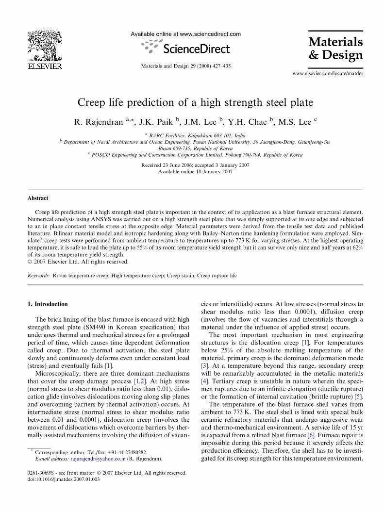
Fig. 1. The variation of true ultimate tensile stress of the high strengthsteel with temperature.
428 R. Rajendran et al. / Materials and Design 29 (2008) 427–435
Low temperature creep was not attached much signifi-cance, because failures due to creep are unlikely for highstrength steels under loads below the yield stress [7]. Ten-sile creep studies on pure iron demonstrated negligiblecreep damage for stresses up to 0.9 ry [8]. Room temper-ature creep deformation studies on a line pipe steel [9]indicated that higher loading rate causes larger creepdeformation.
Various authors have investigated the high tempera-ture creep behaviour of materials and structures. Creeptests were simulated with French and German RPV steels[10] to model creep and plasticity process. A finite ele-ment model was developed using a numerical approach,which avoids the use of a single creep law employingconstants derived from the data for the limited stressand temperature range. A numerical creep databasewas developed and implemented in which the creep strainrate was evaluated as a function of the current totalstrain, temperature and equivalent stress. The numericalmodel was validated by the simulation of and compari-son with experiments. Finite element model was appliedto predict the second stage creep behaviour of A16061/SiC metal matrix composite [11]. The discrepancybetween the FEM and the experimental results weremuch less than the analytical approach. Microstructuredegradation of AISI304 steel with high temperaturewas numerically modeled [12] to predict its creep-fatiguelife.
Creep life fraction of in-service high temperature com-ponents was estimated by assessing the micro structuraldegradation of the material [13]. Grain boundary etchingmethod was used to evaluate the material degradation.FEM analysis of heat affected zone (HAZ) indicated thatcreep deformation and fracture are influenced by themulti-axial state of stress produced in the specimen dueto inhomogeneous microstructure [14]. A benchmark testfor finite element analysis of stress redistribution inducedby creep damage was designed to assess the accuracy ofimplicit time integration scheme [15]. Creep damage analy-sis was carried out using ABAQUS for a serviced Tee sec-tion of a boiler header and compared with experiments,which showed good agreement [16]. Since creep tests areexpensive and time consuming, analytical and numericalstudies are preferred to experimental studies [11].
In the present investigation, a high strength steel (SM490is the Korean Specification) plate of 0.5 m · 0.5 m · 0.06 msize that is used for blast furnace shell is investigated for itscreep life. The temperature experienced by the shell variesfrom ambient to 773 K. Simulated creep tests were carriedout for constant in plane tensile stresses for room tempera-ture and upto 773 K assuming a constant temperature pro-file on the plate under study. The creep life was estimatedfor various creep strains. A design creep curve was pro-posed to assess the creep life for the applied stress and atthe given temperature.
2. Creep model
Holloman’s flow equation states that [3] the flow stress isa function of both strain and strain rate.
r ¼ ken _em ð1Þwhere K is the strength co-efficient, e is the strain, n is thework hardening index which is equal to the true strain atultimate tensile stress and m is the strain rate sensitivity.
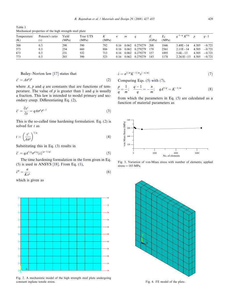
Table 1Mechanical properties of the high strength steel plate
Temperature(K)
Poisson’s ratio(m)
Yield(MPa)
True UTS(MPa)
K
(MPa)n m q E
(GPa)ET
(MPa)q 1�q K1/q p q�1
300 0.3 298 590 792 0.16 0.062 0.279279 208 1846 3.49E�14 4.505 �0.721573 0.3 254 660 886 0.16 0.062 0.279279 170 2561 2.11E�14 4.505 �0.721673 0.3 231 532 713 0.16 0.062 0.279279 157 1895 5.6E�13 4.505 �0.721773 0.3 203 390 523 0.16 0.062 0.279279 143 1178 2.261E�13 4.505 �0.721
0 2000 4000 6000No. of elements
120
160
200
240
von-
Mis
es S
tres
s (M
Pa)
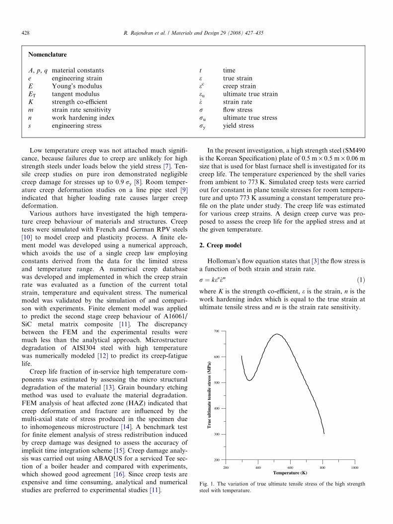
Fig. 3. Variation of von-Mises stress with number of elements; appliedstress = 183 MPa.
R. Rajendran et al. / Materials and Design 29 (2008) 427–435 429
Bailey–Norton law [17] states that
ec ¼ Arptq ð2Þwhere A, p and q are constants that are functions of tem-perature. The value of p is greater than 1 and q is usuallya fraction. This law is intended to model primary and sec-ondary creep. Differentiating Eq. (2),
_ec ¼ oec
ot¼ qArptq�1 ð3Þ
This is the so-called time hardening formulation. Eq. (2) issolved for t as
t ¼ ec
Arp
� �1=q
ð4Þ
Substituting this in Eq. (3) results in
_ec ¼ qA1=qrp=qðeÞðq�1=qÞ ð5ÞThe time hardening formulation in the form given in Eq.
(5) is used in ANSYS [18]. From Eq. (1),
_em ¼ rKen
ð6Þ
which is given as
Fig. 2. A mechanistic model of the high strength steel plate undergoingconstant inplane tensile stress.
_e ¼ r1=mK�1=með�n=mÞ ð7ÞComparing Eqs. (5) with (7),
pq¼ 1
m;
q� 1
q¼ � n
m; qA1=q ¼ K�1=m ð8Þ
from which the parameters in Eq. (5) are calculated as afunction of material parameters as
Fig. 4. FE model of the plate.
430 R. Rajendran et al. / Materials and Design 29 (2008) 427–435
q ¼ mmþ n
; p ¼ 1
mþ n; A ¼ q�qK�p ð9Þ
qA ¼ q1�qK�p ð10Þ
p ¼ q=m ¼ 1
mþ nð11Þ
q� 1 ¼ � nðmþ nÞ ð12Þ
The flow curves at various strain rates appear as par-allel lines with the slope of n [3]. This indicates that thework hardening index does not vary strongly with strainrate. Materials having low work hardening exponentexhibit poor creep properties. Materials with high strainrate sensitivity have reduced creep life. Standard proce-
Fig. 5. von-Mises stress contours of the plate for 0.9 yield stress at various tlife = 41 878 h; (b) temperature = 573 K, applied stress = 229 MPa, lifelife = 459563 h and (d) temperature = 773 K, applied stress = 183 MPa, life =
dures for conducting creep rupture tests on metallicmaterials to establish creep constants are given byASTM E139 [19].
3. Material parameters
The true stress r and true strain e of the high strengthsteel are established from the engineering stress s and straine as
r ¼ sð1þ eÞ ð13Þe ¼ lnð1þ eÞ ð14Þ
The tangent modulus is obtained as
emperatures: (a) ambient temperature (300 K), applied stress = 262 MPa,= 2.04E+06 h; (c) temperature = 673 K, applied stress = 208 MPa,18 250 h.
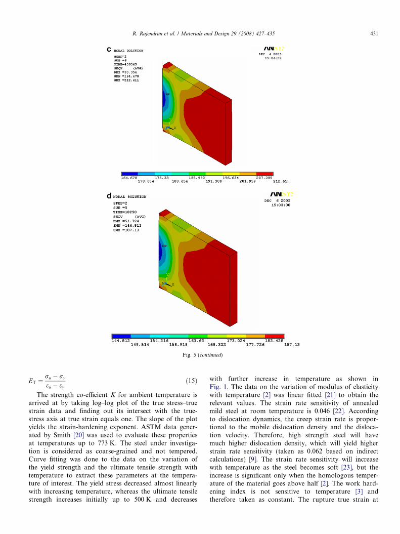
Fig. 5 (continued)
R. Rajendran et al. / Materials and Design 29 (2008) 427–435 431
ET ¼ru � ry
eu � eyð15Þ
The strength co-efficient K for ambient temperature isarrived at by taking log–log plot of the true stress–truestrain data and finding out its intersect with the true-stress axis at true strain equals one. The slope of the plotyields the strain-hardening exponent. ASTM data gener-ated by Smith [20] was used to evaluate these propertiesat temperatures up to 773 K. The steel under investiga-tion is considered as coarse-grained and not tempered.Curve fitting was done to the data on the variation ofthe yield strength and the ultimate tensile strength withtemperature to extract these parameters at the tempera-ture of interest. The yield stress decreased almost linearlywith increasing temperature, whereas the ultimate tensilestrength increases initially up to 500 K and decreases
with further increase in temperature as shown inFig. 1. The data on the variation of modulus of elasticitywith temperature [2] was linear fitted [21] to obtain therelevant values. The strain rate sensitivity of annealedmild steel at room temperature is 0.046 [22]. Accordingto dislocation dynamics, the creep strain rate is propor-tional to the mobile dislocation density and the disloca-tion velocity. Therefore, high strength steel will havemuch higher dislocation density, which will yield higherstrain rate sensitivity (taken as 0.062 based on indirectcalculations) [9]. The strain rate sensitivity will increasewith temperature as the steel becomes soft [23], but theincrease is significant only when the homologous temper-ature of the material goes above half [2]. The work hard-ening index is not sensitive to temperature [3] andtherefore taken as constant. The rupture true strain at
432 R. Rajendran et al. / Materials and Design 29 (2008) 427–435
ambient temperature is 0.2. Table 1 presents the detailsof the materials data that were applied for the creepanalysis. There was an expected fall of rupture strainby nearly 15% at 600 K and an increase up to 7% at800 K [20]. These variations were ignored and a constantrupture strain of 0.2 was assumed.
4. FE model
The plate was simply supported at its one edge and aconstant in plane tensile stress was applied at its oppositeedge as shown in Fig. 2. It was discretized into eight-
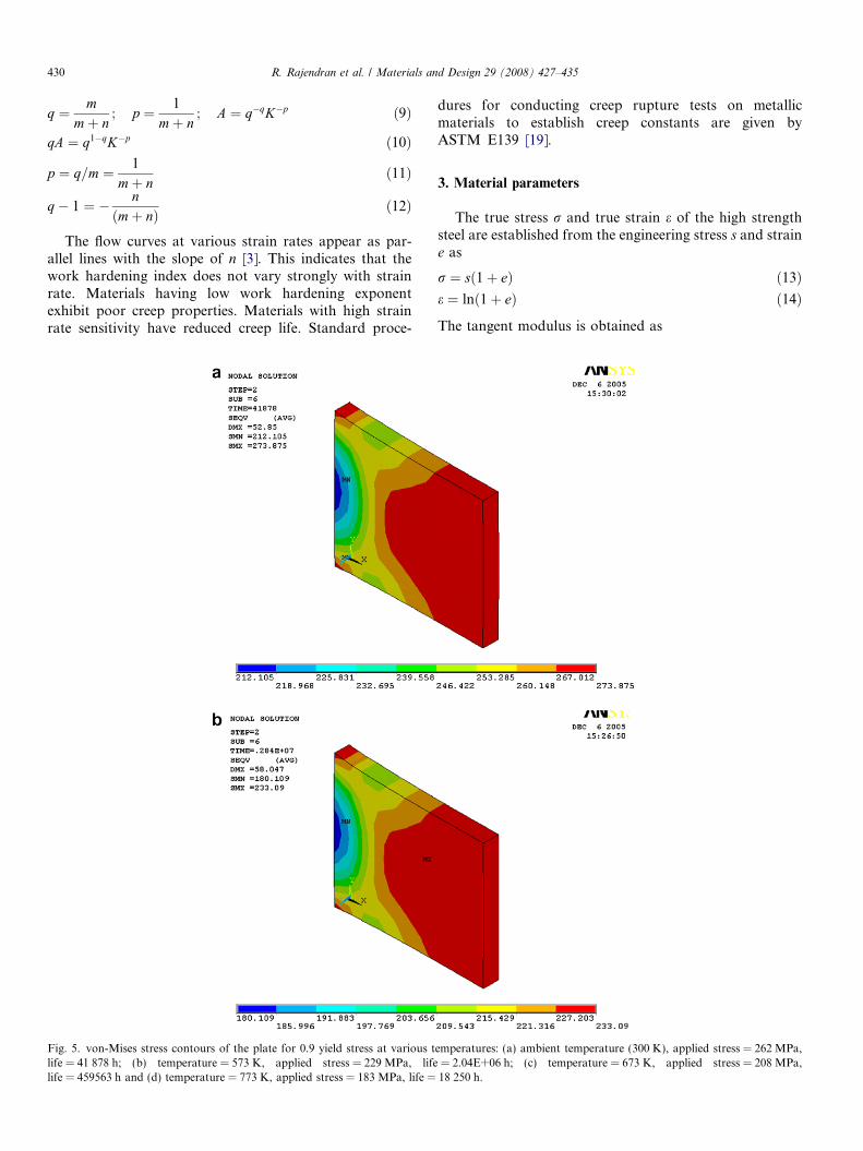
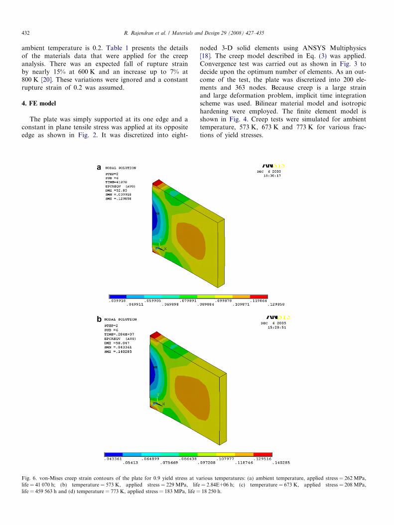
Fig. 6. von-Mises creep strain contours of the plate for 0.9 yield stress at vlife = 41 070 h; (b) temperature = 573 K, applied stress = 229 MPa, lifelife = 459 563 h and (d) temperature = 773 K, applied stress = 183 MPa, life =
noded 3-D solid elements using ANSYS Multiphysics[18]. The creep model described in Eq. (3) was applied.Convergence test was carried out as shown in Fig. 3 todecide upon the optimum number of elements. As an out-come of the test, the plate was discretized into 200 ele-ments and 363 nodes. Because creep is a large strainand large deformation problem, implicit time integrationscheme was used. Bilinear material model and isotropichardening were employed. The finite element model isshown in Fig. 4. Creep tests were simulated for ambienttemperature, 573 K, 673 K and 773 K for various frac-tions of yield stresses.
arious temperatures: (a) ambient temperature, applied stress = 262 MPa,= 2.84E+06 h; (c) temperature = 673 K, applied stress = 208 MPa,18 250 h.
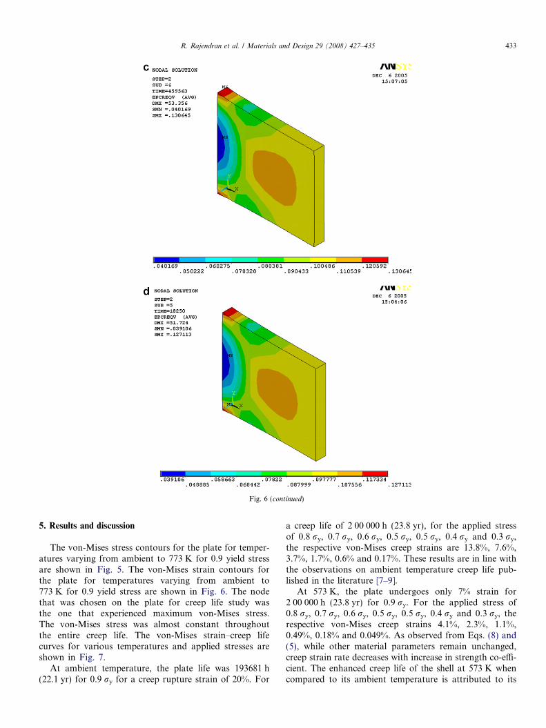
Fig. 6 (continued)
R. Rajendran et al. / Materials and Design 29 (2008) 427–435 433
5. Results and discussion
The von-Mises stress contours for the plate for temper-atures varying from ambient to 773 K for 0.9 yield stressare shown in Fig. 5. The von-Mises strain contours forthe plate for temperatures varying from ambient to773 K for 0.9 yield stress are shown in Fig. 6. The nodethat was chosen on the plate for creep life study wasthe one that experienced maximum von-Mises stress.The von-Mises stress was almost constant throughoutthe entire creep life. The von-Mises strain–creep lifecurves for various temperatures and applied stresses areshown in Fig. 7.
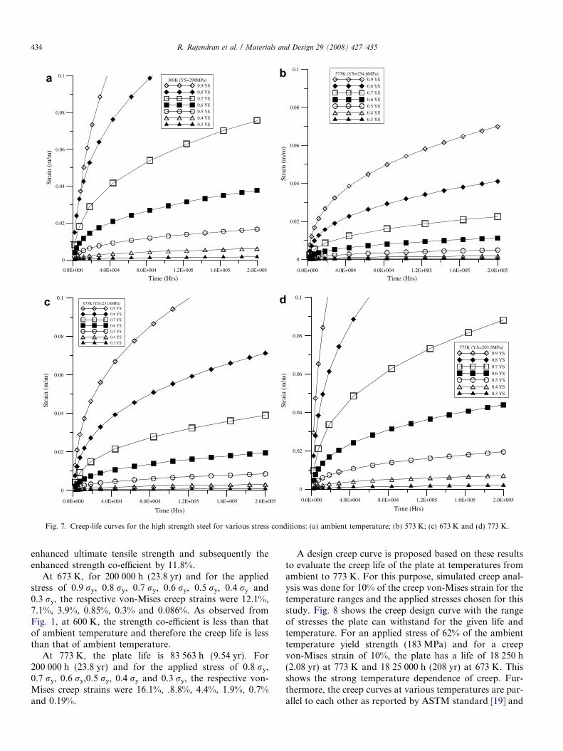
At ambient temperature, the plate life was 193681 h(22.1 yr) for 0.9 ry for a creep rupture strain of 20%. For
a creep life of 2 00 000 h (23.8 yr), for the applied stressof 0.8 ry, 0.7 ry, 0.6 ry, 0.5 ry, 0.5 ry, 0.4 ry and 0.3 ry,the respective von-Mises creep strains are 13.8%, 7.6%,3.7%, 1.7%, 0.6% and 0.17%. These results are in line withthe observations on ambient temperature creep life pub-lished in the literature [7–9].
At 573 K, the plate undergoes only 7% strain for2 00 000 h (23.8 yr) for 0.9 ry. For the applied stress of0.8 ry, 0.7 ry, 0.6 ry, 0.5 ry, 0.5 ry, 0.4 ry and 0.3 ry, therespective von-Mises creep strains 4.1%, 2.3%, 1.1%,0.49%, 0.18% and 0.049%. As observed from Eqs. (8) and(5), while other material parameters remain unchanged,creep strain rate decreases with increase in strength co-effi-cient. The enhanced creep life of the shell at 573 K whencompared to its ambient temperature is attributed to its
0.0E+000 4.0E+004 8.0E+004 1.2E+005 1.6E+005 2.0E+005
Time (Hrs) Time (Hrs)
0
0.02
0.04
0.06
0.08
0.1
Stra
in (
m/m
)
Time (Hrs) Time (Hrs)
Stra
in (
m/m
)
Stra
in (
m/m
)St
rain
(m
/m)
300K (YS=298MPa)0.9 YS
0.8 YS
0.7 YS
0.6 YS
0.5 YS
0.4 YS
0.3 YS
0.0E+000 4.0E+004 8.0E+004 1.2E+005 1.6E+005 2.0E+005
0
0.02
0.04
0.06
0.08
0.1573K (YS=254.6MPa)
0.9 YS
0.8 YS
0.7 YS
0.6 YS
0.5 YS
0.4 YS
0.3 YS
0.0E+000 4.0E+004 8.0E+004 1.2E+005 1.6E+005 2.0E+005
0
0.02
0.04
0.06
0.08
0.1673K (YS=231.6MPa)
0.9 YS
0.8 YS
0.7 YS
0.6 YS
0.5 YS
0.4 YS
0.3 YS
0.0E+000 4.0E+004 8.0E+004 1.2E+005 1.6E+005 2.0E+005
0
0.02
0.04
0.06
0.08
0.1
773K (YS=203.5MPa)0.9 YS
0.8 YS
0.7 YS
0.6 YS
0.5 YS
0.4 YS
0.3 YS
Fig. 7. Creep-life curves for the high strength steel for various stress conditions: (a) ambient temperature; (b) 573 K; (c) 673 K and (d) 773 K.
434 R. Rajendran et al. / Materials and Design 29 (2008) 427–435
enhanced ultimate tensile strength and subsequently theenhanced strength co-efficient by 11.8%.
At 673 K, for 200 000 h (23.8 yr) and for the appliedstress of 0.9 ry, 0.8 ry, 0.7 ry, 0.6 ry, 0.5 ry, 0.4 ry and0.3 ry, the respective von-Mises creep strains were 12.1%,7.1%, 3.9%, 0.85%, 0.3% and 0.086%. As observed fromFig. 1, at 600 K, the strength co-efficient is less than thatof ambient temperature and therefore the creep life is lessthan that of ambient temperature.
At 773 K, the plate life is 83 563 h (9.54 yr). For200 000 h (23.8 yr) and for the applied stress of 0.8 ry,0.7 ry, 0.6 ry,0.5 ry, 0.4 ry and 0.3 ry, the respective von-Mises creep strains were 16.1%, .8.8%, 4.4%, 1.9%, 0.7%and 0.19%.
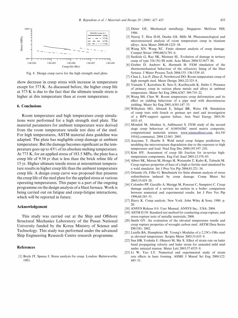
A design creep curve is proposed based on these resultsto evaluate the creep life of the plate at temperatures fromambient to 773 K. For this purpose, simulated creep anal-ysis was done for 10% of the creep von-Mises strain for thetemperature ranges and the applied stresses chosen for thisstudy. Fig. 8 shows the creep design curve with the rangeof stresses the plate can withstand for the given life andtemperature. For an applied stress of 62% of the ambienttemperature yield strength (183 MPa) and for a creepvon-Mises strain of 10%, the plate has a life of 18 250 h(2.08 yr) at 773 K and 18 25 000 h (208 yr) at 673 K. Thisshows the strong temperature dependence of creep. Fur-thermore, the creep curves at various temperatures are par-allel to each other as reported by ASTM standard [19] and
1.0E+004 1.0E+005 1.0E+006 1.0E+007 1.0E+008
Creep life (Hrs)
100
1000
Stre
ss (
MPa
)
SM490 strain 0.1300K
573K
673K
773K
Fig. 8. Design creep curve for the high strength steel plate.
R. Rajendran et al. / Materials and Design 29 (2008) 427–435 435
show decrease in creep stress with increase in temperatureexcept for 573 K. As discussed before, the higher creep lifeat 573 K is due to the fact that the ultimate tensile stress ishigher at this temperature than at room temperature.
6. Conclusions
Room temperature and high temperature creep simula-tions were performed for a high strength steel plate. Thematerial parameters for ambient temperature were derivedfrom the room temperature tensile test data of the steel.For high temperatures, ASTM material data guideline wasadapted. The plate has negligible creep damage at ambienttemperature. But the damage becomes significant as the tem-perature goes up to 43% of its absolute melting temperature.At 773 K, for an applied stress of 183.5 MPa, the plate has acreep life of 9.54 yr that is less than the brick reline life of15 yr. Higher ultimate tensile stress at intermittent tempera-ture results in higher creep life than the ambient temperaturecreep life. A design creep curve was proposed that presentsthe creep life of the steel plate for the applied stress at variousoperating temperatures. This paper is a part of the ongoingprogramme on the design analysis of a blast furnace. Work isbeing carried out on fatigue and creep-fatigue interactions,which will be reported in future.
Acknowledgement
This study was carried out at the Ship and OffshoreStructural Mechanics Laboratory of the Pusan NationalUniversity funded by the Korea Ministry of Science andTechnology. This study was performed under the advancedShip Engineering Research Centre research programme.
References
[1] Boyle JT, Spence J. Stress analysis for creep. London: Butterworths;1983.
[2] Dieter GE. Mechanical metallurgy. Singapore: McGraw Hill;1986.
[3] Neeraj T, Hou D-H, Daehn GS, Mills M. Phenomenological andmicrostructural analysis of room temperature creep in titaniumalloys. Acta Mater 2000;48:1225–38.
[4] Wang XN, Wang XC. Finite element analysis of creep damage.Comput Struct 1996;60(5):781–6.
[5] Sasikala G, Ray SK, Mannan SL. Evolution of damage in tertiarycreep of type 316 (N) SS weld. Acta Mater 2004;52:5677–86.
[6] Gruber D, Andreev K, Harmuth H. FEM simulation of thethermomechanical behaviour of the refractory lining of the blastfurnace. J Mater Process Tech 2004;155–156:1539–43.
[7] Chen L, Liu P, Zhao Z, Northwood DO. Room temperature creep ofhigh strength steel. Mater Design 2001;22:325–8.
[8] Yamada T, Kawabata K, Sato E, Kuribayashi K, Jimbo I. Presenceof primary creep in various phase metals and alloys at ambienttemperature. Mater Sci Eng 2004;A387–389:719–22.
[9] Wang SH, Chen W. Room temperature creep deformation and itseffect on yielding behaviour of a pipe steel with discontinuousyielding. Mater Sci Eng 2001;A301:147–53.
[10] Willschutz HG, Altstadt E, Sehgal BR, Weiss FB. Simulationof creep tests with french or german rpv steel and investigationof a RPV-support against failure. Ann Nucl Energy 2003;30:1033–63.
[11] Mondali M, Abedian A, Adibnazari S. FEM study of the secondstage creep behaviour of A16016/SiC metal matrix composite,computational materials science. www.sciencedirect.com, doi.10/1016/j.commatsci, 2004.12.063. 2005.
[12] Asayama T, Hasebe S. Weld metal creep fatigue prediction bymodeling the microstructure degradation due to the exposure to hightemperature and load. Nucl Eng Des 2000;195:197–210.
[13] Kim HY. Assessment of creep life fraction for in-service high-temperature components. Eng Fail Anal 2005;12:578–85.
[14] Albert SK, Matsui M, Hongo H, Watanabe T, Kubo K, Tabuchi M.Creep rupture properties of hazs of a high cr ferritic steel simulated bya weld simulator. Int J Pres Ves Pip 2004;81:221–34.
[15] Orlando JA, Filho G. Benchmark for finite element analysis of stressredistribution induced by creep damage. Comp Mater Sci2005;33:419–28.
[16] Colombo PP, Garzillo A, Meriggi M, Ponzoni C, Sampietri C. Creepdamage analysis of a services tee section in a boiler: comparisonbetween numerical and experimental results. Int J Pres Ves Pip1996;66:243–51.
[17] Harry K. Creep analysis. New York: John Wiley & Sons; 1980. p.20.
[18] ANSYS Release 8.0. User Manual, ANSYS Inc., USA; 2004.[19] ASTM E139. Standard test method for conducting creep-rupture, and
stress-rupture tests of metallic materials; 2000.[20] Smith GV. An evaluation of the elevated temperature tensile and
creep rupture properties of wrought carbon steel. ASTM Data SeriesDS11S1; 2002.
[21] Latella BA, Humphries SR. Young’s Modulus of a 2.25Cr-1Mo steelat elevated temperature. Scripta Mater 2003;51:635–9.
[22] Sun HB, Yoshida F, Ohmori M, Ma X. Effect of strain rate on luderband propagating velocity and luder strain for annealed mild steelunder uniaxial tension. Mater Lett 2003;57:4535–9.
[23] Li W, Yao LY. Numerical and experimental study of strainrate effects in laser forming. ASME J Manuf Sci Eng 2000;122:445–51.
Related Documents


