Creep effects on the Campbell response in type II superconductors Filippo Gaggioli, 1 Gianni Blatter, 1 and Vadim B. Geshkenbein 1 1 Institut f¨ ur Theoretische Physik, ETH Z¨ urich, CH-8093 Z¨ urich, Switzerland (Dated: November 5, 2021) Applying the strong pinning formalism to the mixed state of a type II superconductor, we study the effect of thermal fluctuations (or creep) on the penetration of an ac magnetic field as quantified by the so-called Campbell length λC. Within strong pinning theory, vortices get pinned by individual defects, with the jumps in the pinning energy (Δepin) and force (Δfpin) between bistable pinned and free states quantifying the pinning process. We find that the evolution of the Campbell length λC(t) as a function of time t is the result of two competing effects, the change in the force jumps Δfpin(t) and a change in the trapping area Strap(t) of vortices; the latter describes the area around the defect where a nearby vortex gets and remains trapped. Contrary to naive expectation, we find that during the decay of the critical state in a zero-field cooled (ZFC) experiment, the Campbell length λC(t) is usually nonmonotonic, first decreasing with time t and then increasing for long waiting times. Field cooled (FC) experiments exhibit hysteretic effects in λC; relaxation then turns out to be predominantly monotonic, but its magnitude and direction depends on the specific phase of the cooling–heating cycle. Furthermore, when approaching equilibrium, the Campbell length relaxes to a finite value, different from the persistent current which vanishes at long waiting times t, e.g., above the irreversibility line. Finally, measuring the Campbell length λC(t) for different states, zero-field cooled, field cooled, and relaxed, as a function of different waiting times t and temperatures T , allows to ‘spectroscopyse’ the pinning potential of the defects. I. INTRODUCTION The phenomenological properties of type II supercon- ductors subject to a magnetic field B are determined by vortices, linear topological defects that guide the field through the material in terms of quantized fluxes 1 Φ 0 = hc/2e. The interaction of these flux tubes with material defects has a decisive impact on the material’s properties, as it determines the amount of current den- sity that the superconductor can transport free of dis- sipation. This phenomenon, known under the name of vortex pinning 2 , has been studied extensively, both in theory and experiment, as one important facet of vortex matter physics 3,4 . Traditional tools to characterize vor- tex pinning are measurements of critical current densities j c and full current–voltage (j –V ) characteristics 2 , as well as the penetration of a small ac magnetic test-field that is quantified through the so-called Campbell penetration length 5 λ C . In characterizing the pinning properties of the material’s mixed state, the Campbell length λ C as- sumes a similar role as the skin depth δ (determining the resistivity ρ in the normal state) or the London penetra- tion depth λ L (determining the superfluid density ρ s in zero magnetic field). Although well established as an ex- perimental tool, a quantitative calculation on the basis of strong pinning theory 6–8 of the ac Campbell response has been given only recently 9 . In this paper, we extend this ‘microscopic’ description of the Campbell penetration to include effects of thermal fluctuations, i.e., creep. The penetration of an ac magnetic field into the mixed state of a superconductor has been first analyzed by Campbell 5 , see also Refs. 10 and 11. This phenomeno- logical theory relates the Campbell length λ C ∝ B/ √ α to the curvature α of the pinning potential that is probed by small-amplitude oscillations of the vortices. Applying strong pinning theory to this problem provides a lot of insights on the pinning landscape: Within the strong pin- ning paradigm, vortices exhibit bistable configurations in the presence of a defect. These bistable configurations describe pinned and unpinned (meta-)stable states, see Fig. 1, with a finite pinning force density F pin result- ing from an asymmetric occupation of the corresponding branches. While the critical current density j c ∝ Δe pin is determined by the jumps in energy Δe pin between pinned and unpinned states at (de)pinning 6–8 , it turns out 9,12 that the Campbell length λ C ∝ 1/ p Δf pin is given by the jumps in the pinning force Δf pin . Interestingly, the rele- vant jumps Δf pin determining λ C depend on the vortex state, e.g., the critical (or zero-field cooled, ZFC) state first defined by Bean 13 or the field cooled (FC) state. Even more, the pinned vortex state depends on the time- trace of its experimental implementation, that leads to hysteretic effects in λ C as shown in Refs. 9 and 12 both theoretically and experimentally. When including thermal fluctuations in the calcula- tion of the pinning force density F pin , different jumps Δe pin (t) in the pinning energy become relevant that de- pend on the time t evolution of the vortex state due to creep. While this relaxational time dependence leads to the decay of the persistent current density j (t), the cor- responding velocity dependence leads to a rounding 14,15 of the transition 16 between pinned and dissipative states in the current–voltage characteristic; again the quanti- tative nature of the strong pinning description allows for a detailed comparison of the temperature-shifted and rounded excess-current characteristic predicted by theory with experimental data on superconducting films 17 . In the present paper, we determine the Campbell length λ C (t) including the effect of thermal fluctuations. We determine the relevant jumps Δf pin (t) in the pinning arXiv:2111.02431v1 [cond-mat.supr-con] 3 Nov 2021

Welcome message from author
This document is posted to help you gain knowledge. Please leave a comment to let me know what you think about it! Share it to your friends and learn new things together.
Transcript

Creep effects on the Campbell response in type II superconductors
Filippo Gaggioli,1 Gianni Blatter,1 and Vadim B. Geshkenbein1
1Institut fur Theoretische Physik, ETH Zurich, CH-8093 Zurich, Switzerland(Dated: November 5, 2021)
Applying the strong pinning formalism to the mixed state of a type II superconductor, we studythe effect of thermal fluctuations (or creep) on the penetration of an ac magnetic field as quantifiedby the so-called Campbell length λC. Within strong pinning theory, vortices get pinned by individualdefects, with the jumps in the pinning energy (∆epin) and force (∆fpin) between bistable pinned andfree states quantifying the pinning process. We find that the evolution of the Campbell length λC(t)as a function of time t is the result of two competing effects, the change in the force jumps ∆fpin(t)and a change in the trapping area Strap(t) of vortices; the latter describes the area around thedefect where a nearby vortex gets and remains trapped. Contrary to naive expectation, we find thatduring the decay of the critical state in a zero-field cooled (ZFC) experiment, the Campbell lengthλC(t) is usually nonmonotonic, first decreasing with time t and then increasing for long waitingtimes. Field cooled (FC) experiments exhibit hysteretic effects in λC; relaxation then turns out tobe predominantly monotonic, but its magnitude and direction depends on the specific phase of thecooling–heating cycle. Furthermore, when approaching equilibrium, the Campbell length relaxes toa finite value, different from the persistent current which vanishes at long waiting times t, e.g., abovethe irreversibility line. Finally, measuring the Campbell length λC(t) for different states, zero-fieldcooled, field cooled, and relaxed, as a function of different waiting times t and temperatures T ,allows to ‘spectroscopyse’ the pinning potential of the defects.
I. INTRODUCTION
The phenomenological properties of type II supercon-ductors subject to a magnetic field B are determinedby vortices, linear topological defects that guide thefield through the material in terms of quantized fluxes1
Φ0 = hc/2e. The interaction of these flux tubes withmaterial defects has a decisive impact on the material’sproperties, as it determines the amount of current den-sity that the superconductor can transport free of dis-sipation. This phenomenon, known under the name ofvortex pinning2, has been studied extensively, both intheory and experiment, as one important facet of vortexmatter physics3,4. Traditional tools to characterize vor-tex pinning are measurements of critical current densitiesjc and full current–voltage (j–V ) characteristics2, as wellas the penetration of a small ac magnetic test-field thatis quantified through the so-called Campbell penetrationlength5 λC. In characterizing the pinning properties ofthe material’s mixed state, the Campbell length λC as-sumes a similar role as the skin depth δ (determining theresistivity ρ in the normal state) or the London penetra-tion depth λL (determining the superfluid density ρs inzero magnetic field). Although well established as an ex-perimental tool, a quantitative calculation on the basis ofstrong pinning theory6–8 of the ac Campbell response hasbeen given only recently9. In this paper, we extend this‘microscopic’ description of the Campbell penetration toinclude effects of thermal fluctuations, i.e., creep.
The penetration of an ac magnetic field into the mixedstate of a superconductor has been first analyzed byCampbell5, see also Refs. 10 and 11. This phenomeno-logical theory relates the Campbell length λC ∝ B/
√α
to the curvature α of the pinning potential that is probedby small-amplitude oscillations of the vortices. Applying
strong pinning theory to this problem provides a lot ofinsights on the pinning landscape: Within the strong pin-ning paradigm, vortices exhibit bistable configurations inthe presence of a defect. These bistable configurationsdescribe pinned and unpinned (meta-)stable states, seeFig. 1, with a finite pinning force density Fpin result-ing from an asymmetric occupation of the correspondingbranches. While the critical current density jc ∝ ∆epin isdetermined by the jumps in energy ∆epin between pinnedand unpinned states at (de)pinning6–8, it turns out9,12
that the Campbell length λC ∝ 1/√
∆fpin is given by thejumps in the pinning force ∆fpin. Interestingly, the rele-vant jumps ∆fpin determining λC depend on the vortexstate, e.g., the critical (or zero-field cooled, ZFC) statefirst defined by Bean13 or the field cooled (FC) state.Even more, the pinned vortex state depends on the time-trace of its experimental implementation, that leads tohysteretic effects in λC as shown in Refs. 9 and 12 boththeoretically and experimentally.
When including thermal fluctuations in the calcula-tion of the pinning force density Fpin, different jumps∆epin(t) in the pinning energy become relevant that de-pend on the time t evolution of the vortex state due tocreep. While this relaxational time dependence leads tothe decay of the persistent current density j(t), the cor-responding velocity dependence leads to a rounding14,15
of the transition16 between pinned and dissipative statesin the current–voltage characteristic; again the quanti-tative nature of the strong pinning description allowsfor a detailed comparison of the temperature-shifted androunded excess-current characteristic predicted by theorywith experimental data on superconducting films17.
In the present paper, we determine the Campbelllength λC(t) including the effect of thermal fluctuations.We determine the relevant jumps ∆fpin(t) in the pinning
arX
iv:2
111.
0243
1v1
[co
nd-m
at.s
upr-
con]
3 N
ov 2
021
2
force which depend on the time t during which the origi-nal, e.g., critical, state has relaxed due to creep. For thisZFC situation, we find that the evolution of the Camp-bell length λC(t) is the result of two competing effects, thechange in the force jumps ∆fpin(t) and, furthermore, anincrease in the trapping area Strap(t) of vortices; the lat-ter describes the area around the defect where a nearbyvortex gets and remains trapped, see Fig. 1. Contraryto expectation, we find that for intermediate and verystrong pinning, the Campbell length λC(t) first decreaseswith time t and then starts increasing for long waitingtimes; at marginally strong pinning, we find λC(t) de-creasing.
Relaxation also appears for the case of field cooledstates, as these drop out of equilibrium upon chang-ing temperature and relax when the cooling or heat-ing process is interrupted. In a FC experiment, theCampbell penetration exhibits hysteretic phenomena ina cooling–heating cycle. The relaxation of the Camp-bell length λC then depends on the type of pinning andthe location within the hysteresis loop. At intermedi-ate and large pinning, we find three different phases, onewhere λC monotonously decreases with time, one where itmonotonously increases towards equilibrium, and a thirdphase where relaxation is slow due to large creep barriers;at marginally strong pinning, we find λC mainly decreas-ing in time. Several of these findings have been observedin experiments18,19 and we will discuss them below. Weconclude that measuring the Campbell length λC for dif-ferent states, ZFC, FC, and relaxed as a function of dif-ferent waiting times t, provides insights into the pinningmechanism and gives access to the jumps ∆fpin at dif-ferent locations of the pinning curve, see Fig. 3(c); suchmeasurements and analysis then allow to ‘spectroscopyse’the pinning potential of defects.
In the following, we first recapitulate relevant aspectsof the strong pinning theory and of creep (Secs. II andIII that focuses on transport) and then proceed with thecalculation of the Campbell penetration depth λC in thepresence of thermal fluctuations, see Sec. IV. We firstfocus on the critical (or zero-field cooled, ZFC) state inSecs. IV A and IV B and then extend the analysis to thecase of field cooling (FC) in Secs. IV C and IV D. SectionV summarizes and concludes our work.
II. STRONG PINNING THEORY
A complete derivation of strong pinning theory start-ing from an elastic description of the vortex lattice (weassume a lattice directed along z with a lattice constanta0 determined by the induction B = Φ0/a
20) that is in-
teracting with a random assembly of defects of densitynp has been given in several papers; here, we make useof the discussion and notation in Refs. 8, 12, 15, and20, see also Refs. 21–23 for numerical work on strongpinning. It turns out, that in the low density limitnpa0ξ
2κ � 1, where ξ denotes the coherence length
−x− x0 x+
u
x
yz z z z
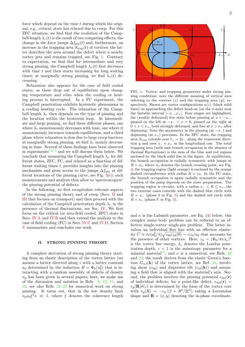
FIG. 1. Vortex- and trapping geometries under strong pin-ning conditions; note the different meaning of vertical axesreferring to the vortices (z) and the trapping area (y), re-spectively. Shown are vortex configurations u(z) (black solidlines) on approaching the defect head-on (on the x-axis) nearthe bistable interval [−x−, x+]. Four stages are highlighted,the (weakly deformed) free state before pinning at x < −x−,pinned on the left at −x− < x < 0, pinned on the right at0 < x < x+, both strongly deformed, and free at x > x+ afterdepinning. Note the asymmetry in the pinning (at −x−) anddepinning (at x+) processes. In the ZFC state, the trappingarea Strap extends over t⊥ = 2x− along the transverse direc-tion y and over x− + x+ in the longitudinal one. The totaltrapping area (with unit branch occupation in the absence ofthermal fluctuations) is the sum of the blue and red regionsenclosed by the black solid line in the figure. At equilibrium,the branch occupation is radially symmetric with jumps atR = x0, where x0 denotes the branch crossing point, see Fig.3; the trapping region (light orange) is enclosed by the orangedashed circumference with radius R = x0. In the FC state,the branch occupation is again radially symmetric and theposition of the jump depends on the state preparation. Thetrapping region is circular, with a radius x− ≤ R ≤ x+; thetwo extreme cases coincide with the dashed blue circle withR = x− (phase b in Fig. 5) and the dashed red circle withR = x+ (phase b′ in Fig. 5).
and κ is the Labusch parameter, see Eq. (4) below, thiscomplex many-body problem can be reduced to an ef-fective single-vortex–single-pin problem. The latter in-volves an individual flux line with an effective elastic-ity C ≈ νε(a2
0/λ)√c66c44(0) ∼ εε0/a0 that accounts for
the presence of other vortices. Here, ε0 = (Φ0/4πλL)2
is the vortex line energy, λL denotes the London pene-tration depth, ε < 1 is the anisotropy parameter for auniaxial material24, and ν is a numerical, see Refs. 21and 23; the result derives from the elastic Green’s func-tion Gαβ(k) of the vortex lattice, see Ref. 24, involv-ing shear (c66) and dispersive tilt (c44(k)) and assum-ing a field that is aligned with the material’s axis. Sec-ond, the problem involves the pinning potential edef(r)of individual defects; for a point-like defect, edef(r) =ep(R)δ(z) is determined by the form of the vortex corewith ep(R) = −ep/(1 + R2/2ξ2) taking a Lorentzianshape and R = (x, y) denoting the in-plane coordinate.

3
Below, we will consider a potential of general form when-ever possible and focus on Lorentzian-shaped defect po-tentials ep(R) in order to arrive at numerically accurateresults; results for non-Lorentzian shaped potentials re-main qualitatively the same.
The generic setup involves a vortex line driven alongx with asymptotic position Rv(z → ±∞) = R∞ thatimpacts on the defect located, say, at the origin. Thesimplest geometry is that of a head-on collision withR∞ = (x, 0) and increasing x for an impact from theleft; given the rotational symmetry of the defect poten-tial ep(R), the geometry for the collision at a finite impactparameter y, R∞ = (x, y) follows straightforwardly. As-suming a head-on collision to begin with, the geometrysimplifies considerably and involves the asymptotic vor-tex position x and the deformation u(z) of the vortex,see Fig. 1; it turns out, that the problem is fully char-acterized by its value u = u(z = 0) at the pin, with thevortex line smoothly joining the tip position r = x + uat z = 0 with the asymptotic position x at z → ±∞, seeFig. 1. The detailed shape x + u(z) of the vortex linethen follows from a simple integration8,12. The cusp atz = 0 is a measure of the pinning strength.
The energy (or Hamiltonian) of this setup involves elas-tic and pinning energies and is given by
epin(x, r) =1
2C(r − x)2 + ep(r). (1)
Minimizing this energy with respect to r at fixed asymp-totic position x, we find the vortex tip position r(x) bysolving the nonlinear problem
C(r − x) = −∂rep = fp(r), (2)
see Fig. 2 for a graphical solution of this self-consistencyproblem. This (microscopic) force-balance equation de-velops multiple solutions when the pin is sufficientlystrong, as quantified by the conditions
∂2repin = C − f ′p(r) = 0 and ∂repin = 0 (3)
for the appearance of a local maximum in epin(x, r), seeFig. 3(b). The condition (3) defines the Labusch param-eter
κ = maxr
f ′p(r)
C=f ′p(rm)
C(4)
(with f ′′p (rm) = 0 providing the maximal force derivativeat rm) that determines the Labusch criterion
κ > 1 (5)
for strong pinning. Defining the force scale fp ≡ ep/ξ andestimating the force derivative or curvature f ′p = −e′′p ∼fp/ξ produces a Labusch parameter κ ∼ ep/Cξ
2, hence,strong pinning is realized for either large pinning energyep or small effective elasticity C. For the Lorentzian po-tential, we obtain a maximal force derivative f ′p(rm) =
ep/4ξ2 at rm =
√2 ξ and hence κ = ep/4Cξ
2.
C(r − x+)
C(r − x−)
rp+
rf−r
fp(r)
0 ξ x− x x+
FIG. 2. Graphical illustration15 of the self-consistent solu-tion of the microscopic force-balance equation Eq. (2) for aLorentzian potential with κ = 2.5. When moving the asymp-totic vortex position x across the bistable interval [x−, x+], weobtain three solutions describing pinned rp < ξ (orange), freerf (blue), and unstable rus (black dotted) states. At the edgesof the bistable interval, we define the limits rp(x+) ≡ rp+ andrf(x−) ≡ rf− with f ′p(rp+) = f ′p(rf−) = C (black solid dots).The tip positions for the pinned (rp(x), open black triangle)and free (rf(x), open red circle) branches increase with x,while the unstable one (rus(x), black cross) decreases.
Within the (symmetric) bistable regions [−x+,−x−]and [x−, x+] opening up at κ > 1, the force-balanceequation Eq. (2) exhibits multiple solutions r(x) corre-sponding to free (rf , elasticity dominated) and pinned(rp, pinning dominated) solutions, see Fig. 2, as well asan unstable solution rus that sets the barrier for creep,see below.
A vortex approaching the defect from the left getstrapped by the pin at −x− and is dragged towards thepinning center. Upon leaving the defect, the vortex getsstrongly deformed, see Fig. 1 and depins at x+. Insertingthe solutions rf(x), rp(x), and rus(x) of Eq. (2) back intoEq. (1), we obtain the pinning energy landscape
eipin(x) = epin[x, ri(x)] (6)
with its multiple branches i = f,p,us shown in Fig. 3(a).The same way, we find the pinning force fp[r(x)] actingon the vortex tip; inserting the different solutions rf(x),rp(x), and rus(x), we obtain the pinning force f i
pin(x) ≡fp[ri(x)] with its multiple branches i = f,p,us as shownin Fig. 3(c). Note that the pinning force fpin(x) can bewritten as the total derivative of the energy epin[x, r(x)],
fpin(x) = fp[r(x)] = −depin[x, r(x)]
dx, (7)
where we have used the force-balance equation (2) toarrive at the last relation.
The energy epin(x) and force fpin(x) experienced bythe vortex are shown in Fig. 3. Due to the presence ofmultiple branches, we see that a right-moving vortex un-dergoes jumps in energy ∆epin and force ∆fpin at the

4
edges −x− and x+ of the bistable intervals (for a leftmoving vortex, corresponding jumps appear at x− and−x+). These jumps are the hallmark of strong pinningand determine physical quantities such as the critical cur-rent density jc or the Campbell penetration depth λC. Inthe following, we evaluate the characteristic quantitiesdefining the pinning landscape of Fig. 3 in the limits ofvery strong (κ� 1) and marginal (κ− 1� 1) pinning.
1. Bistable interval [x−, x+] and extremal tip positions
The extent of the bistable interval [x−, x+] is easilyfound in the very strong pinning limit with κ� 1: Withreference to Fig. 2, we approximate fp[rp(x+)] ≈ fp,max
and drop rp(x+) < ξ against x+ ∼ κξ in (2) to find
x+ ≈ fp,max/C ∼ κξ. (8)
The lower boundary x− is conveniently obtained from thecondition f ′p[rf(x−)] = C. For large κ, we have rf(x−)�ξ residing in the tail of the pinning potential; assuminga defect potential decaying as ep(R) ∼ −2ep(ξ/R)n, weobtain
rf(x−) ≈ ξ[
2n(n+1)epCξ2
]1/(n+2)
∼ ξκ1/(n+2). (9)
Inserting this result back into Eq. (2), we find that
x− ≈n+ 2
n+ 1rf(x−). (10)
For a Lorentzian potential, we have fp,max =
(3/2)3/2 ep/4ξ and rp(x+) ≈√
2/3 ξ and hence
x+ ≈ (3/2)3/2 κξ. (11)
The lower boundary x− relates to rf(x−) via x− ≈(4/3)rf(x−) and with rf(x−) ≈ 2(3κ)1/4ξ, we obtain
x− ≈ (8/3)(3κ)1/4ξ. (12)
The marginally strong pinning case κ & 1 can bequantitatively described via an expansion of the pinningforce fp(r) around the inflection point rm defined throughf ′′p (rm) = 0 and using the Labusch parameter in the form
f ′p(rm) = κC,
fp(rm + δr) ≈ fp(rm) + κC δr − γ (ep/3ξ4)δr 3. (13)
We use κ − 1 � 1 as our small parameter and set κ ≈1 otherwise (however, beware of additional correctionsin κ − 1 through κ ≈ 1 + (κ − 1)). For a Lorentzianpotential, the shape parameter γ assumes the value γ =3/8. The cubic expansion (13) is antisymmetric aboutthe inflection point rm, thus producing symmetric resultsfor pinning and depinning.
The tip locations
rp(x+) = rm − δrmax, rf(x−) = rm + δrmax (14)
(a) (b) x = x
(c)
(d)
eipin
∆ejp−
∆ejp+
x0 10
f ipin
∆f jp−
∆f jp+
x0 10
UdpUp
r
rprusrf
−x− x
f fpin
x− x0 x+−xjp− xjp
+
x
FIG. 3. (a) Multi-valued pinning energy landscape eipin(x),with i = p, f,us corresponding to the pinned (orange), free(blue), and unstable (dotted) branches for κ = 10. The vor-tex coordinate x is expressed in units of ξ. The bistabilityextends over the intervals |x| ∈ [x−, x+] where the differentbranches coexist; pinned and unpinned vortex branches cut atthe branch crossing point x = x0. (b) Total energy epin(x; r)versus vortex tip position r for a fixed vortex position x = x(dashed vertical line in (a)). The points rf (red dot), rp (blacktriangle), and rus (black cross) mark the free, pinned, andunstable solutions of the force-balance equation (2). The bar-riers Up and Udp stabilize the free and pinned states againstthermal fluctuations; they coincide in size at the branch cross-ing point x0. The maximal pinning force density Fpin = Fc isrealized for a maximally asymmetric pinned-branch occupa-tion pc(−x− < x < x+) = 1; for the symmetric equilibriumoccupation peq(−x0 < x < x0) = 1 the pinning force van-ishes. Shown in the figure is the pinned-branch occupationat finite temperatures T (thick colored lines) where thermal
fluctuations allow for early pinning at −xjp− < −x− and early
depinning at xjp+ < x+. The corresponding (total) energy
jump ∆ejppin = ∆ejp+ + ∆ejp− (vertical black solid lines) de-termining the pinning force density Fpin(T ) is reduced withrespect to its critical value (with jumps at −x− and x+). (c)Pinning force f i
pin(x) corresponding to pinned (orange), free(blue), and unstable (dotted) states. The sum of force jumps
∆fpin = ∆f jp− + ∆f jp
+ (vertical black solid lines) determinesthe Campbell length λC. (d) The inset shows a zoom of thepinning force f f
pin near −x− that contributes to λC with asteep square-root change in the force jump in the presence ofcreep, see discussion in Sec. IV B 1.
5
at (de)pinning are defined by the conditions fp[rf(x−)] =fp[rp(x+)] = C, see Fig. 2; making use of the expansion(13), we find
δrmax ≈ξ
2
√4Cξ2
γep(κ− 1)1/2. (15)
Inserting this result into the force-balance equation (2)and using (13), we find the boundaries
x± = xm ± δxmax (16)
of the bistable region with
δxmax ≈ξ
3
√4Cξ2
γep(κ− 1)3/2. (17)
The pair xm and rm of asymptotic and tip positions de-pends on the details of the potential; while rm derivessolely from the shape ep(R) and thus does not dependon the elasticity C, xm as given by (2) involves C andshifts ∝ (κ− 1). For a Lorentzian potential, we have
rm =√
2ξ, xm = 2√
2ξ +√
2ξ(κ− 1), (18)
and
δrmax ≈ ξ [2(κ− 1)/3]1/2, (19)
δxmax ≈ ξ [2(κ− 1)/3]3/2.
Besides the tip positions rp(x+) and rf(x−) at(de)pinning, we also need the tip positions rf(x+) andrp(x−) that are not associated with a special point on thefree and pinned branches. They are obtained by solvingthe force-balance equation (2) at x± = xm± δxmax usingthe expansion (13) with the ansatz rf(x+) = rm+µδrmax
and rp(x−) = rm − µδrmax; the resulting equation for µ,
µ+ 2/3− µ3/3 = 0, (20)
is solved by µ = −1 (→ the result (15) obtained before)and µ = 2, hence
rf(x+)− rm = rm − rp(x−) ≈ 2δrmax, (21)
with δrmax given in (15).
2. Branch crossing point x0
At very strong pinning, the bistable region is arrangedasymmetrically around the branch crossing point x0, seeFig. 3; we find the latter by equating the pinning energies(1) for the free and pinned branches: with x0 � ξ at largeκ, we have the free and pinned vortex tip positions
rf(x0) ≈ x0 and rp(x0)� ξ, (22)
as follows from the force-balance equation x0 − rf(x0) =−fp[rf(x0)]/C (dropping the force term fp[rf(x0)]) and
Fig. 2. With efpin(x0) ≈ 0 and ep
pin(x0) ≈ Cx20/2− ep, we
find that
x0 ≈ 2√
2ξ
(ep
4Cξ2
)1/2
∼ √κξ. (23)
For the Lorentzian potential, we find x0 ≈ 2√
2κξ.When strong pinning is marginal, κ−1� 1, the branch
crossing point x0 coincides with xm. Its location dependson the detailed shape of the potential; for a Lorentzian,we have (see Eq. (18))
x0 ≈ xm = 2√
2ξ +√
2ξ(κ− 1). (24)
3. Activation barrier U0
Finally, we briefly discuss the barriers for thermal acti-vation between bistable branches, specifically, the barrierscale U0 at the branch crossing point. The latter is givenby
U0 = epin[x0, rus(x0)]− epin[x0, rf(x0)]
= epin[x0, rus(x0)]− epin[x0, rp(x0)] (25)
and therefore depends on the unstable and pinned/freetip position at x0. At large κ � 1, the vortex free andpinned vortex tip positions are given in (22). We findthe unstable solution rus by using the asymptotic decayfp(R) ≈ −2n fp(ξ/R)n+1 and dropping the term rus(x0)against x0 in the force-balance equation (2), with theresult that
rus(x0) ≈ ξ(
2n2epCξ2
)1/2(n+1)
, (26)
for a Lorentzian potential, rus(x0) ≈ 2(κ/2)1/6ξ; indeed,the ratio rus(x0)/x0 ≈ (1/4κ)1/3 � 1 is parametricallysmall at large κ. The barrier scale U0 then evaluates to
U0 ≈C
2x2
0 ≈ ep (27)
with small corrections ∝ 1/κn/2(n+1).In the marginally strong pinning case, we find the
tip positions r = rm + δr by solving the force-balanceequation (2) with the expansion (13) at x = x0 = xm,with the three solutions δr = 0, providing the unstablesolution rus(x0) = rm, and the free and pinned meta-stable solutions rf,p(x0) arranged symmetrically with
δr = ±√
3 δrmax,
rf(x0)− rm = rm − rp(x0) =√
3 δrmax. (28)
Making use of these results in the definition (25) for U0
and expanding epin(x0, rf = rm +√
3 δrmax) to fourthorder in δrmax, we find that
U0 ≈3
4
C2ξ4
γep(κ− 1)2 =
ep8
(κ− 1)2, (29)

6
where the last equation applies to the Lorentzian shapedpotential. In deriving (29), we have used the expansion(13) as well as the force balance equation (2) to convertthe elastic energy C(rm − x0)δrmax to a pinning energyfp(rm)δrmax.
III. TRANSPORT
One of the central features of superconductivity isdissipation-free transport. We briefly discuss the resultsof strong pinning theory for critical current densities jcand the effect of thermal fluctuations resulting in a slowlydecaying ‘persistent’ current.
The transport properties of a type II superconduct-ing material is determined by the vortex dynamics asdescribed by the (macroscopic) force-balance equation
ηv = FL(j)− Fpin(v, T ), (30)
a non-linear equation for the mean vortex velocity v,with η = BHc2/ρnc
2 the Bardeen-Stephen viscosity25
(per unit volume; ρn is the normal state resistivity) andFL = j ×B/c the Lorentz force. The pinning force den-sity Fpin is directed along v; it depends on the velocityv, that turns finite beyond the critical force density Fc,and on the temperature T driving thermal fluctuations,i.e., creep—we will discuss these effects shortly.
The pinning force density Fpin is given by the sumover all force contributions fpin; assuming a uniformdistribution of defects, we have to take the averageFpin = np〈fpin〉 with the appropriate branch occupa-tion of vortices. For a vortex approaching the defecthead-on along x, the free branch terminates at −x−and the vortex jumps to the pinned branch, gaining
the energy ∆efppin = ef
pin(−x−) − eppin(−x−) > 0 (de-
noted as ∆ejp− in Fig. 3). Moving forward, the vortex
remains pinned until the branch ends at x+, where the
jump to the free branch involves the energy ∆epfpin =
eppin(x+)− ef
pin(x+) > 0 (denoted as ∆ejp+ in Fig. 3). The
critical pinned-branch occupation for head-on trajecto-ries then is pc(x) ≡ Θ(x + x−)− Θ(x− x+), while for afinite impact factor y, the branch occupation pc(R) co-incides with characteristic function of the trapping areashown in Fig. 1. The critical branch occupation is max-imally asymmetric, what produces the largest possiblepinning force. Other branch occupations produce differ-ent pinning forces, e.g., the radially symmetric equilib-rium occupation peq(R) = Θ(x0−R), with x0 the branchcutting point shown in Fig. 3, leads to a vanishing pin-ning force.
Averaging the pinning force fpin over x and y withthe vortex population described by the critical branchoccupation pc(R), we obtain the critical pinning force
density Fc (we exploit the anti-symmetry of fpin(R))
Fc = −np∫d2R
a20
[pc(R)fp
pin(R) + (1− pc(R))f fpin(R)
]= −np
∫d2R
a20
pc(R)[∂x∆efppin(R)]ex, (31)
with the energy difference ∆efppin(R) = ef
pin(R)− eppin(R)
and ex the unit vector along x; the y-component of thepinning force density vanishes due to the antisymmetryin fpin,y. Following convention, we have included a minussign in the definition of Fc. The branch-occupation pc(R)restricts the integral to the trapping area shown in Fig. 1;the integration over x brings forward the constant energyjumps at the two semi-circular boundaries, hence
Fc = −np∫ x−
−x−
dy
a0
∆efppin(x, y)
a0
∣∣∣x=+√x2+−y2
x=−√x2−−y2
= np∆efp
pin + ∆epfpin
a0
∫ x−
−x−
dy
a0
= npt⊥a0
∆efppin + ∆epf
pin
a0, (32)
where we have defined the transverse trapping lengtht⊥ = 2x−. The result (32) for the pinning force densityshows that all vortices hitting the left-side semi-circle ofdiameter t⊥ get pinned, see Fig. 1, and contribute equallyto the pinning force density, a consequence of the rota-tionally symmetric pinning potential ep(R). We confirmthat the multi-valued energy landscape in Fig. 3 is cen-tral for obtaining a finite pinning force density Fpin ∝ np;for κ < 1 jumps are absent and the integral over the cor-responding smooth periodic function fpin(x) in Eq. (32)vanishes. This is the realm of weak pinning with a mech-anism that is collective, resulting in a density scaling8
Fpin ∝ n2p.
A. Critical current density jc
We obtain the critical current density jc from the forcebalance (30) by setting v = 0 and choosing the maximalpinning force density Fc associated with the most asym-metric branch occupation pc(R),
jc = cFc/B = (c/Φ0)npt⊥∆epin (33)
with ∆epin = ∆efppin|−x− + ∆epf
pin|x+ the sum of (posi-
tive) jumps in the pinning energy epin(x) and t⊥ = 2x−.Note that strong pinning does not necessarily imply alarge critical current density jc, as our approximation ofindependent pins requires a small density np.
B. Creep effects on transport: persistent current
Starting with a non-equilibrium initial state at timet = 0, thermal fluctuations (or creep) drive the system

7
towards equilibrium. To fix ideas, we start from a crit-ical or ZFC state (and a head-on collision) character-ized by the critical pinned-branch occupation pc(x) =Θ(x + x−) − Θ(x − x+) and let it decay through creep;the extension of the result to the 2D situation is straight-forward. The presence of thermal fluctuations then in-creases the probabilities for pinning near −x− and de-pinning near x+, that leads to a reduction of the pin-ning force density Fpin < Fc. We account for such ther-mal hops of vortices into and out of the pin throughproper calculation of the thermal pinned-branch occu-pation probability pth(x; t, T ) via solution of the rateequation15,26,27 (we set the Boltzmann constant to unity,kB = 1)
dpth
dt= −ωp pth e
−Udp/T + ωf (1− pth) e−Up/T , (34)
where
Up(x) = euspin(x)− ef
pin(x), (35)
Udp(x) = euspin(x)− ep
pin(x),
denote the barriers for pinning and depinning (cf. Eq.(6)) and ωp(x), ωf(x) are the corresponding attemptfrequencies. It follows from Fig. 3(a) that the barriersUp(x → −x−) and Udp(x → x+) for pinning and depin-ning vanish, implying that modifications of the pinned-branch occupation probability are largest near −x− andx+ where we can simplify the rate equation (34) by drop-ping one of the terms. One finds15, that after a finitewaiting time t, thermal fluctuations produce a shift inthe jump positions for pinning and depinning (and asmall rounding of the steps in pth(x) that we can ig-nore): the jump from the free to the pinned branch ap-
pears earlier at −xjp− < −x− and so does the location
of depinning, xjp+ < x+, with the solution of the rate
equation (34) well approximated by the step function
pth(x; t, T ) ≈ Θ[x+ xjp−(t, T )]−Θ[x− xjp
+ (t, T )].
The renormalized jump positions −xjp−(t, T ) and
xjp+ (t, T ) are determined by the relations15
Up(−xjp−) ≈ Udp(xjp
+ ) ≈ T ln(t/t0), (36)
with the diffusion time τ0 = πjcd2/2cvthB (d is the sam-
ple dimension) and t0 to be determined self-consistently15
from t0 = τ0T/(jc|∂jU |). Equation (36) tells us, thatthermal fluctuations driven by the temperature T canovercome (de)pinning barriers Up(dp) of size T ln(t/t0)after a waiting time t. As a result, waiting a time tat temperature T , the pinned-branch occupation proba-bility changes from pc(x) ≈ 0 to pth(x) ≈ 1 at all po-
sitions x within the intervall [−xjp−(t),−x−] and drops
from pc(x) ≈ 1 to pth(x) ≈ 0 for x ∈ [xjp+ (t), x+], thereby
reducing the asymmetry of the critical occupation prob-ability pc(x).
The waiting time t then determines the shape ofthe pinned-branch occupation probability pth(x; t, T ): at
short times, thermal relaxation is weak and pth(x; t, T )remains close to pc(x). On the other hand, for finite Tand long waiting times t . teq ≡ t0 exp(U0/T ), withU0 = Up(x0) = Udp(x0) the barrier at the branchcutting point x0, see Fig. 3, relaxation is strong andpth(x; t, T ) approaches the symmetric equilibrium occu-pation peq(x) = Θ(x+x0)−Θ(x−x0). Going to very longtimes t beyond teq, both of the terms in (34) accountingfor pinning and depinning hops near x0 become equallyimportant in establishing the precise equilibrium shapeof the pinned-branch occupation probability.
Generalizing from the head-on collision to a finite-impact geometry is straightforward; evaluating the pin-ning force density Eq. (32) with pc replaced by pth, weobtain the result
Fpin(t, T ) = nptjp⊥(t, T )
a0
∆ejppin(t, T )
a0, (37)
that depends on the temperature T and the waiting timet. The premature pinning and depinning processes at−xjp− and xjp
+ modify the trapping length tjp⊥ = 2xjp− > t⊥
and reduce the (sum of) jumps in the pinning energy,
∆epin → ∆ejppin = ∆efp
pin|−xjp−
+ ∆epfpin|xjp
+. For times t �
t0, the pinning force density (37) takes the analyticalform15
Fpin(t, T ) = Fc[1− g(κ) T 2/3 +O(T 4/3)
], (38)
with the dimensionless creep parameter T
T (t, T ) ≡ T
epln
t
t0. (39)
The exponent 2/3 derives from the vanishing of barri-ers on approaching the boundaries of the bistable region,Udp,p(x) ∝ |x−x±|3/2, with the value 3/2 universal for asmooth pinning potential ep(R); higher-order terms rel-evant away from the edges x± produce the corrections∝ T 4/3 in (38). The coefficient g(κ) subsumes all de-pendencies on the Labusch parameter κ and has beencalculated in Ref. 15; it involves the competing effects ofan increasing trapping length tjp⊥ and a decreasing jump
in the total pinning energy ∆ejppin. As the latter is the
dominating one for not too strong pinning parametersbelow κ ∼ 102, the pinning force density Fpin(t, T ) usu-ally decreases under the influence of creep. The relativeimportance of these two effects will be modified in theanalysis of the Campbell penetration depth below, wherethe role of ∆ejp
pin is replaced by ∆f jppin.
Inserting the result (38) back into the force-balanceequation (30), we immediately obtain the persistent cur-rent density: in a typical relaxation experiment (i.e., aftera short initial waiting time), we can neglect the dissipa-tive term ηv in Eq. (30) and we arrive at the persistentcurrent density in the form
j(t, T ) ≈ cFc[1− g(κ) T 2/3(t, T )
]/B. (40)

8
The result (40) is valid for times t � teq. For largetimes beyond teq, we go over to the TAFF region (ther-mally assisted flux flow28) where the creep dynamics gov-erned by the slow ln(t/t0) behavior turns into a dif-fusive vortex motion (and thus ohmic response). Thevortex front at Rvf then moves into the sample fol-lowing the diffusion law Rvf(t) ∼ const. − √DTAFFtwith the diffusion constant24 DTAFF ∼ c2ρTAFF andρTAFF ∝ ρn(B/Hc2) exp(−U0/T ). The current decays al-gebraically, j ∝ 1/
√t until the sample (of size d) is fully
penetrated at tfp ∼ d2/DTAFF. Thereafter, the remain-ing persistent current decays exponentially, j(t > tfp) ∝exp(−t/tfp).
The above scenario applies to the strong pinningparadigm where barriers saturate in the limit of vanishingcurrents, j → 0. In reality, correlations between differ-ent pinning centers are expected to become relevant atvery small drives j, implying growing barriers and glassyresponse instead.
Below, we will study the influence of creep on the linearresponse under a small external ac magnetic field, that is,again a typical relaxation experiment involving the wait-ing time t determining the evolution of the vortex state.It will be interesting to see that creep affects the per-sistent current and the ac penetration depth very differ-ently, with j(t, T ) vanishing at long times while λC(t, T )remains finite.
IV. AC LINEAR RESPONSE
Probing the superconductor with a small ac field δB =hac exp(−iωt) � B0 on top of the (large) dc externalfield B0 provides us with valuable information on thepinning landscape. Rather than telling about the jumps∆epin in the energy landscape when measuring jc, theCampbell penetration depth λC informs us about theforce landscape, specifically, the jumps ∆fpin, see Fig.3.
Solving the force-balance equation (30) for the dis-placement field U(X, t) (we denote coarse grained quan-tities averaging over many vortices with capital letters,see Ref. 29) assuming a phenomenological Ansatz11 forthe pinning force density Fpin = F0 − αU , one finds thatthe ac field penetrates the superconductor over a dis-tance given by λ2
C(ω) = B20/[4π(α − iωη)]. At the low
frequencies typical of such penetration experiments, wecan drop the dissipative contribution ∝ ηω and obtainthe phenomenological result
λC(ω) =
[B2
0
4π α
]1/2
(41)
due to Campbell11. In the following, we discuss theCampbell penetration physics within the strong pinningparadigm, first for the zero-field cooled (ZFC) or criticalstate and subsequently for the field cooled (FC) situation,including also hysteretic effects appearing upon cyclingthe temperature up and down in the experiment.
A. Campbell penetration depth λC in ZFC state
Within our quantitative strong pinning theory, the ac-tion of the ac field on the zero-field cooled state is toreshuffle vortices at the boundaries −x− and x+, pro-ducing a restoring force density proportional to the dis-placement U of the vortices. We compute the change inthe pinning force density δFpin(U) by subtracting from(31) the expression with the displaced branch occupationpc(R−U),
δFpin(U) = −np∫d2R
a20
[pc(R)− pc(R−U)]
× [fppin(R)− f f
pin(R)]
≈ −np∫d2R
a20
[∇pc(R) ·U] ∆fpfpin(R). (42)
With U directed along x, the scalar product in the lastline of (42) is non-vanishing only along the circular sec-tions of the trapping area in Fig. 1; furthermore, thegradient ∇pc(R) is strongly peaked (with unit weight)on the circular boundaries and directed parallel to eR,the radial unit vector. The scalar product then evaluatesto
−∇pc(R) ·U =[δ(R− x−)(Θ(φ− π/2)−Θ(φ− 3π/2))
+ δ(R− x+)(Θ(φ+ φ+)−Θ(φ− φ+))]U cosφ (43)
with the polar angle φ restricted to angles π/2 < φ <3π/2 on the left circular segment of the trapping bound-ary and −φ+ < φ < φ+ with φ+ = arcsin(x−/x+) onthe right one. Inserting the expression (43) into (42) and
writing ∆fpfpin(R) ≡ −∆f(R) eR (with ∆f(R) the modu-
lus of ∆fpfpin(R)) directed along the radial coordinate, the
change in the pinning force density can be evaluated as
δFpin ≈ −np U[x−∆f(x−)
a20
∫ −1
1
d sinφ [cosφ, sinφ]
+x+∆f(x+)
a20
∫ x−/x+
−x−/x+
d sinφ [cosφ, sinφ]
](44)
= −np U2a2
0
[π x−∆f(x−) + θ+ x+∆f(x+), 0
],
with the effective angle θ+ = 2(φ+ + sinφ+ cosφ+). Theexpression (44) is originally calculated for a left-shiftU < 0 of the vortex critical state; after a short initial-ization period29, the same result applies for positive dis-placements as well, and δFpin(U) = −αsp(U − U0) withU0(X, t) = maxt′<t U(X, t′), not to be confused with thebarrier U0 at the branch-cutting point x0.
In the large κ limit, x+ � x−, see Eqs. (11) and (12),and the curvature in the boundary of the trapping regionat R = x+ becomes negligible, see Fig. 1. We can thenapproximate φ+ ≈ sinφ+ ≈ x−/x+ � 1, and the strongpinning expression for the effective curvature αsp in the

9
ZFC state reads
αsp ≈ npt⊥a0
π4 ∆fpf
pin + ∆f fppin
a0, (45)
with the force jumps ∆fpfpin = fp
pin(−x−)−f fpin(−x−) > 0
and ∆f fppin = f f
pin(x+) − fppin(x+) > 0, where we have
returned to the original notation for the two jumps at
−x− and x+ for convenience (i.e., the difference ∆f fppin is
equal to the modulus ∆f(x+) in Eq. (44)). The factorπ/4 in the numerator of (45) has its origin in the differentgeometries of the circular boundaries at −x− and at x+.
In the opposite limit of marginally strong pinning withκ − 1 � 1, x− . x0 . x+ and the trapping regionacquires an approximately circular geometry. The angleφ+ can be expanded as φ+ ≈ π/2− δφ+/2, with δφ+ �π/2, allowing to approximate the effective angle θ+ as
θ+ ≈ π +O(δφ3+). (46)
The bistable region is symmetric around x0, see Eq. (16),
and we have ∆f(x−) ≈ ∆f(x+) = ∆f fppin(x+) as well as
x0 ≈ (x+ + x−)/2, that produces the following simpleexpression for the Campbell curvature
αsp ≈ npπx0
a0
∆f fppin(x+)
a0, (47)
where we have again returned to the original notation
for the jump at x+, ∆f fppin(x+) = f f
pin(x+) − fppin(x+) >
0. The above results differ from those in Ref. 12 in themore accurate handling of the geometry in the trappingboundary, leading to the appearance of θ+ and factorsπ/4.
The derivation (44) applies to the critical state—thecorresponding result for other vortex states is obtainedby the proper replacement pc(R) → p(R). E.g., for theequilibrium distribution peq(R) with a radially symmet-ric jump at R ≈ x0, the result reads
α0 = npπx0
a0
∆f fppin(x0)
a0. (48)
Note that, at κ−1� 1, the jump ∆f fppin(x0) = f f
pin(x0)−fp
pin(x0) at x0 is larger (by a factor 2/√
3) than the jumps
∆f fppin at x+ or ∆fpf
pin at x−.
Physically, the expressions (45)− (48) describe the av-erage curvature in the pinning landscape that, upon inte-gration, is given by the sum of jumps in the pinning forcefpin. This should be compared with the average pinningforce in Eq. (32) that provides the critical force densityFc and is given by the sum of jumps in the pinning energyepin. Furthermore, the results for the Campbell curvature(45) − (48) involve the precise geometry of the trappingarea with its circular boundaries, while the pinning forcedensity (32) depends only on the total width t⊥ = 2x−.The above interpretation of αsp ∝ ∆fpin in terms of
the average curvature naturally relates the strong pin-ning result to the phenomenological derivation of λC byCampbell11. Finally, we obtain the microscopic expres-sion for the Campbell penetration depth within strongpinning theory,
λC(ω) =
[B2
0
4παsp
]1/2
. (49)
B. Creep effects on λC in ZFC state
At finite temperatures, the analysis of the vortex sys-tem’s linear response proceeds in a manner analogousto the one above ignoring thermal fluctuations, with thefollowing modifications: i) the oscillations in the vortexlattice induced by the small ac field now reshuffle thosevortex lines close to the thermal jump points at −xjp
−and xjp
+ , implying that the relevant jumps in force are
∆fpf, jppin = fp
pin(−xjp−) − f f
pin(−xjp−) > 0 and ∆f fp, jp
pin =
f fpin(xjp
+ ) − fppin(xjp
+ ) > 0, and ii) the trapping area in-
volves the renomalized jump locations xjp± , producing the
thermally renormalized angles φjp+ = arcsin
(xjp−/x
jp+
)and
θjp+ = 2(φjp
+ + sinφjp+ cosφjp
+ ). After a short initializationperiod, that is not relevant for the present discussion, thefield penetration is determined by the effective curvature
αsp(t, T ) = np
(π
2
xjp−a0
∆fpf, jppin
a0+θjp
+
2
xjp+
a0
∆f fp, jppin
a0
). (50)
Equation (50) is the central result of this work; it allowsus to trace the evolution of the Campbell penetrationlength λC(t, T ) ∝ 1/
√αsp as a function of time t dur-
ing a relaxation experiment. The expression (50) fullycharacterizes the dependence of αsp on the pinning pa-rameters for times t� t0.
At short times and very strong pinning κ � 1, thebranch occupation is highly asymmetric and xjp
+ � xjp− ,
leading to θjp+ ≈ 4φjp
+ ≈ 4xjp−/x
jp+ . The Campbell curva-
tures then reads
αsp(t, T ) ≈ nptjp⊥a0
π4 ∆fpf,jp
pin + ∆f fp,jppin
a0, (51)
with the thermally enhanced trapping length tjp⊥ = 2xjp− .
In the marginally strong pinning limit, we have κ−1� 1and xjp
− . x0 . xjp+ , leading to a saturation of the effec-
tive angle θjp+ → π. In this regime, relaxation behaves
symmetrically on both sides of the bistable region with
∆fpf,jppin ≈ ∆f fp,jp
pin , see Eq. (13). Using x0 ≈ (xjp−+xjp
+ )/2,the Campbell curvature takes a simple form analogous toEq. (47),
αsp(t, T ) ≈ npπx0
a0
∆f fp,jppin
a0. (52)
10
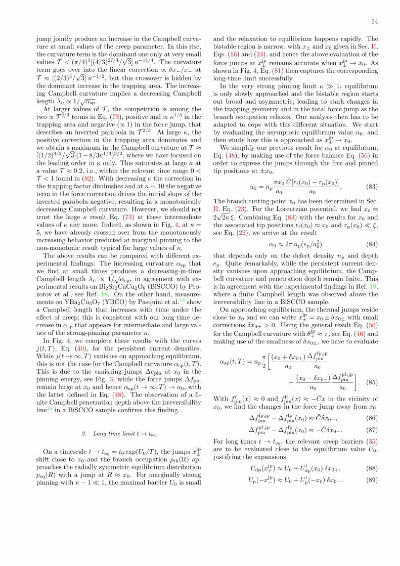
A numerical evaluation of the Campbell curvatureαsp(t, T ), Eqs. (50) and (52), as a function of thecreep parameter T = (T/ep) ln(t/t0) at different pinningstrengths κ is shown in Fig. 4 (blue lines). For compari-son, we also show the decaying persistent current density(40) in the region j < jc. The plots show that αsp(t, T )first increases with time and decreases at long times (butnot in the marginal case with κ close to unity). Froma phenomenological perspective, this can be understoodas a change in the relative occupation of shallow anddeep pinning wells in the course of relaxation. Further-more, we find that, while the persistent current densityj(t, T ) ultimately vanishes on approaching the equilib-rium state, the Campbell curvature αsp(t, T ) remains fi-nite and large. We will discuss these findings in detaillater; before, we analyze their physical origin with thehelp of analytic considerations in the limits of moderatelystrong (κ− 1� 1) and very strong (κ� 1) pinning.
1. Short and intermediate times
Following Eq. (50), we have to determine the thermally
renormalized jumps ∆f fp,jppin and ∆fpf,jp
pin as well as thecorresponding trapping parameters. Here, we first ana-lyze the situation at short times t� teq = t0 exp(U0/T ),
where the jump positions −xjp− and xjp
+ remain close tothe edges of the bistability intervals |x| ∈ [x−, x+],
xjp± = x± ∓ δx±, (53)
with small asymptotic shifts δx± > 0. Furthermore, webegin our discussion with a study of the very strong pin-ning regime, where the bistable interval [x−, x+] is wellseparated from the defect potential, as x− ∼ κ1/(n+2)ξand x+ ∼ κξ are both much larger than ξ, see Eqs. (8) –(10) for more precise expressions for x±.
In this limit, Eq. (51) for αsp is applicable, with therenormalized trapping length straightforwardly relatingto δx−, tjp⊥ = 2xjp
− = t⊥ + 2δx−. Since δx− > 0, we find
that tjp⊥ > t⊥, with thermal fluctuations assisting vortex
trapping. Hence, the task of finding tjp⊥ is reduced to thecalculation of the shift δx− in the jump position.
Next, we focus on the total force jump ∆f jppin =
(π/4)∆fpf,jppin + ∆f fp,jp
pin . It is convenient to determine thedifference in force jumps between the shifted and originaljump positions ±xjp
± and ±x± in the form
∆f jppin −∆fpin ≈ ρ[δfp
pin(−xjp−)− δf f
pin(−xjp−)] (54)
+δf fpin(xjp
+ )− δfppin(xjp
+ ),
with δf ipin(xjp
+ ) = f ipin(xjp
+ ) − f ipin(x+) and i = p, f, as
well as corresponding expressions at −xjp− . Above, we
have introduced the ratio
ρ = π/4 (55)
between the semi-circular and rectangular areas appear-ing in the trapping geometry of Fig. 1, see Eq. (45).Taking a closer look at Fig. 3, we see that the differencesin (54) involve a large term δfp
pin(xjp+ ) on the linear pin-
ning branch near x+, a corresponding term δfppin(−xjp
−)
near −x−, as well as a term δf fpin(−xjp
−) on the (curved,
see Fig. 3(d) inset) free branch near −x−, the remaining
term δf fpin(xjp
+ ) being obviously small at large κ.
The shifts δfppin at −xjp
− and xjp+ are easily obtained
from combining Eqs. (2) and (7),
C(r − x) = fp(r) = fpin(x). (56)
With rp(x) < ξ and x ∈ [x−, x+] � ξ, we find thatfp
pin(x) ≈ −Cx and
ρδfppin(−xjp
−)− δfppin(xjp
+ ) ≈ C (ρ δx− − δx+) (57)
follows from the shifts δx±.
For the calculation of the curvature term δf fpin(−xjp
−),
see Fig. 3(d), we have to include both shifts in r and xin (56) and find that
ρ δf fpin(−xjp
−) ≈ −ρ C (δrf− − δx−), (58)
with
rf(xjp−) ≡ rf(x−) + δrf−. (59)
Note that rf(x) increases with x, see Fig. 2, hence wehave δrf− > 0 in the above equation. As a result, weobtain the thermal change in force jumps
∆f jppin −∆fpin ≈ C(ρ δrf− − δx+), (60)
leaving us with the task to find the shifts δx+ and δrf− inthe asymptotic and free tip positions, the terms ±ρ Cδx−from Eqs. (57) and (58) cancelling out.
Next, we determine the shift δrf− in the tip position byexpanding the microscopic force balance Eq. (2) aroundthe branch endpoint x− (where f ′p[rf(x−)] = C) and find
that δx− ≈ (|f ′′p [rf(x−)]|/2C) δr 2f−, hence the tip shift
δrf− ≈(
2C
|f ′′p [rf(x−)]| δx−)1/2
(61)
scales with the square root of the asymptotic shift δx−.
The corresponding result for δrp+ = rp(x+)−rp(xjp+ ) > 0
involves f ′′p [rp(x+)].At large κ, we can evaluate this expression within
the tail of the defect potential; assuming, as before,an algebraic decay ep(R) ≈ 2ep (ξ/R)n, we find that|f ′′p [rf(x−)]| ≈ C(n + 2)/rf(x−) and relating rf(x−) tox− via Eq. (10), we obtain the shift in the tip position
δrf− ≈√
2(n+ 1)
n+ 2
√x−δx−. (62)
Approximating the force jump ∆fpin ≈ C(x+ + ρ x−) ≈Cx+ in the absence of fluctuations by its leading term,

11
0 0.001
0.6
1
1.2
0 0.16 0 0.60
1
κ = 1.1 κ = 5 κ = 100
(T/ep)log(t/t0)
αsp
(t)/α
sp
(T/ep)log(t/t0) (T/ep)log(t/t0)
j(t)/jc
FIG. 4. Comparison of the numeric (blue) and analytic (orange and red) results for the scaled Cambpell curvature (upperpart) and the scaled persistent current density j(t, T ), Eq. (40) (green, lower part), as a function of the creep parameter inthe form of the scaled logarithmic time (T/ep) log(t/t0). We have assumed a Lorentzian pinning potential with different valuesof κ. For marginally strong pinning, κ = 1.1, αsp(t, T )/αsp grows monotonically as a function of time, with a satisfactoryagreement between numeric and analytic (Eq. (81)) results; throughout the domain of applicability, the result is dominated bythe positive contribution of the curvature in the pinning force branches close to −x− and x+. For very strong pinning, κ = 100,the increase away from zero is dominated by the enhanced trapping length tjp⊥ ; at larger times, the negative contribution tothe force jump dominates the behavior, producing a pronounced maximum in the Campbell curvature αsp(t, T ) that is visiblein both the numeric (blue) and analytic (orange, Eq. (73)) results. The precision in the large κ result is limited in time withdeviations showing up when the vortex state approaches equilibrium where the force jumps are close to x0 rather than ±x±.The red curve is the result Eq. (95) of an expansion around equilibrium that agrees well with the numeric curve. The thickticks at large times mark the asymptotic value α0/αsp close to equilibrium t ∼ teq before entering the TAFF region, see text.At intermediate values of the pinning strength, κ = 5, the increase in αsp(t, T )/αsp, originally due to the curvature term inthe force jump, gets further enhanced by the increase in trapping length. The (numeric) lines terminate at the boundary ofapplicability (T/ep) ln(t/t0) ≈ (κ − 1)2/8 and ∼ 1 for marginally and very strong pinning, respectively. At very short timest ∼ t0, our creep analysis breaks down as the barriers U vanish. The persistent current density j(t, T ) (green) decreasesmonotonically with time for all three values of κ, approaching the TAFF region at t → teq and vanishing in the long-timelimit. On the contrary, the curvature αsp(t, T ) approaches a finite value α0 for t→ teq due to the finite value of the force jump
∆f fppin(x0) at x0 and then crosses over to the TAFF skin effect.
we arrive at a compact result for the scaled Campbellcurvature at large κ,
αsp(t, T )
αsp≈(
1 +δx−x−
)(1 +
π
4
δrf−x+− δx+
x+
)(63)
≈(
1 +δx−x−
)(1 +
π
4
√2(n+ 1)
n+ 2
x−x+
√δx−x−− δx+
x+
).
Here, the linear terms ∝ δx−/x− and ∝ δx+/x+ areuniversal, while the square-root- or curvature term ∝√δx−/x− depends on the shape of the defect potential,
with the numerical prefactor describing a potential withan algebraic tail decaying as 1/Rn. The result (63) in-volves several competing elements: The first factor with alinear correction δx−/x− is due to the enhanced trappingdistance and always leads to an increase in the Camp-bell curvature αsp(t, T ). On the other hand, the secondfactor originating from the renormalized force jump con-tributes with competing terms: While the positive term∝√δx−/x− arising from the curvature in f f
pin at −x−,
see Fig. 3(d), is the dominating one at small shifts, i.e.,short times, the negative contribution −δx+/x+ derivingfrom the pinned branch fp
pin at x+ becomes relevant at
intermediate and larger times.
Note that this competition between trapping area andforce jumps appears as well in the discussion of the pin-ning force density Fpin(t, T ) in Eq. (37), but with theforce jump ∆fpin replaced by the jump ∆epin in pin-ning energy. This competition has been encoded in theprefactor g(κ) of (38) that involves the correspondingtwo factors related to trapping and energy jumps. How-ever, this time, the total energy jump misses the posi-tive square-root term present in (63) and involves termslinear (negative) and quadratic (positive) in δx+ (sinceepin ≈ C (x+ − δx+)2 for large κ). It turns out that thenegative linear term in the total energy jump dominatesover the positive correction in the trapping area, up tovery large κ-values beyond κ ∼ 102, such that Fpin(t, T )decreases monotonously. Increasing κ beyond this verylarge value, the situation gets reversed and we find aregime where creep enhances the pinning force density,with quite interesting new observable effects that will bediscussed in a separate paper30.
Going beyond small values of δx−, the result (63)has to be modified, since the square root approxima-tion for δrf− ∝
√x−δx− breaks down. This is easily

12
seen when considering Fig. 3 for larger values of δx−,where the curvature in the free branch f f
pin(x) flattens
out and f fpin(−xjp
−) → 0 vanishes. In this regime, we
have δf fpin(−xjp
−) ≈ −f fpin(−x−) = C[rf(x−) − x−] ≈
−Cx−/(n + 2), where we have used the force balanceequation (56) as well as the result (10) for rf(x−) andx−. The result (63) then is replaced by
αsp(t, T )
αsp≈(
1 +δx−x−
)(64)
×(
1 +π
4
x−x+
( 1
n+ 2+δx−x−
)− δx+
x+
)at large δx− � x−/2(n + 1). Note that, while δx− isparametrically small in κ as compared to δx+, this is notthe case for the ratios δx−/x− and δx+/x+, since pinningand depinning appear on very different scales x− and x+,respectively.
Next, we wish to evaluate the expressions (63) and(64) in terms of experimental parameters, i.e., as a func-tion of temperature T and waiting time t. We first findthe shifts δxjp
± in the jump positions for the free andpinned branches near −x− and x+, respectively. Theseare determined by the condition (36), telling us that wehave to evaluate the depinning and pinning barriers15
as given by Eq. (35) close to −x− and x+, respectively,see Fig. 3(b). The expressions for Up and Udp involve the
free and pinned tip position rf(xjp−) and rp(xjp
+ ) discussedabove, cf. Eq. (59), as well as the unstable positions rus
at xjp± . The latter are arranged symmetrically with re-
spect to rf(x−) and rp(x+), rus(xjp−) = rf(x−)−δrf− and
rus(xjp+ ) = rp(x+) + δrp+.
While the shift δrf− is given in Eq. (61), the shift δrp+
involves the derivative f ′′p [rp(x+)] at short distances thatdepends on the details of the pinning potential. Using thedimensional estimate f ′′p [rp(x+)] ∼ ep/ξ3, we find that
δrp+ ∼ [(ξ/κ) δx+]1/2. (65)
For a Lorentzian potential, we have the moreprecise results f ′′p [rp(x+)] ≈ (3/2)7/2ep/4ξ
3 and
δrp+ ≈ (√
2/κ)(2/3)5/2√x+δx+. Expanding the pin-
ning/depinning barriers Up and Udp away from −x− andx+, we find the barriers (in compact notation)
U ≈ 4
3Cξ2
√2C/f ′′p ξ (δx/ξ)3/2 (66)
where the second derivative f ′′p has to be evaluated atrf(−x−) (rp(x+)) for the pinning barrier Up (the depin-ning barrier Udp). Focusing on a Lorentzian potential,we arrive at
Up(−xjp−) ≈ ep√
3κ7/8
(1
3
)3/8
(δx−/ξ)3/2, (67)
Udp(xjp+ ) ≈ ep√
3κ3/2
(2
3
)9/4
(δx+/ξ)3/2, (68)
with contributions from e′pinδr ∝ C δx δr and e′′′pin ∝C δr3. After a waiting time t, thermal fluctuations attemperature T can overcome barriers of size T ln(t/t0),rendering smaller barriers ineffective. Making use of Eq.(36) as well as the creep parameter T defined in (39), weobtain the final results for the thermal shifts
δx+ ≈ (3/2)3/2κξ (√
3T )2/3, (69)
δx− ≈ 31/4κ7/12ξ (√
3T )2/3,
δrf− ≈ 31/4κ5/12ξ (√
3T )1/3.
Indeed, δx− ∼ κ−5/12δx+ � δx+ is small, but the ra-tio δx−/x− ≈ (3/8)κ1/3(
√3T )2/3 dominates δx+/x+ ≈
(√
3T )2/3 for κ > 19.Returning back to the evaluation of the Campbell cur-
vature (63), we find the renormalized trapping length(with the numericals appertaining to a Lorentzian po-tential)
tjp⊥(t, T ) ≈ t⊥ + 2δx− (70)
≈ t⊥[1 + (3/8)κ1/3 (
√3T )2/3
],
where we have used that t⊥ = 2x− ≈ (16/3)(3κ)1/4ξ inthe last expression. Combining Eqs. (60) and (69), thefinal result for the renormalized total force jump is
∆f jppin −∆fpin ≈ κξC
[ρ 31/4κ−7/12(
√3T )1/3 (71)
−(3/2)3/2(√
3T )2/3].
These results then provide us with an expression for the(scaled) Campbell curvature in the large-κ – small-timelimit
αsp(t, T )
αsp≈(
1 +3
8κ1/3(
√3T )2/3
)(72)
×(
1 +π
6
(4/3)1/4
κ7/12(√
3T )1/3 − (√
3T )2/3
),
where we have used that ∆fpin ≈ C(ρ x− + x+) ≈(3/2)3/2κξC, keeping only the leading term in κ. Equa-tion (72) expresses the generic large-κ result (63) in termsof the creep parameter T (t, T ) with the numericals de-scribing the situation for a Lorentzian pinning potential.
Going beyond small values of T , we have to use Eq.(64); the condition δx− � x−/6 then translates to a
creep parameter√
3T > (2/3)3/κ1/2. Evaluating (64)using the thermal shifts δx± in (69), we find the resultfor larger values of T to take the slightly modified form,
αsp(t, T )
αsp≈(
1 +3
8κ1/3(
√3T )2/3
)(73)
×[1 +
π
4
(4/3)5/4
3νκ3/4−(
1− π
6
(4/3)1/4
κ5/12
)(√
3T )2/3
ν
].
In the above result, we have accounted for the improvednormalization ∆fpin ≈ Cx+ (1 + ρ x−/x+) = Cx+ν thatincludes the subdominant term ρ x−/x+ for better preci-sion, ν = 1+ρ (4/3κ1/3)9/4; it is this result that compares

13
well with the numerical result shown in Fig. 4. Finally,the approach to equilibrium with t→ teq = t0 exp(U0/T )and beyond is discussed in Sec. IV B 2 below.
The above analysis applies to large κ, where the shiftin the force jump with its various contributions fromfree and pinned branches could be physically well moti-vated. In the following, we focus on the opposite limit ofmarginally strong pinning κ & 1 with κ−1 serving as thesmall parameter (and setting κ = 1 otherwise). In thisregime, the Campbell curvature αsp is described through
Eq. (52), which involves only the force jump ∆f fp, jppin at
x+. Making use of the microscopic force balance equation(56), we find the simple formula
∆f fp, jppin −∆f fp
pin ≈ C[(−δrf+ + δx+)− (−δrp+ + δx+)
]≈ C
[−δrf+ + δrp+
], (74)
expressing the change in the total force jump by the shiftsin tip positions δr alone. The expressions (61) for theshift in the vortex tip positions δrp+ and δrf− involve the
second derivative f ′′p ≈ (ep/ξ3)√γ (κ− 1) at the edges
x± (obtained with the help of the expansion Eq. (13))and we find
δrp+ = δrf− ≈[
4Cξ2
ep
ξ δx±√4γ(κ− 1)
]1/2
, (75)
symmetric at rp(x+) and rf(x−).Besides the shift δrp+ associated with the edge of the
bistability region, we also need the free tip position nearx+,
rf(xjp+ ) ≡ rf(x+)− δrf+, (76)
that is not associated with a special point on the freebranch. It is obtained by evaluating the force-balanceequation (2) on the free branch close to x+,
C[(rf(x+)−δrf+)−(x+−δx+)] = fp[rf(x+)−δrf+], (77)
with the tip position rf(x+) given in (21). Solving Eq.(77) with the help of the expansion (13), we find the(symmetric) tip shifts expressed through δx+,
δrf+ [= δrp−] ≈ [3(κ− 1)]−1 δx+, (78)
independent of γ.Finally, we derive the asymptotic shifts δx± using the
expansion for the pinning/depinning barriers (66) andfind δx±/ξ ≈ (ep/4Cξ
2)[4γ(κ−1)]1/6(3T )2/3. This resultsimplifies considerably when focusing on the Lorentzianpotential, where δx±/ξ ≈ [3(κ− 1)/2]1/6 (3T )2/3.
The renormalized total force jump is obtained by in-serting the above tip shifts into Eqs. (74) and we obtainthe shift in the force jumps
∆f fp, jppin −∆f fp
pin ≈ Cξ[
(2/3)1/6(3T )1/3
(κ−1)1/6(79)
− (3/2)1/6(3T )2/3
3(κ−1)5/6
],
where we have focused on the Lorentzian potential, thegeneralization to an arbitrary potential being straightfor-ward once the shape parameter γ is known.
To find the total force jump ∆f fppin = C[rf(x+) −
rp(x+)] in the absence of fluctuations, we need the freeand pinned vortex tip positons at the edge x+, see Eqs.(15) and (21), that lead us to the result
∆f fppin ≈ 3Cξ
(4Cξ2
ep
)1/2(κ− 1
4γ
)1/2
. (80)
The trapping scale x0 in Eq. (52) depends on the detailsof the potential, see Sec. II. For the Lorentzian poten-
tial, we find the results ∆f fppin ≈ 3Cξ[2(κ − 1)/3]1/2 and
x0 ≈√
2ξ[2+(κ−1)], see Eq. (18), that takes us to the fi-nal result for the curvature at moderately strong pinningκ & 1, to leading order in κ− 1,
αsp(t, T )
αsp≈ 1 +
[(3/2)T ]1/3
[3(κ− 1)]2/3− [(3/2)T ]2/3
[3(κ− 1)]4/3. (81)
Note that the last (negative) term is just the square ofthe second (positive) contribution.
Let us discuss the results (72), (73), and (81) andcompare them with the numerical findings, with all ofthese shown in Fig. 4. First, we translate the time range1 < t/t0 ∼ exp(U0/T ) where our analysis is valid tothe creep variable T = (T/ep) ln(t/t0), that results inthe region 0 < T < U0/ep. Note that going beyondt > teq = t0 exp(U0/T ), we have to include both termsin Eq. (34); instead, here, we simply terminate our ap-proximate analysis with the same result (up to irrelevantdetails in the form of the steps at ±x0) for the equilib-rium distribution peq.
The barriers U0 at the branch crossing point x0 havebeen derived both for strong and marginal pinning in Sec.II, see Eqs. (27) and (29). We then find our analysis to bevalid for values of the creep variable T inside the ranges
0 < T < 1 for κ� 1, (82)
0 < T < (κ− 1)2/8 for κ− 1� 1,
resulting in very different relaxation ranges for the twosituations.
Fig. 4 summarizes all results graphically: the numer-ical evaluation of Eq. (50) in blue, the asymptotic ex-pressions (81) and (73) for moderate and large κ at shorttimes in orange, and the long-time asymptotics discussedbelow, see Eq. (95), in red. Starting with the simpler re-sult (81) for moderately strong pinning κ − 1 � 1, wesee that the increase in the curvature term in the renor-malized force jump produces an increase in the Campbell
curvature. The negative contribution in ∆f fp, jppin formally
dominates the curvature term only at values of the creepparameter T that reside beyond the criterion (82), andhence the ratio (81) increases monotonously.
At very strong pinning κ � 1, again, the increase inthe trapping area and the curvature term in the force
14
jump jointly produce an increase in the Campbell curva-ture at small values of the creep parameter. In this rise,the curvature term is the dominant one only at very smallvalues T < (π/4)3[(4/3)27/4/
√3] κ−11/4. The curvature
term goes over into the linear correction ∝ δx−/x− at
T ≈ [(2/3)3/√
3] κ−1/2, but this crossover is hidden bythe dominant increase in the trapping area. The increas-ing Campbell curvature implies a decreasing Campbelllength λC ∝ 1/
√αsp.
At larger values of T , the competition is among thetwo ∝ T 2/3 terms in Eq. (73), positive and ∝ κ1/3 in thetrapping area and negative (∝ 1) in the force jump, thatdescribes an inverted parabola in T 2/3. At large κ, thepositive correction in the trapping area dominates andwe obtain a maximum in the Campbell curvature at T ≈[(1/2)3/2/
√3](1− 8/3κ1/3)3/2, where we have focused on
the leading order in κ only. This saturates at large κ ata value T ≈ 0.2, i.e., within the relevant time range 0 <T < 1 found in (82). With decreasing κ the correction inthe trapping factor diminishes and at κ ∼ 10 the negativeterm in the force correction drives the initial slope of theinverted parabola negative, resulting in a monotonicallydecreasing Campbell curvature. However, we should nottrust the large κ result Eq. (73) at these intermediatevalues of κ any more. Indeed, as shown in Fig. 4, at κ =5, we have already crossed over from the monotonouslyincreasing behavior predicted at marginal pinning to thenon-monotonic result typical for large values of κ.
The above results can be compared with different ex-perimental findings: The increasing curvature αsp thatwe find at small times produces a decreasing-in-timeCampbell length λC ∝ 1/
√αsp, in agreement with ex-
perimental results on Bi2Sr2CaCu2O8 (BiSCCO) by Pro-zorov et al., see Ref. 18. On the other hand, measure-ments on YBa2Cu3O7 (YBCO) by Pasquini et al.19 showa Campbell length that increases with time under theeffect of creep; this is consistent with our long-time de-crease in αsp that appears for intermediate and large val-ues of the strong-pinning parameter κ.
In Fig. 4, we complete these results with the curvesj(t, T ), Eq. (40), for the persistent current densities.While j(t→∞, T ) vanishes on approaching equilibrium,this is not the case for the Campbell curvature αsp(t, T ).This is due to the vanishing jumps ∆epin at x0 in thepinning energy, see Fig. 3, while the force jumps ∆fpin
remain large at x0 and hence αsp(t→∞, T )→ α0, withthe latter defined in Eq. (48). The observation of a fi-nite Campbell penetration depth above the irreversibilityline18 in a BiSCCO sample confirms this finding.
2. Long time limit t→ teq
On a timescale t→ teq = t0 exp(U0/T ), the jumps xjp±
shift close to x0 and the branch occupation pth(R) ap-proaches the radially symmetric equilibrium distributionpeq(R) with a jump at R ≈ x0. For marginally strongpinning with κ− 1� 1, the maximal barrier U0 is small
and the relaxation to equilibrium happens rapidly. Thebistable region is narrow, with x± and x0 given in Sec. II,Eqs. (16) and (24), and hence the above evaluation of the
force jumps at xjp± remains accurate when xjp
± → x0. Asshown in Fig. 4, Eq. (81) then captures the correspondinglong-time limit successfully.
In the very strong pinning limit κ � 1, equilibriumis only slowly approached and the bistable region startsout broad and asymmetric, leading to stark changes inthe trapping geometry and in the total force jump as thebranch occupation relaxes. Our analysis then has to beadapted to cope with this different situation. We startby evaluating the asymptotic equilibrium value α0, andthen study how this is approached as xjp
± → x0.We simplify our previous result for α0 at equilibrium,
Eq. (48), by making use of the force balance Eq. (56) inorder to express the jumps through the free and pinnedtip positions at ±x0,
α0 = npπx0
a0
C[rf(x0)− rp(x0)]
a0. (83)
The branch cutting point x0 has been determined in Sec.II, Eq. (23). For the Lorentzian potential, we find x0 ≈2√
2κ ξ. Combining Eq. (83) with the results for x0 andthe associated tip positions rf(x0) ≈ x0 and rp(x0)� ξ,see Eq. (22), we arrive at the result
α0 ≈ 2π np(ep/a20) (84)
that depends only on the defect density np and depthep. Quite remarkably, while the persistent current den-sity vanishes upon approaching equilibrium, the Camp-bell curvature and penetration depth remain finite. Thisis in agreement with the experimental findings in Ref. 18,where a finite Campbell length was observed above theirreversibility line in a BiSCCO sample.
On approaching equilibrium, the thermal jumps resideclose to x0 and we can write xjp
± = x0 ± δx0± with smallcorrections δx0± > 0. Using the general result Eq. (50)
for the Campbell curvature with θjp+ ≈ π, see Eq. (46) and
making use of the smallness of δx0±, we have to evaluate
αsp(t, T ) = npπ
2
[(x0 + δx0+)
a0
∆f fp,jppin
a0
+(x0 − δx0−)
a0
∆fpf,jppin
a0
]. (85)
With f fpin(x) ≈ 0 and fp
pin(x) ≈ −Cx in the vicinity ofx0, we find the changes in the force jump away from x0
∆f fp,jppin −∆f fp
pin(x0) ≈ Cδx0+, (86)
∆fpf,jppin −∆f fp
pin(x0) ≈ −Cδx0−. (87)
For long times t → teq, the relevant creep barriers (35)are to be evaluated close to the equilibrium value U0,justifying the expansions
Udp(xjp+ ) ≈ U0 + U ′dp(x0) δx0+, (88)
Up(−xjp−) ≈ U0 + U ′p(−x0) δx0−, (89)

15
with the total derivatives assuming the simple form
U ′p(−x0) ≈ C(rus − rf)|x0 < 0, (90)
U ′dp(x0) ≈ C(rp − rus)|x0< 0, (91)
as all derivatives ∂xrf(x) and ∂xrus(x) cancel due to Eq.(56); indeed, both barriers decrease when going awayfrom equilibrium. Combining the above relations, we can
express the change in the force jumps ∆fdp,jppin and ∆fpf,jp
pinin terms of the barrier difference
U0 − U = T log(teq/t) ≡ epTeq (92)
to find
∆f fp,jppin (t, T )−∆f fp
pin(x0) ≈ eprus − rp
Teq, (93)
∆f fp,jppin (t, T )−∆f fp
pin(x0) ≈ − eprf − rus
Teq. (94)
Combining Eq. (86) and (93) also provides us with theexpressions for δx0± that we need in (85). As a result,we have reduced the problem to the determination ofthe three vortex tip positions ri(x0), i = p,us, f, at theasymptotic vortex position x0. These have been found inSec. II, Eqs. (22) and (26).
Inserting the results for the force jumps and jumppoints into Eq. (85) and focusing on a Lorentzian po-tential, we find the scaled Campbell curvature near equi-librium,
αsp(t, T )
α0≈ (1− Teq/2)2 + (1 + (κ/2)1/3 Teq)2
2, (95)
where we have used the form (48) for α0 with
∆f fppin(x0) ≈ 2C(2κ)1/2ξ and x0 ≈ 2
√2κ ξ. Again,
we find a competition between the trapping length andthe force jump that act the same way as before, withthe opposite signs compensated by evaluating Teq awayfrom the longest time teq = t0 exp(U0/T ). The resultis shown in the large κ panel of Fig. 4 and agrees wellwith the full numerical result close to equilibrium, whereδx0±/x0 � 1.
Going to very large times t > teq, we enter the TAFFregime28 with a diffusive vortex motion characterizedby the TAFF resistivity, ρTAFF ∝ ρflow exp(−U0/T ) andρflow = (B/Hc2) ρn, cf. the corresponding discussion ofthe asymptotic decay of the persistent current densityj(t, T ) in Sec. III B above. The Campbell penetrationdepth λC then transforms into the dispersive TAFF-skindepth λTAFF(ω) ∼
√c2ρTAFF/ω: In the Campbell regime,
vortices displace by U ∼ jB/αc at frequency ω, resultingin a typical velocity vC ∼ ωU ∼ (4πωλ2
C/Bc) j. The typ-ical velocity due to the dissipative motion follows fromFaraday’s law, E = vB/c, combined with Ohm’s law E =ρTAFFj, hence vTAFF ∼ (cρTAFF/B) j. Equating the two,we find the crossover frequency ωTAFF = c2ρTAFF/4πλ
2C
where λC ∼ λTAFF and we enter the dispersive skin-effectregime at low frequencies ω < ωTAFF. Physically, as vC
drops below vTAFF, the ac oscillation of the vortex in the
well is prematurely (i.e., before completion of one cycle)terminated by an escape out of the well.
Note that the Campbell response requires sufficientlysmall frequencies as well: Following the derivation ofEq. (41), the Campbell penetration physics requires fre-quencies ω < α/η that transforms to the conditionω < ωflow with ωflow = c2ρflow/4πλ
2C. As a result, we
find the bounded regime ωTAFF < ω < ωflow for the ap-plication of the Campbell response at very long timest > teq, with a crossover to the usual skin-effect (withρ = ρTAFF ∝ ρflow exp(−U0/T )) at very low and at veryhigh frequencies (with ρ = ρflow).
C. Campbell penetration depth λC in FC state
The FC state is characterized by a homogeneous distri-bution of the magnetic field inside the sample and henceis associated with a vanishing current- and pinning-forcedensity. Correspondingly, at κ > 1, the branch occupa-tion pFC(R) is rotationally symmetric assuming a valuepFC ≈ 1 in a disk with radius xjp ∈ [x−, x+] centeredaround the defect (we note that in Ref. 12, the trappingarea for λC was handled the same way as for jc; it was de-scribed by the transverse trapping length t⊥ = 2x− ∼ 2ξand its circular geometry was ignored). The determina-tion of the jump position xjp as a function of the FC statepreparation and its relaxation through creep is the mainobjective of this section.
Ignoring the initialization process29, as we did in thediscussion of the ZFC case above, we determine therestoring force δFpin(U) using Eq. (42) with pc(R) re-placed by pFC(R) = Θ(xjp−R); accounting for the radialsymmetry of the problem, we find the restoring force den-sity
δFpin(U) ≈ −npπxjp
a0
∆f fppin(xjp)
a0U, (96)
directed along the displacement U parallel to the x-axis,
U = (U, 0); the force jump ∆f fppin(xjp) = f f
pin(xjp) −fp
pin(xjp) is to be evaluated at the radial jump position
xjp. The Campbell curvature then reads
αFC
sp = npπ xjp
a0
∆f fppin(xjp)
a0(97)
and depends on temperature through the position of thejump xjp in multiple ways: first, the pinning parameterκ determining the shape of the pinning force landscapefpin(x) in Fig. 3 depends on T and B through the param-eters of the mean-field Ginzburg-Landau theory whichare functions of (1−T/Tc) and (1−T/Tc−B/Hc2(0)) with
Hc2 the upper critical field12—this dependence generatesinteresting hysteretic phenomena in cyclic measurementsof the Campbell penetration depth with varying temper-ature T 9,12 λC(T ) and will be the subject of Sec. IV C 1.Second, thermal fluctuations, i.e., creep, drive the vortex

16
state towards equilibrium, that corresponds to a relax-ation of the initial jump position xjp after field coolingtowards the equilibrium position x0 characterizing peq—these creep phenomena associated with the relaxing FCstate will be discussed in Sec. IV D.
1. Hysteresis of penetration depth λC in FC state
We start with the discussion of the field-cooled stateand the appearance of hysteretic effects. Here, we have inmind a setup where we fix the magnetic field H and varythe temperature T , typically in a (repeated) cooling–warming cycle. By changing the temperature T , thevortex lattice elastic constant C and the pinning en-ergy ep are modified through their dependence on the
Ginzburg-Landau parameters λ(T,B) ∝ (1− τ − b0)−1/2
and ξ(T ) ∝ (1 − τ)−1/2 on the reduced temperatureτ = T/Tc and reduced field b0 = B/Hc2(0) (we ignorerounding effects appearing at small temperatures). Thesemean-field dependencies on T and B entail a change inthe pinning parameter κ within the B–T phase diagramthat varies with the nature of the defect,
κ(τ, b0) ∼ k√b0
(1− τ)α
(1− τ − b0)β, (98)
with the prefactor k and exponents α and β dependingon the type of defect/pinning (the dependence ∝ 1/
√b0
derives from the field dependence in the effective elastic-ity; at very small fields, we enter the single vortex strongpinning regime where our analysis has to be adapted,see Ref. 8). The cases of small insulating (k = (ρ/ξ0)3,α = 3/2, β = 1/2) or metallic defects (k = 1, α = 0,β = 1/2), of δTc-pinning (with local changes δTc inthe transition temperature Tc and k = (ρ/ξ0)3(δTc/Tc),α = 3/2, β = −1/2) or δ`-pinning (with local changes δ`in the mean free path ` and k = (ρ/ξ0)3(δ`/`), α = 5/2,β = −1/2) have been discussed in Ref. 12, but other sit-uations may produce alternative dependencies (here, ρ isthe size of the defect and ξ0 the coherence length of thesuperconducting material at T = 0). Depending on thetype of defect, strong pinning may turn on smoothly atthe phase boundary Hc2(T ) (this is the case for insulat-ing and metallic defects with β > 0) or collapse frominfinity (this is the case for δTc- and δ`-pinning withβ < 0). However, owed to the factor (1 − τ)α with alarge exponent α = 3/2, 5/2 characterizing δTc- andδ`-pinning, this divergence at Hc2(T ) is strongly sup-pressed at the small fields where our analysis is valid.As a result, at small fields, strong pinning always turnson smoothly upon decreasing the temperature T belowthe phase boundary Tc2(H). Also note that thermal fluc-tuations near the transition shift the onset of pinning tobelow Tc2(H).
In a first step, we establish the onset of strong pinningupon decreasing the temperature T below Tc2(H) at agiven field value H. Figure 5 shows the pinning forceprofile fpin(x) at the onset of strong pinning where the
TL
Tm
inT×
x0L x−(Tmin)
phase b
phase a
phase b′
FIG. 5. Illustration of the evolution of the force profilefpin(x) and of the branch occupation along a temperaturecycle TL → Tmin → TL. Top curve: Strong pinning turnson at the Labusch temperature TL where κ(TL) = 1, withan infinite slope in fpin(x) appearing at x0L. Lowering thetemperature T < TL, a bistable region opens up, widens, andmoves with respect to first instability point x0L. Shown hereis the case for an insulating defect (or δ`-pinning), where thebistable interval moves to the right/left upon cooling/heating.Bottom three curves: The three phases b (cooling), a (heat-ing), and b′ (heating) of the hysteresis loop are characterizedby different branch occupations with jump positions withinfpin(x) marked in blue, orange, and red. Upon cooling belowTL, the branch occupation (thick solid line) changes as partsof the force profile become unstable. The jump xjp in thebranch occupation first follows the inner endpoint (phase b),
xjpb (T ) = x−(T ) (blue solid line, drawn at Tmin). Reversingthe change in temperature at Tmin, the bistable region shrinkswhile heating and moves leftwards, leaving the jump positionxjp(T ) unchanged, xjpa = x−(Tmin) (orange solid line in phasea). When reaching the right end of the S-shaped force-profileat the crossover temperature T×, x+(T×) = xjpa , the jumppoint gets pinned to the boundary x+ of the bistable region,xjpb′ (T ) = x+(T ) (red solid line in phase b′, drawn at T×). Ifat some temperature T the cycle is interrupted, the vortexlattice relaxes towards equilibrium with xjpb,b′(T )→ x0(T ), as
indicated by the horizontal arrows in phases b and b′. In theintermediate phase a, relaxation is weak and depends on therelative position between xjpa (T ) and the edges x±(T ).

17
function fpin(x) develops an infinite slope at the pointx0L. This happens at the Labusch temperature TL thatis defined through the condition κ(TL) = 1. The pointx0L corresponds to the asymptotic position xm associatedwith the inflection point rm of fp(r) at the Labusch pointκ = 1, hence x0L = xm = rm−fp(rm)/C with f ′′p (rm) = 0
and f ′p(rm) = C, as discussed in Sec. II, Eqs. (13) and(18). At κ → 1, this point coincides with the branchcrossing point x0, see Eq. (24).
Decreasing the temperature T below TL, the singu-larity at x0L develops into the finite bistable interval[x−, x+] with a width x+−x− ∼ (κ−1)3/2ξ initially cen-tered around x0 ≈ (x+ +x−)/2 ∼ [const.+(κ−1)]ξ. De-pending on the relative increase in κ(τ) and the decreasein ξ(τ) ≈ ξ0/
√1− τ , the bistable interval may grow to
the right (or left) of x0L with x0L < x− (x0L > x+) orenclose the initial instability at x0L with x− < x0L < x+.Going to smaller temperatures, pinning becomes strongerand the bistable interval [x− ∼ κ1/4ξ, x+ ∼ κξ] increasesasymmetrically around x0 ∼
√κξ; again, the competi-
tion between the growing κ(τ) and the decreasing ξ(τ)determines the evolution of the bistable interval with de-creasing temperature.
Depending on which of the above scenaria is realized,the system will exhibit quite a different behavior. To fixideas, let us start with the specifc case of an insulatingdefect with α = 3/2, β = 1/2 and a small field b0; theevolution of the Labusch parameter κ(τ, b0) within theB–T phase diagram is shown in Fig. 6(a). DecreasingT below TL, one finds that the slope ∂τx±|TL
< 0 andhence the bistable interval [x−, x+] moves to larger valuesof x, x0L < x− < x+. Going to smaller temperatureswith larger values of κ, one finds that x− ∼ const. andx+ ∝ (1 − τ)3/2 increases with decreasing temperature,hence the interval [x−, x+] continues shifting to the rightas T goes down, see Fig. 6(b).
This is the situation illustrated in Fig. 5: With parts ofthe S-shaped force profile fpin(x) turning unstable, thejump position xjp, starting out at x0L, gets pinned to theleft (pinning) edge of the S-profile, xjp
b (T ) = x−(T )—we name this the phase b. This behavior continues untilthe further decrease in temperature is stopped at theminimal temperature Tmin of the cycle where xjp reachesits maximal value xjp
b (Tmin). Upon raising the tempera-ture, we enter phase a of the cycle where the bistableregion shrinks and moves leftward; the jump positionthen stays fixed at its maximum, xjp
a = x−(Tmin) un-til the right end x+(T ) of the bistable region coincideswith the jump at xjp
a at the crossover temperature T×,x−(Tmin) = x+(T×). From T× onwards, the jump po-sition is pinned to the right edge of the S-profile, withxjpb′ (T ) = x+(T ); this is denoted as phase b′ in Fig. 5. The
complete hysteretic loop traced out by xjp(T ) over thethree phases b, a, and b′ is shown in Fig. 6(b). Finally,the changeover between phases b, a, and b′ produces apronounced hysteresis in the Campbell penetration depthλC(τ), as illustrated in Fig. 6(c).
Having established the cycle TL → Tmin → T× → TL
0.0
0.5
1
0.0 0.5 1.045
9
0.0 0.5 1.00.0
2
4
8
-2
0
2(a) (c)
(b)
b 0
log
10κ
S N
τ
xjp
[ξ0]
x−
x0x+
τ
λC/λ
C0
ZFC
0.0
0.5
1
0.0 0.5 1.045
9
0.0 0.5 1.00.0
1
2
3
5
0.78 0.86.3
6.4
-1
0
1(d) (f)
(e)
b 0
log
10κ
S N
τ
xjp
[ξ0]
x−x0
x+
τ
λC/λ
C0
ZFC
FIG. 6. Characteristics of strong pinning for insulating de-fects (top, relative defect size ρ/ξ0 = 1.25) and for δTc-pinning(bottom, same ratio ρ/ξ0 and δTc/Tc = 0.5) assuming aLorentzian potential. (a,d) show maps of the pinning parame-ter κ over the b0–τ phase diagram (N and S denote normal andsuperconducting phases); we focus on small fields b0 = 0.05,with strong pinning (red) turning on at κ = 1 (white color)when decreasing temperature. (b,e) Evolution of the edges x+(red dots) and x− (blue dots) of the bistable pinning region, aswell as branch crossing point x0 (black dots), with decreasingtemperature τ . During a cooling–warming cycle, the jump po-sition xjp follows the phases b (blue line), a (orange), b′ (red)in (b) but remains fixed in the a phase (orange) near x0L ex-cept for a small region near the strong-pinning onset, see (e)and expanding inset. (c,f) Hysteretic trace of the Campbelllength λC(τ) for a cooling–warming cycle, normalized with
respect to λC0 = (B20/4πα0)1/2, α0 the equilibrium Campbell
curvature at T = 0. Colors indicate different phases a (or-ange), b (blue), b′ (red) assumed along the cooling–warmingcycle; the ZFC trace (green) is shown for comparison. Insu-lating defects produce a hysteretic trace with xjp followingx− on cooling that is changing over via the a phase to x+ onheating, see (b). For δTc-pinning, no memory effect shows upaway from the Labusch point, that is owed to the fixed jumpposition xjp ≈ x0L in (e).
for the insulating defect, let us briefly discuss other possi-bilities. Another typical situation is shown in Figs. 6(d–f), where we show the Labusch parameter κ(τ, b) for thecase of δTc-pinning in (d), together with the evolutionof x−, x+, and x0 as well as the resulting cycle in (e),and the Campbell penetration depth λC(τ) in (f). In this

18
case, we find that ∂τx±|TL > 0, hence the S shaped insta-bility in fpin(x) initially moves to the left, [x−, x+] < x0L.However, as shown in Fig. 6(e) and the expanded box,the upper edge x+ quickly turns around with further de-creasing T and we change over from a narrow b′ phase toan a phase that completely dominates the cycle. Withthe jump xjp(τ) remaining fixed close to x0L deep in thebistable regime over the entire cycle, we find essentiallyno hysteresis for the case of δTc-pinning, except for anarrow region close to TL.
The two other cases, δ`-pinning (with ∂τx±|TL< 0)
and the metallic defect (with ∂τx±|TL= 0) closely re-
semble the behavior of the insulating defect and of δTc-pinning, respectively, see Fig. 7, with an important differ-ence remaining, though. Indeed, focusing on the metallicdefect and the δTc-pinning, with both not developing ahysteresis, we notice that for δTc-pinning the a phase isrealized deep in the bistable interval with xjp(τ) far awayfrom the edges x±(τ), while for the metallic defect, thea phase resides close to the edge with xjp(τ) ≈ x+(τ),i.e., close to phase b′. As we have already learnt in Sec.IV B, creep is strong when the barriers are small, whichis the case when the jumps at xjp are close to the edgesx±, see Fig. 3. On the other hand, creep is weak whenthe jump xjp resides deep within the bistable interval,e.g., away from the edges x±(T ) where barriers becomelarge. Hence, we conclude that creep is strong in phasesb and b′ where the jump xjp is pinned to the edges, but isweak, deep in the phase a. And hence, we expect that forδTc-pinning creep will be small, while the metallic defectwill exhibit stronger creep.
We thus conclude, that ‘reading’ a temperature cycleof the Campbell penetration depth λC(τ) allows us togain quite some insights into the pinning mechanism:
For an insulating defect and for δ` pinning, the cycleis hysteretic with strong creep upon cooling in the b-phase, weak creep upon heating in the a-phase, and againstrong creep in the final heating phase close to TL wherethe b′-phase is realized. For a metallic defect, the cycleis non-hysteretic but creep is reasonably strong since thesystem straddles the regime at the edge of the a-phase/b′-phase. Finally, for δTc-pinning, the cycle is again non-hysteretic but with weak creep as the system resides deepin the a-phase. We note, that other pinning types mayoccur exhibiting cycles that are yet different from thoseanalyzed here.
Below, we determine the Campbell curvatures αFCsp for
the different phases a, b, b′. These results then pro-duce the Campbell penetration depth λC(τ) shown infigures 6(c) and (f) and 7(c) and (f). While for the band b′ phases the jump positions at the edges x± arewell defined, for the a phase the jump position dependson the way the phase is entered. E.g., for the cooling-warming loop with underlying insulating defects or withδ`-pinning, we have xjp
a = x−(Tmin) since we enter thea phase from the b phase, while for metallic defects,we enter the a phase upon the onset of strong pinningand hence xjp
a = x0L. In a third case, realized for δ`-
0.0
0.5
1
0.0 0.5 1.045
9
0.0 0.5 1.01
2
3
4
6
-2
0
2(a) (c)
(b)
b 0
log
10κ
S N
τ
xjp
[ξ0]
x−
x0
x+
τ
λC/λ
C0
ZFC
0.0
0.5
1
0.0 0.5 1.0
5
10
0.0 0.5 1.00
2
4
8
-1
0
1(d) (f)
(e)
b 0
log
10κ
S N
τ
xjp
[ξ0]
x−
x0
x+
τ
λC/λ
C0
ZFC
FIG. 7. Characteristics of strong pinning for δ`-pinning (top,with δ`/` = 0.5) and for metallic defects (bottom) assuming aLorentzian potential. (a,d) show maps of the pinning parame-ter κ over the b0–τ phase diagram (N and S denote normal andsuperconducting phases); we focus on small fields b0 = 0.05,with strong pinning (red) turning on below κ = 1 (white color)when decreasing temperature. (b,e) Evolution of the edges x+(red dots) and x− (blue dots) of the bistable pinning region,as well as branch crossing point x0, with decreasing temper-ature τ . During a cooling–warming cycle, the jump positionxjp follows the phases b (blue line), a (orange), b′ (red) in (b)but remains close to x0L and x+ in (e), following a thin cy-cle a (orange), b′ (red), a (orange), b (blue). (c,f) Hysteretictrace of the normalized Campbell length λC(τ) for a cooling–warming cycle. Colors indicate different phases a (orange),b (blue), b′ (red) assumed along the cooling–warming cycle;the ZFC trace (green) is shown for comparison. δ` pinningproduces a hysteretic trace with xjp following x− on coolingthat is changing over via the a phase to x+ on heating, see(b). For metallic defects, memory effects are small, see (e)and (f), as the jump point always remains close to x0L andx+.
pinning, the a phase is entered through the b′ phase withxjpa = x+(Tinf) and Tinf the temperature where ∂τx+(τ)
changes sign; this situation is realized for δTc-pinningclose to TL, see Fig. 6(e). All these different cases pro-duce different values for xjp
a .

19
2. Campbell curvatures for FC phases
We now determine the Campbell curvatures αFCsp for
the different phases a, b, b′ potentially appearing in ahysteresis loop, first in the marginal strong pinning sit-uation κ − 1 � 1 valid close to TL and thereafter atlarge κ potentially realized at small temperatures. Forconvenience, we scale the results for the curvatures αFC
sp
using the corrresponding ZFC results αsp, where we de-note field-cooled results via an upper index FC or withspecific phase indices a,b,b′ , while the ZFC expressionsremain without upper index. Furthermore, while the re-sults for the b and b′ phases can be pushed to closedexpressions, this is not the case for the a phase, as forthe latter the jump position xjp
a , while constant in tem-perature, resides somewhere within the bistable interval[x−, x+], as discussed above.
Let us start close to the Labusch point κ−1� 1 wherethe ZFC result for the Campbell curvature follows fromEq. (47) with the trapping scale x0 and the force jump(80), providing the result
αsp ≈3πx0ξ
a20
(4Cξ2
ep
)1/2(κ− 1
4γ
)1/2
npC. (99)
For the Lorentzian-shaped potential, this reduces to thesimple expression αsp ≈
√3π√κ− 1np (ep/a
20), where we
have used that x0 ≈ 2√
2ξ to leading order in κ− 1.For the FC state at marginal pinning κ − 1 � 1, we
evaluate the Campbell curvature (97) using the jump ra-dius x0 that is same to leading order in κ − 1 for allthree phases a, b, b′. We find the force jumps with
the help of the force balance equation (56), ∆f fppin(x) =
C [rf(x)− rp(x)], and make use of Eqs. (14) and (21) forthe tip positions at the characteristic points x± relevantin phase b and b′ of the cycle. Furthermore, at smallvalues κ − 1 � 1, the bistable interval is narrow andsymmetric around x0; we then choose xjp
a = x0 as a rep-resentative point (with the largest force jump) and makeuse of
rf(x0)−rm = −rp(x0)+rm ≈√
3Cξ4
γep(κ− 1)1/2. (100)
As a result, we find the force jumps,
∆f fppin(x±) ≈ 3
2Cξ
√4Cξ2
γep(κ− 1)1/2, (101)
∆f fppin(x0) ≈
√3Cξ
√4Cξ2
γep(κ− 1)1/2, (102)
relevant, respectively, for the b, b′, and a phases of thetemperature cycle. For a Lorentzian potential, γ =
3/8 provides the force jumps ∆f fppin(x±) ≈
[√3/8 (κ −
1)1/2]ep/ξ and ∆f fp
pin(x0) ≈[(κ− 1)1/2/
√2]ep/ξ. In-
serting these results in the expression (97) for the Camp-bell curvature, we find, to leading order in κ− 1,
αb,b′
sp ≈√
3π(κ− 1)1/2np(ep/a20), (103)
αasp ≈ 2π(κ− 1)1/2np(ep/a20). (104)
Finally, comparing the FC and ZFC results, we obtainthe ratios
αb,b′
sp
αsp≈ 1 and
αaspαsp≈ 2√
3≈ 1.15 (105)
valid in the vicinity of the Labusch temperature T . TL.Given the symmetry between x− and x+ of the bistableregion within the marginally strong pinning limit, theforce jumps in the b and b′ phases are equal to the forcejump (80) in the ZFC state, and hence the FC Campbellcurvature is identical to the ZFC result in the limit κ→1. For the representative point xjp
a = x0 in the a phase,
the force jump is larger by a factor 2/√
3 ≈ 1.15, resultingin a larger ratio for the Campbell curvature.
Including the next (4th) order term τ(ep/4ξ5) δr 4 in
the expansion (13) for fp(rm+δr), we find an asymmetriccorrection to δrmax in Eq. (15),
δrmax(x±) ≈ δrmax ∓ξ
8
τ
γ2
4Cξ2
ep(κ− 1), (106)
where the indices ± refer to pinned and free branches,respectively. For a Lorentzian potential, we have τ =15/(24
√2). Accounting for these 4th order corrections
in the evaluation of the force jumps (101), the results
αb,b′
sp for the b and b′ phases separate, in fact, sym-metrically with respect to the ZFC result, αsp(t) =
[αbsp(t) + αb′
sp(t)]/2, as the latter involves jumps both atx+ and x−. In Fig. 9, we show our analytic results for
αb,b′
sp at marginally strong pinning and find that they com-pare well with the numerical results in the limit t → t0discussed here.
At smaller temperatures, the pinning parameter κgrows larger and the Campbell curvature has to be eval-uated in the κ� 1 limit. Using the expressions (8)–(10)for the endpoints x+ and x−, we find that the Campbellcurvature in the ZFC state scales as
αsp ≈ np2x−a0
Cx+
a0∼ np κ1/(n+2)(ep/a
20) (107)
for an algebraically decaying potential and αsp ≈√6 (3κ)1/4 np (ep/a
20) for the Lorentzian. For the FC
state, we approximate the relevant force jumps in thephases a, b, and b′ as (cf. Eq. (10))
∆f fppin(xjp
a ) ≈ Crf(xjpa ) ≈ Cxjp
a , (108)
∆f fppin(x−) ≈ Crf(x−) ≈ n+ 1
n+ 2Cx−,
∆f fppin(x+) ≈ Cx+,
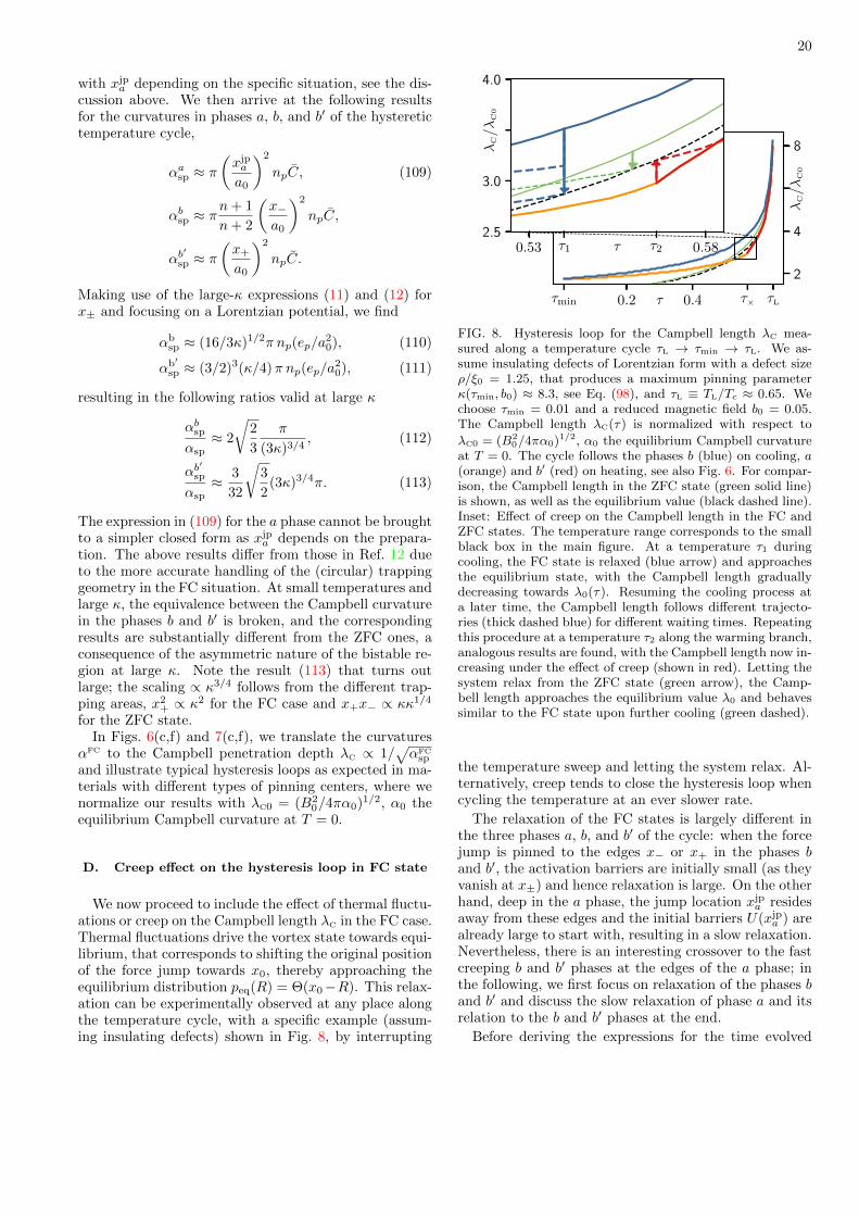
20
with xjpa depending on the specific situation, see the dis-
cussion above. We then arrive at the following resultsfor the curvatures in phases a, b, and b′ of the hysteretictemperature cycle,
αasp ≈ π(xjpa
a0
)2
npC, (109)
αbsp ≈ πn+ 1
n+ 2
(x−a0
)2
npC,
αb′
sp ≈ π(x+
a0
)2
npC.
Making use of the large-κ expressions (11) and (12) forx± and focusing on a Lorentzian potential, we find
αbsp ≈ (16/3κ)1/2π np(ep/a
20), (110)
αb′sp ≈ (3/2)3(κ/4)π np(ep/a
20), (111)
resulting in the following ratios valid at large κ
αbspαsp≈ 2
√2
3
π
(3κ)3/4, (112)
αb′
sp
αsp≈ 3
32
√3
2(3κ)3/4π. (113)
The expression in (109) for the a phase cannot be broughtto a simpler closed form as xjp
a depends on the prepara-tion. The above results differ from those in Ref. 12 dueto the more accurate handling of the (circular) trappinggeometry in the FC situation. At small temperatures andlarge κ, the equivalence between the Campbell curvaturein the phases b and b′ is broken, and the correspondingresults are substantially different from the ZFC ones, aconsequence of the asymmetric nature of the bistable re-gion at large κ. Note the result (113) that turns outlarge; the scaling ∝ κ3/4 follows from the different trap-ping areas, x2
+ ∝ κ2 for the FC case and x+x− ∝ κκ1/4
for the ZFC state.In Figs. 6(c,f) and 7(c,f), we translate the curvatures
αFC to the Campbell penetration depth λC ∝ 1/√αFC
sp
and illustrate typical hysteresis loops as expected in ma-terials with different types of pinning centers, where wenormalize our results with λC0 = (B2
0/4πα0)1/2, α0 theequilibrium Campbell curvature at T = 0.
D. Creep effect on the hysteresis loop in FC state
We now proceed to include the effect of thermal fluctu-ations or creep on the Campbell length λC in the FC case.Thermal fluctuations drive the vortex state towards equi-librium, that corresponds to shifting the original positionof the force jump towards x0, thereby approaching theequilibrium distribution peq(R) = Θ(x0−R). This relax-ation can be experimentally observed at any place alongthe temperature cycle, with a specific example (assum-ing insulating defects) shown in Fig. 8, by interrupting
τmin 0.2 0.4 τ× τL
2
4
8
0.53 τ1 τ2 0.582.5
3.0
4.0
τ
λC/λ
C0
τ
λC/λ
C0
FIG. 8. Hysteresis loop for the Campbell length λC mea-sured along a temperature cycle τL → τmin → τL. We as-sume insulating defects of Lorentzian form with a defect sizeρ/ξ0 = 1.25, that produces a maximum pinning parameterκ(τmin, b0) ≈ 8.3, see Eq. (98), and τL ≡ TL/Tc ≈ 0.65. Wechoose τmin = 0.01 and a reduced magnetic field b0 = 0.05.The Campbell length λC(τ) is normalized with respect to
λC0 = (B20/4πα0)1/2, α0 the equilibrium Campbell curvature
at T = 0. The cycle follows the phases b (blue) on cooling, a(orange) and b′ (red) on heating, see also Fig. 6. For compar-ison, the Campbell length in the ZFC state (green solid line)is shown, as well as the equilibrium value (black dashed line).Inset: Effect of creep on the Campbell length in the FC andZFC states. The temperature range corresponds to the smallblack box in the main figure. At a temperature τ1 duringcooling, the FC state is relaxed (blue arrow) and approachesthe equilibrium state, with the Campbell length graduallydecreasing towards λ0(τ). Resuming the cooling process ata later time, the Campbell length follows different trajecto-ries (thick dashed blue) for different waiting times. Repeatingthis procedure at a temperature τ2 along the warming branch,analogous results are found, with the Campbell length now in-creasing under the effect of creep (shown in red). Letting thesystem relax from the ZFC state (green arrow), the Camp-bell length approaches the equilibrium value λ0 and behavessimilar to the FC state upon further cooling (green dashed).
the temperature sweep and letting the system relax. Al-ternatively, creep tends to close the hysteresis loop whencycling the temperature at an ever slower rate.
The relaxation of the FC states is largely different inthe three phases a, b, and b′ of the cycle: when the forcejump is pinned to the edges x− or x+ in the phases band b′, the activation barriers are initially small (as theyvanish at x±) and hence relaxation is large. On the otherhand, deep in the a phase, the jump location xjp
a residesaway from these edges and the initial barriers U(xjp
a ) arealready large to start with, resulting in a slow relaxation.Nevertheless, there is an interesting crossover to the fastcreeping b and b′ phases at the edges of the a phase; inthe following, we first focus on relaxation of the phases band b′ and discuss the slow relaxation of phase a and itsrelation to the b and b′ phases at the end.
Before deriving the expressions for the time evolved

21
curvatures αFC(t, T ), we summarize our results in Fig.8 on the example of a hysteretic cooling/warming hys-teretic cycle as it appears for the insulating defect or forδ`-pinning. Depending on which part of the temperaturecycle the relaxation process takes place (by stopping thechange in temperature), the Campbell length λC(t, T ) ei-ther grows or decreases in approaching the equilibriumstate. The inset in Fig. 8 shows three cases, relaxationduring the b phase (on cooling, in blue, with decreasingλbC), at the end of the a phase/start of the b′ phase (upon
heating, in red, with increasing λb′
C ), and relaxation of theZFC state in green (decreasing λC). The various relax-ation traces approach the equilibrium value λ0
C ∝ 1/√α0
shown as a black dashed line. Stopping the relaxationby further cooling/heating, the penetration depth λC re-turns back to the FC lines (dashed blue/red lines). Therelaxation in the a phase is slow away from its edgesat Tmin and T× as the activation barriers become large.Hence, we find that combining cooling, heating, and re-laxation allows us to install numerous different vortexstates, permitting us to spectroscopize the pinning forceand thus probe the pinning potential of defects in a ma-terial.
We now return back to the general discussion andderive the time evolution of the Campbell curvaturesαFC(t, T ) for the phases b and b′. In describing the ef-fect of creep on the Campbell curvature, we make heavyuse of the results obtained in Sec. IV B; specifically, wecan make use of the shifts δx± and δrp±, δrf± of the vor-tex asymptotic and tip position as determined throughthe dimensionless thermal barrier T defined in Eq. (39).
Very close to the Labusch point κ−1� 1, the bistableregion is symmetric around x0 and the force jumps at x−and x+ are equal, hence, relaxation of the Campbell cur-vature along phases b and b′ of the temperature cycleare the same to leading order and identical with the re-sult Eq. (81) for the ZFC state with the properly chosenLabusch parameter κ(T ). The beyond leading-order cor-rection (106) to the tip positions shifts the b and b′ curvesfor the curvatures symmetrically down and up with re-spect to the ZFC result, see Fig. 9.
Going to lower temperatures, the pinning parameter κgrows larger and the equivalence between the FC curva-tures αbsp and αb
′sp and the ZFC result αsp is lifted. Using
the expression ∆f fppin(x) = C [rf(x)− rp(x)] to evaluate
the force jumps, and dropping the pinned against the freevortex tip position, i.e., rf(x)� rp(x) for κ� 1, we findthat
∆f jp,bpin −∆f fp
pin(x−) ≈ C δrf−, (114)
∆f jp,b′
pin −∆f fppin(x+) ≈ −Cδrf+, (115)
where ∆f jp,bpin = ∆f fp
pin(xjp−) and ∆f jp,b′
pin = ∆f fppin(xjp
+ ).Combining these results for the force jumps with therenormalized trapping radii
xjpb = x−(1 + δx−/x−), (116)
xjpb′ = x+(1 − δx+/x+), (117)
the general expressions for the relaxation of the Campbellcurvature during the phases b and b′ of the temperaturecycle assume the form (cf. Eq. (63) for the ZFC and notethat δrf+ ≈ δx+; here, κ = κ(T ) is always chosen at theappropriate temperature T )
αbsp(t, T )
αbsp≈(
1 +δx−x−
)(1 +
δrf−rf−
), (118)
αb′
sp(t, T )
αb′sp≈(
1− δx+
x+
)(1− δrf+
x+
). (119)
We observe that, contrary to the situation in the ZFCstate where we found a competition between an increas-ing trapping area and a decreasing force jump, in theFC states, the changes in the trapping area and in theforce jumps work together. In particular, the trappingarea shrinks with time in the b′ phase. Hence, relaxingthe state during phase b always leads to an increasingcurvature, larger then the ZFC result, i.e., a decreasingCampbell penetration depth λC, while the opposite ap-plies during phase b′, see Fig. 9.
Focusing on the phase b for a Lorentzian potential, wecan make use of the results (69) for δx− and δrf− andfind that
αbsp(t, T )
αbsp≈(
1 +3
8κ1/3(
√3T )2/3
)×(
1 +1
2κ1/6(
√3T )1/3
). (120)
This result is valid at short times, where δrf− is domi-nated by the square root behavior of the force profile closeto x−. Going beyond short times, such that δx− � x−/6,the deviation δrf− ≈ rf−/3 + δx− is approximately lin-ear, as discussed in the derivation of Eq. (64), and theCampbell curvature reads
αbsp(t, T )
αbsp≈(
1 +3
8κ1/3(
√3T )2/3
)×(
1 +1
3+
1
2κ1/3(
√3T )2/3
). (121)
In the analysis of the relaxation during phase b′, weproceed the same way: we make use of the result (69) forδx+ and note that δrf+ ≈ δx+ to find the result
αb′
sp(t)
αb′sp≈(
1− δx+
x+
)(1− δx+
x+
)≈(1− 2(
√3T )2/3 + (
√3T )4/3
)(122)
for the Lorentzian potential. With the above results, wefind that the relaxation of the b and b′ phases under FCconditions is always faster than the relaxation for a ZFCexperiment, see Eqs. (72) and (73).
The upward (downward) relaxation of the Campbell
curvatures αb(b′)sp (t, T ) is illustrated in Fig. 9, middle and

22
0 1.2× 10⁻⁵
1
1.1
1.15
0.0 0.15
0.5
2
2.5
0 0.6
1
15
20
0.1 0.6
0.2
1
0 2.5 × 10⁻⁷
0.96
1.08
κ = 1.01 κ = 5 κ = 100
(T/ep)log(t/t0)
αF
Csp
(t)/α
sp
(T/ep)log(t/t0)
αF
Csp
(t)/α
sp
(T/ep)log(t/t0)
αF
Csp
(t)/α
sp
(T/ep)log(t/t0)
αF
Csp
(t)/α
sp
(T/ep)log(t/t0)
αF
C
sp(t
)/α
sp
FIG. 9. Relaxation of the scaled Campbell curvature αFCsp (t)/αsp versus creep parameter T = (T/ep) ln(t/t0). Shown are results
for the field cooled (FC) phases b (in blue), b′ (in red), and a (in orange, middle panel), as well as the zero-field cooled result(ZFC, green) for comparison. Assuming a Lorentzian pinning potential, we show results for marginally strong (κ = 1.01),intermediate (κ = 5), and very strong (κ = 100) pinning. Numerical results are shown as continuous lines, dashed lines (atlarge κ) describe analytic results at small values of T . At marginally strong pinning (κ = 1.01, left panel), the relaxationcurves for the phases b and b′ separate symmetrically away from the ZFC result, a result obtained analytically only when goingbeyond leading order, see Eq. (106); the thick colored ticks marking the analytic results at t = t0 agree well with the end pointsof the numerical curves (dotted lines show the extrapolation of the results to t = 0). The middle panel (κ = 5) also showsresults for the a phase with a flat initial regime (slow relaxation) joining the trace (at time ta, see Eq. (124)) for the b′ (red)or b (blue) phase (depending on the starting point x0 < xjpa < x+ or x− < xjpa < x0, respectively) at large times. Analytic andnumerical results agree well in the large κ limit and at small T , with the results for the b (b′) phases increasing (decreasing)
monotonously with time, while the ZFC result is non-monotonous. Note that the large values of αb′sp/αsp (red curve) require
a large κ that is realized at low temperatures, typically. Thick ticks at large times mark the asymptotic value α0/αsp close toequilibrium t ∼ teq before entering the TAFF region, see text. The (numerical) lines terminate at the boundary of applicability(T/ep) ln(t/t0) ≈ (κ − 1)2/8 and ∼ 1 for marginally strong and very strong pinning, respectively. At very short times t ∼ t0,our creep analysis breaks down as the barriers U vanish.
right panels, with the curves αb,b′
sp (t, T ) (blue and red)enclosing the ZFC result αsp(t, T ) (green). This implies areverse behavior in the Campbell penetration length λC,which decreases with time in the b phase and increases inthe b′ phase, see the example of a cooling–warming cyclefor the case of insulating defects in Fig. 8.
Finally, we discuss the behavior of the a phase uponrelaxation. The a phase can be entered either via theb phase (see, e.g., Fig. 6(b)), via the b′ phase (see, e.g.,Fig. 6(e) very close to TL, or directly from x0L at TL (seeFig. 7(e)). To fix ideas, here we focus on the situationwhere the a phase is entered from the b′ phase; the jumplocation xjp
a then resides in the interval [x0, x+] and the(depinning) barrier Udp(xjp
a ) is finite right from the startat t0. Rather then reanalyzing this new situation ‘micro-scopically’, let us consider a substitute process where westart in the b′ phase and let it decay in time (at the samepoint (τ, b0) in phase space). Then, after a time ta, the
jump location xjpb′ (ta) will reach xjp
a and from there on,the further decay of the b′ phase traces the decay of thea phase. As a result, we find that
αasp(t) = αb′
sp(t+ ta) (123)
with the waiting time ta given by the usual estimate
T ln(ta/t0) ≈ Udp(xjpa ) or
ta ≈ t0 exp[Udp(xjp
a )/T]. (124)
For the case where we enter the a phase from the b phase,we have to shift αbsp instead, αasp(t) = αbsp(t + ta), and
substitute Udp(xjpa ) by Up(xjp
a ). In general, when x0 <
xjpa < x+, we shift αb
′sp, while αbsp is to be shifted when
x− < xjpa < x0.
Translating the seemingly trivial linear-in-time shiftt→ t+ta to the log(t/t0) plot of Fig. 9 produces an inter-esting outcome, see the orange line in the middle panel.With xjp
a < x+, we have a smaller force jump ∆fpin and
hence αasp starts out at a lower value then the αb′
sp(t)
curve, αasp(t0) < αb′
sp(t0). Next, the slope ∂log(t/t0)αasp
∣∣t
at small times t � ta relates to the slope of αb′
sp at ta,
∂log(t/t0)αb′sp
∣∣ta≡ −α′, via
∂log(t/t0)αasp
∣∣t
= t ∂tαasp
∣∣t
(125)
=t
ta
[t ∂tα
b′sp
]ta
= − t
taα′
and hence is small by the factor t/ta � 1. As a result, wefind that αasp(t) evolves flat in log(t/t0) and then bends
over to αb′
sp(t) at t ∼ ta, see Fig. 9, within a log-time

23
interval of unit size or a T -interval of order T/ep, whichis small on the extension T ≈ 1 of the creep parameter.
In an experiment, where the relaxation of the Camp-bell curvature (or length) is plotted versus log-time, thea phase will start out with a seemingly slow decay (a flatcurve) as compared to the decay of the b′ phase, see Fig.9. This is owed to the vanishing of the barrier for theb′ phase at small times, hence the b′ phase decays muchfaster than the a phase. Once the waiting time ta isreached, the decay of the b′ phase has slowed down suchas to catch up with the decay of the a phase. The detec-tion of the a phase in an experiment then depends on itstime resolution: this will be successful if ta resides withinthe observable time window of the relaxation experiment.If ta is too large (note that ta ∝ exp
[U(xjp
a )/T]
exponen-tially depends on the barrier and the temperature T ) ascompared to the time window of the measurement, onlythe flat part of the curve will be observed, with appar-ently no relaxation of the Campbell length. On the otherhand, if ta is too short to be caught by the experimentthen one will resolve a phase b′ type relaxation and thefeature appertaining to the a phase (flat part) is lost. Theabsence of relaxation in the Campbell length observed18
in a BiSCCO sample finds a simple explanation in termsof large barriers that are present in the a phase of thehysteresis loop.
V. SUMMARY AND OUTLOOK
Strong pinning theory delivers a quantitative descrip-tion of vortex pinning in the dilute defect limit. This factis particularly prominent in the context of the Campbellac response: not only can we describe a multitude of dif-ferent vortex states, the zero-field cooled state and var-ious types of field cooled states, we also can accuratelytrace the time evolution of these states and their signa-tures in Campbell penetration depth measurements. Thestrong pinning theory thus provides access to hystereticand relaxation effects in the ac response that are other-wise, e.g., via weak collective pinning theory, at least sofar, not available.
In this work, we have studied the effects of thermalfluctuations at finite temperatures T , or creep, on theCampbell penetration depth λC ∝ 1/
√∆fpin that tracks
the force jumps ∆fpin in the strong pinning landscapeof Fig. 3. The proportionality αsp ∝ ∆fpin, first foundin Ref. 9, provides a satisfying connection to the cur-vature α appearing in Campbell’s original5 phenomeno-logical description: the jump ∆fpin effectively averagesthe curvatures in the pinning landscape. Remarkably, acpenetration experiments provide new information on thepinning landscape, different from standard critical cur-rent density jc ∝ ∆epin measurements that tell aboutthe jumps ∆epin in energy.
In our analysis of the zero-field cooled (ZFC) state,we found an interesting relaxation behaviour of theCampbell curvature αsp(t, T ) (or penetration depth
λC ∝ 1/√αsp) with a non-monotonous time-evolution at
medium to large values of the pinning parameter κ, in-creasing first at small waiting times t and then decreasingtowards a finite equilibrium value α0 > 0. At small val-ues of κ − 1 ll1, the marginal strong pinning situation,we found the curvature αsp(t, T ) rising monotonously;numerical analysis shows that non-monotonicity appearsat still rather small values of κ ≈ 2. The decay to a fi-nite value α0 in the Campbell curvature is very differentfrom the decay to zero of the persistent current densityj(t, T ), a fact owed to the different limits of ∆fpin > 0and ∆epin = 0 at the branch crossing point x0, see Fig.3.
The relaxation of the field cooled (FC) states providesa rich variety of results as well: first of all, we find numer-ous types of hysteresis loops, depending on the character-istics of the defects, with insulating and metallic point-like defects, δTc- and δ`-pinning studied in more detailhere, see also Ref. 12. This different behavior is owedto the competition between an increasing κ(T ) and a de-creasing ξ(T ) as the temperature T is decreased, withthe scaling of κ(T ) determined by the type of pinning.Depending on the relative motion between the bistableinterval [x−, x+] (with x− ∼ κ1/4ξ and x+ ∼ κξ at largeκ) and the initial instability point x0L = x0(TL) upon de-creasing T , the jump location xjp gets pinned at the edgesx±(T ) or stays put somewhere in between—these threecases define the phases b and b′, as well as the a phase,that appear in the hysteresis loop when cycling the tem-perature down and up. The appearance of these phaseswithin a loop again depends on the defect type, with in-sulating defects and δ`-pinning exhibiting all phases inthe sequence b (cooling) to a (heating) to b′ (heating),while the loops for δTc-pinning and metallic defects aredominated by the a phase. The three phases behave quitedifferently, with the b′ phase providing a smaller penetra-tion depth λC at large κ (where αbsp/α
b′sp ∝ 1/κ3/2), while
in terms of creep, the a phase sticks out by its slower de-cay. Further experimental signatures for these phases arethe decay (increase) in magnitude of λC under creep forthe b (b′) phases and a plateau, i.e., an initially muchslower relaxation (both up or down is possible) in the aphase due to the presence of large thermal barriers. Suchcharacteristic differences then allow to make conjecturesabout the underlying pinning landscape.
In the present work, we have made an additional steptowards better precision in our analytic results. Usingthe Lorentzian-shaped potential describing a point-likedefect as an example, we have provided analytic resultsincluding numerical factors; this further illustrates thevalue of the strong pinning concept as a quantitative the-ory. Furthermore, care has been taken to properly treatthe trapping geometry of strong pinning, see Fig. 1. Itturns out, that this geometry affects transport and acresponse in different ways: while in transport only thetransverse trapping length t⊥ = 2x− shows up, whendealing with the (ZFC) ac response, pinning (involvinga semi-circle of radius x−) and depinning (at a circular

24
segment of radius x+) are weighted with separate fac-tors. Furthermore, in the FC situation, trapping alwaysappears on a circle with a radius R ∈ [x−, x+] spanningthe entire bistable region, depending on the induced vor-tex state; this feature has been missed in our previousanalysis12.
Several of the predictions made in the present workhave been observed in experiments measuring the Camp-bell penetration length. Examples are the decreasingλC(t) in a BiSCCO sample18 that is consistent with an in-creasing Campbell curvature at short times or marginallystrong pinning, see Fig. 4, the increasing λC(t) in anYBCO superconductor19 that is consistent with the longtime behavior of the Campbell curvature at intermediateand very strong pinning, see again Fig. 4, the finite equi-librium value of the Campbell length λC0, see Eq. (84),that has been observed in a BiSCCO sample above theirreversibility line, and the absence of creep in the fieldcooled (FC) state of a BiSCCO single crystal18, here ex-plained in terms of an a phase that is characterized bythe presence of large barriers, see also Fig. 9.
In the present study, we have focused on the low-fieldregime where the trapping length x+ stays below the
vortex lattice constant, x+ < a0/2. At larger field val-ues, multiple vortices start competing for the same de-fect and our single-pin–single-vortex description has tobe extended to include several vortices, see also Refs.22 and 23. This becomes particularly relevant in veryanisotropic and layered material with ε � 1, whereκ ∝ 1/ε can become large and x+ ∼ κξ easily goes be-yond a0/2 even at moderate field values already. Re-lated to the possibility of such very strong pinning is theprediction30 of a creep-enhanced critical current due to adominant increase in the trapping area at very large κ.Furthermore, since pinning remains active also beyond20
jc it would be interesting to measure and analyze theCampbell penetration physics in the dynamical vortexstate.
ACKNOWLEDGMENTS
We thank Martin Buchacek and Roland Willa for dis-cussions and acknowledge financial support of the SwissNational Science Foundation, Division II.
1 A. Abrikosov, Sov.Phys.JETP 5 (1957) 5 (1957).2 A. Campbell and J. Evetts, Advances in Physics 21, 199
(1972), https://doi.org/10.1080/00018737200101288.3 M. Tinkham, Introduction to Superconductivity , Dover
Books on Physics Series (Dover Publications, 2004).4 P. G. De Gennes, Superconductivity of Metals and Alloys,
Advanced book classics (Perseus, Cambridge, MA, 1999).5 A. M. Campbell, Journal of Physics C: Solid State Physics
2, 1492 (1969).6 R. Labusch, Crystal Lattice Defects 1 (1969).7 A. I. Larkin and Y. N. Ovchinnikov, Journal of Low Tem-
perature Physics 34, 409 (1979).8 G. Blatter, V. B. Geshkenbein, and J. A. G. Koopmann,
Phys. Rev. Lett. 92, 067009 (2004).9 R. Willa, V. Geshkenbein, R. Prozorov, and G. Blatter,
Physical Review Letters 115, 207001 (2015).10 J. Lowell, Journal of Physics F: Metal Physics 2, 547
(1972).11 A. Campbell, Philosophical Magazine B 37, 149 (1978),
https://doi.org/10.1080/01418637808226649.12 R. Willa, V. B. Geshkenbein, and G. Blatter, Phys. Rev.
B 93, 064515 (2016).13 C. P. Bean, Phys. Rev. Lett. 8, 250 (1962).14 M. Buchacek, R. Willa, V. B. Geshkenbein, and G. Blat-
ter, Physical Review B 98, 094510 (2018).15 M. Buchacek, R. Willa, V. B. Geshkenbein, and G. Blat-
ter, Physical Review B 100, 014501 (2019).16 A. U. Thomann, V. B. Geshkenbein, and G. Blatter, Phys-
ical Review Letters 108, 217001 (2012).17 M. Buchacek, Z. L. Xiao, S. Dutta, E. Y. Andrei, P. Ray-
chaudhuri, V. B. Geshkenbein, and G. Blatter, Phys. Rev.B 100, 224502 (2019).
18 R. Prozorov, R. Giannetta, N. Kameda, T. Tamegai,J. Schlueter, and P. Fournier, Phys. Rev. B 67, 184501(2003).
19 G. Pasquini and V. Bekeris, Phys. Rev. B 71, 014510(2005).
20 A. U. Thomann, V. B. Geshkenbein, and G. Blatter, Phys-ical Review B 96, 144516 (2017).
21 W.-K. Kwok, U. Welp, A. Glatz, A. E. Koshelev, K. J.Kihlstrom, and G. W. Crabtree, Rep. Prog. Phys. 79,116501 (2016).
22 R. Willa, A. Koshelev, I. Sadovskyy, and A. Glatz, Super-cond. Sci. Technol. 31, 014001 (2018).
23 R. Willa, A. E. Koshelev, I. A. Sadovskyy, and A. Glatz,Physical Review B 98, 054517 (2018).
24 G. Blatter, M. V. Feigel’man, V. B. Geshkenbein, A. I.Larkin, and V. M. Vinokur, Rev. Mod. Phys. 66, 1125(1994).
25 J. Bardeen and M. J. Stephen, Physical Review 140,A1197 (1965).
26 S. Brazovskii and A. Larkin, J. Phys. IV France 09, Pr10(1999).
27 S. Brazovskii and T. Nattermann, Adv. Phys. 53, 177(2004).
28 P. H. Kes, J. Aarts, J. van den Berg, C. J. van der Beek,and J. A. Mydosh, Superconductor Science and Technology1, 242 (1989).
29 R. Willa, V. B. Geshkenbein, and G. Blatter, PhysicalReview B 92, 134501 (2015).
30 F. Gaggioli, G. Blatter, and V. Geshkenbein, unpublished(2022).
Related Documents