Subject to change without notice. www.cree.com/xlamp Data Sheet: CLD-DS05.007 Cree ® XLamp ® XR-E LED Data Sheet Cree XLamp LEDs combine the brightness of power LED chips with a rugged package capable of operating up to four watts. Cree XLamp LEDs lead the solid- state lighting industry in brightness while providing a reflow-solderable design that is optimized for ease of use and thermal management. Lighting applications featuring XLamp LEDs maximize light output and increase design flexibility, while minimizing environmental impact. Cree XLamp LEDs bring lighting-class brightness and efficiency to a wide range of lighting and backlighting applications, including portable lighting and flashlights, outdoor and industrial, signaling, architectural, landscaping and entertainment/ advertising installations. Table of Contents Flux Characteristics (T J = 25°C) ............................................................................... 2 Characteristics ......................................................................................................... 3 Relative Spectral Power ........................................................................................... 4 Photometric Output vs. Junction Temperature (I F = 350 mA) .................................. 5 Electrical Characteristics (T J = 25˚C) ....................................................................... 6 Thermal Design ........................................................................................................ 6 Relative Intensity vs. Current (T J = 25˚C) ................................................................ 7 Typical Spatial Radiation Pattern.............................................................................. 7 Reflow Soldering Characteristics .............................................................................. 8 Notes........................................................................................................................ 9 Mechanical Dimensions (T A = 25°C) ....................................................................... 0 Tape and Reel......................................................................................................... Dry Packaging and Packaging ................................................................................ 2 FEATURES Guaranteed minimum flux order codes up to 100 lm in white and 23.5 lm in blue Over 80 lm/W available in white Available in white (2,600 K to 10,000 K CCT), blue and royal blue Drive currents: 350 to 1000 mA Industry’s lowest thermal resistance: 8°C/W Max junction temperature: 150°C • • • • • • Industry-leading JEDEC standard pre- qualification testing Reflow solderable – JEDEC J-STD-020C compatible Electrically neutral thermal path RoHS-compliant Lumen maintenance of greater than 70% after 50,000 hours • • • • •

Welcome message from author
This document is posted to help you gain knowledge. Please leave a comment to let me know what you think about it! Share it to your friends and learn new things together.
Transcript

�Subject to change without notice.www.cree.com/xlamp
Data
Sh
eet:
CLD
-DS
05
.00
7
Cree® XLamp® XR-E LEDData Sheet
Cree XLamp LEDs combine the brightness of power LED chips with a rugged package capable of operating up to four watts. Cree XLamp LEDs lead the solid-state lighting industry in brightness while providing a reflow-solderable design that is optimized for ease of use and thermal management. Lighting applications featuring XLamp LEDs maximize light output and increase design flexibility, while minimizing environmental impact.
Cree XLamp LEDs bring lighting-class brightness and efficiency to a wide range of lighting and backlighting applications, including portable lighting and flashlights, outdoor and industrial, signaling, architectural, landscaping and entertainment/advertising installations.
Table of Contents
Flux Characteristics (TJ = 25°C) ...............................................................................2Characteristics .........................................................................................................3Relative Spectral Power ...........................................................................................4Photometric Output vs. Junction Temperature (IF = 350 mA) ..................................5Electrical Characteristics (TJ = 25˚C) .......................................................................6Thermal Design ........................................................................................................6Relative Intensity vs. Current (TJ = 25˚C) ................................................................7Typical Spatial Radiation Pattern ..............................................................................7Reflow Soldering Characteristics ..............................................................................8Notes ........................................................................................................................9Mechanical Dimensions (TA = 25°C) .......................................................................�0Tape and Reel .........................................................................................................��Dry Packaging and Packaging ................................................................................�2
FEATURES
Guaranteed minimum flux order codes up to
100 lm in white and 23.5 lm in blue
Over 80 lm/W available in white
Available in white (2,600 K to 10,000 K CCT),
blue and royal blue
Drive currents: 350 to 1000 mA
Industry’s lowest thermal resistance: 8°C/W
Max junction temperature: 150°C
•
•
•
•
•
•
Industry-leading JEDEC standard pre-
qualification testing
Reflow solderable – JEDEC J-STD-020C
compatible
Electrically neutral thermal path
RoHS-compliant
Lumen maintenance of greater than 70% after
50,000 hours
•
•
•
•
•
Copyright © 2006-2007 Cree, Inc. All rights reserved. The information in this document is subject to change without notice. Cree, the Cree logo and XLamp are registered trademarks of Cree, Inc.
2 CLD-DS05.007
Cree, Inc.4600 Silicon Drive
Durham, NC 27703USA Tel: +1.919.313.5300
www.cree.com/xlamp
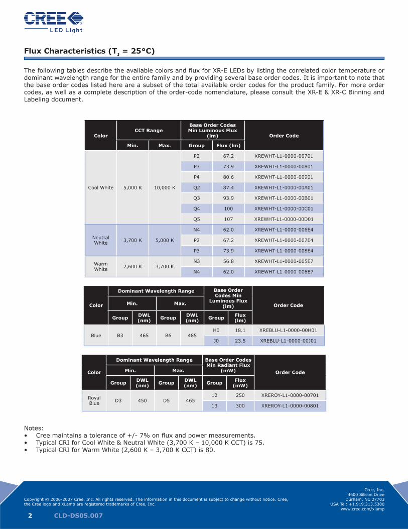
Flux Characteristics (TJ = 25°C)
The following tables describe the available colors and flux for XR-E LEDs by listing the correlated color temperature or dominant wavelength range for the entire family and by providing several base order codes. It is important to note that the base order codes listed here are a subset of the total available order codes for the product family. For more order codes, as well as a complete description of the order-code nomenclature, please consult the XR-E & XR-C Binning and Labeling document.
ColorCCT Range
Base Order Codes Min Luminous Flux
(lm) Order Code
Min. Max. Group Flux (lm)
Cool White 5,000 K 10,000 K
P2 67.2 XREWHT-L1-0000-00701
P3 73.9 XREWHT-L1-0000-00801
P4 80.6 XREWHT-L1-0000-00901
Q2 87.4 XREWHT-L1-0000-00A01
Q3 93.9 XREWHT-L1-0000-00B01
Q4 100 XREWHT-L1-0000-00C01
Q5 107 XREWHT-L1-0000-00D01
Neutral White 3,700 K 5,000 K
N4 62.0 XREWHT-L1-0000-006E4
P2 67.2 XREWHT-L1-0000-007E4
P3 73.9 XREWHT-L1-0000-008E4
Warm White 2,600 K 3,700 K
N3 56.8 XREWHT-L1-0000-005E7
N4 62.0 XREWHT-L1-0000-006E7
Color
Dominant Wavelength Range Base Order Codes Min
Luminous Flux (lm) Order CodeMin. Max.
Group DWL (nm) Group DWL
(nm) Group Flux (lm)
Blue B3 465 B6 485H0 18.1 XREBLU-L1-0000-00H01
J0 23.5 XREBLU-L1-0000-00J01
Color
Dominant Wavelength Range Base Order Codes Min Radiant Flux
(mW) Order CodeMin. Max.
Group DWL (nm) Group DWL
(nm) Group Flux (mW)
Royal Blue D3 450 D5 465
12 250 XREROY-L1-0000-00701
13 300 XREROY-L1-0000-00801
Notes:Cree maintains a tolerance of +/- 7% on flux and power measurements.Typical CRI for Cool White & Neutral White (3,700 K – 10,000 K CCT) is 75.Typical CRI for Warm White (2,600 K – 3,700 K CCT) is 80.
•••

Copyright © 2006-2007 Cree, Inc. All rights reserved. The information in this document is subject to change without notice. Cree, the Cree logo and XLamp are registered trademarks of Cree, Inc.
3 CLD-DS05.007
Cree, Inc.4600 Silicon Drive
Durham, NC 27703USA Tel: +1.919.313.5300
www.cree.com/xlamp
Characteristics
Characteristics Unit Minimum Typical Maximum
Thermal Resistance, junction to solder point °C/W 8
Viewing Angle (FWHM) degrees 90
Temperature coefficient of voltage (white, blue, royal blue) mV/°C -4.0
ESD Classification (HBM per Mil-Std-883D) Class 2
DC Forward Current (white ≥ 5000 K) mA 1000
DC Forward Current (white < 5000 K, blue, royal blue) mA 700
DC Pulse Current (@ 1 kHz, 10% duty cycle) A 1.8
Reverse Voltage V 5
Forward Voltage (@ 350 mA) V 3.3 3.9
Forward Voltage (@ 700 mA) V 3.5
Forward Voltage (@ 1000 mA) (white ≥ 5000 K) V 3.7
LED Junction Temperature * °C 150
* Note: For lumen maintenance data, see the Cree XLamp LED Reliability document.
Copyright © 2006-2007 Cree, Inc. All rights reserved. The information in this document is subject to change without notice. Cree, the Cree logo and XLamp are registered trademarks of Cree, Inc.
4 CLD-DS05.007
Cree, Inc.4600 Silicon Drive
Durham, NC 27703USA Tel: +1.919.313.5300
www.cree.com/xlamp
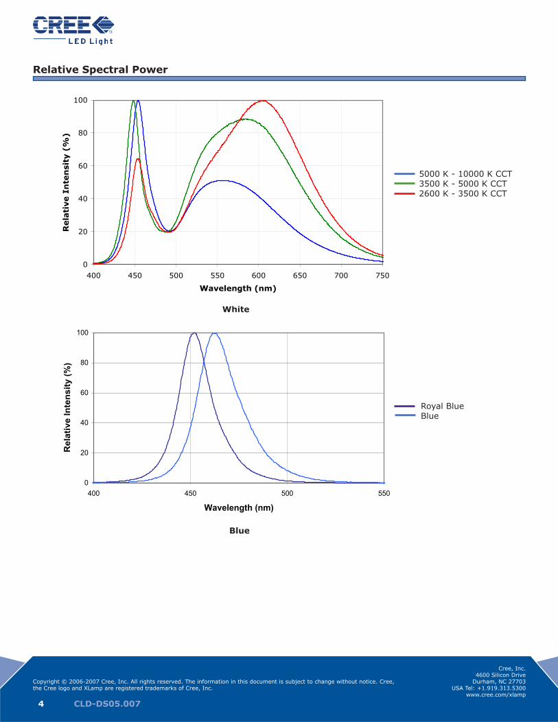
Relative Spectral Power
White
0
20
40
60
80
100
400 450 500 550 600 650 700 750
Wavelength (nm)
Rela
tive I
nte
nsi
ty (
%)
5000K - 10000K CCT
3500K - 5000K CCT
2600K - 2500K CCT
5000 K - 10000 K CCT3500 K - 5000 K CCT2600 K - 3500 K CCT
Blue
0
20
40
60
80
100
400 450 500 550
Wavelength (nm)
Rel
ativ
e In
tens
ity (%
)
Royal BlueBlue

Copyright © 2006-2007 Cree, Inc. All rights reserved. The information in this document is subject to change without notice. Cree, the Cree logo and XLamp are registered trademarks of Cree, Inc.
5 CLD-DS05.007
Cree, Inc.4600 Silicon Drive
Durham, NC 27703USA Tel: +1.919.313.5300
www.cree.com/xlamp
Photometric Output vs. Junction Temperature (IF = 350 mA)
0%
10%
20%
30%
40%
50%
60%
70%
80%
90%
100%
25 50 75 100 125 150
Junction Temperature (°C)
Rela
tive P
ho
tmetr
ic O
utp
ut
White
Blue
0%
10%
20%
30%
40%
50%
60%
70%
80%
90%
100%
25 50 75 100 125 150
Junction Temperature (°C)
Rela
tive R
ad
iom
etr
ic O
utp
ut
Royal Blue

Copyright © 2006-2007 Cree, Inc. All rights reserved. The information in this document is subject to change without notice. Cree, the Cree logo and XLamp are registered trademarks of Cree, Inc.
6 CLD-DS05.007
Cree, Inc.4600 Silicon Drive
Durham, NC 27703USA Tel: +1.919.313.5300
www.cree.com/xlamp
Electrical Characteristics (TJ = 25˚C)
Thermal Design
The maximum forward current is determined by the thermal resistance between the LED junction and ambient. Given an existing thermal resistance of 8°C/W between the junction and the solder point, it is crucial for the end product to be designed in a manner that minimizes the thermal resistance from the solder point to ambient in order to optimize lamp life and optical characteristics.
0
100
200
300
400
500
600
700
800
900
1000
0.0 1.0 2.0 3.0 4.0 5.0
Forward Voltage (V)
Fo
rward
Cu
rren
t (m
A)
Cool White Neutral White, Warm White, Blue and Royal Blue
Rth,j-a 10 Rth,j-a 12Max Current mA 1000 Ta Max Derated Ta Max DeratedTj max °C 150 °C mA mA °C mA mAMax Vf V 4.3 0 3488.4 1000.0 0 2907.0 1000.0Max amb °C 150 107 1000.0 1000.0 98.4 1000.0 1000.0
150 0.0 0.0 150 0.0 0.0
0
200
400
600
800
1000
1200
0 25 50 75 100 125 150
Ambient Temperature (°C)
Max
imum
Cur
rent
(mA
)
Rj-a = 10°C/WRj-a = 12°C/WRj-a = 15°C/WRj-a = 20°C/W
0
100
200
300
400
500
600
700
800
0 25 50 75 100 125 150
Ambient Temperature (°C)
Max
imum
Cur
rent
(mA
)
Rj-a = 10°C/WRj-a = 12°C/WRj-a = 15°C/WRj-a = 20°C/W

Copyright © 2006-2007 Cree, Inc. All rights reserved. The information in this document is subject to change without notice. Cree, the Cree logo and XLamp are registered trademarks of Cree, Inc.
7 CLD-DS05.007
Cree, Inc.4600 Silicon Drive
Durham, NC 27703USA Tel: +1.919.313.5300
www.cree.com/xlamp
Relative Intensity vs. Current (TJ = 25˚C)
0
50
100
150
200
250
0 100 200 300 400 500 600 700 800 900 1000
Forward Current (mA)
Rela
tive I
nte
nsi
ty (
%)
Typical Spatial Radiation Pattern
0
20
40
60
80
100
120
-100 -80 -60 -40 -20 0 20 40 60 80 100
Angle (°)
Rela
tive I
nte
nsi
ty (
%)
Copyright © 2006-2007 Cree, Inc. All rights reserved. The information in this document is subject to change without notice. Cree, the Cree logo and XLamp are registered trademarks of Cree, Inc.
8 CLD-DS05.007
Cree, Inc.4600 Silicon Drive
Durham, NC 27703USA Tel: +1.919.313.5300
www.cree.com/xlamp
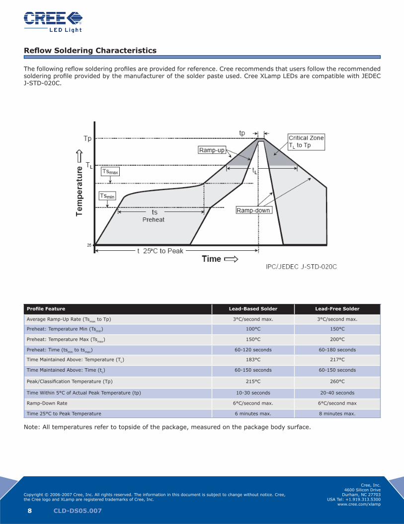
Reflow Soldering Characteristics
The following reflow soldering profiles are provided for reference. Cree recommends that users follow the recommended soldering profile provided by the manufacturer of the solder paste used. Cree XLamp LEDs are compatible with JEDEC J-STD-020C.
Profile Feature Lead-Based Solder Lead-Free Solder
Average Ramp-Up Rate (Tsmax to Tp) 3°C/second max. 3°C/second max.
Preheat: Temperature Min (Tsmin) 100°C 150°C
Preheat: Temperature Max (Tsmax) 150°C 200°C
Preheat: Time (tsmin to tsmax) 60-120 seconds 60-180 seconds
Time Maintained Above: Temperature (TL) 183°C 217°C
Time Maintained Above: Time (tL) 60-150 seconds 60-150 seconds
Peak/Classification Temperature (Tp) 215°C 260°C
Time Within 5°C of Actual Peak Temperature (tp) 10-30 seconds 20-40 seconds
Ramp-Down Rate 6°C/second max. 6°C/second max
Time 25°C to Peak Temperature 6 minutes max. 8 minutes max.
Note: All temperatures refer to topside of the package, measured on the package body surface.

Copyright © 2006-2007 Cree, Inc. All rights reserved. The information in this document is subject to change without notice. Cree, the Cree logo and XLamp are registered trademarks of Cree, Inc.
9 CLD-DS05.007
Cree, Inc.4600 Silicon Drive
Durham, NC 27703USA Tel: +1.919.313.5300
www.cree.com/xlamp
Notes
Lumen Maintenance Projections
Based on internal long-term reliability testing and standardized forecasting methods, Cree projects XLamp LEDs to maintain an average of 70% lumen maintenance after 50,000 hours, provided the LED junction temperature is main-tained at or below 80°C.
Please read the XLamp Reliability application note for more details on Cree’s lumen maintenance testing and forecasting. Please read the XLamp Thermal Management application note for details on how thermal design, ambient temperature, and drive current affect the LED junction temperature.
Moisture Sensitivity
XLamp LEDs are shipped in sealed, moisture-barrier bags (MBB) designed for long shelf life. If XLamp LEDs are exposed to moist environments after opening the MBB packaging but before soldering, damage to the LED may occur during the soldering operation. The following derating table defines the maximum exposure time (in days) for an XLamp LED in the listed humidity and temperature conditions. LEDs with exposure time longer than the time specified below must be baked according to the baking conditions listed below.
TemperatureMaximum Percent Relative Humidity
30% 40% 50% 60% 70% 80% 90%
30ºC 9 5 4 3 1 1 1
25ºC 12 7 5 4 2 1 1
20ºC 17 9 7 6 2 2 1
Baking Conditions
It is not necessary to bake all XLamp LEDs. Only the LEDs that meet all of the following criteria must be baked:LEDs that have been removed from the original MBB packaging LEDs that have been exposed to a humid environment longer than listed in the Moisture Sensitivity section aboveLEDs that have not been soldered
LEDs should be baked at 80ºC for 24 hours. LEDs may be baked on the original reels. Remove LEDs from MBB packaging before baking. Do not bake parts at temperatures higher than 80ºC. This baking operation resets the exposure time as defined in the Moisture Sensitivity section above.
Storage Conditions
XLamp LEDs that have been removed from original MBB packaging but not soldered yet should be stored in a room or cabinet that will maintain an atmosphere of 25 ± 5ºC and no greater than 10% RH (relative humidity). For LEDs stored in these conditions, storage time does not add to exposure time as defined in the Moisture Sensitivity section above.
RoHS Compliance
The levels of environmentally sensitive, persistent biologically toxic (PBT), persistent organic pollutants (POP), or oth-erwise restricted materials in this product are below the maximum concentration values (also referred to as the thresh-old limits) permitted for such substances, or are used in an exempted application, in accordance with EU Directive 2002/95/EC on the restriction of the use of certain hazardous substances in electrical and electronic equipment (RoHS), as amended through April 21, 2006.
Vision Advisory Claim
Users should be cautioned not to stare at the light of this LED product. The bright light can damage the eye.
1.2.3.

Copyright © 2006-2007 Cree, Inc. All rights reserved. The information in this document is subject to change without notice. Cree, the Cree logo and XLamp are registered trademarks of Cree, Inc.
�0 CLD-DS05.007
Cree, Inc.4600 Silicon Drive
Durham, NC 27703USA Tel: +1.919.313.5300
www.cree.com/xlamp
Mechanical Dimensions (TA = 25°C)All measurements are ±.1mm unless otherwise indicated.
Lens
Reflector
SubstrateLens
Reflector
Substrate
8.4 mm
5.6 mm 0.7 mm
9.0 mm
7.0 mm6.46 mm
6.8 mm
4.4 ± .2 mm
7.0 mm
5.6 mm 1.2 mm
9.4 mm
7.4 mm
Side View
Top View Bottom View
Recommended PC Board Solder Pad
7.0 mm
5.6 mm 0.70 mm
8.4 mm
6.46 mm
Recommended PC Board Solder Pad

Copyright © 2006-2007 Cree, Inc. All rights reserved. The information in this document is subject to change without notice. Cree, the Cree logo and XLamp are registered trademarks of Cree, Inc.
�� CLD-DS05.007
Cree, Inc.4600 Silicon Drive
Durham, NC 27703USA Tel: +1.919.313.5300
www.cree.com/xlamp
Tape and ReelAll dimensions in mm.
330.2 mm

Copyright © 2006-2007 Cree, Inc. All rights reserved. The information in this document is subject to change without notice. Cree, the Cree logo and XLamp are registered trademarks of Cree, Inc.
�2 CLD-DS05.007
Cree, Inc.4600 Silicon Drive
Durham, NC 27703USA Tel: +1.919.313.5300
www.cree.com/xlamp
Dry Packaging and Packaging
Cree Bin Code and Barcode Label
Patent Label
Taped Edge
Bin LabelVacuum-Sealed Bag
Desiccant(inside vacuum bag)
Humidity Indicator(inside vacuum bag)
Cree Label withCustomer P/N / Qty / Lot#
Cautionary Labels
Related Documents