Pritika industries limited Submitted by : Jagmohan Dhiman (2312625) Naval Gupta (2312642) Submitted To :

Crank case manufacturing at pritika industries
Jul 06, 2015
Crank Case manufacturing at pritika industries, mohali. it also contains the time study project.
Welcome message from author
This document is posted to help you gain knowledge. Please leave a comment to let me know what you think about it! Share it to your friends and learn new things together.
Transcript

Pritika industries limited
Submitted by :Jagmohan Dhiman (2312625)
Naval Gupta (2312642)
Submitted To :

Pritika at a Glance
Pritika started in 1974 by
Mr. R.S.Nibber, a young technocrat,
manufacturing small automotive
components. The company’s products
include machine components, heavy
castings, flywheel housing, crank
case and hydraulic lift cover.
The quality driven organisation
"PRITIKA Group of Industries" is
producing world class components from
modern facilities.

Products at Pritika
It is the leading supplier &
manufacturer of housings and casting
components.
Most of the components which are
manufactured at pritika are made of
Cast iron because it has ultimate
compressive strength and provide
strength to the component.

It is the leading supplier of Hydraulic lift
cover and the engine covers.
The Crank Case manufactured here is
supplied to mahindra tractors. And the
other casting components are supplied to
various renowned companies.
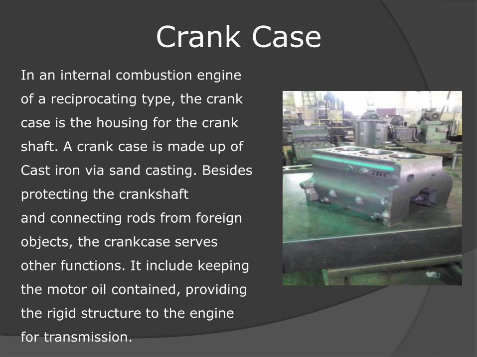
Crank CaseIn an internal combustion engine
of a reciprocating type, the crank
case is the housing for the crank
shaft. A crank case is made up of
Cast iron via sand casting. Besides
protecting the crankshaft
and connecting rods from foreign
objects, the crankcase serves
other functions. It include keeping
the motor oil contained, providing
the rigid structure to the engine
for transmission.
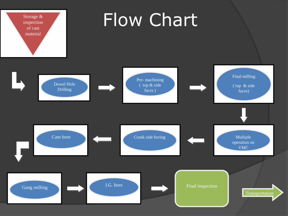
Flow ChartStorage &
inspection
of cast
material
Dowel Hole
Drilling
Pre- machining
( top & side
faces )
Final milling
( top & side
faces)
Multiple
operation on
VMC
Crank side boringCam bore
Gang millingI.G. bore Final inspection
Transportation
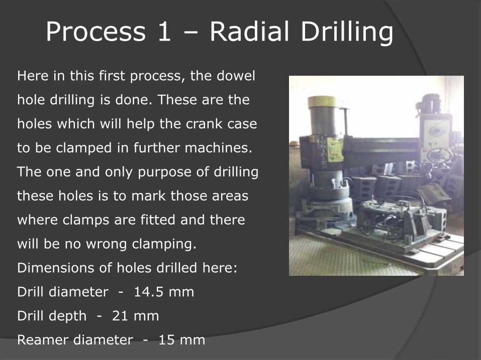
Process 1 – Radial Drilling
Here in this first process, the dowel
hole drilling is done. These are the
holes which will help the crank case
to be clamped in further machines.
The one and only purpose of drilling
these holes is to mark those areas
where clamps are fitted and there
will be no wrong clamping.
Dimensions of holes drilled here:
Drill diameter - 14.5 mm
Drill depth - 21 mm
Reamer diameter - 15 mm
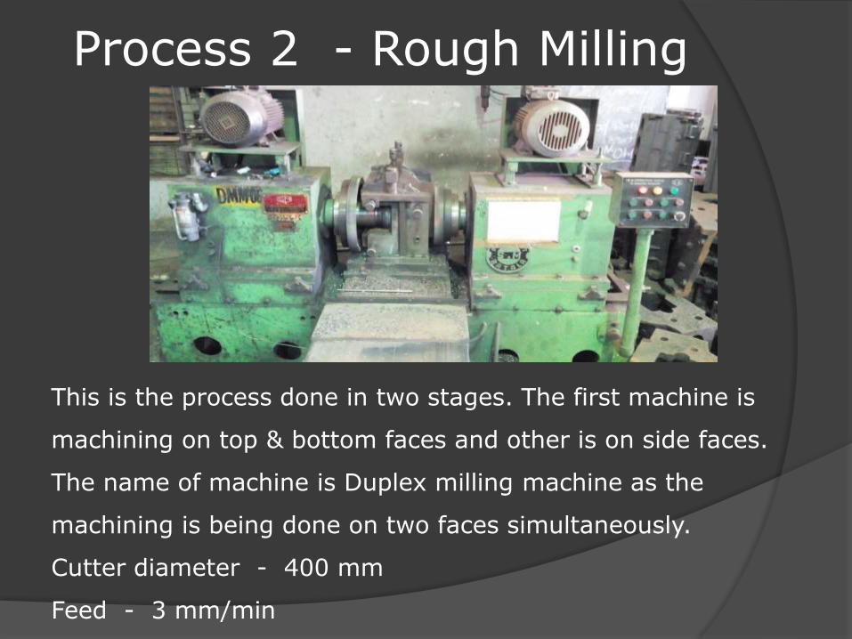
Process 2 - Rough Milling
This is the process done in two stages. The first machine is
machining on top & bottom faces and other is on side faces.
The name of machine is Duplex milling machine as the
machining is being done on two faces simultaneously.
Cutter diameter - 400 mm
Feed - 3 mm/min

Process 3 - Final Milling
Here the machine is
again Duplex Milling
Machine. As the process
is final, so, the accuracy
of the machine matters
here. This process is also
done on two stages. The
machine is driven by two
powerful motors.
Cutter diameter - 400 mm
Speed - 500 r.p.m.
Feed - 0.2 mm/min
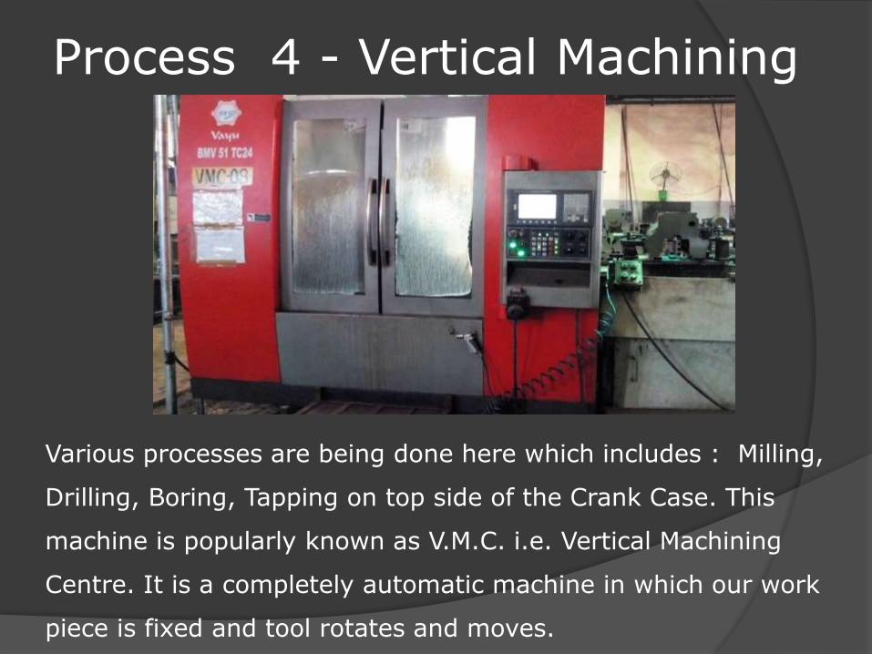
Process 4 - Vertical Machining
Various processes are being done here which includes : Milling,
Drilling, Boring, Tapping on top side of the Crank Case. This
machine is popularly known as V.M.C. i.e. Vertical Machining
Centre. It is a completely automatic machine in which our work
piece is fixed and tool rotates and moves.

The various operations performed in V.M.C. are as follows :
1. Boring :
• Diameter of boring bar - 123.2 mm• Speed - 400 rpm• Feed Rate - 0.2 mm/min
2. Drilling :
• Diameter of drill - 31 mm• Speed - 650 rpm
3. Milling :
• Diameter of cutter - 100 mm
4. Drilling :
• Diameter of bit - 10.2 mm• Speed - 1000 rpm
5. Tapping :
• Diameter of tapp - 12 mm• Speed - 500 rpm• Feed rate - 0.2 mm/min
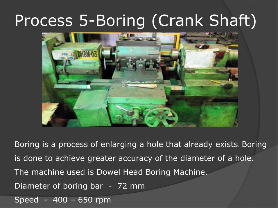
Process 5-Boring (Crank Shaft)
Boring is a process of enlarging a hole that already exists. Boring
is done to achieve greater accuracy of the diameter of a hole.
The machine used is Dowel Head Boring Machine.
Diameter of boring bar - 72 mm
Speed - 400 – 650 rpm

Process 6 - Boring(Cam Shaft)
The bore for Cam Shaft is done here and the machine used is
same Dowel Head Boring Machine. The machining of the
component is done on both sides simultaneously. So, the rate is
quite good and efficient.
Diameter of bore - 49 mm
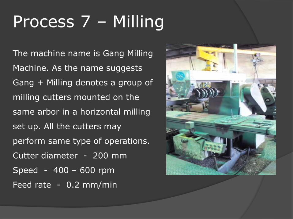
Process 7 – Milling
The machine name is Gang Milling
Machine. As the name suggests
Gang + Milling denotes a group of
milling cutters mounted on the
same arbor in a horizontal milling
set up. All the cutters may
perform same type of operations.
Cutter diameter - 200 mm
Speed - 400 – 600 rpm
Feed rate - 0.2 mm/min

Time Study for Crank CaseThe time observed for operation on different machines during
manufacturing of the Crank Case. A study has been done to
calculate the time consumed by the Crank Case for its
machining is as follows :
• Avg. time for R.D.-20 - 8.04 min
• Avg. time for D.M.M. (pre milling) - 8.26 + 9.55 = 18.35 min
• Avg. time for D.M.M. (final milling) – 10.54 + 8.30 = 19.4min
• Avg. time for V.M.C.- 08 - 15.52 min
• Avg. time for D.H.B.M.- 03 - 6.27 min
• Avg. time for D.H.B.M.- 02 - 8.28 min
• Avg. time for Gang Milling - 6.50 min
• Avg. time for Radial Drill - 1.16 min
So, the total average item taken by all the machines = Time
taken to manufacture a Crank Case after casting is
8.04 + 8.26 + 9.55 + 10.54 + 8.30 + 15.52 + 6.27 + 8.28 +
6.50 + 1.16 = 84.42 minutes.
Hence from the above time study, we have concluded that, A
Crank Case takes 1 hr 24 min for its complete production
process after casting.
Related Documents