MODEL N_ ° 113.201372 _ Serial Number Model and serial number may be found at the rear of the cabinet. You should record both model and serial number in a safe place for future use, CAUTION: Read SAFETY UNSTRUCTIONS carefully 230 AMP DUAL RANGE ARC WELDER ® assembly e operating ® repair parts Sold by SEARS, ROEBUCK AND CO., Chicago, IL 60684 U.S.A. Part No. 61337 Printed in U S A

Craftsman 30-230 Arc Welder
Nov 28, 2015
Craftsman 30-230 volt MMA Arc Stick Welder manual.
Welcome message from author
This document is posted to help you gain knowledge. Please leave a comment to let me know what you think about it! Share it to your friends and learn new things together.
Transcript

MODEL N_ °113.201372 _
SerialNumber
Model and serial
number may be foundat the rear
of the cabinet.
You should record both
model and serial number
in a safe place forfuture use,
CAUTION:
Read
SAFETY
UNSTRUCTIONS
carefully
230 AMPDUAL RANGEARC WELDER® assembly
e operating
® repair parts
Sold by SEARS, ROEBUCK AND CO., Chicago, IL 60684 U.S.A.Part No. 61337 Printed in U SA
SAFETY gNSTRUCTIONS TO OPERATOR
For your own protection, read and observe all instructionsincluded in this manual as well as the following specificsafety precautions:
1, PROTECTION FROM ELECTRICAL SHOCK
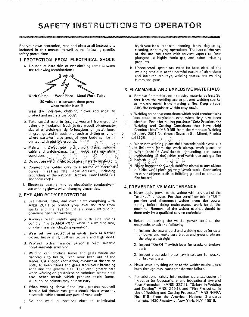
a_ Do not let bare skin or wet clothing come betweenthe following combinations:
Work Clamp
Electrode
Work Piece Metal Work 'Table
80 volts exist between these partswhen welder is onH!
Wear dry hole-free, clothing,_ gloves and shoes toprotect and insulate the body.
b. Take special care to insulate"yourself from groundusing dry insulation (suchas dry wood) of-ad.equatesize when welding] in dam'p locations on metal floorsor grat ngs, and m poslt_ons (such as s=ttmg or lying ! "where parts-or"large"areas of your body can be ircontact with phssible ground_. ; ".;_ ro "_
C. Maintain the_.#l_ctr_de h_tder work clamp, w_ldin'g
cable and welding_:rnach_ne'._n_Qd, safe operating._condition, : _ _; " " ,:' -' • "
Do not use weldm_ electrode as-a claarette hg_ter, . -
e. Connect the welder only to a source of electncal'.-power meeting the requirements, irrcludinggrounding, of the National Electrical Code (ANSI Cl)and local codes.
f. Electrode coating may be electrically conductive-use welding gloves when changing electrodes.
2. EYE AND BODY PROTECTION
a. Use helmet, filter, and cover plate complying withANSI Z87 1 to protect your eyes and face fromsparks and the rays of the arc when welding orobserving open arc welding,
b Always wear safety goggles with side shieldscomplying with ANSI Z871 when in a welding area,or when near slag chipping operation
c. Wear oil free protective garments, such as leathergloves, heavy shirt, cuffless trousers and high shoes.
d Protect other near-by personnel with suitablenon-flammable screening_
e Welding can produce fumes and gases which aredangerous to health, Keep your head out of thefumes, Use enough ventilation, exhaust at the arc, orboth, to keep fumes and gases from your breathingzone and the general area, Take even greater carewhen welding on galvanized or cadmium plated steeland other metals which produce toxic fumesAb-supplied helmets may be necessary
f When working above floor level, protect yourselffrom a fall should you get a shock Never wrap the
electrode cable around arty part of your body
g Do not weld in locations close to chlorinated
hydrocarbon vapors coming from degreasing,cleaning, or spraying operations The heat of the raysof the arc can react with solvent vapors to formphosgene, a highly toxic gas, and other irritatingproducts
h Unprotected spectators must be kept clear of thewelding area due to the harmful nature of ultra÷violetand infra-red arc rays, welding sparks, and weldingfumes and gases
3. FLAMMABLE AND EXPLOSIVE MATERIALS
a Remove flammable and explosive material at least 35feet from the welding arc to prevent welding sparksor molten metal from starting a fire Keep a typeABC fire extinguisher within easy reach.
b, Welding on or near containers which hold combustiblescan cause ar_ explosion, even when they have beencleaned= For information purchase "Safe Practices forWelding one Cutting Containers that Have Hel dCombustibles" (A6.0-65_ from the American Welding
:.Society 2501 Northwest Seventh St Miami, Florida
c. When not welding, place the electrode holder where it"" i_ ihs'61ated from the work clamp, work piece, or'
wc_rk 'table_._ Ac_'idental grounding can cause,_ overheating of the_ables'and_welder, creating a fire
haz_rd_ _ ::_" _ "
iild Never-c_nnect the_work cablelor clamp to any obJectb_ _'he 'worl<:p e_e o_ me.to _ork tab e Conr]ectingto other objects such as bu_l_mg ground can create afire hazard.
4. PREVENTATIVE MAINTENANCE
a. Never apply power to the welder with any part of the"cabinet" removed_ Position on-off switch in "Off"position and disconnect welder from the powersupply before doing maintenance work inside themachine. Removal of the welder cabinet should bedone only by a qualified service technician,
b.
c.
d_
Before connecting the welder power cord to thereceptacle, check the following:
1 Inspect the power cord and welding cables for cutsor burns and make sure blades and ground pin onthe plug are straighL
2 Inspect "On-Off" switch lever for cracks or brokenparts.
3 Inspect electrode holder jaw insulators for cracksor broken parts.
Never weld anything on or to the welder cabinet, as aburn through may cause transformer failure.
For additional safety information, purchase copies of"Practice for Occupational and Educational Eye andFace Protection" (ANSI Z87.1), "Safety in Weldingand Cutting" (ANSI Z49.1), and "Fire Protection inUse of Welding and Cutting Processes" (ANSI/NFPANo. 518) from the American National Standardsinstitute, 1430 Sroadway, New York, N.Y 10018_
2

READANDOBSERVETHEINSTRUCTIONSAPPEARINGONTHEWARNINGLABELSFOUNDONTHEINSIDEOFTHEWELDINGHELMET,ANDONTHESELECTORPLATE,CABINETANDELECTRODEHOLDER.
_MERIEAN N,_ 71ON,_L ST,INI,),_RDS hV_TITUTEPttEC,_UTION_RY I Af]EL
WARNII_G: prolel:I VotJt_ell _t_d {_thefs _e;l(I ;_f_{Iunders14_mt lh_ I_bel
F UJ%_ES AND GASES c;lll he (i,ln{J_ f al_s tn ymJl he_hh
ARC RAYS call inlllle eyel and hum stroll ELECTRICSHOCK cml kill
• Be,_d and understand _l_e incm_Hanh_fef _ =nslnJ_io_t_
and yo_Jt amployef's _alely pr acllce_
• Keep your head aut of _1_ h_nles
• U_a enmJ_h Vel_il_iOl_, _xha_Jst al Ihe ;_,c, ot boUI
lo kee I) _ume_ and _ase_ from 7o_f I_re;_lhi_ I z_)m_
and the {Jene[al area
• Wear cot _ecl eye, _ar _nd body ltlo_ectlon
• Do I_O_ _ouch llve elec_ rical I)aFt_
• See American National Si,_nIt,_f(I Z49.1 S_lety in
Wl!h_hlg mid Cliilin=j ¸' i)_JIilillle(I I}7 lhe Ait/eficalt
Wohthlg Sociel¥ 2501 N W 71h SI,, _,tbm_ Florida33125; OSIIA Saf_W _1_{I He_hh SI,_ndatds 29 CFR
1910, availal)_J_ hont U S Dep_tmenl o_ Labor
Washinglon , DC 20210
DO NOT R E_,_OV E THIS LABEL
WARNING ELeCTR,C SHOCK CAN BE FATALt BEFORE
TURNING WELDER ON CHECK THE ELECTRODE HOLDER TOBE SURE THAT THERE ARE NO PROTRUDING SCREW HEADS
AND THAT ALL INSULATION IS SECURE _ _ll!! 2
CllRI0_USe _lJ 101 IE,_ _n0 _y_ pi01egi0n
a_ins$ =nj_io_ rays Itom _c _ding
_nd culling US_ propel shade li!I_
plale _P¢_.I {ssi_IO _12 plo[_ction(Iil_ pble b_ck_up plale• s_p_lale
salely spectacles) shou+d be wornwheII U_l_ 0 this device It_cl fe-
sislanl plal_ ale DOT un_le.lkable
elted ¢_ s_la_h_d _Je_ t_u_ VISI_I
al_{_ 5_liO_$1 le_uc8 pI01eGIJ0r_--{epia_eintricately
Inspecl {(equ_Ily an_ immedi31_ly
I_p_u_ _om ot d_m_ged p_tls
t,it4_ ir_ t¢=¢.¢_ =f JJ.I.L zr/1DO NOT REMOVE "fills [/_3,E L
LENSSHADENO
WARNING - FOR YOUR SAFET'_R_GAR_ING B0 VOLT POTENTIAL
SHOC;{ AT ELECT}IOD_
REGARDING POTENTIAL SHOCK ON CABINET
COW,FORMING TO 1H_ _ATIONAL _L_CTnlCAL COD_
REGAROING £yE INJURY
REGARDING FIRE
LI_ O_AW _*nC eT_muY't
FULL ONE YEAR WARRANTY ON CRAFTSMAN ELECTRIC WELDER
If this Craftsman Electric Welder fails to perform properly, due to a defect in material or workmanship,within one year from the date of purchase, Sears will repair it free of charge,
WARRANTY SERVICE IS AVAILABLE BY SIMPLY RETURNING THE WELDER TO THE NEARESTSEARS STORE OR SERVICE CENTER THROUGHOUT THE UNITED STATES.
This warranty gives you specific legal rights, and you may also have other rights which vary from state tostate,
SEARS, ROEBUCK AND CO. Sears Tower_ BSC 41-3, Chicago, IL 60684
MATERIAL THICKNESS GAUGE.
ON-OFF SWITCH.-.
GETTING TOKNOW YOURARC WELDER
LOCKING KNOB
'IAMETER GAUGE
DUTLETJACKS
HELMET
ANDELECTRODE HOLDER
WORK CABLE AND WORK CLAMP
TABLE OF CONTENTS
OPERATING INSTRUCTIONS
Safety I nstructions to Operator .............................. 2
Warranty ............................................ 3
Getting to Know Your Welder ............................. 3
Unpacking and Checking Contents .......................... 3
Assembly ................................... 4
Operating Controls ................................ 6
Operating Instructions ........................... 7
Trouble Shooting ............................... 8ARC WELD IT YOURSELF MANUAL .............. 1-1
WELDING ROD SPECIFICATIONS ............... 2-1
REPAIR PARTS ..................................... 2-6
Input Volts (AC): ........... 230Hertz (Cycles): ................ 60Output Amperage: ........ 30 to 140
40 to 230
Rated Input Amps: ............... 50Short Circuit Input Amps: ......... 66
SPECIFICATIONS
Fuse or CircuitBreaker Required: ......... 50 Amps
Arc Voltage: ............... 25KVA: .................... 108KW: ........................... 7 1
Max Open CircuitOutput Volts .......... 80
Power Factor ........... 66%Duty Cycle: ........ 20 to 100%
Electrode Capacity: 1/16" to 3/16"
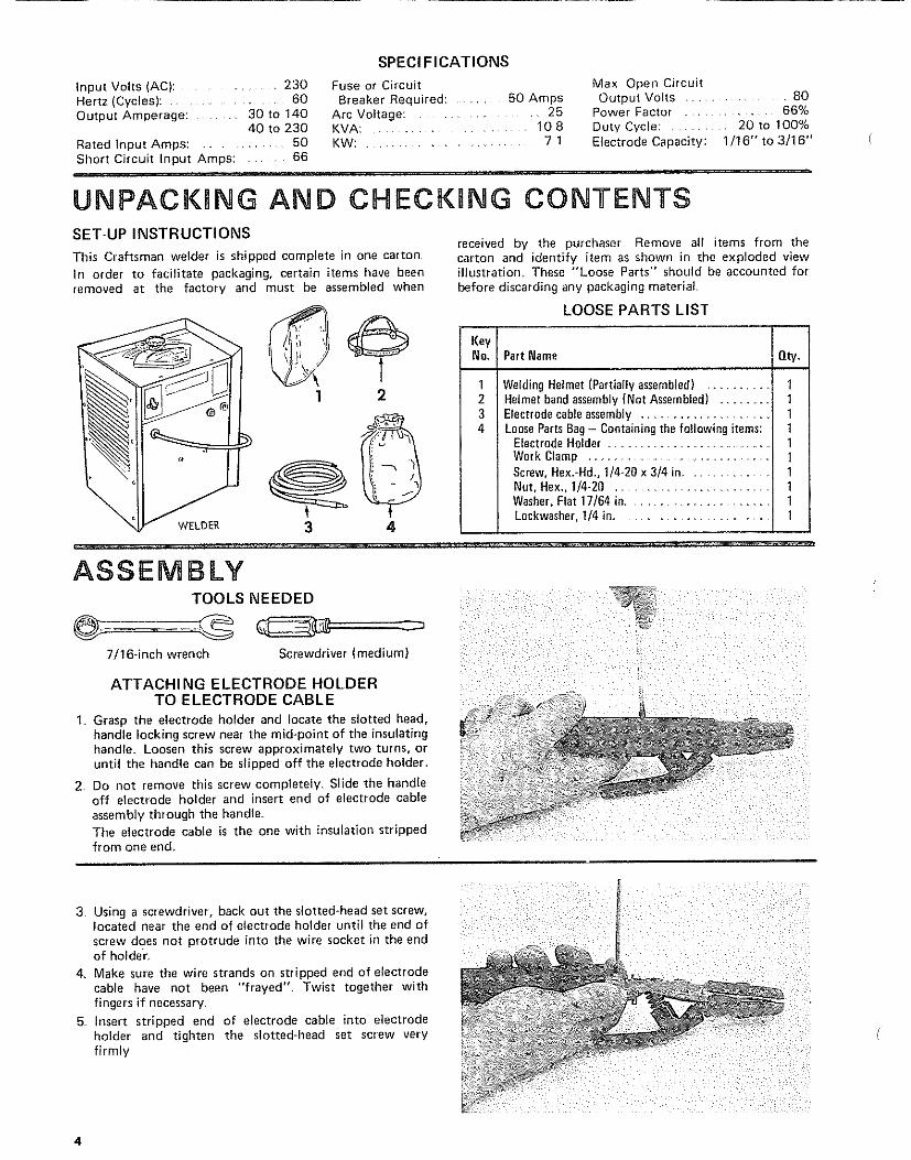
UNPACKING AND CHECKUNG CONTENTSSET-UP INSTRUCTIONS
This Craftsman welder is shipped complete in one carton
In order to facilitate packaging, certain items have beenremoved at the factory and must be assembled when
received by the purchaser Remove all items from thecarton and identify item as shown in the exploded viewillustration These "Loose Parts" should be accounted forbefore discarding any packaging material.
3 4
LOOSE PARTS LIST
KeyNo. Part Name O.ty.
i
1 WeldingHelmet (Partially assembled) ..........2 Helmet band assembly (Not Assembled) ........3 Electrodecableassembly .........................4 LooseParts Bag- Containing the following items:
Electrode Holder .....................................
t11I1
Work Clamp ........................................... 1Screw, Hex.-Hd., 1/4-20 x 3/4 in............... 1Nut, Hex., 1/4-20 ........................... 1Washer,Flat 17/64 in............................... 1Loci{washer,1/4 in 1
ASSEMBLY
TOOLS NEEDED
,,lOinchwrenchScrewdriver(medium)ATTACHING ELECTRODE HOLDER ............. ....
TO ELECTRODE CABLE
I. Grasp the electrode holder and locate the slotted head,handle locking screw near the mid-point of the insulatinghandle Loosen this screw approximately two turns, oruntil the handle can be slipped off the electrode bolder..
2 Do not remove this screw completely. Slide tile handleoff electrode holder and insert end of electrode cableassembly through the handle.The electrode cable is the one with insulation strippedfrom one end
3 Using a screwdriver, back out the slotted-head set screw,
located near the end of electrode holder until the end ofscrew does not protrude into the wire socket in the endof holder
4. Make sure the wire strands on stripped end of electrodecable have not been "frayed" Twist together withfingers if necessary.
5 Insert stripped end of electrode cable into electrodeholder and tighten the slotted-head set screw veryfirmly
4

_i_i ii _' _ i
6 Slide the handle back into place on electrode holder and
position it until the hole in handle is directly over thehead of handle locking screw Tighten the screwclockwise @ just enough to secure the Inandle onelectrode holder
ATTACHING THE WORK CLAMPTO THE WORK CABLE
1. Attach the terminal on end of work cable to the workclamp, at the hole near the nose of the clamp with the1/4-20 x 3/4-inch screw, 1/4-20 nut, 17/64-inch flatwasher and I/4-inch Iockwasher furnished in the loose
parts bag2_ Do not use either of the holes in handle ends of work
clamp
SCREW
LOCKWASHNUTE_ HWORKCABLE
3_ Tighten the screw firmly enough to insure good contactand prevent the cable terminal from slipping on theclamp
CONNECTING WELDER TO POWER SOURCE
CAUTION: Do not attempt to connect this welder to aregular household outlet. Make sure the power-line voltageand frequency agree with the ratings shown on the selectorplate attached to front of eabinet.
Electrical connections between the welder and grounded230-volt, single-phase, 60-cycle a-c power source should bemade by a qualified electrician. All wiring must complywith the National Electrical Code (ANSI C1) and localcodes1. Install an individual (separate) line for the welder with
delayed action type circuit breaker or fuses in the lineFor best results, this circuit should be as short aspossible The size of the supply conductors will dependupon their length as shown in the table below
Supply Conductor (Incl. Extension Cords)
Up to 30 feet ............................ No_ 10 AWG Copper30 to 50 feet ............................. No 8 AWG CopperOver 50 feet ................................... No 6 AWG Copper
NOTE - These conductor sizes are for use with a welderhaving a rated input not more than 60 amps at 20% dutycycle in accordance with Article 630 of the National
RECEPTACLE
k GREENWIRE_. Connect to ground bussin
powerponetConnect to hot wires o[ Qsingle phase system only
FUSES OR CIRCUIT BREAKERS
Electrical Code (ANSI C1) and may not be adequate forother loads Consult a qualified electrician before using forother loads
2 Install 50 ampere circuit breakers or fuses
3 Connect 230wolt power lines and ground as shown in
figure
4 Use Sears Cat #20691 Power Receptacle availablethrough most Sears Retail or Catalog outlets or anycertified 50 amp, 250 volt, 2 pole, 3 wire, groundingtype receptacle.

OPERATnNG CONTROLS
The name "dual range" arc welder is derived from the factthat your new arc welder is equipped with two separatewelding ranges,
The beginner or less-experienced welder will find the30-140 amp range easier to use because it provides extra arcstability when welding with some of the "more difficult toweld with specialty rods" which are prone to pop-outs
The 40-230 amp range requires less line (input current)draw for any given amp setting and permits the use of themaximum amp settings with minimum effect on other'electrical appliances, motors, and lights, on your electricalsystem,
Either range may be used, depending on operatorpreferences when the electrode diameter permits
_TAL TABLE AT THE SAME TIM
REGARDING POTENTIAL SHOCK ON CABINET
1 CONNECT ONLY TO A GROUNDING POWER SOURCECONFORMING TO THE NATIONAL ELECTRICAL CODE
(A N S I C1) AND LOCAL CODES
REGARDING EYE INJURY
1 WEAR WELDING HELMET WITH NO 12 OR DARKER FIL-TER LENS MEETING REQUIREMENTS OF A NSI. Z87,1.
2 WEAR GOGGLES OR FACE SHIELD WHILE CHIPPING ORBRUSHING SLAG.
3 KEEP OTHER PERSONS AND PETS OUT OF WORK AREA
REGARDING FIRE
KEEP COMBUSTIBLES OUT OF RANGE OF WELDING SPARKS
uSE FOR MINIMUM UsE FOR MAXIMUMLINE DRAW ARC STABILITY
AMP AMP Z RANGE/
CONNECTING ELECTRODEAND WORK CABLES
insert the tapered plug on the end of the electrode cableinto the proper outlet jack depending on amperage requiredor operator preference.
To insure a good electrical connection always twist theelectrode plug slightly while inserting_ To remove the plugtwist in the opposite direction while removing
NOTE: If you extend the welding cables beyond thosealready supplied, they must be No= 4 AWG or larger toavoid an undue drop in welding current Do not extendcables over 50 feet,
Connect the work clamp to the piece to be welded, (tocomplete the electrical circuit) or to the welding table itselfprovided it is metallic or will conduct electricity!

OPERATING RNSTRUCTIONS
We feel that welding with your new Craftsman dual rangearc welder is as simple as A B C
A Determine what diameter electrode should be used bygauging the piece to be welded on the material thicknessgauge The fractional number directly beneath the barchart dictates what the proper electrode diameter is forgiven thicknesses of metals You will note that a specificdiameter of electrodes can be used on varyingthicknesses of material. This is accomplished byadjusting the heat selector for more or less amperage•
B Next verify the electrode diameter, by placing the bareportion of the electrode into the electrode diametergauge on the right side of the cabinet
Because electrodes are mass produced, there may besmall burrs on the bare ends of the electrode Make surethe bare end of the rod is as clean as possible foraccurate sizing,
C, Finally, determine the type of electrode by theidentification on the package or by the AmericanWelding Society number stencilled on the coated portionof the electrode, bearing in mind the type of electrodeyou have chosen - E6013 or E7014, and also its'diameter (as previously determined)_
Locate that band on the amp scale There are two E6013bands and two E7014 bands, use the band whichcoordinates with the amp range you have selected•
Now loosen the heat selector knob and move the pointeruntil the fractional number matching your electrodediameter appears in the pointer windowTighten the heat selector knob
Insert the electrode cable into the proper jack(depending on the range selected), Connect the workclamp to the work.
Wear Welding Helmet,
Turn the On-Off switch to the "ON" position and youare ready to weld
Because metals vary in their make up and the techniqueof each operator is different, you may find it necessaryto increase or decrease the amperage output accordingly,
CAUTION: Do not loosen and move heat selector whilewelding
The duty cycle ratings bracketing the amperage scales areprovided for your convenience and protection of your newwelder_ Duty cycle is the performance level of the welderbased on a 10 minute time span. For example welding for 6
minutes out of 10 minutes is a 60% duty cycle To avoidpossible overheating of the welding transformer, whichcould shorten the life of your welder, Do Not exceed theduty cycles listed on the nameplate
7

TROUBLE SHOOTING
WARNING: Removal of the welder cabinet top for any reason must be done bya qualified service technician.
TROUBLE SHOOTING CHART
TROUBLE SUGGESTED REMEDY
Fan and welder do notoperate, or continuallyblow fuses.
Welding current lowor weak,
Can't hold an arc.
PROBABLE CAUSE
1. Improperly fused orprotected_
2 Blown fuse, or opencircuit breaker_
3_ "On-Off" switch not "On".
1. Low line voltage,
2_ Welding currentsetting too Iow_
3, Poor connections.
1 Using a D.C. weldingrod.
2. Low hydrogen rod
1. Use 50 ampere fuses of the delayedaction type such as "'Fusetron" or"Fustat" or 50 ampere 240 voltcircuit breaker.
2 Replace fuse, or reset the circuitbreaker.
3 Turn switch "On".
1_ Have a voltage check performed bythe local power company_
2. Check current recommended forthe electrode being used.
3, Check electrode holder, work andelectrode cable connections
1_Use AC or AC-DC rods
2, Use rod of 1/8-inch maximumdian'leter, or' smaller on 30-140amp range.
SERVICE TIPS
FAN MOTOR
No provision has been made for lubricating the fan motor,as extra large oil reservoirs provide lubrication for the lifeof the motor.
SELECTOR PLUGS OR CONTACTS
WARNING: Be positive you have disconnected the powersupply to the welder_
If for any reason the selector plugs or mating contactsbecome burned or pitted, tiley should be cleaned-up with afine grade of emery cloth or dressed very lightly with a finefile,
f
A COMPREHENSIVE
GUIDE FOR YOURNEW CRAFTSMANARC WELDER AND
WHAT iT W_LL DO
CONTAINS:
INFORMATION ABOUT
o VARIOUS TYPES OF RODS
o USEFUL ACCESSORIES
TIPS ON CUTTING, WELDINGAND BRAZING
,,,J
Form No SP574-4 1-]

IJELD gT Y©U SELF
TABLE OF CONTENTS
Page
Your WelderandWhat It Will Oo ............. 1-3How the CraftsmanContactRodSimplifiesWelding 1-3
What HappensWhenYou Weld? .............. 1-3ReadBeforaWelding ....................... 14LearnBy Doing .......................... 1-5PositionWelding ......................... 1-11Cast-IronWelding ........................ 1-14HardSurfacingWornCuttingEdges .......... 1-15TheTwin CarbonArc Torch ............... 1-16
CuttingandOther MiscellaneousOperations ..o 1-17Inert-GasMetal-ArcWelding ................ 1-19
Read this Manual carefully for additional welding information.
SEARS, ROEBUCK AND COMPANYAND SIMPSONS-SEARS LIMITED
1o2
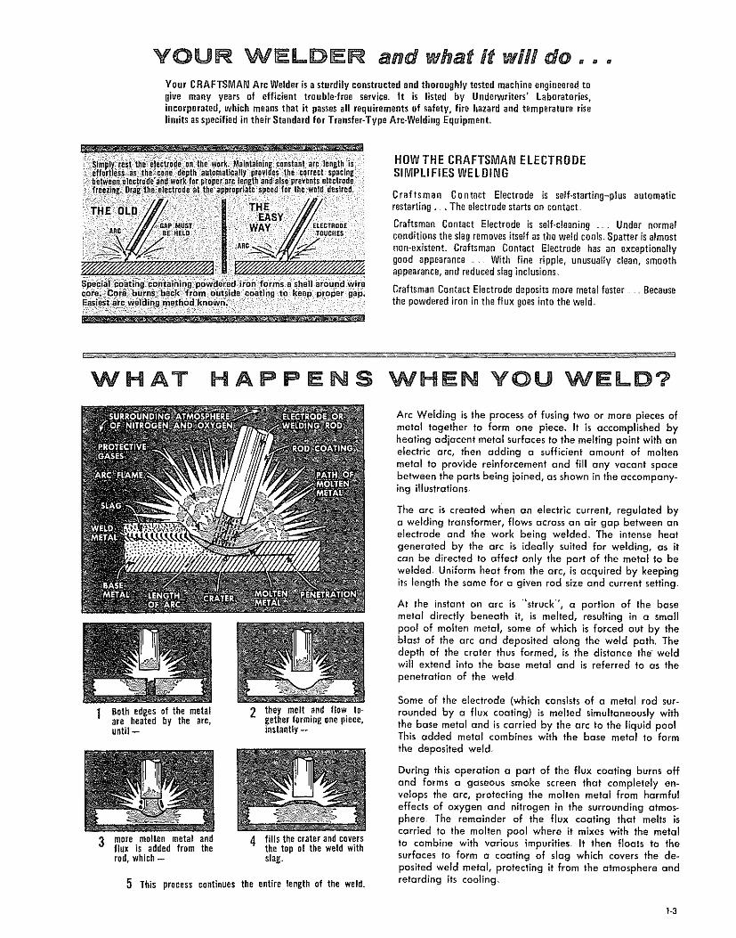
YOUR WELDER and what it will do =°.Your CRAFTSMAN Arc Welderis a sturdilyconstructedend thoroughlytestedmachineengineeredtogive many years of efficient trouble-free service. It is listed by Underwriters' Laboratories,incorporated,which meansthat it passesall requirementsof safety,fire hazardand temperatureriselimitsasspecifiedin theirStandard for Transfer-TypeArc-WeldingEquipment,
HOW THE CRAFTSMAN ELECTRODESIMPLIFIES WELDING
Craftsman Contact Electrode is self-starting-plus automaticrestarting , The electrodestartson contacL
Craftsman Contact Electrode is serf-cleaning..... Under normalconditionstheslagremovesitselfasthe weld cools,Spatter is almostnen-existenL Craftsman Contact Electrode has an exceptionallygood appearance _ With fine ripple, unusually clean, smoothappearance,andreducedslaginclusions
CraftsmanContact Electrode depositsmore metal faster . Becausethe powdered iron in the flux goesinto tile weld_
1 Beth edges of the metalare heated by the arc,until --
3 mere molten metal andflux is added from therod, which-
2 they melt and flow together formingone piece,instantly --
4 fills the crater andcoversthe top of the weld withslag,
5 This process continues the entire length of the weld
Arc Welding is the process of fusing two or more pieces ofmetal together to form one piece. It is accomplished byheating adjacent metal surfaces to the melting point with anelectric arc, then adding a sufficient amount of moltenmetal to provide reinforcement and fill any vacant spacebetween the parts being joined, as shown in the accompany-ing illustrations
The arc is created when an electric current, regulated bya welding transformer, flows across an air gap between anelectrode and the work being welded, The intense heatgenerated by the arc is ideally suited for welding, as itcan be directed to affect only the part of the metal to bewelded, Uniform heat from the arc, is acquired by keepingits length the same for a given rod size and current setting,
At the instant an arc is "struck", a portion of the basemetal directly beneath it, is melted, resulting in a smallpool of molten metal, some of which is forced out by theblast of the arc and deposited along the weld path, Thedepth of the crater thus formed, is the distance the weldwill extend into the base metal and is referred to as thepenetration of the weld
Some of the electrode (which consists of o metal rod sur-rounded by a flux coating) is melted simultaneously withthe base metal and is carried by the arc to the liquid poolThis added metal combines with the base metal to form
the deposited weld,
During th_s operation a part of the flux coating burns offand forms a gaseous smoke screen that completely en-velops the arc, protecting the molten metal from harmfuleffects of oxygen and nitrogen in the surrounding atmos-phere, The remainder of the flux coating that melts iscarried to the molten pool where it mixes with the metalto combine with various impurities It then floats to thesurfaces to form a coating of slag which covers the de-posited weld metal, protecting it from the atmosphere andretarding its cooilng
I-3

READ 5EFORE WELDI NG
When operating a welder, certain precautions mustbe taken to prevent minor injuries to yourself andothers, Although injuries may not be serious or per-manent, knowing how to use the protective equip-ment to safeguard against them is the first step inlearning to weld_
The effects of heat and light given off by the arc, whileelectric welding, may be compared to that of the sun's rays_Even greater precautions are necessary for electric arcwelding. Before starting a weld, caution anyone in theimmediate vicinity against looking at the arc_ in case ofoccidental eye injury, contact a physician immediately.
To protect the face and eyes a heat-resisting, fibreglasshelmet is used. The special tens, which allows the userto view the arc safely, is inserted into the framed openingof the helmet The clear glass, which should be replacedfrom time to time, protects the expensive special lensfrom breakage and weld spatter. The helmet is held firmlyin place on the head with an adjustable head band, therebyleaving both hands free° A close-flttlng skull cap shouldbe worn with the helmet° As the helmet is used only whenactually welding, a tilting arrangement permits it to beswung up clear of the face. When the welding is resumeda slight nod of the head tips the helmet down over the face.To protect the eyes further while cleaning the weld, gogglesshould be worn by the welder and others working aroundhim_ Animals are also affected by the rays and should bekept at a safe distance_
To safeguard the hands against heat and weld spatter,gauntlet-type leather gloves should be worn. A leatherjacket will give better protection against the shower of
sparks than ordinary clothing. High top shoes (not oxfords)should be worn. If a great deal of welding is to be done,foundrymen's shoesare best.
Precautions must also be taken to protect property andequipment against flre_ A large fire extinguisher should bewithin easy reach. The welding area should have a concreteor cinder floor, kept dry and clear of inflammable rubbish.Sometimes, it is necessary to weld close to a fuel tank. Ifpractical, remove the part to be welded. If not, drain thetank and completely fill it with water.
Few tools, in addition to those supplied with the weldingmachine, are needed and most of them can be found inthe average shop Two sawhorses supporting a 1/4-inchsteel plate makes an excellent welding table A permanentbench, using the same steel plate, can be made of angleiron or pipe. A chipping hammer is used to clean slag offa weld and pliers will be useful for handling hot metak Awire brush is used to clean the work before welding andremove small pieces of slag after chipping_
Small pieces of mild-steel scrap iron, reasonably free ofrust and paint, should be used for practice welding_ Angleiron, bar stock or plate steel are good examples. Do notuse scrap cast iron, high carbon or hardened steel as thesemetals require special electrodes and welding techniques.These should be set aside for future practice after com-pleting elementary practice lessons°
1-4
LEARN BY DOBNG
OIRECTiONOFWELG
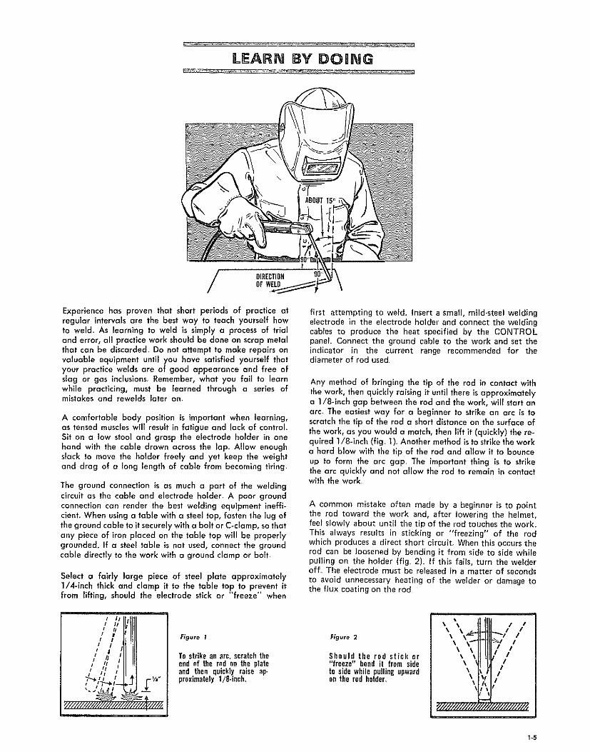
Experience has proven that short periods of practice atregular intervals are the best way to teach yourself howto weld. As learning to weld is simply a process of trialand error, all practice work should be done on scrap metalthat can be discarded. Do not attempt to make repairs onvaluable equipment until you have satisfied yourself thatyour practice welds are of good appearance and free ofslag or gas inclusions. Remember, what you fail to learnwhile practicing, must be learned through a series ofmistakes and rewelds later am
A comfortable body position is important when learning,as tensed muscles will result in fatigue and lack of control.Sit on a low stool and grasp the electrode holder in onehand with the cable drawn across the lap. Allow enoughslack to move the holder freely and yet keep the weightand drag of a long length of cable from becoming tiring,
The ground connection is as much a part of the weldingcircuit as the cable and electrode holder_ A poor groundconnection can render the best welding equipment ineffi-cient. When using a table with a steel top, fasten the lug ofthe ground cable to it securely with a bolt or C<lamp, so thatany piece of iron placed on the table top will be propedygrounded. If a steel table is not used, connect the groundcable d_recfly to the work with a ground clamp or bolt
Select a fairly large piece of steel plate approximately1/4-inch thick and clamp it to the table top to prevent itfrom lifting, should the electrode stick or "freeze" when
I90
first attempting to weld. insert a small, mild-steel weldingelectrode in the electrode holder and connect the weldingcables to produce the heat specified by the CONTROLpanel Connect the ground cable to the work and set theindicator in the current range recommended for thediameter of rod used.
Any method of bringing the tip of the rod in contact withthe work, then quickly raising it until there is approximatelya 1/8-inch gap between the rod and the work, will start anarc_ The easiest way for a beginner to strike an arc is toscratch the tip of the rod a short distance on the surface ofthe work, as you would a match, then lift it (quickly) the re-quired 1/8-1nch (fig. 1). Another method is to strike the worka hard blow with the tip of the rod and allow it to bounceup to form the arc gap. The important thing is to strikethe arc qelckly and not allow the rod to remain in contactwith the work
A common mistake often made by a beginner is to pointthe rod toward the work and, after lowering the helmet,feel slowly about until the tip of the rod touches the work.This always results in sticking or "freezing" of the rodwhich produces a direct short circuiL When this occurs therod can be loosened by bending it from side to side whilepulling on the holder (fig 2). If this fails, turn the welderoff_ The electrode must be released in a matter of secondsto avoid unnecessary heating of the welder or damage tothe flux coating on the rod
,'/,'II'U]I
,,',/
Figure 1
To strike an arc, scratch theend nf the red ne the plateand then quickly raise ap-proximately 1/8-inch,
Figure 2
Should the rod stick or"freeze" bend it from sideto side while palling upwardon the rod ho_er.
\\\
\ /\ /
I
1-5

Figure 3 Figure 4
To lay a weld bead only twomovements are used, dowfi-ward and in the direction theweld is to he laid.
Watch the weld puddle tokeep the slag from flowingin front of it, causing inclu-sions and gas pockets
Figure 5
Fill the crater, when startinga new rod, by striking thearc at A then moving to 8and back to C position
Figure 6
To widen the head, work thered from side to side slightty, with a slow, zigzaggmgcrescent-shaped motion
If difficulty is experienced after repeated attempts tomaintain an arc, check the ground connection for propercontact with the work If this does not help, increase thewelding current Also check the rod size, as larger rodsrequire higher current settings.
Practice striking and maintaining an arc for a few seconds,then snap it out by rapidly pulling the rod away from thework_ Repeat this operation until the arc can be startedand the gap maintained as uniformly as possible. In ashort time you will find the arc length can be controlled bythe crackling or "frying" sound which may be recognizedby gradually shortening the arc until it sputters irregularlyas though it were going to "choke out'* and stick--thenslowly lengthening the arc by pulling the rod away fromthe work until it snaps out_Somewhere between these twoextremes the steady crackllng sound of a proper arc lengthwill be heard_
To lay a weld bead, only two movements are used, asteady downward feeding of the rod to maintain the correctarc length and a slow travel in the direction in which theweld is to be lald (fig. 3)_ Watch the weld puddle andarc length, and move the rod steadily in a straight llne asthe back end of the crater fills up (fig 4). The slight angleof the rod will keep the flux or slag flowing over thedeposited weld metal to form a protective coating. If therod is moved too slowly the slag will flow in front of thepuddle and be trapped in the weld, producing inclusionsand gas pockets.
Lay a bead approximately four inches long. After allowingit to cool slightly, remove the slag coating, which covers thetop of the weld, by scraping along each edge of the weldwith a cold-chlsel foJowed by wire brushing until it is brightand clean_ Inspect the surface of the weld carefully beforestarting another_ The surface of a good weld is rippledunlformly, which results from a steady rate of travel anduniform arc length_
If the scrap plate used is small, it will become very hot afterlaying a few beads. This will alter welding conditionswhich could be very confusing to a beginner Have several
scrap pieces handy so each may be allowed to cool beforelaying a second bead,
When starting with a new rod, chip slag from the craterand strike the arc at the forward end as shown at "A" in
figure 5, Then move the rod to "B" and back to "Ci" atabout twice the normal rate of travel to give the rod and
base metal time to heat up for proper fusion
After laying a number of beads, try "working" the rodfrom side to side slightly (fig. 6) This movement shouldbe slow and not wider than the diameter of the rod being
used. Experiment with different current settings, rod sizesand rates of travel.. Compare results with welds shown in
the diagrams (fig, 9).
Too low a current setting tends to deposit the bead on topof the plate with very little penetration. The arc sound will
be an intermittent crackle with irregular sputtering Toohigh a current setting (for the size of the rod being used)wiII provide sufficient penetration but the bead will be thin
and undercut in places. The arc makes a hissing sound andthe rod becomes red hot before it is half used.
If travel is too slow it will pile up a wide, heavy bead withgood penetration but with overlap of the weld metal onsides without fusion_ A large area surrounding the weld isheated to a high temperature which produces distortion,even on a simple weld If the rod is moved too fast thesmall bead will result w_th little more than melted base
metal. An extremely long arc causes the rod to melt off inglobules, with little or no penetration, and a very irregularweld surface The arc produces a hissing sound.
A good weld laid with correct current setting, speed and arclength will produce a surface that is rippled uniformly, withthe same width throughout its length, and well formedcrater. The cross-sectional view shows it to have good pene-tration and no undercut or overlap.
I I
Figure 7
Lay the weld beads aboutone inch apart, ffemove theslag and examine each weldbefore starting the next
Figure 8
A pad of weld metal is builtup by running a series ofbeads in layers at rightangles to each other,
1.6

CURRENTTOO LOWArc is difficult to maintain.Vurylittle peflctrationHighbead,
TRAVELTOO FASTSmall bead undercut insome places. Rough topand little penetration
CURRENTTOO HIGH
Wide thin bead, undercut,Crater pointed and long,Rod hurns off very fast,
ARC TOO LONG
Surface of weld roughRod melts off in globulesArc makes hissing sound.
TRAVELTOO SLOW
Metal piles up. making awide heavy bead, over°lapped at sides in places
NORMAL CONDITIONS
Uniform ripples on surfaceof weld, Arc makes steadycrackling sound,
Figure 9
Practice laying beads approximately one inch apart untila good weld can be produced with all the different rodsizes the welder will handle (fig, 7). After becoming pro-ficient in running a bead, build up a pad of weld metal,Clean each bead before laying the next and make surethey are fused together (fig. 8) Run the second layer atright angles to the first and the third at right angles to thesecond, etc_, _sntil a pad approximately 1/2-inch thick hasbeen built up This type of welding is used to build upround or flat surfaces or reinforce parts that are rusted thin_
To avoid distortion when building up the end of a shaft,run the beads parallel to the axis and lay each successivebead on the opposite side as shown by the numbered stepsin figure 10. Cover the entire shaft with weld metal forthe desired length. If the place to be welded is not at theend of the shaft, weld around it and turn the shaft slowlyto keep the weld puddle in the flat position (fig_ 11). Cleanoff the slag after each bead, then machine the shaft toproper size.
F_gure 10
1-7

FLAT WELDING
TACK
• WELOS
Flat welding includes all types of joints in which the weldis horizontal, and the electrode is fed down as in the practicewelds of previous pages The five types of joints in figure 1can be welded in the flat position
Butt welds on llght material should be practiced first onscrap stock_ Use 16-gauge mild steel sheet metal (approxi=mately 1/16-inch thick) and 5/64-1ech rods with the welderset at approximately 30 to 50 amperes, Butt edges of metaltogether and tack-weld approximately every three inches(fig. 2)_ (Tack welds are small beads 1/4 to 3/8-1nches inlength_) Place bars of scrap iron under ends of the work toprovide an air space above the table. Simply move the rodin a straight llne directly above the edges to be joined.
If the weld burns thro.ugh in places, reduce the welding cur-rent or increase the rate of travel. Some difficulty may beexperienced in starting the arc at these low current settings
However, once the arc is started, there wlll be sufficientheat to make a sound weld. After laying a bead, turn thework over and inspect the underside which should also havea small uniform bead. To prevent burning through wherethe edges are not butted tightly together, move the rod backand forth with short quick strokes in the direction of theweld to bridge the gap and give the metal in the crater achance to solidify (fig 3).
Butt welds on sheet metal lighter than 18 gauge shouldnot be attempted by the beginner without the use of aback-up strip (fig 4). This consists of a bar of copperclamped tightly against the underside of the seam to absorbthe heat of the arc and prevent the weld from burningthrough To assure complete penetration with butt weldson 8-gauge metal or heavier, a 1/16 to 3/32-1nch gapshould be allowed between them (fig .5) insert a wedge orscrewdriver between the plates when tack-welding to main*tain the gap, then turn the piece over, so the tack welds areon the underside_
Use enough current to melt edges of plates to a depth ofat least one-half their thickness Clean off the slag and
inspect it for smoothness, penetration and height of rein-forcement Agood weld should havea relnforcement slightlymore than flush with the surface (fig 6) Turn the plate
SLIGHT / /GAP / , St;EEl"
METAL
k___J\BACK-UPSTKIP
Figure 4
Figure 3
REINFORCEMEHT
Figure 6
Figure 5
Figure 7
over and weld a similar bead on the other side (fig. 7) Ahigher weidlng current can be used on this side as there isno danger of burning through and fusion with the firstbead will be assured
Although butt welds can be made on steel plates up to3/8-inch thick, with a 295-ampere machine using 1/4-1nchrod, the same results can be obtained with the 180 and230-ampere machines if edges of plates are beveled (fig. 8)Metal of almost any thickness can be welded in this mannerby depositing a number of beads, one on top of the otheruntil the groove is completely filled= If the plate can bewelded from both sides, always use a double bevel (fig_ 9)_If only one plate is beveled, the angle should be at 45 de-grees (fig 10)
1-8
UNDERCUT GASPOCKET
EHTPENETRATION
Figure II
Figure 12
Figure 13
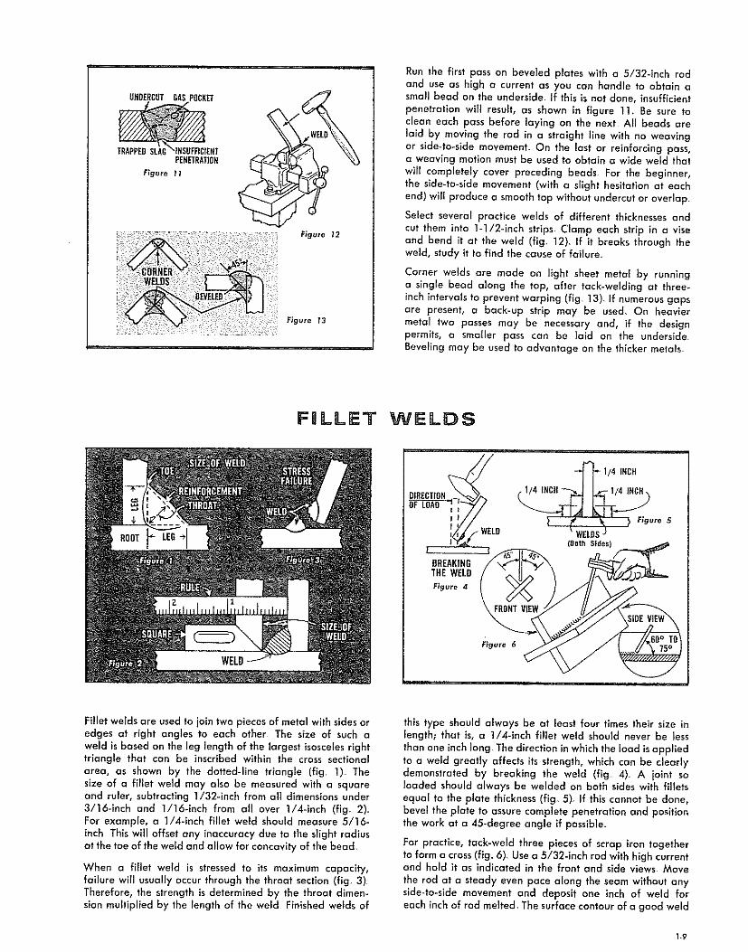
Run the first pass on beveled plates with a 5/32-1rich rodand use as high a current as you can handle to obtain asmall bead on the underslde_ If this is not done, insufficientpenetration will result, as shown in figure 11. Be sure toclean each pass before laying on the next All beads arela_d by moving the rod in a straight llne with no weavingor slde-to-side movement_ On the last or reinforcing pass,a weaving motion must be used to obtain a wide weld thatwill completely cover preceding beads. For the beginner,the slde-to-side movement (with a slight hesitation at eachend) will produce a smooth top without undercut or overlap
Select several practice welds of different thicknesses and
cut them into 1-1/2-inch strips. Clamp each strip in a viseand bend it at the weld (fig. 12)_ If it breaks through theweld, study it to find the cause of failure
Corner welds are made on light sheet metal by runninga single bead along the top, after tack-weldlng at three-inch intervals to prevent warping (fig 13)_ if numerous gapsare present, a back-up strip may be used, On heaviermetal two passes may be necessary and, if the designpermits, a smaller pass can be lald on the underside.Beveling may be used to advantage on the thicker metals
FgLLET WELDS
I
I WELD
BREAKINGTHEWELD
Figure 4
WELD
Fi9ure 6
Fillet welds are used to join two pieces of metal with sides oredges at right angles to each other The size of such aweld is based on the leg length of the largest isoscelesrighttriangle that can be inscribed within the cross sectionalarea, as shown by the dotted-line triangle (fig 1). Thesize of a fillet weld may also be measured with a squareand ruler, subtracting 1/32-inch from all dimensions under3/16-inch and 1/16-inch from all over 1/4-inch (fig. 2)For example, a 1/4-inch fillet weld should measure 5/16-inch This will offset any inaccuracy due to the slight radiusat the toe of the weld and allow for concavity of the bead.
When a fillet weld is stressed to its maximum capacity,failure will usually occur through the throat section (fig. 3)Therefore, the strength is determined by the throat dimen-sion multiplied by the Fength of the weld Finished welds of
this type should always be at least four times their size inlength; that is, a 1/4-inch fillet weld should never be less
than one inch long, The direction in which the load is appliedto a weld greatly affects its strength, which can be clearlydemonstrated by breaking the weld (fig 4) A joint soroaded should always be welded on both sides with filletsequal to the plate thickness (fig 5) If this cannot be done,bevel the plate to assure complete penetration and positionthe work at a 45-degree angle if possible.
For practice, tack-weld three pieces of scrap iron togetherto form a cross (flg_ 6) Use a 5/32-inch rod with high currentand hold it as indicated in the front and side views. Move
the rod at a steady even pace along the seam without anyside-to-side movement and deposit one inch of weld foreach inch of rod melted. The surface contour of a good weld
1-9

SIZE
Figure 11
ROD
UNBERCUTf _P
_,,-CENTER
_OF SEAM
Figure 8
Figure 9
Figure 10
I'_ !EXCESS
BLA Figure 13
LAPWELDS
Figure 16
LAPWELDS
Figure 14 Figure 15
INTEBMII_ENTWELOS
STAGGEREDINTER-MITTENTWELOS
Figure 17
WELDON BOTHSIDESAT ENDOF JOINT
should be nearly flat with a slight radius at the sides ortoes_ Avoid excessive concave or convex surfaces of the
fillet (fig_ 7) Undercuts and colddaps are caused by notholding the rod in the center of the seam (flg_ 8)_ if thedesired fillet weld cannot be made with a single pass,several passes are used to build it up to required size (fig_ 9).Slag must be cleaned from each pass before depositingthe next. Fillet welds over 1/2-inch in size are rarely usedbecause joints requiring more strength can be made moreeconomically by beveling and groove-welding, followedby a small concave fillet weld to provide a radius in thecorner_
Horizontal fillet welding is used when the side or edge ofone member of the joint is in the vertical position particularlyfor small single-pass welds where the work cannot be tilted.For practice, tack-weld two pieces of scrap together toform a tee-joint (fig. 10)_ Use a 5/32-inch rod held atangles indicated, and direct the arc into the corner of thejoint. The arc length should be somewhat shorter than forflat fillet welding_ To assure penetration at the root, use thehighest welding current that can be handled (fig 11)_Good penetration is of prime importance and appearance
will come with experience. If the arc is advanced too fast,or held too close to the vertical plate, undercutting mayresult (fig. 12). Too slow travel will cause overlapping andan extremely dose arc or low current will produce a beadwith a convex surface (fig. 13). To check the penetration andsoundness of the bead, break some of the welds for inspec-tion, as shown in figure 4_
When making a lap weld, care should be taken not to melttoo much of the upper corner on the top plate (fig. 14)Some melting will take place, but proper advance of therod will cause the weld metal to build up and blend into thetop surface. On sheet metal, hold the 3/32-inch rod almostperpendicular and move the arc rapidly. Welds of thistype should be wider than they are high, somewhat like aflat bead (fig_ 15) A slight discoloration on the undersideof the lower sheet indicates good penetration, On heavymetal, a 3/8-inch fillet weld can be lald in one pass with a1/4-1nch rod using a 295-ampere machine However, withsmaller machines, the same weld or larger can be made by
building up with a number of passes (flg_ 16)_ Whenwelding long narrow pieces, stagger the welds in shortintermittent beads, first on one side then on the other side,to minimize distortion (fig_ 17).
1-10

_i_ _¸ _ __
POSMTION WELDING
BUTT WELD
in order to derive the greatest benefits from your welder,you should practice until you can make a welded iolntin almost any conceivable position. The ability to do thisis especially useful when making repairs on machinery asthe amount of welding in most cases is small and does notwarrant disassembling the parts to weld them in the flatposition Welds of this type have been classified into threegroups according to their location and are referred to asvertical, horizontal and overhead welds (fig 1) Of thethree positions, vertlca[ welding will be used the most andshould be practiced first. Skill gained in this type of weldwill make horizontal and overhead welding easier
VERTICAL WELDING
The two methods of welding in the vertical position arecommonly known as "vertlcal-down" and "vertlcal-up"welding (fig_ 2)_ In the former the bead is started at thetop and welded in a straight llne downward In the latterthe bead is started at the bottom and welded up, usuallywith a weaving motion
The chief difficulty encountered with any position weld iskeeping the molten metal in the puddle from falling out.To prevent this the arc must be held as short as possible andthe weld puddle kept fairly small so it will solidify rapidly
Verficabdown welding is the easiest to perform and is usedon material up to 1/8-inch thick Before attempting a vertical
weld, run a few practice beads to get the feel of thearc_ Tack-weld a piece of scrap iron to an old practice plateso it is positioned vertlcal]y (fig 3). Use l/B-inch rods forthe first welds and a current of about 75 to 115 amperesExperiment with various amperage settings until you areusing the highest current you can handle Hold the rod atright angles to the plate laterally, with the tip pointed upat the angle shown in figure 3 Start the weld at the topof the plate and move the rod in a straight line downwardThe correct rate of travel can be determined by graduallyreducing the speed unti! molten metal in the puddle can nolonger be kept in place Then, increase the speed slightlywhile watching the puddie, arc length and angle of the rodA short arc provides better control of the molten meta!Follow the same procedure with 3/32 and 5/32-inch rodsIt will be noted that the larger the rod the more difficult itis to control the puddle For this reason smatler diameterrods are always used for position welding
Lap or tee-joints are made by simply directing the arc intothe cornel of the joint as in fiat welding and moving therod down the seam at a steady pace Butt welds may requiremore practice, as there is a tendency to burn through onlight gauge material if this occurs, continue until the seamis completed and patch the hole by chipping the slag andwire brushing until clean Then, with slightly lower current,strike an arc on the weld directly above the hole and quicklybring the rod down to the lower rim of the hole to deposita small amount of metal Raise the rod far an instant tolet the metal solidify and repeat until the hole is weldedHold a long arc when raising, so there will be no metaldeposited except when the rod is lowered Any hesitationin the rate of travel will cause a "burn through/' if thishappens repeatedly, lower the welding current
Leave a slight gap between pieces for butt welds on materialover 3/32-1nch thick_ Inspect the back side after weldingfor small bead along the seam, indicating complete pene-tration (fig 4) Butt joints on material around 3/16-1nchthick should be welded on both sides.
Vertical-down welds may be made on heavier material bylaying in a number of passes (fig 5), however, this practiceis not recammended as it takes longer than a heavier single*pass weld made by the vertical-up method
VEBTtCAL-OOWNWELO
DlflECTIOHBKVEL
VEffTICAL.DOWNWELDING
Figure 3
A SMALL BEAD OHBACKSiDE [HBICATESCOMPLETEPEHETRATIOH
Figure 4
/3EB PASS
-2HO PASS
-IST FkSS
Figure $
I-I1

VERTICAL*UP 90°WELOIHG
Figure 6
Figure 9
4", J
Figure TO
Use 1/8 and 5/32-1nch rods for all vertical-up welds andstart by running practice beads from bottom to top of a3/16 or 1/4-inch plate, tack-welded in a vertlca_ positionHold the rod as shown in figure 6, noting that the angleof the rod is not as steep as for vertical-down welding, buttilted just slightly (approximately five degrees) so the tipof the electrode points upward. Strike and hold o short arcuntil a small amount of metal is deposited, then quicklyraise the rod upward with a wrist movement to increase thelength of the arc at the top of the stroke (fig. 7). As soonas the metal deposited in the crater has solidified, bring therod down and deposit more metah Keep repeating thiswhipping motion, while gradually moving the rod upwardand toward the plate as the electrode burns off. The lengthof the stroke will depend upon the amount of metal de_posited and the welding current esed_ Keep the rod inconstant motion once it has left the crater. The purposeof a long arc is to prevent any metal from being depositedexcept when the rod is held at the crater. If globules ofmolten metal drop from the tip of the rod when the arc islengthened, either the current is too high or the rod hasremained away from the crater too long. Care should betoken not to break the arc at the top of the stroke. Do notdeposit too much metal at one time as this will cause theweld to sag and result in a high narrow bead undercutalong the sides. Better penetration can be had by thevertical-up method_ This can be demonstrated by ioinlngtwo pieces of 3/16-inch metal with a butt weld, using thewhipping motion.. Leave a gap between the plates and usea 5/32-inch rod with a fairly high current, determined byexperimenting. The whipping motion will melt the corners ofthe plate and form a pocket in which to deposit the weldmetal (fig_ 8)°
Burn the rod in deep so the crater extends through to theback side. After completing the weld, inspect the backside for the small bead, which indicates 100-percent pene-tration. Butt welds on heavier materials should be weldedon both sides.
On materials up to 1/4-inch thick, use the whipping motionon small single-pass fillet welds for lap and tee-joints Largersingle-pass fillet welds can be made by the whipping motionwith a slight side-to-slde weave added and combined withthe up and down movement to make a triangular shaped
weave (fig 9). This will produce a "shelf" upon whichadditional metal is deposited _ntermlttenfly as the weldingprogresses. There should be a slight pause in the weavingmotion at the toes of the weld to avoid making a bead thatis too convex. Materials 1/4-inch and thicker must be bev-eled on one or both sides, depending upon the joint
Practice making a wide bead using a side-to-side weavingmotion with a very slight whipping action at each end togive the metal at each end a chance to solidify and avoidundercutting along the sides of the weld (fig 10). This typeof bead is used on welds that require more than one passand is called the finish bead or "wash" pass. Hold a shortarc, making the bead approximately 3/4-inch wide andfairly light, Multiple vertical welds may be made as shownin the series of diagrams, figure 11_
Figure 11
1-12

Figure 12
_/_ UHRERCUTFigure 14
OVER-LAPPED I]ACI(-Up STRIP
Figure 13 Figure 15
DEPOSITMETALOH GOWHSTROKE
HORIZONTAL WELDING
Horlzontal welding refers to one type of butt weld betweentwo plates in a vertlcal plane. For practice, set up a plateas for vertical welding and run straight beads across fromleft to right (fig 12)_ Use the same current settings as forvertlcal-down welding and hold the rod as indicated witha short arc. Move the rod in a straight line and deposita light bead. The rate of travel will depend upon the currentused Too slow a travel will cause the bead to sag (fig 13).Practice with 3/32, 1/8 and 5/32-inch rods untll a wel!formed bead can be made with each size rod (fig 14).
Sheet metal up to 1/16-inch thick can be butt welded from
one side_ if the seam has numerous gaps, use a back-upstrip, albwlng a slight gap between edges of 1/8-inchthick metal and weld from both sides (fig 15), All metal3/16-1nch thick and over should be beveled and welded
with a number of passes (fig_ 16) Thoroughly clean eachbead before laying the next and use higher current thanfor single-pass welding
The appearance of a multlple-pass horizontal weld can beimproved by vertical down beads laid closely together.Use a swift circular motion to the right; slowly downwardwhile welding (fig 17)
OVERHEAD WELDING
Although overhead welding is generally considered diffl-celt, do not become discouraged, as it is being done everyday by people who have taught themselves_ Once theeartof maintaining a short arc has been mastered, the restwill be easy
Since there will be a shower of sparks, wear a leatherjacket and keep the practice plate slightly higher than thetop of your head when standing To keep sparks out of yourglove, grasp the electrode holder as indicated in figure 18and hold the rod in a nearly vertlcal position with a slighttilt to the right_ Drape the cable over your shoulder so itsweight will not interfere with the use of the electrode_ Use1/8-1nch rods and a current setting the same as for verticalwelding, and move the rod in a straight llne without anyweaving or whipping motions A reasonably fast rate oftravel must be used to prevent the bead from sagging andundercutting along the edges. Vary the rate of travel andnotice its effect on the size and appearance of the weld.When you feel you can run a satisfactory bead, try theslde_to-side weaving motion and deposit a thin weld ap-proximately 3/4-inch wlde_ The movement must be somewhatfaster than for other positions to keep the bead fromsagging (This method of weaving is used only for thelast pass on heavy welds where improved appearance isnecessary)
The whipping motion is used where a gap exists betweenthe plates as it provides better penetration with higherwe]dlng current, For practice work, set up two plates ap-proximately 1/8-inch thick, allowing a gap between themBurn in deep for good penetration with 1/8 and 5/32-inchrods, varying the plate size and gap distances.
Figure 19
Fillet welds for lap or tee-joints are most common in theoverhead position. Tacbweld two pieces of scrap irontogether to form a tee-jolnt, and clamp in the overheadposition so one plate is held vertically (fig. 19)_ Hold therod at angles indicated and deposit a light bead from leftto right without weaving or whipping movements. A slightlyhigher current than used for overhead butt welds will benecessary to get good penetration at the root of the weld
t-13

Figure 21
Figure 20
METAL BENDS
WHEN COOLED
Figure 22DISTORTION TRENOS
WHEN COOLING
Egff W[LO
[RtH Y_LO
F Figure 23
To simulate actua! conditions tack-weld a piece with anirregular edge to another piece leaving numerous gapsalong the joint_ Use the whipping motion and deposit afairly heavy bead, slowing down the rate of travel wherethe gaps are widest to build up a weld of uniform sizethroughout its length. If the gaps are rather wide, fill themfirst, clean off the slag and lay in a fillet weld the entirelength of the joint (fig. 20)
When you can lay single-pass butts and fillet welds you willbe able to make an overhead weld of any size, as it issimply a matter of fusing a number of straight beads to-gether, one on top the other (fig 21)
Weld appearance can be improved by grinding with aproperly guarded abrasive wheel mounted on the end ofa flexible shaft
EXPANSION AND CONTRACTION
Metals expand when heated; contract when cooled. In arcwelding, the deposited metal and edges being joined aremolten and the metal surrounding the weld is heated suf-ficiently to cause expansion_ When the deposited metalsolidifies, it becomes a part of the plates; but, being unre-stricte_ in its expansion in the molten state, it tends tocontract more than the heated surrounding metal If the
Figure 24
surrounding metal is free to move (not clamped or tacked)it cannot resist these forces and bends (flg_ 22)
The weld also contracts in width, as well as in length,tending to pull the plates together, resulting in locked-upstresses (fig_ 23) This is not too serious when welding mildsteel up to 1/2-inch thick, as the ductility and elongation ofthe metal will pelmit it to deform slightly to compensatefor these forces, and prevent cracking. On sheet metal andlight structural members, long continuous welds may causeconsiderable bending and resuJt in a badly distorted weld-ment Fortunately most of this can be avoided by studyingthe effects of expansion and contraction, as related to thejob before welding and working out a procedure to follow.For example: first assemble the job with tack welds, andinstall temporary braces tack-welded to support parts thatmight bend. The braces can be removed after the job iscornpleted_ Lay the beads so the stresses will counteractor nbutralize one another, by running a short pass first onone side then on the other, etc. Often the neutralizing weldis at the other end of the job Do not concentrate too manywelds in one place but space them to distribute the heatand stresses throughout the entire structure Use intermittentwelds whenever possible_ If continuous welds are necessaryto make a water-tight compartment, use the back-stepmethod as shown in figure 24, fusing each bead togetherat the end
CAST IRON WR=LD|NG
Previous experience in handling the arc, plus good judg-ment regarding expansion and contraction, will enableyou to weld gray cast iron successfully in a short time.Two types of electrodes are used, namely: non-machinablefor use in cases where the weld does not have to bemachined, and machinable which deposits a file-soft weldthat can be drilled or machined to close tolerances Non-machinable rods are used for most repair jobs such ascracked motor blocks, water jackets, pump and gear hous-ings, etc. If the weld must be made across a machinedsurface that need not be refinished to a close tolerance,the face of the weld may be ground flush with an abrasivewheel.
As cast iron is very brittle, care must be taken to controlexpansion and contraction, and thus avoid cracking of the
weld or the casting_ Because of low tensile strength andlock of ductility it cannot bend, stretch or distort itseff toconform to the contraction of the weld metal In some casesit may be necessary to pre-heat the entire casting beforewelding_ However, as most cast iron welding jobs can bedone without pre-heatlng, this method will be consideredfirst.
The part must be free of rust, grease, paint or dirt; cleanedby wire brushing, grinding or washing with solvent. Thecrack should be beveled for penetration. If the parts arebroken apart completely,they may be ground on an abrasivewheel to a single or double bevel, depending upon the
thickness of parts and whether or not the ioint can bewelded from both sides. Do not bevel to a sharp edge alongthe entire crack Instead, allow approximately 1/16-inch
1-14

of the fractured surface to line up the two pieces Tack-weldor clamp parts in position If the crack has not separatedthe casting, a vee-groove can be chipped out with a dla-mond-polnt chisel Chip an inch or so beyond the visibleends of the crack as it may extend under the surface. Oncracked water jackets, where only a sea! is required, thedepth of the groove need only be one-half the thicknessof the casting.
Keep the casting as cool as possible and do not expect tocomplete a weld in cast iron as rapidly as in the same lengthin mild steel Use a smaller rod and a slightly higher currentthan for the same thickness of steel. Lay a short bead, aboutan inch long, at one end of the crack and peen it immediatelywith a cross-peen hammer or blunt chisel to spread theweld metal and relieve locked-up stresses, Do not strike the
edges of the casting. Place the second bead at the oppositeend of the crack and the next in the center, etc (fig 1)rAllOW enough time between welding to permit your barehand to be held on it Never use water or a blast of air
to cool the casting Although cracks may not show upimmediately, the locked-up stresses due to uneven coolingwill cause the casting to fail after it is back in service_ Wire
brush each bead before depositing the next Then continueto fill the groove with short weld beads as before, workingrapidly when depositing and peening the bead Allow plentyof time for cooling. Examine the casting for cracks that maydevelop during cooling periods if any of the beads crack,chip them out and re-weld If cracking persists, preheatthe entire casting slowly to a dull red heat with an oxyacety-lene torch or blow-torch When the preheated method isused, the welding can be continuous After completing theweld, cover the casting with warm dry sand or slaked limeso it will cool slowly
Malleable iron is ordinary gray cast iron that has been heattreated to give it a tough ductile outer skin The method ofwelding is the same as for cast iron
HARD FACING WORN CUTTltNG EDGES
PLOW
CULTIVATOR
SHOVEL
SPIKE /HARROWTOOTH .'ULTIVATOR
SWEEPFigure I
Excavating equipment, earth_cutting farm machinery orothers such as plow shares, lister shares, cultivator shovels,sweeps, subsoilers, spike harrow teeth, tractor treads, ex-cavating buckets, or any surface subject to abrasive actionwil! last much longer and require less sharpening whentheir cutting edges are hard faced with hard surfacingelectrodes The arc welding process consists of depositinga layer of abrasion resisting weld metal on the worn cuttingedges as indicated in red on the parts shown in figure 1
Prepare the part for welding by cleaning the surface to bewelded by grinding it approximately 1-1/2 inches backfrom the edge (fig. 2) Position the part so weld metal canbe deposited in the flat position If the material is 1/4_inchthick or less, use a I/8-inch rod and as low a current as
possible that will still permit the metal to flow out smoothand fairly thin (1/16 to 1/8-1nch thick) Weave the rodfrom side-to-side in a crescent-shaped movement and de-
posit a bead about 3/4 to 1-1nch wide Several passes(lald side-by-slde) may be necessary where the worn sur-faces are quite wide In some cases a small straight bead
DRtHO OFF WEAVEDEARS
Figure 2RARD EACIRR
SMALLBEAR-
Figure 3HA_DEACIHR
SOFTBASEMETALWEARSAWAYEASTER MILD,STEEL PATCDTRAHRAflDFACIDG WELDS
Fieure 5
must be deposited along the edge to build it up (fig. 3)Make beads heaviest where the wear will be greatest, butavoid excessive build-up as the metal cannot be filed ormachined If shaping is required, heat the weld metal andforge it. Smoothing and sharpening can be accomplishedby grinding.
For plow and lister shares, cultivator shovels and similarcutting points, deposit the weld metal on one side onlywhich will result in a self-sharpenlng edge (fig 4) Thesofter base metal on the other side will wear away first andleave a knlfe-like edge of hard facing material Parts thatmust wear uniformly on both sides should be hard facedon both sides The condition of the worn part must also betaken into consideration If the part requires a number ofpasses to bring it up to the desired thickness, use mild-steelwelding rods first; then cover with deposited metal fromhard surfacing rods If the edge is entirely worn away, asteel patch (cut to fit) may be welded in place with mild-steelelectrodes, then hard faced (fig 5) To prevent distortionwhen hard facing small parts, peen the deposited weldmetal before it cools
1-15

TRUMB KHOB
CARBORELECTRODES
CORRECTTOGROUNDAND:
SCREWS ELECTRODECABLESOF
ELECTRODETiPS A C WELDER
Figure 1
Work ordinarily done with a gas weldlng torch is possiblewith the twln-carbon arc torch connected to an A.C welder,The carbon-arc flame is similar to the flame of a gas weld-
ing torch in that it provides heat by radiation, rather thanby direct arc between work and electrode, This flame heatgreatly widens the scope of work possible with the arcwelder for brazing, soldering, welding of non.ferrous metalsand localized heaffng for bending, forging and hardening,
The arc torch (fig. 1) consists of an insulated handle wlthtwo projecting carbon electrode holders, one of which is ad-justable to permit striking and breaking an arc at the carbontips. A thumb knob on the handle performs the adjustmentand operates a shut-off switch built into the handle Thereare no valves or gouges that require fine adjustment aswith an oxyacetylene torch. The same protective equipmentused for ordinary arc welding is used when operating thecarbon-arc torch.
A wide selection of flame heats may be had by varyingthe current and size of the carbon electrodes, Although the
actual temperature of the arc remains the same for anycurrent setting, the volume of transferable heat increaseswith an increase in amperage° However, amperages inexcess of those given below will only cause short carbon life.
1/4-ira carbons ............ 30 to 40 amperes
5/16-im carbons .............. 40 to 65 amperes
3/8-im carbons ............... 65 to 90 amperes
To prepare the torch for use, connect its two cables to theground and electrode cables of the welding machine.Grounding of the work is not necessary as the operation ofthe arc flame is entirely independenL With the thumb knobon the handle in the "off" position, insert two 3/8-inch car-bon electrodes in the holders and clamp in place at approxi-mately one-half their length (fig, 2) Do not clamp themon or near the ends opposite from the arc as this will causeoverheating of the carbons When tightening the clampingscrews, be careful not to apply too much pressure on thecarbons, as they are very brittle and break easily Use onlyenough pressure to hold them firmly in place. If the tipsof the carbons do not llne up with each other, an adjustmentmay be made by turning the longest of the electrode holdersslightly; too much turning will loosen it, and make it neces-sary to disassemble the torch to again tighten it properly,
Do not make any turning adlustments wl h the s,id ng holderas this would spoil the contact tension in the switch.
To strike the arc, turn on the welding machine and set it for
approximately 70 amperes Lower the welding helmet andhold the torch up to silhouette it against the light of a win-
dow Slowly move the thumb knob forward until contactis made between the tips of the carbons. This will start thearc Then immediately move the knob back to increase thegap between the carbons The actual distance can be deter-minecl with a little practice When the carbons are too closethe arc flame will have a sharp crackling noise As thedistance between the carbons is increased, the crackling
will change to o soft purring sound which indicates the bestarc flame There are two heat zones and the small inner
zone is by far the hottest, having an estimated temperatureof 9000 degrees Fahrenheit (fig, 3)
The shape of the flame gleatly influences the way in whichit must be used For example: on beveled work the torchshould be held parallel to the groove so the flame will reachthe bottom (fig 4), If held at right angles to the groove, theflame straddles the groove and the heat will not reach thebottom (fig 5). Filler rods, as for gas welding, must be used
on joints of this type.
The soft, bushy flame is pressureless and has no tendencyto blow the mohen metal This is a distinct advantage when
welding thin sheet metal Joints on light material should be
Figure 2 Figure 3
CORRECT FLAME POSITION
Figure 4
INCORRECT FLAME POSITION
Figure 5
,r.,,,,,
1-16
bent and edges fused together by melting down the excessmetal to form a bead (fig 6) No filler rods are requiredThe carbon-arc torch is ideally suited for brazing andsoldering small tubing+
Cast and malleable iron can be brazed with excellent
results A bronze filler red and common brazing flux areused Rust, paint or grease must be cleaned from the areato be brazed If it is a butt joint, such as a crack in a casting,grind or chip out a beveled groove as for arc weldingApply the heat from the arc flame gradually by passingit over the metal surrounding the joint+ When the castinghas become warm, concentrate the arc flame at the jointThe important thing to remember when brazing cost ironis never to heat the edges of the joint to the melting pointThe temperature of the work should not exceed the meltingpaint of the filler rod The carbons are held as close to thework as possible without causlr_g the metal to bubble Holdthe filler rod in the left hand and heat the end of it slightlyby passing it through the arc flame Then dip the heatedend in brazing flux Raise the torch slightly and depositsome of the flux at the part of the joint being heated. Whenthe surface of the heated metal takes on a shiny or wetappearance, the filler rod can be applied
Do not put the rod directly in the flame, but hold it on thework and let the heat of the edge of the flame and the workmelt the rod Deposit only enough metal to fill the part of +the joint that has been coated with flux As the metal isbeing deposited, move the !orch along the joint slowly,applying flux to the rod and joint as required
Copper and copper-base alloys such as bronze and brassmay also be brazed, but as their melting temperatures areso close to the melting point of the filler rod, the processin many cases becomes one of welding rather than brazingA bronze filler rod and common brazing flux are used.
Most non-ferrous metals can be welded by manipulatingthe torch and filler rod in the same manner as for brazing,with the exception that the edges of the joint are heated tothe melting point before depositing the filler metar. If thework is a copper alloy, use common brazing flux If it is an
Figure 6
B
aluminum alloy, use aJumlnum flux The filler rod shouldbe of the same analysis as the work if regular weldingrod is not available, strips of the parent metal may be usedA back-up strip should be used when welding thin material
Small diameter carbons and low amperage setting areused for soldering. The torch is held so the work is just withinthe visible edge of the flame. Apply the soldering flux andplay the flame over the work until it is just hot enough tomelt the solder. If the joint is to be sweat-soldered, tin thesurfaces to be iolned, then press them together and reheat,adding mare solder at the edges of the joint
One of the most practical uses of the arc torch is heatingmetal for bending, forging, etc, Set the torch for a wide,enveloping-type flame and apply the heat to the bottom ofthe work (fig 7) Since a red heat is not visible through thedark weldlng glass, the helmet must be raised periodicallyso the work can be inspected to avoid overheating To pro-tect the eyes from the rays of the arc, hold the torch toone side and above your head The carbon-arc torch isnot recommended for welding mild-steeL However, it maybe used for brazing mild-steel if the metal is too thin forregular metallic-arc welding
CUTTgNG
and other miscellaneous operations
CUTTING WITH THE ELECTRIC ARC
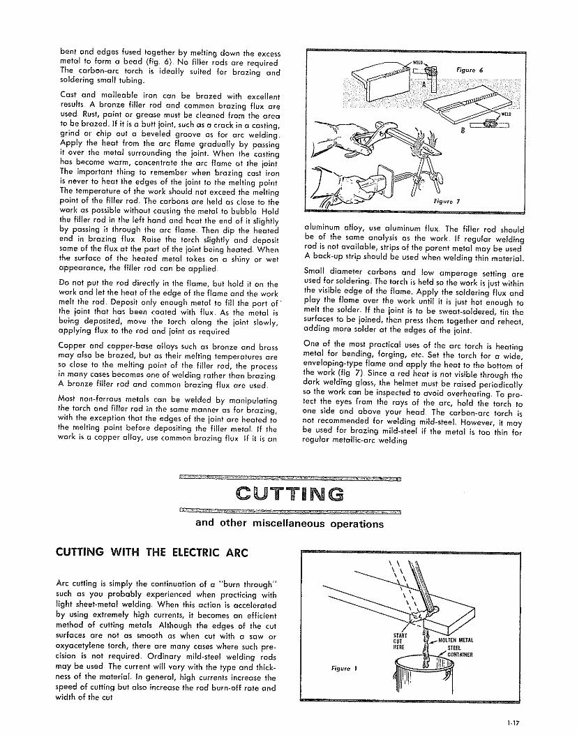
Arc cutting is simply the continuation of a "burn through"
such as you probably experienced when practicing withlight sheet-metal welding When this action is accelerated
by using extremely high currents, it becomes an efficientmethod of cutting metals Although the edges of the cutsurfaces are not as smooth as when cut with a saw or
oxyacetylene torch, there are many cases where such pre-cision is not required. Ordinary mild-steel welding rodsmay be used The current will vary with the type and thick-ness of the material. In general, high currents increase the
speed of cutting but also increase the rod burn-off rate andwidth of the cut
\\ \\
ST_TCUTffEI1E
F_gure 1
d,..-MOLT]_H METALSTEEL
COHTA_HER
117

MOVERODUPANO--_.
DOWNVERTICALLY_:..., _ _'_
,_ --' _" STARTCUTHERE
Figure 2
To make a trlal cut, place a bar of steel approximately
1/4-inch thick on the table so that one end projects overthe edge. Use a 3/32-1nch rod and a current setting of
around 140 amperes HoJd the rod as shown in figure 1 andstrike an arc on the tap corner at the edge of the bar wherethe cut is to be made, Feed the rod into the molten puddle
and keep the crater burning through as the rod is movedacross the bar. To catch the molten metal, place a metalcontainer on the floor directly under the cut
When cutting metal heavler than 1/4-1nch, the arc is startedat the bottom corner and worked up and down verticallyas shown in figure 2, advancing the bottom of the cut
slightly ahead of the top of the cut to permit molten metalto run out more easily_ if a smooth edge is desired, thepieces can be ground on an abrasive wheel. Electrodes
designed especially for cutting may also be used_
REMOVING SEAMS
In addition to cutting, the electric welding arc can be used
for beveling the edges of material to be welded, gougingout cracked welds for rewelding or removing tack-welds.The surface of the metal being worked upon should be ap-
proximately in the vertical position, or tipped slightly towardthe arc (flg_ 3)_Start at the bottom of the seam to be gouged
out and work upward. The rate of speed will depend uponthe depth of the groove and the amount of metal removed.
BOLT AND RIVET CUTTING
Removing rusty bolts or rivets is an easy job with an electricarc welder The arc is struck on the head or nut of the bolt
and worked around in a slight circular movement until the
head is completely melted off (fig. 4). A punch is thenused to drive out the remaining part. The bolt or rivet con
be removed by heating the head almost to the melting point,then quickly shearing it off with a cold chisel Care must betaken not to cause the bolt to become welded to the metal
HOLE PIERCING
Another usefu] application of the welding arc is piercingholes in metal Coated metallic electrodes ore best far
this purpose because of their small size and insulation
afforded by the coatlng_ The process is extremely fast anda surprisingly clean circular hole can be made For practice,place a piece of scrap iron 1/4-inch thick (or less) on the
table and allow it to project over the edge as for arccutting Use a 3/32-1nch rod and the same current as forcutting_ At the place where the hole is to be pierced, strike
an arc and hold it until a molten puddle is formed_ Thenpush the electrode down against the molten puddle andforce it through the plate_ It is possible to hold the electrodeagainst the melted plate because the metal core meffs offfaster than the coating_ The coating (not the rod) touches
the molten metal (fig 5) 1"he gap maintained by the pro-truding coating prevents the metal core of the electrode
from sticking or freezing to the plate
if a larger diameter hole is desired, first pierce a hole asdescribed. Then, holding o fairly long arc, melt the edges
of the hole away by moving the rod around it (flg_ 6). Holesof almost any diameter can be mode_ To pierce a holethrough material thicker than 1/4_inch, work from theunderside
HEATING
The carbon arc provides a convenient method for localizedheating of aJI metals. S_mply strike an arc on the part to beheated and "play" it across the surface until the requiredtemperat_ure is reached
GQUGIRG
Figure 3 Figure 4 Figure 6
!-18

mNERT-GAS METAL-ARC WELDING (Nonconsumabne)
ALLCABLESSHOULDBEKEPTSHORTASPOSSIBLE(Donotex-ceed12-f/2
feet[nlength)
GROUNDEDWORKPIECEORWORKTABLE
TOELECTRODE /HOLDER /
/ GROURBCLAMP
K.F.ATT WELDER_/\ GROUNDCABLE I GROUND
CABLE
_,,o g 230VOLT_=========E_6OCYCLE
SINGLEPHASE
HiGHFREQUENCYATTACHMENT
WELDINGCABLETO WELDER
Figure I
ANYCRAFTSMAHWELDERMAYBEUSEDWiTHHF,
ATTACHMENT
[] DO_
o o WELDERCABINETMUSTBEGROUNDER
ACORDOWELDER
Figure 2
HIGH FREQUENCY ATTACHMENT
The Craftsman, High-Frequency Attachment may be usedwith any Craftsman welder or other single-phase, trans-former_type welder of high quality construction having anAC, or AC/DC power output Tungsten inert gas (T.LG.)welding has many useful and advantageous applicationsas described in the following paragraphs_ In order to usethe T.LG. process with an AC welder, a high-frequencyattachment must be provided_ Figure 1 shows a typicalhookup using this high-frequency attachment with a Crafts-man welder_ When not using the TJ.G, welding process, thehigh-frequency attachment also permits easy "arc" start.ing and greatly improved results with many hard-to-weldrods (low hydrogen rods) as well as making the weldingoperation much easier to perform.
The use of a hlgh-frequency attachment makes possible theestablishment of an arc without touching the electrode tothe work., Once the arc has been established, it isstabilizedby the hlgh-frequency output_ This is essential in the T.I.G.process in order to avoid contaminating the tungsten elec-trode or the work..
PRINCIPLES OF OPERATION
The necessary heat for inert-gas welding (nonconsumable)is produced by an electric arc maintained between the non-consumable electrode and the work-piece. The electrodeused for carrying the current is usually a tungsten or tungstenalloy rod_ The heated weld zone, the molten metal and thenonconsumable electrode are shielded from the oxidizingeffects of the atmosphere by a blanket of inert gas fedthrough the TJ_G. torch and the weld is made by applyingthe arc heat until the abutting edges of the work-places aremelted, adding filler rod if necessary_ The resultant poolof molten metal, upon solidifying, joins the edges of themembers togethen The process may also be used for addingmetal to surfaces, Iocally-meltlng and spot-joinlng parts.
A thorough cleaning of the surface to be welded isrequired_
Alloil, grease, paint, rust, dirt or other contaminants mustbe removed either by mechanical means or by the use ofvapor or liquid cleaners, Files, chisels and stainless wirebrushes may be used Grinding is not recommended, Liquidcleaners such as naphtha, mineral spirits, alcohol, acetoneand methyl-ethyl-ketone can be used All surfaces must bewiped dry with a clean cloth, Cleaners should not be usedafter a joint is assembled prior to welding,
Striking the arc may be accomplished as follows:
1_ Touching the electrode to the work momentarily andquickly withdrawing it a short dlstance_ (DC power source)
2 Use of an apparatus which will cause a spark to jumpwithout touching the electrode to the work. (AC powersource with high-frequency unit attachment)
The high-frequency arc stabilizer provides for this lattermethod of starting the arc. Such devices are not requiredwith DC, consequently it is usually necessary to touch theelectrode to the work to start the arc.
For manual welding, once the arc is started, the electrodeholder is held with the electrode positioned at an angle ofabout 75 degrees to the surface of the weld puddle asshown in figure 2 To start the welding, the holder is usuallymoved in a small circle until a pool of molten metal of suit-able size is obtained. Once adequate fusion is achieved atany one point, a weld is made by gradually moving theelectrode along the parts to be welded to melt the adjoin-ing edges progressively, adding filler rod as required.Solidification of the melted metal follows progression ofthe arc along the joint and completes the welding cycle_
Material thickness, joint design and weld characteristicsdesired will determine whether or not filler metal should
be added to the joints_ When filler metal is added duringmanual welding, it is applied by hand feeding the filler rod(from the side) into the pool of molten metal in the regionof the arc. Filler rod is added in essentially the same mannerwhen welding by the oxyacetylene method.
1-19

(1) DEV_.LOP
THEPUDDLE
DIRECTION
OFWELD".__///I/I///f////////////J
fWOREPIECE
Figure 3
(2) MOVE
TORCH
(4) REMOVEROD
/7_////////////_;///////////_/_
The filler rod is usually held at an angle of approximately15 degrees to the work and slowly fed into the weld puddle.One of the most commonly used techniques for feeding fillerrod is shown in figure 3. Another method, used most often
in multlple-pass welding of vee joints, is to press the fillerrod into the vee groove in line with the weld and melt italong with joint edges_ Still another method, used fre-quently in making large welds, is to feed filler metal con-tinuously into the weld puddle by oscillating the filler rodand arc from one side of the weld to the other° The fillerrod moves in one direction while the arc moves in the
opposite direction, but the filler rod is at all times in closeproximity to the arc and feeding into the weld puddle.
Joints may be welded by the T.I.G process include allstandard types, such as square abutting edge, vee butt, teeand lap connections, It is seldom necessary to bevel edgesof material 1/8-1nch or less, although heavier materials are
usually beveled. Whenever joints are beveled, filler ma-terial must always be added_
The accompanying tame provides a guide to the type ofcurrent recommended for welding some typical materlals.Electrodes used for the T.I.G. (nonconsumable) process may
be pure tungsten or tungsten aBoy. Pure tungsten electrodeswere formerly used exdusively_ At this time, however, many
(3) ADD '_
TILLERMETAL
_,/,//////////,',/,/,,'/,,////,,/_/27_
(5) MOVETORCHTOLEADINGEDGE_
OTPOD L
ADDITIONOFFILLERMETAL
(VERTCAL -_s°'_ IPOSITIO_
electrodes are alloyed with small percentages of thoriumor zirconium. Such electrodes have the advantage of greatercurrent-carrying capacity for a given diameter, a morestable arc at low current values, and longer life with lessdeposit of tungsten in the welds.
TYPES OF GAS TO USE
Either argon, helium, or a mixture of the two can be used withthe T.I.G process. Argon is used most frequently because:
1. It provides general suitability with a wide variety ofmetals
2. It maintains a stabilizing influence on the welding arc.
3_ It costs less (due to the lower flow rates required).
Helium is generally used when welding heavy metal sectionsbecause it provides greater weld penetration. Mixtures ofargon and helium are useful when a balance of these char-acteristics is desired_
Argon is generally supplied in K-cyllnders, having a capacityof approximately 238 cubic feet at a pressure of 2200 psi,or in T-cylinders, having a capacity of approximately 330cubic feet at a pressure of 2640 psi. Purity of commercialargon ranges between 99,95% and 99_99%
CurrentSelectionfor Inert-gas
(nonconsumable)welding
Matetla]
Magnesiumup to _i_-imthickMagnesiumabove_'iG.in thickMagnesiumcastingsAIuminumup to _32.in thickAluminumover_-in thickAluminumcastingsStainlesssteelBrass alloys
iliconcopper;liver
Higb-chlomium,nickelbase,high.temperaturealloys
Silver claddingHard facingCast ironLowcarbonsteel, O015 to 0 030 intLowcarbonsteel, 0.030 to 0.125 in.High.carbonsteel, 0015 to O,O30inHigh.carbonsteel, 0030 in andupDeoxidizedcopperP
*Where aIternating current _s recommended as a second choice, use about 25% higher current than thatrecommended fat DCSP,
t Co no use _lte nang cu rent on tigEhlly jigged p_rts.Use brazing flux or sl con-bronze _x o_ /4, nch and h ck_
1-20

WELDgNG RGD $PEC FmCATmONS
AWS E-6Gll MILD STEEL AC-DC
GENERAL APPLICATIONS: Farm Equipment o Sheet Metal o Car and Truck •Body and Fender = Pipe o Tanks o Maintenance o Jigs and Fixtures o Cabinetso General Repairs oStructuralSteel
Diameter ....
Flat
Vertical
Overhead
SIZES AND HEATS (AMPS)
1/16" 3/32" 1/8"
20"55 20-80 75"130
20"55 20"65 75"11520-55 20"B5 75"115
5132"
100-175
100-t50
100-150
3/16" 7132""t50-225 175-250
150-200
t/4'*
200-375
MEETSTHESE
REQUIREMENTS _'
SPECl FICATIONS
AmericanWeldingSociety ..................... Class:E-6011Military ....................................... MIL-E-15599CAmerican Bureauof Shipping .............. Class:E-5011
Physical Properties of Deposited Metal: As Welded
Tensile Strength .......................................... 70,000 to 75,000 psi
Yield Point .......................................... 60,000 to 65,000 psi
% Elongation in 2-inches ....................................23% to 25%
Reduction in Area ..................................... 50% to 55%
Stress Relieved
65,000 to 70,000 psi55,000 to 60,000 psi
30% to 35%
65% to 75%
DESCRIPTION
The AWS E-6011 is an AC-DC (reverse polarity) electrode with a special coating that provides strongfluxing action for high quality welds, even in dirty, rust covered, galvanized or plated steels, An extremelystable, spray type penetrating arc, is produced that is easy to start and restart after interruption. It is aversatile electrode, producing welds far beyond the requirements of its A.WS. classification It adapts to awide variety of jobs due to the wide range of amperage settings at which top quality results are obtained
Features: Deeper Penetration - Fast-Freeze Puddle - Greater Arc Stability.
WELDING PROCEDURE: Weld with AC or DC (reverse polarity) Strike the arc by brushing rod tip lightlyat the point where weld is to be made. After the arc is established and weld material is deposited,concentrate on holding a short arc that is just long enough to keep the electrode from touching the moltenmetal, In the flat position, use a slight oscillating motion as you advance, In vertical position, on sheet steelstart at the top of the seam and weld down, This provides a more rapid speed of travel, lower penetration,and minimum warpage When welding overhead use a straight stringer bead or a circular motion Keep themolten pool as small as possible_ Use small electrodes overhead, none larger than 5/32 diameter_
2_1
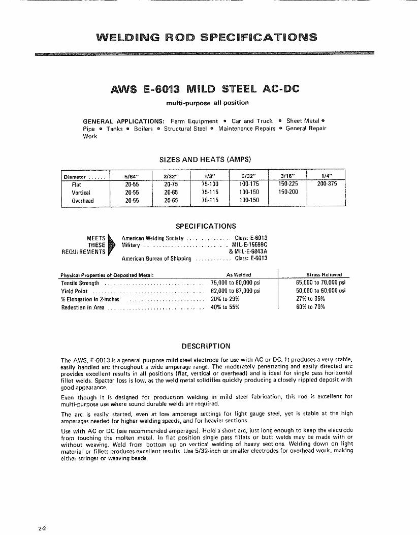
AWS E-6013 MBLD STEEL AC-DC
multi-purpose all position
GENERAL APPLICATIONS: Farm Equipment o Car and Truck o Sheet Metal oPipe o Tanks e Boilers = Structural Steel o Maintenance Repairs o General RepairWork
SIZES AND HEATS (AMPS)
Diameter ......
Fiat
Vertical
Overhead
5/64'"
20-5520-55
20-55
3/32" 118" 5/32" 3/16"
20-75 75-130 100-175 150-225
20-65 75-115 100.150 150-200
20_65 75-115 100-150
1/4"
200"375
MEETSTHESE
REQUIREMENTS
SPECl FICATIONS
_) mericanWeldingSociety .................... Class:E-6013Military ................................................ MIL-E-15509C
& MI L-E-S043AAmerican Bureauof Shipping ................... Class:E-0013
Physical Properties of Deposited Metal: As Welded
TensileStrength ...................................................... 75,000 to 00,000 psi
Yield Point ................................................ 62,000 to 07,000 psi
% Elongation in 2-inches ...................................... 20% to 29%Redaction in Area ................................................. 40%to 55%
Stress Relieved
05,000 to 70,000 psi
50,000 to 00,00g psi27% to 35%
00%to 70%
DESCRIPTION
The AWS, E-6013 is a general purpose mild steel electrode for use with AC or DC It produces a very stable,easily handled arc throughout a wide amperage range_ The moderately penetrating and easily directed arcprovides excellent results in all positions (fiat, vertical or overhead) and is ideal for single pass horizontalfillet welds_ Spatter loss is low, as the weld metal solidifies quickly producing a closely rippled deposit withgood appearance.
Even though it is designed for production welding in mild steel fabrication, this rod is excellent formulti-purpose use where sound durable welds are required,
The arc is easily started, even at low amperage settings for light gauge steel, yet is stable at the highamperages needed for higher welding speeds, and for heavier sections.
Use with AC or DC (see recommended amperages) Hold a short arc, just long enough to keep the electrodefrom touching the molten metal. In flat position single pass fillets or butt welds may be made with orwithout weaving. Weld from bottom up on vertical welding of heavy sections Welding down on lightmaterial or fillets produces excellent results Use 5/32-inch or smaller electrodes for overhead work, makingeither stringer or weaving beads.
2-2

WELDWNG ROD SPECIJFICATiONS
HARD SURFACING AC-DC
medium chrome-carbon electrode
GENERAL APPLICATIONS: Tractor Grousers and Rollers o Scraper Blades o Agri-cultural Implements o Plow Shares o Hitches • Power Shovel o Dipper Teeth andDrive Sprockets = Coal Cutters e Conveyor Rolls • Mining Buckets • Rock Crusherso etc,
SIZES AND HEATS (AMPS)
Diameter .... 3/32" 1/8" _ 5/32" 3/10" 7/32" 1/4"
Amperes 55-85 100-130 1 130-150 175-200 175-250 225-275
SPECl FICATIONS
MEETSTHESE Military ................................. MIL-E-19141CREQUIREMENTS
Physical Properties of De_positedMetalAs Welded Condition (Rockwell "C" 46-50) .................................................... 450-500 Brinell Hardness
After Cold Working (Rockwell "C" 50-54) ............................................. 500-550 Brineli Hardness
DESCRIPTION
The Medium Chrome-Carbon rod is a hard-surfacing alloy steel electrode with a coating of powdered metalsand flux. When welding, this special coating combines in the arc with the steel core wire to give anextremely hard weld-meta! deposit Deposited weld metal requires no heat treatment for maximumstrength, ductility, and wear resistance, Annealing or heat treating will not soften the metal deposit, whichis not machinable, but may be hot forged to any desired shape, Deposited metal has a very fine grain and isfree of slag and porosity The metal is tough and highly resistant to wear and impact
The rod is designed for use with either AC or DC (either polarity) Hold a medium short arc and deposit themetal with a weaving motion Excellent welding results are obtained in either the vertical or flat position,
WELDING PROCEDURE: Gdnd the surface to clean and remove shallow cracks, rust, or other foreignmaterial Cracks too deep to be removed by grinding should be gouged out w_th a cutting torch or cuttingrod Use the "drag" technique to deposit weld metal, to thin edges when desirable or weave a wider bead,or use a "free" arc,
2-3

WELDmNG ROD SPECmF CATmONS
AWS E-7014 CONTACT AC-DCfor welding of mild steel
GENERAL APPLICATIONS: Sheet Metal Fabrication and Repairs e MachineryFabrication • Construction Equipment Repairs = Storage Tanks e ShipbuildingFabricating Structural Shapes and Heavy Equipment = Equipment and Heavy PipeWelding
Diameter .... 1/18" 3/16" 1/4"
Length 12" 18'" 18"
Amperes 70-90 200-250 250-350
SIZES AND HEATS lAMPS)
3/32" 1/8" 5/32"14" 14" 14"
90-110 130-105 190-210
SPECl FICATIONS
MEETS _kTHESE _) AmericanWeldingSociety ..................... Class:E-7014
REQUIREMENTS JV American Bureauof Shipping ................ C/ass:E-7014
Physical Properties of Deposited Metal: AsWelded
TensileStrength ................................................................................... 72,000 psito 78,000 psi
Yield Point ..................................................................................... 60,000 psito 69,000 psi
% Elongation in 2.inches .......................................................................................... 17%to 28%
DESCRIPTION
The AWS E-7014 is an excellent electrode for the inexperienced or experienced welder_ Starts on contactwith smooth surge-free arc, also restrikes instantly. This Craftsman electrode has powdered iron in thecoating which makes welding easier and faster_ The slag is easy to remove in most casesself-peeling as theweld cools_
Ideal for fixture welding where weld appearance and lack of spatter is important. The amount of slagpermits use in all welding positions
WELDING PROCEDURES: Weld materials should be clean. Best results are obtained when fit-up is good.Either AC or DC current may be used. When arc is established, deposit metal holding a short arc or placeelectrode in contact with work,.
2-4

Jm=LDBNG ROD SPECNF CAT ONS
MACHINABLE CAST RON AC-DC
machineable welds on all cast irons
GENERAL APPLICATIONS: Cylinder Blocks o Crankcases o Valve Seats e DefectiveCastings o Gears o Sprockets e Casting Repairs in General o Garages o Farms o Shops
Diameter
Amperes
SIZES AND HEATS (AMPS)
3/32" 1/8" 5/32"
48-85 75-130 100-150
3/18"
130-175
DESCRIPTION
This electrode uses a nickel core wire, and produces a fully machinable weld withoutpre-he._ting the casting, Cast irons can be joined to steel, nickel alloys and copper,
This electrode operates with AC or DC (reverse polarityL It has very stable arccharacteristics
It is recommended for automotive repairs, such as cylinder blocks, crank cases, valve seats
and other cast iron parts In maintenance and repairs it is used on gears, sprockets, andmany farm machinery parts
WELDING PROCEDURE: Remove all dirt and grease from work piece before starting toweld, A cutting electrode may be used to burn a groove along the break where the weld isto be made This cutting electrode removes the grease and scale, and then seals in any oilsoaked into the cast iron
Use the lowest amperage that gives good fusion During cooling, peen hammer the weld torelieve strain and stress
CUTTIING ROD AC-DC
quick, inexpensive, easy cuts through all metals
GENERAL APPLICATIONS: Cutting e Piercing _ Gouging = Scarfing o Beveling = etc
SIZES AND HEATS (AMPS)
Diameter ...... 3/32" 1/8" 3/16"
Amperes- AC 80150 75-130 130-175
Amperes- DC 150-250 -5/32"
100o150
DESCRIPTION
For piercing, gouging, cutting, and scarfing
Excellent for removing old welds in preparation to rewelding_ Also used for bevelingcracks in castings or removing sharp edges prior to welding Needs no oxygen or specialequipment to cut carbon steels, stainless steel, manganese steel, cast iron, etcRecommended for the owners of all arc welders_ AC or DC
WELDING PROCEDURE: Place etectrode in holders so that it's positioned like a lance inthe direction of travel The angle between the electrode and work metal should notexceed 15° Strike arc at starting point, Push electrode along the line of cut, forcing themolten metal ahead and away If deeper gouge is required, repeat procedure untg thedesired depth has been reached
2_5

REPAIR PARTS
PARTS LIST FOR CRAFTSMAN 230 AMP WELDER MODEL 113o201372
35
42
41 27
\\ 44
\
43 27 45 45
34
15
11 10
23 24
19
/
12
32
29
\\
\
28
27 13
= Transformer not replaceable°
2-6
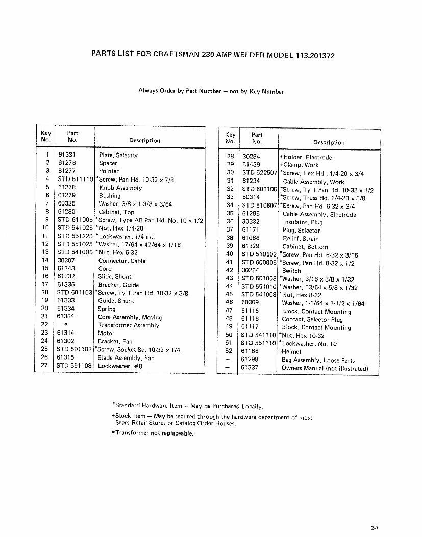
PARTS LIST FOR CRAFTSMAN 230 AMP WELDER MODEL 113.201372
Always Order by Part Number - not by Key Number
Key PartNo. No., Description
1
2
34
5
67
8
9
10
11
1213
14
15
16
17
18
19
2021
22
2324
25
2627
61331
61276
61277STD 511110
61278
61279!60325
61280
STD 611005STD 541025
STD 551225
STD 551025STD 541006
3030761143
61332
61335
STD 601103
61333
6133461384
o
6131461302
STD 501102
61315STD 551108
Plate, Selector
SpacerPointer
*Screw, Pan Hd 10-32 x 7/8
Knob Assembly
Bushing
Washer, 3/8 x 1-3/8 x 3/64Cabinet, ]'op
*Screw, Type AB Pan Hd No 10 x 1/2
*Nut, Hex 1/4-20
*Lockwasher, 1/4 int..
*Washer, 17/64 x 47/64 x 1/16
*Nut, Hex 6-32
Connector, Cable
Cord
Slide, Shunt
Bracket, Guide*Screw, Ty T Pan Hd 10-32 x 3/8
Guide, Shunt
Spring
Core Assembly, MovingTransformer AssemblyMotor
Bracket, Fan
*Screw, Socket Set 10-32 x 1/4
Blade Assembly, FanLockwasher, #8
I(ey J PartNo.. i No_
r28 130284
29 51439
30 _STD 522507
31 61234
32 6TD 601105
33 60314
34 STD 510607
35 61295
36 30332
37 61171
36 61086
39 61329
40 STD 510692
41 STD 600805
42 3025443 STD 551008
44 STD 551010
45 STD 541008
46 60309
47 61115
48 61116
49 61117
50 6TD 54111051 STD 551110
52 61186
- 61298
- 61337
Description
+Holder, Electrode+Clamp, Work
*Screw, Hex Hd, 1/4-20 x 3/4
Cable Assembly, Work
*Screw, Ty T Pan Hd 10-32 x 1/2
*Screw, Truss Hd.. I/4-20 x 5/8
*Screw, Pan Hd 6-32 x 3/4
Cable Assembly, Electrode
insulator, Plug
Plug, Selector
Relief, Strain
Cabinet, Bottom
*Screw, Pan Hd. 6-32 x 3/16
*Screw, Pan Hd. 8-32 x 1/2Switch
*Washer, 3/16 x 3/8 x 1/32*Washer, 13/64 x 5/8 x 1/32
*Nut, Hex 8-32
Washer, 1-1/64 x 1-1/2 x 1/64
Block, Contact Mounting
Contact, Selector Plug
B_ock, Contact Mounting
*Nut, Hex 10-32
*Lockwasher, No 10+Helmet
Bag Assembly, Loose Parts
Owners Manual (not illustrated)
*Standard Hardware Item - May be Purchased Locally,
+Stock Item - May be secured through the hardware department of mostSears Retail Stores or Catalog Order Houses,
OTransformer not replaceable,
_7
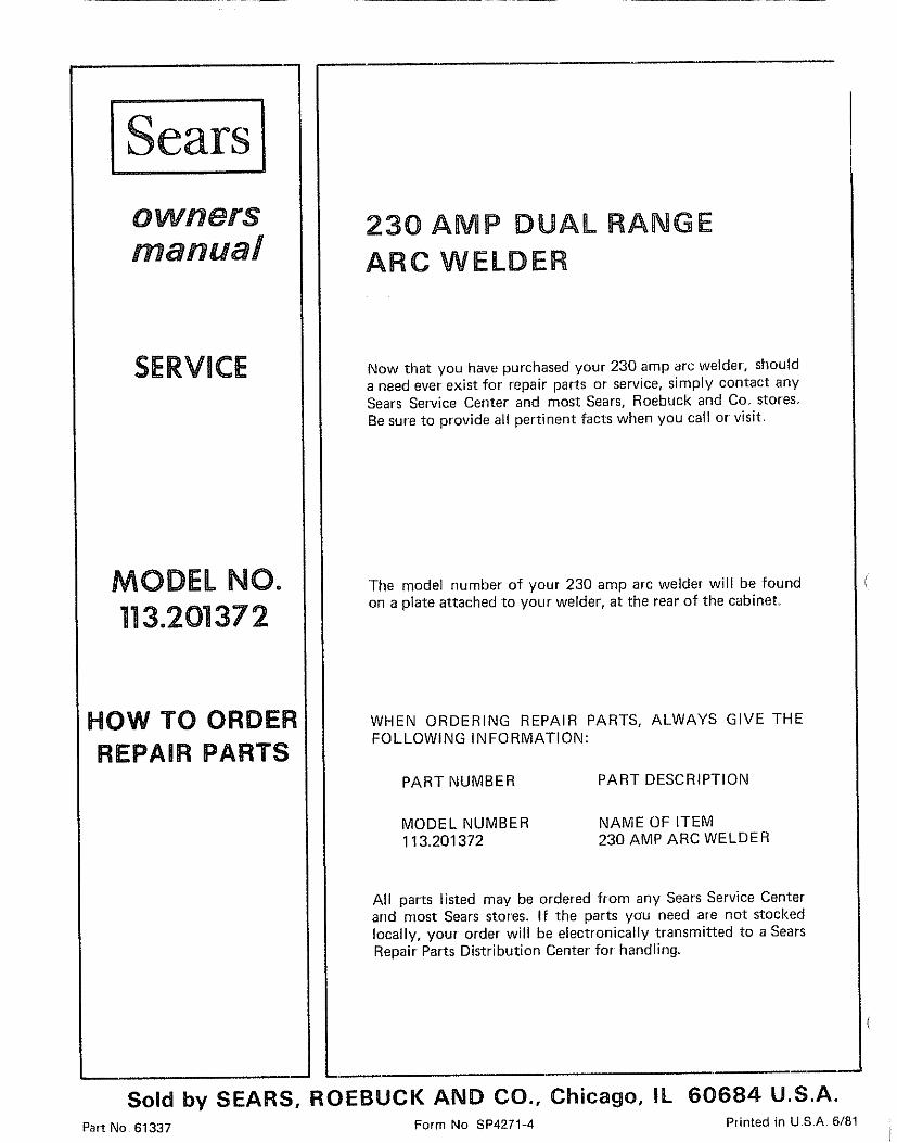
ISears I
SERVICE
MODEL NO.113.20137 2
HOW TO ORDER
REPAIR PARTS
230 AMP DUAL RANGE
ARC WELDER
Now that you have purchased your 230 amp arc welder, shoulda need ever' exist for' repair parts or service, simply contact anySears Service Center and most Sears, Roebuck and Co. stores.Be sure to provide all pertinent facts when you call or visit
The model number' of your 230 amp arc welder will be foundon a plate attached to your' welder, at the rear' of the cabinet.
WHEN ORDERING REPAIR PARTS, ALWAYS GIVE THEFOLLOWING INFORMATION:
PART NUMBER PART DESCRIPTION
MODEL NUMBER113,201372
NAME OF ITEM230 AMP ARC WELDER
All parts listed may be ordered from any Sears Service Centerand most Sears stores. If the parts you need are not stockedlocally, your order will be electronically transmitted to a SearsRepair Parts Distribution Center for handling.
Sold by SEARS, ROEBUCK AND CO., Chicago, IL 60684 U.S.A.Part No 61337 Form No SP4271-4 Printed in USA 6/81
Related Documents