INTERNATIONAL JOURNAL FOR NUMERICAL METHODS IN ENGINEERING Int. J. Numer. Meth. Engng 2008; 75:629–646 Published online 16 January 2008 in Wiley InterScience (www.interscience.wiley.com). DOI: 10.1002/nme.2265 Crack tip enrichment in the XFEM using a cutoff function Elie Chahine 1, ∗,† , Patrick Laborde 2 and Yves Renard 3 1 Institut de Math´ ematiques, UMR CNRS 5215, GMM INSA Toulouse, Complexe Scientifique de Rangueil, 31077 Toulouse Cedex 4, France 2 Institut de Math´ ematiques, UMR CNRS 5215, UPS Toulouse 3, 118 Route de Narbonne, 31062 Toulouse Cedex 4, France 3 Institut Camille Jordan, CNRS UMR 5208, INSA de Lyon,Universit´ e de Lyon, 20 rue Albert Einstein, 69621 Villeurbanne Cedex, France SUMMARY We consider a variant of the eXtended Finite Element Method (XFEM) in which a cutoff function is used to localize the singular enrichment surface. The goal of this variant is to obtain numerically an optimal convergence rate while reducing the computational cost of the classical XFEM with a fixed enrichment area. We give a mathematical result of quasi-optimal error estimate. One of the key points of this paper is to prove the optimality of the coupling between the singular and the discontinuous enrichments. Finally, we present some numerical computations validating the theoretical result. These computations are compared with those of the classical XFEM and a non-enriched method. Copyright 2008 John Wiley & Sons, Ltd. Received 9 January 2007; Revised 2 August 2007; Accepted 1 November 2007 KEY WORDS: fracture mechanics; extended finite element method; cutoff function; error estimates; numerical convergence rate 1. INTRODUCTION The benefits of computational methods using classical finite element strategies are limited when solving problems defined over cracked domains for at least two reasons: the mesh should be sufficiently refined around the crack tip to model the singular strain and the domain should be remeshed step by step according to the geometry of the crack propagation. To overcome these difficulties and to make the finite element methods more flexible, many approaches have been studied. In 1973, Strang and Fix [1] introduced a singular enrichment method using a cutoff function for a mesh dependent on the domain geometry. Since then different approaches had been ∗ Correspondence to: Elie Chahine, Institut de Math´ ematiques, UMR CNRS 5215, GMM INSA Toulouse, Complexe Scientifique de Rangueil, 31077 Toulouse, France. † E-mail: [email protected] Copyright 2008 John Wiley & Sons, Ltd.

Welcome message from author
This document is posted to help you gain knowledge. Please leave a comment to let me know what you think about it! Share it to your friends and learn new things together.
Transcript
INTERNATIONAL JOURNAL FOR NUMERICAL METHODS IN ENGINEERINGInt. J. Numer. Meth. Engng 2008; 75:629–646Published online 16 January 2008 in Wiley InterScience (www.interscience.wiley.com). DOI: 10.1002/nme.2265
Crack tip enrichment in the XFEM using a cutoff function
Elie Chahine1,∗,†, Patrick Laborde2 and Yves Renard3
1Institut de Mathematiques, UMR CNRS 5215, GMM INSA Toulouse, Complexe Scientifique de Rangueil,31077 Toulouse Cedex 4, France
2Institut de Mathematiques, UMR CNRS 5215, UPS Toulouse 3, 118 Route de Narbonne,31062 Toulouse Cedex 4, France
3Institut Camille Jordan, CNRS UMR 5208, INSA de Lyon,Universite de Lyon, 20 rue Albert Einstein,69621 Villeurbanne Cedex, France
SUMMARY
We consider a variant of the eXtended Finite Element Method (XFEM) in which a cutoff function is usedto localize the singular enrichment surface. The goal of this variant is to obtain numerically an optimalconvergence rate while reducing the computational cost of the classical XFEM with a fixed enrichmentarea. We give a mathematical result of quasi-optimal error estimate. One of the key points of this paper isto prove the optimality of the coupling between the singular and the discontinuous enrichments. Finally, wepresent some numerical computations validating the theoretical result. These computations are comparedwith those of the classical XFEM and a non-enriched method. Copyright q 2008 John Wiley & Sons,Ltd.
Received 9 January 2007; Revised 2 August 2007; Accepted 1 November 2007
KEY WORDS: fracture mechanics; extended finite element method; cutoff function; error estimates;numerical convergence rate
1. INTRODUCTION
The benefits of computational methods using classical finite element strategies are limited whensolving problems defined over cracked domains for at least two reasons: the mesh should besufficiently refined around the crack tip to model the singular strain and the domain should beremeshed step by step according to the geometry of the crack propagation. To overcome thesedifficulties and to make the finite element methods more flexible, many approaches have beenstudied. In 1973, Strang and Fix [1] introduced a singular enrichment method using a cutofffunction for a mesh dependent on the domain geometry. Since then different approaches had been
∗Correspondence to: Elie Chahine, Institut de Mathematiques, UMR CNRS 5215, GMM INSA Toulouse, ComplexeScientifique de Rangueil, 31077 Toulouse, France.
†E-mail: [email protected]
Copyright q 2008 John Wiley & Sons, Ltd.
630 E. CHAHINE, P. LABORDE AND Y. RENARD
analyzed such as the partition of unity finite element method (PUFEM, see [2]), the Arlequinmethod (see [3]), the generalized finite element method (see [4, 5]), the eXtended Finite ElementMethod (XFEM) and the patches enrichment approach (see [6]).
Inspired by the PUFEM, the XFEM was introduced by Moes et al. in 1999 (see [7, 8]). The ideaof XFEM consists in enriching the basis of the classical finite element method by a step functionalong the crack line to take into consideration the discontinuity of the displacement field acrossthe crack and by some non-smooth functions representing the asymptotic displacement aroundthe crack tip. The latter enrichment is the so-called singular enrichment. This enrichment strategyallows the use of a mesh independent of the crack geometry. Since the introduction of the XFEM,many works have been achieved in order to explore the capabilities of the XFEM and improve itsaccuracy as in [9–15]. Other works studied XFEM with some 3D applications as in [16–22].
In spite of the singular enrichment of the finite element basis, the obtained convergence error ofXFEM remains only in
√h if linear finite elements are used (see [23], h being the mesh parameter).
To improve this result and obtain an optimal accuracy, many developments have been performed.A first idea was to enrich the degrees of freedom of a whole area around the crack tip by thesingular functions (see [23, 24]). In a second variant, a global enrichment strategy is consideredin order to reduce the number of the enrichment degrees of freedom and improve the conditioningof the linear system. Such a variant is a non-conforming method to deal with the difficulty oftransition between the enriched area and the remaining elements of the mesh [23].
We consider in this paper another variant of the XFEM, which allows one to benefit from theadvantages of the latter one while preserving the conformity of the method. One of the difficultiesis the mathematical analysis of the coupling between the two types of enrichment. The detailedproof of the optimal convergence results, which were announced in [25], is studied in this paper.Moreover, these results are validated by some numerical computations and comparisons with anon-enriched method and the classical XFEM. These numerical results show that the proposedvariant preserves an optimal convergence even though its computational cost is lower than that ofthe XFEM.
The elastostatic problem is presented in Section 2 for a 2D cracked domain. In Section 3, weintroduce the proposed variant in which the linear finite element basis is enriched with singularfunctions using a cutoff function. In Section 4, a mathematical result is given showing the accuracyof the method. To prove the error estimate, the domain � is splitted into two subdomains andan interpolation operator is defined using an extension operator over each subdomain. Then weobtain a quasi-optimal rate of convergence by means of this interpolation operator considered onevery type of triangles: triangle containing the crack tip and triangles partially or totally enrichedwith the discontinuous function. In Section 5, some numerical results are presented including acomparison with a non-enriched method and the XFEM using a singular enrichment over a wholearea. These results show an optimal rate of convergence and a satisfactory conditioning.
2. THE MODEL PROBLEM
Let � be a bounded cracked domain in R2; the crack �C is assumed to be straight. We consider thelinear elasticity problem on this domain for an isotropic material. The boundary of �, denoted by��, is partitioned into �D where a Dirichlet condition is prescribed, �N with a Neumann conditionand �C (the crack) where a traction-free condition is considered (Figure 1).
Copyright q 2008 John Wiley & Sons, Ltd. Int. J. Numer. Meth. Engng 2008; 75:629–646DOI: 10.1002/nme

CRACK TIP ENRICHMENT IN XFEM USING A CUTOFF FUNCTION 631
Figure 1. The cracked domain �.
Let ϑ={v∈H1(�);v=0 on �D} be the space of admissible displacements and
a(u,v) =∫
�r(u) :e(v)dx
l(v) =∫
�f.v dx+
∫�N
g.v d�
r(u) = � tre(u)I +2�e(u)
(1)
where r(u) denotes the stress tensor; e(u) is the linearized strain tensor; f and g are some givenforce densities on � and �N, respectively; and �>0,�>0 are the Lame coefficients. To simplifythe mathematical analysis, we consider a homogeneous Dirichlet boundary condition on �D. Theextension to a non-homogeneous condition is straightforward. The problem can be expressed as
Find u∈ϑ such that a(u,v)= l(v) ∀v∈ϑ (2)
We suppose that f and g are smooth enough to let the solution u of the elasticity problem beexpressed as a sum of a singular part us and a regular part u−us in � (see [26, 27]) satisfying fora fixed �>0 (see [28] for the definition of Hs(�),s∈R):
u−us=u−(KIuI+KIIuII)∈H2+�(�) (3)
where KI and KII denote the stress intensity factors. The asymptotic displacement at the crack tipis defined from functions uI and uII, respectively; the opening mode and the sliding mode for a2D crack are given in polar coordinates by (see [29, 30])
uI(r,�) = 1
E
√r
2�(1+�)
⎛⎜⎜⎝cos�
2(�−cos�)
sin�
2(�−cos�)
⎞⎟⎟⎠ (4)
uII(r,�) = 1
E
√r
2�(1+�)
⎛⎜⎜⎝ sin�
2(�+2+cos�)
cos�
2(2−�−cos�)
⎞⎟⎟⎠ (5)
Copyright q 2008 John Wiley & Sons, Ltd. Int. J. Numer. Meth. Engng 2008; 75:629–646DOI: 10.1002/nme

632 E. CHAHINE, P. LABORDE AND Y. RENARD
r
c
Crack tip
Figure 2. Polar coordinates, respectively, to the crack tip �.
where � denotes the Poisson ratio, E the Young modulus, �=3−4� in the plane stress problemand (r,�) the polar coordinates, respectively, to the crack tip (Figure 2). The normal (respectivelytangential) component of function uI (respectively uII) is discontinuous along the crack. Note thatuI and uII belong to H3/2−�(�) for any �>0 (see [26]), which limits the order of the convergencerate of the classical finite element method to h1/2.
3. DISCRETE PROBLEM
The idea of the classical XFEM (see [7, 8]) is to use a finite element space enriched with someadditional functions. The finite element method is defined independently from the crack on a meshof the non-cracked domain �. At the nodes whose corresponding shape function support is cut bythe crack, an enrichment function of Heaviside type is considered:
H(x)={+1 if (x−x∗) ·n�0
−1 elsewhere(6)
where x∗ denotes the crack tip and n is a given normal to the crack. Moreover, the nodes of thetriangle containing the crack tip are enriched with the following singular functions given in polarcoordinates (Figure 3):
{Fj (x)}1� j�4={√
r sin�
2,√r cos
�
2,√r sin
�
2sin�,
√r cos
�
2sin�
}(7)
We recall that
Fj ∈H3/2−�(�) ∀�>0, j =1, . . . ,4 (8)
In the following, we use the fact that
Fj ∈C2(�\{x∗}) (9)
Since the mesh is independent of the crack geometry, the Heaviside function represents thediscontinuity of the displacement field along the crack and the singular functions allow to takeinto account the asymptotic displacement at the crack tip. Such a method enables to discretize thedomain without explicitly meshing the crack surfaces; hence, the crack propagation simulationscan be done without remeshing.
For the model problem, we consider a Lagrange finite element method of first order defined ona regular triangulation of the non-cracked domain �. The piecewise P1 basis functions are denoted
Copyright q 2008 John Wiley & Sons, Ltd. Int. J. Numer. Meth. Engng 2008; 75:629–646DOI: 10.1002/nme
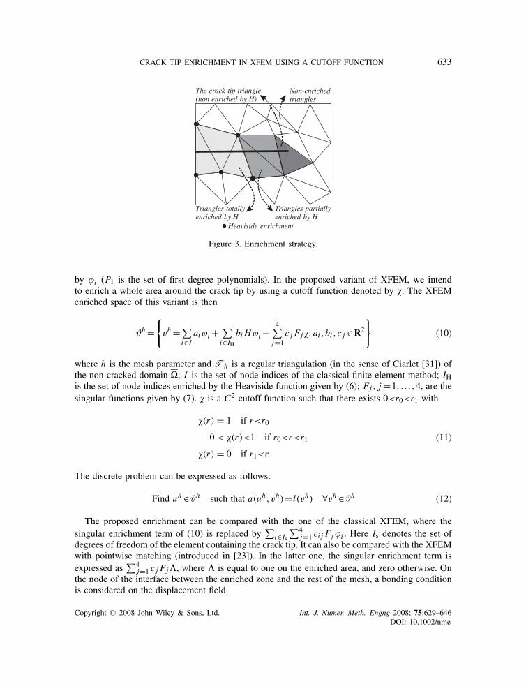
CRACK TIP ENRICHMENT IN XFEM USING A CUTOFF FUNCTION 633
The crack tip triangle(non enriched by H)
Non-enrichedtriangles
Triangles partiallyenriched by H
Triangles totallyenriched by H
Heaviside enrichment
Figure 3. Enrichment strategy.
by i (P1 is the set of first degree polynomials). In the proposed variant of XFEM, we intendto enrich a whole area around the crack tip by using a cutoff function denoted by . The XFEMenriched space of this variant is then
ϑh ={
vh = ∑i∈I
aii +∑i∈IH
bi Hi +4∑j=1
c j Fj;ai ,bi ,c j ∈R2
}(10)
where h is the mesh parameter and Th is a regular triangulation (in the sense of Ciarlet [31]) ofthe non-cracked domain �; I is the set of node indices of the classical finite element method; IHis the set of node indices enriched by the Heaviside function given by (6); Fj , j =1, . . . ,4, are thesingular functions given by (7). is a C2 cutoff function such that there exists 0<r0<r1 with
(r) = 1 if r<r0
0 < (r)<1 if r0<r<r1
(r) = 0 if r1<r
(11)
The discrete problem can be expressed as follows:
Find uh ∈ϑh such that a(uh,vh)= l(vh) ∀vh ∈ϑh (12)
The proposed enrichment can be compared with the one of the classical XFEM, where thesingular enrichment term of (10) is replaced by
∑i∈Is
∑4j=1 ci j Fji . Here Is denotes the set of
degrees of freedom of the element containing the crack tip. It can also be compared with the XFEMwith pointwise matching (introduced in [23]). In the latter one, the singular enrichment term isexpressed as
∑4j=1 c j Fj�, where � is equal to one on the enriched area, and zero otherwise. On
the node of the interface between the enriched zone and the rest of the mesh, a bonding conditionis considered on the displacement field.
Copyright q 2008 John Wiley & Sons, Ltd. Int. J. Numer. Meth. Engng 2008; 75:629–646DOI: 10.1002/nme
634 E. CHAHINE, P. LABORDE AND Y. RENARD
4. ERROR ESTIMATE
The mathematical result obtained in this work as follows.
Theorem 4.1Assume that the displacement field u, solution to problem (2), satisfies condition (3). Then, forany �>0, the following estimate holds:
‖u−uh‖1,��Ch‖u−us‖2+�,� (13)
where uh is the solution to problem (12), ‖.‖s,�,s∈R stands for the norm in Hs(�) (see [28]for the definition of ‖.‖s,�),us is the singular part of u (see (3)), is the C2 cutoff function andfinally C>0 is a constant independent of h.
RemarkWhen using a classical finite element method over a cracked domain, the error is of order
√h, while
the displacement field belongs to H3/2−�,∀��0. The convergence rate obtained here is identicalto the one obtained when using a classical finite element method of first order with a regularproblem. The error estimate is not completely optimal due to the requirement u−us∈H2+ε(�)
instead of u−us∈H2(�). This is strictly a technical difficulty.
To compute the interpolation error, we introduce an interpolation operator �h adapted to theproblem. This is done by using an extension of the displacement field across the crack over �,then defining the interpolation of the displacement field using the extension (Lemma 4.3). Theinterpolation error estimates are then computed locally over every different type of triangles:triangles totally enriched by the discontinuous function (Lemma 4.4), triangles totally enrichedby the singular functions (Lemma 4.5), triangles partially enriched by the discontinuous function(Lemma 4.6) and finally non-enriched triangles.
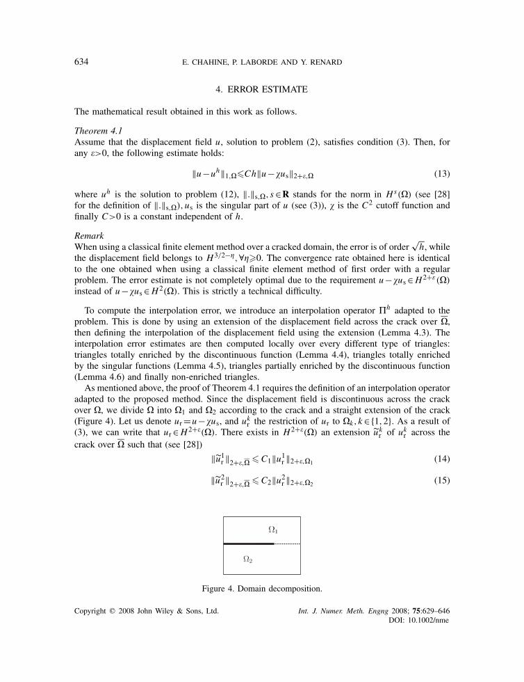
As mentioned above, the proof of Theorem 4.1 requires the definition of an interpolation operatoradapted to the proposed method. Since the displacement field is discontinuous across the crackover �, we divide � into �1 and �2 according to the crack and a straight extension of the crack(Figure 4). Let us denote ur=u−us, and ukr the restriction of ur to �k,k∈{1,2}. As a result of(3), we can write that ur∈H2+�(�). There exists in H2+�(�) an extension u k
r of ukr across thecrack over � such that (see [28])
‖u1r ‖2+�,� �C1‖u1r ‖2+�,�1 (14)
‖u2r ‖2+�,� �C2‖u2r ‖2+�,�2 (15)
Figure 4. Domain decomposition.
Copyright q 2008 John Wiley & Sons, Ltd. Int. J. Numer. Meth. Engng 2008; 75:629–646DOI: 10.1002/nme
CRACK TIP ENRICHMENT IN XFEM USING A CUTOFF FUNCTION 635
The use of such extensions allows us to interpolate over complete triangles and not over sub-triangles or quadrangles that are inducted because of the presence of a crack.
In the following, C denotes a generic constant that might be different at each occurrence but isindependent of h.
Definition 4.2Given a displacement field u satisfying (3) and two extensions u1r and u2
r , respectively, of u1 and
u2 in H2+�(�), we define �hu as the element of ϑh such that
�hu= ∑i∈I
aii +∑i∈IH
bi Hi +4∑
i=1ci Fi (16)
where ai ,bi are given as follows (xi denotes the node associated with i ):
if i ∈ {I \ IH} then ai =ur(xi )
if i ∈ IH and xi ∈�k then (k∈{1,2}, l �=k)
⎧⎪⎪⎨⎪⎪⎩ai = 1
2(ukr (xi )+ u l
r (xi ))
bi = 1
2(ukr (xi )+ u l
r (xi ))H(xi )
(17)
and ci , i=1, . . . ,4, are derived from (4) and (5) such that∑
i ci Fi =us.
Lemma 4.3The function �hu (Definition 4.2) verifies
(i) �hu= I hur+us over a triangle non-enriched by H ,(ii) �hu|K∩�k = I hu k
r +us over a triangle K totally enriched by H ,
where I h denotes the classical interpolation operator for the associated finite element method.
RemarkObviously, the definition of �hu depends on the chosen extension u k
r . From Lemma 4.3, thefunction �hu is called the XFEM interpolation of u. Note that (16) and equations (i) and (ii)of Lemma 4.3 define a unique XFEM interpolation function �hu over the whole domain �.A similar construction of an interpolation operator taking only into account the discontinuityacross the crack was done in [32]. The definition of �hu that we introduce is adapted to thepresence of singularities.
ProofEquation (i) is directly derived from the first equation of (17) since I h is the classical interpolationoperator (see [31]). It means that a classical degree of freedom is equal to the node value of ur ifit is not enriched by H .
To prove (ii), we consider a triangle K totally enriched by the discontinuous function. Using localindexing, let the first node x1 of K be in �1 and the two others x2 and x3 be in �2 (Figure 5(a)).Using (16), we have
�hu|K =3∑j=1
a j j +3∑
i=1b j H j +us (18)
Copyright q 2008 John Wiley & Sons, Ltd. Int. J. Numer. Meth. Engng 2008; 75:629–646DOI: 10.1002/nme

636 E. CHAHINE, P. LABORDE AND Y. RENARD
Figure 5. (a) Totally enriched triangle and (b) partially enriched triangle (Figure 3).
where j denotes the local index of the degrees of freedom. Let pk be the two polynomials definedby (k∈{1,2})
pk =�hu|K∩�k −us (19)
Thus, we have
p1 =3∑j=1
a j j +3∑j=1
b j j
p2 =3∑j=1
a j j −3∑j=1
b j j
(20)
Then, combining (20) and (17), we obtain
p1(x j ) = a j +b j = u1r (x j )
p2(x j ) = a j −b j = u2r (x j )
(21)
We conclude that pk is the classical interpolation of u kr over K , which gives (ii). �
To find the global interpolation error, we will proceed by computing local error estimates overthe triangles totally enriched by H , triangle containing the crack tip, triangles partially enrichedby H and non-enriched triangles (Figure 3). In what follows, let
hL =diam(L)= maxx1,x2∈L
|x1−x2| (22)
and
�L ={sup(diam(B)); B ball of R2, B⊂ L} (23)
where L is a subset of �.
Lemma 4.4Let TH
h be the set of triangles totally enriched by H (Figure 3) and �K =hK�−1K . For all K in
THh and for all u satisfying (3) we have the estimates
‖u−�hu‖1,K∩�1�ChK�K ‖u1r ‖2,K (24)
Copyright q 2008 John Wiley & Sons, Ltd. Int. J. Numer. Meth. Engng 2008; 75:629–646DOI: 10.1002/nme
CRACK TIP ENRICHMENT IN XFEM USING A CUTOFF FUNCTION 637
and
‖u−�hu‖1,K∩�2�ChK�K ‖u2r ‖2,K (25)
In fact, the triangles totally enriched by H are cut into two parts. Using the extensions of u1r andu2r , we associate three interpolation points with every part. Thus, the interpolation operator wedefined allows us to make a classical interpolation on every part of the triangle and have the sameoptimal rate of convergence obtained in the classical global interpolation theorem (see [1, 33]).Thus, Lemma 4.4 is a direct consequence of this theorem.
Lemma 4.5Let K be the triangle containing the crack tip and K ∗ =K \�C. Using the same notations, we havethe following estimate over K ∗:
‖u−�hu‖1,K ∗�ChK�K ‖u−us‖2+�,� (26)
where �K =hK�−1K .
ProofSince we added singular functions to the discrete space (around the crack tip), the singular partof u (see (3)) will be eliminated when we try to estimate ‖u−�hu‖1,K ∗ . Thus, it is sufficient toestimate ‖ur−�hur‖1,K ∗ , where ur=u−us. In fact
‖ur−�hur‖21,K ∗ =‖ur−�hur‖20,K ∗ +|ur−�hur|21,K ∗ (27)
where |·| denotes the H1 semi-norm. Using Sobolev imbedding theorems (see [28]), thespace H2+�(�) (and not H2(�)) is continuously imbedded in C1
B(�), where C1B(�)={v∈
C1(�) such that ∇v ∈L∞(�)} (see [28]). Thus,‖∇ur‖L∞(�)�C‖ur‖2+�,� =C (28)
where
‖∇�hur‖L∞(K ∗)�C d
�K(29)
where d�h denotes the maximal distance between a node of K ∗ and the crack tip. In fact,(ur−�hur)(x) vanishes on the nodes; thus,
‖ur−�hur‖L∞(K ∗)�C h2K�K
(30)
then
‖ur−�hur‖0,K ∗�[∫
K ∗
(C h2K�−1
K
)2dx
]1/2=C h2K�−1
K
√meas(K ∗) (31)
Copyright q 2008 John Wiley & Sons, Ltd. Int. J. Numer. Meth. Engng 2008; 75:629–646DOI: 10.1002/nme
638 E. CHAHINE, P. LABORDE AND Y. RENARD
and
|ur−�hur|1,K ∗�[∫
K ∗
(C hK�−1
K
)2dx
]1/2=C hK�−1
K
√meas(K ∗) (32)
Finally, we can express the following estimates:
‖ur−�hur‖0,K ∗ � (Ch3K�−1K )‖ur‖2+�,�
|ur−�hur|1,K ∗ � (Ch2K�−1K )‖ur‖2+�,�
(33)
Using (27) we obtain (26).
Lemma 4.6Let K be a triangle partially enriched by H (Figure 5(b)) and K ∗ =K \�C. Over this triangle, theinterpolation error can be bounded as follows:
‖u−�hu‖1,K ∗�ChK�K ‖u−us‖2+�,� (34)
ProofWe will estimate ‖ur−�hur‖1,K ∗ when K is the triangle partially enriched showed in Figure 5(b).The same work can be done for every other triangle partially enriched. In fact, �hur over K ∗ canbe expressed as
�hur=2∑
i=1ui (xi )i +
u1(x3)+ u2(x3)
23+ u1(x3)− u2(x3)
2H3 (35)
Thus
�hur=3∑
i=1ur(xi )i +
u2(x3)−u1(x3)
23+ u1(x3)− u2(x3)
2H3 (36)
Using the imbedding result and the continuity of the extension operator, we can say that
u1(x3)− u2(x3)
2�Cd (37)
d�2h denotes the maximal distance between a node of K and the crack tip; thus,
‖∇�hur‖∞,K�C d
�K(38)
By repeating the same arguments of the proof of Lemma 4.5, we obtain the following:
‖ur−�hur‖0,K ∗ � (Ch3K�−1K )‖ur‖2+�,�
|ur−�hur|1,K ∗ � (Ch2K�−1K )‖ur‖2+�,�
(39)
Finally, using (3), we can conclude the lemma’s result. �
Copyright q 2008 John Wiley & Sons, Ltd. Int. J. Numer. Meth. Engng 2008; 75:629–646DOI: 10.1002/nme

CRACK TIP ENRICHMENT IN XFEM USING A CUTOFF FUNCTION 639
Proof of Theorem 4.1Using Cea’s lemma, it is known that there exists C0�0 such that
‖u−uh‖1,��C0‖u−vh‖1,� ∀vh ∈ϑh (40)
thus
‖u−uh‖1,��C0‖u−�hu‖1,� (41)
since �hu∈ϑh . Using the local interpolation errors, the global error can be expressed as
‖u−�hu‖21,� = ∑K ∗∈Th
‖u−�hu‖21,K ∗ (42)
where K ∗ =K \�C. The local interpolation error over the non-enriched triangles can obviously bederived from the global classical interpolation theorem, since we make a classical interpolationover these triangles. Then, for every non-enriched triangle K , we have
‖u−�hu‖1,K�ChK�K ‖u−us‖2,K (43)
Finally, the result of Theorem 4.1 can be obtained using (43) and Lemmas 4.4–4.6. �
5. NUMERICAL RESULTS
The non-cracked domain studied here is defined by �=[−0.5;0.5]×[−0.5;0.5] and the crack isthe line segment �C=[−0.5;0]×{0}. The opening mode displacement field is the exact solutionprescribed as a Dirichlet condition on the domain boundary. The cutoff function ∈C2(�) isdefined such that
(r) = 1 if r<r0=0.01
(r) = 0 if r>r1=0.49(44)
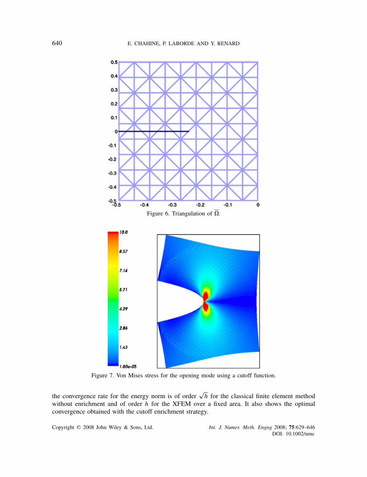
and is identical to a fifth degree polynomial if r0�r�r1. Note that by decreasing the differencebetween r0 and r1, the stiffness of increases and then the interpolation error is higher because ofthe presence of ‖u−us‖2+�,� in the estimate of Theorem 4.1. Finally, the finite element methodis the one defined in Section 3 over a structured triangulation of � (see Figure 6 for an exampleof a structured mesh of �). Note that the numerical tests are achieved using GETFEM++, anobject-oriented C++ finite element library (see [34]).
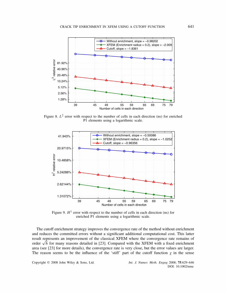
Figure 7 shows the von Mises stress over the opening mode deformed mesh of the modelproblem. As expected, the von Mises stress is concentrated at the crack tip (at the singularity).Figures 8 and 9 show a comparison between the convergence rates of the classical finite elementmethod without enrichment, the XFEM with a fixed enrichment area independent of the parameterh and the cutoff enrichment strategy for the L2- and the H1-norms. These errors are obtainedby running the test problem for some values of the parameter ns, where ns is the number ofsubdivisions (number of cells) in each direction (h=1/ns). The rate of convergence for the L2-normis better than the one for the H1-norm, which is quite usual. However, the Aubin–Nitsche lemmacannot be directly applied here due to the weak regularity of the solution. Figure 9 confirms that
Copyright q 2008 John Wiley & Sons, Ltd. Int. J. Numer. Meth. Engng 2008; 75:629–646DOI: 10.1002/nme
640 E. CHAHINE, P. LABORDE AND Y. RENARD
Figure 6. Triangulation of �.
Figure 7. Von Mises stress for the opening mode using a cutoff function.
the convergence rate for the energy norm is of order√h for the classical finite element method
without enrichment and of order h for the XFEM over a fixed area. It also shows the optimalconvergence obtained with the cutoff enrichment strategy.
Copyright q 2008 John Wiley & Sons, Ltd. Int. J. Numer. Meth. Engng 2008; 75:629–646DOI: 10.1002/nme
CRACK TIP ENRICHMENT IN XFEM USING A CUTOFF FUNCTION 641
39 45 49 55 59 65 69 75 79
1.28%
2.56%
5.12%
10.24%
20.48%
40.96%
81.92%
Number of cells in each direction
L2 rel
ativ
e er
ror
Figure 8. L2 error with respect to the number of cells in each direction (ns) for enrichedP1 elements using a logarithmic scale.
39 45 49 55 59 65 69 75 79
1.31072%
2.62144%
5.24288%
10.4858%
20.9715%
41.943%
Number of cells in each direction
H1 r
elat
ive
erro
r
Figure 9. H1 error with respect to the number of cells in each direction (ns) forenriched P1 elements using a logarithmic scale.
The cutoff enrichment strategy improves the convergence rate of the method without enrichmentand reduces the committed errors without a significant additional computational cost. This latterresult represents an improvement of the classical XFEM where the convergence rate remains oforder
√h for many reasons detailed in [23]. Compared with the XFEM with a fixed enrichment
area (see [23] for more details), the convergence rate is very close, but the error values are larger.The reason seems to be the influence of the ‘stiff’ part of the cutoff function in the sense
Copyright q 2008 John Wiley & Sons, Ltd. Int. J. Numer. Meth. Engng 2008; 75:629–646DOI: 10.1002/nme
642 E. CHAHINE, P. LABORDE AND Y. RENARD
Table I. Number of degrees of freedom.
Number of cells XFEMin each direction Classical FEM (enrichment radius=0.2) Cutoff enrichment
40 3402 4962 341060 7502 11014 751080 13202 19578 13210
40 46 50 56 60 66 70 76 80
2.62144%
5.24288%
10.4858%
20.9715%
Number of cells in each direction
H1 r
elat
ive
erro
r
Cutoff comparison
Cutoff r1=0.01,r
0
Cutoff r1=0.05,r
0
Cutoff r1=0.15,r
0
Cutoff r1=0.01,r
0
Cutoff r1=0.1,r
0
Figure 10. Cutoff comparison using a logarithmic scale.
that its H2(�)-norm influences the error estimate bound given by Theorem 4.1. On the otherhand, the cutoff enrichment reduces significantly the computational cost of the XFEM with afixed enrichment area where every degree of freedom over this area is enriched by the singulardisplacement. This latter enrichment leads to a significant increase in the number of degrees offreedom method, but it eliminates the inconvenience of the classical XFEM where the support ofthe crack tip enrichment functions vanishes when h goes to 0. Table I shows a comparison betweenthe number of the degrees of freedom for different refinements of the classical method, the XFEMwith a fixed enrichment area and the cutoff method.
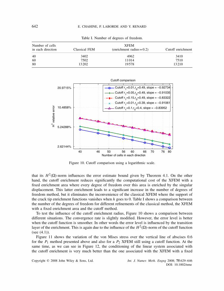
To test the influence of the cutoff enrichment radius, Figure 10 shows a comparison betweendifferent situations. The convergence rate is slightly modified. However, the error level is betterwhen the cutoff function is smoother. In other words the error level is influenced by the transitionlayer of the enrichment. This is again due to the influence of the H2(�)-norm of the cutoff function(see (4.1)).
Figure 11 shows the variation of the von Mises stress over the vertical line of abscises 0.6for the P1 method presented above and also for a P2 XFEM still using a cutoff function. At thesame time, as we can see in Figure 12, the conditioning of the linear system associated withthe cutoff enrichment is very much better than the one associated with the XFEM with a fixed
Copyright q 2008 John Wiley & Sons, Ltd. Int. J. Numer. Meth. Engng 2008; 75:629–646DOI: 10.1002/nme

CRACK TIP ENRICHMENT IN XFEM USING A CUTOFF FUNCTION 643
0 500 1000 1500 20000
0.5
1
1.5
2
2.5
3Von Mises P1 CutoffVon Mises ExactVon Mises P2 Cutoff
Figure 11. Von Mises on the vertical 0.6.
39 45 49 55 59 65 69 75 791e2 1e3 1e4 1e5 1e6 1e7 1e8 1e9 1e101e111e121e131e141e15
Number of cells in each direction
Con
ditio
ning
XFEM (Enrichment radius = 0.2), slope = 6.3736Cutoff, slope = 3.2005
Figure 12. Condition number of the linear system with respect to the number of cells in eachdirection (ns) using a logarithmic scale.
enrichment area. This is in particular due to the non-unisolvence of the XFEM classical enrichment(see [23]).
To explore the capabilities of the proposed variant, we consider a more sophisticated problem.In the following test, the exact solution is a combination of a regular solution to the elasticityproblem, the mode I and the mode II analytical solutions and a higher-order mode (for the
Copyright q 2008 John Wiley & Sons, Ltd. Int. J. Numer. Meth. Engng 2008; 75:629–646DOI: 10.1002/nme

644 E. CHAHINE, P. LABORDE AND Y. RENARD
Figure 13. Von Mises stress for a mixed mode using a cutoff function with P2 elements.
39 45 49 55 59 65 69 75 791.31072%
2.62144%
5.24288%
10.4858%
20.9715%
41.943%
Number of cells in each direction
H1 r
elat
ive
erro
r
Figure 14. H1 error with respect to the number of cells in each direction (ns) for a mixed mode andenriched P1 elements using a logarithmic scale.
deformed configuration, see Figure 13). The von Mises stress for this test is presented in Figure 13.Figure 14 shows a comparison of the convergence curves of the non-enriched classical method,the XFEM and the cutoff strategy. The optimal rate is preserved for the cutoff enrichment.
Copyright q 2008 John Wiley & Sons, Ltd. Int. J. Numer. Meth. Engng 2008; 75:629–646DOI: 10.1002/nme
CRACK TIP ENRICHMENT IN XFEM USING A CUTOFF FUNCTION 645
6. CONCLUDING REMARKS
The originality of this study consists mainly in the mathematical analysis of the transition betweenthe crack tip singular enrichment and the discontinuous Heaviside enrichment. Concerning theXFEM with a fixed enrichment area, the mathematical analysis remains an open problem. However,the result presented here reinforces the confidence on the reliability of the XFEMs. The presentedcutoff strategy is limited to the 2D case. An adaptation to 3D problem is not straightforward andwould require the use of a system of coordinates along the crack front. However, it is an appropriatemethod for 2D problems such as cracked plate problems.
ACKNOWLEDGEMENTS
The authors would like to thank the anonymous referees for their helpful suggestions, which permitted toimprove the clarity and the legibility of the paper. Many thanks also to Julien Pommier for his supportobtaining the numerical results.
REFERENCES
1. Strang G, Fix G. An Analysis of the Finite Element Method. Prentice-Hall: Englewood Cliffs, NJ, 1973.2. Melenk JM, Babuska I. The partition of unity finite element method: basic theory and applications. Computer
Methods in Applied Mechanics and Engineering 1996; 139:289–314.3. Ben Dhia H. Multiscale mechanical problems: the Arlequin method. Comptes Rendus de l’Acadmie des Sciences,
Paris 1998; 326:899–904.4. Strouboulis T, Babuska I, Copps K. The design and analysis of the generalized finite element method. Computer
Methods in Applied Mechanics and Engineering 2000; 181:43–69.5. Strouboulis T, Babuska I, Copps K. The generalized finite element method: an example of its implementation and
illustration of its performance. International Journal for Numerical Methods in Engineering 2000; 47:1401–1417.6. Glowinski R, He J, Rappaz J, Wagner J. Approximation of multi-scale elliptic problems using patches of elements.
Comptes Rendus de l’Acadmie des Sciences, Paris 2003; 337:679–684.7. Moes N, Dolbow J, Belytschko T. A finite element method for crack growth without remeshing. International
Journal for Numerical Methods in Engineering 1999; 46:131–150.8. Moes T, Belytschko N. X-FEM: Nouvelles Frontieres Pour les Elements Finis. Revue europeenne des elements
finis (Calcul des structures GIENS’01) 2002; 11:305–318.9. Bordas S, Nguyen VP, Dunant C, Nguyen-Dang H, Guidoum A. An extended finite element library. International
Journal for Numerical Methods in Engineering 2007; 71(6):703–732.10. Wyart E, Coulon D, Martiny P, Pardoen T. Remacle J-F, Lani F. A substructured FE/XFE method for stress-
intensity factors computation in an industrial structure. Eur. J. Comput. Mech. 2007; 16:199–212.11. Wyart E, Duflot M, Coulon D, Martiny P, Pardoen T, Remacle J-F, Lani F. Substructuring FE-XFE approaches
applied to three-dimensional crack propagation. Journal of Computational and Applied Mathematics 2007;DOI: 10.1016/j.physletb.2003.10.071.
12. Bordas S, Moran B. Enriched finite elements and level sets for damage tolerance assessment of complex structures.Engineering Fracture Mechanics 2006; 73:1176–1201.
13. Bordas S, Conley JGC, Moran B, Gray J, Nichols E. A simulation-based design paradigm for complex castcomponents. Engineering with Computers 2007; 23(1):25–37.
14. Ventura G. On the elimination of quadrature subcells for discontinuous functions in the eXtended Finite-ElementMethod. International Journal for Numerical Methods in Engineering 2006; 66:761–795.
15. Xiao QZ, Karihaloo BL. Improving the accuracy of XFEM crack tip fields using higher order quadratureand statically admissible stress recovery. International Journal for Numerical Methods in Engineering 2006;66:1378–1410.
16. Sukumar N, Moes N, Moran B. Belytschko T. Extended finite element method for three dimensional crackmodelling. International Journal for Numerical Methods in Engineering 2000; 48:1549–1570.
Copyright q 2008 John Wiley & Sons, Ltd. Int. J. Numer. Meth. Engng 2008; 75:629–646DOI: 10.1002/nme

646 E. CHAHINE, P. LABORDE AND Y. RENARD
17. Moes N, Gravouil A, Belytschko T. Non-planar 3D crack growth by the extended finite element and level sets,Part I: mechanical model. International Journal for Numerical Methods in Engineering 2002; 53(11):2549–2568.
18. Gravouil A, Moes N, Belytschko T. Non-planar 3D crack growth by the extended finite element and level sets,Part II: level set update. International Journal for Numerical Methods in Engineering 2002; 53(11):2569–2586.
19. Areias PMA, Belytschko T. Analysis of three-dimensional crack initiation and propagation using the extendedfinite element method. International Journal for Numerical Methods in Engineering 2005; 63:760–788.
20. Gasser TC, Holzapfel GA. Modeling 3D crack propagation in unreinforced concrete using PUFEM. ComputerMethods in Applied Mechanics and Engineering 2005; 194:2859–2896.
21. Gasser TC, Holzapfel GA. 3D crack propagation in unreinforced concrete: a two-step algorithm for tracking 3Dcrack paths. Computer Methods in Applied Mechanics and Engineering 2006; 195:5198–5219.
22. Wyart E, Coulon D, Duflot M, Pardoen T, Remacle J-F, Lani F. A substructured FE-shell/XFE 3D methodfor crack analysis in thin walled structures. International Journal for Numerical Methods in Engineering 2007;72:757–779.
23. Laborde P, Renard Y, Pommier J, Salaun M. High order extended finite element method for cracked domains.International Journal for Numerical Methods in Engineering 2005; 64:354–381.
24. Bechet E, Minnebo H, Moes N. Burgardt B. Improved implementation and robustness study of the X-FEM forstress analysis around cracks. International Journal for Numerical Methods in Engineering 2005; 64:1033–1056.
25. Chahine E, Laborde P, Renard Y. A quasi-optimal convergence result for fracture mechanics with XFEM. ComptesRendus de l’Acadmie des Sciences, Paris 2006; 342:527–532.
26. Grisvard P. Singularities in Boundary Value Problems. Masson: Paris, 1992.27. Grisvard P. Problemes aux limites dans les polygones—mode d’emploi. EDF Bulletin de la Direction des Etudes
et Recherches Serie C Mathematiques Informatique No 1 1986; MR 87g:35073:21–59.28. Adams RA. Sobolev Spaces. Academic Press: New York, 1975.29. Lemaitre J, Chaboche J-L. Mechanics of Solid Materials. Cambridge University Press: Cambridge, 1994.30. Leblond JB. Mecanique de la Rupture Fragile et Ductile. Hermes: Lavoisier, 2003.31. Ciarlet PG. The Finite Element Method For Elliptic Problems. North-Holland: Amsterdam, 1979.32. Hansbo A, Hansbo P. A finite element method for the simulation of strong and weak discontinuities in solid
mechanics. Computer Methods in Applied Mechanics and Engineering 2004; 193:3523–3540.33. Ern A, Guermond JL. Elements finis: theorie, applications, mise en œuvre. Springer: Berlin, 2001.34. Renard Y, Pommier J. An open source generic C++ library for finite element methods. http://home.gna.org/getfem.
Copyright q 2008 John Wiley & Sons, Ltd. Int. J. Numer. Meth. Engng 2008; 75:629–646DOI: 10.1002/nme
Related Documents