Crack resistance curves determination of tube cladding material J. Bertsch * , W. Hoffelner Paul Scherrer Institut, CH-5232 Villigen PSI, Switzerland Abstract Zirconium based alloys have been in use as fuel cladding material in light water reactors since many years. As claddings change their mechanical properties during service, it is essential for the assessment of mechanical integrity to provide parameters for potential rupture behaviour. Usually, fracture mechanics parameters like the fracture toughness K IC or, for high plastic strains, the J-integral based elastic–plastic fracture toughness J IC are employed. In claddings with a very small wall thickness the determination of toughness needs the extension of the J-concept beyond limits of standards. In the paper a new method based on the traditional J approach is presented. Crack resistance curves (J–R curves) were created for unirradiated thin walled Zircaloy-4 and aluminium cladding tube pieces at room temperature using the single sample method. The procedure of creating sharp fatigue starter cracks with respect to optical recording was optimized. It is shown that the chosen test method is appropriate for the determination of complete J–R curves including the values J 0.2 (J at 0.2 mm crack length), J m (J corresponding to the maximum load) and the slope of the curve. Ó 2006 Elsevier B.V. All rights reserved. PACS: 62.20.Mk; 81.40.Lm; 81.40.Np; 81.70.Bt 1. Introduction A manufactured component is, a-priori, expected to be defect-free. But in practice any material of a component may contain flaws or flaws can be created during special operational conditions. The question is whether such a flaw can expand into a crack and whether this crack is going to propagate. Especially for Zircaloy components in a nuclear environment eventually the question of safe opera- tion or handling of the component arises. For normal operational conditions in a nuclear power plant axial split of Zircaloy cladding tubes or the behaviour of cracks in other thin walled compo- nents as spacers/grids may be a concern. For the period after service, during transportation (vibra- tions, shocks), intermediate dry storage (delayed hydride cracking, stress corrosion cracking) or final storage [1] fracture toughness properties of fuel cladding can become relevant. The use of fracture mechanics technology for reactor Zircaloy issues has been limited in the past. This is partly due to a lack of regulatory emphasis on cladding failure as a safety issue [2] and to the fact that much of the standard fracture mechanics methodology does not apply to standard light water reactor (LWR) bundle component geometries. The use of fracture mechanics to predict the behaviour of cracks or defects is increasing. Papers at recent international conferences have illustrated fracture 0022-3115/$ - see front matter Ó 2006 Elsevier B.V. All rights reserved. doi:10.1016/j.jnucmat.2006.02.045 * Corresponding author. Tel.: +41 56 310 4173; fax: +41 56 310 2203. E-mail address: [email protected] (J. Bertsch). Journal of Nuclear Materials 352 (2006) 116–125 www.elsevier.com/locate/jnucmat

Welcome message from author
This document is posted to help you gain knowledge. Please leave a comment to let me know what you think about it! Share it to your friends and learn new things together.
Transcript
Journal of Nuclear Materials 352 (2006) 116–125
www.elsevier.com/locate/jnucmat
Crack resistance curves determination of tube cladding material
J. Bertsch *, W. Hoffelner
Paul Scherrer Institut, CH-5232 Villigen PSI, Switzerland
Abstract
Zirconium based alloys have been in use as fuel cladding material in light water reactors since many years. As claddingschange their mechanical properties during service, it is essential for the assessment of mechanical integrity to provideparameters for potential rupture behaviour. Usually, fracture mechanics parameters like the fracture toughness KIC or,for high plastic strains, the J-integral based elastic–plastic fracture toughness JIC are employed. In claddings with a verysmall wall thickness the determination of toughness needs the extension of the J-concept beyond limits of standards. In thepaper a new method based on the traditional J approach is presented. Crack resistance curves (J–R curves) were createdfor unirradiated thin walled Zircaloy-4 and aluminium cladding tube pieces at room temperature using the single samplemethod. The procedure of creating sharp fatigue starter cracks with respect to optical recording was optimized. It is shownthat the chosen test method is appropriate for the determination of complete J–R curves including the values J0.2 (J at0.2 mm crack length), Jm (J corresponding to the maximum load) and the slope of the curve.� 2006 Elsevier B.V. All rights reserved.
PACS: 62.20.Mk; 81.40.Lm; 81.40.Np; 81.70.Bt
1. Introduction
A manufactured component is, a-priori, expectedto be defect-free. But in practice any material of acomponent may contain flaws or flaws can becreated during special operational conditions. Thequestion is whether such a flaw can expand into acrack and whether this crack is going to propagate.Especially for Zircaloy components in a nuclearenvironment eventually the question of safe opera-tion or handling of the component arises. Fornormal operational conditions in a nuclear powerplant axial split of Zircaloy cladding tubes or the
0022-3115/$ - see front matter � 2006 Elsevier B.V. All rights reserved
doi:10.1016/j.jnucmat.2006.02.045
* Corresponding author. Tel.: +41 56 310 4173; fax: +41 56 3102203.
E-mail address: [email protected] (J. Bertsch).
behaviour of cracks in other thin walled compo-nents as spacers/grids may be a concern. For theperiod after service, during transportation (vibra-tions, shocks), intermediate dry storage (delayedhydride cracking, stress corrosion cracking) or finalstorage [1] fracture toughness properties of fuelcladding can become relevant.
The use of fracture mechanics technology forreactor Zircaloy issues has been limited in the past.This is partly due to a lack of regulatory emphasison cladding failure as a safety issue [2] and to thefact that much of the standard fracture mechanicsmethodology does not apply to standard light waterreactor (LWR) bundle component geometries. Theuse of fracture mechanics to predict the behaviourof cracks or defects is increasing. Papers at recentinternational conferences have illustrated fracture
.
J. Bertsch, W. Hoffelner / Journal of Nuclear Materials 352 (2006) 116–125 117
mechanics techniques for analysing crack propaga-tion in failed Zircaloy tubing [3–5]. And for manyyears, leak-before-break criteria and critical cracklengths in CANDU-type reactor (CANada Deute-rium Uranium) pressure tubes have been analysedusing fracture toughness methodology [6].
The strict methodology of LEFM usually doesnot apply to geometries (particularly thicknesses)of interest to reactor components. The plastic zonesizes of zirconium alloys are too large. For example:In order to satisfy the criteria of ASTM StandardE399 [7] for valid fracture toughness KIC determina-tion for a only roughly expected KIC = 55 MPa m1/2
and a yield stress of 600 MPa for irradiated Zircaloyat 573 K, the thickness of the tested samples mustexceed a value of about 21 mm. This is many timesthe thickness of cladding, grid, channel, etc., com-ponents. For unirradiated Zircaloy the requiredthickness would be even larger.
To accommodate soft material the J-integral isfrequently applied. As commonly used, ‘J’ is relatedto the amount of work (dissipative energy, bothelastic and plastic) per unit crack surface arearequired to extend a crack. But, it is strictly validonly in the case where the crack grows in an elasticmaterial. Its use, however, has been extended [8,9]to include elastic–plastic materials like Zircaloy orfor small radioactive samples of nuclear applicationrelevant steels [10]. But even the less stringent sizerequirements for the applicability of the J-integralare not met theoretically by thin walled claddings.This work attempts to find a J-type approach todefine mechanical quantities of claddings whichallow a prediction of the fracture behaviour of clad-ding material with different toughness. In analogy tothe conventional fracture mechanics approach suchquantities should be as far as possible independentfrom specimen geometry to allow their applicationto components and realistic crack geometries.
2. Experimental
2.1. Material
The experiments were carried out with samplesfabricated from the aluminium alloy Al-7050 andcold-worked stress relieved (SRA) Zircaloy-4. Cold-worked SRA Zircaloy was selected because it showsa lower tendency to very early crack blunting com-pared to re-crystallized Zircaloy. The aluminiumalloy which exhibits significant lower fracture tough-ness was chosen because of comparison reasons.
2.2. Sample geometry
Our approach was based on the followingcriteria:
• In order to have a well defined starting point wehave chosen a specimen geometry, which basis iswell characterized under valid stress intensity fac-tor K and J conditions.
• With respect to later testing of service exposedcladding material the geometry should also alloweasy manipulator handling.
• All parameters reported for established K and J
testing should be measurable.
Fracture mechanics samples can be of bendingtype or of tension type. Typical bending type sam-ples are the compact tension (CT) specimen andthe single edge notched (SEN) bending sample[11]. Well known tension type samples are the singleor double edge notched tension (SENT, DENT)samples or the centre notched panel (CN). Becauseof our approach criteria, basically a pipe type tensileversion was chosen.
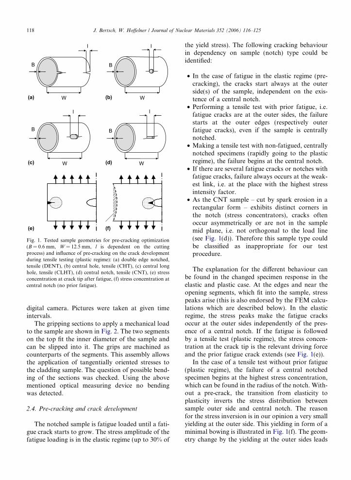
Fig. 1 shows the tested different notched samplesand the influence of their geometries and pre-crack-ing on the failure behaviour. To use an optimal sam-ple form for generating well defined starter cracks byfatigue and to have a situation as close as possible toa potential real crack in a cladding tube, various tubesample geometries and the geometries’ influence onthe pre-cracking procedure were tested. The wallthickness of the samples B is 0.6 mm, the width W
is 12.5 mm and the notch length l is dependent onthe cutting process. The two edge notches on thefront side of the DENT-like ring sample are cut witha wire saw, the holes of the samples which we desig-nate CHT (central hole tension) and CLHT (centrallong hole tension) are drilled and the notch of theCNT (central notch tension) sample is cut by sparkerosion. All hole and notch types are situated atthe sample front side. The notch lengths and sizesrespectively are about 0.8–1.0 mm (DENT), 1.1 mmin diameter (CHT), 1.2 mm · 3.2 mm (CLHT) and0.4 mm · 1.8 mm (CNT).
2.3. Experimental equipment
The samples were tested on an electro-mechani-cal Schenck testing machine at room temperaturein air. We used the ‘one sample method’. Cracklengths and strain were recorded optically with a
B
l
W
B
W
l
(a) (b)
B
W
l
B
W
l
(c) (d)
(e) (f)
Fig. 1. Tested sample geometries for pre-cracking optimization(B = 0.6 mm, W = 12.5 mm, l is dependent on the cuttingprocess) and influence of pre-cracking on the crack developmentduring tensile testing (plastic regime): (a) double edge notched,tensile (DENT), (b) central hole, tensile (CHT), (c) central longhole, tensile (CLHT), (d) central notch, tensile (CNT), (e) stressconcentration at crack tip after fatigue, (f) stress concentration atcentral notch (no prior fatigue).
118 J. Bertsch, W. Hoffelner / Journal of Nuclear Materials 352 (2006) 116–125
digital camera. Pictures were taken at given timeintervals.
The gripping sections to apply a mechanical loadto the sample are shown in Fig. 2. The two segmentson the top fit the inner diameter of the sample andcan be slipped into it. The grips are machined ascounterparts of the segments. This assembly allowsthe application of tangentially oriented stresses tothe cladding sample. The question of possible bend-ing of the sections was checked. Using the abovementioned optical measuring device no bendingwas detected.
2.4. Pre-cracking and crack development
The notched sample is fatigue loaded until a fati-gue crack starts to grow. The stress amplitude of thefatigue loading is in the elastic regime (up to 30% of
the yield stress). The following cracking behaviourin dependency on sample (notch) type could beidentified:
• In the case of fatigue in the elastic regime (pre-cracking), the cracks start always at the outerside(s) of the sample, independent on the exis-tence of a central notch.
• Performing a tensile test with prior fatigue, i.e.fatigue cracks are at the outer sides, the failurestarts at the outer edges (respectively outerfatigue cracks), even if the sample is centrallynotched.
• Making a tensile test with non-fatigued, centrallynotched specimens (rapidly going to the plasticregime), the failure begins at the central notch.
• If there are several fatigue cracks or notches withfatigue cracks, failure always occurs at the weak-est link, i.e. at the place with the highest stressintensity factor.
• As the CNT sample – cut by spark erosion in arectangular form – exhibits distinct corners inthe notch (stress concentrators), cracks oftenoccur asymmetrically or are not in the samplemid plane, i.e. not orthogonal to the load line(see Fig. 1(d)). Therefore this sample type couldbe classified as inappropriate for our testprocedure.
The explanation for the different behaviour canbe found in the changed specimen response in theelastic and plastic case. At the edges and near theopening segments, which fit into the sample, stresspeaks arise (this is also endorsed by the FEM calcu-lations which are described below). In the elasticregime, the stress peaks make the fatigue cracksoccur at the outer sides independently of the pres-ence of a central notch. If the fatigue is followedby a tensile test (plastic regime), the stress concen-tration at the crack tip is the relevant driving forceand the prior fatigue crack extends (see Fig. 1(e)).
In the case of a tensile test without prior fatigue(plastic regime), the failure of a central notchedspecimen begins at the highest stress concentration,which can be found in the radius of the notch. With-out a pre-crack, the transition from elasticity toplasticity inverts the stress distribution betweensample outer side and central notch. The reasonfor the stress inversion is in our opinion a very smallyielding at the outer side. This yielding in form of aminimal bowing is illustrated in Fig. 1(f). The geom-etry change by the yielding at the outer sides leads
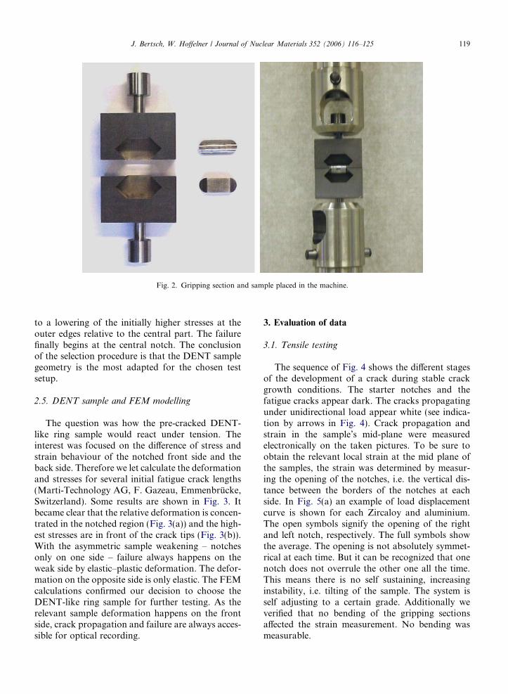
Fig. 2. Gripping section and sample placed in the machine.
J. Bertsch, W. Hoffelner / Journal of Nuclear Materials 352 (2006) 116–125 119
to a lowering of the initially higher stresses at theouter edges relative to the central part. The failurefinally begins at the central notch. The conclusionof the selection procedure is that the DENT samplegeometry is the most adapted for the chosen testsetup.
2.5. DENT sample and FEM modelling
The question was how the pre-cracked DENT-like ring sample would react under tension. Theinterest was focused on the difference of stress andstrain behaviour of the notched front side and theback side. Therefore we let calculate the deformationand stresses for several initial fatigue crack lengths(Marti-Technology AG, F. Gazeau, Emmenbrucke,Switzerland). Some results are shown in Fig. 3. Itbecame clear that the relative deformation is concen-trated in the notched region (Fig. 3(a)) and the high-est stresses are in front of the crack tips (Fig. 3(b)).With the asymmetric sample weakening – notchesonly on one side – failure always happens on theweak side by elastic–plastic deformation. The defor-mation on the opposite side is only elastic. The FEMcalculations confirmed our decision to choose theDENT-like ring sample for further testing. As therelevant sample deformation happens on the frontside, crack propagation and failure are always acces-sible for optical recording.
3. Evaluation of data
3.1. Tensile testing
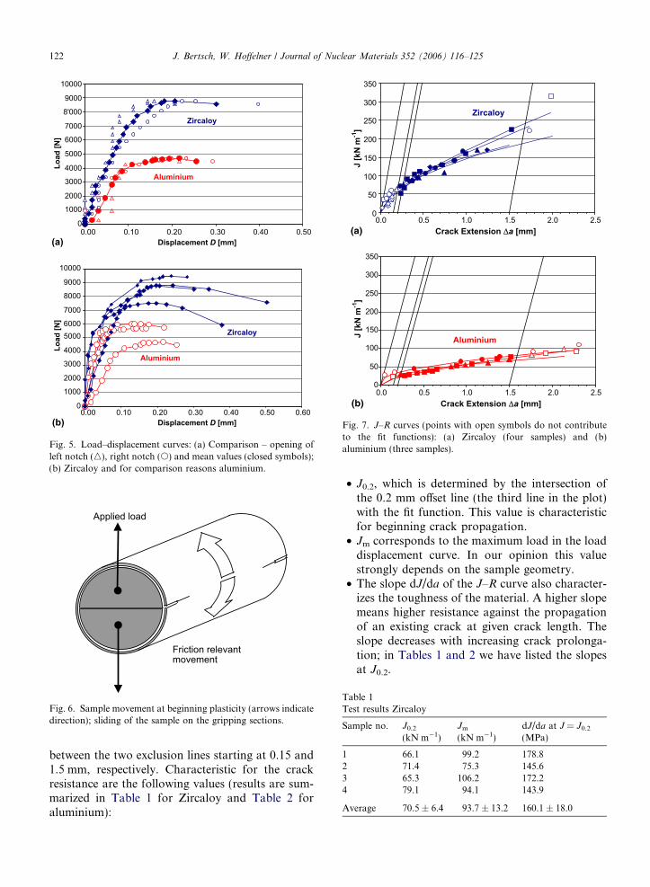
The sequence of Fig. 4 shows the different stagesof the development of a crack during stable crackgrowth conditions. The starter notches and thefatigue cracks appear dark. The cracks propagatingunder unidirectional load appear white (see indica-tion by arrows in Fig. 4). Crack propagation andstrain in the sample’s mid-plane were measuredelectronically on the taken pictures. To be sure toobtain the relevant local strain at the mid plane ofthe samples, the strain was determined by measur-ing the opening of the notches, i.e. the vertical dis-tance between the borders of the notches at eachside. In Fig. 5(a) an example of load displacementcurve is shown for each Zircaloy and aluminium.The open symbols signify the opening of the rightand left notch, respectively. The full symbols showthe average. The opening is not absolutely symmet-rical at each time. But it can be recognized that onenotch does not overrule the other one all the time.This means there is no self sustaining, increasinginstability, i.e. tilting of the sample. The system isself adjusting to a certain grade. Additionally weverified that no bending of the gripping sectionsaffected the strain measurement. No bending wasmeasurable.
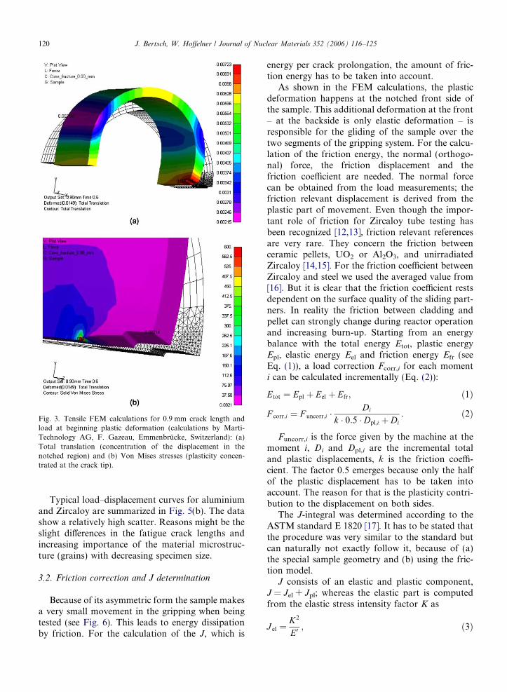
Fig. 3. Tensile FEM calculations for 0.9 mm crack length andload at beginning plastic deformation (calculations by Marti-Technology AG, F. Gazeau, Emmenbrucke, Switzerland): (a)Total translation (concentration of the displacement in thenotched region) and (b) Von Mises stresses (plasticity concen-trated at the crack tip).
120 J. Bertsch, W. Hoffelner / Journal of Nuclear Materials 352 (2006) 116–125
Typical load–displacement curves for aluminiumand Zircaloy are summarized in Fig. 5(b). The datashow a relatively high scatter. Reasons might be theslight differences in the fatigue crack lengths andincreasing importance of the material microstruc-ture (grains) with decreasing specimen size.
3.2. Friction correction and J determination
Because of its asymmetric form the sample makesa very small movement in the gripping when beingtested (see Fig. 6). This leads to energy dissipationby friction. For the calculation of the J, which is
energy per crack prolongation, the amount of fric-tion energy has to be taken into account.
As shown in the FEM calculations, the plasticdeformation happens at the notched front side ofthe sample. This additional deformation at the front– at the backside is only elastic deformation – isresponsible for the gliding of the sample over thetwo segments of the gripping system. For the calcu-lation of the friction energy, the normal (orthogo-nal) force, the friction displacement and thefriction coefficient are needed. The normal forcecan be obtained from the load measurements; thefriction relevant displacement is derived from theplastic part of movement. Even though the impor-tant role of friction for Zircaloy tube testing hasbeen recognized [12,13], friction relevant referencesare very rare. They concern the friction betweenceramic pellets, UO2 or Al2O3, and unirradiatedZircaloy [14,15]. For the friction coefficient betweenZircaloy and steel we used the averaged value from[16]. But it is clear that the friction coefficient restsdependent on the surface quality of the sliding part-ners. In reality the friction between cladding andpellet can strongly change during reactor operationand increasing burn-up. Starting from an energybalance with the total energy Etot, plastic energyEpl, elastic energy Eel and friction energy Efr (seeEq. (1)), a load correction Fcorr,i for each momenti can be calculated incrementally (Eq. (2)):
Etot ¼ Epl þ Eel þ Efr; ð1Þ
F corr;i ¼ F uncorr;i �Di
k � 0:5 � Dpl;i þ Di. ð2Þ
Funcorr,i is the force given by the machine at themoment i, Di and Dpl,i are the incremental totaland plastic displacements, k is the friction coeffi-cient. The factor 0.5 emerges because only the halfof the plastic displacement has to be taken intoaccount. The reason for that is the plasticity contri-bution to the displacement on both sides.
The J-integral was determined according to theASTM standard E 1820 [17]. It has to be stated thatthe procedure was very similar to the standard butcan naturally not exactly follow it, because of (a)the special sample geometry and (b) using the fric-tion model.
J consists of an elastic and plastic component,J = Jel + Jpl; whereas the elastic part is computedfrom the elastic stress intensity factor K as
J el ¼K2
E0; ð3Þ
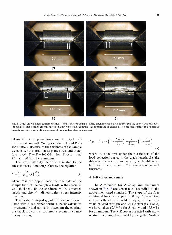
Fig. 4. Crack growth under tensile conditions: (a) just before starting of stable crack growth, only fatigue cracks are visible (white arrows),(b) just after stable crack growth started (mainly white crack contrast), (c) appearance of cracks just before final rupture (black arrowsindicate growing crack), (d) appearance of the cladding after final rupture.
J. Bertsch, W. Hoffelner / Journal of Nuclear Materials 352 (2006) 116–125 121
where E 0 = E for plane stress and E 0 = E/(1 � m2)for plane strain with Young’s modulus E and Pois-son’s ratio m. Because of the thickness of the samplewe consider the situation as plane stress and there-fore used E 0 = E = 100 GPa for Zircaloy andE 0 = E = 70 GPa for aluminium.
The stress intensity factor K is related to thestress intensity function f(a/W) by the equation
K ¼ PB�ffiffiffiffiffi2
W
r� f a
W
� �; ð4Þ
where P is the applied load for one side of thesample (half of the complete load), B the specimenwall thickness, W the specimen width, a = cracklength and f(a/W) = dimensionless stress intensityfunction.
The plastic J-integral Jpl,i at the moment i is eval-uated with a recurrence formula, being calculatedincrementally and taking into account the continu-ous crack growth, i.e. continuous geometry changeduring loading
J pl;i ¼ J pl;i�1 � 1� Dai�1
bi�1
� �þ Ai
Bbi�1
� 1� Dai
bi�1
� �
ð5Þwhere Ai is the area under the plastic part of theload deflection curve, ai the crack length, Dai thedifference between ai and ai�1, bi is the differencebetween W and ai and B is the specimen wallthickness.
4. J–R curves and results
The J–R curves for Zircaloy and aluminiumshown in Fig. 7 are constructed according to theabove mentioned standard. The slope of the fouradditional lines in the plot is M Æ ry. M is set twoand ry is the effective yield strength, i.e. the meanvalue of yield strength and tensile strength. For ry
we have taken 625 MPa for Zircaloy and 475 MPafor aluminium. The J–R curves are fitted with expo-nential functions, determined by using the J-values
0
1000
2000
3000
4000
5000
6000
7000
8'000
9000
10000
0.00 0.10 0.20 0.30 0.40 0.50Displacement D [mm]
Load
[N]
Aluminium
Zircaloy
0.00 0.10 0.20 0.30 0.40 0.50 0.60Displacement D [mm]
Load
[N]
Aluminium
Zircaloy
0
1000
2000
3000
4000
50006000
7000
8000
9000
10000
(a)
(b)
Fig. 5. Load–displacement curves: (a) Comparison – opening ofleft notch (n), right notch (s) and mean values (closed symbols);(b) Zircaloy and for comparison reasons aluminium.
0
50
100
150
200
250
300
350
0.0 0.5 1.0 1.5 2.0 2.5Crack Extension Δa [mm]
J [k
N m
-1]
Zircaloy
0
50
100
150
200
250
300
350
0.0 0.5 1.0 1.5 2.0 2.5Crack Extension Δa [mm]
J [k
N m
-1]
Aluminium
(a)
(b)
Fig. 7. J–R curves (points with open symbols do not contributeto the fit functions): (a) Zircaloy (four samples) and (b)aluminium (three samples).
Applied load
Friction relevantmovement
Fig. 6. Sample movement at beginning plasticity (arrows indicatedirection); sliding of the sample on the gripping sections.
Table 1Test results Zircaloy
Sample no. J0.2
(kN m�1)Jm
(kN m�1)dJ/da at J = J0.2
(MPa)
1 66.1 99.2 178.82 71.4 75.3 145.63 65.3 106.2 172.24 79.1 94.1 143.9
Average 70.5 ± 6.4 93.7 ± 13.2 160.1 ± 18.0
122 J. Bertsch, W. Hoffelner / Journal of Nuclear Materials 352 (2006) 116–125
between the two exclusion lines starting at 0.15 and1.5 mm, respectively. Characteristic for the crackresistance are the following values (results are sum-marized in Table 1 for Zircaloy and Table 2 foraluminium):
• J0.2, which is determined by the intersection ofthe 0.2 mm offset line (the third line in the plot)with the fit function. This value is characteristicfor beginning crack propagation.
• Jm corresponds to the maximum load in the loaddisplacement curve. In our opinion this valuestrongly depends on the sample geometry.
• The slope dJ/da of the J–R curve also character-izes the toughness of the material. A higher slopemeans higher resistance against the propagationof an existing crack at given crack length. Theslope decreases with increasing crack prolonga-tion; in Tables 1 and 2 we have listed the slopesat J0.2.
0
20
40
60
80
100
120
J [k
N m
-1]
Grigoriev Bertolino Bertsch J0.2 Bertsch Jm
0
20
40
60
80
100
120
K [M
Pa m
1/2 ]
Huang Edsinger Bertsch K (J0.2) Bertsch K (Jm)
(a)
(b)
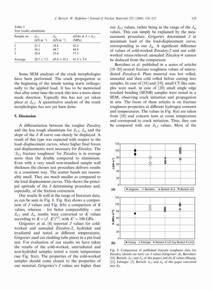
Fig. 8. Comparison of published fracture toughness data forZircaloy (details see text): (a) J values (Grigoriev: [4], Bertolino:[18], Bertsch: J0.2 and Jm of this paper) and (b) K values (Huang:[22], Edsinger: [3], Bertsch: J0.2 and Jm of this paper convertedinto K).
Table 2Test results aluminium
Sample no. J0.2
(kN m�1)Jm
(kN m�1)dJ/da at J = J0.2
(MPa)
1 21.1 34.8 62.22 36.1 44.7 64.93 28.8 55.4 57.3
Average 28.7 ± 7.5 45.0 ± 10.3 61.5 ± 3.9
J. Bertsch, W. Hoffelner / Journal of Nuclear Materials 352 (2006) 116–125 123
Some SEM analyses of the crack morphologieshave been performed. The crack propagation atthe beginning of the tensile testing starts orthogo-nally to the applied load. It has to be mentionedthat after some time the crack tilts into a more shearmode direction. Typically this has not yet takenplace at J0.2. A quantitative analysis of the crackmorphologies has not yet been done.
5. Discussion
A differentiation between the tougher Zircaloyand the less tough aluminium for J0.2, Jm and theslope of the J–R curve can clearly be displayed. Aresult of this type was expected with respect to theload–displacement curves, where higher final forcesand displacements were necessary for Zircaloy. The‘J0.2 fracture toughness’ for Zircaloy is in averagemore than the double compared to aluminium.Even with a very small non-standard sample wallthickness the chosen test procedure delivers resultsin a consistent way. The scatter bands are reason-ably small. They are much smaller as compared tothe load displacement curves. This shows the princi-pal aptitude of the J determining procedure and,especially, of the friction correction.
Our results fit well in the range of literature data,as can be seen in Fig. 8. Fig. 8(a) shows a compar-ison of J values and Fig. 8(b) a comparison of K
values, whereas – for better comparability – ourJ0.2 and Jm results were converted to K valuesaccording to K = (J Æ E 0)1/2, with E 0 = 100 GPa.
Grigoriev et al. [4] reported J values for cold-worked and annealed Zircaloy-2, hydrided andirradiated and tested at different temperatures.Grigoriev used cut cladding tube pieces in a pin loadtest. For evaluation of our results we have takenthe results of the cold-worked, unirradiated andnon-hydrided samples tested a room temperature(see Fig. 8(a)). The properties of the cold-workedsamples should come closest to the properties ofour material. Grigoriev’s J values are higher than
our J0.2 values, rather being in the range of the Jm
values. This can simply be explained by the mea-surement procedure. Grigoriev determined J atmaximum load of the load-displacement curve,corresponding to our Jm. A significant differenceof values of cold-worked Zircaloy-2 and our cold-worked stress-relieved annealed Zircaloy-4 cannotbe deduced from the comparison.
Bertolino et al. published in a series of articles[18–20] several fracture toughness values of unirra-diated Zircaloy-4. Plate material was hot rolled,annealed and then cold rolled before cutting intosamples. In case of [18] and [19], small CT like sam-ples were used, in case of [20] small single edgenotched bending (SENB) samples were tested in aSEM, observing crack initiation and propagationin situ. The focus of these articles is on fracturetoughness properties at different hydrogen contentsand temperatures. The values in Fig. 8(a) are takenfrom [18] and concern tests at room temperatureand correspond to crack initiation. Thus, they canbe compared with our J0.2 values. Most of the
124 J. Bertsch, W. Hoffelner / Journal of Nuclear Materials 352 (2006) 116–125
samples were hydrogen loaded. The highest J valuecoming from this paper and which is displayed inFig. 8(a) is around 80 kN m�1. It corresponds to avery low hydrogen content of approximately 30–40 ppm. The other displayed values belong to higherbut still low hydrogen contents of approximately100–120 ppm. In the mentioned paper, there is onedata point for none-hydrogen loaded samples witha very high value at above 300 kN m�1 (not shownin Fig. 8(a)). The data in [19] indicate similar char-acteristics. Material with a very low content of10 ppm H delivers a J0.2 value of approximately300 kN m�1, whereas a slightly higher H contentof already 50 ppm lets the J0.2 drop strongly downto approximately 100 kN m�1. The differencesbetween the curves for low (50 ppm H) and higherhydrogen contents are relatively small. The testingof the SENB samples in a SEM [20] reveals forlow H contents (approximately 30–50 ppm) J0.2 val-ues somewhat above 100 kN m�1. Because of veryfew non-hydrogen loaded values, in our opinionthe most reasonable comparison with Bertolino’sdata can be done by taking the low hydrogen loadedresults.
Dubey et al. [21] determined J–R curves for smallcurved CT specimen fabricated out of Zircaloy-2pressure tubes for Indian pressurized heavy waterreactors (PHWR); the results are not shown inFig. 8. The tube manufacturing steps compriseextrusion and two stage cold pilgerings with anintermediate annealing. The JIC value for theunirradiated material without hydrogen charging(10–15 ppm H) is high, i.e. 275 kN m�1. But alsothe slope of the J–R curve (dJ/da = 207 MPa) is sig-nificantly higher than our average slope at J0.2 (dJ/da = 160 MPa). The reasons for the higher valuesare not clear, but might be found in the tubesmanufacturing process and the curved samplegeometry.
Huang [22] determined the fracture toughness ofZircaloy-2 CT samples cut from reactor pressuretubes. Crack propagation was measured with thepotential drop method and crack initiation wasattributed to the first potential drop. The so deter-mined fracture toughness can be compared to ourJ0.2 respectively the corresponding K values. InFig. 8(b) the result for the unirradiated sampletested at room temperature is shown. The reasonfor Huang’s somewhat lower K value might be itsdetermination at the very first crack initiation(potential drop) whereas we used J0.2, i.e. whencrack propagation has already started.
Edsinger et al. [3] describe the so called VallecitosEmbedded Charpy (VEC) test. A half of a notchedand pre-cracked tube section is embedded in jacketsand then loaded like in a 3-point-bend fracturetoughness test. Edsinger used different reactor irra-diated material. For the comparison we have takenthe data of non-irradiated, cold-worked Zircaloy-2which was tested at room temperature (seeFig. 8(b)). The determined K values correspond tomaximum load, i.e. the values can be compared withour Jm results, being converted to K values.Edsinger’s results are quite well in line with ourdata, but slightly lower than our Jm values. Thismight be attributed to the stress-relieving annealingof our samples.
It can be summarized that the published data andour results match well, although different test meth-ods were used. Discrepancies can mostly beexplained by differences in the analysis procedureor materials properties. The applied new testmethod seems to deliver reasonable and comparabletest results. However it is clear that, due to the lim-itations of sample thickness, it is not possible toobtain a standard fracture toughness value that isa true material property.
6. Conclusions and outlook
A new fracture mechanics J-type approach forthe determination of fracture toughness of thinwalled claddings was developed, using a tensionloaded modified DENT-like ring sample. Themethod delivers whole crack resistance (J–R) curvesincluding the characteristic values J0.2 (J at startingcrack of 0.2 mm length), Jm (J corresponding tomaximum load in the load-displacement curve)and eventually the slope of the J–R curve. Itprovides a quantitative relationship between a flawof given size (fretting defect, production defect,hydride lens, etc.) and the tolerable loads and itcan therefore be linked with safety considerations.Future work will be aimed at improving andexpanding the method:
• Better understanding of the friction between thecladding and the test gripping sections. Frictionplays an important role for real cladding – espe-cially of high burn-up fuel – concerning energydeposition during failure. Friction can be investi-gated by using different surface finish or applica-tion of different lubrications between sample andgripping sections.
J. Bertsch, W. Hoffelner / Journal of Nuclear Materials 352 (2006) 116–125 125
• Applying the method to further thin walled Zir-caloy components to better elucidate the localelastic–plastic behaviour, additionally using finiteelement modelling.
• Application to higher, reactor relevant tempera-tures, other environments and other loading con-ditions (creep, fatigue, etc.).
• Another experimental challenge will be to applythis method to service exposed cladding materialsfrom nuclear power plants and to determinetoughness values of differently hydrided materialsand different burn-ups.
Acknowledgements
The authors wish to thank Mr Ph. Meyer forsupporting the mechanical testing, Mr RolandBruetsch for his help on SEM observations andPh. Spatig (CRPP, EPF Lausanne) for makingavailable the Schenck testing machine.
References
[1] K.S. Chan, Y. Lee, Nucl. Eng. Des. 201 (2000) 209.[2] U.S. Nuclear Regulatory Commission Standard Review
Plan, NUREG-0800, NRC, 2, July 1981.[3] K. Edsinger, J.H. Davies, R.B. Adamson, in: G.P. Sabol,
G.D. Moan (Eds.), Zirconium in the Nuclear Industry:Twelfth International Symposium, ASTM STP 1354, WestConshohocken, 2000, p. 316.
[4] V. Grigoriev, B. Josefsson, B. Rosborg, in: E.R. Bradley,G.P. Sabol (Eds.), Zirconium in the Nuclear Industry:Eleventh International Symposium, ASTM STP 1295,1996, p. 431.
[5] Y.R. Rashid, C. Lemaignan, A. Strasser, Evaluation ofFracture Initiation and Extension in Fuel Cladding, ANS
Int’l Topical Meeting LWR Fuel Performance, Park City,April 10–13, 2000.
[6] P.H. Davies, R.S.W. Shewfelt, in: G.P. Sabol, G.D. Moan(Eds.) Zirconium in the Nuclear Industry: Twelfth Interna-tional Symposium, ASTM STP 1354, West Conshohocken,2000, p. 356.
[7] ASTM E 399, Standard Test Method for Linear-ElasticPlane-Strain Fracture Toughness KIC of Metallic Materials,ASTM international.
[8] N.E. Dowling, Mechanical Behavior of Materials, seconded., Prentice-Hall, Inc, 1999, ISBN -0-13-905720-X.
[9] G.C. Sih, in: R.P. Wei, R.P. Gangloff (Eds.) FractureMechanics in Two Decades (20th Symposium), ASTM STP1020, Philadelphia, 1989, p. 9.
[10] K. Machida, M. Kikuchi, Int. J. Pres. Ves. Pip. 63 (1995) 9.[11] T.L. Anderson, Fracture Mechanics – Fundamentals and
Applications, second ed., CRC, 1994, ISBN 0-8493-4260-0.[12] R.S. Daum, S. Majumdar, H. Tsai, T. Bray, D.A. Koss, A.T.
Motta, M.C. Billone, in: M.A. Sokolov, J.D. Landes, G.E.Lucas (Eds.), Small Specimen Test Techniques: FourthVolume, ASTM STP 1418, West Conshohocken, 2002, p.195.
[13] S. Arsene, J. Bai, J. Test. Eval. 24 (1996) 386.[14] J.C. Wood, B.A. Surette, I. Aitchison, J. Nucl. Mater. 88
(1980) 81.[15] N. Nakatsuka, J. Nucl. Mater. 96 (1981) 205.[16] B.C. d’Agraives, J. Toornvliet, Application of a Non-
dynamometric Method to the Measurement of the Coeffi-cient of Static Friction in Cold and Hot Water BetweenStainless Steel and Two Alloys of zirconium, EUR 5604 f,JNRC Ispra, 1977.
[17] ASTM E 1820-01, Standard Test Method for Measurementof Fracture Toughness, ASTM international.
[18] G. Bertolino, G. Meyer, J.P. Ipina, J. Alloys Comp. 330–332(2002) 408.
[19] G. Bertolino, G. Meyer, J.P. Ipina, J. Nucl. Mater. 320(2003) 272.
[20] G. Bertolino, G. Meyer, J.P. Ipina, J. Nucl. Mater. 322(2003) 57.
[21] J.S. Dubey, S.L. Wadekar, R.N. Singh, T.K. Sinha, J.K.Chakravartty, J. Nucl. Mater. 264 (1999) 20.
[22] F.H. Huang, J. Nucl. Mater. 207 (1993) 103.
Related Documents