European Journal of Mechanics A/Solids 25 (2006) 230–249 Crack propagation in a four-parameter piezoelectric medium Aldino Piva a , Francesco Tornabene b , Erasmo Viola b,∗ a Department of Physics, University of Bologna, Via Irnerio 46, 40126 Bologna, Italy b DISTART, University of Bologna, Viale Risorgimento 2, 40136 Bologna, Italy Received 26 April 2005; accepted 16 September 2005 Available online 4 November 2005 Abstract The simplified three-parameter formulation of a piezoelectric medium proposed by Gao et al. [Gao, H.J., Zhang, T.Y., Tong, P., 1997. Local and global energy release rates for an electrically yielded crack in a piezoelectric ceramic. J. Mech. Phys. Solids 45, 491–510] is extended to a four-parameter modified model in order to point out the features of a steadily propagating Griffith crack. It is assumed that the crack is electro-elastically free and the medium is subjected to a generalized electro-mechanical loading applied at infinity. The complete solution is provided under impermeable and permeable boundary conditions and results are presented in order to show the main dynamical features. 2005 Elsevier SAS. All rights reserved. Keywords: Piezoelectric material; Crack propagation; Energy release rate; Electric field; Hoop stress 1. Introduction Due to the property of inducing an electric self-polarization when subjected to a mechanical stress or undergoing a strain when an electric field is applied, piezoelectric materials are widely used in many areas of science and technology. In particular, piezo-ceramic transducers play a remarkable role in medical applications as well as in the fabrication of devices to control intelligent structural systems. However, piezo-ceramics are easily affected by fracture at all scales of electro-mechanical loads. Thence, knowledge of the structural performance and service lifetime of devices, is strictly related to a complete understanding of fracture processes of piezoelectric components. Much effort has been devoted to static problems of fracture in piezoelectric materials. Theoretical results include those of Parton (1976), Deeg (1980), McMeeking (1989), Pak (1990), Suo et al. (1992), Sosa (1992), Dunn (1994), Hao and Shen (1994), Park and Sun (1995), Zhang and Tong (1996), Gao (2000), Zhang et al. (2002) and Zhang and Gao (2004), among others. In the last two quoted papers one can find a thorough review of the literature. Few researchers have been engaged in dynamic crack problems in piezoelectric materials. However, to the best of the authors’ knowledge, they studied mostly the Mode-III of crack propagation. See, for example, Chen and Yu (1997), Chen et al. (1998), Chen and Karihaloo (1999), Kwon et al. (2000), Kwon and Lee (2000) and Li et al. (2000). More recently Soh et al. (2002) * Corresponding author. Tel.: +39 51 209 3510; fax: +39 51 209 3495. E-mail address: [email protected] (E. Viola). 0997-7538/$ – see front matter 2005 Elsevier SAS. All rights reserved. doi:10.1016/j.euromechsol.2005.09.002

Welcome message from author
This document is posted to help you gain knowledge. Please leave a comment to let me know what you think about it! Share it to your friends and learn new things together.
Transcript
European Journal of Mechanics A/Solids 25 (2006) 230–249
Crack propagation in a four-parameter piezoelectric medium
Aldino Piva a, Francesco Tornabene b, Erasmo Viola b,∗
a Department of Physics, University of Bologna, Via Irnerio 46, 40126 Bologna, Italyb DISTART, University of Bologna, Viale Risorgimento 2, 40136 Bologna, Italy
Received 26 April 2005; accepted 16 September 2005
Available online 4 November 2005
Abstract
The simplified three-parameter formulation of a piezoelectric medium proposed by Gao et al. [Gao, H.J., Zhang, T.Y., Tong, P.,1997. Local and global energy release rates for an electrically yielded crack in a piezoelectric ceramic. J. Mech. Phys. Solids 45,491–510] is extended to a four-parameter modified model in order to point out the features of a steadily propagating Griffith crack. Itis assumed that the crack is electro-elastically free and the medium is subjected to a generalized electro-mechanical loading appliedat infinity. The complete solution is provided under impermeable and permeable boundary conditions and results are presented inorder to show the main dynamical features. 2005 Elsevier SAS. All rights reserved.
Keywords: Piezoelectric material; Crack propagation; Energy release rate; Electric field; Hoop stress
1. Introduction
Due to the property of inducing an electric self-polarization when subjected to a mechanical stress or undergoing astrain when an electric field is applied, piezoelectric materials are widely used in many areas of science and technology.In particular, piezo-ceramic transducers play a remarkable role in medical applications as well as in the fabricationof devices to control intelligent structural systems. However, piezo-ceramics are easily affected by fracture at allscales of electro-mechanical loads. Thence, knowledge of the structural performance and service lifetime of devices,is strictly related to a complete understanding of fracture processes of piezoelectric components. Much effort has beendevoted to static problems of fracture in piezoelectric materials. Theoretical results include those of Parton (1976),Deeg (1980), McMeeking (1989), Pak (1990), Suo et al. (1992), Sosa (1992), Dunn (1994), Hao and Shen (1994),Park and Sun (1995), Zhang and Tong (1996), Gao (2000), Zhang et al. (2002) and Zhang and Gao (2004), amongothers.
In the last two quoted papers one can find a thorough review of the literature. Few researchers have been engagedin dynamic crack problems in piezoelectric materials. However, to the best of the authors’ knowledge, they studiedmostly the Mode-III of crack propagation. See, for example, Chen and Yu (1997), Chen et al. (1998), Chen andKarihaloo (1999), Kwon et al. (2000), Kwon and Lee (2000) and Li et al. (2000). More recently Soh et al. (2002)
* Corresponding author. Tel.: +39 51 209 3510; fax: +39 51 209 3495.E-mail address: [email protected] (E. Viola).
0997-7538/$ – see front matter 2005 Elsevier SAS. All rights reserved.doi:10.1016/j.euromechsol.2005.09.002
A. Piva et al. / European Journal of Mechanics A/Solids 25 (2006) 230–249 231
studied the generalized plane problem of an impermeable Griffith crack propagating in an anisotropic piezoelectricmedium subjected to a far-field general electromechanical loading. Using the Stroh formalism they obtained a closedform solution to electro-elastic fields in terms of complex variables and pointed attention to crack branching by themaximum hoop stress criterion.
The result of experience concerning the solution to static or dynamic crack problems in piezoelectric materials isthat using the correctly stated constitutive equations often increases the difficulty of finding the closed form solutionand makes the interpretation of physical results difficult. Following this point of view and aiming to capture thefundamental features of electro-mechanical interaction, Gao et al. (1997), in studying a strip saturation model foran impermeable static crack in a piezoelectric material, introduced a simplified constitutive equation in which onlythree material constants were taken into account. In addition, they assumed a null displacement component parallelto the crack direction. The model has been introduced in order to explain discrepancies between theoretical andexperimental results concerning the effect of electrical loading on incipient crack propagation. The above model hasbeen re-proposed by Sih (2002), Li (2003) and more recently by Spyropoulos (2004).
In the present paper, the simplified three-parameter formulation of a piezoelectric medium considered by the abovequoted authors is extended to a four-parameter model without the constraint of null displacement component alongthe crack direction. Under this model the dynamical problem of an electro-elastically free Griffith crack is studiedwith the assumption that the medium is subjected to a remote generalized electro-mechanical loading. Using anapproach related to that proposed by authors (Piva and Viola, 1988; Piva et al., 2005) in studying elastodynamiccrack problems in orthotropic media, the field quantities are obtained by complex potentials and the complete solutionis provided under impermeable and permeable boundary conditions. Finally, results are discussed in order to givealmost a qualitative understanding of the electro-mechanical interaction under dynamical conditions.
2. The constitutive model and basic equations
The general constitutive equations for a piezoelectric medium are:
σij = cijklγkl − ekijEk, Dk = eijkγij + εkmEm, i, j, k = 1,2,3, (2.1)
where σij , γij , Di and Ei are the stress tensor, the strain tensor, the electric displacement vector and the electric fieldvector, respectively. cijkl, eijk and εij stand for the elastic, piezoelectric and dielectric constants, respectively. In aCartesian coordinate system (x1, x2, x3) the equations of motion and the quasistatic Maxwell equations are:
σij,j = ρ∂2ui
∂t2, Di,i = 0, Ei = −ϕ,i (2.2)
where ρ is the density of the material, t is time, ui are the components of the elastic displacement and ϕ is theelectric potential. In Eq. (2.2) a dependent variable followed by a comma and a letter index denotes the derivativeof the dependent variable with respect to the variable corresponding to the letter index. For a transversely isotropicpiezoelectric medium poled along the x3 axis, Eq. (2.1) admit the following matrix form:
σ11
σ22
σ33
σ23
σ13
σ12
=
c11 c12 c13 0 0 0
c12 c11 c13 0 0 0
c13 c13 c33 0 0 0
0 0 0 c44 0 0
0 0 0 0 c44 0
0 0 0 0 0 c66
γ11
γ22
γ33
2γ23
2γ13
2γ12
−
0 0 e31
0 0 e31
0 0 e33
0 e15 0
e15 0 0
0 0 0
E1
E2
E3
, (2.3)
D1
D2
D3
=
0 0 0 0 e15 0
0 0 0 e15 0 0
e31 e31 e33 0 0 0
γ11
γ22
γ33
2γ23
2γ13
2γ12
+ ε11 0 0
0 ε11 0
0 0 ε33
E1
E2
E3
. (2.4)
232 A. Piva et al. / European Journal of Mechanics A/Solids 25 (2006) 230–249
In what follows the three-parameter simplified model introduced by Gao et al. (1997) is extended to a four-parametermodel which leads to the following simplifications of Eqs. (2.3) and (2.4)
σ11
σ22
σ33
σ23
σ13
σ12
=
m ∗ ∗ 0 0 0
∗ m ∗ 0 0 0
∗ ∗ m 0 0 0
0 0 0 n 0 0
0 0 0 0 n 0
0 0 0 0 0 ∗
γ11
γ22
γ33
2γ23
2γ13
2γ12
+
0 0 e
0 0 e
0 0 −e
0 −e 0
−e 0 0
0 0 0
E1
E2
E3
, (2.5)
D1
D2
D3
=
0 0 0 0 e 0
0 0 0 e 0 0
−e −e e 0 0 0
γ11
γ22
γ33
2γ23
2γ13
2γ12
+ ε 0 0
0 ε 0
0 0 ε
E1
E2
E3
(2.6)
where a ∗ means that the corresponding elastic constant does not enter into the model and m, n, e and ε are inde-pendent constants. The introduction of the additional parameter n into Eq. (2.5) allows to take into account of elasticanisotropy of the piezoelectric medium. In the three-parameter formulation all stress components depend only on thesame multiplicative constant m.
By focusing attention on plane strain problems in the x1–x3 plane and avoiding any constraint on the displacementcomponents, the following generalized strain and stress vectors can be introduced:
Γ (1) = (u1,1, u3,1, ϕ,1)T, Γ (2) = (u1,3, u3,3, ϕ,3)
T, σ 1 = (σ11, σ13,D1)T, σ 2 = (σ13, σ33,D3)
T. (2.7)
The corresponding constitutive equations become:
σ 1 = AΓ (1) + BΓ (2),
σ 2 = BTΓ (1) + CΓ (2)(2.8)
where:
A =m 0 0
0 n e
0 e −ε
, B =
0 0 −e
n 0 0
e 0 0
, C =
n 0 0
0 m e
0 e −ε
. (2.9)
By substituting Eqs. (2.8) into Eqs. (2.2)1,2, introducing the Galilean transformation:
x = x1 − ct, y = x3, (2.10)
and renaming the displacement components such that u1 → u, u3 → v, it leads to the following system:
(A − aρc2)Γ (1),x + (B + BT)Γ (1)
,y + CΓ (2),y = 0, a = diag(1,1,0). (2.11)
By introducing the vector Φ = (u,x, u,y, v,x, v,y)T, the system (2.11) can be transformed into:
Φ,x + DΦ,y = 0,
∇2(ϕ − γ v) = 0(2.12)
where γ = e/ε and
D =
0 α α 0
−1 0 0 0
α1 0 0 β
0 0 −1 0
. (2.13)
A. Piva et al. / European Journal of Mechanics A/Solids 25 (2006) 230–249 233
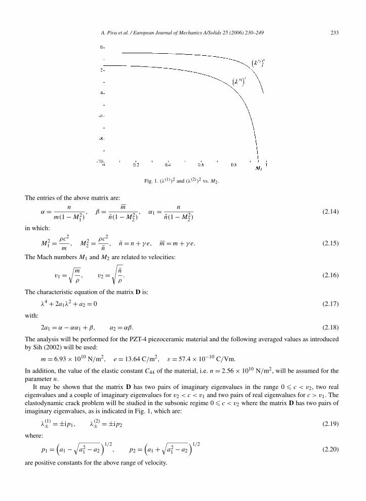
Fig. 1. (λ(1))2 and (λ(2))2 vs. M2.
The entries of the above matrix are:
α = n
m(1 − M21 )
, β = mn(1 − M2
2 ), α1 = n
n(1 − M22 )
(2.14)
in which:
M21 = ρc2
m, M2
2 = ρc2
n, n = n + γ e, m = m + γ e. (2.15)
The Mach numbers M1 and M2 are related to velocities:
v1 =√
m
ρ, v2 =
√n
ρ. (2.16)
The characteristic equation of the matrix D is:
λ4 + 2a1λ2 + a2 = 0 (2.17)
with:
2a1 = α − αα1 + β, a2 = αβ. (2.18)
The analysis will be performed for the PZT-4 piezoceramic material and the following averaged values as introducedby Sih (2002) will be used:
m = 6.93 × 10¹⁰ N/m2, e = 13.64 C/m2, ε = 57.4 × 10⁻¹⁰ C/Vm.
In addition, the value of the elastic constant C44 of the material, i.e. n = 2.56 × 10¹⁰ N/m2, will be assumed for theparameter n.
It may be shown that the matrix D has two pairs of imaginary eigenvalues in the range 0 c < v2, two realeigenvalues and a couple of imaginary eigenvalues for v2 < c < v1 and two pairs of real eigenvalues for c > v1. Theelastodynamic crack problem will be studied in the subsonic regime 0 c < v2 where the matrix D has two pairs ofimaginary eigenvalues, as is indicated in Fig. 1, which are:
λ(1)± = ±ip1, λ
(2)± = ±ip2 (2.19)
where:
p1 =(a1 −
√a2
1 − a2
)1/2, p2 =
(a1 +
√a2
1 − a2
)1/2(2.20)
are positive constants for the above range of velocity.
234 A. Piva et al. / European Journal of Mechanics A/Solids 25 (2006) 230–249
It should be noted that the dynamical extension of the three-parameter model gives v1 v2 and two couples ofcomplex eigenvalues in the whole range 0 M2 < 1.
The eigenvectors corresponding to λ(1)+ and to λ
(2)+ are:
f(j) = g(j) + ih(j) =(
p2jα
α − p2j
, ipjα
α − p2j
,−ipj ,1
)T
, j = 1,2. (2.21)
The real basis h(1), g(1), h(2), g(2) gives the matrix:
S = T−1DT =
0 −p1 0 0
p1 0 0 0
0 0 0 −p2
0 0 p2 0
(2.22)
where T = (h(1),g(1),h(2),g(2)). Using the transformation (2.22) into Eq. ( 2.12 )1 leads to the following Cauchy–Riemann system:
Ψ ,x + SΨ ,y = 0 (2.23)
where Ψ is a four-dimensional column vector field defined by:
Φ = TΨ . (2.24)
The system (2.23) justifies the introduction of complex potentials:
Ω1(z1) = Ψ1(x, y1) + iΨ2(x, y1), z1 = x + iy1, y1 = y
p1,
Ω2(z2) = Ψ3(x, y2) + iΨ4(x, y2), z2 = x + iy2, y2 = y
p2
(2.25)
so that from Eq. (2.24) the components of the vector Φ can be represented in terms of potentials in Eqs. (2.25), asfollows:
Φj = Im2∑
k=1
f(k)j Ωk(zk), j = 1, . . . ,4. (2.26)
Making use of Eq. (2.12)2, which specifies that the function ϕ − γ v can be written as the real (or imaginary) part ofan analytic function, one obtains the derivatives of the electric potential:
ϕ,x = γΦ3 + ReΩ3(z3),
ϕ,y = γΦ4 − ImΩ3(z3)(2.27)
in which z3 ≡ z = x + iy.
3. Representations of field quantities
Under the assumption that the piezoelectric medium is subjected only to the uniform electro-mechanical loadingat infinity:
σ 1(∞) = (σ∞xx , σ∞
xy ,D∞x )T, σ 2(∞) = (σ∞
xy , σ∞yy ,D∞
y )T (3.1)
the vector Ω(z) = (Ω1(z1),Ω2(z2),Ω3(z3))T can be represented as:
Ω(z) = Ω0 + Λ(z) (3.2)
where Ω0 is a constant vector and Λ(z) is an analytic vector vanishing at infinity.Eqs. (2.26), (2.27) and (3.2) allow us to represent vectors Γ (1) and Γ (2) defined by Eqs. (2.7)1,2 in the following
matrix form:
Γ (1) = (Φ1,Φ3, ϕ,x)T = Γ (1)∞ + Im
[EΛ(z)
], Γ (2) = (Φ2,Φ4, ϕ,y)
T = Γ (2)∞ + Im[FΛ(z)
](3.3)
A. Piva et al. / European Journal of Mechanics A/Solids 25 (2006) 230–249 235
where:
E =
f(1)1 f
(2)1 0
f(1)3 f
(2)3 0
γf(1)3 γf
(2)3 i
, F = E diag
(i
pk
), k = 1,2,3 (p3 = 1) (3.4)
and
Γ (1)∞ = Im[EΩ0], Γ (2)∞ = Im[FΩ0]. (3.5)
It should be noted that, assuming a null rotation at infinity, Eqs. (3.5) may be rewritten as follows:
Γ (1)∞ = (γ ∞11 , γ ∞
12 ,−E∞x ), Γ (2)∞ = (γ ∞
12 , γ ∞22 ,−E∞
y ) (3.6)
where the elastic deformations and the electric field at infinity can be obtained from the uniform field equation (3.1)through the constitutive equations, Eqs. (2.8) ( by using the appropriate notation).
The matrix forms of the stress vectors defined by Eqs. (2.7)3,4 are obtained as:
σ 1 = (σxx, σxy,Dx)T = σ∞
1 + Im[GΛ(z)
], σ 2 = (σxy, σyy,Dy)
T = σ∞2 + Im
[HΛ(z)
](3.7)
where:
G =
mf(1)1 − eγf
(1)4 mf
(2)1 − eγf
(2)4 e
nf(1)2 + nf
(1)3 nf
(2)2 + nf
(2)3 ie
ef(1)2 ef
(2)2 −iε
, H =
nf(1)2 + nf
(1)3 nf
(2)2 + nf
(2)3 ie
mf(1)4 mf
(2)4 −e
−ef(1)1 −ef
(2)1 ε
(3.8)
and
σ∞1 = σ 1(∞) = Im[GΩ0], σ∞
2 = σ 2(∞) = Im[HΩ0]. (3.9)
From Eq. (3.2) the primitive of the vector Ω(z) takes on the form:
ω(z) = diag(zk)Ω0 + λ(z) (3.10)
in which λ(z) is the primitive of Λ(z). The displacement vector defined as U = (u, v,ϕ)T can be obtained by directintegration of Eq. (3.3)1 which gives the following representation:
U = U∞ + Im[Eλ(z)
], U∞ = Im
[E diag(zk)Ω0
]. (3.11)
4. The elastodynamic crack problem. Preliminaries
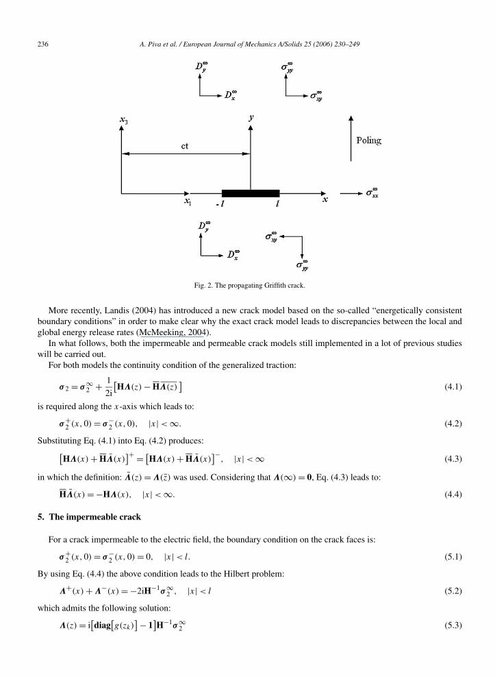
Let an electro-mechanically free Griffith crack of length 2l propagate at constant velocity c < v2 along the positivex1-axis in the piezoelectric medium which is subjected to the remote load stated by Eqs. (3.6). The plane of referenceis identified by the coordinate system (x, y) centered in the middle of the crack (Fig. 2).
It is well known that one of the main subjects for debate in studying fracture behaviour of piezoelectric media isthe electric boundary conditions on crack surfaces. A lot of papers discussed about this topic and correspondinglyabout the modeling of a crack in a piezoelectric medium. The models which receive the attention of researchers are:
(i) The impermeable crack model in which it is assumed that the permittivity inside the crack is negligible (zero)with respect to that of the surrounding medium (Deeg, 1980; Pak, 1990; Suo et al., 1992; Sosa, 1992; Park andSun, 1995; Chen and Yu, 1997; Chen et al., 1998; Soh et al., 2002).
(ii) The permeable crack model in which it is assumed that the crack is transparent to the electric field. For this modelthe crack behaves as if the permittivity in its interior is infinite (Parton, 1976; McMeeking, 1989; Dunn, 1994;Kwon et al., 2000; Li et al., 2000).
(iii) The “exact crack model” in which it is assumed a finite permittivity inside the crack, and in addition the crack-surfaces separation is taken into account (Hao and Shen, 1994; Zhang and Tong, 1996; Zhang and Gao, 2004).
236 A. Piva et al. / European Journal of Mechanics A/Solids 25 (2006) 230–249
Fig. 2. The propagating Griffith crack.
More recently, Landis (2004) has introduced a new crack model based on the so-called “energetically consistentboundary conditions” in order to make clear why the exact crack model leads to discrepancies between the local andglobal energy release rates (McMeeking, 2004).
In what follows, both the impermeable and permeable crack models still implemented in a lot of previous studieswill be carried out.
For both models the continuity condition of the generalized traction:
σ 2 = σ∞2 + 1
2i
[HΛ(z) − HΛ(z)
](4.1)
is required along the x-axis which leads to:
σ+2 (x,0) = σ−
2 (x,0), |x| < ∞. (4.2)
Substituting Eq. (4.1) into Eq. (4.2) produces:[HΛ(x) + HΛ(x)
]+ = [HΛ(x) + HΛ(x)
]−, |x| < ∞ (4.3)
in which the definition: Λ(z) = Λ(z) was used. Considering that Λ(∞) = 0, Eq. (4.3) leads to:
HΛ(x) = −HΛ(x), |x| < ∞. (4.4)
5. The impermeable crack
For a crack impermeable to the electric field, the boundary condition on the crack faces is:
σ+2 (x,0) = σ−
2 (x,0) = 0, |x| < l. (5.1)
By using Eq. (4.4) the above condition leads to the Hilbert problem:
Λ+(x) + Λ−(x) = −2iH−1σ∞2 , |x| < l (5.2)
which admits the following solution:
Λ(z) = i[diag
[g(zk)
] − 1]H−1σ∞
2 (5.3)
A. Piva et al. / European Journal of Mechanics A/Solids 25 (2006) 230–249 237
where g(zk) = zk(z2k − l2)−1/2, k = 1,2,3. Substituting Eq. (5.3) into Eq. (4.1) leads to the generalized stress vector
σ 2 in the following form:
σ 2 = ReH diag
[g(zk)
]H−1σ∞
2 . (5.4)
In particular, Eq. (5.4) indicates that ahead of the crack tip x = l one has:
σ 2(x,0) = x(x2 − l2)−1/2σ∞2 , x > l. (5.5)
The generalized stress vector σ 1 given by Eq. (3.7)1 becomes:
σ 1 = σ∞1 − Re(GH−1)σ∞
2 + Re[G diag
[g(zk)
]H−1]σ∞
2 . (5.6)
The generalized vector intensity factor at the tip x = l defined as:
K(l) = limx→l+
√2π(x − l)σ 2(x,0) (5.7)
is obtained from Eq. (5.5) as follows:
K(l) = √πl σ∞
2 . (5.8)
The primitive λ(z) of Λ(z) is:
λ(z) = i diag[h(zk) − zk
]H−1σ∞
2 (5.9)
in which h(zk) = (z2k − l2)1/2. Then, the generalized displacement, Eq. (3.11), becomes:
U = Γ (1)∞ x + Γ (2)∞ y + ReE diag
[h(zk) − zk
]H−1σ∞
2 . (5.10)
With respect to polar coordinates (r, θ) centered at the tip x = l, the asymptotic dominant terms of the stress vector,Eqs. (5.4) and (5.6), as well as of the displacement vector, Eq. (5.10), are:
σ 2(r, θ) = Re
H diag
[exp(−iθk/2)√
ck(θ)
]H−1
K(l)√
2πr, (5.11)
σ 1(r, θ) = Re
G diag
[exp(−iθk/2)√
ck(θ)
]H−1
K(l)√
2πr, (5.12)
U(r, θ) = Re
E diag
[√ck(θ) exp
(iθk
2
)]H−1
√2r
πK(l) (5.13)
with the following notations:
ck(θ) =(
cos2(θ) + sin2(θ)
p2k
)1/2
, θk = tg−1(
tg θ
pk
). (5.14)
Using Eq. (2.17) into Eqs. (3.4) and (3.8) one obtains:
σ 2(r, θ) = L(θ)K(l)
R(M2)√
2πr, (5.15)
σ 1(r, θ) = M(θ)K(l)
R(M2)√
2πr, (5.16)
U(r, θ) = N(θ)K(l)
R(M2)
√2r
π(5.17)
where the entries of matrices L(θ), M(θ) and N(θ) are given in Appendix A. The function R(M2) has the form:
R(M2) = p1(np21 − αγ e)
[εm(α − p2
2) − αe2p22
] − p2(np22 − αγ e)
[εm(α − p2
1) − αe2p21
]+ α2e2m(p2
1 − p22). (5.18)
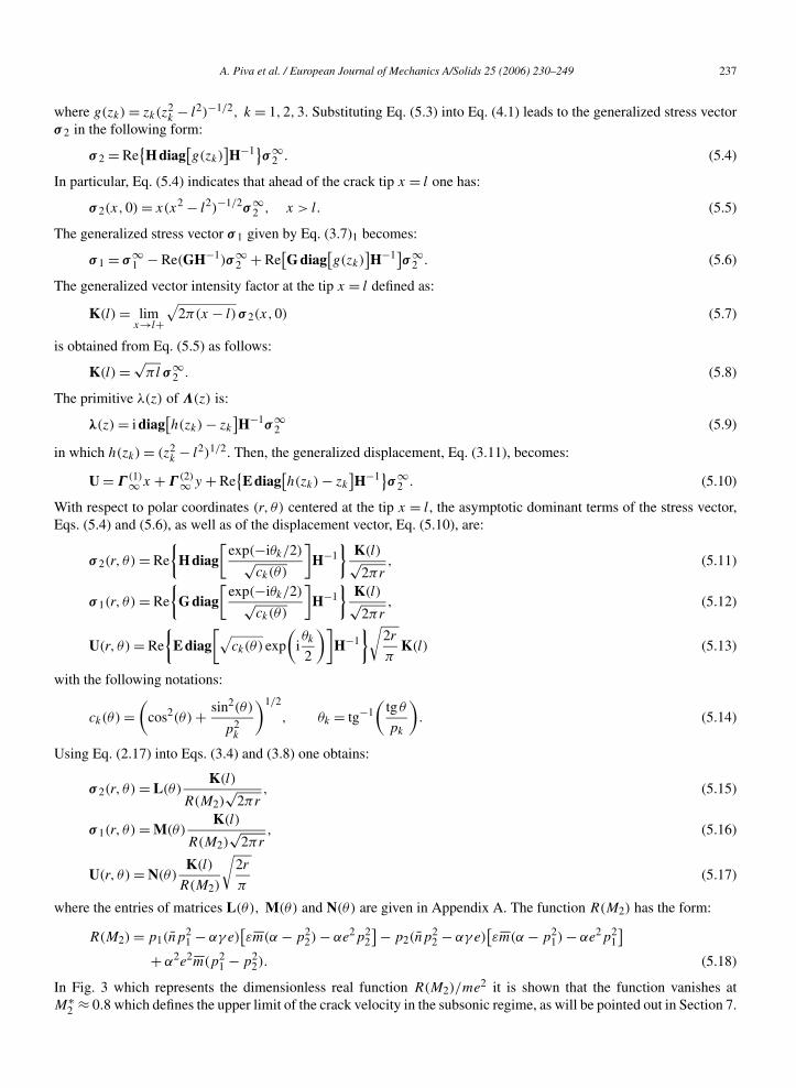
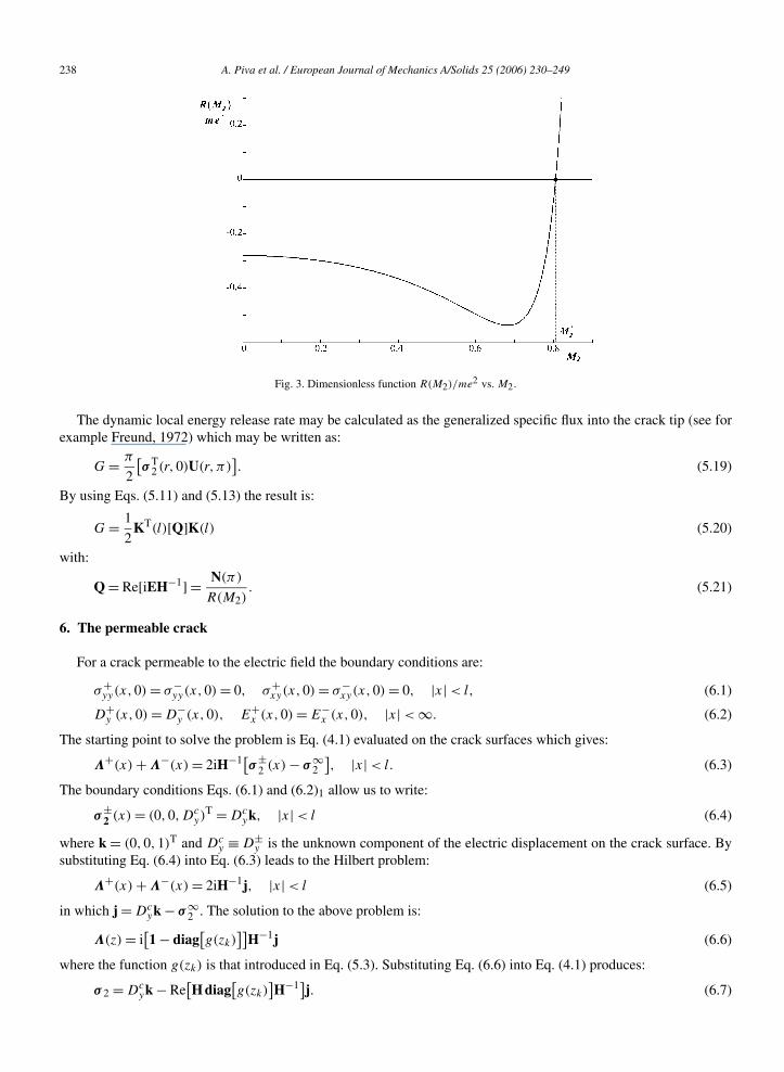
In Fig. 3 which represents the dimensionless real function R(M2)/me2 it is shown that the function vanishes atM∗
2 ≈ 0.8 which defines the upper limit of the crack velocity in the subsonic regime, as will be pointed out in Section 7.
238 A. Piva et al. / European Journal of Mechanics A/Solids 25 (2006) 230–249
Fig. 3. Dimensionless function R(M2)/me2 vs. M2.
The dynamic local energy release rate may be calculated as the generalized specific flux into the crack tip (see forexample Freund, 1972) which may be written as:
G = π
2
[σ T
2 (r,0)U(r,π)]. (5.19)
By using Eqs. (5.11) and (5.13) the result is:
G = 1
2KT(l)[Q]K(l) (5.20)
with:
Q = Re[iEH−1] = N(π)
R(M2). (5.21)
6. The permeable crack
For a crack permeable to the electric field the boundary conditions are:
σ+yy(x,0) = σ−
yy(x,0) = 0, σ+xy(x,0) = σ−
xy(x,0) = 0, |x| < l, (6.1)
D+y (x,0) = D−
y (x,0), E+x (x,0) = E−
x (x,0), |x| < ∞. (6.2)
The starting point to solve the problem is Eq. (4.1) evaluated on the crack surfaces which gives:
Λ+(x) + Λ−(x) = 2iH−1[σ±2 (x) − σ∞
2
], |x| < l. (6.3)
The boundary conditions Eqs. (6.1) and (6.2)1 allow us to write:
σ±2 (x) = (0,0,Dc
y)T = Dc
yk, |x| < l (6.4)
where k = (0,0,1)T and Dcy ≡ D±
y is the unknown component of the electric displacement on the crack surface. Bysubstituting Eq. (6.4) into Eq. (6.3) leads to the Hilbert problem:
Λ+(x) + Λ−(x) = 2iH−1j, |x| < l (6.5)
in which j = Dcyk − σ∞
2 . The solution to the above problem is:
Λ(z) = i[1 − diag
[g(zk)
]]H−1j (6.6)
where the function g(zk) is that introduced in Eq. (5.3). Substituting Eq. (6.6) into Eq. (4.1) produces:
σ 2 = Dcyk − Re
[H diag
[g(zk)
]H−1]j. (6.7)
A. Piva et al. / European Journal of Mechanics A/Solids 25 (2006) 230–249 239
In particular, Eq. (6.7) evaluated ahead of the crack tip x = l gives:
σ 2(x,0) = Dcyk + x√
x2 − l2(σ∞
2 − Dcyk), x > l. (6.8)
The generalized vectors σ 1 and U given by Eqs. (3.7)1 and (3.11)1 respectively, become:
σ 1 = σ∞1 + Re[GH−1]j − Re
[G diag
[g(zk)
]H−1]j, (6.9)
U = Γ (1)∞ x + Γ (2)∞ y + Re[E diag
[zk − h(zk)
]H−1]j. (6.10)
In order to obtain Dcy one can start from the boundary condition Eq. (6.2)2 which can be rewritten as follows:
[Γ (1)]3(x,0) = [Γ (1)]+3 (x) − [Γ (1)]+3 (x) = 0, |x| < ∞ (6.11)
where [·]3 stands for the third row of the term inside brackets. From Eqs. (3.3)1, (4.4) and (5.21) the boundarycondition Eq. (6.11) leads to the condition:[
N(π)]
3(HΛ+)(x) = [N(π)
]3(HΛ−)(x), |x| < ∞ (6.12)
which produces:[N(π)
]3(HΛ)(x) = 0, |x| < ∞. (6.13)
Thence, along the crack faces one has the following relations:
3∑k=1
N3k(π)[H]kΛ+(x) = 0,
3∑k=1
N3k(π)[H]kΛ−(x) = 0, |x| < l (6.14)
or equivalently:
3∑k=1
N3k(π)[H]k(Λ+(x) + Λ−(x)
) = 0, |x| < l. (6.15)
After substituting Eq. (6.5) into Eq. (6.15) it leads to:
N33(π)(Dcy − D∞
y ) − N31(π)σ∞xy − N32(π)σ∞
yy = 0, |x| < l. (6.16)
By noting that N31(π) = 0, the required component of the electric displacement on the crack surfaces can be deter-mined as:
Dcy = D∞
y + Γ (M2)σ∞yy (6.17)
with Γ (M2) = N32(π)/N33(π).The vector intensity factor at the tip x = l, defined by Eq. (5.7), is obtained from Eq. (6.8) in the form:
K(l) = √πl(σ∞
xy , σ∞yy ,D∞
y − Dcy)
T (6.18)
with Dcy given by Eq. (6.17).
The asymptotic dominant terms at the tip x = l of the generalized stress and displacement vectors as well as theenergy release rate are formally the same as those obtained in Section 5 with K(l) given by Eq. (6.18).
7. Discussion of results
In this section, numerical results are represented and discussed by focusing the attention on a crack propagatingunder the action of the far-field electro-mechanical loading (σ∞
yy ,E∞y ), thence assuming σ∞
xx = σ∞xy = D∞
x = 0. Theuse of E∞
y instead of D∞y is with a view to experiments where it is easier to impose an electric field in the medium
than an electric displacement field.For the present case, the relation between the two far-field electric loadings has been obtained from the following
equation:
Dy = ε1Ey + e
m(σyy − σxx) (7.1)
240 A. Piva et al. / European Journal of Mechanics A/Solids 25 (2006) 230–249
produced through Eqs. (2.5) and (2.6), with ε1 = (2e2 + mε)/m.First of all, the combined effects of both the far-field loading and crack velocity on the energy release rate, under
impermeable and permeable conditions, will be analyzed.For an impermeable crack Eqs. (5.20) and (5.21) lead to G∗ = 2G/lπ = G∗
M + G∗E , where G∗
M and G∗E are the
normalized mechanical and electrical components of the energy release rate respectively, obtained as follows:
G∗M =
[N∗
22(π) + e
mN∗
23(π)
](σ∞
yy )2 + ε1N∗23(π)σ∞
yy E∞y ,
G∗E = e
m
[N∗
32(π) + e
mN∗
33(π)
](σ∞
yy )2 + ε1
[N∗
32(π) + 2e
mN∗
33(π)
]σ∞
yy E∞y + ε2
1N∗33(π)(E∞
y )2
(7.2)
with the position that an asterisked entry of a matrix stands for the ratio between the entry and function R(M2), givenby Eq. (5.18). For the permeable crack the same quantity takes the simple form:
G∗p = [
N∗22(π) − Γ (M2)N
∗23(π)
](σ∞
yy )2 (7.3)
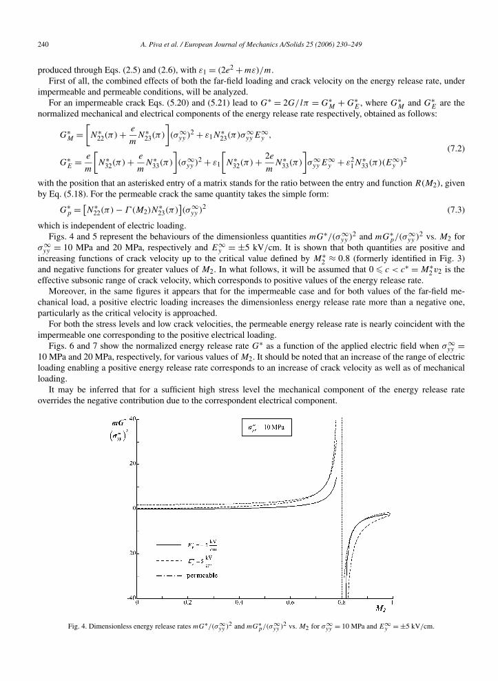
which is independent of electric loading.Figs. 4 and 5 represent the behaviours of the dimensionless quantities mG∗/(σ∞
yy )2 and mG∗p/(σ∞
yy )2 vs. M2 forσ∞
yy = 10 MPa and 20 MPa, respectively and E∞y = ±5 kV/cm. It is shown that both quantities are positive and
increasing functions of crack velocity up to the critical value defined by M∗2 ≈ 0.8 (formerly identified in Fig. 3)
and negative functions for greater values of M2. In what follows, it will be assumed that 0 c < c∗ = M∗2 v2 is the
effective subsonic range of crack velocity, which corresponds to positive values of the energy release rate.Moreover, in the same figures it appears that for the impermeable case and for both values of the far-field me-
chanical load, a positive electric loading increases the dimensionless energy release rate more than a negative one,particularly as the critical velocity is approached.
For both the stress levels and low crack velocities, the permeable energy release rate is nearly coincident with theimpermeable one corresponding to the positive electrical loading.
Figs. 6 and 7 show the normalized energy release rate G∗ as a function of the applied electric field when σ∞yy =
10 MPa and 20 MPa, respectively, for various values of M2. It should be noted that an increase of the range of electricloading enabling a positive energy release rate corresponds to an increase of crack velocity as well as of mechanicalloading.
It may be inferred that for a sufficient high stress level the mechanical component of the energy release rateoverrides the negative contribution due to the correspondent electrical component.
Fig. 4. Dimensionless energy release rates mG∗/(σ∞yy )2 and mG∗
p/(σ∞yy )2 vs. M2 for σ∞
yy = 10 MPa and E∞y = ±5 kV/cm.
A. Piva et al. / European Journal of Mechanics A/Solids 25 (2006) 230–249 241
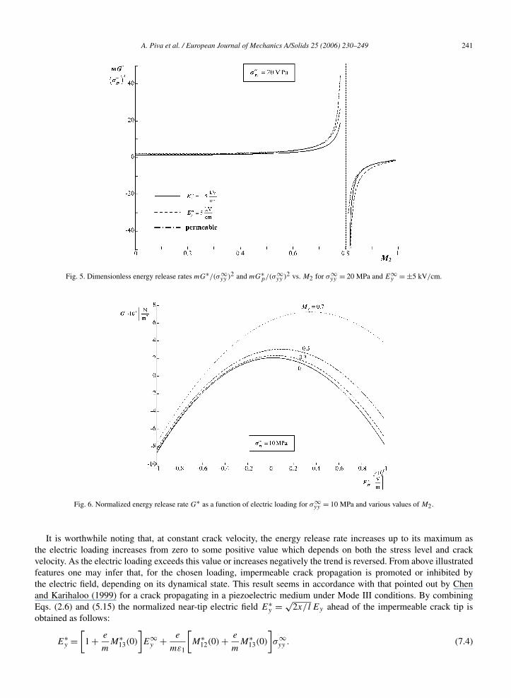
Fig. 5. Dimensionless energy release rates mG∗/(σ∞yy )2 and mG∗
p/(σ∞yy )2 vs. M2 for σ∞
yy = 20 MPa and E∞y = ±5 kV/cm.
Fig. 6. Normalized energy release rate G∗ as a function of electric loading for σ∞yy = 10 MPa and various values of M2.
It is worthwhile noting that, at constant crack velocity, the energy release rate increases up to its maximum asthe electric loading increases from zero to some positive value which depends on both the stress level and crackvelocity. As the electric loading exceeds this value or increases negatively the trend is reversed. From above illustratedfeatures one may infer that, for the chosen loading, impermeable crack propagation is promoted or inhibited bythe electric field, depending on its dynamical state. This result seems in accordance with that pointed out by Chenand Karihaloo (1999) for a crack propagating in a piezoelectric medium under Mode III conditions. By combiningEqs. (2.6) and (5.15) the normalized near-tip electric field E∗
y = √2x/l Ey ahead of the impermeable crack tip is
obtained as follows:
E∗y =
[1 + e
mM∗
13(0)
]E∞
y + e
mε1
[M∗
12(0) + e
mM∗
13(0)
]σ∞
yy . (7.4)
242 A. Piva et al. / European Journal of Mechanics A/Solids 25 (2006) 230–249
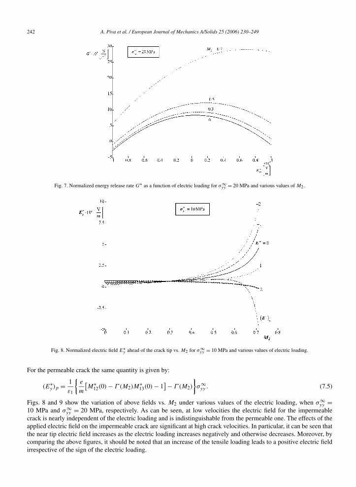
Fig. 7. Normalized energy release rate G∗ as a function of electric loading for σ∞yy = 20 MPa and various values of M2.
Fig. 8. Normalized electric field E∗y ahead of the crack tip vs. M2 for σ∞
yy = 10 MPa and various values of electric loading.
For the permeable crack the same quantity is given by:
(E∗y )p = 1
ε1
e
m
[M∗
12(0) − Γ (M2)M∗13(0) − 1
] − Γ (M2)
σ∞
yy . (7.5)
Figs. 8 and 9 show the variation of above fields vs. M2 under various values of the electric loading, when σ∞yy =
10 MPa and σ∞yy = 20 MPa, respectively. As can be seen, at low velocities the electric field for the impermeable
crack is nearly independent of the electric loading and is indistinguishable from the permeable one. The effects of theapplied electric field on the impermeable crack are significant at high crack velocities. In particular, it can be seen thatthe near tip electric field increases as the electric loading increases negatively and otherwise decreases. Moreover, bycomparing the above figures, it should be noted that an increase of the tensile loading leads to a positive electric fieldirrespective of the sign of the electric loading.
A. Piva et al. / European Journal of Mechanics A/Solids 25 (2006) 230–249 243
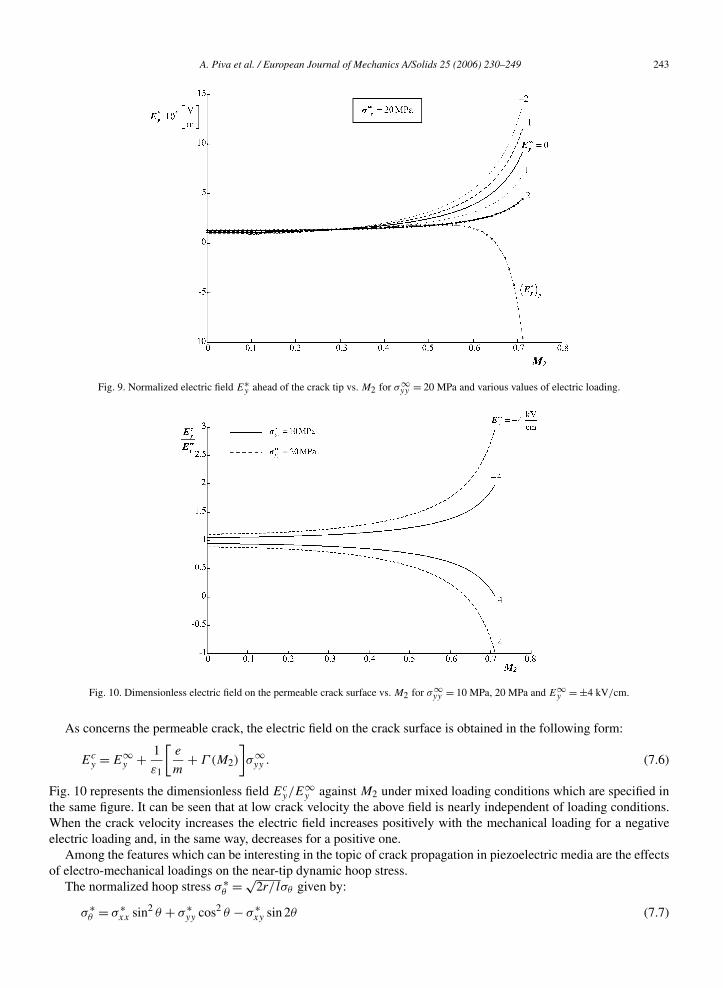
Fig. 9. Normalized electric field E∗y ahead of the crack tip vs. M2 for σ∞
yy = 20 MPa and various values of electric loading.
Fig. 10. Dimensionless electric field on the permeable crack surface vs. M2 for σ∞yy = 10 MPa, 20 MPa and E∞
y = ±4 kV/cm.
As concerns the permeable crack, the electric field on the crack surface is obtained in the following form:
Ecy = E∞
y + 1
ε1
[e
m+ Γ (M2)
]σ∞
yy . (7.6)
Fig. 10 represents the dimensionless field Ecy/E
∞y against M2 under mixed loading conditions which are specified in
the same figure. It can be seen that at low crack velocity the above field is nearly independent of loading conditions.When the crack velocity increases the electric field increases positively with the mechanical loading for a negativeelectric loading and, in the same way, decreases for a positive one.
Among the features which can be interesting in the topic of crack propagation in piezoelectric media are the effectsof electro-mechanical loadings on the near-tip dynamic hoop stress.
The normalized hoop stress σ ∗θ = √
2r/ lσθ given by:
σ ∗θ = σ ∗
xx sin2 θ + σ ∗yy cos2 θ − σ ∗
xy sin 2θ (7.7)
244 A. Piva et al. / European Journal of Mechanics A/Solids 25 (2006) 230–249
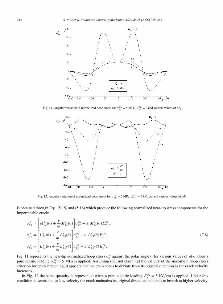
Fig. 11. Angular variation of normalized hoop stress for σ∞yy = 5 MPa, E∞
y = 0 and various values of M2.
Fig. 12. Angular variation of normalized hoop stress for σ∞yy = 5 MPa, E∞
y = 5 kV/cm and various values of M2.
is obtained through Eqs. (5.15) and (5.16) which produce the following normalized near-tip stress components for theimpermeable crack:
σ ∗xx =
[M∗
12(θ) + e
mM∗
13(θ)
]σ∞
yy + ε1M∗13(θ)E∞
y ,
σ ∗yy =
[L∗
22(θ) + e
mL∗
23(θ)
]σ∞
yy + ε1L∗23(θ)E∞
y , (7.8)
σ ∗xy =
[L∗
12(θ) + e
mL∗
13(θ)
]σ∞
yy + ε1L∗13(θ)E∞
y .
Fig. 11 represents the near-tip normalized hoop stress σ ∗θ against the polar angle θ for various values of M2, when a
pure tensile loading σ∞yy = 5 MPa is applied. Assuming (but not claiming) the validity of the maximum hoop stress
criterion for crack branching, it appears that the crack tends to deviate from its original direction as the crack velocityincreases.
In Fig. 12 the same quantity is represented when a pure electric loading E∞y = 5 kV/cm is applied. Under this
condition, it seems that at low velocity the crack maintains its original direction and tends to branch at higher velocity.
A. Piva et al. / European Journal of Mechanics A/Solids 25 (2006) 230–249 245
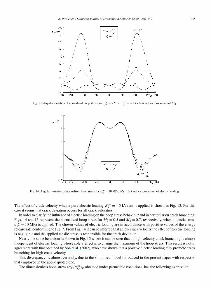
Fig. 13. Angular variation of normalized hoop stress for σ∞yy = 5 MPa, E∞
y = −5 kV/cm and various values of M2.
Fig. 14. Angular variation of normalized hoop stress for σ∞yy = 10 MPa, M2 = 0.5 and various values of electric loading.
The effect of crack velocity when a pure electric loading E∞y = −5 kV/cm is applied is shown in Fig. 13. For this
case it seems that crack deviation occurs for all crack velocities.In order to clarify the influence of electric loading on the hoop stress behaviour and in particular on crack branching,
Figs. 14 and 15 represent the normalized hoop stress for M2 = 0.5 and M2 = 0.7, respectively, when a tensile stressσ∞
yy = 10 MPa is applied. The chosen values of electric loading are in accordance with positive values of the energyrelease rate conforming to Fig. 7. From Fig. 14 it can be inferred that at low crack velocity the effect of electric loadingis negligible and the applied tensile stress is responsible for the crack deviation.
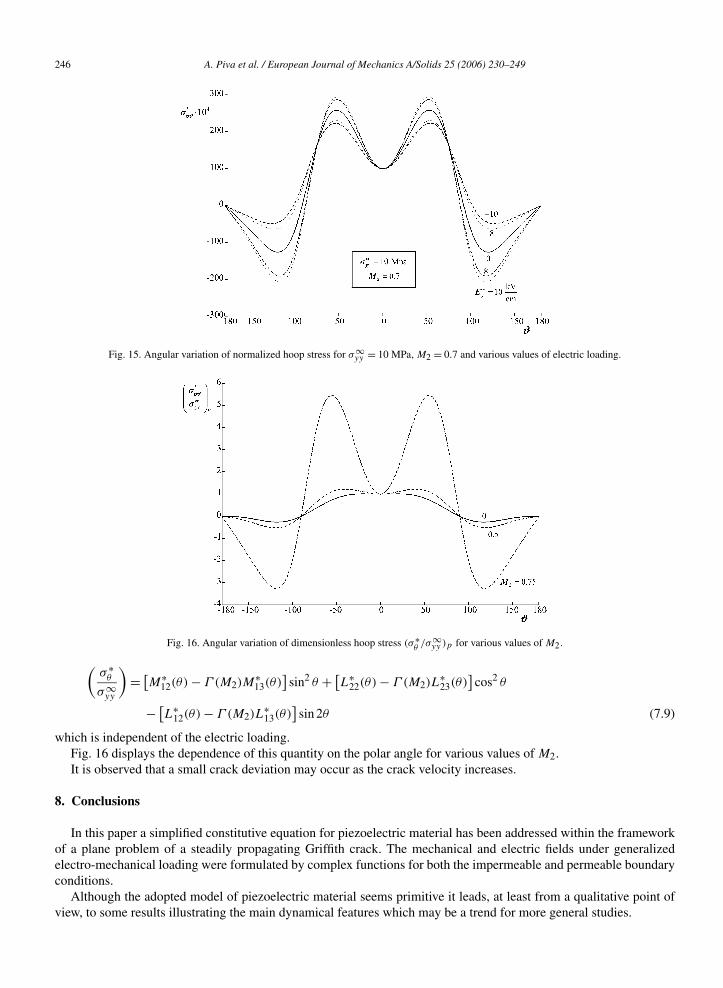
Nearly the same behaviour is shown in Fig. 15 where it can be seen that at high velocity crack branching is almostindependent of electric loading whose solely effect is to change the maximum of the hoop stress. This result is not inagreement with that obtained by Soh et al. (2002), who have shown that a positive electric loading may promote crackbranching for high crack velocity.
This discrepancy is, almost certainly, due to the simplified model introduced in the present paper with respect tothat employed in the above quoted one.
The dimensionless hoop stress (σ ∗θ /σ∞
yy )p obtained under permeable conditions, has the following expression:
246 A. Piva et al. / European Journal of Mechanics A/Solids 25 (2006) 230–249
Fig. 15. Angular variation of normalized hoop stress for σ∞yy = 10 MPa, M2 = 0.7 and various values of electric loading.
Fig. 16. Angular variation of dimensionless hoop stress (σ∗θ /σ∞
yy )p for various values of M2.
(σ ∗
θ
σ∞yy
)= [
M∗12(θ) − Γ (M2)M
∗13(θ)
]sin2 θ + [
L∗22(θ) − Γ (M2)L
∗23(θ)
]cos2 θ
− [L∗
12(θ) − Γ (M2)L∗13(θ)
]sin 2θ (7.9)
which is independent of the electric loading.Fig. 16 displays the dependence of this quantity on the polar angle for various values of M2.It is observed that a small crack deviation may occur as the crack velocity increases.
8. Conclusions
In this paper a simplified constitutive equation for piezoelectric material has been addressed within the frameworkof a plane problem of a steadily propagating Griffith crack. The mechanical and electric fields under generalizedelectro-mechanical loading were formulated by complex functions for both the impermeable and permeable boundaryconditions.
Although the adopted model of piezoelectric material seems primitive it leads, at least from a qualitative point ofview, to some results illustrating the main dynamical features which may be a trend for more general studies.
A. Piva et al. / European Journal of Mechanics A/Solids 25 (2006) 230–249 247
Some main conclusions are summarized as follows:
(a) The effective range of crack velocity in the subsonic regime is 0 c < c∗ ≈ 0.8v2 where v2 is the lowest wavespeed which enters in the chosen model of piezoelectric medium. This range is independent of far-field loadingas well as of electrical boundary conditions.The analysis performed for generalized Mode-I loading conditions (σ∞
yy ,E∞y ) has shown that under impermeable
boundary conditions:(b) For a sufficiently high stress level the energy release rate is a positive increasing function of crack velocity in the
above mentioned range. At constant crack velocity, an increase of the energy release rate may occur dependingon a positive electric load level as well as of the stress level. A negative increase of electric loading leads to adecrease of the energy release rate.
(c) The near tip electric field is an increasing function of crack velocity and this trend is promoted by a negativeincrease of the electric loading and retarded by a positive one.
(d) On the basis of maximum hoop stress criterion it seems that under mixed loading conditions crack branching isnearly independent of the electric loading as well as of crack velocity.For a permeable crack the most significant results are:
(e) The energy release is independent of the electric loading and is a positive increasing function of crack velocity inthe same range as in (a).
(f) The electric field on the crack surface is a positive increasing function of crack velocity for a negative electricloading and decreasing function for a positive one.
(g) Crack branching is promoted by an increase of crack velocity.
Acknowledgements
This research was supported by the Italian Ministry for University and Scientific, Technological Research MIUR(40% and 60%). The research topic is one of the subjects of the Centre of Study and Research for the Identification ofMaterials and Structures (CIMEST)—“M. Capurso”.
Appendix A
By introducing the following constants and notations:
ak = pk(np2k − γ eα)
α − p2k
, bk = p2keα
α − p2k
, C(θk) = cos θk/2√ck(θ)
, S(θk) = sin θk/2√ck(θ)
, k = 1,2,
C(θ) = cos θ/2, S(θ) = sin θ/2
(A.1)
the entries of matrix L(θ) are:
L11 = −[a1h11C(θ1) + a2h21C(θ2) + eh31C(θ)
], L12 = [
a1h12S(θ1) + a2h22S(θ2) + eh32S(θ)],
L13 = [a1h13S(θ1) + a2h23S(θ2) + eh33S(θ)
], L21 = [m(
h11S(θ1) + h21S(θ2)) − eh31S(θ)
)],
L22 = [m(h12C(θ1) + h22C(θ2)
) − eh32C(θ)], L23 = [m(
h13C(θ1) + h23C(θ2)) − eh33C(θ)
], (A.2)
L31 = −[b1h11S(θ1) + b2h21S(θ2) − εh31S(θ)
], L32 = −[
b1h12C(θ1) + b2h22C(θ2) − εh32C(θ)],
L33 = −[b1h13C(θ1) + b2h23C(θ2) − εh33C(θ)
]in which:
h11 = e2αp22(α − p2
1) − mε(α − p21)(α − p2
2), h21 = mε(α − p21)(α − p2
2) − e2αp21(α − p2
2),
h12 = −[εp2(np2
2 − eγ α) + e2p22α
](α − p2
1), h22 = [εp1(np2
1 − eγ α) + e2p21α
](α − p2
2),
h13 = −e[m(α − p2
2) + p2(np22 − eγ α)
](α − p2
1), h23 = e[m(α − p2
1) + p1(np21 − eγ α)
](α − p2
2),
h31 = m(h11 + h21), h32 = eα
ε
(p2
1h12
α − p21
+ p22h22
α − p22
), h33 = m
e(h13 + h23).
(A.3)
248 A. Piva et al. / European Journal of Mechanics A/Solids 25 (2006) 230–249
For the entries of matrix M(θ) the following contractions are considered:
mk = mαp2k
α − p2k
− eγ, nk = pk
(nα
α − p2k
− n
), k = 1,2. (A.4)
Thence:
M11 = m1h11S(θ1) + m2h21S(θ2) + eh31S(θ), M12 = m1h12C(θ1) + m2h22C(θ2) + eh32C(θ),
M13 = m1h13C(θ1) + m2h23C(θ2) + eh33C(θ), M21 = −[n1h11C(θ1) + n2h21C(θ2) + eh31C(θ)
],
M22 = n1h12S(θ1) + n2h22S(θ2) + eh32S(θ), M23 = n1h13S(θ1) + n2h23S(θ2) + eh33S(θ),
M31 = −[
b1
p1h11C(θ1) + b2
p2h21C(θ2) − εh31C(θ)
], M32 = b1
p1h12S(θ1) + b2
p2h22S(θ2) − εh32S(θ),
M33 = b1
p1h13S(θ1) + b2
p2h23S(θ2) − εh33S(θ).
(A.5)
The entries of matrix N(θ) are:
N11 = −1
e
[b1h11c1(θ)S(θ1) + b2h21c2(θ)S(θ2)
], N12 = 1
e
[b1h12c1(θ)C(θ1) + b2h22c2(θ)C(θ2)
],
N13 = 1
e
[b1h13c1(θ)C(θ1) + b2h23c2(θ)C(θ2)
], N21 = p1h11c1(θ)C(θ1) + p2h21c2(θ)C(θ2),
N22 = p1h12c1(θ)S(θ1) + p2h22c2(θ)S(θ2), N23 = p1h13c1(θ)S(θ1) + p2h23c2(θ)S(θ2),
N31 = γN21 − h31C(θ), N32 = γN22 − h32S(θ), N33 = γN23 − h33S(θ).
(A.6)
Appendix B
The following symbols are used in this paper:
σij stress tensorγij strain tensorDi electric displacements vectorEi electric field vectorcijkl elastic constantseijk piezoelectric constantsεij dielectric constantsx1, x2, x3 Cartesian coordinatesρ density of the materialt timeui, u, v elastic displacement componentsϕ electric potentialΓ (1),Γ (2) generalized strainM1,M2 Mach numbersc crack velocityv1, v2 velocities
λ(1)± , λ
(2)± imaginary eigenvalues
Ω1(z1),Ω2(z2) complex potentialsσ 1(∞),σ 2(∞) uniform electro-mechanical loading at infinityE∞
x ,E∞y electric field at infinity
U generalized displacement vector2l length of crackr, θ polar coordinatesG dynamic local energy release rateK(l) vector intensity factorG∗
M normalized mechanical component of the energy release rate
A. Piva et al. / European Journal of Mechanics A/Solids 25 (2006) 230–249 249
G∗E normalized electrical component of the energy release rate
G∗ normalized total energy release rateσ ∗
θ normalized hoop stressσ ∗
xx, σ∗xy, σ
∗yy normalized near-tip stress components
References
Chen, Z.T., Karihaloo, B.L., Yu, S.W., 1998. A Griffith crack moving along the interface of two dissimilar piezoelectric materials. Int. J. Fracture 91,197–203.
Chen, Z.T., Karihaloo, B.L., 1999. Dynamic response of a cracked piezoelectric ceramic under arbitrary electro-mechanical impact. Int. J. SolidsStruct. 36, 5125–5133.
Chen, Z.T., Yu, S.W., 1997. Anti-plane Yofee crack problem in piezoelectric materials. Int. J. Fracture 84, L41–L45.Deeg, W.F., 1980. The analysis of dislocation, crack and inclusion problems in piezoelectric solids. Ph.D. Thesis, Stanford University.Dunn, M.N., 1994. The effect of crack face boundary conditions on the fracture mechanics. Engrg. Fract. Mech. 48, 25–39.Freund, L.B., 1972. Energy flux into the tip of an extending crack in an elastic solid. J. Elasticity 2, 341–349.Gao, C.F., 2000. Further study of the generalized 2D problem of an elliptic hole or a crack in piezoelectric media. Mech. Res. Commun. 27,
429–434.Gao, H.J., Zhang, T.Y., Tong, P., 1997. Local and global energy release rates for an electrically yielded crack in a piezoelectric ceramic. J. Mech.
Phys. Solids 45, 491–510.Hao, T.-H., Shen, Z.-Y., 1994. A new electric boundary condition of electric fracture mechanics and its applications. Engrg. Fract. Mech. 47,
793–802.Kwon, J.H., Lee, K.Y., 2000. Moving interfacial crack between piezoelectric ceramic and elastic layers. Eur. J. Mech. 19, 979–987.Kwon, J.H., Lee, K.Y., Kwon, S.M., 2000. Moving crack in a piezoelectric ceramic strip under anti-plane shear loading. Mech. Res. Commun. 27,
327–332.Landis, C.M., 2004. Energetically consistent boundary conditions for electromechanical fracture. Int. J. Solids Struct. 41, 6291–6315.Li, S., 2003. On saturation-strip model of a permeable crack in a piezoelectric ceramic. Acta Mech. 165, 47–71.Li, X.F., Fan, T.Y., Wu, X.F., 2000. A moving Mode-III crack at the interface between two dissimilar piezoelectric materials. Int. J. Engrg. Sci. 38,
1219–1234.McMeeking, R.M., 1989. Electrostrictive forces near crack-like flaws. J. Appl. Math. Phys. 40, 615–627.McMeeking, R.M., 2004. The energy release rate for a Griffith crack in a piezoelectric material. Engrg. Fracture Mech. 71, 1149–1163.Pak, Y.E., 1990. Crack extension force in a piezoelectric material. J. Appl. Mech. 57, 647–653.Park, S., Sun, C.T., 1995. Fracture criteria for piezoelectric ceramics. J. Amer. Ceram. Soc. 78, 1475–1480.Parton, Y.E., 1976. Fracture mechanics of piezoelectric materials. Acta Astronaut. 3, 671–683.Piva, A., Viola, E., 1988. Crack propagation in an orthotropic medium. Engrg. Fract. Mech. 29, 535–548.Piva, A., Viola, E., Tornabene, F., 2005. Crack propagation in an orthotropic medium with coupled elastodynamic properties. Mech. Res. Comm. 32,
153–159.Sih, G.C., 2002. A field model interpretation of crack initiation and growth behavior in ferroelectric ceramics: change of poling direction and
boundary condition. J. Theor. Appl. Fract. Mech. 38, 1–14.Soh, A.K., Liu, J.X., Lee, K.L., Fang, D.N., 2002. On a moving Griffith crack in anisotropic piezoelectric solids. Arch. Appl. Mech. 72, 458–469.Sosa, H.A., 1992. On the fracture mechanics of piezoelectric solids. Int. J. Solids Struct. 29, 2613–2622.Spyropoulos, C.P., 2004. Energy release rate and path independent integral study for piezoelectric material with crack. Int. J. Solids Struct. 41,
907–921.Suo, Z., Kuo, C.M., Barnett, D.M., Willis, J.R., 1992. Fracture mechanics for piezoelectric ceramics. J. Mech. Phys. Solids 40, 739–765.Zhang, T.Y., Gao, C.F., 2004. Fracture behaviors of piezoelectric materials. J. Theor. Appl. Fract. Mech. 41, 339–379.Zhang, T.Y., Tong, P., 1996. Fracture mechanics for a mode III crack in a piezoelectric material. Int. J. Solids Struct. 33, 343–359.Zhang, T.Y., Zhao, M.H., Tong, P., 2002. Fracture of piezoelectric ceramics. Adv. Appl. Mech. 38, 148–289.
Related Documents