General rights Copyright and moral rights for the publications made accessible in the public portal are retained by the authors and/or other copyright owners and it is a condition of accessing publications that users recognise and abide by the legal requirements associated with these rights. Users may download and print one copy of any publication from the public portal for the purpose of private study or research. You may not further distribute the material or use it for any profit-making activity or commercial gain You may freely distribute the URL identifying the publication in the public portal If you believe that this document breaches copyright please contact us providing details, and we will remove access to the work immediately and investigate your claim. Downloaded from orbit.dtu.dk on: Jan 04, 2020 Crack growth monitoring in composite materials using embedded optical Fiber Bragg Grating sensor Pereira, Gilmar Ferreira; Mikkelsen, Lars Pilgaard; McGugan, Malcolm Published in: Proceedings of the 5th International Conference on Smart Materials and Nanotechnology in Engineering (SMN) in conjunction with the International Conference on Smart Materials and Structures (Cansmart 2015) Publication date: 2015 Document Version Peer reviewed version Link back to DTU Orbit Citation (APA): Pereira, G. F., Mikkelsen, L. P., & McGugan, M. (2015). Crack growth monitoring in composite materials using embedded optical Fiber Bragg Grating sensor. In Proceedings of the 5th International Conference on Smart Materials and Nanotechnology in Engineering (SMN) in conjunction with the International Conference on Smart Materials and Structures (Cansmart 2015)

Welcome message from author
This document is posted to help you gain knowledge. Please leave a comment to let me know what you think about it! Share it to your friends and learn new things together.
Transcript
General rights Copyright and moral rights for the publications made accessible in the public portal are retained by the authors and/or other copyright owners and it is a condition of accessing publications that users recognise and abide by the legal requirements associated with these rights.
Users may download and print one copy of any publication from the public portal for the purpose of private study or research.
You may not further distribute the material or use it for any profit-making activity or commercial gain
You may freely distribute the URL identifying the publication in the public portal If you believe that this document breaches copyright please contact us providing details, and we will remove access to the work immediately and investigate your claim.
Downloaded from orbit.dtu.dk on: Jan 04, 2020
Crack growth monitoring in composite materials using embedded optical Fiber BraggGrating sensor
Pereira, Gilmar Ferreira; Mikkelsen, Lars Pilgaard; McGugan, Malcolm
Published in:Proceedings of the 5th International Conference on Smart Materials and Nanotechnology in Engineering (SMN)in conjunction with the International Conference on Smart Materials and Structures (Cansmart 2015)
Publication date:2015
Document VersionPeer reviewed version
Link back to DTU Orbit
Citation (APA):Pereira, G. F., Mikkelsen, L. P., & McGugan, M. (2015). Crack growth monitoring in composite materials usingembedded optical Fiber Bragg Grating sensor. In Proceedings of the 5th International Conference on SmartMaterials and Nanotechnology in Engineering (SMN) in conjunction with the International Conference on SmartMaterials and Structures (Cansmart 2015)
CANSMART 2015: International Conference on Smart Materials and Structures
SMN 2015: 5th
International Conference on Smart Materials and Nanotechnology in Engineering
CANSMART & SMN 2015
CRACK GROWTH MONITORING IN COMPOSITE MATERIALS USING
EMBEDDED OPTICAL FIBER BRAGG GRATING SENSOR
G. Pereira1, L. P. Mikkelsen
2, M. McGugan
3
1Technical University of Denmark, Department of Wind Energy, Frederiksborgvej
399, 4000 Roskilde
[email protected] 2Technical University of Denmark, Department of Wind Energy, Frederiksborgvej
399, 4000 Roskilde
[email protected] 3Technical University of Denmark, Department of Wind Energy, Frederiksborgvej
399, 4000 Roskilde
ABSTRACT
In this paper a novel method to assess a crack growing/damage event in fiber reinforced
plastic, or adhesive using Fiber Bragg Grating (FBG) sensors embedded in a host material is
shown. Different features of the crack mechanism that induce a change in the FBG response were
identified. Double Cantilever Beams specimens made with glass fibre glued with structural
adhesive, were instrumented with an array of FBG sensors embedded in the material and tested
using an experimental fracture procedure. A digital image correlation technique was used to
determine the presence of the specific phenomena caused by the crack, and to correlate with the
FBG sensor. An algorithm was developed that analyses the reflected peak at each measurement
time, and calculates the contribution of each fracture phenomenon to the change in the FBG
response. This Material-Sensor model was implemented in a Finite Element Method (FEM)
Model of the DCB specimen, to simulate the response of the FBG sensor during the process of
crack growth, proving that this Material-Sensor model can be used as an analysis tool for future
application of this measurement technology in more complex structures.
Keywords: Fibre Bragg Grating Sensors, Crack Growth Monitoring, Fibre Reinforced Plastic
Crack Monitoring, Digital Image Correlation.
CANSMART & SMN 2015
INTRODUCTION
Fibre Reinforced Plastic materials (FRP or as often called composite materials) have been
extensively used in several engineering fields and applications, such as, aerospace, automotive,
naval, civil engineering and wind energy. The rapid growth of the FRP material is mostly due to
its high weight-stiffness ratio when compared with other conventional materials, like steel. The
FRP material consist of two macroscopic phases, a stiff fibre phase, usually glass or carbon fibre,
and polymeric matrix, usually polyester or epoxy. The main advantage of this material is that the
alignment of the fibres can be arranged to suit the required properties of the intended structure.
Taking a wind turbine blade as an example, the requirement for a stiff (but light-weight) structure
means fibre orientation primarily along the length of the blade; however in the axial direction this
stiffness requirement is much lower, meaning that less material is required and used to reinforce
in this direction. In sum, the FRP materials can be tailored to a specific application, and obtain a
high level of customization of mechanical properties, such as weight-stiffness ratio, thermal
expansion, chemical/corrosion resistance, fatigue behaviour, etc. [1].
However, the increasing demand for more cost-effective lightweight composite materials is
pushing for advances in material technology, design philosophies and monitoring techniques, as
well as requiring a deeper understanding of their failure mechanisms. Damage tolerant design is a
developing design concept where the structure/material capability to hold damage is taken into
consideration during the process design. If this concept is incorporated with a structural health
monitoring system over the design and operation of a structure, this will enable safe operation
despite the presence of damage, such as that created by fatigue, intrinsic/discrete damage,
manufacturing defects or accidental damage that can occur. In addition, this approach will enable
a “real time” reactive maintenance of the structure.
Based on this, the authors approach for a successful damaged tolerance design is based not
only on accepting the presence of damage in a structure, but by controlling it and using the full
mechanical capability of the material and structure during the evolution of the damage. This will
require integrated sensors that give information about the presence of damage in an accurate way,
its location and the type of damage [2]. As delamination is one of the most important failure
mechanisms in FRP materials, and one of the most widespread causes of FRP structure life
reduction, in this study a novel method to assess cracking in FRP materials using embedded
Fiber optic Bragg Grating (FBG) sensor was developed, by measuring specific phenomenon that
only appear in the presence of a crack.
FIBER OPTIC BRAGG GRATING SENSOR
Different sensing technology has been implemented in FRP material structures to track
delamination and cracks. Acoustic emission that measures the stress waves generated by the
crack front growing, vibration that detects changes in the specific damping capacity of the
structure, model analysis by monitoring the materials natural frequencies and mode shapes,
piezo-electric actuators/sensors and wavelet analysis based on the energy variation of the
structural dynamic. However, these measurement systems have several limitations, among these
CANSMART & SMN 2015
the need for qualified operators, expensive hardware and that they are often impractical to use
under operation. Also, to detect delamination in FRP materials the sensor must be embedded in
the laminate layers or in the interface of the FRP and a structural adhesive.
Fibre Bragg Gratings (FBG) are a very promising technology to detect delamination in an
operational FRP structure, due to their capability to be embedded in the FRP material, even in an
operational structure, without compromising its structural resistance. This is due to the FBG
reduced size, with a diameter of 125 µm, which makes it a virtually non-intrusive sensing
technique. The FBG sensors, also presents other interesting features, such high strain resolution,
multiplexing capability, immunity to electromagnetic fields, chemical inertness and long term
stability [3].
Fiber Bragg Grating Working Principal
A Fiber Bragg Grating is formed when a permanent periodic modulation of the refractive
index is induced along a section of an optical fiber, by exposing the optical fiber to an
interference pattern of intense ultra-violet light. The photosensitivity of the silica exposed to the
ultra-violet light is increased, so when the optical fiber is illuminated by a broadband light
source, the grating diffractive properties are such that only a very narrow wavelength band is
reflected back [3]. Any external phenomenon that creates a change on the grating, like
temperature, strain, compression, non-uniform strain fields, etc. will change the shape of the
reflected light. Tracking this change in the reflected peak is the measurement working principal
of the FBG, however, different phenomena acting on the grating will make different changes to
the sensor response (like a fingerprint), and so, it will be possible to track specific phenomena
that are characteristic of damage.
The spectral response of a homogeneous FBG is a single peak centred at the wavelength λb.
The λb wavelength is described by the Bragg condition,
0,0,2neffB (1)
where n0 is the mean effective where refractive index at the location of the grating, the index 0
denotes unstrained conditions (initial state). The neff is the effective refractive index and Λ is the
constant nominal period of the refractive index modulation.
DELAMINATION DETECTION IN FRP DOUBLE CANTILIVER BEAM BY
EMBEDDED FBG SENSOR.
To analyse the delamination in FRP material and develop a technique that can assess the
presence and growth of such damage by embedded FBG sensors, Double Cantilever Beam
(DCB) specimens were tested in a fracture testing machine, developed by Sørensen [4]. The
DCB specimens were loaded with different combination of Moments, which will give different
type of fracture modes, simulating different crack/delamination cases.
The DCB specimens were manufactured using two FRP material arms, made of unidirectional
and triaxial glass fibre layers (SAERTEX UD and TRIAX), with a layup stacking of : [90/ +45 /-
45/04/04/+45/-45/90], glued by a commercial epoxy structural adhesive (Epikote MGS BPR
CANSMART & SMN 2015
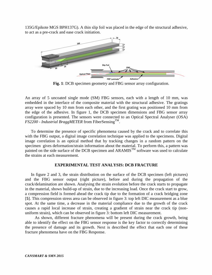
135G/Epikote MGS BPH137G). A thin slip foil was placed in the edge of the structural adhesive,
to act as a pre-crack and ease crack initiation.
Fig. 1: DCB specimen geometry and FBG sensor array configuration.
An array of 5 uncoated single mode (SM) FBG sensors, each with a length of 10 mm, was
embedded in the interface of the composite material with the structural adhesive. The gratings
array were spaced by 10 mm from each other, and the first grating was positioned 10 mm from
the edge of the adhesive. In figure 1, the DCB specimen dimensions and FBG sensor array
configuration is presented. The sensors were connected to an Optical Spectral Analyser (OSA)
FS2200 - Industrial BraggMETER from FiberSensingTM
.
To determine the presence of specific phenomena caused by the crack and to correlate this
with the FBG output, a digital image correlation technique was applied to the specimens. Digital
image correlation is an optical method that by tracking changes in a random pattern on the
specimen gives deformation/strain information about the material. To perform this, a pattern was
painted on the side surface of the DCB specimen and ARAMISTM
software was used to calculate
the strains at each measurement.
EXPERIMENTAL TEST ANALYSIS: DCB FRACTURE
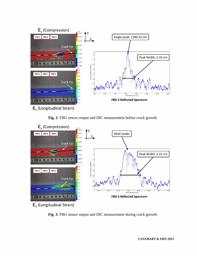
In figure 2 and 3, the strain distribution on the surface of the DCB specimen (left pictures)
and the FBG sensor output (right picture), before and during the propagation of the
crack/delamination are shown. Analysing the strain evolution before the crack starts to propagate
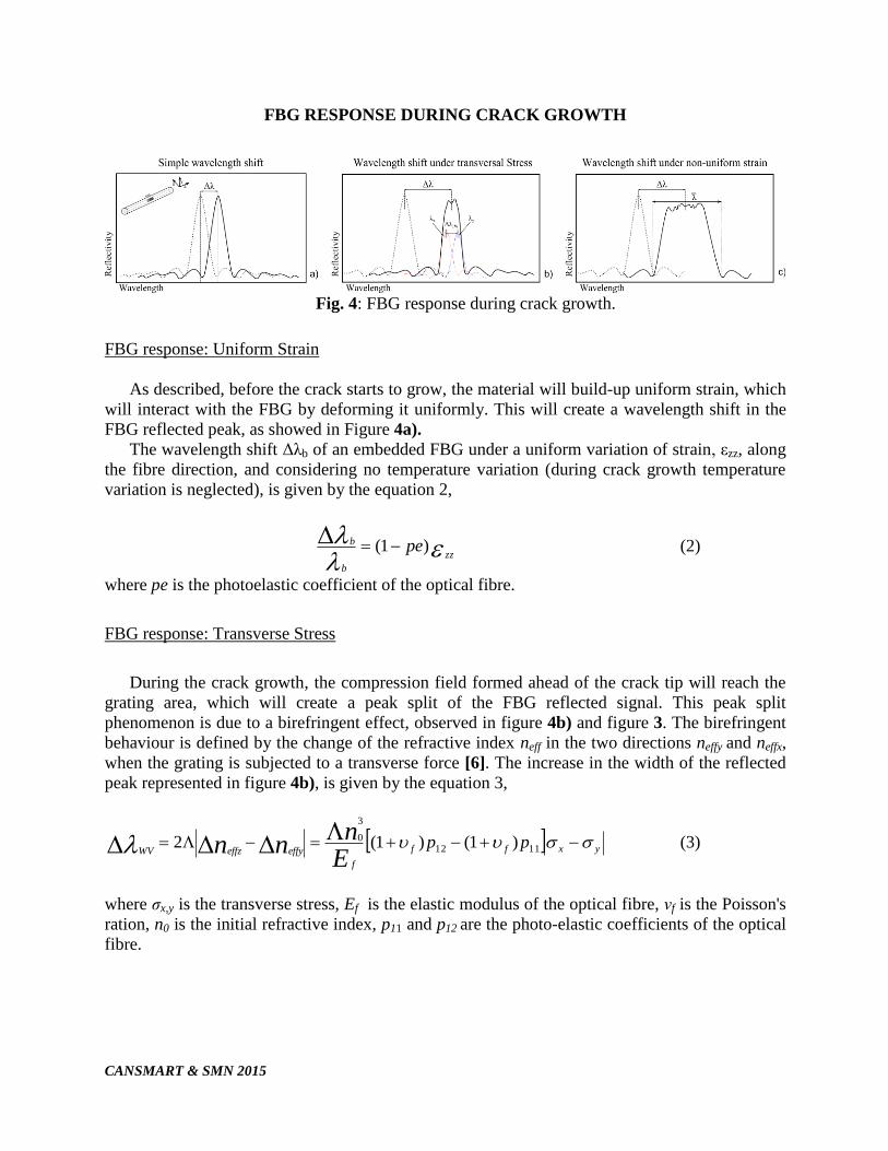
in the material, shows build-up of strain, due to the increasing load. Once the crack start to grow,
a compression field is formed ahead the crack tip due to the formation of a crack bridging zone
[5]. This compression stress area can be observed in figure 3: top left DIC measurement as a blue
spot. At the same time, a decrease in the material compliance due to the growth of the crack
causes a rapid local increase of strain, creating a gradient of strain near the crack tip (non-
uniform strain), which can be observed in figure 3: bottom left DIC measurement.
As shown, different fracture phenomena will be present during the crack growth, being
able to identify the effect on the FBG sensor response is the key factor to correctly determining
the presence of damage and its growth. Next is described the effect that each one of these
fracture phenomena have on the FBG Response.
CANSMART & SMN 2015
Fig. 2: FBG sensor output and DIC measurement before crack growth.
Fig. 3: FBG sensor output and DIC measurement during crack growth.
y
x
y
x
CANSMART & SMN 2015
FBG RESPONSE DURING CRACK GROWTH
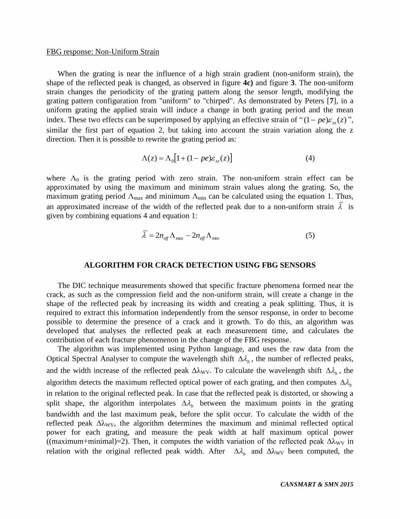
Fig. 4: FBG response during crack growth.
FBG response: Uniform Strain
As described, before the crack starts to grow, the material will build-up uniform strain, which
will interact with the FBG by deforming it uniformly. This will create a wavelength shift in the
FBG reflected peak, as showed in Figure 4a).
The wavelength shift Δλb of an embedded FBG under a uniform variation of strain, εzz, along
the fibre direction, and considering no temperature variation (during crack growth temperature
variation is neglected), is given by the equation 2,
zz
b
b pe)1( (2)
where pe is the photoelastic coefficient of the optical fibre.
FBG response: Transverse Stress
During the crack growth, the compression field formed ahead of the crack tip will reach the
grating area, which will create a peak split of the FBG reflected signal. This peak split
phenomenon is due to a birefringent effect, observed in figure 4b) and figure 3. The birefringent
behaviour is defined by the change of the refractive index neff in the two directions neffy and neffx,
when the grating is subjected to a transverse force [6]. The increase in the width of the reflected
peak represented in figure 4b), is given by the equation 3,
yxff
f
effyeffzWVpp
En
nn 1112
3
0 )1()1(2 (3)
where σx,y is the transverse stress, Ef is the elastic modulus of the optical fibre, νf is the Poisson's
ration, n0 is the initial refractive index, p11 and p12 are the photo-elastic coefficients of the optical
fibre.
CANSMART & SMN 2015
FBG response: Non-Uniform Strain
When the grating is near the influence of a high strain gradient (non-uniform strain), the
shape of the reflected peak is changed, as observed in figure 4c) and figure 3. The non-uniform
strain changes the periodicity of the grating pattern along the sensor length, modifying the
grating pattern configuration from "uniform" to "chirped". As demonstrated by Peters [7], in a
uniform grating the applied strain will induce a change in both grating period and the mean
index. These two effects can be superimposed by applying an effective strain of “ )()1( zpe zz ”,
similar the first part of equation 2, but taking into account the strain variation along the z
direction. Then it is possible to rewrite the grating period as:
)()1(1)( 0 zpez zz (4)
where Λ0 is the grating period with zero strain. The non-uniform strain effect can be
approximated by using the maximum and minimum strain values along the grating. So, the
maximum grating period Λmax and minimum Λmin can be calculated using the equation 1. Thus,
an approximated increase of the width of the reflected peak due to a non-uniform strain is
given by combining equations 4 and equation 1:
minmax 22 effeff nn (5)
ALGORITHM FOR CRACK DETECTION USING FBG SENSORS
The DIC technique measurements showed that specific fracture phenomena formed near the
crack, as such as the compression field and the non-uniform strain, will create a change in the
shape of the reflected peak by increasing its width and creating a peak splitting. Thus, it is
required to extract this information independently from the sensor response, in order to become
possible to determine the presence of a crack and it growth. To do this, an algorithm was
developed that analyses the reflected peak at each measurement time, and calculates the
contribution of each fracture phenomenon in the change of the FBG response.
The algorithm was implemented using Python language, and uses the raw data from the
Optical Spectral Analyser to compute the wavelength shift b , the number of reflected peaks,
and the width increase of the reflected peak ΔλWV. To calculate the wavelength shift b , the
algorithm detects the maximum reflected optical power of each grating, and then computes b
in relation to the original reflected peak. In case that the reflected peak is distorted, or showing a
split shape, the algorithm interpolates b between the maximum points in the grating
bandwidth and the last maximum peak, before the split occur. To calculate the width of the
reflected peak ΔλWV, the algorithm determines the maximum and minimal reflected optical
power for each grating, and measure the peak width at half maximum optical power
((maximum+minimal)=2). Then, it computes the width variation of the reflected peak ΔλWV in
relation with the original reflected peak width. After b and ΔλWV been computed, the
CANSMART & SMN 2015
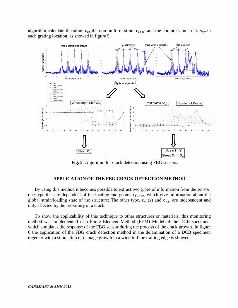
algorithm calculate the strain εzz, the non-uniform strain εzz (z) and the compression stress σx,y in
each grating location, as showed in figure 5.
Fig. 5: Algorithm for crack detection using FBG sensors.
APPLICATION OF THE FBG CRACK DETECTION METHOD
By using this method it becomes possible to extract two types of information from the sensor:
one type that are dependent of the loading and geometry, εzz, which give information about the
global strain/loading state of the structure; The other type, εzz (z) and σx,y, are independent and
only affected by the proximity of a crack.
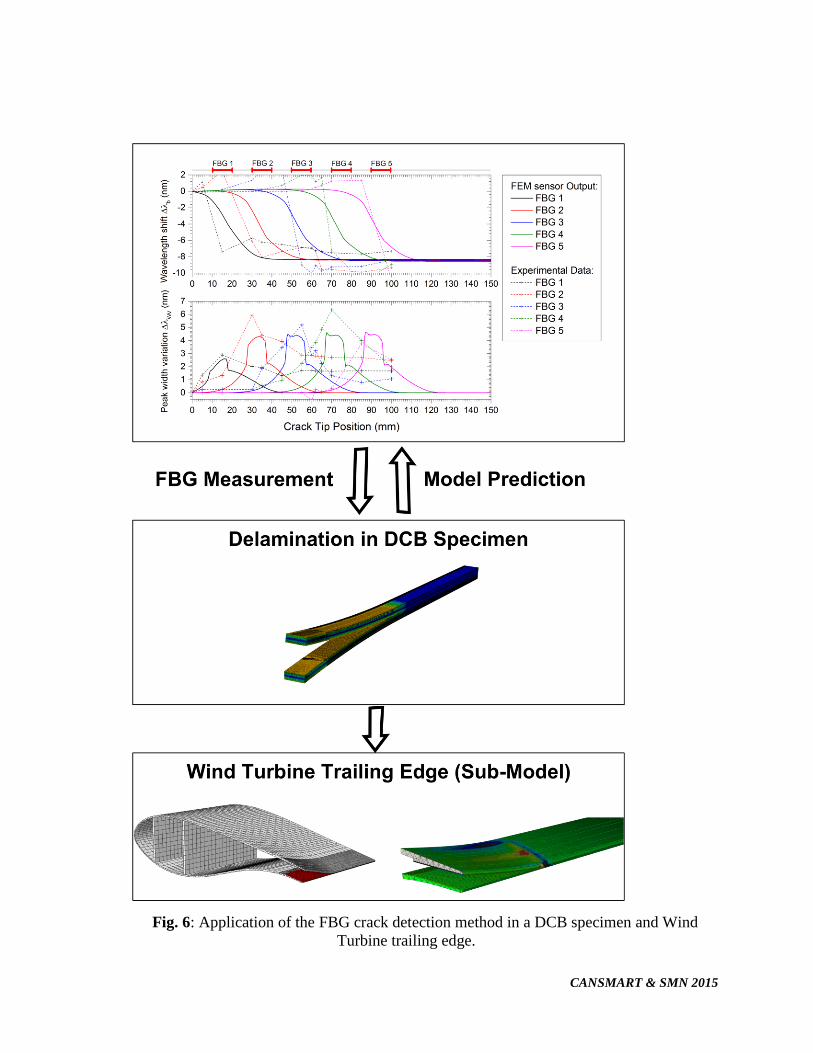
To show the applicability of this technique to other structures or materials, this monitoring
method was implemented in a Finite Element Method (FEM) Model of the DCB specimen,
which simulates the response of the FBG sensor during the process of the crack growth. In figure
6 the application of the FBG crack detection method in the delamination of a DCB specimen
together with a simulation of damage growth in a wind turbine trailing edge is showed.
CANSMART & SMN 2015
Fig. 6: Application of the FBG crack detection method in a DCB specimen and Wind
Turbine trailing edge.
CANSMART & SMN 2015
CONCLUSION
In this article the capability of Fibre Bragg Gratings embedded in composite material to
detect and track cracks/delamination was demonstrated. The use of the digital image correlation
technique proved that specific fracture features near the crack can create a change in the shape of
the reflected peak. Thus, it is possible to extract information from the sensor that is independent
of the loading type, geometry and boundary conditions, and depends only on the proximity of the
crack. This fact allows the application of this technique in general composite material structures.
The wavelength shift is dependent on the loading type, but the increase in the width of the
peak is related to the presence of the crack (Birefringent effect and non-uniform strain). Using
this information it is possible to track the crack by an abrupt variation of the wavelength and/or
increase in the width of the reflected peak. This monitoring method can be implemented in a
structural model using the equations developed. This makes it possible to study the application of
this monitoring technique in other locations, predict the sensor output and determine the
optimized sensor-structure configuration.
ACKNOWLEDGMENT
The author acknowledges the Seventh Framework Programme (FP7) for funding the project
MareWint (Project reference: 309395) as Marie-Curie Initial Training Network, Fibersensing®
for providing the FBG sensors and hardware, and SSP-Technology® for providing the material
tested.
REFERENCES
1. Jones, R., “Mechanics of composite materials”, Taylor & Francis, 1999, ISBN 156032712x,
9781560327127.
2. McGugan, M., Pereira, G., Sørensen, B., Toftegaard, H. and Branner, K., “Damage tolerance
and structural monitoring for wind turbine blades”, Royal Society of London. Philosophical
Transactions A. Mathematical, Physical and Engineering Sciences, 2015, V313.
3. Meltz, G., Hill, K.O, ” Fiber Bragg grating technology fundamentals and overview”, Journal
of lightwave technology, 15(8):1263-1276, 1997.
4. Sørensen, B., Jørgensen, K., Jacobsen, T., and Østergaard, R.C., “DCB-specimen loaded with
uneven bending moments. International Journal of Fracture”, International Journal of
Fracture, 2006, 141(1-2):163–176.
5. Sørensen, B., “Cohesive laws for assessment of materials failure: Theory, experimental
methods and application”, 2010, Ph.D. thesis
6. Sorensen, L., Botsis, J.,Gmür, T. and Humbert, L., “Bridging tractions in mode I
delamination: Measurements and simulations” ,Compos. Sci. Technol., vol. 68, no. 12, pp.
2350–2358, Sep. 2008.
7. Peters, K., Studer, M., Botsis, J., Iocco, A., H. Limberger, H. and Salath, R., “Embedded
Optical Fiber Bragg Grating Sensor in a Nonuniform Strain Field : Measurements and
Simulations”, 2000, Experimental Mechanics, pp. 19–28.
Related Documents