GRUNDFOS DATA BOOKLET CR, CRN high pressure Vertical multistage centrifugal pumps 50/60 Hz

Welcome message from author
This document is posted to help you gain knowledge. Please leave a comment to let me know what you think about it! Share it to your friends and learn new things together.
Transcript

GRUNDFOS DATA BOOKLET
CR, CRN high pressure
Vertical multistage centrifugal pumps50/60 Hz

2
Contents
Product dataPerformance range 3Introduction 4Product range 5Applications 5CRNE 1 and 3 HS 6CRN 3, 5, 10, 15, 20 SF 72 x CR 32, 45, 64 and 902 x CRN 32, 45, 64 and 90 82 x CR 120 and 1502 x CRN 120 and 150 9Type key 10Codes 10Operating range of the shaft seal for the high-pressure pump 11Terminal box positions 11Ambient temperature 11Pumped liquids 11Performance curves 12
Selection and sizingSelection of high-pressure pumps 13
Performance curves/Technical dataCRNE 1 HS - 50/60 Hz 16CRNE 3 HS - 50/60 Hz 18CRN 3 SF, 50 Hz 20CRN 5 SF, 50 Hz 22CRN 10 SF, 50 Hz 24CRN 15 SF, 50 Hz 26CRN 20 SF, 50 Hz 28CR 32, 50 Hz 30CRN 32, 50 Hz 32CR 45, 50 Hz 34CRN 45, 50 Hz 36CR 64, 50 Hz 38CRN 64, 50 Hz 40CR 90, 50 Hz 42CRN 90, 50 Hz 44CR 120, 50 Hz 46CRN 120, 50 Hz 48CR 150, 50 Hz 50CRN 150, 50 Hz 52CRN 3 SF, 60 Hz 54CRN 5 SF, 60 Hz 56CRN 10 SF, 60 Hz 58CRN 15 SF, 60 Hz 60CRN 20 SF, 60 Hz 62CR 32, 60 Hz 64CRN 32, 60 Hz 66CR 45, 60 Hz 68CRN 45, 60 Hz 70CR 64, 60 Hz 72CRN 64, 60 Hz 74CR 90, 60 Hz 76CRN 90, 60 Hz 78CR 120, 60 Hz 80
CRN 120, 60 Hz 82CR 150, 60 Hz 84CRN 150, 60 Hz 86
Motor dataStandard motors for CR, CRN high pressure, 50 Hz 88E-motors for CRNE-HS, 50 Hz 88E-motors for CRNE-SF, 50 Hz 88Standard motors for CR, CRN high pressure, 60 Hz 89E-motors for CRNE-HS, 60 Hz 89E-motors for CRNE-SF, 60 Hz 89
AccessoriesPipe connection 90Connecting pipe 91PJE coupling without pipe stub 91Pressure sensors for CRNE-HS 92LiqTec 92
Further product documentationWebCAPS 93WinCAPS 94

CR, CRN high pressureProduct data
Performance range
TM02
168
9 40
07TM
02 1
687
4007
1 2 3 4 5 6 8 1010 20 30 40 50 60 80 100100 200Q [m³/h]
20
30
40
60
80
100
200
300
400
[m]H
50 Hz
CRN 3-SF
2xCR
2xCR
CRNE
CRNE 2xCR2xCR2xCR323-HS
2xCR45 64 90
1-HS
CRN15-SF
CRN 5-SF
CRN10-SF
CRN20-SF 120
150
10.8 11 2 3 4 5 6 8 1010 20 30 40 50 60 80 100100 200Q [m³/h]
20
30
40
60
80
100
200
300
400
[m]H
60 HzCRN3-SF
2 x CR
2 x CR
CRNCRN CRNCRNCRNE CRNE 2 x CR2 x CR2 x CR2 x CR3-HS 5-SF 10-SF 32 45 64 901-HS 15-SF 20-SF
120
150
3
4
Product data CR, CRN high pressure
IntroductionThis data booklet deals with CR and CRN pumps forhigh-pressure applications.
A high pressure is achieved in two ways:
• Single pump with frequency-controlled high-speed motor, type HS- CRNE-HS, pump sizes 1 and 3.
• Feed pump + high-pressure pump connected in se-ries.- CRN-SF, pump sizes 3 to 20- CR, CRN, pump sizes 32 to 150.
The high-pressure pump comes in two designsdepending on pump size.
• CRNE-HS and CRN-SF: The chamber stack is up-side-down compared to a CR standard pump.
• CR, CRN: Standard pump with or without bearing flange.
The pumps in this data booklet are a CR or CRNstandard pump as feed pump connected in series to alarger pump, the high-pressure pump.
For use of other CR pumps as high-pressure pump, seethe CR data booklet “Custom-built pumps”.
The pressure generated by the high-pressure pumpmakes special demands to the design. This databooklet primarily describes the following aspects wherethe high-pressure is different from the standard pump:
• design• operating conditions• performance curves• dimensions.
The performance curves and dimensional tables showthe high-pressure pump connected in series with astandard pump with various numbers of stages.

Product data CR, CRN high pressure
Product range
ApplicationsThe CRN high-pressure series is a multi-purpose pumprange suitable for a variety of different applicationsdemanding reliable and cost-efficient supply.
CRN handles a variety of liquids from potable water toindustrial liquids within a very wide temperature, flowand pressure scale. Below is a list representing somegeneral examples of applications requiring a high pres-sure.
Pressure boosting• Process water systems• Washing and cleaning systems• High-pressure washdown systems• Boiler feed and condensate systems.
Water treatment• Ultra-filtration systems• Reverse osmosis systems.
Range CRNE 1 HS
CRNE 3 HS
CRN 3 SF
CRN 5 SF
CRN 10 SF
CRN 15 SF
CRN 20 SF
2 x CR,CRN 32
2 x CR,CRN 45
2 x CR,CRN 64
2 x CR,CRN 90
2 x CR,CRN 120
2 x CR,CRN 150
Nominal flow rate, 50 Hz [m3/h] 1 3 3 5 10 15 20 32 45 64 90 120 150Nominal flow rate, 60 Hz [m3/h 1.2 3.6 3.6 6 12 18 24 38 54 77 108 144 180Flow range, 50 Hz [m3/h] 0.8-5 1-7 1.2-4.5 2.5-8.5 5-13 9-24 11-29 15-40 22-58 30-85 45-120 60-160 75-180Flow range, 60 Hz [m3/h] 0.8-5 1-7 1.4-5.4 3-10.2 6-16 10-29 13-35 18-48 26-70 36-102 54-146 60-160 75-180Max. pressure, 50 Hz [bar] 47 41 44 47 44 47 48 39 39 39 40 40 39Max. pressure, 60 Hz [bar] 48 42 48 48 47 47 47 40 40 36 33 37 31Motor power [kW] 4.0-7.5 4.0-7.5 0.37-4.0 0.55-5.5 0.75-7.5 3-15 4-18.5 11-18.5 11-30 11-45 7.5-45 11-75 11-75Temperature range [°C] –20 to +120 –20 to +120 –30 to +120VersionCR, CRE:Cast iron and stainless steel EN/DIN 1.4301/AISI 304
- - - - - - -
CRN, CRNE:Stainless steel EN/DIN 1.4401/AISI 316
Pipe connectionFlange - - - - - - - DN 65 DN 80 DN 100 DN 100 DN 125 DN 125Flange - on request - - - - - - - DN 80 DN 100 DN 125 DN 125 DN 150 DN 150PJE coupling (Victaulic) - -SystemOne pump with high-speed motor - - - - - - - - - -
Two pumps in series - - - Available On request
5

6
Product data CR, CRN high pressure
CRNE 1 and 3 HS
Fig. 1 CRNE 3-HS pump
Fig. 2 Sectional drawing of CRNE 1 and 3-HS
Pump
CRNE-HS is a single pump solution capable of gener-ating up to 48 bar.
The CRNE-HS pump is a non-self-priming, verticalmultistage centrifugal pump fitted with a high-speedGrundfos motor with integrated frequency converter,type MGE.
The direction of rotation is the opposite of that ofstandard pumps, and the chamber stack is turnedupside-down, as a result of which the pumped liquidflows in the opposite direction.
This special design ensures that the shaft seal is notaffected by the pump discharge pressure.
The base, the pump head cover as well as parts incontact with the pumped liquid are made from stainlesssteel.
The pump has a maintenance-free mechanicalcartridge shaft seal.
Operating conditions - high-pressure pump
Liquid temperature: –20 °C to +120 °C.Ambient temperature: Maximum +40 °C.Minimum inlet pressure: See page 13.Maximum inlet pressure: 15/25 bar
(static/operation).Maximum operating pressure: 50 bar.
Materials
TM02
847
0 02
04TM
02 1
688
2803
1
10
2
4
9
6
5
3
8
11
7
Pos. Description Materials EN/DIN AISI/ASTM
1 Pump head Cast ironEN-GJL-200 EN-JL1030 ASTM 25B
2 Pump head cover Stainless steel 1.4408 CF8M (eq. to AISI 316
3 Shaft Stainless steel 1.44011.4460
AISI 316AISI 329
4 Impeller Stainless steel 1.4401 AISI 3165 Chamber Stainless steel 1.4401 AISI 3166 Outer sleeve Stainless steel 1.4401 AISI 316
7 O-ring for outer sleeve
EPDM, FKM, FFKM, and FXM
8 Base Stainless steel 1.4408 CF8M (eq. to AISI 316
9 Neck ring PTFE
10 Shaft seal HQQE, HQQV, HQQF, and HQQK
11 Base plate Cast ironEN-GJL-200 1) EN-JL1030 ASTM 25B
Other rubber parts
EPDM, FKM, FFKM, and FXM
1) Stainless steel on request
Product data CR, CRN high pressure
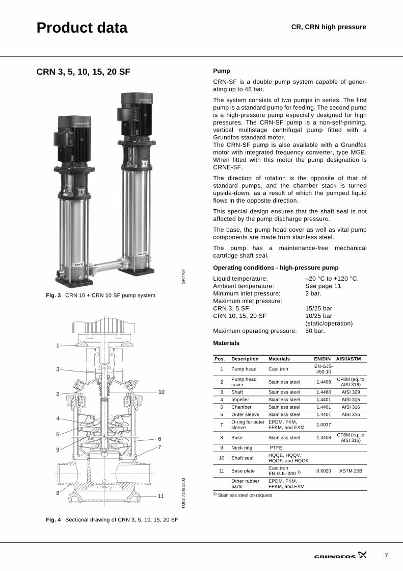
CRN 3, 5, 10, 15, 20 SF
Fig. 3 CRN 10 + CRN 10 SF pump system
Fig. 4 Sectional drawing of CRN 3, 5, 10, 15, 20 SF
Pump
CRN-SF is a double pump system capable of gener-ating up to 48 bar.
The system consists of two pumps in series. The firstpump is a standard pump for feeding. The second pumpis a high-pressure pump especially designed for highpressures. The CRN-SF pump is a non-self-priming,vertical multistage centrifugal pump fitted with aGrundfos standard motor. The CRN-SF pump is also available with a Grundfosmotor with integrated frequency converter, type MGE.When fitted with this motor the pump designation isCRNE-SF.
The direction of rotation is the opposite of that ofstandard pumps, and the chamber stack is turnedupside-down, as a result of which the pumped liquidflows in the opposite direction.
This special design ensures that the shaft seal is notaffected by the pump discharge pressure.
The base, the pump head cover as well as vital pumpcomponents are made from stainless steel.
The pump has a maintenance-free mechanicalcartridge shaft seal.
Operating conditions - high-pressure pump
Liquid temperature: –20 °C to +120 °C.Ambient temperature: See page 11.Minimum inlet pressure: 2 bar.Maximum inlet pressure:CRN 3, 5 SF 15/25 barCRN 10, 15, 20 SF 10/25 bar
(static/operation)Maximum operating pressure: 50 bar.
Materials
GR
7767
TM02
733
6 32
03
3
1
2
4
5
9
8
10
6
7
11
Pos. Description Materials EN/DIN AISI/ASTM
1 Pump head Cast iron EN-GJS-450-10
2 Pump head cover Stainless steel 1.4408 CF8M (eq. to
AISI 316)3 Shaft Stainless steel 1.4460 AISI 3294 Impeller Stainless steel 1.4401 AISI 3165 Chamber Stainless steel 1.4401 AISI 3166 Outer sleeve Stainless steel 1.4401 AISI 316
7 O-ring for outer sleeve
EPDM, FKM, FFKM, and FXM 1.0037
8 Base Stainless steel 1.4408 CF8M (eq. to AISI 316)
9 Neck ring PTFE
10 Shaft seal HQQE, HQQV, HQQF, and HQQK
11 Base plate Cast iron EN-GJL-200 1) 0.6020 ASTM 25B
Other rubber parts
EPDM, FKM, FFKM, and FXM
1) Stainless steel on request
7

8
Product data CR, CRN high pressure
2 x CR 32, 45, 64 and 902 x CRN 32, 45, 64 and 90
Fig. 5 2 x CR, CRN double-pump system
Fig. 6 Sectional drawing of a CR(N) pump
Pump
2 x CR, CRN is a double-pump system capable ofgenerating up to 40 bar.
The system consists of two pumps in series. The firstpump is a standard pump for feeding.
The second pump is a high-pressure pump especiallydesigned for high pressures. If the maximum pressurefrom the feed pump exceeds 15 bar, the high-pressurepump must have a bearing flange to be capable ofhandling the higher inlet pressure.
CRNThe base, the pump head cover and all components incontact with the pumped liquid are made of stainlesssteel.
CRThe base and the pump head are made of ductile castiron.
Operating conditions - high-pressure pump
Liquid temperature: –30 °C to +120 °C.Ambient temperature: See page 11.Maximum inlet pressure:without bearing flange 15 bar.with bearing flange 25 bar.Maximum operating pressure: 40 bar.
Materials
TM02
172
4 18
01TM
01 1
837
1403
PN40
PN 16-25-40
2
1
5
9
4
6
11
8
12
7
13
3
10
2
1
5
9
4
6
11
8
12
7
13
3
10
Pos. Description Materials EN/DIN AISI/ASTM
1 Pump head
CR: Cast ironEN-GJS-500-7 EN-JS1050
CRN: Stainless steel 1.4408 CF8M (eq.
to AISI 316)
2 Motor stool Cast ironEN-GJL-200 EN-JL1030 ASTM 25B
3 Shaft Stainless steel 1.44624 Impeller Stainless steel 1.4401 AISI 3165 Chamber Stainless steel 1.4401 AISI 3166 Outer sleeve Stainless steel 1.4401 AISI 316
7 O-ring for outer sleeve
EPDM, FKM, FFKM, and FXM
8 Base
CR: Cast ironEN-GJS-500-7 EN-JS1050
CRN: Stainless steel 1.4408 CF8M (eq.
to AISI 316)
9 Neck ring Carbon-graphite filled PTFE
10 Shaft seal HQQE, HQQV, HQQF, and HQQK
11 Bearing ringBronze/carbon- graphite filledPTFE
12 Bottom bearing ring TC/TC 1)
13 Base plateCast ironEN-GJS-500-7 EN-JS1050 ASTM
80-55-06Stainless steel
Other rubber parts
EPDM, FKM, FFKM, and FXM
1) TC = Tungsten carbide (cemented)

Product data CR, CRN high pressure
2 x CR 120 and 1502 x CRN 120 and 150
Fig. 7 2 x CR, CRN double-pump system
Fig. 8 Sectional drawing of a CR(N) pump
Pump
2 x CR, CRN is a double-pump system capable ofgenerating up to 40 bar.
The system consists of two pumps in series. The firstpump is a standard pump for feeding. The second pumpis a high-pressure pump.
The CR, CRN pump is a non-self-priming, vertical multi-stage centrifugal pump fitted with a Grundfos standardmotor.
CRNThe base, the pump head cover and all components incontact with the pumped liquid are made of stainlesssteel.
CRThe base and the pump head are made of cast iron.
Operating conditions - high-pressure pump
Liquid temperature: –30 °C to +120 °C.Ambient temperature: See page 11.Maximum inlet pressure: 20 bar.Maximum operating pressure: 40 bar.
Materials
1) Stainless steel available on request.2) Ø22 mm shaft, 11-45 kW. Ø32 mm shaft, 55-75 kW.
TM02
172
4 18
01TM
03 8
836
2607
PN 40
PN 16-25-40
Pos. Designation Materials EN/DIN AISI/ASTM
1 Pump head
CR: Cast ironEN-GJS-500-7 EN-JS1050 A 536
65-45-12CRN:Stainless steel 1.4408 A 351 CF 8M
2
Motor stool(11-45 kW)
Cast ironEN-GJL-200 EN-JL1030 A48-30 B
Motor stool(55-75 kW)
Cast ironEN-GJS-500-7 EN-JS1050 A 536
65-45-12
3 Shaft Stainless steel CR: 1.4057CRN: 1.4462
AISI 431SAF 2205
4 ImpellerStainless steel CR: 1.4301
CRN:1.4401CR: AISI 304
CRN: AISI 3165 Chamber6 Outer sleeve Stainless steel 1.4401 AISI 316
7 O-ring for outer sleeve
EPDM, FKM, FFKM, and FXM
8 Base
CR: Cast ironEN-GJS-500-7 EN-JS1050 A 536
65-45-12CRN: Stainless steel 1.4408 A 351 CF 8M
9 Base plate Cast ironEN-GJS-500-71) EN-JS1050 A 536
65-45-1210 Neck ring PTFE
11 Shaft seal2) SiC/SiC (Ø22)Carbon/SiC (Ø32)
12 Support bearing PTFE
13 Bearing ring SiC/SiC
14 Base plate, CRN only
Cast ironEN-GJS-500-71) EN-JS1050 A 536
65-45-12Other rubber parts
EPDM, FKM, FFKM, and FXM
9

10
Product data CR, CRN high pressure
Type keyCRNE 1 and 3 HS
CRN 3, 5, 10, 15 and 20 SF
2 x CRN 32, 45, 64, 90, 120 and 150
Codes
Example CRNE 3 -23 HS -P -G -E -HQQEType range: CRNE
Flow rate [m3/h]
Number of impellers
Code for pump version
Code for pipe connection
Code for materials
Code for rubber parts
Code for shaft seal
Example CRN 5 -34 -SF -P -G -E -HQQEType range: CRN
Flow rate [m3/h]
Number of impellers
Code for pump version
Code for pipe connection
Code for materials
Code for rubber parts
Code for shaft seal
Example CRN 32 -2 -1 -A -F -G -E -HQQEType range: CR, CRN
Flow rate [m3/h]
Number of stages
Number of reduced - diameter impellers (if any)
Code for pump version
Code for pipe connection
Code for materials
Code for rubber parts
Code for shaft seal
Example A -F -A -E -H QQ EPump versionA Basic versionB Oversize motorE Pump with certificate/approval
F CR pump for high temperatures (air-cooled top assembly)
H Horizontal version
HS High-pressure pump with high-speed MGE motor
I Different pressure ratingJ Pump w/different max speed 1)
K Pump with low NPSHM Magnetic driveN Fitted with sensorP Undersize motor
R Horizontal version with bearing bracket
SF High-pressure pump X Special versionPipe connectionA Oval flangeB NPT thread
CA FlexiClamp (CRI(E), CRN(E) 1, 3, 5, 10, 15, 20)
F DIN flangeG ANSI flangeJ JIS flangeN Changed diameter of portsP PJE couplingX Special versionMaterialsA Basic version, cast iron/1.4301
D Carbon-graphite filled PTFE (bearings)
G Wetted parts 1.4401/AISI 316
GI All parts stainless steel, wetted parts 1.4401/AISI 316
I Wetted parts 1.4301/AISI 304
II All parts stainless steel, wetted parts 1.4301/AISI 304
K Bronze (bearings)
S SiC bearings + PTFE neck rings
X Special versionCode for rubber partsE EPDMF FXMK FFKMV FKMShaft sealH Balanced cartridge sealB CarbonQ Silicon carbideU Tungsten carbideE EPDMF FXMK FFKMV FKM1) The output frequency of the frequency converter of the motor differs
from the standard 50 Hz. In this situation, the frequency is approxi-mately 75 Hz.

Product data CR, CRN high pressure
Operating range of the shaft seal for the high-pressure pumpThe actual operating range of the shaft seal for thehigh-pressure pump depends on operating pressure,type of shaft seal and liquid temperature. The followingtemperature ranges apply to clean water.
Operating conditions of the shaft seal for the CR high-pressure pump
1) Available as HQQE and HQQV on request
Motor protection
MG and Siemens motorsSingle-phase Grundfos motors have a built-in thermal overload switch (IEC 34-11: TP 211).
Three-phase motors must be connected to a motor-protective circuit breaker in accordance with local reg-ulations.
Three-phase Grundfos motors from 3 kW and upwards have a built-in thermistor (PTC) according to DIN 44 082 (IEC 34-11: TP 211).
MGE motorsCRE, CRIE, CRNE pumps require no external motor protection. The MGE motor incorporates thermal pro-tection against slow overloading and blocking (IEC 34-11: TP 211).
Terminal box positionsAs standard the terminal box is mounted on the suction side of the pump.
Fig. 9 Terminal box positions
Ambient temperature
If the ambient temperature exceeds the above temper-ature values or the pump is installed at an altitude exceeding the above altitude values, the motor must not be fully loaded due to the risk of overheating. Over-heating may result from excessive ambient tempera-tures or the low density and consequently low cooling effect of the air.
In such cases, it may be necessary to use a motor with a higher rated output.
Fig. 10 Motor output in relation to temperature/altitude
Pumped liquidsThin, non-flammable liquids, not containing solid parti-cles or fibres. The liquid must not chemically attack thepump materials.
The pumping of liquids with densities or kinematic vis-cosities higher than those of water will cause a consid-erable pressure drop, a drop in the hydraulic perform-ance and a rise in the power consumption.
In such situations, the pump should be equipped with alarger motor.
Whether a pump is suitable for a particular liquiddepends on a number of factors of which the mostimportant are the chloride content, pH value, tempera-ture and content of chemicals, oils, etc.
Please note that aggressive liquids (e.g. sea water andsome acids) may attack or dissolve the protective oxidefilm of the stainless steel and thus cause corrosion.
If in doubt, contact Grundfos.
Standard shaft seal
Motor size [kW]
DescriptionMax.
temperature range [°C]
HQQE 0.37-45 O-ring (cartridge) (balanced seal), SiC/SiC, EPDM –40 °C to +120 °C
HBQE1) 55-75 O-ring (cartridge) (balanced seal), carbon/SiC, EPDM 0 °C to +120 °C
HQQV 0.37-45 O-ring (cartridge) (balanced seal), SiC/SiC, FKM –20 °C to +90 °C
HBQV1) 55-75 O-ring (cartridge) (balanced seal), carbon/SiC, FKM 0 °C to +90 °C
TM03
365
8 06
06
Position 6 Standard
Position 9 Position 12 Position 3
Motor power[kW]
Motor make
Motor efficiency
class
Maximum ambient
temperature[°C]
Maximum altitude
above sea level[m]
0.37-0.75 Grundfos MG EFF 2 +40 1000
1.1-11 Grundfos MG EFF 1 +60 3500
15-75 Siemens EFF 1 +55 2750
TM03
186
8 33
05
20 25 30 35 40 45 50 55 60 65 70 75 80
50
60
70
80
90
100
[%]P2
EFF 2, MG
EFF 1, MG
EFF 1, Siemens
t [°C]
1000 2250 3500 4750 m
11
12
Product data CR, CRN high pressure
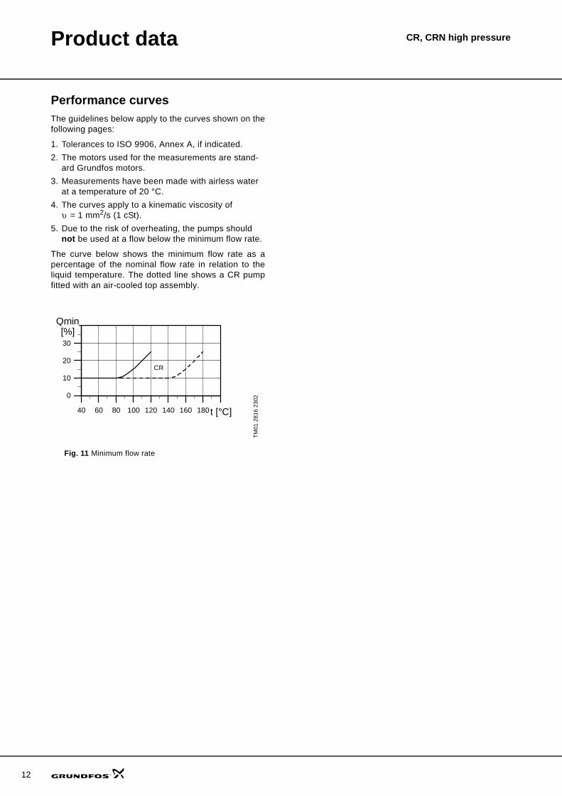
Performance curvesThe guidelines below apply to the curves shown on thefollowing pages:
1. Tolerances to ISO 9906, Annex A, if indicated. 2. The motors used for the measurements are stand-
ard Grundfos motors.3. Measurements have been made with airless water
at a temperature of 20 °C.4. The curves apply to a kinematic viscosity of
υ = 1 mm2/s (1 cSt).5. Due to the risk of overheating, the pumps should
not be used at a flow below the minimum flow rate.
The curve below shows the minimum flow rate as apercentage of the nominal flow rate in relation to theliquid temperature. The dotted line shows a CR pumpfitted with an air-cooled top assembly.
Fig. 11 Minimum flow rate
TM01
281
6 23
02
40 60 80 100 120 140 160 180t [°C]
0
10
20
30
Qmin[%]
CR
CR, CRN high pressureSelection and sizing
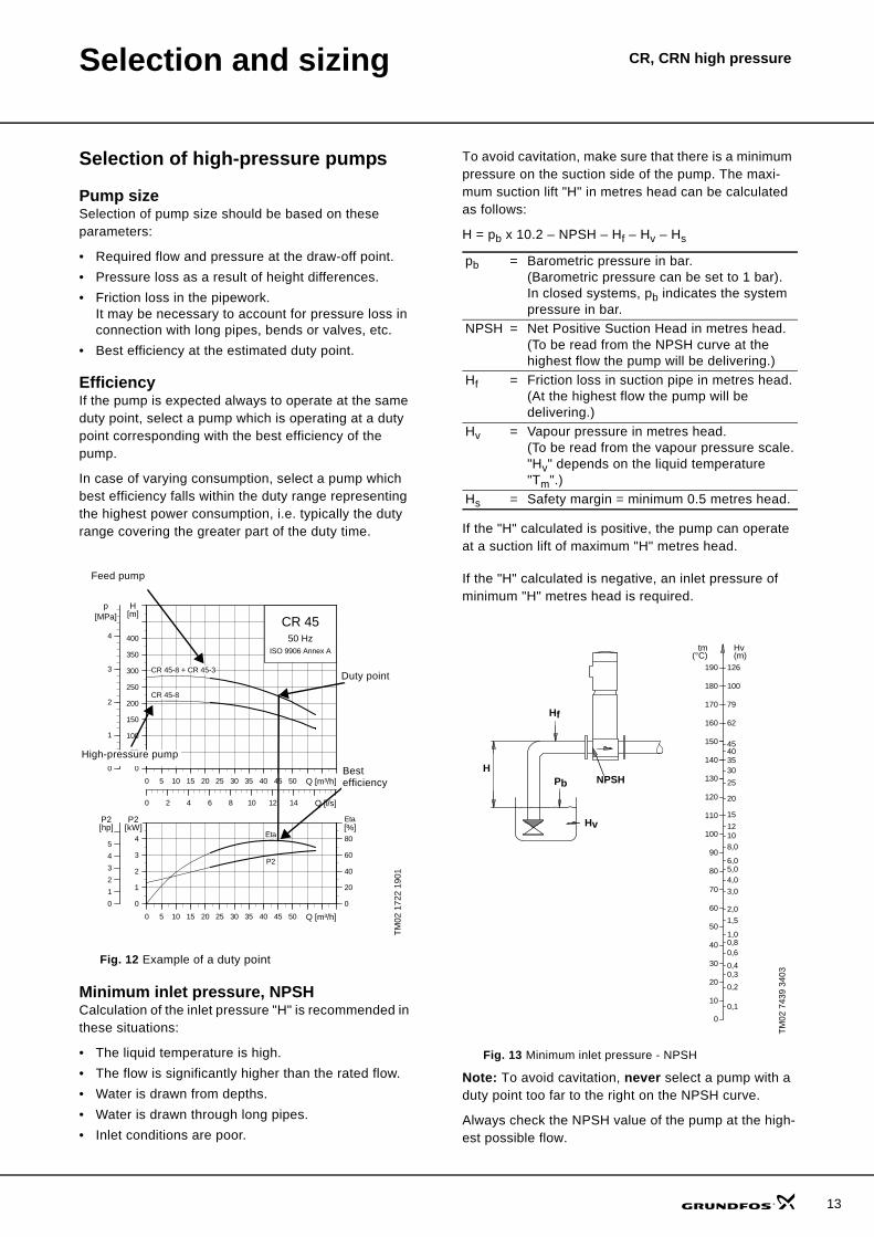
Selection of high-pressure pumps
Pump sizeSelection of pump size should be based on these parameters:
• Required flow and pressure at the draw-off point.• Pressure loss as a result of height differences.• Friction loss in the pipework.
It may be necessary to account for pressure loss in connection with long pipes, bends or valves, etc.
• Best efficiency at the estimated duty point.
EfficiencyIf the pump is expected always to operate at the same duty point, select a pump which is operating at a duty point corresponding with the best efficiency of the pump.
In case of varying consumption, select a pump which best efficiency falls within the duty range representing the highest power consumption, i.e. typically the duty range covering the greater part of the duty time.
Fig. 12 Example of a duty point
Minimum inlet pressure, NPSHCalculation of the inlet pressure "H" is recommended in these situations:
• The liquid temperature is high.• The flow is significantly higher than the rated flow.• Water is drawn from depths.• Water is drawn through long pipes.• Inlet conditions are poor.
To avoid cavitation, make sure that there is a minimum pressure on the suction side of the pump. The maxi-mum suction lift "H" in metres head can be calculated as follows:
H = pb x 10.2 – NPSH – Hf – Hv – Hs
If the "H" calculated is positive, the pump can operate at a suction lift of maximum "H" metres head.
If the "H" calculated is negative, an inlet pressure of minimum "H" metres head is required.
Fig. 13 Minimum inlet pressure - NPSH
Note: To avoid cavitation, never select a pump with a duty point too far to the right on the NPSH curve.
Always check the NPSH value of the pump at the high-est possible flow.
TM02
172
2 19
01
0 5 10 15 20 25 30 35 40 45 50 Q [m³/h]
0
50
100
150
200
250
300
350
400
H[m]
0 2 4 6 8 10 12 14 Q [l/s]
0
1
2
3
4
[MPa]p
CR 4550 Hz
ISO 9906 Annex A
CR 45-8 + CR 45-3
CR 45-8
0 5 10 15 20 25 30 35 40 45 50 Q [m³/h]
0
1
2
3
4
P2[kW]
0
20
40
60
80
[%]Eta
0
1
2
3
4
5
[hp]P2
P2
Eta
Duty point
Best efficiency
Feed pump
High-pressure pump
pb = Barometric pressure in bar. (Barometric pressure can be set to 1 bar). In closed systems, pb indicates the system pressure in bar.
NPSH = Net Positive Suction Head in metres head. (To be read from the NPSH curve at the highest flow the pump will be delivering.)
Hf = Friction loss in suction pipe in metres head.(At the highest flow the pump will be delivering.)
Hv = Vapour pressure in metres head.(To be read from the vapour pressure scale."Hv" depends on the liquid temperature "Tm".)
Hs = Safety margin = minimum 0.5 metres head.
TM02
743
9 34
03
20
15
12108,0
6,05,04,0
3,0
2,0
1,00,80,6
0,40,3
0,2
0,1
1,5
120
110
90
100
80
70
60
50
40
30
20
10
0
Hv(m)
tm(°C)
150
130
140
25
35
4540
30
160
170
180
190
62
79
100
126
Hf
PbH
Hv
NPSH
13

14
Selection and sizing CR, CRN high pressure
Shaft sealAs standard, the CR, CRN high-pressure range is fitted with a HQQE shaft seal suitable for the most common high-pressure applications.
These key parameters must be taken into account when selecting the shaft seal:
• type of pumped liquid • liquid temperature.Grundfos offers a wide range of shaft seal variants to meet specific demands.
Inlet pressure and operating pressureDo not exceed the limit values stated on pages 6 and 9 as regards these pressures:
• minimum inlet pressure• maximum inlet pressure• maximum operating pressure.
Fig. 14 Shaft seal (cartridge type)
TM02
053
8 48
00
15
16
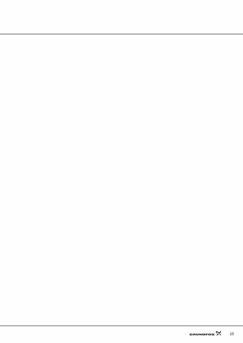
Performance curves/Technical data
CRNE 1 HS - 50/60 Hz
TM02
166
6 36
05
0.0 0.5 1.0 1.5 2.0 2.5 3.0 3.5 4.0 Q [m³/h]
0
50
100
150
200
250
300
350
400
450
500
H[m]
0.0 0.2 0.4 0.6 0.8 1.0 1.2 Q [l/s]
0
1000
2000
3000
4000
5000
p[kPa] CRNE 1-23 HS
ISO 9906 Annex A7.5 kW
6.0 kW
4.6 kW
0.0 0.5 1.0 1.5 2.0 2.5 3.0 3.5 4.0 Q [m³/h]
0
2
4
6
8
P1[kW]
0.0 0.5 1.0 1.5 2.0 2.5 3.0 3.5 4.0 Q [m³/h]
0
3
6
9
12
H[m]
0
3
6
9
12
NPSH[m]
NPSH
CRNE 1 HS - 50/60 Hz

Technical data CRNE 1 HS - 50/60 Hz
Dimensional sketch
Dimensions and weights
TM02
829
8 48
07
G 1/2
B2
50
22 180
B1
150100
210210
4 x ø13
G 1/2ø4
2.2
D2D1
P (PJE)
Pumptype
MotorP2
[kW]
Dimension [mm] Net weight[kg]B1 B2 B1+B2 D1 D2 D3
CRNE 1-23 HS 4.6 680 372 1052 220 188 160 65CRNE 1-23 HS 6.0 680 391 1071 220 188 200 66CRNE 1-23 HS 7.5 680 391 1071 220 188 200 66
17
18
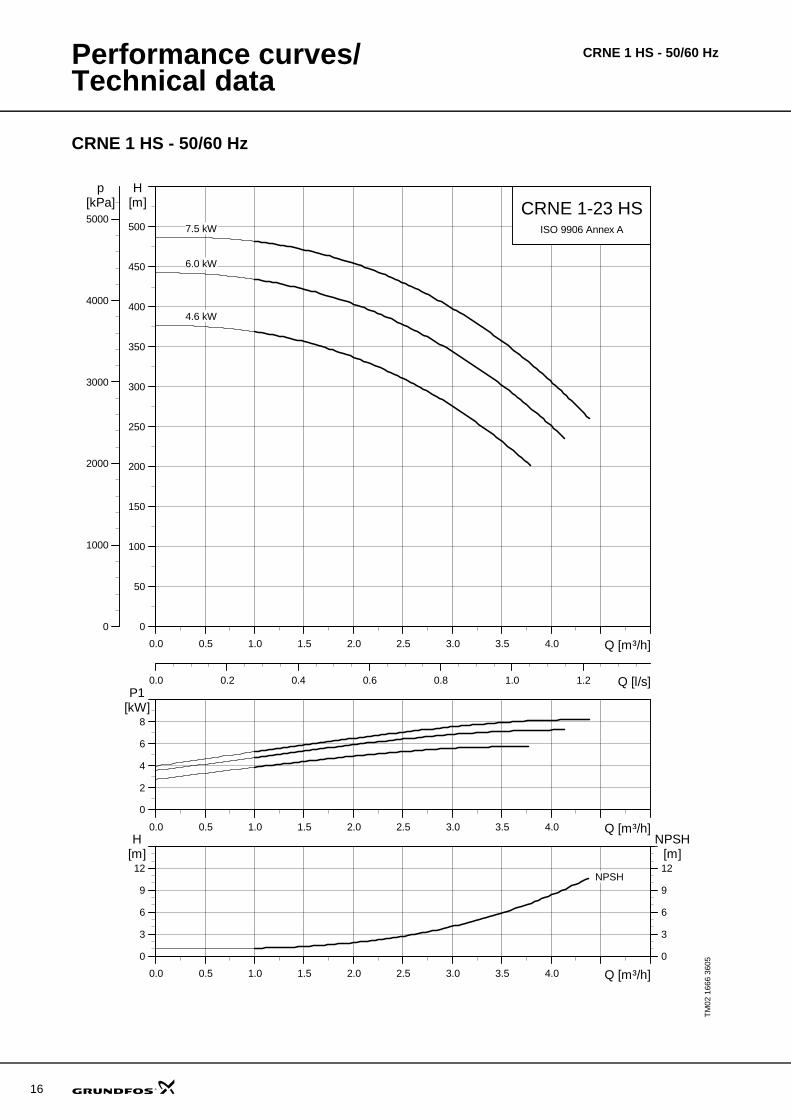
Performance curves CRNE 3 HS - 50/60 Hz
CRNE 3 HS - 50/60 Hz
TM02
166
7 36
05
0.0 0.5 1.0 1.5 2.0 2.5 3.0 3.5 4.0 4.5 5.0 Q [m³/h]
0
50
100
150
200
250
300
350
400
450
H[m]
0.0 0.2 0.4 0.6 0.8 1.0 1.2 1.4 Q [l/s]
0
1000
2000
3000
4000
p[kPa] CRNE 3-23 HS
ISO 9906 Annex A
7.5 kW
6.0 kW
4.6 kW
0.0 0.5 1.0 1.5 2.0 2.5 3.0 3.5 4.0 4.5 5.0 Q [m³/h]
0
2
4
6
8
P1[kW]
0.0 0.5 1.0 1.5 2.0 2.5 3.0 3.5 4.0 4.5 5.0 Q [m³/h]
0
2
4
6
8
H[m]
0
2
4
6
8
NPSH[m]
NPSH
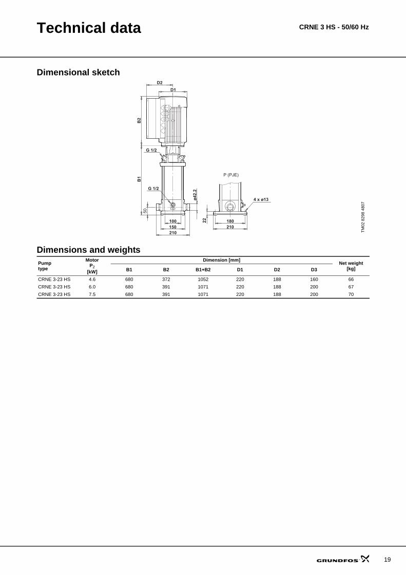
Technical data CRNE 3 HS - 50/60 Hz
Dimensional sketch
Dimensions and weights
TM02
829
8 48
07
G 1/2
B2
50
22 180
B1
150100
210210
4 x ø13
G 1/2ø4
2.2
D2D1
P (PJE)
Pumptype
MotorP2
[kW]
Dimension [mm] Net weight[kg]B1 B2 B1+B2 D1 D2 D3
CRNE 3-23 HS 4.6 680 372 1052 220 188 160 66CRNE 3-23 HS 6.0 680 391 1071 220 188 200 67CRNE 3-23 HS 7.5 680 391 1071 220 188 200 70
19

20
Performance curves CRN 3 SF - 50 Hz
CRN 3 SF, 50 Hz
TM03
979
4 44
07
0.0 0.5 1.0 1.5 2.0 2.5 3.0 3.5 4.0 Q [m³/h]
0
40
80
120
160
200
240
280
320
360
400
440
H[m]
0.0 0.2 0.4 0.6 0.8 1.0 1.2 Q [l/s]
0
800
1600
2400
3200
4000
p[kPa]
50 HzISO 9906 Annex A
CRN 3-31 SF+CRN 3-
+ CRN 3-36
+ CRN 3-31
+ CRN 3-27
+ CRN 3-23
+ CRN 3-19
+ CRN 3-15
+ CRN 3-12
+ CRN 3-10+ CRN 3-8+ CRN 3-6+ CRN 3-4
CRN 3-31 SF
*
*
0.0 0.5 1.0 1.5 2.0 2.5 3.0 3.5 4.0 Q [m³/h]
0.0
0.5
1.0
1.5
2.0
2.5
3.0
P2[kW]
0
10
20
30
40
50
60
[%]Eta
P2
Eta

Technical data CRN 3 SF, 50 Hz
Dimensional sketches
Dimensions and weights
1) High-pressure pump
TM04
001
9 48
07
TM02
737
7 33
03
CRN feed pump/CRN SF high-pressure pump CRN feed pump, connecting pipe and CRN SF high-pressure pump
246
266 250
246
266
Connecting pipe
Pumptype
MotorP2
[kW]
CRN CRNEDimension [mm] Net weight
[kg]Dimension [mm] Net weight
[kg]B1 B2 B1+B2 D1 D2 B1 B2 B1+B2 D1 D2CRN 3-4 0.37 275 191 466 141 109 17 - - - - - - CRN 3-6 0.55 311 191 502 141 109 18 - - - - - - CRN 3-8 0.75 353 231 584 141 109 21 - - - - - - CRN 3-10 0.75 389 231 620 141 109 22 - - - - - - CRN 3-12 1.1 425 231 656 141 109 25 - - - - - - CRN 3-15 1.1 479 231 710 141 109 26 - - - - - - CRN 3-19 1.5 567 281 848 178 110 34 - - - - - - CRN 3-23 2.2 639 321 960 178 110 37 - - - - - - CRN 3-27 2.2 711 321 1032 178 110 38 - - - - - - CRN 3-31 3 788 335 1123 198 120 44 - - - - - - CRN 3-36 3 878 335 1213 198 120 46 - - - - - -
CRN(E) 3-31 SF 1) 3 820 335 1155 1148 198 48 820 335 155 198 177 58
21

22
Performance curves CRN 5 SF, 50 Hz
CRN 5 SF, 50 Hz
TM02
744
7 19
06
0 1 2 3 4 5 6 7 8 Q [m³/h]
0
40
80
120
160
200
240
280
320
360
400
440
480
H[m]
0.0 0.5 1.0 1.5 2.0 2.5 Q [l/s]
0
1000
2000
3000
4000
p[kPa]
50 HzISO 9906 Annex A
CRN 5-34 SF+CRN 5-
+ CRN 5-36
+ CRN 5-29
+ CRN 5-24
+ CRN 5-20
+ CRN 5-16+ CRN 5-14+ CRN 5-12+ CRN 5-10+ CRN 5-8+ CRN 5-6+ CRN 5-4
CRN(E) 5-34 SF
*
*
0 1 2 3 4 5 6 7 8 Q [m³/h]
0
1
2
3
4
5
6
7
8
P2[kW]
0
10
20
30
40
50
60
70
80[%]Eta
Eta
P2

Technical data CRN 5 SF, 50 Hz
Dimensional sketches
Dimensions and weights
1) High-pressure pump
TM02
737
6 48
07
TM02
737
7 33
03
CRN feed pump/CRN SF high-pressure pump CRN feed pump, connecting pipe and CRN SF high-pressure pump
50
22 180
B1
150100
210210
4 x ø13ø42.
2
B2
D2
D1
D3
G 1/2 G 1/2
G 1/2
P (PJE)
246
266 250
246
266
Connecting pipe
Pumptype
MotorP2
[kW]
CRN CRNEDimension [mm] Net weight
[kg]Dimension [mm] Net weight
[kg]B1 B2 B1+B2 D1 D2 D3 B1 B2 B1+B2 D1 D2 D3CRN 5-4 0.55 311 191 502 141 109 - 18 - - - - - - - CRN 5-6 1.1 371 231 602 141 109 - 24 - - - - - - - CRN 5-8 1.1 425 231 656 141 109 - 25 - - - - - - - CRN 5-10 1.5 495 281 776 178 110 - 32 - - - - - - - CRN 5-12 2.2 549 321 870 178 110 - 34 - - - - - - - CRN 5-14 2.2 603 321 924 178 110 - 35 - - - - - - - CRN 5-16 2.2 657 321 978 178 110 - 36 - - - - - - - CRN 5-20 3 770 335 1105 198 120 - 43 - - - - - - - CRN 5-24 4 878 372 1250 220 134 - 56 - - - - - - - CRN 5-29 4 1013 372 1385 220 134 - 59 - - - - - - - CRN 5-36 5.5 1231 391 1622 220 134 300 77 - - - - - - -
CRN(E) 5-34 SF 1) 5.5 1228 391 1619 220 134 300 76 1228 391 1619 220 188 298 89
23
24
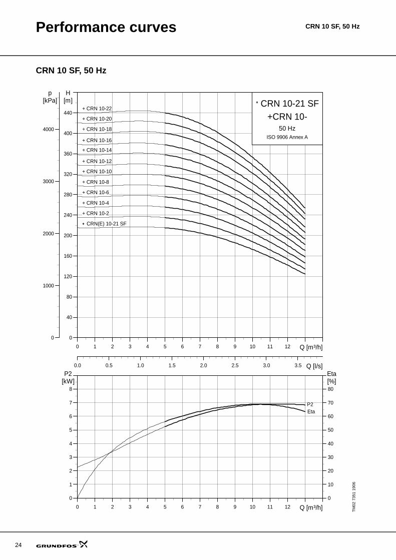
Performance curves CRN 10 SF, 50 Hz
CRN 10 SF, 50 Hz
TM02
735
1 19
060 1 2 3 4 5 6 7 8 9 10 11 12 Q [m³/h]
0
40
80
120
160
200
240
280
320
360
400
440
H[m]
0.0 0.5 1.0 1.5 2.0 2.5 3.0 3.5 Q [l/s]
0
1000
2000
3000
4000
p[kPa]
50 HzISO 9906 Annex A
CRN 10-21 SF+CRN 10-
+ CRN 10-22
+ CRN 10-20
+ CRN 10-18
+ CRN 10-16
+ CRN 10-14
+ CRN 10-12
+ CRN 10-10
+ CRN 10-8
+ CRN 10-6
+ CRN 10-4
+ CRN 10-2
CRN(E) 10-21 SF
*
*
0 1 2 3 4 5 6 7 8 9 10 11 12 Q [m³/h]
0
1
2
3
4
5
6
7
8
P2[kW]
0
10
20
30
40
50
60
70
80[%]Eta
EtaP2

Technical data CRN 10 SF, 50 Hz
Dimensional sketches
Dimensions and weights
1) High-pressure pump
TM02
737
8 48
07
TM02
738
1 33
03
CRN feed pump/CRN SF high-pressure pump CRN feed pump, connecting pipe and CRN SF high-pressure pump
130
ø60.
1
B2
D2D1
200
80
G 1/2
261
B1
G 1/2G 1/2
215248
26 4 x ø13
D3
P (PJE)
317
320 300
317
320
Connecting pipe
Pumptype
MotorP2
[kW]
CRN CRNEDimension [mm] Net weight
[kg]Dimension [mm] Net weight
[kg]B1 B2 B1+B2 D1 D2 D3 B1 B2 B1+B2 D1 D2 D3CRN 10-2 0.75 357 231 588 141 109 - 31 - - - - - - - CRN 10-4 1.5 433 281 714 178 110 - 42 - - - - - - - CRN 10-6 2.2 493 321 814 178 110 - 45 - - - - - - - CRN 10-8 3 558 335 893 198 120 - 52 - - - - - - - CRN 10-10 4 618 372 990 220 134 - 65 - - - - - - - CRN 10-12 4 678 372 1050 220 134 - 67 - - - - - - - CRN 10-14 5.5 770 391 1161 220 134 300 89 - - - - - - - CRN 10-16 5.5 830 391 1221 220 134 300 91 - - - - - - - CRN 10-18 7.5 890 391 1281 220 134 300 96 - - - - - - - CRN 10-20 7.5 950 391 1341 220 134 300 98 - - - - - - - CRN 10-22 7.5 1010 391 1401 220 134 300 100 - - - - - - -
CRN(E) 10-21 SF 1) 7.5 1010 391 1401 220 134 300 99 1010 391 1401 220 188 298 111
25

26
Performance curves CRN 15 SF, 50 Hz
CRN 15 SF, 50 Hz
TM02
735
2 19
060 2 4 6 8 10 12 14 16 18 20 22 Q [m³/h]
0
40
80
120
160
200
240
280
320
360
400
440
480
H[m]
0 1 2 3 4 5 6 Q [l/s]
0
1000
2000
3000
4000
p[kPa]
50 HzISO 9906 Annex A
CRN 15-16 SF+CRN 15-+ CRN 15-17
+ CRN 15-14
+ CRN 15-12
+ CRN 15-9
+ CRN 15-7
+ CRN 15-5
+ CRN 15-3
CRN(E) 15-16 SF
*
*
0 2 4 6 8 10 12 14 16 18 20 22 Q [m³/h]
0
2
4
6
8
10
12
14
16
P2[kW]
0
10
20
30
40
50
60
70
80[%]Eta
P2Eta

Technical data CRN 15 SF, 50 Hz
Dimensional sketches
Dimensions and weights
1) High-pressure pump
TM02
738
0 48
07
TM02
738
1 33
03
CRN feed pump/CRN SF high-pressure pump CRN feed pump, connecting pipe and CRN SF high-pressure pump
B2
D2D1
G 1/2
B1
G 1/2G 1/2
D3
P (PJE)
ø60.
1
4 x ø13
261
215248
130200
26
90 317
320 300
317
320
Connecting pipe
Pumptype
MotorP2
[kW]
CRN CRNEDimension [mm] Net weight
[kg]Dimension [mm] Net weight
[kg]B1 B2 B1+B2 D1 D2 D3 B1 B2 B1+B2 D1 D2 D3CRN 15-3 3 463 335 798 198 120 - 48 - - - - - - - CRN 15-5 4 553 372 925 220 134 - 62 - - - - - - - CRN 15-7 5.5 675 391 1066 220 134 300 86 - - - - - - - CRN 15-9 7.5 765 391 1156 220 134 300 91 - - - - - - - CRN 15-12 11 977 499 1476 260 172 350 126 - - - - - - - CRN 15-14 11 1067 499 1566 260 172 350 130 - - - - - - - CRN 15-17 15 1202 478 1680 320 197 350 149 - - - - - - -
CRN(E) 15-16 SF 1) 15 1202 478 1680 320 197 350 146 1202 461 1663 313 377 350 182
27

28
Performance curves CRN 20 SF, 50 Hz
CRN 20 SF, 50 Hz
TM02
735
3 19
060 2 4 6 8 10 12 14 16 18 20 22 24 26 28 Q [m³/h]
0
40
80
120
160
200
240
280
320
360
400
440
480
H[m]
0 1 2 3 4 5 6 7 8 Q [l/s]
0
1000
2000
3000
4000
p[kPa]
50 HzISO 9906 Annex A
CRN 20-16 SF+CRN 20-
+ CRN 20-17
+ CRN 20-14
+ CRN 20-12
+ CRN 20-10
+ CRN 20-7
+ CRN 20-5
+ CRN 20-3
CRN(E) 20-16 SF
*
*
0 2 4 6 8 10 12 14 16 18 20 22 24 26 28 Q [m³/h]
0
2
4
6
8
10
12
14
16
P2[kW]
0
10
20
30
40
50
60
70
80[%]Eta
Eta
P2

Technical data CRN 20 SF, 50 Hz
Dimensional sketches
Dimensions and weights
1) High-pressure pump
TM02
738
0 48
07
TM02
738
1 33
03
CRN feed pump/CRN SF high-pressure pump CRN feed pump, connecting pipe and CRN SF high-pressure pump
B2
D2D1
G 1/2
B1
G 1/2G 1/2
D3
P (PJE)
ø60.
1
4 x ø13
261
215248
130200
26
90 317
320 300
317
320
Connecting pipe
Pumptype
MotorP2
[kW]
CRN CRNEDimension [mm] Net weight
[kg]Dimension [mm] Net weight
[kg]B1 B2 B1+B2 D1 D2 D3 B1 B2 B1+B2 D1 D2 D3CRN 20-3 4 463 372 835 220 134 - 59 - - - - - - - CRN 20-5 5.5 585 391 976 220 134 300 82 - - - - - - - CRN 20-7 7.5 675 391 1066 220 134 300 88 - - - - - - - CRN 20-10 11 887 499 1386 260 172 350 123 - - - - - - - CRN 20-12 15 977 478 1455 320 197 350 140 - - - - - - - CRN 20-14 15 1067 478 1545 320 197 350 144 - - - - - - - CRN 20-17 18.5 1202 518 1720 320 197 350 179 - - - - - - -
CRN(E) 20-16 SF 1) 18.5 1202 518 1720 320 197 350 177 1202 499 1701 313 377 350 218
29

30
Performance curves CR 32, 50 Hz
CR 32, 50 Hz
TM02
166
8 36
05
0 4 8 12 16 20 24 28 32 36 Q [m³/h]
0
40
80
120
160
200
240
280
320
360
400
H[m]
0 2 4 6 8 10 Q [l/s]
0
1000
2000
3000
4000
p[kPa]
50 HzISO 9906 Annex A
CR 32
CR 32-10
CR 32-10 + CR 32-5
CR 32-10 + CR 32-6
CR 32-10 + CR 32-7
CR 32-10 + CR 32-8
CR 32-10 + CR 32-9
CR 32-10 + CR 32-10
0 4 8 12 16 20 24 28 32 36 Q [m³/h]
0.0
0.5
1.0
1.5
2.0
P2[kW]
0
20
40
60
80
[%]Eta
EtaP2

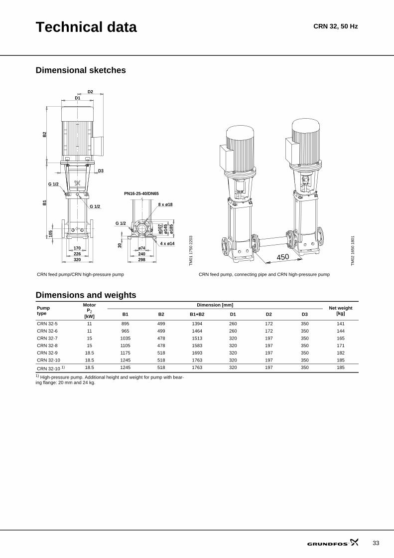
Technical data CR 32, 50 Hz
Dimensional sketches
Dimensions and weights
1) High-pressure pump. Additional height and weight for pump with bear-ing flange: 20 mm and 24 kg.
TM01
175
0 22
03
TM02
165
0 18
01
CR feed pump/CR high-pressure pump CR feed pump, connecting pipe and CR high-pressure pump
8 x ø18
G 1/2
ø74240298
ø107
ø145
ø185
D2D1
170226320
B1
B2
G 1/2
G 1/2
4 x ø14
105
D3
30
PN16-25-40/DN65
450
Pumptype
MotorP2
[kW]
Dimension [mm] Net weight[kg]B1 B2 B1+B2 D1 D2 D3
CR 32-5 11 895 499 1394 260 172 350 139CR 32-6 11 965 499 1464 260 172 350 142CR 32-7 15 1035 478 1513 320 197 350 163CR 32-8 15 1105 478 1583 320 197 350 169CR 32-9 18.5 1175 518 1693 320 197 350 180CR 32-10 18.5 1245 518 1763 320 197 350 183
CR 32-10 1) 18.5 1245 518 1763 320 197 350 183
31

32
Performance curves CRN 32, 50 Hz
CRN 32, 50 Hz
TM02
167
9 36
05
0 4 8 12 16 20 24 28 32 36 Q [m³/h]
0
40
80
120
160
200
240
280
320
360
400
H[m]
0 2 4 6 8 10 Q [l/s]
0
1000
2000
3000
4000
p[kPa]
50 HzISO 9906 Annex A
CRN 32
CRN 32-10
CRN 32-10 + CRN 32-5
CRN 32-10 + CRN 32-6
CRN 32-10 + CRN 32-7
CRN 32-10 + CRN 32-8
CRN 32-10 + CRN 32-9
CRN 32-10 + CRN 32-10
0 4 8 12 16 20 24 28 32 36 Q [m³/h]
0.0
0.5
1.0
1.5
2.0
P2[kW]
0
20
40
60
80
[%]Eta
EtaP2
Technical data CRN 32, 50 Hz
Dimensional sketches
Dimensions and weights
1) High-pressure pump. Additional height and weight for pump with bear-ing flange: 20 mm and 24 kg.
TM01
175
0 22
03
TM02
165
0 18
01
CRN feed pump/CRN high-pressure pump CRN feed pump, connecting pipe and CRN high-pressure pump
8 x ø18
G 1/2
ø74240298
ø107
ø145
ø185
D2D1
170226320
B1
B2
G 1/2
G 1/2
4 x ø14
105
D3
30
PN16-25-40/DN65
450
Pumptype
MotorP2
[kW]
Dimension [mm] Net weight[kg]B1 B2 B1+B2 D1 D2 D3
CRN 32-5 11 895 499 1394 260 172 350 141CRN 32-6 11 965 499 1464 260 172 350 144CRN 32-7 15 1035 478 1513 320 197 350 165CRN 32-8 15 1105 478 1583 320 197 350 171CRN 32-9 18.5 1175 518 1693 320 197 350 182CRN 32-10 18.5 1245 518 1763 320 197 350 185
CRN 32-10 1) 18.5 1245 518 1763 320 197 350 185
33
34
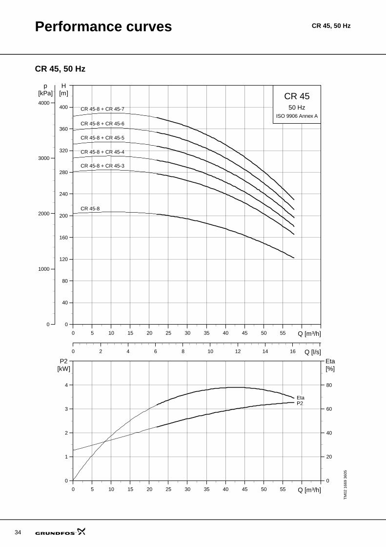
Performance curves CR 45, 50 Hz
CR 45, 50 Hz
TM02
166
9 36
05
0 5 10 15 20 25 30 35 40 45 50 55 Q [m³/h]
0
40
80
120
160
200
240
280
320
360
400
H[m]
0 2 4 6 8 10 12 14 16 Q [l/s]
0
1000
2000
3000
4000
p[kPa]
50 HzISO 9906 Annex A
CR 45
CR 45-8
CR 45-8 + CR 45-3
CR 45-8 + CR 45-4
CR 45-8 + CR 45-5
CR 45-8 + CR 45-6
CR 45-8 + CR 45-7
0 5 10 15 20 25 30 35 40 45 50 55 Q [m³/h]
0
1
2
3
4
P2[kW]
0
20
40
60
80
[%]Eta
P2Eta
Technical data CR 45, 50 Hz
Dimensional sketches
Dimensions and weights
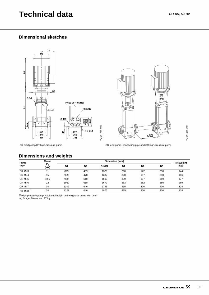
1) High-pressure pump. Additional height and weight for pump with bear-ing flange: 20 mm and 27 kg.
TM02
176
8 28
03
TM02
165
0 18
01
CR feed pump/CR high-pressure pump CR feed pump, connecting pipe and CR high-pressure pump
8 x ø18
G 1/2
ø80266331
ø12
0ø
160
ø20
0
D2D1
190248365
B1
B2
G 1/2
G 1/2
4 x ø14
140
D3
45
PN16-25-40/DN80
450
Pumptype
MotorP2
[kW]
Dimension [mm] Net weight[kg]B1 B2 B1+B2 D1 D2 D3
CR 45-3 11 829 499 1328 260 172 350 144CR 45-4 15 909 478 1387 320 197 350 166CR 45-5 18.5 989 518 1507 320 197 350 177CR 45-6 22 1069 610 1679 363 262 350 269CR 45-7 30 1149 646 1795 415 300 400 324
CR 45-8 1) 30 1229 646 1875 415 300 400 328
35
36
Performance curves CRN 45, 50 Hz
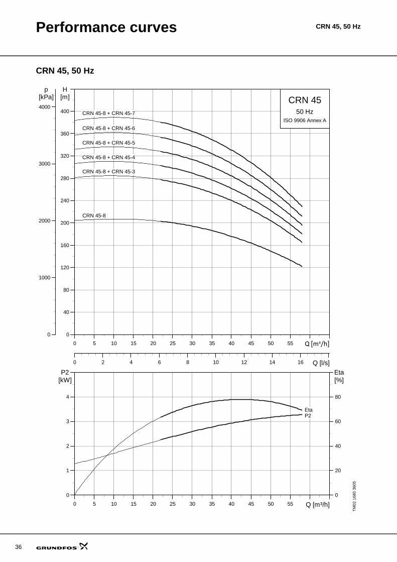
CRN 45, 50 Hz
TM02
168
0 36
05
0 5 10 15 20 25 30 35 40 45 50 55 Q [m³/h]
0
40
80
120
160
200
240
280
320
360
400
H[m]
0 2 4 6 8 10 12 14 16 Q [l/s]
0
1000
2000
3000
4000
p[kPa]
50 HzISO 9906 Annex A
CRN 45
CRN 45-8
CRN 45-8 + CRN 45-3
CRN 45-8 + CRN 45-4
CRN 45-8 + CRN 45-5
CRN 45-8 + CRN 45-6
CRN 45-8 + CRN 45-7
0 5 10 15 20 25 30 35 40 45 50 55 Q [m³/h]
0
1
2
3
4
P2[kW]
0
20
40
60
80
[%]Eta
P2Eta

Technical data CRN 45, 50 Hz
Dimensional sketches
Dimensions and weights
1) High-pressure pump. Additional height and weight for pump with bear-ing flange: 20 mm and 27 kg.
TM02
176
9 28
03
TM02
165
0 18
01
CRN feed pump/ CRN high-pressure pump CRN feed pump, connecting pipe and CRN high-pressure pump
266331
ø12
0ø
160
ø20
0
D2D1
190251365
B1
B2
G 1/2 8 x ø18
G 1/2
4 x ø14
140
D3
45
G 1/2
PN16-25-40/DN80
ø80
450
Pumptype
MotorP2
[kW]
Dimension [mm] Net weight[kg]B1 B2 B1+B2 D1 D2 D3
CRN 45-3 11 829 499 1328 260 172 350 145CRN 45-4 15 909 478 1387 320 197 350 166CRN 45-5 18.5 989 518 1507 320 197 350 177CRN 45-6 22 1069 610 1679 363 262 350 270CRN 45-7 30 1149 646 1795 415 300 400 324
CRN 45-8 1) 30 1229 646 1875 415 300 400 328
37

38
Performance curves CR 64, 50 Hz
CR 64, 50 Hz
TM02
167
0 18
01
0 10 20 30 40 50 60 70 80 Q [m³/h]
0
40
80
120
160
200
240
280
320
360
400
H[m]
0 5 10 15 20 25 Q [l/s]
0
1000
2000
3000
4000
p[kPa]
50 HzISO 9906 Annex A
CR 64
CR 64-7
CR 64-7 + CR 64-2
CR 64-7 + CR 64-3
CR 64-7 + CR 64-4
CR 64-7 + CR 64-5
CR 64-7 + CR 64-6
0 10 20 30 40 50 60 70 80 Q [m³/h]
0
2
4
6
8
P2[kW]
0
20
40
60
80
[%]Eta
Eta
P2

Technical data CR 64, 50 Hz
Dimensional sketches
Dimensions and weights
1) High-pressure pump. Additional height and weight for pump with bear-ing flange: 20 mm and 30 kg.
TM02
177
0 28
03
TM02
165
0 18
01
CR feed pump/CR high-pressure pump CR feed pump, connecting pipe and CR high-pressure pump
D2D1
190248365
B1
B2
G 1/2
G 1/2
140
D3
PN16-25-40/DN100
45
4 x ø14
G 1/2
8 x ø22
ø23
5ø
190
ø15
0
331266
ø100
450
Pumptype
MotorP2
[kW]
Dimension [mm] Net weight[kg]B1 B2 B1+B2 D1 D2 D3
CR 64-2 11 754 499 1253 260 172 350 143CR 64-3 18.5 836 518 1354 320 197 350 173CR 64-4 22 919 610 1529 363 262 350 263CR 64-5 30 1001 646 1647 415 300 400 318CR 64-6 37 1084 703 1787 415 300 400 354
CR 64-7 1) 45 1166 709 1875 442 325 450 438
39
40
Performance curves CRN 64, 50 Hz
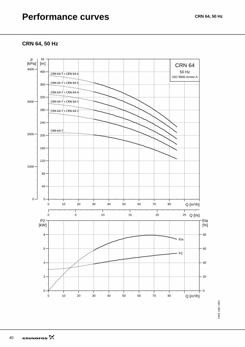
CRN 64, 50 Hz
TM02
168
1 18
01
0 10 20 30 40 50 60 70 80 Q [m³/h]
0
40
80
120
160
200
240
280
320
360
400
H[m]
0 5 10 15 20 25 Q [l/s]
0
1000
2000
3000
4000
p[kPa]
50 HzISO 9906 Annex A
CRN 64
CRN 64-7
CRN 64-7 + CRN 64-2
CRN 64-7 + CRN 64-3
CRN 64-7 + CRN 64-4
CRN 64-7 + CRN 64-5
CRN 64-7 + CRN 64-6
0 10 20 30 40 50 60 70 80 Q [m³/h]
0
2
4
6
8
P2[kW]
0
20
40
60
80
[%]Eta
Eta
P2
Technical data CRN 64, 50 Hz
Dimensional sketches
Dimensions and weights
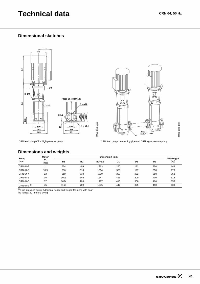
1) High-pressure pump. Additional height and weight for pump with bear-ing flange: 20 mm and 30 kg.
TM02
177
1 28
03
TM02
165
0 18
01
CRN feed pump/CRN high-pressure pump CRN feed pump, connecting pipe and CRN high-pressure pump
D2D1
190251365
B1
B2
G 1/2
G 1/2
140
D3
PN16-25-40/DN100
45
4 x ø14
G 1/2
8 x ø22
ø22
0ø
190
ø15
0
331266
ø100
450
Pumptype
MotorP2
[kW]
Dimension [mm] Net weight[kg]B1 B2 B1+B2 D1 D2 D3
CRN 64-2 11 754 499 1253 260 172 350 143CRN 64-3 18.5 836 518 1354 320 197 350 173CRN 64-4 22 919 610 1529 363 262 350 263CRN 64-5 30 1001 646 1647 415 300 400 318CRN 64-6 37 1084 703 1787 415 300 400 355
CRN 64-7 1) 45 1166 709 1875 442 325 450 439
41

42
Performance curves CR 90, 50 Hz
CR 90, 50 Hz
TM02
167
1 18
01
0 10 20 30 40 50 60 70 80 90 100 110 Q [m³/h]
0
40
80
120
160
200
240
280
320
360
400
440
H[m]
0 5 10 15 20 25 30 Q [l/s]
0
1000
2000
3000
4000
p[kPa]
50 HzISO 9906 Annex A
CR 90
CR 90-6
CR 90-6 + CR 90-1
CR 90-6 + CR 90-2
CR 90-6 + CR 90-3
CR 90-6 + CR 90-4
CR 90-6 + CR 90-5
CR 90-6 + CR 90-6
0 10 20 30 40 50 60 70 80 90 100 110 Q [m³/h]
0
2
4
6
8
P2[kW]
0
20
40
60
80
[%]Eta
Eta
P2
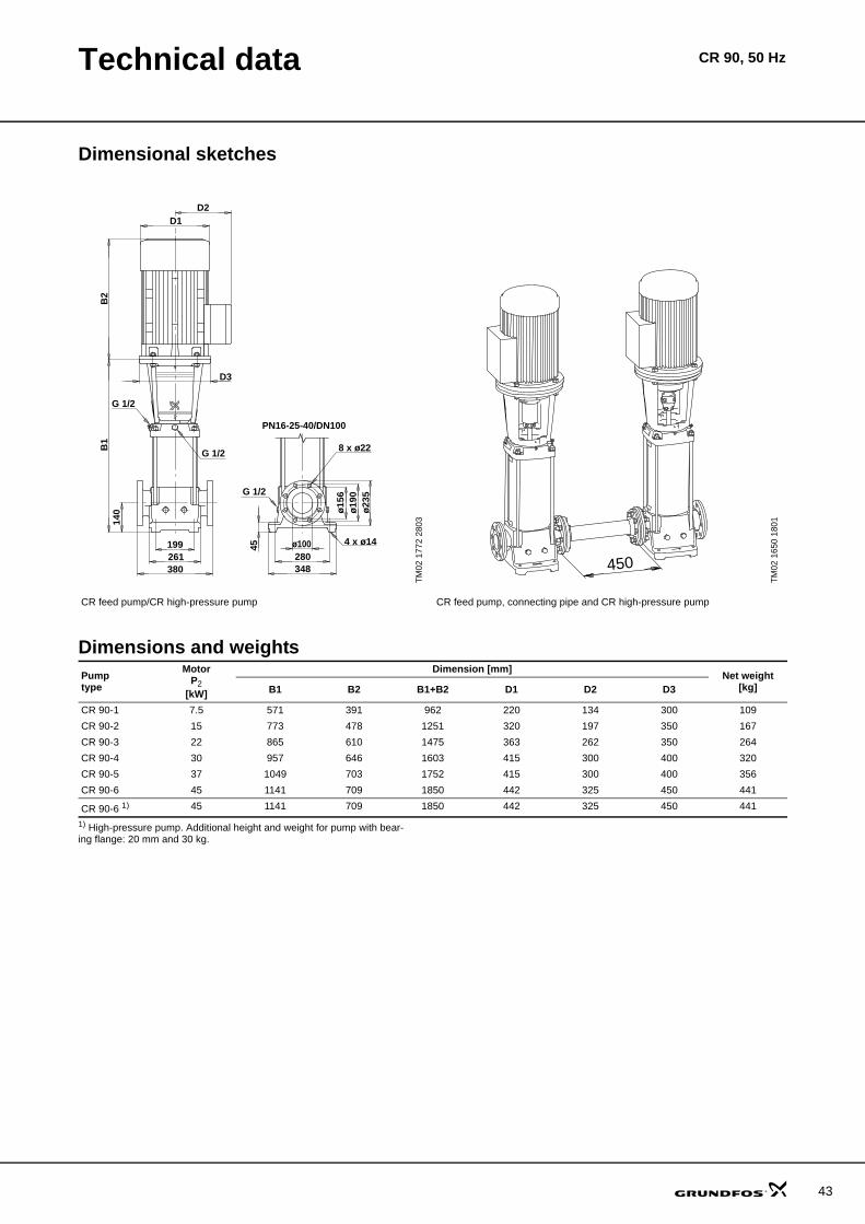
Technical data CR 90, 50 Hz
Dimensional sketches
Dimensions and weights
1) High-pressure pump. Additional height and weight for pump with bear-ing flange: 20 mm and 30 kg.
TM02
177
2 28
03
TM02
165
0 18
01
CR feed pump/CR high-pressure pump CR feed pump, connecting pipe and CR high-pressure pump
D2D1
199261380
B1
B2
G 1/2
140
D3
G 1/2
PN16-25-40/DN100
45
4 x ø14
G 1/2
8 x ø22
ø23
5ø
190
ø15
6
348280
ø100
450
Pumptype
MotorP2
[kW]
Dimension [mm] Net weight[kg]B1 B2 B1+B2 D1 D2 D3
CR 90-1 7.5 571 391 962 220 134 300 109CR 90-2 15 773 478 1251 320 197 350 167CR 90-3 22 865 610 1475 363 262 350 264CR 90-4 30 957 646 1603 415 300 400 320CR 90-5 37 1049 703 1752 415 300 400 356CR 90-6 45 1141 709 1850 442 325 450 441
CR 90-6 1) 45 1141 709 1850 442 325 450 441
43

44
Performance curves CRN 90, 50 Hz
CRN 90, 50 Hz
TM02
168
2 18
01
0 10 20 30 40 50 60 70 80 90 100 110 Q [m³/h]
0
40
80
120
160
200
240
280
320
360
400
440
H[m]
0 5 10 15 20 25 30 Q [l/s]
0
1000
2000
3000
4000
p[kPa]
50 HzISO 9906 Annex A
CRN 90
CRN 90-6
CRN 90-6 + CRN 90-1
CRN 90-6 + CRN 90-2
CRN 90-6 + CRN 90-3
CRN 90-6 + CRN 90-4
CRN 90-6 + CRN 90-5
CRN 90-6 + CRN 90-6
0 10 20 30 40 50 60 70 80 90 100 110 Q [m³/h]
0
2
4
6
8
P2[kW]
0
20
40
60
80
[%]Eta
Eta
P2
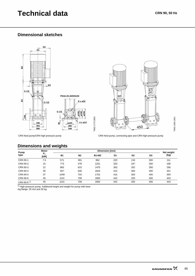
Technical data CRN 90, 50 Hz
Dimensional sketches
Dimensions and weights
1) High-pressure pump. Additional height and weight for pump with bear-ing flange: 20 mm and 30 kg.
TM02
177
3 28
03
TM02
165
0 18
01
CRN feed pump/CRN high-pressure pump CRN feed pump, connecting pipe and CRN high-pressure pump
D2D1
199261380
B1
B2
G 1/2
G 1/2
140
D3
PN16-25-40/DN100
45
4 x ø14
G 1/2
8 x ø22
ø23
5ø
190
ø15
6
348280
ø100
450
Pumptype
MotorP2
[kW]
Dimension [mm] Net weight[kg]B1 B2 B1+B2 D1 D2 D3
CRN 90-1 7.5 571 391 962 220 134 300 111CRN 90-2 15 773 478 1251 320 197 350 168CRN 90-3 22 865 610 1475 363 262 350 266CRN 90-4 30 957 646 1603 415 300 400 321CRN 90-5 37 1049 703 1752 415 300 400 359CRN 90-6 45 1141 709 1850 442 325 450 443
CRN 90-6 1) 45 1141 709 1850 442 325 450 443
45

46
Performance curves CR 120, 50 Hz
CR 120, 50 Hz
TM03
969
8 43
070 10 20 30 40 50 60 70 80 90 100 110 120 130 140 150 Q [m³/h]
80
100
120
140
160
180
200
220
240
260
280
300
320
340
360
380
400
420
440
H[m]
0 5 10 15 20 25 30 35 40 Q [l/s]
1000
1500
2000
2500
3000
3500
4000
p[kPa]
50 HzISO 9906 Annex A
CR 120
120-7 + 120-2
120-7 + 120-2-1
120-7 + 120-3
120-7 + 120-4-1
120-7 + 120-5-1
120-7 + 120-6-1
120-7 + 120-7
120-7
120-7 + 120-1
0 10 20 30 40 50 60 70 80 90 100 110 120 130 140 150 Q [m³/h]
0
2
4
6
8
10
12
14
16
P2[kW]
0
10
20
30
40
50
60
70
80[%]Eta
Eta
P2 1/1
P2 2/3

Technical data CR 120, 50 Hz
Dimensional sketches
Dimensions and weights
1) High-pressure pump
TM03
970
4 44
07
TM02
165
0 08
01
CR feed pump/CR high-pressure pump CR feed pump, connecting pipe and CR high-pressure pump
450
Pumptype
MotorP2
[kW]
Dimension [mm] Net weight[kg]B1 B2 B1+B2 D1 D2 D3
CR 120-1 11 834 499 1333 260 172 350 172CR 120-2-1 18.5 990 518 1508 320 197 350 207CR 120-2 22 990 610 1600 363 262 350 293CR 120-3 30 1145 646 1791 415 300 400 353CR 120-4-1 37 1301 703 2004 415 300 400 392CR 120-5-1 45 1456 709 2165 442 325 450 482CR 120-6-1 55 1642 747 2389 495 392 550 627CR 120-7 75 1797 820 2617 555 432 550 771
CR 120-7 1) 75 1797 820 2617 555 432 550 771
47
48
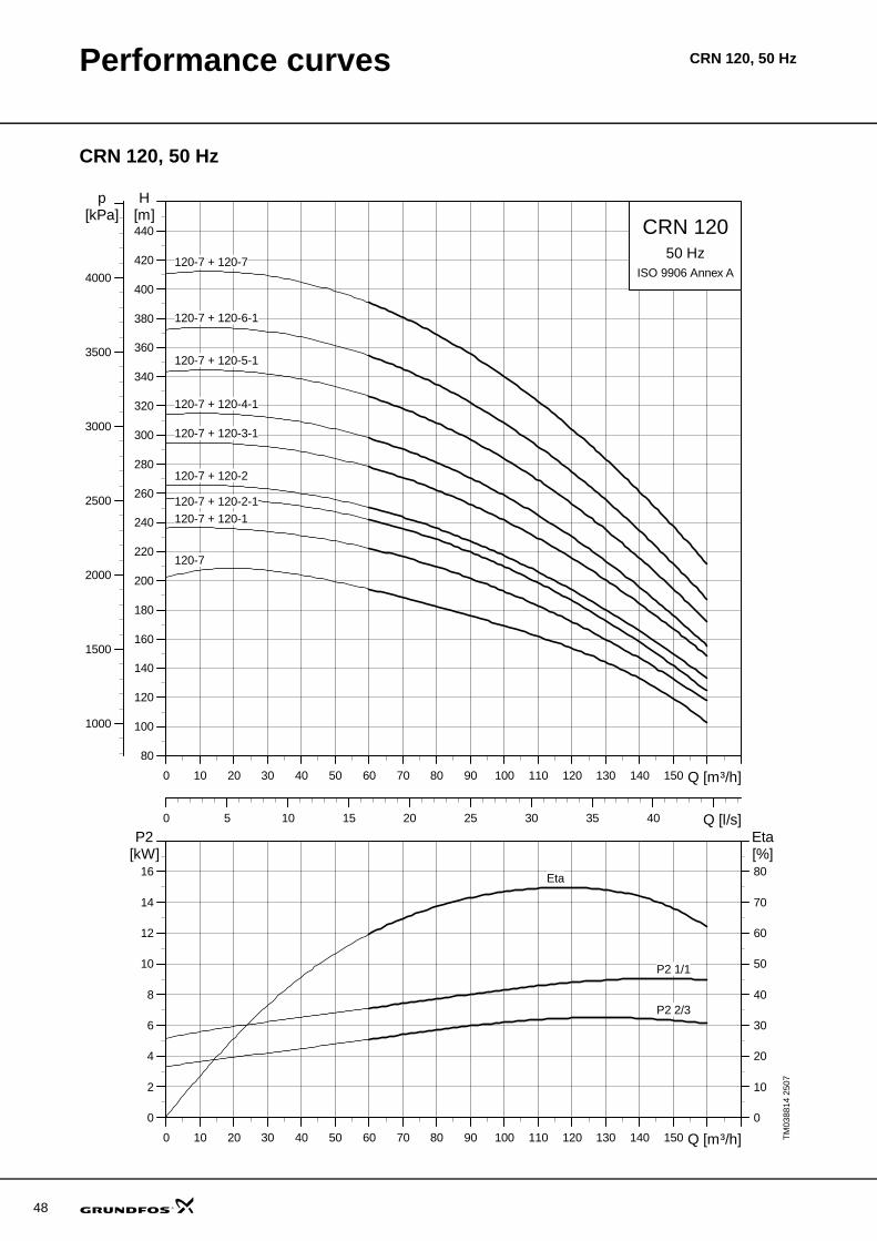
Performance curves CRN 120, 50 Hz
CRN 120, 50 Hz
TM03
8814
250
70 10 20 30 40 50 60 70 80 90 100 110 120 130 140 150 Q [m³/h]
80
100
120
140
160
180
200
220
240
260
280
300
320
340
360
380
400
420
440
H[m]
0 5 10 15 20 25 30 35 40 Q [l/s]
1000
1500
2000
2500
3000
3500
4000
p[kPa]
50 HzISO 9906 Annex A
CRN 120
120-7 + 120-2
120-7 + 120-2-1
120-7 + 120-3-1
120-7 + 120-4-1
120-7 + 120-5-1
120-7 + 120-6-1
120-7 + 120-7
120-7
120-7 + 120-1
0 10 20 30 40 50 60 70 80 90 100 110 120 130 140 150 Q [m³/h]
0
2
4
6
8
10
12
14
16
P2[kW]
0
10
20
30
40
50
60
70
80[%]Eta
Eta
P2 1/1
P2 2/3

Technical data CRN 120, 50 Hz
Dimensional sketches
Dimensions and weights
1) High-pressure pump
TM03
970
5 44
07
TM02
165
0 08
01
CRN feed pump/CRN high-pressure pump CRN feed pump, connecting pipe and CRN high-pressure pump
450
Pumptype
MotorP2
[kW]
Dimension [mm] Net weight[kg]B1 B2 B1+B2 D1 D2 D3
CRN 120-1 11 834 499 1333 260 172 350 175CRN 120-2-1 18.5 990 518 1508 320 197 350 210CRN 120-2 22 990 610 1600 363 262 350 296CRN 120-3 30 1145 646 1791 415 300 400 356CRN 120-4-1 37 1301 703 2004 415 300 400 395CRN 120-5-1 45 1456 709 2165 442 325 450 485CRN 120-6-1 55 1642 747 2389 495 392 550 630CRN 120-7 75 1798 820 2618 555 432 550 775
CRN 120-7 1) 75 1798 820 2618 555 432 550 775
49

50
Performance curves CR 150, 50 Hz
CR 150, 50 Hz
TM03
969
9 43
070 10 20 30 40 50 60 70 80 90 100 110 120 130 140 150 160 170Q [m³/h]
40
60
80
100
120
140
160
180
200
220
240
260
280
300
320
340
360
380
400
H[m]
0 5 10 15 20 25 30 35 40 45 Q [l/s]
500
1000
1500
2000
2500
3000
3500
p[kPa]
50 HzISO 9906 Annex A
CR 150
150-6
150-6 + 150-1
150-6 + 150-1-1
150-6 + 150-2-1
150-6 + 150-3
150-6 + 150-3-2
150-6 + 150-4-1
150-6 + 150-5-2
150-6 + 150-6
0 10 20 30 40 50 60 70 80 90 100 110 120 130 140 150 160 170Q [m³/h]
0
2
4
6
8
10
12
14
16
P2[kW]
0
10
20
30
40
50
60
70
80[%]Eta
P2 1/1
P2 2/3
Eta

Technical data CR 150, 50 Hz
Dimensional sketches
Dimensions and weights
1) High-pressure pump
TM03
970
4 44
07
TM02
165
0 08
01
CR feed pump/CR high-pressure pump CR feed pump, connecting pipe and CR high-pressure pump
450
Pumptype
MotorP2
[kW]
Dimension [mm] Net weight[kg]B1 B2 B1+B2 D1 D2 D3
CR 150-1-1 11 834 499 1333 260 172 350 172CR 150-1 15 834 478 1312 320 197 350 190CR 150-2-1 22 990 610 1600 363 262 350 293CR 150-3-2 30 1145 646 1791 415 300 400 353CR 150-3 37 1145 703 1848 415 300 400 383CR 150-4-1 45 1301 709 2010 442 325 450 472CR 150-5-2 55 1486 747 2233 495 392 550 617CR 150-6 75 1642 820 2462 555 432 550 766
CR 150-6 1) 75 1642 820 2462 555 432 550 766
51

52
Performance curves CRN 150, 50 Hz
CRN 150, 50 Hz
TM03
881
5 25
070 10 20 30 40 50 60 70 80 90 100 110 120 130 140 150 160 Q [m³/h]
40
60
80
100
120
140
160
180
200
220
240
260
280
300
320
340
360
380
400
H[m]
0 5 10 15 20 25 30 35 40 45 Q [l/s]
500
1000
1500
2000
2500
3000
3500
p[kPa]
50 HzISO 9906 Annex A
CRN 150
150-6
150-6 + 150-1
150-6 + 150-1-1
150-6 + 150-2-1
150-6 + 150-3
150-6 + 150-3-2
150-6 + 150-4-1
150-6 + 150-5-2
150-6 + 150-6
0 10 20 30 40 50 60 70 80 90 100 110 120 130 140 150 160 Q [m³/h]
0
2
4
6
8
10
12
14
16
P2[kW]
0
10
20
30
40
50
60
70
80[%]Eta
P2 1/1
P2 2/3
Eta

Technical data CRN 150, 50 Hz
Dimensional sketches
Dimensions and weights
1) High-pressure pump
TM03
970
5 44
07
TM02
165
0 08
01
CRN feed pump/CRN high-pressure pump CRN feed pump, connecting pipe and CRN high-pressure pump
450
Pumptype
MotorP2
[kW]
Dimension [mm] Net weight[kg]B1 B2 B1+B2 D1 D2 D3
CRN 150-1-1 11 834 499 1333 260 172 350 175CRN 150-1 15 834 478 1312 320 197 350 193CRN 150-2-1 22 990 610 1600 363 262 350 296CRN 150-3-2 30 1145 646 1791 415 300 400 356CRN 150-3 37 1145 703 1848 415 300 400 386CRN 150-4-1 45 1301 709 2010 442 325 450 475CRN 150-5-2 55 1486 747 2233 495 392 550 621CRN 150-6 75 1642 820 2462 555 432 550 766
CRN 150-6 1) 75 1642 820 2462 555 432 550 766
53
54
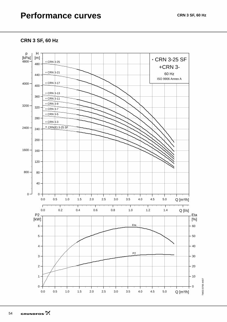
Performance curves CRN 3 SF, 60 Hz
CRN 3 SF, 60 Hz
TM03
979
5 44
070.0 0.5 1.0 1.5 2.0 2.5 3.0 3.5 4.0 4.5 5.0 Q [m³/h]
0
40
80
120
160
200
240
280
320
360
400
440
480
H[m]
0.0 0.2 0.4 0.6 0.8 1.0 1.2 1.4 Q [l/s]
0
800
1600
2400
3200
4000
4800
p[kPa]
60 HzISO 9906 Annex A
CRN 3-25 SF+CRN 3-
+ CRN 3-25
+ CRN 3-21
+ CRN 3-17
+ CRN 3-13
+ CRN 3-11
+ CRN 3-9
+ CRN 3-7
+ CRN 3-5
+ CRN 3-3
CRN(E) 3-25 SF
*
*
0.0 0.5 1.0 1.5 2.0 2.5 3.0 3.5 4.0 4.5 5.0 Q [m³/h]
0
1
2
3
4
5
6
P2[kW]
0
10
20
30
40
50
60
[%]Eta
P2
Eta

Technical data CRN 3 SF, 60 Hz
Dimensional sketches
Dimensions and weights
1) High-pressure pump
TM04
001
9 48
07
TM02
737
7 33
03
CRN feed pump/CRN SF high-pressure pump CRN feed pump, connecting pipe and CRN SF high-pressure pump
246
266 250
246
266
Connecting pipe
Pumptype
MotorP2
[kW]
CRN CRNEDimension [mm] Net weight
[kg]Dimension [mm] Net weight
[kg]B1 B2 B1+B2 D1 D2 B1 B2 B1+B2 D1 D2CRN 3-3 0.55 257 191 448 141 109 17 - - - - - - CRN 3-5 0.75 299 231 530 141 109 20 - - - - - - CRN 3-7 1.1 335 231 566 141 109 23 - - - - - - CRN 3-9 1.5 387 281 668 178 110 30 - - - - - - CRN 3-11 1.5 423 281 704 178 110 31 - - - - - - CRN 3-13 2.2 459 321 780 178 110 33 - - - - - - CRN 3-17 2.2 531 321 852 178 110 34 - - - - - - CRN 3-31 3 608 335 943 198 120 40 - - - - - - CRN 3-25 4 680 372 1052 220 134 53 - - - - - -
CRN(E) 3-25 SF 1) 4 708 372 1080 220 134 53 708 372 1080 220 188 63
55
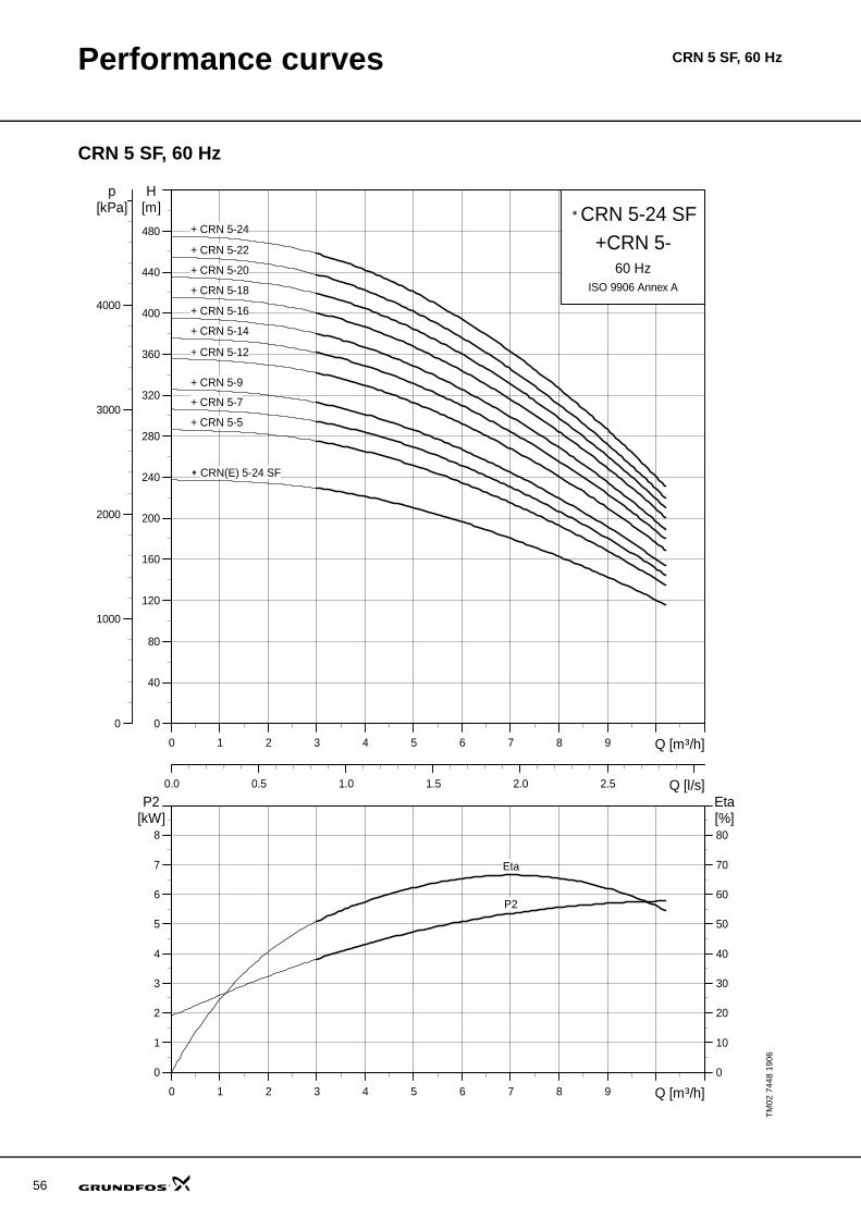
56
Performance curves CRN 5 SF, 60 Hz
CRN 5 SF, 60 Hz
TM02
744
8 19
06
0 1 2 3 4 5 6 7 8 9 Q [m³/h]
0
40
80
120
160
200
240
280
320
360
400
440
480
H[m]
0.0 0.5 1.0 1.5 2.0 2.5 Q [l/s]
0
1000
2000
3000
4000
p[kPa]
60 HzISO 9906 Annex A
CRN 5-24 SF+CRN 5-
+ CRN 5-20
+ CRN 5-18
+ CRN 5-24
+ CRN 5-22
+ CRN 5-16
+ CRN 5-14
+ CRN 5-12
+ CRN 5-9
+ CRN 5-7
+ CRN 5-5
CRN(E) 5-24 SF
*
*
0 1 2 3 4 5 6 7 8 9 Q [m³/h]
0
1
2
3
4
5
6
7
8
P2[kW]
0
10
20
30
40
50
60
70
80[%]Eta
Eta
P2

Technical data CRN 5 SF, 60 Hz
Dimensional sketches
Dimensions and weights
1) High-pressure pump
TM02
737
6 48
07
TM02
737
7 33
03
CRN feed pump/CRN SF high-pressure pump CRN feed pump, connecting pipe and CRN SF high-pressure pump
50
22 180
B1
150100
210210
4 x ø13ø42.
2
B2
D2
D1
D3
G 1/2 G 1/2
G 1/2
P (PJE)
246
266 250
246
266
Connecting pipe
Pumptype
MotorP2
[kW]
CRN CRNEDimension [mm] Net weight
[kg]Dimension [mm] Net weight
[kg]B1 B2 B1+B2 D1 D2 D3 B1 B2 B1+B2 D1 D2 D3CRN 5-5 1.5 360 281 641 178 110 - 30 - - - - - - - CRN 5-7 2.2 414 321 735 178 110 - 31 - - - - - - - CRN 5-9 2.2 468 321 789 178 110 - 32 - - - - - - - CRN 5-12 3 554 335 889 198 120 - 39 - - - - - - - CRN 5-14 4 608 372 980 220 134 - 51 - - - - - - - CRN 5-16 4 662 372 1034 220 134 - 52 - - - - - - - CRN 5-18 5.5 745 391 1136 220 134 300 67 - - - - - - - CRN 5-20 5.5 799 391 1190 220 134 300 68 - - - - - - - CRN 5-22 5.5 853 391 1244 220 134 300 69 - - - - - - - CRN 5-24 7.5 907 391 1298 220 134 300 72 - - - - - - -
CRN(E) 5-24 SF 1) 7.5 928 391 1319 220 134 300 71 928 391 1319 220 188 298 80
57

58
Performance curves CRN 10 SF, 60 Hz
CRN 10 SF, 60 Hz
TM02
735
4 19
060 1 2 3 4 5 6 7 8 9 10 11 12 13 14 15 Q [m³/h]
0
40
80
120
160
200
240
280
320
360
400
440
480
520
H[m]
0.0 0.5 1.0 1.5 2.0 2.5 3.0 3.5 4.0 Q [l/s]
0
1000
2000
3000
4000
5000
p[kPa]
60 HzISO 9906 Annex A
CRN 10-17 SF+CRN 10-+ CRN10-16
+ CRN10-14
+ CRN10-12
+ CRN10-9
+ CRN10-6
+ CRN10-3
CRN(E) 10-17 SF
*
*
0 1 2 3 4 5 6 7 8 9 10 11 12 13 14 15 Q [m³/h]
0
2
4
6
8
10
12
14
16
P2[kW]
0
10
20
30
40
50
60
70
80[%]Eta
Eta
P2

Technical data CRN 10-SF, 60 Hz
Dimensional sketches
Dimensions and weights
1) High-pressure pump
TM02
737
8 48
07
TM02
737
9 33
03
CRN feed pump/CRN SF high-pressure pump CRN feed pump, connecting pipe and CRN SF high-pressure pump
130
ø60.
1
B2
D2D1
200
80
G 1/2
261
B1
G 1/2G 1/2
215248
26 4 x ø13
D3
P (PJE)
317
320 300
317
320
Connecting pipe
Pumptype
MotorP2
[kW]
CRN CRNEDimension [mm] Net weight
[kg]Dimension [mm] Net weight
[kg]B1 B2 B1+B2 D1 D2 D3 B1 B2 B1+B2 D1 D2 D3CRN 10-3 2.2 403 321 724 178 110 - 42 - - - - - - - CRN 10-6 4 498 372 870 220 134 - 60 - - - - - - - CRN 10-9 5.5 620 391 1011 220 134 300 84 - - - - - - - CRN 10-12 7.5 710 391 1101 220 134 300 89 - - - - - - - CRN 10-14 11 847 499 1346 260 172 350 121 - - - - - - - CRN 10-16 11 907 499 1406 260 172 350 124 - - - - - - -
CRN(E) 10-17 SF 1) 11 967 499 1466 260 172 350 126 967 449 1416 258 359 350 179
59
60
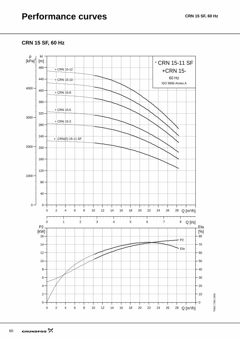
Performance curves CRN 15 SF, 60 Hz
CRN 15 SF, 60 Hz
TM02
735
5 19
060 2 4 6 8 10 12 14 16 18 20 22 24 26 28 Q [m³/h]
0
40
80
120
160
200
240
280
320
360
400
440
480
H[m]
0 1 2 3 4 5 6 7 8 Q [l/s]
0
1000
2000
3000
4000
p[kPa]
60 HzISO 9906 Annex A
CRN 15-11 SF+CRN 15-
+ CRN 15-10
+ CRN 15-8
+ CRN 15-12
+ CRN 15-5
+ CRN 15-3
CRN(E) 15-11 SF
*
*
0 2 4 6 8 10 12 14 16 18 20 22 24 26 28 Q [m³/h]
0
2
4
6
8
10
12
14
16
P2[kW]
0
10
20
30
40
50
60
70
80[%]Eta
Eta
P2

Technical data CRN 15 SF, 60 Hz
Dimensional sketches
Dimensions and weights
1) High-pressure pump
TM02
738
0 48
07
TM02
738
1 33
03
CRN feed pump/CRN SF high-pressure pump CRN feed pump, connecting pipe and CRN SF high-pressure pump
B2
D2D1
G 1/2
B1
G 1/2G 1/2
D3
P (PJE)
ø60.
1
4 x ø13
261
215248
130200
26
90 317
320 300
317
320
Connecting pipe
Pumptype
MotorP2
[kW]
CRN CRNEDimension [mm] Net weight
[kg]Dimension [mm] Net weight
[kg]B1 B2 B1+B2 D1 D2 D3 B1 B2 B1+B2 D1 D2 D3CRN 15-3 4 463 372 835 220 134 - 59 - - - - - - - CRN 15-5 7.5 585 391 976 220 134 300 84 - - - - - - - CRN 15-8 11 797 499 1296 260 172 350 119 - - - - - - - CRN 15-10 15 887 478 1365 320 197 350 137 - - - - - - - CRN 15-12 18.5 977 518 1495 320 197 350 170 - - - - - - -
CRN(E) 15-11 SF 1) 15 977 478 1455 320 197 350 149 977 461 1438 313 377 350 172
61

62
Performance curves CRN 20 SF, 60 Hz
CRN 20 SF, 60 Hz
TM02
735
6 19
060 4 8 12 16 20 24 28 32 Q [m³/h]
0
40
80
120
160
200
240
280
320
360
400
H[m]
0 2 4 6 8 10 Q [l/s]
0
1000
2000
3000
4000
p[kPa]
60 HzISO 9906 Annex A
CRN 20-9 SF+CRN 20-
+ CRN 20-10
+ CRN 20-8
+ CRN 20-6
+ CRN 20-4
+ CRN 20-2
CRN(E) 20-9 SF
*
*
0 4 8 12 16 20 24 28 32 Q [m³/h]
0
2
4
6
8
10
12
14
16
P2[kW]
0
10
20
30
40
50
60
70
80[%]Eta
Eta
P2

Technical data CRN 20 SF, 60 Hz
Dimensional sketches
Dimensions and weights
1) High-pressure pump
TM02
738
0 48
07
TM02
738
1 33
03
CRN feed pump/CRN SF high-pressure pump CRN feed pump, connecting pipe and CRN SF high-pressure pump
B2
D2D1
G 1/2
B1
G 1/2G 1/2
D3
P (PJE)
ø60.
1
4 x ø13
261
215248
130200
26
90 317
320 300
317
320
Connecting pipe
Pumptype
MotorP2
[kW]
CRN CRNEDimension [mm] Net weight
[kg]Dimension [mm] Net weight
[kg]B1 B2 B1+B2 D1 D2 D3 B1 B2 B1+B2 D1 D2 D3CRN 20-2 4 418 372 790 220 134 - 58 - - - - - - - CRN 20-4 7.5 540 391 931 220 134 300 83 - - - - - - - CRN 20-6 11 707 499 1206 260 172 350 116 - - - - - - - CRN 20-8 15 797 478 1275 320 197 350 133 - - - - - - - CRN 20-10 18.5 887 518 1405 320 197 350 167 - - - - - - -
CRN(E) 20-9 SF 1) 18.5 887 518 1405 320 197 350 165 887 499 1386 313 377 350 207
63

64
Performance curves CR 32, 60 Hz
CR 32, 60 Hz
TM02
167
2 36
05
0 5 10 15 20 25 30 35 40 45 Q [m³/h]
0
40
80
120
160
200
240
280
320
360
400
440
H[m]
0 2 4 6 8 10 12 14 Q [l/s]
0
1000
2000
3000
4000
p[kPa]
60 HzISO 9906 Annex A
CR 32
CR 32-7
CR 32-7 + CR 32-3
CR 32-7 + CR 32-4
CR 32-7 + CR 32-5
CR 32-7 + CR 32-6
CR 32-7 + CR 32-7
0 5 10 15 20 25 30 35 40 45 Q [m³/h]
0
1
2
3
4
P2[kW]
0
20
40
60
80
[%]Eta
EtaP2
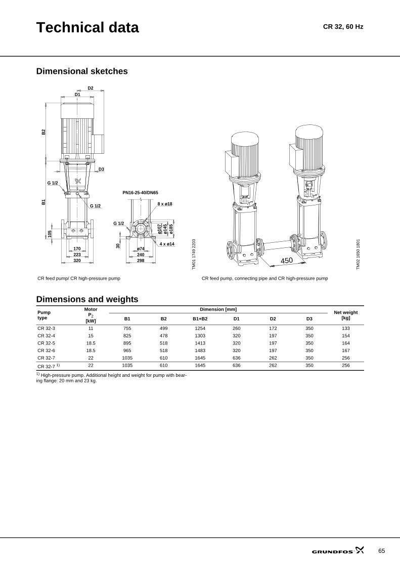
Technical data CR 32, 60 Hz
Dimensional sketches
Dimensions and weights
1) High-pressure pump. Additional height and weight for pump with bear-ing flange: 20 mm and 23 kg.
TM01
174
9 22
03
TM02
165
0 18
01
CR feed pump/ CR high-pressure pump CR feed pump, connecting pipe and CR high-pressure pump
ø74240298
ø107
ø145
ø185
D2D1
170223320
B1
B2
G 1/2 8 x ø18
G 1/2
G 1/2
4 x ø14
105
D3
30
PN16-25-40/DN65
450
Pumptype
MotorP2
[kW]
Dimension [mm] Net weight[kg]B1 B2 B1+B2 D1 D2 D3
CR 32-3 11 755 499 1254 260 172 350 133CR 32-4 15 825 478 1303 320 197 350 154CR 32-5 18.5 895 518 1413 320 197 350 164CR 32-6 18.5 965 518 1483 320 197 350 167CR 32-7 22 1035 610 1645 636 262 350 256
CR 32-7 1) 22 1035 610 1645 636 262 350 256
65

66
Performance curves CRN 32, 60 Hz
CRN 32, 60 Hz
TM02
168
3 36
05
0 5 10 15 20 25 30 35 40 45 Q [m³/h]
0
40
80
120
160
200
240
280
320
360
400
440
H[m]
0 2 4 6 8 10 12 14 Q [l/s]
0
1000
2000
3000
4000
p[kPa]
60 HzISO 9906 Annex A
CRN 32
CRN 32-7
CRN 32-7 + CRN 32-3
CRN 32-7 + CRN 32-4
CRN 32-7 + CRN 32-5
CRN 32-7 + CRN 32-6
CRN 32-7 + CRN 32-7
0 5 10 15 20 25 30 35 40 45 Q [m³/h]
0
1
2
3
4
P2[kW]
0
20
40
60
80
[%]Eta
EtaP2

Technical data CRN 32, 60 Hz
Dimensional sketches
Dimensions and weights
1) High-pressure pump. Additional height and weight for pump with bear-ing flange: 20 mm and 23 kg.
TM01
175
0 22
03
TM02
165
0 18
01
CRN feed pump/CRN high-pressure pump CRN feed pump, connecting pipe and CRN high-pressure pump
8 x ø18
G 1/2
ø74240298
ø107
ø145
ø185
D2D1
170226320
B1
B2
G 1/2
G 1/2
4 x ø14
105
D3
30
PN16-25-40/DN65
450
Pumptype
MotorP2
[kW]
Dimension [mm] Net weight[kg]B1 B2 B1+B2 D1 D2 D3
CRN 32-3 11 755 499 1254 260 172 350 135CRN 32-4 15 825 478 1303 320 197 350 156CRN 32-5 18.5 895 518 1413 320 197 350 166CRN 32-6 18.5 965 518 1483 320 197 350 169CRN 32-7 22 1035 610 1645 636 262 350 258
CRN 32-7 1) 22 1035 610 1645 636 262 350 258
67

68
Performance curves CR 45, 60 Hz
CR 45, 60 Hz
TM02
167
3 36
05
0 5 10 15 20 25 30 35 40 45 50 55 60 65 Q [m³/h]
0
40
80
120
160
200
240
280
320
360
400
440
H[m]
0 2 4 6 8 10 12 14 16 18 Q [l/s]
0
1000
2000
3000
4000
p[kPa]
60 HzISO 9906 Annex A
CR 45
CR 45-6
CR 45-6 + CR 45-2
CR 45-6 + CR 45-3
CR 45-6 + CR 45-4
CR 45-6 + CR 45-5
0 5 10 15 20 25 30 35 40 45 50 55 60 65 Q [m³/h]
0
1
2
3
4
5
6
7
8
P2[kW]
0
10
20
30
40
50
60
70
80[%]Eta
Eta
P2

Technical data CR 45, 60 Hz
Dimensional sketches
Dimensions and weights
1) High-pressure pump. Additional height and weight for pump with bear-ing flange: 20 mm and 27 kg.
TM02
175
1 32
98
TM02
165
0 18
01
CR feed pump/CR high-pressure pump CR feed pump, connecting pipe and CR high-pressure pump
8 x ø18
G 1/2
ø80266331
ø120
ø160
ø200
D2D1
190248365
B1
B2
G 1/2
G 1/2
4 x ø14
140
D3
45
PN16-25-40/DN80
450
Pumptype
MotorP2
[kW]
Dimension [mm] Net weight[kg]B1 B2 B1+B2 D1 D2 D3
CR 45-2 15 749 478 1227 320 197 350 158CR 45-3 18.5 829 518 1347 320 197 350 169CR 45-4 30 909 646 1555 415 300 400 309CR 45-5 30 989 646 1635 415 300 400 313
CR 45-6 1) 37 1069 703 1772 415 300 400 349
69
70
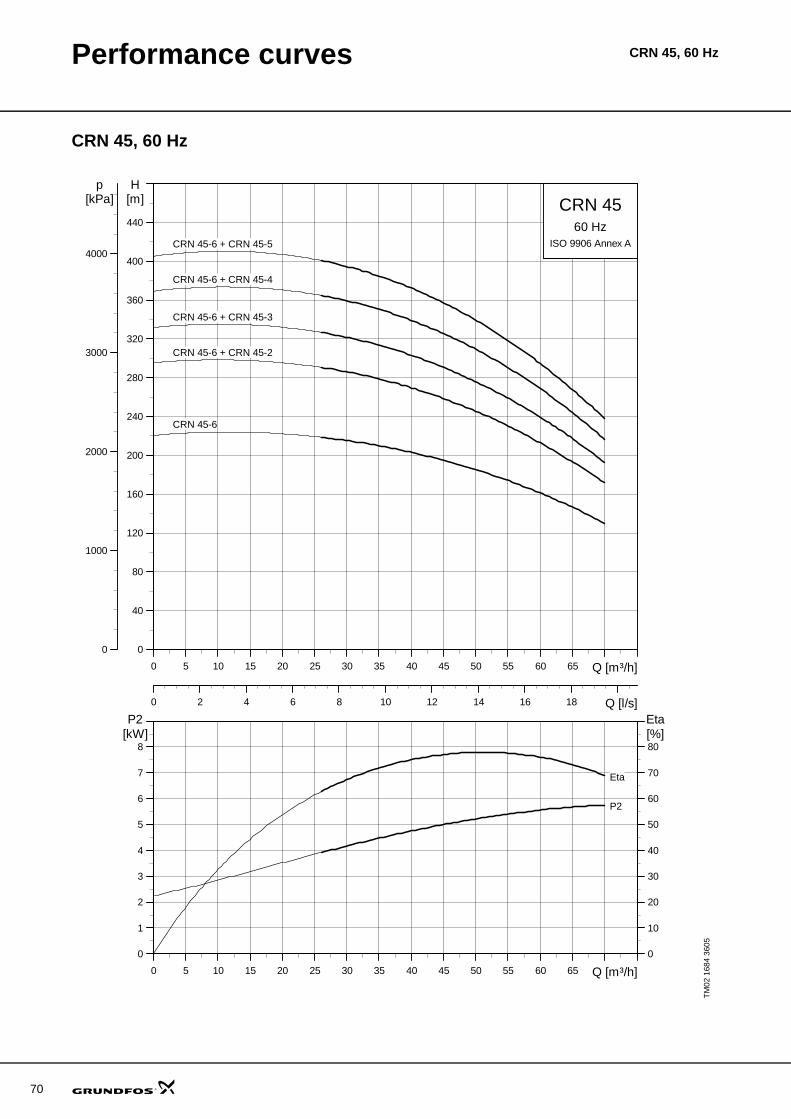
Performance curves CRN 45, 60 Hz
CRN 45, 60 Hz
TM02
168
4 36
05
0 5 10 15 20 25 30 35 40 45 50 55 60 65 Q [m³/h]
0
40
80
120
160
200
240
280
320
360
400
440
H[m]
0 2 4 6 8 10 12 14 16 18 Q [l/s]
0
1000
2000
3000
4000
p[kPa]
60 HzISO 9906 Annex A
CRN 45
CRN 45-6
CRN 45-6 + CRN 45-2
CRN 45-6 + CRN 45-3
CRN 45-6 + CRN 45-4
CRN 45-6 + CRN 45-5
0 5 10 15 20 25 30 35 40 45 50 55 60 65 Q [m³/h]
0
1
2
3
4
5
6
7
8
P2[kW]
0
10
20
30
40
50
60
70
80[%]Eta
Eta
P2

Technical data CRN 45, 60 Hz
Dimensional sketches
Dimensions and weights
1) High-pressure pump. Additional height and weight for pump with bear-ing flange: 20 mm and 27 kg.
TM01
175
2 22
03
TM02
165
0 18
01
CRN feed pump/CRN high-pressure pump CRN feed pump, connecting pipe and CRN high-pressure pump
G 1/2
PN16-25-40/DN80
ø80266331
ø120
ø160
ø200
D2D1
190251365
B1
B2
G 1/2 8 x ø18
G 1/2
4 x ø14
140
D3
45
450
Pumptype
MotorP2
[kW]
Dimension [mm] Net weight[kg]B1 B2 B1+B2 D1 D2 D3
CRN 45-2 15 749 478 1227 320 197 350 159CRN 45-3 18.5 829 518 1347 320 197 350 170CRN 45-4 30 909 646 1555 415 300 400 309CRN 45-5 30 989 646 1635 415 300 400 313
CRN 45-6 1) 37 1069 703 1772 415 300 400 350
71

72
Performance curves CR 64, 60 Hz
CR 64, 60 Hz
TM02
167
4 36
05
0 10 20 30 40 50 60 70 80 90 100 Q [m³/h]
0
40
80
120
160
200
240
280
320
360
H[m]
0 5 10 15 20 25 30 Q [l/s]
0
1000
2000
3000
p[kPa]
60 HzISO 9906 Annex A
CR 64
CR 64-4
CR 64-4 + CR 64-1
CR 64-4 + CR 64-2
CR 64-4 + CR 65-3
CR 64-4 + CR 64-4
0 10 20 30 40 50 60 70 80 90 100 Q [m³/h]
0
2
4
6
8
10
12
14
16
P2[kW]
0
10
20
30
40
50
60
70
80[%]Eta
Eta
P2

Technical data CR 64, 60 Hz
Dimensional sketches
Dimensions and weights
1) High-pressure pump. Additional height and weight for pump with bear-ing flange: 20 mm and 30 kg.
TM02
883
6 09
04
TM02
165
0 18
01
CR feed pump/CR high-pressure pump CR feed pump, connecting pipe and CR high-pressure pump
D2D1
190248365
B1
B2
G 1/2
G 1/2
140
D3
PN25-40/DN100
45
4 x ø14
G 1/2
8 x ø22
ø235
ø190
ø150
331266ø100
450
Pumptype
MotorP2
[kW]
Dimension [mm] Net weight[kg]B1 B2 B1+B2 D1 D2 D3
CR 64-2 11 754 499 1253 260 172 350 143CR 64-3 18.5 836 518 1354 320 197 350 173CR 64-4 22 919 610 1529 363 262 350 263CR 64-5 30 1001 646 1647 415 300 400 318CR 64-6 37 1084 703 1787 415 300 400 354
CR 64-7 1) 45 1166 709 1875 442 325 450 438
73

74
Performance curves CRN 64, 60 Hz
CRN 64, 60 Hz
TM02
168
5 36
05
0 10 20 30 40 50 60 70 80 90 100 Q [m³/h]
0
40
80
120
160
200
240
280
320
360
H[m]
0 5 10 15 20 25 30 Q [l/s]
0
1000
2000
3000
p[kPa]
60 HzISO 9906 Annex A
CRN 64
CRN 64-4
CRN 64-4 + CRN 64-1
CRN 64-4 + CRN 64-2
CRN 64-4 + CRN 65-3
CRN 64-4 + CRN 64-4
0 10 20 30 40 50 60 70 80 90 100 110 Q [m³/h]
0
2
4
6
8
10
12
14
16
P2[kW]
0
10
20
30
40
50
60
70
80[%]Eta
Eta
P2

Technical data CRN 64, 60 Hz
Dimensional sketches
Dimensions and weights
1) High-pressure pump. Additional height and weight for pump with bear-ing flange: 20 mm and 30 kg.
TM02
883
7 09
04
TM02
165
0 18
01
CRN feed pump/CRN high-pressure pump CRN feed pump, connecting pipe and CRN high-pressure pump
D2D1
190251365
B1
B2
G 1/2
G 1/2
140
D3
PN25-40/DN100
45
4 x ø14
G 1/2
8 x ø22
ø235
ø190
ø150
331266ø100
450
Pumptype
MotorP2
[kW]
Dimension [mm] Net weight[kg]B1 B2 B1+B2 D1 D2 D3
CRN 64-1 11 671 499 1170 260 172 350 139CRN 64-2 22 754 610 1364 636 262 350 254CRN 64-3 30 836 646 1482 415 300 400 309CRN 64-4 45 919 709 1628 442 325 450 425
CRN 64-4 1) 45 919 709 1628 442 325 450 425
75

76
Performance curves CR 90, 60 Hz
CR 90, 60 Hz
TM02
167
5 36
05
0 10 20 30 40 50 60 70 80 90 100 110 120 130 140 Q [m³/h]
0
20
40
60
80
100
120
140
160
180
200
220
240
260
280
300
H[m]
0 5 10 15 20 25 30 35 40 Q [l/s]
0
400
800
1200
1600
2000
2400
2800
p[kPa]
60 HzISO 9906 Annex A
CR 90
CR 90-3
CR 90-3 + CR 90-1
CR 90-3 + CR 90-2
CR 90-3 + CR 90-3
0 10 20 30 40 50 60 70 80 90 100 110 120 130 140 Q [m³/h]
0
2
4
6
8
10
12
14
16
P2[kW]
0
10
20
30
40
50
60
70
80[%]Eta
Eta
P2

Technical data CR 90, 60 Hz
Dimensional sketches
Dimensions and weights
1) High-pressure pump. Additional height and weight for pump with bear-ing flange: 20 mm and 30 kg.
TM02
883
8 09
04
TM02
165
0 18
01
CR feed pump/CR high-pressure pump CR feed pump, connecting pipe and CR high-pressure pump
D2D1
199261380
B1
B2
G 1/2
140
D3
G 1/2
PN25-40/DN100
45
4 x ø14
G 1/2
8 x ø22
ø235
ø190
ø156
348280ø100
450
Pumptype
MotorP2
[kW]
Dimension [mm] Net weight[kg]B1 B2 B1+B2 D1 D2 D3
CR 90-1 15 681 478 1159 320 197 350 162CR 90-2 30 773 646 1419 415 300 400 309CR 90-3 45 865 709 1574 442 325 450 424
CR 90-3 1) 45 865 709 1574 442 325 450 424
77

78
Performance curves CRN 90, 60 Hz
CRN 90, 60 Hz
TM02
168
6 36
05
0 10 20 30 40 50 60 70 80 90 100 110 120 130 140 Q [m³/h]
0
20
40
60
80
100
120
140
160
180
200
220
240
260
280
300
H[m]
0 5 10 15 20 25 30 35 40 Q [l/s]
0
400
800
1200
1600
2000
2400
2800
p[kPa]
60 HzISO 9906 Annex A
CRN 90
CRN 90-3
CRN 90-3 + CRN 90-1
CRN 90-3 + CRN 90-2
CRN 90-3 + CRN 90-3
0 10 20 30 40 50 60 70 80 90 100 110 120 130 140 Q [m³/h]
0
2
4
6
8
10
12
14
16
P2[kW]
0
10
20
30
40
50
60
70
80[%]Eta
Eta
P2

Technical data CRN 90, 60 Hz
Dimensional sketches
Dimensions and weights
1) High-pressure pump. Additional height and weight for pump with bear-ing flange: 20 mm and 30 kg.
TM02
883
9 09
04
TM02
165
0 18
01
CRN feed pump/CRN high-pressure pump CRN feed pump, connecting pipe and CRN high-pressure pump
D2D1
199261380
B1
B2
G 1/2
G 1/2
140
D3
PN25-40/DN100
45
4 x ø14
G 1/2
8 x ø22
ø235
ø190
ø156
348280ø100
450
Pumptype
MotorP2
[kW]
Dimension [mm] Net weight[kg]B1 B2 B1+B2 D1 D2 D3
CRN 90-1 15 681 478 1159 320 197 350 163CRN 90-2 30 773 646 1419 415 300 400 311CRN 90-3 45 865 709 1574 442 325 450 426
CRN 90-3 1) 45 865 709 1574 442 325 450 426
79

80
Performance curves CR 120, 60 Hz
CR 120, 60 Hz
TM03
970
0 43
070 10 20 30 40 50 60 70 80 90 100 110 120 130 140 150 Q [m³/h]
80
100
120
140
160
180
200
220
240
260
280
300
320
340
360
380
H[m]
0 5 10 15 20 25 30 35 40 Q [l/s]
1000
1500
2000
2500
3000
3500
p[kPa]
60 HzISO 9906 Annex A
CR 120
120-5-2
120-5-2 + 120-1
120-5-2 + 120-2
120-5-2 + 120-2-1
120-5-2 + 120-2-2
120-5-2 + 120-3-1
120-5-2 + 120-4-1
120-5-2 + 120-3
120-5-2 + 120-5-2
0 10 20 30 40 50 60 70 80 90 100 110 120 130 140 150 Q [m³/h]
0
2
4
6
8
10
12
14
16
P2[kW]
0
10
20
30
40
50
60
70
80[%]Eta
Eta
P2 1/1
P2 2/3

Technical data CR 120, 60 Hz
Dimensional sketches
Dimensions and weights
1) High-pressure pump
TM03
970
4 44
07
TM02
165
0 08
01
CR feed pump/CR high-pressure pump CR feed pump, connecting pipe and CR high-pressure pump
450
Pumptype
MotorP2
[kW]
Dimension [mm] Net weight[kg]B1 B2 B1+B2 D1 D2 D3
CR 120-1 18.5 834 518 1352 320 197 350 197CR 120-2-2 30 990 646 1636 415 300 400 343CR 120-2-1 30 990 646 1636 415 300 400 343CR 120-2 37 990 703 1693 415 300 400 373CR 120-3-1 45 1145 709 1854 442 325 450 462CR 120-3 55 1175 747 1922 495 392 550 597CR 120-4-1 75 1331 820 2151 555 432 550 742CR 120-5-2 75 1486 820 2306 555 432 550 752
CR 120-5-2 1) 75 1486 820 2306 555 432 550 752
81

82
Performance curves CRN 120, 60 Hz
CRN 120, 60 Hz
TM03
881
6 25
070 10 20 30 40 50 60 70 80 90 100 110 120 130 140 150 Q [m³/h]
80
100
120
140
160
180
200
220
240
260
280
300
320
340
360
380
H[m]
0 5 10 15 20 25 30 35 40 Q [l/s]
1000
1500
2000
2500
3000
3500
p[kPa]
60 HzISO 9906 Annex A
CRN 120
120-5-2
120-5-2 + 120-1
120-5-2 + 120-2
120-5-2 + 120-2-1
120-5-2 + 120-2-2
120-5-2 + 120-3-1
120-5-2 + 120-4-1
120-5-2 + 120-3
120-5-2 + 120-5-2
0 10 20 30 40 50 60 70 80 90 100 110 120 130 140 150 Q [m³/h]
0
2
4
6
8
10
12
14
16
P2[kW]
0
10
20
30
40
50
60
70
80[%]Eta
Eta
P2 1/1
P2 2/3

Technical data CRN 120, 60 Hz
Dimensional sketches
Dimensions and weights
1) High-pressure pump
TM03
970
5 44
07
TM02
165
0 08
01
CRN feed pump/CRN high-pressure pump CRN feed pump, connecting pipe and CRN high-pressure pump
450
Pumptype
MotorP2
[kW]
Dimension [mm] Net weight[kg]B1 B2 B1+B2 D1 D2 D3
CRN 120-1 18.5 834 518 1352 320 197 350 200CRN 120-2-2 30 990 646 1636 415 300 400 346CRN 120-2-1 30 990 646 1636 415 300 400 346CRN 120-2 37 990 703 1693 415 300 400 376CRN 120-3-1 45 1145 709 1854 442 325 450 465CRN 120-3 55 1175 747 1922 495 392 550 600CRN 120-4-1 75 1331 820 2151 555 432 550 745CRN 120-5-2 75 1486 820 2306 555 432 550 755
CRN 120-5-2 1) 75 1486 820 2306 555 432 550 755
83

84
Performance curves CR 150, 60 Hz
CR 150, 60 Hz
TM03
970
1 43
07
0 10 20 30 40 50 60 70 80 90 100 110 120 130 140 150 160 170Q [m³/h]
60
80
100
120
140
160
180
200
220
240
260
280
300
320
340
H[m]
0 5 10 15 20 25 30 35 40 45 Q [l/s]
1000
1500
2000
2500
3000
p[kPa]
60 HzISO 9906 Annex A
CR 150
150-4-2
150-4-2 + 150-1
150-4-2 + 150-1-1
150-4-2 + 150-2
150-4-2 + 150-2-1
150-4-2 + 150-2-2
150-4-2 + 150-3
150-4-2 + 150-3-2
150-4-2 + 150-4-2
0 10 20 30 40 50 60 70 80 90 100 110 120 130 140 150 160 Q [m³/h]
0
4
8
12
16
20
24
28
32
P2[kW]
0
10
20
30
40
50
60
70
80[%]Eta
Eta
P2 1/1
P2 2/3
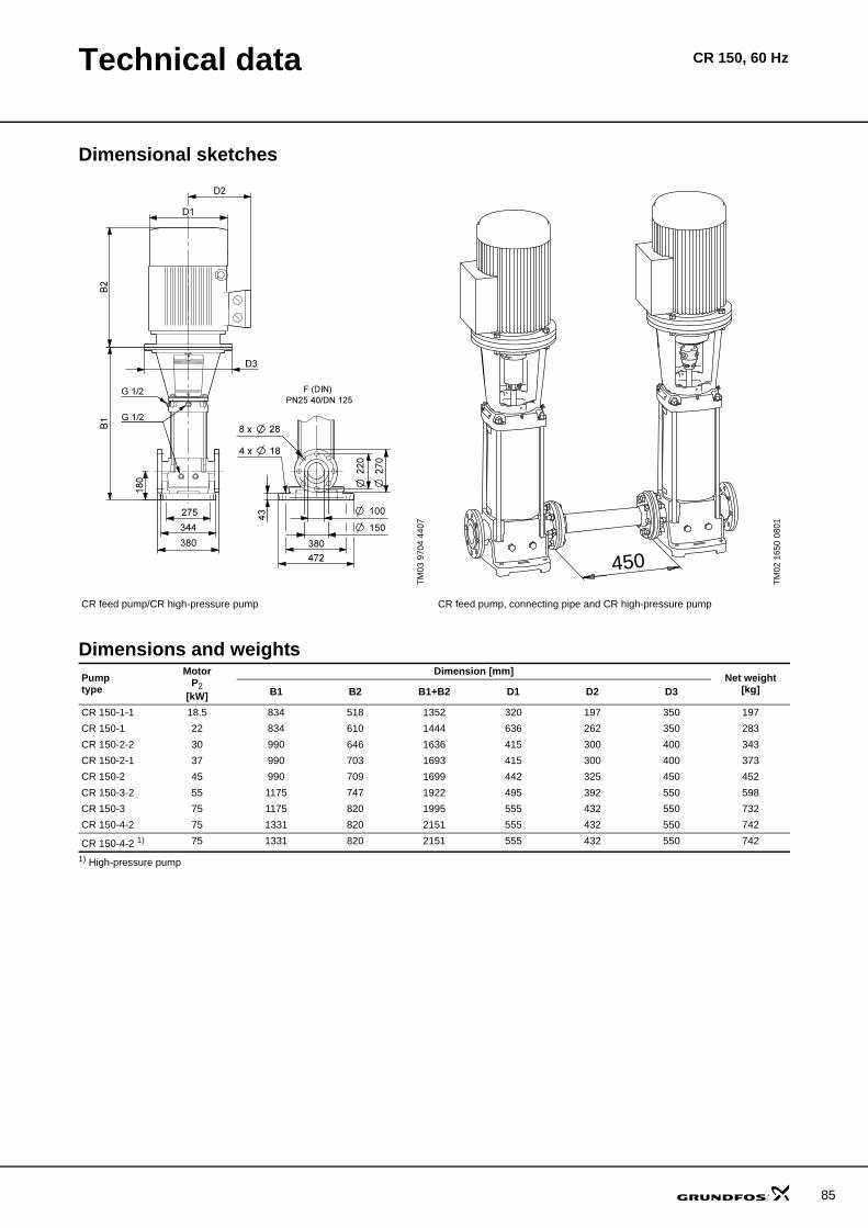
Technical data CR 150, 60 Hz
Dimensional sketches
Dimensions and weights
1) High-pressure pump
TM03
970
4 44
07
TM02
165
0 08
01
CR feed pump/CR high-pressure pump CR feed pump, connecting pipe and CR high-pressure pump
450
Pumptype
MotorP2
[kW]
Dimension [mm] Net weight[kg]B1 B2 B1+B2 D1 D2 D3
CR 150-1-1 18.5 834 518 1352 320 197 350 197CR 150-1 22 834 610 1444 636 262 350 283CR 150-2-2 30 990 646 1636 415 300 400 343CR 150-2-1 37 990 703 1693 415 300 400 373CR 150-2 45 990 709 1699 442 325 450 452CR 150-3-2 55 1175 747 1922 495 392 550 598CR 150-3 75 1175 820 1995 555 432 550 732CR 150-4-2 75 1331 820 2151 555 432 550 742
CR 150-4-2 1) 75 1331 820 2151 555 432 550 742
85

86
Performance curves CRN 150, 60 Hz
CRN 150, 60 Hz
TM03
881
7 25
07
0 10 20 30 40 50 60 70 80 90 100 110 120 130 140 150 160 170Q [m³/h]
60
80
100
120
140
160
180
200
220
240
260
280
300
320
340
H[m]
0 5 10 15 20 25 30 35 40 45 Q [l/s]
1000
1500
2000
2500
3000
p[kPa]
60 HzISO 9906 Annex A
CRN 150
150-4-2
150-4-2 + 150-1
150-4-2 + 150-1-1
150-4-2 + 150-2
150-4-2 + 150-2-1
150-4-2 + 150-2-2
150-4-2 + 150-3
150-4-2 + 150-3-2
150-4-2 + 150-4-2
0 10 20 30 40 50 60 70 80 90 100 110 120 130 140 150 160 Q [m³/h]
0
4
8
12
16
20
24
28
32
P2[kW]
0
10
20
30
40
50
60
70
80[%]Eta
Eta
P2 1/1
P2 2/3
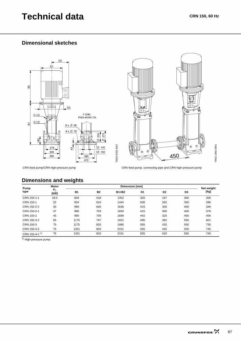
Technical data CRN 150, 60 Hz
Dimensional sketches
Dimensions and weights
1) High-pressure pump
TM03
970
5 44
07
TM02
165
0 08
01
CRN feed pump/CRN high-pressure pump CRN feed pump, connecting pipe and CRN high-pressure pump
450
Pumptype
MotorP2
[kW]
Dimension [mm] Net weight[kg]B1 B2 B1+B2 D1 D2 D3
CRN 150-1-1 18.5 834 518 1352 320 197 350 200CRN 150-1 22 834 610 1444 636 262 350 286CRN 150-2-2 30 990 646 1636 415 300 400 346CRN 150-2-1 37 990 703 1693 415 300 400 376CRN 150-2 45 990 709 1699 442 325 450 456CRN 150-3-2 55 1175 747 1922 495 392 550 601CRN 150-3 75 1175 820 1995 555 432 550 735CRN 150-4-2 75 1331 820 2151 555 432 550 745
CRN 150-4-2 1) 75 1331 820 2151 555 432 550 745
87

88
CR, CRN high pressureMotor data
Standard motors for CR, CRN high pressure, 50 Hz
E-motors for CRNE-HS, 50 Hz
E-motors for CRNE-SF, 50 Hz
MotorP2
[kW]
Frame size
Standard voltage[V] I 1/1 [A] Cos ϕ 1/1 η [%] Istart
Speed[rpm]
TM03
171
1 28
05
MG0.37 71 220-240Δ/380-415Y 1.7/1 0.80-0.70 78.5 8.5-9.2/4.9-5.3 2850-28800.55 71 220-240Δ/380-415Y 2.5/1.4 0.80-0.70 80 12-13/6.9-7.5 2830-28500.75 80 220-240Δ/380-415Y 3.3/1.9 0.81-0.71 81 19.1-20.5/11.0-11.8 2840-28701.1 80 220-240Δ/380-415Y 4.5/2.6 0.84-0.76 82.8 28.5-31.5/16.3-17.9 2820-28601.5 90 220-240Δ/380-415Y 5.5/3.2 0.87-0.82 85.5 46.3-50.7/26.8-29.3 2890-29102.2 90 380-415Δ 4.5-4.5 0.89-0.87 87.5 37.8-42.3 2890-29103.0 100 380-415Δ 6.3-6.3 0.87-0.82 87.5 52.9-58.0 2900-29204.0 112 380-415Δ 8-8 0.88-0.84 89 89.6-98.4 2910-29305.5 132 380-415Δ 11.2-11.2 0.88-0.84 90 119.8-131.0 2910-29307.5 132 380-415Δ 15.2-15.2 0.87-0.80 89.5 152-168.7 2900-292011 160 380-415Δ 21.4-21.4 0.90-0.90 91.4 156.2-171.2 2920-2930
Siemens
TM03
171
0 28
05
15 160 380-415Δ/660-690Y 26.5/15.2 0.90-0.90 91.5 185.5/106.4 294518.5 160 380-415Δ/660-690Y 31.5/18.4 0.92-0.92 92.5 220.5/128.8 294022 180 380-415Δ/660-690Y 38.5/22 0.88-0.88 94 277.2/158.4 295530 200 380-415Δ/660-690Y 53/30.5 0.88-0.88 93.5 371/213.5 296037 200 380-415Δ/660-690Y 64/37 0.89-0.89 94 460.8/266.4 296045 225 380-415Δ/660-690Y 77/44.5 0.89-0.89 95 562.1/324.9 296555 250 380-415Δ/660-690Y 93/54 0.90-0.90 95.5 632.4/367.2 297575 280 380-415Δ/660-690Y 128/74 0.89-0.89 95 896-832/518-481 2975
MotorP2
[kW]Frame size Phases
Standard voltage
[V]I 1/1 [A] Cos ϕ 1/1 η [%] RPM
CRNE 1-23RPM
CRNE 3-23
TM03
171
2 28
05
4.6 112 3 380-480 9.6-8.2 0.84 81 4800 41006.0 132 3 380-480 12.3-10.5 0.85 81 5200 45007.5 132 3 380-480 16.0-13.6 0.85 84 5500 4800
MotorP2
[kW]Frame size Phase
Standard voltage
[V]I 1/1 [A] Cos ϕ 1/1 η [%] MGE MMGE
TM03
171
2 28
05/
TM03
1713
280
5
3.0 100 3 380-480 6.2-5.0 0.94-0.92 835.5 132 3 380-480 11-8.8 0.94-0.93 85.57.5 132 3 380-480 15-12 0.94-0.93 8511 160 3 380-415 21.4 0.93 8415 160 3 380-415 28 0.94 85.5
18.5 160 3 380-415 34 0.95 85.5

Motor data CR, CRN high pressure
Standard motors for CR, CRN high pressure, 60 Hz
E-motors for CRNE-HS, 60 Hz
E-motors for CRNE-SF, 60 Hz
MotorP2
[kW]
Framesize
Standard voltage[V] I 1/1 [A] Cos ϕ 1/1 η [%] Istart
Speed[RPM]
TM03
171
1 28
05
MG0.55 71 220-255Δ/380-440Y 2.2-2.1/1.3-1.2 0.85-0.76 81.5-83 10.8-12.3/6.3-7.2 3390-3460
0.75 80 220-255Δ/380-440Y 2.9-2.7/1.7-1.6 0.86-0.78 83-85 17.1-20.0/9.9-11.5 3400-3470
1.1 80 220-255Δ/380-440Y 4.2-3.9/2.5-2.2 0.88-0.82 82-84.5 25.6-30.4/14.9-17.5 3390-3460
1.5 90 220-277Δ/380-480Y 5.4-4.7/3.1-2.7 0.90-0.81 84-85 41.7-49.4/24.2-28.4 3470-3530
2.2 90 380-480Δ 4.5-3.7 0.91-0.85 84-87 34.7-40.7 3470-3530
3.0 100 380-480Δ 6.2-5.7 0.89-0.84 84-87.5 49.6-62.2 3430-3530
4.0 112 380-480Δ 7.8-6.8 0.90-0.82 88-89.5 79.6-102 3510-3540
5.5 132 380-480Δ 10.8-9.5 0.90-0.82 89-89 108-138 3510-3540
7.5 132 380-480Δ 14.8-13.4 0.90-0.79 89-89.5 137.6-174.2 3490-3530
11 160 380-480Δ 21.4-17.2 0.92-0.88 90-93 132.7-166.8 3490-3540
Siemens
TM03
171
0 28
05
15 160 380-480Δ/660-690Y 27.5-22/15.8-15.8 0.92-0.9 89.5-91 165-200.2/94.8-94.8 3520-3555
18.5 160 380-480Δ/660-690Y 34-26.5/19.6-19.6 0.93-0.92 89-91 197.2-233.2/113.7-113.7 3510-3550
22 180 380-480Δ/660-690Y 39.5-32.5/23-21.5 0.9-0.86 93.5-94.5 260.7-273/151.8-180.6 3535-3565
30 200 380-480Δ/660-690Y 55-45/31.5-30 0.9-0.86 92.5-93.5 357.5-360/252-240 3540-3565
37 200 380-480Δ/660-690Y 67-54/38.5-37 0.9-0.87 93-94 442.2-448.2/254.1-307.1 3540-3565
45 225 380-480Δ/660-690Y 81-65/46.5-44 0.9-0.87 94.5-95 542.7-559/311.6-378.4 3545-3570
55 250 380-480Δ/660-690Y 97-79/56-53 0.91-0.88 94.5-95 620.8-632/358.4-424 3565-3580
75 280 380-480Δ/660-690Y 134-108/77-73 0.9-0.87 95-95.5 871-864/500.5-584 3565-3580
MotorP2
[kW]Frame size Phases
Standard voltage
[V]I 1/1 [A] Cos ϕ 1/1 η [%] RPM
CRNE 1-23RPM
CRNE 3-23
TM03
171
2 28
054.6 112 3 380-480 9.6-8.2 0.84 81 4800 41006.0 132 3 380-480 12.3-10.5 0.85 81 5200 45007.5 132 3 380-480 16.0-13.6 0.85 84 5500 4800
MotorP2
[kW]Frame size Phase
Standard voltage
[V]I 1/1 [A] Cos ϕ 1/1 η [%] MGE MMGE
TM03
171
2 28
05/
TM03
1713
280
5
4.0 112 3 380-480 8.1-6.6 0.94-0.92 857.5 132 3 380-480 15.0-12.0 0.94-0.93 8511 160 3 380-415 21.4 0.93 8415 160 3 380-415 28 0.94 85.5
18.5 160 3 380-415 34 0.95 85.5
89

90
CR, CRN high pressureAccessories
Pipe connectionFor pipe connection, various sets of counter- flanges and couplings are available.
Counter-flangesA counter-flange set consists of one counter-flange, one gasket, bolts and nuts.
Counter-flanges for CRN pumps are made of stainless steel according to EN 1.4401 (AISI 316).
1) CR, CRN 120 and 150 pumps are supplied with DN 125 flanges as standard.
Adapter kitDN 150 flanges are available for CR, CRN 120 and 150 pumps. To use DN 150 flanges, two adapter kit must be ordered per pump.
Counter-flange Pump type Description Rated pressure Pipe connection Product number
TM02
177
4 20
01
TM02
177
6 20
01 CR 32 For welding 40 bar, DIN 2635 65 mm, nominal 349905
CRN 32 For welding 40 bar 65 mm, nominal 349908
TM01
216
2 34
98 CR 45 For welding 40 bar 80 mm, nominal 350542
CRN 45 For welding 40 bar 80 mm, nominal 350545
TM02
177
5 20
01
CR 64CR 90 For welding 40 bar, DIN 2633 100 mm, nominal 369905
CRN 64CRN 90 For welding 40 bar 100 mm, nominal 369906
TM03
889
2 27
07
CR 120CR 150 For welding 40 bar, EN 1092-2 125 mm, nominal 96750475
CRN 120CRN 150 For welding 40 bar, EN 1092-2 125 mm, nominal 96750477
TM03
889
1 27
07
CR 120 1)
CR 150 1) For welding 40 bar, EN 1092-2 150 mm, nominal 96750476
CR 120 1)
CR 150 1) For welding 40 bar, EN 1092-2 150 mm, nominal 96750478
ø18
ø145ø121
ø18
ø185ø145ø122
CRN CR
ø18
ø200ø160
ø22
ø235ø190ø162
ø26
ø270ø220ø188
ø26
ø300ø250ø218
Adapter kit Pump type Pipe connection Number of flange kits needed
Product number
TM04
002
1 48
07
TM04
002
0 48
07
CR 120CR 150 150 mm, nominal 2 96638169
CRN 120CRN 150 150 mm, nominal 2 96638180

Accessories CR, CRN high pressure
PJE couplings with pipe stubMaterials in contact with the pumped liquid are made of stainless steel EN 1.4401 (AISI 316) and rubber.
A set consists of two coupling halves (Victaulic type 77), one gasket, one pipe stud (for welding or threaded), bolts and nuts.
Connecting pipe
1) CR, CRN 32 is with DN 65 flanges as standard. This pump must be ordered with oversize DN 80 flanges.
Fig. 15 Connecting pipe
PJE coupling without pipe stubA set includes one coupling, one gasket and bolts and nuts.
Fig. 16 PJE coupling
Coupling Pump type Pipe stub PN A B Pipe connection
Rubber parts
Number of coupling
sets neededProduct number
TM00
380
8 10
94 CRNE-HS 1, CRNE-HS 3,CRN 3-SFCRN 5-SF
Threaded 80 bar 50 320 R 1¼
EPDM 2 419911
FKM 2 419905
For welding 80 bar 50 280 DN 32
EPDM 2 419912
FKM 2 419904
TM03
889
0 27
07
CRN 10-SF, CRN 15-SF,CRN 20-SF
Threaded 70 bar 80 377 R 2
EPDM 2 339911
FKM 2 339918
For welding 70 bar 80 371 DN 50
EPDM 2 339910
FKM 2 339917BA
Pump type Pipe connection Product numberCRN 3-SF, CRN 5 SF DN 32 400132
CRN 10-SF, CRN 15 SF, CRN 20 SF
DN 50 420138
CR/CRN 321), CR/CRN 45
DN 80 350739
CR/CRN 64, CR/CRN 90 DN 100 370973
TM01
198
4 19
06
Connecting pipe
Pump type Pipe connection
Product numberEPDM FKM
CRN 3-SFCRN 5-SF DN 32 ID1781 ID6742
CRN 10-SF, CRN 15-SF, CRN 20-SF
DN 50 ID2643 ID6743
TM01
650
5 25
99
91
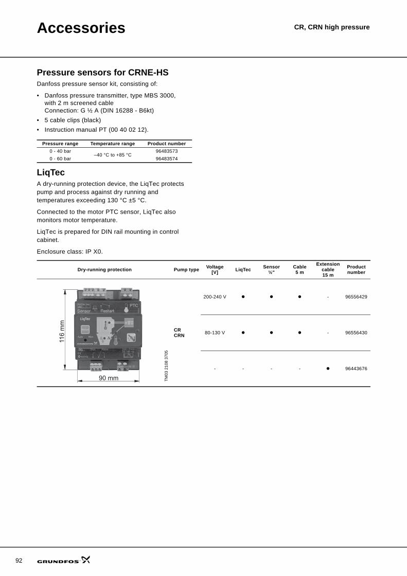
92
Accessories CR, CRN high pressure
Pressure sensors for CRNE-HSDanfoss pressure sensor kit, consisting of:
• Danfoss pressure transmitter, type MBS 3000,with 2 m screened cableConnection: G ½ A (DIN 16288 - B6kt)
• 5 cable clips (black)• Instruction manual PT (00 40 02 12).
LiqTecA dry-running protection device, the LiqTec protects pump and process against dry running and temperatures exceeding 130 °C ±5 °C.
Connected to the motor PTC sensor, LiqTec also monitors motor temperature.
LiqTec is prepared for DIN rail mounting in control cabinet.
Enclosure class: IP X0.
Pressure range Temperature range Product number0 - 40 bar
–40 °C to +85 °C96483573
0 - 60 bar 96483574
Dry-running protection Pump type Voltage[V] LiqTec Sensor
½"Cable5 m
Extension cable15 m
Product number
TM03
210
8 37
05
CRCRN
200-240 V - 96556429
80-130 V - 96556430
- - - - 96443676
116
mm
90 mm

CR, CRN high pressureFurther product documentation
WebCAPSWebCAPS is a Web-based Computer Aided Product Selection program available on www.grundfos.com.
WebCAPS contains detailed information on more than 185,000 Grundfos products in more than 20 languages.
In WebCAPS, all information is divided into 6 sections:
• Catalogue• Literature• Service• Sizing• Replacement• CAD drawings.
Catalogue
This section is based on fields of application and pump types, and contains • technical data• curves (QH, Eta, P1, P2, etc.) which can be adapted to the den-
sity and viscosity of the pumped liquid and show the number of pumps in operation
• product photos• dimensional drawings• wiring diagrams• quotation texts, etc.
Literature
In this section you can access all the latest documents of a given pump, such as• data booklets• installation and operating instructions• service documentation, such as Service kit catalogue and
Service kit instructions• quick guides• product brochures.
Service
This section contains an easy-to-use interactive service catalogue. Here you can find and identify service parts of both existing and dis-continued Grundfos pumps.Furthermore, this section contains service videos showing you how to replace service parts.
93

94
Further product documentation
CR, CRN high pressure
WinCAPS
Fig. 17 WinCAPS CD-ROM
WinCAPS is a Windows-based Computer Aided Product Selection program containing detailed informa-tion on more than 185,000 Grundfos products in more than 20 languages.
The program contains the same features and functions as WebCAPS, but is an ideal solution if no Internet connection is available.
WinCAPS is available on CD-ROM and updated once a year.
Sizing
This section is based on different fields of application and installa-tion examples, and gives easy step-by-step instructions in how to• select the most suitable and efficient pump for your installation• carry out advanced calculations based on energy consumption,
payback periods, load profiles, life cycle costs, etc.• analyse your selected pump via the built-in life cycle cost tool• determine the flow velocity in wastewater applications, etc.
Replacement
In this section you find a guide to selecting and comparing replace-ment data of an installed pump in order to replace the pump with a more efficient Grundfos pump. The section contains replacement data of a wide range of pumps produced by other manufacturers than Grundfos.
Based on an easy step-by-step guide, you can compare Grundfos pumps with the one you have installed on your site. When you have specified the installed pump, the guide will suggest a number of Grundfos pumps which can improve both comfort and efficiency.
CAD drawings
In this section it is possible to download 2-dimensional (2D) and 3-dimensional (3D) CAD drawings of most Grundfos pumps.
These formats are available in WebCAPS:
2-dimensional drawings:• .dxf, wireframe drawings• .dwg, wireframe drawings.
3-dimensional drawings:• .dwg, wireframe drawings (without surfaces)• .stp, solid drawings (with surfaces)• .eprt, E-drawings.
0 1

95

www.grundfos.com
V7174003 1107 GBRepl. V7174003 0606 Subject to alterations.
Being responsible is our foundationThinking ahead makes it possible
Innovation is the essence
GRUNDFOS A/S . DK-8850 Bjerringbro . DenmarkTelephone: +45 87 50 14 00
Related Documents


![3. Performance range · CR 32 CR 45 CR 64 CR 90 CRI 1s CRN 1s CRI 10 CRN 10 CRI 15 CRN 15 CRI 20 CRN 20 CRN 120 CRN 150 1 2 4 6 8 10 20 40 60 80 100 200 400 600 800 Q [US GPM] 0 20](https://static.cupdf.com/doc/110x72/6128df56106c4c14be437383/3-performance-range-cr-32-cr-45-cr-64-cr-90-cri-1s-crn-1s-cri-10-crn-10-cri-15.jpg)