CPU 1505S, CPU 1507S ___________________ ___________________ ___________________ ___________________ ___________________ ___________________ ___________________ ___________________ ___________________ ___________________ SIMATIC S7-1500 Software Controller CPU 1505S, CPU 1507S Operating Manual 11/2014 A5E32565315-AA Preface Documentation guide 1 Product overview 2 Installing 3 Commissioning in STEP 7 4 Operation of the CPU 5 Maintenance 6 Protection 7 Interrupts, diagnostics, error and system message 8 Technical Data 9

Welcome message from author
This document is posted to help you gain knowledge. Please leave a comment to let me know what you think about it! Share it to your friends and learn new things together.
Transcript
CPU 1505S, CPU 1507S
___________________
___________________
___________________
___________________
___________________
___________________
___________________
___________________
___________________
___________________
SIMATIC
S7-1500 Software Controller CPU 1505S, CPU 1507S
Operating Manual
11/2014 A5E32565315-AA
Preface
Documentation guide 1
Product overview 2
Installing 3
Commissioning in STEP 7 4
Operation of the CPU 5
Maintenance 6
Protection 7
Interrupts, diagnostics, error and system message
8
Technical Data 9
Siemens AG Division Digital Factory Postfach 48 48 90026 NÜRNBERG GERMANY
A5E32565315-AA Ⓟ 11/2014 Subject to change
Copyright © Siemens AG 2014. All rights reserved
Legal information Warning notice system
This manual contains notices you have to observe in order to ensure your personal safety, as well as to prevent damage to property. The notices referring to your personal safety are highlighted in the manual by a safety alert symbol, notices referring only to property damage have no safety alert symbol. These notices shown below are graded according to the degree of danger.
DANGER indicates that death or severe personal injury will result if proper precautions are not taken.
WARNING indicates that death or severe personal injury may result if proper precautions are not taken.
CAUTION indicates that minor personal injury can result if proper precautions are not taken.
NOTICE indicates that property damage can result if proper precautions are not taken.
If more than one degree of danger is present, the warning notice representing the highest degree of danger will be used. A notice warning of injury to persons with a safety alert symbol may also include a warning relating to property damage.
Qualified Personnel The product/system described in this documentation may be operated only by personnel qualified for the specific task in accordance with the relevant documentation, in particular its warning notices and safety instructions. Qualified personnel are those who, based on their training and experience, are capable of identifying risks and avoiding potential hazards when working with these products/systems.
Proper use of Siemens products Note the following:
WARNING Siemens products may only be used for the applications described in the catalog and in the relevant technical documentation. If products and components from other manufacturers are used, these must be recommended or approved by Siemens. Proper transport, storage, installation, assembly, commissioning, operation and maintenance are required to ensure that the products operate safely and without any problems. The permissible ambient conditions must be complied with. The information in the relevant documentation must be observed.
Trademarks All names identified by ® are registered trademarks of Siemens AG. The remaining trademarks in this publication may be trademarks whose use by third parties for their own purposes could violate the rights of the owner.
Disclaimer of Liability We have reviewed the contents of this publication to ensure consistency with the hardware and software described. Since variance cannot be precluded entirely, we cannot guarantee full consistency. However, the information in this publication is reviewed regularly and any necessary corrections are included in subsequent editions.
CPU 1505S, CPU 1507S Operating Manual, 11/2014, A5E32565315-AA 3
Preface
Purpose of the documentation This manual supplements the system manual of the S7-1500 Automation System as well as the function manuals. Cross-system functions are described in the system manual.
The information provided in this manual and the system manual enables you to commission the CPU.
Notes Please also observe notes labeled as follows:
Note
A note contains important information on the product described in the documentation, on the handling of the product or on the section of the documentation to which particular attention should be paid.
Definitions and naming conventions The following terms are used in this documentation:
● CPU: This term refers to both the CPU 1505S and the CPU 1507S. If only one of the two CPU versions is meant, it is explicitly named.
● Display: This term refers to the display application of the CPU.
● STEP 7: In this documentation, for referring to the configuration and programming software, we use the term "STEP 7" as a synonym for the "STEP 7 V13 SP1 (TIA Portal)" version.
Preface
CPU 1505S, CPU 1507S 4 Operating Manual, 11/2014, A5E32565315-AA
Security information Siemens provides products and solutions with industrial security functions that support the secure operation of plants, solutions, machines, equipment and/or networks. They are important components in a holistic industrial security concept. With this in mind, Siemens’ products and solutions undergo continuous development. Siemens recommends strongly that you regularly check for product updates.
For the secure operation of Siemens products and solutions, it is necessary to take suitable preventive action (e.g. cell protection concept) and integrate each component into a holistic, state-of-the-art industrial security concept. Third-party products that may be in use should also be considered. You can find more information about industrial security on the Internet (http://www.siemens.com/industrialsecurity).
To stay informed about product updates as they occur, sign up for a product-specific newsletter. You can find more information on the Internet (http://support.automation.siemens.com).
Change of the operating mode with critical actions Switch the CPU to “STOP” mode before actions that result in very high utilization of the hardware (“critical actions”).
NOTICE
Malfunctions of the CPU caused by critical actions
If a BIOS update is taking place during CPU operation, there may be CPU malfunctions, such as breakdown of communication and failures. CPU malfunctions can also be triggered by other actions that put an extremely high demand on the PC hardware (for example, hardware tests such as benchmarking).
Do not perform a BIOS update or other actions during CPU operation that place an extremely high demand on the hardware.
Change the CPU to the "STOP" mode prior to a BIOS update or other critical actions.
Information about third-party software updates This product contains third-party software. Siemens accepts liability with respect to updates/patches for the third-party software only when these are distributed by Siemens in the context of a Software Update Service contract or officially approved by Siemens. Otherwise, updates/patches are installed at the user's own risk. You can obtain more information about our Software Update Service under (http://w3.siemens.com/mcms/automation-software/en/software-update-service/Pages/Default.aspx)
Preface
CPU 1505S, CPU 1507S Operating Manual, 11/2014, A5E32565315-AA 5
Notes on protecting administrator accounts A user with administrator rights has extensive access and manipulation possibilities.
Therefore, make sure that the administrator account is adequately protected to prevent unauthorized changes. To do this, set secure passwords and use a standard user account for regular operation. Other measures, such as the use of security policies, should be applied as required.
CPU 1505S, CPU 1507S 6 Operating Manual, 11/2014, A5E32565315-AA
Table of contents
Preface ...................................................................................................................................................... 3
1 Documentation guide ................................................................................................................................. 9
1.1 Guide to documentation S7-1500 / ET 200MP ........................................................................ 9
2 Product overview ..................................................................................................................................... 12
2.1 Introduction to PC-based control ........................................................................................... 12
2.2 Explanation of the real-time concept of the CPU ................................................................... 13
2.3 Properties ............................................................................................................................... 15
2.4 Operator controls of the CPU display .................................................................................... 18 2.4.1 Introduction to the CPU display ............................................................................................. 18 2.4.2 Operator controls and controller ............................................................................................ 20
2.5 Functions ................................................................................................................................ 24 2.5.1 Storing .................................................................................................................................... 24 2.5.1.1 CPU memory areas ............................................................................................................... 24 2.5.1.2 Storage of retentive data ........................................................................................................ 26 2.5.2 PROFINET IO ........................................................................................................................ 28 2.5.3 PROFIenergy ......................................................................................................................... 28 2.5.4 PROFIBUS DP ....................................................................................................................... 29 2.5.5 Central I/O .............................................................................................................................. 29 2.5.6 Web server of the CPU .......................................................................................................... 30
3 Installing .................................................................................................................................................. 32
3.1 System Requirements ............................................................................................................ 32
3.2 Overview of the Installation Tasks ......................................................................................... 33
3.3 Installing the software controller ............................................................................................ 34
3.4 Creation of the CPU volume .................................................................................................. 36
3.5 Licensing the software controller ........................................................................................... 37
3.6 Uninstalling the software controller ........................................................................................ 39
4 Commissioning in STEP 7 ....................................................................................................................... 40
4.1 Configuring the CPU with STEP 7 ......................................................................................... 40 4.1.1 Creating the configuration ...................................................................................................... 40 4.1.2 Downloading the project to the target system ........................................................................ 42
4.2 Selecting startup type ............................................................................................................ 43
4.3 Setting the storage location for retentive data ....................................................................... 46
4.4 Setting up copy protection ..................................................................................................... 48
4.5 Using the LEDs of the hardware ............................................................................................ 50
4.6 Configuring the web server .................................................................................................... 52
Table of contents
CPU 1505S, CPU 1507S Operating Manual, 11/2014, A5E32565315-AA 7
4.7 Assigning interfaces for the communication ........................................................................... 55
4.8 Using open communication via Windows interface ................................................................ 58
4.9 Time synchronization based on Windows clock ..................................................................... 59
4.10 Using the uninterruptible power supply (UPS) ........................................................................ 61
5 Operation of the CPU .............................................................................................................................. 62
5.1 Manually starting and stopping the CPU ................................................................................ 62
5.2 Operating modes .................................................................................................................... 65 5.2.1 Basic principles of the operating modes ................................................................................. 65 5.2.2 Operating mode transitions ..................................................................................................... 66 5.2.3 Changing the operating mode ................................................................................................ 68
5.3 Setting language options in the display .................................................................................. 71
5.4 Setting the date and time ........................................................................................................ 74
5.5 Supported command line commands ..................................................................................... 76
6 Maintenance ............................................................................................................................................ 77
6.1 Status display in the notification area ..................................................................................... 77
6.2 PC station display in the notification area ............................................................................... 79
6.3 Firmware update of I/O modules ............................................................................................ 80
6.4 Reset ....................................................................................................................................... 82 6.4.1 Reset using the display ........................................................................................................... 83 6.4.2 Reset using STEP 7 ................................................................................................................ 85 6.4.3 Resetting via the mode switch ................................................................................................ 86 6.4.4 Formatting the CPU volume ................................................................................................... 87
6.5 Backing up the image of the PC mass storage ...................................................................... 90
6.6 Special features ...................................................................................................................... 91 6.6.1 Installation of drivers ............................................................................................................... 91 6.6.2 Downloaded user program is not compatible with the target system ..................................... 91 6.6.3 Special situations when starting or stopping the CPU ............................................................ 92 6.6.4 CPU behavior at Windows shutdown ..................................................................................... 93 6.6.5 Operating the CPU after a Windows crash (Blue Screen) ...................................................... 94 6.6.6 Special situations when downloading in STEP 7 .................................................................... 95
7 Protection ................................................................................................................................................ 96
7.1 Overview of the protective functions of the CPU .................................................................... 96
7.2 General safety instructions ..................................................................................................... 97
7.3 Access protection .................................................................................................................... 98 7.3.1 Configuring access protection for the CPU in STEP 7 ........................................................... 98 7.3.2 Using the display to change the protection level for display access .................................... 102
7.4 Protecting blocks ................................................................................................................... 106
7.5 Virus scanners and firewall ................................................................................................... 107
Table of contents
CPU 1505S, CPU 1507S 8 Operating Manual, 11/2014, A5E32565315-AA
8 Interrupts, diagnostics, error and system message ................................................................................ 108
8.1 Status and error display of the CPU .................................................................................... 108
8.2 Export of diagnostic information ........................................................................................... 110
8.3 Diagnostics ........................................................................................................................... 111 8.3.1 Diagnostic information via the CPU display ......................................................................... 111 8.3.1.1 "Overview" and "Diagnostics" menu .................................................................................... 111 8.3.1.2 Display of alarms.................................................................................................................. 113 8.3.1.3 Display of the diagnostics buffer entries .............................................................................. 115 8.3.2 Diagnostic information using STEP 7 .................................................................................. 117 8.3.3 Diagnostics information using the web server ..................................................................... 118
9 Technical Data ....................................................................................................................................... 119
Glossary ................................................................................................................................................ 120
Index ...................................................................................................................................................... 123
CPU 1505S, CPU 1507S Operating Manual, 11/2014, A5E32565315-AA 9
Documentation guide 1 1.1 Guide to documentation S7-1500 / ET 200MP
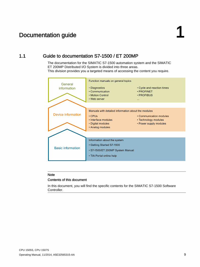
The documentation for the SIMATIC S7-1500 automation system and the SIMATIC ET 200MP Distributed I/O System is divided into three areas. This division provides you a targeted means of accessing the content you require.
Note Contents of this document
In this document, you will find the specific contents for the SIMATIC S7-1500 Software Controller.
Documentation guide 1.1 Guide to documentation S7-1500 / ET 200MP
CPU 1505S, CPU 1507S 10 Operating Manual, 11/2014, A5E32565315-AA
Basic information
The system manual and the Getting Started manual describe in detail the configuration and commissioning of the SIMATIC S7-1500 and ET 200MP systems. The STEP 7 online help supports you in the configuration and programming.
Device information
Manuals for devices contain a compact description of the module-specific information, such as properties and technical specifications.
General information
The function manuals contain detailed descriptions on general topics regarding the SIMATIC S7-1500 and ET 200MP systems, e.g. diagnostics, communication, Motion Control, Web server.
You can download the documentation free of charge from the Internet (http://www.automation.siemens.com/mcms/industrial-automation-systems-simatic/en/manual-overview/tech-doc-controllers/Pages/Default.aspx).
Changes and supplements to the manuals are documented in a Product Information.
Manual Collection S7-1500 / ET 200MP The Manual Collection contains the complete documentation on the SIMATIC S7-1500 automation system and the ET 200MP distributed I/O system gathered together in one file.
You can find the Manual Collection on the Internet (http://support.automation.siemens.com/WW/view/en/86140384).
My Documentation Manager With the My Documentation Manager, you combine whole manuals or portions thereof to form your own manual. You can export the manual as a PDF file or in a format that can be edited later.
You can find the My Documentation Manager on the Internet (http://support.automation.siemens.com/WW/view/en/38715968).
Applications & Tools Applications & Tools supports you with various tools and examples for solving your automation tasks. Solutions are shown in interplay with multiple components in the system - separated from the focus in individual products.
You can find Applications & Tools on the Internet (http://support.automation.siemens.com/WW/view/en/20208582).
Documentation guide 1.1 Guide to documentation S7-1500 / ET 200MP
CPU 1505S, CPU 1507S Operating Manual, 11/2014, A5E32565315-AA 11
CAx Download Manager The CAx Download Manager is used to access the current product data for your CAx or CAe systems.
You configure your own download package with a few clicks.
In doing so you can select:
● Product images, 2D dimension drawings, 3D models, internal circuit diagrams, EPLAN macro files
● Manuals, characteristics, operating manuals, certificates
● Product master data
You can find the CAx Download Manager on the Internet (http://support.automation.siemens.com/WW/view/en/42455541).
CPU 1505S, CPU 1507S 12 Operating Manual, 11/2014, A5E32565315-AA
Product overview 2 2.1 Introduction to PC-based control
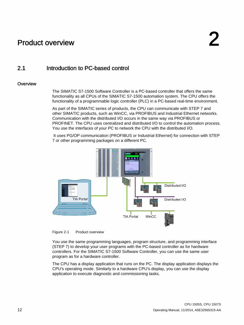
Overview The SIMATIC S7-1500 Software Controller is a PC-based controller that offers the same functionality as all CPUs of the SIMATIC S7-1500 automation system. The CPU offers the functionality of a programmable logic controller (PLC) in a PC-based real-time environment.
As part of the SIMATIC series of products, the CPU can communicate with STEP 7 and other SIMATIC products, such as WinCC, via PROFIBUS and Industrial Ethernet networks. Communication with the distributed I/O occurs in the same way via PROFIBUS or PROFINET. The CPU uses centralized and distributed I/O to control the automation process. You use the interfaces of your PC to network the CPU with the distributed I/O.
It uses PG/OP communication (PROFIBUS or Industrial Ethernet) for connection with STEP 7 or other programming packages on a different PC.
Figure 2-1 Product overview
You use the same programming languages, program structure, and programming interface (STEP 7) to develop your user programs with the PC-based controller as for hardware controllers. For the SIMATIC S7-1500 Software Controller, you can use the same user program as for a hardware controller.
The CPU has a display application that runs on the PC. The display application displays the CPU's operating mode. Similarly to a hardware CPU's display, you can use the display application to execute diagnostic and commissioning tasks.
Product overview 2.2 Explanation of the real-time concept of the CPU
CPU 1505S, CPU 1507S Operating Manual, 11/2014, A5E32565315-AA 13
2.2 Explanation of the real-time concept of the CPU
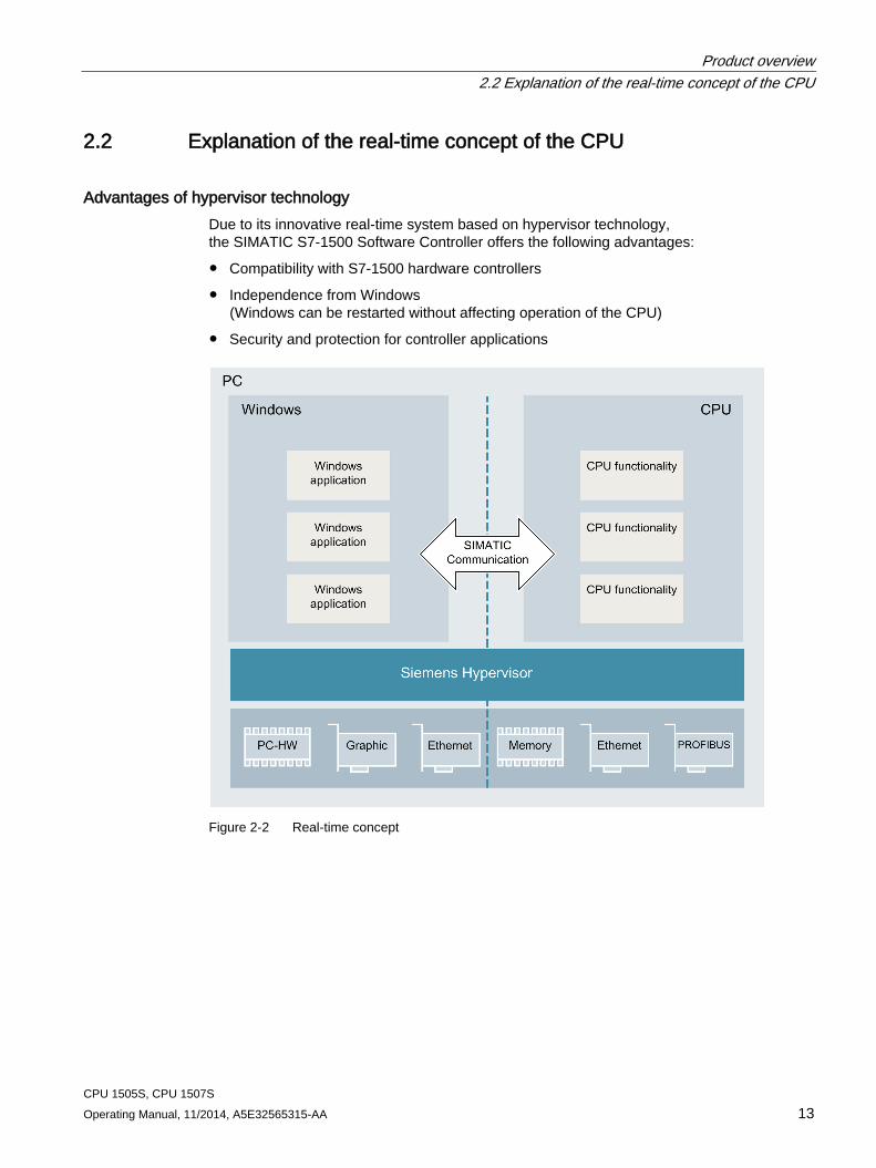
Advantages of hypervisor technology Due to its innovative real-time system based on hypervisor technology, the SIMATIC S7-1500 Software Controller offers the following advantages:
● Compatibility with S7-1500 hardware controllers
● Independence from Windows (Windows can be restarted without affecting operation of the CPU)
● Security and protection for controller applications
Figure 2-2 Real-time concept
Product overview 2.2 Explanation of the real-time concept of the CPU
CPU 1505S, CPU 1507S 14 Operating Manual, 11/2014, A5E32565315-AA
Division of the PC resources The hypervisor technology divides the PC and assigns all resources necessary for the control task exclusively to the SIMATIC S7-1500 Software Controller. Windows and Windows applications have no access to these resources.
The SIMATIC communication architecture allows secure and transparent communication between Windows applications and the CPU:
● Local communication with the HMI or other Windows applications
● Controlled access to PROFINET or PROFIBUS modules for STEP 7 or HMI
● Controlled communication with external devices via Windows interfaces
Product overview 2.3 Properties
CPU 1505S, CPU 1507S Operating Manual, 11/2014, A5E32565315-AA 15
2.3 Properties The S7-1500 Software Controller realizes the function of an S7-1500 hardware controller as software on a PC with Windows. This enables a PC to be used to control machines or systems.
Technical properties The CPU has the following technical properties:
● Configuration and programming with STEP 7 in the TIA Portal
– Programmable in accordance with IEC 61131-3
– Supported programming languages: SCL, LAD, FBD, STL, and Graph7
● Innovative real-time system based on virtualization technology
The real-time system of the S7-1500 Software Controller enables it to be operated in parallel with, but independent of, Windows.
– Real-time and deterministic behavior
– Operation independent of Windows: Windows can be restarted while the controller is running
– Fast power-up at Power On of the PC independent of Windows
● Fast program execution with multiple, priority-controlled execution levels
– Cyclically, time-controlled, isochronously with PROFINET
– Event-driven via hardware and diagnostic interrupts
● Storing of retentive data
The software controller ensures protection of the data of a system even after a power failure:
– Storing of retentive data on the hard drive of the PC (UPS required)
– Storing retentive data on the NVRAM in case of a voltage dip is possible
Product overview 2.3 Properties
CPU 1505S, CPU 1507S 16 Operating Manual, 11/2014, A5E32565315-AA
● Communication
The S7-1500 Software Controller makes use of the interfaces of the PC for PROFINET and PROFIBUS.
– Windows-independent use of PC interfaces for PROFINET or PROFIBUS for operating distributed I/O. Depending on the interface hardware used, the following functions are possible:
PROFINET IO RT
PROFINET IO IRT
PROFIenergy
PROFIBUS DP master
Media redundancy
I-device
Isochronous mode
– Communication (SIMATIC Communication, Open User Communication) with Windows applications or external devices
● Integrated Web server
All CPUs of the SIMATIC S7-1500 automation system support querying of the CPU via the web server. The web server of the CPU provides the following diagnostics possibilities:
– CPU mapping with LEDs and current operating mode
– Reading out entries from the diagnostics buffer
– Querying module states
– Querying current alarms
– Information on the status of the topology/PROFINET devices
– Transferring user data to the load memory of the CPU and managing this data
– User-programmable web pages for support of service- and commissioning-specific machine functions
● Trace functionality
All CPUs of the SIMATIC S7-1500 automation system support the trace functionality. The trace functionality supports the cycle-by-cycle recording of analog and digital variables and the display of these as a curve with STEP 7. This is especially beneficial for motion control or closed-loop control applications.
Product overview 2.3 Properties
CPU 1505S, CPU 1507S Operating Manual, 11/2014, A5E32565315-AA 17
● Integrated technology
– S7-1500 Motion Control
PLC Open blocks for programming motion functionality by means of PROFINET IO and PROFIdrive interface.
The functionality supports speed-controlled axes, positioning axes, synchronous axes, and external encoders.
– Integrated closed-loop control functionality: The CPU has three PID controllers with integrated optimization for a wide range of closed-loop control tasks:
PID_Compact for universal closed-loop control tasks
PID_3Step for valves
PID_Temp for closed-loop temperature control tasks
● Integrated system diagnostics
System diagnostics are generated automatically and displayed by a PG/PC, HMI device, the web server, or the display application. System diagnostics are also available when the CPU is in STOP mode.
● Integrated security
– Know-how protection
Algorithms can be securely protected against unauthorized access and modification.
– Access protection
Extended access protection provides comprehensive protection against unauthorized configuration changes. Authorization levels can be used to assign separate rights to different user groups.
– Integrity protection
The system protects the data transferred to the CPU from unauthorized manipulation. Altered or external transmission of engineering data is reliably detected by the CPU.
Reference You can find additional information on "Integrated security/access protection" under "Protection" in the S7-1500 Automation System system manual (http://support.automation.siemens.com/WW/view/en/59191792).
Product overview 2.4 Operator controls of the CPU display
CPU 1505S, CPU 1507S 18 Operating Manual, 11/2014, A5E32565315-AA
2.4 Operator controls of the CPU display
2.4.1 Introduction to the CPU display
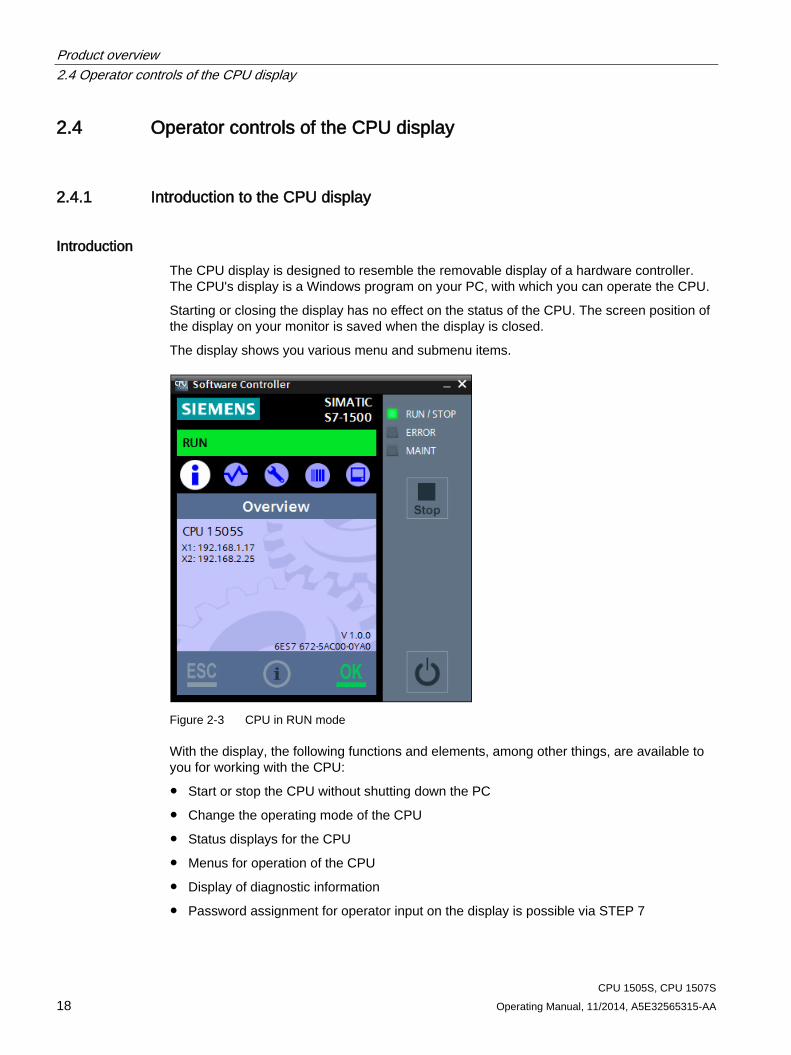
Introduction The CPU display is designed to resemble the removable display of a hardware controller. The CPU's display is a Windows program on your PC, with which you can operate the CPU.
Starting or closing the display has no effect on the status of the CPU. The screen position of the display on your monitor is saved when the display is closed.
The display shows you various menu and submenu items.
Figure 2-3 CPU in RUN mode
With the display, the following functions and elements, among other things, are available to you for working with the CPU:
● Start or stop the CPU without shutting down the PC
● Change the operating mode of the CPU
● Status displays for the CPU
● Menus for operation of the CPU
● Display of diagnostic information
● Password assignment for operator input on the display is possible via STEP 7
Product overview 2.4 Operator controls of the CPU display
CPU 1505S, CPU 1507S Operating Manual, 11/2014, A5E32565315-AA 19
Advantages The display offers the following advantages:
● Reduced downtimes through diagnostics alarms in plain text
● Changing of the interface settings on site without programming device
Product overview 2.4 Operator controls of the CPU display
CPU 1505S, CPU 1507S 20 Operating Manual, 11/2014, A5E32565315-AA
2.4.2 Operator controls and controller
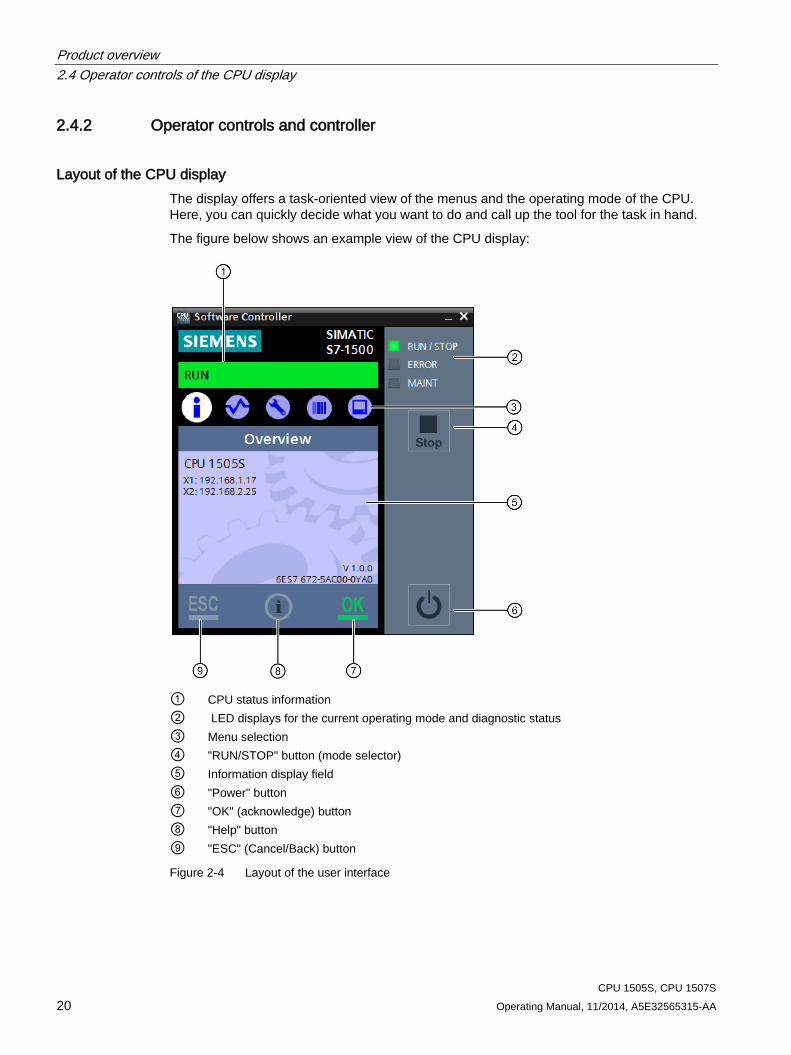
Layout of the CPU display The display offers a task-oriented view of the menus and the operating mode of the CPU. Here, you can quickly decide what you want to do and call up the tool for the task in hand.
The figure below shows an example view of the CPU display:
① CPU status information ② LED displays for the current operating mode and diagnostic status ③ Menu selection ④ "RUN/STOP" button (mode selector) ⑤ Information display field ⑥ "Power" button ⑦ "OK" (acknowledge) button ⑧ "Help" button ⑨ "ESC" (Cancel/Back) button
Figure 2-4 Layout of the user interface
Product overview 2.4 Operator controls of the CPU display
CPU 1505S, CPU 1507S Operating Manual, 11/2014, A5E32565315-AA 21
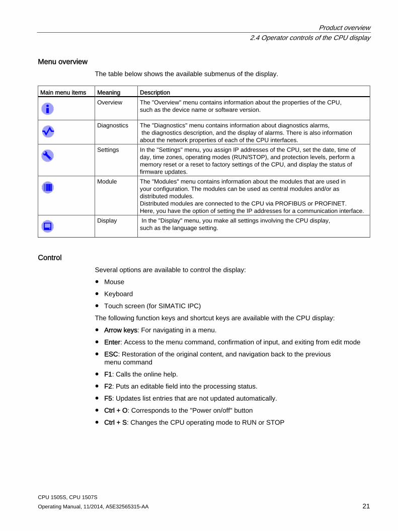
Menu overview The table below shows the available submenus of the display.
Main menu items Meaning Description
Overview The "Overview" menu contains information about the properties of the CPU, such as the device name or software version.
Diagnostics The "Diagnostics" menu contains information about diagnostics alarms, the diagnostics description, and the display of alarms. There is also information about the network properties of each of the CPU interfaces.
Settings In the "Settings" menu, you assign IP addresses of the CPU, set the date, time of day, time zones, operating modes (RUN/STOP), and protection levels, perform a memory reset or a reset to factory settings of the CPU, and display the status of firmware updates.
Module The "Modules" menu contains information about the modules that are used in your configuration. The modules can be used as central modules and/or as distributed modules. Distributed modules are connected to the CPU via PROFIBUS or PROFINET. Here, you have the option of setting the IP addresses for a communication interface.
Display In the "Display" menu, you make all settings involving the CPU display,
such as the language setting.
Control Several options are available to control the display:
● Mouse
● Keyboard
● Touch screen (for SIMATIC IPC)
The following function keys and shortcut keys are available with the CPU display:
● Arrow keys: For navigating in a menu.
● Enter: Access to the menu command, confirmation of input, and exiting from edit mode
● ESC: Restoration of the original content, and navigation back to the previous menu command
● F1: Calls the online help.
● F2: Puts an editable field into the processing status.
● F5: Updates list entries that are not updated automatically.
● Ctrl + O: Corresponds to the "Power on/off" button
● Ctrl + S: Changes the CPU operating mode to RUN or STOP
Product overview 2.4 Operator controls of the CPU display
CPU 1505S, CPU 1507S 22 Operating Manual, 11/2014, A5E32565315-AA
Functions of the "OK" and "ESC" buttons ● For menu commands in which an entry can be made:
– OK → valid access to the menu command, confirmation of input, and exit from the edit mode
– ESC → set the original contents (which means changes are not saved) and exit from edit mode
● For menu commands in which no entry can be made:
– OK → to next submenu item
– ESC → back to previous menu item
Tool tips for support of usability The CPU display provides tool tips for the most important buttons.
Note What is a tool tip?
A tool tip is a small pop-up window in application programs or on web pages. It displays a description for an element of the graphical user interface. Tool tips either display the text that the element itself contains or contain supplementary information about the related element.
A tool tip appears only when the button is active.
The CPU display contains buttons that have different functionalities. These buttons have different tool tips depending on the functionality. These buttons include:
● "RUN/STOP" button (mode selector)
● "Power" button
● "OK" button
● "ESC" button
Product overview 2.4 Operator controls of the CPU display
CPU 1505S, CPU 1507S Operating Manual, 11/2014, A5E32565315-AA 23
Starting help You can open the online help for the CPU directly from the opened display in two ways:
● Click . This button is always active in the CPU display. This button always opens the start page of the help.
● Press the "F1" key to open the help for a specific context. The help opens in a separate dialog. The start page of the help opens by default.
Some menus and submenus in the CPU display are linked to a specific help topic. In this case, the "F1" key opens the relevant help.
Note Language of the help
The help opens in the same language that you have selected for the CPU display.
Reference You will find additional information on the topic of the "CPU's display" in the System manual S7-1500 Automation System (http://support.automation.siemens.com/WW/view/en/59191792).
Product overview 2.5 Functions
CPU 1505S, CPU 1507S 24 Operating Manual, 11/2014, A5E32565315-AA
2.5 Functions
2.5.1 Storing
2.5.1.1 CPU memory areas
Introduction This section describes the structure of the memory of the CPU.
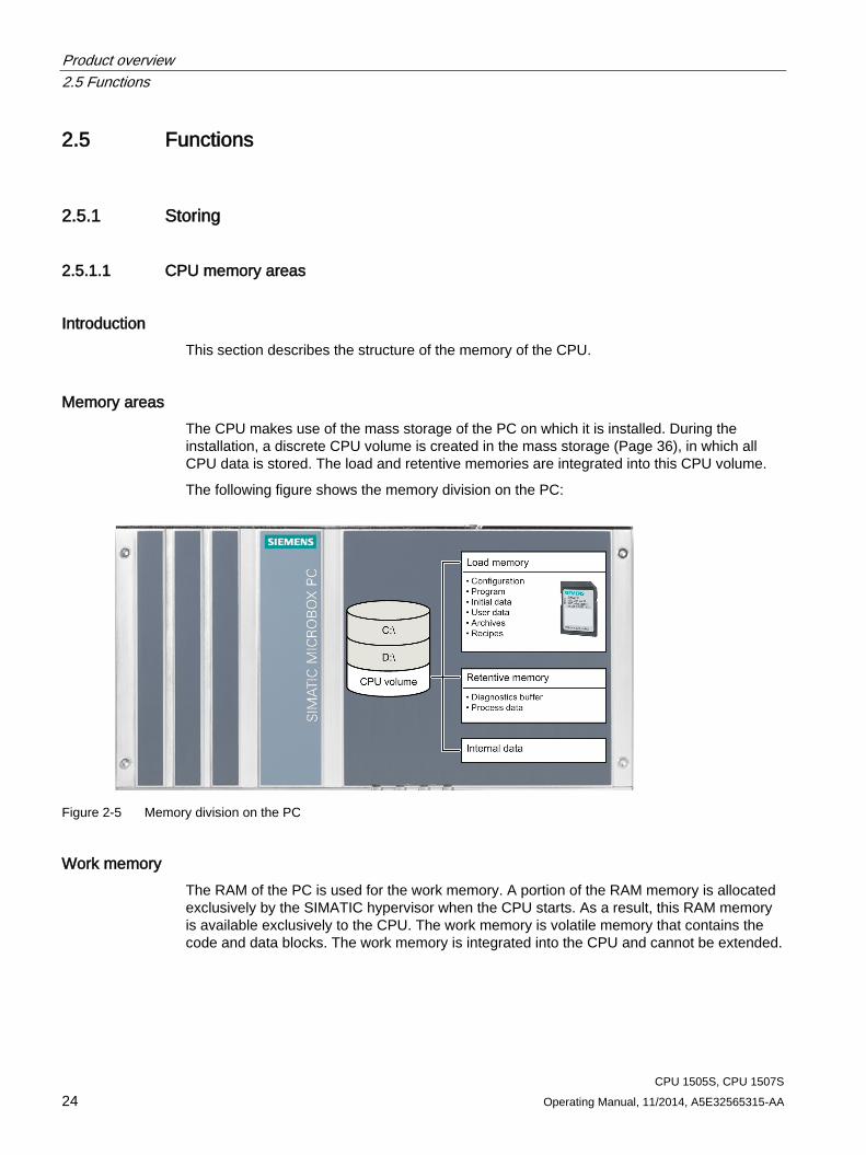
Memory areas The CPU makes use of the mass storage of the PC on which it is installed. During the installation, a discrete CPU volume is created in the mass storage (Page 36), in which all CPU data is stored. The load and retentive memories are integrated into this CPU volume.
The following figure shows the memory division on the PC:
Figure 2-5 Memory division on the PC
Work memory The RAM of the PC is used for the work memory. A portion of the RAM memory is allocated exclusively by the SIMATIC hypervisor when the CPU starts. As a result, this RAM memory is available exclusively to the CPU. The work memory is volatile memory that contains the code and data blocks. The work memory is integrated into the CPU and cannot be extended.
Product overview 2.5 Functions
CPU 1505S, CPU 1507S Operating Manual, 11/2014, A5E32565315-AA 25
Load memory The load memory is located in the mass storage of the PC. For this, a logical partition (CPU volume) to which the CPU has exclusive access is created during installation. The CPU volume contains not only the load memory but also internal configuration data and even retentive data, depending on the configuration. The CPU volume is not assigned to Windows. This ensures operation of the CPU independent of the operating system.
Note Enhanced write filter
The CPU volume cannot be protected by an enhanced write filter (EWF, FBWF).
Retentive memory Retentive memory is non-volatile memory for saving a limited quantity of data in the event of power failure. Retentive data can be stored in two ways, depending on the resources of the PC:
● In the NVRAM of a SIMATIC IPC (if the SIMATIC IPC used has this option)
● On the CPU volume
The data defined as retentive is stored in retentive memory. This data is retained beyond a power-off or power failure.
NVRAM When NVRAM is used, the storing of retentive data in the event of a power failure is also possible. Use only SIMATIC IPCs with a Windows Embedded Standard operating system and activated EWF for this.
The amount of data that can be stored retentively is limited and can depend on properties of the SIMATIC IPC used.
CPU volume The amount of data that can be stored retentively is limited. Use a UPS (Page 61) in order to guarantee correct shutdown of the PC even in the event of a power failure.
Reference Additional information about the memory structure and the basic meaning of these memory areas can be found in the Function Manual Structure and Use of the CPU Memory (http://support.automation.siemens.com/WW/view/en/59193101/0/en). This documentation also describes how you obtain information about the memory utilization using STEP 7.
Product overview 2.5 Functions
CPU 1505S, CPU 1507S 26 Operating Manual, 11/2014, A5E32565315-AA
2.5.1.2 Storage of retentive data
Introduction The CPU provides the option of storing data retentively in the PC mass storage or in the integrated NVRAM when the CPU is stopped or a power failure occurs. The following data is saved:
● The current data from data blocks, bit memories, timers, counters, and technology objects that is identified as retentive in the TIA Portal
● Contents of the diagnostics buffer
● Contents of the message buffer
● Current operating mode (RUN/STOP)
The retentive data is stored automatically in the following situations:
● Stopping the CPU by a manual trigger via the CPU display
● Shutdown of the Windows operating system (standard or triggered by a UPS signal)
● Power failure (by using a UPS or NVRAM)
Note Options for storage of retentive data
For information on the memory type and memory size of your hardware platform, check your PC system's technical specifications.
Product overview 2.5 Functions
CPU 1505S, CPU 1507S Operating Manual, 11/2014, A5E32565315-AA 27
Saving in mass storage The CPU has its own CPU volume in the mass storage of your PC. The storage process is thus independent of the status of your operating system and an enhanced write protection (EWF/FBWF). The storage process takes place during restart of the Windows operating system.
Note Preservation of retentive data when saving in mass storage
If you save the data in your PC's mass storage, copy the mass storage, and then start the CPU150xS with this copied data, the retentive data from the original configuration are retained. In order to delete the data, the CPU 1515SP PC's mode selector must be set to STOP, and a memory reset must be started.
When saving the retentive data on the PC's mass storage, the quantity of the retentive data that is to be stored on the mass storage differs from the quantity of memory in NVRAM.
NOTICE
Uninterruptible power supply (UPS)
A power failure without shutting down the operating system can cause damage to the file structure of the operating system. Use a UPS (Page 61) to protect the file system. You also have the option to activate the EWF (enhanced write filter) and NVRAM functionalities.
Storage in NVRAM The storage of retentive data in NVRAM protects you from losing important program data after a power failure. The storage in NVRAM has the advantage that the storage process is also possible in case of a sudden power failure. But the storage process with this method depends on the buffer capacity of the power supply of your PC. This frequently yields a very short time span sufficient to save all necessary data.
Reference Additional information on setting the storage type can be found in section Setting the storage location for retentive data (Page 46).
Additional information on setting the size of the diagnostic buffer and the retentive areas of bit memories, timers, and counters is available in the STEP 7 online help.
Product overview 2.5 Functions
CPU 1505S, CPU 1507S 28 Operating Manual, 11/2014, A5E32565315-AA
2.5.2 PROFINET IO
Properties of PROFINET IO PROFINET is a fieldbus standard of the PROFIBUS user organization that defines a cross-vendor communication and engineering model.
Within the context of PROFINET, PROFINET IO is a communication concept for the implementation of modular, distributed applications. PROFINET IO IRT enables defined response times and high-precision system behavior.
A PROFINET IO system consists of the following PROFINET devices:
● IO controller Device used to address the connected IO devices.
● IO device A distributed field device that is assigned to an IO controller.
The PROFINET IO controller operating mode enables direct access to IO devices via Industrial Ethernet.
The PROFINET IO device operating mode enables you to operate S7 stations as "intelligent" PROFINET IO devices on Industrial Ethernet.
Reference You can find additional information on the "PROFINET IO" topic in the STEP 7 online help and in the PROFINET System Description (http://support.automation.siemens.com/WW/view/en/19292127) manual.
2.5.3 PROFIenergy
PROFIenergy PROFIenergy (for PROFINET) reduces the energy consumption by using PROFIenergy commands during the production-free time.
Additional information ● System manual: PROFINET System Description
(http://support.automation.siemens.com/WW/view/en/19292127)
● Additional information on PROFIenergy is available on the Internet (http://www.profibus.com) under Common Application Profile PROFIenergy; Technical Specification for PROFINET; Version 1.0; January 2010; Order no: 3.802.
Product overview 2.5 Functions
CPU 1505S, CPU 1507S Operating Manual, 11/2014, A5E32565315-AA 29
2.5.4 PROFIBUS DP The PROFIBUS DP interface is used to connect distributed I/O. PROFIBUS DP allows you to create extensive subnets, for example.
PROFIBUS is the fieldbus network for the cell and field areas. PROFIBUS is physically implemented either as an electrical network based on shielded twisted-pair cables, or as an optical network based on fiber-optic cable.
Data transfer via PROFIBUS-DP provides a standardized interface (EN 50170 Vol. 2) for the transfer of process input and process output data between SIMATIC S7 and field devices (DP slaves).
Cyclic data exchange between a DP master and DP slaves is a characteristic of data transfer via PROFIBUS-DP.
A DP system based on the PROFIBUS-DP standard (EN 50170 Vol. 2) provides the DP master device. A device of this function class handles the actual control task. The device sends and receives process input and process output signals.
When in master mode, the CPU sends its configured bus parameters on the PROFIBUS DP interface. This means, for example, that a programming device can obtain the correct parameters so that the CPU can go online with the PG without any further settings. Transmission of the bus parameters can be activated/deactivated in the configuration. As default, the CPU sends the bus parameters.
Properties of the PROFIBUS DP interface The PROFIBUS DP interface provides the following properties and functions:
● PROFIBUS DP master
● Time-of-day synchronization
● Line diagnostics
● S7 services
Reference You will find additional information on "PROFIBUS DP" in the STEP 7 online help and in the PROFIBUS with STEP 7 (http://support.automation.siemens.com/WW/view/en/59193579) function manual.
2.5.5 Central I/O There are no special configuration requirements for use of the CPU 1505S on CPU 1515SP PC.
On a CPU 1515SP PC, the CPU uses distributed I/O. You can use any commonly used ET 200SP input and output modules with the CPU.
Product overview 2.5 Functions
CPU 1505S, CPU 1507S 30 Operating Manual, 11/2014, A5E32565315-AA
2.5.6 Web server of the CPU The CPU has an integrated web server that enables, among other things, the display of system diagnostics information via PROFINET. Any web client, such as a PC, multi panel, or smartphone, can be used to read-access module data, user program data, and diagnostics data of the CPU by means of an Internet browser. This means access to the CPU is possible without STEP 7 installed.
The web server can only be configured using STEP 7. The following options are available for accessing the web server of the CPU:
● Via Windows using a web browser
● Remote access by an external device via Ethernet
Note HTTPS for secure connection
The CPU supports the HTTPS protocol for secure and protected communication via the assigned PROFINET interface.
Benefits of the web server The web server enables monitoring and administering of the CPU by authorized users over a network. This enables long-distance evaluations and diagnostics. Monitoring and evaluation is possible without STEP 7; all you need is a web browser. Make sure that you protect the CPU from being compromised through the use of different methods (for example limiting network access, using firewalls (Page 107)).
Web browser You need a web browser to access the HTML pages of the CPU via Windows. The following web browsers have been tested for communication with the CPU:
● Internet Explorer (Version 8 to 11)
● Mozilla Firefox (Version 22 to 26)
● Mobile Safari (iOS 6.1 and iOS 7)
● Android Browser and Android Chrome (JellyBean operating system)
Product overview 2.5 Functions
CPU 1505S, CPU 1507S Operating Manual, 11/2014, A5E32565315-AA 31
Specific web pages for the CPU 150xS The functionalities of the web server apply to all CPUs of the S7-1500 automation system. The CPU 150xS has the following special features:
● "Start page" web page
The start page before the login provides general information about the CPU.
The "Start page" web page also reflects the position of the mode selector. If the CPU 150xS is located on a hardware platform that has no physical mode selector, the position of the mode selector in the web server always indicates RUN mode. If the CPU 150xS is located on a hardware platform that has a physical mode selector, the position of the mode selector in the web server always indicates the current operating mode of the hardware platform.
● "Identification" web page
The "Identification" web page gives you an overview of important specifications of the CPU.
Reference You can find additional information about the "Web server" topic in the Web Server Function Manual (http://support.automation.siemens.com/WW/view/en/59193560).
CPU 1505S, CPU 1507S 32 Operating Manual, 11/2014, A5E32565315-AA
Installing 3 3.1 System Requirements
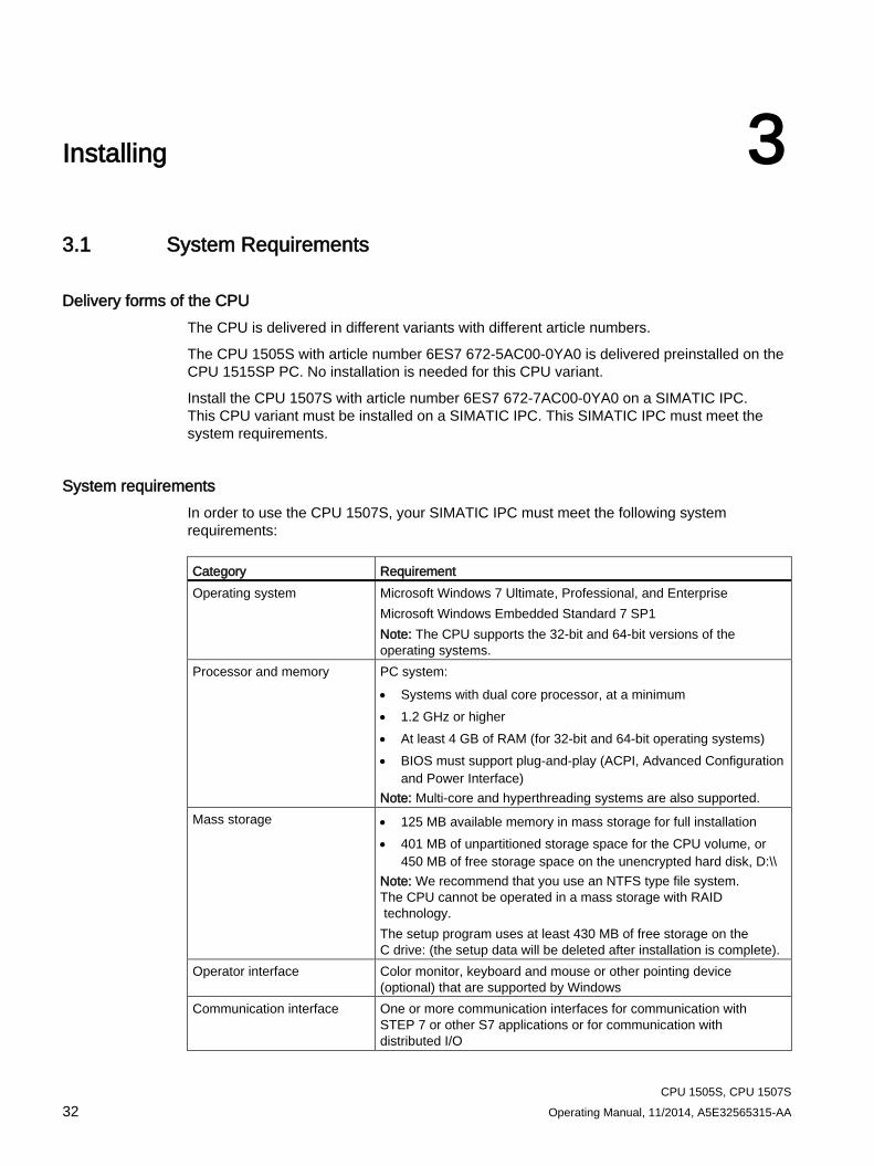
Delivery forms of the CPU The CPU is delivered in different variants with different article numbers.
The CPU 1505S with article number 6ES7 672-5AC00-0YA0 is delivered preinstalled on the CPU 1515SP PC. No installation is needed for this CPU variant.
Install the CPU 1507S with article number 6ES7 672-7AC00-0YA0 on a SIMATIC IPC. This CPU variant must be installed on a SIMATIC IPC. This SIMATIC IPC must meet the system requirements.
System requirements In order to use the CPU 1507S, your SIMATIC IPC must meet the following system requirements: Category Requirement Operating system Microsoft Windows 7 Ultimate, Professional, and Enterprise
Microsoft Windows Embedded Standard 7 SP1 Note: The CPU supports the 32-bit and 64-bit versions of the operating systems.
Processor and memory PC system: • Systems with dual core processor, at a minimum • 1.2 GHz or higher • At least 4 GB of RAM (for 32-bit and 64-bit operating systems) • BIOS must support plug-and-play (ACPI, Advanced Configuration
and Power Interface) Note: Multi-core and hyperthreading systems are also supported.
Mass storage • 125 MB available memory in mass storage for full installation • 401 MB of unpartitioned storage space for the CPU volume, or
450 MB of free storage space on the unencrypted hard disk, D:\\ Note: We recommend that you use an NTFS type file system. The CPU cannot be operated in a mass storage with RAID technology. The setup program uses at least 430 MB of free storage on the C drive: (the setup data will be deleted after installation is complete).
Operator interface Color monitor, keyboard and mouse or other pointing device (optional) that are supported by Windows
Communication interface One or more communication interfaces for communication with STEP 7 or other S7 applications or for communication with distributed I/O
Installing 3.2 Overview of the Installation Tasks
CPU 1505S, CPU 1507S Operating Manual, 11/2014, A5E32565315-AA 33
3.2 Overview of the Installation Tasks You must have administrator rights on the CPU 1507S to install the software on your PC.
Note Installation with multiple hard disks
Install the software for the CPU on the same hard disk (Disk 0 in the BIOS) where the operating system is installed.
Requirement Observe the following requirements for the installation:
● Your PC must meet the system requirements (Page 32).
● You must have Windows administrator (ADMIN) rights.
● DiagBase V1.5 or higher is recommended on your PC.
● The CPU cannot be installed on encrypted drives.
Procedure To perform the installation properly, follow these steps:
1. Deactivate the enhanced write filter EWF or FBWF.
2. Ensure that no other version of the CPU is installed at the time of installation. If a version of the CPU is already installed, uninstall that version first.
3. Install the software for the CPU on the same hard disk where the operating system is installed.
4. License the installation (Page 37) with the Automation License Manager.
Note Data loss
Uninstalling the CPU deletes the STEP 7 user program present on the controller, the configurations, the retentive data, and all settings from the CPU display.
Installing 3.3 Installing the software controller
CPU 1505S, CPU 1507S 34 Operating Manual, 11/2014, A5E32565315-AA
3.3 Installing the software controller In order to install the software for the CPU, insert the installation DVD. Follow the instructions of the setup program.
If the setup program does not start automatically, manually start the "Start.exe" file from the installation DVD by double clicking it.
If you do not have administrator rights, run the "Start.exe" file using the "Run as administrator" shortcut menu command.
Note Effect of the installation on the power saving settings of the PC
The CPU does not allow the use of "Hibernate" or "Standby" of the operating system.
Even if your PC supports these power saving settings, they will be disabled by default after installation of the software controller.
Procedure To install the software for the CPU, follow these steps:
1. Execute the "Start.exe" file.
2. Select the language for performing the installation.
3. Read the product information.
4. Confirm with "Next". This installation continues.
5. Select the components to be installed in the list.
Select an installation path.
6. Continue to follow the instructions, which guide you through the installation.
7. Choose whether you want to carry out the licensing (Page 37) during the installation or at a later time.
8. Confirm the installation dialog with the "Install" button.
9. Restart the PC after successful completion of the installation.
Installing 3.3 Installing the software controller
CPU 1505S, CPU 1507S Operating Manual, 11/2014, A5E32565315-AA 35
Result The installation is complete. During the installation process, all product languages have been installed by default. An entry in the Windows Start menu is created by the installation.
The following options appear in the boot menu when the PC is restarted, which you can choose between:
● Windows only
Windows starts normally but the CPU cannot be started.
● Windows and CPU 150xS
Windows starts normally and you can open the CPU display in "Power off" mode. Switch on the CPU using the "Power" button. The CPU starts in "STOP" mode.
Note
If you do not choose either of the options within five seconds, the PC starts with the "Windows and CPU" option by default.
Installing 3.4 Creation of the CPU volume
CPU 1505S, CPU 1507S 36 Operating Manual, 11/2014, A5E32565315-AA
3.4 Creation of the CPU volume
Introduction The CPU makes use of the mass storage of the PC on which it is installed. During the installation, a discrete CPU volume is created in the mass storage, in which all CPU data is stored. The load and retentive memories are integrated into this CPU volume.
Note Size of the CPU volume
In order to ensure reliable operation of the CPU, the CPU volume must not be reduced during operation. If you reduce the assigned mass storage area, this can lead to data loss or even a CPU crash.
Requirement for creation of a CPU volume The allocation and formatting of the CPU volume is carried out automatically during the installation process. One of the following requirements must be met for this:
● At least 401 MB of unpartitioned memory on the hard drive
● At least 401 MB available memory on the expanded partition on the hard drive
● At least 450 MB available memory on the unencrypted hard drive D:\\
Result The CPU volume is created automatically as part of the installation process.
Manual creation of the CPU volume If the CPU volume cannot be created automatically, you have the following options available:
● The installation process outputs a message that provides you the opportunity to manually perform the partitioning. Alternatively, you can cancel the installation process at any time.
● You must remove files from the D:\\ partition, since there is insufficient storage space available to perform the partitioning of the hard drive.
● You must manually decrypt the D:\\ partition
Installing 3.5 Licensing the software controller
CPU 1505S, CPU 1507S Operating Manual, 11/2014, A5E32565315-AA 37
3.5 Licensing the software controller The software requires a product-specific license key that you install with the Automation License Manager. Each SIMATIC software product for automation (e.g., STEP 7) has its own license key. You must install the license key for each product.
Working with the Automation License Manager The Automation License Manager is a product of Siemens AG and is used for managing license keys. The Automation License Manager is supplied on the installation data medium of the software controller by default and is transferred automatically during the installation process.
Software products that require license keys for operation register the requirement for license keys automatically in the Automation License Manager. If the Automation License Manager finds a valid license key for this software, the software can be used according to the conditions of use associated with this license key.
Certificate of license A Certificate of License is included in the scope of delivery. It contains your unique license number. This serves as proof that you have a valid license key. Store this certificate in a safe place. You must have a valid certificate of license to get a replacement license key.
License key The license key for the CPU is located on a USB stick that is included in the scope of delivery.
If the USB stick containing the license key is lost or damaged, you can contact the hotline to obtain a new license key. You need the certificate of license to receive a replacement license key from Siemens.
Installing 3.5 Licensing the software controller
CPU 1505S, CPU 1507S 38 Operating Manual, 11/2014, A5E32565315-AA
Transferring the license key The license key can be transferred during the installation or afterwards.
Note
The license key must be installed on a file system of the type NTFS.
If the USB stick with the relevant license key is inserted in the USB port of the PC at the start of installation, the license key will be transferred automatically during the installation. If the USB stick is not inserted at the start of installation, you have three options for installing the license key subsequently:
● To transfer the license key manually from a network computer or other storage medium, select the "Manual license transfer" button.
● Insert the USB stick with license key, and select the "Retry license transfer" button. The Automation License Manager opens in order to transfer the license key.
● If you do not want to install a license key, select the "Skip license transfer" button.
Note Working with the CPU without a license key
For legal reasons, a valid license key is required for this product.
If no license key is present on your PC, the CPU will continue running. However, a message will inform you at regular intervals that a valid license key has not been found.
Manually transferring the license key subsequently If you start the CPU without a transferred license key, a message is displayed on the screen. If the Automation License Manager is not yet installed on your computer, you must install it first.
To manually transfer the license key for the CPU subsequently, follow these steps:
1. Start the installation of the software controller with administrator rights.
2. In the "License Transfer" section, select the "Manual license transfer" button.
A dialog box for synchronization of the license opens.
3. Select the destination and the source of the license key.
4. To transfer the license key, click the "Synchronize" button.
The license key is transferred.
Recovering the license key in case of defective mass storage If a error has occurred on the mass storage or USB stick containing your license key file, contact your Siemens representative (http://www.siemens.com/automation/service&support). Make sure you have your certificate of license available when you contact the hotline.
Installing 3.6 Uninstalling the software controller
CPU 1505S, CPU 1507S Operating Manual, 11/2014, A5E32565315-AA 39
3.6 Uninstalling the software controller
Procedure To uninstall the software on your PC, follow these steps:
1. In the "Control Panel > Programs > Uninstall program" menu, select the "CPU 1505S" or "CPU 1507S" entry.
A dialog for the uninstallation opens.
2. Select the CPU.
3. Follow the rest of the steps for the uninstallation.
Note Uninstallation when the CPU display is open
When you uninstall the CPU, the CPU display is closed automatically if it was still open.
Result The software for the CPU and the CPU display are uninstalled. CPU-specific data and links are deleted.
The Automation License Manager is not uninstalled automatically with the uninstallation of the software for the CPU. The Automation License Manager must be uninstalled separately if required.
CPU 1505S, CPU 1507S 40 Operating Manual, 11/2014, A5E32565315-AA
Commissioning in STEP 7 4 4.1 Configuring the CPU with STEP 7
This section describes the example configuration of a STEP 7 project with a CPU 1507S on a SIMATIC IPC.
4.1.1 Creating the configuration
Requirement ● You have created a project in STEP 7 with a SIMATIC IPC.
● You are in the device view.
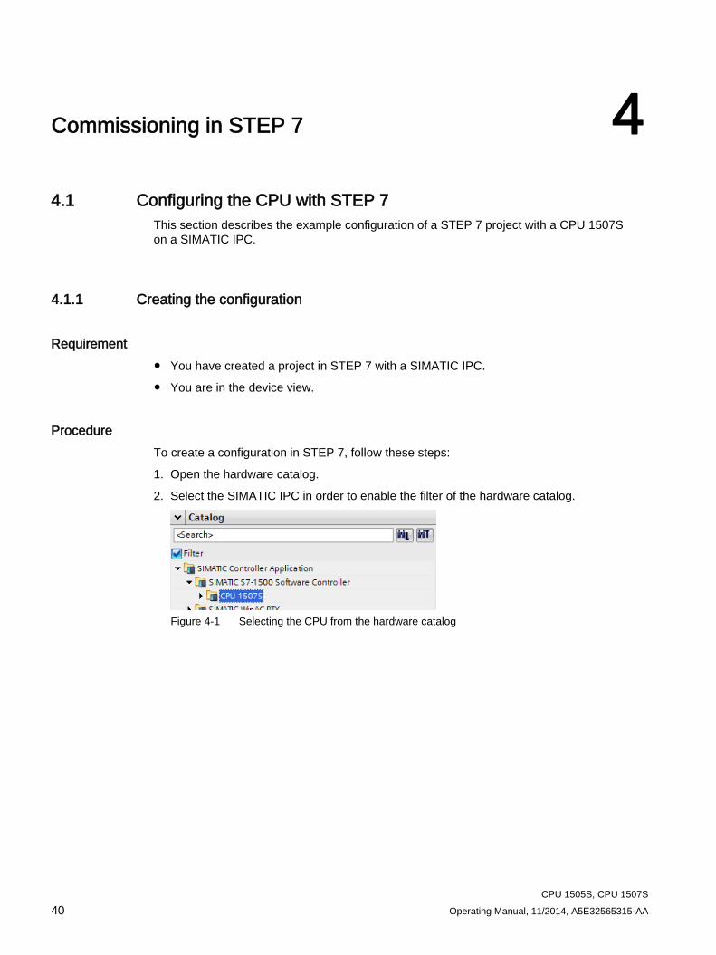
Procedure To create a configuration in STEP 7, follow these steps:
1. Open the hardware catalog.
2. Select the SIMATIC IPC in order to enable the filter of the hardware catalog.
Figure 4-1 Selecting the CPU from the hardware catalog
Commissioning in STEP 7 4.1 Configuring the CPU with STEP 7
CPU 1505S, CPU 1507S Operating Manual, 11/2014, A5E32565315-AA 41
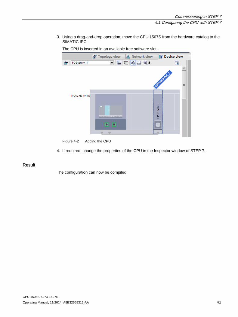
3. Using a drag-and-drop operation, move the CPU 1507S from the hardware catalog to the SIMATIC IPC.
The CPU is inserted in an available free software slot.
Figure 4-2 Adding the CPU
4. If required, change the properties of the CPU in the Inspector window of STEP 7.
Result The configuration can now be compiled.
Commissioning in STEP 7 4.1 Configuring the CPU with STEP 7
CPU 1505S, CPU 1507S 42 Operating Manual, 11/2014, A5E32565315-AA
4.1.2 Downloading the project to the target system
Requirement ● The SIMATIC IPC hardware component is physically connected to the PC on which
STEP 7 is installed via Ethernet.
● The interface settings match on the CPU and in STEP 7.
Note
Recommended interfaces
Use the "IE/PN" interface with a SIMATIC IPC. Use the "X2" interface with a CPU 1515SP PC
Procedure To download the STEP 7 project, follow these steps:
1. Select the PC system in the device view.
2. Select the "Download to device" shortcut menu command.
The "Extended download to device" dialog opens.
3. Configure the settings for the interface.
4. Click the "Download" button to start the download.
Result The project is downloaded. A dialog shows the download progress.
Depending on the change that was made (for example a change to the interfaces, LED, NVRAM or index), STEP 7 displays a message indicating that the target system must be restarted. The target system is restarted automatically.
The CPU starts in STOP mode in order to ensure the continuation of the download.
STEP 7 establishes a connection to the CPU automatically. Click the "Download" button again to complete the download.
Checking the result of the download After successful completion of the download, the CPU link appears in the Windows Start menu with the name you have assigned in the settings of the CPU in STEP 7.
The name assigned in STEP 7 is also visible in the CPU display.
Commissioning in STEP 7 4.2 Selecting startup type
CPU 1505S, CPU 1507S Operating Manual, 11/2014, A5E32565315-AA 43
4.2 Selecting startup type
Configuration of the startup type of the CPU The CPU can be started (POWER ON) in two different ways. You must configure the start type in STEP 7.
● Manual start via the "Power" button on the CPU display (Page 62)
● Automatic start during PC start
The "Automatic start after booting the PC" option is selected by default in STEP 7. If you deselect the option, you must start the CPU manually via the CPU display.
Note
BIOS memory test on SIMATIC IPCs
PCs provide the option of a memory test. Some hardware tests, such as the memory test, are disabled by default in the BIOS setup program and are skipped during startup of the PC. Booting is accelerated as a result.
If you are using the CPU on a SIMATIC IPC or CPU 1515SP PC, the BIOS memory test must not be enabled.
Commissioning in STEP 7 4.2 Selecting startup type
CPU 1505S, CPU 1507S 44 Operating Manual, 11/2014, A5E32565315-AA
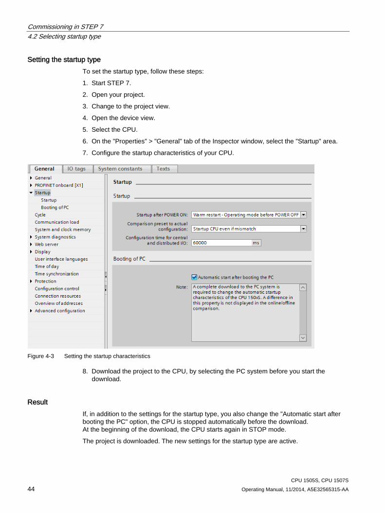
Setting the startup type To set the startup type, follow these steps:
1. Start STEP 7.
2. Open your project.
3. Change to the project view.
4. Open the device view.
5. Select the CPU.
6. On the "Properties" > "General" tab of the Inspector window, select the "Startup" area.
7. Configure the startup characteristics of your CPU.
Figure 4-3 Setting the startup characteristics
8. Download the project to the CPU, by selecting the PC system before you start the download.
Result If, in addition to the settings for the startup type, you also change the "Automatic start after booting the PC" option, the CPU is stopped automatically before the download. At the beginning of the download, the CPU starts again in STOP mode.
The project is downloaded. The new settings for the startup type are active.
Commissioning in STEP 7 4.2 Selecting startup type
CPU 1505S, CPU 1507S Operating Manual, 11/2014, A5E32565315-AA 45
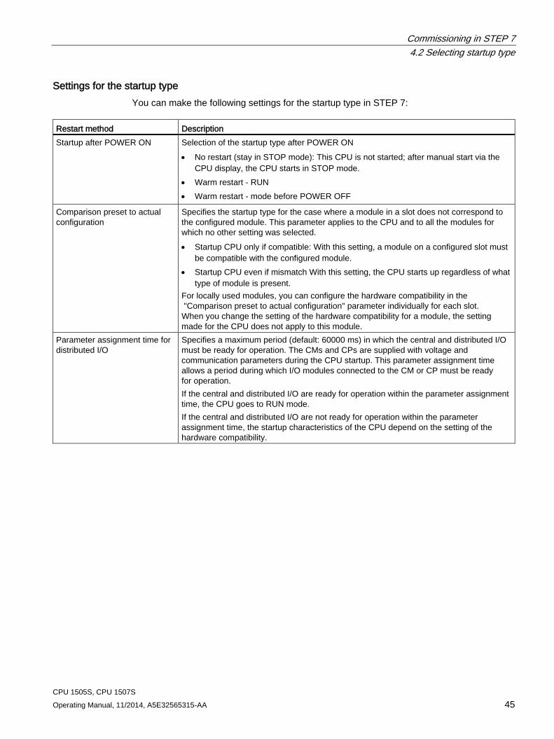
Settings for the startup type You can make the following settings for the startup type in STEP 7:
Restart method Description Startup after POWER ON Selection of the startup type after POWER ON
• No restart (stay in STOP mode): This CPU is not started; after manual start via the CPU display, the CPU starts in STOP mode.
• Warm restart - RUN • Warm restart - mode before POWER OFF
Comparison preset to actual configuration
Specifies the startup type for the case where a module in a slot does not correspond to the configured module. This parameter applies to the CPU and to all the modules for which no other setting was selected. • Startup CPU only if compatible: With this setting, a module on a configured slot must
be compatible with the configured module. • Startup CPU even if mismatch With this setting, the CPU starts up regardless of what
type of module is present. For locally used modules, you can configure the hardware compatibility in the "Comparison preset to actual configuration" parameter individually for each slot. When you change the setting of the hardware compatibility for a module, the setting made for the CPU does not apply to this module.
Parameter assignment time for distributed I/O
Specifies a maximum period (default: 60000 ms) in which the central and distributed I/O must be ready for operation. The CMs and CPs are supplied with voltage and communication parameters during the CPU startup. This parameter assignment time allows a period during which I/O modules connected to the CM or CP must be ready for operation. If the central and distributed I/O are ready for operation within the parameter assignment time, the CPU goes to RUN mode. If the central and distributed I/O are not ready for operation within the parameter assignment time, the startup characteristics of the CPU depend on the setting of the hardware compatibility.
Commissioning in STEP 7 4.3 Setting the storage location for retentive data
CPU 1505S, CPU 1507S 46 Operating Manual, 11/2014, A5E32565315-AA
4.3 Setting the storage location for retentive data The CPU provides the option of storing data retentively in the PC mass storage or in the integrated NVRAM when the CPU is stopped or a power failure occurs. You set the type of data storage in the CPU properties in STEP 7.
Note Data loss when changing the storage type
The current retentive data and the contents of the diagnostic buffer are deleted when you change the storage type.
Requirement STEP 7 is open.
The project view is open.
The device view is open.
Commissioning in STEP 7 4.3 Setting the storage location for retentive data
CPU 1505S, CPU 1507S Operating Manual, 11/2014, A5E32565315-AA 47
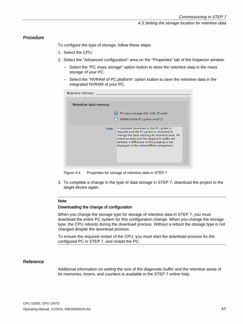
Procedure To configure the type of storage, follow these steps:
1. Select the CPU.
2. Select the "Advanced configuration" area on the "Properties" tab of the Inspector window.
– Select the "PC mass storage" option button to store the retentive data in the mass storage of your PC.
– Select the "NVRAM of PC platform" option button to save the retentive data in the integrated NVRAM of your PC.
Figure 4-4 Properties for storage of retentive data in STEP 7
3. To complete a change in the type of data storage in STEP 7, download the project to the target device again.
Note Downloading the change of configuration
When you change the storage type for storage of retentive data in STEP 7, you must download the entire PC system for this configuration change. When you change the storage type, the CPU reboots during the download process. Without a reboot the storage type is not changed despite the download process.
To ensure the required restart of the CPU, you must start the download process for the configured PC in STEP 7, and restart the PC.
Reference Additional information on setting the size of the diagnostic buffer and the retentive areas of bit memories, timers, and counters is available in the STEP 7 online help.
Commissioning in STEP 7 4.4 Setting up copy protection
CPU 1505S, CPU 1507S 48 Operating Manual, 11/2014, A5E32565315-AA
4.4 Setting up copy protection
Application Copy protection allows you to bind the program or the blocks to a particular CPU. By binding a program or block to the serial number of the CPU, use of this program or block is only possible in conjunction with the CPU.
Unlike a hardware CPU, copy protection for a software controller goes against your PC's hard disk, and not against a SIMATIC memory card.
Note Reading out the serial number
For a SIMATIC S7-1500 Software Controller, you can read out the serial number only in the CPU display. You can find information about the serial number of your CPU in the "Overview" menu.
Copy and know-how protection When you set up such a copy protection for a block, also assign know-how protection (Page 106) to this block. Without know-how protection, anyone can reset the copy protection. You must, however, set up copy protection first as the copy protection settings are read-only if the block is already know-how-protected.
Requirement STEP 7 is open.
The project view is open.
The device view is open.
Commissioning in STEP 7 4.4 Setting up copy protection
CPU 1505S, CPU 1507S Operating Manual, 11/2014, A5E32565315-AA 49
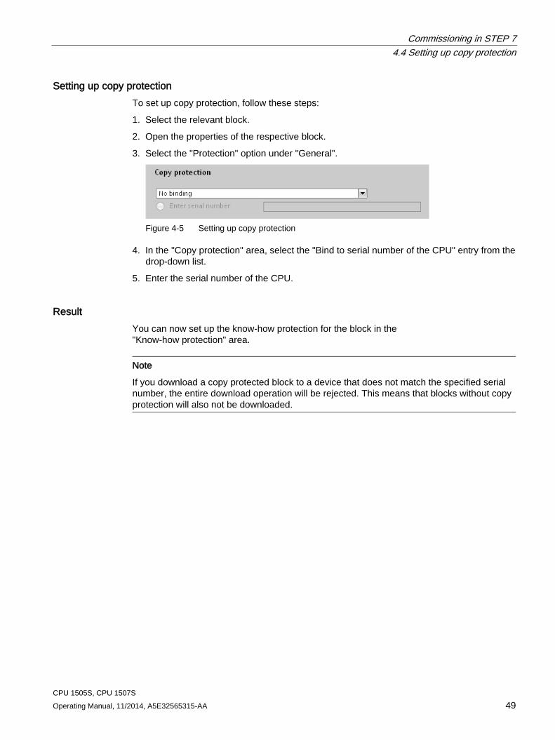
Setting up copy protection To set up copy protection, follow these steps:
1. Select the relevant block.
2. Open the properties of the respective block.
3. Select the "Protection" option under "General".
Figure 4-5 Setting up copy protection
4. In the "Copy protection" area, select the "Bind to serial number of the CPU" entry from the drop-down list.
5. Enter the serial number of the CPU.
Result You can now set up the know-how protection for the block in the "Know-how protection" area.
Note
If you download a copy protected block to a device that does not match the specified serial number, the entire download operation will be rejected. This means that blocks without copy protection will also not be downloaded.
Commissioning in STEP 7 4.5 Using the LEDs of the hardware
CPU 1505S, CPU 1507S 50 Operating Manual, 11/2014, A5E32565315-AA
4.5 Using the LEDs of the hardware The CPU provides the functionality of displaying its status on the LEDs of the hardware platform on which it is installed. You set this functionality in the CPU properties in STEP 7.
Note Simultaneous access by multiple components
Take care that multiple competing components (for example DiagBase and CPU) do not make simultaneous access to the hardware LED.
Requirement STEP 7 is open.
Your project is open.
You are in the project view.
Commissioning in STEP 7 4.5 Using the LEDs of the hardware
CPU 1505S, CPU 1507S Operating Manual, 11/2014, A5E32565315-AA 51
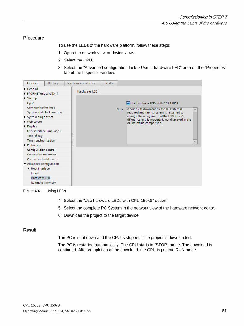
Procedure To use the LEDs of the hardware platform, follow these steps:
1. Open the network view or device view.
2. Select the CPU.
3. Select the "Advanced configuration task > Use of hardware LED" area on the "Properties" tab of the Inspector window.
Figure 4-6 Using LEDs
4. Select the "Use hardware LEDs with CPU 150xS" option.
5. Select the complete PC System in the network view of the hardware network editor.
6. Download the project to the target device.
Result The PC is shut down and the CPU is stopped. The project is downloaded.
The PC is restarted automatically. The CPU starts in "STOP" mode. The download is continued. After completion of the download, the CPU is put into RUN mode.
Commissioning in STEP 7 4.6 Configuring the web server
CPU 1505S, CPU 1507S 52 Operating Manual, 11/2014, A5E32565315-AA
4.6 Configuring the web server
System diagnostics using the CPU web server The web server can only be configured using STEP 7. The web server is disabled by default.
Requirement ● You have opened STEP 7.
● You have added a CPU to the project.
● You have opened the project view.
Configuring the web server To configure the web server in STEP 7, follow these steps:
1. Open the network view.
2. Select the CPU.
3. Open the "Properties" tab in the Inspector window.
4. Select the entry "Web server" in the "General" area navigation.
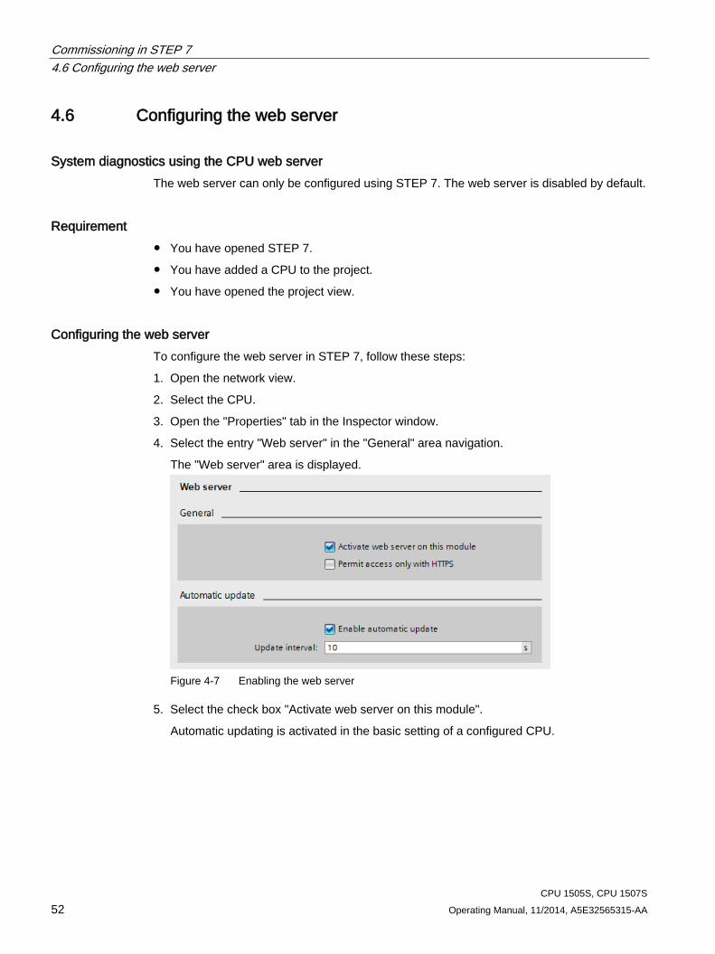
The "Web server" area is displayed.
Figure 4-7 Enabling the web server
5. Select the check box "Activate web server on this module".
Automatic updating is activated in the basic setting of a configured CPU.
Commissioning in STEP 7 4.6 Configuring the web server
CPU 1505S, CPU 1507S Operating Manual, 11/2014, A5E32565315-AA 53
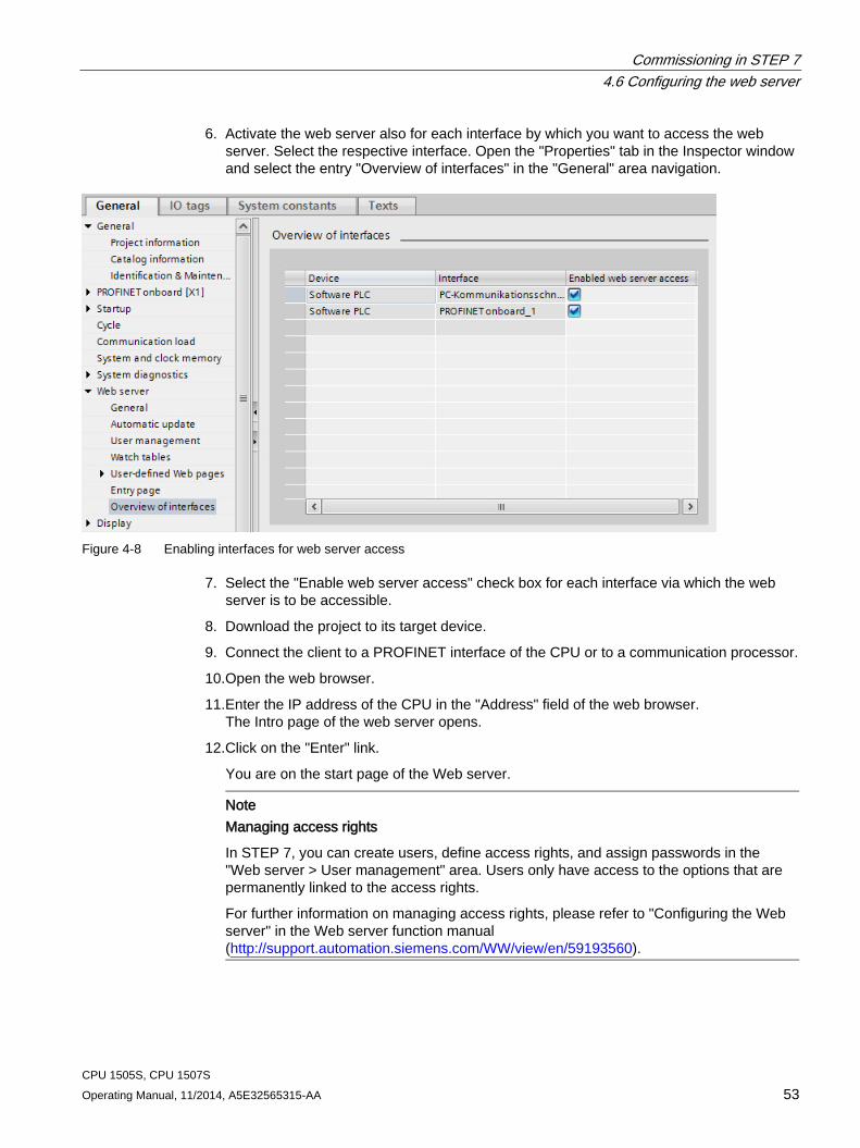
6. Activate the web server also for each interface by which you want to access the web server. Select the respective interface. Open the "Properties" tab in the Inspector window and select the entry "Overview of interfaces" in the "General" area navigation.
Figure 4-8 Enabling interfaces for web server access
7. Select the "Enable web server access" check box for each interface via which the web server is to be accessible.
8. Download the project to its target device.
9. Connect the client to a PROFINET interface of the CPU or to a communication processor.
10. Open the web browser.
11. Enter the IP address of the CPU in the "Address" field of the web browser. The Intro page of the web server opens.
12. Click on the "Enter" link.
You are on the start page of the Web server.
Note Managing access rights
In STEP 7, you can create users, define access rights, and assign passwords in the "Web server > User management" area. Users only have access to the options that are permanently linked to the access rights.
For further information on managing access rights, please refer to "Configuring the Web server" in the Web server function manual (http://support.automation.siemens.com/WW/view/en/59193560).
Commissioning in STEP 7 4.6 Configuring the web server
CPU 1505S, CPU 1507S 54 Operating Manual, 11/2014, A5E32565315-AA
"Intro" page After you have established the connection to the web server, the "Intro" page opens. Click the ENTER link to go to the web server pages.
Note "Skip Intro"
Select the "Skip Intro" check box in order to skip the Intro. In the future, you will go directly to the start page of the web server. You can undo the "Skip Intro" setting by clicking the "Intro" link on the Start page.
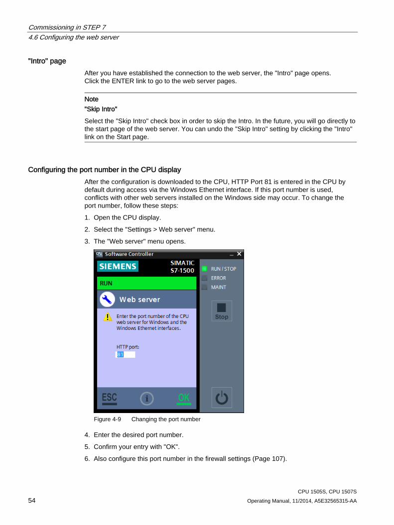
Configuring the port number in the CPU display After the configuration is downloaded to the CPU, HTTP Port 81 is entered in the CPU by default during access via the Windows Ethernet interface. If this port number is used, conflicts with other web servers installed on the Windows side may occur. To change the port number, follow these steps:
1. Open the CPU display.
2. Select the "Settings > Web server" menu.
3. The "Web server" menu opens.
Figure 4-9 Changing the port number
4. Enter the desired port number.
5. Confirm your entry with "OK".
6. Also configure this port number in the firewall settings (Page 107).
Commissioning in STEP 7 4.7 Assigning interfaces for the communication
CPU 1505S, CPU 1507S Operating Manual, 11/2014, A5E32565315-AA 55
Reference You can find additional information about the "Web server" topic in the Web Server Function Manual (http://support.automation.siemens.com/WW/view/en/59193560).
4.7 Assigning interfaces for the communication Interfaces can be exclusively used by the software controller. Only these exclusively assigned interfaces allow distributed I/O to be connected. In addition, SIMATIC communication is also possible.
Interface types The following list gives you an overview of the interfaces that are used by your PC:
● CPU 1505S:
– one PROFINET interface
– one PROFIBUS interface
– onboard interfaces of the CPU 1515SP PC
● CPU 1507S:
– two PROFINET interfaces
– one PROFIBUS interface
– Onboard PROFINET/IE interfaces, or onboard PROFIBUS interfaces of the SIMATIC IPC
– additional insertable interface cards
Additional information about the interfaces of the PC that is used can be found in your device's technical specifications.
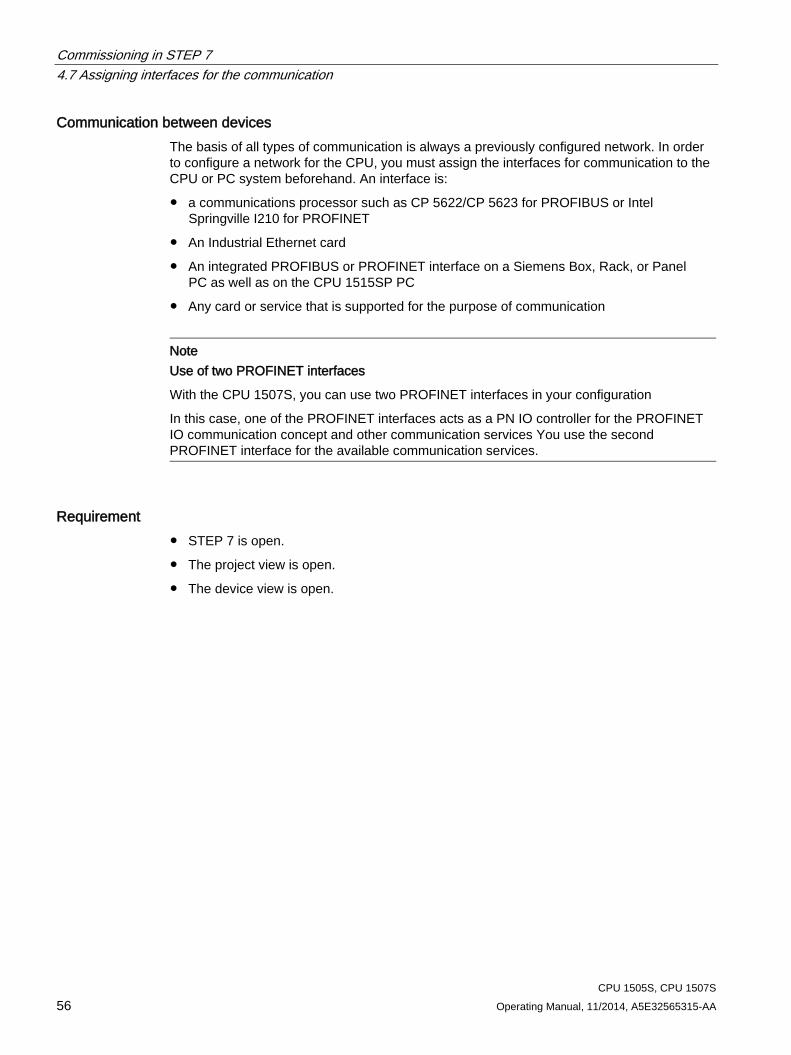
Commissioning in STEP 7 4.7 Assigning interfaces for the communication
CPU 1505S, CPU 1507S 56 Operating Manual, 11/2014, A5E32565315-AA
Communication between devices The basis of all types of communication is always a previously configured network. In order to configure a network for the CPU, you must assign the interfaces for communication to the CPU or PC system beforehand. An interface is:
● a communications processor such as CP 5622/CP 5623 for PROFIBUS or Intel Springville I210 for PROFINET
● An Industrial Ethernet card
● An integrated PROFIBUS or PROFINET interface on a Siemens Box, Rack, or Panel PC as well as on the CPU 1515SP PC
● Any card or service that is supported for the purpose of communication
Note Use of two PROFINET interfaces
With the CPU 1507S, you can use two PROFINET interfaces in your configuration
In this case, one of the PROFINET interfaces acts as a PN IO controller for the PROFINET IO communication concept and other communication services You use the second PROFINET interface for the available communication services.
Requirement ● STEP 7 is open.
● The project view is open.
● The device view is open.
Commissioning in STEP 7 4.7 Assigning interfaces for the communication
CPU 1505S, CPU 1507S Operating Manual, 11/2014, A5E32565315-AA 57
Procedure To assign the interfaces for the communication to the CPU or PC system, follow these steps:
1. Select the CPU.
2. Select the integrated interface X2 in the device view.
3. Assign the interface in the PC system's properties.
Figure 4-10 Assigning the interface to the "SIMATIC PC system"
4. Add the desired PN/IE communication processor from the catalog.
5. Assign the communication processor in the CPU properties.
6. Compile the project with "Edit > Compile".
7. Download the hardware configuration of the PC system to the target device.
Result The PC restarts during the download. The download is finished.
Reference You can find more information on the topic "Assigning interfaces" in the STEP 7 online help.
Commissioning in STEP 7 4.8 Using open communication via Windows interface
CPU 1505S, CPU 1507S 58 Operating Manual, 11/2014, A5E32565315-AA
4.8 Using open communication via Windows interface
Introduction The S7-1500 software controller supports open communication (Open User Communication, OUC) via the assigned PROFINET interfaces in the full scope of an S7-1500 hardware CPU.
In addition the S7-1500 software controller supports open communication with Windows applications, and with communications partners via Windows Ethernet interfaces with the following protocols:
● TCP
● UDP
The usual program blocks for open communication can be used for this purpose:
● TSEND_C, TRECV_C
● TMAIL_C
● TCON/TSEND/TRCV
Note Use of ISO on TCP
Use of ISO on TCP is not available in Windows. You must used programmed communication.
Utilized interface The CPU uses the "PC Communication interface (HW_ID 59) for configuration of OUC connections. For this purpose, enter the system constant <NAME> in the relevant location in the data block for the connection data.
Commissioning in STEP 7 4.9 Time synchronization based on Windows clock
CPU 1505S, CPU 1507S Operating Manual, 11/2014, A5E32565315-AA 59
4.9 Time synchronization based on Windows clock
Introduction The CPU supports various time sources, including the internal system clock and the Windows clock. This time information can be different, especially in the case of extended operating times. To prevent this, perform a time synchronization at regular intervals.
Note Time synchronization based on Windows and NTP
Time synchronization based on Windows and NTP cannot be configured at the same time.
With STEP 7, you have the option of configuring time synchronization based on Windows for your CPU.
Requirement STEP 7 is open.
The project view is open.
The device view is open.
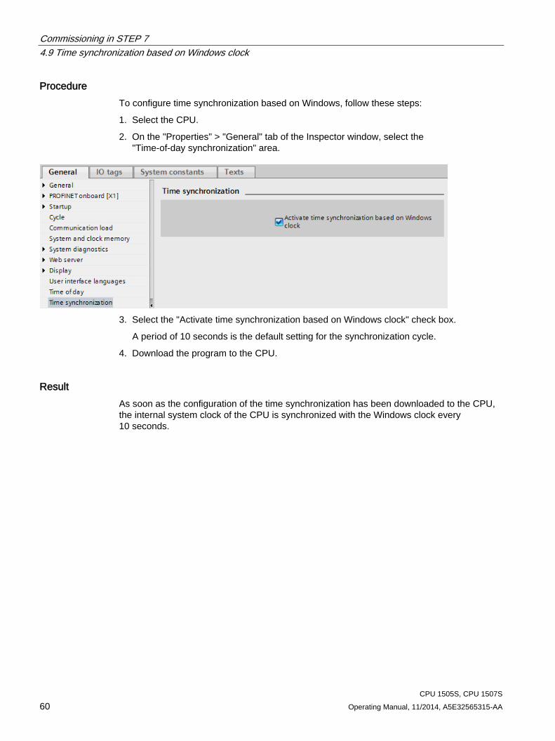
Commissioning in STEP 7 4.9 Time synchronization based on Windows clock
CPU 1505S, CPU 1507S 60 Operating Manual, 11/2014, A5E32565315-AA
Procedure To configure time synchronization based on Windows, follow these steps:
1. Select the CPU.
2. On the "Properties" > "General" tab of the Inspector window, select the "Time-of-day synchronization" area.
3. Select the "Activate time synchronization based on Windows clock" check box.
A period of 10 seconds is the default setting for the synchronization cycle.
4. Download the program to the CPU.
Result As soon as the configuration of the time synchronization has been downloaded to the CPU, the internal system clock of the CPU is synchronized with the Windows clock every 10 seconds.
Commissioning in STEP 7 4.10 Using the uninterruptible power supply (UPS)
CPU 1505S, CPU 1507S Operating Manual, 11/2014, A5E32565315-AA 61
4.10 Using the uninterruptible power supply (UPS) You can use a UPS to supply emergency power to your PC. A UPS system can help to ensure that the CPU shuts down correctly and saves the current state in case of a power failure. Siemens strongly recommends the use of a UPS for operation with the Windows operating system.
Setting up the UPS for your PC The CPU provides two options for using a UPS:
● Connect the UPS to the PC via USB. The UPS notifies Windows.
● Connect the UPS to the CPU via a digital input. Windows can be shut down in the CPU's user program by means of the "SHUT_DOWN" instruction.
The CPU supports the "shutdown" command, which you can call and execute using command line commands. To ensure reliable data retention, the CPU must be stopped by the installed UPS system using the "CPU _Control /PowerOffCPU" command line command.
The PC detects a power failure and sends a power failure signal to the CPU. The CPU can then initiate a fast shutdown and save retentive data if so configured. Systems with CompactFlash or CFast file system that is protected with EWF are stable against unexpected power failure.
Consequences of a power loss without an operating system shutdown A power failure without shutting down the Windows 7 or Windows Embedded Standard 7 operating system with deactivated EWF can damage the file systems of the operating system. Use a UPS system to protect the file systems.
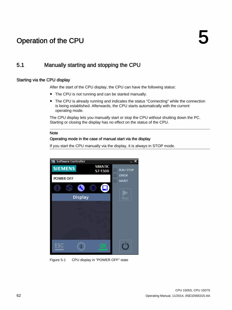
CPU 1505S, CPU 1507S 62 Operating Manual, 11/2014, A5E32565315-AA
Operation of the CPU 5 5.1 Manually starting and stopping the CPU
Starting via the CPU display After the start of the CPU display, the CPU can have the following status:
● The CPU is not running and can be started manually.
● The CPU is already running and indicates the status "Connecting" while the connection is being established. Afterwards, the CPU starts automatically with the current operating mode.
The CPU display lets you manually start or stop the CPU without shutting down the PC. Starting or closing the display has no effect on the status of the CPU.
Note Operating mode in the case of manual start via the display
If you start the CPU manually via the display, it is always in STOP mode.
Figure 5-1 CPU display in "POWER OFF" state
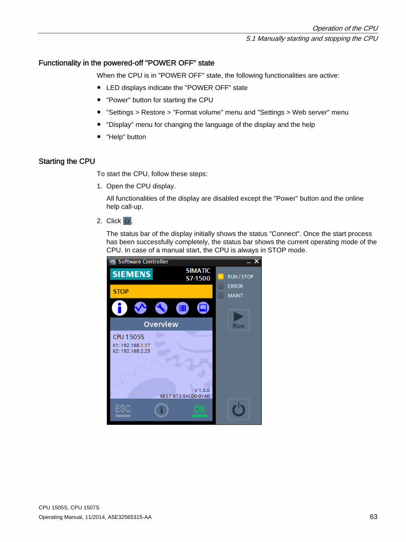
Operation of the CPU 5.1 Manually starting and stopping the CPU
CPU 1505S, CPU 1507S Operating Manual, 11/2014, A5E32565315-AA 63
Functionality in the powered-off "POWER OFF" state When the CPU is in "POWER OFF" state, the following functionalities are active:
● LED displays indicate the "POWER OFF" state
● "Power" button for starting the CPU
● "Settings > Restore > "Format volume" menu and "Settings > Web server" menu
● "Display" menu for changing the language of the display and the help
● "Help" button
Starting the CPU To start the CPU, follow these steps:
1. Open the CPU display.
All functionalities of the display are disabled except the "Power" button and the online help call-up.
2. Click .
The status bar of the display initially shows the status "Connect". Once the start process has been successfully completely, the status bar shows the current operating mode of the CPU. In case of a manual start, the CPU is always in STOP mode.
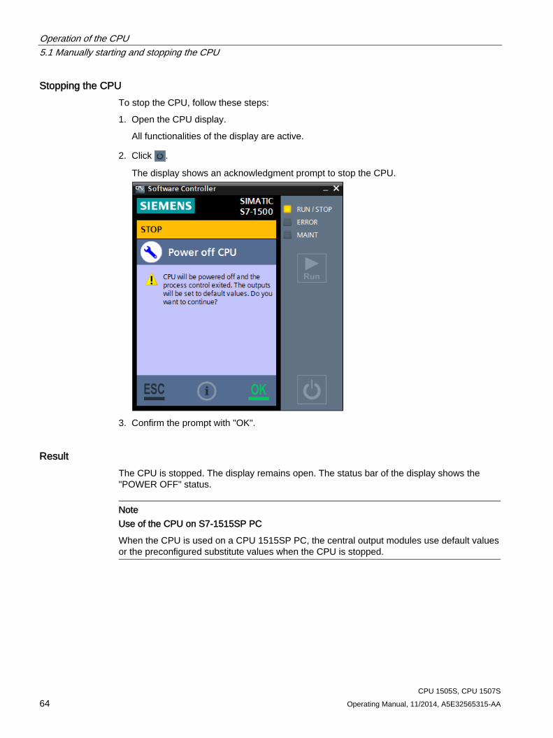
Operation of the CPU 5.1 Manually starting and stopping the CPU
CPU 1505S, CPU 1507S 64 Operating Manual, 11/2014, A5E32565315-AA
Stopping the CPU To stop the CPU, follow these steps:
1. Open the CPU display.
All functionalities of the display are active.
2. Click .
The display shows an acknowledgment prompt to stop the CPU.
3. Confirm the prompt with "OK".
Result The CPU is stopped. The display remains open. The status bar of the display shows the "POWER OFF" status.
Note Use of the CPU on S7-1515SP PC
When the CPU is used on a CPU 1515SP PC, the central output modules use default values or the preconfigured substitute values when the CPU is stopped.
Operation of the CPU 5.2 Operating modes
CPU 1505S, CPU 1507S Operating Manual, 11/2014, A5E32565315-AA 65
5.2 Operating modes
5.2.1 Basic principles of the operating modes
Introduction Operating modes describe the states of the CPU. The following operating modes can be set via the CPU display:
● RUN
● STOP
In these operating modes, the CPU can communicate, e.g., via the PN/IE interface.
The status LEDs indicate the current operating mode.
Reference You can find additional information in the STEP 7 online help.
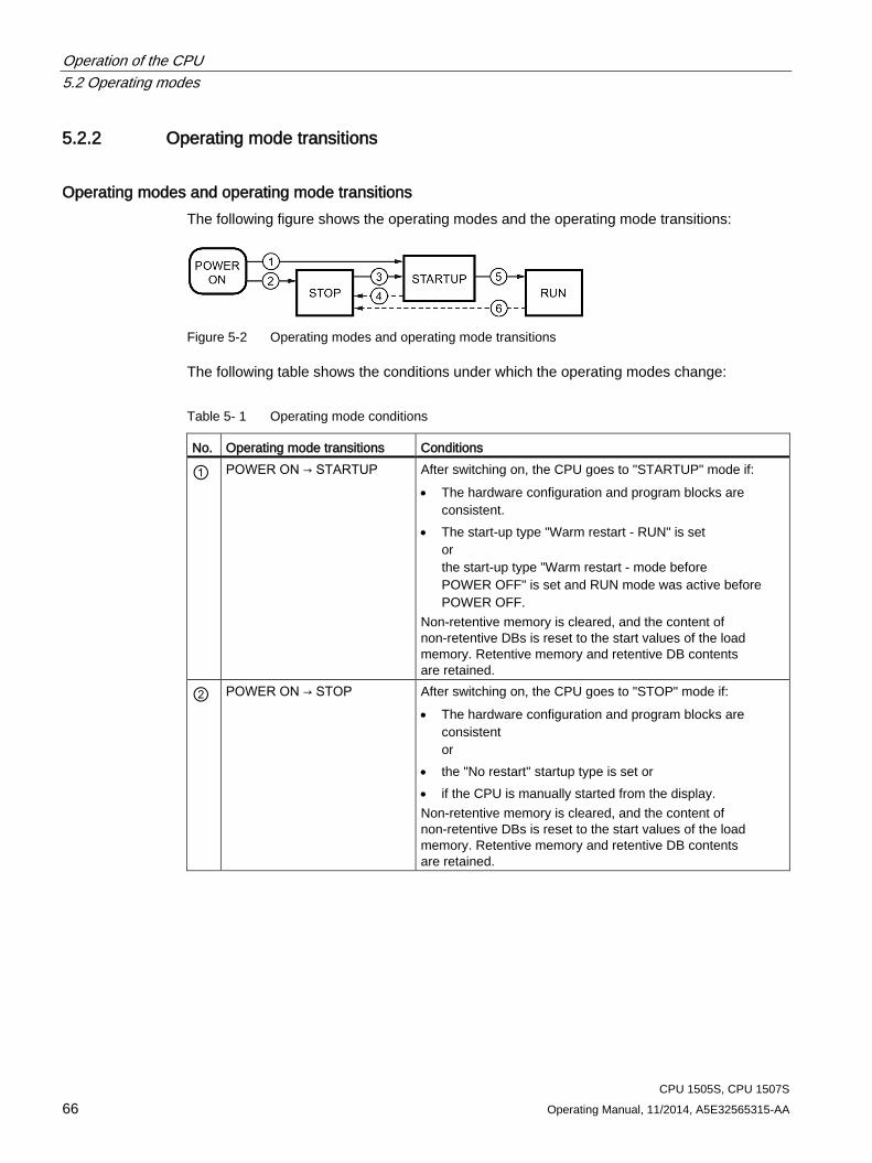
Operation of the CPU 5.2 Operating modes
CPU 1505S, CPU 1507S 66 Operating Manual, 11/2014, A5E32565315-AA
5.2.2 Operating mode transitions
Operating modes and operating mode transitions The following figure shows the operating modes and the operating mode transitions:
Figure 5-2 Operating modes and operating mode transitions
The following table shows the conditions under which the operating modes change:
Table 5- 1 Operating mode conditions
No. Operating mode transitions Conditions
① POWER ON → STARTUP After switching on, the CPU goes to "STARTUP" mode if: • The hardware configuration and program blocks are
consistent. • The start-up type "Warm restart - RUN" is set
or the start-up type "Warm restart - mode before POWER OFF" is set and RUN mode was active before POWER OFF.
Non-retentive memory is cleared, and the content of non-retentive DBs is reset to the start values of the load memory. Retentive memory and retentive DB contents are retained.
② POWER ON → STOP After switching on, the CPU goes to "STOP" mode if: • The hardware configuration and program blocks are
consistent or
• the "No restart" startup type is set or • if the CPU is manually started from the display. Non-retentive memory is cleared, and the content of non-retentive DBs is reset to the start values of the load memory. Retentive memory and retentive DB contents are retained.
Operation of the CPU 5.2 Operating modes
CPU 1505S, CPU 1507S Operating Manual, 11/2014, A5E32565315-AA 67
No. Operating mode transitions Conditions
③ STOP → STARTUP The CPU goes to "STARTUP" mode if: • The hardware configuration and program blocks are
consistent. • The CPU is set to "RUN" by the programming device or
via the display and the mode selector is in the RUN position or
• the mode selector is switched from STOP to RUN. Non-retentive memory is cleared, and the content of non-retentive DBs is reset to the start values of the load memory. Retentive memory and retentive DB contents are retained.
④ STARTUP → STOP The CPU returns from "STARTUP" mode to "STOP" mode in the following cases: • An error is detected during start-up. • The CPU is set to "STOP" from the programming device. • A STOP command is executed in the Startup OB.
⑤ STARTUP → RUN The CPU goes to the "RUN" mode in the following cases of "START-UP": • The CPU has initialized the PLC tags. • The CPU has executed the startup blocks successfully.
⑥ RUN → STOP The CPU returns from "RUN" mode to "STOP" mode in the following cases: • An error is detected that prevents continued processing. • A STOP command is executed in the user program. • The CPU is set to "STOP" mode via the programming
device, the display, or the mode selector.
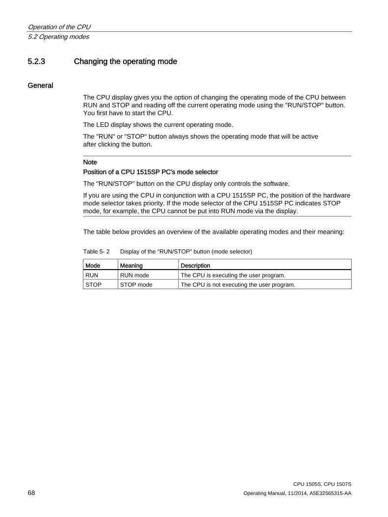
Operation of the CPU 5.2 Operating modes
CPU 1505S, CPU 1507S 68 Operating Manual, 11/2014, A5E32565315-AA
5.2.3 Changing the operating mode
General The CPU display gives you the option of changing the operating mode of the CPU between RUN and STOP and reading off the current operating mode using the "RUN/STOP" button. You first have to start the CPU.
The LED display shows the current operating mode.
The "RUN" or "STOP" button always shows the operating mode that will be active after clicking the button.
Note Position of a CPU 1515SP PC's mode selector
The "RUN/STOP" button on the CPU display only controls the software.
If you are using the CPU in conjunction with a CPU 1515SP PC, the position of the hardware mode selector takes priority. If the mode selector of the CPU 1515SP PC indicates STOP mode, for example, the CPU cannot be put into RUN mode via the display.
The table below provides an overview of the available operating modes and their meaning:
Table 5- 2 Display of the "RUN/STOP" button (mode selector)
Mode Meaning Description RUN RUN mode The CPU is executing the user program. STOP STOP mode The CPU is not executing the user program.
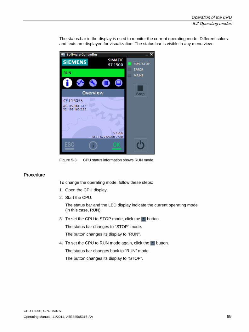
Operation of the CPU 5.2 Operating modes
CPU 1505S, CPU 1507S Operating Manual, 11/2014, A5E32565315-AA 69
The status bar in the display is used to monitor the current operating mode. Different colors and texts are displayed for visualization. The status bar is visible in any menu view.
Figure 5-3 CPU status information shows RUN mode
Procedure To change the operating mode, follow these steps:
1. Open the CPU display.
2. Start the CPU.
The status bar and the LED display indicate the current operating mode (in this case, RUN).
3. To set the CPU to STOP mode, click the button.
The status bar changes to "STOP" mode.
The button changes its display to "RUN".
4. To set the CPU to RUN mode again, click the button.
The status bar changes back to "RUN" mode.
The button changes its display to "STOP".
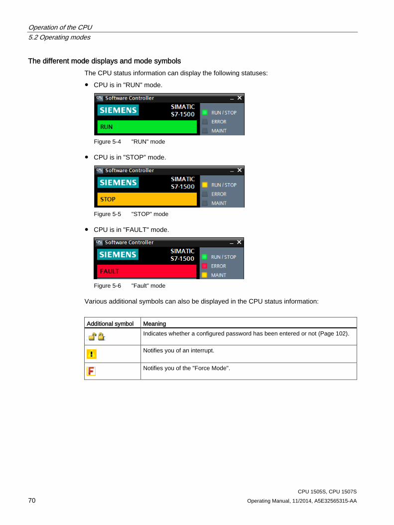
Operation of the CPU 5.2 Operating modes
CPU 1505S, CPU 1507S 70 Operating Manual, 11/2014, A5E32565315-AA
The different mode displays and mode symbols The CPU status information can display the following statuses:
● CPU is in "RUN" mode.
Figure 5-4 "RUN" mode
● CPU is in "STOP" mode.
Figure 5-5 "STOP" mode
● CPU is in "FAULT" mode.
Figure 5-6 "Fault" mode
Various additional symbols can also be displayed in the CPU status information:
Additional symbol Meaning
Indicates whether a configured password has been entered or not (Page 102).
Notifies you of an interrupt.
Notifies you of the "Force Mode".
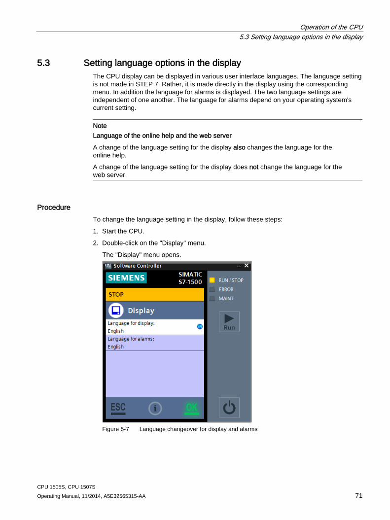
Operation of the CPU 5.3 Setting language options in the display
CPU 1505S, CPU 1507S Operating Manual, 11/2014, A5E32565315-AA 71
5.3 Setting language options in the display The CPU display can be displayed in various user interface languages. The language setting is not made in STEP 7. Rather, it is made directly in the display using the corresponding menu. In addition the language for alarms is displayed. The two language settings are independent of one another. The language for alarms depend on your operating system's current setting.
Note Language of the online help and the web server
A change of the language setting for the display also changes the language for the online help.
A change of the language setting for the display does not change the language for the web server.
Procedure To change the language setting in the display, follow these steps:
1. Start the CPU.
2. Double-click on the "Display" menu.
The "Display" menu opens.
Figure 5-7 Language changeover for display and alarms
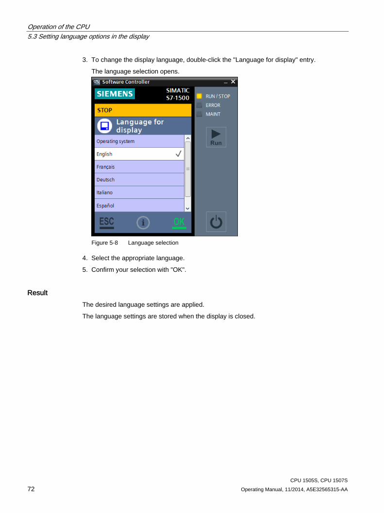
Operation of the CPU 5.3 Setting language options in the display
CPU 1505S, CPU 1507S 72 Operating Manual, 11/2014, A5E32565315-AA
3. To change the display language, double-click the "Language for display" entry.
The language selection opens.
Figure 5-8 Language selection
4. Select the appropriate language.
5. Confirm your selection with "OK".
Result The desired language settings are applied.
The language settings are stored when the display is closed.
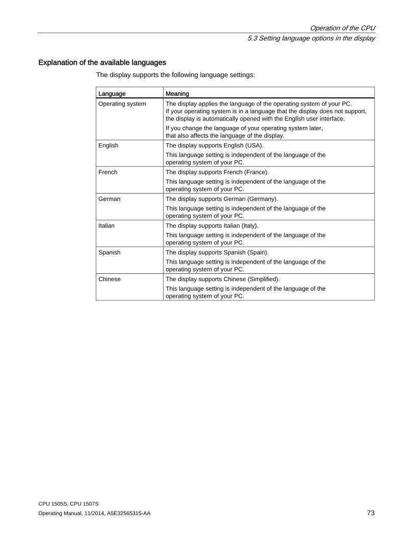
Operation of the CPU 5.3 Setting language options in the display
CPU 1505S, CPU 1507S Operating Manual, 11/2014, A5E32565315-AA 73
Explanation of the available languages The display supports the following language settings: Language Meaning Operating system The display applies the language of the operating system of your PC.
If your operating system is in a language that the display does not support, the display is automatically opened with the English user interface. If you change the language of your operating system later, that also affects the language of the display.
English The display supports English (USA). This language setting is independent of the language of the operating system of your PC.
French The display supports French (France). This language setting is independent of the language of the operating system of your PC.
German The display supports German (Germany). This language setting is independent of the language of the operating system of your PC.
Italian The display supports Italian (Italy). This language setting is independent of the language of the operating system of your PC.
Spanish The display supports Spanish (Spain). This language setting is independent of the language of the operating system of your PC.
Chinese The display supports Chinese (Simplified). This language setting is independent of the language of the operating system of your PC.
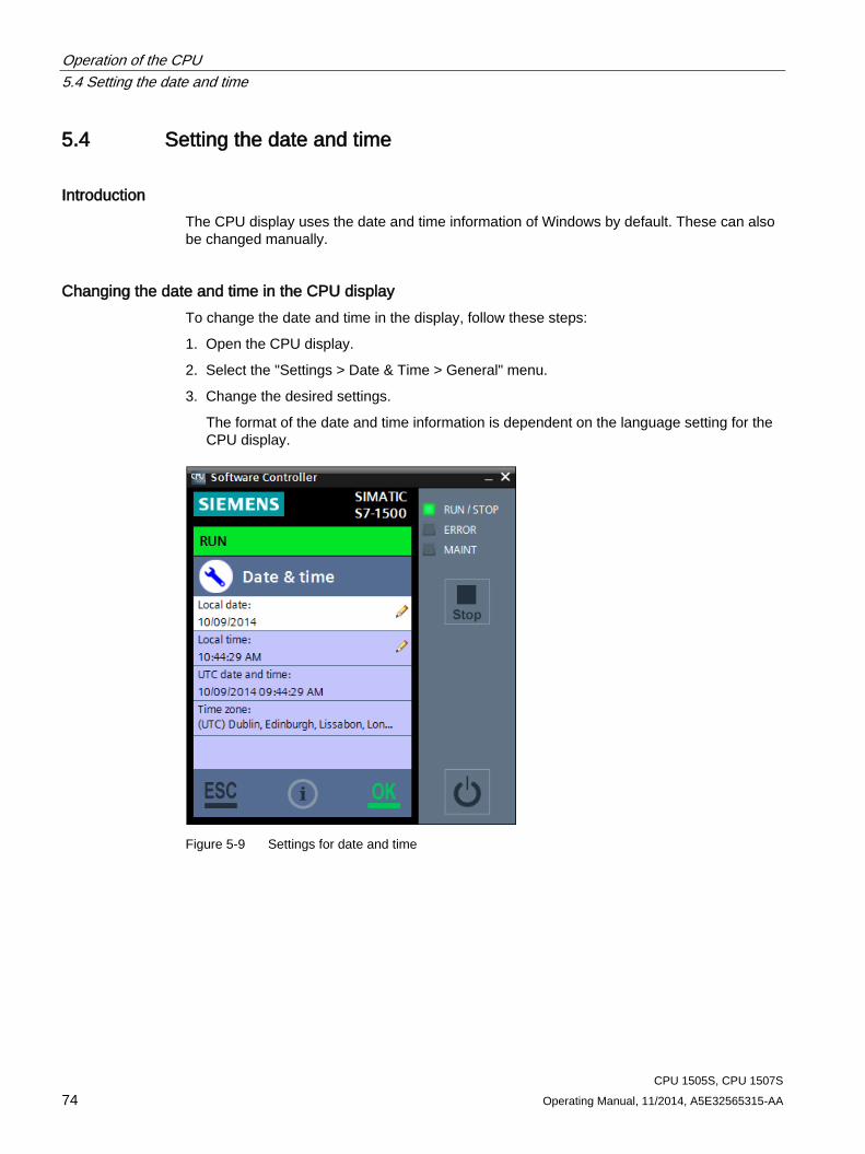
Operation of the CPU 5.4 Setting the date and time
CPU 1505S, CPU 1507S 74 Operating Manual, 11/2014, A5E32565315-AA
5.4 Setting the date and time
Introduction The CPU display uses the date and time information of Windows by default. These can also be changed manually.
Changing the date and time in the CPU display To change the date and time in the display, follow these steps:
1. Open the CPU display.
2. Select the "Settings > Date & Time > General" menu.
3. Change the desired settings.
The format of the date and time information is dependent on the language setting for the CPU display.
Figure 5-9 Settings for date and time
Operation of the CPU 5.4 Setting the date and time
CPU 1505S, CPU 1507S Operating Manual, 11/2014, A5E32565315-AA 75
Result The settings for date and time are applied.
Three other ways are available for changing the date and time:
● With the Online & Diagnostics function “Set time of day”
● In the CPU properties in STEP 7
● Using instructions in the user program
The time zone can only be changed using STEP 7.
Note Change of setting with time synchronization
If you are using the time synchronization functionality, each change with the CPU display is overwritten at the next synchronization.
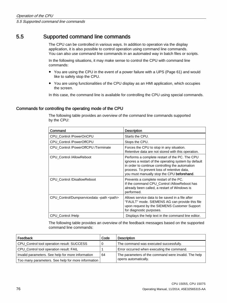
Operation of the CPU 5.5 Supported command line commands
CPU 1505S, CPU 1507S 76 Operating Manual, 11/2014, A5E32565315-AA
5.5 Supported command line commands The CPU can be controlled in various ways. In addition to operation via the display application, it is also possible to control operation using command line commands. You can also use command line commands in an automated way in batch files or scripts.
In the following situations, it may make sense to control the CPU with command line commands:
● You are using the CPU in the event of a power failure with a UPS (Page 61) and would like to safely stop the CPU.
● You are using functionalities of the CPU display as an HMI application, which occupies the screen.
In this case, the command line is available for controlling the CPU using special commands.
Commands for controlling the operating mode of the CPU The following table provides an overview of the command line commands supported by the CPU: Command Description CPU_Control /PowerOnCPU Starts the CPU. CPU_Control /PowerOffCPU Stops the CPU. CPU_Control /PowerOffCPU /Terminate Forces the CPU to stop in any situation.
Retentive data are not stored with this operation. CPU_Control /AllowReboot Performs a complete restart of the PC. The CPU
ignores a restart of the operating system by default in order to continue controlling the automation process. To prevent loss of retentive data, you must manually stop the CPU beforehand.
CPU_Control /DisallowReboot Prevents a complete restart of the PC. If the command CPU_Control /AllowReboot has already been called, a restart of Windows is performed.
CPU_Control/Dumpservicedata –path <path> Allows service data to be saved in a file after "FAULT" mode. SIEMENS AG can provide this file upon request by the SIEMENS Customer Support for diagnostic purposes.
CPU_Control /Help Displays the help text in the command line editor.
The following table provides an overview of the feedback messages based on the supported command line commands:
Feedback Code Description CPU_Control tool operation result: SUCCESS 0 The command was executed successfully. CPU_Control tool operation result: FAIL 1 Error occurred when executing the command. Invalid parameters. See help for more information 64 The parameters of the command were invalid. The help
opens automatically. Too many parameters. See help for more information
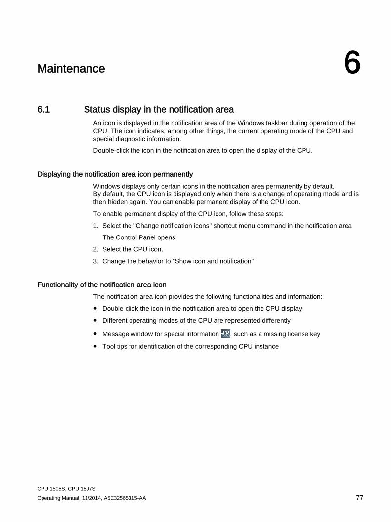
CPU 1505S, CPU 1507S Operating Manual, 11/2014, A5E32565315-AA 77
Maintenance 6 6.1 Status display in the notification area
An icon is displayed in the notification area of the Windows taskbar during operation of the CPU. The icon indicates, among other things, the current operating mode of the CPU and special diagnostic information.
Double-click the icon in the notification area to open the display of the CPU.
Displaying the notification area icon permanently Windows displays only certain icons in the notification area permanently by default. By default, the CPU icon is displayed only when there is a change of operating mode and is then hidden again. You can enable permanent display of the CPU icon.
To enable permanent display of the CPU icon, follow these steps:
1. Select the "Change notification icons" shortcut menu command in the notification area
The Control Panel opens.
2. Select the CPU icon.
3. Change the behavior to "Show icon and notification"
Functionality of the notification area icon The notification area icon provides the following functionalities and information:
● Double-click the icon in the notification area to open the CPU display
● Different operating modes of the CPU are represented differently
● Message window for special information , such as a missing license key
● Tool tips for identification of the corresponding CPU instance
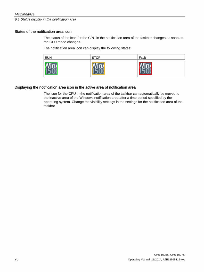
Maintenance 6.1 Status display in the notification area
CPU 1505S, CPU 1507S 78 Operating Manual, 11/2014, A5E32565315-AA
States of the notification area icon The status of the icon for the CPU in the notification area of the taskbar changes as soon as the CPU mode changes.
The notification area icon can display the following states: RUN STOP Fault
Displaying the notification area icon in the active area of notification area The icon for the CPU in the notification area of the taskbar can automatically be moved to the inactive area of the Windows notification area after a time period specified by the operating system. Change the visibility settings in the settings for the notification area of the taskbar.
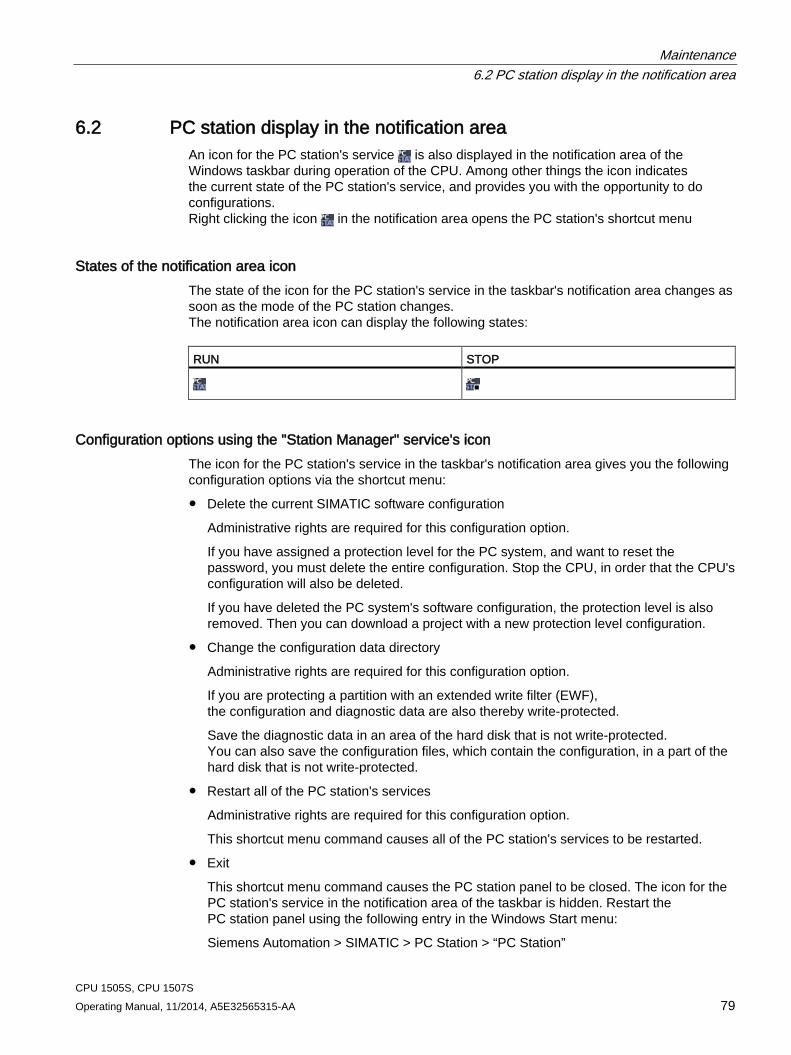
Maintenance 6.2 PC station display in the notification area
CPU 1505S, CPU 1507S Operating Manual, 11/2014, A5E32565315-AA 79
6.2 PC station display in the notification area An icon for the PC station's service is also displayed in the notification area of the Windows taskbar during operation of the CPU. Among other things the icon indicates the current state of the PC station's service, and provides you with the opportunity to do configurations. Right clicking the icon in the notification area opens the PC station's shortcut menu
States of the notification area icon The state of the icon for the PC station's service in the taskbar's notification area changes as soon as the mode of the PC station changes. The notification area icon can display the following states: RUN STOP
Configuration options using the "Station Manager" service's icon The icon for the PC station's service in the taskbar's notification area gives you the following configuration options via the shortcut menu:
● Delete the current SIMATIC software configuration
Administrative rights are required for this configuration option.
If you have assigned a protection level for the PC system, and want to reset the password, you must delete the entire configuration. Stop the CPU, in order that the CPU's configuration will also be deleted.
If you have deleted the PC system's software configuration, the protection level is also removed. Then you can download a project with a new protection level configuration.
● Change the configuration data directory
Administrative rights are required for this configuration option.
If you are protecting a partition with an extended write filter (EWF), the configuration and diagnostic data are also thereby write-protected.
Save the diagnostic data in an area of the hard disk that is not write-protected. You can also save the configuration files, which contain the configuration, in a part of the hard disk that is not write-protected.
● Restart all of the PC station's services
Administrative rights are required for this configuration option.
This shortcut menu command causes all of the PC station's services to be restarted.
● Exit
This shortcut menu command causes the PC station panel to be closed. The icon for the PC station's service in the notification area of the taskbar is hidden. Restart the PC station panel using the following entry in the Windows Start menu:
Siemens Automation > SIMATIC > PC Station > “PC Station”
Maintenance 6.3 Firmware update of I/O modules
CPU 1505S, CPU 1507S 80 Operating Manual, 11/2014, A5E32565315-AA
6.3 Firmware update of I/O modules
Introduction During operation it may be necessary to update the firmware (for example due to functional enhancements).
Note Firmware update of I/O modules
The firmware of an I/O module can be updated centrally or distributed.
Requirement ● You have downloaded the file(s) for the firmware update from the Customer Support
(http://www.siemens.com/automation/) web site.
On this web site, select: Automation technology > Automation systems > SIMATIC industrial automation system > Controllers > SIMATIC S7 modular controllers > SIMATIC S7-1500.
From there, navigate to the specific type of module that you want to update. To continue, click on the link for "Software downloads" under "Support". Save the desired firmware update files.
● Before installing the firmware update, ensure that the modules are not being used.
Options for the firmware update A firmware update is performed using STEP 7 (online) or the web server.
Maintenance 6.3 Firmware update of I/O modules
CPU 1505S, CPU 1507S Operating Manual, 11/2014, A5E32565315-AA 81
Installation of the firmware update
WARNING
Impermissible plant states possible
Due to the installation of the firmware update, the CPU enters the STOP mode, which can impact the operation of an online process or a machine.
Unexpected operation of a process or a machine can lead to fatal or severe injuries and/or to material damages.
Ensure before installing the firmware update, that the CPU is not executing any active process.
Procedure using STEP 7 Proceed as follows to perform an online firmware update via STEP 7:
1. Select the module in the device view.
2. Select the "Online & diagnostics" command from the shortcut menu.
3. Select the "Firmware update" group in the "Functions" folder.
4. Click the "Browse" button in the "Firmware update" area to select the path to the firmware update files.
5. Select the matching firmware file. The table in the firmware update area lists all modules for which an update is possible with the selected firmware file.
6. Click the "Start update" button. If the selected file can be interpreted by the module, the file is downloaded to the module. If the operating mode of the CPU needs to be changed for this purpose, you will be prompted to do this by means of dialogs.
Note Updating the firmware
The "Run firmware after update" check box is always activated.
Reference Further information on the procedure can be found in the STEP 7 online help.
Maintenance 6.4 Reset
CPU 1505S, CPU 1507S 82 Operating Manual, 11/2014, A5E32565315-AA
6.4 Reset During a reset, the CPU is set to the "delivery state". This means that all data stored in the CPU is deleted.
The following reasons may require a data reset:
● A restart with the original data (cold restart)
● Reset all internally persistent settings (e.g., IP address) for a defined status
● Use a cleaned state of the CPU for new projects
Reset options You have the following options to reset the CPU.
● Memory reset: The CPU is reset to the project settings configured by default. You can run this function as follows:
– In the CPU display (Page 83)
– Via the mode selector of the utilized hardware platform (Page 86)
● Factory settings: CPU is reset to the default factory settings. You can run this function as follows:
– In the CPU display (Page 83)
– Using STEP 7 (Page 85)
● Format the CPU volume: The CPU volume is cleaned (Page 87). You run this function in the CPU display.
Note STOP mode required
The CPU must be in STOP mode to be reset.
Reference Additional information on the topic "Resetting to factory settings" can be found in the Structure and Use of the CPU Memory (http://support.automation.siemens.com/WW/view/en/59193101) Function Manual, section on memory areas and retentivity, and in the online help for STEP 7.
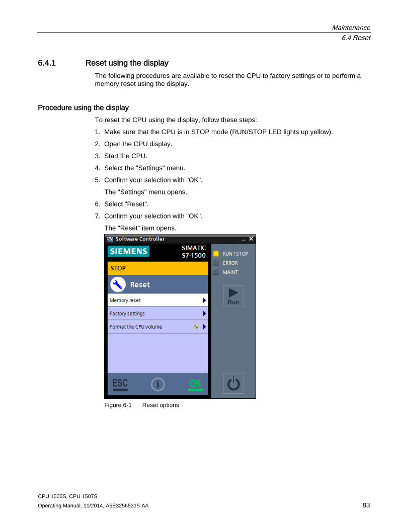
Maintenance 6.4 Reset
CPU 1505S, CPU 1507S Operating Manual, 11/2014, A5E32565315-AA 83
6.4.1 Reset using the display The following procedures are available to reset the CPU to factory settings or to perform a memory reset using the display.
Procedure using the display To reset the CPU using the display, follow these steps:
1. Make sure that the CPU is in STOP mode (RUN/STOP LED lights up yellow).
2. Open the CPU display.
3. Start the CPU.
4. Select the "Settings" menu.
5. Confirm your selection with "OK".
The "Settings" menu opens.
6. Select "Reset".
7. Confirm your selection with "OK".
The "Reset" item opens.
Figure 6-1 Reset options
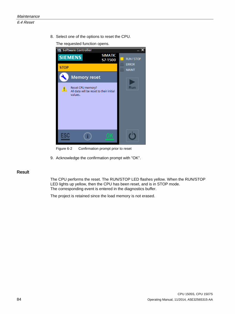
Maintenance 6.4 Reset
CPU 1505S, CPU 1507S 84 Operating Manual, 11/2014, A5E32565315-AA
8. Select one of the options to reset the CPU.
The requested function opens.
Figure 6-2 Confirmation prompt prior to reset
9. Acknowledge the confirmation prompt with "OK".
Result The CPU performs the reset. The RUN/STOP LED flashes yellow. When the RUN/STOP LED lights up yellow, then the CPU has been reset, and is in STOP mode. The corresponding event is entered in the diagnostics buffer.
The project is retained since the load memory is not erased.
Maintenance 6.4 Reset
CPU 1505S, CPU 1507S Operating Manual, 11/2014, A5E32565315-AA 85
6.4.2 Reset using STEP 7 The following procedures are available to reset the CPU to factory settings using STEP 7.
Procedure using STEP 7 To reset the CPU using STEP 7, follow these steps:
1. Make sure there is an online connection to the CPU that is to be reset to the factory settings.
2. Open the online and diagnostics view of the CPU.
3. Select the "Reset to factory settings" group in the "Functions" folder.
4. Select the "Keep IP address" option button if you want to keep the IP address or the "Reset IP address" option button if you want to delete the IP address.
5. Click the "Reset" button.
6. Acknowledge the confirmation prompt with "OK".
Result The CPU is set to STOP mode and is reset to factory settings.
The project is retained since the load memory is not erased.
Maintenance 6.4 Reset
CPU 1505S, CPU 1507S 86 Operating Manual, 11/2014, A5E32565315-AA
6.4.3 Resetting via the mode switch
Procedure using the mode selector This procedure is possible only for operation on the CPU 1515SP PC.
Make sure that the CPU is in STOP mode (the CPU display shows STOP mode or RUN/STOP LED lights up yellow).
Note
A memory reset of the CPU via the mode selector also deletes the CPU's IP address.
To reset the CPU memory using the mode selector, follow these steps:
1. Set the mode selector to the STOP position.
Result: The RUN/STOP LED lights up yellow.
2. Set the mode selector to the MRES position. Hold the mode selector in this position until the RUN/STOP LED lights up for the 2nd time and remains continuously lit (this takes three seconds). After this, release the switch.
3. Within the next three seconds, switch the mode selector back to the MRES position, and then back to STOP again.
Result The CPU executes the memory reset, while the RUN/STOP LED flashes yellow. When the RUN/STOP LED lights up yellow, then the CPU has been reset, and is in STOP mode. The corresponding event is entered in the diagnostics buffer.
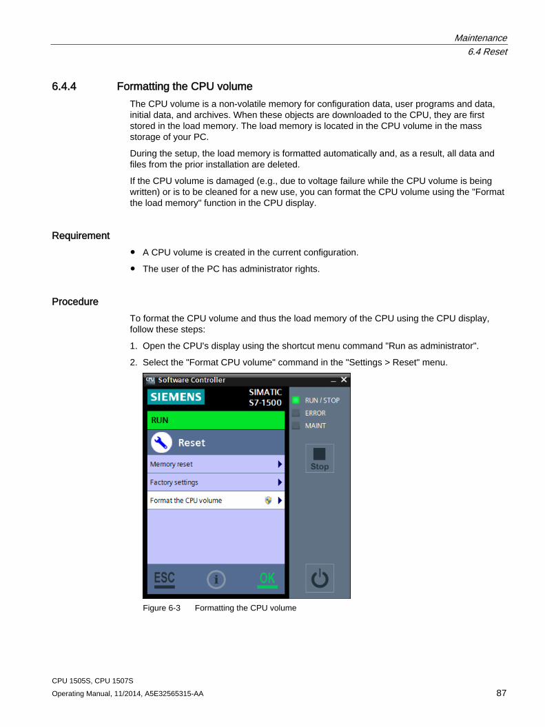
Maintenance 6.4 Reset
CPU 1505S, CPU 1507S Operating Manual, 11/2014, A5E32565315-AA 87
6.4.4 Formatting the CPU volume The CPU volume is a non-volatile memory for configuration data, user programs and data, initial data, and archives. When these objects are downloaded to the CPU, they are first stored in the load memory. The load memory is located in the CPU volume in the mass storage of your PC.
During the setup, the load memory is formatted automatically and, as a result, all data and files from the prior installation are deleted.
If the CPU volume is damaged (e.g., due to voltage failure while the CPU volume is being written) or is to be cleaned for a new use, you can format the CPU volume using the "Format the load memory" function in the CPU display.
Requirement ● A CPU volume is created in the current configuration.
● The user of the PC has administrator rights.
Procedure To format the CPU volume and thus the load memory of the CPU using the CPU display, follow these steps:
1. Open the CPU's display using the shortcut menu command "Run as administrator".
2. Select the "Format CPU volume" command in the "Settings > Reset" menu.
Figure 6-3 Formatting the CPU volume
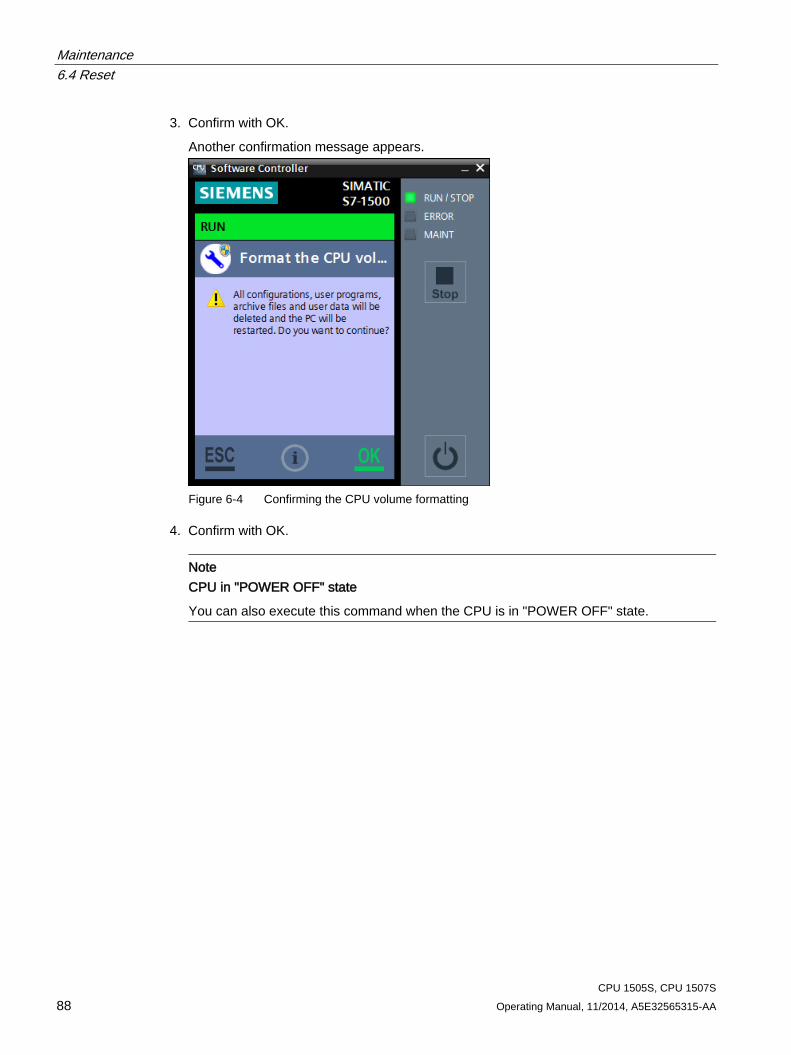
Maintenance 6.4 Reset
CPU 1505S, CPU 1507S 88 Operating Manual, 11/2014, A5E32565315-AA
3. Confirm with OK.
Another confirmation message appears.
Figure 6-4 Confirming the CPU volume formatting
4. Confirm with OK.
Note
CPU in "POWER OFF" state
You can also execute this command when the CPU is in "POWER OFF" state.

Maintenance 6.4 Reset
CPU 1505S, CPU 1507S Operating Manual, 11/2014, A5E32565315-AA 89
Result The CPU is stopped and shows the status of the formatting with the help of a progress bar. The formatting deletes the following data and values:
● The complete load memory
● Retentive data
● User programs and configurations
● Archives and user data
● Web server directories
The following internal CPU data are restored:
● Module name
● Index
● Assigned interfaces
● Retentive data memory
● Position of the mode selector
● Use of the LEDs
The startup type setting is retained. When you switch on the CPU the next time, the load memory is preset with default settings. The CPU is in STOP mode.
Maintenance 6.5 Backing up the image of the PC mass storage
CPU 1505S, CPU 1507S 90 Operating Manual, 11/2014, A5E32565315-AA
6.5 Backing up the image of the PC mass storage
Overview Once you have configured the computer for your application, you can create an image of your system. An image must always contain the Windows partitions and the CPU volume
You can use this image to restore your user-specific application to your system at a later time, if necessary. A system image is helpful when you have to restore all files and registry entries for your application.
You should back up an image of your configuration for these reasons:
● To save a fixed intermediate status of the configuration
● Create a backup of the current configuration in case of hardware problems and when the PC must be replaced
● Create a master image to download the configuration to other PCs
Note Observe consistency
The image for the Windows drive, on which the CPU is installed, must always be consistent with the image of the CPU volume.
The images depend on the computer on which they were created. They may not be used on different computer types.
SIMATIC IPC Image & Partition Creator Use the "SIMATIC IPC Image & Partition Creator" to back up your configuration.
"SIMATIC IPC Image & Partition Creator" is used to back up and restore files, directories, partitions and entire hard drives. By creating backup images, "SIMATIC IPC Image & Partition Creator" prevents data loss caused, for example, by hardware failure, installation problems, operating errors or external influences (viruses).
Reference For additional information on backing up an image, see the documentation on "SIMATIC IPC Image & Partition Creator" (http://support.automation.siemens.com/DE/view/en/21766418).
You also have access to topic-related FAQs (http://support.automation.siemens.com/DE/view/en/19422936/133000).
Maintenance 6.6 Special features
CPU 1505S, CPU 1507S Operating Manual, 11/2014, A5E32565315-AA 91
6.6 Special features
6.6.1 Installation of drivers All necessary drivers are installed automatically by default when the software for the CPU is installed. Additional dialogs and messages regarding installation of drivers do not appear. The supplied drivers are certified by Microsoft and have a digital signature that indicates SIEMENS AG as the supplier.
If warning messages concerning the driver software are displayed during installation, you must assume that the installation files have been altered.
Check whether the utilized installation files are identical to those on the installation DVD supplied by SIEMENS AG.
6.6.2 Downloaded user program is not compatible with the target system You must download new or modified project data to the CPU.
If you download your user program to the wrong CPU, the pre-configured project data is not compatible with the target system. This situation can occur if the DiagBase software is disabled on the SIMATIC IPC or CPU 1515SP PC.
If your target system does not react as expected, the following options are available to you:
● Restart the PC with the "Windows only" option.
● Check whether your loaded project data are compatible with the hardware type of the target system.
● Check whether the configuration of the interfaces matches the hardware interfaces of the PC.
● Download the entire PC system. The PC automatically restarts with the "Windows only" option. Restart the download process again with the "Windows and CPU 150xS" option.
Maintenance 6.6 Special features
CPU 1505S, CPU 1507S 92 Operating Manual, 11/2014, A5E32565315-AA
6.6.3 Special situations when starting or stopping the CPU
Possible situations The following special situations can occur when starting or stopping the CPU:
● The CPU indicates the "Faulted" status.
● The CPU display cannot establish a connection to the CPU.
● The PC is powered up in "Windows only" mode.
● The CPU has been started or stopped using a command line command.
CPU in "Faulted" status The "Faulted" status can occur in the following cases:
● While the CPU is starting
The CPU remains in "Faulted" status until the user selects one of the functions in the "Restore" menu.
● While the CPU is running
The display changes automatically to the "Restore" menu. The CPU restarts automatically after 10 seconds in STOP mode.
No connection to the CPU If the display cannot establish a connection to the CPU, the display automatically opens the "Restore" menu. You can choose from the following options:
● Restart CPU
The CPU restarts.
● Terminate CPU
The CPU is stopped. Retentive data are lost.
Note PC start in "Windows only" mode
If the display does not indicate any of the options named, the PC has possibly been started in "Windows only" mode.
PC start in "Windows only" mode If you start the CPU display after the PC has been started in "Windows only" mode, the display automatically opens the Restore mean for restarting the PC.
Maintenance 6.6 Special features
CPU 1505S, CPU 1507S Operating Manual, 11/2014, A5E32565315-AA 93
6.6.4 CPU behavior at Windows shutdown When you switch off your PC, the Windows operating system is shut down automatically and all active applications are closed.
You can shut down the Windows operating system using the following actions:
● PC is switched off via the Start menu
● Triggered by the uninterruptible power supply (UPS)
When the Windows operating system shuts down, the CPU is stopped properly. The CPU stores the retentive data and all CPU-specific files.
When you restart the PC, the CPU starts as previously configured.
Note Disabling the memory test in the BIOS
PCs provide the option of a memory test. Some hardware tests, such as the memory test, are disabled by default in the BIOS setup program and are skipped during startup of the PC. Booting is accelerated as a result.
If you are using the CPU on a SIMATIC IPC or a CPU 1515SP PC, the BIOS memory test must not be enabled.
Reference Additional information about the CPU behavior during starting or stopping can be found in the sections Selecting startup type (Page 43) and Manually starting and stopping the CPU (Page 62).
Maintenance 6.6 Special features
CPU 1505S, CPU 1507S 94 Operating Manual, 11/2014, A5E32565315-AA
6.6.5 Operating the CPU after a Windows crash (Blue Screen)
Introduction The CPU is a PC-based controller. It is installed for use on a PC with the Windows operating system. The following operating system-related situations can affect the operation of the CPU:
● Crash of the Windows operating system
● Restart of Windows after installation of operating system updates
Reaction of the CPU to a Windows crash In order to guarantee operation of the CPU even during a crash of the operating system, Windows must be configured in such a way that it restarts automatically after a crash. No BIOS activities may be run during the restart. If this is the case, the restart of Windows has no effect on the CPU performance. The CPU remains in RUN mode and controls the automation process even during the crash. Because increased drive accesses by the operating system can occur during the Windows restart, the drive accesses of the CPU may become slower temporarily. Once Windows has been started up again, the user program of the CPU is notified about the restart of the operating system.
If Windows does not restart automatically after a crash, restart the PC manually:
Switch off the PC using the "Power" switch or by briefly removing the power supply (remove and insert the connector). The CPU is stopped. If you have configured the storing of retentive data in the integrated NVRAM of your PC, the retentive data are retained during this operation. If you have configured the storing of retentive data in the mass storage of your PC, the retentive data are deleted during this operation. The CPU starts in unbuffered state.
Note Diagnostics on Windows availability
In the event of a Windows crash, OB 82 (diagnostics alarm) is called. You can use this function for diagnostics on Windows availability.
Maintenance 6.6 Special features
CPU 1505S, CPU 1507S Operating Manual, 11/2014, A5E32565315-AA 95
Restarting the operating system and CPU Only Windows is restarted by default. The Windows restart has no effect on the function of the CPU. The CPU remains in RUN mode and continues to control the automation process. To perform a complete restart of the PC with operating system and CPU, follow these steps:
Shut down the PC using the appropriate command in the Windows Start menu. Restart the PC using the "Power" switch, or remove and insert the connector.
If neither the "Power" switch nor the connector is accessible due to the location of the PC or if the PC must be shut down via a remote connection, the command line (Page 76) provides you the possibility of completely restarting the PC. You must explicitly stop the CPU beforehand.
To restart the complete PC, create a small batch file with the following command sequence in the command line:
CPU_Control /PowerOffCPU
CPU_Control /AllowReboot
shutdown /r /t 1
This command sequence can be created as batch processing in a batch file.
6.6.6 Special situations when downloading in STEP 7
No connection possible In order to download the project to the target system, an online connection must be established.
If an online connection to the target system is not possible, check the interface settings, such as the IP address. You also have the option of establishing an online connection via the IE General interface.
Download aborts If the download aborts for unidentifiable reasons, you may need to reset the CPU to factory settings using the display (Page 83).
CPU 1505S, CPU 1507S 96 Operating Manual, 11/2014, A5E32565315-AA
Protection 7 7.1 Overview of the protective functions of the CPU
Introduction This section describes the functions for protecting the S7-1500 automation system against unauthorized access. The following functions are available:
● Configuring access protection
● Using complex passwords
● Using virus scanners and firewall
● Protection against unauthorized operation (deactivating or restricting remote access)
● Copy protection
● Know-how protection
● Using Windows user rights management
● Using whitelisting tools
Further measures for protecting the CPU The following measures additionally increase the protection against unauthorized access to functions and data of the CPU from outside and via the network:
● Deactivation of the Web server
● Deactivation of the time synchronization via an NTP Server
● Deactivation of the time synchronization via Windows clock
● Deactivation of the PUT/GET communication
Note Functionalities disabled by default
These functionalities are deactivated by default. To use the functionalities, you enable them in STEP 7.
Reference For additional information on the protection functions of the S7-1500 automation system, see the section on protection in the S7-1500 Automation System System Manual (http://support.automation.siemens.com/WW/view/en/59191792).
Protection 7.2 General safety instructions
CPU 1505S, CPU 1507S Operating Manual, 11/2014, A5E32565315-AA 97
7.2 General safety instructions
Configuration for the web server A user with the name "Any" is created by default in the user list of the web server. This user has minimal access rights such as read-only access to the introduction and home page. Because the user "Any" does not have a password assigned in STEP 7, pay close attention to the access rights you assign to this user. Individual authorizations, such as the option to change the operating mode, may represent a security risk.
To assign safety-related authorizations, configure a new user and always assign a password in STEP 7. Assign secure passwords to users during configuration. An example of a secure password is one which is only used for a single application, is more than 8 characters long, and consists of lower-case and upper-case letters as well as special characters and numbers (?!+%$1234...).
Whenever possible, select the option "Permit access only with HTTPS" as soon as you have assigned a password to at least one user.
Data blocks for PUT/GET instructions The PUT/GET instructions are suitable for connections configured at one end or both ends.
When using the PUT/GET instructions, you can only use data blocks with absolute addressing. Symbolic addressing of data blocks is not possible.
Reference You will find more information on the configuration of the web server in the Web Server (http://support.automation.siemens.com/WW/view/en/59193560)Function Manual.
You will find more information on the PUT/GET and NTP instructions in the Communication (http://support.automation.siemens.com/WW/view/en/59192925) Function Manual.
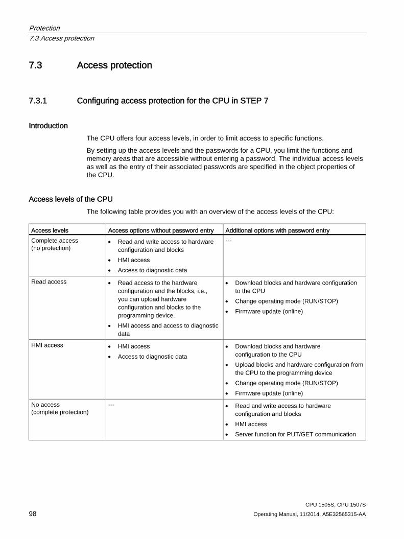
Protection 7.3 Access protection
CPU 1505S, CPU 1507S 98 Operating Manual, 11/2014, A5E32565315-AA
7.3 Access protection
7.3.1 Configuring access protection for the CPU in STEP 7
Introduction The CPU offers four access levels, in order to limit access to specific functions.
By setting up the access levels and the passwords for a CPU, you limit the functions and memory areas that are accessible without entering a password. The individual access levels as well as the entry of their associated passwords are specified in the object properties of the CPU.
Access levels of the CPU The following table provides you with an overview of the access levels of the CPU:
Access levels Access options without password entry Additional options with password entry Complete access (no protection)
• Read and write access to hardware configuration and blocks
• HMI access • Access to diagnostic data
---
Read access • Read access to the hardware configuration and the blocks, i.e., you can upload hardware configuration and blocks to the programming device.
• HMI access and access to diagnostic data
• Download blocks and hardware configuration to the CPU
• Change operating mode (RUN/STOP) • Firmware update (online)
HMI access • HMI access • Access to diagnostic data
• Download blocks and hardware configuration to the CPU
• Upload blocks and hardware configuration from the CPU to the programming device
• Change operating mode (RUN/STOP) • Firmware update (online)
No access (complete protection)
--- • Read and write access to hardware configuration and blocks
• HMI access • Server function for PUT/GET communication
Protection 7.3 Access protection
CPU 1505S, CPU 1507S Operating Manual, 11/2014, A5E32565315-AA 99
Each access level allows unrestricted access to certain functions without entering a password, e.g. identification using the "Accessible devices" function.
The CPU's default setting is "No restriction" and "No password protection". In order to protect access to a CPU, you must edit the properties of the CPU and set up a password.
Communication between the CPUs (via the communication functions in the blocks) is not restricted by the protection level of the CPU, unless PUT/GET communication is deactivated.
Entry of the right password allows access to all the functions that are allowed in the corresponding level.
Note Configuring an access level does not replace know-how protection
Configuring access levels prevents unauthorized changes to the CPU, by restricting download privileges. However, blocks are not write- or read-protected. Use know-how protection to protect the code of blocks.
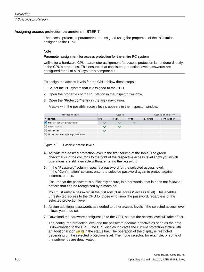
Protection 7.3 Access protection
CPU 1505S, CPU 1507S 100 Operating Manual, 11/2014, A5E32565315-AA
Assigning access protection parameters in STEP 7 The access protection parameters are assigned using the properties of the PC station assigned to the CPU.
Note Parameter assignment for access protection for the entire PC system
Unlike for a hardware CPU, parameter assignment for access protection is not done directly in the CPU's properties. This ensures that consistent protection level passwords are configured for all of a PC system's components.
To assign the access levels for the CPU, follow these steps:
1. Select the PC system that is assigned to the CPU.
2. Open the properties of the PC station in the Inspector window.
3. Open the "Protection" entry in the area navigation.
A table with the possible access levels appears in the Inspector window.
Figure 7-1 Possible access levels
4. Activate the desired protection level in the first column of the table. The green checkmarks in the columns to the right of the respective access level show you which operations are still available without entering the password.
5. In the "Password" column, specify a password for the selected access level. In the "Confirmation" column, enter the selected password again to protect against incorrect entries.
Ensure that the password is sufficiently secure, in other words, that is does not follow a pattern that can be recognized by a machine!
You must enter a password in the first row ("Full access" access level). This enables unrestricted access to the CPU for those who know the password, regardless of the selected protection level.
6. Assign additional passwords as needed to other access levels if the selected access level allows you to do so.
7. Download the hardware configuration to the CPU, so that the access level will take effect.
The configured protection level and the password become effective as soon as the data is downloaded to the CPU. The CPU display indicates the current protection status with an additional icon in the status bar. The operation of the display is restricted depending on the selected protection level. The mode selector, for example, or some of the submenus are deactivated.
Protection 7.3 Access protection
CPU 1505S, CPU 1507S Operating Manual, 11/2014, A5E32565315-AA 101
Behavior of a password-protected CPU during operation The CPU protection takes effect after the settings are downloaded in the CPU.
Before an online function is executed, the necessary permission is checked and, if necessary, the user is prompted to enter a password. The functions protected by a password can only be executed by one programming device/PC at any one time. Another programming device/PC cannot log on.
Access authorization to the protected data is in effect for the duration of the online connection or until the access authorization is manually rescinded with "Online > Delete access rights".
Access to a password-protected CPU in the RUN mode can be limited locally in the display so that access with a password is also not possible.
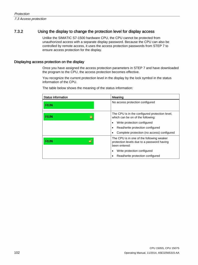
Protection 7.3 Access protection
CPU 1505S, CPU 1507S 102 Operating Manual, 11/2014, A5E32565315-AA
7.3.2 Using the display to change the protection level for display access Unlike the SIMATIC S7-1500 hardware CPU, the CPU cannot be protected from unauthorized access with a separate display password. Because the CPU can also be controlled by remote access, it uses the access protection passwords from STEP 7 to ensure access protection for the display.
Displaying access protection on the display Once you have assigned the access protection parameters in STEP 7 and have downloaded the program to the CPU, the access protection becomes effective.
You recognize the current protection level in the display by the lock symbol in the status information of the CPU.
The table below shows the meaning of the status information: Status information Meaning
No access protection configured
The CPU is in the configured protection level, which can be on of the following: • Write protection configured • Read/write protection configured • Complete protection (no access) configured
The CPU is in one of the following weaker protection levels due to a password having been entered: • Write protection configured • Read/write protection configured
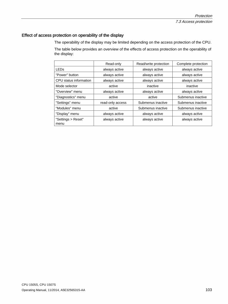
Protection 7.3 Access protection
CPU 1505S, CPU 1507S Operating Manual, 11/2014, A5E32565315-AA 103
Effect of access protection on operability of the display The operability of the display may be limited depending on the access protection of the CPU.
The table below provides an overview of the effects of access protection on the operability of the display: Read-only Read/write protection Complete protection LEDs always active always active always active "Power" button always active always active always active CPU status information always active always active always active Mode selector active inactive inactive "Overview" menu always active always active always active "Diagnostics" menu active active Submenus inactive "Settings" menu read-only access Submenus inactive Submenus inactive "Modules" menu active Submenus inactive Submenus inactive "Display" menu always active always active always active "Settings > Reset" menu
always active always active always active
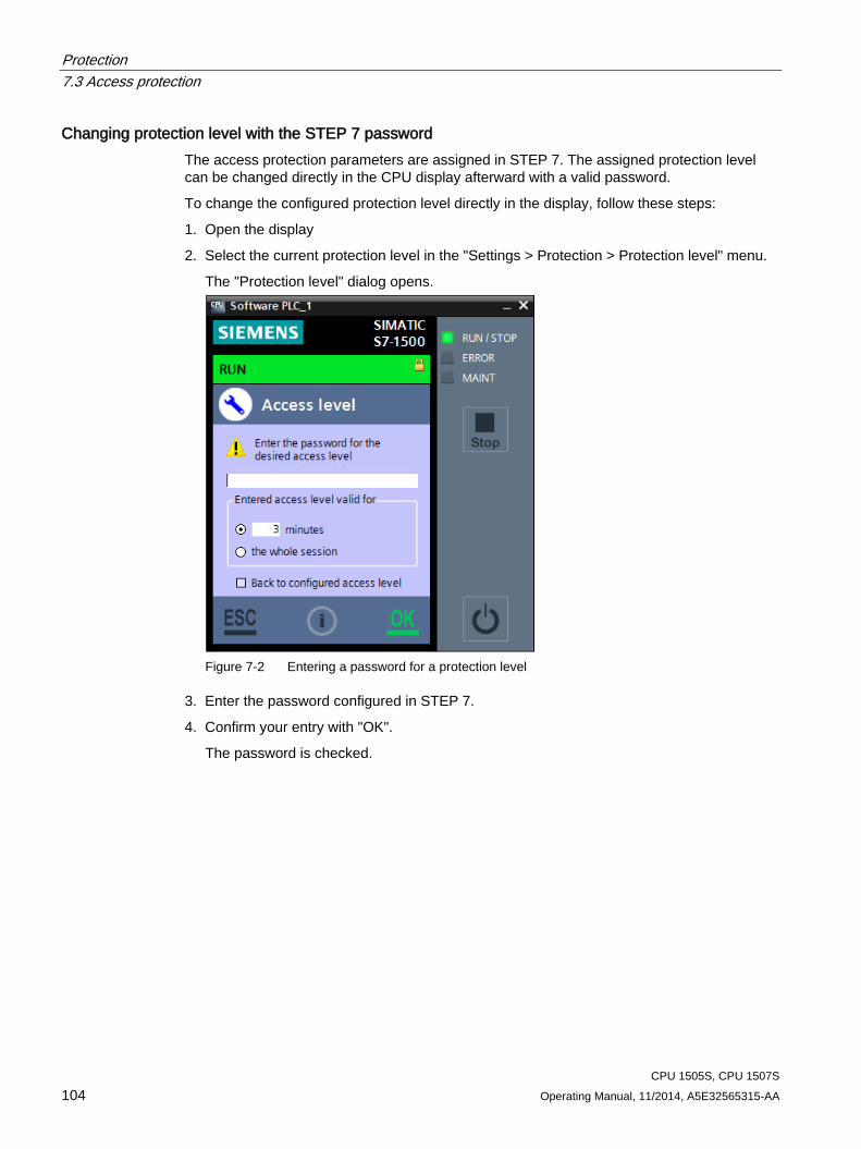
Protection 7.3 Access protection
CPU 1505S, CPU 1507S 104 Operating Manual, 11/2014, A5E32565315-AA
Changing protection level with the STEP 7 password The access protection parameters are assigned in STEP 7. The assigned protection level can be changed directly in the CPU display afterward with a valid password.
To change the configured protection level directly in the display, follow these steps:
1. Open the display
2. Select the current protection level in the "Settings > Protection > Protection level" menu.
The "Protection level" dialog opens.
Figure 7-2 Entering a password for a protection level
3. Enter the password configured in STEP 7.
4. Confirm your entry with "OK".
The password is checked.
Protection 7.3 Access protection
CPU 1505S, CPU 1507S Operating Manual, 11/2014, A5E32565315-AA 105
Result The requested protection level is activated.
The protection level is only valid for the defined time period and for activities with the CPU display. You receive an error message if the password is incorrect. The current protection level has not been changed. After confirmation of the error message, re-enter the password.
If you cancel the "Protection level" dialog with "ESC", the current protection level remains in effect.
Note Using the user program to set additional access protection
In addition to restricting access to the display you can also restrict access to a password-protected CPU in the user program using the block SFC 110. You can find a description of this block in the STEP 7 online help under the keyword "ENDIS_PW: Limit and enable password legitimation".
Reference You can find additional information about access protection and an overview of the protection functions of the CPU in the S7-1500 Automation System System Manual (http://support.automation.siemens.com/WW/view/en/59191792).
Protection 7.4 Protecting blocks
CPU 1505S, CPU 1507S 106 Operating Manual, 11/2014, A5E32565315-AA
7.4 Protecting blocks One or more blocks of the OB, FB, and FC types and global data blocks can be protected when you use a password to protect against unauthorized access (Page 48).
This protects the code of the block from unauthorized reading and modification.
Note Transferring a protected block or library
If you transfer a protected block from a hardware controller to a project of a SIMATIC S7-1500 Software Controller, the block must be recompiled. To do so, you need the password for the block that is to be compiled.
If you transfer a system library from a hardware controller to a project of a SIMATIC S7-1500 Software Controller, the library must be recompiled.
Possible actions The following actions can be performed with a know-how-protected block:
● Copying and deleting
● Calling in a program
● Online/offline comparison
● Downloading
Readable data If a block is know-how protected, only the following data is readable without the correct password:
● In/out parameters Input, Output, InOut, Return, Static, Temp
● Block title
● Block comment
● Block properties
● Global tags without information on the point of use
Reference Further information on protected blocks or copying protected blocks and libraries can be found in the online help for STEP 7.
Protection 7.5 Virus scanners and firewall
CPU 1505S, CPU 1507S Operating Manual, 11/2014, A5E32565315-AA 107
7.5 Virus scanners and firewall
Operation on systems with virus scanner The CPU and all associated components can be operated on systems with virus scanner. The virus scanner used should give you the option to back up the runtime system.
The CPU has been tested with the following virus scanners:
● Symantec AntiVirus Corporate Edition
● Trend Micro Office Scan Corporate Edition
● McAfee VirusScan Enterprise
Operation on systems with firewall The CPU and all associated components can be operated on systems with activated firewall. For the CPU's default settings, the setup program will configure the firewall rules automatically. You must confirm the changes to the firewall rules during the installation.
For Open User Communication and web server applications, application-specific IP ports can be used, which are not opened by default by the setup program. Due to the default settings, the firewall can thus prevent the connection. You therefore configure the firewall rules for the following applications yourself:
● Open User Communication via Windows interface
● Web server via Windows interface (default: port 81)
Configuring the firewall for web server use If you use a PC with an enabled firewall, you must configure the firewall for the use of the web server. In order to open the application-specific ports in the Windows firewall, create a new firewall rule for this purpose in the firewall settings.
To configure a new firewall rule, proceed as follows:
1. Select the "Advanced settings" command in the "Control Panel > Windows Firewall" menu.
The "Windows Firewall with Advanced Security" dialog is opened.
2. Select the "Inbound Rules" entry.
3. Select the "New Rule" command in the "Actions" panel.
The "New Inbound Rule Wizard" dialog opens.
4. Select the "Port" option.
5. Follow the steps in the dialog.
6. Confirm the configuration by clicking the "Finish" button.
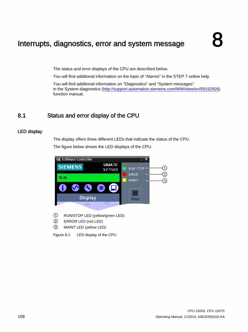
CPU 1505S, CPU 1507S 108 Operating Manual, 11/2014, A5E32565315-AA
Interrupts, diagnostics, error and system message 8
The status and error displays of the CPU are described below.
You will find additional information on the topic of "Alarms" in the STEP 7 online help.
You will find additional information on "Diagnostics" and "System messages" in the System diagnostics (http://support.automation.siemens.com/WW/view/en/59192926) function manual.
8.1 Status and error display of the CPU
LED display The display offers three different LEDs that indicate the status of the CPU.
The figure below shows the LED displays of the CPU.
① RUN/STOP LED (yellow/green LED) ② ERROR LED (red LED) ③ MAINT LED (yellow LED)
Figure 8-1 LED display of the CPU
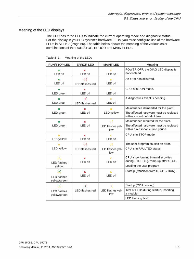
Interrupts, diagnostics, error and system message 8.1 Status and error display of the CPU
CPU 1505S, CPU 1507S Operating Manual, 11/2014, A5E32565315-AA 109
Meaning of the LED displays The CPU has three LEDs to indicate the current operating mode and diagnostic status. For the display in your PC system's hardware LEDs, you must configure use of the hardware LEDs in STEP 7 (Page 50). The table below shows the meaning of the various color combinations of the RUN/STOP, ERROR and MAINT LEDs.
Table 8- 1 Meaning of the LEDs
RUN/STOP LED ERROR LED MAINT LED Meaning
LED off
LED off
LED off
POWER OFF, the DIAG LED display is not enabled
LED off
LED flashes red
LED off
An error has occurred.
LED green
LED off
LED off
CPU is in RUN mode.
LED green
LED flashes red
LED off
A diagnostics event is pending.
LED green
LED off
LED yellow
Maintenance demanded for the plant. The affected hardware must be replaced within a short period of time.
LED green
LED off
LED flashes yel-
low
Maintenance required for the plant. The affected hardware must be replaced within a reasonable time period.
LED yellow
LED off
LED off
CPU is in STOP mode.
LED yellow
LED flashes red
LED flashes yel-
low
The user program causes an error. CPU is in FAULTED status
LED flashes
yellow
LED off
LED off
CPU is performing internal activities during STOP, e.g. ramp-up after STOP. Loading the user program
LED flashes yellow/green
LED off
LED off
Startup (transition from STOP → RUN)
LED flashes yellow/green
LED flashes red
LED flashes yel-
low
Startup (CPU booting) Test of LEDs during startup, inserting a module. LED flashing test
Interrupts, diagnostics, error and system message 8.2 Export of diagnostic information
CPU 1505S, CPU 1507S 110 Operating Manual, 11/2014, A5E32565315-AA
8.2 Export of diagnostic information Customer Support offers help in critical cases. Customer Support needs detailed diagnostic information for a thorough analysis of your situation. You can export these service data with the "SIMATIC Diagnostics Tool". The "SIMATIC Diagnostics Tool" gives you the option to collect diagnostic and system information. The "SIMATIC Diagnostics Tool" collects the information from a local computer or by remote access even from several computers connected by a network.
The "SIMATIC Diagnostics Tool" is available as Download (http://support.automation.siemens.com/WW/view/en/65976201) on the Internet.
Required service data The exported service data must include the following information:
● Product-specific data
● Internal error logging as binary code
● Diagnostic buffer entries
● Latest call list
● Memory dump (optional)
● Time stamp of the TIA Portal project
Additional information and download For the download and additional information on handling the "SIMATIC Diagnostics Tool", see the corresponding FAQ (http://support.automation.siemens.com/WW/view/en/65976201).
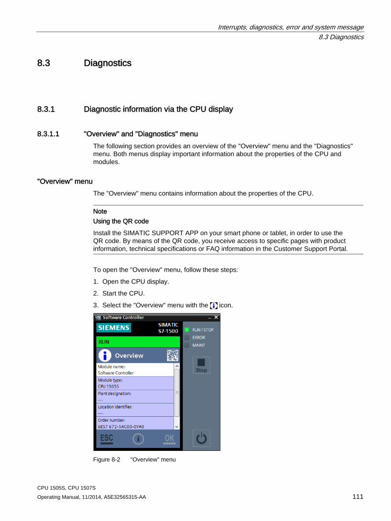
Interrupts, diagnostics, error and system message 8.3 Diagnostics
CPU 1505S, CPU 1507S Operating Manual, 11/2014, A5E32565315-AA 111
8.3 Diagnostics
8.3.1 Diagnostic information via the CPU display
8.3.1.1 "Overview" and "Diagnostics" menu The following section provides an overview of the "Overview" menu and the "Diagnostics" menu. Both menus display important information about the properties of the CPU and modules.
"Overview" menu The "Overview" menu contains information about the properties of the CPU.
Note Using the QR code
Install the SIMATIC SUPPORT APP on your smart phone or tablet, in order to use the QR code. By means of the QR code, you receive access to specific pages with product information, technical specifications or FAQ information in the Customer Support Portal.
To open the "Overview" menu, follow these steps:
1. Open the CPU display.
2. Start the CPU.
3. Select the "Overview" menu with the icon.
Figure 8-2 "Overview" menu
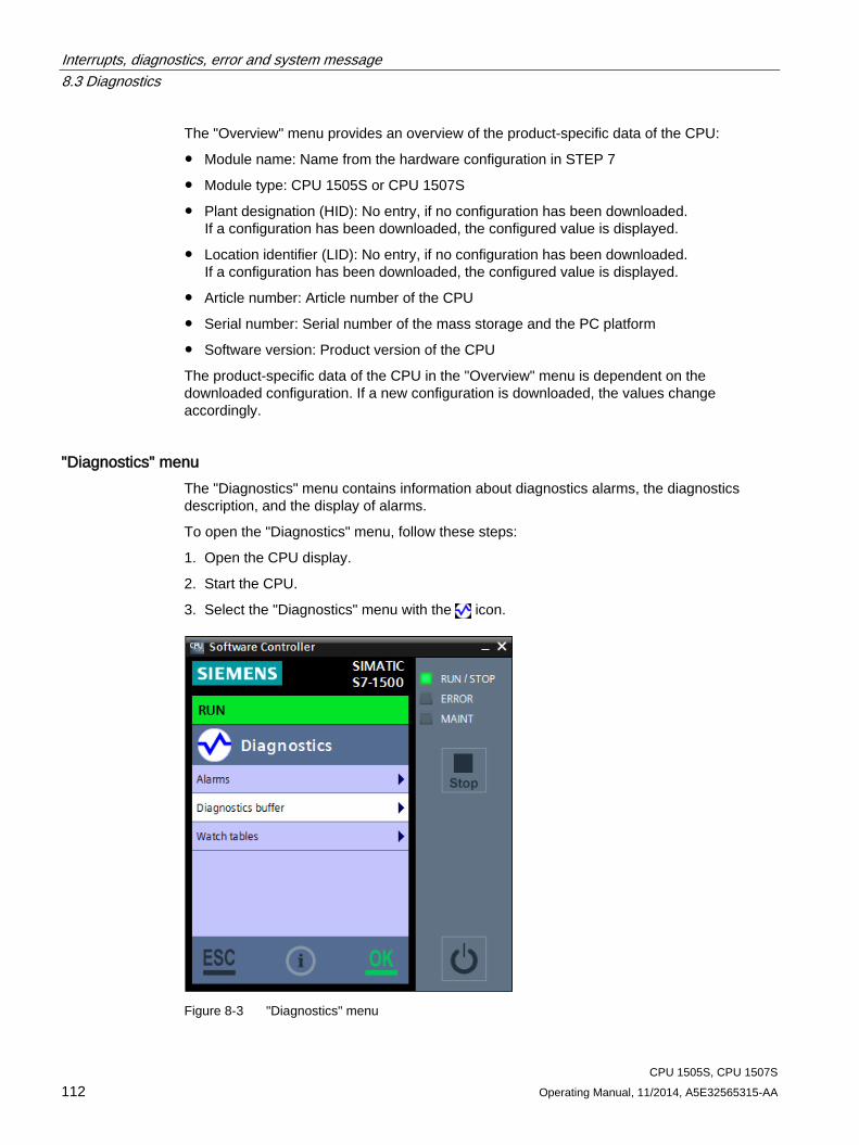
Interrupts, diagnostics, error and system message 8.3 Diagnostics
CPU 1505S, CPU 1507S 112 Operating Manual, 11/2014, A5E32565315-AA
The "Overview" menu provides an overview of the product-specific data of the CPU:
● Module name: Name from the hardware configuration in STEP 7
● Module type: CPU 1505S or CPU 1507S
● Plant designation (HID): No entry, if no configuration has been downloaded. If a configuration has been downloaded, the configured value is displayed.
● Location identifier (LID): No entry, if no configuration has been downloaded. If a configuration has been downloaded, the configured value is displayed.
● Article number: Article number of the CPU
● Serial number: Serial number of the mass storage and the PC platform
● Software version: Product version of the CPU
The product-specific data of the CPU in the "Overview" menu is dependent on the downloaded configuration. If a new configuration is downloaded, the values change accordingly.
"Diagnostics" menu The "Diagnostics" menu contains information about diagnostics alarms, the diagnostics description, and the display of alarms.
To open the "Diagnostics" menu, follow these steps:
1. Open the CPU display.
2. Start the CPU.
3. Select the "Diagnostics" menu with the icon.
Figure 8-3 "Diagnostics" menu
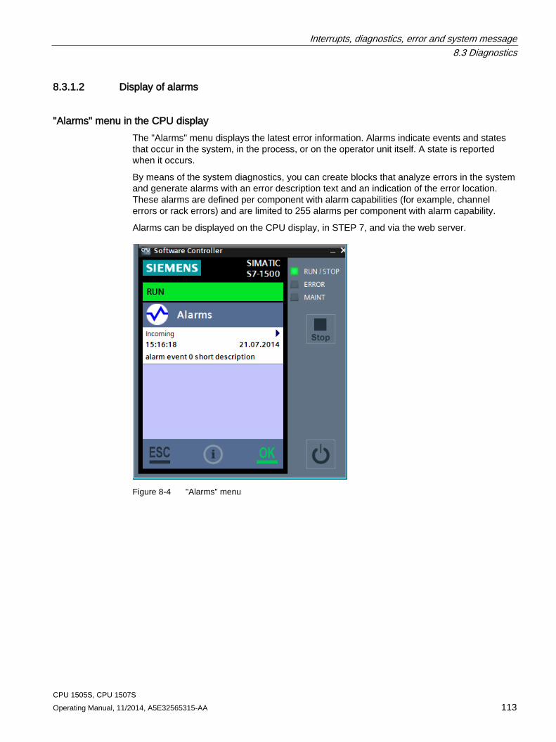
Interrupts, diagnostics, error and system message 8.3 Diagnostics
CPU 1505S, CPU 1507S Operating Manual, 11/2014, A5E32565315-AA 113
8.3.1.2 Display of alarms
"Alarms" menu in the CPU display The "Alarms" menu displays the latest error information. Alarms indicate events and states that occur in the system, in the process, or on the operator unit itself. A state is reported when it occurs.
By means of the system diagnostics, you can create blocks that analyze errors in the system and generate alarms with an error description text and an indication of the error location. These alarms are defined per component with alarm capabilities (for example, channel errors or rack errors) and are limited to 255 alarms per component with alarm capability.
Alarms can be displayed on the CPU display, in STEP 7, and via the web server.
Figure 8-4 "Alarms" menu
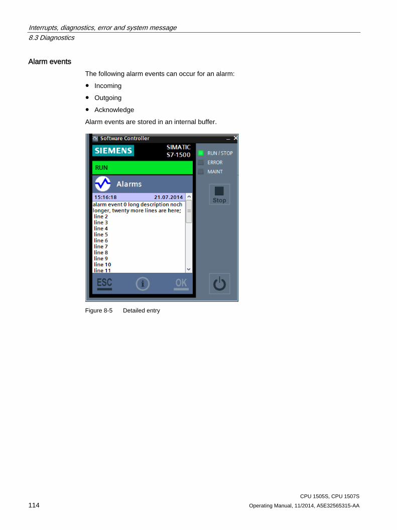
Interrupts, diagnostics, error and system message 8.3 Diagnostics
CPU 1505S, CPU 1507S 114 Operating Manual, 11/2014, A5E32565315-AA
Alarm events The following alarm events can occur for an alarm:
● Incoming
● Outgoing
● Acknowledge
Alarm events are stored in an internal buffer.
Figure 8-5 Detailed entry
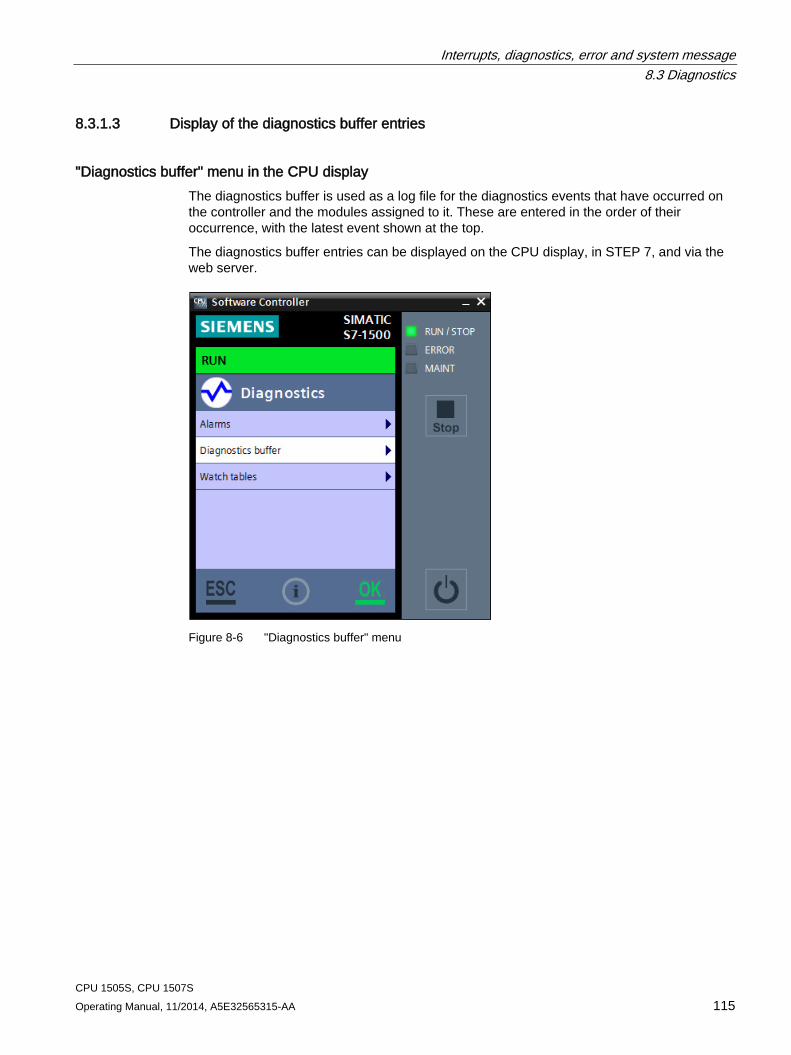
Interrupts, diagnostics, error and system message 8.3 Diagnostics
CPU 1505S, CPU 1507S Operating Manual, 11/2014, A5E32565315-AA 115
8.3.1.3 Display of the diagnostics buffer entries
"Diagnostics buffer" menu in the CPU display The diagnostics buffer is used as a log file for the diagnostics events that have occurred on the controller and the modules assigned to it. These are entered in the order of their occurrence, with the latest event shown at the top.
The diagnostics buffer entries can be displayed on the CPU display, in STEP 7, and via the web server.
Figure 8-6 "Diagnostics buffer" menu
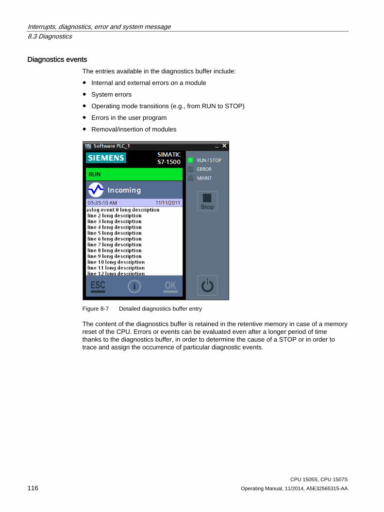
Interrupts, diagnostics, error and system message 8.3 Diagnostics
CPU 1505S, CPU 1507S 116 Operating Manual, 11/2014, A5E32565315-AA
Diagnostics events The entries available in the diagnostics buffer include:
● Internal and external errors on a module
● System errors
● Operating mode transitions (e.g., from RUN to STOP)
● Errors in the user program
● Removal/insertion of modules
Figure 8-7 Detailed diagnostics buffer entry
The content of the diagnostics buffer is retained in the retentive memory in case of a memory reset of the CPU. Errors or events can be evaluated even after a longer period of time thanks to the diagnostics buffer, in order to determine the cause of a STOP or in order to trace and assign the occurrence of particular diagnostic events.
Interrupts, diagnostics, error and system message 8.3 Diagnostics
CPU 1505S, CPU 1507S Operating Manual, 11/2014, A5E32565315-AA 117
8.3.2 Diagnostic information using STEP 7
Options for identifying diagnostic information When the online connection to the CPU is established in STEP 7, the diagnostics status of the CPU and its lower-level components and the operating mode are also determined.
You have various options in STEP 7 for identifying diagnostic information:
● Accessible devices
● Devices and networks
● Online & Diagnostics
● "Diagnostics" tab in the Inspector window
● CPU diagnostics buffer
● "Online tools" task card
Reference Additional information on the topic "Diagnostics using STEP 7" can be found in the Diagnostics Function Manual (http://support.automation.siemens.com/WW/view/en/59192926) and in the STEP 7 online help.
Interrupts, diagnostics, error and system message 8.3 Diagnostics
CPU 1505S, CPU 1507S 118 Operating Manual, 11/2014, A5E32565315-AA
8.3.3 Diagnostics information using the web server
System diagnostics using the CPU web server The CPU has an integrated web server that enables, among other things, the display of system diagnostics information via PROFINET. Any web client, such as a PC, multi panel, or smartphone, can be used to read-access module data, user program data, and diagnostics data of the CPU by means of an Internet browser. This means access to the CPU is possible without STEP 7 installed.
The web server offers web pages with reduced complexity which have been optimized for devices with small screens and low computing power.
The following diagnostics options are available with the integrated web server:
● Start page with general CPU information
● Identification information
● Contents of the diagnostics buffer
● Module information
● Messages (without acknowledgment option)
● Information about communication
● Topology
Reference You can find additional information about the "Web server" topic in the Web Server Function Manual (http://support.automation.siemens.com/WW/view/en/59193560).
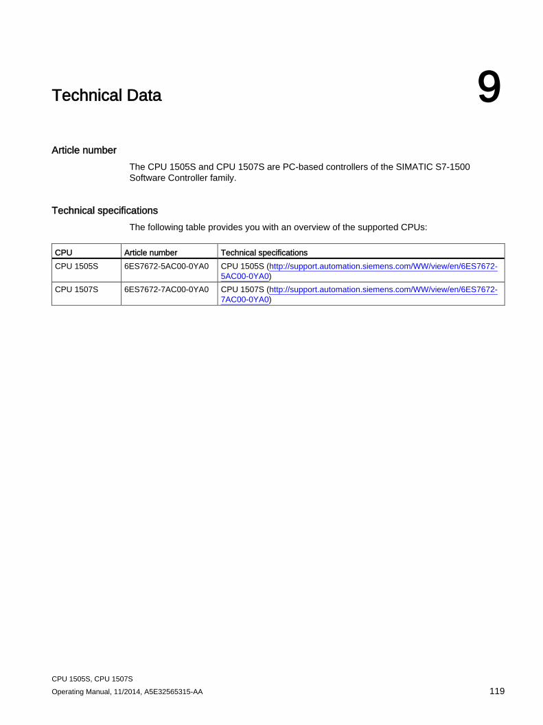
CPU 1505S, CPU 1507S Operating Manual, 11/2014, A5E32565315-AA 119
Technical Data 9
Article number The CPU 1505S and CPU 1507S are PC-based controllers of the SIMATIC S7-1500 Software Controller family.
Technical specifications The following table provides you with an overview of the supported CPUs:
CPU Article number Technical specifications CPU 1505S 6ES7672-5AC00-0YA0 CPU 1505S (http://support.automation.siemens.com/WW/view/en/6ES7672-
5AC00-0YA0) CPU 1507S 6ES7672-7AC00-0YA0 CPU 1507S (http://support.automation.siemens.com/WW/view/en/6ES7672-
7AC00-0YA0)
CPU 1505S, CPU 1507S 120 Operating Manual, 11/2014, A5E32565315-AA
Glossary
Blue screen Termination of the Windows operating system, resulting in a display on the monitor of the fatal error on a blue background. A blue screen is also known as a Windows Stop Error.
Cold restart The controller executes OB 102 before the start of the free scan cycle (OB 1). Like a warm restart, a cold restart resets the peripheral inputs (PI) and changes the peripheral outputs (PQ) to a pre-defined safe state (default is 0). However, a cold restart does not save the retentive memory (M, T, C, or DB), but sets these areas to their default settings.
Communication interface CP card that is used for the communication by the CPU, in the PROFIBUS interface built into the Siemens PC or Industrial Ethernet interface.
CP card Communications processor
Cycle time The cycle time is the time required to execute the complete scan cycle.
Industrial Ethernet Physical communication layer that supports communication with STEP 7, S7 CPUs, PGs, OPs, S7 applications, and PROFINET IO.
Load memory Memory area (RAM) allocated for all of the blocks downloaded from STEP 7 excluding the symbol table and comments.
NVRAM Non-Volatile Random Access Memory: Non-volatile memory area
PC system Representation of a software-based virtual rack in STEP that defines a PC-based automation system.
Glossary
CPU 1505S, CPU 1507S Operating Manual, 11/2014, A5E32565315-AA 121
PG Programming device
PG/OP communication Communication between the CPU and other S7 applications, such as programming devices, operator panels, and S7 controllers. The CPU supports PROFIBUS and Industrial Ethernet for PG/OP communication.
PLC Programmable logic controller - electronic control system. The PLC functions are stored in a program on the control device. The device configuration and wiring are therefore independent of the controller functions. The PLC is configured similar to a computer. It consists of a CPU with memory, input and output devices, and an internal bus system. The I/O and the programming language are oriented to control engineering requirements.
Priority The priority of an application determines the order in which the operating system executes or interrupts an application in relation to the other applications that are running on the computer. An application with a higher priority interrupts the execution of an application with a lower priority. After the application with the higher priority finishes, the application with the lower priority resumes. A higher number indicates a higher priority.
PROFIBUS Physical communications layer that can be used for PROFIBUS DP communication with I/O or S7 communication with STEP 7, S7 CPUs, and S7 applications.
PROFIBUS DP Communications network protocol used to communicate to DP I/O.
PROFINET IO Communications network protocol used to communicate with PROFINET IO devices.
S7 communication Communication between controllers on the network, hardware or software, using the S7 communication functions.
Scan cycle The cycle includes writing to the outputs, reading the inputs, executing OB 1, and satisfying the idle time requirement.
Glossary
CPU 1505S, CPU 1507S 122 Operating Manual, 11/2014, A5E32565315-AA
STEP 7 user program Application program created with STEP 7 and downloaded to the CPU for execution. It includes all organization blocks and the other instructions that they call.
TCP Transmission Control Protocol: Enables transmission of data packets ("messages") if both nodes support RFC 1006.
Time-of-day synchronization The ability to broadcast a system standard time from a single source to all devices within the system so that they can set their own clocks to the standard time.
Warm restart The controller executes OB 100 before the start of the free scan cycle (OB 1). A warm restart resets the distributed I/O inputs and puts the distributed I/O outputs into a pre-defined safe state. A warm restart saves the current value of the retentive memory areas of bit memories, timers, counters, etc.
Web server The Web server is used to monitor the CPU via the Internet or via your company Intranet. This approach lets you carry out evaluations and diagnostics even at great distances. Messages and status information are visualized on HTML pages.
Windows Stop Error Termination of the Windows operating system, resulting in a display on the monitor of the fatal error on a blue background. A Windows Stop Error is also known as a "blue screen".
Work memory Memory area (RAM) allocated for the blocks used at runtime.
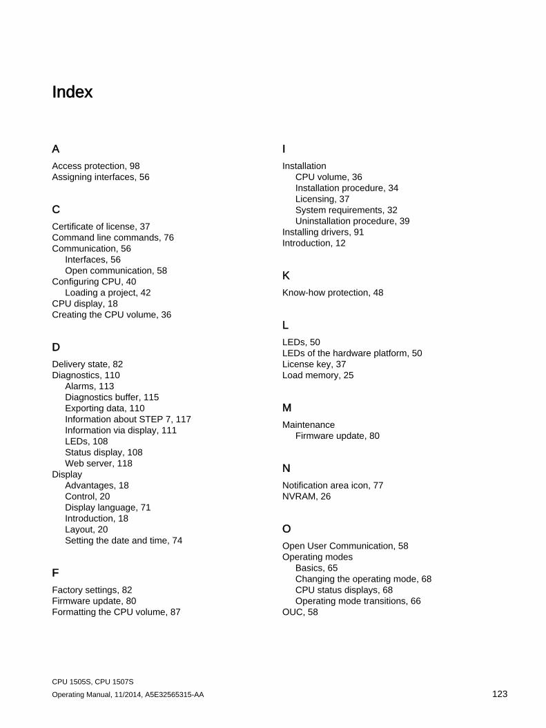
CPU 1505S, CPU 1507S Operating Manual, 11/2014, A5E32565315-AA 123
Index
A Access protection, 98 Assigning interfaces, 56
C Certificate of license, 37 Command line commands, 76 Communication, 56
Interfaces, 56 Open communication, 58
Configuring CPU, 40 Loading a project, 42
CPU display, 18 Creating the CPU volume, 36
D Delivery state, 82 Diagnostics, 110
Alarms, 113 Diagnostics buffer, 115 Exporting data, 110 Information about STEP 7, 117 Information via display, 111 LEDs, 108 Status display, 108 Web server, 118
Display Advantages, 18 Control, 20 Display language, 71 Introduction, 18 Layout, 20 Setting the date and time, 74
F Factory settings, 82 Firmware update, 80 Formatting the CPU volume, 87
I Installation
CPU volume, 36 Installation procedure, 34 Licensing, 37 System requirements, 32 Uninstallation procedure, 39
Installing drivers, 91 Introduction, 12
K Know-how protection, 48
L LEDs, 50 LEDs of the hardware platform, 50 License key, 37 Load memory, 25
M Maintenance
Firmware update, 80
N Notification area icon, 77 NVRAM, 26
O Open User Communication, 58 Operating modes
Basics, 65 Changing the operating mode, 68 CPU status displays, 68 Operating mode transitions, 66
OUC, 58
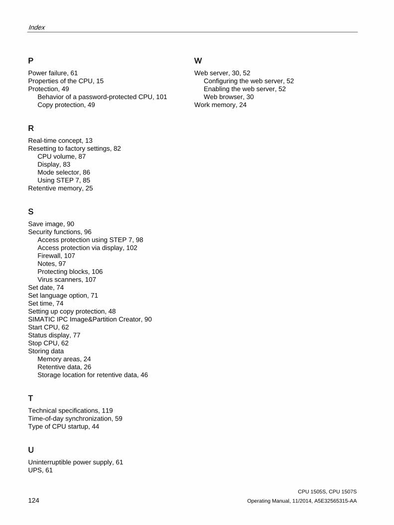
Index
CPU 1505S, CPU 1507S 124 Operating Manual, 11/2014, A5E32565315-AA
P Power failure, 61 Properties of the CPU, 15 Protection, 49
Behavior of a password-protected CPU, 101 Copy protection, 49
R Real-time concept, 13 Resetting to factory settings, 82
CPU volume, 87 Display, 83 Mode selector, 86 Using STEP 7, 85
Retentive memory, 25
S Save image, 90 Security functions, 96
Access protection using STEP 7, 98 Access protection via display, 102 Firewall, 107 Notes, 97 Protecting blocks, 106 Virus scanners, 107
Set date, 74 Set language option, 71 Set time, 74 Setting up copy protection, 48 SIMATIC IPC Image&Partition Creator, 90 Start CPU, 62 Status display, 77 Stop CPU, 62 Storing data
Memory areas, 24 Retentive data, 26 Storage location for retentive data, 46
T Technical specifications, 119 Time-of-day synchronization, 59 Type of CPU startup, 44
U Uninterruptible power supply, 61 UPS, 61
W Web server, 30, 52
Configuring the web server, 52 Enabling the web server, 52 Web browser, 30
Work memory, 24
Related Documents