CPSC 875 CPSC 875 John D McGregor John D . McGregor ABS module – a work in progress

Welcome message from author
This document is posted to help you gain knowledge. Please leave a comment to let me know what you think about it! Share it to your friends and learn new things together.
Transcript

CPSC 875CPSC 875
John D McGregorJohn D. McGregorABS module – a work in progress

PurposePurpose
• This is a unit that blends software architectureThis is a unit that blends software architecture information with telematics information regarding anti‐lock brakingregarding anti lock braking.
• Several resources are provided:A AADL d l– An AADL model
– Results of using associated tools is providedf b– Information about ABS systems
Background informationBackground information
• The material in this url is fundamentalThe material in this url is fundamental background
• http://teachersites schoolworld com/webpag• http://teachersites.schoolworld.com/webpages/MTurner/files/studyguide%20legacy%20brakes pdfakes.pdf
• ABS is a separate system from the main b ki I b i i h hbraking system. It begins operation when the wheels are observed to be slipping or about to l klock up.

ContextContext
Much of the information in this module was taken fromThe Meritor WABCO E-Version Hydraulic ABS System
Mechanic’s viewMechanic s view
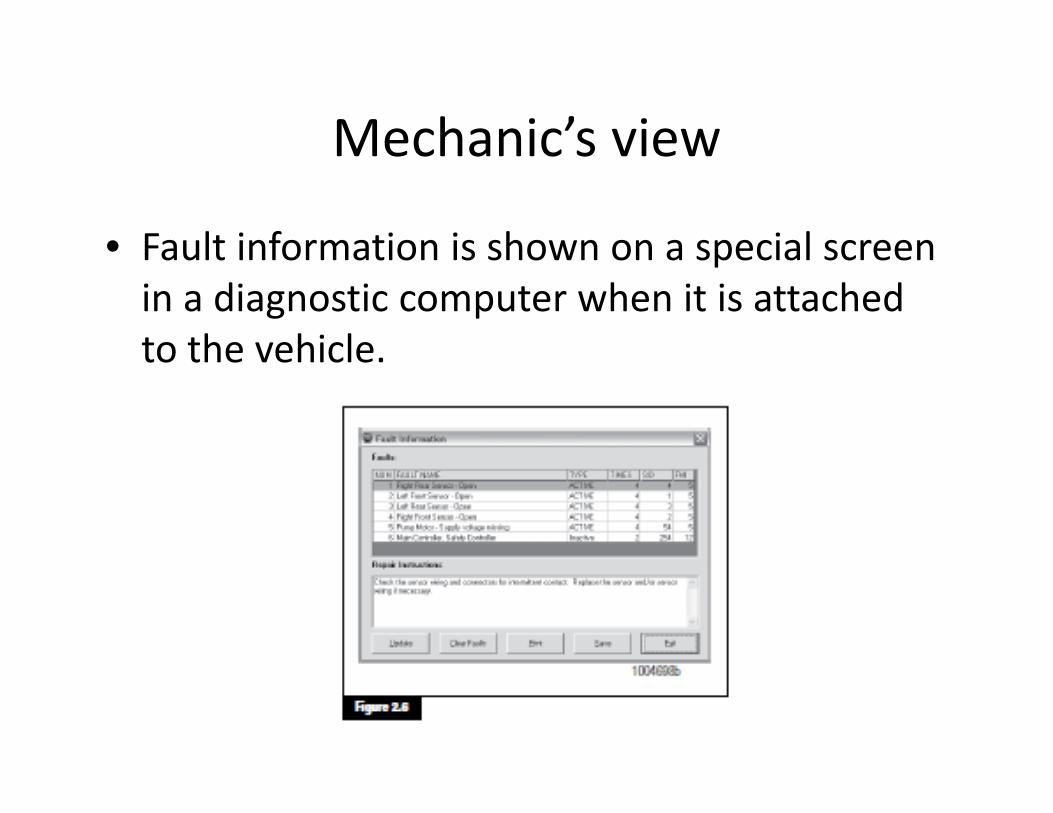
• Fault information is shown on a special screenFault information is shown on a special screen in a diagnostic computer when it is attached to the vehicleto the vehicle.

ABSABS
• An anti‐locking brake system is one that monitors theAn anti locking brake system is one that monitors the speed of each wheel and senses when one or more of the wheels is about to lock up. The system releases pressure on that wheel to avoid the lock up but reapplies the pressure as soon as a threshold
d i h dspeed is reached.• A typical system is composed of a controller, a pump, valves to release the pressure and sensors tovalves to release the pressure, and sensors to determine wheel speed.

ECU Control LoopECU Control Loop
http://www.onsemi.com/pub_link/Collateral/TND393-D.PDF
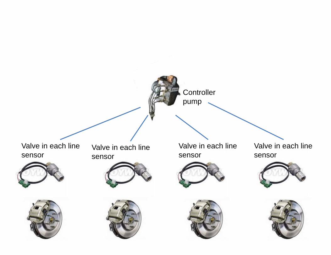
Controllerpump
V l i h li V l i h liV l i h li Valve in each linesensor
Valve in each linesensor
Valve in each linesensor
Valve in each linesensor
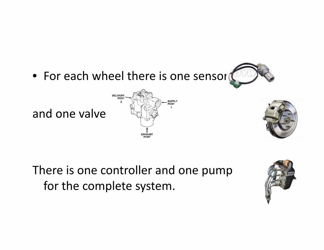
• For each wheel there is one sensorFor each wheel there is one sensor
d land one valve
There is one controller and one pumpThere is one controller and one pump for the complete system.
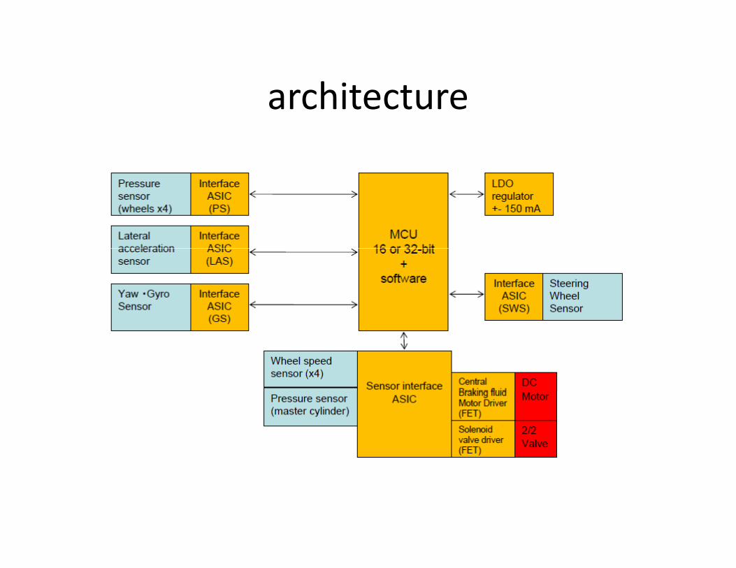
architecturearchitecture

Speed sensorsSpeed sensors
• There are several different manufacturers ofThere are several different manufacturers of ABS systems.
• There are also several different technologies• There are also several different technologies for sensing the speed at which the wheel is turning Most if not all of them have a sensorturning. Most, if not all of them, have a sensor that transmits an AC current to the controller. The frequency of that current is characteristicThe frequency of that current is characteristic of the speed at which the wheel is turining.
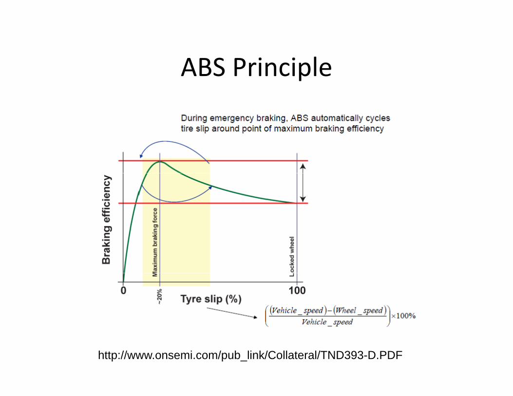
ABS PrincipleABS Principle
http://www.onsemi.com/pub_link/Collateral/TND393-D.PDF
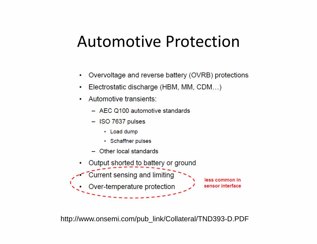
Automotive ProtectionAutomotive Protection
http://www.onsemi.com/pub_link/Collateral/TND393-D.PDF

Speed sensorSpeed sensor
• A control feedback loop is used to measureA control feedback loop is used to measure speed. The frequency of the current generated by brushes in the wheel encodesgenerated by brushes in the wheel encodes the speed.
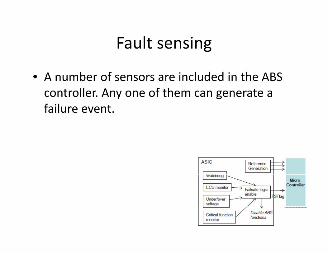
Fault sensingFault sensing
• A number of sensors are included in the ABSA number of sensors are included in the ABS controller. Any one of them can generate a failure eventfailure event.

SensorsSensors
• General list of sensorsGeneral list of sensors
Architecture modelArchitecture model
• Software in the form of firmware perhapsSoftware, in the form of firmware perhaps, runs in the controller to make decisions about which brakes to release and which to tightenwhich brakes to release and which to tighten to give maximum braking without the wheels locking up and the vehicle skiddinglocking up and the vehicle skidding.
• This module contains an evolving AADL model of a generic ABS systemof a generic ABS system.
Layered dependenciesLayered dependencies
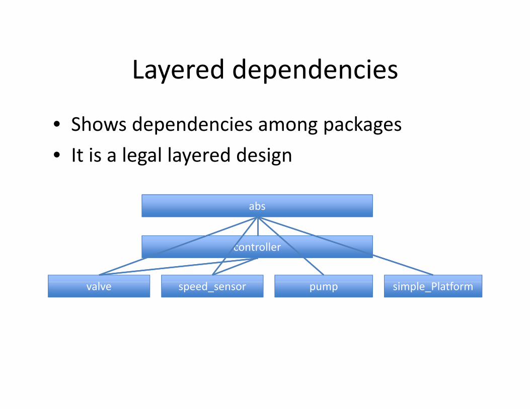
• Shows dependencies among packagesShows dependencies among packages• It is a legal layered design
abs
controller
l l fl d simple_Platformvalve pumpspeed_sensor
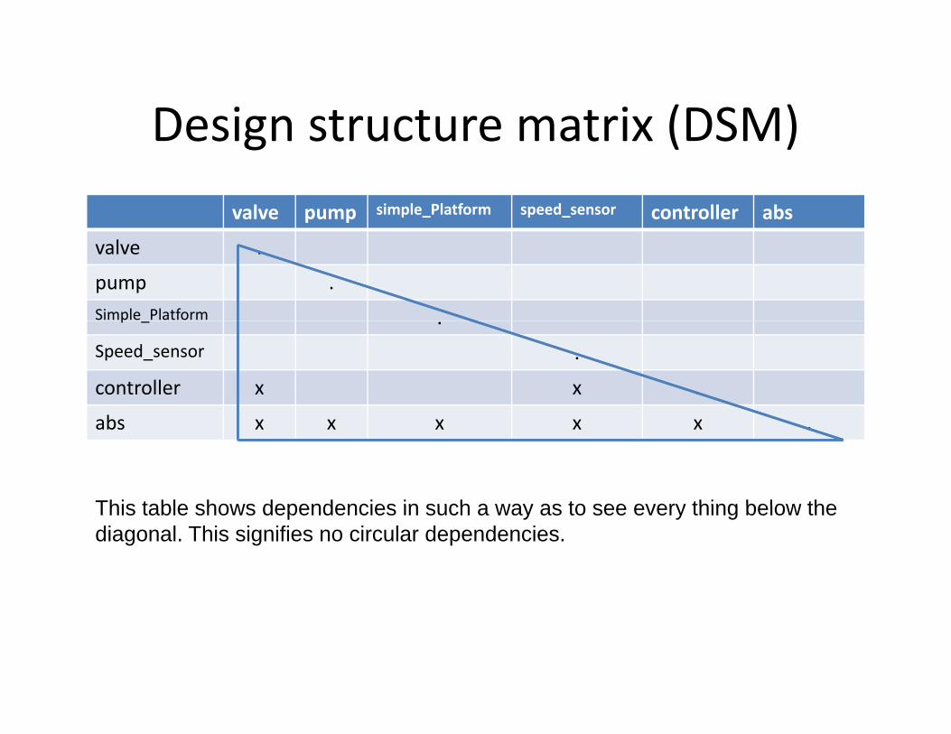
Design structure matrix (DSM)Design structure matrix (DSM)valve pump simple_Platform speed_sensor controller abs
valve .
pump .Simple Platformp _ .Speed_sensor .
controller x x .
abs x x x x x .
This table shows dependencies in such a way as to see every thing below theThis table shows dependencies in such a way as to see every thing below the diagonal. This signifies no circular dependencies.
Top level system that shows a complete configuration
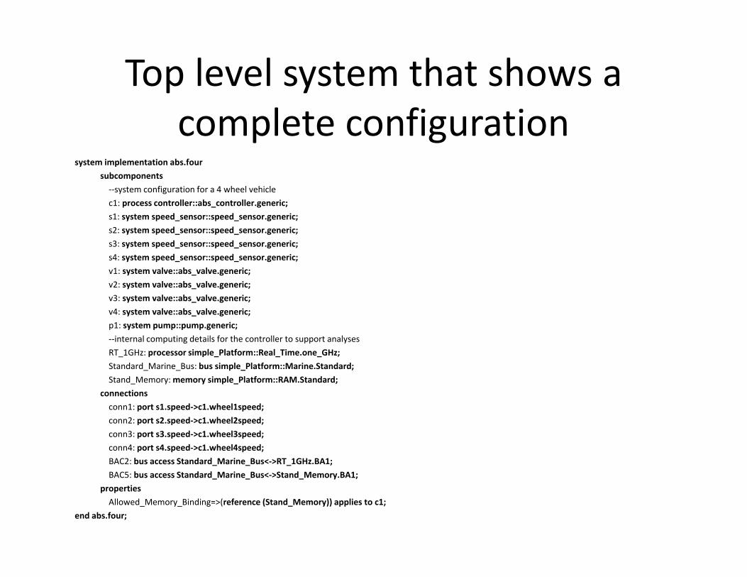
system implementation abs.foursubcomponentsp‐‐system configuration for a 4 wheel vehiclec1: process controller::abs_controller.generic;s1: system speed_sensor::speed_sensor.generic;s2: system speed_sensor::speed_sensor.generic;s3: system speed_sensor::speed_sensor.generic;s4: system speed_sensor::speed_sensor.generic;v1: system valve::abs_valve.generic;v2: system valve::abs_valve.generic;v3: system valve::abs_valve.generic;v4: system valve::abs_valve.generic;p1: system pump::pump generic;p1: system pump::pump.generic;‐‐internal computing details for the controller to support analysesRT_1GHz: processor simple_Platform::Real_Time.one_GHz;Standard_Marine_Bus: bus simple_Platform::Marine.Standard;Stand_Memory: memory simple_Platform::RAM.Standard;
connectionsconn1: port s1.speed‐>c1.wheel1speed;conn2: port s2.speed‐>c1.wheel2speed;conn3: port s3.speed‐>c1.wheel3speed;conn4: port s4.speed‐>c1.wheel4speed;BAC2: bus access Standard_Marine_Bus<‐>RT_1GHz.BA1;BAC5: bus access Standard_Marine_Bus<‐>Stand_Memory.BA1;
propertiesAllowed_Memory_Binding=>(reference (Stand_Memory)) applies to c1;
end abs.four;

State machine for a valveState machine for a valvesystem implementation abs_valve.generic
dmodesopened: initial mode;blocking: mode;releasing: mode;opened‐[block]‐>blocking;blocking‐[release]‐>releasing;releasing‐[open]‐>opened;
end abs_valve.generic;
The valve has three states: opened, blocking, and releasing. The implementation should have methods for moving into each of these states.
BindingBinding
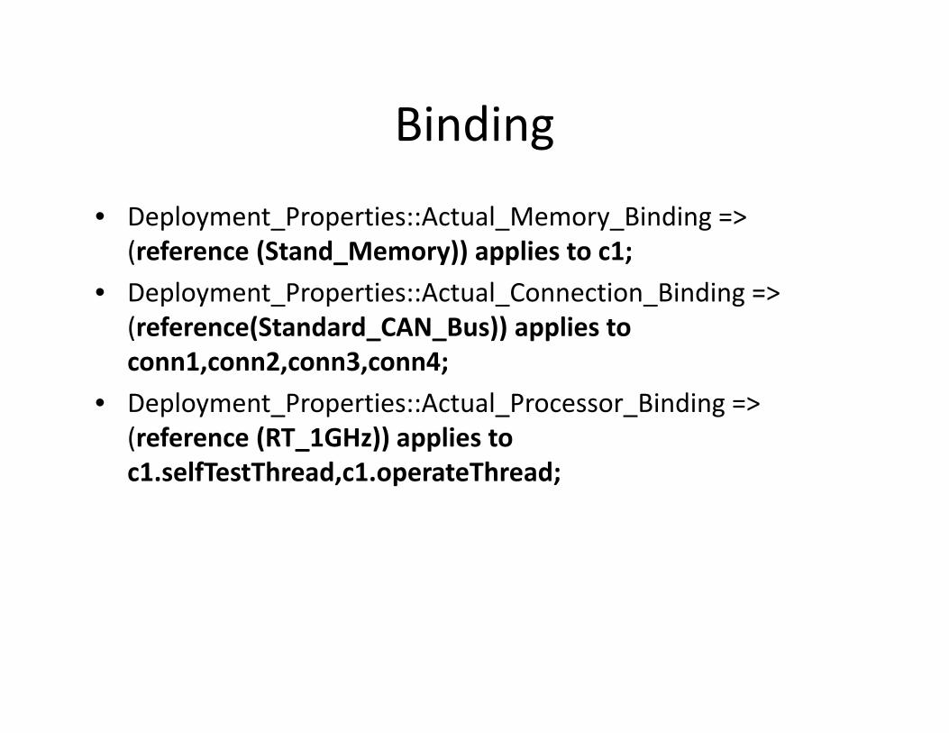
• Deployment Properties::Actual Memory Binding => p y _ p _ y_ g(reference (Stand_Memory)) applies to c1;
• Deployment_Properties::Actual_Connection_Binding => ( f (St d d CAN B )) li t(reference(Standard_CAN_Bus)) applies to conn1,conn2,conn3,conn4;
• Deployment Properties::Actual Processor Binding => p y _ p _ _ g(reference (RT_1GHz)) applies to c1.selfTestThread,c1.operateThread;
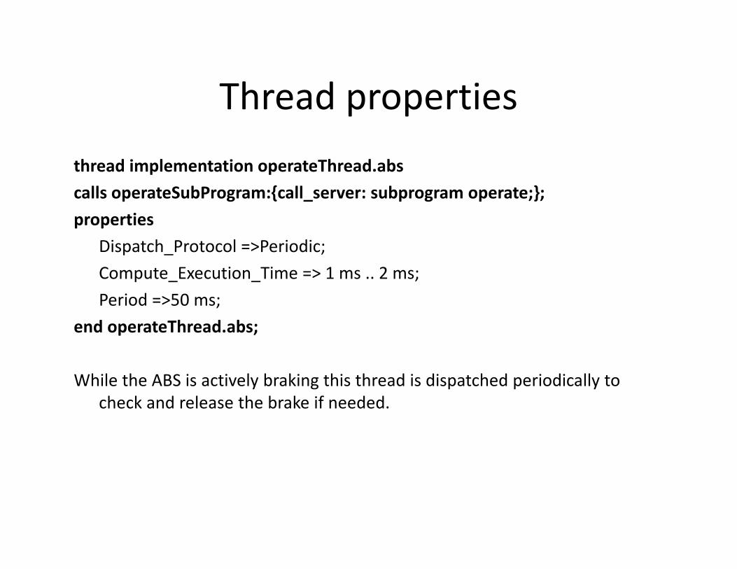
Thread propertiesThread propertiesthread implementation operateThread.abscalls operateSubProgram:{call_server: subprogram operate;};properties
Dispatch Protocol =>Periodic;Dispatch_Protocol =>Periodic;Compute_Execution_Time => 1 ms .. 2 ms;Period =>50 ms;d h d bend operateThread.abs;
While the ABS is actively braking this thread is dispatched periodically to check and release the brake if needed.
Thread propertiesThread properties
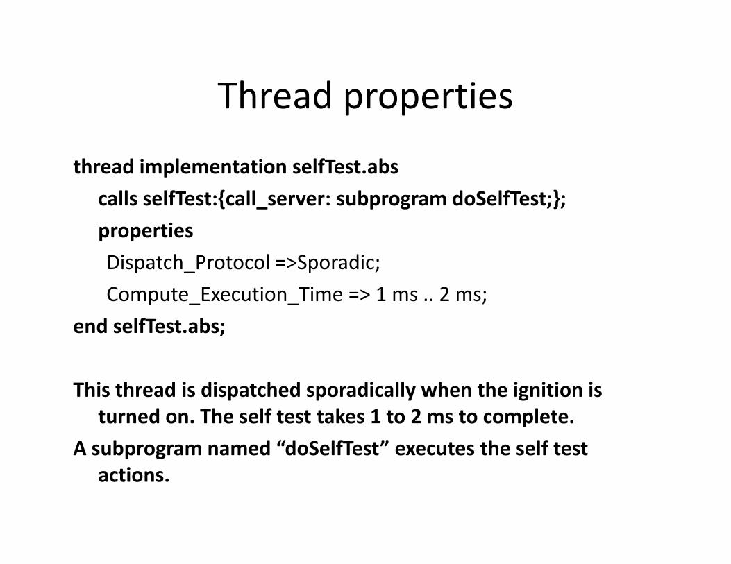
thread implementation selfTest.abspcalls selfTest:{call_server: subprogram doSelfTest;};propertiesDispatch_Protocol =>Sporadic;Compute_Execution_Time => 1 ms .. 2 ms;
end selfTest.abs;
This thread is dispatched sporadically when the ignition isThis thread is dispatched sporadically when the ignition is turned on. The self test takes 1 to 2 ms to complete.
A subprogram named “doSelfTest” executes the self test actions.
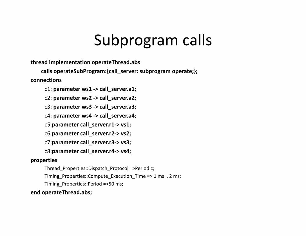
Subprogram callsSubprogram callsthread implementation operateThread.abs
calls operateSubProgram:{call server: subprogram operate;};p g { _ p g p ;};connections
c1: parameter ws1 ‐> call_server.a1;c2: parameter ws2 ‐> call_server.a2;c3: parameter ws3 ‐> call_server.a3;c4: parameter ws4 ‐> call_server.a4;c5:parameter call_server.r1‐> vs1;c6:parameter call server r2 > vs2;c6:parameter call_server.r2‐> vs2;c7:parameter call_server.r3‐> vs3;c8:parameter call_server.r4‐> vs4;
propertiesp pThread_Properties::Dispatch_Protocol =>Periodic;Timing_Properties::Compute_Execution_Time => 1 ms .. 2 ms;Timing_Properties::Period =>50 ms;
end operateThread abs;end operateThread.abs;
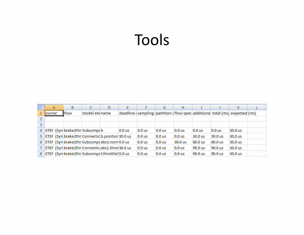
ToolsTools
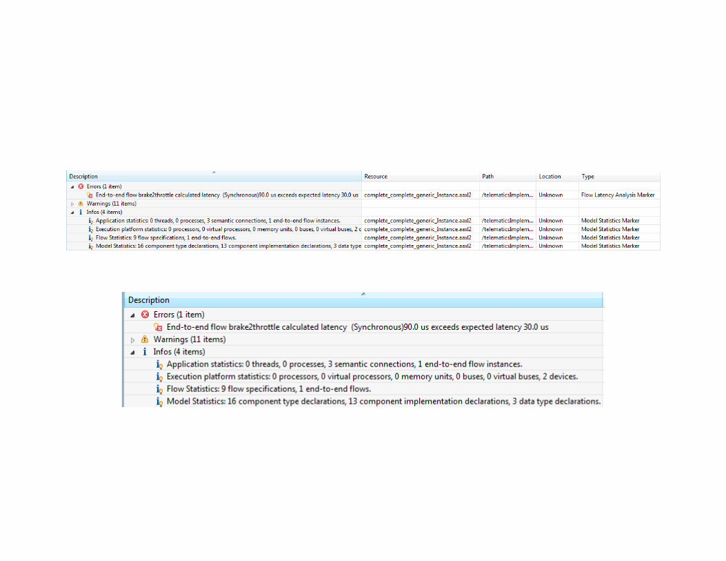
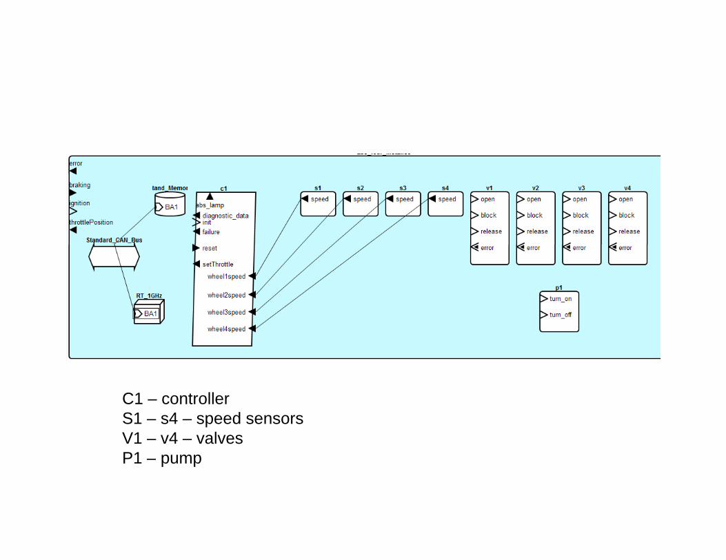
C1 – controllerS1 – s4 – speed sensorsV1 – v4 – valvesP1 pumpP1 – pump
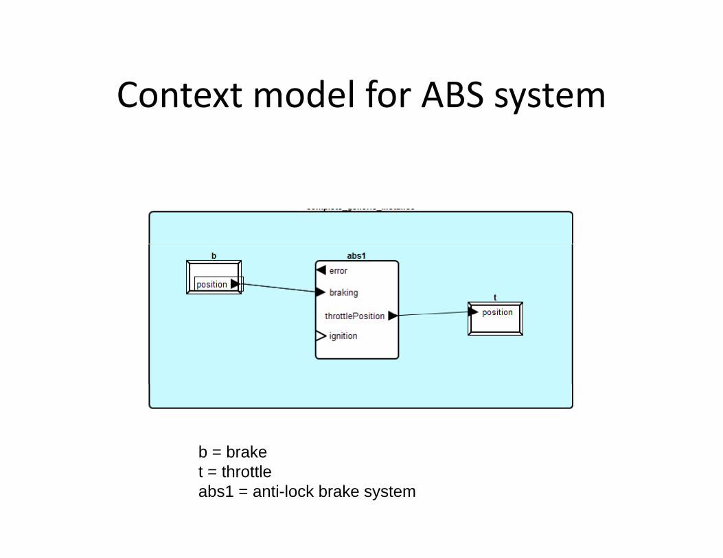
Context model for ABS systemContext model for ABS system
b = brakeb braket = throttleabs1 = anti-lock brake system

Architecture evolutionArchitecture evolution
• We begin a new system with essentially aWe begin a new system with essentially a monolithic block.
ABS
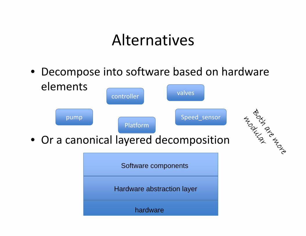
AlternativesAlternatives
• Decompose into software based on hardwareDecompose into software based on hardware elements
controller valves
pumpPlatform
Speed_sensor
• Or a canonical layered decomposition
Hardware abstraction layer
Software components
hardware
y
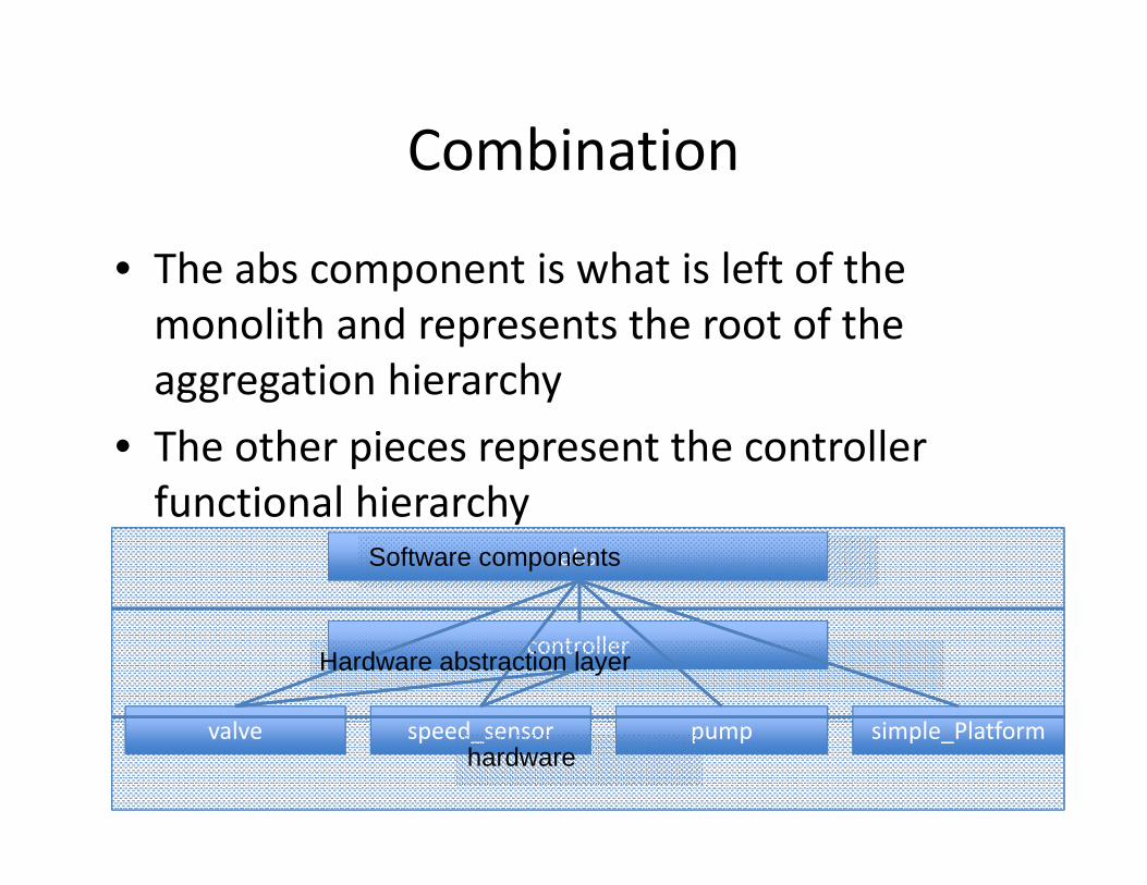
CombinationCombination
• The abs component is what is left of theThe abs component is what is left of the monolith and represents the root of the aggregation hierarchyaggregation hierarchy
• The other pieces represent the controller functional hierarchyfunctional hierarchy
absSoftware components
controller
l l fl d
Hardware abstraction layer
simple_Platformvalve pumpspeed_sensorhardware
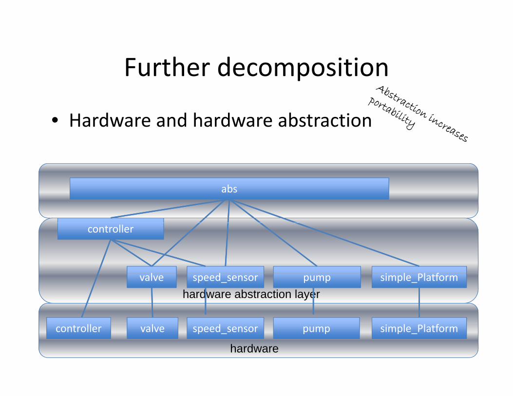
Further decompositionFurther decomposition
• Hardware and hardware abstractionHardware and hardware abstraction
abs
controller
l l fl d simple_Platformvalve pumpspeed_sensorhardware abstraction layer
simple_Platformvalve pumpspeed_sensor
hardware
controller
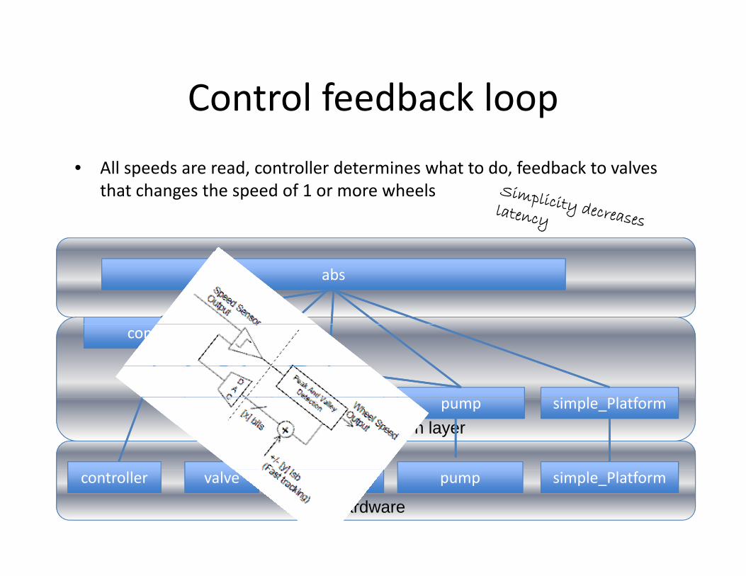
Control feedback loopControl feedback loop• All speeds are read, controller determines what to do, feedback to valves
that changes the speed of 1 or more wheels
abs
controller
l l fl d simple_Platformvalve pumpspeed_sensorhardware abstraction layer
simple_Platformvalve pumpspeed_sensor
hardware
controller
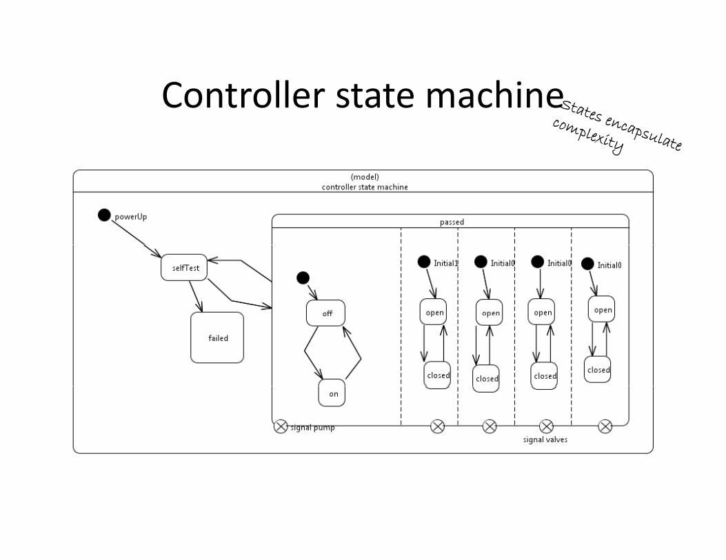
Controller state machineController state machine

ThreadsThreads
• The controller process is multi‐threadedThe controller process is multi threaded• Synchronization is simple
t th d b t l ti t ti– two threads but only one active at a time– only one thread in the state machine at a time
• These are bound to the processor

With Error PathWith Error Path
Error handlingError handling
• In some cases a separate thread is used forIn some cases a separate thread is used for error handling
• Definitely separate threads are used for• Definitely separate threads are used for watchdog timers, etc.
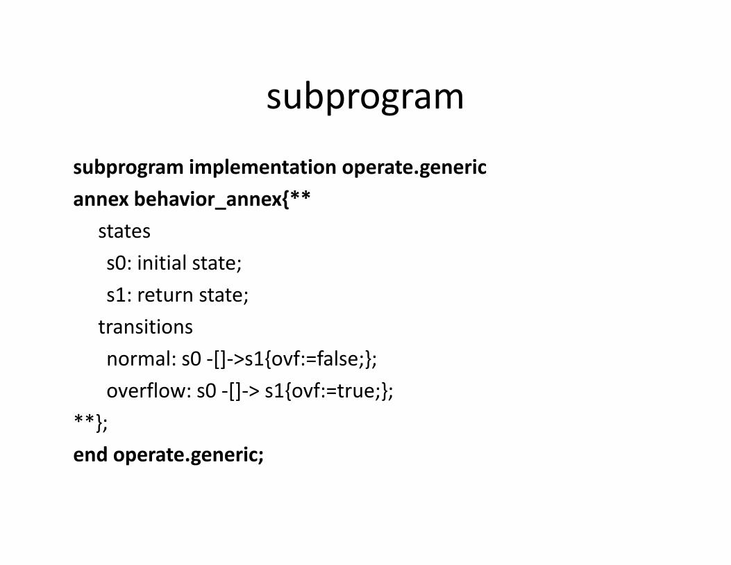
subprogramsubprogram
subprogram implementation operate.genericp g p p gannex behavior_annex{**
statess0: initial state;s1: return state;transitionsnormal: s0 ‐[]‐>s1{ovf:=false;};overflow: s0 [] > s1{ovf:=true;};overflow: s0 ‐[]‐> s1{ovf:=true;};
**};end operate.generic;end operate.generic;
referencesreferences
These readings give some general and someThese readings give some general and some specific information about ABS
• http://wwwmeritorwabco com/MeritorWABC• http://www.meritorwabco.com/MeritorWABCO_document/tp9738.pdfh // i / b li k/C ll l/• http://www.onsemi.com/pub_link/Collateral/TND393‐D.PDF
Related Documents