CPSC 871 John D. McGregor Module 7 Session 1 More UML

CPSC 871 John D. McGregor Module 7 Session 1 More UML.
Jan 17, 2016
Welcome message from author
This document is posted to help you gain knowledge. Please leave a comment to let me know what you think about it! Share it to your friends and learn new things together.
Transcript

CPSC 871
John D. McGregorModule 7 Session 1
More UML

Types of association• GameBoardImpl is an
implementation of the interface GameBoardInterface. The line marked (2) indicates “realization” of an interface. An interface is a specification of behavior but it does not provide any implementation like a class would.
• GameBoardImpl provides behavior (code) for each method in the interface.
• The clear diamonds indicate aggregation (1)
• Instances of these classes are contained in the GameBoardImpl
(1)
(2)
(1)
(1)

Generalization
• Generalization takes three classes as seen below and creates a more abstract class
• Each of the special (generalized) classes has the same specification as the generalization but with some variation maybe in behavior or maybe just in how the behavior is implemented.

Generalization/inheritance
• A classification scheme using an inheritance hierarchy
• The subclasses are special cases of the base class
• Enables substitution

Generalization/inheritance
• MovableSprite gives the main behaviors of the moving sprites
• An alternative would be to have a Movability class, an instance of which that is aggregated into those Sprites that must move.
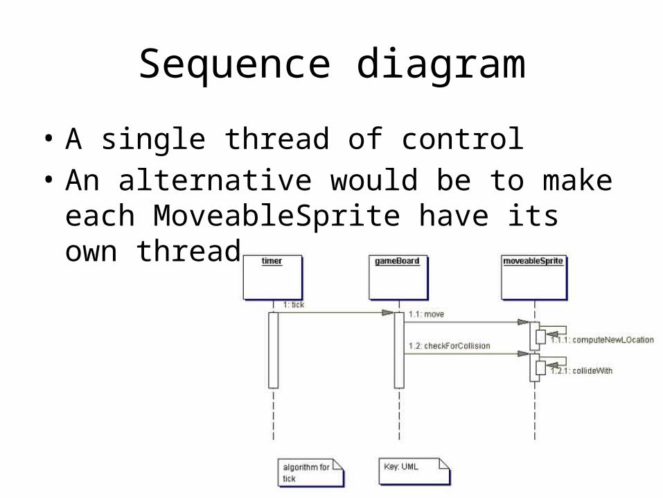
Sequence diagram
• A single thread of control• An alternative would be to make each
MoveableSprite have its own thread

Activity diagram
• This is the main animation loop.• Each rectangle represents an object from a
class. Much like• the sequence• diagram but more • complex behavior• is represented.

Activity diagram for exception
• Handling a collision can be an exceptional event since it happens a very small percentage of the time.

State machine
• A state is a configuration of data.• A transition is a change in some data values
that are sufficiently different that the program changes behavior

UML – deployment diagram
• This diagram shows two components on one computing box. One of those components aggregates 3 other components.

Java2UML
• UML gives a higher level view of a program• To understand a Java program the Java2UML
function automatically creates a UML class diagram

Click on project, then click on UML Class Diagram from Java

Give name to the model

The class diagram primitives are in the outline view

Expand the elements in the outline

Drag and drop the first entry in the outline

Drag ‘n drop each element in the outline

Round trip engineering
• A UML model is created including several diagrams.
• Code is generated from the model with some custom programming
• Java2UML will take code to uml• UML model is reviewed and modified• Repeat

Here’s what you are going to do
• Follow along and create the class diagram as I did.
• In the third session of this module you will use the debugger to track down a defect in the Brickles code.
• As a starting point to understanding that code create two sequence diagrams from the code.
• Use the Papyrus UML to draw these. Take screen shots and submit.
Related Documents