Advanced Ar-L Personal Computer TM CP/M-86 System Reference Guide NEe NEe Information Svstems,lnc. 819-000102-2001 REV. 01 8-83

Welcome message from author
This document is posted to help you gain knowledge. Please leave a comment to let me know what you think about it! Share it to your friends and learn new things together.
Transcript
~~ Advanced Ar-L Personal Computer
TM
CP/M-86 System Reference Guide
NEe NEe Information Svstems,lnc.
819-000102-2001 REV. 01 8-83
Important Notice
(1) All rights reserved. This manual is protected by copyright. No part of this manual may be reproduced in any form whatsoever without the written permission of the copyright owner.
(2) The policy of NEe being that of continuous product improvement, the contents of this manual are subject to change, from time to time, without notice.
(3) All efforts have been made to ensure that the contents of this manual are correct; however, should any errors be detected, NEC would greatly appreciate being informed.
(4) NEC can assume no responsibility for errors in this manual or their consequences.
©Copyright 1983 by NEC Corporation.
Contents Page
PREFACE........................................................ lX
Chapter 1 CP/M-86 System Overview
CP/M-86 GENERAL CHARACTERISTICS. . .. . .. . . . . . . . .. . . . . . . .... 1-1 CP/M-80 AND CP/M-86 DIFFERENCES............................ 1-4
Relocatable Groups. . . . . . . . . . . . . . . . . . . . . . . . . . . . . . . . . . . . . . . . . . .. 1-4 Memory Models. ... . . .. . . . . .. . . ... . . . . .. . .. . . . . . .. ... . . . . . .... 1-4 Disk Definition Tables ......................................... 1-5 Bootstrap Operation ...... . . . . . . . . . . . . . . . . . . . . . . . . . . . . . . . . . . . . . 1-5 BDOS Calls. . . . . . . . . . . . . . . . . . . . . . . . . . . . . . . . . . . . . . . . . . . . . . . . . .. 1-5 Addressing ................................................... 1-5 Program Termination. . . . . . . . . . . . . . . . . . . . . . . . . . . . . . .. . . . . . . . . .. 1-6
Chapter 2 Command Setup and Execution Under CP/M -86
CCP BUILT-IN AND TRANSIENT COMMANDS.................... 2-1 TRANSIENT PROGRAM EXECUTION MODELS ................... 2-2
The 8080 Memory Model. . . . . . .. .... . . . .. . .. . . . . . . . ... . . . . . . ... 2-3 The Small Memory Model ...................................... 2-5 The Compact Memory Model ................................... 2-6 Base Page Initialization. . . . . . . . . . . . . . . . . . . . . . . . . . . . . . . . . . . . . . . .. 2-7
TRANSIENT PROGRAM LOAD. . . . . . . . . . . . . . . . . . . . . . . . . . . . . . . . . .. 2-9 TRANSIENT PROGRAM EXIT. . . . . . . . . . . . . . . . . . . . . . . . . . . . . . . . . . .. 2-9
Chapter 3 Command (CMD) File Generation
INTEL 8086 HEX FILE FORMAT.................................. 3-1 OPERATION OF GENCMD ....................................... 3-3 COMMAND FILE FORMAT ....................................... 3-6
iii
iv
Contents (cont' d) Page
Chapter 4 Basic Disk Operating System (BDOS) Functions
BDOS PARAMETERS............................................. 4-1 BDOS FUNCTION CODES ........ : . . . . . . . . . . . . . . . . . . . . . . . . . . . . . .. 4-2
Simple BDOS Calls . . . . . . . . . . . . . . . . . . . . . . . . . . . . . . . . . . . . . . . . . . .. 4-4 BDOS File Operations ......................................... 4-10 BDOS Memory Management and Program Functions. . . . . . . . . . . . . .. 4-32
Chapter 5 Basic 1/0 System (BIOS) Organization
ORGANIZATION OF THE BIOS................................... 5-2 THE BIOS JUMP VECTOR. . . . . . . . . . . . . . . . . . . . . . . . . . . . . . . . . . . . . . .. 5-3 BIOS SUBROUTINES . . . . . . . . . . . . . . . . . . . . . . . . . . . . . . . . . . . . . . . . . . . .. 5-3 STANDARD BIOS SUBROUTINE ENTRY POINTS.................. 5-5
System Initialization Subroutines ................................ 5-5 Simple Character 1/0 Subroutines. . . . . . . . . . . . . . . . . . . . . . . . . . . . . .. 5-6 10BYTE Function. . . . . . . . . . . . . . . . . . . . . . . . . . . . . . . . . . . . . . . . . . . .. 5-8 Disk 1/0 Subroutines .......................................... 5-10 Other Functions . . . . . . . . . . . . . . . . . . . . . . . . . . . . . . . . . . . . . . . . . . . . . .. 5-18
Chapter 6 Advanced BIOS Functions
CRT ESCAPE SEQUENCE FUNCTIONS............................ 6-1 Format and Definitions. . . . . . . . . . . . . . . . . . . . . . . . . . . . . . . . . . . . . . . .. 6-1 APC Escape Code Sequences. . . . . . . . . . . . . . . . . . . . . . . . . . . . . . . . . . .. 6-4
ASCII CONTROL CODES. . . . . . . . . . . . . . . . . . . . . . . . . . . . . . . . . . . . . . . .. 6-9 EXTENDED FUNCTION CALLS .................................. 6-9
Get Time and Date ............................................ 6-10 Set Time and Date. . . . . . . . . . . . . . . . . . . . . . . . . . . . . . . . . . . . . . . . . . . .. 6-11 Play Music .................................................... 6-11 Sound Beep. . . . . . . . . . . . . . . . . . . . . . . . . . . . . . . . . . . . . . . . . . . . . . . . . .. 6-15 Report Cursor Position. . . . . . . . . . . . . . . . . . . . . . . . . . . . . . . . . . . . . . . .. 6-17 Auto Power Off ............................................... 6-17 Initialize Keyboard FIFO Buffer . . . . . . . . . . . . . . . . . . . . . . . . . . . . . . . .. 6-18 Direct CRT 1/0 ............................................... 6-18 Write CMOS .................................................. 6-26 Read CMOS .................................................. 6-26 Initialize RS 232C ............................................. 6-27
Contents (cont' d) Page
Chapter 7 Disk Definition Tables
DISK PARAMETER TABLE FORMAT ............................. 7-1 DISK DEFINITION TABLES ...................................... 7-7 PHYSICAL AND LOGICAL STRUCTURES FOR FLOPPY DISKETTES ........................................ 7-11
Chapter 8 CP /M-86 Bootstrap and Adaptation Procedures
THE COLD START LOAD OPERATION.. .. .. . . .. .. . . .. .. .. . .. .. .. 8-2 ORGANIZATION OF CPM.SYS. . ... . . . . . . . . . . . . . . . . . . .. . . . . . . . . . .. 8-4
Chapter 9 GSX-86: Graphics for the APC
WHAT IS GSX-86................................................. 9-1 GSX-86 and Application Programs. . . . . . . . . . . . . . . . . . . . . . . . . . . . . .. 9-1 GSX-86 and Graphics Products... . . . . . . .. . . . . . . . . . . . . .. . . . . . . . .. 9-2
USING GSX-86 . . . . . . . . . . . . . . . . . . . . . . . . . . . . . . . . . . . . . . . . . . . . . . . . . .. 9-2 Setting Up GSX-86 ............................................ 9-2 Updating the Assignment Table. . . . . . . . . . . . . . . . . . . . . . . . . . . . . . . . .. 9-3 Device Drivers ............. . . . . . . . . . . . . . . . . . . . . . . . . . . . . . . . . . .. 9-4 Invoking GSX-86 . . . . . . . . . . . . . . . . . . . . . . . . . . . . . . . . . . . . . . . . . . . . .. 9-6 Warm Starts and Cold Starts. . . . . . . . . . . . . . . . . . . . . . . . . . . . . . . . . . .. 9-6
OVERVIEW OF GRAPHICS SYSTEM EXTENSION STRUCTURE .... 9-6 GSX-86 Architecture. . . . . . . . . . . . . . . . . . . . . . . . . . . . . . . . . . . . . . . . . .. 9-6 Memory Management . . . . . . . . . . . . . . . . . . . . . . . . . . . . . . . . . . . . . . . . .. 9-7
THE GRAPHICS DEVICE OPERATING SYSTEM (GDOS) ........... 9-8 Virtual Device Interface (VDI). . . . . . . . . . . . . . . . . . . . . . . . . . . . . . . . . .. 9-9 Normalized Device Coordinates ................................. 9-10 G DOS Opcodes . . . . . . . . . . . . . . . . . . . . . . . . . . . . . . . . . . . . . . . . . . . . . .. 9-11
THE GRAPHICS INPUT/OUTPUT SYSTEM (GIOS) ................. 9-44 Creating a GIOS File ........................................... 9-44
v

vi
Contents (cont' d)
Appendix A Escape Sequences
Appendix B Soft Key Table Memory Format
Appendix C Auxiliary Character Generator RAM Format
Appendix D Memory Map
Appendix E Keyboard Structures
Appendix F CP/M-86 Control Characters
Appendix G CP/M-86 Error Messages
Appendix H CBIOS Error Messages
Appendix I Blocking and Deblocking Algorithms
Appendix J Physical Format of Hard Disks
Appendix K GSX-86 Device Specific Information
Illustrations
Figure
2-1 2-2 2-3 2-4 3-1 4-1 4-2 4-3 5-1 5-2 6-1 6-2 6-3 6-4 6-5 6-6 8-1 8-2 9-1 C-l C-2 E-l E-2 E-3 J-l J-2 J-3
Title Page
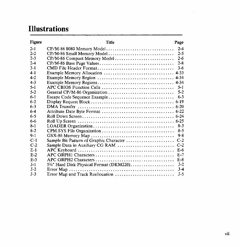
CP/M-86 8080 Memory Model... . . .... . . . . . . . ... . . . . ... ... .. 2-4 CP/M-86 Small Memory Model. . ..... . . ... . . . ... .. . ..... .... 2-5 CP/M-86 Compact Memory Model..... .. . . .. . ... . . . . ... .. ... 2-6 CP/M-86 Base Page Values. .. . . . . . . . . . . . . . . . . ... . . . . . . . . . . .. 2-8 CMD File Header Format.. ... . . . ..... .. . ... . ... . . . . ... ..... 3-6 Example Memory Allocation .......... . . . . . . . . . . . . . . . . . . . . .. 4-33 Example Memory Region ................................... 4-34 Example Memory Regions ................................... 4-34 APC CBIOS Function Calls. . . . . . . . . . . . . . . . . . . .. . . . . . . . . . . .. 5-1 General CP/M-86 Organization. . . . . . . . . . . . . . . . .. . . . . . . . . . . .. 5-2 Escape Code Sequence Example. . . . . . . . . . . . . . . . . . . . . . . . . . . . .. 6-3 Display Request Block. . . . . . . . . . . . . . . . . . . . . . . . . . . . . . . . . . . . .. 6-19 DMA Transfer ............................................ 6-20 Attribute Date Byte Format ................................. 6-22 Roll Down Screen .......................................... 6-24 Roll Up Screen ............................................ 6-25 LOADER Organization. . . . . . . . . . . . . . . . . . . . . . . . . . . . . . . . . . . .. 8-3 CPM.SYS File Organization. . . . . . . . . . . . . . . . . . . . . . . . . . . . . . . .. 8-5 GSX-86 Memory Map . . . . . . . . . . . . . . . . . . . . . . . . . . . . . . . . . . . . .. 9-8 Sample Bit Pattern of Graphic Character. . . . . . . . . . . . . . . . . . . . .. C-2 Sample Data in Auxiliary CG RAM .......................... C-2 APC Keyboard . . . . . . . . . . . . . . . . . . . . . . . . . . . . . . . . . . . . . . . . . . .. E-6 APC G RPH 1 Characters. . . . . . . . . . . . . . . . . . . . . . . . . . . . . . . . . . .. E-7 APC G RPH2 Characters. . . . . . . . . . . . . . . . . . . . . . . . . . . . . . . . . . .. E-8 5Y/' Hard Disk Physical Format (DKM220). . . . . . . . . . . . . . . . . . .. J-2 Error Map. . ... . . . .... . ...... ... . . .. .... .... .. ... . . .. . .... J-4 Error Map and Track Reallocation. . . . . . . . . . . . . .. .. . . . . . . . . .. J-5
vii

Tables Table Title Page
1-1 CP/M-86 Terms.. . . . . . . . . . ... . . . . . . . ... . . . . . . . . . . . . . . . . . .. 1-3 2-1 CP/M-86 Memory Models. . ...... .. ..... . ... ... .... . .. ..... 2-2 3-1 Intel Hex Field Definitions . . . . . . . . . . . . . . . . . . . . . . . . . . . . . . . . .. 3-2 3-2 Group Descriptors . . . . . . . . . . . . . . . . . . . . . . . . . . . . . . . . . . . . . . . .. 3-7 4-1 BDOS Parameter Summary..... .... ..... . ....... .. . . . . .. ... 4-1 4-2 CP IM-86 BDOS Functions. . . . . . . . . . . . . . . . . . . . . . . . . . . . . . . . .. 4-3 4-3 Line Editing Controls. . . . . . . . . . . . . . . . . . . . . . . . . . . . . . . . . . . . . .. 4-9 4-4 Function 33 (Read Random) Error Codes ..................... 4-25 4-5 Function 34 (Write Random) Error Codes ..................... 4-27 5-1 BIOS Jump Vector. . . . . . . . . . . . . . . .. . . . . . . . . . . . . . . . . . . . . . . .. 5-4 5-2 CP/M-86 Logical Device Characteristics ...................... 5-6 5-3 IOBYTE Field Definitions .................................. 5-9 6-1 ASCII Control Codes. . . . . . . . . . . . . . . . . . . . . . . . . . . . . . . . . . . . . .. 6-9 6-2 Extended Function Calls .................................... 6-10 6-3 Melody Data Control Commands ............................ 6-12 6-4 Note Values ............................................... 6-13 6-5 Duration Values ........................................... 6-14 6-6 Short Sound Control Commands. . . . . . . . . . . . . . . . . . . . . . . . . . . .. 6-15 6-7 Beep Sound Parameters . . . . . . . . . . . . . . . . . . . . . . . . . . . . . . . . . . . .. 6-16 6-8 Direct CRT 1/0 Function Calls .............................. 6-18 7-1 Disk Parameter Header Elements. . . . . . . . . . . . . . . . . . . . . . . . . . . .. 7-2 7-2 DPH Values for the APC ................................... 7-2 7-3 Disk Parameter Block Fields. . . . . . . . . . . . . . . . . . . . . . . . . . . . . . . .. 7-4 7-4 BSH and BLM Values for Selected BLS . . . . . . . . . . . . . . . . . . . . . .. 7-5 7-5 Maximum EXM Values. . . . . . . . . . . . . . . . . . . . . . . . . . . • . . . . . . . .. 7-5 7-6 BLS and Number of Directory Entries ........................ 7-6 7-7 DPH Values for the APC ................................... 7-7 7-8 Physical and Logical Addressing for Floppy Diskettes. . . . . . . . . .. 7-8 9-1 Device Drivers Supplied with GSX-86. . . . . . . . . . . . . . . . . . . . . . . .. 9-5 9-2 GDOS Opcodes ........................................... 9-12 E-l Code Table ............................................... E-2 E-2 ASCII Special Characters. . . . . . . . . . . . . . . . . . . . . . . . . . . . . . . . . .. E-3 E-3 APC Special Characters. . . . . . . . . . . . . . . . . . . . . . . . . . . . . . . . . . . .. E-4 E-4 Quick Reference Guide for ASCII Special
Characterl APC Special Character Association. . . . . . . . . . . . . . . .. E-5
viii
Preface
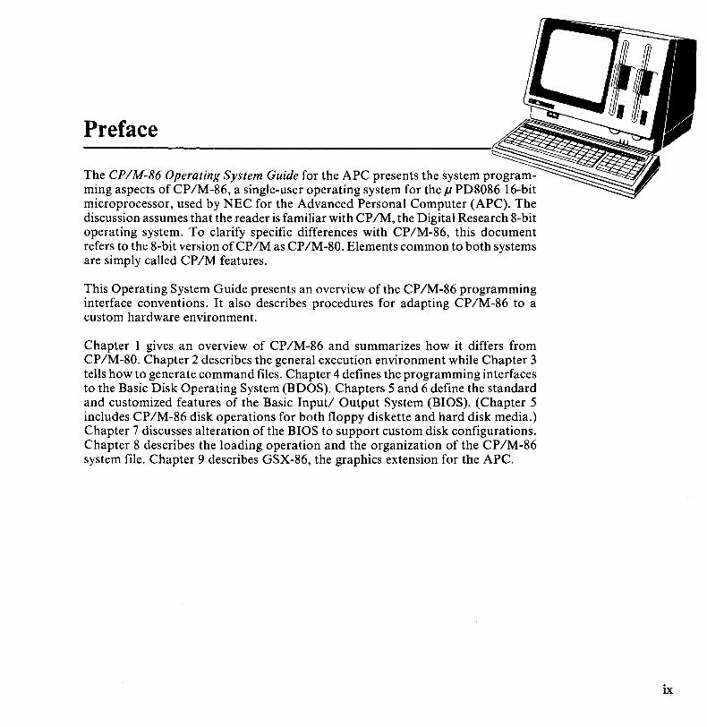
The CPIM-86 Operating System Guide for the APC presents the system programming aspects of CP/M-86, a single-user operating system for the Jl PD8086 16-bit microprocessor, used by NEC for the Advanced Personal Computer (APC). The discussion assumes that the reader is familiar with CP/M, the Digital Research 8-bit operating system. To clarify specific differences with CP/M-86, this document refers to the 8-bit version of CP/M as CP/M-80. Elements common to both systems are simply called CP/M features.
This Operating System Guide presents an overview of the CP/M-86 programming interface conventions. It also describes procedures for adapting CP /M-86 to a custom hardware environment.
Chapter 1 gives an overview of CP/M-86 and summarizes how it differs from CP/M-80. Chapter 2 describes the general execution environment while Chapter 3 tells how to generate command files. Chapter 4 defines the programming interfaces to the Basic Disk Operating System (BDOS). Chapters 5 and 6 define the standard and customized features of the Basic Input/ Output System (BIOS). (Chapter 5 includes CP/M-86 disk operations for both floppy diskette and hard disk media.) Chapter 7 discusses alteration of the BIOS to support custom disk configurations. Chapter 8 describes the loading operation and the organization of the CP /M-86 system file. Chapter 9 describes GSX-86, the graphics extension for the APC.
ix

Chapter 1
CP IM-86 System Overview CP/M-86 GENERAL CHARACTERISTICS
CP/M-86 consists of all the facilities of CP/M-80 with additional features to account for increased processor address space of up to one megabyte (1,048,576) of main memory. CP/M-86 maintains file compatibility with all previous versions of CP/M. It uses the file structure of CP/M Version 2, allowing as many as sixteen drives with up tb eight megabytes on each drive. CP/M-80 and CP/M-86 programs may exchange files without any modification to the file formats.
CP/M-86 resides in the file CPM.SYS, which is loaded into memory by a cold start loader during system initialization. The cold start loader resides on the first two tracks of the system disk. CPM.SYS contains three program modules: the Console Command Processor (CCP), the Basic Disk Operating System (BDOS), and the Basic Input/Output System (BIOS). The BIOS distributed on the CP/M system diskette has been configured for the APC and is called the Customized BIOS, or CBIOS. It is made up of three parts: the standard BIOS, the APC escape sequence functions, and the extended BIOS. The CCP and BDOS portions occupy approximately 10K bytes, and the BIOS is approximately 22 bytes. The operating system executes in memory above the reserved interrupt locations. The remainder of the address space may be partitioned into eight non-contiguous regions, as defined in a BIOS table. Unlike CP/M-80, CP/M-86 does not allow the CCP area to be used as a data area subsequent to transient program load. All CP/M-86 modules remain in memory at all times and are not reloaded at a warm start.
Like CP/M-80, CP/M-86 loads and executes memory image files from disk. Memory image files are preceded by a header record, defined in Chapter 3, which provides information required for proper program loading and execution. Memory image files under CP/M-86 are identified by the CMD file type exte.nsion.
1-1

CP/M-86 System Overview
1-2
Unlike CP/M-80, CP/M-86 does not use absolute locations for system entry or default variables. The BDOS entry takes place through a reserved software interrupt. Entry to the BIOS is provided by a new BDOS call. Entry to the extended BIOS is made directly through an interrupt vector. Two variables maintained in low memory under CP/M-80, the default disk number and I/O Byte, are placed in the CCP and BIOS respectively in CP/M-86. Dependence on absolute addresses is minimized in CP/M-86 by maintaining inital base page values, such as the default File Control Block and default command buffer, in the transient program data area.
Utility programs such as ED, PIP, STAT, and SUBMIT operate in the same manner under CP/M-86 and CP/M-80. DDT-86 allows interactive debugging of 8086 machine code. ASM-86 allows assembly language programming and development for the 8086 using Intel-like mnemonics.
CP/M-86 includes two utilities that replace equivalent CP/M-80 utilities .
• GENCMD (Generate CMD file) replaces the LOAD program ofCP/M-80. It converts the hex files produced by ASM-86 or Intel utilities into memory image format suitable for execution under CP/M-86 .
• LDCOPY (Loader Copy) replaces the SYSGEN utility used under CP/M-80. It is used to copy the cold start loader from a system disk for replication.
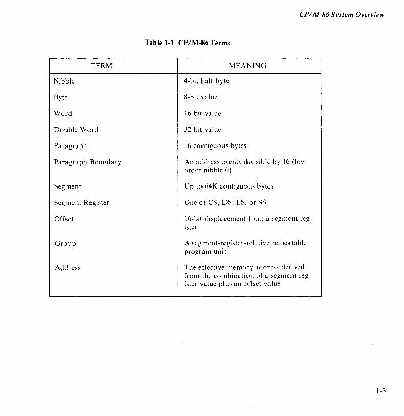
Several terms used throughout this manual are defined in Table 1-1.
A group consists of segments that are loaded into memory as a single unit. Since a group may consist of more than 64 bytes, it is the responsibility of the application program to manage segment registers when accessing code or data beyond the first 64K segment.
CP/M-86 supports eight program groups: the code, data, stack, and extra groups, and four auxiliary groups. When a code, data, stack, or extra group is loaded, CP/M-86 sets the respective segment register (CS, DS, SS or ES) to the base of the group. CP/M-86 can also load four auxiliary groups. A transient program manages the location of the auxiliary groups using values stored by CP/M-86 in the user's base page.
CPIM-86 System Overview
Table 1-1 CP/M-86 Terms
TERM MEANING
Nibble 4-bit half-byte
Byte 8-bit value
Word 16-bit value
Double Word 32-bit value
Paragraph 16 contiguous bytes
Paragraph Boundary An address evenly divisible by 16 (low order nibble 0)
Segment Up to 64K contiguous bytes
Segment Register One of CS, OS, ES, or SS
Offset 16-bit displacement from a segment reg-ister
Group A segment-register-rela tive reloca table program unit
Address The effective memory address derived from the combination of a segment reg-ister value plus an offset value
1-3
CPIM-86 System Overview
1-4
CP/M-80 AND CP/M-86 DIFFERENCES
The structure of CP/M-86 is as close to CP/M-80 as possible. This provides a familiar programming environment which allows application programs to be transported to the 8086 processor with minimal effort. This section points out specific differences between CP/M-80 and CP/M-86 to reduce your time in scanning the manual if you are already familiar with CP /M-80. The terms and concepts presented in this section are explained in detail throughout the manual, so refer to the Table of Contents for the relevant chapters which provide specific definitions and information.
Relocatable Groups
The fundamental difference between CP/M-80 and CP/M-86 is found in the management of the various relocatable groups. Although CP/M-80 references absolute memory locations by necessity, CP /M-86 takes advantage of the static relocation inherent in the 8086 processor. The operating system itself is loaded directly above the interrupt locations, at location 0400H, and relocatable transient programs load in the best fit memory region. However, you can load CP /M-86 into any portion of memory without changing the operating system (thus, there is no MOVCPM utility with CP /M-86), and transient programs will load and run in any non-reserved region.
Memory Models
CP/M-86 is constructed as an 8080 Model. This means that all the segment registers are placed at the base of CP/M-86, and the CBIOS is identical in most respects to that of CP IM-80 (with changes in instruction mnemonics, of course). In fact, the only additions are found in the SETDMAB, GETSEGB, SETIOB, and GETIOB entry points in the BIOS, the additions for hard disk I/O, and the custom APC features in the extended functions. The warm start subroutine is simpler since you are not required to reload the CCP and BDOS under CP/M-86. If you implement the IOBYTE facility, you have to define the variable in your BIOS. Taking these changes into account, you need only perform a simple translation of your CP/M-80 BIOS into 8086 code to implement the 8086 BIOS.
Disk Definition Tables
The disk definition tables included with CP /M-86 for the APC have been developed, configured, and included in the CBIOS. Therefore, there is no need to generate your own disk definition tables using GENDEF.
Bootstrap Operation
CP/M-86 resides on the first two tracks of the double-sided, double-density system distribution diskette. It is loaded by a single step bootstrap loader operation.

CPIM-86 System Overview
BDOS Calls
To make a BDOS system call, use the reserved software interrupt #224. The jump to the BDOS at location 0005H found in CP/M-80 is not present in CP/M-86. However, the address field at offset 0006 is present so that programs which "size" available memory using this word value will operate without change. CP IM-80 BDOS functions use certain 8080 registers for entry parameters and returned values. CP/M-86 BDOS functions use a table of corresponding 8086 registers. For example, the 8086 registers CH and CL correspond to the 8080 registers Band C. Look through the list of BDOS function numbers in Table 4-2. You'll find that functions 0, 27, and 31 have changed slightly. Several new functions have been added, but they do not affect existing programs.
Addressing
A major difference between the two CP 1M operating systems is their approach to addressing. In CP/M-80, all addresses sent to the BDOS are 16-bit values in the range OOOOH to OFFFFH. In CP/M-86, the addresses are 16-bit offsets from the DS (Data Segment) register, which is set to the base of your data area. If you translate an existing CP/M-80 program to the CP/M-86 environment, the data segment is fewer than 64K bytes. Therefore, the DS register does not have to be changed following intialload, and all CP IM-80 addresses become simple DS-relative offsets in CP/M-86.
Program Termination
Under CP/M-80, programs terminate in one of three ways:
• return directly to the CCP;
• call BDOS function 0;
• transfer control to absolute location OOOOH.
CP/M-86, however, supports only the first two methods of program termination. Consequently, the automatic disk system reset that follows ajump to OOOOH is not performed. Instead, disk system reset is accomplished by entering a CONTROL-C at the CCP level.
Many new facilities in CP IM-86 simplify programming and expand application programming capability. CP/M-86 was designed to make it easy to get started. If you are converting from CP 1M -80 to CP 1M -86, there are no major changes beyond the translation to 8086 machine code.
1-5

Chapter 2
Command Setup and Execution Under CP 1M -86 This chapter discusses the operation of the Console Command Processor, the format of transient programs, CP/M-86 memory models, and memory image formats.
CCP BUILT-IN AND TRANSIENT COMMANDS
The operation of the CP/M-86 Console Command Processor (CCP) is similar to that of CP/M-80's CCP. At initial cold start, it prints the CP/M sign-on message, automatically logs in Drive A, and issues the standard prompt at the console. CP /M-86 then waits for input command lines from the console.
The command line may include one of the built-in commands: DIR, ERA, REN, TYPE, or USER. (Note that SAVE is not supported under CP/M-86 since the equivalent function is performed by DDT-86.) See the CPIM-86 User's Guide for the APC for more information about these programs.
The command line may also begin with the name of a transient program with the assumed file type CMD, denoting a commandfile. The CMD file type differentiates transient command files used under CP/M-86 from COM files, which operate under CP /M-80.
The CCP allows multiple programs to reside in memory, providing facilities for background tasks. A transient program may load additional programs for execution under its own control.
2-1
Command Setup and Execution Under CP / M-86
2-2
For example, a background printer spooler could first be loaded, followed by an execution ofDDT-S6. DDT-S6 may, in turn, load a test program for a debugging session and transfer control to the test program between breakpoints. CP/M-S6 keeps track of the order in which programs are loaded and, upon encountering a CONTROL-C, discontinues execution of the program most recently activated at the CCP level. In this example, a CONTROL-C at the DDT-86 command level aborts DDT-S6 and its test program. A second CONTROL-C at the CCP level aborts the background printer spooler. A third CONTROL-C resets the disk system.
Note that program abort due to CONTROL-C does not reset the disk system, as is the case in CP/M-SO. A disk reset does not occur unless the CONTROL-C occurs at the CCP command input level with no programs residing in memory.
When CP/M-S6 receives a request to load a transient program from the CCP or another transient program, it checks the program's memory requirements. If sufficient memory is available, CP /M-86 assigns the required amount of memory to the program and loads it. Once loaded, the program can request additional memory from the BDOS for buffer space. When the program is terminated, CP/M-S6 frees both the program memory area and any additional buffer space.
TRANSIENT PROGRAM EXECUTION MODELS
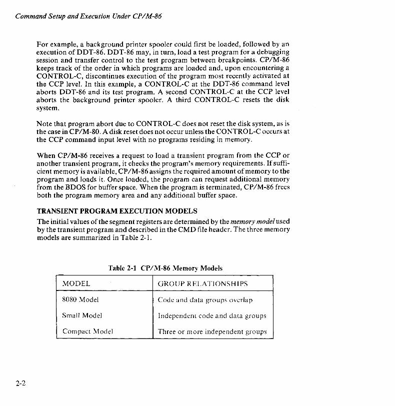
The initial values of the segment registers are determined by the memory model used by the transient program and described in the CMD file header. The three memory models are summarized in Table 2-1.
Table 2-1 CP/M-86 Memory Models
MODEL GROUP RELATIONSHIPS
8080 Model Code and data groups overlap
Small Model Independent code and data groups
Compact Model Three or more independent groups
Command Setup and Execution Under CPIM-86
The 8080 Model supports programs which are directly translated from CP IM-80 when code and data areas are intermixed. The 8080 model consists of one group which contains all the code, data, and stack areas. Segment registers are initialized to the starting address of the region containing this group. The segment registers can, however, be managed by the application program during execution so that multiple segments within the code group can be addressed.
The Small Model is similar to that defined by Intel, where the program consists of independent code and data groups. The Small Model is suitable for use by programs taken from CP IM-80 where code and data are easily separated. The code and data groups often consist of, but are not restricted to, single 64K byte segments.
The Compact Model occurs when any of the extra, stack, or auxiliary groups is present in a program. Each group may consist of one or more segments, but if any group exceeds one segment in size, or if auxiliary groups are present, then the application program must manage its own segment registers during execution in order to address all code and data areas.
In all three models, local stacks are required in user programs that make BDOS calls since the BDOS may change information in the system stack.
The three models differ primarily in the manner in which segment registers are~ initialized upon transient program loading. The operating system program load function determines the memory model used by a transient program by examining the program group usage, as described in the following sections of this chapter.
The 8080 Memory Model
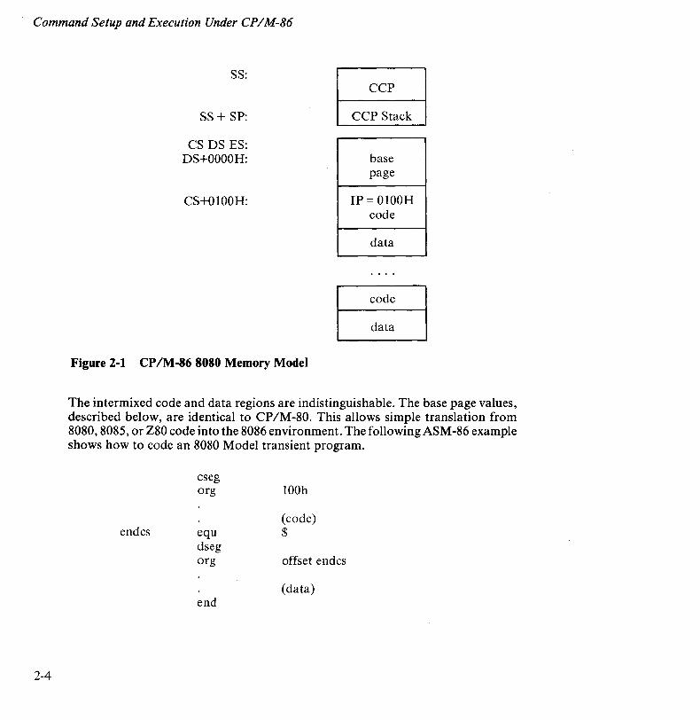
The 8080 Model is assumed when the transient program contains only a code group. In this case, the CS, DS, and ES registers are initialized to the beginning of the code group, while the SS and SP registers remain set to a 96-byte stack area in the CCP. The Instruction Pointer Register (IP) is set to 100H, as in CP IM-80, thus allowing base page values at the beginning of the code group. Following program load, the 8080 Model appears as shown in Figure 2-1, where low addresses are at the top of the diagram.
2-3
Command Setup and Execution Under CPIM-86
2-4
SS:
SS + SP:
CS DS ES: DS+OOOOH:
CS+OIOOH:
CCP
CCP Stack
base page
IP = OIOOH code
data
~ ~
Figure 2-1 CP 1M -86 8080 Memory Model
The intermixed code and data regions are indistinguishable. The base page values, described below, are identical to CP/M-80. This allows simple translation from 8080,8085, or Z80 code into the 8086 environment. The following ASM-86 example shows how to code an 8080 Model transient program.
cseg org 100h
(code) endcs equ $
dseg org offset endcs
(data) end
Command Setup and Execution Under CPIM-86
The Small Memory Model
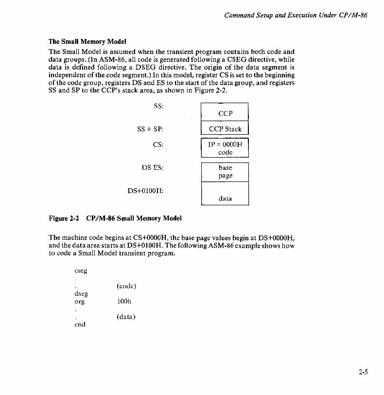
The Small Model is assumed when the transient program contains both code and data groups. (In ASM-86, all code is generated following a CSEG directive, while data is defined following a DSEG directive. The origin of the data segment is independent of the code segment.) In this model, register CS is set to the beginning of the code group, registers DS and ES to the start of the data group, and registers SS and SP to the CCP's stack area, as shown in Figure 2-2.
SS: CCP
SS + SP: CCP Stack
CS: IP = OOOOH code
DS ES: base page
DS+OI00H: data
Figure 2-2 CP/M-86 Small Memory Model
The machine code begins at CS+OOOOH, the base page values begin at DS+OOOOH, and the data area starts at DS+OI00H. The following ASM-86 example shows how to code a Small Model transient program.
cseg
(code) dseg org 100h
(data) end
2-5

Command Setup and Execution Under CPIM-86
2-6
The Compact Memory Model
The Compact Memory Model is assumed when code and data groups are present, along with one or more of the stack, extra, or auxiliary groups. In this case, the CS, DS, and ES registers are set to the base addresses of their respective areas. Figure 2-3 shows the initial configuration of segment registers in the Compact Model. The segment register values can be changed during program execution by loading from the initial values placed in base page by the CCP, thus allowing access to the entire memory space.
SS: CCP
SS + SP: CCP Stack
CS: IP = OOOOH code
DS: base page
DS+OI00H: data
ES: data
Figure 2-3 CP/M-86 Compact Memory Model
Local stacks are required in programs that make BDOS calls since the BDOS may change information in the system stack. If the transient program intends to use the stack group as a stack area, registers SS and SP must be set upon entry. The SS and SP registers remain set to the CCP area, even if a stack group is defined. Although it may appear that the SS and SP registers should be set to address the stack group, there are two reasons this cannot be done. First, the transient program may be using the stack group as a data area. In that case, the Far Call instruction used by the CCP to transfer control to the transient program could write over data in the stack area. Second, the SS register would logically be set to the base of the group, while the SP register would be set to the offset of the end of the group. However, if the stack group exceeds 64K, the address range from the base to the end of the group could exceed a 16-bit offset value.
Command Setup and Execution Under CPIM-86
The following ASM-86 example shows how to code a Compact Model transient program.
cseg
(code) dseg org 100h
(data) eseg
(more data) sseg
(stack area) end
Base Page Initialization
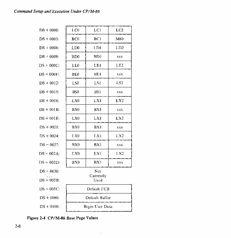
As in CP/M-80, the CP/M-86 base page contains default values and locations initialized by the CCP and used by the transient program. The base page occupies the regions from offset OOOOH through OOFFH relative to the DS register. The values in the base page for CP/M-86 include those of CP/M-80 and appear in the same relative positions, as shown in Figure 2-4.
Each byte is indexed by 0, I, and 2, corresponding to the standard Intel storage convention of low, middle, and high-order (most significant) byte. In Figure 2-4, "xxx" marks unused bytes. LC is the last code group location (24 bits, where the 4 high-order bits equal zero).
In the 8080 Model, the low order bytes of LC (LCO and LC 1) never exceed OFFFFH and the high order byte (LC2) is always zero. BC is the base paragraph address of the code group (16-bits). LD and BD provide the last position and paragraph base of the data group. The last position is one byte less than the group length. Note that bytes LDO and LD 1 appear in the same relative positions of the base page in both CP /M-80 and CP /M-86, thus easing the program translation task. The M80 byte is equal to 1 for the 8080 Model. LE and BE provide the length and paragraph base of the optional extra group, while LS and BS give the optional stack group length and base. The bytes marked LX and BX correspond to a set of four optional, independent groups which may be required for programs that execute using the Compact Model. The initial values for these descriptors are derived from the header record in the memory image file, described in Chapter 3.
2-7
Command Setup and Execution Under CPIM-86
2-8
DS + 0000:
DS + 0003:
DS + 0006:
DS + 0009:
DS + OOOC:
DS + OOOF:
DS + 0012:
DS + 0015:
DS + 0018:
DS + 001B:
DS + OOIE:
DS + 0021:
DS + 0024:
DS + 0027:
DS + 002A:
DS + 002D:
DS + 0030:
DS + 005B:
DS + 005C:
DS + 0080:
DS + 0100:
LCO
BCO
LDO
BDO
LEO
BEO
LSO
BSO
LXO
BXO
LXO
BXO
LXO
BXO
LXO
BXO
LCI
BCl
LDI
BDI
LEI
BEl
LSI
BSI
LXI
BXl
LXI
BXI
LXI
BXl
LXI
BXI
Not Currently
Used
Default FCB
Default Buffer
Begin User Data
Figure 2-4 CP/M-86 Base Page Values
LC2
M80
LD2
xxx
LE2
xxx
LS2
xxx
LX2
xxx
LX2
xxx
LX2
xxx
LX2
xxx
Command Setup and Execution Under CPIM-86
TRANSIENT PROGRAM LOAD
Like CP/M-80, the CCP in CP/M-86 parses up to two file names following the command and places the properly fomatted File Control Blocks (FCBs) at locations 005CH and 006CH in the base page relative to the DS register. Under CP/M-80, the default DMA address is initialized to 0080H in the base page. However, due to the segmented memory of the 8086 processor, the DMA address is divided into two parts: the DMA segment address the DMA offset. Therefore, under CP/M-86, the default DMA base is initialized to the value of DS, and the default DMA offset is initialized to 0080H. Thus, CP /M-80 and CP /M-86 operate in the same way: both assume the default DMA buffer occupies the second half of the base page.
TRANSIENT PROGRAM EXIT
The CCP transfers control to the transient program through an 8086 "Far Call". The transient program may exit in one of three ways.
• It can use the 96-byte CCP stack and return directly to the CCP upon program termination by executing a "Far Return". If BDOS calls are to be made, the transient program requires its own stack.
• Program termination can occur when BDOS function 0 is executed. Function 0 can terminate a program without removing the program from memory or changing the memory allocation state (see Chapter 4).
• The operator can terminate program execution by pressing CONTROL-C during line edited input. This has the same effect as the program executing BDOS function O. No disk reset occurs and the CCP and BDOS modules are not reloaded from disk upon program termination.
2-9

Chapter 3
Command (CMD) File Generation The GENCMD utility program provided with CP/M-86 produces CMD memory image files suitable for execution under CP/M-86.
INTEL 8086 HEX FILE FORMAT
GENCMD input is in Intel hex format produced by either the Digital Research ASM-86 assembler (see the CPIM-86 Programmer's Guide for the APC) or the standard Intel OH86 utility program (see Intel document #9800639-03, MCS-86 Software Development Utilities Operatinglnstructionsfor ISIS-II Users). The CMD file produced by GENCMD contains a header record which defines the memory model and memory size requirements for loading and executing the CMD file.
An Intel hex file consists of the traditional sequence of ASCII records in the following format:
where the beginning of the record is marked by an ASCII colon, and each subsequent digit position contains an ASCII hexadecimal digit in the range 0-9 or A-F. The fields are defined in Table 3-1.
3-1

Command (CMD) File Generation
Table 3-1 Intel Hex Field Definitions
FIELD CONTENTS
11 Record Length OO-FFH (0-255 in decimal)
aaaa Load Address
It Record Type: 00 data record, loaded starting at offset
aaaa from current base paragraph
01 end of file (cc = FF)
02 extended address (aaaa is paragraph base for subsequent records)
03 start address is aaaa (ignored, IP set according to memory model in use)
The following are output from ASM-86 only:
81 Same as 00, data belongs to code segment
82 Same as 00, data belongs to data segment
83 Same as 00, data belongs to stack segment
84 Same as 00, data belongs to extra segment
85 Paragraph address for absolute code segment
86 Paragraph address for absolute data segment
87 Paragraph address for absolute stack segment
88 Paragraph address for absolute extra segment
d Data Byte
cc Check Sum (OO-sum of previous digits, FF for end of file)
All characters preceding the colon for each record are ignored.
3-2
Command (CMD) File Generation
OPERATION OF GENCMD
The GENCMD utility is invoked at the CCP level by the following command.
GENCMD filename parameter-list
wherefilename corresponds to the hex input file with an assumed (and unspecified) file type ofH86. GENCMD accepts optional parameters to specifically identify the 8080 Memory Model and to describe the memory requirements of each segment group. The GENCMD parameters are listed following the filename. The list consists of a sequence of keywords and associated values. The keywords are:
8080 CODE DATA EXTRA STACK Xl X2 X3 X4
The 8080 keyword forces a single code group so that the BDOS load function sets up the 8080 Memory Model for execution. This model allows intermixed code and data within a single segment. This form of the command is shown below.
GENCMD filename 8080
The remaining keywords follow the filename or the 8080 option and define specific memory requirements for each segment group corresponding one-to-one with the segment groups defined in Chapter 2.
For each segment group keyword, the corresponding values are enclosed in square brackets and separated by commas. Each value is a hexadecimal number representing a paragraph address or segment length in paragraph units (denoted by hhhh below). Each value is prefixed by a single letter, which defines its meaning.
Ahhhh Bhhhh Mhhhh Xhhhh
Load the group at absolute location hhhh. The group starts at hhhh in the hex file. The group requires a minimum of (hhhh * 16) bytes. The group can address a maximum of (hhhh * 16) bytes.
3-3

Command (CMD) File Generation
3-4
Generally, the CMD file header values are derived directly from the hex file and the parameters shown above need not be included. The following situations, however, require the use of GENCMD parameters.
• Use the 8080 keyword whenever ASM-86 is used to convert 8080 programs that have code and data intermixed within a single 64K segment, regardless of the use of the CSEG and DSEG directives in the source program.
• Use an absolute address (A value) for any group which must be located at an absolute location. Normally, this value is not specified since CP/M-86 cannot generally ensure that the required memory region is available (in which case the CMD file cannot be loaded). "
• Use the B value when GENCMD processes a hex file produced by Intel's OH86 or a similar utility program that contains more than one group. The output from OH86 consists of a sequence of data records with no information to identify code, data, extra, stack, or auxiliary groups. The B value marks the beginning address of the group named by the keyword, causing GENCMD to load data following this address to the named group (see the examples that follow). The B value is normally used to mark the boundary between code and data segments when no segment information is included in the hex file. Files produced by ASM -86 do not require the B value since segment information is included in the hex file.
• The minimum memory value (M value) is included only when the hex records do not define the minimum memory requirements for the named group. Generally, the code group size is determined precisely by the data records loaded into the area. That is, the total space required for the group is defined by the range between the lowest and highest data byte addresses. The data group, however, may contain un initialized storage at the end of the group and thus no data records are present in the hex file which define the highest referenced data item. The highest address in the data group should be defined within the source program by including "DBO" as the last data item. Alternatively, the M value can be included to allocate the additional space at the end of the group. The stack, extra, and auxiliary group sizes must be defined using the M value unless the highest addresses within the groups are implicitly defined by data records in the hex file.
Command (CMD) File Generation
• The maximum memory size (X value) is generally used when additional free memory may be needed for such purposes as 1/0 buffers or symbol tables. If the data area size is fixed, the X parameter need not be included. In this case, the X value is assumed to be the same as the M value. The value XFFFF allocates the largest memory region available but if it is used, the transient program must know that a three-byte length field is produced in the base page for this group where the high order byte may be non-zero. Programs converted directly from CP/M-SO, or programs that use a twobyte pointer to address buffers, should restrict this value to XFFF or less, producing a maximum allocation length of OFFFOH bytes.
For example, the following GENCMD command line transforms the file X.HS6 into the file X.CMD with the proper header record.
gencmd x code[a40] data[m30,xfff]
In this case, the code group is forced to paragraph address 40H or, equivalently, byte address 400H. The data group requires a minimum of300H bytes, but can use up to OFFFOH bytes, if available.
As another example, assume a file Y .H86 exists on Drive B and consists of Intel hex records with no interspersed segment information. The command
gencmd b:y data[b30,m20] extra[b50] stack[m40] xl[m40]
produces the file Y.CMD on Drive B by selecting records beginning at address OOOOH for the code segment, and records beginning at address 300H for the data segment. The extra segment is filled from records beginning at 500H, while the stack and auxiliary segment #1 are uninitialized areas requiring a minimum of 400H bytes each. In this example, the data area requires a minimum of200H bytes. Note again that the B value need not be included if the Digital Research ASM-86 assembler is used.
3-5
Command (CMD) File Generation
3-6
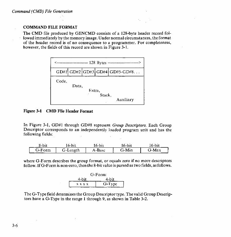
COMMAND FILE FORMAT The CMD file produced by GENCMD consists of a 128-byte header record followed immediately by the memory image. Under normal circumstances, the format of the header record is of no consequence to a programmer. For completeness, however, the fields of this record are shown in Figure 3-1.
<---------------------- 128 Bytes ---------------------->
GD#I\ GD#2\GD#3JGD#41 GD#5-GD#8 ...
Code, Data,
Extra, Stack,
Auxiliary
Figure 3-1 CMD File Header Format
In Figure 3-1, GD#1 through GD#8 represent Group Descriptors. Each Group Descriptor corresponds to an independently loaded program unit and has the following fields:
8-bit 16-bit 16-bit 16-bit 16-bit G-Form G-Length A-Base G-Min G-Max
where G-Form describes the group format, or equals zero if no more descriptors follow. If G-Form is non-zero, then the 8-bit value is parsed as two fields, as follows.
G-Form: 4-bit 4-bit
x x x x G-Type
The G-Type field determines the Group Descriptor type. The valid Group Descriptors have a G-Type in the range I through 9, as shown in Table 3-2.
Command (CMD) File Generation
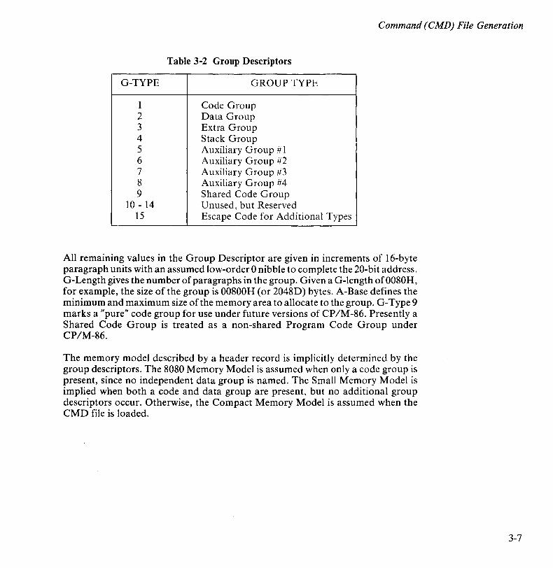
Table 3-2 Group Descriptors
G-TYPE GROUP-TYPE
1 Code Group 2 Data Group 3 Extra Group 4 Stack Group 5 Auxiliary Group # 1 6 Auxiliary Group #2 7 Auxiliary Group #3 8 Auxiliary Group #4 9 Shared Code Group
10 - 14 Unused, but Reserved 15 Escape Code for Additional Types
All remaining values in the Group Descriptor are given in increments of 16-byte paragraph units with an assumed low-order 0 nibble to complete the 20-bit address. G-Length gives the number of paragraphs in the group. Given a G-Iength of0080H, for example, the size of the group is 00800H (or 2048D) bytes. A-Base defines the minimum and maximum size of the memory area to allocate to the group. G-Type 9 marks a "pure" code group for use under future versions of CP/M-86. Presently a Shared Code Group is treated as a non-shared Program Code Group under CP/M-86.
The memory model described by a header record is implicitly determined by the group descriptors. The 8080 Memory Model is assumed when only a code group is present, since no independent data group is named. The Small Memory Model is implied when both a code and data group are present, but no additional group descriptors occur. Otherwise, the Compact Memory Model is assumed when the CMD file is loaded.
3-7


Chapter 4
Basic Disk Operating System (BDOS) Functions This chapter presents the interface conventions which allow transient program access to CP 1M -86 BOOS functions. The BOOS calls correspond closely to CP IM-80 Version 2 in order to simplify translation of existing CP/M-80 programs for operation under CP IM-86. BOOS entry and exit conditions are described first, followed by the individual BOOS function calls.
BDOS PARAMETERS
Entry to the BOOS is accomplished through the 8086 software interrupt #224, which is reserved by Intel Corporation for use by CP/M-86. The function code is passed in register CL, with byte parameters in OL and word parameters in ox. Single byte values are returned in AL, word values in both AX and BX, and double-word values in ES and BX. All segment registers, except ES, are saved upon entry and restored upon exit from the BOOS (corresponding to PL/M-86 conventions). Table 4-1 summarizes input and output parameter passing.
Table 4-1 BDOS Parameter Summary
BOOS ENTRY REGISTERS BOOS RETURN REGISTERS
CL Function Code Byte value returned in AL DL Byte Parameter Word value returned in both AX and BX DX Word Parameter Double-word value returned with DS Data Segment offset in BX and
segment in ES
4-1

Basic Disk Operating System (BDOS) Functions
4-2
The CP/M -80 BDOS requires an "information address" as input to various functions. This address usually provides buffer or File Control Block information used in the system call. In CP/M-86, however, the information address is derived from the current DS register combined with the offset in the DX register. That is, the DX register in CP/M-86 performs the same function as the DE pair in CP/M-80, assuming that DS is properly set. This poses no particular problem for programs which use only a single data segment, as is the case for programs converted from CP/M-80. However, when the data group exceeds a single segment, you must ensure that the DS register is set to the segment containing the data area related to the call. Zero values are returned for function calls which are out of range.
BDOS FUNCTION CODES
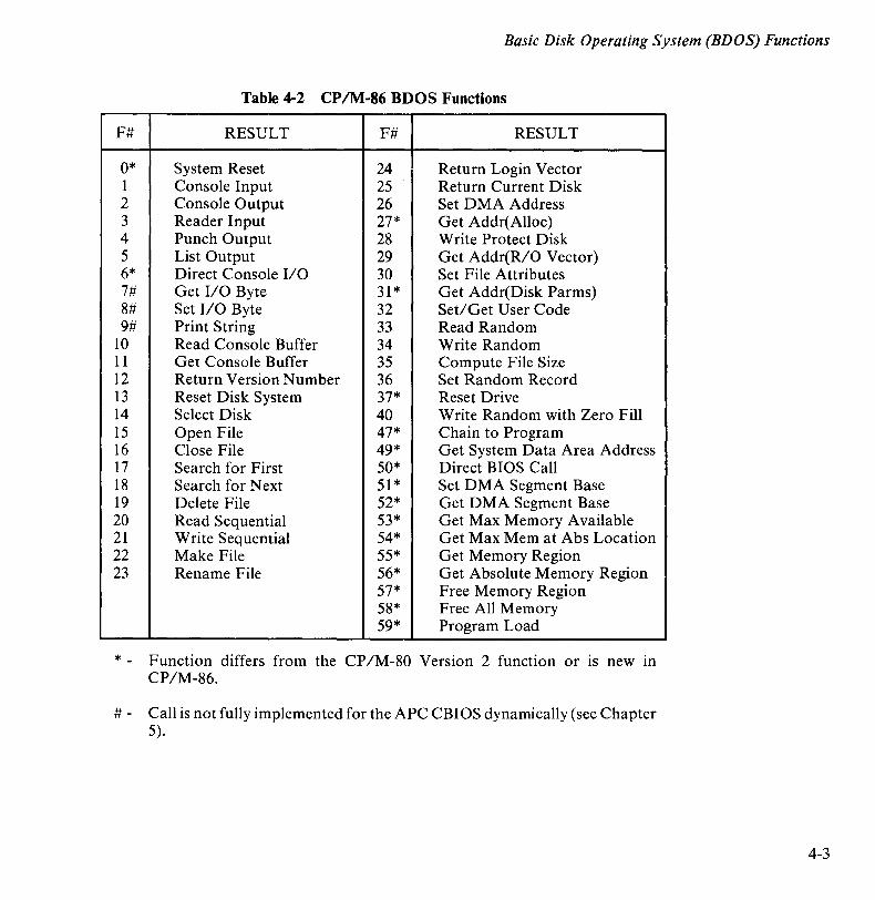
Table 4-2 lists the CP /M-86 BDOS function calls. The individual BDOS functions are described in the following three sections of this chapter. The function calls are grouped into simple functions, file operations, and memory management and program loading functions.
Basic Disk Operating System (BDOS) Functions
Table 4-2 CP/M-86 BDOS Functions
F# RESULT F# RESULT
0* System Reset 24 Return Login Vector 1 Console Input 25 Return Current Disk 2 Console Output 26 Set DMA Address 3 Reader Input 27* Get Addr(Alloc) 4 Punch Output 28 W rite Protect Disk 5 List Output 29 Get Addr(R/O Vector) 6* Direct Console I/O 30 Set File Attributes 7# Get I/O Byte 31* Get Addr(Disk Parms) 8# Set I/O Byte 32 Set/ Get User Code 9# Print String 33 Read Random
10 Read Console Buffer 34 Write Random 11 Get Console Buffer 35 Compute File Size 12 Return Version Number 36 Set Random Record 13 Reset Disk System 37* Reset Drive 14 Select Disk 40 Write Random with Zero Fill 15 Open File 47* Chain to Program 16 Close File 49* Get System Data Area Address 17 Search for First 50* Direct BIOS Call 18 Search for Next 51* Set DMA Segment Base 19 Delete File 52* Get DMA Segment Base 20 Read Sequential 53* Get Max Memory Available 21 Write Sequential 54* Get Max Mem at Abs Location 22 Make File 55* Get Memory Region 23 Rename File 56* Get Absolute Memory Region
57* Free Memory Region 58* Free All Memory 59* Program Load
* - Function differs from the CP/M-80 Version 2 function or IS new in CP/M-86.
# - Call is not fully implemented for the APC CBIOS dynamically (see Chapter 5).
4-3
Basic Disk Operating System (BDOS) Functions
4-4
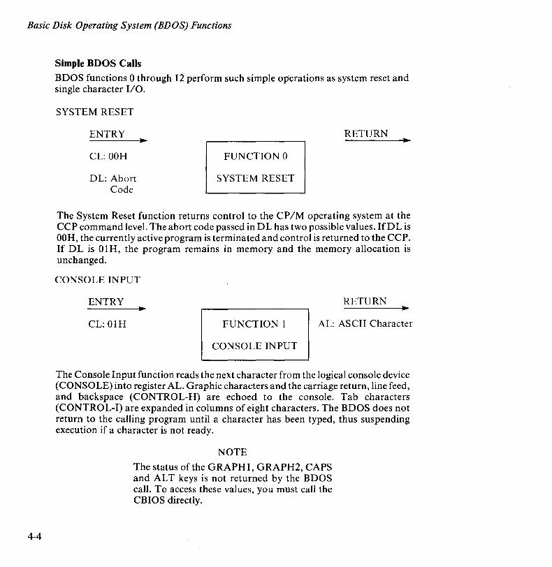
Simple BDOS Calls
BDOS functions 0 through 12 perform such simple operations as system reset and single character 1/0.
SYSTEM RESET
ENTRY
CL: OOH
DL: Abort Code
RETURN
FUNCTION 0
SYSTEM RESET
The System Reset function returns control to the CP 1M operating system at the CCP command level. The abort code passed in DL has two possible values. IfDL is OOH, the currently active program is terminated and control is returned to the CCP. If DL is 01H, the program remains in memory and the memory allocation is unchanged.
CONSOLE INPUT
ENTRY RETURN
CL: OlH FUNCTION 1 AL: ASCII Character
CONSOLE INPUT
The Console Input function reads the next character from the logical console device (CONSOLE) into register AL. Graphic characters and the carriage return, line feed, and backspace (CONTROL-H) are echoed to the console. Tab characters (CONTROL-I) are expanded in columns of eight characters. The BDOS does not return to the calling program until a character has been typed, thus suspending execution if a character is not ready.
NOTE
The status of the GRAPH1, GRAPH2, CAPS and AL T keys is not returned by the BDOS call. To access these values, you must call the CBIOS directly.

Basic Disk Operating System (BDOS) Functions
CONSOLE OUTPUT
ENTRY
CL: 02H
DL: ASCII Character
RETURN
FUNCTION 2
CONSOLE OUTPUT
The Console Output function sends the ASCII character in DL to the logical console. Tab characters expand in columns of eight characters. This function also makes a check for start/stop scroll (CONTROL-S).
READER INPUT
ENTRY RETURN
CL: 03H FUNCTION 3 AL: ASCII Charactel
READER INPUT
The Reader input function reads the next character from the logical reader (READER) into register AL. Control does not return to the calling program until a character has been read.
PUNCH OUTPUT
ENTRY
CL: 04H
DL: ASCII Character
RETURN
FUNCTION 4
PUNCH OUTPUT
The Punch Output function sends the ASCII character in register DL to the logical ·punch device (PUNCH).
4-5
Basic Disk Operating System (BDOS) Functions
4-6
LIST OUTPUT
ENTRY
CL: 05H
DL: ASCII Character
RETURN
FUNCTION 5
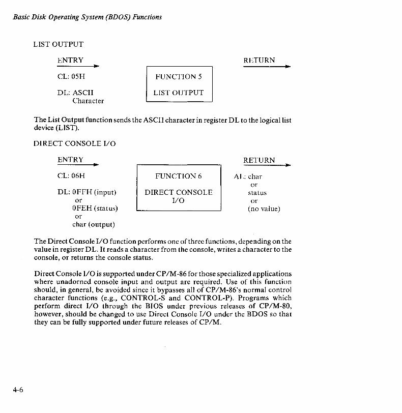
LIST OUTPUT
The List Output function sends the ASCII character in register DL to the logical list device (LIST).
DIRECT CONSOLE I/O
ENTRY
CL: 06H
DL: OFFH (input) or
OFEH (status) or
char (output)
FUNCTION 6
DIRECT CONSOLE I/O
RETURN
AL: char or
status or
(no value)
The Direct Console I/O function performs one of three functions, depending on the value in register DL. It reads a character from the console, writes a character to the console, or returns the console status.
Direct Console 1/0 is supported under CP/M-86 for those specialized applications where unadorned console input and output are required. Use of this function should, in general, be avoided since it bypasses all of CP/M-86's normal control character functions (e.g., CONTROL-S and CONTROL-P). Programs which perform direct I/O through the BIOS under previous releases of CP/M-80, however, should be changed to use Direct Console I/O under the BDOS so that they can be fully supported under future releases of CP/M.
Basic Disk Operating System (BDOS) Functions
Upon entry to function 6, register D L contains either (1) hexadecimal FF, denoting a CONSOLE input status request, (2) hexadecimal FE, denoting a CONSOLE status request, or (3) an ASCII character to be output to CONSOLE, where CONSOLE is the logical console device.
• If the input value is FF, function· 6 directly calls the BIOS console input function. If a character is ready, it is returned in AL; otherwise a zero is returned in AL.
• If the input value is FE, function 6 returns zero in register AL ifno character is ready, and FF in register AL otherwise.
• If the input value in DL is not FE or FF, function 6 sends the ASCII character in DL to the console.
Do not use function 6 (with FE of FF) in combination with either function 1 or function 2. Function 1 should be used in conjunction with function 2. Function 6 must be used independently.
GET I/O BYTE
ENTRY RETURN
CL: 07H FUNCTION 7 AL: I/O Byte Value
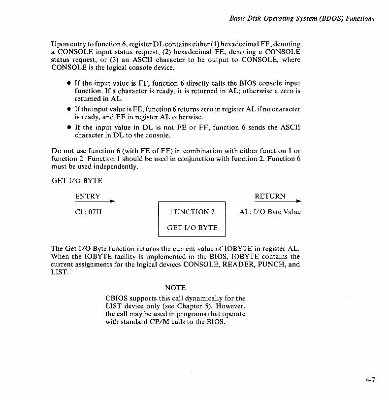
GET I/O BYTE
The Get I/O Byte function returns the current value of 10BYTE in register AL. When the 10BYTE facility is implemented in the BIOS, IOBYTE contains the current assignments for the logical devices CONSOLE, READER, PUNCH, and LIST.
NOTE
CBIOS supports this call dynamically for the LIST device only (see Chapter 5). However, the call may be used in programs that operate with standard CP/M calls to the BIOS.
4-7
Basic Disk Operating System (BDOS) Functions
4-8
SET I/O BYTE
ENTRY
CL: 08H
DL: I/O Byte Value
RETURN
FUNCTION 8
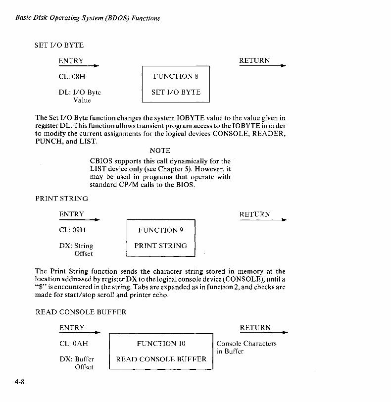
SET I/O BYTE
The Set I/O Byte function changes the system 10BYTE value to the value given in register DL. This function allows transient program access to the 10BYTE in order to modify the current assignments for the logical devices CONSOLE, READER, PUNCH, and LIST.
PRINT STRING
ENTRY
CL: 09H
NOTE
CBIOS supports this call dynamically for the LIST device only (see Chapter 5). However, it may be used in programs that operate with standard CP/M calls to the BIOS.
FUNCTION 9
DX: String Offset
PRINT STRING
RETURN
The Print String function sends the character string stored in memory at the location addressed by register DX to the logical console device (CONSOLE), until a "$" is encountered in the string. Tabs are expanded as in function 2, and checks are made for start/stop scroll and printer echo.
READ CONSOLE BUFFER
ENTRY
CL: OAH
DX: Buffer Offset
FUNCTION 10
READ CONSOLE BUFFER
RETURN
Console Characters in Buffer

Basic Disk Operating System (BDOS) Functions
The Read Console Buffer function reads a line of edited console input from the logical console device (CONSOLE) into a buffer addressed by register DX. Console input terminates when the input buffer is filled, or when either a return (CONTROL-M) or line feed (CONTROL-J) character is entered. The input buffer addressed by DX takes the following form.
DX: +0+1 +2+3+4+5+6+7+8 ... +n
Imxlncl ell c21 c31 c41c51c61 c71· . ·1 ?? I where mx is the maximum number of characters which the buffer will hold, and nc is the number of characters placed in the buffer. The characters entered by the operator follow the nc value. The value mx must be set prior to making a function 10 call and may range from 1 to 255. Setting mx to zero is equivalent to setting mx to one. The value nc is returned to the calling program and may range from 0 to mx. If nc is less than mx, then uninitialized positions follow the last character, denoted by "??" in the diagram. A terminating return or line feed character is not placed in the buffer and not included in the count nco
The line editing control functions supported during console input under function 1 0 are summarized in Table 4-3.
Table 4-3 Line Editing Controls
KEYSTROKE RESULT
DEL Removes and echoes the last character CONTROL-C Reboots when at the beginning of line CONTROL-E Causes physical end of line CONTROL-H Backspaces one character position CONTROL-J Terminates input line (line feed) CONTROL-M Terminates input line (return) CONTROL-R Retypes the current line after new line CONTROL-U Removes current line after new line CONTROL-X Backspaces to beginning of current line
Certain functions which return the carriage to the leftmost ~OSlt10n (e.g., CONTROL-X) do so only to the column position where the prompt ended. This convention makes operator data input and line correction more legible.
4-9
Basic Disk Operating System (BDOS) Functions
4-10
GET CONSOLE STATUS
ENTRY RETURN
CL: OBH FUNCTION 11 AL: Console Status
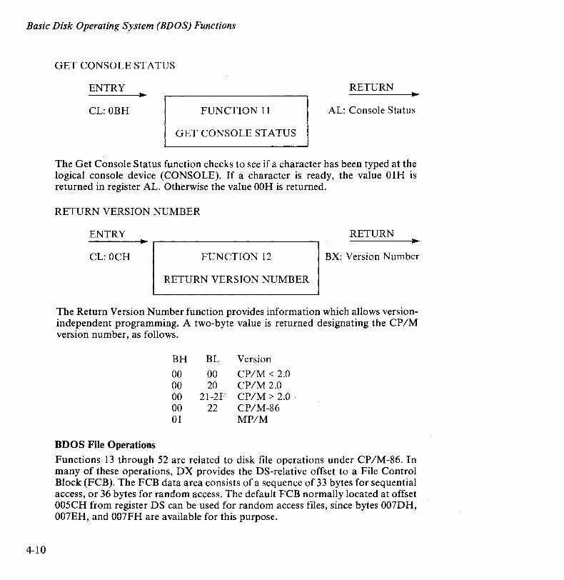
GET CONSOLE STATUS
The Get Console Status function checks to see if a character has been typed at the logical console device (CONSOLE). If a character is ready, the value 01H is returned in register AL. Otherwise the value OOH is returned.
RETURN VERSION NUMBER
ENTRY RETURN
CL: OCH FUNCTION 12 BX: Version Number
RETURN VERSION NUMBER
The Return Version Number function provides information which allows versionindependent programming. A two-byte value is returned designating the CP/M version number, as follows.
BDOS File Operations
BH
00 00 00 00 01
BL
00 20
2l-2F 22
Version
CP/M < 2.0 CP/M 2.0 CP/M> 2.0 CP/M-86 MP/M
Functions 13 through 52 are related to disk file operations under CP/M-86. In many of these operations, DX provides the DS-relative offset to a File Control Block (FCB). The FCB data area consists of a sequence of 33 bytes for sequential access, or 36 bytes for random access. The default FCB normally located at offset 005CH from register DS can be used for random access files, since bytes 007DH, 007EH, and 007FH are available for this purpose.
Basic Disk Operating System (BDOS) Functions
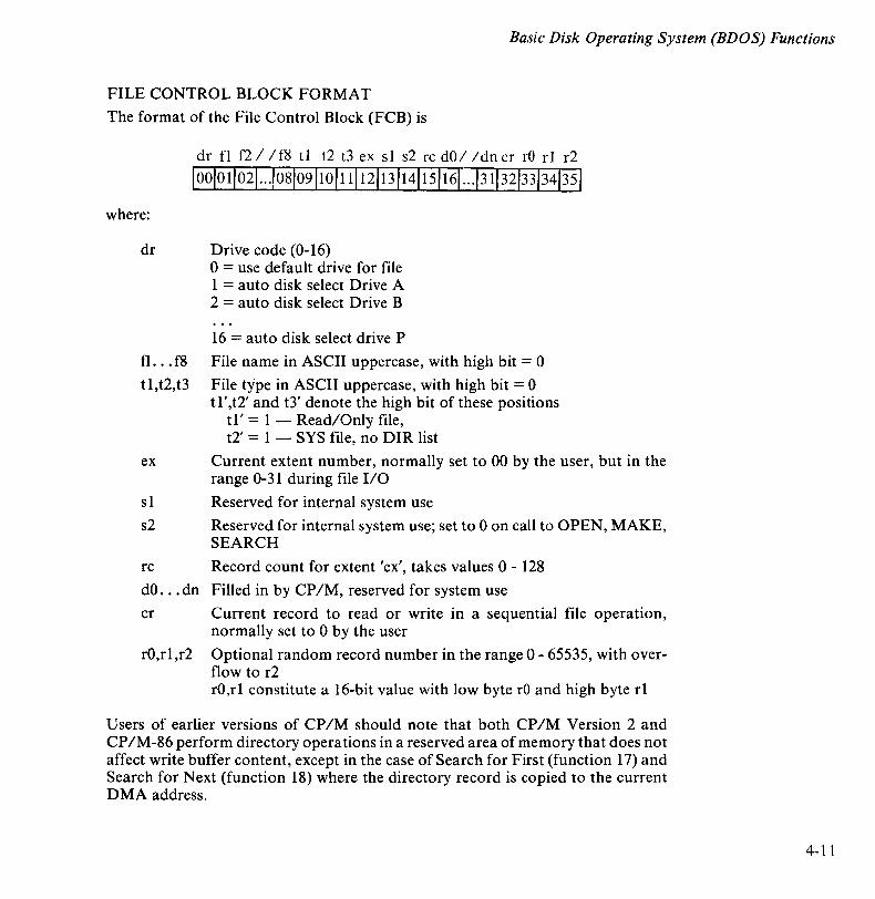
FILE CONTROL BLOCK FORMAT
The format of the File Control Block (FCB) is
dr fl f2 / / f8 t 1 t2 t3 ex s I s2 rc dO / / dn cr rO r1 r2
10010 11021 ... 1081091101111121131141151161 ... 1311321331341351
where:
dr Drive code (0-16) o = use default drive for file 1 = auto disk select Drive A 2 = auto disk select Drive B
16 = auto disk select drive P
fl ... f8 File name in ASCII uppercase, with high bit = 0
tl,t2,t3 File type in ASCII uppercase, with high bit = 0 tl',t2' and t3' denote the high bit of these positions
tl' = 1 - Read/Only file, t2' = 1 - SYS file, no DIR list
ex Current extent number, normally set to 00 by the user, but in the range 0-31 during file I/O
s 1 Reserved for internal system use
s2 Reserved for internal system use; set to 0 on call to OPEN, MAKE, SEARCH
rc Record count for extent 'ex', takes values 0 - 128
dO ... dn Filled in by CP/M, reserved for system use
cr Current record to read or write in a sequential file operation, normally set to 0 by the user
rO,rl,r2 Optional random record number in the range 0 - 65535, with overflow to r2 rO,rl constitute a 16-bit value with low byte rO and high byte rl
Users of earlier versions of CP/M should note that both CP 1M Version 2 and CP IM-86 perform directory operations in a reserved area of memory that does not affect write buffer content, except in the case of Search for First (function 17) and Search for Next (function 18) where the directory record is copied to the current DMA address.
4-11

Basic Disk Operating System (BDOS) Functions
4-12
NOTE
Although CP/M-86 supports up to 16 logical drives, labelled A through P, the APC is currently configured for up to only four diskette drives, A through D and up to four hard disk drives, E through H. This must be taken into account throughout this manual for all references up to 16 disk drives.
BDOS FILE PROCESSING ERRORS
There are three error situations that the BDOS may encounter during file processing initiated as a result of a BDOS file 1/0 function call. When one of these conditions is detected, the BDOS issues the following message to the console.
BDOS ERR ON x: error
where x is the name of the drive selected when the error condition was detected and error is one of the following three messages.
BAD SECTOR SELECT RIO
These error situations are trapped by the BDOS, temporarily halting the transient program when the error is detected. No indication of the error situation is returned to the transient program.
The "BAD SECTOR" error is issued as the result of an error condition returned to the BDOS from the BIOS module. The BDOS makes BIOS sector read and write commands as part of the execution of BDOS file-related system calls. If the BIOS read or write routine detects a hardware error, it returns an error code to the BDOS resulting in this error message. The operator may respond to this error in two ways:
• CONTROL-C terminates the executing program.
• RETURN instructs CP 1M -86 to ignore the error and allow the program to continue execution.
Basic Disk Operating System (BDOS) Functions
The "SELECT" error is also issued as the result of an error condition returned to the BDOS from the BIOS module. The BDOS makes a BIOS disk select call prior to issuing any BIOS read or write to a particular drive. If the selected drive is not supported in the BIOS module, it returns an error code to the BDOS resulting in this error message. CP/M-86 terminates the currently running program and returns to the command level of the CCP following any input from the console.
The "R/O" message occurs when the BDOS receives a command to write to a drive that is in read/only status. Drives may be placed in read/only status explicitly by a STAT command or BDOS function call, or implicitly if the BDOS detects that a diskette medium has been changed and a warm start has not been performed. The ability to detect changed media is optionally included in the BIOS, and exists only if a checksum vector is included for the selected drive. When any character is pressed on the keyboard, the transient program is aborted and control returns to the CCP.
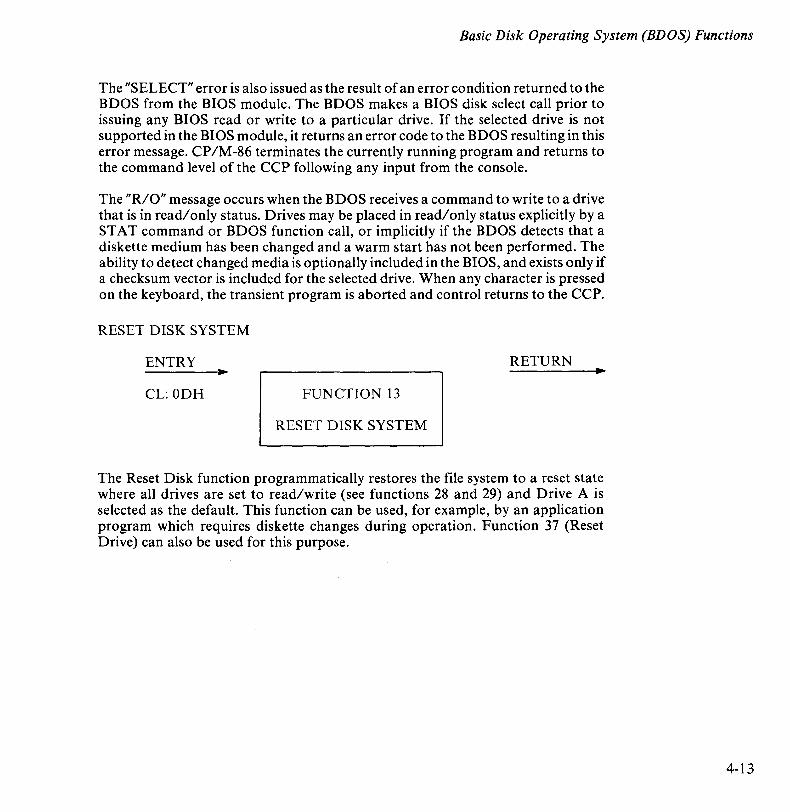
RESET DISK SYSTEM
ENTRY RETURN
CL: ODH FUNCTION 13
RESET DISK SYSTEM
The Reset Disk function programmatically restores the file system to a reset state where all drives are set to read/write (see functions 28 and 29) and Drive A is selected as the default. This function can be used, for example, by an application program which requires diskette changes during operation. Function 37 (Reset Drive) can also be used for this purpose.
4-13
Basic Disk Operating System (BDOS) Functions
4-14
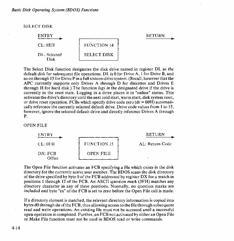
SELECT DISK
ENTRY
CL: OEH
D L: Selected Disk
RETURN
FUNCTION 14
SELECT DISK
The Select Disk function designates the disk drive named in register DL as the default disk for subsequent file operations. DL is 0 for Drive A, 1 for Drive B, and so on through 15 for Drive P in a full sixteen-drive system. (Recall, however that the APC currently supports only Drives A through D for diskettes and Drives E through H for hard disk.) The function logs in the designated drive if the drive is currently in the reset state. Logging in a drive places it in "online" status. This activates the drive's directory until the next cold start, warm start, disk system reset, or drive reset operation. FCBs which specify drive code zero (dr = OOH) automatically reference the currently selected default drive. Drive code values from 1 to 15, however, ignore the selected default drive and directly reference Drives A through P.
OPEN FILE
ENTRY
CL: OFH
DX: FCB Offset
RETURN
FUNCTION 15 AL: Return Code
OPEN FILE
The Open File function activates an FCB specifying a file which exists in the disk directory for the currently active user number. The BDOS scans the disk directory of the drive specified by byte 0 of the FCB addressed by register DX for a match in positions 1 through 12 of the FCB. An ASCII question mark (3FH) matches any directory character in any of these positions. Normally, no question marks are included and byte "ex" of the FCB is set to zero before the Open File call is made.
If a directory element is matched, the relevant directory information is copied into bytes dO through dn of the FCB, thus allowing access to the file through subsequent read and write operations. An existing file must not be accessed until a successful open operation is completed. Further, an FCB not activated by either an Open File or Make File function must not be used in BDOS read or write commands.
Basic Disk Operating System (BDOS) Functions
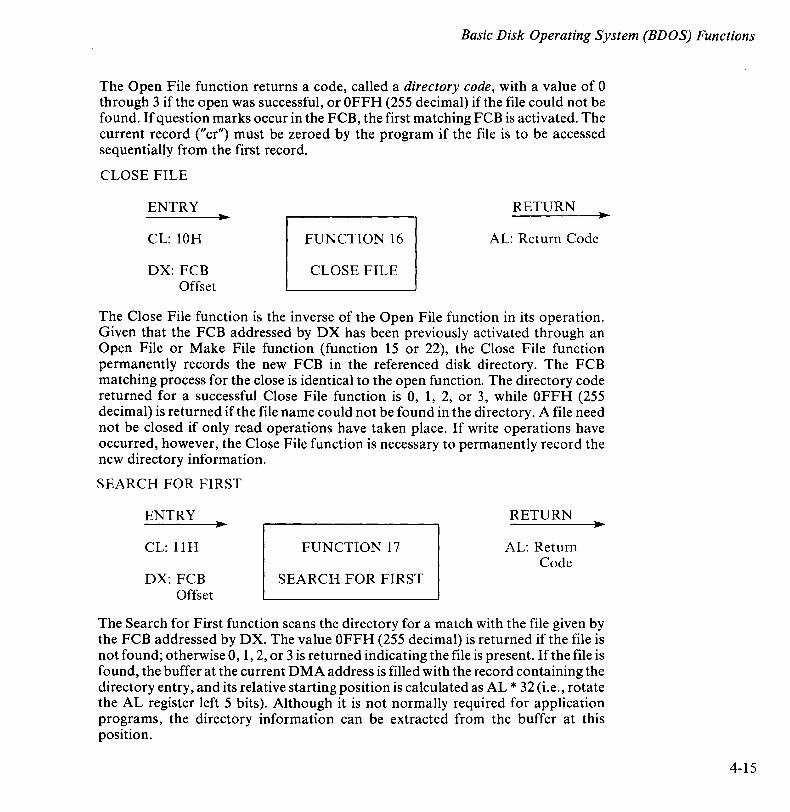
The Open File function returns a code, called a directory code, with a value of 0 through 3 if the open was successful, or OFFH (255 decimal) if the file could not be found. If question marks occur in the FCB, the first matching FCB is activated. The current record (" cr") must be zeroed by the program if the file is to be accessed sequentially from the first record.
CLOSE FILE
ENTRY
CL: 10H
DX: FCB Offset
RETURN
FUNCTION 16 AL: Return Code
CLOSE FILE
The Close File function is the inverse of the Open File function in its operation. Given that the FCB addressed by DX has been previously activated through an Open File or Make File function (function 15 or 22), the Close File function permanently records the new FCB in the referenced disk directory. The FCB matching process for the close is identical to the open function. The directory code returned for a successful Close File function is 0, 1, 2, or 3, while OFFH (255 decimal) is returned if the file name could not be found in the directory. A file need not be closed if only read operations have taken place. If write operations have occurred, however, the Close File function is necessary to permanently record the new directory information.
SEARCH FOR FIRST
ENTRY
CL: IlH
DX: FCB Offset
FUNCTION 17
SEARCH FOR FIRST
RETURN
AL: Return Code
The Search for First function scans the directory for a match with the file given by the FCB addressed by DX. The value OFFH (255 decimal) is returned if the file is not found; otherwise 0, 1, 2, or 3 is returned indicating the file is present. If the file is found, the buffer at the current DMA address is filled with the record containing the directory entry, and its relative starting position is calculated as AL * 32 (i.e., rotate the AL register left 5 bits). Although it is not normally required for application programs, the directory information can be extracted from the buffer at this position.
4-15
Basic Disk Operating System (BDOS) Functions
4-16
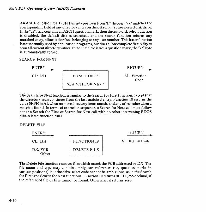
An ASCII question mark (3FH) in any position from "fl" through "ex" matches the corresponding field of any directory entry on the default or auto-selected disk drive. If the "dr" field contains an ASCII question mark, then the auto disk select function is disabled, the default disk is searched, and the search function returns any matched entry, allocated or free, belonging to any user number. This latter function is not normally used by application programs, but does allow complete flexibility to scan all current directory values. If the "dr" field is not a question mark, the "s2" byte is automatically zeroed.
SEARCH FOR NEXT
ENTRY
CL: 12H FUNCTION 18
SEARCH FOR NEXT
RETURN
AL: Function Code
The Search for Next function is similar to the Search for First function, except that the directory scan continues from the last matched entry. Function 18 returns the value OFFH in AL when no more directory items match, and any other value when a match is found. In terms of execution sequence, a Search for Next call must follow either a Search for First or Search for Next call with no other intervening BDOS disk-related function calls.
DELETE FILE
ENTRY
CL: 13H
DX: FCB Offset
RETURN
FUNCTION 19 AL: Return Code
DELETE FILE
The Delete File function removes files which match the FCB addressed by DX. The file name and type may contain ambiguous references (i.e, question marks in various positions), but the drive select code cannot be ambiguous, as in the Search for First and Search for Next functions. Function 19 returns OFFH (255 decimal) if the referenced file or files cannot be found. Otherwise, it returns zero.
Basic Disk Operating System (BDOS) Functions
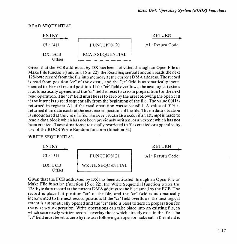
READ SEQUENTIAL
ENTRY
CL: 14H
DX: FCB Offset
RETURN
FUNCTION 20 AL: Return Code
READ SEQUENTIAL
Given that the FCB addressed by DX has been activated through an Open File or Make File function (function 15 or 22), the Read Sequential function reads the next 128-byte record from the file into memory at the current DMA address. The record is read from position" cr" of the extent, and the" cr" field is automatically incremented to the next record position. If the "Cf" field overflows, the next logical extent is automatically opened and the "cr" field is reset to zero in preparation for the next read operation. The "cr" field must be set to zero by the user following the open call if the intent is to read sequentially from the beginning of the file. The value OOH is returned in register AL if the read operation was successful. A value of 01 H is returned if no data exists at the next record position of the file. The no data situation is encountered at the end of a file. However, it can also occur if an attempt is made to read a data block which has not been previously written, or an extent which has not been created. These situations are usually restricted to files created or appended by-use of the BDOS Write Random function (function 34).
WRITE SEQUENTIAL
ENTRY
CL: ISH
DX: FCB Offset
RETURN
FUNCTION 21 AL: Return Code
WRITE SEQUENTIAL
Given that the FCB addressed by DX has been activated through an Open File or Make File function (function 15 or 22), the Write Sequential function writes the 128-byte data record at the current DMA address to the file named by the FeB. The record is placed at position "cr" of the file, and the "cr" field is automatically incremented to the next record position. If the" cr" field overflows, the next logical extent is automatically opened and the" cr" field is reset to zero in preparation for the next write operation. Write operations can take place into an existing file, in which case newly written records overlay those which already exist in the file. The "cr" field must be set to zero by the user following an open or make call if the intent is
4-17
Basic Disk Operating System (BDOS) Functions
4-18
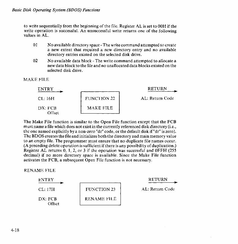
to write sequentially from the beginning of the file. Register AL is set to OOH if the write operation is successful. An unsuccessful write returns one of the following values in AL.
01 No available directory space - The write command attempted to create a new extent that required a new directory entry and no available directory entries existed on the selected disk drive.
02 No available data block - The write command attempted to allocate a new data block to the file and no unallocated data blocks existed on the selected disk drive.
MAKE FILE
ENTRY
CL: 16H
DX: FCB Offset
RETURN
FUNCTION 22 AL: Return Code
MAKE FILE
The Make File function is similar to the Open File function except that the FCB must name a file which does not exist in the currently referenced disk directory (Le., the one named explicitly by a non-zero "dr" code, or the default disk if"dr" is zero). The BDOS creates the file and initializes both the directory and main memory value to an empty file. The programmer must ensure that no duplicate file names occur. (A preceding delete operation is sufficient if there is any possibility of duplication.) Register AL returns 0, 1, 2, or 3 if the operation was successful and OFFH (255 decimal) if no more directory space is available. Since the Make File function activates the FCB, a subsequent Open File function is not necessary.
RENAME FILE
ENTRY
CL: 17H
DX: FCB Offset
RETURN
FUNCTION 23 AL: Return Code
RENAME FILE
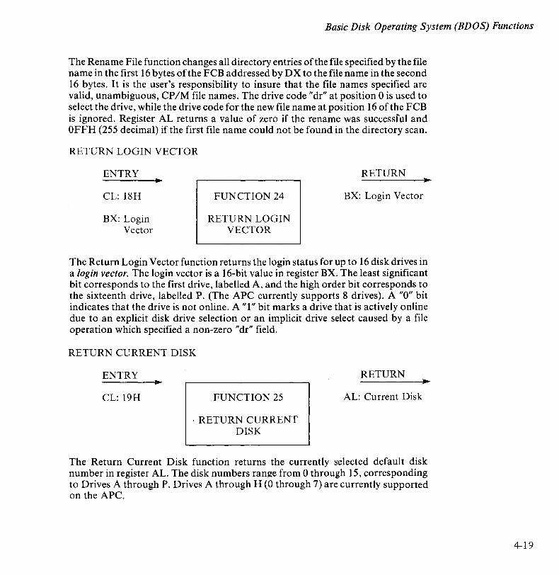
Basic Disk Operating System (BDOS) Functions
The Rename File function changes all directory entries of the file specified by the file name in the first 16 bytes of the FCB addressed by D X to the file name in the second 16 bytes. It is the user's responsibility to insure that the file names specified are valid, unambiguous, CP/M file names. The drive code "dr" at position 0 is used to select the drive, while the drive code for the new file name at position 16 of the FCB is ignored. Register AL returns a value of zero if the rename was successful and OFFH (255 decimal) if the first file name could not be found in the directory scan.
RETURN LOGIN VECTOR
ENTRY
CL: 18H
BX: Login Vector
FUNCTION 24
RETURN LOGIN VECTOR
RETURN
BX: Login Vector
The Return Login Vector function returns the login status for up to 16 disk drives in a login vector. The login vector is a 16-bit value in register BX. The least significant bit corresponds to the first drive, labelled A, and the high order bit corresponds to the sixteenth drive, labelled P. (The APC currently supports 8 drives). A "0" bit indicates that the drive is not online. A "1" bit marks a drive that is actively online due to an explicit disk drive selection or an implicit drive select caused by a file operation which specified a non-zero "dr" field.
RETURN CURRENT DISK
ENTRY
CL: 19H FUNCTION 25
. RETURN CURRENT DISK
RETURN
AL: Current Disk
The Return Current Disk function returns the currently selected default disk number in register AL. The disk numbers range from 0 through 15, corresponding to Drives A through P. Drives A through H (0 through 7) are currently supported on the APC.
4-19
Basic Disk Operating System (BDOS) Functions
4-20
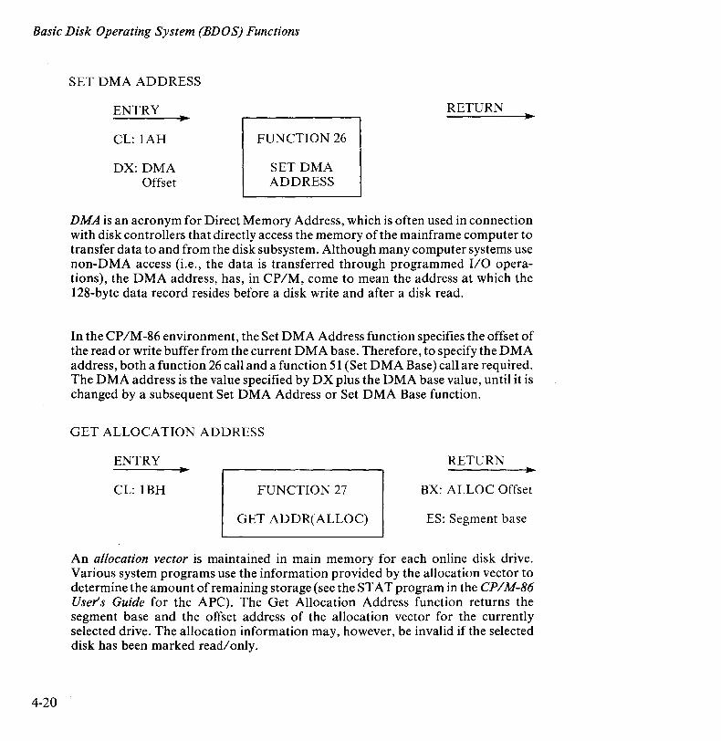
SET DMA ADDRESS
ENTRY
CL: IAH
DX: DMA Offset
FUNCTION 26
SET DMA ADDRESS
RETURN
DMA is an acronym for Direct Memory Address, which is often used in connection with disk controllers that directly access the memory of the mainframe computer to transfer data to and from the disk subsystem. Although many computer systems use non-DMA access (i.e., the data is transferred through programmed I/O operations), the DMA address, has, in CP/M, come to mean the address at which the 128-byte data record resides before a disk write and after a disk read.
In the CP/M-86 environment, the Set DMA Address function specifies the offset of the read or write buffer from the current DMA base. Therefore, to specify the DMA address, both a function 26 call and a function 51 (Set DMA Base) call are required. The DMA address is the value specified by DX plus the DMA base value, until it is changed by a subsequent Set DMA Address or Set DMA Base function.
GET ALLOCATION ADDRESS
ENTRY RETURN
CL: IBH FUNCTION 27 BX: ALLOC Offset
GET ADDR(ALLOC) ES: Segment base
An allocation vector is maintained in main memory for each online disk drive. Various system programs use the information provided by the allocation vector to determine the amount of remaining storage (see the STAT program in the CP / M-86 User's Guide for the APC). The Get Allocation Address function returns the segment base and the offset address of the allocation vector for the currently selected drive. The allocation information may, however, be invalid if the selected disk has been marked read/only.

Basic Disk Operating System (BDOS) Functions
WRITE PROTECT DISK
ENTRY RETURN III
CL:lCH FUNCTION 28
WRITE PROTECT DISK
The Write Protect Disk function provides temporary write protection for the currently selected disk. Any attempt to write the disk before the next cold start, warm start, disk system reset, or drive reset operation produces the following message: "BDOS Err on d: RIO".
ENTRY
CL: lDH FUNCTION 29
GET READIONLY VECTOR
RETURN • BX: RIO Vector Value
The Get ReadlOnly Vector function returns a 16-bit vector in register BX which indicates drives which have the temporary readlonly (RIO) bit set. Like function 24, the least significant bit corresponds to Drive A, while the most significant bit corresponds to Drive P. The RIO bit is set either by an explicit call to function 28, or by the automatic software mechanisms within CP/M-86 which detect changed disk media.
SET FILE ATTRIBUTES
ENTRY
CL: lEH
DX: FCB Offset
III
FUNCTION 30
SET FILE ATTRIBUTES
RETURN
AL: Return Code
The Set File Attributes function programmatically manipulates permanent indicators attached to files. In particular, the RIO, System, and Archive attributes (tl', t2', and t3') can be set or reset. The DX pair addresses an FCB containing a file name
4-21
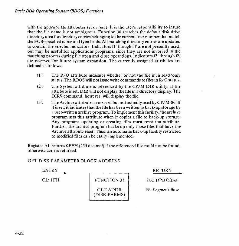
Basic Disk Operating System (BDOS) Functions
4-22
with the appropriate attributes set or reset. It is the user's responsibility to insure that the file name is not ambiguous. Function 30 searches the default disk drive directory area for directory entries belonging to the current user number that match the FCB-specified name and type fields. All matching directory entries are updated to contain the selected indicators. Indicators fl' though f4' are not presently used, but may be useful for applications programs, since they are not involved in the matching process during file open and close operations. Indicators f5' through f8' are reserved for future system expansion. The currently assigned attributes are defined as follows.
t1': The R/O attribute indicates whether or not the file is in read/only status. The BDOS will not issue write commands to files in R/O status.
t2': The System attribute is referenced by the CP/M DIR utility. If the attribute is set, DIR will not display the file in a directory display. The DIRS command, however, will display the file.
t3': The Archive attribute is reserved but not actually used by CP /M-86. If it is set, it indicates that the file has been written to back-up storage by a user-written archive program. To implement this facility, the archive program sets this attribute when it copies a file to back-up storage. Any programs updating or creating files must reset the attribute. Further, the archive program backs up only those files that have the Archive attribute reset. Thus, an automatic back-up facility restricted to modified files can be easily implemented.
Register AL returns OFFH (255 decimal) if the referenced file could not be found, otherwise zero is returned.
GET DISK PARAMETER BLOCK ADDRESS
ENTRY
CL: 1FH FUNCTION 31
GET ADDR (DISK PARMS)
RETURN
BX: DPB Offset
ES: Segment Base
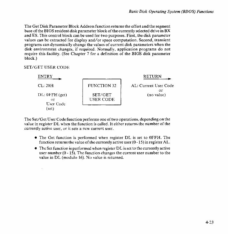
Basic Disk Operating System (BDOS) Functions
The Get Disk Parameter Block Address function returns the offset and the segment base of the BIOS resident disk parameter block of the currently selected drive in BX and ES. This control block can be used for two purposes. First, the disk parameter values can be extracted for display and/or space computation. Second, transient programs can dynamically change the values of current disk parameters when the disk environment changes, if required. Normally, application programs do not require this facility. (See Chapter 7 for a definition of the BIOS disk parameter block.)
SET/GET USER CODE
ENTRY
CL: 20H
DL: OFFH (get) or
User Code (set)
FUNCTION 32
SET/GET USER CODE
RETURN
AL: Current User Code or
(no value)
The Set/Get User Code function performs one of two operations, depending on the value in register DL when the function is called. It either returns the number of the currently active user, or it sets a new current user .
• The Get function is performed when register DL is set to OFFH. The function returns the value of the currently active user (0 - 15) in register AL.
e The Set function is performed when register DL is set to the currently active user number (0 - 15). The function changes the current user number to the value in DL (modulo 16). No value is returned.
4-23
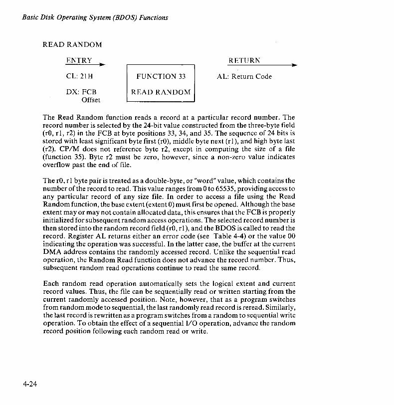
Basic Disk Operating System (BDOS) Functions
4-24
READ RANDOM
ENTRY
CL: 2lH
DX: FCB Offset
RETURN
FUNCTION 33 AL: Return Code
READ RANDOM
The Read Random function reads a record at a particular record number. The record number is selected by the 24-bit value constructed from the three-byte field (rO, rl, r2) in the FCB at byte positions 33, 34, and 35. The sequence of 24 bits is stored with least significant byte first (rO), middle byte next (rl), and high byte last (r2). CPIM does not reference byte r2, except in computing the size of a file (function 35). Byte r2 must be zero, however, since a non-zero value indicates overflow past the end of file.
The rO, rl byte pair is treated as a double-byte, or "word" value, which contains the number of the record to read. This value ranges from 0 to 65535, providing access to any particular record of any size file. In order to access a file using the Read Random function, the base extent (extent 0) must first be opened. Although the base extent mayor may not contain allocated data, this ensures that the FCB is properly initialized for subsequent random access operations. The selected record number is then stored into the random record field (rO, r 1), and the BDOS is called to read the record. Register AL returns either an error code (see Table 4-4) or the value 00 indicating the operation was successful. In the latter case, the buffer at the current DMA address contains the randomly accessed record. Unlike the sequential read operation, the Random Read function does not advance the record number. Thus, subsequent random read operations continue to read the same record.
Each random read operation automatically sets the logical extent and current record values. Thus, the file can be sequentially read or written starting from the current randomly accessed position. Note, however, that as a program switches from random mode to sequential, the last randomly read record is reread. Similarly, the last record is rewritten as a program switches from a random to sequential write operation. To obtain the effect of a sequential 1/0 operation, advance the random record position following each random read or write.
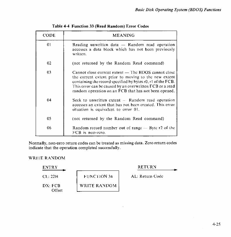
Basic Disk Operating System (BDOS) Functions
Table 4-4 Function 33 (Read Random) Error Codes
CODE
01
02
03
04
05
06
MEANING
Reading unwritten data - Random read operation accesses a data block which has not been previously written.
(not returned by the Random Read command)
Cannot close current extent - The BDOS cannot close the current extent prior to moving to the new extent containing the record specified by bytes rO, r I of the FCB. This error can be caused by an overwritten FCB or a read random operation on an FCB that has not been opened.
Seek to unwritten extent - Random read operation accesses an extent that has not been created. This error situation is equivalent to error 0 I.
(not returned by the Random Read command)
Random record number out of range - Byte r2 of the FCB is non-zero.
Normally, non-zero return codes can be treated as missing data. Zero return codes indicate that the operation completed successfully.
WRITE RANDOM
ENTRY
CL: 22H
DX: FCB Offset
RETURN
FUNCTION 34 AL: Return Code
WRITE RANDOM
4-25

Basic Disk Operating System (BDOS) Functions
4-26
The Write Random function writes data to the disk from the current DMA address. If the disk extent or data block which is the target of the write has not yet been allocated, the allocation is performed before the write operation continues. As in the Read Random function, the random record number is not changed as a result of the write. The logical extent number and current record position of the file control block are set to correspond to the random record which is being written. Sequential read or write operations can follow a random write. However, the currently addressed record is rewritten as the sequential operation begins. To get the effect of a sequential write operation, advance the random record position following each write. Reading or writing the last record of an extent in random mode does not cause an automatic extent switch as it does in sequential mode.
To access a file using the Write Random function, the base extent (extent 0) must first be opened. This ensures that the FCB is properly initialized for subsequent random access operations. If the file is empty, a Make File function must be issued for the base extent. Although the base extent mayor may not contain allocated data, this ensures that the file is properly recorded in the directory and is visible in DIR requests.
A Write Random call returns a value in register AL indicating an error, as listed in Table 4-5, or the value 00 indicating the operation was successful.
COMPUTE FILE SIZE
ENTRY
CL: 23H
DX: FCB Offset
FUNCTION 35
COMPUTE FILE SIZE
RETURN
Random Record Field Set
When computing the size of a file, the DX register addresses an FCB in random mode format (bytes rO, rl, and r2 are present). The FCB contains an unambiguous file name which is used in the directory scan. Upon return, the random record bytes contain the virtual file size which is, in effect, the record address of the record following the end of the file. If, following a call to function 35, the high record byte r2 is 01, then the file contains the maximum record count 65536. Otherwise, bytes rO and rl constitute a 16-bit value (rO is the least significant byte) which is the file size.
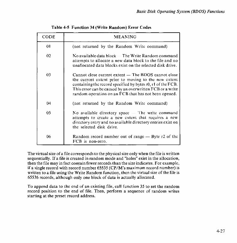
Basic Disk Operating System (BDOS) Functions
Table 4-5 Function 34 (Write Random) Error Codes
CODE
01
02
03
04
05
06
MEANING
(not returned by the Random Write command)
No a vaiia ble data block - The Write Random command attempts to allocate a new data block to the file and no unallocated data blocks exist on the selected disk drive.
Cannot close current extent - The BOOS cannot close the current extent prior to moving to the new extent containing the record specified by bytes rO, r 1 of the FCB. This error can be caused by an overwritten FCB or a write random operation on an FCB that has not been opened.
(not returned by the Random Write command)
No available directory space - The write command attempts to create a new extent that requires a new directory entry and no available directory entries exist on the selected disk drive.
Random record number out of range - Byte r2 of the FCB is non-zero.
The virtual size of a file corresponds to the physical size only when the file is written sequentially. If a file is created in random mode and "holes" exist in the allocation, then the file may in fact contain fewer records than the size indicates. For example, if a single record with record number 65535 (CP/M's maximum record number) is written to a file using the Write Random function, then the virtual size of the file is 65536 records, although only one block of data is actually allocated.
To append data to the end of an existing file, call function 35 to set the random record position to the end of file. Then, perform a sequence of random writes starting at the preset record address.
4-27
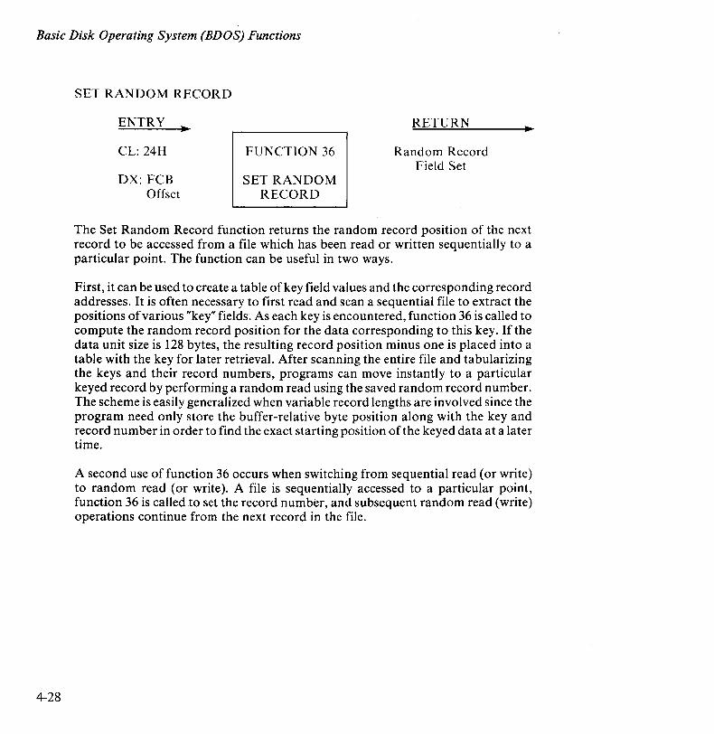
Basic Disk Operating System (EDOS) Functions
4-28
SET RANDOM RECORD
ENTRY
CL: 24H
DX: FCB Offset
FUNCTION 36
SET RANDOM RECORD
RETURN
Random Record Field Set
The Set Random Record function returns the random record position of the next record to be accessed from a file which has been read or written sequentially to a particular point. The function can be useful in two ways.
First, it can be used to create a table of key field values and the corresponding record addresses. It is often necessary to first read and scan a sequential file to extract the positions of various "key" fields. As each key is encountered, function 36 is called to compute the random record position for the data corresponding to this key. If the data unit size is 128 bytes, the resulting record position minus one is placed into a table with the key for later retrieval. After scanning the entire file and tabularizing the keys and their record numbers, programs can move instantly to a particular keyed record by performing a random read using the saved random record number. The scheme is easily generalized when variable record lengths are involved since the program need only store the buffer-relative byte position along with the key and record number in order to find the exact starting position of the keyed data at a later time.
A second use of function 36 occurs when switching from sequential read (or write) to random read (or write). A file is sequentially accessed to a particular point, function 36 is called to set the record number, and subsequent random read (write) operations continue from the next record in the file.
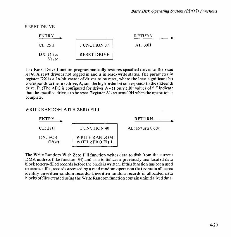
Basic Disk Operating System (BDOS) Functions
RESET DRIVE
ENTRY
CL: 25H
DX: Drive Vector
RETURN
FUNCTION 37 AL: OOH
RESET DRIVE
The Reset Drive function programmatically restores specified drives to the reset state. A reset drive is not logged in and is in read/write status. The parameter in register DX is a 16-bit vector of drives to be reset, where the least significant bit corresponds to the first drive, A, and the high order bit corresponds to the sixteenth drive, P. (The APC is configured for drives A - H only.) Bit values of "1" indicate that the specified drive is to be reset. Register AL returns OOH when the operation is complete.
WRITE RANDOM WITH ZERO FILL
ENTRY
CL: 28H
DX: FCB Offset
FUNCTION 40
WRITE RANDOM WITH ZERO FILL
RETURN
AL: Return Code
The Write Random With Zero Fill function writes data to disk from the current DMA address (like function 34) and also initializes a previously unallocated data block to zero-filled records before the block is written. If this function has been used to create a file, records accessed by a read random operation that contain all zeros identify unwritten random records. Unwritten random records in allocated data blocks of files created using the Write Random function contain uninitialized data.
4-29
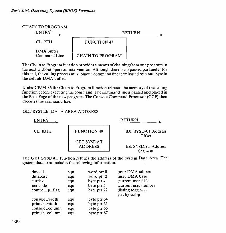
Basic Disk Operating System (BDOS) Functions
4-30
CHAIN TO PROGRAM ENTRY RETURN
CL: 2FH FUNCTION 47
DMA buffer: Command Line CHAIN TO PROGRAM
The Chain to Program function provides a means of chaining from one program to the next without operator intervention. Although there is no passed parameter for this call, the calling process must place a command line terminated by a null byte in the default DMA buffer.
Under CP 1M -86 the Chain to Program function releases the memory of the calling function before executing the command. The command line is parsed and placed in the Base Page of the new program. The Console Command Processor (CCP) then executes the command line.
GET SYSTEM DATA AREA ADDRESS
ENTRY
CL: 031H FUNCTION 49
GETSYSDAT ADDRESS
RETURN
BX: SYSDAT Address Offset
ES: SYSDA T Address Segment
The GET SYSDA T function returns the address of the System Data Area. The system data area includes the following information.
dmaad equ word ptr 0 ;user DMA address dmabase equ word ptr 2 ;user DMA base curdsk equ byte ptr 4 ;current user disk usr code equ byte ptr 5 ;current user number control_p_flag equ byte ptr 22 ;listing toggle ...
;set by ctrl-p console _ width equ byte ptr 64 printer _ width equ byte ptr 65 console_column equ byte ptr 66 printer _column equ byte ptr 67

Basic Disk Operating System (BDOS) Functions
where:
dmaad = current user DMA address dmabase= current user DMA base curdsk = current user disk, 0-15 (A-P) usrcode = current user area, 0-15 control_pJlag, 0 means do not echo console output to the printer. FF
means echo to the printer.
DIRECT BIOS CALL
ENTRY RETURN
CL: 32H FUNCTION 50 AH: Keyboard Input Status
DX: BIOS Descriptor Offset
DIRECT BIOS CALL or (no value)
The Direct BIOS Call function provides a direct BIOS call and transfers control through the BDOS to the BIOS. The DX register addresses a five-byte memory area containing the BIOS call parameters:
8-bit 16-bit 16-bit
Func value (CX) value (DX) ]
where Func is a BIOS function number (see Table 5-1), and value (CX) and value (DX) are the 16-bit values which would normally be passed directly in the CX and DX registers with the BIOS call. The ex and DX values are loaded into the 8086 registers before the BIOS call is initiated.
NOTE
If the eON IN BIOS subroutine is called by this function, the keyboard input status signal is returned in register AH, indicating which latch key (GRPH1, GRPH2, ALT, etc.) is pressed. (See Appendix E, Keyboard Input Status.)
4-31
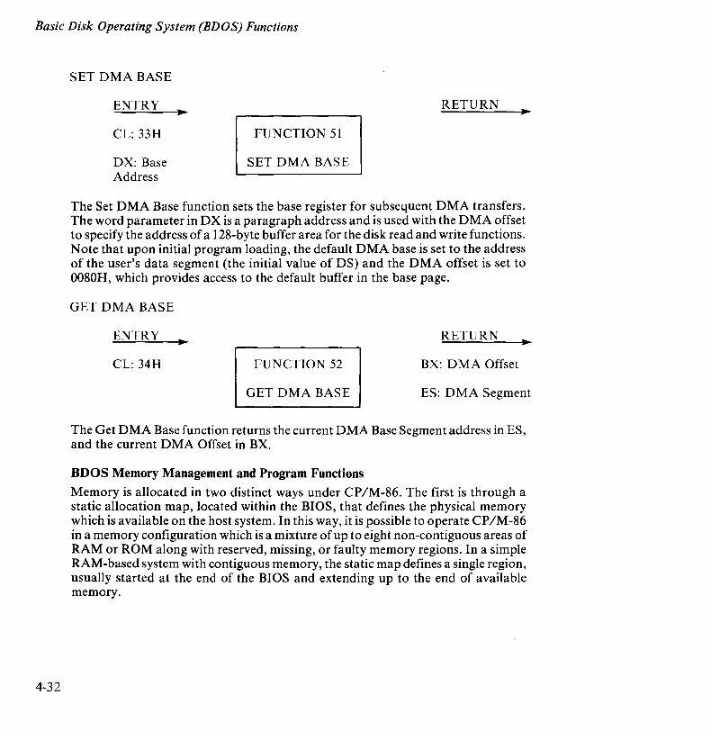
Basic Disk Operating System (BDOS) Functions
4-32
SET DMA BASE
ENTRY
CL: 33H
DX: Base Address
RETURN
FUNCTION 51
SET DMA BASE
The Set DMA Base function sets the base register for subsequent DMA transfers. The word parameter in DX is a paragraph address and is used with the DMA offset to specify the address of a 128-byte buffer area for the disk read and write functions. Note that upon initial program loading, the default DMA base is set to the address of the user's data segment (the initial value of DS) and the DMA offset is set to 0080H, which provides access to the default buffer in the base page.
GET DMA BASE
ENTRY RETURN
CL: 34H FUNCTION 52 BX: DMA Offset
GET DMA BASE ES: DMA Segment
The Get DMA Base function returns the current DMA Base Segment address in ES, and the current DMA Offset in BX.
BDOS Memory Management and Program Functions
Memory is allocated in two distinct ways under CP IM-86. The first is through a static allocation map, located within the BIOS, that defines the physical memory which is available on the host system. In this way, it is possible to operate CP/M-86 in a memory configuration which is a mixture of up to eight non-contiguous areas of RAM or ROM along with reserved, missing, or faulty memory regions. In a simple RAM-based system with contiguous memory, the static map defines a single region, usually started at the end of the BIOS and extending up to the end of available memory.
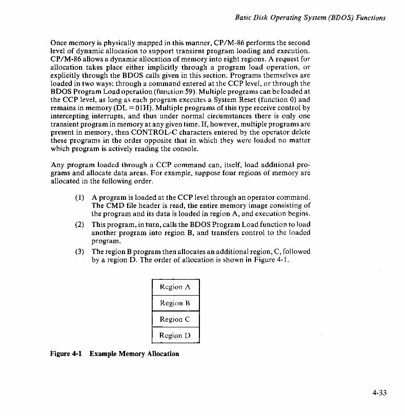
Basic Disk Operating System (BDOS) Functions
Once memory is physically mapped in this manner, CP/M-86 performs the second level of dynamic allocation to support transient program loading and execution. CP IM-86 allows a dynamic allocation of memory into eight regions. A request for allocation takes place either implicitly through a program load operation, or explicitly through the BDOS calls given in this section. Programs themselves are loaded in two ways: through a command entered at the CCP level, or through the BDOS Program Load operation (function 59). Multiple programs can be loaded at the CCP level, as long as each program executes a System Reset (function 0) and remains in memory (DL = OIH). Multiple programs of this type receive control by intercepting interrupts, and thus under normal circumstances there is only one transient program in memory at any given time. If, however, multiple programs are present in memory, then CONTROL-C characters entered by the operator delete these programs in the order opposite that in which they were loaded no matter which program is actively reading the console.
Any program loaded through a CCP command can, itself, load additional programs and allocate data areas. For example, suppose four regions of memory are allocated in the following order.
(I) A program is loaded at the CCP level through an operator command. The CMD file header is read, the entire memory image consisting of the program and its data is loaded in region A, and execution begins.
(2) This program, in turn, calls the BDOS Program Load function to load another program into region B, and transfers control to the loaded program.
(3) The region B program then allocates an additional region, C, followed by a region D. The order of allocation is shown in Figure 4-1.
Region A
Region B
Region C
Region D
Figure 4-1 Example Memory Allocation
4-33

Basic Disk Operating System (BDOS) Functions
4-34
There is a hierarchical ownership of these regions. The program in A controls all memory from A through D. The program in B also controls regions B through D. The program in A can release regions B through D, if required, and reload yet another program. (DDT-86, for example, operates in this manner by executing function 57, the Free Memory call, to release the memory used by the current program before loading another test program.) Further, the program in Bean release regions C and D if required by the application. However, if either A or B terminates by a System Reset (BDOS function 0 with DL = OOH), then all four regions A through D are released.
A transient program may release a portion of a region, allowing the released portion to be assigned on the next allocation request. The released portion must, however, be at the beginning or end of the region. Suppose, for example, the program in region B in the previous example receives 800H paragraphs at paragraph location 100H following its first allocation request, as shown in Figure 4-2.
Length =
8000H
!-IOOOH:
Figure 4-2 Example Memory Region
Region C
Suppose further that region D is then allocated. The last 200H paragraphs in region C can be returned without affecting region D by releasing the 200H paragraphs beginning at paragraph base 700H, resulting in the memory arrangement shown in Figure 4-3.
Length =
6000H
Length =
2000H
:----1000 H:
1 __ 7000H:
Figure 4-3 Example Memory Regions
Region C
111111/11/1 1111111/1/1

Basic Disk Operating System (BDOS) Functions
The region beginning at paragraph address 700H is now available for allocation in the next request. Note that a memory request will fail if eight memory regions have already been allocated. Normally, if all program units can reside in a contiguous region, the system allocates only one region.
MEMORY CONTROL BLOCKS (MCB)
Memory management functions (functions 53-57) reference a Memory Control Block (MCB), defined in the calling programs, which takes the form:
16-bit 16-bit 8-bit
MCB: M-Base M-Length M-Ext
where M-Base and M-Length are either input or output values expressed in 16-byte paragraph units, and M-Ext is a returned byte value, as defined specifically with each function code. An error condition is normally flagged with a OFFH returned value in order to match the file error conventions of CP/M-80.
GET MAXIMUM MEMORY
ENTRY
CL: 35H
DX: Offset ofMCB
FUNCTION 53
GET MAX MEM
RETURN
AL: Return Code
The Get Maximum Memory function finds the largest available memory region which is less than or equal to M-Length paragraphs. If successful, M-Base is set to the base paragraph address of the available area and M-Length to the paragraph length. Register AL returns the value OFFH if no memory is available, and OOH if the request was successful. M-Ext is set to 1 if there is additional memory for allocation, and 0 if no additional memory is available.
4-35

Basic Disk Operating System (BDOS) Functions
4-36
GET ABSOLUTE MAXIMUM MEMORY
ENTRY.
CL: 36H
DX: Offset ofMCB
FUNCTION 54
GET ABS MAX
RETURN
AL: Return Code
The Get Absolute Maximum Memory function finds the largest possible region at the absolute paragraph boundary given by M-Base, for a maximum of M-Length paragraphs. If successful, M-Length is set to the actual length. If no memory is available at the absolute address, AL returns the value OFFH.
ALLOCATE MEMORY
ENTRY
CL: 37H
DX: Offset ofMCB
RETURN
FUNCTION 55 AL: Return Code
ALLOC MEM
The Allocate Memory function allocates a memory area according to the MCB addressed by DX. The allocation request size is obtained from M-Length. Function 55 returns the base paragraph address of the allocated region in the user's MCB. Register AL contains OOH if the request was successful and OFFH if the memory could not be allocated.
ALLOCATE ABSOLUTE MEMORY
ENTRY
CL: 38H
DX: Offset ofMCB
FUNCTION 56
ALLOC ABS MEM
RETURN
AL: Return Code
The Allocate Absolute Memory function allocates a memory area according to the MCB addressed by DX. The allocation request size is obtained from M-Length, and the absolute base address from M-Base. Register AL contains OOH if the request was successful and OFFH if the memory could not be allocated.

Basic Disk Operating System (BDOS) Functions
FREE MEMORY
ENTRY
CL: 39H
DX: Offset ofMCB
RETURN
FUNCTION 57
FREE MEM
The Free Memory function releases memory areas allocated to the program. The value of the M-Ext field controls the operation of this function. If M-Ext is OFFH, all memory areas allocated by the calling program are released. Otherwise, M-Ext should be set to OOH. This releases the memory area oflength M-Length at location M-Base given in the MCB addressed by DX. As previously explained, either an entire allocated region or the end of a region must be released. The middle section of a region cannot be returned under CP IM-86.
FREE ALL MEMORY
ENTRY RETURN
CL: 3AH FUNCTION 58
FREE ALL MEM
The Free All Memory function releases all memory in the CP 1M -86 environment. It is normally used only by the CCP during initialization.
4-37

Basic Disk Operating System (BDOS) Functions
4-38
PROGRAM LOAD
ENTRY RETURN
CL: 3BH FUNCTION 59
DX: Offset ofFCB
PROGRAM LOAD
AX: Return Code/ Base Page Addr
BX: Base Page Addr
The Program Load function-loads a CMD file. Register DX contains the DS relative offset of a successfully opened FCB which names the input CMD file. AX returns the value OFFH if the program load was unsuccessful. Otherwise, AX and BX both contain the paragraph address of the base page belonging to the loaded program. The base address and segment length of each segment are stored in the base page.
NOTE
Upon program load at the CCP level, the DMA base address is initialized to the base page of the loaded program and the DMA offset adddress is initialized to 0080H. This is a function of the CCP. Function 59 does not establish a default DMA address. It is the responsibiiity of the program which executes function 59 to also execute function 51 to set the DMA base, and function 26 to set the DMA offset before passing control to the loaded program.

Chapter 5
Basic 1/0 System (BIOS) Organization The version of CP /M-86 you have purchased is set up for operation with the NEC APC. All hardware dependencies are concentrated in subroutines which are collectively referred to as the Basic Input/Output System, or BIOS. NEC has modified these subroutines to tailor CP/M-86 to fit the APC operating environment. The BIOS has been customized, and so is referred to as the CBIOS.
The BIOS consists of three sections: standard BIOS functions, escape sequence functions, and extended functions. The latter two sections of the BIOS contain APC-specific modifications to CP /M-86 that are referred to collectively as advanced BIOS functions. They are described in Chapter 6. Standard BIOS functions, for both floppy diskette and hard disk systems, are discussed in this chapter. In both chapters, entry points and variables are defined as necessary and BIOS tables are referenced. The discussion of Disk Definition Tables is treated separately in Chapter 7 of this manual. Listings are supplied on the distribution diskette.
The relationship among applications programs, the BDOS, and the BIOS is shown in Figure 5-1.
Figure 5-1 APC CBIOS Function Calls
EXTENDED FUNCTION CALLS
5-1
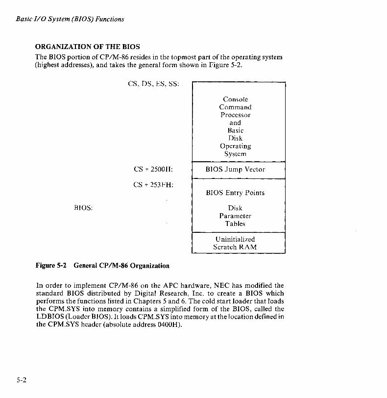
Basic I/O System (BIOS) Functions
5-2
ORGANIZATION OF THE BIOS
The BIOS portion of CP IM-86 resides in the topmost part of the operating system (highest addresses), and takes the general form shown in Figure 5-2.
CS, DS, ES, SS:
Console Command Processor
and Basic Disk
Operating System
CS + 2500H: BIOS Jump Vector
CS + 253FH: BIOS Entry Points
BIOS: Disk Parameter
Tables
U nini tialized Scratch RAM
Figure 5-2 General CP/M-86 Organization
In order to implement CP IM-86 on the APC hardware, NEC has modified the standard BIOS distributed by Digital Research, Inc. to create a BIOS which performs the functions listed in Chapters 5 and 6. The cold start loader that loads the CPM.syS into memory contains a simplified form of the BIOS, called the LDBIOS (Loader BIOS). It loads CPM.SYS into memory at the location defined in the CPM.SYS header (absolute address 0400H).
Basic I/O System (BIOS) Functions
THE BIOS JUMP VECTOR
Entry to the BIOS is through ajump vector located at offset 2500H from the base of the operating system. The jump vector is a sequence of 31 three-byte jump instructions which transfer program control to the individual BIOS entry points. Although some nonessential BIOS subroutines may contain a single return (RET) instruction, the corresponding jump vector element must be present in the location shown in Table 5-1.
Parameters for the individual subroutines in the BIOS are passed in the ex and DX registers, when required. ex holds the first parameter; DX is used for a second argument. Return values are passed in the registers according to type.
• Byte values are returned in AL.
• Word values ( 16 bits) are returned in BX.
Specific parameters and returned values are described with each subroutine.
BIOS SUBROUTINES
There are three major divisions in the BIOS jump table: system (re)initialization subroutines, simple character I/O subroutines, and disk I/O subroutines. The BIOS subroutines for disk I/O differ for floppy and hard disks. However, the same jump vector is used for entry to the subroutine for both types of disk. The system distinguishes between the media based on the value of the currently selected drive specifier. Drives A through D identify floppy disk drives. Drives E and F correspond to hard disk unit #0, while Drives G and H correspond to hard disk unit # 1. The system supports a maximum of four floppy diskette drives and two hard disk units (four logical hard disk drives).
5-3
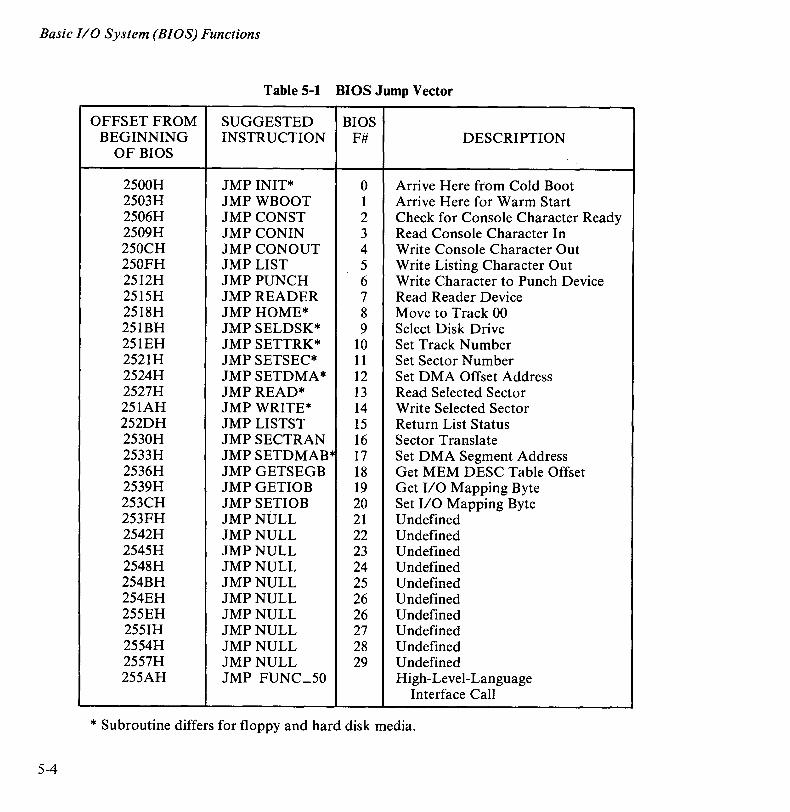
Basic I/O System (BIOS) Functions
Table 5-1 BIOS Jump Vector
OFFSET FROM SUGGESTED BIOS BEGINNING INSTRUCTION F# DESCRIPTION
OF BIOS
2500H JMP INIT* 0 Arrive Here from Cold Boot 2503H JMPWBOOT 1 Arrive Here for Warm Start 2506H JMPCONST 2 Check for Console Character Ready 2509H JMP CONIN 3 Read Console Character In 250CH JMPCONOUT 4 Write Console Character Out 250FH JMP LIST 5 Write Listing Character Out 2512H JMPPUNCH 6 Write Character to Punch Device 2515H JMPREADER 7 Read Reader Device 2518H JMPHOME* 8 Move to Track 00 251BH JMP SELDSK* 9 Select Disk Drive 251EH JMP SETTRK* 10 Set Track Number 2521H JMP SETSEC* 11 Set Sector Number 2524H JMPSETDMA* 12 Set DMA Offset Address 2527H JMPREAD* 13 Read Selected Sector 251AH JMPWRITE* 14 Write Selected Sector 252DH JMP LISTST 15 Return List Status 2530H JMPSECTRAN 16 Sector Translate 2533H JMP SETDMAB" 17 Set DMA Segment Address 2536H JMPGETSEGB 18 Get MEM DESC Table Offset 2539H JMPGETIOB 19 Get I/O Mapping Byte 253CH JMPSETIOB 20 Set I/O Mapping Byte 253FH JMPNULL 21 Undefined 2542H JMPNULL 22 Undefined 2545H JMPNULL 23 Undefined 2548H JMPNULL 24 Undefined 254BH JMPNULL 25 Undefined 254EH JMPNULL 26 Undefined 255EH JMPNULL 26 Undefined 2551H JMPNULL 27 Undefined 2554H JMPNULL 28 Undefined 2557H JMPNULL 29 Undefined 255AH JMP FUNC_50 High-Level-Language
Interface Call
* Subroutine differs for floppy and hard disk media.
5-4
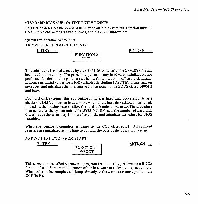
Basic I/O System (BIOS) Functions
STANDARD BIOS SUBROUTINE ENTRY POINTS
This section describes the standard BIOS subroutines: system initialization subroutines, simple character 1/0 subroutines, and disk 1/0 subroutines.
System Initialization Subroutines
ARRIVE HERE FROM COLD BOOT
ENTRY. FUNCTION 0
INIT
RETURN
This subroutine is called directly by the CP/M-86 loader after the CPM.SYS file has been read into memory. The procedure performs any hardware initialization not performed by the bootstrap loader (see below for a discussion of hard <;lisk initialization), sets initial values for BIOS variables (including IOBYTE), prints sign-on messages, and initializes the interrupt vector to point to the BDOS offset (OB06H) and base.
For hard disk systems, this subroutine initializes hard disk processing. It first checks the DMA controller to determine whether the hard disk adapter is installed. lfit exists, the routine waits to allow the hard disk units to warm up. The procedure then generates the system unit table (SYSUNITID), sets the number of hard disk drives, reads the error map from the hard disk, and initializes the values for BIOS variables.
When the routine is complete, it jumps to the CCP offset (OlH). All segment registers are initialized at this time to contain the base of the operating system.
ARRIVE HERE FOR WARM START
ENTRY. FUNCTION 1
WBOOT
RETURN
This subroutine is called whenever a program terminates by performing a BDOS function 0 call. Some reinitialization of the hardware or software may occur here. When this routine completes, it jumps directly to the warm start entry point of the CCP (06H).
5-5
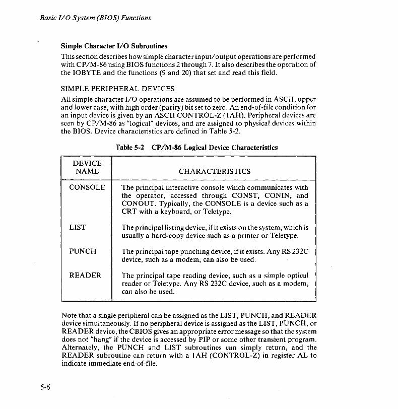
Basic I/O System (BIOS) Functions
5-6
Simple Character 1/0 Subroutines This section describes how simple character inputloutput operations are performed with CP/M-86 using BIOS functions 2 through 7. It also describes the operation of the IOBYTE and the functions (9 and 20) that set and read this field.
SIMPLE PERIPHERAL DEVICES
All simple character 1/0 operations are assumed to be performed in ASCII, upper and lower case, with high order (parity) bit set to zero. An end-of-file condition for an input device is given by an ASCII CONTROL-Z (lAH). Peripheral devices are seen by CP/M-86 as "logical" devices, and are assigned to physical devices within the BIOS. Device characteristics are defined in Table 5-2.
Table 5-2 CP IM-86 Logical Device Characteristics
DEVICE NAME CHARACTERISTICS
CONSOLE The principal interactive console which communicates with the operator, accessed through CONST, CONIN, and CONOUT. Typically, the CONSOLE is a device such as a CRT with a keyboard, or Teletype.
LIST The principal listing device, ifit exists on the system, which is usually a hard-copy device such as a printer or Teletype.
PUNCH The principal tape punching device, if it exists. Any RS 232C device, such as a modem, can also be used.
READER The principal tape reading device, such as a simple optical reader or Teletype. Any RS 232C device, such as a modem, can also be used.
Note that a single peripheral can be assigned as the LIST, PUNCH, and READER device simultaneously. If no peripheral device is assigned as the LIST, PUNCH, or READER device, the CBIOS gives an appropriate error message so that the system does not "hang" if the device is accessed by PIP or some other transient program. Alternately, the PUNCH and LIST subroutines can simply return, and the READER subroutine can return with a lAH (CONTROL-Z) in register AL to indicate immediate end-of-file.
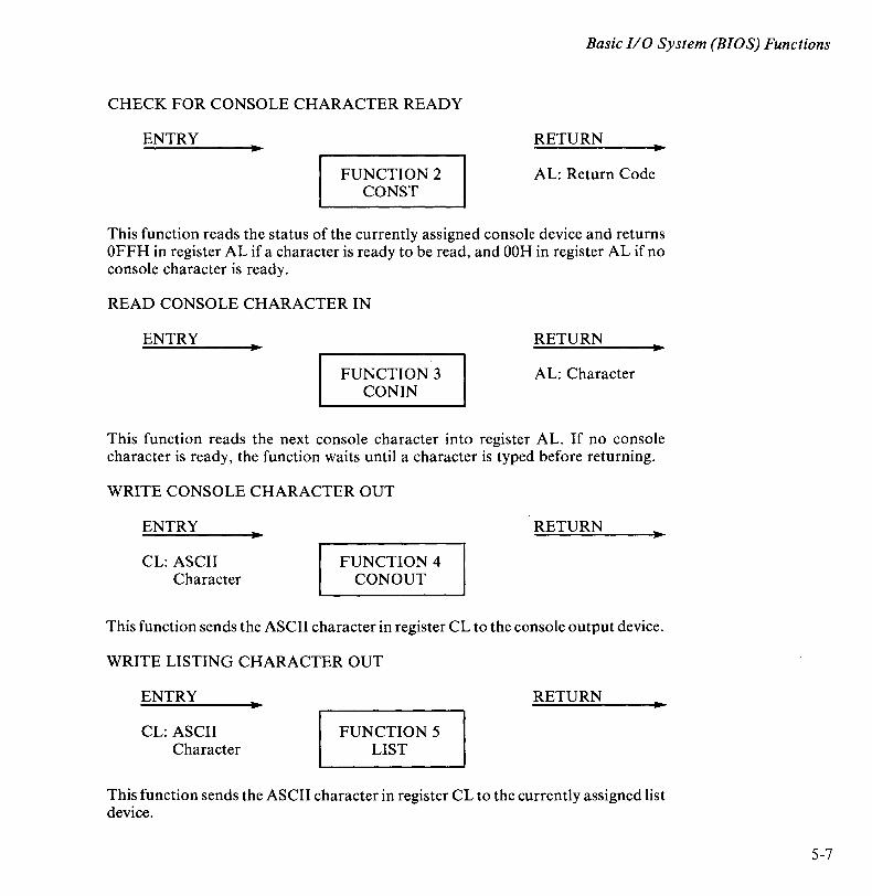
Basic I/O System (BIOS) Functions
CHECK FOR CONSOLE CHARACTER READY
ENTRY
FUNCTION 2 CONST
RETURN
AL: Return Code
This function reads the status of the currently assigned console device and returns OFFH in register AL if a character is ready to be read, and OOH in register AL if no console character is ready.
READ CONSOLE CHARACTER IN
ENTRY
FUNCTION 3 CONIN
RETURN
AL: Character
This function reads the next console character into register AL. If no console character is ready, the function waits until a character is typed before returning.
WRITE CONSOLE CHARACTER OUT
ENTRY
CL: ASCII Character
FUNCTION 4 CONOUT
RETURN
This function sends the ASCII character in register CL to the console output device.
WRITE LISTING CHARACTER OUT
ENTRY
CL: ASCII Character
FUNCTION 5 LIST
RETURN
This function sends the ASCII character in register CL to the currently assigned list device.
5-7
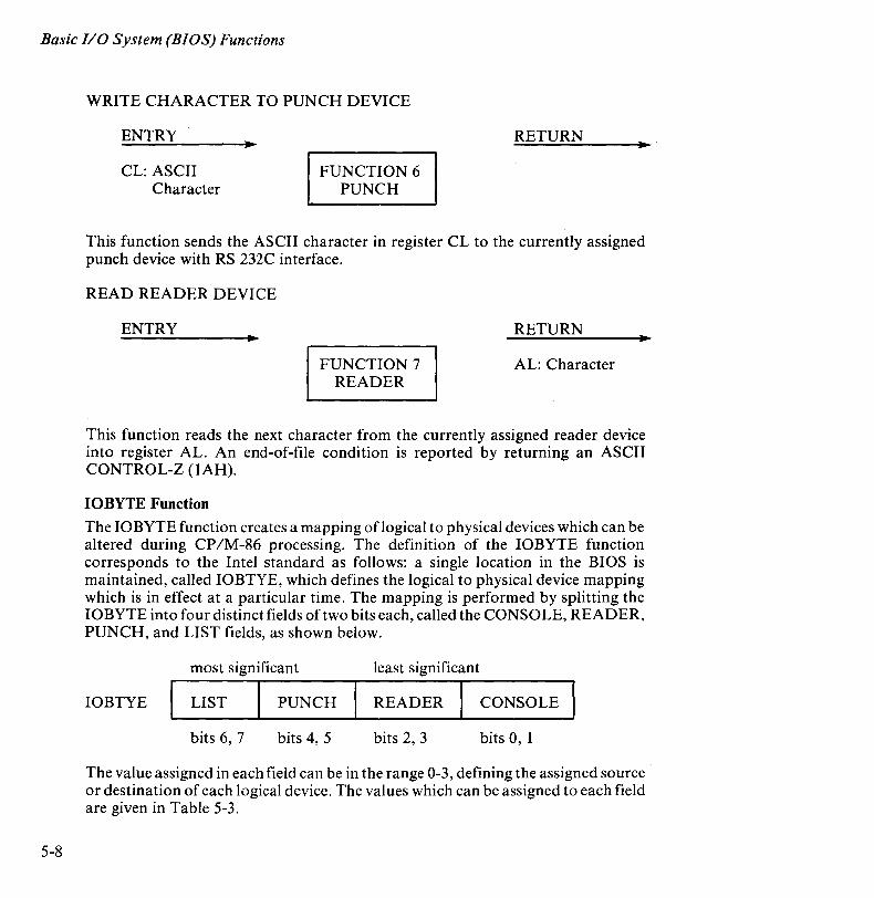
Basic I/O System (BIOS) Functions
5-8
WRITE CHARACTER TO PUNCH DEVICE
ENTRY
CL: ASCII Character
FUNCTION 6 PUNCH
RETURN
This function sends the ASCII character in register CL to the currently assigned punch device with RS 232C interface.
READ READER DEVICE
ENTRY
FUNCTION 7 READER
RETURN
AL: Character
This function reads the next character from the currently assigned reader device into register AL. An end-of-file condition is reported by returning an ASCII CONTROL-Z (lAH).
IOBYTE Function
The IOBYTE function creates a mapping oflogical to physical devices which can be altered during CP IM-86 processing. The definition of the IOBYTE function corresponds to the Intel standard as follows: a single location in the BIOS is maintained, called IOBTYE, which defines the logical to physical device mapping which is in effect at a particular time. The mapping is performed by splitting the IOBYTE into four distinct fields of two bits each, called the CONSOLE, READER, PUNCH, and LIST fields, as shown below.
most significant least significant
IOBTYE LIST PUNCH READER CONSOLE
bits 6, 7 bits 4, 5 bits 2, 3 bits 0, 1
The value assigned in each field can be in the range 0-3, defining the assigned source or destination of each logical device. The values which can be assigned to each field are given in Table 5-3.
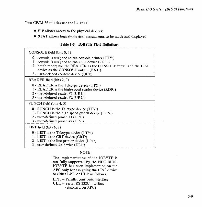
Basic I/O System (BIOS) Functions
Two CP/M-86 utilities use the IOBYTE:
• PIP allows access to the physical devices;
• ST A T allows logical-physical assignments to be made and displayed.
Table 5-3 IOBYTE Field Defintions
CONSOLE field (bits 0, 1)
o - console is assigned to the console printer (TTY:) I - console is assigned to the CRT device (CRT:) 2 - batch mode; use the READER as the CONSOLE input, and the LIST
device as the CONSOLE output (BAT:) 3 - user-defined console device (UCI:)
READER field (bits 2, 3)
0- READER is the Teletype device (TTY:) 1 - READER is the high-speed reader device (RDR:) 2 - user-defined reader # 1 (UR 1:) 3 - user-defined reader #2 (UR2:)
PUNCH field (bits 4, 5)
0- PUNCH is the Teletype device (TTY:) 1 - PUNCH is the high speed punch device (PUN:) 2 - user-defined punch # 1 (UP 1:) 3 - user-defined punch #2 (UP2:)
LIST field (bits 6, 7)
0- LIST is the Teletype device (TTY:) 1 - LIST is the CRT device (CRT:) 2 - LIST is the line printer device (LPT:) 3 - user-defined list device (UL1:)
NOTE
The implementation of the IOBYTE is not fully supported by the NEC BIOS. IOBYTE has been implemented on the APC only for assigning the LIST device to either LPT: or UL1: as follows.
LPT: = Parallel centronix interface UL 1: = Serial RS 232C interface
(standard on APC)
5-9
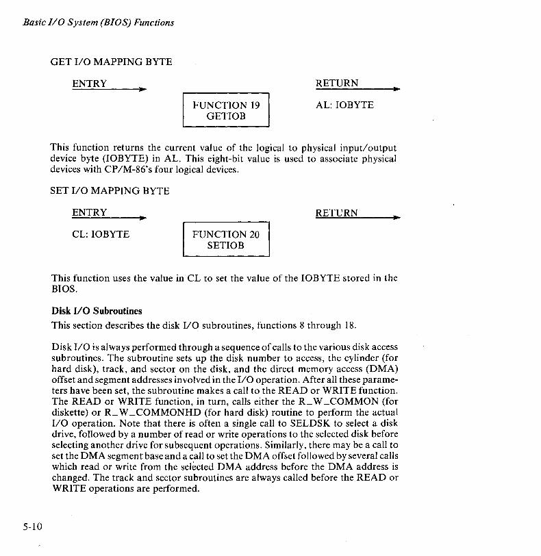
Basic I/O System (BIOS) Functions
5-10
GET I/O MAPPING BYTE
ENTRY
FUNCTION 19 GETIOB
RETURN
AL: IOBYTE
This function returns the current value of the logical to physical input/output device byte (IOBYTE) in AL. This eight-bit value is used to associate physical devices with CP/M-86's four logical devices.
SET I/O MAPPING BYTE
ENTRY
CL: 10BYTE FUNCTION 20 SETIOB
RETURN
This function uses the value in CL to set the value of the IOBYTE stored in the BIOS.
Disk I/O Subroutines This section describes the disk I/O subroutines, functions 8 through 18.
Disk I/O is always performed through a sequence of calls to the various disk access subroutines. The subroutine sets up the disk number to access, the cylinder (for hard disk), track, and sector on the disk, and the direct memory access (DMA) offset and segment addresses involved in the I/O operation. After all these parameters have been set, the subroutine makes a call to the READ or WRITE function. The READ or WRITE function, in turn, calls either the R_ W _COMMON (for diskette) or R_ W _COMMONHD (for hard disk) routine to perform the actual I/O operation. Note that there is often a single call to SELDSK to select a disk drive, followed by a number of read or write operations to the selected disk before selecting another drive for subsequent operations. Similarly, there may be a call to set the DMA segment base and a call to set the DMA offset followed by several calls which read or write from the selected DMA address before the DMA address is changed. The track and sector subroutines are always called before the READ or WRITE operations are performed.
Basic 110 System (BIOS) Functions
The READ and WRITE subroutines perform 24 retries before reporting an error condition to the BDOS.
MOVE TO TRACK 00
ENTRY
FUNCTION 8 HOME
RETURN
This function returns the disk head of the currently selected drive to the track 00 position. In the APC CBIOS, this subroutine does not actually perform the track 00 seek. Instead the call is translated into a call to function 10 with a parameter of 00.
The drive must have been previously selected by the SELDSK function (function 9). Before accessing the disk, the routine initializes the sector blockingl deblocking flags.
If a "not ready" condition is detected, one of the following error messages is displayed:
FDC HIW ERROR HDC H/W ERROR
to identify the disk that the controller is unable to access. The system waits for operator input (R to retry, I to ignore) to continue.
5-11

Basic I/O System (BIOS) Functions
5-12
SELECT DISK DRIVE
ENTRY
CL: Disk Drive OOH-OFFH
FUNCTION 9 SELDSK
RETURN
BX:DPH Address
This function selects the disk drive given by register CL for further operations. Register CL can contain a value ranging from 0 for Drive A to 15 for Drive P. Recall, however, that the APC is configured to support diskette drives A-D (OH-3H) and hard disk drives E-H (4H-7H) only. SELDSK returns the base address of the selected drive's Disk Parameter Header (DPH) in BX.
On entry to SELDSK it is possible to determine whether it is the first time the specified disk has been selected. Register DL, bit 0 (least significant bit) is zero if the drive has not been previously selected. This information can be used to set up a dynamic disk definition table.
This routine does not change the contents of the header and associated tables. For hard disk the routine checks SYSUNITID for the hard disk unit number. For both diskette and hard disk, if the call attempts to select a nonexistent drive, SELDSK returns OOH in BX as an error indicator.
Although this operation must return the header address on each call, it is advisable to postpone the actual physical disk select operation until an I/O function (seek, read, or write) is performed. This is due to the fact that disk select operations may take place without a subsequent disk operation and thus disk access may be substantially slower.
Basic I/O System (BIOS) Functions
SET TRACK NUMBER
ENTRY
cx: Track Number FUNCTION 10 SETTRK
RETURN
This function sets a track number. Register CX contains the track number for subsequent disk accesses on the currently selected drive. Programs can seek the selected track at this time, or delay the seek until the next read or write actually occurs. Register CX can take values in the range 0-76 (for floppy diskettes) and 0-720 (for hard disk) corresponding to valid track numbers. A call to this function with the value 00 in CX is equivalent to a call to function 8.
SET SECTOR NUMBER
ENTRY
CX: Sector Number FUNCTION 11 SETSEC
RETURN
This function sets a sector number. Register CX contains the translated sector number (see function 16) for subsequent disk accesses on the currently selected drive. Programs can send this information to the controller at this point, or delay sector selection until a read or write operation occurs. The BIOS uses a combination of track number and sector number to determine the physical location of data on a diskette.
• For single-sided, single-density diskettes (lD), there are 26 sectors (numbered 1-26) per track, and one track per cylinder.
• For double-sided, double-density diskettes (2D), there are 26 sectors (numbered 1-26) per track, and two tracks (numbered 0 and 1) per cylinder. Track 1, sector 1 refers to cylinder 0, sector 52.
• For hard disks, there are 64 logical sectors (numbered 1-64) per track, and 8 tracks per cylinder.
See Chapter 7 for more complete addressing information.
5-13
Basic I/O System (BIOS) Functions
5-14
SET DMA OFFSET ADDRESS
ENTRY
CX: DMA Offset FUNCTION 12 SETDMA
RETURN
This function sets the DMA Offset Address. Register CX contains the DMA (Direct Memory Address) offset for subsequent READ or WRITE operations. For example, if CX is 80H when SETDMA is called, all subsequent READ operations read their data into 80H through OFFH offset from the current DMA segment base, and all subsequent WRITE operations get their data from that address, until the next calls to SETDMA and SETDMAB occur. This data is then transferred to the DMA buffer addressed by the SETDMA and SETDMAB commands.
READ SELECTED SECTOR
ENTRY
FUNCTION 13 READ
RETURN
AL: Return Code OH,OFFH
Assuming the drive has been selected, the track has been set, the sector has been set, and the DMA offset and segment base have been specified, the READ subroutine attempts to read based on these parameters by calling R_ W _COMMON for diskette I/O or R_ W _COMMONHD for hard disk I/O. It returns zero in register AL if the read is successful. If the read is not successful, it returns OFFH in register AL.
This routine first calculates the physical sector address from the logical track address given by the BDOS. It then determines whether the requested record already exists in the work buffer. If the record is not in the buffer, the routine calls the appropriate routine to read from the disk medium to a buffer. R_ W _COMMON reads 128 bytes from a single density diskette, and 256 bytes from double density diskette. R_ W _COMMONHD reads 8K bytes (multisector read) from the disk to the work buffer. Finally, the requested record is moved from the work buffer to the user-specified DMA address.
Basic I/O System (BIOS) Functions
If an error occurs, the CBIOS attempts 16 retries to see if the error is recoverable. When an error is reported, the BDOS prints the message "BDOS ERR ON x: BAD SECTOR", where x is the drive specifier. The operator then has the option of pressing RETURN to ignore the error, or CONTROL-C to abort.
Refer to Appendix I for information about blocking and deblocking.
WRITE SELECTED SECTOR
ENTRY
FUNCTION 14 WRITE
RETURN
AL: Return Code OH,OFFH
This function writes the data from the currently selected DMA base and offset address to the currently selected drive, cylinder (hard disk only), track, and sector. This routine actually writes the data to a buffer at a fixed location and calls R_ W _COMMON or R_ W _COMMONHD to perform the physical write.
The error codes given for Read Selected Sector (function 13) are also returned in register AL for this function, with error recovery attempts as described for that function.
Refer to Appendix I for information about blocking and deblocking.
RETURN LIST STATUS
ENTRY
FUNCTION 15 LISTST
RETURN
AL: Return Code OH,OFFH
This function returns the ready status of the list device. The value returned in AL is 00 if the list device is not ready to accept a character, and OFFH if a character is sent to the printer.
5-15

Basic I/O System (BIOS) Functions
5-16
SECTOR TRANSLATE
ENTRY
CX: Logical Sector Number
DX: Translate Table Offset
FUNCTION 16 SECTRAN
RETURN
This function performs logical to physical sector translation to improve the overall response of CP/M-86. The CP/M-86 operation system is shipped with a "skew factor" of 6 for single-sided single-density diskettes and 3 for double-sided doubledensity diskettes. This skew factor allows enough time between sectors for most programs to load their buffers without missing the next sector. In general, SECTRAN receives a logical sector number in CX. This logical sector number may range from 0 to n - I, where n is the number of sectors.
SECTRAN also receives a translate table offset in DX. The sector number is used as an index into the translate table, with the resulting physical sector number in BX. The CBIOS for the APe includes correct tables for the skew factors in use.
SET DMA BASE ADDRESS
ENTRY • CX: DMA Base FUNCTION 17
SETDMAB
RETURN .,
This function sets the DMA base address. Register CX contains the segment base for subsequent DMA read or write operations. The BIOS uses the 128-byte buffer at the memory address determined by the DMA base and the DMA offset during read and write operations.
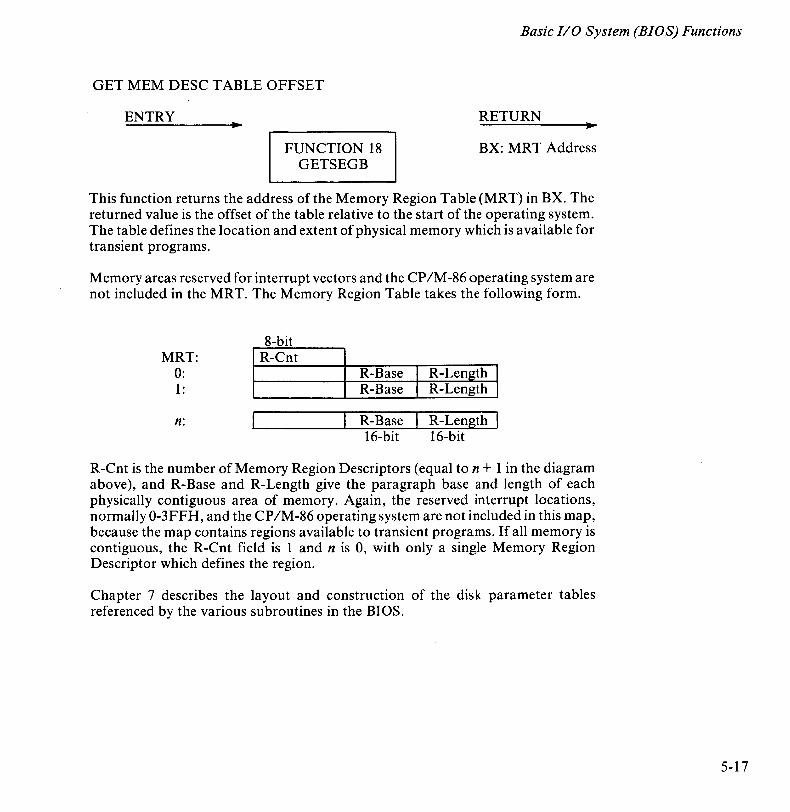
Basic I/O System (BIOS) Functions
GET MEM DESC TABLE OFFSET
ENTRY
FUNCTION 18 GETSEGB
RETURN
BX: MR T Address
This function returns the address of the Memory Region Table (MRT) in BX. The returned value is the offset of the table relative to the start of the operating system. The table defines the location and extent of physical memory which is available for transient programs.
Memory areas reserved for interrupt vectors and the CP 1M -86 operating system are not included in the MRT. The Memory Region Table takes the following form.
MRT: 0: 1:
n:
8-bit R-Cnt
R-Base I R-Length 1 R-Base I R-Length 1
R-Base R-Length 16-bit 16-bit
R-Cnt is the number of Memory Region Descriptors (equal to n + 1 in the diagram above), and R-Base and R-Length give the paragraph base and length of each physically contiguous area of memory. Again, the reserved interrupt locations, normally 0-3FFH, and the CP/M-86 operating system are not included in this map, because the map contains regions available to transient programs. If all memory is contiguous, the R-Cnt field is 1 and n is 0, with only a single Memory Region Descriptor which defines the region.
Chapter 7 describes the layout and construction of the disk parameter tables referenced by the various subroutines in the BIOS.
5-17

Basic I/O System (BIOS) Functions
5-18
Other Functions NULL Each of the remaining functions, 21 - 27, executes a simple
return without an operation.
This function is a high-level language interface to the BDOS function 50 call. To use this function, the high level language program must first set up the parameter values used by BDOS function 50 in a five-byte memory area starting at location 40:250B. (See BDOS function 50 for a description of the parameter area.) The calling program then issues a Far Call to BDOS function 50.
Chapter 6
Advanced BIOS Functions The CP/M-86 operating system distributed with the APC contains a customized BIOS, called the CBIOS, with features specific to the APC. CRT control codes, or escape sequence functions, reside in the BIOS and are called by BDOS functions. Extended functions also reside in the BIOS and are called directly by application programs using program interrupt #220. The relationship among applicant programs, the BDOS, and CBIOS is shown in Figure 5-1.
CRT ESCAPE SEQUENCE FUNCTIONS
The CONOUT (Write Console Character Out) routine in the BIOS recognizes CRT escape code sequences and performs the appropriate action in response to the codes received. Any of the following standard functions can be used to effect the APC console escape sequences.
• BDOS function 2 (Console Output)
• BDOS function 6 (Direct Console I/O)
• BDOS function 50 (Direct BIOS call)
Format and Definitions
Escape sequences consist of three kinds of fields: a sequence introducer that identifies the instruction as an escape sequence, one or more parameters, and a final character. For example, the following escape sequence moves the cursor up two lines.
ESC[2A
The general format for the above escape sequence
ESC[PnA
presents the basic elements of all APC escape sequences.
6-1
Advanced BIOS Functions
6-2
• The Control Sequence Introducer (CSI) signals an escape sequence command to the system. In the APC environment, the CSI is the ESC character (lBH or 27 decimal). The ESC is usually followed by a square bracket (D. (The use of a bracket or other character depends on the particular escape sequence.)
A t the CP 1M -86" A>" prompt, pressing the ESC key causes the characters ""[" to appear on the display screen. Therefore, escape sequences that are introduced by ESC followed by a square bracket appear on the display screen as "11[[".
• A parameter is a string of zero or more decimal characters which represent a single value. Leading zeros are ignored. The decimal characters have a range of 0 (30H) to 9 (39H). Two types of parameters are used in escape sequences .
• Numeric parameters represent numbers. Unless otherwise specified, any numeric value may be used. Numeric parameters are designated Pn in this document.
• Selective parameters, designated in this document by Ps, are those that select a subfunction from a specified list of subfunctions.
You must replace Pn and Ps, as well as certain command-specific parameters, with the appropriate values in the command.
A parameter string is a list of parameters, separated by semicolons (3BH).
Default is a function-dependent value that is assumed when no value is explicitly specified for a parameter.
• The Final Character is a character whose bit combination terminates an escape or control sequence. There is a different character for each escape sequence. In the example above, "A" is the Final Character. The Final Character must be entered exactly as it appears in the command format. Be careful to use uppercase or lowercase correctly.
As another example, the following escape sequence format is used to set character attributes.
ESC[Ps; ... ;Psm
To select the attributes "over line" (3), "under line" (4), and "blink" (5), you would enter the values that correspond to the following sequence. Note that lowercase "m" is the Final Character.
ESC[2; 3; 4m

Advanced BIOS Functions
delimiter delimiter , ~ , t ESC [ 2 3 4 m IB 5B 32 3B 33 3B 34 6D
I t t +
Selective Parameters
t t • Selective
Parameters
Parameter Parameter String String
CSI Final CSI Final Character Character
Figure 6-1 Escape Code Sequence Example
At the "A>" prompt, this command would appear as follows.
A A> [[2; 3; 4m
6-3
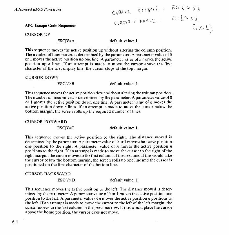
Advanced BIOS Functions f..;;([>sh
t.Yt [ '> S X
6-4
APC Escape Code Sequences c'~ (tS\ (l
CURSOR UP
ESC[PnA default value: 1
This sequence moves the active position up without altering the column position. The number of lines moved is determined by the parameter. A parameter value of 0 or 1 moves the active position up one line. A parameter value of n moves the active position up n lines. If an attempt is made to move the cursor above the first character of the first display line, the cursor stops at the top margin.
CURSOR DOWN
ESC[PnB default value: 1
This sequence moves the active position down without altering the column position. The number oflines moved is determined by the parameter. A parameter value of 0 or 1 moves the active position down one line. A parameter value of n moves the active position down n lines. If an attempt is made to move the cursor below the bottom margin, the screen rolls up the required number of lines.
CURSOR FORWARD
ESC[PnC default value: 1
This sequence moves the active position to the right. The distance moved is determined by the parameter. A parameter value of 0 or 1 moves the active position one position to the right. A parameter value of n moves the active position n positions to the right. If an attempt is made to move the cursor to the right of the right margin, the cursor moves to the first column of the next line. If this would take the cursor below the bottom margin, the screen rolls up one line and the cursor is positioned on the first character of the bottom line.
CURSOR BACKWARD
ESC[PnD default value: 1
This sequence moves the active position to the left. The distance moved is determined by the parameter. A parameter value of 0 or 1 moves the active position one position to the left. A parameter value of n moves the active position n positions to the left. If an attempt is made to move the cursor to the left of the left margin, the cursor moves to the last column in the previous row. If this would place the cursor above the home position, the cursor does not move.
(-, I \
\_ \.\\\, 1.-
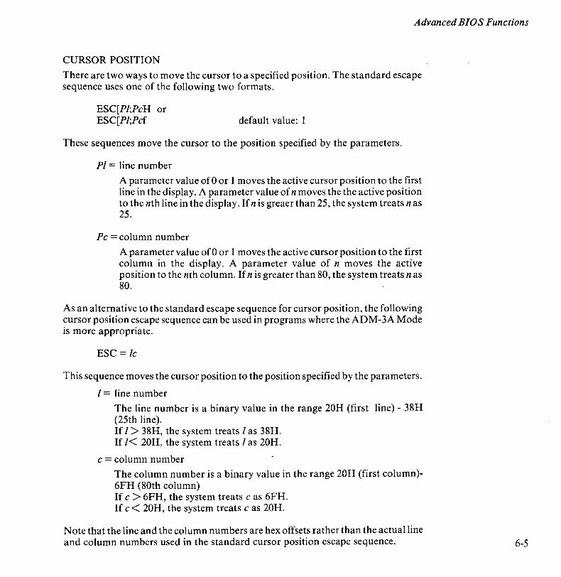
Advanced BIOS Functions
CURSOR POSITION
There are two ways to move the cursor to a specified position. The standard escape sequence uses one of the following two formats.
ESC[PI;PcH or ESC[PI;Pcf default value: 1
These sequences move the cursor to the position specified by the parameters.
PI = line number
A parameter value of 0 or 1 moves the active cursor position to the first line in the display. A parameter value of n moves the the active position to the nth line in the display. If n is greaer than 25, the system treats n as 25.
Pc = column number
A parameter value of 0 or 1 moves the active cursor position to the first column in the display. A parameter value of n moves the active position to the nth column. If n is greater than SO, the system treats n as SO.
As an alternative to the standard escape sequence for cursor position, the following cursor position escape sequence can be used in programs where the ADM-3A Mode is more appropriate.
ESC = Ic
This sequence moves the cursor position to the position specified by the parameters.
I = line number
The line number is a binary value in the range 20H (first line) - 3SH (25th line). If I > 3SH, the system treats I as 3SH. If 1< 20H, the system treats I as 20H.
c = column number
The column number is a binary value in the range 20H (first column)-6FH (SOth column) If c > 6FH, the system treats c as 6FH. If c < 20H, the system treats cas 20H.
Note that the line and the column numbers are hex offsets rather than the actual line and column numbers used in the standard cursor position escape sequence. 6-5
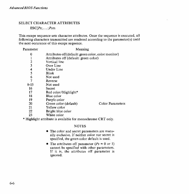
Advanced BIOS Functions
6-6
SELECT CHARACTER ATTRIBUTES
ESC[Ps; . .. ;Psm
This escape sequence sets character attributes. Once the sequence is executed, all following characters transmitted are rendered according to the parameter(s) until the next occurence of this escape sequence.
Parameter
o 1 2 3 4 5 6 7
8-15 16 17 18 19 20 21 22 23
Meaning
Attributes off (default: green color, color monitor) Attributes off (default: green color) Vertical line Over Line Under Line Blink Not used Reverse Not used Secret Red color/Highlight* Blue color Purple color Green color (default) Yellow color Bright blue color White color
Color Parameters
* Highlight attribute is available for monochrome CRT only.
NOTES
• The color and secret parameters are mutually exclusive. If neither color nor secret is specified, the green color default is used.
• The attributes off parameter (Ps = 0 or 1) cannot be specified with other parameters. If it is, the attributes off parameter is ignored.

Advanced BIOS Functions
ERASE WITHIN DISPLAY
ESC[PsJ default value: 0
This sequence erases some or all of the characters in the display according to the parameter.
Parameter
o
1
2
Meaning
Erase from the active position to the end of the screen, inclusive.
Erase from the start of the screen to the active position, inclusive.
Erase all of the display. All lines are erased and the cursor remains at its current position.
ERASE WITHIN LINE
ESC[PsK default value: 0
Erases some or all characters in the active line according to the parameter.
Parameter
o
1
2
Meaning
Erase from the active position to the end of the line, inclusive.
Erase from the start of the screen to the active position, inclusive.
Erase all of the line.
6-7
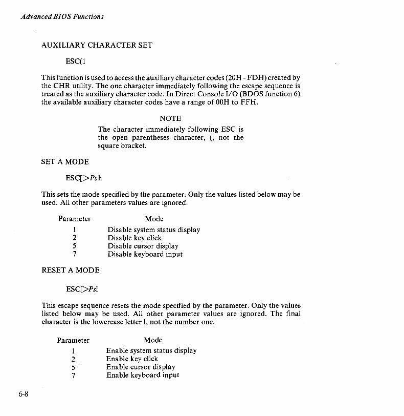
Advanced BIOS Functions
6-8
AUXILIARY CHARACTER SET
ESC(l
This function is used to access the auxiliary character codes (20H - FDH) created by the CHR utility. The one character immediately following the escape sequence is treated as the auxiliary character code. In Direct Console 1/0 (BDOS function 6) the available auxiliary character codes have a range of OOH to FFH.
SETA MODE
NOTE
The character immediately following ESC is the open parentheses character, (, not the square bracket.
ESC[>Psh
This sets the mode specified by the parameter. Only the values listed below may be used. All other parameters values are ignored.
Parameter
I 2 5 7
RESET A MODE
ESC[>Psl
Mode
Disable system status display Disable key click Disable cursor display Disable keyboard input
This escape sequence resets the mode specified by the parameter. Only the values listed below may be used. All other parameter values are ignored. The final character is the lowercase letter 1, not the number one.
Parameter
I 2 5 7
Mode
Enable system status display Enable key click Enable cursor display Enable keyboard input
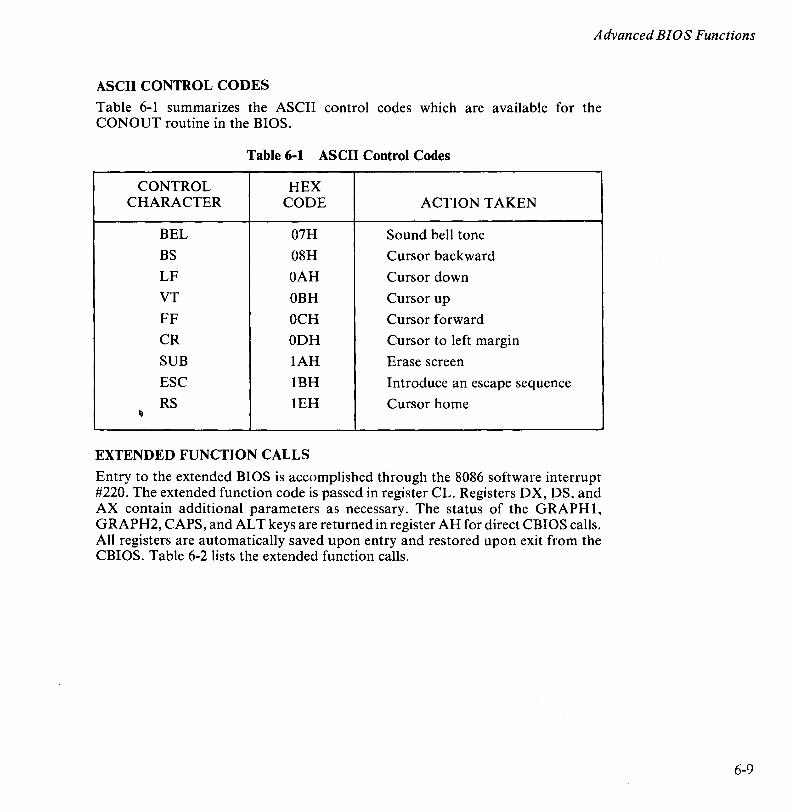
Advanced BIOS Functions
ASCII CONTROL CODES
Table 6-1 summarizes the ASCII control codes which are available for the CONOUT routine in the BIOS.
Table 6-1 ASCII Control Codes
CONTROL HEX CHARACTER CODE ACTION TAKEN
BEL 07H Sound bell tone BS 08H Cursor backward
LF OAH Cursor down
VT OBH Cursor up FF OCH Cursor forward CR ODH Cursor to left margin
SUB lAH Erase screen
ESC IBH Introduce an escape sequence RS lEH Cursor home
~
EXTENDED FUNCTION CALLS
Entry to the extended BIOS is accomplished through the 8086 software interrupt #220. The extended function code is passed in register CL. Registers DX, DS, and AX contain additional parameters as necessary. The status of the GRAPH1, GRAPH2, CAPS, and AL T keys are returned in register AH for direct CBIOS calls. All registers are automatically saved upon entry and restored upon exit from the CBIOS. Table 6-2 lists the extended function calls.
6-9
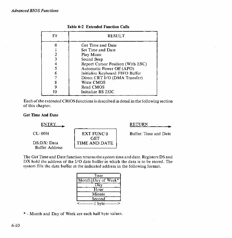
Advanced BIOS Functions
6-10
Table 6-2 Extended Function Calls
F# RESULT
0 Get Time and Date 1 Set Time and Date 2 Play Music 3 Sound Beep 4 Report Cursor Position (With ESC) 5 Automatic Power Off (APO) 6 Initialize Keyboard FIFO Buffer 7 Direct CRT I/O (DMA Transfer) 8 Write CMOS 9 Read CMOS
10 Initialize RS 232C
Each of the extended CBIOS functions is described in detail in the following section of this chapter.
Get Time And Date
ENTRY
CL: OOH
DS:DX: Data Buffer Address
EXT FUNCO GET
TIME AND DATE
RETURN
Buffer: Time and Date
The Get Time and Date function returns the system time and date. Registers DS and DX hold the address of the I/O data buffer in which the data is to be stored. The system fills the data buffer at the indicated address in the following format.
Year Month IDay of Week*
Day Hour
Minute Second
<----------1 byte--------->
* - Month and Day of Week are each half byte values.

Advanced BIOS Functions
Year = 00-99 BCD Month = 1-12 Hex Day of Week = 1-7 Hex (I-Sun, 2-Mon, etc.)
Set Time And Date
ENTRY
CL: 01H
DS:DX Data Buffer Address
Day = 1-31 Hour = 0-23 Minute = 0-59 Second = 0-59
BCD BCD BCD BCD
RETURN
EXT FUNC 1 SET
TIME AND DATE
The Set Time and Date function sets the system time and date. The buffer addressed by registers DS and DX must contain the time and date. The I/O data buffer format is the same as that used by extended function 0, Get Time and Date.
Play Music
ENTRY
CL: 02H
AX: Buffer length
DS:DX: Data Buffer Address
RETURN
EXT FUNC 2
PLAY MUSIC
The Play Music function plays music on the APC. The I/O buffer addressed by registers DS and DX consists of melody data. Register AX is set to the I/O buffer length in bytes. Melody data consists of two types of information: control commands and scale data. Control Commands set the loudness and speed. Scale data refer to notes, duration, and accent.
Control data is written in the following format.
[M[n]] [T[n]]
6-11
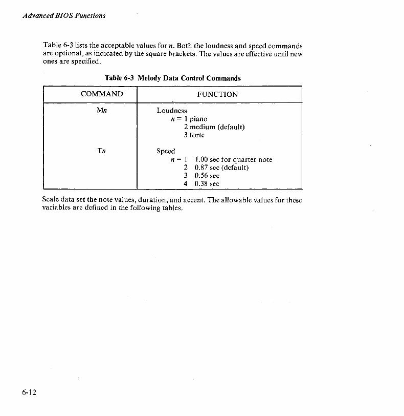
Advanced BIOS Functions
6-12
Table 6-3 lists the acceptable values for n. Both the loudness and speed commands are optional, as indicated by the square brackets. The values are effective until new ones are specified.
Table 6-3 Melody Data Control Commands
COMMAND FUNCTION
Mn Loudness n = 1 piano
2 medium (default) 3 forte
Tn Speed n=l 1.00 sec for quarter note
2 0.87 sec (default) 3 0.56 sec 4 0.38 sec
Scale data set the note values, duration, and accent. The allowable values for these variables are defined in the following tables.
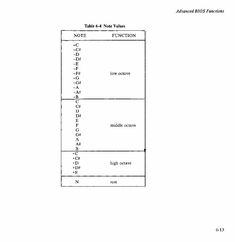
Advanced BIOS Functions
Table 6-4 Note Values
NOTE FUNCTION
-C -C# -D -D# -E -F -F# low octave -G -G# -A -A# -B
C C# D D# E F middle octave G G# A A# B ~~
+C +C# +D high octave +D# +E
N rest
6-13
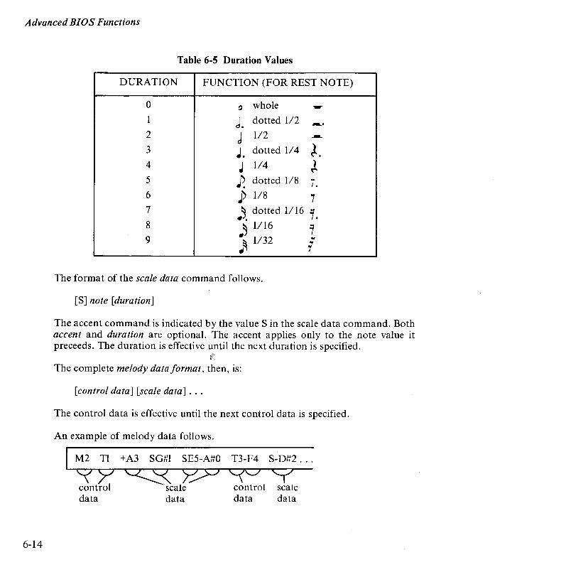
Advanced BIOS Functions
6-14
Table 6-5 Duration Values
DURATION FUNCTION (FOR REST NOTE)
0 0 whole ~
1 J. dotted 1/2 -... 2 d 1/2 ---3 J. dotted 1/4 ~. 4 J 1/4 ~ 5 P. dotted 1/8 i. 6 J) 1/8 7 7 ~~. dotted 1/16 7. 8 ~ 1/16 1 9 ~ 1/32
.. 1
The format of the scale data command follows.
[S] note [duration]
The accent command is indicated by the value S in the scale data command. Both accent and duration are optional. The accent applies only to the note value it preceeds. The duration is effective until the next duration is specified.
The complete melody data format, then, is:
[control data] [scale data] ...
The control data is effective until the next control data is specified.
An example of melody data follows.
M2 TI +A3 SG#l SE5-A#O T3-F4 S-D#2 ...
'? Y ~ Y.,;>J C(C/ Y control scale control scale da~ d~a da~ da~
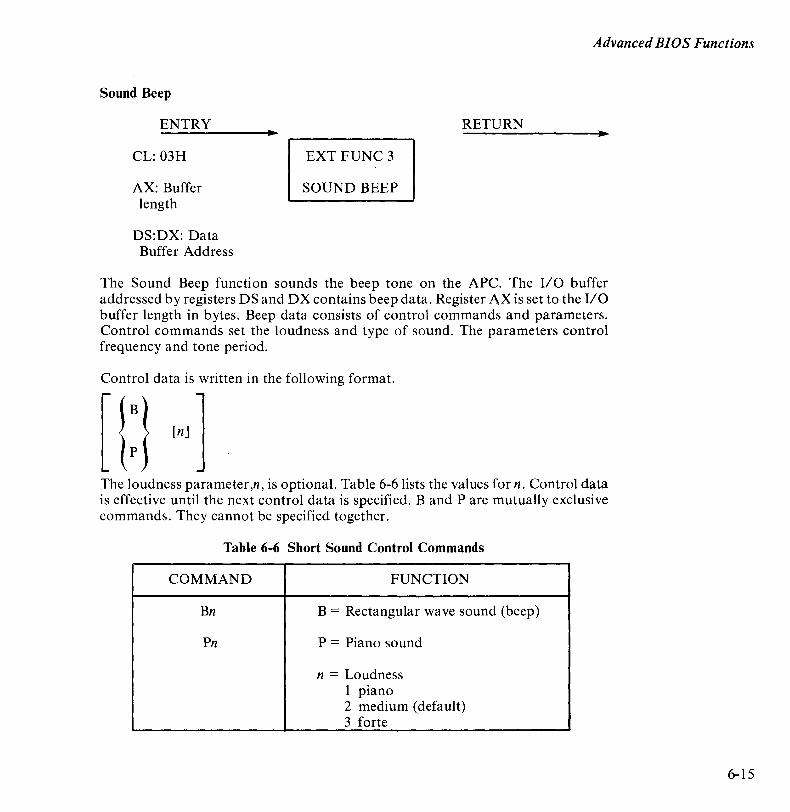
Advanced BIOS Functions
Sound Beep
ENTRY
CL: 03H
AX: Buffer length
DS:DX: Data Buffer Address
RETURN
EXT FUNC 3
SOUND BEEP
The Sound Beep function sounds the beep tone on the APC. The 110 buffer addressed by registers DS and DX contains beep data. Register AX is set to the 1/0 buffer length in bytes. Beep data consists of control commands and parameters. Control commands set the loudness and type of sound. The parameters control frequency and tone period.
Control data is written in the following format.
The loudness parameter,n, is optional. Table 6-6 lists the values for n. Control data is effective until the next control data is specified. Band P are mutually exclusive commands. They cannot be specified together.
Table 6-6 Short Sound Control Commands
COMMAND FUNCTION
Bn B = Rectangular wave sound (beep)
Pn P = Piano sound
n = Loudness 1 piano 2 medium (default) 3 forte
6-15
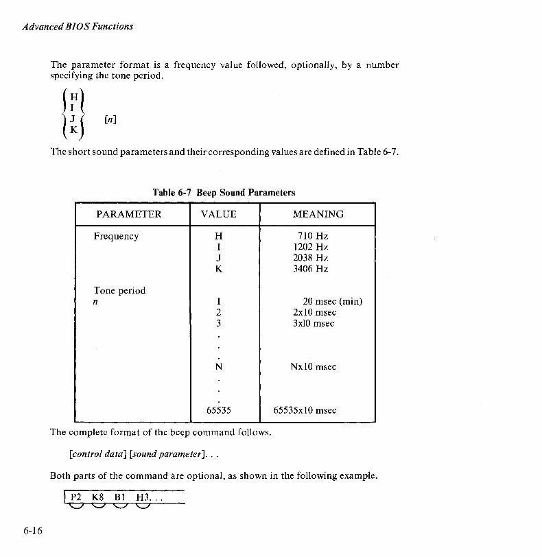
Advanced BIOS Functions
6-16
The parameter format is a frequency value followed, optionally, by a number specifying the tone period.
trl [n]
The short sound parameters and their corresponding values are defined in Table 6-7.
Table 6-7 Beep Sound Parameters
PARAMETER VALUE MEANING
Frequency H 710 Hz I 1202 Hz J 2038 Hz K 3406 Hz
Tone period n 1 20 msec (min)
2 2xl0 msec 3 3xlO msec
N Nxl0 msec
65535 65535xl0 msec
The complete format of the beep command follows.
[control data] [sound parameter] . ..
Both parts of the command are optional, as shown in the following example.
I P2 K8 Bl H3 ...

Advanced BIOS Functions
Report Cursor Position
ENTRY
CL: 04H
DS:DX: Data Buffer Address
EXT FUNC 4
REPORT CURSOR POSITION
RETURN
Buffer: Cursor Position
The Report Cursor Position function gets the current active position on the console screen. Registers DS and DX point to the address of the I/O buffer in which the data is to be stored. The system returns the column and line numbers of the current position prefixed by the escape (ESC) code in the following format.
E S [ PI , Pc R C
~8 bytes
All characters are returned as ASCII code values. PI is the line number (01-25). Pc is the column number (01-80).
Auto Power Off
ENTRY RETURN
CL: 05H EXT FUNC 5
APO
The Auto Power Off function turns off the power of the machine. When the function is called, the system waits approximately five seconds before turning off the power. To turn the system back on, remove any diskettes in the drives, turn the power switch off, then turn it back on.
6-17
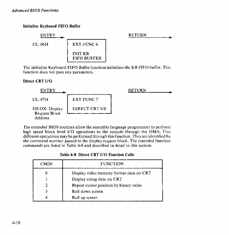
Advanced BIOS Functions
6-18
Initialize Keyboard FIFO Buffer
ENTRY RETURN
CL: 06H EXT FUNC 6
INIT KB FIFO BUFFER
The Initialize Keyboard FIFO Buffer function initializes the KB FIFO buffer. This function does not pass any parameters.
Direct CRT va
ENTRY
CL: 07H
DS:DX: Display Request Block Address
RETURN II
EXT FUNC 7
DIRECT CRT I/O
The extended BIOS routines allow the assembly language programmer to perform high speed block level I/O operations to the console through the DMA. Five different operations may be performed through this function. They are identified by the command number passed in the display request block. The extended function commands are listed in Table 6-8 and described in detail in this section.
Table 6-8 Direct CRT va Function Calls
CMD# FUNCTION
0 Display video memory format data on CRT
1 Display string data on CRT
2 Report cursor position by binary value
3 Roll down screen
4 Roll up screen
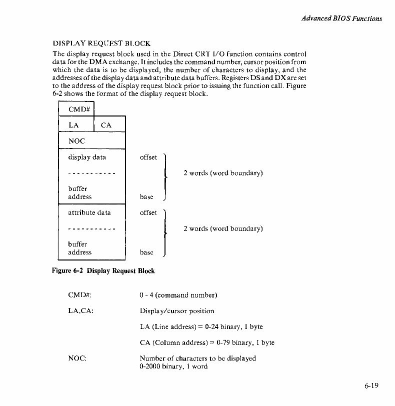
Advanced BIOS Functions
DISPLAY REQUEST BLOCK
The display request block used in the Direct CRT I/O function contains control data for the DMA exchange. It includes the command number, cursor position from which the data is to be displayed, the number of characters to display, and the addresses of the display data and attribute data buffers. Registers DS and DX are set to the address of the display request block prior to issuing the function call. Figure 6-2 shows the format of the display request block.
CMD#
LA CA
NOC
display data offset
----------- 2 words (word boundary)
buffer address base
attribute data offset
----------- 2 words (word boundary)
buffer address base
Figure 6-2 Display Request Block
CMD#:
LA,CA:
NOC:
o -4 (command number)
Display/cursor position
LA (Line address) = 0-24 binary, 1 byte
CA (Column address) = 0-79 binary, 1 byte
Number of characters to be displayed 0-2000 binary, 1 word
6-19
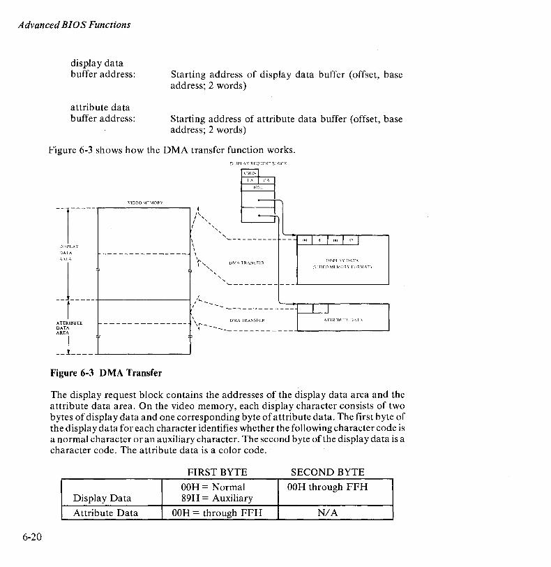
Advanced BIOS Functions
6-20
dis pIa y data buffer address:
attribute data buffer address:
Starting address of display data buffer (offset, base address; 2 words)
Starting address of attribute data buffer (offset, base address; 2 words)
Figure 6-3 shows how the DMA transfer function works. DISPL.A Y REQCEST BLOCK
--1 DISPLAY
DATA
VIDEO MEMORY
~ Il...
I ,
I " I ",
\ \ \ --------------- \
ARI,A \"
;~ " "
~ LA I CA
NOL
-r---.
-,'----------
DMA TRANSHR
--- 1111 I 41 I 00 I 42 I
DISPL\ Y DATA
[I'IDIO MIMORY H)RMA'I)
j I',
~-----------,~--------------~
l -- -----.~--------~ ,'L-- .......
I -- I I \
A TfRIBUTE t- - - - - - - - - - - - - - -DMA TRANSII R \T1RIHI'TID.YIA
DATA AREA
\r-_ i
-------------,-~--------------~
__ 1 ____ ->----1 __ I
Figure 6-3 DMA Transfer
The display request block contains the addresses of the display data area and the attribute data area. On the video memory, each display character consists of two bytes of display data and one corresponding byte of attribute data. The first byte of the display data for each character identifies whether the following character code is a normal character or an auxiliary character. The second byte of the display data is a character code. The attribute data is a color code.
FIRST BYTE SECOND BYTE
OOH= Normal OOH through FFH Display Data 89H = Auxiliary
Attribute Data OOH = through FFH N/A
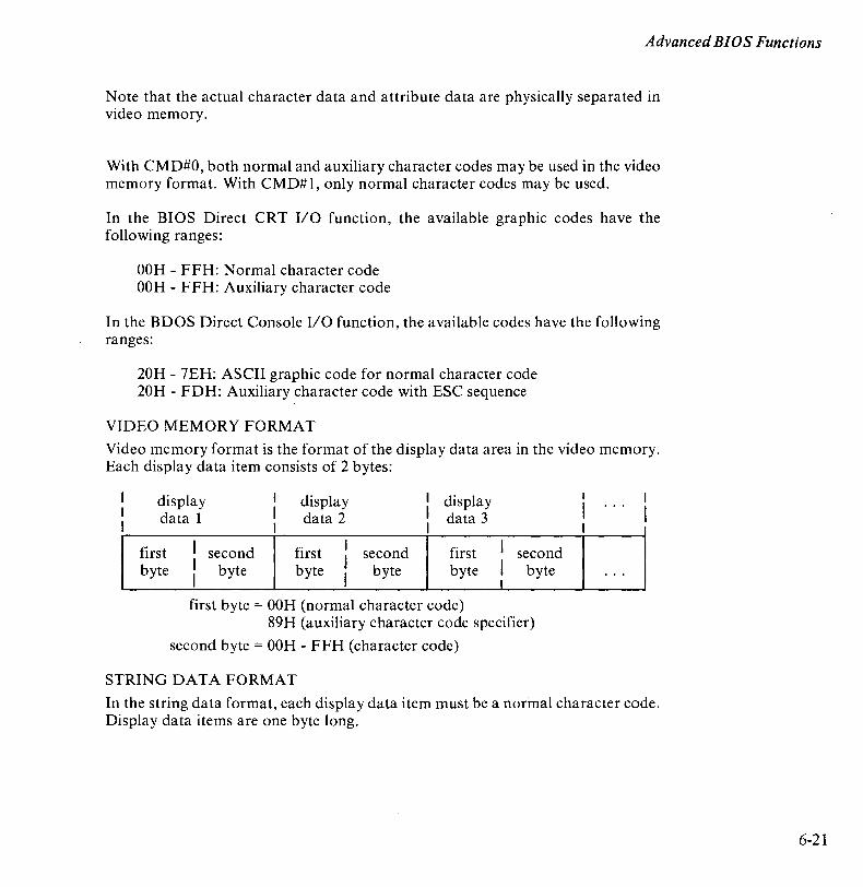
Advanced BIOS Functions
Note that the actual character data and attribute data are physically separated in video memory.
With CMD#O, both normal and auxiliary character codes may be used in the video memory format. With CMD#I, only normal character codes may be used.
In the BIOS Direct CRT I/O function, the available graphic codes have the following ranges:
OOH - FFH: Normal character code OOH - FFH: Auxiliary character code
In the BDOS Direct Console I/O function, the available codes have the following ranges:
20H - 7EH: ASCII graphic code for normal character code 20H - FDH: Auxiliary character code with ESC sequence
VIDEO MEMORY FORMAT
Video memory format is the format of the display data area in the video memory. Each display data item consists of 2 bytes:
display data 1
first I byte I
I
second byte
display data 2
first I
byte I I
second byte
display data 3
first byte
first byte = OOH (normal character code)
I second I byte I
89H (auxiliary character code specifier)
second byte = OOH - FFH (character code)
STRING DATA FORMAT
...
In the string data format, each display data item must be a normal character code. Display data items are one byte long.
6-21
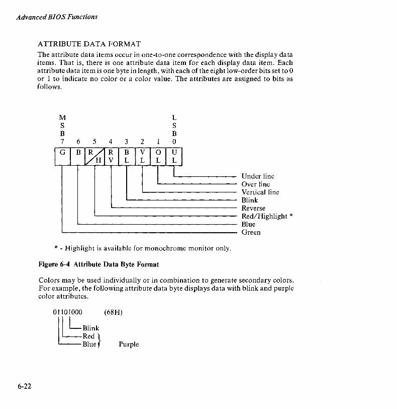
Advanced BIOS Functions
6-22
ATTRIBUTE DATA FORMAT
The attribute data items occur in one-to-one correspondence with the display data items. That is, there is one attribute data item for each display data item. Each attribute data item is one byte in length, with each of the eight low-order bits set to 0 or 1 to indicate no color or a color value. The attributes are assigned to bits as follows.
M S B 7 6 5 3 2 1
L S B o
* - Highlight is available for monochrome monitor only.
Figure 6-4 Attribute Data Byte Format
Under line Over line Vertical line Blink Reverse Red/Highlight * Blue Green
Colors may be used individually or in combination to generate secondary colors. For example, the following attribute data byte displays data with blink and purple color attributes.
01101000 (68H)
~LBlink LRed} Blue Purple
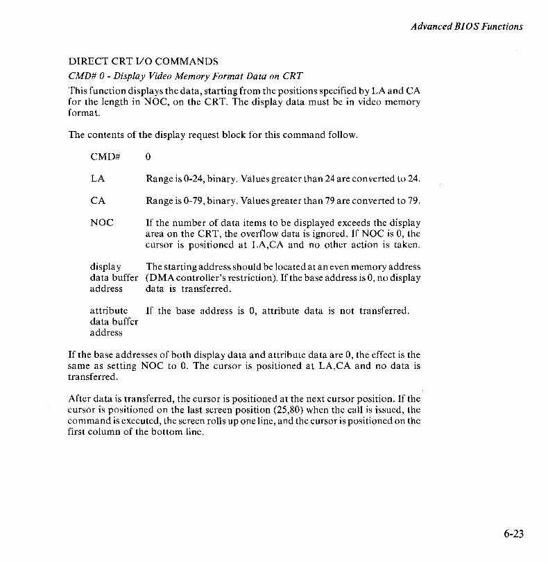
Advanced BIOS Functions
DIRECT CRT I/O COMMANDS
CMD# 0 - Display Video Memory Format Data on CRT
This function displays the data, starting from the positions specified by LA and CA for the length in NOC, on the CRT. The display data must be in video memory format.
The contents of the display request block for this command follow.
CMD#
LA
CA
NOC
o
Range is 0-24, binary. Values greater than 24 are converted to 24.
Range is 0-79, binary. Values greater than 79 are converted to 79.
If the number of data items to be displayed exceeds the display area on the CRT, the overflow data is ignored. If NOC is 0, the cursor is positioned at LA,CA and no other action is taken.
display The starting address should be located at an even memory address data buffer (DMA controller's restriction). If the base address is 0, no display address da ta is transferred.
attribute If the base address IS 0, attribute data is not transferred. data buffer address
If the base addresses of both display data and attribute data are 0, the effect is the same as setting NOC to O. The cursor is positioned at LA,CA and no data is transferred.
After data is transferred, the cursor is positioned at the next cursor position. If the cursor is positioned on the last screen position (25,80) when the call is issued, the command is executed, the screen rolls up one line, and the cursor is positioned on the first column of the bottom line.
6-23
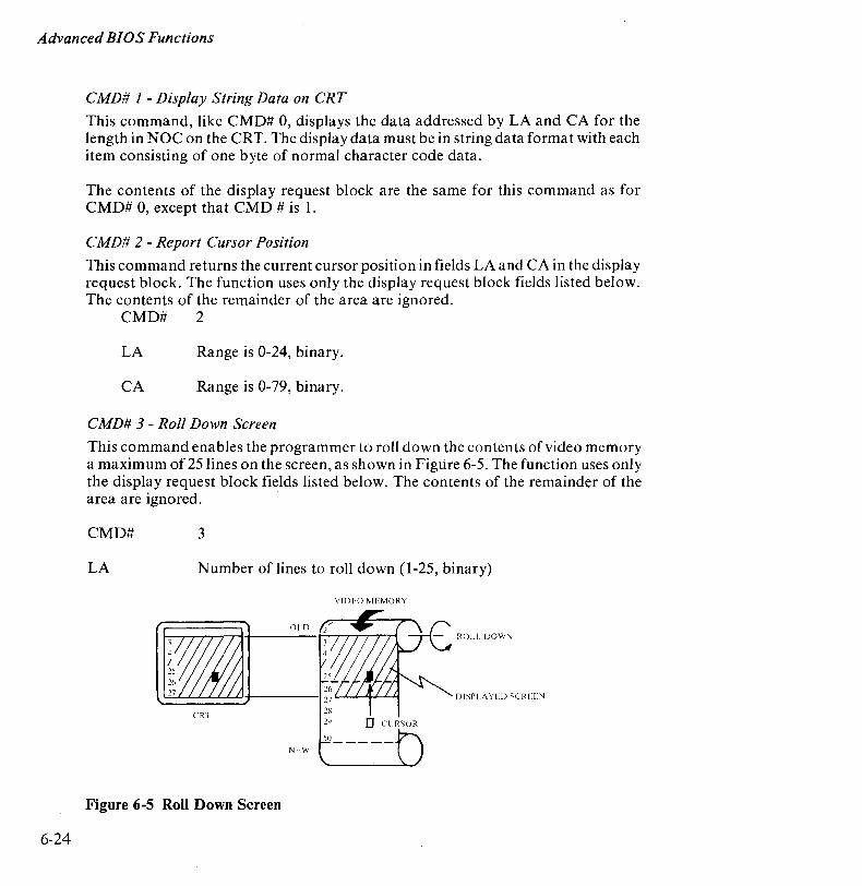
Advanced BIOS Functions
6-24
CMD# 1 - Display String Data on CRT
This command, like CMD# 0, displays the data addressed by LA and CA for the length in NOC on the CRT. The display data must be in string data format with each item consisting of one byte of normal character code data.
The contents of the display request block are the same for this command as for CMD# 0, except that CMD # is 1.
CMD# 2 - Report Cursor Position
This command returns the current cursor position in fields LA and CA in the display request block. The function uses only the display request block fields listed below. The contents of the remainder of the area are ignored.
CMD# 2
LA Range is 0-24, binary.
CA Range is 0-79, binary.
CMD# 3 - Roll Down Screen
This command enables the programmer to roll down the contents of video memory a maximum of 25 lines on the screen, as shown in Figure 6-5. The function uses only the display request block fields listed below. The contents of the remainder of the area are ignored.
CMD# 3
LA Number of lines to roll down (1-25, binary)
VIDLO MEMORY
DISPLA YLD SCREEN
29 0 CURSOR
NI:W
Figure 6-5 Roll Down Screen

Advanced BIOS Functions
CMD# 4 - Roll Up Screen
This command enables the programmer to roll up the specified number of lines on the screen, as shown in Figure 6-6. The function uses only the display request block fields listed below. The contents of the remainder of the area are ignored.
CMD#
LA
4
Number of lines to roll up If the number of lines to roll up exceeds the number of lines that have been written, the next line is erased.
YJ[)IO ""1.l\10R~
OlD ROil 1'1'
_
_ 6 -----
27
50 ______ -4---'---'---'--' ............ ~
'" I \\
Figure 6-6 Roll Up Screen
6-25
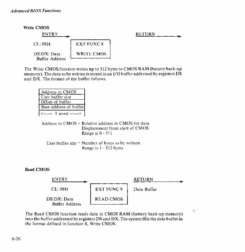
Advanced BIOS Functions
6-26
Write CMOS
ENTRY
CL: 08H
DS:DX: Data Buffer Address
RETURN
EXT FUNC 8
WRITE CMOS
The Write CMOS function writes up to 512 bytes to CMOS RAM (battery back-up memory). The data to be written is stored in an I/O buffer addressed by registers DS and DX. The format of the buffer follows.
Address in CM OS User buffer size Offset of buffer Base address of buffer
<------ 1 word ------>
Address in CMOS = Relative address in CMOS for data Displacement from start of CMOS Range is 0 - 511
User buffer size = Number of bytes to be written Range is 1 - 512 bytes
Read CMOS
ENTRY
CL: 09H
DS:DX: Data Buffer Address
RETURN
EXT FUNC 9 Data Buffer
READ CMOS
The Read CMOS function reads data in CMOS RAM (battery back-up memory) into the buffer addressed by registers DS and DX. The system fills the data buffer in the format defined in function 8, Write CMOS.

Advanced BIOS Functions
Initialize RS 232C
ENTRY
CL: OAH
DX: Baud Rate and Mode
EXT FUNC 10 INITIALIZE
RS 232C
RETURN
The Initialize RS 232C function is used in asynchronous mode only to set the baud rate (DH) and mode (DL). (In synchronous mode, an external clock determines the baud rate.) The register values are set as follows.
DH = Baud Rate
0= 150 BPS 1 = 200 BPS 2 = 300 BPS 3 = 600 BPS 4 = 1200 BPS 5 = 2400 BPS 6 = 4800 BPS 7 = 9600 BPS
6-27

Advanced BIOS Functions
6-28
DL = Asynchronous mode byte for J1. PD8251
7 6 5 4 3 2 1 o
I S2 lSI I EP I PEN I L2 I LI I B2 I B 1 I baud rate
~----------------~~ ~--------------------~~
'*t baud rate L...-:..
length of character
010 1 o 0 1 1
5 bit 6 bit 7 bit 8 bit
parity enable/disable '--_________ -<{ 1 = enable
0= disable
parity check { 1 = even
~----------------~ 0= odd
length of stop bit
1 1 o 1
1 bit 2 bit
NOTE
Typically, when communication software is operating, the system timer is off and the keyboard repeat feature does not operate.
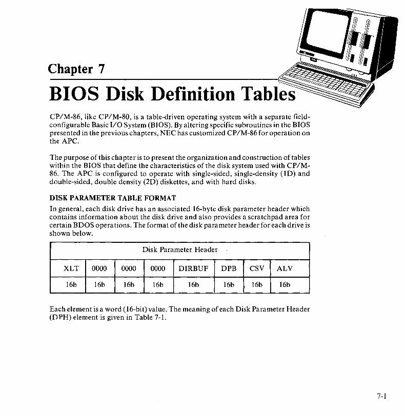
Chapter 7
BIOS Disk Definition Tables CP/M-86, like CP/M-80, is a table-driven operating system with a separate fieldconfigurable Basic I/O System (BIOS). By altering specific subroutines in the BIOS presented in the previous chapters, NEC has customized CP/M-86 for operation on the APC.
The purpose of this chapter is to present the organization and construction of tables within the BIOS that define the characteristics of the disk system used with CP/M-86. The APC is configured to operate with single-sided, single-density (lD) and double-sided, double density (2D) diskettes, and with hard disks.
DISK PARAMETER TABLE FORMAT
In general, each disk drive has an associated 16-byte disk parameter header which contains information about the disk drive and also provides a scratchpad area for certain BDOS operations. The format of the disk parameter header for each drive is shown below.
Disk Parameter Header
XLT 0000 0000 0000 DIRBUF DPB CSV ALV
16b 16b 16b 16b 16b 16b 16b 16b
Each element is a word (16-bit) value. The meaning of each Disk Parameter Header (DPH) element is given in Table 7-1.
7-1

BIOS Disk Definition Tables
7-2
Table 7-1 Disk Parameter Header Elements
ELEMENT DESCRIPTION
XLT Offset of the logical-to-physical translation vector, ifused for this particular drive, or the value OOOOH if no sector translation takes place (i.e., the physical and logical sector numbers are the same). Disk drives with identical sector skew factors share the same translate tables.
0000 Scratchpad values for use within the BDOS (initial value is unimportant).
DIRBUF Offset of a 128-byte scratchpad area for directory operations within BDOS. All DPHs address the same scratchpad area.
DPB Offset of a disk parameter block for this drive. Drives with identical disk characteristics address the same disk parameter block.
CSV Offset of a scratchpad area used for software check for changed disketts. This offset is different for each DPH and is used for floppy diskettes only.
ALV Offset of a scratchpad area used by the BDOS to keep disk storage allocation information. This offset is different for each DPH.
Table 7-2 lists the DPH values for the APC.
DIRBUF
CSV
ALV
Table 7-2 DPH Values For The APe
FO-ID FD-2D
128 bytes 128 bytes
16 bytes 64 bytes x 4 drives x 4 drives
31 bytes 62 bytes x 4 drives x 4 drives
HARD DISK
128 bytes
a
71 bytes x 4 drives
CPMSPT= 64 SECMSK = 63

BIOS Disk Definition Tables
Given n disk drives, the DPHs are arranged in a table whose first row of 16 bytes corresponds to Drive 0, and whose last row corresponds to drive n-1. The table appears as follows.
DPBASE
00 XLTOO 0000 0000 0000 DIRBUF DBPOO CSVOO ALVOO
01 XLT01 0000 0000 0000 DIRBUF DBP 01 CSV01 ALV01
(and so forth through)
The label DPBASE defines the offset of the DPH table relative to the beginning of the operating system.
A responsibility of the SELDSK subroutine, defined in Chapter 5, is to return the offset of the DPH from the beginning of the operating system for the selected drive. The following sequence of operations returns the table offset, with a value ofOOOOH returned if the selected drive does not exist.
NDISKS EQU 8 ;NUMBER OF DISK DRIVES
SELDSK: ;SELECT DISK N GIVEN BY CL MOV BX,OOOOH ;READY FOR ERR CMP CL,NDISKS ;N BEYOND MAX DISKS? JNB RETURN ;RETURN IF SO
;0 <= N < NDISKS MOV CH,O ;DOUBLE (N) MOV BX,CX ;BX = N MOV CL,4 ;READY FOR * 16 SHL BX,CL ;N = N * 16 MOV CX,OFFSET DPBASE ADD BX,CX ;DPBASE + N * 16
RETURN: RET ;BX - .DPH (N)
7-3
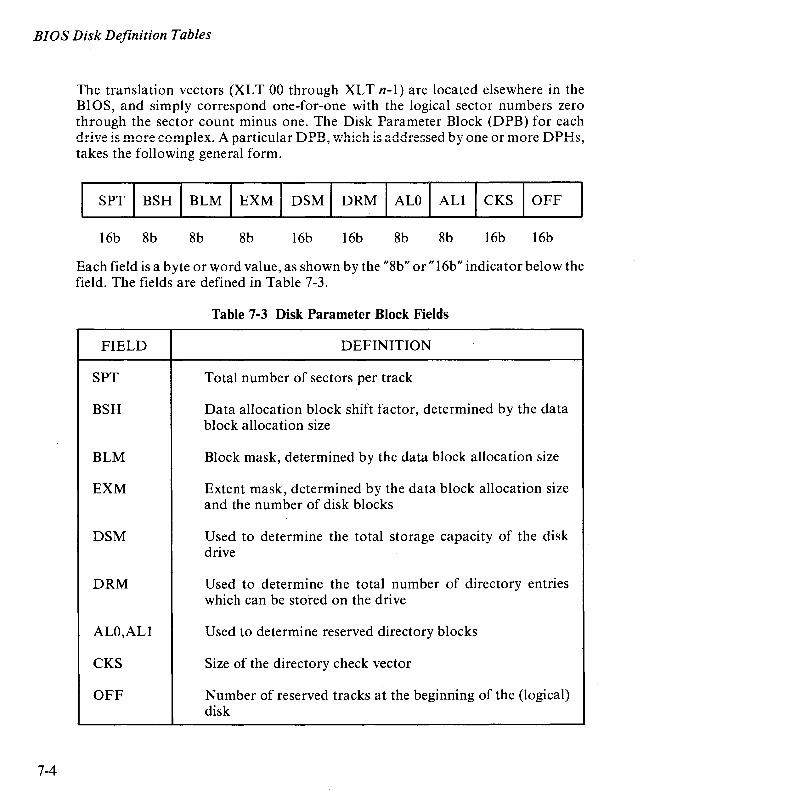
BIOS Disk Definition Tables
7-4
The translation vectors (XLT 00 through XL Tn-I) are located elsewhere in the BIOS, and simply correspond one-far-one with the logical sector numbers zero through the sector count minus one. The Disk Parameter Block (DPB) for each drive is more complex. ~A1 particular DPB, which is addressed by one or more DPHs, takes the following general form.
SPT I BSH I BLM I EXM I DSM I DRM I ALO I ALl I CKS I OFF
16b 8b 8b 8b 16b 16b 8b 8b 16b 16b
Each field is a byte or word value, as shown by the "8b" or "16b" indicator below the field. The fields are defined in Table 7-3.
Table 7-3 Disk Parameter Block Fields
FIELD DEFINITION
SPT Total number of sectors per track
BSH Data allocation block shift factor, determined by the data block allocation size
BLM Block mask, determined by the data block allocation size
EXM Extent mask, determined by the data block allocation size and the number of disk blocks
DSM Used to determine the total storage capacity of the disk drive
DRM Used to determine the total number of directory entries which can be stored on the drive
ALO,ALI Used to determine reserved directory blocks
CKS Size of the directory check vector
OFF Number of reserved tracks at the beginning of the (logical) disk
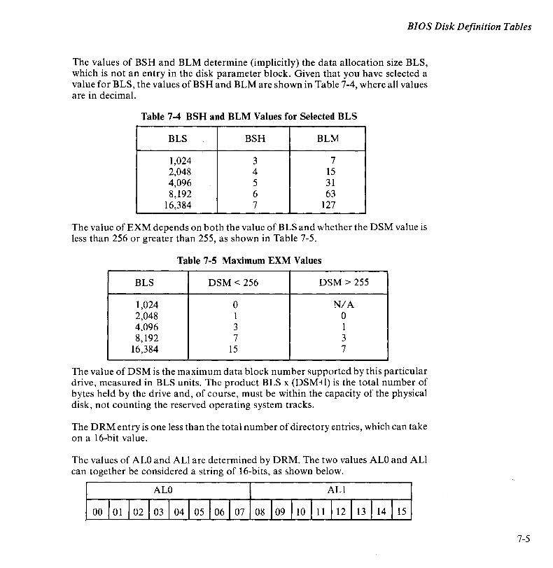
BIOS Disk Definition Tables
The values of BSH and BLM determine (implicitly) the data allocation size BLS, which is not an entry in the disk parameter block. Given that you have selected a value for BLS, the values of BSH and BLM are shown in Table 7-4, where all values are in decimal.
Table 7-4 BSH and BLM Values for Selected BLS
BLS BSH BLM
1,024 3 7 2,048 4 15 4,096 5 31 8,192 6 63
16,384 7 127
The value of EXM depends on both the value of BLS and whether the DSM value is less than 256 or greater than 255, as shown in Table 7-5.
Table 7-5 Maximum EXM Values
BLS DSM < 256 DSM > 255
1,024 ° N/A 2,048 I ° 4,096 3 1 8,192 7 3
16,384 15 7
The value of DSM is the maximum data block number supported by this particular drive, measured in BLS units. The product BLS x (DSM+I) is the total number of bytes held by the drive and, of course, must be within the capacity of the physical disk, not counting the reserved operating system tracks.
The DRM entry is one less than the total number of directory entries, which can take on a 16-bit value.
The values of ALO and ALl are determined by DRM. The two values ALO and ALl can together be considered a string of 16-bits, as shown below.
ALO ALl
15
7-5
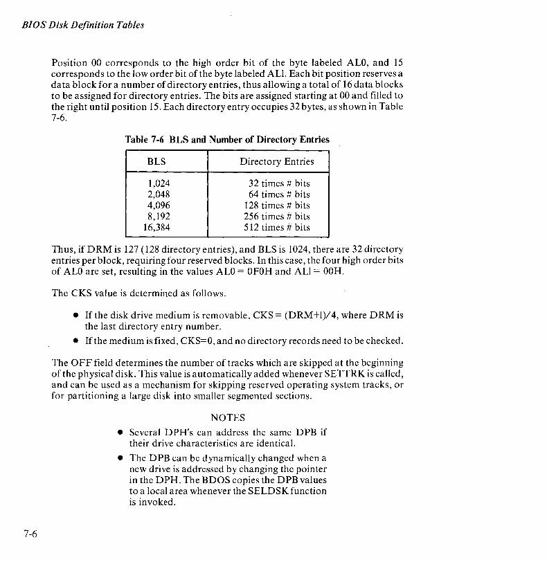
BIOS Disk Definition Tables
7-6
Position 00 corresponds to the high order bit of the byte labeled ALO, and 15 corresponds to the low order bit of the byte labeled ALl. Each bit position reserves a data block for a number of directory entries, thus allowing a total of 16 data blocks to be assigned for directory entries. The bits are assigned starting at 00 and filled to the right until position 15. Each directory entry occupies 32 bytes, as shown in Table 7-6.
Table 7-6 BLS and Number of Directory Entries
BLS Directory Entries
1,024 32 times # bits 2,048 64 times # bits 4,096 128 times # bits 8,192 256 times # bits
16,384 512 times # bits
Thus, if DRM is 127 (128 directory entries), and BLS is 1024, there are 32 directory entries per block, requiring four reserved blocks. In this case, the four high order bits of ALO are set, resulting in the values ALO = OFOH and ALl = OOH.
The CKS value is determined as follows .
• If the disk drive medium is removable, CKS = (DRM+I)/4, where DRM is the last directory entry number .
• If the medium is fixed, CKS=O, and no directory records need to be checked.
The OFF field determines the number of tracks which are skipped at the beginning of the physical disk. This value is automatically added whenever SETTRK is called, and can be used as a mechanism for skipping reserved operating system tracks, or for partitioning a large disk into smaller segmented sections.
NOTES
• Several D PH's can address the same D PB if their drive characteristics are identical.
• The DPB can be dynamically changed when a new drive is addressed by changing the pointer in the DPH. The BDOS copies the DPB values to a local area whenever the SELDSK function is invoked.
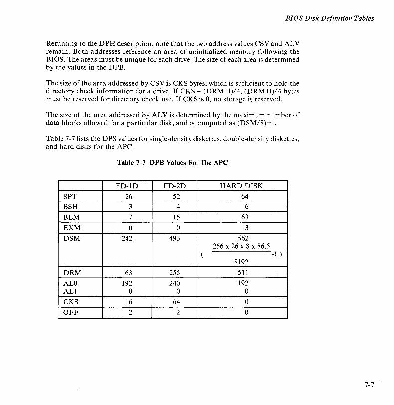
BIOS Disk Definition Tables
Returning to the DPH description, note that the two address values CSVand ALV remain. Both addresses reference an area of uninitialized memory following the BIOS. The areas must be unique for each drive. The size of each area is determined by the values in the DPB.
The size of the area addressed by CSV is CKS bytes, which is sufficient to hold the directory check information for a drive. If CKS = (DRM+I)/4, (DRM+I)/4 bytes must be reserved for directory check use. If CKS is 0, no storage is reserved.
The size of the area addressed by ALV is determined by the maximum number of data blocks allowed for a particular disk, and is computed as (DSM/8)+ 1.
Table 7-7 lists the DPS values for single-density diskettes, double-density diskettes, and hard disks for the APC.
Table 7-7 DPB Values For The APe
FD-1D FD-2D HARD DISK
SPT 26 52 64
BSH 3 4 6
BLM 7 15 63
EXM 0 0 3
DSM 242 493 562 256 x 26 x 8 x 86.5
( -1 ) 8192
DRM 63 255 511
ALO 192 240 192 ALl 0 0 0
CKS 16 64 0
OFF 2 2 0
7-7
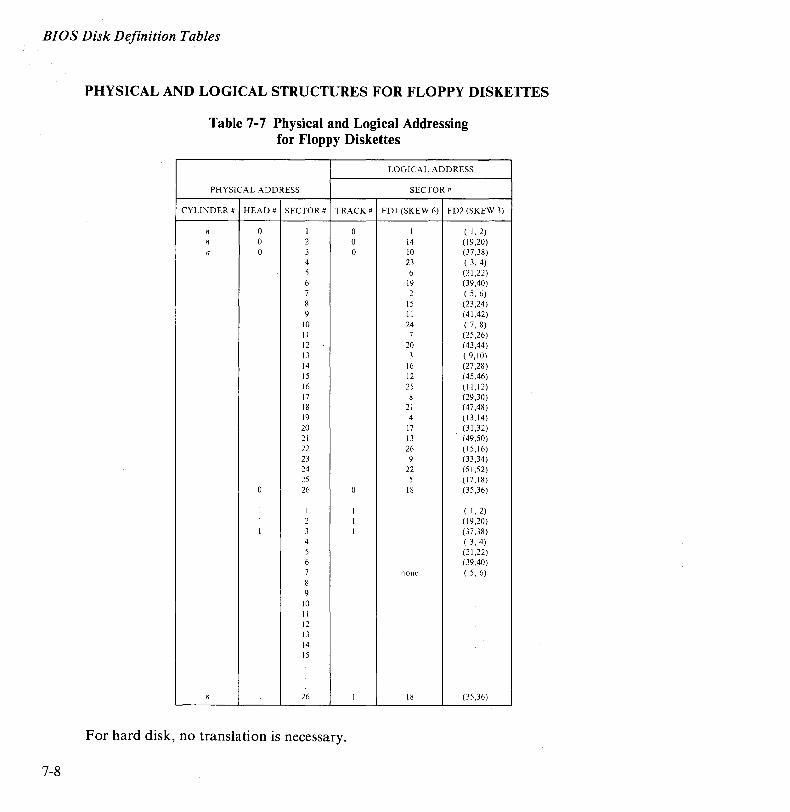
BIOS Disk Definition Tables
7-8
PHYSICAL AND LOGICAL STRUCTURES FOR FLOPPY DISKETTES
Table 7-7 Physical and Logical Addressing for Floppy Diskettes
LOGICAL ADDRESS
PHYSICAL ADDRESS SECTOR #
CYLINDER # HEAD# SECTOR # TRACK # FDI (SKEW 6) FD2 (SKEW 3)
n 0 I 0 I ( 1,2) n 0 2 0 14 (19,20) n 0 3 0 10 (37,38)
4 23 ( 3, 4) 5 6 (21,22) 6 19 (39,40) 7 2 ( 5,6) 8 15 (23,24) 9 II (41,42)
10 24 ( 7, 8) II 7 (25,26) 12 20 (43,44) 13 3 ( 9,10) 14 16 (27,28) 15 12 (45,46) 16 25 (II ,12) 17 8 (29,30) 18 21 (47,48) 19 4 (13,14) 20 17 (31,32) 21 13 (49,50) 22 26 (15,16) 23 9 (33,34) 24 22 (51,52) 25 5 ( 17,18)
0 26 0 18 (35,36)
1 1 I ( 1,2) 1 2 1 (19,20) 1 3 I (37,38)
4 ( 3, 4) 5 (21,22) 6 (39,40) 7 none ( 5,6) 8 9
10 II 12 13 14 15
n 1 26 1 18 (35,36 )
For hard disk, no translation is necessary.
Chapter 8
CP/M-86 Bootstrap and Adaptation Procedures This chapter describes the components of the NEC CP/M-86 system distribution diskette, the operation of each component, and the procedures followed in modifying CP/M-86 for the APC hardware environment. NEC used these procedures to adapt the standard CP/M-86 distributed by Digital Research, Inc. to make available to you the unique features of the APC. There is no need for you to modify the operating system in any way for normal use on your APC. This chapter is included primarily for informational purposes.
CAUTION
The procedures outlined in this chapter should be used only by system programmers who need to reconfigure the operating system for systems development purposes. °Do not attempt the procedures unless it is your intent to modify the CBIOS. If the procedures are not understood and followed exactly, you may lose the entire CP/M-86 operating system.
CP/M-86 is customized for the APC and distributed on two double-sided, doubledensity IBM-compatible eight-inch diskettes using a file format which is compatible with all previous CP/M-80 operating systems. The principal components of the distribution system are found on the CP/M-86 System Diskette. They are:
• 86/12 Bootstrap ROM (BOOT ROM)
• Cold Start Loader (LOADER)
• CP/M-86 System (CPM.SYS)
All the hardware and firmware necessary for running the APC are available in the BOOT ROM.
8-1
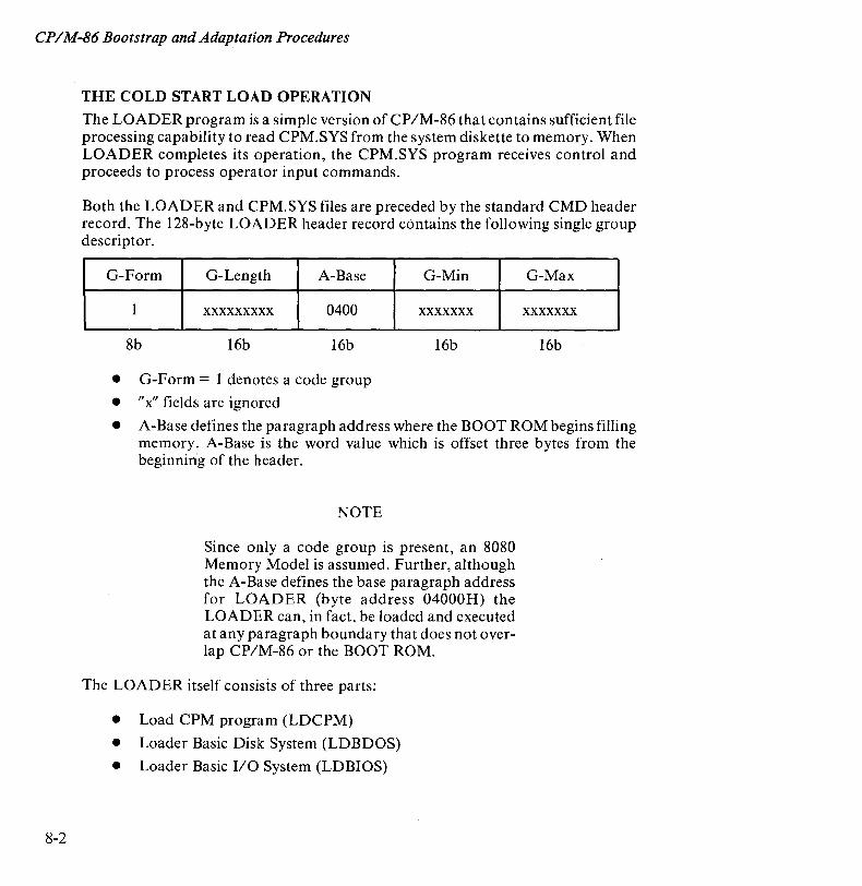
CPIM-86 Bootstrap and Adaptation Procedures
8-2
THE COLD START LOAD OPERATION
The LOADER program is a simple version of CP/M-86 that contains sufficient file processing capability to read CPM.SYS from the system diskette to memory. When LOADER completes its operation, the CPM.SYS program receives control and proceeds to process operator input commands.
Both the LOADER and CPM.SYS files are preceded by the standard CMD header record. The 128-byte LOADER header record contains the following single group descriptor.
G-Form G-Length A-Base G-Min G-Max
1 xxxxxxxxx 0400 xxxxxxx xxxxxxx
8b 16b 16b 16b 16b
• G-Form = 1 denotes a code group
• "x" fields are ignored
• A-Base defines the paragraph address where the BOOT ROM begins filling memory. A-Base is the word value which is offset three bytes from the beginning of the header.
NOTE
Since only a code group is present, an 8080 Memory Model is assumed. Further, although the A-Base defines the base paragraph address for LOADER (byte address 04000H) the LOADER can, in fact, be loaded and executed at any paragraph boundary that does not overlap CP/M-86 or the BOOT ROM.
The LOADER itself consists of three parts:
• Load CPM program (LDCPM)
• Loader Basic Disk System (LDBDOS)
• Loader Basic I/O System (LDBIOS)
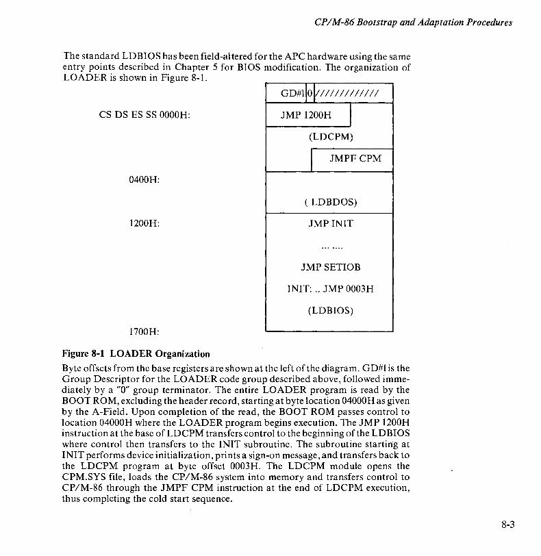
CPIM-86 Bootstrap and Adaptation Procedures
The standard LDBIOS has been field-altered for the APC hardware using the same entry points described in Chapter 5 for BIOS modification. The organization of LOADER is shown in Figure 8-1.
GD#l]OV III I I IIII I II
CS DS ES SS OOOOH: JMP 1200H I (LDCPM)
I JMPF CPM
0400H:
( LDBDOS)
1200H: JMP INIT
.......
JMP SETIOB
INIT: .. JMP 0003H
(LDBIOS)
1700H:
Figure 8-1 LOADER Organization
Byte offsets from the base registers are shown at the left of the diagram. GD#1 is the Group Descriptor for the LOADER code group described above, followed immediately by a "0" group terminator. The entire LOADER program is read by the BOOT ROM, excluding the header record, starting at byte location 04000H as given by the A-Field. Upon completion of the read, the BOOT ROM passes control to location 04000H where the LOADER program begins execution. The JMP 1200H instruction at the base of LDCPM transfers control to the beginning of the LDBIOS where control then transfers to the INIT subroutine. The subroutine starting at INIT performs device initialization, prints a sign-on message, and transfers back to the LDCPM program at byte offset 0003H. The LDCPM module opens the CPM.SYS file, loads the CP/M-86 system into memory and transfers control to CP/M-86 through the JMPF CPM instruction at the end of LDCPM execution, thus completing the cold start sequence.
8-3
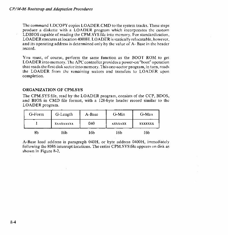
CP/M-86 Bootstrap and Adaptation Procedures
8-4
The command LDCOPY copies LOADER.CMD to the system tracks. These steps produce a diskette with a LOADER program which incorporates the custom LDBIOS capable of reading the CPM.SYS file into memory. For standardization, LOADER executes at location 4000H. LOADER is statically relocatable, however, and its operating address is determined only by the value of A- Base in the header record.
You must, of course, perform the same function as the BOOT ROM to get LOADER into memory. The APC controller provides a power-on "boot" operation that reads the first disk sector into memory. This one-sector program, in turn, reads the LOADER from the remaining sectors and transfers to LOADER upon completion.
ORGANIZATION OF CPM.SYS
The CPM.SYS file, read by the LOADER program, consists of the CCP, BDOS, and BIOS in CMD file format, with a 128-byte header record similar to the LOADER program.
G-Form G-Length A-Base G-Min G-Max
1 xxxxxxxxx 040 xxxxxxx xxxxxxx
8b 16b 16b 16b 16b
A-Base load address is paragraph 040H, or byte address 0400H, immediately following the 8086 interrupt locations. The entire CPM.SYS file appears on disk as shown in Figure 8-2.
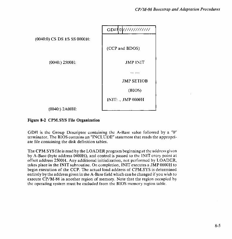
CPIM-86 Bootstrap and Adaptation Procedures
(0040:0) CS DS ES SS OOOOH:
(0040:) 2500H:
(0040:) 2AOOH:
Figure 8-2 CPM.SYS File Organization
G D# 1\ 0 V I I I I I I I I I I I I
(CCP and BDOS)
JMP INIT
JMP SETIOB
(BIOS)
INIT: .. JMP OOOOH
GD#1 is the Group Descriptor containing the A-Base value followed by a "0" terminator. The BIOS contains an "INCLUDE" statement that reads the appropriate file containing the disk definition tables.
The CPM.SYS file is read by the LOADER program beginning at the address given by A-Base (byte address 0400H), and control is passed to the INIT entry point at offset address 2500H. Any additional initialization, n,ot performed by LOADER, takes place in the INIT subroutine. On completion, INIT executes a JMP OOOOH to begin execution of the CCP. The actual load address of CPM.SYS is determined entirely by the address given in the A-Base field which can be changed if you wish to execute CP/M-86 in another region of memory. Note that the region occupied by the operating system must be excluded from the BIOS memory region table.
8-5

Chapter 9
GSX-86: Graphics For The APe This chapter describes the features and operating procedures of GSX-86, the Graphics System Extension of the CPM-86 Operating System. It explains what GSX-86 does and how you can use its graphics functions. Later sections of the chapter describe the GSX-86 system's architecture.
WHAT IS GSX-86
GSX-86 incorporates graphics capability into the CP/M-86 operating system and provides a host-independent and device-independent interface for application programs. Graphics primitives are provided for implementing graphics applications with reduced programming effort. OSX-86 enhances program portability by allowing an application to run on any CP/M-86 system with the GSX-86 option.
GSX-86 And Application Programs
GSX-86 defines a standard interface to graphics peripherals from an application program. Application programs written in assembly language (or a high-level language that supports the GSX-86 calling conventions) can call GSX-86 with appropriate calls to the Graphics Devices Operating System (ODOS). You can compile/assemble and link programs containing GSX-86 calls in the normal manner.
GSX-86 translates GDOS calls to fit the peculiarities of each graphics device (printer, plotter, CRT, and so on). Since graphics devices are mechanically and electronically different, GSX-86 requires a special program (called a device driver) to run each device. Application programs can use the device drivers that are included as part of GSX-86 on the CP/M-86 system distribution diskette (see Table 9-1). Alternatively, you can create customized device drivers using the procedures described later in this chapter.
9-1
GSX-86: Graphics for the APC
9-2
GSX-86 And Graphics Products
GSX-86 also supports high-level-language graphics interfaces to commercially available software, including the following products.
• GSS-KERNEL is a utility library that allows a program to do complex graphic functions with only a few commands. It supports popular high-level languages such as BASIC, PASCAL, FORTRAN, and PLII with standard procedure calls.
• GSS-PLOT is a high-level programming tool that can be used to produce graphs and plots with just a few calls from a high-level language.
• GSS-GRAPH allows a system user to graph and plot data by making simple menu selections.
• GSS-DRA W provides an advanced capability. It uses simple symbols to create more complex graphics.
USING GSX-86
The following files are required to run GSX-86.
• ASSIGN.SYS
• GRAPHICS.CMD
• One device driver file for each graphics device in use.
ASSIGN.SYS is the Assignment Table file. It is a simple text file that consists of the file names of all device drivers and an associated logical device number for each device driver.
GRAPHICS.CMD is the file that contains GSX-86 for the APC.
. The device drivers provide the interface between GSX-86 and specific pieces of hardware. Each device driver is contained in its own file. Standard device drivers are included on the CP/M-86 system distribution diskette. They are described in The CPIM-86 System User's Guide for the APC and in Table 9-1 of this manual.
Setting Up GSX-86
In order to use GSX-86, you must ensure that the required device drivers are present on the disk specified in the GRAPHICS command, that the Assignment Table contains the names of all device drivers and their corresponding logical device numbers, and that GRAPHICS.CMD is available to the system.
GSX-86: Graphics for the APe
Updating The Assignment Table
The Assignment Table (ASSIGN.SYS) on the distribution diskette is configured to operate with the APC only. To use any other graphics device, you must update the table. The Assignment Table consists entirely of text and can be created and modified with any text editor (ED, for example). It must reside in a file called ASSIGN.SYS on the drive specified in the GRAPHICS command (or the current default drive if no drive was specified in the GRAPHICS command). For each device driver, there is an entry containing the driver number (workstation ID) and the name of the file containing the associated graphics device driver.
The following is a sample Assignment Table. It shows the complete contents of ASSIGN.SYS on the distribution diskette.
1 DDNECAPC ; NEC APC DRIVER
The syntax for entries in the Assignment Table is:
where:
DD [d:]filename [;comments ]
DD = logical driver number d = optional drive specifier filename = device driver file comments = optional text string
The logical device number may be one or two digits. The following convention for assigning logical device numbers to graphics devices assures the maximum degree of device independence within programs.
1-10 CRT 11-20 Plotter 21-30 Printer 31-40 Other devices
The first string of alphanumeric characters is the filename of the device driver. It may be preceded by a drive specifier. If the filetype extension is not specified, ".SYS" is assumed.
Comments are optional. A comment must be separated from the filename by a semicolon.
9-3
GSX-86: Graphics for the APe
9-4
The following examples demonstrate valid Assignment Table entry formats.
11 A: D D PLOT ;plotter 1 B:CRTDRV ;system console
21 A:PRINTR ;printer 2 E:DRIVER.ABC
14 DRIVER2.SYS
The largest device driver must be listed first in the Assignment Table. This is the default driver. Its size determines the amount of space the system allocates for device drivers. If there is enough space for the largest driver, the system will always have enough room for any other driver that GSX-86 uses.
Device Drivers
Table 9-1 lists the standard device drivers that are included on the CP/M-86 system distribution diskette. DDNECAPC.SYS is the only device driver in ASSIGN.SYS. You can use a text editor (such as ED) or a word processor to update the Assignment Table with any of the device drivers listed in the table or your custom device drivers.
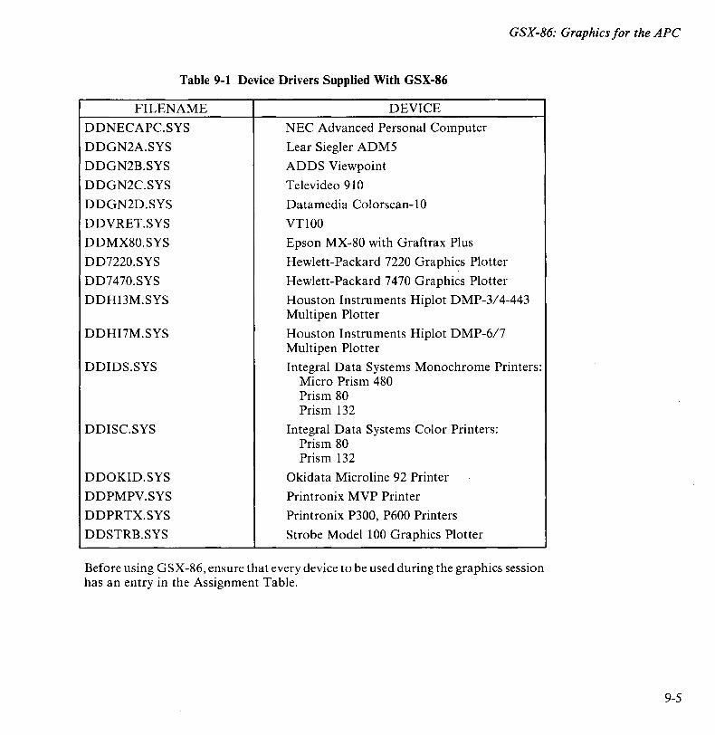
GSX-86: Graphics for the APe
Table 9-1 Device Drivers Supplied With GSX-86
FILENAME DEVICE
DDNECAPC.SYS NEC Advanced Personal Computer
DDGN2A.SYS Lear Siegler ADM5
DDGN2B.SYS ADDS Viewpoint
DDGN2C.SYS Televideo 910
DDGN2D.SYS Datamedia Colorscan-l0
DDVRET.SYS VT100
DDMX80.SYS Epson MX-80 with Graftrax Plus
DD7220.SYS Hewlett-Packard 7220 Graphics Plotter
DD7470.SYS Hewlett-Packard 7470 Graphics Plotter
DDHI3M.SYS Houston Instruments Hiplot DMP-3/4-443 Multipen Plotter
DDHI7M.SYS Houston Instruments Hiplot DMP-6/7 Multipen Plotter
DDIDS.SYS Integral Data Systems Monochrome Printers: Micro Prism 480 Prism 80 Prism 132
DDISC.SYS Integral Data Systems Color Printers: Prism 80 Prism 132
DDOKID.SYS Okidata Microline 92 Printer
DDPMPV.SYS Printronix MVP Printer
DDPRTX.SYS Printronix P300, P600 Printers
DDSTRB.SYS Strobe Model 100 Graphics Plotter
Before using GSX-86, ensure that every device to be used during the graphics session has an entry in the Assignment Table.
9-5
GSX-86: Graphics for the APe
9-6
Invoking GSX-86
To invoke GSX-86, enter the command
GRAPHICS [:d]
where d is the specifier of the drive that holds both ASSIGN.SYS and the device driver(s).
To disable GSX-86, enter the following command.
GRAPHICS NO
This frees the memory space used by GSX-86 and the device driver.
Warm Starts And Cold Starts
If the system hangs when GRAPHICS is enabled, a warm start does not disturb the graphics mode initialization. However, a cold start (rebooting the hardware) disables GSX-86.
For more information on the operation of GRAPHICS and a complete listing of GSX-86 command and error messages, see The CPIM-86 System User's Guide for the APC.
OVERVIEW OF GRAPHICS SYSTEM EXTENSION STRUCTURE
This section introduces the GSX-86 architecture, its components, and their functions. Each part of GSX-86 is described in detail later in this chapter. This section also describes the memory management techniques used by GSX-86.
GSX-86 Architecture
GSX-86 is an integral part of the operating system. Application programs interface to GSX-86 through a standard calling sequence similar to the BDOS conventions. Drivers for specific graphics devices translate the standard GSX-86 calls to the unique characteristics of the device. In this way, GSX-86 provides deviceindependence since the peculiarities of the graphics device are not visible to the application program.
GSX-86 consists of two components:
• Graphics Device Operating System (GDOS)
• Graphics Input/Output System (GIOS).
GSX-86: Graphics for the APe
The GDOS contains the basic host-independent and device-independent graphics functions that can be called by an application program. GDOS provides a standard interface to graphics that is constant regardless of specific devices or host hardware, just as the BDOS standardizes disk interfaces. Application programs access the GDOS in much the same way that they access the BDOS.
The GDOS performs coordinate scaling so that a program can specify points in a normalized coordinate space. It uses device-specific information to translate the normalized coordinates into the corresponding values for each graphics device.
Multiple graphics devices can be supported under GSX-86 within a single application. By referring to devices with a workstation identification number, an application program can send graphics information to anyone of several devices.
The Graphics Input/Output System (GIOS) is similar to the BIOS. It contains the device-specific code required to interface specific graphics devices to the GDOS. The GIOS consists of a set of device drivers that communicate directly with the graphics devices. GSX-86 requires a unique device driver for each different graphics device on a system. The term GIOS refers to the functional layer in GSX-86 that holds the collection of available device drivers. The particular driver that is loaded into memory when required by an application is called a GIOS file. Although a single program can use several graphics devices, GDOS loads only one GIOS file at a time.
The GIOS performs the graphics primitives of GSX-86, consistent with the inherent capabilities of a graphics device. In some cases, a device driver emulates standard GDOS capabilities which are not provided by the graphics device hardware. For example, some devices require that dashed lines be simulated by a series of short vectors generated in the device driver.
Memory Management
The default device driver and GDOS are loaded directly above CPM-86 after the GRAPHICS command has been executed. The application program is loaded in the normal manner, starting at the top of the user area.
9-7
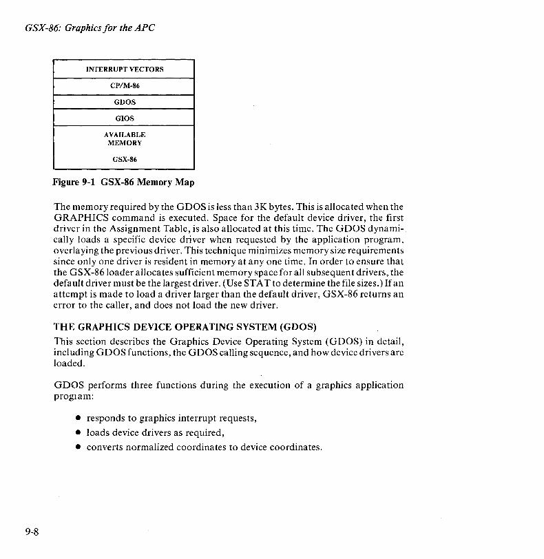
GSX-86: Graphics for the APe
9-8
INTERRUPT VECTORS
CP/M-86
GDOS
GIOS
AVAILABLE MEMORY
GSX-86
Figure 9-1 GSX-86 Memory Map
The memory required by the GDOS is less than 3K bytes. This is allocated when the GRAPHICS command is executed. Space for the default device driver, the first driver in the Assignment Table, is also allocated at this time. The GDOS dynamically loads a specific device driver when requested by the application program, overlaying the previous driver. This technique minimizes memory size requirements since only one driver is resident in memory at anyone time. In order to ensure that the GSX-86 loader allocates sufficient memory space for all subsequent drivers, the default driver must be the largest driver. (Use STAT to determine the file sizes.) Ifan attempt is made to load a driver larger than the default driver, GSX-86 returns an error to the caller, and does not load the new driver.
THE GRAPHICS DEVICE OPERATING SYSTEM (GDOS)
This section describes the Graphics Device Operating System (GDOS) in detail, including GDOS functions, the GDOS calling sequence, and how device drivers are loaded.
GDOS performs three functions during the execution of a graphics application proglam:
• responds to graphics interrupt requests,
• loads device drivers as required,
• converts normalized coordinates to device coordinates.
GSX-86: Graphics for the APe
Virtual Device Interface (VOl)
GSX-86 uses a standard method to access graphics capabilities. It is called the Virtual Device Interface (VDI) since it makes all graphics devices appear "virtually" identical. The implementation of the VDI employs the conventional BDOS calling sequence. The application program calls GDOS via interrupt #224 with function code 0473H in register CX. Registers DS and DX contain the segment base and offset, respectively, of the parameter list (PB). The parameter list consists of five double-word addresses, the addresses of five arrays, as follows.
PB PB+4 PB+8 PB+12 PB+16
adQress of input control array address of input parameter array address of input point coordinate array address of output parameter array address of output point coordinate array
The specific graphics function to be performed by GDOS is indicated by an operation code in the input control array.
All data passed to the device driver are assumed to be two-byte integers.
The GDOS preserves the BP (base pointer) and DS (data segment) registers. All other registers are subject to change when returned from GDOS.
INPUT CONTROL ARRAY
The control array contains the following values when the function is called.
control (1) control (2)
control (4) control (6-n)
Opcode Number of vertices in input coordinate point array (ptsin) Length of input parameter array Opcode-dependent (intin)
INPUT PARAMETER ARRAY
The input parameter array contains the following values when the function is called.
intin Array of input parameters. Length of array is opcode-dependent and specified in control (4).
9-9
GSX-86: Graphics for the APC
9-10
INPUT POINT COORDINATE ARRAY
The input point coordinate array contains the following values when the function is called.
ptsin Array of input coordinates. Each point is specified by an X,Y coordinate pair given in Normalized Device Coordinates (0-32,767 with length control(2) * 2).
OUTPUT CONTROL ARRAY
The output control array contains the following values when the function is completed.
control (3) control (5) control (6-n)
Number of vertices in output point array (ptsout) Length of input parameter array Opcode-dependent
OUTPUT PARAMETER ARRAY
The output parameter array contains the following values when the function is called.
intout Array of output parameters. Length of array is opcodedependent.
OUTPUT POINT COORDINATE ARRAY
The output point coordinate array contains the following values when the function is called.
ptsout Array of output coordinates. Each point is specified by an X, Y coordinate pair given in Normalized Device Coordinates (0-32,767) and must be greater than the largest possible value of control (5) * 2.
Normalized Device Coordinates
The application program passes all graphics coordinates to G DOS as Normalized Device Coordinates (NDC) in a range from 0 to 32,767 along each axis. These units are mapped to the actual device units (e.g. rasters for CRTs or steps for plotters/printers) using information passed from the device driver when the workstation was opened by GSX-86 so that all coordinates passed to the device driver are in device units.
GSX-86: Graphics for the APe
The full scale NDC space is always mapped to the full dimensions of the graphics device in each axis. This assures that all graphics information will appear on the display surface regardless of the dimensions of the device.
Both input and output coordinates are converted by GSX-86. Therefore, both the calling routine and the device driver must ensure that the input vertex count (contrl(2)) and output vertex count (contrl(3)) are set. The calling routine must set contrl(2) to 0 if no X,Y coordinates are being passed to GSX-86. Similarly, the device driver must set contrl(3) to 0 if no X,Y coordinates are being returned through GSX-86.
Since 0-32767 maps to the full extent on each axis, coordinate values are scaled differently on the X and Y axes of devices that do not have a square display.
Each time an application program opens a workstation, GDOS determines whether the required device driver is resident in memory. If not, G DOS loads the driver from disk and then services the graphics request.
Device driver I/O (i.e., communication between the device driver and the device via the system hardware ports) is done through CP/M-86 BDOS calls. CRT devices are assumed to be the console device. Plotters are assumed to be connected as the Auxiliary Input/Output device. Printers are assumed to be connected as the list device.
GDOS Opcodes
Table 9-2 lists the GSX-86 opcodes and indicates whether each is required for CRT devices and plotters/printers. Each operation is described in detail in the following sections of this chapter. These opcodes must be present and perform as specified. When creating device drivers, you should implement all opcodes. Full implementation of opcodes results in better quality graphics.
In addition to required opcodes, you may be able to use other, non-required opcodes with a particular device. To determine if a non-required opcode is available in a particular driver, you may use one of two methods. You can check the information about available features returned from the OPEN WORKSTATION opcode, or you can check the selected value returned from an opcode against the requested value. If the two values do n9t match, then either opcode is not available or the requested value is not available and a best fit value was selected.
9-11

GSX-86: Graphics for the APe
Table 9-2 GDOS Opcodes
9-12
OPCODE DESCRIPTION
I Open workstation 2 Close workstation 3 Clear workstation 4 Update workstation 5 Escape
Jd Definition I Inquire addressable character cells 2 Enter graphics mode 3 Exit graphics mode 4 Cursor up 5 Cursor down 6 Cursor right 7 Cursor left 8 Home cursor 9 Erase to end of screen 10 Erase to end of line II Direct cursor address 12 Output cursor addressable text 13 Reverse video on 14 Reverse video off 15 Inquire current cursor address 16 Inquire tablet status 17 Hard copy 18 Place cursor at location 19 Remove cursor
6 Polyline 7 Polymarker 8 Text 9 Filled area
10 Cell array II Generalized drawing primitive 12 Set character height 13 Set character up vector 14 Set color representation 15 Set polyline linetype 16 Set polyline linewidth 17 Set polyline color index 18 Set polymarker type 19 Set polymarker scale 20 Set poly marker color index 21 Set text font 22 Set text color index 23 Set fill interior style 24 Set fill style index 25 Set fill color index 26 Inquire color representation 27 Inquire cell array 28 Input locator 29 Input valuator 30 Input choice 31 Input string 32 Set writing mode 33 Set input mode
Y - Required for CRTs, printers, and plotters C - Required for CRTs only
REQUIRED
Y Y y Y
y C C C C C C C C C C C
C
Y Y y Y Y
Y
Y Y
y Y
Y
y
y y
Y
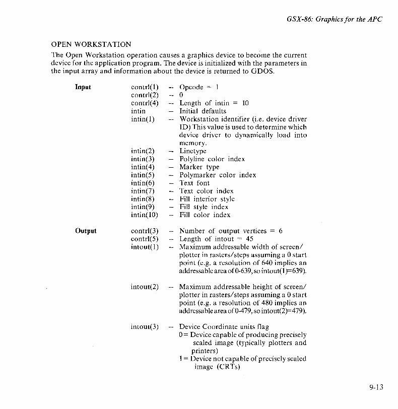
GSX-86: Graphics for the APe
OPEN WORKSTATION
The Open Workstation operation causes a graphics device to become the current device for the application program. The device is initialized with the parameters in the input array and information about the device is returned to GDOS.
Input
Output
contrl(l) contrl(2) contrl(4) intin intin( 1)
intin(2) intin(3) intin( 4) intin(5) intin(6) intin(7) intin(8) intin(9) intin(10)
contrl(3) contrl(5) intout(1)
intout(2)
intout(3)
Opcode = 1 o Length of intin = 10 Initial defaults Workstation identifier (i.e. device driver ID) This value is used to determine which device driver to dynamically load into memory. Linetype Polyline color index Marker type Polymarker color index Text font Text color index Fill interior style Fill style index Fill color index
Number of output vertices = 6 Length of intout = 45 Maximum addressable width of screen/ plotter in rasters/steps assuming a 0 start point (e.g. a resolution of 640 implies an addressab Ie area of 0-639, so intou t( 1 )= 639).
Maximum addressable height of screen/ plotter in rasters/steps assuming a 0 start point (e.g. a resolution of 480 implies an addressable area of 0-479, so intout(2)=479).
Device Coordinate units flag 0= Device capable of prod ucing precisely
scaled image (typically plotters and printers)
1 = Device not capable of precisely scaled image (CRTs)
9-13
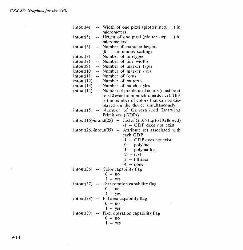
GSX-86: Graphics for the APe
9-14
intout( 4)
intout(5)
intout(6)
intout(7) intout(8) intout(9) intout(lO) intout(11) intout(l2) intout(l3) intout(l4)
Width of one pixel (plotter step ... ) in micrometers Height of one pixel (plotter step ... ) in micrometers Number of character heights (0 = continuous scaling) Number of linetypes Number of line widths Number of marker types N umber of marker sizes Number of fonts Number of patterns Number of hatch styles Number of pre-defined colors (must be at least 2 even for monochrome device). This is the number of colors that can be displayed on the device simultaneously.
intout(l5) -- Number of Generalized Dra wing Primitives (GDPs)
intout(l6)-intout(25) List of GDPs (up to 10 allowed)
intout(26)-intout(35) -1 -- GDP does not exist Attribute set associated with each GDP -1 -- GDP does not exist o -- polyline 1 -- polymarker 2 -- text 3 -- fill area 4 -- none
intout(36) -- Color capability flag o -- no 1 -- yes
intout(37) -- Text rotation capability flag o -- no 1 -- yes
intout(38) -- Fill area capability flag o -- no 1 -- yes
intout(39) -- Pixel operation capability flag o -- no 1 -- yes

intout( 40) --
intout(41 ) intout(42) intout(43) intout(44) intout(45)
ptsout( 1) ptsout(2) ptsout(3) ptsout( 4) ptsout(5) ptsout(6) ptsout(7) ptsout(8) ptsout(9) ptsout(lO) ptsout(ll ) ptsout(l2)
GSX-86: Graphics for the APe
Number of available colors (total number of colors in color palette) o -- continuous device 2 -- monochrome (black and white)
>2 -- number of colors available Number of locator devices available Number of valuator devices available Number of choice devices available Number of string devices available Workstation type o -- Output only 1 -- Input only 2 -- Input/Output 3 -- Device independent segment storage 4 -- GKS Metafile output o Minimum character height in device units o Maximum character height in device units Minimum line width in device units o Maximum line width in device units o o Minimum marker height in device units o Maximum marker height in device units
9-15
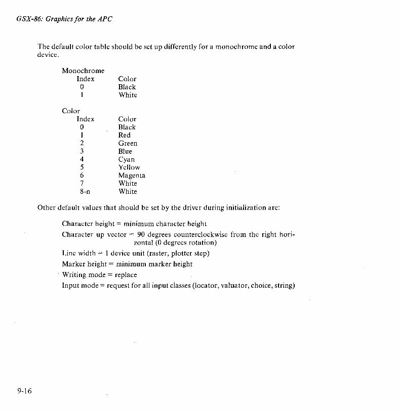
GSX-86: Graphics for the APe
9-16
The default color table should be set up differently for a monochrome and a color device.
Monochrome Index Color 0 Black 1 White
Color Index Color 0 Black 1 Red 2 Green 3 Blue 4 Cyan 5 Yellow 6 Magenta 7 White 8-n White
Other default values that should be set by the driver during initialization are:
Character height = minimum character height
Character up vector = 90 degrees counterclockwise from the right horizontal (0 degrees rotation)
Line width = 1 device unit (raster, plotter step)
Marker height = minimum marker height
. Writing mode = replace
Input mode = request for all input classes (locator, valuator, choice, string)

GSX-86: Graphics for the APe
CLOSE WORKSTATION
The Close Workstation operation terminates the graphics device properly and prevents any further output to the device.
Input
Output
contrl(l) contrl(2)
contrl(3)
CLEAR WORKSTATION
Opcode = 2 o
o
The Clear Workstation operation causes CRT screen to be erased and hardcopy devices to perform a top-of-form operation. On plotters without paper advance, the operator is prompted to load a new page.
Input
Output
contrl(l) contrl(2)
contrl(3)
UPDATE WORKSTATION
Opcode = 3 o
o
The Update Workstation operation causes all pending graphics commands which are queued to be executed immediately.
Input
Output
contrl(l) contrl(2)
contr1(3)
Opcode = 4 o
o
9-17
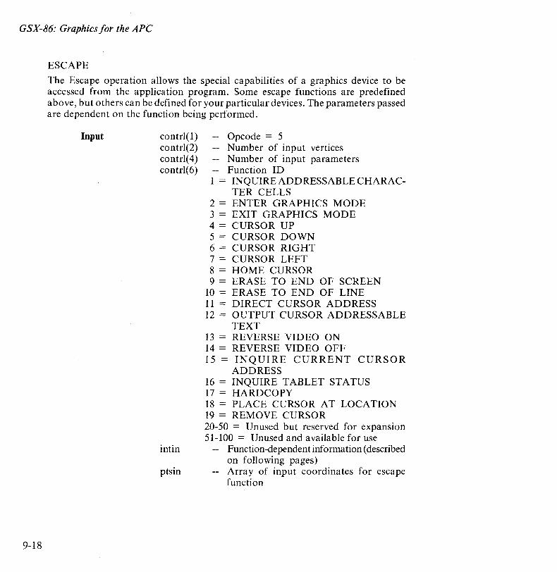
GSX-86: Graphics for the APe
9-18
ESCAPE
The Escape operation allows the special capabilities of a graphics device to be accessed from the application program. Some escape functions are predefined above, but others can be defined for your particular devices. The parameters passed are dependent on the function being performed.
Input contrl(l) contrl(2) contrl(4) contrl(6)
Opcode = 5 -- Number of input vertices -- Number of input parameters -- Function ID 1 = INQUIRE ADDRESSABLE CHARAC-
TER CELLS 2 = ENTER GRAPHICS MODE 3 = EXIT GRAPHICS MODE 4 = CURSOR UP 5 = CURSOR DOWN 6 = CURSOR RIGHT 7 = CURSOR LEFT 8 = HOME CURSOR 9 = ERASE TO END OF SCREEN
10 = ERASE TO END OF LINE 11 = DIRECT CURSOR ADDRESS 12 = OUTPUT CURSOR ADDRESSABLE
TEXT 13 = REVERSE VIDEO ON 14 = REVERSE VIDEO OFF 15 = INQUIRE CURRENT CURSOR
ADDRESS 16 = INQUIRE TABLET STATUS 17 = HARDCOPY 18 = PLACE CURSOR AT LOCATION 19 = REMOVE CURSOR 20-50 = Unused but reserved for expansion 51-100 = Unused and available for use
intin Function-dependent information (described on following pages)
ptsin Array of input coordinates for escape function
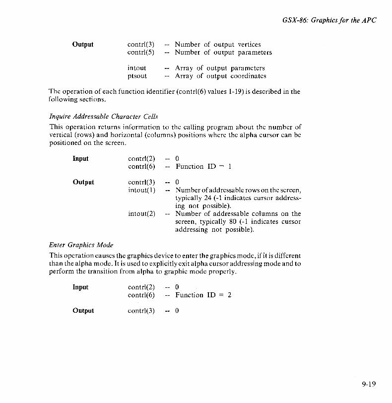
GSX-86: Graphics for the APe
Output contrl(3) contrl(5)
intout ptsout
Number of output vertices Number of output parameters
Array of output parameters Array of output coordinates
The operation of each function identifier (contrl(6) values 1-19) is described in the following sections.
Inquire Addressable Character Cells
This operation returns information to the calling program about the number of vertical (rows) and horizontal (columns) positions where the alpha cursor can be positioned on the screen.
Input
Output
Enter Graphics Mode
contrl(2) contrl(6)
contrl(3) intout(1 )
intout(2)
o Function ID = 1
o Number of addressable rows on the screen, typicall y 24 (-1 indicates cursor addressing not possible). Number of addressable columns on the screen, typically 80 (-1 indicates cursor addressing not possible).
This operation causes the graphics device to enter the graphics mode, if it is different than the alpha mode. It is used to explicitly exit alpha cursor addressing mode and to perform the transition from alpha to graphic mode properly.
Input
Output
contrl(2) contrl(6)
contrl(3)
o Function ID = 2
o
9-19
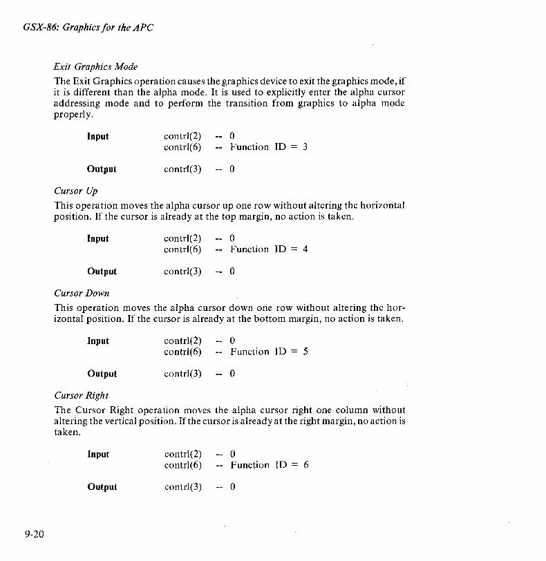
GSX-86: Graphics for the APC
9-20
Exit Graphics Mode
The Exit Graphics operation causes the graphics device to exit the graphics mode, if it is different than the alpha mode. It is used to explicitly enter the alpha cursor addressing mode and to perform the transition from graphics to alpha mode properIy.
Input
Output
Cursor Up
contrl(2) contrl(6)
contrI(3)
o Function ID = 3
o
This operation moves the alpha cursor up one row without altering the horizontal position. If the cursor is already at the top margin, no action is taken.
Input
Output
Cursor Down
contrl(2) contrl(6)
contrl(3)
o Function ID = 4
o
This operation moves the alpha cursor down one row without altering the horizontal position. If the cursor is already at the bottom margin, no action is taken.
Input
Output
Cursor Right
contrI(2) contrI(6)
contrI(3)
o Function ID = 5
o
The Cursor Right operation moves the alpha cursor right one column without altering the vertical position. If the cursor is already at the right margin, no action is taken.
Input
Output
contrl(2) contrl(6)
contrI(3)
o Function ID = 6
o
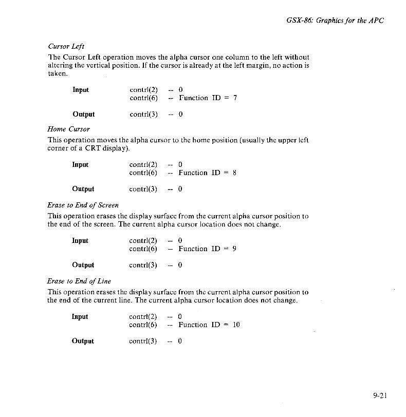
GSX-86: Graphics for the APC
Cursor Left
The Cursor Left operation moves the alpha cursor one column to the left without altering the vertical position. If the cursor is already at the left margin, no action is taken.
Input
Output
Home Cursor
contrl(2) contrl(6)
contrl(3)
o Function ID = 7
o
This operation moves the alpha cursor to the home position (usually the upper left corner of a CRT display).
Input
Output
Erase to End of Screen
contrl(2) contrl(6)
contrl(3)
o Function ID = 8
o
This operation erases the display surface from the current alpha cursor position to the end of the screen. The current alpha cursor location does not change.
Input
Output
Erase to End of Line
contrl(2) contrl(6)
contrl(3)
o Function ID = 9
o
This operation erases the display surface from the current alpha cursor position to the end of the current line. The current alpha cursor location does not change.
Input
Output
contrl(2) contrl(6)
contrl(3)
o Function ID = 10
o
9-21

GSX-86: Graphics for the APC
9-22
Direct Cursor Address
The Direct Cursor Address operation moves the alpha cursor directly to the specified row and column address anywhere on the display surface.
Input
Output
contrl(2) contrl(6) intin(l) intin(2)
contrl(3)
Output Cursor Addressable Text
o Function ID = 11 Row number (l - number of rows) Column number (1 - number of columns)
o
This operation displays a string of text starting at the current cursor position. Alpha text characteristics are determined by the attributes currently in effect (for example, reverse video).
Input
Output
Reverse Video On
contrl(2) contrl( 4) contrl(6) intin
contrl(3)
o Number of characters in character string Function ID = 12 Text string in ASCII Decimal Equivalent
o
This operation causes all subsequent text to be displayed in reverse video format; that is, characters are dark on a light background.
Input
Output
Reverse Video Off
contrl(2) contrl(6)
contrl(3)
o Function ID = 13
o
This operation causes all subsequent text to be displayed in normal video format; that is, characters are light on a dark background.
Input
Output
contrl(2) contrl(6)
contrl(3)
o Function ID = 14
o
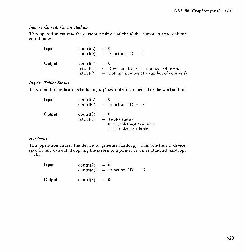
GSX-86: Graphics for the APC
Inquire Current Cursor Address
This operation returns the current position of the alpha cursor in row, column coordinates.
Input contr1(2) 0 contrl(6) Function ID = 15
Output contrl(3) 0 intout(l) Row number (l - number of rows) intout(2) Column number (l - number of columns)
Inquire Tablet Status
This operation indicates whether a graphics tablet is connected to the workstation.
Input
Output
Hardcopy
contrl(2) contrl(6)
contrl(3) intout(l)
o Function ID = 16
o Tablet status o = tablet not available 1 = tablet available
This operation causes the device to generate hardcopy. This function is devicespecific and can entail copying the screen to a printer or other attached hardcopy device.
Input
Output
contrl(2) contrl(6)
contr1(3)
o Function ID = 17
o
9-23
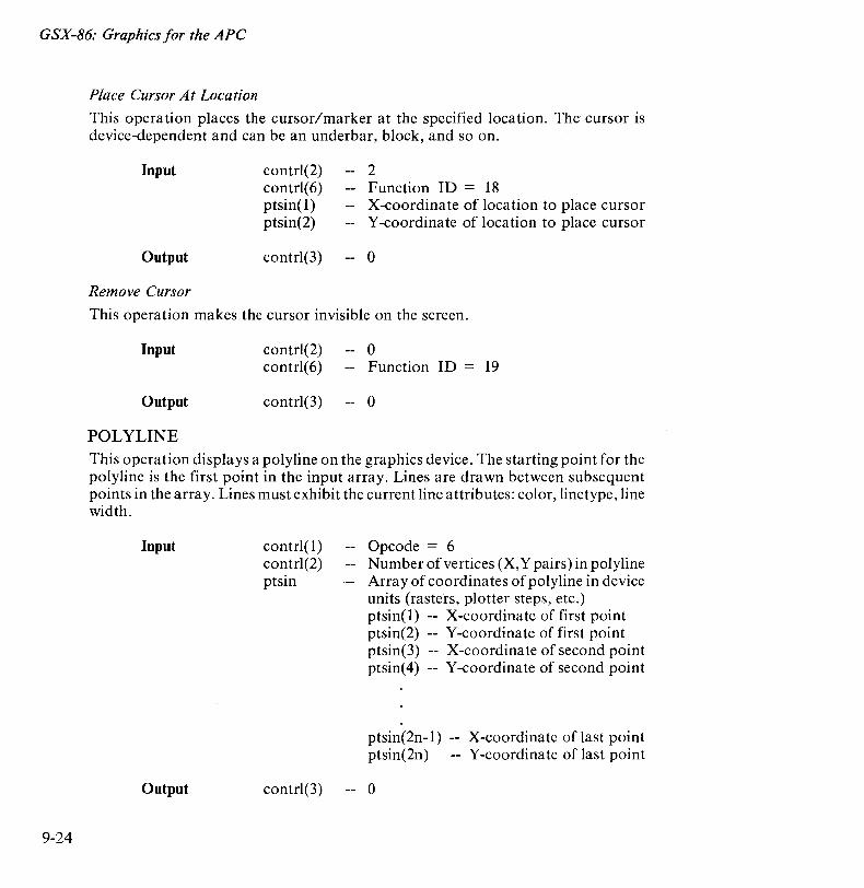
GSX-86: Graphics for the APe
9-24
Place Cursor At Location
This operation places the cursor/marker at the specified location. The cursor is device-dependent and can be an underbar, block, and so on.
Input
Output
Remove Cursor
contr1(2) contr1(6) ptsin(l) ptsin(2)
contr1(3)
2 Function ID = 18 X-coordinate of location to place cursor Y -coordinate of location to place cursor
o
This operation makes the cursor invisible on the screen.
Input
Output
POLYLINE
contrl(2) contr1(6)
contr1(3)
o Function ID = 19
o
This operation displays a polyline on the graphics device. The starting point for the polyline is the first point in the input array. Lines are drawn between subsequent points in the array. Lines must exhibit the current line attributes: color, linetype, line width.
Input
Output
contrl(l) contr1(2) ptsin
contr1(3)
Opcode = 6 Number of vertices (X,Y pairs) in polyline Array of coordinates of polyline in device units (rasters, plotter steps, etc.) ptsin(l) -- X-coordinate of first point ptsin(2) -- Y-coordinate of first point ptsin(3) -- X-coordinate of second point ptsin(4) -- Y-coordinate of second point
ptsin(2n-l) -- X-coordinate of last point ptsin(2n) -- Y-coordinate of last point
o
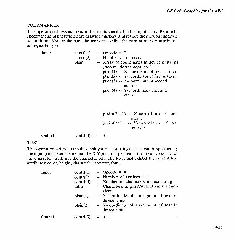
GSX-86: Graphics for the APe
POLYMARKER
This operation draws markers at the points specified in the input array. Be sure to specify the solid linestyle before dra wing markers, and restore the previous linestyle when done. Also, make sure the markers exhibit the current marker attributes: color, scale, type.
Input
Output
TEXT
contrI(l) contrl(2) ptsin
contrI(3) --
Ope ode = 7 N umber of markers Array of coordinates in device units (n) (rasters, plotter steps, etc.) ptsin(1) X-coordinate of first marker ptsin(2) Y -coordinate of first marker ptsin(3) X-coordinate of second
marker ptsin( 4) Y -coordina te of second
marker
ptsin(2n-l) -- X-coordinate of marker
ptsin(2n) -- Y -coordinate of marker
0
last
last
This operation writes text to the display surface starting at the position specified by the input parameters. Note that the X,Y position specified is the lower left corner of the character itself, not the character cell. The text must exhibit the current text attributes: color, height, character up vector, font.
Input
Output
contrI(l) contrI(2) contrI(4) intin
ptsin(l)
ptsin(2)
contrI(3)
Ope ode = 8 Number of vertices = Number of characters in text string Character string in ASCII Decimal Equivalent X-coordinate of start point of text in device units Y-coordinate of start point of text in device units
o
9-25
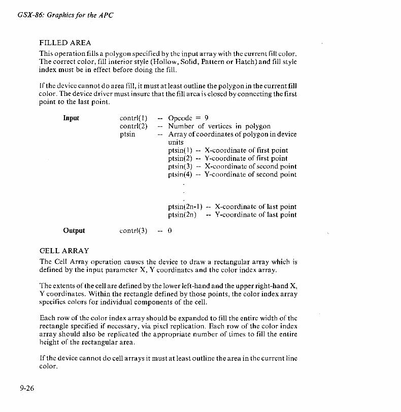
GSX-86: Graphics for the APe
9-26
FILLED AREA
This operation fills a polygon specified by the input array with the current fill color. The correct color, fill interior style (Hollow, Solid, Pattern or Hatch) and fill style index must be in effect before doing the fill.
If the device cannot do area fill, it must at least outline the polygon in the current fill color. The device driver must insure that the fill area is closed by connecting the first point to the last point.
Input
Output
GELLARRAY
contrI(l ) contrI(2) ptsin
contrI(3)
Opcode = 9 Number of vertices in polygon Array of coordinates of polygon in device units ptsin( 1) -- X-coordinate of first point ptsin(2) -- Y -coordinate of first point ptsin(3) -- X-coordinate of second point ptsin( 4) -- Y -coordinate of second point
ptsin(2n -1) ptsin(2n)
o
X-coordinate of last point Y-coordinate of last point
The Cell Array operation causes the device to draw a rectangular array which is defined by the input parameter X, Y coordinates and the color index array.
The extents of the cell are defined by the lower left-hand and the upper right-hand X, Y coordinates. Within the rectangle defined by those points, the color index array specifies colors for individual components of the cell.
Each row of the color index array should be expanded to fill the entire width of the rectangle specified if necessary, via pixel replication. Each row of the color index array should also be replicated the appropriate number of times to fill the entire height of the rectangular area.
If the device cannot do cell arrays it must at least outline the area in the current line color.
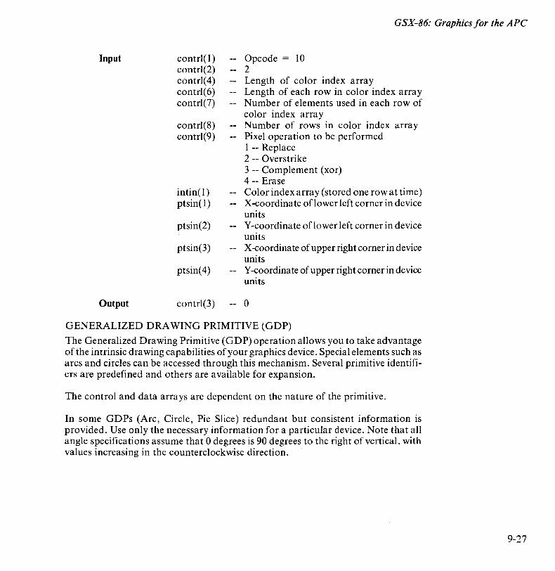
GSX-86: Graphics for the APe
Input
Output
contr1(I) contr1(2) contr1(4) contr1(6) contr1(7)
contr1(8) contr1(9)
intin( I) ptsin(l)
ptsin(2)
ptsin(3)
ptsin( 4)
contr1(3)
Opcode = 10 2 Length of color index array Length of each row in color index array Number of elements used in each row of color index array Number of rows in color index array Pixel operation to be performed I -- Replace 2 -- Overstrike 3 -- Complement (xor) 4 -- Erase Color index array (stored one row at time) X-coordinate oflower left corner in device units Y -coordinate oflower left corner in device units X -coordina te of upper righ t corner in device units Y -coordina te of upper right corner in device units
o
GENERALIZED DRAWING PRIMITIVE (GDP)
The Generalized Drawing Primitive (GDP) operation allows you to take advantage of the intrinsic dra wing ca pabili ties of your graphics device. Special elements such as arcs and circles can be accessed through this mechanism. Several primitive identifiers are predefined and others are available for expansion.
The control and data arrays are dependent on the nature of the primitive.
In some GDPs (Are, Circle, Pie Slice) redundant but consistent information is provided. Use only the necessary information for a particular device. Note that all angle specifications assume that 0 degrees is 90 degrees to the right of vertical, with values increasing in the counterclockwise direction.
9-27
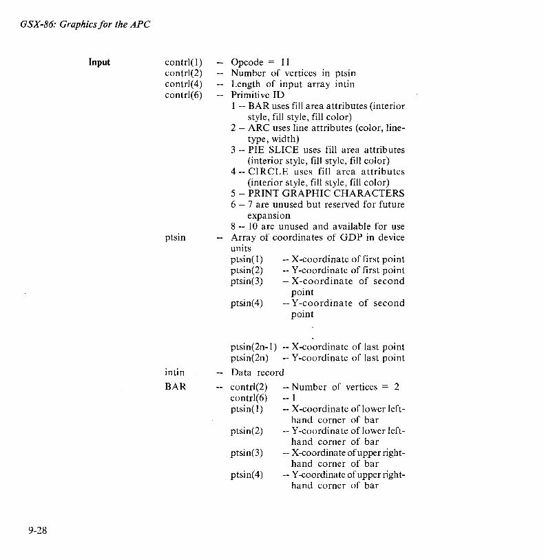
GSX-86: Graphics for the APe
Input
9-28
contrl(l) contrl(2) contrl(4) contrl(6)
ptsin
intin
BAR
Opcode = 11 Number of vertices in ptsin Length of input array intin Primitive ID 1 -- BAR uses fill area attributes (interior
style, fill style, fill color) 2 -- ARC uses line attributes (color, line
type, width) 3 -- PIE SLICE uses fill area attributes
(interior style, fill style, fill color) 4 -- CIRCLE uses fill area attributes
(interior style, fill style, fill color) 5 -- PRINT GRAPHIC CHARACTERS 6 -- 7 are unused but reserved for future
expansion 8 -- 10 are unused and available for use Array of coordinates of GDP in device units ptsin(l) ptsin(2) ptsin(3)
ptsin(4)
-- X-coordinate of first point -- Y-coordinate of first point -- X-coordina te of second
point -- Y -coordina te of second
point
ptsin(2n-l) -- X-coordinate of last point ptsin(2n) -- Y-coordinate of last point
Data record
contrl(2) contrl(6) ptsin(l)
ptsin(2)
ptsin(3)
ptsin(4)
-- Number of vertices = 2 -- 1 -- X-coordinate of lower left-
hand corner of bar -- Y -coordina te of lower left
hand corner of bar -- X-coordinate of upper right
hand corner of bar -- Y-coordinate of upper right
hand corner of bar
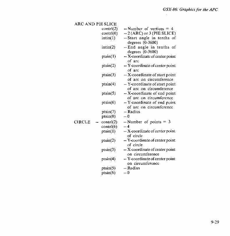
ARC AND PIE SLICE contrl(2) contrl(6) intin( 1)
intin(2)
ptsin(l)
ptsin(2)
ptsin(3)
ptsin(4)
ptsin(5)
ptsin(6)
ptsin(7) ptsin(8)
CIRCLE contrl(2) contrl(6) ptsin(l)
ptsin(2)
ptsin(3)
ptsin(4)
ptsin(5) ptsin(6)
GSX-86: Graphics for the APe
-- Number of vertices = 4 -- 2 (ARC) or 3 (PIE SLICE) -- Start angle in tenths of
degrees (0-3600) -- End angle in tenths of
degrees (0-3600) -- X-coordinate of center point
of arc -- Y -coordinate of center point
of arc -- X-coordinate of start point
of arc on circumference -- Y -coordinate of start point
of arc on circumference -- X-coordinate of end point
of arc on circumference -- Y-coordinate of end point
of arc on circumference -- Radius -- 0 -- Number of points = 3 -- 4 -- X-coordinate of center point
of circle -- Y -coordinate of center point
of circle -- X-coordinate of center point
on circumference -- Y -coordinate of center point
on circumference -- Radius -- 0
9-29
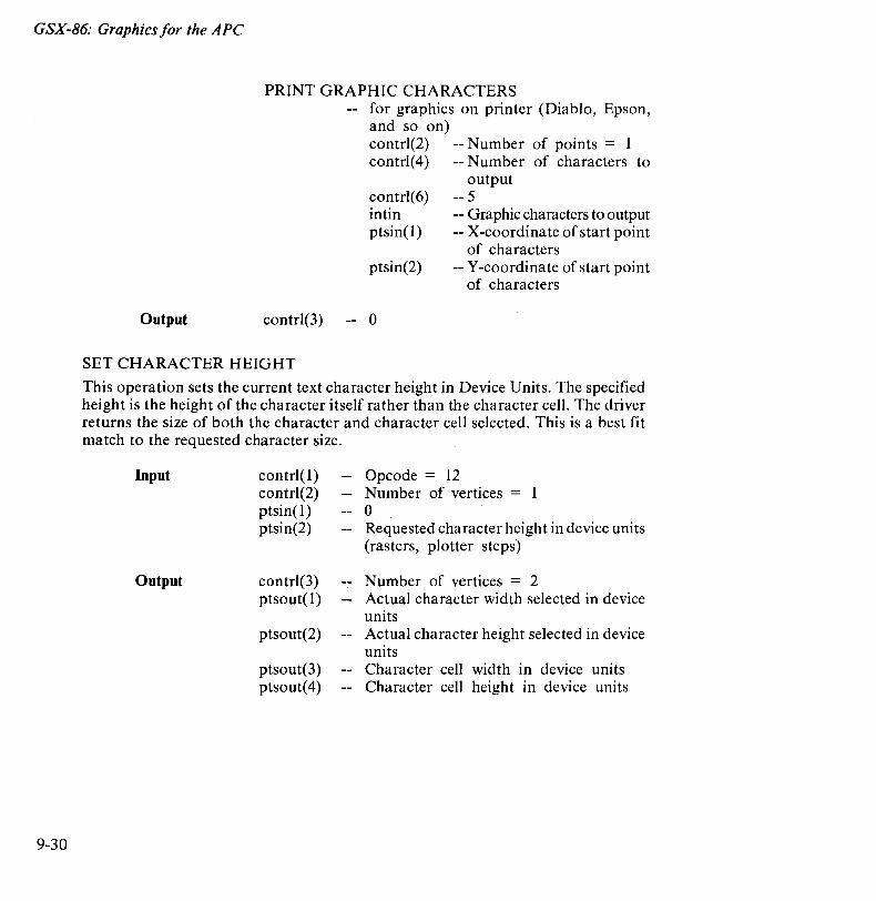
GSX-86: Graphics for the APe
9-30
Output
PRINT GRAPHIC CHARACTERS for graphics on printer (Diablo, Epson, and so on) contr1(2) -- Number of points = I contr1(4) -- Number of characters to
contr1(6) intin ptsin(l)
ptsin(2)
contr1(3) -- 0
output -- 5 -- Graphic characters to output -- X-coordinate of start point
of characters -- Y -coordinate of start point
of characters
SET CHARACTER HEIGHT
This operation sets the current text character height in Device Units. The specified height is the height of the character itself rather than the character cell. The driver returns the size of both the character and character cell selected. This is a best fit match to the requested character size.
Input
Output
contr1(l) contr1(2) ptsin(l) ptsin(2)
contr1(3) ptsout(l)
ptsout(2)
ptsout(3) ptsout(4)
Opcode = 12 Number of vertices = 1 o Requested character height in device units (rasters, plotter steps)
Number of vertices = 2 Actual character width selected in device units Actual character height selected in device units Character cell width in device units Character cell height in device units
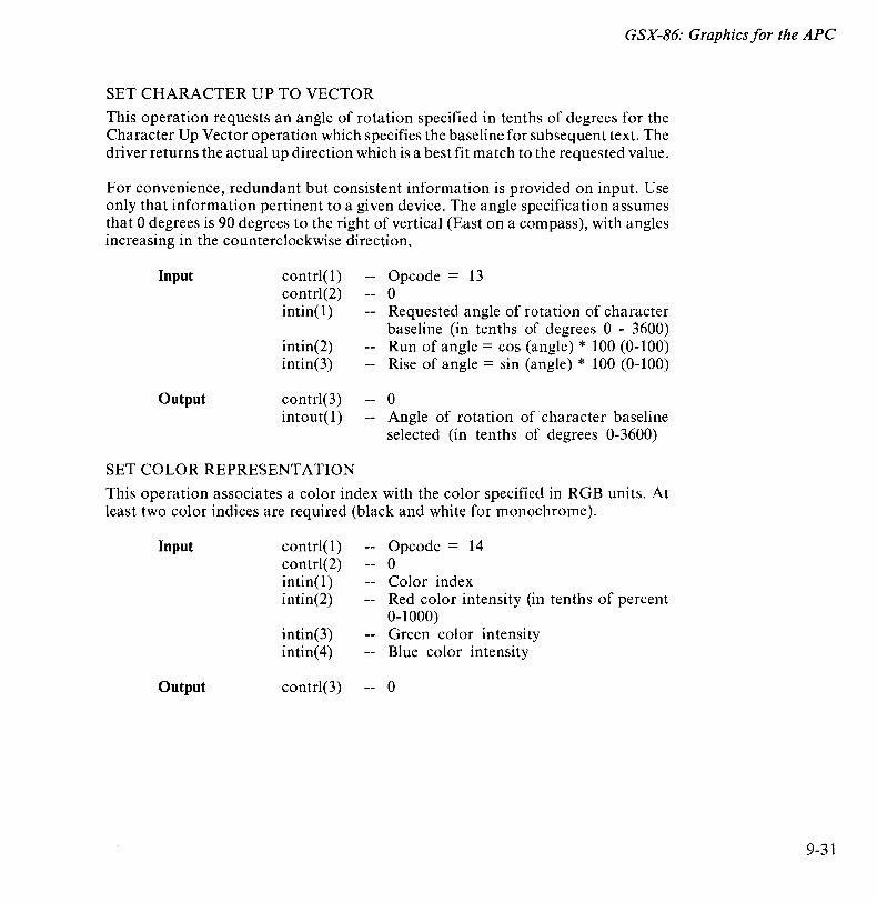
GSX-86: Graphics for the APe
SET CHARACTER UP TO VECTOR
This operation requests an angle of rotation specified in tenths of degrees for the Character Up Vector operation which specifies the baseline for subsequent text. The driver returns the actual up direction which is a best fit match to the requested value.
For convenience, redundant but consistent information is provided on input. Use only that information pertinent to a given device. The angle specification assumes that 0 degrees is 90 degrees to the right of vertical (East on a compass), with angles increasing in the counterclockwise direction.
Input
Output
contrl(l) contrl(2) intin(1)
intin(2) intin(3)
contrl(3) intout(1)
SET COLOR REPRESENTATION
Opcode = 13 o Requested angle of rotation of character baseline (in tenths of degrees 0 - 3600) Run of angle = cos (angle) * 100 (0-100) Rise of angle = sin (angle) * 100 (0-100)
o Angle of rotation of character baseline selected (in tenths of degrees 0-3600)
This operation associates a color index with the color specified in RGB units. At least two color indices are required (black and white for monochrome).
Input
Output
contrl(l) contrl(2) intin(1) intin(2)
intin(3) intin(4)
contrl(3)
Opcode = 14 o Color index Red color intensity (in tenths of percent 0-1000) Green color intensity Blue color intensity
o
9-31
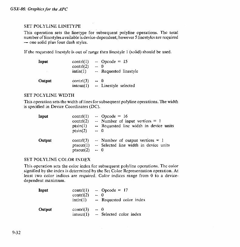
GSX-86: Graphics for the APe
9-32
SET POLYLINE LINETYPE
This operation sets the linetype for subsequent polyline operations. The total number oflinestyles available is device-dependent; however 5linestyles are required - one solid plus four dash styles.
If the requested linestyle is out of range then linestyle 1 (solid) should be used.
Input
Output
contr1(I) contrl(2) intin(l)
contr1(3) intout(l)
SET POLYLINE WIDTH
Opcode = 15 o Requested linestyle
o Linestyle selected
This operation sets the width oflines for subsequent polyline operations. The width is specified in Device Coordinates (DC).
Input
Output
contr1(I) contrl(2) ptsin(l) ptsin(2)
contr1(3) ptsout(l) ptsout(2)
SET POLYLINE COLOR INDEX
Opcode = 16 Number of input vertices = 1 Requested line width in device units o
Number of output vertices = 1 Selected line width in device units o
This operation sets the color index for subsequent polyline operations. The color signified by the index is determined by the Set Color Representation operation. At
. least two color indices are required. Color indices range from 0 to a devicedependent maximum.
Input
Output
contr1(l) contr1(2) intin( 1)
contr1(3) intout(l)
Opcode = 17 o Requested color index
o Selected color index
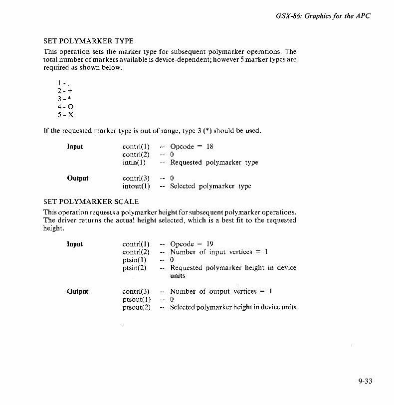
GSX-86: Graphics for the APe
SET POL YMARKER TYPE
This operation sets the marker type for subsequent polymarker operations. The total number of markers available is device-dependent; however 5 marker types are required as shown below.
1 - . 2-+ 3-* 4 - 0 5 - X
If the requested marker type is out of range, type 3 (*) should be used.
Input
Output
contrl(l) contrl(2) intin(l)
contrl(3) intout( 1)
SET POLYMARKER SCALE
Opcode = 18 o Requested polymarker type
o Selected polymarker type
This operation requests a polymarker height for subsequent polymarker operations. The driver returns the actual height selected, which is a best fit to the requested height.
Input
Output
contrl(l) contrl(2) ptsin(1) ptsin(2)
contrl(3) ptsout(1) ptsout(2)
Opcode = 19 Number of input vertices = o Requested polymarker height in device units
Number of output vertices = o Selected polymarker height in device units
9-33
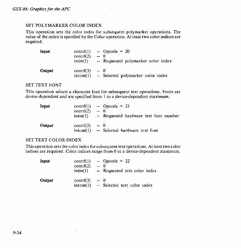
GSX-86: Graphics for the APe
9-34
SET POL YMARKER COLOR INDEX
This operation sets the color index for subsequent polymarker operations. The value of the index is specified by the Color operation. At least two color indices are required.
Input
Output
SET TEXT FONT
contrl(l) contrl(2) intin( I)
contrl(3) intout(l)
Opcode = 20 o Requested polymarker color index
o Selected polymarker color index
This operation selects a character font for subsequent text operations. Fonts are device-dependent and are specified from 1 to a device-dependent maximum.
Input
Output
contrl(l) contrl(2) intin( 1)
contrl(3) intout(l)
SET TEXT COLOR INDEX
Opcode = 21 o Requested hardware text font number
o Selected hardware text font
This operation sets the color index for subsequent text operations. At least two color indices are required. Color indices range from 0 to a device-dependent maximum.
Input
Output
contrl(l) contrl(2) intin( 1)
contrl(3) intout(l)
Opcode = 22 o Requested text color index
o Selected text color index
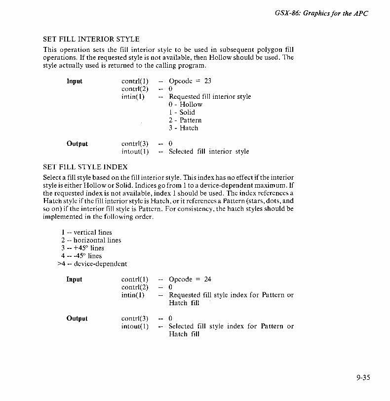
GSX-86: Graphics for the APe
SET FILL INTERIOR STYLE
This operation sets the fill interior style to be used in subsequent polygon fill operations. If the requested style is not available, then Hollow should be used. The style actually used is returned to the calling program.
Input
Output
contrl(l) contrl(2) intin( l)
contrl(3) intout(l)
SET FILL STYLE INDEX
Opcode = 23 o Requested fill interior style o - Hollow 1 - Solid 2 - Pattern 3 - Hatch
o Selected fill interior style
Select a fill style based on the fill interior style. This index has no effect if the interior style is either Hollow or Solid. Indices go from 1 to a device-dependent maximum. If the requested index is not available, index 1 should be used. The index references a Hatch style if the fill interior style is Hatch, or it references a Pattern (stars, dots, and so on) if the interior fill style is Pattern. For consistency, the hatch styles should be implemented in the following order.
1 -- vertical lines 2 -- horizontal lines 3 -- +450 lines 4 -- -450 lines
>4 -- device-dependent
Input
Output
contrl( 1) contrl(2) intin( 1)
contrl(3) intout(l)
Opcode = 24 o Requested fill style index for Pattern or Hatch fill
o Selected fill style index for Pattern or Hatch fill
9-35
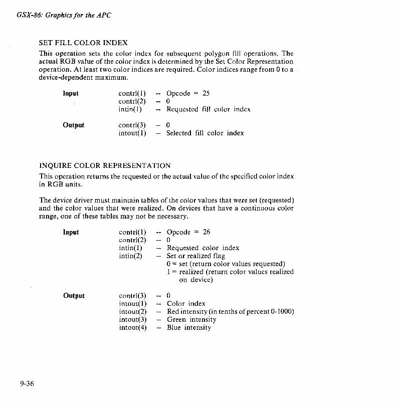
GSX-86: Graphics for the APe
9-36
SET FILL COLOR INDEX
This operation sets the color index for subsequent polygon fill operations. The actual RG B value of the color index is determined by the Set Color Representation operation. At least two color indices are required. Color indices range from 0 to a device-dependent maximum.
Input
Output
contrl(l) contrl(2) intin(1)
contrl(3) intout(1)
Opcode = 25 o Requested fill color index
o Selected fill color index
INQUIRE COLOR REPRESENTATION
This operation returns the requested or the actual value of the specified color index in RGB units.
The device driver must maintain tables of the color values that were set (requested) and the color values that were realized. On devices that have a continuous color range, one of these tables may not be necessary.
Input
Output
contrl(1) contrl(2) intin(1) intin(2)
contrl(3) intout( 1) intout(2) intout(3) intout(4)
Opcode = 26 o Requested color index Set or realized flag 0= set (return color values requested) 1 = realized (return color values realized
on device)
o Color index Red intensity (in tenths of percent 0-1000) Green intensity Blue intensity

GSX-86: Graphics for the APe
INQUIRE CELL ARRAY
This operation returns the cell array definition of the specified cell. Color indices are returned one row at a time, starting from the top of the rectangular area and proceeding downward.
Input
Output
contrl( 1) contrl(2) contrl(4) contrl(6) contrl(7) ptsin(l)
ptsin(2)
ptsin(3)
ptsin(4)
contrl(3) contrl(8)
contrl(9) contrl(lO)
intout
Opcode = 27 2 Length of color index array Length of each row in color index array Number of rows in color index array X-coordinate of lower left corner in device units Y -coordinate of lower left corner in device units X-coordinate of upper right corner 10
device units Y -coordina te of upper right corner in device units
o Number of elements used in each row of color index array Number of rows used in color index array Invalid value flag o -- no errors 1 -- color value could not be determined
for some pixel Color index array (stored one row at a time) -1 -- indicates that a color index could not
be determined for that particular pixel
9-37
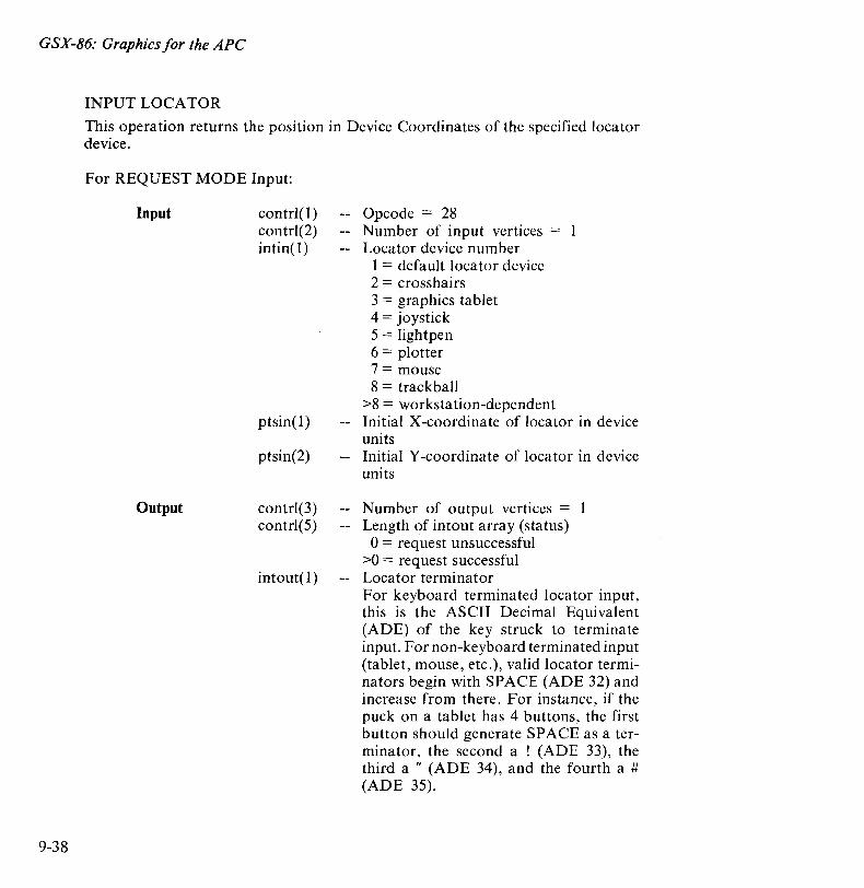
GSX-86: Graphics for the APe
9-38
INPUT LOCATOR
This operation returns the position in Device Coordinates of the specified locator device.
For REQUEST MODE Input:
Input
Output
contrl(l) contrl(2) intin(l)
ptsin(l)
ptsin(2)
contrl(3) contrl(5)
intout( l)
Opcode = 28 Number of input vertices = Locator device number
1 = default locator device 2 = crosshairs 3 = graphics tablet 4 = joystick 5 = lightpen 6 = plotter 7 = mouse 8 = trackball
>8 = workstation-dependent Initial X-coordinate of locator in device units Initial Y-coordinate of locator in device units
Number of output vertices = 1 Length of intout array (status) 0= request unsuccessful
>0 = request successful Locator terminator For keyboard terminated locator input, this is the ASCII Decimal Equivalent (ADE) of the key struck to terminate input. For non-keyboard terminated input (tablet, mouse, etc.), valid locator terminators begin with SPACE (ADE 32) and increase from there. For instance, if the puck on a tablet has 4 buttons, the first button should generate SPACE as a terminator, the second a ! (ADE 33), the third a " (ADE 34), and the fourth a # (ADE 35).
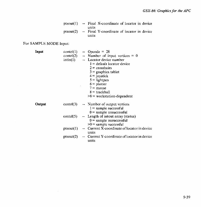
ptsout(l)
ptsout(2)
For SAMPLE MODE Input:
Input
Output
contrl(1) contrl(2) intin(1)
contrl(3)
contrl(5)
ptsout(1)
ptsout(2)
GSX-86: Graphics for the APe
Final X-coordinate of locator in device units Final Y -coordina te of locator in device units
Opcode = 28 Number of input vertices = 0 Locator device number
1 = default locator device 2 = crosshairs 3 = graphics tablet 4 = joystick 5 = lightpen 6 = plotter 7 = mouse 8 = trackball
>8 = workstation-dependent
Number of output vertices 1 = sample successful 0= sample unsuccessful
Length of intout array (status) 0= sample unsuccessful
>0 = sample successful Current X-coordinate oflocator in device units Current Y -coordinate of locator in device units
9-39
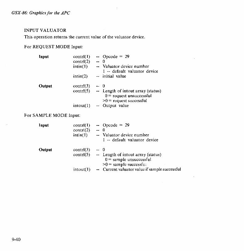
GSX-86: Graphics for the APe
INPUT VALUATOR
This operation returns the current value of the valuator device.
9-40
For REQUEST MODE Input:
Input
Output
contrI(l) contr1(2) intin(l)
intin(2)
contrI(3) contrI(5)
intout( 1)
For SAMPLE MODE Input:
Input
Output
c~ntrIC 1) contr1(2) intin( 1)
contrI(3) contr1(5)
intout(l)
Opcode = 29 o Valuator device number 1 -- default valuator device initial value
o Length of intout array (status) o = request unsuccessful
>0 = request successful Output value
Opcode = 29 o Valuator device number 1 -- default valuator device
o Length of intout array (status) 0= sample unsuccessful
>0 = sample successfu; Current valuator value if sample successful
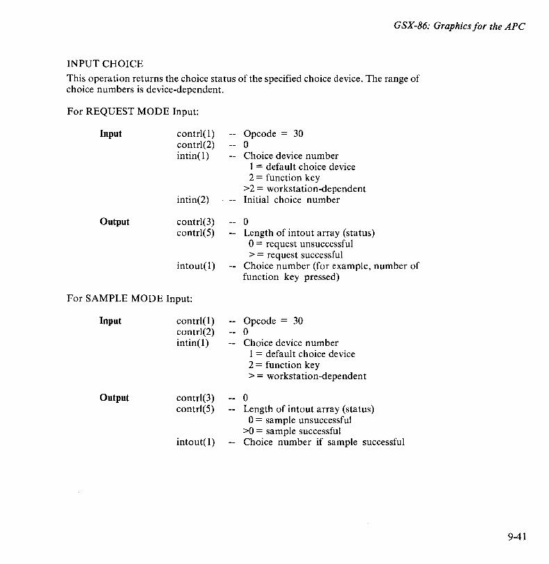
GSX-86: Graphics for the APe
INPUT CHOICE
This operation returns the choice status of the specified choice device. The range of choice numbers is device-dependent.
For REQUEST MODE Input:
Input
Output
contr1( 1) contr1(2) intin( 1)
intin(2)
contr1(3) contr1(5)
intout( 1)
For SAMPLE MODE Input:
Input
Output
contr1(l) contr1(2) intin(l)
contr1(3) contr1(5)
intout(l)
Opcode = 30 o Choice device number
1 = default choice device 2 = function key
>2 = workstation-dependent Initial choice number
o Length of intout array (status) o = request unsuccessful > = request successful
Choice number (for example, number of function key pressed)
Opcode = 30 o Choice device number
o
1 = default choice device 2 = function key > = workstation-dependent
Length of intout array (status) o = sample unsuccessful
>0 = sample successful Choice number if sample successful
9-41
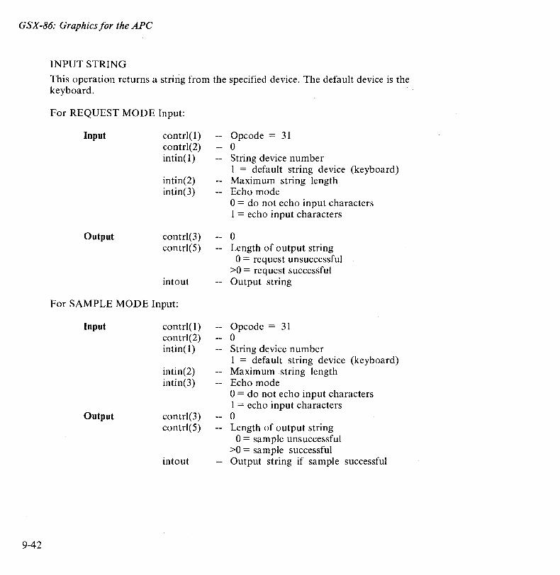
GSX-86: Graphics for the APe
9-42
INPUT STRING
This operation returns a string from the specified device. The default device is the keyboard.
For REQUEST MODE Input:
Input
Output
contrl(l) contrl(2) intin(l)
intin(2) intin(3)
contrl(3) contrl(5)
intout
For SAMPLE MODE Input:
Input
Output
contrl(l) contrl(2) intin( 1)
intin(2) intin(3)
contrl(3) contrl(5)
intout
Opcode = 31 o String device number 1 = default string device (keyboard) Maxim urn string length Echo mode 0= do not echo input characters 1 = echo input characters
o Length of output string o = request unsuccessful
>0 = request successful Output string
Opcode = 31 o String device number 1 = default string device (keyboard) Maxim urn string length Echo mode o = do not echo input characters 1 = echo input characters o Length of output string o = sam pIe unsuccessful
>0 = sample successful Output string if sample successful
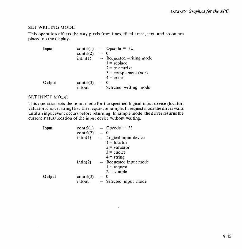
GSX-86: Graphics for the APe
SET WRITING MODE
This operation affects the way pixels from lines, filled areas, text, and so on are placed on the display.
Input
Output
SET INPUT MODE
contrl(l) contrl(2) intin(1)
contrl(3) intout
Opcode = 32 o Requested writing mode 1 = replace 2 = overstrike 3 = complement (xor) 4 = erase o Selected writing mode
This operation sets the input mode for the specified logical input device (locator, valuator, choice, string) to either request or sample. In request mode the driver waits until an input event occurs before returning. In sample mode, the driver returns the current status/location of the input device without waiting.
Input
Output
contrl(l) contrl(2) intin(1)
intin(2)
contrl(3) intout
Opcode = 33 o Logical input device 1 = locator 2 = valuator 3 = choice 4 = string Requested input mode 1 = request 2 = sample o Selected input mode
9-43

GSX-86: Graphics for the APe
9-44
THE GRAPHICS INPUT/OUTPUT SYSTEM (GIOS)
The GIOS contains the device-dependent code in the GSX-86 system. Its is analogous the CP/M-86 BIOS but pertains to graphics devices only. The GIOS contains a GIOS file, or device driver, for each of the graphics devices on the system. Each GIOS file contains code to communicate with a single specific graphics device. A major difference between the GIOS and the BIOS is that while all device drivers contained within the BIOS are resident in memory at the same time, only one graphics device driver is resident at a given time. The active device must be changed by a request from the application program.
Creating A GIOS File
GSX-86 is distributed with a number of device drivers for popular graphics devices. The device drivers are listed in Table 9-1. If your devices are included in the table, you need only to edit the Assignment Table file to ensure that it reflects the logical device numbering assignments you prefer. However, if your device is not supported, you must create a driver program for it. You can write a driver in any language, but at least part of it is usually implemented in assembler due to the low-level hardware interface required.
Device driver files must be in standard CMD format so they can be loaded by the GDOS. The driver must provide the functions listed as required in the VDI specification and must observe the VDI parameter passing conventions. If the graphics device itself does not support all the GDOS operations directly, the driver must emulate the capability in software. For example, if a plotter cannot produce a dashed line, the driver must emulate it by converting a single dashed line into a series of short vectors and transmitting them to the plotter.
The CP/M-86 Program Development Aids diskette contains a listing of the device driver for the APC. Use this as a model if you develop your own device driver.
Device drivers are invoked with a "CALLF" from GSX-86, and should return with a "RETF". The driver must switch to its own stack for internal use, except for an allowed overhead for a few pushes to save the caller's context. The following entry procedure is recommended.
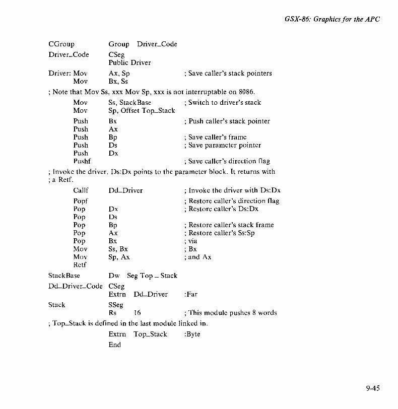
CGroup
Driver_Code
Group Driver_Code
CSeg Public Driver
Driver: Mov Ax, Sp Mov Bx, Ss
; Save caller's stack pointers
; Note that Mov Ss, xxx Mov Sp, xxx is not interruptable on 8086.
Mov Ss, Stack Base ; Switch to driver's stack Mov Sp, Offset Top_Stack
Push Bx ; Push caller's stack pointer Push Ax Push Bp ; Save caller's frame Push Ds ; Save parameter pointer Push Dx Pushf ; Save caller's direction flag
; Invoke the driver. Ds:Dx points to the parameter block. It returns with ; a Retf.
CalIf
Popf Pop Pop Pop Pop Pop Mov Mov Retf
DcLDriver
Dx Ds Bp Ax Bx Ss, Bx Sp, Ax
Stack Base Dw Seg Top _ Stack
DcLDriver_Code CSeg
; Invoke the driver with Ds:Dx
; Restore caller's direction flag ; Restore caller's Ds:Dx
; Restore caller's stack frame ; Restore caller's Ss:Sp ; via ; Bx ; and Ax
Extrn DcLDriver :Far
Stack SSeg Rs 16 ; This module pushes 8 words
; Top_Stack is defined in the last module linked in.
Extrn Top_Stack :Byte
End
GSX-86: Graphics for the APe
9-45
GSX-86: Graphics for the APe
9-46
Sufficient stack space must be available for GSX-86 operations. This includes a buffer area for points passed to GSX-86 and some fixed overhead space. To determine the amount of stack space required to run a given application, make the following calculation:
OPEN WORKSTATION call = approximately 400 bytes All other calls = ptsin size + 64
where ptsin is the point array passed to the device driver from the application program (two words per point)
The stack requirement is the largest of the two resulting values. This stack space must be available in the application program.
After coding and assembling or compiling the source code, link it with any required external subroutines and run-time support libraries to produce a load module. Then, use the RENAME (REN) command to rename the CMD file to a file with the SYS extention. To make the driver known to GSX-86, include its name in the Assignment Table and associate it with a device.
Graphics programs can be debugged like any other application using DDT-86 or another debugger. The default device driver and GDOS are loaded directly above CPM-86 after the GRAPHICS command has been executed. The applications program is loaded in the normal manner, starting at the top of the user area.

Appendix A
Escape Sequences This appendix summarizes the escape sequences for the APC under CP IM-86. The following symbols are used in the escape sequence descriptions:
Pn = Decimal parameter expressed in ASCII digits
Ps = Selective parameter that can take on only the specific values listed
Multiple parameters are separated by ASCII semicolon characters (3BH).
1. ANSI-Compatible Escape Sequences
Cursor Movement Commands: Cursor up Cursor down Cursor forward (right) Cursor backward (left) Direct cursor addressing where P 1 = line number
Pc = column number
ESC[PnA ESC[PnB ESC[PnC ESC[PnD ESC[PI;PcH or ESC[PI;Pcf
A-I
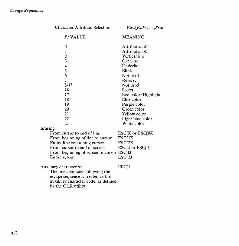
Escape Sequences
A-2
Erasing
Character Attribute Selection:
PsVALUE
o 1 2 3 4 5 6 7 8-15 16 17 18 19 20 21 22 23
ESC[Ps;Ps; ... ;Psm
MEANING
Attributes off Attributes off Vertical line Overline Underline Blink Not used Reverse Not used Secret Red color IHighlight Blue color Purple color Green color Yellow color Light blue color White color
From cursor to end of line ESC[K or ESC[OK From beginning of line to cursor ESC[ 1 K Entire line containing cursor ESC[2K From cursor to end of screen ESC[J or ESC[OJ From beginning of screen to cursor ESC[lJ Entire screen ESC[2J
Auxiliary character set ESC( 1 The one character following the escape sequence is treated as the auxiliary character code, as defined by the CHR utility.
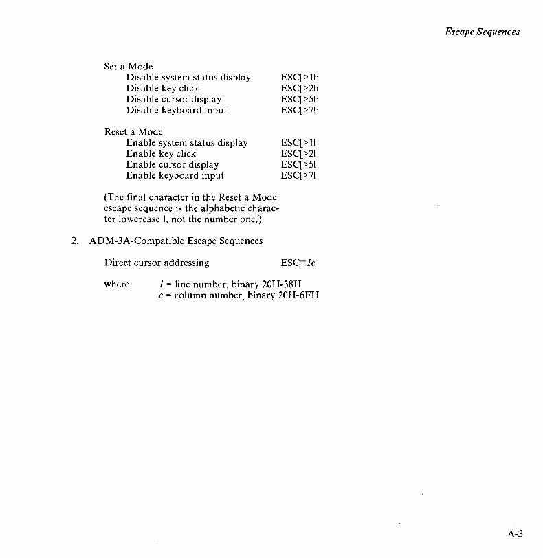
Set a Mode Disable system status display Disable key click Disable cursor display Disable keyboard input
Reset a Mode Enable system status display Enable key click Enable cursor display Enable keyboard input
(The final character in the Reset a Mode escape sequence is the alphabetic character lowercase 1, not the number one.)
2. ADM-3A-Compatible Escape Sequences
Direct cursor addressing
ESC[> Ih ESC[>2h ESC[>5h ESC[>7h
ESC[> 11 ESC[>21 ESC[>51 ESC[>71
ESC=]c
where: ] = line number, binary 20H-38H c = column number, binary 20H-6FH
Escape Sequences
A-3

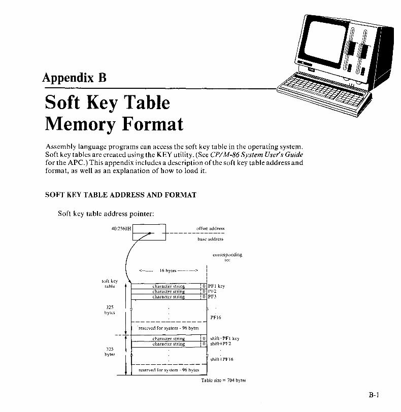
Appendix B
Soft Key Table Memory Format Assembly language programs can access the soft key table in the operating system. Soft key tables are created using the KEY utility. (See CPIM-86 System User's Guide for the APe.) This appendix includes a description of the soft key table address and format, as well as an explanation of how to load it.
SOFT KEY TABLE ADDRESS AND FORMAT
Soft key table address pointer:
40 :2560H I + offset ---------
soft key table
325 bytes
325 bytes
I / base
( ( I
<-----------16 bytes -----------> I I I I
1
character string .0 character string :0 character string 10
j ---------------reserved for system - 96 bytes
f character string '0 character string .0
------------- ---l
reserved for system - 96 bytes
address
address
corresponding to:
PFI key PF2 PF3
PF16
shift+PFI key shift+PF2
shift+PFl6
Table size = 704 bytes
B-1
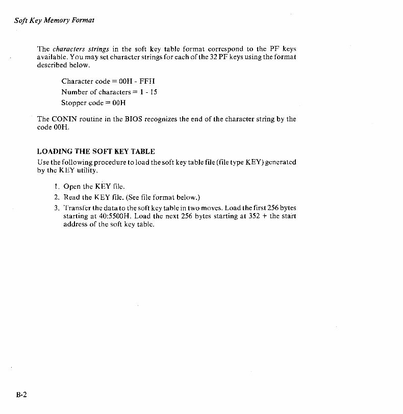
Soft Key Memory Format
B-2
The characters strings in the soft key table format correspond to the PF keys available. You may set character strings for each of the 32 PF keys using the format described below.
Character code = OOH - FFH
Number of characters = 1 - 15
Stopper code = OOH
The CONIN routine in the BIOS recognizes the end of the character string by the code OOH.
LOADING THE SOFT KEY TABLE
Use the following procedure to load the soft key table file (file type KEY) generated by the KEY utility.
1. Open the KEY file.
2. Read the KEY file. (See file format below.)
3. Transfer the data to the soft key table in two moves. Load the first 256 bytes starting at 40:5500H. Load the next 256 bytes starting at 352 + the start address of the soft key table.

Soft Key Memory Format
KEY FILE FORMAT
FFI L1H1
Header (128 bytes)
Character string
l 16x16 bytes PFI I PF16
Character string FNC+PFI I
1 16x16 bytes
FNC+PFI6
<-------- 16 bytes ------>
The last six function keys on the keyboard, unshifted and shifted, produce the following predefined escape sequences.
ESCOO ESCOP ESCOQ ESCOR ESCOS ESCOT
ESCOU ESCOV ESCOW ESCOX ESCOY ESCOZ
These sequences do not actually perform any function. They must be implemented by an application program, which establishes an action or series of operations for each escape sequence.
B-3

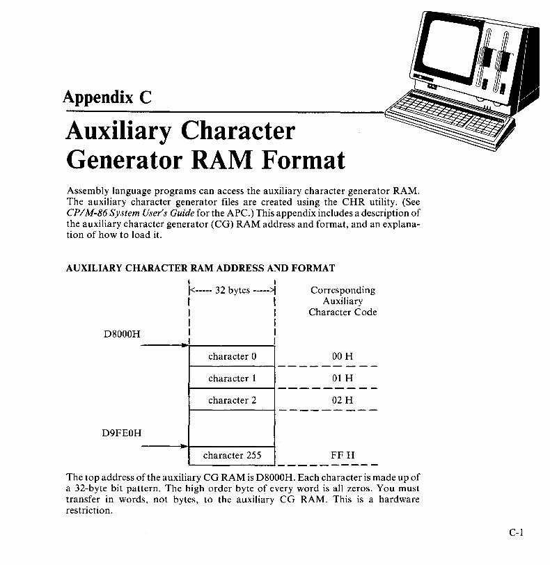
Appendix C
Auxiliary Character Generator RAM Format Assembly language programs can access the auxiliary character generator RAM. The auxiliary character generator files are created using the CHR utility. (See CPIM-86 System User's Guide for the APC.) This appendix includes a description of the auxiliary character generator (CG) RAM address and format, and an explanation of how to load it.
AUXILIARY CHARACTER RAM ADDRESS AND FORMAT
D8000H
D9FEOH ...
I I 1<----- 32 bytes ----->f I I I I I I I I I I
character 0
character 1
character 2
character 255
Corresponding Auxiliary
Character Code
OOH
01 H
02H
FFH
The top address of the auxiliary CG RAM is D8000H. Each character is made up of a 32-byte bit pattern. The high order byte of every word is all zeros. You must transfer in words, not bytes, to the auxiliary CG RAM. This is a hardware restriction.
C-I
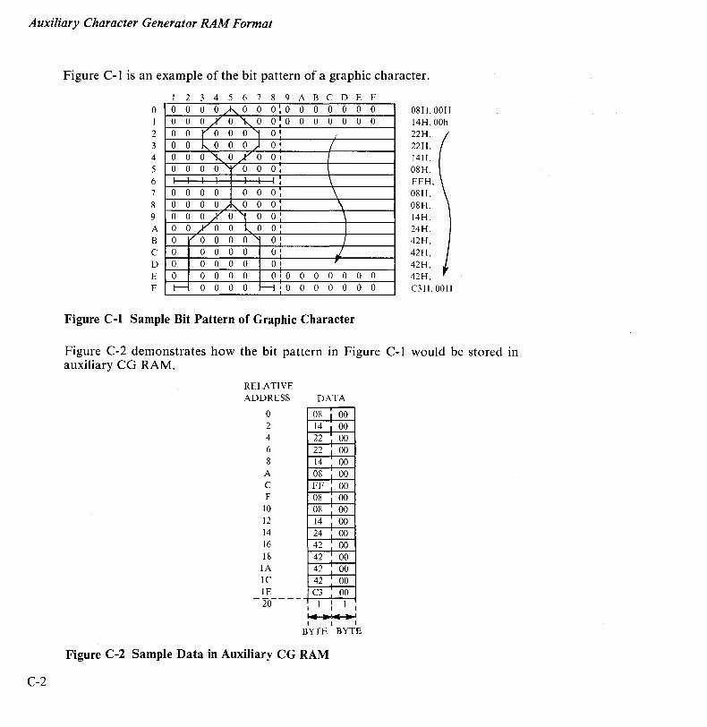
Auxiliary Character Generator RAM Format
C-2
Figure C-l is an example of the bit pattern of a graphic character.
1 234 5 6 7 8 9 ABC D E F o 1 2 3 4 5 6 7 8 9 A B C D E F
0 0 0 o A 0 0 0:0 0 0 070,,"0 0 1 0 0 oro 0 0"1 O' 0 o ~ 0 0 o ) O· 0 0 0,,"0/0 O. 0 0 0 o " v 0 0 o.
1 1 1 : 0 0 0 0 0 0 o. 0 0 0 o /1\... 0 0 o. 0 0 0/0,,\ 0 0: 0 o ./ 0 o "0 0 1
0 Vo 0 0 o "" O' 0 0 0 0 0 o' 0 0 0 0 0 O' 0 0 0 0 0 0 1 0 J-- 0 0 0 0 H I 0
0 0 0 0 0 0 0 0
I
I I \ \
\ \
I
.f , 0 0 0 0 0 0 0 0
Figure C-l Sample Bit Pattern of Graphic Character
0 0 0 0
0 0 0 0
08H, OOH 14H, OOh 22H, 22H, 14H, 08H, FFH, 08H, 08H, 14H. 24H, 42H, 42H, 42H, 42H, C3H,00H
Figure C-2 demonstrates how the bit pattern in Figure C-l would be stored in auxiliary CG RAM.
RELATIVE ADDRESS
o 2 4 6 8 A C E
IO
12 14 16 18 lA lC IE
DATA
08 1 00 14 1 00 22 i 00 22 I 00 14 00 08 I 00 FF : 00 08 I 00 08 i 00 14 • 00 24 1 00 42 -'- 00 42 00 42 00 42 I 00
- 20- - - - • 1 I 1 • C3-,- 00
• I ... Ie .1 • I I
BYTE BYTE
Figure C-2 Sample Data in Auxiliary CG RAM

Auxiliary Character Generator RAM Format
LOADING THE AUXILIARY CHARACTER FILE
Use the following procedure ~o load the auxiliary CO RAM with data from the file (file type CHR) generated by the CHR utility.
1. Open the CHR file.
2. Read the CHR file into the temporary user buffer that is automatically created by the CHR utility. (See file format below.)
3. Transfer the data (8K bytes) in the user buffer to the auxiliary CO RAM, starting at D8000H, by word.
CHR TYPE FILE FORMAT
Header (128 bytes) reserved
for future use
character character character character 0 I 2 3
4 5 6 7
8 9 10 11
C-3

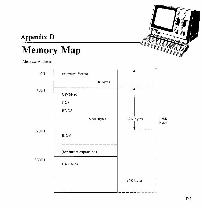
Appendix D
Memory Map Absolute Address:
OH Interrupt Vector
lK bytes
400H CP/M-86
CCP
BDOS
9.5K bytes
2900H BIOS
----------------(for future expansion)
8000H User Area
32K bytes ____ 1 ____ _
96K bytes
128K bytes
D-l

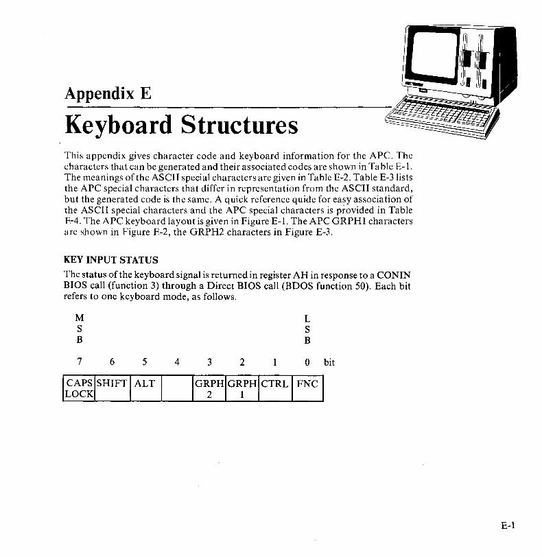
Appendix E
Keyboard Structures This appendix gives character code and keyboard information for the APC. The characters that can be generated and their associated codes are shown in Table E-l. The meanings of the ASCII special characters are given in Table E-2. Table E-3lists the APC special characters that differ in representation from the ASCII standard, but the generated code is the same. A quick reference quide for easy association of the ASCII special characters and the APC special characters is provided in Table E-4. The APC keyboard layout is given in Figure E-l. The APC GRPHI characters are shown in Figure E-2, the GRPH2 characters in Figure E-3.
KEY INPUT STATUS
The status of the keyboard signal is returned in register AH in response to a CONIN BIOS call (function 3) through a Direct BIOS call (BDOS function 50). Each bit refers to one keyboard mode, as follows.
M S B
7
CAPS LOCK
6 5 4
SHIFT ALT
3 2
IG~PH GRPH 1
1
CTRL
L S B
Obit
FNC
E-l
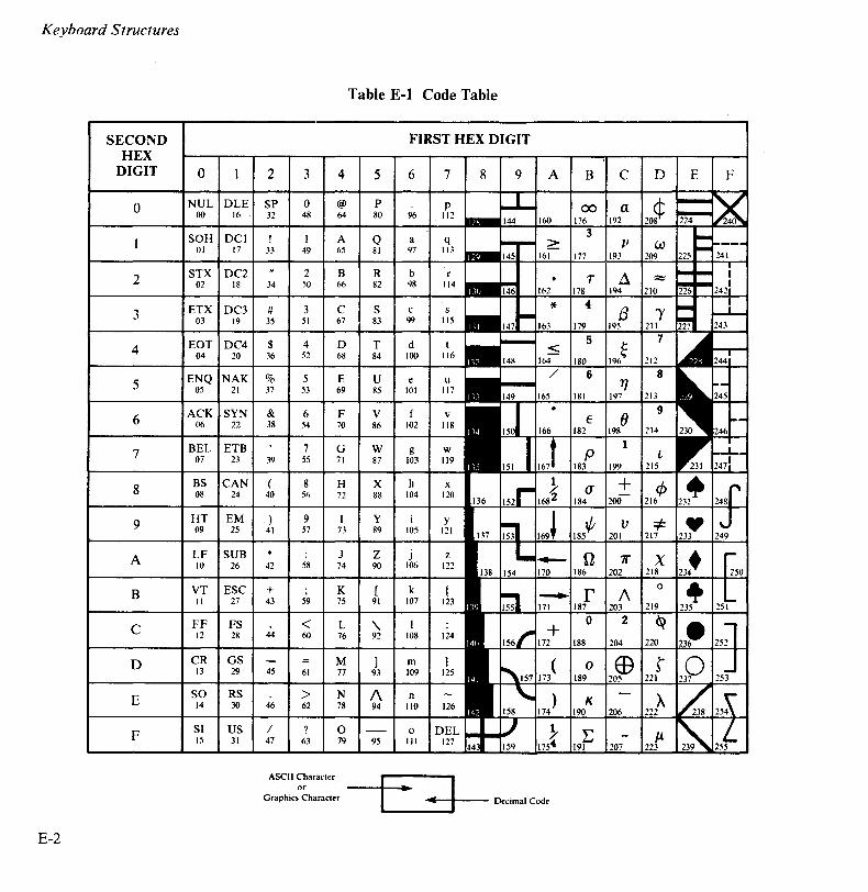
Keyboard Structures
Table E-l Code Table
SECOND FIRST HEX DIGIT HEX
DIGIT 0 2 3 4 5 6 7 8 9 A B C D E F
0 NUL DLE SP 0 @ P P 00 a 00 16 32 48 64 80 96 112
176 192
3 SOH DCI ! A Q a q V 01 17 33 49 65 81 97 113 177 193 209
STX DC2 2 B R b r 2 02 18 34 50 66 82 98 114
ETX DC3 # 3 C S c s 3 03 19 35 51 67 83 99 115
EOT DC4 $ 4 D T d t 4 04 20 36 52 68 84 100 116
ENQ NAK % 5 E U e u 5 05 21 37 53 69 85 101 117
ACK SYN & 6 F V v 6 06 22 38 54 70 86 102 118
7 BEL ETB 7 G W g W 07 23 39 55 71 87 103 119
199 215
BS CAN ( 8 H X h x (J + 8 08 24 40 5n 72 88 104 120 184 200
9 HT EM ) 9 I Y i y 185t/;
V 09 25 41 57 73 89 105 121 201
LF SUB J Z j z n 7r A 10 26 42 58 74 90 106 122 186 202
B VT ESC + K [ k { II 27 43 59 75 91 107 123
C FF FS < L '\ 12 28 44 60 76 92 108 124
D CR GS M ] m } 13 29 45 61 77 93 109 125
E SO RS > N 1\ n 14 30 46 62 78 94 110 126
SI US / ? 0 0 F 15 31 47 63 79 95 III
ASCII Character or ..
Graphics Character .. Decimal Code
E-2
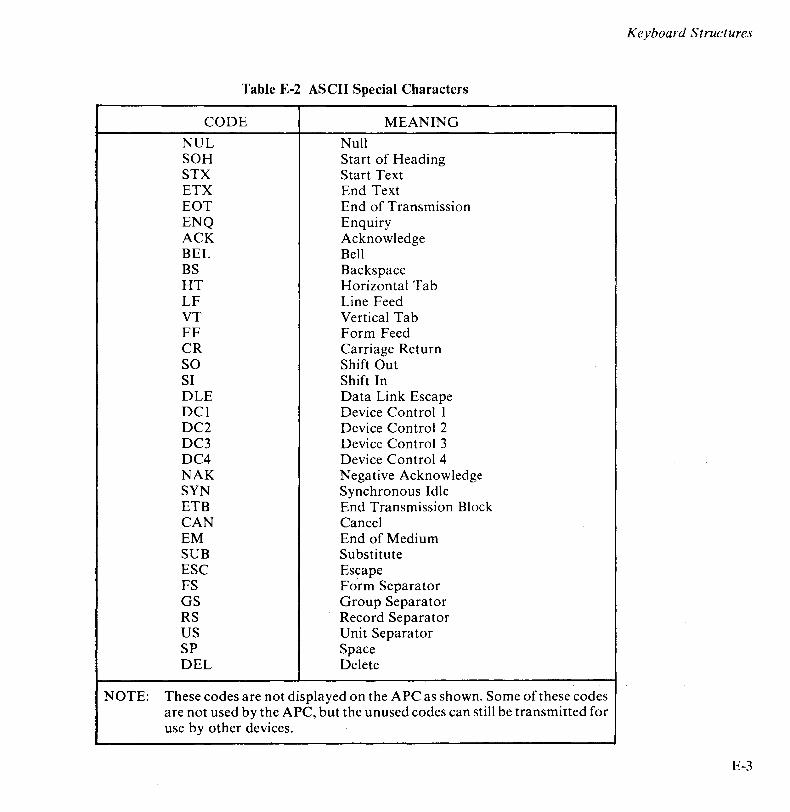
Keyboard Structures
Table E-2 ASCII Special Characters
CODE MEANING
NUL Null SOH Start of Heading STX Start Text ETX End Text EaT End of Transmission ENQ Enquiry ACK Acknowledge BEL Bell BS Backspace HT Horizontal Tab LF Line Feed VT Vertical Tab FF Form Feed CR Carriage Return SO Shift Out SI Shift In DLE Data Link Escape DCI Device Control I DC2 Device Control 2 DC3 Device Control 3 DC4 Device Control 4 NAK Negative Acknowledge SYN Synchronous Idle ETB End Transmission Block CAN Cancel EM End of Medi urn SUB Substitute ESC Escape FS Form Separator GS Group Separator RS Record Separator US Unit Separator SP Space DEL Delete
NOTE: These codes are not displayed on the APC as shown. Some of these codes are not used by the APC, but the unused codes can still be transmitted for use by other devices.
E-3
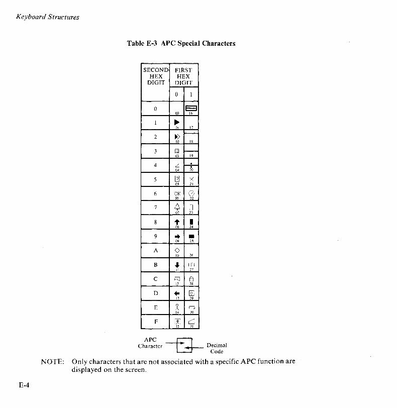
Keyboard Structures
E-4
Table E-3 APC Special Characters
SECOND FIRST HEX HEX
DIGIT DIGIT
0 1
0 E3 00 16
1 ~ 01 17
2 ~ -02 18
3 CD -03 19
4 Z -i-04 20
5 [1J X 05 21
6 OK CD 06 22
7 ~ 0 07 23
8 1- • 08 24
9 .. -09 25
A 0 10 26
B ... OJ II 27
C h] 0 12 28
D .. [2J 13 29
E -* 0 14 30
F rn c::J 15 31
APC -G-Character Decimal
Code
NOTE: Only characters that are not associated with a specific APC function are displayed on the screen.

Table E-4 Quick Reference Guide for ASCII Special Character/ APC Special Character Association
ASCII APC SPECIAL SPECIAL
CHARACTER CHARACTER
NUL SOH ~ STX ~ ETX m EaT z ENQ @1 ACK OK
BEL cC BS ... HT .. LF 0 VT ... FF c;:::J
CR .. SO 1: SI W DLE !=:=l DCI DC2 -DC3 -DC4 NAK X SYN CD ETB 0 CAN • EM -SUB ESC rn FS EJ GS [£J
RS 0
US c:1 SP DEL
NOTE: Characters associated with a specific APC function are not displayed.
Keyboard Structures
E-5
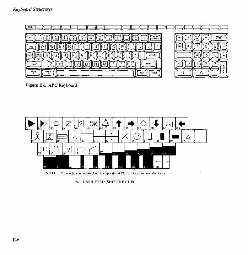
Keyboard Structures
Figure E-l APe Keyboard
@] OK -t -+ 0 • ~ +-08 09 OA
• 6 6
II 12 IA
D IE
88
NOTE: Characters associated with a specific APC function are not displayed.
A. UNSHIFTED (SHIFT KEY UP)
E-6
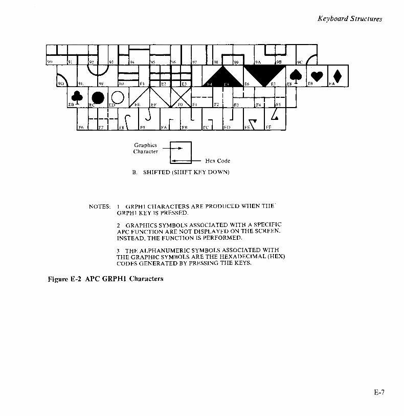
Graphics Character
Hex Code
B. SHIFTED (SHIFT KEY DOWN)
NOTES: I GRPH I CHARACTERS ARE PRODUCED WHEN THE GRPH I KEY IS PRESSED.
2 GRAPHICS SYMBOLS ASSOCIATED WITH A SPECIFIC APC FUNCTION ARE NOT DISPLA YED ON THE SCREEN. INSTEAD, THE FUNCTION IS PERFORMED.
3 THE ALPHANUMERIC SYMBOLS ASSOCIATED WITH THE GRAPHIC SYMBOLS ARE THE HEXADECIMAL (HEX) CODES GENERATED BY PRESSING THE KEYS.
Figure E-2 APC GRPHI Characters
Keyboard Structures
£-7
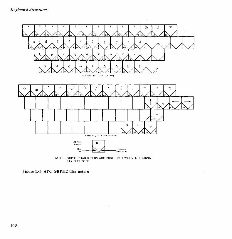
Keyboard Structures
GRPH2 Character
Hex Code
A. lJNSHIFTED (SHII·T KEY UP)
B. SIlII·IED (SIIII·' KI·.Y DOWN)
Character on Key Cap
NOTE: GRPH2 CHARACTERS ARE PRODUCED WHEN THE GRPH2 KEY IS PRESSED
Figure E-3 APC GRPH2 Characters
E-8
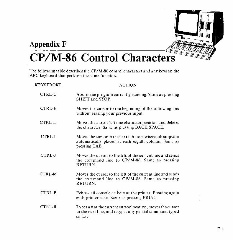
Appendix F
CP IM-86 Control Characters The following table describes the CP/M-86 control characters and any keys on the APC keyboard that perform the same function.
KEYSTROKE
CTRL-C
CTRL-E
CTRL-H
CTRL-I
CTRL-J
CTRL-M
CTRL-P
CTRL-R
ACTION
Aborts the program currently running. Same as pressing SHIFT and STOP.
Moves the cursor to the beginning of the following line without erasing your previous input.
Moves the cursor left one character position and deletes the character. Same as pressing BACK SPACE.
Moves the cursor to the next tab stop, where tab stops are automatically placed at each eighth column. Same as pressing TAB.
Moves the cursor to the left of the current line and sends the command line to CP/M-86. Same as pressing RETURN.
Moves the cursor to the left of the current line and sends the command line to CP/M-86. Same as pressing RETURN.
Echoes all console activity at the printer. PrelfSing again ends printer echo. Same as pressing PRINT.
Types a # at the current cursor location, moves the cursor to the next line, and retypes any partial command typed so far.
F-I

CP/ M-86 Control Characters
CTRL-S
CTRL-U
CTRL-X
CTRL-Z
F-2
Temporarily stops console listing. Pressing again resumes the listing. Same as pressing STOP.
Discards all characters in the command typed so far, types a # at the current cursor location, and moves the cursor to the next command line.
Discards all characters in the command line typed so far and moves the cursor back to the beginning of the current line. Same as pressing DEL.
Separates fields or strings.
Appendix G
CP 1M -86 Error Messages MESSAGE
Ambiguous operand
Bad Directory on d:
MEANING AND SUGGESTED CORRECTION
DDT-86. An attempt was made to assemble a command with an ambiguous operand. Precede the operand with the prefix "BYTE" or "WORD".
Space Allocation Conflict: User n d:filename.typ
BDOS err on d:
ST AT has detected a space allocation conflict in which one data block is assigned to more than one file. One or more filenames might be listed. Each of the files listed contains a data block already allocated to another file on the disk. You can correct the problem by erasing the files listed. After erasing the conflicting file orfiles, press tC to regenerate the allocation vector. If you do not, the error might repeat itself.
CP IM-86 replaces d: with the drive specifier of the drive where the error occurred. This message appears when CP/M-86 finds no disk in the drive, when the disk is improperly formatted, when the drive latch is open, or when power to the drive is off. Check for one of these situations and retry.
G-l

CP/ M-86 Error Messages
BDOS err on d: bad sector
BDOS err on d: RO
Cannot close
Command name?
G-2
This could indicate a hardware problem or a worn or improperly formatted disk. Press CTRL-C to terminate the program and return to CP/M-86, or press the enter key to ignore the error.
BDOS err on d: select
CP/M-86 has received a request specifying a nonexistent drive, or a disk in a drive is improperly formatted. CP/M-86 terminates the current program as soon as you press any key.
Drive has been assigned Read-Only status with a STAT command, or the disk in the drive has been changed without being initialized with a CTRL-C. CP/M-86 terminates the current program as soon as you press any key.
ASM-86. An output file cannot be closed. This is a fatal error that terminates ASM-86 execution. The user should take appropriate action after checking to see if the correct disk is in the drive and that the disk is not write protected.
DDT -86. The disk file written by a W command cannot be closed. This is a fatal error that terminates DDT-86 execution. The user should take appropriate action after checking to see if the correct disk is in the drive and that the disk is not write protected.
If CP/M-86 cannot find the command you specified, it returns the command name you entered followed by a question mark. Check that you have typed the command name correctly, or that the command you requested exists as a CMD file on the default or specified disk.
CP/ M-86 Error Messages
DESTINATION IS RIO, DELETE (YIN)?
Directory full
Disk full
Disk read error
Disk write error
PIP. The destination file specified in a PIP command already exists and has the Read-Only attribute. If you type Y, the destination file is deleted before the file copy is done.
ASM-86. There is not enough directory space for the output files. You should either erase some unnecessary files or get another disk with more directory space and execute ASM-86 again.
ASM-86. There is not enough disk space for the output files (LST, H86 and SYM). You should either erase some unnecessary files or get another disk with more space and execute ASM-86 again.
ASM-86. A source or include file could not be read properly. This is usually the result of an unexpected end of file. Correct the problem in your source file.
DDT -86. The disk file specified in an R command could not be read properly. This is usually the result of an unexpected end of file. Correct the problem in your file.
DDT -86. A disk write operation could not be successfully performed during a W command, probably due to a full disk. You should either erase some unnecessary files or get another disk with more space and execute ASM-86 again.
G-3

CP/ M-86 Error Messages
G-4
Double defined variable
Double defined label
ASM-86. An identifier used as the name of a variable is used elsewhere in the program as the name of a variable or label. Example:
x DB 5
x DB 123H
ASM-86. An identifier used as a label is used elsewhere in the program as a label or variable name. Example:
LAB3: MOV BX,5
LAB3: CALL MOVE
Double defined symbol - treated as undefined
ASM-86. The identifier used as the name of an EQU directive is used as a name elsewhere in the program.
ERROR: BAD PARAMETER
PIP. An illegal parameter was entered in a PIP command. Retype the entry correctly.
ERROR: CLOSE FILE - {filespec}
PIP. An output file cannot be closed. The user should take appropriate action after checking to see if the correct disk is in the drive and that the disk is not write protected.
ERROR: DISK READ - {filespec}
PIP. The input disk file specified in a PIP command cannot be read properly. This is usually the result of an unexpected end of file. Correct the problem in your file.

CP/ M-86 Error Messages
ERROR: DISK WRITE - {filespec}
PIP. A disk write operation cannot be successfully performed during a PIP command, probably due to a full disk. You should either erase some unnecessary files or get another disk with more space and execute PIP again.
ERROR: FILE NOT FOUND - {filespec}
PIP. An input file that you have specified does not exist.
ERROR: HEX RECORD CHECKSUM - {filespec}
PIP. A hex record checksum was encountered during the transfer of a hex file. The hex file with the checksum error should be corrected, probably by recreating the hex file.
Error in codemacro building
ASM-86. Either a codemacro contains invalid statements, or a codemacro directive was encountered outside a codemacro.
ERROR: INVALID DESTINATION
PIP. The destination specified in your PIP command is illegal. You have probably specified an input device as a destination.
ERROR: INVALID FORMAT
PIP. The format of your PIP command is illegal. See the description of the PIP command.
ERROR: INVALID HEX DIGIT - {filespec}
PIP. An invalid hex digit has been encountered while reading a hex file. The hex file with the invalid hex digit should be corrected, probably by recreating the hex file.
ERROR: INVALID SEPARATOR
PIP. You used an invalid character for a separator between two input filenames.
G-5
CPIM-86 Error Messages
G-6
ERROR: INVALID SOURCE
PIP. The source specified in your PIP command is illegal. You have probably specified an output device as a source.
ERROR: INVALID USER NUMBER
PIP. You have specified a User Number greater than 15. User Numbers are in the range 0 to 15.
ERROR: NO DIRECTORY SPACE - {filespec}
PIP. There is not enough directory space for the output file. You should either erase some unnecessary files or get another disk with more directory space and execute PIP again.
ERROR: QUIT NOT FOUND
PIP. The string argument to a Q parameter was not found in your input file.
ERROR: START NOT FOUND
PIP. The string argument to an S parameter cannot be found in the source file.
ERROR: UNEXPECTED END OF HEX FILE - {filespec}
PIP. An end of file was encountered prior to a termination hex record. The hex file without a termination record should be corrected, probably by recreating the hex file.
ERROR: USER ABORTED
PIP. The user has aborted a PIP operation by pressing a key.
ERROR: VERIFY - {filespec}
PIP. When copying with the V option, PIP found a difference when rereading the data just written and comparing it to the data in its memory buffer. Usually this indicates a failure of either the destination disk or drive.

CP/ M-86 Error Messages
File exists
File name syntax error
File not found
You have asked CP 1M -86 to create a new file using a file specification that is already assigned to another file. Either delete the existing file or use another file specification.
ASM-86. The filename in an INCLUDE directive is improperly formed. Example:
INCLUDE FILE.A86X
CP/M-86 could not find the specified file. Check that you have entered the correct drive specification and that you have the correct disk in the drive.
Garbage at end of line - ignored
ASM-86. Additional items were encountered on a line when ASM-86 was expecting an end of line. Examples:
NOLIST 4 MOV AX,4 RET
Illegal expression element
Illegal first item
ASM-86. An expression is improperly formed. Examples:
X DB 12X DW (4 * )
ASM-86. The first item on a source line is not a valid identifier, directive or mnemonic. Example:
1234H
G-7
CP/ M-86 Error Messages
G-8
Illegal "IF" operand - "IF" ignored
Illegal pseudo instruction
Illegal pseudo operand
ASM-86. Either the expression in an IF statement is not numeric, or it contains a forward reference.
ASM-86. Either a required identifier in front of a pseudo instruction is missing, or an identifier appears before a pseudo instrucion that doesn't allow an identifier.
ASM-86. The operand in a directive is invalid. Examples:
x EQU OAGH
TITLE UNQUOTED STRING
Instruction not in code segment
ASM-86. An instruction appears in a segment other than a CSEG.
Is this what you want to do (YIN)?
Insufficient memory
Invalid Assignment
COPYDISK. If the displayed COPYDISK function is what you want performed, type Y.
DDT-86. There is not enough memory to load the file specified in an R or E command.
ST AT. An invalid device was specified in a STAT device assignment. Use the STAT val: command to display the valid assignments for each of the four logical STAT devices: CON:, RDR:, PUN: and LST:.
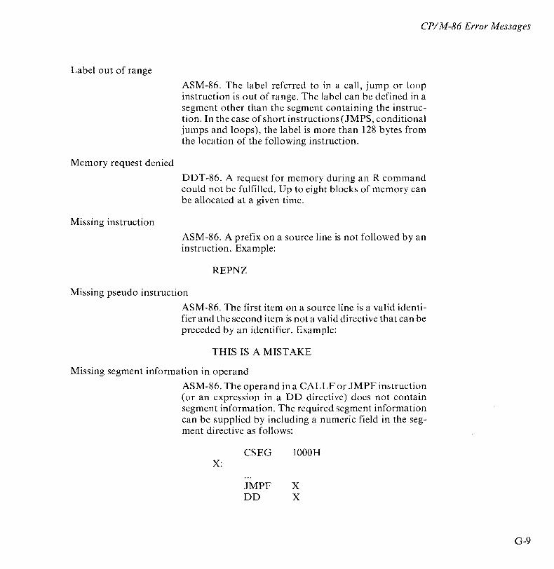
CP/ M-86 Error Messages
Label out of range
Memory request denied
Missing instruction
ASM-86. The label referred to in a call, jump or loop instruction is out of range. The label can be defined in a segment other than the segment containing the instruction. In the case of short instructions (JMPS, conditional jumps and loops), the label is more than 128 bytes from the location of the following instruction.
DDT -86. A request for memory during an R command could not be fulfilled. Up to eight blocks of memory can be allocated at a given time.
ASM-86. A prefix on a source line is not followed by an instruction. Example:
REPNZ
Missing pseudo instruction
ASM-86. The first item on a source line is a valid identifier and the second item is not a valid directive that can be preceded by an identifier. Example:
THIS IS A MISTAKE
Missing segment information in operand
ASM-86. The operand in a CALLF or JMPF instruction (or an expression in a DD directive) does not contain segment information. The required segment information can be supplied by including a numeric field in the segment directive as follows:
CSEG 1000H X:
JMPF X DD X
G-9
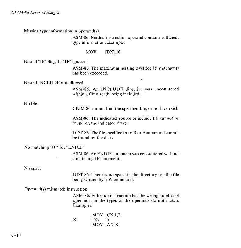
CP/ M-86 Error Messages
G-IO
Missing type information in operand(s)
ASM-86. Neither instruction operand contains sufficient type information. Example:
MOV [BX],lO
Nested "IF" illegal - "IF" ignored
ASM-86. The maximum nesting level for IF statements has been exceeded.
Nested INCLUDE not allowed
No file
ASM-86. An INCLUDE directive was encountered within a file already being included.
CP/M-86 cannot find the specified file, or no files exist.
ASM-86. The indicated source or include file cannot be found on the indicated drive.
DDT-86. The file specified in an R or E command cannot be found on the disk.
No matching "IF" for "ENDIF"
No space
ASM-86. An ENDIF statement was encountered without a matching IF statement.
DDT-86. There is no space in the directory for the file being written by a W command.
Operand(s) mismatch instruction
ASM-86. Either an instruction has the wrong number of operands, or the types of the operands do not match. Examples:
MOV CX,1,2 X DB 0
MOV AX,X

CPIM-86 Error Messages
Parameter error
ASM-86. A parameter in the command tail of the ASM-86 command was specified incorrectly. Example:
ASM86 TEST $S;
Symbol illegally forward referenced - neglected
Symbol table overflow
ASM-86. The indicated symbol was illegally forward referenced in an ORG, RS, EQU or IF statement.
ASM-86. There is not enough memory for the symbol table. Either reduce the length and! or number of symbols, or reassemble on a system with more memory available.
Undefined element of expression
Undefined instruction
ASM-86. An identifier used as an operand is not defined or has been illegally forward referenced. Examples:
JMP X A EQU B B EQU 5
MOV AL,B
ASM-86. The item following a label on a source line is not a valid instruction. Example:
DONE: BAD INSTR
Use: [size] [ro] [rw] [sys] or [dir]
Use: STATd:=RO
ST AT. This message results from an invalid set file attributes command. These are the only options valid in a STAT filespec [option] command.
STAT. An invalid STAT drive command was given. The only valid drive assignment in STAT is STAT d:=RO.
G-ll
CP/ M-86 Error Messages
Too Many Files
Verify error at s:o
G-12
STAT. A STAT wildcard command matched more files in the directory than STAT can sort. STAT can sort a maximum of 512 files.
DDT-86. The value placed in memory by a Fill, Set, Move, or Assemble command cannot be read back correctly, indicating bad user memory, an attempt to write to ROM, or nonexistent memory at the indicated location.
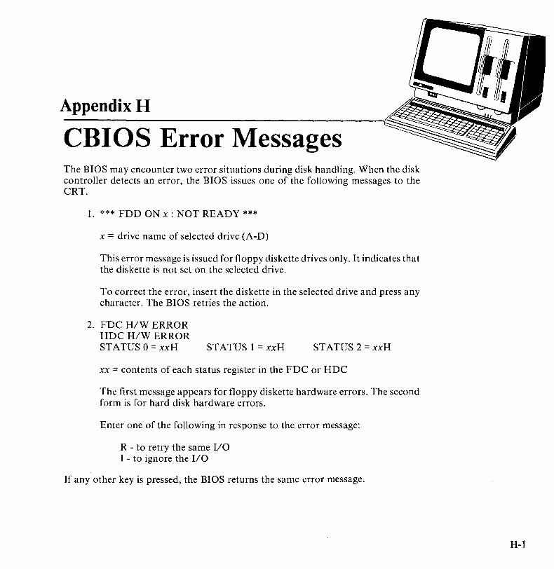
Appendix H
CBIOS Error Messages The BIOS may encounter two error situations during disk handling. When the disk controller detects an error, the BIOS issues one of the following messages to the CRT.
1. *** FDD ON x : NOT READY ***
x = drive name of selected drive (A-D)
This error message is issued for floppy diskette drives only. It indicates that the diskette is not set on the selected drive.
To correct the error, insert the diskette in the selected drive and press any character. The BIOS retries the action.
2. FDC H/W ERROR HDC H/W ERROR STATUS 0 = xxH STATUS 1 = xxH STATUS 2 = xxH
xx = contents of each status register in the FDC or HDC
The first message appears for floppy diskette hardware errors. The second form is for hard disk hardware errors.
Enter one of the following in response to the error message:
R - to retry the same I/O I - to ignore the I/O
If any other key is pressed, the BIOS returns the same error message.
H-l

CBIOS Error Messages
H-2
When a write-protected diskette is selected, the following message is displayed.
*** This floppy on x : is the write protected floppy ***
x = drive name of selected drive (A-D)
This is not an error, but is a warning not to attempt to write to the disk. If a write operation is attempted to a write-protected diskette, the FDC H/W error message is returned.
Appendix I
Blocking and Deblocking Algorithms Upon each call to the BIOS WRITE entry point, the CP/M-86 BDOS includes information that allows effective sector blocking and deblocking where the host disk subsystem has a sector size which is a multiple of the basic 128-byte unit. This appendix presents a general-purpose algorithm that is included in the CBIOS and that uses the BDOS information to perform the operations automatically.
Upon each call to WRITE, the BDOS provides the following information in register CL:
0= normal sector write 1 = write to directory sector 2 = write to the first sector
of a new data block
Condition 0 occurs whenever the next write operation is into a previously written area, such as a random mode record update, when the write is to other than the first sector of an unallocated block, or when the write is not into the directory area. Condition 1 occurs when a write into the directory area is performed. Condition 2 occurs when the first record (only) of a newly allocated data block is written. In most cases, application programs read or write mUltiple 128-byte sectors in sequence, and thus there is little overhead involved in either operation when blocking and deblocking records since pre-read operations can be avoided when writing records.
This appendix briefly describes the blocking and deblocking algorithm (the file is included on your CP/M-86 system diskette). Generally, the algorithms map all CP 1M sector read operations onto the host disk through an intermediate buffer which is the size of the host disk sector. Throughout the program, values and variables which relate to the CP 1M sector involved in a seek operation are prefixed by "sek", while those related to the host disk system are prefixed by "hst".
1-1
Blocking and Deblocking
1-2
The SELDSK entry point clears the host buffer flag whenever a new disk is logged in. Note that although the SELDSK entry point computes and returns the Disk Parameter Header address, it does not physically select the host disk at this point (it is selected later at READHST or WRITEHST). Further, SETTRK, SETSEC, and SETDMA simply store the values, but do not take any other action at this point. SECTRAN performs-a trivial function of returning the physical sector number.
The principal entry points are READ and WRITE. These subroutines take the place of your previous READ and WRITE operations.
For hard disk, the READ and WRITE operations actually move data from or to a work buffer. The work buffer is located on the hard disk adapter board starting at location 9CaaaH. This buffer is used by the CBIOS only and is not accessible to the user for either programs or data.
The actual physical read or write takes place at either WRITEHST or READHST, where all values have been prepared: hstdsk is the host disk number, hsttrk is the host track number, and hstsec is the host sector number (which may require translation to a physical sector number). You must insert code at this point which performs the full host sector read into, or write out of, the buffer at hstbuj of length hstsiz. All other mapping functions are performed by the algorithms.
See the listing of the CBIOS on the CP /M-86 Program Development Aids diskette for the sector blocking/deblocking algorithm for the APC.
Appendix J
Physical Format Of Hard Disks CP/M-86 restricts the maximum size of a disk to 8MB. The APC hard disk units have a 10MB capacity. Therefore, to maintain compatibility with CP/M-86, the APC CBIOS views each physical hard disk unit as two logical disk drives. This structure provides additional benefits.
• The drives may be initialized independently.
• Free space is allocated independently for the two drives.
• The system can physically copy from one drive to the other.
The system supports up to two physical hard disk units, labelled 0 and 1. The drives are labelled E and F (unit 0), G and H (unit 1).
PHYSICAL FORMAT
Each drive is organized in the following format, as shown in Figure J-1.
• 89.5 cylinders
• 562 allocation blocks
• 4.60MB disk space
• 24 tracks free space (for track reallocation)
The disk space is organized as follows:
• 256 bytes/sector
• 26 sectors/track (0-25)
• 8 tracks/cylinder (0-7)
• 181 cylinders/unit (0-180)
J-l
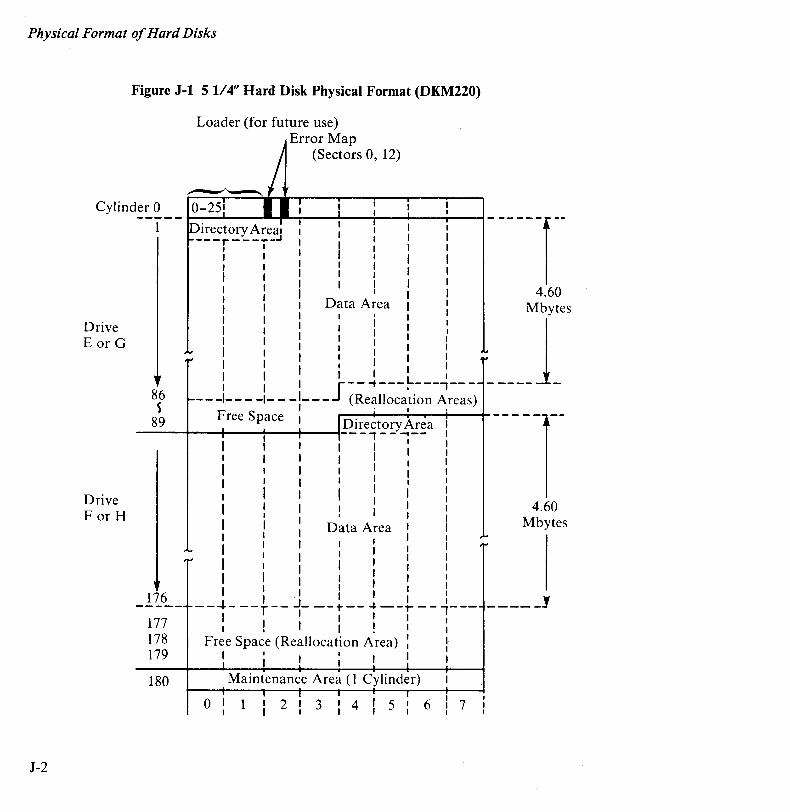
Physical Format of Hard Disks
J-2
Figure J-l 5 1/4" Hard Disk Physical Format (DKM220)
Loader (for future use) . Error Map
(Sectors 0, 12)
Cylinder 0 --1-- J-D- 1
-· r-ec...Lt-o-ry-A---IIr"ea-f,---:---~--r-1 --+--r---I - - - - - -1 --
Drive E or G
Drive For H
86 ~
89
---r - - _ ... _.J I I , 1 I I , 4.60
Data A~ea Mbytes
JI --t--L -,--- _____ 1_ - - -1- - - -1- - -1- - - (Realloca'ti~~ Areas)
1 . I ,
Free Space I r---+---i---r--+---+- --- -- --Directory Area 1
---+--+--~--+----!-- - i - - ..... -- I
176
177 178 179
180
1 I I 1 I I I I I 1 I I
I l : I I
I I 1
Data Area 1 I I
I I I
I I l 1 ,
--~- --r-- .J_ --1' -- -I- --r - - .,---I I 1 I I 1 ! I I ! 1
Free Space (Reallocation Area) 1
I I ' ; , Maintenance Area (l Cylinder)
o 1213 1 4 1 5' 6 I I I I I 7
4.60 Mbytes
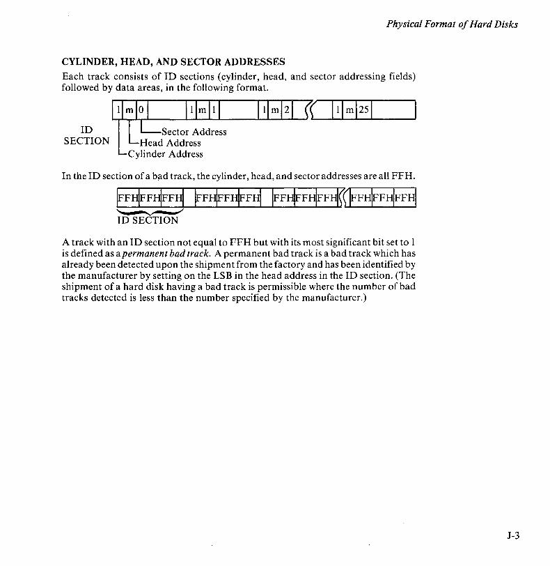
Physical Format of Hard Disks
CYLINDER, HEAD, AND SECTOR ADDRESSES
Each track consists of ID sections (cylinder, head, and sector addressing fields) followed by data areas, in the following format.
ID SECTION
Sector Address Head Address
Cylinder Address
In the ID section of a bad track, the cylinder, head, and sector addresses are all FFH.
A track with an ID section not equal to FFH but with its most significant bit set to 1 is defined as a permanent bad track. A permanent bad track is a bad track which has already been detected upon the shipment from the factory and has been identified by the manufacturer by setting on the LSB in the head address in the ID section. (The shipment of a hard disk having a bad track is permissible where the number of bad tracks detected is less than the number specified by the manufacturer.)
J-3

Physical Format of Hard Disks
J-4
ERROR MAP
The error map (cylinder 0, sectors 0 and 12) is used to reallocate the next normal track in place of a bad track. Sector 0 is the error map. Sector 12 is the back-up error map.
The map is formatted as shown in Figure J-2. Each bit corresponds to a track on the disk.
o 5 6 7 8 188 255 I I I I I I I I
EIRIMIAIP 6. I I I I I I I I
Figure J-2 Error Map
NOC C IC I C' I I I I I I I I I I I I I I I I I
# : # : # I ERROR BIT MAP o III 2: I : I : : : I
I ,
, ....... ....... / ........
/ ........ /
~
t ~ t t : t : t I t , I I I
O~ 1 2 :3 : 4 : 5
MSB
............
: t :6
1 = bad track
.............
: t :7
LSB
o = normal track
L Number of Cylinders
C#O - C#180: Cylinder No. 0-180 to - t7: Track No. 0-7
To reduce seek time, the system uses the track that immediately follows the bad track for the reallocation. Figure J-3 demonstrates track reallocation.
UNU:EDI

Physical Format of Hard Disks
Figure J-3 Error Map And Track Reallocation
Error Map
Cylinder #1 00000000 M L S S B B
Track I ,
Cylinder #2 00000100
Cylinder #3 01000000
0: 1 '2 I 3 456 7
Cylinder (1.0) I (1.1) I (1.2) , (1.3) I (1.4) I (1.5) I (1.6) I (1.7) I
_...! __ J~OL,_ Q.·~-U~L+ ~.~ ~ l!.4] L~·~_:J.l.:?L.:-~.7]--: (2.0)! (2.1) I (2.2) I (2.3) I (2.4) I (FFF,FF), (2.6) I (2.7) I
2 [2.0] I [2.1] J [2.2] I [2.3] I [2.4]' ,[2.5] I [2.6] ,
--- (3.0) j(FFF,FF): (3.2) T (3.3) 1 (3.4) i (3.5)-; (3.6) 11- (3.7)-;
_~ _ ~.7]-+ ____ :J.3.0]_:_[~IL t-[3.~ _[~31-+ [3.4] +.l3.5~i
4 I I I , I, I I I I I I' I I I
Note:
(i, j) [c, t]
(i, j) - i cylinder, j track physical id written by HDFORMAT. (FFFH, FFH) or (i, 80 - 87H) is a bad track
[c, t] - c cylinder, t track logical id used by CBIOS
J-5

Appendix K
GSX-86 Device Specific Information This Appendix contains information about each of the device drivers which is supplied with GSX-86.
NEC ADVANCED PERSONAL COMPUTER
FILENAME DDNECAPC.SYS
DEVICE INDEX The device index is 1 in ASSIGN.SYS on the distribution diskette. You can use the driver with this number or change the assignment.
MAXIMUM BAUD RATE NI A
COMMUNICATIONS NI A
GRAPHIC INPUT The cursor is moved by pressing one of the four cursor movement keys on the keyboard. When the cursor is at the desired location, the point can be selected by pressing any alphanumeric key (other than RETURN).
TEXT The APC has 16 character sizes. Text can be rotated in 45-degree increments. Two fonts, straight and slanted, are available.
MARKERS 1 2 + 3 * 4 0 5 X
K-I
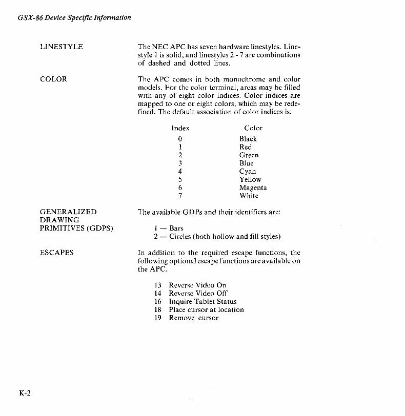
GSX-86 Device Specific Information
K-2
LINESTYLE
COLOR
GENERALIZED DRAWING PRIMITIVES (GDPS)
ESCAPES
The NEC APC has seven hardware linestyles. Linestyle 1 is solid, and linestyles 2 - 7 are combinations of dashed and dotted lines.
The APC comes in both monochrome and color models. For the color terminal, areas may be filled with any of eight color indices. Color indices are mapped to one or eight colors, which may be redefined. The default association of color indices is:
Index Color
0 Black 1 Red 2 Green 3 Blue 4 Cyan 5 Yellow 6 Magenta 7 White
The available GDPs and their identifiers are:
1 - Bars 2 - Circles (both hollow and fill styles)
In addition to the required escape functions, the following optional escape functions are available on the APC.
13 Reverse Video On 14 Reverse Video Off 16 Inquire Tablet Status 18 Place cursor at location 19 Remove cursor
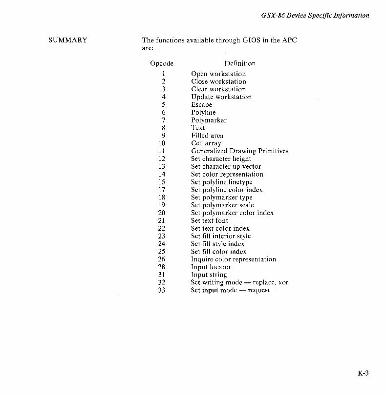
SUMMARY
GSX-86 Device Specific Information
The functions available through GIOS in the APC are:
Opcode
1 2 3 4 5 6 7 8 9
10 11 12 13 14 15 17 18 19 20 21 22 23 24 25 26 28 31 32 33
Definition
Open workstation Close workstation Clear workstation Update workstation Escape Polyline Polymarker Text Filled area Cell array Generalized Drawing Primitives Set character height Set character up vector Set color representation Set polyline linetype Set polyline color index Set polymarker type Set polymarker scale Set polymarker color index Set text font Set text color index Set fill interior style Set fill style index Set fill color index Inquire color representation Input locator Input string Set writing mode - replace, xor Set input mode - request
K-3
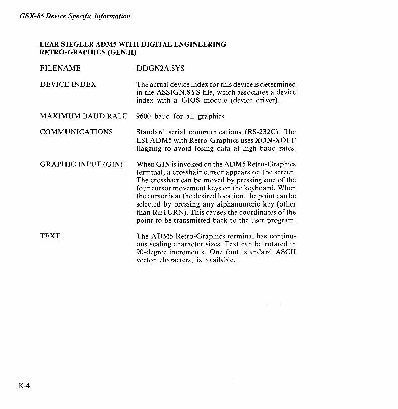
GSX-86 Device Specific Information
K-4
LEAR SIEGLER ADM5 WITH DIGITAL ENGINEERING RETRO-GRAPHICS (GEN.II)
FILENAME DDGN2A.SYS
DEVICE INDEX The actual device index for this device is determined in the ASSIGN.SYS file, which associates a device index with a GIOS module (device driver).
MAXIMUM BAUD RATE 9600 baud for all graphics
COMMUNICATIONS Standard serial communications (RS-232C). The LSI ADM5 with Retro-Graphics uses XON-XOFF flagging to avoid losing data at high baud rates.
GRAPHIC INPUT (GIN) When GIN is invoked on the ADM5 Retro-Graphics terminal, a crosshair cursor appears on the screen. The crosshair can be moved by pressing one of the four cursor movement keys on the keyboard. When the cursor is at the desired location, the point can be selected by pressing any alphanumeric key (other than RETURN). This causes the coordinates of the point to be transmitted back to the user program.
TEXT The ADM5 Retro-Graphics terminal has continuous scaling character sizes. Text can be rotated in 90-degree increments. One font, standard ASCII vector characters, is available.
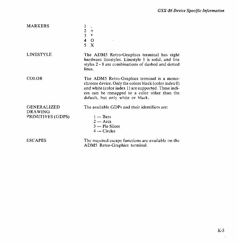
MARKERS
LINESTYLE
COLOR
GENERALIZED DRAWING PRIMITIVES (GDPS)
ESCAPES
GSX-86 Device Specific Information
1 2 + 3 * 4 0 5 X
The ADM5 Retro-Graphics terminal has eight hardware linestyles. Linestyle 1 is solid, and line styles 2 - 8 are combinations of dashed and dotted lines.
The ADM5 Retro-Graphics terminal is a monochrome device. Only the colors black (color index 0) and white (color index 1) are supported. These indices can be remapped to a color other than the default, but only white or black.
The available G DPs and their identifiers are:
1 - Bars 2 - Arcs 3 - Pie Slices 4 - Circles
The required escape functions are available on the ADM5 Retro-Graphics terminal.
K-5
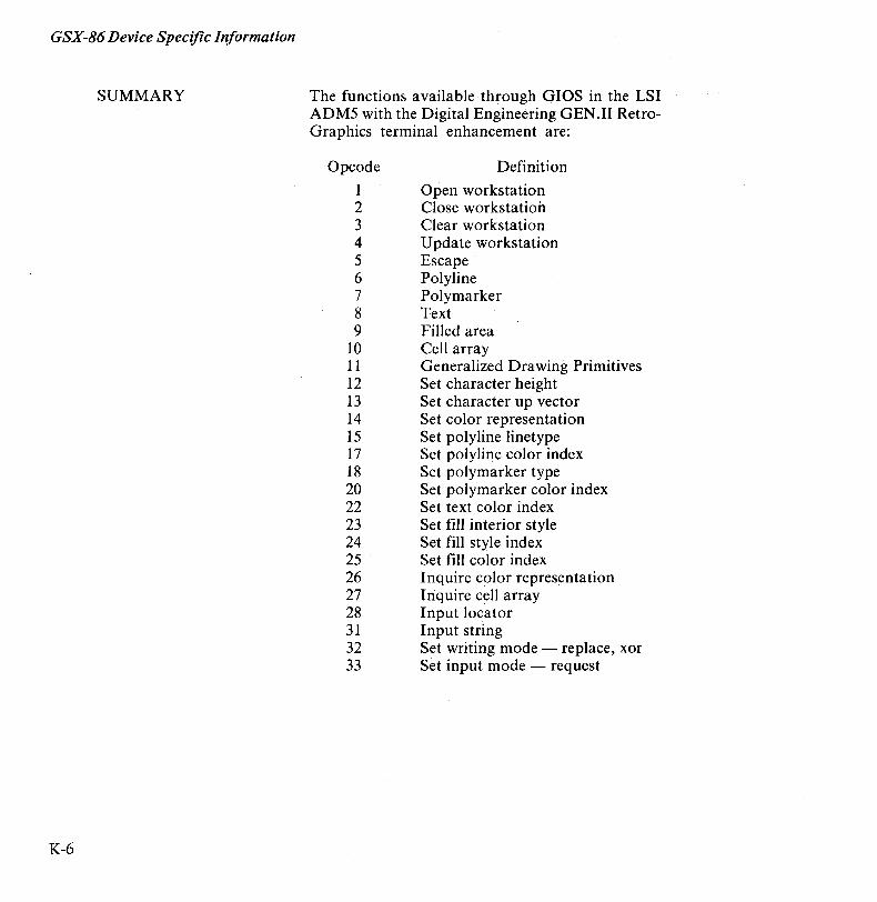
GSX-86 Device Specific Information
SUMMARY
K-6
The functions available through GIOS in the LSI ADM5 with the Digital Engineering GEN.II RetroGraphics terminal enhancement are:
Opcode
1 2 3 4 5 6 7 8 9
10 11 12 13 14 15 17 18 20 22 23 24 25 26 27 28 31 32 33
Definition
Open workstation Close workstation Clear workstation Update workstation Escape Polyline Polymarker Text Filled area Cell array Generalized Drawing Primitives Set character height Set character up vector Set color representation Set polyline linetype Set polyline color index Set polymarker type Set polymarker color index Set text color index Set fill interior style Set fill style index Set fill color index Inquire color repres~ntation Inquire cell array Input locator Input string Set writing mode - replace, xor Set input mode - request
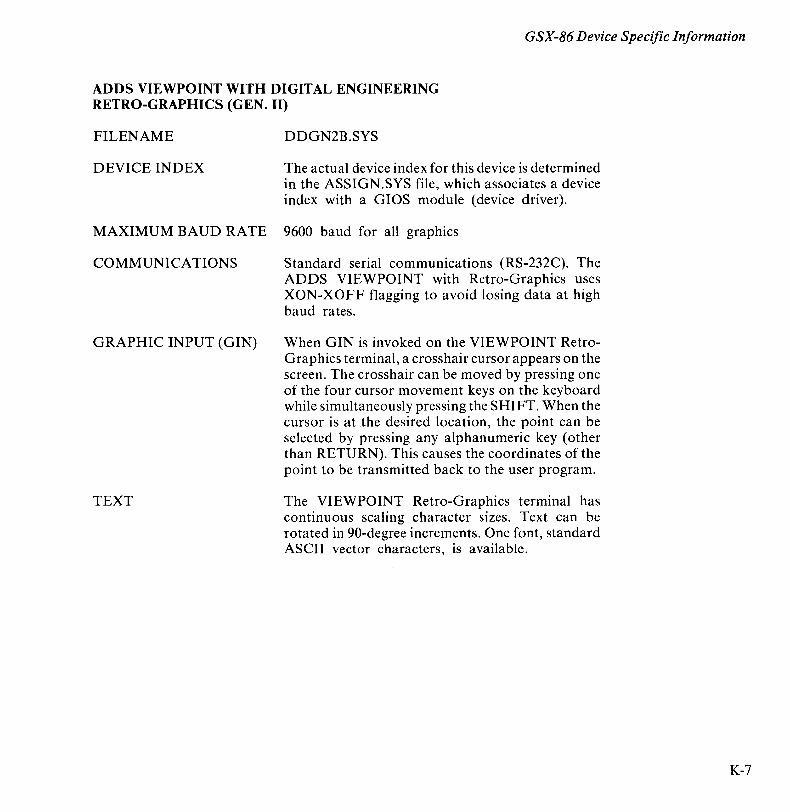
GSX-86 Device Specific Information
ADDS VIEWPOINT WITH DIGITAL ENGINEERING RETRO-GRAPHICS (GEN. II)
FILENAME DDGN2B.SYS
DEVICE INDEX The actual device index for this device is determined in the ASSIGN.SYS file, which associates a device index with a GIOS module (device driver).
MAXIMUM BAUD RATE 9600 baud for all graphics
COMMUNICATIONS Standard serial communications (RS-232C). The ADDS VIEWPOINT with Retro-Graphics uses XON-XOFF flagging to avoid losing data at high baud rates.
GRAPHIC INPUT (GIN) When GIN is invoked on the VIEWPOINT RetroGraphics terminal, a crosshair cursor appears on the screen. The crosshair can be moved by pressing one of the four cursor movement keys on the keyboard while simultaneously pressing the SHIFT. When the cursor is at the desired location, the point can be selected by pressing any alphanumeric key (other than RETURN). This causes the coordinates of the point to be transmitted back to the user program.
TEXT The VIEWPOINT Retro-Graphics terminal has continuous scaling character sizes. Text can be rotated in 90-degree increments. One font, standard ASCII vector characters, is available.
K-7
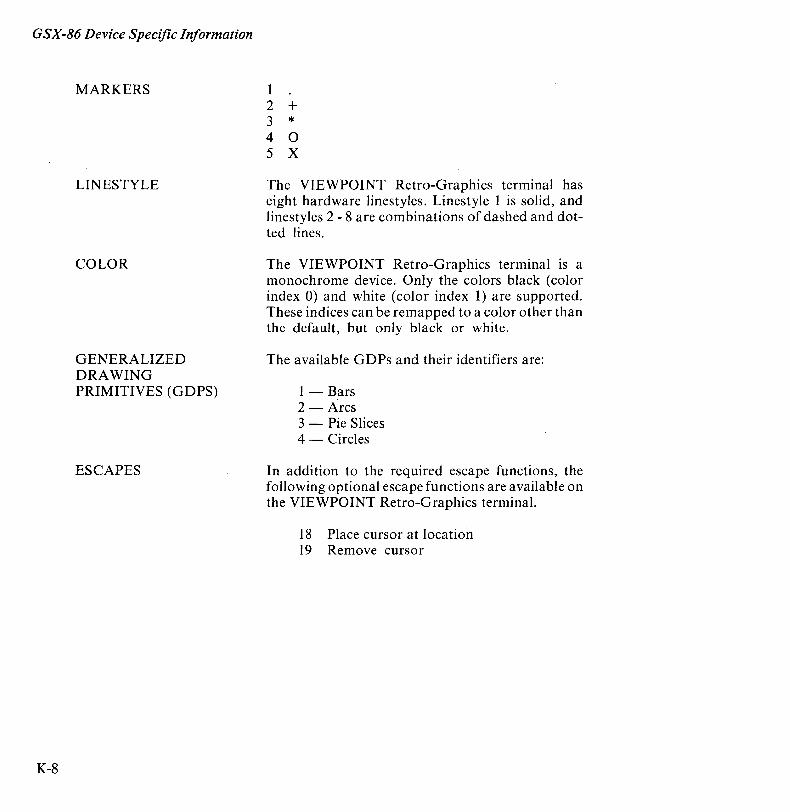
GSX-86 Device Specific Information
K-8
MARKERS
LINESTYLE
COLOR
GENERALIZED DRAWING PRIMITIVES (GDPS)
ESCAPES
1 2 + 3 * 4 0 5 X
The VIEWPOINT Retro-Graphics terminal has eight hardware linestyles. Linestyle 1 is solid, and linestyles 2 - 8 are combinations of dashed and dotted lines.
The VIEWPOINT Retro-Graphics terminal is a monochrome device. Only the colors black (color index 0) and white (color index 1) are supported. These indices can be remapped to a color other than the default, but only black or white.
The available GDPs and their identifiers are:
1 - Bars 2 - Arcs 3 - Pie Slices 4 - Circles
In addition to the required escape functions, the following optional escape functions are available on the VIEWPOINT Retro-Graphics terminal.
18 Place cursor at location 19 Remove cursor
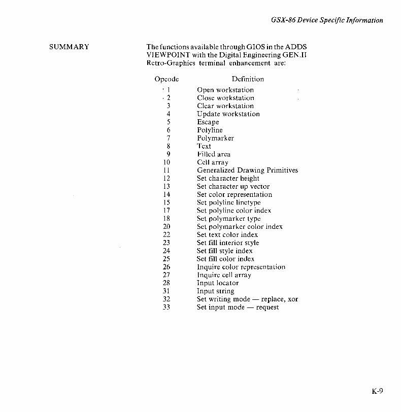
SUMMARY
GSX-86 Device Specific Information
The functions available through GIOS in the ADDS VIEWPOINT with the Digital Engineering GEN.II Retro-Graphics terminal enhancement are:
Opcode , 1 ,2
3 4 5 6 7 8 9
10 11 12 13 14 '15 17 18 20 22 23 24 25 26 27 28 31 32 33
Definition
Open workstation Close workstation Clear workstation Update workstation Escape Polyline Poly marker Text Filled area Cell array Generalized Drawing Primitives Set character height Set character up vector Set color representation Set polyline linetype Set polyline color index Set polymarker type Set polymarker color index Set text color index Set fill interior style Set fill style index Set fill color index Inquire color representation Inquire cell array Input locator Input string Set writing mode - replace, xor Set input mode - request
K-9

GSX-86 Device Specific Information
K-I0
TELEVIDEO 910 WITH DIGITAL ENGINEERING RETRO-GRAPHICS (GEN. II)
FILENAME DDGN2C.SYS
DEVICE INDEX The actual device index for this device is determined in the ASSIGN.SYS file, which associates a device index with a GIOS module (device driver).
MAXIMUM BAUD RATE 9600 baud for all graphics
COMMUNICATIONS Standard serial communications (RS-232C). The TELEVIDEO 910 with Retro-Graphics uses XONXOFF flagging to avoid losing data at high baud rates.
GRAPHIC INPUT (GIN) When GIN is invoked on the 910 Retro-Graphics terminal, a crosshair cursor appears on the screen. The crosshair can be moved by pressing one of the four cursor movement keys on the keyboard. When the cursor is at the desired location, the point can be selected by pressing any alphanumeric key (other than RETURN). This causes the coordinates of the point to be transmitted back to the user program.
TEXT The 910 Retro-Graphics terminal has continuous scaling character sizes. Text can be rotated in 90-degree increments. One font, standard ASCII vector characters, is available.
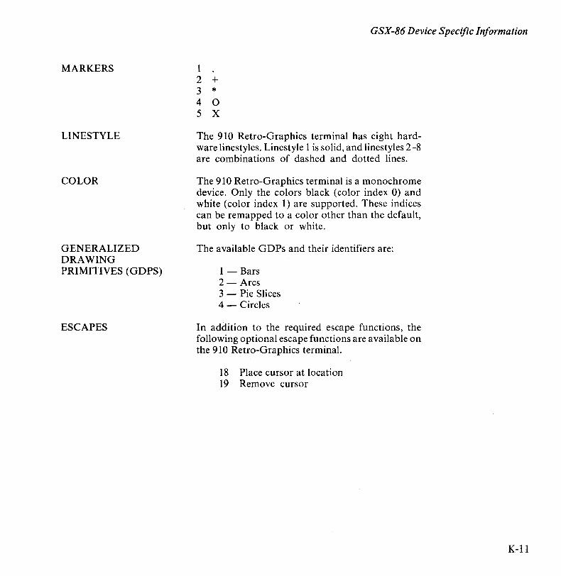
MARKERS
LINESTYLE
COLOR
GENERALIZED DRAWING PRIMITIVES (G D PS)
ESCAPES
GSX-86 Device Specific Information
1 2 + 3 * 4 0 5 X
The 910 Retro-Graphics terminal has eight hardware linestyles. Linestyle 1 is solid, and linestyles 2 -8 are combinations of dashed and dotted lines.
The 910 Retro-Graphics terminal is a monochrome device. Only the colors black (color index 0) and white (color index 1) are supported. These indices can be remapped to a color other than the default, but only to black or white.
The available GDPs and their identifiers are:
1 - Bars 2 - Arcs 3 - Pie Slices 4 - Circles
In addition to the required escape functions, the following optional escape functions are available on the 910 Retro-Graphics terminal.
18 Place cursor at location 19 Remove cursor
K-ll
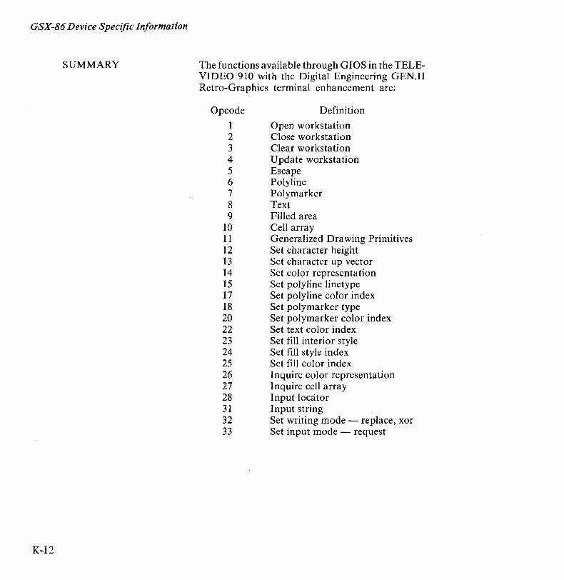
GSX-86 Device Specific Information
SUMMARY
K-12
The functions available through GIOS in the TELEVIDEO 910 with the Digital Engineering GEN.II Retro-Graphics terminal enhancement are:
Opcode
1 2 3 4 5 6 7 8 9
10 11 12 13 14 15 17 18 20 22 23 24 25 26 27 28 31 32 33
Definition
Open workstation Close workstation Clear workstation Update workstation Escape Polyline Polymarker Text Filled area Cell array Generalized Drawing Primitives Set character height Set character up vector Set color representation Set polyline linetype Set polyline color index Set polymarker type Set polymarker color index Set text color index Set fill interior style Set fill style index Set fill color index Inquire color representation Inquire cell array Input locator Input string Set writing mode - replace, xor Set input mode - request
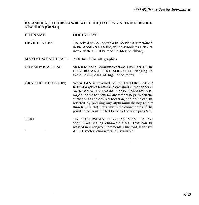
GSX-86 Device Specific Information
DATAMEDIA COLORSCAN-IO WITH DIGITAL ENGINEERING RETROGRAPHICS (GEN.II)
FILENAME DDGN2D.SYS
DEVICE INDEX The actual device index for this device is determined in the ASSIGN.SYS file, which associates a device index with a GIOS module (device driver).
MAXIMUM BAUD RATE 9600 baud for all graphics
COMMUNICATIONS Standard serial communications (RS-232C). The COLORSCAN-IO uses XON-XOFF flagging to avoid losing data at high baud rates.
GRAPHIC INPUT (GIN) When GIN is invoked on the COLORSCAN-IO Retro-Graphics terminal, a crosshair cursor appears on the screen. The crosshair can be moved by pressing one of the four cursor movement keys. When the cursor is at the desired location, the point can be selected by pressing any alphanumeric key (other than RETURN). This causes the coordinates of the point to be transmitted back to the user program.
TEXT The COLORSCAN Retro-Graphics terminal has continuous scaling character sizes. Text can be rotated in 90-degree increments. One font, standard ASCII vector characters, is available.
K-13
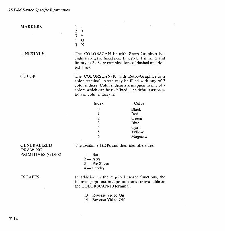
GSX-86 Device Specific Information
K-14
MARKERS
LINESTYLE
COLOR
GENERALIZED DRAWING PRIMITIVES (GDPS)
ESCAPES
1 2 + 3 * 4 0 5 X
The COLORSCAN-I0 with Retro-Graphics has eight hardware linestyles. Linestyle 1 is solid and linestyles 2 - 8 are combinations of dashed and dotted lines.
The COLORSCAN-I0 with Retro-Graphics is a color terminal. Areas may be filled with any of 7 color indices. Color indices are mapped to one of 7 colors which can be redefined. The default association of color indices is:
Index Color
0 Black 1 Red 2 Green 3 Blue 4 Cyan 5 Yellow 6 Magenta
The available GDPs and their identifiers are:
1 - Bars 2 - Arcs 3 - Pie Slices 4 - Circles
In addition to the required escape functions, the following optional escape functions are available on the COLORSCAN-I0 terminal.
13 Reverse Video On 14 Reverse Video Off
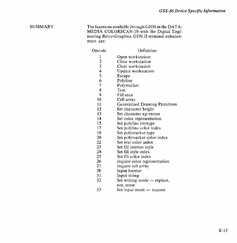
SUMMARY
GSX-86 Device Specific Information
The functions available through GIOS in the DATAMEDIA COLORSCAN-IO with the Digital Engineering Retro-Graphics G EN. II terminal enhancement are:
Opcode
1 2 3 4 5 6 7 8 9
10 11 12 13 14 15 17 18 20 22 23 24 25 26 27 28 31 32
33
Definition
Open workstation Close workstation Clear workstation Update workstation Escape Polyline Polymarker Text Fill area Cell array Generalized Drawing Primitives Set character height Set character up vector Set color representation Set polyline linetype Set polyline color index Set polymarker type Set polymarker color index Set text color index Set fill interior style Set fill style index Set fill color index Inquire color representation Inquire cell array Input locator Input string Set writing mode - replace, xor, erase Set input mode - request
K-15

GSX-86 Device Specific Information
K-16
VT100 WITH DIGITAL ENGINEERING RETRO-GRAPHICS
FILENAME DDVRET,SYS
DEVICE INDEX The actual device index for this device is determined in the ASSIGN.SYS,file, which associates a device index with a GIOS, module (device driver).
MAXIMUM BAUD RATE 9600 baud for all graphics
COMMUNICATIONS Standard serial communications (RS-232C). The VT100 uses XON/XOFF flagging to avoid losing data at high baud rates.
GRAPHIC INPUT (GIN) When GIN is invoked on the VT100 Retro-Graphics terminal, a crosshair cursor appears on the screen. The crosshair can be moved by pressing one of the four cursor movement keys (up, down, left, right) on the top row of keys on the keyboard. When the cursor is at the desired location, the point can be selected by pressing any alphanumeric key (other than RETURN). This ,causes the coordinates of the point to be transmitted back to the user program. The terminal must be set up so that GIN is terminated by CR only. This can be done by setting the two trailer codes in Retro-Graphics set-up mode to OD hex and FF hex respectively. Refer to the instructions in the User Manual for Retro-Graphics Model VT640, "Set Up Procedures," for a further discussion of trailer characters.
TEXT The VT100 has four character sizes. It cannot rotate text.
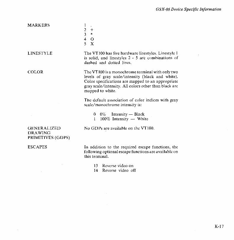
MARKERS
LINESTYLE
COLOR
GENERALIZED DRAWING PRIMITIVES (GDPS)
ESCAPES
GSX-86 Device Specific Information
1 2 + 3 * 4 0 5 X
The VT100 has five hardware linestyles. Linestyle 1 is solid, and linestyles 2 - 5 are combinations of dashed and dotted lines.
The VT100 is a monochrome terminal with only two levels of gray scale/intensity (black and white). Color specifications are mapped to an appropriate gray scale/intensity. All colors other than black are mapped to white.
The default association of color indices with gray scale/monochrome intensity is:
o 0% Intensity - Black 1 100% Intensity - White
No GDPs are available on the VT100.
In addition to the required escape functions, the following optional escape functions are available on this terminal.
13 Reverse video on 14 Reverse video off
K-17
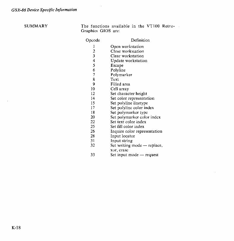
GSX-86 Device Specific Information
SUMMARY
K-18
The functions available In the VT100 RetroGraphics GIOS are:
Opcode
1 2 3 4 5 6 7 8 9
10 12 14 15 17 18 20 22 25 26 28 31 32
33
Definition
Open workstation Close workstation Clear workstation Update workstation Escape Polyline Polymarker Text Filled area Cell array Set character height Set color representation Set polyline linetype Set polyline color index Set polymarker type Set polymarker color index Set text color index Set fill color index Inquire color representation Input locator Input string Set writing mode - replace, xor, erase Set input mode - request
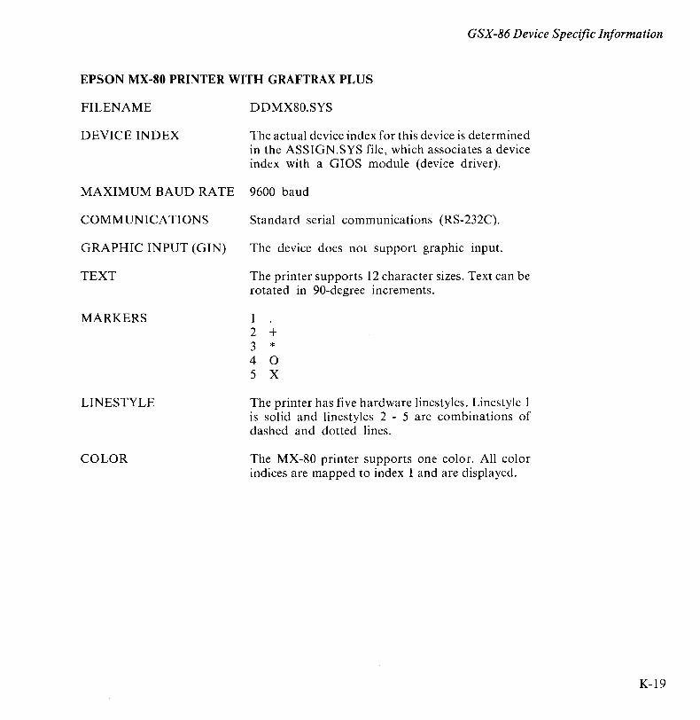
GSX-86 Device Specific Information
EPSON MX-80 PRINTER WITH GRAFTRAX PLUS
FILENAME DDMX80.SYS
DEVICE INDEX The actual device index for this device is determined in the ASSIGN.SYS file, which associates a device index with a GIOS module (device driver).
MAXIMUM BAUD RATE 9600 baud
COMMUNICA TIONS Standard serial communications (RS-232C).
GRAPHIC INPUT (GIN) The device does not support graphic input.
TEXT The printer supports 12 character sizes. Text can be rotated in 90-degree increments.
MARKERS 1 2 + 3 * 4 0 5 X
LINESTYLE The printer has five hardware linestyles. Linestyle 1 is solid and linestyles 2 - 5 are combinations of dashed and dotted lines.
COLOR The MX-80 printer supports one color. All color indices are mapped to index 1 and are displayed.
K-19
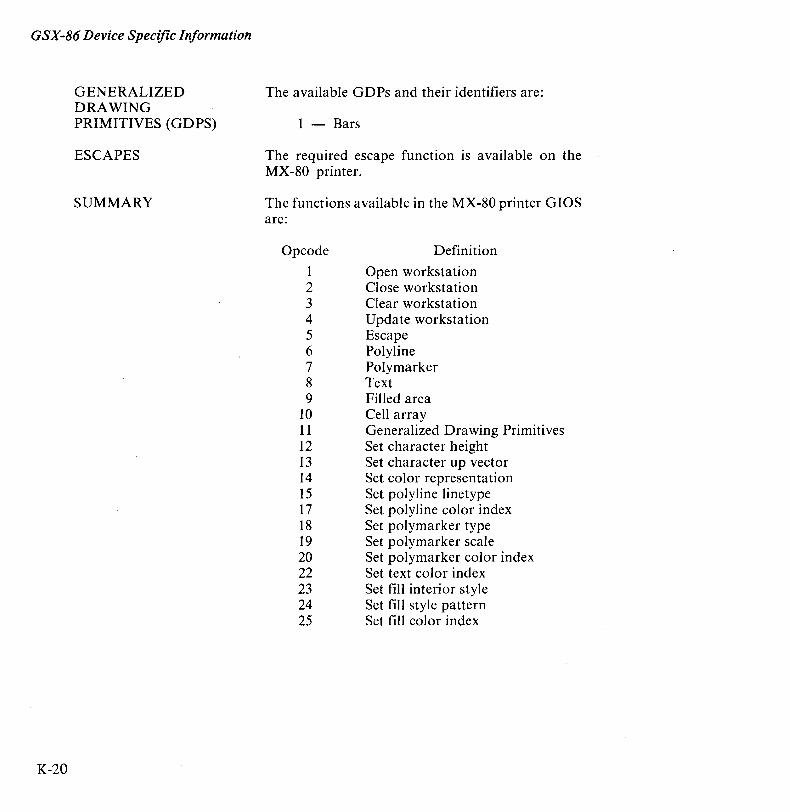
GSX-86 Device Specific Information
K-20
GENERALIZED DRAWING PRIMITIVES (GDPS)
ESCAPES
SUMMARY
The available GDPs and their identifiers are:
1 - Bars
The required escape function is available on the MX-80 printer.
The functions available in the MX-80 printer GIOS are:
Opcode
1 2 3 4 5 6 7 8 9
10 11 12 13 14 15 17 18 19 20 22 23 24 25
Definition
Open workstation Close workstation Clear workstation Update workstation Escape Polyline Polymarker Text Filled area Cell array Generalized Drawing Primitives Set character height Set character up vector Set color representation Set polyline linetype Set polyline color index Set polymarker type Set polymarker scale Set polymarker color index Set text color index Set fill interior style Set fill style pattern Set fill color index
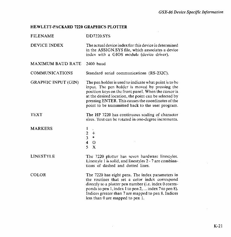
GSX-86 Device Specific Information
HEWLETT-PACKARD 7220 GRAPHICS PLOTTER
FILENAME DD7220.SYS
DEVICE INDEX The actual device index for this device is determined in the ASSIGN.SYS file, which associates a device index with a GIOS module (device driver).
MAXIMUM BAUD RATE 2400 baud
COMMUNICATIONS Standard serial communications (RS-232C).
GRAPHIC INPUT (GIN) The pen holder is used to indicate what point is to be input. The pen holder is moved by pressing the position keys on the front panel. When the cursor is at the desired location, the point can be selected by pressing ENTER. This causes the coordinates of the point to be transmitted back to the user program.
TEXT The HP 7220 has continuous scaling of character sizes. Text can be rotated in one-degree increments.
MARKERS I 2 + 3 * 4 0 5 X
LINESTYLE The 7220 plotter has seven hardware linestyles. Linestyle I is solid, and linestyles 2 - 7 are combinations of dashed and dotted lines.
COLOR The 7220 has eight pens. The index parameters in the routines that set a color index correspond directly to a plotter pen number (i.e. index 0 corresponds to pen I, index I to pen 2, ... index 7 to pen 8). Indices greater than 7 are mapped to pen 8. Indices less than 0 are mapped to pen I.
K-21
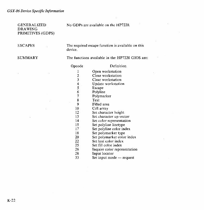
GSX-86 Device Specific Information
K-22
GENERALIZED DRAWING PRIMITIVES (GDPS)
ESCAPES
SUMMARY
No GDPs are available on the HP7220.
The required escape function is available on this device.
The functions available in the HP7220 GIOS are:
Opcode
1 2 3 4 5 6 7 8 9
10 12 13 14 15 17 18 20 22 25 26 28 33
Definition
Open workstation Close workstation Clear workstation Update workstation Escape Polyline Polymarker Text Filled area Cell array Set character height Set character up vector Set color representation Set polyline linetype Set polyline color index Set polymarker type Set polymarker color index Set text color index Set fill color index Inquire color representation Input locator Set input mode - request
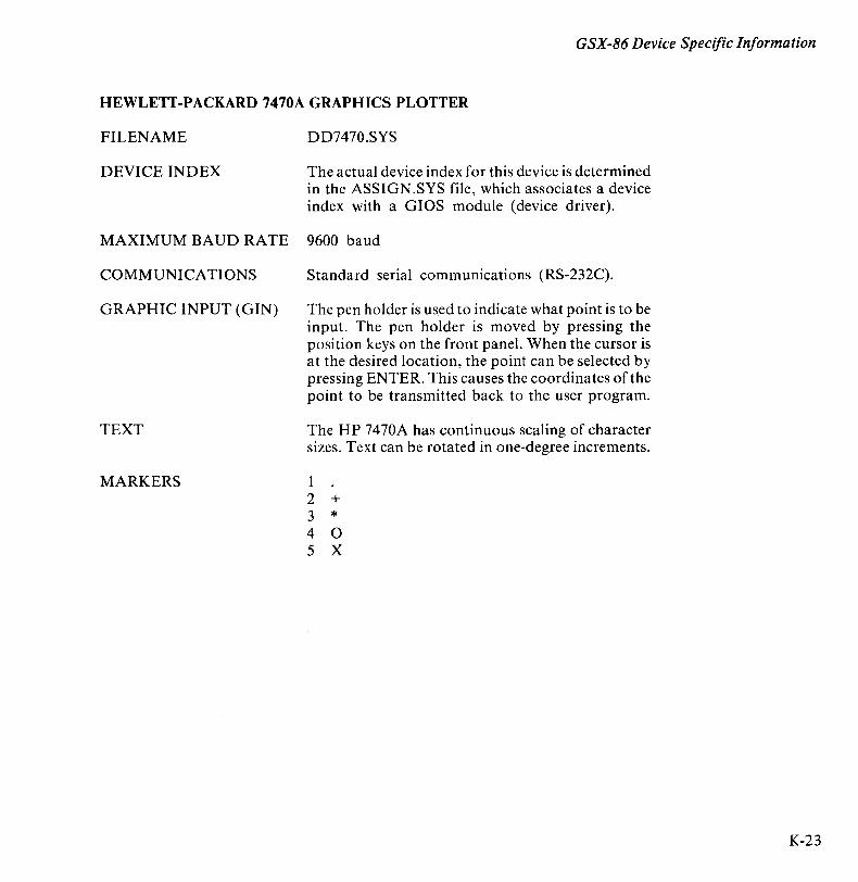
GSX-86 Device Specific Information
HEWLETT-PACKARD 7470A GRAPHICS PLOTTER
FILENAME DD7470.SYS
DEVICE INDEX The actual device index for this device is determined in the ASSIGN.SYS file, which associates a device index with a GIOS module (device driver).
MAXIMUM BAUD RATE 9600 baud
COMMUNICATIONS Standard serial communications (RS-232C).
GRAPHIC INPUT (GIN) The pen holder is used to indicate what point is to be input. The pen holder is moved by pressing the position keys on the front panel. When the cursor is at the desired location, the point can be selected by pressing ENTER. This causes the coordinates of the point to be transmitted back to the user program.
TEXT The HP 7470A has continuous scaling of character sizes. Text can be rotated in one-degree increments.
MARKERS 1 2 + 3 * 4 0 5 X
K-23
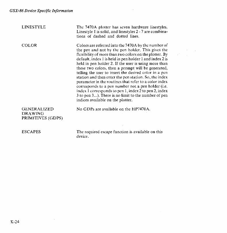
GSX-86 Device Specific In/ormation
K-24
LINESTYLE
COLOR
GENERALIZED DRAWING PRIMITIVES (G D PS)
ESCAPES
The 7470A plotter has seven hardware linestyles. Linestyle 1 is solid, and linestyles 2 - 7 are combinations of dashed and dotted lines.
Colors are referred into the 7470A by the number of the pen and not by the pen holder. This gives the flexibility of more than.two colors on the plotter. By default, index 1 is held in pen holder 1 and index 2 is held in pen holder 2. If the user is using more than these two colors, then a prompt will be generated, telling the user to insert the desired color in a pen station and then enter the pen station. So, the index parameter in the routines that refer to a color index corresponds to a pen number not a pen holder (i.e. index 1 corresponds to pen 1, index 2 to pen 2, index 3 to pen 3 ... ). There is no limit to the number of pen indices available on the plotter.
No GDPs are available on the HP7470A.
The required escape function is available on this device.

SUMMARY
GSX-86 Device Specific Information
The functions available in the HP7470A GIOS are:
Opcode
1 2 3 4 5 6 7 8 9
10 12 13 14 15 17 18 19 20 21 22 25 26 28 33
Definition
Open workstation Close workstation Clear workstation Update workstation Escape Polyline Polymarker Text Filled area Cell array Set character height Set character up vector Set color representation Set polyline linetype Set polyline color index Set polymarker type Set polymarker scale Set polymarker color index Set text font Set text color index Set fill color index Inquire color representation Input locator Set input mode - request
K-25
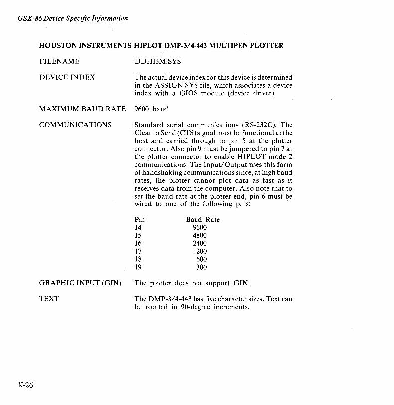
GSX-86 Device Specific Information
K-26
HOUSTON INSTRUMENTS HIPLOT DMP-3/4-443 MULTIPEN PLOTTER
FILENAME DDHI3M.SYS
DEVICE INDEX The actual device index for this device is determined in the ASSIGN.SYS file, which associates a device index with a GIOS module (device driver).
MAXIMUM BAUD RATE 9600 baud
COMMUNICATIONS Standard serial communications (RS-232C). The Clear to Send (CTS) signal must be functional at the host and carried through to pin 5 at the plotter connector. Also pin 9 must be jumpered to pin 7 at the plotter connector to enable HIPLOT mode 2 communications. The Input/Output uses this form of handshaking communications since, at high baud rates, the plotter cannot plot data as fast as it receives data from the computer. Also note that to set the baud rate at the plotter end, pin 6 must be wired to one of the following pins:
GRAPHIC INPUT (GIN)
TEXT
Pin 14 15 16 17 18 19
Baud Rate 9600 4800 2400 1200 600 300
The plotter does not support GIN.
The DMP-3/4-443 has five character sizes. Text can be rotated in 90-degree increments.

MARKERS
LINESTYLE
COLOR
GENERALIZED DRAWING PRIMITIVES (G D PS)
ESCAPES
GSX-86 Device Specific Information
1 + 2 X 3 0 4 0 5 ~ 6 X
The DMP-3/4-443 Multipen plotter has nine hardware linestyles. Linestyle 1 is solid, and linestyles 2 -9 are combinations of dashed and dotted lines.
TheDMP-3/4-443 has six pens. The index parameter in the routines that set a color index corresponds directly to a plotter pen number (i.e., index 0 corresponds to pen 1, index 1 to pen 2, ... index 5 to pen 6). Indices greater than 5 are mapped to pen 6. Indices less than 0 are mapped to pen 1.
No GDPs are available on the DMP-3/4-443.
The required escape function is available on this device.
K-27
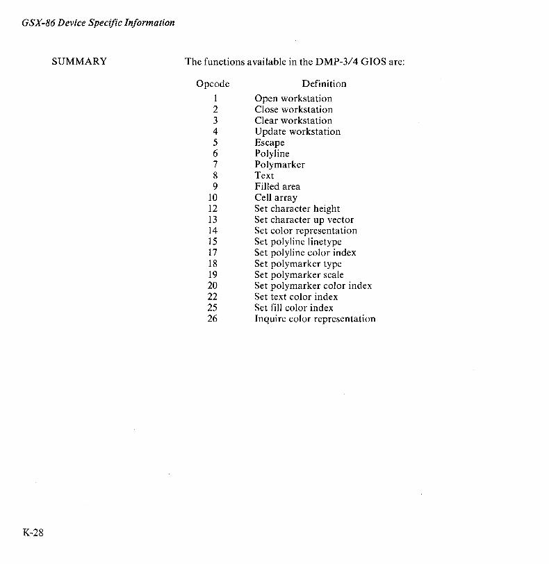
GSX-86 Device Specific Information
SUMMARY
K-28
The functions available in the DMP-3/4 GIOS are:
Opcode
1 2 3 4 5 6 7 8 9
10 12 13 14 15 17 18 19 20 22 25 26
Definition
Open workstation Close workstation Clear workstation Update workstation Escape Polyline Polymarker Text Filled area Cell array Set character height Set character up vector Set color representation Set polyline linetype Set polyline color index Set polymarker type Set polymarker scale Set polymarker color index Set text color index Set fill color index Inquire color representation
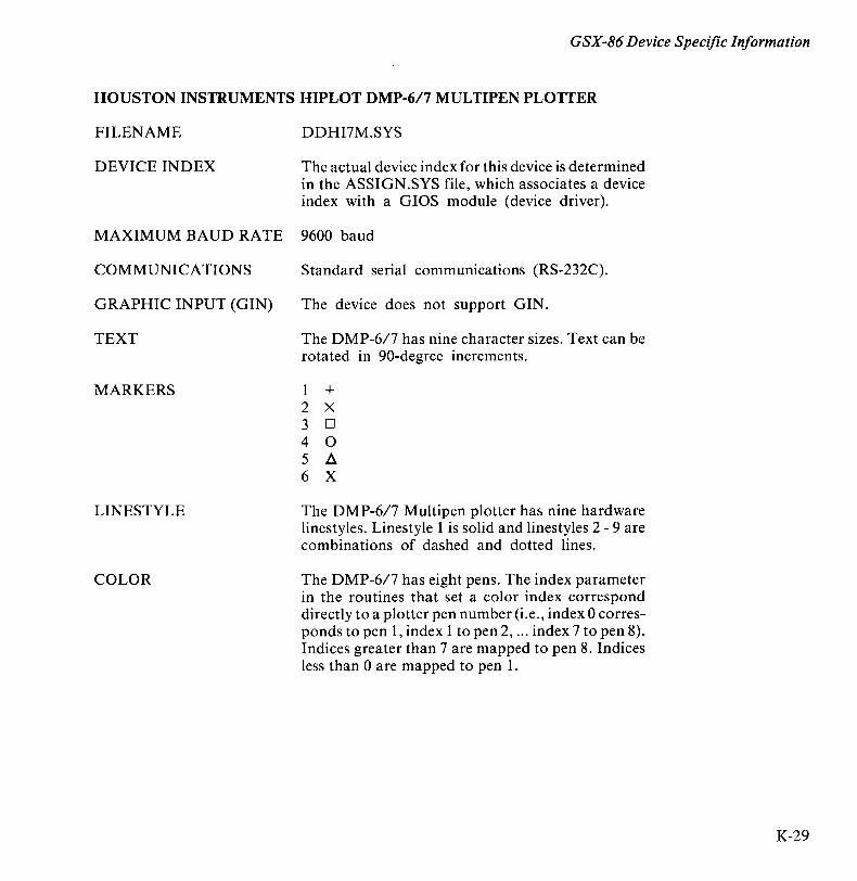
GSX-86 Device Specific Information
HOUSTON INSTRUMENTS HIPLOT DMP-6/7 MULTIPEN PLOTTER
FILENAME DDHI7M.SYS
DEVICE INDEX The actual device index for this device is determined in the ASSIGN .SYS file, which associates a device index with a GIOS module (device driver).
MAXIMUM BAUD RATE 9600 baud
COMMUNICATIONS Standard serial communications (RS-232C).
GRAPHIC INPUT (GIN) The device does not support GIN.
TEXT The DMP-6/7 has nine character sizes. Text can be rotated in 90-degree increments.
MARKERS 1 + 2 X 3 D 4 0 5 ~ 6 X
LINESTYLE The DMP-6/7 Multipen plotter has nine hardware linestyles. Linestyle 1 is solid and linestyles 2 - 9 are combinations of dashed and dotted lines.
COLOR The DMP-6/7 has eight pens. The index parameter in the routines that set a color index correspond directly to a plotter pen number (i.e., index 0 corresponds to pen 1, index 1 to pen 2, ... index 7 to pen 8). Indices greater than 7 are mapped to pen 8. Indices less than 0 are mapped to pen 1.
K-29
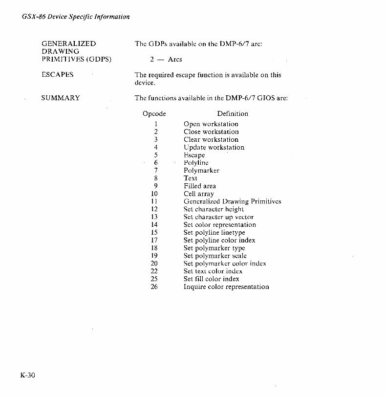
GSX-86 Device Specific Information
K-30
GENERALIZED DRAWING PRIMITIVES (G D PS)
ESCAPES
SUMMARY
The GDPs available on the DMP-6/7 are:
2 - Arcs
The required escape function is available on this device.
The functions available in the DMP-6/7 GIOS are:
Opcode
1 2 3 4 5 6 7 8 9
10 11 12 13 14 15 17 18 19 20 22 25 26
Definition
Open workstation Close workstation Clear workstation Update workstation Escape Polyline Polymarker Text Filled area Cell array Generalized Drawing Primitives Set character height Set character up vector Set color representation Set polyline linetype Set polyline color index Set polymarker type Set polymarker scale Set polymarker color index Set text color index Set fill color index Inquire color representation
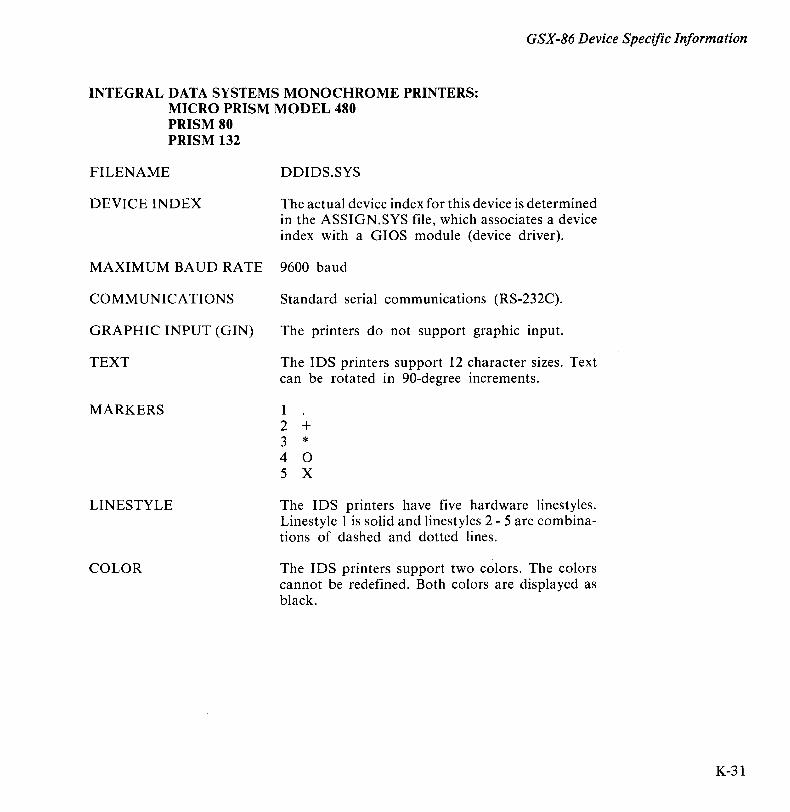
GSX-86 Device Specific Information
INTEGRAL DATA SYSTEMS MONOCHROME PRINTERS: MICRO PRISM MODEL 480 PRISM 80 PRISM 132
FILENAME DDIDS.SYS
DEVICE INDEX The actual device index for this device is determined in the ASSIGN.SYS file, which associates a device index with a GIOS module (device driver).
MAXIMUM BAUD RATE 9600 baud
COMMUNICATIONS Standard serial communications (RS-232C).
GRAPHIC INPUT (GIN) The printers do not support graphic input.
TEXT The IDS printers support 12 character sizes. Text can be rotated in 90-degree increments.
MARKERS 1 2 + 3 * 4 0 5 X
LINESTYLE The IDS printers have five hardware linestyles. Linestyle 1 is solid and line styles 2 - 5 are combinations of dashed and dotted lines.
COLOR The IDS printers support two colors. The colors cannot be redefined. Both colors are displayed as black.
K-31

GSX-86 Device Specific Information
K-32
GENERALIZED DRAWING PRIMITIVES (GDPS)
ESCAPES
SUMMARY
The GDPs available on this device are:
1 - Bars
The required escape function is available on this device.
The functions available in the GIOS for the IDS printers are:
Opcode
1 2 3 4 5 6 7 8 9
10 11 12 13 14 15 17 18 20 22 23 24 25 26
Definition
Open workstation Close workstation Clear workstation Update workstation Escape Polyline Polymarker Text Filled area Cell array Generalized Drawing Primitives Set character height Set character up vector Set color representation Set polyline linetype Set polyline color index Set polymarker type Set polymarker color index Set text color index Set fill interior style Set fill style pattern Set fill color index Inquire color representation

GSX-86 Device Specific Information
INTEGRAL DATA SYSTEMS PRINTERS WITH COLOR OPTION: PRISM 80 PRISM 132
FILENAME DDIDSC.SYS
DEVICE INDEX The actual device index for this device is determined in the ASSIGN.SYS file, which associates a device index with a GIOS module (device driver).
MAXIMUM BAUD RATE 9600 baud
COMMUNICA TIONS Standard serial communications (RS-232C).
GRAPHIC INPUT (GIN) The printers do not support graphic input.
TEXT The IDS printers support 12 character sizes. Text can be rotated in 90-degree increments.
MARKERS 1 2 + 3 * 4 0 5 X
LINESTYLE The IDS printers have five hardware linestyles. Linestyle 1 is solid, and linestyles 2 - 5 are combinations of dashed and dotted lines.
COLOR The IDS printers with the color option support eight colors. It is assumed that the process ribbon is being used to allow color mixing. The printer does not allow the colors to be redefined. The association of color indices with the displayed color is as follows:
o Background color - not displayed 1 Red 2 Green 3 Blue 4 Orange 5 Yellow 6 Violet 7 Black
K-33
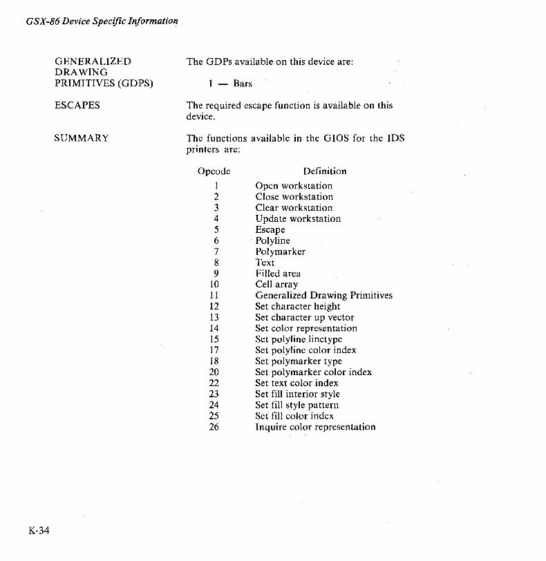
GSX-86 Device Specific Information
K-34
GENERALIZED DRAWING PRIMITIVES (GDPS)
ESCAPES
SUMMARY
The GDPs available on this device are:
1 - Bars
The required escape function is available on this device.
The functions available in the GIOS for the IDS printers are:
Opcode
1 2 3 4 5 6 7 8 9
10 11 12 13 14 15 17 18 20 22 23 24 25 26
Definition
Open workstation Close workstation Clear workstation Update workstation Escape Polyline Polymarker Text Filled area Cell array Generalized Drawing Primitives Set character height Set character up vector Set color representation Set polyline linetype Set polyline color index Set polymarker type Set polymarker color index Set text color index Set fill interior style Set fill style pattern Set fill color index Inquire color representation
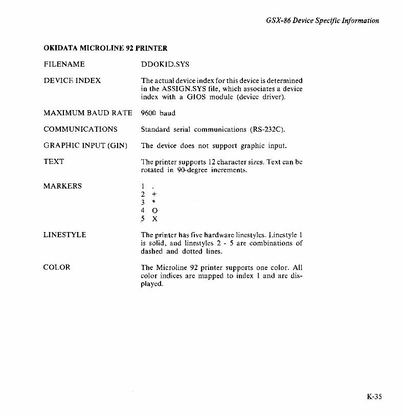
GSX-86 Device Specific Information
OKIDATA MICROLINE 92 PRINTER
FILENAME DDOKID.SYS
DEVICE INDEX The actual device index for this device is determined in the ASSIGN.SYS file, which associates a device index with a GIOS module (device driver).
MAXIMUM BAUD RATE 9600 baud
COMMUNICATIONS Standard serial communications (RS-232C).
GRAPHIC INPUT (GIN) The device does not support graphic input.
TEXT The printer supports 12 character sizes. Text can be rotated in 90-degree increments.
MARKERS 1 2 + 3 * 4 0 5 X
LINESTYLE The printer has five hardware linestyles. Linestyle 1 is solid, and linestyles 2 - 5 are combinations of dashed and dotted lines.
COLOR The Microline 92 printer supports one color. All color indices are mapped to index 1 and are displayed.
K-35
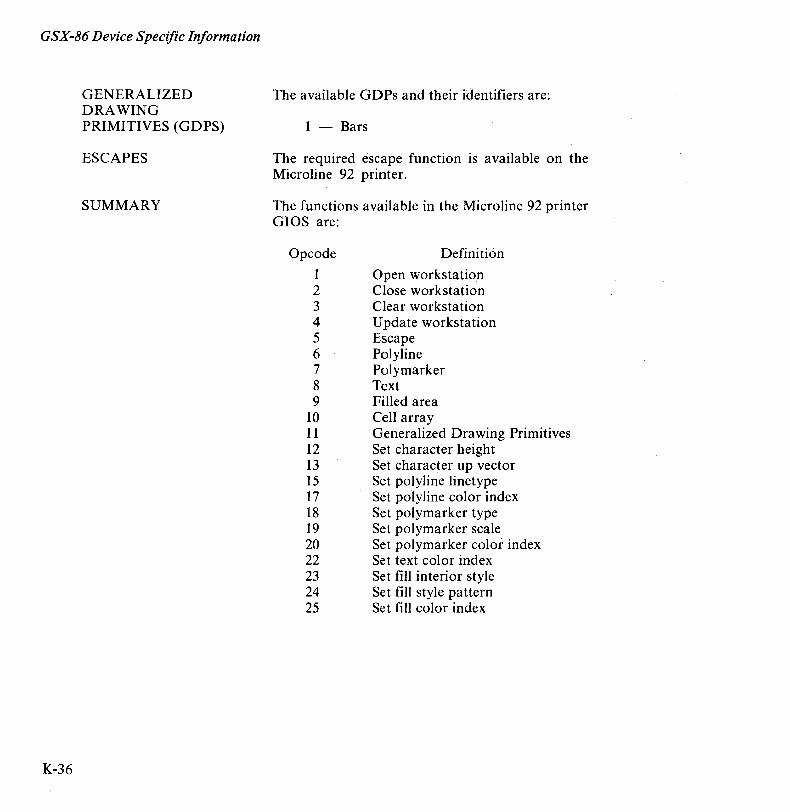
GSX-86 Device Specific Information
K-36
GENERALIZED DRAWING PRIMITIVES (GDPS)
ESCAPES
SUMMARY
The available GDPs and their identifiers are:
1 - Bars
The required escape function is available on the Microline 92 printer.
The functions available in the Microline 92 printer GIOS are:
Opcode
1 2 3 4 5 6 7 8 9
10 11 12 13 15 17 18 19 20 22 23 24 25
Definition
Open workstation Close workstation Clear workstation Update workstation Escape Polyline Polymarker Text Filled area Cell array Generalized Drawing Primitives Set character height Set character up vector Set polyline linetype Set polyline color index Set polymarker type Set polymarker scale Set polymarker color index Set text color index Set fill interior style Set fill style pattern Set fill color index
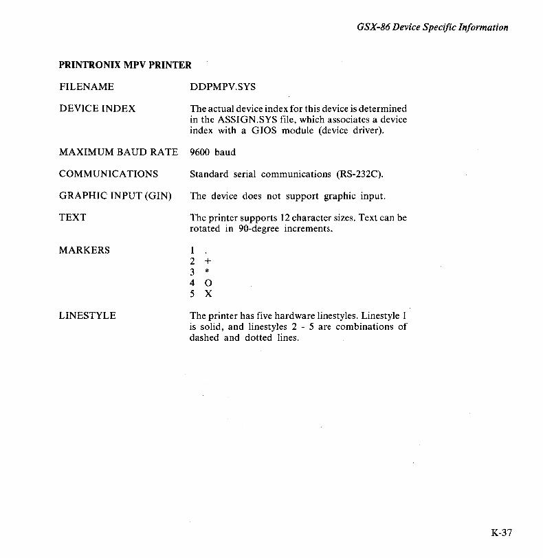
GSX-86 Device Specific Information
PRINTRONIX MPV PRINTER
FILENAME DDPMPV.SYS
DEVICE INDEX The actual device index for this device is determined in the ASSIGN.SYS file, which associates a device index with a GIOS module (device driver).
MAXIMUM BAUD RATE 9600 baud
COMMUNICATIONS Standard serial communications (RS-232C).
GRAPHIC INPUT (GIN) The device does not support graphic input.
TEXT The printer supports 12 character sizes. Text can be rotated in 90-degree increments.
MARKERS 1 2 + 3 * 4 0 5 X
LINESTYLE The printer has five hardware linestyles. Linestyle 1 is solid, and linestyles 2 - 5 are combinations of dashed and dotted lines.
K-37
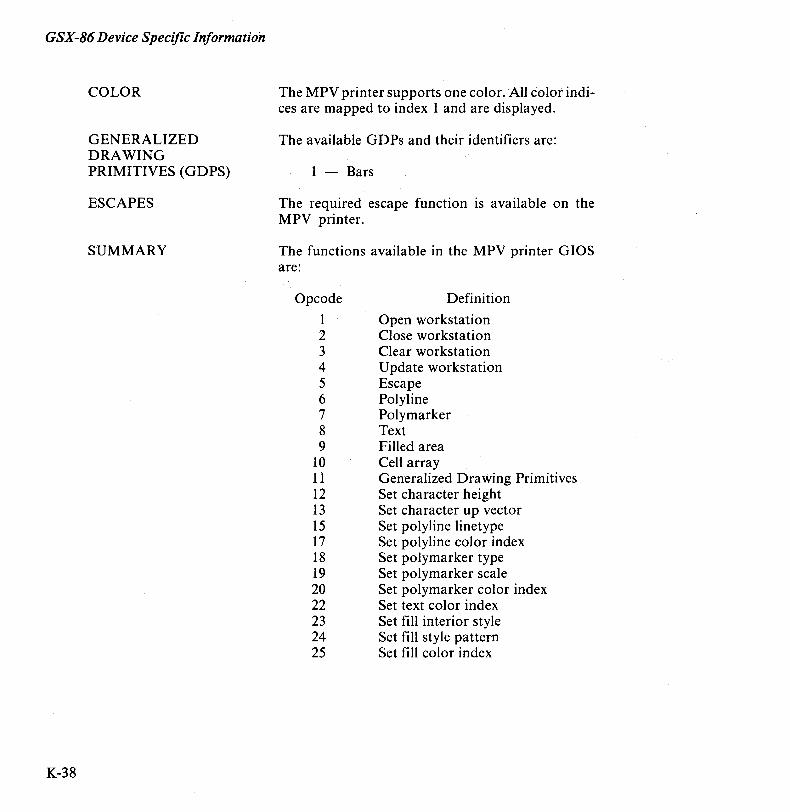
GSX-86 Device Specific Information
K-38
COLOR
GENERALIZED DRAWING PRIMITIVES (GDPS)
ESCAPES
SUMMARY
The MPV printer supports one color. All color indices are mapped to index 1 and are displayed.
The available GDPs and their identifiers are:
1 - Bars
The required escape function is available on the MPV printer.
The functions available in the MPV printer GIOS are:
Opcode
1 2 3 4 5 6 7 8 9
10 11 12 13 15 17 18 19 20 22 23 24 25
Definition
Open workstation Close workstation Clear workstation Update workstation Escape Polyline Polymarker Text Filled area Cell array Generalized Drawing Primitives Set character height Set character up vector Set polyline linetype Set polyline color index Set polymarker type Set polymarker scale Set polymarker color index Set text color index Set fill interior style Set fill style pattern Set fill color index
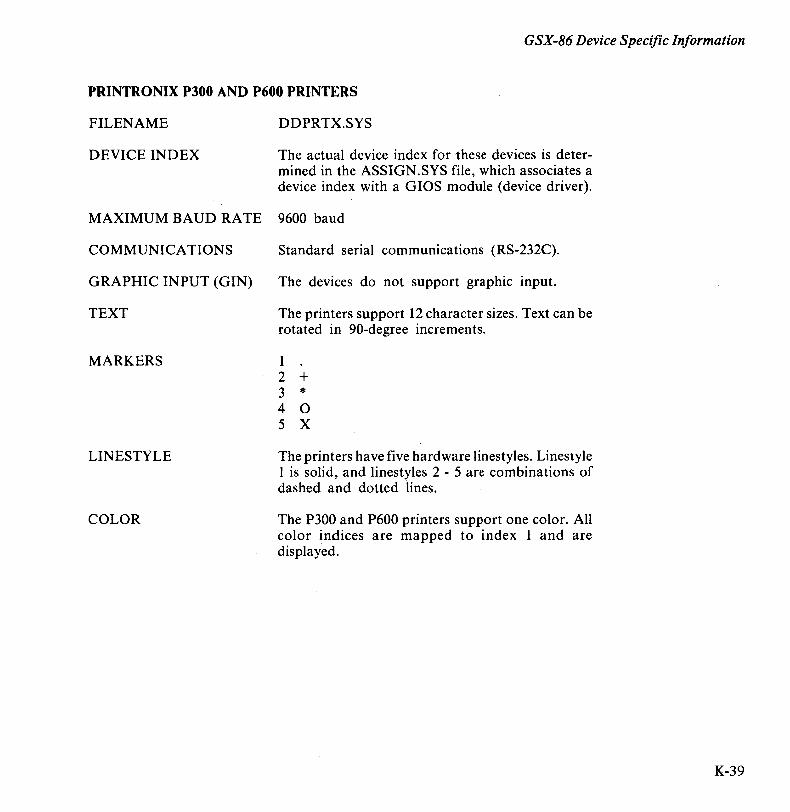
GSX-86 Device Specific Information
PRINTRONIX P300 AND P600 PRINTERS
FILENAME
DEVICE INDEX
DDPRTX.SYS
The actual device index for these devices is determined in the ASSIGN.SYS file, which associates a device index with a GIOS module (device driver).
MAXIMUM BAUD RATE 9600 baud
COMMUNICATIONS
GRAPHIC INPUT (GIN)
TEXT
MARKERS
LINESTYLE
COLOR
Standard serial communications (RS-232C).
The devices do not support graphic input.
The printers support 12 character sizes. Text can be rotated in 90-degree increments.
1 2 + 3 * 4 0 5 X
The printers have five hardware linestyles. Linestyle 1 is solid, and linestyles 2 - 5 are combinations of dashed and dotted lines.
The P300 and P600 printers support one color. All color indices are mapped to index 1 and are displayed.
K-39
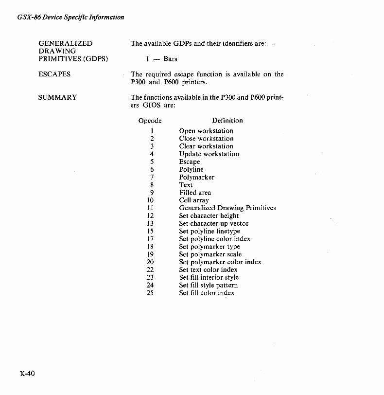
GSX-86 Device Specific Information
K-40
GENERALIZED DRAWING PRIMITIVES (GDPS)
ESCAPES
SUMMARY
The available GDPs and their identifiers are:
1 - Bars
The required escape function is available on the P300 and P600 printers.
The functions available in the P300 and P600 printers GIOS are:
Opcode
1 2 3 4 5 6 7 8 9
10 11 12 13 15 17 18 19 20 22 23 24 25
Definition
Open workstation Close workstation Clear workstation Update workstation Escape Polyline Polymarker Text Filled area Cell array Generalized Drawing Primitives Set character height Set character up vector Set polyline linetype Set polyline color index Set polymarker type Set polymarker scale Set polymarker color index Set text color index Set fill interior style Set fill style pattern Set fill color index

GSX-86 Device Specific Information
STROBE MODEL 100 GRAPHICS PLOTTER
FILENAME DDSTRB.SYS
DEVICE INDEX The actual device index for this device is determined in the ASSIGN.SYS file, which associates a device index with a GIOS module (device driver).
MAXIMUM BAUD RATE 9600 baud
COMMUNICATIONS Standard serial communications (RS-232C).
GRAPHIC INPUT (GIN) No graphic input is available.
TEXT The STROBE 100 has continuous scaling of character sizes. Text can be rotated in 90-degree increments. Lowercase characters are mapped to upper-case.
MARKERS 1 2 X 3 + 4 0 5 D 6 ~ 7 '1 8 0 9 0
LINESTYLE The STROBE 100 plotter has five software emulated linestyles. Linestyle 1 is solid, and linestyles 2 -5 are combinations of dashed and dotted lines.
K-41
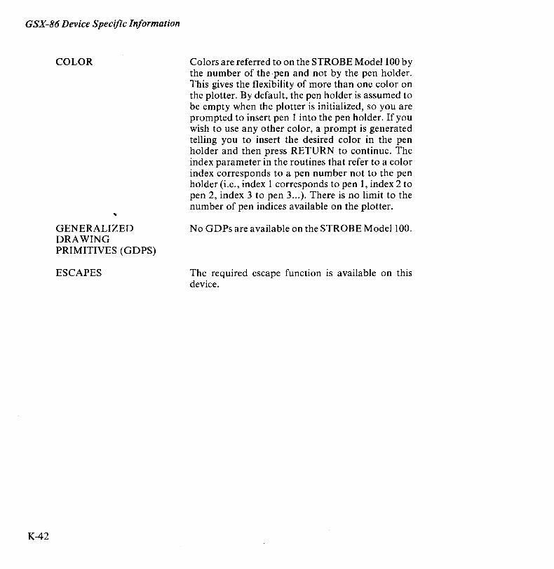
GSX-86 Device Specific Information
K-42
COLOR
GENERALIZED DRAWING PRIMITIVES (GDPS)
ESCAPES
Colors are referred to on the STROBE Model 100 by the number of the pen and not by the pen holder. This gives the flexibility of more than one color on the plotter. By default, the pen holder is assumed to be empty when the plotter is initialized, so you are prompted to insert pen 1 into the pen holder. If you wish to use any other color, a prompt is generated telling you to insert the desired color in the pen holder and then press RETURN to continue. The index parameter in the routines that refer to a color index corresponds to a pen number not to the pen holder (i.e., index 1 corresponds to pen 1, index 2 to pen 2, index 3 to pen 3 ... ). There is no limit to the number of pen indices available on the plotter.
No GDPs are available on the STROBE Model 100.
The required escape function is available on this device.
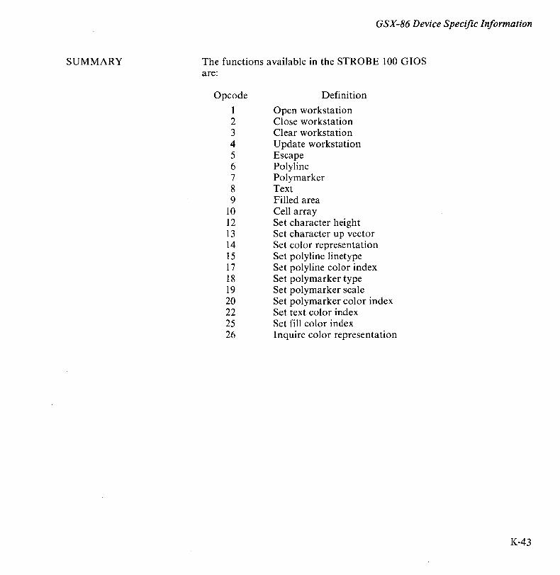
SUMMARY
GSX-86 Device Specific Information
The functions available in the STROBE 100 GIOS are:
Opcode
1 2 3 4 5 6 7 8 9
10 12 13 14 15 17 18 19 20 22 25 26
Definition
Open workstation Close workstation Clear workstation Update workstation Escape Polyline Polymarker Text Filled area Cell array Set character height Set character up vector Set color representation Set polyline linetype Set polyline color index Set polymarker type Set polymarker scale Set polymarker color index Set text color index Set fill color index Inquire color representation
K-43


Index
8080 Keyword 3-3,3-4 8080 Memory Model 1-4, 2-2, 2-3, 3-3,
3-6
A Absolute Address 3-3, 3-4 Accent command 6-11 Address 1-3, 3-4 Address Space 1-1 Addressing 1-5 ADDS Viewpoint 9-5, K-6 ADM-3A Mode Cursor Position Escape
Sequence 6-5, A-3 Advanced BIOS Functions 5-1 Allocation Vector 4-20 ALT 4-4,4-31,6-9 Arc 9-27 ASCII Control Codes 6-9 ASCII Records 3-1 ASM-86 1-2, 2-7, 3-1, 3-4 ASSIGN.SYS 9-2, 9-3 Assignment Table 9-3, 9-8, 9-44 Asynchronous Mode Byte 6-27 Attribute Data 6-6, 6-19, 6-22, A-2 Attributes Off 6-6, A-2 Auto Power Off 6-17 Auxiliary Character Generator C-l A uxiliary Character Set 6-8 Auxiliary Group 1-2, 2-3
B Background Tasks 2-1 BAD SECTOR Error 4-12,5-15 Bar 9-27
Base Page 1-2,2-3,2-4,2-5,2-7 Base Page Initialization 1-2, 2-7 Basic Disk Operating System (BDOS)
1-1, 1-4, 1-5,2-6,3-3,4-1,5-1,6-1,8-4, D-l
Basic 1/0 System (BIOS) 1-1, 1-2, 1-4, 4-12,4-13,4-30,4-32,5-1,6-1, 7-1, 8-4 D-l
Baud Rate 6-27 BDOS Error 4-12,4-21 BDOS File Operations
Close File 4-3,4-15 Chain to Program 4-3,4-30 Compute File Size 4-3, 4-26 Delete File 4-3,4-16 Direct BIOS call 4-3,4-31,5-18,6-1 Get Addr (Alloc) 4-3,4-20 Get Addr (Disk Parms) 4-3,4-22 Get Addr (RIO Vector) 4-3,4-21 Get DMA Segment Base 4-3, 4-32 Get System Data Area Address 4-3,
4-30 Make File 4-3,4-14,4-17,4-18 Open File 4-3,4-14,4-15,4-17,4-18 Read Random 4-3,4-24,4-26 Read Sequential 4-3,4-17 Rename File 4-3,4-18 Reset Disk System 4-3,4-13 Reset Drive 4-3,4-13,4-29 Return Current Disk 4-3,4-19,4-21 Return Login Vector 4-3,4-19 Return Version Number 4-3,4-10 Search for First 4-3,4-11,4-15,4-16 Search for Next 4-3,4-11,4-16
Index-l

Index
Select Disk 4-3, 4-14 Set DMA Address 4-3, 4-20, 4-38 Set DMA Segment Base 4-3, 4-20,
4-32,4-38 Set File Attributes 4-3, 4-21 Set Random Record 4-3, 4-28 Set/Get User Code 4-3,4-23 Write Protect Disk 4-3, 4-21 Write Random 4-3,4-17,4-25,4-27,
4-29 Write Random with Zero Fill 4-3,
4-29 Write Sequential 4-3,4-17
BDOS Memory Management Operations Free All Memory 4-3, 4-37 Free Memory Region 4-3, 4-37 Get Absolute Memory Region 4-3,
4-36 Get Max Mem at Abs Location 4-3,
4-35 Get Max Memory Region 4-3,4-36 Get-Memory Region 4-3,4-36 Program Load 4-3, 4-38
BDOS Simple Functions 4-2 Console Input 4-3, 4-4 Console Output 4-3,4-5, 6-1 Direct Console I/O 4..,3, 4-6, 6-1, 6-8 Get Console Buffer 4-3, 4-10 Get I/O Byte 4-3, 4-7 List Output 4-3, 4-6 Print String 4-3, 4-8 Punch Output 4-3, 4-5 Read Console Buffer 4-3,4-8 Reader Input 4-3,4-5 Return Version Number 4-3,4-10 Set I/O Byte 4-3, 4-8 System Reset 4-3, 4-4, 5-5
Beep Sound Parameters 6-15 Beginning Address (B) 3-3, 3-4 BIOS Functions 4-31, 5-1 BIOS Jump Vector 5-2
Index-2
Blink Attribute 6-6, 6-22, A-2 Blocking 1-1 BOOT ROM 8-1,8-2,8-3,8-4 Bootstrap 1-4, 5-5, 8-1 Built-in Command 2-1
DIR 2-1 ERA 2-1 REN 2-1 TYPE 2-1 USER 2-1
Byte 1-3
C CAPS Key 4-4, 6-9 CBIOS Error Messages 4-1 Cell Array 9-12, 9-26 CHR Utility 6-8, C-l Circle 9-27 Clear Workstation 9-12, 9-17 Close File 4-3,4-15 Close Workstation 9-12, 9-17 CMD File Format 3-6, 7-2 CMD File Type 1-1,2-1,4-38 Code Group 1-2, 2-3 Cold Start 2-1,4-14
. Cold Start Loader 1-1, 5.;.2, 8-1, 8-2 Color Attribute 6-6, A-2 COM File Type 2-1 Command File 2-1, 3-6 Compact Memory Model 2-2, 2-3, 2-6,
3-6 Compute File Size 4-3, 4-26 CONIN 4-31, 5-2, 5-7, B-2 CONOUT 5-2,5-7,6-1,6-9 CONSOLE 4-4, 5-6, 5-8, 5-9 Console Command Processor (CCP)
1-1,1-5,2-1,2-6,2-7,2-9,3-3,4-4,4-33, 4-37,4-38, 5-2, 5-5, 8-4, D-l
Console Input 4-3, 4-4 Console Output 4-3, 4-4 Control Characters F-l CONST 5-2,5-7

CONTROL-C 1-5,2-2,2-9,4-9,4-12, 4-33, F-l
CONTROL-E 4-9, F-l CONTROL-H 4-9, F-l CONTROL-J 4-9, F-l CONTROL-M 4-9, F-l CONTROL-R 4-9, F-l CONTROL-U 4-9, F-2 CONTROL-X 4-9, F-2 CONTROL-Z 5-6, 5-8, F-2 Control Sequence Introducer (CSI) 6-1 Coordinate Scaling 9-7 CPM.SYS 1-1, 5-2, 5-5, 8-1, 8-2, 8-4 CRT Control Codes 6-1 CSV 7-1 Cursor Backward 6-4, A-I Cursor Down (CBIOS) 6-4, A-I Cursor Down (GDOS) 9-12, 9-20 Cursor Forward 6-4, A-I Cursor Left 9-12, 9-21 Cursor Position 6-4, A-I Cursor Right 9-12, 9-20 Cursor Up (CBIOS) 6-4, A-I Cursor Up (GDOS) 9-12,9-20 Customized BIOS (CBIOS) 1-1, 1-4,
4-4, 4-7, 4-8, 5-1, 6-1, 8-1 Cylinder 5-10, 5-13, 5-15
D Data Group 1-2, 2-3 Data Segment 1-5 Datamedia Colorscan-l0 9-5, K-13 DDNECAPC.SYS 9-5, K-l DDGN2A.SYS 9-5, K-4 DDGN2B.SYS 9-5, K-6 DDGN2C.SYS 9-5, K-I0 DDGN2D.SYS 9-5, K-13 DDVRET.SYS 9-5, K-16 DDMX80.SYS 9-5, K-19 DD7220.SYS 9-5, K-21 DD7470.SYS 9-5, K-23 DDHI3M.SYS 9-5, K-26
DDHI7M.SYS 9-5, K-29 DDIDS.SYS 9-5, K-31 DDISC.SYS 9-5, K-33 DDOKID.SYS 9-5, K-35 DDPMPV.SYS 9-5, K-37 DDPRTX.SYS 9-5, K-39 DDSTRB.SYS 9-5, K-41 DDT-86 1-2, 2-1, 2-2,4-32, 9-46 Deblocking 1-1 Default disk number 1-2 DEL 4-9 Delete File 4-3,4-16 Device Driver 9-1,9-2,9-3,9-4,9-7,
9-44 DIR 2-1 DIRBUF 7-1 Direct BIOS Call 4-3, 4-31, 5-18, 6-1 Direct Console 1/0 4-3,4-6, 6-1, 6-8 Direct CRT I/O 6-18,6-23 Direct Cursor Address 9-12, 9-22 Directory Code 4-15 Directory Entries 4-15,4-21, 7-6 Disk Definition Tables 1-4, 5-1, 5-12,
7-1 Disk Directory 4-14,4-18,4-19, 7-1 Disk drive specifiers 5-3 Disk Parameter Block (DPB) 4-23, 7-2 Disk Parameter Header (D PH) 5-12,
7-1 Disk Parameter Table 5-17, 6-7 Disk Reset 2-2, 2-9,4-14 Display Data 6-19 Display Request Block 6-19 Display String Data on CRT 6-18, 6-24 Display Video Memory Format on CRT
6-18,6-24 DMA 4-20 DMA Address 2-9,4-15,4-20,4-26,
4-29, 4-30, 4-38, 5-10, 5-14 DMA Buffer 4-15,4-17,4-26,5-11 DMA Controller 5-5
Index
Index-3
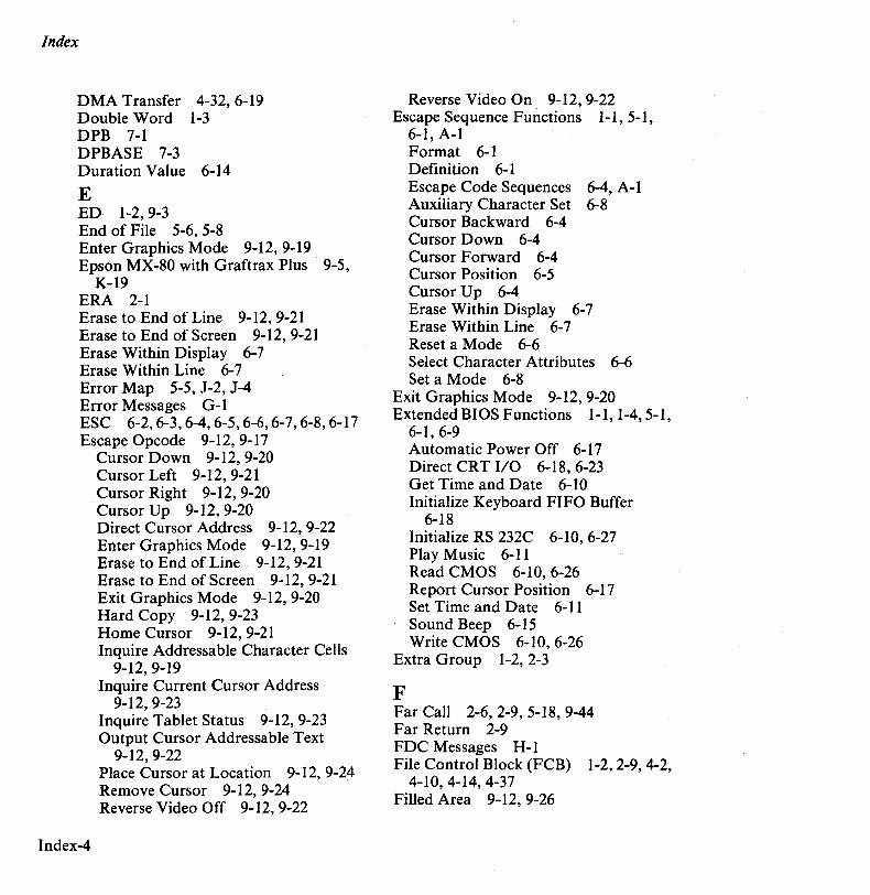
Index
DMA Transfer 4-32, 6-19 Double Word 1-3 DPB 7-1 DPBASE 7-3 Duration Value 6-14
E ED 1-2,9-3 End of File 5-6, 5-8 Enter Graphics Mode 9-12, 9-19 Epson MX-80 with Graftrax Plus 9-5,
K-19 ERA 2-1 Erase to End of Line 9-12, 9-21 Erase to End of Screen 9-12, 9-21 Erase Within Display 6-7 Erase Within Line 6-7 Error Map 5-5, J-2, J-4 Error Messages G-l ESC 6-2,6-3,6-4,6-5,6-6,6-7,6-8,6-17 Escape Opcode 9-12, 9-17
Index-4
Cursor Down 9-12,9-20 Cursor Left 9-12, 9-21 Cursor Right 9-12, 9-20 Cursor Up 9-12, 9-20 Direct Cursor Address 9-12, 9-22 Enter Graphics Mode 9-12,9-19 Erase to End of Line 9-12, 9-21 Erase to End of Screen 9-12,9-21 Exit Graphics Mode 9-12, 9-20 Hard Copy 9-12,9-23 Home Cursor 9-12, 9-21 Inquire Addressable Character Cells
9-12,9-19 Inquire Current Cursor Address
9-12, 9-23 Inquire Tablet Status 9-12, 9-23 Output Cursor Addressable Text
9-12,9-22 Place Cursor at Location 9-12, 9-24 Remove Cursor 9-12, 9-24 Reverse Video Off 9-12,9-22
Reverse Video On 9-12,9-22 Escape Sequence Functions 1-1 5-1
6-1, A-I ' , Format 6-1 Definition 6-1 Escape Code Sequences 6-4, A-I Auxiliary Character Set 6-8 Cursor Backward 6-4 Cursor Down 6-4 Cursor Forward 6-4 Cursor Position 6-5 Cursor Up 6-4 Erase Within Display 6-7 Erase Within Line 6-7 Reset a Mode 6-6 Select Character Attributes 6-6 Set a Mode 6-8
Exit Graphics Mode 9-12,9-20 Extended BIOS Functions 1-1 1-4 5-1
6-1, 6-9 ' , , Automatic Power Off 6-17 Direct CRT I/O 6-18,6-23 Get Time and Date 6-10 Initialize Keyboard FIFO Buffer
6-18 Initialize RS 232C 6-10, 6-27 Play Music 6-11 Read CMOS 6-10,6-26 Report Cursor Position 6-17 Set Time and Date 6-11 Sound Beep 6-15 Write CMOS 6-10,6-26
Extra Group 1-2, 2-3
F Far Call 2-6, 2-9, 5-18, 9-44 Far Return 2-9 FDC Messages H-l File Control Block (FCB) 1-2,2-9,4-2,
4-10, 4-14, 4-37 Filled Area 9-12, 9-26
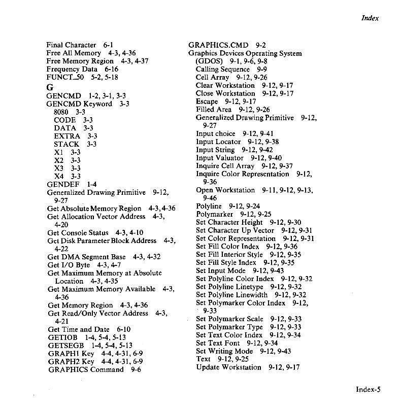
Final Character 6-1 Free All Memory 4-3, 4-36 Free Memory Region 4-3, 4-37 Frequency Data 6-16 FUNCT...50 5-2,5-18
G GENCMD 1-2, 3-1, 3-3 GENCMD Keyword 3-3
8080 3-3 CODE 3-3 DATA 3-3 EXTRA 3-3 STACK 3-3 Xl 3-3 X2 3-3 X3 3-3 X4 3-3
GENDEF 1-4 Generalized Drawing Primitive 9-12,
9-27 Get Absolute Memory Region 4-3,4-36 Get Allocation Vector Address 4-3,
4-20 Get Console Status 4-3,4-10 Get Disk Parameter Block Address 4-3,
4-22 Get DMA Segment Base 4-3, 4-32 Get I/O Byte 4-3,4-7 Get Maximum Memory at Absolute
Location 4-3,4-35 Get Maximum Memory Available 4-3,
4-36 Get Memory Region 4-3,4-36 Get Read/Only Vector Address 4-3,
4-21 Get Time and Date 6-10 GETIOB 1-4, 5-4, 5-13 GETSEGB 1-4, 5-4, 5-13 GRAPHI Key 4-4,4-31,6-9 GRAPH2 Key 4-4,4-31,6-9 GRAPHICS Command 9-6
GRAPHICS.CMD 9-2 Graphics Devices Operating System
(GDOS) 9-1, 9-6, 9-8 Calling Sequence 9-9 Cell Array 9-12, 9-26 Clear Workstation 9-12,9-17 Close Workstation 9-12, 9-17 Escape 9-12, 9-17 Filled Area 9-12,9-26 Generalized Drawing Primitive 9-12,
9-27 Input choice 9-12,9-41 Input Locator 9-12,9-38 Input String 9-12, 9-42 Input Valuator 9-12, 9-40 Inquire Cell Array 9-12, 9-37 Inquire Color Representation 9-12,
9-36 Open Workstation 9-11,9-12,9-13,
9-46 Polyline 9-12, 9-24 Polymarker 9-12, 9-25 Set Character Height 9-12,9-30 Set Character Up Vector 9-12,9-31 Set Color Representation 9-12, 9-31 Set Fill Color Index 9-12, 9-36 Set Fill Interior Style 9-12, 9-35 Set Fill Style Index 9-12, 9-35 Set Input Mode 9-12,9-43 Set Polyline Color Index 9-12, 9-32 Set Polyline Linetype 9-12, 9-32 Set Polyline Linewidth 9-12, 9-32 Set Poly marker Color Index 9-12,
9-33 Set Polymarker Scale 9-12, 9-33 Set Polymarker Type 9-12,9-33 Set Text Color Index 9-12, 9-34 Set Text Font 9-12, 9-34 Set Writing Mode 9-12, 9-43 Text 9-12, 9-25 Update Workstation 9-12,9-17
Index
Index-5
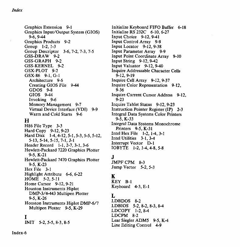
Index
Graphics Extension 9-1 Graphics Input/Output System (GIOS)
9-6,9-44 Graphics Products 9-2 Group 1-2, 1-3 Group Descriptor 3-6, 7-2, 7-3, 7-5 GSS-DRA W 9-2 GSS-GRAPH 9-2 GSS-KERNEL 9-2 GSX-PLOT 9-2 GSX-86 9-1, G-I
H
Architecture 9-6 Creating GIOS File 9-44 GDOS 9-8 GIOS 9-44 Invoking 9-6 Memory Management 9-7 Virtual Device Interface (VDI) 9-9 Warm and Cold Starts 9-6
H86 File Type 3-3 Hard Copy 9-12, 9-23 Hard Disk 1-4,4-12,5-1,5-3,5-5,5-12,
5-13, 5-14, 5-15, 7-1, J-l Header Record I-I, 2-7, 3-1, 3-6 Hewlett-Packard 7220 Graphics Plotter
9-5, K-21 Hewlett-Packard 7470 Graphics Plotter
9-5, K-23 Hex File 3-1 Highlight Attribute 6-6, 6-22 HOME 5-2,5-11 Home Cursor 9-12, 9-21 Houston Instruments Hiplot
DMP-3/4-443 Multipen Plotter 9-5, K-26
Houston Instruments Hiplot DMP-6/7 MUltipen Plotter 9-5, K-29
I IN IT 5-2, 5-5, 8-3, 8-5
Index-6
Initialize Keyboard FIFO Buffer 6-18 Initialize RS 232C 6-10, 6-27 Input Choice 9-12, 9-41 Input Control Array 9-9 Input Locator 9-12, 9-38 Input Parameter Array 9-9 Input Point Coordinate Array 9-10 Input String 9-12,9-42 Input Valuator 9-12, 9-40 Inquire Addressable Character Cells
9-12, 9-19 Inquire Cell Array 9-12, 9-37 Inquire Color Representation 9-12,
9-36 Inquire Current Cursor Address 9-12,
9-23 Inquire Tablet Status 9-12,9-23 Instruction Pointer Register (lP) 2-3 Integral Data Systems Color Printers
9-5, K-33 Integral Data Systems Monochrome
Printers 9-5, K-31 Intel Hex File 1-2, 1-4, 3-1 Intel Utilities 3-1, 3-4 Interrupt Vector D-l IOBYTE 1-2, 1-4,4-8, 5-8
J JMPFCPM 8-3 Jump Vector 5-2, 5-3
K KEY B-1 Keyboard 4-3, E-l
L LDBDOS 8-2 LDBIOS 5-2, 8-2, 8-3, 8-4 LDCOPY 1-2,8-4 LDCPM 8-2 Lear Siegler ADM5 9-5, K-4 Line Editing Control 4-9

LIST Device 4-8, 5-6, 5-8, 5-9 LIST Function 5-2, 5-7 LIST Output 4-3, 4-6 LISTST 5-15 LOAD Program 1-2 LOADER 8-1,8-2 LOADER.CMD 8-4 Logical Disk Drive 4-12, 5-3 Logical Diskette Structure 6-11 Logical to Physical Sector Translation
5-16, 7-2, 7-8 Login 2-1, 4-14 Login Vector 4-19 Loudness 6-12
M Make File 4-3, 4-14, 4-17, 4-18 Maximum Memory Size 3-3, 3-5 Melody Data 6-11 Memory Allocation 2-2, 2-9, 4-4, 4-32 Memory Control Block (MCB) 4-35 Memory Image File, Header Record
1-1, 3-1, 3-6 Memory Map D-l Memory Model 1-4, 2-1, 3-1, 3-3, 3-7,
7-2 Memory Region Table (MRT) 5-17 Memory Regions 4-32, 7-5 Minimum Memory Value 3-3,3-4 MOVCPM 1-4
N NEC Advanced Personal Computer
9-5, K-l Nibble 1-3, 3-7 Normalized Device Coordinates (NDC)
9-7,9-10 Note Value 6-13 NULL 5-2,5-18
o Offset 1-3, 1-5
Okidata Microline 92 Printer 9-5 K-35 Online Status 4-14 ' Open File 4-3,4-14,4-15,4-17,4-18 Open Parentheses 6-8 Open Workstation 9-11, 9-12, 9-13,
9-46 Output Cursor Addressable Text 9-12,
9-22 Over Line Attribute 6-6, 6-22, A-2
p Paragraph 1-3 Paragraph Boundary 1-3 Parity Check 6-28 Peripheral Devices 5-6 Physical Diskette Structure 7-8 Pie Slice 9-27 PIP 1-2, 5-6, 5-9 Place Cursor at Location 9-12, 9-24 Play Music 6-11 Polyline 9-12, 9-24 Polymarker 9-12, 9-25 Print String 4-3, 4-8 Printronix MVP Printer 9-5, K-37 Printronix P300, P600 Printers 9-5,
K-39 Program Group 1-2, 2-3 Program Interrupt 6-1, 9-9 Program Load 2-3,4-3,4-33,4-38 Program Termination 1-5,2-9 PUNCH 4-8, 5-6, 5-8, 5-9 Punch Output 4-3, 4-5
R lLW_COMMON 5-10,5-14 R_W_COMMONHD 5-10,5-14 RIO Error 4-12,4-13,4-21 READ 5-10,5-14,1-2 Read CMOS 6-10,6-26 Read Console Buffer 4-3, 4-8 Read Random 4-3,4-24,4-26
Index
Index-7
Index
Read Sequential 4-3,4-17 Read/Only Vector 4-21 READER 4-8, 5-6, 5-8, 5-9 Reader Input 4-3, 4-5 Relocatable Group 1-4 Remove Cursor 9-12,9-24 REN 2-1 Rename File 4-3,4-18 Report Cursor Position 6-17 Report Cursor Position by Binary Value
6-18, 6-24 Reserved Software Interrupt 1-1, 1-5 Reset a Mode 6-8, A-3 Reset Disk System 4-3,4-13 Reset Drive 4-3, 4-13, 4-29 Reset State 4-13, 4-14, 4-29 Return Current Disk 4-3,4-19 Return Login Vector 4-3,4-19,4-21 Return Version Number 4-3,4-10 Reverse Attribute 6-6, 6-22, A-2 Reverse Video Off 9-12, 9-22 Reverse Video On 9-12,9-22 Roll Down Screen 6-18, 6-24 Roll Up Screen 6-18, 6-25
S SAVE 2-1 Scale Data 6-11 Search for First 4-3,4-11,4-15,4-16 Search for Next 4-3,4-11,4-16 SECTRAN 5-2, 5-16 Secret Attribute 6-6, A-2 Sector 5-10,5-13,5-15 Segment 1-3 Segment Register 1-2, 1-3, 2-3,4-1 Segment Register Initialization 2-3, 7-3 SELDSK 5-10, 5-11, 5-12, 1-2 Select Character Attributes 6-6 Select Disk 4-3, 4-14 SELECT Error 4-12 Sequence Introducer 6-1 Set a Mode 6-8, A-3
Index-8
Set Character Height 9-12, 9-30 Set Character Up Vector 9-12, 9-31 Set Color Representation 9:-12, 9-31 Set DMA Address 4-3, 4-20, 4-38 Set DMA Segment Base 4-3,4-20,4-32,
4-38 Set File Attributes 4-3, 4-21 Set Fill Color Index 9-12, 9-36 Set Fill Interior Style 9-12, 9-35 Set Fill Style Index 9-12, 9-35 Set I/O Byte 4-3, 4-8 Set Polyline Color Index 9-12, 9-32 Set Polyline Linetype 9-12, 9-32 Set Polyline Linewidth 9-12, 9-32 Set Polymarker Color Index 9-12, 9-33 Set Polymarker Scale 9-12, 9-33 Set Polymarker Type 9-12, 9-33 Set Random Record 4-3, 4-28 Set Text Color Index 9-12, 9-34 Set Text Font 9-12, 9-34 Set Time and Date 6-11 Set Writing Mode 9-12, 9-43 Set/Get User Code 4-3, 4-23 SETDMA 5-2,5-14 SETDMAB 1-4, 5-2, 5-14, 5-16 SETIOB 1-4, 5-2, 5-10, 8-3, 8-5 SETSEC 5-13 SETTRK 5-13 Skew Factor 5-16, 7-2, 7-8 Small Memory Model 2-2, 2-3, 2-5, 3-6 Soft Key Table B-1 Software Interrupt #224 1-5,4-1,6-9 Sound Beep 6-15 Stack Group 1-2, 2-3 STAT 1-2,4-20,5-9,9-8 Static Allocation Map 4-32 Stop Bit 6-28 Strobe Model 100 Graphics Plotter 9-5,
K-41 String Data Format 6-21 SUBMIT 1-2
SYSGEN 1-2 Synchronous Mode 6-27 System Reset 1-5, 2-9, 4-3, 4-4, 4-14,
4-21, 5-5 System Unit Table 5-5 SYSUNITID 5-5,5-12
T Tabs 4-5, 4-9 Televideo 900 9-5, K-I0 Text 9-12, 9-25 Text Editor 9-3 Tone Period 6-16 Track 5-10, 5-13, 5-15 Track Reallocation 1-5 Transient Program 1-2, 1-4,2-1,4-1,
4-23, 4-30, 4-32, 5-6 Transient Program Load 1-1, 2-9 Translating Programs 1-4, 2-1, 2-7, 4-1 TYPE 2-1
U Under Line Attribute 6-6, 6-22, A-2 Update Workstation 9-12,9-17 USER 2-1
V Vertical Line Attribute 6-6, 6-22, A-2 Video Memory Format 6-21 Virtual Device Interface (VDI) 9-9,
9-44 Virtual File Size 4-26 VT100 9-5, K-16
W Warm Start 1-1, 1-4,4-14,4-21, 5-5 WBOOT 5-2,5-5,5-15 Word 1-3 Workstation ID 9-3,9-7 WRITE 5-10, 5-14, 1-1, 1-2 Write CMOS 6-10,6-26
Write Protect Disk 4-3, 4-21 Write Random 4-3,4-17,4-25,4-27,
4-29 Write Random with Zero Fill 4-3, 4-29 Write Sequential 4-3,4-17
X XLT 7-1
Index
Index-9


I I I I I I I I
I I~ :.c
I~ -;
\ ~ ~ ~
.!:! 0..
~ .... Advanced A'--~Personal Computer
TM
["ft~\,
NEe Information Systems, Inc.
USER'S COMMENTS FORM
Document: CP/M-86 System Reference Guide
Document No.: 819-000102-200 1 REV. 01
Please suggest improvements to this manual.
Please list any errors in this manual. Specify by page.
From: Name ______________________________________________________________________ _
Title _______________________________________ ~ __________ _
Company __________________________________________________ _
Address _________________________________________________________________ ____
DealerName ____________________________________________________ _____
Date: _________________ _
Seal or tape all edges for mailing-do not use staples.
FOLD HERE
""" BUSINESS REPLY CARD
FIRST CLASS PERMIT NO. 386 LEXINGTON, MA
POSTAGE WILL BE PAID BY ADDRESSEE
NEe Information Systems, Inc. Dept: Publications -APC 5 Militia Drive Lexington, MA 02173
FOLD HERE
Seal or tape all edges for mailing-do not use staples.
NO POSTAGE NECESSARY
IF MAILED IN THE
UNITFD STATES
Related Documents