USER GUIDE www.kontron.com // 1 CP6006-SA User Guide, Rev. 1.2 Doc. ID: 1065-1684

Welcome message from author
This document is posted to help you gain knowledge. Please leave a comment to let me know what you think about it! Share it to your friends and learn new things together.
Transcript
USER GUIDE
www.kontron.com // 1
CP6006-SA User Guide, Rev. 1.2
Doc. ID: 1065-1684

CP6006-SA – User Guide, Rev. 1.2
www.kontron.com // 2
This page has been intentionally left blank
CP6006-SA – User Guide, Rev. 1.2
www.kontron.com // 3
CP6006-SA - USER GUIDE
Disclaimer Kontron would like to point out that the information contained in this user guide may be subject to alteration, particularly as a result of the constant upgrading of Kontron products. This document does not entail any guarantee on the part of Kontron with respect to technical processes described in the user guide or any product characteristics set out in the user guide. Kontron assumes no responsibility or liability for the use of the described product(s), conveys no license or title under any patent, copyright or mask work rights to these products and makes no representations or warranties that these products are free from patent, copyright or mask work right infringement unless otherwise specified. Applications that are described in this user guide are for illustration purposes only. Kontron makes no representation or warranty that such application will be suitable for the specified use without further testing or modification. Kontron expressly informs the user that this user guide only contains a general description of processes and instructions which may not be applicable in every individual case. In cases of doubt, please contact Kontron.
This user guide is protected by copyright. All rights are reserved by Kontron. No part of this document may be reproduced, transmitted, transcribed, stored in a retrieval system, or translated into any language or computer language, in any form or by any means (electronic, mechanical, photocopying, recording, or otherwise), without the express written permission of Kontron. Kontron points out that the information contained in this user guide is constantly being updated in line with the technical alterations and improvements made by Kontron to the products and thus this user guide only reflects the technical status of the products by Kontron at the time of publishing.
Brand and product names are trademarks or registered trademarks of their respective owners.
©2021 by Kontron S&T AG
Kontron Europe GmbH
Gutenbergstraße 2 85737 Ismaning Germany www.kontron.com
CP6006-SA – User Guide, Rev. 1.2
www.kontron.com // 4
Intended Use THIS DEVICE AND ASSOCIATED SOFTWARE ARE NOT DESIGNED, MANUFACTURED OR INTENDED FOR USE OR RESALE FOR THE OPERATION OF NUCLEAR FACILITIES, THE NAVIGATION, CONTROL OR COMMUNICATION SYSTEMS FOR AIRCRAFT OR OTHER TRANSPORTATION, AIR TRAFFIC CONTROL, LIFE SUPPORT OR LIFE SUSTAINING APPLICATIONS, WEAPONS SYSTEMS, OR ANY OTHER APPLICATION IN A HAZARDOUS ENVIRONMENT, OR REQUIRING FAIL-SAFE PERFORMANCE, OR IN WHICH THE FAILURE OF PRODUCTS COULD LEAD DIRECTLY TO DEATH, PERSONAL INJURY, OR SEVERE PHYSICAL OR ENVIRONMENTAL DAMAGE (COLLECTIVELY, "HIGH RISK APPLICATIONS").
You understand and agree that your use of Kontron devices as a component in High Risk Applications is entirely at your risk. To minimize the risks associated with your products and applications, you should provide adequate design and operating safeguards. You are solely responsible for compliance with all legal, regulatory, safety, and security related requirements concerning your products. You are responsible to ensure that your systems (and any Kontron hardware or software components incorporated in your systems) meet all applicable requirements. Unless otherwise stated in the product documentation, the Kontron device is not provided with error-tolerance capabilities and cannot therefore be deemed as being engineered, manufactured or setup to be compliant for implementation or for resale as device in High Risk Applications. All application and safety related information in this document (including application descriptions, suggested safety measures, suggested Kontron products, and other materials) is provided for reference only.
Handling and operation of the product is permitted only for trained personnel within a work
place that is access controlled. Please follow the “General Safety Instructions” supplied with the system.
CP6006-SA – User Guide, Rev. 1.2
www.kontron.com // 5
Revision History
Revision Brief Description of Changes Date of Issue Author/Editor
1.0 Initial Version 2017-May-23 MK
1.1 New ambient temperature diagrams added, Pentium® D1519 processor added
2020-June-25 MK
1.2 SATA M.2 module, power considerations, M.2 socket descriptions updated
2021-March-25 MK
Terms and Conditions Kontron warrants products in accordance with defined regional warranty periods. For more information about warranty compliance and conformity, and the warranty period in your region, visit http://www.kontron.com/terms-and-conditions.
Kontron sells products worldwide and declares regional General Terms & Conditions of Sale, and Purchase Order Terms & Conditions. Visit http://www.kontron.com/terms-and-conditions.
For contact information, refer to the corporate offices contact information on the last page of this user guide or visit our website CONTACT US.
Customer Support Find Kontron contacts by visiting: https://www.kontron.de/support-and-services.
Customer Service As a trusted technology innovator and global solutions provider, Kontron extends its embedded market strengths into a services portfolio allowing companies to break the barriers of traditional product lifecycles. Proven product expertise coupled with collaborative and highly-experienced support enables Kontron to provide exceptional peace of mind to build and maintain successful products.
For more details on Kontron’s service offerings such as: enhanced repair services, extended warranty, Kontron training academy, and more visit http://www.kontron.com/support-and-services/services.
Customer Comments If you have any difficulties using this user guide, discover an error, or just want to provide some feedback, contact Kontron support. Detail any errors you find. We will correct the errors or problems as soon as possible and post the revised user guide on our website.
CP6006-SA – User Guide, Rev. 1.2
www.kontron.com // 6
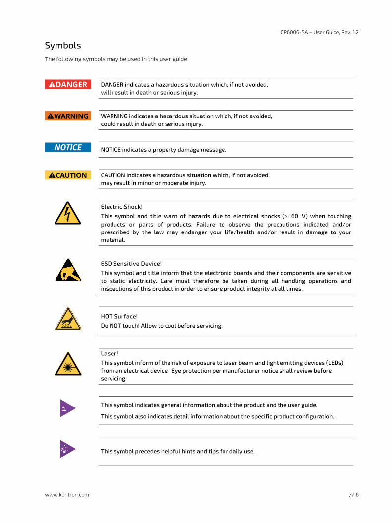
Symbols The following symbols may be used in this user guide
DANGER indicates a hazardous situation which, if not avoided,
will result in death or serious injury.
WARNING indicates a hazardous situation which, if not avoided,
could result in death or serious injury.
NOTICE indicates a property damage message.
CAUTION indicates a hazardous situation which, if not avoided,
may result in minor or moderate injury.
Electric Shock!
This symbol and title warn of hazards due to electrical shocks (> 60 V) when touching products or parts of products. Failure to observe the precautions indicated and/or prescribed by the law may endanger your life/health and/or result in damage to your material.
ESD Sensitive Device!
This symbol and title inform that the electronic boards and their components are sensitive to static electricity. Care must therefore be taken during all handling operations and inspections of this product in order to ensure product integrity at all times.
HOT Surface!
Do NOT touch! Allow to cool before servicing.
Laser!
This symbol inform of the risk of exposure to laser beam and light emitting devices (LEDs) from an electrical device. Eye protection per manufacturer notice shall review before servicing.
This symbol indicates general information about the product and the user guide.
This symbol also indicates detail information about the specific product configuration.
This symbol precedes helpful hints and tips for daily use.
CP6006-SA – User Guide, Rev. 1.2
www.kontron.com // 7
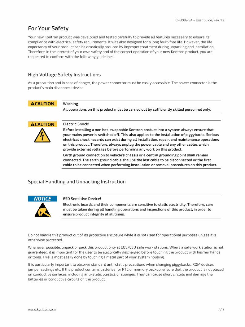
For Your Safety Your new Kontron product was developed and tested carefully to provide all features necessary to ensure its compliance with electrical safety requirements. It was also designed for a long fault-free life. However, the life expectancy of your product can be drastically reduced by improper treatment during unpacking and installation. Therefore, in the interest of your own safety and of the correct operation of your new Kontron product, you are requested to conform with the following guidelines.
High Voltage Safety Instructions
As a precaution and in case of danger, the power connector must be easily accessible. The power connector is the product’s main disconnect device.
Warning
All operations on this product must be carried out by sufficiently skilled personnel only.
Electric Shock!
Before installing a non hot-swappable Kontron product into a system always ensure that your mains power is switched off. This also applies to the installation of piggybacks. Serious electrical shock hazards can exist during all installation, repair, and maintenance operations on this product. Therefore, always unplug the power cable and any other cables which provide external voltages before performing any work on this product.
Earth ground connection to vehicle’s chassis or a central grounding point shall remain connected. The earth ground cable shall be the last cable to be disconnected or the first cable to be connected when performing installation or removal procedures on this product.
Special Handling and Unpacking Instruction
ESD Sensitive Device!
Electronic boards and their components are sensitive to static electricity. Therefore, care must be taken during all handling operations and inspections of this product, in order to ensure product integrity at all times.
Do not handle this product out of its protective enclosure while it is not used for operational purposes unless it is otherwise protected.
Whenever possible, unpack or pack this product only at EOS/ESD safe work stations. Where a safe work station is not guaranteed, it is important for the user to be electrically discharged before touching the product with his/her hands or tools. This is most easily done by touching a metal part of your system housing.
It is particularly important to observe standard anti-static precautions when changing piggybacks, ROM devices, jumper settings etc. If the product contains batteries for RTC or memory backup, ensure that the product is not placed on conductive surfaces, including anti-static plastics or sponges. They can cause short circuits and damage the batteries or conductive circuits on the product.

CP6006-SA – User Guide, Rev. 1.2
www.kontron.com // 8
Lithium Battery Precautions
If your product is equipped with a lithium battery, take the following precautions when replacing the battery.
Danger of explosion if the battery is replaced incorrectly.
Replace only with same or equivalent battery type recommended by the manufacturer.
Dispose of used batteries according to the manufacturer’s instructions.
General Instructions on Usage In order to maintain Kontron’s product warranty, this product must not be altered or modified in any way. Changes or modifications to the product, that are not explicitly approved by Kontron and described in this user guide or received from Kontron Support as a special handling instruction, will void your warranty. This product should only be installed in or connected to systems that fulfill all necessary technical and specific environmental requirements. This also applies to the operational temperature range of the specific board version that must not be exceeded. If batteries are present, their temperature restrictions must be taken into account. In performing all necessary installation and application operations, only follow the instructions supplied by the present user guide. Keep all the original packaging material for future storage or warranty shipments. If it is necessary to store or ship the product then re-pack it in the same manner as it was delivered. Special care is necessary when handling or unpacking the product. See Special Handling and Unpacking Instruction.
Quality and Environmental Management Kontron aims to deliver reliable high-end products designed and built for quality, and aims to complying with environmental laws, regulations, and other environmentally oriented requirements. For more information regarding Kontron’s quality and environmental responsibilities, visit http://www.kontron.com/about-kontron/corporate-responsibility/quality-management.
Disposal and Recycling
Kontron’s products are manufactured to satisfy environmental protection requirements where possible. Many of the components used are capable of being recycled. Final disposal of this product after its service life must be accomplished in accordance with applicable country, state, or local laws or regulations.
WEEE Compliance
The Waste Electrical and Electronic Equipment (WEEE) Directive aims to:
Reduce waste arising from electrical and electronic equipment (EEE)
Make producers of EEE responsible for the environmental impact of their products, especially when the product become waste
Encourage separate collection and subsequent treatment, reuse, recovery, recycling and sound environmental disposal of EEE
Improve the environmental performance of all those involved during the lifecycle of EEE
Environmental protection is a high priority with Kontron.
Kontron follows the WEEE directive
You are encouraged to return our products for proper disposal.
CP6006-SA – User Guide, Rev. 1.2
www.kontron.com // 9
Table of Contents Symbols ................................................................................................................................................................................................................. 6 For Your Safety .................................................................................................................................................................................................... 7 High Voltage Safety Instructions .................................................................................................................................................................. 7 Special Handling and Unpacking Instruction ............................................................................................................................................ 7 Lithium Battery Precautions .......................................................................................................................................................................... 8 General Instructions on Usage...................................................................................................................................................................... 8 Quality and Environmental Management ................................................................................................................................................. 8 Disposal and Recycling .................................................................................................................................................................................... 8 WEEE Compliance.............................................................................................................................................................................................. 8 Table of Contents ............................................................................................................................................................................................... 9 List of Tables ...................................................................................................................................................................................................... 12 List of Figures .................................................................................................................................................................................................... 13 1/ Introduction .......................................................................................................................................................................................... 14 1.1. Board Overview .......................................................................................................................................................................................... 14 1.2. System Expansion Capabilities ............................................................................................................................................................. 15 1.2.1. PMC Module ............................................................................................................................................................................................. 15 1.2.2. XMC Module ............................................................................................................................................................................................. 15 1.2.3. Rear I/O Module ..................................................................................................................................................................................... 15 1.2.4. SATA SSD Flash Module ...................................................................................................................................................................... 15 1.3. Board Diagrams ......................................................................................................................................................................................... 16 1.3.1. Functional Block Diagram .................................................................................................................................................................... 16 1.3.2. Front Panel ............................................................................................................................................................................................... 17 1.3.3. Board Layout ........................................................................................................................................................................................... 18 1.4. Technical Specification ........................................................................................................................................................................... 21 1.5. Standards .................................................................................................................................................................................................... 26 1.6. Related Publications ............................................................................................................................................................................... 27 2/ Functional Description ..................................................................................................................................................................... 28 2.1. Processor .................................................................................................................................................................................................... 28 2.1.1. Graphics Controller ............................................................................................................................................................................... 29 2.2. Memory ....................................................................................................................................................................................................... 29 2.3. Watchdog Timer ...................................................................................................................................................................................... 29 2.4. Battery ........................................................................................................................................................................................................ 29 2.5. Flash Memory ........................................................................................................................................................................................... 30 2.5.1. SPI Boot Flash for uEFI BIOS .............................................................................................................................................................. 30 2.5.2. M.2 Flash Module ................................................................................................................................................................................. 30 2.6. Security Options ........................................................................................................................................................................................ 31 2.6.1. Trusted Platform Module 2.0 ............................................................................................................................................................ 31 2.6.2. Kontron APPROTECT ............................................................................................................................................................................ 31 2.7. Board Interfaces....................................................................................................................................................................................... 32 2.7.1. Front Panel LEDs ................................................................................................................................................................................... 32 2.7.2. USB Interfaces ....................................................................................................................................................................................... 35 2.7.3. VGA Interface ......................................................................................................................................................................................... 35 2.7.4. Serial Ports ............................................................................................................................................................................................. 36 2.7.5. Gigabit Ethernet .................................................................................................................................................................................... 36 2.7.6. SATA Interfaces .................................................................................................................................................................................... 37 2.7.7. M.2 Socket ............................................................................................................................................................................................... 37
CP6006-SA – User Guide, Rev. 1.2
www.kontron.com // 10
2.7.8. PMC Interface ........................................................................................................................................................................................ 38 2.7.9. XMC Interface ........................................................................................................................................................................................ 38 2.7.10. CompactPCI Interface........................................................................................................................................................................ 39 2.7.11. CompactPCI Connectors ..................................................................................................................................................................... 41 2.7.12. High-Speed Serial Rear I/O Interconnection .............................................................................................................................. 51 3/ Configuration ...................................................................................................................................................................................... 52 3.1. DIP Switch Configuration ....................................................................................................................................................................... 52 3.1.1. DIP Switch SW1 ....................................................................................................................................................................................... 52 3.1.2. DIP Switch SW2 ..................................................................................................................................................................................... 52 3.2. System Write Protection ....................................................................................................................................................................... 53 3.3. CP6006(X)-SA-Specific Registers ...................................................................................................................................................... 53 3.3.1. Write Protection Register (WPROT) ............................................................................................................................................... 54 3.3.2. Reset Status Register (RSTAT) ........................................................................................................................................................ 55 3.3.3. Board ID High Byte Register (BIDH) ................................................................................................................................................ 56 3.3.4. Geographic Addressing Register (GEOAD) .................................................................................................................................. 56 3.3.5. Watchdog Timer Control Register (WTIM) ................................................................................................................................... 57 3.3.6. Board ID Low Byte Register (BIDL) ................................................................................................................................................. 58 3.3.7. LED Configuration Register (LCFG) ................................................................................................................................................. 58 3.3.8. LED Control Register (LCTRL) .......................................................................................................................................................... 59 3.3.9. General Purpose Output Register (GPOUT) ................................................................................................................................. 59 3.3.10. General Purpose Input Register (GPIN) ....................................................................................................................................... 60 4/ Power Considerations ....................................................................................................................................................................... 61 4.1. System Power ............................................................................................................................................................................................ 61 4.1.1. CP6006(X)-SA Voltage Ranges .......................................................................................................................................................... 61 4.1.2. Power Supply Units ............................................................................................................................................................................... 61 4.2. Power Consumption ............................................................................................................................................................................... 63 4.2.1. Power Consumption of the CP6006(X)-SA Accessories ......................................................................................................... 65 4.2.2. Power Consumption per Gigabit Ethernet Port ......................................................................................................................... 65 4.2.3. Power Consumption per 10 Gigabit Ethernet Port (CP6006X-SA) ....................................................................................... 65 4.2.4. Power Consumption of PMC Modules .......................................................................................................................................... 66 4.2.5. Power Consumption of XMC Modules .......................................................................................................................................... 66 5/ Thermal Considerations .................................................................................................................................................................. 67 5.1. How to read the Temperature Diagrams ......................................................................................................................................... 67 5.2. Volumetric flow rate ............................................................................................................................................................................... 67 5.3. Airflow ......................................................................................................................................................................................................... 67 5.3.1. Peripherals .............................................................................................................................................................................................. 70 6/ Installation ............................................................................................................................................................................................ 71 6.1. Safety ............................................................................................................................................................................................................ 71 6.2. General Instructions on Usage ............................................................................................................................................................. 71 6.3. Board Installation ..................................................................................................................................................................................... 71 6.3.1. Hot Swap Insertion ................................................................................................................................................................................ 71 6.3.2. Hot Swap Removal .............................................................................................................................................................................. 72 6.4. Installation of Peripheral Devices ..................................................................................................................................................... 73 6.4.1. SATA M.2 Module Installation .......................................................................................................................................................... 74 6.4.2. Installation of External SATA Devices ........................................................................................................................................... 75 6.4.3. PMC Module Installation .................................................................................................................................................................... 75 6.4.4. XMC Module Installation .................................................................................................................................................................... 75 6.4.5. Rear Transition Module Installation .............................................................................................................................................. 76 6.5. Battery Replacement ............................................................................................................................................................................. 76
CP6006-SA – User Guide, Rev. 1.2
www.kontron.com // 11
6.5.1. Updating the IPMI Firmware ............................................................................................................................................................. 76 7/ uEFI BIOS ................................................................................................................................................................................................ 77 7.1. Starting the uEFI BIOS .............................................................................................................................................................................. 77 7.2. Setup Menus .............................................................................................................................................................................................. 78 7.2.1. Main Setup Menu .................................................................................................................................................................................. 78 7.2.2. Advanced Setup Menu ........................................................................................................................................................................ 79 7.2.3. Security Setup Menu ........................................................................................................................................................................... 80 7.2.4. Boot Setup Menu ................................................................................................................................................................................... 81 7.2.5. Exit Setup Menu .................................................................................................................................................................................... 82 7.3. The uEFI Shell ............................................................................................................................................................................................ 83 7.3.1. Introduction, Basic Operation ........................................................................................................................................................... 83 7.3.2. Kontron-Specific uEFI Shell Commands ....................................................................................................................................... 84 7.4. uEFI Shell Scripting ................................................................................................................................................................................. 85 7.4.1. Startup Scripting ................................................................................................................................................................................... 85 7.4.2. Create a Startup Script ....................................................................................................................................................................... 85 7.4.3. Examples of Startup Scripts ............................................................................................................................................................. 85 7.5. Firmware Update ..................................................................................................................................................................................... 87 7.5.1. Updating the uEFI BIOS ........................................................................................................................................................................ 87 7.5.2. Updating the IPMI Firmware ............................................................................................................................................................. 88 8/ IPMI Firmware..................................................................................................................................................................................... 89 8.1. Overview ..................................................................................................................................................................................................... 89 8.2. IPMI Firmware and KCS Interface Configuration .......................................................................................................................... 89 8.3. Supported IPMI and ATCA Commands ............................................................................................................................................. 89 8.3.1. Standard IPMI Commands ................................................................................................................................................................. 90 8.3.2. AdvancedTCA and AMC Commands............................................................................................................................................... 93 8.4. Firmware Identification ......................................................................................................................................................................... 94 8.4.1. Get Device ID Command ..................................................................................................................................................................... 94 8.4.2. Device Locator Record ....................................................................................................................................................................... 95 8.5. Board Control Extensions ..................................................................................................................................................................... 95 8.5.1. SPI Boot Flash Selection—uEFI BIOS Failover Control .............................................................................................................. 95 8.6. Sensors Implemented on the Board ................................................................................................................................................. 95 8.6.1. Sensor List .............................................................................................................................................................................................. 96 8.7. Sensor Thresholds .................................................................................................................................................................................. 99 8.8. OEM Event/Reading Types ................................................................................................................................................................ 100 8.9. IPMI Firmware Code .............................................................................................................................................................................. 101 8.9.1. Firmware Upgrade .............................................................................................................................................................................. 101 8.9.2. IPMI Firmware and FRU Data Write Protection ........................................................................................................................ 101 8.10. LAN Functions ........................................................................................................................................................................................ 101 9/ Technical Support ........................................................................................................................................................................... 102 9.1. Warranty ................................................................................................................................................................................................... 102 9.2. Returning Defective Merchandise ................................................................................................................................................... 103 Appendix A: List of Acronyms .................................................................................................................................................................... 104 About Kontron ................................................................................................................................................................................................ 106
CP6006-SA – User Guide, Rev. 1.2
www.kontron.com // 12
List of Tables Table 1: CP 6006(X)-SA Main Specifications ........................................................................................................................................... 21 Table 2: Standards .......................................................................................................................................................................................... 26 Table 3: Additional Standards ..................................................................................................................................................................... 26 Table 4: Related Publications ...................................................................................................................................................................... 27 Table 5: Features of the Processors Supported on the CP6006(X)-SA ......................................................................................... 28 Table 6: Watchdog and Temperature Status LEDs’ Functions ......................................................................................................... 32 Table 7: IPMI and HS LEDs’ Functions ....................................................................................................................................................... 33 Table 8: General Purpose LEDs’ Functions on the CP6006-SA ........................................................................................................ 34 Table 9: General Purpose LEDs’ Functions on the CP6006X-SA ...................................................................................................... 34 Table 10: POST Code Sequence ................................................................................................................................................................... 35 Table 11: POST Code Example ...................................................................................................................................................................... 35 Table 12: Serial Port Port Connect or J8 Pinout ..................................................................................................................................... 36 Table 13: Gigabit Ethernet Controller Port Mapping ............................................................................................................................ 36 Table 14: 10 Gigabit Ethernet Controller Port Mapping ...................................................................................................................... 37 Table 15: PMC PCI Frequency Configuration ........................................................................................................................................... 38 Table 16: CompactPCI PCI / PCI-X Configuration ................................................................................................................................... 39 Table 17: CompactPCI Bus Connector J1 System Slot Pinout ............................................................................................................. 42 Table 18: CompactPCI Bus Connector J1 Peripheral Slot Pinout ....................................................................................................... 43 Table 19: 64-bit CompactPCI Bus Connector J2 System Slot Pinout .............................................................................................. 44 Table 20: 64-bit CompactPCI Bus Connector J2 Peripheral Slot Pinout ........................................................................................ 45 Table 21: 64-bit CompactPCI Rear I/O Connector J3 Pinout .............................................................................................................. 46 Table 22: CompactPCI Rear I/O Connector J3 Signals ......................................................................................................................... 47 Table 23: CompactPCI Rear I/O Connector J5 Pinout ........................................................................................................................... 48 Table 24: CompactPCI Rear I/O Connector J5 Signals ......................................................................................................................... 48 Table 25: High-Speed Serial Rear I/O Connector J41 Pinout ............................................................................................................. 49 Table 26: High-Speed Serial Rear I/O Connector J4 Pinout ............................................................................................................... 50 Table 27: High-Speed Serial Rear I/O Connectors J41 and J4 Signal Description ...................................................................... 50 Table 28: High-Speed Serial Rear I/O Interconnection Port Mapping ............................................................................................ 51 Table 29: DIP Switch SW1 Functionality ................................................................................................................................................... 52 Table 30: DIP Switch SW2 Functionality .................................................................................................................................................. 52 Table 31: CP6006(X)-SA-Specific Registers ........................................................................................................................................... 53 Table 32: Write Protection Register (WPROT) ....................................................................................................................................... 54 Table 33: Reset Status Register (RSTAT) ................................................................................................................................................ 55 Table 34: Board ID High Byte Register (BIDH) ........................................................................................................................................ 56 Table 35: Geographic Addressing Register (GEOAD) ........................................................................................................................... 56 Table 36: Watchdog Timer Control Register (WTIM) ........................................................................................................................... 57 Table 37: Board ID Low Byte Register (BIDL).......................................................................................................................................... 58 Table 38: LED Configuration Register (LCFG) ......................................................................................................................................... 58 Table 39: LED Control Register (LCTRL) ................................................................................................................................................... 59 Table 40: General Purpose Output Register (GPOUT) ......................................................................................................................... 59 Table 41: General Purpose Input Register (GPIN) ................................................................................................................................. 60 Table 42: Operational Input Voltage Range ............................................................................................................................................. 61 Table 43: Workload: uEFI Shell ................................................................................................................................................................... 64 Table 44: Workload: Idle (Win 7) ................................................................................................................................................................ 64 Table 45: Workload: Typical ......................................................................................................................................................................... 65 Table 46: Workload: Maximum ................................................................................................................................................................... 65 Table 47: Power Consumption of CP6006(X)-SA Accessories ......................................................................................................... 65 Table 48: Power Consumption per Gigabit Ethernet Port ................................................................................................................. 65 Table 49: Power Consumption per 10 Gigabit Ethernet Port ............................................................................................................ 65 Table 50: PMC Module Current ................................................................................................................................................................... 66 Table 51: XMC Module Current .................................................................................................................................................................... 66 Table 52: Navigation Hot Keys Available in the Legend Bar ............................................................................................................... 77 Table 53: Main Setup Menu Functions ..................................................................................................................................................... 78 Table 54: Advanced Setup Menu Sub-Screens and Functions ......................................................................................................... 79
CP6006-SA – User Guide, Rev. 1.2
www.kontron.com // 13
Table 55: Security Setup Menu Functions ............................................................................................................................................... 80 Table 56: Boot Priority Order ........................................................................................................................................................................ 81 Table 57: Exit Setup Menu Functions ........................................................................................................................................................ 82 Table 58: Kontron-Specific uEFI Shell Commands ............................................................................................................................... 84 Table 59: Standard IPMI Commands ......................................................................................................................................................... 90 Table 60: Standard IPMI Commands ......................................................................................................................................................... 93 Table 61: Get Device ID Command .............................................................................................................................................................. 94 Table 62: Sensor List ...................................................................................................................................................................................... 96 Table 63: Thresholds - Standard and Extended Temperature Range ........................................................................................... 99 Table 64: Voltage Sensor Thresholds ...................................................................................................................................................... 99 Table 65: OEM Event/Reading Types...................................................................................................................................................... 100 Table 66: List of Acronyms ......................................................................................................................................................................... 104
List of Figures Figure 1: CP6006(X)-SA Functional Block Diagram ............................................................................................................................... 16 Figure 2: 4 HP CP6006(X)-SA Front Panel ................................................................................................................................................ 17 Figure 3: 4 HP CP6006-SA Front Panel (Top View) ............................................................................................................................... 18 Figure 4: 4 HP CP6006X-SA Front Panel (Top View) ............................................................................................................................ 19 Figure 5: 4 HP CP6006(X)-SA Front Panel (Bottom View) ................................................................................................................. 20 Figure 6: Serial Port Connect or J8 ............................................................................................................................................................. 36 Figure 7: M.2 Connector ................................................................................................................................................................................. 38 Figure 7: Compact PCI Connectors .............................................................................................................................................................. 41 Figure 9: Ambient Temperature for Xeon® D-1539, measured by Intel PTU Tool for Broadwell-DE rev. 1.1 .................... 68 Figure 10: Ambient Temperature for Xeon® D-1548, measured by Intel PTU Tool for Broadwell-DE rev. 1.1 .................. 68 Figure 11: Ambient Temperature for Pentium® D1519, measured by Intel PTU Tool for Broadwell-DE rev. 1.1 ................ 69 Figure 12: Connecting a Peripheral Device to the CP6006X-SA ....................................................................................................... 73 Figure 13: Removing a M.2 Card .................................................................................................................................................................. 74 Figure 14: Installing a M.2 Card .................................................................................................................................................................... 75
CP6006-SA – User Guide, Rev. 1.2
www.kontron.com // 14
1/ Introduction
1.1. Board Overview
CP6006-SA is a 6U server class CPU platform, based on the 14 nm Intel® Xeon® D-1500 processor with 2–16 cores options, with excellent performance-per-watt values. Its scalable power budget allows users to tailor the power dissipation to their requirements. CP6006-SA provides cooling mechanics for standard air cooled systems.
CP6006 is well suited for advanced Multi-CPU server applications, built as virtual machines. By using virtualization, any CP6006 based platform becomes a future proof investment. The well-established CompactPCI eco system, combined with a long availability of the Xeon® D-1500 processor family and 10 years Intel reliability, make it a safe choice.
The outstanding Xeon® server capabilities can be combined with a high storage capacity of 32 GB DDR4 with ECC or on request even 64 GB, to allow for excellent virtualization support. This makes CP6006-SA and CP6006X-SA the ideal choice for servers and computing nodes, when ordinary 19” Rackmount systems do not meet the required robustness and longevity.
The Xeon® D system on a chip (SoC) has an integrated platform controller hub (PCH), two integrated 10 Gigabit Ethernet ports, and integrated I/O such as USB and Serial ATA channels. Different Serial ATA storage devices can be used with CP6006: an onboard M.2 flash device, or others such as a 2.5" HDD/SSD by using the additional onboard cable connection or one of the rear transition modules. The highly integrated CP6006-SA also features an XMC site supporting x8 PCI Express® and alternatively a PMC site for various market available extensions. Based on the Kontron rear I/O concept, existing rear I/O transition modules are fully functional on the CP6006-SA, where the CP6006X-SA provides additional 10GbE and PCI-Express on the backplane for communication between CompactPCI® slots.
CP6006-SA is ready to be used with Kontron APPROTECT. Kontron APPROTECT is a complementary product and may be purchased separately as option. The related security chip is soldered onto the PCB which is important for many field deployments. It provides copy protection, IP protection, license model enforcement, license handling, implementation of license models, assignment of privileges respectively access levels. In addition, CP6006-SA is equipped with a Trusted Platform Module (TPM 2.0) for enhanced hardware and software based data and system security, such as secure boot and trusted boot. TPM access is disabled by default.
PCI Express® and 10 Gigabit Ethernet is enabled via a high speed backplane connector at J4 position and the signalling according to PICMG2.20. The function is provided as additional option beyond PICMG2.16 by the product variant CP6006X-SA. The PICMG2.20 based products are the right choice whenever highest data throughput and maximum bandwidth within the system is required. Further PICMG2.20 based boards are the PMC/XMC carrier CP6105X, the GPU carrier CP6108X, the GPU card CP6-GPU8860, backplanes, card cages, and a sample system CP-RAPID.
The board is offered with various board support packages including Windows, VxWorks and Linux operating systems. For further information concerning the operating systems available for the CP6006(X)-SA, please contact Kontron.
CP6006-SA – User Guide, Rev. 1.2
www.kontron.com // 15
1.2. System Expansion Capabilities
1.2.1. PMC Module
The CP6006(X)-SA has a 3.3 V, PMC mezzanine interface configurable for 32-bit / 66 MHz PCI operation. This interface supports a wide range of PMC modules with PCI interface including all of Kontron’s PMC modules and provides an easy and flexible way to configure the CP6006(X)-SA for various application requirements. For information on the PMC interface, refer to Chapter 2.7.7, "PMC Interface".
1.2.2. XMC Module
The CP6006(X)-SA has one XMC mezzanine interface for support of x1, x4 and x8 PCI Express 2.0 XMC modules providing an easy and flexible way to configure the CP6006(X)-SA for various application requirements. For information on the XMC interface, refer to Chapter 2.7.8, "XMC Interface".
1.2.3. Rear I/O Module
The CP6006(X)-SA provides support for one rear I/O module via the CompactPCI rear I/O connectors. For further information about the compatibility of rear I/O modules with the CP6006(X)-SA, refer to the CP6006(X)-SA datasheet.
1.2.4. SATA SSD Flash Module
CP6006(X)-SA provides support for SATA SSD Flash memory in combination with an optional M.2 storage device, connected to a respective onboard connector. Market available M.2 devices of suitable size and keying currently provide storage capacities of 32 GB up to 1 TB. For further information about the SATA Flash module, refer to Chapter 2.7.6 “SATA Interfaces”.
CP6006-SA – User Guide, Rev. 1.2
www.kontron.com // 16
1.3. Board Diagrams
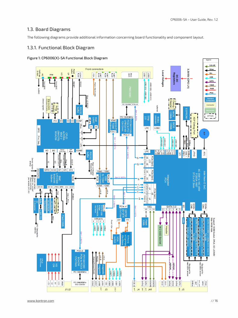
The following diagrams provide additional information concerning board functionality and component layout.
1.3.1. Functional Block Diagram
Figure 1: CP6006(X)-SA Functional Block Diagram
CP6006-SA – User Guide, Rev. 1.2
www.kontron.com // 17
1.3.2. Front Panel
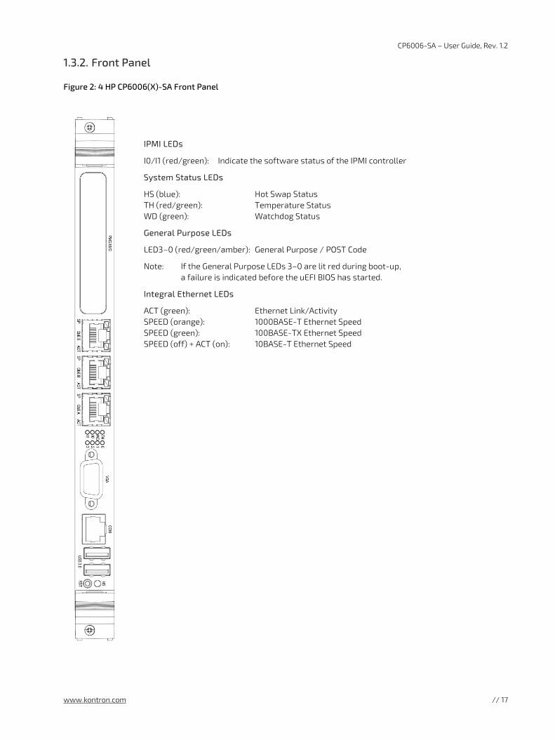
Figure 2: 4 HP CP6006(X)-SA Front Panel
IPMI LEDs
I0/I1 (red/green): Indicate the software status of the IPMI controller
System Status LEDs
HS (blue): Hot Swap Status TH (red/green): Temperature Status WD (green): Watchdog Status
General Purpose LEDs
LED3–0 (red/green/amber): General Purpose / POST Code
Note: If the General Purpose LEDs 3–0 are lit red during boot-up, a failure is indicated before the uEFI BIOS has started.
Integral Ethernet LEDs
ACT (green): Ethernet Link/Activity SPEED (orange): 1000BASE-T Ethernet Speed SPEED (green): 100BASE-TX Ethernet Speed SPEED (off) + ACT (on): 10BASE-T Ethernet Speed
CP6006-SA – User Guide, Rev. 1.2
www.kontron.com // 18
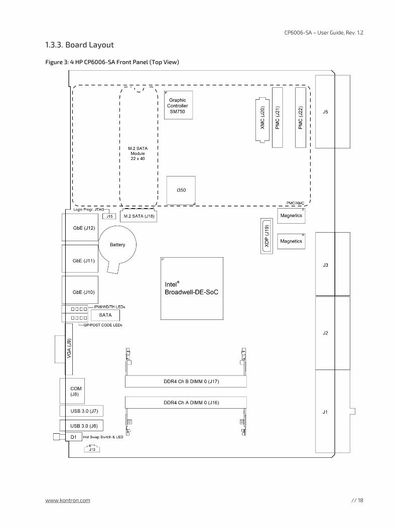
1.3.3. Board Layout
Figure 3: 4 HP CP6006-SA Front Panel (Top View)
CP6006-SA – User Guide, Rev. 1.2
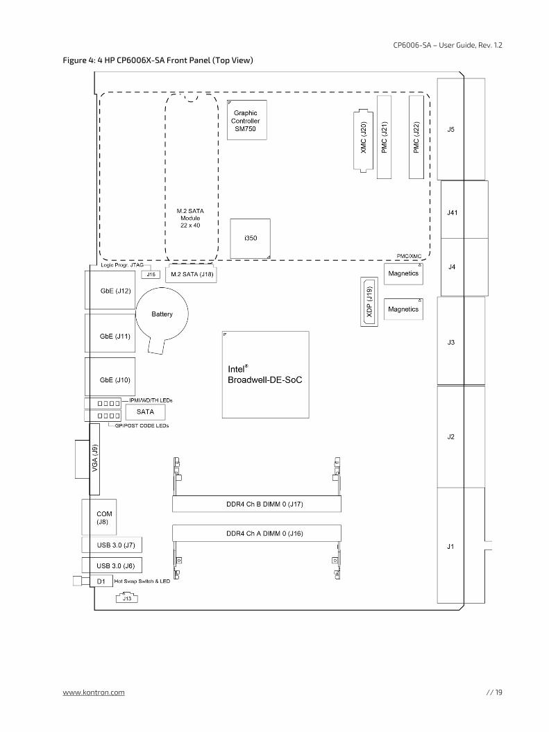
www.kontron.com // 19
Figure 4: 4 HP CP6006X-SA Front Panel (Top View)
CP6006-SA – User Guide, Rev. 1.2
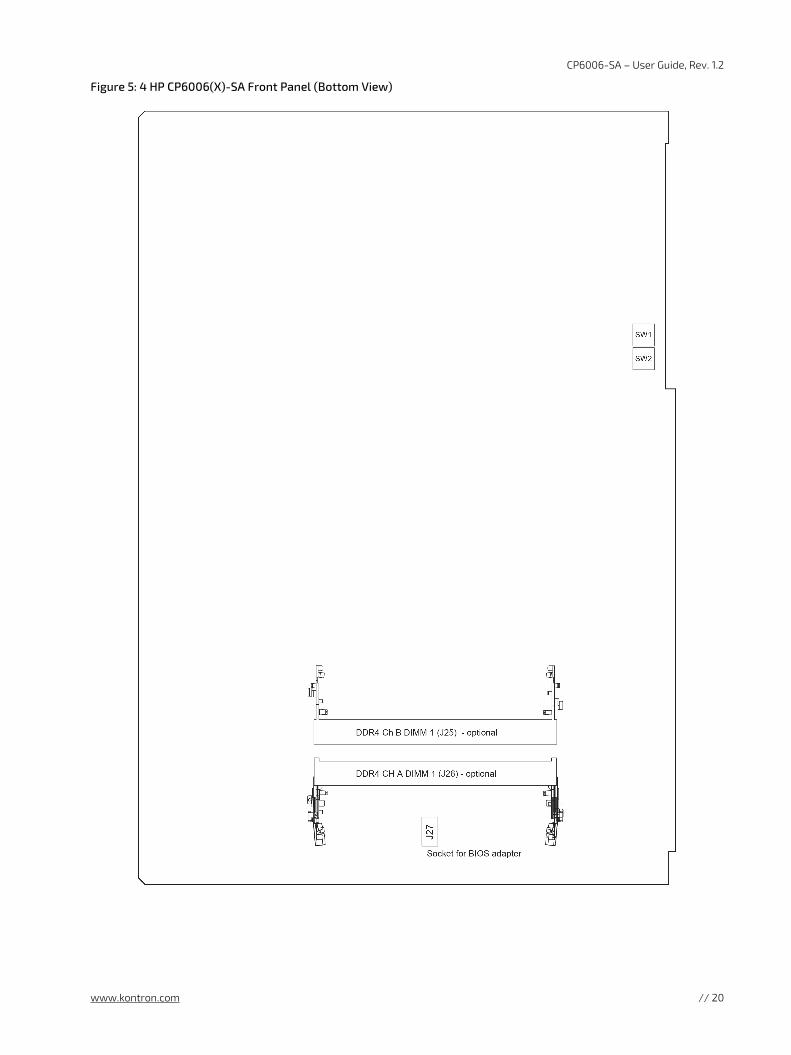
www.kontron.com // 20
Figure 5: 4 HP CP6006(X)-SA Front Panel (Bottom View)
CP6006-SA – User Guide, Rev. 1.2
www.kontron.com // 21
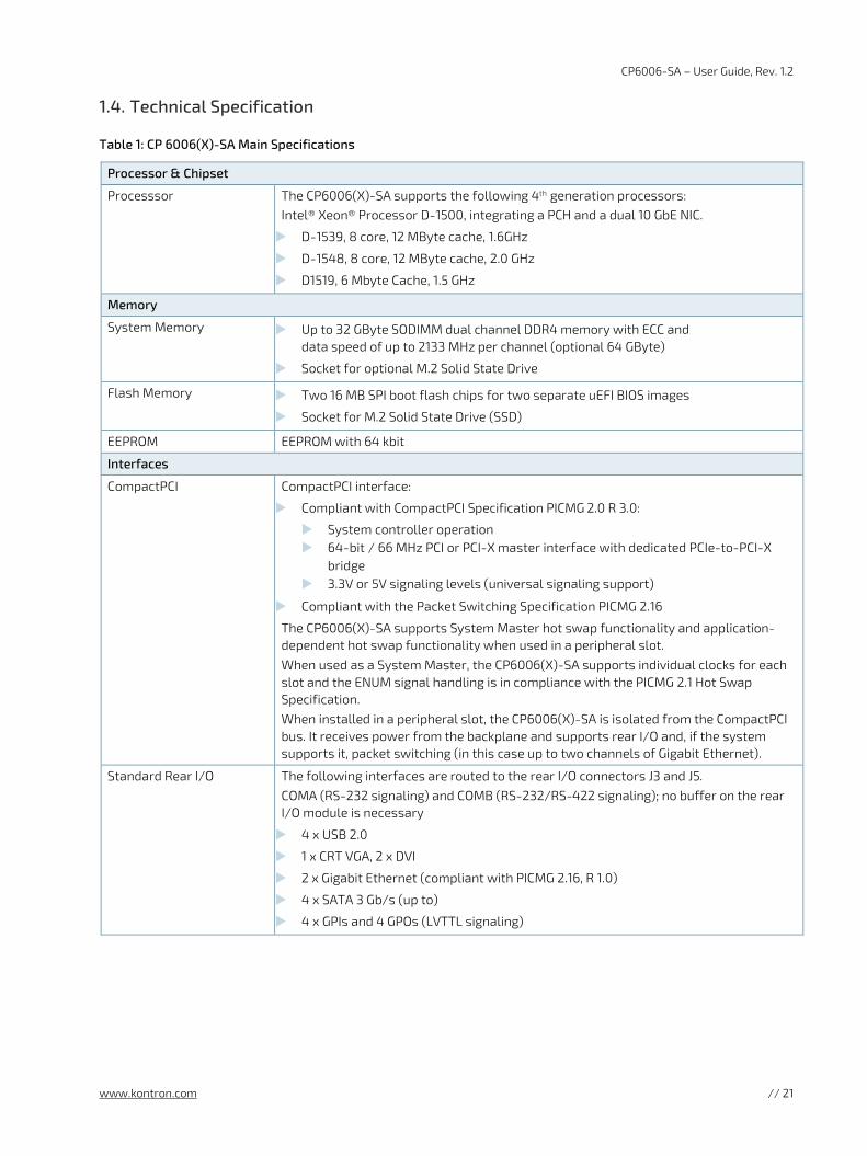
1.4. Technical Specification
Table 1: CP 6006(X)-SA Main Specifications
Processor & Chipset
Processsor The CP6006(X)-SA supports the following 4th generation processors: Intel® Xeon® Processor D-1500, integrating a PCH and a dual 10 GbE NIC.
D-1539, 8 core, 12 MByte cache, 1.6GHz
D-1548, 8 core, 12 MByte cache, 2.0 GHz
D1519, 6 Mbyte Cache, 1.5 GHz
Memory
System Memory Up to 32 GByte SODIMM dual channel DDR4 memory with ECC and data speed of up to 2133 MHz per channel (optional 64 GByte)
Socket for optional M.2 Solid State Drive
Flash Memory Two 16 MB SPI boot flash chips for two separate uEFI BIOS images
Socket for M.2 Solid State Drive (SSD)
EEPROM EEPROM with 64 kbit
Interfaces
CompactPCI CompactPCI interface:
Compliant with CompactPCI Specification PICMG 2.0 R 3.0:
System controller operation 64-bit / 66 MHz PCI or PCI-X master interface with dedicated PCIe-to-PCI-X
bridge 3.3V or 5V signaling levels (universal signaling support)
Compliant with the Packet Switching Specification PICMG 2.16
The CP6006(X)-SA supports System Master hot swap functionality and application-dependent hot swap functionality when used in a peripheral slot.
When used as a System Master, the CP6006(X)-SA supports individual clocks for each slot and the ENUM signal handling is in compliance with the PICMG 2.1 Hot Swap Specification. When installed in a peripheral slot, the CP6006(X)-SA is isolated from the CompactPCI bus. It receives power from the backplane and supports rear I/O and, if the system supports it, packet switching (in this case up to two channels of Gigabit Ethernet).
Standard Rear I/O The following interfaces are routed to the rear I/O connectors J3 and J5. COMA (RS-232 signaling) and COMB (RS-232/RS-422 signaling); no buffer on the rear I/O module is necessary
4 x USB 2.0
1 x CRT VGA, 2 x DVI
2 x Gigabit Ethernet (compliant with PICMG 2.16, R 1.0)
4 x SATA 3 Gb/s (up to)
4 x GPIs and 4 GPOs (LVTTL signaling)
CP6006-SA – User Guide, Rev. 1.2
www.kontron.com // 22
Interfaces
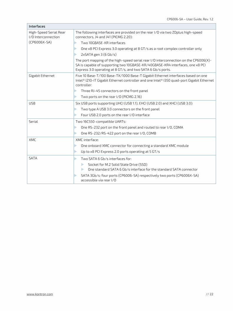
High-Speed Serial Rear I/O Interconnection (CP6006X-SA)
The following interfaces are provided on the rear I/O via two ZDplus high-speed connectors, J4 and J41 (PICMG 2.20):
Two 10GBASE-KR interfaces
One x8 PCI Express 3.0 operating at 8 GT/s as a root complex controller only
2xSATA gen 3 (6 Gb/s)
The port mapping of the high-speed serial rear I/O interconnection on the CP6006(X)-SA is capable of supporting two 10GBASE-KR/40GBASE-KR4 interfaces, one x8 PCI Express 3.0 operating at 8 GT/s, and two SATA 6 Gb/s ports.
Gigabit Ethernet Five 10 Base-T/100 Base-TX/1000 Base-T Gigabit Ethernet interfaces based on one Intel® I210-IT Gigabit Ethernet controller and one Intel® I350 quad-port Gigabit Ethernet controller:
Three RJ-45 connectors on the front panel
Two ports on the rear I/O (PICMG 2.16)
USB Six USB ports supporting UHCI (USB 1.1), EHCI (USB 2.0) and XHCI (USB 3.0):
Two type A USB 3.0 connectors on the front panel
Four USB 2.0 ports on the rear I/O interface
Serial Two 16C550-compatible UARTs:
One RS-232 port on the front panel and routed to rear I/O, COMA
One RS-232/RS-422 port on the rear I/O, COMB
XMC XMC interface:
One onboard XMC connector for connecting a standard XMC module
Up to x8 PCI Express 2.0 ports operating at 5 GT/s
SATA Two SATA 6 Gb/s interfaces for:
Socket for M.2 Solid State Drive (SSD) One standard SATA 6 Gb/s interface for the standard SATA connector
SATA 3Gb/s: four ports (CP6006-SA) respectively two ports (CP6006X-SA) accessible via rear I/O
CP6006-SA – User Guide, Rev. 1.2
www.kontron.com // 23
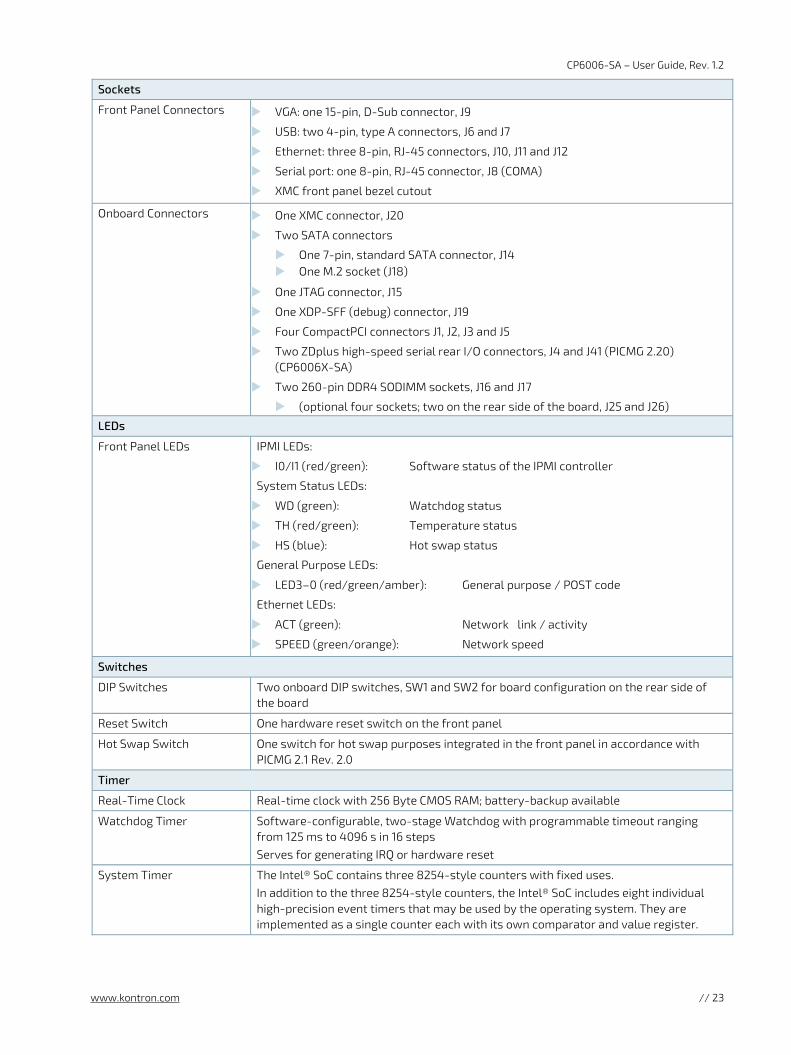
Sockets
Front Panel Connectors VGA: one 15-pin, D-Sub connector, J9
USB: two 4-pin, type A connectors, J6 and J7
Ethernet: three 8-pin, RJ-45 connectors, J10, J11 and J12
Serial port: one 8-pin, RJ-45 connector, J8 (COMA)
XMC front panel bezel cutout
Onboard Connectors One XMC connector, J20
Two SATA connectors
One 7-pin, standard SATA connector, J14 One M.2 socket (J18)
One JTAG connector, J15
One XDP-SFF (debug) connector, J19
Four CompactPCI connectors J1, J2, J3 and J5
Two ZDplus high-speed serial rear I/O connectors, J4 and J41 (PICMG 2.20) (CP6006X-SA)
Two 260-pin DDR4 SODIMM sockets, J16 and J17
(optional four sockets; two on the rear side of the board, J25 and J26)
LEDs
Front Panel LEDs IPMI LEDs:
I0/I1 (red/green): Software status of the IPMI controller
System Status LEDs:
WD (green): Watchdog status
TH (red/green): Temperature status
HS (blue): Hot swap status
General Purpose LEDs:
LED3–0 (red/green/amber): General purpose / POST code
Ethernet LEDs:
ACT (green): Network link / activity
SPEED (green/orange): Network speed
Switches
DIP Switches Two onboard DIP switches, SW1 and SW2 for board configuration on the rear side of the board
Reset Switch One hardware reset switch on the front panel
Hot Swap Switch One switch for hot swap purposes integrated in the front panel in accordance with PICMG 2.1 Rev. 2.0
Timer
Real-Time Clock Real-time clock with 256 Byte CMOS RAM; battery-backup available
Watchdog Timer Software-configurable, two-stage Watchdog with programmable timeout ranging from 125 ms to 4096 s in 16 steps Serves for generating IRQ or hardware reset
System Timer The Intel® SoC contains three 8254-style counters with fixed uses. In addition to the three 8254-style counters, the Intel® SoC includes eight individual high-precision event timers that may be used by the operating system. They are implemented as a single counter each with its own comparator and value register.
CP6006-SA – User Guide, Rev. 1.2
www.kontron.com // 24
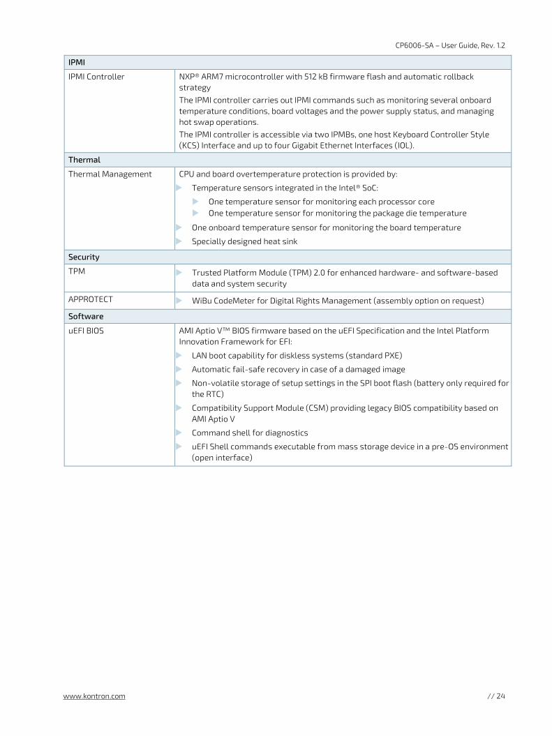
IPMI
IPMI Controller NXP® ARM7 microcontroller with 512 kB firmware flash and automatic rollback strategy
The IPMI controller carries out IPMI commands such as monitoring several onboard temperature conditions, board voltages and the power supply status, and managing hot swap operations. The IPMI controller is accessible via two IPMBs, one host Keyboard Controller Style (KCS) Interface and up to four Gigabit Ethernet Interfaces (IOL).
Thermal
Thermal Management CPU and board overtemperature protection is provided by:
Temperature sensors integrated in the Intel® SoC:
One temperature sensor for monitoring each processor core One temperature sensor for monitoring the package die temperature
One onboard temperature sensor for monitoring the board temperature
Specially designed heat sink
Security
TPM Trusted Platform Module (TPM) 2.0 for enhanced hardware- and software-based data and system security
APPROTECT WiBu CodeMeter for Digital Rights Management (assembly option on request)
Software
uEFI BIOS AMI Aptio V™ BIOS firmware based on the uEFI Specification and the Intel Platform Innovation Framework for EFI:
LAN boot capability for diskless systems (standard PXE)
Automatic fail-safe recovery in case of a damaged image
Non-volatile storage of setup settings in the SPI boot flash (battery only required for the RTC)
Compatibility Support Module (CSM) providing legacy BIOS compatibility based on AMI Aptio V
Command shell for diagnostics
uEFI Shell commands executable from mass storage device in a pre-OS environment (open interface)
CP6006-SA – User Guide, Rev. 1.2
www.kontron.com // 25
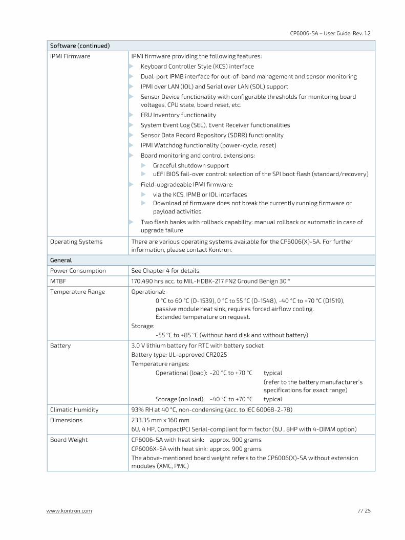
Software (continued)
IPMI Firmware IPMI firmware providing the following features:
Keyboard Controller Style (KCS) interface
Dual-port IPMB interface for out-of-band management and sensor monitoring
IPMI over LAN (IOL) and Serial over LAN (SOL) support
Sensor Device functionality with configurable thresholds for monitoring board voltages, CPU state, board reset, etc.
FRU Inventory functionality
System Event Log (SEL), Event Receiver functionalities
Sensor Data Record Repository (SDRR) functionality
IPMI Watchdog functionality (power-cycle, reset)
Board monitoring and control extensions:
Graceful shutdown support uEFI BIOS fail-over control: selection of the SPI boot flash (standard/recovery)
Field-upgradeable IPMI firmware:
via the KCS, IPMB or IOL interfaces Download of firmware does not break the currently running firmware or
payload activities
Two flash banks with rollback capability: manual rollback or automatic in case of upgrade failure
Operating Systems There are various operating systems available for the CP6006(X)-SA. For further information, please contact Kontron.
General
Power Consumption See Chapter 4 for details.
MTBF 170,490 hrs acc. to MIL-HDBK-217 FN2 Ground Benign 30 °
Temperature Range Operational: 0 °C to 60 °C (D-1539), 0 °C to 55 °C (D-1548), -40 °C to +70 °C (D1519), passive module heat sink, requires forced airflow cooling. Extended temperature on request. Storage: -55 °C to +85 °C (without hard disk and without battery)
Battery 3.0 V lithium battery for RTC with battery socket Battery type: UL-approved CR2025 Temperature ranges: Operational (load): -20 °C to +70 °C typical
(refer to the battery manufacturer’s specifications for exact range) Storage (no load): -40 °C to +70 °C typical
Climatic Humidity 93% RH at 40 °C, non-condensing (acc. to IEC 60068-2-78)
Dimensions 233.35 mm x 160 mm 6U, 4 HP, CompactPCI Serial-compliant form factor (6U , 8HP with 4-DIMM option)
Board Weight CP6006-SA with heat sink: approx. 900 grams CP6006X-SA with heat sink: approx. 900 grams The above-mentioned board weight refers to the CP6006(X)-SA without extension modules (XMC, PMC)
CP6006-SA – User Guide, Rev. 1.2
www.kontron.com // 26
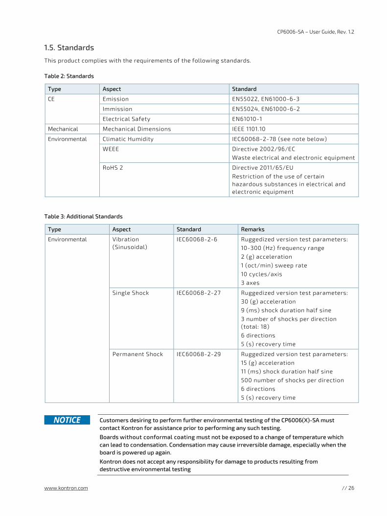
1.5. Standards
This product complies with the requirements of the following standards.
Table 2: Standards
Type Aspect Standard
CE Emission EN55022, EN61000-6-3
Immission EN55024, EN61000-6-2
Electrical Safety EN61010-1
Mechanical Mechanical Dimensions IEEE 1101.10
Environmental Climatic Humidity IEC60068-2-78 (see note below)
WEEE Directive 2002/96/EC Waste electrical and electronic equipment
RoHS 2 Directive 2011/65/EU Restriction of the use of certain hazardous substances in electrical and electronic equipment
Table 3: Additional Standards
Type Aspect Standard Remarks
Environmental Vibration (Sinusoidal)
IEC60068-2-6 Ruggedized version test parameters: 10-300 (Hz) frequency range 2 (g) acceleration 1 (oct/min) sweep rate 10 cycles/axis 3 axes
Single Shock IEC60068-2-27 Ruggedized version test parameters: 30 (g) acceleration 9 (ms) shock duration half sine 3 number of shocks per direction (total: 18) 6 directions 5 (s) recovery time
Permanent Shock IEC60068-2-29 Ruggedized version test parameters: 15 (g) acceleration 11 (ms) shock duration half sine 500 number of shocks per direction 6 directions 5 (s) recovery time
Customers desiring to perform further environmental testing of the CP6006(X)-SA must
contact Kontron for assistance prior to performing any such testing.
Boards without conformal coating must not be exposed to a change of temperature which can lead to condensation. Condensation may cause irreversible damage, especially when the board is powered up again.
Kontron does not accept any responsibility for damage to products resulting from destructive environmental testing
CP6006-SA – User Guide, Rev. 1.2
www.kontron.com // 27
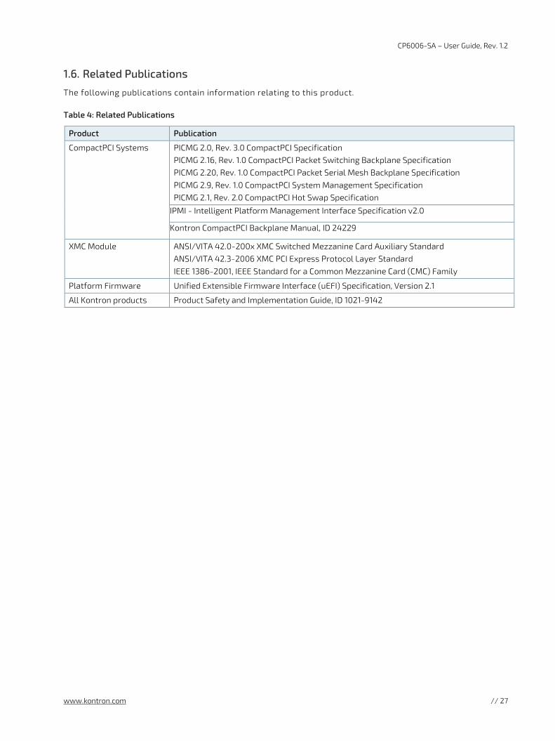
1.6. Related Publications
The following publications contain information relating to this product.
Table 4: Related Publications
Product Publication
CompactPCI Systems PICMG 2.0, Rev. 3.0 CompactPCI Specification PICMG 2.16, Rev. 1.0 CompactPCI Packet Switching Backplane Specification PICMG 2.20, Rev. 1.0 CompactPCI Packet Serial Mesh Backplane Specification PICMG 2.9, Rev. 1.0 CompactPCI System Management Specification PICMG 2.1, Rev. 2.0 CompactPCI Hot Swap Specification
IPMI - Intelligent Platform Management Interface Specification v2.0
Kontron CompactPCI Backplane Manual, ID 24229
XMC Module ANSI/VITA 42.0-200x XMC Switched Mezzanine Card Auxiliary Standard ANSI/VITA 42.3-2006 XMC PCI Express Protocol Layer Standard IEEE 1386-2001, IEEE Standard for a Common Mezzanine Card (CMC) Family
Platform Firmware Unified Extensible Firmware Interface (uEFI) Specification, Version 2.1
All Kontron products Product Safety and Implementation Guide, ID 1021-9142
CP6006-SA – User Guide, Rev. 1.2
www.kontron.com // 28
2/ Functional Description
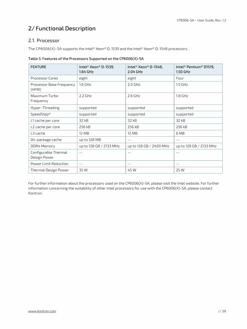
2.1. Processor
The CP6006(X)-SA supports the Intel® Xeon® D-1539 and the Intel® Xeon® D-1548 processors.
Table 5: Features of the Processors Supported on the CP6006(X)-SA
FEATURE Intel® Xeon® D-1539, 1.64 GHz
Intel® Xeon® D-1548, 2.04 GHz
Intel® Pentium® D1519, 1.50 GHz
Processor Cores eight eight Four
Processor Base Frequency (HFM)
1.6 GHz 2.0 GHz 1.5 GHz
Maximum Turbo Frequency
2.2 GHz 2.6 GHz
1.8 GHz
Hyper-Threading supported supported supported
SpeedStep® supported supported supported
L1 cache per core 32 kB 32 kB 32 kB
L2 cache per core 256 kB 256 kB 256 kB
L3 cache 12 MB 12 MB 6 MB
On-package cache up to 128 MB -- --
DDR4 Memory up to 128 GB / 2133 MHz up to 128 GB / 2400 MHz up to 128 GB / 2133 MHz
Configurable Thermal Design Power
-- -- --
Power Limit Reduction -- -- --
Thermal Design Power 35 W 45 W 25 W
For further information about the processors used on the CP6006(X)-SA, please visit the Intel website. For further information concerning the suitability of other Intel processors for use with the CP6006(X)-SA, please contact Kontron.
CP6006-SA – User Guide, Rev. 1.2
www.kontron.com // 29
2.1.1. Graphics Controller
CP6006-SA provides a low-power graphic controller, SM750 LynxExp with video and 2D capability. It supports two independent display interfaces with a maximum resolution of 1920x1440 pixels.
One of the graphic ports of the SM750 is for the DVI1 port at the rear IO, the second port is a switched between: VGA front or VGA rear or DVI2 rear, which is user selectable via uEFI Shell kboardconfig Graphic command. The default setting is forced front VGA.
Video switch logic uses monitor presence detection. In case Kboardconfig Graphic is set to Auto, DVI2 rear is first choice, VGA front is second choice followed by VGA rear. Selection of Front, Rear or DVI2 forces the use of respective video-output.
2.2. Memory
The CP6006(X)-SA supports a dual-channel (72-bit) DDR4 SDRAM memory with Error Checking and Correcting (ECC) running at 2133 MHz. It provides two (optional: 4) 260-pin sockets for two DDR4 (optional: 4) ECC SODIMM modules that support up to 32 GB (optional: 64GB) system memory. The maximum memory size per slot is 16 GB.
The available memory module configuration can be either 16 GB, 32 GB (optional: 64GB).
Only qualified DDR4 ECC SODIMM modules from Kontron are authorized for use with the
CP6006(X)-SA. Replacement of the SODIMM modules by the customer without authorization from Kontron will void the warranty.
2.3. Watchdog Timer
The CP6006(X)-SA provides a Watchdog timer that is programmable for a timeout period ranging from 125 ms to 4096 s in 16 steps.
The Watchdog timer provides the following modes or operation:
Timer-only mode
Reset mode
Interrupt mode
Dual-stage mode
In dual-stage mode, a combination of both interrupt and reset is generated if the Watchdog is not serviced.
2.4. Battery
The CP6006(X)-SA is provided with an UL-approved CR2025, 3.0 V, “coin cell” lithium battery for the RTC. When a battery is installed, refer to the operational specifications of the battery as this determines the storage temperature of the CP6006(X)-SA.
CP6006-SA – User Guide, Rev. 1.2
www.kontron.com // 30
2.5. Flash Memory
The CP6006(X)-SA provides flash interfaces for the uEFI BIOS and a M.2 Flash module.
2.5.1. SPI Boot Flash for uEFI BIOS
The CP6006(X)-SA provides two 16 MB SPI boot flashes for two separate uEFI BIOS images, a standard SPI boot flash and a recovery SPI boot flash. The fail-over mechanism for the uEFI BIOS recovery can be controlled via the DIP switch SW1, switch 2.
The uEFI BIOS code and settings are stored in the SPI boot flashes. Changes made to the uEFI
BIOS settings are available only in the currently selected SPI boot flash. Thus, switching over to the other SPI boot flash may result in operation with different uEFI BIOS code and settings. Switching flashes while ME is in full operating mode could result in malfunction.
2.5.2. M.2 Flash Module
The M.2 connector (Type 2280) can be used for a SSD flash module for operating system and data.
CP6006-SA – User Guide, Rev. 1.2
www.kontron.com // 31
2.6. Security Options
2.6.1. Trusted Platform Module 2.0
The CP6006(X)-SA supports the Trusted Platform Module (TPM) 2.0, conceived by TCG (Trusted Computing Group). TPM2.0 is a security chip specifically designed to provide enhanced hardware- and software-based data and system security. TPM2.0 is based on the Infineon SLB9665XT 2.0 security controller and stores sensitive data such as encryption and signature keys, certificates and passwords, and is able to withstand software attacks to protect the stored information.
2.6.2. Kontron APPROTECT
A fully protected framework for your application
Kontron APPROTECT is a combined hardware and software solution that includes an embedded hardware security chip on CP6006, in addition to the TPM 2.0 (Trusted Platform Module) chip, and a software framework, in order to provide comprehensive protection for your application software.
Kontron APPROTECT encrypts an application's source code in a way that makes reverse engineering impossible (IP Protection/Reverse Engineering Protection). Features include:
Copy protection
IP Protection
Protection from reverse engineering and tampering
In addition, Kontron’s APPROTECT Licensing enables new business models such as pay per use, time based trial versions, or enable/disable features. Kontron APPROTECT Licensing additionally adds:
Enablement of new business models by offering SDKs and software integration
Based on time base, by counting executions or by enabling/disabling features
Software management framework
After purchasing Kontron APPROTECT, a new firmware code for the security chip will be provided that can be installed by Kontron or by the customer.
For more details, please consult the product information and datasheet to “Kontron APPROTECT”.
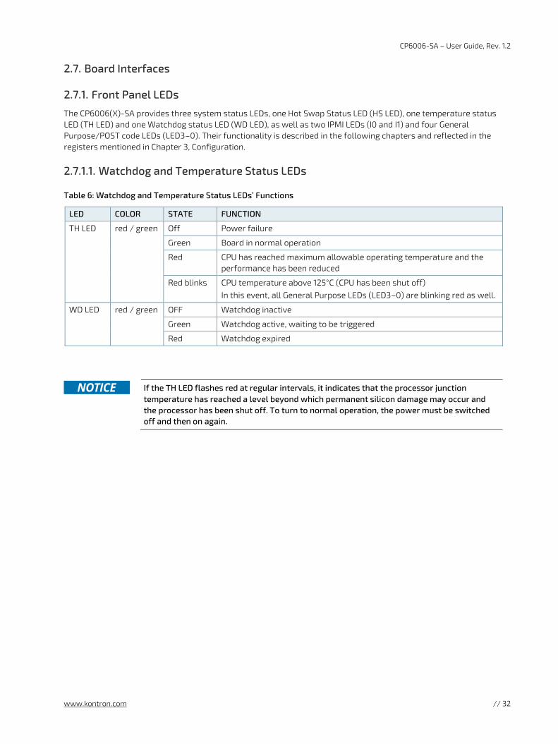
CP6006-SA – User Guide, Rev. 1.2
www.kontron.com // 32
2.7. Board Interfaces
2.7.1. Front Panel LEDs
The CP6006(X)-SA provides three system status LEDs, one Hot Swap Status LED (HS LED), one temperature status LED (TH LED) and one Watchdog status LED (WD LED), as well as two IPMI LEDs (I0 and I1) and four General Purpose/POST code LEDs (LED3–0). Their functionality is described in the following chapters and reflected in the registers mentioned in Chapter 3, Configuration.
2.7.1.1. Watchdog and Temperature Status LEDs
Table 6: Watchdog and Temperature Status LEDs’ Functions
LED COLOR STATE FUNCTION
TH LED red / green Off Power failure
Green Board in normal operation
Red CPU has reached maximum allowable operating temperature and the performance has been reduced
Red blinks CPU temperature above 125°C (CPU has been shut off) In this event, all General Purpose LEDs (LED3–0) are blinking red as well.
WD LED red / green OFF Watchdog inactive
Green Watchdog active, waiting to be triggered
Red Watchdog expired
If the TH LED flashes red at regular intervals, it indicates that the processor junction
temperature has reached a level beyond which permanent silicon damage may occur and the processor has been shut off. To turn to normal operation, the power must be switched off and then on again.
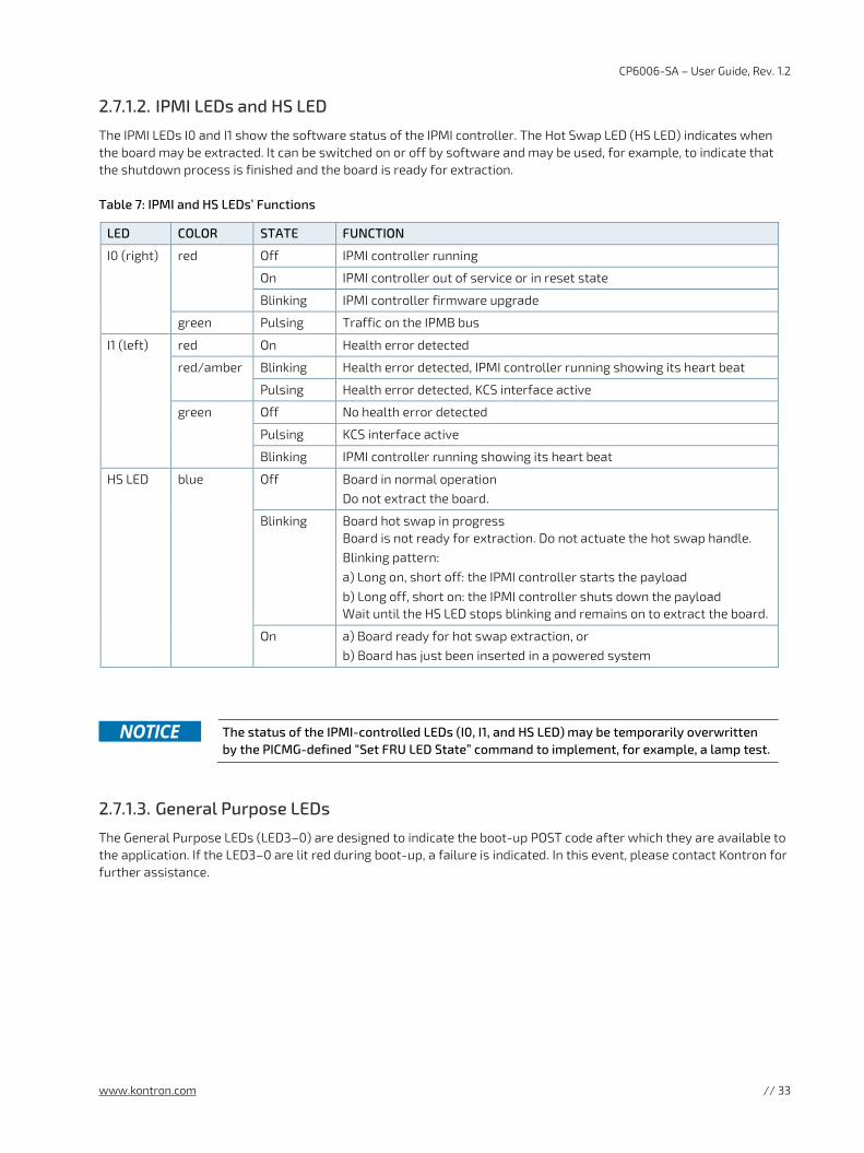
CP6006-SA – User Guide, Rev. 1.2
www.kontron.com // 33
2.7.1.2. IPMI LEDs and HS LED
The IPMI LEDs I0 and I1 show the software status of the IPMI controller. The Hot Swap LED (HS LED) indicates when the board may be extracted. It can be switched on or off by software and may be used, for example, to indicate that the shutdown process is finished and the board is ready for extraction.
Table 7: IPMI and HS LEDs’ Functions
LED COLOR STATE FUNCTION
I0 (right) red Off IPMI controller running
On IPMI controller out of service or in reset state
Blinking IPMI controller firmware upgrade
green Pulsing Traffic on the IPMB bus
I1 (left) red On Health error detected
red/amber Blinking Health error detected, IPMI controller running showing its heart beat
Pulsing Health error detected, KCS interface active
green Off No health error detected
Pulsing KCS interface active
Blinking IPMI controller running showing its heart beat
HS LED blue Off Board in normal operation Do not extract the board.
Blinking Board hot swap in progress Board is not ready for extraction. Do not actuate the hot swap handle. Blinking pattern: a) Long on, short off: the IPMI controller starts the payload b) Long off, short on: the IPMI controller shuts down the payload Wait until the HS LED stops blinking and remains on to extract the board.
On a) Board ready for hot swap extraction, or b) Board has just been inserted in a powered system
The status of the IPMI-controlled LEDs (I0, I1, and HS LED) may be temporarily overwritten
by the PICMG-defined “Set FRU LED State” command to implement, for example, a lamp test.
2.7.1.3. General Purpose LEDs
The General Purpose LEDs (LED3–0) are designed to indicate the boot-up POST code after which they are available to the application. If the LED3–0 are lit red during boot-up, a failure is indicated. In this event, please contact Kontron for further assistance.
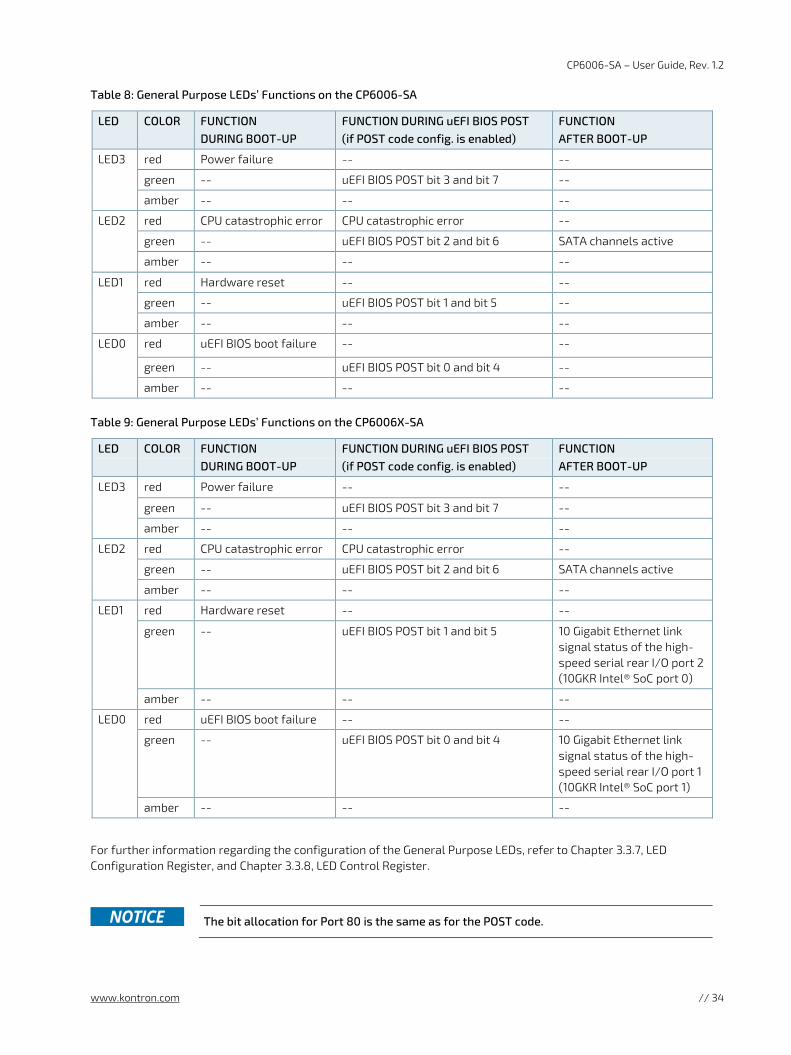
CP6006-SA – User Guide, Rev. 1.2
www.kontron.com // 34
Table 8: General Purpose LEDs’ Functions on the CP6006-SA
LED COLOR FUNCTION DURING BOOT-UP
FUNCTION DURING uEFI BIOS POST (if POST code config. is enabled)
FUNCTION AFTER BOOT-UP
LED3 red Power failure -- --
green -- uEFI BIOS POST bit 3 and bit 7 --
amber -- -- --
LED2 red CPU catastrophic error CPU catastrophic error --
green -- uEFI BIOS POST bit 2 and bit 6 SATA channels active
amber -- -- --
LED1 red Hardware reset -- --
green -- uEFI BIOS POST bit 1 and bit 5 --
amber -- -- --
LED0 red uEFI BIOS boot failure -- --
green -- uEFI BIOS POST bit 0 and bit 4 --
amber -- -- --
Table 9: General Purpose LEDs’ Functions on the CP6006X-SA
LED COLOR FUNCTION DURING BOOT-UP
FUNCTION DURING uEFI BIOS POST (if POST code config. is enabled)
FUNCTION AFTER BOOT-UP
LED3 red Power failure -- --
green -- uEFI BIOS POST bit 3 and bit 7 --
amber -- -- --
LED2 red CPU catastrophic error CPU catastrophic error --
green -- uEFI BIOS POST bit 2 and bit 6 SATA channels active
amber -- -- --
LED1 red Hardware reset -- --
green -- uEFI BIOS POST bit 1 and bit 5 10 Gigabit Ethernet link signal status of the high-speed serial rear I/O port 2 (10GKR Intel® SoC port 0)
amber -- -- --
LED0 red uEFI BIOS boot failure -- --
green -- uEFI BIOS POST bit 0 and bit 4 10 Gigabit Ethernet link signal status of the high-speed serial rear I/O port 1 (10GKR Intel® SoC port 1)
amber -- -- --
For further information regarding the configuration of the General Purpose LEDs, refer to Chapter 3.3.7, LED Configuration Register, and Chapter 3.3.8, LED Control Register.
The bit allocation for Port 80 is the same as for the POST code.
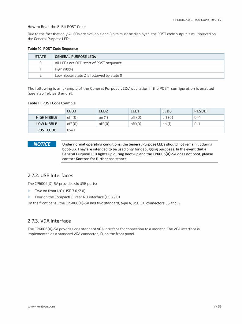
CP6006-SA – User Guide, Rev. 1.2
www.kontron.com // 35
How to Read the 8-Bit POST Code
Due to the fact that only 4 LEDs are available and 8 bits must be displayed, the POST code output is multiplexed on the General Purpose LEDs.
Table 10: POST Code Sequence
STATE GENERAL PURPOSE LEDs
0 All LEDs are OFF; start of POST sequence
1 High nibble
2 Low nibble; state 2 is followed by state 0
The following is an example of the General Purpose LEDs’ operation if the POST configuration is enabled (see also Tables 8 and 9).
Table 11: POST Code Example
LED3 LED2 LED1 LED0 RESULT
HIGH NIBBLE off (0) on (1) off (0) off (0) 0x4
LOW NIBBLE off (0) off (0) off (0) on (1) 0x1
POST CODE 0x41
Under normal operating conditions, the General Purpose LEDs should not remain lit during
boot-up. They are intended to be used only for debugging purposes. In the event that a General Purpose LED lights up during boot-up and the CP6006(X)-SA does not boot, please contact Kontron for further assistance.
2.7.2. USB Interfaces
The CP6006(X)-SA provides six USB ports:
Two on front I/O (USB 3.0/2.0)
Four on the CompactPCI rear I/O interface (USB 2.0)
On the front panel, the CP6006(X)-SA has two standard, type A, USB 3.0 connectors, J6 and J7.
2.7.3. VGA Interface
The CP6006(X)-SA provides one standard VGA interface for connection to a monitor. The VGA interface is implemented as a standard VGA connector, J9, on the front panel.
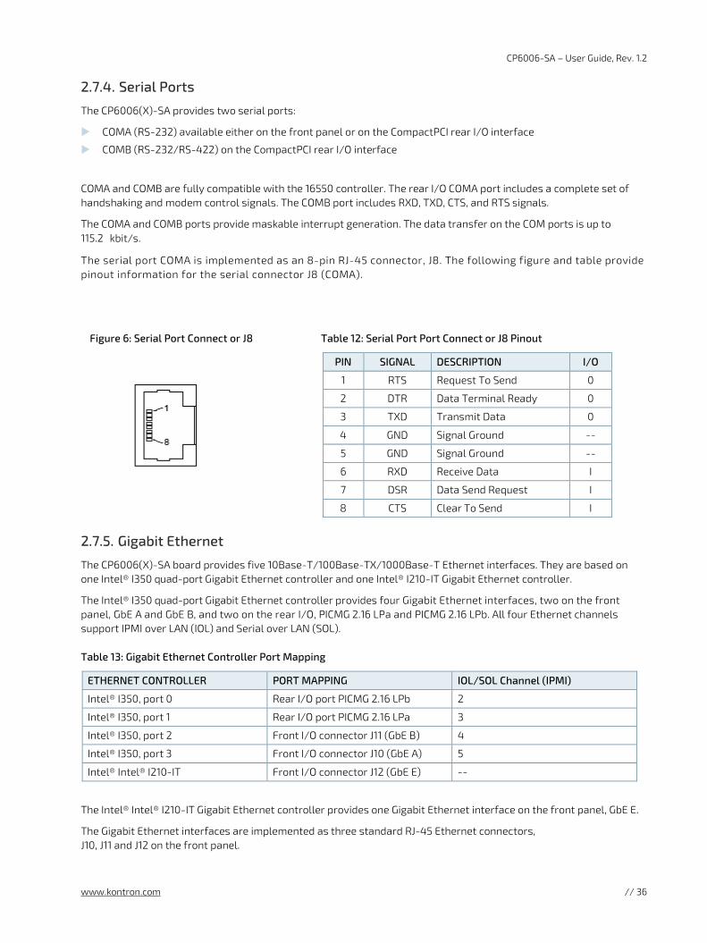
CP6006-SA – User Guide, Rev. 1.2
www.kontron.com // 36
2.7.4. Serial Ports
The CP6006(X)-SA provides two serial ports:
COMA (RS-232) available either on the front panel or on the CompactPCI rear I/O interface
COMB (RS-232/RS-422) on the CompactPCI rear I/O interface
COMA and COMB are fully compatible with the 16550 controller. The rear I/O COMA port includes a complete set of handshaking and modem control signals. The COMB port includes RXD, TXD, CTS, and RTS signals.
The COMA and COMB ports provide maskable interrupt generation. The data transfer on the COM ports is up to 115.2 kbit/s.
The serial port COMA is implemented as an 8-pin RJ-45 connector, J8. The following figure and table provide pinout information for the serial connector J8 (COMA).
Figure 6: Serial Port Connect or J8
Table 12: Serial Port Port Connect or J8 Pinout
PIN SIGNAL DESCRIPTION I/O
1 RTS Request To Send 0
2 DTR Data Terminal Ready 0
3 TXD Transmit Data 0
4 GND Signal Ground --
5 GND Signal Ground --
6 RXD Receive Data I
7 DSR Data Send Request I
8 CTS Clear To Send I
2.7.5. Gigabit Ethernet
The CP6006(X)-SA board provides five 10Base-T/100Base-TX/1000Base-T Ethernet interfaces. They are based on one Intel® I350 quad-port Gigabit Ethernet controller and one Intel® I210-IT Gigabit Ethernet controller.
The Intel® I350 quad-port Gigabit Ethernet controller provides four Gigabit Ethernet interfaces, two on the front panel, GbE A and GbE B, and two on the rear I/O, PICMG 2.16 LPa and PICMG 2.16 LPb. All four Ethernet channels support IPMI over LAN (IOL) and Serial over LAN (SOL).
Table 13: Gigabit Ethernet Controller Port Mapping
ETHERNET CONTROLLER PORT MAPPING IOL/SOL Channel (IPMI)
Intel® I350, port 0 Rear I/O port PICMG 2.16 LPb 2
Intel® I350, port 1 Rear I/O port PICMG 2.16 LPa 3
Intel® I350, port 2 Front I/O connector J11 (GbE B) 4
Intel® I350, port 3 Front I/O connector J10 (GbE A) 5
Intel® Intel® I210-IT Front I/O connector J12 (GbE E) --
The Intel® Intel® I210-IT Gigabit Ethernet controller provides one Gigabit Ethernet interface on the front panel, GbE E.
The Gigabit Ethernet interfaces are implemented as three standard RJ-45 Ethernet connectors, J10, J11 and J12 on the front panel.
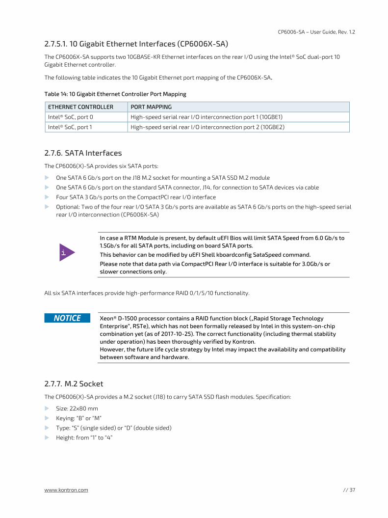
CP6006-SA – User Guide, Rev. 1.2
www.kontron.com // 37
2.7.5.1. 10 Gigabit Ethernet Interfaces (CP6006X-SA)
The CP6006X-SA supports two 10GBASE-KR Ethernet interfaces on the rear I/O using the Intel® SoC dual-port 10 Gigabit Ethernet controller.
The following table indicates the 10 Gigabit Ethernet port mapping of the CP6006X-SA.
Table 14: 10 Gigabit Ethernet Controller Port Mapping
ETHERNET CONTROLLER PORT MAPPING
Intel® SoC, port 0 High-speed serial rear I/O interconnection port 1 (10GBE1)
Intel® SoC, port 1 High-speed serial rear I/O interconnection port 2 (10GBE2)
2.7.6. SATA Interfaces
The CP6006(X)-SA provides six SATA ports:
One SATA 6 Gb/s port on the J18 M.2 socket for mounting a SATA SSD M.2 module
One SATA 6 Gb/s port on the standard SATA connector, J14, for connection to SATA devices via cable
Four SATA 3 Gb/s ports on the CompactPCI rear I/O interface
Optional: Two of the four rear I/O SATA 3 Gb/s ports are available as SATA 6 Gb/s ports on the high-speed serial rear I/O interconnection (CP6006X-SA)
In case a RTM Module is present, by default uEFI Bios will limit SATA Speed from 6.0 Gb/s to 1.5Gb/s for all SATA ports, including on board SATA ports.
This behavior can be modified by uEFI Shell kboardconfig SataSpeed command.
Please note that data path via CompactPCI Rear I/O interface is suitable for 3.0Gb/s or slower connections only.
All six SATA interfaces provide high-performance RAID 0/1/5/10 functionality.
Xeon® D-1500 processor contains a RAID function block („Rapid Storage Technology
Enterprise“, RSTe), which has not been formally released by Intel in this system-on-chip combination yet (as of 2017-10-25). The correct functionality (including thermal stability under operation) has been thoroughly verified by Kontron. However, the future life cycle strategy by Intel may impact the availability and compatibility between software and hardware.
2.7.7. M.2 Socket
The CP6006(X)-SA provides a M.2 socket (J18) to carry SATA SSD flash modules. Specification:
Size: 22x80 mm
Keying: “B” or “M”
Type: “S” (single sided) or “D” (double sided)
Height: from “1” to “4”
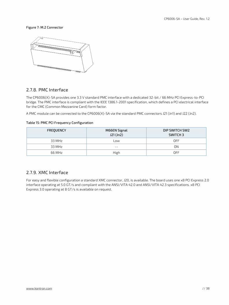
CP6006-SA – User Guide, Rev. 1.2
www.kontron.com // 38
Figure 7: M.2 Connector
2.7.8. PMC Interface
The CP6006(X)-SA provides one 3.3 V standard PMC interface with a dedicated 32-bit / 66 MHz PCI Express-to-PCI bridge. The PMC interface is compliant with the IEEE 1386.1-2001 specification, which defines a PCI electrical interface for the CMC (Common Mezzanine Card) form factor.
A PMC module can be connected to the CP6006(X)-SA via the standard PMC connectors J21 (Jn1) and J22 (Jn2).
Table 15: PMC PCI Frequency Configuration
FREQUENCY M66EN Signal J21 (Jn2)
DIP SWITCH SW2 SWITCH 3
33 MHz Low OFF
33 MHz -- ON
66 MHz High OFF
2.7.9. XMC Interface
For easy and flexible configuration a standard XMC connector, J20, is available. The board uses one x8 PCI Express 2.0 interface operating at 5.0 GT/s and compliant with the ANSI/VITA 42.0 and ANSI/VITA 42.3 specifications. x8 PCI Express 3.0 operating at 8 GT/s is available on request.
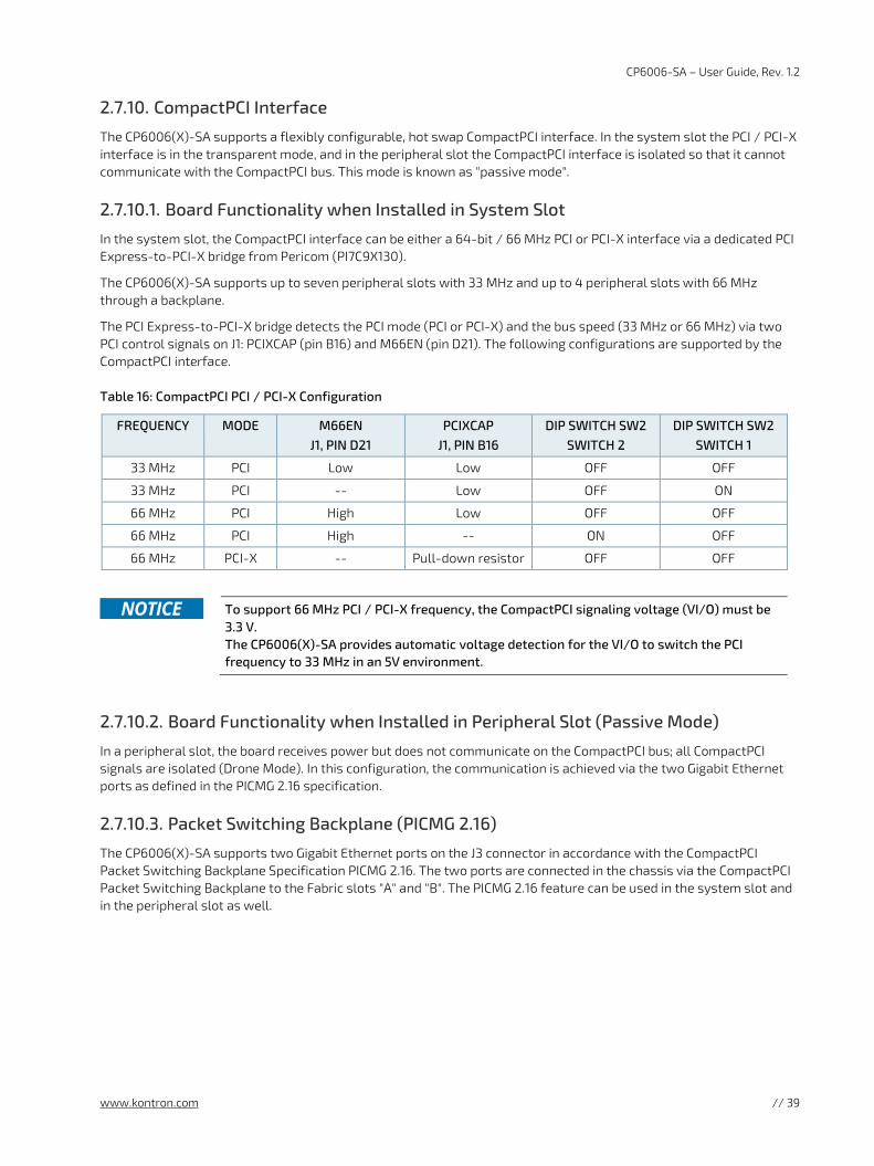
CP6006-SA – User Guide, Rev. 1.2
www.kontron.com // 39
2.7.10. CompactPCI Interface
The CP6006(X)-SA supports a flexibly configurable, hot swap CompactPCI interface. In the system slot the PCI / PCI-X interface is in the transparent mode, and in the peripheral slot the CompactPCI interface is isolated so that it cannot communicate with the CompactPCI bus. This mode is known as "passive mode".
2.7.10.1. Board Functionality when Installed in System Slot
In the system slot, the CompactPCI interface can be either a 64-bit / 66 MHz PCI or PCI-X interface via a dedicated PCI Express-to-PCI-X bridge from Pericom (PI7C9X130).
The CP6006(X)-SA supports up to seven peripheral slots with 33 MHz and up to 4 peripheral slots with 66 MHz through a backplane.
The PCI Express-to-PCI-X bridge detects the PCI mode (PCI or PCI-X) and the bus speed (33 MHz or 66 MHz) via two PCI control signals on J1: PCIXCAP (pin B16) and M66EN (pin D21). The following configurations are supported by the CompactPCI interface.
Table 16: CompactPCI PCI / PCI-X Configuration
FREQUENCY MODE M66EN J1, PIN D21
PCIXCAP J1, PIN B16
DIP SWITCH SW2 SWITCH 2
DIP SWITCH SW2 SWITCH 1
33 MHz PCI Low Low OFF OFF
33 MHz PCI -- Low OFF ON
66 MHz PCI High Low OFF OFF
66 MHz PCI High -- ON OFF
66 MHz PCI-X -- Pull-down resistor OFF OFF
To support 66 MHz PCI / PCI-X frequency, the CompactPCI signaling voltage (VI/O) must be
3.3 V. The CP6006(X)-SA provides automatic voltage detection for the VI/O to switch the PCI frequency to 33 MHz in an 5V environment.
2.7.10.2. Board Functionality when Installed in Peripheral Slot (Passive Mode)
In a peripheral slot, the board receives power but does not communicate on the CompactPCI bus; all CompactPCI signals are isolated (Drone Mode). In this configuration, the communication is achieved via the two Gigabit Ethernet ports as defined in the PICMG 2.16 specification.
2.7.10.3. Packet Switching Backplane (PICMG 2.16)
The CP6006(X)-SA supports two Gigabit Ethernet ports on the J3 connector in accordance with the CompactPCI Packet Switching Backplane Specification PICMG 2.16. The two ports are connected in the chassis via the CompactPCI Packet Switching Backplane to the Fabric slots "A" and "B". The PICMG 2.16 feature can be used in the system slot and in the peripheral slot as well.
CP6006-SA – User Guide, Rev. 1.2
www.kontron.com // 40
2.7.10.4. Hot Swap Support
To ensure that a board may be removed and replaced in a working bus without disturbing the system, the following additional features are required:
Power ramping
Precharge
Hot swap control and status register bits
Automatic interrupt generation whenever a board is about to be removed or replaced
A Hot Swap LED to indicate that the board may be safely removed
2.7.10.5. Power Ramping
On the CP6006(X)-SA a special hot swap controller is used to ramp up the onboard supply voltage. This is done to avoid transients on the +3.3V, +5V, +12V and -12V power supplies from the hot swap system. When the power supply is stable, the hot swap controller generates an onboard reset to put the board into a definite state.
2.7.10.6. Precharge
Precharge is provided on the CP6006(X)-SA by a resistor on each signal line (PCI bus) connected to a +1V reference voltage.
2.7.10.7. Handle Switch
A microswitch is situated in the extractor handle. The status of the handle is included in the onboard logic. The microswitch is connected to the onboard connector J13.
2.7.10.8. ENUM# Interrupt
If the board is operated in the system slot, the ENUM signal is an input.
2.7.10.9. Hot Swap LED
The blue HS LED can be switched on or off by software. It may be used, for example, to indicate that the shutdown process is finished and the board is ready for extraction.
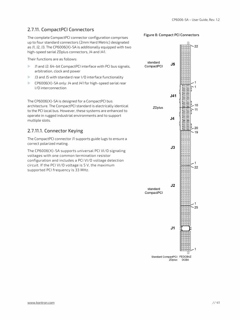
CP6006-SA – User Guide, Rev. 1.2
www.kontron.com // 41
2.7.11. CompactPCI Connectors
The complete CompactPCI connector configuration comprises up to four standard connectors (2mm Hard Metric) designated as J1, J2, J3. The CP6006(X)-SA is additionally equipped with two high-speed serial ZDplus connectors, J4 and J41.
Their functions are as follows:
J1 and J2: 64-bit CompactPCI interface with PCI bus signals, arbitration, clock and power
J3 and J5 with standard rear I/O interface functionality
CP6006(X)-SA only: J4 and J41 for high-speed serial rear I/O interconnection
The CP6006(X)-SA is designed for a CompactPCI bus architecture. The CompactPCI standard is electrically identical to the PCI local bus. However, these systems are enhanced to operate in rugged industrial environments and to support multiple slots.
2.7.11.1. Connector Keying
The CompactPCI connector J1 supports guide lugs to ensure a correct polarized mating.
The CP6006(X)-SA supports universal PCI VI/O signaling voltages with one common termination resistor configuration and includes a PCI VI/O voltage detection circuit. If the PCI VI/O voltage is 5 V, the maximum supported PCI frequency is 33 MHz.
Figure 8: Compact PCI Connectors
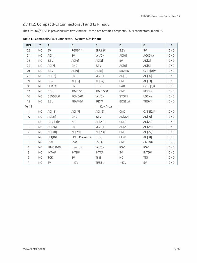
CP6006-SA – User Guide, Rev. 1.2
www.kontron.com // 42
2.7.11.2. CompactPCI Connectors J1 and J2 Pinout
The CP6006(X)-SA is provided with two 2 mm x 2 mm pitch female CompactPCI bus connectors, J1 and J2.
Table 17: CompactPCI Bus Connector J1 System Slot Pinout
PIN Z A B C D E F
25 NC 5V REQ64# ENUM# 3.3V 5V GND
24 NC AD[1] 5V V(I/O) AD[0] ACK64# GND
23 NC 3.3V AD[4] AD[3] 5V AD[2] GND
22 NC AD[7] GND 3.3V AD[6] AD[5] GND
21 NC 3.3V AD[9] AD[8] M66EN C/BE[0]# GND
20 NC AD[12] GND V(I/O) AD[11] AD[10] GND
19 NC 3.3V AD[15] AD[14] GND AD[13] GND
18 NC SERR# GND 3.3V PAR C/BE[1]# GND
17 NC 3.3V IPMB SCL IPMB SDA GND PERR# GND
16 NC DEVSEL# PCIXCAP V(I/O) STOP# LOCK# GND
15 NC 3.3V FRAME# IRDY# BDSEL# TRDY# GND
14-12 Key Area
11 NC AD[18] AD[17] AD[16] GND C/BE[2]# GND
10 NC AD[21] GND 3.3V AD[20] AD[19] GND
9 NC C/BE[3]# NC AD[23] GND AD[22] GND
8 NC AD[26] GND V(I/O) AD[25] AD[24] GND
7 NC AD[30] AD[29] AD[28] GND AD[27] GND
6 NC REQ0# CPCI_Present# 3.3V CLK0 AD[31] GND
5 NC RSV RSV RST# GND GNT0# GND
4 NC IPMB PWR Health# V(I/O) RSV RSV GND
3 NC INTA# INTB# INTC# 5V INTD# GND
2 NC TCK 5V TMS NC TDI GND
1 NC 5V -12V TRST# +12V 5V GND
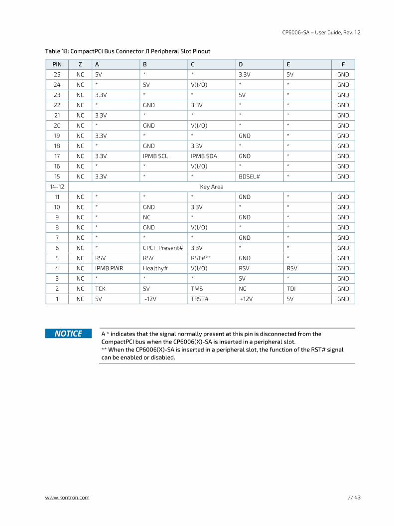
CP6006-SA – User Guide, Rev. 1.2
www.kontron.com // 43
Table 18: CompactPCI Bus Connector J1 Peripheral Slot Pinout
PIN Z A B C D E F
25 NC 5V * * 3.3V 5V GND
24 NC * 5V V(I/O) * * GND
23 NC 3.3V * * 5V * GND
22 NC * GND 3.3V * * GND
21 NC 3.3V * * * * GND
20 NC * GND V(I/O) * * GND
19 NC 3.3V * * GND * GND
18 NC * GND 3.3V * * GND
17 NC 3.3V IPMB SCL IPMB SDA GND * GND
16 NC * * V(I/O) * * GND
15 NC 3.3V * * BDSEL# * GND
14-12 Key Area
11 NC * * * GND * GND
10 NC * GND 3.3V * * GND
9 NC * NC * GND * GND
8 NC * GND V(I/O) * * GND
7 NC * * * GND * GND
6 NC * CPCI_Present# 3.3V * * GND
5 NC RSV RSV RST#** GND * GND
4 NC IPMB PWR Healthy# V(I/O) RSV RSV GND
3 NC * * * 5V * GND
2 NC TCK 5V TMS NC TDI GND
1 NC 5V -12V TRST# +12V 5V GND
A * indicates that the signal normally present at this pin is disconnected from the
CompactPCI bus when the CP6006(X)-SA is inserted in a peripheral slot. ** When the CP6006(X)-SA is inserted in a peripheral slot, the function of the RST# signal can be enabled or disabled.
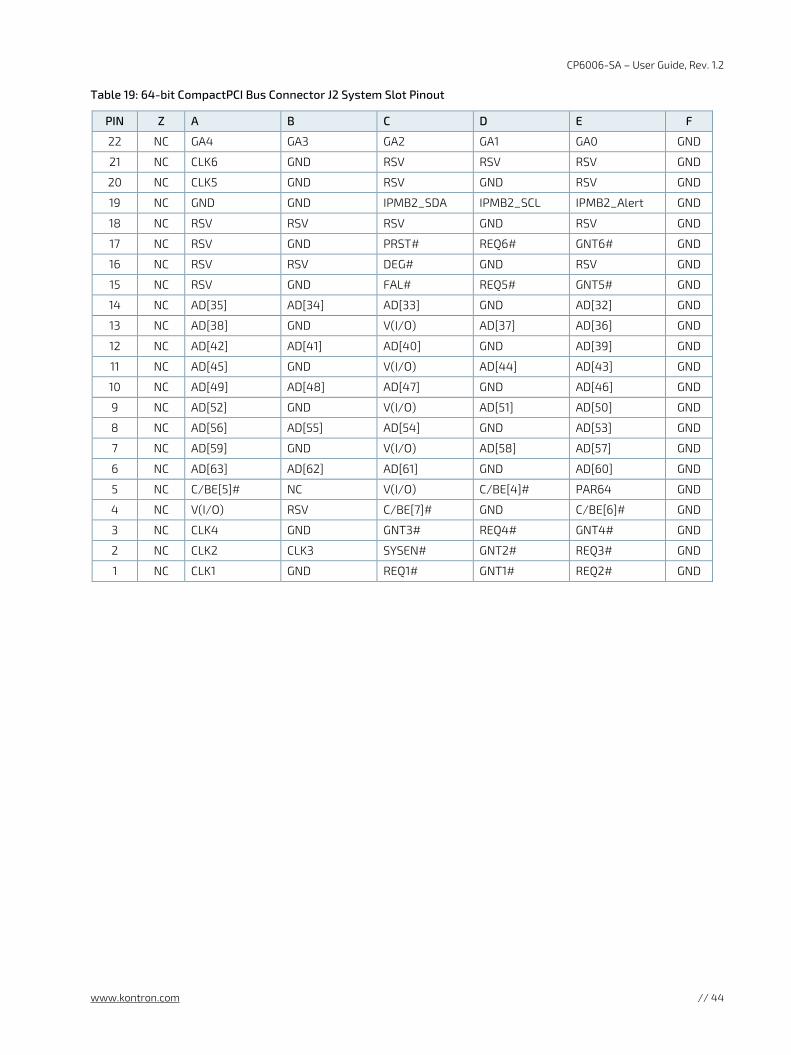
CP6006-SA – User Guide, Rev. 1.2
www.kontron.com // 44
Table 19: 64-bit CompactPCI Bus Connector J2 System Slot Pinout
PIN Z A B C D E F
22 NC GA4 GA3 GA2 GA1 GA0 GND
21 NC CLK6 GND RSV RSV RSV GND
20 NC CLK5 GND RSV GND RSV GND
19 NC GND GND IPMB2_SDA IPMB2_SCL IPMB2_Alert GND
18 NC RSV RSV RSV GND RSV GND
17 NC RSV GND PRST# REQ6# GNT6# GND
16 NC RSV RSV DEG# GND RSV GND
15 NC RSV GND FAL# REQ5# GNT5# GND
14 NC AD[35] AD[34] AD[33] GND AD[32] GND
13 NC AD[38] GND V(I/O) AD[37] AD[36] GND
12 NC AD[42] AD[41] AD[40] GND AD[39] GND
11 NC AD[45] GND V(I/O) AD[44] AD[43] GND
10 NC AD[49] AD[48] AD[47] GND AD[46] GND
9 NC AD[52] GND V(I/O) AD[51] AD[50] GND
8 NC AD[56] AD[55] AD[54] GND AD[53] GND
7 NC AD[59] GND V(I/O) AD[58] AD[57] GND
6 NC AD[63] AD[62] AD[61] GND AD[60] GND
5 NC C/BE[5]# NC V(I/O) C/BE[4]# PAR64 GND
4 NC V(I/O) RSV C/BE[7]# GND C/BE[6]# GND
3 NC CLK4 GND GNT3# REQ4# GNT4# GND
2 NC CLK2 CLK3 SYSEN# GNT2# REQ3# GND
1 NC CLK1 GND REQ1# GNT1# REQ2# GND
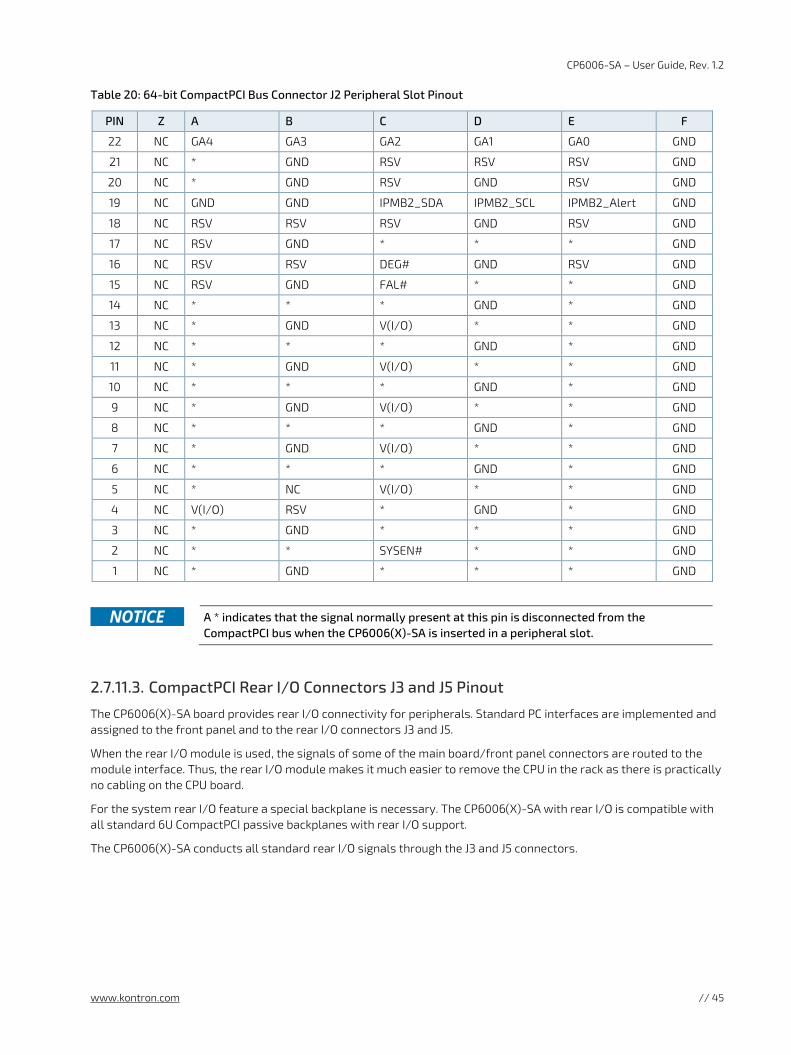
CP6006-SA – User Guide, Rev. 1.2
www.kontron.com // 45
Table 20: 64-bit CompactPCI Bus Connector J2 Peripheral Slot Pinout
PIN Z A B C D E F
22 NC GA4 GA3 GA2 GA1 GA0 GND
21 NC * GND RSV RSV RSV GND
20 NC * GND RSV GND RSV GND
19 NC GND GND IPMB2_SDA IPMB2_SCL IPMB2_Alert GND
18 NC RSV RSV RSV GND RSV GND
17 NC RSV GND * * * GND
16 NC RSV RSV DEG# GND RSV GND
15 NC RSV GND FAL# * * GND
14 NC * * * GND * GND
13 NC * GND V(I/O) * * GND
12 NC * * * GND * GND
11 NC * GND V(I/O) * * GND
10 NC * * * GND * GND
9 NC * GND V(I/O) * * GND
8 NC * * * GND * GND
7 NC * GND V(I/O) * * GND
6 NC * * * GND * GND
5 NC * NC V(I/O) * * GND
4 NC V(I/O) RSV * GND * GND
3 NC * GND * * * GND
2 NC * * SYSEN# * * GND
1 NC * GND * * * GND
A * indicates that the signal normally present at this pin is disconnected from the
CompactPCI bus when the CP6006(X)-SA is inserted in a peripheral slot.
2.7.11.3. CompactPCI Rear I/O Connectors J3 and J5 Pinout
The CP6006(X)-SA board provides rear I/O connectivity for peripherals. Standard PC interfaces are implemented and assigned to the front panel and to the rear I/O connectors J3 and J5.
When the rear I/O module is used, the signals of some of the main board/front panel connectors are routed to the module interface. Thus, the rear I/O module makes it much easier to remove the CPU in the rack as there is practically no cabling on the CPU board.
For the system rear I/O feature a special backplane is necessary. The CP6006(X)-SA with rear I/O is compatible with all standard 6U CompactPCI passive backplanes with rear I/O support.
The CP6006(X)-SA conducts all standard rear I/O signals through the J3 and J5 connectors.
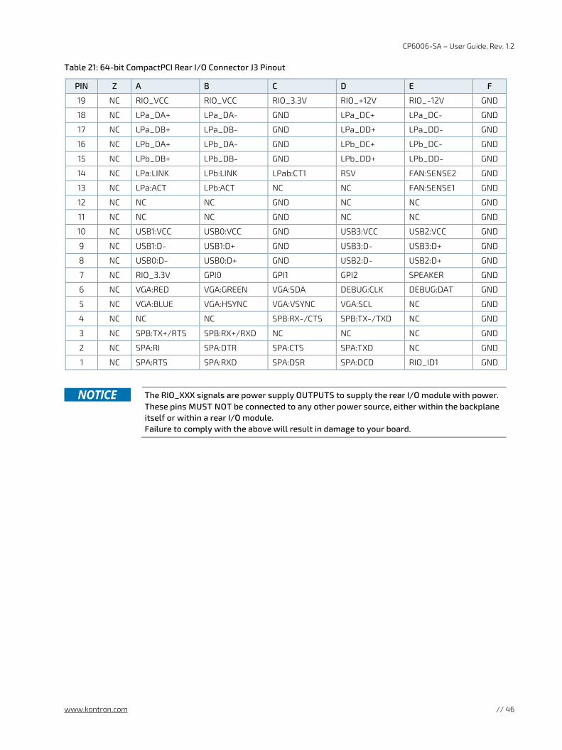
CP6006-SA – User Guide, Rev. 1.2
www.kontron.com // 46
Table 21: 64-bit CompactPCI Rear I/O Connector J3 Pinout
PIN Z A B C D E F
19 NC RIO_VCC RIO_VCC RIO_3.3V RIO_+12V RIO_-12V GND
18 NC LPa_DA+ LPa_DA- GND LPa_DC+ LPa_DC- GND
17 NC LPa_DB+ LPa_DB- GND LPa_DD+ LPa_DD- GND
16 NC LPb_DA+ LPb_DA- GND LPb_DC+ LPb_DC- GND
15 NC LPb_DB+ LPb_DB- GND LPb_DD+ LPb_DD- GND
14 NC LPa:LINK LPb:LINK LPab:CT1 RSV FAN:SENSE2 GND
13 NC LPa:ACT LPb:ACT NC NC FAN:SENSE1 GND
12 NC NC NC GND NC NC GND
11 NC NC NC GND NC NC GND
10 NC USB1:VCC USB0:VCC GND USB3:VCC USB2:VCC GND
9 NC USB1:D- USB1:D+ GND USB3:D- USB3:D+ GND
8 NC USB0:D- USB0:D+ GND USB2:D- USB2:D+ GND
7 NC RIO_3.3V GPI0 GPI1 GPI2 SPEAKER GND
6 NC VGA:RED VGA:GREEN VGA:SDA DEBUG:CLK DEBUG:DAT GND
5 NC VGA:BLUE VGA:HSYNC VGA:VSYNC VGA:SCL NC GND
4 NC NC NC SPB:RX-/CTS SPB:TX-/TXD NC GND
3 NC SPB:TX+/RTS SPB:RX+/RXD NC NC NC GND
2 NC SPA:RI SPA:DTR SPA:CTS SPA:TXD NC GND
1 NC SPA:RTS SPA:RXD SPA:DSR SPA:DCD RIO_ID1 GND
The RIO_XXX signals are power supply OUTPUTS to supply the rear I/O module with power.
These pins MUST NOT be connected to any other power source, either within the backplane itself or within a rear I/O module. Failure to comply with the above will result in damage to your board.
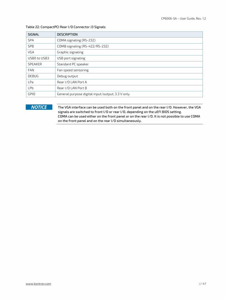
CP6006-SA – User Guide, Rev. 1.2
www.kontron.com // 47
Table 22: CompactPCI Rear I/O Connector J3 Signals
SIGNAL DESCRIPTION
SPA COMA signaling (RS-232)
SPB COMB signaling (RS-422/RS-232)
VGA Graphic signaling
USB0 to USB3 USB port signaling
SPEAKER Standard PC speaker
FAN Fan speed sensoring
DEBUG Debug output
LPa Rear I/O LAN Port A
LPb Rear I/O LAN Port B
GPIO General purpose digital input/output; 3.3 V only
The VGA interface can be used both on the front panel and on the rear I/O. However, the VGA
signals are switched to front I/O or rear I/O, depending on the uEFI BIOS setting. COMA can be used either on the front panel or on the rear I/O. It is not possible to use COMA on the front panel and on the rear I/O simultaneously.
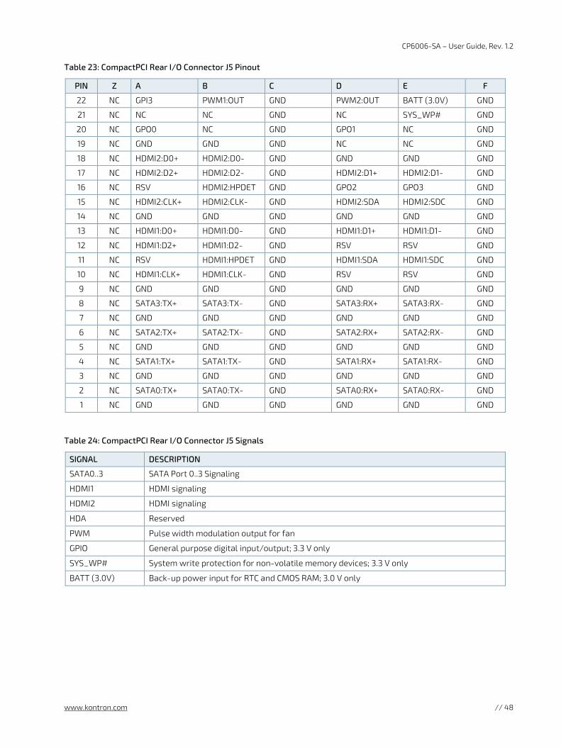
CP6006-SA – User Guide, Rev. 1.2
www.kontron.com // 48
Table 23: CompactPCI Rear I/O Connector J5 Pinout
PIN Z A B C D E F
22 NC GPI3 PWM1:OUT GND PWM2:OUT BATT (3.0V) GND
21 NC NC NC GND NC SYS_WP# GND
20 NC GPO0 NC GND GPO1 NC GND
19 NC GND GND GND NC NC GND
18 NC HDMI2:D0+ HDMI2:D0- GND GND GND GND
17 NC HDMI2:D2+ HDMI2:D2- GND HDMI2:D1+ HDMI2:D1- GND
16 NC RSV HDMI2:HPDET GND GPO2 GPO3 GND
15 NC HDMI2:CLK+ HDMI2:CLK- GND HDMI2:SDA HDMI2:SDC GND
14 NC GND GND GND GND GND GND
13 NC HDMI1:D0+ HDMI1:D0- GND HDMI1:D1+ HDMI1:D1- GND
12 NC HDMI1:D2+ HDMI1:D2- GND RSV RSV GND
11 NC RSV HDMI1:HPDET GND HDMI1:SDA HDMI1:SDC GND
10 NC HDMI1:CLK+ HDMI1:CLK- GND RSV RSV GND
9 NC GND GND GND GND GND GND
8 NC SATA3:TX+ SATA3:TX- GND SATA3:RX+ SATA3:RX- GND
7 NC GND GND GND GND GND GND
6 NC SATA2:TX+ SATA2:TX- GND SATA2:RX+ SATA2:RX- GND
5 NC GND GND GND GND GND GND
4 NC SATA1:TX+ SATA1:TX- GND SATA1:RX+ SATA1:RX- GND
3 NC GND GND GND GND GND GND
2 NC SATA0:TX+ SATA0:TX- GND SATA0:RX+ SATA0:RX- GND
1 NC GND GND GND GND GND GND
Table 24: CompactPCI Rear I/O Connector J5 Signals
SIGNAL DESCRIPTION
SATA0..3 SATA Port 0..3 Signaling
HDMI1 HDMI signaling
HDMI2 HDMI signaling
HDA Reserved
PWM Pulse width modulation output for fan
GPIO General purpose digital input/output; 3.3 V only
SYS_WP# System write protection for non-volatile memory devices; 3.3 V only
BATT (3.0V) Back-up power input for RTC and CMOS RAM; 3.0 V only
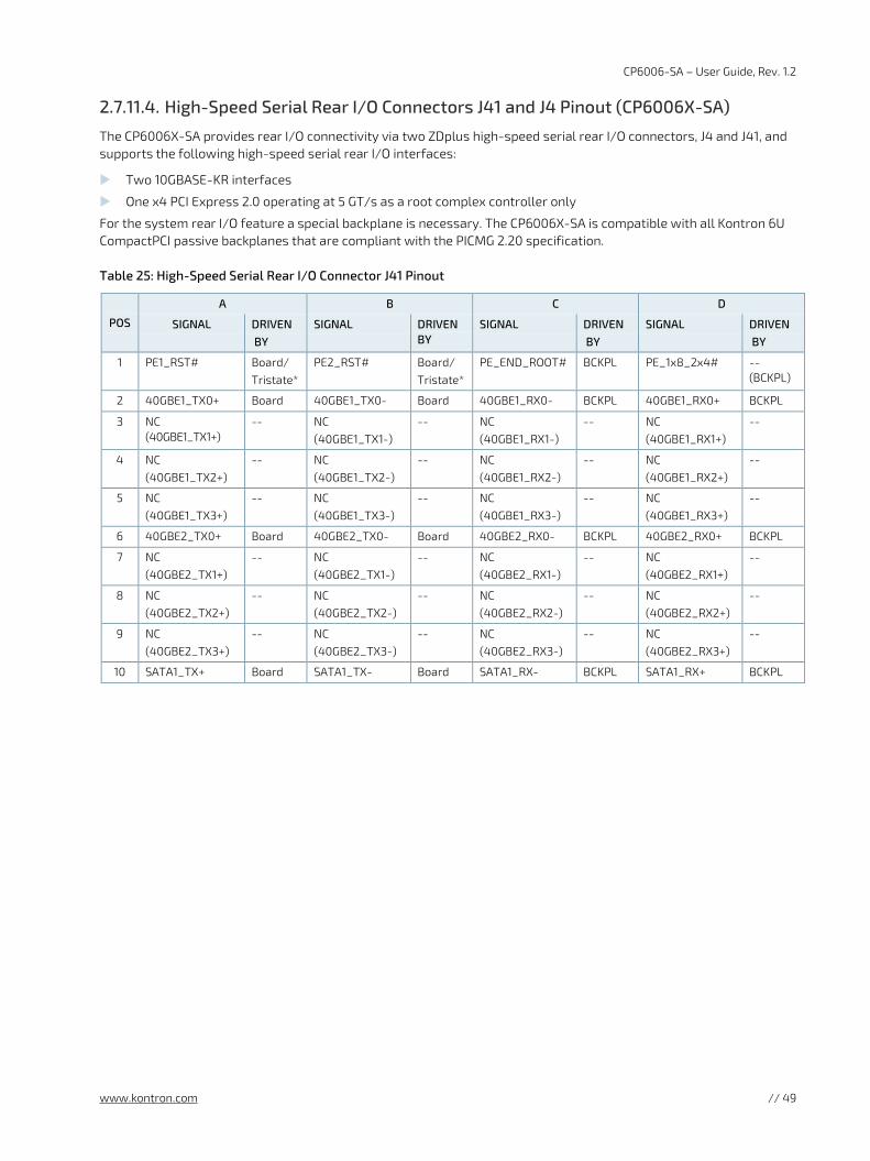
CP6006-SA – User Guide, Rev. 1.2
www.kontron.com // 49
2.7.11.4. High-Speed Serial Rear I/O Connectors J41 and J4 Pinout (CP6006X-SA)
The CP6006X-SA provides rear I/O connectivity via two ZDplus high-speed serial rear I/O connectors, J4 and J41, and supports the following high-speed serial rear I/O interfaces:
Two 10GBASE-KR interfaces
One x4 PCI Express 2.0 operating at 5 GT/s as a root complex controller only
For the system rear I/O feature a special backplane is necessary. The CP6006X-SA is compatible with all Kontron 6U CompactPCI passive backplanes that are compliant with the PICMG 2.20 specification.
Table 25: High-Speed Serial Rear I/O Connector J41 Pinout
POS
A B C D
SIGNAL DRIVEN BY
SIGNAL DRIVEN BY
SIGNAL DRIVEN BY
SIGNAL DRIVEN BY
1 PE1_RST# Board/ Tristate*
PE2_RST# Board/ Tristate*
PE_END_ROOT# BCKPL PE_1x8_2x4# -- (BCKPL)
2 40GBE1_TX0+ Board 40GBE1_TX0- Board 40GBE1_RX0- BCKPL 40GBE1_RX0+ BCKPL
3 NC (40GBE1_TX1+)
-- NC (40GBE1_TX1-)
-- NC (40GBE1_RX1-)
-- NC (40GBE1_RX1+)
--
4 NC (40GBE1_TX2+)
-- NC (40GBE1_TX2-)
-- NC (40GBE1_RX2-)
-- NC (40GBE1_RX2+)
--
5 NC (40GBE1_TX3+)
-- NC (40GBE1_TX3-)
-- NC (40GBE1_RX3-)
-- NC (40GBE1_RX3+)
--
6 40GBE2_TX0+ Board 40GBE2_TX0- Board 40GBE2_RX0- BCKPL 40GBE2_RX0+ BCKPL
7 NC (40GBE2_TX1+)
-- NC (40GBE2_TX1-)
-- NC (40GBE2_RX1-)
-- NC (40GBE2_RX1+)
--
8 NC (40GBE2_TX2+)
-- NC (40GBE2_TX2-)
-- NC (40GBE2_RX2-)
-- NC (40GBE2_RX2+)
--
9 NC (40GBE2_TX3+)
-- NC (40GBE2_TX3-)
-- NC (40GBE2_RX3-)
-- NC (40GBE2_RX3+)
--
10 SATA1_TX+ Board SATA1_TX- Board SATA1_RX- BCKPL SATA1_RX+ BCKPL
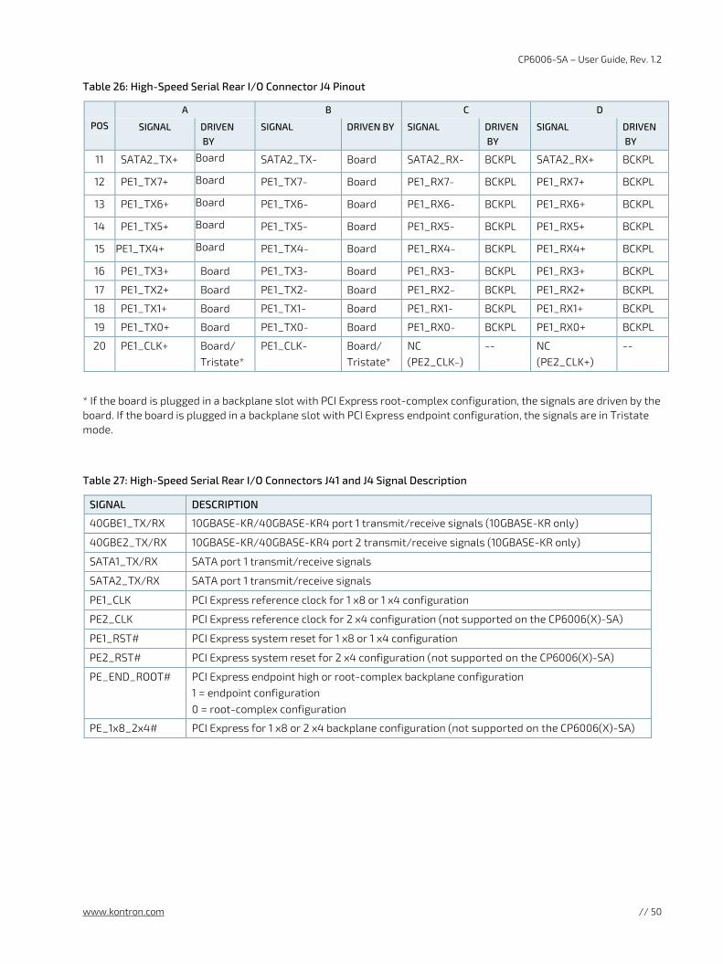
CP6006-SA – User Guide, Rev. 1.2
www.kontron.com // 50
Table 26: High-Speed Serial Rear I/O Connector J4 Pinout
POS
A B C D
SIGNAL DRIVEN BY
SIGNAL DRIVEN BY SIGNAL DRIVEN BY
SIGNAL DRIVEN BY
11 SATA2_TX+ Board SATA2_TX- Board SATA2_RX- BCKPL SATA2_RX+ BCKPL
12 PE1_TX7+ Board PE1_TX7- Board PE1_RX7- BCKPL PE1_RX7+ BCKPL
13 PE1_TX6+ Board PE1_TX6- Board PE1_RX6- BCKPL PE1_RX6+ BCKPL
14 PE1_TX5+ Board PE1_TX5- Board PE1_RX5- BCKPL PE1_RX5+ BCKPL
15 PE1_TX4+ Board PE1_TX4- Board PE1_RX4- BCKPL PE1_RX4+ BCKPL
16 PE1_TX3+ Board PE1_TX3- Board PE1_RX3- BCKPL PE1_RX3+ BCKPL
17 PE1_TX2+ Board PE1_TX2- Board PE1_RX2- BCKPL PE1_RX2+ BCKPL
18 PE1_TX1+ Board PE1_TX1- Board PE1_RX1- BCKPL PE1_RX1+ BCKPL
19 PE1_TX0+ Board PE1_TX0- Board PE1_RX0- BCKPL PE1_RX0+ BCKPL
20 PE1_CLK+ Board/ Tristate*
PE1_CLK- Board/ Tristate*
NC (PE2_CLK-)
-- NC (PE2_CLK+)
--
* If the board is plugged in a backplane slot with PCI Express root-complex configuration, the signals are driven by the board. If the board is plugged in a backplane slot with PCI Express endpoint configuration, the signals are in Tristate mode.
Table 27: High-Speed Serial Rear I/O Connectors J41 and J4 Signal Description
SIGNAL DESCRIPTION
40GBE1_TX/RX 10GBASE-KR/40GBASE-KR4 port 1 transmit/receive signals (10GBASE-KR only)
40GBE2_TX/RX 10GBASE-KR/40GBASE-KR4 port 2 transmit/receive signals (10GBASE-KR only)
SATA1_TX/RX SATA port 1 transmit/receive signals
SATA2_TX/RX SATA port 1 transmit/receive signals
PE1_CLK PCI Express reference clock for 1 x8 or 1 x4 configuration
PE2_CLK PCI Express reference clock for 2 x4 configuration (not supported on the CP6006(X)-SA)
PE1_RST# PCI Express system reset for 1 x8 or 1 x4 configuration
PE2_RST# PCI Express system reset for 2 x4 configuration (not supported on the CP6006(X)-SA)
PE_END_ROOT# PCI Express endpoint high or root-complex backplane configuration 1 = endpoint configuration 0 = root-complex configuration
PE_1x8_2x4# PCI Express for 1 x8 or 2 x4 backplane configuration (not supported on the CP6006(X)-SA)
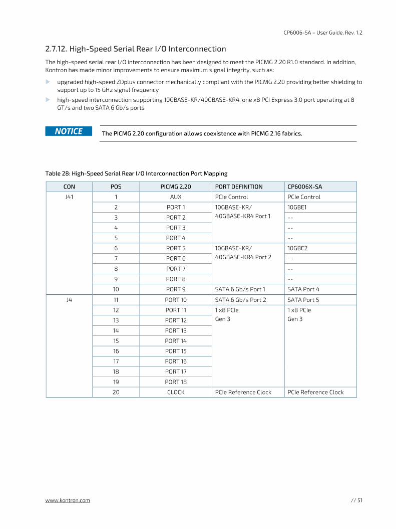
CP6006-SA – User Guide, Rev. 1.2
www.kontron.com // 51
2.7.12. High-Speed Serial Rear I/O Interconnection
The high-speed serial rear I/O interconnection has been designed to meet the PICMG 2.20 R1.0 standard. In addition, Kontron has made minor improvements to ensure maximum signal integrity, such as:
upgraded high-speed ZDplus connector mechanically compliant with the PICMG 2.20 providing better shielding to support up to 15 GHz signal frequency
high-speed interconnection supporting 10GBASE-KR/40GBASE-KR4, one x8 PCI Express 3.0 port operating at 8 GT/s and two SATA 6 Gb/s ports
The PICMG 2.20 configuration allows coexistence with PICMG 2.16 fabrics.
Table 28: High-Speed Serial Rear I/O Interconnection Port Mapping
CON POS PICMG 2.20 PORT DEFINITION CP6006X-SA
J41 1 AUX PCIe Control PCIe Control
2 PORT 1 10GBASE-KR/ 40GBASE-KR4 Port 1
10GBE1
3 PORT 2 --
4 PORT 3 --
5 PORT 4 --
6 PORT 5 10GBASE-KR/ 40GBASE-KR4 Port 2
10GBE2
7 PORT 6 --
8 PORT 7 --
9 PORT 8 --
10 PORT 9 SATA 6 Gb/s Port 1 SATA Port 4
J4 11 PORT 10 SATA 6 Gb/s Port 2 SATA Port 5
12 PORT 11 1 x8 PCIe Gen 3
1 x8 PCIe Gen 3 13 PORT 12
14 PORT 13
15 PORT 14
16 PORT 15
17 PORT 16
18 PORT 17
19 PORT 18
20 CLOCK PCIe Reference Clock PCIe Reference Clock
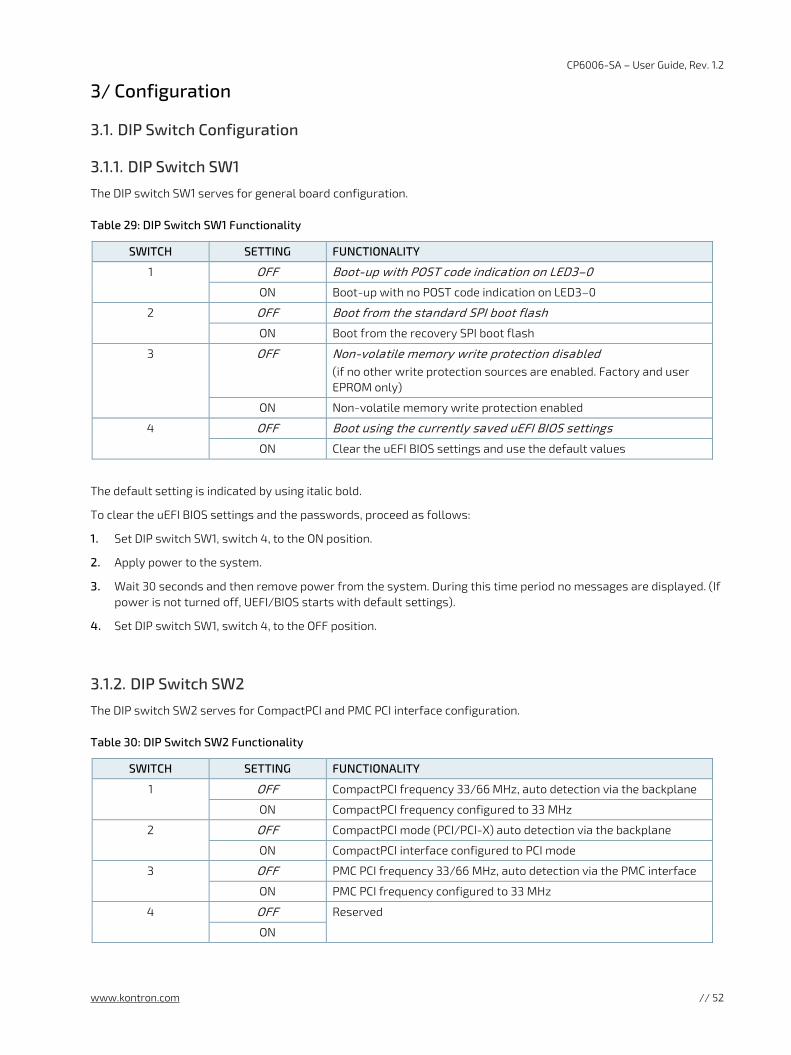
CP6006-SA – User Guide, Rev. 1.2
www.kontron.com // 52
3/ Configuration
3.1. DIP Switch Configuration
3.1.1. DIP Switch SW1
The DIP switch SW1 serves for general board configuration.
Table 29: DIP Switch SW1 Functionality
SWITCH SETTING FUNCTIONALITY
1 OFF Boot-up with POST code indication on LED3–0
ON Boot-up with no POST code indication on LED3–0
2 OFF Boot from the standard SPI boot flash
ON Boot from the recovery SPI boot flash
3 OFF Non-volatile memory write protection disabled (if no other write protection sources are enabled. Factory and user EPROM only)
ON Non-volatile memory write protection enabled
4 OFF Boot using the currently saved uEFI BIOS settings
ON Clear the uEFI BIOS settings and use the default values
The default setting is indicated by using italic bold.
To clear the uEFI BIOS settings and the passwords, proceed as follows:
1. Set DIP switch SW1, switch 4, to the ON position.
2. Apply power to the system.
3. Wait 30 seconds and then remove power from the system. During this time period no messages are displayed. (If power is not turned off, UEFI/BIOS starts with default settings).
4. Set DIP switch SW1, switch 4, to the OFF position.
3.1.2. DIP Switch SW2
The DIP switch SW2 serves for CompactPCI and PMC PCI interface configuration.
Table 30: DIP Switch SW2 Functionality
SWITCH SETTING FUNCTIONALITY
1 OFF CompactPCI frequency 33/66 MHz, auto detection via the backplane
ON CompactPCI frequency configured to 33 MHz
2 OFF CompactPCI mode (PCI/PCI-X) auto detection via the backplane
ON CompactPCI interface configured to PCI mode
3 OFF PMC PCI frequency 33/66 MHz, auto detection via the PMC interface
ON PMC PCI frequency configured to 33 MHz
4 OFF Reserved
ON
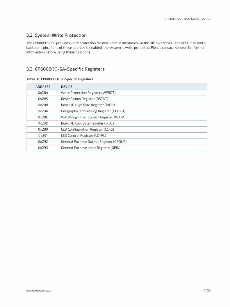
CP6006-SA – User Guide, Rev. 1.2
www.kontron.com // 53
3.2. System Write Protection
The CP6006(X)-SA provides write protection for non-volatile memories via the DIP switch SW1, the uEFI Shell and a backplane pin. If one of these sources is enabled, the system is write protected. Please contact Kontron for further information before using these functions.
3.3. CP6006(X)-SA-Specific Registers
Table 31: CP6006(X)-SA-Specific Registers
ADDRESS DEVICE
0x284 Write Protection Register (WPROT)
0x285 Reset Status Register (RSTAT)
0x288 Board ID High Byte Register (BIDH)
0x28A Geographic Addressing Register (GEOAD)
0x28C Watchdog Timer Control Register (WTIM)
0x28D Board ID Low Byte Register (BIDL)
0x290 LED Configuration Register (LCFG)
0x291 LED Control Register (LCTRL)
0x292 General Purpose Output Register (GPOUT)
0x293 General Purpose Input Register (GPIN)
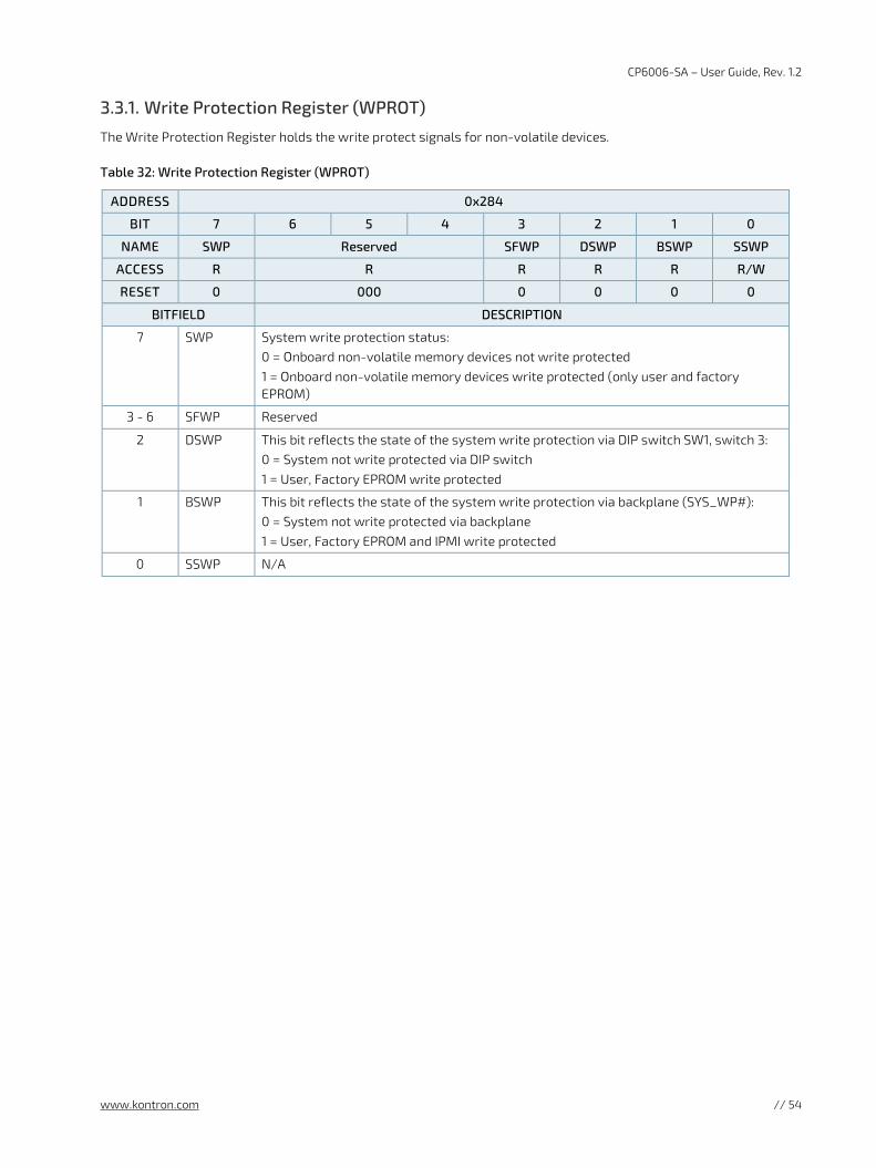
CP6006-SA – User Guide, Rev. 1.2
www.kontron.com // 54
3.3.1. Write Protection Register (WPROT)
The Write Protection Register holds the write protect signals for non-volatile devices.
Table 32: Write Protection Register (WPROT)
ADDRESS 0x284
BIT 7 6 5 4 3 2 1 0
NAME SWP Reserved SFWP DSWP BSWP SSWP
ACCESS R R R R R R/W
RESET 0 000 0 0 0 0
BITFIELD DESCRIPTION
7 SWP System write protection status: 0 = Onboard non-volatile memory devices not write protected 1 = Onboard non-volatile memory devices write protected (only user and factory EPROM)
3 - 6 SFWP Reserved
2 DSWP This bit reflects the state of the system write protection via DIP switch SW1, switch 3: 0 = System not write protected via DIP switch 1 = User, Factory EPROM write protected
1 BSWP This bit reflects the state of the system write protection via backplane (SYS_WP#): 0 = System not write protected via backplane 1 = User, Factory EPROM and IPMI write protected
0 SSWP N/A
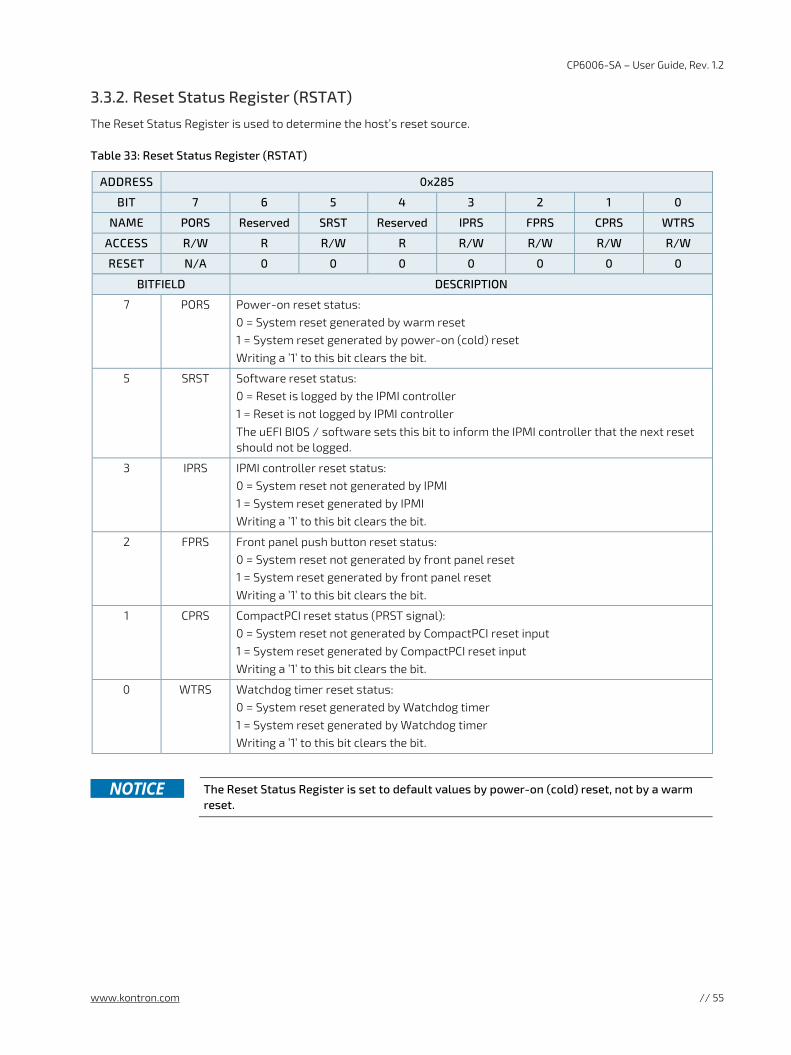
CP6006-SA – User Guide, Rev. 1.2
www.kontron.com // 55
3.3.2. Reset Status Register (RSTAT)
The Reset Status Register is used to determine the host’s reset source.
Table 33: Reset Status Register (RSTAT)
ADDRESS 0x285
BIT 7 6 5 4 3 2 1 0
NAME PORS Reserved SRST Reserved IPRS FPRS CPRS WTRS
ACCESS R/W R R/W R R/W R/W R/W R/W
RESET N/A 0 0 0 0 0 0 0
BITFIELD DESCRIPTION
7 PORS Power-on reset status: 0 = System reset generated by warm reset 1 = System reset generated by power-on (cold) reset Writing a ’1’ to this bit clears the bit.
5 SRST Software reset status: 0 = Reset is logged by the IPMI controller 1 = Reset is not logged by IPMI controller The uEFI BIOS / software sets this bit to inform the IPMI controller that the next reset should not be logged.
3 IPRS IPMI controller reset status: 0 = System reset not generated by IPMI 1 = System reset generated by IPMI Writing a ’1’ to this bit clears the bit.
2 FPRS Front panel push button reset status: 0 = System reset not generated by front panel reset 1 = System reset generated by front panel reset Writing a ’1’ to this bit clears the bit.
1 CPRS CompactPCI reset status (PRST signal): 0 = System reset not generated by CompactPCI reset input 1 = System reset generated by CompactPCI reset input Writing a ’1’ to this bit clears the bit.
0 WTRS Watchdog timer reset status: 0 = System reset generated by Watchdog timer 1 = System reset generated by Watchdog timer Writing a ’1’ to this bit clears the bit.
The Reset Status Register is set to default values by power-on (cold) reset, not by a warm
reset.
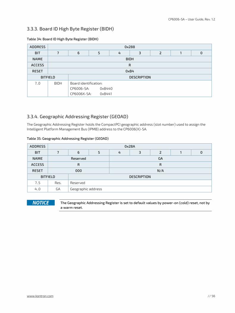
CP6006-SA – User Guide, Rev. 1.2
www.kontron.com // 56
3.3.3. Board ID High Byte Register (BIDH)
Table 34: Board ID High Byte Register (BIDH)
ADDRESS 0x288
BIT 7 6 5 4 3 2 1 0
NAME BIDH
ACCESS R
RESET 0xB4
BITFIELD DESCRIPTION
7..0 BIDH Board identification: CP6006-SA: 0xB440 CP6006X-SA: 0xB441
3.3.4. Geographic Addressing Register (GEOAD)
The Geographic Addressing Register holds the CompactPCI geographic address (slot number) used to assign the Intelligent Platform Management Bus (IPMB) address to the CP6006(X)-SA.
Table 35: Geographic Addressing Register (GEOAD)
ADDRESS 0x28A
BIT 7 6 5 4 3 2 1 0
NAME Reserved GA
ACCESS R R
RESET 000 N/A
BITFIELD DESCRIPTION
7..5 Res. Reserved
4..0 GA Geographic address
The Geographic Addressing Register is set to default values by power-on (cold) reset, not by
a warm reset.
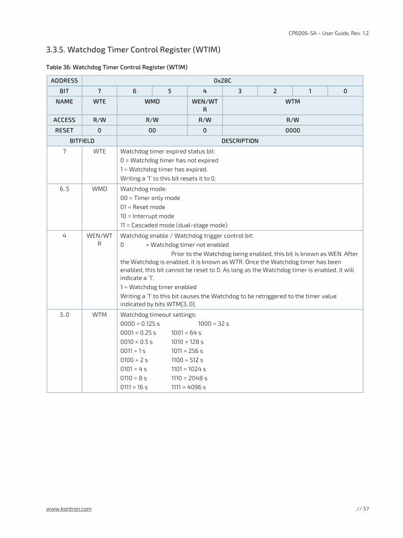
CP6006-SA – User Guide, Rev. 1.2
www.kontron.com // 57
3.3.5. Watchdog Timer Control Register (WTIM)
Table 36: Watchdog Timer Control Register (WTIM)
ADDRESS 0x28C
BIT 7 6 5 4 3 2 1 0
NAME WTE WMD WEN/WTR
WTM
ACCESS R/W R/W R/W R/W
RESET 0 00 0 0000
BITFIELD DESCRIPTION
7 WTE Watchdog timer expired status bit: 0 = Watchdog timer has not expired 1 = Watchdog timer has expired. Writing a ’1’ to this bit resets it to 0.
6..5 WMD Watchdog mode: 00 = Timer only mode 01 = Reset mode 10 = Interrupt mode 11 = Cascaded mode (dual-stage mode)
4 WEN/WTR
Watchdog enable / Watchdog trigger control bit: 0 = Watchdog timer not enabled Prior to the Watchdog being enabled, this bit is known as WEN. After the Watchdog is enabled, it is known as WTR. Once the Watchdog timer has been enabled, this bit cannot be reset to 0. As long as the Watchdog timer is enabled, it will indicate a ’1’. 1 = Watchdog timer enabled Writing a ’1’ to this bit causes the Watchdog to be retriggered to the timer value indicated by bits WTM[3..0].
3..0 WTM Watchdog timeout settings: 0000 = 0.125 s 1000 = 32 s 0001 = 0.25 s 1001 = 64 s 0010 = 0.5 s 1010 = 128 s 0011 = 1 s 1011 = 256 s 0100 = 2 s 1100 = 512 s 0101 = 4 s 1101 = 1024 s 0110 = 8 s 1110 = 2048 s 0111 = 16 s 1111 = 4096 s
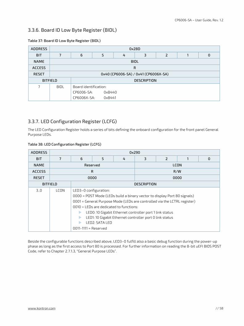
CP6006-SA – User Guide, Rev. 1.2
www.kontron.com // 58
3.3.6. Board ID Low Byte Register (BIDL)
Table 37: Board ID Low Byte Register (BIDL)
ADDRESS 0x28D
BIT 7 6 5 4 3 2 1 0
NAME BIDL
ACCESS R
RESET 0x40 (CP6006-SA) / 0x41 (CP6006X-SA)
BITFIELD DESCRIPTION
7 BIDL Board identification: CP6006-SA: 0xB440 CP6006X-SA: 0xB441
3.3.7. LED Configuration Register (LCFG)
The LED Configuration Register holds a series of bits defining the onboard configuration for the front panel General Purpose LEDs.
Table 38: LED Configuration Register (LCFG)
ADDRESS 0x290
BIT 7 6 5 4 3 2 1 0
NAME Reserved LCON
ACCESS R R/W
RESET 0000 0000
BITFIELD DESCRIPTION
3..0 LCON LED3–0 configuration: 0000 = POST Mode (LEDs build a binary vector to display Port 80 signals) 0001 = General Purpose Mode (LEDs are controlled via the LCTRL register) 0010 = LEDs are dedicated to functions: LED0: 10 Gigabit Ethernet controller port 1 link status LED1: 10 Gigabit Ethernet controller port 0 link status LED2: SATA LED
0011-1111 = Reserved
Beside the configurable functions described above, LED3–0 fulfill also a basic debug function during the power-up phase as long as the first access to Port 80 is processed. For further information on reading the 8-bit uEFI BIOS POST Code, refer to Chapter 2.7.1.3, “General Purpose LEDs”.
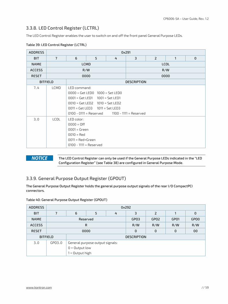
CP6006-SA – User Guide, Rev. 1.2
www.kontron.com // 59
3.3.8. LED Control Register (LCTRL)
The LED Control Register enables the user to switch on and off the front panel General Purpose LEDs.
Table 39: LED Control Register (LCTRL)
ADDRESS 0x291
BIT 7 6 5 4 3 2 1 0
NAME LCMD LCOL
ACCESS R/W R/W
RESET 0000 0000
BITFIELD DESCRIPTION
7..4 LCMD LED command: 0000 = Get LED0 1000 = Set LED0 0001 = Get LED1 1001 = Set LED1 0010 = Get LED2 1010 = Set LED2 0011 = Get LED3 1011 = Set LED3 0100 - 0111 = Reserved 1100 - 1111 = Reserved
3..0 LCOL LED color: 0000 = Off 0001 = Green 0010 = Red 0011 = Red+Green 0100 - 1111 = Reserved
The LED Control Register can only be used if the General Purpose LEDs indicated in the “LED
Configuration Register” (see Table 38) are configured in General Purpose Mode.
3.3.9. General Purpose Output Register (GPOUT)
The General Purpose Output Register holds the general purpose output signals of the rear I/O CompactPCI connectors.
Table 40: General Purpose Output Register (GPOUT)
ADDRESS 0x292
BIT 7 6 5 4 3 2 1 0
NAME Reserved GPO3 GPO2 GPO1 GPO0
ACCESS R R/W R/W R/W R/W
RESET 0000 0 0 0 00
BITFIELD DESCRIPTION
3..0 GPO3..0 General purpose output signals: 0 = Output low 1 = Output high
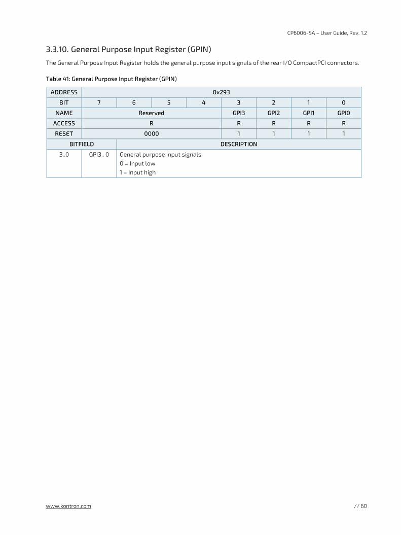
CP6006-SA – User Guide, Rev. 1.2
www.kontron.com // 60
3.3.10. General Purpose Input Register (GPIN)
The General Purpose Input Register holds the general purpose input signals of the rear I/O CompactPCI connectors.
Table 41: General Purpose Input Register (GPIN)
ADDRESS 0x293
BIT 7 6 5 4 3 2 1 0
NAME Reserved GPI3 GPI2 GPI1 GPI0
ACCESS R R R R R
RESET 0000 1 1 1 1
BITFIELD DESCRIPTION
3..0 GPI3.. 0 General purpose input signals: 0 = Input low 1 = Input high
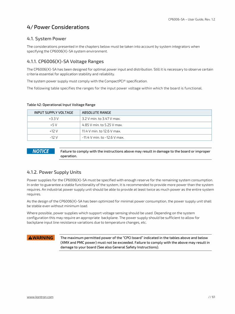
CP6006-SA – User Guide, Rev. 1.2
www.kontron.com // 61
4/ Power Considerations
4.1. System Power
The considerations presented in the chapters below must be taken into account by system integrators when specifying the CP6006(X)-SA system environment.
4.1.1. CP6006(X)-SA Voltage Ranges
The CP6006(X)-SA has been designed for optimal power input and distribution. Still it is necessary to observe certain criteria essential for application stability and reliability.
The system power supply must comply with the CompactPCI® specification.
The following table specifies the ranges for the input power voltage within which the board is functional.
Table 42: Operational Input Voltage Range
INPUT SUPPLY VOLTAGE ABSOLUTE RANGE
+3.3 V 3.2 V min. to 3.47 V max.
+5 V 4.85 V min. to 5.25 V max.
+12 V 11.4 V min. to 12.6 V max.
-12 V -11.4 V min. to -12.6 V max.
Failure to comply with the instructions above may result in damage to the board or improper
operation.
4.1.2. Power Supply Units
Power supplies for the CP6006(X)-SA must be specified with enough reserve for the remaining system consumption. In order to guarantee a stable functionality of the system, it is recommended to provide more power than the system requires. An industrial power supply unit should be able to provide at least twice as much power as the entire system requires.
As the design of the CP6006(X)-SA has been optimized for minimal power consumption, the power supply unit shall be stable even without minimum load.
Where possible, power supplies which support voltage sensing should be used. Depending on the system configuration this may require an appropriate backplane. The power supply should be sufficient to allow for backplane input line resistance variations due to temperature changes, etc.
The maximum permitted power of the “CPCI board” indicated in the tables above and below
(XMX and PMC power) must not be exceeded. Failure to comply with the above may result in damage to your board (See also General Safety Instructions).
CP6006-SA – User Guide, Rev. 1.2
www.kontron.com // 62
4.1.2.1. Start-Up Requirement
Power supplies must comply with the following guidelines, in order to be used with the CP6006(X)-SA:
Beginning at 10% of the nominal output voltage, the voltage must rise within > 0.1 ms to < 20 ms to the specified regulation range of the voltage. Typically: > 5 ms to < 15 ms.
There must be a smooth and continuous ramp of each DC output voltage from 10% to 90% of the regulation band.
The slope of the turn-on waveform shall be a positive, almost linear voltage increase and have a value from 0 V to nominal Vout.
4.1.2.2. Power-Up Sequence
The +5 VDC output level must always be equal to or higher than the +3.3 VDC output during power-up and normal operation.
Both voltages must reach their minimum in-regulation level not later than 20 ms after the output power ramp start.
4.1.2.3. Regulation
The power supply shall be unconditionally stable under line, load, unload and transient load conditions including capacitive loads. The operation of the power supply must be consistent even without the minimum load on all output lines.
All of the input voltages must be functionally coupled to each other so that if one input
voltage fails, all other input voltages must be regulated proportionately to the failed voltage. For example, if the +5V begins to decrease, all other input voltages must decrease accordingly. This is required in order to preclude cross currents within the CP6006(X)-SA. Failure to comply with above may result in damage to the board or improper system operation.
If the main power input is switched off, the supply voltages will not go to 0V instantly. It will
take a couple of seconds until the capacitors are discharged. If the voltage rises again before it has gone below a certain level, the circuits may enter a latch-up state where even a hard RESET will not help any more. The system must be switched off for at least 10 seconds before it may be switched on again. If problems still occur, turn off the main power for 30 seconds before turning it on again.
CP6006-SA – User Guide, Rev. 1.2
www.kontron.com // 63
4.2. Power Consumption
The goal of this description is to provide a method to calculate the power consumption for the CP6006(X)-SA baseboard and for additional configurations. The processor and the memory dissipate the majority of the thermal power.
The power consumption measurements were carried out using the following testing parameters:
CP6006(X)-SA installed in the system slot
Ethernet ports not connected
16 GB/32 GB DDR4 SDRAM in dual-channel mode
+3.3 V, 5 V, and 12 V main supply voltage
2.5 m/s airflow
The operating systems used were uEFI Shell and Windows® 7, 64-bit. All measurements were conducted at an ambient temperature of 25 °C. The power consumption values indicated in the tables below can vary depending on the ambient temperature. This can result in deviations of the power consumption values of up to 15%.
The power consumption was measured using the following processors:
Intel® Xeon® D-1539, 1.6 GHz, 12 MB cache
Intel® Xeon® D-1548, 2.0 GHz, 12 MB cache
Intel® Pentium® D1519, 1.5 GHz, 6 MB cache
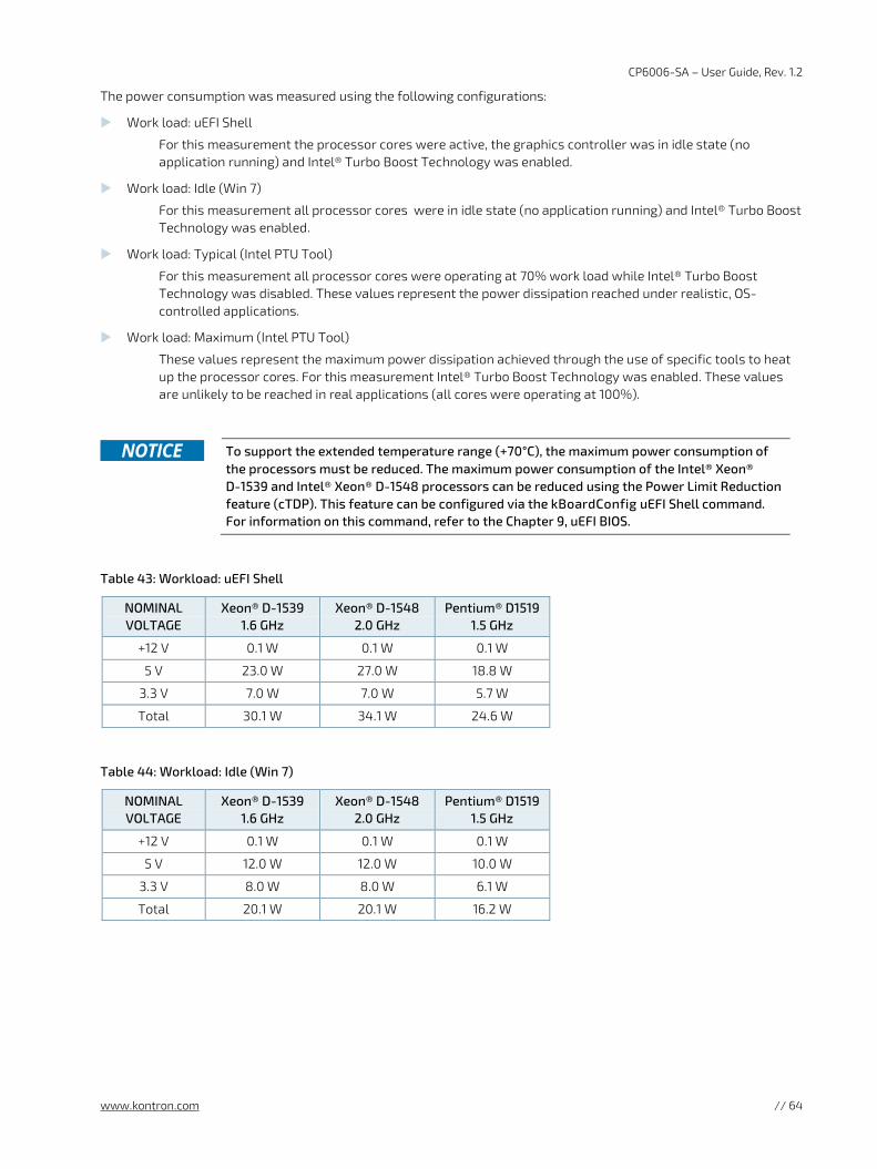
CP6006-SA – User Guide, Rev. 1.2
www.kontron.com // 64
The power consumption was measured using the following configurations:
Work load: uEFI Shell
For this measurement the processor cores were active, the graphics controller was in idle state (no application running) and Intel® Turbo Boost Technology was enabled.
Work load: Idle (Win 7)
For this measurement all processor cores were in idle state (no application running) and Intel® Turbo Boost Technology was enabled.
Work load: Typical (Intel PTU Tool)
For this measurement all processor cores were operating at 70% work load while Intel® Turbo Boost Technology was disabled. These values represent the power dissipation reached under realistic, OS-controlled applications.
Work load: Maximum (Intel PTU Tool)
These values represent the maximum power dissipation achieved through the use of specific tools to heat up the processor cores. For this measurement Intel® Turbo Boost Technology was enabled. These values are unlikely to be reached in real applications (all cores were operating at 100%).
To support the extended temperature range (+70°C), the maximum power consumption of
the processors must be reduced. The maximum power consumption of the Intel® Xeon® D-1539 and Intel® Xeon® D-1548 processors can be reduced using the Power Limit Reduction feature (cTDP). This feature can be configured via the kBoardConfig uEFI Shell command. For information on this command, refer to the Chapter 9, uEFI BIOS.
Table 43: Workload: uEFI Shell
NOMINAL VOLTAGE
Xeon® D-1539 1.6 GHz
Xeon® D-1548 2.0 GHz
Pentium® D1519 1.5 GHz
+12 V 0.1 W 0.1 W 0.1 W
5 V 23.0 W 27.0 W 18.8 W
3.3 V 7.0 W 7.0 W 5.7 W
Total 30.1 W 34.1 W 24.6 W
Table 44: Workload: Idle (Win 7)
NOMINAL VOLTAGE
Xeon® D-1539 1.6 GHz
Xeon® D-1548 2.0 GHz
Pentium® D1519 1.5 GHz
+12 V 0.1 W 0.1 W 0.1 W
5 V 12.0 W 12.0 W 10.0 W
3.3 V 8.0 W 8.0 W 6.1 W
Total 20.1 W 20.1 W 16.2 W
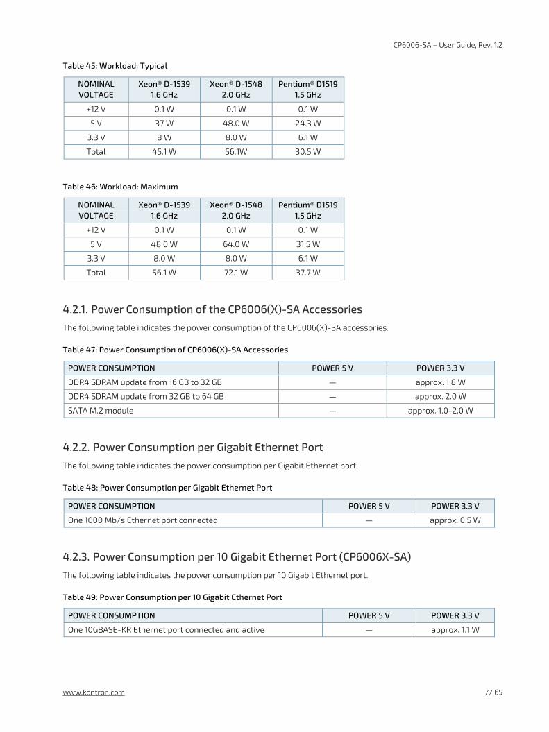
CP6006-SA – User Guide, Rev. 1.2
www.kontron.com // 65
Table 45: Workload: Typical
NOMINAL VOLTAGE
Xeon® D-1539 1.6 GHz
Xeon® D-1548 2.0 GHz
Pentium® D1519 1.5 GHz
+12 V 0.1 W 0.1 W 0.1 W
5 V 37 W 48.0 W 24.3 W
3.3 V 8 W 8.0 W 6.1 W
Total 45.1 W 56.1W 30.5 W
Table 46: Workload: Maximum
NOMINAL VOLTAGE
Xeon® D-1539 1.6 GHz
Xeon® D-1548 2.0 GHz
Pentium® D1519 1.5 GHz
+12 V 0.1 W 0.1 W 0.1 W
5 V 48.0 W 64.0 W 31.5 W
3.3 V 8.0 W 8.0 W 6.1 W
Total 56.1 W 72.1 W 37.7 W
4.2.1. Power Consumption of the CP6006(X)-SA Accessories
The following table indicates the power consumption of the CP6006(X)-SA accessories.
Table 47: Power Consumption of CP6006(X)-SA Accessories
POWER CONSUMPTION POWER 5 V POWER 3.3 V
DDR4 SDRAM update from 16 GB to 32 GB — approx. 1.8 W
DDR4 SDRAM update from 32 GB to 64 GB — approx. 2.0 W
SATA M.2 module — approx. 1.0-2.0 W
4.2.2. Power Consumption per Gigabit Ethernet Port
The following table indicates the power consumption per Gigabit Ethernet port.
Table 48: Power Consumption per Gigabit Ethernet Port
POWER CONSUMPTION POWER 5 V POWER 3.3 V
One 1000 Mb/s Ethernet port connected — approx. 0.5 W
4.2.3. Power Consumption per 10 Gigabit Ethernet Port (CP6006X-SA)
The following table indicates the power consumption per 10 Gigabit Ethernet port.
Table 49: Power Consumption per 10 Gigabit Ethernet Port
POWER CONSUMPTION POWER 5 V POWER 3.3 V
One 10GBASE-KR Ethernet port connected and active — approx. 1.1 W
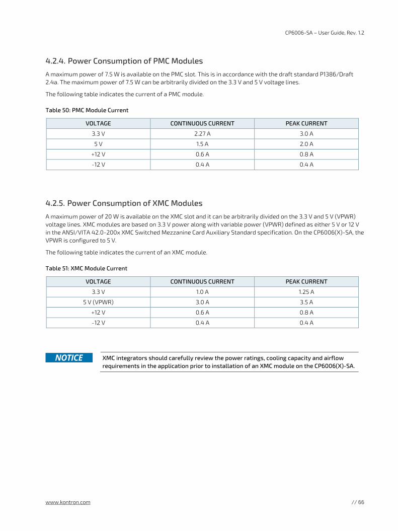
CP6006-SA – User Guide, Rev. 1.2
www.kontron.com // 66
4.2.4. Power Consumption of PMC Modules
A maximum power of 7.5 W is available on the PMC slot. This is in accordance with the draft standard P1386/Draft 2.4a. The maximum power of 7.5 W can be arbitrarily divided on the 3.3 V and 5 V voltage lines.
The following table indicates the current of a PMC module.
Table 50: PMC Module Current
VOLTAGE CONTINUOUS CURRENT PEAK CURRENT
3.3 V 2.27 A 3.0 A
5 V 1.5 A 2.0 A
+12 V 0.6 A 0.8 A
-12 V 0.4 A 0.4 A
4.2.5. Power Consumption of XMC Modules
A maximum power of 20 W is available on the XMC slot and it can be arbitrarily divided on the 3.3 V and 5 V (VPWR) voltage lines. XMC modules are based on 3.3 V power along with variable power (VPWR) defined as either 5 V or 12 V in the ANSI/VITA 42.0-200x XMC Switched Mezzanine Card Auxiliary Standard specification. On the CP6006(X)-SA, the VPWR is configured to 5 V.
The following table indicates the current of an XMC module.
Table 51: XMC Module Current
VOLTAGE CONTINUOUS CURRENT PEAK CURRENT
3.3 V 1.0 A 1.25 A
5 V (VPWR) 3.0 A 3.5 A
+12 V 0.6 A 0.8 A
-12 V 0.4 A 0.4 A
XMC integrators should carefully review the power ratings, cooling capacity and airflow
requirements in the application prior to installation of an XMC module on the CP6006(X)-SA.
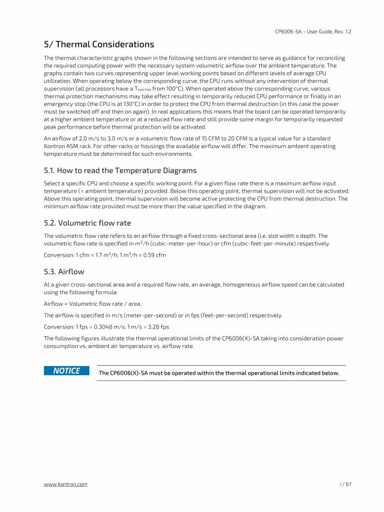
CP6006-SA – User Guide, Rev. 1.2
www.kontron.com // 67
5/ Thermal Considerations The thermal characteristic graphs shown in the following sections are intended to serve as guidance for reconciling the required computing power with the necessary system volumetric airflow over the ambient temperature. The graphs contain two curves representing upper level working points based on different levels of average CPU utilization. When operating below the corresponding curve, the CPU runs without any intervention of thermal supervision (all processors have a TJUNCTION from 100°C). When operated above the corresponding curve, various thermal protection mechanisms may take effect resulting in temporarily reduced CPU performance or finally in an emergency stop (the CPU is at 130°C) in order to protect the CPU from thermal destruction (in this case the power must be switched off and then on again). In real applications this means that the board can be operated temporarily at a higher ambient temperature or at a reduced flow rate and still provide some margin for temporarily requested peak performance before thermal protection will be activated.
An airflow of 2.0 m/s to 3.0 m/s or a volumetric flow rate of 15 CFM to 20 CFM is a typical value for a standard Kontron ASM rack. For other racks or housings the available airflow will differ. The maximum ambient operating temperature must be determined for such environments.
5.1. How to read the Temperature Diagrams
Select a specific CPU and choose a specific working point. For a given flow rate there is a maximum airflow input temperature (= ambient temperature) provided. Below this operating point, thermal supervision will not be activated. Above this operating point, thermal supervision will become active protecting the CPU from thermal destruction. The minimum airflow rate provided must be more than the value specified in the diagram.
5.2. Volumetric flow rate
The volumetric flow rate refers to an airflow through a fixed cross-sectional area (i.e. slot width x depth. The volumetric flow rate is specified in m³/h (cubic-meter-per-hour) or cfm (cubic-feet-per-minute) respectively.
Conversion: 1 cfm = 1.7 m³/h; 1 m³/h = 0.59 cfm
5.3. Airflow
At a given cross-sectional area and a required flow rate, an average, homogeneous airflow speed can be calculated using the following formula:
Airflow = Volumetric flow rate / area.
The airflow is specified in m/s (meter-per-second) or in fps (feet-per-second) respectively.
Conversion: 1 fps = 0.3048 m/s; 1 m/s = 3.28 fps
The following figures illustrate the thermal operational limits of the CP6006(X)-SA taking into consideration power consumption vs. ambient air temperature vs. airflow rate.
The CP6006(X)-SA must be operated within the thermal operational limits indicated below.
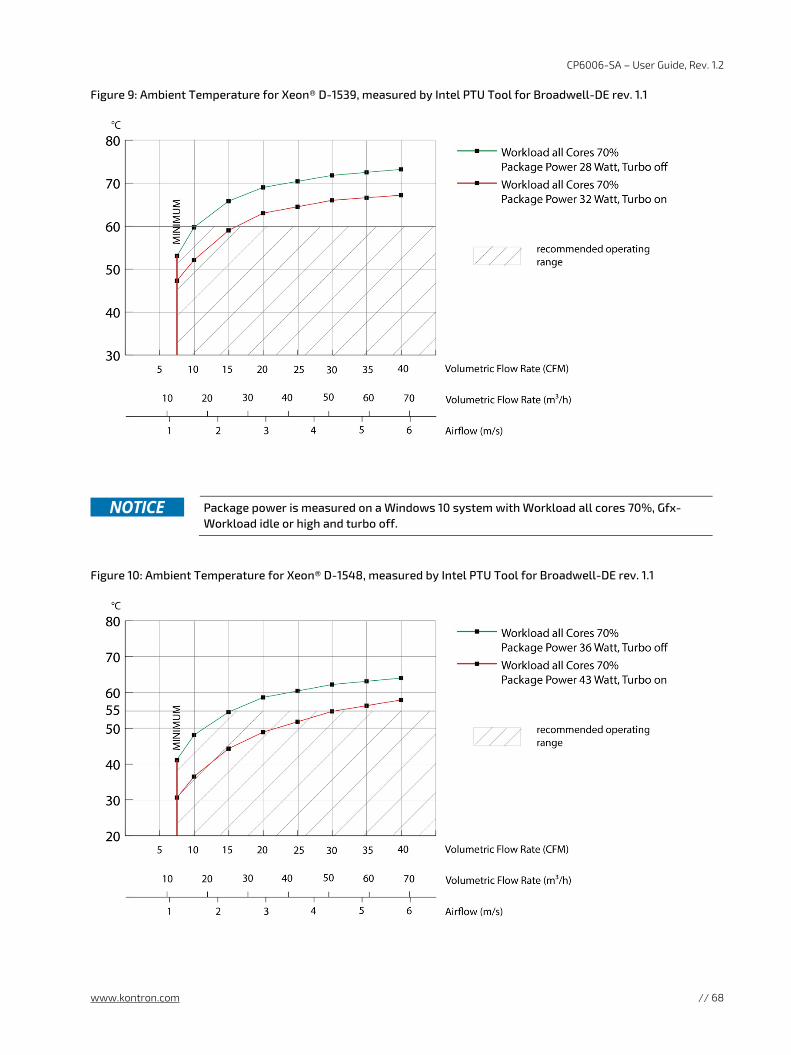
CP6006-SA – User Guide, Rev. 1.2
www.kontron.com // 68
Figure 9: Ambient Temperature for Xeon® D-1539, measured by Intel PTU Tool for Broadwell-DE rev. 1.1
Figure 10: Ambient Temperature for Xeon® D-1548, measured by Intel PTU Tool for Broadwell-DE rev. 1.1
Package power is measured on a Windows 10 system with Workload all cores 70%, Gfx-
Workload idle or high and turbo off.
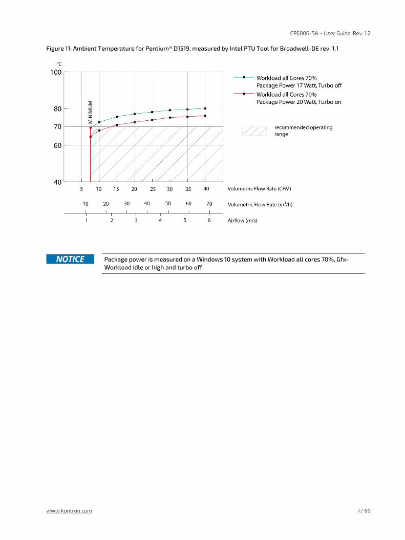
CP6006-SA – User Guide, Rev. 1.2
www.kontron.com // 69
Figure 11: Ambient Temperature for Pentium® D1519, measured by Intel PTU Tool for Broadwell-DE rev. 1.1
Package power is measured on a Windows 10 system with Workload all cores 70%, Gfx-
Workload idle or high and turbo off.
CP6006-SA – User Guide, Rev. 1.2
www.kontron.com // 70
5.3.1. Peripherals
When determining the thermal requirements for a given application, peripherals to be used with the CP6006(X)-SA must also be considered. Devices such as HDDs, SSDs, PMC modules, XMC modules which are directly attached to the CP6006(X)-SA must also be capable of being operated at the temperatures foreseen for the application. It may very well be necessary to revise system requirements to comply with operational environment conditions. In most cases, this will lead to a reduction in the maximum allowable ambient operating temperature or even require active cooling of the operating environment.
As Kontron assumes no responsibility for any damage to the CP6006(X)-SA or other
equipment resulting from overheating of the CPU, it is highly recommended that system integrators as well as end users confirm that the operational environment of the CP6006(X)-SA complies with the thermal considerations set forth in this document.
CP6006-SA – User Guide, Rev. 1.2
www.kontron.com // 71
6/ Installation This chapter is oriented towards an application environment. Some aspects may, however, be applicable to a development environment.
6.1. Safety
To ensure personnel safety and correct operation of this product, the following safety precautions must be observed:
All operations involving the CP6006(X)-SA require that personnel be familiar with system equipment, safety requirements and the CP6006(X)-SA.
This product contains electrostatically sensitive components which can be seriously damaged by electrical static discharge (ESD). Therefore, proper handling must be ensured at all times.
Whenever possible, unpack or pack this product only at EOS/ESD safe work stations. Where a safe work station is not guaranteed, it is important for the user to be electrically discharged before touching the product with his/her hands or tools. This is most easily done by touching a metal part of your system housing.
Do not handle this product out of its protective enclosure while it is not used for operational purposes unless it is otherwise protected.
Do not touch components, connector-pins or traces.
Kontron assumes no liability for any damage resulting from failure to comply with these requirements.
6.2. General Instructions on Usage
In order to maintain Kontron’s product warranty, this product must not be altered or modified in any way. Changes or modifications to the device, which are not explicitly approved by Kontron and described in this manual or received from Kontron’s Technical Support as a special handling instruction, will void your warranty.
This device should only be installed in or connected to systems that fulfill all necessary technical and specific environmental requirements. This applies also to the operational temperature range of the specific board version, which must not be exceeded. If batteries are present, their temperature restrictions must be taken into account.
6.3. Board Installation
The CP6006(X)-SA is designed for use either as a system board or as an autonomous CPU board in a peripheral slot.
When installed in the system slot, the CP6006(X)-SA provides all required functions for supporting the hot swapping of peripheral boards which are capable of being hot swapped.
When installed in a peripheral slot, the CP6006(X)-SA operates autonomously, meaning that it only draws power from the backplane.
6.3.1. Hot Swap Insertion
Prior to following the steps below, ensure that the safety requirements are met.
To insert the CP6006(X)-SA in a running system proceed as follows:
1. Ensure that the board ejection handles are open.
2. Insert the board into the slot designated until it makes contact with the backplane connectors.
3. Using the ejector handles, engage the board with the backplane. When the ejector handles are closed, the board is engaged.
4. The blue HS LED turns on and then off indicating that the CP6006(X)-SA is operating.
5. Fasten the front panel retaining screws.
6. Connect all external interfacing cables to the board as required.
CP6006-SA – User Guide, Rev. 1.2
www.kontron.com // 72
6.3.2. Hot Swap Removal
Prior to following the steps below, ensure that the safety requirements are met. When removing a board from the system, particular attention must be paid to the components that may be hot, such as heat sink, etc.
To remove the CP6006(X)-SA from a running system proceed as follows:
1. Unlock the board ejection handles by pressing their release buttons. The blue HS LED starts blinking indicating that the shutdown process has begun.
2. After approximately 1 to 15 seconds, the HS LED turns on steady indicating that the CP6006(X)-SA may be removed from the system.
3. Disconnect any interfacing cables that may be connected to the board.
4. Unscrew the front panel retaining screws.
5. Using the ejector handles, disengage the board from the backplane and remove it from the system.
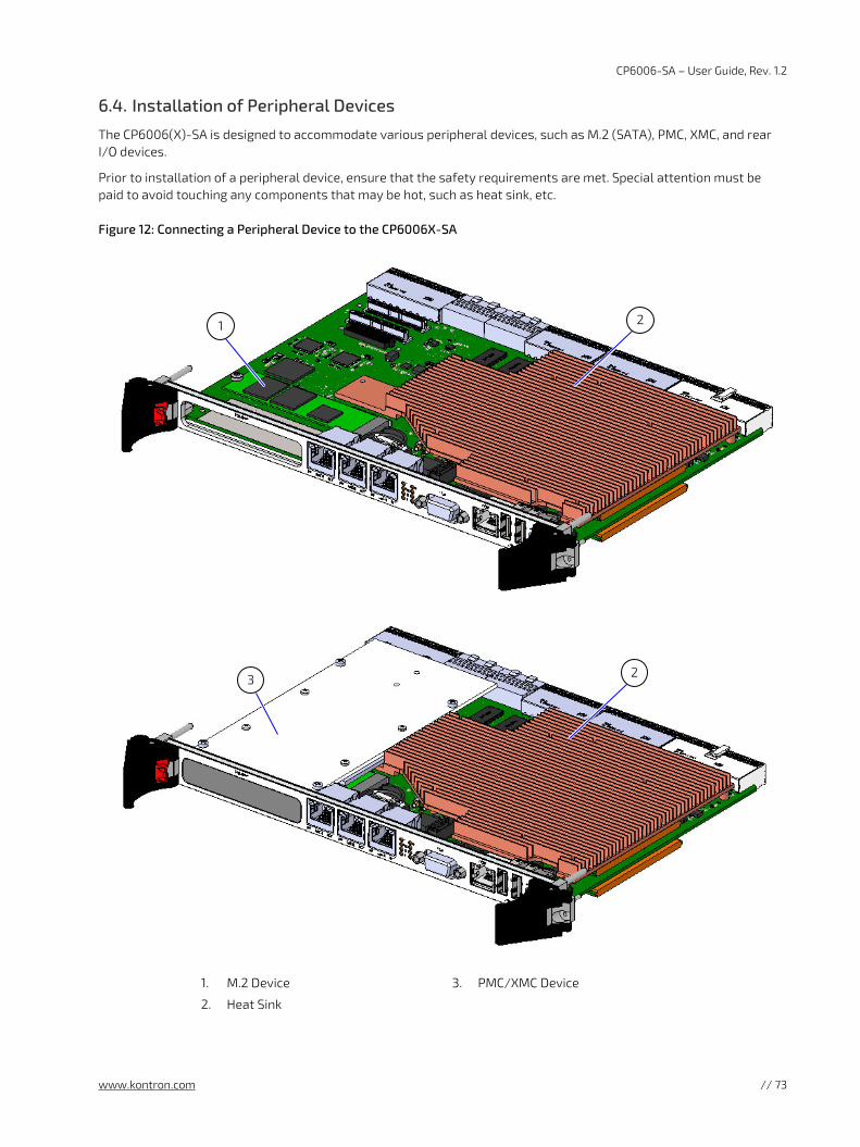
CP6006-SA – User Guide, Rev. 1.2
www.kontron.com // 73
6.4. Installation of Peripheral Devices
The CP6006(X)-SA is designed to accommodate various peripheral devices, such as M.2 (SATA), PMC, XMC, and rear I/O devices.
Prior to installation of a peripheral device, ensure that the safety requirements are met. Special attention must be paid to avoid touching any components that may be hot, such as heat sink, etc.
Figure 12: Connecting a Peripheral Device to the CP6006X-SA
1. M.2 Device
2. Heat Sink
3. PMC/XMC Device
1
3
2
2
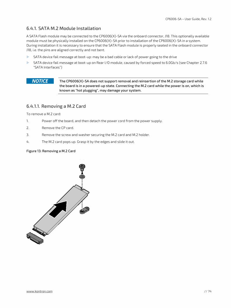
CP6006-SA – User Guide, Rev. 1.2
www.kontron.com // 74
6.4.1. SATA M.2 Module Installation
A SATA Flash module may be connected to the CP6006(X)-SA via the onboard connector, J18. This optionally available module must be physically installed on the CP6006(X)-SA prior to installation of the CP6006(X)-SA in a system. During installation it is necessary to ensure that the SATA Flash module is properly seated in the onboard connector J18, i.e. the pins are aligned correctly and not bent.
SATA device fail message at boot-up: may be a bad cable or lack of power going to the drive
SATA device fail message at boot-up on Rear I/O module, caused by forced speed to 6.0Gb/s (see Chapter 2.7.6 “SATA Interfaces”)
The CP6006(X)-SA does not support removal and reinsertion of the M.2 storage card while
the board is in a powered-up state. Connecting the M.2 card while the power is on, which is known as "hot plugging", may damage your system.
6.4.1.1. Removing a M.2 Card
To remove a M.2 card:
1. Power off the board, and then detach the power cord from the power supply.
2. Remove the CP card.
3. Remove the screw and washer securing the M.2 card and M.2 holder.
4. The M.2 card pops up. Grasp it by the edges and slide it out.
Figure 13: Removing a M.2 Card
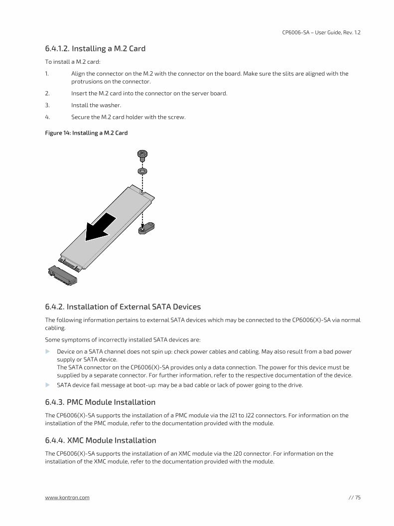
CP6006-SA – User Guide, Rev. 1.2
www.kontron.com // 75
6.4.1.2. Installing a M.2 Card
To install a M.2 card:
1. Align the connector on the M.2 with the connector on the board. Make sure the slits are aligned with the protrusions on the connector.
2. Insert the M.2 card into the connector on the server board.
3. Install the washer.
4. Secure the M.2 card holder with the screw.
Figure 14: Installing a M.2 Card
6.4.2. Installation of External SATA Devices
The following information pertains to external SATA devices which may be connected to the CP6006(X)-SA via normal cabling.
Some symptoms of incorrectly installed SATA devices are:
Device on a SATA channel does not spin up: check power cables and cabling. May also result from a bad power supply or SATA device. The SATA connector on the CP6006(X)-SA provides only a data connection. The power for this device must be supplied by a separate connector. For further information, refer to the respective documentation of the device.
SATA device fail message at boot-up: may be a bad cable or lack of power going to the drive.
6.4.3. PMC Module Installation
The CP6006(X)-SA supports the installation of a PMC module via the J21 to J22 connectors. For information on the installation of the PMC module, refer to the documentation provided with the module.
6.4.4. XMC Module Installation
The CP6006(X)-SA supports the installation of an XMC module via the J20 connector. For information on the installation of the XMC module, refer to the documentation provided with the module.
CP6006-SA – User Guide, Rev. 1.2
www.kontron.com // 76
6.4.5. Rear Transition Module Installation
For physical installation of rear transition modules, refer to the documentation provided with the module itself.
6.5. Battery Replacement
The CP6006(X)-SA RTC may be backed up using a single UL-approved CR2025, 3.0 V “coin cell” lithium battery from one of two possible points of installation:
onboard
on the rear transition module
Only one battery may be installed at a time. Refer to Table 1 for battery requirements.
6.5.1. Updating the IPMI Firmware
6.5.1.1. IPMI Rollback Mechanism
The CP6006(X)-SA’s IPMI controller has an internal flash, where the boot block or the active IPMI firmware is running from, as well as an external flash, where two IPMI firmware images are stored, namely:
a copy of the currently active image, and
the previously good image or the newly downloaded image.
During firmware upgrade, the previously good image in the external flash is replaced by the newly downloaded image. Then the boot block activates the new image by copying it to the internal flash. If the newly downloaded image was successfully activated, its copy in the external flash is now the active image. The copy of the old active image becomes the previously good image.
Manual rollback is also possible via the kIpmi hpm rollback uEFI Shell command.
6.5.1.2. Determining the Active IPMI Firmware Image
To determine the active IPMI firmware image, use the kIpmi info command.
6.5.1.3. Updating Procedure
The active IPMI firmware image can be updated with the latest HPM.1 file using the kIpmi hpm upgrade uEFI Shell command.
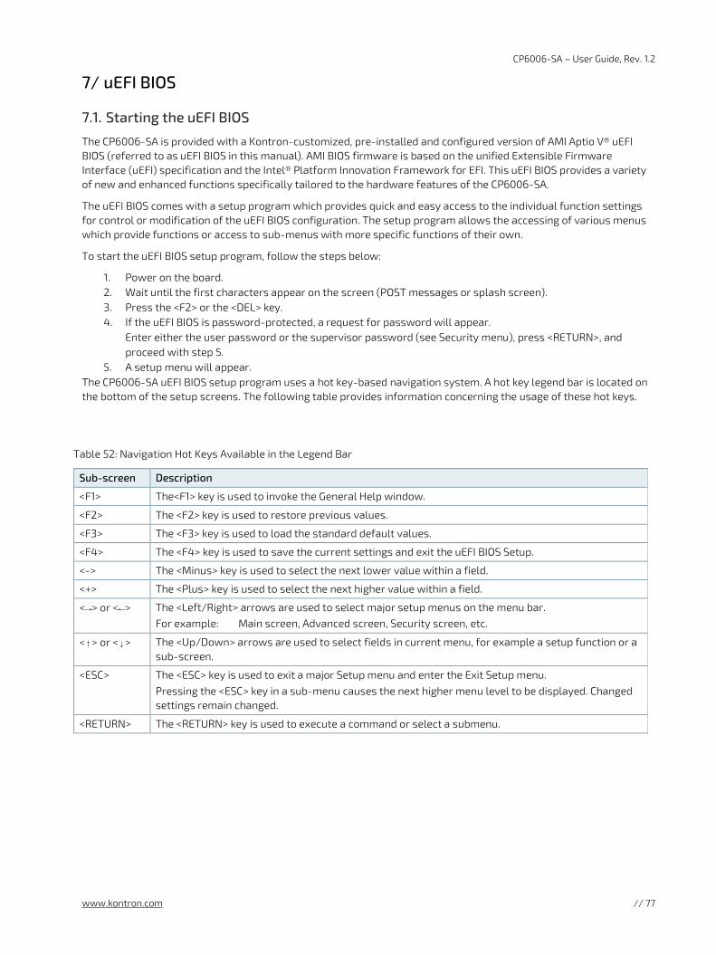
CP6006-SA – User Guide, Rev. 1.2
www.kontron.com // 77
7/ uEFI BIOS
7.1. Starting the uEFI BIOS
The CP6006-SA is provided with a Kontron-customized, pre-installed and configured version of AMI Aptio V® uEFI BIOS (referred to as uEFI BIOS in this manual). AMI BIOS firmware is based on the unified Extensible Firmware Interface (uEFI) specification and the Intel® Platform Innovation Framework for EFI. This uEFI BIOS provides a variety of new and enhanced functions specifically tailored to the hardware features of the CP6006-SA.
The uEFI BIOS comes with a setup program which provides quick and easy access to the individual function settings for control or modification of the uEFI BIOS configuration. The setup program allows the accessing of various menus which provide functions or access to sub-menus with more specific functions of their own.
To start the uEFI BIOS setup program, follow the steps below:
1. Power on the board. 2. Wait until the first characters appear on the screen (POST messages or splash screen). 3. Press the <F2> or the <DEL> key. 4. If the uEFI BIOS is password-protected, a request for password will appear.
Enter either the user password or the supervisor password (see Security menu), press <RETURN>, and proceed with step 5.
5. A setup menu will appear. The CP6006-SA uEFI BIOS setup program uses a hot key-based navigation system. A hot key legend bar is located on the bottom of the setup screens. The following table provides information concerning the usage of these hot keys.
Table 52: Navigation Hot Keys Available in the Legend Bar
Sub-screen Description
<F1> The<F1> key is used to invoke the General Help window.
<F2> The <F2> key is used to restore previous values.
<F3> The <F3> key is used to load the standard default values.
<F4> The <F4> key is used to save the current settings and exit the uEFI BIOS Setup.
<-> The <Minus> key is used to select the next lower value within a field.
<+> The <Plus> key is used to select the next higher value within a field.
<→> or <←> The <Left/Right> arrows are used to select major setup menus on the menu bar. For example: Main screen, Advanced screen, Security screen, etc.
<↑> or <↓> The <Up/Down> arrows are used to select fields in current menu, for example a setup function or a sub-screen.
<ESC> The <ESC> key is used to exit a major Setup menu and enter the Exit Setup menu. Pressing the <ESC> key in a sub-menu causes the next higher menu level to be displayed. Changed settings remain changed.
<RETURN> The <RETURN> key is used to execute a command or select a submenu.
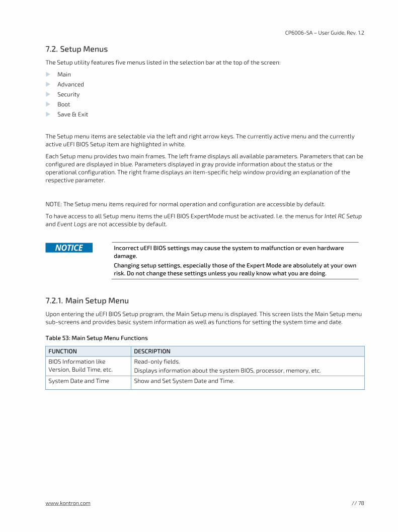
CP6006-SA – User Guide, Rev. 1.2
www.kontron.com // 78
7.2. Setup Menus
The Setup utility features five menus listed in the selection bar at the top of the screen:
Main
Advanced
Security
Boot
Save & Exit
The Setup menu items are selectable via the left and right arrow keys. The currently active menu and the currently active uEFI BIOS Setup item are highlighted in white.
Each Setup menu provides two main frames. The left frame displays all available parameters. Parameters that can be configured are displayed in blue. Parameters displayed in gray provide information about the status or the operational configuration. The right frame displays an item-specific help window providing an explanation of the respective parameter.
NOTE: The Setup menu items required for normal operation and configuration are accessible by default.
To have access to all Setup menu items the uEFI BIOS ExpertMode must be activated. I.e. the menus for Intel RC Setup and Event Logs are not accessible by default.
Incorrect uEFI BIOS settings may cause the system to malfunction or even hardware
damage.
Changing setup settings, especially those of the Expert Mode are absolutely at your own risk. Do not change these settings unless you really know what you are doing.
7.2.1. Main Setup Menu
Upon entering the uEFI BIOS Setup program, the Main Setup menu is displayed. This screen lists the Main Setup menu sub-screens and provides basic system information as well as functions for setting the system time and date.
Table 53: Main Setup Menu Functions
FUNCTION DESCRIPTION
BIOS Information like Version, Build Time, etc.
Read-only fields. Displays information about the system BIOS, processor, memory, etc.
System Date and Time Show and Set System Date and Time.
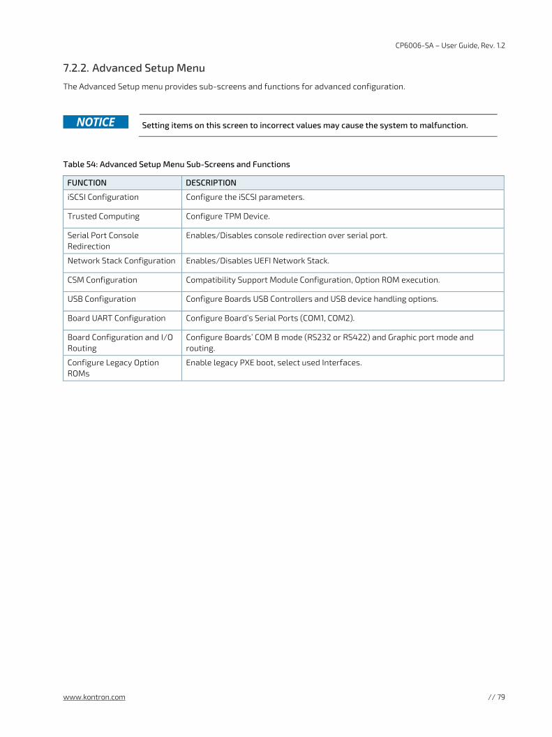
CP6006-SA – User Guide, Rev. 1.2
www.kontron.com // 79
7.2.2. Advanced Setup Menu
The Advanced Setup menu provides sub-screens and functions for advanced configuration.
Setting items on this screen to incorrect values may cause the system to malfunction.
Table 54: Advanced Setup Menu Sub-Screens and Functions
FUNCTION DESCRIPTION
iSCSI Configuration Configure the iSCSI parameters.
Trusted Computing Configure TPM Device.
Serial Port Console Redirection
Enables/Disables console redirection over serial port.
Network Stack Configuration Enables/Disables UEFI Network Stack.
CSM Configuration Compatibility Support Module Configuration, Option ROM execution.
USB Configuration Configure Boards USB Controllers and USB device handling options.
Board UART Configuration Configure Board’s Serial Ports (COM1, COM2).
Board Configuration and I/O Routing
Configure Boards’ COM B mode (RS232 or RS422) and Graphic port mode and routing.
Configure Legacy Option ROMs
Enable legacy PXE boot, select used Interfaces.
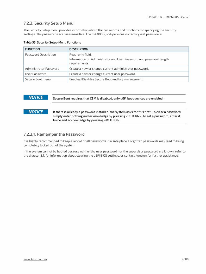
CP6006-SA – User Guide, Rev. 1.2
www.kontron.com // 80
7.2.3. Security Setup Menu
The Security Setup menu provides information about the passwords and functions for specifying the security settings. The passwords are case-sensitive. The CP6005(X)-SA provides no factory-set passwords.
Table 55: Security Setup Menu Functions
FUNCTION DESCRIPTION
Password Description Read-only field. Information on Administrator and User Password and password length requirements.
Administrator Password Create a new or change current administrator password.
User Password Create a new or change current user password.
Secure Boot menu Enables/Disables Secure Boot and key management.
Secure Boot requires that CSM is disabled, only uEFI boot devices are enabled.
If there is already a password installed, the system asks for this first. To clear a password,
simply enter nothing and acknowledge by pressing <RETURN>. To set a password, enter it twice and acknowledge by pressing <RETURN>.
7.2.3.1. Remember the Password
It is highly recommended to keep a record of all passwords in a safe place. Forgotten passwords may lead to being completely locked out of the system.
If the system cannot be booted because neither the user password nor the supervisor password are known, refer to the chapter 3.1, for information about clearing the uEFI BIOS settings, or contact Kontron for further assistance.
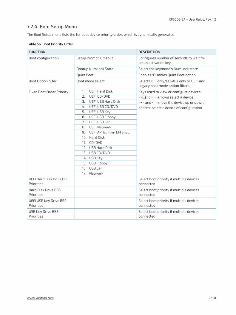
CP6006-SA – User Guide, Rev. 1.2
www.kontron.com // 81
7.2.4. Boot Setup Menu
The Boot Setup menu lists the for boot device priority order, which is dynamically generated.
Table 56: Boot Priority Order
FUNCTION DESCRIPTION
Boot configuration Setup Prompt Timeout Configures number of seconds to wait for setup activation key.
Bootup NumLock State Select the keyboard’s NumLock state.
Quiet Boot Enables/Disables Quiet Boot option
Boot Option filter Boot mode select Select UEFI only/LEGACY only or UEFI and Legacy boot mode option filters
Fixed Boot Order Priority 1. UEFI Hard Disk Keys used to view or configure devices: <>and <¯> arrows select a device. <+> and <-> move the device up or down. <Enter> select a device of configuration.
2. UEFI CD/DVD 3. UEFI USB Hard Disk 4. UEFI USB CD/DVD 5. UEFI USB Key 6. UEFI USB Floppy 7. UEFI USB Lan 8. UEFI Network 9. UEFI AP: Built-in EFI Shell 10. Hard Disk 11. CD/DVD 12. USB Hard Disk 13. USB CD/DVD 14. USB Key 15. USB Floppy 16. USB Lan 17. Network
UFEI Hard Disk Drive BBS Priorities
Select boot priority if multiple devices connected
Hard Disk Drive BBS Priorities
Select boot priority if multiple devices connected
UEFI USB Key Drive BBS Priorities
Select boot priority if multiple devices connected
USB Key Drive BBS Priorities
Select boot priority if multiple devices connected
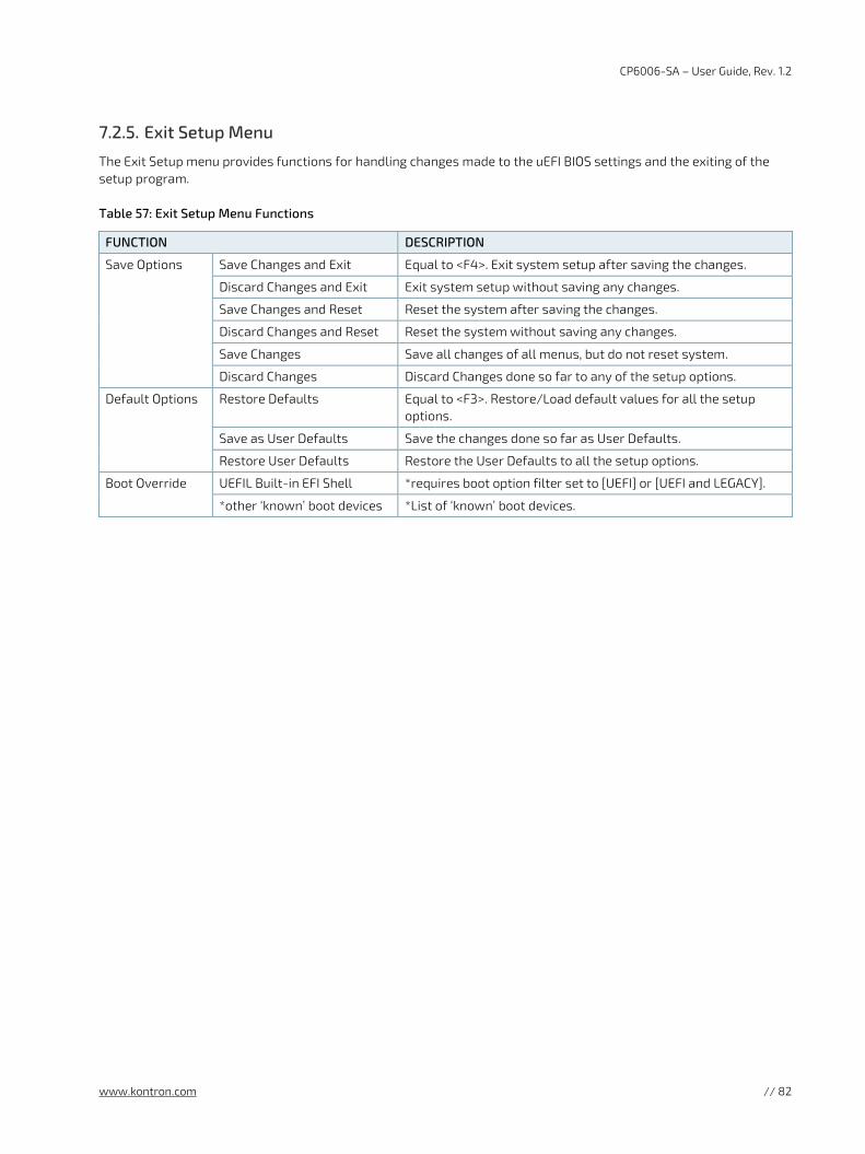
CP6006-SA – User Guide, Rev. 1.2
www.kontron.com // 82
7.2.5. Exit Setup Menu
The Exit Setup menu provides functions for handling changes made to the uEFI BIOS settings and the exiting of the setup program.
Table 57: Exit Setup Menu Functions
FUNCTION DESCRIPTION
Save Options Save Changes and Exit Equal to <F4>. Exit system setup after saving the changes.
Discard Changes and Exit Exit system setup without saving any changes.
Save Changes and Reset Reset the system after saving the changes.
Discard Changes and Reset Reset the system without saving any changes.
Save Changes Save all changes of all menus, but do not reset system.
Discard Changes Discard Changes done so far to any of the setup options.
Default Options Restore Defaults Equal to <F3>. Restore/Load default values for all the setup options.
Save as User Defaults Save the changes done so far as User Defaults.
Restore User Defaults Restore the User Defaults to all the setup options.
Boot Override UEFIL Built-in EFI Shell *requires boot option filter set to [UEFI] or [UEFI and LEGACY].
*other ‘known’ boot devices *List of ‘known’ boot devices.
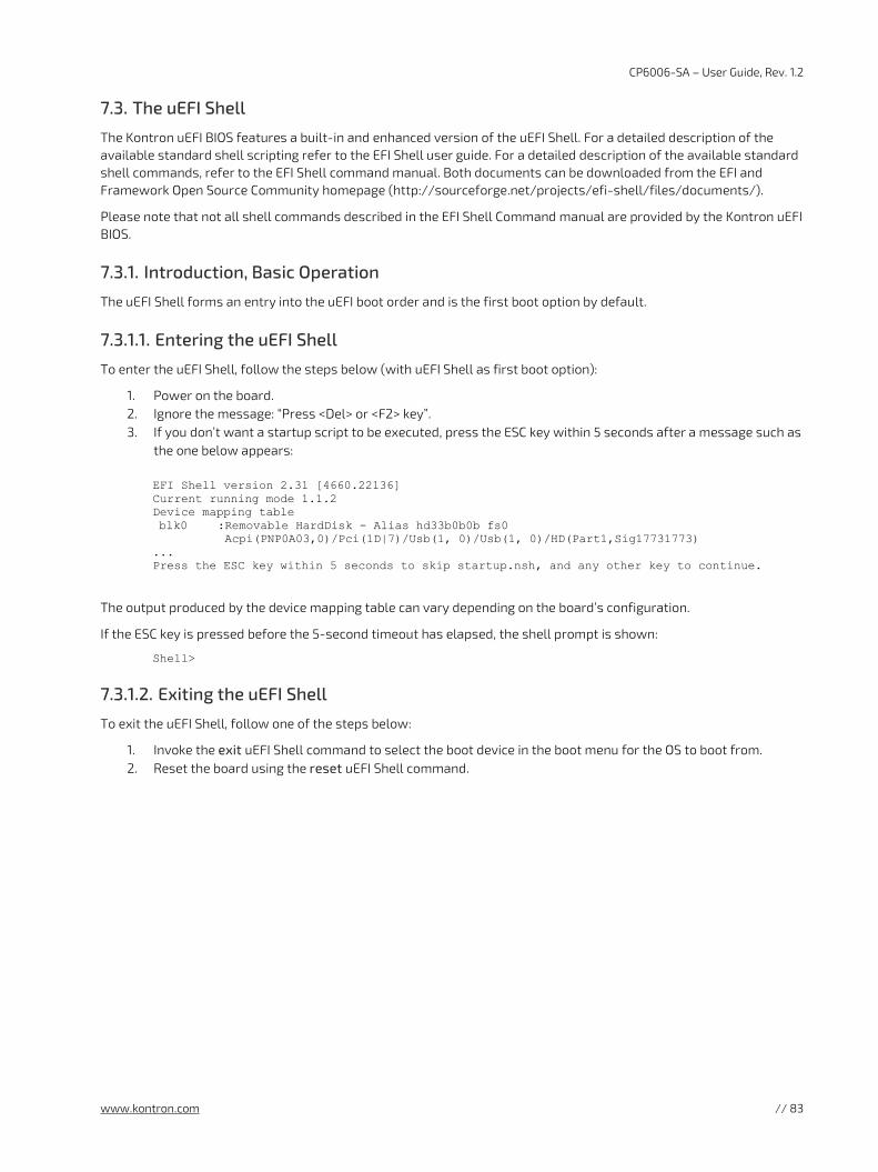
CP6006-SA – User Guide, Rev. 1.2
www.kontron.com // 83
7.3. The uEFI Shell
The Kontron uEFI BIOS features a built-in and enhanced version of the uEFI Shell. For a detailed description of the available standard shell scripting refer to the EFI Shell user guide. For a detailed description of the available standard shell commands, refer to the EFI Shell command manual. Both documents can be downloaded from the EFI and Framework Open Source Community homepage (http://sourceforge.net/projects/efi-shell/files/documents/).
Please note that not all shell commands described in the EFI Shell Command manual are provided by the Kontron uEFI BIOS.
7.3.1. Introduction, Basic Operation
The uEFI Shell forms an entry into the uEFI boot order and is the first boot option by default.
7.3.1.1. Entering the uEFI Shell
To enter the uEFI Shell, follow the steps below (with uEFI Shell as first boot option):
1. Power on the board. 2. Ignore the message: “Press <Del> or <F2> key”. 3. If you don’t want a startup script to be executed, press the ESC key within 5 seconds after a message such as
the one below appears:
EFI Shell version 2.31 [4660.22136] Current running mode 1.1.2 Device mapping table blk0 :Removable HardDisk - Alias hd33b0b0b fs0 Acpi(PNP0A03,0)/Pci(1D|7)/Usb(1, 0)/Usb(1, 0)/HD(Part1,Sig17731773) ... Press the ESC key within 5 seconds to skip startup.nsh, and any other key to continue.
The output produced by the device mapping table can vary depending on the board’s configuration.
If the ESC key is pressed before the 5-second timeout has elapsed, the shell prompt is shown:
Shell>
7.3.1.2. Exiting the uEFI Shell
To exit the uEFI Shell, follow one of the steps below:
1. Invoke the exit uEFI Shell command to select the boot device in the boot menu for the OS to boot from. 2. Reset the board using the reset uEFI Shell command.
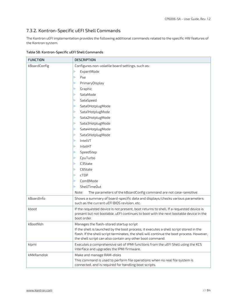
CP6006-SA – User Guide, Rev. 1.2
www.kontron.com // 84
7.3.2. Kontron-Specific uEFI Shell Commands
The Kontron uEFI implementation provides the following additional commands related to the specific HW features of the Kontron system.
Table 58: Kontron-Specific uEFI Shell Commands
FUNCTION DESCRIPTION
kBoardConfig Configures non-volatile board settings, such as:
ExpertMode
Pxe
PrimaryDisplay
Graphic
SataMode
SataSpeed
Sata0HotplugMode
Sata1HotplugMode
Sata2HotplugMode
Sata3HotplugMode
Sata4HotplugMode
Sata5HotplugMode
IntelVT
IntelHT
SpeedStep
CpuTurbo
C3State
C6State
cTDP
ComBMode
ShellTimeOut
Note: The parameters of the kBoardConfig command are not case-sensitive.
kBoardInfo Shows a summary of board-specific data and displays/checks various parameters such as the current uEFI BIOS revision, etc.
kboot If the requested device is not present, boot returns to shell. If a requested device is present but not bootable, uEFI continues to boot with the next bootable device in the boot order.
kBootNsh Manages the flash-stored startup script If the shell is launched by the boot process, it executes a shell script stored in the flash. If the shell script terminates, the shell will continue the boot process. However, the shell script can also contain any other boot command.
kIpmi Executes a comprehensive set of IPMI functions from the uEFI Shell using the KCS interface and upgrades the IPMI firmware.
kMkRamdisk Make and manage RAM-disks This command is used to perform file operations when no real file system is connected, and is required for handling boot scripts.
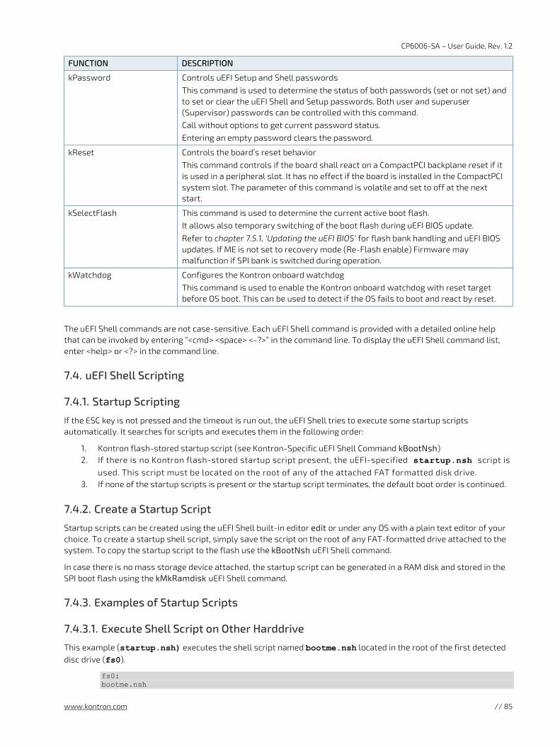
CP6006-SA – User Guide, Rev. 1.2
www.kontron.com // 85
FUNCTION DESCRIPTION
kPassword Controls uEFI Setup and Shell passwords This command is used to determine the status of both passwords (set or not set) and to set or clear the uEFI Shell and Setup passwords. Both user and superuser (Supervisor) passwords can be controlled with this command. Call without options to get current password status. Entering an empty password clears the password.
kReset Controls the board’s reset behavior This command controls if the board shall react on a CompactPCI backplane reset if it is used in a peripheral slot. It has no effect if the board is installed in the CompactPCI system slot. The parameter of this command is volatile and set to off at the next start.
kSelectFlash This command is used to determine the current active boot flash. It allows also temporary switching of the boot flash during uEFI BIOS update.
Refer to chapter 7.5.1, ‘Updating the uEFI BIOS’ for flash bank handling and uEFI BIOS updates. If ME is not set to recovery mode (Re-Flash enable) Firmware may malfunction if SPI bank is switched during operation.
kWatchdog Configures the Kontron onboard watchdog This command is used to enable the Kontron onboard watchdog with reset target before OS boot. This can be used to detect if the OS fails to boot and react by reset.
The uEFI Shell commands are not case-sensitive. Each uEFI Shell command is provided with a detailed online help that can be invoked by entering “<cmd> <space> <-?>” in the command line. To display the uEFI Shell command list, enter <help> or <?> in the command line.
7.4. uEFI Shell Scripting
7.4.1. Startup Scripting
If the ESC key is not pressed and the timeout is run out, the uEFI Shell tries to execute some startup scripts automatically. It searches for scripts and executes them in the following order:
1. Kontron flash-stored startup script (see Kontron-Specific uEFI Shell Command kBootNsh) 2. If there is no Kontron flash-stored startup script present, the uEFI-specified startup.nsh script is
used. This script must be located on the root of any of the attached FAT formatted disk drive. 3. If none of the startup scripts is present or the startup script terminates, the default boot order is continued.
7.4.2. Create a Startup Script
Startup scripts can be created using the uEFI Shell built-in editor edit or under any OS with a plain text editor of your choice. To create a startup shell script, simply save the script on the root of any FAT-formatted drive attached to the system. To copy the startup script to the flash use the kBootNsh uEFI Shell command.
In case there is no mass storage device attached, the startup script can be generated in a RAM disk and stored in the SPI boot flash using the kMkRamdisk uEFI Shell command.
7.4.3. Examples of Startup Scripts
7.4.3.1. Execute Shell Script on Other Harddrive
This example (startup.nsh) executes the shell script named bootme.nsh located in the root of the first detected disc drive (fs0).
fs0: bootme.nsh
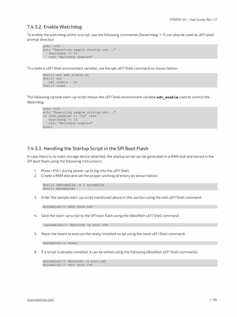
CP6006-SA – User Guide, Rev. 1.2
www.kontron.com // 86
7.4.3.2. Enable Watchdog
To enable the watchdog within a script, use the following commands (kwatchdog -t 15 can also be used at uEFI shell prompt directly):
echo -off echo “Executing sample startup.nsh...” kwatchdog -t 15 echo “Watchdog enabled”
To create a uEFI Shell environment variable, use the set uEFI Shell command as shown below:
Shell> set wdt_enable on Shell> set wdt_enable : on Shell> reset
The following sample start-up script shows the uEFI Shell environment variable wdt_enable used to control the Watchdog.
echo -off echo “Executing sample startup.nsh...” if %wdt_enable% == “on” then kwatchdog -t 15 echo “Watchdog enabled” endif
7.4.3.3. Handling the Startup Script in the SPI Boot Flash
In case there is no mass storage device attached, the startup script can be generated in a RAM disk and stored in the SPI boot flash using the following instructions:
1. Press <ESC> during power-up to log into the uEFI Shell. 2. Create a RAM disk and set the proper working directory as shown below:
Shell> kmkramdisk -s 3 myramdisk Shell> myramdisk:
3. Enter the sample start-up script mentioned above in this section using the edit uEFI Shell command.
myramdisk:\> edit boot.nsh
4. Save the start-up script to the SPI boot flash using the kBootNsh uEFI Shell command.
myramdisk:\> kbootnsh -p boot.nsh
5. Reset the board to execute the newly installed script using the reset uEFI Shell command.
myramdisk:\> reset
6. If a script is already installed, it can be edited using the following kBootNsh uEFI Shell commands.
myramdisk:\> kbootnsh -g boot.nsh myramdisk:\> edit boot.nsh
CP6006-SA – User Guide, Rev. 1.2
www.kontron.com // 87
7.5. Firmware Update
7.5.1. Updating the uEFI BIOS
7.5.1.1. uEFI BIOS Fail-Over Mechanism
The CP6005(X)-SA has two SPI boot flashes programmed with the uEFI BIOS, a standard SPI boot flash and a recovery SPI boot flash. The basic idea behind that is to always have at least one working uEFI BIOS flash available regardless if there have been any flashing errors or not.
7.5.1.2. Updating the uEFI BIOS
For updating the BIOS, perform the following steps: 1. Download AFU from AMI
https://ami.com/en/download-license-agreement/?DownloadFile=Aptio_V_AMI_Firmware_Update_Utility.zip
2. Prepare USB Stick with
AfuEfix64.efi update.nsh (optional) BIOS Binary
3. Plug USB Stick into CP6006-SA
4. Boot into uEFI Shell and enable ExpertMode Shell>kboardconfig ExpertMode enabled Shell>reset
5. Boot into uEFI BIOS Setup and enable ME Update Advanced> IntelRCSetup> Server ME Configuration> Switch ME to Recovery Mode
6. Save and Exit and directly boot to EFI Shell
7. Go to USB Stick (use "map" to list all devices): e.g.: fs0:
8. Start update
update.nsh <FileName>.bin
Or use AfuEfix64.efi according to the help (user manual) provided by AMI with AFU tool.
7.5.1.3. uEFI BIOS Recovery
In case of the standard SPI boot flash being corrupted and therefore the board not starting up, the board can be booted from the recovery SPI boot flash if the DIP switch SW1, switch 2 is set to ON. For further information, refer to the Chapter 3.1, DIP Switch Configuration.
The uEFI BIOS code and settings are stored in the SPI boot flashes. Changes made to the uEFI BIOS settings are available only in the currently selected SPI boot flash. Thus, switching over to the other SPI boot flash may result in operation with different uEFI BIOS code and settings.
CP6006-SA – User Guide, Rev. 1.2
www.kontron.com // 88
7.5.1.4. Determining the Active Flash
Sometimes it may be necessary to check which flash is active. On the uEFI BIOS, this information is available via the uEFI Shell commands: kBoardInfo and kSelectFlash.
The kBoardInfo uEFI Shell command always displays the SPI flash information from which the uEFI BIOS was started.
The kSelectFlash uEFI Shell command displays the current selected SPI boot flash.
If changed after booting (e.g. via DIP switch SW1 switch 2 or the kSelectFlash uEFI Shell command itself)
7.5.2. Updating the IPMI Firmware
7.5.2.1. IPMI Rollback Mechanism
The CP6005(X)-SA’s IPMI controller has an internal flash, where the boot block or the active IPMI firmware is running from, as well as an external flash, where two IPMI firmware images are stored, namely:
a copy of the currently active image, and
the previously good image or the newly downloaded image.
During firmware upgrade, the previously good image in the external flash is replaced by the newly downloaded image. Then the boot block activates the new image by copying it to the internal flash. If the newly downloaded image was successfully activated, its copy in the external flash is now the active image. The copy of the old active image becomes the previously good image.
Manual rollback is also possible via the kIpmi hpm rollback uEFI Shell command.
7.5.2.2. Determining the Active IPMI Firmware Image
To determine the active IPMI firmware image, use the kIpmi info command.
7.5.2.3. Updating Procedure
The active IPMI firmware image can be updated with the latest HPM.1 file using the kIpmi hpm upgrade uEFI Shell command.
CP6006-SA – User Guide, Rev. 1.2
www.kontron.com // 89
8/ IPMI Firmware
8.1. Overview
The CP6006(X)-SA provides an IPMI controller (NXP® ARM7) with 512 kB of internal firmware flash as well as external firmware flash for firmware upgrade and rollback. The IPMI controller carries out IPMI commands such as monitoring several onboard temperature conditions, board voltages and the power supply status, and managing hot swap operations. The IPMI controller is accessible via two IPMBs, one host Keyboard Controller Style (KCS) interface and up to four Gigabit Ethernet interfaces (IOL).
The CP6006(X)-SA is fully compliant with the IPMI - Intelligent Platform Management Interface v2.0 and the PICMG 2.9 R1.0 specifications.
The following are key features of the CP6006(X)-SA’s IPMI firmware:
Keyboard Controller Style (KCS) interface
Dual-port IPMB interface for out-of-band management and sensor monitoring
IPMI over LAN (IOL) and Serial over LAN (SOL) support
Sensor Device functionality with configurable thresholds for monitoring board voltages, CPU state, board reset, etc.
FRU Inventory functionality
System Event Log (SEL), Event Receiver functionalities
Sensor Data Record Repository (SDRR) functionality
IPMI Watchdog functionality (power-cycle, reset)
Board monitoring and control extensions:
Graceful shutdown support uEFI BIOS fail-over control: selection of the SPI boot flash (standard/recovery)
Field-upgradeable IPMI firmware:
via the KCS, IPMB or IOL interfaces Download of firmware does not break the currently running firmware or payload activities
Two flash banks with rollback capability: manual rollback or automatic in case of upgrade failure
For general information on the Kontron IPMI Firmware, refer to the IPMI Firmware User Guide.
8.2. IPMI Firmware and KCS Interface Configuration
Initially the default configuration of the IPMI firmware (KCS interface) is:
IRQ = 11
MODE = SMC
IPMB = single-ported.
If this is the required configuration, no further action is required. If the configuration must be modified, the kIpmi uEFI Shell command is used to modify the configuration as required, e.g. “kIpmi irq [0|11]”, “kIpmi mode [smc|bmc]”, and “kIpmi ipmb [single-ported|dual-ported]”. For information on the kIpmi uEFI Shell command, refer to the uEFI BIOS Chapter.
The KCS interface serves for the communication between the CP6006(X)-SA’s payload and the IPMI controller. The IPMI OS kernel s require the KCS interface configuration during their loading time. The KCS interface configuration is available in the “IPMI Device Information Record” included in the SMBIOS table.
8.3. Supported IPMI and ATCA Commands
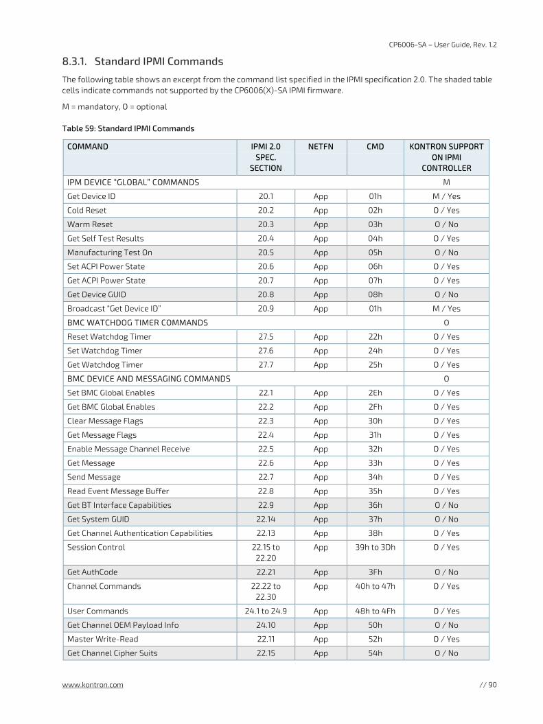
CP6006-SA – User Guide, Rev. 1.2
www.kontron.com // 90
8.3.1. Standard IPMI Commands
The following table shows an excerpt from the command list specified in the IPMI specification 2.0. The shaded table cells indicate commands not supported by the CP6006(X)-SA IPMI firmware.
M = mandatory, O = optional
Table 59: Standard IPMI Commands
COMMAND IPMI 2.0 SPEC.
SECTION
NETFN CMD KONTRON SUPPORT ON IPMI
CONTROLLER
IPM DEVICE “GLOBAL” COMMANDS M
Get Device ID 20.1 App 01h M / Yes
Cold Reset 20.2 App 02h O / Yes
Warm Reset 20.3 App 03h O / No
Get Self Test Results 20.4 App 04h O / Yes
Manufacturing Test On 20.5 App 05h O / No
Set ACPI Power State 20.6 App 06h O / Yes
Get ACPI Power State 20.7 App 07h O / Yes
Get Device GUID 20.8 App 08h O / No
Broadcast “Get Device ID” 20.9 App 01h M / Yes
BMC WATCHDOG TIMER COMMANDS O
Reset Watchdog Timer 27.5 App 22h O / Yes
Set Watchdog Timer 27.6 App 24h O / Yes
Get Watchdog Timer 27.7 App 25h O / Yes
BMC DEVICE AND MESSAGING COMMANDS O
Set BMC Global Enables 22.1 App 2Eh O / Yes
Get BMC Global Enables 22.2 App 2Fh O / Yes
Clear Message Flags 22.3 App 30h O / Yes
Get Message Flags 22.4 App 31h O / Yes
Enable Message Channel Receive 22.5 App 32h O / Yes
Get Message 22.6 App 33h O / Yes
Send Message 22.7 App 34h O / Yes
Read Event Message Buffer 22.8 App 35h O / Yes
Get BT Interface Capabilities 22.9 App 36h O / No
Get System GUID 22.14 App 37h O / No
Get Channel Authentication Capabilities 22.13 App 38h O / Yes
Session Control 22.15 to 22.20
App 39h to 3Dh O / Yes
Get AuthCode 22.21 App 3Fh O / No
Channel Commands 22.22 to 22.30
App 40h to 47h O / Yes
User Commands 24.1 to 24.9 App 48h to 4Fh O / Yes
Get Channel OEM Payload Info 24.10 App 50h O / No
Master Write-Read 22.11 App 52h O / Yes
Get Channel Cipher Suits 22.15 App 54h O / No
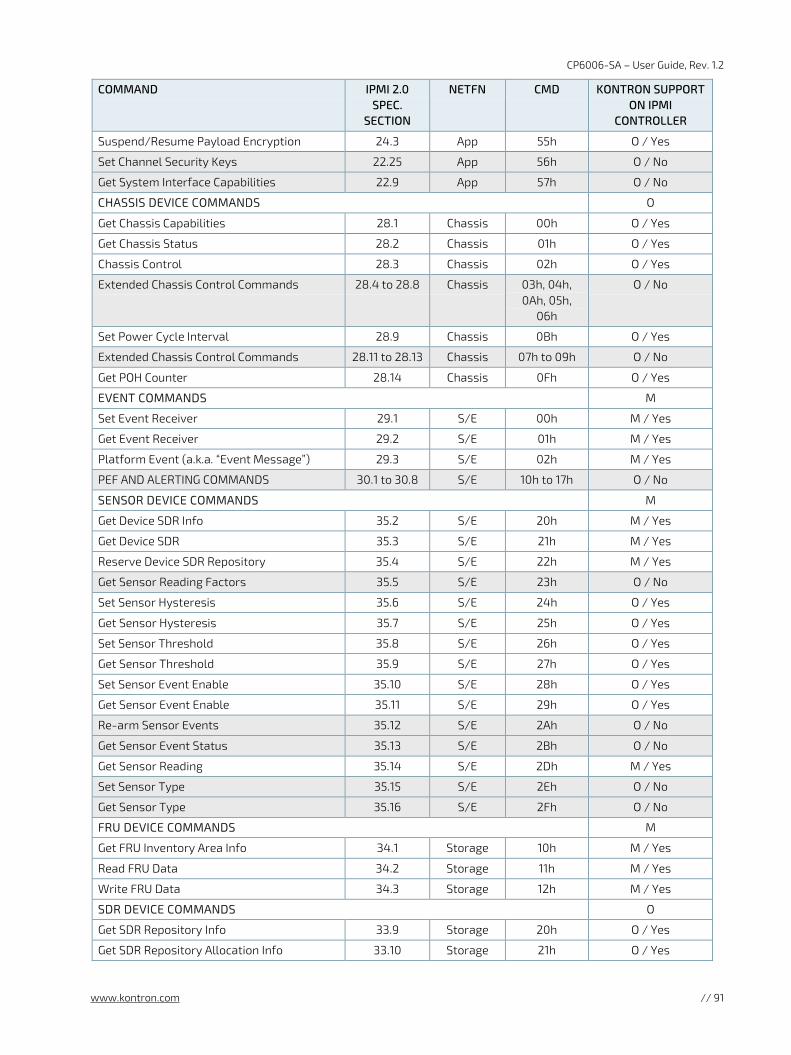
CP6006-SA – User Guide, Rev. 1.2
www.kontron.com // 91
COMMAND IPMI 2.0 SPEC.
SECTION
NETFN CMD KONTRON SUPPORT ON IPMI
CONTROLLER
Suspend/Resume Payload Encryption 24.3 App 55h O / Yes
Set Channel Security Keys 22.25 App 56h O / No
Get System Interface Capabilities 22.9 App 57h O / No
CHASSIS DEVICE COMMANDS O
Get Chassis Capabilities 28.1 Chassis 00h O / Yes
Get Chassis Status 28.2 Chassis 01h O / Yes
Chassis Control 28.3 Chassis 02h O / Yes
Extended Chassis Control Commands 28.4 to 28.8 Chassis 03h, 04h, 0Ah, 05h,
06h
O / No
Set Power Cycle Interval 28.9 Chassis 0Bh O / Yes
Extended Chassis Control Commands 28.11 to 28.13 Chassis 07h to 09h O / No
Get POH Counter 28.14 Chassis 0Fh O / Yes
EVENT COMMANDS M
Set Event Receiver 29.1 S/E 00h M / Yes
Get Event Receiver 29.2 S/E 01h M / Yes
Platform Event (a.k.a. “Event Message”) 29.3 S/E 02h M / Yes
PEF AND ALERTING COMMANDS 30.1 to 30.8 S/E 10h to 17h O / No
SENSOR DEVICE COMMANDS M
Get Device SDR Info 35.2 S/E 20h M / Yes
Get Device SDR 35.3 S/E 21h M / Yes
Reserve Device SDR Repository 35.4 S/E 22h M / Yes
Get Sensor Reading Factors 35.5 S/E 23h O / No
Set Sensor Hysteresis 35.6 S/E 24h O / Yes
Get Sensor Hysteresis 35.7 S/E 25h O / Yes
Set Sensor Threshold 35.8 S/E 26h O / Yes
Get Sensor Threshold 35.9 S/E 27h O / Yes
Set Sensor Event Enable 35.10 S/E 28h O / Yes
Get Sensor Event Enable 35.11 S/E 29h O / Yes
Re-arm Sensor Events 35.12 S/E 2Ah O / No
Get Sensor Event Status 35.13 S/E 2Bh O / No
Get Sensor Reading 35.14 S/E 2Dh M / Yes
Set Sensor Type 35.15 S/E 2Eh O / No
Get Sensor Type 35.16 S/E 2Fh O / No
FRU DEVICE COMMANDS M
Get FRU Inventory Area Info 34.1 Storage 10h M / Yes
Read FRU Data 34.2 Storage 11h M / Yes
Write FRU Data 34.3 Storage 12h M / Yes
SDR DEVICE COMMANDS O
Get SDR Repository Info 33.9 Storage 20h O / Yes
Get SDR Repository Allocation Info 33.10 Storage 21h O / Yes
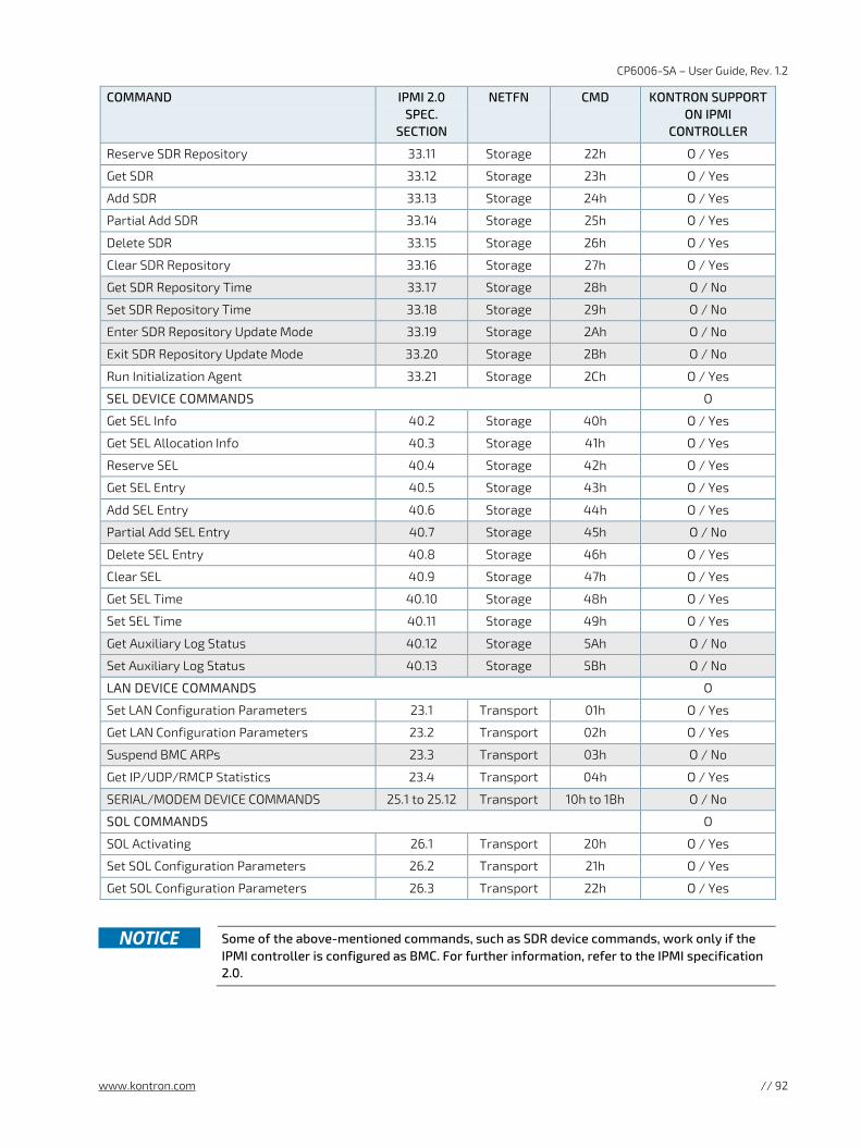
CP6006-SA – User Guide, Rev. 1.2
www.kontron.com // 92
COMMAND IPMI 2.0 SPEC.
SECTION
NETFN CMD KONTRON SUPPORT ON IPMI
CONTROLLER
Reserve SDR Repository 33.11 Storage 22h O / Yes
Get SDR 33.12 Storage 23h O / Yes
Add SDR 33.13 Storage 24h O / Yes
Partial Add SDR 33.14 Storage 25h O / Yes
Delete SDR 33.15 Storage 26h O / Yes
Clear SDR Repository 33.16 Storage 27h O / Yes
Get SDR Repository Time 33.17 Storage 28h O / No
Set SDR Repository Time 33.18 Storage 29h O / No
Enter SDR Repository Update Mode 33.19 Storage 2Ah O / No
Exit SDR Repository Update Mode 33.20 Storage 2Bh O / No
Run Initialization Agent 33.21 Storage 2Ch O / Yes
SEL DEVICE COMMANDS O
Get SEL Info 40.2 Storage 40h O / Yes
Get SEL Allocation Info 40.3 Storage 41h O / Yes
Reserve SEL 40.4 Storage 42h O / Yes
Get SEL Entry 40.5 Storage 43h O / Yes
Add SEL Entry 40.6 Storage 44h O / Yes
Partial Add SEL Entry 40.7 Storage 45h O / No
Delete SEL Entry 40.8 Storage 46h O / Yes
Clear SEL 40.9 Storage 47h O / Yes
Get SEL Time 40.10 Storage 48h O / Yes
Set SEL Time 40.11 Storage 49h O / Yes
Get Auxiliary Log Status 40.12 Storage 5Ah O / No
Set Auxiliary Log Status 40.13 Storage 5Bh O / No
LAN DEVICE COMMANDS O
Set LAN Configuration Parameters 23.1 Transport 01h O / Yes
Get LAN Configuration Parameters 23.2 Transport 02h O / Yes
Suspend BMC ARPs 23.3 Transport 03h O / No
Get IP/UDP/RMCP Statistics 23.4 Transport 04h O / Yes
SERIAL/MODEM DEVICE COMMANDS 25.1 to 25.12 Transport 10h to 1Bh O / No
SOL COMMANDS O
SOL Activating 26.1 Transport 20h O / Yes
Set SOL Configuration Parameters 26.2 Transport 21h O / Yes
Get SOL Configuration Parameters 26.3 Transport 22h O / Yes
Some of the above-mentioned commands, such as SDR device commands, work only if the
IPMI controller is configured as BMC. For further information, refer to the IPMI specification 2.0.
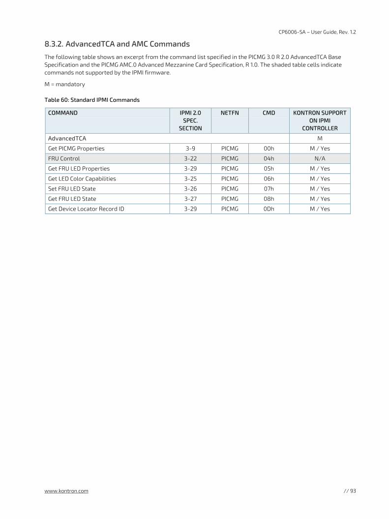
CP6006-SA – User Guide, Rev. 1.2
www.kontron.com // 93
8.3.2. AdvancedTCA and AMC Commands
The following table shows an excerpt from the command list specified in the PICMG 3.0 R 2.0 AdvancedTCA Base Specification and the PICMG AMC.0 Advanced Mezzanine Card Specification, R 1.0. The shaded table cells indicate commands not supported by the IPMI firmware.
M = mandatory
Table 60: Standard IPMI Commands
COMMAND IPMI 2.0 SPEC.
SECTION
NETFN CMD KONTRON SUPPORT ON IPMI
CONTROLLER
AdvancedTCA M
Get PICMG Properties 3-9 PICMG 00h M / Yes
FRU Control 3-22 PICMG 04h N/A
Get FRU LED Properties 3-29 PICMG 05h M / Yes
Get LED Color Capabilities 3-25 PICMG 06h M / Yes
Set FRU LED State 3-26 PICMG 07h M / Yes
Get FRU LED State 3-27 PICMG 08h M / Yes
Get Device Locator Record ID 3-29 PICMG 0Dh M / Yes
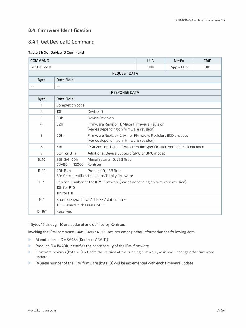
CP6006-SA – User Guide, Rev. 1.2
www.kontron.com // 94
8.4. Firmware Identification
8.4.1. Get Device ID Command
Table 61: Get Device ID Command
COMMAND LUN NetFn CMD
Get Device ID 00h App = 06h 01h
REQUEST DATA
Byte Data Field
-- --
RESPONSE DATA
Byte Data Field
1 Completion code
2 10h Device ID
3 80h Device Revision
4 02h Firmware Revision 1: Major Firmware Revision (varies depending on firmware revision)
5 00h Firmware Revision 2: Minor Firmware Revision, BCD encoded (varies depending on firmware revision)
6 51h IPMI Version, holds IPMI command specification version, BCD encoded
7 BDh or BFh Additional Device Support (SMC or BMC mode)
8..10 98h 3Ah 00h Manufacturer ID, LSB first 03A98h = 15000 = Kontron
11..12 40h B4h Product ID, LSB first B440h = Identifies the board/family firmware
13* Release number of the IPMI firmware (varies depending on firmware revision): 10h for R10 11h for R11
14* Board Geographical Address/slot number: 1 … = Board in chassis slot 1…
15..16* Reserved
* Bytes 13 through 16 are optional and defined by Kontron.
Invoking the IPMI command Get Device ID returns among other information the following data:
Manufacturer ID = 3A98h (Kontron IANA ID)
Product ID = B440h, identifies the board family of the IPMI firmware
Firmware revision (byte 4:5) reflects the version of the running firmware, which will change after firmware update.
Release number of the IPMI firmware (byte 13) will be incremented with each firmware update

CP6006-SA – User Guide, Rev. 1.2
www.kontron.com // 95
8.4.2. Device Locator Record
The device ID string which can be found by reading the Device Locator Record (SDR Type 12h) contains the string “BMC:x ... x”. For example, invoking the “ipmitool” command ipmitool sdr list mcloc will return the device ID strings of all available boards. If the IPMI controller is in BMC mode, this string will be displayed without change. If the IPMI controller is in SMC mode, then the string will be changed into “Sxx: x ... x” where xx is the slot number where the board is residing, e.g. “S09: x ... x”.
8.5. Board Control Extensions
8.5.1. SPI Boot Flash Selection—uEFI BIOS Failover Control
The uEFI BIOS code is stored in two different SPI boot flash devices designated as the standard SPI boot flash and the recovery SPI boot flash.
By default, the uEFI BIOS code stored in the standard SPI boot flash is executed first. If this fails, the uEFI BIOS code in the recovery SPI boot flash is then executed.
During boot-up, the uEFI BIOS reports its operational status to the IPMI controller within a given time. If the status is "failed" or not reported within the given time, the IPMI controller selects the recovery SPI boot flash, resets the board's processor, and waits for the status report from the uEFI BIOS again.
In the event the recovery boot operation fails, the IPMI controller reports it, but takes no further action of its own.
When a boot operation fails, a "Boot Error - Invalid boot sector" event is asserted for the related sensor:
"FWH0 Boot Err" sensor indicates the standard SPI boot flash has failed
"FWH1 Boot Err" sensor indicates the recovery SPI boot flash has failed
8.6. Sensors Implemented on the Board
The IPMI controller includes several sensors for voltage or temperature monitoring and various others for pass/fail type signal monitoring. Every sensor is associated with a Sensor Data Record (SDR). Sensor Data Records contain information about the sensor’s identification such as sensor type, sensor name, and sensor unit. SDRs also contain the configuration of a specific sensor such as threshold, hysteresis or event generation capabilities that specify the sensor's behavior. Some fields of the sensor SDR are configurable using IPMI commands, others are always set to built-in default values.
The IPMI controller supports sensor device commands and uses the static sensor population feature of IPMI. All Sensor Data Records can be queried using Device SDR commands.
The sensor name (ID string) has a name prefix which is ‘NNN:’ in the lists below. When reading the sensor name after board insertion, this prefix becomes automatically adapted to the role (BMC or SMC) and the physical position (slot number) of the board in a rack. If the IPMI controller is set up as a BMC, the prefix will be ‘BMC:’ independent of the slot where it resides. If the IPMI controller is set up as an SMC, the prefix will be ‘Sxx:’ where xx is the slot number (e.g. 09).
The sensor number is the number which identifies the sensor e.g. when using the IPMI command Get Sensor Reading. Please note that “ipmitool” accepts sensor numbers in decimal (e.g. “10”) or hexadecimal (e.g. “0xa”) notation.
The IPMI tool “ipmitool” displays for the command “ipmitool sdr list” the contents of the sensor data record repository (SDRR) of the whole rack if the SDRR has been generated. The generation of the SDRR must always be redone after adding or removing a board from the rack. For further information, refer to the IPMI Firmware User Guide, section “IPMI Setup for the Rack”.
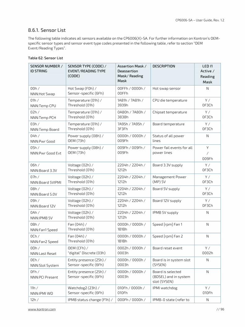
CP6006-SA – User Guide, Rev. 1.2
www.kontron.com // 96
8.6.1. Sensor List
The following table indicates all sensors available on the CP6006(X)-SA. For further information on Kontron’s OEM-specific sensor types and sensor event type codes presented in the following table, refer to section “OEM Event/Reading Types”.
Table 62: Sensor List
SENSOR NUMBER / ID STRING
SENSOR TYPE (CODE) / EVENT/READING TYPE (CODE)
Assertion Mask / Deassertion Mask/ Reading Mask
DESCRIPTION LED I1 Active / Reading
Mask
00h / NNN:Hot Swap
Hot Swap (F0h) / Sensor-specific (6Fh)
00FFh / 0000h / 00FFh
Hot swap sensor N
01h / NNN:Temp CPU
Temperature (01h) / Threshold (01h)
1A81h / 7A81h / 3939h
CPU die temperature Y / 0F3Ch
02h / NNN:Temp PCH
Temperature (01h) / Threshold (01h)
0A80h / 7A80h / 3838h
Chipset temperature Y / 0F3Ch
03h / NNN:Temp Board
Temperature (01h) / Threshold (01h)
7A95h / 7A95h / 3F3Fh
Board temperature Y / 0F3Ch
04h / NNN:Pwr Good
Power supply (08h) / OEM (73h)
0000h / 0000h / 009Fh
Status of all power lines
N
05h / NNN:Pwr Good Evt
Power supply (08h) / OEM (73h)
009Fh / 009Fh / 009Fh
Power fail events for all power lines
Y /
009Fh
06h / NNN:Board 3.3V
Voltage (02h) / Threshold (01h)
2204h / 2204h / 1212h
Board 3.3V supply Y / 0F3Ch
07h / NNN:Board 5VIPMI
Voltage (02h) / Threshold (01h)
2204h / 2204h / 1212h
Management Power (MP) 5V
Y / 0F3Ch
08h / NNN:Board 5.0V
Voltage (02h) / Threshold (01h)
2204h / 2204h / 1212h
Board 5V supply Y / 0F3Ch
09h / NNN:Board 12V
Voltage (02h) / Threshold (01h)
2204h / 2204h / 1212h
Board 12V supply Y / 0F3Ch
0Ah / NNN:IPMB 5V
Voltage (02h) / Threshold (01h)
2204h / 2204h / 1212h
IPMB 5V supply N
0Bh / NNN:Fan1 Speed
Fan (04h) / Threshold (01h)
0000h / 0000h / 1B1Bh
Speed [rpm] Fan 1 N
0Ch / NNN:Fan2 Speed
Fan (04h) / Threshold (01h)
0000h / 0000h / 1B1Bh
Speed [rpm] Fan 2 N
0Dh / NNN:Last Reset
OEM (CFh) / “digital” Discrete (03h)
0002h / 0000h / 0003h
Board reset event Y / 0002h
0Eh / NNN:Slot System
Entity presence (25h) / Sensor-specific (6Fh)
0000h / 0000h / 0003h
Board is in system slot (SYSEN)
N
0Fh / NNN:PCI Present
Entity presence (25h) / Sensor-specific (6Fh)
0000h / 0000h / 0003h
Board is selected (BDSEL) and in system slot (SYSEN)
N
11h / NNN:IPMI WD
Watchdog2 (23h) / Sensor-specific (6Fh)
010Fh / 0000h / 010Fh
IPMI watchdog Y / 010Fh
12h / IPMB status change (F1h) / 000Fh / 0000h / IPMB-0 state (refer to N
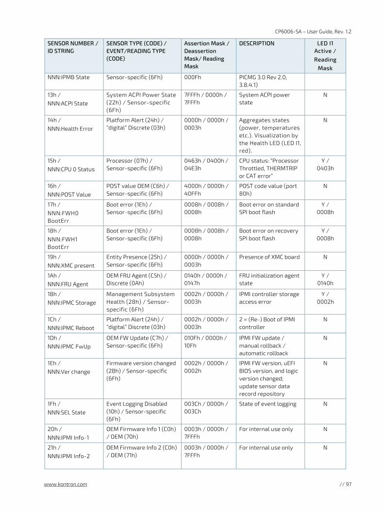
CP6006-SA – User Guide, Rev. 1.2
www.kontron.com // 97
SENSOR NUMBER / ID STRING
SENSOR TYPE (CODE) / EVENT/READING TYPE (CODE)
Assertion Mask / Deassertion Mask/ Reading Mask
DESCRIPTION LED I1 Active / Reading
Mask
NNN:IPMB State Sensor-specific (6Fh) 000Fh PICMG 3.0 Rev 2.0, 3.8.4.1)
13h / NNN:ACPI State
System ACPI Power State (22h) / Sensor-specific (6Fh)
7FFFh / 0000h / 7FFFh
System ACPI power state
N
14h / NNN:Health Error
Platform Alert (24h) / “digital” Discrete (03h)
0000h / 0000h / 0003h
Aggregates states (power, temperatures etc.). Visualization by the Health LED (LED I1, red).
N
15h / NNN:CPU 0 Status
Processor (07h) / Sensor-specific (6Fh)
0463h / 0400h / 04E3h
CPU status: “Processor Throttled, THERMTRIP or CAT error”
Y / 0403h
16h / NNN:POST Value
POST value OEM (C6h) / Sensor-specific (6Fh)
4000h / 0000h / 40FFh
POST code value (port 80h)
N
17h / NNN:FWH0 BootErr
Boot error (1Eh) / Sensor-specific (6Fh)
0008h / 0008h / 0008h
Boot error on standard SPI boot flash
Y / 0008h
18h / NNN:FWH1 BootErr
Boot error (1Eh) / Sensor-specific (6Fh)
0008h / 0008h / 0008h
Boot error on recovery SPI boot flash
Y / 0008h
19h / NNN:XMC present
Entity Presence (25h) / Sensor-specific (6Fh)
0000h / 0000h / 0003h
Presence of XMC board N
1Ah / NNN:FRU Agent
OEM FRU Agent (C5h) / Discrete (0Ah)
0140h / 0000h / 0147h
FRU initialization agent state
Y / 0140h
1Bh / NNN:IPMC Storage
Management Subsystem Health (28h) / Sensor-specific (6Fh)
0002h / 0000h / 0003h
IPMI controller storage access error
Y / 0002h
1Ch / NNN:IPMC Reboot
Platform Alert (24h) / “digital” Discrete (03h)
0002h / 0000h / 0003h
2 = (Re-) Boot of IPMI controller
N
1Dh / NNN:IPMC FwUp
OEM FW Update (C7h) / Sensor-specific (6Fh)
010Fh / 0000h / 10Fh
IPMI FW update / manual rollback / automatic rollback
N
1Eh / NNN:Ver change
Firmware version changed (2Bh) / Sensor-specific (6Fh)
0002h / 0000h / 0002h
IPMI FW version, uEFI BIOS version, and logic version changed; update sensor data record repository
N
1Fh / NNN:SEL State
Event Logging Disabled (10h) / Sensor-specific (6Fh)
003Ch / 0000h / 003Ch
State of event logging N
20h / NNN:IPMI Info-1
OEM Firmware Info 1 (C0h) / OEM (70h)
0003h / 0000h / 7FFFh
For internal use only N
21h / NNN:IPMI Info-2
OEM Firmware Info 2 (C0h) / OEM (71h)
0003h / 0000h / 7FFFh
For internal use only N
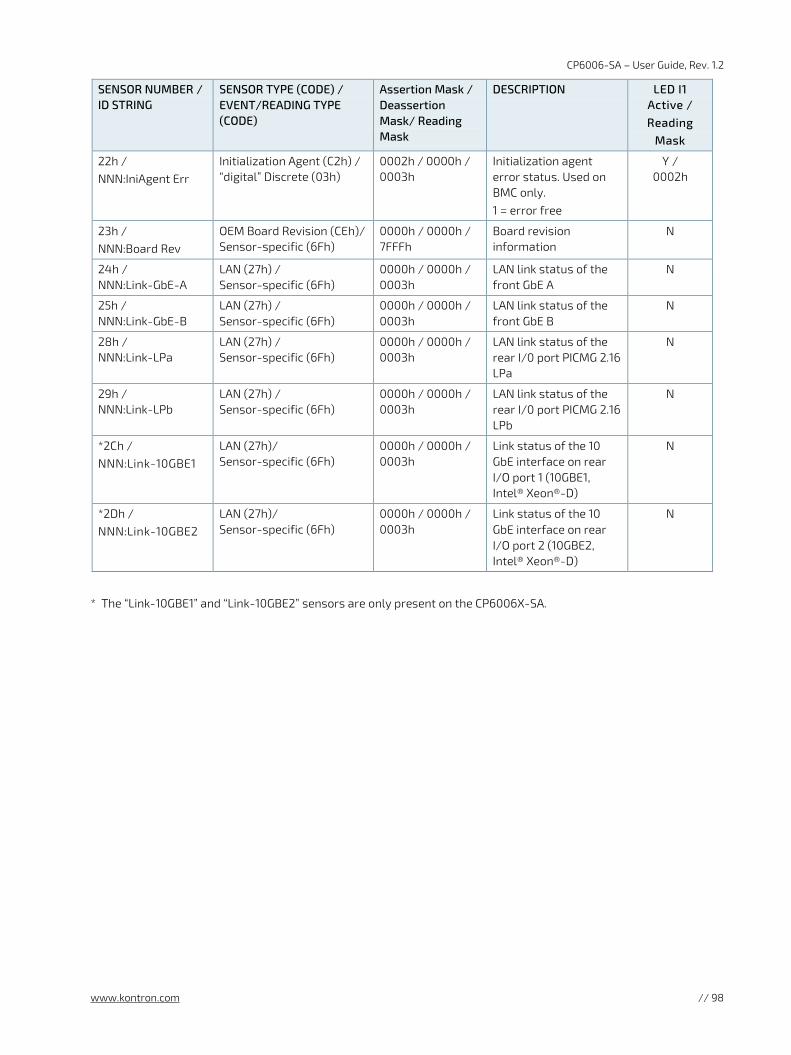
CP6006-SA – User Guide, Rev. 1.2
www.kontron.com // 98
SENSOR NUMBER / ID STRING
SENSOR TYPE (CODE) / EVENT/READING TYPE (CODE)
Assertion Mask / Deassertion Mask/ Reading Mask
DESCRIPTION LED I1 Active / Reading
Mask
22h / NNN:IniAgent Err
Initialization Agent (C2h) / “digital” Discrete (03h)
0002h / 0000h / 0003h
Initialization agent error status. Used on BMC only. 1 = error free
Y / 0002h
23h / NNN:Board Rev
OEM Board Revision (CEh)/ Sensor-specific (6Fh)
0000h / 0000h / 7FFFh
Board revision information
N
24h / NNN:Link-GbE-A
LAN (27h) / Sensor-specific (6Fh)
0000h / 0000h / 0003h
LAN link status of the front GbE A
N
25h / NNN:Link-GbE-B
LAN (27h) / Sensor-specific (6Fh)
0000h / 0000h / 0003h
LAN link status of the front GbE B
N
28h / NNN:Link-LPa
LAN (27h) / Sensor-specific (6Fh)
0000h / 0000h / 0003h
LAN link status of the rear I/0 port PICMG 2.16 LPa
N
29h / NNN:Link-LPb
LAN (27h) / Sensor-specific (6Fh)
0000h / 0000h / 0003h
LAN link status of the rear I/0 port PICMG 2.16 LPb
N
*2Ch / NNN:Link-10GBE1
LAN (27h)/ Sensor-specific (6Fh)
0000h / 0000h / 0003h
Link status of the 10 GbE interface on rear I/O port 1 (10GBE1, Intel® Xeon®-D)
N
*2Dh / NNN:Link-10GBE2
LAN (27h)/ Sensor-specific (6Fh)
0000h / 0000h / 0003h
Link status of the 10 GbE interface on rear I/O port 2 (10GBE2, Intel® Xeon®-D)
N
* The “Link-10GBE1” and “Link-10GBE2” sensors are only present on the CP6006X-SA.
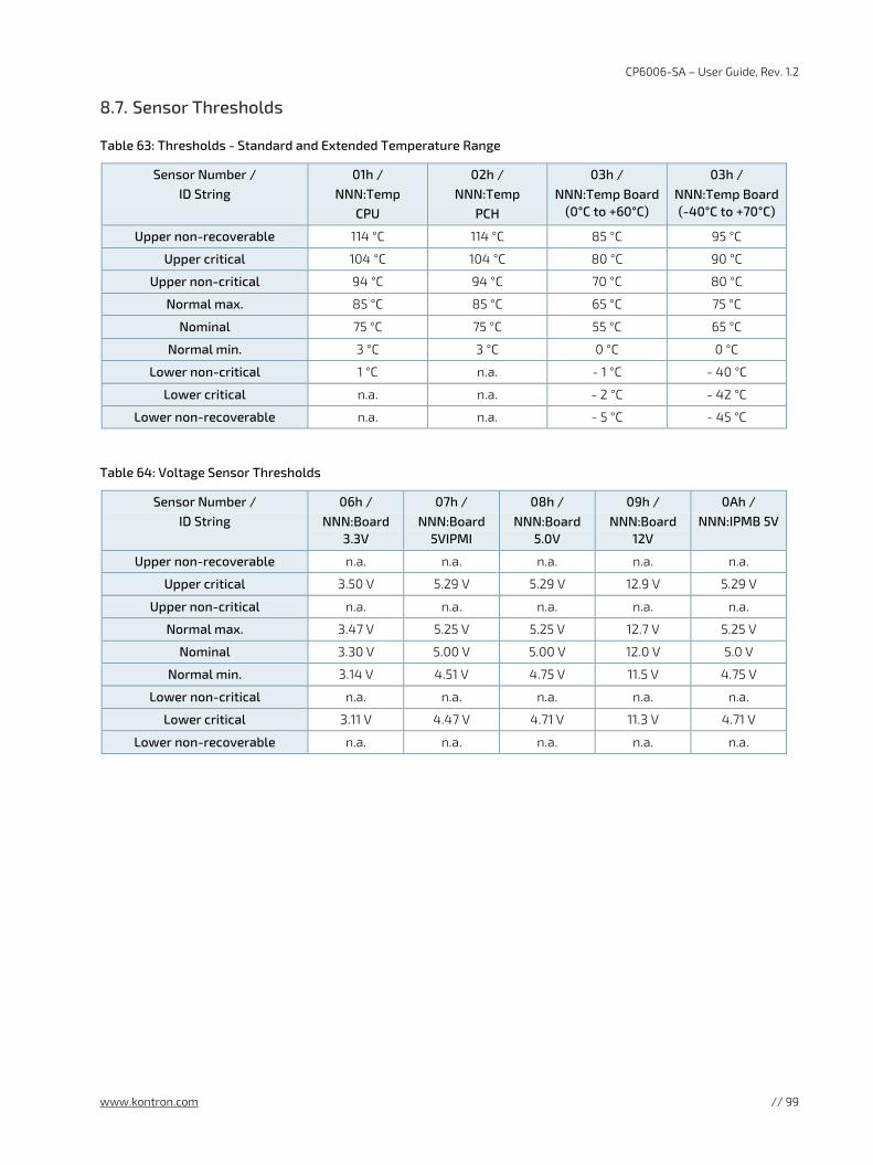
CP6006-SA – User Guide, Rev. 1.2
www.kontron.com // 99
8.7. Sensor Thresholds
Table 63: Thresholds - Standard and Extended Temperature Range
Sensor Number / ID String
01h / NNN:Temp
CPU
02h / NNN:Temp
PCH
03h / NNN:Temp Board
(0°C to +60°C)
03h / NNN:Temp Board (-40°C to +70°C)
Upper non-recoverable 114 °C 114 °C 85 °C 95 °C
Upper critical 104 °C 104 °C 80 °C 90 °C
Upper non-critical 94 °C 94 °C 70 °C 80 °C
Normal max. 85 °C 85 °C 65 °C 75 °C
Nominal 75 °C 75 °C 55 °C 65 °C
Normal min. 3 °C 3 °C 0 °C 0 °C
Lower non-critical 1 °C n.a. - 1 °C - 40 °C
Lower critical n.a. n.a. - 2 °C - 42 °C
Lower non-recoverable n.a. n.a. - 5 °C - 45 °C
Table 64: Voltage Sensor Thresholds
Sensor Number / ID String
06h / NNN:Board
3.3V
07h / NNN:Board
5VIPMI
08h / NNN:Board
5.0V
09h / NNN:Board
12V
0Ah / NNN:IPMB 5V
Upper non-recoverable n.a. n.a. n.a. n.a. n.a.
Upper critical 3.50 V 5.29 V 5.29 V 12.9 V 5.29 V
Upper non-critical n.a. n.a. n.a. n.a. n.a.
Normal max. 3.47 V 5.25 V 5.25 V 12.7 V 5.25 V
Nominal 3.30 V 5.00 V 5.00 V 12.0 V 5.0 V
Normal min. 3.14 V 4.51 V 4.75 V 11.5 V 4.75 V
Lower non-critical n.a. n.a. n.a. n.a. n.a.
Lower critical 3.11 V 4.47 V 4.71 V 11.3 V 4.71 V
Lower non-recoverable n.a. n.a. n.a. n.a. n.a.
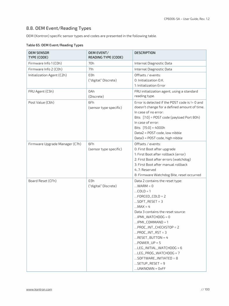
CP6006-SA – User Guide, Rev. 1.2
www.kontron.com // 100
8.8. OEM Event/Reading Types
OEM (Kontron) specific sensor types and codes are presented in the following table.
Table 65: OEM Event/Reading Types
OEM SENSOR TYPE (CODE)
OEM EVENT/ READING TYPE (CODE)
DESCRIPTION
Firmware Info 1 (C0h) 70h Internal Diagnostic Data
Firmware Info 2 (C0h) 71h Internal Diagnostic Data
Initialization Agent (C2h) 03h (“digital” Discrete)
Offsets / events: 0: Initialization O.K. 1: Initialization Error
FRU Agent (C5h) 0Ah (Discrete)
FRU initialization agent, using a standard reading type.
Post Value (C6h) 6Fh (sensor type specific)
Error is detected if the POST code is != 0 and doesn't change for a defined amount of time. In case of no error: Bits [7:0] = POST code (payload Port 80h) In case of error: Bits [15:0] = 4000h Data2 = POST code, low nibble Data3 = POST code, high nibble
Firmware Upgrade Manager (C7h) 6Fh (sensor type specific)
Offsets / events: 0: First Boot after upgrade 1: First Boot after rollback (error) 2: First Boot after errors (watchdog) 3: First Boot after manual rollback 4..7: Reserved 8: Firmware Watchdog Bite, reset occurred
Board Reset (CFh) 03h (“digital” Discrete)
Data 2 contains the reset type: …WARM = 0 …COLD = 1 …FORCED_COLD = 2 …SOFT_RESET = 3 …MAX = 4 Data 3 contains the reset source: …IPMI_WATCHDOG = 0 …IPMI_COMMAND = 1 …PROC_INT_CHECKSTOP = 2 …PROC_INT_RST = 3 …RESET_BUTTON = 4 …POWER_UP = 5 …LEG_INITIAL_WATCHDOG = 6 …LEG_PROG_WATCHDOG = 7 …SOFTWARE_INITIATED = 8 …SETUP_RESET = 9 …UNKNOWN = 0xFF
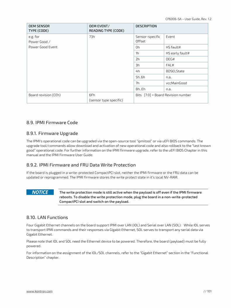
CP6006-SA – User Guide, Rev. 1.2
www.kontron.com // 101
OEM SENSOR TYPE (CODE)
OEM EVENT/ READING TYPE (CODE)
DESCRIPTION
e.g. for Power Good / Power Good Event
73h Sensor-specific Offset
Event
0h HS fault#
1h HS early fault#
2h DEG#
3h FAL#
4h BDSELState
5h..6h n.a.
7h vccMainGood
8h..Eh n.a.
Board revision (CEh) 6Fh (sensor type specific)
Bits [7:0] = Board Revision number
8.9. IPMI Firmware Code
8.9.1. Firmware Upgrade
The IPMI's operational code can be upgraded via the open-source tool “ipmitool” or via uEFI BIOS commands. The upgrade tool/commands allow download and activation of new operational code and also rollback to the “last known good” operational code. For further information on the IPMI firmware upgrade, refer to the uEFI BIOS Chapter in this manual and the IPMI Firmware User Guide.
8.9.2. IPMI Firmware and FRU Data Write Protection
If the board is plugged in a write-protected CompactPCI slot, neither the IPMI firmware or the FRU data can be updated or reprogrammed. The IPMI firmware stores the write protect state in it’s local NV-RAM.
The write protection mode is still active when the payload is off even if the IPMI firmware
reboots. To disable the write protection mode, plug the board in a non-write-protected CompactPCI slot and switch on the payload.
8.10. LAN Functions
Four Gigabit Ethernet channels on the board support IPMI over LAN (IOL) and Serial over LAN (SOL). While IOL serves to transport IPMI commands and their responses via Gigabit Ethernet, SOL serves to transport any serial data via Gigabit Ethernet.
Please note that IOL and SOL need the Ethernet device to be powered. Therefore, the board (payload) must be fully powered.
For information on the assignment of the IOL/SOL channels, refer to the “Gigabit Ethernet” section in the “Functional Description” chapter.
CP6006-SA – User Guide, Rev. 1.2
www.kontron.com // 102
9/ Technical Support For technical support contact our Support department:
E-mail: [email protected]
Phone: +49-821-4086-888
Make sure you have the following information available when you call:
Product ID Number (PN),
Serial Number (SN)
The serial number can be found on the Type Label, located on the product’s rear side.
Be ready to explain the nature of your problem to the service technician.
9.1. Warranty
Due to their limited service life, parts that by their nature are subject to a particularly high degree of wear (wearing parts) are excluded from the warranty beyond that provided by law. This applies to the CMOS battery, for example.
If there is a protection label on your product, then the warranty is lost if the product is opened.
CP6006-SA – User Guide, Rev. 1.2
www.kontron.com // 103
9.2. Returning Defective Merchandise
All equipment returned to Kontron must have a Return of Material Authorization (RMA) number assigned exclusively by Kontron. Kontron cannot be held responsible for any loss or damage caused to the equipment received without an RMA number. The buyer accepts responsibility for all freight charges for the return of goods to Kontron's designated facility. Kontron will pay the return freight charges back to the buyer's location in the event that the equipment is repaired or replaced within the stipulated warranty period. Follow these steps before returning any product to Kontron.
1. Visit the RMA Information website: http://www.kontron.com/support-and-services/support/rma-information
Download the RMA Request sheet for Kontron Europe GmbH and fill out the form. Take care to include a short detailed description of the observed problem or failure and to include the product identification Information (Name of product, Product number and Serial number). If a delivery includes more than one product, fill out the above information in the RMA Request form for each product. 2. Send the completed RMA-Request form to the fax or email address given below at Kontron Europe GmbH.
Kontron will provide an RMA-Number.
Kontron Europe GmbH RMA Support Phone: +49 (0) 821 4086-0 Fax: +49 (0) 821 4086 111 Email: [email protected]
3. The goods for repair must be packed properly for shipping, considering shock and ESD protection.
Goods returned to Kontron Europe GmbH in non-proper packaging will be considered as customer caused faults and cannot be accepted as warranty repairs.
4. Include the RMA-Number with the shipping paperwork and send the product to the delivery address provided in the RMA form or received from Kontron RMA Support.
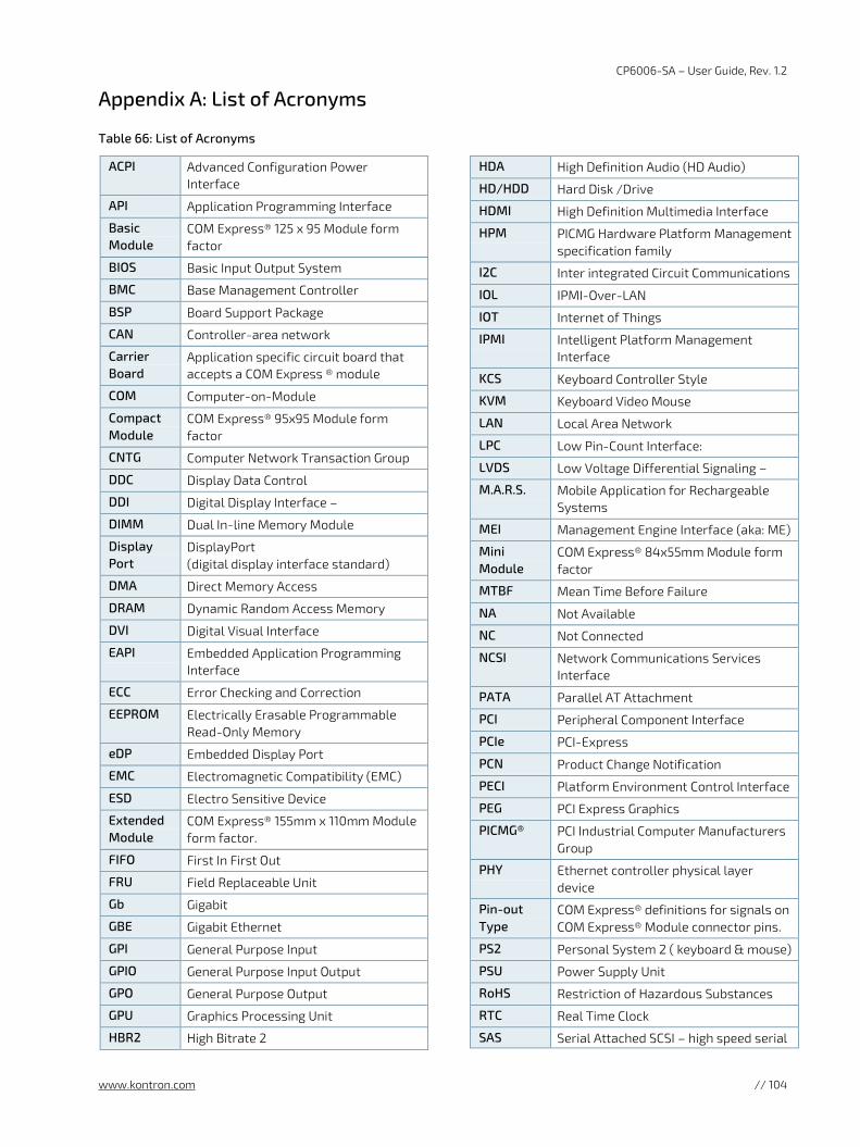
CP6006-SA – User Guide, Rev. 1.2
www.kontron.com // 104
Appendix A: List of Acronyms
Table 66: List of Acronyms
ACPI Advanced Configuration Power Interface
API Application Programming Interface
Basic Module
COM Express® 125 x 95 Module form factor
BIOS Basic Input Output System
BMC Base Management Controller
BSP Board Support Package
CAN Controller-area network
Carrier Board
Application specific circuit board that accepts a COM Express ® module
COM Computer-on-Module
Compact Module
COM Express® 95x95 Module form factor
CNTG Computer Network Transaction Group
DDC Display Data Control
DDI Digital Display Interface –
DIMM Dual In-line Memory Module
Display Port
DisplayPort (digital display interface standard)
DMA Direct Memory Access
DRAM Dynamic Random Access Memory
DVI Digital Visual Interface
EAPI Embedded Application Programming Interface
ECC Error Checking and Correction
EEPROM Electrically Erasable Programmable Read-Only Memory
eDP Embedded Display Port
EMC Electromagnetic Compatibility (EMC)
ESD Electro Sensitive Device
Extended Module
COM Express® 155mm x 110mm Module form factor.
FIFO First In First Out
FRU Field Replaceable Unit
Gb Gigabit
GBE Gigabit Ethernet
GPI General Purpose Input
GPIO General Purpose Input Output
GPO General Purpose Output
GPU Graphics Processing Unit
HBR2 High Bitrate 2
HDA High Definition Audio (HD Audio)
HD/HDD Hard Disk /Drive
HDMI High Definition Multimedia Interface
HPM PICMG Hardware Platform Management specification family
I2C Inter integrated Circuit Communications
IOL IPMI-Over-LAN
IOT Internet of Things
IPMI Intelligent Platform Management Interface
KCS Keyboard Controller Style
KVM Keyboard Video Mouse
LAN Local Area Network
LPC Low Pin-Count Interface:
LVDS Low Voltage Differential Signaling –
M.A.R.S. Mobile Application for Rechargeable Systems
MEI Management Engine Interface (aka: ME)
Mini Module
COM Express® 84x55mm Module form factor
MTBF Mean Time Before Failure
NA Not Available
NC Not Connected
NCSI Network Communications Services Interface
PATA Parallel AT Attachment
PCI Peripheral Component Interface
PCIe PCI-Express
PCN Product Change Notification
PECI Platform Environment Control Interface
PEG PCI Express Graphics
PICMG® PCI Industrial Computer Manufacturers Group
PHY Ethernet controller physical layer device
Pin-out Type
COM Express® definitions for signals on COM Express® Module connector pins.
PS2 Personal System 2 ( keyboard & mouse)
PSU Power Supply Unit
RoHS Restriction of Hazardous Substances
RTC Real Time Clock
SAS Serial Attached SCSI – high speed serial
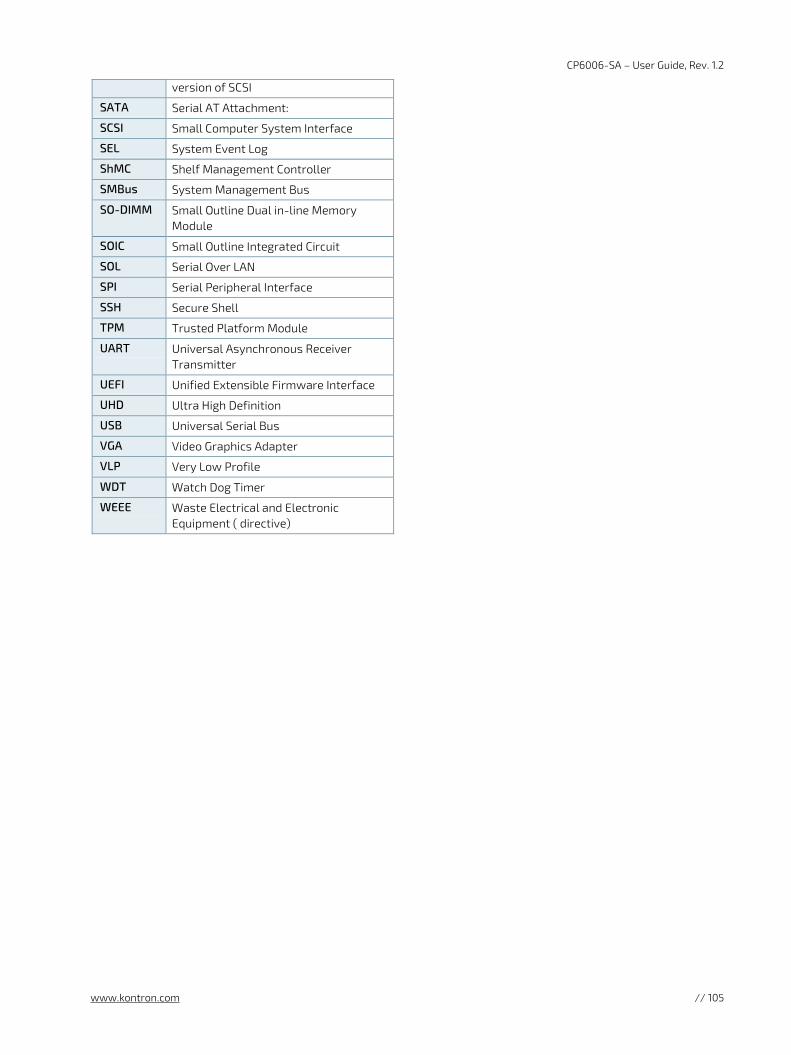
CP6006-SA – User Guide, Rev. 1.2
www.kontron.com // 105
version of SCSI
SATA Serial AT Attachment:
SCSI Small Computer System Interface
SEL System Event Log
ShMC Shelf Management Controller
SMBus System Management Bus
SO-DIMM Small Outline Dual in-line Memory Module
SOIC Small Outline Integrated Circuit
SOL Serial Over LAN
SPI Serial Peripheral Interface
SSH Secure Shell
TPM Trusted Platform Module
UART Universal Asynchronous Receiver Transmitter
UEFI Unified Extensible Firmware Interface
UHD Ultra High Definition
USB Universal Serial Bus
VGA Video Graphics Adapter
VLP Very Low Profile
WDT Watch Dog Timer
WEEE Waste Electrical and Electronic Equipment ( directive)
CP6006-SA – User Guide, Rev. 1.2
www.kontron.com // 106
About Kontron
Kontron is a global leader in IoT/Embedded Computing Technology (ECT). As a part of technology group S&T, Kontron, together with its sister company S&T Technologies, offers a combined portfolio of secure hardware, middleware and services for Internet of Things (IoT) and Industry 4.0 applications. With its standard products and tailor-made solutions based on highly reliable state-of-the-art embedded technologies, Kontron provides secure and innovative applications for a variety of industries. As a result, customers benefit from accelerated time-to-market, reduced total cost of ownership, product longevity and the best fully integrated applications overall.
For more information, please visit: www.kontron.com
GLOBAL HEADQUARTERS
Kontron Europe GmbH
Gutenbergstraße 2 85737 Ismaning, Germany Tel.: + 49 821 4086-0 Fax: + 49 821 4086-111 [email protected]
Related Documents