CP115 (LOLO) Evaluation Report SIRE+/WP5/40/D Version 1.0 EUROCONTROL Mode S & ACAS Programme – Project SIRE+ - Sofréavia /DSNA CP115 (LOLO) Evaluation Report Safety Issue Rectification Extension+ Project SIRE+ Project ACAS/07-085 Edition : 1.0 Edition Date : 16 May 2007 Status : Released Issue Class : EATM

Welcome message from author
This document is posted to help you gain knowledge. Please leave a comment to let me know what you think about it! Share it to your friends and learn new things together.
Transcript
CP115 (LOLO) Evaluation Report SIRE+/WP5/40/D Version 1.0
EUROCONTROL Mode S & ACAS Programme – Project SIRE+ - Sofréavia /DSNA
CP115 (LOLO) Evaluation Report
Safety Issue Rectification Extension+ Project
SIRE+ Project
ACAS/07-085
Edition : 1.0Edition Date : 16 May 2007Status : Released IssueClass : EATM
CP115 (LOLO) Evaluation Report SIRE+/WP5/40/D Version 1.0
DOCUMENT IDENTIFICATION SHEET
DOCUMENT DESCRIPTION
Document Title CP115 (LOLO) Evaluation Report
Safety Issue Rectification Extension + Project SIRE+ Project
PROGRAMME REFERENCE INDEX: ACAS ref.: ACAS/07-085 Edition 1.0
ALDA ref. : 07/05/31-21
EDITION DATE: 16 May 2007 Abstract
The SIRE+ Project, builds upon the SIR and EMOTION-7 work methods and expertise to rectify a problem regarding opposite pilot responses to “Adjust vertical speed, adjust” (AVSA) RAs. The solution proposed to address the issue is a simplification of TCAS RA design by replacing the current four AVSA RAs by a single “Level-off, level-off” (LOLO) RA. The result is thus a single RA indication associated to a single aural message and requiring a single action from the pilot. The LOLO solution is implemented through the inclusion of CP115 into the TCAS MOPS. The evaluation of CP115 through simulations has demonstrated that it provides substantial safety benefits and improves risk ratios in all the situations that have been investigated. This EUROCONTROL project was conducted by Sofréavia with the support of DSNA.
TCAS CAS logic safety performance
RA reversal
CONTACT PERSON: John Law TEL: 32 2 729 37 66 UNIT: SUR/MSA
Authors: Thierry Arino, Eric Vallauri, Herve Drévillon, Stéphan Chabert, Christian Aveneau
DOCUMENT STATUS AND TYPE
STATUS CLASSIFICATION
Working Draft General Public Draft EATM Proposed Issue Restricted Released Issue
ELECTRONIC BACKUP
INTERNAL REFERENCE NAME:
HOST SYSTEM MEDIA SOFTWARE Microsoft Windows Type: Hard disk
Media Identification:
____________________________________________________________________________________________ EUROCONTROL Mode S & ACAS Programme – Project SIRE+ – Sofréavia / DSNA

CP115 (LOLO) Evaluation Report 16-05-2007 SIRE+/WP5/40/D Version 1.0
Eurocontrol MSA Programme – DSNA & Sofréavia – SIRE+ Project Page 1/133
CP115 (LOLO) Evaluation Report
Safety Issue Rectification Extension+ Project
SIRE+ Project
Written by: T. Arino, E. Vallauri, H. Drévillon, S. Chabert & C. Aveneau
Authorised by: Thierry Arino on 16-05-07
CP115 (LOLO) Evaluation Report 16-05-2007 SIRE+/WP5/40/D Version 1.0
Eurocontrol Mode S & ACAS Programme – Sofréavia & DSNA – SIRE+ Project Page 2/133
RECORD OF CHANGES
Issue Date Detail of changes
0.1 20-04-07 Initial complete draft
0.2 11-05-07 Revised draft following internal review
1.0 16-05-07 First version delivered to EUROCONTROL
IMPORTANT NOTE: ANY NEW VERSION SUPERSEDES THE PRECEDING VERSION, WHICH MUST BE DESTROYED OR CLEARLY MARKED ON THE FRONT PAGE WITH THE MENTION OBSOLETE VERSION
CP115 (LOLO) Evaluation Report 16-05-2007 SIRE+/WP5/40/D Version 1.0
Eurocontrol Mode S & ACAS Programme – Sofréavia & DSNA – SIRE+ Project Page 3/133
EXECUTIVE SUMMARY
E.1 Introduction
E.1.1. Since 1st January 2000, through the performance of both the European Maintenance Of TCAS II logic versION 7 (EMOTION-7) project ([EMO1]), which was completed in 2002, and the subsequent Safety Issue Rectification (SIR) and Safety Issue Rectification Extension (SIRE) projects ([SIR1] & [SIRE1]), the EUROCONTROL Mode S & ACAS Programme has played a leading role, at the international level, in progressing work to improve the performance of the TCAS collision avoidance logic.
E.1.2. EUROCONTROL has notably developed the SIR initiative to address specific safety issues. In this scope, EUROCAE WG75 has also been set up to input considerations and concerns raised by European organisations with respect to these safety issues. One of the safety issues under consideration has been labelled SA-AVSA and is related to flight crews unintentionally reacting in the opposite direction to a specific type of Resolution Advisory (RA), i.e. “Adjust Vertical Speed, Adjust” (AVSA) RAs. An investigation of this issue and of its causes has been conducted by the Operations Working Group (OWG) of RTCA SC147 ([RTCA1]).
E.1.3. Within the EUROCONTROL SIRE+ project, a solution to the SA-AVSA issue has been developed based on the observation that it occurs almost exclusively on “Vertical Speed Limit” (VSL) 500, 1000 & 2000 advisories. The solution consists in replacing the 4 AVSA RAs by a single VSL 0 RA and modifying the aural annunciation into “Level-Off, Level-Off” (LOLO). This solution has been formally submitted to RTCA as a Change Proposal (CP) to the TCAS Minimal Operational Performance Standards (MOPS) of the Collision Avoidance System (CAS) logic ([MOPS]), as CP115 ([SIRE+1]).
E.1.4. A significant body of work has been conducted to validate the proposed LOLO solution and encompassed three specific areas:
• A safety performance study based on encounter modelling. The main objective was to determine whether the change in the way VSL RAs are issued would affect the safety provided by TCAS II. The work built upon the methodology developed by the Requirements Working Group (RWG) of RTCA SC147 ([RTCA2]) for assessing the safety performance of the CP112E solution to the SA01 issue;
• An operational performance study, also based on encounter modelling and on US radar data. The main objective was to assess the compatibility with Air Traffic Control (ATC) and the acceptability of having all negative RAs replaced by a single Level-Off RA. The task evaluated the effect of this change on the flight crew and on the Air Traffic Controller (ATCO) in charge of the aircraft receiving the RA, notably using the airspace disruption perspective; and
• A Human Factors (HF) study based on real-time simulations (RTS) with pilots and ATCOs in the loop. The main objective was to determine whether the introduction of the Level-Off RA would impact the pilot behaviour when faced with such an RA, impact the pilot / controller cooperation and induce disruption from a controller standpoint. These RTS also helped building a

CP115 (LOLO) Evaluation Report 16-05-2007 SIRE+/WP5/40/D Version 1.0
Eurocontrol Mode S & ACAS Programme – Sofréavia & DSNA – SIRE+ Project Page 4/133
comprehensive comparison between the current AVSA RAs and the proposed Level-Off RA.
E.2 SA-AVSA analysis & proposed solution E.2.1. Issue description
E.2.1.1 The issue of unintentional opposite responses to negative RAs was first identified on TCAS II Version 6.04a, leading pilots to increase their vertical speed instead of reducing it. The aural annunciation associated to these negative RAs was either “Reduce Climb, Reduce Climb” or “Reduce Descent, Reduce Descent”, and analysis of opposite responses suggested that the word “Reduce” was sometimes not heard by the crew, who misunderstood the RA respectively for a “Climb” or “Descend” RA.
E.2.1.2 In the subsequent TCAS II Version 7.0, which was mandated in 2000 in the European Civil Aviation Conference (ECAC) and worldwide in 2003, the “Reduce Climb” and “Reduce Descent” aural messages were replaced by “Adjust Vertical Speed, Adjust” aural in order to solve the issue. However, unintentional opposite responses to AVSA RAs continued to be identified in Europe by some airline monitoring and the active monitoring set up by EUROCONTROL. More recently, unintentional opposite reactions have been identified by a major US airline. These opposite reactions increase the risk of collision.
E.2.1.3 The following figure shows vertical views of two actual severe events, in which pilots received an AVSA RA requesting to limit their rate of climb to 1000 fpm (indicated by the ‘LC1’ tag). In these two events, the pilots reacted by actually increasing their rate of climb to more than 6000 fpm. TCAS was not able to provide the target minimum vertical spacing (600 ft at that altitude).
March 2003 - 300 ft & 0.8 NM at CPA February 2005 - 0 ft & 1.6 NM CPA
Figure 1: Examples of SA-AVSA incidents

CP115 (LOLO) Evaluation Report 16-05-2007 SIRE+/WP5/40/D Version 1.0
Eurocontrol Mode S & ACAS Programme – Sofréavia & DSNA – SIRE+ Project Page 5/133
E.2.2. Collision risk estimate
E.2.2.1 A risk of collision as a consequence of an opposite response to an initial AVSA RA can be estimated in two steps by first computing the probability of occurrence of such opposite responses, and then finding the probability of a collision during an SA-AVSA event.
E.2.2.2 In 2004 and 2005, 15 opposite responses to initial AVSA RAs leading to an altitude bust have been identified in French airspace, involving operators from various States. Given the total number of 3.93x10⁶ flight hours over these two years, the probability of occurrence of such opposite responses can be estimated to 3.82x10⁻⁶ per flight hour.
E.2.2.3 By measuring the horizontal and vertical separations at closest approach in these 15 altitude busts, a probability of collision given that an AVSA event has occurred can be derived and is estimated to 1.41x10⁻³. By combining the above two figures, the resulting estimated risk of collision because of SA-AVSA amounts to 5.4 collisions per 109 flight hour. This rate is equivalent to 1 collision every 15 years when extrapolated for European airspace as a whole, and exceeds the tolerable rate for catastrophic events caused by equipment-related hazards (10-9 per flight hour) by a factor of 5.
E.2.3. LOLO solution
E.2.3.1 A thorough analysis performed on data provided by major European airlines that were aware of the SA-AVSA issue through their Flight Data Management (FDM) programmes showed that this issue occurred almost exclusively with AVSA RAs requesting a reduction to 2000, 1000 or 500 fpm and only with Vertical Speed Indicators (VSI) RA displays.
E.2.3.2 Several causes were identified to explain opposite responses to AVSA RAs, including a lack of specific training for this type of RAs and the limitations of the associated aural annunciation which does not convey the sense of the manoeuvre required by the RA. However, the main factor remains the design of the AVSA RAs and the misleading position of the green area displayed to pilots.
CP115 (LOLO) Evaluation Report 16-05-2007 SIRE+/WP5/40/D Version 1.0
Eurocontrol Mode S & ACAS Programme – Sofréavia & DSNA – SIRE+ Project Page 6/133
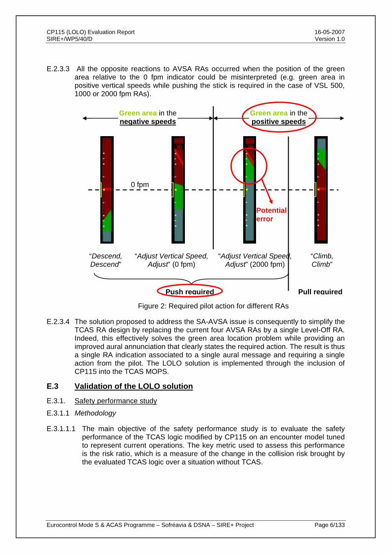
E.2.3.3 All the opposite reactions to AVSA RAs occurred when the position of the green area relative to the 0 fpm indicator could be misinterpreted (e.g. green area in positive vertical speeds while pushing the stick is required in the case of VSL 500, 1000 or 2000 fpm RAs).
“Descend, Descend”
“Adjust Vertical Speed,Adjust” (0 fpm)
“Adjust Vertical Speed, Adjust” (2000 fpm)
“Climb,Climb”
Green area in the negative speeds
Green area in the positive speeds
Push required Pull required
0 fpm
Figure 2: Required pilot action for different RAs
E.2.3.4 The solution proposed to address the SA-AVSA issue is consequently to simplify the TCAS RA design by replacing the current four AVSA RAs by a single Level-Off RA. Indeed, this effectively solves the green area location problem while providing an improved aural annunciation that clearly states the required action. The result is thus a single RA indication associated to a single aural message and requiring a single action from the pilot. The LOLO solution is implemented through the inclusion of CP115 into the TCAS MOPS.
E.3 Validation of the LOLO solution
E.3.1. Safety performance study
E.3.1.1 Methodology
E.3.1.1.1 The main objective of the safety performance study is to evaluate the safety performance of the TCAS logic modified by CP115 on an encounter model tuned to represent current operations. The key metric used to assess this performance is the risk ratio, which is a measure of the change in the collision risk brought by the evaluated TCAS logic over a situation without TCAS.
Potential error
CP115 (LOLO) Evaluation Report 16-05-2007 SIRE+/WP5/40/D Version 1.0
Eurocontrol Mode S & ACAS Programme – Sofréavia & DSNA – SIRE+ Project Page 7/133
E.3.1.1.2 In order to build a complete picture, a risk ratio has been computed on several representative model scenarios, combining a threat configuration (i.e. standard response, non response or no TCAS onboard) with a type of pilot response for the TCAS aircraft (i.e. standard, typical for European airspace, slow or aggressive).
E.3.1.1.3 A risk ratio has also been computed on a key operational scenario which has been specifically designed to represent current operations. This has been complemented by an investigation of potential issues in scenarios mixing different TCAS versions, as well as in multiple threat situations.
E.3.1.2 Results
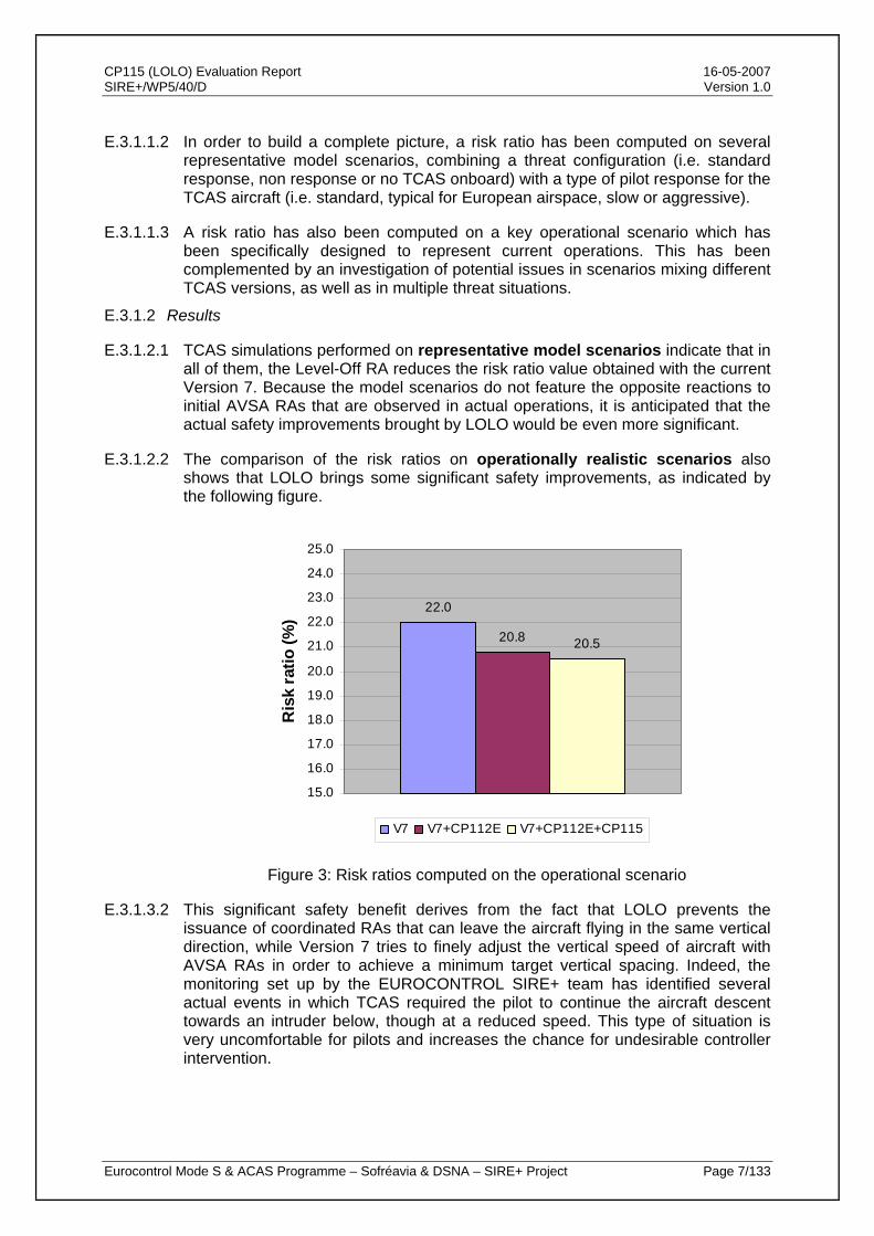
E.3.1.2.1 TCAS simulations performed on representative model scenarios indicate that in all of them, the Level-Off RA reduces the risk ratio value obtained with the current Version 7. Because the model scenarios do not feature the opposite reactions to initial AVSA RAs that are observed in actual operations, it is anticipated that the actual safety improvements brought by LOLO would be even more significant.
E.3.1.2.2 The comparison of the risk ratios on operationally realistic scenarios also shows that LOLO brings some significant safety improvements, as indicated by the following figure.
22.0
20.8 20.5
15.0
16.0
17.0
18.0
19.0
20.0
21.0
22.0
23.0
24.0
25.0
Ris
k ra
tio (%
)
V7 V7+CP112E V7+CP112E+CP115
Figure 3: Risk ratios computed on the operational scenario
E.3.1.3.2 This significant safety benefit derives from the fact that LOLO prevents the issuance of coordinated RAs that can leave the aircraft flying in the same vertical direction, while Version 7 tries to finely adjust the vertical speed of aircraft with AVSA RAs in order to achieve a minimum target vertical spacing. Indeed, the monitoring set up by the EUROCONTROL SIRE+ team has identified several actual events in which TCAS required the pilot to continue the aircraft descent towards an intruder below, though at a reduced speed. This type of situation is very uncomfortable for pilots and increases the chance for undesirable controller intervention.
CP115 (LOLO) Evaluation Report 16-05-2007 SIRE+/WP5/40/D Version 1.0
Eurocontrol Mode S & ACAS Programme – Sofréavia & DSNA – SIRE+ Project Page 8/133
E.3.1.3.3 Analysis of the interoperability of LOLO with the current version of TCAS has demonstrated that safety benefits were obtained in mixed TCAS equipage environment, as a reduction in the risk ratio metric can be observed when only part of the fleet is fitted with LOLO. No interoperability issue has been identified.
E.3.1.3.4 Investigation of the safety performance in multiple aircraft encounters has also been undertaken. The vast majority of these multiple aircraft encounters are sequential encounters in which LOLO provides comparable safety benefits over Version 7 to those observed in single threat situations. For the specific case of simultaneous threat encounters, LOLO slightly increases the risk ratio obtained with Version 7 because of the reduced range of solutions in “sandwich” situations. However, it must be noted that these simultaneous threat encounters are very rare events in operations.
E.3.2. Operational performance study
E.3.2.1 Methodology
E.3.2.1.1 The main objective of this study is to evaluate the operational performance of the TCAS logic modified by CP115 on an encounter model providing a large set of TCAS events. The operational scenario defined for the safety study has been used to compute two sets of operational performance metrics.
E.3.2.1.2 These key metrics have been defined in collaboration with RTCA SC147 OWG and are related to airspace disruption on one hand and to the airborne perspective on the other hand. Decision criteria, generally based on the metric values for Version 7, have been associated to each of these metrics.
E.3.2.1.3 The work performed for the European airspace has been complemented by an investigation of LOLO operational performance in the Boston TMA, which mixes various traffic types, based on 6 months of radar and RA downlink data. The focus of this investigation was on the likelihood of inducing conflicts with 3rd party aircraft by responding to a Level-Off RA. To this effect, pair-wise events were identified in the data, where an initial AVSA RA was issued by TCAS and where one or more other traffic were found in the vicinity.
E.3.2.2 Results
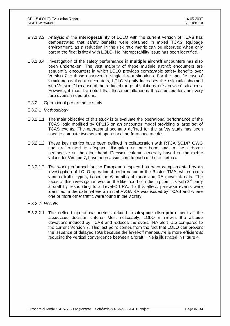
E.3.2.2.1 The defined operational metrics related to airspace disruption meet all the associated decision criteria. Most noticeably, LOLO minimizes the altitude deviations induced by TCAS and reduces the overall RA alert rate compared to the current Version 7. This last point comes from the fact that LOLO can prevent the issuance of delayed RAs because the level-off manoeuvre is more efficient at reducing the vertical convergence between aircraft. This is illustrated in Figure 4.
CP115 (LOLO) Evaluation Report 16-05-2007 SIRE+/WP5/40/D Version 1.0
Eurocontrol Mode S & ACAS Programme – Sofréavia & DSNA – SIRE+ Project Page 9/133
RAs triggered by Version 7 RAs triggered by LOLO
Figure 4: Illustration of operational benefits
E.3.2.2.2 As anticipated, the rates of 3rd party aircraft involvement computed on the European scenario and on the Boston TMA data are identical for both Version 7 and LOLO.
E.3.2.2.3 In Boston TMA, LOLO would modify the outcome of only 15 events where an initial AVSA RA was issued and where some other traffic was found in the vicinity during the 6 month period that has been investigated. When simulating these 15 events with LOLO, there are no traffic that may interfere with the own aircraft level-off manoeuvre. This confirms that the probability of LOLO inducing a conflict with a nearby 3rd party aircraft is extremely remote as no TA or RA would have been issued, or even close to be issued, in the 6 months of data recorded within the Boston TMA that have been investigated.
E.3.2.2.4 The defined operational metrics related to the airborne perspective also meet all the associated decision criteria. These metrics notably indicate a significant reduction in the rate of complex RA sequences (i.e. including more than one RA), as illustrated in Figure 4 above.
E.3.3. Human Factor study
E.3.3.1 Experiment set-up
E.3.3.1.1 In May 2006, the LORA1 real-time simulations were conducted by DSNA in order to investigate the operational acceptability by pilots and air traffic controllers of the LOLO solution to the SA-AVSA issue, as well as its impact on the pilot / controller cooperation. These RTS also had the objective of verifying that LOLO did not induce additional disruption from the controller standpoint.
E.3.3.1.2 14 pilots from major European airlines and 12 DSNA controllers participated in LORA1. None of them were aware of the subject of the experiments, as no briefing or training was organised prior to the simulations. The participants were involved in 3 scenarios derived from actual events and provided feedback through a specific questionnaire and collective interviews.
Descend RA No RA
CP115 (LOLO) Evaluation Report 16-05-2007 SIRE+/WP5/40/D Version 1.0
Eurocontrol Mode S & ACAS Programme – Sofréavia & DSNA – SIRE+ Project Page 10/133
E.3.3.1.3 Following LORA1, a second round of RTS has been set up by DSNA and Airbus in coordination with RTCA SC147 OWG. The objectives of the LORA2 experiments were to conduct a comprehensive comparison between the AVSA RAs and the Level-Off RA, and to confirm initial findings from LORA1 in a more realistic cockpit simulator.
E.3.3.1.4 19 pilots from 5 European and 2 US major airlines were involved in the 10 days of the LORA2 experiments held in November 2006. All pilots were submitted to the same scenario, built around a Paris-Frankfurt two-way flight, during which they experienced up to 7 RAs occurring during the different phases of the flight. By changing the TCAS logic during the cruise phase, a same flight could lead to either AVSA RAs or Level-Off RAs.
E.3.3.2 Results
E.3.3.2.1 The LORA1 experiments highlighted that the Level-Off RA was operationally accepted by subject pilots and controllers and showed that it improved the cooperation between pilots and ATC by reducing the confusion in TCAS reporting.
E3.3.2.2 In LORA2, the questionnaires enabled to collect the pilot’s perception of the proposed Level-Off RA and asked them to rate its various aspects against the AVSA RAs. 18 of the 19 participating pilots concluded with their preference for the Level-Off RA, commenting that it was much simpler than the AVSA RAs, both in the interpretation and in the execution of the required manoeuvre. One pilot expressed no preference.
E.3.3.2.3 The “Level-Off, Level-Off” RA aural annunciation was also well received as, contrary to the AVSA RA, it provides pilots with a clear indication of the manoeuvre required by the RA. Overall, the Level-Off RA received better ratings than the AVSA RAs, similar to those attributed to Climb or Descend RAs.
E.3.3.2.4 Analysis of pilot responses to Level-Off RAs has identified no negative impact. Indeed, those responses were comparable, in terms of delay and acceleration, to the Climb or Descend RA responses and the expected standard response. On the contrary, responses to AVSA RAs were slower and weaker than expected.
E.3.3.2.5 This analysis also enabled to identify an opposite response to an AVSA RA. A native English speaking pilot received an AVSA RA requiring a reduction of his rate of descent (i.e. an upwards manoeuvre), but reacted by pushing the stick and started increasing the vertical rate until the PNF warned him about his mistake. This opposite response is shown through the vertical speed vs. time graph below.

CP115 (LOLO) Evaluation Report 16-05-2007 SIRE+/WP5/40/D Version 1.0
Eurocontrol Mode S & ACAS Programme – Sofréavia & DSNA – SIRE+ Project Page 11/133
-2000
-1500
-1000
-500
0
500
0 10 20 30 40 50 60
VS (fpm)AVSACoC
Figure 5: Opposite response to AVSA RA
E.4 Conclusions and recommendations
E.4.1. The SIRE+ project has investigated the safety issue of unintentional opposite responses to initial “Adjust Vertical Speed, Adjust” RAs (SA-AVSA) and concluded that it occurred at an unacceptable rate, leading to a risk of collision exceeding the tolerable rate for catastrophic events for equipment-related hazards (10-9 per flight hour) by a factor of 5. A solution, called LOLO, consisting in the replacement of the AVSA RAs by a single Level-Off RA has been proposed to RTCA as Change Proposal 115 to the TCAS MOPS.
E.4.2. The evaluation of CP115 has demonstrated that it provides substantial safety benefits by solving SA-AVSA and improving risk ratios in all the situations that have been investigated, including operationally realistic scenarios. In addition, analysis of the interoperability issue with current Version 7 showed that safety benefits are obtained as soon as LOLO is introduced into the fleet.
E.4.3. Significant operational benefits have also been identified, as CP115 reduces the RA alert rate and minimizes the altitude deviations induced by TCAS, reducing potential impact on ATC operations.
E.4.4. Finally, two sets of real-time simulations have demonstrated that LOLO was operationally accepted by both pilots and air traffic controllers. Participating pilots expressed a very clear preference for the Level-Off RA over the current AVSA RA, while controllers saw no disturbance with the proposed new RA. In addition, the observed confusion in reporting AVSA RAs is removed by the Level-Off RA.
E.4.5. European stakeholders (EASA, AEA, major European airlines, EUROCONTROL, EUROCAE, DSNA, Airbus, Sofréavia, …) support the incorporation of the Level-Off RA in the forthcoming 7.1 revision of TCAS II.
E.4.6. It is recommended that: • CP115 be included in the forthcoming revision of the TCAS MOPS;
• CP115 be implemented as soon as possible in the TCAS fleet in conjunction with CP112E
AVSA RA requiring a reduction of descent rate
Increase of descent rate
CP115 (LOLO) Evaluation Report 16-05-2007 SIRE+/WP5/40/D Version 1.0
Eurocontrol MSA Programme – DSNA & Sofréavia – SIRE+ Project Page 12/133
THIS PAGE INTENTIONALLY LEFT BLANK
CP115 (LOLO) Evaluation Report 16-05-2007 SIRE+/WP5/40/D Version 1.0
Eurocontrol MSA Programme – DSNA & Sofréavia – SIRE+ Project Page 13/133
LIST OF DEFINITIONS
ACAS Airborne Collision Avoidance System - A system standardised in the
ICAO SARPs that uses transponder replies from other aircraft to warn the pilot of a risk of impending collision. The SIRE+ project focuses on safety issues related to ACAS II – a system that generates traffic advisories (TAs) and also generates resolution advisories (RAs) in the vertical plane.
ACASA safety encounter model
A safety encounter model developed in the ACASA project which characterised close encounters occurring in European airspace before the introduction of RVSM.
ASARP (or European) safety encounter model
An update of the ACASA safety encounter model developed in the ASARP project, following the introduction of RVSM operations in European airspace.
AVSA RA An “Adjust Vertical Speed, Adjust” RA, or negative RA, is an RA requiring the pilot to reduce his vertical speed to 2000, 1000, 500 or 0 fpm.
Closest Point of Approach
Minimum in the physical distance between two aircraft (slant range) involved in an encounter.
The issuance of ACAS alerts and the type of alert depends on the predicted time to CPA, which is calculated by dividing the slant range by the closure rate.
CP112E A change proposal to the TCAS MOPS addressing a safety issue labelled SA01 and related to an inappropriate reversal logic operation. This change proposal has been accepted by RTCA and will be included in the future TCAS II version 7.1.
CP115 A change proposal to the TCAS MOPS addressing the safety issue of unintentional opposite reactions to initial AVSA RAs and implementing the LOLO solution.
EMOTION-7 European Monitoring of TCAS II version 7 – a study commissioned by EUROCONTROL to obtain the adequate tool and structure to minimise the risks associated with the implementation of ACAS II in Europe
ICAO safety encounter model
A safety encounter model defined in the ICAO SARPs and built out of the characteristics of close encounters observed in the US and in Europe before the introduction of RVSM. It is therefore not representative of any given airspace.
Intruder A transponder-equipped aircraft within the surveillance range of ACAS and that is tracked by ACAS.
LOLO (Level-Off, Level-Off)
The solution to the issue of unintentional opposite response to AVSA RAs proposed by the SIRE+ project. It consists in the replacement of the AVSA RAs by a single Vertical Speed Limit 0 fpm RA through the inclusion of CP115 in the TCAS MOPS. This change in the CAS logic is associated with a new “Level-Off, Level-Off” aural annunciation.
CP115 (LOLO) Evaluation Report 16-05-2007 SIRE+/WP5/40/D Version 1.0
Eurocontrol MSA Programme – DSNA & Sofréavia – SIRE+ Project Page 14/133
Near Mid-Air Collision
An encounter in which the horizontal separation between two aircraft is less than 500ft and the vertical separation is less than 100ft. The ACASA project established that the rate of NMACs to actual collisions was 10 to 1.
Negative RA An RA requiring the flight crew to conform to a restriction of manoeuvre in order to maintain a minimum vertical separation from the intruders. The proper response to a negative RA is always a reduction in vertical speed.
Own aircraft The aircraft fitted with the ACAS that is the subject of the discourse, which ACAS is to protect against possible collisions, and which may enter a manoeuvre in response to an ACAS indication
Positive RA An RA requiring the flight crew to perform a manoeuvre in order to acquire a minimum vertical separation from the intruders.
RA sense The sense of an ACAS II resolution advisory is “upward” if it requires climb or limitation of descent rate and “downward” if it requires descent or limitation of climb rate.
Resolution advisory
A resolution advisory (RA) is an ACAS alert instructing the pilot how to modify or regulate his vertical speed so as to avoid the risk of collision diagnosed by the system.
Risk ratio The ratio of the risk of collision after some change in conditions to the risk of collision that existed before the change in conditions.
A risk ratio of 0% would indicate a perfect system that eliminated the risk of collision; a risk ratio of 100% would indicate an ineffective system that made no change to the risk of collision.
Safety encounter model
An encounter model which generates encounters in which the two aircraft are on a close encounter course.
Safety issue An issue that has the potential to debase the safety benefits brought by ACAS, possibly leading to reduced vertical separations or even to NMACs.
SIRE+ Safety Issue Rectification – a series of studies (SIR, SIRE, SIRE+) commissioned by EUROCONTROL that built on the EMOTION-7 project. It corresponds to a EUROCONTROL initiative to improve TCAS safety performance.
SIRE+ addresses two safety issues:
- SA01: inappropriate reversal logic operations,
- SA-AVSA: misinterpretation of AVSA RAs leading to unintentional responses in the opposite direction.

CP115 (LOLO) Evaluation Report 16-05-2007 SIRE+/WP5/40/D Version 1.0
Eurocontrol MSA Programme – DSNA & Sofréavia – SIRE+ Project Page 15/133
TABLE OF CONTENTS
1. INTRODUCTION............................................................................................................17 1.1. BACKGROUND AND CONTEXT ....................................................................................17 1.2. OBJECTIVE AND SCOPE.............................................................................................18 1.3. DOCUMENT OVERVIEW..............................................................................................18
2. ANALYSIS OF THE SA-AVSA ISSUE ..........................................................................21 2.1. DESCRIPTION OF THE ISSUE......................................................................................21 2.2. SEVERITY OF THE ISSUE ...........................................................................................23 2.3. COLLISION RISK ESTIMATE ........................................................................................24 2.4. IDENTIFIED CAUSES ..................................................................................................25 2.5. CONCLUSIONS AND PROPOSED SOLUTION .................................................................26
3. SAFETY PERFORMANCE VALIDATION .....................................................................27 3.1. SIMULATION FRAMEWORK.........................................................................................27
3.1.1. Summary of the European safety encounter model.................................................... 27 3.1.1.1. General ................................................................................................................... 27 3.1.1.2. Safety encounter model .......................................................................................... 28 3.1.1.3. Pilot response models............................................................................................. 30 3.1.1.4. Altimetry error models and aircraft performance classes ....................................... 31
3.1.2. Scenario definition....................................................................................................... 33 3.1.2.1. Representative model scenarios............................................................................. 33 3.1.2.2. SIRE+ operational scenario .................................................................................... 34 3.1.2.3. Interoperability scenarios ........................................................................................ 34
3.2. KEY VALIDATION RESULTS.........................................................................................36 3.2.1. Metrics ......................................................................................................................... 36 3.2.2. Representative model scenarios ................................................................................. 37
3.2.2.1. Standard response.................................................................................................. 37 3.2.2.2. Illustration of safety benefits ................................................................................... 39 3.2.2.3. Non response.......................................................................................................... 42 3.2.2.4. Intruder not TCAS-equipped ................................................................................... 44
3.2.3. Operational scenario ................................................................................................... 46 3.2.3.1. Nominal case .......................................................................................................... 46 3.2.3.2. Interoperability......................................................................................................... 47
3.2.4. Multi-aircraft encounter scenario ................................................................................. 48 3.3. CONCLUSIONS ON THE SAFETY PERFORMANCE VALIDATION .......................................52
4. OPERATIONAL PERFORMANCE VALIDATION .........................................................53 4.1. KEY OPERATIONAL METRICS......................................................................................53
4.1.1. Approach ..................................................................................................................... 53 4.1.2. Sets of metrics............................................................................................................. 54
4.2. VALIDATION RESULTS ...............................................................................................54 4.2.1. Flight hours used for computations ............................................................................. 54 4.2.2. Airspace disruption metrics ......................................................................................... 54
4.2.2.1. Metric AD1: RA alert rate ........................................................................................ 54 4.2.2.2. Metric AD2: VSL 0 fpm RA alert rate ...................................................................... 57 4.2.2.3. Metric AD3: Nuisance RA alert rate ........................................................................ 58 4.2.2.4. Metric AD4a: Vertical deviation average................................................................. 59 4.2.2.5. Metric AD4b: Vertical deviation difference .............................................................. 62 4.2.2.6. Metric AD5: Compatible RA sense rate .................................................................. 63
CP115 (LOLO) Evaluation Report 16-05-2007 SIRE+/WP5/40/D Version 1.0
Eurocontrol MSA Programme – DSNA & Sofréavia – SIRE+ Project Page 16/133
4.2.2.7. Metric AD6: 3rd party involvement rate.................................................................... 64 4.2.3. Airborne perspective metrics....................................................................................... 73
4.2.3.1. Metric AP1: Positive RA alert rate........................................................................... 73 4.2.3.2. Metric AP2: Complex RA sequence rate ................................................................ 74 4.2.3.3. Metric AP3: Strengthening RA rate......................................................................... 75
4.3. CONCLUSION ON THE OPERATIONAL PERFORMANCE VALIDATION................................76 5. VALIDATION RELATED TO HUMAN FACTORS ASPECTS.......................................77
5.1. CONTEXT AND BACKGOUND ......................................................................................77 5.2. LORA1 EXPERIMENTS..............................................................................................77
5.2.1. Experimental protocol.................................................................................................. 77 5.2.2. Analysis of results........................................................................................................ 78
5.2.2.1. Approach................................................................................................................. 78 5.2.2.2. Analysis of pilot responses ..................................................................................... 78 5.2.2.3. Controller assessment of LOLO.............................................................................. 80 5.2.2.4. Main LORA1 findings .............................................................................................. 80
5.3. LORA2 EXPERIMENTS..............................................................................................81 5.3.1. Objectives of the experiments ..................................................................................... 81 5.3.2. Experimental protocol.................................................................................................. 81
5.3.2.1. Experiment set up ................................................................................................... 81 5.3.2.2. Data collection......................................................................................................... 82 5.3.2.3. Scenario description................................................................................................ 83
5.3.3. Analysis of results........................................................................................................ 84 5.3.3.1. Questionnaires ........................................................................................................ 84 5.3.3.2. Aircraft data............................................................................................................. 90 5.3.3.3. Noticeable responses recorded .............................................................................. 94
5.4. CONCLUSIONS ON THE HUMAN FACTORS ASPECTS VALIDATION .................................99 6. CONCLUSIONS...........................................................................................................101
7. RECOMMENDATIONS................................................................................................103
8. REFERENCES.............................................................................................................105
9. APPENDIX A: CP115 PROPOSED CHANGE TO THE TCAS II MOPS.....................107 9.1. PSEUDOCODE ........................................................................................................107 9.2. REVISED MOPS TABLE 2-16...................................................................................112
10. APPENDIX B : ILLSUTRATION OF ACTUAL SA-AVSA EVENTS........................119 10.1. DESCRIPTION OF THE REPLAY TOOL ....................................................................119 10.2. 9TH FEBRUARY 2005 EVENT.................................................................................120 10.3. 23RD MARCH 2003 EVENT....................................................................................124
11. APPENDIX C: GENERAL DESCRIPTION OF OSCAR DISPLAYS .......................129
12. ACRONYMS.............................................................................................................131
CP115 (LOLO) Evaluation Report 16-05-2007 SIRE+/WP5/40/D Version 1.0
Eurocontrol MSA Programme – DSNA & Sofréavia – SIRE+ Project Page 17/133
1. Introduction
1.1. Background and context
1.1.1. From 1st January 2000 in the European Civil Aviation Conference (ECAC) area, all civil fixed-wing turbine-engined aircraft having a maximum takeoff mass exceeding 15,000 kg or a maximum approved passenger seating configuration of more than 30 shall be equipped with Airborne Collision Avoidance System (ACAS) II. From 1st January 2005, the mandatory carriage of ACAS II also applies to all aeroplanes of a maximum takeoff mass exceeding 5,700 kg or authorised to carry more than 19 passengers. With this implementation phase, the Traffic alert and Collision Avoidance System (TCAS) II version 7.0, which is ACAS II compliant, is now part of the current European Air Traffic Management (ATM) System.
1.1.2. Since 1st January 2000, through the performance of both the European Maintenance Of TCAS II logic versION 7 (EMOTION-7) project ([EMO1]), which was completed in 2002, and the subsequent Safety Issue Rectification (SIR) and Safety Issue Rectification Extension (SIRE) projects ([SIR1] & [SIRE1]), the EUROCONTROL Mode S & ACAS Programme has played a leading role, at the international level, progressing work to improve the performance of the TCAS collision avoidance logic.
1.1.3. This work was undertaken to address specific safety issues. In this scope, EUROCAE WG75 has also been set up to input considerations and concerns raised by European organisations with respect to these safety issues. One of the issues under consideration has been labelled SA-AVSA and is related to flight crew misinterpreting Resolution Advisories (RAs). This is linked with a specific type of RA display and to a specific type of RA, i.e. “Adjust Vertical Speed, Adjust” (AVSA) RAs. An investigation of this issue and of its causes has been conducted by the Operations Working Group (OWG) of RTCA SC147 and is reported in [RTCA1].
1.1.4. Within the EUROCONTROL SIRE+ project, a solution has been developed, which consists in the replacement of the “Vertical Speed Limit” (VSL) 500, 1000 & 2000 advisories by a VSL 0 RA (i.e., a simplified VSL RA logic) together with the modification of the aural annunciation into “Level-Off, Level-Off” (LOLO). This solution has been formally submitted to RTCA as a Change Proposal (CP) to the TCAS Minimal Operational Performance Standards (MOPS) of the Collision Avoidance System (CAS) logic ([MOPS]), under the CP115 name ([SIRE+1]) and provided in Appendix A.
1.1.5. A significant body of work was required to validate the proposed LOLO solution and encompassed three specific areas:
• Safety performance study based on safety encounter modelling (using the European encounter model developed within the ACAS Safety Analysis post-RVSM Project (ASARP)). The main objective was to determine whether the change in the way VSL RAs are issued would affect the safety provided by TCAS II. The work built upon the safety methodology developed by the Requirement Working Group (RWG) [RTCA2] for assessing the safety performance of the solution to the SA01 safety issue (i.e., CP112E);

CP115 (LOLO) Evaluation Report 16-05-2007 SIRE+/WP5/40/D Version 1.0
Eurocontrol MSA Programme – DSNA & Sofréavia – SIRE+ Project Page 18/133
• Operational performance study based on encounter modelling (using the European ASARP encounter model and an operationally realistic scenario), as well as on US radar and RA downlink data. The main objective was to assess the compatibility with Air Traffic Control (ATC) and the acceptability of having all negative RAs replaced by a single Level-Off RA. The task evaluated the effect of this change on the flight crew and on the Air Traffic Controller (ATCO) in charge of the aircraft receiving the RA, notably using the airspace disruption perspective; and
• Human Factors (HF) study based on real-time experiments with pilots and ATCOs in the loop. The main objective was to determine whether the introduction of the Level-Off RA would impact the pilot behaviour when faced with such an RA, impact the pilot / controller cooperation and induce disruption from a controller standpoint. These RTS also helped building a comprehensive comparison between the current AVSA RAs and the proposed Level-Off RA.
1.2. Objective and scope
1.2.1. The main objective of this document is to present the outcomes of the validation work performed within the SIRE+ project in the three areas detailed above on the proposed solution to the safety issue of unintentional opposite responses to initial AVSA RAs.
1.2.2. Results from the safety and operational performance validation efforts on CP115 have been issued as separate documents (respectively [SIRE+2] and [SIRE+3]), but a major part of their contents is included in the present document, and complemented by the results of the assessment of the Human Factors impact of replacing the current AVSA RAs by the Level-Off RA. The result is a standalone document reporting on the three areas covered by the validation work performed on the proposed Level-Off RA and presenting a broad picture of the performance and operational benefits expected from the LOLO solution.
1.2.3. This report has also been developed with the intent of gathering all the validation results obtained by the EUROCONTROL SIRE+ team on CP115 in a single document, in order to provide a comprehensive case supporting any decision by RTCA SC147 / EUROCAE WG75 to include CP115 in a revision of the TCAS MOPS.
1.3. Document overview
1.3.1. The document is organised into seven chapters, including this Chapter 1 on the objectives and purpose of this evaluation report.
1.3.2. Chapter 2 contains a description of the safety issue consisting of unintentional opposite reactions to initial AVSA RAs, as well as an assessment of the collision risk induced by such occurrences of issue SA-AVSA and a presentation of the solution brought forward by the EUROCONTROL SIRE+ project.
1.3.3. Chapter 3 presents the safety validation of LOLO through the results of performance metrics computed on the latest European safety encounter model
CP115 (LOLO) Evaluation Report 16-05-2007 SIRE+/WP5/40/D Version 1.0
Eurocontrol MSA Programme – DSNA & Sofréavia – SIRE+ Project Page 19/133
using a large number of scenarios, representative of current TCAS operations in European airspace.
1.3.4. Chapter 4 gives the details of the operational validation of LOLO, which has been conducted using a set of operational metrics reviewed and approved by the RTCA SC147 OWG and computed for both the current Version 7 logic and Version 7 including CP115, so as to allow for a comparison of their respective performances.
1.3.5. Chapter 5 summarizes the outcomes of the LORA1 and LORA2 real-time experiments which have been set up to support a Human Factors based assessment of LOLO and to compare pilot evaluation of both the current AVSA RAs and the proposed Level-Off RA.
1.3.6. Chapter 6 concludes on the validation work performed around CP115.
1.3.7. Finally, chapter 7 draws some recommendations for the future tasks leading to an effective and complete resolution of the SA-AVSA safety issue based on the LOLO solution proposed by the EUROCONTROL SIRE+ project, i.e. a revision of the TCAS MOPS including CP115.

CP115 (LOLO) Evaluation Report 16-05-2007 SIRE+/WP5/40/D Version 1.0
Eurocontrol MSA Programme – DSNA & Sofréavia – SIRE+ Project Page 20/133
THIS PAGE INTENTIONALLY LEFT BLANK

CP115 (LOLO) Evaluation Report 16-05-2007 SIRE+/WP5/40/D Version 1.0
Eurocontrol MSA Programme – DSNA & Sofréavia – SIRE+ Project Page 21/133
2. Analysis of the SA-AVSA issue
2.1. Description of the issue 2.1.1. Monitoring of TCAS performance performed within the framework of the former
EUROCONTROL EMOTION-7 project has identified several instances where flight crews responded unintentionally in the opposite direction to that specified by TCAS when an RA was displayed and announced to the flight crews.
2.1.2. Many of these unintentional opposite responses were observed for initial “Adjust Vertical Speed, Adjust” RAs. An AVSA RA is typically issued when a TCAS-equipped aircraft is climbing or descending towards another aircraft, and the CAS logic determines that the TCAS-desired vertical miss distance between the two aircraft can best be achieved by the TCAS aircraft reducing its vertical speed, while maintaining its current vertical direction. These RAs, mainly occurring in 1000 ft level-off geometries, represent two thirds of all RAs in the European airspace.
2.1.3. The proper response to an AVSA RA is always a reduction in vertical speed, i.e., a manoeuvre towards level flight. When a flight crew manoeuvres in the opposite direction to an AVSA RA, it is almost always manoeuvring towards the intruder and thus reducing, rather than increasing, the vertical miss distance with the other aircraft. Such an unintentional opposite response increases the risk of collision and therefore represents a safety issue.
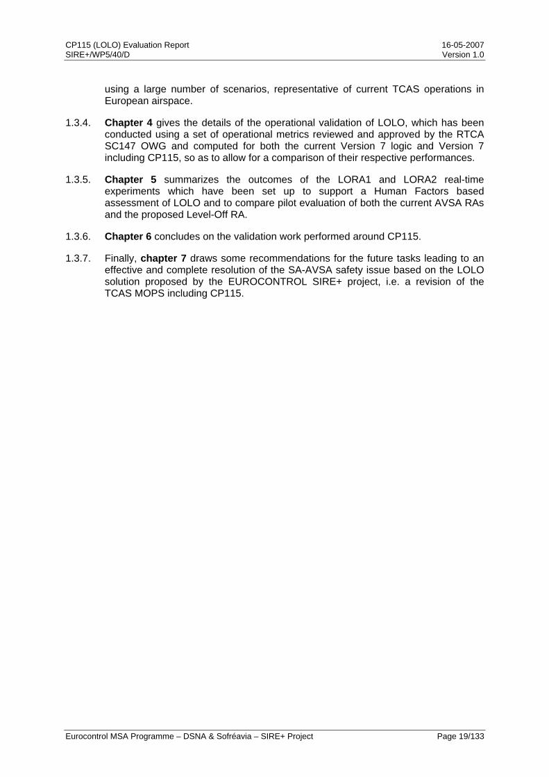
2.1.4. This section describes an actual SA-AVSA event which occurred in March 2003. This event is further described in Appendix B and a replay providing both the airborne and controller perspective is available through [SIRE+4]. This incident involves a level aircraft at FL270, heading South, and an A320 climbing towards FL260 with a 3000 fpm rate and heading North. The controller had thus planned to perform a 1000 ft level-off to maintain separation.
2.1.5. However, because of the high vertical convergence rate, the TCAS units onboard both aircraft issued coordinated RAs, requiring the A320 to limit its rate of climb to 1000 fpm at the time it went through FL250. In response, the pilot rapidly increased the vertical rate to more than 7000 fpm and eventually went through the conflicting aircraft initial level. Because of this opposite reaction to the AVSA RA, the separation between the aircraft was only 300 ft and 0.8 NM at Closest Point of Approach (CPA).
2.1.6. The following figure presents the vertical profiles of the aircraft versus time, as well as the ACAS events for one particular aircraft: the RA updates are shown by tags on the own trajectory and the intruder status is shown by a TCAS-like symbol on the intruder trajectory (cf. Appendix C for a description of the various labels and symbols used in OSCAR displays).
CP115 (LOLO) Evaluation Report 16-05-2007 SIRE+/WP5/40/D Version 1.0
Eurocontrol MSA Programme – DSNA & Sofréavia – SIRE+ Project Page 22/133
Figure 1: March 2003 SA-AVSA event
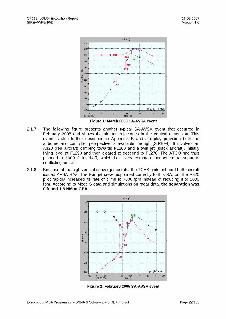
2.1.7. The following figure presents another typical SA-AVSA event that occurred in February 2005 and shows the aircraft trajectories in the vertical dimension. This event is also further described in Appendix B and a replay providing both the airborne and controller perspective is available through [SIRE+4]. It involves an A320 (red aircraft) climbing towards FL260 and a twin jet (black aircraft), initially flying level at FL290 and then cleared to descend to FL270. The ATCO had thus planned a 1000 ft level-off, which is a very common manoeuvre to separate conflicting aircraft.
2.1.8. Because of the high vertical convergence rate, the TCAS units onboard both aircraft issued AVSA RAs. The twin jet crew responded correctly to this RA, but the A320 pilot rapidly increased its rate of climb to 7500 fpm instead of reducing it to 1000 fpm. According to Mode S data and simulations on radar data, the separation was 0 ft and 1.6 NM at CPA.
Figure 2: February 2005 SA-AVSA event
CP115 (LOLO) Evaluation Report 16-05-2007 SIRE+/WP5/40/D Version 1.0
Eurocontrol MSA Programme – DSNA & Sofréavia – SIRE+ Project Page 23/133
2.2. Severity of the issu
ollected a significant body of data on opposite reactions djust” RAs from airline Flight Data Management (FDM)
2.2.2. ing to opposite reactions, of the order of 5% of
2.2.3. L 0 fpm RAs account for 32%
2.2.4. d with vertical speed TCAS displays. However, the SA-AVSA issue is not
2.2.5. munication campaigns, airlines have
2.2.6. following their
2.2.7. tems from a design issue with this type of RA.
e
2.2.1. The SIRE monitoring has cto “Adjust Vertical Speed, Aprogrammes, accident investigations, pilots and controller reports, as well as through Real-Time Simulations (RTS). This material has been used to support an analysis of the causes of the issue, an estimation of its frequency and the development of a possible solution.
Both Air France and Lufthansa have discovered a significant rate of misinterpretation of AVSA RAs leadall RAs received. Their analysis concluded that the primary cause of these misinterpretations is that the AVSA RA does not convey the manoeuvre requested from the pilot in a precise and unambiguous manner.
Observations performed by a major European airline, based on on-board data collected on their A320 fleet, indicate that although VSof all AVSA RAs, less than 1% of them induce opposite reactions. On the other hand, VSL 500, 1000 and 2000 fpm account for 19 to 24% of all AVSA RAs and opposite reactions are observed in 4 to 7% of them. It can thus be concluded that the vast majority of unintentional opposite reactions occur with VSL 500, 1000 and 2000 fpm.
Additionally, opposite reactions to initial AVSA RAs have only been identified on aircraft fittespecific to a given implementation (i.e. vertical speed tape or Instantaneous Vertical Speed Indicator (IVSI)), as it has been observed on Embraer RJ, Airbus A320, MD11, Canadair RJ, Avro RJ, Falcon, etc ...
Despite significant improvements to their training programmes, targeted at this specific issue, and dedicated internal comobserved that the opposite reactions to AVSA RAs continue to occur, thus ruling out that this is only a training issue. As a consequence, both airlines have expressed to RTCA their concern over this issue through a joint statement and requested a change in the existing aural annunciation associated with AVSA RAs.
Analysis of reported incidents also shows that such wrong reactions are occurring regularly, despite the involved pilots believing that they are correctly RAs. Some cases have been observed where this erroneous belief has led to aircraft unnecessarily crossing in altitude and where, by chance, only horizontal spacing prevented collision as aircraft entered an SA01 geometry. This indicates the potential for opposite reactions to AVSA RAs to act as a precursor to SA01 situations.
Consequently, the issue of opposite reactions to initial AVSA RAs is a safety issue that s
CP115 (LOLO) Evaluation Report 16-05-2007 SIRE+/WP5/40/D Version 1.0
Eurocontrol MSA Programme – DSNA & Sofréavia – SIRE+ Project Page 24/133
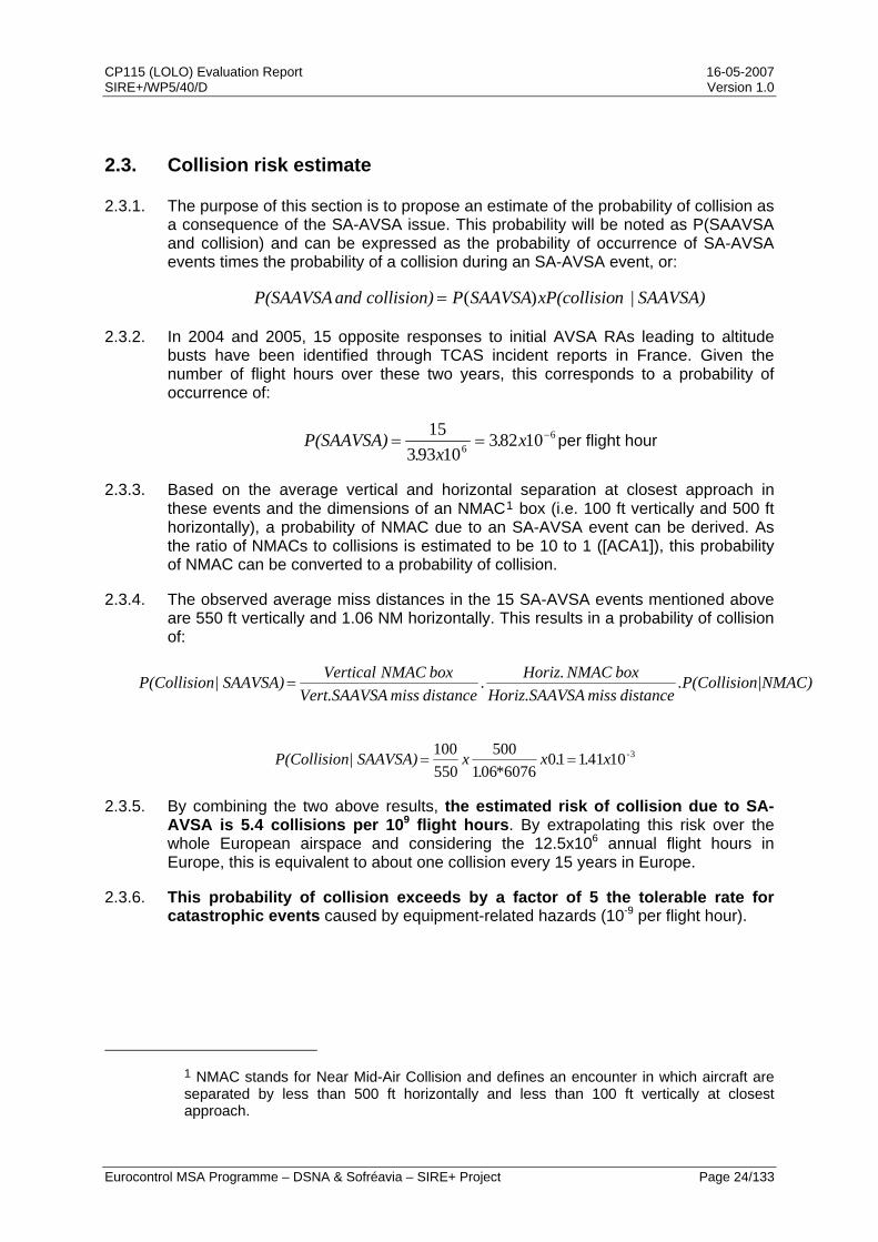
2.3. Collision risk estimate
2.3.1. The purpose of this section is to propose an estimate of the probability of collision as a consequence of the SA-AVSA issue. This probability will be noted as P(SAAVSA and collision) and can be expressed as the probability of occurrence of SA-AVSA events times the probability of a collision during an SA-AVSA event, or:
SAAVSA)| nP(collisioxSAAVSAPcollision) and P(SAAVSA )(=
2.3.2. In 2004 and 2005, 15 opposite responses to initial AVSA RAs leading to altitude busts have been identified through TCAS incident reports in France. Given the number of flight hours over these two years, this corresponds to a probability of occurrence of:
66 10823
1093315 −== x.x.
P(SAAVSA) per flight hour
2.3.3. Based on the average vertical and horizontal separation at closest approach in these events and the dimensions of an NMAC1 box (i.e. 100 ft vertically and 500 ft horizontally), a probability of NMAC due to an SA-AVSA event can be derived. As the ratio of NMACs to collisions is estimated to be 10 to 1 ([ACA1]), this probability of NMAC can be converted to a probability of collision.
2.3.4. The observed average miss distances in the 15 SA-AVSA events mentioned above are 550 ft vertically and 1.06 NM horizontally. This results in a probability of collision of:
on|NMAC).P(CollisidistancemissSAHoriz.SAAV
box NMAC Horiz..distancemissAVert.SAAVSbox NMAC Verticaln| SAAVSA)P(Collisio =
310411106076061
500550100 -x..x
*.xn| SAAVSA)P(Collisio ==
2.3.5. By combining the two above results, the estimated risk of collision due to SA-AVSA is 5.4 collisions per 109 flight hours. By extrapolating this risk over the whole European airspace and considering the 12.5x10⁶ annual flight hours in Europe, this is equivalent to about one collision every 15 years in Europe.
2.3.6. This probability of collision exceeds by a factor of 5 the tolerable rate for catastrophic events caused by equipment-related hazards (10-9 per flight hour).
1 NMAC stands for Near Mid-Air Collision and defines an encounter in which aircraft are separated by less than 500 ft horizontally and less than 100 ft vertically at closest approach.
CP115 (LOLO) Evaluation Report 16-05-2007 SIRE+/WP5/40/D Version 1.0
Eurocontrol MSA Programme – DSNA & Sofréavia – SIRE+ Project Page 25/133
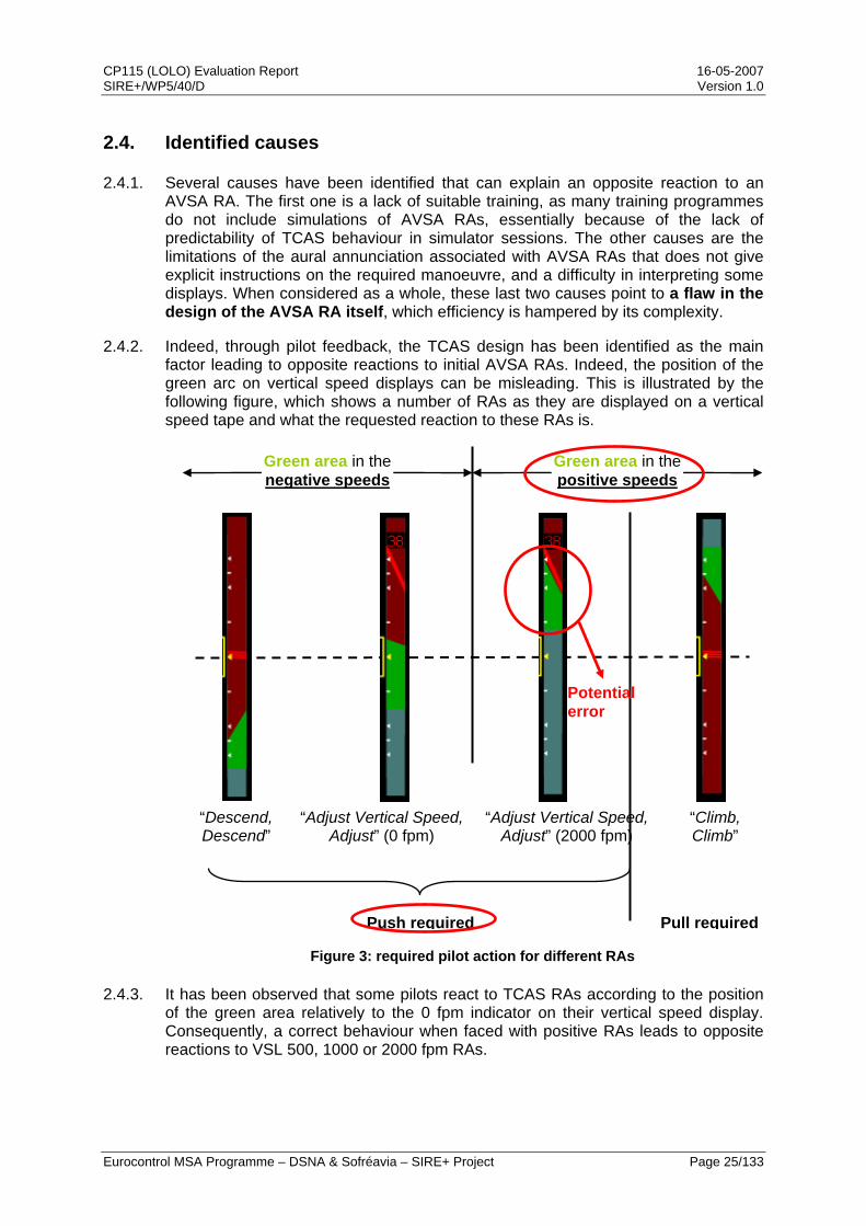
2.4. Identified causes
2.4.1. Several causes have been identified that can explain an opposite reaction to an AVSA RA. The first one is a lack of suitable training, as many training programmes do not include simulations of AVSA RAs, essentially because of the lack of predictability of TCAS behaviour in simulator sessions. The other causes are the limitations of the aural annunciation associated with AVSA RAs that does not give explicit instructions on the required manoeuvre, and a difficulty in interpreting some displays. When considered as a whole, these last two causes point to a flaw in the design of the AVSA RA itself, which efficiency is hampered by its complexity.
2.4.2. Indeed, through pilot feedback, the TCAS design has been identified as the main factor leading to opposite reactions to initial AVSA RAs. Indeed, the position of the green arc on vertical speed displays can be misleading. This is illustrated by the following figure, which shows a number of RAs as they are displayed on a vertical speed tape and what the requested reaction to these RAs is.
“Descend, Descend”
“Adjust Vertical Speed,Adjust” (0 fpm)
“Adjust Vertical Speed, Adjust” (2000 fpm)
“Climb,Climb”
Green area in the negative speeds
Green area in the positive speeds
Push required Pull required
Potential error
Figure 3: required pilot action for different RAs
2.4.3. It has been observed that some pilots react to TCAS RAs according to the position of the green area relatively to the 0 fpm indicator on their vertical speed display. Consequently, a correct behaviour when faced with positive RAs leads to opposite reactions to VSL 500, 1000 or 2000 fpm RAs.

CP115 (LOLO) Evaluation Report 16-05-2007 SIRE+/WP5/40/D Version 1.0
Eurocontrol MSA Programme – DSNA & Sofréavia – SIRE+ Project Page 26/133
2.4.4. As has been shown, enhancements in training alone can only improve the behaviour of a flight crew when an AVSA RA is issued. An improved training can therefore not be considered as a valid solution to the SA-AVSA issue, but rather as a good mitigation means. Similarly, modifying operational procedures, such as requesting a reduction of the vertical speed when approaching a cleared FL, can only reduce the probability of issuance of an AVSA RA.
2.4.5. Therefore, to fully address this issue, a complete solution has also to be envisaged. Indeed, several organization, including airlines and incident investigation authorities, have concluded that the “Adjust Vertical Speed, Adjust” aural message is too ambiguous and that the presentation (i.e. both the display and the aural message) of AVSA RAs to flight crews should be enhanced.
2.5. Conclusions and proposed solution
2.5.1. Replacing the different AVSA RAs with a single Level-off RA is the solution to the SA-AVSA issue, as the associated aural message is straightforward and the associated manoeuvre corresponds to the standard manoeuvre already performed in critical situations. This replacement would accordingly affect TCAS aural annunciations and the RA display.
2.5.2. This proposed modification has the added benefit of simplifying the list of RAs posted by TCAS II, as RAs requesting a reduction of the vertical rate to 500, 1000 or 2000 fpm become unnecessary. Additionally, this replacement will also simplify the TCAS procedure and training.
CP115 (LOLO) Evaluation Report 16-05-2007 SIRE+/WP5/40/D Version 1.0
Eurocontrol MSA Programme – DSNA & Sofréavia – SIRE+ Project Page 27/133
3. Safety performance validation
3.1. Simulation framework
3.1.1. Summary of the European safety encounter model
3.1.1.1. General
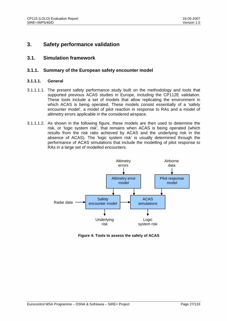
3.1.1.1.1. The present safety performance study built on the methodology and tools that supported previous ACAS studies in Europe, including the CP112E validation. These tools include a set of models that allow replicating the environment in which ACAS is being operated. These models consist essentially of a ‘safety encounter model’, a model of pilot reaction in response to RAs and a model of altimetry errors applicable in the considered airspace.
3.1.1.1.2. As shown in the following figure, these models are then used to determine the risk, or ‘logic system risk’, that remains when ACAS is being operated (which results from the risk ratio achieved by ACAS and the underlying risk in the absence of ACAS). The ‘logic system risk’ is usually determined through the performance of ACAS simulations that include the modelling of pilot response to RAs in a large set of modelled encounters.
Altimetry error model
Pilot response model
Safety encounter model
ACAS simulations Radar data
Airborne data
Altimetry errors
Underlying risk
Logic system risk
Figure 4: Tools to assess the safety of ACAS
CP115 (LOLO) Evaluation Report 16-05-2007 SIRE+/WP5/40/D Version 1.0
Eurocontrol MSA Programme – DSNA & Sofréavia – SIRE+ Project Page 28/133
3.1.1.2. Safety encounter model
3.1.1.2.1. Two-aircraft encounter model
3.1.1.2.1.1. A ‘safety encounter model’ is a model of traffic situations (involving two aircraft only) that captures the properties of ‘close’ encounters2 as a series of statistical distributions (defined as histograms and implemented as tables) describing the parameters of a typical encounter and their interdependencies. The encounter model approach is a powerful technique by which a large set of risk bearing encounters (which are rare events) can be stochastically generated to assess the safety benefits of ACAS or, indeed, any other ATM safety nets.
3.1.1.2.1.2. The initial European safety encounter model developed in the EUROCONTROL ACASA project reflected the ATM procedures that applied at the time, notably the use of 2,000ft separation above FL285 (Conventional Vertical Separation Minima). Following the introduction of Reduced Vertical Separation Minima (RVSM) in European airspace and the availability of operational data relative to RVSM operations, a safety encounter model representing current operations has been developed within the ASARP study ([ASA1]).
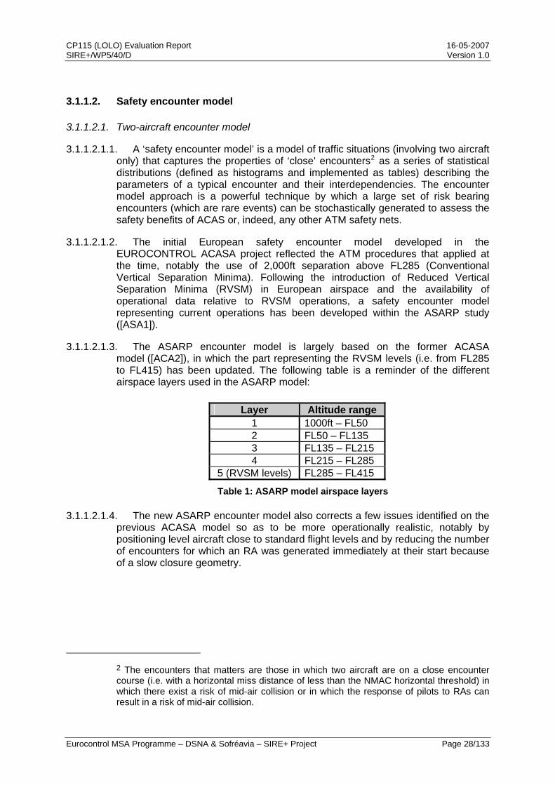
3.1.1.2.1.3. The ASARP encounter model is largely based on the former ACASA model ([ACA2]), in which the part representing the RVSM levels (i.e. from FL285 to FL415) has been updated. The following table is a reminder of the different airspace layers used in the ASARP model:
Layer Altitude range 1 1000ft – FL50 2 FL50 – FL135 3 FL135 – FL215 4 FL215 – FL285
5 (RVSM levels) FL285 – FL415
Table 1: ASARP model airspace layers
3.1.1.2.1.4. The new ASARP encounter model also corrects a few issues identified on the previous ACASA model so as to be more operationally realistic, notably by positioning level aircraft close to standard flight levels and by reducing the number of encounters for which an RA was generated immediately at their start because of a slow closure geometry.
2 The encounters that matters are those in which two aircraft are on a close encounter course (i.e. with a horizontal miss distance of less than the NMAC horizontal threshold) in which there exist a risk of mid-air collision or in which the response of pilots to RAs can result in a risk of mid-air collision.
CP115 (LOLO) Evaluation Report 16-05-2007 SIRE+/WP5/40/D Version 1.0
Eurocontrol MSA Programme – DSNA & Sofréavia – SIRE+ Project Page 29/133
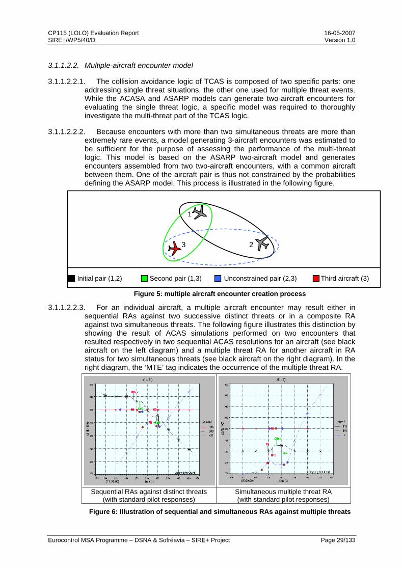
3.1.1.2.2. Multiple-aircraft encounter model
3.1.1.2.2.1. The collision avoidance logic of TCAS is composed of two specific parts: one addressing single threat situations, the other one used for multiple threat events. While the ACASA and ASARP models can generate two-aircraft encounters for evaluating the single threat logic, a specific model was required to thoroughly investigate the multi-threat part of the TCAS logic.
3.1.1.2.2.2. Because encounters with more than two simultaneous threats are more than extremely rare events, a model generating 3-aircraft encounters was estimated to be sufficient for the purpose of assessing the performance of the multi-threat logic. This model is based on the ASARP two-aircraft model and generates encounters assembled from two two-aircraft encounters, with a common aircraft between them. One of the aircraft pair is thus not constrained by the probabilities defining the ASARP model. This process is illustrated in the following figure.
Figure 5: multiple aircraft encounter creation process
3.1.1.2.2.3. For an individual aircraft, a multiple aircraft encounter may result either in sequential RAs against two successive distinct threats or in a composite RA against two simultaneous threats. The following figure illustrates this distinction by showing the result of ACAS simulations performed on two encounters that resulted respectively in two sequential ACAS resolutions for an aircraft (see black aircraft on the left diagram) and a multiple threat RA for another aircraft in RA status for two simultaneous threats (see black aircraft on the right diagram). In the right diagram, the ‘MTE’ tag indicates the occurrence of the multiple threat RA.
Sequential RAs against distinct threats (with standard pilot responses)
Simultaneous multiple threat RA (with standard pilot responses)
Figure 6: Illustration of sequential and simultaneous RAs against multiple threats
1
23
Initial pair (1,2) Second pair (1,3) Unconstrained pair (2,3) Third aircraft (3)

CP115 (LOLO) Evaluation Report 16-05-2007 SIRE+/WP5/40/D Version 1.0
Eurocontrol MSA Programme – DSNA & Sofréavia – SIRE+ Project Page 30/133
3.1.1.2.2.4. expected to be significantly more frequent than composite ones in the operational
3.1.1.3.
. nse to a corrective RA is described in the International Civil Aviation Organization (ICAO) ACAS Standards And Recommended
3.1.1.3.2. the mid-90s) were examined to determine the actual response of pilots to operational RAs. The
3.1.1.3.3. ere expected to have improved pilot behaviour and so the exercise was repeated within the ASARP
se,
3.1.1.3.4. The following figure provides an overall picture of the main pilot response characteristics and associated probabilities of each of these elementary models.
In order to obtain both composite RAs and sequential RAs, which are
world, when simulating TCAS in multiple aircraft encounters, a random shift has been inserted between the CPAs of the first and second pairs of aircraft. This shift ranges from -30 to +30 seconds around the CPA of the first pair of aircraft.
Pilot response models
3.1.1.3.1 The ‘standard’ pilot respo
Practices (SARPS) ([ANN10]). It notably requires the pilot to react to the RA within 5 seconds using an acceleration of 0.25 g to achieve the required vertical velocity. The ACAS logic has been tuned for such a response.
During the ACASA project, data from on-board recorders (from
analysis indicated than the pilots did react to corrective RAs in about half of the cases. Further, when pilots did react, none of the pilot responses were close to the standard response. Actual pilot responses observed at that time fell into two distinct groups that were modelled as two distinct pilot response models, i.e. an ‘aggressive response’ model and a ‘slow response’ model.
Improved training and increased familiarity with ACAS w
study ([ASA2]). Recent onboard recording data provided by European airlines for the years 2001, 2002 & 2004 have been collected, analysed and used to define an up-to-date model of actual pilot responses to RAs. In this model, pilot responses to corrective RAs form a multidimensional continuum ranging from non-responses or slow responses to aggressive responses. This pilot model identifies 32 types of responses, based on the variations of the following 3 parameters:
• The time between the issuance of the RA and the beginning of the respon
• The vertical acceleration taken to perform the manoeuvre,
• The targeted vertical speed to perform the manoeuvre.
In line with the figure commonly observed for the European airspace, this ASARP typical response model includes a 20% proportion of non-responding pilots.

CP115 (LOLO) Evaluation Report 16-05-2007 SIRE+/WP5/40/D Version 1.0
Eurocontrol MSA Programme – DSNA & Sofréavia – SIRE+ Project Page 31/133
3s5s
7s8s 0,09g-730fpm
0,15g-730fpm
0,15g-1300fpm
0,22g-1300fpm
0,15g-2200fpm
0,22g-2200fpm
0,3g-2200fpm
0,22g-3900fpm
No reaction
0%
3%
6%
9%
12%
15%
18%
21%
Figure 7: ASARP pilot model
3.1.1.3.5. Observation of actual pilot responses to AVSA RAs has also shown that pilots generally maintained the vertical speed required by the RA until the “Clear of Conflict” annunciation, thus potentially busting their Cleared Flight Level (CFL). This behaviour is illustrated in the following figure.
Altitude
Time AVSA
RA
Planned trajectory
“Fly the green” behaviour
Behaviour in previous simulations
Figure 8: "fly the green" pilot behaviour on AVSA RAs
3.1.1.3.6. This “fly the green” behaviour has therefore been introduced in all the pilot response models (i.e. standard, ACASA aggressive, ACASA slow or ASARP typical) used for the validation of CP115.
3.1.1.4. Altimetry error models and aircraft performance classes
3.1.1.4.1. An ‘altimetry error model’ (AEM) is also an essential element in any determination of the risk ratio. It is important that this model is as close as possible to actual avionics systems performance relevant to aircraft flying in a given airspace at a given time.
CP115 (LOLO) Evaluation Report 16-05-2007 SIRE+/WP5/40/D Version 1.0
Eurocontrol MSA Programme – DSNA & Sofréavia – SIRE+ Project Page 32/133
3.1.1.4.2. A standard AEM is also defined in the ICAO ACAS SARPs ([ANN10]), which was developed in the early 1990s. As avionics systems have improved, it has become progressively out-of-date. In particular, an aircraft whose altimetry error would only be as good as this ‘traditional’ AEM would not comply with the ‘Minimum Aviation System Performance Specification’ (MASPS) for flights in RVSM airspace.
3.1.1.4.3. Within the framework of the ASARP study, an up-to-date AEM has also been developed using data collected in the RVSM airspace by European Height Measuring Units ([ASA3]). This new AEM has been applied to all RVSM-capable aircraft in the encounter model, while the altimetry error model defined in [ANN10] has been applied to the other categories of aircraft.
3.1.1.4.4. The former ACASA safety encounter model also introduced the idea of aircraft performance classes. Seven classes were defined depending on the aircraft propulsion type and maximum take-off mass (MTOM) with thresholds that correspond to the MTOM thresholds of the European ACAS mandate (viz. 5,700 kg and 15,000 kg). The ASARP safety encounter model expanded these categories by splitting the class for heaviest jets, so as to distinguish between the aircraft performances in the medium and heavy wake vortex categories.
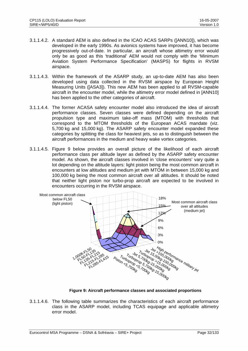
3.1.1.4.5. Figure 9 below provides an overall picture of the likelihood of each aircraft performance class per altitude layer as defined by the ASARP safety encounter model. As shown, the aircraft classes involved in ‘close encounters’ vary quite a lot depending on the altitude layers: light piston being the most common aircraft in encounters at low altitudes and medium jet with MTOM in between 15,000 kg and 100,000 kg being the most common aircraft over all altitudes. It should be noted that neither light piston nor turbo-prop aircraft are expected to be involved in encounters occurring in the RVSM airspace.
1,000ft-FL50
FL50-FL135
FL135-FL215
FL215-FL285
FL285-FL415 Piston <5,700kg
Turboprop <5,700kg
Turboprop 5,700kg-15,000kg
Jet 5,700kg-15,000kg
Turboprop >15,000kg
Jet 15,00kg-100,000kg
Jet >100,000kg
High performance military jet
0%
3%
6%
9%
12%
15%
18%
Most common aircraft class below FL50 (light piston) Most common aircraft class
over all altitudes (medium jet)
Figure 9: Aircraft performance classes and associated proportions
3.1.1.4.6. The following table summarizes the characteristics of each aircraft performance class in the ASARP model, including TCAS equipage and applicable altimetry error model.
CP115 (LOLO) Evaluation Report 16-05-2007 SIRE+/WP5/40/D Version 1.0
Eurocontrol MSA Programme – DSNA & Sofréavia – SIRE+ Project Page 33/133
Aircraft class TCAS
equippedICAO AEM
ASARP AEM
A (piston) B (turboprop < 5.7t) C (turboprop between 5.7t and 15t) D (jet between 5.7t and 15t) E (turboprop > 15t) F1 (jet between 15t and 100t) F2 (jet > 100t) G (military jet)
Table 2: ACAS equipage and altimetry error model
3.1.2. Scenario definition
3.1.2.1. Representative model scenarios
3.1.2.1.1. A baseline has first been established by performing ACAS simulations on a number of scenarios, with both the current Version 7 and Version 7 including CP112E. These scenarios feature varying types of pilot responses and of TCAS-equipage, allowing for a broad range of artificial situations. The same simulations have then been performed with LOLO to evaluate the benefits brought by the proposed change to the TCAS logic, using this baseline as the reference.
3.1.2.1.2. The 12 scenarios used to build the baseline and evaluate the proposed changes to the TCAS logic are described in the table below. In all these scenarios, the aircraft reported their altitude in 25 ft increments.
Configuration Pilot 1 Pilot 2
Standard Standard ACASA slow Standard
ACASA aggressive Standard Responding vs.
responding ASARP typical (100%
response) Standard
Standard Non-responding ACASA slow Non-responding
ACASA aggressive Non-responding Responding vs. non-responding
ASARP typical (100% response)
Non-responding
Standard N/A ACASA slow N/A
ACASA aggressive N/A Responding vs.
unequipped ASARP typical (100%
response) N/A
Table 3: definition of the scenarios investigated
3.1.2.1.3. For the scenarios using the ASARP typical pilot response with 100% response, the probabilities given in Figure 7 have been scaled up to reflect a ‘No response’ probability of 0.0 instead of 0.2.
CP115 (LOLO) Evaluation Report 16-05-2007 SIRE+/WP5/40/D Version 1.0
Eurocontrol MSA Programme – DSNA & Sofréavia – SIRE+ Project Page 34/133
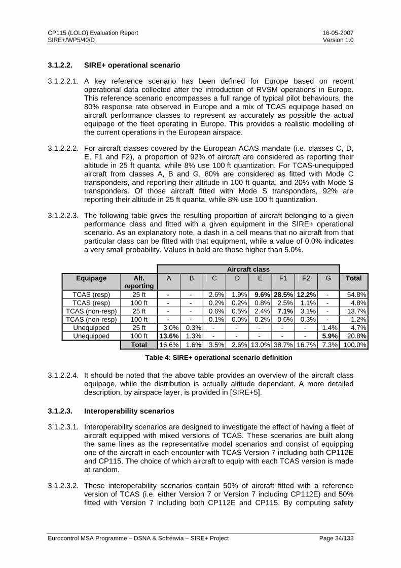
3.1.2.2. SIRE+ operational scenario
3.1.2.2.1. A key reference scenario has been defined for Europe based on recent operational data collected after the introduction of RVSM operations in Europe. This reference scenario encompasses a full range of typical pilot behaviours, the 80% response rate observed in Europe and a mix of TCAS equipage based on aircraft performance classes to represent as accurately as possible the actual equipage of the fleet operating in Europe. This provides a realistic modelling of the current operations in the European airspace.
3.1.2.2.2. For aircraft classes covered by the European ACAS mandate (i.e. classes C, D, E, F1 and F2), a proportion of 92% of aircraft are considered as reporting their altitude in 25 ft quanta, while 8% use 100 ft quantization. For TCAS-unequipped aircraft from classes A, B and G, 80% are considered as fitted with Mode C transponders, and reporting their altitude in 100 ft quanta, and 20% with Mode S transponders. Of those aircraft fitted with Mode S transponders, 92% are reporting their altitude in 25 ft quanta, while 8% use 100 ft quantization.
3.1.2.2.3. The following table gives the resulting proportion of aircraft belonging to a given performance class and fitted with a given equipment in the SIRE+ operational scenario. As an explanatory note, a dash in a cell means that no aircraft from that particular class can be fitted with that equipment, while a value of 0.0% indicates a very small probability. Values in bold are those higher than 5.0%.
Aircraft class Equipage Alt.
reporting A B C D E F1 F2 G Total
TCAS (resp) 25 ft - - 2.6% 1.9% 9.6% 28.5% 12.2% - 54.8%TCAS (resp) 100 ft - - 0.2% 0.2% 0.8% 2.5% 1.1% - 4.8%
TCAS (non-resp) 25 ft - - 0.6% 0.5% 2.4% 7.1% 3.1% - 13.7%TCAS (non-resp) 100 ft - - 0.1% 0.0% 0.2% 0.6% 0.3% - 1.2%
Unequipped 25 ft 3.0% 0.3% - - - - - 1.4% 4.7%Unequipped 100 ft 13.6% 1.3% - - - - - 5.9% 20.8%
Total 16.6% 1.6% 3.5% 2.6% 13.0% 38.7% 16.7% 7.3% 100.0%
Table 4: SIRE+ operational scenario definition
3.1.2.2.4. It should be noted that the above table provides an overview of the aircraft class equipage, while the distribution is actually altitude dependant. A more detailed description, by airspace layer, is provided in [SIRE+5].
3.1.2.3. Interoperability scenarios
3.1.2.3.1. Interoperability scenarios are designed to investigate the effect of having a fleet of aircraft equipped with mixed versions of TCAS. These scenarios are built along the same lines as the representative model scenarios and consist of equipping one of the aircraft in each encounter with TCAS Version 7 including both CP112E and CP115. The choice of which aircraft to equip with each TCAS version is made at random.
3.1.2.3.2. These interoperability scenarios contain 50% of aircraft fitted with a reference version of TCAS (i.e. either Version 7 or Version 7 including CP112E) and 50% fitted with Version 7 including both CP112E and CP115. By computing safety

CP115 (LOLO) Evaluation Report 16-05-2007 SIRE+/WP5/40/D Version 1.0
Eurocontrol MSA Programme – DSNA & Sofréavia – SIRE+ Project Page 35/133
metrics for a reference TCAS version, a 50% LOLO equipage and a full LOLO equipage, potential interoperability issues between the different versions can be identified.
3.1.2.3.3. The above principles for the building of interoperability scenarios can also be applied to the operational scenario described in 3.1.2.2, in order to obtain a realistic mixed equipage scenario.
3.1.2.3.4. In addition, the various pilot models used with the representative model scenarios (cf. 3.1.2.1) can also be used with the interoperability scenarios, so as to provide a broader scope of situations in the safety benefit assessment. The following table summarizes the different interoperability scenarios that have been investigated:
Scenario 50% V7 - 50% CP112E+CP115
50% CP112E - 50% CP112E+CP115
Standard vs. standard Standard vs. ACASA slow
Standard vs. ACASA aggressive
Standard vs. ASARP typical (100% response)
Non-responding vs. standard
Non-responding vs. ACASA slow
Non responding vs. ACASA aggressive
Non-responding vs. ASARP typical (100% response)
SIRE+ operational
Table 5: definition of the interoperability scenarios investigated
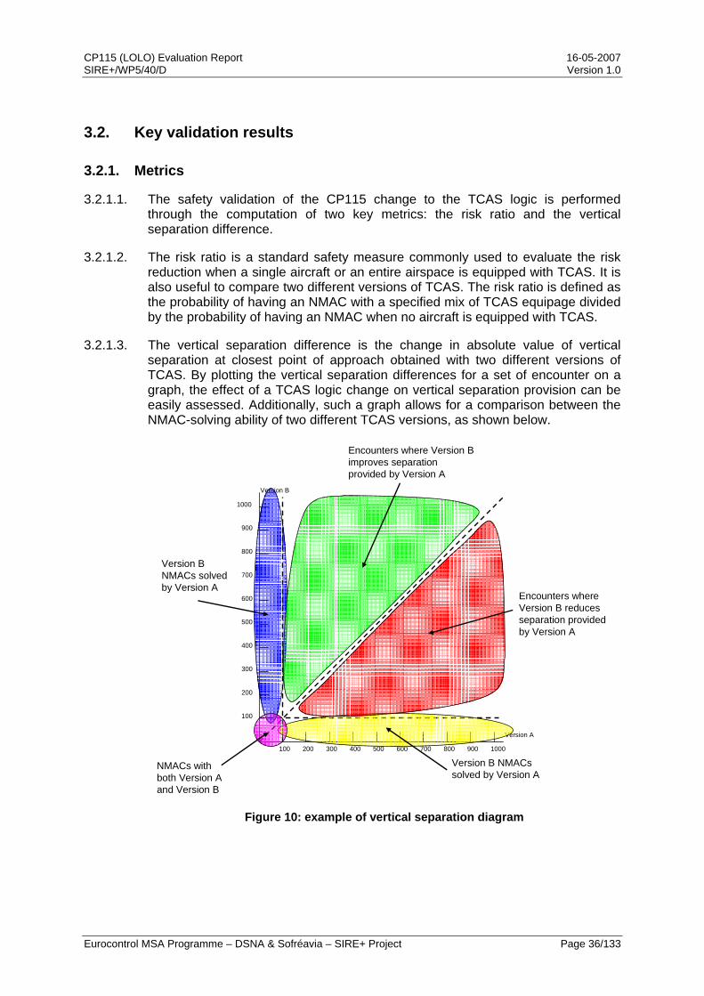
CP115 (LOLO) Evaluation Report 16-05-2007 SIRE+/WP5/40/D Version 1.0
Eurocontrol MSA Programme – DSNA & Sofréavia – SIRE+ Project Page 36/133
3.2. Key validation results
3.2.1. Metrics
3.2.1.1. The safety validation of the CP115 change to the TCAS logic is performed through the computation of two key metrics: the risk ratio and the vertical separation difference.
3.2.1.2. The risk ratio is a standard safety measure commonly used to evaluate the risk reduction when a single aircraft or an entire airspace is equipped with TCAS. It is also useful to compare two different versions of TCAS. The risk ratio is defined as the probability of having an NMAC with a specified mix of TCAS equipage divided by the probability of having an NMAC when no aircraft is equipped with TCAS.
3.2.1.3. The vertical separation difference is the change in absolute value of vertical separation at closest point of approach obtained with two different versions of TCAS. By plotting the vertical separation differences for a set of encounter on a graph, the effect of a TCAS logic change on vertical separation provision can be easily assessed. Additionally, such a graph allows for a comparison between the NMAC-solving ability of two different TCAS versions, as shown below.
1000
Version B
Figure 10: example of vertical separation diagram
100 200 300 400 500 600 700 800 900 1000
Version A
100
200
300
400
500
600
700
800
900
Encounters where Version B improves separation provided by Version A
Encounters where Version B reduces separation provided by Version A
Version B NMACs solved by Version A
Version B NMACs solved by Version A
NMACs with both Version A and Version B
CP115 (LOLO) Evaluation Report 16-05-2007 SIRE+/WP5/40/D Version 1.0
Eurocontrol MSA Programme – DSNA & Sofréavia – SIRE+ Project Page 37/133
3.2.2. Representative model scenarios
3.2.2.1. Standard response
3.2.2.1.1. This section presents the details on the safety validation results that have already been progressively introduced in the RTCA arena through [SIRE+6], then [SIRE+7] and finally [SIRE+2]. It provides metric computations on a broad range of scenarios, including mixed equipage situations.
3.2.2.1.2. The following figure shows the results of the risk ratio computations for the standard scenarios involving two responding pilots (cf. Table 3).
1.21.5
3.9
1.11.21.5
3.8
1.11.01.4
3.7
1.0
0
0.5
1
1.5
2
2.5
3
3.5
4
Standard Typical Slow Aggressive
Pilot response
Ris
k ra
tio (%
)
V7 V7+CP112E V7+CP112E+CP115
Figure 11: risk ratios for response/response standard scenarios
3.2.2.1.3. As can be seen in the above figure, LOLO (i.e. V7+CP112E+CP115) provides safety benefits over Version 7 in all cases where both pilots respond to their RAs, as risk ratios are decreased. It also has to be noted that LOLO provides benefits over CP112E, most notably in the standard response vs. standard response scenario.
3.2.2.1.4. The following figure shows the vertical separation diagram obtained with Version 7 including CP112E and Version 7 including both CP112E and CP115, for the standard response vs. standard response scenario. For clarity’s sake, the diagram is provided as a density graph, where each cell is colour-coded depending on the number of encounters it contains. The darker a cell, the more populated it is.
CP115 (LOLO) Evaluation Report 16-05-2007 SIRE+/WP5/40/D Version 1.0
Eurocontrol MSA Programme – DSNA & Sofréavia – SIRE+ Project Page 38/133
Figure 12: separation difference for standard response vs. standard response scenario
3.2.2.1.5. As can be seen in the above figure, introducing LOLO in the TCAS logic significantly improves the vertical separation provided without inducing any new NMAC. In a very few cases, LOLO reduces the vertical separation obtained with CP112E, but these are vastly outnumbered by the cases where LOLO increases the separation. The other scenarios involving two responding pilots show similar separation difference diagrams and are presented in details in [SIRE+2].
3.2.2.1.6. The following figure shows the results of the risk ratio computations for the two interoperability scenarios involving two pilots responding with the standard response (cf. Table 5). The risk ratios for the corresponding standard scenarios (i.e. Version 7 vs. Version 7, CP112E vs. CP112E and LOLO vs. LOLO) are given as a reference.
CP115 (LOLO) Evaluation Report 16-05-2007 SIRE+/WP5/40/D Version 1.0
Eurocontrol MSA Programme – DSNA & Sofréavia – SIRE+ Project Page 39/133
1.2 1.21.1 1.1
1.0 1
0
0.25
0.5
0.75
1
1.25
V7 V7+CP112E
Reference logic version
Ris
k ra
tio (%
)
Ref vs. Ref Ref vs. LOLO LOLO vs. LOLO
Figure 13: risk ratios for interoperability scenarios with 2 standard responses
3.2.2.1.7. The above figure shows that safety benefits can be expected as soon the LOLO solution is introduced into the fleet. The other interoperability scenarios involving two responding pilots show similar trends in the collision risk reduction and detailed results are presented in [SIRE+2].
3.2.2.2. Illustration of safety benefits
3.2.2.2.1. The next series of figures illustrate how the safety benefits brought by LOLO are obtained by comparing the behaviour of TCAS II Version 7, with and without LOLO, on an actual event that occurred in September 2004. The left side picture shows the RAs received by the red aircraft, while the right side picture shows the RA received by the black aircraft. The thick black line between the trajectories materializes the CPA.
Figure 14: September 2004 event - actual event

CP115 (LOLO) Evaluation Report 16-05-2007 SIRE+/WP5/40/D Version 1.0
Eurocontrol MSA Programme – DSNA & Sofréavia – SIRE+ Project Page 40/133
3.2.2.2.2. In the previous figure, the TCAS logic solves the situation by issuing an AVSA RA to the upper aircraft, limiting its rate of descent to 1000 fpm (red LD1 label), and ordering the lower aircraft to maintain its current rate of descent (red MDes label). The net result is that both aircraft are left going in the same vertical direction. The reasons for this choice of RAs is that the logic tries to provide a target minimum vertical spacing, which exact value depends on the altitude, while minimizing deviations from the aircraft current path and does so by modelling the expected pilot reactions to the posted RA.
3.2.2.2.3. However, despite correct pilot reactions in this event, the initial RAs have to be strengthened when the logic predicts that the target vertical separation of 400 ft will not be achieved. The resulting separation at CPA is 1.6 NM horizontally and 300 ft vertically.
3.2.2.2.4. The solution chosen by the logic is both very uncomfortable for the pilots and unsatisfactory from the perspective of providing vertical separation between aircraft.
3.2.2.2.5. The next figures show the RAs received by both aircraft when the same event is simulated with standard pilot reactions and Version 7 including LOLO.
Figure 15: September 2004 event - standard pilot reactions and LOLO
3.2.2.2.6. The above figure illustrates how Version 7 with LOLO handles the situation in a safer manner, by having the red aircraft stopping its descent and the black one maintaining its descent. In addition, it can be observed that Version 7 with LOLO achieves the target vertical separation of 400 ft, when Version 7 did not. Last, each aircraft only receives one RA instead of a series of RAs in short sequence.
3.2.2.2.7. The next figures show another actual event that occurred in April 2003 and also provide an illustration of the safety benefits brought by LOLO. Again, the left side picture shows the RAs received by the red aircraft, while the right side picture shows the RA received by the black aircraft. The thick black line between the trajectories materializes the CPA.
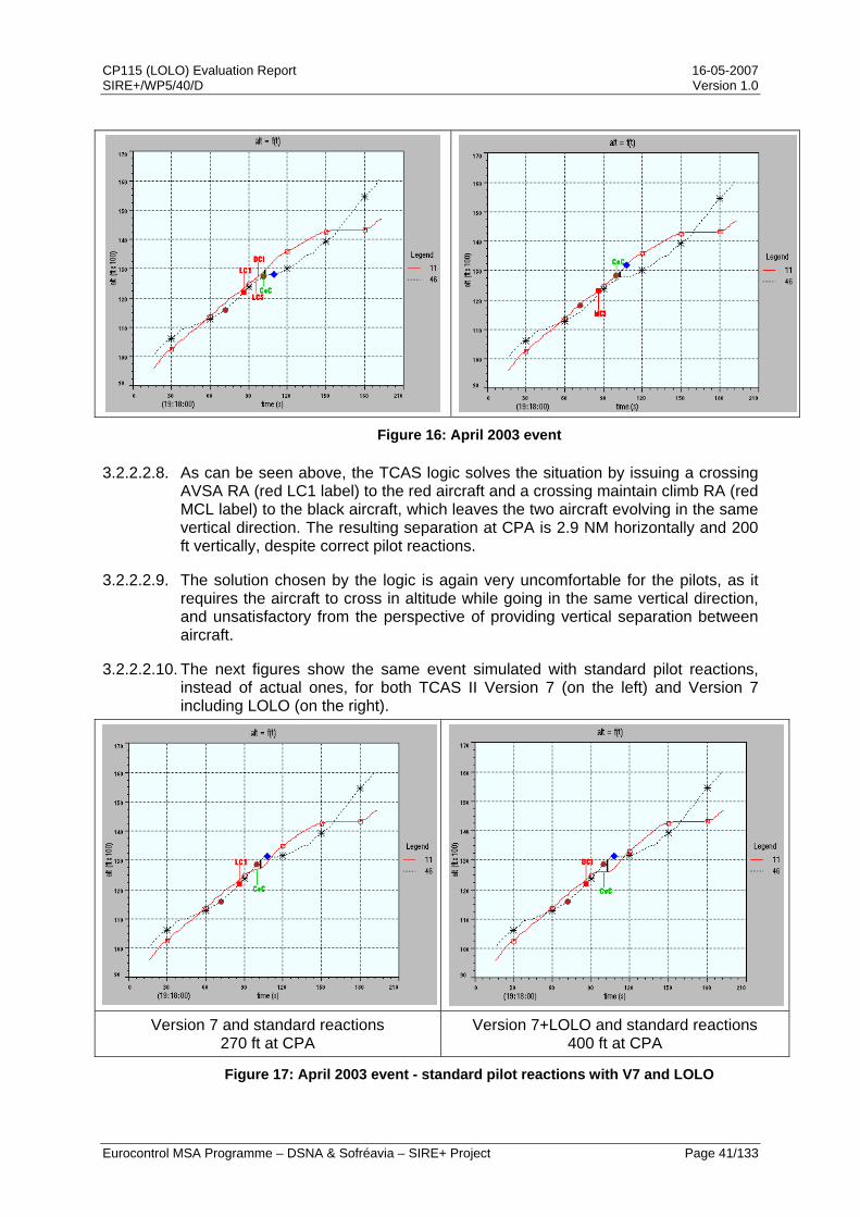
CP115 (LOLO) Evaluation Report 16-05-2007 SIRE+/WP5/40/D Version 1.0
Eurocontrol MSA Programme – DSNA & Sofréavia – SIRE+ Project Page 41/133
Figure 16: April 2003 event
3.2.2.2.8. As can be seen above, the TCAS logic solves the situation by issuing a crossing AVSA RA (red LC1 label) to the red aircraft and a crossing maintain climb RA (red MCL label) to the black aircraft, which leaves the two aircraft evolving in the same vertical direction. The resulting separation at CPA is 2.9 NM horizontally and 200 ft vertically, despite correct pilot reactions.
3.2.2.2.9. The solution chosen by the logic is again very uncomfortable for the pilots, as it requires the aircraft to cross in altitude while going in the same vertical direction, and unsatisfactory from the perspective of providing vertical separation between aircraft.
3.2.2.2.10. The next figures show the same event simulated with standard pilot reactions, instead of actual ones, for both TCAS II Version 7 (on the left) and Version 7 including LOLO (on the right).
Version 7 and standard reactions 270 ft at CPA
Version 7+LOLO and standard reactions 400 ft at CPA
Figure 17: April 2003 event - standard pilot reactions with V7 and LOLO

CP115 (LOLO) Evaluation Report 16-05-2007 SIRE+/WP5/40/D Version 1.0
Eurocontrol MSA Programme – DSNA & Sofréavia – SIRE+ Project Page 42/133
3.2.2.2.11. The above figure illustrates how Version 7 including LOLO handles the situation in a safer manner, by having the red aircraft stopping its climb and the black one maintaining its climb, while Version 7 leaves both aircraft climbing at different rates. In addition, it can be observed that Version 7 does not achieve the target vertical separation of 400 ft while Version 7 including LOLO does.
3.2.2.3. Non response
3.2.2.3.1. The following figure shows the results of the risk ratio computations for the scenarios involving only one responding pilot (cf. Table 3).
17.3 17.2
96.3
8.611.8 13.2
95.1
7.011.6 13.1
94.3
6.8
0102030405060708090
100
Standard Typical Slow Aggressive
Pilot response
Ris
k ra
tio (%
)
V7 V7+CP112E V7+CP112E+CP115
Figure 18: risk ratios for response/non-response standard scenarios
3.2.2.3.2. Again, the above figure indicates that LOLO performs better than CP112E, which, in turn, performed significantly better than Version 7 in terms of safety benefits.
3.2.2.3.3. The following figure shows the vertical separation diagram obtained with Version 7 including CP112E and Version 7 including both CP112E and CP115, for the standard response vs. non-response scenario.
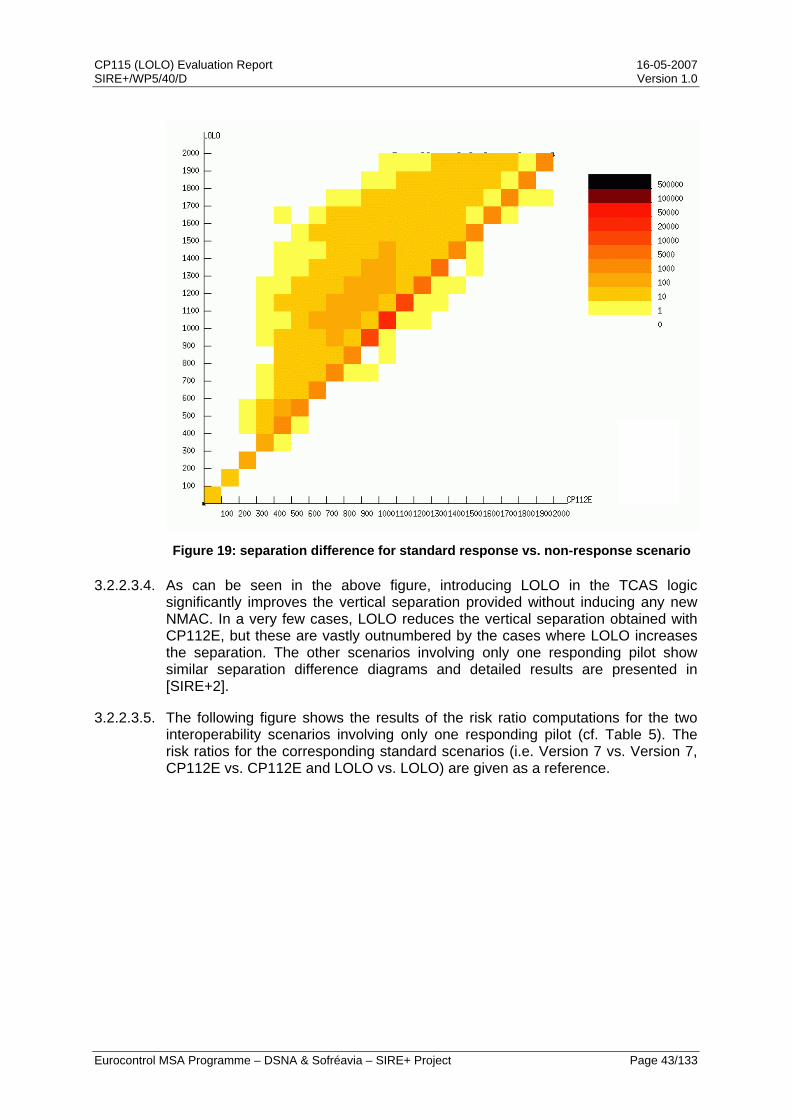
CP115 (LOLO) Evaluation Report 16-05-2007 SIRE+/WP5/40/D Version 1.0
Eurocontrol MSA Programme – DSNA & Sofréavia – SIRE+ Project Page 43/133
Figure 19: separation difference for standard response vs. non-response scenario
3.2.2.3.4. As can be seen in the above figure, introducing LOLO in the TCAS logic significantly improves the vertical separation provided without inducing any new NMAC. In a very few cases, LOLO reduces the vertical separation obtained with CP112E, but these are vastly outnumbered by the cases where LOLO increases the separation. The other scenarios involving only one responding pilot show similar separation difference diagrams and detailed results are presented in [SIRE+2].
3.2.2.3.5. The following figure shows the results of the risk ratio computations for the two interoperability scenarios involving only one responding pilot (cf. Table 5). The risk ratios for the corresponding standard scenarios (i.e. Version 7 vs. Version 7, CP112E vs. CP112E and LOLO vs. LOLO) are given as a reference.
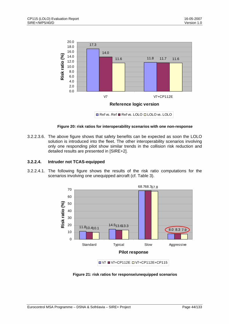
CP115 (LOLO) Evaluation Report 16-05-2007 SIRE+/WP5/40/D Version 1.0
Eurocontrol MSA Programme – DSNA & Sofréavia – SIRE+ Project Page 44/133
17.3
11.814.0
11.711.6 11.6
0.02.04.06.08.0
10.012.014.016.018.020.0
V7 V7+CP112E
Reference logic version
Ris
k ra
tio (%
)
Ref vs. Ref Ref vs. LOLO LOLO vs. LOLO
Figure 20: risk ratios for interoperability scenarios with one non-response
3.2.2.3.6. The above figure shows that safety benefits can be expected as soon the LOLO solution is introduced into the fleet. The other interoperability scenarios involving only one responding pilot show similar trends in the collision risk reduction and detailed results are presented in [SIRE+2].
3.2.2.4. Intruder not TCAS-equipped
3.2.2.4.1. The following figure shows the results of the risk ratio computations for the scenarios involving one unequipped aircraft (cf. Table 3).
11.8 14.5
68.7
8.010.4 13.6
68.7
8.310.113.3
67.8
7.9
0
10
20
30
40
50
60
70
Standard Typical Slow Aggressive
Pilot response
Ris
k ra
tio (%
)
V7 V7+CP112E V7+CP112E+CP115
Figure 21: risk ratios for response/unequipped scenarios
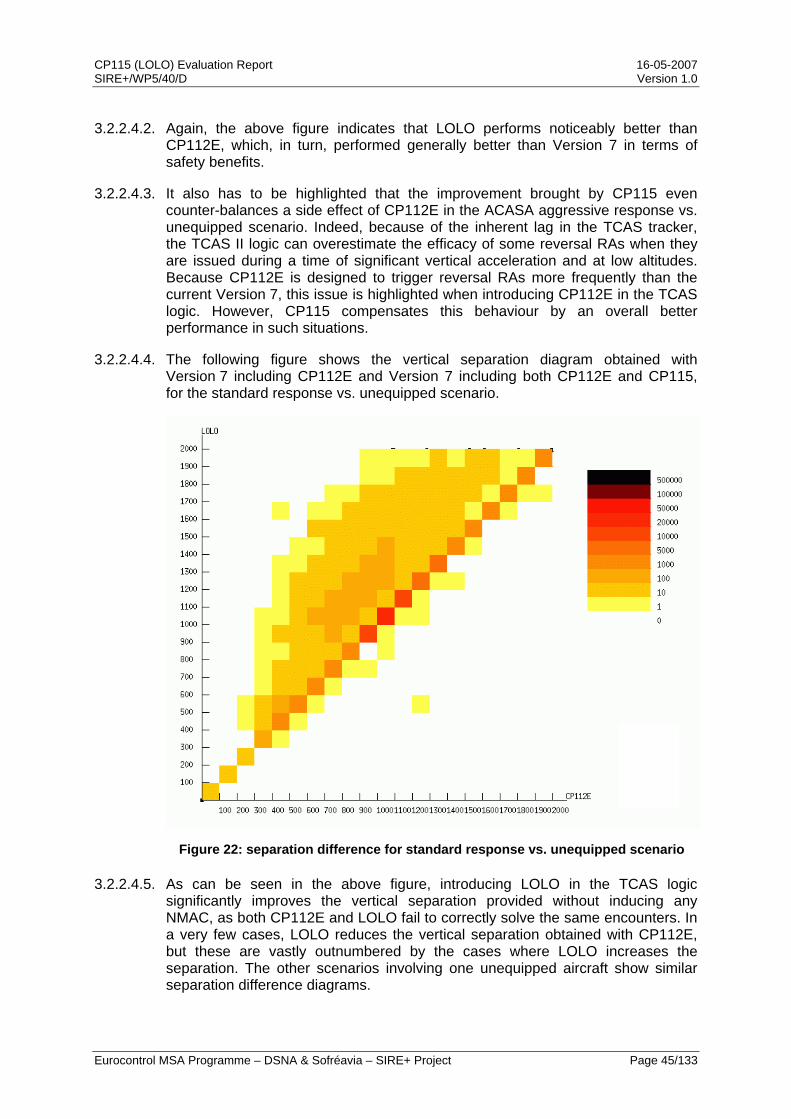
CP115 (LOLO) Evaluation Report 16-05-2007 SIRE+/WP5/40/D Version 1.0
Eurocontrol MSA Programme – DSNA & Sofréavia – SIRE+ Project Page 45/133
3.2.2.4.2. Again, the above figure indicates that LOLO performs noticeably better than CP112E, which, in turn, performed generally better than Version 7 in terms of safety benefits.
3.2.2.4.3. It also has to be highlighted that the improvement brought by CP115 even counter-balances a side effect of CP112E in the ACASA aggressive response vs. unequipped scenario. Indeed, because of the inherent lag in the TCAS tracker, the TCAS II logic can overestimate the efficacy of some reversal RAs when they are issued during a time of significant vertical acceleration and at low altitudes. Because CP112E is designed to trigger reversal RAs more frequently than the current Version 7, this issue is highlighted when introducing CP112E in the TCAS logic. However, CP115 compensates this behaviour by an overall better performance in such situations.
3.2.2.4.4. The following figure shows the vertical separation diagram obtained with Version 7 including CP112E and Version 7 including both CP112E and CP115, for the standard response vs. unequipped scenario.
Figure 22: separation difference for standard response vs. unequipped scenario
3.2.2.4.5. As can be seen in the above figure, introducing LOLO in the TCAS logic significantly improves the vertical separation provided without inducing any NMAC, as both CP112E and LOLO fail to correctly solve the same encounters. In a very few cases, LOLO reduces the vertical separation obtained with CP112E, but these are vastly outnumbered by the cases where LOLO increases the separation. The other scenarios involving one unequipped aircraft show similar separation difference diagrams.
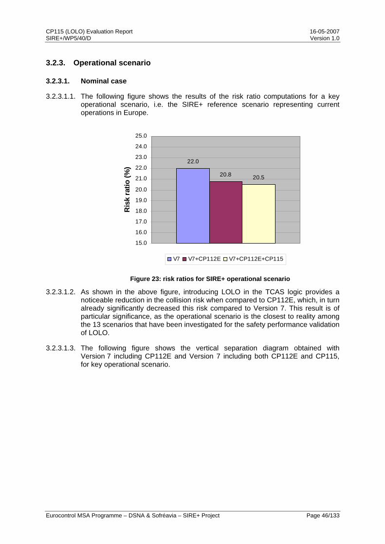
CP115 (LOLO) Evaluation Report 16-05-2007 SIRE+/WP5/40/D Version 1.0
Eurocontrol MSA Programme – DSNA & Sofréavia – SIRE+ Project Page 46/133
3.2.3. Operational scenario
3.2.3.1. Nominal case
3.2.3.1.1. The following figure shows the results of the risk ratio computations for a key operational scenario, i.e. the SIRE+ reference scenario representing current operations in Europe.
22.0
20.8 20.5
15.0
16.0
17.0
18.0
19.0
20.0
21.0
22.0
23.0
24.0
25.0R
isk
ratio
(%)
V7 V7+CP112E V7+CP112E+CP115
Figure 23: risk ratios for SIRE+ operational scenario
3.2.3.1.2. As shown in the above figure, introducing LOLO in the TCAS logic provides a noticeable reduction in the collision risk when compared to CP112E, which, in turn already significantly decreased this risk compared to Version 7. This result is of particular significance, as the operational scenario is the closest to reality among the 13 scenarios that have been investigated for the safety performance validation of LOLO.
3.2.3.1.3. The following figure shows the vertical separation diagram obtained with Version 7 including CP112E and Version 7 including both CP112E and CP115, for key operational scenario.
CP115 (LOLO) Evaluation Report 16-05-2007 SIRE+/WP5/40/D Version 1.0
Eurocontrol MSA Programme – DSNA & Sofréavia – SIRE+ Project Page 47/133
Figure 24: separation difference for SIRE+ operational scenario
3.2.3.1.4. As can be seen in the above figure, introducing LOLO in the TCAS logic significantly improves the vertical separation provided without inducing any NMAC, as both CP112E and LOLO fail to correctly solve the same encounters. In a very few cases, LOLO reduces the vertical separation obtained with CP112E, but these are vastly outnumbered by the cases where LOLO increases the separation.
3.2.3.2. Interoperability
3.2.3.2.1. The following figure shows the results of the risk ratio computations for the interoperability scenarios involving two pilots responding according to the ASARP typical model (cf. Table 5). The risk ratios for the corresponding operational scenarios (i.e. Version 7 vs. Version 7, CP112E vs. CP112E and LOLO vs. LOLO) are given as a reference.

CP115 (LOLO) Evaluation Report 16-05-2007 SIRE+/WP5/40/D Version 1.0
Eurocontrol MSA Programme – DSNA & Sofréavia – SIRE+ Project Page 48/133
22.0
20.820.9 20.620.5 20.5
15.016.017.018.019.020.021.022.023.024.025.0
V7 V7+CP112E
Reference logic version
Ris
k ra
tio (%
)
Ref vs. Ref Ref vs. LOLO LOLO vs. LOLO
Figure 25: risk ratios for interoperability operational scenario
3.2.3.2.2. The above figure shows that risk ratios are significantly decreased with only half of the aircraft fitted with TCAS including LOLO. This result is of particular significance as the operational scenario is the closest to reality among the 13 scenarios that have been investigated and because it indicates that safety benefits can be expected as soon as LOLO is introduced into the fleet.
3.2.4. Multi-aircraft encounter scenario
3.2.4.1. The following figure shows the results of the risk ratio computations for the scenario designed to investigate the multiple threat part of the TCAS logic. It shows the results obtained in encounters featuring composite RAs (i.e. RAs against multiple simultaneous threats) on one hand and in encounters featuring sequential RAs (i.e. RAs against several single threats in quick succession) on the other hand.
26.6
37.6
25.6
35.4
27.2
33.7
0
5
10
15
20
25
30
35
40
Composite Sequential
RA type
Ris
k ra
tio (%
)
V7 V7+CP112E V7+CP112E+CP115
Figure 26: risk ratios for multiple aircraft scenario

CP115 (LOLO) Evaluation Report 16-05-2007 SIRE+/WP5/40/D Version 1.0
Eurocontrol MSA Programme – DSNA & Sofréavia – SIRE+ Project Page 49/133
3.2.4.2. As can be seen in the above figure, introducing LOLO increases the risk ratio in encounters leading to composite RAs. This result was anticipated, because LOLO reduces the range of available RA strengths in “sandwich” situations.
3.2.4.3. However, in the operational world, encounters leading to sequential RAs are significantly more frequent than those leading to composite RAs. Consequently, LOLO brings some overall benefits in multiple threat situations, as for single threat encounters. Additionally, it has to be mentioned that multiple threat encounters are very rare events (only few cases are identified each year in Europe).
3.2.4.4. The following example illustrates the benefits brought by CP115 in sequential RA situations. The next figure shows the initial situation in which an aircraft (in black) successively goes through the altitude of two level aircraft (in red and in blue) at about 2500 fpm.
3.2.4.5. Both the black and blue aircraft are equipped with TCAS and their pilot responds to RAs according to the typical ASARP model (cf. 3.1.1.3.4), close to the standard pilot response in this specific case. The red aircraft is not TCAS-equipped. In the absence of TCAS alerts, the minimum separation between the black and red aircraft would be 0.05 NM laterally and 480 ft vertically at t=64 s, while the minimum separation between the black and blue aircraft would be 0.52 NM laterally and 660 ft vertically at t=80s.
CP115 (LOLO) Evaluation Report 16-05-2007 SIRE+/WP5/40/D Version 1.0
Eurocontrol MSA Programme – DSNA & Sofréavia – SIRE+ Project Page 50/133
Figure 27: example of benefits in sequential RA situations - initial encounter
3.2.4.6. The next figure shows the RAs received by the different aircraft when simulating the same encounter with TCAS II Version 7 onboard the two equipped aircraft.

CP115 (LOLO) Evaluation Report 16-05-2007 SIRE+/WP5/40/D Version 1.0
Eurocontrol MSA Programme – DSNA & Sofréavia – SIRE+ Project Page 51/133
RAs received onboard black aircraft RAs received onboard blue aircraft
550 ft
740 ft
Figure 28: example of benefits in sequential RA situations - Version 7
3.2.4.7. As can be seen above, the black aircraft receives an AVSA RA (Limit Climb 2000 fpm) against the red aircraft. 5 seconds after the Clear of Conflict for this first RA, the black aircraft receives another AVSA RA (Limit Climb 2000 fpm) against the blue aircraft. In the following seconds, this initial RA is strengthened three times up to a Don’t Climb RA which eventually solves the situation. In the meantime, the blue aircraft receives a short Climb RA just before CPA.
3.2.4.8. The next figure shows the RAs received by the different aircraft when simulating the same encounter with TCAS II Version 7 including CP115 onboard both equipped aircraft.
RAs received onboard black aircraft RAs received onboard blue aircraft
710 ft
1310 ft
Figure 29: example of benefits in sequential RA situations - LOLO solution

CP115 (LOLO) Evaluation Report 16-05-2007 SIRE+/WP5/40/D Version 1.0
Eurocontrol MSA Programme – DSNA & Sofréavia – SIRE+ Project Page 52/133
3.2.4.9. As shown in the above figure, adding CP115 to Version 7 leads to the black aircraft receiving a “Level-Off, Level-Off” RA against the red aircraft. Because of the improved vertical separation provided by this RA, the Vertical Miss Distance (VMD) between the black and blue aircraft is also increased. Consequently, with CP115, no second RA sequence is issued between these two aircraft.
3.3. Conclusions on the safety performance validation
3.3.1. A thorough analysis of the safety performance of the CP115 proposed change to TCAS II Version 7 has been conducted and shows that substantial safety benefits can be expected. An immediate safety benefit derives from the design of CP115, which prevents the issuance of RAs that leave the aircraft going in the same vertical direction.
3.3.2. For single threat encounters, all the simulations performed on representative model scenarios indicate that adopting the LOLO solution leads to some improvements on the risk ratio metric. In the vast majority of multiple aircraft encounters, which are sequential events, LOLO provides comparable safety benefits to those observed in single threat encounters. For the specific case of simultaneous threat encounters, LOLO slightly increases the risk ratio because of the reduced range of solutions in “sandwich” situations. However, these simultaneous threat encounters are very rare events in operations.
3.3.3. Furthermore, the safety validation of CP115 on operationally realistic scenarios also indicates that introducing both CP112E and CP115 into the CAS logic provides significant improvements on the risk of collision when compared to the current TCAS II Version 7.
3.3.4. It also has to be highlighted that the methodology used during this safety analysis underestimates the safety benefits brought by CP115. Indeed, the various pilot response models used in the simulations do not include the opposite responses to initial AVSA RAs that can be observed in actual operations.
3.3.5. Lastly, the investigation of scenarios involving mixed versions of TCAS equipage has demonstrated that no interoperability issue is expected, and rather that safety benefits are observed as soon as the CP115 proposed change is introduced into the fleet.
3.3.6. The assessment of CP115 safety performance shows that substantial safety benefits can be expected when the LOLO solution is implemented into the CAS logic in conjunction with CP112E and as soon as it starts to be implemented.
CP115 (LOLO) Evaluation Report 16-05-2007 SIRE+/WP5/40/D Version 1.0
Eurocontrol MSA Programme – DSNA & Sofréavia – SIRE+ Project Page 53/133
4. Operational performance validation
4.1. Key operational metrics
4.1.1. Approach
4.1.1.1. The approach adopted by RTCA SC147 for the safety evaluation of CP112E [RTCA2] has been retained for the validation of the operational aspects of the LOLO solution. It consists in the definition of metrics, and their computation on a common basis with both a reference CAS logic (i.e., Version 7 including CP112E) and a compared CAS logic (i.e., Version 7 including both CP112E and CP115).
4.1.1.1.1. The computation of these metrics has been performed on the European safety encounter model, as it provided a large number of TCAS events. The value of a given metric depends on the scenario used during simulation. It is critical that this scenario is as operationally realistic as possible to ensure that the operational metrics that are computed are useful and that comparisons between operational metrics are meaningful. It is also critical that, when metrics are presented, the scenario used to generate them is clearly stated.
4.1.1.2. To support the computation of the various operational metrics, the SIRE+ operational scenario (cf. 3.1.2.2) has been considered as the most appropriate. Indeed, this reference scenario encompasses a full range of typical pilot behaviours, the response rate observed in Europe and a mix of TCAS equipage based on aircraft performance classes to represent as accurately as possible the actual equipage of the fleet operating in Europe. This provides a realistic modelling of the current operations in the European airspace
4.1.1.3. The value of some metrics may improve while others slightly degrade, but the resulting trade-off may still be favourable to support the proposed change. The key point is that a variety of metrics provides a solid basis to make an informed engineering / operational judgment.
4.1.1.4. As for the validation of CP112E, the judgment should be made on a comparative basis rather than on absolute values. The objective of the proposed change is to suppress a safety issue related to human factors (i.e., unintentional opposite reactions due to RA misinterpretation by flight crew). As a consequence, it is underlined that the validation objective for the operational performance study is not to show improved operational metrics (although, of course, this could be desirable), but rather to show that the proposed change does not modify compatibility with ATC by an increase of the airspace disruption nor degrade the airborne perspective (i.e. to show no metric degradation).
4.1.1.5. The current section presents the metrics one by one, the associated decision criteria, and then provides the results of the computation of the metrics using CP115 and CP112E. Then a discussion and an illustration are provided, when necessary.
CP115 (LOLO) Evaluation Report 16-05-2007 SIRE+/WP5/40/D Version 1.0
Eurocontrol MSA Programme – DSNA & Sofréavia – SIRE+ Project Page 54/133
4.1.2. Sets of metrics
4.1.2.1. Even if some key operational performance metrics are not specifically related to only one topic, these metrics can be divided in two main sets:
• A set related to airspace disruption and aiming at assessing the compatibility of the modified logic (i.e., Version 7 including both CP112E and CP115) with ATC operations. Metrics from this first set are referenced to as ADx.
• A set related to airborne perspective, with the objective of providing indicators on the acceptability of the modified logic by flight crews. Metrics from this second set are referenced to as APx.
4.1.2.2. The airspace disruption set includes metrics based on concepts already introduced in the ACAS performance SARPs [ANN10]. All the metrics from these two sets have been presented to RTCA SC147 OWG and amended to take into account the feedback they provided ([SIRE+8]).
4.2. Validation results
4.2.1. Flight hours used for computations
4.2.1.1. The computations of the metrics are made counting a number of events or RAs, and finding a correspondence in flight hours. As the counting of events and RAs is done on encounter models, ratios of encounters by flight hours were used for each of the encounter models.
4.2.1.2. When computing metrics on the two-aircraft encounter model, a ratio of 1 encounter every 600 flight hours in the model was used for the computations [ASA4]. This corresponds to 60,000,000 flight hours for the model, which is equivalent to 4.8 years in Europe.
4.2.1.3. When computing metrics on the multi-aircraft encounter model, a ratio of 1 encounter every 170,000 flight hours in the model was used for the computations [ASA5]. This corresponds to 17,000,000,000 flight hours for the model, which is equivalent to 1360 years in Europe.
4.2.2. Airspace disruption metrics
4.2.2.1. Metric AD1: RA alert rate
4.2.2.1.1. The RA alert rate, over a defined period of time (e.g., per flight hour, per year) and over a defined region (e.g., an entire airspace or a sector), provides a metric of the disruption caused by TCAS to ATC. Reducing the number of alerts while maintaining the equivalent level of safety delivered by TCAS improves the TCAS operational performance.
4.2.2.1.2. For the purpose of computing the number of RA alerts, a maximum of one alert by aircraft (whatever the number of advisories in the sequence) will be considered during a given TCAS conflict. The RA alert rate computed with LOLO has to be equal or lower than the RA alert rate computed with Version 7. Indeed, one

CP115 (LOLO) Evaluation Report 16-05-2007 SIRE+/WP5/40/D Version 1.0
Eurocontrol MSA Programme – DSNA & Sofréavia – SIRE+ Project Page 55/133
requires no degradation or little improvement in the RA alert rate following the introduction of CP115.
4.2.2.1.3. The RA alert rate is equal to 4.47 x 10⁻⁴ per flight hour with Version 7 including CP112E and falls to 4.38 x 10⁻⁴ per flight hour when introducing CP115. Consequently, changing VSL 2000, 1000 and 500 fpm RAs to VSL 0 fpm RAs decreases the number of RAs triggered by 2%.
447438
300
320
340
360
380
400
420
440
460
V7+CP112E V7+CP112E+CP115
TCAS logic version
Rat
e (p
er m
illio
n of
flig
ht h
our)
Figure 30: AD1 - RA alert rate
4.2.2.1.4. This decrease in the rate of RAs can be explained by the fact that during level-off encounters, which account for 17% of all encounters in the ASARP safety encounter model, the vertical convergence between the aircraft is decreased when a pilot is responding to a VSL 0 fpm RA instead of a VSL 2000, 1000 or 500 fpm RA. Therefore, the likelihood of having an RA onboard the other aircraft is decreased.
4.2.2.1.5. The following set of figures illustrates this point through an example in which a descending aircraft (in red) busts FL100 and continues descending towards an aircraft (in black) that is level at FL90. The first two figures show this encounter simulated with Version 7 including CP112E and standard pilot reactions.
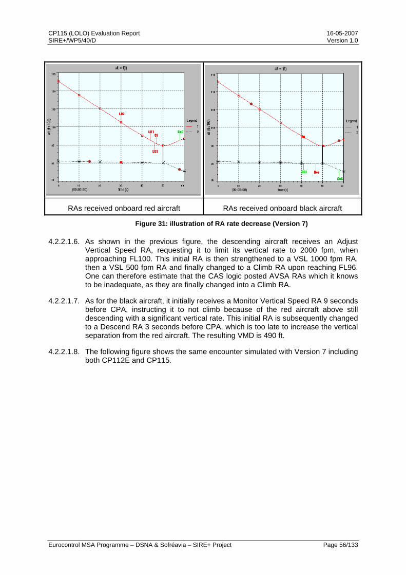
CP115 (LOLO) Evaluation Report 16-05-2007 SIRE+/WP5/40/D Version 1.0
Eurocontrol MSA Programme – DSNA & Sofréavia – SIRE+ Project Page 56/133
RAs received onboard red aircraft RAs received onboard black aircraft
Figure 31: illustration of RA rate decrease (Version 7)
4.2.2.1.6. As shown in the previous figure, the descending aircraft receives an Adjust Vertical Speed RA, requesting it to limit its vertical rate to 2000 fpm, when approaching FL100. This initial RA is then strengthened to a VSL 1000 fpm RA, then a VSL 500 fpm RA and finally changed to a Climb RA upon reaching FL96. One can therefore estimate that the CAS logic posted AVSA RAs which it knows to be inadequate, as they are finally changed into a Climb RA.
4.2.2.1.7. As for the black aircraft, it initially receives a Monitor Vertical Speed RA 9 seconds before CPA, instructing it to not climb because of the red aircraft above still descending with a significant vertical rate. This initial RA is subsequently changed to a Descend RA 3 seconds before CPA, which is too late to increase the vertical separation from the red aircraft. The resulting VMD is 490 ft.
4.2.2.1.8. The following figure shows the same encounter simulated with Version 7 including both CP112E and CP115.

CP115 (LOLO) Evaluation Report 16-05-2007 SIRE+/WP5/40/D Version 1.0
Eurocontrol MSA Programme – DSNA & Sofréavia – SIRE+ Project Page 57/133
RAs received onboard red aircraft RAs received onboard black aircraft
Figure 32: illustration of RA rate decrease (Version 7 + CP115)
4.2.2.1.9. As shown above, the initial AVSA RA received by the red aircraft with Version 7 is replaced by a Level-Off RA when introducing CP115 into the TCAS logic. As a result, the red aircraft only reaches FL99. The intruder does not receive any RA and the resulting VMD is 860 ft.
4.2.2.1.10. The above example also illustrates how introducing CP115 reduces the number of RAs, but also decreases the number of positive RAs (cf. Metric AP1 results) and the number of complex sequences of RAs (cf. Metric AP2 results).
4.2.2.2. Metric AD2: VSL 0 fpm RA alert rate
4.2.2.2.1. The VSL0 RA alert rate, over a defined period of time (e.g., per flight hour, per year) and over a defined region (e.g., an entire airspace or a sector), provides a metric characterising the proposed change. The metric may be of interest when comparing the rate induced by the change with the version 7 logic rate (i.e., the rate of AVSA RAs that are limiting the rate of descent or climb to 0 fpm).
4.2.2.2.2. The VSL 0 fpm RA alert rate is equal to 5.16 x 10⁻⁵ per flight hour with Version 7 including CP112E and to 20.31 x 10⁻⁵ per flight hour with Version 7 including both CP112E and CP115.
4.2.2.2.3. The value for this metric is increased by a factor of 4. This result was expected as CP115 leads to the TCAS logic issuing VSL 0 fpm RAs instead of the 4 other VSL RAs. The following figure gives the rates of occurrence for the different types of VSL RAs, for both Version 7 including CP112E and Version 7 including CP112E and CP115.
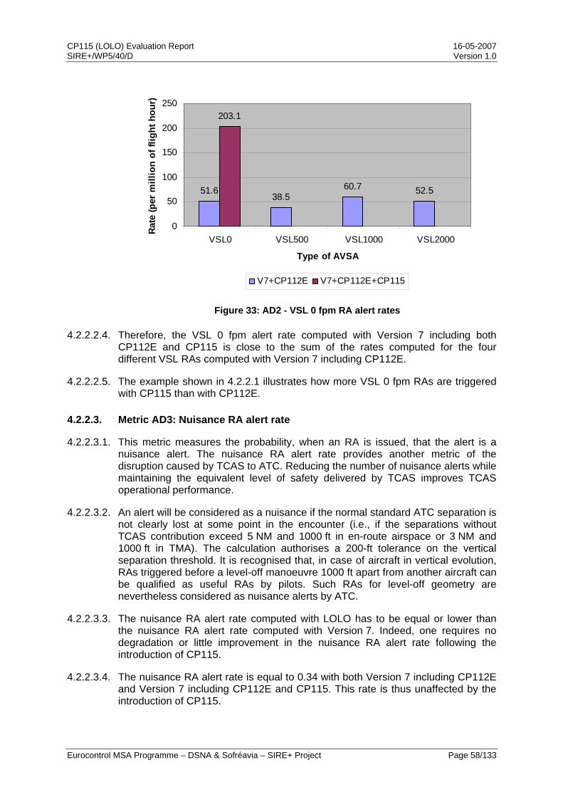
CP115 (LOLO) Evaluation Report 16-05-2007 SIRE+/WP5/40/D Version 1.0
Eurocontrol MSA Programme – DSNA & Sofréavia – SIRE+ Project Page 58/133
51.638.5
60.7 52.5
203.1
0
50
100
150
200
250
VSL0 VSL500 VSL1000 VSL2000
Type of AVSA
Rate
(per
mill
ion
of fl
ight
hou
r)
V7+CP112E V7+CP112E+CP115
Figure 33: AD2 - VSL 0 fpm RA alert rates
4.2.2.2.4. Therefore, the VSL 0 fpm alert rate computed with Version 7 including both CP112E and CP115 is close to the sum of the rates computed for the four different VSL RAs computed with Version 7 including CP112E.
4.2.2.2.5. The example shown in 4.2.2.1 illustrates how more VSL 0 fpm RAs are triggered with CP115 than with CP112E.
4.2.2.3. Metric AD3: Nuisance RA alert rate
4.2.2.3.1. This metric measures the probability, when an RA is issued, that the alert is a nuisance alert. The nuisance RA alert rate provides another metric of the disruption caused by TCAS to ATC. Reducing the number of nuisance alerts while maintaining the equivalent level of safety delivered by TCAS improves TCAS operational performance.
4.2.2.3.2. An alert will be considered as a nuisance if the normal standard ATC separation is not clearly lost at some point in the encounter (i.e., if the separations without TCAS contribution exceed 5 NM and 1000 ft in en-route airspace or 3 NM and 1000 ft in TMA). The calculation authorises a 200-ft tolerance on the vertical separation threshold. It is recognised that, in case of aircraft in vertical evolution, RAs triggered before a level-off manoeuvre 1000 ft apart from another aircraft can be qualified as useful RAs by pilots. Such RAs for level-off geometry are nevertheless considered as nuisance alerts by ATC.
4.2.2.3.3. The nuisance RA alert rate computed with LOLO has to be equal or lower than the nuisance RA alert rate computed with Version 7. Indeed, one requires no degradation or little improvement in the nuisance RA alert rate following the introduction of CP115.
4.2.2.3.4. The nuisance RA alert rate is equal to 0.34 with both Version 7 including CP112E and Version 7 including CP112E and CP115. This rate is thus unaffected by the introduction of CP115.

CP115 (LOLO) Evaluation Report 16-05-2007 SIRE+/WP5/40/D Version 1.0
Eurocontrol MSA Programme – DSNA & Sofréavia – SIRE+ Project Page 59/133
4.2.2.3.5. Actually, the nuisance RA alert rate decreases very slightly but the rounding of the result hides this improvement brought by the CP115 solution. Indeed, the improvement is lower than the noise introduced by the accuracy of simulations.
0.34 0.34
0.00
0.05
0.10
0.15
0.20
0.25
0.30
0.35
0.40
V7+CP112E V7+CP112E+CP115
TCAS logic version
Rate
Figure 34: AD3 - nuisance RA alert rate
4.2.2.4. Metric AD4a: Vertical deviation average
4.2.2.4.1. This metric measures the average of non-null vertical deviations (i.e., of deviations greater than 0 foot). The vertical deviation provides a major metric of the disruption caused by TCAS to ATC. Minimising the altitude deviations makes TCAS more compatible with the ATC system.
4.2.2.4.2. The crucial element in the calculation of vertical deviation is to identify deviations that have an impact on ATC. An aircraft that is limiting its rate of descent or climb does not deviate from its original flight path in the ATC general sense. The deviations will be computed as explained in the figure below. A box is modelled between the points at which the aircraft deviates from and then resumes its original flight path. A positive deviation is only considered if the modified flight path goes outside the box.
Time
Altitude
Deviation > 0
Modified flight path
Initial flight path

CP115 (LOLO) Evaluation Report 16-05-2007 SIRE+/WP5/40/D Version 1.0
Eurocontrol MSA Programme – DSNA & Sofréavia – SIRE+ Project Page 60/133
Time
Altitude
Deviation = 0
Figure 35: Vertical deviation calculation.
4.2.2.4.3. The vertical deviation average computed with CP115 has to be equal or lower than the vertical deviation average computed with TCAS II logic version 7. Indeed, one requires no degradation or little improvement in the vertical deviation with CP115.
4.2.2.4.4. The vertical deviation average with Version 7 including CP112E is equal to 280 ft, while it is 236 ft with Version 7 including both CP112E and CP115. It has to be noted that this 16% decrease in the average vertical deviation was not initially expected from CP115.
280
236
150
170
190
210
230
250
270
290
V7+CP112E V7+CP112E+CP115
TCAS logic version
Ave
rage
ver
tical
dev
iatio
n (ft
)
Figure 36: AD4a - Vertical deviation average
4.2.2.4.5. The following set of figures illustrates how CP115 can decrease vertical deviations through an example in which an aircraft (in red) is descending slowly from FL80 to FL70, and the other aircraft (in black) is climbing and intends to level-off at FL60. The first figure shows this encounter simulated with Version 7 including CP112E.

CP115 (LOLO) Evaluation Report 16-05-2007 SIRE+/WP5/40/D Version 1.0
Eurocontrol MSA Programme – DSNA & Sofréavia – SIRE+ Project Page 61/133
VMD=600 ft
deviation=1000 ft
Planned trajectory
« Fly the green » response
Figure 37: illustration of vertical deviation improvement (Version 7)
4.2.2.4.6. As can be observed in the above figure, the black aircraft pilot’s response to the VSL 2000 fpm RA leads him to bust his planned altitude of FL60 and to maintain the vertical rate requested by the TCAS logic until the Clear of Conflict advisory. As a consequence, the vertical separation at CPA is 600 ft and the vertical deviation from the planned trajectory is 1,000 ft. The pilot flies the green as expected.
4.2.2.4.7. The following figure shows the same encounter simulated with Version 7 including both CP112E and CP115.
VMD=1200 ft
deviation=0 ft
Figure 38: illustration of vertical deviation improvement (Version 7+CP115)
4.2.2.4.8. When introducing CP115 in the TCAS logic, the black aircraft receives an initial Level-Off RA instead of a VSL2000 fpm RA. In the above figure, its pilot still maintains the vertical rate requested by the TCAS logic until the Clear of Conflict advisory. However, in doing so, he sticks to his planned trajectory (i.e. a level-off)
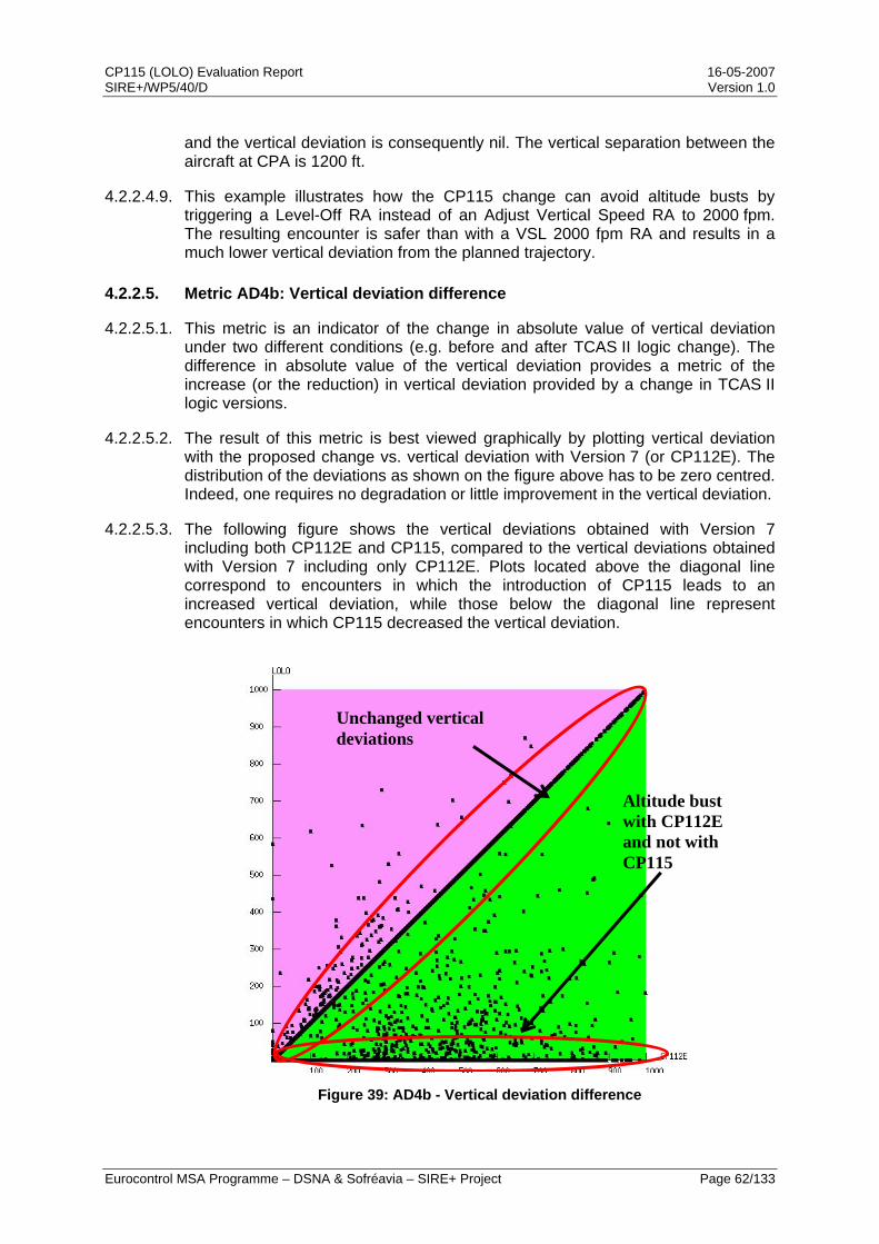
CP115 (LOLO) Evaluation Report 16-05-2007 SIRE+/WP5/40/D Version 1.0
Eurocontrol MSA Programme – DSNA & Sofréavia – SIRE+ Project Page 62/133
and the vertical deviation is consequently nil. The vertical separation between the aircraft at CPA is 1200 ft.
4.2.2.4.9. This example illustrates how the CP115 change can avoid altitude busts by triggering a Level-Off RA instead of an Adjust Vertical Speed RA to 2000 fpm. The resulting encounter is safer than with a VSL 2000 fpm RA and results in a much lower vertical deviation from the planned trajectory.
4.2.2.5. Metric AD4b: Vertical deviation difference
4.2.2.5.1. This metric is an indicator of the change in absolute value of vertical deviation under two different conditions (e.g. before and after TCAS II logic change). The difference in absolute value of the vertical deviation provides a metric of the increase (or the reduction) in vertical deviation provided by a change in TCAS II logic versions.
4.2.2.5.2. The result of this metric is best viewed graphically by plotting vertical deviation with the proposed change vs. vertical deviation with Version 7 (or CP112E). The distribution of the deviations as shown on the figure above has to be zero centred. Indeed, one requires no degradation or little improvement in the vertical deviation.
4.2.2.5.3. The following figure shows the vertical deviations obtained with Version 7 including both CP112E and CP115, compared to the vertical deviations obtained with Version 7 including only CP112E. Plots located above the diagonal line correspond to encounters in which the introduction of CP115 leads to an increased vertical deviation, while those below the diagonal line represent encounters in which CP115 decreased the vertical deviation.
Unchanged vertical deviations
Altitude bust with CP112E and not with CP115
Figure 39: AD4b - Vertical deviation difference

CP115 (LOLO) Evaluation Report 16-05-2007 SIRE+/WP5/40/D Version 1.0
Eurocontrol MSA Programme – DSNA & Sofréavia – SIRE+ Project Page 63/133
4.2.2.5.4. The deviation from the planned trajectory increases for some encounters, and decreases for some others. However, there are more gains than losses overall and, consequently, a lower average deviation when introducing CP115 into the TCAS logic.
4.2.2.5.5. More particularly, in a significant number of encounters, the deviation from the planned trajectory becomes nil when introducing CP115. These are the encounters which result in a level bust with VSL 2000, 1000 or 500 fpm RAs when simulating a pilot who follows RAs correctly. When a VSL 0 fpm RA is triggered instead, a pilot who follows RAs correctly does not bust his flight level.
4.2.2.5.6. The example shown in 4.2.2.4 illustrates the result of this metric, by showing how the deviation from the planned trajectory can be reduced by the introduction of CP115 in the TCAS logic.
4.2.2.6. Metric AD5: Compatible RA sense rate
4.2.2.6.1. This metric measures the probability, when an RA is issued, that the advisory sequence leads to a vertical manoeuvre compatible with the ATC clearance (i.e., a vertical manoeuvre that does not change the sign of the Vertical Miss Distance (VMD) at Closest Point of Approach (CPA)). It is usually least disruptive, most effective and safest for TCAS to be consistent with the original ATC intention. In particular, TCAS should avoid generating crossing RAs in encounters where no crossing was originally intended.
4.2.2.6.2. An RA can disrupt ATC or the normal operation of the aircraft by inverting (when compared with a situation without TCAS contribution) the relative vertical position of two aircraft at CPA. In this case, the RA will be qualified as not compatible with the ATC clearance. The compatible RA sense rate computed with CP115 has to be equal or higher than the compatible RA sense rate computed with Version 7. Indeed, one requires no degradation or little improvement in compatible RA sense rate with CP115
4.2.2.6.3. The compatible RA sense rate is equal to 0.96 with both Version 7 including CP112E and with Version 7 including CP112E and CP115. This metric thus remains unchanged when introducing the CP115 modification into the CAS logic.

CP115 (LOLO) Evaluation Report 16-05-2007 SIRE+/WP5/40/D Version 1.0
Eurocontrol MSA Programme – DSNA & Sofréavia – SIRE+ Project Page 64/133
0.96 0.96
0.500.550.600.650.700.750.800.850.900.951.00
V7+CP112E V7+CP112E+CP115
TCAS logic version
Rate
Figure 40: AD5 - Compatible RA sense rate
4.2.2.7. Metric AD6: 3rd party involvement rate
4.2.2.7.1. Introduction
4.2.2.7.1.1. The possibility of 3rd party involvement has been investigated in depth so as to provide a definitive answer to a concern raised within the RTCA SC147 OWG that requesting an aircraft to level-off may increase the risk of inducing a conflict with a nearby level aircraft, and most notably an aircraft flying under Visual Flight Rules (VFR).
4.2.2.7.1.2. To address this concern, a rate of 3rd party involvement has been computed on the multiple threat part of the European safety encounter model, for both Version 7 including CP112E and Version 7 including CP112E and CP115. The purpose of this computation is to provide a direct comparison between the two versions of the TCAS logic based on a large number of scenarios.
4.2.2.7.1.3. This first step has been complemented by an investigation of the operational behaviour of CP115 in the Boston Terminal Control Area (TMA), based on radar and RA downlink data. This second study aims at answering the specific question of whether the introduction of CP115 can induce conflicts with 3rd parties in a US TMA mixing various types of traffic.

CP115 (LOLO) Evaluation Report 16-05-2007 SIRE+/WP5/40/D Version 1.0
Eurocontrol MSA Programme – DSNA & Sofréavia – SIRE+ Project Page 65/133
4.2.2.7.2. Computation on multi-threat encounter model
4.2.2.7.2.1. The 3rd party involvement rate is equal to 8.59 x 10⁻⁷ per flight hour with both Version 7 including CP112E and Version 7 including both CP112E and CP115.
0.86 0.86
0.500.550.600.650.700.750.800.850.900.951.00
V7+CP112E V7+CP112E+CP115
TCAS logic version
Rate
(per
mill
ion
of fl
ight
hou
rs)
Figure 41: AD6 - 3rd party involvement rate
4.2.2.7.2.2. As shown in the above figure, introducing CP115 in the Version 7 logic does not change the 3rd party involvement rate, as computed on the European safety encounter model.
4.2.2.7.2.3. Indeed, analysis of the outcomes of Version 7 including CP112E and Version 7 including both CP112E and CP115 on multiple threat encounters indicates that, although CP115 can induce conflicts with 3rd party aircraft when Version 7 does not, the opposite is also true (i.e. CP115 can solve conflicts with 3rd party aircraft induced by Version 7).
4.2.2.7.2.4. The following set of figures illustrates how Version 7 including CP112E can induce a 3rd party conflict where Version 7 including both CP112E and CP115 does not. In this encounter involving three aircraft, one (in blue) is level at FL280, another one (in black) is climbing and levelling off at FL260, and the 3rd one (in red) is descending and levelling off at FL270.

CP115 (LOLO) Evaluation Report 16-05-2007 SIRE+/WP5/40/D Version 1.0
Eurocontrol MSA Programme – DSNA & Sofréavia – SIRE+ Project Page 66/133
Horizontal view Vertical view Figure 42: 3rd party induced conflict (no TCAS contribution)
4.2.2.7.2.5. The next figures show, in the vertical dimension, how Version 7 including CP112E solves this encounter.
RAs onboard red aircraft RAs onboard black aircraft
RAs onboard blue aircraft
Figure 43: 3rd party induced conflict (Version 7+CP112E)
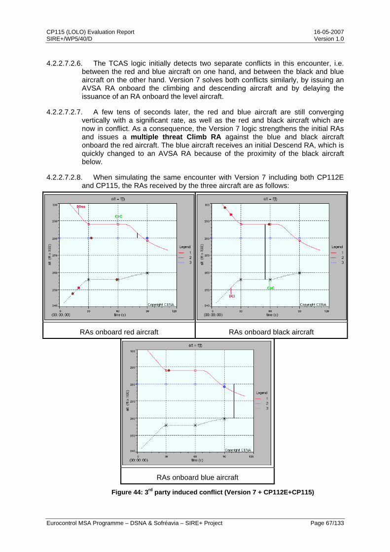
CP115 (LOLO) Evaluation Report 16-05-2007 SIRE+/WP5/40/D Version 1.0
Eurocontrol MSA Programme – DSNA & Sofréavia – SIRE+ Project Page 67/133
4.2.2.7.2.6. The TCAS logic initially detects two separate conflicts in this encounter, i.e. between the red and blue aircraft on one hand, and between the black and blue aircraft on the other hand. Version 7 solves both conflicts similarly, by issuing an AVSA RA onboard the climbing and descending aircraft and by delaying the issuance of an RA onboard the level aircraft.
4.2.2.7.2.7. A few tens of seconds later, the red and blue aircraft are still converging vertically with a significant rate, as well as the red and black aircraft which are now in conflict. As a consequence, the Version 7 logic strengthens the initial RAs and issues a multiple threat Climb RA against the blue and black aircraft onboard the red aircraft. The blue aircraft receives an initial Descend RA, which is quickly changed to an AVSA RA because of the proximity of the black aircraft below.
4.2.2.7.2.8. When simulating the same encounter with Version 7 including both CP112E and CP115, the RAs received by the three aircraft are as follows:
RAs onboard red aircraft RAs onboard black aircraft
RAs onboard blue aircraft
Figure 44: 3rd party induced conflict (Version 7 + CP112E+CP115)
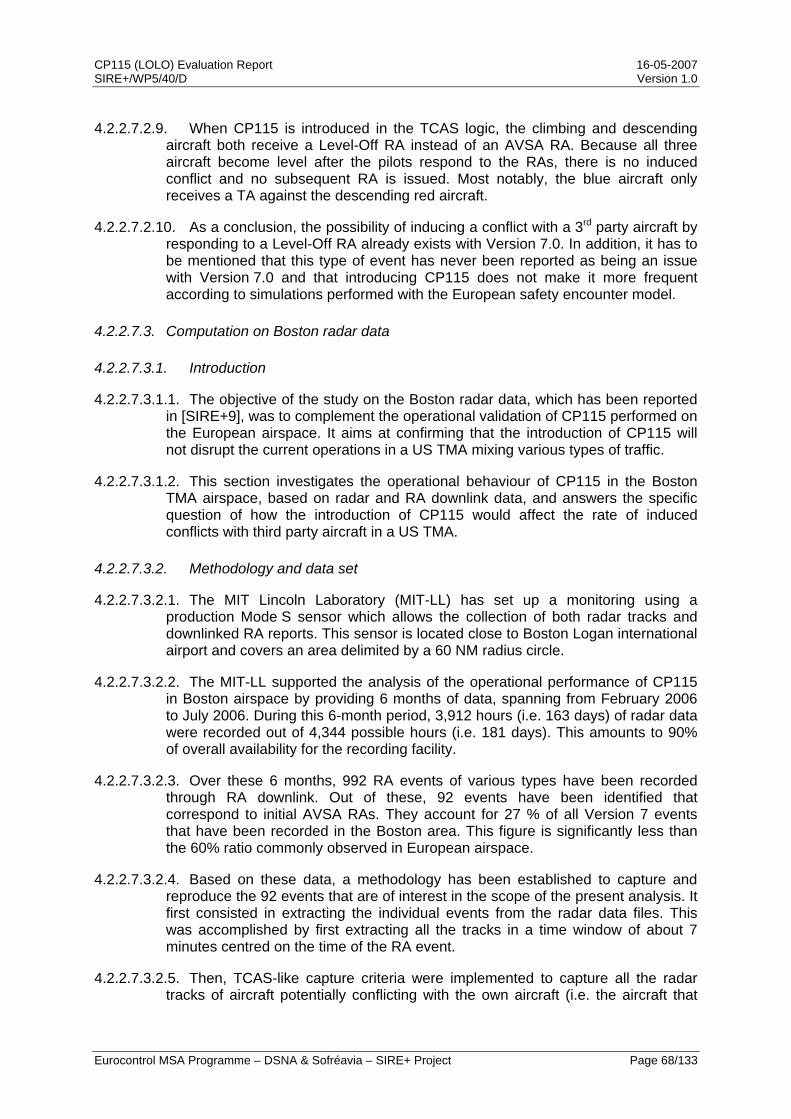
CP115 (LOLO) Evaluation Report 16-05-2007 SIRE+/WP5/40/D Version 1.0
Eurocontrol MSA Programme – DSNA & Sofréavia – SIRE+ Project Page 68/133
4.2.2.7.2.9. When CP115 is introduced in the TCAS logic, the climbing and descending aircraft both receive a Level-Off RA instead of an AVSA RA. Because all three aircraft become level after the pilots respond to the RAs, there is no induced conflict and no subsequent RA is issued. Most notably, the blue aircraft only receives a TA against the descending red aircraft.
4.2.2.7.2.10. As a conclusion, the possibility of inducing a conflict with a 3rd party aircraft by responding to a Level-Off RA already exists with Version 7.0. In addition, it has to be mentioned that this type of event has never been reported as being an issue with Version 7.0 and that introducing CP115 does not make it more frequent according to simulations performed with the European safety encounter model.
4.2.2.7.3. Computation on Boston radar data
4.2.2.7.3.1. Introduction
4.2.2.7.3.1.1. The objective of the study on the Boston radar data, which has been reported in [SIRE+9], was to complement the operational validation of CP115 performed on the European airspace. It aims at confirming that the introduction of CP115 will not disrupt the current operations in a US TMA mixing various types of traffic.
4.2.2.7.3.1.2. This section investigates the operational behaviour of CP115 in the Boston TMA airspace, based on radar and RA downlink data, and answers the specific question of how the introduction of CP115 would affect the rate of induced conflicts with third party aircraft in a US TMA.
4.2.2.7.3.2. Methodology and data set
4.2.2.7.3.2.1. The MIT Lincoln Laboratory (MIT-LL) has set up a monitoring using a production Mode S sensor which allows the collection of both radar tracks and downlinked RA reports. This sensor is located close to Boston Logan international airport and covers an area delimited by a 60 NM radius circle.
4.2.2.7.3.2.2. The MIT-LL supported the analysis of the operational performance of CP115 in Boston airspace by providing 6 months of data, spanning from February 2006 to July 2006. During this 6-month period, 3,912 hours (i.e. 163 days) of radar data were recorded out of 4,344 possible hours (i.e. 181 days). This amounts to 90% of overall availability for the recording facility.
4.2.2.7.3.2.3. Over these 6 months, 992 RA events of various types have been recorded through RA downlink. Out of these, 92 events have been identified that correspond to initial AVSA RAs. They account for 27 % of all Version 7 events that have been recorded in the Boston area. This figure is significantly less than the 60% ratio commonly observed in European airspace.
4.2.2.7.3.2.4. Based on these data, a methodology has been established to capture and reproduce the 92 events that are of interest in the scope of the present analysis. It first consisted in extracting the individual events from the radar data files. This was accomplished by first extracting all the tracks in a time window of about 7 minutes centred on the time of the RA event.
4.2.2.7.3.2.5. Then, TCAS-like capture criteria were implemented to capture all the radar tracks of aircraft potentially conflicting with the own aircraft (i.e. the aircraft that
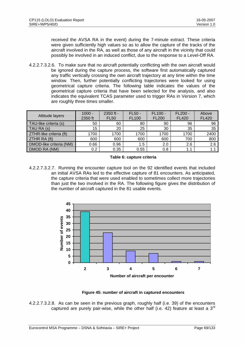
CP115 (LOLO) Evaluation Report 16-05-2007 SIRE+/WP5/40/D Version 1.0
Eurocontrol MSA Programme – DSNA & Sofréavia – SIRE+ Project Page 69/133
received the AVSA RA in the event) during the 7-minute extract. These criteria were given sufficiently high values so as to allow the capture of the tracks of the aircraft involved in the RA, as well as those of any aircraft in the vicinity that could possibly be involved in an induced conflict, due to the response to a Level-Off RA.
4.2.2.7.3.2.6. To make sure that no aircraft potentially conflicting with the own aircraft would be ignored during the capture process, the software first automatically captured any traffic vertically crossing the own aircraft trajectory at any time within the time window. Then, further potentially conflicting trajectories were looked for using geometrical capture criteria. The following table indicates the values of the geometrical capture criteria that have been selected for the analysis, and also indicates the equivalent TCAS parameter used to trigger RAs in Version 7, which are roughly three times smaller.
Altitude layers 1000 -2350 ft
2350 ft - FL50
FL50 - FL100
FL100 - FL200
FL200 - FL420
Above FL420
TAU-like criteria (s) 50 60 80 90 96 96TAU RA (s) 15 20 25 30 35 35ZTHR-like criteria (ft) 1700 1700 1700 1700 1700 2400ZTHR RA (ft) 600 600 600 600 700 800DMOD-like criteria (NM) 0.66 0.96 1.5 2.0 2.6 2.6DMOD RA (NM) 0.2 0.35 0.55 0.8 1.1 1.1
Table 6: capture criteria
4.2.2.7.3.2.7. Running the encounter capture tool on the 92 identified events that included an initial AVSA RAs led to the effective capture of 81 encounters. As anticipated, the capture criteria that were used enabled to sometimes collect more trajectories than just the two involved in the RA. The following figure gives the distribution of the number of aircraft captured in the 81 usable events.
05
1015202530354045
2 3 4 5 6 7
Number of aircraft per encounter
Num
ber o
f eve
nts
Figure 45: number of aircraft in captured encounters
4.2.2.7.3.2.8. As can be seen in the previous graph, roughly half (i.e. 39) of the encounters captured are purely pair-wise, while the other half (i.e. 42) feature at least a 3rd
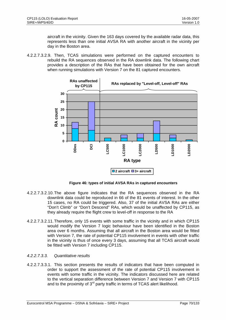
CP115 (LOLO) Evaluation Report 16-05-2007 SIRE+/WP5/40/D Version 1.0
Eurocontrol MSA Programme – DSNA & Sofréavia – SIRE+ Project Page 70/133
aircraft in the vicinity. Given the 163 days covered by the available radar data, this represents less than one initial AVSA RA with another aircraft in the vicinity per day in the Boston area.
4.2.2.7.3.2.9. Then, TCAS simulations were performed on the captured encounters to rebuild the RA sequences observed in the RA downlink data. The following chart provides a description of the RAs that have been obtained for the own aircraft when running simulations with Version 7 on the 81 captured encounters.
0
5
10
15
20
25
30
DD
es DC
l
LC50
0
LC10
00
LC20
00
LD50
0
LD10
00
LD20
00
RA type
RA
cou
nt
2 aircraft 3+ aircraft
RAs unaffected by CP115 RAs replaced by "Level-off, Level-off" RAs
Figure 46: types of initial AVSA RAs in captured encounters
4.2.2.7.3.2.10. The above figure indicates that the RA sequences observed in the RA downlink data could be reproduced in 66 of the 81 events of interest. In the other 15 cases, no RA could be triggered. Also, 37 of the initial AVSA RAs are either “Don’t Climb” or “Don’t Descend” RAs, which would be unaffected by CP115, as they already require the flight crew to level-off in response to the RA
4.2.2.7.3.2.11. Therefore, only 15 events with some traffic in the vicinity and in which CP115 would modify the Version 7 logic behaviour have been identified in the Boston area over 6 months. Assuming that all aircraft in the Boston area would be fitted with Version 7, the rate of potential CP115 involvement in events with other traffic in the vicinity is thus of once every 3 days, assuming that all TCAS aircraft would be fitted with Version 7 including CP115.
4.2.2.7.3.3. Quantitative results
4.2.2.7.3.3.1. This section presents the results of indicators that have been computed in order to support the assessment of the rate of potential CP115 involvement in events with some traffic in the vicinity. The indicators discussed here are related to the vertical separation difference between Version 7 and Version 7 with CP115 and to the proximity of 3rd party traffic in terms of TCAS alert likelihood.
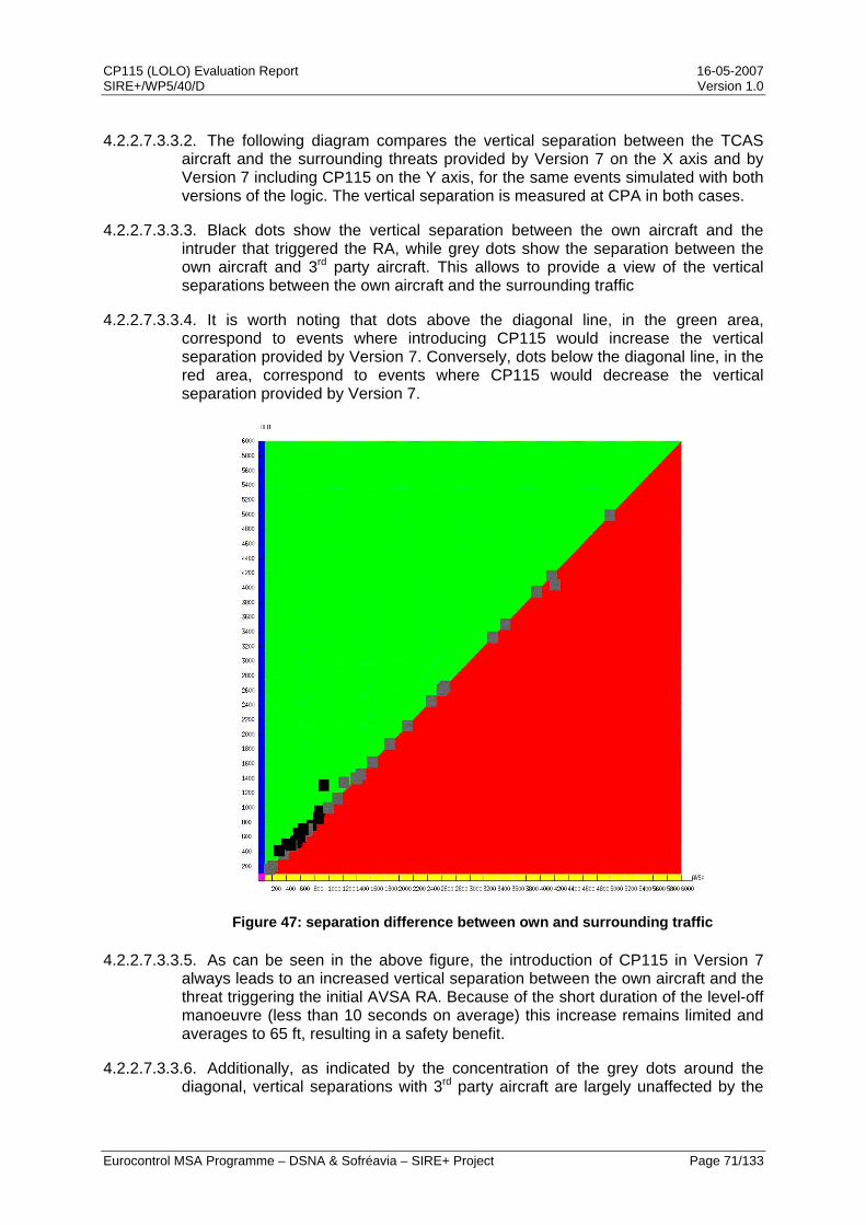
CP115 (LOLO) Evaluation Report 16-05-2007 SIRE+/WP5/40/D Version 1.0
Eurocontrol MSA Programme – DSNA & Sofréavia – SIRE+ Project Page 71/133
4.2.2.7.3.3.2. The following diagram compares the vertical separation between the TCAS aircraft and the surrounding threats provided by Version 7 on the X axis and by Version 7 including CP115 on the Y axis, for the same events simulated with both versions of the logic. The vertical separation is measured at CPA in both cases.
4.2.2.7.3.3.3. Black dots show the vertical separation between the own aircraft and the intruder that triggered the RA, while grey dots show the separation between the own aircraft and 3rd party aircraft. This allows to provide a view of the vertical separations between the own aircraft and the surrounding traffic
4.2.2.7.3.3.4. It is worth noting that dots above the diagonal line, in the green area, correspond to events where introducing CP115 would increase the vertical separation provided by Version 7. Conversely, dots below the diagonal line, in the red area, correspond to events where CP115 would decrease the vertical separation provided by Version 7.
Figure 47: separation difference between own and surrounding traffic
4.2.2.7.3.3.5. As can be seen in the above figure, the introduction of CP115 in Version 7 always leads to an increased vertical separation between the own aircraft and the threat triggering the initial AVSA RA. Because of the short duration of the level-off manoeuvre (less than 10 seconds on average) this increase remains limited and averages to 65 ft, resulting in a safety benefit.
4.2.2.7.3.3.6. Additionally, as indicated by the concentration of the grey dots around the diagonal, vertical separations with 3rd party aircraft are largely unaffected by the
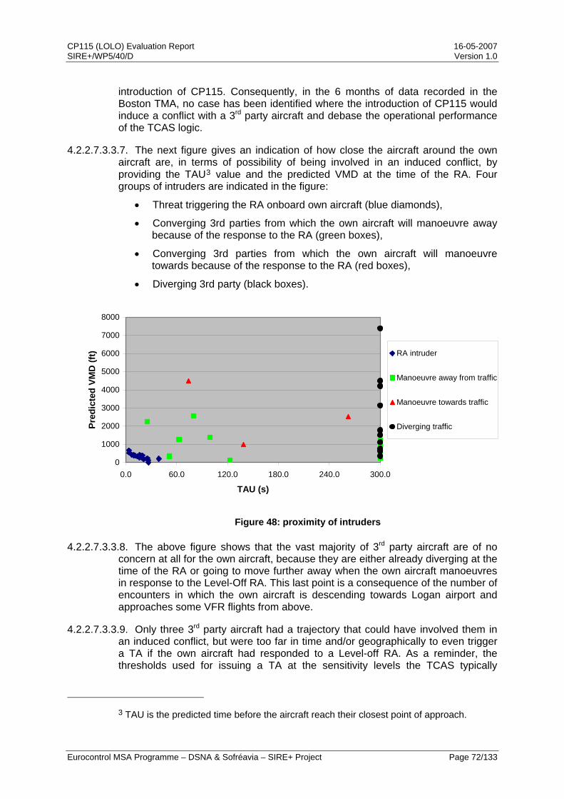
CP115 (LOLO) Evaluation Report 16-05-2007 SIRE+/WP5/40/D Version 1.0
Eurocontrol MSA Programme – DSNA & Sofréavia – SIRE+ Project Page 72/133
introduction of CP115. Consequently, in the 6 months of data recorded in the Boston TMA, no case has been identified where the introduction of CP115 would induce a conflict with a 3rd party aircraft and debase the operational performance of the TCAS logic.
4.2.2.7.3.3.7. The next figure gives an indication of how close the aircraft around the own aircraft are, in terms of possibility of being involved in an induced conflict, by providing the TAU3 value and the predicted VMD at the time of the RA. Four groups of intruders are indicated in the figure:
• Threat triggering the RA onboard own aircraft (blue diamonds),
• Converging 3rd parties from which the own aircraft will manoeuvre away because of the response to the RA (green boxes),
• Converging 3rd parties from which the own aircraft will manoeuvre towards because of the response to the RA (red boxes),
• Diverging 3rd party (black boxes).
0
1000
2000
3000
4000
5000
6000
7000
8000
0.0 60.0 120.0 180.0 240.0 300.0
TAU (s)
Pred
icte
d VM
D (f
t) RA intruder
Manoeuvre away from traffic
Manoeuvre towards traffic
Diverging traffic
Figure 48: proximity of intruders
4.2.2.7.3.3.8. The above figure shows that the vast majority of 3rd party aircraft are of no concern at all for the own aircraft, because they are either already diverging at the time of the RA or going to move further away when the own aircraft manoeuvres in response to the Level-Off RA. This last point is a consequence of the number of encounters in which the own aircraft is descending towards Logan airport and approaches some VFR flights from above.
4.2.2.7.3.3.9. Only three 3rd party aircraft had a trajectory that could have involved them in an induced conflict, but were too far in time and/or geographically to even trigger a TA if the own aircraft had responded to a Level-off RA. As a reminder, the thresholds used for issuing a TA at the sensitivity levels the TCAS typically
3 TAU is the predicted time before the aircraft reach their closest point of approach.
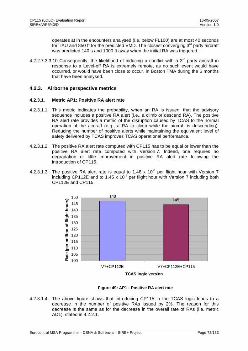
CP115 (LOLO) Evaluation Report 16-05-2007 SIRE+/WP5/40/D Version 1.0
Eurocontrol MSA Programme – DSNA & Sofréavia – SIRE+ Project Page 73/133
operates at in the encounters analysed (i.e. below FL100) are at most 40 seconds for TAU and 850 ft for the predicted VMD. The closest converging 3rd party aircraft was predicted 140 s and 1000 ft away when the initial RA was triggered.
4.2.2.7.3.3.10. Consequently, the likelihood of inducing a conflict with a 3rd party aircraft in response to a Level-off RA is extremely remote, as no such event would have occurred, or would have been close to occur, in Boston TMA during the 6 months that have been analysed.
4.2.3. Airborne perspective metrics
4.2.3.1. Metric AP1: Positive RA alert rate
4.2.3.1.1. This metric indicates the probability, when an RA is issued, that the advisory sequence includes a positive RA alert (i.e., a climb or descend RA). The positive RA alert rate provides a metric of the disruption caused by TCAS to the normal operation of the aircraft (e.g., a RA to climb while the aircraft is descending). Reducing the number of positive alerts while maintaining the equivalent level of safety delivered by TCAS improves TCAS operational performance.
4.2.3.1.2. The positive RA alert rate computed with CP115 has to be equal or lower than the positive RA alert rate computed with Version 7. Indeed, one requires no degradation or little improvement in positive RA alert rate following the introduction of CP115.
4.2.3.1.3. The positive RA alert rate is equal to 1.48 x 10⁻⁴ per flight hour with Version 7 including CP112E and to 1.45 x 10⁻⁴ per flight hour with Version 7 including both CP112E and CP115.
148145
100105110115120125130135140145150
V7+CP112E V7+CP112E+CP115
TCAS logic version
Rate
(per
mill
ion
of fl
ight
hou
rs)
Figure 49: AP1 - Positive RA alert rate
4.2.3.1.4. The above figure shows that introducing CP115 in the TCAS logic leads to a decrease in the number of positive RAs issued by 2%. The reason for this decrease is the same as for the decrease in the overall rate of RAs (i.e. metric AD1), stated in 4.2.2.1.
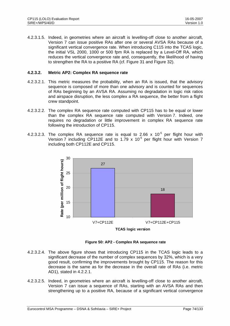
CP115 (LOLO) Evaluation Report 16-05-2007 SIRE+/WP5/40/D Version 1.0
Eurocontrol MSA Programme – DSNA & Sofréavia – SIRE+ Project Page 74/133
4.2.3.1.5. Indeed, in geometries where an aircraft is levelling-off close to another aircraft, Version 7 can issue positive RAs after one or several AVSA RAs because of a significant vertical convergence rate. When introducing C115 into the TCAS logic, the initial VSL 2000, 1000 or 500 fpm RA is replaced by a Level-Off RA, which reduces the vertical convergence rate and, consequently, the likelihood of having to strengthen the RA to a positive RA (cf. Figure 31 and Figure 32).
4.2.3.2. Metric AP2: Complex RA sequence rate
4.2.3.2.1. This metric measures the probability, when an RA is issued, that the advisory sequence is composed of more than one advisory and is counted for sequences of RAs beginning by an AVSA RA. Assuming no degradation in logic risk ratios and airspace disruption, the less complex a RA sequence, the better from a flight crew standpoint.
4.2.3.2.2. The complex RA sequence rate computed with CP115 has to be equal or lower than the complex RA sequence rate computed with Version 7. Indeed, one requires no degradation or little improvement in complex RA sequence rate following the introduction of CP115.
4.2.3.2.3. The complex RA sequence rate is equal to 2.66 x 10⁻⁵ per flight hour with Version 7 including CP112E and to 1.79 x 10⁻⁵ per flight hour with Version 7 including both CP112E and CP115.
27
18
10
15
20
25
30
V7+CP112E V7+CP112E+CP115
TCAS logic version
Rate
(per
mill
ion
of fl
ight
hou
rs)
Figure 50: AP2 - Complex RA sequence rate
4.2.3.2.4. The above figure shows that introducing CP115 in the TCAS logic leads to a significant decrease of the number of complex sequences by 32%, which is a very good result, confirming the improvements brought by CP115. The reason for this decrease is the same as for the decrease in the overall rate of RAs (i.e. metric AD1), stated in 4.2.2.1.
4.2.3.2.5. Indeed, in geometries where an aircraft is levelling-off close to another aircraft, Version 7 can issue a sequence of RAs, starting with an AVSA RAs and then strengthening up to a positive RA, because of a significant vertical convergence

CP115 (LOLO) Evaluation Report 16-05-2007 SIRE+/WP5/40/D Version 1.0
Eurocontrol MSA Programme – DSNA & Sofréavia – SIRE+ Project Page 75/133
rate. When introducing C115 into the TCAS logic, this sequence of RAs is replaced by a single Level-Off RA, which there is no need to further strengthen, as the vertical convergence rate is reduced (cf. Figure 31 and Figure 32).
4.2.3.3. Metric AP3: Strengthening RA rate
4.2.3.3.1. This metric is an indicator of the probability, when an RA is issued, that the initial advisory is strengthened through the issuance of a positive RA (with nominal, increase or reversal rate). The metric may reveal inadequate advisory sequences posted by a logic version (e.g., issuance of an initial advisory limiting the rate of descent while a climb RA is eventually triggered). In addition, stressful situations induced by strengthening RAs should be minimised.
4.2.3.3.2. The strengthening RA rate computed with CP115 has to be equal or lower than the strengthening RA rate computed with Version 7. Indeed, one requires no degradation or little improvement in strengthening RA rate following the introduction of CP115.
4.2.3.3.3. The strengthening RA rate is equal to 1.25 x 10⁻⁵ per flight hour with Version 7 including CP112E and to 1.24 x 10⁻⁵ per flight hour with Version 7 including both CP112E and CP115.
12.5 12.4
8
9
10
11
12
13
14
V7+CP112E V7+CP112E+CP115
TCAS logic version
Rate
(per
mill
ion
of fl
ight
hou
rs)
Figure 51: AP3 - Strengthening RA rate
4.2.3.3.4. The above figure shows that introducing CP115 in the TCAS logic leads to a decrease of the number of strengthening RAs by 1%. The reason for this decrease is the same as for the decrease in the overall rate of RAs (i.e. metric AD1), stated in 4.2.2.1.
4.2.3.3.5. Indeed, in geometries where an aircraft is levelling-off close to another aircraft, Version 7 can strengthen an initial AVSA RA because of a still significant vertical convergence rate after the pilot has responded to this RA. When introducing C115 into the TCAS logic, the initial AVSA RA is replaced by a Level-Off RA, which there is no need to further strengthen, as the vertical convergence rate is reduced (cf. Figure 31 and Figure 32).
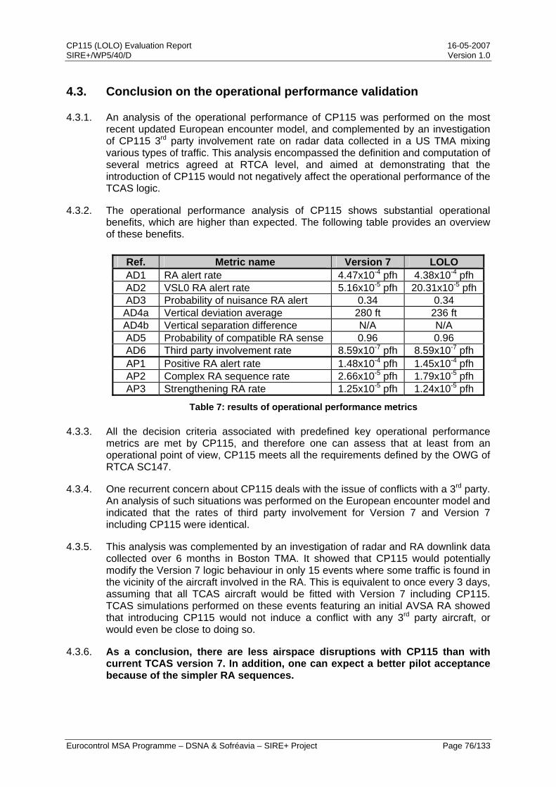
CP115 (LOLO) Evaluation Report 16-05-2007 SIRE+/WP5/40/D Version 1.0
Eurocontrol MSA Programme – DSNA & Sofréavia – SIRE+ Project Page 76/133
4.3. Conclusion on the operational performance validation
4.3.1. An analysis of the operational performance of CP115 was performed on the most recent updated European encounter model, and complemented by an investigation of CP115 3rd party involvement rate on radar data collected in a US TMA mixing various types of traffic. This analysis encompassed the definition and computation of several metrics agreed at RTCA level, and aimed at demonstrating that the introduction of CP115 would not negatively affect the operational performance of the TCAS logic.
4.3.2. The operational performance analysis of CP115 shows substantial operational benefits, which are higher than expected. The following table provides an overview of these benefits.
Ref. Metric name Version 7 LOLO AD1 RA alert rate 4.47x10⁻⁴ pfh 4.38x10⁻⁴ pfh AD2 VSL0 RA alert rate 5.16x10⁻⁵ pfh 20.31x10⁻⁵ pfh AD3 Probability of nuisance RA alert 0.34 0.34
AD4a Vertical deviation average 280 ft 236 ft AD4b Vertical separation difference N/A N/A AD5 Probability of compatible RA sense 0.96 0.96 AD6 Third party involvement rate 8.59x10⁻⁷ pfh 8.59x10⁻⁷ pfh AP1 Positive RA alert rate 1.48x10⁻⁴ pfh 1.45x10⁻⁴ pfh AP2 Complex RA sequence rate 2.66x10⁻⁵ pfh 1.79x10⁻⁵ pfh AP3 Strengthening RA rate 1.25x10⁻⁵ pfh 1.24x10⁻⁵ pfh
Table 7: results of operational performance metrics
4.3.3. All the decision criteria associated with predefined key operational performance metrics are met by CP115, and therefore one can assess that at least from an operational point of view, CP115 meets all the requirements defined by the OWG of RTCA SC147.
4.3.4. One recurrent concern about CP115 deals with the issue of conflicts with a 3rd party. An analysis of such situations was performed on the European encounter model and indicated that the rates of third party involvement for Version 7 and Version 7 including CP115 were identical.
4.3.5. This analysis was complemented by an investigation of radar and RA downlink data collected over 6 months in Boston TMA. It showed that CP115 would potentially modify the Version 7 logic behaviour in only 15 events where some traffic is found in the vicinity of the aircraft involved in the RA. This is equivalent to once every 3 days, assuming that all TCAS aircraft would be fitted with Version 7 including CP115. TCAS simulations performed on these events featuring an initial AVSA RA showed that introducing CP115 would not induce a conflict with any 3rd party aircraft, or would even be close to doing so.
4.3.6. As a conclusion, there are less airspace disruptions with CP115 than with current TCAS version 7. In addition, one can expect a better pilot acceptance because of the simpler RA sequences.
CP115 (LOLO) Evaluation Report 16-05-2007 SIRE+/WP5/40/D Version 1.0
Eurocontrol MSA Programme – DSNA & Sofréavia – SIRE+ Project Page 77/133
5. Validation related to Human Factors aspects
5.1. Context and backgound
5.1.1. In order to evaluate the Human Factors aspects associated with the proposed LOLO solution to the SA-AVSA issue, two sets of Real-Time Simulations (RTS) have been conducted in 2006, respectively led by DSNA and Airbus.
5.1.2. The DSNA LORA1 human-in-the-loop experiments took place in May 2006 and had the objective of investigating the impact of the LOLO solution on the pilot /controller cooperation and assess the pilot behaviour when faced to Level-Off RAs. These experiments have used DSNA simulation facilities, including a part-task cockpit simulator, a control working position (CWP) and a position for the management of surrounding traffic.
5.1.3. The LORA2 human-in-the-loop experiments were held jointly by Airbus and DSNA between mid-October and mid-November 2006 to build a comprehensive comparison between the current situation and the proposed rectification. This second round of RTS also helped confirming the findings of LORA1. These simulations were performed on an Airbus simulator, incorporating a modified Honeywell TCAS unit.
5.2. LORA1 experiments
5.2.1. Experimental protocol
5.2.1.1. The DSNA simulation platform was largely based on a part-time A320 simulator that included a modified TCAS logic able to generate Level-Off RAs in lieu of AVSA RAs. The simulation facilities also included a controller working position, featuring a radar screen and paper strips, as well as a pseudo-pilot position for the management of surrounding traffic.
5.2.1.2. The experimental protocol specified that participants (i.e. both pilots and controllers) would be observed simultaneously and, as coordinated with the participating airlines, would not be aware of the fact that the experiments were dealing with TCAS. To this effect, neither preliminary briefings nor trainings were organised prior to the simulation runs, to ensure that their reactions and comments would be spontaneous and unbiased.
5.2.1.3. 14 pilots qualified on A320 took part in the LORA1 experiments, representing British Airways, Lufthansa, KLM, Air France and business aviation airlines. 12 air traffic controllers from French DSNA were also involved, emanating from both en-route and approach centres.
5.2.1.4. In order to support an analysis of the experiment outcomes, different types of data were collected during the simulation sessions. First, qualitative feedback from the participants was collected through collective interviews, self-assessments and questionnaires. Then, more quantitative measures were gathered through the recording of several parameters through the simulation software, as well as the heart rate of the participants to assess their stress.

CP115 (LOLO) Evaluation Report 16-05-2007 SIRE+/WP5/40/D Version 1.0
Eurocontrol MSA Programme – DSNA & Sofréavia – SIRE+ Project Page 78/133
5.2.1.5. Three operationally realistic scenarios had been designed to support the experiments, all built from real situations and focusing on comparable sequences of TCAS events including Level-Off RAs. These scenarios consisted of:
• A 1000 ft level-off situation in en-route airspace,
• An encounter with a VFR traffic while on long final (i.e. 18 NM from the runway),
• A 1000 ft level-off situation at FL100, corresponding to a departure from Paris-Charles de Gaulle airport.
5.2.2. Analysis of results
5.2.2.1. Approach
5.2.2.1.1. The analysis of the Human Factors aspects in LORA1 was developed through a detailed evaluation of the pilot responses to the RAs they received, automatically recorded by the simulation software through a set of parameters. The pilot responses were further divided into four different steps, corresponding to the identification phase, the interpretation phase, the execution of the required manoeuvre and the notification to ATC.
5.2.2.1.2. In addition, the appraisal of the proposed Level-Off RA by participating ATCOs was also collected through a dedicated questionnaire.
5.2.2.2. Analysis of pilot responses
5.2.2.2.1. The analysis of the first step of the pilot responses, i.e. the identification phase, focused on the recognition of the aural annunciation by the participating pilots. The proportion of pilots able to distinctively hear and recognize the “Level-Off, Level-Off” aural message was generally low (i.e. 10%). This proportion rose to 25% on the second simulation session.
5.2.2.2.2. This result is largely explained by the voluntary lack of initial briefing prior to the experiments, and by the difficulty in accurately reproducing the quality of aural alert and the volume of the alarms that are found in real cockpit alerts, which the pilots are used to.
5.2.2.2.3. Regarding the interpretation phase and the comparative clarity of the “Adjust Vertical Speed, Adjust” and “Level-Off, Level-Off” aural annunciations, pilot comments to questionnaires showed that the LOLO solution was preferable. The reasons mentioned were notably that the associated aural message was clearer (“it is very clear. There is no ambiguity”) and explicitly conveyed the manoeuvre required by the RA (“We know what to do”). For the AVSA RAs, pilots stressed that they needed to use the TCAS display in order to properly respond (“Without the RA display, I can not do anything”) and required to interpretation the aural alert (“You have to think”, “You need time for thinking”).
5.2.2.2.4. This difficulty in interpreting the “Adjust Vertical Speed, Adjust” aural annunciation was further highlighted in a test of intuitiveness that was proposed to pilot aside from the simulation runs. This test ran on a PC and consisted in measuring the pilots’ reactions to different RAs, including both AVSA and Level-Off RAs, with and without the RA display. The following figure shows a comparison of results

CP115 (LOLO) Evaluation Report 16-05-2007 SIRE+/WP5/40/D Version 1.0
Eurocontrol MSA Programme – DSNA & Sofréavia – SIRE+ Project Page 79/133
obtained on downward sense AVSA and Level-Off RAs. Results obtained on upward sense RAs are comparable.
Figure 52: pilot responses to AVSA and Level-Off RAs, with and without display
5.2.2.2.5. As indicated in the above figure, about 50% of subject pilots had no reaction to the AVSA RAs when they were not shown the associated display, and this, despite a reinforced training effort by major airlines underlining that “Adjust means Reduce”. When the RA display is available, the breakdowns of pilot responses are similar for both AVSA and Level-Off RAs. On the other hand, when the aural annunciation is the only source of information, only half of the pilots respond to the AVSA RAs and responses to Level-Off RAs are more consistent.
5.2.2.2.6. The analysis of the execution of the manoeuvre required by the Level-Off RA was based on parameters recorded by the simulation software and notably the altitude of the aircraft at the time of the RA. The following figure shows vertical views of the trajectories flown by pilots playing the en-route scenario when they received a Level-Off RA, as an altitude versus time graph.
Figure 53: trajectories flown in response to Level-Off RAs
0
1
2
3
4
5
6
7
8
0 10 to 25% 25 to 50% 50 to 75% > 75%
Aural & Display
AVSA LOLO
0
1
2
3
4
5
6
7
8
0 10 to 25% 25 to 50% 50 to 75% > 75%
Aural only
AVSA LOLO
About 50% with no reactionAbout 50% with no reaction
CP115 (LOLO) Evaluation Report 16-05-2007 SIRE+/WP5/40/D Version 1.0
Eurocontrol MSA Programme – DSNA & Sofréavia – SIRE+ Project Page 80/133
5.2.2.2.7. As indicated by the above figure, all pilots flew the Level-Off RA appropriately, even though they did not receive a specific training to this new RA. This confirms the comments received that the Level-Off RA is easy to fly and that it is intuitive.
5.2.2.2.8. The last part of the analysis regarded the notification of RAs to ATC. Previous real-time simulations had shown that pilots frequently (about 50% of the cases) mentioned a wrong sense when notifying an AVSA RA to the controller. The reason was a mix-up between the attitude of the aircraft and the sense of the manoeuvre required by the RA. With the Level-Off RA, to which pilots were not trained prior to the experiments, reporting to ATC was generally better. For example, 4 out of 6 pilots correctly reported “TCAS descend” when they received a Level-Off RA requiring them to stop climbing in the CDG departure scenario. This confirms the fact that the Level-Off RA is more intuitive than the AVSA RAs, and thus reduces the opportunity for confusion between pilots and ATC.
5.2.2.3. Controller assessment of LOLO
5.2.2.3.1. The controllers involved in the LORA1 experiments were asked to provide their views on the proposed Level-Off RA through a dedicated questionnaire focusing on a potential disturbance of operations by the level-off manoeuvre induced by the RA.
5.2.2.3.2. None of the ATCOs foresaw any disturbance induced by LOLO, as they could not imagine having a third aircraft coming at the same level as the levelling-off aircraft without either an appropriate time separation or a controller instruction to change its altitude. In addition, one of them actually considered the current AVSA RAs as a bigger source of disruption because of the potential for a pilot to bust his cleared altitude when responding to such an RA.
5.2.2.4. Main LORA1 findings
5.2.2.5. The main result of the LORA1 experiments was that the Level-Off RA was well received by subject pilots, as well as by air traffic controllers. Pilots reported that the “Level-Off, Level-Off” aural annunciation was easier to interpret than the “Adjust Vertical Speed, Adjust” one because the terminology made sense immediately and the requested response was unambiguously conveyed by the aural message.
5.2.2.6. Because of this clearer aural annunciation and because of the more straightforward manoeuvre required by the Level-Off RA, pilots found it more intuitive than the current AVSA RAs. As a consequence, pilots had no difficulty in executing the manoeuvre required by the Level-Off RA. When reporting the RA to ATC, opportunities for confusing reports were reduced and air traffic controllers foresaw no disturbance in operations.
5.2.2.7. The LORA1 experiments thus showed that the Level-Off RA was operationally accepted by both subject pilots and controllers, and that it improved the pilot/controller cooperation. However, a follow-up was deemed necessary to further evaluate the Human Factors issues associated to the introduction of the Level-Off RA on one hand, and to address a request from the RTCA SC147 OWG on the other hand that a comprehensive comparison between the AVSA RAs and the Level-Off RA be performed.
CP115 (LOLO) Evaluation Report 16-05-2007 SIRE+/WP5/40/D Version 1.0
Eurocontrol MSA Programme – DSNA & Sofréavia – SIRE+ Project Page 81/133
5.3. LORA2 experiments
5.3.1. Objectives of the experiments
5.3.1.1. During the RTCA SC147 OWG meeting held on 25 April 2006 in Phoenix, AZ, the SIRE+ team provided a status report of the validation activities performed on the Level-Off RA. When the LORA1 experiments conducted by DSNA were presented, the OWG members raised two main comments:
• They considered unfortunate that these trials did not attempt at comparing the current AVSA RAs with the proposed Level-Off RA;
• They would have liked to be involved at an earlier stage, and not informed just before the beginning of the simulations, in order to be in a position to comment the experimental plan (e.g. simulation objectives, protocol, etc.).
5.3.1.2. To address the first of these comments, Airbus and DSNA decided to conduct new TCAS trials, the LORA2 real-time simulations, with the main objective of conducting a comprehensive comparison between the AVSA RAs and the Level-Off RA, as requested by the RTCA SC147 OWG. In addition, these LORA2 experiments also helped confirming the initial findings from the LORA1 experiments, regarding the operational acceptability by pilots, in a more realistic cockpit simulator.
5.3.1.3. The simulations were conducted jointly by Airbus and DSNA, with the support of the EUROCONTROL Mode S and ACAS Programme. Taking opportunity of the partnership between Airbus and TCAS manufacturers, these experiments also involved Honeywell who implemented the LOLO solution on a TCAS unit which was fitted in the simulator. LORA2 also took advantage of the contacts with major European and US airlines developed in previous experiments to involve flight crews from these airlines.
5.3.2. Experimental protocol
5.3.2.1. Experiment set up
5.3.2.1.1. The simulator used for the LORA2 experiments was an A320 integration simulator located in Airbus facilities in Toulouse, made of actual equipment. To support these experiments, Honeywell has provided a modified TCAS equipment in which CP115 was implemented and the new “Level-Off, Level-Off” aural annunciation was created.
5.3.2.1.2. Ten days of experiment had been scheduled between 24th October and 5th December 2006. The objective was to have the participation of a different crew (i.e. a Captain and a First Officer) qualified on the A320 family aircraft every day. For the results to be as representative as possible and not biased by particular characteristics related to language, training, procedure, etc., an objective was to have the participation of pilots from many different airlines. 19 pilots from 5 European (Air France, British Airways, KLM, Lufthansa, SAS) and 2 US airlines (Northwest Airlines, United Airlines) participated to the LORA2 experiments. This mix on native and non-native English speaking pilots provided an opportunity to identify potential language-related issues with the proposed Level-Off RA.

CP115 (LOLO) Evaluation Report 16-05-2007 SIRE+/WP5/40/D Version 1.0
Eurocontrol MSA Programme – DSNA & Sofréavia – SIRE+ Project Page 82/133
5.3.2.1.3. For the LORA2 experiments, the participating pilots were not informed in advance about the objective of the experiments, but rather briefed at the beginning of the session that they would receive a new RA (i.e., the Level-Off RA) during the simulations, in addition to the other current RAs.
5.3.2.2. Data collection
5.3.2.2.1. A questionnaire, reviewed by RTCA SC147 OWG, contained 14 questions aiming at capturing the pilots’ subjective assessment of both the Level-Off RA and the AVSA RA and how each option compared in their view. To this effect, most of the questions asked them to rate a specific point on a scale of 1 (worst) to 5 (best) and also to provide their comments.
5.3.2.2.2. For the purpose of comparing pilot responses to AVSA RAs and the Level-Off RA, the following parameters have been recorded every half second by the simulator software:
• Altitude,
• Vertical speed,
• Vertical acceleration,
• Stick input,
• Flight Director (FD) engagement status,
• Autopilot (AP) engagement status,
• Autothrottle engagement status,
• Vertical Speed button,
• Selected Vertical Speed,
• TCAS Resolution Advisories.
5.3.2.2.3. The above parameters enabled to finely analyse the pilots’ responses to the RAs in terms of reaction time (measured from the time of the RA to either the AP disengagement or the first significant acceleration), but also to assess the duration of the level flight phase induced by the Level-Off RAs, as well as the time needed to return to the initial clearance after the “Clear of Conflict” annunciation. In case of noticeable responses to an RA, these recorded data also provided elements to develop a detailed understanding of the pilot’s reactions.
5.3.2.2.4. Lastly, video recorders were used to capture images of both the Pilot Flying (PF) and the Pilot Not Flying (PNF) Primary Flight Displays (PFD) during the simulation sessions, so as to keep a trace of the RAs that were displayed to the pilots, of the actions they performed in response to these RAs and of the communication between them. These recordings proved to be very valuable to analyse and understand some RA responses of interest that occurred during the experiments.
5.3.2.2.5. Lastly, observers were present in the cockpit simulator during the session to identify any relevant behaviour from the subject pilots during the simulations.
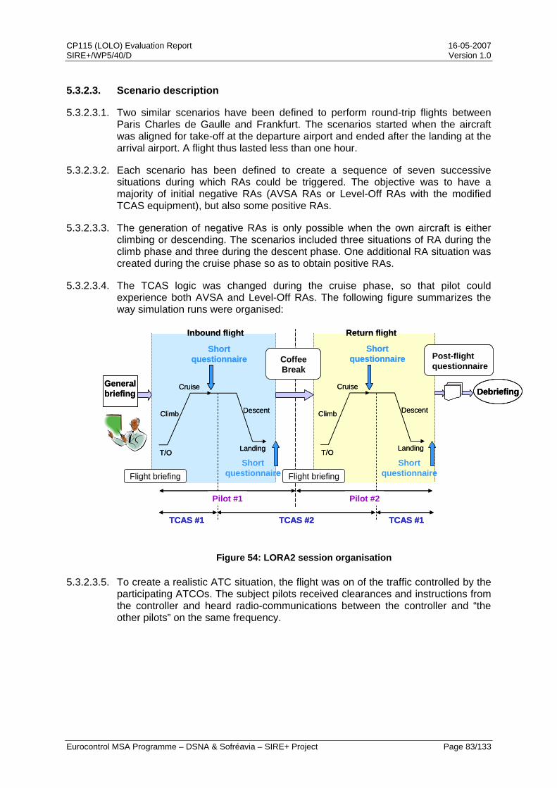
CP115 (LOLO) Evaluation Report 16-05-2007 SIRE+/WP5/40/D Version 1.0
Eurocontrol MSA Programme – DSNA & Sofréavia – SIRE+ Project Page 83/133
5.3.2.3. Scenario description
5.3.2.3.1. Two similar scenarios have been defined to perform round-trip flights between Paris Charles de Gaulle and Frankfurt. The scenarios started when the aircraft was aligned for take-off at the departure airport and ended after the landing at the arrival airport. A flight thus lasted less than one hour.
5.3.2.3.2. Each scenario has been defined to create a sequence of seven successive situations during which RAs could be triggered. The objective was to have a majority of initial negative RAs (AVSA RAs or Level-Off RAs with the modified TCAS equipment), but also some positive RAs.
5.3.2.3.3. The generation of negative RAs is only possible when the own aircraft is either climbing or descending. The scenarios included three situations of RA during the climb phase and three during the descent phase. One additional RA situation was created during the cruise phase so as to obtain positive RAs.
5.3.2.3.4. The TCAS logic was changed during the cruise phase, so that pilot could experience both AVSA and Level-Off RAs. The following figure summarizes the way simulation runs were organised:
Figure 54: LORA2 session organisation
5.3.2.3.5. To create a realistic ATC situation, the flight was on of the traffic controlled by the participating ATCOs. The subject pilots received clearances and instructions from the controller and heard radio-communications between the controller and “the other pilots” on the same frequency.
General briefing
T/O
Climb
Cruise
Shortquestionnaire
Descent
Landing
Inbound flight Return flight
T/O
Climb
Cruise
Shortquestionnaire
Descent
Landing
Debriefing
Post-flightquestionnaire
Flight briefingShort
questionnaireShort
questionnaire
TCAS #1 TCAS #2 TCAS #1
Pilot #1 Pilot #2
CoffeeBreak
Flight briefing
General briefing
Inbound flight Return flight
T/O
Climb
Cruise
Shortquestionnaire
Descent
LandingT/O
Climb
Cruise
Shortquestionnaire
Descent
Landing T/O
Climb
Cruise
Shortquestionnaire
Descent
LandingT/O
Climb
Cruise
Shortquestionnaire
Descent
Landing
DebriefingDebriefing
Post-flightquestionnairePost-flightquestionnaire
Flight briefingShort
questionnaireShort
questionnaire
TCAS #1 TCAS #2 TCAS #1TCAS #1 TCAS #2 TCAS #1
Pilot #1 Pilot #2Pilot #1
CoffeeBreakCoffeeBreak
Flight briefing
Pilot #2
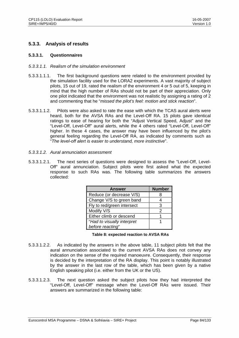
CP115 (LOLO) Evaluation Report 16-05-2007 SIRE+/WP5/40/D Version 1.0
Eurocontrol MSA Programme – DSNA & Sofréavia – SIRE+ Project Page 84/133
5.3.3. Analysis of results
5.3.3.1. Questionnaires
5.3.3.1.1. Realism of the simulation environment
5.3.3.1.1.1. The first background questions were related to the environment provided by the simulation facility used for the LORA2 experiments. A vast majority of subject pilots, 15 out of 19, rated the realism of the environment 4 or 5 out of 5, keeping in mind that the high number of RAs should not be part of their appreciation. Only one pilot indicated that the environment was not realistic by assigning a rating of 2 and commenting that he “missed the pilot’s feel: motion and stick reaction”.
5.3.3.1.1.2. Pilots were also asked to rate the ease with which the TCAS aural alerts were heard, both for the AVSA RAs and the Level-Off RA. 15 pilots gave identical ratings to ease of hearing for both the “Adjust Vertical Speed, Adjust” and the “Level-Off, Level-Off” aural alerts, while the 4 others rated “Level-Off, Level-Off” higher. In these 4 cases, the answer may have been influenced by the pilot’s general feeling regarding the Level-Off RA, as indicated by comments such as “The level-off alert is easier to understand, more instinctive”.
5.3.3.1.2. Aural annunciation assessment
5.3.3.1.2.1. The next series of questions were designed to assess the ”Level-Off, Level-Off” aural annunciation. Subject pilots were first asked what the expected response to such RAs was. The following table summarizes the answers collected:
Answer Number Reduce (or decrease V/S) 8 Change V/S to green band 4 Fly to red/green intersect 3 Modify V/S 2 Either climb or descend 1 “Had to visually interpret before reacting”
1
Table 8: expected reaction to AVSA RAs
5.3.3.1.2.2. As indicated by the answers in the above table, 11 subject pilots felt that the aural annunciation associated to the current AVSA RAs does not convey any indication on the sense of the required manoeuvre. Consequently, their response is decided by the interpretation of the RA display. This point is notably illustrated by the answer in the last row of the table, which has been given by a native English speaking pilot (i.e. either from the UK or the US).
5.3.3.1.2.3. The next question asked the subject pilots how they had interpreted the “Level-Off, Level-Off” message when the Level-Off RAs were issued. Their answers are summarized in the following table:
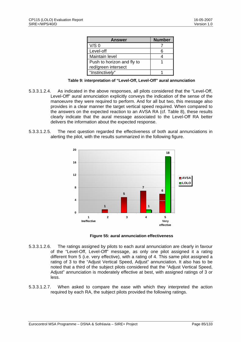
CP115 (LOLO) Evaluation Report 16-05-2007 SIRE+/WP5/40/D Version 1.0
Eurocontrol MSA Programme – DSNA & Sofréavia – SIRE+ Project Page 85/133
Answer Number V/S 0 7 Level-off 6 Maintain level 4 Push to horizon and fly to red/green intersect
1
“Instinctively” 1
Table 9: interpretation of “Level-Off, Level-Off” aural annunciation
5.3.3.1.2.4. As indicated in the above responses, all pilots considered that the “Level-Off, Level-Off” aural annunciation explicitly conveys the indication of the sense of the manoeuvre they were required to perform. And for all but two, this message also provides in a clear manner the target vertical speed required. When compared to the answers on the expected reaction to an AVSA RA (cf. Table 8), these results clearly indicate that the aural message associated to the Level-Off RA better delivers the information about the expected response.
5.3.3.1.2.5. The next question regarded the effectiveness of both aural annunciations in alerting the pilot, with the results summarized in the following figure.
1
5
76
1
18
0
4
8
12
16
20
1Ineffective
2 3 4 5Very
effective
AVSALOLO
Figure 55: aural annunciation effectiveness
5.3.3.1.2.6. The ratings assigned by pilots to each aural annunciation are clearly in favour of the “Level-Off, Level-Off” message, as only one pilot assigned it a rating different from 5 (i.e. very effective), with a rating of 4. This same pilot assigned a rating of 3 to the “Adjust Vertical Speed, Adjust” annunciation. It also has to be noted that a third of the subject pilots considered that the “Adjust Vertical Speed, Adjust” annunciation is moderately effective at best, with assigned ratings of 3 or less.
5.3.3.1.2.7. When asked to compare the ease with which they interpreted the action required by each RA, the subject pilots provided the following ratings.
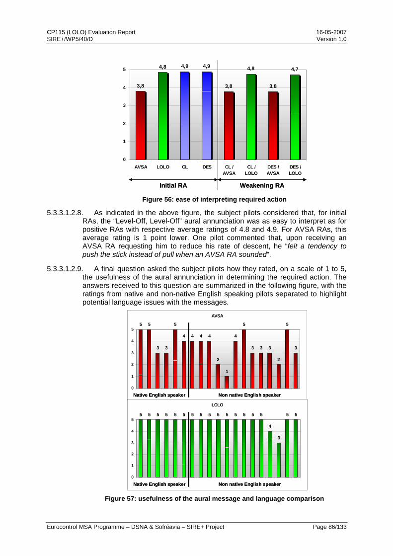
CP115 (LOLO) Evaluation Report 16-05-2007 SIRE+/WP5/40/D Version 1.0
Eurocontrol MSA Programme – DSNA & Sofréavia – SIRE+ Project Page 86/133
3,8
4,8 4,9 4,9
3,8
4,8
3,8
4,7
0
1
2
3
4
5
AVSA LOLO CL DES CL /AVSA
CL /LOLO
DES /AVSA
DES /LOLO
Initial RA Weakening RAInitial RA Weakening RA Figure 56: ease of interpreting required action
5.3.3.1.2.8. As indicated in the above figure, the subject pilots considered that, for initial RAs, the “Level-Off, Level-Off” aural annunciation was as easy to interpret as for positive RAs with respective average ratings of 4.8 and 4.9. For AVSA RAs, this average rating is 1 point lower. One pilot commented that, upon receiving an AVSA RA requesting him to reduce his rate of descent, he “felt a tendency to push the stick instead of pull when an AVSA RA sounded”.
5.3.3.1.2.9. A final question asked the subject pilots how they rated, on a scale of 1 to 5, the usefulness of the aural annunciation in determining the required action. The answers received to this question are summarized in the following figure, with the ratings from native and non-native English speaking pilots separated to highlight potential language issues with the messages.
AVSA
5 5
3 3
5
4 4 4 4
2
1
4
5
3 3 3
2
5
3
0
1
2
3
4
5
Figure 57: usefulness of the aural message and language comparison
Non native English speakerNative English speaker
AVSA
5 5
3 3
5
4 4 4 4
2
1
4
5
3 3 3
2
5
3
0
1
2
3
4
5
Non native English speakerNative English speaker Non native English speakerNative English speaker
LOLO
5 5 5 5 5 5 5 5 5 5 5 5 5 5 5
4
3
5 5
0
1
2
3
4
5
Non native English speakerNative English speaker
LOLO
5 5 5 5 5 5 5 5 5 5 5 5 5 5 5
4
3
5 5
0
1
2
3
4
5
Non native English speakerNative English speaker Non native English speakerNative English speaker
CP115 (LOLO) Evaluation Report 16-05-2007 SIRE+/WP5/40/D Version 1.0
Eurocontrol MSA Programme – DSNA & Sofréavia – SIRE+ Project Page 87/133
5.3.3.1.2.10. As evel-Off, Level-Off” message was useful or very useful for the purpose of determining
5.3.3.1.3.
seful the visual information was in determining the required action for both types of RAs, the subject pilots had similar answers with a majority
5.3.3.1.3.2 isual display, 13 pilots rated it 5 (i.e. fully consistent) in the case of the Level-Off RA and 5 pilots
5.3.3.1.4. tion
ere then asked to answer a question on the potential operational issues they could figure with either the AVSA RA or the Level-Off RA.
5.3.3.1.4.2 d to this question, 4 pilots indicated that they felt a difficulty to fly an AVSA RA because the aural annunciation is not clear, which can
5.3.3.1.4.3. ssible deviation from the ATC instruction in response to the RA, which the operational assessment of CP115 in
5.3.3.1.4.4 t question asked pilots how they felt about the replacement of the VSL 2000, 1000 and 500 fpm RAs by a VSL 0 RA in the Level-Off option. Their
indicated in the above figure, 18 pilots out of 19 estimated that the “L
the required action (i.e. rating of 4 or 5), while only 10 of them had the same rating for the “Adjust Vertical Speed, Adjust” message. This result confirms that the new “Level-Off, Level-Off” aural annunciation is really helping pilots in deciding is what the appropriate response to the RA. It is also important to note that no difference in this appreciation was found between native English speaking and non-native English speaking pilots.
Display assessment
5.3.3.1.3.1. When asked how u
of them judging the visual display as very useful for this purpose.
. Regarding the consistency of the aural annunciation and the v
rated it 4 because the green arc on the display allowed a light climb or descent. For the AVSA RAs, only 5 pilots found the aural annunciation fully consistent with the visual display.
Operational evalua
5.3.3.1.4.1. The subject pilots w
The first question in this series asked pilots if they could foresee any operational encounter in which the visual display and/or the aural annunciations would be inappropriate. 32% of pilots foresaw problems with the AVSA RA, while only 21% did so with the Level-Off RA.
. In the comments associate
lead to problems. Some comments also mentioned possible misunderstanding with ATC when reporting the RA and the fact that the aural annunciation was very confusing in multiple threat “sandwich” situations.
Comments on the Level-Off RA included a po
section 4 has anticipated to be less frequent than with the current Version 7. Pilots also felt that the Level-Off RA could lead to TCAS performance issues in multiple threat encounters. The safety analysis of CP115 in section 3 shows that multiple threat events are very rare situations and the better performance of CP115 in the more frequent sequential situations leads to an overall benefit over Version 7.
. The nex
answers are illustrated in the following figure.

CP115 (LOLO) Evaluation Report 16-05-2007 SIRE+/WP5/40/D Version 1.0
Eurocontrol MSA Programme – DSNA & Sofréavia – SIRE+ Project Page 88/133
2 2
15
0
4
8
12
16
1Not at all in
favour
2 3 4 5Very much in
favour
Figure 58: pilot feeling about replacement of AVSA RAs
5.3.3.1.4.5. As can be seen in the above chart, the subject pilots are largely in favour of the TCAS RA list simplification coming with the introduction of the Level-Off RA. One pilot justified his rating by commenting that “to keep it as simple as possible is the main goal in such critical situations”. It also has to be noted that one of the two pilots who gave a rating of 3 added that “level-off is a very simple command to perform”.
5.3.3.1.4.6. In a subsequent question, pilots were asked to rate the overall suitability of each option as a collision avoidance device. Their answers are summarized in the following figure.
4 4
7
4
1
18
0
4
8
12
16
20
1Not suitable
2 3 4 5Very
suitable
AVSALOLO
Figure 59: overall suitability as a collision avoidance device
5.3.3.1.4.7. This question led to the largest difference in rating between the AVSA and the Level-Off RAs, as 18 pilots out of 19 gave the highest rating of 5 for the Level-Off RA, while only 4 did so for the AVSA RA. One native English speaking pilot

CP115 (LOLO) Evaluation Report 16-05-2007 SIRE+/WP5/40/D Version 1.0
Eurocontrol MSA Programme – DSNA & Sofréavia – SIRE+ Project Page 89/133
notably commented that the “AVSA aural does not always register in my brain during the manoeuvre; LOLO definitely does”.
5.3.3.1.4.8. A subsequent question dealt with the operational benefits that the subject
5.3.3.1.4.9. Regarding operational benefits provided the AVSA RAs, 12 pilots out of 19
5.3.3.1.4.10. The next question was the converse of the above one and asked pilots to
5.3.3.1.4.11. It should also be noted that answers to these questions dealing with the
5.3.3.1.5. Preferred option
5.3.3.1.5.1. The concluding question aimed at capturing the pilots overall opinion about
pilots foresaw for each option and how these benefits compared. Two main benefits were identified for the Level-Off RA, with the first being that this proposed new RA is easy to interpret (10 out of 19 answers). One of the pilots commented that, with the Level-Off RA, “the red area becomes an information of confirmation and not a hazardous area from which we must imperatively exit, with the risk to want to exit by the wrong side”. The second operational benefit provided by LOLO is an RA which is also easy to fly, as indicated by a majority of pilots (i.e. 10 out of 19). 3 pilots also mentioned that the Level-Off RA set them in the correct direction and provided them with a precise target vertical speed.
saw none. Although 6 pilots considered that the AVSA RA allowed some compliance with the ATC clearance, they nonetheless preferred the Level-Off RA.
compare the potential operational issues they identified with each option. The most frequently mentioned problem with the AVSA RA, in 8 cases, was the difficulty to determine the required action (“confusing”, “misunderstanding could be catastrophic”, etc.). For the Level-Off RA, a possible deviation from the ATC instruction was the most commonly cited problem, with only 3 answers. However, it was considered a “minor issue compared with benefits of clear command” by one of the native English speaking pilots.
operational assessment of the two options allowed some pilots to identify the reporting issue, and the benefits provided by LOLO with respect to this issue, that had been highlighted in the LORA1 experiments. Indeed, some pilots mentioned that the RA reporting to ATC was sometimes problematic with AVSA RAs, while it is improved with the Level-Off RA.
the replacement of AVSA RAs by the Level-Off RA and asked them which their preferred option was, between the current AVSA RAs and the proposed Level-Off RA. Their answers are summarized in the following figure.
CP115 (LOLO) Evaluation Report 16-05-2007 SIRE+/WP5/40/D Version 1.0
Eurocontrol MSA Programme – DSNA & Sofréavia – SIRE+ Project Page 90/133
0
18
1
0
4
8
12
16
20
Adjust Vertical Speed,Adjust
Level-Off, Level-Off None
Figure 60: subject pilots preferred option
5.3.3.1.5.2. As can be seen above, the subject pilots who took part in the LORA2 real-time experiments were overwhelmingly in favour of the Level-Off RA, as 18 out of 19 preferred the Level-Off RA over the AVSA RAs and the last one expressed no preference. The main reasons for their choice were that the proposed new RA is “simple”, “clear”, “instinctive”, “easy to fly” and gives them a “unique objective: V/S 0”. One native English speaking pilot added that the Level-Off RA is “safer, removes all doubts. No interpretation”.
5.3.3.2. Aircraft data
5.3.3.2.1. Analysis of pilot responses
5.3.3.2.1.1. The pilot responses to the RAs triggered during the experiments have been analysed using three parameters:
• Reaction time, measured from the time of the initial RA until the first significant vertical acceleration;
• Vertical acceleration taken to perform the required manoeuvre;
• Vertical speed reached after acceleration phase.
5.3.3.2.1.2. The reaction times recorded for all the RAs (i.e. AVSA, positive and Level-Off RAs) are summarized in the following figure, which indicates the average, minimum and maximum times measured for each type of RA.
CP115 (LOLO) Evaluation Report 16-05-2007 SIRE+/WP5/40/D Version 1.0
Eurocontrol MSA Programme – DSNA & Sofréavia – SIRE+ Project Page 91/133
0
1
2
3
4
5
6
7
8
9
10
ClDes
DCL200
0
DDES2000
DCL100
0
DDES1000
DCL500
DDES500
V7 DCL
V7 DDES
LOLO
DCL
LOLO
DDES
Tim
e, m
in &
max
(s)
No such RAs
Time between initial RA and first significant acceleration
Figure 61: reaction time to initial RAs
5.3.3.2.1.3. Several different behaviours can be clearly observed in the above figure. On the left part, it can be seen that responses to positive RAs are very fast, with an average response time of about 2 seconds. Responses to Level-Off RAs, on the right part, are remarkably close with an average time of about 2.2 seconds as indicated by the green line. Then, for all AVSA RAs except DCL2000 (Do not climb more than 2000 fpm), the average response time is about 3 seconds, i.e. close to 1 second longer than for Level-Off RAs. For DCL2000 RAs, the average response time was even longer (i.e. 4.5 seconds).
5.3.3.2.1.4. It is also worth noting that reaction times to the current Version 7 Do not descend RA and the LOLO Do not descend RA are significantly different (1 second on average) although they are displayed in the same way on the TCAS display. This confirms that the aural annunciation “Level-Off, Level-Off” is more intuitive to pilots and contributes to a quicker reaction.
5.3.3.2.1.5. The following chart provides the average accelerations measured for AVSA, positive and Level-Off RAs, and compares them to the expected standard response of 0.25g ([ANN10]).
No such RAs0
1
2
3
4
5
6
7
8
9
10
ClDes
DCL200
0
DDES2000
DCL100
0
DDES1000
DCL500
DDES500
V7 DCL
V7 DDES
LOLO
DCL
LOLO
DDES
Tim
e, m
in &
max
(s)
No such RAs
Time between initial RA and first significant acceleration
No such RAs
CP115 (LOLO) Evaluation Report 16-05-2007 SIRE+/WP5/40/D Version 1.0
Eurocontrol MSA Programme – DSNA & Sofréavia – SIRE+ Project Page 92/133
Figure 62: vertical acceleration in response to RA
5.3.3.2.1.6. As shown in the above figure, average accelerations taken by pilots in response to either positive RAs or Level-Off RAs are similar and close to the expected standard response of 0.25g. This is also true when considering the ranges of measured accelerations, which span from 0.11g to 0.36g for positive RAs and from 0.19g to 0.34g for Level-Off RAs. Responses to Level-Off RAs are thus comparable with positive RAs and compliant with the standard response. On the other hand, accelerations taken in response to AVSA RAs are slightly slower than the standard response, as they average only 0.20g.
5.3.3.2.1.7. The next chart provides average values for the last of the parameters analysing the pilot responses, i.e. the vertical speed reached after the acceleration phase.
-1250
-1000
-750
-500
-250
0
250
500
750
1000
1250
1500
1750
2000
DCL2000 DDES2000 DCL1000 DDES1000 DCL500 DDES500 DCL DDES LOLO DCL LOLO DDESVz, m
in &
max
(fpm
)
No such RAs
: Required vertical speed: Required vertical speed
Figure 63: vertical speed in response to RAs

CP115 (LOLO) Evaluation Report 16-05-2007 SIRE+/WP5/40/D Version 1.0
Eurocontrol MSA Programme – DSNA & Sofréavia – SIRE+ Project Page 93/133
5.3.3.2.1.8. On the above graph, the green squares indicate the required vertical speeds for each type of RA. For both Level-Off RAs and Version 7 VSL 0 fpm RAs, this green squares coincide with the average vertical speeds taken by pilots, meaning that they complied precisely with the target vertical speed required by the RAs.
5.3.3.2.1.9. For AVSA RAs, the average vertical speeds are below the required vertical speed for climb sense RAs and above for descend sense RAs, which means that pilots took a lower vertical rate than allowed by the RA. It is also worth noting that within all the range of recorded responses, no pilot exactly adjusted his vertical rate to the limit imposed by the RA. In addition, the higher this vertical speed limit, the further away the responses are from the expected reactions. These findings indicate that pilots have a tendency to go towards low vertical speeds when responding to AVSA RAs.
5.3.3.2.2. Level flight phase
5.3.3.2.2.1. The average durations of the level flight phases in response to VSL 0 fpm RAs or Level-Off RAs were very similar, as they were 33 seconds and 30 seconds respectively. The following figure shows the breakdown of this duration by altitude, as the duration of an RA is highly dependant on the altitude it occurs at.
0,0
5,0
10,0
15,0
20,0
25,0
30,0
35,0
40,0
Dur
atio
n (s
)
30
AVSA 0 fpm
33
LOLO0,0
5,0
10,0
15,0
20,0
25,0
30,0
35,0
40,0
Dur
atio
n (s
)
30
AVSA 0 fpm
33
LOLO
Figure 64: duration of level flight phase for VSL 0 fpm and Level-Off RAs
5.3.3.2.2.2. As can be seen in the above figure, the average duration of both VSL 0 fpm RAs and Level-Off RAs are rather similar, ranging from 15 to 50 seconds depending on the altitude layer. No significant difference can be found between the average durations of VSL 0 fpm RAs and Level-Off RAs.
5.3.3.2.3. Return to clearance
5.3.3.2.3.1. Once the “Clear of Conflict” has been issued, two different pilot behaviours have been observed during the LORA2 experiments. Some pilots re-engaged the autopilot right after the advisory, while others continued piloting the aircraft manually and re-engaged the autopilot in a second step. Therefore, two different times had to be computed to determine the duration of reaction to return to the initial clearance; i.e. the time to re-engage the AP after the Clear of Conflict and the time between the Clear of Conflict and the first significant acceleration (higher than 0.03g). The time of reaction to return to the initial clearance was thus computed as the minimum between these two durations.
CP115 (LOLO) Evaluation Report 16-05-2007 SIRE+/WP5/40/D Version 1.0
Eurocontrol MSA Programme – DSNA & Sofréavia – SIRE+ Project Page 94/133
5.3.3.2.3.2. The following figure shows the breakdown of reaction times to return to the initial clearance, for both VSL 0 fpm RAs and Level-Off RAs.
Figure 65: reaction time to CoC for AVSA and Level-Off RAs
5.3.3.2.3.3. As indicated above, reaction times to the “Clear of Conflict” annunciation after either AVSA RA or Level-Off RAs are very similar. Indeed, the average reaction times are 5.8 seconds for AVSA RAs and 5.4 seconds for Level-Off RAs. Nevertheless, it can be noted that the maximum time for Level-Off RAs is 15 seconds, whereas some reactions to AVSA RAs were significantly longer (up to 26 seconds).
5.3.3.3. Noticeable responses recorded
5.3.3.3.1. Altitude bust following an AVSA RA
5.3.3.3.1.1. During the course of the experiments, two situations of interest from an operational standpoint have occurred. In the case described in this section, one pilot flew through his cleared flight level after receiving an AVSA RA instructing him to limit his rate of climb.
5.3.3.3.1.2. The pilot had been cleared to FL110 and upon reaching FL100, he received an AVSA RA requiring him to limit his rate of climb to 2000 fpm because of a traffic above. The following figure shows the vertical profile of the aircraft during the RA, as an altitude vs. time graph. The TCAS advisories and significant pilot actions are also indicated along the trajectory.
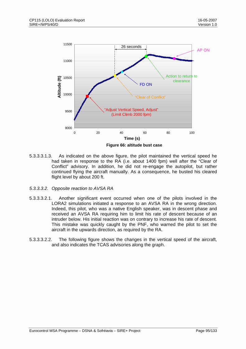
CP115 (LOLO) Evaluation Report 16-05-2007 SIRE+/WP5/40/D Version 1.0
Eurocontrol MSA Programme – DSNA & Sofréavia – SIRE+ Project Page 95/133
9000
9500
10000
10500
11000
11500
0 20 40 60 80 100
Figure 66: altitude bust case
5.3.3.3.1.3. As indicated on the above figure, the pilot maintained the vertical speed he had taken in response to the RA (i.e. about 1400 fpm) well after the “Clear of Conflict” advisory. In addition, he did not re-engage the autopilot, but rather continued flying the aircraft manually. As a consequence, he busted his cleared flight level by about 200 ft.
5.3.3.3.2. Opposite reaction to AVSA RA
5.3.3.3.2.1. Another significant event occurred when one of the pilots involved in the LORA2 simulations initiated a response to an AVSA RA in the wrong direction. Indeed, this pilot, who was a native English speaker, was in descent phase and received an AVSA RA requiring him to limit his rate of descent because of an intruder below. His initial reaction was on contrary to increase his rate of descent. This mistake was quickly caught by the PNF, who warned the pilot to set the aircraft in the upwards direction, as required by the RA.
5.3.3.3.2.2. The following figure shows the changes in the vertical speed of the aircraft, and also indicates the TCAS advisories along the graph.
“Adjust Vertical Speed, Adjust”(Limit Climb 2000 fpm)
“Clear of Conflict”
FD ON
Action to return to clearance
26 secondsAP ON
Alti
tude
(ft)
Time (s)
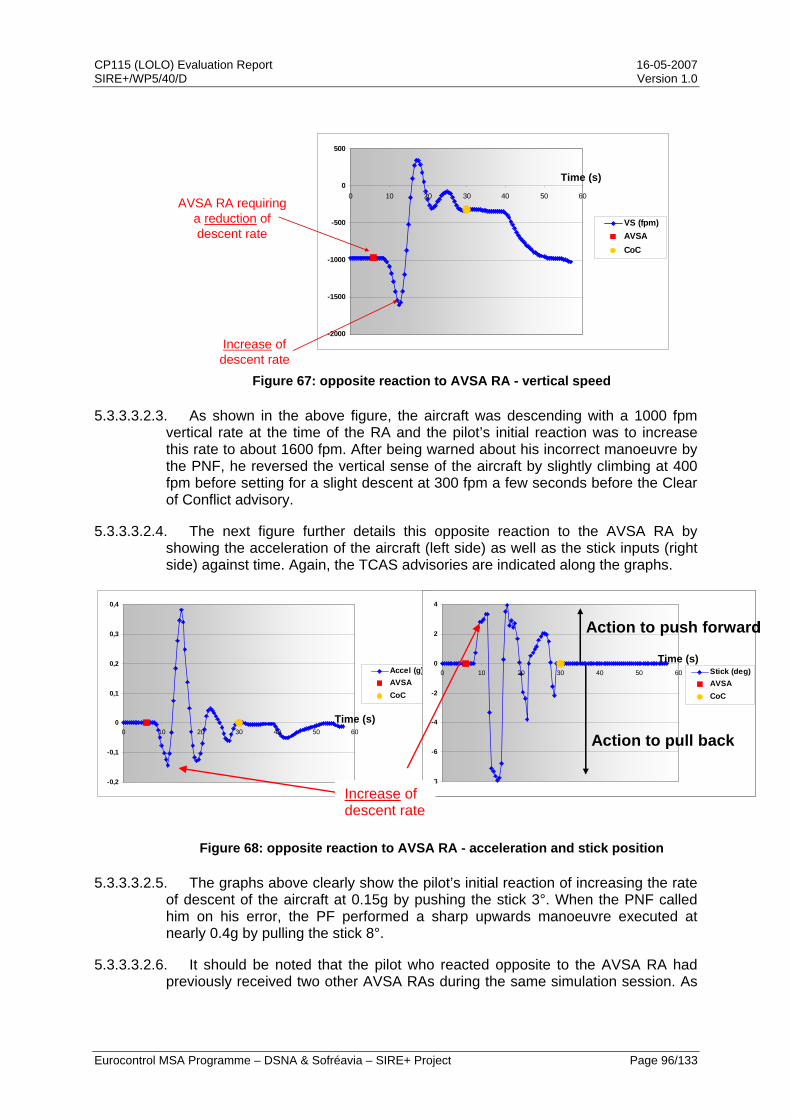
CP115 (LOLO) Evaluation Report 16-05-2007 SIRE+/WP5/40/D Version 1.0
Eurocontrol MSA Programme – DSNA & Sofréavia – SIRE+ Project Page 96/133
-2000
-1500
-1000
-500
0
500
0 10 20 30 40 50 60
VS (fpm)AVSACoC
Time (s)
AVSA RA requiring a reduction of descent rate
Increase of descent rate
Figure 67: opposite reaction to AVSA RA - vertical speed
5.3.3.3.2.3. As shown in the above figure, the aircraft was descending with a 1000 fpm vertical rate at the time of the RA and the pilot’s initial reaction was to increase this rate to about 1600 fpm. After being warned about his incorrect manoeuvre by the PNF, he reversed the vertical sense of the aircraft by slightly climbing at 400 fpm before setting for a slight descent at 300 fpm a few seconds before the Clear of Conflict advisory.
5.3.3.3.2.4. The next figure further details this opposite reaction to the AVSA RA by showing the acceleration of the aircraft (left side) as well as the stick inputs (right side) against time. Again, the TCAS advisories are indicated along the graphs.
-0,2
-0,1
0
0,1
0,2
0,3
0,4
0 10 20 30 40 50 60
Accel (g)AVSACoC
-8
-6
-4
-2
0
2
4
0 10 20 30 40 50 60 Stick (deg)AVSACoC
Action to push forward
Action to pull back
-8
-6
-4
-2
0
2
4
0 10 20 30 40 50 60 Stick (deg)AVSACoC
Action to push forward
Action to pull back
Time (s)
Time (s)
Increase of descent rate
Figure 68: opposite reaction to AVSA RA - acceleration and stick position
5.3.3.3.2.5. The graphs above clearly show the pilot’s initial reaction of increasing the rate of descent of the aircraft at 0.15g by pushing the stick 3°. When the PNF called him on his error, the PF performed a sharp upwards manoeuvre executed at nearly 0.4g by pulling the stick 8°.
5.3.3.3.2.6. It should be noted that the pilot who reacted opposite to the AVSA RA had previously received two other AVSA RAs during the same simulation session. As
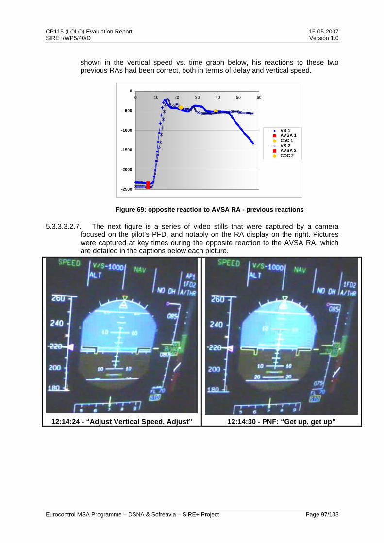
CP115 (LOLO) Evaluation Report 16-05-2007 SIRE+/WP5/40/D Version 1.0
Eurocontrol MSA Programme – DSNA & Sofréavia – SIRE+ Project Page 97/133
shown in the vertical speed vs. time graph below, his reactions to these two previous RAs had been correct, both in terms of delay and vertical speed.
Figure 69: opposite reaction to AVSA RA - previous reactions
5.3.3.3.2.7. The next figure is a series of video stills that were captured by a camera focused on the pilot’s PFD, and notably on the RA display on the right. Pictures were captured at key times during the opposite reaction to the AVSA RA, which are detailed in the captions below each picture.
12:14:24 - “Adjust Vertical Speed, Adjust” 12:14:30 - PNF: “Get up, get up”
-2500
-2000
-1500
-1000
-500
00 10 20 30 40 50 60
VS 1AVSA 1CoC 1VS 2AVSA 2COC 2
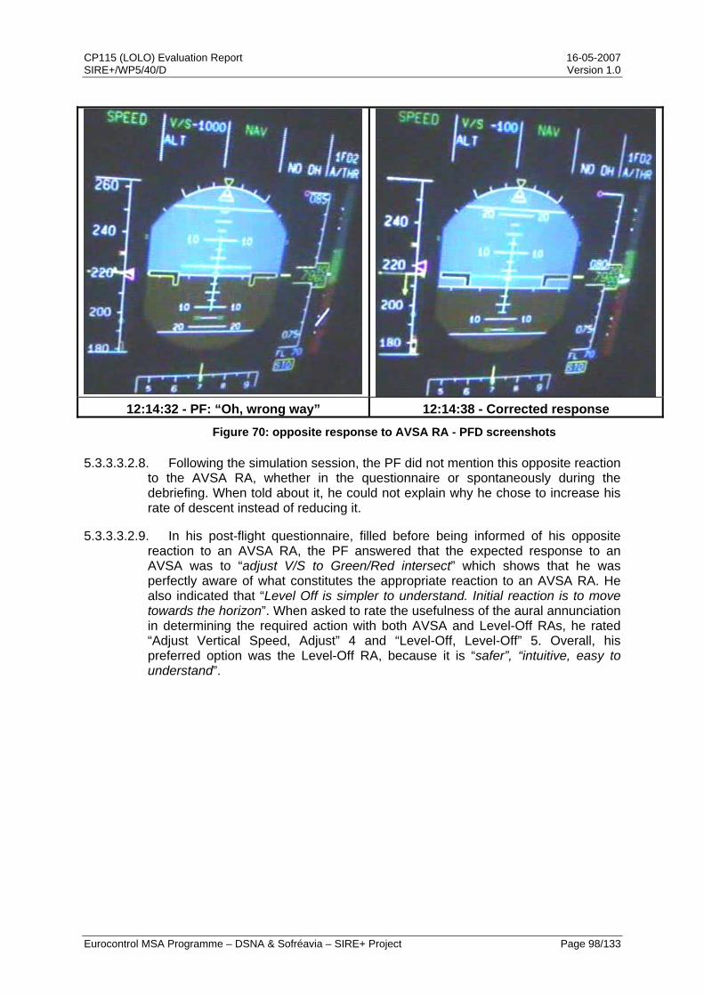
CP115 (LOLO) Evaluation Report 16-05-2007 SIRE+/WP5/40/D Version 1.0
Eurocontrol MSA Programme – DSNA & Sofréavia – SIRE+ Project Page 98/133
12:14:32 - PF: “Oh, wrong way” 12:14:38 - Corrected response
Figure 70: opposite response to AVSA RA - PFD screenshots
5.3.3.3.2.8. Following the simulation session, the PF did not mention this opposite reaction to the AVSA RA, whether in the questionnaire or spontaneously during the debriefing. When told about it, he could not explain why he chose to increase his rate of descent instead of reducing it.
5.3.3.3.2.9. In his post-flight questionnaire, filled before being informed of his opposite reaction to an AVSA RA, the PF answered that the expected response to an AVSA was to “adjust V/S to Green/Red intersect” which shows that he was perfectly aware of what constitutes the appropriate reaction to an AVSA RA. He also indicated that “Level Off is simpler to understand. Initial reaction is to move towards the horizon”. When asked to rate the usefulness of the aural annunciation in determining the required action with both AVSA and Level-Off RAs, he rated “Adjust Vertical Speed, Adjust” 4 and “Level-Off, Level-Off” 5. Overall, his preferred option was the Level-Off RA, because it is “safer”, “intuitive, easy to understand”.
CP115 (LOLO) Evaluation Report 16-05-2007 SIRE+/WP5/40/D Version 1.0
Eurocontrol MSA Programme – DSNA & Sofréavia – SIRE+ Project Page 99/133
5.4. Conclusions on the Human Factors aspects validation
5.4.1. In May 2006, DSNA set up the LORA1 real-time experiments to investigate the Human Factors aspects of the proposed LOLO solution to the SA-AVSA issue. These RTS indicated that both participating pilots and ATCOs considered the Level-Off RA as an operationally acceptable solution and highlighted improvements in TCAS reporting to ATC with this new RA. In addition, participating pilots underlined the better clarity and intuitiveness of the Level-Off RA over the current AVSA RAs.
5.4.2. In the wake of the LORA1 experiments, a second round of real-time experiments has been set up by Airbus between mid-October and mid-November 2006 in cooperation with the RTCA SC147 OWG. The main objectives of the LORA2 experiments were to conduct a comprehensive comparison between the AVSA RAs and the Level-Off RA and to confirm initial findings from the LORA1 experiments.
5.4.3. The two sets of real-time simulations have confirmed the operational acceptability of the Level-Off RA, as ATCOs considered it would not disrupt current operations and as 18 out of the 19 participating pilots preferred the proposed Level-Off RA over the current Version 7 AVSA RAs, while the last pilot had no preference. In addition, controller / pilot cooperation is improved by LOLO, as it leads to a much improved TCAS reporting to ATC.
5.4.4. Because the issue of opposite responses to initial AVSA RAs has sometimes been associated to a language issue, a specific effort has been made on this topic when questionnaires have been analysed. There is indeed an issue with the current AVSA RAs, as indicated by the training effort undertook by some major airlines to explain that “Adjust means Reduce”. With the Level-Off RA, the aural annunciation is more easily understood, as indicated by the fact that no difference appeared in the answers collected from native (i.e. from the US or the UK) and non-native English speaking pilots.
5.4.5. Pilots involved in the experiments have identified two main benefits of the Level-Off RA over the current AVSA RAs. First, it is easier to interpret, as the aural annunciation effectively conveys the direction of the required manoeuvre and the targeted vertical speed. Then, it is also easier to fly because the manoeuvre required by the Level-Off RA is more straightforward. Additionally, the Level-Off RA was considered safer than the AVSA RAs. Overall, the Level-Off RA received a similar assessment to the positive RAs.
5.4.6. On the other hand, the only benefit that some participating pilots have identified for the AVSA RAs is that they are more compliant with the ATC instruction. In fact, some pilots have commented that they foresaw this point as a limitation for the Level-Off RA, although a minor one in comparison to the difficulty in interpreting the action required by the AVSA RAs.
5.4.7. Analysis of the responses to Level-Off RAs through recorded parameters has identified no negative impact. Indeed, the profile of these responses was similar to responses to positive RAs, both in terms of reaction time and vertical acceleration. On the contrary, the responses to AVSA RAs, and especially on AVSA requiring a reduction to 2000 fpm, showed a slower reaction time and a vertical acceleration weaker than expected.
CP115 (LOLO) Evaluation Report 16-05-2007 SIRE+/WP5/40/D Version 1.0
Eurocontrol MSA Programme – DSNA & Sofréavia – SIRE+ Project Page 100/133
5.4.8. When comparing responses obtained on Level-Off RAs with responses to the similar Version 7 AVSA RAs requesting a 0 fpm vertical rate, analysis of recorded parameters indicated that the initial reaction time to a Level-Off RA was on average one second quicker than to an VSL 0 RA. Response to the two types of RAs were otherwise similar in the vertical speed reached and in the duration of the level flight phase, while the reaction time to return to the initial clearance after the Clear of Conflict advisory was slightly faster with the Level-Off RA.
5.4.9. Finally, the LORA2 experiments enabled to record a noticeable response as a native English speaking pilot reacted to an AVSA RA by going in the opposite vertical sense than required by the RA. This opposite reaction is of particular significance as it occurred in a context of simulations, with a pilot aware of the objectives of the experiments he was taking part in.
CP115 (LOLO) Evaluation Report 16-05-2007 SIRE+/WP5/40/D Version 1.0
Eurocontrol MSA Programme – DSNA & Sofréavia – SIRE+ Project Page 101/133
6. Conclusions
6.1. A significant safety issue with TCAS II Version 7, labelled SA-AVSA, was initially identified in 2002. This issue is related to flight crews unintentionally reacting opposite to initial “Adjust Vertical Speed, Adjust” RAs. These opposite reactions increase the risk of collision and they continue to occur despite focused training actions.
6.2. The severity of the SA-AVSA issue is such that the risk of collision due to an SA-AVSA event exceeds the tolerated rate of catastrophic events caused by equipment-related hazards by a factor of 5. This risk is equivalent to a collision about every 15 years in Europe.
6.3. The EUROCONTROL SIRE+ initiative has developed a solution to this safety issue which consists in a CAS logic change replacing the four different AVSA RAs with a single RA requesting the pilot to level-off and in accompanying this new RA with the “Level-Off, Level-Off” aural annunciation. This LOLO solution was formally proposed to RTCA in 2006 (CP115).
6.4. A significant body of work has been carried out to validate CP115. It encompasses a safety performance study, an operational performance study and a Human Factors study. Each of these studies indicates substantial benefits from CP115 introduction.
6.5. In addition to the resolution of the opposite reactions, an immediate safety benefit derives from the design of the LOLO solution, which prevents the issuance of RAs leaving the aircraft evolving in the same vertical direction. All the safety simulations, including those on operationally realistic scenarios, indicate that implementing CP115 in conjunction with CP112E will further improve the safety of TCAS. The evaluation shows the greatest improvement where all aircraft carry CP115. However, improvement is even seen for airspace in which some aircraft carry CP115 while others carry other versions. No problems of interoperability between versions have been found.
6.6. The operational performance analysis of the LOLO solution shows some substantial operational benefits. CP115 reduces the RA alert rate and minimises the altitude deviations induced by TCAS. The potential issue of an induced conflict with a 3rd party aircraft has been investigated using European and US operational data. This investigation has shown that introducing CP115 will not cause induced conflicts with 3rd party aircraft more frequently than with the current version of TCAS.
6.7. The LORA 1 real-time simulations have demonstrated that both participating pilots and ATCOs considered the Level-Off RA as a viable solution to the safety issue of opposite reactions to initial AVSA RAs. The subsequent LORA 2 real-time simulations have confirmed the acceptability of CP115 and developed a comprehensive comparison between the current AVSA RAs and the proposed Level-Off RA. 95% of participating pilots expressed their preference for the Level-Off RA because it is much simpler than the AVSA RAs and because the associated aural annunciation explicitly conveys the manoeuvre required by the RA. In addition, analysis of the recorded pilot responses indicates that responses to Level-Off RAs will be almost identical to the expected standard reaction in terms of reaction time, acceleration and accuracy. Finally, no disadvantages have been identified from a
CP115 (LOLO) Evaluation Report 16-05-2007 SIRE+/WP5/40/D Version 1.0
Eurocontrol MSA Programme – DSNA & Sofréavia – SIRE+ Project Page 102/133
controller standpoint and the analysis clearly shows that LOLO improves the cooperation between pilots and ATC by reducing the confusion in TCAS reporting.
6.8. The Level-Off RA has proven to be a very effective solution to the safety issue of unintentional opposite responses to initial AVSA RAs. European stakeholders (EASA, AEA, major European airlines, EUROCONTROL, EUROCAE, DSNA, Airbus, Sofréavia …) support the incorporation of the Level-Off RA in the forthcoming 7.1 revision of TCAS II.
CP115 (LOLO) Evaluation Report 16-05-2007 SIRE+/WP5/40/D Version 1.0
Eurocontrol MSA Programme – DSNA & Sofréavia – SIRE+ Project Page 103/133
7. Recommendations
7.1. CP115 should be included in the forthcoming revision of the TCAS MOPS.
7.2. CP115 should be implemented as soon as possible in the TCAS fleet in conjunction with CP112E.

CP115 (LOLO) Evaluation Report 16-05-2007 SIRE+/WP5/40/D Version 1.0
Eurocontrol MSA Programme – DSNA & Sofréavia – SIRE+ Project Page 104/133
THIS PAGE INTENTIONALLY LEFT BLANK
CP115 (LOLO) Evaluation Report 16-05-2007 SIRE+/WP5/40/D Version 1.0
Eurocontrol MSA Programme – DSNA & Sofréavia – SIRE+ Project Page 105/133
8. References
[ACA1] ACASA, WP-1.1.7 – ‘NMAC rate’ – ACASA/WP1.1.7/115, Version 2.2, October 2000.
[ACA2] ACASA, WP-1.2.5 – ‘European Encounter Model: Part ½’ – EUROCONTROL ACAS Programme – Specifications, ACASA/WP1.1/186, Version 2.1, December 2001
[ASA1] ASARP, WP2 – Final report on post-RVSM European safety encounter model – EUROCONTROL Mode S & ACAS Programme – ASARP/WP2/34/D, Version 1.0, July 2005.
[ASA2] ASARP, WP4 – Final report on the analysis of airborne recorded data and pilot model specification – EUROCONTROL Mode S & ACAS Programme – ASARP/WP4/19/D, Version 1.0, April 2005.
[ASA3] ASARP, WP3 – Update of altimetry error assumptions – EUROCONTROL Mode S & ACAS Programme – ASARP/WP3/16/D, Version 2.0, January 2006.
[ASA4] ASARP, WP2 – ‘Final Report on post-RVSM European safety encounter model’ – EUROCONTROL Mode S & ACAS Programme, Sofréavia & DSNA – ASARP/WP2/34D – Version 1.1, January 2006.
[ASA5] ASARP, WP7 – ‘Final report on the investigation of the multiple aircraft encounter issue’ – Eurocontrol Mode S & ACAS Programme –ASARP/WP7/53/W – Version 1.0, February 2006
[ANN10] ICAO – Annex 10 to the Convention on Civil Aviation, Volume IV, Surveillance Radar and Collision Avoidance Systems, 3rd edition, July 2002.
[EMO1] ‘EMOTION-7 Final Report’ – EUROCONTROL ACAS Programme – ACAS/03-003 Edition 1 – January 2003
[MOPS] RTCA – ‘Minimum operational performance standards for Traffic alert and Collision Avoidance System II airborne equipment’ – DO-185A, 997.
[RTCA1] RTCA – ‘Assessment and Recommendations on Visual Alerts and Aural Annunciations for TCAS II’ – DO-299, March 2006.
[RTCA2] RTCA – ‘Safety Analysis of Proposed Change to TCAS RA Reversal Logic’ – DO-298, November 2005.
[SIR1] ‘SIR Final Report’ – EUROCONTROL ACAS Programme – SIR/WP3/20D – Version 1.2, July 2004.
[SIRE1] ‘SIRE Final Report’ – EUROCONTROL Mode S & ACAS Programme, Sofréavia & DSNA – SIRE/WP4/58/D – Version 1.1, December 2005.
CP115 (LOLO) Evaluation Report 16-05-2007 SIRE+/WP5/40/D Version 1.0
Eurocontrol MSA Programme – DSNA & Sofréavia – SIRE+ Project Page 106/133
[SIRE+1] ‘Draft change proposal for simplified VSL RA list’ – EUROCONTROL Mode S & ACAS Programme, Sofréavia & DSNA – SIRE+/WP2/15/D – Version 1.2, September 2006.
[SIRE+2] ‘Safety performance of the CP115 solution (a.k.a. the “Level-Off, Level-Off solution)’ – EUROCONTROL Mode S & ACAS Programme, Sofréavia & DSNA – SIRE+/WP5/31/D – Version 1.0, January 2007.
[SIRE+3] ‘Operational performance of CP115 aka the “level-off, level-off” (LOLO) solution’ – EUROCONTROL Mode S & ACAS Programme, Sofréavia & DSNA – SIRE+/WP2/32/D – Version 1.1, February 2006.
[SIRE+4] ‘RITA-like animation supporting LOLO implementation’– EUROCONTROL Mode S & ACAS Programme, Sofréavia & DSNA – SIRE+/WP5/43/D – Version 1.0, May 2007.
[SIRE+5] ‘SIRE+ simulation framework’ – EUROCONTROL Mode S & ACAS Programme, Sofréavia & DSNA – SIRE+/WP1/03/W – Version 1.1, February 2006.
[SIRE+6] ‘’AVSA safety issue rectification: Preliminary investigation of the “Level-Off, Level-Off” solution” – EUROCONTROL Mode S & ACAS Programme, Sofréavia & DSNA – SIRE+/WP2/07/D – Version 1.0, April 2006.
[SIRE+7] ‘Safety performance of the “Level-Off, Level-Off” (LOLO) solution’ – EUROCONTROL Mode S & ACAS Programme, Sofréavia & DSNA – SIRE+/WP3/18/D – Version 1.0, October 2006.
[SIRE+8] ‘Key Operational Performance Metrics and Decision Criteria - TCAS II Version 7 Vertical Speed Limit RA Logic’ – EUROCONTROL Mode S & ACAS Programme, Sofréavia & DSNA – SIRE+/WP2/14/D – Version 0.4, June 2006.
[SIRE+9] ‘Operational performance of CP115 in Boston airspace’ – EUROCONTROL Mode S & ACAS Programme, Sofréavia & DSNA – SIRE+/WP5/37/D – Version 1.0, March 2007.

CP115 (LOLO) Evaluation Report 16-05-2007 SIRE+/WP5/40/D Version 1.0
Eurocontrol MSA Programme – DSNA & Sofréavia – SIRE+ Project Page 107/133
9. Appendix A: CP115 proposed change to the TCAS II MOPS
9.1. Pseudocode
HIGH-LEVEL PSEUDO-CODE BEFORE PROCESS Set_up_global_flags; CLEAR global flags to be set up; REPEAT WHILE (more entries in Intruder Track File); IF (no RA is to be displayed) THEN IF (Mode C threat became non-altitude reporting during RA) THEN IF (range rate shows intruder not diverging) THEN SET flag to suppress clear-of-conflict announcement; CLEAR altitude lost flag; ELSEIF (surveillance dropped track on threat during RA) THEN SET flag to suppress clear-of-conflict announcement; ELSE PERFORM Crossing_flag_check; <RA is to be displayed> IF (RA sense has been reversed and RA is positive Climb or Descend) THEN indicate that announcement is needed; CLEAR indication of reversal on current cycle; IF (former threat has lost alt. reporting AND the range rate is diverging) THEN CLEAR altitude lost flag; IF (clear of conflict) THEN indicate that "clear of conflict" is to be announced; Select next Intruder Track File entry; ENDREPEAT; IF (a reversal is in effect for a multiaircraft encounter AND there is a positive climb or descend RA) THEN SET flag indicating that an RA reversal has been issued; CLEAR flag indicating that a reversal is in effect for a multiaircraft encounter; PERFORM Set_up_display_outputs; Set flags to indicate if RA is crossing or reversal; IF (any new threat OR any change from preventive to corrective OR increase rate RA has been issued OR any strengthening or weakening occurred OR dual negative RA converted to single negative) THEN SET aural alarm flag; END Set_up_global_flags;

CP115 (LOLO) Evaluation Report 16-05-2007 SIRE+/WP5/40/D Version 1.0
Eurocontrol MSA Programme – DSNA & Sofréavia – SIRE+ Project Page 108/133
HIGH-LEVEL PSEUDO-CODE AFTER PROCESS Set_up_global_flags; CLEAR global flags to be set up; REPEAT WHILE (more entries in Intruder Track File); IF (an RA is active against this intruder) THEN IF (previous advisory was corrective) THEN IF (previous advisory was a VSL to 500, 1000 or 2000 fpm) THEN IF (advisory was Climb sense) THEN update resolution advisory array to Don’t Descend advisory; IF (advisory was Descend sense) THEN update resolution advisory array to Don’t Climb advisory; Select negative advisory; Set displayed model rate to 0; IF (advisory was Climb sense) THEN save this advisory if strongest climb sense so far; Set climb goal to 0; IF (advisory was Descend sense) THEN save this advisory if strongest descend sense so far; Set descend goal to 0; Set index to own advisory array to index of saved advisory; IF (no RA is to be displayed) THEN IF (Mode C threat became non-altitude reporting during RA) THEN IF (range rate shows intruder not diverging) THEN SET flag to suppress clear-of-conflict announcement; CLEAR altitude lost flag; ELSEIF (surveillance dropped track on threat during RA) THEN SET flag to suppress clear-of-conflict announcement; ELSE PERFORM Crossing_flag_check; <RA is to be displayed> IF (RA sense has been reversed and RA is positive Climb or Descend) THEN indicate that announcement is needed; CLEAR indication of reversal on current cycle; IF (former threat has lost alt. reporting AND the range rate is diverging) THEN CLEAR altitude lost flag; IF (clear of conflict) THEN indicate that "clear of conflict" is to be announced; Select next Intruder Track File entry; ENDREPEAT; IF (a reversal is in effect for a multiaircraft encounter AND there is a positive climb or descend RA) THEN SET flag indicating that an RA reversal has been issued; CLEAR flag indicating that a reversal is in effect for a multiaircraft encounter; PERFORM Set_up_display_outputs; Set flags to indicate if RA is crossing or reversal; IF (any new threat OR any change from preventive to corrective OR increase rate RA has been issued OR any strengthening or weakening occurred OR dual negative RA converted to single negative) THEN SET aural alarm flag;
END Set_up_global_flags;
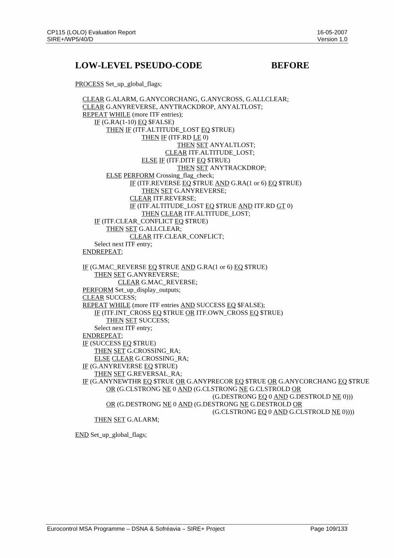
CP115 (LOLO) Evaluation Report 16-05-2007 SIRE+/WP5/40/D Version 1.0
Eurocontrol MSA Programme – DSNA & Sofréavia – SIRE+ Project Page 109/133
LOW-LEVEL PSEUDO-CODE BEFORE PROCESS Set_up_global_flags; CLEAR G.ALARM, G.ANYCORCHANG, G.ANYCROSS, G.ALLCLEAR; CLEAR G.ANYREVERSE, ANYTRACKDROP, ANYALTLOST; REPEAT WHILE (more ITF entries); IF (G.RA(1-10) EQ $FALSE) THEN IF (ITF.ALTITUDE_LOST EQ $TRUE) THEN IF (ITF.RD LE 0) THEN SET ANYALTLOST; CLEAR ITF.ALTITUDE_LOST; ELSE IF (ITF.DITF EQ $TRUE) THEN SET ANYTRACKDROP; ELSE PERFORM Crossing_flag_check; IF (ITF.REVERSE EQ $TRUE AND G.RA(1 or 6) EQ $TRUE) THEN SET G.ANYREVERSE; CLEAR ITF.REVERSE; IF (ITF.ALTITUDE_LOST EQ $TRUE AND ITF.RD GT 0) THEN CLEAR ITF.ALTITUDE_LOST; IF (ITF.CLEAR_CONFLICT EQ $TRUE) THEN SET G.ALLCLEAR; CLEAR ITF.CLEAR_CONFLICT; Select next ITF entry; ENDREPEAT; IF (G.MAC_REVERSE EQ $TRUE AND G.RA(1 or 6) EQ $TRUE) THEN SET G.ANYREVERSE; CLEAR G.MAC_REVERSE; PERFORM Set_up_display_outputs; CLEAR SUCCESS; REPEAT WHILE (more ITF entries AND SUCCESS EQ $FALSE); IF (ITF.INT_CROSS EQ $TRUE OR ITF.OWN_CROSS EQ $TRUE) THEN SET SUCCESS; Select next ITF entry; ENDREPEAT; IF (SUCCESS EQ $TRUE) THEN SET G.CROSSING_RA; ELSE CLEAR G.CROSSING_RA; IF (G.ANYREVERSE EQ $TRUE) THEN SET G.REVERSAL_RA; IF (G.ANYNEWTHR EQ $TRUE OR G.ANYPRECOR EQ $TRUE OR G.ANYCORCHANG EQ $TRUE OR (G.CLSTRONG NE 0 AND (G.CLSTRONG NE G.CLSTROLD OR (G.DESTRONG EQ 0 AND G.DESTROLD NE 0))) OR (G.DESTRONG NE 0 AND (G.DESTRONG NE G.DESTROLD OR (G.CLSTRONG EQ 0 AND G.CLSTROLD NE 0)))) THEN SET G.ALARM; END Set_up_global_flags;
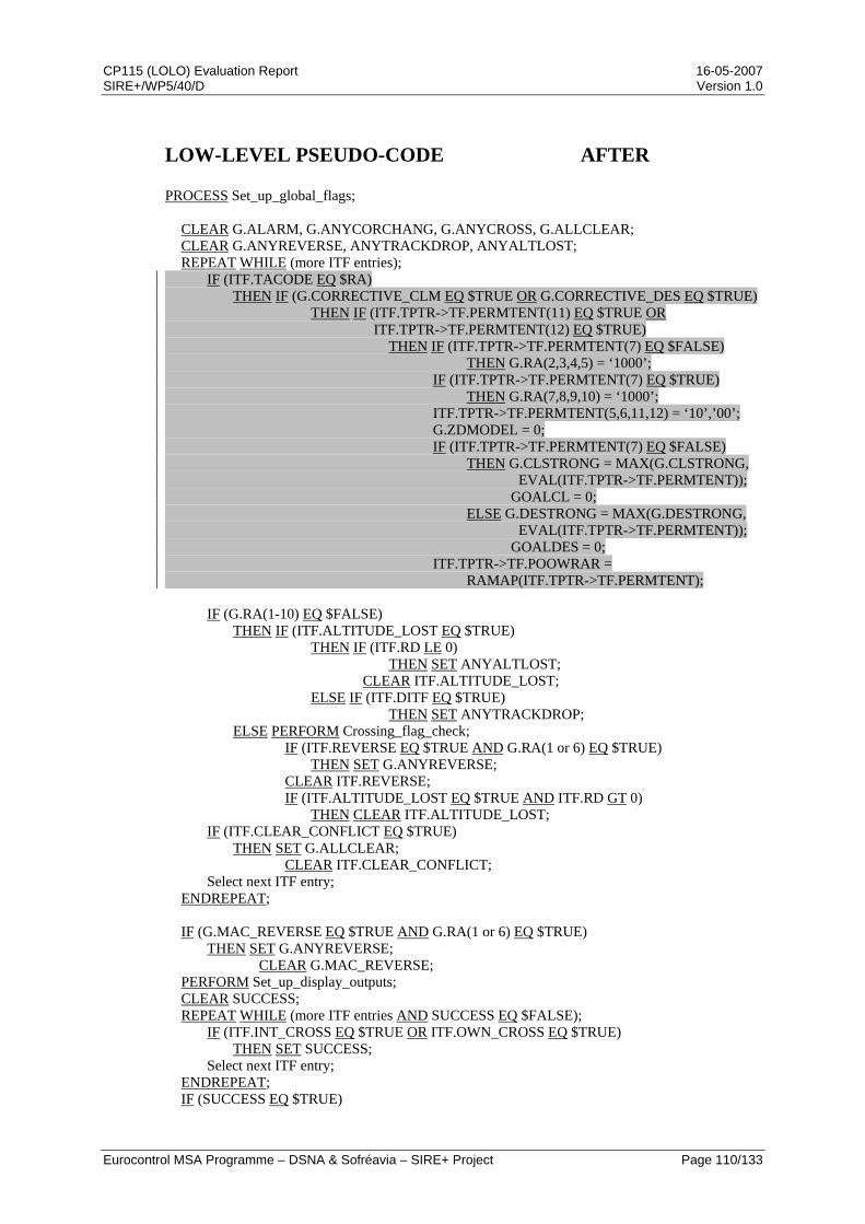
CP115 (LOLO) Evaluation Report 16-05-2007 SIRE+/WP5/40/D Version 1.0
Eurocontrol MSA Programme – DSNA & Sofréavia – SIRE+ Project Page 110/133
LOW-LEVEL PSEUDO-CODE AFTER PROCESS Set_up_global_flags; CLEAR G.ALARM, G.ANYCORCHANG, G.ANYCROSS, G.ALLCLEAR; CLEAR G.ANYREVERSE, ANYTRACKDROP, ANYALTLOST; REPEAT WHILE (more ITF entries); IF (ITF.TACODE EQ $RA) THEN IF (G.CORRECTIVE_CLM EQ $TRUE OR G.CORRECTIVE_DES EQ $TRUE) THEN IF (ITF.TPTR->TF.PERMTENT(11) EQ $TRUE OR ITF.TPTR->TF.PERMTENT(12) EQ $TRUE) THEN IF (ITF.TPTR->TF.PERMTENT(7) EQ $FALSE) THEN G.RA(2,3,4,5) = ‘1000’; IF (ITF.TPTR->TF.PERMTENT(7) EQ $TRUE) THEN G.RA(7,8,9,10) = ‘1000’; ITF.TPTR->TF.PERMTENT(5,6,11,12) = ‘10’,’00’; G.ZDMODEL = 0; IF (ITF.TPTR->TF.PERMTENT(7) EQ $FALSE) THEN G.CLSTRONG = MAX(G.CLSTRONG, EVAL(ITF.TPTR->TF.PERMTENT)); GOALCL = 0; ELSE G.DESTRONG = MAX(G.DESTRONG, EVAL(ITF.TPTR->TF.PERMTENT)); GOALDES = 0; ITF.TPTR->TF.POOWRAR = RAMAP(ITF.TPTR->TF.PERMTENT); IF (G.RA(1-10) EQ $FALSE) THEN IF (ITF.ALTITUDE_LOST EQ $TRUE) THEN IF (ITF.RD LE 0) THEN SET ANYALTLOST; CLEAR ITF.ALTITUDE_LOST; ELSE IF (ITF.DITF EQ $TRUE) THEN SET ANYTRACKDROP; ELSE PERFORM Crossing_flag_check; IF (ITF.REVERSE EQ $TRUE AND G.RA(1 or 6) EQ $TRUE) THEN SET G.ANYREVERSE; CLEAR ITF.REVERSE; IF (ITF.ALTITUDE_LOST EQ $TRUE AND ITF.RD GT 0) THEN CLEAR ITF.ALTITUDE_LOST; IF (ITF.CLEAR_CONFLICT EQ $TRUE) THEN SET G.ALLCLEAR; CLEAR ITF.CLEAR_CONFLICT; Select next ITF entry; ENDREPEAT; IF (G.MAC_REVERSE EQ $TRUE AND G.RA(1 or 6) EQ $TRUE) THEN SET G.ANYREVERSE; CLEAR G.MAC_REVERSE; PERFORM Set_up_display_outputs; CLEAR SUCCESS; REPEAT WHILE (more ITF entries AND SUCCESS EQ $FALSE); IF (ITF.INT_CROSS EQ $TRUE OR ITF.OWN_CROSS EQ $TRUE) THEN SET SUCCESS; Select next ITF entry; ENDREPEAT; IF (SUCCESS EQ $TRUE)
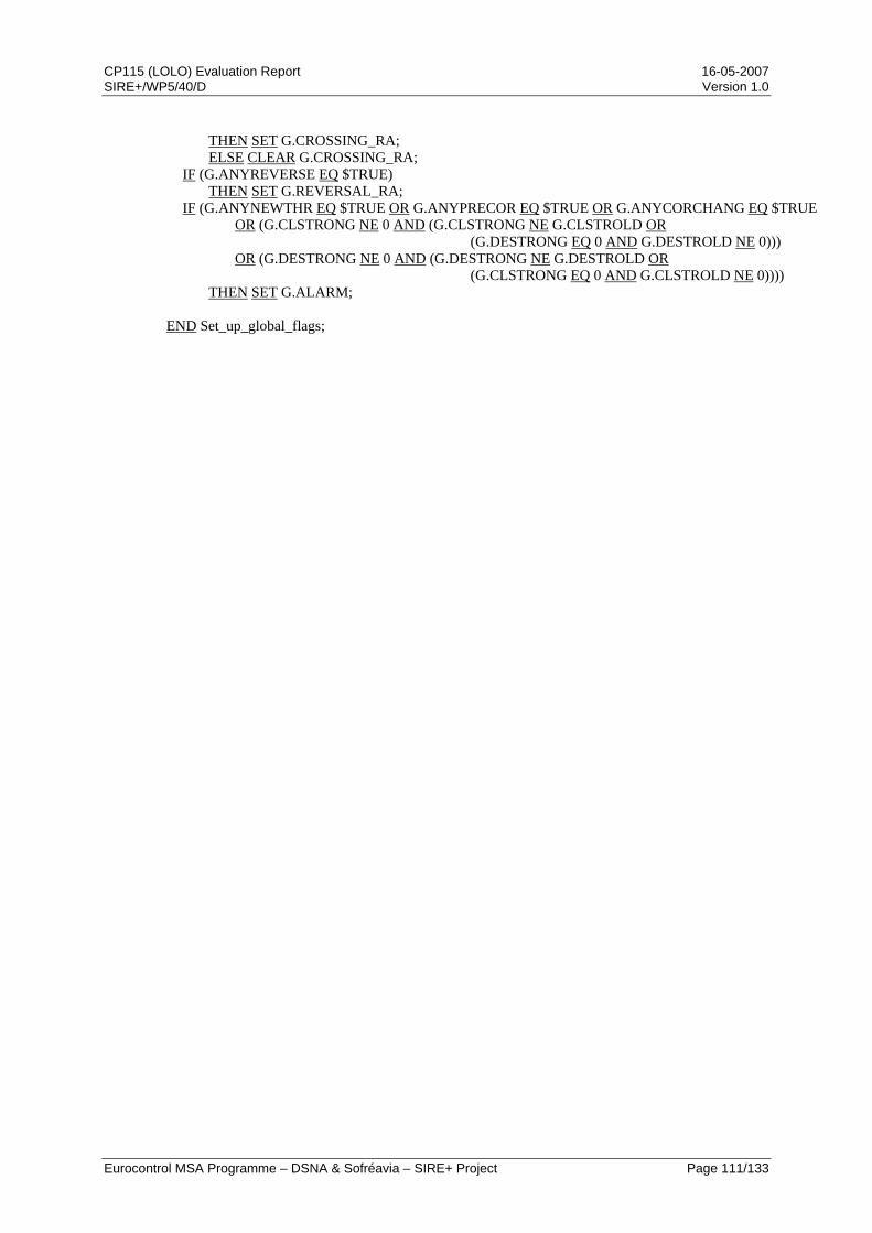
CP115 (LOLO) Evaluation Report 16-05-2007 SIRE+/WP5/40/D Version 1.0
Eurocontrol MSA Programme – DSNA & Sofréavia – SIRE+ Project Page 111/133
THEN SET G.CROSSING_RA; ELSE CLEAR G.CROSSING_RA; IF (G.ANYREVERSE EQ $TRUE) THEN SET G.REVERSAL_RA; IF (G.ANYNEWTHR EQ $TRUE OR G.ANYPRECOR EQ $TRUE OR G.ANYCORCHANG EQ $TRUE OR (G.CLSTRONG NE 0 AND (G.CLSTRONG NE G.CLSTROLD OR (G.DESTRONG EQ 0 AND G.DESTROLD NE 0))) OR (G.DESTRONG NE 0 AND (G.DESTRONG NE G.DESTROLD OR (G.CLSTRONG EQ 0 AND G.CLSTROLD NE 0)))) THEN SET G.ALARM; END Set_up_global_flags;
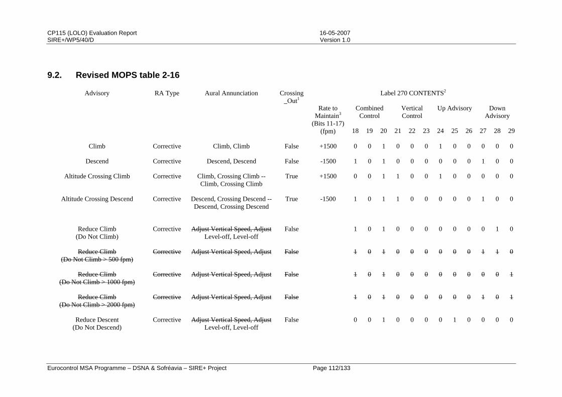
CP115 (LOLO) Evaluation Report 16-05-2007 SIRE+/WP5/40/D Version 1.0
Eurocontrol MSA Programme – DSNA & Sofréavia – SIRE+ Project Page 112/133
9.2. Revised MOPS table 2-16
Label 270 CONTENTS2
Combined Control
Vertical Control
Up Advisory Down Advisory
Advisory RA Type Aural Annunciation Crossing_Out1
Rate to Maintain3
(Bits 11-17) (fpm) 18 19 20 21 22 23 24 25 26 27 28 29
Climb Corrective Climb, Climb False +1500 0 0 1 0 0 0 1 0 0 0 0 0
Descend Corrective Descend, Descend False -1500 1 0 1 0 0 0 0 0 0 1 0 0
Altitude Crossing Climb Corrective Climb, Crossing Climb -- Climb, Crossing Climb
True +1500 0 0 1 1 0 0 1 0 0 0 0 0
Altitude Crossing Descend Corrective Descend, Crossing Descend --Descend, Crossing Descend
True
-1500 1 0 1 1 0 0 0 0 0 1 0 0
Reduce Climb (Do Not Climb)
Corrective Adjust Vertical Speed, AdjustLevel-off, Level-off
False 1 0 1 0 0 0 0 0 0 0 1 0
Reduce Climb (Do Not Climb > 500 fpm)
Corrective Adjust Vertical Speed, Adjust False 1 0 1 0 0 0 0 0 0 1 1 0
Reduce Climb (Do Not Climb > 1000 fpm)
Corrective Adjust Vertical Speed, Adjust False 1 0 1 0 0 0 0 0 0 0 0 1
Reduce Climb (Do Not Climb > 2000 fpm)
Corrective Adjust Vertical Speed, Adjust False 1 0 1 0 0 0 0 0 0 1 0 1
Reduce Descent (Do Not Descend)
Corrective Adjust Vertical Speed, AdjustLevel-off, Level-off
False 0 0 1 0 0 0 0 1 0 0 0 0
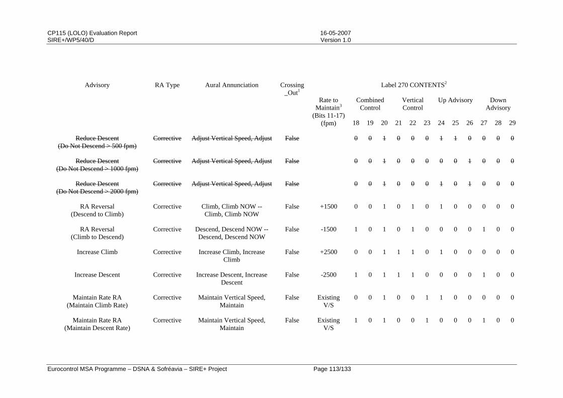
CP115 (LOLO) Evaluation Report 16-05-2007 SIRE+/WP5/40/D Version 1.0
Eurocontrol MSA Programme – DSNA & Sofréavia – SIRE+ Project Page 113/133
Label 270 CONTENTS2
Combined Control
Vertical Control
Up Advisory Down Advisory
Advisory RA Type Aural Annunciation Crossing_Out1
Rate to Maintain3
(Bits 11-17) (fpm) 18 19 20 21 22 23 24 25 26 27 28 29
Reduce Descent (Do Not Descend > 500 fpm)
Corrective Adjust Vertical Speed, Adjust False 0 0 1 0 0 0 1 1 0 0 0 0
Reduce Descent (Do Not Descend > 1000 fpm)
Corrective Adjust Vertical Speed, Adjust False 0 0 1 0 0 0 0 0 1 0 0 0
Reduce Descent (Do Not Descend > 2000 fpm)
Corrective Adjust Vertical Speed, Adjust False 0 0 1 0 0 0 1 0 1 0 0 0
RA Reversal (Descend to Climb)
Corrective Climb, Climb NOW -- Climb, Climb NOW
False +1500 0 0 1 0 1 0 1 0 0 0 0 0
RA Reversal (Climb to Descend)
Corrective Descend, Descend NOW -- Descend, Descend NOW
False -1500 1 0 1 0 1 0 0 0 0 1 0 0
Increase Climb Corrective Increase Climb, Increase Climb
False +2500 0 0 1 1 1 0 1 0 0 0 0 0
Increase Descent Corrective Increase Descent, Increase Descent
False -2500 1 0 1 1 1 0 0 0 0 1 0 0
Maintain Rate RA (Maintain Climb Rate)
Corrective Maintain Vertical Speed, Maintain
False Existing V/S
0 0 1 0 0 1 1 0 0 0 0 0
Maintain Rate RA (Maintain Descent Rate)
Corrective Maintain Vertical Speed, Maintain
False Existing V/S
1 0 1 0 0 1 0 0 0 1 0 0
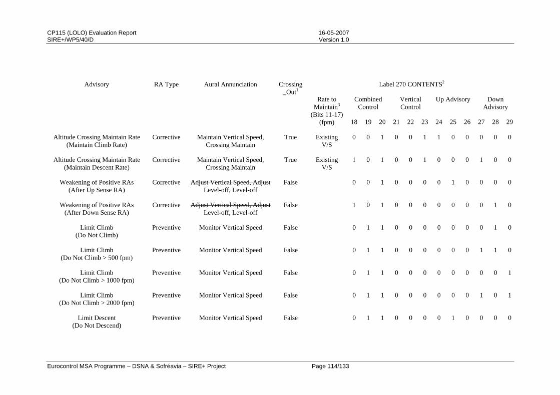
CP115 (LOLO) Evaluation Report 16-05-2007 SIRE+/WP5/40/D Version 1.0
Eurocontrol MSA Programme – DSNA & Sofréavia – SIRE+ Project Page 114/133
Label 270 CONTENTS2
Combined Control
Vertical Control
Up Advisory Down Advisory
Advisory RA Type Aural Annunciation Crossing_Out1
Rate to Maintain3
(Bits 11-17) (fpm) 18 19 20 21 22 23 24 25 26 27 28 29
Altitude Crossing Maintain Rate (Maintain Climb Rate)
Corrective Maintain Vertical Speed, Crossing Maintain
True Existing V/S
0 0 1 0 0 1 1 0 0 0 0 0
Altitude Crossing Maintain Rate (Maintain Descent Rate)
Corrective Maintain Vertical Speed, Crossing Maintain
True Existing V/S
1 0 1 0 0 1 0 0 0 1 0 0
Weakening of Positive RAs (After Up Sense RA)
Corrective Adjust Vertical Speed, AdjustLevel-off, Level-off
False 0 0 1 0 0 0 0 1 0 0 0 0
Weakening of Positive RAs (After Down Sense RA)
Corrective Adjust Vertical Speed, AdjustLevel-off, Level-off
False 1 0 1 0 0 0 0 0 0 0 1 0
Limit Climb (Do Not Climb)
Preventive Monitor Vertical Speed False 0 1 1 0 0 0 0 0 0 0 1 0
Limit Climb (Do Not Climb > 500 fpm)
Preventive Monitor Vertical Speed False 0 1 1 0 0 0 0 0 0 1 1 0
Limit Climb (Do Not Climb > 1000 fpm)
Preventive Monitor Vertical Speed False 0 1 1 0 0 0 0 0 0 0 0 1
Limit Climb (Do Not Climb > 2000 fpm)
Preventive Monitor Vertical Speed False 0 1 1 0 0 0 0 0 0 1 0 1
Limit Descent (Do Not Descend)
Preventive Monitor Vertical Speed False 0 1 1 0 0 0 0 1 0 0 0 0

CP115 (LOLO) Evaluation Report 16-05-2007 SIRE+/WP5/40/D Version 1.0
Eurocontrol MSA Programme – DSNA & Sofréavia – SIRE+ Project Page 115/133
Label 270 CONTENTS2
Combined Control
Vertical Control
Up Advisory Down Advisory
Advisory RA Type Aural Annunciation Crossing_Out1
Rate to Maintain3
(Bits 11-17) (fpm) 18 19 20 21 22 23 24 25 26 27 28 29
Limit Descent (Do Not Descend > 500 fpm)
Preventive Monitor Vertical Speed False 0 1 1 0 0 0 1 1 0 0 0 0
Limit Descent (Do Not Descend > 1000 fpm)
Preventive Monitor Vertical Speed False 0 1 1 0 0 0 0 0 1 0 0 0
Limit Descent (Do Not Descend > 2000 fpm)
Preventive Monitor Vertical Speed False 0 1 1 0 0 0 1 0 1 0 0 0
Multi-Aircraft Encounter4,7 (Maintain Existing V/S)
Preventive Maintain Vertical Speed, Maintain
See Note 7
0 1 1 0 0 1 0 1 0 0 1 0
Multi-Aircraft Encounter5 (Issued While Climbing)
Corrective Adjust Vertical Speed, AdjustLevel-off, Level-off
False 1 0 1 0 0 0 0 1 0 0 1 0
Multi-Aircraft Encounter5 (Issued While Descending)
Corrective Adjust Vertical Speed, AdjustLevel-off, Level-off
False 0 0 1 0 0 0 0 1 0 0 1 0
Multi-Aircraft Encounter6 Preventive Monitor Vertical Speed False 0 1 1 0 0 0
Clear of Conflict Clear of Conflict False 1 0 0 0 0 0 0 0 0 0 0 0
1This flag is set for any positive, altitude crossing RA, bur is only used to indicate when the aural annunciation “Maintain Vertical Speed, Crossing Maintain” is to be annunciated. This flag is set by the CAS logic.
2The relationship between the content of ARINC Label 270 and the CRS Variables and their expected values are shown below:
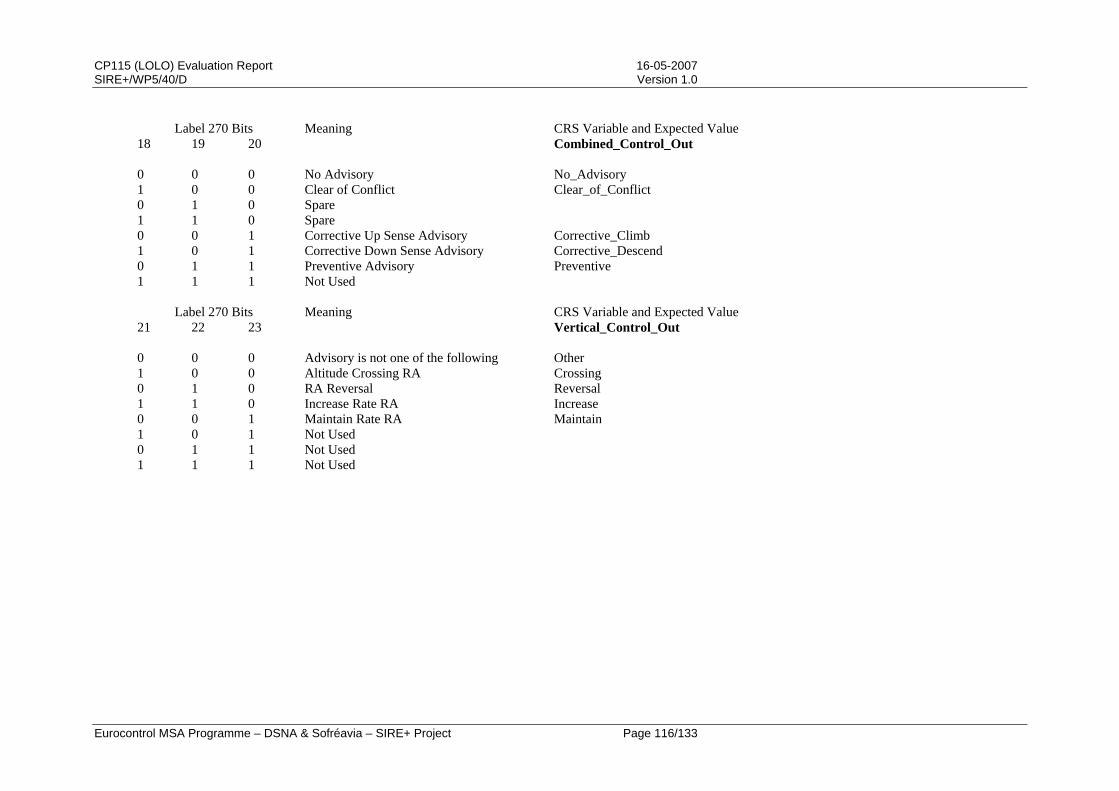
CP115 (LOLO) Evaluation Report 16-05-2007 SIRE+/WP5/40/D Version 1.0
Eurocontrol MSA Programme – DSNA & Sofréavia – SIRE+ Project Page 116/133
Label 270 Bits 18 19 20
Meaning CRS Variable and Expected Value Combined_Control_Out
0 0 0 No Advisory No_Advisory 1 0 0 Clear of Conflict Clear_of_Conflict 0 1 0 Spare 1 1 0 Spare 0 0 1 Corrective Up Sense Advisory Corrective_Climb 1 0 1 Corrective Down Sense Advisory Corrective_Descend 0 1 1 Preventive Advisory Preventive 1 1 1 Not Used
Label 270 Bits 21 22 23
Meaning CRS Variable and Expected Value Vertical_Control_Out
0 0 0 Advisory is not one of the following Other 1 0 0 Altitude Crossing RA Crossing 0 1 0 RA Reversal Reversal 1 1 0 Increase Rate RA Increase 0 0 1 Maintain Rate RA Maintain 1 0 1 Not Used 0 1 1 Not Used 1 1 1 Not Used
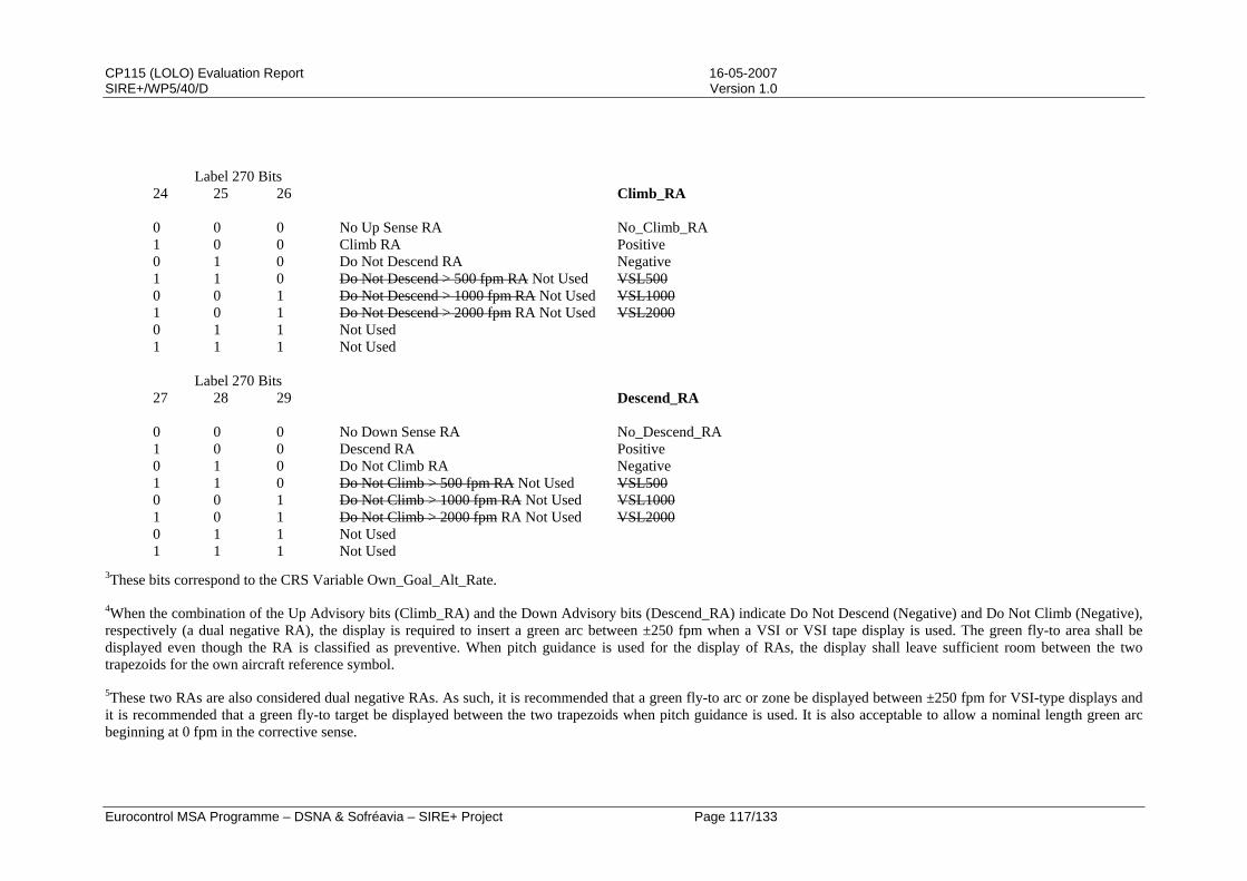
CP115 (LOLO) Evaluation Report 16-05-2007 SIRE+/WP5/40/D Version 1.0
Eurocontrol MSA Programme – DSNA & Sofréavia – SIRE+ Project Page 117/133
Label 270 Bits
24 25 26
Climb_RA 0 0 0 No Up Sense RA No_Climb_RA 1 0 0 Climb RA Positive 0 1 0 Do Not Descend RA Negative 1 1 0 Do Not Descend > 500 fpm RA Not Used VSL5000 0 1 Do Not Descend > 1000 fpm RA Not Used VSL10001 0 1 Do Not Descend > 2000 fpm RA Not Used VSL20000 1 1 Not Used 1 1 1 Not Used
Label 270 Bits 27 28 29
Descend_RA
0 0 0 No Down Sense RA No_Descend_RA 1 0 0 Descend RA Positive 0 1 0 Do Not Climb RA Negative 1 1 0 Do Not Climb > 500 fpm RA Not Used VSL5000 0 1 Do Not Climb > 1000 fpm RA Not Used VSL10001 0 1 Do Not Climb > 2000 fpm RA Not Used VSL20000 1 1 Not Used 1 1 1 Not Used
3These bits correspond to the CRS Variable Own_Goal_Alt_Rate.
4When the combination of the Up Advisory bits (Climb_RA) and the Down Advisory bits (Descend_RA) indicate Do Not Descend (Negative) and Do Not Climb (Negative), respectively (a dual negative RA), the display is required to insert a green arc between ±250 fpm when a VSI or VSI tape display is used. The green fly-to area shall be displayed even though the RA is classified as preventive. When pitch guidance is used for the display of RAs, the display shall leave sufficient room between the two trapezoids for the own aircraft reference symbol.
5These two RAs are also considered dual negative RAs. As such, it is recommended that a green fly-to arc or zone be displayed between ±250 fpm for VSI-type displays and it is recommended that a green fly-to target be displayed between the two trapezoids when pitch guidance is used. It is also acceptable to allow a nominal length green arc beginning at 0 fpm in the corrective sense.

CP115 (LOLO) Evaluation Report 16-05-2007 SIRE+/WP5/40/D Version 1.0
Eurocontrol MSA Programme – DSNA & Sofréavia – SIRE+ Project Page 118/133
6Any combination of the Up Advisory bits (Climb_RA) and the Down Advisory bits (Descend_RA) cans be set for a multi-aircraft encounter which is an initial preventive RA. This gives a total of 16 possible composite RAs that can be displayed in a multi-aircraft encounter which requires only initial preventive RAs.
7In a multi-aircraft encounter, Crossing_Out may be either True or False depending on the encounter geometry. If the maintain rate RA requires the TCAS aircraft to cross through the intruder aircraft’s altitude, Crossing_Out is set true and the aural annunciation will be “Maintain Vertical Speed, Crossing Maintain”. If the TCAS aircraft will not cross the intruder’s altitude, Crossing_Out will be set to False and the aural annunciation will be “Maintain Vertical Speed, Maintain”.
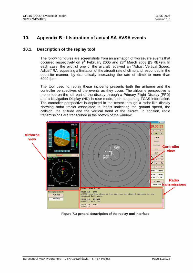
CP115 (LOLO) Evaluation Report 16-05-2007 SIRE+/WP5/40/D Version 1.0
Eurocontrol MSA Programme – DSNA & Sofréavia – SIRE+ Project Page 119/133
10. Appendix B : Illsutration of actual SA-AVSA events
10.1. Description of the replay tool
The following figures are screenshots from an animation of two severe events that occurred respectively on 9th February 2005 and 23rd March 2003 ([SIRE+9]). In each case, the pilot of one of the aircraft received an “Adjust Vertical Speed, Adjust” RA requesting a limitation of the aircraft rate of climb and responded in the opposite manner, by dramatically increasing the rate of climb to more than 6000 fpm.
The tool used to replay these incidents presents both the airborne and the controller perspectives of the events as they occur. The airborne perspective is presented on the left part of the display through a Primary Flight Display (PFD) and a Navigation Display (ND) in rose mode, both supporting TCAS information. The controller perspective is depicted in the centre through a radar-like display showing radar tracks associated to labels indicating the ground speed, the callsign, the altitude and the vertical trend of the aircraft. In addition, radio transmissions are transcribed in the bottom of the window.
Figure 71: general description of the replay tool interface
Radio transmissions
Controller view
Airborne view

CP115 (LOLO) Evaluation Report 16-05-2007 SIRE+/WP5/40/D Version 1.0
Eurocontrol MSA Programme – DSNA & Sofréavia – SIRE+ Project Page 120/133
10.2. 9th February 2005 event
The event described in this section involves an A320 (with the AVSA01 callsign) climbing towards FL260 and a twin jet (with the AVSA02 callsign), initially flying level at FL290 and then cleared to descend to FL270. The controller had thus planned a 1000 ft level-off, which is a very common manoeuvre to separate conflicting aircraft.
Because of the high vertical convergence rate, the TCAS units onboard both aircraft issued coordinated AVSA RAs: a Don’t Descend more than 1000 fpm for AVSA02 and a Don’t Climb more than 500 fpm for the AVSA01. These RAs are issued a few seconds after an STCA alert has been triggered on the controller’s screen. The following figure shows the situation at the time of the RA onboard AVSA01 and on the controller’s radar screen.
Figure 72: 09 Feb 2005 event - situation at time of the RA

CP115 (LOLO) Evaluation Report 16-05-2007 SIRE+/WP5/40/D Version 1.0
Eurocontrol MSA Programme – DSNA & Sofréavia – SIRE+ Project Page 121/133
The AVSA01 pilot has responded to his AVSA RA by dramatically increasing his rate of climb to about 6000 fpm, instead of reducing it to 1000 fpm. In his mind, he is following a climb sense RA, as indicated by his incorrect report to the controller. A few seconds earlier, the controller has also been reported a climb sense RA by the AVSA02 report. This situation is depicted in the screenshot below, taken at the time AVSA01 reaches its highest vertical speed in the event and when the aircraft are about 700 ft apart.
Figure 73: 09 Feb 2005 event - opposite response to the RA

CP115 (LOLO) Evaluation Report 16-05-2007 SIRE+/WP5/40/D Version 1.0
Eurocontrol MSA Programme – DSNA & Sofréavia – SIRE+ Project Page 122/133
Because of the opposite reaction of the AVSA01 pilot, the initial AVSA RA has been strengthened to first a Descend RA and then an Increase Descent RA, which the pilot follows. Because of the high vertical speed he has previously reached, he is still climbing with a 2000 fpm rate when the aircraft reach their closest point of approach, as indicated in the screenshot below. At this time, the aircraft are at co-altitude and less than 2 NM apart.
Figure 74: 09 Feb 2005 event - closest point of approach
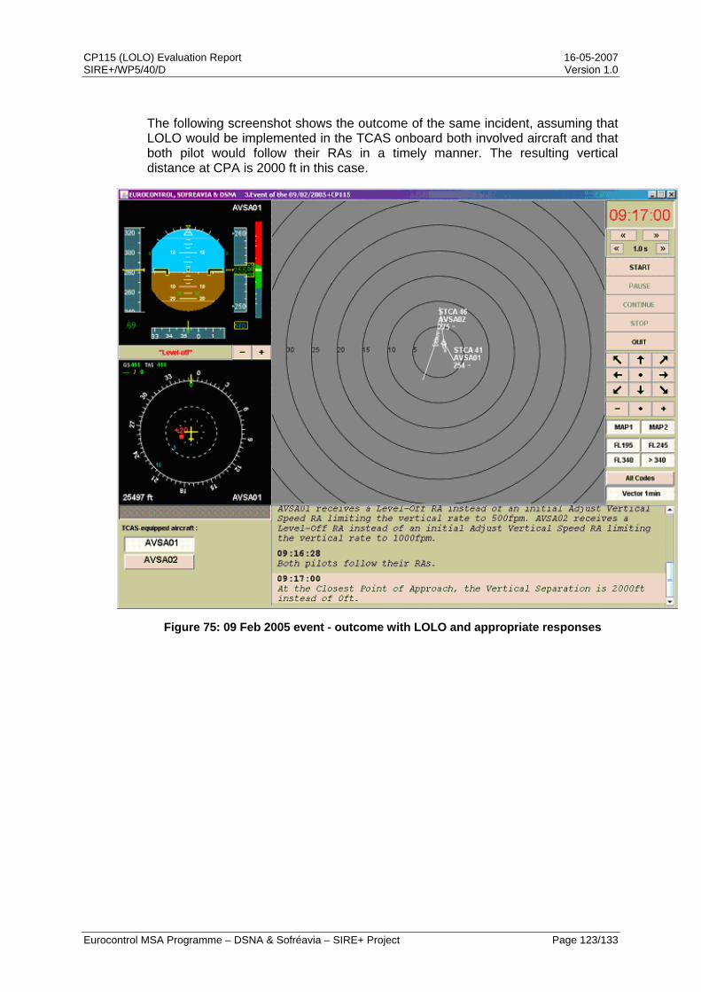
CP115 (LOLO) Evaluation Report 16-05-2007 SIRE+/WP5/40/D Version 1.0
Eurocontrol MSA Programme – DSNA & Sofréavia – SIRE+ Project Page 123/133
The following screenshot shows the outcome of the same incident, assuming that LOLO would be implemented in the TCAS onboard both involved aircraft and that both pilot would follow their RAs in a timely manner. The resulting vertical distance at CPA is 2000 ft in this case.
Figure 75: 09 Feb 2005 event - outcome with LOLO and appropriate responses

CP115 (LOLO) Evaluation Report 16-05-2007 SIRE+/WP5/40/D Version 1.0
Eurocontrol MSA Programme – DSNA & Sofréavia – SIRE+ Project Page 124/133
10.3. 23rd March 2003 event
The event described in this section involves an A319 (with the AVSA01 callsign), level at FL270 and an A320 (with the AVSA02 callsign) climbing towards FL260. The controller had thus planned a 1000 ft level-off, which is a very common manoeuvre to separate conflicting aircraft.
Because of the high vertical convergence rate, the TCAS unit onboard AVSA02 issued an AVSA RA requesting the pilot to limit the aircraft rate of climb to 1000 fpm. This RA is issued a few seconds after an STCA alert has been triggered on the controller’s screen. AVSA01 receives a Climb RA a few seconds after the AVSA RA is triggered onboard AVSA02. The following figure shows the situation at the time of the RA onboard AVSA02 and on the controller’s radar screen.
Figure 76: 23 Mar 2003 event - situation at time of the RA

CP115 (LOLO) Evaluation Report 16-05-2007 SIRE+/WP5/40/D Version 1.0
Eurocontrol MSA Programme – DSNA & Sofréavia – SIRE+ Project Page 125/133
The AVSA02 pilot has responded to his AVSA RA by dramatically increasing his rate of climb to about 6000 fpm, instead of reducing it to 1000 fpm. In his mind, he is following a climb sense RA, as indicated by his incorrect report to the controller. This situation is depicted in the screenshot below, taken at the time AVSA02 reaches its highest vertical speed in the event and when the aircraft are about 600 ft apart
Figure 77: 23 Mar 2003 event - opposite response to the RA

CP115 (LOLO) Evaluation Report 16-05-2007 SIRE+/WP5/40/D Version 1.0
Eurocontrol MSA Programme – DSNA & Sofréavia – SIRE+ Project Page 126/133
Because of the opposite reaction of the AVSA02 pilot, the initial AVSA RA has been strengthened to first a Descend RA, which the pilot follows. The pilot has also initiated an emergency left turn. At the time the aircraft reach their closest point of approach, as indicated in the screenshot below, they are 300 ft and less than 1 NM apart.
Figure 78: 23 Mar 2003 event - closest point of approach

CP115 (LOLO) Evaluation Report 16-05-2007 SIRE+/WP5/40/D Version 1.0
Eurocontrol MSA Programme – DSNA & Sofréavia – SIRE+ Project Page 127/133
The following screenshot shows the outcome of the same incident, assuming that LOLO would be implemented in the TCAS onboard both involved aircraft and that both pilot would follow their RAs in a timely manner. The resulting vertical distance at CPA is 1300 ft in this case.
Figure 79: 23 Mar 2003 event - outcome with LOLO and appropriate responses

CP115 (LOLO) Evaluation Report 16-05-2007 SIRE+/WP5/40/D Version 1.0
Eurocontrol MSA Programme – DSNA & Sofréavia – SIRE+ Project Page 128/133
THIS PAGE INTENTIONALLY LEFT BLANK
CP115 (LOLO) Evaluation Report 16-05-2007 SIRE+/WP5/40/D Version 1.0
Eurocontrol MSA Programme – DSNA & Sofréavia – SIRE+ Project Page 129/133
11. Appendix C: General description of OSCAR displays
The OSCAR test bench is a set of integrated tools to prepare, execute and analyse scenarios of encounters involving TCAS II equipped aircraft. It includes an implementation of the TCAS II version 7.0.
For each encounter, the most relevant results of the TCAS II simulations are provided by screen dumps of OSCAR windows. Several types of information are displayed:
Horizontal trajectories (X,Y) of the aircraft
involved in the encounter, beginning at ‘O’
Altitude function of the time (alt = f(t)), correlation
with the horizontal trajectories through the
markers on the trajectories
Information on a point of a trajectory selected by
the operator Information on a pair
of aircraft selected by the operator
CPA
Selected timeRA on - board the selected aircraft
ACAS status of the intruders for the selected aircraft
Selected aircraft
Figure 80: OSCAR display
CP115 (LOLO) Evaluation Report 16-05-2007 SIRE+/WP5/40/D Version 1.0
Eurocontrol MSA Programme – DSNA & Sofréavia – SIRE+ Project Page 130/133
TCAS II simulation results are displayed on the horizontal and vertical trajectories. RAs are displayed on the trajectory of the selected aircraft and ACAS status of the intruders on their respective trajectories, according to the symbols and labels described hereafter:
Figure 81: OSCAR symbols
Label Advisory CoC Clear of Conflict Cl Climb (1500 fpm)
DDes Don’t Descend LD5 / LD1 / LD2 Limit Descent 500 / 1000 / 2000 fpm
Des Descend (1500 fpm) DCl Don’t Climb
LC5 / LC1 / LC2 Limit Climb 500 / 1000 / 2000 fpm CCl Crossing Climb (1500 fpm) RCl Reverse Climb (1500 fpm) ICl Increase Climb (2500 fpm)
MCl Maintain Climb CDes Crossing Descend (-1500 fpm) RDes Reverse Descent (-1500 fpm) IDes Increase Descent (-2500 fpm) MDes Maintain Descent
Table 10: OSCAR labels
CP115 (LOLO) Evaluation Report 16-05-2007 SIRE+/WP5/40/D Version 1.0
Eurocontrol MSA Programme – DSNA & Sofréavia – SIRE+ Project Page 131/133
12. Acronyms
ACAS Airborne Collision Avoidance System
ACASA ACAS Analysis
AEA Association of European Airlines
AEM Altimetry Error Model
AP AutoPilot
ASARP ACAS Safety Analysis post-RVSM Project
ATC Air Traffic Control
ATCO Air Traffic COntroller
ATM Air Traffic Management
AVSA Adjust Vertical Speed, Adjust
CAS Collision Avoidance System
CFL Cleared Flight Level
CoC Clear of Conflict
CP Change Proposal
CPA Closest Point of Approach
CWP Controller Working Position
DSNA Direction des Services de la Navigation Aérienne
EASA European Aviation Safety Agency
ECAC European Civil Aviation Conference
EMOTION-7 European Maintenance Of TCAS versION 7
EUROCAE European Organisation for Civil Aviation Equipment
EUROCONTROL European Organisation for the Safety of Air Navigation
FD Flight Director
FDM Flight Data Management
FL Flight Level
HF Human Factors

CP115 (LOLO) Evaluation Report 16-05-2007 SIRE+/WP5/40/D Version 1.0
Eurocontrol MSA Programme – DSNA & Sofréavia – SIRE+ Project Page 132/133
ICAO International Civil Aviation Organization
IVSI Instantaneous Vertical Speed Indicator
LOLO Level-Off, Level-Off
LORA Level-Off RA
MASPS Minimum Aviation System Performance Specification
MOPS Minimum Operational Performance Standards
MTOM Maximum Take-Off Mass
NM Nautical Mile
NMAC Near Mid-Air Collision
OSCAR Off-line Simulator for Collision Avoidance Resolution
OWG Operations Working Group
PF Pilot Flying
PFD Primary Flight Display
PNF Pilot Not Flying
RA Resolution Advisory
RTS Real-Time Simulation
RWG Requirements Working Group
SA01 SAfety issue 01
SA-AVSA SAfety issue AVSA
SARPs Standards And Recommended Practices
SC147 Special Committee 147
SIR Safety Issue Rectification
SIRE Safety Issue Rectification Extension
SOFREAVIA Société Française d’Etudes et Réalisations d’Equipements Aéronautiques (a groupe EGIS company)
TCAS Traffic alert and Collision Avoidance System
TMA Terminal Control Area
VFR Visual Flight Rules
V/S Vertical Speed
CP115 (LOLO) Evaluation Report 16-05-2007 SIRE+/WP5/40/D Version 1.0
Eurocontrol MSA Programme – DSNA & Sofréavia – SIRE+ Project Page 133/133
VMD Vertical Miss Distance
VSI Vertical Speed Indicator
VSL Vertical Speed Limit
WP Work Package
*** END OF DOCUMENT ***
Related Documents