CP 150 12-lead resting electrocardiograph Service manual

Welcome message from author
This document is posted to help you gain knowledge. Please leave a comment to let me know what you think about it! Share it to your friends and learn new things together.
Transcript

CP 150 12-lead restingelectrocardiograph
Service manual

© 2013 Welch Allyn. All rights are reserved. To support the intended use of the product described in thispublication, the purchaser of the product is permitted to copy this publication, for internal distributiononly, from the media provided by Welch Allyn. No other use, reproduction, or distribution of thispublication, or any part of it, is permitted without written permission from Welch Allyn. Welch Allynassumes no responsibility for any injury to anyone, or for any illegal or improper use of the product, thatmay result from failure to use this product in accordance with the instructions, cautions, warnings, orstatement of intended use published in this manual.
Welch Allyn is a registered trademark of Welch Allyn.
Software in this product is copyright 2013 Welch Allyn. All rights are reserved. The software is protectedby United States of America copyright laws and international treaty provisions applicable worldwide.Under such laws, the licensee is entitled to use the copy of the software incorporated with thisinstrument as intended in the operation of the product in which it is embedded. The software may not becopied, decompiled, reverse-engineered, disassembled, or otherwise reduced to human-perceivableform. This is not a sale of the software or any copy of the software; all right, title, and ownership of thesoftware remain with Welch Allyn.
Welch Allyn Technical Support:
http://www.welchallyn.com/about/company/locations.htm
105323 (printed copy)
Material Number 719489
DIR 80018104 Ver. B
Welch Allyn, Inc.4341 State Street RoadSkaneateles Falls, NY 13153-0220 USA
www.welchallyn.com

Contents
Symbols ................................................................................................... 1
Safety ....................................................................................................... 5General warnings ................................................................................................. 5General cautions .................................................................................................. 7General safety considerations .............................................................................. 8Electrostatic discharge (ESD) ............................................................................... 9
Overview ................................................................................................ 11Purpose and scope ............................................................................................ 11Technical support services ................................................................................. 11Service loaners ................................................................................................... 12Service options .................................................................................................. 12Repairs ............................................................................................................... 13Configuration options ......................................................................................... 14The Welch Allyn Service Tool ............................................................................ 15Returning products ............................................................................................ 15
Service menu ......................................................................................... 19Access the Service screen ................................................................................. 19Performing the full-functional tests .................................................................... 19Manage tests and other files ............................................................................. 27
Troubleshooting .................................................................................... 29Symptoms and solutions ................................................................................... 29Printer ................................................................................................................ 31User interface .................................................................................................... 33Post test error messages ................................................................................... 35
Disassembly, repair, and reassembly .................................................. 37Required tools and equipment ........................................................................... 38Power down the electrocardiograph .................................................................. 40Remove the battery ........................................................................................... 40Separate the top housing assembly from the bottom housing assembly ......... 41
Electrical safety testing ......................................................................... 69
Software updates process .................................................................... 71Update process .................................................................................................. 71Export and import of the device configuration ................................................... 72
iii

Field replaceable units .......................................................................... 75Housing top assembly ...................................................................................... 75Housing base assembly ..................................................................................... 79Printer 8 inch assembly tray ............................................................................... 82Bottom assembly ............................................................................................... 86Partners in Care service and support agreements ............................................. 89Service and repair training .................................................................................. 89
Appendices ............................................................................................ 91Decontamination and cleaning requirements .................................................... 91Interconnect diagram ......................................................................................... 92
iv Contents CP 150 12-lead resting electrocardiograph

Symbols
Documentation symbolsWARNING The warning statements inthis manual identify conditions orpractices that could lead to illness, injury,or death.
Caution The caution statements in thismanual identify conditions or practicesthat could result in damage to theequipment or other property, or loss ofdata. This definition applies to bothyellow and black and white symbols.
Consult operating instructions.
Power symbolsPower on/standby
(LED off) No AC power is present The battery is absent or faulty
(LED green) AC power is present, andbattery is charged. (LED amber) AC poweris present, and battery is charging.
The battery is charged to the indicatedlevel
Alternating current Battery is charging
Dangerous voltage Battery door
Fuse Rechargeable battery
1

Protective earth Nonionizing electromagnetic radiation
Equipotential terminal AC input power
Connectivity symbolsUSB Ethernet (RJ-45 )
Shipping, storing, and environment symbolsThis end up Keep dry
Fragile Relative humidity limit
Temperature limits Atmospheric air-pressure limits
Separate the battery from otherdisposables for recycling
Recycle
Separate the device from otherdisposables for recycling.
See www.welchallyn.com/weee.
China RoHS (restriction of hazardoussubstances) symbols for control ofpollution caused by electronicinformation products. 5-yearenvironment-friendly use period (EFUP)for batteries. 10-year EFUP for the device.For details, see the accompanyingdocumentation.
Lithium ion battery
2 Symbols CP 150 12-lead resting electrocardiograph
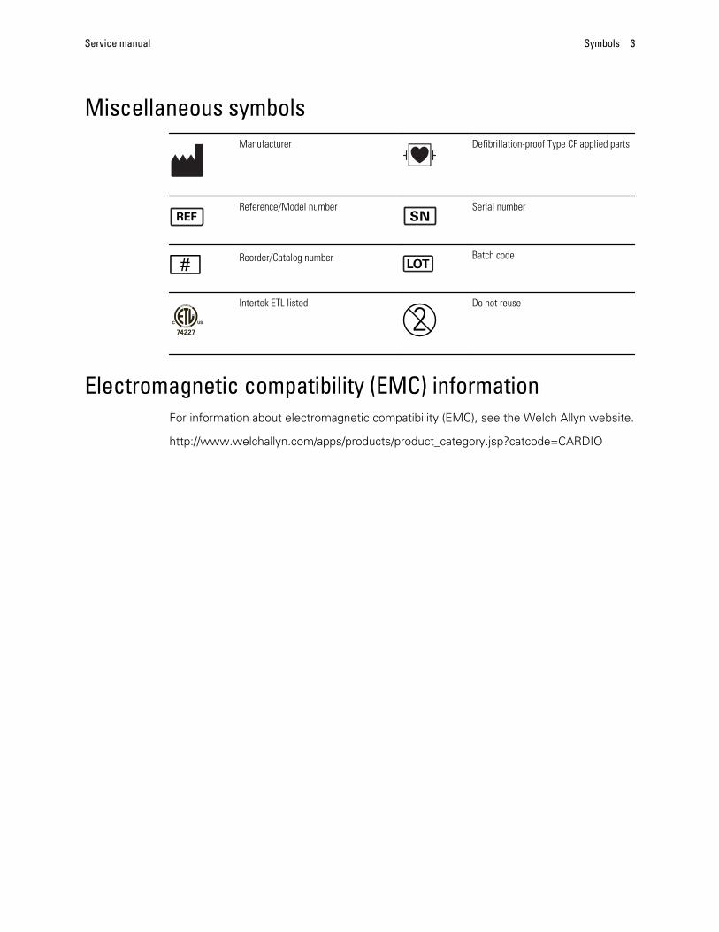
Miscellaneous symbolsManufacturer Defibrillation-proof Type CF applied parts
Reference/Model number Serial number
Reorder/Catalog number Batch code
Intertek ETL listed Do not reuse
Electromagnetic compatibility (EMC) informationFor information about electromagnetic compatibility (EMC), see the Welch Allyn website.
http://www.welchallyn.com/apps/products/product_category.jsp?catcode=CARDIO
Service manual Symbols 3

4 Symbols CP 150 12-lead resting electrocardiograph

Safety
All users of the device must read and understand all safety information presented in thismanual before using or repairing the device.
United States federal law restricts this device to sale, distribution, or use by or on theorder of a licensed medical practitioner.
General warningsWarnings indicate conditions or practices that could lead to illness, injury, or death.
Warnings related to the environment
WARNING The power cord is considered the disconnect device forisolating this equipment from supply mains. Do not position the equipmentso that it is difficult to reach or disconnect.
WARNING To avoid a possible explosion, do not use theelectrocardiograph in the presence of flammable anesthetics: mixturescontaining air, oxygen, or nitrous oxide.
WARNING When transporting the electrocardiograph on a cart, tuck thepatient cable away to keep them clear of the wheels and to minimize triphazards.
Warnings related to accessories and other equipment
WARNING To avoid the risk of electric shock, this equipment must onlybe connected to a supply mains with protective earth.
WARNING For operator and patient safety, peripheral equipment andaccessories that can come in direct patient contact must be in compliancewith all appropriate safety, EMC, and regulatory requirements.
WARNING All signal input and output (I/O) connectors are intended forconnection of only devices complying with IEC 60601-1, or other IECstandards (for example, IEC 60950), as appropriate to the device.Connecting additional devices to the electrocardiograph might increasechassis or patient leakage currents.
5

WARNING The electrocardiograph has not been designed for use withhigh-frequency (HF) surgical equipment and does not protect againsthazards to the patient.
WARNING Defective batteries can damage the electrocardiograph.Visually inspect the battery at least monthly, if the battery shows any signsof damage or cracking, it must be replaced immediately and only with abattery approved by Welch Allyn.
WARNING Improper disposal of batteries may create an explosion orcontamination hazard. Never dispose of batteries in refuse containers.Always recycle batteries according to local regulations.
WARNING All signal input and output (SIP/SOP) connectors should not becontacted by patient directly and indirectly through the user duringoperation.
Warnings related to using the electrocardiograph
WARNING No modification of this equipment is allowed.
WARNING This device captures and presents data reflecting a patient’sphysiological condition. When reviewed by a trained physician or clinician,this data can be useful in determining a diagnosis. However, the datashould not be used as a sole means for determining a patient’s diagnosis orprescribing treatment.
WARNING To provide CF protection use only accessories approved byWelch Allyn. Visit www.welchallyn.com. The use of any other accessoriescan result in inaccurate patient data, can damage the equipment, and canvoid your product warranty.
WARNING To avoid serious injury or death, take these precautions duringpatient defibrillation:
• Avoid contact with the electrocardiograph, patient cable, and patient.
• Verify that the patient leads are properly connected.
• Place defibrillator paddles properly in relation to electrodes.
• After defibrillation, pull each patient lead out of the patient cable and inspectthe tips for charring (black carbon marks). If there is any charring, the patientcable and individual leads must be replaced. If there is no charring, fullyreinsert the leads into the patient cable. (Charring can occur only if a lead isnot fully inserted into the patient cable before defibrillation.)
WARNING To prevent the spread of infection, take these precautions:
• Dispose of single-use components (for example, electrodes) after usingthem once.
• Regularly clean all components that come in contact with patients.
• Avoid ECG testing for patients with open, infectious sores.
WARNING Avoid positioning any leads or cables so that they could easilytrip someone or become wrapped around a patient’s neck.
6 Safety CP 150 12-lead resting electrocardiograph

WARNING To ensure safe use of the device, follow the documentedmaintenance procedures.
WARNING Only qualified service personnel should attempt to repair theelectrocardiograph. In case of a malfunction, call Technical Support.
WARNING Do not perform ST segment analysis on the ECG screendisplay, since these ECG representations are scaled. Make manualmeasurements of ECG intervals and magnitudes on printed ECG reportsonly.
WARNING To maintain diagnostic accuracy and to comply with IEC60601-02-51 and IEC 60601-02-25, do not scale (re size) when sending asaved ECG to an external printer.
WARNING To avoid injury, do not touch the print head immediately afterprinting. It might be hot.
General cautionsCautions indicate conditions or practices that could damage the equipment or otherproperty.
CAUTION When removing the electrocardiograph from storage, allow it tothermally stabilize to surrounding environmental conditions before using it.
CAUTION To prevent possible damage, do not use sharp or hard objectsto press the touch screen or the buttons. Only use fingertips.
CAUTION Do not expose the patient cable to strong ultraviolet radiation.
CAUTION Do not pull or stretch the patient cable. Doing so could result inmechanical or electrical failures. Form the patient cable into a loose loopbefore storing.
CAUTION Avoid positioning the patient cable where it might get pinched,stretched, or stepped on. Otherwise, measurements might no longer beaccurate, and repair might be necessary.
CAUTION Using the equipotential terminal for anything but groundingpurposes may contribute to damage of the device.
CAUTION Use only parts and accessories, including thermal paper, thatwere supplied with the device and available through Welch Allyn. The useof accessories other than those specified may result in degradedperformance or unsafe use of this device.
CAUTION Portable and mobile RF communications equipment can affectthe performance of the electrocardiograph.
CAUTION The electrocardiograph meets the Class A requirements of IEC60601-1-2 regarding incidental emission of radio frequency interference. Assuch it is suitable for use in commercial grade electrical environments. Ifthe electrocardiograph is used in residential grade electrical environmentsand you experience incidental interference with other equipment that usesradio frequency signals to operate, minimize the interference.
Service manual Safety 7

CAUTION Other medical equipment—including but not limited todefibrillators, ultrasound machines, pacemakers, and other stimulators—may be used simultaneously with the electrocardiograph. However, suchdevices may disturb the electrocardiograph signal.
CAUTION The power cord must be disconnected from AC power beforecleaning, maintaining, transporting, or servicing.
CAUTION The requirements of AAMI EC11, Section 3.2.7.2, Frequencyand Impulse Response, for an impulse triangle waveform may be impactedby up to 5 milliseconds of small amplitude dampened ringing immediatelyafter the impulse when the muscle filter (35 Hz) is turned on or a smallamplitude offset when the baseline filter (0.5 Hz) is turned on. These filters,in any combination turned on or off, meet the AAMI requirements.Measurements performed by the optional interpretation algorithm areunaffected by any filter selections.
Note The entire patient cable, up to and including the electrodes are consideredto be an Applied Part.
General safety considerations
• To ensure patient safety, use only accessories recommended or supplied by WelchAllyn. Always use accessories according to your facility’s standards and according tothe manufacturer’s recommendations and instructions. Always follow themanufacturer’s directions for use.
• Welch Allyn recommends that only Welch Allyn service personnel or an authorizedrepair center perform warranty service. Performing unauthorized service on a devicethat is within warranty may void the warranty.
8 Safety CP 150 12-lead resting electrocardiograph

Electrostatic discharge (ESD)
CAUTION Electrostatic discharge (ESD) can damage or destroy electroniccomponents. Handle static-sensitive components only at static-safeworkstation.
CAUTION Assume that all electrical and electronic components of thedevice are static-sensitive.
Electrostatic discharge is a sudden current flowing from a charged object to anotherobject or to ground. Electrostatic charges can accumulate on common items such asfoam drinking cups, cellophane tape, synthetic clothing, untreated foam packagingmaterial, and untreated plastic bags and work folders, to name only a few.
Electronic components and assemblies, if not properly protected against ESD, can bepermanently damaged or destroyed when near or in contact with electrostaticallycharged objects. When you handle components or assemblies that are not in protectivebags and you are not sure whether they are static-sensitive, assume that they are static-sensitive and handle them accordingly.
• Perform all service procedures in a static-protected environment. Always usetechniques and equipment designed to protect personnel and equipment fromelectrostatic discharge.
• Remove static-sensitive components and assemblies from their static-shielding bagsonly at static-safe workstations—a properly grounded table and grounded floor mat—and only when you are wearing a grounded wrist strap (with a resistor of at least 1megohm in series) or other grounding device.
• Use only grounded tools when inserting, adjusting, or removing static-sensitivecomponents and assemblies.
• Remove or insert static-sensitive components and assemblies only with devicepower turned off.
• Insert and seal static-sensitive components and assemblies into their original static-shielding bags before removing them from static-protected areas.
• Always test your ground strap, bench mat, conductive work surface, and groundcord before removing components and assemblies from their protective bags andbefore beginning any disassembly or assembly procedures.
Service manual Safety 9

10 Safety CP 150 12-lead resting electrocardiograph

Overview
Purpose and scopeThe purpose of this manual is to assist with some common troubleshooting scenariosyou may encounter and to explain the export, import, update and upgrade process. It isintended for use only by trained and qualified service personnel.
Corrective service is supported to the level of field-replaceable units. These includecircuit-board assemblies and some subassemblies, case parts, and other parts.
WARNING When performing a service procedure, follow the instructionsexactly as presented in this manual. Failure to do so could damage thedevice, invalidate the product warranty, and lead to serious personal injury.
CAUTION No component-level repair of circuit boards and subassembliesis supported. Use only the repair procedures described in this manual.
Find instructions for functional testing and performance verification in the Welch AllynService Tool help files (http://www.welchallyn.com/promotions/services/serviceTool.htm.)
This manual applies only to this device. For servicing of any other device, see the servicemanual for the specific device.
Service work not described in this manual must be performed by qualified servicepersonnel at the factory or at an authorized Welch Allyn service center.
Related documentsWhen using this manual, refer to the following:
• Welch Allyn CP 150 12-lead resting electrocardiograph Directions for use (partnumber 105313)
• Welch Allyn Service Tool Install guide (part number 103820)
• Welch Allyn website: www.welchallyn.com
Technical support servicesWelch Allyn offers the following technical support services:
• Telephone support
11

• Loaner equipment
• Service Agreements
• Service training
• Replacement service parts
• Product service
For information on any of these services, contact the Welch Allyn Service Center nearestyou.
Service loanersFor warranty or non-warranty repairs not covered under a support agreement, loaners areavailable for a nominal charge, subject to availability. Payment is required prior toshipment for all loaners not covered under a support agreement. The loaner fee can befound on the Welch Allyn loaner price list.
Welch Allyn Service Centers that provide repair service for this product can, on request,loan a device for use while the device is being repaired. Loaned devices are providedfree of charge for products repaired while under a support agreement that includes afree loaner provision.
Loaner equipment for the individual component modules is not available.
Service options
Partners in Care service agreementsWhile product warranties provide basic assurance of Welch Allyn hardware quality, theymay not include the full range of services and support you need. Welch Allyn offerspremium service and support through our Partners in Care program. Whether youservice your own devices and require a minimum of support or rely on us to service yourdevice, Welch Allyn provides a program that will meet your needs. For more informationvisit our web site at www.welchallyn.com or call your sales representative.
Warranty serviceAll repairs on products under warranty must be performed or approved by Welch Allyn.Refer all warranty service to Welch Allyn Product Service or another authorized WelchAllyn Service Center. Obtain a Return Material Authorization (RMA) number for all returnsto Welch Allyn Product Service.
CAUTION Unauthorized repairs will void the product warranty.
Non-warranty serviceWelch Allyn product service and authorized service centers support non-warranty repairs.Contact any Welch Allyn regional service center for pricing and service options.
Welch Allyn offers modular repair parts for sale to support non-warranty service. Thisservice must be performed only by qualified end-user biomedical/clinical engineers usingthis service manual.
12 Overview CP 150 12-lead resting electrocardiograph

RepairsA Welch Allyn Service Center must perform all repairs on products under warranty,unless you have purchased a Welch Allyn support agreement allowing you to service thedevice while under warranty.
CAUTION Unauthorized repairs will void the product warranty.
Qualified service personnel or a Welch Allyn Service Center should repair products out ofwarranty.
If you are advised to return a product to Welch Allyn for repair or routine maintenance,schedule the repair with the service center nearest you.
Welch Allyn Technical Support
If you have a problem with the device that you cannot resolve, call the Welch AllynTechnical Support Center nearest you for assistance. A representative will assist you introubleshooting the problem and will make every effort to solve the problem over thephone, avoiding a potential unnecessary return.
If your product requires warranty or non-warranty repair service, a Welch Allyn TechnicalSupport representative will record all necessary information to issue an RMA number.The support representative will provide you with the address of the Welch Allyn ServiceCenter to send your device to.
An RMA number must be obtained prior to any return. Be sure to note this number onthe outside of your shipping box and include a copy of the RMA in the box.
Returns without an RMA number will not be accepted for delivery.
Technical support is available during local business hours.
Service manual Overview 13

Configuration optionsModel Accessories Language Power cord
CP150 1 - AHA, disposable EN - English 2 - Europe
A - Interpretation 2 - IEC, disposable FR - French 3 - Israel
None 3 - AHA, reusable DE - German 4 - UK
4 - IEC, reusable ES - Spanish 5 - Switzerland
NL - Dutch 66 - Australia
BP - BrazilianPortuguese
7 - S. Africa
PT - Portuguese B - North America
ZH - SimplifiedChinese
C - China
RU - Russian G – Argentina
NO - Norwegian N – India/UAE
SV - Swedish Z - Brazil
Examples: CP150-1ENB, CP150A-1ENB, CP150A-4DE5
14 Overview CP 150 12-lead resting electrocardiograph

The Welch Allyn Service ToolThe Welch Allyn Service Tool is available in the Silver edition. Download from WelchAllyn website.
Clinicians and technical service personnel can use the service tool to manage andmaintain supported Welch Allyn products. You can use the service tool to do thefollowing:
• Review device information. When connected to the device, the service tool listsinstalled modules, installed firmware and hardware versions, warranty and repairinformation, status, and usage history.
• Receive notifications when periodic maintenance is needed. The service tool canhelp you manage and maintain your entire inventory of supported Welch Allynproducts. Through the remote service function, the service tool can connect toWelch Allyn Customer Service. With this functionality you can automatically receivefirmware updates and feature upgrades for your supported products, includingsoftware upgrades for the service tool.
• Install updates. The service tool can read the firmware version of the CP 150 andcheck for available updates or upgrades.
• Install upgrades. An interpretation option is available for purchase. The CP 150basic can be upgraded to a CP 150A (with the Interpretation option) through theWelch Allyn Service Tool.
• Create a work list. The work list provides information about service actions—referred to as work orders—that are waiting for you to perform on your maintaineddevices. Work orders may include periodic calibrations, upgrades, or licenseinstallations.
• Schedule periodic maintenance. You can use the service tool to set the serviceinterval for each maintained device.
• View and save logs. You can download and save log files from the device foranalysis to help diagnose and identify reported issues.
• Create user accounts. Administrators can create user accounts and set permissionlevels to control access to the features, allowing one group to perform administrativetasks and another to perform service tasks. Restricting access prevents the servicetool from being used to make unauthorized changes on a connected device.
• Perform functional verification. The service tool can be used to test the device toensure that it meets performance specifications.
• Recover devices. In the rare case where a device can no longer boot because ofcorrupted firmware, the service tool can connect the device to Welch Allyn TechnicalSupport to reinstall the firmware.
• Extensible. The device accepts new plug-ins to support future Welch Allyn products.
Returning productsWhen returning a product to Welch Allyn for service, ensure that you have the followinginformation:
• Product name, model number, and serial number. This information may be found onthe product and serial number labels on the bottom of the device.
• A complete return shipping address.
• A contact name and phone number.
Service manual Overview 15

• Any special shipping instructions.
• A purchase-order number or credit-card number if the product is not covered by awarranty.
• A full description of the problem or service request.
1. Contact Welch Allyn and request an RMA number.
Note Welch Allyn does not accept returned products without anRMA.
2. Ship the device to Welch Allyn, observing these packing guidelines:
a. Remove from the package the battery, all hoses, connectors, cables, sensors,power cords, and other ancillary products and equipment, except those itemsthat might be associated with the problem.
Recommendations for returning the Lithium Ion battery
• Use ground transportation to return batteries.
• If returning multiple batteries, package each battery individually.
• Do not consolidate multiple batteries in a single package.
• Use packaging provided by Welch Allyn or the battery manufacturer.
• Do not pack a defective battery in checked or carry-on baggage if travelingby air.
Packaging
• If you return the battery with the device, remove the battery, seal the batteryin an antistatic plastic bag, and place the battery in the position reserved forthe battery in the original shipping carton near the device.
• If you return the battery separately, package the battery in the replacementbattery’s plastic bag and shipping box.
If the original shipping carton or replacement battery shipping box is unavailable,consult the manufacturer website for information regarding shipping lithium ionbatteries:
www.nexergy.com/lithium-shipping.htm
WARNING Safety risk. Do not ship any battery that hasbeen physically damaged or shows signs of leakageunless you receive specific instructions which meet therequirements for the shipment of Lithium batteries.Dispose of damaged or leaking batteries in anenvironmentally safe manner consistent with localregulations.
Note In the United States, the applicable regulations can befound in the Code of Federal Regulations (CFR). Refer to49 CFR 173.185 for shipping lithium batteries by air orground. Use 49 CFR 172.102 sections 29, 188, 189, A54,A55, A100, A101, A103, and A104 to find the specialprovisions for shipping lithium batteries.
b. Clean the device.
16 Overview CP 150 12-lead resting electrocardiograph

Note To ensure safe receipt of your device by the servicecenter and to expedite processing and return of thedevice to you, thoroughly clean all residues from thedevice before you ship it to Welch Allyn. Fordecontamination and cleaning requirements, see“Decontamination and cleaning” in the appendices.If a returned device is found to be contaminated withbodily fluids, it will be returned at the owner’s expense.United States federal regulations prohibit the processingof any device contaminated with blood-borne pathogens.Welch Allyn thoroughly cleans all returned devices onreceipt, but any device that cannot be adequatelycleaned cannot be repaired.
c. Put the device, enclosed in a plastic bag with a packing list, into the originalshipping carton with the original packing materials or into another appropriateshipping carton.
d. Write the Welch Allyn RMA number with the Welch Allyn address on the outsideof the shipping carton.
Service manual Overview 17

18 Overview CP 150 12-lead resting electrocardiograph

Service menu
Access the Service screenNote The service menu ID and password are based on a telephone keypad.
ID: 7378423 (=SERVICE)
PASSWORD: 6676737 (=NORMSER)
1. From the ECG home tab, touch the Settings tab. The ECG tab and the vertical ECGconfiguration tab appear.
2. Touch the Service tab.
3. Enter 7378423 as the User ID code and touch the OK button.
4. Enter 6676737 as the Password and touch the OK button.
5. Touch the OK button again.
6. When you are done, touch .
The ECG home tab appears.
Performing the full-functional testsComplete the full-functional CP 150 tests to verify device functionality.
Note If any of the tests fail, contact Technical Support.
The following off-the-shelf tools are required to complete the functional verification tests:
• Standard ECG Patient Simulator (example: Model 430B, Medi Cal Instrument, Inc. orequivalent)
• USB Cable (Type A (M) connector to mini-B (M) connector)
• Standard USB Thumb drive (256M to 64Gb, recommend 2 Gb)
• 2 RJ45 Ethernet cables (less than 3 M in length)
With the Service tab open, touch the CP 150 button to perform a hardware test.
19

Battery test
Note Ensure that the battery is installed and has been charged for a minimum offour hours before preforming this test.
1. If the Battery remaining field shows 70% or less, replace the battery.
2. Touch the (Next) button to perform the next functional test.
Audio test
1. Touch the button to play the audio sample.
2. Touch the Yes button if you are able to hear the sound, or touch the No button if youare not able to hear the sound.
3. Touch the (Next) button to perform the next functional test.
20 Service menu CP 150 12-lead resting electrocardiograph

USB host test
Note Welch Allyn has not validated specific USB flash drives. Use only 64Gb orless USB flash drives.
1. Insert a USB flash drive into each of the four ports on the back of the device andfollow the instructions on the screen to test each of the ports.
2. Touch the USB host test button to test each port from left to right.
3. Touch the (Next) button to perform the next functional test.
USB client test1. Connect a USB type mini-B connector to the device client USB port and a type A
connector to a free USB port on the PC. Verify that the PC is able to recognizeCP150 device.
2. Touch the Yes button to confirm that your PC recognized the CP 150 device, ortouch the No button if your PC did not recognized the CP 150 device.
3. Touch the (Next) button to perform the next functional test.
Service manual Service menu 21

Keypad test
1. Press the button on the device to check the On/Off keypad. "Pass" is indicatedwith a √ (check mark) and "fail" is indicated with an X.
2. Touch the (Next) button to perform the next functional test.
22 Service menu CP 150 12-lead resting electrocardiograph

ECG lead test1. Connect a set of known good Patient Cables, with leads, to an ECG simulator.
Note Any yellow dots on the lead-status screen indicateunattached or poorly attached leads.
2. Verify the lead placement on the screen by observing that all leads appear green.
3. Touch the (Next) button to perform the next functional test.
Service manual Service menu 23

Printer pattern test1. Touch the Print button to print a test page.
2. Use the specifications in the Print verification checklist table and the Printer patterntest and check point graphic to verify the correct operation of the device printer bycomparing the pattern printed on the test page.
Print verification checklist
Point Description
Point A Verify the distance of the arc on the circle from the top edge of the paper is11 mm +/- 3 mm
Point B Verify the distance of the arc on the circle from the left edge of the paper is50 mm +/- 5 mm
Point C Verify that the line is straight and without breaks from top to bottom
Point D Verify that the thick black line is uniform in blackness without breaks fromtop to bottom
Point E Verify the print is readable
Point F Verify line is straight and measures 100 mm +/ -5 mm
24 Service menu CP 150 12-lead resting electrocardiograph

Printer pattern test and check point
3. Touch the Yes button if the test page printed correctly, or touch the No button if thetest page did not print correctly.
4. Touch the (Next) button to perform the next functional test.
Printer speed test1. Touch each of the 10 mm/s, 25 mm/s, and 50 mm/s buttons to print a test page.
2. Use the speed test print page to verify the correct operation of the device printer bycomparing the pattern printed on the test page to point F in the Printer speed testand check point graphic. The line should be a straight line that measures 100 mm(+/-5 mm).
Printer speed test and check point
3. Touch the Yes button if the test page printed correctly, or touch the No button if thetest page did not print correctly.
4. Touch the (Next) button to perform the next functional test.
Service manual Service menu 25

Ping test1. Use an ethernet cable to connect the device to a known network and setup the CP
150 DHCP. (Refer to the CP 150 DFU for setup instructions.) Under the Hostaddress, enter the IP of a PC connected to the network. Touch the Ping test buttonto perform the test.
2. Touch the (Next) button to exit the functional test.
Test results
Note If any of the tests fail, contact Technical Support.
26 Service menu CP 150 12-lead resting electrocardiograph

Manage tests and other files
Tests:
Button Feature
Tests + Print Prints the patient list from the internal memory of the CP150
Tests + Delete Deletes the patient test list from the internal memory of theCP 150
Tests + Send Sends the patient test list to a USB flash drive
Tests + Import Imports the patient test list from a USB flash drive
Logs:
Button Feature
Log + Delete Deletes the log file
Log + Send Sends the log file to a USB flash drive
Service manual Service menu 27

28 Service menu CP 150 12-lead resting electrocardiograph

Troubleshooting
Complete the full-functional tests prior to troubleshooting the CP 150 device
This section provides the following tables to help you troubleshoot the device.
• Symptoms and solutions○ System problems○ Printer problems○ User interface problems○ Post test error messages
These tables list symptoms you might observe, list possible causes, and suggest actionsthat might eliminate the problem. These tables can help you diagnose and fix a problem.They do not replace basic troubleshooting skills. You must still trace the source of theproblem to the board or module level to decide the best course of action.
Welch Allyn does not support component-level repair to the board or module.
For available replacement parts, see Field Replaceable Units.
WARNING Do not perform troubleshooting on a device that is emittingsmoke or exhibits other signs of excessive overheating. Disconnect thedevice from AC power and call Welch Allyn Technical Support immediately.
CAUTION Replace parts, components, or accessories only with partssupplied or approved by Welch Allyn. The use of any other parts can lead toinferior performance and will void the product warranty.
Symptoms and solutions
System problems:Complete the full functional tests prior to troubleshooting the CP150 electrocardiograph.
Symptom Possible cause Suggested action
The electrocardiograph does not powerup when it is plugged into AC powerand the AC power LED is not lit
There is no AC power Check the AC fuses.
AC fuse is blown Check the AC fuse.
29

Symptom Possible cause Suggested action
Loose, disconnected, or faulty switchpower flex
Reseat or replace the switch powerflex.
Faulty or disconnected 60W powersupply
Reseat or replaced the harness powersupply PSU-BAT-SMB-PRT-SMCE.
Replace the 60W power supply.
The electrocardiograph does not powerup when it is plugged into AC powerand the AC power LED is lit
LCD screen is faulty Replace the 7 inch display assembly.
Loose or faulty flex SMCE-LCD Reseat the flex SMCE-LCD at SMCE orreplace the flex SMCE-LCD.
I/O board harness has a looseconnection or is faulty
Reseat or replace the I/O harness.
I/O board is faulty Replace the I/O board.
The electrocardiograph does not powerup when it is unplugged
The battery power is low Charge the battery.
The battery is disconnected Check the battery connections.
The battery is not charging, is depleted,or is faulty
Replace the battery.
The battery will not charge or thebattery status displays a disconnectedbattery
Faulty battery Replace the battery.
Damaged pins on the batteryconnection point
Replace the battery case assembly.
Smart bus harness has a looseconnection or is faulty
Reseat or replace the harness.
When connected to AC power and withthe battery installed, the battery statusdisplays a faulty battery
Faulty battery Replace the battery.
The electrocardiograph prints fewerthan 10 reports on a full battery charge
The battery is degraded Replace the battery.
While powered-on, theelectrocardiograph does not respondwhen you touch the screen
The electrocardiograph cannot performan immediate action because thesoftware is unresponsive.
Reset the electrocardiograph bypressing and holding the power buttonfor at least six seconds until the screengoes blank. Press the power buttonagain to restart.
Note: The electrocardiograph will gothrough some diagnostic tests that willcause it to take longer than usual topower up.
Off-colored display Loose or faulty flex SMCE-LCD Reseat the flex SMCE-LCD at theSMCE or replace the flex SMCE-LCD.
Faulty LCD display assembly Replace the 7 inch display assembly.
30 Troubleshooting CP 150 12-lead resting electrocardiograph

Symptom Possible cause Suggested action
No response when LCD screen istouched
Loose or faulty flex SMCE-LCD Reseat the flex SMCE-LCD at theSMCE or replace the flex SMCE-LCD.
Faulty LCD display assembly Replace the 7 inch display assembly.
Unable to obtain a valid IP addresswhen DHCP is turned on
Local network problem Verify working network connection.
The communication board isdisconnected
Reseat the communication boardconnection.
Incorrect waveform while connected toa simulator
Faulty patient cable Replace the patient cable.
Loose ECG harness Reseat the ECG harness.
Faulty ECG board Replace the ECG board.
All leads showing off Faulty patient cable Replace the patient cable.
Loose ECG harness Reseat the ECG harness.
Faulty ECG board Replace the ECG board.
Printer
Printer problems:
Symptom Possible cause Suggested action
The paper does not feed The paper is jammed Reload the paper.
Lost communication Reseat the printer harness.
The printer door is open Close the printer door.
The door sensor is faulty Replace the door sensor.
The motor is faulty Replace the motor.
The motor gear is faulty Replace the gear assembly.
The paper is blank Lost communication Reseat or replace the printer harness.
Faulty print head Replace the print head assembly.
Error loading the paper Check to ensure that the printer door isfully closed.Check the orientation of the paper.
The wrong type of paper is being used Use only Welch Allyn approved paper.
Service manual Troubleshooting 31

Symptom Possible cause Suggested action
The electrocardiograph shuts downduring printing when in battery mode
The battery is low or faulty Recharge or replace the battery.
Printing is not clear or is garbled Foreign particles on the printer heatingelement
Clean the heating element of theprinter to remove any foreign particles.Apply isopropyl alcohol to a cottonswab and wipe off the heating elementsurface. Allow to dry completely.
Faulty print head Replace the print head assembly.
Loose platent roller Reseat the platent roller on the papertray assembly.
Check the platent roller catch for acrack. If a crack is found, replace thepaper tray assembly.
Door open message even when door isclosed
Loose door sensor harness connection Reseat door sensor harness connector.
Faulty door sensor Replace door sensor.
Missing dowel pin on one side of thepaper tray assembly
Replace paper tray assembly.
Grinding sound in the gear Wear of the gear assembly Replace gear assembly.
Presence of a foreign object in theteeth of the gear
Clean and remove foreign object fromthe gear assembly.
32 Troubleshooting CP 150 12-lead resting electrocardiograph

User interface
User interface problems:
Symptom Possible cause Suggested action
Battery is critically low. Shuttingdown...
Device automatically shuts down when it reachesthe shutdown capacity. This prevents file systemcorruption. (May lose the last unsaved test.)
If you are unable to charge thebattery, replace the battery.
ECG front-end microprocessorboard error. Contact TechnicalSupport.
ECG Front End detects CPLD Voltage error whichindicates that any ECG data received from it isinvalid. The Front End will notify themicrocompute engine and will display this error.When the error is acknowledged, the device willshutdown.
Check connection to the ECGboard. If connection is okay,replace ECG board. If the ECGfront end error is still received,replace the small microcomputeengine board.
Export/Import unsuccessful Faulty communication module Replace I/O board.
Loose or faulty I/O harness Reseat or replace I/O harness.
USB flash drive is at wrong port Insert flash drive at correct portand try again.
Faulty Small microcompute engine Replace small microcomputeengine.
Internal printer error. ContactTechnical Support.
The printer error includes the following:1. RAM error.2. Print head temperature above 70°C (replace
printer FSS).3. Flash memory error.
Check communication betweenthe printer board andcommunication board.If the board tries to communicatewith the printer and the printerresponds with an error message,then complete a printerfunctional test to ensure printeris operating properly.
Check harnesses on printer tosee if they are loose.
If problem persists, replace theprint head assembly and printerboard.
Internal printer is overheated. Tryto print again after 10 minutes tolet the printer cool down.
Extended printing has caused the print head tooverheat.
If printing at a high speed for anextended period of time, theprinter will overheat and willnotify the small microcomputeengine board that it isoverheating and needs to stopand cool down.Contact Technical Support ifprinter displays this messagewhen high-speed printing has nottaken place.
Service manual Troubleshooting 33

Symptom Possible cause Suggested action
The read-back file is corrupted. During the Service USB Host test, the contentread back from file does not match the contentpreviously written.
Ensure that the thumb drive andport are working properly. Ifusing another thumb drive resultsin the same error, contactTechnical Support.
Internal printer is out of paper.Reload.
The cue marker on the paper sensor is causingthe printer to incorrectly identify that paper trayis empty.
Check Que Sensor board andharness.
34 Troubleshooting CP 150 12-lead resting electrocardiograph

Post test error messages
Post test error messages:
Symptom Possible cause Suggested action
System Fault code 0x01 Battery capacity is at critical capacity and auxiliarypower is not present
Ensure that AC power is plugged in.
Check for faulty battery and/or 60Wpower supply.
Check all harness to power supply.
System Fault code 0x02 Core image verification fails Reload software through the Welch AllynService Tool.
System Fault code 0x03 Core image is missing Reload software through the Welch AllynService Tool.
System Fault code 0x04 Software update failure Reload software through the Welch AllynService Tool.
System Fault code 0x05 RAM Test failure Check for faulty SMCE board.
Service manual Troubleshooting 35

36 Troubleshooting CP 150 12-lead resting electrocardiograph
Disassembly, repair, and reassembly
These procedures provide instructions for system disassembly and board removal.Except where otherwise noted, the assembly procedure is the reverse of thedisassembly procedure.
Each procedure may include the following:
• Reassembly notes: This contains information specific to reassembly not addressedin the disassembly instructions.
WARNING Electrical shock hazard. Disconnect power before opening thedevice.
CAUTION Before disassembling the device, disconnect the AC powercord and any attached accessories.
CAUTION Perform all repair procedures at a static-protected station.
CAUTION When the system case is opened, regard all parts as extremelyfragile. Execute all procedure steps with care and precision.
CAUTION Observe screw torque specifications, especially with screwsthat secure directly into plastic standoffs.
CAUTION To avoid mismatching screws and holes, keep the screws foreach piece with that piece as you remove modules and circuit assemblies.
37

CP 150 Disassembly Flow chart
Required tools and equipment• #1 Phillips bit
• #2 Phillips bit
• #10 Torx bit
• 3/16" Hex Socket
• 1/4" Hex Socket
• Torque driver calibrated for 3.5 in-lb ±0.5 in-lb
• Torque driver calibrated for 4.0 in-lb ±0.5 in-lb
• Torque driver calibrated for 5.0 in-lb ±0.5 in-lb
• Tie-wrap cutter
Note The torque specifications are only applicable for the assembly processes.
Tools and torque value used during reassembly of Main Unit:
Part Number Description TorqueSpecification
Bit/Socket Type
713017 Shoulder Screw, EAR G-411-1 Metric 5 +/- 0.5 in-lbs. PH2
106124-34 Screw 4-20 .375 Pan Phillips 5 +/- 0.5 in-lbs. PH1
38 Disassembly, repair, and reassembly CP 150 12-lead resting electrocardiograph

Part Number Description TorqueSpecification
Bit/Socket Type
713016 Screw, M3 x 5 Pan Head 5 +/- 0.5 in-lbs. PH1
761077-1 Wire Tie INT N/A
713031 Screw, M4 X 10 Pan Head 5 +/- 0.5 in-lbs. PH2
716960 Shoulder Screw M3 PHD 2 +/- 0.5 in-lbs. PH1
Tools and torque value used during reassembly of Printer Assembly:
Part Number Description TorqueSpecification
Bit/Socket Type
703246 Screw, M3 X 0.5, Pan Phillips 5 +/- 0.5 in-lbs. PH1
700118 Shoulder Screw M3 X .5 4 +/- 0.5 in-lbs. 3/16” Hex Socket
106137-1 Nut,4-40X.250 Hex, KEPS Extlock 3.5 +/- 0.5 in-lbs. 1/4" Hex Socket
703258 Screw M3 X 6 PHP FH 5 +/- 0.5 in-lbs. PH1
106124-34 4-20 0.375 Pan Head Screw 5 +/- 0.5 in-lbs. PH1
713015 4-20x.5 Pan Head Plastite Screw 5 +/- 0.5 in-lbs. T10
761077-1 Wire Tie INT N/A
Service manual Disassembly, repair, and reassembly 39
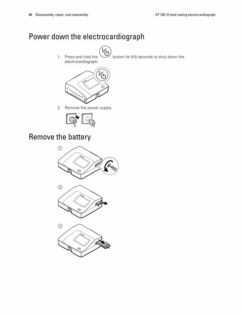
Power down the electrocardiograph
1. Press and hold the button for 6-8 seconds to shut down theelectrocardiograph.
2. Remove the power supply.
Remove the battery
40 Disassembly, repair, and reassembly CP 150 12-lead resting electrocardiograph

Separate the top housing assembly from the bottomhousing assembly
1. Turn the electrocardiograph over to access the bottom housing assembly.
2. Remove the eight M4x10 screws from the bottom housing assembly using a #2Phillips bit.
3. Turn the electrocardiograph over again to access the top housing assembly.
4. Lift up the top housing assembly to access the printer board.
5. Unhook the harness cables from the printer top assembly.
6. Disconnect the harness cable at J16 from the small-medium compute engine(SMCE) board.
Service manual Disassembly, repair, and reassembly 41

7. Cut the wire tie on the EMC ferrite.
8. Disconnect the CN202 connector from the printer board.
9. Disconnect the three harness cables at J8, J17, and J10 from the small-mediumcompute engine (SMCE) board.
10. Lift off the top housing and set aside for reuse during reassembly.
42 Disassembly, repair, and reassembly CP 150 12-lead resting electrocardiograph

Reassembly note
• Use a #2 Phillips bit and a Torque driver calibrated to 5.0 in-lb ± 0.5 in-lb to securethe bottom housing screws.
Cable identification for reassembly:
Service manual Disassembly, repair, and reassembly 43

Top housing disassemblyThese procedures provide instructions for system disassembly and board removal.Except where otherwise noted, the assembly procedure is the reverse of thedisassembly procedure.
Remove the Input/Output (I/O) communication board• Separate the top housing assembly from the bottom housing assembly as described.
1. Cut the wire tie on the ECG ferrite and the two wire ties on the EMC harnessferrites.
44 Disassembly, repair, and reassembly CP 150 12-lead resting electrocardiograph

2. Disconnect the J7 and J15 connectors from the SMCE board.
3. Disconnect the WA7 connector from the display assembly.
4. Remove the four 4-20 self-tapping screws from the I/O board using a #1 Phillips bit.
Service manual Disassembly, repair, and reassembly 45

5. Disconnect the three harness cables at CN201, CN203, and CN202 from the I/Oboard and remove the harnesses.
Note Set the harness cables aside for reuse during reassembly.
Reassembly note
• Use a #1 Phillips bit and a Torque driver calibrated to 5.0 in-lb ± 0.5 in-lb to securethe SMCE board screws.
SMCE I/O harness cable connection for reassembly:
Note Ensure that the twisted white wires of the J15 SMCE I/O harness face thecenter of the SMCE board so that the pins line up correctly.
46 Disassembly, repair, and reassembly CP 150 12-lead resting electrocardiograph

Remove the SMCE board• Separate the top housing assembly from the bottom housing assembly as described.
1. Lift up the latch of the J18 connector on the SMCE board and disconnect the flexcable.
2. Gently pull up on the locking tab latch of the J6 connector on SMCE board and slideout the flex cable.
Service manual Disassembly, repair, and reassembly 47

3. Remove the four M3x5 screws from the SMCE board using a #1 Phillips bit.
Reassembly note
• Use a #1 Phillips bit and a Torque driver calibrated to 5.0 in-lb ± 0.5 in-lb to securethe SMCE board M3x5 screws.
48 Disassembly, repair, and reassembly CP 150 12-lead resting electrocardiograph

Remove the LCD frame and display assembly• Separate the top housing assembly from the bottom housing assembly as described.
1. Remove the Pro-Gaff tape that holds the power switch flex cable to the LCD frame.
2. Remove the six shoulder screws on the LCD frame using a #1 Phillips bit.
3. Remove the LCD frame.
4. Remove the LCD display and gasket from the top housing assembly.
Note: Be sure to support the LCD display if you are removing it with the frame.
5. Remove the LCD display gasket.
Set aside the LCD gasket for reassembly.
6. Unlock the LCD flex connector from the LCD display assembly.
Service manual Disassembly, repair, and reassembly 49

Reassembly notes
• Use a #2 Phillips bit and a Torque driver calibrated to 5.0 in-lb ± 0.5 in-lb to securethe LCD frame shoulder screws.
Ensure that the LCD flex cable is not under the LCD frame.
CAUTION The LCD flex cable is extremely fragile and easily damaged. Donot cause creases that may break the connections.
Insert the LCD display into the gasket with the exposed printed circuit board on thebottom. Verify that the LCD flex cable feeds through the gasket's notched clearancefeature.
Place the LCD frame over the display. Verify that the LCD frame does not cover the LCDflex cable.
50 Disassembly, repair, and reassembly CP 150 12-lead resting electrocardiograph

Bottom housing disassemblyThese procedures provide instructions for system disassembly and board removal.Except where otherwise noted, the assembly procedure is the reverse of thedisassembly procedure.
Remove the ECG board• Separate the top housing assembly from the bottom housing assembly as described.
1. Lift up the ECG cover to access the ECG board.
2. Disconnect the J401 connector from the ECG board.
3. Remove the two M3x5 screws from the ECG board using a #1 Phillips bit.
4. Push back slighty on the two latches to remove the ECG board from the bottomassembly.
Reassembly note
• Use a #1 Phillips bit and a Torque driver calibrated to 5.0 in-lb ± 0.5 in-lb to securethe SMCE board screws.
Service manual Disassembly, repair, and reassembly 51

Remove the ECG ferrite• Separate the top housing assembly from the bottom housing assembly as described.
Gently open the two side-catches to remove the ECG ferrite and the ECG boardharness from the printer top assembly.
Note Set the harness cable aside for reuse during reassembly.
52 Disassembly, repair, and reassembly CP 150 12-lead resting electrocardiograph

Remove the battery housing cover and the battery connector board• Separate the top housing assembly from the bottom housing assembly as described.
1. Disconnect the CN304 connector from the printer board.
2. Remove the four 4-20 self-tapping screws from the battery housing top cover usinga #1 Phillips bit.
Service manual Disassembly, repair, and reassembly 53

3. Lift up the battery housing bottom cover and disconnect the J2 connector from thepower supply board.
4. Disconnect the J2 and J3 connectors from the battery connector board to removethe cables.
54 Disassembly, repair, and reassembly CP 150 12-lead resting electrocardiograph

5. Remove the two 4-20 self-tapping screws from the battery connector board using a#1 Phillips bit.
Reassembly notes
• Use a #1 Phillips bit and a Torque driver calibrated to 5.0 in-lb ± 0.5 in-lb to securethe two 4-20 self-tapping screws to the battery connector board.
• Use a #1 Phillips bit and a Torque driver calibrated to 5.0 in-lb ± 0.5 in-lb to securethe four 4-20 self-tapping screws to the battery housing top cover.
Service manual Disassembly, repair, and reassembly 55

Remove the power supply assembly• Separate the top housing assembly from the bottom housing assembly as described.
1. Remove the P1 and J1 connectors from the power supply assembly.
2. Remove the four 4-20 self-tapping screws from the power assembly using a #1Phillips bit.
3. Remove the power supply.
Reassembly noteUse a #1 Phillips bit and a Torque driver calibrated to 5.0 in-lb ± 0.5 in-lb to secure thepower supply screws.
56 Disassembly, repair, and reassembly CP 150 12-lead resting electrocardiograph

Remove and disassemble the printer assembly• Separate the top housing assembly from the bottom housing assembly as described.
1. Remove the ground cable at the J603 connection from the printer board (PCA).
2. Remove the four M4x7 screws from the printer assembly using a # 2 Phillips bit.
Reassembly notes
• Use a #2 Phillips bit and a Torque driver calibrated to 5.0 in-lb ± 0.5 in-lb to securethe printer assembly M4x7 screws.
• Route the ground cable around the outside of the screw boss during reassembly.
Service manual Disassembly, repair, and reassembly 57

Ground cable routing for reassembly:
58 Disassembly, repair, and reassembly CP 150 12-lead resting electrocardiograph

Remove the printer board• Separate the top housing assembly from the bottom housing assembly as described.
1. Remove the four connectors J602, CN601, J601, and CN602 from the printer board.
2. Remove the four 4-20 self-tapping screws from the printer board using a #1 Phillipsbit.
Service manual Disassembly, repair, and reassembly 59

3. Remove the printer board by lifting up the side nearest the print roller and sliding itout from the printer board catch.
4. Separate the printer tray assembly from the printer top assembly by pressing thetray eject button and sliding out the paper tray assembly.
Reassembly note
• Use a #1 Phillips bit and a Torque driver calibrated to 5.0 in-lb ± 0.5 in-lb to securethe printer board 4-20 self-tapping screws.
60 Disassembly, repair, and reassembly CP 150 12-lead resting electrocardiograph

Remove the printer door sensor• Separate the top housing assembly from the bottom housing assembly as described.
1. Remove the printer door sensor cable from the printer top assembly catches.
2. Remove the 4-20 pan head screw from the printer top assembly using a #10 Torx bit.
Reassembly note
• Use a #10 Torx bit and a Torque driver calibrated to 5.0 in-lb ± 0.5 in-lb to secure the4-20 pan head screw to the printer top assembly.
Service manual Disassembly, repair, and reassembly 61

Remove the gear train and motor• Separate the top housing assembly from the bottom housing assembly as described.
1. Cut the wire tie on the motor harness.
2. Remove the three 4-20 screws from the printer tray using a #1 Phillips bit.
62 Disassembly, repair, and reassembly CP 150 12-lead resting electrocardiograph

3. Remove the two M3x6 screws from the gear train assembly using a #1 Phillips bit.
Reassembly notes
• Use a #1 Phillips bit and a Torque driver calibrated to 5.0 in-lb ± 0.5 in-lb to securethe motor assembly to the printer tray.
• Use a #1 Phillips bit and a Torque driver calibrated to 5.0 in-lb ± 0.5 in-lb to securethe gear train assembly to the motor assembly.
Service manual Disassembly, repair, and reassembly 63

Remove the print head assembly• Separate the top housing assembly from the bottom housing assembly as described.
1. Feed the 3 printer harnesses through the openings of the printer top housing.
2. Disconnect one connector of the Cue sensor board to remove the harness.
64 Disassembly, repair, and reassembly CP 150 12-lead resting electrocardiograph

3. Pull the middle of the retaining rod slightly away from the print head and lift upwardto remove the retaining rod from the ground-harness-side first.
4. Slide the print head assembly inward and then upward through the retaining channel.
Remove the print head1. Remove the two M3x0.5 screws from the Cue sensor board with a #1 Phillips bit.
Service manual Disassembly, repair, and reassembly 65

2. Remove the nut with ¼” Hex Socket to remove the ground harness.
3. Remove the two shoulder screws with a 3/16" Hex Socket.
Note Take note of the shoulder screw direction during thereassembly process.
66 Disassembly, repair, and reassembly CP 150 12-lead resting electrocardiograph

4. Remove the two connectors on each side of the print head to remove the print headharness.
Note Ensure that the connectors are reattached to their originalposition. Do not interchange the connectors.
Reassembly notes
• Use a #1 Phillips bit and a Torque driver calibrated to 5.0 in-lb ± 0.5 in-lb to securethe Cue sensor board M3x0.5 screws.
• Use a 1/4” Hex Socket and a Torque driver calibrated to 3.5 in-lb ± 0.5 in-lb to securethe Cue sensor board nut.
• Use a 3/16" Hex Socket and a Torque driver calibrated to 4.0 in-lb ± 0.5 in-lb tosecure the Cue sensor board two shoulder screws.
• Secure the shoulder screws to the Cue sensor board with each shoulder of thescrew facing the board so that they fit into the board recess.
Service manual Disassembly, repair, and reassembly 67

68 Disassembly, repair, and reassembly CP 150 12-lead resting electrocardiograph

Electrical safety testing
Welch Allyn recommends performing ground continuity, leakage current, and dielectricstrength tests1 when replacing the power supply or primary wiring according to EN/IEC60601-1 - Medical Electrical Equipment – Part 1: General Requirements for Basic Safetyand Essential Performance or EN/IEC 62353 - Medical Electrical Equipment - RecurrentTest and Test After Repair of Medical Electrical Equipment.
Due to the variability of test equipment in the field, Welch Allyn does not include specificinstructions to perform electrical safety tests. When performing electrical safety tests,refer to your test equipment manuals for detailed instruction. The following tableprovides connections and test limits to assist you in performing these tests.
Test Limits
Ground continuity Ground continuity from EP stud* (equipotential terminal) to the Gnd pin of theIEC power connector shall be no greater than 0.1 ohms.
Leakage current Leakage current shall be less than 300 µA from EP stud* to mains (Line andNeutral pins of the IEC power connector).
Dielectric strength Dielectric strength shall be 1.8 kVAC EP stud* to IEC mains (Line and Neutralpins of the IEC power connector).
* To locate the equipotential terminal, see “Controls, indicators, and connectors.”
1 Perform this test only if there is a reason to doubt the integrity of the electrical insulation (e.g. multipletrips of a residual-current device or liquid ingress of a saline solution). If you determine this test shouldbe performed, return the device to Welch Allyn for service.
69

70 Electrical safety testing CP 150 12-lead resting electrocardiograph

Software updates process
Update process1. From the ECG home tab, touch the Settings tab. The ECG tab and the vertical ECG
configuration tab appear.
2. Touch the Device tab.
3. Insert a USB flash drive containing the latest software into a USB port on the back ofthe device and touch the Update button.
71

4. “Update complete. Press OK to reboot.” displays after the update is complete.Reboot the device to use the updated software.
Export and import of the device configurationConfiguration files can be exported and imported for backup purposes or to configuremultiple CP150 devices.
To begin the export or import process, insert a USB flash drive into one of the USBports on the back of the device.
1. From the ECG home tab, touch the Settings tab. The ECG tab and the vertical ECGconfiguration tab appear.
2. Touch the Device tab.
3. Touch the Updates tab.
• Touch Update to install the latest device software.
• Touch Restore to restore factory defaults.
• Touch Save configuration to save the device configuration to USB.
• Touch Copy configuration to copy the configure from USB.
72 Software updates process CP 150 12-lead resting electrocardiograph

Button Feature
Update Updates the device software from a USB flash drive.
Restore Restores the device settings to the factory defaults.
Save Configuration Saves the device configuration to USB flash drive.
Copy Configure Loads the device configuration from USB flash drive.
Service manual Software updates process 73

74 Software updates process CP 150 12-lead resting electrocardiograph

Field replaceable units
This listing includes only field-replaceable service parts. Service kits are shown with thecontents listed underneath each kit.
Note Product accessories are listed separately on the CD.
Housing top assembly
Serv Kit, CP150, Hsg Top Assy (material no. CP150-0001)
No. Item Qty
1 CP150 Subassembly Housing top 1 ea
2 CP150 Power Switch 1 ea
3 Product label 1 ea
n/a Wire tie holder with adhesive 1 ea
75

Serv Kit, CP150, 7 Inch Display (material no. CP150-0002)
No. Item Qty
1 LCD Assy with Touch Panel 1 ea
2 LCD Bezel 7 inch 1 ea
n/a Flex SMCE-LCD Display 7 inch 1 ea
Serv Kit, Frame LCD (material no. CP150-0003)
76 Field replaceable units CP 150 12-lead resting electrocardiograph

No. Item Qty
1 Frame LCD 1 ea
n/a Wire tie holder with adhesive 2 ea
Serv Kit, SMCE PCA (material no. CP150-0004)
No. Item Qty
1 Assy, Small Med Compute Eng (SMCE) 1 ea
n/a Harness SMCE-I/O 1 ea
n/a Harness I/O-LCD 1 ea
n/a CP150 EMC Harness Ferrite 3 ea
n/a ECG Ferrite 1 ea
n/a Wire tie 4 ea
Service manual Field replaceable units 77

Serv Kit, CP150, I/O PCA (material no. CP150-0005)
No. Item Qty
1 CP150 Assy PCA 1 ea
n/a Harness SMCE-I/O 1 ea
n/a Harness I/O-LCD 1 ea
n/a CP150 EMC Harness Ferrite 3 ea
n/a ECG Ferrite 1 ea
n/a Wire tie 4 ea
78 Field replaceable units CP 150 12-lead resting electrocardiograph

Housing base assembly
Serv Kit, CP150, ECG PCA (material no. CP150-0006)
No. Item Qty
1 ECG PCA Assy 1 ea
n/a CP150 Harness ECG SMCE 1 ea
n/a ECG Ferrite 1 ea
Service manual Field replaceable units 79

Serv Kit, Battery Case Assy (material no. CP150-0007)
No. Item Qty
1 Assy Battery Cover bottom 1 ea
2 Battery Cover top 1 ea
3 Screw 4-20 pan phillips 4 ea
4 PCA, Battery Connector 1 ea
n/a Harness PSU-BAT-SMB-PRT-SMCE 1 ea
80 Field replaceable units CP 150 12-lead resting electrocardiograph

Serv Kit, Printer PCA (material no. CP150-0008)
No. Item Qty
1 Printer PCA 1 ea
Service manual Field replaceable units 81

Printer 8 inch assembly tray
Serv Kit, CP150, Tray paper assy (material no. CP150-0009)
No. Item Qty
1 Printer 8 in Assy Tray 1 ea
2 Printer 8 in Assy top (handle) 1 ea
3 Screw 4-20 .375 pan phillips 3 ea
4 Printer 8 in Platen Roller Assy 1 ea
82 Field replaceable units CP 150 12-lead resting electrocardiograph

Serv Kit, Printer Top Assy (material no. CP150-0010)
No. Item Qty
1 Housing top 1 ea
2 Latch assy 1 ea
3 Coil spring right 2 ea
4 Coil spring left 1 ea
5 Retaining ring 1 ea
6 Printer button 1 ea
7 Screw 4-20 2 ea
8 Locknut 1 ea
9 Latch left 1 ea
n/a CP150 ECG cover 1 ea
n/a Wire tie holder with adhesive 1 ea
Service manual Field replaceable units 83

Serv Kit, Print Head Assy (material no. CP150-0011)
No. Item Qty
1 Printhead Holder 1 ea
2 Printhead 1 ea
3 Printhead spring 1 ea
4 Shoulder screws M3x0.5 2 ea
5 Screw pan head phillips M3 x 0.5 2 ea
6 Cue Sensor PCBA 1 ea
n/a Harness Print Cue 1 ea
n/a Brush anti-static 2 ea
n/a Harness Printhead 1 ea
n/a Nut 4-40 1 ea
n/a Harness print-earth 1 ea
84 Field replaceable units CP 150 12-lead resting electrocardiograph

Serv Kit, Gear Train Assy (material no. CP150-0012)
No. Item Qty
1 Gear train assy 1 ea
Serv Kit, Motor Assy (material no. CP150-0013)
No. Item Qty
1 Harness motor 1 ea
n/a Wire tie 1 ea
Service manual Field replaceable units 85

Serv Kit, Door Sensor (material no. CP150-0014)
No. Item Qty
1 Door Sensor 1 ea
n/a Plastite 4-20x.5 pan head screw 1 ea
Bottom assembly
86 Field replaceable units CP 150 12-lead resting electrocardiograph

Serv Kit, Bottom assy (material no. CP150-0015)
No. Item Qty
1 Subassembly housing base 1 ea
2 Subassy Schurter Kea power mod 1 ea
3 Nut 2 ea
4 Washer lock serrated 1 ea
5 Ground poag 1 ea
6 Bumpers 5 ea
Serv Kit, Power supply (material no. CP150-0016)
No. Item Qty
1 Power supply, 60 W 1 ea
Serv Kit, Software upgrade (material no. CP150-0017)
No. Item Qty
n/a Flash drive 1 ea
n/a Software update document 1 ea
Service manual Field replaceable units 87

Serv Kit, Battery door (material no. CP150-0018)
No. Item Qty
1 Battery door 1 ea
Serv Kit, Miscellaneous (material no. CP150-0019)
No. Item Qty
n/a Screw 4-20 pan phillips 30
n/a Screw M4X10 30
n/a Shoulder screw 10
n/a Pan head M3x5 10
n/a Pan phillips M3x0.5 10
n/a Shoulder screw M3x0.5 10
n/a Nut 4-40 10
n/a Screw M3x6 php 10
n/a Screw, Plastite 4-20 pan head 10
n/a Wire tie 20
n/a Grommet ear 10
88 Field replaceable units CP 150 12-lead resting electrocardiograph

No. Item Qty
n/a Bumper 20
n/a Cable tie with adhesive 20
n/a CP150 ECG cover 10
Partners in Care service and support agreementsMaterial no. Item Material no. Item
S1-CP150 CP150, Comprehensive partnershipprogram 1 year
S1-CP150-2 CP150, Comprehensive,Comprehensive partnership program2 years
S2-CP150 CP150, Bio-med partnership program1 year
S2-CP150-2 CP150, Bio-med partnership program2 years
S4-CP150 CP150, extended warranty, 1 year S4-CP150-2 CP150, extended warranty, 2 years
Service and repair trainingMaterial no. Item
CP150REPW-TRN CP150 repair web training
PRV-001 Preventive Svc WA Bench per unit
PRV-002 Preventive Svc planned onsite per unit
Service manual Field replaceable units 89

90 Field replaceable units CP 150 12-lead resting electrocardiograph

Appendices
Decontamination and cleaning requirementsAs a general safety precaution, the device must undergo decontamination before beingreturned to Welch Allyn for service, repair, inspection, or disposal.
Note Contaminated items must not be returned without prior, writtenagreement.
Note Decontaminate the device according to your facility’s procedures and localregulations.
Cleaning is an essential prerequisite for effective disinfection or decontamination.
Note The following guidelines apply to the device only. For peripheral items,follow the cleaning instructions in the directions for use that accompanythese accessories.
WARNING Before you clean the CP 150 Electrocardiograph, unplug it fromthe wall socket.
WARNING Electric shock hazard. DO NOT autoclave the CP 150Electrocardiograph or accessories.
WARNING Liquids can damage electronics inside the CP 150Electrocardiograph. Prevent liquids from spilling on or dripping into the CP150 Electrocardiograph. If liquids are spilled on or drip into the CP 150Electrocardiograph:1. Disconnect the power plug.2. Dry off excess liquid from the CP 150 Electrocardiograph.3. Verify that the CP 150 Electrocardiograph functions normally before using it.
Clean the CP 150 Electrocardiograph on a routine basis according to your facilitiesprotocols and standards or local regulations.
To clean the CP 150 Electrocardiograph, use any of the following:
• A clean cloth slightly dampened with 70 percent isopropyl alcohol or 10 percentchlorine bleach solution. Wipe dry with a clean cloth.
• Sani-Cloth® Plus.
• CaviWipes™
91

Interconnect diagram
92 Appendices CP 150 12-lead resting electrocardiograph


105323
Material No. 719489
Related Documents