CP 100 and CP 200™ 12-Lead Resting Electrocardiograph Service Manual CP 100 TM 12- Lead Resting Electrocardiograph CP 200 TM 12- Lead Resting Electrocardiograph

Welcome message from author
This document is posted to help you gain knowledge. Please leave a comment to let me know what you think about it! Share it to your friends and learn new things together.
Transcript
CP 100 and CP 200™ 12-Lead Resting Electrocardiograph
Service Manual
CP 100TM 12- Lead Resting Electrocardiograph CP 200TM 12- Lead Resting Electrocardiograph
ii Welch Allyn CP 100 and CP 200 Electrocardiograph
Copyright 2005, Welch Allyn, Inc. All rights are reserved. No one is permitted to reproduce or duplicate, in any form, this manual or any part thereof without permission from Welch Allyn.
Caution: Federal US law restricts sale of the device identified in this manual to, or on the order of, a licensed physician.
Welch Allyn assumes no responsibility for any injury, or for any illegal or improper use of the product, that may result from failure to use this product in accordance with the instructions, cautions, warnings, or indications for use published in this manual.
Welch Allyn is a registered trademark of Welch Allyn, Inc., and CP 200, CP100, and CardioPerfect are trademarks of Welch Allyn, Inc.
SD is a trademark of Toshiba.
Software in this product is Copyright 2005, Welch Allyn, Inc., or its vendors. All rights are reserved. The software is protected by United States of America copyright laws and international treaty provisions applicable worldwide. Under such laws, the licensee is entitled to use the copy of the software incorporated within this instrument as intended in the operation of the product in which it is embedded. The software may not be copied, decompiled, reverse-engineered, disassembled or otherwise reduced to human-perceivable form. This is not a sale of the software or any copy of the software; all right, title and ownership of the software remains with Welch Allyn or its vendors.
For information about any Welch Allyn product, please call Welch Allyn Technical Support:
Part Number (manual only): 704340 Rev D
Welch AllynPO Box 220Skaneateles Falls, NY 13153-0220
www.welchallyn.com
Printed in USA
USA 1 800 535 6663+1 315 685 4560
Australia +61 29 638 3000800 074 793
Canada 1 800 561 8797 China +86 216 327 9631
European Call Center +353 46 906 7790 France +33 15 569 5849
Germany +49 747 792 7186 Japan +81 33 219 0071
Latin America +315 685 2644 Netherlands +31 15 750 5000
Singapore +65 6419 8100 South Africa +27 11 777 7555
United Kingdom +44 207 365 6780 Sweden +46 85 853 6551
0297

iii
Contents
1 - Safety Summary. . . . . . . . . . . . . . . . . . . . . . . . . . . . . . . . . . . . . . . . . 1Introduction. . . . . . . . . . . . . . . . . . . . . . . . . . . . . . . . . . . . . . . . . . . . . . . . . . . . . . 2Symbols . . . . . . . . . . . . . . . . . . . . . . . . . . . . . . . . . . . . . . . . . . . . . . . . . . . . . . . . 2Servicing the Electrocardiograph Safely . . . . . . . . . . . . . . . . . . . . . . . . . . . . . . . . 4
General Warnings. . . . . . . . . . . . . . . . . . . . . . . . . . . . . . . . . . . . . . . . . . . . . . 4Electrostatic Discharge (ESD). . . . . . . . . . . . . . . . . . . . . . . . . . . . . . . . . . . . . 5General Cautions . . . . . . . . . . . . . . . . . . . . . . . . . . . . . . . . . . . . . . . . . . . . . . 6
2 - Overview. . . . . . . . . . . . . . . . . . . . . . . . . . . . . . . . . . . . . . . . . . . . . . . 7Purpose and Scope. . . . . . . . . . . . . . . . . . . . . . . . . . . . . . . . . . . . . . . . . . . . . . . . 8Service Options . . . . . . . . . . . . . . . . . . . . . . . . . . . . . . . . . . . . . . . . . . . . . . . . . . 8
Warranty Service . . . . . . . . . . . . . . . . . . . . . . . . . . . . . . . . . . . . . . . . . . . . . . 8Non-Warranty Service . . . . . . . . . . . . . . . . . . . . . . . . . . . . . . . . . . . . . . . . . . 8Technical Support Services . . . . . . . . . . . . . . . . . . . . . . . . . . . . . . . . . . . . . . 9Returning Products. . . . . . . . . . . . . . . . . . . . . . . . . . . . . . . . . . . . . . . . . . . . . 9
Product Configurations . . . . . . . . . . . . . . . . . . . . . . . . . . . . . . . . . . . . . . . . . . . . 10Recommended Service Intervals . . . . . . . . . . . . . . . . . . . . . . . . . . . . . . . . . . . . 10Controls, Indicators, and Connectors . . . . . . . . . . . . . . . . . . . . . . . . . . . . . . . . . 11“System Settings” Menu Tree . . . . . . . . . . . . . . . . . . . . . . . . . . . . . . . . . . . . . . 16About the Main Menu. . . . . . . . . . . . . . . . . . . . . . . . . . . . . . . . . . . . . . . . . . . . . 17Moving Through the Menus . . . . . . . . . . . . . . . . . . . . . . . . . . . . . . . . . . . . . . . . 18Reviewing the Device Information . . . . . . . . . . . . . . . . . . . . . . . . . . . . . . . . . . . 19CP 100 and CP 200 Electrocardiograph . . . . . . . . . . . . . . . . . . . . . . . . . . . . . . . 20
Service Menus . . . . . . . . . . . . . . . . . . . . . . . . . . . . . . . . . . . . . . . . . . . . . . . 20Entering the Service Info Screen . . . . . . . . . . . . . . . . . . . . . . . . . . . . . . . . . 20Print Log . . . . . . . . . . . . . . . . . . . . . . . . . . . . . . . . . . . . . . . . . . . . . . . . . . . . 21Battery Life Test . . . . . . . . . . . . . . . . . . . . . . . . . . . . . . . . . . . . . . . . . . . . . . 22Printer Test . . . . . . . . . . . . . . . . . . . . . . . . . . . . . . . . . . . . . . . . . . . . . . . . . . 22Export Files . . . . . . . . . . . . . . . . . . . . . . . . . . . . . . . . . . . . . . . . . . . . . . . . . 23Import Files . . . . . . . . . . . . . . . . . . . . . . . . . . . . . . . . . . . . . . . . . . . . . . . . . 24Delete Files . . . . . . . . . . . . . . . . . . . . . . . . . . . . . . . . . . . . . . . . . . . . . . . . . 24Serial Number . . . . . . . . . . . . . . . . . . . . . . . . . . . . . . . . . . . . . . . . . . . . . . . 25Lead Off Threshold. . . . . . . . . . . . . . . . . . . . . . . . . . . . . . . . . . . . . . . . . . . . 25Service Tests . . . . . . . . . . . . . . . . . . . . . . . . . . . . . . . . . . . . . . . . . . . . . . . . 25
3 - Functional Verification . . . . . . . . . . . . . . . . . . . . . . . . . . . . . . . . . . . 29Functional Verification Overview. . . . . . . . . . . . . . . . . . . . . . . . . . . . . . . . . . . . . 30Full Functional Check . . . . . . . . . . . . . . . . . . . . . . . . . . . . . . . . . . . . . . . . . . . . . 30Equipment Required . . . . . . . . . . . . . . . . . . . . . . . . . . . . . . . . . . . . . . . . . . . . . . 30

iv Contents Welch Allyn CP 100 and CP 200 Electrocardiograph
Operating/Non-Printing Mode Current Test . . . . . . . . . . . . . . . . . . . . . . . . . 30Battery Accuracy Test. . . . . . . . . . . . . . . . . . . . . . . . . . . . . . . . . . . . . . . . . . 31Sleep/Standby Mode Current Test . . . . . . . . . . . . . . . . . . . . . . . . . . . . . . . . 31Charger Detect Test . . . . . . . . . . . . . . . . . . . . . . . . . . . . . . . . . . . . . . . . . . . 31LED Test. . . . . . . . . . . . . . . . . . . . . . . . . . . . . . . . . . . . . . . . . . . . . . . . . . . . 32LCD Test. . . . . . . . . . . . . . . . . . . . . . . . . . . . . . . . . . . . . . . . . . . . . . . . . . . . 32Set Unit Initial Configuration/SD Slot Test . . . . . . . . . . . . . . . . . . . . . . . . . . 32ECG Communication Test (ECG Input test and lead off) . . . . . . . . . . . . . . . 33Spirometer Communication Test . . . . . . . . . . . . . . . . . . . . . . . . . . . . . . . . . 33USB Communications Test . . . . . . . . . . . . . . . . . . . . . . . . . . . . . . . . . . . . . 34Beeper Test . . . . . . . . . . . . . . . . . . . . . . . . . . . . . . . . . . . . . . . . . . . . . . . . . 34Keyboard Test. . . . . . . . . . . . . . . . . . . . . . . . . . . . . . . . . . . . . . . . . . . . . . . . 35Printer Test . . . . . . . . . . . . . . . . . . . . . . . . . . . . . . . . . . . . . . . . . . . . . . . . . . 35Dielectric Strength Test . . . . . . . . . . . . . . . . . . . . . . . . . . . . . . . . . . . . . . . . 38Hi-Pot Test Connections . . . . . . . . . . . . . . . . . . . . . . . . . . . . . . . . . . . . . . . . 39Chassis, Earth and Patient Leakage Current Tests . . . . . . . . . . . . . . . . . . . . 39
Checklist and Test Results Report Form . . . . . . . . . . . . . . . . . . . . . . . . . . . . . . . 40
4 - Troubleshooting . . . . . . . . . . . . . . . . . . . . . . . . . . . . . . . . . . . . . . . . 41Problem-Solving Suggestions . . . . . . . . . . . . . . . . . . . . . . . . . . . . . . . . . . . . . . . 42Limited Warranty . . . . . . . . . . . . . . . . . . . . . . . . . . . . . . . . . . . . . . . . . . . . . . . . 45Service Policy . . . . . . . . . . . . . . . . . . . . . . . . . . . . . . . . . . . . . . . . . . . . . . . . . . . 46
5 - Disassembly and Repair Procedures . . . . . . . . . . . . . . . . . . . . . . . 47Introduction. . . . . . . . . . . . . . . . . . . . . . . . . . . . . . . . . . . . . . . . . . . . . . . . . . . . . 48Screws . . . . . . . . . . . . . . . . . . . . . . . . . . . . . . . . . . . . . . . . . . . . . . . . . . . . . . . . 48Torque Specs . . . . . . . . . . . . . . . . . . . . . . . . . . . . . . . . . . . . . . . . . . . . . . . . . . . 48Disassembly Procedures . . . . . . . . . . . . . . . . . . . . . . . . . . . . . . . . . . . . . . . . . . 49
Opening the Unit . . . . . . . . . . . . . . . . . . . . . . . . . . . . . . . . . . . . . . . . . . . . . 49Replacing the Printer Assembly . . . . . . . . . . . . . . . . . . . . . . . . . . . . . . . . . . 50Replacing the Paper Tray Cover . . . . . . . . . . . . . . . . . . . . . . . . . . . . . . . . . . 52Replacing the Platen Roller . . . . . . . . . . . . . . . . . . . . . . . . . . . . . . . . . . . . . 54Replacing the Printhead . . . . . . . . . . . . . . . . . . . . . . . . . . . . . . . . . . . . . . . . 55Replacing the Stepper Motor and Gear Box. . . . . . . . . . . . . . . . . . . . . . . . . 57Replacing the Battery or Fuse . . . . . . . . . . . . . . . . . . . . . . . . . . . . . . . . . . . 58Replacing the Battery (DC) Fuse . . . . . . . . . . . . . . . . . . . . . . . . . . . . . . . . . 60Replacing the Main Board . . . . . . . . . . . . . . . . . . . . . . . . . . . . . . . . . . . . . . 61Replacing the Power Supply. . . . . . . . . . . . . . . . . . . . . . . . . . . . . . . . . . . . . 62Replacing the IEC (AC input) Connector . . . . . . . . . . . . . . . . . . . . . . . . . . . 63Replacing the LCD Inverter and LCD Assembly (CP 200) . . . . . . . . . . . . . . 64Replacing the Function Keypad Assembly (CP 200). . . . . . . . . . . . . . . . . . . 65Replacing the Keyboard Assembly (CP 200) . . . . . . . . . . . . . . . . . . . . . . . . 66Replacing the LCD Assembly (CP 100) . . . . . . . . . . . . . . . . . . . . . . . . . . . . 67Replacing the Keyboard Assembly (CP 100). . . . . . . . . . . . . . . . . . . . . . . . . 68
6 - Field Replaceable Parts . . . . . . . . . . . . . . . . . . . . . . . . . . . . . . . . . . 69Introduction. . . . . . . . . . . . . . . . . . . . . . . . . . . . . . . . . . . . . . . . . . . . . . . . . . . . . 69Field Replacement Parts . . . . . . . . . . . . . . . . . . . . . . . . . . . . . . . . . . . . . . . . . . . 70

Service Manual CP 100 and CP 200 Electrocardiograph v
A - Specifications. . . . . . . . . . . . . . . . . . . . . . . . . . . . . . . . . . . . . . . . . . 77
B - EMC Guidance and Manufacturer’s Declarations . . . . . . . . . . . . . 79
C - Software Updates . . . . . . . . . . . . . . . . . . . . . . . . . . . . . . . . . . . . . . 83
D - Interconnect Diagrams . . . . . . . . . . . . . . . . . . . . . . . . . . . . . . . . . . 85CP 200 Interconnect Diagram . . . . . . . . . . . . . . . . . . . . . . . . . . . . . . . . . . . . . . 86CP 100 Interconnect Diagram. . . . . . . . . . . . . . . . . . . . . . . . . . . . . . . . . . . . . . . 87

vi Contents Welch Allyn CP 100 and CP 200 Electrocardiograph
1
1
Safety SummaryIntroduction . . . . . . . . . . . . . . . . . . . . . . . . . . . . . . . . . . . . . . . . . . . . . . . . . . . . . . . . . . . . 2
Symbols . . . . . . . . . . . . . . . . . . . . . . . . . . . . . . . . . . . . . . . . . . . . . . . . . . . . . . . . . . . . . . . 2
Servicing the Electrocardiograph Safely . . . . . . . . . . . . . . . . . . . . . . . . . . . . . . . . . . . . . . 4

2 Safety Summary CP 100 and CP 200 Electrocardiograph
IntroductionThe safety summary, and all additional specific warnings and cautions located throughout the documentation, must be read and understood by all users of the CP 100 and CP 200 Electrocardiograph.
SymbolsThe symbols illustrated on the following pages may appear on the electrocardiograph, the packaging, the shipping container, or in this manual.
Documentation Symbols
WARNING Indicates conditions or practices that could lead to illness, injury, or death.
Caution In the manual, indicates conditions or practices that could damage the equipment or other property.
Caution On the product, means “Consult accompanying documentation.”
Shipping, Storing, and Environment Symbols
This end up Keep dry
Fragile Altitude limits
Temperature limits Relative humidity limit
Certification Symbols
Meets essential requirements of European Medical Device Directive 93/42/EEC
Complies with applicable U.S. and Canadian medical safety standards
European Regulatory ManagerWelch Allyn LTD.Navan Business ParkDublin RoadNavan, County Meath, Republic of IrelandTel.: 353-46-90-67700Fax: 353-46-90-67756
Australian registered importer
-20°C
+49°C
EC REPN344
Directions for Use Safety Summary 3
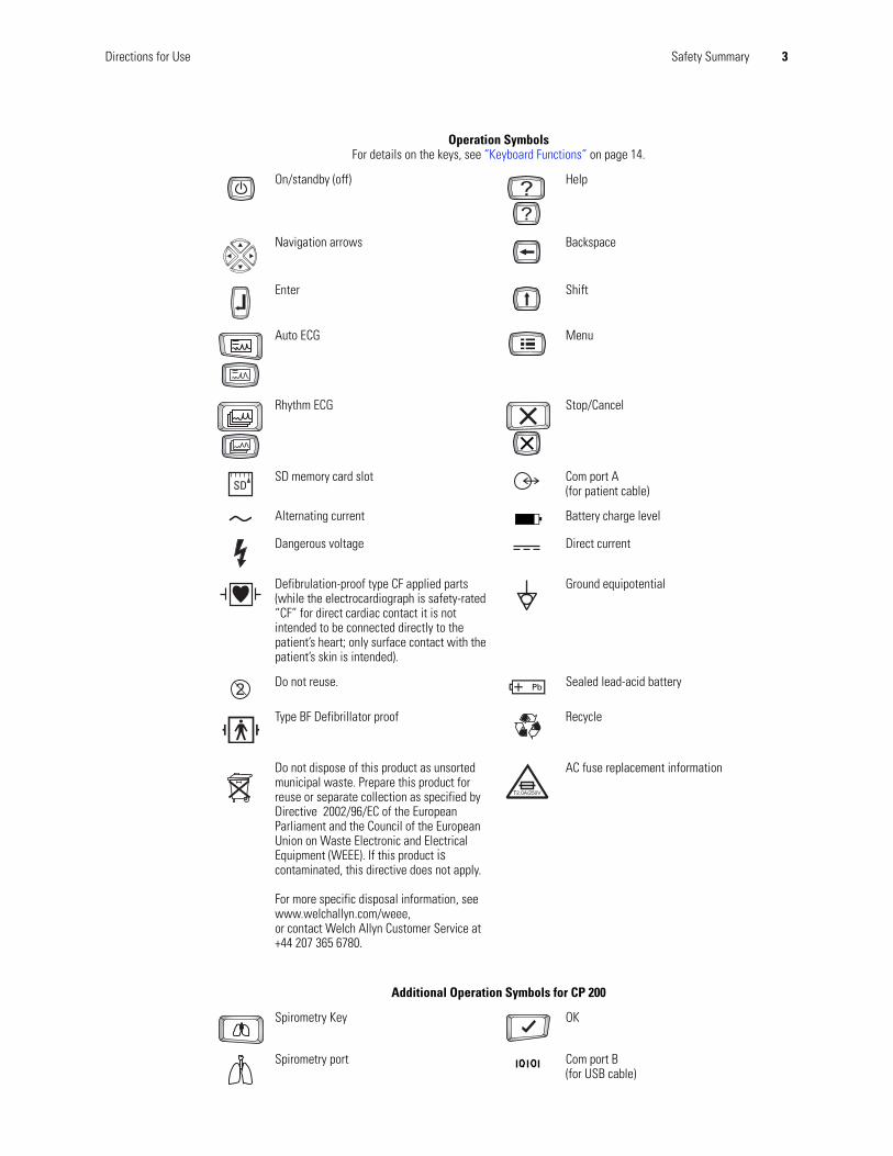
Operation SymbolsFor details on the keys, see “Keyboard Functions” on page 14.
On/standby (off) Help
Navigation arrows Backspace
Enter Shift
Auto ECG Menu
Rhythm ECG Stop/Cancel
SD memory card slot Com port A(for patient cable)
Alternating current Battery charge level
Dangerous voltage Direct current
Defibrulation-proof type CF applied parts (while the electrocardiograph is safety-rated “CF” for direct cardiac contact it is not intended to be connected directly to the patient’s heart; only surface contact with the patient’s skin is intended).
Ground equipotential
Do not reuse. Sealed lead-acid battery
Type BF Defibrillator proof Recycle
Do not dispose of this product as unsorted municipal waste. Prepare this product for reuse or separate collection as specified by Directive 2002/96/EC of the European Parliament and the Council of the European Union on Waste Electronic and Electrical Equipment (WEEE). If this product is contaminated, this directive does not apply.
For more specific disposal information, see www.welchallyn.com/weee,or contact Welch Allyn Customer Service at +44 207 365 6780.
AC fuse replacement information
Additional Operation Symbols for CP 200
Spirometry Key OK
Spirometry port Com port B (for USB cable)
T2.0A/250V
4 Safety Summary CP 100 and CP 200 Electrocardiograph
Servicing the Electrocardiograph SafelyBefore using or servicing the electrocardiograph, you must read and understand the following safety-related information.
General WarningsThe following warning statements apply to electrocardiograph use in general. Warning statements that apply specifically to particular procedures, such as connecting the patient cable or performing an ECG test, appear in the corresponding sections of the manual.
Warning statements indicate conditions or practices that could lead to illness, injury, or death.
Warnings Related to the Environment
WARNING To avoid a possible explosion, do not use the electrocardiograph in the presence of flammable anesthetics.
WARNING When transporting the electrocardiograph on a cart, tuck the patient cable away from the wheels so that it does not present a hazard.
WARNING Do not use the CP 100 and CP 200 Electrocardiograph in an MRI suite or hyperbaric chamber.
WARNING Do not autoclave the CP 100 and CP 200 Electrocardiograph or patient cable.
Warnings Related to Accessories and Other Equipment
WARNING For operator and patient safety, peripheral equipment and accessories that can come in direct patient contact must be in compliance with all appropriate safety, EMC, and regulatory requirements. See “EMC Guidance and Manufacturer’s Declarations” on page 79
WARNING All signal input and output (I/O) connectors are intended for connection of only devices complying with IEC 60601-1, or other IEC standards (for example, IEC 60950), as appropriate to the device. Connecting additional devices to the electrocardiograph may increase chassis or patient leakage currents. To maintain operator and patient safety, consider the requirements of IEC 60601-1-1. Measure the leakage currents to confirm that no electric shock hazard exists.
WARNING The electrocardiograph has not been designed for use with high-frequency (HF) surgical equipment and does not protect against hazards to the patient.

Directions for Use Safety Summary 5
Electrostatic Discharge (ESD)
Electrostatic discharge is a sudden current flowing from a charged object to another object or to ground. Electrostatic charges can accumulate on common items such as foam drinking cups, cellophane tape, synthetic clothing, untreated foam packaging material, and untreated plastic bags and work folders, to name only a few.
Electronic components and assemblies, if not properly protected against ESD, can be permanently damaged or destroyed when near or in contact with electrostatically charged objects. When you handle components or assemblies that are not in protective bags and you are not sure whether they are static-sensitive, assume that they are static-sensitive and handle them accordingly.
• Perform all service procedures in a static-protected environment. Always use techniques and equipment designed to protect personnel and equipment from electrostatic discharge.
• Remove static-sensitive components and assemblies from their static-shielding bags only at static-safe workstations—a properly grounded table and grounded floor mat—and only when you are wearing a grounded wrist strap (with a resistor of at least 1 megohm in series) or other grounding device.
Warnings Related to Using the Electrocardiograph
WARNING Avoid positioning any leads or cables so that they could easily trip someone.
WARNING Satisfactory maintenance procedures must be implemented, or equipment failure and health hazards may result.
Warnings Related to Repairing the Electrocardiograph
WARNING Only qualified service personnel should attempt to repair the electrocardiograph. In case of a malfunction, call Technical Support and precisely describe the problem. For phone numbers, see page ii.
WARNING While under warranty, the electrocardiograph must be serviced only by a Welch Allyn service technician.
WARNING Electrostatic discharge (ESD) can damage or destroy electronic components. Handle static-sensitive components only at static-safe workstation.
WARNING Consider all electrical and electronic components of the monitor as static-sensitive.

6 Safety Summary CP 100 and CP 200 Electrocardiograph
• Use only grounded tools when inserting, adjusting, or removing static-sensitive components and assemblies.
• Remove or insert static-sensitive components and assemblies only with monitor power turned off.
• Insert and seal static-sensitive components and assemblies into their original static-shielding bags before removing them from static-protected areas.
Always test your ground strap, bench mat, conductive work surface, and ground cord before removing components and assemblies from their protective bags and before beginning any disassembly or assembly procedures.
General CautionsThe following caution statements apply to electrocardiograph use in general. Caution statements that apply specifically to particular procedures, such as connecting the patient cable or performing an ECG test, appear in the corresponding sections of the manual.
Caution statements indicate conditions or practices that could damage the equipment or other property.
Caution When removing the electrocardiograph from storage, allow it to thermally stabilize to surrounding environmental conditions before using it.
Caution To prevent possible damage to the keypad, do not use sharp or hard objects to press keys. Only use fingertips.
Caution Do not expose the patient cable to strong ultra-violet radiation.
Caution Do not pull or stretch the patient cable. Doing so could result in mechanical or electrical failures. Form the patient cable into a loose loop before storing.
Caution Avoid positioning the patient cable where it might get pinched or stepped on. If the cable’s impedance is altered, measurements might no longer be accurate, and repair might be necessary.
Caution Using the equipotential terminal for anything but grounding purposes may contribute to damage of the device.
Caution Use only parts and accessories supplied with the device and available through Welch Allyn. The use of accessories other than those specified may result in degraded performance of this device.
Caution Portable and mobile RF communications equipment can affect the performance of the electrocardiograph.
Caution Other medical equipment—including but not limited to defibrillators, ultrasound machines, pacemakers, and other stimulators—may be used simultaneously with the electrocardiograph. However, such devices may disturb the electrocardiograph signal.
2
7
OverviewPurpose and Scope . . . . . . . . . . . . . . . . . . . . . . . . . . . . . . . . . . . . . . . . . . . . . . . . . . . . . . 8
Service Options . . . . . . . . . . . . . . . . . . . . . . . . . . . . . . . . . . . . . . . . . . . . . . . . . . . . . . . . . 8
Product Configurations . . . . . . . . . . . . . . . . . . . . . . . . . . . . . . . . . . . . . . . . . . . . . . . . . . 10
Recommended Service Intervals. . . . . . . . . . . . . . . . . . . . . . . . . . . . . . . . . . . . . . . . . . . 10
Controls, Indicators, and Connectors . . . . . . . . . . . . . . . . . . . . . . . . . . . . . . . . . . . . . . . 11
“System Settings” Menu Tree . . . . . . . . . . . . . . . . . . . . . . . . . . . . . . . . . . . . . . . . . . . . 16
About the Main Menu . . . . . . . . . . . . . . . . . . . . . . . . . . . . . . . . . . . . . . . . . . . . . . . . . . . 17
Moving Through the Menus . . . . . . . . . . . . . . . . . . . . . . . . . . . . . . . . . . . . . . . . . . . . . . 18
Reviewing the Device Information. . . . . . . . . . . . . . . . . . . . . . . . . . . . . . . . . . . . . . . . . . 19
CP 100 and CP 200 Electrocardiograph . . . . . . . . . . . . . . . . . . . . . . . . . . . . . . . . . . . . . . 20
8 Overview Welch Allyn CP 100 and CP 200 Electrocardiograph
Purpose and ScopeThe service manual is a reference for periodic preventive maintenance and corrective service procedures for the Welch Allyn CP 100 and CP 200 Electrocardiograph.
Corrective service is supported to the level of field-replaceable units. This includes some circuit-board assemblies and some subassemblies, case parts, and other parts. See “Field Replaceable Parts” on page 69 for complete list of user-replaceable service parts.
This guide provides troubleshooting information, assembly procedures, and instructions for functional testing and performance verification. It is intended for use only by technically qualified service personnel.
Service Options
Warranty ServiceAll repairs on products under warranty must be performed and/or approved by Welch Allyn. Refer all warranty service to Welch Allyn Factory Service or another authorized Welch Allyn Service Center. Obtain an RMA number for all returns to Welch Allyn Factory Service – see Returning Products (page 9).
Non-Warranty ServiceWelch Allyn Factory Service and authorized Service Centers support non-warranty repairs. Contact any Welch Allyn regional service center for pricing and service options.
Welch Allyn offers modular repair parts for sale to support non-warranty service. This service must be performed only by qualified end-user biomedical/clinical engineers using this service manual.
The Welch Allyn Electrocardiograph Service Information supports certain service functions. For information about any Welch Allyn product, please call Welch Allyn Technical Support: (page ii).
Note Repair and replacement of the main board is not supported. All service work on the main board must be performed by certified and qualified service personnel at an authorized Welch Allyn service center.
Caution No component-level repair of circuit boards and subassemblies is supported. Use only the repair procedures described in this manual.
WARNING When performing a service procedure, follow the instructions exactly as presented in this manual. Failure to do so could damage the monitor, invalidate the product warranty, and lead to serious personal injury.
Caution Unauthorized repairs will void the product warranty.

Service Manual CP 100 and CP 200 Electrocardiograph 9
Technical Support ServicesWelch Allyn offers the following technical support services:
Telephone supportLoaner equipmentService agreementsReplacement service partsFactory Service
For information on any of these services, contact Welch Allyn at the numbers listed on page ii
Returning ProductsTo return a product for service, contact Welch Allyn Technical Support and request a Return Material Authorization (RMA) number.
• When requesting an RMA, please have the following information available:
• Product name, model number, and serial number
• A complete return shipping address, including a contact name and phone number; include any special shipping instructions
• A purchase-order number or credit-card number if the product is not covered by warranty
• A full description of the problem or service request
To ship the unit, please observe these packing guidelines:
• Remove from the package all hoses, connectors, cables, sensors, power cords, and other ancillary products and equipment, except those items that might be associated with the problem.
• Use the original shipping carton and packing materials, or as close an approximation as possible.
• Include a packing list.
• Write the Welch Allyn RMA number with the Welch Allyn address on the outside of the shipping carton.
United States federal regulations require that any unit received by Factory Service must be free from blood-borne pathogens before processing. All incoming products are cleaned as well as possible, but products that cannot be effectively cleaned cannot be accepted for repair. Please thoroughly clean all organic residues from the product before shipment. This will ensure safe receipt, processing and repair, and will help expedite the return of your device.
Note Welch Allyn does not accept returned products without an RMA.
10 Overview Welch Allyn CP 100 and CP 200 Electrocardiograph
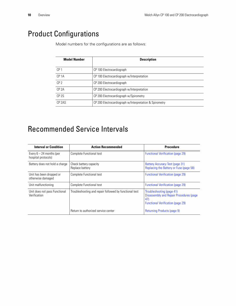
Product ConfigurationsModel numbers for the configurations are as follows:
Recommended Service Intervals
Model Number Description
CP 1 CP 100 Electrocardiograph
CP 1A CP 100 Electrocardiograph w/Interpretation
CP 2 CP 200 Electrocardiograph
CP 2A CP 200 Electrocardiograph w/Interpretation
CP 2S CP 200 Electrocardiograph w/Spirometry
CP 2AS CP 200 Electrocardiograph w/Interpretation & Spirometry
Interval or Condition Action Recommended Procedure
Every 6 – 24 months (per hospital protocols)
Complete Functional test Functional Verification (page 29)
Battery does not hold a charge Check battery capacityReplace battery
Battery Accuracy Test (page 31)Replacing the Battery or Fuse (page 58)
Unit has been dropped or otherwise damaged
Complete Functional test Functional Verification (page 29)
Unit malfunctioning Complete Functional test Functional Verification (page 29)
Unit does not pass Functional Verification
Troubleshooting and repair followed by functional test
Return to authorized service center
Troubleshooting (page 41)Disassembly and Repair Procedures (page 47)Functional Verification (page 29)
Returning Products (page 9)
Service Manual CP 100 and CP 200 Electrocardiograph 11
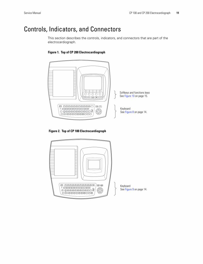
Controls, Indicators, and ConnectorsThis section describes the controls, indicators, and connectors that are part of the electrocardiograph.
Softkeys and functions keysSee Figure 10 on page 15.
Keyboard See Figure 8 on page 14.
Figure 1. Top of CP 200 Electrocardiograph
Keyboard See Figure 9 on page 14.
Figure 2. Top of CP 100 Electrocardiograph

12 Overview Welch Allyn CP 100 and CP 200 Electrocardiograph
AC power inlet
AC fuses
Equipotential stud
Figure 3. Back of Electrocardiograph
Com port B(for USB cable)
(Not functional on CP 100)
SD memory card slot
Spirometry port
(Not functional on CP 100)
Reset Button
Figure 4. Right Side of Electrocardiograph
Paper tray latch
Figure 5. Left Side of Electrocardiograph

Service Manual CP 100 and CP 200 Electrocardiograph 13
Com port A(for patient cable)
Figure 6. Front of CP 200 Electrocardiograph
Com port A(for patient cable)
Figure 7. Front of CP 100 Electrocardiograph

14 Overview Welch Allyn CP 100 and CP 200 Electrocardiograph
Keyboard Functions
Green LEDLights up when the electrocardiograph is connected to AC power.
MenuSee “About the Main Menu” on page 17.
HelpSee the Directions For Use manual.
Navigation arrowsSee “Moving Through the Menus” on page 18.
On/OffSee “ Powering the Electrocardiograph” in the Directions of Use manual.
EnterSee “Moving Through the Menus” on page 18.
BackspaceDeletes the character to the left of the cursor.
ShiftCapitalizes letters.
TabMoves through the data-entry fields.
SpaceEnters a space.
Figure 8. Keyboard for CP 200 Electrocardiograph
Green LEDLights up when the electrocardiograph is connected to AC power.
EnterSee “Moving Through the Menus” on page 18.
Rhythm ECGBegins a Rhythm ECG. .
Navigation arrowsSee “Moving Through the Menus” on page 18.
On/OffSee “ Powering the Electrocardiograph” in the Directions of Use manual.
MenuSee “About the Main Menu” on page 17.
BackspaceDeletes the character to the left of the cursor.
ShiftCapitalizes letters.
TabMoves through the data-entry fields.
SpaceEnters a space.
HelpSee the Directions for Use manual.
Auto ECGBegins Auto ECGs, normal and stat.
Stop/CancelStops any current activity. See “Moving Through the Menus” on page 18.
Figure 9. Keyboard for CP 100 Electrocardiograph
Service Manual CP 100 and CP 200 Electrocardiograph 15
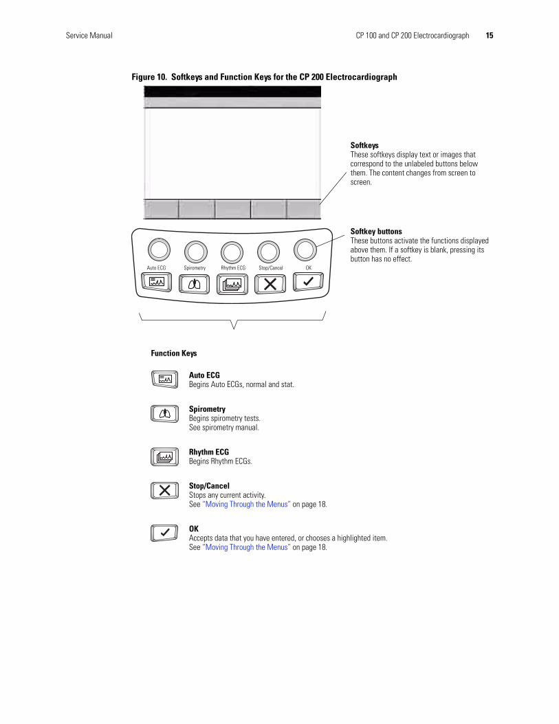
Figure 10. Softkeys and Function Keys for the CP 200 Electrocardiograph
SoftkeysThese softkeys display text or images that correspond to the unlabeled buttons below them. The content changes from screen to screen.
Softkey buttonsThese buttons activate the functions displayed above them. If a softkey is blank, pressing its button has no effect.
Function Keys
Auto ECGBegins Auto ECGs, normal and stat.
SpirometryBegins spirometry tests. See spirometry manual.
Rhythm ECGBegins Rhythm ECGs.
Stop/CancelStops any current activity. See “Moving Through the Menus” on page 18.
OKAccepts data that you have entered, or chooses a highlighted item. See “Moving Through the Menus” on page 18.
Auto ECG Spirometry Rhythm ECG Stop/Cancel OK
16 Overview Welch Allyn CP 100 and CP 200 Electrocardiograph
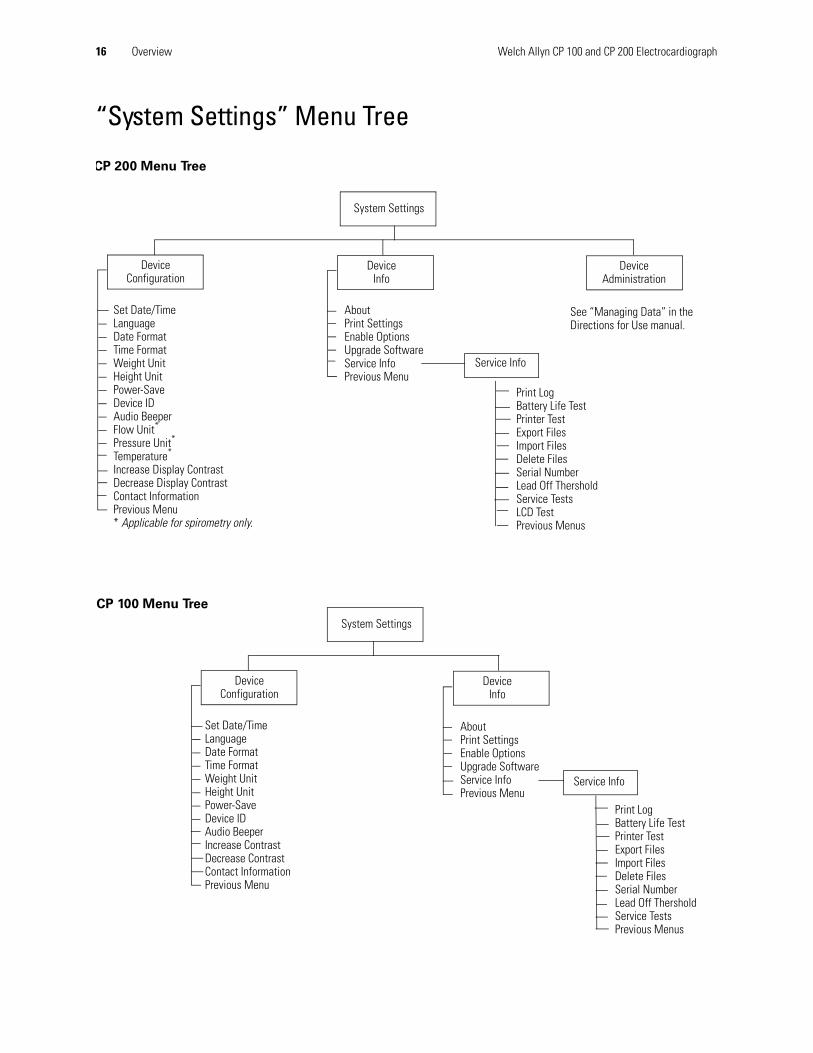
“System Settings” Menu Tree
System Settings
Device Configuration
DeviceInfo
Device Administration
Set Date/TimeLanguageDate FormatTime FormatWeight UnitHeight UnitPower-SaveDevice IDAudio BeeperFlow Unit*
Pressure Unit*
Temperature*
Increase Display ContrastDecrease Display ContrastContact InformationPrevious Menu* Applicable for spirometry only.
AboutPrint SettingsEnable OptionsUpgrade SoftwareService InfoPrevious Menu
See “Managing Data” in the Directions for Use manual.
Service Info
Print LogBattery Life TestPrinter TestExport FilesImport FilesDelete FilesSerial NumberLead Off ThersholdService TestsLCD TestPrevious Menus
CP 200 Menu Tree
System Settings
Device Configuration
Set Date/TimeLanguageDate FormatTime FormatWeight UnitHeight UnitPower-SaveDevice IDAudio BeeperIncrease ContrastDecrease ContrastContact InformationPrevious Menu
DeviceInfo
AboutPrint SettingsEnable OptionsUpgrade SoftwareService InfoPrevious Menu
Service Info
Print LogBattery Life TestPrinter TestExport FilesImport FilesDelete FilesSerial NumberLead Off ThersholdService TestsPrevious Menus
CP 100 Menu Tree

Service Manual CP 100 and CP 200 Electrocardiograph 17
About the Main MenuThe main menu appears when you press the Menu key .
Figure 11. Main Menu CP 200
Submenu Purpose Procedure
Test Directory View, change, print, or send saved tests. (CP 200 Only)
See the Directions for Use manual on your specific model.
Scheduled Patients View the scheduled patients list, add patients to the list, or delete patients from the list. (CP 200 Only
See the Directions for Use manual on your specific model.
ECG Settings Review or change ECG settings: Auto Report format, Rhythm Report format, and so on.
See the Directions for Use manual on your specific model.
Spirometry Settings Review or change spirometry settings: display settings, print settings, and so on. (CP 200 Only
See the Directions for Use manual on your specific model.
System Settings Review or change system settings: device configuration, device info, user setup, and so on.
See the Directions for Use manual on your specific model.
Edit Medication List Edit the list of medication choices available to choose during patient data entry. (CP 200 Only
See the Directions for Use manual on your specific model.
Edit History List Edit the list of clinical conditions available to choose during patient data entry. (CP 200 Only
See CP 200 Electrocardiograph Directions for Use manual.
Main Menu9:17AM Mar 16 05
1 Test Directory2 Scheduled Patients3 ECG Settings4 Spirometry Settings5 System Settings6 Edit Medication List7 Edit History List0 Exit
Main Menu9:17AM Mar 16 05
1 ECG Settings2 System Settings0 Exit
Figure 12. Main Menu CP 100
18 Overview Welch Allyn CP 100 and CP 200 Electrocardiograph
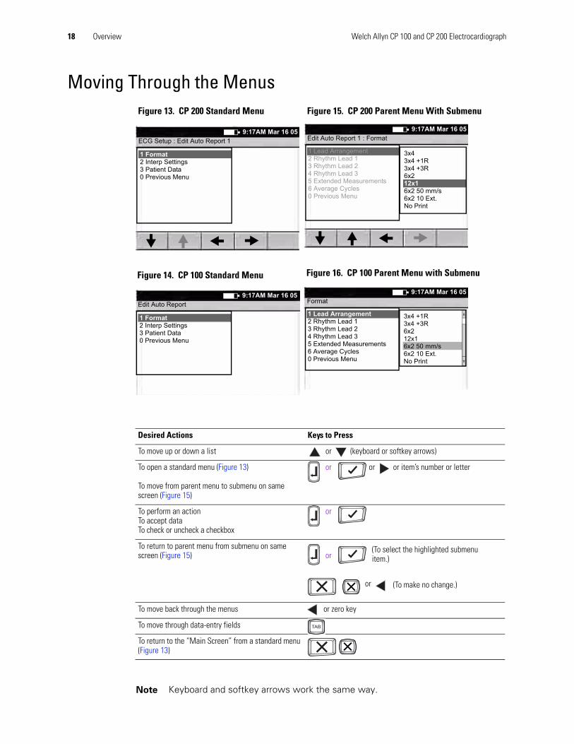
Moving Through the MenusFigure 13. CP 200 Standard Menu Figure 15. CP 200 Parent Menu With Submenu
Desired Actions Keys to Press
To move up or down a list or (keyboard or softkey arrows)
To open a standard menu (Figure 13)
To move from parent menu to submenu on same screen (Figure 15)
or or or item’s number or letter
To perform an actionTo accept dataTo check or uncheck a checkbox
or
To return to parent menu from submenu on same screen (Figure 15) or
or
To move back through the menus or zero key
To move through data-entry fields
To return to the “Main Screen” from a standard menu (Figure 13)
Note Keyboard and softkey arrows work the same way.
ECG Setup : Edit Auto Report 19:17AM Mar 16 05
1 Format2 Interp Settings3 Patient Data0 Previous Menu
Edit Auto Report9:17AM Mar 16 05
1 Format2 Interp Settings3 Patient Data0 Previous Menu
Figure 14. CP 100 Standard Menu
Edit Auto Report 1 : Format9:17AM Mar 16 05
1 Lead Arrangement2 Rhythm Lead 13 Rhythm Lead 24 Rhythm Lead 35 Extended Measurements6 Average Cycles0 Previous Menu
3x43x4 +1R3x4 +3R6x212x16x2 50 mm/s6x2 10 Ext.No Print
Format9:17AM Mar 16 05
1 Lead Arrangement2 Rhythm Lead 13 Rhythm Lead 24 Rhythm Lead 35 Extended Measurements6 Average Cycles0 Previous Menu
3x4 +1R3x4 +3R6x212x16x2 50 mm/s6x2 10 Ext.No Print
Figure 16. CP 100 Parent Menu with Submenu
(To select the highlighted submenu item.)
(To make no change.)

Service Manual CP 100 and CP 200 Electrocardiograph 19
Reviewing the Device Information1. Press the Menu key .
2. Choose System Settings > Device Info.
The following screen appears.
Figure 17. “Device Info” CP 200 Screen
3. Select the desired item:
Item Description
About Displays the following information about the electrocardiograph:
• serial number• modules configured• version numbers
Print Settings CP 200 = Prints your ECG, spirometry, and system settings as well as medication & history lists.CP 100 = Prints your ECG and system settings.
Enable Options Contact Technical Support. For phone numbers, see page ii.
Upgrade Software Contact Technical Support. For phone numbers, see page ii.
Service Info Accessible to service support only. See Service Menus (page 20)
System Setup : Device Info
1 About2 Print Settings3 Enable Options4 Upgrade Software5 Service Info0 Previous Menu
9:17AM Mar 16 05
Device Info
1 About2 Print Settings3 Enable Options4 Upgrade Software5 Service Info0 Previous Menu
9:17AM Mar 16 05
Figure 18. “Device Info” CP 100 Screen

20 Overview Welch Allyn CP 100 and CP 200 Electrocardiograph
CP 100 and CP 200 Electrocardiograph
Service Menus
Entering the Service Info ScreenThis menu is password protected and only Welch Allyn Authorized Technician can access the Service Menus,)
CP 200 Service Info Screen
Procedure Figure 19. CP 200 “User Login”1. Power ON unit.
2. Press Menu key.
3. Choose System Setting> Device Info> Service Info
The “UserLogin” screen appears. See Figure 19.
Use the “Tab” or “Arrow” keys to move the cursor from field to field.
Enter the following: User ID: Service (case sensitive)Password:normser (case sensitive)
4. Press “Done” using the softkey. Do not use the“Enter” key.
The “Service Info” screen appears see Figure 20
Figure 20. CP 200 “Service Info” Screen
9:17AM Mar 16 05
UserLogin
User ID
Password
ChangePassword
Cancel Done
Enter valid user ID and password
9:17AM Mar 16 05
1.Print Log2.Battery Life Test3.Printer Test4.Export Files5.Import Files6. Delete Files7.Serial Number8.Lead Off Thershold9.Service TestsA LCD Test0.Previous Menus
Service Info
Service Manual CP 100 and CP 200 Electrocardiograph 21
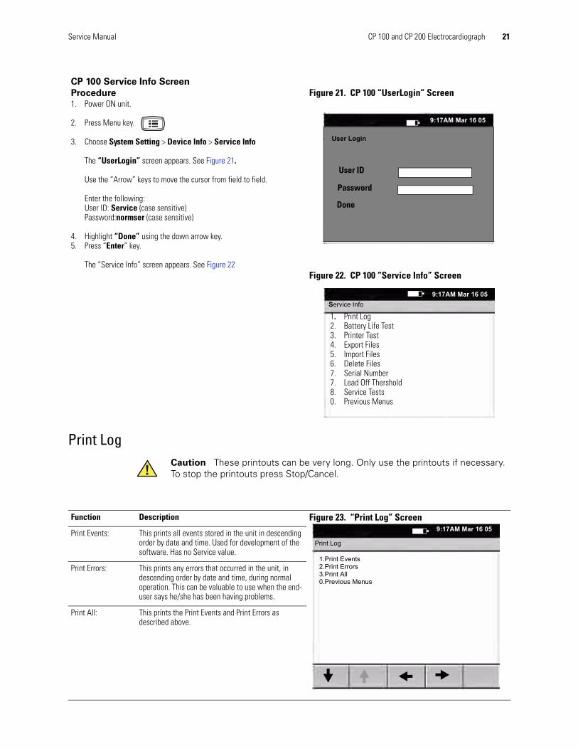
Print Log
CP 100 Service Info Screen
Procedure Figure 21. CP 100 “UserLogin” Screen1. Power ON unit.
2. Press Menu key.
3. Choose System Setting > Device Info > Service Info
The “UserLogin” screen appears. See Figure 21.
Use the “Arrow” keys to move the cursor from field to field.
Enter the following: User ID: Service (case sensitive)Password:normser (case sensitive)
4. Highlight “Done” using the down arrow key.5. Press “Enter” key.
The “Service Info” screen appears. See Figure 22Figure 22. CP 100 “Service Info” Screen
Caution These printouts can be very long. Only use the printouts if necessary. To stop the printouts press Stop/Cancel.
User Login
User ID
Password
Done
9:17AM Mar 16 05
9:17AM Mar 16 05Service Info
1. Print Log2. Battery Life Test3. Printer Test4. Export Files5. Import Files6. Delete Files7. Serial Number7. Lead Off Thershold8. Service Tests0. Previous Menus
Function Description Figure 23. “Print Log” Screen
Print Events: This prints all events stored in the unit in descending order by date and time. Used for development of the software. Has no Service value.
Print Errors: This prints any errors that occurred in the unit, in descending order by date and time, during normal operation. This can be valuable to use when the end-user says he/she has been having problems.
Print All: This prints the Print Events and Print Errors as described above.
9:17AM Mar 16 05
1.Print Events2.Print Errors3.Print All0.Previous Menus
Print Log

22 Overview Welch Allyn CP 100 and CP 200 Electrocardiograph
Battery Life Test This displays the percentage of battery life remaining on the battery, based on the number of charges it has incurred. This percentage approximates the life left in the battery based on this information.
Printer Test
Caution Only reset when the battery has been replaced and charged for at least 12hrs continuously.
Function Description Figure 24. “Battery Life Test” Screen
Reset Resets the battery life to 100%. This is used only when the battery has been replaced
Reset Pages Resets page count for the number of prints made on the printer. Should only be reset when print head has been replaced.
9:17AM Mar 16 05
Battery Life Test
Battery Life Remaining: 99%
ResetResetPages Exit
Function Description Figure 25. Printer Test” Screen
Test Page Prints a test page which repeats until the “Cancel” button is pressed. Refer to Functional Verification test for explanation. See Printer Test (page 35).
Ramp Test Prints a one page ramp test. Refer to Functional Verification test for explanation. See Printer Test (page 35).
9:17AM Mar 16 05
Printer Test
Select a print test
Test Page RampPage
Exit
Service Manual CP 100 and CP 200 Electrocardiograph 23
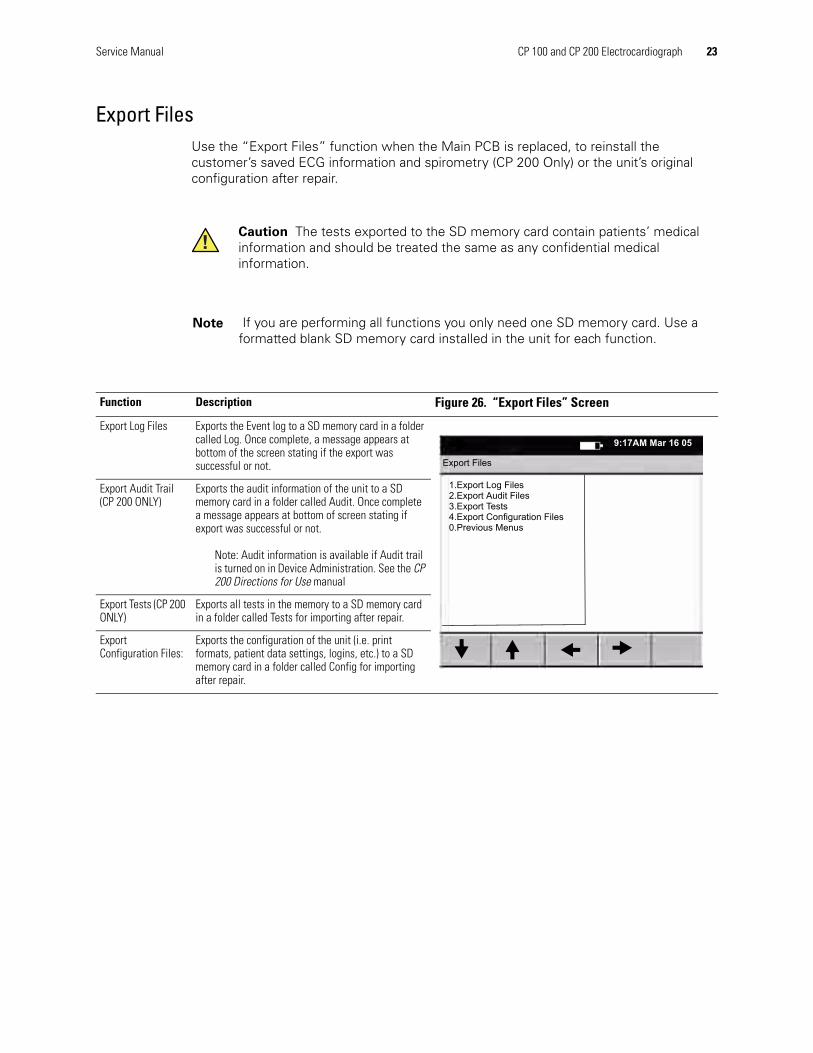
Export FilesUse the “Export Files” function when the Main PCB is replaced, to reinstall the customer’s saved ECG information and spirometry (CP 200 Only) or the unit’s original configuration after repair.
Caution The tests exported to the SD memory card contain patients’ medical information and should be treated the same as any confidential medical information.
Note If you are performing all functions you only need one SD memory card. Use a formatted blank SD memory card installed in the unit for each function.
Function Description Figure 26. “Export Files” Screen
Export Log Files Exports the Event log to a SD memory card in a folder called Log. Once complete, a message appears at bottom of the screen stating if the export was successful or not.
Export Audit Trail (CP 200 ONLY)
Exports the audit information of the unit to a SD memory card in a folder called Audit. Once complete a message appears at bottom of screen stating if export was successful or not.
Note: Audit information is available if Audit trail is turned on in Device Administration. See the CP 200 Directions for Use manual
Export Tests (CP 200 ONLY)
Exports all tests in the memory to a SD memory card in a folder called Tests for importing after repair.
Export Configuration Files:
Exports the configuration of the unit (i.e. print formats, patient data settings, logins, etc.) to a SD memory card in a folder called Config for importing after repair.
9:17AM Mar 16 05
1.Export Log Files2.Export Audit Files3.Export Tests4.Export Configuration Files0.Previous Menus
Export Files

24 Overview Welch Allyn CP 100 and CP 200 Electrocardiograph
Import Files
Delete Files
Function Description Figure 27. “Import Files” Screen
Import Tests (CP 200 ONLY)*
Imports previously exported tests from the SD memory card.
*Before importing tests, you must delete the previous copies from the unit using the “Delete Files” menu.
Import Configuration Files
Imports previously exported configuration files from SD memory card.
After the import configurations files process is complete, the screen displays a reset prompt. Press any key to reset, and then follow the prompts to set the date and time.
Caution No warning is displayed when you delete files/tests.
9:17AM Mar 16 05
1.Import Tests2.Import Configuration Files0.Previous Menus
Import Files
Function Description Figure 28. “Delete Files” Screen
Delete Log Files Deletes log files (event and error) from unit.
Delete Audit Files: (CP 200 ONLY)
Deletes the Audit Log file from the unit.
Delete Tests: (CP 200 ONLY)*
Deletes ALL saved ECG and Spirometry tests in memory.
Delete Configuration Files:
Deletes the Configuration files from the unit.
Note *Before importing the tests file, you must delete any previous tests from the unit using the “Delete Files” menu.
You do not have to delete the Configuration files on the unit before importing a Configuration files from SD memory card. All previous Configurations Files on the unit will be overwritten during the importing process.
9:17AM Mar 16 05
1.Delete Log Files2.Delete Audit Files3.Delete Tests4.Delete Configuration Files0.Previous Menus
Delete Files

Service Manual CP 100 and CP 200 Electrocardiograph 25
Serial NumberUsed to enter the S/N of the unit after a Main Board has been replaced.
Lead Off ThresholdThe Lead Off Threshold setting provides a mechanism to increase/decrease the sensitivity of the device to lead impedance. Lead impedance is the electrical resistance of a lead. Lead impedance can rise if there is poor electrode/skin contact. As lead impedance rises, the input signals become imbalanced, resulting in a poor quality signal.
If the lead impedance for any of the leads is above the threshold, the device replaces the poor quality signal received from the patient cable with a square wave to indicate to the user that the affected signals are not usable. The lead impedance of each of the leads is independent, but there is a single threshold value. The threshold can be any of 15 values, from 1 (lowest threshold) to 15 (highest threshold). The default threshold is 7. If the threshold is changed to 1, it causes Lead Off all of the time, and setting it to 15 causes the leads to never appear “Off”
Service TestsOnly authorized Welch Allyn Authorized Technicians are to perform the service tests.
Note For use by Welch Allyn Authorized Repair facilities.
Function Description
Lead Off Threshold The Lead Off Threshold setting is provided to diagnose problems with the front end. By increasing the Lead Off Threshold setting, the device accepts higher impedance signals, instead of replacing them with square waves. Although the device displays poorer quality signals, they may be unsuitable for diagnostic purposes, because they could be significantly distorted.
The Default setting for the Lead Off Threshold to 7
To access and change the Lead Off Threshold
Select Main Menu > Service Info > Device Info > Lead Off Threshold
Note To exit any of the applications press the “Enter” or”OK” key.
Function Description
CPWSTEST.EXE Used to help troubleshoot USB issues.Enable USB: Turns USB port on to be recognized by computer.
Disable USB: Turns USB port off so it is not recognized by computer.
MEANSMDWTESTER.EXE: Strictly used for development purposes.

26 Overview Welch Allyn CP 100 and CP 200 Electrocardiograph
MMCSDTEST.EXE: Used to test the SD memory card write/read function of the unit. Can also be used to test an SD memory card for problems.
GO: Starts the SD memory card test by pressing “G”
STOP: Stops the SD memory card test by pressing “S”
ERASE ALL: Erases all files written by this tester by pressing “E”
Card Present: If checked the unit detects the SD memory card inserted.
Write Protect: If checked the unit detects the lock is enabled on the SD memory card.
Pulse: Flashes when test is active
Note: Once the test is started it runs continuously. Press the “S” key to stop the test.
NORMANDY.EXE: Used to return to the ECG program.
NORMTESTER.EXE Strictly used for development purposes.
PPPTEST.EXE Strictly used for development purposes.
PPPTEST2.EXE Used to see battery and charger status/state. There are a number of selections on this screen. Listed below are the most commonly used functions. To activate a selection press the letter that coincides with the selection.
Real-time: Activates a real-time monitoring of the readings from the battery circuit.
Battery Voltage: Unplugged from AC this reflects the Voltage of the battery in millivolts; plugged into AC this reflects the charge voltage in millivolts.
Fast charge = 6800 – 7300Trickle charge = 6300 – 6800
Battery Current: Indicates charge current in mA when charger is on.
Charger State: Indicates if charge circuit is on or off
Charge State: Indicates if the Fast Charge is on or off
Fast Charge On: Turns fast charge on. If battery is fully charged the sensing circuit can work against you. It only changes the reading for a brief second before switching back.
Fast Charge Off: Turns fast charge off.
Charger On: Turns charger on when plugged into AC.
Charger Off: Turns charger off.
Function Description
Service Manual CP 100 and CP 200 Electrocardiograph 27
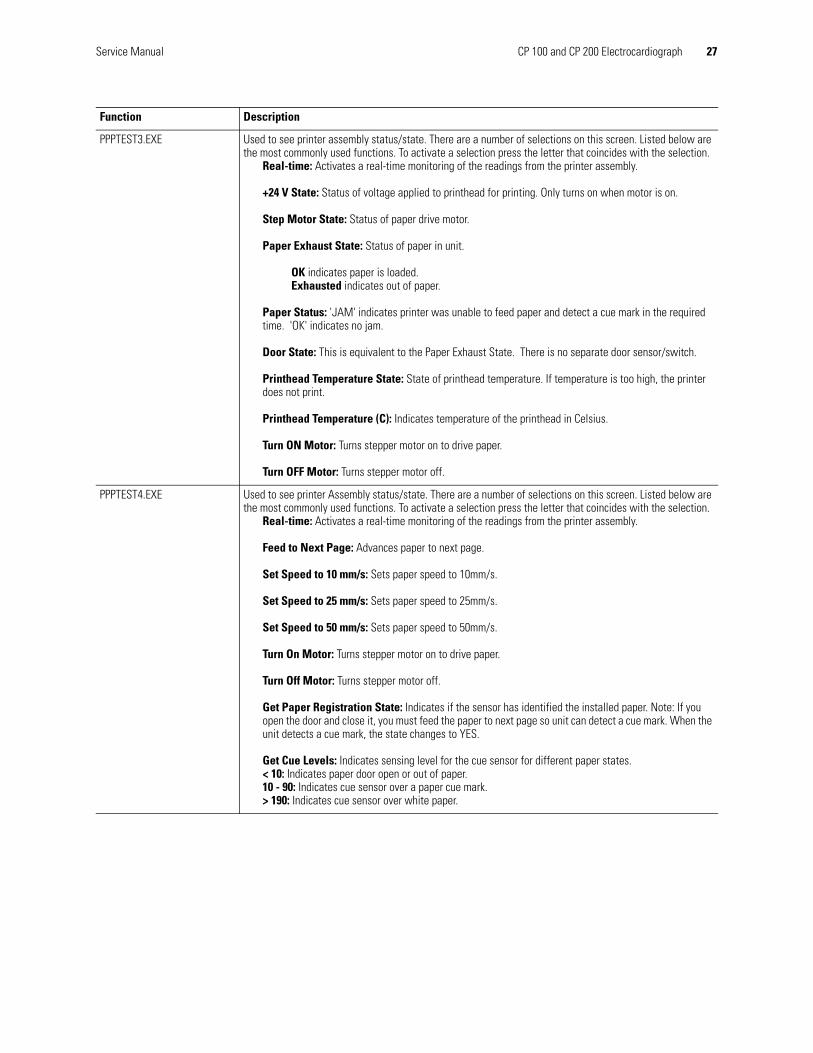
PPPTEST3.EXE Used to see printer assembly status/state. There are a number of selections on this screen. Listed below are the most commonly used functions. To activate a selection press the letter that coincides with the selection.
Real-time: Activates a real-time monitoring of the readings from the printer assembly.
+24 V State: Status of voltage applied to printhead for printing. Only turns on when motor is on.
Step Motor State: Status of paper drive motor.
Paper Exhaust State: Status of paper in unit.
OK indicates paper is loaded.Exhausted indicates out of paper.
Paper Status: 'JAM' indicates printer was unable to feed paper and detect a cue mark in the required time. 'OK' indicates no jam.
Door State: This is equivalent to the Paper Exhaust State. There is no separate door sensor/switch.
Printhead Temperature State: State of printhead temperature. If temperature is too high, the printer does not print.
Printhead Temperature (C): Indicates temperature of the printhead in Celsius.
Turn ON Motor: Turns stepper motor on to drive paper.
Turn OFF Motor: Turns stepper motor off.
PPPTEST4.EXE Used to see printer Assembly status/state. There are a number of selections on this screen. Listed below are the most commonly used functions. To activate a selection press the letter that coincides with the selection.
Real-time: Activates a real-time monitoring of the readings from the printer assembly.
Feed to Next Page: Advances paper to next page.
Set Speed to 10 mm/s: Sets paper speed to 10mm/s.
Set Speed to 25 mm/s: Sets paper speed to 25mm/s.
Set Speed to 50 mm/s: Sets paper speed to 50mm/s.
Turn On Motor: Turns stepper motor on to drive paper.
Turn Off Motor: Turns stepper motor off.
Get Paper Registration State: Indicates if the sensor has identified the installed paper. Note: If you open the door and close it, you must feed the paper to next page so unit can detect a cue mark. When the unit detects a cue mark, the state changes to YES.
Get Cue Levels: Indicates sensing level for the cue sensor for different paper states.< 10: Indicates paper door open or out of paper.10 - 90: Indicates cue sensor over a paper cue mark.> 190: Indicates cue sensor over white paper.
Function Description

28 Overview Welch Allyn CP 100 and CP 200 Electrocardiograph

3
29
Functional VerificationFunctional Verification Overview . . . . . . . . . . . . . . . . . . . . . . . . . . . . . . . . . . . . . . . . . . . 30
Full Functional Check . . . . . . . . . . . . . . . . . . . . . . . . . . . . . . . . . . . . . . . . . . . . . . . . . . . . 30
Equipment Required . . . . . . . . . . . . . . . . . . . . . . . . . . . . . . . . . . . . . . . . . . . . . . . . . . . . 30
Checklist and Test Results Report Form . . . . . . . . . . . . . . . . . . . . . . . . . . . . . . . . . . . . . 40
30 Functional Verification Welch Allyn CP 100 and CP 200 Electrocardiograph
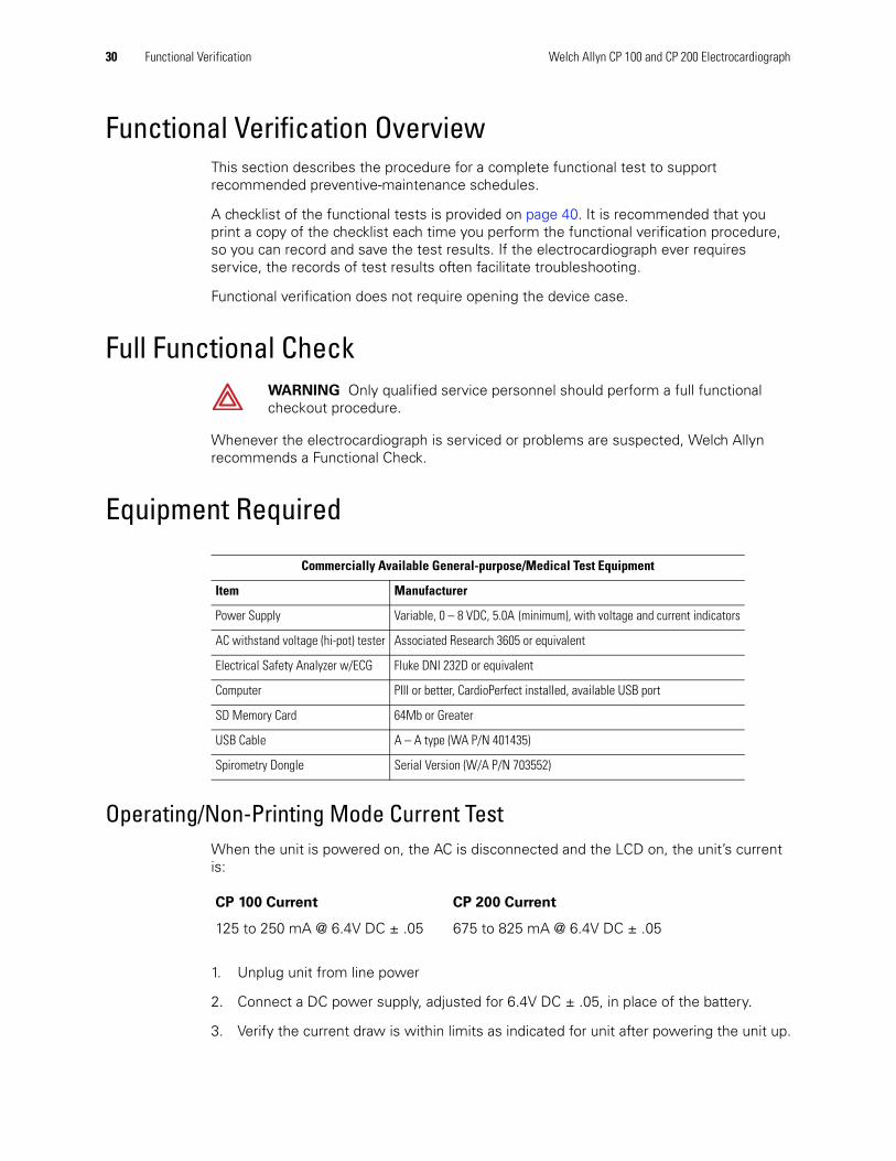
Functional Verification OverviewThis section describes the procedure for a complete functional test to support recommended preventive-maintenance schedules.
A checklist of the functional tests is provided on page 40. It is recommended that you print a copy of the checklist each time you perform the functional verification procedure, so you can record and save the test results. If the electrocardiograph ever requires service, the records of test results often facilitate troubleshooting.
Functional verification does not require opening the device case.
Full Functional Check
Whenever the electrocardiograph is serviced or problems are suspected, Welch Allyn recommends a Functional Check.
Equipment Required
Operating/Non-Printing Mode Current TestWhen the unit is powered on, the AC is disconnected and the LCD on, the unit’s current is:
1. Unplug unit from line power
2. Connect a DC power supply, adjusted for 6.4V DC ± .05, in place of the battery.
3. Verify the current draw is within limits as indicated for unit after powering the unit up.
WARNING Only qualified service personnel should perform a full functional checkout procedure.
Commercially Available General-purpose/Medical Test Equipment
Item Manufacturer
Power Supply Variable, 0 – 8 VDC, 5.0A (minimum), with voltage and current indicators
AC withstand voltage (hi-pot) tester Associated Research 3605 or equivalent
Electrical Safety Analyzer w/ECG Fluke DNI 232D or equivalent
Computer PIII or better, CardioPerfect installed, available USB port
SD Memory Card 64Mb or Greater
USB Cable A – A type (WA P/N 401435)
Spirometry Dongle Serial Version (W/A P/N 703552)
CP 100 Current CP 200 Current
125 to 250 mA @ 6.4V DC ± .05 675 to 825 mA @ 6.4V DC ± .05

Service Manual Functional Verification 31
Battery Accuracy TestWhen a voltage of 6.2 ± 0.05 VDC is supplied to the unit battery terminals, and the AC is disconnected from the unit, the unit reports a “Normal to High” voltage.
When a voltage of 5.45 ± 0.05VDC is supplied to the unit battery terminals, and the AC is disconnected from the unit, the unit reports a “critically low” voltage.
1. Unplug unit from line power.
2. Connect a DC power supply in place of the battery.
3. Adjust power supply to 6.2VDC.
4. Turn the unit on, and then verify the unit does not indicate a low or critically low battery.
5. Adjust power supply to 5.45 VDC.
6. Verify the unit indicates a critically low power and will shut down.
Sleep/Standby Mode Current TestWhen the unit is powered on and the AC is disconnected, and the unit is in low power standby mode, the unit’s current is:
1. Unplug the unit from line power and adjust the power supply to 6.4V DC ± .05.
2. Connect the DVM in series with the positive battery connection from the power supply.
3. Press the on/standby button.
4. Verify the LCD turns off and that the current draw is less than indicated for the unit.
5. Disconnect the power supply.
Charger Detect Test1. Connect a DVM to the battery harness while observing correct polarity.
2. Plug the unit into the AC power, and power ON.
3. Choose Main Menu > Systems Setting > Device info > Service Info > Service
Tests>PPPTEST2.EXE.See “Service Tests” on page 25.
Note The unit may have a 5 to 10 second delayed response.
CP 100 Current CP 200 Current
< 5 mA < 5 mA
Note There may be up to a 10 sec delay in the drop of current due to the progressive hibernation mode.

32 Functional Verification Welch Allyn CP 100 and CP 200 Electrocardiograph
4. Turn fast charge ON. Check DVM for 6.8 to 7.3 VDC.
5. Turn fast charge off. Check DVM for 6.3 to 6.8 VDC.
6. Unplug the unit from the AC power.
7. Disconnect the DVM and install the battery.
LED TestVerify the Power LED light is on when unit is plugged in, and verify the light is off when unit is unplugged.
1. Plug the unit into AC power.
2. Verify the AC indicator LED under the On/Standby button is lit.
3. Unplug the AC power cord.
4. Verify the LED is off.
5. Plug the unit back into AC power.
LCD Test
CP 200
1. Choose Main Menu > Systems Setting > Device info > Service Info > LCD Test.
2. Verify the test pattern is visible without breaks and is consistent over the entire screen.
3. Verify Contrast can be adjusted to adequately see the display.
CP 100
1. Disconnect the patient cable.
2. Turn ON unit. The patient hook up screen appears.
3. Verify the display is visible without breaks.
Set Unit Initial Configuration/SD Slot Test
Initial Configuration of Unit
1. Verify the Serial Number on the unit is the same as displayed on the unit’s screen. If incorrect, enter correct S/N. See ““System Settings” Menu Tree” on page 16, Service Info.
Note There may be a few seconds delay in the LED response to the line being removed and added.
Note If contrast adjustment is needed refer to the Directions for Use manual for CP 100.

Service Manual Functional Verification 33
Select Main Menu > System Settings > Device Info > Service Info > Serial
Number.
2. If the main board was replaced and a configuration files were exported, import the configuration files, see “Import Files” on page 24.
3. Print the Configuration of the unit.
Select Main Menu > System Settings > Device Info > Print Settings
4. Verify the settings from the printout.
a. Check for software version installed.
b. S/N of the unit.
c. Interpretation (if applicable).
If imported, check any customized customer settings.
SD Slot Test
1. Insert a formatted SD memory card into the unit.
2. Choose Main Menu > System Settings > Device info > Service Info > Service
Tests>MMCSDTEST.EXE file.
3. Press G to start the test. After 30 seconds the MyFile.TXT increases one increment.
4. Press S to stop the test and confirm that no errors are reported.
ECG Communication Test (ECG Input test and lead off)Test the patient cable and lead off indications connection.
1. Connect a known good Patient Cable w/leads
2. Connect to ECG simulator with V1/C1 lead disconnected.
3. Power ON unit.
4. Verify the lead placement screen shows V1/C1 lead flashing and all other leads should appear not flashing.
5. Remove LL from the Simulator and verify LL flashes with all V/C leads grayed, RA,LA & RL should not be flashing.
6. Connect all leads to the simulator.
7. Verify all leads stop flashing and the next screen appears in approximately three seconds.
Spirometer Communication Test
CP 200 (Only)
Verify and test the connection of a Spirometer Dongle to the serial port.
1. Attach a known good spirometer dongle to the spirometer port on the side of the unit.
2. Power ON unit.

34 Functional Verification Welch Allyn CP 100 and CP 200 Electrocardiograph
3. Press the Spirometry button
4. Verify that the unit opens the Spirometry module without errors.
USB Communications Test Verify the test connection between the unit and the CardioPerfect Workstation computer.
1. Connect the unit to the computer using a USB A-A Cable.
2. The computer should recognize the CP 200 connected and load the driver for communication.
3. Transfer an ECG record to the CardioPerfect Workstation.
a. Press the Menu button.
b. Choose Test Directory.
c. Press the Search softkey.
d. Press the WorkStation softkey.
4. Verify the record was transferred into the workstation.
Beeper TestTurn on and test the Audible beeper by using the keyboard keys.
1. Power On unit.
2. Choose Main Menu > System Settings > Device Configuration >Audio Beeper > set to ON.
3. Exit the Main Menu
4. Verify that an Audible beep is heard when invalid keys are pressed on the keyboard.
5. If the Audio Beeper was originally set to off, choose Main Menu >
System Settings > Device Configuration > Audio Beeper > set to OFF to return the Audio Beeper to its original setting.

Service Manual Functional Verification 35
Keyboard Test The unit detects all the keys pressed listed in Table 1, “Keyboard Keys”.
1. Power On unit.
2. Press Auto ECG. See Figure 9 on page 14 for button location.
3. The patient information screen appears.
4. Press the Keys indicated in Table 1, “Keyboard Keys” and verify the corresponding action.
5. Use the softkeys to verify the correct response for the keys (Only for the CP 200 unit). See Figure 10 on page 15.
Printer Test
1. Plug unit into AC power to perform the printer test.
2. Choose Main Menu > System Settings > Device Info > Service Info > Printer
Test.
3. Press the “Test Page” softkey. The test print starts after a few seconds.
4. Press the “Cancel” softkey when the second page has completed printing.
5. Use the second test print page to verify correct operation. See Table 2, “Print Verification Check List” and Figure 29 on page 36.
Table 1. Keyboard Keys
Key CP 100 CP 200’5’ 5 5‘R’ R R‘D’ D D‘X’ X XBackspace Back a space Back a space‘P’ P PDown Down a field Down a fieldUp Up a field Up a field
Note Please note these measurements are dependent upon the tracking of the paper being in the center. Please make sure there is no curling/crinkling of the paper at the top or bottom when printing.

36 Functional Verification Welch Allyn CP 100 and CP 200 Electrocardiograph
Table 2. Print Verification Check List
Figure 29. Test Printout Example
Point Description
Point A Verify the distance of the arc on the circle from the top edge of the paper is 37mm +/- 3mm
Point B Verify the distance of the arc on the circle from the left edge of the paper is 45mm +/- 5mm
Point C Verify line is straight and without breaks from top to bottom
Point D Verify thick black line is Uniform in Blackness without breaks from top to bottom
Point E Verify line is straight and measures 200mm +/- 4mm
Point F Verify the print is readable
Point G Verify the lead in and output trail of the cue sensor are between 19 and 82mm down from the 200mm line measured in point E
Point H Verify the cue sense pattern is between 97 and 135mm down from the 200mm line measured in point E

Service Manual Functional Verification 37
Ramp Page Test Printout
1. Press the Ramp Page key.
2. Verify the top of the ramp cuts off between 250 and 550 on the gauge printed.
Figure 30. Ramp Printout Example
38 Functional Verification Welch Allyn CP 100 and CP 200 Electrocardiograph
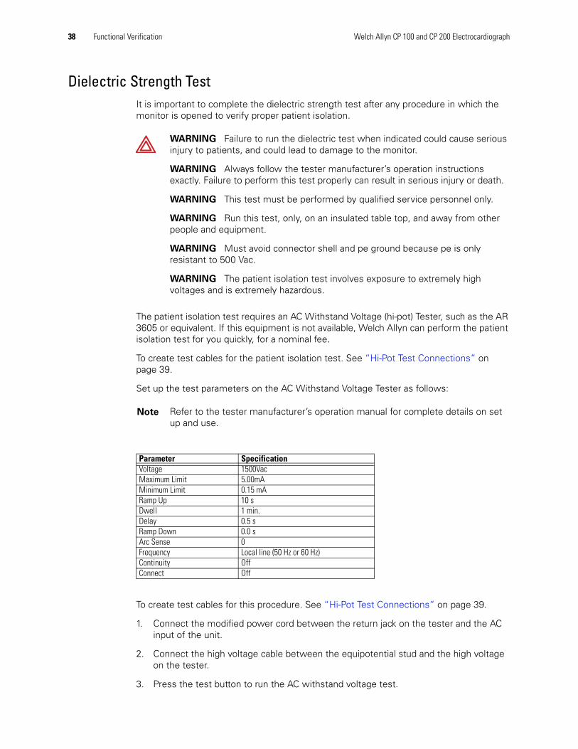
Dielectric Strength TestIt is important to complete the dielectric strength test after any procedure in which the monitor is opened to verify proper patient isolation.
The patient isolation test requires an AC Withstand Voltage (hi-pot) Tester, such as the AR 3605 or equivalent. If this equipment is not available, Welch Allyn can perform the patient isolation test for you quickly, for a nominal fee.
To create test cables for the patient isolation test. See “Hi-Pot Test Connections” on page 39.
Set up the test parameters on the AC Withstand Voltage Tester as follows:
To create test cables for this procedure. See “Hi-Pot Test Connections” on page 39.
1. Connect the modified power cord between the return jack on the tester and the AC input of the unit.
2. Connect the high voltage cable between the equipotential stud and the high voltage on the tester.
3. Press the test button to run the AC withstand voltage test.
WARNING Failure to run the dielectric test when indicated could cause serious injury to patients, and could lead to damage to the monitor.
WARNING Always follow the tester manufacturer’s operation instructions exactly. Failure to perform this test properly can result in serious injury or death.
WARNING This test must be performed by qualified service personnel only.
WARNING Run this test, only, on an insulated table top, and away from other people and equipment.
WARNING Must avoid connector shell and pe ground because pe is only resistant to 500 Vac.
WARNING The patient isolation test involves exposure to extremely high voltages and is extremely hazardous.
Note Refer to the tester manufacturer’s operation manual for complete details on set up and use.
Parameter SpecificationVoltage 1500VacMaximum Limit 5.00mAMinimum Limit 0.15 mARamp Up 10 sDwell 1 min.Delay 0.5 sRamp Down 0.0 sArc Sense 0Frequency Local line (50 Hz or 60 Hz)Continuity OffConnect Off

Service Manual Functional Verification 39
4. Verify the electrocardiograph passed the test. (If the unit current never exceeds 5.00mA, the shielding is sufficient.)
Hi-Pot Test Connections
Chassis, Earth and Patient Leakage Current TestsVerify continued electrical safety of the device, using IEC 60601-1 or ANSI/AAMI ES1 methods and limits. Test for the following:
• Earth leakage
• Chassis leakage
• Patient leakage
Cable Electrocardiograph Connection Hi-Pot Tester ConnectionConnector/
CableConnect to Wiring Connect to
Power Cord IEC Power cord AC Input Connector
Hot and neutral (black and white) wires connected together and terminated appropriately for your hi-pot tester. Cut and terminate the ground (green) wire to prevent possible injury.
Return
Note Refer to the Electrical Safety Analyzer manual for complete details on set-up and use for testing.
40 Functional Verification Welch Allyn CP 100 and CP 200 Electrocardiograph
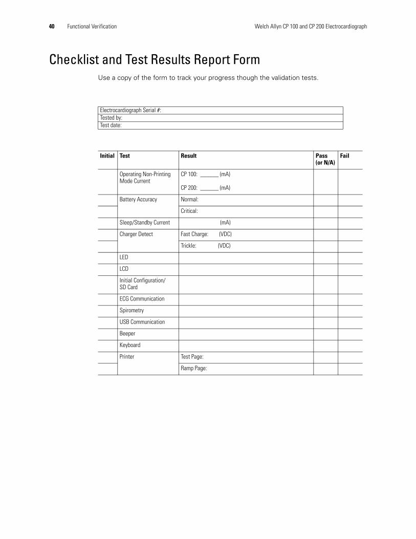
Checklist and Test Results Report FormUse a copy of the form to track your progress though the validation tests.
Electrocardiograph Serial #:Tested by:Test date:
Initial Test Result Pass(or N/A)
Fail
Operating Non-Printing Mode Current
CP 100: ______ (mA)
CP 200: ______ (mA)
Battery Accuracy Normal:
Critical:
Sleep/Standby Current (mA)
Charger Detect Fast Charge: (VDC)
Trickle: (VDC)
LED
LCD
Initial Configuration/SD Card
ECG Communication
Spirometry
USB Communication
Beeper
Keyboard
Printer Test Page:
Ramp Page:

4
41
TroubleshootingProblem-Solving Suggestions . . . . . . . . . . . . . . . . . . . . . . . . . . . . . . . . . . . . . . . . . . . . . 42
Limited Warranty . . . . . . . . . . . . . . . . . . . . . . . . . . . . . . . . . . . . . . . . . . . . . . . . . . . . . . . 45
Service Policy. . . . . . . . . . . . . . . . . . . . . . . . . . . . . . . . . . . . . . . . . . . . . . . . . . . . . . . . . . 46
42 Troubleshooting Welch Allyn CP 100 and CP 200 Electrocardiograph
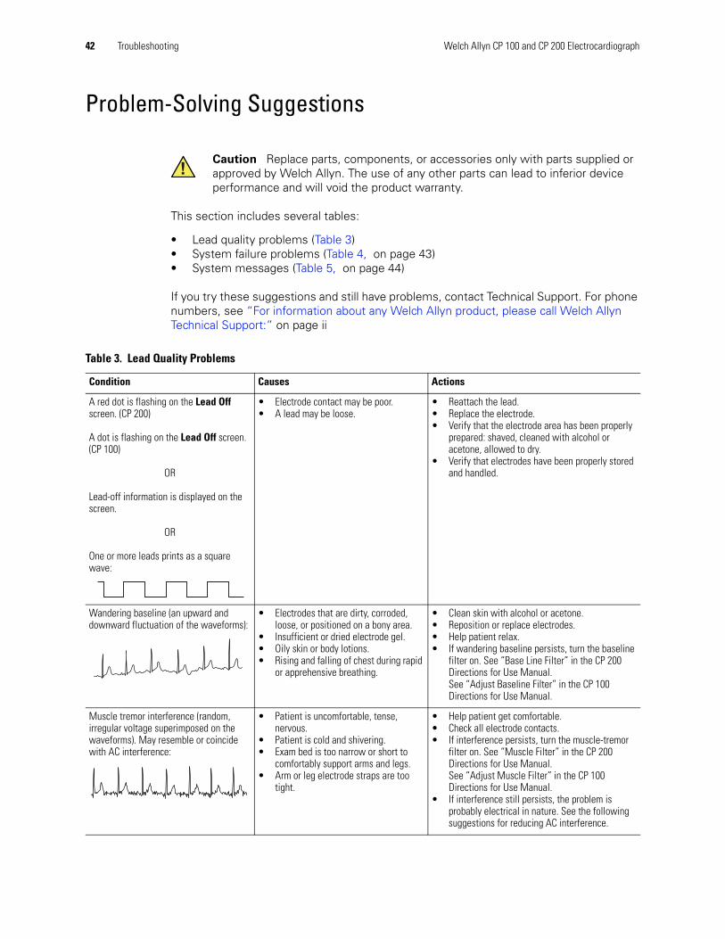
Problem-Solving Suggestions
This section includes several tables:
• Lead quality problems (Table 3)• System failure problems (Table 4, on page 43)• System messages (Table 5, on page 44)
If you try these suggestions and still have problems, contact Technical Support. For phone numbers, see “For information about any Welch Allyn product, please call Welch Allyn Technical Support:” on page ii
Caution Replace parts, components, or accessories only with parts supplied or approved by Welch Allyn. The use of any other parts can lead to inferior device performance and will void the product warranty.
Table 3. Lead Quality Problems
Condition Causes Actions
A red dot is flashing on the Lead Off screen. (CP 200)
A dot is flashing on the Lead Off screen. (CP 100)
OR
Lead-off information is displayed on the screen.
OR
One or more leads prints as a square wave:
• Electrode contact may be poor.• A lead may be loose.
• Reattach the lead.• Replace the electrode.• Verify that the electrode area has been properly
prepared: shaved, cleaned with alcohol or acetone, allowed to dry.
• Verify that electrodes have been properly stored and handled.
Wandering baseline (an upward and downward fluctuation of the waveforms):
• Electrodes that are dirty, corroded, loose, or positioned on a bony area.
• Insufficient or dried electrode gel.• Oily skin or body lotions.• Rising and falling of chest during rapid
or apprehensive breathing.
• Clean skin with alcohol or acetone.• Reposition or replace electrodes.• Help patient relax.• If wandering baseline persists, turn the baseline
filter on. See “Base Line Filter” in the CP 200 Directions for Use Manual. See “Adjust Baseline Filter” in the CP 100 Directions for Use Manual.
Muscle tremor interference (random, irregular voltage superimposed on the waveforms). May resemble or coincide with AC interference:
• Patient is uncomfortable, tense, nervous.
• Patient is cold and shivering.• Exam bed is too narrow or short to
comfortably support arms and legs.• Arm or leg electrode straps are too
tight.
• Help patient get comfortable.• Check all electrode contacts.• If interference persists, turn the muscle-tremor
filter on. See “Muscle Filter” in the CP 200 Directions for Use Manual.See “Adjust Muscle Filter” in the CP 100 Directions for Use Manual.
• If interference still persists, the problem is probably electrical in nature. See the following suggestions for reducing AC interference.

Service Manual Troubleshooting 43
AC interference (even-peaked, regular voltage superimposed on the waveforms). May resemble or coincide with muscle-tremor interference.
• Electrodes that are dirty, corroded, loose, or positioned on a bony area.
• Insufficient or dried electrode gel.• Patient or technician touching an
electrode during recording.• Patient touching any metal parts of an
exam table or bed.• Broken lead wire, patient cable, or
power cord.• Electrical devices in the immediate
area, lighting, concealed wiring in walls or floors.
• Improperly grounded electrical outlet.• Incorrect AC filter frequency setting or
AC filter is turned off.
• Check all electrode contacts and lead wires.• Verify that the patient is not touching any metal.• Verify that the AC power cable is not touching
the patient lead cable.• Verify that the proper AC filter is selected. See
“Mains Filter” in the Directions For Use manual.• If interference persists, unplug the
electrocardiograph from AC power and run it on the battery. If this solves the problem, you’ll know that the noise was introduced through the power line.
• If interference still persists, the noise may be caused by other equipment in the room or by poorly grounded power lines. Try moving to another room.
Table 3. Lead Quality Problems (continued)
Condition Causes Actions
Table 4. System Failure Problems
Condition Causes Actions
Won't turn on when plugged into AC power.
• Faulty AC power connection.• Blown AC fuses.• No AC power.
• Check the AC power source.• Check the AC fuses. See “Replacing the AC
Fuses” in the Directions for Use manual.
Won't turn on when unplugged from AC power.
• Battery disconnected or incorrectly connected.
• Battery low, not charging, depleted, or bad.
• Blown battery fuse.
• Check battery connections. See“Replacing the Battery or Fuse” on page 58.
• Recharge the battery. See “Recharging a Fully Discharged Battery” in the Directions for Use manual.
• Replace battery. See“Replacing the Battery or Fuse” on page 58.
• Replace battery fuse. See “Replacing the Battery (DC) Fuse” on page 60.
Shuts down during printing Battery low or bad. • Recharge the battery. See “Recharging a Fully Discharged Battery” in the Directions for Use manual.
• Replace battery. See“Replacing the Battery or Fuse” on page 58.
Prints fewer than 10 reports on a full battery charge.
Degraded battery. Replace battery. See“Replacing the Battery or Fuse” on page 58.

44 Troubleshooting Welch Allyn CP 100 and CP 200 Electrocardiograph
Table 5. System Messages (alphabetical order)
System Message Problems Actions
“A test is being printed that has not been saved and will be lost. Continue shutdown?” (CP 200)
was pressed while printing an Auto ECG.
To shut down without saving the test, press .
To cancel the shutdown, press .
“Audit Trail is too large. Please print and purge.” (CP 200)
Audit information is approaching its maximum allotted storage.
Print and purge the audit trail. See “Working With the Audit Trail”.
“Battery extremely low. Please connect AC power.”
Battery low or bad. • Recharge the battery. See “Recharging a Fully Discharged Battery” in the Directions for Use manual.
• Replace battery. See“Replacing the Battery or Fuse” on page 58.
“Insufficient space available” Not enough space on memory card. • Delete some tests from the card at a PC.• Use a different card.
“Memory card error” Problem writing to memory card. • Verify that the write-protect tab is in the unprotected position.
• Reseat the card in its slot.• Use a different card.
“Out Of Paper” • Printer is out of paper.• Printer door is open.
• Load paper. See “Loading the Thermal Chart Paper” in the Directions for Use.
• Close the printer door. See “Loading the Thermal Chart Paper” in the Directions for Use.
“Paper Error” (CP 200)“Paper Jam” ( CP 100)
Paper was loaded incorrectly. • Reload the paper. See “Loading the Thermal Chart Paper” in the Directions for Use.
“Powering down” Low battery. Recharge the battery. See “Recharging a Fully Discharged Battery”.
“Problem loading the following settings:<System><ECG>***Using default settings.”
Problem loading your settings at startup. May indicate memory problems.
Contact Technical Support. For phone numbers, see page ii.
“Shutdown?” was pressed while printing a Rhythm ECG.
To shut down, press .
To cancel the shutdown, press .
“Temperature Error” Printer head temp is too high. Allow to cool, then try again.
“Test has not been saved. Continue shutdown?” (CP 200)
was pressed after printing an Auto ECG.
To shut down without saving the test, press .
To cancel the shutdown, press .
“Unable to communicate with workstation“ (CP 200)
• Configuration not correct.• Cable not properly connected.
• Verify communication settings on the PC. • Check cable connections.

Service Manual Troubleshooting 45
Limited WarrantyWelch Allyn, Inc., warrants that the Cardiopulmonary line of electrocardiographs, including the CP 100 and CP 200 models (the Products) meet the labeled specifications of the Products and will be free from defects in materials and workmanship that occur within 3 years after the date of purchase, except that accessories used with the Products are warranted for 90 days after the date of purchase. Such accessories include: lead wires, cabling, electrodes, and battery.
The date of purchase is: 1) the date specified in our records, if you purchased the Product directly from us, 2) the date specified in the warranty registration card that we ask you to send to us, or 3) if you don’t return the warranty registration card, 30 days after the date on which the Product was sold to the dealer from whom you bought the Product, as documented in our records.
This warranty does not cover damage caused by: 1) handling during shipping, 2) use or maintenance contrary to labeled instructions, 3) alteration or repair by anyone not authorized by Welch Allyn, and 4) accidents.
If a Product or accessory covered by this warranty is determined to be defective because of defective materials, components, or workmanship, and the warranty claim is made within the warranty period described above, Welch Allyn will, at its discretion, repair or replace the defective Product or accessory free of charge. If your Product requires repairs covered by this warranty, upon your request Welch Allyn will loan to you, at no cost, a substitute Product for use until your repaired Product is returned.
You must obtain a return authorization from Welch Allyn to return your Product before you send it to Welch Allyn’s designated service center for repair. Contact Welch Allyn Technical Support. For phone numbers, see page ii.
THIS WARRANTY IS IN LIEU OF ALL OTHER WARRANTIES, EXPRESS OR IMPLIED, INCLUDING BUT NOT LIMITED TO THE IMPLIED WARRANTIES OF MERCHANTABILTY AND FITNESS FOR A PARTICULAR PURPOSE. WELCH ALLYN’S OBLIGATION UNDER THIS WARRANTY IS LIMITED TO REPAIR OR REPLACEMENT OF PRODUCTS CONTAINING A DEFECT. WELCH ALLYN IS NOT RESPONSIBLE FOR ANY INDIRECT OR CONSEQUENTIAL DAMAGES RESULTING FROM A PRODUCT DEFECT COVERED BY THE WARRANTY.

46 Troubleshooting Welch Allyn CP 100 and CP 200 Electrocardiograph
Service PolicyAll repairs on products under warranty must be performed or approved by Welch Allyn. Unauthorized repairs will void the warranty. In addition, whether or not covered under warranty, any product repair shall exclusively be performed by Welch Allyn certified service personnel.
If the product fails to function properly—or if you need assistance, service, or spare parts—contact the nearest Welch Allyn Technical Support Center. For phone numbers, see page ii.
Before contacting Welch Allyn, try to duplicate the problem, and check all accessories to ensure that they are not causing the problem. When calling, please be prepared to provide:
• Product name and model number and complete description of the problem.• Serial number of your product (if applicable).• Complete name, address and phone number of your facility.• For out-of-warranty repairs or spare parts orders, a purchase order (or credit card)
number.• For parts orders, the required spare or replacement part numbers.
If your product requires warranty, extended warranty, or non-warranty repair service, please call first the nearest Welch Allyn Technical Support Center. A representative will assist you troubleshooting the problem and will make every effort to solve it over the phone, avoiding potential unnecessary returns.
In case a return cannot be avoided, the representative will record all necessary information and will provide a Return Material Authorization (RMA) number, as well as the appropriate return address. An RMA number must be obtained prior to any return.
If you have to return goods for service, follow these recommended packing instructions:
• Remove all hoses, cables, sensors, power cords, and ancillary products (as appropriate) before packing, unless you suspect they are associated with the problem.
• Wherever possible use the original shipping carton and packing materials. • Include a packing list and the Welch Allyn Return Material Authorization (RMA)
number.
It is recommended that all returned goods be insured. Claims for loss or damage to the product must be initiated by the sender.

5
47
Disassembly and Repair ProceduresIntroduction . . . . . . . . . . . . . . . . . . . . . . . . . . . . . . . . . . . . . . . . . . . . . . . . . . . . . . . . . . . 48
Screws. . . . . . . . . . . . . . . . . . . . . . . . . . . . . . . . . . . . . . . . . . . . . . . . . . . . . . . . . . . . . . . 48
Torque Specs . . . . . . . . . . . . . . . . . . . . . . . . . . . . . . . . . . . . . . . . . . . . . . . . . . . . . . . . . . 48
Disassembly Procedures . . . . . . . . . . . . . . . . . . . . . . . . . . . . . . . . . . . . . . . . . . . . . . . . . 49

48 Disassembly and Repair Procedures Welch Allyn CP 100 and CP 200 Electrocardiograph
IntroductionThese procedures cover CP 200 and CP 100 electrocardiograph disassembly for sub-assemblies and board removal. Unless otherwise noted:
• The procedure is the same for both units.
• The assembly procedure is the reverse of the disassembly procedure.
Screws
Torque SpecsThe Following are recommended torque specs for all screws and hex nuts..
Caution Perform all repair procedures at a static-protected station. Observe recommended screw torque specifications, especially with screws that secure directly into plastic standoffs.
WARNING The battery can deliver currents sufficient to cause serious personal injury and to damage the electrocardiograph. When opening the electrocardiograph for any reason, always remove and disconnect the battery immediately, before proceeding with disassembly.
Caution To avoid mismatching screws and holes, keep the screws for each piece with the piece as you remove modules, circuit assemblies, and other components.
Table 6. Torque Specifications s
Qty Location Part Number Type Torque (English) Torque (Metric)1 Paper Drive Gear 700091 Set Screw 3.5 +/- .25 lbf-in 395 + /- 28 mN-m4 Paper Cover Latch 711776 Machine 3.5 +/- .25 lbf-in 395 + /- 28 mN-m2 Drive Motor 700140 Machine 3.5 +/- .25 lbf-in 395 + /- 28 mN-m1 Drive Motor Gear 700091 Set Screw 3.5 +/- .25 lbf-in 395 + /- 28 mN-m3 Gear Box Assembly 711776 Machine 3.5 +/- .25 lbf-in 395 + /- 28 mN-m2 Paper Sensor Board 711776 Machine 3.5 +/- .25 i lbf-in 395 + /- 28 mN-m2 Print head mount 700118 Shoulder Screw 4 +/- .25 lbf-in 452 +/- 28 mN-m1 Ground to Shoulder Screw 106137-1 Hex nut 3.5 +/- .25 lbf-in 395 + /- 28 mN-m3 Paper Guide 711776 Machine 3.5 +/- .25 lbf-in 395 + /- 28 mN-m2 Ground Plug 102-0001 Hex Nut 16 +/- .25 lbf-in 1.81+/- .028 N-m4 Power Supply 106124-4 Machine 3.5 +/- .25 lbf-in 395 + /- 28 mN-m5 Main PCB 106124-4 Machine 3.5 +/- .25 lbf-in 395 + /- 28 mN-m4 LCD Assembly / Bracket 106140-3 Machine 3.5 +/- .25 lbf-in 395 + /- 28 mN-m2 Inverter Board 200076-1 Thread-Forming 1 +/- .25 lbf-in 113 +/- 28 mN-m5 Function Key Board 106124-4 Machine 3.5 +/- .25 lbf-in 395 + /- 28 mN-m13 QWERTY Keyboard 106124-13 Thread-Forming 1 +/- .25 lbf-in 113 +/- 28 mN-m4 Printer Assembly 703247 Machine 3.5 +/- .25 lbf-in 395 + /- 28 mN-m8 Housing 703247 Machine 3.5 +/- .25 lbf-in 395 + /- 28 mN-m2 Battery Cover 703247 Machine 3.5 +/- .25 lbf-in 395 + /- 28 mN-m

Service Manual CP 100 and CP 200 Electrocardiograph 49
Disassembly Procedures
Opening the Unit
WARNING Disconnect ALL power from the unit before repairing or disassembling unit. Unplug the power cord and disconnect the battery at the fuse in the battery compartment. See Replacing the Battery or Fuse (page 58)
Procedure Figure 31. Removing the Screws
1. Place unit on a clean, static mat.
2. Turn the unit up-side-down
3. Remove the 8 screws around the outside rim of the unit. SeeFigure 31.
4. Using both hands, hold the upper case and lower case of the unit together, turn the unit upright.
5. Slowly lift the upper case, and disconnect the ribbon cable from the upper case.
6. Lift off the top cover. See Figure 32.
Figure 32. Disconnecting the Ribbon Cable
Screws
Ribbon Cable
Upper Case
Lower Case
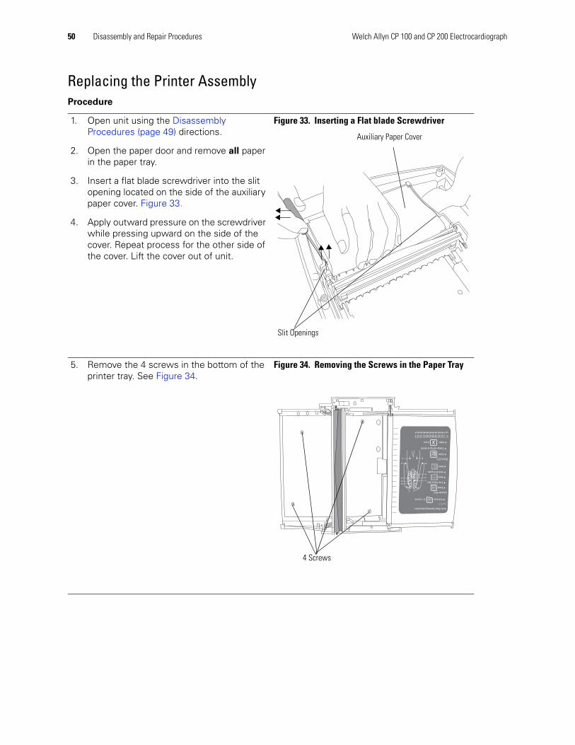
50 Disassembly and Repair Procedures Welch Allyn CP 100 and CP 200 Electrocardiograph
Replacing the Printer AssemblyProcedure
1. Open unit using the Disassembly Procedures (page 49) directions.
2. Open the paper door and remove all paper in the paper tray.
3. Insert a flat blade screwdriver into the slit opening located on the side of the auxiliary paper cover. Figure 33.
4. Apply outward pressure on the screwdriver while pressing upward on the side of the cover. Repeat process for the other side of the cover. Lift the cover out of unit.
Figure 33. Inserting a Flat blade Screwdriver
5. Remove the 4 screws in the bottom of the printer tray. See Figure 34.
Figure 34. Removing the Screws in the Paper Tray
Auxiliary Paper Cover
Slit Openings
QuickStepOperatingInstructions
StatECG StatECG
Holddownfor1second
AutomaticECG
Select
EnterPatientData
SelectDONE
VerifyECGquality
Select
RhythmECG
Selecttoend
Select
Changesettingsasdesired
PrintECG
IECC1C2C3C4C5C6RLNF
AAMIV1V2V3V4V5V6RALARLLL
VI
V2
V3
R4
V4
V5
V6
LA
LL RL
4 Screws
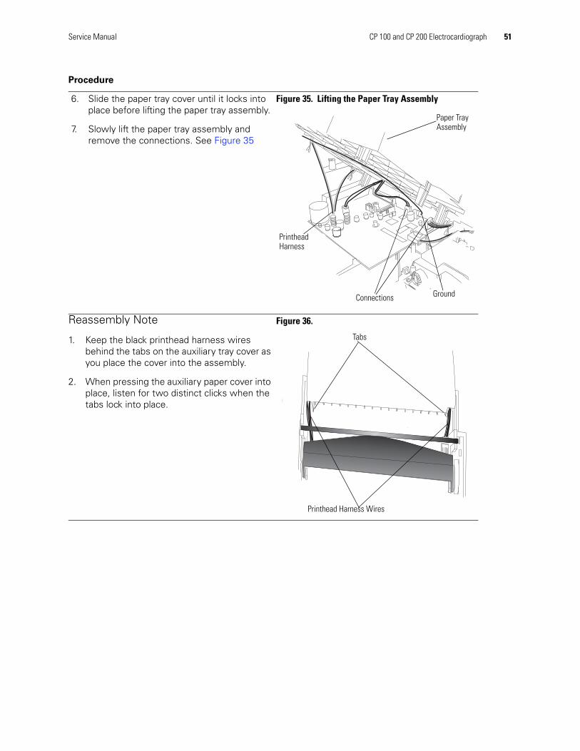
Service Manual CP 100 and CP 200 Electrocardiograph 51
6. Slide the paper tray cover until it locks into place before lifting the paper tray assembly.
7. Slowly lift the paper tray assembly and remove the connections. See Figure 35
Figure 35. Lifting the Paper Tray Assembly
Reassembly Note
1. Keep the black printhead harness wires behind the tabs on the auxiliary tray cover as you place the cover into the assembly.
2. When pressing the auxiliary paper cover into place, listen for two distinct clicks when the tabs lock into place.
Figure 36.
Procedure
Paper Tray Assembly
Connections
Printhead Harness
Ground
Printhead Harness Wires
Tabs

52 Disassembly and Repair Procedures Welch Allyn CP 100 and CP 200 Electrocardiograph
Replacing the Paper Tray CoverProcedure
1. Open the unit using the Disassembly Procedures (page 49) directions.
2. Next, remove the paper tray cover. See Replacing the Printer Assembly (page 50).
3. Slide the paper tray cover out until it stops. See Figure 37.
Figure 37. Sliding the Paper Tray Cover
4. Turn paper tray assembly up-side-down.
5. Remove the 3 screws holding the paper guide. See Figure 38.
Figure 38. Bottom of the Paper Tray Assembly
QuickStepOperatingInstructions
StatECG StatECG
Holddownfor1second
AutomaticECG
Select
EnterPatientData
SelectDONE
VerifyECGquality
Select
RhythmECG
Selecttoend
Select
Changesettingsasdesired
PrintECG
IECC1C2C3C4C5C6RLNF
AAMIV1V2V3V4V5V6RALARLLL
VI
V2
V3
R4
V4
V5
V6
LA
LL RL
Paper Tray Cover
Screws holding paper guide
Bottom of paper tray cover

Service Manual CP 100 and CP 200 Electrocardiograph 53
6. Turn the paper tray assembly upright.
7. Slide the paper tray cover in half way until the paper guide drops into the paper tray.
8. Slide the paper tray cover out to remove it. Figure 39.
Figure 39. Removing the Paper Tray Cover
Reassembly Note
1. Slide the paper tray cover half way into the paper tray assembly.
2. Place the paper guide under the roller on the paper tray cover.
3. While holding the paper guide in place, slide the paper tray cover out until it hits the stop.
4. Turn the paper assembly up-side-down.
5. Replace the 3 screws in the holes located in the bottom of the paper tray assembly. See Figure 38.
Procedure
QuickStepOperatingInstructions
StatECG StatECG
Holddownfor1second
AutomaticECG
Select
EnterPatientData
SelectDONE
VerifyECGquality
Select
RhythmECG
Selecttoend
Select
Changesettingsasdesired
PrintECG
IECC1C2C3C4C5C6RLNF
AAMIV1V2V3V4V5V6RALARLLL
VI
V2
V3
R4
V4
V5
V6
LA
LL RL
Paper GuidePrinthead Direction to Slide Tray Cover to Drop Paper Guide into the Tray.
Direction to Slide Paper Tray Cover to

54 Disassembly and Repair Procedures Welch Allyn CP 100 and CP 200 Electrocardiograph
Replacing the Platen RollerProcedure
1. Open unit using the Disassembly Procedures (page 49) directions.
2. Remove printer assembly using the Replacing the Printer Assembly (page 50) directions.
3. Remove the paper tray cover using the Replacing the Paper Tray Cover (page 52) directions.
To remove the platen roller
4. Loosen the set screw using a T5 Torx on the drive gear and slide the drive gear off the platen roller shaft.
5. Remove the retaining ring from both ends of the platen roller.
6. Lift the platen roller shaft out of the paper tray cover on the end opposite the drive gear.
7. Slide the roller out.
Figure 40. Platen Roller
Reassemble Note
First, place the hardware into the side opposite the drive gear for ease of assembly.
Quic
kS
tep
Opera
ting
Instru
ctio
ns
Sta
tE
CG
Sta
tE
CG
Ho
ldd
ow
nfo
r1
se
co
nd
Auto
matic
EC
G
Se
lect
En
ter
Pa
tien
tD
ata
Se
lect
DO
NE
Ve
rifyE
CG
qu
ality
Se
lect
Rh
yth
mE
CG
Se
lect
toe
nd
Se
lect
Ch
an
ge
se
tting
sa
sd
esire
d
Prin
tE
CG
IEC
C1
C2
C3
C4
C5
C6
RL
NF
AA
MI
V1
V2
V3
V4
V5
V6
RA
LA
RL
LL
VI
V2
V3
R4
V4
V5
V6
LA
LL
RL
Paper Tray Cover
Drive Gear
Platen Roller
Set Screw
Bearings
Retaining Ring
Bearings
Place the bearings in this side first for ease of assembly.
Retaining Ring
SpacersSpacers
Spring
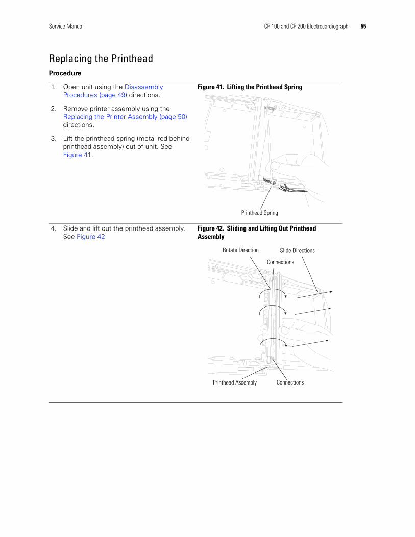
Service Manual CP 100 and CP 200 Electrocardiograph 55
Replacing the PrintheadProcedure
1. Open unit using the Disassembly Procedures (page 49) directions.
2. Remove printer assembly using the Replacing the Printer Assembly (page 50) directions.
3. Lift the printhead spring (metal rod behind printhead assembly) out of unit. See Figure 41.
Figure 41. Lifting the Printhead Spring
4. Slide and lift out the printhead assembly. See Figure 42.
Figure 42. Sliding and Lifting Out Printhead Assembly
Printhead Spring
Printhead Assembly
Rotate Direction Slide Directions
Connections
Connections
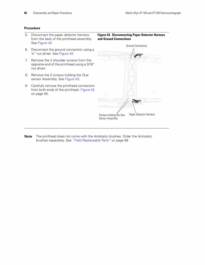
56 Disassembly and Repair Procedures Welch Allyn CP 100 and CP 200 Electrocardiograph
5. Disconnect the paper detector harness from the back of the printhead assembly. See Figure 43
6. Disconnect the ground connection using a ¼” nut driver. See Figure 43
7. Remove the 2 shoulder screws from the opposite end of the printhead using a 3/16” nut driver.
8. Remove the 2 screws holding the Que sensor Assembly. See Figure 43.
9. Carefully remove the printhead connectors from both ends of the printhead. Figure 42 on page 55.
Figure 43. Disconnecting Paper Detector Harness and Ground Connections
Note The printhead does not come with the Antistatic brushes. Order the Antistatic brushes separately. See “Field Replaceable Parts” on page 69
Procedure
Ground Connection
Paper Detector HarnessScrews holding the Que Sensor Assembly
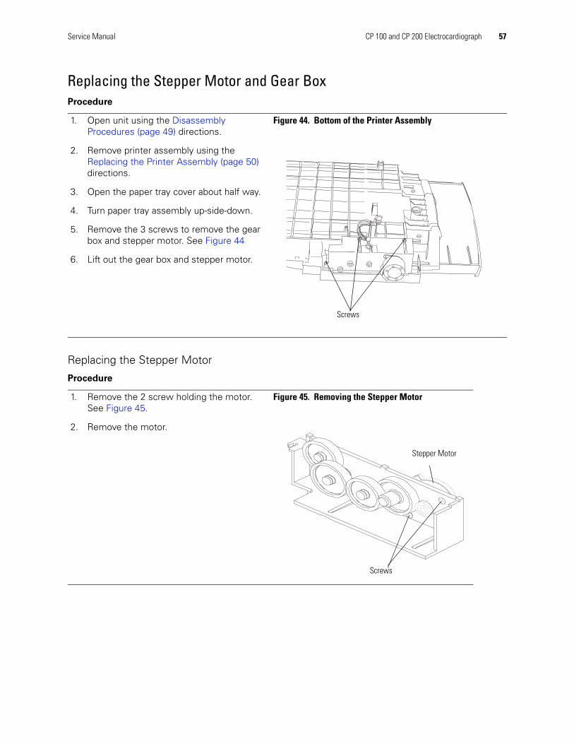
Service Manual CP 100 and CP 200 Electrocardiograph 57
Replacing the Stepper Motor and Gear Box
Replacing the Stepper Motor
Procedure
1. Open unit using the Disassembly Procedures (page 49) directions.
2. Remove printer assembly using the Replacing the Printer Assembly (page 50) directions.
3. Open the paper tray cover about half way.
4. Turn paper tray assembly up-side-down.
5. Remove the 3 screws to remove the gear box and stepper motor. See Figure 44
6. Lift out the gear box and stepper motor.
Figure 44. Bottom of the Printer Assembly
Procedure
1. Remove the 2 screw holding the motor. See Figure 45.
2. Remove the motor.
Figure 45. Removing the Stepper Motor
Screws
Stepper Motor
Screws

58 Disassembly and Repair Procedures Welch Allyn CP 100 and CP 200 Electrocardiograph
Replacing the Battery or FuseProcedure
1. Turn the electrocardiograph up-side-down.
2. Unscrew and remove the battery door. See Figure 46.
Figure 46. Removing the Battery Door
3. Lift out the battery. See Figure 47.Figure 47. Lifting Out the Battery
4. Inspect the fuse. See Figure 48.
• If the “Z” wire is intact, go to Step 5.
• If the “Z” wire is broken or dark, replace the fuse. See “Replacing the Battery (DC) Fuse” on page 60.
Figure 48. Battery Fuse Plugged In
Battery door
Battery
Fuse
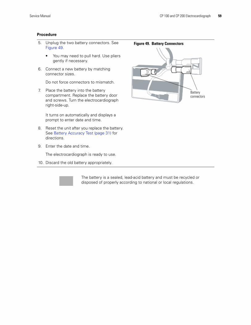
Service Manual CP 100 and CP 200 Electrocardiograph 59
5. Unplug the two battery connectors. See Figure 49.
• You may need to pull hard. Use pliers gently if necessary.
6. Connect a new battery by matching connector sizes.
Do not force connectors to mismatch.
7. Place the battery into the battery compartment. Replace the battery door and screws. Turn the electrocardiograph right-side-up.
It turns on automatically and displays a prompt to enter date and time.
8. Reset the unit after you replace the battery. See Battery Accuracy Test (page 31) for directions.
9. Enter the date and time.
The electrocardiograph is ready to use.
10. Discard the old battery appropriately.
Figure 49. Battery Connectors
Procedure
Batteryconnectors
The battery is a sealed, lead-acid battery and must be recycled or disposed of properly according to national or local regulations.
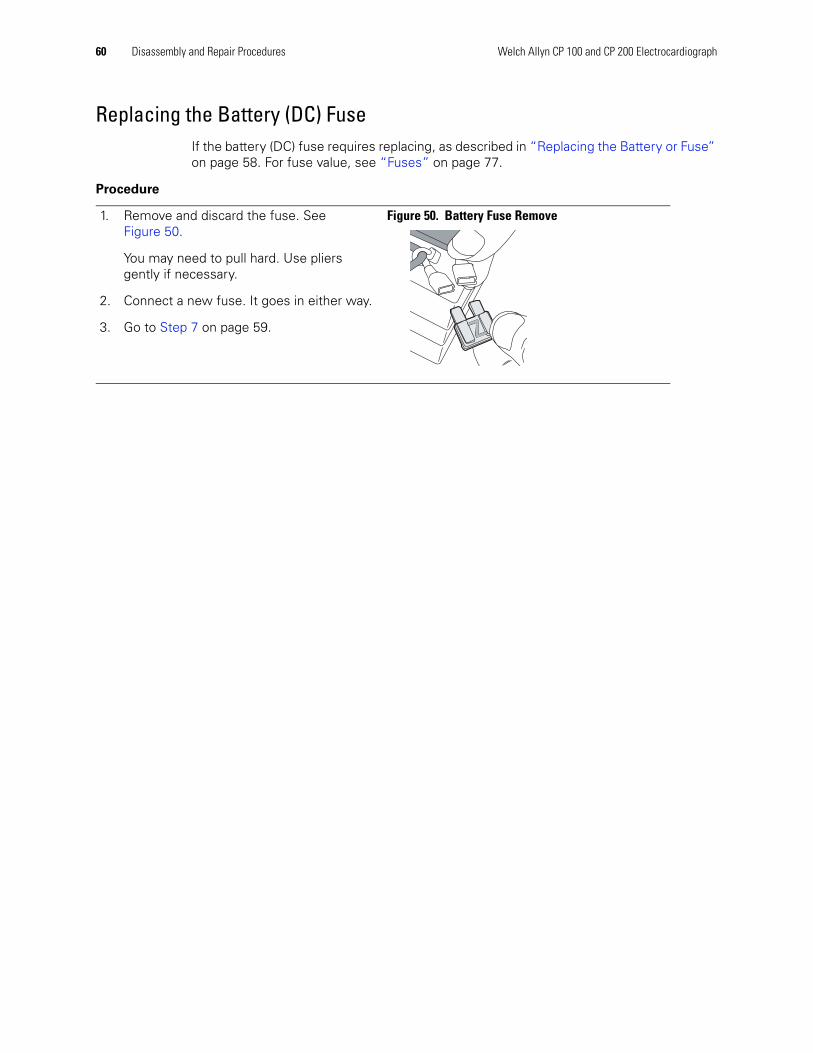
60 Disassembly and Repair Procedures Welch Allyn CP 100 and CP 200 Electrocardiograph
Replacing the Battery (DC) FuseIf the battery (DC) fuse requires replacing, as described in “Replacing the Battery or Fuse” on page 58. For fuse value, see “Fuses” on page 77.
Procedure
1. Remove and discard the fuse. See Figure 50.
You may need to pull hard. Use pliers gently if necessary.
2. Connect a new fuse. It goes in either way.
3. Go to Step 7 on page 59.
Figure 50. Battery Fuse Remove

Service Manual CP 100 and CP 200 Electrocardiograph 61
Replacing the Main BoardProcedure
1. Open unit using the Disassembly Procedures (page 49) directions.
2. Remove printer assembly using the Replacing the Printer Assembly (page 50) directions.
3. Disconnect the locking connection for the power supply and the battery.
4. Remove the ribbon cable that attaches the top case.
5. Remove the 5 self taping screws holding the board into place. See Figure 51.
6. Carefully lift and slide the board toward the power supply.
Figure 51. Removing the Main Board
Ribbon Cable
Locking Connection
Power Supply
ConnectionScrews

62 Disassembly and Repair Procedures Welch Allyn CP 100 and CP 200 Electrocardiograph
Replacing the Power SupplyProcedure
1. Open unit using the Disassembly Procedures (page 49) directions.
2. Remove printer assembly using the Replacing the Printer Assembly (page 50) directions.
3. Disconnect connections from the power supply to main board. See Figure 52.
4. Disconnect Ground wire and AC input connections. See Figure 52.
5. Remove the 4 screws holding the power supply in place.
6. Lift out the power supply.
Figure 52. Replacing the Power Supply
Connection
Ground and AC Connections
Power Supply

Service Manual CP 100 and CP 200 Electrocardiograph 63
Replacing the IEC (AC input) Connector Procedure
1. Open unit using the Disassembly Procedures (page 49) directions.
2. Remove printer assembly using the Replacing the Printer Assembly (page 50) directions.
3. Disconnect connections from the back of the IEC connector.
4. Press in locking devices located on each side of the IEC connector.
5. While pressing in locking devices, apply pressure out on the connector.
Note Do one side at a time.
6. After the locking devices are released, pull the connector out of the housing. See Figure 53.
Figure 53. IEC (AC input) Connector
IEC Connector
Housing
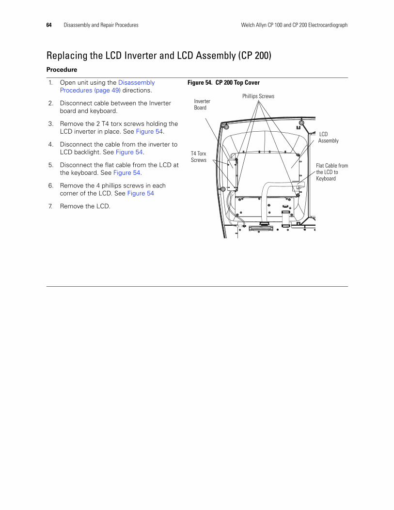
64 Disassembly and Repair Procedures Welch Allyn CP 100 and CP 200 Electrocardiograph
Replacing the LCD Inverter and LCD Assembly (CP 200)Procedure
1. Open unit using the Disassembly Procedures (page 49) directions.
2. Disconnect cable between the Inverter board and keyboard.
3. Remove the 2 T4 torx screws holding the LCD inverter in place. See Figure 54.
4. Disconnect the cable from the inverter to LCD backlight. See Figure 54.
5. Disconnect the flat cable from the LCD at the keyboard. See Figure 54.
6. Remove the 4 phillips screws in each corner of the LCD. See Figure 54
7. Remove the LCD.
Figure 54. CP 200 Top Cover
T4 Torx Screws
Inverter Board
LCD Assembly
Phillips Screws
Flat Cable fromthe LCD to Keyboard
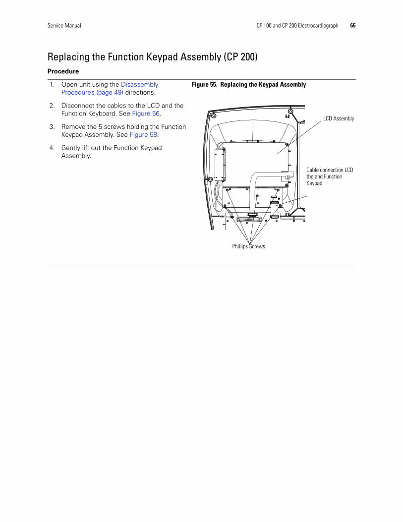
Service Manual CP 100 and CP 200 Electrocardiograph 65
Replacing the Function Keypad Assembly (CP 200)Procedure
1. Open unit using the Disassembly Procedures (page 49) directions.
2. Disconnect the cables to the LCD and the Function Keyboard. See Figure 56.
3. Remove the 5 screws holding the Function Keypad Assembly. See Figure 58.
4. Gently lift out the Function Keypad Assembly.
Figure 55. Replacing the Keypad Assembly
LCD Assembly
Phillips Screws
Cable connection LCD the and Function Keypad

66 Disassembly and Repair Procedures Welch Allyn CP 100 and CP 200 Electrocardiograph
Replacing the Keyboard Assembly (CP 200)Procedure
1. Open unit using the Disassembly Procedures (page 49) directions.
2. Disconnect the ground and the flat data cable to the LCD and the flat data cable, the cables to the Inverter, to the Keypad Assembly.
3. Remove the 13 screws holding in the Keyboard Assembly.
4. Gently lift out the Keyboard Assembly.
Reassembly Note
1. Install and tighten the 3 screws first (shown in Figure 56) to align the keyboard.
DO NOT tighten the screws past the specified torque.
2. Install remaining 10 screws using the specified torque.
Figure 56. Replacing the Keyboard Assembly (CP 200)
Cable between Inverter board and Keyboard
Flat Cable from the LCD to Keyboard
Screws
LCD Assembly
Keypad Assembly

Service Manual CP 100 and CP 200 Electrocardiograph 67
Replacing the LCD Assembly (CP 100)Procedure
1. Open unit using the Disassembly Procedures (page 49) directions.
2. Disconnect the flat cable from the keyboard. See Figure 57.
3. Remove the 4 screws securing the LCD bracket. See Figure 57.
4. Gently lift out the LCD bracket.
5. Gently lift out the LCD assemby.
Figure 57. CP 100 Top Cover
Screws
LCD Assembly LCD Bracket
Flat Cable

68 Disassembly and Repair Procedures Welch Allyn CP 100 and CP 200 Electrocardiograph
Replacing the Keyboard Assembly (CP 100)Procedure
1. Open unit using the Disassembly Procedures (page 49) directions.
2. Disconnect the flat cable from the keyboard.
3. Remove the 13 screws holding in the keyboard assembly.
4. Gently lift out the keyboard assembly.
Reassembly Note
1. Install and tighten the 3 screws first (shown in Figure 58) to align the keyboard.
DO NOT tighten the screws past the specified torque.
2. Install remaining 10 screws using the specified torque.
Figure 58. Replacing the Keyboard Assembly (CP 100)
Flat Cable
Screws
6
69
Field Replaceable Parts
IntroductionThe field replaceable parts list is intended as a guide for ordering parts for both the CP 100 and CP 200 Electrocardiographs along with the optional Cart. The list is organized, by assembly, with all parts to that assembly listed including quantity per assembly.
“For information about any Welch Allyn product, please call Welch Allyn Technical Support:” on page ii. or www.welchAllyn.com/medical/support.
Note Hardware pieces such as screws, washers, bearings, nuts, setscrews, and some labels may only be available in kits. However, all such pieces are listed with sizes, in the description, to allow for possible purchase from your local hardware store.
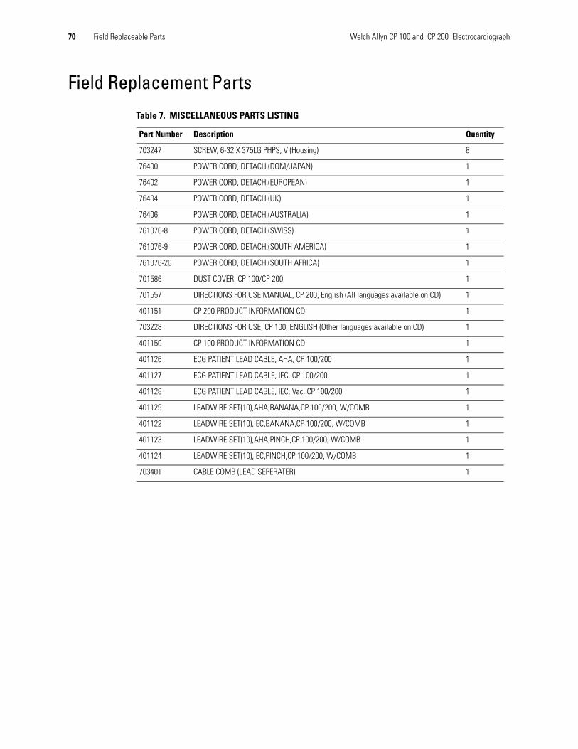
70 Field Replaceable Parts Welch Allyn CP 100 and CP 200 Electrocardiograph
Field Replacement Parts
Table 7. MISCELLANEOUS PARTS LISTING
Part Number Description Quantity
703247 SCREW, 6-32 X 375LG PHPS, V (Housing) 8
76400 POWER CORD, DETACH.(DOM/JAPAN) 1
76402 POWER CORD, DETACH.(EUROPEAN) 1
76404 POWER CORD, DETACH.(UK) 1
76406 POWER CORD, DETACH.(AUSTRALIA) 1
761076-8 POWER CORD, DETACH.(SWISS) 1
761076-9 POWER CORD, DETACH.(SOUTH AMERICA) 1
761076-20 POWER CORD, DETACH.(SOUTH AFRICA) 1
701586 DUST COVER, CP 100/CP 200 1
701557 DIRECTIONS FOR USE MANUAL, CP 200, English (All languages available on CD) 1
401151 CP 200 PRODUCT INFORMATION CD 1
703228 DIRECTIONS FOR USE, CP 100, ENGLISH (Other languages available on CD) 1
401150 CP 100 PRODUCT INFORMATION CD 1
401126 ECG PATIENT LEAD CABLE, AHA, CP 100/200 1
401127 ECG PATIENT LEAD CABLE, IEC, CP 100/200 1
401128 ECG PATIENT LEAD CABLE, IEC, Vac, CP 100/200 1
401129 LEADWIRE SET(10),AHA,BANANA,CP 100/200, W/COMB 1
401122 LEADWIRE SET(10),IEC,BANANA,CP 100/200, W/COMB 1
401123 LEADWIRE SET(10),AHA,PINCH,CP 100/200, W/COMB 1
401124 LEADWIRE SET(10),IEC,PINCH,CP 100/200, W/COMB 1
703401 CABLE COMB (LEAD SEPERATER) 1

Service Manual Field Replaceable Parts 71
Table 8. ASSEMBLY, BASE CP 100/200
Part Number Description Quantity
703511 HOUSING, CP 100/CP 200 BASE 1
101-0038 GROUND PLUG, 6/25 1
620198 FOOT 4
106124-4 SCREW 4-20.250 PAN PHILLIPS 9
236732 IEC CONNECTOR 1
236733 FUSE DRAWER 1
703611 EOS MVLT80-1001-S77 PWR SUPPLY 1
703774 FERRITE, FLAT CABLE SNAP-ITS 1
104-0007 WASHER, FLAT 1
104-0008 WASHER LOCK SERRATED 4
102-0001 NUT HEX 2
401370 BATTERY ASSEMBLY, CP 100/CP 200 1
704064 BATTERY FUSE, ZEUS PC5-6 1
700015 BATTERY DOOR, CP 100/CP 200 1
703247 PHPS 6-32 X.375 (Battery Door) 2
704068 HARNESS, INCOMING PWR (W001) 1
704067 HARNESS, GROUND POWER SUPPLY (W003) 1
700157 HARNESS, PWR SUPPLY TO MAIN PCB (W002) 1
704221 HARNESS, BATTERY (W008) 1
700152 HARNESS, MAIN PCB TO KEYBOARD (W014) 1
455508 LABEL, PROTECTIVE EARTH GROUND 3
703922 FUSE, 250V, 5 X 20MM, TIME LAG 2
Table 9. ASSEMBLY PRINTER, CP 100/200
Part Number Description Quantity
700007 AUX PAPER COVER, CP 100/CP 200 1
700012 PAPER TRAY , CP 100/CP 200 1
703258 SCREW M3 X 6 PHP FH, V 2
700117 SPRING, PRINT HEAD 1
700118 SHOULDER SCREW M3 X .5 2
703246 SCREW, M3 X 0.5, PAN PHILLIPS 8
106137-1 NUT,4-40X.250 HEX,KEPS EXTLOCK 1
700160 HARNESS, GROUND PRINT HEAD (W005) 1
700161 HARNESS, PAPER DETECTION (W006) 1
700162 HARNESS, PRINT HEAD (W007) 1
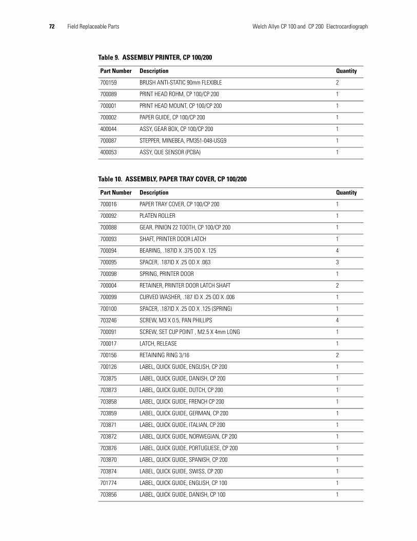
72 Field Replaceable Parts Welch Allyn CP 100 and CP 200 Electrocardiograph
700159 BRUSH ANTI-STATIC 90mm FLEXIBLE 2
700089 PRINT HEAD ROHM, CP 100/CP 200 1
700001 PRINT HEAD MOUNT, CP 100/CP 200 1
700002 PAPER GUIDE, CP 100/CP 200 1
400044 ASSY, GEAR BOX, CP 100/CP 200 1
700087 STEPPER, MINEBEA, PM351-048-USG9 1
400053 ASSY, QUE SENSOR (PCBA) 1
Table 10. ASSEMBLY, PAPER TRAY COVER, CP 100/200
Part Number Description Quantity
700016 PAPER TRAY COVER, CP 100/CP 200 1
700092 PLATEN ROLLER 1
700088 GEAR, PINION 22 TOOTH, CP 100/CP 200 1
700093 SHAFT, PRINTER DOOR LATCH 1
700094 BEARING, .187ID X .375 OD X .125 4
700095 SPACER, .187ID X .25 OD X .063 3
700098 SPRING, PRINTER DOOR 1
700004 RETAINER, PRINTER DOOR LATCH SHAFT 2
700099 CURVED WASHER, .187 ID X .25 OD X .006 1
700100 SPACER, .187ID X .25 OD X .125 (SPRING) 1
703246 SCREW, M3 X 0.5, PAN PHILLIPS 4
700091 SCREW, SET CUP POINT , M2.5 X 4mm LONG 1
700017 LATCH, RELEASE 1
700156 RETAINING RING 3/16 2
700126 LABEL, QUICK GUIDE, ENGLISH, CP 200 1
703875 LABEL, QUICK GUIDE, DANISH, CP 200 1
703873 LABEL, QUICK GUIDE, DUTCH, CP 200 1
703858 LABEL, QUICK GUIDE, FRENCH CP 200 1
703859 LABEL, QUICK GUIDE, GERMAN, CP 200 1
703871 LABEL, QUICK GUIDE, ITALIAN, CP 200 1
703872 LABEL, QUICK GUIDE, NORWEGIAN, CP 200 1
703876 LABEL, QUICK GUIDE, PORTUGUESE, CP 200 1
703870 LABEL, QUICK GUIDE, SPANISH, CP 200 1
703874 LABEL, QUICK GUIDE, SWISS, CP 200 1
701774 LABEL, QUICK GUIDE, ENGLISH, CP 100 1
703856 LABEL, QUICK GUIDE, DANISH, CP 100 1
Table 9. ASSEMBLY PRINTER, CP 100/200
Part Number Description Quantity

Service Manual Field Replaceable Parts 73
703854 LABEL, QUICK GUIDE, DUTCH, CP 100 1
703847 LABEL, QUICK GUIDE, FRENCH CP 100 1
703850 LABEL, QUICK GUIDE, GERMAN, CP 100 1
703852 LABEL, QUICK GUIDE, ITALIAN, CP 100 1
703853 LABEL, QUICK GUIDE, NORWEGIAN, CP 100 1
703857 LABEL, QUICK GUIDE, PORTUGUESE, CP 100 1
703851 LABEL, QUICK GUIDE, SPANISH, CP 100 1
703855 LABEL, QUICK GUIDE, SWISS, CP 100 1
Table 11. ASSEMBLY, TOP COVER, CP 200
Part Number Description Quantity
704343 HOUSING, CP 200, TOP 1
700122 DISPLAY, LCD, COLOR - 320 x 240 , 5.7" N, CP 200 1
700121 GLARE SCREEN, CP 200 1
401462 ASSY, QWERTY KEYBOARD, CP 200 1
401461 ASSY, FUNCTION KEYPAD, CP 200 1
703680 SCREW,TORX#2 x 1/4 PAN PLASTITE 13
106124-4 SCREW 4-20.250 PAN PHILLIPS 5
700119 INVERTER, LCD 1
200076-1 SCREW 0-40 .187 PAN TORX 2
106140-3 SCREW 4-40 .250 PAN PHILLIPS STEEL ZINC 4
704232 HARNESS, QWERTY BOARD TO LCD (W013) 1
700079 HARNESS, KEY BOARD TO KEYPAD BOARD(W012) 1
700151 HARNESS, INVERTER SUPPLY (W009) 1
700730 HARNESS, GRND LCD (W010) 1
700124 LABEL, QWERTY CP 200 1
703108 LABEL, FKP, ENGLISH 1
703152 LABEL, FKP, DANISH 1
703150 LABEL, FKP, DUTCH 1
703105 LABEL, FKP, FRENCH 1
701032 LABEL, FKP, GERMAN 1
703834 LABEL, FKP, ITIALIAN 1
703109 LABEL, FKP, NORWEGIAN 1
703153 LABEL, FKP, PORTUGUESE 1
703107 LABEL, FKP, SPANISH 1
703151 LABEL, FKP, SWISS 1
Table 10. ASSEMBLY, PAPER TRAY COVER, CP 100/200
Part Number Description Quantity
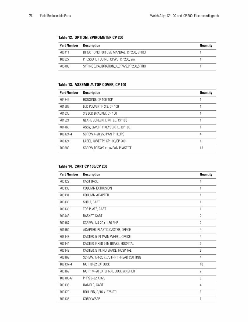
74 Field Replaceable Parts Welch Allyn CP 100 and CP 200 Electrocardiograph
Table 12. OPTION, SPIROMETER CP 200
Part Number Description Quantity
703411 DIRECTIONS FOR USE MANUAL, CP 200, SPIRO 1
100627 PRESSURE TUBING, CPWS, CP 200, 2m 1
703480 SYRINGE,CALIBRATION,3L,CPWS,CP 200,SPIRO 1
Table 13. ASSEMBLY, TOP COVER, CP 100
Part Number Description Quantity
704342 HOUSING, CP 100 TOP 1
701588 LCD POWERTIP 3.9, CP 100 1
701035 3.9 LCD BRACKET, CP 100 1
701521 GLARE SCREEN, LIMITED, CP 100 1
401463 ASSY, QWERTY KEYBOARD, CP 100 1
106124-4 SCREW 4-20.250 PAN PHILLIPS 4
700124 LABEL, QWERTY, CP 100/CP 200 1
703680 SCREW,TORX#2 x 1/4 PAN PLASTITE 13
Table 14. CART CP 100/CP 200
Part Number Description Quantity
703129 CAST BASE 1
703133 COLUMN EXTRUSION 1
703131 COLUMN ADAPTER 1
703138 SHELF, CART 1
703139 TOP PLATE, CART 1
703443 BASKET, CART 2
703167 SCREW, 1/4-20 x 1.50 PHP 2
703160 ADAPTER, PLASTIC CASTER, OFFICE 4
703143 CASTER, 5 IN TWIN WHEEL, OFFICE 4
703144 CASTER, FIXED 5 IN BRAKE, HOSPITAL 2
703142 CASTER, 5 IN, NO BRAKE, HOSPITAL 2
703168 SCREW, 1/4-20 x .75 FHP THREAD CUTTING 4
106137-4 NUT,10-32 EXTLOCK 10
703169 NUT, 1/4-20 EXTERNAL LOCK WASHER 2
106100-6 PHPS 6-32 X.375 6
703136 HANDLE, CART 4
703179 ROLL PIN, 3/16 x .875 STL 8
703135 CORD WRAP 1

Service Manual Field Replaceable Parts 75
703410 SCREW, 10-32 x .312 PHP 2
703130 AUX TRAY 1
703462 NUT, T, 1/-4-20 2
703461 TRILOBULAR KNOB 1/4-20 X .5 2
703454 QUICK CONNECT, FLEX ARM 2
703145 FLEX ARM 1
703137 HOLSTER, FRONT END 1
106100-56 SCREW, 1/4-20 X 1.00 PAN HEAD PHILLIPS 1
106106-4 WASHER, LOCK, EXT 1/4 1
703510 THUMB SCREWS, PKG 1
Table 14. CART CP 100/CP 200
Part Number Description Quantity

76 Field Replaceable Parts Welch Allyn CP 100 and CP 200 Electrocardiograph

A
77
Specifications.
Item Specification
Dimensions
Weight 11.6 lb (5.3 kg)
Keyboard type Elastomer keypad with complete alphanumeric keysSoft-key menu and dedicated function keys (CP 200 Only)
Paper type 8.25 x 11 inches (21 x 28 cm), Z-fold thermal paper, 200 sheets
Thermal printer (internal) Computer-controlled dot array, 8 dots/mm
Thermal paper speeds 10, 25, 50 mm/s
Gain settings:Auto ECGsRhythm ECGs
5, 10, 20 mm/mV, AUTO5, 10, 20 mm/mV
Report print formats:Auto ECGsRhythm ECGsAverage cycles
3x4, 3x4+ 1R, 3x4 +3R, 6x2, 12x1, 6x2 50 mm/s, 6x2 Ext.3, 6, or 12 leads at a time (CP 200) 3 leads at a time (CP 100)3x4 50 mm/s + 3R, 6x2 50 mm/s + 6R
ECG storage Up to 50 ECGs (CP 200 Only)
Frequency range 0.3 to 150 Hz
Digital sampling rate > 1,000 samples/second/channel
Pacemaker detection ANSI/AAMI EC11
Power requirement Universal AC power supply 100/240 V ~, 50/60 Hz ~, 2.2 A maximum
FusesAC DC (battery fuse)
Time-delay type, 2 amp 250 V rating, Littlefuse 0215002 or equivalent.Fast-acting type, 10 amp 32 V rating, Bussman ATC-10 or equivalent.
15.6 in(39.7 cm)
6.2 in(15.7 cm)
16.2 in(41.1 cm)
15.6 in(39.7 cm)
6.2 in(15.7 cm)
16.2 in(41.1 cm)

78 Appendix A Specifications Welch Allyn CP 100 and CP 200 Electrocardiograph
*Per AAMI EC11:1991/(R)2001 Diagnostic Electrocardiographic Devices, Section 3.1.2.1 Disclosure of cautionary information/ performance characteristics paragraph c) Accuracy of input signal reproduction, the manufacturer shall disclose the methods used to establish overall system error and frequency response. Welch Allyn has used methods A & D, as prescribed in section 3.2.7.2 and 4.2.7.2 of this same standard, to verify overall system error and frequency response. Because of the sampling characteristics and the asynchronism between sample rate and signal rate, digital ECG systems such as the CP 100 and CP 200 may produce a noticeable modulating effect from one cycle to the next, particularly in pediatric recordings. This phenomenon is not physiologic.
Specifications are subject to change without notice.
Lead configurations Standard, Cabrera
Rechargeable battery Lead acid gel, 6 volt, 5 AHPrints up to 100 continuous ECGs per charge12-hour recharging
Filters 0.5 Hz high-performance baseline filter35 Hz muscle-tremor filterAC-interference filter 50 Hz or 60 Hz
Safety, EMC, and regulatory compliance
ANSI/AAMI EC11* UL60601-1CAN/CSA C22.2 No. 601.1 IEC/EN 60601-1CAN/CSA C22.2 No. 601.1.1 IEC/EN 60601-1-1CAN/CSA C22.2 No. 601.1.2 IEC/EN 60601-1-2CAN/CSA C22.2 No. 601.1.4 IEC/EN 60601-1-4CAN/CSA C22.2 No. 601.2.25 IEC/EN 60601-2-25AS/NZS CISPR 11
Standard connectivity Com port, SD memory card slot (for use with cards ≥ 64 MB)
Connectivity with electronic medical records
Supported through the Welch Allyn CardioPerfect workstation software
Electrodes Rigorously tested for conductivity, adhesion, and hypoallergenic qualities, and exceed all AAMI standards
Cables and wires Meet or exceed IEC 60601
Environmental operating conditions:TemperatureRelative humidityAltitude
+10° C to +40° C (+50° F to +104° F)15 – 95% noncondensing700 – 1060 hPa
Environmental storage conditions:TemperatureRelative humidityAltitude
-20° C to +49° C (-4° F to +120° F)15 – 95% noncondensing (30 – 70% for printing)500 – 1060 hPa
Protection against electric shock Class I, internally poweredType CF
Protection against ingress of water, per IEC 60529:
ElectrocardiographSpirometry Component
IPXØIPXØ
Mode of operation Continuous
Item (Continued) Specification (Continued)
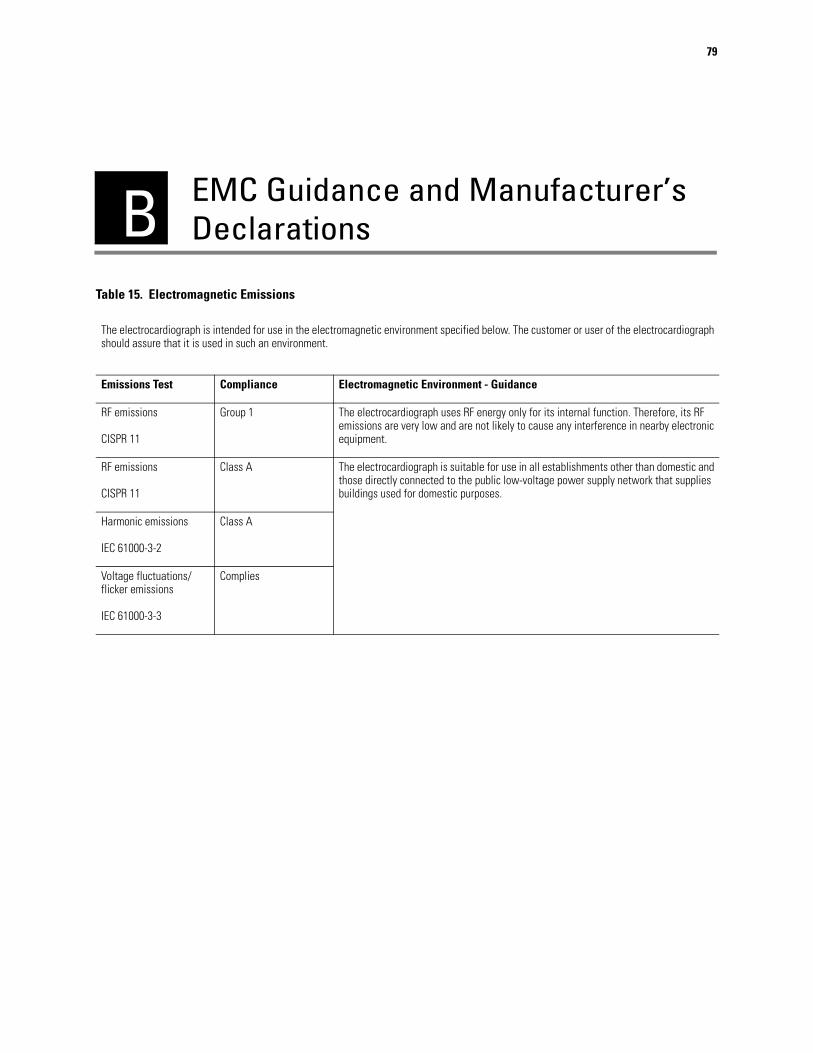
B
79
EMC Guidance and Manufacturer’s Declarations
Table 15. Electromagnetic Emissions
The electrocardiograph is intended for use in the electromagnetic environment specified below. The customer or user of the electrocardiograph should assure that it is used in such an environment.
Emissions Test Compliance Electromagnetic Environment - Guidance
RF emissions
CISPR 11
Group 1 The electrocardiograph uses RF energy only for its internal function. Therefore, its RF emissions are very low and are not likely to cause any interference in nearby electronic equipment.
RF emissions
CISPR 11
Class A The electrocardiograph is suitable for use in all establishments other than domestic and those directly connected to the public low-voltage power supply network that supplies buildings used for domestic purposes.
Harmonic emissions
IEC 61000-3-2
Class A
Voltage fluctuations/flicker emissions
IEC 61000-3-3
Complies

80 Appendix B EMC Guidance and Manufacturer’s Declarations Welch Allyn CP 100 and CP 200 Electrocardiograph
Table 16. Electromagnetic Immunity
The electrocardiograph is intended for use in the electromagnetic environment specified below. The customer or user of the electrocardiograph should assure that it is used in such an environment.
Immunity Test IEC 60601Test Level
Compliance Level Electromagnetic Environment - Guidance
Electrostatic discharge (ESD)
IEC 61000-4-2
± 6 kV contact
± 8 kV air
± 6 kV contact
± 8 kV air
Floors should be wood, concrete, or ceramic tile. If floors are covered with synthetic material, the relative humidity should be at least 30%.
Electrical fast transient/burst
IEC 61000-4-4
±2 kV for power supply lines
±1 kV for input/output lines
±2 kV for power supply lines
Not applicable
Mains power quality should be that of a typical commercial or hospital environment.
Surge
IEC 61000-4-5
±1 kV differential mode
±2 kV common mode
±1 kV differential mode
±2 kV common mode
Mains power quality should be that of a typical commercial or hospital environment.
Voltage dips, short interruptions, and voltage variations on power supply input lines.
IEC 61000-4-11
>95% dip in 0.5 cycle
60% dip in 5 cycles
30% dip for 25 cycles
>95% dip in 5 seconds
>95% dip in 0.5 cycle
60% dip in 5 cycles
30% dip for 25 cycles
>95% dip in 5 seconds
Mains power quality should be that of a typical commercial or hospital environment. If the user of the electrocardiograph requires continued operation during power mains interruptions, it is recommended that the electrocardiograph be powered from an uninterruptible power supply or battery.
Power frequency (50/60Hz)magnetic field
IEC 61000-4-8
3 A/m 3 A/m Power frequency magnetic fields should be at levels characteristic of a typical location in a typical commercial or hospital environment.

Service Manual Appendix B EMC Guidance and Manufacturer’s Declarations 81
Table 17. Electromagnetic Immunity
The electrocardiograph is intended for use in the electromagnetic environment specified below. The customer or user of the electrocardiograph should assure that it is used in such an environment.
Immunity Test IEC 60601Test Level
Compliance Level
Electromagnetic Environment - Guidance
Portable and mobile RF communications equipment should be used no closer to any part of the electrocardiograph, including cables, than the recommended separation distance calculated from the equation applicable to the frequency of the transmitter.
Recommended separation distance
Conducted RFIEC 61000-4-6
3 Vrms150 kHz to 80 MHz
3 Vrms d = (1.17)
Radiated RFIEC 61000-4-3
3 V/m80 MHz to 2.5 GHz
3 V/m d = (1.17) 80 MHz to 800 MHz
d = (2.33) 800 MHz to 2.5 GHz
where P is the maximum output power rating of the transmitter in watts (W) according to the transmitter manufacturer and d is the recommended separation distance in metres (m).
Field strengths from fixed RF transmitters, as determined by an electromagnetic site survey,a should be less than the compliance level in each frequency range.b
Interference may occur in the vicinity of equipment marked with the following symbol:
Note 1: At 80 MHz and 800 MHz, the higher frequency range applies.
Note 2: These guidelines may not apply in all situations. Electromagnetic propagation is affected by absorption and reflection from structures, objects, and people.
a Field strengths from fixed transmitters, such as base stations for radio (cellular/cordless) telephones and land mobile radios, amateur radio, AM and FM radio broadcast and TV broadcast cannot be predicted theoretically with accuracy. To assess the electromagnetic environment due to fixed RF transmitters, an electromagnetic site survey should be considered. If the measured field strength in the location in which the electrocardiograph is used exceeds the applicable RF compliance level above, the electrocardiograph should be observed to verify normal operation. If abnormal performance is observed, additional measures may be necessary, such as reorienting or relocating the electrocardiograph.
b Over the frequency range 150 kHz to 80 MHz, field strengths should be less than 3 V/m.
P
P
P

82 Appendix B EMC Guidance and Manufacturer’s Declarations Welch Allyn CP 100 and CP 200 Electrocardiograph
Table 18. Recommended Separation Distances Between Portable and Mobile RF Communications Equipment and the Electrocardiograph
The electrocardiograph is intended for use in an electromagnetic environment in which radiated RF disturbances are controlled. The customer or user of the electrocardiograph can help prevent electromagnetic interference by maintaining a minimum distance between portable and mobile RF communications equipment (transmitters) and the electrocardiograph as recommended below, according to the maximum output power of the communications equipment.
Separation Distance According to Frequency of Transmitter (m)
Rated Max. Output Power of Transmitter
(W)
150 kHz to 80 MHz
d = (1.17)
80 MHz to 800 MHz
d = (1.17)
800 MHz to 2.5 GHz
d = (2.33)
0.01 0.117 0.117 0.233
0.1 0.37 0.37 0.74
1 1.17 1.17 2.33
10 3.70 3.70 7.37
100 11.70 11.70 23.30
For transmitters rated at a maximum output power not listed above, the recommended separation distance d in meters (m) can be estimated using the equation applicable to the frequency of the transmitter, where P is the maximum output power rating of the transmitter in watts (W) according to the transmitter manufacturer.
Note 1: At 80 MHz and 800 MHz, the separation distance for the higher frequency range applies.
Note 2: These guidelines may not apply in all situations. Electromagnetic propagation is affected by absorption and reflection from structures, objects, and people.
P P P
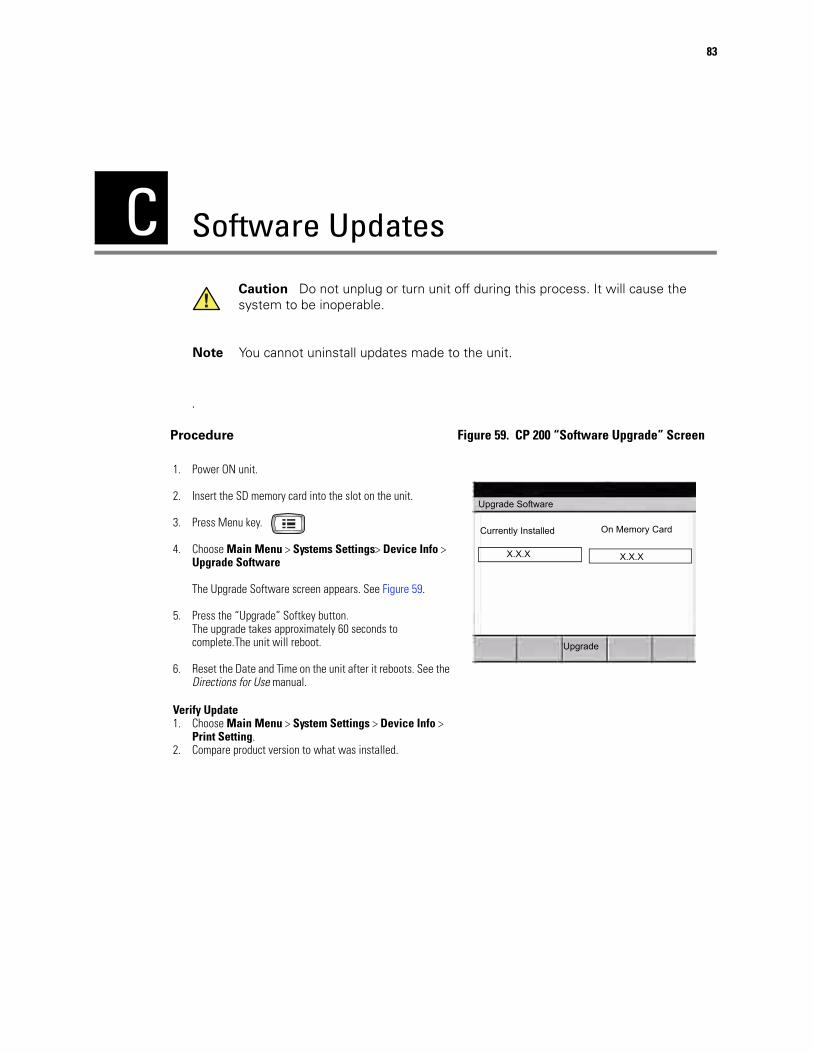
C
83
Software Updates
.
Caution Do not unplug or turn unit off during this process. It will cause the system to be inoperable.
Note You cannot uninstall updates made to the unit.
Procedure Figure 59. CP 200 “Software Upgrade” Screen
1. Power ON unit.
2. Insert the SD memory card into the slot on the unit.
3. Press Menu key.
4. Choose Main Menu > Systems Settings> Device Info > Upgrade Software
The Upgrade Software screen appears. See Figure 59.
5. Press the “Upgrade” Softkey button.The upgrade takes approximately 60 seconds to complete.The unit will reboot.
6. Reset the Date and Time on the unit after it reboots. See the Directions for Use manual.
Verify Update 1. Choose Main Menu > System Settings > Device Info >
Print Setting.2. Compare product version to what was installed.
Upgrade Software
Currently Installed On Memory Card
X.X.X X.X.X
Upgrade

84 Appendix C Software Updates Welch Allyn CP 100 and CP 200 Electrocardiograph

D
85
Interconnect DiagramsCP 200 Interconnect Diagram . . . . . . . . . . . . . . . . . . . . . . . . . . . . . . . . . . . . . . . . . . . . . 86
CP 100 Interconnect Diagram . . . . . . . . . . . . . . . . . . . . . . . . . . . . . . . . . . . . . . . . . . . . . 87
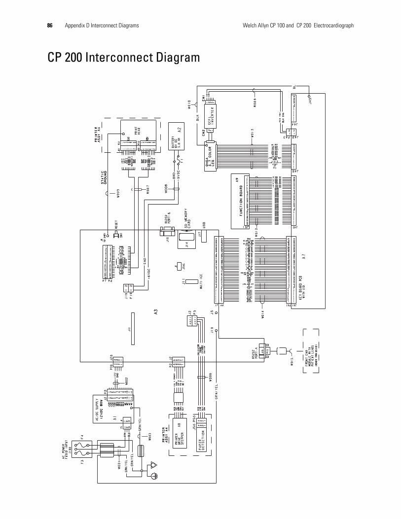
86 Appendix D Interconnect Diagrams Welch Allyn CP 100 and CP 200 Electrocardiograph
CP 200 Interconnect Diagram

Service Manual Appendix D Interconnect Diagrams 87
CP 100 Interconnect Diagram

88 Appendix D Interconnect Diagrams Welch Allyn CP 100 and CP 200 Electrocardiograph


Material Number.704340 Rev. D
PO Box 220, Skaneateles Falls, NY 13153-0220 USA800 535 6663 www.welchallyn.com
Related Documents