www.schneider-electric.us 23 RELAYS AND TIMERS 23-2 © 2012 Schneider Electric All Rights Reserved General Purpose Relays RSL Refer to Catalog DIA3ED2090304EN-US Zelio™ Interface Relays Zelio RSL slim interface relays save valuable panel space with a 6 mm width and have a 6 Amp general purpose load rating. Features include: • Pre-assembled option: relay and socket are combined into one catalog number. • Universal AC/DC sockets have built-in protection from transients and reverse polarity voltages (see catalog DIA3ED2090304EN-US for more detailed information). • Accessories, which include isolators, ID tags, and bus jumper save valuable installation time. a Relays are mounted on sockets equipped with LED and protection circuit. Approvals for RSL relays: Approvals for RSLZ sockets: Table 23.1: Zelio RSL Slim Interface: Pre-assembled Relay + Socket (sold in lots of 10) Socket Supply Voltage (Vac/Vdc) Socket Type Replacement Relays Screw Connector Spring Terminal Catalog No. Catalog Numbera $ Price ea. Catalog Numbera $ Price ea. 12 RSL1PVJU 12.00 RSL1PRJU 12.00 RSL1AB4JD 24 RSL1PVBU 14.60 RSL1PRBU 15.70 RSL1AB4BD 48 RSL1PVEU 14.90 RSL1PREU 16.10 RSL1AB4ED 110 RSL1PVFU 14.90 RSL1PRFU 16.10 RSL1AB4ND 230 RSL1PVPU 14.90 RSL1PRPU 16.10 RSL1AB4ND Table 23.2: Zelio RSL Slim Interface: Relay Only (sold in lots of 10) Relay Coil Voltage (Vdc) Catalog Number $ Price ea. 12 RSL1AB4JD 6.20 24 RSL1AB4BD 7.70 48 RSL1AB4ED 7.90 60 RSL1AB4ND 7.90 Table 23.3: Zelio RSL Slim Interface: Socket Only (sold in lots of 10) Socket Supply Voltage (Vac/Vdc) Socket Type For use with relays: Screw Connector Spring Terminal Catalog Number $ Price ea. Catalog Number $ Price ea. 12 RSLZVA1 7.20 RSLZRA1 8.30 RSL1AB4JD 24 RSL1AB4BD 48 RSLZVA2 7.20 RSLZRA2 8.30 RSL1AB4ED 60 RSL1AB4ND 110 RSLZVA3 7.40 RSLZRA3 8.60 RSL1AB4ND 230 RSLZVA4 7.40 RSLZRA4 8.60 RSL1AB4ND Table 23.4: Socket Accessories Description Compatibility Catalog Number $ Price ea. ID tags (2 sheets of 64 tags) With all sockets RSLZ5 4.60 Bus jumper (10 x 20-pole jumpers) With all sockets RSLZ2 3.80 Butterfly isolator (10 isolators) With all sockets RSLZ3 3.70 File CCN E173076 NRNT2, NRNT8 File Class 240278 3211 04 IEC 61810-1 RoHS Compliant File CCN E172326S SWIV2 SWIV8 File Class 247510 3211 07 IEC 61810-1 RoHS Compliant RSL 1PV•• RSL 1PR•• RSL 1AB•• RSL ZVA• RSL ZRA• RSL Z2 RSL Z3 CP2 Discount Schedule Courtesy of www.mdwindustrialsupply.com Courtesy of www.mdwindustrialsupply.com

Welcome message from author
This document is posted to help you gain knowledge. Please leave a comment to let me know what you think about it! Share it to your friends and learn new things together.
Transcript
www.schneider-electric.us
23R
ELA
YS
AN
D T
IME
RS
23-2 © 2012 Schneider ElectricAll Rights Reserved
General Purpose Relays RSLRefer to Catalog DIA3ED2090304EN-US
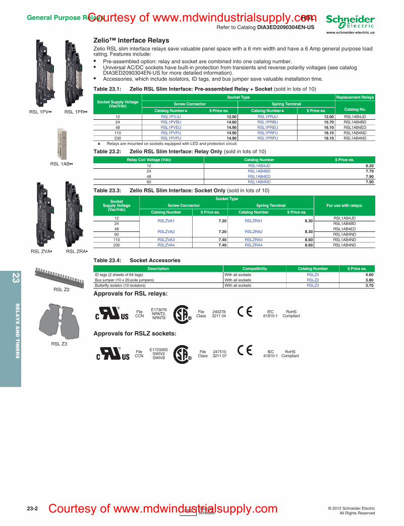
Zelio™ Interface RelaysZelio RSL slim interface relays save valuable panel space with a 6 mm width and have a 6 Amp general purpose load rating. Features include:• Pre-assembled option: relay and socket are combined into one catalog number.• Universal AC/DC sockets have built-in protection from transients and reverse polarity voltages (see catalog
DIA3ED2090304EN-US for more detailed information).• Accessories, which include isolators, ID tags, and bus jumper save valuable installation time.
a Relays are mounted on sockets equipped with LED and protection circuit.
Approvals for RSL relays:
Approvals for RSLZ sockets:
Table 23.1: Zelio RSL Slim Interface: Pre-assembled Relay + Socket (sold in lots of 10)
Socket Supply Voltage(Vac/Vdc)
Socket Type Replacement Relays
Screw Connector Spring TerminalCatalog No.Catalog Numbera $ Price ea. Catalog Numbera $ Price ea.
12 RSL1PVJU 12.00 RSL1PRJU 12.00 RSL1AB4JD24 RSL1PVBU 14.60 RSL1PRBU 15.70 RSL1AB4BD48 RSL1PVEU 14.90 RSL1PREU 16.10 RSL1AB4ED110 RSL1PVFU 14.90 RSL1PRFU 16.10 RSL1AB4ND230 RSL1PVPU 14.90 RSL1PRPU 16.10 RSL1AB4ND
Table 23.2: Zelio RSL Slim Interface: Relay Only (sold in lots of 10)
Relay Coil Voltage (Vdc) Catalog Number $ Price ea.
12 RSL1AB4JD 6.2024 RSL1AB4BD 7.7048 RSL1AB4ED 7.9060 RSL1AB4ND 7.90
Table 23.3: Zelio RSL Slim Interface: Socket Only (sold in lots of 10)
SocketSupply Voltage
(Vac/Vdc)
Socket Type
For use with relays:Screw Connector Spring Terminal
Catalog Number $ Price ea. Catalog Number $ Price ea.
12RSLZVA1 7.20 RSLZRA1 8.30
RSL1AB4JD24 RSL1AB4BD48
RSLZVA2 7.20 RSLZRA2 8.30RSL1AB4ED
60 RSL1AB4ND110 RSLZVA3 7.40 RSLZRA3 8.60 RSL1AB4ND230 RSLZVA4 7.40 RSLZRA4 8.60 RSL1AB4ND
Table 23.4: Socket AccessoriesDescription Compatibility Catalog Number $ Price ea.
ID tags (2 sheets of 64 tags) With all sockets RSLZ5 4.60Bus jumper (10 x 20-pole jumpers) With all sockets RSLZ2 3.80Butterfly isolator (10 isolators) With all sockets RSLZ3 3.70
FileCCN
E173076NRNT2, NRNT8
FileClass
2402783211 04
IEC 61810-1
RoHS Compliant
FileCCN
E172326SSWIV2SWIV8
FileClass
2475103211 07
IEC 61810-1
RoHS Compliant
RSL 1PV•• RSL 1PR••
RSL 1AB••
RSL ZVA• RSL ZRA•
RSL Z2
RSL Z3
CP2 Discount Schedule
Courtesy of www.mdwindustrialsupply.com
Courtesy of www.mdwindustrialsupply.com
www.schneider-electric.us
23R
EL
AY
S A
ND
TIM
ER
S
© 2012 Schneider ElectricAll Rights Reserved
23-3
General Purpose Relays RSBRefer to Catalog DIA3ED2090304EN-US
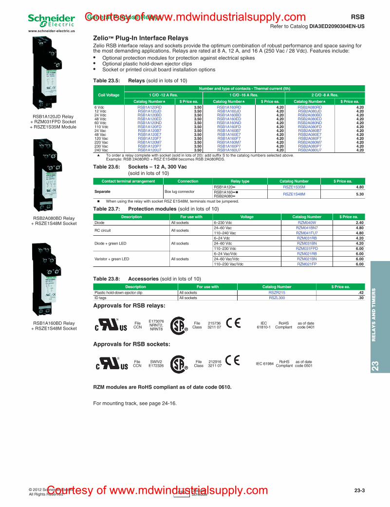
Zelio™ Plug-In Interface RelaysZelio RSB interface relays and sockets provide the optimum combination of robust performance and space saving for the most demanding applications. Relays are rated at 8 A, 12 A, and 16 A (250 Vac / 28 Vdc). Features include:• Optional protection modules for protection against electrical spikes• Optional plastic hold-down ejector clips• Socket or printed circuit board installation options
a To order a relay complete with socket (sold in lots of 20): add suffix S to the catalog numbers selected above.Example: RSB 2A080RD + RSZ E1S48M becomes RSB 2A080RDS.
b When using the relay with socket RSZ E1S48M, terminals must be jumpered.
Approvals for RSB relays:
Approvals for RSB sockets:
RZM modules are RoHS compliant as of date code 0610.
For mounting track, see page 24-16.
Table 23.5: Relays (sold in lots of 10)
Coil Voltage
Number and type of contacts - Thermal current (Ith)
1 C/O -12 A Res. 1 C/O -16 A Res. 2 C/O -8 A Res.
Catalog Numbera $ Price ea. Catalog Numbera $ Price ea. Catalog Numbera $ Price ea.
6 Vdc RSB1A120RD 3.50 RSB1A160RD 4.20 RSB2A080RD 4.2012 Vdc RSB1A120JD 3.50 RSB1A160JD 4.20 RSB2A080JD 4.2024 Vdc RSB1A120BD 3.50 RSB1A160BD 4.20 RSB2A080BD 4.2048 Vdc RSB1A120ED 3.50 RSB1A160ED 4.20 RSB2A080ED 4.2060 Vdc RSB1A120ND 3.50 RSB1A160ND 4.20 RSB2A080ND 4.20110 Vdc RSB1A120FD 3.50 RSB1A160FD 4.20 RSB2A080FD 4.2024 Vac RSB1A120B7 3.50 RSB1A160B7 4.20 RSB2A080B7 4.2048 Vac RSB1A120E7 3.50 RSB1A160E7 4.20 RSB2A080E7 4.20120 Vac RSB1A120F7 3.50 RSB1A160F7 4.20 RSB2A080F7 4.20220 Vac RSB1A120M7 3.50 RSB1A160M7 4.20 RSB2A080M7 4.20230 Vac RSB1A120P7 3.50 RSB1A160P7 4.20 RSB2A080P7 4.20240 Vac RSB1A120U7 3.50 RSB1A160U7 4.20 RSB2A080U7 4.20
Table 23.6: Sockets – 12 A, 300 Vac(sold in lots of 10)
Contact terminal arrangement Connection Relay type Catalog Number $ Price ea.
Separate Box lug connectorRSB1A120•• RSZE1S35M 4.80RSB1A160••bRSB2A080•• RSZE1S48M 5.30
Table 23.7: Protection modules (sold in lots of 10)
Description For use with Voltage Catalog Number $ Price ea.
Diode All sockets 6–230 Vdc RZM040W 2.40
RC circuit All sockets24–60 Vac RZM041BN7 4.80110–240 Vac RZM041FU7 4.80
Diode + green LED All sockets6–24 Vdc RZM031RB 4.2024–60 Vdc RZM031BN 4.20110–230 Vdc RZM031FPD 6.00
Varistor + green LED All sockets6–24 Vac/Vdc RZM021RB 6.0024–60 Vac/Vdc RZM021BN 6.00110–230 Vac/Vdc RZM021FP 6.00
Table 23.8: Accessories (sold in lots of 10)
Description For use with Catalog Number $ Price ea.
Plastic hold-down ejector clip All sockets RSZR215 .42ID tags All sockets RSZL300 .30
FileCCN
E173076NRNT2, NRNT8
FileClass
2157363211 07
IEC 61810-1
RoHS Compliant
as of date code 0401
FileCCN
SWIV2E172326
FileClass
2129163211 07 IEC 61984 RoHS
Compliantas of date code 0501
RSB1A120JD Relay+ RZM031FPD Socket+ RSZE1S35M Module
RSB2A080BD Relay+ RSZE1S48M Socket
RSB1A160BD Relay+ RSZE1S48M Socket
CP2 Discount Schedule
Courtesy of www.mdwindustrialsupply.com
Courtesy of www.mdwindustrialsupply.com
www.schneider-electric.us
23R
ELA
YS
AN
D T
IME
RS
23-4 © 2012 Schneider ElectricAll Rights Reserved
General Purpose Relays RXMRefer to Catalog DIA3ED2090304EN-US
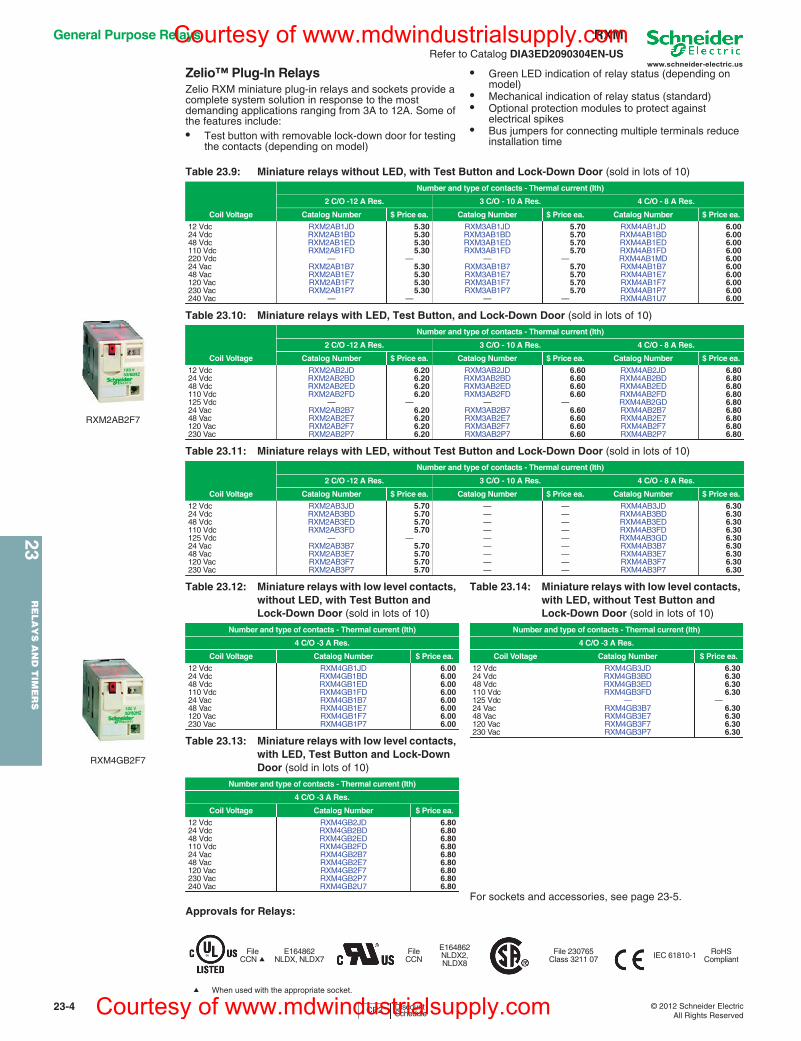
Zelio™ Plug-In RelaysZelio RXM miniature plug-in relays and sockets provide a complete system solution in response to the most demanding applications ranging from 3A to 12A. Some of the features include:• Test button with removable lock-down door for testing
the contacts (depending on model)
• Green LED indication of relay status (depending on model)
• Mechanical indication of relay status (standard)• Optional protection modules to protect against
electrical spikes• Bus jumpers for connecting multiple terminals reduce
installation timeIO
For sockets and accessories, see page 23-5.Approvals for Relays:
a When used with the appropriate socket.
RXM2AB2F7
RXM4GB2F7
Table 23.9: Miniature relays without LED, with Test Button and Lock-Down Door (sold in lots of 10)
Number and type of contacts - Thermal current (Ith)
2 C/O -12 A Res. 3 C/O - 10 A Res. 4 C/O - 8 A Res.
Coil Voltage Catalog Number $ Price ea. Catalog Number $ Price ea. Catalog Number $ Price ea.
12 Vdc RXM2AB1JD 5.30 RXM3AB1JD 5.70 RXM4AB1JD 6.0024 Vdc RXM2AB1BD 5.30 RXM3AB1BD 5.70 RXM4AB1BD 6.0048 Vdc RXM2AB1ED 5.30 RXM3AB1ED 5.70 RXM4AB1ED 6.00110 Vdc RXM2AB1FD 5.30 RXM3AB1FD 5.70 RXM4AB1FD 6.00220 Vdc — — — — RXM4AB1MD 6.0024 Vac RXM2AB1B7 5.30 RXM3AB1B7 5.70 RXM4AB1B7 6.0048 Vac RXM2AB1E7 5.30 RXM3AB1E7 5.70 RXM4AB1E7 6.00120 Vac RXM2AB1F7 5.30 RXM3AB1F7 5.70 RXM4AB1F7 6.00230 Vac RXM2AB1P7 5.30 RXM3AB1P7 5.70 RXM4AB1P7 6.00240 Vac — — — — RXM4AB1U7 6.00
Table 23.10: Miniature relays with LED, Test Button, and Lock-Down Door (sold in lots of 10)
Number and type of contacts - Thermal current (Ith)
2 C/O -12 A Res. 3 C/O - 10 A Res. 4 C/O - 8 A Res.
Coil Voltage Catalog Number $ Price ea. Catalog Number $ Price ea. Catalog Number $ Price ea.
12 Vdc RXM2AB2JD 6.20 RXM3AB2JD 6.60 RXM4AB2JD 6.8024 Vdc RXM2AB2BD 6.20 RXM3AB2BD 6.60 RXM4AB2BD 6.8048 Vdc RXM2AB2ED 6.20 RXM3AB2ED 6.60 RXM4AB2ED 6.80110 Vdc RXM2AB2FD 6.20 RXM3AB2FD 6.60 RXM4AB2FD 6.80125 Vdc — — — — RXM4AB2GD 6.8024 Vac RXM2AB2B7 6.20 RXM3AB2B7 6.60 RXM4AB2B7 6.8048 Vac RXM2AB2E7 6.20 RXM3AB2E7 6.60 RXM4AB2E7 6.80120 Vac RXM2AB2F7 6.20 RXM3AB2F7 6.60 RXM4AB2F7 6.80230 Vac RXM2AB2P7 6.20 RXM3AB2P7 6.60 RXM4AB2P7 6.80
Table 23.11: Miniature relays with LED, without Test Button and Lock-Down Door (sold in lots of 10)
Number and type of contacts - Thermal current (Ith)
2 C/O -12 A Res. 3 C/O - 10 A Res. 4 C/O - 8 A Res.
Coil Voltage Catalog Number $ Price ea. Catalog Number $ Price ea. Catalog Number $ Price ea.
12 Vdc RXM2AB3JD 5.70 — — RXM4AB3JD 6.3024 Vdc RXM2AB3BD 5.70 — — RXM4AB3BD 6.3048 Vdc RXM2AB3ED 5.70 — — RXM4AB3ED 6.30110 Vdc RXM2AB3FD 5.70 — — RXM4AB3FD 6.30125 Vdc — — — — RXM4AB3GD 6.3024 Vac RXM2AB3B7 5.70 — — RXM4AB3B7 6.3048 Vac RXM2AB3E7 5.70 — — RXM4AB3E7 6.30120 Vac RXM2AB3F7 5.70 — — RXM4AB3F7 6.30230 Vac RXM2AB3P7 5.70 — — RXM4AB3P7 6.30
Table 23.12: Miniature relays with low level contacts, without LED, with Test Button and Lock-Down Door (sold in lots of 10)
Number and type of contacts - Thermal current (Ith)
4 C/O -3 A Res.
Coil Voltage Catalog Number $ Price ea.
12 Vdc RXM4GB1JD 6.0024 Vdc RXM4GB1BD 6.0048 Vdc RXM4GB1ED 6.00110 Vdc RXM4GB1FD 6.0024 Vac RXM4GB1B7 6.0048 Vac RXM4GB1E7 6.00120 Vac RXM4GB1F7 6.00230 Vac RXM4GB1P7 6.00
Table 23.13: Miniature relays with low level contacts, with LED, Test Button and Lock-Down Door (sold in lots of 10)
Number and type of contacts - Thermal current (Ith)
4 C/O -3 A Res.
Coil Voltage Catalog Number $ Price ea.
12 Vdc RXM4GB2JD 6.8024 Vdc RXM4GB2BD 6.8048 Vdc RXM4GB2ED 6.80110 Vdc RXM4GB2FD 6.8024 Vac RXM4GB2B7 6.8048 Vac RXM4GB2E7 6.80120 Vac RXM4GB2F7 6.80230 Vac RXM4GB2P7 6.80240 Vac RXM4GB2U7 6.80
Table 23.14: Miniature relays with low level contacts, with LED, without Test Button andLock-Down Door (sold in lots of 10)
Number and type of contacts - Thermal current (Ith)
4 C/O -3 A Res.
Coil Voltage Catalog Number $ Price ea.
12 Vdc RXM4GB3JD 6.3024 Vdc RXM4GB3BD 6.3048 Vdc RXM4GB3ED 6.30110 Vdc RXM4GB3FD 6.30125 Vdc — —24 Vac RXM4GB3B7 6.3048 Vac RXM4GB3E7 6.30120 Vac RXM4GB3F7 6.30230 Vac RXM4GB3P7 6.30
FileCCN a
E164862NLDX, NLDX7
FileCCN
E164862NLDX2, NLDX8
File 230765Class 3211 07 IEC 61810-1 RoHS
Compliant
CP2 Discount Schedule
Courtesy of www.mdwindustrialsupply.com
Courtesy of www.mdwindustrialsupply.com
www.schneider-electric.us
23R
EL
AY
S A
ND
TIM
ER
S
© 2012 Schneider ElectricAll Rights Reserved
23-5
General Purpose Relays RXMRefer to Catalog DIA3ED2090304EN-US
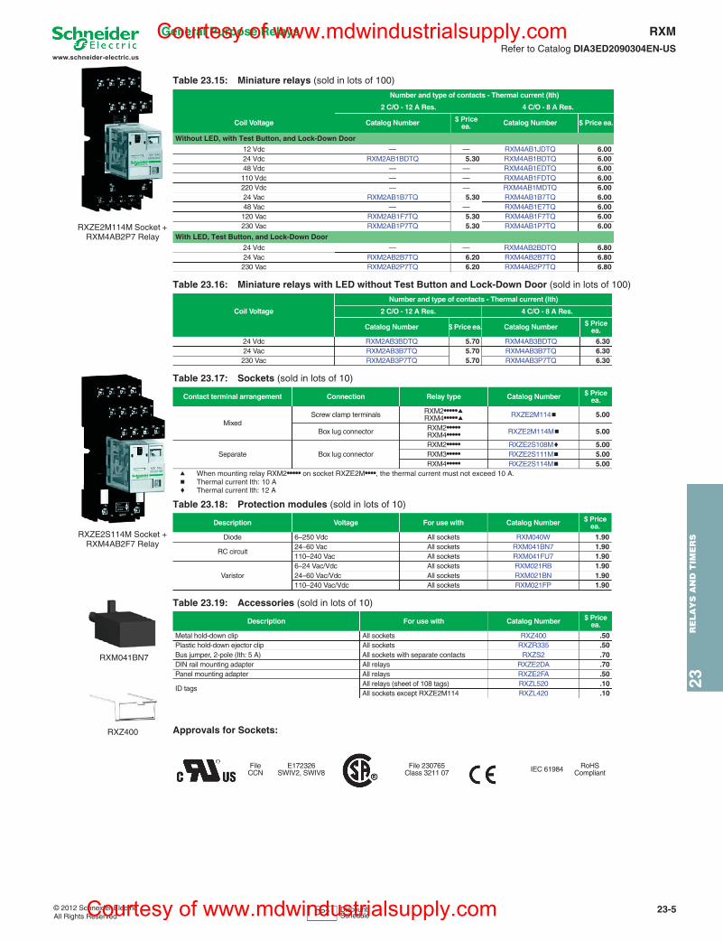
a When mounting relay RXM2••••• on socket RXZE2M••••, the thermal current must not exceed 10 A.b Thermal current Ith: 10 Ac Thermal current lth: 12 A
Approvals for Sockets:
Table 23.15: Miniature relays (sold in lots of 100)
Number and type of contacts - Thermal current (Ith)
2 C/O - 12 A Res. 4 C/O - 8 A Res.
Coil Voltage Catalog Number $ Price ea. Catalog Number $ Price ea.
Without LED, with Test Button, and Lock-Down Door
12 Vdc — — RXM4AB1JDTQ 6.0024 Vdc RXM2AB1BDTQ 5.30 RXM4AB1BDTQ 6.0048 Vdc — — RXM4AB1EDTQ 6.00110 Vdc — — RXM4AB1FDTQ 6.00220 Vdc — — RXM4AB1MDTQ 6.0024 Vac RXM2AB1B7TQ 5.30 RXM4AB1B7TQ 6.0048 Vac — — RXM4AB1E7TQ 6.00120 Vac RXM2AB1F7TQ 5.30 RXM4AB1F7TQ 6.00230 Vac RXM2AB1P7TQ 5.30 RXM4AB1P7TQ 6.00
With LED, Test Button, and Lock-Down Door
24 Vdc — — RXM4AB2BDTQ 6.8024 Vac RXM2AB2B7TQ 6.20 RXM4AB2B7TQ 6.80230 Vac RXM2AB2P7TQ 6.20 RXM4AB2P7TQ 6.80
Table 23.16: Miniature relays with LED without Test Button and Lock-Down Door (sold in lots of 100)
Number and type of contacts - Thermal current (Ith)
Coil Voltage 2 C/O - 12 A Res. 4 C/O - 8 A Res.
Catalog Number $ Price ea. Catalog Number $ Price ea.
24 Vdc RXM2AB3BDTQ 5.70 RXM4AB3BDTQ 6.3024 Vac RXM2AB3B7TQ 5.70 RXM4AB3B7TQ 6.30230 Vac RXM2AB3P7TQ 5.70 RXM4AB3P7TQ 6.30
Table 23.17: Sockets (sold in lots of 10)
Contact terminal arrangement Connection Relay type Catalog Number $ Price ea.
MixedScrew clamp terminals RXM2•••••a
RXM4•••••a RXZE2M114b 5.00
Box lug connector RXM2•••••RXM4••••• RXZE2M114Mb 5.00
Separate Box lug connectorRXM2••••• RXZE2S108Mc 5.00RXM3••••• RXZE2S111Mb 5.00RXM4••••• RXZE2S114Mb 5.00
Table 23.18: Protection modules (sold in lots of 10)
Description Voltage For use with Catalog Number $ Price ea.
Diode 6–250 Vdc All sockets RXM040W 1.90
RC circuit24–60 Vac All sockets RXM041BN7 1.90110–240 Vac All sockets RXM041FU7 1.90
Varistor6–24 Vac/Vdc All sockets RXM021RB 1.9024–60 Vac/Vdc All sockets RXM021BN 1.90110–240 Vac/Vdc All sockets RXM021FP 1.90
Table 23.19: Accessories (sold in lots of 10)
Description For use with Catalog Number $ Price ea.
Metal hold-down clip All sockets RXZ400 .50Plastic hold-down ejector clip All sockets RXZR335 .50Bus jumper, 2-pole (Ith: 5 A) All sockets with separate contacts RXZS2 .70DIN rail mounting adapter All relays RXZE2DA .70Panel mounting adapter All relays RXZE2FA .50
ID tagsAll relays (sheet of 108 tags) RXZL520 .10All sockets except RXZE2M114 RXZL420 .10
FileCCN
E172326SWIV2, SWIV8
File 230765Class 3211 07 IEC 61984 RoHS
Compliant
RXZE2M114M Socket + RXM4AB2P7 Relay
RXZE2S114M Socket + RXM4AB2F7 Relay
RXM041BN7
RXZ400
CP2 Discount Schedule
Courtesy of www.mdwindustrialsupply.com
Courtesy of www.mdwindustrialsupply.com
www.schneider-electric.us
23R
ELA
YS
AN
D T
IME
RS
23-6 © 2012 Schneider ElectricAll Rights Reserved
General Purpose Relays RPMRefer to Catalog DIA3ED2090304EN-US
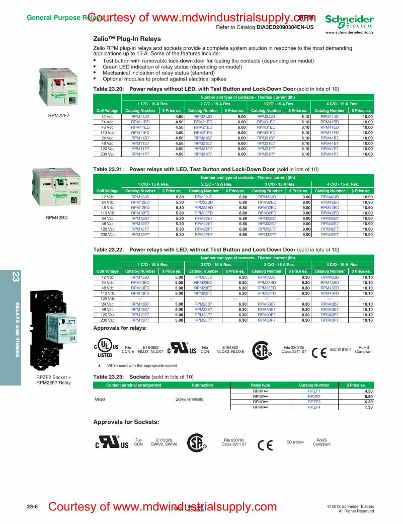
Zelio™ Plug-In RelaysZelio RPM plug-in relays and sockets provide a complete system solution in response to the most demanding applications up to 15 A. Some of the features include:• Test button with removable lock-down door for testing the contacts (depending on model)• Green LED indication of relay status (depending on model)• Mechanical indication of relay status (standard)• Optional modules to protect against electrical spikes
Approvals for relays:
Approvals for Sockets:
Table 23.20: Power relays without LED, with Test Button and Lock-Down Door (sold in lots of 10)
Number and type of contacts - Thermal current (Ith)
1 C/O - 15 A Res. 2 C/O - 15 A Res. 3 C/O - 15 A Res. 4 C/O - 15 A Res.
Coil Voltage Catalog Number $ Price ea. Catalog Number $ Price ea. Catalog Number $ Price ea. Catalog Number $ Price ea.
12 Vdc RPM11JD 4.50 RPM21JD 6.00 RPM31JD 8.10 RPM41JD 10.0024 Vdc RPM11BD 4.50 RPM21BD 6.00 RPM31BD 8.10 RPM41BD 10.0048 Vdc RPM11ED 4.50 RPM21ED 6.00 RPM31ED 8.10 RPM41ED 10.00110 Vdc RPM11FD 4.50 RPM21FD 6.00 RPM31FD 8.10 RPM41FD 10.0024 Vac RPM11B7 4.50 RPM21B7 6.00 RPM31B7 8.10 RPM41B7 10.0048 Vac RPM11E7 4.50 RPM21E7 6.00 RPM31E7 8.10 RPM41E7 10.00120 Vac RPM11F7 4.50 RPM21F7 6.00 RPM31F7 8.10 RPM41F7 10.00230 Vac RPM11P7 4.50 RPM21P7 6.00 RPM31P7 8.10 RPM41P7 10.00
Table 23.21: Power relays with LED, Test Button and Lock-Down Door (sold in lots of 10)
Number and type of contacts - Thermal current (Ith)
1 C/O - 15 A Res. 2 C/O - 15 A Res. 3 C/O - 15 A Res. 4 C/O - 15 A Res.
Coil Voltage Catalog Number $ Price ea. Catalog Number $ Price ea. Catalog Number $ Price ea. Catalog Number $ Price ea.
12 Vdc RPM12JD 5.30 RPM22JD 6.80 RPM32JD 9.00 RPM42JD 10.9024 Vdc RPM12BD 5.30 RPM22BD 6.80 RPM32BD 9.00 RPM42BD 10.9048 Vdc RPM12ED 5.30 RPM22ED 6.80 RPM32ED 9.00 RPM42ED 10.90110 Vdc RPM12FD 5.30 RPM22FD 6.80 RPM32FD 9.00 RPM42FD 10.9024 Vac RPM12B7 5.30 RPM22B7 6.80 RPM32B7 9.00 RPM42B7 10.9048 Vac RPM12E7 5.30 RPM22E7 6.80 RPM32E7 9.00 RPM42E7 10.90120 Vac RPM12F7 5.30 RPM22F7 6.80 RPM32F7 9.00 RPM42F7 10.90230 Vac RPM12P7 5.30 RPM22P7 6.80 RPM32P7 9.00 RPM42P7 10.90
Table 23.22: Power relays with LED, without Test Button and Lock-Down Door (sold in lots of 10)
Number and type of contacts - Thermal current (Ith)
1 C/O - 15 A Res. 2 C/O - 15 A Res. 3 C/O - 15 A Res. 4 C/O - 15 A Res.
Coil Voltage Catalog Number $ Price ea. Catalog Number $ Price ea. Catalog Number $ Price ea. Catalog Number $ Price ea.
12 Vdc RPM13JD 5.00 RPM23JD 6.30 RPM33JD 8.30 RPM43JD 10.1024 Vdc RPM13BD 5.00 RPM23BD 6.30 RPM33BD 8.30 RPM43BD 10.1048 Vdc RPM13ED 5.00 RPM23ED 6.30 RPM33ED 8.30 RPM43ED 10.10110 Vdc RPM13FD 5.00 RPM23FD 6.30 RPM33FD 8.30 RPM43FD 10.10125 Vdc — — — — — — — —24 Vac RPM13B7 5.00 RPM23B7 6.30 RPM33B7 8.30 RPM43B7 10.1048 Vac RPM13E7 5.00 RPM23E7 6.30 RPM33E7 8.30 RPM43E7 10.10120 Vac RPM13F7 5.00 RPM23F7 6.30 RPM33F7 8.30 RPM43F7 10.10230 Vac RPM13P7 5.00 RPM23P7 6.30 RPM33P7 8.30 RPM43P7 10.10
FileCCN a
E164862NLDX, NLDX7
FileCCN
E164862NLDX2, NLDX8
File 230765Class 3211 07 IEC 61810-1 RoHS
Compliant
a When used with the appropriate socket
Table 23.23: Sockets (sold in lots of 10)
Contact terminal arrangement Connection Relay type Catalog Number $ Price ea.
Mixed Screw terminals
RPM1••• RPZF1 4.30RPM2••• RPZF2 5.50RPM3••• RPZF3 6.30RPM4••• RPZF4 7.30
FileCCN
E172326SWIV2, SWIV8
File 230765Class 3211 07 IEC 61984 RoHS
Compliant
RPM22F7
RPM42BD
RPZF2 Socket + RPM22F7 Relay
CP2 Discount Schedule
Courtesy of www.mdwindustrialsupply.com
Courtesy of www.mdwindustrialsupply.com
www.schneider-electric.us
23R
ELA
YS
AN
D T
IME
RS
23-8 © 2012 Schneider ElectricAll Rights Reserved
General Purpose Relays RUMRefer to Catalog DIA3ED2090304EN-US
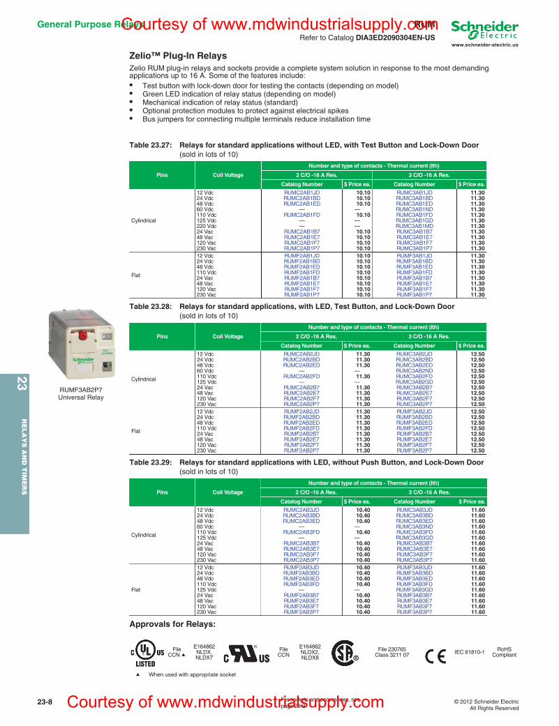
Zelio™ Plug-In RelaysZelio RUM plug-in relays and sockets provide a complete system solution in response to the most demanding applications up to 16 A. Some of the features include:• Test button with lock-down door for testing the contacts (depending on model)• Green LED indication of relay status (depending on model)• Mechanical indication of relay status (standard)• Optional protection modules to protect against electrical spikes• Bus jumpers for connecting multiple terminals reduce installation time
Approvals for Relays:
Table 23.27: Relays for standard applications without LED, with Test Button and Lock-Down Door(sold in lots of 10)
Pins Coil Voltage
Number and type of contacts - Thermal current (Ith)
2 C/O -16 A Res. 3 C/O -16 A Res.
Catalog Number $ Price ea. Catalog Number $ Price ea.
Cylindrical
12 Vdc RUMC2AB1JD 10.10 RUMC3AB1JD 11.3024 Vdc RUMC2AB1BD 10.10 RUMC3AB1BD 11.3048 Vdc RUMC2AB1ED 10.10 RUMC3AB1ED 11.3060 Vdc — — RUMC3AB1ND 11.30110 Vdc RUMC2AB1FD 10.10 RUMC3AB1FD 11.30125 Vdc — — RUMC3AB1GD 11.30220 Vdc — — RUMC3AB1MD 11.3024 Vac RUMC2AB1B7 10.10 RUMC3AB1B7 11.3048 Vac RUMC2AB1E7 10.10 RUMC3AB1E7 11.30120 Vac RUMC2AB1F7 10.10 RUMC3AB1F7 11.30230 Vac RUMC2AB1P7 10.10 RUMC3AB1P7 11.30
Flat
12 Vdc RUMF2AB1JD 10.10 RUMF3AB1JD 11.3024 Vdc RUMF2AB1BD 10.10 RUMF3AB1BD 11.3048 Vdc RUMF2AB1ED 10.10 RUMF3AB1ED 11.30110 Vdc RUMF2AB1FD 10.10 RUMF3AB1FD 11.3024 Vac RUMF2AB1B7 10.10 RUMF3AB1B7 11.3048 Vac RUMF2AB1E7 10.10 RUMF3AB1E7 11.30120 Vac RUMF2AB1F7 10.10 RUMF3AB1F7 11.30230 Vac RUMF2AB1P7 10.10 RUMF3AB1P7 11.30
Table 23.28: Relays for standard applications, with LED, Test Button, and Lock-Down Door(sold in lots of 10)
Pins Coil Voltage
Number and type of contacts - Thermal current (Ith)
2 C/O -16 A Res. 3 C/O -16 A Res.
Catalog Number $ Price ea. Catalog Number $ Price ea.
Cylindrical
12 Vdc RUMC2AB2JD 11.30 RUMC3AB2JD 12.5024 Vdc RUMC2AB2BD 11.30 RUMC3AB2BD 12.5048 Vdc RUMC2AB2ED 11.30 RUMC3AB2ED 12.5060 Vdc — — RUMC3AB2ND 12.50110 Vdc RUMC2AB2FD 11.30 RUMC3AB2FD 12.50125 Vdc — — RUMC3AB2GD 12.5024 Vac RUMC2AB2B7 11.30 RUMC3AB2B7 12.5048 Vac RUMC2AB2E7 11.30 RUMC3AB2E7 12.50120 Vac RUMC2AB2F7 11.30 RUMC3AB2F7 12.50230 Vac RUMC2AB2P7 11.30 RUMC3AB2P7 12.50
Flat
12 Vdc RUMF2AB2JD 11.30 RUMF3AB2JD 12.5024 Vdc RUMF2AB2BD 11.30 RUMF3AB2BD 12.5048 Vdc RUMF2AB2ED 11.30 RUMF3AB2ED 12.50110 Vdc RUMF2AB2FD 11.30 RUMF3AB2FD 12.5024 Vac RUMF2AB2B7 11.30 RUMF3AB2B7 12.5048 Vac RUMF2AB2E7 11.30 RUMF3AB2E7 12.50120 Vac RUMF2AB2F7 11.30 RUMF3AB2F7 12.50230 Vac RUMF2AB2P7 11.30 RUMF3AB2P7 12.50
Table 23.29: Relays for standard applications with LED, without Push Button, and Lock-Down Door(sold in lots of 10)
Pins Coil Voltage
Number and type of contacts - Thermal current (Ith)
2 C/O -16 A Res. 3 C/O -16 A Res.
Catalog Number $ Price ea. Catalog Number $ Price ea.
Cylindrical
12 Vdc RUMC2AB3JD 10.40 RUMC3AB3JD 11.6024 Vdc RUMC2AB3BD 10.40 RUMC3AB3BD 11.6048 Vdc RUMC2AB3ED 10.40 RUMC3AB3ED 11.6060 Vdc — — RUMC3AB3ND 11.60110 Vdc RUMC2AB3FD 10.40 RUMC3AB3FD 11.60125 Vdc — — RUMC3AB3GD 11.6024 Vac RUMC2AB3B7 10.40 RUMC3AB3B7 11.6048 Vac RUMC2AB3E7 10.40 RUMC3AB3E7 11.60120 Vac RUMC2AB3F7 10.40 RUMC3AB3F7 11.60230 Vac RUMC2AB3P7 10.40 RUMC3AB3P7 11.60
Flat
12 Vdc RUMF2AB3JD 10.40 RUMF3AB3JD 11.6024 Vdc RUMF2AB3BD 10.40 RUMF3AB3BD 11.6048 Vdc RUMF2AB3ED 10.40 RUMF3AB3ED 11.60110 Vdc RUMF2AB3FD 10.40 RUMF3AB3FD 11.60125 Vdc — — RUMF3AB3GD 11.6024 Vac RUMF2AB3B7 10.40 RUMF3AB3B7 11.6048 Vac RUMF2AB3E7 10.40 RUMF3AB3E7 11.60120 Vac RUMF2AB3F7 10.40 RUMF3AB3F7 11.60230 Vac RUMF2AB3P7 10.40 RUMF3AB3P7 11.60
FileCCN a
E164862NLDX, NLDX7
FileCCN
E164862NLDX2, NLDX8
File 230765Class 3211 07 IEC 61810-1 RoHS
Compliant
a When used with appropriate socket
RUMF3AB2P7 Universal Relay
For sockets and accessories, see page 23-9
Courtesy of www.mdwindustrialsupply.com
Courtesy of www.mdwindustrialsupply.com
www.schneider-electric.us
23R
EL
AY
S A
ND
TIM
ER
S
© 2012 Schneider ElectricAll Rights Reserved
23-9
General Purpose Relays RUMRefer to Catalog DIA3ED2090304EN-US
a The inputs are mixed with the relay coil terminals, with the outputs located on the opposite side of the socket.b The inputs and outputs are separated from the relay coil terminals.
c See timer module description (selection of functions and time delays) in catalog 8501CT0601.
Approvals for Sockets:
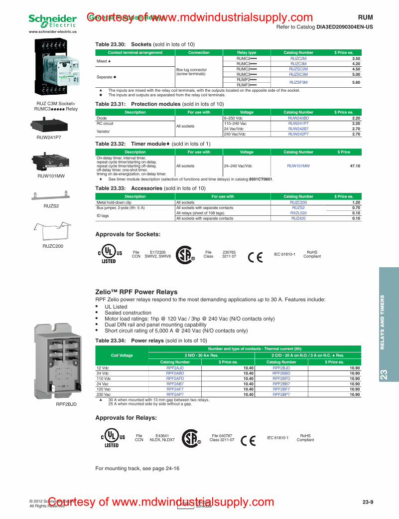
Zelio™ RPF Power RelaysRPF Zelio power relays respond to the most demanding applications up to 30 A. Features include:• UL Listed• Sealed construction• Motor load ratings: 1hp @ 120 Vac / 3hp @ 240 Vac (N/O contacts only)• Dual DIN rail and panel mounting capability• Short circuit rating of 5,000 A @ 240 Vac (N/O contacts only)
a 30 A when mounted with 13 mm gap between two relays.25 A when mounted side by side without a gap.
Approvals for Relays:
For mounting track, see page 24-16
Table 23.30: Sockets (sold in lots of 10)
Contact terminal arrangement Connection Relay type Catalog Number $ Price ea.
Mixed a
Box lug connector(screw terminals)
RUMC2••••• RUZC2M 3.50RUMC3••••• RUZC3M 4.20
Separate b
RUMC2••••• RUZSC2M 4.50RUMC3••••• RUZSC3M 5.00RUMF2•••••
RUZSF3M 5.60RUMF3•••••
Table 23.31: Protection modules (sold in lots of 10)
Description For use with Voltage Catalog Number $ Price ea.
Diode
All sockets
6–250 Vdc RUW240BD 2.20RC circuit 110–240 Vac RUW241P7 2.20
Varistor24 Vac/Vdc RUW242B7 2.70240 Vac/Vdc RUW242P7 2.70
Table 23.32: Timer modulec (sold in lots of 1)
Description For use with Voltage Catalog Number $ Price
On-delay timer, interval timer, repeat cycle timer/starting on-delay, repeat cycle timer/starting off-delay,off-delay timer, one-shot timer,timing on de-energization, on-delay timer.
All sockets 24–240 Vac/Vdc RUW101MW 47.10
Table 23.33: Accessories (sold in lots of 10)
Description For use with Catalog Number $ Price ea.
Metal hold-down clip All sockets RUZC200 1.20Bus jumper, 2-pole (Ith: 5 A) All sockets with separate contacts RUZS2 0.70
ID tagsAll relays (sheet of 108 tags) RXZL520 0.10All sockets with separate contacts RUZ420 0.10
FileCCN
E172326SWIV2, SWIV8
FileClass
2307653211 07 IEC 61810-1 RoHS
Compliant
Table 23.34: Power relays (sold in lots of 10)
Coil Voltage
Number and type of contacts - Thermal current (Ith)
2 N/O - 30 Aa Res. 2 C/O - 30 A on N.O. / 3 A on N.C. a Res.
Catalog Number $ Price ea. Catalog Number $ Price ea.
12 Vdc RPF2AJD 10.40 RPF2BJD 10.9024 Vdc RPF2ABD 10.40 RPF2BBD 10.90110 Vdc RPF2AFD 10.40 RPF2BFD 10.9024 Vac RPF2AB7 10.40 RPF2BB7 10.90120 Vac RPF2AF7 10.40 RPF2BF7 10.90230 Vac RPF2AP7 10.40 RPF2BP7 10.90
FileCCN
E43641NLDX, NLDX7
File 040787Class 3211-07 IEC 61810-1 RoHS
Compliant
RUZ C3M Socket+ RUMC3ppppp Relay
RUW241P7
RUW101MW
RUZS2
RUZC200
RPF2BJD
CP2 Discount Schedule
Courtesy of www.mdwindustrialsupply.com
Courtesy of www.mdwindustrialsupply.com
www.schneider-electric.us
23R
ELA
YS
AN
D T
IME
RS
23-10 © 2012 Schneider ElectricAll Rights Reserved
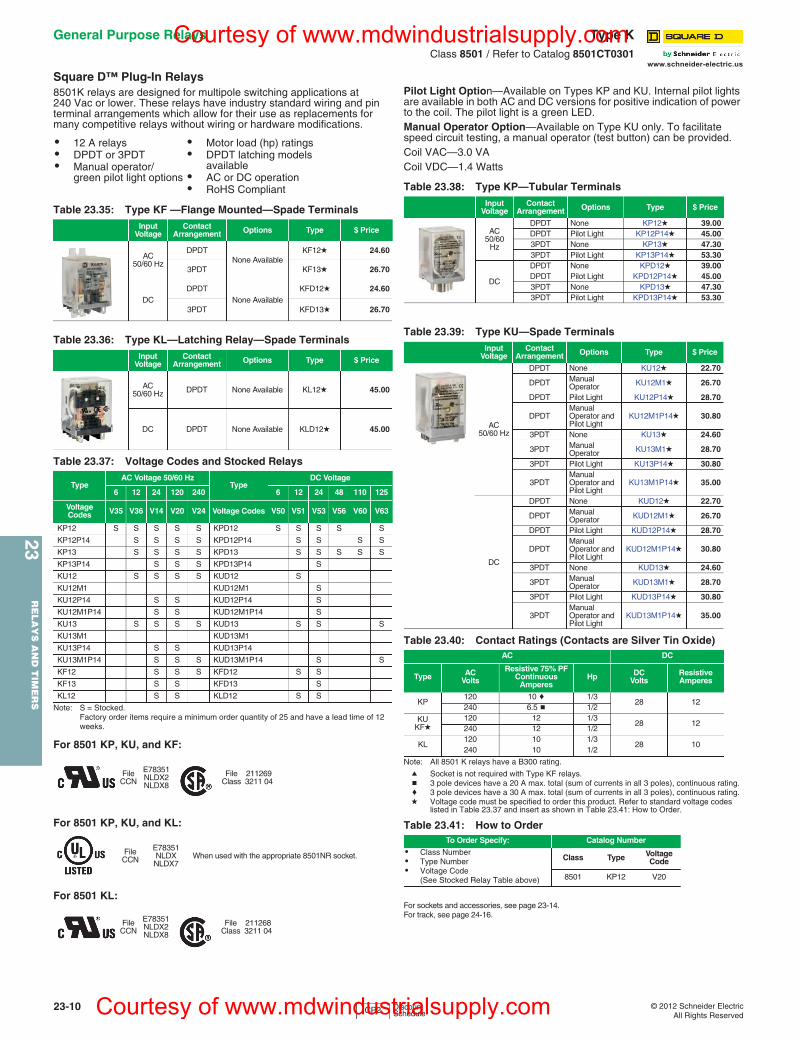
Square D™ Plug-In Relays8501K relays are designed for multipole switching applications at 240 Vac or lower. These relays have industry standard wiring and pin terminal arrangements which allow for their use as replacements for many competitive relays without wiring or hardware modifications.
Note: S = Stocked. Factory order items require a minimum order quantity of 25 and have a lead time of 12 weeks.
Pilot Light Option—Available on Types KP and KU. Internal pilot lights are available in both AC and DC versions for positive indication of power to the coil. The pilot light is a green LED.Manual Operator Option—Available on Type KU only. To facilitate speed circuit testing, a manual operator (test button) can be provided. Coil VAC—3.0 VACoil VDC—1.4 Watts
Note: All 8501 K relays have a B300 rating.
a Socket is not required with Type KF relays.b 3 pole devices have a 20 A max. total (sum of currents in all 3 poles), continuous rating.c 3 pole devices have a 30 A max. total (sum of currents in all 3 poles), continuous rating.d Voltage code must be specified to order this product. Refer to standard voltage codes
listed in Table 23.37 and insert as shown in Table 23.41: How to Order.
For sockets and accessories, see page 23-14.For track, see page 24-16.
• 12 A relays• DPDT or 3PDT• Manual operator/
green pilot light options
• Motor load (hp) ratings• DPDT latching models
available• AC or DC operation• RoHS Compliant
Table 23.35: Type KF —Flange Mounted—Spade TerminalsInput
VoltageContact
Arrangement Options Type $ Price
AC50/60 Hz
DPDTNone Available
KF12d 24.60
3PDT KF13d 26.70
DCDPDT
None AvailableKFD12d 24.60
3PDT KFD13d 26.70
Table 23.36: Type KL—Latching Relay—Spade TerminalsInput
VoltageContact
Arrangement Options Type $ Price
AC50/60 Hz DPDT None Available KL12d 45.00
DC DPDT None Available KLD12d 45.00
Table 23.37: Voltage Codes and Stocked Relays
TypeAC Voltage 50/60 Hz
TypeDC Voltage
6 12 24 120 240 6 12 24 48 110 125
Voltage Codes V35 V36 V14 V20 V24 Voltage Codes V50 V51 V53 V56 V60 V63
KP12 S S S S S KPD12 S S S S S
KP12P14 S S S S KPD12P14 S S S S
KP13 S S S S KPD13 S S S S S
KP13P14 S S S KPD13P14 S
KU12 S S S S KUD12 S
KU12M1 KUD12M1 S
KU12P14 S S KUD12P14 S
KU12M1P14 S S KUD12M1P14 S
KU13 S S S S KUD13 S S S
KU13M1 KUD13M1
KU13P14 S S KUD13P14
KU13M1P14 S S S KUD13M1P14 S S
KF12 S S S KFD12 S S
KF13 S S KFD13 S
KL12 S S KLD12 S S
For 8501 KP, KU, and KF:
FileCCN
E78351NLDX2NLDX8
FileClass
2112693211 04
For 8501 KP, KU, and KL:
FileCCN
E78351NLDXNLDX7
When used with the appropriate 8501NR socket.
For 8501 KL:
FileCCN
E78351NLDX2NLDX8
FileClass
2112683211 04
Table 23.38: Type KP—Tubular TerminalsInput
VoltageContact
Arrangement Options Type $ Price
AC50/60
Hz
DPDT None KP12d 39.00DPDT Pilot Light KP12P14d 45.003PDT None KP13d 47.303PDT Pilot Light KP13P14d 53.30
DC
DPDT None KPD12d 39.00DPDT Pilot Light KPD12P14d 45.003PDT None KPD13d 47.303PDT Pilot Light KPD13P14d 53.30
Table 23.39: Type KU—Spade TerminalsInput
VoltageContact
Arrangement Options Type $ Price
AC50/60 Hz
DPDT None KU12d 22.70
DPDT Manual Operator KU12M1d 26.70
DPDT Pilot Light KU12P14d 28.70
DPDTManual Operator and Pilot Light
KU12M1P14d 30.80
3PDT None KU13d 24.60
3PDT Manual Operator KU13M1d 28.70
3PDT Pilot Light KU13P14d 30.80
3PDTManual Operator and Pilot Light
KU13M1P14d 35.00
DC
DPDT None KUD12d 22.70
DPDT Manual Operator KUD12M1d 26.70
DPDT Pilot Light KUD12P14d 28.70
DPDTManual Operator and Pilot Light
KUD12M1P14d 30.80
3PDT None KUD13d 24.60
3PDT Manual Operator KUD13M1d 28.70
3PDT Pilot Light KUD13P14d 30.80
3PDTManual Operator and Pilot Light
KUD13M1P14d 35.00
Table 23.40: Contact Ratings (Contacts are Silver Tin Oxide)AC DC
Type ACVolts
Resistive 75% PF Continuous
AmperesHp DC
VoltsResistive Amperes
KP120 10 c 1/3
28 12240 6.5 b 1/2
KUKFd
120 12 1/328 12
240 12 1/2
KL 120 10 1/3
28 10240 10 1/2
Table 23.41: How to OrderTo Order Specify: Catalog Number
• Class Number• Type Number• Voltage Code
(See Stocked Relay Table above)
Class Type Voltage Code
8501 KP12 V20
CP2 Discount Schedule
General Purpose Relays Type KClass 8501 / Refer to Catalog 8501CT0301
Courtesy of www.mdwindustrialsupply.com
Courtesy of www.mdwindustrialsupply.com
23R
ELA
YS
AN
D T
IME
RS
23-12 © 2012 Schneider ElectricAll Rights Reserved
www.schneider-electric.us
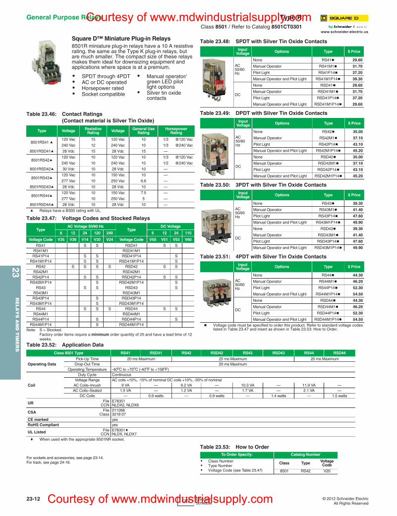
Square D™ Miniature Plug-in Relays8501R miniature plug-in relays have a 10 A resistive rating, the same as the Type K plug-in relays, but are much smaller. The compact size of these relays makes them ideal for downsizing equipment and applications where space is at a premium.
a Relays have a B300 rating with UL.
b Voltage code must be specified to order this product. Refer to standard voltage codes listed in Table 23.47 and insert as shown in Table 23.53: How to Order.
c When used with the appropriate 8501NR socket.
For sockets and accessories, see page 23-14. For track, see page 24-16.
• SPDT through 4PDT• AC or DC operated• Horsepower rated• Socket compatible
• Manual operator/ green LED pilot light options
• Silver tin oxide contacts
Table 23.46: Contact Ratings (Contact material is Silver Tin Oxide)
Type Voltage ResistiveRating Voltage General Use
RatingHorsepower
Rating
8501RS41 a120 Vac 15 120 Vac 10 1/3 @120 Vac
240 Vac 12 240 Vac 10 1/3 @240 Vac
8501RSD41a 28 Vdc 15 28 Vdc 15 —
8501RS42a120 Vac 10 120 Vac 10 1/3 @120 Vac
240 Vac 10 240 Vac 10 1/2 @240 Vac
8501RSD42a 30 Vdc 10 28 Vdc 10 —
8501RS43a120 Vac 10 150 Vac 10 —
277 Vac 10 250 Vac 6.6 —
8501RSD43a 28 Vdc 10 28 Vdc 10 —
8501RS44a120 Vac 10 150 Vac 7.5 —
277 Vac 10 250 Vac 5 —
8501RSD44a 28 Vdc 10 28 Vdc 10 —
Table 23.47: Voltage Codes and Stocked Relays
TypeAC Voltage 50/60 Hz
TypeDC Voltage
6 12 24 120 240 6 12 24 110
Voltage Code V35 V36 V14 V20 V24 Voltage Code V50 V51 V53 V60
RS41 S S RSD41 S SRS41M1 RSD41M1RS41P14 S S RSD41P14 S
RS41M1P14 S S RSD41M1P14 SRS42 S S S S RSD42 S S
RS42M1 RSD42M1RS42P14 S S RSD42P14 S S
RS42M1P14 S RSD42M1P14 SRS43 S S RSD43 S
RS43M1 RSD43M1RS43P14 S RSD43P14
RS43M1P14 S RSD43M1P14RS44 S S S RSD44 S S
RS44M1 RSD44M1RS44P14 S RSD44P14 S
RS44M1P14 S RSD44M1P14Note: S = Stocked.
Factory order items require a minimum order quantity of 25 and have a lead time of 12 weeks.
Table 23.48: SPDT with Silver Tin Oxide ContactsInput
Voltage Options Type $ Price
AC50/60Hz
None RS41b 29.60
Manual Operator RS41M1b 31.70
Pilot Light RS41P14b 37.20
Manual Operator and Pilot Light RS41M1P14b 39.30
DC
None RSD41b 29.60
Manual Operator RSD41M1b 31.70
Pilot Light RSD41P14b 37.20
Manual Operator and Pilot Light RSD41M1P14b 29.60
Table 23.49: DPDT with Silver Tin Oxide ContactsInput
Voltage Options Type $ Price
AC50/60Hz
None RS42b 35.00
Manual Operator RS42M1b 37.10
Pilot Light RS42P14b 43.10
Manual Operator and Pilot Light RS42M1P14b 45.20
DC
None RSD42b 35.00
Manual Operator RSD42M1b 37.10
Pilot Light RSD42P14b 43.10
Manual Operator and Pilot Light RSD42M1P14b 45.20
Table 23.50: 3PDT with Silver Tin Oxide ContactsInput
Voltage Options Type $ Price
AC50/60Hz
None RS43b 39.30
Manual Operator RS43M1b 41.40
Pilot Light RS43P14b 47.60
Manual Operator and Pilot Light RS43M1P14b 49.90
DC
None RSD43b 39.30
Manual Operator RSD43M1b 41.40
Pilot Light RSD43P14b 47.60
Manual Operator and Pilot Light RSD43M1P14b 49.90
Table 23.51: 4PDT with Silver Tin Oxide ContactsInput
Voltage Options Type $ Price
AC50/60Hz
None RS44b 44.30
Manual Operator RS44M1b 46.20
Pilot Light RS44P14b 52.30
Manual Operator and Pilot Light RS44M1P14b 54.50
DC
None RSD44b 44.30
Manual Operator RSD44M1b 46.20
Pilot Light RSD44P14b 52.30
Manual Operator and Pilot Light RSD44M1P14b 54.50
Table 23.52: Application DataClass 8501 Type RS41 RSD41 RS42 RSD42 RS43 RSD43 RS44 RSD44
Operating DataPick-Up Time 20 ms Maximum 25 ms Maximum 20 ms Maximum
Drop-Out Time 20 ms MaximumOperating Temperature -40oC to +70oC (-40oF to +158oF)
Coil
Duty Cycle ContinuousVoltage Range AC coils +10%, -15% of nominal DC coils +10%, -20% of nominal
AC Coils–Inrush 9 VA — 6.2 VA — 10.3 VA — 11.9 VA —AC Coils–Sealed 1.5 VA — 1.2 VA — 1.7 VA — 2.1 VA —
DC Coils — 0.9 watts — 0.9 watts — 1.4 watts — 1.5 watts
UR FileCCN
E78351NLDX2, NLDX8
CSA FileClass
2112683218 07
CE marked yesRoHS Compliant yes
UL Listed FileCCN
E78351cNLDX, NLDX7
Table 23.53: How to OrderTo Order Specify: Catalog Number
• Class Number• Type Number• Voltage Code (see Table 23.47)
Class Type Voltage Code
8501 RS42 V20
CP2 Discount Schedule
General Purpose Relays Type RClass 8501 / Refer to Catalog 8501CT0301
Courtesy of www.mdwindustrialsupply.com
Courtesy of www.mdwindustrialsupply.com
23R
EL
AY
S A
ND
TIM
ER
S
© 2012 Schneider ElectricAll Rights Reserved
23-13
www.schneider-electric.us
General Purpose Relays Type RClass 8501 / Refer to Catalog 8501CT0301
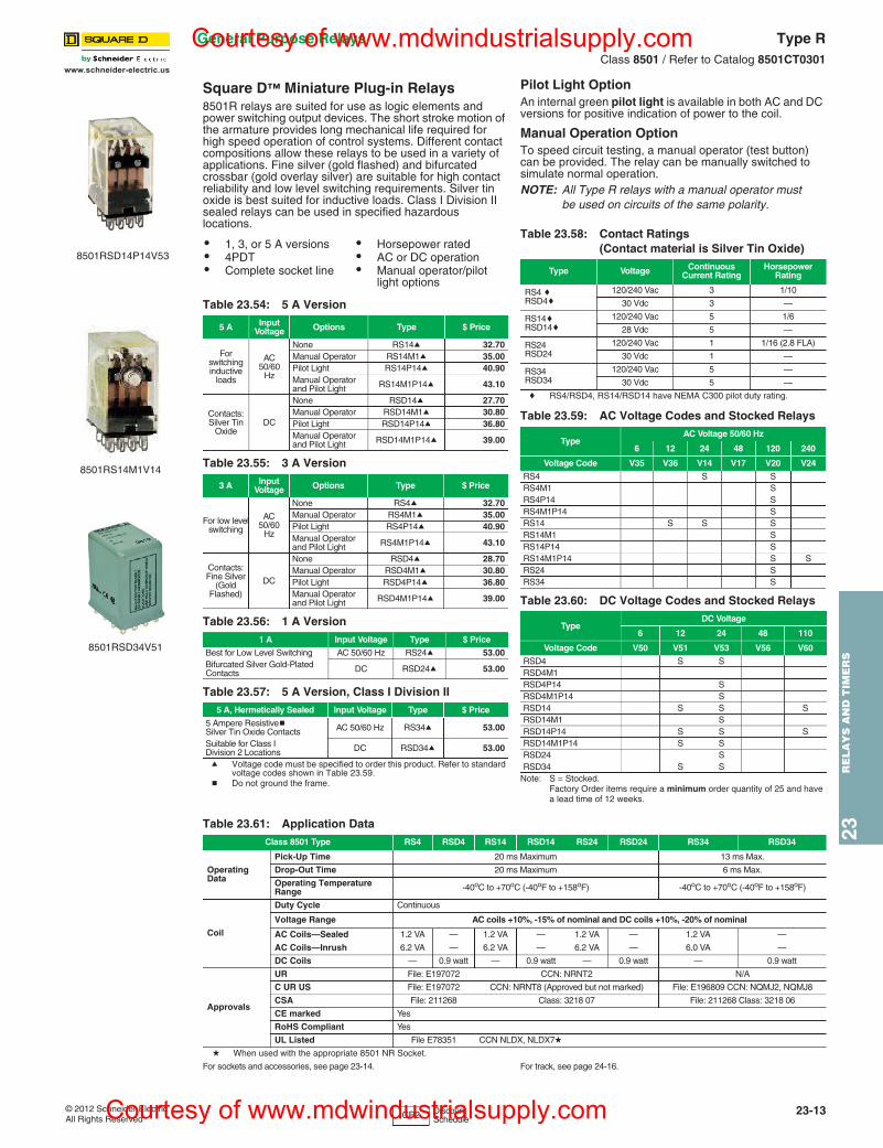
Square D™ Miniature Plug-in Relays8501R relays are suited for use as logic elements and power switching output devices. The short stroke motion of the armature provides long mechanical life required for high speed operation of control systems. Different contact compositions allow these relays to be used in a variety of applications. Fine silver (gold flashed) and bifurcated crossbar (gold overlay silver) are suitable for high contact reliability and low level switching requirements. Silver tin oxide is best suited for inductive loads. Class I Division II sealed relays can be used in specified hazardous locations.
a Voltage code must be specified to order this product. Refer to standard voltage codes shown in Table 23.59.
b Do not ground the frame.
Pilot Light OptionAn internal green pilot light is available in both AC and DC versions for positive indication of power to the coil.
Manual Operation OptionTo speed circuit testing, a manual operator (test button) can be provided. The relay can be manually switched to simulate normal operation.NOTE: All Type R relays with a manual operator must
be used on circuits of the same polarity.
c RS4/RSD4, RS14/RSD14 have NEMA C300 pilot duty rating.
Note: S = Stocked. Factory Order items require a minimum order quantity of 25 and have a lead time of 12 weeks.
For sockets and accessories, see page 23-14. For track, see page 24-16.
• 1, 3, or 5 A versions• 4PDT• Complete socket line
• Horsepower rated• AC or DC operation• Manual operator/pilot
light options
Table 23.54: 5 A Version
5 A Input Voltage Options Type $ Price
For switchinginductive
loads
AC50/60
Hz
None RS14a 32.70Manual Operator RS14M1a 35.00Pilot Light RS14P14a 40.90Manual Operatorand Pilot Light RS14M1P14a 43.10
Contacts:Silver Tin
OxideDC
None RSD14a 27.70Manual Operator RSD14M1a 30.80Pilot Light RSD14P14a 36.80Manual Operatorand Pilot Light RSD14M1P14a 39.00
Table 23.55: 3 A Version
3 A Input Voltage Options Type $ Price
For low levelswitching
AC50/60
Hz
None RS4a 32.70Manual Operator RS4M1a 35.00Pilot Light RS4P14a 40.90Manual Operatorand Pilot Light RS4M1P14a 43.10
Contacts:Fine Silver
(Gold Flashed)
DC
None RSD4a 28.70Manual Operator RSD4M1a 30.80Pilot Light RSD4P14a 36.80Manual Operatorand Pilot Light RSD4M1P14a 39.00
Table 23.56: 1 A Version1 A Input Voltage Type $ Price
Best for Low Level Switching AC 50/60 Hz RS24a 53.00Bifurcated Silver Gold-Plated Contacts DC RSD24a 53.00
Table 23.57: 5 A Version, Class I Division II5 A, Hermetically Sealed Input Voltage Type $ Price
5 Ampere ResistivebSilver Tin Oxide Contacts AC 50/60 Hz RS34a 53.00
Suitable for Class I Division 2 Locations DC RSD34a 53.00
8501RSD14P14V53
Table 23.58: Contact Ratings (Contact material is Silver Tin Oxide)
Type Voltage Continuous Current Rating
Horsepower Rating
RS4 cRSD4c
120/240 Vac 3 1/10
30 Vdc 3 —
RS14cRSD14c
120/240 Vac 5 1/6
28 Vdc 5 —
RS24RSD24
120/240 Vac 1 1/16 (2.8 FLA)
30 Vdc 1 —
RS34RSD34
120/240 Vac 5 —
30 Vdc 5 —
Table 23.59: AC Voltage Codes and Stocked Relays
TypeAC Voltage 50/60 Hz
6 12 24 48 120 240
Voltage Code V35 V36 V14 V17 V20 V24
RS4 S SRS4M1 SRS4P14 SRS4M1P14 SRS14 S S SRS14M1 SRS14P14 SRS14M1P14 S SRS24 SRS34 S
Table 23.60: DC Voltage Codes and Stocked Relays
TypeDC Voltage
6 12 24 48 110
Voltage Code V50 V51 V53 V56 V60
RSD4 S SRSD4M1RSD4P14 SRSD4M1P14 SRSD14 S S SRSD14M1 SRSD14P14 S S SRSD14M1P14 S SRSD24 SRSD34 S S
8501RS14M1V14
8501RSD34V51
Table 23.61: Application DataClass 8501 Type RS4 RSD4 RS14 RSD14 RS24 RSD24 RS34 RSD34
Operating Data
Pick-Up Time 20 ms Maximum 13 ms Max.
Drop-Out Time 20 ms Maximum 6 ms Max.
Operating Temperature Range -40oC to +70oC (-40oF to +158oF) -40oC to +70oC (-40oF to +158oF)
Coil
Duty Cycle Continuous
Voltage Range AC coils +10%, -15% of nominal and DC coils +10%, -20% of nominal
AC Coils—Sealed 1.2 VA — 1.2 VA — 1.2 VA — 1.2 VA —
AC Coils—Inrush 6.2 VA — 6.2 VA — 6.2 VA — 6.0 VA —
DC Coils — 0.9 watt — 0.9 watt — 0.9 watt — 0.9 watt
Approvals
UR File: E197072 CCN: NRNT2 N/A
C UR US File: E197072 CCN: NRNT8 (Approved but not marked) File: E196809 CCN: NQMJ2, NQMJ8
CSA File: 211268 Class: 3218 07 File: 211268 Class: 3218 06
CE marked Yes
RoHS Compliant Yes
UL Listed File E78351 CCN NLDX, NLDX7d
d When used with the appropriate 8501 NR Socket.
CP2 Discount Schedule
Courtesy of www.mdwindustrialsupply.com
Courtesy of www.mdwindustrialsupply.com
23R
ELA
YS
AN
D T
IME
RS
23-14 © 2012 Schneider ElectricAll Rights Reserved
www.schneider-electric.us
General Purpose Relays Type NClass 8501 / Refer to Catalog 8501CT0301
Square D™ Sockets
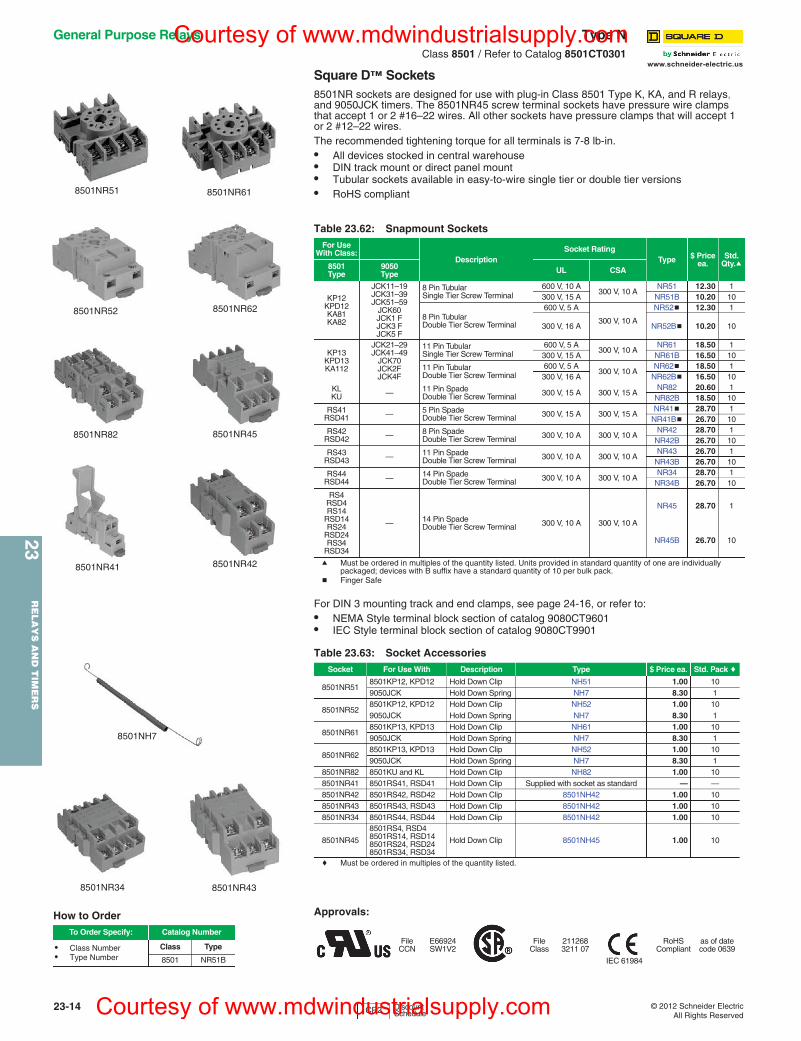
8501NR sockets are designed for use with plug-in Class 8501 Type K, KA, and R relays, and 9050JCK timers. The 8501NR45 screw terminal sockets have pressure wire clamps that accept 1 or 2 #16–22 wires. All other sockets have pressure clamps that will accept 1 or 2 #12–22 wires.The recommended tightening torque for all terminals is 7-8 lb-in.• All devices stocked in central warehouse• DIN track mount or direct panel mount• Tubular sockets available in easy-to-wire single tier or double tier versions• RoHS compliant
a Must be ordered in multiples of the quantity listed. Units provided in standard quantity of one are individually packaged; devices with B suffix have a standard quantity of 10 per bulk pack.
b Finger Safe
For DIN 3 mounting track and end clamps, see page 24-16, or refer to:• NEMA Style terminal block section of catalog 9080CT9601• IEC Style terminal block section of catalog 9080CT9901
c Must be ordered in multiples of the quantity listed.
Table 23.62: Snapmount SocketsFor Use
With Class:Description
Socket RatingType $ Price
ea.Std.
Qty.a8501 Type
9050 Type UL CSA
KP12KPD12KA81KA82
JCK11–19JCK31–39JCK51–59
JCK60JCK1 FJCK3 FJCK5 F
8 Pin TubularSingle Tier Screw Terminal
600 V, 10 A300 V, 10 A
NR51 12.30 1300 V, 15 A NR51B 10.20 10
8 Pin TubularDouble Tier Screw Terminal
600 V, 5 A
300 V, 10 A
NR52b 12.30 1
300 V, 16 A NR52Bb 10.20 10
KP13KPD13KA112
JCK21–29JCK41–49
JCK70JCK2FJCK4F
11 Pin TubularSingle Tier Screw Terminal
600 V, 5 A300 V, 10 A
NR61 18.50 1300 V, 15 A NR61B 16.50 10
11 Pin TubularDouble Tier Screw Terminal
600 V, 5 A300 V, 10 A
NR62b 18.50 1300 V, 16 A NR62Bb 16.50 10
KLKU — 11 Pin Spade
Double Tier Screw Terminal 300 V, 15 A 300 V, 15 ANR82 20.60 1
NR82B 18.50 10
RS41RSD41 — 5 Pin Spade
Double Tier Screw Terminal 300 V, 15 A 300 V, 15 ANR41b 28.70 1
NR41Bb 26.70 10
RS42RSD42 — 8 Pin Spade
Double Tier Screw Terminal 300 V, 10 A 300 V, 10 ANR42 28.70 1
NR42B 26.70 10
RS43RSD43 — 11 Pin Spade
Double Tier Screw Terminal 300 V, 10 A 300 V, 10 ANR43 26.70 1
NR43B 26.70 10
RS44RSD44 — 14 Pin Spade
Double Tier Screw Terminal 300 V, 10 A 300 V, 10 ANR34 28.70 1
NR34B 26.70 10
RS4RSD4RS14
RSD14RS24
RSD24RS34
RSD34
— 14 Pin SpadeDouble Tier Screw Terminal 300 V, 10 A 300 V, 10 A
NR45 28.70 1
NR45B 26.70 10
Table 23.63: Socket AccessoriesSocket For Use With Description Type $ Price ea. Std. Pack c
8501NR518501KP12, KPD12 Hold Down Clip NH51 1.00 109050JCK Hold Down Spring NH7 8.30 1
8501NR528501KP12, KPD12 Hold Down Clip NH52 1.00 109050JCK Hold Down Spring NH7 8.30 1
8501NR618501KP13, KPD13 Hold Down Clip NH61 1.00 109050JCK Hold Down Spring NH7 8.30 1
8501NR628501KP13, KPD13 Hold Down Clip NH52 1.00 109050JCK Hold Down Spring NH7 8.30 1
8501NR82 8501KU and KL Hold Down Clip NH82 1.00 108501NR41 8501RS41, RSD41 Hold Down Clip Supplied with socket as standard — —8501NR42 8501RS42, RSD42 Hold Down Clip 8501NH42 1.00 108501NR43 8501RS43, RSD43 Hold Down Clip 8501NH42 1.00 108501NR34 8501RS44, RSD44 Hold Down Clip 8501NH42 1.00 10
8501NR45
8501RS4, RSD48501RS14, RSD148501RS24, RSD248501RS34, RSD34
Hold Down Clip 8501NH45 1.00 10
8501NR51 8501NR61
8501NR52 8501NR62
8501NR82 8501NR45
8501NR41 8501NR42
8501NR43
8501NH7
8501NR34
How to OrderTo Order Specify: Catalog Number
• Class Number• Type Number
Class Type
8501 NR51B
Approvals:
FileCCN
E66924SW1V2
FileClass
2112683211 07
IEC 61984
RoHSCompliant
as of date code 0639
CP2 Discount Schedule
Courtesy of www.mdwindustrialsupply.com
Courtesy of www.mdwindustrialsupply.com
23R
EL
AY
S A
ND
TIM
ER
S
© 2012 Schneider ElectricAll Rights Reserved
23-15
www.schneider-electric.us
Note: S = Stocked. Factory order items require a minimum order quantity of 25 and have a lead time of 12 weeks.
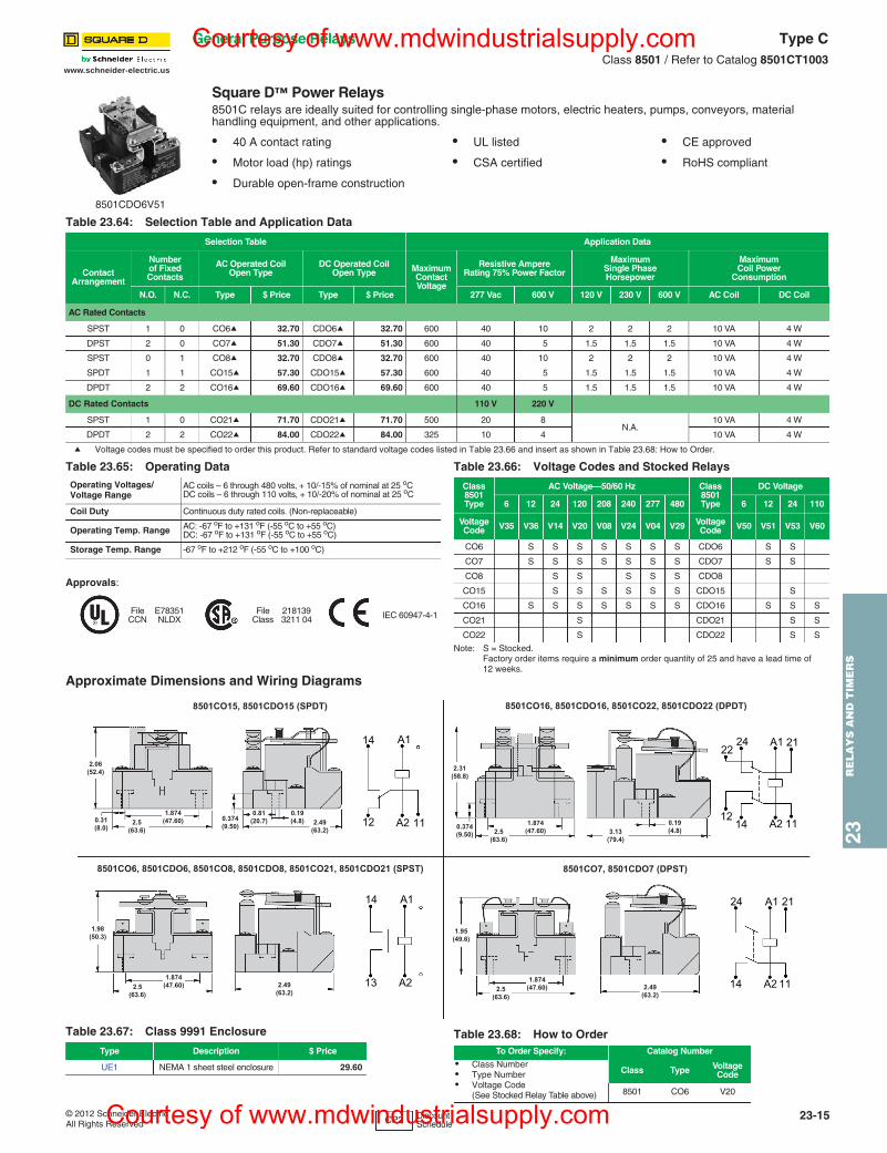
Approximate Dimensions and Wiring Diagrams
Square D™ Power Relays8501C relays are ideally suited for controlling single-phase motors, electric heaters, pumps, conveyors, material handling equipment, and other applications.
• 40 A contact rating • UL listed • CE approved
• Motor load (hp) ratings • CSA certified • RoHS compliant
• Durable open-frame construction
Table 23.64: Selection Table and Application Data
Selection Table Application Data
ContactArrangement
Numberof FixedContacts
AC Operated CoilOpen Type
DC Operated CoilOpen Type Maximum
ContactVoltage
Resistive Ampere Rating 75% Power Factor
MaximumSingle PhaseHorsepower
Maximum Coil Power
Consumption
N.O. N.C. Type $ Price Type $ Price 277 Vac 600 V 120 V 230 V 600 V AC Coil DC Coil
AC Rated Contacts
SPST 1 0 CO6a 32.70 CDO6a 32.70 600 40 10 2 2 2 10 VA 4 W
DPST 2 0 CO7a 51.30 CDO7a 51.30 600 40 5 1.5 1.5 1.5 10 VA 4 W
SPST 0 1 CO8a 32.70 CDO8a 32.70 600 40 10 2 2 2 10 VA 4 W
SPDT 1 1 CO15a 57.30 CDO15a 57.30 600 40 5 1.5 1.5 1.5 10 VA 4 W
DPDT 2 2 CO16a 69.60 CDO16a 69.60 600 40 5 1.5 1.5 1.5 10 VA 4 W
DC Rated Contacts 110 V 220 V
SPST 1 0 CO21a 71.70 CDO21a 71.70 500 20 8N.A.
10 VA 4 W
DPDT 2 2 CO22a 84.00 CDO22a 84.00 325 10 4 10 VA 4 W
a Voltage codes must be specified to order this product. Refer to standard voltage codes listed in Table 23.66 and insert as shown in Table 23.68: How to Order.
8501CDO6V51
Table 23.65: Operating DataOperating Voltages/Voltage Range
AC coils – 6 through 480 volts, + 10/-15% of nominal at 25 oCDC coils – 6 through 110 volts, + 10/-20% of nominal at 25 oC
Coil Duty Continuous duty rated coils. (Non-replaceable)
Operating Temp. Range AC: -67 oF to +131 oF (-55 oC to +55 oC)DC: -67 oF to +131 oF (-55 oC to +55 oC)
Storage Temp. Range -67 oF to +212 oF (-55 oC to +100 oC)
Approvals:
File CCN
E78351NLDX
File Class
2181393211 04 IEC 60947-4-1
Table 23.66: Voltage Codes and Stocked Relays
Class8501Type
AC Voltage—50/60 Hz Class8501Type
DC Voltage
6 12 24 120 208 240 277 480 6 12 24 110
Voltage Code V35 V36 V14 V20 V08 V24 V04 V29 Voltage
Code V50 V51 V53 V60
CO6 S S S S S S S CDO6 S S
CO7 S S S S S S S CDO7 S S
CO8 S S S S S CDO8
CO15 S S S S S S CDO15 S
CO16 S S S S S S S CDO16 S S S
CO21 S CDO21 S S
CO22 S CDO22 S S
2.49(63.2)
1.98(50.3)
2.5(63.6)
1.874(47.60)
1.874(47.60)2.5
(63.6)
0.374(9.50)
0.19(4.8)3.13
(79.4)
2.31(58.8)
2.5(63.6)
2.06(52.4)
2.49(63.2)
1.874(47.60) 0.374
(9.50)0.31(8.0)
0.81(20.7)
0.19(4.8)
8501CO15, 8501CDO15 (SPDT)
2.49(63.2)
1.95(49.6)
2.5(63.6)
1.874(47.60)
8501CO7, 8501CDO7 (DPST)8501CO6, 8501CDO6, 8501CO8, 8501CDO8, 8501CO21, 8501CDO21 (SPST)
8501CO16, 8501CDO16, 8501CO22, 8501CDO22 (DPDT)
14
12
A1
A2 11
A1
A2
14
13
A1
A2 11
2124
14
22
12
A1
A2 11
2124
14
Table 23.67: Class 9991 Enclosure
Type Description $ Price
UE1 NEMA 1 sheet steel enclosure 29.60
Table 23.68: How to OrderTo Order Specify: Catalog Number
• Class Number• Type Number• Voltage Code
(See Stocked Relay Table above)
Class Type Voltage Code
8501 CO6 V20
CP2 Discount Schedule
General Purpose Relays Type CClass 8501 / Refer to Catalog 8501CT1003
Courtesy of www.mdwindustrialsupply.com
Courtesy of www.mdwindustrialsupply.com
23-16 © 2012 Schneider ElectricAll Rights Reserved
www.schneider-electric.us
23R
ELA
YS
AN
D T
IME
RS
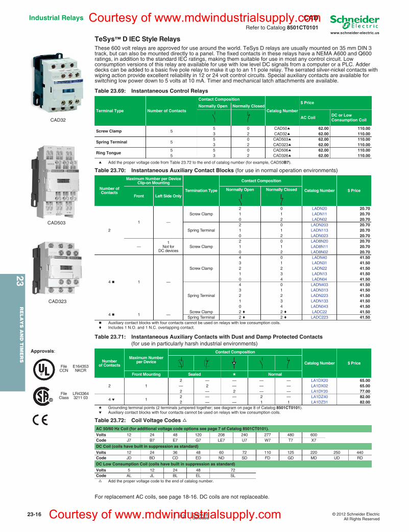
Industrial Relays CADRefer to Catalog 8501CT0101
TeSys™ D IEC Style RelaysThese 600 volt relays are approved for use around the world. TeSys D relays are usually mounted on 35 mm DIN 3 track, but can also be mounted directly to a panel. The fixed contacts in these relays have a NEMA A600 and Q600 ratings, in addition to the standard IEC ratings, making them suitable for use in most any control circuit. Low consumption versions of this relay are available for use with low level DC signals from a computer or a PLC. Adder decks can be added to a basic five pole relay to make it up to an 11 pole relay. The serrated silver-nickel contacts with wiping action provide excellent reliability in 12 or 24 volt control circuits. Special auxiliary contacts are available for switching low power down to 5 volts at 10 mA. Timer and mechanical latch attachments are available.
a Add the proper voltage code from Table 23.72 to the end of catalog number (for example, CAD50B7).
b Auxiliary contact blocks with four contacts cannot be used on relays with low consumption coils.c Includes 1 N.O. and 1 N.C. overlapping contact.
d Grounding terminal points (2 terminals jumpered together; see diagram on page 8 of Catalog 8501CT0101).e Auxiliary contact blocks with four contacts cannot be used on relays with low consumption coils.
f Add the proper voltage code to the end of catalog number.
For replacement AC coils, see page 18-16. DC coils are not replaceable.
Table 23.69: Instantaneous Control Relays
Terminal Type Number of Contacts
Contact Composition
Catalog Number
$ PriceNormally Open Normally Closed
AC Coil DC or Low Consumption Coil
Screw Clamp 55 0 CAD50a 62.00 110.003 2 CAD32a 62.00 110.00
Spring Terminal 55 0 CAD503a 62.00 110.003 2 CAD323a 62.00 110.00
Ring Tongue5 5 0 CAD506a 62.00 110.005 3 2 CAD326a 62.00 110.00
Table 23.70: Instantaneous Auxiliary Contact Blocks (for use in normal operation environments)
Number of Contacts
Maximum Number per Device Clip-on Mounting
Termination Type
Contact Composition
Catalog Number $ PriceFront Left Side Only
Normally Open Normally Closed
2
1 —
Screw Clamp2 0 LADN20 20.701 1 LADN11 20.700 2 LADN02 20.70
Spring Terminal2 0 LADN203 20.701 1 LADN113 20.700 2 LADN023 20.70
—1
Not for DC devices
Screw Clamp2 0 LAD8N20 20.701 1 LAD8N11 20.700 2 LAD8N02 20.70
4 b 1 —
Screw Clamp
4 0 LADN40 41.503 1 LADN31 41.502 2 LADN22 41.501 3 LADN13 41.500 4 LADN04 41.50
Spring Terminal
4 0 LADN403 41.503 1 LADN313 41.502 2 LADN223 41.501 3 LADN133 41.500 4 LADN043 41.50
4 b 1 —Screw Clamp 2 c 2 c LADC22 41.50
Spring Terminal 2 c 2 c LADC223 41.50
Table 23.71: Instantaneous Auxiliary Contacts with Dust and Damp Protected Contacts(for use in particularly harsh industrial environments)
Number of Contacts
Maximum Number per Device
Contact Composition
Catalog Number $ Price
Front Mounting Sealed d Normal
2 12 — — — — LA1DX20 65.00— 2 — — — LA1DX02 65.002 — 2 — — LA1DY20 77.00
4 e 12 — — 2 — LA1DZ40 82.002 — — 1 1 LA1DZ31 82.00
Table 23.72: Coil Voltage Codes fAC 50/60 Hz Coil (for additional voltage code options see page 7 of Catalog 8501CT0101).
Volts 12 24 48 120 208 240 277 480 600Code J7 B7 E7 G7 LE7 U7 W7 T7 X7
DC Coil (coils have built in suppression as standard)
Volts 12 24 36 48 60 72 110 125 220 250 440Code JD BD CD ED ND SD FD GD MD UD RD
DC Low Consumption Coil (coils have built in suppression as standard)
Volts 5 12 24 48 72Code AL JL BL EL SL
CAD32
CAD503
CAD323
I12 Discount Schedule
Approvals:
FileCCN
E164353NKCR
FileClass
LR433643211 03
Courtesy of www.mdwindustrialsupply.com
Courtesy of www.mdwindustrialsupply.com
www.schneider-electric.us
23R
ELA
YS
AN
D T
IME
RS
23-18 © 2012 Schneider ElectricAll Rights Reserved
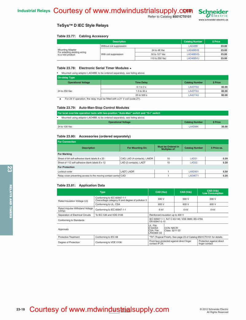
Industrial Relays CADRefer to Catalog 8501CT0101
TeSys™ D IEC Style Relays
a For 24 V operation, the relay must be fitted with a 21 V coil (code Z7).
Table 23.77: Cabling Accessory
Description Catalog Number $ Price
Mounting AdapterFor adapting existing wiring to a new product
Without coil suppression LAD4BB 23.00
With coil suppression
24 to 48 Vac LAD4BBVE 23.00
50 to 127 Vac LAD4BBVG 23.00
110 to 250 Vac LAD4BBVU 23.00
Table 23.78: Electronic Serial Timer Modules a• Mounted using adaptor LAD4BB, to be ordered separately, see listing above.
On-delay Type
Operational Voltage Time Delay Catalog Number $ Price
24 to 250 Vac
0.1 to 2 s LA4DT0U 82.00
1.5 to 30 s LA4DT2U 82.00
25 to 500 s LA4DT4U 82.00
Table 23.79: Auto-Man-Stop Control Modules
For local override operation tests with two-position “Auto-Man” switch and “O-I” switch
• Mounted using adaptor LAD4BB, to be ordered separately, see listing above.
Operational Voltage Catalog Number $ Price
24 to 100 Vac LA4DMK 35.00
Table 23.80: Accessories (ordered separately)
For Connection
Description For Mounting On: Must be Ordered in Multiples of: Catalog Number $ Price ea.
For Marking
Sheet of 64 self-adhesive blank labels 8 x 33 CAD, LAD (4 contacts), LA6DK 10 LAD21 5.20
Sheet of 112 self-adhesive blank labels 8 x 12 LAD (2 contacts), LADT 10 LAD22 5.20
For Protection
Lockout cover LADT, LADR 1 LA9D901 5.50
Relay cover preventing access to the moving contact carrier CAD 1 LAD9ET1 5.20
Table 23.81: Application Data
Type CAD (Vac) CAD (Vdc) CAD (Vdc) Low Consumption
Rated Insulation Voltage (Ui)Conforming to IEC 60947-1-1Overvoltage category III and degree of pollution 3 690 V 690 V 690 V
Conforming to UL, CSA 600 V 600 V 600 V
Rated Impulse Withstand Voltage (Uimp) Conforming to IEC 60947-1-1 6 kV 6 kV 6 kV
Separation of Electrical Circuits To IEC 536 and VDE 0106 Reinforced insulation up to 400 V
Conforming to Standards IEC 60947-1-1, N-F C 63-140, VDE 0660, BS 4794.EN 60947-5-15
Approvals
UL: File: E164353CSA: File: LR43364 CE
CCN: NKCRClass: 3211 03
Protective Treatment Conforming to IEC 68 “TH” (Tropical Finish). See page 23 of Catalog 8501CT0101 for details.
Degree of Protection Conforming to VDE 0106 Front face protected against direct finger contact IP 2X
Protection against direct finger contact
I12 Discount Schedule
Courtesy of www.mdwindustrialsupply.com
Courtesy of www.mdwindustrialsupply.com
www.schneider-electric.us
23R
EL
AY
S A
ND
TIM
ER
S
© 2012 Schneider ElectricAll Rights Reserved
23-19
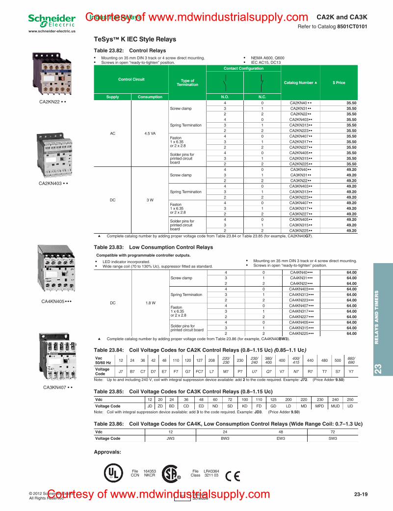
Industrial Relays CA2K and CA3KRefer to Catalog 8501CT0101
TeSys™ K IEC Style Relays
a Complete catalog number by adding proper voltage code from Table 23.84 or Table 23.85 (for example, CA2KN40G7).
a Complete catalog number by adding proper voltage code from Table 23.86 (for example, CA4KN40BW3).
Approvals:
Table 23.82: Control Relays• Mounting on 35 mm DIN 3 track or 4 screw direct mounting. • Screws in open “ready-to-tighten” position.
• NEMA A600, Q600• IEC AC15, DC13
Control Circuit Type of Termination
Contact Configuration
Catalog Number a $ Price
Supply Consumption N.O. N.C.
AC 4.5 VA
Screw clamp4 0 CA2KN40 • • 35.503 1 CA2KN31•• 35.502 2 CA2KN22•• 35.50
Spring Termination4 0 CA2KN403•• 35.503 1 CA2KN313•• 35.502 2 CA2KN223•• 35.50
Faston 1 x 6.35 or 2 x 2.8
4 0 CA2KN407•• 35.503 1 CA2KN317•• 35.502 2 CA2KN227•• 35.50
Solder pins for printed circuitboard
4 0 CA2KN405•• 35.503 1 CA2KN315•• 35.502 2 CA2KN225•• 35.50
DC 3 W
Screw clamp4 0 CA3KN40•• 49.203 1 CA3KN31•• 49.202 2 CA3KN22•• 49.20
Spring Termination4 0 CA3KN403•• 49.203 1 CA3KN313•• 49.202 2 CA3KN223•• 49.20
Faston 1 x 6.35 or 2 x 2.8
4 0 CA3KN407•• 49.203 1 CA3KN317•• 49.202 2 CA3KN227•• 49.20
Solder pins for printed circuit board
4 0 CA3KN405•• 49.203 1 CA3KN315•• 49.202 2 CA3KN225•• 49.20
Table 23.83: Low Consumption Control Relays Compatible with programmable controller outputs.
• LED indicator incorporated. • Wide range coil (70 to 130% Uc), suppressor fitted as standard.
• Mounting on 35 mm DIN 3 track or 4 screw direct mounting.• Screws in open “ready-to-tighten” position.
DC 1.8 W
Screw clamp4 0 CA4KN40••• 64.003 1 CA4KN31••• 64.002 2 CA4KN22••• 64.00
Spring Termination4 0 CA4KN403••• 64.003 1 CA4KN313••• 64.002 2 CA4KN223••• 64.00
Faston 1 x 6.35 or 2 x 2.8
4 0 CA4KN407••• 64.003 1 CA4KN317••• 64.002 2 CA4KN227••• 64.00
Solder pins for printed circuit board
4 0 CA4KN405••• 64.003 1 CA4KN315••• 64.002 2 CA4KN225••• 64.00
Table 23.84: Coil Voltage Codes for CA2K Control Relays (0.8–1.15 Uc) (0.85–1.1 Uc)Vac50/60 Hz 12 24 36 42 48 110 120 127 208 220/
230 230 230/ 240
380/ 400 400 400/
415 440 480 500 660/ 690
Voltage Code J7 B7 C7 D7 E7 F7 G7 FC7 L7 M7 P7 U7 Q7 V7 N7 R7 T7 S7 Y7
Note: Up to and including 240 V, coil with integral suppression device available: add 2 to the code required. Example: J72. (Price Adder 9.50)
Table 23.85: Coil Voltage Codes for CA3K Control Relays (0.8–1.15 Uc)Vdc 12 20 24 36 48 60 72 100 110 125 200 220 230 240 250
Voltage Code JD ZD BD CD ED ND SD KD FD GD LD MD MPD MUD UD
Note: Coil with integral suppression device available: add 3 to the code required. Example: JD3. (Price Adder 9.50)
Table 23.86: Coil Voltage Codes for CA4K, Low Consumption Control Relays (Wide Range Coil: 0.7–1.3 Uc)Vdc 12 24 48 72
Voltage Code JW3 BW3 EW3 SW3
FileCCN
164353NKCR
FileClass
LR433643211 03
CA2KN22 • •
CA3KN407 • •
CA2KN403 • •
CA4KN405 • • •
I12 Discount Schedule
Courtesy of www.mdwindustrialsupply.com
Courtesy of www.mdwindustrialsupply.com
www.schneider-electric.us
23R
EL
AY
S A
ND
TIM
ER
S
© 2012 Schneider ElectricAll Rights Reserved
23-21
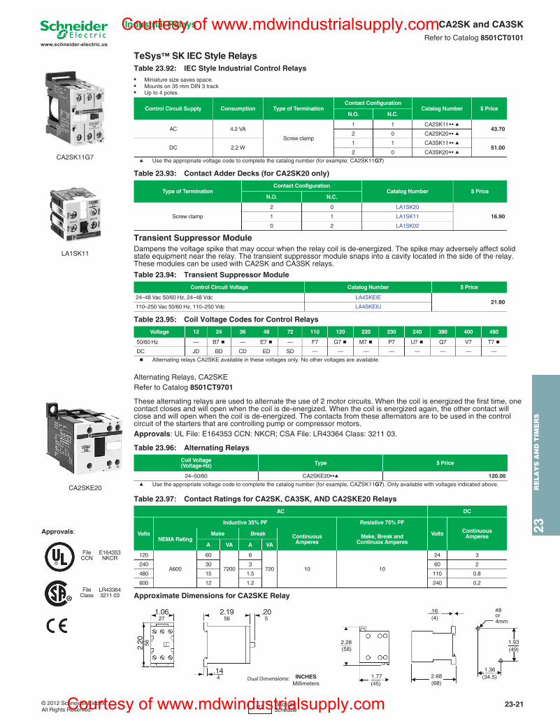
Industrial Relays CA2SK and CA3SKRefer to Catalog 8501CT0101
TeSys™ SK IEC Style Relays
a Use the appropriate voltage code to complete the catalog number (for example: CA2SK11G7)
Transient Suppressor ModuleDampens the voltage spike that may occur when the relay coil is de-energized. The spike may adversely affect solid state equipment near the relay. The transient suppressor module snaps into a cavity located in the side of the relay. These modules can be used with CA2SK and CA3SK relays.
b Alternating relays CA2SKE available in these voltages only. No other voltages are available.
Alternating Relays, CA2SKERefer to Catalog 8501CT9701
These alternating relays are used to alternate the use of 2 motor circuits. When the coil is energized the first time, one contact closes and will open when the coil is de-energized. When the coil is energized again, the other contact will close and will open when the coil is de-energized. The contacts from these alternators are to be used in the control circuit of the starters that are controlling pump or compressor motors. Approvals: UL File: E164353 CCN: NKCR; CSA File: LR43364 Class: 3211 03.
a Use the appropriate voltage code to complete the catalog number (for example, CAZSK11G7). Only available with voltages indicated above.
Table 23.92: IEC Style Industrial Control Relays• Miniature size saves space.• Mounts on 35 mm DIN 3 track• Up to 4 poles.
Control Circuit Supply Consumption Type of TerminationContact Configuration
Catalog Number $ PriceN.O. N.C.
AC 4.2 VA
Screw clamp
1 1 CA2SK11•• a43.70
2 0 CA2SK20•• a
DC 2.2 W1 1 CA3SK11•• a
51.002 0 CA3SK20•• a
Table 23.93: Contact Adder Decks (for CA2SK20 only)
Type of TerminationContact Configuration
Catalog Number $ Price N.O. N.C.
Screw clamp
2 0 LA1SK20
16.901 1 LA1SK11
0 2 LA1SK02
Table 23.94: Transient Suppressor Module
Control Circuit Voltage Catalog Number $ Price
24–48 Vac 50/60 Hz, 24–48 Vdc LA4SKEIE21.80
110–250 Vac 50/60 Hz, 110–250 Vdc LA4SKEIU
Table 23.95: Coil Voltage Codes for Control Relays
Voltage 12 24 36 48 72 110 120 220 230 240 380 400 480
50/60 Hz — B7 b — E7 b — F7 G7 b M7 b P7 U7 b Q7 V7 T7 b
DC JD BD CD ED SD — — — — — — — —
Table 23.96: Alternating Relays
Coil Voltage(Voltage-Hz) Type $ Price
24–50/60 CA2SKE20••a 120.00
Table 23.97: Contact Ratings for CA2SK, CA3SK, AND CA2SKE20 Relays
AC DC
Volts
Inductive 35% PF Resistive 75% PF
Volts Continuous AmperesNEMA Rating
Make Break Continuous Amperes
Make, Break and Continuos AmperesA VA A VA
120
A600
60
7200
6
720 10 10
24 3
240 30 3 60 2
480 15 1.5 110 0.8
600 12 1.2 240 0.2
Approximate Dimensions for CA2SKE Relay
CA2SK11G7
LA1SK11
CA2SKE20
2.20 56
1.0627
2.1956
.205
.144 Dual Dimensions: INCHES
Millimeters
#8or
(49)1.93
(34.5)1.36
(68)2.68
(45)1.77
(58)2.28
(4).16
4mm
I12 Discount Schedule
Approvals:
FileCCN
E164353NKCR
FileClass
LR433643211 03
Courtesy of www.mdwindustrialsupply.com
Courtesy of www.mdwindustrialsupply.com
23R
ELA
YS
AN
D T
IME
RS
23-22 © 2012 Schneider ElectricAll Rights Reserved
www.schneider-electric.us
Industrial RelaysSquare D™ NEMA Style
Type XClass 8501 / Refer to Catalog 8501CT9601
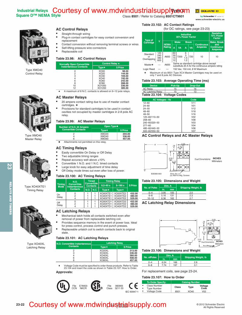
AC Control Relays• Straight-through wiring• Plug-in contact cartridges for easy contact conversion and
replacement• Contact conversion without removing terminal screws or wires• Self-lifting pressure wire connectors• Replaceable coil
a A maximum of 8 N.C. contacts is allowed on 9–12 pole relays.
AC Master Relays• 20 ampere contact rating due to use of master contact
cartridges. d• Provisions for standard cartridges to be used in contact
cavities not occupied by master cartridges in 2-8 pole AC relay.
b Attachments not permitted on this relay.
AC Timing Relays• Easily convertible On Delay or Off Delay• Two adjustable timing ranges• Repeat accuracy well above ±10%• Convertible 1 N.O. and 1 N.C. timed contacts• Large knob for easy adjustment of time delay• Off Delay mode times out even after loss of power.
AC Latching Relays• Mechanical latch holds all contacts switched even after
removal of power from replaceable latching coil.• Provides sequence memory in the event of power loss. Ideal
for press control, process control and punch presses.• Replaceable unlatch coil to switch contacts back to original
state.
c Voltage Code must be specified to order these products. Refer to Table 23.104 and insert the code as shown in Table 23.107: How to Order.
Approvals:
d Maximum of six 8501 Type XC4 Master Cartridges may be used on only 7 and 8 pole AC Devices
AC Control Relays and AC Master Relays
AC Latching Relay Dimensions
For replacement coils, see page 23-24.
Table 23.98: AC Control Relays
Normally Open ConvertibleInstantaneous Contacts
Control Relay a
Typec $ Price
023468
1012
XO00XO20XO30XO40XO60XO80
XO1000XO1200
98.00144.00169.00192.00242.00288.00336.00385.00
Table 23.99: AC Master Relays
Number of N.O. 20 Ampere Convertible Contacts
Open Typeb
Typec $ Price
246
XMO20XMO40XMO60
204.00336.00457.00
Table 23.100: AC Timing Relays
Timing Mode
N.O.Convertible
Instantaneous Contacts
Timed Convertible
Contacts
Timing Relay
$ Price0.2–60 s 5–180 s
N.O. N.C. Typec Typec
On Delay
024
111
111
XO00XTE1XO20XTE1XO40XTE1
XO00XTE2XO20XTE2XO40XTE2
432.00480.00529.00
Off Delay
024
111
111
XO00XTD1XO20XTD1XO40XTD1
XO00XTD2XO20XTD2XO40XTD2
432.00480.00529.00
Table 23.101: AC Latching Relays
N.O. Convertible Instantaneous Contacts
Latching Relay
Typec $ Price
23468
XO20XLXO30XLXO40XLXO60XLXO80XL
313.00336.00360.00408.00457.00
FileCCN
E78403NKCR
FileClass
0609053211 03
IEC 60947-1
Type XMO40Control Relay
Type XMO40Master Relay
Type XO40XTE1Timing Relay
Type XO40XLLatching Relay
Table 23.102: AC Contact Ratings (for DC ratings, see page 23-23)
Type of Cartridge V
Inductive35% Power Factor
Resistive75% Power
Factor
NEMARating
Make BreakContinuous
Amperes
Make, Break and
Continuous Amperes
A VA A VA
Standardor
Overlapping
120240480600
A600
60301512
7200
63
1.51.2
720 10 10
Masterd — A600 Same as standard cartridge above except substitute 20 A for the continuous ampere rating
Logic Reed — — 150 Vac, 150 mA, 8 W Maximum
Table 23.103: Average Operating Time (ms)Device Pick-Up Drop-Out
AC Relay 15 16AC Latching Relay 15 13
Table 23.104: Voltage CodesAC Voltages - Hz Code
12–6024–6024–5048–6048–50120–60/110–50208–60240–60/220–50277–60480–60/440–50600–60/550–50
V11V01V12V18V16V02V08V03V04V06V07
Table 23.105: Dimensions and Weight
No. of PolesDim. A
Shipping Weight, lbin. mm
0–4 3.95 100 2.06–8 5.16 131 2.3
10–12 6.36 162 2.7
Table 23.106: Dimensions and Weight
No. ofPoles Dim. A
Shipping Weight, lbin. mm
2–4 6.54 166 2.86–8 7.74 197 3.1
Table 23.107: How to OrderTo Order Specify: Catalog Number
• Class Number• Type Number• Voltage Code
Class Type Voltage Code
8501 XO40 V02
.195
2.23571.12
28
3.5089
3.1279
Prov. for(2) #8/#10 Mtg. Screws
B30080-064
A
Dual Dimensions: INCHESMillimeters
A.195
2.2357
1.1228
3.1279
3.5089 Dual Dimensions: INCHES
Millimeters
CP2 Discount Schedule
Courtesy of www.mdwindustrialsupply.com
Courtesy of www.mdwindustrialsupply.com
www.schneider-electric.us
23R
ELA
YS
AN
D T
IME
RS
23-26 © 2012 Schneider ElectricAll Rights Reserved
Timers RE11/RE48/REXLRefer to Catalog 9050CT0001
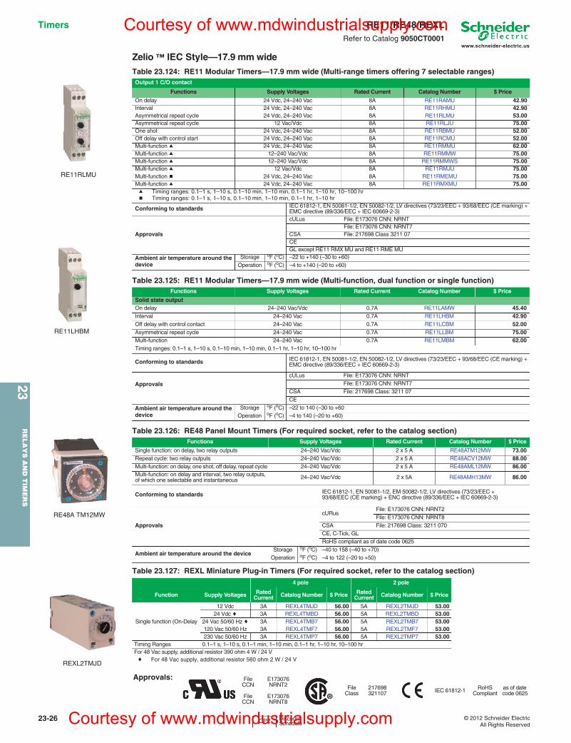
Zelio ™ IEC Style—17.9 mm wideTable 23.124: RE11 Modular Timers—17.9 mm wide (Multi-range timers offering 7 selectable ranges)Output 1 C/O contact
Functions Supply Voltages Rated Current Catalog Number $ Price
On delay 24 Vdc, 24–240 Vac 8A RE11RAMU 42.90Interval 24 Vdc, 24–240 Vac 8A RE11RHMU 42.90Asymmetrical repeat cycle 24 Vdc, 24–240 Vac 8A RE11RLMU 53.00Asymmetrical repeat cycle 12 Vac/Vdc 8A RE11RLJU 75.00One shot 24 Vdc, 24–240 Vac 8A RE11RBMU 52.00Off delay with control start 24 Vdc, 24–240 Vac 8A RE11RCMU 52.00Multi-function a 24 Vdc, 24–240 Vac 8A RE11RMMU 62.00Multi-function a 12–240 Vac/Vdc 8A RE11RMMW 75.00Multi-function a 12–240 Vac/Vdc 8A RE11RMMWS 75.00Multi-function a 12 Vac/Vdc 8A RE11RMJU 75.00Multi-function b 24 Vdc, 24–240 Vac 8A RE11RMEMU 75.00Multi-function a 24 Vdc, 24–240 Vac 8A RE11RMXMU 75.00a Timing ranges: 0.1–1 s, 1–10 s, 0.1–10 min, 1–10 min, 0.1–1 hr, 1–10 hr, 10–100 hrb Timing ranges: 0.1–1 s, 1–10 s, 0.1–10 min, 1–10 min, 0.1–1 hr, 1–10 hr
Conforming to standards IEC 61812-1, EN 50081-1/2, EN 50082-1/2, LV directives (73/23/EEC + 93/68/EEC (CE marking) +EMC directive (89/336/EEC + IEC 60669-2-3)
Approvals
cULus File: E173076 CNN: NRNTFile: E173076 CNN: NRNT7
CSA File: 217698 Class 3211 07CEGL except RE11 RMX MU and RE11 RME MU
Ambient air temperature around the device
Storage oF (oC) –22 to +140 (–30 to +60)Operation oF (oC) –4 to +140 (–20 to +60)
Table 23.125: RE11 Modular Timers—17.9 mm wide (Multi-function, dual function or single function)Functions Supply Voltages Rated Current Catalog Number $ Price
Solid state outputOn delay 24–240 Vac/Vdc 0.7A RE11LAMW 45.40Interval 24–240 Vac 0.7A RE11LHBM 42.90Off delay with control contact 24–240 Vac 0.7A RE11LCBM 52.00Asymmetrical repeat cycle 24–240 Vac 0.7A RE11LLBM 75.00Multi-function 24–240 Vac 0.7A RE11LMBM 62.00Timing ranges: 0.1–1 s, 1–10 s, 0.1–10 min, 1–10 min, 0.1–1 hr, 1–10 hr, 10–100 hr
Conforming to standards IEC 61812-1, EN 50081-1/2, EN 50082-1/2, LV directives (73/23/EEC + 93/68/EEC (CE marking) + EMC directive (89/336/EEC + IEC 60669-2-3)
Approvals
cULus File: E173076 CNN: NRNTFile: E173076 CNN: NRNT7
CSA File: 217698 Class: 3211 07CE
Ambient air temperature around the device
Storage oF (oC) –22 to 140 (–30 to +60Operation oF (oC) –4 to 140 (–20 to +60)
Table 23.126: RE48 Panel Mount Timers (For required socket, refer to the catalog section)Functions Supply Voltages Rated Current Catalog Number $ Price
Single function: on delay, two relay outputs 24–240 Vac/Vdc 2 x 5 A RE48ATM12MW 73.00Repeat cycle: two relay outputs 24–240 Vac/Vdc 2 x 5 A RE48ACV12MW 88.00Multi-function: on delay, one shot, off delay, repeat cycle 24–240 Vac/Vdc 2 x 5 A RE48AML12MW 86.00Multi-function: on delay and interval, two relay outputs, of which one selectable and instantaneous 24–240 Vac/Vdc 2 x 5A RE48AMH13MW 86.00
Conforming to standards IEC 61812-1, EN 50081-1/2, EM 50082-1/2, LV directives (73/23/EEC +93/68/EEC (CE marking) + ENC directive (89/336/EEC + IEC 60669-2-3)
Approvals
cURusFile: E173076 CNN: NRNT2File: E173076 CNN: NRNT8
CSA File: 217698 Class: 3211 070CE, C-Tick, GLRoHS compliant as of date code 0625
Ambient air temperature around the deviceStorage oF (oC) –40 to 158 (–40 to +70)
Operation oF (oC) –4 to 122 (–20 to +50)
Table 23.127: REXL Miniature Plug-in Timers (For required socket, refer to the catalog section)4 pole 2 pole
Function Supply Voltages RatedCurrent Catalog Number $ Price Rated
Current Catalog Number $ Price
Single function (On-Delay
12 Vdc 3A REXL4TMJD 56.00 5A REXL2TMJD 53.0024 Vdc c 3A REXL4TMBD 56.00 5A REXL2TMBD 53.00
24 Vac 50/60 Hz c 3A REXL4TMB7 56.00 5A REXL2TMB7 53.00120 Vac 50/60 Hz 3A REXL4TMF7 56.00 5A REXL2TMF7 53.00230 Vac 50/60 Hz 3A REXL4TMP7 56.00 5A REXL2TMP7 53.00
Timing Ranges 0.1–1 s, 1–10 s, 0.1–1 min, 1–10 min, 0.1–1 hr, 1–10 hr, 10–100 hrFor 48 Vac supply, additional resistor 390 ohm 4 W / 24 Vc For 48 Vac supply, additional resistor 560 ohm 2 W / 24 V
Approvals: FileCCN
FileCCN
E173076NRNT2
E173076NRNT8
FileClass
217698321107 IEC 61812-1 RoHS
Compliantas of date code 0625
RE11RLMU
RE11LHBM
REXL2TMJD
RE48A TM12MW
CP2 Discount Schedule
Courtesy of www.mdwindustrialsupply.com
Courtesy of www.mdwindustrialsupply.com
www.schneider-electric.us
23R
ELA
YS
AN
D T
IME
RS
23-28 © 2012 Schneider ElectricAll Rights Reserved
Timers RE7Refer to Catalog 9050CT0001
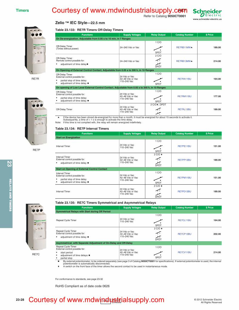
Zelio ™ IEC Style—22.5 mm
a If the device has been stored de-energized for more than a month, it must be energized for about 15 seconds to activate it. Subsequently, a time of > 1 s is enough to activate the time delay.
Note: If this time is not complied with, the relay will remain energized indefinitely.
b By external potentiometer, to be ordered separately (see page 3 of Catalog 9050CT0001 for specifications). If external potentiometer is used, the internal potentiometer is automatically disconnected.
c A switch on the front face of the timer allows the second contact to be used in instantaneous mode.
For conformance to standards, see page 23-32
RoHS Compliant as of date code 0626
Table 23.133: RE7R Timers Off-Delay TimersFunctions Supply Voltages Relay Output Catalog Number $ Price
On De-energization, Adjustable from 0.05 s to 10 min, in 7 Ranges
Off-Delay Timer(Times without power) 24–240 Vdc or Vac
1 C/O
SPDT
RE7RB11MWa 189.00
Off-Delay TimerRemote control possible for:
• adjustment of time delayb24–240 Vdc or Vac
2 C/O
DPDT
RE7RB13MWa 214.00
On Opening of External Control Contact, Adjustable from 0.05 s to 300 h, in 10 Ranges
Off-Delay TimerExternal control possible for:
• partial stop of time delay• adjustment of time delay b
24 Vdc or Vac42–48 Vdc or Vac110–240 Vac
1 C/O
SPDT
RE7RA11BU 164.00
On opening of Low Level External Control Contact, Adjustable from 0.05 s to 300 h, in 10 Ranges
Off-Delay TimerExternal control possible for:
• partial stop of time delay• adjustment of time delay b
24 Vdc or Vac42–48 Vdc or Vac110–240 Vac
1 C/O
SPDT
RE7RM11BU 177.00
Off-Delay Timer24 Vdc or Vac42–48 Vdc or Vac110–240 Vac
2 C/Oc, DPDT
RE7RL13BU 189.00
Table 23.134: RE7P Interval TimersFunctions Supply Voltages Relay Output Catalog Number $ Price
Start on Energization
Interval Timer 24 Vdc or Vac110–240 Vac
1 C/O
SPDT
RE7PE11BU 151.00
Interval TimerExternal control possible for:
• adjustment of time delay b
24 Vdc or Vac42–48 Vdc or Vac110–240 Vac
2 C/O c
DPDT
RE7PP13BU 189.00
Start on Opening of External Control Contact
Interval TimerExternal control possible for:
• partial stop of time delay• adjustment of time delay b
24 Vdc or Vac42–48 Vdc or Vac110–240 Vac
1 C/O
SPDT
RE7PM11BU 151.00
Interval Timer24 Vdc or Vac42–48 Vdc or Vac110–240 Vac
2 C/O c
DPDT
RE7PD13BU 189.00
Table 23.135: RE7C Timers Symmetrical and Asymmetrical RelaysFunctions Supply Voltages Relay Output Catalog Number $ Price
Symmetrical Relays with Start during Off Period
Repeat Cycle Timer 24 Vdc or Vac110–240 Vac
1 C/O
SPDT
RE7CL11BU 164.00
Repeat Cycle TimerExternal control possible for:
• adjustment of time delay b
24 Vdc or Vac42–48 Vdc or Vac110–240 Vac
2 C/O c
DPDT
RE7CP13BU 202.00
Asymmetrical, with Separate Adjustment of On-Delay and Off-Delay
Repeat Cycle TimerExternal control possible for:
• start period• adjustment of time delays b• partial stop
24 Vdc or Vac42–48 Vdc or Vac110–240 Vac
1 C/O
SPDT
RE7CV11BU 214.00
RE7R
RE7P
RE7C
CP2 Discount Schedule
Courtesy of www.mdwindustrialsupply.com
Courtesy of www.mdwindustrialsupply.com
23R
ELA
YS
AN
D T
IME
RS
23-30 © 2012 Schneider ElectricAll Rights Reserved
www.schneider-electric.us
Square D™ General Purpose Plug-In9050JCK timing relays are designed to provide low-cost timing in a plug-in housing. The Types JCK11 thru 59 provide ±1% repeat accuracy. The Types JCK60 and 70 offer ±0.1% repeat accuracy. These timers are directly interchangeable with many other 8 and 11 pin tube base timers.
• Up to ±0.1% repeat accuracy• Timing from 0.05 seconds to 999 hours• Available in 5 timing modes• DPDT contacts (2 N.O. and 2 N.C.)• 10 A contact rating• Transient protected• Hold down spring available• Variable or fixed time delay• Horsepower rated• RoHS compliant
c (XXXX) denotes the timing period in seconds. Example: Class 9050 Type JCK1F60 is an On Delay timer fixed at 60 seconds.
d Fixed repeat cycle timers can be supplied with the same or different On-Time and Off-Time.
e Initiating contact can be up to 50 feet from the timer.f Voltage code must be specified to order this product. Refer to standard voltage codes
listed below and insert as shown in How To Order.
Class 8501 Sockets For sockets, see page 23-14For DIN rail, see page 24-16
For all 9050JCK timers:
B300, R300, AC15 and DC13
Type JCK60This On Delay timer uses a 5 position rotary switch to select the timing range. The three pushbutton thumbwheels are used to select the time value.
Type JCK70Two 5 position rotary switches are used to select the timing mode and timing range. The three pushbutton thumbwheels are used to select the time value.
g The repeat cycle mode utilizes the same on-time and off-time.
9050JCK46V209050JCK32V36 with 8501NH7
Table 23.142: Variable Time DelayKnob Adjustable
Timing RangeOn
Delay $ Price OffDelayb $ Price Off Delay
Power Trigger $ Price Interval $ Price One Shotb $ Price One Shot Power Trigger $ Price Repeat
Cyclea $ Price
0.1–10 seconds JCK11f 78.00 JCK21f 98.00 JCK21PTf 98.00 JCK31f 78.00 JCK41f 98.00 JCK41PTf 98.00 JCK51f 140.000.3–30 seconds JCK12f 78.00 JCK22f 98.00 JCK22PTf 98.00 JCK32f 78.00 JCK42f 98.00 JCK42PTf 98.00 JCK52f 140.000.6–60 seconds JCK13f 78.00 JCK23f 98.00 JCK23PTf 98.00 JCK33f 78.00 JCK43f 98.00 JCK43PTf 98.00 JCK53f 140.001.2–120 seconds JCK14f 78.00 JCK24f 98.00 JCK24PTf 98.00 JCK34f 78.00 JCK44f 98.00 JCK44PTf 98.00 JCK54f 140.001.8–180 seconds JCK15f 78.00 JCK25f 98.00 JCK25PTf 98.00 JCK35f 78.00 JCK45f 98.00 JCK45PTf 98.00 JCK55f 140.000.1–10 minutes JCK16f 87.00 JCK26f 107.00 JCK26PTf 107.00 JCK36f 87.00 JCK46f 107.00 JCK46PTf 107.00 JCK56f 147.000.3–30 minutes JCK17f 87.00 JCK27f 107.00 JCK27PTf 107.00 JCK37f 87.00 JCK47f 107.00 JCK47PTf 107.00 JCK57f 98.000.6–60 minutes JCK18f 87.00 JCK28f 107.00 JCK28PTf 107.00 JCK38f 87.00 JCK48f 107.00 JCK48PTf 107.00 JCK58f 98.001.2–120 minutes JCK19f 87.00 JCK29f 107.00 JCK29PTf 107.00 JCK39f 87.00 JCK49f 107.00 JCK49PTf 107.00 JCK59f 98.00a Two dials are provided for independently adjustable repeat cycle timing ranges.b Initiating contact can be up to 50 feet from the timer.
Table 23.143: Fixed Time DelayTiming Mode Type Timing Range (seconds) $ Price
On Delay JCK1F(XXXX)cf0.1 to 180 78.00181 to 3600 87.00
Off Delay e JCK2F(XXXX)cf0.1 to 180 98.00181 to 3600 107.00
Off Delay with Power Trigger JCK2F(XXXX)PTcf
0.1 to 180 98.00181 to 3600 107.00
Interval JCK3F(XXXX)cf0.1 to 180 78.00181 to 3600 87.00
One Shote JCK4F(XXXX)cf0.1 to 180 98.00181 to 3600 107.00
One Shot with Power Trigger JCK4F(XXXX)PTcf
0.1 to 180 98.00181 to 3600 107.00
Repeat Cycle JCK5F(XXXX)cdf0.1 to 180 140.00181 to 3600 147.00
With appropriate 8501NR Socket:
FileCCN
E78351NLDX
FileClass
2147683211 07
Without Socket
FileCCN
E78351NLDX2
IEC 60947-1
RoHSCompliant
as of date code
9050JCK1-5 = 06279050JCK6070=0648
Table 23.144: Voltage CodesVoltage Code
12 Vdc V3624 Vac/Vdc V1448 Vac/Vdc V17120 Vac/110 Vdc V20240–50/60 Vac V24
Table 23.145: Contact Ratings
ACVolts
AC Amperes
hp DCVolts
DC Amperes
Inductive 35% P.F.
Res
. 75%
P.F
.M
ake
Bre
ak a
ndC
ontin
uous
Inductive
Res
. Mak
e B
reak
and
Con
tinuo
us
Mak
e
Bre
ak
Con
tinuo
us
Mak
e
Bre
ak
120 30 3 10 10 1/328 3 3 10
240 15 1.5 10 10 1/2
Table 23.146: Selection and PricingTimingModes Timing Ranges Type $ Price
On Delay
.01s 0.1sS0.1mM0.1hH
0.05–9.99 seconds00.1–99.9 seconds001–999 seconds00.1–99.9 minutes001–999 minutes00.1–99.9 hours001–999 hours
JCK60f 152.00
Table 23.147: Selection and PricingTimingModes
TimingRange Type $ Price
On DelayOff DelayIntervalOne ShotRepeat Cycleg
Same asJCK60 JCK70f 173.00
Table 23.148: Class 8501 Hold Down SpringFor use on Class 9050 Type JCK Timers Class Type $ Price ea.
Hold down spring holds timer in socket during heavy vibration. (See 9050JCK with 8501NH7 photo at the top of this page.) 8501 NH7 8.30
Table 23.149: How to OrderTo Order Specify: Catalog Number
• Class Number• Type Number• Voltage Code
Class Type Voltage Code
9050 JCK11 V20
CP2 Discount Schedule
Timers Type JCKClass 9050 / Refer to Catalog 9050CT9601
Courtesy of www.mdwindustrialsupply.com
Courtesy of www.mdwindustrialsupply.com
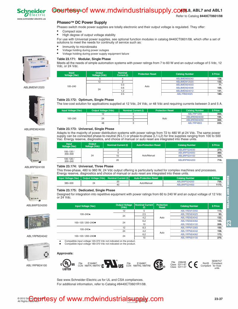
www.schneider-electric.us
23R
EL
AY
S A
ND
TIM
ER
S
© 2012 Schneider ElectricAll Rights Reserved
23-37
Other Products ABL8, ABL7 and ABL1Refer to Catalog 8440CT0601/08
Phaseo™ DC Power SupplyPhaseo switch mode power supplies are totally electronic and their output voltage is regulated. They offer:• Compact size• High degree of output voltage stabilityFor use with Universal power supplies, see optional function modules in catalog 8440CT0601/08, which offer a set of solutions to meet the needs for continuity of service such as:• Immunity to microbreaks • Voltage holding during power outages • Voltage holding during power supply equipment failure
Table 23.175: Dedicated, Single PhaseDesigned for integration into repetitive equipment with power ratings from 60 to 240 W and an output voltage of 12 Vdc or 24 Vdc..
a Compatible input voltage 120-370 Vdc not indicated on the product.b Compatible input voltage 180-370 Vdc not indicated on the product.
Approvals:
See www.Schneider-Electric.us for UL and CSA compliances.For additional information, refer to Catalog #8440CT0601R1/08.
Table 23.171: Modular, Single PhaseMeets all the needs of simple automation systems with power ratings from 7 to 60 W and an output voltage of 5 Vdc, 12 Vdc, or 24 Vdc.
InputVoltage (Vac)
OutputVoltage (Vdc)
NominalCurrent (I) Protection Reset Catalog Number $ Price
100–240
5 4
Auto
ABL8MEM05040 128.12 2 ABL8MEM12020 132.
24
0.3 ABL8MEM24003 71.0.6 ABL8MEM24006 105.1.2 ABL8MEM24012 141.2.5 ABL7RM24025 180.
Table 23.172: Optimum, Single PhaseThe low-cost solution for applications supplied at 12 Vdc, 24 Vdc, or 48 Vdc and requiring currents between 3 and 5 A.
Input Voltage (Vac) Output Voltage (Vdc) Nominal Current (I) Protection Reset Catalog Number $ Price
100–240
12 5
Auto
ABL7RP1205 360.
243 ABL8REM24030 195.5 ABL8REM24050 300.
48 3 ABL7RP4803 225.
Table 23.173: Universal, Single PhaseAdapts to the majority of power distribution systems with power ratings from 72 to 480 W at 24 Vdc. The same power supply can be connected phase-to-neutral (N-L1) or phase-to-phase (L1-L2) for line supplies ranging from 100 to 500 Vac. Energy reserve, diagnostics, and choice of manual or auto reset are integrated into these units.
Input Voltage (Vac)
Output Voltage (Vdc) Nominal Current (I) Auto-Protection Reset Catalog Number $ Price
100–120 / 200–500
24
3
Auto/Manual
ABL8RPS24030 270.5 ABL8RPS24050 360.
10 ABL8RPS24100 525.100–120 / 200–240 20 ABL8RPM24200 716.
Table 23.174: Universal, Three PhaseThis three-phase, 480 to 960 W, 24 Vdc output offering is particularly suited for complex machines and processes. Energy reserve, diagnostics and choice of manual or auto reset are integrated into these units.
Input Voltage (Vac) Output Voltage (Vdc) Nominal Current (I) Auto-Protection Reset Catalog Number $ Price
380–500 2420
Auto/ManualABL8WPS24200 735.
40 ABL8WPS24400 1173.
Input Voltage (Vac) Output Voltage (Vdc)
Nominal Current (I)
Protection Reset Catalog Number $ Price
100–240a12 5
Auto
ABL1REM12050 113.
242.5 ABL1REM24025 93.4.2 ABL1REM24042 132.
100–120 / 200–240b 246.2 ABL1REM24062 143.10 ABL1REM24100 206.
100–240a12 8.3
Auto
ABL1RPM12083 150.24 4.2 ABL1RPM24042 158.
100–120 / 200–240b 246.2 ABL1RPM24062 173.10 ABL1RPM24100 270.
FileCCN
E164867,NMTR, NMTR7
FileCCN
E164867,NMTR2, NMTR8
FileClassClass
2384385311-875311-07
RoHS Compliant
SEMI F47 Compliantfor most
units
ABL8MEM12020
ABL8REM24030
ABL8RPS24100
ABL8WPS24200
ABL1RPM24042
ABL1RPM24100
CP12 Discount Schedule
Courtesy of www.mdwindustrialsupply.com
Courtesy of www.mdwindustrialsupply.com
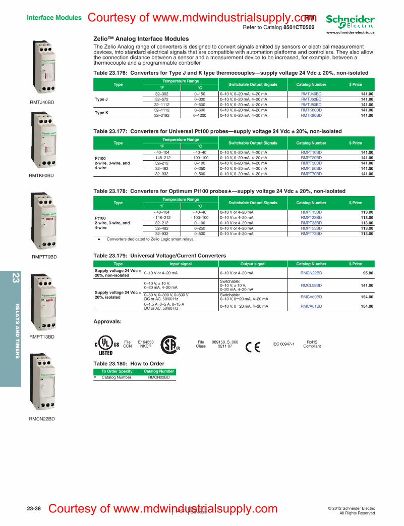
www.schneider-electric.us
23R
ELA
YS
AN
D T
IME
RS
23-38 © 2012 Schneider ElectricAll Rights Reserved
Interface Modules RMRefer to Catalog 8501CT0502
Zelio™ Analog Interface ModulesThe Zelio Analog range of converters is designed to convert signals emitted by sensors or electrical measurement devices, into standard electrical signals that are compatible with automation platforms and controllers. They also allow the connection distance between a sensor and a measurement device to be increased, for example, between a thermocouple and a programmable controller
a Converters dedicated to Zelio Logic smart relays.
Approvals:
Table 23.176: Converters for Type J and K type thermocouples—supply voltage 24 Vdc ± 20%, non-isolated
TypeTemperature Range
Switchable Output Signals Catalog Number $ Price°F °C
Type J 32–302 0–150 0–10 V, 0–20 mA, 4–20 mA RMTJ40BD 141.0032–572 0–300 0–10 V, 0–20 mA, 4–20 mA RMTJ60BD 141.0032–1112 0–600 0–10 V, 0–20 mA, 4–20 mA RMTJ80BD 141.00
Type K 32–1112 0–600 0–10 V, 0–20 mA, 4–20 mA RMTK80BD 141.0032–2192 0–1200 0–10 V, 0–20 mA, 4–20 mA RMTK90BD 141.00
Table 23.177: Converters for Universal Pt100 probes—supply voltage 24 Vdc ± 20%, non-isolated
TypeTemperature Range
Switchable Output Signals Catalog Number $ Price°F °C
Pt1002-wire, 3-wire, and 4-wire
- 40–104 - 40–40 0–10 V, 0–20 mA, 4–20 mA RMPT10BD 141.00- 148–212 - 100–100 0–10 V, 0–20 mA, 4–20 mA RMPT20BD 141.0032–212 0–100 0–10 V, 0–20 mA, 4–20 mA RMPT30BD 141.0032–482 0–250 0–10 V, 0–20 mA, 4–20 mA RMPT50BD 141.0032–932 0–500 0–10 V, 0–20 mA, 4–20 mA RMPT70BD 141.00
Table 23.178: Converters for Optimum Pt100 probesa—supply voltage 24 Vdc ± 20%, non-isolated
TypeTemperature Range
Switchable Output Signals Catalog Number $ Price°F °C
Pt1002-wire, 3-wire, and 4-wire
- 40–104 - 40–40 0–10 V or 4–20 mA RMPT13BD 113.00- 148–212 - 100–100 0–10 V or 4–20 mA RMPT23BD 113.0032–212 0–100 0–10 V or 4–20 mA RMPT33BD 113.0032–482 0–250 0–10 V or 4–20 mA RMPT53BD 113.0032–932 0–500 0–10 V or 4–20 mA RMPT73BD 113.00
Table 23.179: Universal Voltage/Current ConvertersType Input signal Output signal Catalog Number $ Price
Supply voltage 24 Vdc ± 20%, non-isolated 0–10 V or 4–20 mA 0–10 V or 4–20 mA RMCN22BD 95.00
Supply voltage 24 Vdc ± 20%, isolated
0–10 V, ± 10 V,0–20 mA, 4–20 mA
Switchable:0–10 V, ± 10 V,0–20 mA, 4–20 mA
RMCL55BD 141.00
0–50 V, 0–300 V, 0–500 VDC or AC, 50/60 Hz
Switchable:0–10 V, 0–20 mA, 4–20 mA RMCV60BD 154.00
0–1.5 A, 0–5 A, 0–15 ADC or AC, 50/60 Hz 0–10 V, 0–20 mA, 4–20 mA RMCA61BD 154.00
FileCCN
E164353NKCR
FileClass
089150_S_0003211 07 IEC 60947-1 RoHS
Compliant
Table 23.180: How to OrderTo Order Specify: Catalog Number
• Catalog Number RMCN22BD
RMTJ40BD
RMTK90BD
RMPT70BD
RMPT13BD
RMCN22BD
CP2 Discount Schedule
Courtesy of www.mdwindustrialsupply.com
Courtesy of www.mdwindustrialsupply.com
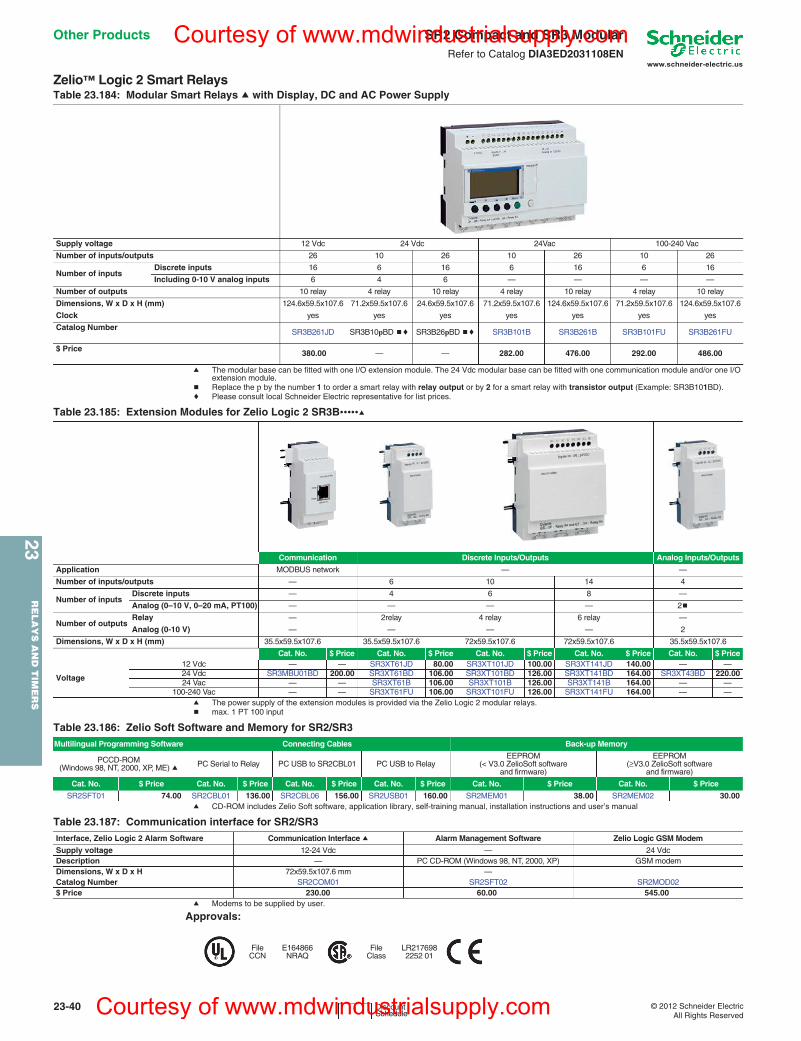
www.schneider-electric.us
23R
ELA
YS
AN
D T
IME
RS
23-40 © 2012 Schneider ElectricAll Rights Reserved
Other Products SR2 Compact and SR3 ModularRefer to Catalog DIA3ED2031108EN
Zelio™ Logic 2 Smart Relays
a The modular base can be fitted with one I/O extension module. The 24 Vdc modular base can be fitted with one communication module and/or one I/O extension module.
b Replace the p by the number 1 to order a smart relay with relay output or by 2 for a smart relay with transistor output (Example: SR3B101BD).c Please consult local Schneider Electric representative for list prices.
a The power supply of the extension modules is provided via the Zelio Logic 2 modular relays.b max. 1 PT 100 input
a CD-ROM includes Zelio Soft software, application library, self-training manual, installation instructions and user’s manual
a Modems to be supplied by user.
Approvals:
Table 23.184: Modular Smart Relays a with Display, DC and AC Power Supply
Supply voltage 12 Vdc 24 Vdc 24Vac 100-240 Vac
Number of inputs/outputs 26 10 26 10 26 10 26
Number of inputsDiscrete inputs 16 6 16 6 16 6 16
Including 0-10 V analog inputs 6 4 6 — — — —
Number of outputs 10 relay 4 relay 10 relay 4 relay 10 relay 4 relay 10 relay
Dimensions, W x D x H (mm) 124.6x59.5x107.6 71.2x59.5x107.6 24.6x59.5x107.6 71.2x59.5x107.6 124.6x59.5x107.6 71.2x59.5x107.6 124.6x59.5x107.6
Clock yes yes yes yes yes yes yes
Catalog NumberSR3B261JD SR3B10pBD bc SR3B26pBD bc SR3B101B SR3B261B SR3B101FU SR3B261FU
$ Price 380.00 — — 282.00 476.00 292.00 486.00
Table 23.185: Extension Modules for Zelio Logic 2 SR3B•••••a
Communication Discrete Inputs/Outputs Analog Inputs/Outputs
Application MODBUS network — —
Number of inputs/outputs — 6 10 14 4
Number of inputsDiscrete inputs — 4 6 8 —
Analog (0–10 V, 0–20 mA, PT100) — — — — 2b
Number of outputsRelay — 2relay 4 relay 6 relay —
Analog (0-10 V) — — — — 2
Dimensions, W x D x H (mm) 35.5x59.5x107.6 35.5x59.5x107.6 72x59.5x107.6 72x59.5x107.6 35.5x59.5x107.6
Cat. No. $ Price Cat. No. $ Price Cat. No. $ Price Cat. No. $ Price Cat. No. $ Price
Voltage
12 Vdc — — SR3XT61JD 80.00 SR3XT101JD 100.00 SR3XT141JD 140.00 — —24 Vdc SR3MBU01BD 200.00 SR3XT61BD 106.00 SR3XT101BD 126.00 SR3XT141BD 164.00 SR3XT43BD 220.0024 Vac — — SR3XT61B 106.00 SR3XT101B 126.00 SR3XT141B 164.00 — —
100-240 Vac — — SR3XT61FU 106.00 SR3XT101FU 126.00 SR3XT141FU 164.00 — —
Table 23.186: Zelio Soft Software and Memory for SR2/SR3Multilingual Programming Software Connecting Cables Back-up Memory
PCCD-ROM (Windows 98, NT, 2000, XP, ME) a PC Serial to Relay PC USB to SR2CBL01 PC USB to Relay
EEPROM (< V3.0 ZelioSoft software
and firmware)
EEPROM (≥V3.0 ZelioSoft software
and firmware)
Cat. No. $ Price Cat. No. $ Price Cat. No. $ Price Cat. No. $ Price Cat. No. $ Price Cat. No. $ Price
SR2SFT01 74.00 SR2CBL01 136.00 SR2CBL06 156.00 SR2USB01 160.00 SR2MEM01 38.00 SR2MEM02 30.00
Table 23.187: Communication interface for SR2/SR3Interface, Zelio Logic 2 Alarm Software Communication Interface a Alarm Management Software Zelio Logic GSM Modem
Supply voltage 12-24 Vdc — 24 VdcDescription — PC CD-ROM (Windows 98, NT, 2000, XP) GSM modemDimensions, W x D x H 72x59.5x107.6 mm —Catalog Number SR2COM01 SR2SFT02 SR2MOD02$ Price 230.00 60.00 545.00
FileCCN
E164866NRAQ
FileClass
LR2176982252 01
I Discount Schedule
Courtesy of www.mdwindustrialsupply.com
Courtesy of www.mdwindustrialsupply.com
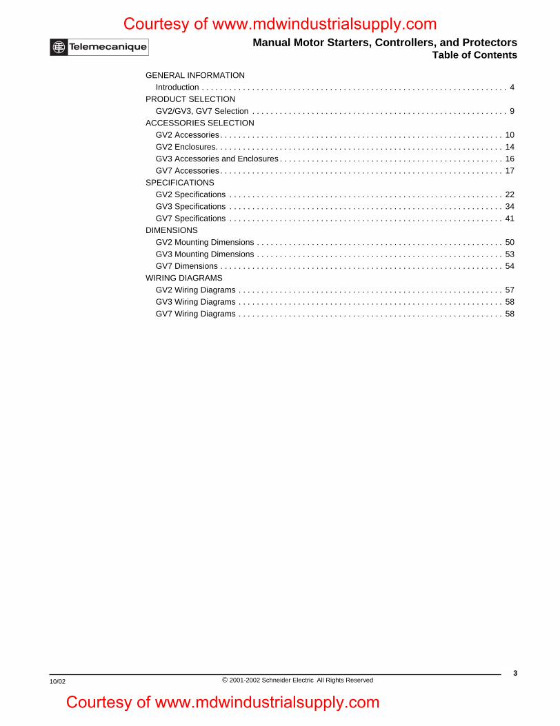
Manual Motor Starters, Controllers, and ProtectorsTable of Contents
10/02
Courtesy of www.mdwindustrialsupply.com
Courtesy o
GENERAL INFORMATIONIntroduction . . . . . . . . . . . . . . . . . . . . . . . . . . . . . . . . . . . . . . . . . . . . . . . . . . . . . . . . . . . . . . . . . . . 4
PRODUCT SELECTION
GV2/GV3, GV7 Selection . . . . . . . . . . . . . . . . . . . . . . . . . . . . . . . . . . . . . . . . . . . . . . . . . . . . . . . . 9ACCESSORIES SELECTION
GV2 Accessories . . . . . . . . . . . . . . . . . . . . . . . . . . . . . . . . . . . . . . . . . . . . . . . . . . . . . . . . . . . . . . 10
GV2 Enclosures. . . . . . . . . . . . . . . . . . . . . . . . . . . . . . . . . . . . . . . . . . . . . . . . . . . . . . . . . . . . . . . 14GV3 Accessories and Enclosures . . . . . . . . . . . . . . . . . . . . . . . . . . . . . . . . . . . . . . . . . . . . . . . . . 16
GV7 Accessories . . . . . . . . . . . . . . . . . . . . . . . . . . . . . . . . . . . . . . . . . . . . . . . . . . . . . . . . . . . . . . 17
SPECIFICATIONSGV2 Specifications . . . . . . . . . . . . . . . . . . . . . . . . . . . . . . . . . . . . . . . . . . . . . . . . . . . . . . . . . . . . 22
GV3 Specifications . . . . . . . . . . . . . . . . . . . . . . . . . . . . . . . . . . . . . . . . . . . . . . . . . . . . . . . . . . . . 34
GV7 Specifications . . . . . . . . . . . . . . . . . . . . . . . . . . . . . . . . . . . . . . . . . . . . . . . . . . . . . . . . . . . . 41DIMENSIONS
GV2 Mounting Dimensions . . . . . . . . . . . . . . . . . . . . . . . . . . . . . . . . . . . . . . . . . . . . . . . . . . . . . . 50
GV3 Mounting Dimensions . . . . . . . . . . . . . . . . . . . . . . . . . . . . . . . . . . . . . . . . . . . . . . . . . . . . . . 53GV7 Dimensions . . . . . . . . . . . . . . . . . . . . . . . . . . . . . . . . . . . . . . . . . . . . . . . . . . . . . . . . . . . . . . 54
WIRING DIAGRAMS
GV2 Wiring Diagrams . . . . . . . . . . . . . . . . . . . . . . . . . . . . . . . . . . . . . . . . . . . . . . . . . . . . . . . . . . 57GV3 Wiring Diagrams . . . . . . . . . . . . . . . . . . . . . . . . . . . . . . . . . . . . . . . . . . . . . . . . . . . . . . . . . . 58
GV7 Wiring Diagrams . . . . . . . . . . . . . . . . . . . . . . . . . . . . . . . . . . . . . . . . . . . . . . . . . . . . . . . . . . 58
3© 2001-2002 Schneider Electric All Rights Reserved
f www.mdwindustrialsupply.com
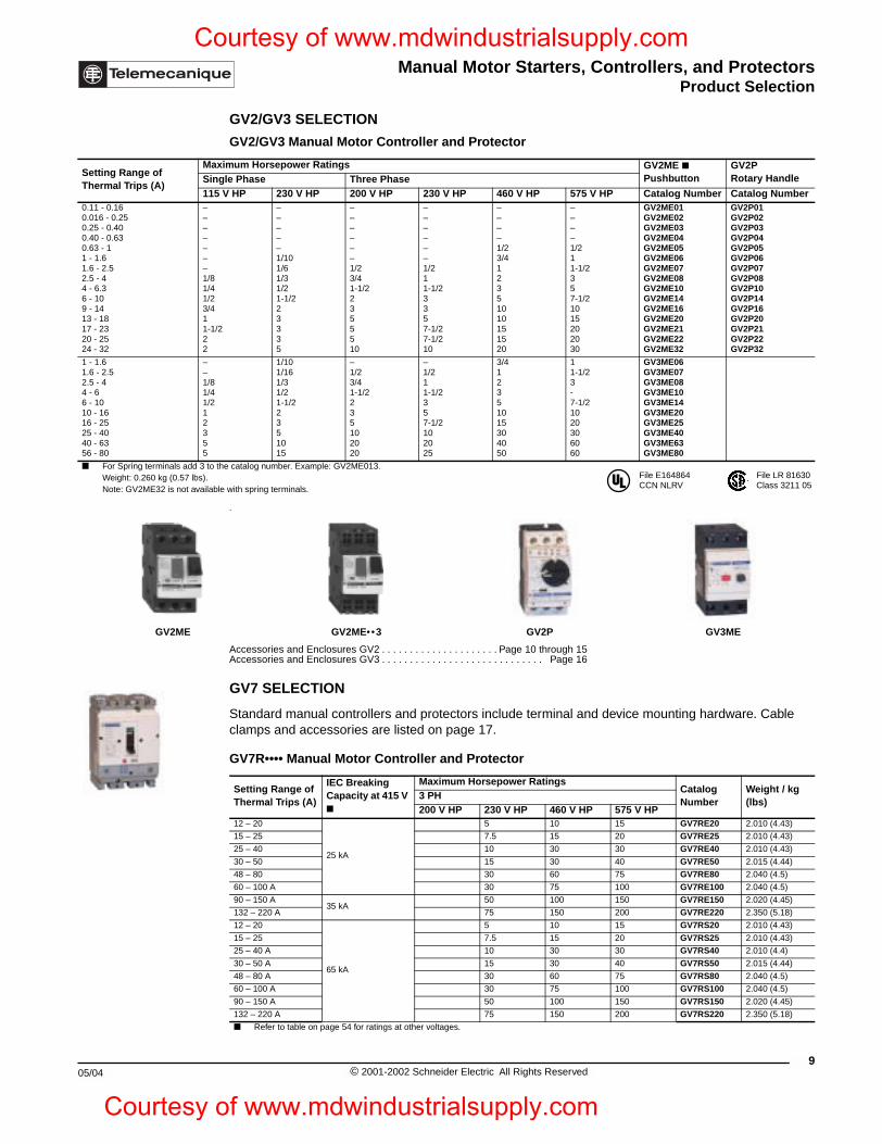
Manual Motor Starters, Controllers, and ProtectorsProduct Selection
10/02
Setting Range of Thermal Trips (A)
MaSin115
0.11 - 0.160.016 - 0.250.25 - 0.400.40 - 0.630.63 - 11 - 1.61.6 - 2.52.5 - 44 - 6.36 - 109 - 1413 - 1817 - 2320 - 2524 - 32
–––––––1/81/41/23/411-1/22
1 - 1.61.6 - 2.52.5 - 44 - 66 - 10 10 - 1616 - 2525 - 40 40 - 6356 - 80
– – 1/8 1/41/212 3 55
For Spring terminals add 3 to tWeight: 0.260 kg (0.57 lbs). Note: GV2ME32 is not availab
GV2ME
05/04
Courtesy of www.mdwindustrialsupply.com
Courtesy o
GV2/GV3 SELECTION
.
Accessories and Enclosures GV2 . . . . . . . . . . . . . . . . . . . . . Page 10 through 15Accessories and Enclosures GV3 . . . . . . . . . . . . . . . . . . . . . . . . . . . . . Page 16
GV7 SELECTION
Standard manual controllers and protectors include terminal and device mounting hardware. Cable clamps and accessories are listed on page 17.
GV2/GV3 Manual Motor Controller and Protector
ximum Horsepower Ratings GV2ME Pushbutton
GV2P Rotary Handlegle Phase Three Phase
V HP 230 V HP 200 V HP 230 V HP 460 V HP 575 V HP Catalog Number Catalog Number
2
–––––1/101/61/31/21-1/223335
––––––1/23/41-1/22355510
––––––1/211-1/23357-1/27-1/210
––––1/23/412351010151520
––––1/211-1/2357-1/21015202030
GV2ME01GV2ME02GV2ME03GV2ME04GV2ME05GV2ME06GV2ME07GV2ME08GV2ME10GV2ME14GV2ME16GV2ME20GV2ME21GV2ME22GV2ME32
GV2P01GV2P02GV2P03GV2P04GV2P05GV2P06GV2P07GV2P08GV2P10GV2P14GV2P16GV2P20GV2P21GV2P22GV2P32
1/10 1/16 1/31/21-1/22 3 51015
–1/23/41-1/22 35102020
– 1/2 11-1/2357-1/2102025
3/412351015304050
1 1-1/23-7-1/21020306060
GV3ME06GV3ME07GV3ME08GV3ME10GV3ME14GV3ME20GV3ME25GV3ME40GV3ME63GV3ME80
he catalog number. Example: GV2ME013.
le with spring terminals.
GV2ME••3 G V2P GV3ME
GV7R•••• Manual Motor Controller and Protector
Setting Range of Thermal Trips (A)
IEC Breaking Capacity at 415 V
Maximum Horsepower RatingsCatalog Number
Weight / kg (lbs)
3 PH200 V HP 230 V HP 460 V HP 575 V HP
12 – 20
25 kA
5 10 15 GV7RE20 2.010 (4.43)
15 – 25 7.5 15 20 GV7RE25 2.010 (4.43)
25 – 40 10 30 30 GV7RE40 2.010 (4.43)
30 – 50 15 30 40 GV7RE50 2.015 (4.44)
48 – 80 30 60 75 GV7RE80 2.040 (4.5)
60 – 100 A 30 75 100 GV7RE100 2.040 (4.5)
90 – 150 A35 kA
50 100 150 GV7RE150 2.020 (4.45)
132 – 220 A 75 150 200 GV7RE220 2.350 (5.18)
12 – 20
65 kA
5 10 15 GV7RS20 2.010 (4.43)
15 – 25 7.5 15 20 GV7RS25 2.010 (4.43)
25 – 40 A 10 30 30 GV7RS40 2.010 (4.4)
30 – 50 A 15 30 40 GV7RS50 2.015 (4.44)
48 – 80 A 30 60 75 GV7RS80 2.040 (4.5)
60 – 100 A 30 75 100 GV7RS100 2.040 (4.5)
90 – 150 A 50 100 150 GV7RS150 2.020 (4.45)
132 – 220 A 75 150 200 GV7RS220 2.350 (5.18)
Refer to table on page 54 for ratings at other voltages.
File E164864CCN NLRV
File LR 81630Class 3211 05
9© 2001-2002 Schneider Electric All Rights Reserved
f www.mdwindustrialsupply.com
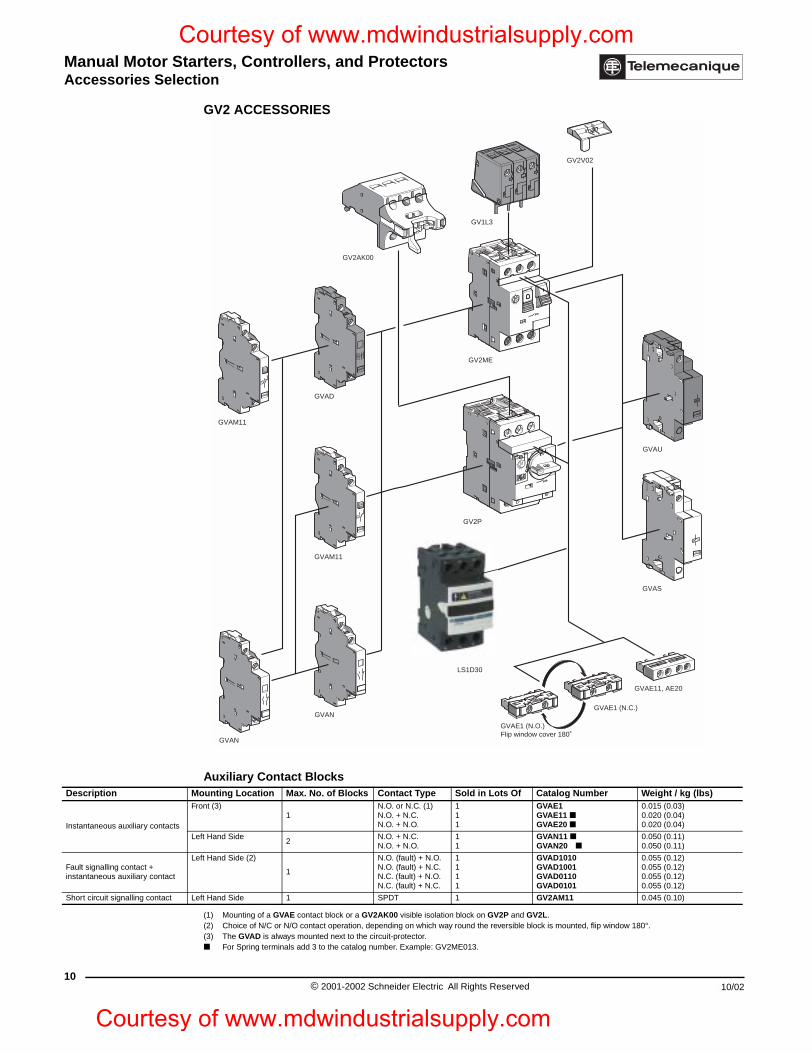
Manual Motor Starters, Controllers, and ProtectorsAccessories Selection
10
Description M
Instantaneous auxiliary contacts
F
L
Fault signalling contact +instantaneous auxiliary contact
L
Short circuit signalling contact L
Courtesy of www.mdwindustrialsupply.com
Courtesy
GV2 ACCESSORIES
(1) Mounting of a GVAE contact block or a GV2AK00 visible isolation block on GV2P and GV2L.(2) Choice of N/C or N/O contact operation, depending on which way round the reversible block is mounted, flip window 180°.(3) The GVAD is always mounted next to the circuit-protector. For Spring terminals add 3 to the catalog number. Example: GV2ME013.
Auxiliary Contact Blocksounting Location Max. No. of Blocks Contact Type Sold in Lots Of Catalog Number Weight / kg (lbs)
ront (3)1
N.O. or N.C. (1) N.O. + N.C. N.O. + N.O.
111
GVAE1GVAE11 GVAE20
0.015 (0.03)0.020 (0.04)0.020 (0.04)
eft Hand Side2
N.O. + N.C.N.O. + N.O.
11
GVAN11 GVAN20
0.050 (0.11)0.050 (0.11)
eft Hand Side (2)
1
N.O. (fault) + N.O.N.O. (fault) + N.C.N.C. (fault) + N.O.N.C. (fault) + N.C.
1111
GVAD1010GVAD1001GVAD0110GVAD0101
0.055 (0.12)0.055 (0.12)0.055 (0.12)0.055 (0.12)
eft Hand Side 1 SPDT 1 GV2AM11 0.045 (0.10)
GV2AK00
GV2V02
GV1L3
GVAD
GVAM11
GVAM11
GVAN
GVAN
GV2P
GV2ME
GVAU
GVAS
GVAE1 (N.C.)
GVAE1 (N.O.)Flip window cover 180˚
GVAE11, AE20
LS1D30
© 2001-2002 Schneider Electric All Rights Reserved 10/02
of www.mdwindustrialsupply.com
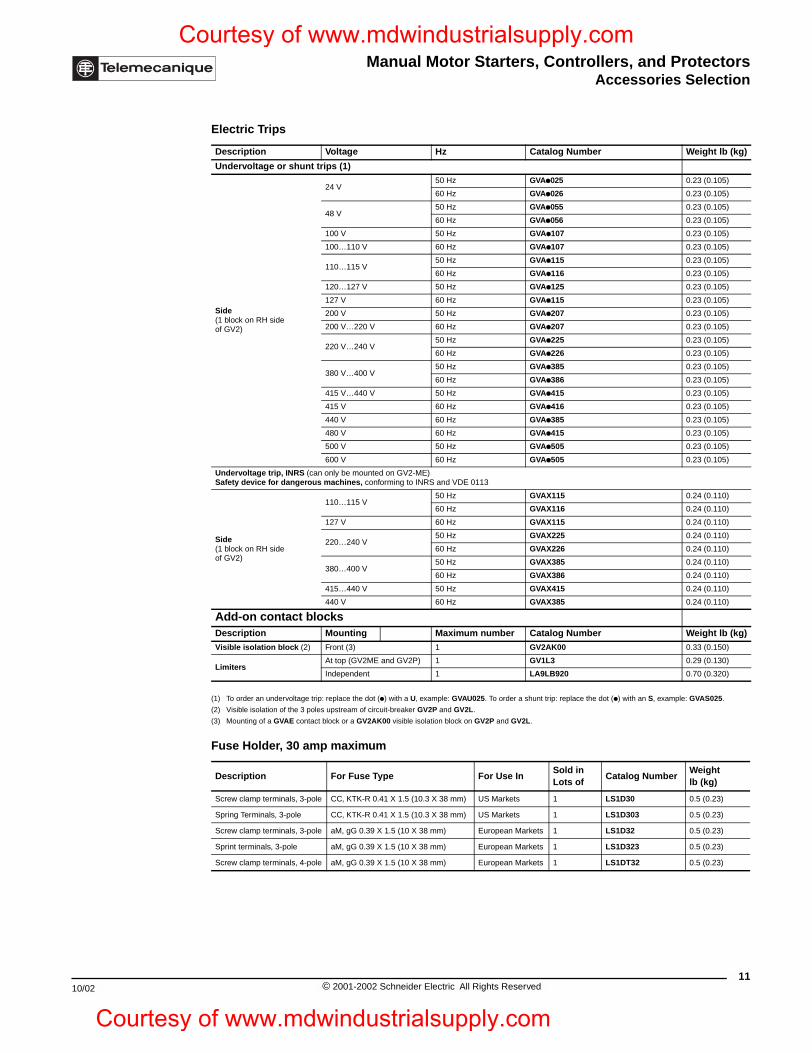
Manual Motor Starters, Controllers, and ProtectorsAccessories Selection
10/02
Courtesy of www.mdwindustrialsupply.com
Courtesy o
(1) To order an undervoltage trip: replace the dot (p) with a U, example: GVAU025. To order a shunt trip: replace the dot (p) with an S, example: GVAS025.
(2) Visible isolation of the 3 poles upstream of circuit-breaker GV2P and GV2L.
(3) Mounting of a GVAE contact block or a GV2AK00 visible isolation block on GV2P and GV2L.
Electric Trips
Description Voltage Hz Catalog Number Weight lb (kg)
Undervoltage or shunt trips (1)
Side(1 block on RH sideof GV2)
24 V50 Hz GVAp025 0.23 (0.105)
60 Hz GVAp026 0.23 (0.105)
48 V50 Hz GVAp055 0.23 (0.105)
60 Hz GVAp056 0.23 (0.105)
100 V 50 Hz GVAp107 0.23 (0.105)
100…110 V 60 Hz GVAp107 0.23 (0.105)
110…115 V50 Hz GVAp115 0.23 (0.105)
60 Hz GVAp116 0.23 (0.105)
120…127 V 50 Hz GVAp125 0.23 (0.105)
127 V 60 Hz GVAp115 0.23 (0.105)
200 V 50 Hz GVAp207 0.23 (0.105)
200 V…220 V 60 Hz GVAp207 0.23 (0.105)
220 V…240 V50 Hz GVAp225 0.23 (0.105)
60 Hz GVAp226 0.23 (0.105)
380 V…400 V50 Hz GVAp385 0.23 (0.105)
60 Hz GVAp386 0.23 (0.105)
415 V…440 V 50 Hz GVAp415 0.23 (0.105)
415 V 60 Hz GVAp416 0.23 (0.105)
440 V 60 Hz GVAp385 0.23 (0.105)
480 V 60 Hz GVAp415 0.23 (0.105)
500 V 50 Hz GVAp505 0.23 (0.105)
600 V 60 Hz GVAp505 0.23 (0.105)
Undervoltage trip, INRS (can only be mounted on GV2-ME)Safety device for dangerous machines, conforming to INRS and VDE 0113
Side(1 block on RH sideof GV2)
110…115 V50 Hz GVAX115 0.24 (0.110)
60 Hz GVAX116 0.24 (0.110)
127 V 60 Hz GVAX115 0.24 (0.110)
220…240 V50 Hz GVAX225 0.24 (0.110)
60 Hz GVAX226 0.24 (0.110)
380…400 V50 Hz GVAX385 0.24 (0.110)
60 Hz GVAX386 0.24 (0.110)
415…440 V 50 Hz GVAX415 0.24 (0.110)
440 V 60 Hz GVAX385 0.24 (0.110)
Add-on contact blocksDescription Mounting Maximum number Catalog Number Weight lb (kg)Visible isolation block (2) Front (3) 1 GV2AK00 0.33 (0.150)
LimitersAt top (GV2ME and GV2P) 1 GV1L3 0.29 (0.130)
Independent 1 LA9LB920 0.70 (0.320)
Fuse Holder, 30 amp maximum
Description For Fuse Type For Use InSold in Lots of
Catalog NumberWeight lb (kg)
Screw clamp terminals, 3-pole CC, KTK-R 0.41 X 1.5 (10.3 X 38 mm) US Markets 1 LS1D30 0.5 (0.23)
Spring Terminals, 3-pole CC, KTK-R 0.41 X 1.5 (10.3 X 38 mm) US Markets 1 LS1D303 0.5 (0.23)
Screw clamp terminals, 3-pole aM, gG 0.39 X 1.5 (10 X 38 mm) European Markets 1 LS1D32 0.5 (0.23)
Sprint terminals, 3-pole aM, gG 0.39 X 1.5 (10 X 38 mm) European Markets 1 LS1D323 0.5 (0.23)
Screw clamp terminals, 4-pole aM, gG 0.39 X 1.5 (10 X 38 mm) European Markets 1 LS1DT32 0.5 (0.23)
11© 2001-2002 Schneider Electric All Rights Reserved
f www.mdwindustrialsupply.com
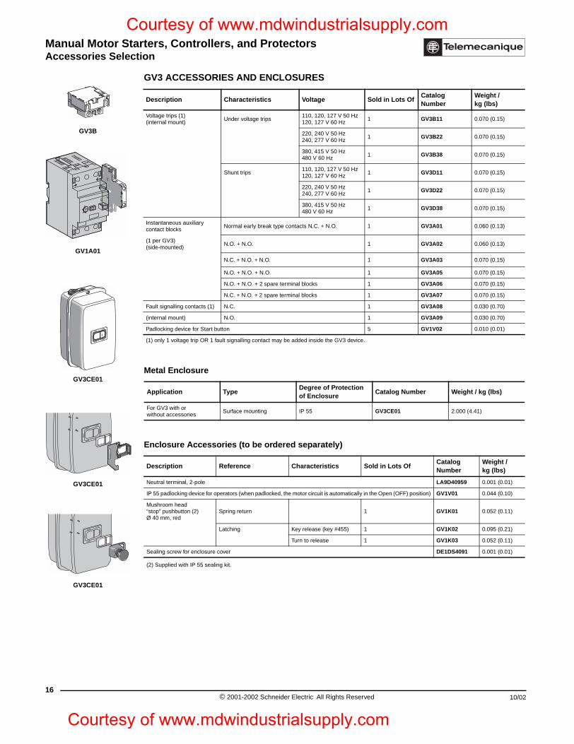
Manual Motor Starters, Controllers, and ProtectorsAccessories Selection
16
GV3B
GV1A01
GV3CE01
GV3CE01
GV3CE01
Courtesy of www.mdwindustrialsupply.com
Courtesy
GV3 ACCESSORIES AND ENCLOSURES
Description Characteristics Voltage Sold in Lots OfCatalog Number
Weight / kg (lbs)
Voltage trips (1) (internal mount)
Under voltage trips110, 120, 127 V 50 Hz 120, 127 V 60 Hz
1 GV3B11 0.070 (0.15)
220, 240 V 50 Hz 240, 277 V 60 Hz
1 GV3B22 0.070 (0.15)
380, 415 V 50 Hz 480 V 60 Hz
1 GV3B38 0.070 (0.15)
Shunt trips110, 120, 127 V 50 Hz 120, 127 V 60 Hz
1 GV3D11 0.070 (0.15)
220, 240 V 50 Hz240, 277 V 60 Hz
1 GV3D22 0.070 (0.15)
380, 415 V 50 Hz480 V 60 Hz
1 GV3D38 0.070 (0.15)
Instantaneous auxiliary contact blocks
Normal early break type contacts N.C. + N.O. 1 GV3A01 0.060 (0.13)
(1 per GV3) (side-mounted)
N.O. + N.O. 1 GV3A02 0.060 (0.13)
N.C. + N.O. + N.O. 1 GV3A03 0.070 (0.15)
N.O. + N.O. + N.O. 1 GV3A05 0.070 (0.15)
N.O. + N.O. + 2 spare terminal blocks 1 GV3A06 0.070 (0.15)
N.C. + N.O. + 2 spare terminal blocks 1 GV3A07 0.070 (0.15)
Fault signalling contacts (1) N.C. 1 GV3A08 0.030 (0.70)
(internal mount) N.O. 1 GV3A09 0.030 (0.70)
Padlocking device for Start button 5 GV1V02 0.010 (0.01)
(1) only 1 voltage trip OR 1 fault signalling contact may be added inside the GV3 device.
Metal Enclosure
Application TypeDegree of Protectionof Enclosure
Catalog Number Weight / kg (lbs)
For GV3 with or without accessories
Surface mounting IP 55 GV3CE01 2.000 (4.41)
Enclosure Accessories (to be ordered separately)
Description Reference Characteristics Sold in Lots OfCatalog Number
Weight / kg (lbs)
Neutral terminal, 2-pole LA9D40959 0.001 (0.01)
IP 55 padlocking device for operators (when padlocked, the motor circuit is automatically in the Open (OFF) position) GV1V01 0.044 (0.10)
Mushroom head “stop” pushbutton (2) Ø 40 mm, red
Spring return 1 GV1K01 0.052 (0.11)
Latching Key release (key #455) 1 GV1K02 0.095 (0.21)
Turn to release 1 GV1K03 0.052 (0.11)
Sealing screw for enclosure cover DE1DS4091 0.001 (0.01)
(2) Supplied with IP 55 sealing kit.
© 2001-2002 Schneider Electric All Rights Reserved 10/02
of www.mdwindustrialsupply.com
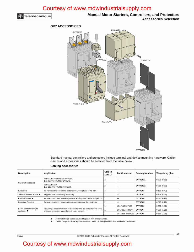
Manual Motor Starters, Controllers, and ProtectorsAccessories Selection
10/02
Description App
Clip-On Connectors
For G1.5–
For G1.5–
Spreaders To in
Terminal Shields IP 405 Supp
Phase Barriers Prov
Insulating Screens Prov
Kit for combination with contactor
Provprov
05/04
Courtesy of www.mdwindustrialsupply.com
Courtesy o
GV7 ACCESSORIES
Standard manual controllers and protectors include terminal and device mounting hardware. Cable clamps and accessories should be selected from the table below.
Terminal shields cannot be used together with phase barriers. The kit comprises links, a protective shield and a depth adjustable metal bracket for the breaker.
Cabling Accessories
licationSold in Lots Of
For Contactor Catalog Number Weight / kg (lbs)
V7R•40 through GV7R •150,95 mm2 (#14 to # 3/0 awg).
3 — GV7AC021 0.300 (0.66)
V7R•220185 mm2 (#14 to 350 mcm).
3 — GV7AC022 0.350 (0.77)
crease the center line distance between phase to 45 mm. 3 — GV7AC03 0.180 (0.40)
lied with the sealing accessory. 1 — GV7AC01 0.125 (0.28)
ides maximum phase separation at the power connection points. 2 — GV7AC04 0.075 (0.17)
ides insulation between the connections and the backplate. 2 — GV7AC05 0.075 (0.17)
iding a direct link between the starter and the contactor, the cover ides protection against direct finger contact.
1 LC1F115 to F185 GV7AC06 0.550 (1.21)
1 LC1F225 and F265 GV7AC07 0.550 (1.21)
1 LC1D115 and D150 GV7AC08 0.550 (1.21)
GV7AC03GV7AC01
GV7AC02 GV7AC04
GV7RE, RS
GV7AC01
GV7AC04
17© 2001-2002 Schneider Electric All Rights Reserved
f www.mdwindustrialsupply.com
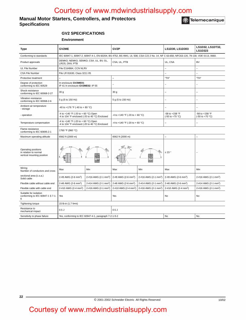
Manual Motor Starters, Controllers, and ProtectorsSpecifications
22
Type
Conforming to standards
Product approvals
UL File Number
CSA File Number
Protective treatment
Degree of protection conforming to IEC 60529
Shock resistance conforming to IEC 60068-2-27
Vibration resistance conforming to IEC 60068-2-6
Ambient air temperature - storage
- operation
Temperature compensation
Flame resistance conforming to IEC 60695-2-1
Maximum operating altitude
Operating positions in relation to normal vertical mounting position
Wiring Number of conductors and cross
sectional area (c.s.a.) Solid cable
Flexible cable without cable end
Flexible cable with cable end
Suitable for isolation conforming to IEC 60947-1 § 7-1-6
Tightening torque
Resistance to mechanical impact
Sensitivity to phase failure
Courtesy of www.mdwindustrialsupply.com
Courtesy
GV2 SPECIFICATIONS
Environment
GV2ME GV2P LS1D30, LS1D303LS1D32, LS1DT32, LS1D323
IEC 60947-1, 60947-2, 60947-4-1, EN 60204, BS 4752, BS 4941, UL 508, CSA C22.2 No. 14, NF C 63-650, NFC63-120, 79-130, VDE 0113, 0660.
DEMKO, NEMKO, SEMKO, CSA. UL, BV, GL, LROS, DNV, PTB
CSA, UL, PTB UL, CSA BV
File E164864, CCN NLRV – –
File LR 81630, Class 3211 05 – –
– – “TH” “TH”
In enclosure GV2ME01: IP 41 In enclosure GV2ME02: IP 55
– – –
30 g 30 g – –
5 g (5 to 150 Hz) 5 g (5 to 150 Hz) – –
-40 to +176 °F (-40 to + 80 °C) – –
-4 to +140 °F (-20 to + 60 °C) Open-4 to 104 °F enclosed (-20 to 40 °C) Enclosed
-4 to +140 °F (-20 to + 60 °C)-58 to +158 °F (-50 to +70 °C)
-58 to +158 °F (-50 to +70 °C)
-4 to +140 °F (-20 to + 60 °C) Open-4 to 104 °F enclosed (-20 to 40 °C) Enclosed
-4 to +140 °F (-20 to + 60 °C) – –
1760 °F (960 °C)
6562 ft (2000 m) 6562 ft (2000 m) – –
± 23 ° –
Max Min Max Min Max Min
2-#8 AWG (2-6 mm2) 2-#16 AWG (2-1 mm2) 2-#8 AWG (2-6 mm2) 2-#16 AWG (2-1 mm2) 2-#8 AWG (2-6 mm2) 2-#16 AWG (2-1 mm2)
2-#8 AWG (2-6 mm2) 2-#14 AWG (2-1 mm2) 2-#8 AWG (2-6 mm2) 2-#14 AWG (2-1 mm2) 2-#8 AWG (2-6 mm2) 2-#14 AWG (2-1 mm2)
2-#10 AWG (2-4 mm2) 2-#16 AWG (2-1 mm2) 2-#10 AWG (2-4 mm2) 2-#16 AWG (2-1 mm2) 2-#10 AWG (2-4 mm2) 2-#16 AWG (2-1 mm2)
Yes Yes No No
15 lb-in (1.7 N•m)
0.5 J 0.5 J
Yes, conforming to IEC 60947-4-1, paragraph 7-2-1-5-2 No No
90° 90° 90° 90°
90°90°
30° 30°
© 2001-2002 Schneider Electric All Rights Reserved 10/02
of www.mdwindustrialsupply.com
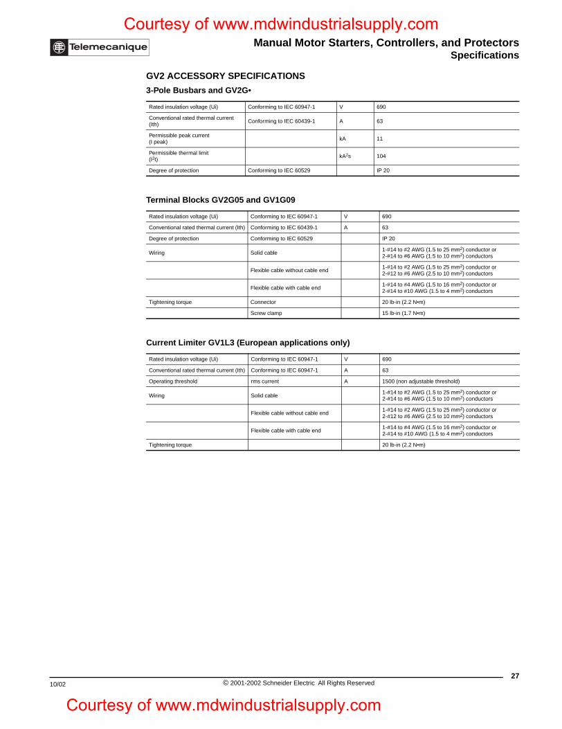
Manual Motor Starters, Controllers, and ProtectorsSpecifications
10/02
Courtesy of www.mdwindustrialsupply.com
Courtesy o
GV2 ACCESSORY SPECIFICATIONS
3-Pole Busbars and GV2G•
Rated insulation voltage (Ui) Conforming to IEC 60947-1 V 690
Conventional rated thermal current (Ith)
Conforming to IEC 60439-1 A 63
Permissible peak current (I peak)
kA 11
Permissible thermal limit (I2t)
kA2s 104
Degree of protection Conforming to IEC 60529 IP 20
Terminal Blocks GV2G05 and GV1G09
Rated insulation voltage (Ui) Conforming to IEC 60947-1 V 690
Conventional rated thermal current (Ith) Conforming to IEC 60439-1 A 63
Degree of protection Conforming to IEC 60529 IP 20
Wiring Solid cable1-#14 to #2 AWG (1.5 to 25 mm2) conductor or 2-#14 to #6 AWG (1.5 to 10 mm2) conductors
Flexible cable without cable end1-#14 to #2 AWG (1.5 to 25 mm2) conductor or 2-#12 to #6 AWG (2.5 to 10 mm2) conductors
Flexible cable with cable end1-#14 to #4 AWG (1.5 to 16 mm2) conductor or 2-#14 to #10 AWG (1.5 to 4 mm2) conductors
Tightening torque Connector 20 lb-in (2.2 N•m)
Screw clamp 15 lb-in (1.7 N•m)
Current Limiter GV1L3 (European applications only)
Rated insulation voltage (Ui) Conforming to IEC 60947-1 V 690
Conventional rated thermal current (Ith) Conforming to IEC 60947-1 A 63
Operating threshold rms current A 1500 (non adjustable threshold)
Wiring Solid cable1-#14 to #2 AWG (1.5 to 25 mm2) conductor or 2-#14 to #6 AWG (1.5 to 10 mm2) conductors
Flexible cable without cable end1-#14 to #2 AWG (1.5 to 25 mm2) conductor or 2-#12 to #6 AWG (2.5 to 10 mm2) conductors
Flexible cable with cable end1-#14 to #4 AWG (1.5 to 16 mm2) conductor or 2-#14 to #10 AWG (1.5 to 4 mm2) conductors
Tightening torque 20 lb-in (2.2 N•m)
27© 2001-2002 Schneider Electric All Rights Reserved
f www.mdwindustrialsupply.com
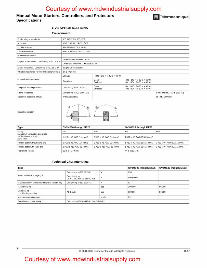
Manual Motor Starters, Controllers, and ProtectorsSpecifications
34
Conforming to standards
Approvals
UL File Number
CSA File Number
Protective treatment
Degree of protection / Conforming t
Shock resistance / Conforming to IE
Vibration resistance / Conforming to
Ambient air temperature
Temperature compensation
Flame resistance
Maximum operating altitude
Operating position
Type
Wiring Number of conductors and cross sectional area (c.s.a.) Solid cable
Flexible cable without cable end
Flexible cable with cable end
Tightening Torque
Type
Rated insulation voltage (UI)
Maximum conventional rated therm
Mechanical life
Electrical life ops: Closing-opening
Maximum operating rate
Sensitivity to phase failure
Courtesy of www.mdwindustrialsupply.com
Courtesy
GV3 SPECIFICATIONS
Environment
IEC, NF C, BS, IEC, VDE
ASE, CSA, UL, LROS, ÖVE
File E164864, CCN NLRV
File LR 81630, Class 3211 05
“TC”
o IEC 60529GV3ME open-mounted: IP 20
GV3ME in enclosure GV3CE01: IP 55
C 68-2-27 22 g for 20 ms duration
IEC 68-2-6 2.5 g (0-25 Hz)
Storage -40 to +176 °F (-40 to + 80 °C)
OperationOpenEnclosed
-4 to +140 °F (-20 to + 60 °C)-4 to +104 °F (-20 to + 40 °C)
Conforming to IEC 60157-1OpenEnclosed
-4 to +140 °F (-20 to + 60 °C)-4 to +104 °F (-20 to + 40 °C)
Conforming to IEC 60695-2-1 Conforms for 1760 °F (960 °C)
Without derating 9843 ft. (3000 m)
GV3ME06 through ME20 GV3ME25 through ME63
Min Max Min Max
1-#16 to #8 AWG (1-6 mm2) 2-#16 to #8 AWG (1-6 mm2) 1-#12 to #1 AWG (2.5-35 mm2)
1-#16 to #8 AWG (1-6 mm2) 2-#16 to #8 AWG (1-6 mm2) 1-#12 to #2 AWG (2.5-25 mm2) 2-#12 to #4 AWG (2.5-16 mm2)
1-#16 to #10 AWG (1-4 mm2) 2-#16 to #10 AWG (1-4 mm2) 1-#12 to #2 AWG (2.5-25 mm2) 2-#12 to #4 AWG (2.5-16 mm2)
15 lb-in (1.7 N•m) 44 lb-in (5 N•m)
Technical Characteristics
GV3ME06 through ME25 GV3ME40 through ME63
Conforming to IEC 60158-1 V 690
Conforming to CSA C 22.2 No. 14 and UL 508
V 600 (B600)
al current (lth) Conforming to IEC 60157-1 A 63
ops 100 000 50 000
AC-3 duty ops 100 000 50 000
ops/h 25
Conforms to IEC 60947-4-1 Sec 7-2-1-5-2
90°90°90°90°
© 2001-2002 Schneider Electric All Rights Reserved 10/02
of www.mdwindustrialsupply.com
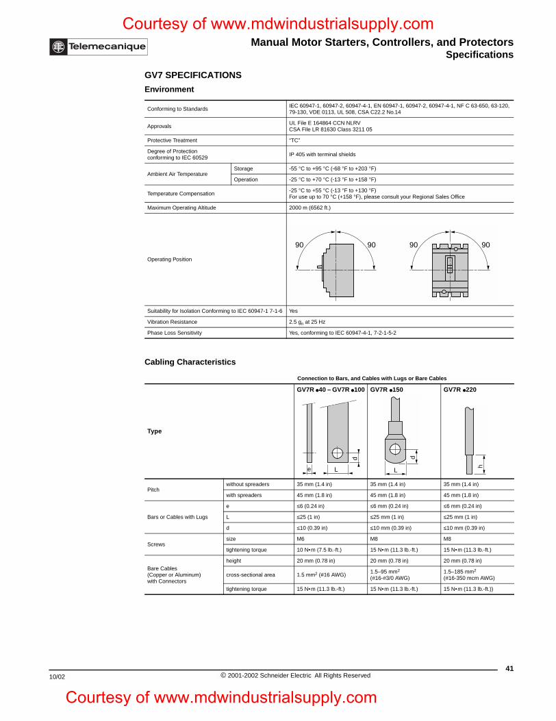
Manual Motor Starters, Controllers, and ProtectorsSpecifications
10/02
Courtesy of www.mdwindustrialsupply.com
Courtesy o
GV7 SPECIFICATIONS
Environment
Conforming to StandardsIEC 60947-1, 60947-2, 60947-4-1, EN 60947-1, 60947-2, 60947-4-1, NF C 63-650, 63-120, 79-130, VDE 0113, UL 508, CSA C22.2 No.14
ApprovalsUL File E 164864 CCN NLRVCSA File LR 81630 Class 3211 05
Protective Treatment “TC”
Degree of Protectionconforming to IEC 60529
IP 405 with terminal shields
Ambient Air TemperatureStorage -55 °C to +95 °C (-68 °F to +203 °F)
Operation -25 °C to +70 °C (-13 °F to +158 °F)
Temperature Compensation-25 °C to +55 °C (-13 °F to +130 °F) For use up to 70 °C (+158 °F), please consult your Regional Sales Office
Maximum Operating Altitude 2000 m (6562 ft.)
Operating Position
Suitability for Isolation Conforming to IEC 60947-1 7-1-6 Yes
Vibration Resistance 2.5 gn at 25 Hz
Phase Loss Sensitivity Yes, conforming to IEC 60947-4-1, 7-2-1-5-2
Cabling Characteristics
Connection to Bars, and Cables with Lugs or Bare Cables
Type
GV7R 40 – GV7R 100 GV7R 150 GV7R 220
Pitchwithout spreaders 35 mm (1.4 in) 35 mm (1.4 in) 35 mm (1.4 in)
with spreaders 45 mm (1.8 in) 45 mm (1.8 in) 45 mm (1.8 in)
Bars or Cables with Lugs
e ≤6 (0.24 in) ≤6 mm (0.24 in) ≤6 mm (0.24 in)
L ≤25 (1 in) ≤25 mm (1 in) ≤25 mm (1 in)
d ≤10 (0.39 in) ≤10 mm (0.39 in) ≤10 mm (0.39 in)
Screwssize M6 M8 M8
tightening torque 10 N•m (7.5 lb.-ft.) 15 N•m (11.3 lb.-ft.) 15 N •m (11.3 lb.-ft.)
Bare Cables (Copper or Aluminum)with Connectors
height 20 mm (0.78 in) 20 mm (0.78 in) 20 mm (0.78 in)
cross-sectional area 1.5 mm2 (#16 AWG)1.5–95 mm2 (#16-#3/0 AWG)
1.5–185 mm2
(#16-350 mcm AWG)
tightening torque 15 N•m (11.3 lb.-ft.) 15 N •m (11.3 lb.-ft.) 15 N •m (11.3 lb.-ft.))
90 90 90 90
e
d
L
d
L
h
41© 2001-2002 Schneider Electric All Rights Reserved
f www.mdwindustrialsupply.com
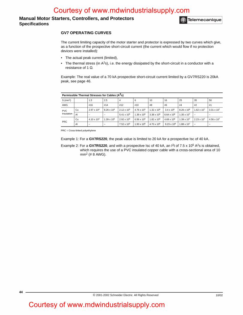
Manual Motor Starters, Controllers, and ProtectorsSpecifications
44
Courtesy of www.mdwindustrialsupply.com
Courtesy
GV7 OPERATING CURVES
The current limiting capacity of the motor starter and protector is expressed by two curves which give, as a function of the prospective short-circuit current (the current which would flow if no protection devices were installed):
• The actual peak current (limited),
• The thermal stress (in A2s), i.e. the energy dissipated by the short-circuit in a conductor with a resistance of 1 Ω.
Example: The real value of a 70 kA prospective short-circuit current limited by a GV7RS220 is 20kA peak, see page 46.
PRC = Cross-linked polyethylene
Example 1: For a GV7RS220, the peak value is limited to 20 kA for a prospective Isc of 40 kA.
Example 2: For a GV7RS220, and with a prospective Isc of 40 kA, an I2t of 7.5 x 10⁵ A2s is obtained, which requires the use of a PVC insulated copper cable with a cross-sectional area of 10 mm2 (# 8 AWG).
Permissible Thermal Stresses for Cables (A2s)
S (mm2) 1.5 2.5 4 6 10 16 25 35 50
AWG #16 #14 #12 #10 #8 #6 #4 #2 #1
PVCInsulation
Cu 2.97 x 10⁴ 8.26 x 10⁴ 2.12 x 10⁵ 4.76 x 10⁵ 1.32 x 10⁶ 3.4 x 10⁶ 8.26 x 10⁶ 1.62 x 10⁷ 3.31 x 10⁷
Al – – 5.41 x 10⁵ 1.39 x 10⁶ 3.38 x 10⁶ 6.64 x 10⁶ 1.35 x 10⁷ – –
PRCCu 4.10 x 10⁴ 1.39 x 10⁵ 2.92 x 10⁵ 6.56 x 10⁵ 1.82 x 10⁶ 4.69 x 10⁶ 1.39 x 10⁷ 2.23 x 10⁷ 4.56 x 10⁷
Al – – 7.52 x 10⁵ 1.93 x 10⁶ 4.70 x 10⁶ 9.23 x 10⁶ 1.88 x 10⁷ – –
© 2001-2002 Schneider Electric All Rights Reserved 10/02
of www.mdwindustrialsupply.com
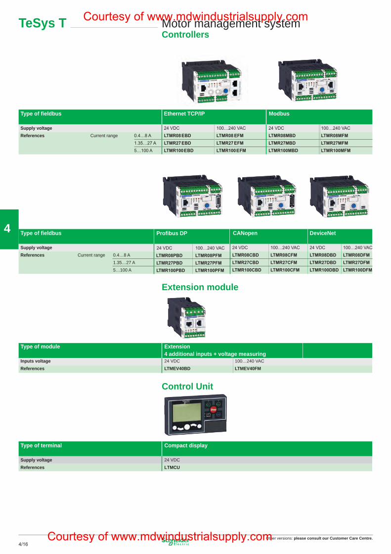
Other versions: please consult our Customer Care Centre.4/16
4
Motor management systemControllers
TeSys T
Type of fi eldbus Ethernet TCP/IP Modbus
Supply voltageReferences Current range
Type of fi eldbus CANopen DeviceNet
Supply voltageReferences Current range 0.4…8 A
1.35…27 A5…100 A
Extension module
Type of module Extension4 additional inputs + voltage measuring
Inputs voltage 24 VDC 100…240 VACReferences LTMEV40BD LTMEV40FM
Control Unit
Type of terminal Compact display
Supply voltage 24 VDCReferences LTMCU
Profibus DP
16
Type of transformer External
Operational current primary 100 A 200 A 400 A 800 Asecondary 1 A
References LT6CT1001 LT6CT2001 LT6CT4001 LT6CT8001
Earth fault toroidsType of toroid Closed Split
Maximum current 65 A 85 A 160 A 250 A 400 A 630 A 85 A 250 AInternal diameter Ø 30 Ø 50 Ø 80 Ø 120 Ø 200 Ø 300 Ø 46 Ø 110References 50437 50438 50439 50440 50441 50442 50485 50486
PTC thermistor probeType of probe Triple
Operating temperature 90°C 110°C 120°C 130°C 140°C 150°C 160°C 170°CReferences DA1TT090 DA1TT110 DA1TT120 DA1TT130 DA1TT140 DA1TT150 DA1TT160 DA1TT170
Accessories (1)
Type of accessory Connecting cableController / Extension module
Length of cable 0.04 m 0.3 m 1 mReferences LTMCC004 LU9R03 LU9R10
Type of accessory Connecting cableController / Display
Connection kitPC serial port
Length of cable 1 m 3 m 5 m –References VW3A1104R10 VW3A1104R30 VW3A1104R50 VW3A8106
(1) For other connection accessories, see www.schneider-electric.ca
Motor management systemCurrent transformers
TeSys T
Other versions: Please consult our Customer Care Centre.
17
Courtesy of www.mdwindustrialsupply.com
Courtesy of www.mdwindustrialsupply.com
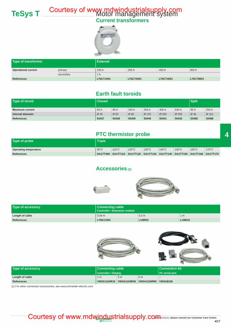
Other versions: please consult our Customer Care Centre.4/174/17
4
Motor management systemControllers
TeSys T
Type of fi eldbus Ethernet TCP/IP Modbus
Supply voltageReferences Current range
Type of fi eldbus CANopen DeviceNet
Supply voltageReferences Current range 0.4…8 A
1.35…27 A5…100 A
Extension module
Type of module Extension4 additional inputs + voltage measuring
Inputs voltage 24 VDC 100…240 VACReferences LTMEV40BD LTMEV40FM
Control Unit
Type of terminal Compact display
Supply voltage 24 VDCReferences LTMCU
Profibus DP
16
Type of transformer External
Operational current primary 100 A 200 A 400 A 800 Asecondary 1 A
References LT6CT1001 LT6CT2001 LT6CT4001 LT6CT8001
Earth fault toroidsType of toroid Closed Split
Maximum current 65 A 85 A 160 A 250 A 400 A 630 A 85 A 250 AInternal diameter Ø 30 Ø 50 Ø 80 Ø 120 Ø 200 Ø 300 Ø 46 Ø 110References 50437 50438 50439 50440 50441 50442 50485 50486
PTC thermistor probeType of probe Triple
Operating temperature 90°C 110°C 120°C 130°C 140°C 150°C 160°C 170°CReferences DA1TT090 DA1TT110 DA1TT120 DA1TT130 DA1TT140 DA1TT150 DA1TT160 DA1TT170
Accessories (1)
Type of accessory Connecting cableController / Extension module
Length of cable 0.04 m 0.3 m 1 mReferences LTMCC004 LU9R03 LU9R10
Type of accessory Connecting cableController / Display
Connection kitPC serial port
Length of cable 1 m 3 m 5 m –References VW3A1104R10 VW3A1104R30 VW3A1104R50 VW3A8106
(1) For other connection accessories, see www.schneider-electric.com
Motor management systemCurrent transformers
TeSys T
Other versions: Please consult our Customer Care Centre.
17
Courtesy of www.mdwindustrialsupply.com
Courtesy of www.mdwindustrialsupply.com
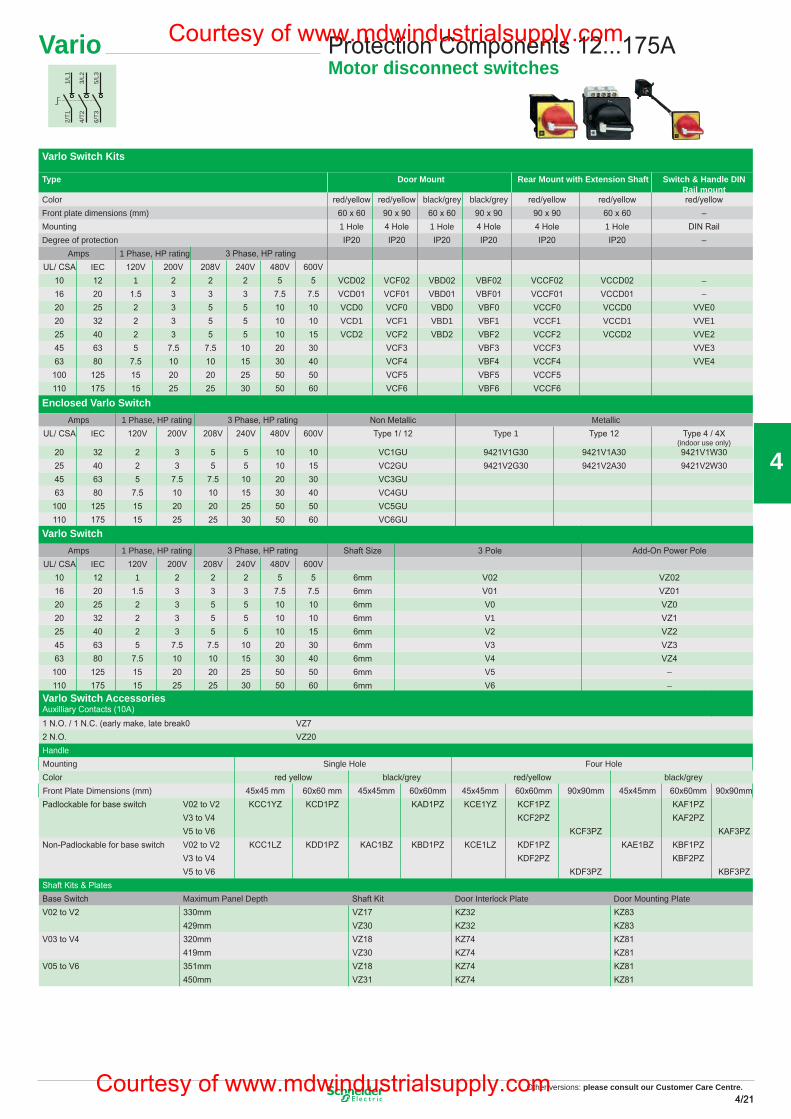
Other versions: please consult our Customer Care Centre.4/214/21
4
TeSys GV7
Manual motor starters5 to 200 HP
Manual motor starters GV7R for connection by screw clamp terminalsControl by rocker lever
t fo egnar gnitteSzH 06/05 srotom esahp-3 fo sgnitar rewopesroH hermal trips Catalog Number
230 V 460V AV 575
2151015 –20 GV7RE2052–5102515.7 GV7RE25
04–52030301 GV7RE4005–03040351 GV7RE5008–84570603 GV7RE80
001–060015703 GV7RE100051–0905100105 GV7RE150
022–23100205157 GV7RE220
GV7RS20GV7RS25
GV7RS40GV7RS50GV7RS80GV7RS100GV7RS150
GV7RS220
25-35KA 65KA
Add-on blocksContact blocks
Auxiliary contacts
O/Cepyt tcatnoC
GV7AE11
Thermal or magnetic fault discrimination
211DA7VG111DA7VG
Electric trips
V 044–083V 042–002V 031–011V 84zH 06/05egatloV
50 Hz 525 V
Undervoltage trip (1) GV7AU055 GV7AU107 GV7AU207 GV7AU387 GV7AU525
Shunt trip (1) GV7AS055 GV7AS107 GV7AS207 GV7AS387 GV7AS525
(1) For mounting of a GV7AD or a GV7AU or AS
Accessories
Terminal shields IP 405
Supplied with the sealing accessory GV7AC01
Phase barriers
Safety accessories GV7AC04
used when fitting of shields is impossible
Insulating screens
Ensure insulation between GV7AC05
the connections and the backplate
Kit for combination with contactor
Allowing link between the circuit-breaker and the contactor LC1F115 to F185 LC1F225 and F26 LC1D115 and D150
80CA7VG70CA7VG60CA7VG
Rotary handles
Handle derkcalb
wolleykcalbetalp dnegeL
direct IP 40 40PA7VG30PA7VG
extended IP 55 20PA7VG10PA7VG
Conversion accessory
for mounting on enclosure door IP 43 GV7AP05
Locking device
For circuit-breaker not fitted with a rotary handle GV7V01
20
Vario Protection Components 12...175AMotor disconnect switches
Varlo Switch Kits
Type Door Mount Rear Mount with Extension Shaft Switch & Handle DIN Rail mount
Color red/yellow red/yellow black/grey black/grey red/yellow red/yellow red/yellowFront plate dimensions (mm) 60 x 60 90 x 90 60 x 60 90 x 90 90 x 90 60 x 60 –Mounting 1 Hole 4 Hole 1 Hole 4 Hole 4 Hole 1 Hole DIN RailDegree of protection IP20 IP20 IP20 IP20 IP20 IP20 –
Amps 1 Phase, HP rating 3 Phase, HP ratingUL/ CSA IEC 120V 200V 208V 240V 480V 600V
10 12 1 2 2 2 5 5 VCD02 VCF02 VBD02 VBF02 VCCF02 VCCD02 –16 20 1.5 3 3 3 7.5 7.5 VCD01 VCF01 VBD01 VBF01 VCCF01 VCCD01 –20 25 2 3 5 5 10 10 VCD0 VCF0 VBD0 VBF0 VCCF0 VCCD0 VVE020 32 2 3 5 5 10 10 VCD1 VCF1 VBD1 VBF1 VCCF1 VCCD1 VVE125 40 2 3 5 5 10 15 VCD2 VCF2 VBD2 VBF2 VCCF2 VCCD2 VVE245 63 5 7.5 7.5 10 20 30 VCF3 VBF3 VCCF3 VVE363 80 7.5 10 10 15 30 40 VCF4 VBF4 VCCF4 VVE4100 125 15 20 20 25 50 50 VCF5 VBF5 VCCF5110 175 15 25 25 30 50 60 VCF6 VBF6 VCCF6
Enclosed Varlo SwitchAmps 1 Phase, HP rating 3 Phase, HP rating Non Metallic Metallic
UL/ CSA IEC 120V 200V 208V 240V 480V 600V Type 1/ 12 Type 1 Type 12 Type 4 / 4X(indoor use only)
20 32 2 3 5 5 10 10 VC1GU 9421V1G30 9421V1A30 9421V1W3025 40 2 3 5 5 10 15 VC2GU 9421V2G30 9421V2A30 9421V2W3045 63 5 7.5 7.5 10 20 30 VC3GU63 80 7.5 10 10 15 30 40 VC4GU100 125 15 20 20 25 50 50 VC5GU110 175 15 25 25 30 50 60 VC6GU
Varlo SwitchAmps 1 Phase, HP rating 3 Phase, HP rating Shaft Size 3 Pole Add-On Power Pole
UL/ CSA IEC 120V 200V 208V 240V 480V 600V10 12 1 2 2 2 5 5 6mm V02 VZ0216 20 1.5 3 3 3 7.5 7.5 6mm V01 VZ0120 25 2 3 5 5 10 10 6mm V0 VZ020 32 2 3 5 5 10 10 6mm V1 VZ125 40 2 3 5 5 10 15 6mm V2 VZ245 63 5 7.5 7.5 10 20 30 6mm V3 VZ363 80 7.5 10 10 15 30 40 6mm V4 VZ4
100 125 15 20 20 25 50 50 6mm V5 –110 175 15 25 25 30 50 60 6mm V6 –
Varlo Switch AccessoriesAuxilliary Contacts (10A)1 N.O. / 1 N.C. (early make, late break0 VZ72 N.O. VZ20HandleMounting Single Hole Four HoleColor red yellow black/grey red/yellow black/greyFront Plate Dimensions (mm) 45x45 mm 60x60 mm 45x45mm 60x60mm 45x45mm 60x60mm 90x90mm 45x45mm 60x60mm 90x90mmPadlockable for base switch V02 to V2 KCC1YZ KCD1PZ KAD1PZ KCE1YZ KCF1PZ KAF1PZ
V3 to V4 KCF2PZ KAF2PZV5 to V6 KCF3PZ KAF3PZ
Non-Padlockable for base switch V02 to V2 KCC1LZ KDD1PZ KAC1BZ KBD1PZ KCE1LZ KDF1PZ KAE1BZ KBF1PZV3 to V4 KDF2PZ KBF2PZV5 to V6 KDF3PZ KBF3PZ
Shaft Kits & PlatesBase Switch Maximum Panel Depth Shaft Kit Door Interlock Plate Door Mounting PlateV02 to V2 330mm VZ17 KZ32 KZ83
429mm VZ30 KZ32 KZ83V03 to V4 320mm VZ18 KZ74 KZ81
419mm VZ30 KZ74 KZ81V05 to V6 351mm VZ18 KZ74 KZ81
450mm VZ31 KZ74 KZ81
1/L1
2/T1
3/L2
4/T2
5/L3
6/T3
Other versions: Please consult our Customer Care Centre.
21
Courtesy of www.mdwindustrialsupply.com
Courtesy of www.mdwindustrialsupply.com
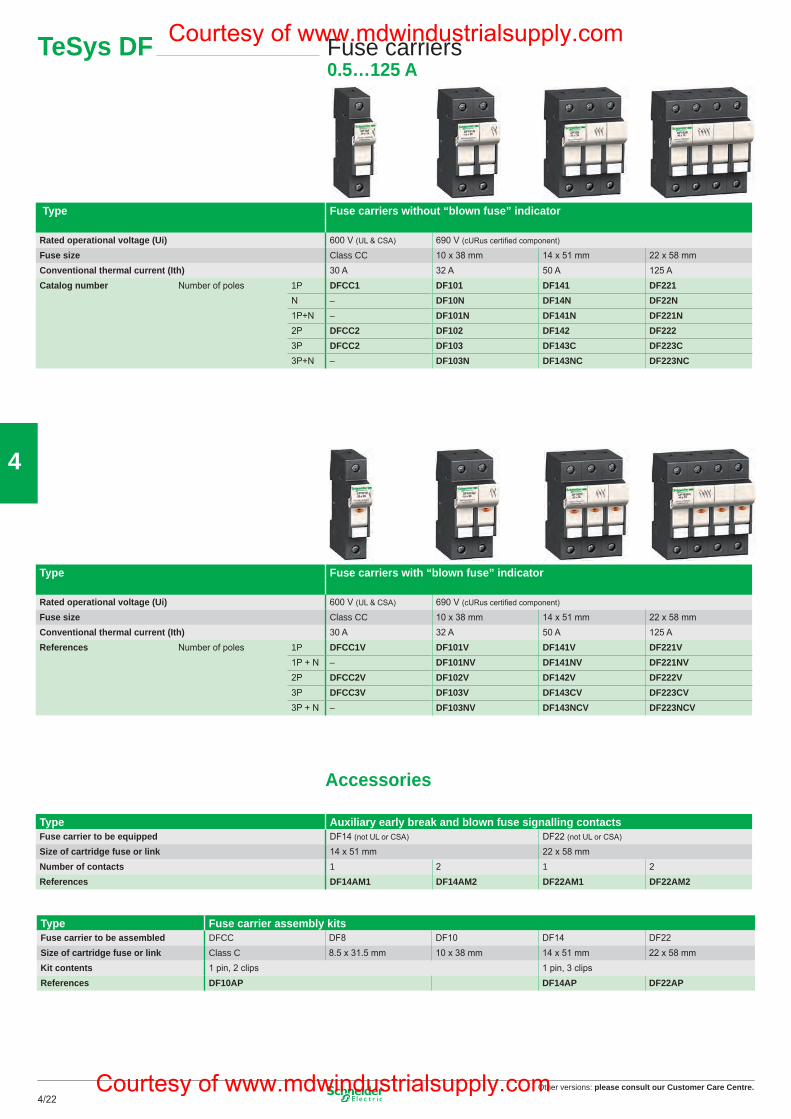
Other versions: please consult our Customer Care Centre.4/22
4
TeSys DF Fuse carriers0.5…125 A
Type Fuse carriers without “blown fuse” indicator
Rated operational voltage (Ui) 600 V (UL & CSA) 690 V (cURus certifi ed component)
Fuse size Class CC 10 x 38 mm 14 x 51 mm 22 x 58 mmConventional thermal current (Ith) 30 A 32 A 50 A 125 ACatalog number Number of poles 1P DFCC1 DF101 DF141 DF221
N – DF10N DF14N DF22N1P+N – DF101N DF141N DF221N2P DFCC2 DF102 DF142 DF2223P DFCC2 DF103 DF143C DF223C3P+N – DF103N DF143NC DF223NC
Type Fuse carriers with “blown fuse” indicator
Rated operational voltage (Ui) 600 V (UL & CSA) 690 V (cURus certifi ed component)
Fuse size Class CC 10 x 38 mm 14 x 51 mm 22 x 58 mmConventional thermal current (Ith) 30 A 32 A 50 A 125 AReferences Number of poles 1P DFCC1V DF101V DF141V DF221V
1P + N – DF101NV DF141NV DF221NV2P DFCC2V DF102V DF142V DF222V3P DFCC3V DF103V DF143CV DF223CV3P + N – DF103NV DF143NCV DF223NCV
Accessories
Type Auxiliary early break and blown fuse signalling contactsFuse carrier to be equipped DF14 (not UL or CSA) DF22 (not UL or CSA)
Size of cartridge fuse or link 14 x 51 mm 22 x 58 mmNumber of contacts 1 2 1 2References DF14AM1 DF14AM2 DF22AM1 DF22AM2
Type Fuse carrier assembly kitsFuse carrier to be assembled DFCC DF8 DF10 DF14 DF22Size of cartridge fuse or link Class C 8.5 x 31.5 mm 10 x 38 mm 14 x 51 mm 22 x 58 mmKit contents 1 pin, 2 clips 1 pin, 3 clipsReferences DF10AP DF14AP DF22AP
22
Courtesy of www.mdwindustrialsupply.com
Courtesy of www.mdwindustrialsupply.com
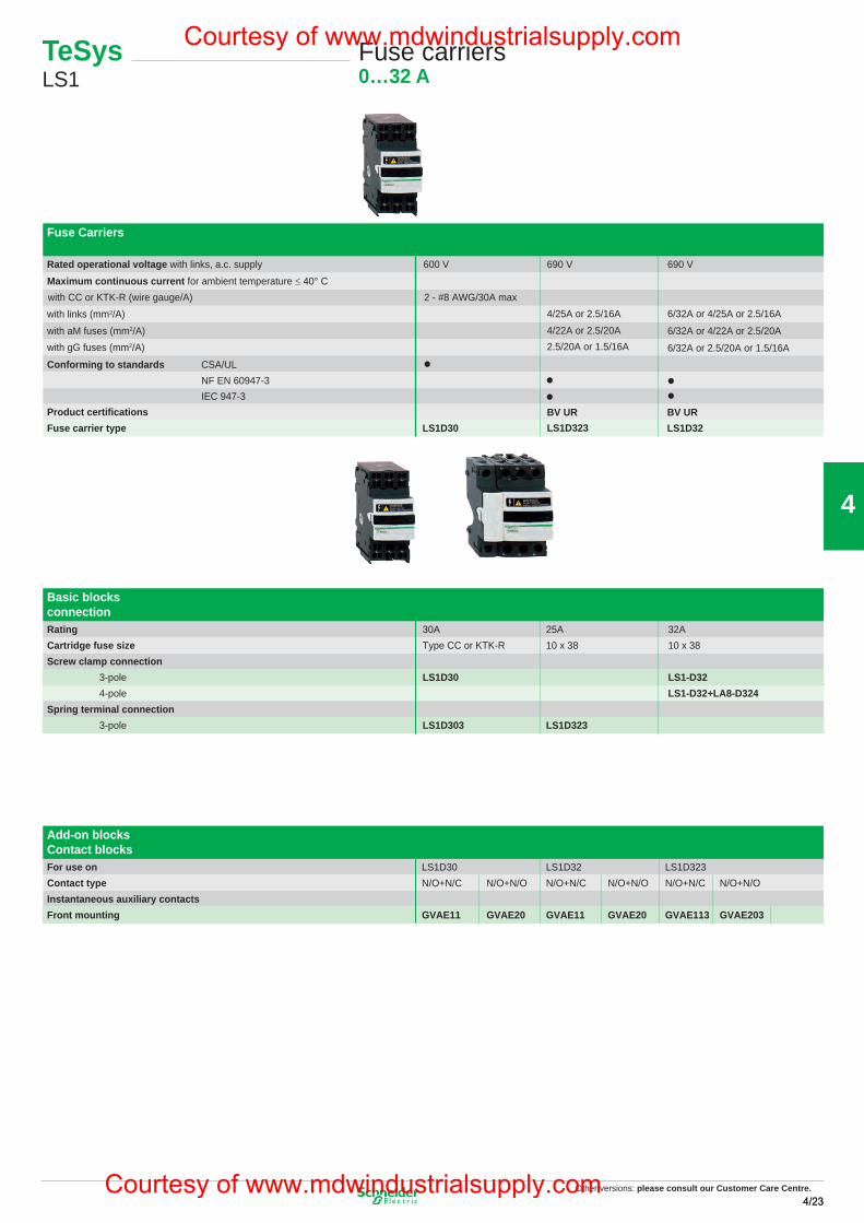
Other versions: please consult our Customer Care Centre.4/234/23
4
TeSys LS1
Fuse carriers0…32 A
Basic blocksconnection
Fuse Carriers
Rated operational voltage with links, a.c. supply 600 V 690 V 690 VMaximum continuous current for ambient temperature ≤ 40° C
with links (mm2/A)with CC or KTK-R (wire gauge/A) 2 - #8 AWG/30A max
with aM fuses (mm2/A)
4/25A or 2.5/16A4/22A or 2.5/20A
6/32A or 4/25A or 2.5/16A
6/32A or 4/22A or 2.5/20A
6/32A or 2.5/20A or 1.5/16Awith gG fuses (mm2/A) 2.5/20A or 1.5/16A
Conforming to standards CSA/ULNF EN 60947-3IEC 947-3
Product certifi
cationsFuse carrier type
Rating 30A 25A 32ACartridge fuse size Type CC or KTK-R 10 x 38 10 x 38Screw clamp connection 3-pole LS1D30 LS1-D32 4-pole LS1-D32+LA8-D324Spring terminal connection 3-pole LS1D303 LS1D323
LS1D30 LS1D323BV UR BV UR
LS1D32
Add-on blocksContact blocksFor use on LS1D30 LS1D32 LS1D323Contact type N/O+N/C N/O+N/O N/O+N/C N/O+N/O N/O+N/C N/O+N/OInstantaneous auxiliary contacts Front mounting GVAE11 GVAE20 GVAE11 GVAE20 GVAE113 GVAE203
Other versions: Please consult our Customer Care Centre.
23
Courtesy of www.mdwindustrialsupply.com
Courtesy of www.mdwindustrialsupply.com
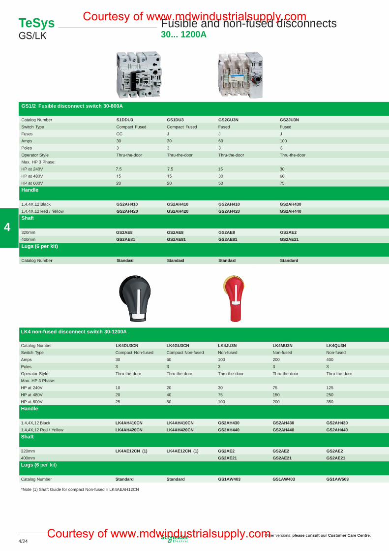
Other versions: please consult our Customer Care Centre.4/24
4
GS1/2 Fusible disconnect switch 30-800A
Catalog Number S1DDU3 GS1DU3 GS2GU3N GS2JU3N GS2MU3N GS2QU3N GS2SU3 GS2TU3Switch Type Compact Fused Compact Fused Fused Fuse used Fused Fused Fused
Fuses CC J J J J L
Amps 30 30 60
30
50
100 200 400 600 800
Poles 3 3 3 3 3 3 3
Operator Style Thru-the-door Thru-the-door Thru-the-door Thru-the-door Thru-the-door Thru-the-door Thru-the-door Thru-the-door
Max. HP 3 Phase:
HP at 240V 7.5 30 60 125 200 200
HP at 480V 60 125 250 400 500
HP at 600V
15
75 150 350 500 500
Handle
1,4,4X,12 Black GS2AH410 GS2AH410 GS2AH410 GS2AH430 GS2AH430 GS2AH430 GS2AH150 GS2AH1501,4,4X,12 Red / Yellow GS2AH420 GS2AH420 GS2AH420 GS2AH440 GS2AH440 GS2AH440 GS2AH160 GS2AH160Shaft
320mm GS2AE8 GS2AE2 GS2AE2 GS2AE2 GS2AE5 GS2AE5400mm GS2AE81 GS2AE81
GS2AE8GS2AE8GS2AE81 GS2AE21 GS2AE21 GS2AE21 GS2AE51 GS2AE51
Lugs (6 per kit)
Catalog Number Standard Standard Standard Standard GS1AW403 GS1AW503 GS1AW503 GS1AW503
LK4 non-fused disconnect switch 30-1200A
Catalog Number LK4DU3CN LK4GU3CN LK4JU3N LK4MU3N LK4QU3N LK4SU3N LK4TU3N LK4UU3N LK4WU3NSwitch Type Compact Non-fused Compact Non-fused Non-fused Non-fused Non-fused Non-fused Non-fused Non-fused Non-fused
Amps 30 60 100 200 400 600 800 1000 1200
Poles 3 3 3 3 3 3 3 3 3
Operator Style Thru-the-door Thru-the-door Thru-the-door Thru-the-door Thru-the-door Thru-the-door Thru-the-door Thru-the-door Thru-the-door
Max. HP 3 Phase:
HP at 240V 10 20 30 75 125 200 200 200 200
HP at 480V 20 40 75 150 250 400 500 500 500
HP at 600V 25 50 100 200 350 350 500 500 500
Handle
1,4,4X,12 Black LK4AH410CNLK4AH420CN
LK4AH410CN GS2AH430 GS2AH430 GS2AH430 GS2AH150 GS2AH170 GS2AH170 GS2AH1701,4,4X,12 Red / Yellow LK4AH420CN GS2AH440 GS2AH440 GS2AH440 GS2AH160 GS2AH180 GS2AH180 GS2AH180Shaft
320mm GS2AE2 GS2AE2 GS2AE2 GS2AE6 GS2AE6 GS2AE6 GS2AE6400mm
LK4AE12CN (1) LK4AE12CN (1)GS2AE21 GS2AE21 GS2AE21 GS2AE61 GS2AE61 GS2AE61 GS2AE61
Lugs (6 per kit)
Catalog Number Standard Standard GS1AW403 GS1AW403 GS1AW503 GS1AW503 GS1AW903 GS1AW903 GS1AW903
*Note (1) Shaft Guide for compact Non-fused = LK4AEAH12CN
Compact 30A SwitchLK4DU3
200A SwitchLK4MU3
200A SwitchGS2MU3
800A SwitchGS2TU3
TeSys GS/LK
Fusible and non-fused disconnects30... 1200A
24
GS1/2 Fusible disconnect switch 30-800A
Catalog Number S1DDU3 GS1DU3 GS2GU3N GS2JU3N GS2MU3N GS2QU3N GS2SU3 GS2TU3Switch Type Compact Fused Compact Fused Fused Fuse used Fused Fused Fused
Fuses CC J J J J L
Amps 30 30 60
30
50
100 200 400 600 800
Poles 3 3 3 3 3 3 3
Operator Style Thru-the-door Thru-the-door Thru-the-door Thru-the-door Thru-the-door Thru-the-door Thru-the-door Thru-the-door
Max. HP 3 Phase:
HP at 240V 7.5 30 60 125 200 200
HP at 480V 60 125 250 400 500
HP at 600V
15
75 150 350 500 500
Handle
1,4,4X,12 Black GS2AH410 GS2AH410 GS2AH410 GS2AH430 GS2AH430 GS2AH430 GS2AH150 GS2AH1501,4,4X,12 Red / Yellow GS2AH420 GS2AH420 GS2AH420 GS2AH440 GS2AH440 GS2AH440 GS2AH160 GS2AH160Shaft
320mm GS2AE8 GS2AE2 GS2AE2 GS2AE2 GS2AE5 GS2AE5400mm GS2AE81 GS2AE81
GS2AE8GS2AE8GS2AE81 GS2AE21 GS2AE21 GS2AE21 GS2AE51 GS2AE51
Lugs (6 per kit)
Catalog Number Standard Standard Standard Standard GS1AW403 GS1AW503 GS1AW503 GS1AW503
LK4 non-fused disconnect switch 30-1200A
Catalog Number LK4DU3CN LK4GU3CN LK4JU3N LK4MU3N LK4QU3N LK4SU3N LK4TU3N LK4UU3N LK4WU3NSwitch Type Compact Non-fused Compact Non-fused Non-fused Non-fused Non-fused Non-fused Non-fused Non-fused Non-fused
Amps 30 60 100 200 400 600 800 1000 1200
Poles 3 3 3 3 3 3 3 3 3
Operator Style Thru-the-door Thru-the-door Thru-the-door Thru-the-door Thru-the-door Thru-the-door Thru-the-door Thru-the-door Thru-the-door
Max. HP 3 Phase:
HP at 240V 10 20 30 75 125 200 200 200 200
HP at 480V 20 40 75 150 250 400 500 500 500
HP at 600V 25 50 100 200 350 350 500 500 500
Handle
1,4,4X,12 Black LK4AH410CNLK4AH420CN
LK4AH410CN GS2AH430 GS2AH430 GS2AH430 GS2AH150 GS2AH170 GS2AH170 GS2AH1701,4,4X,12 Red / Yellow LK4AH420CN GS2AH440 GS2AH440 GS2AH440 GS2AH160 GS2AH180 GS2AH180 GS2AH180Shaft
320mm GS2AE2 GS2AE2 GS2AE2 GS2AE6 GS2AE6 GS2AE6 GS2AE6400mm
LK4AE12CN (1) LK4AE12CN (1)GS2AE21 GS2AE21 GS2AE21 GS2AE61 GS2AE61 GS2AE61 GS2AE61
Lugs (6 per kit)
Catalog Number Standard Standard GS1AW403 GS1AW403 GS1AW503 GS1AW503 GS1AW903 GS1AW903 GS1AW903
*Note (1) Shaft Guide for compact Non-fused = LK4AEAH12CN
Compact 30A SwitchLK4DU3
200A SwitchLK4MU3
200A SwitchGS2MU3
800A SwitchGS2TU3
Other versions: Please consult our Customer Care Centre.
25
Courtesy of www.mdwindustrialsupply.com
Courtesy of www.mdwindustrialsupply.com
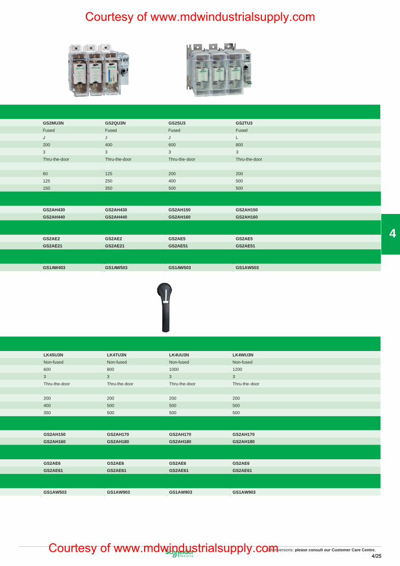
Other versions: please consult our Customer Care Centre.4/254/25
4
GS1/2 Fusible disconnect switch 30-800A
Catalog Number S1DDU3 GS1DU3 GS2GU3N GS2JU3N GS2MU3N GS2QU3N GS2SU3 GS2TU3Switch Type Compact Fused Compact Fused Fused Fuse used Fused Fused Fused
Fuses CC J J J J L
Amps 30 30 60
30
50
100 200 400 600 800
Poles 3 3 3 3 3 3 3
Operator Style Thru-the-door Thru-the-door Thru-the-door Thru-the-door Thru-the-door Thru-the-door Thru-the-door Thru-the-door
Max. HP 3 Phase:
HP at 240V 7.5 30 60 125 200 200
HP at 480V 60 125 250 400 500
HP at 600V
15
75 150 350 500 500
Handle
1,4,4X,12 Black GS2AH410 GS2AH410 GS2AH410 GS2AH430 GS2AH430 GS2AH430 GS2AH150 GS2AH1501,4,4X,12 Red / Yellow GS2AH420 GS2AH420 GS2AH420 GS2AH440 GS2AH440 GS2AH440 GS2AH160 GS2AH160Shaft
320mm GS2AE8 GS2AE2 GS2AE2 GS2AE2 GS2AE5 GS2AE5400mm GS2AE81 GS2AE81
GS2AE8GS2AE8GS2AE81 GS2AE21 GS2AE21 GS2AE21 GS2AE51 GS2AE51
Lugs (6 per kit)
Catalog Number Standard Standard Standard Standard GS1AW403 GS1AW503 GS1AW503 GS1AW503
LK4 non-fused disconnect switch 30-1200A
Catalog Number LK4DU3CN LK4GU3CN LK4JU3N LK4MU3N LK4QU3N LK4SU3N LK4TU3N LK4UU3N LK4WU3NSwitch Type Compact Non-fused Compact Non-fused Non-fused Non-fused Non-fused Non-fused Non-fused Non-fused Non-fused
Amps 30 60 100 200 400 600 800 1000 1200
Poles 3 3 3 3 3 3 3 3 3
Operator Style Thru-the-door Thru-the-door Thru-the-door Thru-the-door Thru-the-door Thru-the-door Thru-the-door Thru-the-door Thru-the-door
Max. HP 3 Phase:
HP at 240V 10 20 30 75 125 200 200 200 200
HP at 480V 20 40 75 150 250 400 500 500 500
HP at 600V 25 50 100 200 350 350 500 500 500
Handle
1,4,4X,12 Black LK4AH410CNLK4AH420CN
LK4AH410CN GS2AH430 GS2AH430 GS2AH430 GS2AH150 GS2AH170 GS2AH170 GS2AH1701,4,4X,12 Red / Yellow LK4AH420CN GS2AH440 GS2AH440 GS2AH440 GS2AH160 GS2AH180 GS2AH180 GS2AH180Shaft
320mm GS2AE2 GS2AE2 GS2AE2 GS2AE6 GS2AE6 GS2AE6 GS2AE6400mm
LK4AE12CN (1) LK4AE12CN (1)GS2AE21 GS2AE21 GS2AE21 GS2AE61 GS2AE61 GS2AE61 GS2AE61
Lugs (6 per kit)
Catalog Number Standard Standard GS1AW403 GS1AW403 GS1AW503 GS1AW503 GS1AW903 GS1AW903 GS1AW903
*Note (1) Shaft Guide for compact Non-fused = LK4AEAH12CN
Compact 30A SwitchLK4DU3
200A SwitchLK4MU3
200A SwitchGS2MU3
800A SwitchGS2TU3
TeSys GS/LK
Fusible and non-fused disconnects30... 1200A
24
GS1/2 Fusible disconnect switch 30-800A
Catalog Number S1DDU3 GS1DU3 GS2GU3N GS2JU3N GS2MU3N GS2QU3N GS2SU3 GS2TU3Switch Type Compact Fused Compact Fused Fused Fuse used Fused Fused Fused
Fuses CC J J J J L
Amps 30 30 60
30
50
100 200 400 600 800
Poles 3 3 3 3 3 3 3
Operator Style Thru-the-door Thru-the-door Thru-the-door Thru-the-door Thru-the-door Thru-the-door Thru-the-door Thru-the-door
Max. HP 3 Phase:
HP at 240V 7.5 30 60 125 200 200
HP at 480V 60 125 250 400 500
HP at 600V
15
75 150 350 500 500
Handle
1,4,4X,12 Black GS2AH410 GS2AH410 GS2AH410 GS2AH430 GS2AH430 GS2AH430 GS2AH150 GS2AH1501,4,4X,12 Red / Yellow GS2AH420 GS2AH420 GS2AH420 GS2AH440 GS2AH440 GS2AH440 GS2AH160 GS2AH160Shaft
320mm GS2AE8 GS2AE2 GS2AE2 GS2AE2 GS2AE5 GS2AE5400mm GS2AE81 GS2AE81
GS2AE8GS2AE8GS2AE81 GS2AE21 GS2AE21 GS2AE21 GS2AE51 GS2AE51
Lugs (6 per kit)
Catalog Number Standard Standard Standard Standard GS1AW403 GS1AW503 GS1AW503 GS1AW503
LK4 non-fused disconnect switch 30-1200A
Catalog Number LK4DU3CN LK4GU3CN LK4JU3N LK4MU3N LK4QU3N LK4SU3N LK4TU3N LK4UU3N LK4WU3NSwitch Type Compact Non-fused Compact Non-fused Non-fused Non-fused Non-fused Non-fused Non-fused Non-fused Non-fused
Amps 30 60 100 200 400 600 800 1000 1200
Poles 3 3 3 3 3 3 3 3 3
Operator Style Thru-the-door Thru-the-door Thru-the-door Thru-the-door Thru-the-door Thru-the-door Thru-the-door Thru-the-door Thru-the-door
Max. HP 3 Phase:
HP at 240V 10 20 30 75 125 200 200 200 200
HP at 480V 20 40 75 150 250 400 500 500 500
HP at 600V 25 50 100 200 350 350 500 500 500
Handle
1,4,4X,12 Black LK4AH410CNLK4AH420CN
LK4AH410CN GS2AH430 GS2AH430 GS2AH430 GS2AH150 GS2AH170 GS2AH170 GS2AH1701,4,4X,12 Red / Yellow LK4AH420CN GS2AH440 GS2AH440 GS2AH440 GS2AH160 GS2AH180 GS2AH180 GS2AH180Shaft
320mm GS2AE2 GS2AE2 GS2AE2 GS2AE6 GS2AE6 GS2AE6 GS2AE6400mm
LK4AE12CN (1) LK4AE12CN (1)GS2AE21 GS2AE21 GS2AE21 GS2AE61 GS2AE61 GS2AE61 GS2AE61
Lugs (6 per kit)
Catalog Number Standard Standard GS1AW403 GS1AW403 GS1AW503 GS1AW503 GS1AW903 GS1AW903 GS1AW903
*Note (1) Shaft Guide for compact Non-fused = LK4AEAH12CN
Compact 30A SwitchLK4DU3
200A SwitchLK4MU3
200A SwitchGS2MU3
800A SwitchGS2TU3
Other versions: Please consult our Customer Care Centre.
25
Courtesy of www.mdwindustrialsupply.com
Courtesy of www.mdwindustrialsupply.com
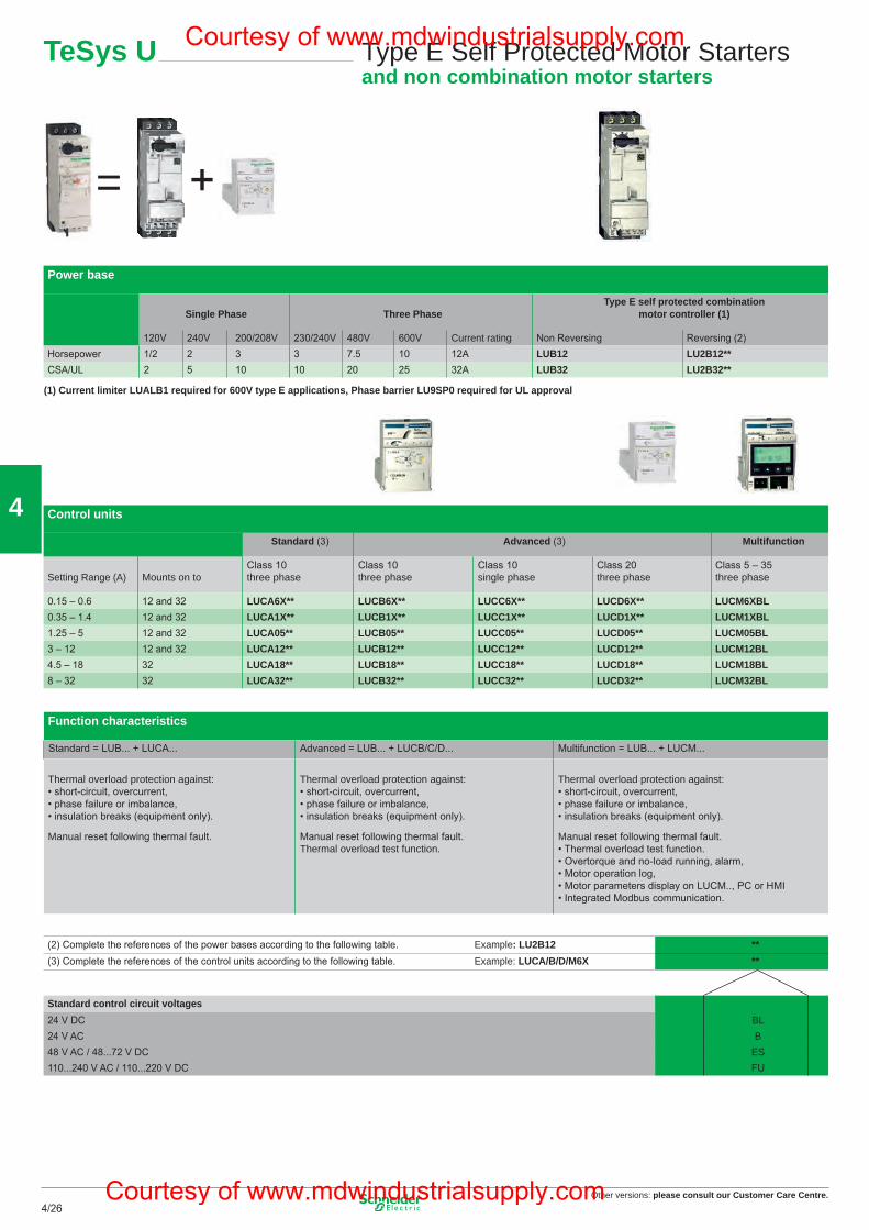
Other versions: please consult our Customer Care Centre.4/26
4
Standard control circuit voltages24 V DC BL24 V AC B48 V AC / 48...72 V DC ES110...240 V AC / 110...220 V DC FU
(2) Complete the references of the power bases according to the following table. Example: LU2B12 **(3) Complete the references of the control units according to the following table. Example: LUCA/B/D/M6X **
Function characteristics
Standard = LUB... + LUCA... Advanced = LUB... + LUCB/C/D... Multifunction = LUB... + LUCM...
Thermal overload protection against: • short-circuit, overcurrent, • phase failure or imbalance, • insulation breaks (equipment only).
Manual reset following thermal fault.
Thermal overload protection against: • short-circuit, overcurrent, • phase failure or imbalance, • insulation breaks (equipment only).
Manual reset following thermal fault. Thermal overload test function.
Thermal overload protection against: • short-circuit, overcurrent, • phase failure or imbalance, • insulation breaks (equipment only).
Manual reset following thermal fault. • Thermal overload test function. • Overtorque and no-load running, alarm, • Motor operation log, • Motor parameters display on LUCM.., PC or HMI • Integrated Modbus communication.
Control units
Standard (3) Advanced (3) Multifunction
Setting Range (A) Mounts on toClass 10three phase
Class 10three phase
Class 10single phase
Class 20three phase
Class 5 – 35three phase
0.15 – 0.6 12 and 32 LUCA6X** LUCB6X** LUCC6X** LUCD6X** LUCM6XBL0.35 – 1.4 12 and 32 LUCA1X** LUCB1X** LUCC1X** LUCD1X** LUCM1XBL1.25 – 5 12 and 32 LUCA05** LUCB05** LUCC05** LUCD05** LUCM05BL3 – 12 12 and 32 LUCA12** LUCB12** LUCC12** LUCD12** LUCM12BL4.5 – 18 32 LUCA18** LUCB18** LUCC18** LUCD18** LUCM18BL8 – 32 32 LUCA32** LUCB32** LUCC32** LUCD32** LUCM32BL
Power base
Single Phase Three PhaseType E self protected combination
motor controller (1)
120V 240V 200/208V 230/240V 480V 600V Current rating Non Reversing Reversing (2)Horsepower 1/2 2 3 3 7.5 10 12A LUB12 LU2B12**CSA/UL 2 5 10 10 20 25 32A LUB32 LU2B32**
TeSys U Type E Self Protected Motor Startersand non combination motor starters
(1) Current limiter LUALB1 required for 600V type E applications, Phase barrier LU9SP0 required for UL approval
= +
26
Courtesy of www.mdwindustrialsupply.com
Courtesy of www.mdwindustrialsupply.com
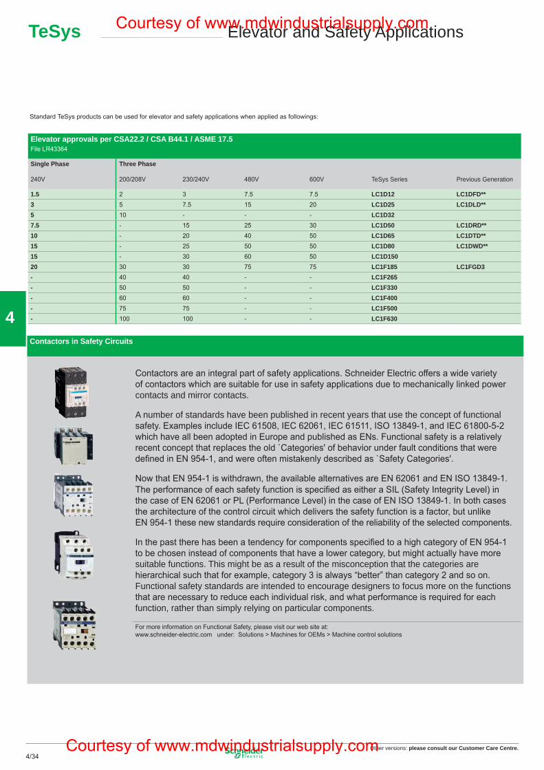
Other versions: please consult our Customer Care Centre.4/34
4Contactors in Safety Circuits
Contactors are an integral part of safety applications. Schneider Electric offers a wide variety of contactors which are suitable for use in safety applications due to mechanically linked power contacts and mirror contacts.
A number of standards have been published in recent years that use the concept of functional safety. Examples include IEC 61508, IEC 62061, IEC 61511, ISO 13849-1, and IEC 61800-5-2 which have all been adopted in Europe and published as ENs. Functional safety is a relatively recent concept that replaces the old `Categories' of behavior under fault conditions that were defi ned in EN 954-1, and were often mistakenly described as `Safety Categories'.
Now that EN 954-1 is withdrawn, the available alternatives are EN 62061 and EN ISO 13849-1.The performance of each safety function is specifi ed as either a SIL (Safety Integrity Level) in the case of EN 62061 or PL (Performance Level) in the case of EN ISO 13849-1. In both cases the architecture of the control circuit which delivers the safety function is a factor, but unlike EN 954-1 these new standards require consideration of the reliability of the selected components.
In the past there has been a tendency for components specifi ed to a high category of EN 954-1 to be chosen instead of components that have a lower category, but might actually have more suitable functions. This might be as a result of the misconception that the categories are hierarchical such that for example, category 3 is always “better” than category 2 and so on. Functional safety standards are intended to encourage designers to focus more on the functions that are necessary to reduce each individual risk, and what performance is required for each function, rather than simply relying on particular components.
For more information on Functional Safety, please visit our web site at: www.schneider-electric.com under: Solutions > Machines for OEMs > Machine control solutions
Elevator approvals per CSA22.2 / CSA B44.1 / ASME 17.5File LR43364
Single Phase
240V
Three Phase
200/208V 230/240V 480V 600V TeSys Series Previous Generation
1.5 2 3 7.5 7.5 LC1D12 LC1DFD**3 5 7.5 15 20 LC1D25 LC1DLD**5 10 - - - LC1D327.5 - 15 25 30 LC1D50 LC1DRD**10 - 20 40 50 LC1D65 LC1DTD**15 - 25 50 50 LC1D80 LC1DWD**15 - 30 60 50 LC1D15020 30 30 75 75 LC1F185 LC1FGD3- 40 40 - - LC1F265- 50 50 - - LC1F330- 60 60 - - LC1F400- 75 75 - - LC1F500- 100 100 - - LC1F630
TeSys Elevator and Safety Applications
Standard TeSys products can be used for elevator and safety applications when applied as followings:
34
Combination Starters – Type E & Type F
UL508A & Control Panels
Group Protection
TeSys Applications InformationGroup Motor and Type E
Combination Starters are the most common type of packaged motor starter. They are called ‘Combination’ because of their structure and their combined functions. The fi gure opposite shows the four combined functions that constitute a complete motor starter circuit, defi ned as a “Motor branch circuit” by the CEC and NEC. CSA 22.2 no 14 and UL508 currently give different types of combination starter that meet the requirements of a «Motor branch circuit».
Type E, called “self-protected combination starter”, covers all these functions and can be controlled manually (thermal-magnetic circuit-breaker) or remotely (starter-controller). Type E starters withstand faults within their declared nominal rating without sustaining damage, after which they can be put back into service. In addition, they can withstand more severe short-circuit and durability performance tests without welding or excessive wear of the contact tips.
Type F, called “Combination motor starter”, consists of a type E manual starter (thermal-magnetic circuit-breaker) combined with a contactor. These starters are evaluated by means of basic short-circuit tests, but are not considered as “self-protected”. For this combination, the type E starter must be marked “Combination Motor Controller when used with ...”, followed by the reference of the load side contactor.
At present, CSA does not recognize Type F combinations. Manual starters used with contactors can be used in Group Protection as described below.
To help users properly coordinate their motor control equipment with their distribution system in the event of a fault, article 409 of the 2005 NEC requires panel builders to list the short-circuit withstand rating of their motor control panels. According to standard UL508A, manufacturers must use the short-circuit withstand value of the lowest rated device as the nominal withstand rating of the panel, unless the devices have been tested together for a higher coordinated rating. The minimum “short-circuit current rating” (SCCR), on motor control components for horsepower ratings of 50 hp or below is 5000 A. Using a type E or type F combination starter eliminates the coordination problems of using individual components for the “motor branch circuit protection”, “motor controller” and “motor overload protection” functions. The panel builder uses the declared short-circuit current rating for the combination starter. This value is generally higher than 5000 A. This makes it easier to list the short-circuit current ratings and to check the compatibility of a UL508A motor control panel within a given distribution system.
1 Motor disconnect (disconnect switch) 2 Motor Branch Circuit Protection (short circuit protection) 3 Motor controller (contactor) 4 Motor Overload Protection (thermal overload relay)
Both the CEC and NEC allow a single short-circuit protection device to be used for more than one motor circuit if the components used are marked and listed for such use. Components suitable for use in group protection, known as “motor group installations”, can be marked in one of the following two ways: Case n° 1 The contactor and the motor overload relay are both listed as suitable for group installation. An inverse time circuit-breaker can be used as the short-circuit protection device if it is also listed as suitable for group installation. The panel builder must therefore make sure that the short-circuit protection device selected (fuses or inverse time circuit-breaker) does not exceed the value allowed by rule 28-206 of the CEC or article 430.40 of the NEC for the smallest overload relay used in the circuit. Once these conditions have been met, the panel buil-der can reduce the size of the conductor connecting the short-circuit protection device to the individual motor contactor/overload relay, to one third of the size of the upstream circuit conductor supplying the protection device. The panel builder must limit the length of the motor starter conductor (connecting the short-circuit protection device to the motor contactor/overload relay) to a maximum of 7.5 m (25 feet). Case n° 2 (Not approved under the CEC for US export applications only) The motor contactor and overload relay are listed as suitable for “tap conductor protection” in group installations. This category allows the panel designer to reduce the size of the conductor connecting the short-circuit protection device to the individual motor contactor/overload relay, to one tenth of the size of the upstream circuit conductor supplying the protection device. The designer must limit the length of this conductor to a maximum of 3.05 m (10 feet). In both cases, the supply circuits must not be less than 125 % of the connec-ted motor FLA (Full Load Amps) rating. For panel builders, using type F combination starters in group installations simplifi es group motor considerations. Each starter is a fully coordinated motor branch circuit. The panel builder follows the same NEC requirements for sizing the supply conductors as those required for single motor branch circuits. The size of the supply conductors can be reduced in accor-dance with the specifi cations of article 430.28. This allows the same fl exibility in conductor sizing as that offered in article 430.53 (D), without a requirement to check the short-circuit protection rating marked on the components and the overload relay limit. A UL508A panel does not need a short-circuit protection device when each motor starter installed is a type F. The upstream short-circuit protection device supplying the starter protects the panel. The panel builder only has to consider the panel/enclosure disconnect requirements specifi ed by the NEC or local codes.
M
1
2
3
4
Other versions: Please consult our Customer Care Centre.
35
Courtesy of www.mdwindustrialsupply.com
Courtesy of www.mdwindustrialsupply.com
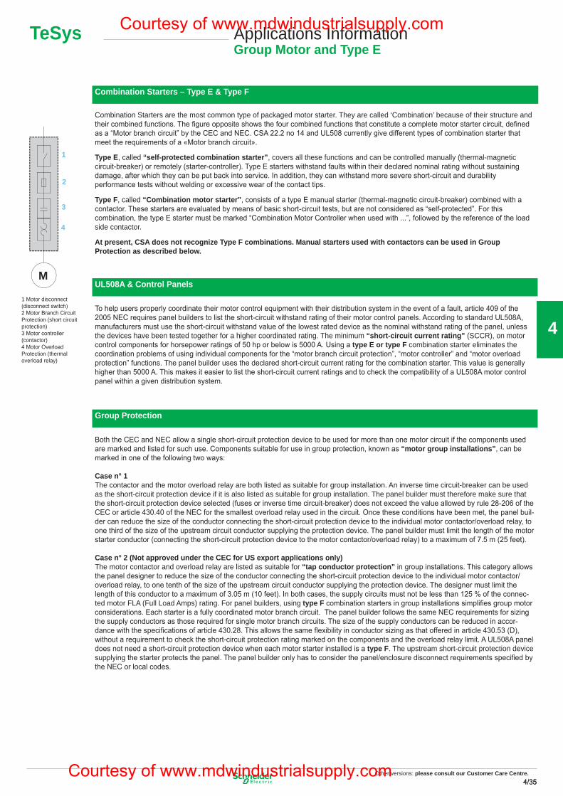
Other versions: please consult our Customer Care Centre.4/354/35
4
Combination Starters – Type E & Type F
UL508A & Control Panels
Group Protection
TeSys Applications InformationGroup Motor and Type E
Combination Starters are the most common type of packaged motor starter. They are called ‘Combination’ because of their structure and their combined functions. The fi gure opposite shows the four combined functions that constitute a complete motor starter circuit, defi ned as a “Motor branch circuit” by the CEC and NEC. CSA 22.2 no 14 and UL508 currently give different types of combination starter that meet the requirements of a «Motor branch circuit».
Type E, called “self-protected combination starter”, covers all these functions and can be controlled manually (thermal-magnetic circuit-breaker) or remotely (starter-controller). Type E starters withstand faults within their declared nominal rating without sustaining damage, after which they can be put back into service. In addition, they can withstand more severe short-circuit and durability performance tests without welding or excessive wear of the contact tips.
Type F, called “Combination motor starter”, consists of a type E manual starter (thermal-magnetic circuit-breaker) combined with a contactor. These starters are evaluated by means of basic short-circuit tests, but are not considered as “self-protected”. For this combination, the type E starter must be marked “Combination Motor Controller when used with ...”, followed by the reference of the load side contactor.
At present, CSA does not recognize Type F combinations. Manual starters used with contactors can be used in Group Protection as described below.
To help users properly coordinate their motor control equipment with their distribution system in the event of a fault, article 409 of the 2005 NEC requires panel builders to list the short-circuit withstand rating of their motor control panels. According to standard UL508A, manufacturers must use the short-circuit withstand value of the lowest rated device as the nominal withstand rating of the panel, unless the devices have been tested together for a higher coordinated rating. The minimum “short-circuit current rating” (SCCR), on motor control components for horsepower ratings of 50 hp or below is 5000 A. Using a type E or type F combination starter eliminates the coordination problems of using individual components for the “motor branch circuit protection”, “motor controller” and “motor overload protection” functions. The panel builder uses the declared short-circuit current rating for the combination starter. This value is generally higher than 5000 A. This makes it easier to list the short-circuit current ratings and to check the compatibility of a UL508A motor control panel within a given distribution system.
1 Motor disconnect (disconnect switch) 2 Motor Branch Circuit Protection (short circuit protection) 3 Motor controller (contactor) 4 Motor Overload Protection (thermal overload relay)
Both the CEC and NEC allow a single short-circuit protection device to be used for more than one motor circuit if the components used are marked and listed for such use. Components suitable for use in group protection, known as “motor group installations”, can be marked in one of the following two ways: Case n° 1 The contactor and the motor overload relay are both listed as suitable for group installation. An inverse time circuit-breaker can be used as the short-circuit protection device if it is also listed as suitable for group installation. The panel builder must therefore make sure that the short-circuit protection device selected (fuses or inverse time circuit-breaker) does not exceed the value allowed by rule 28-206 of the CEC or article 430.40 of the NEC for the smallest overload relay used in the circuit. Once these conditions have been met, the panel buil-der can reduce the size of the conductor connecting the short-circuit protection device to the individual motor contactor/overload relay, to one third of the size of the upstream circuit conductor supplying the protection device. The panel builder must limit the length of the motor starter conductor (connecting the short-circuit protection device to the motor contactor/overload relay) to a maximum of 7.5 m (25 feet). Case n° 2 (Not approved under the CEC for US export applications only) The motor contactor and overload relay are listed as suitable for “tap conductor protection” in group installations. This category allows the panel designer to reduce the size of the conductor connecting the short-circuit protection device to the individual motor contactor/overload relay, to one tenth of the size of the upstream circuit conductor supplying the protection device. The designer must limit the length of this conductor to a maximum of 3.05 m (10 feet). In both cases, the supply circuits must not be less than 125 % of the connec-ted motor FLA (Full Load Amps) rating. For panel builders, using type F combination starters in group installations simplifi es group motor considerations. Each starter is a fully coordinated motor branch circuit. The panel builder follows the same NEC requirements for sizing the supply conductors as those required for single motor branch circuits. The size of the supply conductors can be reduced in accor-dance with the specifi cations of article 430.28. This allows the same fl exibility in conductor sizing as that offered in article 430.53 (D), without a requirement to check the short-circuit protection rating marked on the components and the overload relay limit. A UL508A panel does not need a short-circuit protection device when each motor starter installed is a type F. The upstream short-circuit protection device supplying the starter protects the panel. The panel builder only has to consider the panel/enclosure disconnect requirements specifi ed by the NEC or local codes.
M
1
2
3
4
Other versions: Please consult our Customer Care Centre.
35
Courtesy of www.mdwindustrialsupply.com
Courtesy of www.mdwindustrialsupply.com
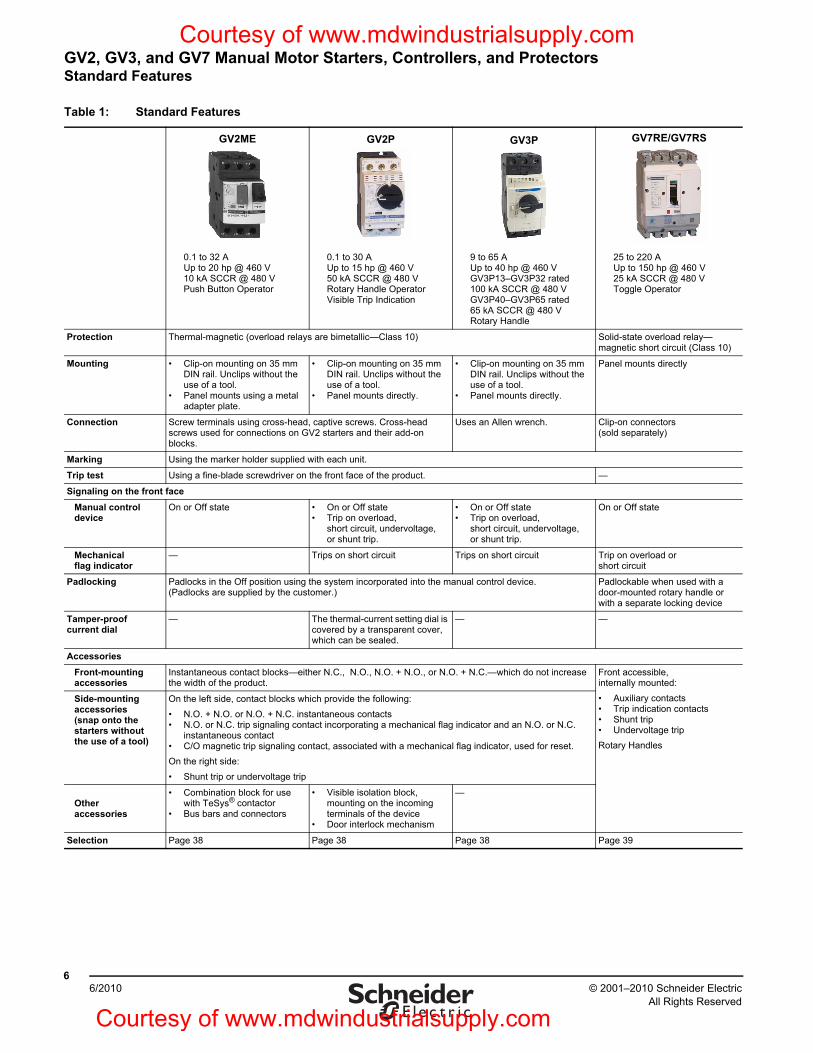
© 2001–2010 Schneider ElectricAll Rights Reserved
GV2, GV3, and GV7 Manual Motor Starters, Controllers, and ProtectorsStandard Features
66/2010
Table 1: Standard Features
GV2ME GV2P GV3P GV7RE/GV7RS
0.1 to 32 AUp to 20 hp @ 460 V10 kA SCCR @ 480 VPush Button Operator
0.1 to 30 AUp to 15 hp @ 460 V50 kA SCCR @ 480 VRotary Handle OperatorVisible Trip Indication
9 to 65 AUp to 40 hp @ 460 VGV3P13–GV3P32 rated 100 kA SCCR @ 480 VGV3P40–GV3P65 rated 65 kA SCCR @ 480 VRotary Handle
25 to 220 AUp to 150 hp @ 460 V25 kA SCCR @ 480 VToggle Operator
Protection Thermal-magnetic (overload relays are bimetallic—Class 10) Solid-state overload relay—magnetic short circuit (Class 10)
Mounting • Clip-on mounting on 35 mm DIN rail. Unclips without the use of a tool.
• Panel mounts using a metal adapter plate.
• Clip-on mounting on 35 mm DIN rail. Unclips without the use of a tool.
• Panel mounts directly.
• Clip-on mounting on 35 mm DIN rail. Unclips without the use of a tool.
• Panel mounts directly.
Panel mounts directly
Connection Screw terminals using cross-head, captive screws. Cross-head screws used for connections on GV2 starters and their add-on blocks.
Uses an Allen wrench. Clip-on connectors (sold separately)
Marking Using the marker holder supplied with each unit.
Trip test Using a fine-blade screwdriver on the front face of the product. —
Signaling on the front faceManual control device
On or Off state • On or Off state• Trip on overload,
short circuit, undervoltage, or shunt trip.
• On or Off state• Trip on overload,
short circuit, undervoltage, or shunt trip.
On or Off state
Mechanical flag indicator
— Trips on short circuit Trips on short circuit Trip on overload or short circuit
Padlocking Padlocks in the Off position using the system incorporated into the manual control device. (Padlocks are supplied by the customer.)
Padlockable when used with a door-mounted rotary handle or with a separate locking device
Tamper-proof current dial
— The thermal-current setting dial is covered by a transparent cover, which can be sealed.
— —
AccessoriesFront-mounting accessories
Instantaneous contact blocks—either N.C., N.O., N.O. + N.O., or N.O. + N.C.—which do not increase the width of the product.
Front accessible, internally mounted:• Auxiliary contacts• Trip indication contacts• Shunt trip• Undervoltage tripRotary Handles
Side-mounting accessories (snap onto the starters without the use of a tool)
On the left side, contact blocks which provide the following:• N.O. + N.O. or N.O. + N.C. instantaneous contacts• N.O. or N.C. trip signaling contact incorporating a mechanical flag indicator and an N.O. or N.C.
instantaneous contact• C/O magnetic trip signaling contact, associated with a mechanical flag indicator, used for reset.On the right side:• Shunt trip or undervoltage trip
Other accessories
• Combination block for use with TeSys® contactor
• Bus bars and connectors
• Visible isolation block, mounting on the incoming terminals of the device
• Door interlock mechanism
—
Selection Page 38 Page 38 Page 38 Page 39
Courtesy of www.mdwindustrialsupply.com
Courtesy of www.mdwindustrialsupply.com
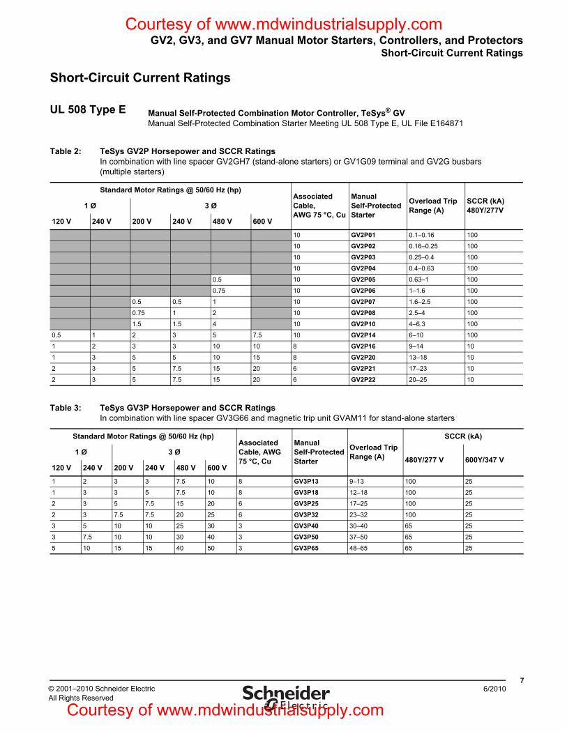
GV2, GV3, and GV7 Manual Motor Starters, Controllers, and ProtectorsShort-Circuit Current Ratings
76/2010© 2001–2010 Schneider Electric
All Rights Reserved
Short-Circuit Current Ratings
UL 508 Type E Manual Self-Protected Combination Motor Controller, TeSys® GVManual Self-Protected Combination Starter Meeting UL 508 Type E, UL File E164871
Table 2: TeSys GV2P Horsepower and SCCR RatingsIn combination with line spacer GV2GH7 (stand-alone starters) or GV1G09 terminal and GV2G busbars (multiple starters)
Standard Motor Ratings @ 50/60 Hz (hp)Associated Cable, AWG 75 °C, Cu
Manual Self-Protected Starter
Overload Trip Range (A)
SCCR (kA) 480Y/277V1 Ø 3 Ø
120 V 240 V 200 V 240 V 480 V 600 V
10 GV2P01 0.1–0.16 100
10 GV2P02 0.16–0.25 100
10 GV2P03 0.25–0.4 100
10 GV2P04 0.4–0.63 100
0.5 10 GV2P05 0.63–1 100
0.75 10 GV2P06 1–1.6 100
0.5 0.5 1 10 GV2P07 1.6–2.5 100
0.75 1 2 10 GV2P08 2.5–4 100
1.5 1.5 4 10 GV2P10 4–6.3 100
0.5 1 2 3 5 7.5 10 GV2P14 6–10 100
1 2 3 3 10 10 8 GV2P16 9–14 10
1 3 5 5 10 15 8 GV2P20 13–18 10
2 3 5 7.5 15 20 6 GV2P21 17–23 10
2 3 5 7.5 15 20 6 GV2P22 20–25 10
Table 3: TeSys GV3P Horsepower and SCCR RatingsIn combination with line spacer GV3G66 and magnetic trip unit GVAM11 for stand-alone starters
Standard Motor Ratings @ 50/60 Hz (hp)Associated Cable, AWG 75 °C, Cu
Manual Self-Protected Starter
Overload Trip Range (A)
SCCR (kA)
1 Ø 3 Ø480Y/277 V 600Y/347 V
120 V 240 V 200 V 240 V 480 V 600 V
1 2 3 3 7.5 10 8 GV3P13 9–13 100 25
1 3 3 5 7.5 10 8 GV3P18 12–18 100 25
2 3 5 7.5 15 20 6 GV3P25 17–25 100 25
2 3 7.5 7.5 20 25 6 GV3P32 23–32 100 25
3 5 10 10 25 30 3 GV3P40 30–40 65 25
3 7.5 10 10 30 40 3 GV3P50 37–50 65 25
5 10 15 15 40 50 3 GV3P65 48–65 65 25
Courtesy of www.mdwindustrialsupply.com
Courtesy of www.mdwindustrialsupply.com
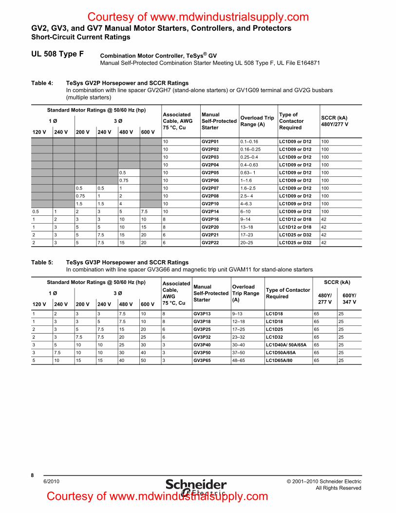
GV2, GV3, and GV7 Manual Motor Starters, Controllers, and ProtectorsShort-Circuit Current Ratings
© 2001–2010 Schneider ElectricAll Rights Reserved
86/2010
UL 508 Type F Combination Motor Controller, TeSys® GVManual Self-Protected Combination Starter Meeting UL 508 Type F, UL File E164871
Table 4: TeSys GV2P Horsepower and SCCR RatingsIn combination with line spacer GV2GH7 (stand-alone starters) or GV1G09 terminal and GV2G busbars (multiple starters)
Standard Motor Ratings @ 50/60 Hz (hp)Associated Cable, AWG 75 °C, Cu
Manual Self-Protected Starter
Overload Trip Range (A)
Type of Contactor Required
SCCR (kA)480Y/277 V1 Ø 3 Ø
120 V 240 V 200 V 240 V 480 V 600 V
10 GV2P01 0.1–0.16 LC1D09 or D12 100
10 GV2P02 0.16–0.25 LC1D09 or D12 100
10 GV2P03 0.25–0.4 LC1D09 or D12 100
10 GV2P04 0.4–0.63 LC1D09 or D12 100
0.5 10 GV2P05 0.63– 1 LC1D09 or D12 100
0.75 10 GV2P06 1–1.6 LC1D09 or D12 100
0.5 0.5 1 10 GV2P07 1.6–2.5 LC1D09 or D12 100
0.75 1 2 10 GV2P08 2.5– 4 LC1D09 or D12 100
1.5 1.5 4 10 GV2P10 4–6.3 LC1D09 or D12 100
0.5 1 2 3 5 7.5 10 GV2P14 6–10 LC1D09 or D12 100
1 2 3 3 10 10 8 GV2P16 9–14 LC1D12 or D18 42
1 3 5 5 10 15 8 GV2P20 13–18 LC1D12 or D18 42
2 3 5 7.5 15 20 6 GV2P21 17–23 LC1D25 or D32 42
2 3 5 7.5 15 20 6 GV2P22 20–25 LC1D25 or D32 42
Table 5: TeSys GV3P Horsepower and SCCR RatingsIn combination with line spacer GV3G66 and magnetic trip unit GVAM11 for stand-alone starters
Standard Motor Ratings @ 50/60 Hz (hp) Associated Cable, AWG 75 °C, Cu
Manual Self-Protected Starter
Overload Trip Range (A)
Type of Contactor Required
SCCR (kA)
1 Ø 3 Ø 480Y/277 V
600Y/347 V120 V 240 V 200 V 240 V 480 V 600 V
1 2 3 3 7.5 10 8 GV3P13 9–13 LC1D18 65 25
1 3 3 5 7.5 10 8 GV3P18 12–18 LC1D18 65 25
2 3 5 7.5 15 20 6 GV3P25 17–25 LC1D25 65 25
2 3 7.5 7.5 20 25 6 GV3P32 23–32 LC1D32 65 25
3 5 10 10 25 30 3 GV3P40 30–40 LC1D40A/ 50A/65A 65 25
3 7.5 10 10 30 40 3 GV3P50 37–50 LC1D50A/65A 65 25
5 10 15 15 40 50 3 GV3P65 48–65 LC1D65A/80 65 25
Courtesy of www.mdwindustrialsupply.com
Courtesy of www.mdwindustrialsupply.com
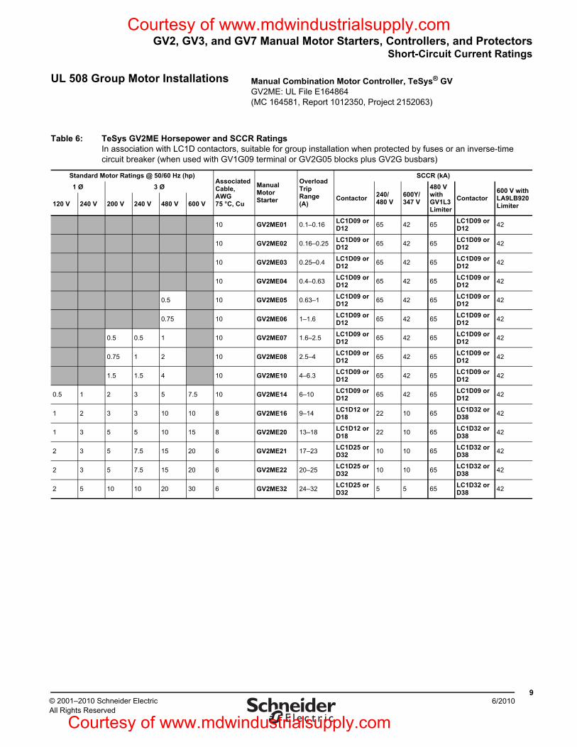
GV2, GV3, and GV7 Manual Motor Starters, Controllers, and ProtectorsShort-Circuit Current Ratings
96/2010© 2001–2010 Schneider Electric
All Rights Reserved
UL 508 Group Motor Installations Manual Combination Motor Controller, TeSys® GVGV2ME: UL File E164864(MC 164581, Report 1012350, Project 2152063)
Table 6: TeSys GV2ME Horsepower and SCCR RatingsIn association with LC1D contactors, suitable for group installation when protected by fuses or an inverse-time circuit breaker (when used with GV1G09 terminal or GV2G05 blocks plus GV2G busbars)
Standard Motor Ratings @ 50/60 Hz (hp)Associated Cable, AWG 75 °C, Cu
Manual Motor Starter
Overload Trip Range (A)
SCCR (kA)1 Ø 3 Ø
Contactor 240/480 V
600Y/347 V
480 V with GV1L3 Limiter
Contactor600 V with LA9LB920 Limiter120 V 240 V 200 V 240 V 480 V 600 V
10 GV2ME01 0.1–0.16 LC1D09 or D12 65 42 65 LC1D09 or
D12 42
10 GV2ME02 0.16–0.25 LC1D09 or D12 65 42 65 LC1D09 or
D12 42
10 GV2ME03 0.25–0.4 LC1D09 or D12 65 42 65 LC1D09 or
D12 42
10 GV2ME04 0.4–0.63 LC1D09 or D12 65 42 65 LC1D09 or
D12 42
0.5 10 GV2ME05 0.63–1 LC1D09 or D12 65 42 65 LC1D09 or
D12 42
0.75 10 GV2ME06 1–1.6 LC1D09 or D12 65 42 65 LC1D09 or
D12 42
0.5 0.5 1 10 GV2ME07 1.6–2.5 LC1D09 or D12 65 42 65 LC1D09 or
D12 42
0.75 1 2 10 GV2ME08 2.5–4 LC1D09 or D12 65 42 65 LC1D09 or
D12 42
1.5 1.5 4 10 GV2ME10 4–6.3 LC1D09 or D12 65 42 65 LC1D09 or
D12 42
0.5 1 2 3 5 7.5 10 GV2ME14 6–10 LC1D09 or D12 65 42 65 LC1D09 or
D12 42
1 2 3 3 10 10 8 GV2ME16 9–14 LC1D12 or D18 22 10 65 LC1D32 or
D38 42
1 3 5 5 10 15 8 GV2ME20 13–18 LC1D12 or D18 22 10 65 LC1D32 or
D38 42
2 3 5 7.5 15 20 6 GV2ME21 17–23 LC1D25 or D32 10 10 65 LC1D32 or
D38 42
2 3 5 7.5 15 20 6 GV2ME22 20–25 LC1D25 or D32 10 10 65 LC1D32 or
D38 42
2 5 10 10 20 30 6 GV2ME32 24–32 LC1D25 or D32 5 5 65 LC1D32 or
D38 42
Courtesy of www.mdwindustrialsupply.com
Courtesy of www.mdwindustrialsupply.com
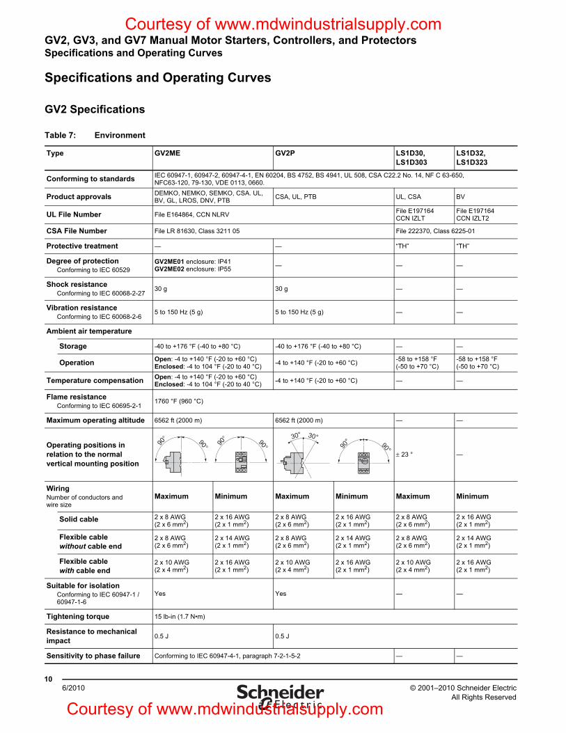
GV2, GV3, and GV7 Manual Motor Starters, Controllers, and ProtectorsSpecifications and Operating Curves
© 2001–2010 Schneider ElectricAll Rights Reserved
106/2010
Specifications and Operating Curves
GV2 Specifications
Table 7: Environment
Type GV2ME GV2P LS1D30, LS1D303
LS1D32, LS1D323
Conforming to standards IEC 60947-1, 60947-2, 60947-4-1, EN 60204, BS 4752, BS 4941, UL 508, CSA C22.2 No. 14, NF C 63-650, NFC63-120, 79-130, VDE 0113, 0660.
Product approvals DEMKO, NEMKO, SEMKO, CSA. UL, BV, GL, LROS, DNV, PTB CSA, UL, PTB UL, CSA BV
UL File Number File E164864, CCN NLRV File E197164CCN IZLT
File E197164CCN IZLT2
CSA File Number File LR 81630, Class 3211 05 File 222370, Class 6225-01
Protective treatment — — “TH” “TH”
Degree of protectionConforming to IEC 60529
GV2ME01 enclosure: IP41 GV2ME02 enclosure: IP55 — — —
Shock resistanceConforming to IEC 60068-2-27
30 g 30 g — —
Vibration resistanceConforming to IEC 60068-2-6
5 to 150 Hz (5 g) 5 to 150 Hz (5 g) — —
Ambient air temperature
Storage -40 to +176 °F (-40 to +80 °C) -40 to +176 °F (-40 to +80 °C) — —
Operation Open: -4 to +140 °F (-20 to +60 °C) Enclosed: -4 to 104 °F (-20 to 40 °C) -4 to +140 °F (-20 to +60 °C) -58 to +158 °F
(-50 to +70 °C)-58 to +158 °F (-50 to +70 °C)
Temperature compensation Open: -4 to +140 °F (-20 to +60 °C) Enclosed: -4 to 104 °F (-20 to 40 °C) -4 to +140 °F (-20 to +60 °C) — —
Flame resistanceConforming to IEC 60695-2-1
1760 °F (960 °C)
Maximum operating altitude 6562 ft (2000 m) 6562 ft (2000 m) — —
Operating positions in relation to the normal vertical mounting position
± 23 ° —
WiringNumber of conductors and wire size
Maximum Minimum Maximum Minimum Maximum Minimum
Solid cable 2 x 8 AWG(2 x 6 mm2)
2 x 16 AWG(2 x 1 mm2)
2 x 8 AWG(2 x 6 mm2)
2 x 16 AWG(2 x 1 mm2)
2 x 8 AWG(2 x 6 mm2)
2 x 16 AWG(2 x 1 mm2)
Flexible cable without cable end
2 x 8 AWG(2 x 6 mm2)
2 x 14 AWG(2 x 1 mm2)
2 x 8 AWG(2 x 6 mm2)
2 x 14 AWG(2 x 1 mm2)
2 x 8 AWG(2 x 6 mm2)
2 x 14 AWG(2 x 1 mm2)
Flexible cable with cable end
2 x 10 AWG(2 x 4 mm2)
2 x 16 AWG(2 x 1 mm2)
2 x 10 AWG(2 x 4 mm2)
2 x 16 AWG(2 x 1 mm2)
2 x 10 AWG(2 x 4 mm2)
2 x 16 AWG(2 x 1 mm2)
Suitable for isolationConforming to IEC 60947-1 / 60947-1-6
Yes Yes — —
Tightening torque 15 lb-in (1.7 N•m)
Resistance to mechanical impact 0.5 J 0.5 J
Sensitivity to phase failure Conforming to IEC 60947-4-1, paragraph 7-2-1-5-2 — —
90° 90° 90° 90°
90°90°
30°30°
Courtesy of www.mdwindustrialsupply.com
Courtesy of www.mdwindustrialsupply.com
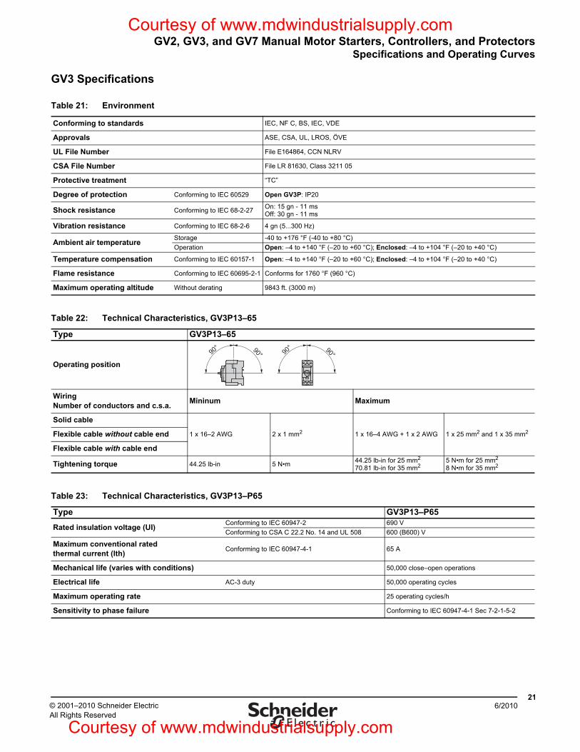
GV2, GV3, and GV7 Manual Motor Starters, Controllers, and ProtectorsSpecifications and Operating Curves
216/2010© 2001–2010 Schneider Electric
All Rights Reserved
GV3 Specifications
Table 21: Environment
Conforming to standards IEC, NF C, BS, IEC, VDE
Approvals ASE, CSA, UL, LROS, ÖVE
UL File Number File E164864, CCN NLRV
CSA File Number File LR 81630, Class 3211 05
Protective treatment “TC”
Degree of protection Conforming to IEC 60529 Open GV3P: IP20
Shock resistance Conforming to IEC 68-2-27 On: 15 gn - 11 msOff: 30 gn - 11 ms
Vibration resistance Conforming to IEC 68-2-6 4 gn (5...300 Hz)
Ambient air temperature Storage -40 to +176 °F (-40 to +80 °C)Operation Open: –4 to +140 °F (–20 to +60 °C); Enclosed: –4 to +104 °F (–20 to +40 °C)
Temperature compensation Conforming to IEC 60157-1 Open: –4 to +140 °F (–20 to +60 °C); Enclosed: –4 to +104 °F (–20 to +40 °C)
Flame resistance Conforming to IEC 60695-2-1 Conforms for 1760 °F (960 °C)
Maximum operating altitude Without derating 9843 ft. (3000 m)
Table 22: Technical Characteristics, GV3P13–65
Type GV3P13–65
Operating position
WiringNumber of conductors and c.s.a. Mininum Maximum
Solid cable
1 x 16–2 AWG 2 x 1 mm2 1 x 16–4 AWG + 1 x 2 AWG 1 x 25 mm2 and 1 x 35 mm2Flexible cable without cable end
Flexible cable with cable end
Tightening torque 44.25 lb-in 5 N•m 44.25 lb-in for 25 mm2
70.81 lb-in for 35 mm25 N•m for 25 mm2
8 N•m for 35 mm2
90° 90°90
° 90°
Table 23: Technical Characteristics, GV3P13–P65
Type GV3P13–P65
Rated insulation voltage (UI) Conforming to IEC 60947-2 690 VConforming to CSA C 22.2 No. 14 and UL 508 600 (B600) V
Maximum conventional ratedthermal current (lth) Conforming to IEC 60947-4-1 65 A
Mechanical life (varies with conditions) 50,000 close–open operations
Electrical life AC-3 duty 50,000 operating cycles
Maximum operating rate 25 operating cycles/h
Sensitivity to phase failure Conforming to IEC 60947-4-1 Sec 7-2-1-5-2
Courtesy of www.mdwindustrialsupply.com
Courtesy of www.mdwindustrialsupply.com
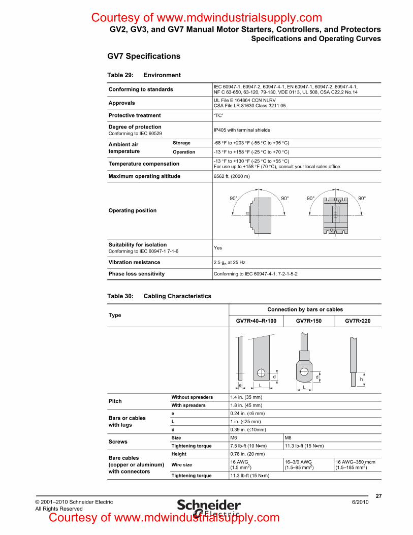
GV2, GV3, and GV7 Manual Motor Starters, Controllers, and ProtectorsSpecifications and Operating Curves
276/2010© 2001–2010 Schneider Electric
All Rights Reserved
GV7 Specifications
Table 29: Environment
Conforming to standards IEC 60947-1, 60947-2, 60947-4-1, EN 60947-1, 60947-2, 60947-4-1, NF C 63-650, 63-120, 79-130, VDE 0113, UL 508, CSA C22.2 No.14
Approvals UL File E 164864 CCN NLRVCSA File LR 81630 Class 3211 05
Protective treatment “TC”
Degree of protectionConforming to IEC 60529
IP405 with terminal shields
Ambient air temperature
Storage -68 °F to +203 °F (-55 °C to +95 °C)
Operation -13 °F to +158 °F (-25 °C to +70 °C)
Temperature compensation -13 °F to +130 °F (-25 °C to +55 °C) For use up to +158 °F (70 °C), consult your local sales office.
Maximum operating altitude 6562 ft. (2000 m)
Operating position
Suitability for isolationConforming to IEC 60947-1 7-1-6
Yes
Vibration resistance 2.5 gn at 25 Hz
Phase loss sensitivity Conforming to IEC 60947-4-1, 7-2-1-5-2
Table 30: Cabling Characteristics
TypeConnection by bars or cables
GV7R•40–R•100 GV7R•150 GV7R•220
PitchWithout spreaders 1.4 in. (35 mm)
With spreaders 1.8 in. (45 mm)
Bars or cables with lugs
e 0.24 in. (≤6 mm)
L 1 in. (≤25 mm)
d 0.39 in. (≤10mm)
ScrewsSize M6 M8
Tightening torque 7.5 lb-ft (10 N•m) 11.3 lb-ft (15 N•m)
Bare cables (copper or aluminum)with connectors
Height 0.78 in. (20 mm)
Wire size 16 AWG (1.5 mm2)
16–3/0 AWG(1.5–95 mm2)
16 AWG–350 mcm (1.5–185 mm2)
Tightening torque 11.3 lb-ft (15 N•m)
90° 90° 90° 90°
e L
d d
Lh
Courtesy of www.mdwindustrialsupply.com
Courtesy of www.mdwindustrialsupply.com
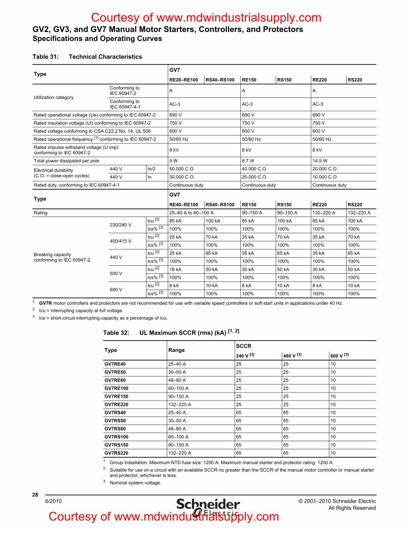
© 2001–2010 Schneider ElectricAll Rights Reserved
GV2, GV3, and GV7 Manual Motor Starters, Controllers, and ProtectorsSpecifications and Operating Curves
286/2010
Table 31: Technical Characteristics
TypeGV7
RE20–RE100 RS40–RS100 RE150 RS150 RE220 RS220
Utilization category
Conforming to IEC 60947-2 A A A
Conforming to IEC 60947-4-1 AC-3 AC-3 AC-3
Rated operational voltage (Ue) conforming to IEC 60947-2 690 V 690 V 690 V
Rated insulation voltage (Ui) conforming to IEC 60947-2 750 V 750 V 750 V
Rated voltage conforming to CSA C22.2 No. 14, UL 508 600 V 600 V 600 V
Rated operational frequency [1] conforming to IEC 60947-2 50/60 Hz 50/60 Hz 50/60 Hz
Rated impulse withstand voltage (U imp)conforming to IEC 60947-2 8 kV 8 kV 8 kV
Total power dissipated per pole 5 W 8.7 W 14.5 W
Electrical durability(C.O. = close-open cycles)
440 V In/2 50,000 C.O. 40,000 C.O. 20,000 C.O.
440 V In 30,000 C.O. 20,000 C.O. 10,000 C.O.
Rated duty, conforming to IEC 60947-4-1 Continuous duty Continuous duty Continuous duty
TypeGV7
RE40–RE100 RS40–RS100 RE150 RS150 RE220 RS220Rating 25–40 A to 60–100 A 90–150 A 90–150 A 132–220 A 132–220 A
Breaking capacity conforming to IEC 60947-2
230/240 VIcu [2] 85 kA 100 kA 85 kA 100 kA 85 kA 100 kA
Ics% [3] 100% 100% 100% 100% 100% 100%
400/415 VIcu [2] 25 kA 70 kA 35 kA 70 kA 35 kA 70 kA
Ics% [3] 100% 100% 100% 100% 100% 100%
440 VIcu [2] 25 kA 65 kA 35 kA 65 kA 35 kA 65 kA
Ics% [3] 100% 100% 100% 100% 100% 100%
500 VIcu [2] 18 kA 50 kA 30 kA 50 kA 30 kA 50 kA
Ics% [3] 100% 100% 100% 100% 100% 100%
690 VIcu [2] 8 kA 10 kA 8 kA 10 kA 8 kA 10 kA
Ics% [3] 100% 100% 100% 100% 100% 100%1 GV7R motor controllers and protectors are not recommended for use with variable speed controllers or soft start units in applications under 40 Hz.2 Icu = interrupting capacity at full voltage.3 Ics = short-circuit interrupting capacity as a percentage of Icu.
Table 32: UL Maximum SCCR (rms) (kA) [1, 2]
1 Group Installation: Maximum NTD fuse size: 1200 A. Maximum manual starter and protector rating: 1200 A.2 Suitable for use on a circuit with an available SCCR no greater than the SCCR of the manual motor controller or manual starter
and protector, whichever is less.
Type RangeSCCR
240 V [3]
3 Nominal system voltage.
480 V [3] 600 V [3]
GV7RE40 25–40 A 25 25 10
GV7RE50 30–50 A 25 25 10
GV7RE80 48–80 A 25 25 10
GV7RE100 60–100 A 25 25 10
GV7RE150 90–150 A 25 25 10
GV7RE220 132–220 A 25 25 10
GV7RS40 25–40 A 65 65 10
GV7RS50 30–50 A 65 65 10
GV7RS80 48–80 A 65 65 10
GV7RS100 60–100 A 65 65 10
GV7RS150 90–150 A 65 65 10
GV7RS220 132–220 A 65 65 10
Courtesy of www.mdwindustrialsupply.com
Courtesy of www.mdwindustrialsupply.com
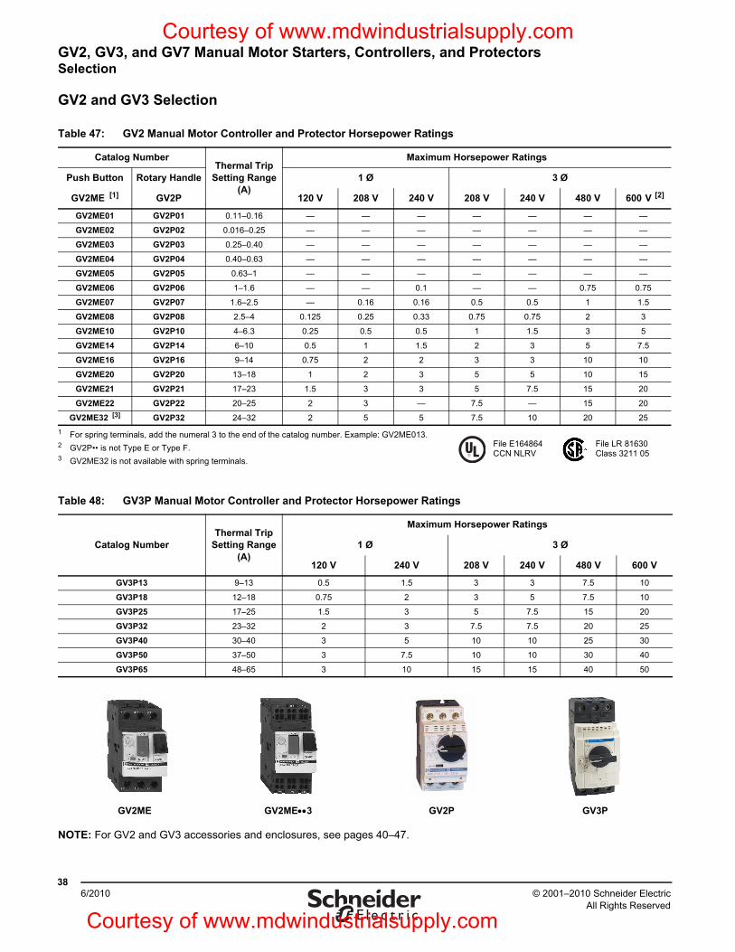
GV2, GV3, and GV7 Manual Motor Starters, Controllers, and ProtectorsSelection
© 2001–2010 Schneider ElectricAll Rights Reserved
386/2010
GV2 and GV3 Selection
NOTE: For GV2 and GV3 accessories and enclosures, see pages 40–47.
Table 47: GV2 Manual Motor Controller and Protector Horsepower Ratings
Catalog NumberThermal Trip
Setting Range (A)
Maximum Horsepower Ratings
Push Button Rotary Handle 1 Ø 3 Ø
GV2ME [1]
1 For spring terminals, add the numeral 3 to the end of the catalog number. Example: GV2ME013.
GV2P 120 V 208 V 240 V 208 V 240 V 480 V 600 V [2]
2 GV2P•• is not Type E or Type F.
GV2ME01 GV2P01 0.11–0.16 — — — — — — —
GV2ME02 GV2P02 0.016–0.25 — — — — — — —
GV2ME03 GV2P03 0.25–0.40 — — — — — — —
GV2ME04 GV2P04 0.40–0.63 — — — — — — —
GV2ME05 GV2P05 0.63–1 — — — — — — —
GV2ME06 GV2P06 1–1.6 — — 0.1 — — 0.75 0.75
GV2ME07 GV2P07 1.6–2.5 — 0.16 0.16 0.5 0.5 1 1.5
GV2ME08 GV2P08 2.5–4 0.125 0.25 0.33 0.75 0.75 2 3
GV2ME10 GV2P10 4–6.3 0.25 0.5 0.5 1 1.5 3 5
GV2ME14 GV2P14 6–10 0.5 1 1.5 2 3 5 7.5
GV2ME16 GV2P16 9–14 0.75 2 2 3 3 10 10
GV2ME20 GV2P20 13–18 1 2 3 5 5 10 15
GV2ME21 GV2P21 17–23 1.5 3 3 5 7.5 15 20
GV2ME22 GV2P22 20–25 2 3 — 7.5 — 15 20
GV2ME32 [3]
3 GV2ME32 is not available with spring terminals.
GV2P32 24–32 2 5 5 7.5 10 20 25
File LR 81630Class 3211 05
File E164864CCN NLRV
Table 48: GV3P Manual Motor Controller and Protector Horsepower Ratings
Catalog NumberThermal Trip
Setting Range (A)
Maximum Horsepower Ratings
1 Ø 3 Ø
120 V 240 V 208 V 240 V 480 V 600 V
GV3P13 9–13 0.5 1.5 3 3 7.5 10
GV3P18 12–18 0.75 2 3 5 7.5 10
GV3P25 17–25 1.5 3 5 7.5 15 20
GV3P32 23–32 2 3 7.5 7.5 20 25
GV3P40 30–40 3 5 10 10 25 30
GV3P50 37–50 3 7.5 10 10 30 40
GV3P65 48–65 3 10 15 15 40 50
GV2ME GV2ME••3 GV2P GV3P
Courtesy of www.mdwindustrialsupply.com
Courtesy of www.mdwindustrialsupply.com
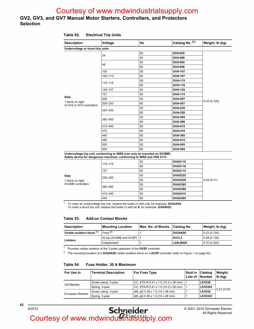
© 2001–2010 Schneider ElectricAll Rights Reserved
GV2, GV3, and GV7 Manual Motor Starters, Controllers, and ProtectorsSelection
426/2010
Table 52: Electrical Trip Units
Description Voltage Hz Catalog No. [1]
1 To order an undervoltage trip unit: replace the bullet (•) with a U, for example: GVAU025. To order a shunt trip unit: replace the bullet (•) with an S, for example: GVAS025.
Weight, lb (kg)Undervoltage or shunt trip units
Side1 block on rightof GV2 or GV3 controllers
2450 GVA•025
0.23 (0.105)
60 GVA•026
4850 GVA•05560 GVA•056
100 50 GVA•107100–110 60 GVA•107
110–11550 GVA•11560 GVA•116
120–127 50 GVA•125127 60 GVA•115200 50 GVA•207200–220 60 GVA•207
220–24050 GVA•22560 GVA•226
380–40050 GVA•38560 GVA•386
415–440 50 GVA•415415 60 GVA•416440 60 GVA•385480 60 GVA•415500 50 GVA•505600 60 GVA•505
Undervoltage trip unit, conforming to INRS (can only be mounted on GV2ME)Safety device for dangerous machines, conforming to INRS and VDE 0113
Side1 block on rightGV2ME controllers
110–11550 GVAX115
0.24 (0.11)
60 GVAX116127 60 GVAX115
220–24050 GVAX22560 GVAX226
380–40050 GVAX38560 GVAX386
415–440 50 GVAX415440 60 GVAX385
Table 53: Add-on Contact Blocks
Description Mounting Location Max. No. of Blocks Catalog No. Weight, lb (kg)
Visible isolation block [1]
1 Provides visible isolation of the 3 poles upstream of the GV2P controller.
Front [2]
2 The mounting location of a GV2AK00 visible isolation block on a GV2P controller (refer to Figure 1 on page 40).
1 GV2AK00 0.33 (0.150)
LimitersAt top (GV2ME and GV2P) 1 GV1L3 0.29 (0.130)
Independent 1 LA9LB920 0.70 (0.320)
Table 54: Fuse Holder, 30 A Maximum
For Use In Terminal Description For Fuse Type Sold in Lots of
Catalog Number
Weight, lb (kg)
US MarketsScrew clamp, 3-pole CC, KTK-R 0.41 x 1.5 (10.3 x 38 mm) 1 LS1D30
0.23 (0.50)Spring, 3-pole CC, KTK-R 0.41 x 1.5 (10.3 x 38 mm) 1 LS1D303
European MarketsScrew clamp, 3-pole aM, gG 0.39 x 1.5 (10 x 38 mm) 1 LS1D32Spring, 3-pole aM, gG 0.39 x 1.5 (10 x 38 mm) 1 LS1D323
Courtesy of www.mdwindustrialsupply.com
Courtesy of www.mdwindustrialsupply.com
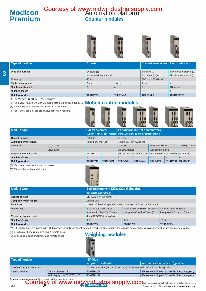
For other versions, please consult with your local Schneider Electric/
Square D sales office: visit www.us.telemecanique.com3/36
3
Automation platformCounter modules
Type of module Counter Counter/measurement Electronic cam
Type of inputs for Sensors (1) Sensors (1) Incremental encoders (2)
Incremental encoders (2) Encoders (2)(3) Absolute encoders (4)
Counting 40 kHz 500 kHz/200 kHz (4)
Cycle time module 5 ms 10 ms 1 ms –
Number of channels 2 4 2 128 cams
Number of axes – – – 1
Catalog number TSXCTY2A TSXCTY4A TSXCTY2C TSXCCY1128
(1) For 2/3-wire PNP/NPN 24 VDC sensors.
(2) For 5 VDC RS422, 10–30 VDC Totem Pole incremental encoders.
(3) For SSI serial or parallel output absolute encoders.
(4) For RS485 serial or parallel output absolute encoders.
Module type For translators For analog control servomotors(amplifier for stepper motor) (for asynchronous and brushless motors)
Control outputs RS 422 +/- 10 V
Compatible with drives Lexium 05, Twin Line Lexium 05/17D, Twin Line
Functions Linear axes – Limited Limited or infinite Limited or infinite(5)
Slave axes – With static ratio With dynamic ratio –
Frequency for each axis 187 kHz 500 kHz with incremental encoder, 200 kHz with absolute encoder (6)
Number of axes 1 2 2 4 2 4 3
Catalog number TSXCFY11 TSXCFY21 TSXCAY21 TSXCAY41 TSXCAY22 TSXCAY42 TSXCAY33
(5) With linear interpolation on 2 or 3 axes .
(6) SSI serial or with parallel outputs.
Module type Servomotors with SERCOS® digital ring(for brushless motors)
Control outputs SERCOS® network r ing
Compatible with ranges Lexium 17D
Functions Linear or infinite independent axes, slave axes with cam profile or ratio
Processing 4 sets of axes with linear 4 sets of axes with linear and circular 4 sets of axes with linear
interpolation from 2 to 8 axes inter polation from 2 to 3 axes (7) inter polation from 2 to 8 axes
Frequency for each axis 4 Mb SERCOS® network r ing
Number of axes 8 (8) 8 (8) 16 (9)
Catalog number TSXCSY84 TSXCSY85 TSXCSY164
(7) TSXCSY85 module supplied with TJE trajectory editor: linear trajectories with links between segments according to polynomial or circular inter polation and circular trajectories.
(8) 8 real axes , 4 imaginary axes and 4 remote axes.
(9) 16 axes (real axes, imaginary and remote axes).
Type of module ISP Plussupplied uncalibrated supplied calibrated and offer
Load cell inputs / outputs 50 measurements (for 1 to 8 load cells) / 2 discrete and 1 RS 485 for display unit
Catalog number Without display unit TSXISPY101 Please consult your Schneider Electric agency
With display unit TSXXBTH100 TSXISPY111 Please consult your Schneider Electric agency
Connection accessories: See www.us.telemecanique.com
ModiconPremium
Weighing modules
Motion control modules
Courtesy of www.mdwindustrialsupply.com
Courtesy of www.mdwindustrialsupply.com
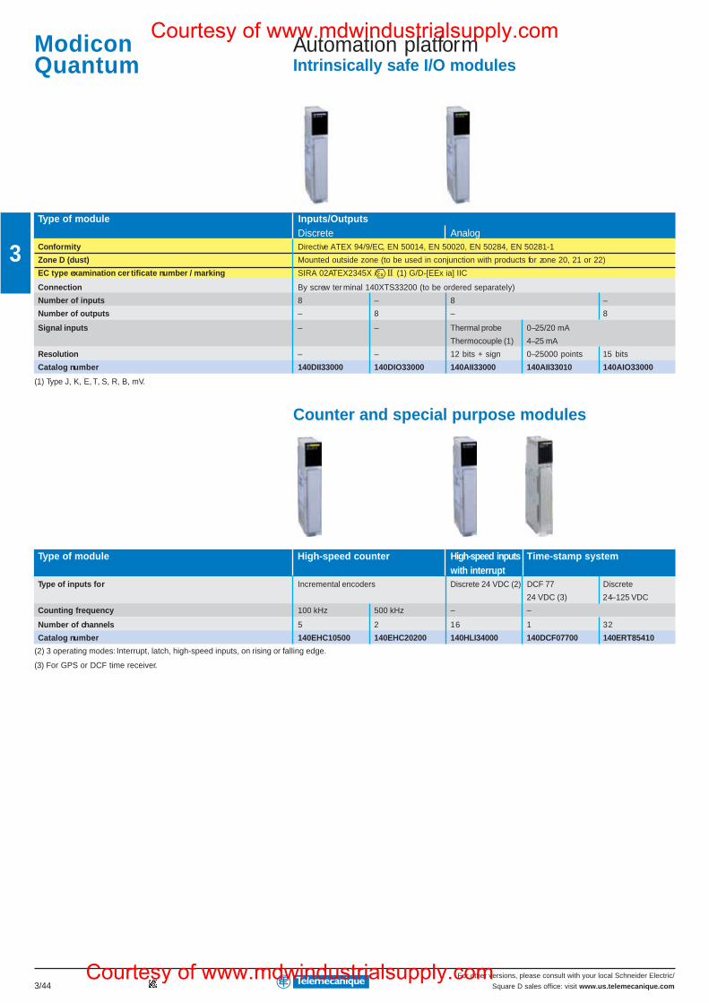
For other versions, please consult with your local Schneider Electric/
Square D sales office: visit www.us.telemecanique.com3/44
3
Automation platformIntrinsically safe I/O modules
Type of module Inputs/OutputsDiscrete Analog
Conformity Directive ATEX 94/9/EC, EN 50014, EN 50020, EN 50284, EN 50281-1
Zone D (dust) Mounted outside zone (to be used in conjunction with products for zone 20, 21 or 22)
EC type examination cer tificate number / marking SIRA 02ATEX2345X / II (1) G/D-[EEx ia] IIC
Connection By screw ter minal 140XTS33200 (to be ordered separately)
Number of inputs 8 – 8 –
Number of outputs – 8 – 8
Signal inputs – – Thermal probe 0–25/20 mA
Thermocouple (1) 4–25 mA
Resolution – – 12 bits + sign 0–25000 points 15 bits
Catalog number 140DII33000 140DIO33000 140AII33000 140AII33010 140AIO33000
(1) Type J, K, E, T, S, R, B, mV.
Counter and special purpose modules
Type of module High-speed counter High-speed inputs Time-stamp systemwith interrupt
Type of inputs for Incremental encoders Discrete 24 VDC (2) DCF 77 Discrete
24 VDC (3) 24–125 VDC
Counting frequency 100 kHz 500 kHz – –
Number of channels 5 2 16 1 32
Catalog number 140EHC10500 140EHC20200 140HLI34000 140DCF07700 140ERT85410
(2) 3 operating modes: Interrupt, latch, high-speed inputs, on rising or falling edge.
(3) For GPS or DCF time receiver.
ModiconQuantum
Courtesy of www.mdwindustrialsupply.com
Courtesy of www.mdwindustrialsupply.com
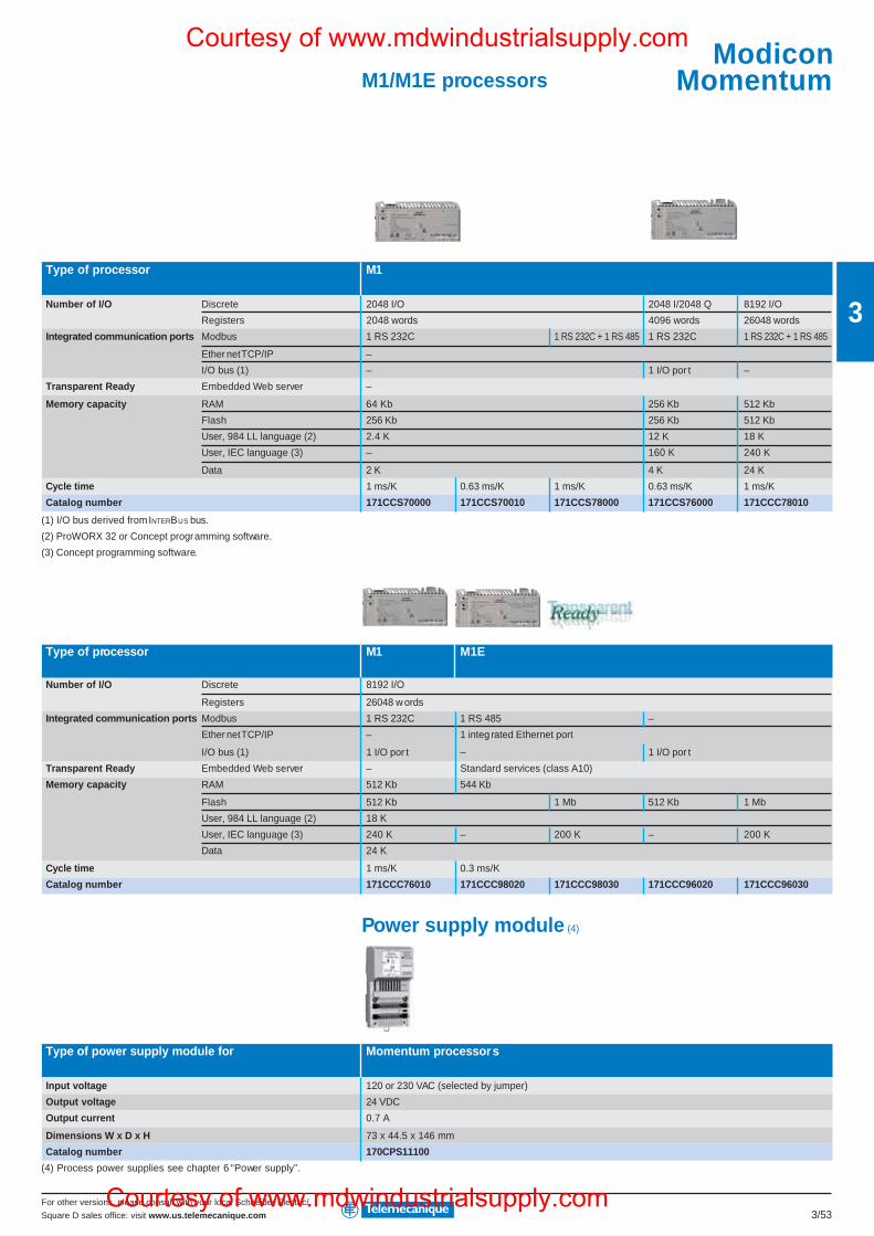
For other versions, please consult with your local Schneider Electric/
Square D sales office: visit www.us.telemecanique.com 3/53
3
M1/M1E processors
Type of processor M1
Number of I/O Discrete 2048 I/O 2048 I/2048 Q 8192 I/O
Registers 2048 words 4096 words 26048 words
Integrated communication ports Modbus 1 RS 232C 1 RS 232C + 1 RS 485 1 RS 232C 1 RS 232C + 1 RS 485
Ether net TCP/IP –
I/O bus (1) – 1 I/O por t –
Transparent Ready Embedded Web server –
Memory capacity RAM 64 Kb 256 Kb 512 Kb
Flash 256 Kb 256 Kb 512 Kb
User, 984 LL language (2) 2.4 K 12 K 18 K
User, IEC language (3) – 160 K 240 K
Data 2 K 4 K 24 K
Cycle time 1 ms/K 0.63 ms/K 1 ms/K 0.63 ms/K 1 ms/K
Catalog number 171CCS70000 171CCS70010 171CCS78000 171CCS76000 171CCC78010
(1) I/O bus derived from INTERBUS bus.
(2) ProWORX 32 or Concept programming software.
(3) Concept programming software.
Type of processor M1 M1E
Number of I/O Discrete 8192 I/O
Registers 26048 w ords
Integrated communication ports Modbus 1 RS 232C 1 RS 485 –
Ether net TCP/IP – 1 integ rated Ethernet port
I/O bus (1) 1 I/O por t – 1 I/O por t
Transparent Ready Embedded Web server – Standard services (class A10)
Memory capacity RAM 512 Kb 544 Kb
Flash 512 Kb 1 Mb 512 Kb 1 Mb
User, 984 LL language (2) 18 K
User, IEC language (3) 240 K – 200 K – 200 K
Data 24 K
Cycle time 1 ms/K 0.3 ms/K
Catalog number 171CCC76010 171CCC98020 171CCC98030 171CCC96020 171CCC96030
Power supply module (4)
Type of power supply module for Momentum processors
Input voltage 120 or 230 VAC (selected by jumper)
Output voltage 24 VDC
Output current 0.7 A
Dimensions W x D x H 73 x 44.5 x 146 mm
Catalog number 170CPS11100
(4) Process power supplies see chapter 6 “Power supply”.
ModiconMomentum
Courtesy of www.mdwindustrialsupply.com
Courtesy of www.mdwindustrialsupply.com
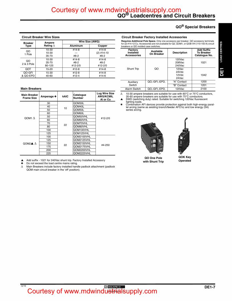
DE1-7
QO® Loadcentres and Circuit Breakers
DE
1L
OA
D C
EN
TR
ES
12/16
10-30 ampere breakers are suitable for use with 60°C or 75°C conductors, 35-60 ampere breakers are suitable for use with 75°C conductors.
SWD (switching duty) rated. Suitable for switching 120Vac fluorescent lighting loads.
Combination AFI devices provide protection against both high-energy paral-lel arcing (same as existing branch/feeder AFCI’s) and low energy (5A) series arcing.
Circuit Breaker Wire Sizes
BreakerType
AmpereRating
Wire Size (AWG)
Aluminum Copper
QO1 Pole
10-30 #14-8 #14-810-30 — (2) #14-1035-70 #8-2 #8-2
QO2 & 3 Pole
10-30 #14-8 #14-835-70 #8-2 #8-2
80-125 #12-2/0 #12-2/0QOT 15-20 #12-8 #14-8
QO-GFI& QO-EPD
15-30 #12-8 #14-840-60 #12-4 #14-6
Circuit Breaker Factory Installed AccessoriesRequires Additional Pole Space. Only one accessory per breaker. QO accessory terminals for (2) #14-12 Cu. Accessories are not available for Q2, QOM1, or QOB-VH (110-150 A) circuit breakers or QO molded case switches.
FactoryInstalled
Accessories
AvailableOn Breaker Description
Add SuffixTo Breaker
Catalogue No.
120Vac208Vac 1021240Vac
Shunt Trip QO 12Vac24Vdc12Vdc 104224Vac
AuxiliarySwitch
QO,-GFI,-EPD, “A” Contact 1200“B” Contact 1201
Alarm Switch QO,-GFI,-EPD, 120Vac 2100
QO® Special Breakers
Main Breakers
Main BreakerFrame Size Amperage kAIC Catalogue
Number
Lug Wire Size AWG/KCMIL
Al or Cu
QOM1
30
10
QOM30L
#12-2/0
40 QOM40L50 QOM50L60 QOM60L50
22
QOM50VHL60 QOM60VHL70 QOM70VHL80 QOM80VHL100 QOM100VHL125 QOM125VHL
QOM2
100
22
QOM2100VHL
#4-250
125 QOM2125VHL150 QOM2150VHL175 QOM2175VHL200 QOM2200VHL225 QOM2225VHL
Add suffix - 1021 for 240Vac shunt trip. Factory Installed Accessory Do not exceed the load centre mains rating. Main Breakers include factory installed handle padlock attachment (padlock
QOM main circuit breaker in the 'off' position).
QO One Polewith Shunt Trip
QOK KeyOperated
DE1_p03-16.fm Page 7 Friday, December 2, 2016 1:08 PM
Courtesy of www.mdwindustrialsupply.com
Courtesy of www.mdwindustrialsupply.com
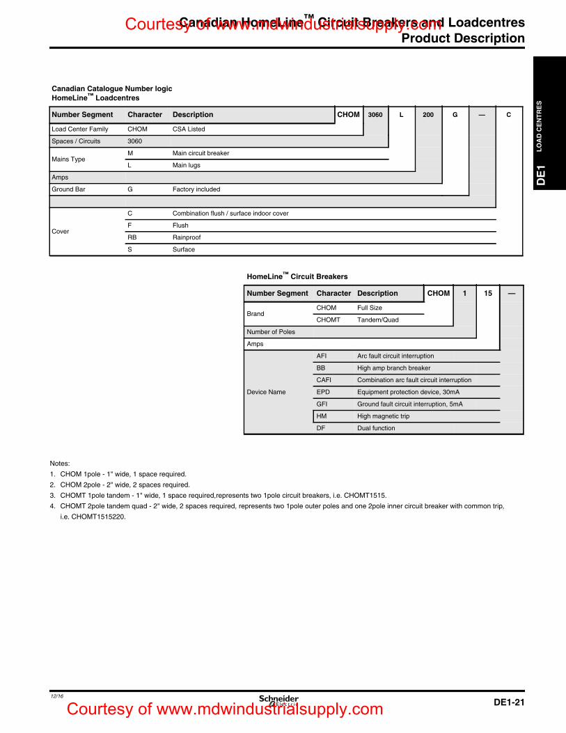
Canadian HomeLine™ Circuit Breakers and LoadcentresProduct Description
DE
1L
OA
DC
EN
TR
ES
DE1-2112/16
Notes:
1. CHOM 1pole - 1" wide, 1 space required.
2. CHOM 2pole - 2" wide, 2 spaces required.
3. CHOMT 1pole tandem - 1" wide, 1 space required,represents two 1pole circuit breakers, i.e. CHOMT1515.
4. CHOMT 2pole tandem quad - 2" wide, 2 spaces required, represents two 1pole outer poles and one 2pole inner circuit breaker with common trip,
i.e. CHOMT1515220.
Canadian Catalogue Number logicHomeLine™ Loadcentres
Number Segment Character Description CHOM 3060 L 200 G — C
Load Center Family CHOM CSA Listed
Spaces / Circuits 3060
Mains TypeM Main circuit breaker
L Main lugs
Amps
Ground Bar G Factory included
Cover
C Combination flush / surface indoor cover
F Flush
RB Rainproof
S Surface
HomeLine™ Circuit Breakers
Number Segment Character Description CHOM 1 15 —
BrandCHOM Full Size
CHOMT Tandem/Quad
Number of Poles
Amps
Device Name
AFI Arc fault circuit interruption
BB High amp branch breaker
CAFI Combination arc fault circuit interruption
EPD Equipment protection device, 30mA
GFI Ground fault circuit interruption, 5mA
HM High magnetic trip
DF Dual function
DE1_p21.fm Page 21 Friday, December 2, 2016 8:05 PM
Courtesy of www.mdwindustrialsupply.com
Courtesy of www.mdwindustrialsupply.com
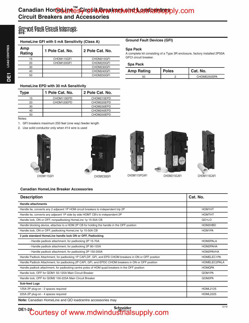
DE1-24
Canadian HomeLine™ Circuit Breakers and LoadcentresCircuit Breakers and Accessories
DE
1L
OA
DC
EN
TR
ES
12/16
Note: Canadian HomeLine and QO loadcentre accessories may
Canadian HomeLine Breaker Accessories
Description Cat. No.
Handle attachments
Handle tie, converts any 2 adjacent 1P HOM circuit breakers to independent trip 2P HOM1HT
Handle tie, converts any adjacent 1P side by side HOMT CB's to independent 2P HOMTHT
Handle lock, ON or OFF, nonpadlocking HomeLine 1p 15-50A CB QO1LO
Handle blocking device, attaches to a HOM 2P CB for holding the handle in the OFF position HOM2HBD
Handle lock, ON or OFF, padlocking HomeLine 1p 15-50A CB HOM1PA
2 pole standard HomeLine handle lock ON or OFF, Padlocking
- Handle padlock attachment, for padlocking 2P 15-70A HOM2PALA
- Handle padlock attachment, for padlocking 2P 80-125A HOM2PAHA
- Handle padlock attachment, for padlocking 2P 150-200A HOM2PAVHA
Handle Padlock Attachment, for padlocking 1P CAFI,DF, GFI, and EPD CHOM breakers in ON or OFF position HOMELEC1PA
Handle Padlock Attachment, for padlocking 2P CAFI, GFI, and EPDC CHOM breakers in ON or OFF position HOMELEC2PALA
Handle padlock attachment, for padlocking centre poles of HOM quad breakers in the OFF position HOMQPA
Handle lock, OFF for QOM1 50-125A Main Circuit Breaker QOM1PA
Handle lock, OFF for QOM2 100-225A Main Circuit Breaker QOM2PA
Sub-feed Lugs
125A 2P plug-on - 2 spaces required HOML2125
225A 2P plug-on - 4 spaces required HOML2225
Ground Fault Circuit Interrupt-ers, Arc Fault Circuit Interrupt-ers
Notes:
1. GFI breakers maximum 250 feet (one way) feeder length
2. Use solid conductor only when #14 wire is used
Ground Fault Devices (GFI)
Spa PackA complete kit consisting of a Type 3R enclosure, factory installed 2P50AGFCI circuit breaker.
HomeLine GFI with 5 mA Sensitivity (Class A)
AmpRating
1 Pole Cat. No. 2 Pole Cat. No.
15 CHOM115GFI CHOM215GFI20 CHOM120GFI CHOM220GFI30 CHOM230GFI40 CHOM240GFI50 CHOM250GFI
HomeLine EPD with 30 mA Sensitivity
Type 1 Pole Cat. No. 2 Pole Cat. No.15 CHOM115EPD CHOM215EPD20 CHOM120EPD CHOM220EPD30 CHOM230EPD40 CHOM240EPD50 CHOM250EPD
Spa Pack
Amp Rating Poles Cat. No.50 2 CHOME250SPA
CHOM115GFI CHOM230GFI CHOM115CAFICHOM215CAFICHOM115PCAFI
DE1_p24.fm Page 24 Friday, December 2, 2016 8:07 PM
Courtesy of www.mdwindustrialsupply.com
Courtesy of www.mdwindustrialsupply.com
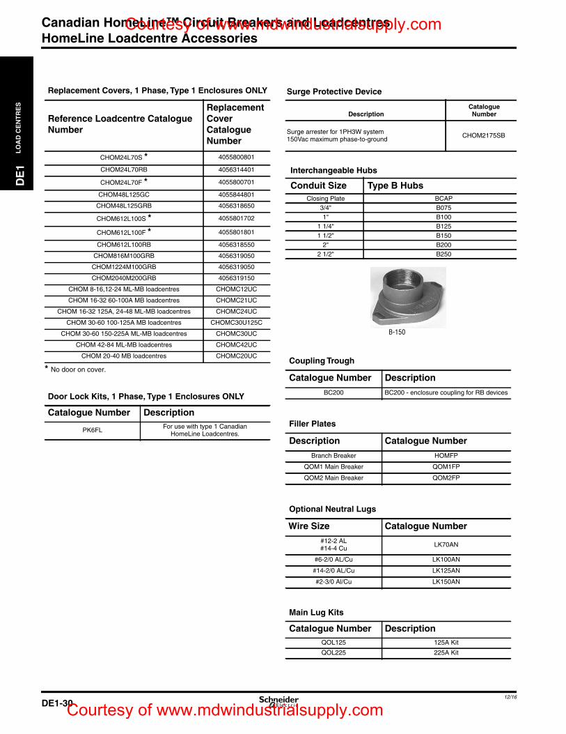
Canadian HomeLine™ Circuit Breakers and LoadcentresHomeLine Loadcentre Accessories
DE1-3012/16
DE
1L
OA
DC
EN
TR
ES
* No door on cover.
Replacement Covers, 1 Phase, Type 1 Enclosures ONLY
Reference Loadcentre CatalogueNumber
ReplacementCoverCatalogueNumber
CHOM24L70S * 4055800801
CHOM24L70RB 4056314401
CHOM24L70F * 4055800701
CHOM48L125GC 4055844801
CHOM48L125GRB 4056318650
CHOM612L100S * 4055801702
CHOM612L100F * 4055801801
CHOM612L100RB 4056318550
CHOM816M100GRB 4056319050
CHOM1224M100GRB 4056319050
CHOM2040M200GRB 4056319150
CHOM 8-16,12-24 ML-MB loadcentres CHOMC12UC
CHOM 16-32 60-100A MB loadcentres CHOMC21UC
CHOM 16-32 125A, 24-48 ML-MB loadcentres CHOMC24UC
CHOM 30-60 100-125A MB loadcentres CHOMC30U125C
CHOM 30-60 150-225A ML-MB loadcentres CHOMC30UC
CHOM 42-84 ML-MB loadcentres CHOMC42UC
CHOM 20-40 MB loadcentres CHOMC20UC
Door Lock Kits, 1 Phase, Type 1 Enclosures ONLY
Catalogue Number Description
PK6FL For use with type 1 CanadianHomeLine Loadcentres.
Surge Protective Device
DescriptionCatalogueNumber
Surge arrester for 1PH3W system150Vac maximum phase-to-ground CHOM2175SB
Interchangeable Hubs
Conduit Size Type B HubsClosing Plate BCAP
3/4" B0751" B100
1 1/4" B1251 1/2" B150
2" B2002 1/2" B250
Coupling Trough
Catalogue Number Description
BC200 BC200 - enclosure coupling for RB devices
Filler Plates
Description Catalogue Number
Branch Breaker HOMFP
QOM1 Main Breaker QOM1FP
QOM2 Main Breaker QOM2FP
Optional Neutral Lugs
Wire Size Catalogue Number
#12-2 AL#14-4 Cu LK70AN
#6-2/0 AL/Cu LK100AN
#14-2/0 AL/Cu LK125AN
#2-3/0 Al/Cu LK150AN
Main Lug Kits
Catalogue Number DescriptionQOL125 125A Kit
QOL225 225A Kit
B-150
DE1_p30.fm Page 30 Friday, December 2, 2016 8:12 PM
Courtesy of www.mdwindustrialsupply.com
Courtesy of www.mdwindustrialsupply.com
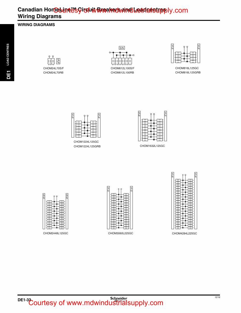
Canadian HomeLine™ Circuit Breakers and LoadcentresWiring Diagrams
DE
1L
OA
DC
EN
TR
ES
DE1_p31-35.fm Page 32 Friday, December 2, 2016 8:13 PM
Courtesy of www.mdwindustrialsupply.com
WIRING DIAGRAMS
CHOM24L70S/F
CHOM24L70RB
SN
CHOM612L100S/F
CHOM612L100RB
S/N
CHOM816L125GC
CHOM816L125GRB
CHOM1224L125GC
S N
S N
SN
SN
SN
CHOM1632L125GC
CHOM3060L225GC CHOM4284L225GCCHOM2448L125GC
CHOM1224L125GRB
SN
SN
SN
SN
SN
SN
SN
DE1-3212/16
Courtesy of www.mdwindustrialsupply.com
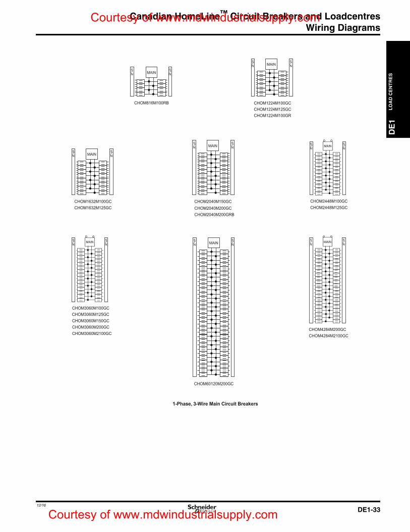
Canadian HomeLine™ Circuit Breakers and LoadcentresWiring Diagrams
DE
1L
OA
DC
EN
TR
ES
DE1_p31-35.fm Page 33 Friday, December 2, 2016 8:13 PM
Courtesy of www.mdwindustrialsupply.com
1-Phase, 3-Wire Main Circuit Breakers
SN
CHOM816M100RB
SNMAIN
SN
CHOM1224M100GC
SNMAIN
SN
CHOM1632M100GCCHOM1632M125GC
SNMAIN
CHOM2040M150GC
SNMAIN
SN
CHOM2448M100GCCHOM2448M125GC
CHOM3060M100GCCHOM3060M125GC
MAINSN
CHOM60120M200GC
SN
CHOM4284M200GCCHOM4284M2100GC
CHOM1224M125GCCHOM1224M100GR
CHOM2040M200GCCHOM2040M200GRB
MAIN
MAIN
CHOM3060M150GCCHOM3060M200GCCHOM3060M2100GC
MAINSN
SN
SN
SN
SN
SN
DE1-3312/16
Courtesy of www.mdwindustrialsupply.com
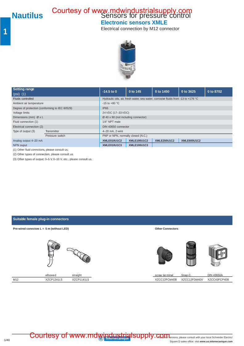
1/40For other versions, please consult with your local Schneider Electric/
Square D sales office: visit www.us.telemecanique.com
1
Setting range-14.5 to 0 0 to 145 0 to 1450 0 to 3625 0 to 8702
(psi) (1)Fluids controlled Hydraulic oils, air, fresh water, sea water, corrosive fluids from -13 to +176 °C
Ambient air temperature -15 to +80 °C
Degree of protection (conforming to IEC 60529) IP65
Voltage limits 24 VDC (17–33 VDC)
Dimensions (mm) Ø x L Ø 40 x 90 (not including connector)
Fluid connection (1) 1/4" NPT male
Electrical connection (2) DIN 43650 connector
Type of output (3) Transmitter 4–20 mA, 2-wire
Pressure switch PNP or NPN, normally closed (N.C.)
Analog output 4–20 mA XMLE010U1C2 XMLE100U1C2 XMLE250U1C2 XMLE600U1C2
NPN ouput XMLE010U1C3 XMLE100U1C3
(1) Other fluid connctions, please consult us.
(2) Other types of connection, please consult us.
(3) Other types of output; 0–5 V, 0–10 V, etc., please consult us.
Suitable female plug-in connectors
Pre-wired conectors L = 5 m (without LED) Other Connectors
elbowed straight screw ter minal Snap-C DIN 43650A
M12 XZCP1241L5 XZCP1141L5 XZCC12FCM40B XZCC12FDM40V XZCC43FCP40B
Nautilus Sensors for pressure controlElectronic sensors XMLEElectrical connection by M12 connector
Courtesy of www.mdwindustrialsupply.com
Courtesy of www.mdwindustrialsupply.com
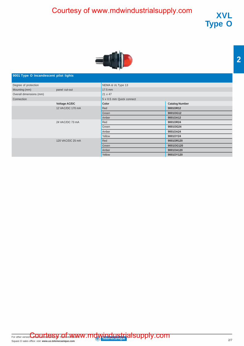
For other versions, please consult with your Schneider Electric/
Square D sales office: visit www.us.telemecanique.com
2
2/7
9001 Type O Incandescent pilot lights
Degree of protection NEMA & UL Type 13
Mounting (mm) panel cut-out 17.5 mm
Overall dimensions (mm) 21 x 47
Connection 5 x 0.5 mm Quick connect
Voltage AC/DC Color Catalog Number
12 VAC/DC 170 mA Red 9001OR12
Green 9001OG12
Amber 9001OA12
24 VAC/DC 73 mA Red 9001OR24
Green 9001OG24
Amber 9001OA24
Yellow 9001OY24
120 VAC/DC 25 mA Red 9001OR120
Green 9001OG120
Amber 9001OA120
Yellow 9001OY120
XVLType O
Courtesy of www.mdwindustrialsupply.com
Courtesy of www.mdwindustrialsupply.com
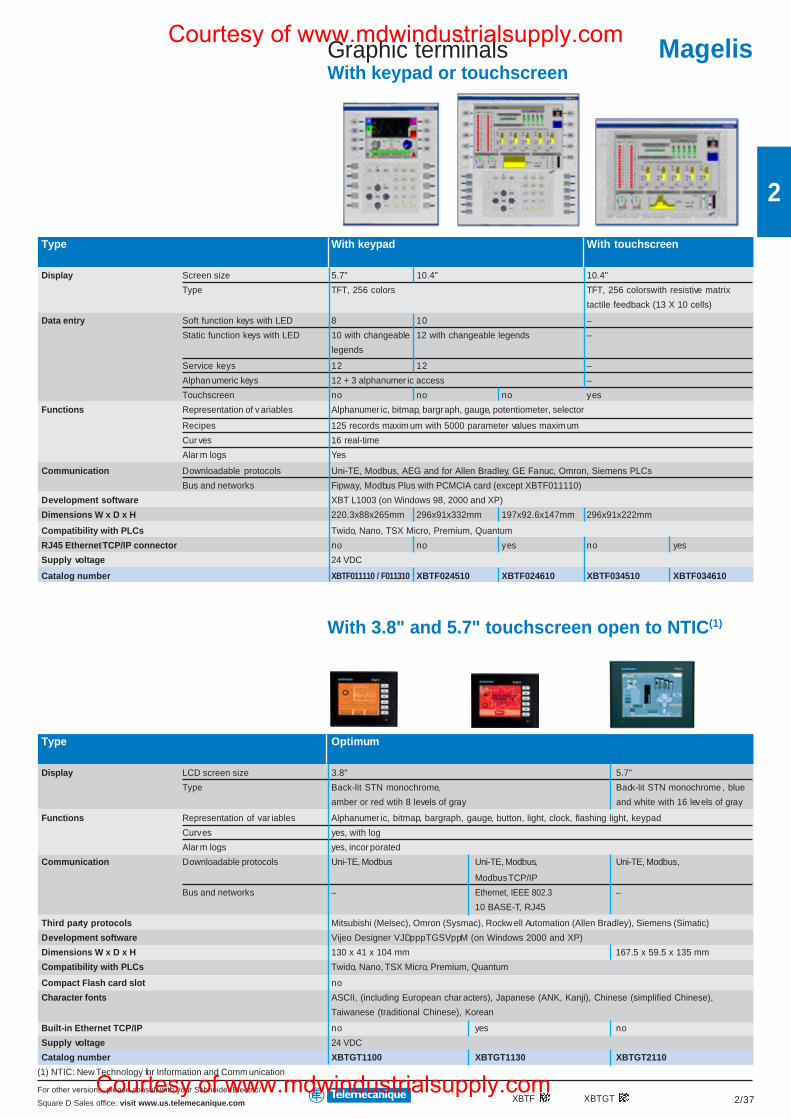
For other versions, please consult with your Schneider Electric/
Square D Sales office: visit www.us.telemecanique.com 2/37
2
Graphic terminalsWith keypad or touchscreen
XBTF XBTGT
Type With keypad With touchscreen
Display Screen size 5.7" 10.4" 10.4"
Type TFT, 256 colors TFT, 256 colorswith resistive matrix
tactile feedback (13 X 10 cells)
Data entry Soft function keys with LED 8 10 –
Static function keys with LED 10 with changeable 12 with changeable legends –
legends
Service keys 12 12 –
Alphan umeric keys 12 + 3 alphanumer ic access –
Touchscreen no no no yes
Functions Representation of v ariables Alphanumer ic, bitmap, bargraph, gauge, potentiometer, selector
Recipes 125 records maxim um with 5000 parameter values maxim um
Cur ves 16 real-time
Alar m logs Yes
Communication Downloadable protocols Uni-TE, Modbus, AEG and for Allen Bradley, GE Fanuc, Omron, Siemens PLCs
Bus and networks Fipway, Modbus Plus with PCMCIA card (except XBTF011110)
Development software XBT L1003 (on Windows 98, 2000 and XP)
Dimensions W x D x H 220.3x88x265mm 296x91x332mm 197x92.6x147mm 296x91x222mm
Compatibility with PLCs Twido, Nano, TSX Micro, Premium, Quantum
RJ45 Ethernet TCP/IP connector no no yes no yes
Supply voltage 24 VDC
Catalog number XBTF011110 / F011310 XBTF024510 XBTF024610 XBTF034510 XBTF034610
With 3.8" and 5.7" touchscreen open to NTIC(1)
Type Optimum
Display LCD screen size 3.8" 5.7"
Type Back-lit STN monochrome, Back-lit STN monochrome , blue
amber or red wtih 8 levels of gray and white with 16 levels of gray
Functions Representation of var iables Alphanumer ic, bitmap, bargraph, gauge, button, light, clock, flashing light, keypad
Curves yes, with log
Alar m logs yes, incor porated
Communication Downloadable protocols Uni-TE, Modbus Uni-TE, Modbus, Uni-TE, Modbus,
Modbus TCP/IP
Bus and networks – Ethernet, IEEE 802.3 –
10 BASE-T, RJ45
Third party protocols Mitsubishi (Melsec), Omron (Sysmac), Rockw ell Automation (Allen Bradley), Siemens (Simatic)
Development software Vijeo Designer VJDpppTGSVppM (on Windows 2000 and XP)
Dimensions W x D x H 130 x 41 x 104 mm 167.5 x 59.5 x 135 mm
Compatibility with PLCs Twido, Nano, TSX Micro, Premium, Quantum
Compact Flash card slot no
Character fonts ASCII, (including European char acters), Japanese (ANK, Kanji), Chinese (simplified Chinese),
Taiwanese (traditional Chinese), Korean
Built-in Ethernet TCP/IP no yes no
Supply voltage 24 VDC
Catalog number XBTGT1100 XBTGT1130 XBTGT2110
(1) NTIC: New Technology for Information and Comm unication
MagelisCourtesy of www.mdwindustrialsupply.com
Courtesy of www.mdwindustrialsupply.com
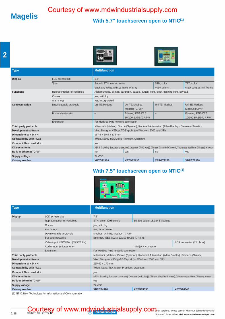
For other versions, please consult with your Schneider Electric/
Square D Sales office: visit www.us.telemecanique.com2/38
2
With 5.7" touchscreen open to NTIC(1)
Type Multifunction
Display LCD screen size 5.7"
Type Back-lit STN, monochrome STN, color TFT, color
black and white with 16 levels of gray 4096 colors 65,536 colors 16,384 if flashing
Functions Representation of variables Alphanumeric, bitmap, bargraph, gauge, button, light, clock, flashing light, k eypad
Curves yes, with log
Alarm logs yes, incorporated
Communication Downloadable protocols Uni-TE, Modbus Uni-TE, Modbus, Uni-TE, Modbus Uni-TE, Modbus,
Modbus TCP/IP Modbus TCP/IP
Bus and networks – Ethernet, IEEE 802.3 – Ethernet, IEEE 802.3
10/100 BASE-T, RJ45 10/100 BASE-T, RJ45
Expansion For Modb us Plus network connection
Third party protocols Mitsubishi (Melsec), Omron (Sysmac), Rockwell Automation (Allen Bradley), Siemens (Simatic)
Development software Vijeo Designer VJDpppTGSVppM (on Windows 2000 and XP)
Dimensions W x D x H 167.5 x 59.5 x 135 mm
Compatibility with PLCs Twido, Nano, TSX Micro, Premium, Quantum
Compact Flash card slot yes
Character fonts ASCII, (including European characters), Japanese (ANK, Kanji), Chinese (simplified Chinese), Taiwanese (traditional Chinese), K orean
Built-in Ethernet TCP/IP no yes no yes
Supply voltage 24 VDC
Catalog number XBTGT2120 XBTGT2130 XBTGT2220 XBTGT2330
With 7.5" touchscreen open to NTIC(1)
Type Multifunction
Display LCD screen size 7.5"
Representation of var iables STN, color 4096 colors 65,536 colors 16,384 if flashing
Cur ves yes, with log
Alar m logs yes, incor porated
Downloadable protocols Modbus, Uni-TE, Modbus TCP/IP
Bus and networks Ethernet, IEEE 802.3 10/100 BASE-T, RJ 45
Video input NTCS/PAL (59.5/50 Hz) RCA connector (75 ohms)
Audio input (microphone) mini-jac k connector
Expansion For Modbus Plus network connection
Third par ty protocols Mitsubishi (Melsec), Omron (Sysmac), Rockw ell Automation (Allen Bradley), Siemens (Simatic)
Development software Vijeo Designer VJDpppTGSVppM (on Windows 2000 and XP)
Dimensions W x D x H 215 60 x 170 mm
Compatibility with PLCs Twido, Nano, TSX Micro, Premium, Quantum
Compact Flash card slot yes
Character fonts ASCII, (including European characters), Japanese (ANK, Kanji), Chinese (simplified Chinese), Taiwanese (traditional Chinese), K orean
Built-in Ethernet TCP/IP yes
Supply voltage 24 VDC
Catalog number XBTGT4320 XBTGT4330 XBTGT4340
(1) NTIC: New Technology for Information and Communication
XBTGT XBTG
MagelisCourtesy of www.mdwindustrialsupply.com
Courtesy of www.mdwindustrialsupply.com
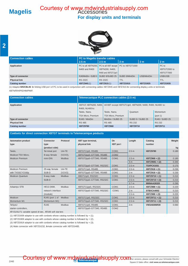
For other versions, please consult with your Schneider Electric/
Square D Sales office: visit www.us.telemecanique.com2/40
2
Magelis AccessoriesFor display units and terminals
Connection cables PC to Magelis transfer cables2.5 m 2.5 m 2 m 2 m 2 m
Application PC to all XBTN200, PC to all XBT except PC to XBTGT1000 PC to
N400 and R400 XBTN200, N400, XBTGT2000 to
R400 and XBTGT11p0 XBTGT7000
Type of connector RJ45/MiniDin + SUBD 9 SUBD 9/SUBD 25 SUBD 9/MiniDin USB/MiniDin USB/USB
Physical link RS 232C RS 232C TTL TTL
Catalog number XBTZ945 (1) XBTZ915 (1) XBTZG915 XBTZG925 XBTZG935
(1) Adaptor SR2CBL06 for linking USB por t of PC, to be used in conjunction with connecting cables XBTZ945 and XBTZ915 for connecting displa y units or terminals
XBTN/R/H/P/E/HM/PM/F.
Connection cables Telemecanique PLC connection cables (2.5 m)
Application XBTGT, XBTN200, N400, All XBT except XBTGT11p0, XBTN200, N400, R400, NU400 to:
R400, NU400 to:
Twido, Nano, Twido, Nano, Quantum Momentum
TSX Micro, Premium TSX Micro, Premium (port 1)
Type of connector RJ45 / MiniDin MiniDin / SUBD 25 SUBD 9 / SUBD 25 RJ45 / SUBD 25
Physical link RS 485 RS 485 RS 232 RS 232
Catalog number XBTZ9780 XBTZ968 XBTZ9710 XBTZ9711
Cordsets for direct connection XBTGT terminals to Telemecanique products
Automation product Connector Protocol XBT type terminal, On Length Catalog Weight
type type physical link XBT por t number
(product side) kg
Twido, Ter minal port Uni-TE XBTGT11p0, RS485 COM1 2.5 m XBTZ9780 0.180
Modicon TSX Micro, 8-way female (V1/V2), XBTGT2pp0–GT7340, RS485 COM2
Modicon Premium mini-DIN Modbus XBTGT2pp0–GT7340, RS485 COM1 2.5 m XBTZ968 + (2) 0.180
5 m XBTZ9681 + (2) 0.340
XBTGT2pp0–GT7340, RS232C COM1 2.5 m TSXPCX1031 0.170
Modicon Premium 25-way female Uni-TE XBTGT11p0, RS485 COM1 2.5 m XBTZ918 + (1) 0.230
with TXSSCY2160p SUB-D (V1/V2) XBTGT2pp0–GT7340, RS485 COM1 2 m XBTZ918 + (2) 0.230
Modicon Quantum 9-way male Modbus XBGT11p0, RS232C COM1 2.5 m XBTZ9710 + (1) 0.210
SUB-D XBTGT2pp0–GT7340, RS232C COM1 2.5 m XBTZ9710 + (3) 0.210
3.7 m 990NAA26320 0.290
Advantys STB HE13 (NIM, Modbus XBTGT11pp0, RS232C COM1 2.5 m XBTZ988 + (1) 0.220
networ k interface XBTGT2pp0–GT7340, RS232C COM1 2 m STBXCA4002 0.210
(module) 2.5 m XBTZ988 + (3) 0.220
Modicon RJ45 (port 1 of Modbus XBTGT11p0, RS232C COM1 2.5 m XBTZ9711 + (1) 0.210
Momentum M1 Momentum M1) XBTGT2pp0–GT7340, RS232C COM1 2.5 m XBTZ9711 + (3) 0.210
TeSysU RJ45 Modbus XBTGT11p0, RS485 COM1 3 m VW3A8306R30 0.060
starter-controllers , XBTGT2pp0–GT7340, RS485 COM2
ATV31/61/71 variable speed dr ives , ATS48 soft star ters
(1) XBTZG939 adaptor to use with cordsets whose catalog number is followed by + (1).
(2) XBTZG909 adaptor to use with cordsets whose catalog number is followed by + (2).
(3) XBTZG919 adaptor to use with cordsets whose catalog number is followed by + (3).
(4) Male connector with XBTZGI232, female connector with XBTZGI485.
Courtesy of www.mdwindustrialsupply.com
Courtesy of www.mdwindustrialsupply.com

For other versions, please consult with your local Schneider Electric/
Square D sales office: visit www.us.telemecanique.com3/36
3
Automation platformCounter modules
Type of module Counter Counter/measurement Electronic cam
Type of inputs for Sensors (1) Sensors (1) Incremental encoders (2)
Incremental encoders (2) Encoders (2)(3) Absolute encoders (4)
Counting 40 kHz 500 kHz/200 kHz (4)
Cycle time module 5 ms 10 ms 1 ms –
Number of channels 2 4 2 128 cams
Number of axes – – – 1
Catalog number TSXCTY2A TSXCTY4A TSXCTY2C TSXCCY1128
(1) For 2/3-wire PNP/NPN 24 VDC sensors.
(2) For 5 VDC RS422, 10–30 VDC Totem Pole incremental encoders.
(3) For SSI serial or parallel output absolute encoders.
(4) For RS485 serial or parallel output absolute encoders.
Module type For translators For analog control servomotors(amplifier for stepper motor) (for asynchronous and brushless motors)
Control outputs RS 422 +/- 10 V
Compatible with drives Lexium 05, Twin Line Lexium 05/17D, Twin Line
Functions Linear axes – Limited Limited or infinite Limited or infinite(5)
Slave axes – With static ratio With dynamic ratio –
Frequency for each axis 187 kHz 500 kHz with incremental encoder, 200 kHz with absolute encoder (6)
Number of axes 1 2 2 4 2 4 3
Catalog number TSXCFY11 TSXCFY21 TSXCAY21 TSXCAY41 TSXCAY22 TSXCAY42 TSXCAY33
(5) With linear interpolation on 2 or 3 axes .
(6) SSI serial or with parallel outputs.
Module type Servomotors with SERCOS® digital ring(for brushless motors)
Control outputs SERCOS® network r ing
Compatible with ranges Lexium 17D
Functions Linear or infinite independent axes, slave axes with cam profile or ratio
Processing 4 sets of axes with linear 4 sets of axes with linear and circular 4 sets of axes with linear
interpolation from 2 to 8 axes inter polation from 2 to 3 axes (7) inter polation from 2 to 8 axes
Frequency for each axis 4 Mb SERCOS® network r ing
Number of axes 8 (8) 8 (8) 16 (9)
Catalog number TSXCSY84 TSXCSY85 TSXCSY164
(7) TSXCSY85 module supplied with TJE trajectory editor: linear trajectories with links between segments according to polynomial or circular inter polation and circular trajectories.
(8) 8 real axes , 4 imaginary axes and 4 remote axes.
(9) 16 axes (real axes, imaginary and remote axes).
Type of module ISP Plussupplied uncalibrated supplied calibrated and offer
Load cell inputs / outputs 50 measurements (for 1 to 8 load cells) / 2 discrete and 1 RS 485 for display unit
Catalog number Without display unit TSXISPY101 Please consult your Schneider Electric agency
With display unit TSXXBTH100 TSXISPY111 Please consult your Schneider Electric agency
Connection accessories: See www.us.telemecanique.com
ModiconPremium
Weighing modules
Motion control modules
Courtesy of www.mdwindustrialsupply.com
Courtesy of www.mdwindustrialsupply.com

For other versions, please consult with your local Schneider Electric/
Square D sales office: visit www.us.telemecanique.com3/44
3
Automation platformIntrinsically safe I/O modules
Type of module Inputs/OutputsDiscrete Analog
Conformity Directive ATEX 94/9/EC, EN 50014, EN 50020, EN 50284, EN 50281-1
Zone D (dust) Mounted outside zone (to be used in conjunction with products for zone 20, 21 or 22)
EC type examination cer tificate number / marking SIRA 02ATEX2345X / II (1) G/D-[EEx ia] IIC
Connection By screw ter minal 140XTS33200 (to be ordered separately)
Number of inputs 8 – 8 –
Number of outputs – 8 – 8
Signal inputs – – Thermal probe 0–25/20 mA
Thermocouple (1) 4–25 mA
Resolution – – 12 bits + sign 0–25000 points 15 bits
Catalog number 140DII33000 140DIO33000 140AII33000 140AII33010 140AIO33000
(1) Type J, K, E, T, S, R, B, mV.
Counter and special purpose modules
Type of module High-speed counter High-speed inputs Time-stamp systemwith interrupt
Type of inputs for Incremental encoders Discrete 24 VDC (2) DCF 77 Discrete
24 VDC (3) 24–125 VDC
Counting frequency 100 kHz 500 kHz – –
Number of channels 5 2 16 1 32
Catalog number 140EHC10500 140EHC20200 140HLI34000 140DCF07700 140ERT85410
(2) 3 operating modes: Interrupt, latch, high-speed inputs, on rising or falling edge.
(3) For GPS or DCF time receiver.
ModiconQuantum
Courtesy of www.mdwindustrialsupply.com
Courtesy of www.mdwindustrialsupply.com
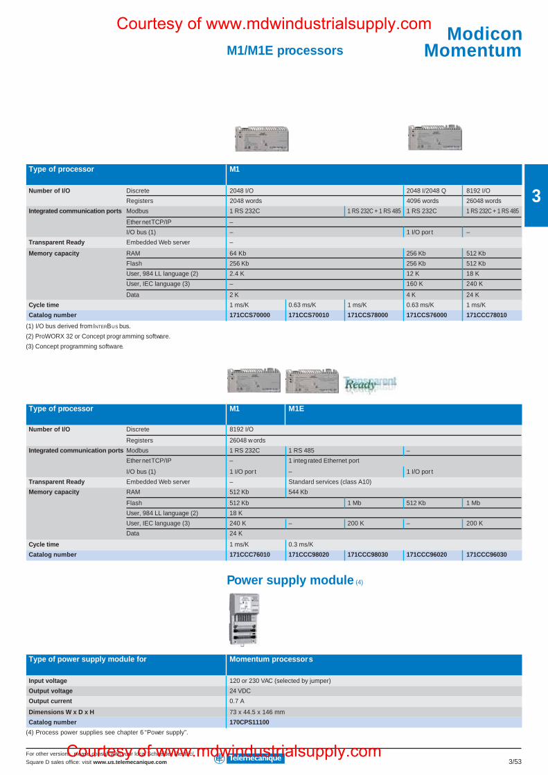
For other versions, please consult with your local Schneider Electric/
Square D sales office: visit www.us.telemecanique.com 3/53
3
M1/M1E processors
Type of processor M1
Number of I/O Discrete 2048 I/O 2048 I/2048 Q 8192 I/O
Registers 2048 words 4096 words 26048 words
Integrated communication ports Modbus 1 RS 232C 1 RS 232C + 1 RS 485 1 RS 232C 1 RS 232C + 1 RS 485
Ether net TCP/IP –
I/O bus (1) – 1 I/O por t –
Transparent Ready Embedded Web server –
Memory capacity RAM 64 Kb 256 Kb 512 Kb
Flash 256 Kb 256 Kb 512 Kb
User, 984 LL language (2) 2.4 K 12 K 18 K
User, IEC language (3) – 160 K 240 K
Data 2 K 4 K 24 K
Cycle time 1 ms/K 0.63 ms/K 1 ms/K 0.63 ms/K 1 ms/K
Catalog number 171CCS70000 171CCS70010 171CCS78000 171CCS76000 171CCC78010
(1) I/O bus derived from INTERBUS bus.
(2) ProWORX 32 or Concept programming software.
(3) Concept programming software.
Type of processor M1 M1E
Number of I/O Discrete 8192 I/O
Registers 26048 w ords
Integrated communication ports Modbus 1 RS 232C 1 RS 485 –
Ether net TCP/IP – 1 integ rated Ethernet port
I/O bus (1) 1 I/O por t – 1 I/O por t
Transparent Ready Embedded Web server – Standard services (class A10)
Memory capacity RAM 512 Kb 544 Kb
Flash 512 Kb 1 Mb 512 Kb 1 Mb
User, 984 LL language (2) 18 K
User, IEC language (3) 240 K – 200 K – 200 K
Data 24 K
Cycle time 1 ms/K 0.3 ms/K
Catalog number 171CCC76010 171CCC98020 171CCC98030 171CCC96020 171CCC96030
Power supply module (4)
Type of power supply module for Momentum processors
Input voltage 120 or 230 VAC (selected by jumper)
Output voltage 24 VDC
Output current 0.7 A
Dimensions W x D x H 73 x 44.5 x 146 mm
Catalog number 170CPS11100
(4) Process power supplies see chapter 6 “Power supply”.
ModiconMomentum
Courtesy of www.mdwindustrialsupply.com
Courtesy of www.mdwindustrialsupply.com
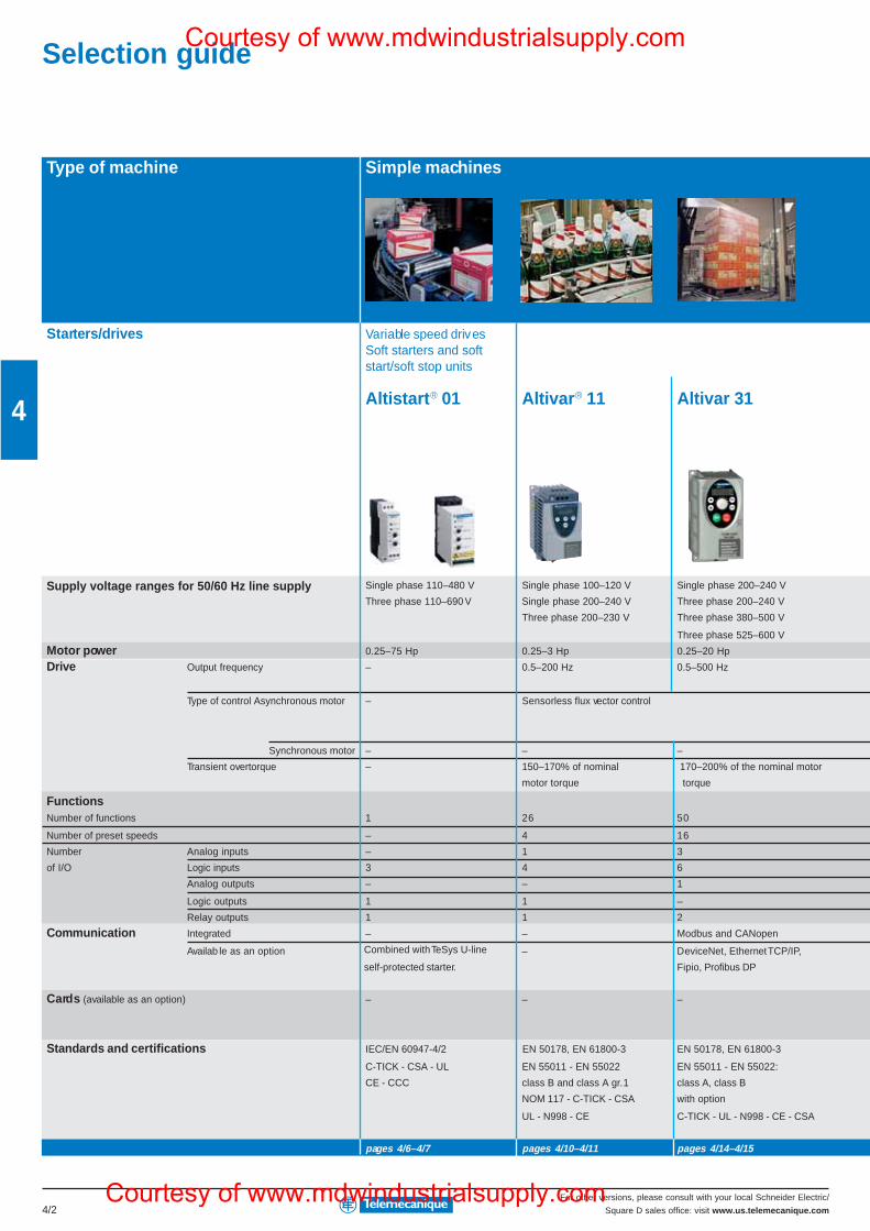
For other versions, please consult with your local Schneider Electric/
Square D sales office: visit www.us.telemecanique.com4/2
4
Selection guide
Type of machine Simple machines
Starters/drives Variable speed drives
Altistart® 01 Altivar® 11 Altivar 31
Single phase 110–480 V Single phase 100–120 V Single phase 200–240 V
Three phase 110–690 V Single phase 200–240 V Three phase 200–240 V
Three phase 200–230 V Three phase 380–500 V
Three phase 525–600 V
Motor power 0.25–75 Hp 0.25–3 Hp 0.25–20 Hp
Drive Output frequency – 0.5–200 Hz 0.5–500 Hz
Type of control Asynchronous motor – Sensorless flux vector control
Synchronous motor – – –
Transient overtorque – 170–200% of the nominal motor
torque
FunctionsNumber of functions 1 26 50
Number of preset speeds – 4 16
Number Analog inputs – 1 3
of I/O Logic inputs 3 4 6
Analog outputs – – 1
Logic outputs 1 1 –
Relay outputs 1 1 2
Communication Integrated – – Modbus and CANopen
Availab le as an option – DeviceNet, Ethernet TCP/IP,
Fipio, Profibus DP
Cards (available as an option) – – –
Standards and certifications IEC/EN 60947-4/2 EN 50178, EN 61800-3 EN 50178, EN 61800-3
C-TICK - CSA - UL EN 55011 - EN 55022 EN 55011 - EN 55022:
CE - CCC class B and class A gr.1 class A, class B
NOM 117 - C-TICK - CSA with option
UL - N998 - CE C-TICK - UL - N998 - CE - CSA
pages 4/6–4/7 pages 4/10–4/11 pages 4/14–4/15
Combined with TeSys U-line
self-protected starter.
Soft starters and softstart/soft stop units
Supply voltage ranges for 50/60 Hz line supply
150–170% of nominal
motor torque
Courtesy of www.mdwindustrialsupply.com
Courtesy of www.mdwindustrialsupply.com
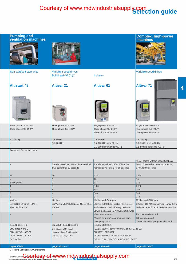
For other versions, please consult with your local Schneider Electric/
Square D sales office: visit www.us.telemecanique.com 4/3
4
Variable speed dr ives Variable speed dr ivesBuilding (HVAC) (1) Industry
Altistart 48 Altivar 21 Altivar 61 Altivar 71
Three phase 230–415 V Three phase 200–240 V Single phase 200–240 V Single phase 200–240 V
Three phase 208–690 V Three phase 380–480 V Three phase 200–240 V Three phase 200–240 V
Three phase 380–480 V Three phase 380–480 V
2–1200 Hp 0.1–40 Hp 0.5–900 Hp 0.5–700 Hp
– 0.5–200 Hz 0.5–1600 Hz up to 50 Hp 0.1–1600 Hz up to 50 Hp
0.5–500 Hz from 50 to 900 Hp 0.1–500 Hz from 50 to 700 Hp
Sensorless flux vector control
– – – Vector control without speed feedback
– 200% of the nominal motor torque for 2 s
170% for 60 seconds
36 50 > 150 > 150
– 8 16 16
1 PTC probe 2 2–4 2–4
4 3 6–20 6–20
1 1 1–3 1–3
2 – 0–8 0–8
3 2 2–4 2–4
Modbus Modbus Modbus and CANopen Modbus and CANopen
DeviceNet, Ethernet TCP/IP, LonWor ks, METASYS N2, APOGEE FLN, Ethernet TCP/IP, Fipio , Modbus Plus, INTERBUS, Ethernet TCP/IP, Modbus/Uni-Telway, Fipio,
Fipio, Profibus DP BACnet Profibus DP, Modbus/Uni-Telway, DeviceNet, Modbus Plus, Profibus DP, DeviceNet, I NTERBUS
LonWorks, METASYS N2, APOGEE FLN, BACnet
– – I/O extension cards Encoder interface card
“Controller Inside” programmable card, I/O extension card
multi-pump cards “Controller Inside” programmable card
IEC/EN 60947-4-2 EN 50178, IEC/EN 61800-3 IEC/EN 61800-5-1,
EMC class A and B EN 55011, EN 55022: IEC/EN 61800-3 (environments 1 and 2, C1 to C3)
DNV - C-TICK - GOST class A, class B with option EN 55011, EN 55022,
CCIB - NOM - UL - CE CE, UL, C-Tick, N998 IEC/EN 61000-4-2/4-3/4-4/4-5/4-6/4-11
CCC - CSA CE, UL, CSA, DNV, C-Tick, NOM 117, GOST
pages 4/8-4/9 pages 4/12-4/13 pages 4/16-4/21 pages 4/22-4/27
(1) Heating Ventilation Air Conditioning
Soft start/soft stop units
Pumping andventilation machines
Complex, high-powermachines
Transient overload: 110–120% of the
nominal drive current for 60 seconds
Transient overload: 110% of the nominal
drive current for 60 seconds
Selection guideCourtesy of www.mdwindustrialsupply.com
Courtesy of www.mdwindustrialsupply.com
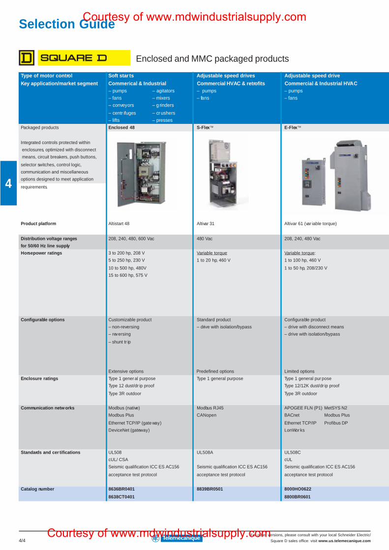
For other versions, please consult with your local Schneider Electric/
Square D sales office: visit www.us.telemecanique.com4/4
4
Type of motor control Soft star ts Adjustable speed drives Adjustable speed drive
Key application/market segment Commerical & Industrial Commercial HVAC & retrofits Commercial & Industrial HVAC– pumps – agitators – pumps – pumps
– fans – mixers – fans – fans
– conveyors – g rinders
– centr ifuges – crushers
– lifts – presses
Packaged products Enclosed 48 S-Flex™ E-Flex™
Integrated controls protected within
enclosures, optimized with disconnect
means, circuit breakers, push buttons,
selector switches, control logic,
communication and miscellaneous
options designed to meet application
requirements.
Product platform Altistart 48 Altivar 31 Altivar 61 (var iable torque)
Distribution voltage ranges 208, 240, 480, 600 Vac 480 Vac 208, 240, 480 Vac
for 50/60 Hz line supply
Horsepower ratings 3 to 200 hp, 208 V Variable torque: Variable torque:
5 to 250 hp, 230 V 1 to 20 hp, 460 V 1 to 100 hp, 460 V
10 to 500 hp, 480V 1 to 50 hp, 208/230 V
15 to 600 hp, 575 V
Configurable options Customizable product Standard product Configurable product
– non-reversing – drive with isolation/bypass – drive with disconnect means
– reversing – drive with isolation/bypass
– shunt tr ip
Extensive options Predefined options Limited options
Enclosure ratings Type 1 gener al purpose Type 1 general purpose Type 1 general pur pose
Type 12 dust/dr ip proof Type 12/12K dust/dr ip proof
Type 3R outdoor Type 3R outdoor
Communication netw orks Modbus (native) Modbus RJ45 APOGEE FLN (P1) MetSYS N2
Modbus Plus CANopen BACnet Modbus Plus
Ethernet TCP/IP (gate way) Ethernet TCP/IP Profibus DP
DeviceNet (gateway) LonWor ks
Standards and cer tifications UL508 UL508A UL508C
cUL/ CSA cUL
Seismic qualification ICC ES AC156 Seismic qualification ICC ES AC156 Seismic qualification ICC ES AC156
acceptance test protocol acceptance test protocol acceptance test protocol
Catalog number 8636BR0401 8839BR0501 8000HO0622
8638CT0401 8800BR0601
Selection Guide
Enclosed and MMC packaged products
Courtesy of www.mdwindustrialsupply.com
Courtesy of www.mdwindustrialsupply.com
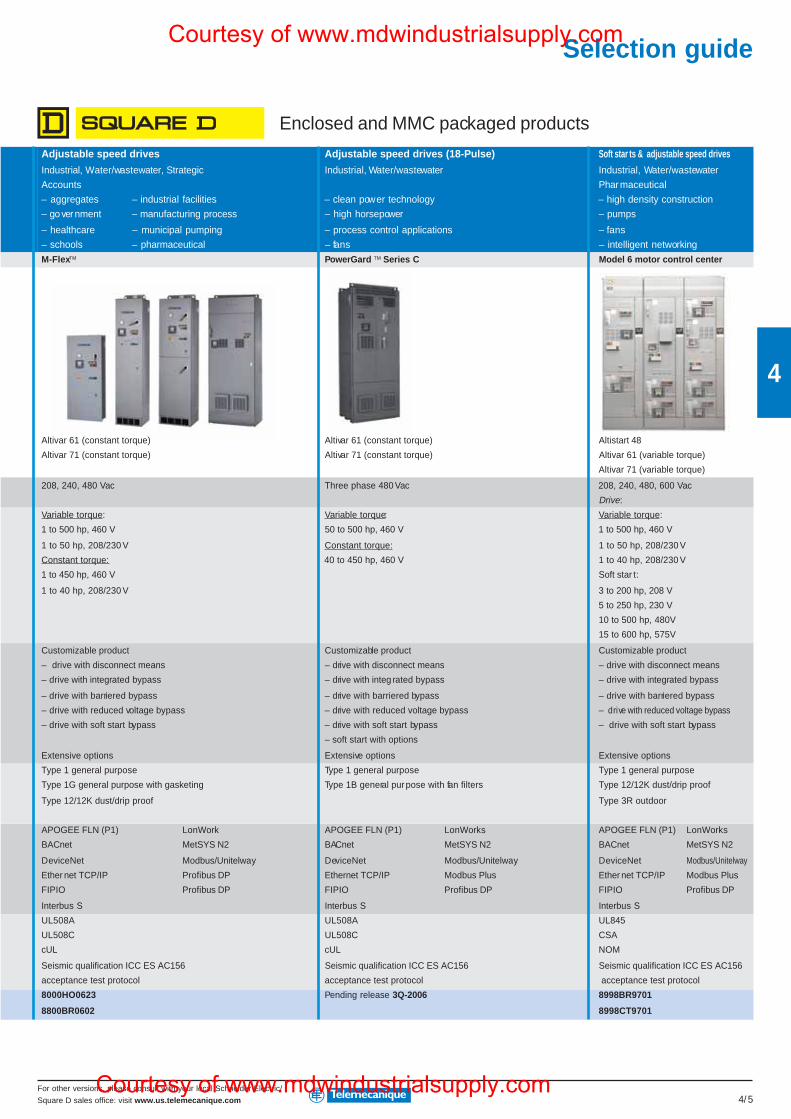
For other versions, please consult with your local Schneider Electric/
Square D sales office: visit www.us.telemecanique.com 4/5
4
Adjustable speed drives Adjustable speed drives (18-Pulse) Soft star ts & adjustable speed drives
Industrial, Water/wastewater, Strategic Industrial, Water/wastewater Industrial, Water/wastewater
Accounts Pharmaceutical
– aggregates – industrial facilities – clean power technology – high density construction
– government – manufacturing process – high horsepower – pumps
– healthcare – municipal pumping – process control applications – fans
– schools – pharmaceutical – fans – intelligent networking
M-Flex™ PowerGard ™ Series C Model 6 motor control center
Altivar 61 (constant torque) Altivar 61 (constant torque) Altistart 48
Altivar 71 (constant torque) Altivar 71 (constant torque) Altivar 61 (variable torque)
Altivar 71 (variable torque)
208, 240, 480 Vac Three phase 480 Vac 208, 240, 480, 600 Vac
Drive:
Variable torque: Variable torque: Variable torque:
1 to 500 hp, 460 V 50 to 500 hp, 460 V 1 to 500 hp, 460 V
1 to 50 hp, 208/230 V Constant torque: 1 to 50 hp, 208/230 V
Constant torque: 40 to 450 hp, 460 V 1 to 40 hp, 208/230 V
1 to 450 hp, 460 V Soft star t:
1 to 40 hp, 208/230 V 3 to 200 hp, 208 V
5 to 250 hp, 230 V
10 to 500 hp, 480V
15 to 600 hp, 575V
Customizable product Customizable product Customizable product
– drive with disconnect means – drive with disconnect means – drive with disconnect means
– drive with integrated bypass – drive with integ rated bypass – drive with integrated bypass
– drive with barriered bypass – drive with barriered bypass – drive with barriered bypass
– drive with reduced voltage bypass – drive with reduced voltage bypass – drive with reduced voltage bypass
– drive with soft start bypass – drive with soft start bypass – drive with soft start bypass
– soft start with options
Extensive options Extensive options Extensive options
Type 1 general purpose Type 1 general purpose Type 1 general purpose
Type 1G general purpose with gasketing Type 1B general pur pose with fan filters Type 12/12K dust/drip proof
Type 12/12K dust/drip proof Type 3R outdoor
APOGEE FLN (P1) LonWork APOGEE FLN (P1) LonWorks APOGEE FLN (P1) LonWorks
BACnet MetSYS N2 BACnet MetSYS N2 BACnet MetSYS N2
DeviceNet Modbus/Unitelway DeviceNet Modbus/Unitelway DeviceNet Modbus/Unitelway
Ether net TCP/IP Profibus DP Ethernet TCP/IP Modbus Plus Ether net TCP/IP Modbus Plus
FIPIO Profibus DP FIPIO Profibus DP FIPIO Profibus DP
Interbus S Interbus S Interbus S
UL508A UL508A UL845
UL508C UL508C CSA
cUL cUL NOM
Seismic qualification ICC ES AC156 Seismic qualification ICC ES AC156 Seismic qualification ICC ES AC156
acceptance test protocol acceptance test protocol acceptance test protocol
8000HO0623 Pending release 3Q-2006 8998BR9701
8800BR0602 8998CT9701
Enclosed and MMC packaged products
Selection guideCourtesy of www.mdwindustrialsupply.com
Courtesy of www.mdwindustrialsupply.com
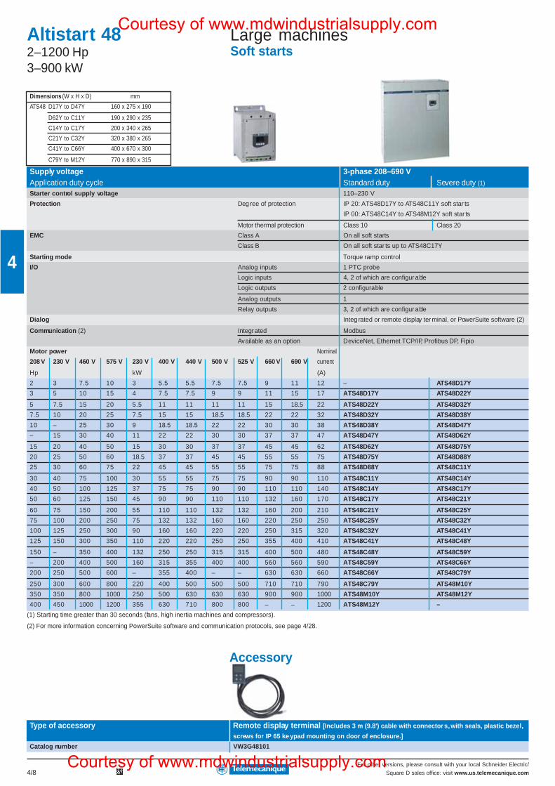
For other versions, please consult with your local Schneider Electric/
Square D sales office: visit www.us.telemecanique.com4/8
4
Dimensions (W x H x D) mm
ATS48 D17Y to D47Y 160 x 275 x 190
D62Y to C11Y 190 x 290 x 235
C14Y to C17Y 200 x 340 x 265
C21Y to C32Y 320 x 380 x 265
C41Y to C66Y 400 x 670 x 300
C79Y to M12Y 770 x 890 x 315
Altistart 482–1200 Hp3–900 kW
Large machinesSoft starts
Supply voltage 3-phase 208–690 VApplication duty cycle Standard duty Severe duty (1)
Starter control supply voltage 110–230 V
Protection Deg ree of protection IP 20: ATS48D17Y to ATS48C11Y soft star ts
IP 00: ATS48C14Y to ATS48M12Y soft star ts
Motor thermal protection Class 10 Class 20
EMC Class A On all soft starts
Class B On all soft star ts up to ATS48C17Y
Starting mode Torque ramp control
I/O Analog inputs 1 PTC probe
Logic inputs 4, 2 of which are configur able
Logic outputs 2 configurable
Analog outputs 1
Relay outputs 3, 2 of which are configur able
Dialog Integ rated or remote display ter minal, or PowerSuite software (2)
Communication (2) Integrated Modbus
Available as an option DeviceNet, Ethernet TCP/IP, Profibus DP, Fipio
Motor power Nominal
208 V 230 V 460 V 575 V 230 V 400 V 440 V 500 V 525 V 660 V 690 V current
Hp kW (A)
2 3 7.5 10 3 5.5 5.5 7.5 7.5 9 11 12 – ATS48D17Y
3 5 10 15 4 7.5 7.5 9 9 11 15 17 ATS48D17Y ATS48D22Y
5 7.5 15 20 5.5 11 11 11 11 15 18.5 22 ATS48D22Y ATS48D32Y
7.5 10 20 25 7.5 15 15 18.5 18.5 22 22 32 ATS48D32Y ATS48D38Y
10 – 25 30 9 18.5 18.5 22 22 30 30 38 ATS48D38Y ATS48D47Y
– 15 30 40 11 22 22 30 30 37 37 47 ATS48D47Y ATS48D62Y
15 20 40 50 15 30 30 37 37 45 45 62 ATS48D62Y ATS48D75Y
20 25 50 60 18.5 37 37 45 45 55 55 75 ATS48D75Y ATS48D88Y
25 30 60 75 22 45 45 55 55 75 75 88 ATS48D88Y ATS48C11Y
30 40 75 100 30 55 55 75 75 90 90 110 ATS48C11Y ATS48C14Y
40 50 100 125 37 75 75 90 90 110 110 140 ATS48C14Y ATS48C17Y
50 60 125 150 45 90 90 110 110 132 160 170 ATS48C17Y ATS48C21Y
60 75 150 200 55 110 110 132 132 160 200 210 ATS48C21Y ATS48C25Y
75 100 200 250 75 132 132 160 160 220 250 250 ATS48C25Y ATS48C32Y
100 125 250 300 90 160 160 220 220 250 315 320 ATS48C32Y ATS48C41Y
125 150 300 350 110 220 220 250 250 355 400 410 ATS48C41Y ATS48C48Y
150 – 350 400 132 250 250 315 315 400 500 480 ATS48C48Y ATS48C59Y
– 200 400 500 160 315 355 400 400 560 560 590 ATS48C59Y ATS48C66Y
200 250 500 600 – 355 400 – – 630 630 660 ATS48C66Y ATS48C79Y
250 300 600 800 220 400 500 500 500 710 710 790 ATS48C79Y ATS48M10Y
350 350 800 1000 250 500 630 630 630 900 900 1000 ATS48M10Y ATS48M12Y
400 450 1000 1200 355 630 710 800 800 – – 1200 ATS48M12Y –
(1) Starting time greater than 30 seconds (fans, high inertia machines and compressors).
(2) For more information concerning PowerSuite software and communication protocols, see page 4/28.
Accessory
Type of accessory Remote display terminal [Includes 3 m (9.8') cable with connector s, with seals, plastic bezel,
screws for IP 65 ke ypad mounting on door of enclosure.]
Catalog number VW3G48101
Courtesy of www.mdwindustrialsupply.com
Courtesy of www.mdwindustrialsupply.com
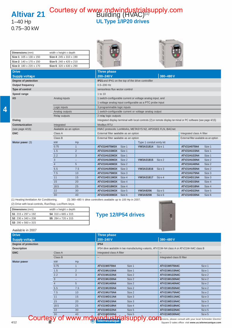
For other versions, please consult with your local Schneider Electric/
Square D sales office: visit www.us.telemecanique.com4/12
4
Altivar 211–40 Hp0.75–30 kW
Building (HVAC)(1)
UL Type 1/IP20 drives
Drive Three phaseSupply voltage 200–240 V 380–480 VDegree of protection IP21 and IP41 on the top of the drive controlller
Output frequency 0.5–200 Hz
Type of control sensorless flux vector control
Speed range 1 to 10
I/O Analog inputs 1 switch-configurable current or voltage analog input, and
1 voltage analog input configurable as a PTC probe input
Logic inputs 3 programmable logic inputs
Analog outputs 1 switch-configurable current or voltage analog output
Relay outputs 2 relay logic outputs
Dialog Integrated display terminal with local controls (2) or remote display ter minal or PC software (see page 4/15)
Communication Integrated Modbus RTU
(see page 4/15) Available as an option HVAC protocols: LonWorks, METASYS N2, APOGEE FLN, BACnet
EMC Class A External filter available as an option Integrated class A filter
Class B External filter available as an option External filter available as an option
Motor power (3) kW Hp Type 1 conduit enrty kit
0.75 1 ATV21H075M3X Size 1 VW3A31814 Siz e 1 ATV21H075N4 Size 1
1.5 2 ATV21HU15M3X Size 1 ATV21HU15N4 Size 1
2.2 3 ATV21HU22M3X Size 1 ATV21HU22N4 Size 1
3 – ATV21HU30M3X Size 2 VW3A31815 Siz e 2 ATV21HU30N4 Size 2
4 5 ATV21HU40M3X Size 2 ATV21HU40N4 Size 2
5.5 7.5 ATV21HU55M3X Size 3 VW3A31816 Siz e 3 ATV21HU55N4 Size 2
7.5 10 ATV21HU75M3X Size 3 ATV21HU75N4 Size 3
11 15 ATV21HD11M3X Size 4 VW3A31817 Siz e 4 ATV21HD11N4 Size 3
15 20 ATV21HD15M3X Size 4 ATV21HD15N4 Size 4
18.5 25 ATV21HD18M3X Size 4 ATV21HD18N4 Size 4
22 30 ATV21HD22M3X Size 5 VW3A9206 Siz e 5 ATV21HD22N4 Size 5
30 40 ATV21HD30M3X Size 6 VW3A9208 Siz e 6 ATV21HD30N4 Size 6
(1) Heating Ventilation Air Conditioning. (3) 380–480 V drive controllers available up to 100 Hp in 2007.
(2) Drive with local controls, Run/Stop, Loc/Rem. keys.
Type 12/IP54 drives
Availab le in 2007Drive Three phaseSupply voltage 200–240 V 380–480 VDegree of protection IP54
Description IP54 drive available in two manufacturing v ariants, ATV21W–N4 class A or ATV21W–N4C class B
EMC Class A Integrated class A filter –
Class B – Integrated class B filter
Motor power kW Hp
0.75 1 ATV21W075N4 Size 1 ATV21W075N4C Siz e 1
1.5 2 ATV21WU15N4 Size 1 ATV21WU15N4C Siz e 1
2.2 3 ATV21WU22N4 Size 2 ATV21WU22N4C Siz e 2
3 – ATV21WU30N4 Size 2 ATV21WU30N4C Siz e 2
4 5 ATV21WU40N4 Size 2 ATV21WU40N4C Siz e 2
5.5 7.5 ATV21WU55N4 Size 2 ATV21WU55N4C Siz e 2
7.5 10 ATV21WU75N4 Size 2 ATV21WU75N4C Siz e 2
11 15 ATV21WD11N4 Size 3 ATV21WD11N4C Siz e 3
15 20 ATV21WD15N4 Size 3 ATV21WD15N4C Siz e 3
18.5 25 ATV21WD18N4 Size 4 ATV21WD18N4C Siz e 4
22 30 ATV21WD22N4 Size 5 ATV21WD22N4C Siz e 5
30 40 ATV21WD30N4 Size 5 ATV21WD30N4C Siz e 5
Dimensions (mm) width x height x depth
Size 1: 105 x 130 x 150 Size 4 : 245 x 310 x 190
Size 2: 140 x 170 x 150 Size 5 : 240 x 420 x 210
Size 3: 180 x 220 x 170 Size 6 : 320 x 630 x 290
Dimensions (mm) width x height x depth
S1: 215 x 297 x 192 S4: 310 x 665 x 315
S2: 230 x 340 x 208 S5: 284 x 720 x 315
S3: 290 x 560 x 315
Courtesy of www.mdwindustrialsupply.com
Courtesy of www.mdwindustrialsupply.com
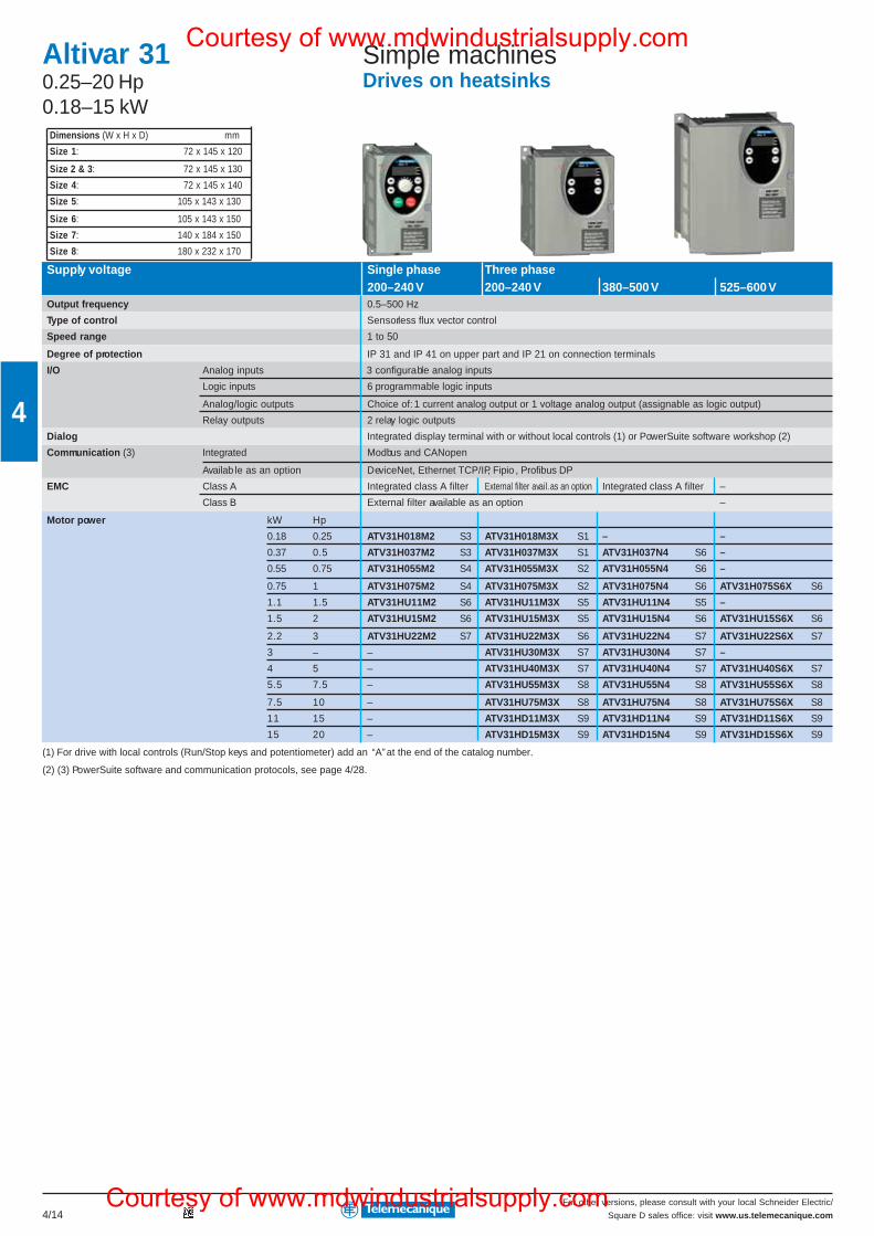
For other versions, please consult with your local Schneider Electric/
Square D sales office: visit www.us.telemecanique.com4/14
4
Dimensions (W x H x D) mm
Size 1: 72 x 145 x 120
Size 2 & 3: 72 x 145 x 130
Size 4: 72 x 145 x 140
Size 5: 105 x 143 x 130
Size 6: 105 x 143 x 150
Size 7: 140 x 184 x 150
Size 8: 180 x 232 x 170
Altivar 310.25–20 Hp0.18–15 kW
Simple machinesDrives on heatsinks
Supply voltage Single phase Three phase200–240 V 200–240 V 380–500 V 525–600 V
Output frequency 0.5–500 Hz
Type of control Sensorless flux vector control
Speed range 1 to 50
Degree of protection IP 31 and IP 41 on upper part and IP 21 on connection terminals
I/O Analog inputs 3 configurable analog inputs
Logic inputs 6 programmable logic inputs
Analog/logic outputs Choice of: 1 current analog output or 1 voltage analog output (assignable as logic output)
Relay outputs 2 relay logic outputs
Dialog Integrated display terminal with or without local controls (1) or PowerSuite software workshop (2)
Communication (3) Integrated Modbus and CANopen
Availab le as an option DeviceNet, Ethernet TCP/IP, Fipio , Profibus DP
EMC Class A Integrated class A filter External filter avail. as an option Integrated class A filter –
Class B External filter available as an option –
Motor power kW Hp
0.18 0.25 ATV31H018M2 S3 ATV31H018M3X S1 – –
0.37 0.5 ATV31H037M2 S3 ATV31H037M3X S1 ATV31H037N4 S6 –
0.55 0.75 ATV31H055M2 S4 ATV31H055M3X S2 ATV31H055N4 S6 –
0.75 1 ATV31H075M2 S4 ATV31H075M3X S2 ATV31H075N4 S6 ATV31H075S6X S6
1.1 1.5 ATV31HU11M2 S6 ATV31HU11M3X S5 ATV31HU11N4 S5 –
1.5 2 ATV31HU15M2 S6 ATV31HU15M3X S5 ATV31HU15N4 S6 ATV31HU15S6X S6
2.2 3 ATV31HU22M2 S7 ATV31HU22M3X S6 ATV31HU22N4 S7 ATV31HU22S6X S7
3 – – ATV31HU30M3X S7 ATV31HU30N4 S7 –
4 5 – ATV31HU40M3X S7 ATV31HU40N4 S7 ATV31HU40S6X S7
5.5 7.5 – ATV31HU55M3X S8 ATV31HU55N4 S8 ATV31HU55S6X S8
7.5 10 – ATV31HU75M3X S8 ATV31HU75N4 S8 ATV31HU75S6X S8
11 15 – ATV31HD11M3X S9 ATV31HD11N4 S9 ATV31HD11S6X S9
15 20 – ATV31HD15M3X S9 ATV31HD15N4 S9 ATV31HD15S6X S9
(1) For drive with local controls (Run/Stop keys and potentiometer) add an “A” at the end of the catalog number.
(2) (3) PowerSuite software and communication protocols, see page 4/28.
Courtesy of www.mdwindustrialsupply.com
Courtesy of www.mdwindustrialsupply.com
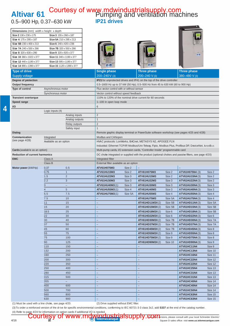
For other versions, please consult with your local Schneider Electric/
Square D sales office: visit www.us.telemecanique.com4/16
4
Pumping and ventilation machinesIP21 drives
Altivar 610.5–900 Hp, 0.37–630 kW
Type of drive Single phase Three phase Three phaseSupply voltage 200–240 V (3) 200–240 V (3) 380–480 V (3)
Degree of protection IP21 for unprotected drives and IP41 on the top of the drive controller
Output frequency 0.5–1600 Hz up to 37 kW (50 Hp); 0.5–500 Hz from 45 to 630 kW (60 to 900 Hp)
Type of control Asynchronous motor Flux vector control with or without sensor
Synchronous motor Vector control without speed feedback
Transient overtorque 110% to 120% of the nominal drive current for 60 seconds
Speed range 1–100 in open loop mode
I/O 6
Logic inputs (4)
Analog inputs 2
Analog outputs 1
Relay outputs 2
Safety input 1
Dialog Remote graphic display terminal or PowerSuite software workshop (see pages 4/25 and 4/28)
Communication Integrated Modbus and CANopen(see page 4/28) Available as an option HVAC protocols: LonWorks, BACnet, METASYS N2, APOGEE FLN
Industrial: Ethernet TCP/IP, Modbus/Uni-Telway, Fipio, Modbus Plus, Profibus DP, DeviceNet, INTERBUS
Cards (availab le as an option) Multi-pump cards, I/O extension cards, “Controller Inside” programmable card
Reduction of current harmonics DC choke integrated or supplied with the product (optional chokes and passive filters, see page 4/20)
EMC Class A Integrated filter
Class B External filter available as an option
Motor power (kW/Hp) 0.37 0.5 ATV61H075M3 Size 2 – –
0.75 1 ATV61HU15M3 Size 2 ATV61H075M3 Size 2 ATV61H075N4 (3) Size 2
1.5 2 ATV61HU22M3 Size 3 ATV61HU15M3 Size 2 ATV61HU15N4 (3) Size 2
2.2 3 ATV61HU30M3 Size 3 ATV61HU22M3 Size 3 ATV61HU22N4 (3) Size 2
3 – ATV61HU40M3 (1) Size 3 ATV61HU30M3 Size 3 ATV61HU30N4 (3) Size 3
4 5 ATV61HU55M3 (1) Size 4 ATV61HU40M3 Size 3 ATV61HU40N4 (3) Size 3
5.5 7.5 ATV61HU75M3 (1) Size 5A ATV61HU55M3 Size 4 ATV61HU55N4 (3) Size 4
7.5 10 – ATV61HU75M3 Size 5A ATV61HU75N4 (3) Size 4
11 15 – ATV61HD11M3X (2) Size 5B ATV61HD11N4 (3) Size 5A
15 20 – ATV61HD15M3X (2) Size 5B ATV61HD15N4 (3) Size 5B
18.5 25 – ATV61HD18M3X (2) Size 6 ATV61HD18N4 (3) Size 5B
22 30 – ATV61HD22M3X (2) Size 6 ATV61HD22N4 (3) Size 6
30 40 – ATV61HD30M3X (2) Size 7B ATV61HD30N4 (3) Size 7A
37 50 – ATV61HD37M3X (2) Size 7B ATV61HD37N4 (3) Size 7A
45 60 – ATV61HD45M3X (2) Size 7B ATV61HD45N4 (3) Size 8
55 75 – ATV61HD55M3X (2) Size 9 ATV61HD55N4 (3) Size 8
75 100 – ATV61HD75M3X (2) Size 9 ATV61HD75N4 (3) Size 8
90 125 – ATV61HD90M3X (2) Size 10 ATV61HD90N4 (3) Size 9
110 150 – – ATV61HC11N4 Size 9
132 200 – – ATV61HC13N4 Size 10
160 250 – – ATV61HC16N4 Size 11
200 300 – – ATV61HC22N4 Size 12
220 350 – – ATV61HC22N4 Size 12
250 400 – – ATV61HC25N4 Size 13
280 450 – – ATV61HC31N4 Size 13
315 500 – – ATV61HC31N4 Size 13
355 – – – ATV61HC40N4 Size 14
400 600 – – ATV61HC40N4 Size 14
500 700 – – ATV61HC50N4 Size 14
560 800 – – ATV61HC63N4 Size 15
630 900 – – ATV61HC63N4 Size 15
(1) Must be used with a line choke, see page 4/20. (2) Drive supplied without EMC filter.
(3) To order a reinforced version of the dr ive for specific environmental conditions, conforming to IEC 60721-3-3 class 3c2, add S337 at the end of the catalog number.
(4) Refer to page 4/24 for information on option cards if additional I/O is needed.
Dimensions (mm) width x height x depth
Size 2: 130 x 230 x 175 Size 3: 155 x 260 x 187
Size 4: 175 x 295 x 187 Size 5A: 210 x 295 x 213
Size 5B: 230 x 400 x 213 Size 6: 240 x 420 x 236
Size 7A: 240 x 550 x 266 Size 7B: 320 x 550 x 266
Size 8: 320 x 630 x 290 Size 9: 320 x 920 x 377
Size 10: 360 x 1022 x 377 Size 11: 340 x 1190 x 377
Size 12: 440 x 1190 x 377 Size 13: 595 x 1190 x 377
Size 14: 890 x 1390 x 377 Size 15: 1120 x 1390 x 377
Courtesy of www.mdwindustrialsupply.com
Courtesy of www.mdwindustrialsupply.com
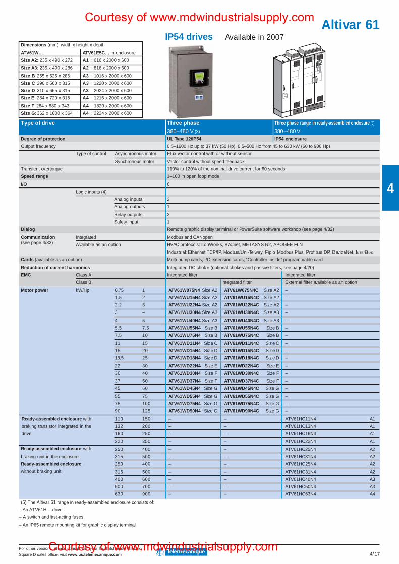
For other versions, please consult with your local Schneider Electric/
Square D sales office: visit www.us.telemecanique.com 4/17
4
Type of drive Three phase Three phase range in ready-assembled enclosure (5)
380–480 V (3) 380–480 VDegree of protection UL Type 12/IP54 IP54 enclosure
Output frequency 0.5–1600 Hz up to 37 kW (50 Hp); 0.5–500 Hz from 45 to 630 kW (60 to 900 Hp)
Type of control Asynchronous motor Flux vector control with or without sensor
Synchronous motor Vector control without speed feedbac k
Transient overtorque 110% to 120% of the nominal drive current for 60 seconds
Speed range 1–100 in open loop mode
I/O 6
Logic inputs (4)
Analog inputs 2
Analog outputs 1
Relay outputs 2
Safety input 1
Dialog Remote g raphic display ter minal or PowerSuite software workshop (see page 4/32)
Communication Integrated Modbus and CANopen(see page 4/32) Available as an option HVAC protocols: LonWorks, BACnet, METASYS N2, APOGEE FLN
Industrial: Ether net TCP/IP, Modbus/Uni-Telway, Fipio, Modbus Plus, Profibus DP, DeviceNet, INTERBUS
Cards (available as an option) Multi-pump cards, I/O extension cards, “Controller Inside” programmable card
Reduction of current harmonics Integrated DC chok e (optional chokes and passive filters, see page 4/20)
EMC Class A Integrated filter Integrated filter
Class B Integrated filter External filter availab le as an option
Motor power kW/Hp 0.75 1 ATV61W075N4 Size A2 ATV61W075N4C Size A2 –
1.5 2 ATV61WU15N4 Size A2 ATV61WU15N4C Size A2 –
2.2 3 ATV61WU22N4 Size A2 ATV61WU22N4C Size A2 –
3 – ATV61WU30N4 Size A3 ATV61WU30N4C Size A3 –
4 5 ATV61WU40N4 Size A3 ATV61WU40N4C Size A3 –
5.5 7.5 ATV61WU55N4 Size B ATV61WU55N4C Size B –
7.5 10 ATV61WU75N4 Size B ATV61WU75N4C Size B –
11 15 ATV61WD11N4 Siz e C ATV61WD11N4C Siz e C –
15 20 ATV61WD15N4 Siz e D ATV61WD15N4C Siz e D –
18.5 25 ATV61WD18N4 Siz e D ATV61WD18N4C Siz e D –
22 30 ATV61WD22N4 Size E ATV61WD22N4C Size E –
30 40 ATV61WD30N4 Size F ATV61WD30N4C Size F –
37 50 ATV61WD37N4 Size F ATV61WD37N4C Size F –
45 60 ATV61WD45N4 Size G ATV61WD45N4C Size G –
55 75 ATV61WD55N4 Size G ATV61WD55N4C Size G –
75 100 ATV61WD75N4 Size G ATV61WD75N4C Size G –
90 125 ATV61WD90N4 Size G ATV61WD90N4C Size G –
110 150 – – ATV61HC11N4 A1
132 200 – – ATV61HC13N4 A1
160 250 – – ATV61HC16N4 A1
220 350 – – ATV61HC22N4 A1
250 400 – – ATV61HC25N4 A2
315 500 – – ATV61HC31N4 A2
250 400 – – ATV61HC25N4 A2
315 500 – – ATV61HC31N4 A2
400 600 – – ATV61HC40N4 A3
500 700 – – ATV61HC50N4 A3
630 900 – – ATV61HC63N4 A4
(5) The Altivar 61 range in ready-assembled enclosure consists of:
– An ATV61H… drive
– A switch and fast-acting fuses
– An IP65 remote mounting kit for graphic display terminal
IP54 drives Available in 2007Dimensions (mm) width x height x depth
ATV61W… ATV61E5C… in enclosure
Size A2: 235 x 490 x 272 A1 : 616 x 2000 x 600
Size A3: 235 x 490 x 286 A2 : 816 x 2000 x 600
Size B: 255 x 525 x 286 A3 : 1016 x 2000 x 600
Size C: 290 x 560 x 315 A3 : 1220 x 2000 x 600
Size D: 310 x 665 x 315 A3 : 2024 x 2000 x 600
Size E: 284 x 720 x 315 A4 : 1216 x 2000 x 600
Size F: 284 x 880 x 343 A4 : 1820 x 2000 x 600
Size G: 362 x 1000 x 364 A4 : 2224 x 2000 x 600
Ready-assembled enclosure with
braking transistor integrated in the
drive
Ready-assembled enclosure with
braking unit in the enclosure
Ready-assembled enclosure
without braking unit
Altivar 61Courtesy of www.mdwindustrialsupply.com
Courtesy of www.mdwindustrialsupply.com
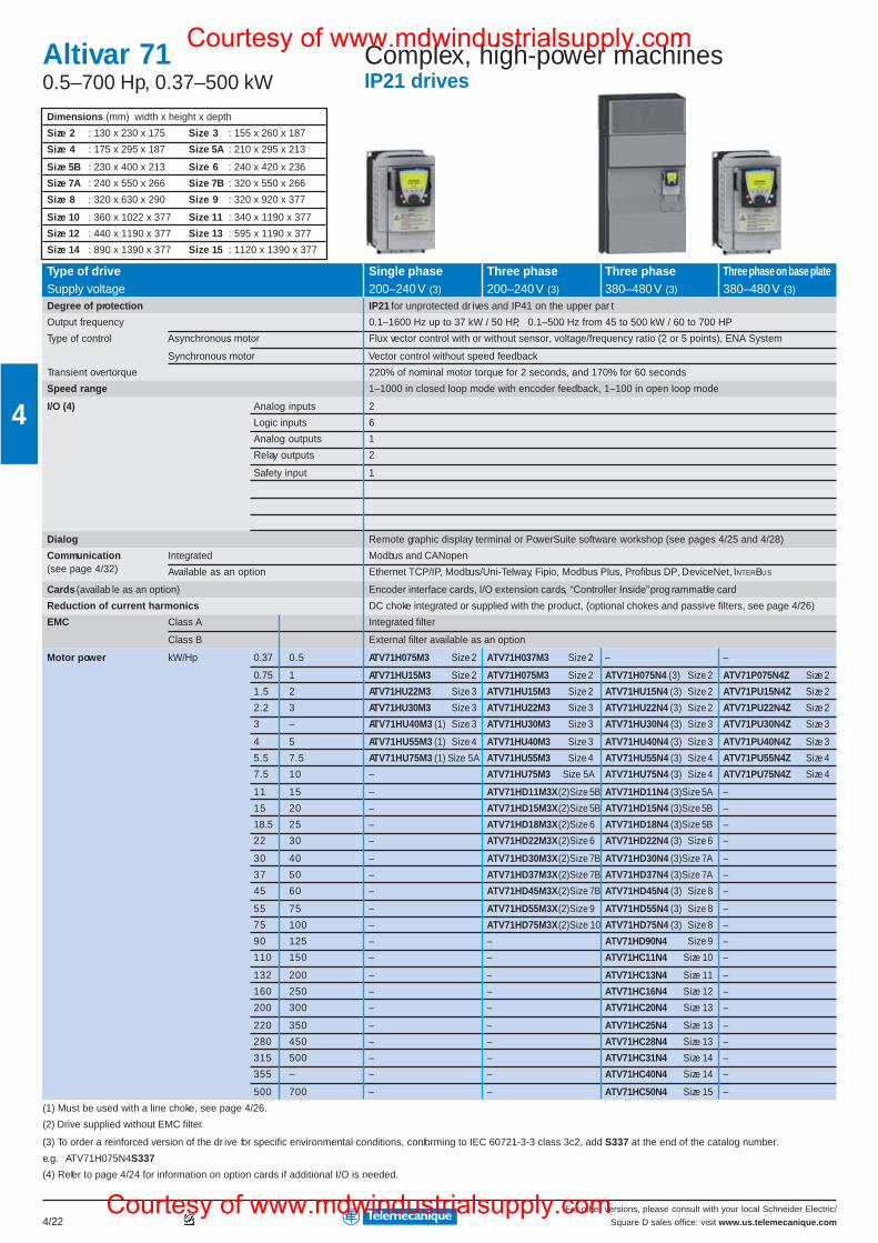
For other versions, please consult with your local Schneider Electric/
Square D sales office: visit www.us.telemecanique.com4/22
4
Complex, high-power machinesIP21 drives
Altivar 710.5–700 Hp, 0.37–500 kW
Type of drive Single phase Three phase Three phase Three phase on base plateSupply voltage 200–240 V (3) 200–240 V (3) 380–480 V (3) 380–480 V (3)
Degree of protection IP21 for unprotected dr ives and IP41 on the upper par t
Output frequency 0.1–1600 Hz up to 37 kW / 50 HP, 0.1–500 Hz from 45 to 500 kW / 60 to 700 HP
Type of control Asynchronous motor Flux vector control with or without sensor, voltage/frequency ratio (2 or 5 points), ENA System
Synchronous motor Vector control without speed feedback
Transient overtorque 220% of nominal motor torque for 2 seconds, and 170% for 60 seconds
Speed range 1–1000 in closed loop mode with encoder feedback, 1–100 in open loop mode
I/O (4) Analog inputs 2
Logic inputs 6
Analog outputs 1
Relay outputs 2
Safety input 1
Dialog Remote graphic display terminal or PowerSuite software workshop (see pages 4/25 and 4/28)
Communication Integrated Modbus and CANopen(see page 4/32) Available as an option Ethernet TCP/IP, Modbus/Uni-Telway, Fipio, Modbus Plus, Profibus DP, DeviceNet, INTERBUS
Cards (availab le as an option) Encoder interface cards, I/O extension cards, “Controller Inside” prog rammable card
Reduction of current harmonics DC choke integrated or supplied with the product, (optional chokes and passive filters, see page 4/26)
EMC Class A Integrated filter
Class B External filter available as an option
Motor power kW/Hp 0.37 0.5 ATV71H075M3 Size 2 ATV71H037M3 Size 2 – –
0.75 1 ATV71HU15M3 Size 2 ATV71H075M3 Size 2 ATV71H075N4 (3) Size 2 ATV71P075N4Z Size 2
1.5 2 ATV71HU22M3 Size 3 ATV71HU15M3 Size 2 ATV71HU15N4 (3) Size 2 ATV71PU15N4Z Size 2
2.2 3 ATV71HU30M3 Size 3 ATV71HU22M3 Size 3 ATV71HU22N4 (3) Size 2 ATV71PU22N4Z Size 2
3 – ATV71HU40M3 (1) Size 3 ATV71HU30M3 Size 3 ATV71HU30N4 (3) Size 3 ATV71PU30N4Z Size 3
4 5 ATV71HU55M3 (1) Size 4 ATV71HU40M3 Size 3 ATV71HU40N4 (3) Size 3 ATV71PU40N4Z Size 3
5.5 7.5 ATV71HU75M3 (1) Size 5A ATV71HU55M3 Size 4 ATV71HU55N4 (3) Size 4 ATV71PU55N4Z Size 4
7.5 10 – ATV71HU75M3 Size 5A ATV71HU75N4 (3) Size 4 ATV71PU75N4Z Size 4
11 15 – ATV71HD11M3X (2)Size 5B ATV71HD11N4 (3)Size 5A –
15 20 – ATV71HD15M3X (2)Size 5B ATV71HD15N4 (3)Size 5B –
18.5 25 – ATV71HD18M3X (2)Size 6 ATV71HD18N4 (3)Size 5B –
22 30 – ATV71HD22M3X (2)Size 6 ATV71HD22N4 (3) Size 6 –
30 40 – ATV71HD30M3X (2)Size 7B ATV71HD30N4 (3)Size 7A –
37 50 – ATV71HD37M3X (2)Size 7B ATV71HD37N4 (3)Size 7A –
45 60 – ATV71HD45M3X (2)Size 7B ATV71HD45N4 (3) Size 8 –
55 75 – ATV71HD55M3X (2)Size 9 ATV71HD55N4 (3) Size 8 –
75 100 – ATV71HD75M3X (2)Size 10 ATV71HD75N4 (3) Size 8 –
90 125 – – ATV71HD90N4 Size 9 –
110 150 – – ATV71HC11N4 Size 10 –
132 200 – – ATV71HC13N4 Size 11 –
160 250 – – ATV71HC16N4 Size 12 –
200 300 – – ATV71HC20N4 Size 13 –
220 350 – – ATV71HC25N4 Size 13 –
280 450 – – ATV71HC28N4 Size 13 –
315 500 – – ATV71HC31N4 Size 14 –
355 – – – ATV71HC40N4 Size 14 –
500 700 – – ATV71HC50N4 Size 15 –
(1) Must be used with a line choke, see page 4/26.
(2) Drive supplied without EMC filter.
(3) To order a reinforced version of the dr ive for specific environmental conditions, conforming to IEC 60721-3-3 class 3c2, add S337 at the end of the catalog number.
e.g. ATV71H075N4S337
(4) Refer to page 4/24 for information on option cards if additional I/O is needed.
Dimensions (mm) width x height x depth
Size 2 : 130 x 230 x 175 Size 3 : 155 x 260 x 187
Size 4 : 175 x 295 x 187 Size 5A : 210 x 295 x 213
Size 5B : 230 x 400 x 213 Size 6 : 240 x 420 x 236
Size 7A : 240 x 550 x 266 Size 7B : 320 x 550 x 266
Size 8 : 320 x 630 x 290 Size 9 : 320 x 920 x 377
Size 10 : 360 x 1022 x 377 Size 11 : 340 x 1190 x 377
Size 12 : 440 x 1190 x 377 Size 13 : 595 x 1190 x 377
Size 14 : 890 x 1390 x 377 Size 15 : 1120 x 1390 x 377
Courtesy of www.mdwindustrialsupply.com
Courtesy of www.mdwindustrialsupply.com
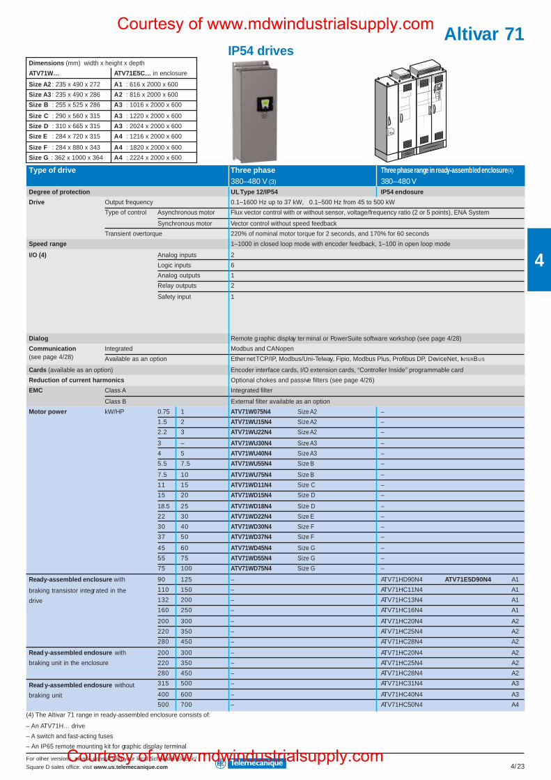
For other versions, please consult with your local Schneider Electric/
Square D sales office: visit www.us.telemecanique.com 4/23
4
IP54 drives
Type of drive Three phase Three phase range in ready-assembled enclosure (4)
380–480 V (3) 380–480 VDegree of protection UL Type 12/IP54 IP54 enclosure
Drive Output frequency 0.1–1600 Hz up to 37 kW, 0.1–500 Hz from 45 to 500 kW
Type of control Asynchronous motor Flux vector control with or without sensor, voltage/frequency ratio (2 or 5 points), ENA System
Synchronous motor Vector control without speed feedback
Transient overtorque 220% of nominal motor torque for 2 seconds, and 170% for 60 seconds
Speed range 1–1000 in closed loop mode with encoder feedback, 1–100 in open loop mode
I/O (4) Analog inputs 2
Logic inputs 6
Analog outputs 1
Relay outputs 2
Safety input 1
Dialog Remote g raphic display ter minal or PowerSuite software workshop (see page 4/28)
Communication Integrated Modbus and CANopen(see page 4/28) Available as an option Ether net TCP/IP, Modbus/Uni-Telway, Fipio, Modbus Plus, Profibus DP, DeviceNet, INTERBUS
Cards (available as an option) Encoder interface cards, I/O extension cards, “Controller Inside” programmable card
Reduction of current harmonics Optional chokes and passive filters (see page 4/26)
EMC Class A Integrated filter
Class B External filter available as an option
Motor power kW/HP 0.75 1 ATV71W075N4 Size A2 –
1.5 2 ATV71WU15N4 Size A2 –
2.2 3 ATV71WU22N4 Size A2 –
3 – ATV71WU30N4 Size A3 –
4 5 ATV71WU40N4 Size A3 –
5.5 7.5 ATV71WU55N4 Size B –
7.5 10 ATV71WU75N4 Size B –
11 15 ATV71WD11N4 Size C –
15 20 ATV71WD15N4 Size D –
18.5 25 ATV71WD18N4 Size D –
22 30 ATV71WD22N4 Size E –
30 40 ATV71WD30N4 Size F –
37 50 ATV71WD37N4 Size F –
45 60 ATV71WD45N4 Size G –
55 75 ATV71WD55N4 Size G –
75 100 ATV71WD75N4 Size G –
90 125 – ATV71HD90N4 ATV71E5D90N4 A1
110 150 – ATV71HC11N4 A1
132 200 – ATV71HC13N4 A1
160 250 – ATV71HC16N4 A1
200 300 – ATV71HC20N4 A2
220 350 – ATV71HC25N4 A2
280 450 – ATV71HC28N4 A2
200 300 – ATV71HC20N4 A2
220 350 – ATV71HC25N4 A2
280 450 – ATV71HC28N4 A2
315 500 – ATV71HC31N4 A3
400 600 – ATV71HC40N4 A3
500 700 – ATV71HC50N4 A4
(4) The Altivar 71 range in ready-assembled enclosure consists of:
– An ATV71H… drive
– A switch and fast-acting fuses
– An IP65 remote mounting kit for graphic display terminal
Dimensions (mm) width x height x depth
ATV71W… ATV71E5C… in enclosure
Size A2 : 235 x 490 x 272 A1 : 616 x 2000 x 600
Size A3 : 235 x 490 x 286 A2 : 816 x 2000 x 600
Size B : 255 x 525 x 286 A3 : 1016 x 2000 x 600
Size C : 290 x 560 x 315 A3 : 1220 x 2000 x 600
Size D : 310 x 665 x 315 A3 : 2024 x 2000 x 600
Size E : 284 x 720 x 315 A4 : 1216 x 2000 x 600
Size F : 284 x 880 x 343 A4 : 1820 x 2000 x 600
Size G : 362 x 1000 x 364 A4 : 2224 x 2000 x 600
Ready-assembled enclosure with
braking transistor integrated in the
drive
Read y-assembled enclosure with
braking unit in the enclosure
Read y-assembled enclosure without
braking unit
Altivar 71Courtesy of www.mdwindustrialsupply.com
Courtesy of www.mdwindustrialsupply.com
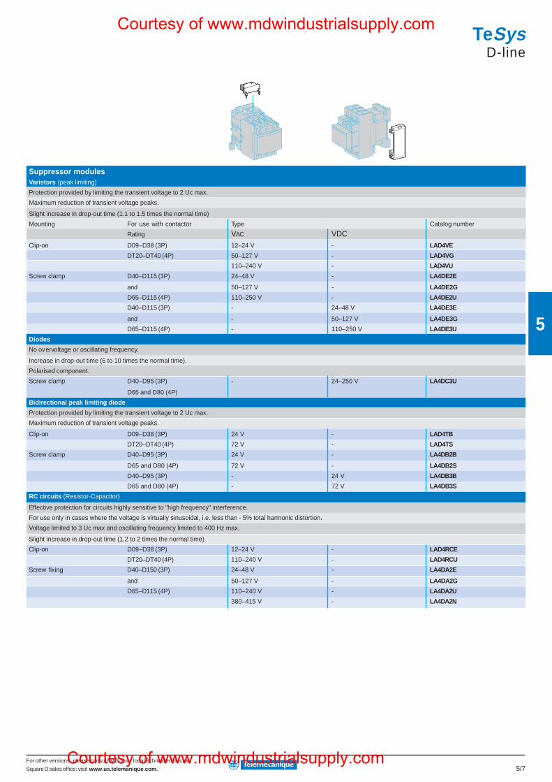
For other versions, please consult with your local Schneider Electric/
Square D sales office: visit www.us.telemanique.com. 5/7
5
Suppressor modulesVaristors (peak limiting)
Protection provided by limiting the transient voltage to 2 Uc max.
Maximum reduction of transient voltage peaks.
Slight increase in drop-out time (1.1 to 1.5 times the normal time)
Mounting For use with contactor Type Catalog number
Rating VAC VDCClip-on D09–D38 (3P) 12–24 V - LAD4VE
DT20–DT40 (4P) 50–127 V - LAD4VG
110–240 V - LAD4VU
Screw clamp D40–D115 (3P) 24–48 V - LA4DE2E
and 50–127 V - LA4DE2G
D65–D115 (4P) 110–250 V - LA4DE2U
D40–D115 (3P) - 24–48 V LA4DE3E
and - 50–127 V LA4DE3G
D65–D115 (4P) - 110–250 V LA4DE3U
Diodes
No overvoltage or oscillating frequency.
Increase in drop-out time (6 to 10 times the normal time).
Polarised component.
Screw clamp D40–D95 (3P) - 24–250 V LA4DC3U
D65 and D80 (4P)
Bidirectional peak limiting diode
Protection provided by limiting the transient voltage to 2 Uc max.
Maximum reduction of transient voltage peaks.
Clip-on D09–D38 (3P) 24 V - LAD4TB
DT20–DT40 (4P) 72 V - LAD4TS
Screw clamp D40–D95 (3P) 24 V - LA4DB2B
D65 and D80 (4P) 72 V - LA4DB2S
D40–D95 (3P) - 24 V LA4DB3B
D65 and D80 (4P) - 72 V LA4DB3S
RC circuits (Resistor-Capacitor)
Effective protection for circuits highly sensitive to "high frequency" interference.
For use only in cases where the voltage is virtually sinusoidal, i.e. less than - 5% total harmonic distortion.
Voltage limited to 3 Uc max and oscillating frequency limited to 400 Hz max.
Slight increase in drop-out time (1.2 to 2 times the normal time)
Clip-on D09–D38 (3P) 12–24 V - LAD4RCE
DT20–DT40 (4P) 110–240 V - LAD4RCU
Screw fixing D40–D150 (3P) 24–48 V - LA4DA2E
and 50–127 V - LA4DA2G
D65–D115 (4P) 110–240 V - LA4DA2U
380–415 V - LA4DA2N
TeSysD-line
Courtesy of www.mdwindustrialsupply.com
Courtesy of www.mdwindustrialsupply.com
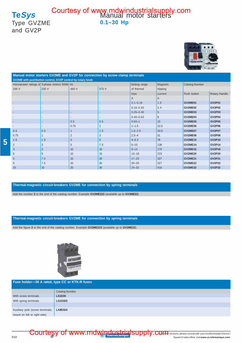
For other versions, please consult with your localSchneider Electric /
Square D sales office: visit www.us.telemanique.com.5/10
5
Thermal-magnetic circuit-breakers GV2ME for connection by spring terminals
Add the figure 3 to the end of the catalog number. Example GV2ME223 (available up to GV2ME22)
TeSysType GVZMEand GV2P
Manual motor starters0.1–30 Hp
Manual motor starters GV2ME and GV2P for connection by screw clamp terminalsGV2ME with pushbutton control, GV2P control by rotary knob
Horsepower ratings of 3-phase motors 50/60 Hz Setting range Magnetic Catalog Number
200 V 230 V 460 V 575 V of thermal tripping
trips current Push button Rotary Handle
A A
- - - - 0.1–0.16 1.5 GV2ME01 GV2P01
- - - - 0.16–0.25 2.4 GV2ME02 GV2P02
- - - - 0.25–0.40 5 GV2ME03 GV2P03
- - - - 0.40–0.63 8 GV2ME04 GV2P04
- - 0.5 0.5 0.63–1 13 GV2ME05 GV2P05
- - 0.75 1 1–1.6 22.5 GV2ME06 GV2P06
0.5 0.5 1 1.5 1.6–2.5 33.5 GV2ME07 GV2P07
0.75 1 2 3 2.5–4 51 GV2ME08 GV2P08
1.5 1.5 3 5 4–6.3 78 GV2ME10 GV2P10
2 3 5 7.5 6–10 138 GV2ME14 GV2P14
3 3 10 10 9–14 170 GV2ME16 GV2P16
5 5 10 15 13–18 223 GV2ME20 GV2P20
5 7.5 15 20 17–23 327 GV2ME21 GV2P21
5 7.5 15 20 20–25 327 GV2ME22 GV2P22
10 10 20 30 24–32 416 GV2ME32 GV2P32
Thermal-magnetic circuit-breakers GV2ME for connection by spring terminals
Add the number 3 to the end of the catalog number. Example GV2ME223 (available up to GV2ME22)
Fuse holder—30 A rated, type CC or KTK-R fuses
Catalog Number
With screw terminals LS1D30
With spring terminals LS1D303
Auxiliary pole (screw terminals; LA8D324
mount on left or right side)
Courtesy of www.mdwindustrialsupply.com
Courtesy of www.mdwindustrialsupply.com
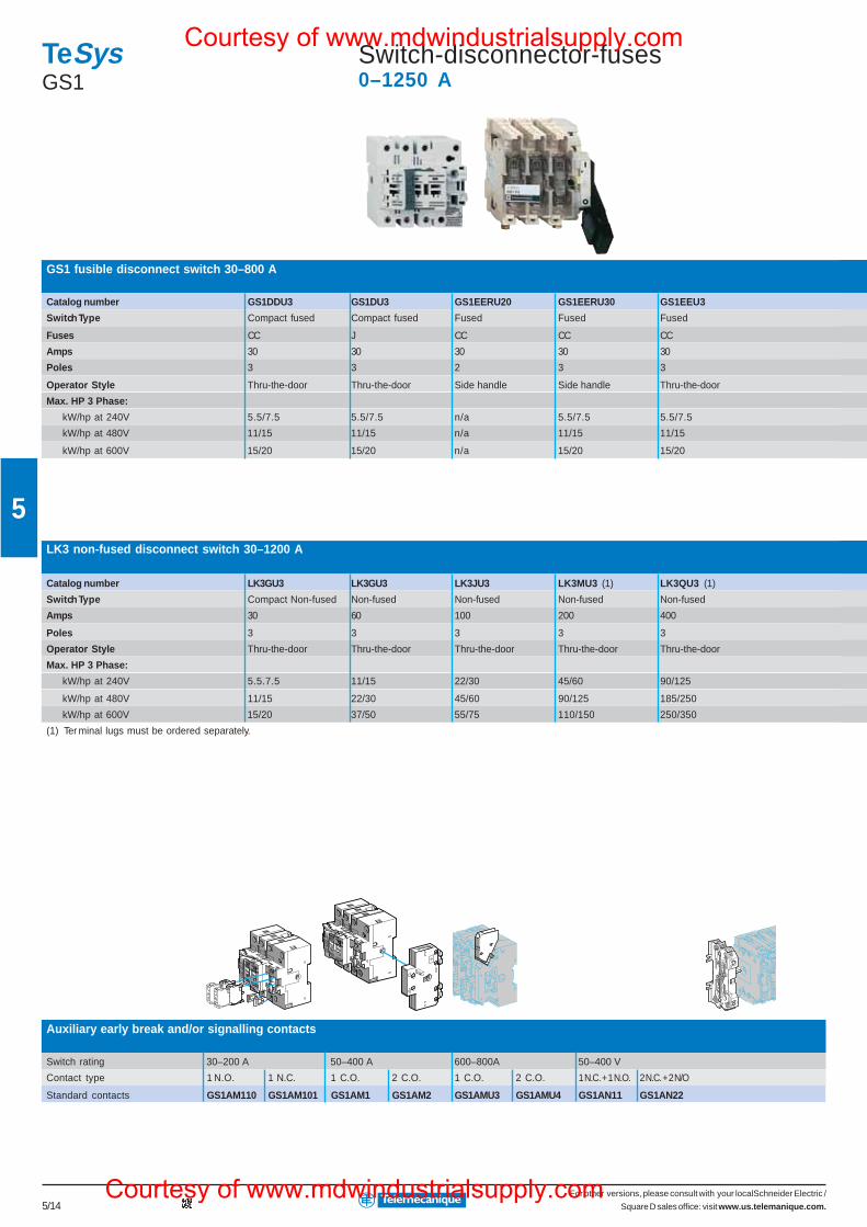
For other versions, please consult with your localSchneider Electric /
Square D sales office: visit www.us.telemanique.com.5/14
5
Auxiliary early break and/or signalling contacts
Switch rating 30–200 A 50–400 A 600–800A 50–400 V
Contact type 1 N.O. 1 N.C. 1 C.O. 2 C.O. 1 C.O. 2 C.O. 1 N.C. + 1 N.O. 2 N.C. + 2 N/O
Standard contacts GS1AM110 GS1AM101 GS1AM1 GS1AM2 GS1AMU3 GS1AMU4 GS1AN11 GS1AN22
TeSysGS1
Switch-disconnector-fuses0–1250 A
GS1 fusible disconnect switch 30–800 A
Catalog number GS1DDU3 GS1DU3 GS1EERU20 GS1EERU30 GS1EEU3
Switch Type Compact fused Compact fused Fused Fused Fused
Fuses CC J CC CC CC
Amps 30 30 30 30 30
Poles 3 3 2 3 3
Operator Style Thru-the-door Thru-the-door Side handle Side handle Thru-the-door
Max. HP 3 Phase:
kW/hp at 240V 5.5/7.5 5.5/7.5 n/a 5.5/7.5 5.5/7.5
kW/hp at 480V 11/15 11/15 n/a 11/15 11/15
kW/hp at 600V 15/20 15/20 n/a 15/20 15/20
LK3 non-fused disconnect switch 30–1200 A
Catalog number LK3GU3 LK3GU3 LK3JU3 LK3MU3 (1) LK3QU3 (1)
Switch Type Compact Non-fused Non-fused Non-fused Non-fused Non-fused
Amps 30 60 100 200 400
Poles 3 3 3 3 3
Operator Style Thru-the-door Thru-the-door Thru-the-door Thru-the-door Thru-the-door
Max. HP 3 Phase:
kW/hp at 240V 5.5.7.5 11/15 22/30 45/60 90/125
kW/hp at 480V 11/15 22/30 45/60 90/125 185/250
kW/hp at 600V 15/20 37/50 55/75 110/150 250/350
(1) Ter minal lugs must be ordered separately.
Courtesy of www.mdwindustrialsupply.com
Courtesy of www.mdwindustrialsupply.com
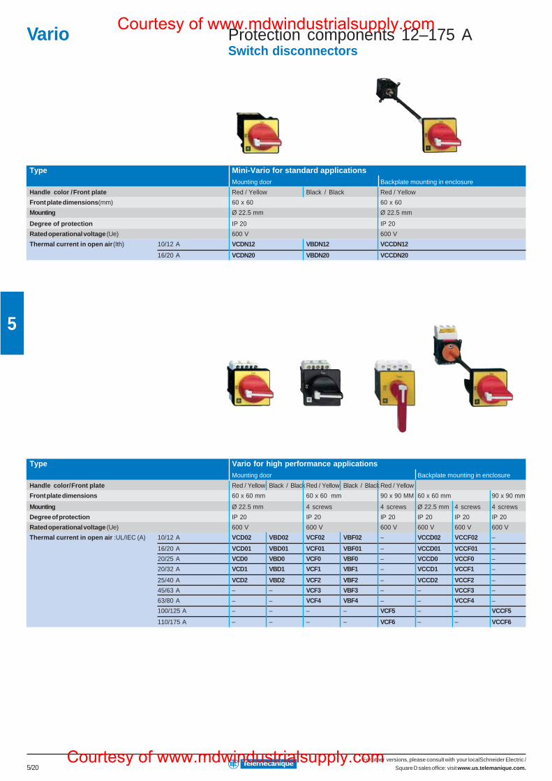
For other versions, please consult with your localSchneider Electric /
Square D sales office: visit www.us.telemanique.com.5/20
5
Vario Protection components 12–175 ASwitch disconnectors
Type Mini-Vario for standard applicationsMounting door Backplate mounting in enclosure
Handle color / Front plate Red / Yellow Black / Black Red / Yellow
Front plate dimensions (mm) 60 x 60 60 x 60
Mounting Ø 22.5 mm Ø 22.5 mm
Degree of protection IP 20 IP 20
Rated operational voltage (Ue) 600 V 600 V
Thermal current in open air (Ith) 10/12 A VCDN12 VBDN12 VCCDN12
16/20 A VCDN20 VBDN20 VCCDN20
Type Vario for high performance applicationsMounting door Backplate mounting in enclosure
Handle color/ Front plate Red / Yellow Black / Black Red / Yellow Black / Black Red / Yellow
Front plate dimensions 60 x 60 mm 60 x 60 mm 90 x 90 MM 60 x 60 mm 90 x 90 mm
Mounting Ø 22.5 mm 4 screws 4 screws Ø 22.5 mm 4 screws 4 screws
Degree of protection IP 20 IP 20 IP 20 IP 20 IP 20 IP 20
Rated operational voltage (Ue) 600 V 600 V 600 V 600 V 600 V 600 V
Thermal current in open air :UL/IEC (A) 10/12 A VCD02 VBD02 VCF02 VBF02 – VCCD02 VCCF02 –
16/20 A VCD01 VBD01 VCF01 VBF01 – VCCD01 VCCF01 –
20/25 A VCD0 VBD0 VCF0 VBF0 – VCCD0 VCCF0 –
20/32 A VCD1 VBD1 VCF1 VBF1 – VCCD1 VCCF1 –
25/40 A VCD2 VBD2 VCF2 VBF2 – VCCD2 VCCF2 –
45/63 A – – VCF3 VBF3 – – VCCF3 –
63/80 A – – VCF4 VBF4 – – VCCF4 –
100/125 A – – – – VCF5 – – VCCF5
110/175 A – – – – VCF6 – – VCCF6
Courtesy of www.mdwindustrialsupply.com
Courtesy of www.mdwindustrialsupply.com
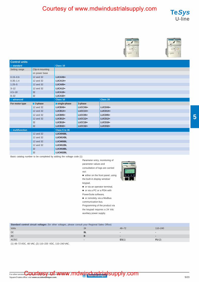
For other versions, please consult with your local Schneider Electric/
Square D sales office: visit www.us.telemanique.com. 5/23
5
Standard control circuit voltages (for other voltages, please consult your Regional Sales Office)
Volts 24 48–72 110–240
DC BL - -
AC B - -
AC/DC - ES (1) FU (2)
(1) 48–72 VDC, 48 VAC. (2) 110–220 VDC, 110–240 VAC.
Control units standard Class 10
Setting range Clip-in mounting
on power base
0.15–0.6 12 and 32 LUCAX6••
0.35–1.4 12 and 32 LUCA1X••
1.25–5 12 and 32 LUCA05••
3–12 12 and 32 LUCA12••
4.5–18 32 LUCA18••
8–32 32 LUCA32••
advanced Class 10 Class 20
For motor type 3-phase single-phase 3-phase
12 and 32 LUCBX6•• LUCCX6•• LUCDX6••
12 and 32 LUCB1X•• LUCC1X•• LUCD1X••
12 and 32 LUCB05•• LUCC05•• LUCD05••
12 and 32 LUCB12•• LUCC12•• LUCD12••
32 LUCB18•• LUCC18•• LUCD18••
32 LUCB32•• LUCC32•• LUCD32••
multifunction Class 5 to 35
12 and 32 LUCMX6BL
12 and 32 LUCM1XBL
12 and 32 LUCM05BL
12 and 32 LUCM12BL
32 LUCM18BL
32 LUCM32BL
Basic catalog number to be completed by adding the voltage code (1)
Parameter entry, monitoring of
parameter values and
consultation of logs are carried
out:
either on the front panel, using
the built-in display window/
keypad,
or via an operator terminal,
or via a PC or a PDA with
PowerSuite software,
or remotely, via a Modbus
communication bus.
Programming of the product via
the keypad requires a 24 Vdc
auxiliary power supply.
TeSysU-line
Courtesy of www.mdwindustrialsupply.com
Courtesy of www.mdwindustrialsupply.com
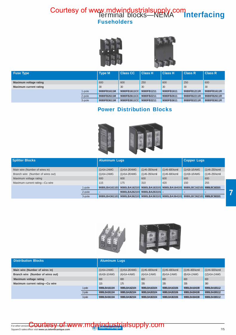
For other versions, consult with your local Schneider Electric/
Square D sales office: visit www.us.telemecanique.com 7/5
7
Terminal blocks—NEMAFuseholders
Fuse Type Type M Class CC Class H Class H Class R Class R
Maximum voltage rating 600 600 250 600 250 600
Maximum current rating 30 30 30 30 30 30
1-pole 9080FB1611M 9080FB1611CC 9080FB1211 9080FB1611 9080FB1211R 9080FB1611R
2-pole 9080FB2611M 9080FB2611CC 9080FB2211 9080FB2611 9080FB2211R 9080FB2611R
3-pole 9080FB3611M 9080FB3611CC 9080FB3211 9080FB3611 9080FB3211R 9080FB3611R
Power Distribution Blocks
Splitter Blocks Aluminum Lugs Copper Lugs
Main wire (Number of wires in) (1) #14–2 AWG (1) #14–2/0 AWG (1) #6–350 kcmil (1) #6–600 kcmil (1) #18–1/0 AWG (1) #6–250 kcmil
Branch wire (Number of wires out) (1) #14–2 AWG (1) #14–2/0 AWG (1) #6–350 kcmil (1) #6–600 kcmil (1) #18–1/0 AWG (1) #6–250 kcmil
Maximum voltage rating 600 600 600 600 600 600
Maximum current rating—Cu wire 115 175 310 420 150 255
1-pole 9080LBA161101 9080LBA162101 9080LBA163101 9080LBA164101 9080LBC162101 9080LBC163101
2-pole – 9080LBA262101 9080LBA263101 – – –
3-pole 9080LBA361101 9080LBA362101 9080LBA363101 9080LBA364101 9080LBC362101 9080LBC363101
Distribution Blocks Aluminum Lugs
Main wire (Number of wires in) (1) #14–2 AWG (1) #14–2/0 AWG (1) #6–400 kcmil (1) #6–400 kcmil (1) #6–400 kcmil (1) #4–500 kcmil
Branch wire (Number of wires out) (4) #18–10 AWG (4) #14–4 AWG (4) #14–2 AWG (6) #14–2 AWG (8) #14–2 AWG (12) #14–2 AWG
Maximum voltage rating 600 600 600 600 600 600
Maximum current rating—Cu wire 115 175 335 335 335 380
1-pole 9080LBA161104 9080LBA162104 9080LBA163104 9080LBA163106 9080LBA164108 9080LBA165112
2-pole 9080LBA261104 9080LBA262104 9080LBA263104 9080LBA263106 9080LBA264108 9080LBA265112
3-pole 9080LBA361104 9080LBA362104 9080LBA363104 9080LBA363106 9080LBA364108 9080LBA365112
InterfacingCourtesy of www.mdwindustrialsupply.com
Courtesy of www.mdwindustrialsupply.com
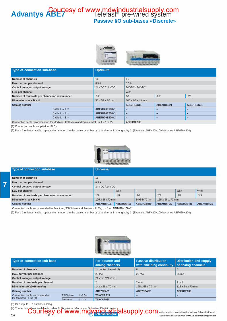
For other versions, consult with your local Schneider Electric/
Square D sales office: visit www.us.telemecanique.com7/6
7
Telefast® pre-wired systemPassive I/O sub-bases «Discrete»
Type of connection sub-base Optimum
Number of channels 16 16
Max. current per channel 0.5 A 0.5 A
Control voltage / output voltage 24 VDC / 24 VDC 24 VDC / 24 VDC
LED per channel – With
Number of terminals per channel/on row number 1/2 1/1 2/2 3/3
Dimensions W x D x H 55 x 59 x 67 mm 106 x 60 x 49 mm
Catalog number – ABE7H16C11 ABE7H16C21 ABE7H16C31
Cable L = 1 m ABE7H20E100 (1) – – –
Cable L = 2 m ABE7H20E200 (1) – – –
Cable L = 3 m ABE7H20E300 (1) – – –
Connection cable recommended for Modicon, TSX Micro and Premium PLCs, L = 1 m (2) ABFH20H100
(1) Connection cable supplied for PLCs.
(2) For a 2 m length cable, replace the number 1 in the catalog number by 2, and for a 3 m length, by 3. (Example: ABFH20H100 becomes ABFH20H200).
Type of connection sub-base Universal
Number of channels 16
Max. current per channel 0.5 A
Control voltage / output voltage 24 VDC / 24 VDC
LED per channel – With – – With With
Number of terminals per channel/on row number 1/1 1/1 1/2 2/2 2/2 3/3
Dimensions W x D x H 125 x 58 x70 mm 84x58x70 mm 125 x 58 x 70 mm
Catalog number ABE7H16R10 ABE7H16R11 ABE7H16R50 ABE7H16R20 ABE7H16R21 ABE7H16R31
Connection cable recommended for Modicon, TSX Micro and Premium PLCs, L = 1 m: ABFH20H100 (2)
(2) For a 2 m length cable, replace the number 1 in the catalog number by 2, and for a 3 m length, by 3. (Example: ABFH20H100 becomes ABFH20H200).
Type of connection sub-base For counter and Passive distribution Distribution and supplyanalog channels with shielding continuity of analog channels
Number of channels 1 counter channel (3) 8 8
Max. current per channel 25 mA 25 mA 25 mA
Control voltage / output voltage 24 VDC / 24 VDC
Number of terminals per channel 2 2 or 4 2 or 4
Dimensions WxDxH (mm/in) 143 x 58 x 70 mm 125 x 58 x 70 mm 125 x 58 x 70 mm
Catalog number ABE7CPA01 ABE7CPA02 ABE7CPA03
Connection cable recommended TSX Micro L = 2.5 m TSXCCPS15 – –for Modicon PLCs (4) Premium L = 3 m TSXCAP030
(3) Or 8 inputs + 2 outputs, analog.
(4) Connection cables available for other PLCs, please refer to your Schneider Electr ic agency.
Advantys ABE7Courtesy of www.mdwindustrialsupply.com
Courtesy of www.mdwindustrialsupply.com
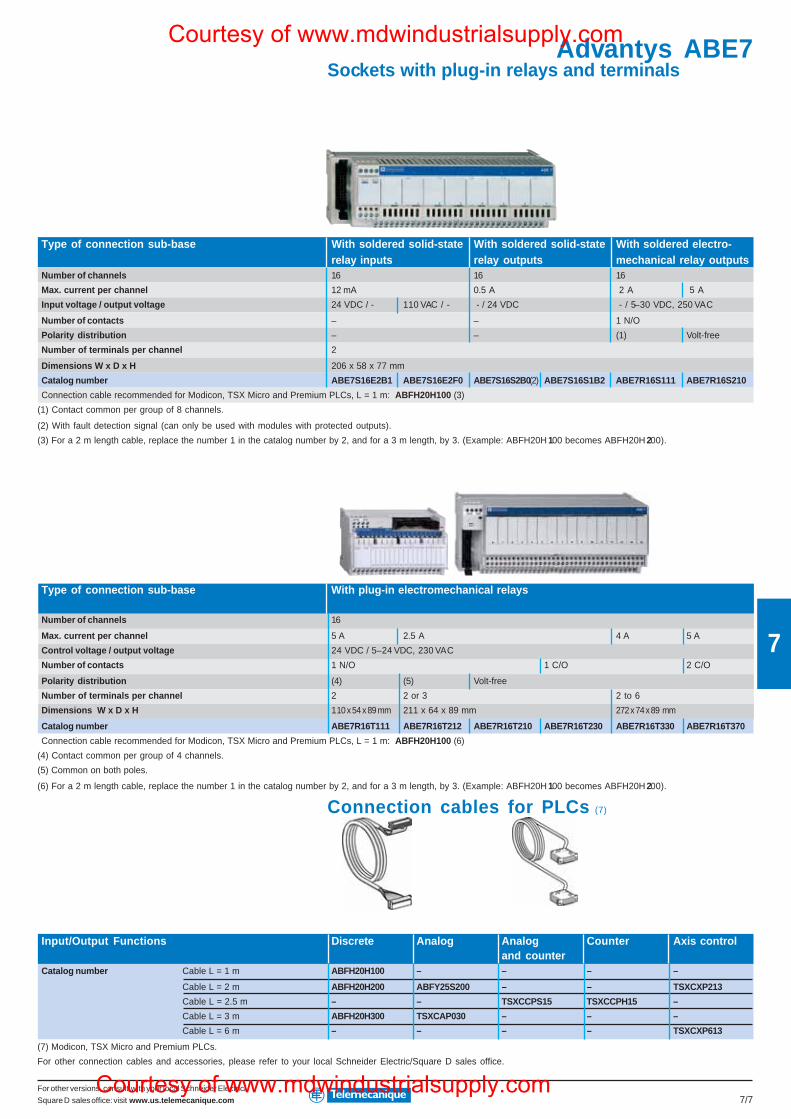
For other versions, consult with your local Schneider Electric/
Square D sales office: visit www.us.telemecanique.com 7/7
7
Sockets with plug-in relays and terminals
Type of connection sub-base With soldered solid-state With soldered solid-state With soldered electro-relay inputs relay outputs mechanical relay outputs
Number of channels 16 16 16
Max. current per channel 12 mA 0.5 A 2 A 5 A
Input voltage / output voltage 24 VDC / - 110 VAC / - - / 24 VDC - / 5–30 VDC, 250 VAC
Number of contacts – – 1 N/O
Polarity distribution – – (1) Volt-free
Number of terminals per channel 2
Dimensions W x D x H 206 x 58 x 77 mm
Catalog number ABE7S16E2B1 ABE7S16E2F0 ABE7S16S2B0(2) ABE7S16S1B2 ABE7R16S111 ABE7R16S210
Connection cable recommended for Modicon, TSX Micro and Premium PLCs, L = 1 m: ABFH20H100 (3)
(1) Contact common per group of 8 channels.
(2) With fault detection signal (can only be used with modules with protected outputs).
(3) For a 2 m length cable, replace the number 1 in the catalog number by 2, and for a 3 m length, by 3. (Example: ABFH20H 100 becomes ABFH20H 200).
Type of connection sub-base With plug-in electromechanical relays
Number of channels 16
Max. current per channel 5 A 2.5 A 4 A 5 A
Control voltage / output voltage 24 VDC / 5–24 VDC, 230 VAC
Number of contacts 1 N/O 1 C/O 2 C/O
Polarity distribution (4) (5) Volt-free
Number of terminals per channel 2 2 or 3 2 to 6
Dimensions W x D x H 110 x 54 x 89 mm 211 x 64 x 89 mm 272 x 74 x 89 mm
Catalog number ABE7R16T111 ABE7R16T212 ABE7R16T210 ABE7R16T230 ABE7R16T330 ABE7R16T370
Connection cable recommended for Modicon, TSX Micro and Premium PLCs, L = 1 m: ABFH20H100 (6)
(4) Contact common per group of 4 channels.
(5) Common on both poles.
(6) For a 2 m length cable, replace the number 1 in the catalog number by 2, and for a 3 m length, by 3. (Example: ABFH20H 100 becomes ABFH20H 200).
Connection cables for PLCs (7)
Input/Output f
Input/Output Functions Discrete Analog Analog Counter Axis controland counter
Catalog number Cable L = 1 m ABFH20H100 – – – –
Cable L = 2 m ABFH20H200 ABFY25S200 – – TSXCXP213
Cable L = 2.5 m – – TSXCCPS15 TSXCCPH15 –
Cable L = 3 m ABFH20H300 TSXCAP030 – – –
Cable L = 6 m – – – – TSXCXP613
(7) Modicon, TSX Micro and Premium PLCs.
For other connection cables and accessories, please refer to your local Schneider Electric/Square D sales office.
Advantys ABE7Courtesy of www.mdwindustrialsupply.com
Courtesy of www.mdwindustrialsupply.com
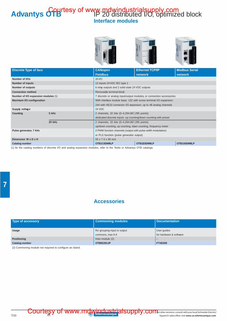
For other versions, consult with your local Schneider Electric/
Square D sales office: visit www.us.telemecanique.com7/10
7
IP 20 distributed I/O, optimized blockInterface modules
Discrete Type of bus CANopen Ethernet TCP/IP Modbus SerialFieldbus network network
Number of I/Os 20 I/O
Number of inputs 12 inputs 24 VDC IEC type 1
Number of outputs 6 relay outputs and 2 solid state 24 VDC outputs
Connection method Removable terminal block
Number of I/O expansion modules (1) 7 discrete or analog input/output modules, or connection accessories
Maximum I/O configuration With interface module base: 132 with screw terminal I/O expansion;
244 with HE10 connector I/O expansion; up to 48 analog channels
Supply voltage 24 VDC
Counting 5 kHz 2 channels, 32 bits (0–4,294,967,295 points)
dedicated discrete inputs -up counting/down counting with preset
20 kHz 2 channels, 32 bits (0–4,294,967,295 points)
up/down counting, up counting, down counting, frequency meter
Pulse generator, 7 kHz 2 PWM function channels (output with pulse width modulation)
or PLS function (pulse generator output)
Dimension W x D x H 55 x 7 0 x 90 mm
Catalog number OTB1C0DM9LP OTB1E0DM9LP OTB1S0DM9LP
(1) for the catalog numbers of discrete I/O and analog expansion modules, refer to the Twido or Advantys OTB catalogs.
Accessories
Type of accessory Commoning modules Documentation
Usage For grouping input or output User guides
commons, max 8 A for hardware & software
Positioning Inter-module (2) –
Catalog number OTB9ZZ61JP FTXES00
(2) Commoning module not required to configure an island.
Advantys OTBCourtesy of www.mdwindustrialsupply.com
Courtesy of www.mdwindustrialsupply.com
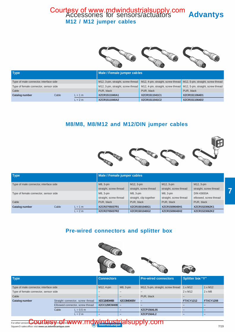
For other versions, consult with your local Schneider Electric/
Square D sales office: visit www.us.telemecanique.com 7/19
7
Accessories for sensors/actuatorsM12 / M12 jumper cables
Type Male / Female jumper cables
Type of male connector, interface side M12, 3-pin, straight, screw thread M12, 4-pin, straight, screw thread M12, 5-pin, straight, screw thread
Type of female connector, sensor side M12, 3-pin, straight, screw thread M12, 4-pin, straight, screw thread M12, 5-pin, straight, screw thread
Cable PUR, black PUR, black PUR, black
Catalog number Cable L = 1 m XZCR1511040A1 XZCR1511041C1 XZCR1511064D1
L = 2 m XZCR1511040A2 XZCR1511041C2 XZCR1511064D2
M8/M8, M8/M12 and M12/DIN jumper cables
Type Male / Female jumper cables
Type of male connector, interface side M8, 3-pin M12, 3-pin M12, 3-pin M12, 3-pin
straight, screw thread straight, screw thread straight, screw thread straight, screw thread
Type of female connector, sensor side M8, 3-pin M8, 3-pin M8, 3-pin DIN 43650A
straight, screw thread straight, clip together straight, screw thread elbowed, screw thread
Cable PUR, black PUR, black PUR, black PUR, black
Catalog number Cable L = 1 m XZCR2705037R1 XZCR1501040G1 XZCR1509040H1 XZCR1523062K1
L = 2 m XZCR2705037R2 XZCR1501040G2 XZCR1509040H2 XZCR1523062K2
Pre-wired connectors and splitter box
Type Connectors Pre-wired connectors Splitter box “Y”
Type of male connector, interface side M12, 4-pin M8, 3-pin M12, 5-pin, straight, screw thread 1 x M12 1 x M12
Type of female connector, sensor side – – – 2 x M12 2 x M8
Cable – – PUR, black –
Catalog number Straight connector, screw thread XZCC12MDM40B XZCC8MDM30V – FTXCY1212 FTXCY1208
Elbowed connector, screw thread XZCC12MCM40B – – – –
Cable L = 0.5 m – – XZCP1564L05 – –
L = 2 m – – XZCP1564L2 – –
AdvantysCourtesy of www.mdwindustrialsupply.com
Courtesy of www.mdwindustrialsupply.com
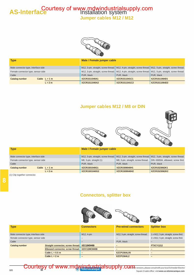
For other versions, please consult with your local Schneider Electric/
Square D sales office: visit www.us.telemecanique.com8/8
8
AS-Interface Installation systemJumper cables M12 / M12
Type Male / Female jumper cable
Male connector type, interface side M12, 3-pin, straight, screw thread. M12, 4-pin, straight, screw thread. M12, 5-pin, straight, screw thread.
Female connector type, sensor side M12, 3-pin, straight, screw thread. M12, 4-pin, straight, screw thread. M12, 5-pin, straight, screw thread.
Cable PUR, black PUR, black PUR, black
Catalog number Cable L = 1 m XZCR1511040A1 XZCR1511041C1 XZCR1511064D1
L = 2 m XZCR1511040A2 XZCR1511041C2 XZCR1511064D2
Jumper cables M12 / M8 or DIN
Type Male / Female jumper cable
Male connector type, interface side M12, 3-pin, straight, screw thread. M12, 3-pin, straight, screw thread. M12, 3-pin, straight, screw thread.
Female connector type, sensor side M8, 3-pin, straight (1) M8, 3-pin, straight, screw thread. DIN 43650A, elbowed, screw thrd.
Cable PUR, black PUR, black PUR, black
Catalog number Cable L = 1 m XZCR1501040G1 XZCR1509040H1 XZCR1523062K1
L = 2 m XZCR1501040G2 XZCR1509040H2 XZCR1523062K2
(1) Clip together connector.
Connectors, splitter box
Type Connectors Pre-wired connectors Splitter box
Male connector type, interface side M12, 4-pin M12, 5-pin, straight, screw thread. 1 x M12, 5-pin, straight, screw thrd.
Female connector type, sensor side – – 2 x M12, 5-pin, straight, screw thrd.
Cable – PUR, black –
Catalog number Straight connector, screw thread. XZCC12MDM40B – FTXCY1212
Elbowed connector, screw thread. XZCC12MCM40B – –
Cable L = 0.5 m – XZCP1564L05 –
Cable L = 2 m – XZCP1564L2 –
Courtesy of www.mdwindustrialsupply.com
Courtesy of www.mdwindustrialsupply.com
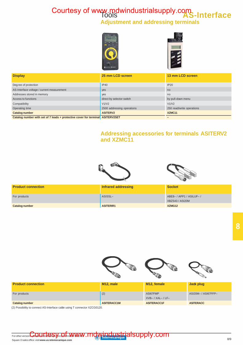
For other versions, please consult with your local Schneider Electric/
Square D sales office: visit www.us.telemecanique.com 8/9
8
ToolsAdjustment and addressing terminals
Display 25 mm LCD screen 13 mm LCD screen
Deg ree of protection IP40 IP20
AS-Interface voltage / current measurement yes no
Addresses stored in memory yes no
Access to functions direct by selector switch by pull-down menu
Compatibility V1/V2 V1/V2
Operating time 2500 addressing operations 250 read/write operations
Catalog number ASITERV2 XZMC11
Catalog number with set of 7 leads + protective cover for terminal ASITERV2SET –
Addressing accessories for terminals ASITERV2and XZMC11
Product connection Infrared addressing Socket
For products ASISSL– ABE8– / APP1 / ASILUF– /
XBZS43 / ASI20M
Catalog number ASITERIR1 XZMG12
Product connection M12, male M12, female Jack plug
For products (2) ASI67FMP ASI20M– / ASI67FFP–
XVB– / XAL– / LF–
Catalog number ASITERACC1M ASITERACC1F ASITERACC
(2) Possibility to connect AS-Interface cable using T connector XZCG0120.
AS-InterfaceCourtesy of www.mdwindustrialsupply.com
Courtesy of www.mdwindustrialsupply.com
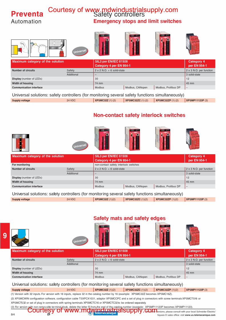
For other versions, please consult with your local Schneider Electric/
Square D sales office: visit www.us.telemecanique.com
9
9/4
Universal
Universal
Universal
PreventaAutomation
Safety controllersEmergency stops and limit switches
Maximum category of the solution SIL3 per EN/IEC 61508 Category 4Category 4 per EN 954-1 per EN 954-1
Number of circuits Safety 2 x 2 N.O. + 6 solid-state 2 x 3 N.O. per function
Additional – 3 solid-state
Display (number of LEDs) 30 12
Width of housing 74 mm 45 mm
Communication interface Modbus Modbus, CANopen Modbus, Profibus DP –
Universal solutions: safety controllers (for monitoring several safety functions simultaneously)Supply voltage 24 VDC XPSMC32Z (1) (2) XPSMC32ZC (1) (2) XPSMC32ZP (1) (2) XPSMP11123P (3)
Non-contact safety interlock switches
Maximum category of the solution SIL3 per EN/IEC 61508 Category 4Category 4 per EN 954-1 per EN 954-1
For monitoring non-contact safety interlock switches
Number of circuits Safety 2 x 2 N.O. + 6 solid-state 2 x 3 N.O. per function
Additional – 3 solid-state
Display (number of LEDs) 30 12
Width of housing 74 mm 45 mm
Communication interface Modbus Modbus, CANopen Modbus, Profibus DP –
Universal solutions: safety controllers (for monitoring several safety functions simultaneously)Supply voltage 24 VDC XPSMC32Z (1)(2) XPSMC32ZC (1)(2) XPSMC32ZP (1)(2) XPSMP11123P (3)
Safety mats and safety edges
Maximum category of the solution SIL3 per EN/IEC 61508 Category 4Category 4 per EN 954-1 per EN 954-1
Number of circuits Safety 2 x 2 N.O. + 6 solid-state 2 x 3 N.O. per function
Additional – 3 solid-state
Display (number of LEDs) 30 12
Width of housing 74 mm 45 mm
Communication interface Modbus Modbus, CANopen Modbus, Profibus DP –
Universal solutions: safety controllers (for monitoring several safety functions simultaneously)Supply voltage 24 VDC XPSMC32Z (1)(2) XPSMC32ZC (1)(2) XPSMC32ZP (1)(2) XPSMP11123P (3)
(1) Version with 32 inputs. For version with 16 inputs, replace 32 in the catalog number by 16 (example: XPSMC32Z becomes XPSMC16Z).
(2) XPSMCWIN configuration software, configuration cable TSXPCX1031, adaptor XPSMCCPC and a set of plug in connectors with screw terminals XPSMCTS16 or
XPSMCTS32 or set of plug in connectors with spring terminals XPSMCTC16 or XPSMCTC32 to be ordered separately.
(3) For version with non-removable ter minal block, delete the letter P from the end of the catalog number (example: XPSMP11123P becomes XPSMP11123).
Courtesy of www.mdwindustrialsupply.com
Courtesy of www.mdwindustrialsupply.com
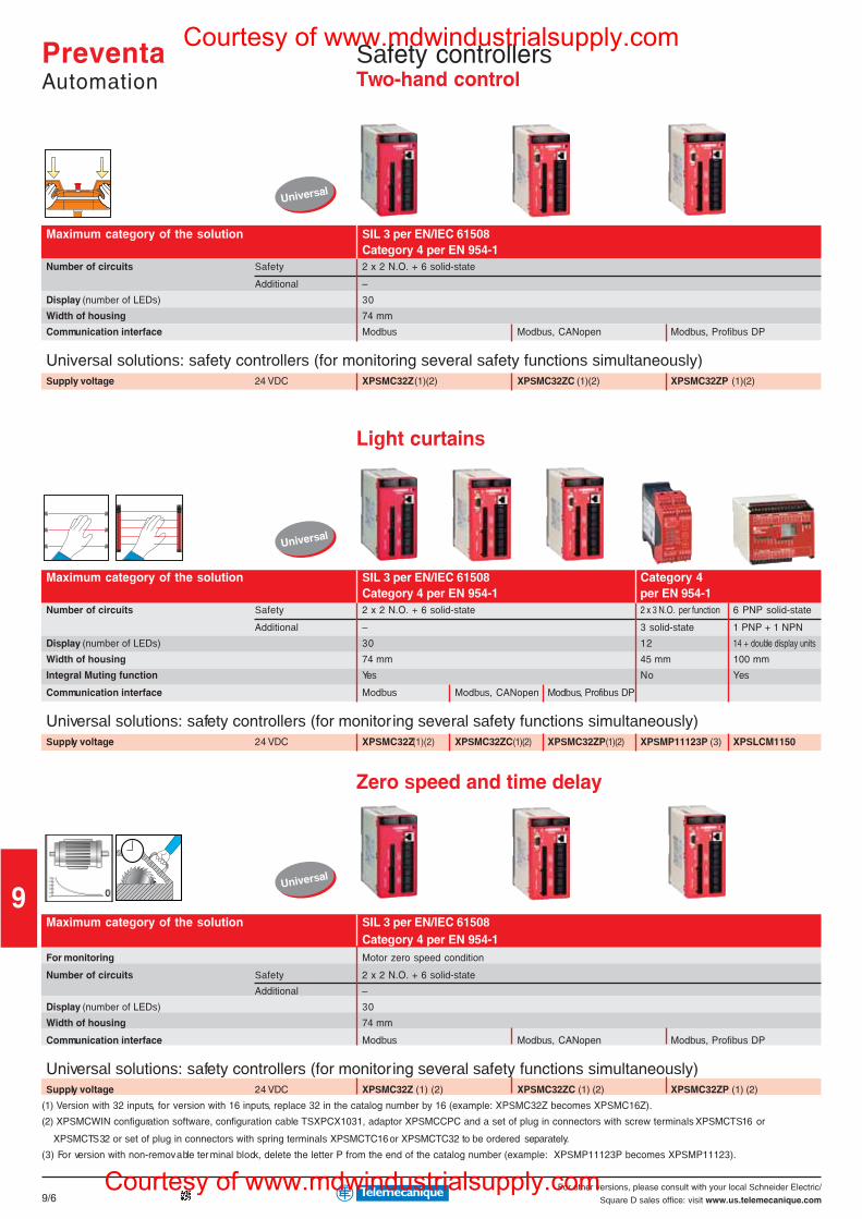
For other versions, please consult with your local Schneider Electric/
Square D sales office: visit www.us.telemecanique.com
9
9/6
Universal
Universal
Universal
Maximum category of the solution SIL 3 per EN/IEC 61508Category 4 per EN 954-1
Number of circuits Safety 2 x 2 N.O. + 6 solid-state
Additional –
Display (number of LEDs) 30
Width of housing 74 mm
Communication interface Modbus Modbus, CANopen Modbus, Profibus DP
Universal solutions: safety controllers (for monitoring several safety functions simultaneously)Supply voltage 24 VDC XPSMC32Z (1)(2) XPSMC32ZC (1)(2) XPSMC32ZP (1)(2)
Light curtains
Maximum category of the solution SIL 3 per EN/IEC 61508 Category 4Category 4 per EN 954-1 per EN 954-1
Number of circuits Safety 2 x 2 N.O. + 6 solid-state 2 x 3 N.O. per function 6 PNP solid-state
Additional – 3 solid-state 1 PNP + 1 NPN
Display (number of LEDs) 30 12 14 + double display units
Width of housing 74 mm 45 mm 100 mm
Integral Muting function Yes No Yes
Communication interface Modbus Modbus, CANopen Modbus, Profibus DP
Universal solutions: safety controllers (for monitoring several safety functions simultaneously)Supply voltage 24 VDC XPSMC32Z(1)(2) XPSMC32ZC(1)(2) XPSMC32ZP(1)(2) XPSMP11123P (3) XPSLCM1150
Zero speed and time delay
Maximum category of the solution SIL 3 per EN/IEC 61508Category 4 per EN 954-1
For monitoring Motor zero speed condition
Number of circuits Safety 2 x 2 N.O. + 6 solid-state
Additional –
Display (number of LEDs) 30
Width of housing 74 mm
Communication interface Modbus Modbus, CANopen Modbus, Profibus DP
Universal solutions: safety controllers (for monitoring several safety functions simultaneously)Supply voltage 24 VDC XPSMC32Z (1) (2) XPSMC32ZC (1) (2) XPSMC32ZP (1) (2)
(1) Version with 32 inputs, for version with 16 inputs, replace 32 in the catalog number by 16 (example: XPSMC32Z becomes XPSMC16Z).
(2) XPSMCWIN configuration software, configuration cable TSXPCX1031, adaptor XPSMCCPC and a set of plug in connectors with screw terminals XPSMCTS16 or
XPSMCTS32 or set of plug in connectors with spring terminals XPSMCTC16 or XPSMCTC32 to be ordered separately.
(3) For version with non-removable ter minal block, delete the letter P from the end of the catalog number (example: XPSMP11123P becomes XPSMP11123).
PreventaAutomation
Safety controllersTwo-hand control
Courtesy of www.mdwindustrialsupply.com
Courtesy of www.mdwindustrialsupply.com
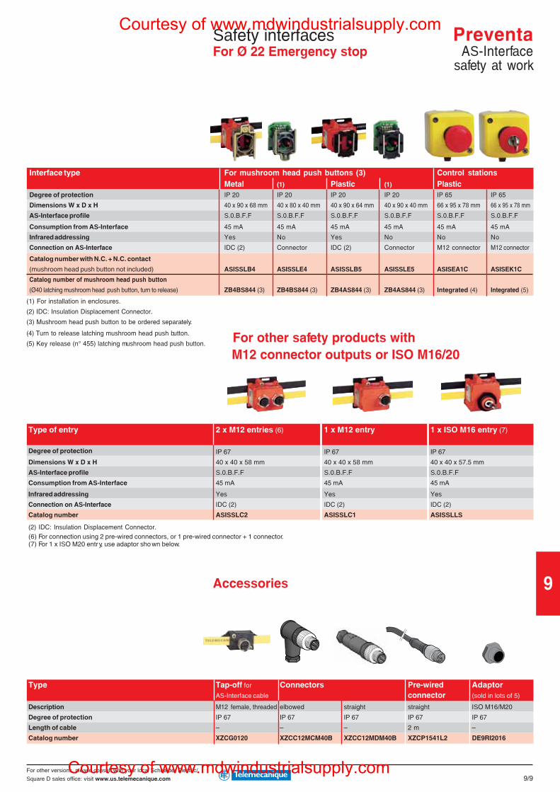
For other versions, please consult with your local Schneider Electric/
Square D sales office: visit www.us.telemecanique.com
9
9/9
Interface type For mushroom head push buttons (3) Control stationsMetal (1) Plastic (1) Plastic
Degree of protection IP 20 IP 20 IP 20 IP 20 IP 65 IP 65
Dimensions W x D x H 40 x 90 x 68 mm 40 x 80 x 40 mm 40 x 90 x 64 mm 40 x 90 x 40 mm 66 x 95 x 78 mm 66 x 95 x 78 mm
AS-Interface profile S.0.B.F.F S.0.B.F.F S.0.B.F.F S.0.B.F.F S.0.B.F.F S.0.B.F.F
Consumption from AS-Interface 45 mA 45 mA 45 mA 45 mA 45 mA 45 mA
Infrared addressing Yes No Yes No No No
Connection on AS-Interface IDC (2) Connector IDC (2) Connector M12 connector M12 connector
Catalog number with N.C. + N.C. contact
(mushroom head push button not included) ASISSLB4 ASISSLE4 ASISSLB5 ASISSLE5 ASISEA1C ASISEK1C
Catalog number of mushroom head push button
(Ø40 latching mushroom head push button, turn to release) ZB4BS844 (3) ZB4BS844 (3) ZB4AS844 (3) ZB4AS844 (3) Integrated (4) Integrated (5)
(1) For installation in enclosures.
(2) IDC: Insulation Displacement Connector.
(3) Mushroom head push button to be ordered separately.
(4) Turn to release latching mushroom head push button.
(5) Key release (n° 455) latching mushroom head push button.
M12 connector outputs or ISO M16/20
Type
Description
Degree of protection
Length of cable
Catalog number
Accessories
(2) IDC: Insulation Displacement Connector.(6) For connection using 2 pre-wired connectors, or 1 pre-wired connector + 1 connector.(7) For 1 x ISO M20 entr y, use adaptor sho wn below.
2 x M12 entries (6) 1 x M12 entry 1 x ISO M16 entry (7)Type of entry
Degree of protection
Dimensions W x D x H
AS-Interface profile
Consumption from AS-Interface
Infrared addressing
Connection on AS-Interface
Catalog number
IP 67 IP 67 IP 67
40 x 40 x 58 mm 40 x 40 x 58 mm 40 x 40 x 57.5 mm
S.0.B.F.F S.0.B.F.F S.0.B.F.F
45 mA 45 mA 45 mA
Yes Yes Yes
IDC (2) IDC (2) IDC (2)
ASISSLC2 ASISSLC1 ASISSLLS
Safety interfacesFor Ø 22 Emergency stop
Tap-off for Connectors Pre-wired AdaptorAS-Interface cable connector (sold in lots of 5)
M12 female, threaded elbowed straight straight ISO M16/M20
IP 67 IP 67 IP 67 IP 67 IP 67
– – – 2 m –
XZCG0120 XZCC12MCM40B XZCC12MDM40B XZCP1541L2 DE9RI2016
For other safety products with
PreventaAS-Interface
safety at work
Courtesy of www.mdwindustrialsupply.com
Courtesy of www.mdwindustrialsupply.com
Related Documents