1 DARBHANGA COLLEGE OF ENGINEERING, DARBHANGA COURSE FILE OF ENGINEERING GRAPHICS AND DESIGN FACULTY NAME: Dr. MD ASJAD MOKHTAR ASSISTANT PROFESSOR DEPARTMENT OF MECHANICAL ENGINEERING

Welcome message from author
This document is posted to help you gain knowledge. Please leave a comment to let me know what you think about it! Share it to your friends and learn new things together.
Transcript
1
DARBHANGA COLLEGE OF ENGINEERING,
DARBHANGA
COURSE FILE
OF
ENGINEERING GRAPHICS AND DESIGN
FACULTY NAME:
Dr. MD ASJAD MOKHTAR
ASSISTANT PROFESSOR
DEPARTMENT OF MECHANICAL ENGINEERING
2
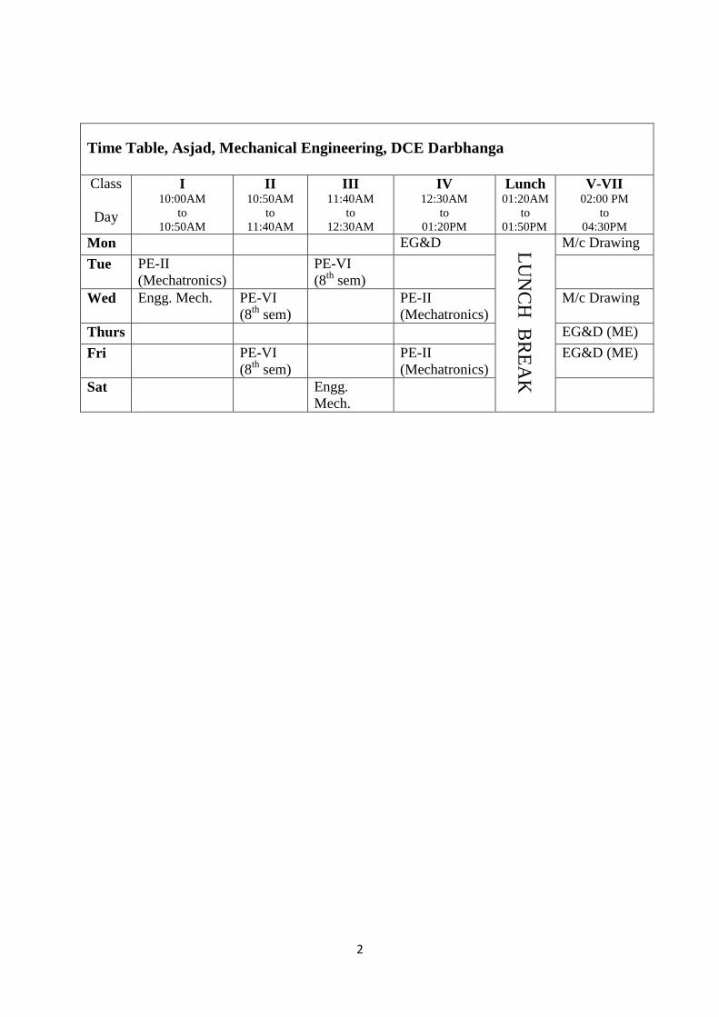
Time Table, Asjad, Mechanical Engineering, DCE Darbhanga
Class
Day
I 10:00AM
to
10:50AM
II 10:50AM
to
11:40AM
III 11:40AM
to
12:30AM
IV 12:30AM
to
01:20PM
Lunch 01:20AM
to
01:50PM
V-VII 02:00 PM
to
04:30PM
Mon EG&D LU
NC
H B
RE
AK
M/c Drawing
Tue PE-II
(Mechatronics)
PE-VI
(8th
sem)
Wed Engg. Mech. PE-VI
(8th
sem)
PE-II
(Mechatronics)
M/c Drawing
Thurs EG&D (ME)
Fri PE-VI
(8th
sem)
PE-II
(Mechatronics)
EG&D (ME)
Sat Engg.
Mech.
3
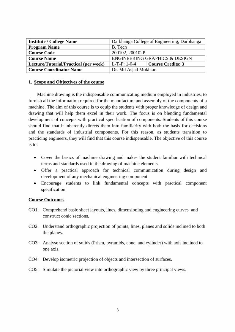
Institute / College Name Darbhanga College of Engineering, Darbhanga
Program Name B. Tech
Course Code 200102, 200102P
Course Name ENGINEERING GRAPHICS & DESIGN
Lecture/Tutorial/Practical (per week) L-T-P: 1-0-4 Course Credits: 3
Course Coordinator Name Dr. Md Asjad Mokhtar
1. Scope and Objectives of the course
Machine drawing is the indispensable communicating medium employed in industries, to
furnish all the information required for the manufacture and assembly of the components of a
machine. The aim of this course is to equip the students with proper knowledge of design and
drawing that will help them excel in their work. The focus is on blending fundamental
development of concepts with practical specification of components. Students of this course
should find that it inherently directs them into familiarity with both the basis for decisions
and the standards of industrial components. For this reason, as students transition to
practicing engineers, they will find that this course indispensable. The objective of this course
is to:
Cover the basics of machine drawing and makes the student familiar with technical
terms and standards used in the drawing of machine elements.
Offer a practical approach for technical communication during design and
development of any mechanical engineering component.
Encourage students to link fundamental concepts with practical component
specification.
Course Outcomes
CO1: Comprehend basic sheet layouts, lines, dimensioning and engineering curves and
construct conic sections.
CO2: Understand orthographic projection of points, lines, planes and solids inclined to both
the planes.
CO3: Analyse section of solids (Prism, pyramids, cone, and cylinder) with axis inclined to
one axis.
CO4: Develop isometric projection of objects and intersection of surfaces.
CO5: Simulate the pictorial view into orthographic view by three principal views.
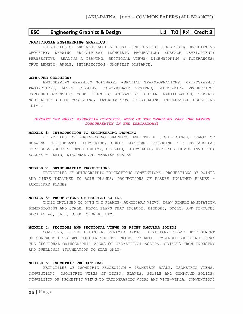
[AKU-PATNA] [000 – COMMON PAPERS (ALL BRANCH)]
35 | P a g e
ESC Engineering Graphics & Design L:1 T:0 P:4 Credit:3
TRADITIONAL ENGINEERING GRAPHICS:
PRINCIPLES OF ENGINEERING GRAPHICS; ORTHOGRAPHIC PROJECTION; DESCRIPTIVE
GEOMETRY; DRAWING PRINCIPLES; ISOMETRIC PROJECTION; SURFACE DEVELOPMENT;
PERSPECTIVE; READING A DRAWING; SECTIONAL VIEWS; DIMENSIONING & TOLERANCES;
TRUE LENGTH, ANGLE; INTERSECTION, SHORTEST DISTANCE.
COMPUTER GRAPHICS:
ENGINEERING GRAPHICS SOFTWARE; -SPATIAL TRANSFORMATIONS; ORTHOGRAPHIC
PROJECTIONS; MODEL VIEWING; CO-ORDINATE SYSTEMS; MULTI-VIEW PROJECTION;
EXPLODED ASSEMBLY; MODEL VIEWING; ANIMATION; SPATIAL MANIPULATION; SURFACE
MODELLING; SOLID MODELLING, INTRODUCTION TO BUILDING INFORMATION MODELLING
(BIM).
(EXCEPT THE BASIC ESSENTIAL CONCEPTS, MOST OF THE TEACHING PART CAN HAPPEN
CONCURRENTLY IN THE LABORATORY)
MODULE 1: INTRODUCTION TO ENGINEERING DRAWING
PRINCIPLES OF ENGINEERING GRAPHICS AND THEIR SIGNIFICANCE, USAGE OF
DRAWING INSTRUMENTS, LETTERING, CONIC SECTIONS INCLUDING THE RECTANGULAR
HYPERBOLA (GENERAL METHOD ONLY); CYCLOID, EPICYCLOID, HYPOCYCLOID AND INVOLUTE;
SCALES – PLAIN, DIAGONAL AND VERNIER SCALES
MODULE 2: ORTHOGRAPHIC PROJECTIONS
PRINCIPLES OF ORTHOGRAPHIC PROJECTIONS-CONVENTIONS -PROJECTIONS OF POINTS
AND LINES INCLINED TO BOTH PLANES; PROJECTIONS OF PLANES INCLINED PLANES -
AUXILIARY PLANES
MODULE 3: PROJECTIONS OF REGULAR SOLIDS
THOSE INCLINED TO BOTH THE PLANES- AUXILIARY VIEWS; DRAW SIMPLE ANNOTATION,
DIMENSIONING AND SCALE. FLOOR PLANS THAT INCLUDE: WINDOWS, DOORS, AND FIXTURES
SUCH AS WC, BATH, SINK, SHOWER, ETC.
MODULE 4: SECTIONS AND SECTIONAL VIEWS OF RIGHT ANGULAR SOLIDS
COVERING, PRISM, CYLINDER, PYRAMID, CONE – AUXILIARY VIEWS; DEVELOPMENT
OF SURFACES OF RIGHT REGULAR SOLIDS- PRISM, PYRAMID, CYLINDER AND CONE; DRAW
THE SECTIONAL ORTHOGRAPHIC VIEWS OF GEOMETRICAL SOLIDS, OBJECTS FROM INDUSTRY
AND DWELLINGS (FOUNDATION TO SLAB ONLY)
MODULE 5: ISOMETRIC PROJECTIONS
PRINCIPLES OF ISOMETRIC PROJECTION – ISOMETRIC SCALE, ISOMETRIC VIEWS,
CONVENTIONS; ISOMETRIC VIEWS OF LINES, PLANES, SIMPLE AND COMPOUND SOLIDS;
CONVERSION OF ISOMETRIC VIEWS TO ORTHOGRAPHIC VIEWS AND VICE-VERSA, CONVENTIONS
[AKU-PATNA] [000 – COMMON PAPERS (ALL BRANCH)]
36 | P a g e
MODULE 6: OVERVIEW OF COMPUTER GRAPHICS
LISTING THE COMPUTER TECHNOLOGIES THAT IMPACT ON GRAPHICAL COMMUNICATION,
DEMONSTRATING KNOWLEDGE OF THE THEORY OF CAD SOFTWARE [SUCH AS: THE MENU SYSTEM,
TOOLBARS (STANDARD, OBJECT PROPERTIES, DRAW, MODIFY AND DIMENSION), DRAWING
AREA (BACKGROUND, CROSSHAIRS, COORDINATE SYSTEM), DIALOG BOXES AND WINDOWS,
SHORTCUT MENUS (BUTTON BARS), THE COMMAND LINE (WHERE APPLICABLE), THE STATUS
BAR, DIFFERENT METHODS OF ZOOM AS USED IN CAD, SELECT AND ERASE OBJECTS.;
ISOMETRIC VIEWS OF LINES, PLANES, SIMPLE AND COMPOUND SOLIDS]
MODULE 7: CUSTOMISATION& CAD DRAWING
CONSISTING OF SET UP OF THE DRAWING PAGE AND THE PRINTER, INCLUDING SCALE
SETTINGS, SETTING UP OF UNITS AND DRAWING LIMITS; ISO AND ANSI STANDARDS FOR
COORDINATE DIMENSIONING AND TOLERANCING; ORTHOGRAPHIC CONSTRAINTS, SNAP TO
OBJECTS MANUALLY AND AUTOMATICALLY; PRODUCING DRAWINGS BY USING VARIOUS
COORDINATE INPUT ENTRY METHODS TO DRAW STRAIGHT LINES, APPLYING VARIOUS WAYS OF
DRAWING CIRCLES.
MODULE 8: ANNOTATIONS, LAYERING & OTHER FUNCTIONS
COVERING APPLYING DIMENSIONS TO OBJECTS, APPLYING ANNOTATIONS TO
DRAWINGS; SETTING UP AND USE OF LAYERS, LAYERS TO CREATE DRAWINGS, CREATE, EDIT
AND USE CUSTOMIZED LAYERS; CHANGING LINE LENGTHS THROUGH MODIFYING EXISTING
LINES (EXTEND/LENGTHEN); PRINTING DOCUMENTS TO PAPER USING THE PRINT COMMAND;
ORTHOGRAPHIC PROJECTION TECHNIQUES; DRAWING SECTIONAL VIEWS OF COMPOSITE RIGHT
REGULAR GEOMETRIC SOLIDS AND PROJECT THE TRUE SHAPE OF THE SECTIONED SURFACE;
DRAWING ANNOTATION, COMPUTER-AIDED DESIGN (CAD) SOFTWARE MODELING OF PARTS AND
ASSEMBLIES. PARAMETRIC AND NON-PARAMETRIC SOLID, SURFACE, AND WIREFRAME MODELS.
PART EDITING AND TWO-DIMENSIONAL DOCUMENTATION OF MODELS. PLANAR PROJECTION
THEORY, INCLUDING SKETCHING OF PERSPECTIVE, ISOMETRIC, MULTIVIEW, AUXILIARY,
AND SECTION VIEWS. SPATIAL VISUALIZATION EXERCISES. DIMENSIONING GUIDELINES,
TOLERANCING TECHNIQUES; DIMENSIONING AND SCALE MULTI VIEWS OF DWELLING.
MODULE 9: DEMONSTRATION OF A SIMPLE TEAM DESIGN PROJECT THAT ILLUSTRATES
GEOMETRY AND TOPOLOGY OF ENGINEERED COMPONENTS: CREATION OF ENGINEERING
MODELS AND THEIR PRESENTATION IN STANDARD 2D BLUEPRINT FORM AND AS 3D WIRE-
FRAME AND SHADED SOLIDS; MESHED TOPOLOGIES FOR ENGINEERING ANALYSIS AND TOOL-
PATH GENERATION FOR COMPONENT MANUFACTURE; GEOMETRIC DIMENSIONING AND
TOLERANCING; USE OF SOLID-MODELING SOFTWARE FOR CREATING ASSOCIATIVE MODELS AT
THE COMPONENT AND ASSEMBLY LEVELS. FLOOR PLANS THAT INCLUDE: WINDOWS, DOORS,
AND FIXTURES SUCH AS WC, BATH, SINK, SHOWER, ETC. APPLYING COLOUR CODING
ACCORDING TO BUILDING DRAWING PRACTICE; DRAWING SECTIONAL ELEVATION SHOWING
FOUNDATION TO CEILING; INTRODUCTION TO BUILDING INFORMATION MODELLING (BIM).
[AKU-PATNA] [000 – COMMON PAPERS (ALL BRANCH)]
37 | P a g e
SUGGESTED TEXT/REFERENCE BOOKS:
BHATT N.D., PANCHAL V.M. & INGLE P.R., (2014), ENGINEERING DRAWING,
CHAROTAR PUBLISHING HOUSE
SHAH, M.B. &RANA B.C. (2008), ENGINEERING DRAWING AND COMPUTER GRAPHICS, PEARSON EDUCATION
AGRAWAL B. & AGRAWAL C. M. (2012), ENGINEERING GRAPHICS, TMH PUBLICATION
NARAYANA, K.L. & P KANNAIAH (2008), TEXT BOOK ON ENGINEERING DRAWING, SCITECHPUBLISHERS
(CORRESPONDING SET OF) CAD SOFTWARE THEORY AND USER MANUALS
COURSE OUTCOMES
ALL PHASES OF MANUFACTURING OR CONSTRUCTION REQUIRE THE CONVERSION OF NEW
IDEAS AND DESIGN CONCEPTS INTO THE BASIC LINE LANGUAGE OF GRAPHICS. THEREFORE,
THERE ARE MANY AREAS (CIVIL, MECHANICAL, ELECTRICAL, ARCHITECTURAL AND
INDUSTRIAL) IN WHICH THE SKILLS OF THE CAD TECHNICIANS PLAY MAJOR ROLES IN THE
DESIGN AND DEVELOPMENT OF NEW PRODUCTS OR CONSTRUCTION. STUDENTS PREPARE FOR
ACTUAL WORK SITUATIONS THROUGH PRACTICAL TRAINING IN A NEW STATE-OF-THE-ART
COMPUTER DESIGNED CAD LABORATORY USING ENGINEERING SOFTWARE
THIS COURSE IS DESIGNED TO ADDRESS:
TO PREPARE YOU TO DESIGN A SYSTEM, COMPONENT, OR PROCESS TO MEET DESIRED
NEEDS WITHIN REALISTIC CONSTRAINTS SUCH AS ECONOMIC, ENVIRONMENTAL,
SOCIAL, POLITICAL, ETHICAL, HEALTH AND SAFETY, MANUFACTURABILITY, AND
SUSTAINABILITY
TO PREPARE YOU TO COMMUNICATE EFFECTIVELY
TO PREPARE YOU TO USE THE TECHNIQUES, SKILLS, AND MODERN ENGINEERING TOOLS
NECESSARY FOR ENGINEERING PRACTICE
THE STUDENT WILL LEARN:
INTRODUCTION TO ENGINEERING DESIGN AND ITS PLACE IN SOCIETY
EXPOSURE TO THE VISUAL ASPECTS OF ENGINEERING DESIGN
EXPOSURE TO ENGINEERING GRAPHICS STANDARDS
EXPOSURE TO SOLID MODELLING
EXPOSURE TO COMPUTER-AIDED GEOMETRIC DESIGN
EXPOSURE TO CREATING WORKING DRAWINGS
EXPOSURE TO ENGINEERING COMMUNICATION
──── ──── ────

4
2. Textbooks
TB1: Engineering drawing by ND Bhatt
TB2: Engineering drawing by KL Narayna & Kanaiah
3. Reference Books
RB1: Engineering Drawing by P. S. Gill
4. Other reading and relevant websites
SN Link of Journals, Magazines, Websites and Research Papers
1 http://nptel.ac.in/courses/112103019/
2 https://swayam.gov.in/courses/1370-engineering-graphics
3 https://www.youtube.com/watch?v=z4xZmBpXIzQ
4 https://www.youtube.com/watch?v=P2p6CtxOAX4
5 https://en.wikipedia.org/wiki/Engineering_drawing
6 http://nptel.ac.in/courses/105104148
5. Course Plan
Lecture
Number
Date of
Lecture
Topics Web Links
for video
Lecture
Text
Book/
Reference
Book, etc.
Page
numbers
of Text
Books
1-2 Drawing instruments, sheet layout, lines, lettering,
dimensioning, engineering curves (ellipse, parabola,
hyperbola, spiral)
TB1, TB2 Ch. 1, 4-
32
3 Orthographic projection
4-5 Projection of points, projection of straight line
6 Projection of planes
7-8 Projection of solids (Prism, Pyramid, Cone, Cylinder) Axis inclined to one reference plane.
Mid- Semester Exam (Syllabus covered from 1-8 lectures)
9 Section of solid
10 (Prism, Pyramid, Cone, Cylinder) Axis inclined to one reference plane.
11 Development of surface
12 Intersection of surfaces
13 Axes of both solids at right angles
14 Isometric projection

5
15-16 Conversion of pictorial view into orthographic view- Simple cases.
17 Introduction to computer aided drawing.
18-19 CUSTOMISATION & CAD DRAWING
20 ANNOTATIONS, LAYERING & OTHER FUNCTIONS
21 DEMONSTRATION OF A SIMPLE TEAM DESIGN PROJECT THAT ILLUSTRATES
6. Evaluation Scheme (theory)
Component 1 Mid Semester Examination 20
Component 2 Assignment Evaluation and
class performances, Attendence
10
Component 3 End Term Examination**
70
Total 100
Evaluation Scheme (Practical)
Component 1 Assignment Evaluation and
class performances, Attendence
20
Component 2 External Examination and viva-
voce
30
Total 50
** The End term Comprehensive Examination will be held at the end of the semester.
The mandatory requirement of 75% attendance in all theory and practical classes is to be
met for being eligible to appear in this component.
6
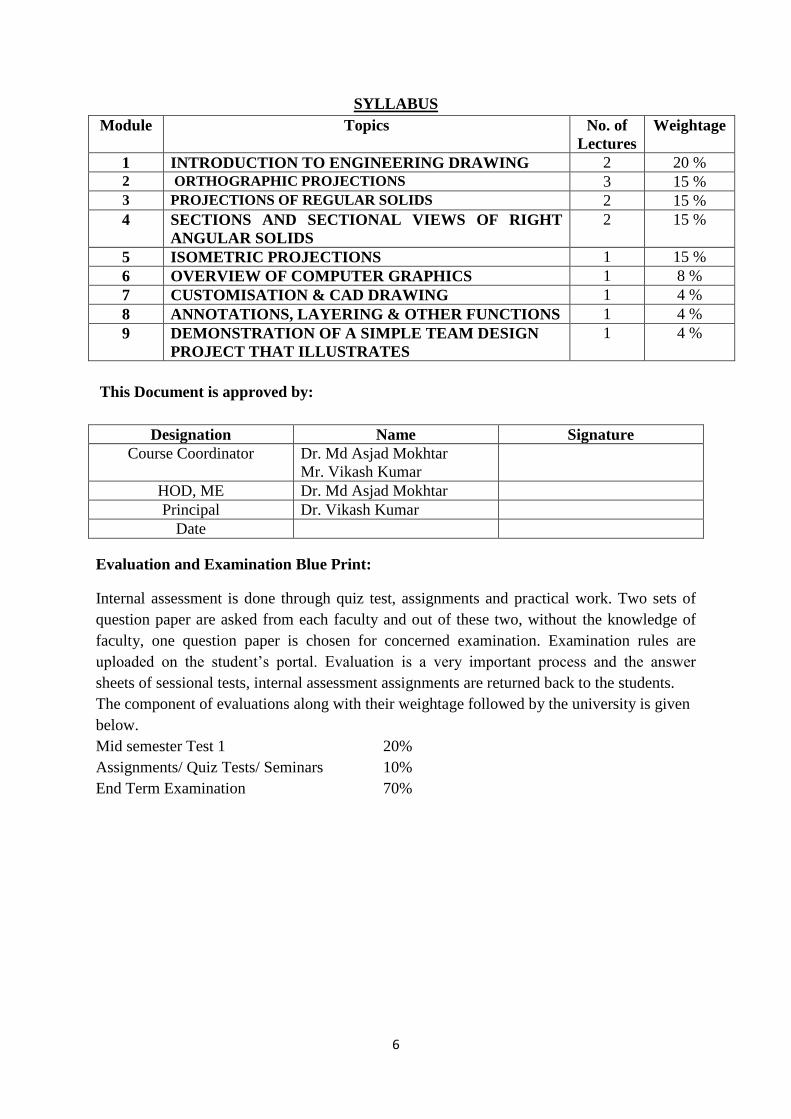
SYLLABUS
Module Topics No. of
Lectures
Weightage
1 INTRODUCTION TO ENGINEERING DRAWING 2 20 %
2 ORTHOGRAPHIC PROJECTIONS 3 15 %
3 PROJECTIONS OF REGULAR SOLIDS 2 15 %
4 SECTIONS AND SECTIONAL VIEWS OF RIGHT
ANGULAR SOLIDS
2 15 %
5 ISOMETRIC PROJECTIONS 1 15 %
6 OVERVIEW OF COMPUTER GRAPHICS 1 8 %
7 CUSTOMISATION & CAD DRAWING 1 4 %
8 ANNOTATIONS, LAYERING & OTHER FUNCTIONS 1 4 %
9 DEMONSTRATION OF A SIMPLE TEAM DESIGN
PROJECT THAT ILLUSTRATES
1 4 %
This Document is approved by:
Designation Name Signature
Course Coordinator Dr. Md Asjad Mokhtar
Mr. Vikash Kumar
HOD, ME Dr. Md Asjad Mokhtar
Principal Dr. Vikash Kumar
Date
Evaluation and Examination Blue Print:
Internal assessment is done through quiz test, assignments and practical work. Two sets of
question paper are asked from each faculty and out of these two, without the knowledge of
faculty, one question paper is chosen for concerned examination. Examination rules are
uploaded on the student’s portal. Evaluation is a very important process and the answer
sheets of sessional tests, internal assessment assignments are returned back to the students.
The component of evaluations along with their weightage followed by the university is given
below.
Mid semester Test 1 20%
Assignments/ Quiz Tests/ Seminars 10%
End Term Examination 70%

7
1st Sem. Branch:- Mechanical Engineering Batch (2021-25)
SN Name Class Roll No. Category Mob. No.
1. RAVI KUMAR YADAV 21-M-02 EBC 9102864348
2. CHANDAN KUMAR 21-M-03 SC 7631894205
3. VIKASH RAJ 21-M-04 EBC 8409852500
4. ANIL KUMAR 21-M-05 SC 9304933990
5. ANIL KUMAR DAS 21-M-06 SC 7280962533
6. SHIVAM KUMAR 21-M-07 EWS 6200115787
7. JITENDRA KUMAR YADAV 21-M-08 BC 7859097170
8. RANJEET KUMAR 21-M-10 EWS 9771723264
9. SURYA KANT SHARMA 21-M-11 EBC 9117764702
10. MD FAHIM ZAFAR 21-M-12 EWS 7492970543
11. AYUSH 21-M-13 BC 7992473988
12. ABHISHEK KUMAR 21-M-16 EBC 8789003282
13. AMARJEET KUMAR 21-M-17 EBC 9523242642
14. AAVYA SHARMA 21-M-18 EBC 7667594969
15. ADITYA KUMAR 21-M-19 BC 6209420264
16. PRIYANKA GUPTA 21-M-20 BC 9142235447
17. ANKIT JAGAT 21-M-21 EWS 6299517194
18. SHUBHAM KUMARI 21-M-22 BC 7992413243
19. PRABHAT KUMAR 21-M-23 BC 9525974101
20. ANKITA KUMARI 21-M-24 GEN 8709622365
21. AJEET KUMAR PANDIT 21-M-25 EBC 6209238485
22. AMAN KUMAR 21-M-26 BC 9162801172
23. SUMAN KUMAR 21-M-27 EWS 6203107244
24. PUSHKAR JHA 21-M-28 UR 9608724790
25. GAUTAM SACHIDEV 21-M-29 SC 8809972339
26. MALA KUMARI 21-M-30 EWS 7370977408
27. MD RAIHAN AHMAD 21-M-32 EBC 8271633406
28. ANUJ KUMAR 21-M-33 EBC 8678896478
29. RAMAN KUMAR 21-M-34 EWS 9117577346
30. AKSHAY KUMAR 21-M-35 EBC 7004338840
31. KOMAL KUMARI 21-M-36 EBC 9472215176
32. MD HASSAN 21-M-37 EWS 8016593472
33. AYUSHA KUMARI 21-M-38 BC 7282897160
34. JAYANT KUMAR 21-M-39 EWS 8210174860
35. SALMAN ARSHAD 21-M-40 EWS 8603315820
36. KUNAL PRATAP SINGH 21-M-42 EWS 7250711719
37. NISHANT KUMAR 21-M-44 EWS 6299021662
38. AMARNATH KUMAR 21-M-45 SC 9798747337
39 AMAN SINGH 21-M-46 EWS 9955662401
8
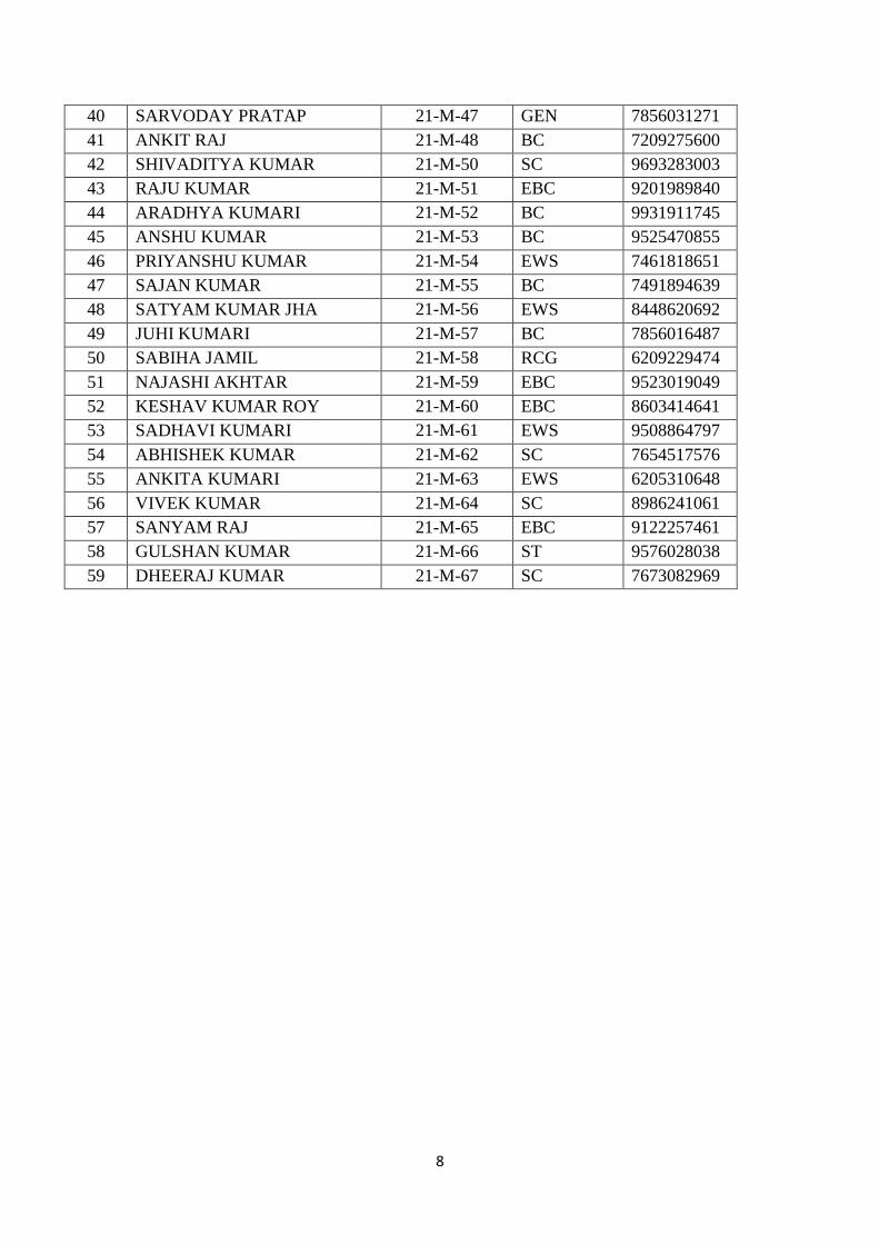
40 SARVODAY PRATAP 21-M-47 GEN 7856031271
41 ANKIT RAJ 21-M-48 BC 7209275600
42 SHIVADITYA KUMAR 21-M-50 SC 9693283003
43 RAJU KUMAR 21-M-51 EBC 9201989840
44 ARADHYA KUMARI 21-M-52 BC 9931911745
45 ANSHU KUMAR 21-M-53 BC 9525470855
46 PRIYANSHU KUMAR 21-M-54 EWS 7461818651
47 SAJAN KUMAR 21-M-55 BC 7491894639
48 SATYAM KUMAR JHA 21-M-56 EWS 8448620692
49 JUHI KUMARI 21-M-57 BC 7856016487
50 SABIHA JAMIL 21-M-58 RCG 6209229474
51 NAJASHI AKHTAR 21-M-59 EBC 9523019049
52 KESHAV KUMAR ROY 21-M-60 EBC 8603414641
53 SADHAVI KUMARI 21-M-61 EWS 9508864797
54 ABHISHEK KUMAR 21-M-62 SC 7654517576
55 ANKITA KUMARI 21-M-63 EWS 6205310648
56 VIVEK KUMAR 21-M-64 SC 8986241061
57 SANYAM RAJ 21-M-65 EBC 9122257461
58 GULSHAN KUMAR 21-M-66 ST 9576028038
59 DHEERAJ KUMAR 21-M-67 SC 7673082969

9
Pre-requisite test
DCE, Darbhanga, Pre-requisite test for EG&D, Batch 2021-25, ME, 1st semester,
Marks: 10, time: 1hr
1. Draw a straight line segment and find its shortest distance from a specified point.
[1]
2. Draw the Cartesian coordinate system (in three perpendicular dimension, X, Y & Z) and then
draw a cuboid of side 4×7×10 (cm) with one edge parallel to x-axis.
[2]
3. Draw a line segment of 75 mm length and construct a perpendicular bisector of it.
[1]
4. Draw a line segment of 11 cm and divide it into a ratio of 5/7.
[1]
5. Draw a circle of 50 mm radius with its centre at (15, 20) and construct a tangent on any point on
the circumference of the circle.
[2]
6. Construct a hexagon of side 30mm and draw a circle inscribed in it.
[1]
7. Construct neatly an angle of 45 degree.
[1]
8. Draw a right handed Cartesian coordinate system (in three perpendicular dimension, X, Y & Z)
and mark point P1 at (5, 8, 0), P2 at (8, 0, 5), P3 at (0, 8, 5) and P4 at (3, 5, 8)
[2]
10
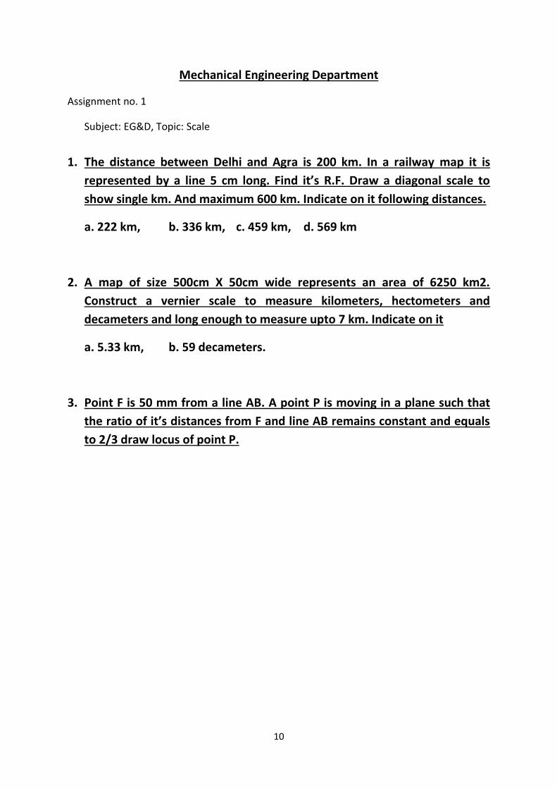
Mechanical Engineering Department
Assignment no. 1
Subject: EG&D, Topic: Scale
1. The distance between Delhi and Agra is 200 km. In a railway map it is
represented by a line 5 cm long. Find it’s R.F. Draw a diagonal scale to
show single km. And maximum 600 km. Indicate on it following distances.
a. 222 km, b. 336 km, c. 459 km, d. 569 km
2. A map of size 500cm X 50cm wide represents an area of 6250 km2.
Construct a vernier scale to measure kilometers, hectometers and
decameters and long enough to measure upto 7 km. Indicate on it
a. 5.33 km, b. 59 decameters.
3. Point F is 50 mm from a line AB. A point P is moving in a plane such that
the ratio of it’s distances from F and line AB remains constant and equals
to 2/3 draw locus of point P.

11
Mechanical Engineering Department
Assignment no. 2
Subject: EG&D, Topic: Conic Section
1. A fixed point F is 7.5 cm from a fixed straight line. Draw the locus of a point P moving in
such a way that its distance from the fixed straight line is 2/3 times the distance from
focus. Name the curve. Draw the tangent and normal at any point on the curve.
2. A point moves such that its distance from a fixed straight line to its distance from a fixed
point is equal. Draw the locus of the curve traced by that point. Add a normal and
tangent to the curve at 40mm above the axis.
3. Draw hyperbola whose distance of focus is 55 mm and e = 1.5. Draw the tangent and
normal 50 mm from the directrix.
12
Darbhanga College of Engineering, Darbhanga
Subject: Engineering Graphics and Design
Branch: ME, Batch 2021-25, Semester – 1st
Assignment no. 3
Module 03: Projections of Regular Solids
1. A cone 40 mm diameter and 50 mm axis is resting on one generator on HP which makes 30o
inclination with the VP. Draw it’s projections.
2. A right circular cone, 40 mm base diameter and 60 mm long axis is resting on HP on one point of
base circle such that it’s axis makes 45o inclination with HP and 40o inclination with VP. Draw it’s
projections.
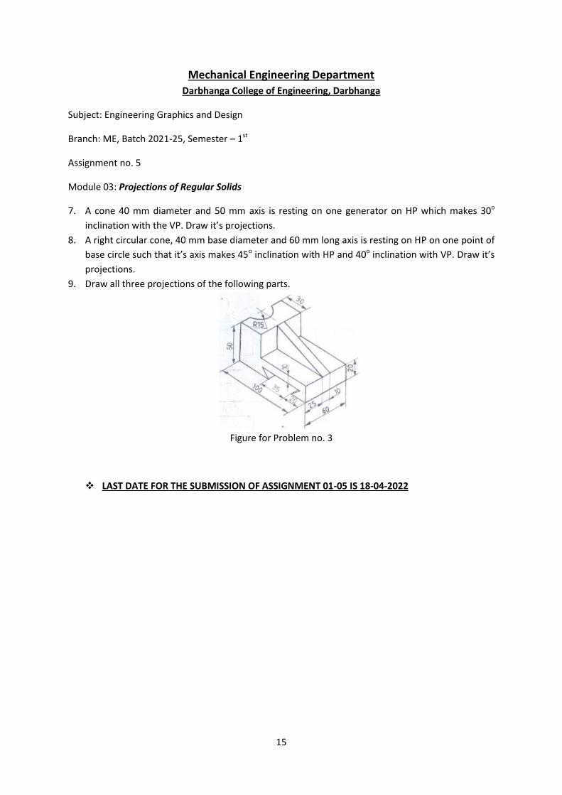
3. Draw all three projections of the following parts.
Figure for Problem no. 3
13
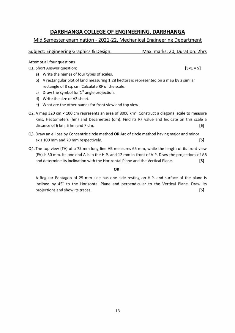
DARBHANGA COLLEGE OF ENGINEERING, DARBHANGA
Mid Semester examination - 2021-22, Mechanical Engineering Department
Subject: Engineering Graphics & Design. Max. marks: 20, Duration: 2hrs
Attempt all four questions
Q1. Short Answer question: [5×1 = 5]
a) Write the names of four types of scales.
b) A rectangular plot of land measuring 1.28 hectors is represented on a map by a similar
rectangle of 8 sq. cm. Calculate RF of the scale.
c) Draw the symbol for 1st angle projection.
d) Write the size of A3 sheet.
e) What are the other names for front view and top view.
Q2. A map 320 cm × 100 cm represents an area of 8000 km2. Construct a diagonal scale to measure
Kms, Hectometers (hm) and Decameters (dm). Find its RF value and Indicate on this scale a
distance of 6 km, 5 hm and 7 dm. [5]
Q3. Draw an ellipse by Concentric circle method OR Arc of circle method having major and minor
axis 100 mm and 70 mm respectively. [5]
Q4. The top view (TV) of a 75 mm long line AB measures 65 mm, while the length of its front view
(FV) is 50 mm. Its one end A is in the H.P. and 12 mm in-front of V.P. Draw the projections of AB
and determine its inclination with the Horizontal Plane and the Vertical Plane. [5]
OR
A Regular Pentagon of 25 mm side has one side resting on H.P. and surface of the plane is
inclined by 45o to the Horizontal Plane and perpendicular to the Vertical Plane. Draw its
projections and show its traces. [5]
14
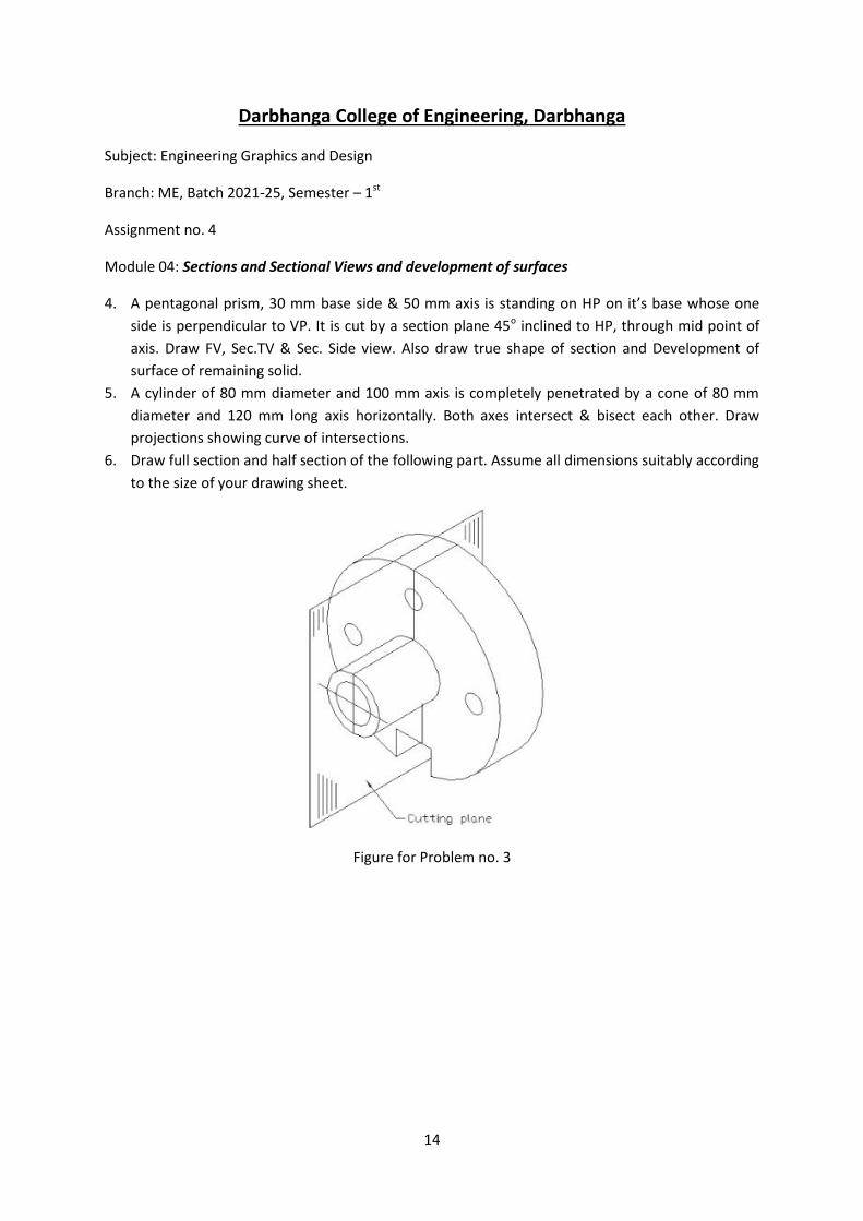
Darbhanga College of Engineering, Darbhanga
Subject: Engineering Graphics and Design
Branch: ME, Batch 2021-25, Semester – 1st
Assignment no. 4
Module 04: Sections and Sectional Views and development of surfaces
4. A pentagonal prism, 30 mm base side & 50 mm axis is standing on HP on it’s base whose one
side is perpendicular to VP. It is cut by a section plane 45o inclined to HP, through mid point of
axis. Draw FV, Sec.TV & Sec. Side view. Also draw true shape of section and Development of
surface of remaining solid.
5. A cylinder of 80 mm diameter and 100 mm axis is completely penetrated by a cone of 80 mm
diameter and 120 mm long axis horizontally. Both axes intersect & bisect each other. Draw
projections showing curve of intersections.
6. Draw full section and half section of the following part. Assume all dimensions suitably according
to the size of your drawing sheet.
Figure for Problem no. 3
15
Mechanical Engineering Department
Darbhanga College of Engineering, Darbhanga
Subject: Engineering Graphics and Design
Branch: ME, Batch 2021-25, Semester – 1st
Assignment no. 5
Module 03: Projections of Regular Solids
7. A cone 40 mm diameter and 50 mm axis is resting on one generator on HP which makes 30o
inclination with the VP. Draw it’s projections.
8. A right circular cone, 40 mm base diameter and 60 mm long axis is resting on HP on one point of
base circle such that it’s axis makes 45o inclination with HP and 40o inclination with VP. Draw it’s
projections.
9. Draw all three projections of the following parts.
Figure for Problem no. 3
LAST DATE FOR THE SUBMISSION OF ASSIGNMENT 01-05 IS 18-04-2022
ENGINEERING GRAPHICS (Engineering Drawing is the language of Engineers)
UNIT 1
Conic Section (Ellipse, Parabola & Hyperbola) - Cycloids, epicycloids,
hypocycloids & Involutes around circle and square – scales – diagonal – vernier
scale – Free hand sketching
Definition: Engineering graphical language for effective communication among engineers which
elaborates the details of any component, structure or circuit at its initial drawing through
drawing.
The following are the various drafting tools used in engineering graphics.
Drawing Board
Mini drafter or T- square
Drawing Instrument box
Drawing Pencils
Eraser
Templates
Set squares
Protractor
Scale Set
French curves
Drawing clips
Duster piece of cloth (or) brush
Sand-paper (or) Emery sheet block
Drawing sheet
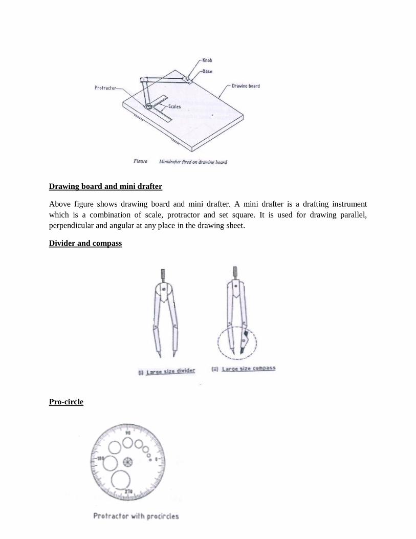
Drawing board and mini drafter
Above figure shows drawing board and mini drafter. A mini drafter is a drafting instrument
which is a combination of scale, protractor and set square. It is used for drawing parallel,
perpendicular and angular at any place in the drawing sheet.
Divider and compass
Pro-circle
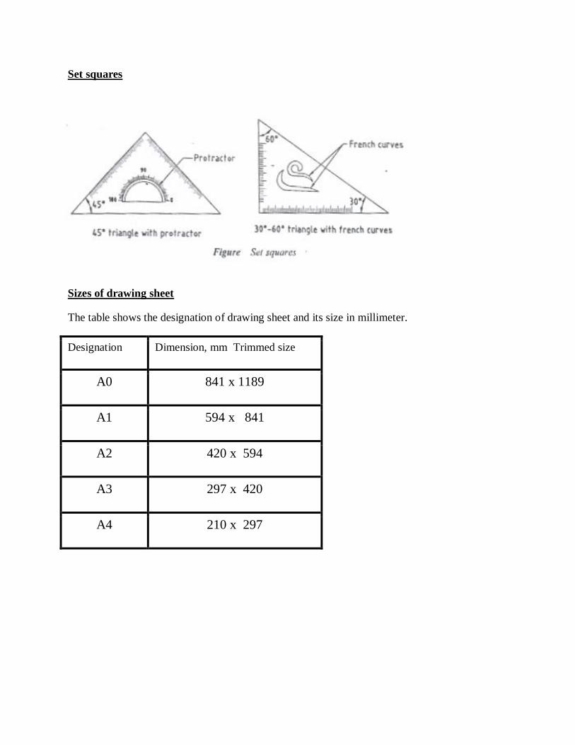
Set squares
Sizes of drawing sheet
The table shows the designation of drawing sheet and its size in millimeter.
Designation Dimension, mm Trimmed size
A0 841 x 1189
A1 594 x 841
A2 420 x 594
A3 297 x 420
A4 210 x 297

Method of dimensioning for circle, arc, semicircle:
Φ – diameter
R - radius
CONIC SECTIONS
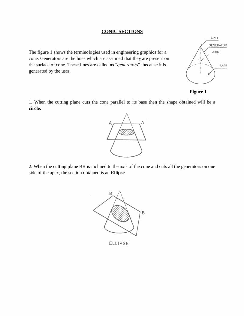
The figure 1 shows the terminologies used in engineering graphics for a
cone. Generators are the lines which are assumed that they are present on
the surface of cone. These lines are called as “generators”, because it is
generated by the user.
Figure 1
1. When the cutting plane cuts the cone parallel to its base then the shape obtained will be a
circle.
2. When the cutting plane BB is inclined to the axis of the cone and cuts all the generators on one
side of the apex, the section obtained is an Ellipse
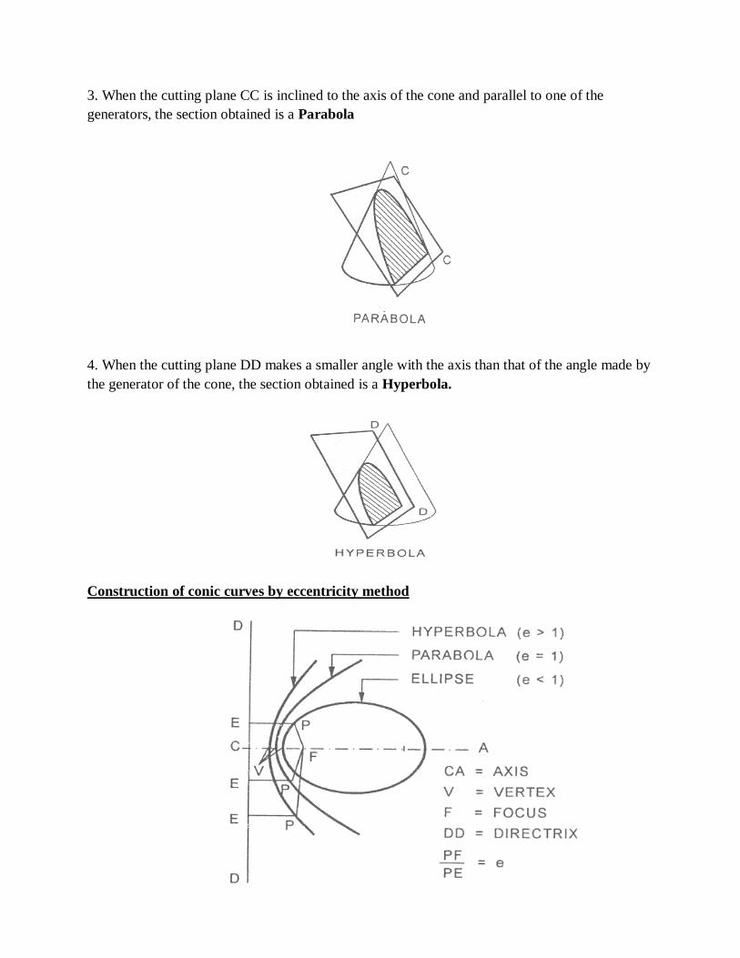
3. When the cutting plane CC is inclined to the axis of the cone and parallel to one of the
generators, the section obtained is a Parabola
4. When the cutting plane DD makes a smaller angle with the axis than that of the angle made by
the generator of the cone, the section obtained is a Hyperbola.
Construction of conic curves by eccentricity method
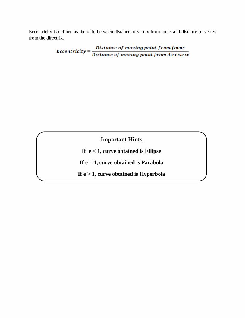
Eccentricity is defined as the ratio between distance of vertex from focus and distance of vertex
from the directrix.
Important Hints
If e < 1, curve obtained is Ellipse
If e = 1, curve obtained is Parabola
If e > 1, curve obtained is Hyperbola
SOLVED EXAMPLES
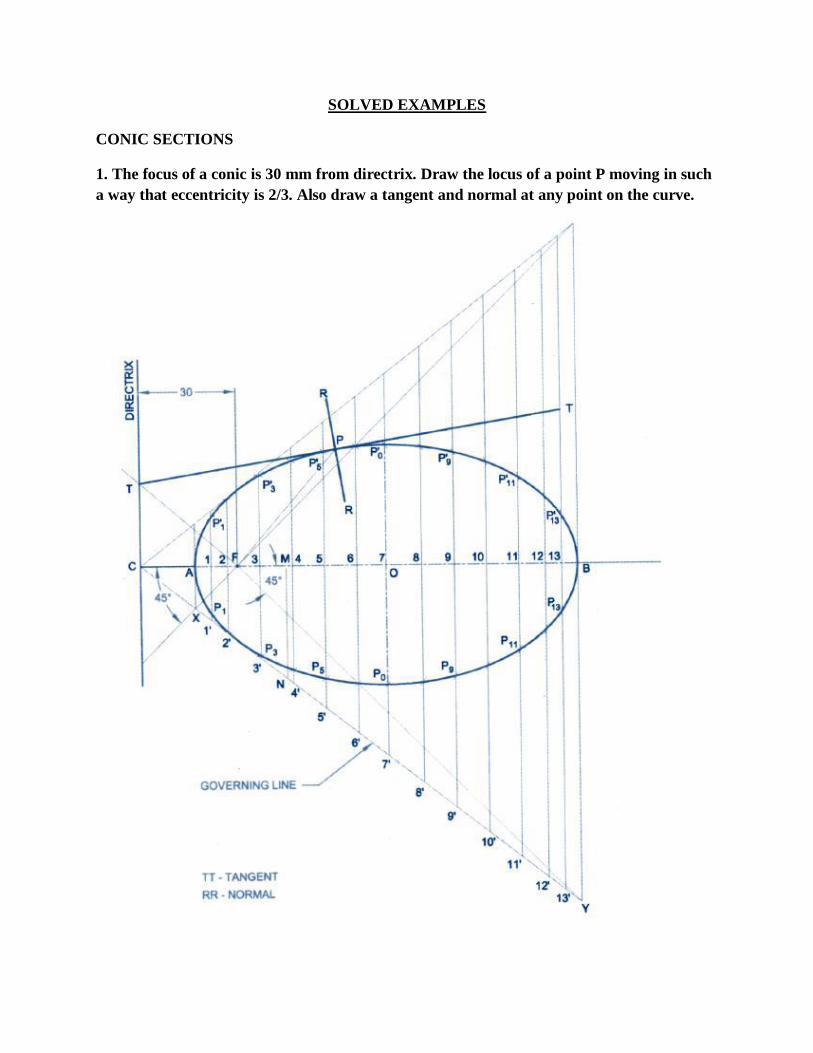
CONIC SECTIONS
1. The focus of a conic is 30 mm from directrix. Draw the locus of a point P moving in such
a way that eccentricity is 2/3. Also draw a tangent and normal at any point on the curve.
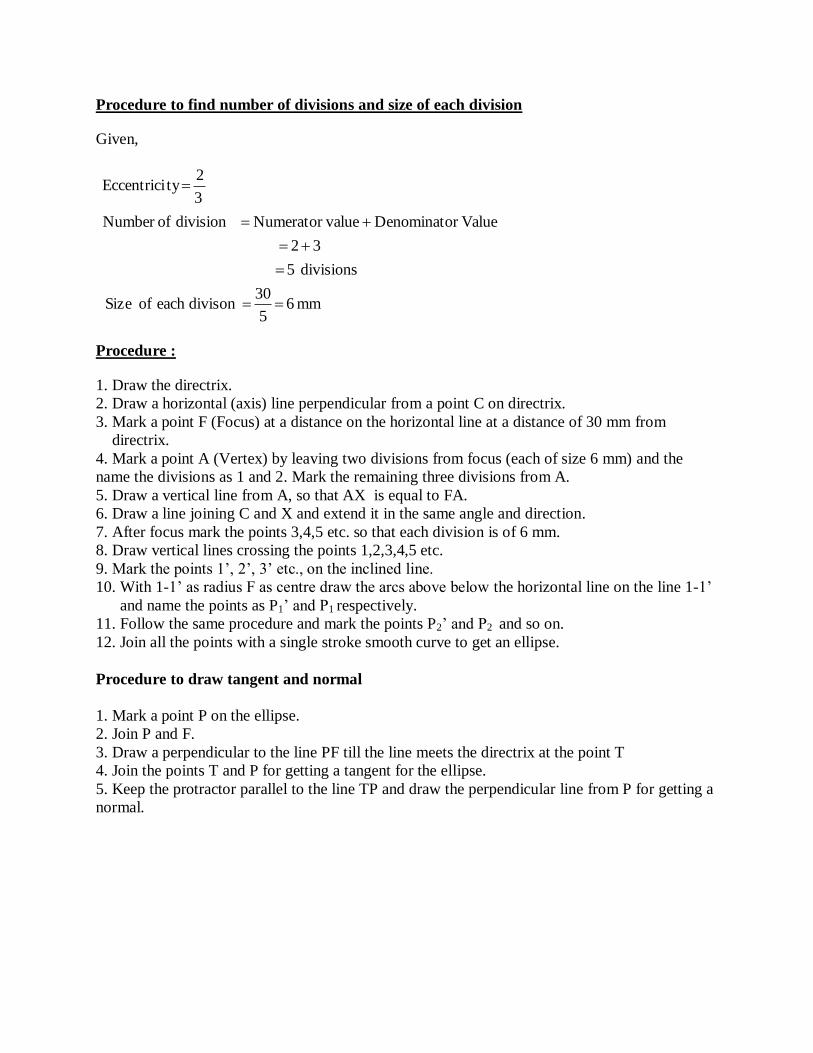
Procedure to find number of divisions and size of each division
Given,
mm65
30divisoneachofSize
divisions5
32
ValuerDenominatovalueNumerator divisionofNumber
3
2tyEccentrici
Procedure :
1. Draw the directrix.
2. Draw a horizontal (axis) line perpendicular from a point C on directrix.
3. Mark a point F (Focus) at a distance on the horizontal line at a distance of 30 mm from
directrix.
4. Mark a point A (Vertex) by leaving two divisions from focus (each of size 6 mm) and the
name the divisions as 1 and 2. Mark the remaining three divisions from A.
5. Draw a vertical line from A, so that AX is equal to FA.
6. Draw a line joining C and X and extend it in the same angle and direction.
7. After focus mark the points 3,4,5 etc. so that each division is of 6 mm.
8. Draw vertical lines crossing the points 1,2,3,4,5 etc.
9. Mark the points 1’, 2’, 3’ etc., on the inclined line.
10. With 1-1’ as radius F as centre draw the arcs above below the horizontal line on the line 1-1’
and name the points as P1’ and P1 respectively.
11. Follow the same procedure and mark the points P2’ and P2 and so on.
12. Join all the points with a single stroke smooth curve to get an ellipse.
Procedure to draw tangent and normal
1. Mark a point P on the ellipse.
2. Join P and F.
3. Draw a perpendicular to the line PF till the line meets the directrix at the point T
4. Join the points T and P for getting a tangent for the ellipse.
5. Keep the protractor parallel to the line TP and draw the perpendicular line from P for getting a
normal.
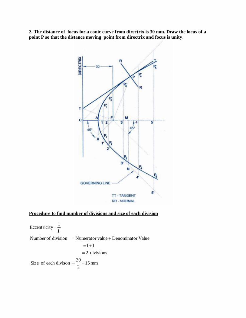
2. The distance of focus for a conic curve from directrix is 30 mm. Draw the locus of a
point P so that the distance moving point from directrix and focus is unity.
Procedure to find number of divisions and size of each division
mm512
30divisoneachofSize
divisions2
11
ValuerDenominatovalueNumerator divisionofNumber
1
1tyEccentrici

Procedure :
1. Draw the directrix d-d’.
2. Draw a horizontal (axis) line perpendicular from a point C on directrix.
3. Mark a point F (Focus) at a distance on the horizontal line at a distance of 30 mm from
directrix.
4. Mark a point A (Vertex) by leaving two divisions from focus (each of size 6 mm) and the
name the divisions as 1 and 2. Mark the remaining three divisions from A.
5. Draw a vertical line from A, so that AX is equal to FA.
6. Draw a line joining C and X and extend it in the same angle and direction.
7. After focus mark the points 3,4,5 etc. so that each division is of 6 mm.
8. Draw vertical lines crossing the points 1,2,3,4,5 etc.
9. Mark the points 1’, 2’, 3’ etc., on the inclined line.
10. With 1-1’ as radius F as centre draw the arcs above below the horizontal line on the line 1-1’
and name the points as P1’ and P1 respectively.
11. Follow the same procedure and mark the points P2’ and P2 and so on.
12. Join all the points with a single stroke smooth curve to get a parabola.
Procedure to draw tangent and normal
1. Mark a point P on the ellipse.
2. Join P and F.
3. Draw a perpendicular to the line PF till the line meets the directrix at the point T
4. Join the points T and P for getting a tangent for the ellipse.
5. Keep the protractor parallel to the line TP and draw the perpendicular line from P for getting a
normal.
3. Draw a hyperbola whose distance of focus from directrix is 60 mm. The eccentricity is
3/2. Also draw a tangent and normal at any point P on the curve.
mm65
30divisoneachofSize
divisions5
23
ValuerDenominatovalueNumerator divisionofNumber
2
3tyEccentrici
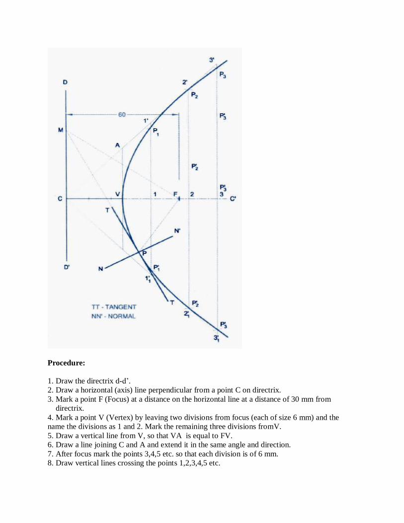
Procedure:
1. Draw the directrix d-d’.
2. Draw a horizontal (axis) line perpendicular from a point C on directrix.
3. Mark a point F (Focus) at a distance on the horizontal line at a distance of 30 mm from
directrix.
4. Mark a point V (Vertex) by leaving two divisions from focus (each of size 6 mm) and the
name the divisions as 1 and 2. Mark the remaining three divisions fromV.
5. Draw a vertical line from V, so that VA is equal to FV.
6. Draw a line joining C and A and extend it in the same angle and direction.
7. After focus mark the points 3,4,5 etc. so that each division is of 6 mm.
8. Draw vertical lines crossing the points 1,2,3,4,5 etc.
9. Mark the points 1’, 2’, 3’ etc., on the inclined line.
10. With 1-1’ as radius F as centre draw the arcs above below the horizontal line on the line 1-1’
and name the points as P1’ and P1 respectively.
11. Follow the same procedure and mark the points P2’ and P2 and so on.
12. Join all the points with a single stroke smooth curve to get a hyperbola.
Procedure to draw tangent and normal
1. Mark a point P on the hyperbola.
2. Join P and F.
3. Draw a perpendicular to the line PF till the line meets the directrix at the point T
4. Join the points T and P for getting a tangent for the ellipse.
5. Keep the protractor parallel to the line TP and draw the perpendicular line from P for getting a
normal.
PROBLEMS FOR PRACTICE
1. A fixed point F is 7.5 cm from a fixed straight line. Draw the locus of a point P moving in
such a way that its distance from the fixed straight line is 2/3 times the distance from focus.
Name the curve. Draw the tangent and normal at any point on the curve.
2. Draw the path traced by a point P moving in such a way that the distance of the focus from
directrix is 40 mm. The eccentricity is unity.
3. A point moves such that its distance from a fixed straight line to its distance from a fixed point
is equal. Draw the locus of the curve traced by that point. Add a normal and tangent to the curve
at 40mm above the axis
4. Draw an ellipse when the distance of focus from the directrix is equal to 35 mm and
eccentricity is 3/4. Draw a tangent and normal at a point P located at 30mm above the major axis.
5. Draw an ellipse whose focus distance from is 70 mm and e is 0.5. Draw the tangent and
normal 40 mm above the axis.
6. Draw hyperbola whose distance of focus is 55 mm and e = 1.5. Draw the tangent and normal
50 mm from the directrix.
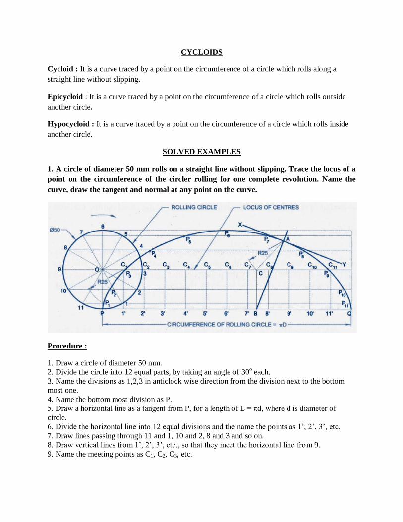
CYCLOIDS
Cycloid : It is a curve traced by a point on the circumference of a circle which rolls along a
straight line without slipping.
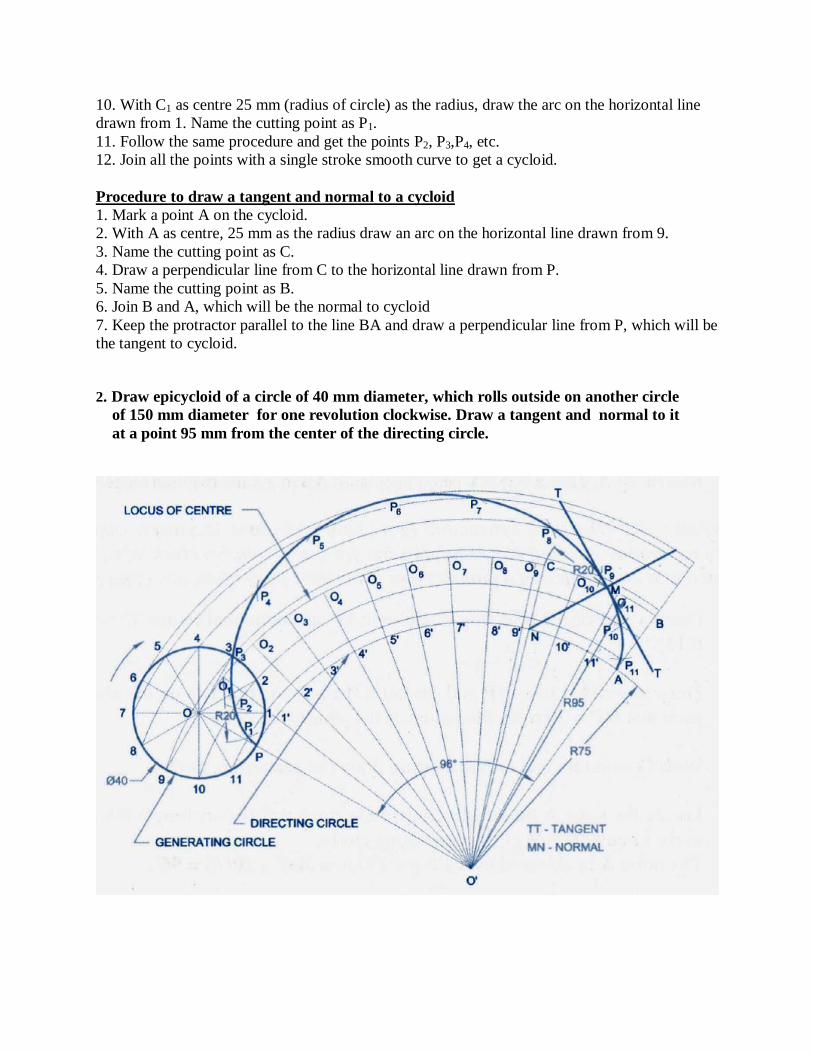
Epicycloid : It is a curve traced by a point on the circumference of a circle which rolls outside
another circle.
Hypocycloid : It is a curve traced by a point on the circumference of a circle which rolls inside
another circle.
SOLVED EXAMPLES
1. A circle of diameter 50 mm rolls on a straight line without slipping. Trace the locus of a
point on the circumference of the circler rolling for one complete revolution. Name the
curve, draw the tangent and normal at any point on the curve.
Procedure :
1. Draw a circle of diameter 50 mm.
2. Divide the circle into 12 equal parts, by taking an angle of 30o each.
3. Name the divisions as 1,2,3 in anticlock wise direction from the division next to the bottom
most one.
4. Name the bottom most division as P.
5. Draw a horizontal line as a tangent from P, for a length of L = πd, where d is diameter of
circle.
6. Divide the horizontal line into 12 equal divisions and the name the points as 1’, 2’, 3’, etc.
7. Draw lines passing through 11 and 1, 10 and 2, 8 and 3 and so on.
8. Draw vertical lines from 1’, 2’, 3’, etc., so that they meet the horizontal line from 9.
9. Name the meeting points as C1, C2, C3, etc.
10. With C1 as centre 25 mm (radius of circle) as the radius, draw the arc on the horizontal line
drawn from 1. Name the cutting point as P1.
11. Follow the same procedure and get the points P2, P3,P4, etc.
12. Join all the points with a single stroke smooth curve to get a cycloid.
Procedure to draw a tangent and normal to a cycloid
1. Mark a point A on the cycloid.
2. With A as centre, 25 mm as the radius draw an arc on the horizontal line drawn from 9.
3. Name the cutting point as C.
4. Draw a perpendicular line from C to the horizontal line drawn from P.
5. Name the cutting point as B.
6. Join B and A, which will be the normal to cycloid
7. Keep the protractor parallel to the line BA and draw a perpendicular line from P, which will be
the tangent to cycloid.
2. Draw epicycloid of a circle of 40 mm diameter, which rolls outside on another circle
of 150 mm diameter for one revolution clockwise. Draw a tangent and normal to it
at a point 95 mm from the center of the directing circle.
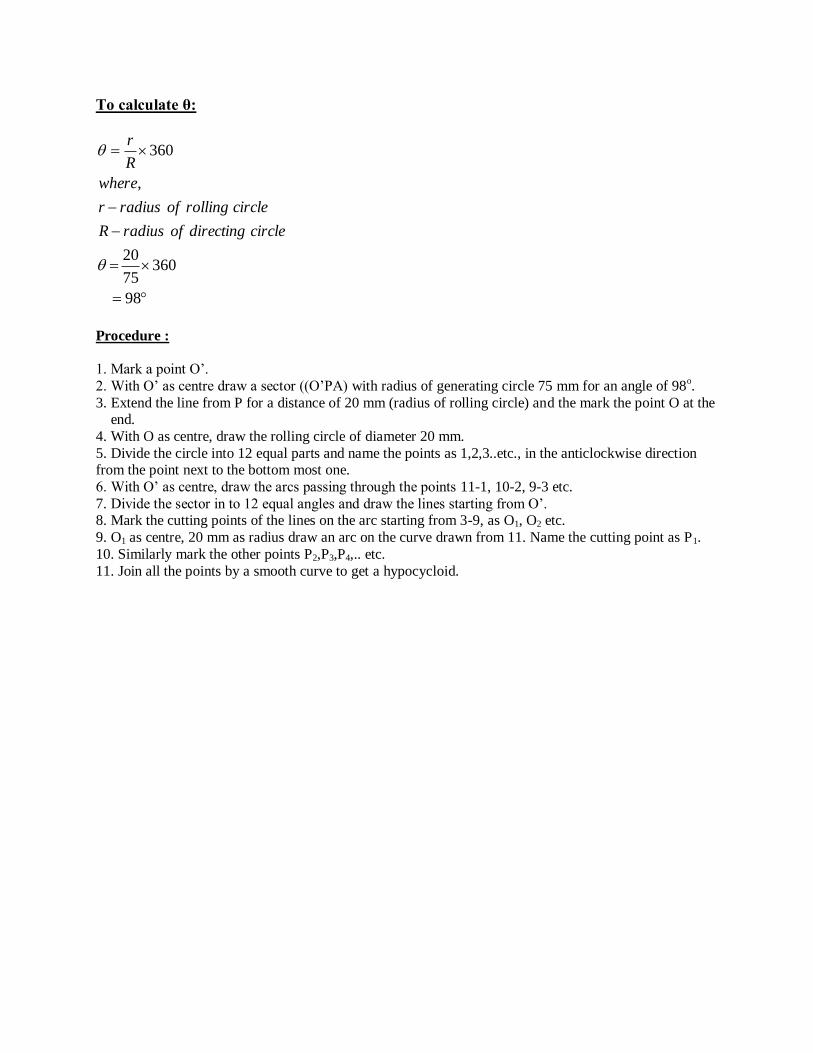
To calculate θ:
98
36075
20
,
360
circledirectingofradiusR
circlerollingofradiusr
where
R
r
Procedure :
1. Mark a point O’.
2. With O’ as centre draw a sector ((O’PA) with radius of generating circle 75 mm for an angle of 98o.
3. Extend the line from P for a distance of 20 mm (radius of rolling circle) and the mark the point O at the end.
4. With O as centre, draw the rolling circle of diameter 20 mm.
5. Divide the circle into 12 equal parts and name the points as 1,2,3..etc., in the anticlockwise direction from the point next to the bottom most one.
6. With O’ as centre, draw the arcs passing through the points 11-1, 10-2, 9-3 etc.
7. Divide the sector in to 12 equal angles and draw the lines starting from O’. 8. Mark the cutting points of the lines on the arc starting from 3-9, as O1, O2 etc.
9. O1 as centre, 20 mm as radius draw an arc on the curve drawn from 11. Name the cutting point as P1.
10. Similarly mark the other points P2,P3,P4,.. etc.
11. Join all the points by a smooth curve to get a hypocycloid.
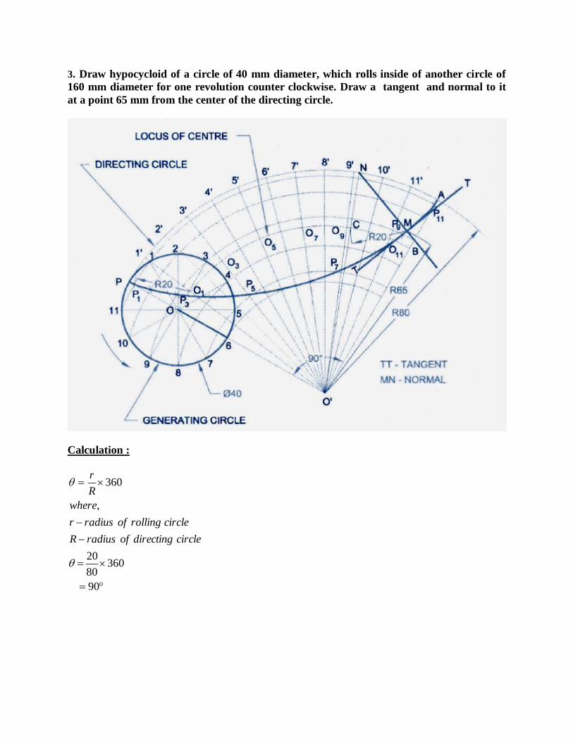
3. Draw hypocycloid of a circle of 40 mm diameter, which rolls inside of another circle of
160 mm diameter for one revolution counter clockwise. Draw a tangent and normal to it
at a point 65 mm from the center of the directing circle.
Calculation :
90
36080
20
,
360
circledirectingofradiusR
circlerollingofradiusr
where
R
r

Procedure :
1. Mark a point O’.
2. With O’ as centre draw a sector (O’PA) with radius of generating circle 80 mm for an angle of 98o.
3. Mark P on the line PO’ so that OP = radius of rolling circle.
4. With O as centre, draw the rolling circle of diameter 20 mm. 5. Divide the circle into 12 equal parts and name the points as 1,2,3..etc., in the clockwise direction from
the point next to the top most one.
6. With O’ as centre, draw the arcs passing through the points 11-1, 10-2, 9-3 etc. 7. Divide the sector in to 12 equal angles and draw the lines starting from O’.
8. Mark the cutting points of the lines on the arc starting from 3-9, as O1, O2 etc.
9. O1 as centre, 20 mm as radius draw an arc on the curve drawn from 11. Name the cutting point as P1. 10. Similarly mark the other points P2,P3,P4,.. etc.
11. Join all the points by a smooth curve to get an epicycloid.
PROBLEMS FOR PRACTICE
1. Draw epicycloids of a circle of 40 mm diameter, which rolls outside on another circle of 150
mm diameter for one revolution clockwise. Draw a a tangent and normal to it at a point 95 mm
from the center of the directing circle.
2. Draw hypocycloids of a circle of 40 mm diameter, which rolls inside of another circle of 160
mm diameter for one revolution counter clockwise. Draw a a tangent and normal to it at a point
65 mm from the center of the directing circle.
3. A roller of 40 mm diameter rolls over a horizontal table without slipping. A point on the
circumference of the roller is in contact with the table surface in the beginning till one end of
revolution. Draw the path traced by the point.
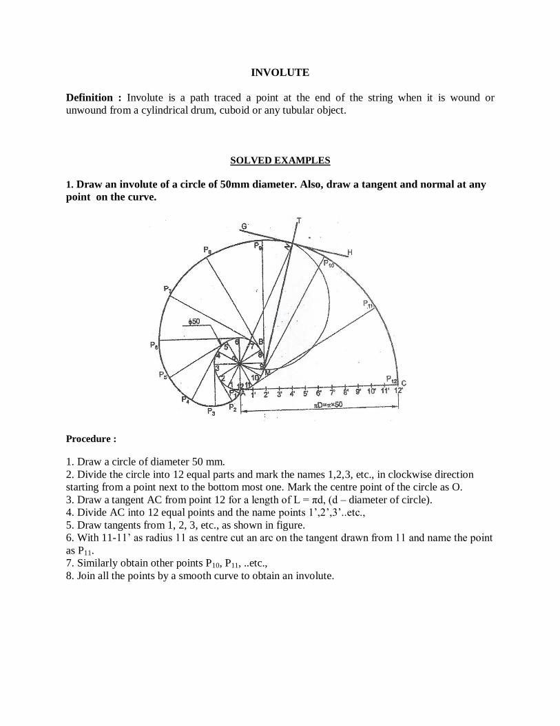
INVOLUTE
Definition : Involute is a path traced a point at the end of the string when it is wound or
unwound from a cylindrical drum, cuboid or any tubular object.
SOLVED EXAMPLES
1. Draw an involute of a circle of 50mm diameter. Also, draw a tangent and normal at any
point on the curve.
Procedure :
1. Draw a circle of diameter 50 mm.
2. Divide the circle into 12 equal parts and mark the names 1,2,3, etc., in clockwise direction
starting from a point next to the bottom most one. Mark the centre point of the circle as O.
3. Draw a tangent AC from point 12 for a length of L = πd, (d – diameter of circle).
4. Divide AC into 12 equal points and the name points 1’,2’,3’..etc.,
5. Draw tangents from 1, 2, 3, etc., as shown in figure.
6. With 11-11’ as radius 11 as centre cut an arc on the tangent drawn from 11 and name the point
as P11.
7. Similarly obtain other points P10, P11, ..etc.,
8. Join all the points by a smooth curve to obtain an involute.
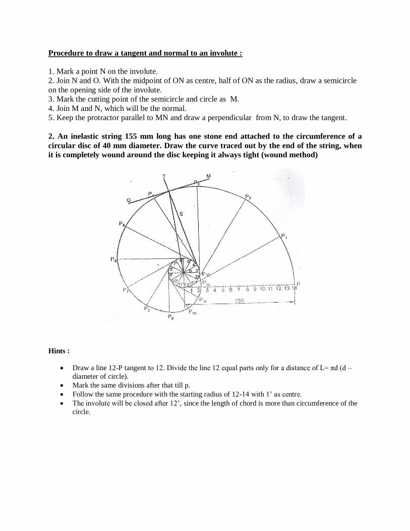
Procedure to draw a tangent and normal to an involute :
1. Mark a point N on the involute.
2. Join N and O. With the midpoint of ON as centre, half of ON as the radius, draw a semicircle
on the opening side of the involute.
3. Mark the cutting point of the semicircle and circle as M.
4. Join M and N, which will be the normal.
5. Keep the protractor parallel to MN and draw a perpendicular from N, to draw the tangent.
2. An inelastic string 155 mm long has one stone end attached to the circumference of a
circular disc of 40 mm diameter. Draw the curve traced out by the end of the string, when
it is completely wound around the disc keeping it always tight (wound method)
Hints :
Draw a line 12-P tangent to 12. Divide the line 12 equal parts only for a distance of L= πd (d –
diameter of circle).
Mark the same divisions after that till p.
Follow the same procedure with the starting radius of 12-14 with 1’ as centre.
The involute will be closed after 12’, since the length of chord is more than circumference of the
circle.

Tutorial: (Students are requested to refer the book and write the procedure for problem 3)
3. Draw the path traced by a point at the end of a string, when it is wound around a square of size
40 mm.
PROBLEMS FOR PRACTICE
1. Draw the path traced by the end of a string when it is wound around a cylindrical drum of
diameter 40 mm.
2. Draw an involute around a hexagon of side 25 mm.
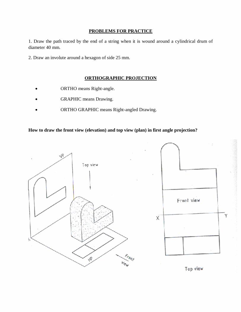
ORTHOGRAPHIC PROJECTION
ORTHO means Right-angle.
GRAPHIC means Drawing.
ORTHO GRAPHIC means Right-angled Drawing.
How to draw the front view (elevation) and top view (plan) in first angle projection?
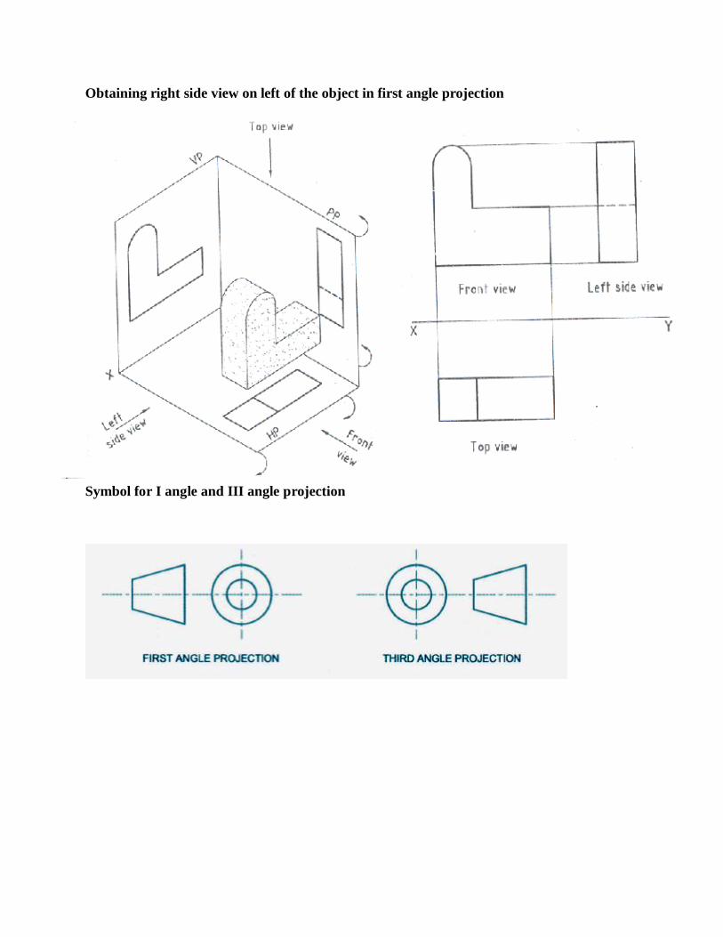
Obtaining right side view on left of the object in first angle projection
Symbol for I angle and III angle projection
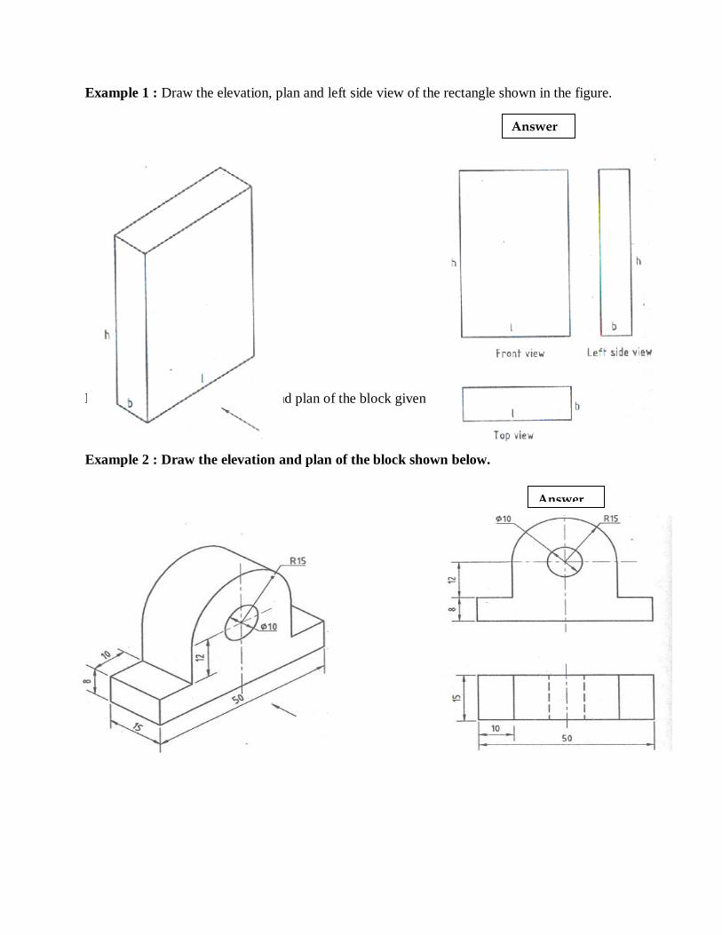
Example 1 : Draw the elevation, plan and left side view of the rectangle shown in the figure.
Example 2 : Draw the elevation and plan of the block given below.
Example 2 : Draw the elevation and plan of the block shown below.
Answer
Answer

Example 3 : Draw the elevation, plan and left end view of the object shown below.
Example 4: Draw the front view, top view and left side view of the block shown below.
Answer
Answer

Example 5: Draw the front, top and right end view of the block shown below.
Example 6: Draw the elevation, plan and right side view of the object.
Answer
Answer
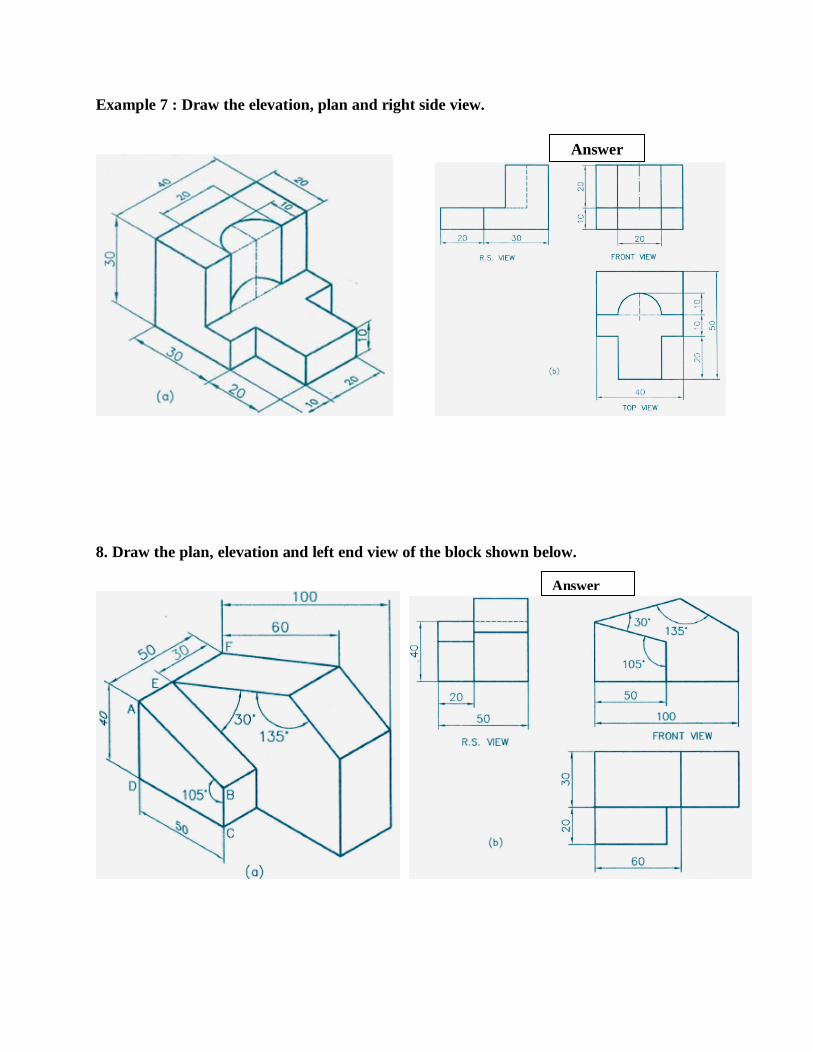
Example 7 : Draw the elevation, plan and right side view.
8. Draw the plan, elevation and left end view of the block shown below.
Answer
Answer
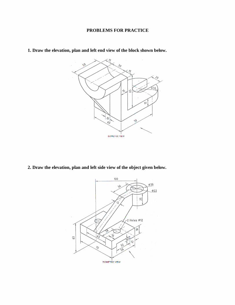
PROBLEMS FOR PRACTICE
1. Draw the elevation, plan and left end view of the block shown below.
2. Draw the elevation, plan and left side view of the object given below.
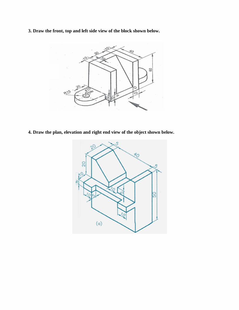
3. Draw the front, top and left side view of the block shown below.
4. Draw the plan, elevation and right end view of the object shown below.
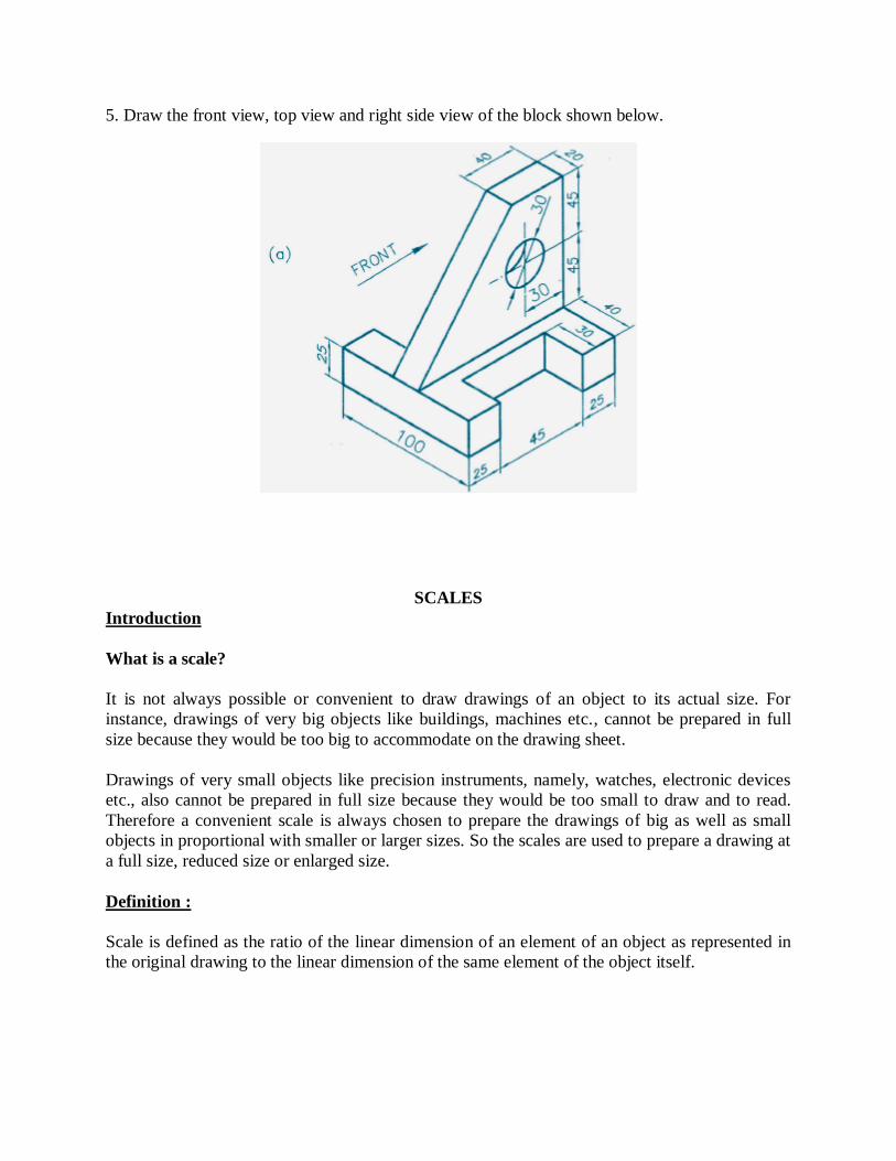
5. Draw the front view, top view and right side view of the block shown below.
SCALES
Introduction
What is a scale?
It is not always possible or convenient to draw drawings of an object to its actual size. For
instance, drawings of very big objects like buildings, machines etc., cannot be prepared in full
size because they would be too big to accommodate on the drawing sheet.
Drawings of very small objects like precision instruments, namely, watches, electronic devices
etc., also cannot be prepared in full size because they would be too small to draw and to read.
Therefore a convenient scale is always chosen to prepare the drawings of big as well as small
objects in proportional with smaller or larger sizes. So the scales are used to prepare a drawing at
a full size, reduced size or enlarged size.
Definition :
Scale is defined as the ratio of the linear dimension of an element of an object as represented in
the original drawing to the linear dimension of the same element of the object itself.

Full size scale
If we show the actual length of an object on a drawing, then the scale used is called full size
scale.
Reducing scale
If we reduce the actual length of an object so as to accommodate that object on drawing, then
scale used is called reducing scale. Such scales are used for the preparation of drawings of large
machine parts, buildings, bridges, survey maps, architectural drawings etc.
Enlarging scale
Drawings of smaller machine parts, mechanical instruments, watches, etc. are made larger than
their real size. These are said to be drawn in an increasing or enlarging scale.
Note: The scale of a drawing is always indicated on the drawing sheet at a suitable place either
below the drawing or near the title thus “scale 1:2”. Representative Fraction (R.F)
The ratio of the drawing of an object to its actual size is called the representative fraction, usually
referred to as R.F.
R.F = Drawing of an object/ Its actual size (in same units)
For reducing scale, the drawings will have R.F. values of less than unity.
For example, if 1 cm on drawing represents 1 m length of an object,
1100
1.
)1001(
1.
FR
cm
cmFR
For drawings using increasing or enlarging scale, the R.F values will be greater than unity.
For example, when 1 mm length of an object is shown by a length of 1cm on the drawing, then
11
10
1
101.
mmFR
The engineering scales recommended by BIS (Bureau of Indian Standards) are as follows
Types of Scales
1. Simple scales
2. Diagonal scales
3. Vernier scales
Plain Scale
A plain scale is simply a line, which is divided into a suitable number of equal parts, the first of
which is further sub-divided into small parts. It is used to represent either two units or a unit and
its fraction such as km, m and dm, etc.
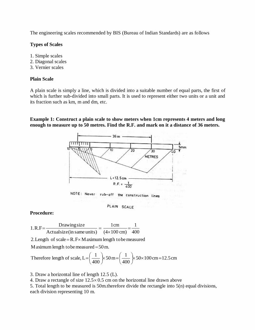
Example 1: Construct a plain scale to show meters when 1cm represents 4 meters and long
enough to measure up to 50 metres. Find the R.F. and mark on it a distance of 36 meters.
Procedure:
cm12.5cm10050400
1m50
400
1Lscale,oflengthTherefore
m.50measuredbetolengthMaximum
measuredbetolengthMaximumFR.scaleofLength2.
400
1
cm)100(4
cm1
units)same(insizeActual
sizeDrawingR.F.1
3. Draw a horizontal line of length 12.5 (L).
4. Draw a rectangle of size 12.50.5 cm on the horizontal line drawn above
5. Total length to be measured is 50m.therefore divide the rectangle into 5(n) equal divisions,
each division representing 10 m.
6. Mark 0 at the end of the first main division.
7. From 0, number 10, 20, 30 and 40 at the end of subsequent main divisions towards right as
shown.
8. Then sub-divide the first main division into 10 subdivisions to represent metres (using
geometrical construction).
9. Number the sub-divisions i.e. metres to the left of 0 as shown.
10.Write the names of main units and sub-units (METRES) below the scale. Also mention
the R.F. as shown.
11. Indicate on the scale a distance of 36metres [=3main divisions to the right side of 0+6
subdivisions to the left of 0 (zero)]
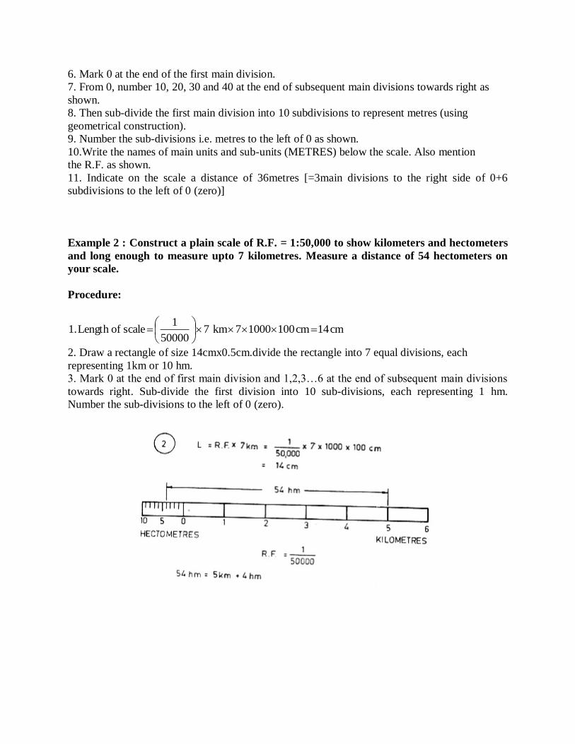
Example 2 : Construct a plain scale of R.F. = 1:50,000 to show kilometers and hectometers
and long enough to measure upto 7 kilometres. Measure a distance of 54 hectometers on
your scale.
Procedure:
cm14cm10010007km750000
1scaleofLength1.
2. Draw a rectangle of size 14cmx0.5cm.divide the rectangle into 7 equal divisions, each
representing 1km or 10 hm.
3. Mark 0 at the end of first main division and 1,2,3…6 at the end of subsequent main divisions
towards right. Sub-divide the first division into 10 sub-divisions, each representing 1 hm.
Number the sub-divisions to the left of 0 (zero).
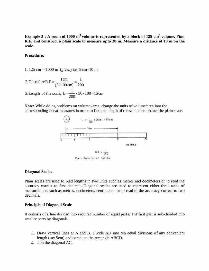
Example 3 : A room of 1000 m3
volume is represented by a block of 125 cm3 volume. Find
R.F. and construct a plain scale to measure upto 30 m. Measure a distance of 18 m on the
scale.
Procedure:
1. 125 cm3 =1000 m
3 (given) i.e. 5 cm=10 m.
200
1
cm)100(2
cm1R.FTherefore2.
cm1510030200
1Lscale,theofLength3.
Note: While doing problems on volume /area, change the units of volume/area into the
corresponding linear measures in order to find the length of the scale to construct the plain scale.
Diagonal Scales
Plain scales are used to read lengths in two units such as metres and decimeters or to read the
accuracy correct to first decimal. Diagonal scales are used to represent either three units of
measurements such as metres, decimeters, centimeters or to read to the accuracy correct to two
decimals.
Principle of Diagonal Scale
It consists of a line divided into required number of equal parts. The first part is sub-divided into
smaller parts by diagonals.
1. Draw vertical lines at A and B. Divide AD into ten equal divisions of any convenient
length (say 5cm) and complete the rectangle ABCD.
2. Join the diagonal AC.
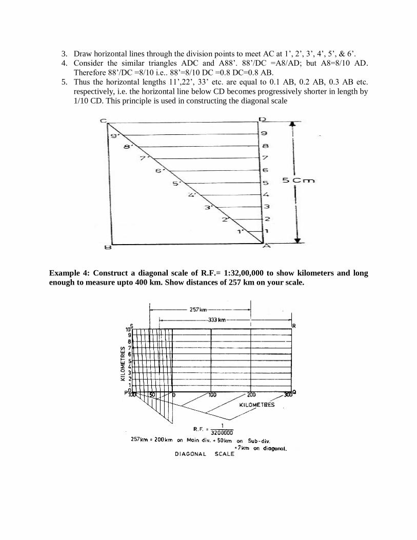
3. Draw horizontal lines through the division points to meet AC at 1’, 2’, 3’, 4’, 5’, & 6’.
4. Consider the similar triangles ADC and A88’. 88’/DC =A8/AD; but A8=8/10 AD.
Therefore 88’/DC =8/10 i.e.. 88’=8/10 DC =0.8 DC=0.8 AB.
5. Thus the horizontal lengths 11’,22’, 33’ etc. are equal to 0.1 AB, 0.2 AB, 0.3 AB etc.
respectively, i.e. the horizontal line below CD becomes progressively shorter in length by
1/10 CD. This principle is used in constructing the diagonal scale
Example 4: Construct a diagonal scale of R.F.= 1:32,00,000 to show kilometers and long
enough to measure upto 400 km. Show distances of 257 km on your scale.
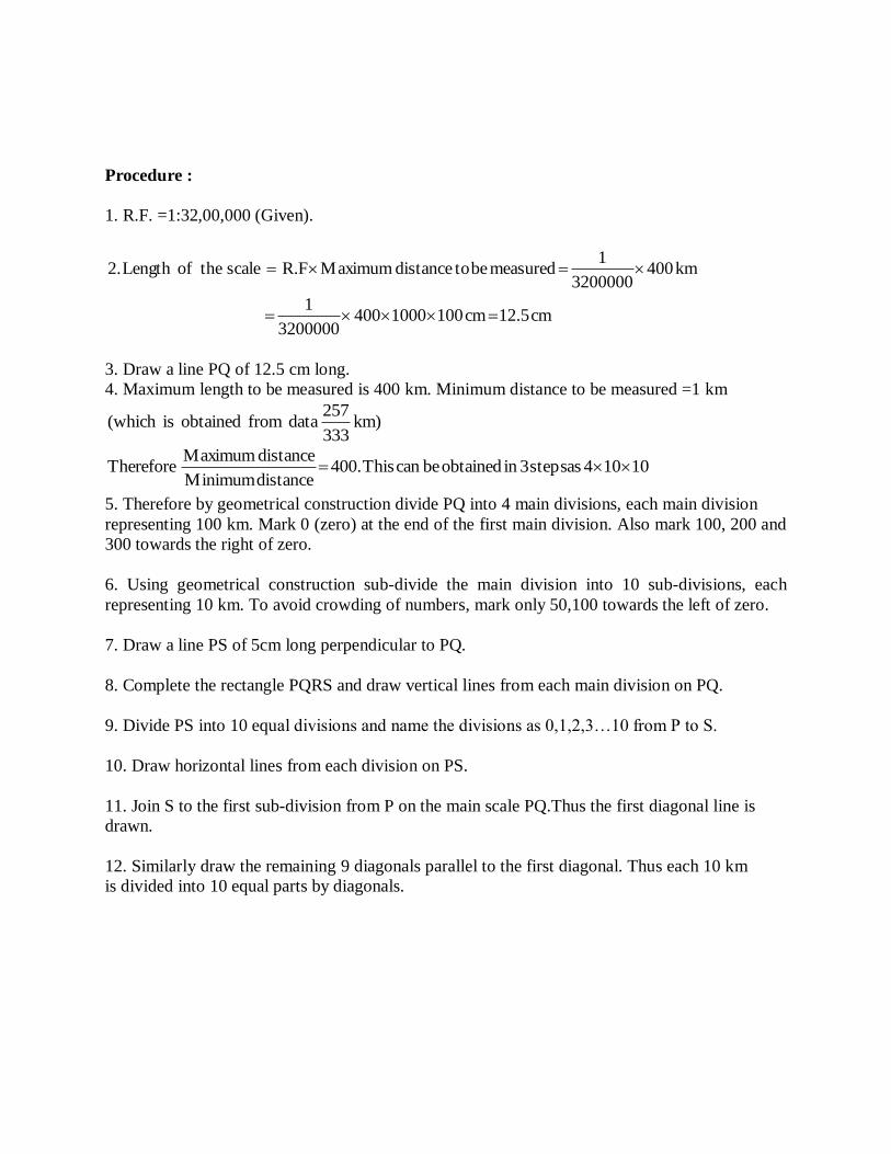
Procedure :
1. R.F. =1:32,00,000 (Given).
cm12.5cm10010004003200000
1
km4003200000
1measuredbetodistanceMaximumR.FscaletheofLength2.
3. Draw a line PQ of 12.5 cm long.
4. Maximum length to be measured is 400 km. Minimum distance to be measured =1 km
km)333
257datafromobtainedis(which
10104assteps3inobtainedbecanThis400.distanceMinimum
distanceMaximumTherefore
5. Therefore by geometrical construction divide PQ into 4 main divisions, each main division
representing 100 km. Mark 0 (zero) at the end of the first main division. Also mark 100, 200 and
300 towards the right of zero.
6. Using geometrical construction sub-divide the main division into 10 sub-divisions, each
representing 10 km. To avoid crowding of numbers, mark only 50,100 towards the left of zero.
7. Draw a line PS of 5cm long perpendicular to PQ.
8. Complete the rectangle PQRS and draw vertical lines from each main division on PQ.
9. Divide PS into 10 equal divisions and name the divisions as 0,1,2,3…10 from P to S.
10. Draw horizontal lines from each division on PS.
11. Join S to the first sub-division from P on the main scale PQ.Thus the first diagonal line is
drawn.
12. Similarly draw the remaining 9 diagonals parallel to the first diagonal. Thus each 10 km
is divided into 10 equal parts by diagonals.
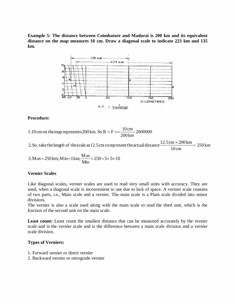
Example 5: The distance between Coimbatore and Madurai is 200 km and its equivalent
distance on the map measures 10 cm. Draw a diagonal scale to indicate 223 km and 135
km.
Procedure:
1055250inM
Maxkm;1Minkm;250Max3.
km250cm10
km200cm12.5distanceactualtherepresenttocm12.5asscaletheoflengththetakeSo,2.
2000000km200
cm10FRSokm.200representsmaptheoncm10.1
Vernier Scales
Like diagonal scales, vernier scales are used to read very small units with accuracy. They are
used, when a diagonal scale is inconvenient to use due to lack of space. A vernier scale consists
of two parts, i.e., Main scale and a vernier. The main scale is a Plain scale divided into minor
divisions.
The vernier is also a scale used along with the main scale to read the third unit, which is the
fraction of the second unit on the main scale.
Least count: Least count the smallest distance that can be measured accurately by the vernier
scale and is the vernier scale and is the difference between a main scale division and a vernier
scale division.
Types of Verniers:
1. Forward vernier or direct vernier
2. Backward vernier or retrograde vernier

Backward / Retrograde Vernier
In this type, the markings on the vernier are in a direction opposite to that of the main scale
and (n+1) main scale divisions are divided into n vernier scale divisions.
Example 6: Construct a vernier scale to read meters, decimeters and centimeters and long
enough to measure upto 4 m. R >F> of the scale is 1/20. Mark on your scale a distance of
2.28 m.
Procedure:
1. Least count: It is required to measure metres, decimeters and centimeters, i.e., the smallest
measurement on the scale is cm. Therefore, L.C .= smallest distance to be measured = 1cm =
0.01m.
2. cm420
1measuredbetodistancemaximumFRscaletheofLength
dm110
m1m.s.d1divisions.scalemain10intoparteachdivideSub
metre.1ngrepresentieachpartsequal4intothisdivideand
cm0.5cm20ofrectangletheCompletelength.cm20oflineaDraw:scaleMain 3.
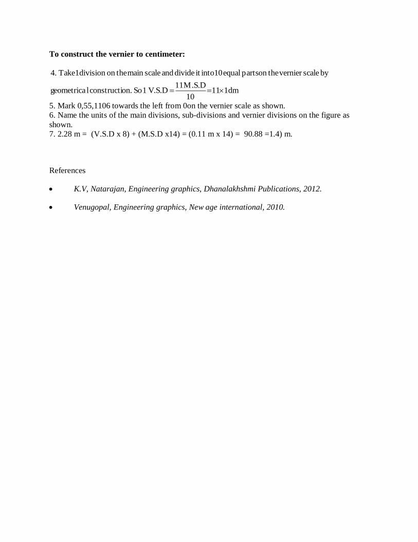
To construct the vernier to centimeter:
dm11110
M.S.D11V.S.D1Soon.constructilgeometrica
byscaleverniertheonpartsequal10intoitdivideandscalemaintheondivision1Take4.
5. Mark 0,55,1106 towards the left from 0on the vernier scale as shown.
6. Name the units of the main divisions, sub-divisions and vernier divisions on the figure as
shown.
7. 2.28 m = (V.S.D x 8) + (M.S.D x14) = (0.11 m x 14) = 90.88 =1.4) m.
References
K.V, Natarajan, Engineering graphics, Dhanalakhshmi Publications, 2012.
Venugopal, Engineering graphics, New age international, 2010.
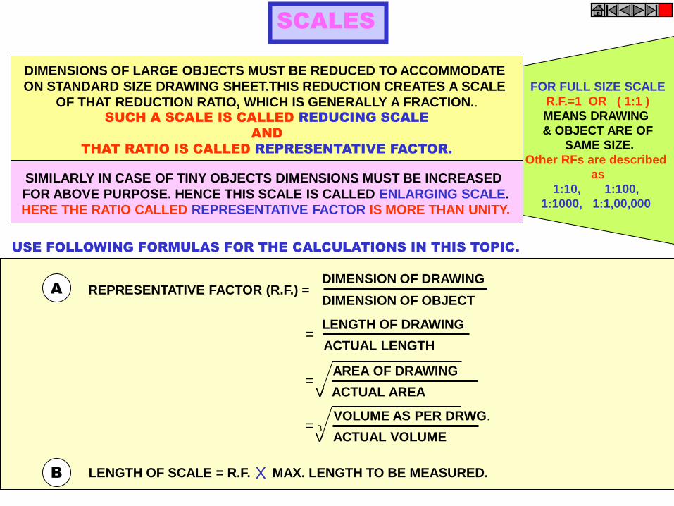
FOR FULL SIZE SCALE
R.F.=1 OR ( 1:1 )
MEANS DRAWING
& OBJECT ARE OF
SAME SIZE.
Other RFs are described
as
1:10, 1:100,
1:1000, 1:1,00,000
SCALES
DIMENSIONS OF LARGE OBJECTS MUST BE REDUCED TO ACCOMMODATE
ON STANDARD SIZE DRAWING SHEET.THIS REDUCTION CREATES A SCALE
OF THAT REDUCTION RATIO, WHICH IS GENERALLY A FRACTION.. SUCH A SCALE IS CALLED REDUCING SCALE
AND
THAT RATIO IS CALLED REPRESENTATIVE FACTOR.
SIMILARLY IN CASE OF TINY OBJECTS DIMENSIONS MUST BE INCREASED
FOR ABOVE PURPOSE. HENCE THIS SCALE IS CALLED ENLARGING SCALE.
HERE THE RATIO CALLED REPRESENTATIVE FACTOR IS MORE THAN UNITY.
REPRESENTATIVE FACTOR (R.F.) =
=
=
=
A
USE FOLLOWING FORMULAS FOR THE CALCULATIONS IN THIS TOPIC.
B LENGTH OF SCALE = R.F. MAX. LENGTH TO BE MEASURED. X
DIMENSION OF DRAWING
DIMENSION OF OBJECT
LENGTH OF DRAWING
ACTUAL LENGTH
AREA OF DRAWING
ACTUAL AREA
VOLUME AS PER DRWG.
ACTUAL VOLUME
V
V 3
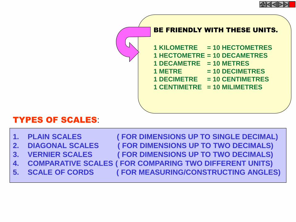
1. PLAIN SCALES ( FOR DIMENSIONS UP TO SINGLE DECIMAL)
2. DIAGONAL SCALES ( FOR DIMENSIONS UP TO TWO DECIMALS)
3. VERNIER SCALES ( FOR DIMENSIONS UP TO TWO DECIMALS)
4. COMPARATIVE SCALES ( FOR COMPARING TWO DIFFERENT UNITS)
5. SCALE OF CORDS ( FOR MEASURING/CONSTRUCTING ANGLES)
TYPES OF SCALES:
= 10 HECTOMETRES
= 10 DECAMETRES
= 10 METRES
= 10 DECIMETRES
= 10 CENTIMETRES
= 10 MILIMETRES
1 KILOMETRE
1 HECTOMETRE
1 DECAMETRE
1 METRE
1 DECIMETRE
1 CENTIMETRE
BE FRIENDLY WITH THESE UNITS.
0 1 2 3 4 5 10
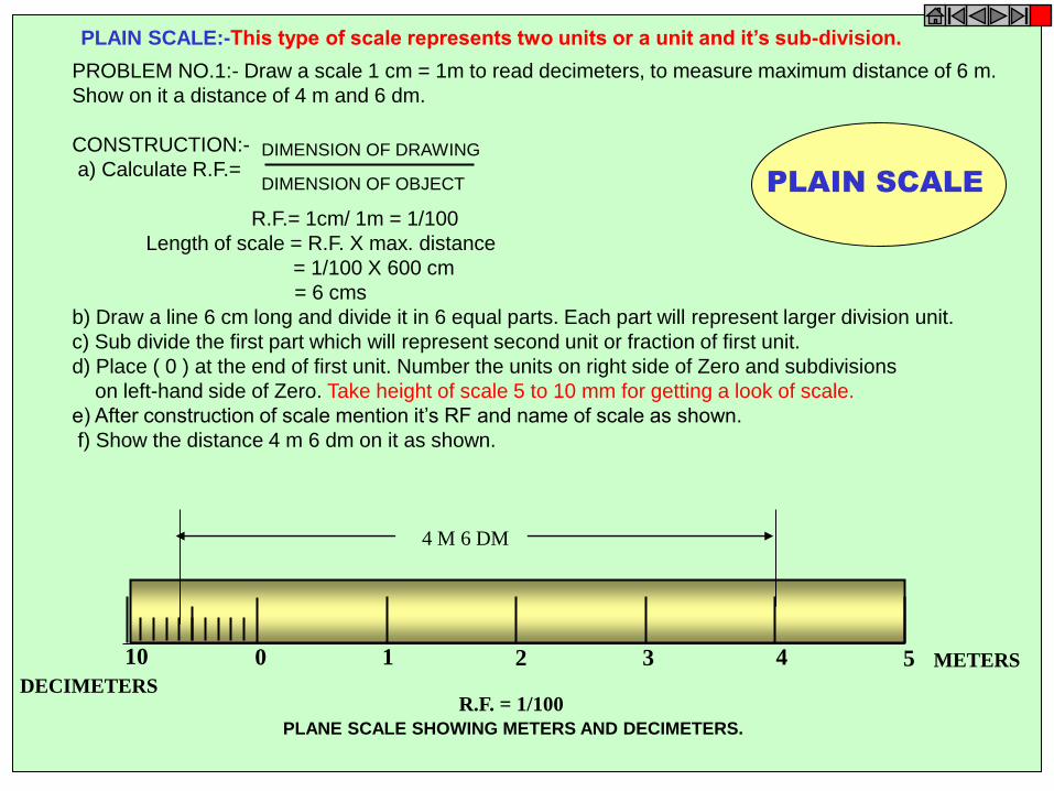
PLAIN SCALE:- This type of scale represents two units or a unit and it’s sub-division.
METERS
DECIMETERS R.F. = 1/100
4 M 6 DM
PLANE SCALE SHOWING METERS AND DECIMETERS.
PLAIN SCALE
PROBLEM NO.1:- Draw a scale 1 cm = 1m to read decimeters, to measure maximum distance of 6 m.
Show on it a distance of 4 m and 6 dm.
CONSTRUCTION:-
a) Calculate R.F.=
R.F.= 1cm/ 1m = 1/100
Length of scale = R.F. X max. distance
= 1/100 X 600 cm
= 6 cms
b) Draw a line 6 cm long and divide it in 6 equal parts. Each part will represent larger division unit.
c) Sub divide the first part which will represent second unit or fraction of first unit.
d) Place ( 0 ) at the end of first unit. Number the units on right side of Zero and subdivisions
on left-hand side of Zero. Take height of scale 5 to 10 mm for getting a look of scale.
e) After construction of scale mention it’s RF and name of scale as shown.
f) Show the distance 4 m 6 dm on it as shown.
DIMENSION OF DRAWING
DIMENSION OF OBJECT
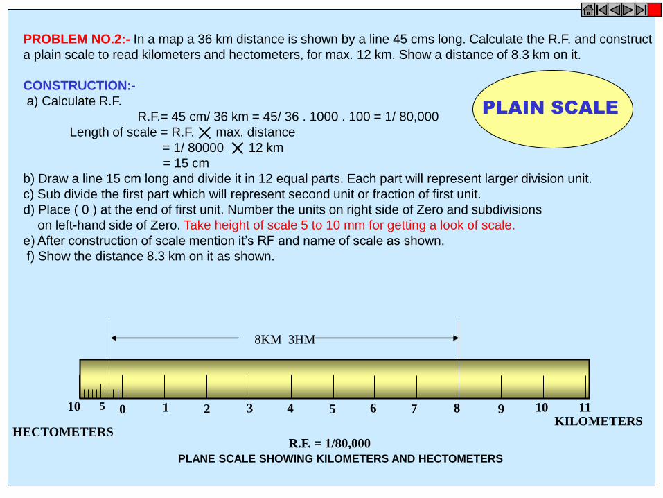
PROBLEM NO.2:- In a map a 36 km distance is shown by a line 45 cms long. Calculate the R.F. and construct
a plain scale to read kilometers and hectometers, for max. 12 km. Show a distance of 8.3 km on it.
CONSTRUCTION:-
a) Calculate R.F.
R.F.= 45 cm/ 36 km = 45/ 36 . 1000 . 100 = 1/ 80,000
Length of scale = R.F. max. distance
= 1/ 80000 12 km
= 15 cm
b) Draw a line 15 cm long and divide it in 12 equal parts. Each part will represent larger division unit.
c) Sub divide the first part which will represent second unit or fraction of first unit.
d) Place ( 0 ) at the end of first unit. Number the units on right side of Zero and subdivisions
on left-hand side of Zero. Take height of scale 5 to 10 mm for getting a look of scale.
e) After construction of scale mention it’s RF and name of scale as shown.
f) Show the distance 8.3 km on it as shown.
KILOMETERS HECTOMETERS
8KM 3HM
R.F. = 1/80,000
PLANE SCALE SHOWING KILOMETERS AND HECTOMETERS
0 1 2 3 4 5 6 7 8 9 10 11 10 5
PLAIN SCALE

PROBLEM NO.3:- The distance between two stations is 210 km. A passenger train covers this distance
in 7 hours. Construct a plain scale to measure time up to a single minute. RF is 1/200,000 Indicate the distance
traveled by train in 29 minutes.
CONSTRUCTION:-
a) 210 km in 7 hours. Means speed of the train is 30 km per hour ( 60 minutes)
Length of scale = R.F. max. distance per hour
= 1/ 2,00,000 30km
= 15 cm
b) 15 cm length will represent 30 km and 1 hour i.e. 60 minutes.
Draw a line 15 cm long and divide it in 6 equal parts. Each part will represent 5 km and 10 minutes.
c) Sub divide the first part in 10 equal parts,which will represent second unit or fraction of first unit.
Each smaller part will represent distance traveled in one minute.
d) Place ( 0 ) at the end of first unit. Number the units on right side of Zero and subdivisions
on left-hand side of Zero. Take height of scale 5 to 10 mm for getting a proper look of scale.
e) Show km on upper side and time in minutes on lower side of the scale as shown.
After construction of scale mention it’s RF and name of scale as shown.
f) Show the distance traveled in 29 minutes, which is 14.5 km, on it as shown.
PLAIN SCALE
0 10 20 30 40 50 10 MINUTES MIN
R.F. = 1/100
PLANE SCALE SHOWING METERS AND DECIMETERS.
KM KM 0 5 10 15 20 25 5 2.5
DISTANCE TRAVELED IN 29 MINUTES.
14.5 KM
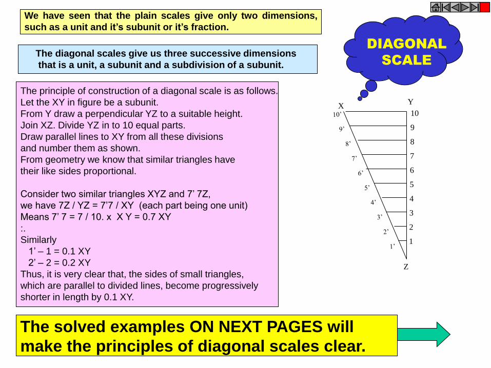
We have seen that the plain scales give only two dimensions,
such as a unit and it’s subunit or it’s fraction.
1
2
3
4
5
6
7
8
9
10 X
Y
Z
The principle of construction of a diagonal scale is as follows.
Let the XY in figure be a subunit.
From Y draw a perpendicular YZ to a suitable height.
Join XZ. Divide YZ in to 10 equal parts.
Draw parallel lines to XY from all these divisions
and number them as shown.
From geometry we know that similar triangles have
their like sides proportional.
Consider two similar triangles XYZ and 7’ 7Z,
we have 7Z / YZ = 7’7 / XY (each part being one unit)
Means 7’ 7 = 7 / 10. x X Y = 0.7 XY
:.
Similarly
1’ – 1 = 0.1 XY
2’ – 2 = 0.2 XY
Thus, it is very clear that, the sides of small triangles,
which are parallel to divided lines, become progressively
shorter in length by 0.1 XY.
The solved examples ON NEXT PAGES will
make the principles of diagonal scales clear.
The diagonal scales give us three successive dimensions
that is a unit, a subunit and a subdivision of a subunit.
DIAGONAL
SCALE
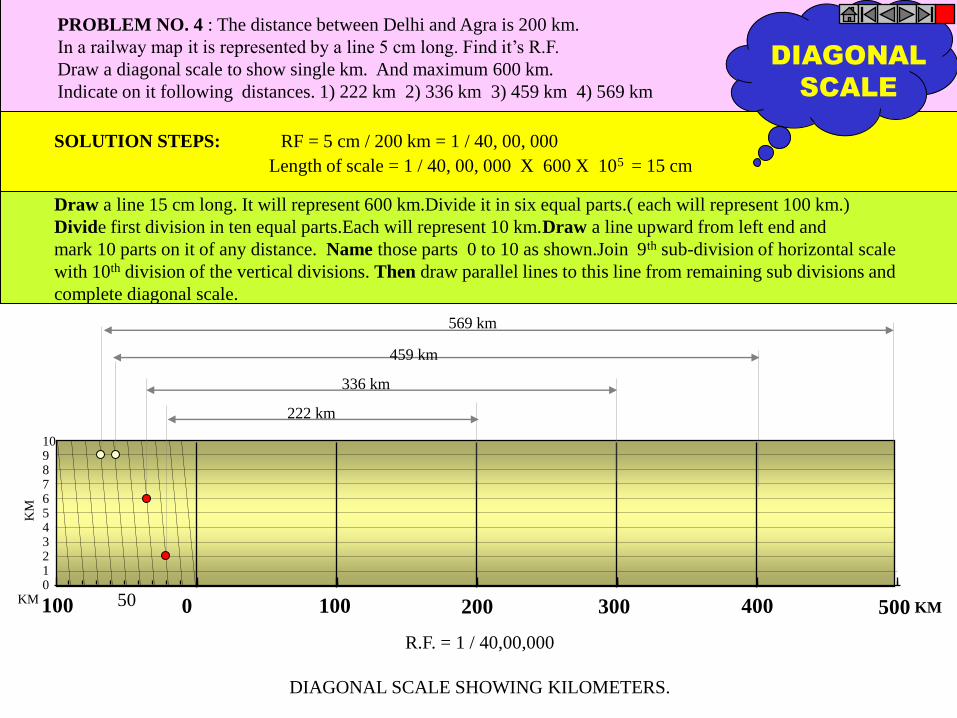
R.F. = 1 / 40,00,000
DIAGONAL SCALE SHOWING KILOMETERS.
0 100 200 300 400 500 100 50
10 9 8 7 6 5 4 3 2 1 0
KM KM
KM
569 km
459 km
336 km
222 km
PROBLEM NO. 4 : The distance between Delhi and Agra is 200 km.
In a railway map it is represented by a line 5 cm long. Find it’s R.F.
Draw a diagonal scale to show single km. And maximum 600 km.
Indicate on it following distances. 1) 222 km 2) 336 km 3) 459 km 4) 569 km
SOLUTION STEPS: RF = 5 cm / 200 km = 1 / 40, 00, 000
Length of scale = 1 / 40, 00, 000 X 600 X 105 = 15 cm
Draw a line 15 cm long. It will represent 600 km.Divide it in six equal parts.( each will represent 100 km.)
Divide first division in ten equal parts.Each will represent 10 km.Draw a line upward from left end and
mark 10 parts on it of any distance. Name those parts 0 to 10 as shown.Join 9th sub-division of horizontal scale
with 10th division of the vertical divisions. Then draw parallel lines to this line from remaining sub divisions and
complete diagonal scale.
DIAGONAL
SCALE
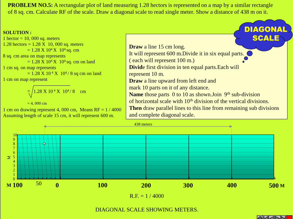
PROBLEM NO.5: A rectangular plot of land measuring 1.28 hectors is represented on a map by a similar rectangle
of 8 sq. cm. Calculate RF of the scale. Draw a diagonal scale to read single meter. Show a distance of 438 m on it.
Draw a line 15 cm long.
It will represent 600 m.Divide it in six equal parts.
( each will represent 100 m.)
Divide first division in ten equal parts.Each will
represent 10 m.
Draw a line upward from left end and
mark 10 parts on it of any distance.
Name those parts 0 to 10 as shown.Join 9th sub-division
of horizontal scale with 10th division of the vertical divisions.
Then draw parallel lines to this line from remaining sub divisions
and complete diagonal scale.
DIAGONAL
SCALE
SOLUTION :
1 hector = 10, 000 sq. meters
1.28 hectors = 1.28 X 10, 000 sq. meters
= 1.28 X 104 X 104 sq. cm
8 sq. cm area on map represents
= 1.28 X 104 X 104 sq. cm on land
1 cm sq. on map represents
= 1.28 X 10 4 X 10⁴ / 8 sq cm on land
1 cm on map represent
= 1.28 X 10 4 X 10⁴ / 8
cm
= 4, 000 cm
1 cm on drawing represent 4, 000 cm, Means RF = 1 / 4000
Assuming length of scale 15 cm, it will represent 600 m.
0 100 200 300 400 500 100 50
10 9 8 7 6 5 4 3 2 1 0
M
M
M
438 meters
R.F. = 1 / 4000
DIAGONAL SCALE SHOWING METERS.

10 9 8 7 6 5 4 3 2 1 0
CENTIMETRES
MM
CM
R.F. = 1 / 2.5
DIAGONAL SCALE SHOWING CENTIMETERS.
0 5 10 15 5 4 3 2 1
PROBLEM NO.6:. Draw a diagonal scale of R.F. 1: 2.5, showing centimeters
and millimeters and long enough to measure up to 20 centimeters.
SOLUTION STEPS:
R.F. = 1 / 2.5
Length of scale = 1 / 2.5 X 20 cm.
= 8 cm.
1.Draw a line 8 cm long and divide it in to 4 equal parts.
(Each part will represent a length of 5 cm.)
2.Divide the first part into 5 equal divisions.
(Each will show 1 cm.)
3.At the left hand end of the line, draw a vertical line and
on it step-off 10 equal divisions of any length.
4.Complete the scale as explained in previous problems.
Show the distance 13.4 cm on it.
13 .4 CM
DIAGONAL
SCALE

Figure to the right shows a part of a plain scale in
which length A-O represents 10 cm. If we divide A-O
into ten equal parts, each will be of 1 cm. Now it would
not be easy to divide each of these parts into ten equal
divisions to get measurements in millimeters.
Now if we take a length BO equal to 10 + 1 = 11 such
equal parts, thus representing 11 cm, and divide it into
ten equal divisions, each of these divisions will
represent 11 / 10 – 1.1 cm.
The difference between one part of AO and one division
of BO will be equal 1.1 – 1.0 = 0.1 cm or 1 mm.
This difference is called Least Count of the scale.
Minimum this distance can be measured by this scale.
The upper scale BO is the vernier.The combination of
plain scale and the vernier is vernier scale.
Vernier Scales: These scales, like diagonal scales , are used to read to a very small unit with great accuracy.
It consists of two parts – a primary scale and a vernier. The primary scale is a plain scale fully
divided into minor divisions.
As it would be difficult to sub-divide the minor divisions in ordinary way, it is done with the help of the vernier.
The graduations on vernier are derived from those on the primary scale.
9.9 7.7 5.5 3.3 1.1
9 8 7 6 5 4 3 2 1 0 A
0 B
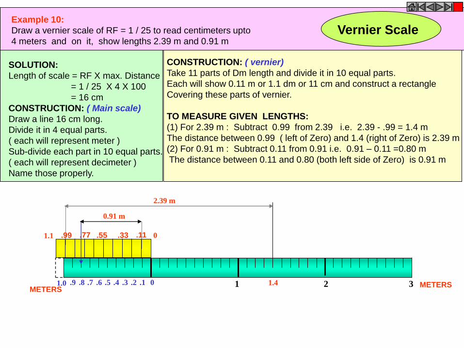
Example 10:
Draw a vernier scale of RF = 1 / 25 to read centimeters upto
4 meters and on it, show lengths 2.39 m and 0.91 m
.9 .8 .7 .6 .5 .4 .3 .2 .1
.99 .77 .55 .33 .11 0 1.1
0 1 2 3 1.0
SOLUTION:
Length of scale = RF X max. Distance
= 1 / 25 X 4 X 100
= 16 cm
CONSTRUCTION: ( Main scale)
Draw a line 16 cm long.
Divide it in 4 equal parts.
( each will represent meter )
Sub-divide each part in 10 equal parts.
( each will represent decimeter )
Name those properly.
CONSTRUCTION: ( vernier)
Take 11 parts of Dm length and divide it in 10 equal parts.
Each will show 0.11 m or 1.1 dm or 11 cm and construct a rectangle
Covering these parts of vernier.
TO MEASURE GIVEN LENGTHS:
(1) For 2.39 m : Subtract 0.99 from 2.39 i.e. 2.39 - .99 = 1.4 m
The distance between 0.99 ( left of Zero) and 1.4 (right of Zero) is 2.39 m
(2) For 0.91 m : Subtract 0.11 from 0.91 i.e. 0.91 – 0.11 =0.80 m
The distance between 0.11 and 0.80 (both left side of Zero) is 0.91 m
1.4
2.39 m
0.91 m
METERS METERS
Vernier Scale
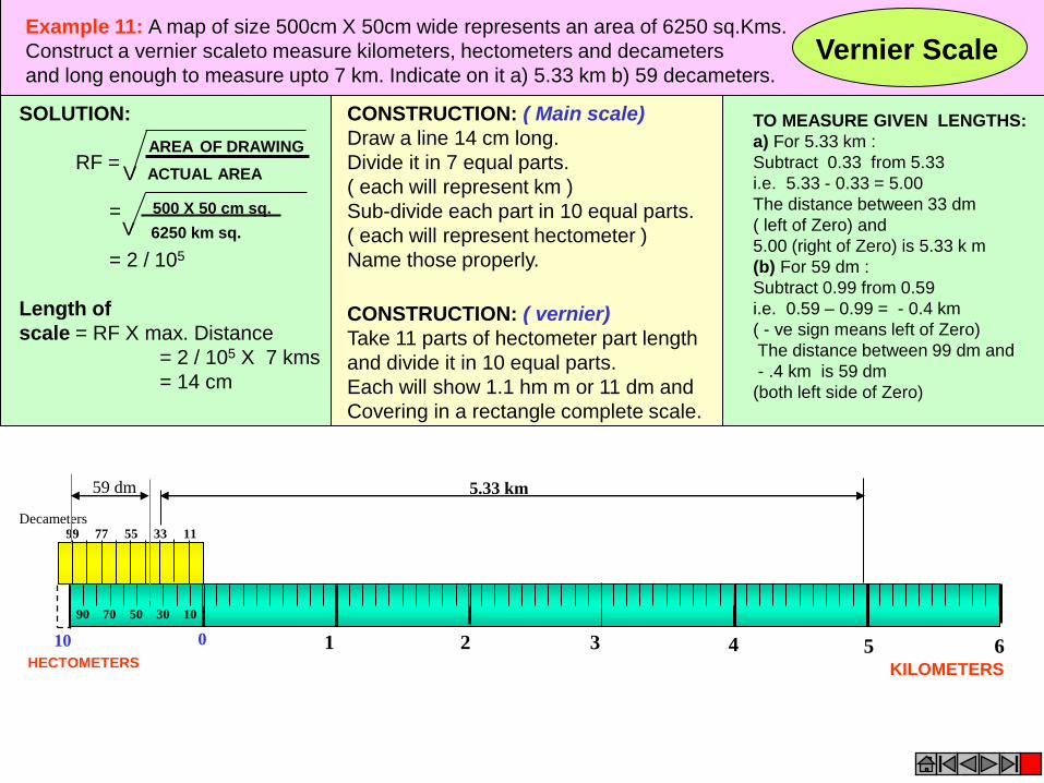
Example 11: A map of size 500cm X 50cm wide represents an area of 6250 sq.Kms.
Construct a vernier scaleto measure kilometers, hectometers and decameters
and long enough to measure upto 7 km. Indicate on it a) 5.33 km b) 59 decameters. Vernier Scale
SOLUTION:
RF =
=
= 2 / 105
Length of
scale = RF X max. Distance
= 2 / 105 X 7 kms
= 14 cm
AREA OF DRAWING
ACTUAL AREA V
500 X 50 cm sq.
6250 km sq. V
CONSTRUCTION: ( vernier)
Take 11 parts of hectometer part length
and divide it in 10 equal parts.
Each will show 1.1 hm m or 11 dm and
Covering in a rectangle complete scale.
CONSTRUCTION: ( Main scale)
Draw a line 14 cm long.
Divide it in 7 equal parts.
( each will represent km )
Sub-divide each part in 10 equal parts.
( each will represent hectometer )
Name those properly.
KILOMETERS HECTOMETERS
0 1 2 3 10 4 5 6
90 70 50 30 10
99 77 55 33 11
Decameters
TO MEASURE GIVEN LENGTHS:
a) For 5.33 km :
Subtract 0.33 from 5.33
i.e. 5.33 - 0.33 = 5.00
The distance between 33 dm
( left of Zero) and
5.00 (right of Zero) is 5.33 k m
(b) For 59 dm :
Subtract 0.99 from 0.59
i.e. 0.59 – 0.99 = - 0.4 km
( - ve sign means left of Zero)
The distance between 99 dm and
- .4 km is 59 dm
(both left side of Zero)
5.33 km 59 dm

These are the loci of points moving in a plane such that the ratio of it’s distances
from a fixed point And a fixed line always remains constant.
The Ratio is called ECCENTRICITY. (E)
A) For Ellipse E<1
B) For Parabola E=1
C) For Hyperbola E>1
SECOND DEFINATION OF AN ELLIPSE:-
It is a locus of a point moving in a plane
such that the SUM of it’s distances from TWO fixed points
always remains constant.
{And this sum equals to the length of major axis.}
These TWO fixed points are FOCUS 1 & FOCUS 2
Refer Problem nos. 6. 9 & 12
Refer Problem no.4
Ellipse by Arcs of Circles Method.
COMMON DEFINATION OF ELLIPSE, PARABOLA & HYPERBOLA:
1
2
3
4
5
6
7
8
9
10
B A
D
C
1
2 3
4
5
6
7 8
9
10
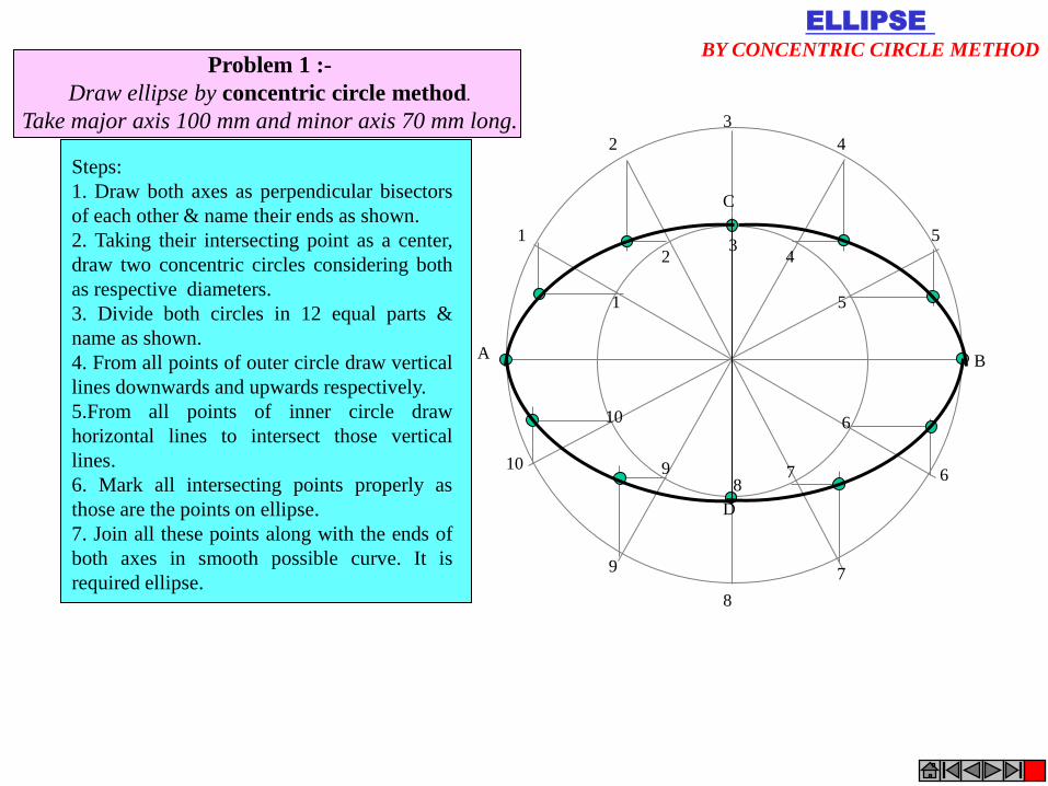
Steps:
1. Draw both axes as perpendicular bisectors
of each other & name their ends as shown.
2. Taking their intersecting point as a center,
draw two concentric circles considering both
as respective diameters.
3. Divide both circles in 12 equal parts &
name as shown.
4. From all points of outer circle draw vertical
lines downwards and upwards respectively.
5.From all points of inner circle draw
horizontal lines to intersect those vertical
lines.
6. Mark all intersecting points properly as
those are the points on ellipse.
7. Join all these points along with the ends of
both axes in smooth possible curve. It is
required ellipse.
Problem 1 :-
Draw ellipse by concentric circle method.
Take major axis 100 mm and minor axis 70 mm long.
ELLIPSE
BY CONCENTRIC CIRCLE METHOD

1
2
3
4
1
2
3
4
A B
C
D
Problem 2
Draw ellipse by Rectangle method.
Take major axis 100 mm and minor axis 70 mm long.
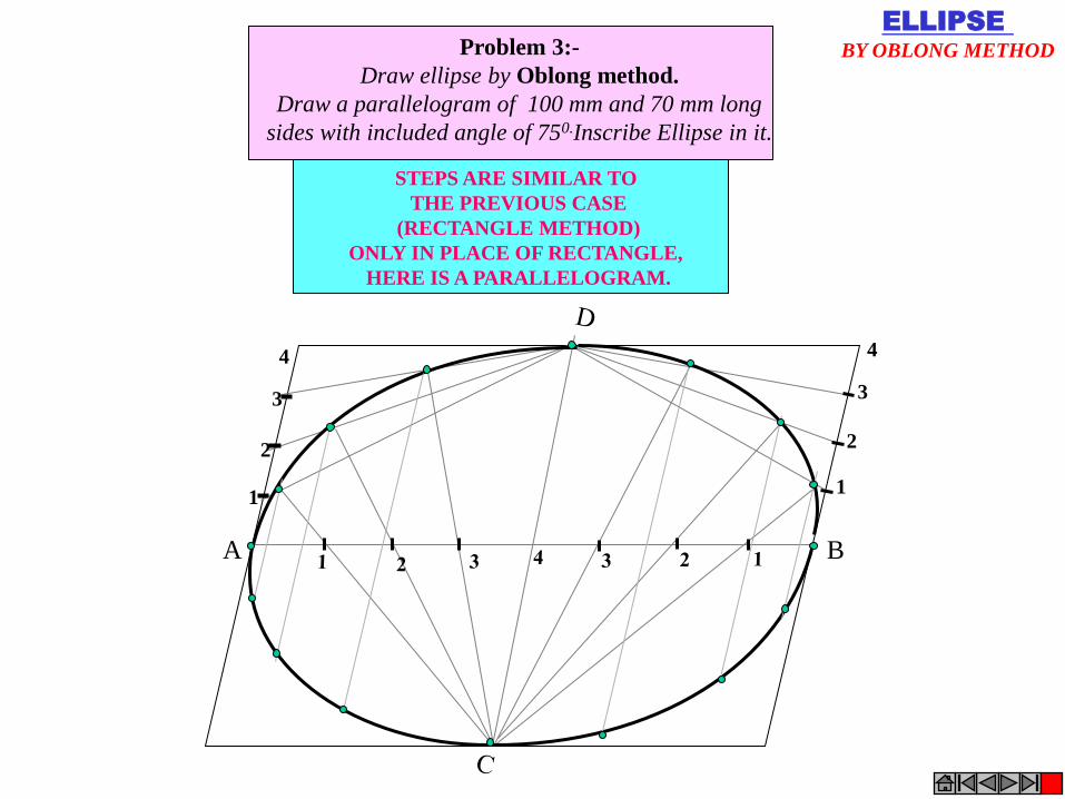
Steps:
1 Draw a rectangle taking major
and minor axes as sides.
2. In this rectangle draw both
axes as perpendicular bisectors of
each other..
3. For construction, select upper
left part of rectangle. Divide
vertical small side and horizontal
long side into same number of
equal parts.( here divided in four
parts)
4. Name those as shown..
5. Now join all vertical points
1,2,3,4, to the upper end of minor
axis. And all horizontal points
i.e.1,2,3,4 to the lower end of
minor axis.
6. Then extend C-1 line upto D-1
and mark that point. Similarly
extend C-2, C-3, C-4 lines up to
D-2, D-3, & D-4 lines.
7. Mark all these points properly
and join all along with ends A
and D in smooth possible curve.
Do similar construction in right
side part.along with lower half of
the rectangle.Join all points in
smooth curve.
It is required ellipse.
ELLIPSE
BY RECTANGLE METHOD
1
2
3
4
A B
1
2
3
4
Problem 3:-
Draw ellipse by Oblong method.
Draw a parallelogram of 100 mm and 70 mm long
sides with included angle of 750.Inscribe Ellipse in it.
STEPS ARE SIMILAR TO
THE PREVIOUS CASE
(RECTANGLE METHOD)
ONLY IN PLACE OF RECTANGLE,
HERE IS A PARALLELOGRAM.
ELLIPSE
BY OBLONG METHOD
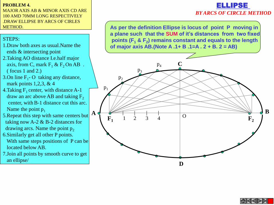
F1 F2 1 2 3 4
A B
C
D
p1
p2
p3
p4
ELLIPSE
BY ARCS OF CIRCLE METHOD
O
PROBLEM 4.
MAJOR AXIS AB & MINOR AXIS CD ARE
100 AMD 70MM LONG RESPECTIVELY
.DRAW ELLIPSE BY ARCS OF CIRLES
METHOD.
STEPS:
1.Draw both axes as usual.Name the
ends & intersecting point
2.Taking AO distance I.e.half major
axis, from C, mark F1 & F2 On AB .
( focus 1 and 2.)
3.On line F1- O taking any distance,
mark points 1,2,3, & 4
4.Taking F1 center, with distance A-1
draw an arc above AB and taking F2
center, with B-1 distance cut this arc.
Name the point p1
5.Repeat this step with same centers but
taking now A-2 & B-2 distances for
drawing arcs. Name the point p2
6.Similarly get all other P points.
With same steps positions of P can be
located below AB.
7.Join all points by smooth curve to get
an ellipse/
As per the definition Ellipse is locus of point P moving in
a plane such that the SUM of it’s distances from two fixed
points (F1 & F2) remains constant and equals to the length
of major axis AB.(Note A .1+ B .1=A . 2 + B. 2 = AB)
1
4
2
3
A B
D C
ELLIPSE
BY RHOMBUS METHOD
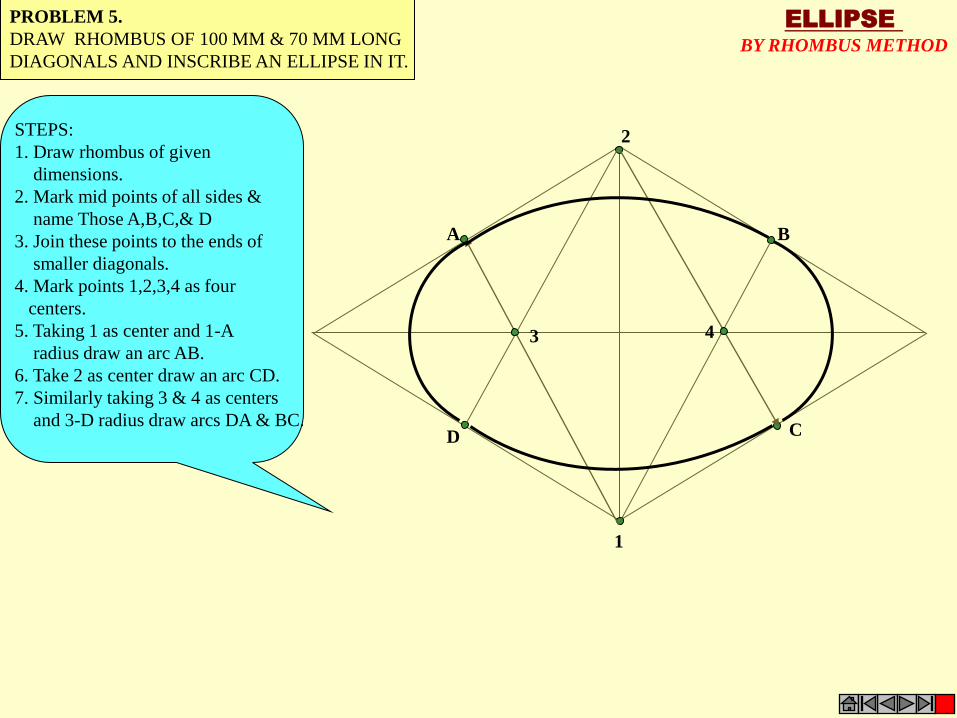
PROBLEM 5.
DRAW RHOMBUS OF 100 MM & 70 MM LONG
DIAGONALS AND INSCRIBE AN ELLIPSE IN IT.
STEPS:
1. Draw rhombus of given
dimensions.
2. Mark mid points of all sides &
name Those A,B,C,& D
3. Join these points to the ends of
smaller diagonals.
4. Mark points 1,2,3,4 as four
centers.
5. Taking 1 as center and 1-A
radius draw an arc AB.
6. Take 2 as center draw an arc CD.
7. Similarly taking 3 & 4 as centers
and 3-D radius draw arcs DA & BC.
ELLIPSE
DIRECTRIX-FOCUS METHOD
PROBLEM 6:- POINT F IS 50 MM FROM A LINE AB.A POINT P IS MOVING IN A PLANE
SUCH THAT THE RATIO OF IT’S DISTANCES FROM F AND LINE AB REMAINS CONSTANT
AND EQUALS TO 2/3 DRAW LOCUS OF POINT P. { ECCENTRICITY = 2/3 }
F ( focus) V
ELLIPSE
(vertex)
A
B
STEPS:
1 .Draw a vertical line AB and point F
50 mm from it.
2 .Divide 50 mm distance in 5 parts.
3 .Name 2nd part from F as V. It is 20mm
and 30mm from F and AB line resp.
It is first point giving ratio of it’s
distances from F and AB 2/3 i.e 20/30
4 Form more points giving same ratio such
as 30/45, 40/60, 50/75 etc.
5.Taking 45,60 and 75mm distances from
line AB, draw three vertical lines to the
right side of it.
6. Now with 30, 40 and 50mm distances in
compass cut these lines above and below,
with F as center.
7. Join these points through V in smooth
curve.
This is required locus of P.It is an ELLIPSE.
45mm

1
2
3
4
5
6
1 2 3 4 5 6
1
2
3
4
5
6
5 4 3 2 1
PARABOLA
RECTANGLE METHOD PROBLEM 7: A BALL THROWN IN AIR ATTAINS 100 M HIEGHT
AND COVERS HORIZONTAL DISTANCE 150 M ON GROUND.
Draw the path of the ball (projectile)-
STEPS:
1.Draw rectangle of above size and
divide it in two equal vertical parts
2.Consider left part for construction.
Divide height and length in equal
number of parts and name those
1,2,3,4,5& 6
3.Join vertical 1,2,3,4,5 & 6 to the
top center of rectangle
4.Similarly draw upward vertical
lines from horizontal1,2,3,4,5
And wherever these lines intersect
previously drawn inclined lines in
sequence Mark those points and
further join in smooth possible curve.
5.Repeat the construction on right side
rectangle also.Join all in sequence.
This locus is Parabola.
.
C
A B
PARABOLA
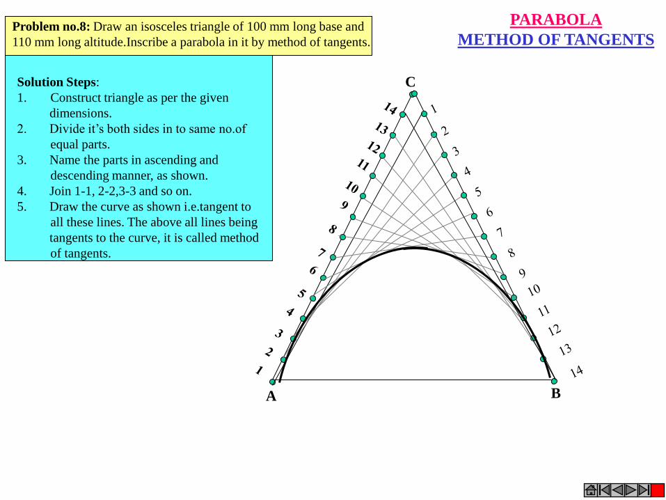
METHOD OF TANGENTS Problem no.8: Draw an isosceles triangle of 100 mm long base and
110 mm long altitude.Inscribe a parabola in it by method of tangents.
Solution Steps:
1. Construct triangle as per the given
dimensions.
2. Divide it’s both sides in to same no.of
equal parts.
3. Name the parts in ascending and
descending manner, as shown.
4. Join 1-1, 2-2,3-3 and so on.
5. Draw the curve as shown i.e.tangent to
all these lines. The above all lines being
tangents to the curve, it is called method
of tangents.
A
B
V
PARABOLA
(VERTEX)
F
( focus) 1 2 3 4
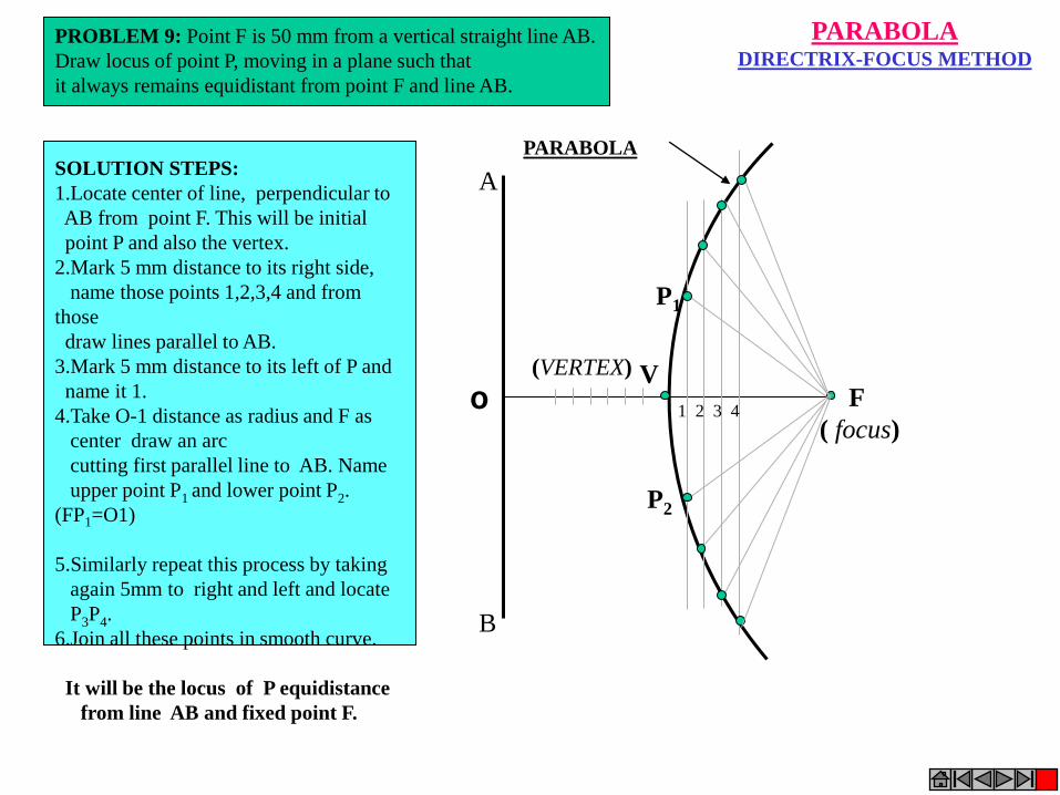
PARABOLA DIRECTRIX-FOCUS METHOD
SOLUTION STEPS:
1.Locate center of line, perpendicular to
AB from point F. This will be initial
point P and also the vertex.
2.Mark 5 mm distance to its right side,
name those points 1,2,3,4 and from
those
draw lines parallel to AB.
3.Mark 5 mm distance to its left of P and
name it 1.
4.Take O-1 distance as radius and F as
center draw an arc
cutting first parallel line to AB. Name
upper point P1 and lower point P2.
(FP1=O1)
5.Similarly repeat this process by taking
again 5mm to right and left and locate
P3P4.
6.Join all these points in smooth curve.
It will be the locus of P equidistance
from line AB and fixed point F.
PROBLEM 9: Point F is 50 mm from a vertical straight line AB.
Draw locus of point P, moving in a plane such that
it always remains equidistant from point F and line AB.
O
P1
P2

P
O
40 mm
30 mm
1
2
3
1 2 1 2 3
1
2
HYPERBOLA THROUGH A POINT
OF KNOWN CO-ORDINATES Solution Steps: 1) Extend horizontal
line from P to right side.
2) Extend vertical line
from P upward.
3) On horizontal line
from P, mark some points
taking any distance and
name them after P-1,
2,3,4 etc.
4) Join 1-2-3-4 points
to pole O. Let them cut
part [P-B] also at 1,2,3,4
points.
5) From horizontal
1,2,3,4 draw vertical
lines downwards and
6) From vertical 1,2,3,4
points [from P-B] draw
horizontal lines.
7) Line from 1
horizontal and line from
1 vertical will meet at
P1.Similarly mark P2, P3,
P4 points.
8) Repeat the procedure
by marking four points
on upward vertical line
from P and joining all
those to pole O. Name
this points P6, P7, P8 etc.
and join them by smooth
curve.
Problem No.10: Point P is 40 mm and 30 mm from horizontal
and vertical axes respectively.Draw Hyperbola through it.
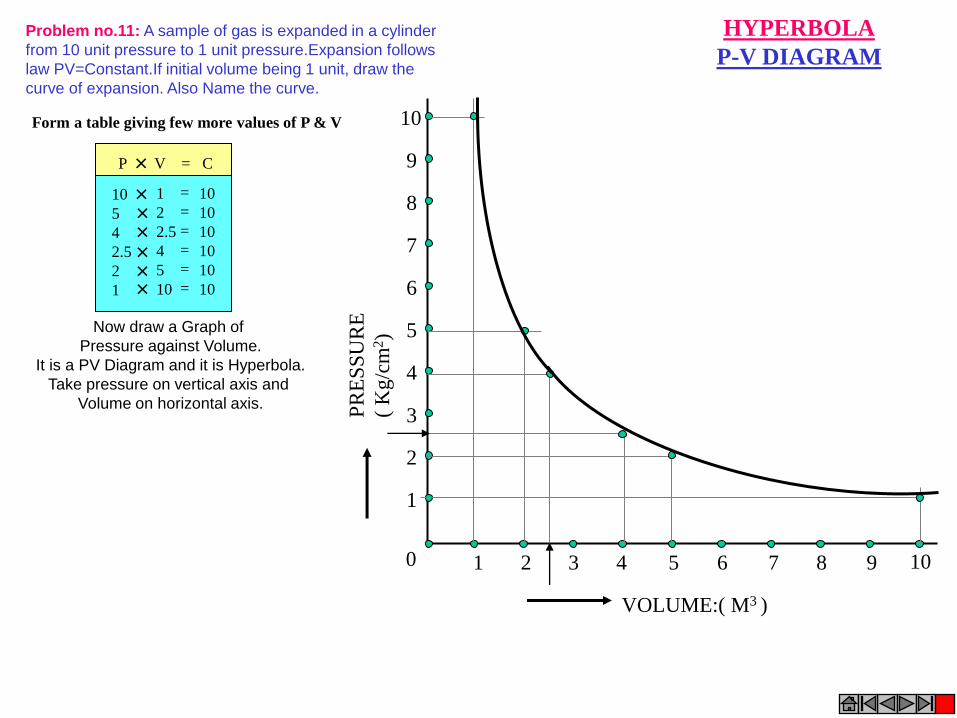
VOLUME:( M3 )
PR
ES
SU
RE
( K
g/c
m2)
0 1 2 3 4 5 6 7 8 9 10
1
2
3
4
5
6
7
8
9
10
HYPERBOLA
P-V DIAGRAM
Problem no.11: A sample of gas is expanded in a cylinder
from 10 unit pressure to 1 unit pressure.Expansion follows
law PV=Constant.If initial volume being 1 unit, draw the
curve of expansion. Also Name the curve.
Form a table giving few more values of P & V
P V = C
10
5
4
2.5
2
1
1
2
2.5
4
5
10
10
10
10
10
10
10
=
=
=
=
=
=
Now draw a Graph of
Pressure against Volume.
It is a PV Diagram and it is Hyperbola.
Take pressure on vertical axis and
Volume on horizontal axis.
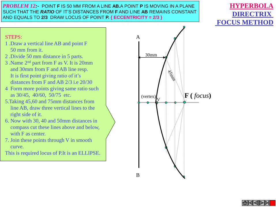
F ( focus) V
(vertex)
A
B
30mm
HYPERBOLA
DIRECTRIX
FOCUS METHOD
PROBLEM 12:- POINT F IS 50 MM FROM A LINE AB.A POINT P IS MOVING IN A PLANE
SUCH THAT THE RATIO OF IT’S DISTANCES FROM F AND LINE AB REMAINS CONSTANT
AND EQUALS TO 2/3 DRAW LOCUS OF POINT P. { ECCENTRICITY = 2/3 }
STEPS:
1 .Draw a vertical line AB and point F
50 mm from it.
2 .Divide 50 mm distance in 5 parts.
3 .Name 2nd part from F as V. It is 20mm
and 30mm from F and AB line resp.
It is first point giving ratio of it’s
distances from F and AB 2/3 i.e 20/30
4 Form more points giving same ratio such
as 30/45, 40/60, 50/75 etc.
5.Taking 45,60 and 75mm distances from
line AB, draw three vertical lines to the
right side of it.
6. Now with 30, 40 and 50mm distances in
compass cut these lines above and below,
with F as center.
7. Join these points through V in smooth
curve.
This is required locus of P.It is an ELLIPSE.
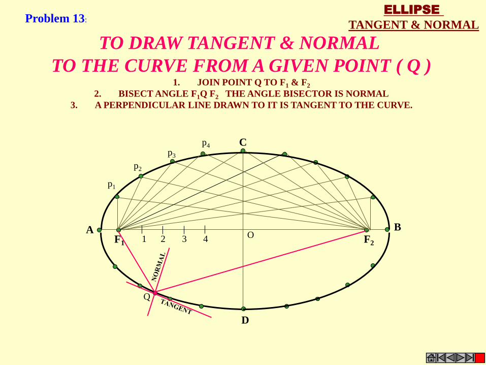
D
F1 F2 1 2 3 4
A B
C
p1
p2
p3
p4
O
Q
TO DRAW TANGENT & NORMAL
TO THE CURVE FROM A GIVEN POINT ( Q ) 1. JOIN POINT Q TO F1 & F2
2. BISECT ANGLE F1Q F2 THE ANGLE BISECTOR IS NORMAL
3. A PERPENDICULAR LINE DRAWN TO IT IS TANGENT TO THE CURVE.
ELLIPSE
TANGENT & NORMAL Problem 13:
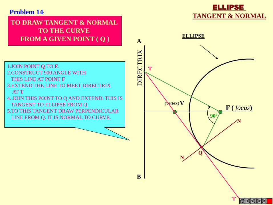
ELLIPSE
TANGENT & NORMAL
F ( focus) V
ELLIPSE
(vertex)
A
B
T
T
N
N
Q
900
TO DRAW TANGENT & NORMAL
TO THE CURVE
FROM A GIVEN POINT ( Q )
1.JOIN POINT Q TO F.
2.CONSTRUCT 900 ANGLE WITH
THIS LINE AT POINT F
3.EXTEND THE LINE TO MEET DIRECTRIX
AT T
4. JOIN THIS POINT TO Q AND EXTEND. THIS IS
TANGENT TO ELLIPSE FROM Q
5.TO THIS TANGENT DRAW PERPENDICULAR
LINE FROM Q. IT IS NORMAL TO CURVE.
Problem 14:
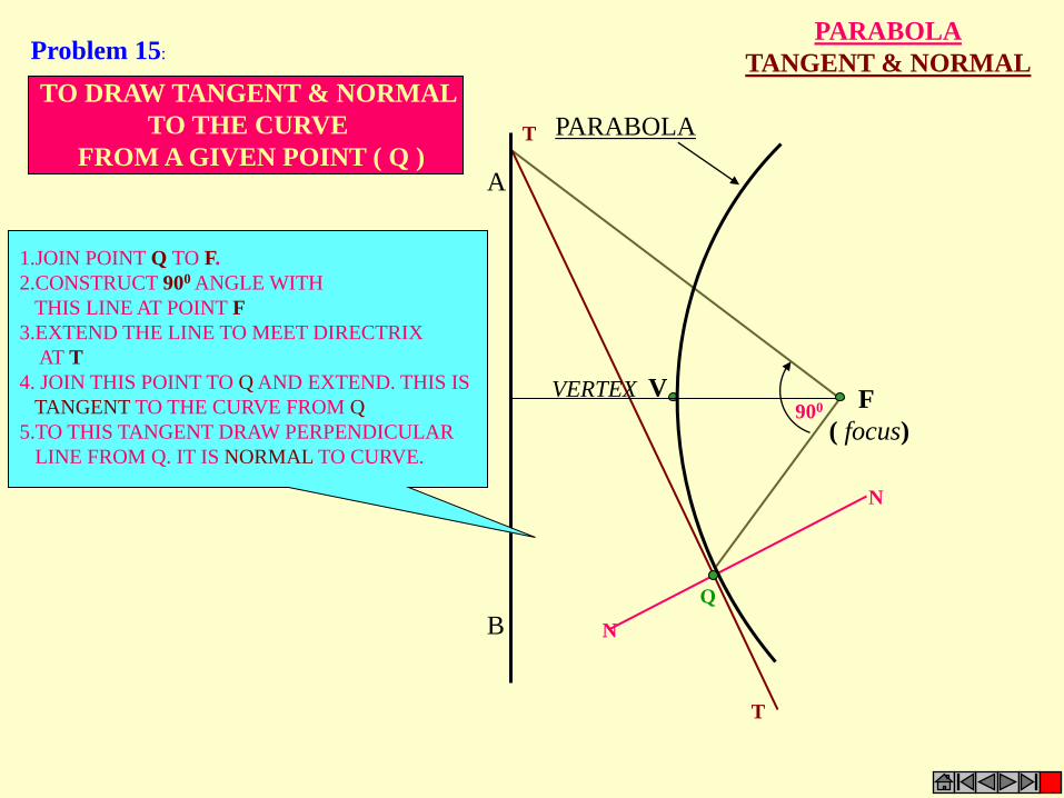
A
B
PARABOLA
VERTEX F
( focus)
V
Q
T
N
N
T
900
TO DRAW TANGENT & NORMAL
TO THE CURVE
FROM A GIVEN POINT ( Q )
1.JOIN POINT Q TO F.
2.CONSTRUCT 900 ANGLE WITH
THIS LINE AT POINT F
3.EXTEND THE LINE TO MEET DIRECTRIX
AT T
4. JOIN THIS POINT TO Q AND EXTEND. THIS IS
TANGENT TO THE CURVE FROM Q
5.TO THIS TANGENT DRAW PERPENDICULAR
LINE FROM Q. IT IS NORMAL TO CURVE.
PARABOLA
TANGENT & NORMAL Problem 15:
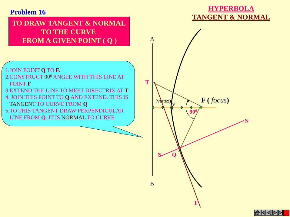
F ( focus) V
(vertex)
A
B
HYPERBOLA
TANGENT & NORMAL
Q N
N
T
T
900
TO DRAW TANGENT & NORMAL
TO THE CURVE
FROM A GIVEN POINT ( Q )
1.JOIN POINT Q TO F.
2.CONSTRUCT 900 ANGLE WITH THIS LINE AT
POINT F
3.EXTEND THE LINE TO MEET DIRECTRIX AT T
4. JOIN THIS POINT TO Q AND EXTEND. THIS IS
TANGENT TO CURVE FROM Q
5.TO THIS TANGENT DRAW PERPENDICULAR
LINE FROM Q. IT IS NORMAL TO CURVE.
Problem 16
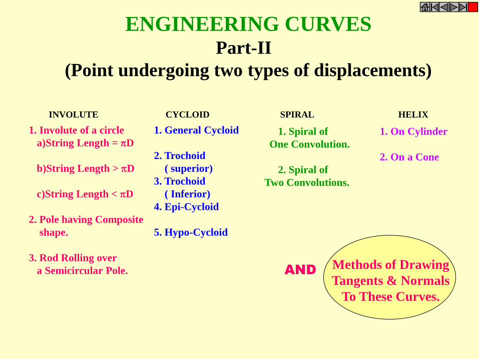
INVOLUTE CYCLOID SPIRAL HELIX
ENGINEERING CURVES Part-II
(Point undergoing two types of displacements)
1. Involute of a circle
a)String Length = D
b)String Length > D
c)String Length < D
2. Pole having Composite
shape.
3. Rod Rolling over
a Semicircular Pole.
1. General Cycloid
2. Trochoid
( superior)
3. Trochoid
( Inferior)
4. Epi-Cycloid
5. Hypo-Cycloid
1. Spiral of
One Convolution.
2. Spiral of
Two Convolutions.
1. On Cylinder
2. On a Cone
Methods of Drawing
Tangents & Normals
To These Curves.
AND

CYCLOID: IT IS A LOCUS OF A POINT ON THE PERIPHERY OF A CIRCLE WHICH ROLLS ON A STRAIGHT LINE PATH.
INVOLUTE:
IT IS A LOCUS OF A FREE END OF A STRING WHEN IT IS WOUND ROUND A CIRCULAR POLE
SPIRAL:
IT IS A CURVE GENERATED BY A POINT WHICH REVOLVES AROUND A FIXED POINT AND AT THE SAME MOVES TOWARDS IT.
HELIX:
IT IS A CURVE GENERATED BY A POINT WHICH MOVES AROUND THE SURFACE OF A RIGHT CIRCULAR CYLINDER / CONE AND AT THE SAME TIME ADVANCES IN AXIAL DIRECTION AT A SPEED BEARING A CONSTANT RATIO TO THE SPPED OF ROTATION. ( for problems refer topic Development of surfaces)
DEFINITIONS
SUPERIORTROCHOID: IF THE POINT IN THE DEFINATION OF CYCLOID IS OUTSIDE THE CIRCLE
INFERIOR TROCHOID.: IF IT IS INSIDE THE CIRCLE
EPI-CYCLOID
IF THE CIRCLE IS ROLLING ON ANOTHER CIRCLE FROM OUTSIDE
HYPO-CYCLOID. IF THE CIRCLE IS ROLLING FROM INSIDE THE OTHER CIRCLE,
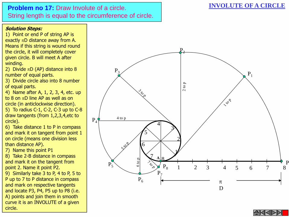
INVOLUTE OF A CIRCLE Problem no 17: Draw Involute of a circle.
String length is equal to the circumference of circle.
1 2 3 4 5 6 7 8 P
P8
1
2
3 4
5
6
7 8
P3
P4 4 to p
P5
P7
P6
P2
P1
D
A
Solution Steps: 1) Point or end P of string AP is exactly D distance away from A. Means if this string is wound round the circle, it will completely cover given circle. B will meet A after winding. 2) Divide D (AP) distance into 8 number of equal parts. 3) Divide circle also into 8 number of equal parts. 4) Name after A, 1, 2, 3, 4, etc. up to 8 on D line AP as well as on circle (in anticlockwise direction). 5) To radius C-1, C-2, C-3 up to C-8 draw tangents (from 1,2,3,4,etc to circle). 6) Take distance 1 to P in compass and mark it on tangent from point 1 on circle (means one division less than distance AP). 7) Name this point P1 8) Take 2-B distance in compass and mark it on the tangent from point 2. Name it point P2. 9) Similarly take 3 to P, 4 to P, 5 to P up to 7 to P distance in compass and mark on respective tangents and locate P3, P4, P5 up to P8 (i.e. A) points and join them in smooth curve it is an INVOLUTE of a given circle.
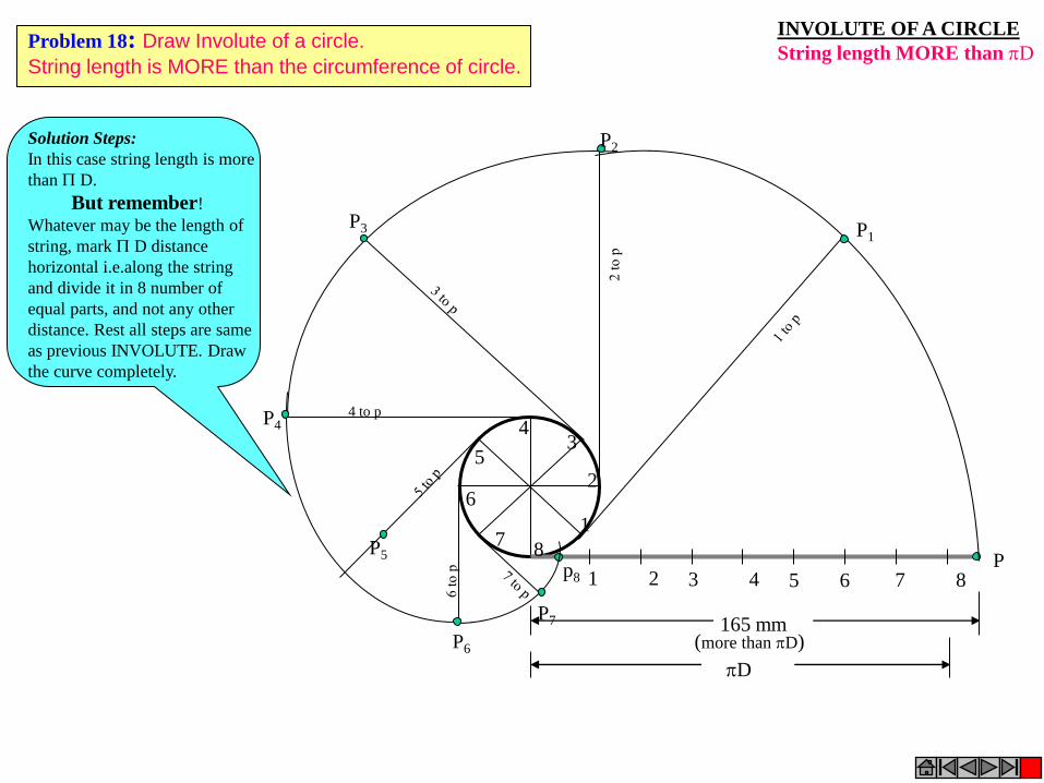
INVOLUTE OF A CIRCLE
String length MORE than D
1 2 3 4 5 6 7 8 P
1
2
3 4
5
6
7 8
P3
P4 4 to p
P5
P7
P6
P2
P1
165 mm (more than D)
D
p8
Solution Steps:
In this case string length is more
than D.
But remember!
Whatever may be the length of
string, mark D distance
horizontal i.e.along the string
and divide it in 8 number of
equal parts, and not any other
distance. Rest all steps are same
as previous INVOLUTE. Draw
the curve completely.
Problem 18: Draw Involute of a circle.
String length is MORE than the circumference of circle.

1 2 3 4 5 6 7 8
P
1
2
3 4
5
6
7 8
P3
P4 4 to p
P5
P7 P6
P2
P1
150 mm (Less than D)
D
INVOLUTE OF A CIRCLE
String length LESS than D
Problem 19: Draw Involute of a circle.
String length is LESS than the circumference of circle.
Solution Steps:
In this case string length is Less
than D.
But remember!
Whatever may be the length of
string, mark D distance
horizontal i.e.along the string
and divide it in 8 number of
equal parts, and not any other
distance. Rest all steps are same
as previous INVOLUTE. Draw
the curve completely.
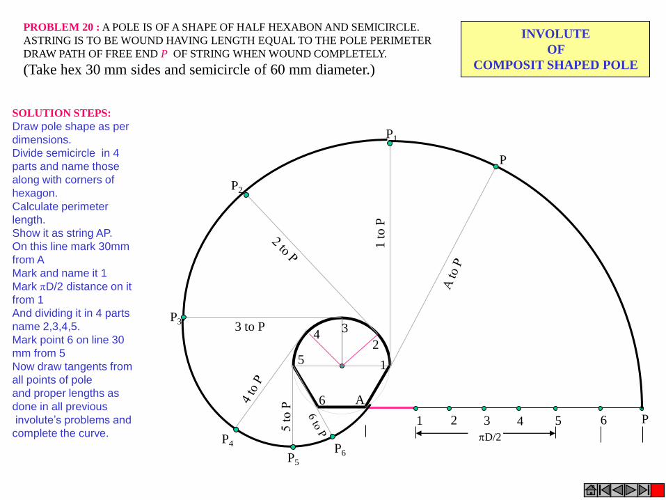
1
2
3 4
5
6
1 2 3 4 5 6
A
P
D/2
P1
1 t
o P
P2
P3 3 to P
P4
P
P5
P6
INVOLUTE
OF
COMPOSIT SHAPED POLE
PROBLEM 20 : A POLE IS OF A SHAPE OF HALF HEXABON AND SEMICIRCLE.
ASTRING IS TO BE WOUND HAVING LENGTH EQUAL TO THE POLE PERIMETER
DRAW PATH OF FREE END P OF STRING WHEN WOUND COMPLETELY.
(Take hex 30 mm sides and semicircle of 60 mm diameter.)
SOLUTION STEPS:
Draw pole shape as per
dimensions.
Divide semicircle in 4
parts and name those
along with corners of
hexagon.
Calculate perimeter
length.
Show it as string AP.
On this line mark 30mm
from A
Mark and name it 1
Mark D/2 distance on it
from 1
And dividing it in 4 parts
name 2,3,4,5.
Mark point 6 on line 30
mm from 5
Now draw tangents from
all points of pole
and proper lengths as
done in all previous
involute’s problems and
complete the curve.
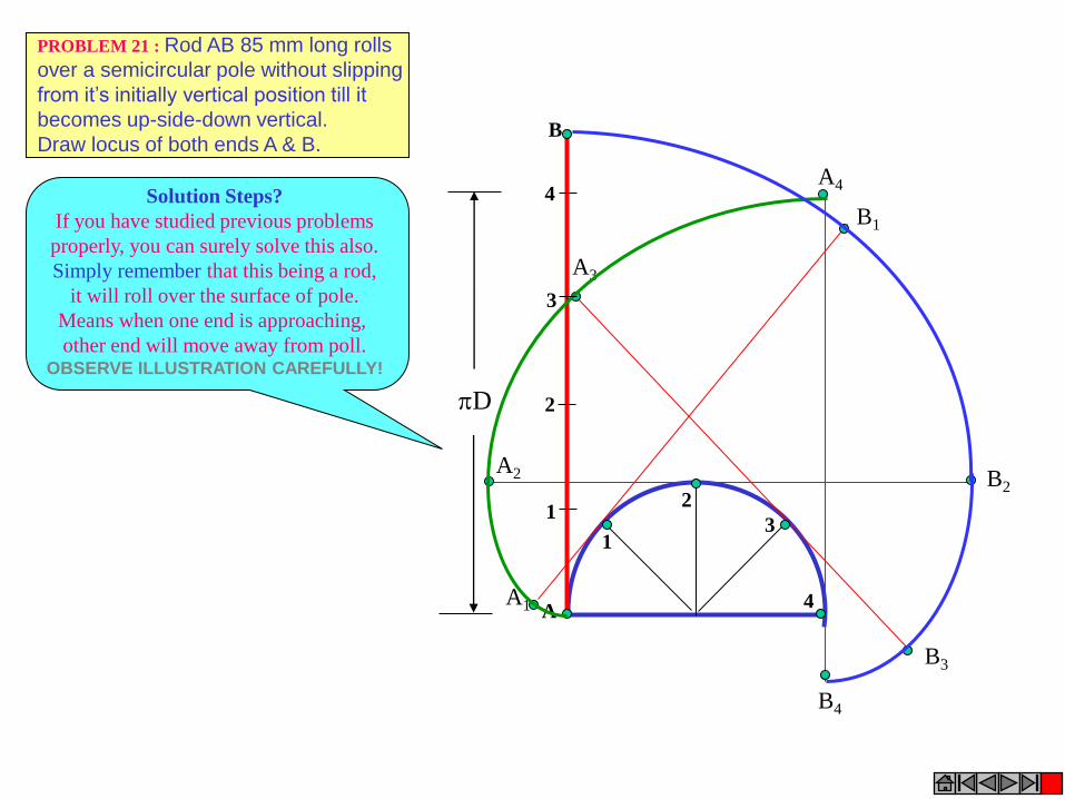
1
2
3
4
D
1
2
3
4
A
B
A1
B1
A2 B2
A3
B3
A4
B4
PROBLEM 21 : Rod AB 85 mm long rolls
over a semicircular pole without slipping
from it’s initially vertical position till it
becomes up-side-down vertical.
Draw locus of both ends A & B.
Solution Steps?
If you have studied previous problems
properly, you can surely solve this also.
Simply remember that this being a rod,
it will roll over the surface of pole.
Means when one end is approaching,
other end will move away from poll. OBSERVE ILLUSTRATION CAREFULLY!
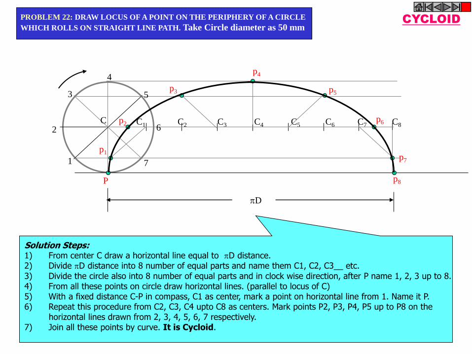
P
C1 C2 C3 C4 C5 C6 C7 C8
p1
p2
p3
p4
p5
p6
p7
p8
1
2
3
4
5
6
7
C
D
CYCLOID PROBLEM 22: DRAW LOCUS OF A POINT ON THE PERIPHERY OF A CIRCLE
WHICH ROLLS ON STRAIGHT LINE PATH. Take Circle diameter as 50 mm
Solution Steps: 1) From center C draw a horizontal line equal to D distance. 2) Divide D distance into 8 number of equal parts and name them C1, C2, C3__ etc. 3) Divide the circle also into 8 number of equal parts and in clock wise direction, after P name 1, 2, 3 up to 8. 4) From all these points on circle draw horizontal lines. (parallel to locus of C) 5) With a fixed distance C-P in compass, C1 as center, mark a point on horizontal line from 1. Name it P. 6) Repeat this procedure from C2, C3, C4 upto C8 as centers. Mark points P2, P3, P4, P5 up to P8 on the horizontal lines drawn from 2, 3, 4, 5, 6, 7 respectively. 7) Join all these points by curve. It is Cycloid.
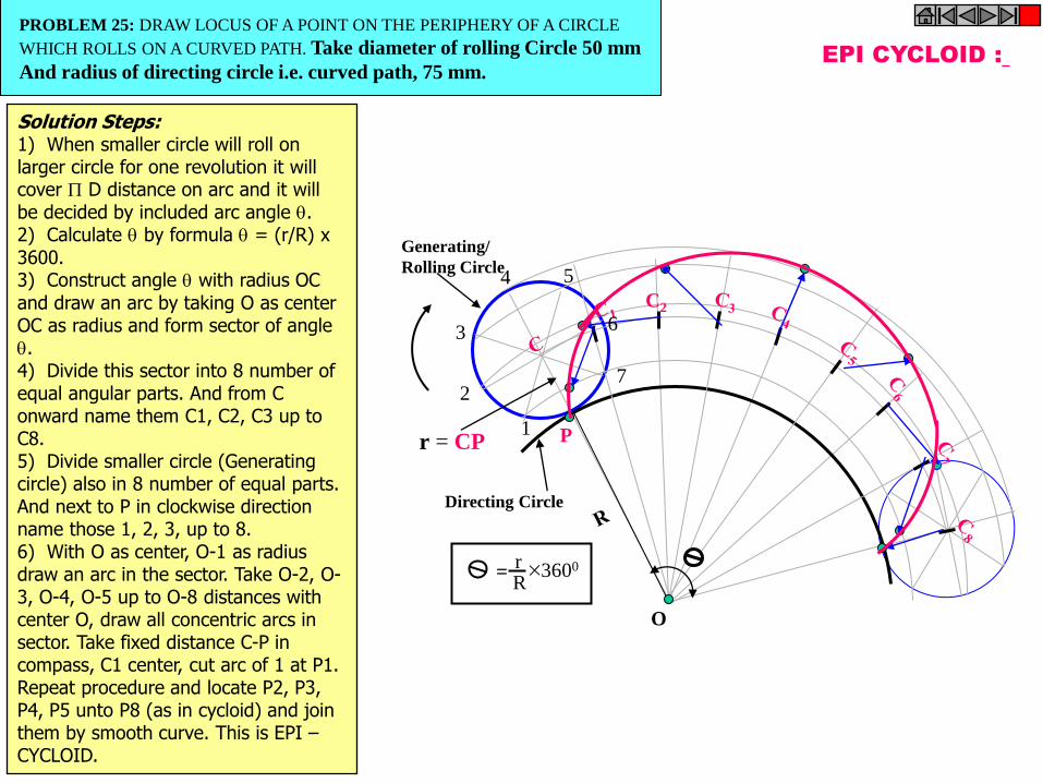
C2
EPI CYCLOID :
P
O
r = CP
r R
3600 =
1
2
3
4 5
6
7
Generating/
Rolling Circle
Directing Circle
PROBLEM 25: DRAW LOCUS OF A POINT ON THE PERIPHERY OF A CIRCLE
WHICH ROLLS ON A CURVED PATH. Take diameter of rolling Circle 50 mm
And radius of directing circle i.e. curved path, 75 mm.
Solution Steps: 1) When smaller circle will roll on larger circle for one revolution it will cover D distance on arc and it will be decided by included arc angle . 2) Calculate by formula = (r/R) x 3600. 3) Construct angle with radius OC and draw an arc by taking O as center OC as radius and form sector of angle . 4) Divide this sector into 8 number of equal angular parts. And from C onward name them C1, C2, C3 up to C8. 5) Divide smaller circle (Generating circle) also in 8 number of equal parts. And next to P in clockwise direction name those 1, 2, 3, up to 8. 6) With O as center, O-1 as radius draw an arc in the sector. Take O-2, O-3, O-4, O-5 up to O-8 distances with center O, draw all concentric arcs in sector. Take fixed distance C-P in compass, C1 center, cut arc of 1 at P1. Repeat procedure and locate P2, P3, P4, P5 unto P8 (as in cycloid) and join them by smooth curve. This is EPI – CYCLOID.

HYPO CYCLOID
P1
P2
P3
P4
P5 P6 P7
P8
P
1
2
3
6
5
7
4
O
OC = R ( Radius of Directing Circle)
CP = r (Radius of Generating Circle)
r
R 3600 =
PROBLEM 26: DRAW LOCUS OF A POINT ON THE PERIPHERY OF A CIRCLE
WHICH ROLLS FROM THE INSIDE OF A CURVED PATH. Take diameter of
rolling circle 50 mm and radius of directing circle (curved path) 75 mm.
Solution Steps: 1) Smaller circle is rolling here, inside the larger circle. It has to rotate anticlockwise to move ahead. 2) Same steps should be taken as in case of EPI – CYCLOID. Only change is in numbering direction of 8 number of equal parts on the smaller circle. 3) From next to P in anticlockwise direction, name 1,2,3,4,5,6,7,8. 4) Further all steps are that of epi – cycloid. This is called HYPO – CYCLOID.
TO DRAW PROJECTIONS OF ANY OBJECT,
ONE MUST HAVE FOLLOWING INFORMATION
A) OBJECT { WITH IT’S DESCRIPTION, WELL DEFINED.}
B) OBSERVER { ALWAYS OBSERVING PERPENDICULAR TO RESP. REF.PLANE}.
C) LOCATION OF OBJECT, { MEANS IT’S POSITION WITH REFFERENCE TO H.P. & V.P.}
TERMS ‘ABOVE’ & ‘BELOW’ WITH RESPECTIVE TO H.P.
AND TERMS ‘INFRONT’ & ‘BEHIND’ WITH RESPECTIVE TO V.P
FORM 4 QUADRANTS.
OBJECTS CAN BE PLACED IN ANY ONE OF THESE 4 QUADRANTS.
IT IS INTERESTING TO LEARN THE EFFECT ON THE POSITIONS OF VIEWS ( FV, TV )
OF THE OBJECT WITH RESP. TO X-Y LINE, WHEN PLACED IN DIFFERENT QUADRANTS.
ORTHOGRAPHIC PROJECTIONS OF POINTS, LINES, PLANES, AND SOLIDS.
STUDY ILLUSTRATIONS GIVEN ON HEXT PAGES AND NOTE THE RESULTS.TO MAKE IT EASY
HERE A POINT A IS TAKEN AS AN OBJECT. BECAUSE IT’S ALL VIEWS ARE JUST POINTS.

NOTATIONS
FOLLOWING NOTATIONS SHOULD BE FOLLOWED WHILE NAMEING
DIFFERENT VIEWS IN ORTHOGRAPHIC PROJECTIONS.
IT’S FRONT VIEW a’ a’ b’
SAME SYSTEM OF NOTATIONS SHOULD BE FOLLOWED
INCASE NUMBERS, LIKE 1, 2, 3 – ARE USED.
OBJECT POINT A LINE AB
IT’S TOP VIEW a a b
IT’S SIDE VIEW a” a” b”

X
Y
1ST Quad. 2nd Quad.
3rd Quad. 4th Quad.
X Y
VP
HP
Observer
THIS QUADRANT PATTERN,
IF OBSERVED ALONG X-Y LINE ( IN RED ARROW DIRECTION)
WILL EXACTLY APPEAR AS SHOWN ON RIGHT SIDE AND HENCE,
IT IS FURTHER USED TO UNDERSTAND ILLUSTRATION PROPERLLY.
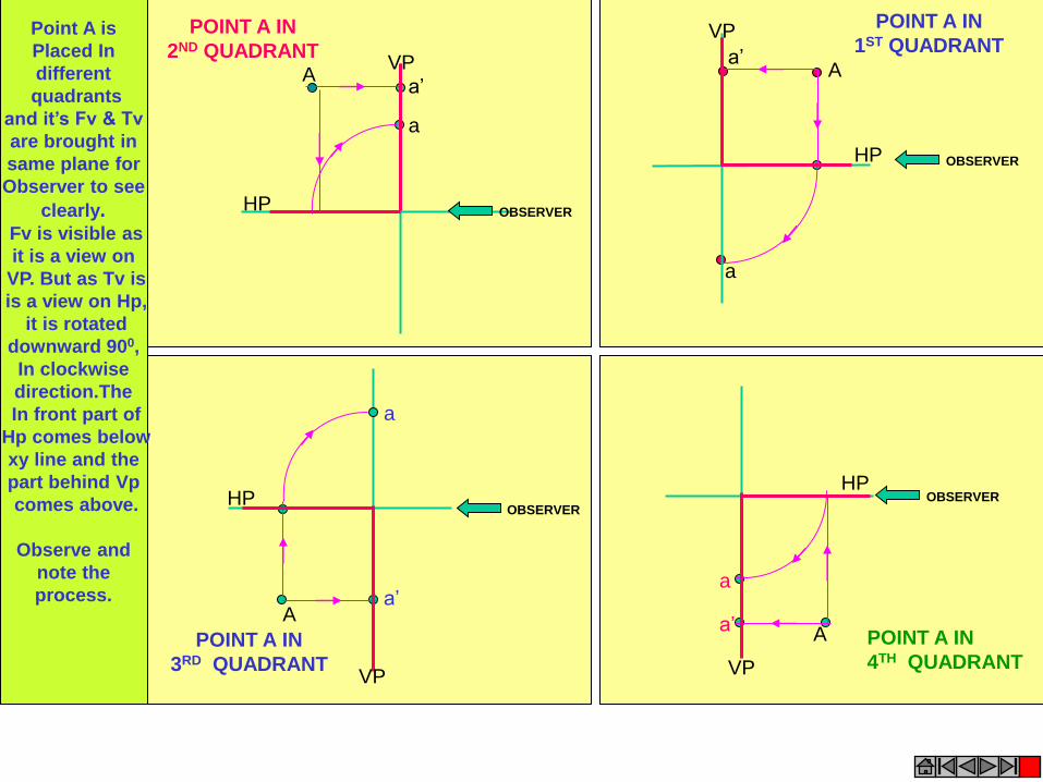
HP
VP
a’
a
A
POINT A IN
1ST QUADRANT
OBSERVER
VP
HP
POINT A IN
2ND QUADRANT
OBSERVER
a’
a
A
OBSERVER
a
a’
POINT A IN
3RD QUADRANT
HP
VP
A
OBSERVER
a
a’ POINT A IN
4TH QUADRANT
HP
VP
A
Point A is
Placed In
different
quadrants
and it’s Fv & Tv
are brought in
same plane for
Observer to see
clearly. Fv is visible as
it is a view on
VP. But as Tv is
is a view on Hp,
it is rotated
downward 900,
In clockwise
direction.The
In front part of
Hp comes below
xy line and the
part behind Vp
comes above.
Observe and
note the
process.
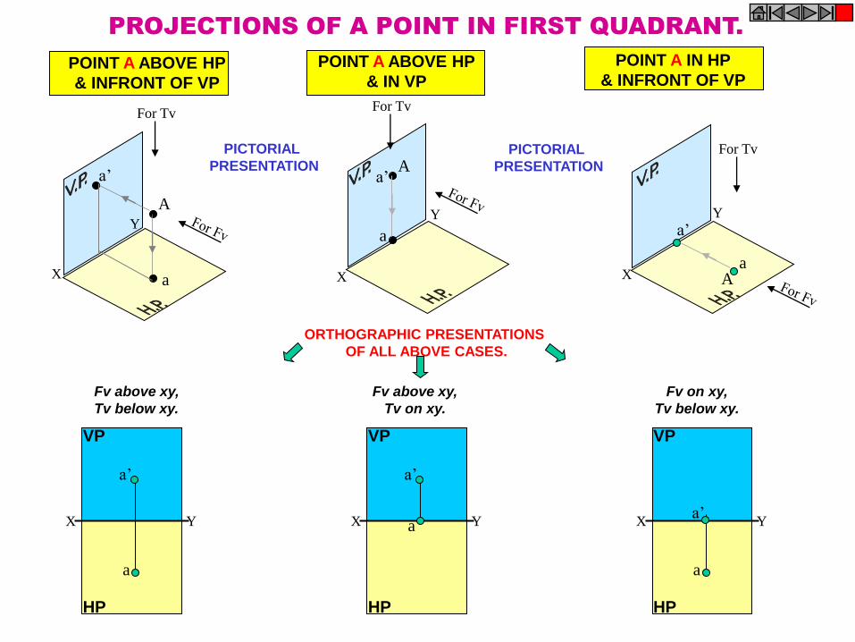
A
a
a’ A
a
a’
A a
a’
X
Y
X
Y
X
Y
For Tv For Tv
For Tv
POINT A ABOVE HP
& INFRONT OF VP
POINT A IN HP
& INFRONT OF VP POINT A ABOVE HP
& IN VP
PROJECTIONS OF A POINT IN FIRST QUADRANT.
PICTORIAL
PRESENTATION PICTORIAL
PRESENTATION
ORTHOGRAPHIC PRESENTATIONS
OF ALL ABOVE CASES.
X Y
a
a’
VP
HP
X Y
a’
VP
HP
a X Y
a
VP
HP
a’
Fv above xy,
Tv below xy.
Fv above xy,
Tv on xy.
Fv on xy,
Tv below xy.
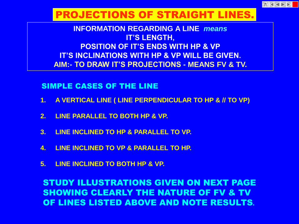
SIMPLE CASES OF THE LINE
1. A VERTICAL LINE ( LINE PERPENDICULAR TO HP & // TO VP)
2. LINE PARALLEL TO BOTH HP & VP.
3. LINE INCLINED TO HP & PARALLEL TO VP.
4. LINE INCLINED TO VP & PARALLEL TO HP.
5. LINE INCLINED TO BOTH HP & VP.
STUDY ILLUSTRATIONS GIVEN ON NEXT PAGE
SHOWING CLEARLY THE NATURE OF FV & TV
OF LINES LISTED ABOVE AND NOTE RESULTS.
PROJECTIONS OF STRAIGHT LINES.
INFORMATION REGARDING A LINE means
IT’S LENGTH,
POSITION OF IT’S ENDS WITH HP & VP
IT’S INCLINATIONS WITH HP & VP WILL BE GIVEN.
AIM:- TO DRAW IT’S PROJECTIONS - MEANS FV & TV.
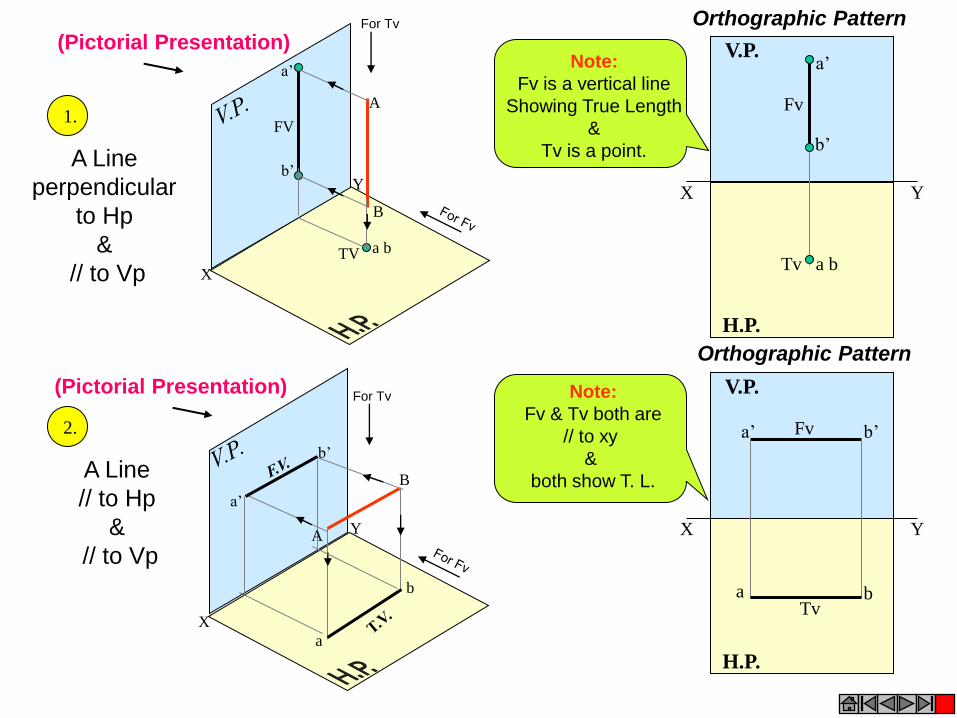
X
Y
X
Y
b’
a’
b
a
a b
a’
b’
B
A
TV
FV
A
B
X Y
H.P.
V.P. a’
b’
a b
Fv
Tv
X Y
H.P.
V.P.
a b
a’ b’ Fv
Tv
For Tv
For Tv
Note:
Fv is a vertical line
Showing True Length
&
Tv is a point.
Note:
Fv & Tv both are
// to xy
&
both show T. L.
1.
2.
A Line
perpendicular
to Hp
&
// to Vp
A Line
// to Hp
&
// to Vp
Orthographic Pattern
Orthographic Pattern
(Pictorial Presentation)
(Pictorial Presentation)

A Line inclined to Hp and
parallel to Vp
(Pictorial presentation) X
Y
A
B
b’
a’
b
a
A Line inclined to Vp and
parallel to Hp
(Pictorial presentation)
Ø a b
a’
b’
B A Ø
X Y
H.P.
V.P.
T.V. a b
a’
b’
X Y
H.P.
V.P.
Ø a
b
a’ b’
Tv
Fv
Tv inclined to xy
Fv parallel to xy.
3.
4.
Fv inclined to xy
Tv parallel to xy.
Orthographic Projections
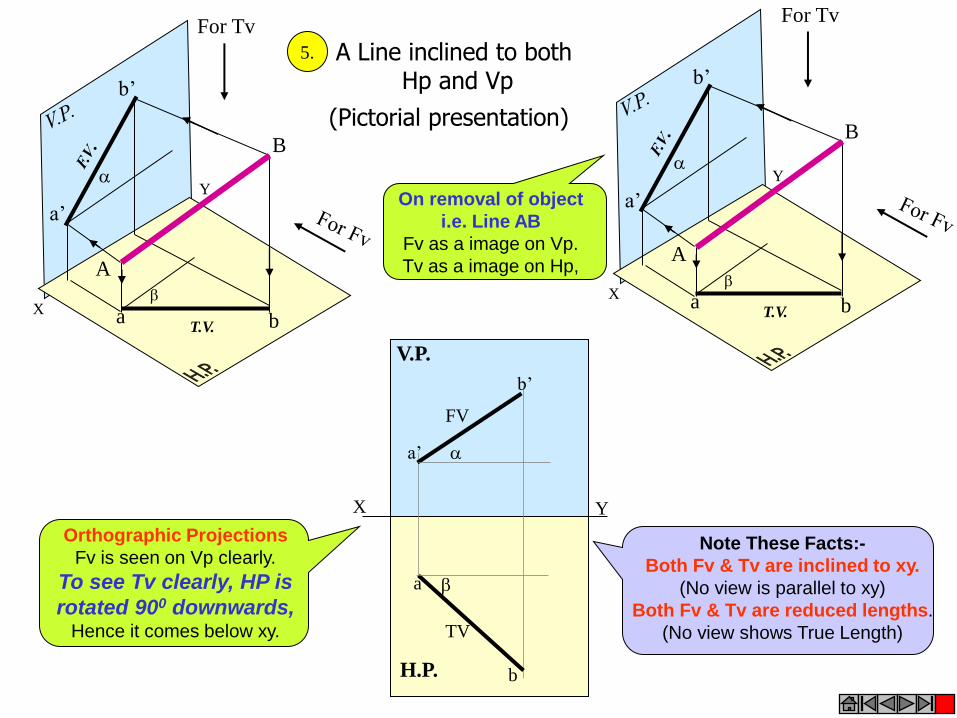
X
Y
a’
b’
a b
B
A
For Tv
T.V.
X
Y
a’
b’
a b
T.V.
For Tv
B
A
X Y
H.P.
V.P.
a
b
FV
TV
a’
b’
A Line inclined to both Hp and Vp
(Pictorial presentation)
5.
Note These Facts:-
Both Fv & Tv are inclined to xy.
(No view is parallel to xy)
Both Fv & Tv are reduced lengths.
(No view shows True Length)
Orthographic Projections
Fv is seen on Vp clearly.
To see Tv clearly, HP is
rotated 900 downwards, Hence it comes below xy.
On removal of object
i.e. Line AB
Fv as a image on Vp.
Tv as a image on Hp,
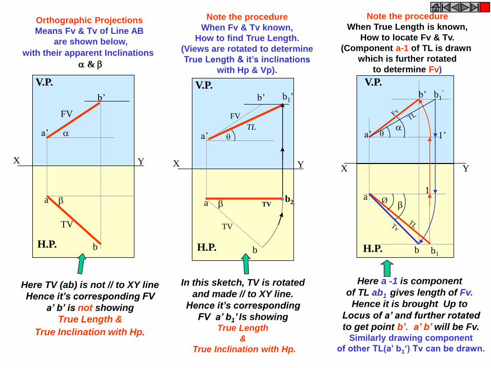
X Y
H.P.
V.P.
X Y
H.P.
V.P.
a
b
TV
a’
b’
FV
TV
b2
b1’
TL
X Y
H.P.
V.P.
a
b
FV
TV
a’
b’
Here TV (ab) is not // to XY line
Hence it’s corresponding FV
a’ b’ is not showing
True Length &
True Inclination with Hp.
In this sketch, TV is rotated
and made // to XY line.
Hence it’s corresponding
FV a’ b1’ Is showing True Length
&
True Inclination with Hp.
Note the procedure
When Fv & Tv known,
How to find True Length.
(Views are rotated to determine
True Length & it’s inclinations
with Hp & Vp).
Note the procedure
When True Length is known,
How to locate Fv & Tv.
(Component a-1 of TL is drawn
which is further rotated
to determine Fv)
1 a
a’
b’
1’
b
b1’
b1
Ø
Orthographic Projections
Means Fv & Tv of Line AB
are shown below,
with their apparent Inclinations
&
Here a -1 is component
of TL ab1 gives length of Fv.
Hence it is brought Up to
Locus of a’ and further rotated
to get point b’. a’ b’ will be Fv. Similarly drawing component
of other TL(a’ b1‘) Tv can be drawn.
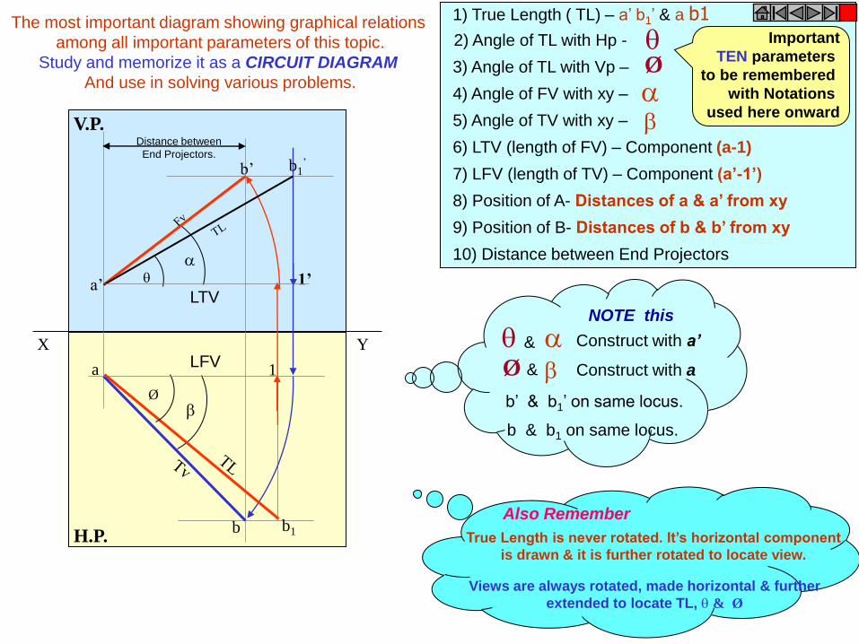
The most important diagram showing graphical relations
among all important parameters of this topic.
Study and memorize it as a CIRCUIT DIAGRAM
And use in solving various problems.
True Length is never rotated. It’s horizontal component
is drawn & it is further rotated to locate view.
Views are always rotated, made horizontal & further
extended to locate TL, & Ø
Also Remember
Important
TEN parameters
to be remembered
with Notations
used here onward
Ø
1) True Length ( TL) – a’ b1’ & a b1
2) Angle of TL with Hp -
3) Angle of TL with Vp –
4) Angle of FV with xy –
5) Angle of TV with xy –
6) LTV (length of FV) – Component (a-1)
7) LFV (length of TV) – Component (a’-1’)
8) Position of A- Distances of a & a’ from xy
9) Position of B- Distances of b & b’ from xy
10) Distance between End Projectors
X Y
H.P.
V.P.
1 a
b
b1
Ø
LFV
a’
b’
1’
b1’
LTV
Distance between
End Projectors.
& Construct with a’
Ø & Construct with a
b & b1 on same locus.
b’ & b1’ on same locus.
NOTE this

a’
b’
a
b
X Y
b’1
b1
Ø
GROUP (A) GENERAL CASES OF THE LINE INCLINED TO BOTH HP & VP
( based on 10 parameters). PROBLEM 1) Line AB is 75 mm long and it is 300 &
400 Inclined to Hp & Vp respectively.
End A is 12mm above Hp and 10 mm
in front of Vp.
Draw projections. Line is in 1st quadrant.
SOLUTION STEPS:
1) Draw xy line and one projector.
2) Locate a’ 12mm above xy line
& a 10mm below xy line.
3) Take 300 angle from a’ & 400 from
a and mark TL I.e. 75mm on both
lines. Name those points b1’ and b1
respectively.
4) Join both points with a’ and a resp.
5) Draw horizontal lines (Locus) from
both points.
6) Draw horizontal component of TL
a b1 from point b1 and name it 1.
( the length a-1 gives length of Fv
as we have seen already.)
7) Extend it up to locus of a’ and
rotating a’ as center locate b’ as
shown. Join a’ b’ as Fv.
8) From b’ drop a projector down
ward & get point b. Join a & b
I.e. Tv.
1 LFV
TL
TL
FV
TV
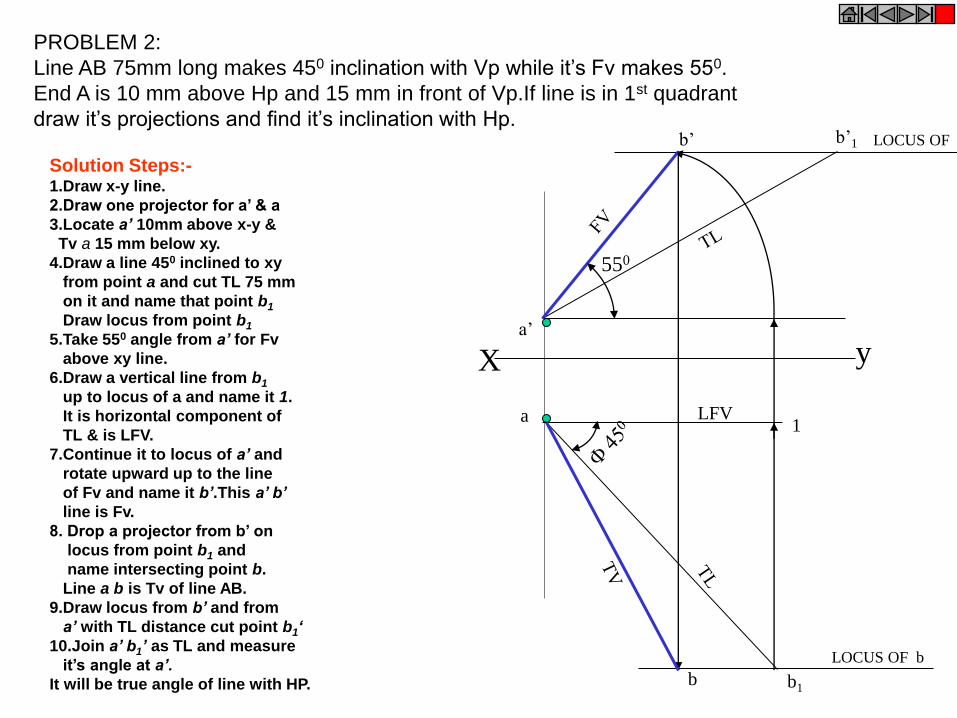
X y
a
a’
b1
1
b’1 b’
LFV
550
b
PROBLEM 2:
Line AB 75mm long makes 450 inclination with Vp while it’s Fv makes 550.
End A is 10 mm above Hp and 15 mm in front of Vp.If line is in 1st quadrant
draw it’s projections and find it’s inclination with Hp.
LOCUS OF b
LOCUS OF b1’
Solution Steps:- 1.Draw x-y line.
2.Draw one projector for a’ & a
3.Locate a’ 10mm above x-y &
Tv a 15 mm below xy.
4.Draw a line 450 inclined to xy
from point a and cut TL 75 mm
on it and name that point b1
Draw locus from point b1
5.Take 550 angle from a’ for Fv
above xy line.
6.Draw a vertical line from b1
up to locus of a and name it 1.
It is horizontal component of
TL & is LFV.
7.Continue it to locus of a’ and
rotate upward up to the line
of Fv and name it b’.This a’ b’
line is Fv.
8. Drop a projector from b’ on
locus from point b1 and
name intersecting point b.
Line a b is Tv of line AB.
9.Draw locus from b’ and from
a’ with TL distance cut point b1‘
10.Join a’ b1’ as TL and measure
it’s angle at a’.
It will be true angle of line with HP.

X a’
y
a
b’
500
b
600
b1
b’1
PROBLEM 3:
Fv of line AB is 500 inclined to xy and measures 55
mm long while it’s Tv is 600 inclined to xy line. If
end A is 10 mm above Hp and 15 mm in front of
Vp, draw it’s projections,find TL, inclinations of line
with Hp & Vp.
SOLUTION STEPS:
1.Draw xy line and one projector.
2.Locate a’ 10 mm above xy and
a 15 mm below xy line.
3.Draw locus from these points.
4.Draw Fv 500 to xy from a’ and
mark b’ Cutting 55mm on it.
5.Similarly draw Tv 600 to xy
from a & drawing projector from b’
Locate point b and join a b.
6.Then rotating views as shown,
locate True Lengths ab1 & a’b1’
and their angles with Hp and Vp.
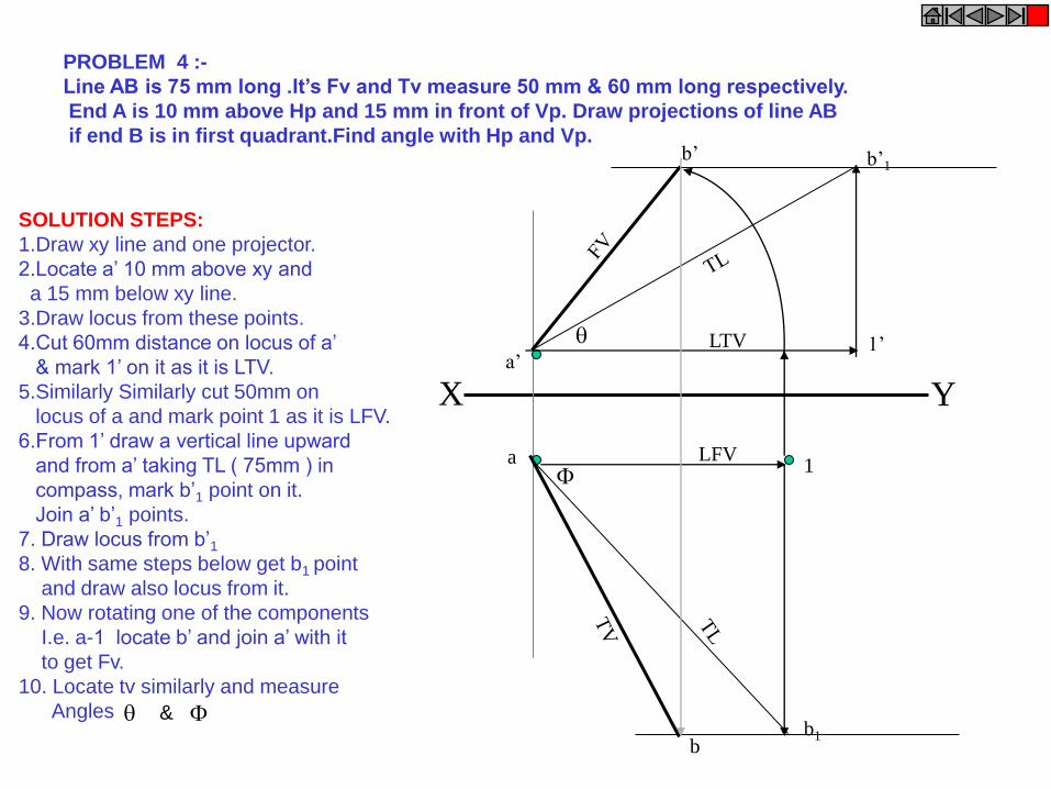
X Y a’
1’
a
b’1
LTV
b1
1
b’
b
LFV
PROBLEM 4 :-
Line AB is 75 mm long .It’s Fv and Tv measure 50 mm & 60 mm long respectively.
End A is 10 mm above Hp and 15 mm in front of Vp. Draw projections of line AB
if end B is in first quadrant.Find angle with Hp and Vp.
SOLUTION STEPS:
1.Draw xy line and one projector.
2.Locate a’ 10 mm above xy and
a 15 mm below xy line.
3.Draw locus from these points.
4.Cut 60mm distance on locus of a’
& mark 1’ on it as it is LTV.
5.Similarly Similarly cut 50mm on
locus of a and mark point 1 as it is LFV.
6.From 1’ draw a vertical line upward
and from a’ taking TL ( 75mm ) in
compass, mark b’1 point on it.
Join a’ b’1 points.
7. Draw locus from b’1
8. With same steps below get b1 point
and draw also locus from it.
9. Now rotating one of the components
I.e. a-1 locate b’ and join a’ with it
to get Fv.
10. Locate tv similarly and measure
Angles &

X Y c’
c
LOCUS OF d & d1 d d1
d’ d’1
LOCUS OF d’ & d’1
PROBLEM 5 :-
T.V. of a 75 mm long Line CD, measures 50 mm.
End C is in Hp and 50 mm in front of Vp.
End D is 15 mm in front of Vp and it is above Hp.
Draw projections of CD and find angles with Hp and Vp.
SOLUTION STEPS:
1.Draw xy line and one projector.
2.Locate c’ on xy and
c 50mm below xy line.
3.Draw locus from these points.
4.Draw locus of d 15 mm below xy
5.Cut 50mm & 75 mm distances on
locus of d from c and mark points
d & d1 as these are Tv and line CD
lengths resp.& join both with c.
6.From d1 draw a vertical line upward
up to xy I.e. up to locus of c’ and
draw an arc as shown.
7 Then draw one projector from d to
meet this arc in d’ point & join c’ d’
8. Draw locus of d’ and cut 75 mm
on it from c’ as TL
9.Measure Angles &

TRACES OF THE LINE:-
THESE ARE THE POINTS OF INTERSECTIONS OF A LINE ( OR IT’S EXTENSION )
WITH RESPECTIVE REFFERENCE PLANES.
A LINE ITSELF OR IT’S EXTENSION, WHERE EVER TOUCHES H.P.,
THAT POINT IS CALLED TRACE OF THE LINE ON H.P.( IT IS CALLED H.T.)
SIMILARLY, A LINE ITSELF OR IT’S EXTENSION, WHERE EVER TOUCHES V.P.,
THAT POINT IS CALLED TRACE OF THE LINE ON V.P.( IT IS CALLED V.T.)
V.T.:- It is a point on Vp.
Hence it is called Fv of a point in Vp.
Hence it’s Tv comes on XY line.( Here onward named as v )
H.T.:- It is a point on Hp.
Hence it is called Tv of a point in Hp.
Hence it’s Fv comes on XY line.( Here onward named as ’h’ )
GROUP (B)
PROBLEMS INVOLVING TRACES OF THE LINE.
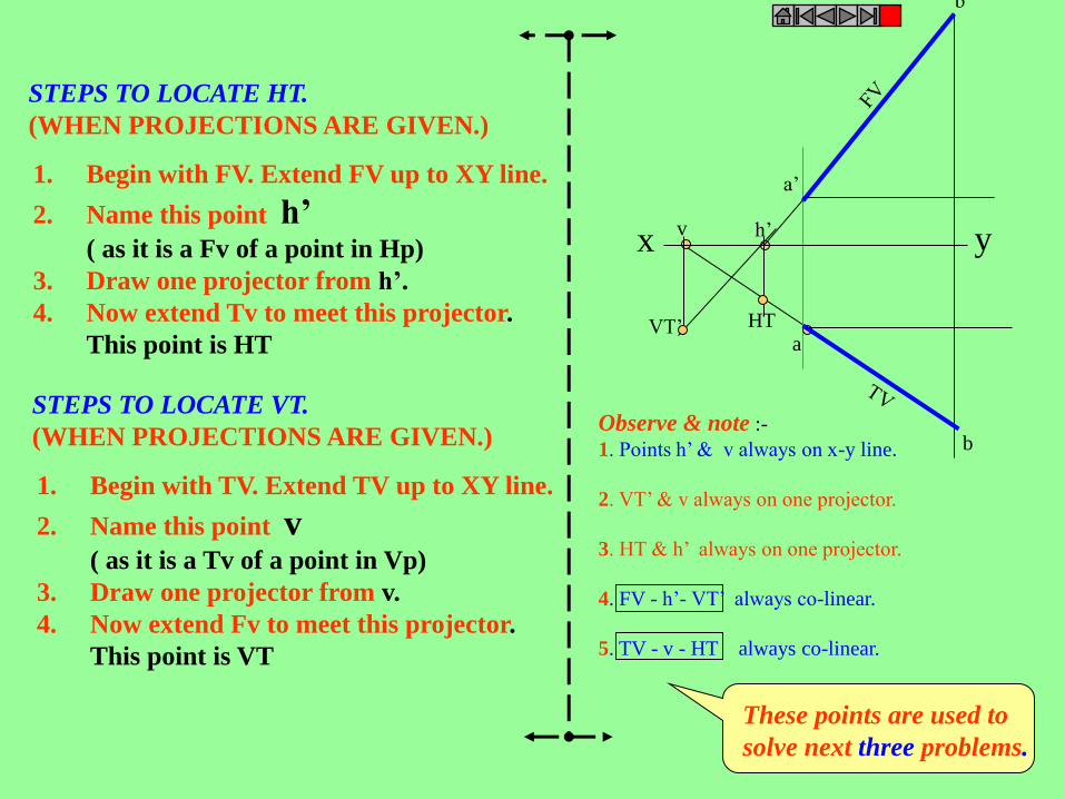
1. Begin with FV. Extend FV up to XY line.
2. Name this point h’ ( as it is a Fv of a point in Hp)
3. Draw one projector from h’.
4. Now extend Tv to meet this projector.
This point is HT
STEPS TO LOCATE HT.
(WHEN PROJECTIONS ARE GIVEN.)
1. Begin with TV. Extend TV up to XY line.
2. Name this point v ( as it is a Tv of a point in Vp)
3. Draw one projector from v.
4. Now extend Fv to meet this projector.
This point is VT
STEPS TO LOCATE VT.
(WHEN PROJECTIONS ARE GIVEN.)
h’
HT VT’
v
a’
x y
a
b’
b
Observe & note :-
1. Points h’ & v always on x-y line.
2. VT’ & v always on one projector.
3. HT & h’ always on one projector.
4. FV - h’- VT’ always co-linear.
5. TV - v - HT always co-linear.
These points are used to
solve next three problems.

x y
b’ b’1
a
v
VT’
a’
b
h’
b1
300
450
PROBLEM 6 :- Fv of line AB makes 450 angle with XY line and measures 60 mm.
Line’s Tv makes 300 with XY line. End A is 15 mm above Hp and it’s VT is 10 mm
below Hp. Draw projections of line AB,determine inclinations with Hp & Vp and locate HT, VT.
15
10
SOLUTION STEPS:-
Draw xy line, one projector and
locate fv a’ 15 mm above xy.
Take 450 angle from a’ and
marking 60 mm on it locate point b’.
Draw locus of VT, 10 mm below xy
& extending Fv to this locus locate VT.
as fv-h’-vt’ lie on one st.line.
Draw projector from vt, locate v on xy.
From v take 300 angle downward as
Tv and it’s inclination can begin with v.
Draw projector from b’ and locate b I.e.Tv point.
Now rotating views as usual TL and
it’s inclinations can be found.
Name extension of Fv, touching xy as h’
and below it, on extension of Tv, locate HT.
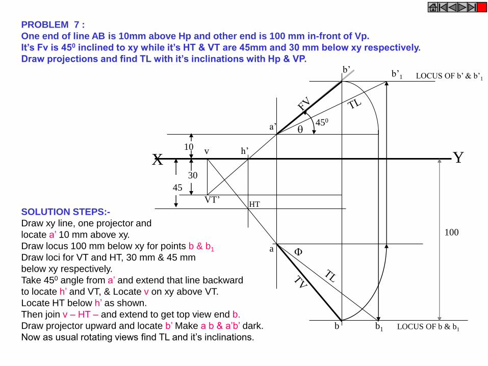
a’
b’
30
45
10
LOCUS OF b’ & b’1
X Y
450
VT’
v
HT
h’
LOCUS OF b & b1
100
a
b
b’1
b1
PROBLEM 7 :
One end of line AB is 10mm above Hp and other end is 100 mm in-front of Vp.
It’s Fv is 450 inclined to xy while it’s HT & VT are 45mm and 30 mm below xy respectively.
Draw projections and find TL with it’s inclinations with Hp & VP.
SOLUTION STEPS:-
Draw xy line, one projector and
locate a’ 10 mm above xy.
Draw locus 100 mm below xy for points b & b1
Draw loci for VT and HT, 30 mm & 45 mm
below xy respectively.
Take 450 angle from a’ and extend that line backward
to locate h’ and VT, & Locate v on xy above VT.
Locate HT below h’ as shown.
Then join v – HT – and extend to get top view end b.
Draw projector upward and locate b’ Make a b & a’b’ dark.
Now as usual rotating views find TL and it’s inclinations.
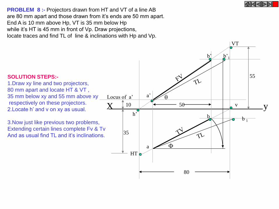
X y
HT
VT
h’
a’
v
b’
a
b
80
50
b’1
b 1
10
35
55
Locus of a’
PROBLEM 8 :- Projectors drawn from HT and VT of a line AB
are 80 mm apart and those drawn from it’s ends are 50 mm apart.
End A is 10 mm above Hp, VT is 35 mm below Hp
while it’s HT is 45 mm in front of Vp. Draw projections,
locate traces and find TL of line & inclinations with Hp and Vp.
SOLUTION STEPS:-
1.Draw xy line and two projectors,
80 mm apart and locate HT & VT ,
35 mm below xy and 55 mm above xy
respectively on these projectors.
2.Locate h’ and v on xy as usual.
3.Now just like previous two problems,
Extending certain lines complete Fv & Tv
And as usual find TL and it’s inclinations.
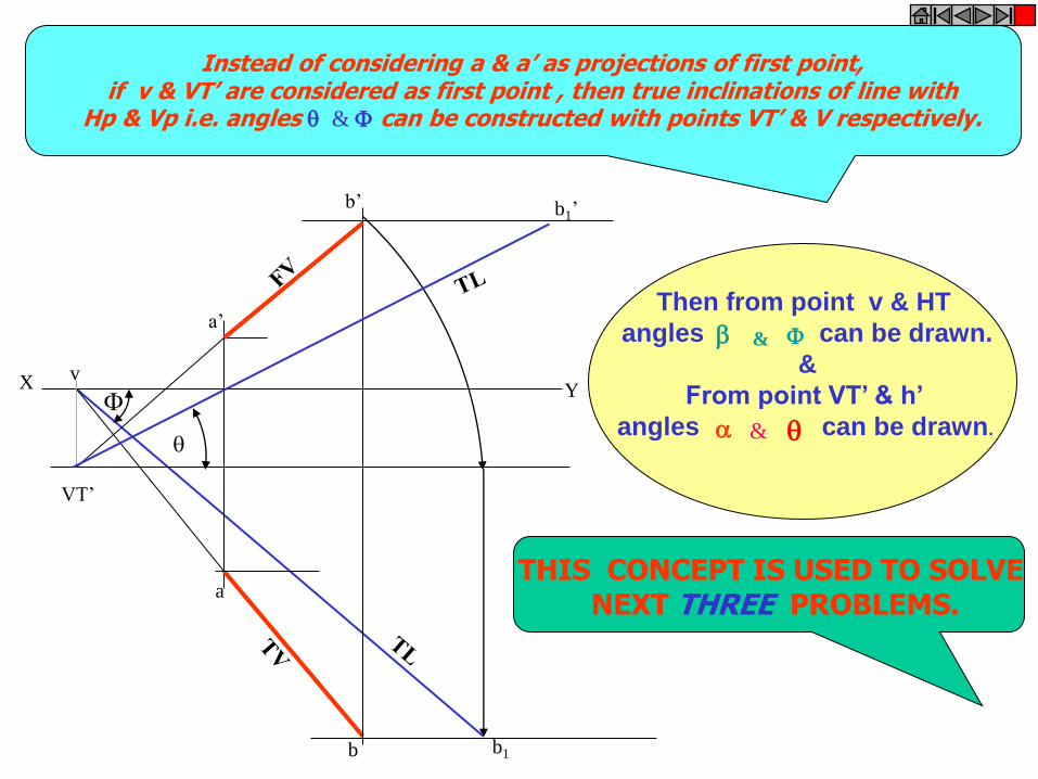
b1
a’
VT’
v X Y
b’
a
b
b1’
Then from point v & HT
angles can be drawn.
&
From point VT’ & h’
angles can be drawn. &
&
Instead of considering a & a’ as projections of first point, if v & VT’ are considered as first point , then true inclinations of line with
Hp & Vp i.e. angles & can be constructed with points VT’ & V respectively.
THIS CONCEPT IS USED TO SOLVE NEXT THREE PROBLEMS.
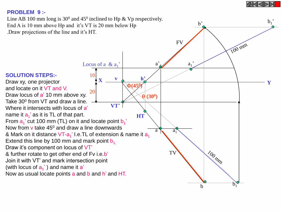
PROBLEM 9 :-
Line AB 100 mm long is 300 and 450 inclined to Hp & Vp respectively.
End A is 10 mm above Hp and it’s VT is 20 mm below Hp
.Draw projections of the line and it’s HT.
X Y
VT’
v 10
20
Locus of a & a1’
(300)
(450)
a1’
b1’
b1
a1
b’
a’
b
a
FV
TV
HT
h’ SOLUTION STEPS:-
Draw xy, one projector
and locate on it VT and V.
Draw locus of a’ 10 mm above xy.
Take 300 from VT and draw a line.
Where it intersects with locus of a’
name it a1’ as it is TL of that part.
From a1’ cut 100 mm (TL) on it and locate point b1’
Now from v take 450 and draw a line downwards
& Mark on it distance VT-a1’ I.e.TL of extension & name it a1
Extend this line by 100 mm and mark point b1.
Draw it’s component on locus of VT’
& further rotate to get other end of Fv i.e.b’
Join it with VT’ and mark intersection point
(with locus of a1’ ) and name it a’
Now as usual locate points a and b and h’ and HT.
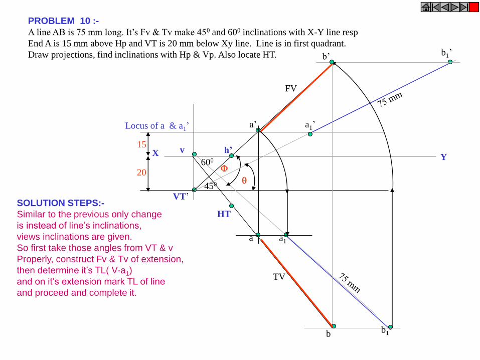
PROBLEM 10 :-
A line AB is 75 mm long. It’s Fv & Tv make 450 and 600 inclinations with X-Y line resp
End A is 15 mm above Hp and VT is 20 mm below Xy line. Line is in first quadrant.
Draw projections, find inclinations with Hp & Vp. Also locate HT.
X Y
VT’
v 15
20
Locus of a & a1’ a1’
b1’
b1
a1
b’
a’
b
a
FV
TV
HT
h’
450
600
SOLUTION STEPS:-
Similar to the previous only change
is instead of line’s inclinations,
views inclinations are given.
So first take those angles from VT & v
Properly, construct Fv & Tv of extension,
then determine it’s TL( V-a1)
and on it’s extension mark TL of line
and proceed and complete it.
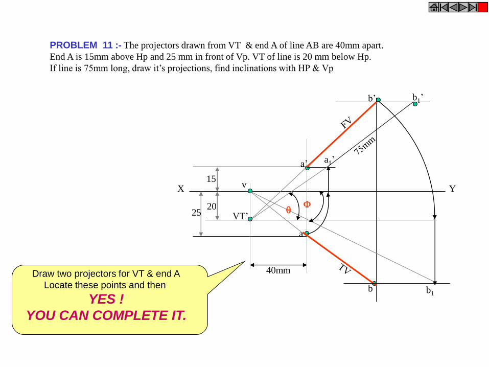
PROBLEM 11 :- The projectors drawn from VT & end A of line AB are 40mm apart.
End A is 15mm above Hp and 25 mm in front of Vp. VT of line is 20 mm below Hp.
If line is 75mm long, draw it’s projections, find inclinations with HP & Vp
X Y
40mm
15
20 25
v
VT’
a’
a
a1’
b1’ b’
b b1
Draw two projectors for VT & end A
Locate these points and then
YES !
YOU CAN COMPLETE IT.
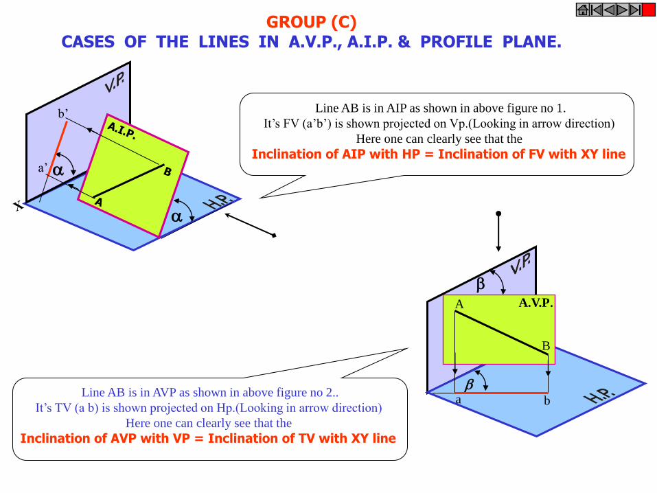
GROUP (C) CASES OF THE LINES IN A.V.P., A.I.P. & PROFILE PLANE.
a’
b’ Line AB is in AIP as shown in above figure no 1.
It’s FV (a’b’) is shown projected on Vp.(Looking in arrow direction)
Here one can clearly see that the
Inclination of AIP with HP = Inclination of FV with XY line
Line AB is in AVP as shown in above figure no 2..
It’s TV (a b) is shown projected on Hp.(Looking in arrow direction)
Here one can clearly see that the
Inclination of AVP with VP = Inclination of TV with XY line
A.V.P.
A
B
a b
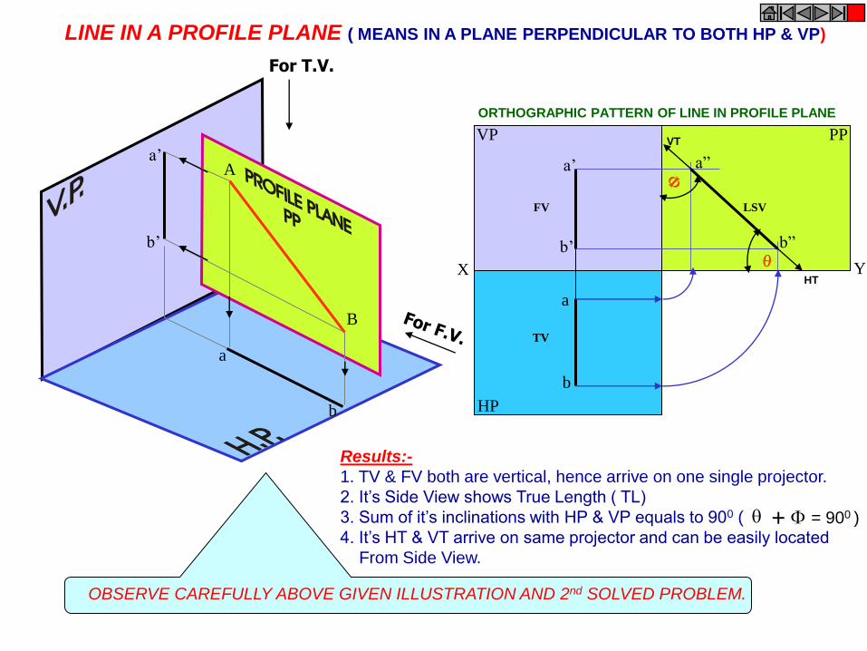
PP VP
HP
a
b
a’
b’
a”
b”
X Y
FV
TV
LSV
A
B
a
b
a’
b’
For T.V.
LINE IN A PROFILE PLANE ( MEANS IN A PLANE PERPENDICULAR TO BOTH HP & VP)
Results:-
1. TV & FV both are vertical, hence arrive on one single projector.
2. It’s Side View shows True Length ( TL)
3. Sum of it’s inclinations with HP & VP equals to 900 (
4. It’s HT & VT arrive on same projector and can be easily located
From Side View.
+ = 900 )
OBSERVE CAREFULLY ABOVE GIVEN ILLUSTRATION AND 2nd SOLVED PROBLEM.
ORTHOGRAPHIC PATTERN OF LINE IN PROFILE PLANE
HT
VT
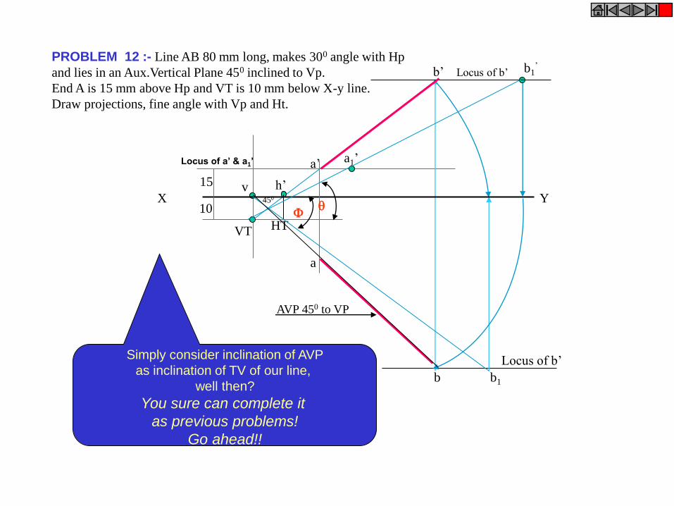
PROBLEM 12 :- Line AB 80 mm long, makes 300 angle with Hp
and lies in an Aux.Vertical Plane 450 inclined to Vp.
End A is 15 mm above Hp and VT is 10 mm below X-y line.
Draw projections, fine angle with Vp and Ht.
VT
v X Y
a
b
a’
b’
a1’
b1’
Locus of b’
Locus of b’
10
15
HT
h’
b1
AVP 450 to VP
450
Locus of a’ & a1’
Simply consider inclination of AVP
as inclination of TV of our line,
well then?
You sure can complete it
as previous problems!
Go ahead!!
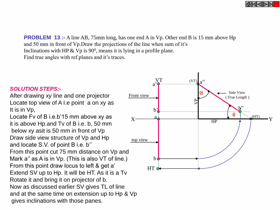
PROBLEM 13 :- A line AB, 75mm long, has one end A in Vp. Other end B is 15 mm above Hp
and 50 mm in front of Vp.Draw the projections of the line when sum of it’s
Inclinations with HP & Vp is 900, means it is lying in a profile plane.
Find true angles with ref.planes and it’s traces.
a
b
HT
VT
X Y
a’
b’
Side View
( True Length )
a”
b”
(HT)
(VT)
HP
VP
Front view
top view
SOLUTION STEPS:-
After drawing xy line and one projector
Locate top view of A I.e point a on xy as
It is in Vp,
Locate Fv of B i.e.b’15 mm above xy as
it is above Hp.and Tv of B i.e. b, 50 mm
below xy asit is 50 mm in front of Vp
Draw side view structure of Vp and Hp
and locate S.V. of point B i.e. b’’
From this point cut 75 mm distance on Vp and
Mark a’’ as A is in Vp. (This is also VT of line.)
From this point draw locus to left & get a’
Extend SV up to Hp. It will be HT. As it is a Tv
Rotate it and bring it on projector of b.
Now as discussed earlier SV gives TL of line
and at the same time on extension up to Hp & Vp
gives inclinations with those panes.

APPLICATIONS OF PRINCIPLES OF PROJECTIONS OF LINES IN SOLVING CASES OF DIFFERENT PRACTICAL SITUATIONS.
In these types of problems some situation in the field
or
some object will be described .
It’s relation with Ground ( HP )
And
a Wall or some vertical object ( VP ) will be given.
Indirectly information regarding Fv & Tv of some line or lines,
inclined to both reference Planes will be given
and
you are supposed to draw it’s projections
and
further to determine it’s true Length and it’s inclinations with ground.
Here various problems along with
actual pictures of those situations are given
for you to understand those clearly.
Now looking for views in given ARROW directions,
YOU are supposed to draw projections & find answers,
Off course you must visualize the situation properly.
CHECK YOUR ANSWERS
WITH THE SOLUTIONS
GIVEN IN THE END.
ALL THE BEST !!

Wall Q
A
B
PROBLEM 14:-Two objects, a flower (A) and an orange (B) are within a rectangular compound wall,
whose P & Q are walls meeting at 900. Flower A is 1M & 5.5 M from walls P & Q respectively.
Orange B is 4M & 1.5M from walls P & Q respectively. Drawing projection, find distance between them
If flower is 1.5 M and orange is 3.5 M above the ground. Consider suitable scale.. TV
FV
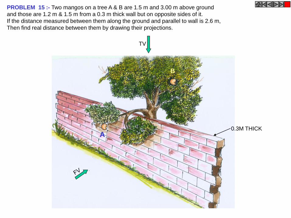
PROBLEM 15 :- Two mangos on a tree A & B are 1.5 m and 3.00 m above ground
and those are 1.2 m & 1.5 m from a 0.3 m thick wall but on opposite sides of it.
If the distance measured between them along the ground and parallel to wall is 2.6 m,
Then find real distance between them by drawing their projections.
TV
A
B
0.3M THICK
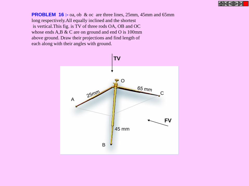
PROBLEM 16 :- oa, ob & oc are three lines, 25mm, 45mm and 65mm
long respectively.All equally inclined and the shortest
is vertical.This fig. is TV of three rods OA, OB and OC
whose ends A,B & C are on ground and end O is 100mm
above ground. Draw their projections and find length of
each along with their angles with ground.
45 mm
A
B
C
O
FV
TV
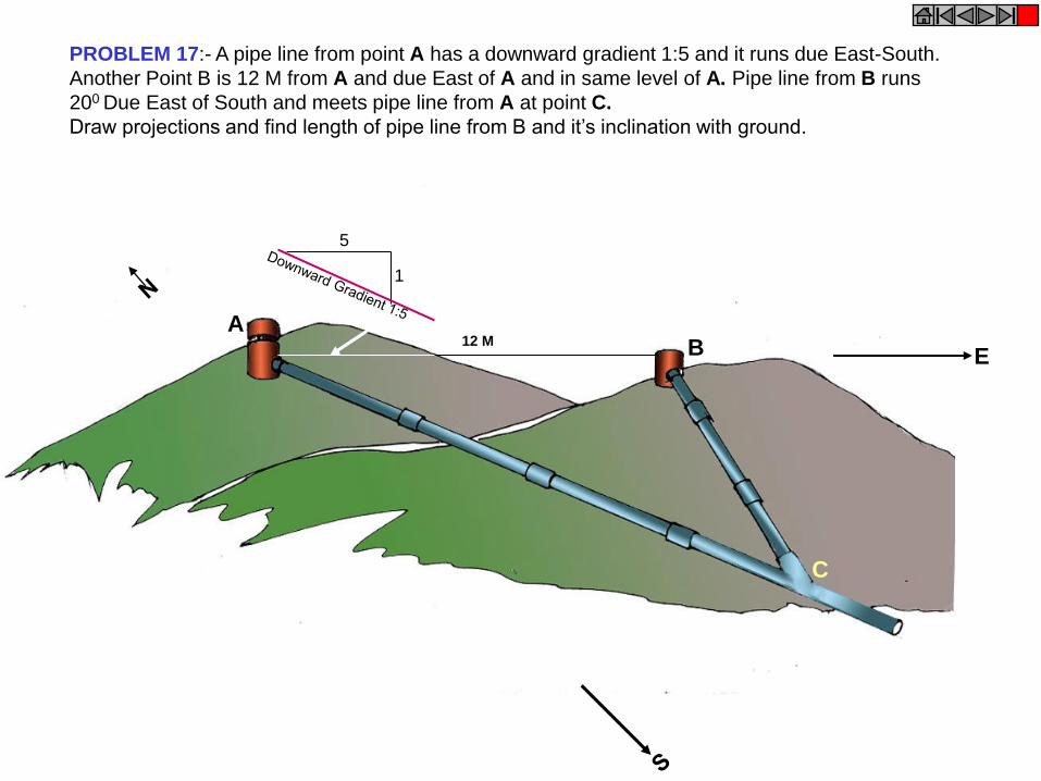
PROBLEM 17:- A pipe line from point A has a downward gradient 1:5 and it runs due East-South.
Another Point B is 12 M from A and due East of A and in same level of A. Pipe line from B runs
200 Due East of South and meets pipe line from A at point C.
Draw projections and find length of pipe line from B and it’s inclination with ground.
A B
C
1
5
12 M
E
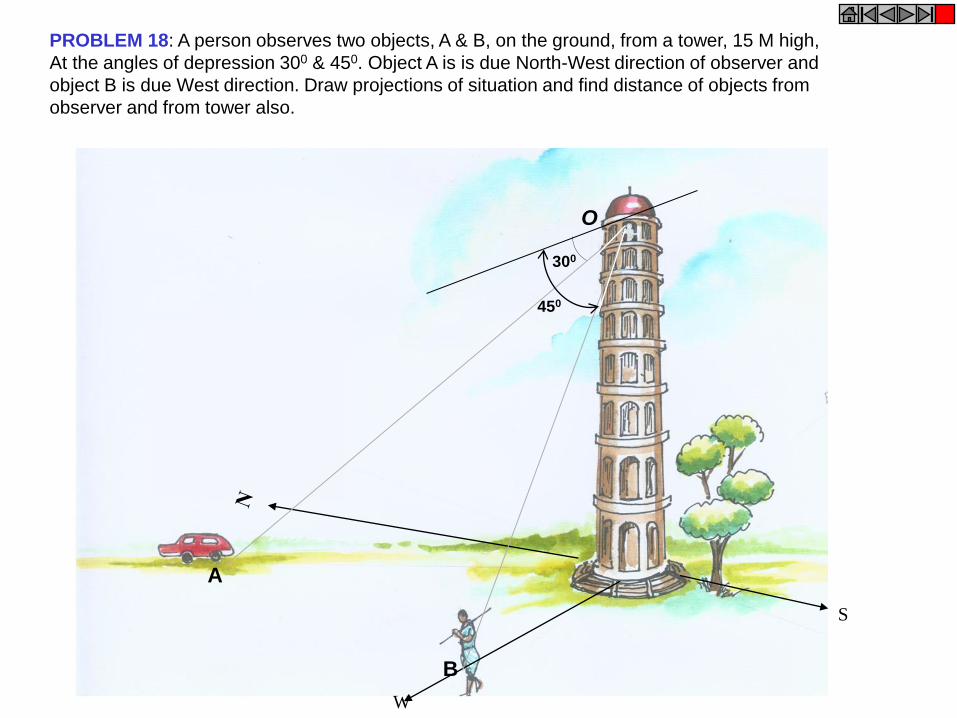
W
S
PROBLEM 18: A person observes two objects, A & B, on the ground, from a tower, 15 M high,
At the angles of depression 300 & 450. Object A is is due North-West direction of observer and
object B is due West direction. Draw projections of situation and find distance of objects from
observer and from tower also.
A
B
O
300
450
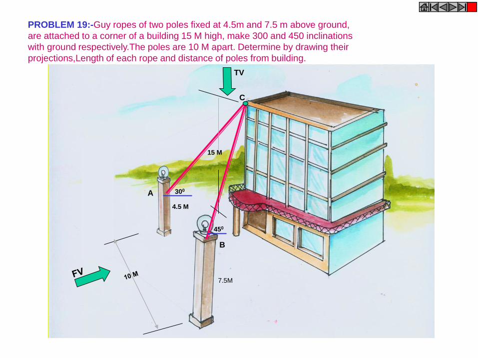
4.5 M
7.5M
300
450
15 M
TV
A
B
C
PROBLEM 19:-Guy ropes of two poles fixed at 4.5m and 7.5 m above ground,
are attached to a corner of a building 15 M high, make 300 and 450 inclinations
with ground respectively.The poles are 10 M apart. Determine by drawing their
projections,Length of each rope and distance of poles from building.
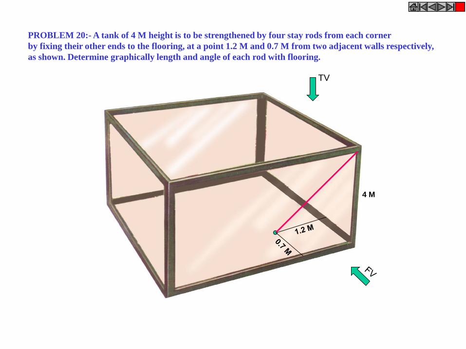
4 M
TV
PROBLEM 20:- A tank of 4 M height is to be strengthened by four stay rods from each corner
by fixing their other ends to the flooring, at a point 1.2 M and 0.7 M from two adjacent walls respectively,
as shown. Determine graphically length and angle of each rod with flooring.

A
B
C
D
Hook
TV
PROBLEM 21:- A horizontal wooden platform 2 M long and 1.5 M wide is supported by four chains
from it’s corners and chains are attached to a hook 5 M above the center of the platform.
Draw projections of the objects and determine length of each chain along with it’s inclination with ground.
H
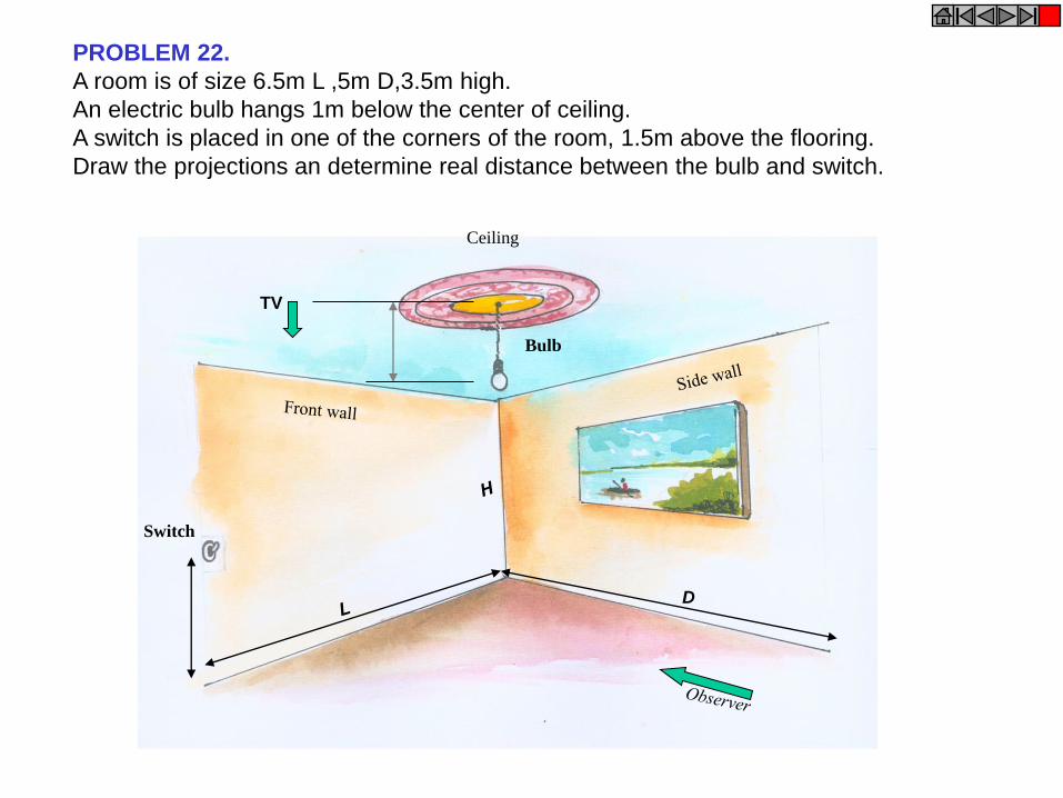
PROBLEM 22.
A room is of size 6.5m L ,5m D,3.5m high.
An electric bulb hangs 1m below the center of ceiling.
A switch is placed in one of the corners of the room, 1.5m above the flooring.
Draw the projections an determine real distance between the bulb and switch.
Switch
Bulb
Ceiling
TV
D
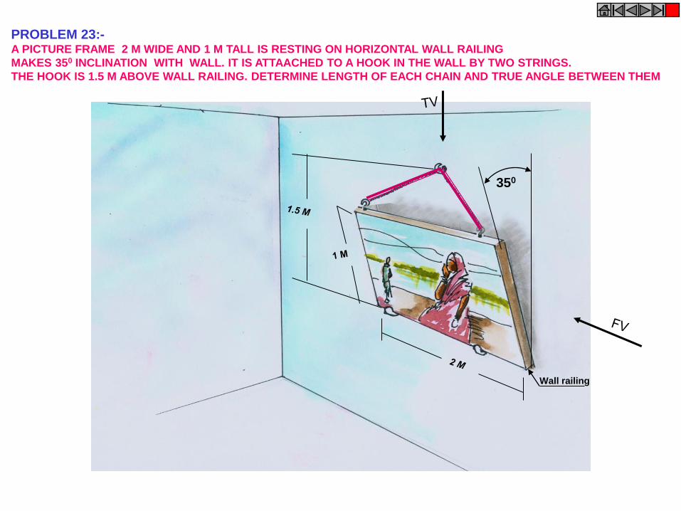
PROBLEM 23:- A PICTURE FRAME 2 M WIDE AND 1 M TALL IS RESTING ON HORIZONTAL WALL RAILING
MAKES 350 INCLINATION WITH WALL. IT IS ATTAACHED TO A HOOK IN THE WALL BY TWO STRINGS.
THE HOOK IS 1.5 M ABOVE WALL RAILING. DETERMINE LENGTH OF EACH CHAIN AND TRUE ANGLE BETWEEN THEM
350
Wall railing
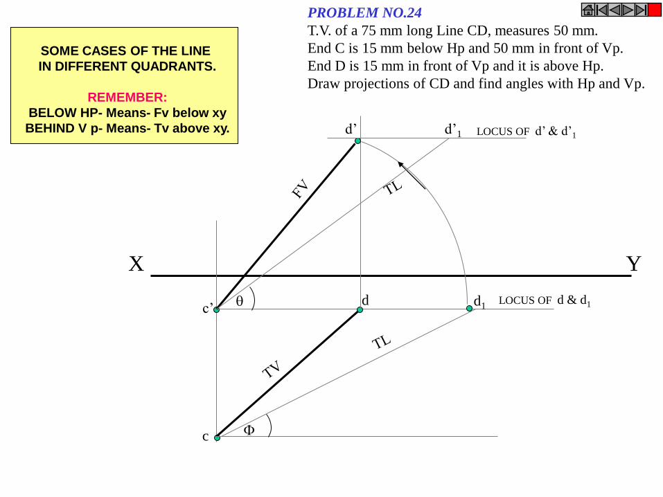
X Y
c’
c
LOCUS OF d & d1 d d1
d’ d’1
LOCUS OF d’ & d’1
PROBLEM NO.24
T.V. of a 75 mm long Line CD, measures 50 mm.
End C is 15 mm below Hp and 50 mm in front of Vp.
End D is 15 mm in front of Vp and it is above Hp.
Draw projections of CD and find angles with Hp and Vp.
SOME CASES OF THE LINE
IN DIFFERENT QUADRANTS.
REMEMBER:
BELOW HP- Means- Fv below xy
BEHIND V p- Means- Tv above xy.
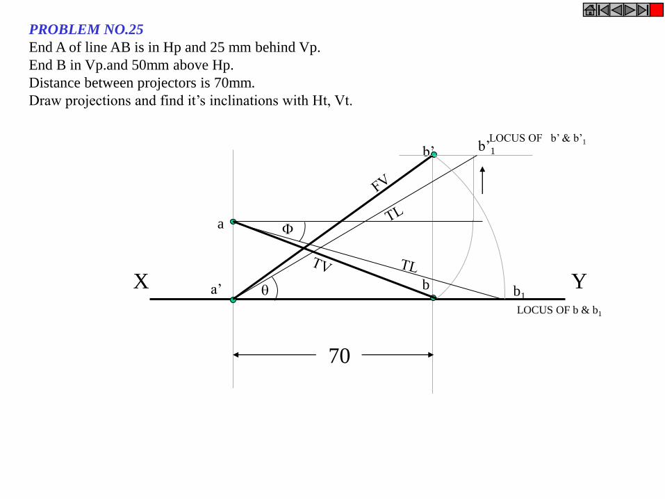
X Y
a
a’ b
b’ LOCUS OF b’ & b’1
LOCUS OF b & b1
b’1
b1
70
PROBLEM NO.25
End A of line AB is in Hp and 25 mm behind Vp.
End B in Vp.and 50mm above Hp.
Distance between projectors is 70mm.
Draw projections and find it’s inclinations with Ht, Vt.
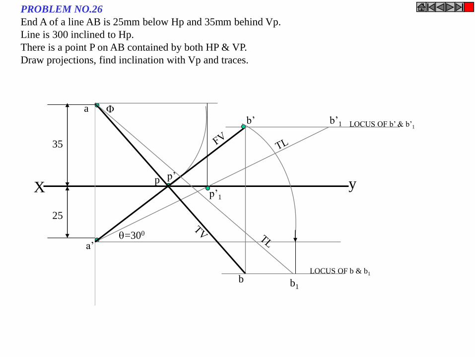
X y
a b’1
=300
p’1
a’
p’
b’
b b1
LOCUS OF b’ & b’1
LOCUS OF b & b1
p
35
25
PROBLEM NO.26
End A of a line AB is 25mm below Hp and 35mm behind Vp.
Line is 300 inclined to Hp.
There is a point P on AB contained by both HP & VP.
Draw projections, find inclination with Vp and traces.
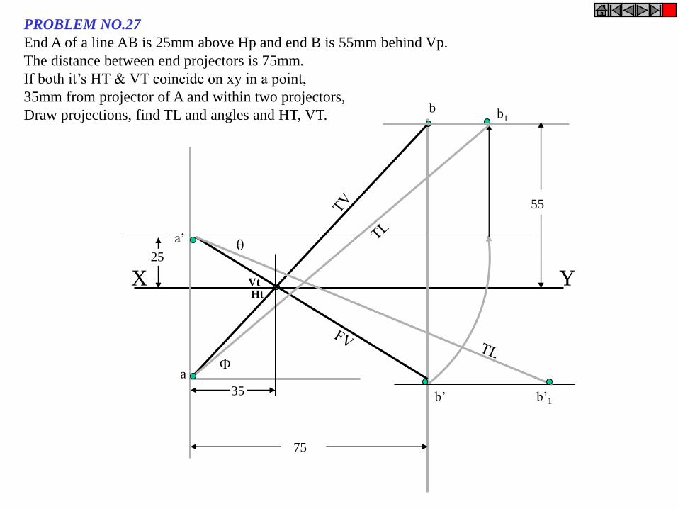
a’
b’
a
b
b’1
b1
75
35
Ht Vt X Y
25
55
PROBLEM NO.27
End A of a line AB is 25mm above Hp and end B is 55mm behind Vp.
The distance between end projectors is 75mm.
If both it’s HT & VT coincide on xy in a point,
35mm from projector of A and within two projectors,
Draw projections, find TL and angles and HT, VT.

PROJECTIONS OF PLANES
In this topic various plane figures are the objects.
What will be given in the problem?
1. Description of the plane figure.
2. It’s position with HP and VP.
In which manner it’s position with HP & VP will be described?
1.Inclination of it’s SURFACE with one of the reference planes will be given.
2. Inclination of one of it’s EDGES with other reference plane will be given
(Hence this will be a case of an object inclined to both reference Planes.)
To draw their projections means F.V, T.V. & S.V.
What is usually asked in the problem?
Study the illustration showing
surface & side inclination given on next page.
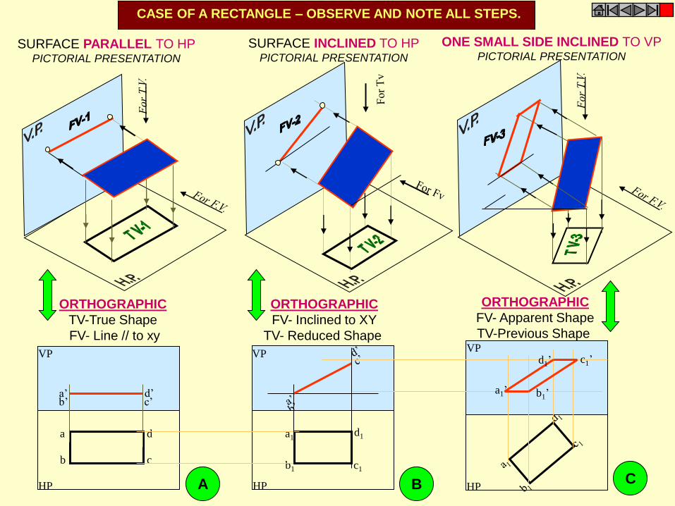
HP
VP VP VP
a’ d’ c’ b’
HP
a
b c
d
a1’
d1’ c1’
b1’
HP
a1
b1 c1
d1
CASE OF A RECTANGLE – OBSERVE AND NOTE ALL STEPS.
SURFACE PARALLEL TO HP PICTORIAL PRESENTATION
SURFACE INCLINED TO HP PICTORIAL PRESENTATION
ONE SMALL SIDE INCLINED TO VP PICTORIAL PRESENTATION
ORTHOGRAPHIC
TV-True Shape
FV- Line // to xy
ORTHOGRAPHIC
FV- Inclined to XY
TV- Reduced Shape
ORTHOGRAPHIC
FV- Apparent Shape
TV-Previous Shape
A B C
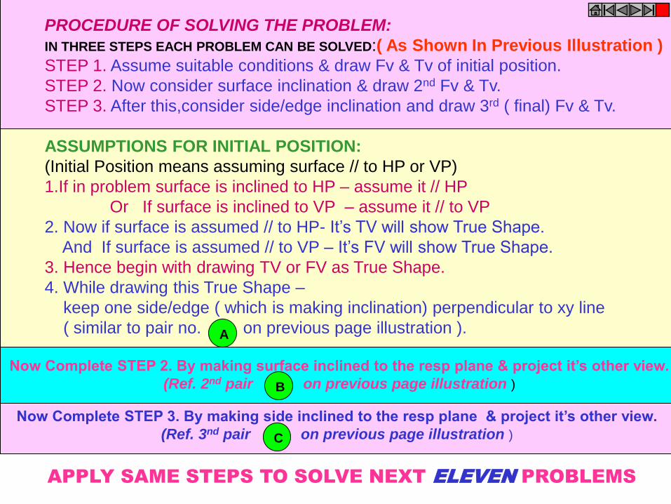
PROCEDURE OF SOLVING THE PROBLEM:
IN THREE STEPS EACH PROBLEM CAN BE SOLVED:( As Shown In Previous Illustration )
STEP 1. Assume suitable conditions & draw Fv & Tv of initial position.
STEP 2. Now consider surface inclination & draw 2nd Fv & Tv.
STEP 3. After this,consider side/edge inclination and draw 3rd ( final) Fv & Tv.
ASSUMPTIONS FOR INITIAL POSITION:
(Initial Position means assuming surface // to HP or VP)
1.If in problem surface is inclined to HP – assume it // HP
Or If surface is inclined to VP – assume it // to VP
2. Now if surface is assumed // to HP- It’s TV will show True Shape.
And If surface is assumed // to VP – It’s FV will show True Shape.
3. Hence begin with drawing TV or FV as True Shape.
4. While drawing this True Shape –
keep one side/edge ( which is making inclination) perpendicular to xy line
( similar to pair no. on previous page illustration ).
A
B
Now Complete STEP 2. By making surface inclined to the resp plane & project it’s other view.
(Ref. 2nd pair on previous page illustration )
C
Now Complete STEP 3. By making side inclined to the resp plane & project it’s other view.
(Ref. 3nd pair on previous page illustration )
APPLY SAME STEPS TO SOLVE NEXT ELEVEN PROBLEMS
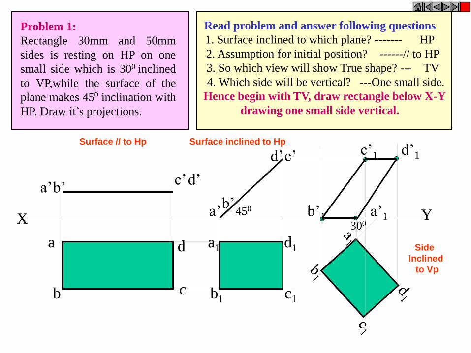
X Y
a
b c
d
a’ b’
c’ d’
a1
b1 c1
d1
a’ b’
d’ c’ c’1 d’1
b’1 a’1 450
300
Problem 1:
Rectangle 30mm and 50mm
sides is resting on HP on one
small side which is 300 inclined
to VP,while the surface of the
plane makes 450 inclination with
HP. Draw it’s projections.
Read problem and answer following questions
1. Surface inclined to which plane? ------- HP
2. Assumption for initial position? ------// to HP
3. So which view will show True shape? --- TV
4. Which side will be vertical? ---One small side.
Hence begin with TV, draw rectangle below X-Y
drawing one small side vertical.
Surface // to Hp Surface inclined to Hp
Side
Inclined
to Vp

Problem 2:
A 300 – 600 set square of longest side
100 mm long, is in VP and 300 inclined
to HP while it’s surface is 450 inclined
to VP.Draw it’s projections
(Surface & Side inclinations directly given)
Read problem and answer following questions
1 .Surface inclined to which plane? ------- VP
2. Assumption for initial position? ------// to VP
3. So which view will show True shape? --- FV
4. Which side will be vertical? ------longest side.
c1
X Y 300
450
a’1
b’1
c’1
a
c
a’
a b1
b’
b
a1 b
c
a’1
b’1
c’1
c’
Hence begin with FV, draw triangle above X-Y
keeping longest side vertical.
Surface // to Vp Surface inclined to Vp
side inclined to Hp
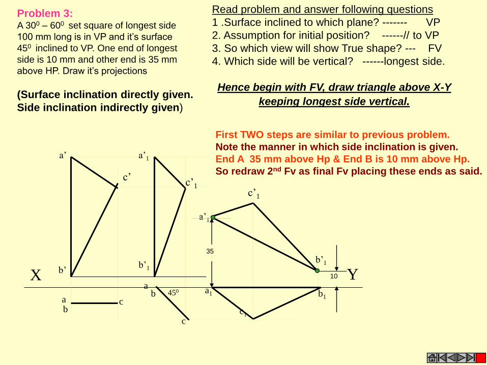
c c1
X Y 450
a’1
b’1
c’1
a
c
a’
a b1
b’
b
a1 b
a’1
b’1
c’1
c’
35
10
Problem 3: A 300 – 600 set square of longest side
100 mm long is in VP and it’s surface
450 inclined to VP. One end of longest
side is 10 mm and other end is 35 mm
above HP. Draw it’s projections
(Surface inclination directly given.
Side inclination indirectly given)
Read problem and answer following questions
1 .Surface inclined to which plane? ------- VP
2. Assumption for initial position? ------// to VP
3. So which view will show True shape? --- FV
4. Which side will be vertical? ------longest side.
Hence begin with FV, draw triangle above X-Y
keeping longest side vertical.
First TWO steps are similar to previous problem.
Note the manner in which side inclination is given.
End A 35 mm above Hp & End B is 10 mm above Hp.
So redraw 2nd Fv as final Fv placing these ends as said.
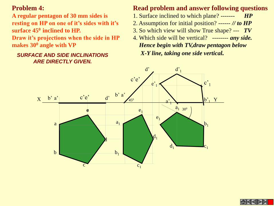
Read problem and answer following questions 1. Surface inclined to which plane? ------- HP
2. Assumption for initial position? ------ // to HP
3. So which view will show True shape? --- TV
4. Which side will be vertical? -------- any side.
Hence begin with TV,draw pentagon below
X-Y line, taking one side vertical.
Problem 4: A regular pentagon of 30 mm sides is
resting on HP on one of it’s sides with it’s
surface 450 inclined to HP.
Draw it’s projections when the side in HP
makes 300 angle with VP
a’ b’ d’
b1
d
c1
a
c’e’
b
c
d1
b’1
a1
e’1 c’1
d’1
a1
b1
c1 d1
d’
a’ b’
c’e’
e1
e1
a’1 X Y 450
300 e
SURFACE AND SIDE INCLINATIONS
ARE DIRECTLY GIVEN.
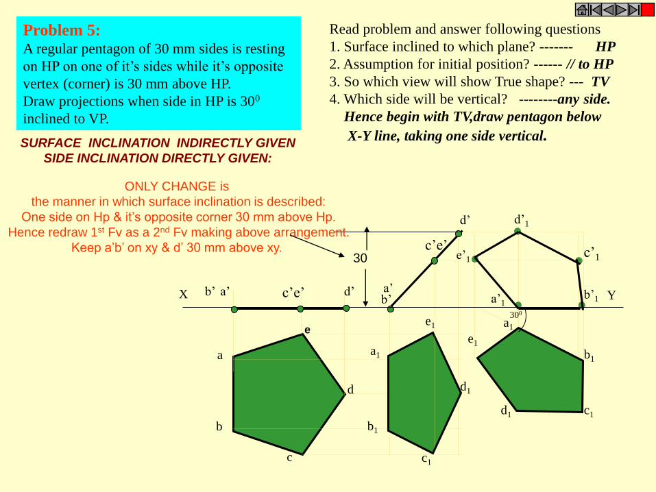
Problem 5: A regular pentagon of 30 mm sides is resting
on HP on one of it’s sides while it’s opposite
vertex (corner) is 30 mm above HP.
Draw projections when side in HP is 300
inclined to VP.
Read problem and answer following questions
1. Surface inclined to which plane? ------- HP
2. Assumption for initial position? ------ // to HP
3. So which view will show True shape? --- TV
4. Which side will be vertical? --------any side.
Hence begin with TV,draw pentagon below
X-Y line, taking one side vertical.
b’
d’
a’
c’e’
a1
b1
c1 d1
e1
b1
c1
d1
a1
e1
b’1
e’1 c’1
d’1
a’1 X Y a’ b’ d’ c’e’
30
a
b
c
d
e
300
SURFACE INCLINATION INDIRECTLY GIVEN
SIDE INCLINATION DIRECTLY GIVEN:
ONLY CHANGE is
the manner in which surface inclination is described:
One side on Hp & it’s opposite corner 30 mm above Hp.
Hence redraw 1st Fv as a 2nd Fv making above arrangement.
Keep a’b’ on xy & d’ 30 mm above xy.

a
d
c
b
a’ b’ d’ c’
X Y
a1
b1
d1
c1
450 300 a’1
b’1
c’1
d’1
a1
b1
d1
c1 a
d
c
b
a’ b’ d’ c’
300
a’1
b’1
c’1
d’1
Problem 8: A circle of 50 mm diameter is
resting on Hp on end A of it’s diameter AC
which is 300 inclined to Hp while it’s Tv
is 450 inclined to Vp.Draw it’s projections.
Problem 9: A circle of 50 mm diameter is
resting on Hp on end A of it’s diameter AC
which is 300 inclined to Hp while it makes
450 inclined to Vp. Draw it’s projections.
Read problem and answer following questions
1. Surface inclined to which plane? ------- HP
2. Assumption for initial position? ------ // to HP
3. So which view will show True shape? --- TV
4. Which diameter horizontal? ---------- AC
Hence begin with TV,draw rhombus below
X-Y line, taking longer diagonal // to X-Y
The difference in these two problems is in step 3 only.
In problem no.8 inclination of Tv of that AC is
given,It could be drawn directly as shown in 3rd step.
While in no.9 angle of AC itself i.e. it’s TL, is
given. Hence here angle of TL is taken,locus of c1
Is drawn and then LTV I.e. a1 c1 is marked and
final TV was completed.Study illustration carefully.
Note the difference in
construction of 3rd step
in both solutions.

Problem 10: End A of diameter AB of a circle is in HP
A nd end B is in VP.Diameter AB, 50 mm long is
300 & 600 inclined to HP & VP respectively.
Draw projections of circle.
The problem is similar to previous problem of circle – no.9.
But in the 3rd step there is one more change.
Like 9th problem True Length inclination of dia.AB is definitely expected
but if you carefully note - the the SUM of it’s inclinations with HP & VP is 900.
Means Line AB lies in a Profile Plane.
Hence it’s both Tv & Fv must arrive on one single projector.
So do the construction accordingly AND note the case carefully..
SOLVE SEPARATELY
ON DRAWING SHEET
GIVING NAMES TO VARIOUS
POINTS AS USUAL,
AS THE CASE IS IMPORTANT
X Y 300
600
Read problem and answer following questions
1. Surface inclined to which plane? ------- HP
2. Assumption for initial position? ------ // to HP
3. So which view will show True shape? --- TV
4. Which diameter horizontal? ---------- AB
Hence begin with TV,draw CIRCLE below
X-Y line, taking DIA. AB // to X-Y
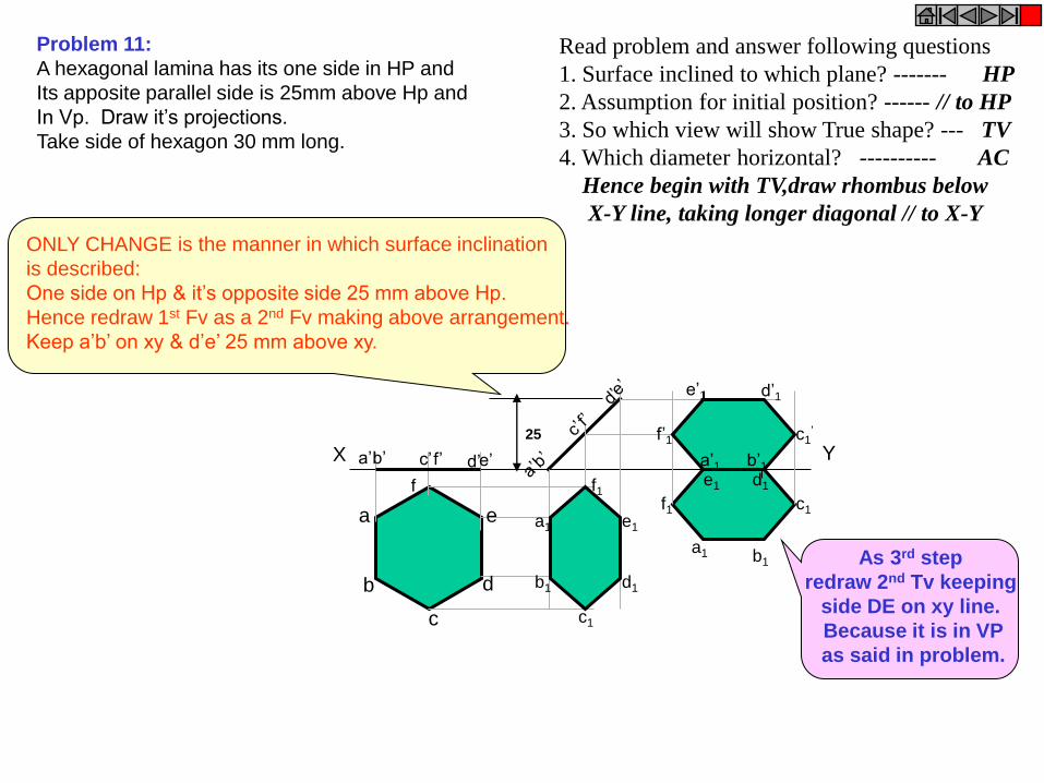
As 3rd step
redraw 2nd Tv keeping
side DE on xy line.
Because it is in VP
as said in problem.
X Y
a
b
c
d
e
f
Problem 11:
A hexagonal lamina has its one side in HP and
Its apposite parallel side is 25mm above Hp and
In Vp. Draw it’s projections.
Take side of hexagon 30 mm long.
ONLY CHANGE is the manner in which surface inclination
is described:
One side on Hp & it’s opposite side 25 mm above Hp.
Hence redraw 1st Fv as a 2nd Fv making above arrangement.
Keep a’b’ on xy & d’e’ 25 mm above xy.
25
f’ e’ d’ c’ b’ a’
a1
b1
c1
d1
e1
f1
c1’
b’1 a’1
f’1
d’1 e’1
f1
a1
c1
b1
d1 e1
Read problem and answer following questions
1. Surface inclined to which plane? ------- HP
2. Assumption for initial position? ------ // to HP
3. So which view will show True shape? --- TV
4. Which diameter horizontal? ---------- AC
Hence begin with TV,draw rhombus below
X-Y line, taking longer diagonal // to X-Y

A B
C
H
H/3
G
X Y
a’
b’
c’
g’
b a,g c 450
a’1
c’1
b’1 g’1
FREELY SUSPENDED CASES.
1.In this case the plane of the figure always remains perpendicular to Hp.
2.It may remain parallel or inclined to Vp.
3.Hence TV in this case will be always a LINE view.
4.Assuming surface // to Vp, draw true shape in suspended position as FV.
(Here keep line joining point of contact & centroid of fig. vertical )
5.Always begin with FV as a True Shape but in a suspended position.
AS shown in 1st FV.
IMPORTANT POINTS
Problem 12:
An isosceles triangle of 40 mm long
base side, 60 mm long altitude Is
freely suspended from one corner of
Base side.It’s plane is 450 inclined to
Vp. Draw it’s projections.
Similarly solve next problem
of Semi-circle
First draw a given triangle
With given dimensions,
Locate it’s centroid position
And
join it with point of suspension.

G
A
P
20 mm
CG
X Y
e’
c’
d’
b’
a’
p’
g’
b c a p,g d e
Problem 13
:A semicircle of 100 mm diameter
is suspended from a point on its
straight edge 30 mm from the midpoint
of that edge so that the surface makes
an angle of 450 with VP.
Draw its projections.
First draw a given semicircle
With given diameter,
Locate it’s centroid position
And
join it with point of suspension.
1.In this case the plane of the figure always remains perpendicular to Hp.
2.It may remain parallel or inclined to Vp.
3.Hence TV in this case will be always a LINE view.
4.Assuming surface // to Vp, draw true shape in suspended position as FV.
(Here keep line joining point of contact & centroid of fig. vertical )
5.Always begin with FV as a True Shape but in a suspended position.
AS shown in 1st FV.
IMPORTANT POINTS
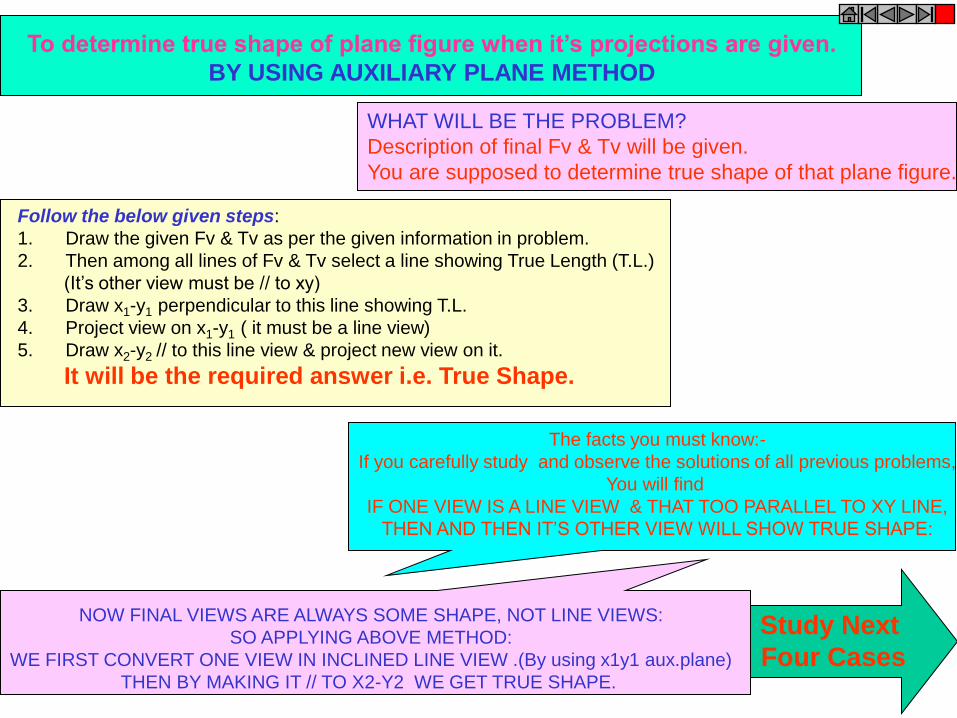
To determine true shape of plane figure when it’s projections are given.
BY USING AUXILIARY PLANE METHOD
WHAT WILL BE THE PROBLEM?
Description of final Fv & Tv will be given.
You are supposed to determine true shape of that plane figure.
Follow the below given steps:
1. Draw the given Fv & Tv as per the given information in problem.
2. Then among all lines of Fv & Tv select a line showing True Length (T.L.)
(It’s other view must be // to xy)
3. Draw x1-y1 perpendicular to this line showing T.L.
4. Project view on x1-y1 ( it must be a line view)
5. Draw x2-y2 // to this line view & project new view on it.
It will be the required answer i.e. True Shape.
The facts you must know:-
If you carefully study and observe the solutions of all previous problems,
You will find
IF ONE VIEW IS A LINE VIEW & THAT TOO PARALLEL TO XY LINE,
THEN AND THEN IT’S OTHER VIEW WILL SHOW TRUE SHAPE:
NOW FINAL VIEWS ARE ALWAYS SOME SHAPE, NOT LINE VIEWS:
SO APPLYING ABOVE METHOD:
WE FIRST CONVERT ONE VIEW IN INCLINED LINE VIEW .(By using x1y1 aux.plane)
THEN BY MAKING IT // TO X2-Y2 WE GET TRUE SHAPE.
Study Next
Four Cases
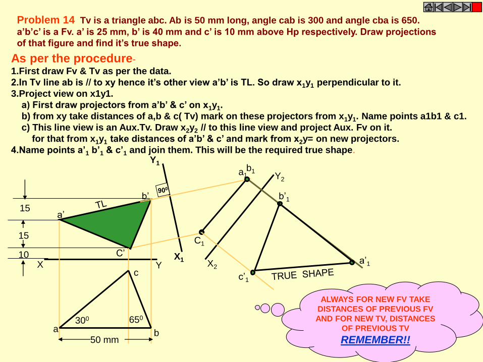
X Y
a
c
b
C’
b’
a’
10
15
15
X1
Y1
C1
b1 a1
a’1
b’1
c’1
X2
Y2
Problem 14 Tv is a triangle abc. Ab is 50 mm long, angle cab is 300 and angle cba is 650.
a’b’c’ is a Fv. a’ is 25 mm, b’ is 40 mm and c’ is 10 mm above Hp respectively. Draw projections
of that figure and find it’s true shape.
300 650
50 mm
As per the procedure-
1.First draw Fv & Tv as per the data.
2.In Tv line ab is // to xy hence it’s other view a’b’ is TL. So draw x1y1 perpendicular to it.
3.Project view on x1y1.
a) First draw projectors from a’b’ & c’ on x1y1.
b) from xy take distances of a,b & c( Tv) mark on these projectors from x1y1. Name points a1b1 & c1.
c) This line view is an Aux.Tv. Draw x2y2 // to this line view and project Aux. Fv on it.
for that from x1y1 take distances of a’b’ & c’ and mark from x2y= on new projectors.
4.Name points a’1 b’1 & c’1 and join them. This will be the required true shape.
ALWAYS FOR NEW FV TAKE
DISTANCES OF PREVIOUS FV
AND FOR NEW TV, DISTANCES
OF PREVIOUS TV
REMEMBER!!
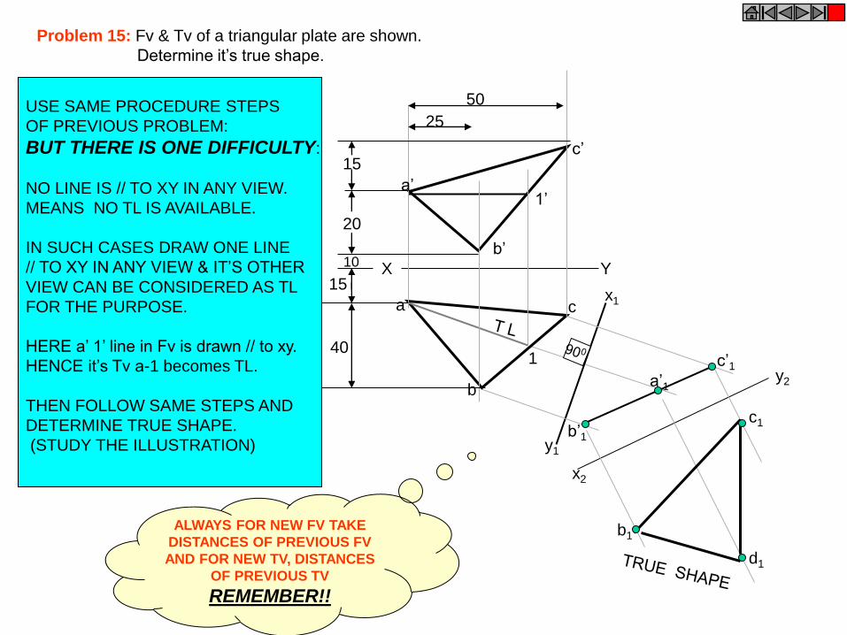
x1
y1
c’1
b’1
a’1
x2
y2
b1
c1
d1
c’
X Y
a’
b’
b
c a
10
20
15
15
1’
1 40
50
25
Problem 15: Fv & Tv of a triangular plate are shown.
Determine it’s true shape.
USE SAME PROCEDURE STEPS
OF PREVIOUS PROBLEM:
BUT THERE IS ONE DIFFICULTY:
NO LINE IS // TO XY IN ANY VIEW.
MEANS NO TL IS AVAILABLE.
IN SUCH CASES DRAW ONE LINE
// TO XY IN ANY VIEW & IT’S OTHER
VIEW CAN BE CONSIDERED AS TL
FOR THE PURPOSE.
HERE a’ 1’ line in Fv is drawn // to xy.
HENCE it’s Tv a-1 becomes TL.
THEN FOLLOW SAME STEPS AND
DETERMINE TRUE SHAPE.
(STUDY THE ILLUSTRATION)
ALWAYS FOR NEW FV TAKE
DISTANCES OF PREVIOUS FV
AND FOR NEW TV, DISTANCES
OF PREVIOUS TV
REMEMBER!!
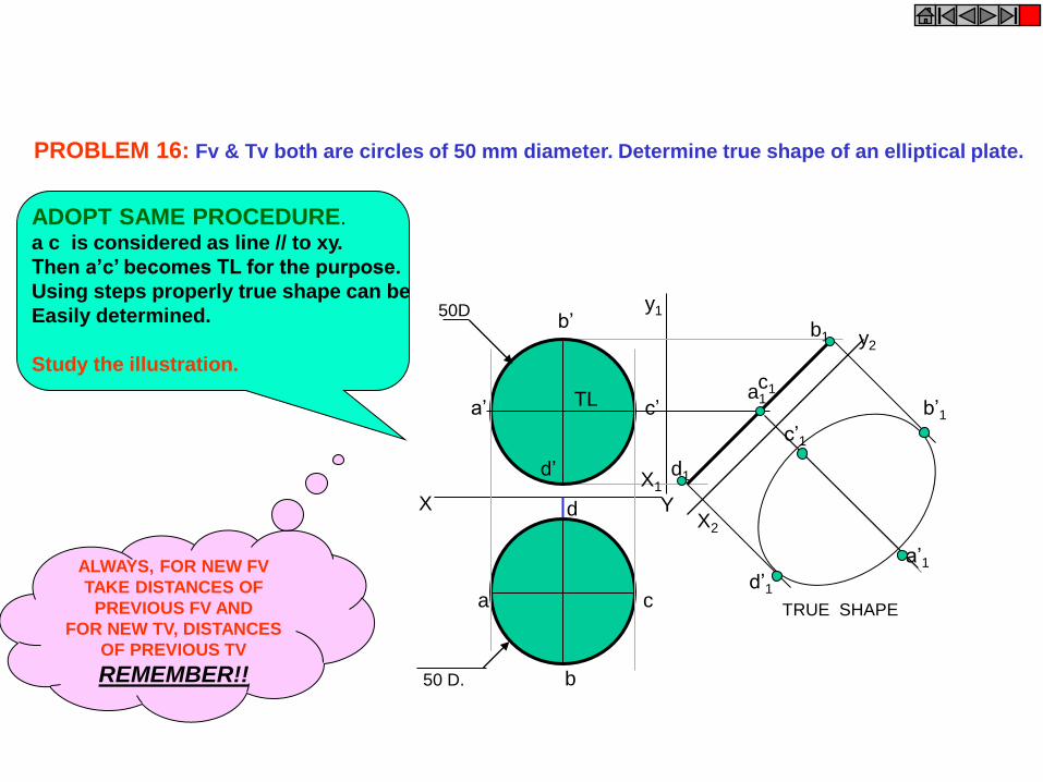
y1
X2
X1
a1 c1
d1
b1
c’1
d’1
b’1
a’1
y2
TRUE SHAPE a
b
c
d Y X
a’
d’
c’
b’
50 D.
50D
TL
PROBLEM 16: Fv & Tv both are circles of 50 mm diameter. Determine true shape of an elliptical plate.
ADOPT SAME PROCEDURE.
a c is considered as line // to xy.
Then a’c’ becomes TL for the purpose.
Using steps properly true shape can be
Easily determined.
Study the illustration.
ALWAYS, FOR NEW FV
TAKE DISTANCES OF
PREVIOUS FV AND
FOR NEW TV, DISTANCES
OF PREVIOUS TV
REMEMBER!!

a
b c
d
e
a’
b’
e’
c’ d’
a1
b1
e1 d1
c1
300 X Y
X1
Y1
450
Problem 17 : Draw a regular pentagon of
30 mm sides with one side 300 inclined to xy.
This figure is Tv of some plane whose Fv is
A line 450 inclined to xy.
Determine it’s true shape.
IN THIS CASE ALSO TRUE LENGTH
IS NOT AVAILABLE IN ANY VIEW.
BUT ACTUALLY WE DONOT REQUIRE
TL TO FIND IT’S TRUE SHAPE, AS ONE
VIEW (FV) IS ALREADY A LINE VIEW.
SO JUST BY DRAWING X1Y1 // TO THIS
VIEW WE CAN PROJECT VIEW ON IT
AND GET TRUE SHAPE:
STUDY THE ILLUSTRATION..
ALWAYS FOR NEW FV
TAKE DISTANCES OF
PREVIOUS FV AND FOR
NEW TV, DISTANCES OF
PREVIOUS TV
REMEMBER!!

SOLIDS Dimensional parameters of different solids.
Top
Rectangular
Face
Longer
Edge
Base
Edge
of
Base
Corner of
base
Corner of
base
Triangular
Face
Slant
Edge
Base
Apex
Square Prism Square Pyramid Cylinder Cone
Edge
of
Base
Base
Apex
Base
Generators
Imaginary lines
generating curved surface
of cylinder & cone.
Sections of solids( top & base not parallel) Frustum of cone & pyramids.
( top & base parallel to each other)
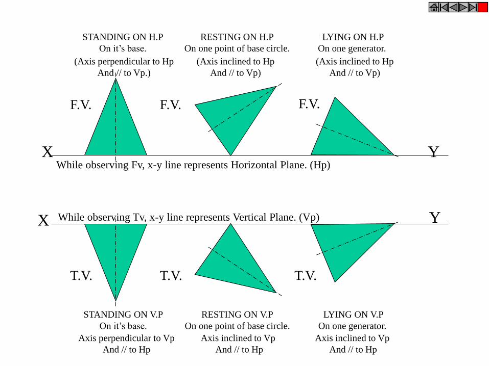
X Y
STANDING ON H.P
On it’s base.
RESTING ON H.P
On one point of base circle.
LYING ON H.P
On one generator.
(Axis perpendicular to Hp
And // to Vp.)
(Axis inclined to Hp
And // to Vp)
(Axis inclined to Hp
And // to Vp)
While observing Fv, x-y line represents Horizontal Plane. (Hp)
Axis perpendicular to Vp
And // to Hp
Axis inclined to Vp
And // to Hp
Axis inclined to Vp
And // to Hp
X Y
F.V. F.V. F.V.
T.V. T.V. T.V.
While observing Tv, x-y line represents Vertical Plane. (Vp)
STANDING ON V.P
On it’s base.
RESTING ON V.P
On one point of base circle.
LYING ON V.P
On one generator.
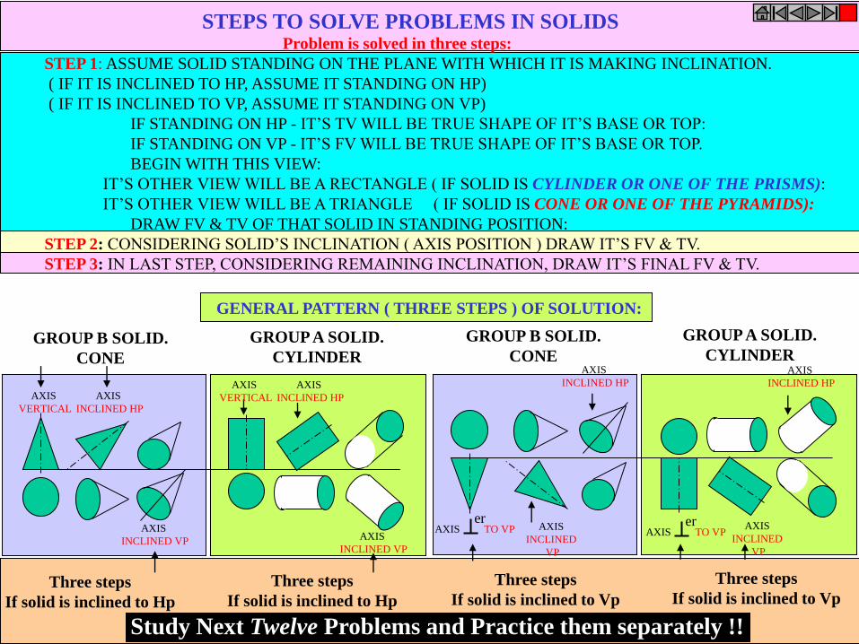
STEPS TO SOLVE PROBLEMS IN SOLIDS Problem is solved in three steps:
STEP 1: ASSUME SOLID STANDING ON THE PLANE WITH WHICH IT IS MAKING INCLINATION.
( IF IT IS INCLINED TO HP, ASSUME IT STANDING ON HP)
( IF IT IS INCLINED TO VP, ASSUME IT STANDING ON VP)
IF STANDING ON HP - IT’S TV WILL BE TRUE SHAPE OF IT’S BASE OR TOP:
IF STANDING ON VP - IT’S FV WILL BE TRUE SHAPE OF IT’S BASE OR TOP.
BEGIN WITH THIS VIEW:
IT’S OTHER VIEW WILL BE A RECTANGLE ( IF SOLID IS CYLINDER OR ONE OF THE PRISMS):
IT’S OTHER VIEW WILL BE A TRIANGLE ( IF SOLID IS CONE OR ONE OF THE PYRAMIDS):
DRAW FV & TV OF THAT SOLID IN STANDING POSITION:
STEP 2: CONSIDERING SOLID’S INCLINATION ( AXIS POSITION ) DRAW IT’S FV & TV.
STEP 3: IN LAST STEP, CONSIDERING REMAINING INCLINATION, DRAW IT’S FINAL FV & TV.
AXIS
VERTICAL
AXIS
INCLINED HP
AXIS
INCLINED VP
AXIS
VERTICAL
AXIS
INCLINED HP
AXIS
INCLINED VP
AXIS TO VP er
AXIS
INCLINED
VP
AXIS
INCLINED HP
AXIS TO VP er AXIS
INCLINED
VP
AXIS
INCLINED HP
GENERAL PATTERN ( THREE STEPS ) OF SOLUTION:
GROUP B SOLID.
CONE
GROUP A SOLID.
CYLINDER
GROUP B SOLID.
CONE
GROUP A SOLID.
CYLINDER
Three steps
If solid is inclined to Hp
Three steps
If solid is inclined to Hp
Three steps
If solid is inclined to Vp
Study Next Twelve Problems and Practice them separately !!
Three steps
If solid is inclined to Vp

PROBLEM NO.1, 2, 3, 4 GENERAL CASES OF SOLIDS INCLINED TO HP & VP
PROBLEM NO. 5 & 6 CASES OF CUBE & TETRAHEDRON
PROBLEM NO. 7 CASE OF FREELY SUSPENDED SOLID WITH SIDE VIEW.
PROBLEM NO. 8 CASE OF CUBE ( WITH SIDE VIEW)
PROBLEM NO. 9 CASE OF TRUE LENGTH INCLINATION WITH HP & VP.
PROBLEM NO. 10 & 11 CASES OF COMPOSITE SOLIDS. (AUXILIARY PLANE)
PROBLEM NO. 12 CASE OF A FRUSTUM (AUXILIARY PLANE)
CATEGORIES OF ILLUSTRATED PROBLEMS!
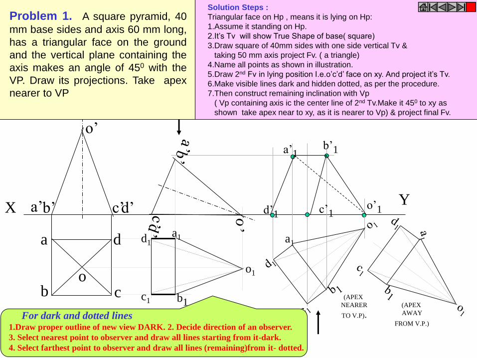
X Y
a
b c
d
o
o’
d’ c’ b’ a’
o1
d1
b1 c1
a1
a’1
d’1 c’1
b’1
o’1
a1
(APEX
NEARER
TO V.P).
(APEX
AWAY
FROM V.P.)
Problem 1. A square pyramid, 40
mm base sides and axis 60 mm long,
has a triangular face on the ground
and the vertical plane containing the
axis makes an angle of 450 with the
VP. Draw its projections. Take apex
nearer to VP
Solution Steps :
Triangular face on Hp , means it is lying on Hp:
1.Assume it standing on Hp.
2.It’s Tv will show True Shape of base( square)
3.Draw square of 40mm sides with one side vertical Tv &
taking 50 mm axis project Fv. ( a triangle)
4.Name all points as shown in illustration.
5.Draw 2nd Fv in lying position I.e.o’c’d’ face on xy. And project it’s Tv.
6.Make visible lines dark and hidden dotted, as per the procedure.
7.Then construct remaining inclination with Vp
( Vp containing axis ic the center line of 2nd Tv.Make it 450 to xy as
shown take apex near to xy, as it is nearer to Vp) & project final Fv.
For dark and dotted lines 1.Draw proper outline of new view DARK. 2. Decide direction of an observer.
3. Select nearest point to observer and draw all lines starting from it-dark.
4. Select farthest point to observer and draw all lines (remaining)from it- dotted.
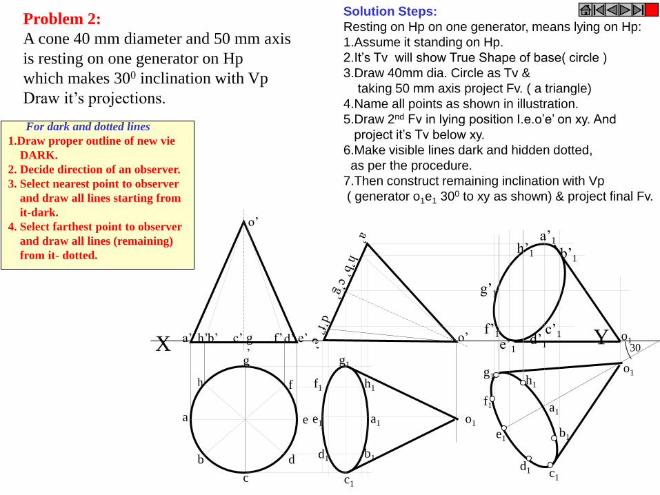
Problem 2:
A cone 40 mm diameter and 50 mm axis
is resting on one generator on Hp
which makes 300 inclination with Vp
Draw it’s projections.
h
a
b
c
d
e
g
f
X Y a’ b’ d’ e’ c’ g
’
f’ h’
o’
o’
a1
h1
g1
f1
e1
d1
c1
b1
a1
c1
b1
d1
e1
f1
g1 h1
o1
a’1
b’1
c’1 d’1 e’1
f’1
g’1
h’1
o1
o1
30
Solution Steps:
Resting on Hp on one generator, means lying on Hp:
1.Assume it standing on Hp.
2.It’s Tv will show True Shape of base( circle )
3.Draw 40mm dia. Circle as Tv &
taking 50 mm axis project Fv. ( a triangle)
4.Name all points as shown in illustration.
5.Draw 2nd Fv in lying position I.e.o’e’ on xy. And
project it’s Tv below xy.
6.Make visible lines dark and hidden dotted,
as per the procedure.
7.Then construct remaining inclination with Vp
( generator o1e1 300 to xy as shown) & project final Fv.
For dark and dotted lines
1.Draw proper outline of new vie
DARK.
2. Decide direction of an observer.
3. Select nearest point to observer
and draw all lines starting from
it-dark.
4. Select farthest point to observer
and draw all lines (remaining)
from it- dotted.
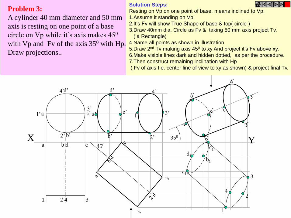
X Y a b d c
1 2 4 3
a’
b’
c’
d’
1’
2’
3’
4’
450
4’
3’
2’
1’
d’
c’
b’
a’
350
a1
b1
c1
d1
1
2
3
4
Problem 3:
A cylinder 40 mm diameter and 50 mm
axis is resting on one point of a base
circle on Vp while it’s axis makes 450
with Vp and Fv of the axis 350 with Hp.
Draw projections..
Solution Steps:
Resting on Vp on one point of base, means inclined to Vp:
1.Assume it standing on Vp
2.It’s Fv will show True Shape of base & top( circle )
3.Draw 40mm dia. Circle as Fv & taking 50 mm axis project Tv.
( a Rectangle)
4.Name all points as shown in illustration.
5.Draw 2nd Tv making axis 450 to xy And project it’s Fv above xy.
6.Make visible lines dark and hidden dotted, as per the procedure.
7.Then construct remaining inclination with Hp
( Fv of axis I.e. center line of view to xy as shown) & project final Tv.
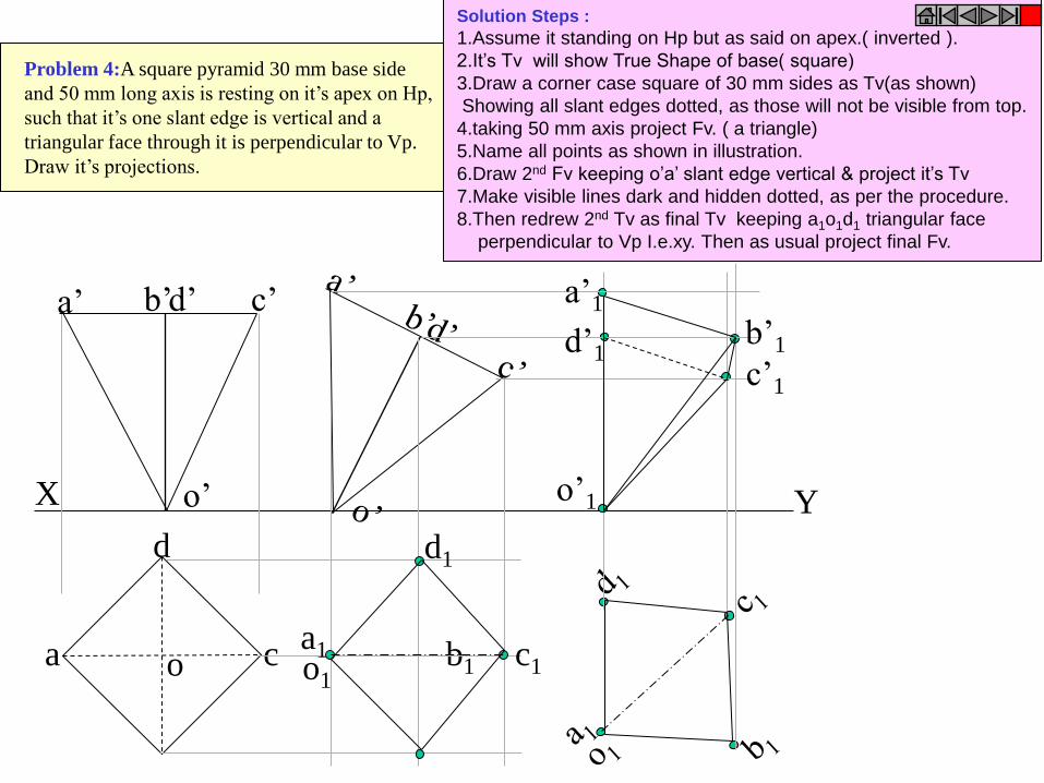
b b1
X Y
a
d
c o
d’ c’ b’ a’
o’
c1 a1
d1
o1
o’1
a’1
b’1
c’1
d’1
Problem 4:A square pyramid 30 mm base side
and 50 mm long axis is resting on it’s apex on Hp,
such that it’s one slant edge is vertical and a
triangular face through it is perpendicular to Vp.
Draw it’s projections.
Solution Steps :
1.Assume it standing on Hp but as said on apex.( inverted ).
2.It’s Tv will show True Shape of base( square)
3.Draw a corner case square of 30 mm sides as Tv(as shown)
Showing all slant edges dotted, as those will not be visible from top.
4.taking 50 mm axis project Fv. ( a triangle)
5.Name all points as shown in illustration.
6.Draw 2nd Fv keeping o’a’ slant edge vertical & project it’s Tv
7.Make visible lines dark and hidden dotted, as per the procedure.
8.Then redrew 2nd Tv as final Tv keeping a1o1d1 triangular face
perpendicular to Vp I.e.xy. Then as usual project final Fv.
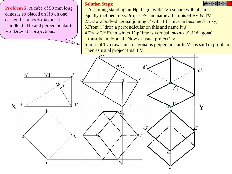
Problem 5: A cube of 50 mm long
edges is so placed on Hp on one
corner that a body diagonal is
parallel to Hp and perpendicular to
Vp Draw it’s projections.
X Y
b
c
d
a
a’ d’ c’ b’
a1
b1
d1
c1
1’
a’1
d’1
c’1
d’1
Solution Steps:
1.Assuming standing on Hp, begin with Tv,a square with all sides
equally inclined to xy.Project Fv and name all points of FV & TV.
2.Draw a body-diagonal joining c’ with 3’( This can become // to xy)
3.From 1’ drop a perpendicular on this and name it p’
4.Draw 2nd Fv in which 1’-p’ line is vertical means c’-3’ diagonal
must be horizontal. .Now as usual project Tv..
6.In final Tv draw same diagonal is perpendicular to Vp as said in problem.
Then as usual project final FV.
1’ 3’ 1’
3’
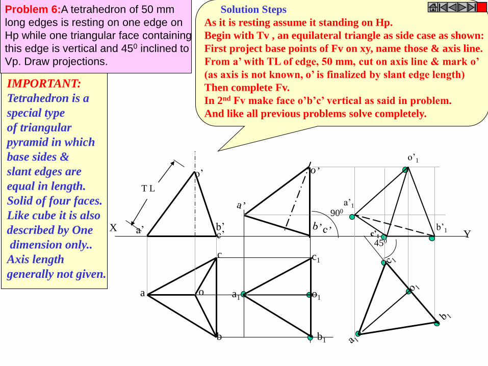
Y
Problem 6:A tetrahedron of 50 mm
long edges is resting on one edge on
Hp while one triangular face containing
this edge is vertical and 450 inclined to
Vp. Draw projections.
X
T L
a o
b
c
b’ a’ c’
o’
a1
c1
o1
b1
900
450 c’1
a’1
o’1
b’1
IMPORTANT:
Tetrahedron is a
special type
of triangular
pyramid in which
base sides &
slant edges are
equal in length.
Solid of four faces.
Like cube it is also
described by One
dimension only..
Axis length
generally not given.
Solution Steps
As it is resting assume it standing on Hp.
Begin with Tv , an equilateral triangle as side case as shown:
First project base points of Fv on xy, name those & axis line.
From a’ with TL of edge, 50 mm, cut on axis line & mark o’
(as axis is not known, o’ is finalized by slant edge length)
Then complete Fv.
In 2nd Fv make face o’b’c’ vertical as said in problem.
And like all previous problems solve completely.
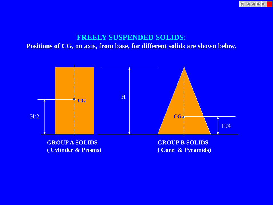
FREELY SUSPENDED SOLIDS: Positions of CG, on axis, from base, for different solids are shown below.
H
H/2
H/4
GROUP A SOLIDS
( Cylinder & Prisms)
GROUP B SOLIDS
( Cone & Pyramids)
CG
CG

X Y
a’ d’ e’ c’ b’
o’
a
b
c
d
e
o
g’
H/4
H
LINE d’g’ VERTICAL
a’ b’
c’
d’
o”
e’
g’
a1
b1
o1
e1
d1
c1
a”
e”
d”
c”
b”
FOR SIDE VIEW
Problem 7: A pentagonal pyramid
30 mm base sides & 60 mm long axis,
is freely suspended from one corner of
base so that a plane containing it’s axis
remains parallel to Vp.
Draw it’s three views.
IMPORTANT: When a solid is freely
suspended from a
corner, then line
joining point of
contact & C.G.
remains vertical.
( Here axis shows
inclination with Hp.)
So in all such cases,
assume solid standing
on Hp initially.)
Solution Steps: In all suspended cases axis shows inclination with Hp.
1.Hence assuming it standing on Hp, drew Tv - a regular pentagon,corner case.
2.Project Fv & locate CG position on axis – ( ¼ H from base.) and name g’ and
Join it with corner d’
3.As 2nd Fv, redraw first keeping line g’d’ vertical.
4.As usual project corresponding Tv and then Side View looking from.
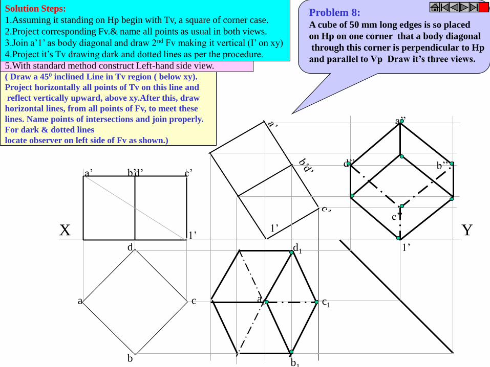
a’ d’ c’ b’
b
c
d
a a1
b1
d1
c1
d’’
c’’
a’’
b’’
X Y 1’ 1’
1’
Problem 8: A cube of 50 mm long edges is so placed
on Hp on one corner that a body diagonal
through this corner is perpendicular to Hp
and parallel to Vp Draw it’s three views.
Solution Steps:
1.Assuming it standing on Hp begin with Tv, a square of corner case.
2.Project corresponding Fv.& name all points as usual in both views.
3.Join a’1’ as body diagonal and draw 2nd Fv making it vertical (I’ on xy)
4.Project it’s Tv drawing dark and dotted lines as per the procedure.
5.With standard method construct Left-hand side view. ( Draw a 450 inclined Line in Tv region ( below xy).
Project horizontally all points of Tv on this line and
reflect vertically upward, above xy.After this, draw
horizontal lines, from all points of Fv, to meet these
lines. Name points of intersections and join properly.
For dark & dotted lines
locate observer on left side of Fv as shown.)
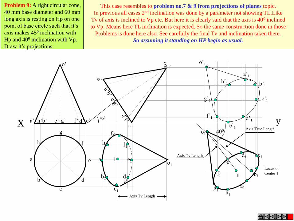
1
400
Axis Tv Length
Axis Tv Length
Axis True Length
Locus of
Center 1
c’1
a’1
b’1
e’1
d’1
h’1
f’1
g’1
o’1
h
a
b
c
d
e
g
f
y X a’ b’ d’ e’ c’ g’ f’ h’
o’
450
a1
h1 f1
e1
d1
c1
b1
g1
o1
1
Problem 9: A right circular cone,
40 mm base diameter and 60 mm
long axis is resting on Hp on one
point of base circle such that it’s
axis makes 450 inclination with
Hp and 400 inclination with Vp.
Draw it’s projections.
This case resembles to problem no.7 & 9 from projections of planes topic.
In previous all cases 2nd inclination was done by a parameter not showing TL.Like
Tv of axis is inclined to Vp etc. But here it is clearly said that the axis is 400 inclined
to Vp. Means here TL inclination is expected. So the same construction done in those
Problems is done here also. See carefully the final Tv and inclination taken there.
So assuming it standing on HP begin as usual.
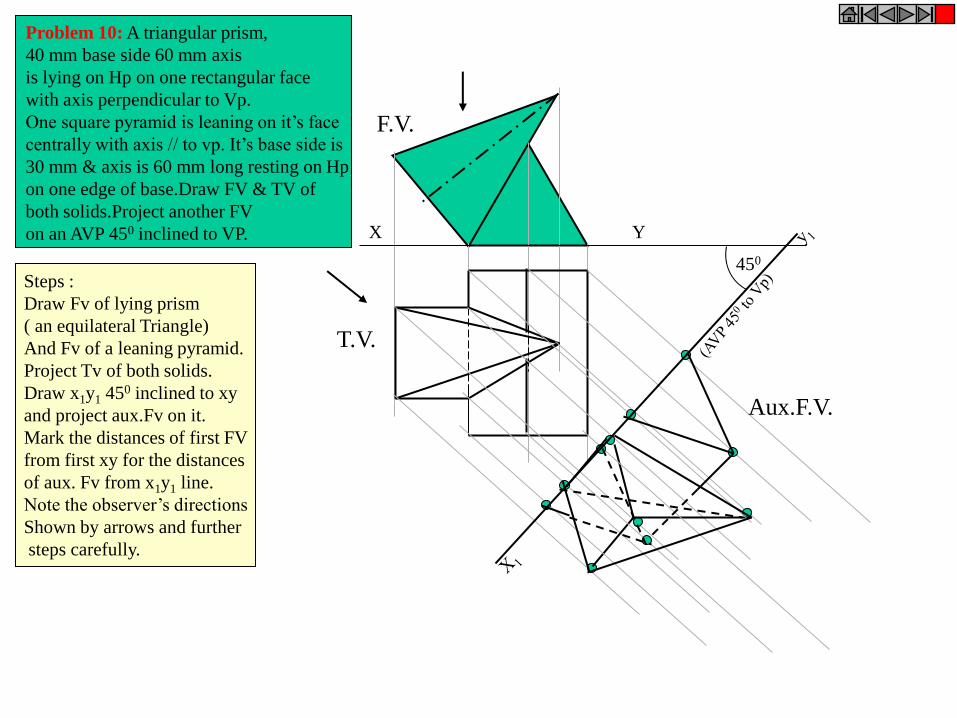
450
F.V.
T.V.
Aux.F.V.
X Y
Problem 10: A triangular prism,
40 mm base side 60 mm axis
is lying on Hp on one rectangular face
with axis perpendicular to Vp.
One square pyramid is leaning on it’s face
centrally with axis // to vp. It’s base side is
30 mm & axis is 60 mm long resting on Hp
on one edge of base.Draw FV & TV of
both solids.Project another FV
on an AVP 450 inclined to VP.
Steps :
Draw Fv of lying prism
( an equilateral Triangle)
And Fv of a leaning pyramid.
Project Tv of both solids.
Draw x1y1 450 inclined to xy
and project aux.Fv on it.
Mark the distances of first FV
from first xy for the distances
of aux. Fv from x1y1 line.
Note the observer’s directions
Shown by arrows and further
steps carefully.
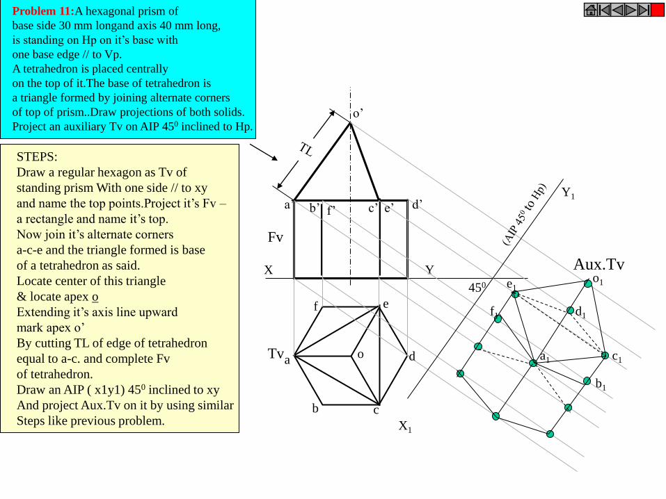
X Y
X1
Y1
o’
o
Fv
Tv
Aux.Tv
450
Problem 11:A hexagonal prism of
base side 30 mm longand axis 40 mm long,
is standing on Hp on it’s base with
one base edge // to Vp.
A tetrahedron is placed centrally
on the top of it.The base of tetrahedron is
a triangle formed by joining alternate corners
of top of prism..Draw projections of both solids.
Project an auxiliary Tv on AIP 450 inclined to Hp.
a’ b’ d’ c’ e’ f’
a
b c
d
e f
STEPS:
Draw a regular hexagon as Tv of
standing prism With one side // to xy
and name the top points.Project it’s Fv –
a rectangle and name it’s top.
Now join it’s alternate corners
a-c-e and the triangle formed is base
of a tetrahedron as said.
Locate center of this triangle
& locate apex o
Extending it’s axis line upward
mark apex o’
By cutting TL of edge of tetrahedron
equal to a-c. and complete Fv
of tetrahedron.
Draw an AIP ( x1y1) 450 inclined to xy
And project Aux.Tv on it by using similar
Steps like previous problem.
a1
b1
c1
d1
e1
f1
o1
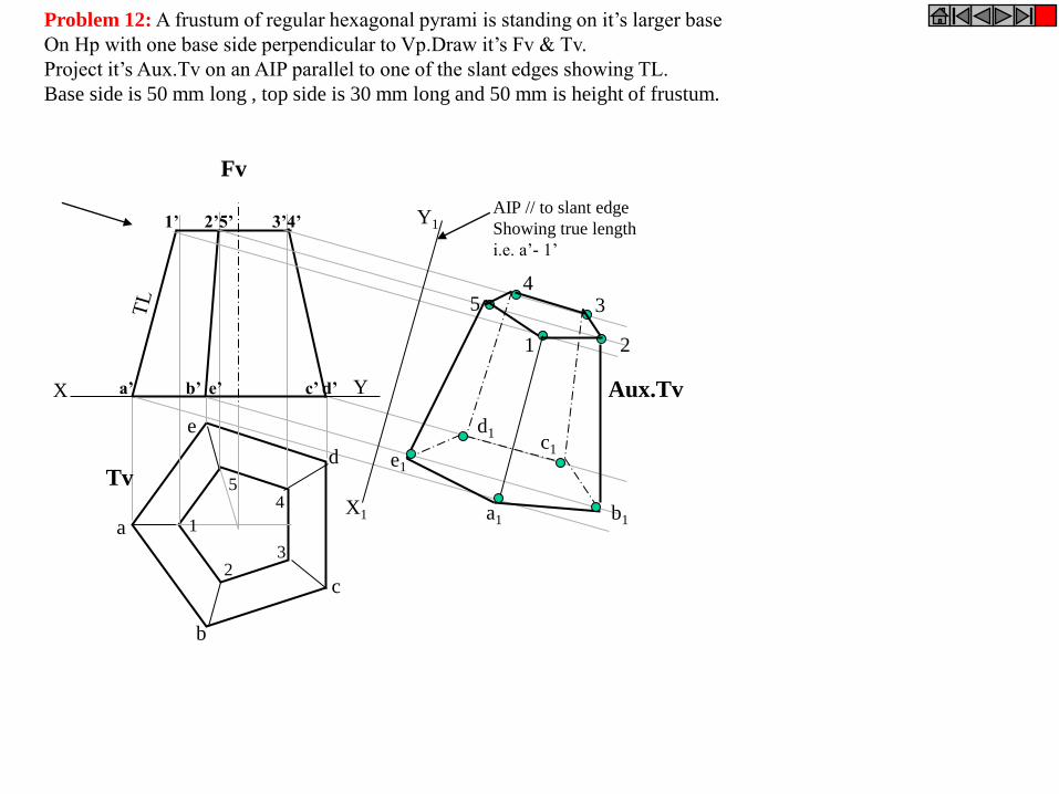
X Y
X1
Y1 AIP // to slant edge
Showing true length
i.e. a’- 1’
a’ b’ e’ c’ d’
1’ 2’5’ 3’4’
Fv
Tv
Aux.Tv
1
2 3
4 5
a
b
d
c
e
1 2
3 4
5
b1
c1
d1
e1
a1
Problem 12: A frustum of regular hexagonal pyrami is standing on it’s larger base
On Hp with one base side perpendicular to Vp.Draw it’s Fv & Tv.
Project it’s Aux.Tv on an AIP parallel to one of the slant edges showing TL.
Base side is 50 mm long , top side is 30 mm long and 50 mm is height of frustum.
DRAWINGS:
( A Graphical Representation)
The Fact about: If compared with Verbal or Written Description,
Drawings offer far better idea about the Shape, Size & Appearance of
any object or situation or location, that too in quite a less time.
Hence it has become the Best Media of Communication
not only in Engineering but in almost all Fields.
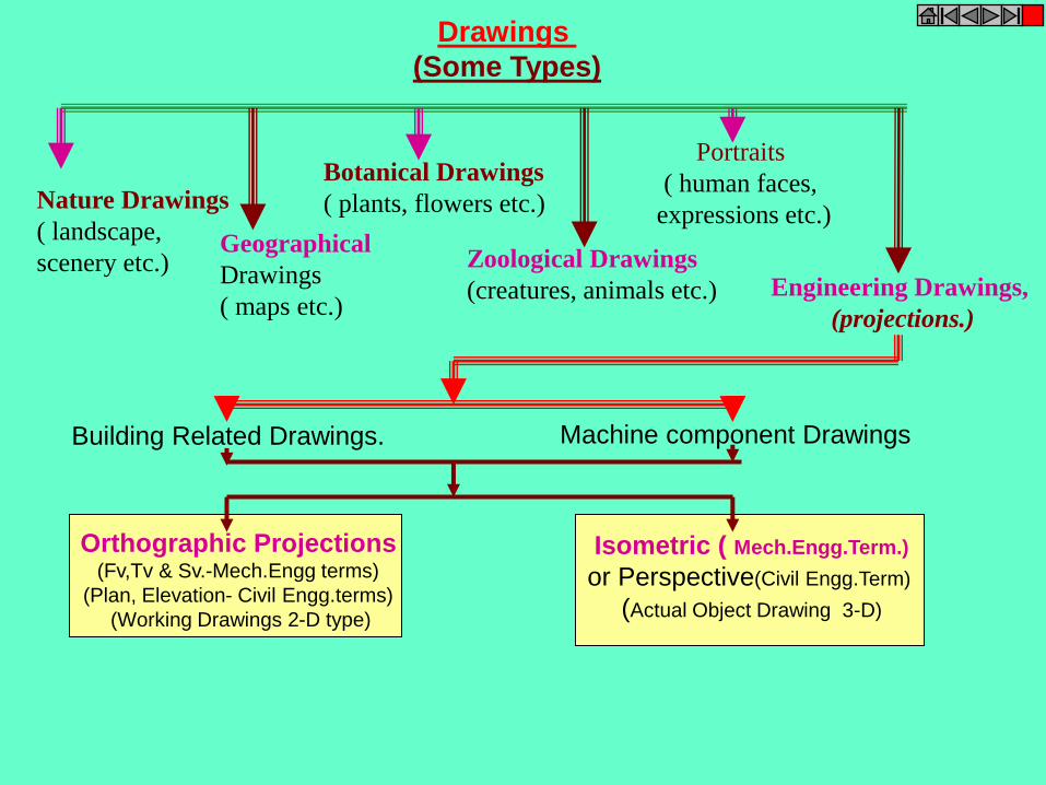
Drawings
(Some Types)
Nature Drawings
( landscape,
scenery etc.) Geographical
Drawings
( maps etc.)
Botanical Drawings
( plants, flowers etc.)
Zoological Drawings
(creatures, animals etc.)
Portraits
( human faces,
expressions etc.)
Engineering Drawings,
(projections.)
Machine component Drawings Building Related Drawings.
Orthographic Projections (Fv,Tv & Sv.-Mech.Engg terms)
(Plan, Elevation- Civil Engg.terms)
(Working Drawings 2-D type)
Isometric ( Mech.Engg.Term.)
or Perspective(Civil Engg.Term)
(Actual Object Drawing 3-D)
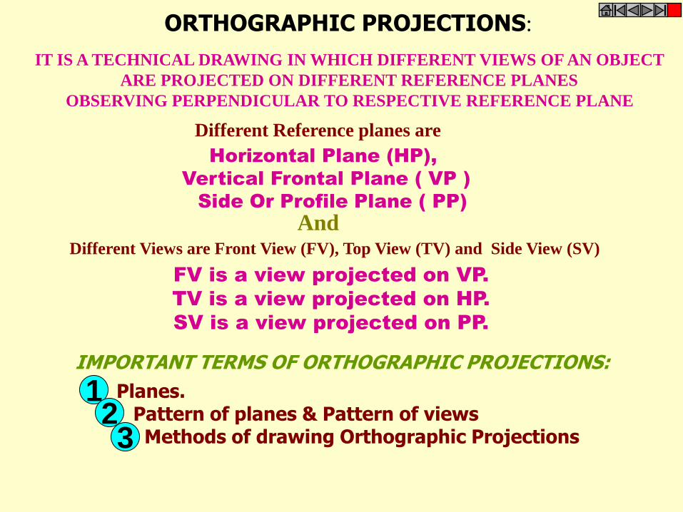
ORTHOGRAPHIC PROJECTIONS:
Horizontal Plane (HP),
Vertical Frontal Plane ( VP )
Side Or Profile Plane ( PP)
Planes. Pattern of planes & Pattern of views Methods of drawing Orthographic Projections
Different Reference planes are
FV is a view projected on VP.
TV is a view projected on HP.
SV is a view projected on PP.
And Different Views are Front View (FV), Top View (TV) and Side View (SV)
IMPORTANT TERMS OF ORTHOGRAPHIC PROJECTIONS:
IT IS A TECHNICAL DRAWING IN WHICH DIFFERENT VIEWS OF AN OBJECT
ARE PROJECTED ON DIFFERENT REFERENCE PLANES
OBSERVING PERPENDICULAR TO RESPECTIVE REFERENCE PLANE
1 2 3
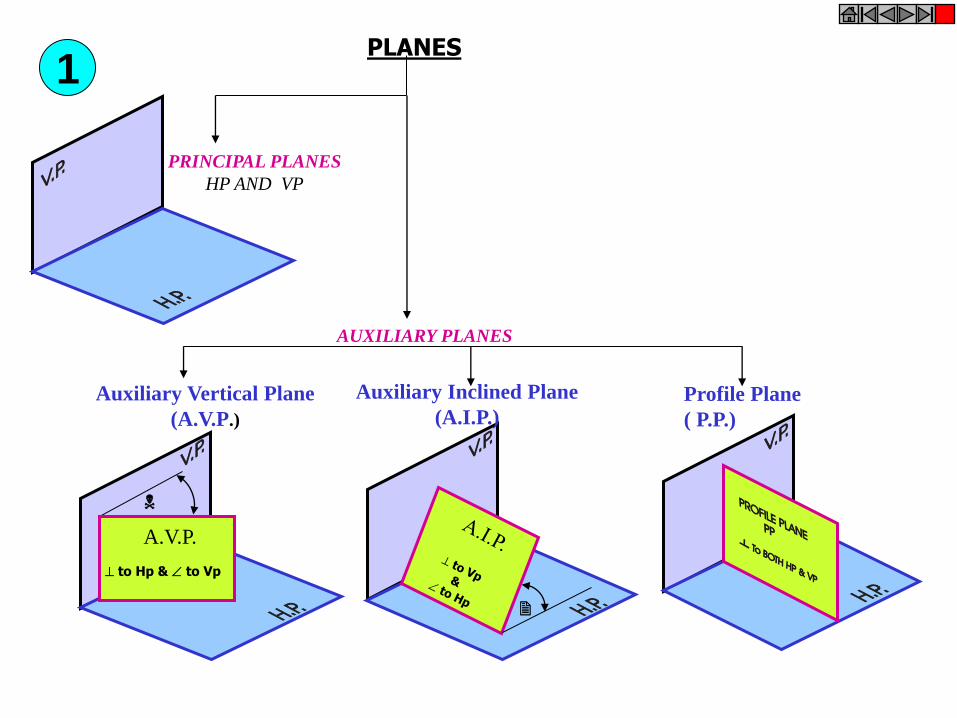
A.V.P.
to Hp & to Vp
PLANES
PRINCIPAL PLANES
HP AND VP
AUXILIARY PLANES
Auxiliary Vertical Plane
(A.V.P.)
Profile Plane
( P.P.)
Auxiliary Inclined Plane
(A.I.P.)
1
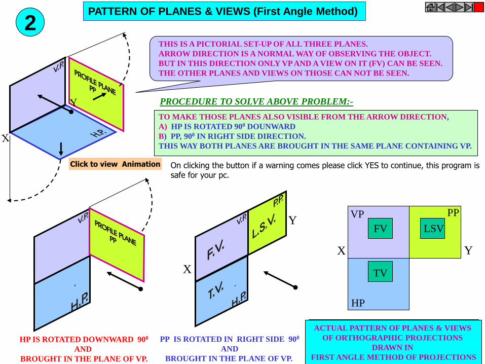
THIS IS A PICTORIAL SET-UP OF ALL THREE PLANES.
ARROW DIRECTION IS A NORMAL WAY OF OBSERVING THE OBJECT.
BUT IN THIS DIRECTION ONLY VP AND A VIEW ON IT (FV) CAN BE SEEN.
THE OTHER PLANES AND VIEWS ON THOSE CAN NOT BE SEEN.
HP IS ROTATED DOWNWARD 900
AND
BROUGHT IN THE PLANE OF VP.
PP IS ROTATED IN RIGHT SIDE 900
AND
BROUGHT IN THE PLANE OF VP.
X
Y
X Y
VP
HP
PP
FV
ACTUAL PATTERN OF PLANES & VIEWS
OF ORTHOGRAPHIC PROJECTIONS
DRAWN IN
FIRST ANGLE METHOD OF PROJECTIONS
LSV
TV
PROCEDURE TO SOLVE ABOVE PROBLEM:-
TO MAKE THOSE PLANES ALSO VISIBLE FROM THE ARROW DIRECTION,
A) HP IS ROTATED 900 DOUNWARD
B) PP, 900 IN RIGHT SIDE DIRECTION.
THIS WAY BOTH PLANES ARE BROUGHT IN THE SAME PLANE CONTAINING VP.
PATTERN OF PLANES & VIEWS (First Angle Method)
2
Click to view Animation On clicking the button if a warning comes please click YES to continue, this program is safe for your pc.

Methods of Drawing Orthographic Projections
First Angle Projections Method Here views are drawn
by placing object
in 1st Quadrant ( Fv above X-y, Tv below X-y )
Third Angle Projections Method Here views are drawn
by placing object
in 3rd Quadrant.
( Tv above X-y, Fv below X-y )
FV
TV
X Y X Y
G L
TV
FV
SYMBOLIC
PRESENTATION
OF BOTH METHODS
WITH AN OBJECT
STANDING ON HP ( GROUND)
ON IT’S BASE.
3
NOTE:- HP term is used in 1st Angle method
&
For the same
Ground term is used
in 3rd Angle method of projections

FOR T.V. FIRST ANGLE
PROJECTION
IN THIS METHOD, THE OBJECT IS ASSUMED TO BE SITUATED IN FIRST QUADRANT
MEANS ABOVE HP & INFRONT OF VP.
OBJECT IS INBETWEEN
OBSERVER & PLANE.
ACTUAL PATTERN OF PLANES & VIEWS
IN FIRST ANGLE METHOD
OF PROJECTIONS
X Y
VP
HP
PP
FV LSV
TV
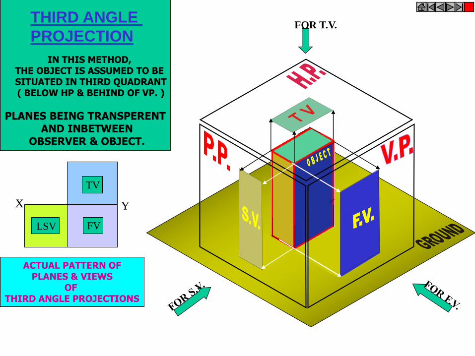
FOR T.V.
IN THIS METHOD, THE OBJECT IS ASSUMED TO BE SITUATED IN THIRD QUADRANT ( BELOW HP & BEHIND OF VP. )
PLANES BEING TRANSPERENT AND INBETWEEN
OBSERVER & OBJECT.
ACTUAL PATTERN OF PLANES & VIEWS
OF THIRD ANGLE PROJECTIONS
X Y
TV
THIRD ANGLE
PROJECTION
LSV FV

ORTHOGRAPHIC PROJECTIONS { MACHINE ELEMENTS }
OBJECT IS OBSERVED IN THREE DIRECTIONS.
THE DIRECTIONS SHOULD BE NORMAL
TO THE RESPECTIVE PLANES.
AND NOW PROJECT THREE DIFFERENT VIEWS ON THOSE PLANES.
THESE VEWS ARE FRONT VIEW , TOP VIEW AND SIDE VIEW.
FRONT VIEW IS A VIEW PROJECTED ON VERTICAL PLANE ( VP )
TOP VIEW IS A VIEW PROJECTED ON HORIZONTAL PLANE ( HP )
SIDE VIEW IS A VIEW PROJECTED ON PROFILE PLANE ( PP )
AND THEN STUDY NEXT 26 ILLUSTRATED CASES CAREFULLY.
TRY TO RECOGNIZE SURFACES
PERPENDICULAR TO THE ARROW DIRECTIONS
FIRST STUDY THE CONCEPT OF 1ST
AND 3RD
ANGLE
PROJECTION METHODS
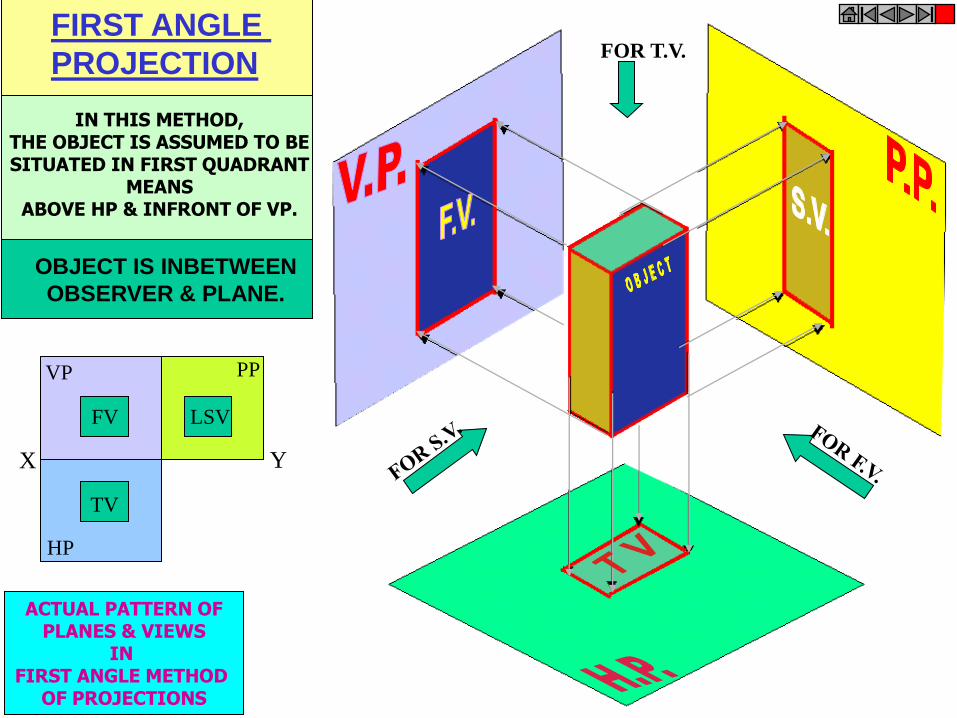
FOR T.V. FIRST ANGLE
PROJECTION
IN THIS METHOD, THE OBJECT IS ASSUMED TO BE SITUATED IN FIRST QUADRANT
MEANS ABOVE HP & INFRONT OF VP.
OBJECT IS INBETWEEN
OBSERVER & PLANE.
ACTUAL PATTERN OF PLANES & VIEWS
IN FIRST ANGLE METHOD
OF PROJECTIONS
X Y
VP
HP
PP
FV LSV
TV

ACTUAL PATTERN OF PLANES & VIEWS
OF THIRD ANGLE PROJECTIONS
X
TV
LSV FV
IN THIS METHOD, THE OBJECT IS ASSUMED TO BE SITUATED IN THIRD QUADRANT ( BELOW HP & BEHIND OF VP. )
PLANES BEING TRANSPERENT AND INBETWEEN
OBSERVER & OBJECT.
FOR T.V.
Y
THIRD ANGLE
PROJECTION
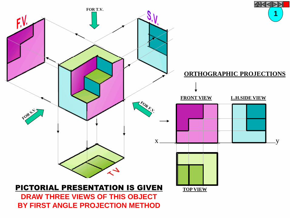
x y
FRONT VIEW
TOP VIEW
L.H.SIDE VIEW
FOR T.V.
PICTORIAL PRESENTATION IS GIVEN
DRAW THREE VIEWS OF THIS OBJECT
BY FIRST ANGLE PROJECTION METHOD
ORTHOGRAPHIC PROJECTIONS
1
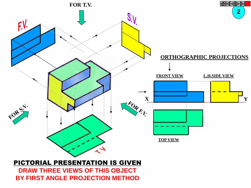
FOR T.V.
X Y
FRONT VIEW
TOP VIEW
L.H.SIDE VIEW
ORTHOGRAPHIC PROJECTIONS
PICTORIAL PRESENTATION IS GIVEN
DRAW THREE VIEWS OF THIS OBJECT
BY FIRST ANGLE PROJECTION METHOD
2
FOR T.V.
ORTHOGRAPHIC PROJECTIONS
X Y
FRONT VIEW
TOP VIEW
L.H.SIDE VIEW
3
PICTORIAL PRESENTATION IS GIVEN
DRAW THREE VIEWS OF THIS OBJECT
BY FIRST ANGLE PROJECTION METHOD
FOR T.V.
ORTHOGRAPHIC PROJECTIONS
FRONT VIEW
TOP VIEW
L.H.SIDE VIEW
X Y
4
PICTORIAL PRESENTATION IS GIVEN
DRAW THREE VIEWS OF THIS OBJECT
BY FIRST ANGLE PROJECTION METHOD
FOR T.V.
ORTHOGRAPHIC PROJECTIONS
FRONT VIEW
TOP VIEW
L.H.SIDE VIEW
X Y
5
PICTORIAL PRESENTATION IS GIVEN
DRAW THREE VIEWS OF THIS OBJECT
BY FIRST ANGLE PROJECTION METHOD
FOR T.V.
ORTHOGRAPHIC PROJECTIONS
FRONT VIEW
TOP VIEW
L.H.SIDE VIEW
X Y
6
PICTORIAL PRESENTATION IS GIVEN
DRAW THREE VIEWS OF THIS OBJECT
BY FIRST ANGLE PROJECTION METHOD
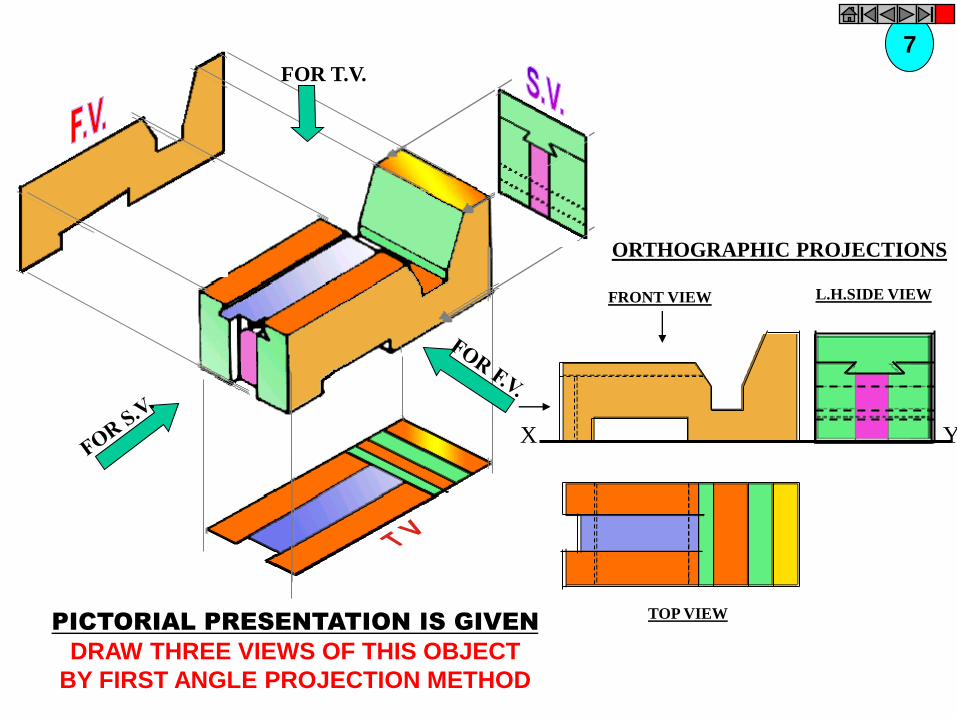
FRONT VIEW
TOP VIEW
L.H.SIDE VIEW
X Y
FOR T.V.
ORTHOGRAPHIC PROJECTIONS
7
PICTORIAL PRESENTATION IS GIVEN
DRAW THREE VIEWS OF THIS OBJECT
BY FIRST ANGLE PROJECTION METHOD
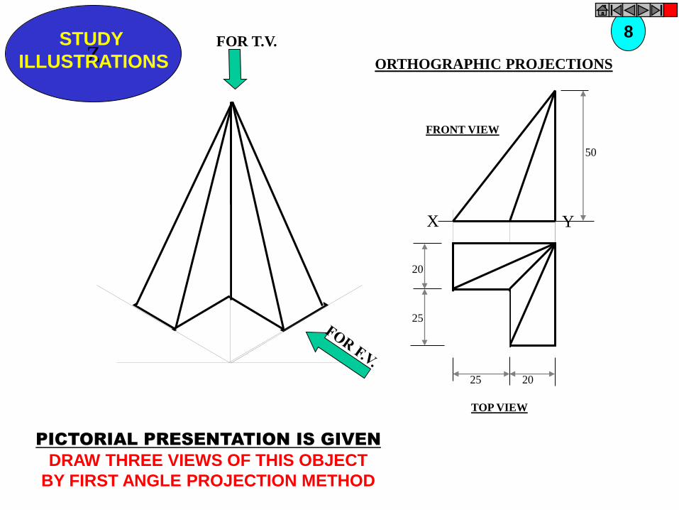
Z STUDY
ILLUSTRATIONS
X Y
50
20
25
25 20
FOR T.V.
PICTORIAL PRESENTATION IS GIVEN
DRAW THREE VIEWS OF THIS OBJECT
BY FIRST ANGLE PROJECTION METHOD
8
ORTHOGRAPHIC PROJECTIONS
FRONT VIEW
TOP VIEW
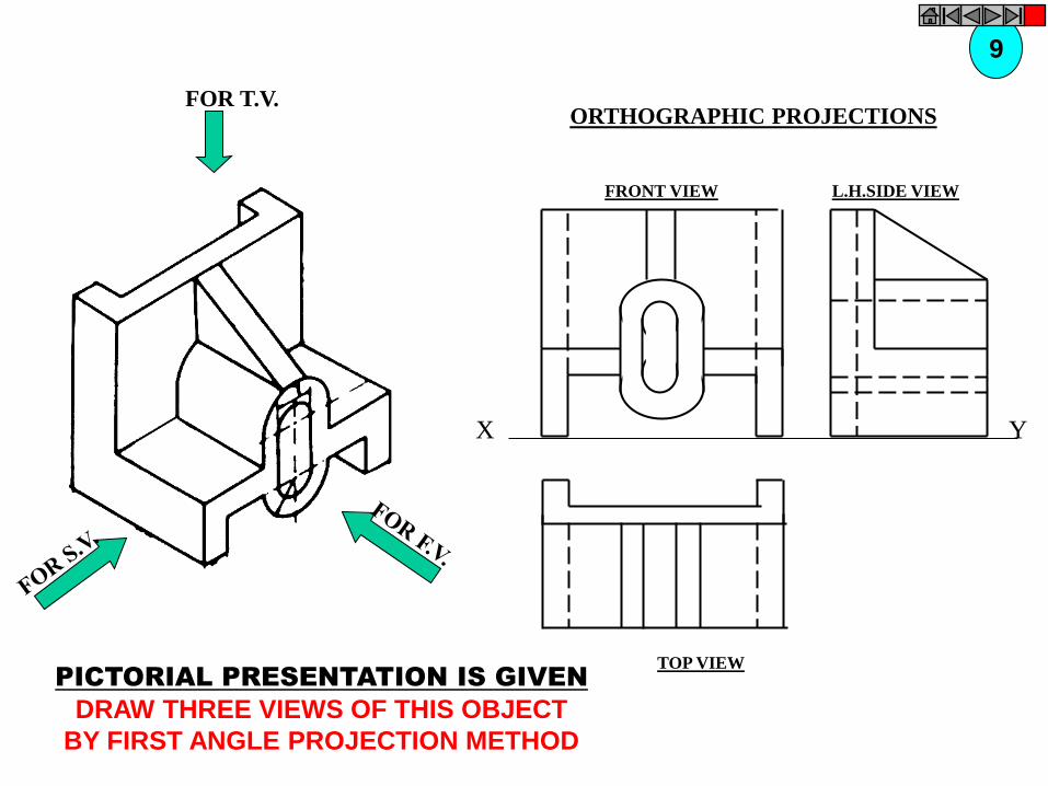
FOR T.V.
PICTORIAL PRESENTATION IS GIVEN
DRAW THREE VIEWS OF THIS OBJECT
BY FIRST ANGLE PROJECTION METHOD
9
ORTHOGRAPHIC PROJECTIONS
FRONT VIEW
TOP VIEW
L.H.SIDE VIEW
X Y

FOR T.V.
PICTORIAL PRESENTATION IS GIVEN
DRAW THREE VIEWS OF THIS OBJECT
BY FIRST ANGLE PROJECTION METHOD
10 ORTHOGRAPHIC PROJECTIONS
FRONT VIEW
TOP VIEW
L.H.SIDE VIEW
X Y

FOR T.V.
PICTORIAL PRESENTATION IS GIVEN
DRAW THREE VIEWS OF THIS OBJECT
BY FIRST ANGLE PROJECTION METHOD
11 ORTHOGRAPHIC PROJECTIONS
FRONT VIEW
TOP VIEW
L.H.SIDE VIEW
X Y
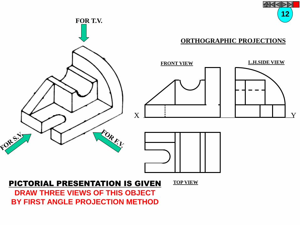
FOR T.V.
PICTORIAL PRESENTATION IS GIVEN
DRAW THREE VIEWS OF THIS OBJECT
BY FIRST ANGLE PROJECTION METHOD
12
ORTHOGRAPHIC PROJECTIONS
FRONT VIEW
TOP VIEW
L.H.SIDE VIEW
X Y
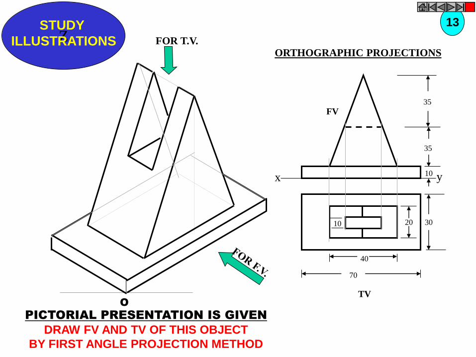
Z STUDY
ILLUSTRATIONS
x y
FV 35
35
10
TV
30 20 10
40
70
O
FOR T.V.
PICTORIAL PRESENTATION IS GIVEN
DRAW FV AND TV OF THIS OBJECT
BY FIRST ANGLE PROJECTION METHOD
13
ORTHOGRAPHIC PROJECTIONS
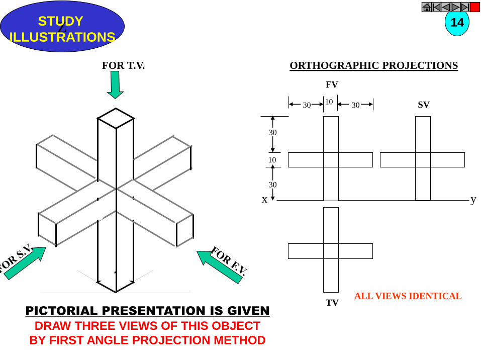
Z STUDY
ILLUSTRATIONS
SV
TV
y x
FV
30
30
10
30 10 30
ALL VIEWS IDENTICAL
FOR T.V.
PICTORIAL PRESENTATION IS GIVEN
DRAW THREE VIEWS OF THIS OBJECT
BY FIRST ANGLE PROJECTION METHOD
14
ORTHOGRAPHIC PROJECTIONS
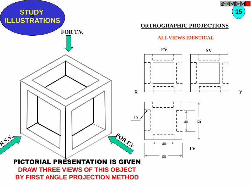
x y
FV SV
Z STUDY
ILLUSTRATIONS
TV
10 40 60
60
40
ALL VIEWS IDENTICAL
FOR T.V.
PICTORIAL PRESENTATION IS GIVEN
DRAW THREE VIEWS OF THIS OBJECT
BY FIRST ANGLE PROJECTION METHOD
15
ORTHOGRAPHIC PROJECTIONS

FOR T.V.
PICTORIAL PRESENTATION IS GIVEN
DRAW THREE VIEWS OF THIS OBJECT
BY FIRST ANGLE PROJECTION METHOD
16 ORTHOGRAPHIC PROJECTIONS
x y
FV SV
ALL VIEWS IDENTICAL
40 60
60
40
10
TOP VIEW

40 20
30 SQUARE
20
50
60
30
10
F.V. S.V.
O
PICTORIAL PRESENTATION IS GIVEN
DRAW FV AND SV OF THIS OBJECT
BY FIRST ANGLE PROJECTION METHOD
17
ORTHOGRAPHIC PROJECTIONS
FRONT VIEW L.H.SIDE VIEW
X Y

50
80
10
30 D
TV
O
FOR T.V.
PICTORIAL PRESENTATION IS GIVEN
DRAW FV AND TV OF THIS OBJECT
BY FIRST ANGLE PROJECTION METHOD
18 ORTHOGRAPHIC PROJECTIONS
40
10
45
FV
O
X Y
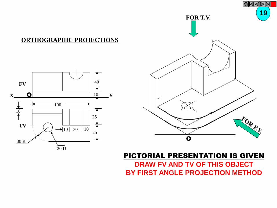
X Y
FV
O
40
10
10
TV
25
25
30 R
100
10 30 10
20 D
O
PICTORIAL PRESENTATION IS GIVEN
DRAW FV AND TV OF THIS OBJECT
BY FIRST ANGLE PROJECTION METHOD
19
ORTHOGRAPHIC PROJECTIONS
FOR T.V.

O
20 D
30 D
60 D
TV
10
30
50
10
35
FV
X Y
RECT.
SLOT
FOR T.V.
PICTORIAL PRESENTATION IS GIVEN
DRAW FV AND TV OF THIS OBJECT
BY FIRST ANGLE PROJECTION METHOD
20 ORTHOGRAPHIC PROJECTIONS
TOP VIEW
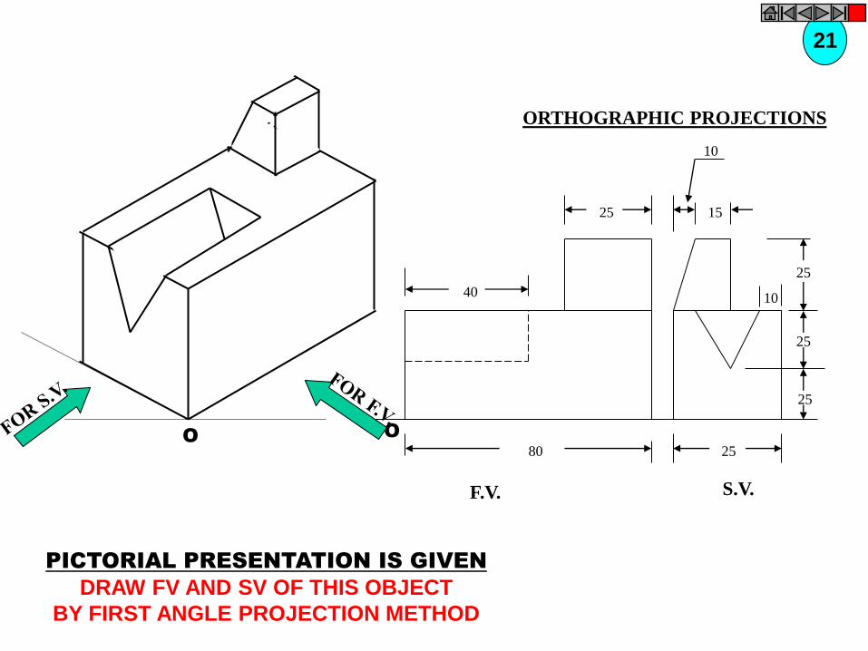
O O
40
25
80
F.V.
10
15
25
25
25
25
10
S.V.
PICTORIAL PRESENTATION IS GIVEN
DRAW FV AND SV OF THIS OBJECT
BY FIRST ANGLE PROJECTION METHOD
21
ORTHOGRAPHIC PROJECTIONS
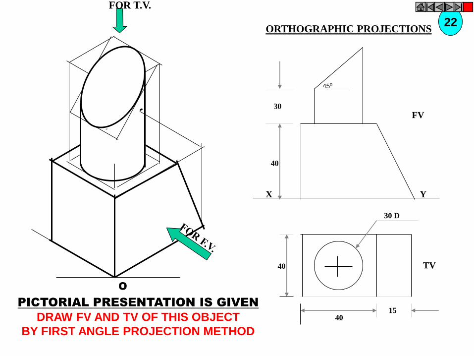
450
X
FV
Y
30
40
TV
30 D
40
40 15
O
FOR T.V.
PICTORIAL PRESENTATION IS GIVEN
DRAW FV AND TV OF THIS OBJECT
BY FIRST ANGLE PROJECTION METHOD
22 ORTHOGRAPHIC PROJECTIONS
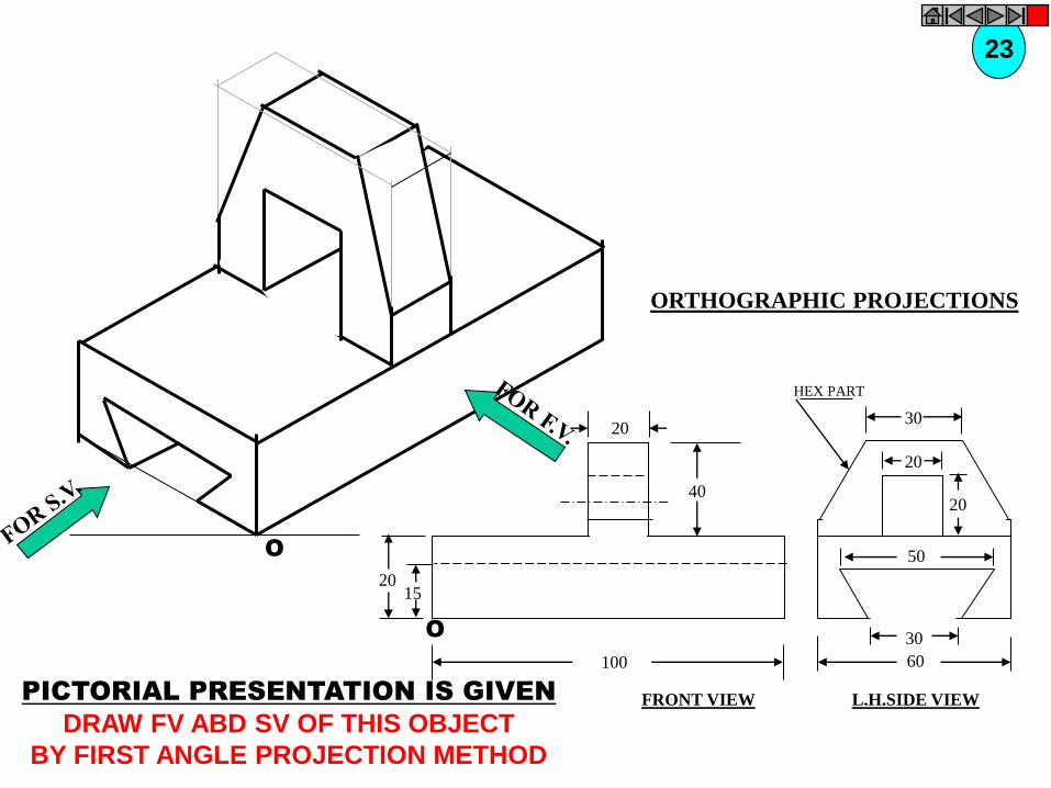
O
O
20
20 15
40
100
30
60
30
20
20
50
HEX PART
PICTORIAL PRESENTATION IS GIVEN
DRAW FV ABD SV OF THIS OBJECT
BY FIRST ANGLE PROJECTION METHOD
23
ORTHOGRAPHIC PROJECTIONS
FRONT VIEW L.H.SIDE VIEW
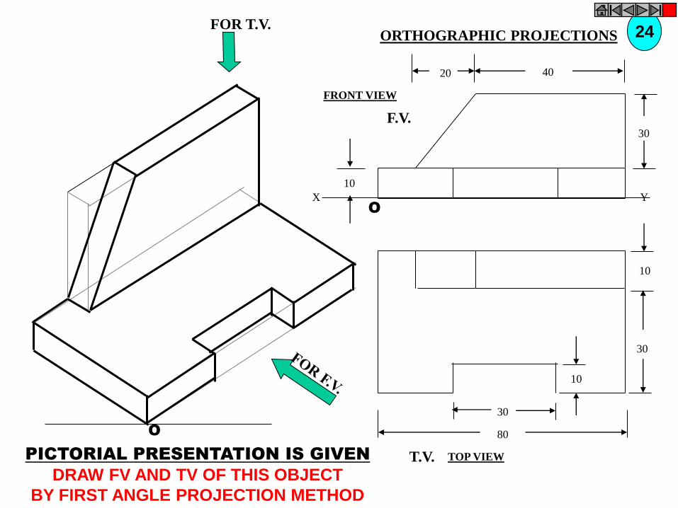
O
10
30
10
80
30
T.V.
O
10
30
40 20
F.V.
X Y
FOR T.V.
PICTORIAL PRESENTATION IS GIVEN
DRAW FV AND TV OF THIS OBJECT
BY FIRST ANGLE PROJECTION METHOD
24 ORTHOGRAPHIC PROJECTIONS
FRONT VIEW
TOP VIEW
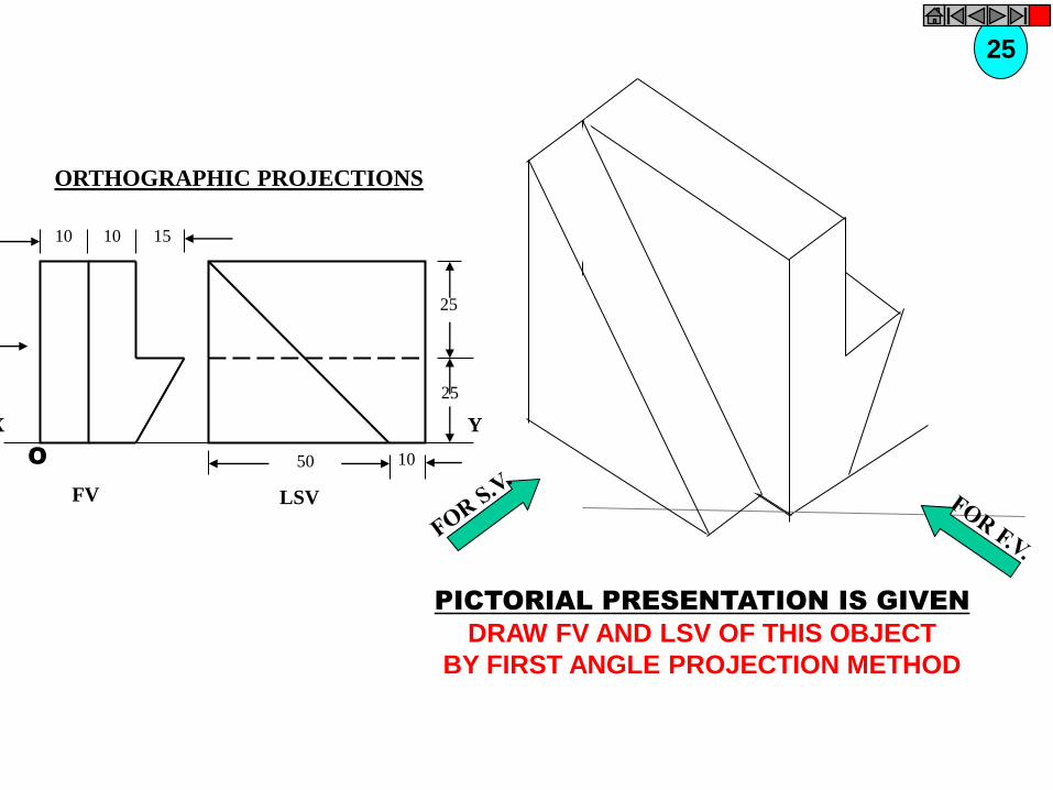
LSV
Y
25
25
10 50
FV
X
10 10 15
O
PICTORIAL PRESENTATION IS GIVEN
DRAW FV AND LSV OF THIS OBJECT
BY FIRST ANGLE PROJECTION METHOD
25
ORTHOGRAPHIC PROJECTIONS
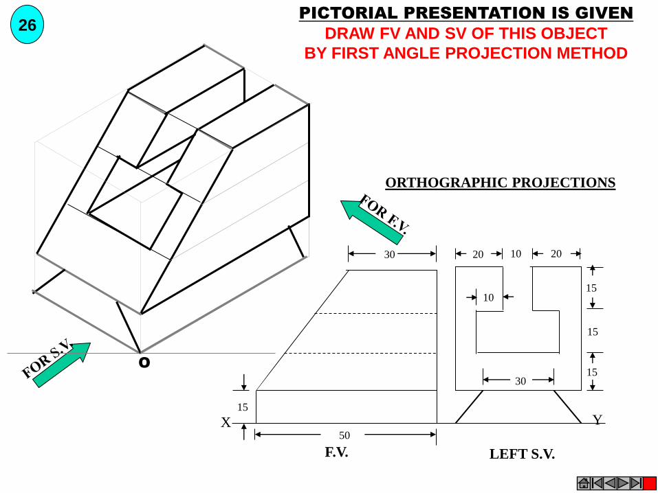
Y X
F.V. LEFT S.V.
20 20 10
15
15
15 30
10
30
50
15
O
PICTORIAL PRESENTATION IS GIVEN
DRAW FV AND SV OF THIS OBJECT
BY FIRST ANGLE PROJECTION METHOD
26
ORTHOGRAPHIC PROJECTIONS
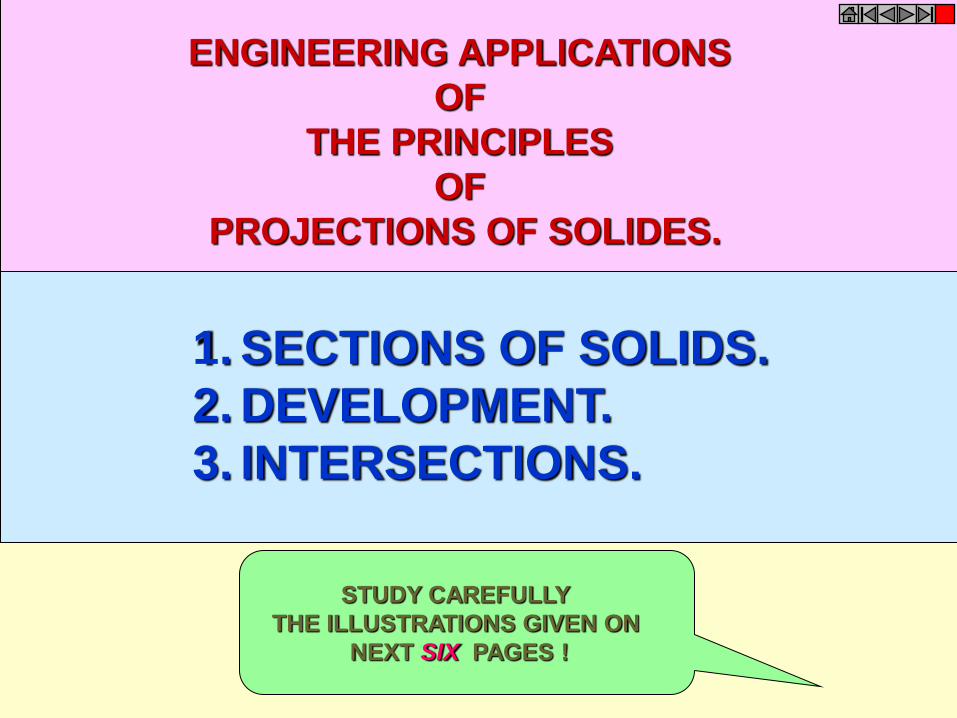
1. SECTIONS OF SOLIDS.
2. DEVELOPMENT.
3. INTERSECTIONS.
ENGINEERING APPLICATIONS
OF
THE PRINCIPLES
OF
PROJECTIONS OF SOLIDES.
STUDY CAREFULLY
THE ILLUSTRATIONS GIVEN ON
NEXT SIX PAGES !

SECTIONING A SOLID.
An object ( here a solid ) is cut by
some imaginary cutting plane
to understand internal details of that object.
The action of cutting is called
SECTIONING a solid
&
The plane of cutting is called
SECTION PLANE.
Two cutting actions means section planes are recommended.
A) Section Plane perpendicular to Vp and inclined to Hp.
( This is a definition of an Aux. Inclined Plane i.e. A.I.P.)
NOTE:- This section plane appears
as a straight line in FV.
B) Section Plane perpendicular to Hp and inclined to Vp.
( This is a definition of an Aux. Vertical Plane i.e. A.V.P.)
NOTE:- This section plane appears
as a straight line in TV. Remember:- 1. After launching a section plane either in FV or TV, the part towards observer is assumed to be removed. 2. As far as possible the smaller part is assumed to be removed.
OBSERVER
ASSUME
UPPER PART
REMOVED
OBSERVER
ASSUME
LOWER PART
REMOVED
(A)
(B)
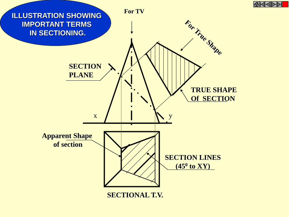
ILLUSTRATION SHOWING
IMPORTANT TERMS
IN SECTIONING.
x y
TRUE SHAPE
Of SECTION
SECTION
PLANE
SECTION LINES
(450 to XY)
Apparent Shape
of section
SECTIONAL T.V.
For TV
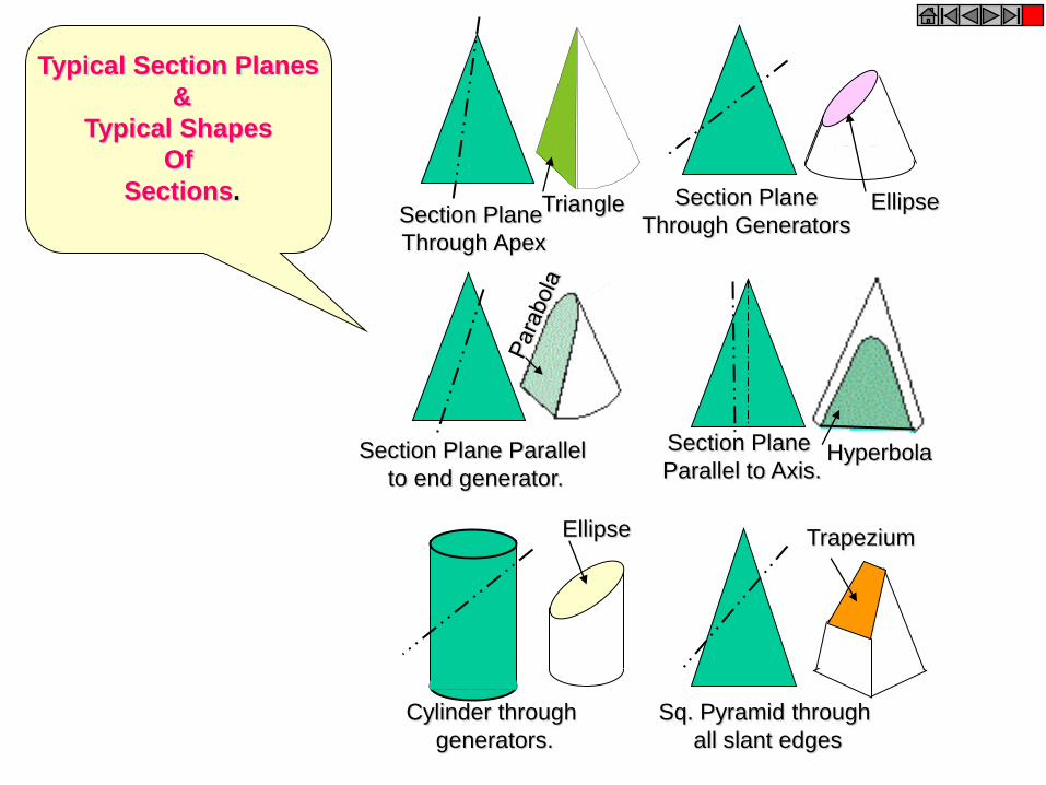
Section Plane
Through Apex
Section Plane
Through Generators
Section Plane Parallel
to end generator.
Section Plane
Parallel to Axis.
Triangle Ellipse
Hyperbola
Ellipse
Cylinder through
generators.
Sq. Pyramid through
all slant edges
Trapezium
Typical Section Planes
&
Typical Shapes
Of
Sections.
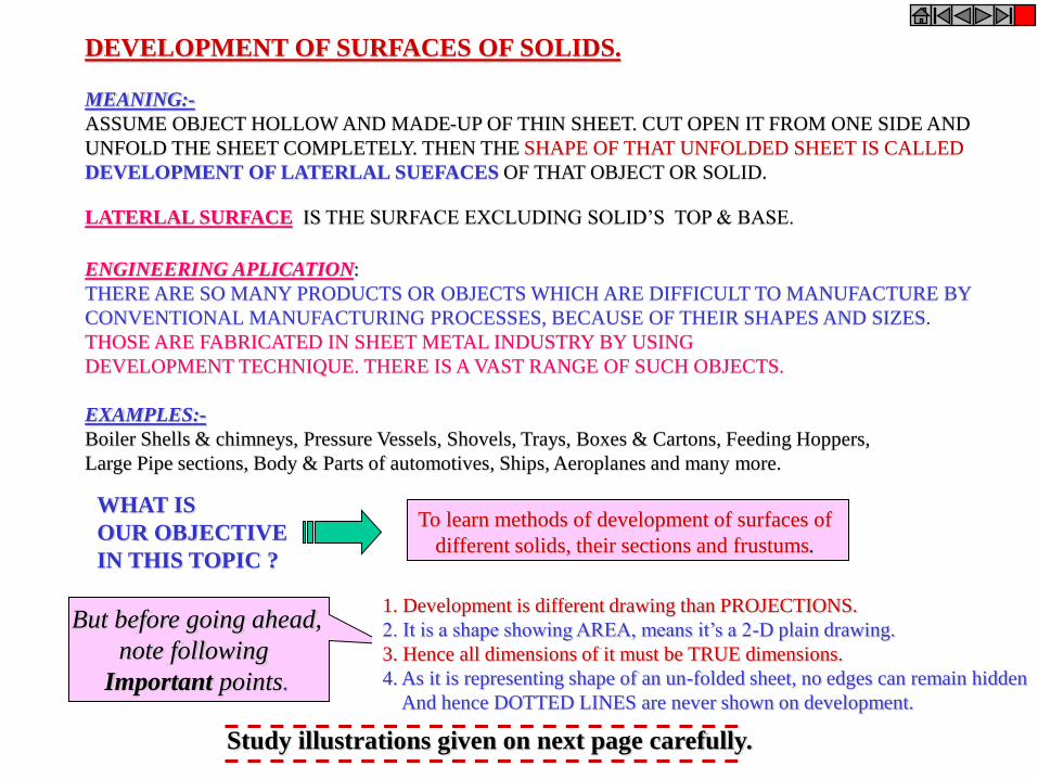
DEVELOPMENT OF SURFACES OF SOLIDS.
MEANING:-
ASSUME OBJECT HOLLOW AND MADE-UP OF THIN SHEET. CUT OPEN IT FROM ONE SIDE AND
UNFOLD THE SHEET COMPLETELY. THEN THE SHAPE OF THAT UNFOLDED SHEET IS CALLED
DEVELOPMENT OF LATERLAL SUEFACES OF THAT OBJECT OR SOLID.
LATERLAL SURFACE IS THE SURFACE EXCLUDING SOLID’S TOP & BASE.
ENGINEERING APLICATION:
THERE ARE SO MANY PRODUCTS OR OBJECTS WHICH ARE DIFFICULT TO MANUFACTURE BY
CONVENTIONAL MANUFACTURING PROCESSES, BECAUSE OF THEIR SHAPES AND SIZES.
THOSE ARE FABRICATED IN SHEET METAL INDUSTRY BY USING
DEVELOPMENT TECHNIQUE. THERE IS A VAST RANGE OF SUCH OBJECTS.
EXAMPLES:-
Boiler Shells & chimneys, Pressure Vessels, Shovels, Trays, Boxes & Cartons, Feeding Hoppers,
Large Pipe sections, Body & Parts of automotives, Ships, Aeroplanes and many more.
WHAT IS
OUR OBJECTIVE
IN THIS TOPIC ?
To learn methods of development of surfaces of
different solids, their sections and frustums.
1. Development is different drawing than PROJECTIONS.
2. It is a shape showing AREA, means it’s a 2-D plain drawing.
3. Hence all dimensions of it must be TRUE dimensions.
4. As it is representing shape of an un-folded sheet, no edges can remain hidden
And hence DOTTED LINES are never shown on development.
But before going ahead,
note following
Important points.
Study illustrations given on next page carefully.
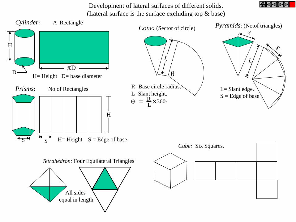
D
H
D
S S
H
= R L
3600
R=Base circle radius. L=Slant height.
L= Slant edge.
S = Edge of base
H= Height S = Edge of base
H= Height D= base diameter
Development of lateral surfaces of different solids.
(Lateral surface is the surface excluding top & base)
Prisms: No.of Rectangles
Cylinder: A Rectangle Cone: (Sector of circle) Pyramids: (No.of triangles)
Tetrahedron: Four Equilateral Triangles
All sides
equal in length
Cube: Six Squares.
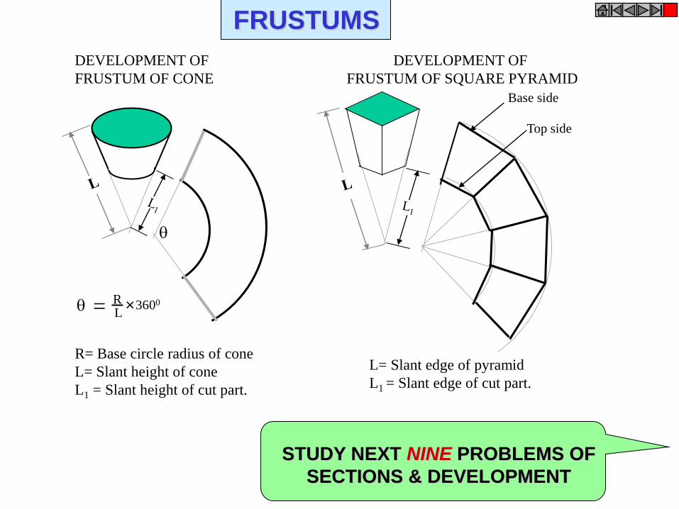
= R L
3600
R= Base circle radius of cone
L= Slant height of cone
L1 = Slant height of cut part.
Base side
Top side
L= Slant edge of pyramid
L1 = Slant edge of cut part.
DEVELOPMENT OF
FRUSTUM OF CONE
DEVELOPMENT OF
FRUSTUM OF SQUARE PYRAMID
STUDY NEXT NINE PROBLEMS OF
SECTIONS & DEVELOPMENT
FRUSTUMS
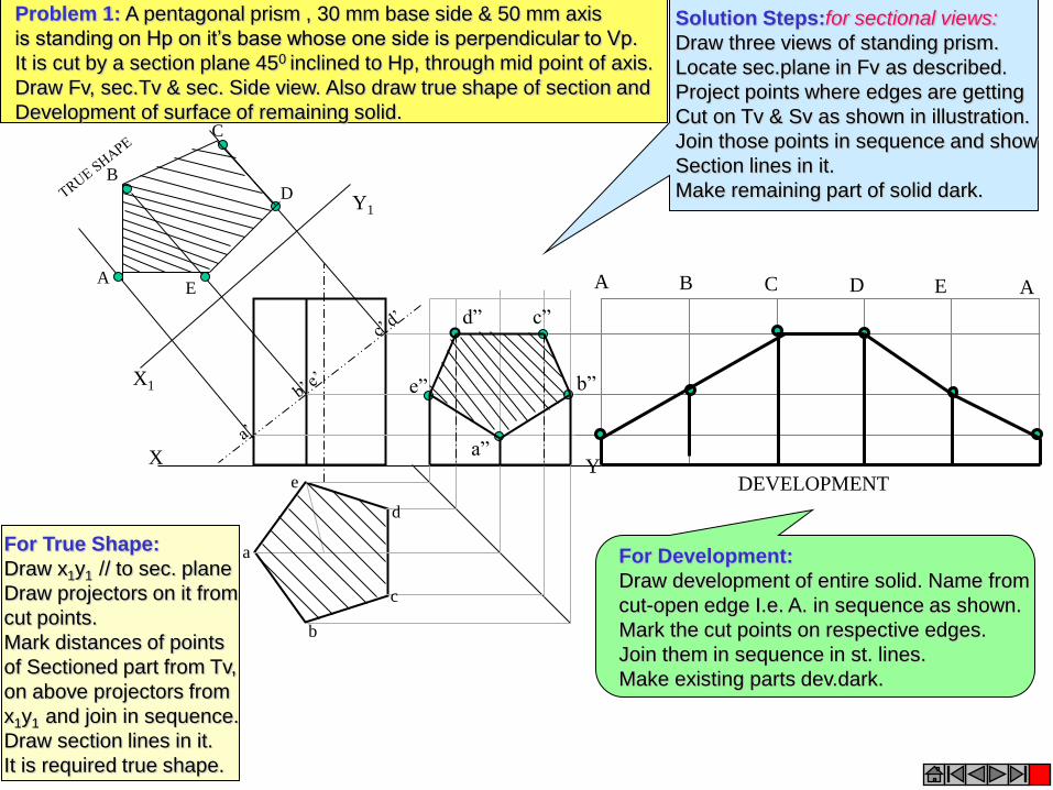
X Y
X1
Y1
A
B
C
E
D
a
e
d
b
c
A B C D E A
DEVELOPMENT
a”
b”
c” d”
e”
Problem 1: A pentagonal prism , 30 mm base side & 50 mm axis
is standing on Hp on it’s base whose one side is perpendicular to Vp.
It is cut by a section plane 450 inclined to Hp, through mid point of axis.
Draw Fv, sec.Tv & sec. Side view. Also draw true shape of section and
Development of surface of remaining solid.
Solution Steps:for sectional views:
Draw three views of standing prism.
Locate sec.plane in Fv as described.
Project points where edges are getting
Cut on Tv & Sv as shown in illustration.
Join those points in sequence and show
Section lines in it.
Make remaining part of solid dark.
For True Shape:
Draw x1y1 // to sec. plane
Draw projectors on it from
cut points.
Mark distances of points
of Sectioned part from Tv,
on above projectors from
x1y1 and join in sequence.
Draw section lines in it.
It is required true shape.
For Development:
Draw development of entire solid. Name from
cut-open edge I.e. A. in sequence as shown.
Mark the cut points on respective edges.
Join them in sequence in st. lines.
Make existing parts dev.dark.
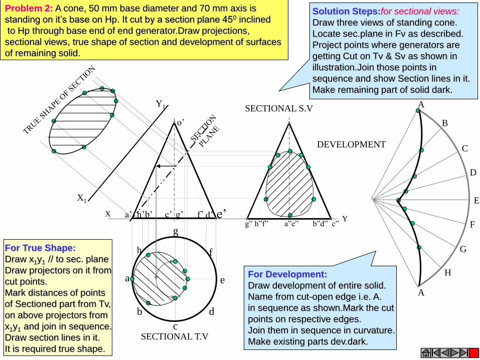
Y
h
a
b
c
d
e
g
f
X a’ b’ d’ e’ c’ g’ f’ h’
o’
X1
Y1
g” h”f” a”e” b”d” c”
A
B
C
D
E
F
A
G
H
SECTIONAL T.V
SECTIONAL S.V
DEVELOPMENT
Problem 2: A cone, 50 mm base diameter and 70 mm axis is
standing on it’s base on Hp. It cut by a section plane 450 inclined
to Hp through base end of end generator.Draw projections,
sectional views, true shape of section and development of surfaces
of remaining solid.
Solution Steps:for sectional views:
Draw three views of standing cone.
Locate sec.plane in Fv as described.
Project points where generators are
getting Cut on Tv & Sv as shown in
illustration.Join those points in
sequence and show Section lines in it.
Make remaining part of solid dark.
For True Shape:
Draw x1y1 // to sec. plane
Draw projectors on it from
cut points.
Mark distances of points
of Sectioned part from Tv,
on above projectors from
x1y1 and join in sequence.
Draw section lines in it.
It is required true shape.
For Development:
Draw development of entire solid.
Name from cut-open edge i.e. A.
in sequence as shown.Mark the cut
points on respective edges.
Join them in sequence in curvature.
Make existing parts dev.dark.
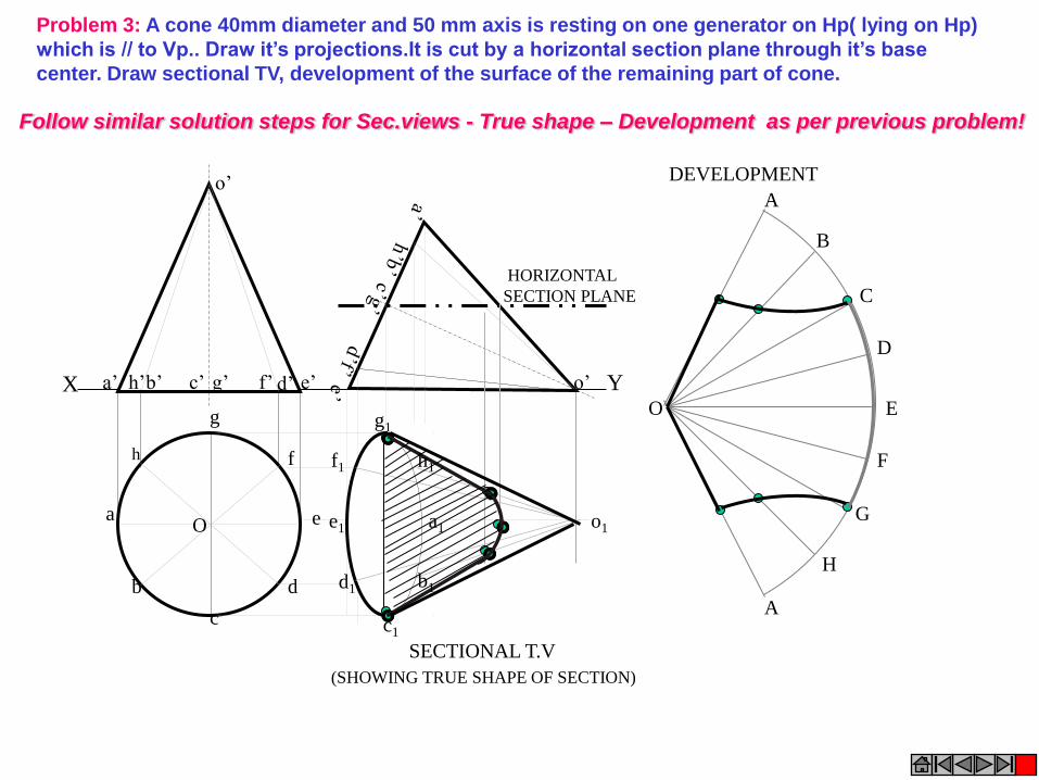
X Y e’ a’ b’ d’ c’ g’ f’ h’
o’
o’
Problem 3: A cone 40mm diameter and 50 mm axis is resting on one generator on Hp( lying on Hp)
which is // to Vp.. Draw it’s projections.It is cut by a horizontal section plane through it’s base
center. Draw sectional TV, development of the surface of the remaining part of cone.
A
B
C
D
E
F
A
G
H
O
a1
h1
g1
f1
e1
d1
c1
b1
o1
SECTIONAL T.V
DEVELOPMENT
(SHOWING TRUE SHAPE OF SECTION)
HORIZONTAL
SECTION PLANE
h
a
b
c
d
e
g
f
O
Follow similar solution steps for Sec.views - True shape – Development as per previous problem!
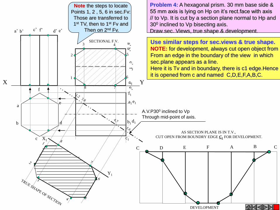
A.V.P300 inclined to Vp
Through mid-point of axis.
X Y 1
2
3 4
5
6
7 8
b’ f’ a’ e’ c’ d’
a
b
c
d
e
f
a1
d1 b1
e1
c1
f1
X1
Y1
AS SECTION PLANE IS IN T.V.,
CUT OPEN FROM BOUNDRY EDGE C1 FOR DEVELOPMENT.
C D E F A B C
DEVELOPMENT
SECTIONAL F.V.
Problem 4: A hexagonal prism. 30 mm base side &
55 mm axis is lying on Hp on it’s rect.face with axis
// to Vp. It is cut by a section plane normal to Hp and
300 inclined to Vp bisecting axis.
Draw sec. Views, true shape & development.
Use similar steps for sec.views & true shape. NOTE: for development, always cut open object from
From an edge in the boundary of the view in which
sec.plane appears as a line.
Here it is Tv and in boundary, there is c1 edge.Hence
it is opened from c and named C,D,E,F,A,B,C.
Note the steps to locate
Points 1, 2 , 5, 6 in sec.Fv:
Those are transferred to
1st TV, then to 1st Fv and
Then on 2nd Fv.
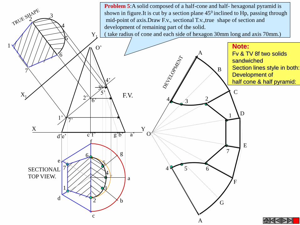
1’
2’
3’
4’
5’
6’
7’
7
1
5
4
3
2
6
7
1
6
5
4
3 2
a
b
c
d
e
f
g
4
4 5
3
6
2
7
1
A
B
C
D
E
A
F
G
O
O’
d’e’ c’f’ g’b’ a’ X Y
X1
Y1
F.V.
SECTIONAL
TOP VIEW.
Problem 5:A solid composed of a half-cone and half- hexagonal pyramid is
shown in figure.It is cut by a section plane 450 inclined to Hp, passing through
mid-point of axis.Draw F.v., sectional T.v.,true shape of section and
development of remaining part of the solid.
( take radius of cone and each side of hexagon 30mm long and axis 70mm.)
Note: Fv & TV 8f two solids
sandwiched
Section lines style in both:
Development of
half cone & half pyramid:
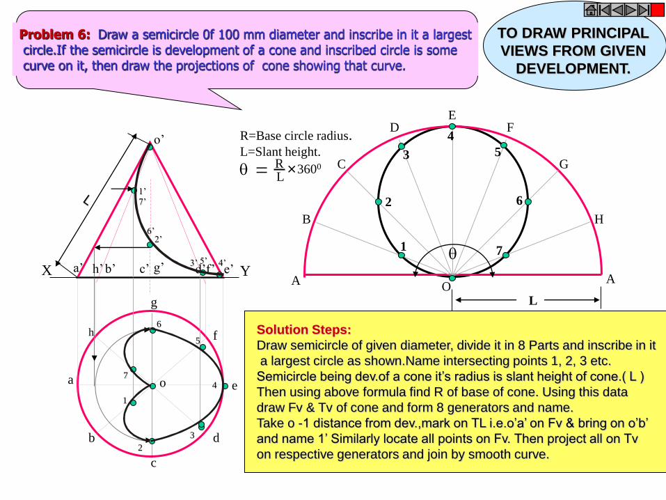
o’
h
a
b
c
d
g
f
o e
a’ b’ c’ g’ d’f’ e’ h’ X Y
= R L
3600
R=Base circle radius. L=Slant height.
A
B
C
D E
F
G
H
A O
1
3
2
4
7
6
5
L
1
2
3
4
5
6
7
1’
2’
3’ 4’ 5’
6’
7’
Problem 6: Draw a semicircle 0f 100 mm diameter and inscribe in it a largest circle.If the semicircle is development of a cone and inscribed circle is some curve on it, then draw the projections of cone showing that curve.
Solution Steps:
Draw semicircle of given diameter, divide it in 8 Parts and inscribe in it
a largest circle as shown.Name intersecting points 1, 2, 3 etc.
Semicircle being dev.of a cone it’s radius is slant height of cone.( L )
Then using above formula find R of base of cone. Using this data
draw Fv & Tv of cone and form 8 generators and name.
Take o -1 distance from dev.,mark on TL i.e.o’a’ on Fv & bring on o’b’
and name 1’ Similarly locate all points on Fv. Then project all on Tv
on respective generators and join by smooth curve.
TO DRAW PRINCIPAL
VIEWS FROM GIVEN
DEVELOPMENT.

h
a
b
c
d
g
f
e
o’
a’ b’ d’ c’ g’ f’ h’ e’ X Y
A
B
C
D E
F
G
H
A O L
= R L
3600
R=Base circle radius. L=Slant height.
1’
2’ 3’
4’
5’ 6’
7’
1 2
3
4
5
6 7
Problem 7:Draw a semicircle 0f 100 mm diameter and inscribe in it a largest
rhombus.If the semicircle is development of a cone and rhombus is some curve
on it, then draw the projections of cone showing that curve.
TO DRAW PRINCIPAL
VIEWS FROM GIVEN
DEVELOPMENT.
Solution Steps:
Similar to previous
Problem:

a’ b’ c’ d’
o’
e’
a
b
c
d
o e
X Y
A
B
C
D
E
A
O
2
3
4
1
Problem 8: A half cone of 50 mm base diameter, 70 mm axis, is standing on it’s half base on HP with it’s flat face
parallel and nearer to VP.An inextensible string is wound round it’s surface from one point of base circle and
brought back to the same point.If the string is of shortest length, find it and show it on the projections of the cone.
1 2
3
4
1’
2’ 3’ 4’
TO DRAW A CURVE ON
PRINCIPAL VIEWS
FROM DEVELOPMENT. Concept: A string wound
from a point up to the same
Point, of shortest length
Must appear st. line on it’s
Development.
Solution steps:
Hence draw development,
Name it as usual and join
A to A This is shortest
Length of that string.
Further steps are as usual.
On dev. Name the points of
Intersections of this line with
Different generators.Bring
Those on Fv & Tv and join
by smooth curves.
Draw 4’ a’ part of string dotted
As it is on back side of cone.
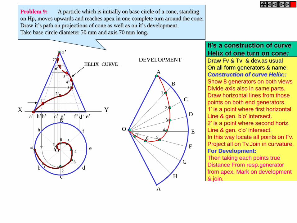
X Y e’ a’ b’ d’ c’ g’ f’ h’
o’
h
a
b
c
d
e
g
f
O
DEVELOPMENT
A
B
C
D
E
F
A
G
H
O
1 2
3
4
6 5 7
1’
2’
3’
4’
5’
6’
7’
1
2
3
4
5 6 7
HELIX CURVE
Problem 9: A particle which is initially on base circle of a cone, standing
on Hp, moves upwards and reaches apex in one complete turn around the cone.
Draw it’s path on projections of cone as well as on it’s development.
Take base circle diameter 50 mm and axis 70 mm long.
It’s a construction of curve
Helix of one turn on cone: Draw Fv & Tv & dev.as usual
On all form generators & name.
Construction of curve Helix::
Show 8 generators on both views
Divide axis also in same parts.
Draw horizontal lines from those
points on both end generators.
1’ is a point where first horizontal
Line & gen. b’o’ intersect.
2’ is a point where second horiz.
Line & gen. c’o’ intersect.
In this way locate all points on Fv.
Project all on Tv.Join in curvature.
For Development:
Then taking each points true
Distance From resp.generator
from apex, Mark on development
& join.
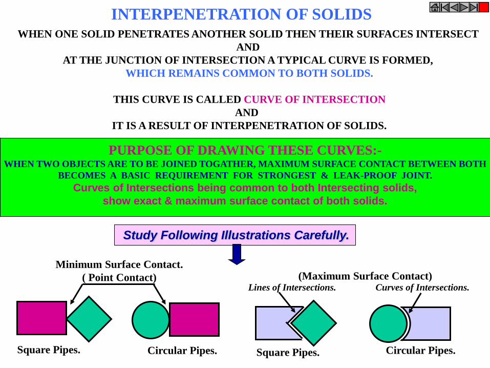
INTERPENETRATION OF SOLIDS WHEN ONE SOLID PENETRATES ANOTHER SOLID THEN THEIR SURFACES INTERSECT
AND
AT THE JUNCTION OF INTERSECTION A TYPICAL CURVE IS FORMED,
WHICH REMAINS COMMON TO BOTH SOLIDS.
THIS CURVE IS CALLED CURVE OF INTERSECTION
AND
IT IS A RESULT OF INTERPENETRATION OF SOLIDS.
PURPOSE OF DRAWING THESE CURVES:- WHEN TWO OBJECTS ARE TO BE JOINED TOGATHER, MAXIMUM SURFACE CONTACT BETWEEN BOTH
BECOMES A BASIC REQUIREMENT FOR STRONGEST & LEAK-PROOF JOINT.
Curves of Intersections being common to both Intersecting solids,
show exact & maximum surface contact of both solids.
Study Following Illustrations Carefully.
Square Pipes. Circular Pipes. Square Pipes. Circular Pipes.
Minimum Surface Contact.
( Point Contact) (Maximum Surface Contact) Lines of Intersections. Curves of Intersections.
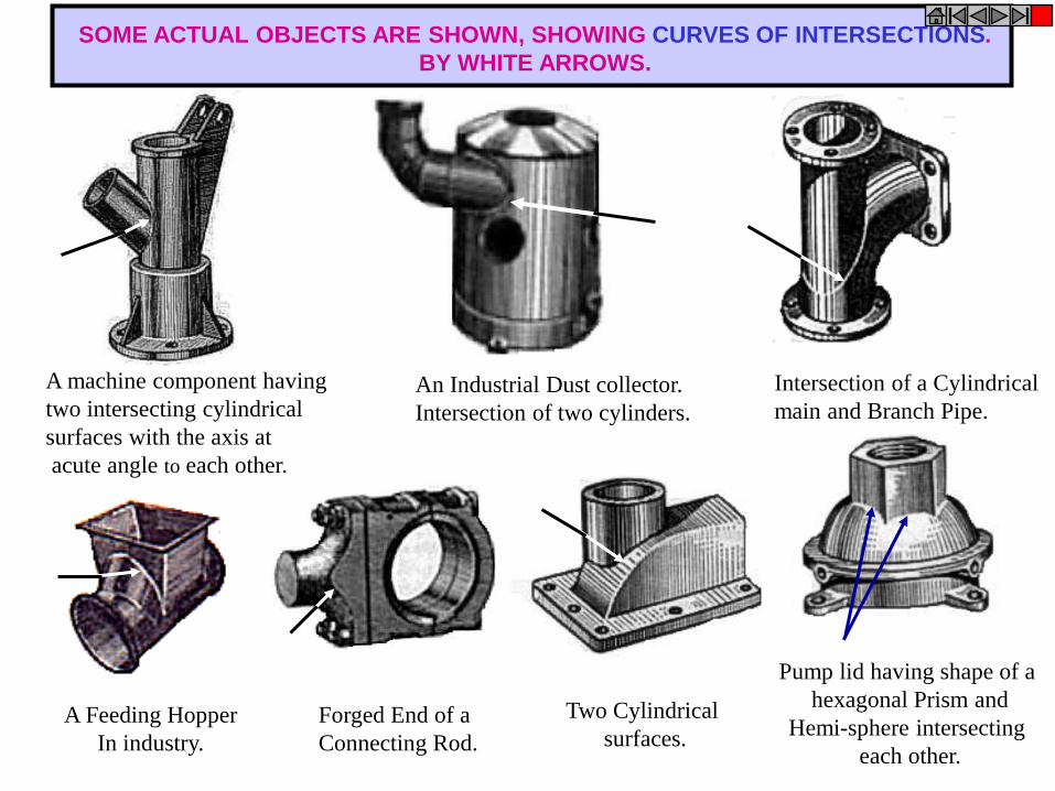
A machine component having
two intersecting cylindrical
surfaces with the axis at
acute angle to each other.
Intersection of a Cylindrical
main and Branch Pipe.
Pump lid having shape of a
hexagonal Prism and
Hemi-sphere intersecting
each other.
Forged End of a
Connecting Rod.
A Feeding Hopper
In industry.
An Industrial Dust collector.
Intersection of two cylinders.
Two Cylindrical
surfaces.
SOME ACTUAL OBJECTS ARE SHOWN, SHOWING CURVES OF INTERSECTIONS.
BY WHITE ARROWS.
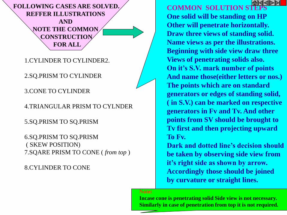
FOLLOWING CASES ARE SOLVED.
REFFER ILLUSTRATIONS
AND
NOTE THE COMMON
CONSTRUCTION
FOR ALL
1.CYLINDER TO CYLINDER2.
2.SQ.PRISM TO CYLINDER
3.CONE TO CYLINDER
4.TRIANGULAR PRISM TO CYLNDER
5.SQ.PRISM TO SQ.PRISM
6.SQ.PRISM TO SQ.PRISM
( SKEW POSITION)
7.SQARE PRISM TO CONE ( from top )
8.CYLINDER TO CONE
COMMON SOLUTION STEPS
One solid will be standing on HP
Other will penetrate horizontally.
Draw three views of standing solid.
Name views as per the illustrations.
Beginning with side view draw three
Views of penetrating solids also.
On it’s S.V. mark number of points
And name those(either letters or nos.)
The points which are on standard
generators or edges of standing solid,
( in S.V.) can be marked on respective
generators in Fv and Tv. And other
points from SV should be brought to
Tv first and then projecting upward
To Fv.
Dark and dotted line’s decision should
be taken by observing side view from
it’s right side as shown by arrow.
Accordingly those should be joined
by curvature or straight lines.
Note:
Incase cone is penetrating solid Side view is not necessary.
Similarly in case of penetration from top it is not required.
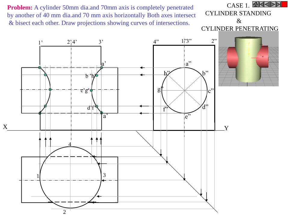
X Y
1
2
3
4
a”
g” c”
e”
b”
f” d”
h”
4” 1” 3” 2” 1’ 2’ 4’ 3’
a’
b ’h’
c’g’
d’f’
a’
CASE 1.
CYLINDER STANDING
&
CYLINDER PENETRATING
Problem: A cylinder 50mm dia.and 70mm axis is completely penetrated
by another of 40 mm dia.and 70 mm axis horizontally Both axes intersect
& bisect each other. Draw projections showing curves of intersections.
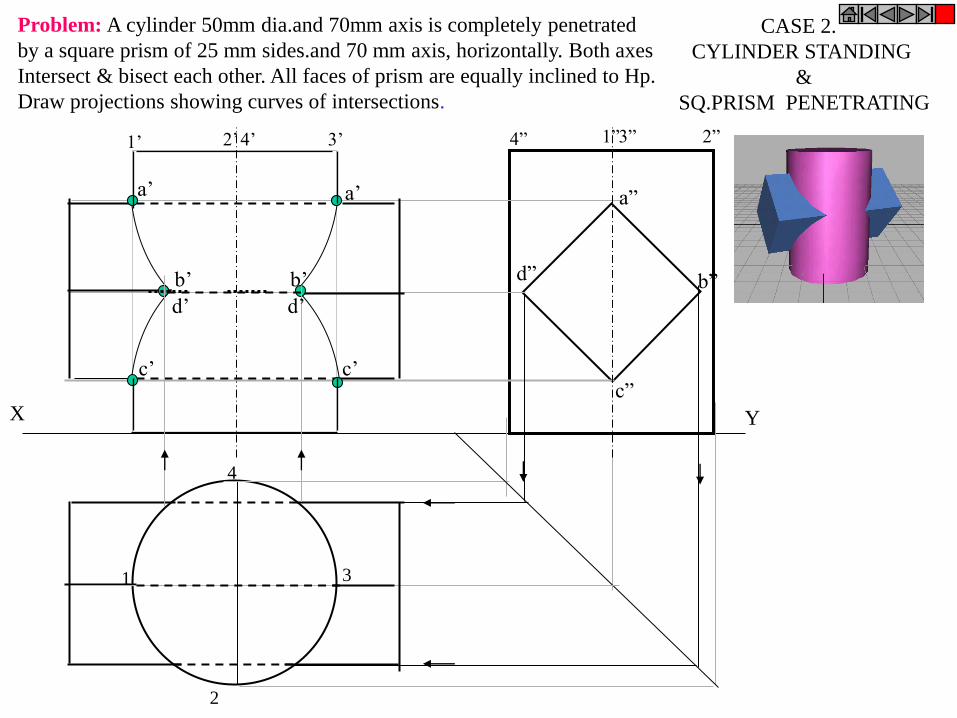
X Y
a”
d” b”
c”
4” 1” 3” 2” 1’ 2’ 4’ 3’
1
2
3
4
a’
d’
b’
c’
a’
c’
d’
b’
CASE 2.
CYLINDER STANDING
&
SQ.PRISM PENETRATING
Problem: A cylinder 50mm dia.and 70mm axis is completely penetrated
by a square prism of 25 mm sides.and 70 mm axis, horizontally. Both axes
Intersect & bisect each other. All faces of prism are equally inclined to Hp.
Draw projections showing curves of intersections.
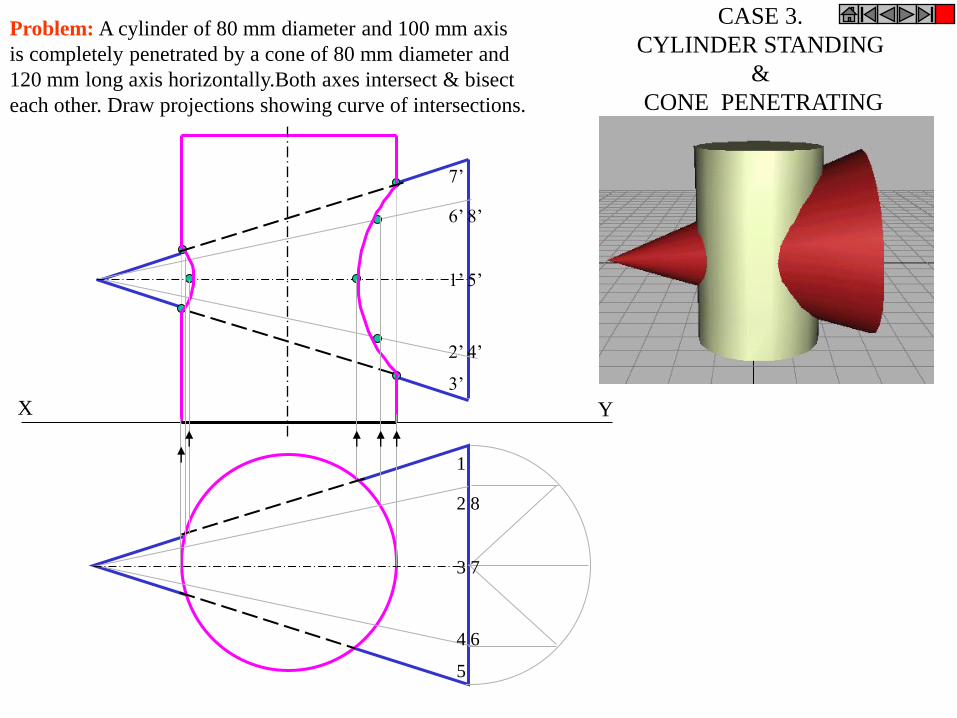
X Y
CASE 3.
CYLINDER STANDING
&
CONE PENETRATING
Problem: A cylinder of 80 mm diameter and 100 mm axis
is completely penetrated by a cone of 80 mm diameter and
120 mm long axis horizontally.Both axes intersect & bisect
each other. Draw projections showing curve of intersections.
1
2 8
3 7
4 6
5
7’
6’ 8’
1’ 5’
2’ 4’
3’
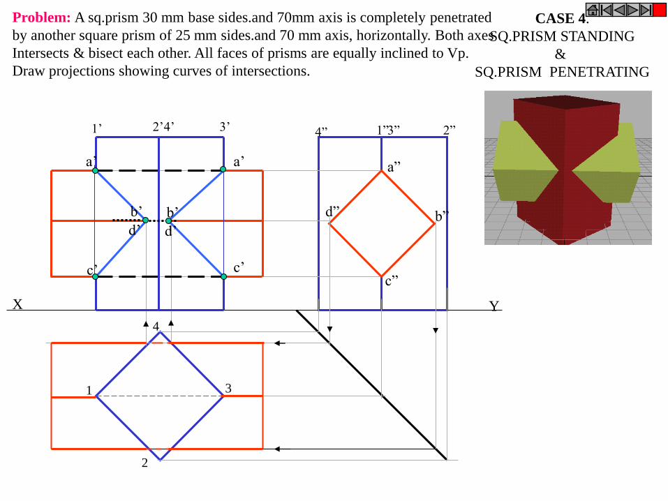
X Y
a”
d” b”
c”
a’
c’
a’
d’
b’
c’
d’
b’
1
2
3
4
1’ 2’ 4’ 3’ 4” 1” 3” 2”
CASE 4.
SQ.PRISM STANDING
&
SQ.PRISM PENETRATING
Problem: A sq.prism 30 mm base sides.and 70mm axis is completely penetrated
by another square prism of 25 mm sides.and 70 mm axis, horizontally. Both axes
Intersects & bisect each other. All faces of prisms are equally inclined to Vp.
Draw projections showing curves of intersections.
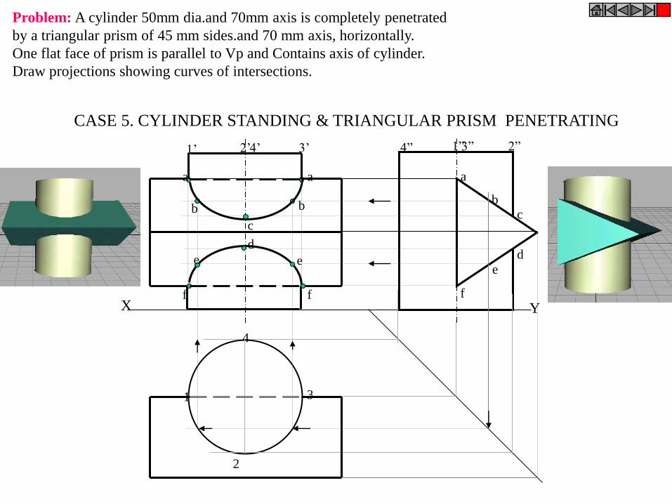
X Y
1
2
3
4
4” 1” 3” 2” 1’ 2’ 4’ 3’
b
e
a
c
d
f
b b
c
d
e e
a a
f f
CASE 5. CYLINDER STANDING & TRIANGULAR PRISM PENETRATING
Problem: A cylinder 50mm dia.and 70mm axis is completely penetrated
by a triangular prism of 45 mm sides.and 70 mm axis, horizontally.
One flat face of prism is parallel to Vp and Contains axis of cylinder.
Draw projections showing curves of intersections.
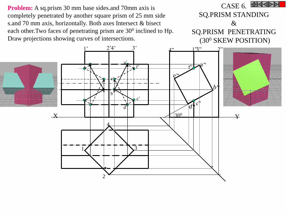
X Y
1
2
3
4
1’ 2’ 4’ 3’ 4” 1” 3” 2”
300
c”
f” a’
f’
c’
d’
b’
e’
CASE 6.
SQ.PRISM STANDING
&
SQ.PRISM PENETRATING
(300 SKEW POSITION)
Problem: A sq.prism 30 mm base sides.and 70mm axis is
completely penetrated by another square prism of 25 mm side
s.and 70 mm axis, horizontally. Both axes Intersect & bisect
each other.Two faces of penetrating prism are 300 inclined to Hp.
Draw projections showing curves of intersections.
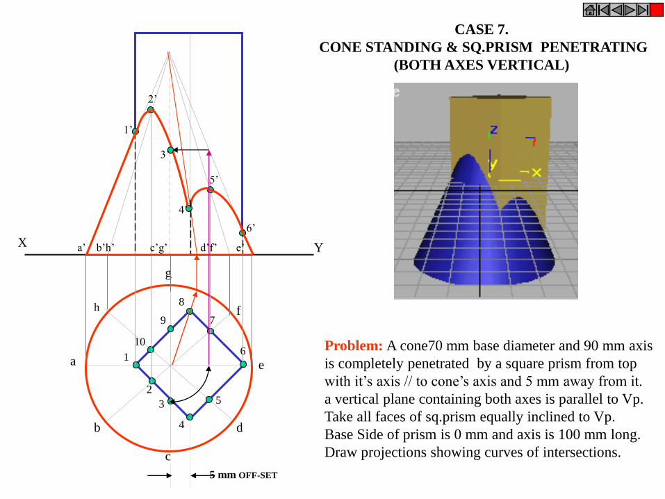
X Y
h
a
b
c
d
e
g
f
1
2
3
4
5
6 10
9
8
7
a’ b’h’ c’g’ d’f’ e’
5 mm OFF-SET
1’
2’
5’
4’
3’
6’
CASE 7.
CONE STANDING & SQ.PRISM PENETRATING
(BOTH AXES VERTICAL)
Problem: A cone70 mm base diameter and 90 mm axis
is completely penetrated by a square prism from top
with it’s axis // to cone’s axis and 5 mm away from it.
a vertical plane containing both axes is parallel to Vp.
Take all faces of sq.prism equally inclined to Vp.
Base Side of prism is 0 mm and axis is 100 mm long.
Draw projections showing curves of intersections.

CASE 8.
CONE STANDING
&
CYLINDER PENETRATING
h
a
b
c
d
e
g
f
a’ b’h’ c’g’ d’f’ e’ g” g”h” a”e” b”d” c”
1 2
3
4
5
6
7
8
X Y
o” o’
1 1
3 3
5 5 6
7,
8, 2 2
4 4
Problem: A vertical cone, base diameter 75 mm and axis 100 mm long,
is completely penetrated by a cylinder of 45 mm diameter. The axis of the
cylinder is parallel to Hp and Vp and intersects axis of the cone at a point
28 mm above the base. Draw projections showing curves of intersection.
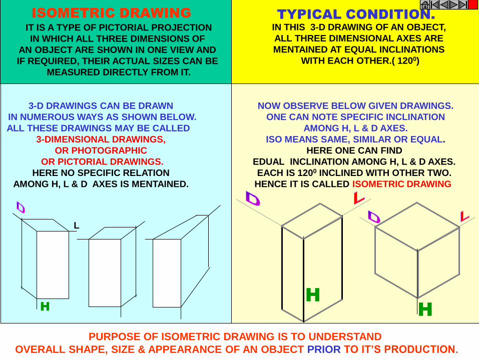
H
3-D DRAWINGS CAN BE DRAWN
IN NUMEROUS WAYS AS SHOWN BELOW.
ALL THESE DRAWINGS MAY BE CALLED
3-DIMENSIONAL DRAWINGS,
OR PHOTOGRAPHIC
OR PICTORIAL DRAWINGS.
HERE NO SPECIFIC RELATION
AMONG H, L & D AXES IS MENTAINED.
H
NOW OBSERVE BELOW GIVEN DRAWINGS.
ONE CAN NOTE SPECIFIC INCLINATION
AMONG H, L & D AXES.
ISO MEANS SAME, SIMILAR OR EQUAL.
HERE ONE CAN FIND
EDUAL INCLINATION AMONG H, L & D AXES.
EACH IS 1200 INCLINED WITH OTHER TWO.
HENCE IT IS CALLED ISOMETRIC DRAWING
H
L
IT IS A TYPE OF PICTORIAL PROJECTION
IN WHICH ALL THREE DIMENSIONS OF
AN OBJECT ARE SHOWN IN ONE VIEW AND
IF REQUIRED, THEIR ACTUAL SIZES CAN BE
MEASURED DIRECTLY FROM IT.
IN THIS 3-D DRAWING OF AN OBJECT,
ALL THREE DIMENSIONAL AXES ARE
MENTAINED AT EQUAL INCLINATIONS
WITH EACH OTHER.( 1200)
PURPOSE OF ISOMETRIC DRAWING IS TO UNDERSTAND
OVERALL SHAPE, SIZE & APPEARANCE OF AN OBJECT PRIOR TO IT’S PRODUCTION.
ISOMETRIC DRAWING TYPICAL CONDITION.
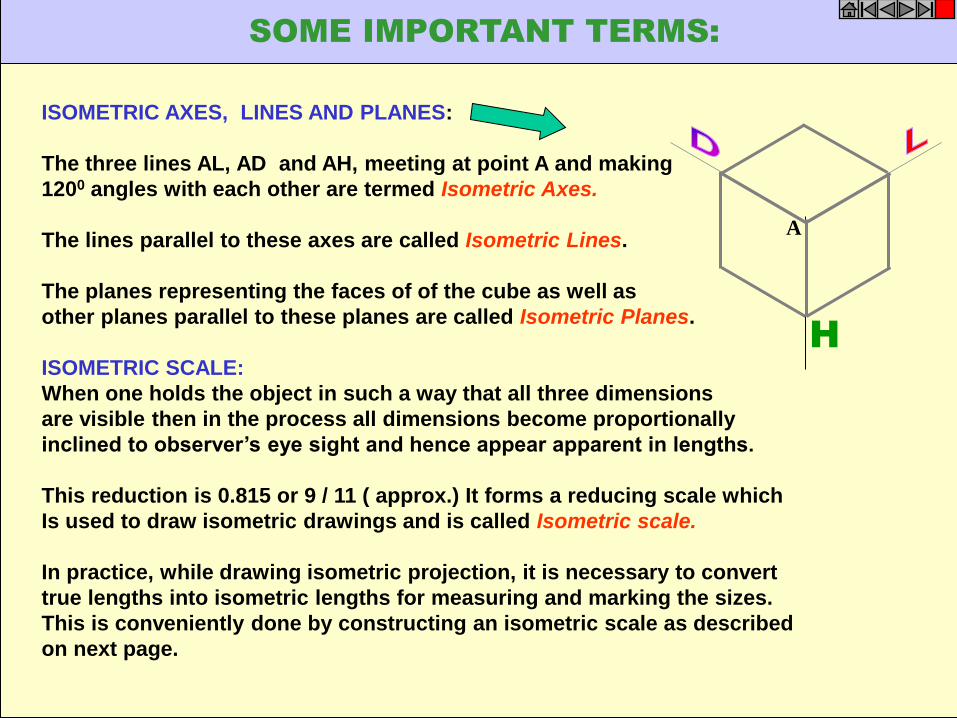
ISOMETRIC AXES, LINES AND PLANES:
The three lines AL, AD and AH, meeting at point A and making
1200 angles with each other are termed Isometric Axes.
The lines parallel to these axes are called Isometric Lines.
The planes representing the faces of of the cube as well as
other planes parallel to these planes are called Isometric Planes.
ISOMETRIC SCALE:
When one holds the object in such a way that all three dimensions
are visible then in the process all dimensions become proportionally
inclined to observer’s eye sight and hence appear apparent in lengths.
This reduction is 0.815 or 9 / 11 ( approx.) It forms a reducing scale which
Is used to draw isometric drawings and is called Isometric scale.
In practice, while drawing isometric projection, it is necessary to convert
true lengths into isometric lengths for measuring and marking the sizes.
This is conveniently done by constructing an isometric scale as described
on next page.
H
A
SOME IMPORTANT TERMS:
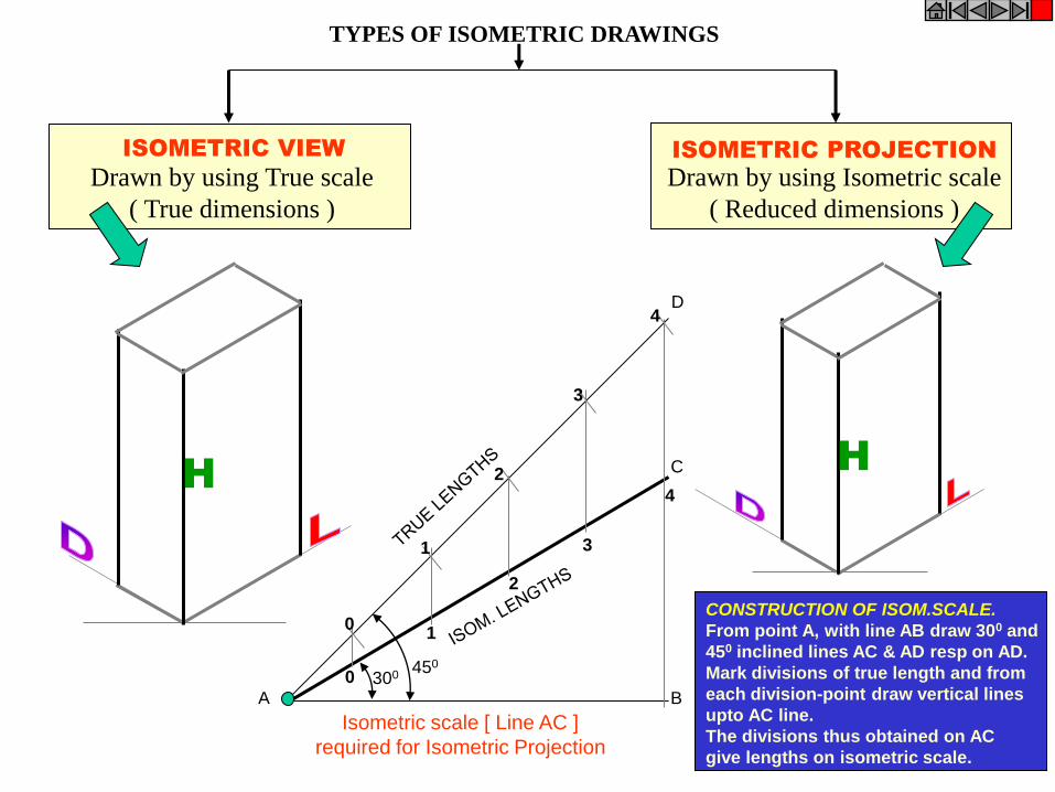
ISOMETRIC VIEW ISOMETRIC PROJECTION
H H
TYPES OF ISOMETRIC DRAWINGS
Drawn by using Isometric scale
( Reduced dimensions )
Drawn by using True scale
( True dimensions )
450
300
0
1
2
3
4
0
1
2
3
4
Isometric scale [ Line AC ]
required for Isometric Projection
A B
C
D
CONSTRUCTION OF ISOM.SCALE.
From point A, with line AB draw 300 and
450 inclined lines AC & AD resp on AD.
Mark divisions of true length and from
each division-point draw vertical lines
upto AC line.
The divisions thus obtained on AC
give lengths on isometric scale.

SHAPE Isometric view if the Shape is
F.V. or T.V.
TRIANGLE
A
B
RECTANGLE D
C
H D
A
B
C
A
B
D
C
H
1
2
3
A
B 3
1
2
A
B
3
1
2
A
B
H
1
2 3
4
PENTAGON
A
B C
D
E 1
2
3
4
A
B
C
D
E
1
2
3
4
A
B
C
D E
ISOMETRIC OF
PLANE FIGURES
AS THESE ALL ARE 2-D FIGURES
WE REQUIRE ONLY TWO ISOMETRIC AXES.
IF THE FIGURE IS
FRONT VIEW, H & L AXES ARE REQUIRED.
IF THE FIGURE IS TOP VIEW, D & L AXES ARE
REQUIRED.
Shapes containing Inclined lines should
be enclosed in a rectangle as shown. Then first draw isom. of that rectangle and
then inscribe that shape as it is.
1
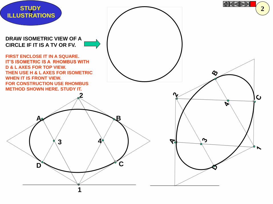
1
4
2
3
A B
D C
Z STUDY
ILLUSTRATIONS
DRAW ISOMETRIC VIEW OF A
CIRCLE IF IT IS A TV OR FV.
FIRST ENCLOSE IT IN A SQUARE.
IT’S ISOMETRIC IS A RHOMBUS WITH
D & L AXES FOR TOP VIEW.
THEN USE H & L AXES FOR ISOMETRIC
WHEN IT IS FRONT VIEW.
FOR CONSTRUCTION USE RHOMBUS
METHOD SHOWN HERE. STUDY IT.
2
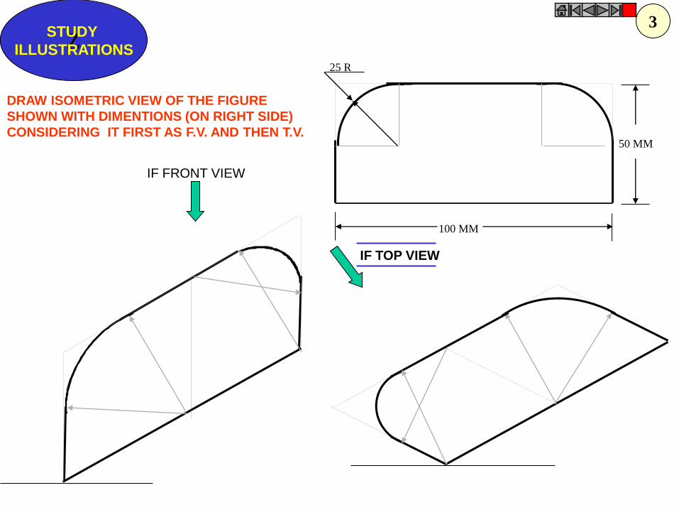
25 R
100 MM
50 MM
Z STUDY
ILLUSTRATIONS
DRAW ISOMETRIC VIEW OF THE FIGURE
SHOWN WITH DIMENTIONS (ON RIGHT SIDE)
CONSIDERING IT FIRST AS F.V. AND THEN T.V.
IF TOP VIEW
IF FRONT VIEW
3
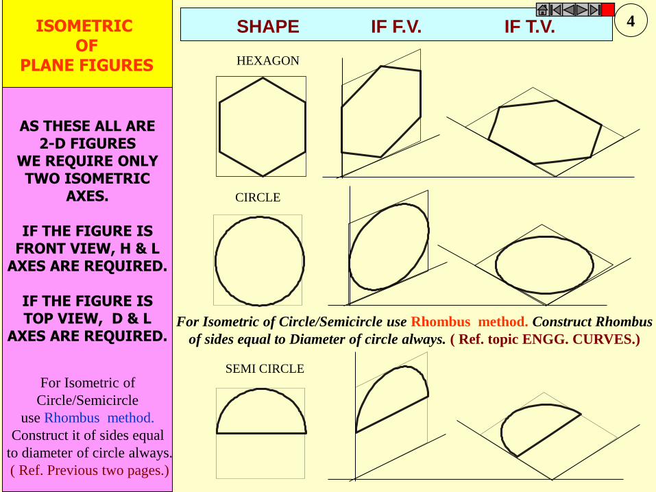
CIRCLE
HEXAGON
SEMI CIRCLE
ISOMETRIC OF
PLANE FIGURES
AS THESE ALL ARE 2-D FIGURES
WE REQUIRE ONLY TWO ISOMETRIC
AXES.
IF THE FIGURE IS FRONT VIEW, H & L
AXES ARE REQUIRED.
IF THE FIGURE IS TOP VIEW, D & L
AXES ARE REQUIRED.
SHAPE IF F.V. IF T.V.
For Isometric of Circle/Semicircle use Rhombus method. Construct Rhombus
of sides equal to Diameter of circle always. ( Ref. topic ENGG. CURVES.)
For Isometric of
Circle/Semicircle
use Rhombus method.
Construct it of sides equal
to diameter of circle always.
( Ref. Previous two pages.)
4
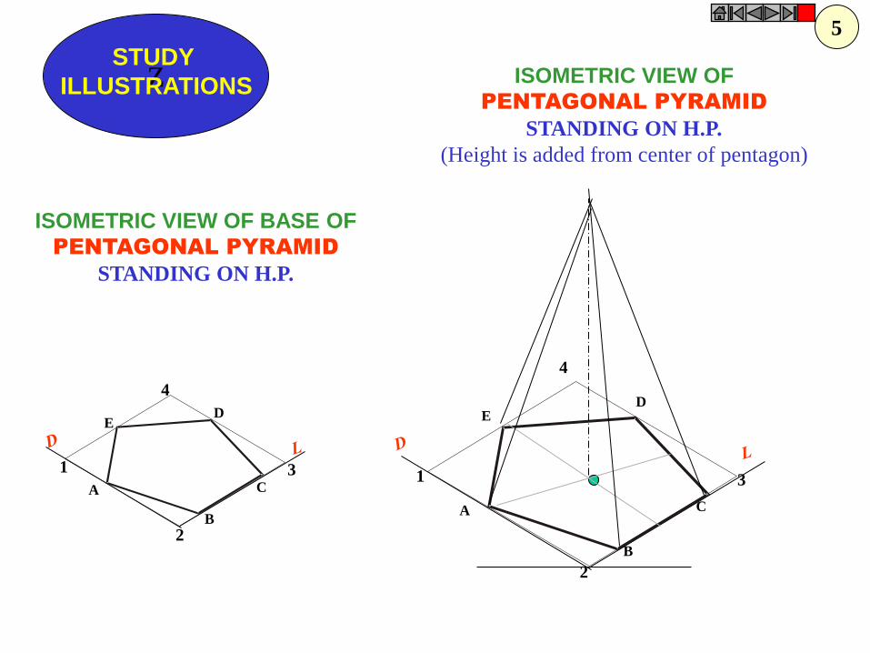
1
2
3
4
A
B
C
D E
1
2
3
4
A
B
C
D E
ISOMETRIC VIEW OF
PENTAGONAL PYRAMID
STANDING ON H.P.
(Height is added from center of pentagon)
ISOMETRIC VIEW OF BASE OF
PENTAGONAL PYRAMID
STANDING ON H.P.
Z STUDY
ILLUSTRATIONS
5
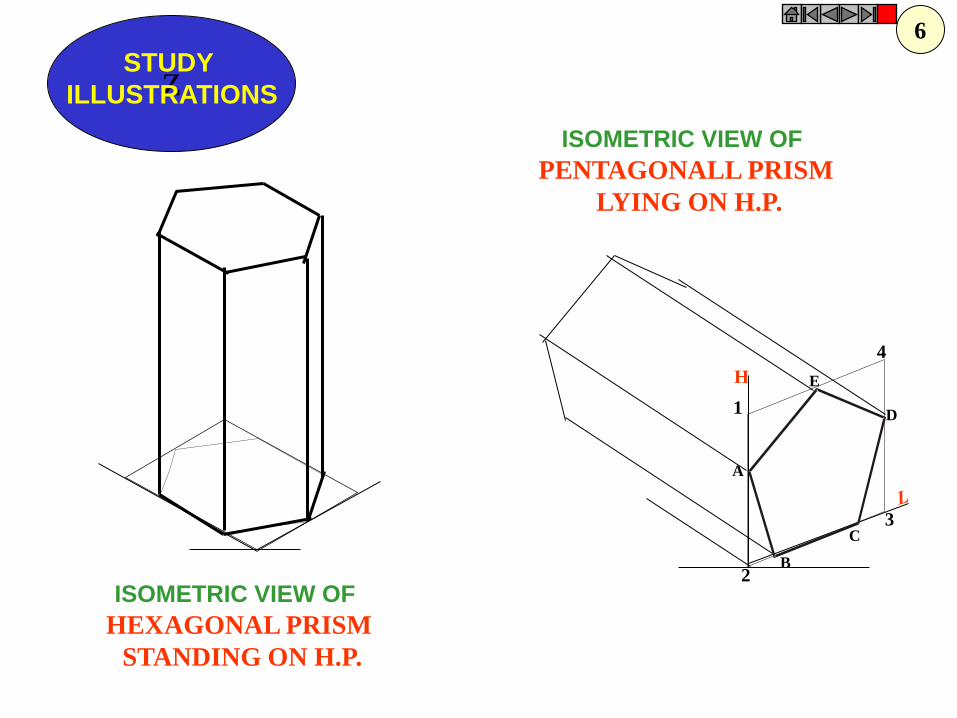
H
1
2
3
4
A
B
C
D
E
Z STUDY
ILLUSTRATIONS
ISOMETRIC VIEW OF
PENTAGONALL PRISM
LYING ON H.P.
ISOMETRIC VIEW OF
HEXAGONAL PRISM
STANDING ON H.P.
6
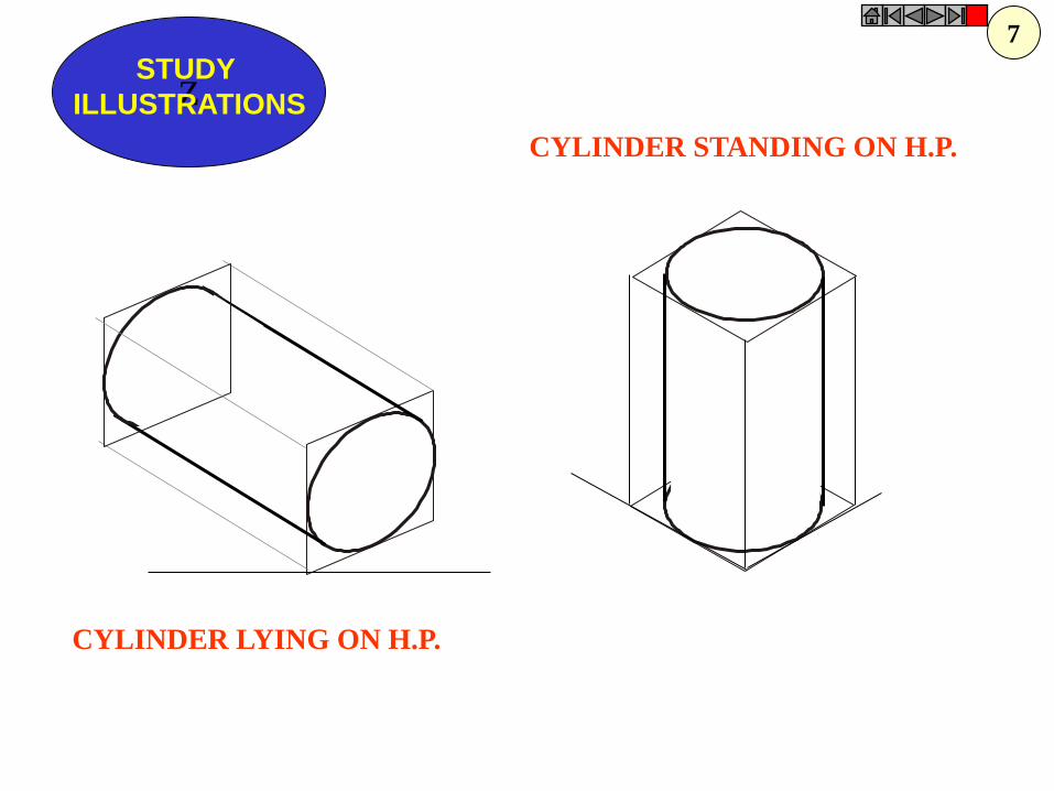
Z STUDY
ILLUSTRATIONS
CYLINDER LYING ON H.P.
CYLINDER STANDING ON H.P.
7
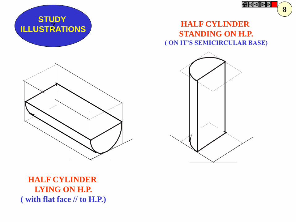
Z STUDY
ILLUSTRATIONS
HALF CYLINDER
LYING ON H.P.
( with flat face // to H.P.)
HALF CYLINDER
STANDING ON H.P. ( ON IT’S SEMICIRCULAR BASE)
8

Z STUDY
ILLUSTRATIONS
ISOMETRIC VIEW OF
A FRUSTOM OF SQUARE PYRAMID
STANDING ON H.P. ON IT’S LARGER BASE.
40 20
60
X Y
FV
TV
9
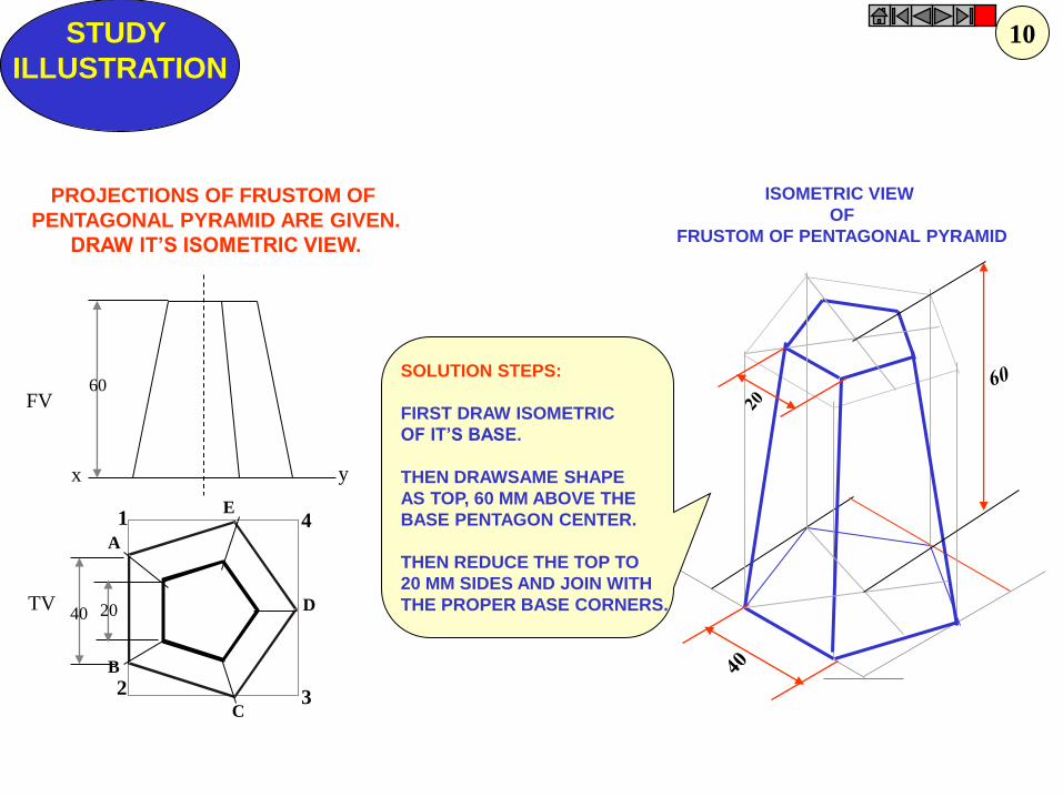
ISOMETRIC VIEW
OF
FRUSTOM OF PENTAGONAL PYRAMID
STUDY
ILLUSTRATION
1
2 3
4
y
A
B
C
D
E
40 20
60
x
FV
TV
PROJECTIONS OF FRUSTOM OF
PENTAGONAL PYRAMID ARE GIVEN.
DRAW IT’S ISOMETRIC VIEW.
SOLUTION STEPS:
FIRST DRAW ISOMETRIC
OF IT’S BASE.
THEN DRAWSAME SHAPE
AS TOP, 60 MM ABOVE THE
BASE PENTAGON CENTER.
THEN REDUCE THE TOP TO
20 MM SIDES AND JOIN WITH
THE PROPER BASE CORNERS.
10
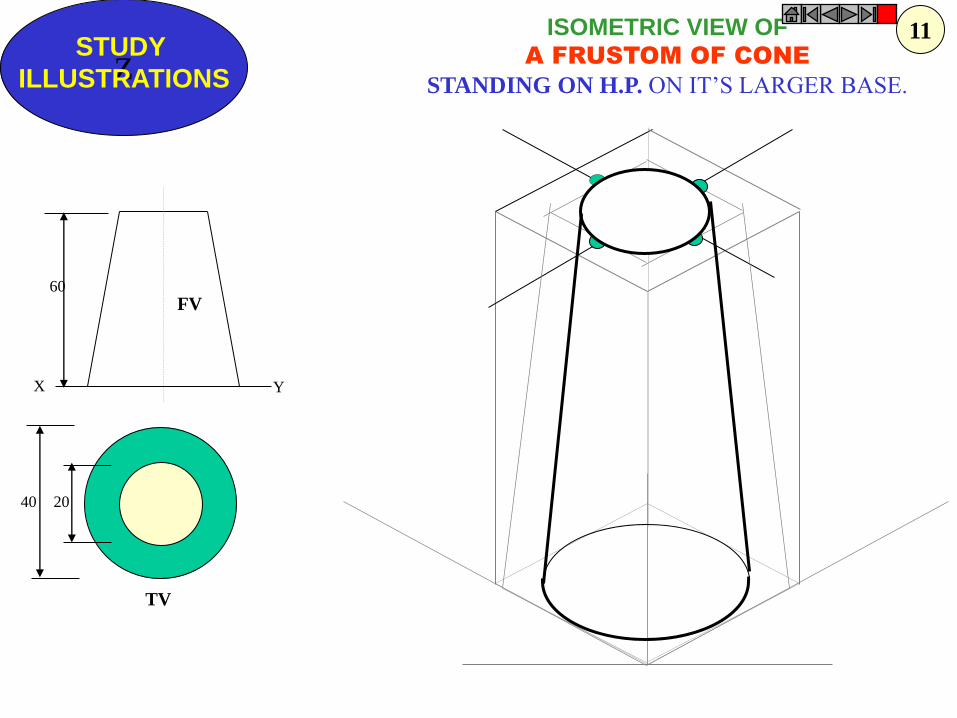
Z STUDY
ILLUSTRATIONS
ISOMETRIC VIEW OF
A FRUSTOM OF CONE
STANDING ON H.P. ON IT’S LARGER BASE.
FV
TV
40 20
60
X Y
11
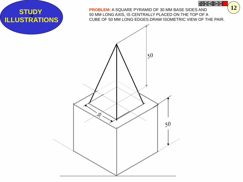
Z STUDY
ILLUSTRATIONS
PROBLEM: A SQUARE PYRAMID OF 30 MM BASE SIDES AND
50 MM LONG AXIS, IS CENTRALLY PLACED ON THE TOP OF A
CUBE OF 50 MM LONG EDGES.DRAW ISOMETRIC VIEW OF THE PAIR.
12
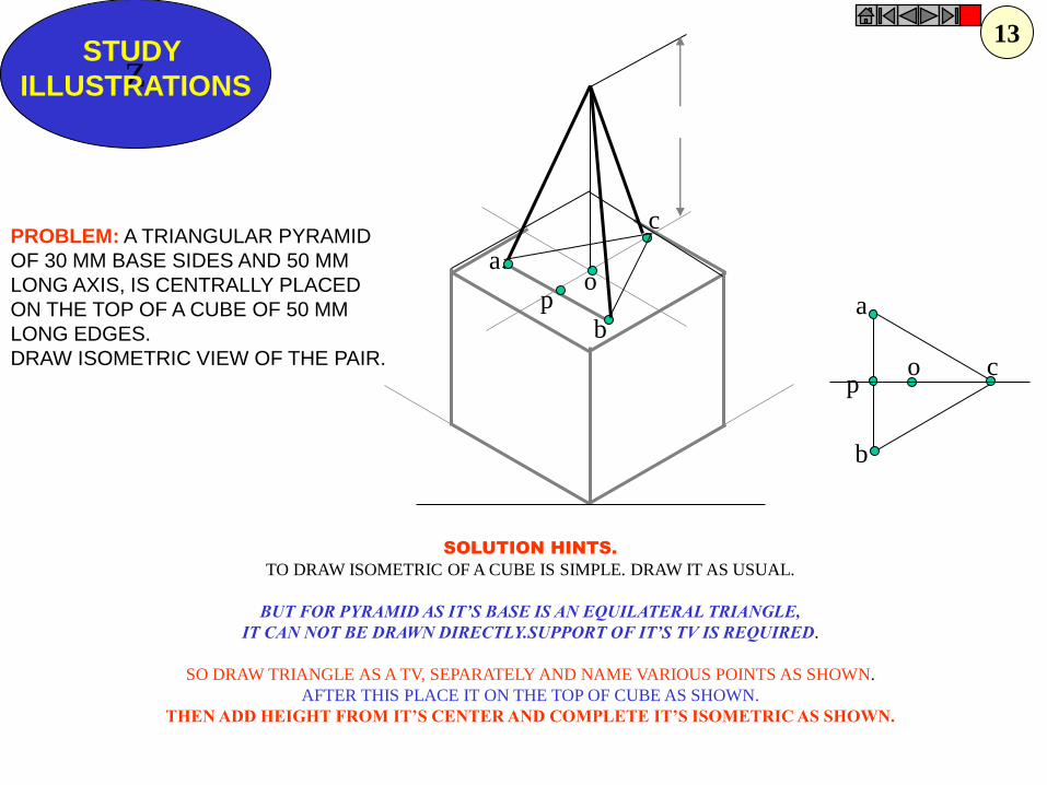
a
b
c o p
p
a
b
c
o
Z STUDY
ILLUSTRATIONS
PROBLEM: A TRIANGULAR PYRAMID
OF 30 MM BASE SIDES AND 50 MM
LONG AXIS, IS CENTRALLY PLACED
ON THE TOP OF A CUBE OF 50 MM
LONG EDGES.
DRAW ISOMETRIC VIEW OF THE PAIR.
SOLUTION HINTS.
TO DRAW ISOMETRIC OF A CUBE IS SIMPLE. DRAW IT AS USUAL.
BUT FOR PYRAMID AS IT’S BASE IS AN EQUILATERAL TRIANGLE,
IT CAN NOT BE DRAWN DIRECTLY.SUPPORT OF IT’S TV IS REQUIRED.
SO DRAW TRIANGLE AS A TV, SEPARATELY AND NAME VARIOUS POINTS AS SHOWN.
AFTER THIS PLACE IT ON THE TOP OF CUBE AS SHOWN.
THEN ADD HEIGHT FROM IT’S CENTER AND COMPLETE IT’S ISOMETRIC AS SHOWN.
13

Z STUDY
ILLUSTRATIONS
50
50
30 D
30
10
30
+
FV
TV
PROBLEM:
A SQUARE PLATE IS PIERCED THROUGH CENTRALLY
BY A CYLINDER WHICH COMES OUT EQUALLY FROM BOTH FACES
OF PLATE. IT’S FV & TV ARE SHOWN. DRAW ISOMETRIC VIEW.
14
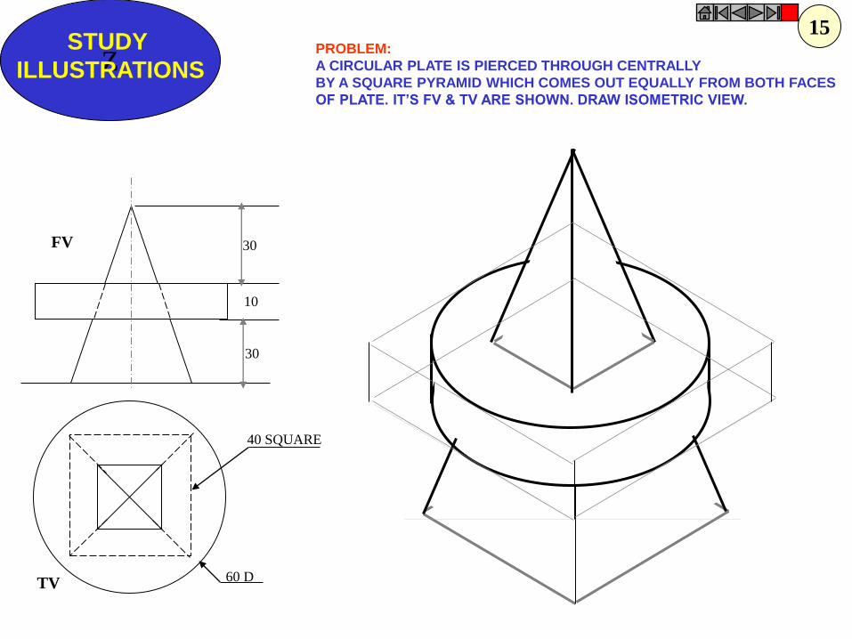
Z STUDY
ILLUSTRATIONS
30
10
30
60 D
40 SQUARE
FV
TV
PROBLEM:
A CIRCULAR PLATE IS PIERCED THROUGH CENTRALLY
BY A SQUARE PYRAMID WHICH COMES OUT EQUALLY FROM BOTH FACES
OF PLATE. IT’S FV & TV ARE SHOWN. DRAW ISOMETRIC VIEW.
15
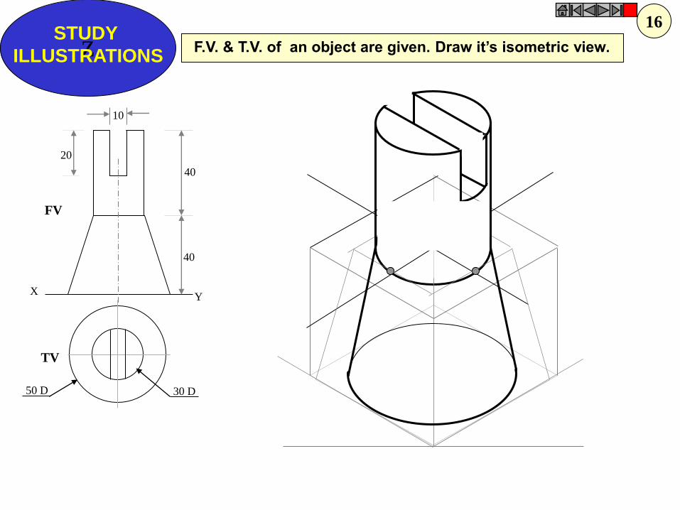
Z STUDY
ILLUSTRATIONS
X Y
30 D 50 D
10
40
20
40
FV
TV
F.V. & T.V. of an object are given. Draw it’s isometric view.
16

P
r
R R
r
P
C
C = Center of Sphere.
P = Point of contact
R = True Radius of Sphere
r = Isometric Radius.
R
r
P
r
R
C
r
r
ISOMETRIC PROJECTIONS OF SPHERE & HEMISPHERE
450
300
TO DRAW ISOMETRIC PROJECTION
OF A HEMISPHERE
TO DRAW ISOMETRIC PROJECTION OF A SPHERE
1. FIRST DRAW ISOMETRIC OF SQUARE PLATE.
2. LOCATE IT’S CENTER. NAME IT P.
3. FROM PDRAW VERTICAL LINE UPWARD, LENGTH ‘ r mm’
AND LOCATE CENTER OF SPHERE “C”
4. ‘C’ AS CENTER, WITH RADIUS ‘R’ DRAW CIRCLE.
THIS IS ISOMETRIC PROJECTION OF A SPHERE.
Adopt same procedure.
Draw lower semicircle only.
Then around ‘C’ construct
Rhombus of Sides equal to
Isometric Diameter.
For this use iso-scale.
Then construct ellipse in
this Rhombus as usual
And Complete
Isometric-Projection
of Hemi-sphere.
Z STUDY
ILLUSTRATIONS
Isom. Scale
17

P
r
R
r
r 50 D
30 D
50 D
50
450
300
PROBLEM:
A HEMI-SPHERE IS CENTRALLY PLACED
ON THE TOP OF A FRUSTOM OF CONE.
DRAW ISOMETRIC PROJECTIONS OF THE ASSEMBLY.
FIRST CONSTRUCT ISOMETRIC SCALE.
USE THIS SCALE FOR ALL DIMENSIONS
IN THIS PROBLEM.
Z STUDY
ILLUSTRATIONS
18
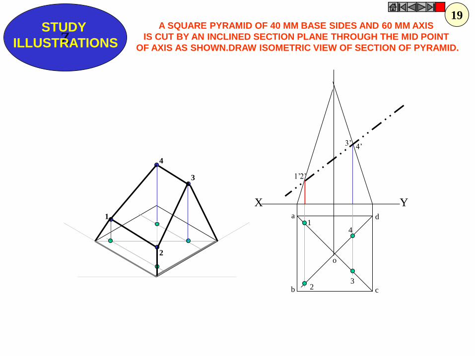
a
b c
d 1
2 3
4
o
1’
4’ 3’
2’
1
2
4
3
X Y
Z STUDY
ILLUSTRATIONS
A SQUARE PYRAMID OF 40 MM BASE SIDES AND 60 MM AXIS
IS CUT BY AN INCLINED SECTION PLANE THROUGH THE MID POINT
OF AXIS AS SHOWN.DRAW ISOMETRIC VIEW OF SECTION OF PYRAMID.
19

Z STUDY
ILLUSTRATIONS
X Y
50
20
25
25 20
O
O
F.V. & T.V. of an object are given. Draw it’s isometric view.
20
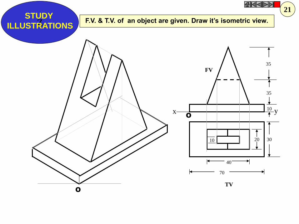
Z STUDY
ILLUSTRATIONS
x y
FV
TV
35
35
10
30 20 10
40
70
O
O
F.V. & T.V. of an object are given. Draw it’s isometric view.
21
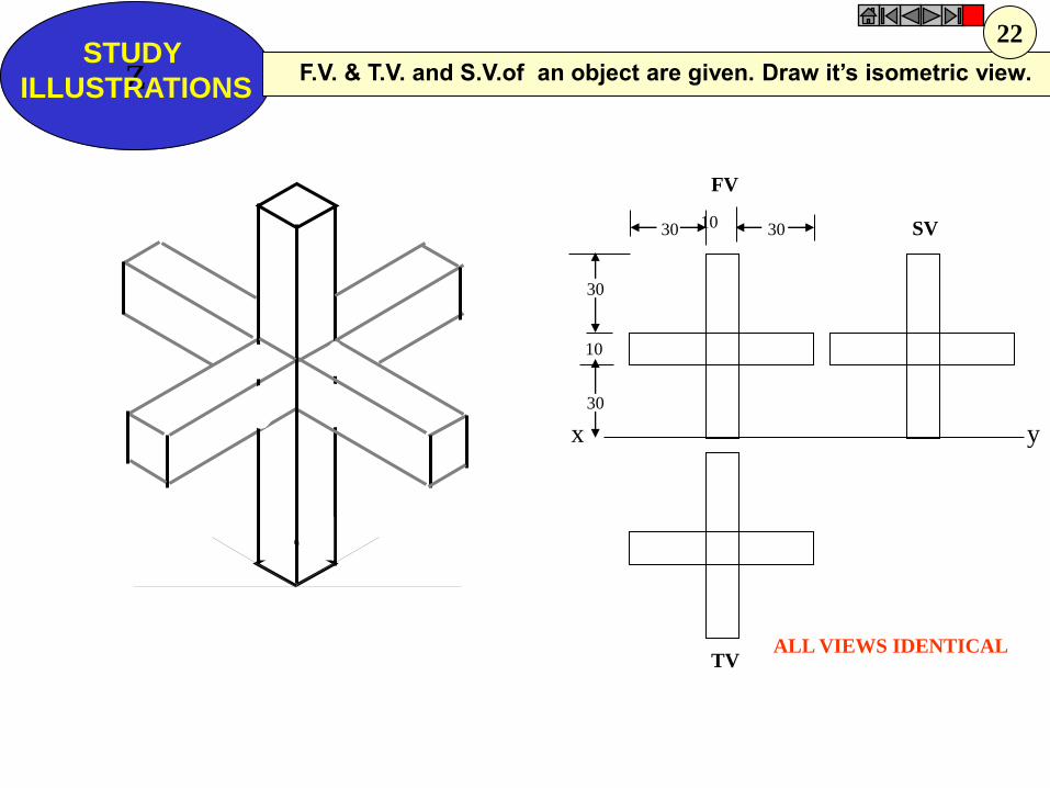
Z STUDY
ILLUSTRATIONS
x y
FV
SV
TV
30
30
10
30 10 30
ALL VIEWS IDENTICAL
F.V. & T.V. and S.V.of an object are given. Draw it’s isometric view.
22

x y
FV SV
TV
Z STUDY
ILLUSTRATIONS
10 40 60
60
40
ALL VIEWS IDENTICAL
F.V. & T.V. and S.V.of an object are given. Draw it’s isometric view.
24
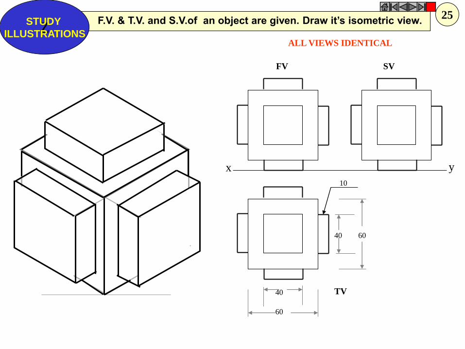
x y
FV SV
TV
ALL VIEWS IDENTICAL
40 60
60
40
10
F.V. & T.V. and S.V.of an object are given. Draw it’s isometric view. Z
STUDY
ILLUSTRATIONS
25
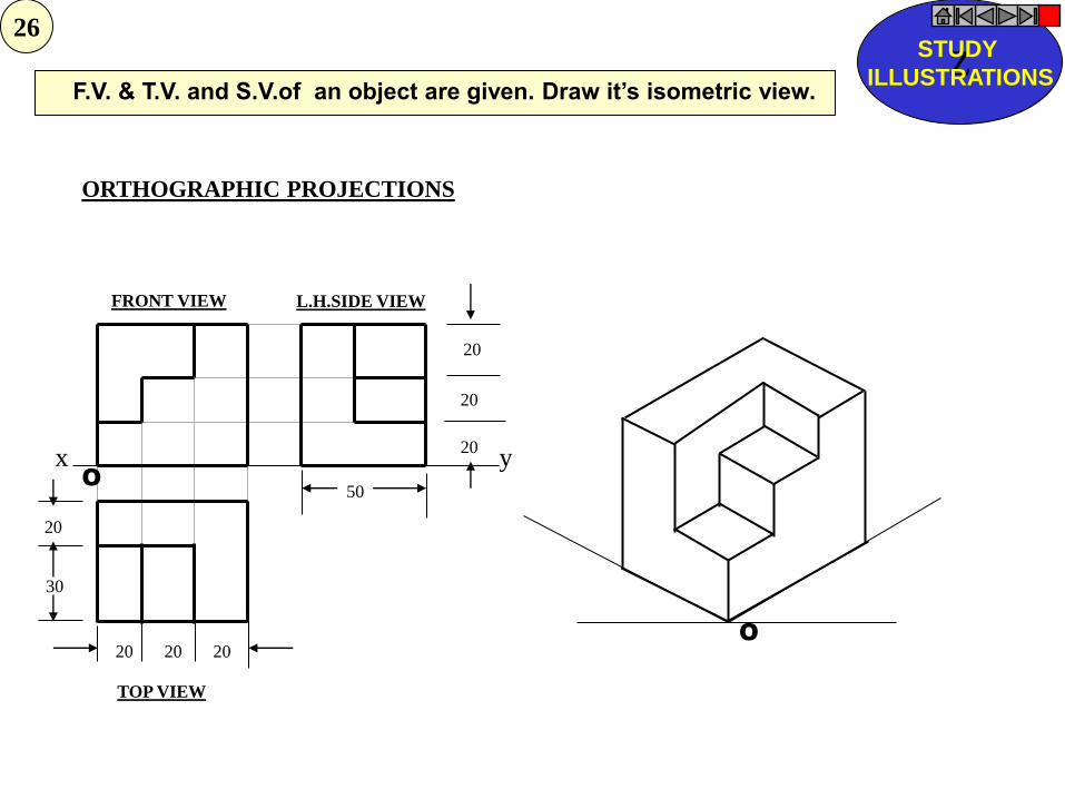
ORTHOGRAPHIC PROJECTIONS
FRONT VIEW
TOP VIEW
L.H.SIDE VIEW
x y
20
20
20
50
20 20 20
20
30
O
O
F.V. & T.V. and S.V.of an object are given. Draw it’s isometric view. Z
STUDY
ILLUSTRATIONS
26
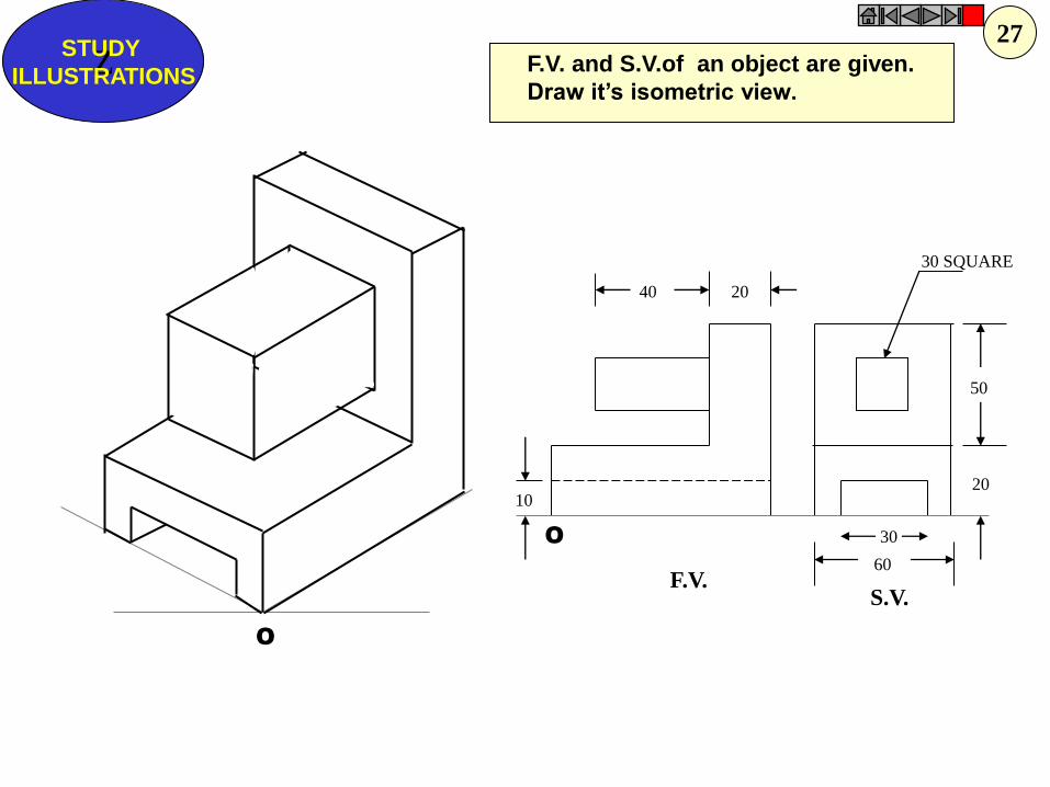
40 20
30 SQUARE
20
50
60
30
10
F.V. S.V.
O
O
F.V. and S.V.of an object are given.
Draw it’s isometric view. Z
STUDY
ILLUSTRATIONS
27
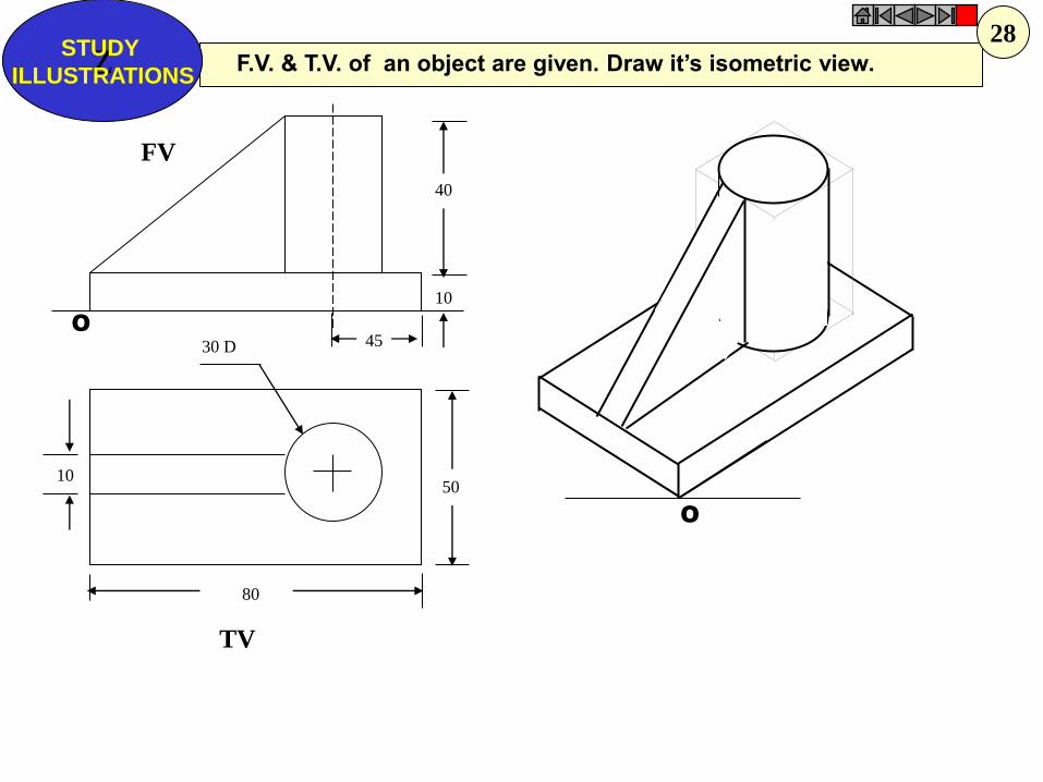
40
10
50
80
10
30 D 45
FV
TV
O
O
F.V. & T.V. of an object are given. Draw it’s isometric view. Z STUDY
ILLUSTRATIONS
28
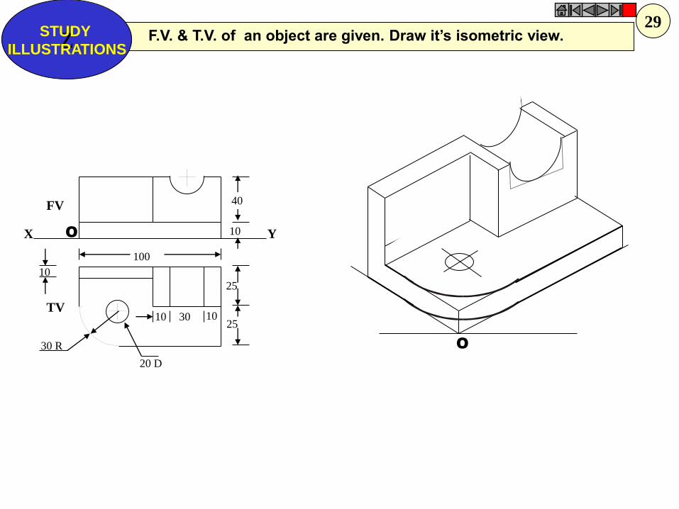
O
FV
TV
X Y O
40
10
25
25
30 R
10
100
10 30 10
20 D
F.V. & T.V. of an object are given. Draw it’s isometric view. Z STUDY
ILLUSTRATIONS
29
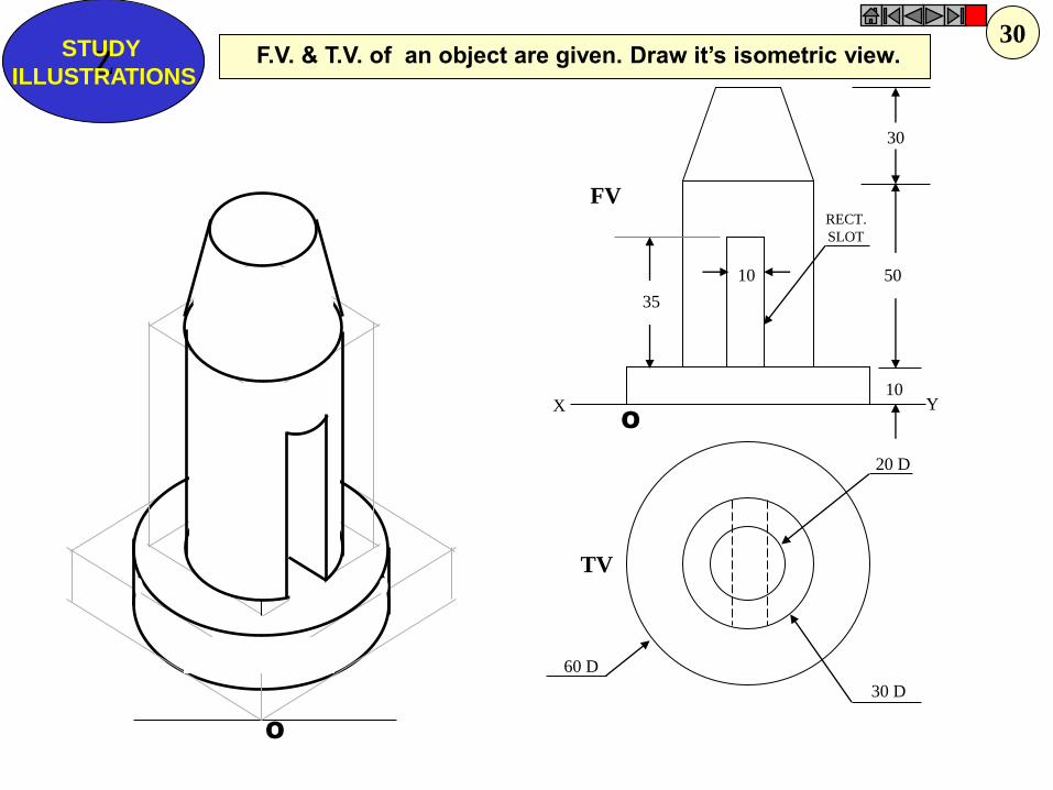
O
O
10
30
50
10
35
20 D
30 D
60 D
FV
TV
X Y
RECT.
SLOT
F.V. & T.V. of an object are given. Draw it’s isometric view. Z STUDY
ILLUSTRATIONS
30
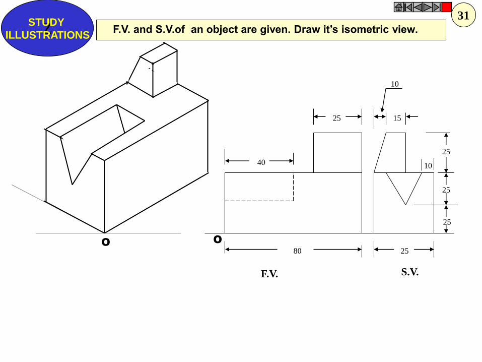
O
10
O
40
25 15
25
25
25
25 80
10
F.V. S.V.
F.V. and S.V.of an object are given. Draw it’s isometric view. Z STUDY
ILLUSTRATIONS
31
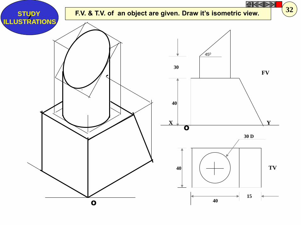
O
450
X
TV
FV
Y
30 D
30
40
40
40 15
O
F.V. & T.V. of an object are given. Draw it’s isometric view. Z
STUDY
ILLUSTRATIONS
32
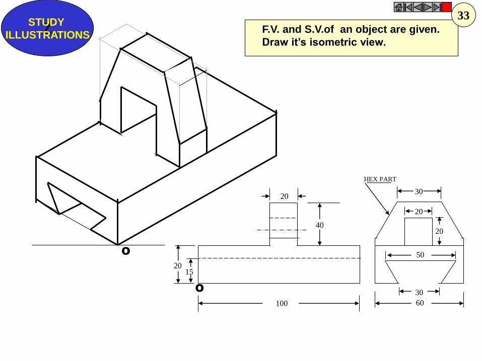
O
O
20
20 15
30
60
30
20
20
40
100
50
HEX PART
F.V. and S.V.of an object are given.
Draw it’s isometric view. Z
STUDY
ILLUSTRATIONS
33

O
O
10
10
30
10
30
40 20
80
30
F.V.
T.V.
X Y
F.V. & T.V. of an object are given. Draw it’s isometric view. Z STUDY
ILLUSTRATIONS
34

FV LSV
X Y
10
O
FV LSV
X Y
10 10 15
25
25
10 50 O
F.V. and S.V.of an object are given.
Draw it’s isometric view.
Z STUDY
ILLUSTRATIONS
35
36
NOTE THE SMALL CHZNGE IN 2ND FV & SV.
DRAW ISOMETRIC ACCORDINGLY.

Y X
F.V. LEFT S.V.
30 20 20 10
15
15
15 30
50
10
15 O
O
F.V. and S.V.of an object are given.
Draw it’s isometric view.
Z STUDY
ILLUSTRATIONS
37
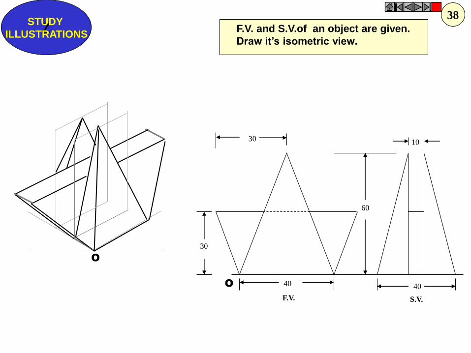
30
40
10
60
30
40
F.V. S.V.
O
O
F.V. and S.V.of an object are given.
Draw it’s isometric view. Z
STUDY
ILLUSTRATIONS
38

PROJECTIONS OF STRAIGHT LINES
1. A line AB is in first quadrant. Its ends A and B are 25mm and 65mm in front of VP
respectively. The distance between the end projectors is 75mm. The line is inclined at 300 to
VP and its VT is 10mm above HP. Draw the projections of AB and determine its true length
and HT and inclination with HP.
2. A line AB measures 100mm. The projections through its VT and end A are 50mm apart.
The point A is 35mm above HP and 25mm in front VP. The VT is 15mm above HP. Draw the
projections of line and determine its HT and Inclinations with HP and VP.
3. Draw the three views of line AB, 80mm long, when it is lying in profile plane and inclined
at 350 to HP. Its end A is in HP and 20mm in front of VP, while other end B is in first
quadrant. Determine also its traces.
4. A line AB 75 mm long, has its one end A in VP and other end B 15mm above HP and
50mm in front of VP. Draw the projections of line when sum of inclinations with HP and VP
is 900. Determine the true angles of inclination and show traces.
5. A line AB is 75mm long and lies in an auxiliary inclined plane (AIP) which makes an
angle of 450 with the HP. The front view of the line measures 55mm. The end A is in VP and
20mm above HP. Draw the projections of the line AB and find its inclination with HP and
VP.
6. Line AB lies in an AVP 500 inclined to Vp while line is 300 inclined to Hp. End A is 10
mm above Hp. & 15 mm in front of Vp.Distance between projectors is 50 mm.Draw
projections and find TL and inclination of line with Vp. Locate traces also.
EXERCISES:
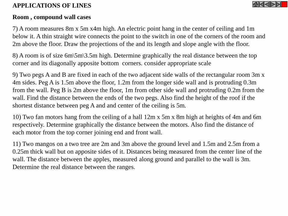
APPLICATIONS OF LINES
Room , compound wall cases
7) A room measures 8m x 5m x4m high. An electric point hang in the center of ceiling and 1m
below it. A thin straight wire connects the point to the switch in one of the corners of the room and
2m above the floor. Draw the projections of the and its length and slope angle with the floor.
8) A room is of size 6m\5m\3.5m high. Determine graphically the real distance between the top
corner and its diagonally apposite bottom corners. consider appropriate scale
9) Two pegs A and B are fixed in each of the two adjacent side walls of the rectangular room 3m x
4m sides. Peg A is 1.5m above the floor, 1.2m from the longer side wall and is protruding 0.3m
from the wall. Peg B is 2m above the floor, 1m from other side wall and protruding 0.2m from the
wall. Find the distance between the ends of the two pegs. Also find the height of the roof if the
shortest distance between peg A and and center of the ceiling is 5m.
10) Two fan motors hang from the ceiling of a hall 12m x 5m x 8m high at heights of 4m and 6m
respectively. Determine graphically the distance between the motors. Also find the distance of
each motor from the top corner joining end and front wall.
11) Two mangos on a two tree are 2m and 3m above the ground level and 1.5m and 2.5m from a
0.25m thick wall but on apposite sides of it. Distances being measured from the center line of the
wall. The distance between the apples, measured along ground and parallel to the wall is 3m.
Determine the real distance between the ranges.
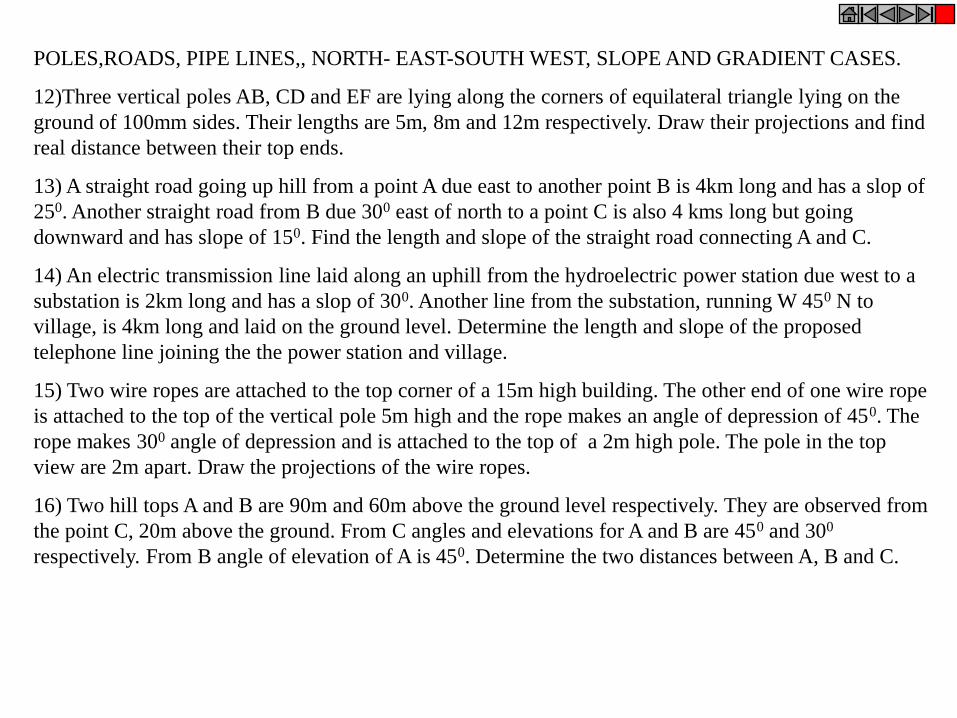
POLES,ROADS, PIPE LINES,, NORTH- EAST-SOUTH WEST, SLOPE AND GRADIENT CASES.
12)Three vertical poles AB, CD and EF are lying along the corners of equilateral triangle lying on the
ground of 100mm sides. Their lengths are 5m, 8m and 12m respectively. Draw their projections and find
real distance between their top ends.
13) A straight road going up hill from a point A due east to another point B is 4km long and has a slop of
250. Another straight road from B due 300 east of north to a point C is also 4 kms long but going
downward and has slope of 150. Find the length and slope of the straight road connecting A and C.
14) An electric transmission line laid along an uphill from the hydroelectric power station due west to a
substation is 2km long and has a slop of 300. Another line from the substation, running W 450 N to
village, is 4km long and laid on the ground level. Determine the length and slope of the proposed
telephone line joining the the power station and village.
15) Two wire ropes are attached to the top corner of a 15m high building. The other end of one wire rope
is attached to the top of the vertical pole 5m high and the rope makes an angle of depression of 450. The
rope makes 300 angle of depression and is attached to the top of a 2m high pole. The pole in the top
view are 2m apart. Draw the projections of the wire ropes.
16) Two hill tops A and B are 90m and 60m above the ground level respectively. They are observed from
the point C, 20m above the ground. From C angles and elevations for A and B are 450 and 300
respectively. From B angle of elevation of A is 450. Determine the two distances between A, B and C.
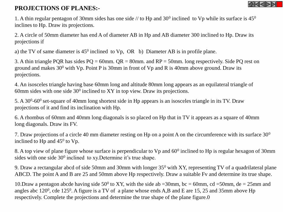
PROJECTIONS OF PLANES:-
1. A thin regular pentagon of 30mm sides has one side // to Hp and 300 inclined to Vp while its surface is 450
inclines to Hp. Draw its projections.
2. A circle of 50mm diameter has end A of diameter AB in Hp and AB diameter 300 inclined to Hp. Draw its
projections if
a) the TV of same diameter is 450 inclined to Vp, OR b) Diameter AB is in profile plane.
3. A thin triangle PQR has sides PQ = 60mm. QR = 80mm. and RP = 50mm. long respectively. Side PQ rest on
ground and makes 300 with Vp. Point P is 30mm in front of Vp and R is 40mm above ground. Draw its
projections.
4. An isosceles triangle having base 60mm long and altitude 80mm long appears as an equilateral triangle of
60mm sides with one side 300 inclined to XY in top view. Draw its projections.
5. A 300-600 set-square of 40mm long shortest side in Hp appears is an isosceles triangle in its TV. Draw
projections of it and find its inclination with Hp.
6. A rhombus of 60mm and 40mm long diagonals is so placed on Hp that in TV it appears as a square of 40mm
long diagonals. Draw its FV.
7. Draw projections of a circle 40 mm diameter resting on Hp on a point A on the circumference with its surface 300
inclined to Hp and 450 to Vp.
8. A top view of plane figure whose surface is perpendicular to Vp and 600 inclined to Hp is regular hexagon of 30mm
sides with one side 300 inclined to xy.Determine it’s true shape.
9. Draw a rectangular abcd of side 50mm and 30mm with longer 350 with XY, representing TV of a quadrilateral plane
ABCD. The point A and B are 25 and 50mm above Hp respectively. Draw a suitable Fv and determine its true shape.
10.Draw a pentagon abcde having side 500 to XY, with the side ab =30mm, bc = 60mm, cd =50mm, de = 25mm and
angles abc 1200, cde 1250. A figure is a TV of a plane whose ends A,B and E are 15, 25 and 35mm above Hp
respectively. Complete the projections and determine the true shape of the plane figure.0
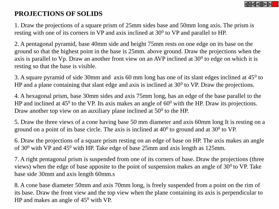
PROJECTIONS OF SOLIDS
1. Draw the projections of a square prism of 25mm sides base and 50mm long axis. The prism is
resting with one of its corners in VP and axis inclined at 300 to VP and parallel to HP.
2. A pentagonal pyramid, base 40mm side and height 75mm rests on one edge on its base on the
ground so that the highest point in the base is 25mm. above ground. Draw the projections when the
axis is parallel to Vp. Draw an another front view on an AVP inclined at 300 to edge on which it is
resting so that the base is visible.
3. A square pyramid of side 30mm and axis 60 mm long has one of its slant edges inclined at 450 to
HP and a plane containing that slant edge and axis is inclined at 300 to VP. Draw the projections.
4. A hexagonal prism, base 30mm sides and axis 75mm long, has an edge of the base parallel to the
HP and inclined at 450 to the VP. Its axis makes an angle of 600 with the HP. Draw its projections.
Draw another top view on an auxiliary plane inclined at 500 to the HP.
5. Draw the three views of a cone having base 50 mm diameter and axis 60mm long It is resting on a
ground on a point of its base circle. The axis is inclined at 400 to ground and at 300 to VP.
6. Draw the projections of a square prism resting on an edge of base on HP. The axis makes an angle
of 300 with VP and 450 with HP. Take edge of base 25mm and axis length as 125mm.
7. A right pentagonal prism is suspended from one of its corners of base. Draw the projections (three
views) when the edge of base apposite to the point of suspension makes an angle of 300 to VP. Take
base side 30mm and axis length 60mm.s
8. A cone base diameter 50mm and axis 70mm long, is freely suspended from a point on the rim of
its base. Draw the front view and the top view when the plane containing its axis is perpendicular to
HP and makes an angle of 450 with VP.
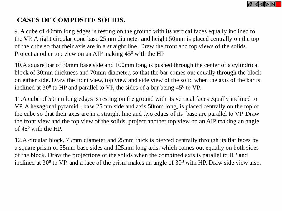
9. A cube of 40mm long edges is resting on the ground with its vertical faces equally inclined to
the VP. A right circular cone base 25mm diameter and height 50mm is placed centrally on the top
of the cube so that their axis are in a straight line. Draw the front and top views of the solids.
Project another top view on an AIP making 450 with the HP
10.A square bar of 30mm base side and 100mm long is pushed through the center of a cylindrical
block of 30mm thickness and 70mm diameter, so that the bar comes out equally through the block
on either side. Draw the front view, top view and side view of the solid when the axis of the bar is
inclined at 300 to HP and parallel to VP, the sides of a bar being 450 to VP.
11.A cube of 50mm long edges is resting on the ground with its vertical faces equally inclined to
VP. A hexagonal pyramid , base 25mm side and axis 50mm long, is placed centrally on the top of
the cube so that their axes are in a straight line and two edges of its base are parallel to VP. Draw
the front view and the top view of the solids, project another top view on an AIP making an angle
of 450 with the HP.
12.A circular block, 75mm diameter and 25mm thick is pierced centrally through its flat faces by
a square prism of 35mm base sides and 125mm long axis, which comes out equally on both sides
of the block. Draw the projections of the solids when the combined axis is parallel to HP and
inclined at 300 to VP, and a face of the prism makes an angle of 300 with HP. Draw side view also.
CASES OF COMPOSITE SOLIDS.
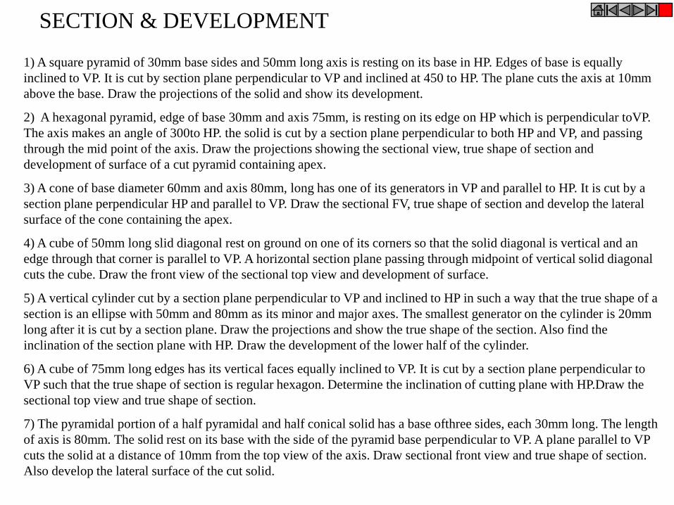
1) A square pyramid of 30mm base sides and 50mm long axis is resting on its base in HP. Edges of base is equally
inclined to VP. It is cut by section plane perpendicular to VP and inclined at 450 to HP. The plane cuts the axis at 10mm
above the base. Draw the projections of the solid and show its development.
2) A hexagonal pyramid, edge of base 30mm and axis 75mm, is resting on its edge on HP which is perpendicular toVP.
The axis makes an angle of 300to HP. the solid is cut by a section plane perpendicular to both HP and VP, and passing
through the mid point of the axis. Draw the projections showing the sectional view, true shape of section and
development of surface of a cut pyramid containing apex.
3) A cone of base diameter 60mm and axis 80mm, long has one of its generators in VP and parallel to HP. It is cut by a
section plane perpendicular HP and parallel to VP. Draw the sectional FV, true shape of section and develop the lateral
surface of the cone containing the apex.
4) A cube of 50mm long slid diagonal rest on ground on one of its corners so that the solid diagonal is vertical and an
edge through that corner is parallel to VP. A horizontal section plane passing through midpoint of vertical solid diagonal
cuts the cube. Draw the front view of the sectional top view and development of surface.
5) A vertical cylinder cut by a section plane perpendicular to VP and inclined to HP in such a way that the true shape of a
section is an ellipse with 50mm and 80mm as its minor and major axes. The smallest generator on the cylinder is 20mm
long after it is cut by a section plane. Draw the projections and show the true shape of the section. Also find the
inclination of the section plane with HP. Draw the development of the lower half of the cylinder.
6) A cube of 75mm long edges has its vertical faces equally inclined to VP. It is cut by a section plane perpendicular to
VP such that the true shape of section is regular hexagon. Determine the inclination of cutting plane with HP.Draw the
sectional top view and true shape of section.
7) The pyramidal portion of a half pyramidal and half conical solid has a base ofthree sides, each 30mm long. The length
of axis is 80mm. The solid rest on its base with the side of the pyramid base perpendicular to VP. A plane parallel to VP
cuts the solid at a distance of 10mm from the top view of the axis. Draw sectional front view and true shape of section.
Also develop the lateral surface of the cut solid.
SECTION & DEVELOPMENT
8) A hexagonal pyramid having edge to edge distance 40mm and height 60mm has its base in HP and an edge
of base perpendicular to VP. It is cut by a section plane, perpendicular to VP and passing through a point on the
axis 10mm from the base. Draw three views of solid when it is resting on its cut face in HP, resting the larger
part of the pyramid. Also draw the lateral surface development of the pyramid.
9) A cone diameter of base 50mm and axis 60mm long is resting on its base on ground. It is cut by a section
plane perpendicular to VP in such a way that the true shape of a section is a parabola having base 40mm. Draw
three views showing section, true shape of section and development of remaining surface of cone removing its
apex.
10) A hexagonal pyramid, base 50mm side and axis 100mm long is lying on ground on one of its triangular
faces with axis parallel to VP. A vertical section plane, the HT of which makes an angle of 300 with the
reference line passes through center of base, the apex being retained. Draw the top view, sectional front view
and the development of surface of the cut pyramid containing apex.
11) Hexagonal pyramid of 40mm base side and height 80mm is resting on its base on ground. It is cut by a
section plane parallel to HP and passing through a point on the axis 25mm from the apex. Draw the projections
of the cut pyramid. A particle P, initially at the mid point of edge of base, starts moving over the surface and
reaches the mid point of apposite edge of the top face. Draw the development of the cut pyramid and show the
shortest path of particle P. Also show the path in front and top views
12) A cube of 65 mm long edges has its vertical face equally inclined to the VP. It is cut by a section plane,
perpendicular to VP, so that the true shape of the section is a regular hexagon, Determine the inclination of the
cutting plane with the HP and draw the sectional top view and true shape of the section.
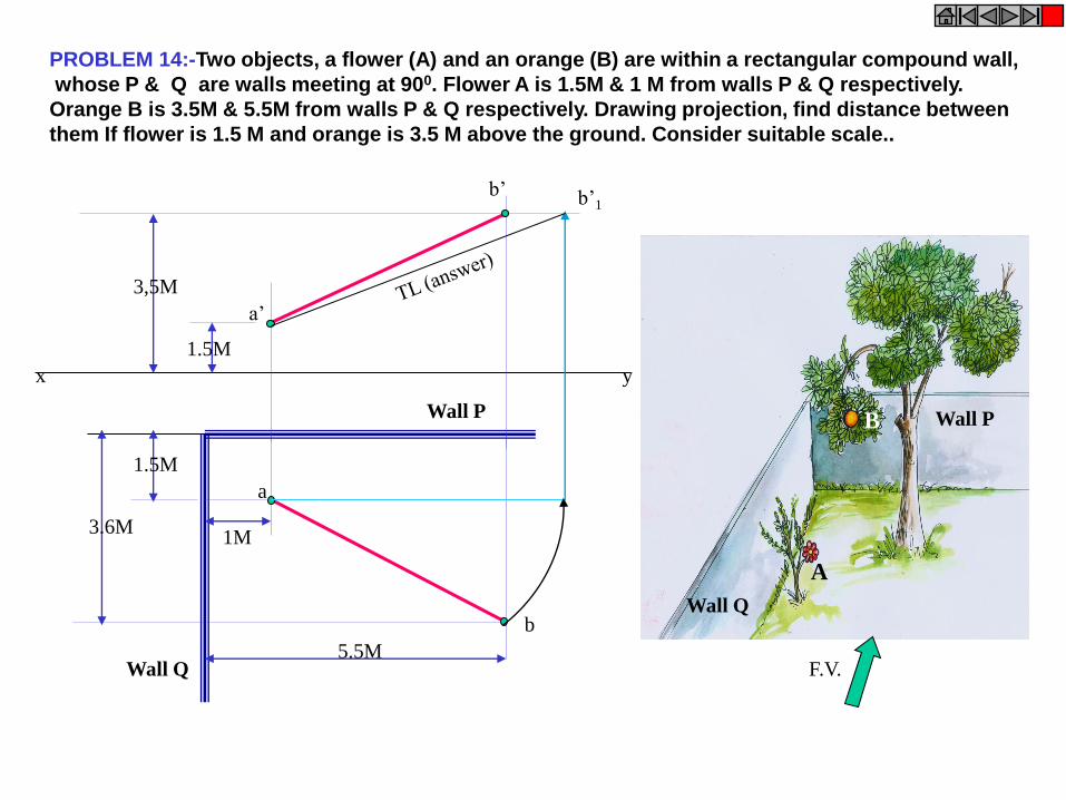
PROBLEM 14:-Two objects, a flower (A) and an orange (B) are within a rectangular compound wall,
whose P & Q are walls meeting at 900. Flower A is 1.5M & 1 M from walls P & Q respectively.
Orange B is 3.5M & 5.5M from walls P & Q respectively. Drawing projection, find distance between
them If flower is 1.5 M and orange is 3.5 M above the ground. Consider suitable scale..
a
b
a’
b’ b’1
x y
1.5M
3,5M
1M
1.5M
3.6M
5.5M
Wall P
Wall Q
A
B
Wall Q
Wall P
F.V.

a
b
a’
b’
3.00 m
1.5m
2.6m
1.2m
1.5m
b1’
Wall thickness
0.3m
WALL
X Y (GL)
REAL DISTANCE BETWEEN
MANGOS A & B IS = a’ b1’
PROBLEM 15 :- Two mangos on a tree A & B are 1.5 m and 3.00 m above ground
and those are 1.2 m & 1.5 m from a 0.3 m thick wall but on opposite sides of it.
If the distance measured between them along the ground and parallel to wall is 2.6 m,
Then find real distance between them by drawing their projections.
TV
0.3M THICK A
B
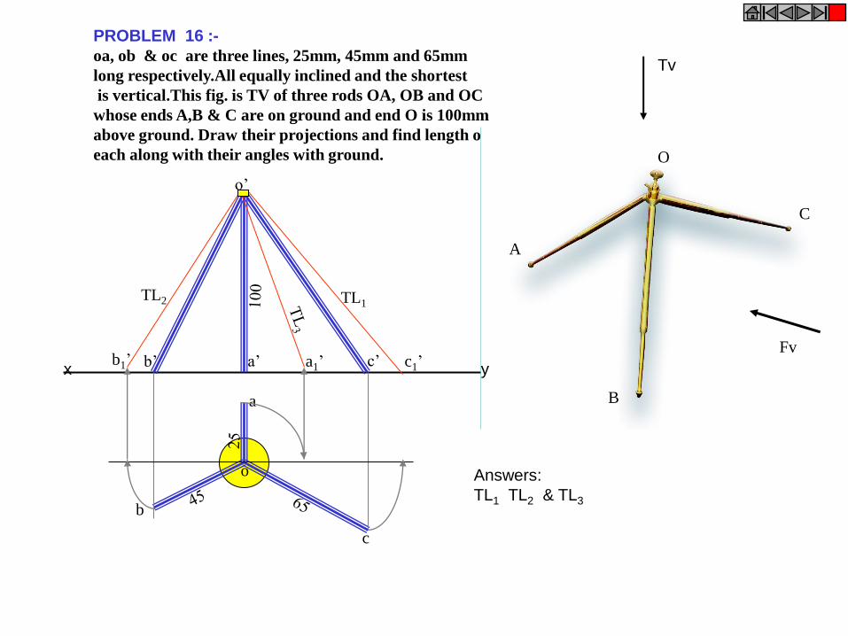
a
b
c
o
a’ b’ c’
o’
TL1 TL2
c1’ b1’ a1’
PROBLEM 16 :-
oa, ob & oc are three lines, 25mm, 45mm and 65mm
long respectively.All equally inclined and the shortest
is vertical.This fig. is TV of three rods OA, OB and OC
whose ends A,B & C are on ground and end O is 100mm
above ground. Draw their projections and find length of
each along with their angles with ground.
A
O
B
C
Fv
Tv
Answers:
TL1 TL2 & TL3
x y
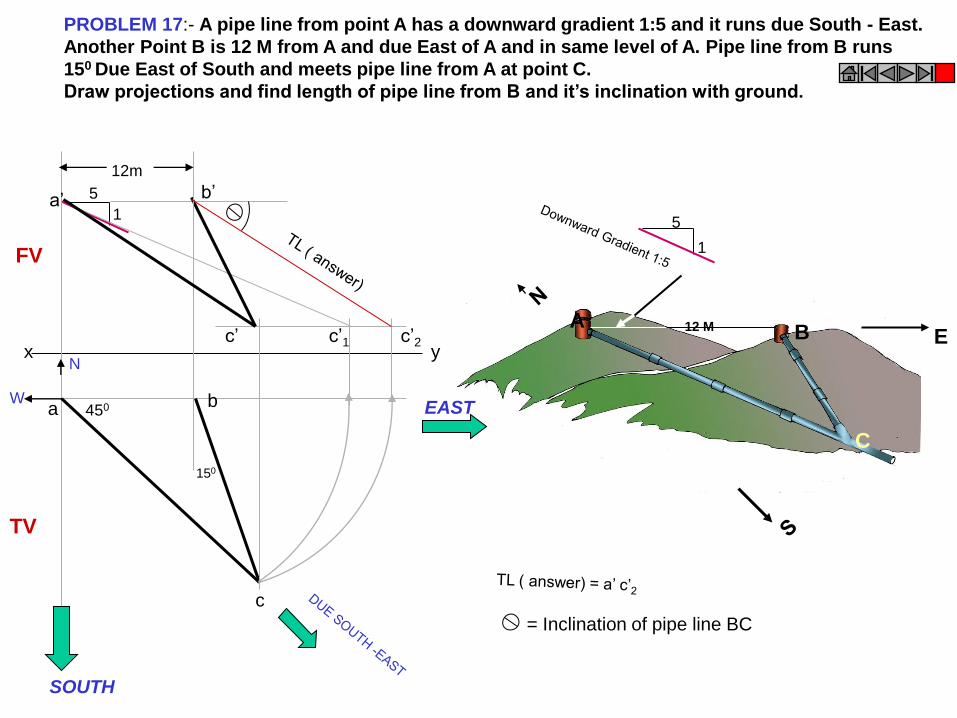
PROBLEM 17:- A pipe line from point A has a downward gradient 1:5 and it runs due South - East.
Another Point B is 12 M from A and due East of A and in same level of A. Pipe line from B runs
150 Due East of South and meets pipe line from A at point C.
Draw projections and find length of pipe line from B and it’s inclination with ground.
A B
C
1
5
12 M E
1
5
a b
c
x y
150
450
12m
N
EAST
SOUTH
W
a’ b’
c’2 c’ c’1
= Inclination of pipe line BC
FV
TV

PROBLEM 18: A person observes two objects, A & B, on the ground, from a tower, 15 M high,
At the angles of depression 300 & 450. Object A is is due North-West direction of observer and
object B is due West direction. Draw projections of situation and find distance of objects from
observer and from tower also.
W
S
A
B
O
300
450
W
S
E
N
o
a
b
o’
a’1 b’ a’
300
450
15M
Answers:
Distances of objects
from observe
o’a’1 & o’b’
From tower
oa & ob
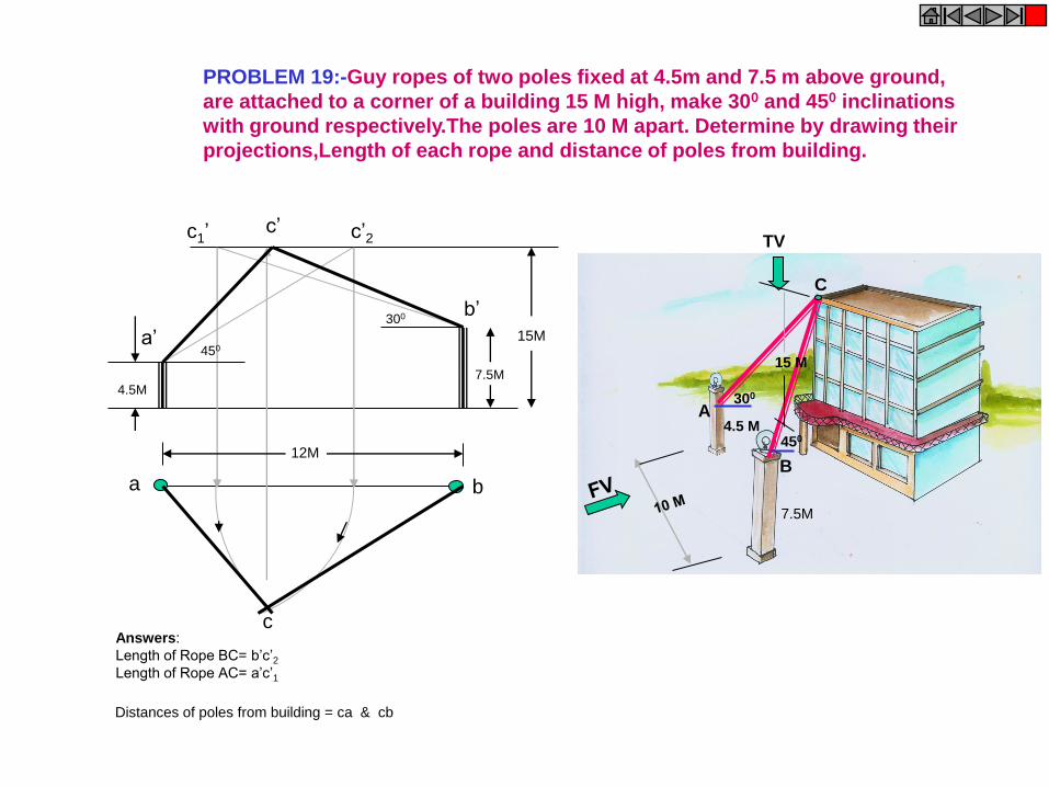
7.5M
TV
B
4.5 M
300
450
15 M
A
C
PROBLEM 19:-Guy ropes of two poles fixed at 4.5m and 7.5 m above ground,
are attached to a corner of a building 15 M high, make 300 and 450 inclinations
with ground respectively.The poles are 10 M apart. Determine by drawing their
projections,Length of each rope and distance of poles from building.
c’
a b
c
a’
b’
c1’ c’2
12M
15M
4.5M 7.5M
300
450
Answers:
Length of Rope BC= b’c’2
Length of Rope AC= a’c’1
Distances of poles from building = ca & cb

4 M
TV
PROBLEM 20:- A tank of 4 M height is to be strengthened by four stay rods from each corner
by fixing their other ends to the flooring, at a point 1.2 M and 0.7 M from two adjacent walls respectively,
as shown. Determine graphically length and angle of each rod with flooring.
A
B a
b
a’
b’ b’1
True Length
Answers:
Length of each rod
= a’b’1
Angle with Hp.
=
X Y
TV
FV
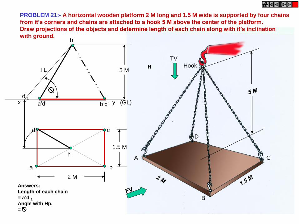
A
B
C
D
Hook
TV
PROBLEM 21:- A horizontal wooden platform 2 M long and 1.5 M wide is supported by four chains
from it’s corners and chains are attached to a hook 5 M above the center of the platform.
Draw projections of the objects and determine length of each chain along with it’s inclination
with ground.
H
(GL)
a b
c d
h
a’d’ b’c’
h’
5 M
2 M
1.5 M
x y
TL
d’1
Answers:
Length of each chain
= a’d’1
Angle with Hp.
=
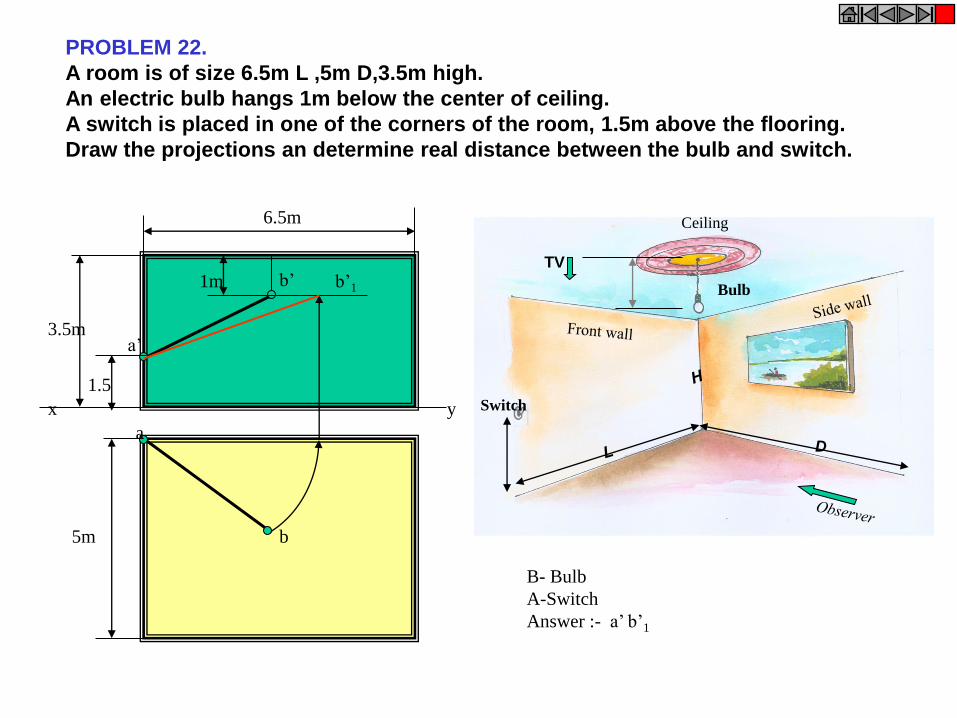
PROBLEM 22.
A room is of size 6.5m L ,5m D,3.5m high.
An electric bulb hangs 1m below the center of ceiling.
A switch is placed in one of the corners of the room, 1.5m above the flooring.
Draw the projections an determine real distance between the bulb and switch.
Switch
Bulb
Ceiling
TV
D
B- Bulb
A-Switch
Answer :- a’ b’1
a
b
x y
a’
b’ b’1
6.5m
3.5m
5m
1m
1.5
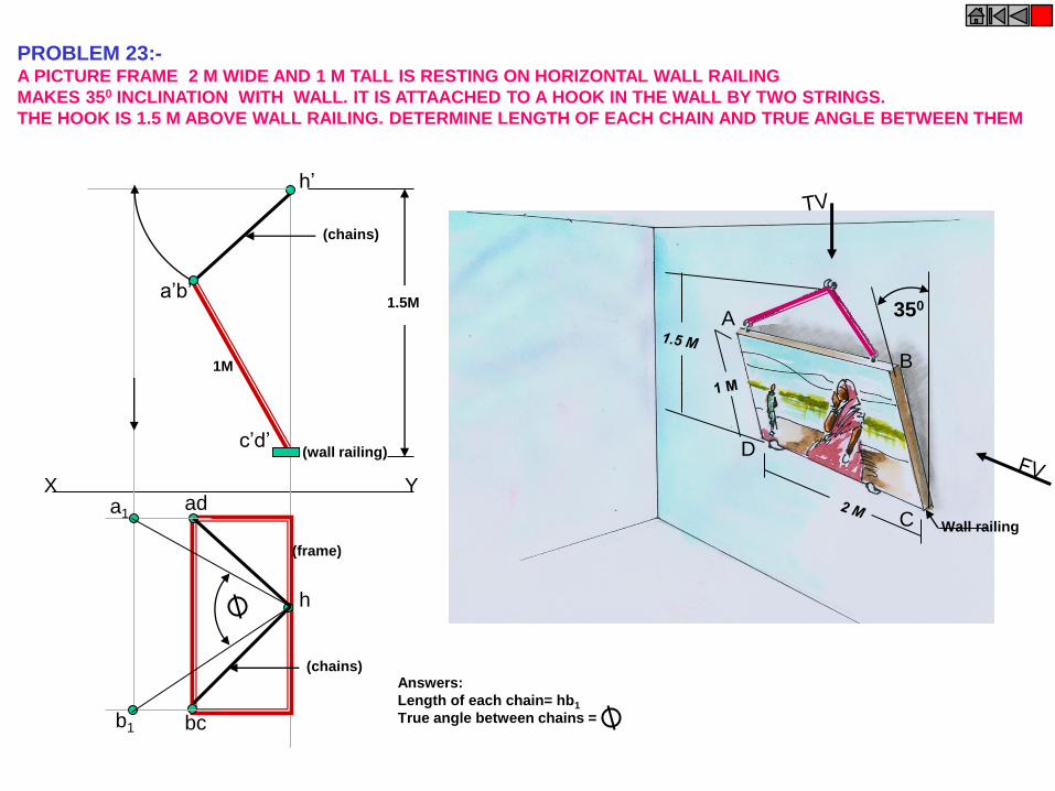
PROBLEM 23:- A PICTURE FRAME 2 M WIDE AND 1 M TALL IS RESTING ON HORIZONTAL WALL RAILING
MAKES 350 INCLINATION WITH WALL. IT IS ATTAACHED TO A HOOK IN THE WALL BY TWO STRINGS.
THE HOOK IS 1.5 M ABOVE WALL RAILING. DETERMINE LENGTH OF EACH CHAIN AND TRUE ANGLE BETWEEN THEM
350
Wall railing
A
B
C
D
ad
h
bc
a1
b1
a’b’
c’d’ (wall railing)
(frame)
(chains) Answers:
Length of each chain= hb1
True angle between chains =
(chains)
X Y
h’
1.5M
1M
Related Documents