M&C 2017 - International Conference on Mathematics & Computational Methods Applied to Nuclear Science & Engineering, Jeju, Korea, April 16-20, 2017, on USB (2017) Coupling of Mesh Generator Code (VEGA) to Two-dimensional Tokamak Plasma Transport Code (C2) J. G. Lee and Yong-Su Na * Department of Nuclear Engineering, Seoul National University, Seoul 151-744, Korea * [email protected] Abstract – By upgrading the mesh generator, VEGA, to VEGA2.0 and developing a bridge code, a 2-D core- edge coupled modelling package consist of VEGA2.0 and the two-dimensional tokamak plasma transport code C2 is complete for analysis of the entire region of the poloidal plane of the tokamak plasma. The upgrade is conducted with the reconstruction of the entire code in C++ programming language and modification for the flexibility. In this procedure, VEGA2.0 has an organized data structure and system layout, and a robustness in various configurations of plasma. In the following procedure, a bridge code is made with the matching each grid storage format of the two codes and adding the additional data that C2 needs. The VEGA2.0 is verified with the former VEGA in KSTAR Connected Double Null (CDN) plasma by the grid quality factors. In Last, plasma simulation results in KSTAR CDN plasma conducted by this completed core- edge coupled modelling package are presented. I. INTRODUCTION Computational simulation of the tokamak plasma transport can be broadly divided into two different areas, core and edge/Scrape-Off Layer (SOL) region. The transport in the core region is dominated by the parallel transport along the magnetic field lines due to high temperatures and it can be described on the magnetic flux surface with surface averaged one-dimension (1-D) quantities [1]. On the other hand, the two-dimensional (2-D) effect should be considered in the edge/SOL region because the parallel and the perpendicular transport are comparable and the wall structures such as the divertor and the first wall should be considered [2]. Conventionally, two approaches have been used to simulate the plasma transport in the coupled core and edge/SOL regions where these distinct features coexist. The first approach is integrating the codes designed to solve each core or edge/SOL region in a corresponding manner to simulate the entire plasma region. Packages such as OMFIT [3], ITM [4], and JINTRAC [5] belong to this way, and most of them get the plasma status 1-D in the core and 2-D in the edge/SOL region. In this case, it is important to maintain numerical self-consistency at the boundary between the two regions. The second one is to simulate in the entire poloidal plane two-dimensionally through a set of inherent equations. C2 [6] is one of the codes using this approach where the multi-fluid MHD equations with the modified neoclassical heat and momentum diffusivities are solved. In this case, coupling at the boundary between the two regions (core and edge/SOL) is inherently made because this code treats the plasma in the same manner regardless the region. Therefore, it is convenient to study the various effects of the plasma interaction at the divertor or Plasma Facing Component (PFC) on the core plasma with this C2. However, the computational domain, grid, is static in a whole process of time-varying plasma simulations in C2. Because the boundary area of the subjected core-edge/SOL phenomena changes over time, the grid needs to adapt this variation. According to this demand, a VEctor-following Grid generator for Adaptive mesh (VEGA) has been developed [7]. The characteristic of this code is that it automatically defines the magnetic configuration of the given plasma equilibrium data and generates the grid using the vector-following method. A time-dependent coupled core-edge/SOL simulation is feasible by integrating VEGA and C2 as a core- edge coupled modelling package. However, VEGA had several limitations to be described in the next chapter which needs to be resolved for broader applications and rigid simulations. In addition, as C2 and VEGA grid formats are different and C2 uses additional data, a bridge code is required to link them in order to complete the core-edge coupled modelling package. Therefore, the grid generator VEGA is upgraded to VEGA2.0 in this work. The paper is organized as follows. Firstly, the limitations of former VEGA are addressed. Then, upgrade of VEGA, VEGA2.0 is described in detail. Next, the bridge code is introduced. In chapter III, the results of grid generated by VEGA2.0 are presented and compared with the result of former VEGA. The results of a plasma simulation by using the core-edge coupled modelling package are followed. Finally, the summary and conclusion are presented in chapter IV. II. DESCRIPTION OF THE ACTUAL WORK In this chapter, two processes are introduced to establish the core-edge coupled modelling package. First, VEGA is upgraded to VEGA2.0 by solving the internal limitations.

Welcome message from author
This document is posted to help you gain knowledge. Please leave a comment to let me know what you think about it! Share it to your friends and learn new things together.
Transcript

M&C 2017 - International Conference on Mathematics & Computational Methods Applied to Nuclear Science & Engineering ,
Jeju, Korea, April 16-20, 2017, on USB (2017)
Coupling of Mesh Generator Code (VEGA) to Two-dimensional Tokamak Plasma Transport Code (C2)
J. G. Lee and Yong-Su Na*
Department of Nuclear Engineering, Seoul National University, Seoul 151-744, Korea *[email protected]
Abstract – By upgrading the mesh generator, VEGA, to VEGA2.0 and developing a bridge code, a 2-D core-
edge coupled modelling package consist of VEGA2.0 and the two-dimensional tokamak plasma transport
code C2 is complete for analysis of the entire region of the poloidal plane of the tokamak plasma. The upgrade
is conducted with the reconstruction of the entire code in C++ programming language and modification for
the flexibility. In this procedure, VEGA2.0 has an organized data structure and system layout, and a
robustness in various configurations of plasma. In the following procedure, a bridge code is made with the
matching each grid storage format of the two codes and adding the additional data that C2 needs. The
VEGA2.0 is verified with the former VEGA in KSTAR Connected Double Null (CDN) plasma by the grid
quality factors. In Last, plasma simulation results in KSTAR CDN plasma conducted by this completed core-
edge coupled modelling package are presented.
I. INTRODUCTION
Computational simulation of the tokamak plasma
transport can be broadly divided into two different areas, core
and edge/Scrape-Off Layer (SOL) region. The transport in
the core region is dominated by the parallel transport along
the magnetic field lines due to high temperatures and it can
be described on the magnetic flux surface with surface
averaged one-dimension (1-D) quantities [1]. On the other
hand, the two-dimensional (2-D) effect should be considered
in the edge/SOL region because the parallel and the
perpendicular transport are comparable and the wall
structures such as the divertor and the first wall should be
considered [2].
Conventionally, two approaches have been used to
simulate the plasma transport in the coupled core and
edge/SOL regions where these distinct features coexist. The
first approach is integrating the codes designed to solve each
core or edge/SOL region in a corresponding manner to
simulate the entire plasma region. Packages such as OMFIT
[3], ITM [4], and JINTRAC [5] belong to this way, and most
of them get the plasma status 1-D in the core and 2-D in the
edge/SOL region. In this case, it is important to maintain
numerical self-consistency at the boundary between the two
regions.
The second one is to simulate in the entire poloidal plane
two-dimensionally through a set of inherent equations. C2 [6]
is one of the codes using this approach where the multi-fluid
MHD equations with the modified neoclassical heat and
momentum diffusivities are solved. In this case, coupling at
the boundary between the two regions (core and edge/SOL)
is inherently made because this code treats the plasma in the
same manner regardless the region. Therefore, it is
convenient to study the various effects of the plasma
interaction at the divertor or Plasma Facing Component (PFC)
on the core plasma with this C2.
However, the computational domain, grid, is static in a
whole process of time-varying plasma simulations in C2.
Because the boundary area of the subjected core-edge/SOL
phenomena changes over time, the grid needs to adapt this
variation.
According to this demand, a VEctor-following Grid
generator for Adaptive mesh (VEGA) has been developed [7].
The characteristic of this code is that it automatically defines
the magnetic configuration of the given plasma equilibrium
data and generates the grid using the vector-following
method. A time-dependent coupled core-edge/SOL
simulation is feasible by integrating VEGA and C2 as a core-
edge coupled modelling package. However, VEGA had
several limitations to be described in the next chapter which
needs to be resolved for broader applications and rigid
simulations.
In addition, as C2 and VEGA grid formats are different
and C2 uses additional data, a bridge code is required to link
them in order to complete the core-edge coupled modelling
package. Therefore, the grid generator VEGA is upgraded to
VEGA2.0 in this work.
The paper is organized as follows. Firstly, the limitations
of former VEGA are addressed. Then, upgrade of VEGA,
VEGA2.0 is described in detail. Next, the bridge code is
introduced. In chapter III, the results of grid generated by
VEGA2.0 are presented and compared with the result of
former VEGA. The results of a plasma simulation by using
the core-edge coupled modelling package are followed.
Finally, the summary and conclusion are presented in chapter
IV.
II. DESCRIPTION OF THE ACTUAL WORK
In this chapter, two processes are introduced to establish
the core-edge coupled modelling package. First, VEGA is
upgraded to VEGA2.0 by solving the internal limitations.
M&C 2017 - International Conference on Mathematics & Computational Methods Applied to Nuclear Science & Engineering ,
Jeju, Korea, April 16-20, 2017, on USB (2017)
Second, a bridge code to link this VEGA2.0 with C2 is
developed. The details are described below.
1. Upgrade of VEGA to VEGA2.0
The former VEGA has several limitations. Firstly, it is
coded in MATLAB [8]. MATLAB is a very flexible language
versatile and easily analyzable, but has weak points of
incompatibility with other codes in a Linux system in a
computational cluster and slow computation speed because
all modules are loaded every time the program is executed. In
addition, the input and the output parts of the system process
are missing, making it difficult to connect with other codes.
Also, it is not easy to interpret the code and manage the
variables because the data is not organized.
Secondly, the former VEGA can deal with only specific
magnetic configurations. It can generate a grid for Connected
Double Null (CDN) and Single Null (SN) only, thus its
application can be limited when dealing with other
configurations. For example, the constraint applied when the
grid is twisted near X-point or divertor plates are too
localized, or the number and the accuracy of the first points
in the separatrix lines from the X-point are limited.
Therefore, the following procedures and methods are
employed to overcome these limitations.
A. Re-construction to C++ Programming Language
There is a need to reconstruct the former VEGA in other
programming languages in order to overcome the
compatibility problems. The programming languages used in
other conventional codes are listed in Table 1. As shown
FORTRAN has been used extensively that has been
developing for long, such as ASTAR [1] or B2.5 [2].
However, relatively recently developed C2 is coded in
the C++ programming language, so VEGA to be coupled
with this code is also reconstructed in this C++ language. The
advantage of C++ is that it is suitable for Linux systems and
has a wide range of applications because it has already been
dealt with in a lot of areas, and it is also good for connecting
with other codes.
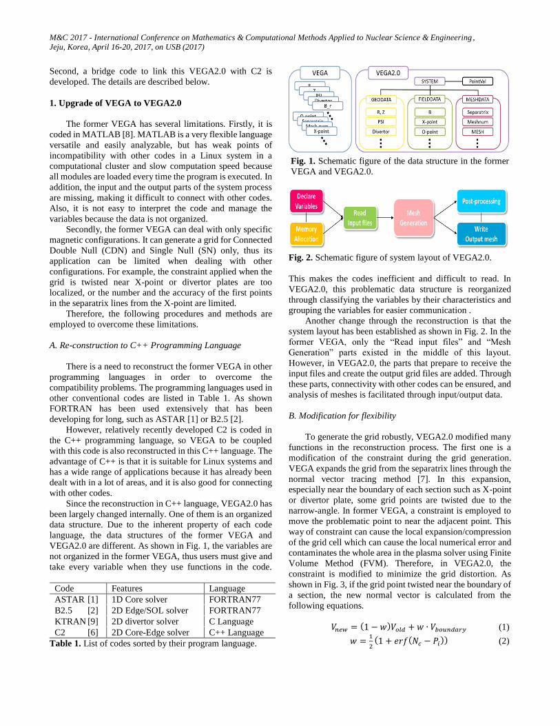
Since the reconstruction in C++ language, VEGA2.0 has
been largely changed internally. One of them is an organized
data structure. Due to the inherent property of each code
language, the data structures of the former VEGA and
VEGA2.0 are different. As shown in Fig. 1, the variables are
not organized in the former VEGA, thus users must give and
take every variable when they use functions in the code.
Code Features Language
ASTAR [1] 1D Core solver FORTRAN77
B2.5 [2] 2D Edge/SOL solver FORTRAN77
KTRAN [9] 2D divertor solver C Language
C2 [6] 2D Core-Edge solver C++ Language
Table 1. List of codes sorted by their program language.
Fig. 2. Schematic figure of system layout of VEGA2.0.
This makes the codes inefficient and difficult to read. In
VEGA2.0, this problematic data structure is reorganized
through classifying the variables by their characteristics and
grouping the variables for easier communication .
Another change through the reconstruction is that the
system layout has been established as shown in Fig. 2. In the
former VEGA, only the “Read input files” and “Mesh
Generation” parts existed in the middle of this layout.
However, in VEGA2.0, the parts that prepare to receive the
input files and create the output grid files are added. Through
these parts, connectivity with other codes can be ensured, and
analysis of meshes is facilitated through input/output data.
B. Modification for flexibility
To generate the grid robustly, VEGA2.0 modified many
functions in the reconstruction process. The first one is a
modification of the constraint during the grid generation.
VEGA expands the grid from the separatrix lines through the
normal vector tracing method [7]. In this expansion,
especially near the boundary of each section such as X-point
or divertor plate, some grid points are twisted due to the
narrow-angle. In former VEGA, a constraint is employed to
move the problematic point to near the adjacent point. This
way of constraint can cause the local expansion/compression
of the grid cell which can cause the local numerical error and
contaminates the whole area in the plasma solver using Finite
Volume Method (FVM). Therefore, in VEGA2.0, the
constraint is modified to minimize the grid distortion. As
shown in Fig. 3, if the grid point twisted near the boundary of
a section, the new normal vector is calculated from the
following equations.
𝑉𝑛𝑒𝑤 = (1 − 𝑤)𝑉𝑜𝑙𝑑 + 𝑤 ∙ 𝑉𝑏𝑜𝑢𝑛𝑑𝑎𝑟𝑦 (1)
𝑤 =1
2(1 + 𝑒𝑟𝑓(𝑁𝑐 − 𝑃𝑖)) (2)
Fig. 1. Schematic figure of the data structure in the former
VEGA and VEGA2.0.

M&C 2017 - International Conference on Mathematics & Computational Methods Applied to Nuclear Science & Engineering ,
Jeju, Korea, April 16-20, 2017, on USB (2017)
Where 𝑉𝑛𝑒𝑤 , 𝑉𝑜𝑙𝑑, 𝑉𝑏𝑜𝑢𝑛𝑑𝑎𝑟𝑦 are the direction vectors as
shown in Fig. 3 and w is a weighting factor which consists of
the error function as shown in the equation where 𝑁𝑐 and 𝑃𝑖
are the control and the position number respectively. New
grid points are generated following the modified normal
vector 𝑉𝑛𝑒𝑤 which is a combination of the original normal
vector, 𝑉𝑜𝑙𝑑 and the boundary vector, 𝑉𝑏𝑜𝑢𝑛𝑑𝑎𝑟𝑦 . Controlling
the number of 𝑁𝑐 would make w diminished rapidly away
from the boundary vector.
The next modification is an improvement of the first
point finding algorithm. VEGA uses the vector-following
method to generate the contour lines of the magnetic field
from the X- point. However, near the X-point, since the
magnetic field hardly changes from zero, the accuracy of the
direction vector is not guaranteed. Therefore, the first points
of the separatrix line from the X-point are taken from the first
point finding algorithm by the linear interpolation in the
searching area [7].
But the searching area is only 4 cells and the number of
the first point are also limited as 4 in VEGA. These restricted
conditions are able to cause the high numerical error or lose
the scalability to the other magnetic configurations. So in
VEGA2.0, the searching area is expanded to 9 cells and the
available first points are increased up to 12 as shown in Fig.
4.
Through these two major modifications, VEGA2.0 can
generate grid flexible in the various magnetic configurations.
2. Bridge code
Since its development, the grid of the former VEGA has
never been used to simulate the plasma transport coupled
with C2. It is because the format of the grid produced by
VEGA differs from that of C2. Therefore, the bridge code is
newly developed to match the grid formats of the two codes,
to divide the input files according to the Message Passing
Interface (MPI) [10] used in C2, and to generate data other
than the grid information.
A. Matching the Grid Format
VEGA2.0 is designed to store the grid of the entire
tokamak plasma region in one matrix based on the separatrix
lines, as shown in Fig. 5 (a). Therefore, in order to convert
the grid data in this matrix into a grid format accepted by C2,
the matrix should be split according to each separatrix line,
which is separated by an X-point. By combining this
separated grid matrix parts, the input grid files are generated
according to the order of grid data and domain classification
based on the direction of the magnetic field as shown in Fig.
5 (b). This domain classification is partitioned according to
the computational domain of processors assigned through
MPI.
Fig. 3. Schematic cartoon of a computational domain with a
separatrix line and several boundary vectors associated with
X-points and divertor plates.
Fig. 4. Schematic view of grid points around the X-point with
dotted separatrix lines. As an example, the first points are
marked with red circles on the searching area.
Fig. 5. Schematic diagram of grid format. a) Output grid
format of VEGA2.0 and b) the order and format of the grid
input in C2.

M&C 2017 - International Conference on Mathematics & Computational Methods Applied to Nuclear Science & Engineering ,
Jeju, Korea, April 16-20, 2017, on USB (2017)
Table 2. The variables and their definition of 1-D data for
core input file in C2
B. Adding Other Data
For completion of input files for C2, other information
that C2 needs must be included. In these data, a poloidal and
a toroidal magnetic field, and inter-domain matching
conditions for communicating the boundary data of each
computational domain though MPI is included. For the case
of core input file, a 1-D special information is added to
calculate the magnetic surface averaged current profile and
heat and momentum diffusivities.
The magnetic field value is calculated from the given
plasma equilibrium data and assigned to each grid point. The
inter-domain matching condition is the information required
when the computation domain assigned to each processor
through MPI exchanges data at its boundary. Therefore, the
exact number and order of what a grid point can meet the grid
point in the other computation domain. The Last item, 1-D
spatial information, is only for the core grid input file. This is
shown in Table 2. The minor and the major radius, the
effective minor radius which is defined on the magnetic flux
surface, the plasma shape variables, and coordinate-related
information are the components of this 1-D data. Most of
these variables are an averaged value along the magnetic flux
surface at the grid position of the 2-D core.
III. RESULTS
In this chapter, two kinds of results are presented. The
first one shows the grid data provided from both former
VEGA and VEGA2.0 to verify the upgrade of the mesh
generator. In this process, a comparative analysis is
performed quantitatively using the mesh quality factor used
to verify the former VEGA. The second is to verify that the
VEGA2.0 and C2 are well connected through the developed
bridge code, and then perform a plasma simulation using this
2-D core-edge coupled plasma transport modelling package.
1. Grid Generation Results for Verification of VEGA2.0
The verification of VEGA2.0 is conducted with
comparing the grid results of the same plasma state, in this
case of KSTAR CDN plasma, with those of the former
VEGA. The input plasma equilibrium data is provided by a
free boundary MHD equilibrium code, Tokamak Equilibrium
Solver (TES) [11], as shown in Fig. 6. The grid distribution
is set as higher near the boundary region such as X-points,
the separatrix lines, and the divertor plates.
In Fig. 7, the results of both former VEGA and VEGA2.0
are presented. The both grid generation is successfully
conducted and seems to fit well each other. However, the
differences between the meshes near the boundary region are
certainly noticeable, especially near the X-points. These
differences are mainly caused by the modifications of
constraint and the first point finding algorithm. To be specific,
the grid cells near the X-point are nearly triangular shapes in
the result of former VEGA, which can produce local grid
compression. On the other hand, in the result of VEGA2.0,
the orthogonality is not collapsed much since the adjacent
grid points move accordingly.
Fig. 6. Contour plots of the plasma equilibrium data of
KSTAR tokamak provided by the TES code.

M&C 2017 - International Conference on Mathematics & Computational Methods Applied to Nuclear Science & Engineering ,
Jeju, Korea, April 16-20, 2017, on USB (2017)
For the more quantitatively comparative analysis, the
mesh quality factors are evaluated. Based on the preference
of using FVM, the mesh quality factors of ‘Cell
orthogonality’, ‘Radial flux deviation’, and ‘Field alignment’
were introduced [7]. The ‘Cell orthogonality’ represents the
orthogonal property of each grid cell by calculating the
deviation of the degree from the right angle. The ‘Radial flux
deviation’ shows the surface normal deviations in the radial
direction of the real geometry. And the ‘Field alignment’ is a
standard deviation between the poloidal grid contour and the
magnetic flux surfaces. Here, the ‘Field alignment’, another
mesh quality factor introduced in [7] is excluded because
both of the codes using the same vector-following method.
The results of the two mesh quality factors are shown in
Fig. 8. Each column represents the cell averaged value of
each domain corresponding to the number shown in Table 3.
In Fig. 8 a), the ‘Cell orthogonality’ of VEGA2.0 is a little
higher than that of the former VEGA in the most of the
domain. On the other hand, the values of the all domain
except core show the better results of the ‘Radial flux
deviation’ as shown in Fig. 8 b). These results can be inferred
that the modification of the constraint caused an observable
change near the boundary of each section of the grid. Also,
one can say that VEGA2.0 is able to generate a better grid for
the analysis of the plasma in the edge/SOL region.
Fig. 7. The results of the grid for CDN configuration in
KSTAR.
Table 3. The assigned number of each computational domain.
Fig. 8. The results of cell averaged grid quality factor for each
domain of a) ‘Cell orthogonality’ and b) ‘Radial flux
deviation’. The blue column is for former VEGA and the red
for VEGA2.0.
2. Simulation of 2-D Plasma Transport in KSTAR
In this section, a confirmation of the coupling between
C2 and VEGA2.0 through the developed bridge code and the
plasma transport simulation results of the KSTAR CDN
configuration by using this completed 2-D core-edge coupled
modelling package are presented.
A. Confirmation of coupling between C2 and VEGA2.0
Confirming the coupling between the plasma transport
solver, C2, and the upgraded mesh generator, VEGA2.0,
proceeds as follows. First, when C2 takes the input grid files,
it calculates the center position of each grid cell where the
plasma variables stored in. Then, at the beginning of the
plasma calculation, the initial plasma values set by the user
are stored at this location. Therefore, by comparing 2-D
profiles generated with these initial values to the input grid,
it can be confirmed whether C2 receives the grid generated
by VEGA2.0 well.
The results of the above procedure are shown as lower
half of the poloidal plane in Fig. 9. This figure is made by
aligning the location of the initial data from C2 on the grid
data plot that VEGA2.0 creates. As shown, the initial plasma
values are well centered in the grid cell regardless some low
orthogonality near the X-point. Thus, the bridge code allows
the C2 to accept the grid of VEGA2.0, and conducting the 2-
D core-edge coupled plasma simulation is possible.
In addition, at the plasma boundary such as the divertor
plates, outer side of SOL, and the private region, it can be
seen that the transport calculations are made in the middle of
the boundary lines, not the center of the cell.

M&C 2017 - International Conference on Mathematics & Computational Methods Applied to Nuclear Science & Engineering ,
Jeju, Korea, April 16-20, 2017, on USB (2017)
Fig. 9. A plot of the input grid created by VEGA2.0
overlapping with the initial plasma values from C2 on the
lower half plane of KSTAR plasma.
B. Simulation Results of KSTAR CDN Plasma
In this section, simulation of the plasma transport is
conducted through the completed 2-D core-edge coupled
modelling package. The target plasma is an L-mode plasma
of KSTAR in CDN configuration, and the corresponding
main parameters are shown in Table 4. In this table,
‘Tolerance’, ‘Max matrix solver iteration’, and ‘Max residue’
are the controlling factors for the iterative matrix solver in C2.
The plasma equilibrium data for this target is calculated from
the TES code. The initial conditions for temperature and
density profiles of electron and ion, as well as the boundary
conditions, are set as shown in Table 5. The simulation is
conducted with an ohmic heating for 3000 normalized unit
time steps or about 217 microseconds in real time.
The simulation results are presented in Fig. 10. The area
near the magnetic null points such as O- or X- points is
excluded from the calculation because the grid diverges or
converges.
The electron temperature increases from the initial
condition of 1000 eV to 1586.21 eV in the core region and
dropped steeply to 100 eV near the separatrix line. Also,
looking closer at the divertor region, the temperature of SOL
region is hardly diffused to the private region. In other words,
considering the flow velocity, it can be said that most of the
heat transport is convective rather than conductive in the
divertor region. In the case of ion, the core temperature is
1212.32 eV, which is lower than electrons, but with a similar
profile. The density of the ion increases up to about 2.94 ×
1019 from the initial condition in the core. In the case of
neutrals, they are produced highly near the divertor region,
especially outer region, and has a very weak influence on the
core region. In Fig. 10 e), it can be seen that the flow of the
plasma varies in sign depending on the position. This is
because there is a direction in the flow that follows the
direction of the grid. Considering this, most of the plasma is
shown to flow to the divertor plates. The normalized viscosity
is calculated only in the core region in this work which shows
a hollow profile on the poloidal plane.
In short, plasma transport simulation of the KSTAR L-
mode plasma is conducted. Although the results may vary
depending on the heat and momentum transport model, the
very peaked temperature profiles and the broad density
profiles are obtained. Furthermore, in the region near the
divertor, which is known to have a high collision rate due to
the low temperature, the plasma temperature seems to be
more diffused by convection than conduction.
Table 4. Main operation parameters for the KSTAR L-mode
plasmas.
Table 5. The initial condition of plasma density and
temperature for both electron and ion at the magnetic center,
separatrix line, and wall. The red circled parameters indicate
the boundary conditions.

M&C 2017 - International Conference on Mathematics & Computational Methods Applied to Nuclear Science & Engineering ,
Jeju, Korea, April 16-20, 2017, on USB (2017)
Fig. 10. Contour plots of a) electron temperature, b) ion
temperature, c) ion density, d) neutral density, e) flow
velocity of plasma, and f) normalized viscosity in KSTAR
CDN plasma. The both temperature profiles use eV units, and
the flow velocity and viscosity use their own normalized unit.
IV. CONCLUSIONS
The 2-D core-edge coupled plasma modelling package
for analysis of tokamak transport is completed by upgrading
the mesh generator, VEGA to VEGA2.0 and by developing a
bridge code to couple this VEGA2.0 to the 2-D plasma
transport solver, C2. The upgrade of the grid generator is
conducted with the reconstruction, translation of the
programming language from MATLAB to C++, and
modification of the internal functions, the constraint for
twisted mesh and the first point finding algorithm. The bridge
code is developed so that the output grid of VEGA2.0 is
converted into the input grid files of C2. The upgrade mesh
generator is verified by comparing the output grid with that
of former VEGA with the grid quality factors. The coupling
by the bridge code is evaluated by comparing the VEGA2.0
grid with the initial profile produced by C2. The both results
show that the 2-D core-edge coupled modelling code is
successfully completed. Therefore, with this package, first
coupled plasma transport simulation is carried out for the
KSTAR L-mode plasmas in CDN configuration.
In the future, this package will be improved to observe
plasma profiles and divertor heat flux changes depending on
the various magnetic field configurations. The candidates of
this include a Disconnected Double Null (DDN) or biased
double null configuration in which the two X-points are
broken in the Double Null (DN) geometry, or a snowflake or
super X divertor configuration designed to dissipate the
divertor heat flux. As the coupled modelling package has
limitations on dynamic plasma simulations yet, it will be
upgraded to deal with the time-evolving plasmas.
REFERENCES
1. G. V. Pereverzev and P. N. Yushmanov, "ASTAR.
Automated System for TRansport Analysis in a
Tokamak", IPP Report 5/98, Max-Planck-Institut für
Plasmaphysik, Garching (2002).
2. R. Schneider et al., "B2-EIRENE simulation of ASDEX
and ASDEX-Upgrade scrape-off layer plasmas", J. Nucl.
Matter., 196-198 810 (1992).
3. O. Meneghini et al., "Integrated modeling applications
for tokamak experiments with OMFIT", Nucl. Fusion 55
083008, 13pp, (2015).
4. G. L. Falchetto et al., "The European Integrated
Tokamak Modelling (ITM) effort: achievements and
first physics results", Nucl. Fusion 54 043018, 19pp,
(2014).
5. Romanelli M. et al., "JINTRAC: A System of Codes for
Integrated Simulation of Tokamak Scenarios", Plasma
Fusion Res. 9 3403023 (2014).
6. J.M. Park, "Integrated Simulation of Tokamak H=mode
Operation by a Two-Dimensional Plasma Transport
Code in Coupled Core-Edge Pedestal-SOL Region,"
Ph.D. Dissertation, Seoul National University (2005).

M&C 2017 - International Conference on Mathematics & Computational Methods Applied to Nuclear Science & Engineering,
Jeju, Korea, April 16-20, 2017, on USB (2017)
7. Y. J. Kim et al., "Development of Vector Following
Mesh Generator for Analysis of Two Dimensional
Tokamak Plasma Transport", Comput. Phys. Comm.,
186, 31-38, (2015).
8. The mathworks “Matlab, User'S. Guide.” Inc., Natick,
MA 1760 (1992).
9. D. K. Kim, “Two-dimensional Simulation of Tokamak
Scrape-off Layer and Divertor Region by a Coupled
Transport Code for Plasma, Neutral, and Impurity
Particles,” Ph.D. Dissertation, Seoul National University
(2001).
10. P. S. Pacheco, Parallel Programming with MPI (Morgan
Kaufmann Publishers, San Francisco, (1997).
11. Y. M. Jeon, "Development of a Free-boundary Tokamak
Equilibrium Solver for Advanced Study of Tokamak
Equilibria", Journal of Korean Phys. Society 67, 843-
853 (2015).
Related Documents