Journal of Energy and Power Engineering 7 (2013) 2068-2077 Coupling Heat and Electricity Sources to Intermediate Temperature Steam Electrolysis Martin Roeb 1 , Nathalie Monnerie 1 , Anis Houaijia 1 , Christian Sattler 1 , Javier Sanz-Bermejo 2 , Manuel Romero 2 , Ignacio Canadas 3 , Anabella Drisaldi Castro 3 , Cristina Lucero 4 , Rocio Palomino 4 , Floriane Petipas 5 and Annabelle Brisse 5 1. German Aerospace Center (DLR), Institute of Solar Research, Linder Hoehe, Koeln 51147, Germany 2. Madrid Institute of Advanced Studies (IMDEA Energy), Avda. Ramón de la Sagra 3, Parque Tecnológico de Móstoles, Madrid, Móstoles 28935, Spain 3. Empresarios Agrupados, Magallanes 3, Madrid 28015, Spain 4. Abengoa Hidrógeno, Campus Palmas Altas, Parcela ZE-3 (Palmas Altas), Edificio B-Planta Baja, Seville 41012, Spain 5. EIFER (European Institute for Energy Research), Karlsruhe 76131, Germany Received: March 18, 2013 / Accepted: May 23, 2013 / Published: November 30, 2013. Abstract: The use of CO 2 -free energy sources for running SOEC (solid-oxide electrolysis cell) technologies has a great potential to reduce the carbon dioxide emissions compared to fossil fuel based technologies for hydrogen production. The operation of the electrolysis cell at higher temperature offers the benefit of increasing the efficiency of the process. The range of the operating temperature of the SOEC is typically between 800 °C and 1,000 °C. Main sources of degradation that affect the SOEC stack lifetime is related to the high operating temperature. To increase the electrolyser durability, one possible solution is to decrease the operating temperature down to 650 °C, which represents the typical operating range of the ITSE (intermediate temperature steam electrolysis). This paper is related to the work of the JU-FCH project ADEL, which investigates different carbon-free energy sources with respect to potential coupling schemes to ITSE. A predominant focus of the analysis is put on solar concentrating energy systems (solar tower) and nuclear energy as energy sources to provide the required electricity and heat for the ITSE. This study will present an overview of the main considerations, the boundary conditions and the results concerning the development of coupling schemes of the energy conversion technologies to the electrolyser. Key words: Intermediate temperature electrolysis, electrolyser, hydrogen, solar, flow chart. 1. Introduction Hydrogen is mainly produced from fossil fuels through steam reforming of natural gas. Unfortunately, the fossil fuel based hydrogen generation does not contribute to the reduction of greenhouse gas emissions. Hydrogen can be generated instead by carbon-free energy sources via water electrolysis in order to avoid the emissions of carbon dioxide. The concept of integrating renewable energy with hydrogen systems Corresponding author: Martin Roeb, Dr., team leader of The Solar Chemical Engineering Group, research fields: solar fuels and solar high temperature applications. E-mail: [email protected]. was given serious consideration in the 1970s [1, 2]. Numerous studies have been reported on the hydrogen production systems from solar energy, wind energy and biomass in Refs. [3-5]. There are three main types of water electrolysis: the alkaline electrolysis, the PEM (polymer electrolyte membrane) electrolysis and the SOEC (solid oxide electrolysis cell) [6, 7]. Most of the water electrolysis technologies to date have used alkaline or acidic electrolyte systems for hydrogen generation [8, 9], which are operated at temperatures below 100 °C, while the SOEC operates with water steam at temperatures in the range of 800-1,000 °C. SOEC uses D DAVID PUBLISHING

Welcome message from author
This document is posted to help you gain knowledge. Please leave a comment to let me know what you think about it! Share it to your friends and learn new things together.
Transcript
Journal of Energy and Power Engineering 7 (2013) 2068-2077
Coupling Heat and Electricity Sources to Intermediate
Temperature Steam Electrolysis
Martin Roeb1, Nathalie Monnerie1, Anis Houaijia1, Christian Sattler1, Javier Sanz-Bermejo2, Manuel Romero2,
Ignacio Canadas3, Anabella Drisaldi Castro3, Cristina Lucero4, Rocio Palomino4, Floriane Petipas5 and Annabelle
Brisse5
1. German Aerospace Center (DLR), Institute of Solar Research, Linder Hoehe, Koeln 51147, Germany
2. Madrid Institute of Advanced Studies (IMDEA Energy), Avda. Ramón de la Sagra 3, Parque Tecnológico de Móstoles, Madrid,
Móstoles 28935, Spain
3. Empresarios Agrupados, Magallanes 3, Madrid 28015, Spain
4. Abengoa Hidrógeno, Campus Palmas Altas, Parcela ZE-3 (Palmas Altas), Edificio B-Planta Baja, Seville 41012, Spain
5. EIFER (European Institute for Energy Research), Karlsruhe 76131, Germany
Received: March 18, 2013 / Accepted: May 23, 2013 / Published: November 30, 2013.
Abstract: The use of CO2-free energy sources for running SOEC (solid-oxide electrolysis cell) technologies has a great potential to reduce the carbon dioxide emissions compared to fossil fuel based technologies for hydrogen production. The operation of the electrolysis cell at higher temperature offers the benefit of increasing the efficiency of the process. The range of the operating temperature of the SOEC is typically between 800 °C and 1,000 °C. Main sources of degradation that affect the SOEC stack lifetime is related to the high operating temperature. To increase the electrolyser durability, one possible solution is to decrease the operating temperature down to 650 °C, which represents the typical operating range of the ITSE (intermediate temperature steam electrolysis). This paper is related to the work of the JU-FCH project ADEL, which investigates different carbon-free energy sources with respect to potential coupling schemes to ITSE. A predominant focus of the analysis is put on solar concentrating energy systems (solar tower) and nuclear energy as energy sources to provide the required electricity and heat for the ITSE. This study will present an overview of the main considerations, the boundary conditions and the results concerning the development of coupling schemes of the energy conversion technologies to the electrolyser.
Key words: Intermediate temperature electrolysis, electrolyser, hydrogen, solar, flow chart.
1. Introduction
Hydrogen is mainly produced from fossil fuels
through steam reforming of natural gas. Unfortunately,
the fossil fuel based hydrogen generation does not
contribute to the reduction of greenhouse gas emissions.
Hydrogen can be generated instead by carbon-free
energy sources via water electrolysis in order to avoid
the emissions of carbon dioxide. The concept of
integrating renewable energy with hydrogen systems
Corresponding author: Martin Roeb, Dr., team leader of
The Solar Chemical Engineering Group, research fields: solar fuels and solar high temperature applications. E-mail: [email protected].
was given serious consideration in the 1970s [1, 2].
Numerous studies have been reported on the hydrogen
production systems from solar energy, wind energy and
biomass in Refs. [3-5].
There are three main types of water electrolysis: the
alkaline electrolysis, the PEM (polymer electrolyte
membrane) electrolysis and the SOEC (solid oxide
electrolysis cell) [6, 7]. Most of the water electrolysis
technologies to date have used alkaline or acidic
electrolyte systems for hydrogen generation [8, 9],
which are operated at temperatures below 100 °C,
while the SOEC operates with water steam at
temperatures in the range of 800-1,000 °C. SOEC uses
D DAVID PUBLISHING

Coupling Heat and Electricity Sources to Intermediate Temperature Steam Electrolysis
2069
a combination of thermal energy and electricity and the
water is fed to the electrolyser in vapor phase. The
advantage of the operation at higher temperature
consists of reducing the electricity demand of the
electrolyser. In addition to that, the reaction kinetics is
increasing at higher temperatures. The overall
thermal-to-hydrogen efficiency for the high
temperature electrolysis can be as high as 50%, which
is about double the overall efficiency of the alkaline
electrolysis [10]. This higher operating temperature of
the SOEC has an impact on the solid oxide cells and
stack lifetime. Indeed, this temperature range of 800 °C
to 1,000 °C enhances chemical species evaporation and
diffusion, resulting in the formation of secondary
isolating phases, as well as in a decrease of the
mechanical stability of ceramic and metal components.
To increase the electrolyser durability, a very
suitable solution is to decrease the operating
temperature of the electrolyser. The resistances of cells,
interconnects and contact layers will tend to increase
and to limit the electrolyser performance, but at the
same time, all parasitic phenomena such as
interdiffusion, corrosion or vaporization responsible
for cell and stack degradation will be significantly
slowed down. Cells and interconnect coatings are now
available that allow reaching at 600-650 °C equivalent
performance that are obtained at 800 °C in the frame of
an EU founded project [11] . The operation of the
electrolyser in temperature range of 600 °C to 650 °C is
known as the ITSE (intermediate temperature steam
electrolysis). The reduction of the operating
temperature reduction will open the door for extended
operation modes and will allow the coupling of the
electrolyser with renewable energy sources. As a
consequence, heat sources such as solar energy or
nuclear high temperature reactor could directly feed the
electrolyser.
Within the ADEL project, the integration of the
ITSE system with different carbon-free energy sources
has been analyzed. Some of these energy sources are:
CSP (concentrated solar power) systems (tower
systems, parabolic trough collectors, dish Stirling and
linear Fresnel reflector), nuclear plants etc.. In this
work, the integration with central receiver systems
using air, steam and molten salt as well as nuclear PWR
(pressurized water reactor) are analyzed.
2. Thermodynamics of the Intermediate Temperature Electrolysis
2.1 Principle
ITSE aims to operate at temperatures below 700 °C.
This process integrates a ceramic electrolyte
conducting ions O2-. The advantage of this process is
that its electricity consumption is lower than the one of
a low temperature electrolyser (PEM or alkaline), as
seen in the thermodynamic diagram (Fig. 1). On top of
that, the improvement of reaction kinetics at high
temperature enhances the process efficiency. This type
of process could enable a large scale hydrogen
production in the future [12].
The reactions that take place in the electrolyser are:
Cathode: )(22
)(2 2 gg HOeOH
Anode: eOO g 22
1)(2
2
At the cathode (hydrogen electrode), the water
molecule is dissociated because of the electrical current
and the heat provision, in order to form a molecule of
hydrogen and an oxygen ion O2-. Under the effect of
the electrical field, the ion O2- goes through the
electrolyte and migrates to the anode (oxygen electrode)
where its oxidation produces an oxygen molecule O2.
2.2 Operation Mode
Thermoneutral mode:
The thermoneutral voltage (Ethermoneutral) of an
electrolyser corresponds to an operation where
electrolysis-needed heat is brought by all the
overvoltages present in the cell. This voltage is given
by the following equation:
nF
HE r
ralthermoneut
(1)
Coupling Heat and Electricity Sources to Intermediate Temperature Steam Electrolysis
2070
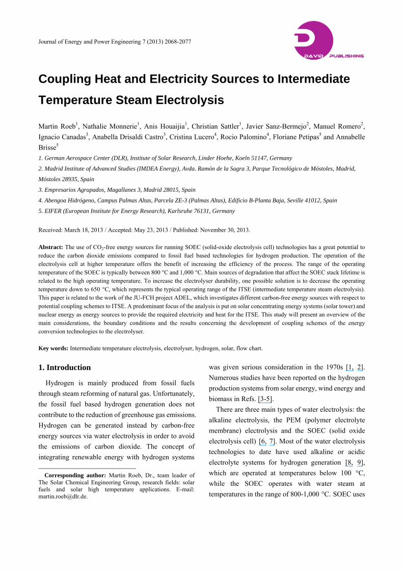
Fig. 1 Scheme of different HTSE operating modes at 1,073 K.
Ethermoneutral: thermoneutral voltage in V;
ΔrH: enthalpy change of reaction in J/mol;
F: faraday constant in C/mol;
n: number of exchanged electrons in the water
electrolysis reaction.
At 298 K and 1 bar, the thermoneutral voltage is
1.481 V. It decreases to 1.286 V at 1,073 K and 1 bar.
At this particular voltage, the heat absorbed by the
endothermic electrolysis reaction is compensated by
overvoltages. In this mode, outlet gases (H2/H2O and
O2) have the same temperature as the inlet gases
(H2O/H2).
Exothermal mode:
In this operating mode, the cell voltage is above the
thermoneutral voltage. Current densities imposed on
the cell are higher, so that overvoltages are also higher.
Heat production in the cell is higher than heat absorbed
by the endothermic electrolysis reaction. Thus, exhaust
gases (H2/H2O and O2) have higher temperature than
inlet gases (H2O/H2). Therefore, low temperature
steam can be heated up to the electrolyser operational
temperature just by the exhaust gases. As a part of the
electricity is used to overheat the streams, the voltage
efficiency of this mode is lower than 100%.
Enodthermic mode:
If the cells’ voltage is lower than the thermoneutral
voltage, overvoltages are also lower. Heat production
in the cell is lower than heat absorbed by the
endothermic electrolysis reaction. Therefore, outlet
streams (H2/H2O and O2) have lower temperature than
the inlet gases (H2O/H2). Heat to reach the operational
stack temperature should be provided by external heat.
As a part of the heat needed by the endothermic
reaction is supplied by external heat sources, the
voltage efficiency of this mode is higher than 100%.
This operating mode is particularly adapted for
coupling a high temperature electrolyser with an
available external high temperature heat source.
2.3 System Performance
Theses electrolysers can operate at high current
densities (up to 1.4 A/cm2 with 1.1 V at 800 °C [13]
and up to 3.6 A/cm2 with 1.48 V at 950 °C [14] ).
Because they are at research state, most tests have been
carried out only at atmospheric pressure on planar cells
so far. Tubular cells operate better at higher pressure,
but research is currently focuses on planar cells, whose
production capacity can be higher. The operating
temperature is commonly 600-800 °C. The system can
reach 70% efficiency based on primary energy
(considering that the production of electricity has an
average efficiency of less than 40%), or 90% efficiency
based on total energy input into the electrolyser [15].
The ITSE operating temperature enables ionic
conductivity of the electrolyte to be high enough, and
ensures high electrode reaction kinetics, so that
electrode overvoltages are low compared to low
temperature electrolysis.
These different elements have a notable impact on
the total electricity consumption of electrolysis. Indeed,
the electricity consumption is around 4.6 kWhe/Nm3 of
hydrogen with low temperature electrolysis, whereas it
is 3.2 kWhe/Nm3 of hydrogen with high temperature
electrolysis in the thermoneutral mode. The
Coupling Heat and Electricity Sources to Intermediate Temperature Steam Electrolysis
2071
consumption can even be reduced to 2.6 kWhe/Nm3 of
hydrogen in the endothermic mode according to the
results of Dönitz et al. [16].
3. Energy Conversion Technologies
3.1 Solar Tower Applying Air as Heat Transfer Fluid
3.1.1 Description of the Technology
Some current European designs use air as heat
transfer medium for solar power tower operation
because of its high temperature and its good handiness
[17]. Another advantage of air as heat transfer medium
is its abundance without costs, his non-toxicity, and the
fact that it does not require freeze protection during
times of non-operation. That is why air is also
considered as heat transfer fluid in the present concept
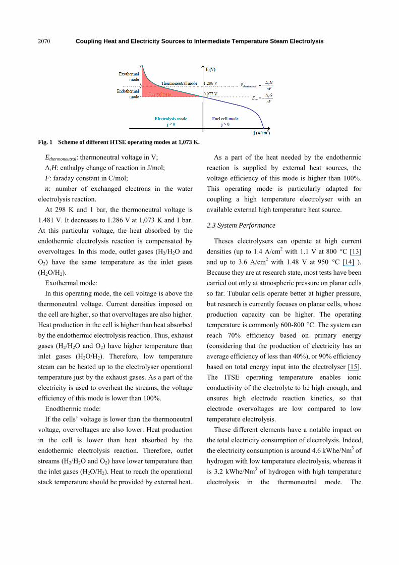
for powering an ITSE system. Ambient air is sucked
through a blackened porous ceramic structure on which
the solar radiation is focused. The air cools the outer
parts of the receiver and is heated up gradually to the
design temperature level at the inner surface of the
porous absorber. In passing through the receiver, the air
is heated up to 700 °C and this heat is delivered to the
water-steam cycle in a heat recovery boiler. The steam
generated there drives a turbine/generator and returns
in form of condensate to the steam generator (Fig. 2).
3.1.2 Process Design Basis
In this study, a solar tower with a nominal capacity
of 10 MWe is considered. The time-dependant
performance for the solar collector field and the solar
transients and fluctuations can be resolved by using an
oversized heliostat field and making use of the excess
energy to load a thermal storage system. The electricity
for the electrolyser will be generated with a steam
turbine for which the steam will be produced with
concentrating solar energy. Power tower plants use a
conventional power block and can easily dispatch
power when storage is available. The thermal source of
the steam generator is hot air stream at 680 ºC.
Thermal-energy storage in the power tower allows
electricity to be dispatched to the grid when demand for
power is the highest, thus increasing the monetary
Fig. 2 Air solar power tower.
value of the electricity. Besides making the power
dispatchable, thermal storage also gives the
power-plant designer freedom to develop power plants
with a wide range of capacity factors to meet the needs
of the utility grid.
In parallel to the steam generator and receiver, the
heat storage is integrated into the power cycle and
implemented as air-cooled regenerator storage. This
technology stores in a ceramic solid-state storage
system some of the thermal energy collected by the
solar field for conversion to electricity later in the day.
Storage can adapt the profile of power produced
throughout the day to demand and can increase the total
power output of a plant with given maximum turbine
capacity. With this storage type, air is in direct contact
with the solid storage medium and exchanges heat as it
flows along a flow-path through the storage medium.
3.1.3 Flow Chart
The solar power tower consists of the following
components:
an heliostat field;
an open volumetric receiver (RECEIVER), at the
top of the solar tower, for air heating and sweep gas
generation.
The electrolyser consists of two components:
a steam splitter (STEAMSPL), where the water
splitting reaction will take place;
a membrane (MEM), where the product is splitted
into a stream containing H2 and H2O and a stream
containing O2 and N2.
Finally, the heat recovery system is used to overheat
the water steam up to the operating temperature of the
Coupling Heat and Electricity Sources to Intermediate Temperature Steam Electrolysis
2072
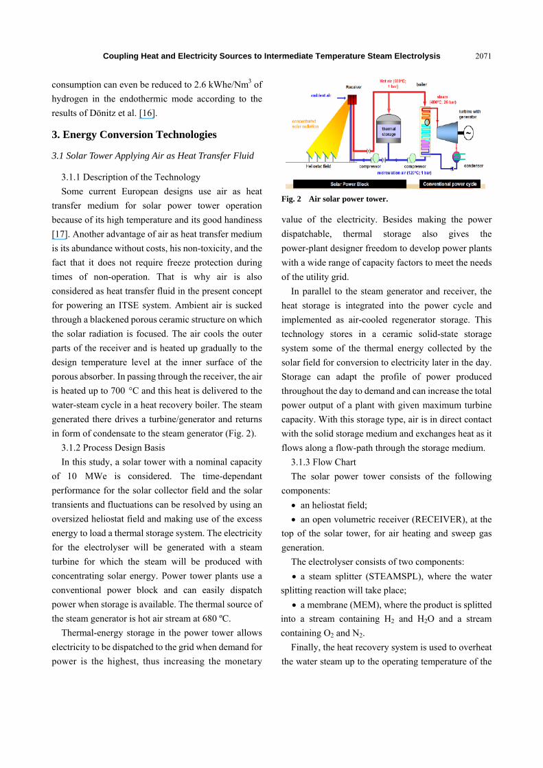
Fig. 3 Flow chart of the air cooled solar tower coupled to the ITSE.
electrolyser. It consists of two heat exchangers
(SUPERHX 3, SUPERHX 2).
The above figure (Fig. 3) shows the flow chart of the
plant.
High concentrated solar radiation is used in the open
volumetric receiver (RECEIVER) to produce hot air at
700 °C (Air 3) to generate high temperature steam in a
heat boiler (BOILER). This steam is used as feed for a
steam Rankine cycle (TURBINE) to generate
electricity for the electrolyser.
A part of the hot air is directly delivered to the
electrolyser and used as sweep gas (Air 9) while
another part (Air 12) is led to the storage system
(STORAGE) which is connected parallel to the boiler.
A third part of the hot air production (Air 10) is used
for the evaporation of the electrolysis water. The
evaporator has been simulated as a single heat
exchanger (EVAPORA 2), which is connected to B3
by the red heat stream (23) in the flow diagram.
After the evaporation of the electrolysis water, the
steam (Water 2) is split in the splitter (SPLIT 3) into
two sub-streams (Water 3 and Water 4); the first
sub-stream (Water 3) is overheated in the heat
exchanger (SUPERHX 2) up to 680 °C by the stream
(HY1) leaving the electrolyser. The second sub-stream
(Water 4) is overheated in the heat exchanger
(SUPERHX 3) up to 525 °C by the stream (O2 Stack 1).
Then, both sub-streams are mixed in the mixer
(MIXER 1) and the mixture is introduced to another
mixer (MIXER 3), where it will be mixed with the
stream (HY 3) in order to maintain reducing conditions
at the cathode side, since it was assumed by the ADEL
project-partner that the stream (Water 8) has to contain
10 mol% H2.
An electrical heater (ELECHX) is necessary in order
to rich the operating temperature of the electrolyser. A
second electrical heater is added to heat the sweep gas
up to 700 °C if it is necessary for the transient
conditions. Thus it enables to control the sweep gas
temperature and to guarantee fixed conditions for the
sweep gas in the electrolyser. The electrical air and
steam heaters are modelled as heaters receiving heat,
which is considered to be a realistic representation
since virtually all electric power supplied will be
dissipated as heat.
The first simulation results show that the quantity of
sweep gas and the ratio sweep gas/steam is a very
important factor for the process efficiency. The 10
Coupling Heat and Electricity Sources to Intermediate Temperature Steam Electrolysis
2073
MWe plant with a sweep gas flow rate of 16.6 kg/s can
produce 3,240 Nm3/h hydrogen. In an optimized case,
an efficiency of 62% has been reached.
3.2 Direct Steam Generation Central Receiver System,
DSG-CRS
Among central receiver concentrating solar plant,
water/steam cooled receiver technology is the most
mature, with commercial plants operating since 2007.
DSG-CRS has the advantage of avoiding the steam
generator required in other CSP technologies, which
might reduce the cost of the plant. Within this study the
possibility of integration of an ITSE into a DSG-CRS
has been analyzed. The variables analyzed in the study
were the electrolyser steam generation system, thermal
energy storage, and steam conditions and design of the
Rankine cycle.
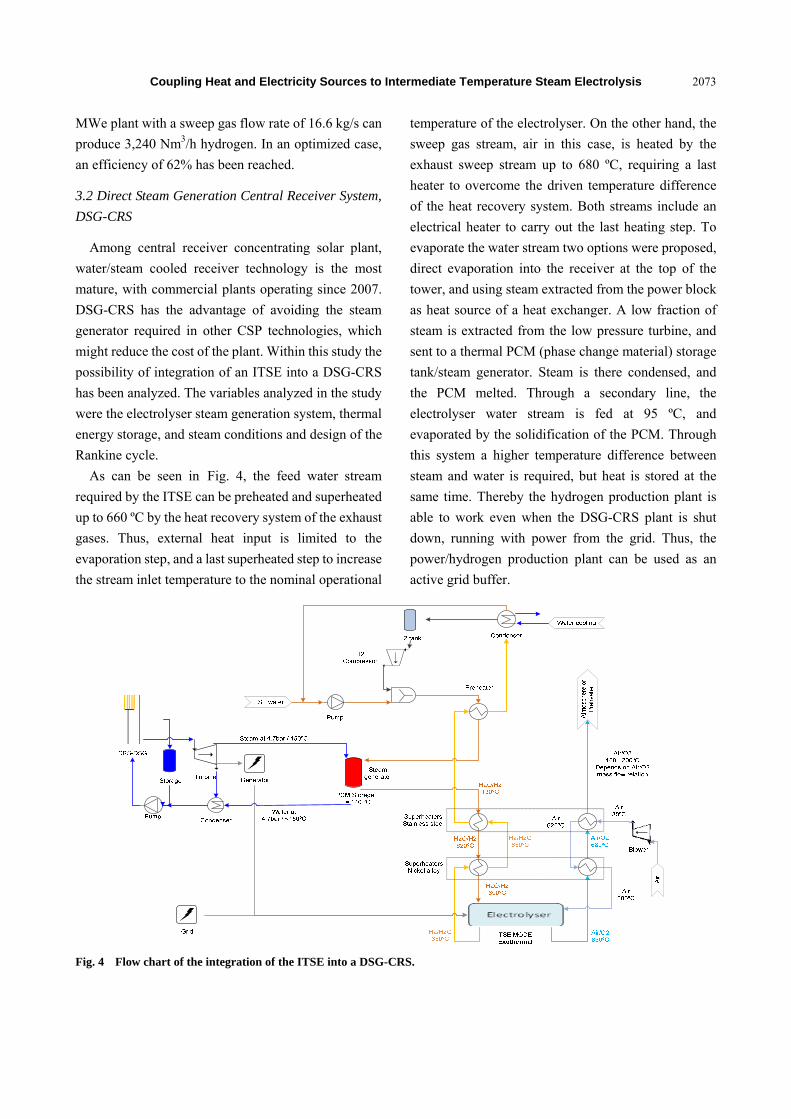
As can be seen in Fig. 4, the feed water stream
required by the ITSE can be preheated and superheated
up to 660 ºC by the heat recovery system of the exhaust
gases. Thus, external heat input is limited to the
evaporation step, and a last superheated step to increase
the stream inlet temperature to the nominal operational
temperature of the electrolyser. On the other hand, the
sweep gas stream, air in this case, is heated by the
exhaust sweep stream up to 680 ºC, requiring a last
heater to overcome the driven temperature difference
of the heat recovery system. Both streams include an
electrical heater to carry out the last heating step. To
evaporate the water stream two options were proposed,
direct evaporation into the receiver at the top of the
tower, and using steam extracted from the power block
as heat source of a heat exchanger. A low fraction of
steam is extracted from the low pressure turbine, and
sent to a thermal PCM (phase change material) storage
tank/steam generator. Steam is there condensed, and
the PCM melted. Through a secondary line, the
electrolyser water stream is fed at 95 ºC, and
evaporated by the solidification of the PCM. Through
this system a higher temperature difference between
steam and water is required, but heat is stored at the
same time. Thereby the hydrogen production plant is
able to work even when the DSG-CRS plant is shut
down, running with power from the grid. Thus, the
power/hydrogen production plant can be used as an
active grid buffer.
Fig. 4 Flow chart of the integration of the ITSE into a DSG-CRS.
Coupling Heat and Electricity Sources to Intermediate Temperature Steam Electrolysis
2074
Seven different Rankine cycles have been compared
for DSG-CRS plants which capacities are 10 MWe and
50 MWe. Steam conditions have been varied from
saturated to superheated condition; and reheat and
no-reheat turbine have been analyzed. In every case,
the reduction of the DSG-CRS performance when
integrating the ITSE unit has been lower than 4%.
Under nominal conditions, the electrolyser unit
achieves an electrical efficiency of 94.7%. Taken into
account thermal requirements for the feeding water
evaporation, the efficiency of the unit decreases down
to 75.3%. The ITSE unit required about 35 kWh of
electricity and 9 kWh of heat to produce 1 kg/h of
hydrogen. The small CSP plant, 12.4 MWe, coupled
with two ITSE units of 2.5 MWe, is able to produce
1,656 Nm3/h of hydrogen, and inject to the grid above 7
MWe. The bigger plant, with a total electricity
production of 62 MWe, was coupled with three ITSE
units of 10 MWe, producing 9,938.5 Nm3/h of
hydrogen and injecting to the grid more than 31 MWe.
From the simulation it was found that the Rankine
cycle performance variation decreases by just 2.6%
when the ITSE Unit is integrated; and the hybrid plant
has 5.5% lower performance in comparison with the
reference solar plant without the electrolyser.
3.3 Molten Salt Tower System
The third option analyzed was the integration of the
ITSE unit with a molten salt tower plant. Molten
salt-cooled central receiver plant has two heat transfer
fluid loops, which decouples the steam generation from
the collector subsystem and makes possible the
integration of high capacity thermal energy storage.
Therefore, the ITSE can operate under high stable
steam and electricity conditions. Thanks to long-term
thermal storage system, which normally is integrated in
these kinds of plants, it is possible to operate
round-the-clock in summertime, leading to an annual
capacity factor of 74%. Therefore, these plants can be
designed easily for both cases: stand-alone hydrogen
production plants or grid stabilizer as a power sink at
low demand periods.
The temperature range of this kind of plants is
between 565 ºC in the hot tank, and 290 ºC in the cold
tank. The cold tank is kept 70-40 ºC above the salt
mixture freezing point, 220-250 ºC. Steam temperature
at the inlet of the electrolyser system must be at 130 ºC.
Therefore, it could be possible to feed the ITSE steam
generator with cold molten salt. In this way,
temperature difference between hot and cold streams of
the steam generator is reduced, maximizing the energy
efficiency of the process. However, it should be kept in
mind that solidification must be avoided and therefore,
molten salt can not be cooled down below a limited
temperature, higher than freezing temperature. The
temperature reduction achieved by the cold molten salt
through the steam generator depends on the salt
mixture quality, its design cold temperature and the
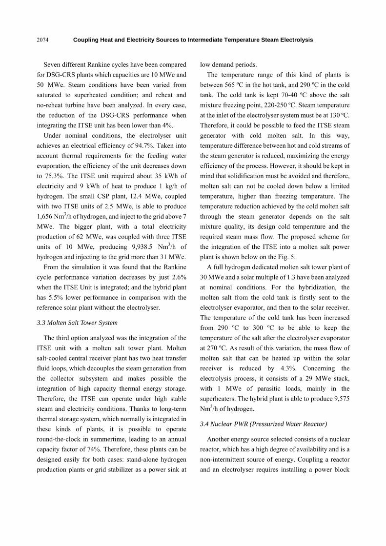
required steam mass flow. The proposed scheme for
the integration of the ITSE into a molten salt power
plant is shown below on the Fig. 5.
A full hydrogen dedicated molten salt tower plant of
30 MWe and a solar multiple of 1.3 have been analyzed
at nominal conditions. For the hybridization, the
molten salt from the cold tank is firstly sent to the
electrolyser evaporator, and then to the solar receiver.
The temperature of the cold tank has been increased
from 290 ºC to 300 ºC to be able to keep the
temperature of the salt after the electrolyser evaporator
at 270 ºC. As result of this variation, the mass flow of
molten salt that can be heated up within the solar
receiver is reduced by 4.3%. Concerning the
electrolysis process, it consists of a 29 MWe stack,
with 1 MWe of parasitic loads, mainly in the
superheaters. The hybrid plant is able to produce 9,575
Nm3/h of hydrogen.
3.4 Nuclear PWR (Pressurized Water Reactor)
Another energy source selected consists of a nuclear
reactor, which has a high degree of availability and is a
non-intermittent source of energy. Coupling a reactor
and an electrolyser requires installing a power block
Coupling Heat and Electricity Sources to Intermediate Temperature Steam Electrolysis
2075
Fig. 5 Flow chart of the integration of the ITSE into a molten salt solar tower.
that uses part of the heat from the reactor to generate
the electric power needed for the electrolyser.
Therefore, a proper power block needs to be chosen,
and this decision is mainly determined by the reactor
technology chosen and by the way of coupling it with
the electrolyser system.
A PWR was chosen, since it is a mature technology
being able to reliably provide the necessary electricity
and heat to generate the steam. A typical steam cycle is
considered for a PWR reactor that will extract the
electricity demanded by the electrolyser. Furthermore,
in this case, the only feasible option is to transfer heat
to the electrolyser system from one of the extractions of
the low pressure turbine in that cycle, and choosing a
suitable pressure for it accordingly. It will therefore be
necessary to have an electrolyser system that includes
heat recovery and electric heating in order to reach the
700 ºC as required.
It would be a steam cycle operating with saturated
steam at 70 bar at the inlet to the high pressure turbine,
where it would expand up to 12 bar. This would also be
the pressure of the deaerator fed from the outlet of that
HP turbine. In addition, the discharged steam would go
to the required moisture separator (the steam would
exit the high pressure turbine at too low a quality to
keep it expanding in the low pressure turbine), and then
undergo double heating with steam taken from the high
pressure turbine and with main steam. The reheated
steam then goes to the low pressure turbine and
condenses. A pump pumps the condensate through the
train of low pressure pre-heaters and on to the deaerator.
The deaerator drainage is pumped by the feedwater
pump to the train of feedwater pre-heaters and finally
enters the reactor steam generator. To do this, a
configuration was chosen consisting of two extractions
from the high pressure turbine (two high pressure
pre-heats) and three extractions from the low pressure
turbine to do three low pressure pre-heats. In addition,
there is also a first extraction just at the inlet to the
turbine for the thermal demand of the electrolyser
system. The most efficient way to produce H2 using a
constant power source, as a nuclear reactor, is to feed.
Connecting the power cycle to the grid, which will
absorb a potential surplus of energy, allows to couple
hydrogen production from nuclear energy as a constant
power source to a variable sink of energy like storage.
Coupling Heat and Electricity Sources to Intermediate Temperature Steam Electrolysis
2076
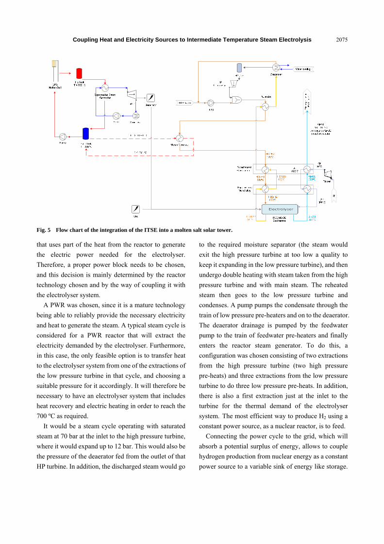
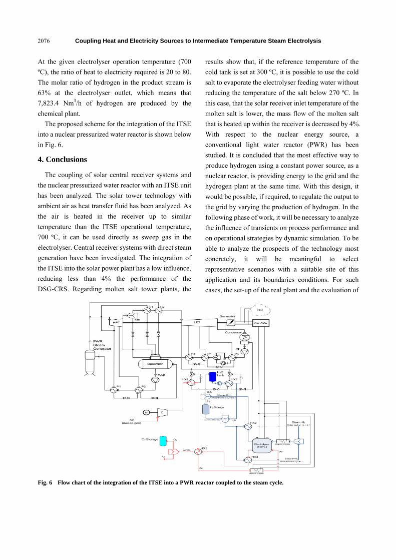
At the given electrolyser operation temperature (700
ºC), the ratio of heat to electricity required is 20 to 80.
The molar ratio of hydrogen in the product stream is
63% at the electrolyser outlet, which means that
7,823.4 Nm3/h of hydrogen are produced by the
chemical plant.
The proposed scheme for the integration of the ITSE
into a nuclear pressurized water reactor is shown below
in Fig. 6.
4. Conclusions
The coupling of solar central receiver systems and
the nuclear pressurized water reactor with an ITSE unit
has been analyzed. The solar tower technology with
ambient air as heat transfer fluid has been analyzed. As
the air is heated in the receiver up to similar
temperature than the ITSE operational temperature,
700 ºC, it can be used directly as sweep gas in the
electrolyser. Central receiver systems with direct steam
generation have been investigated. The integration of
the ITSE into the solar power plant has a low influence,
reducing less than 4% the performance of the
DSG-CRS. Regarding molten salt tower plants, the
results show that, if the reference temperature of the
cold tank is set at 300 ºC, it is possible to use the cold
salt to evaporate the electrolyser feeding water without
reducing the temperature of the salt below 270 ºC. In
this case, that the solar receiver inlet temperature of the
molten salt is lower, the mass flow of the molten salt
that is heated up within the receiver is decreased by 4%.
With respect to the nuclear energy source, a
conventional light water reactor (PWR) has been
studied. It is concluded that the most effective way to
produce hydrogen using a constant power source, as a
nuclear reactor, is providing energy to the grid and the
hydrogen plant at the same time. With this design, it
would be possible, if required, to regulate the output to
the grid by varying the production of hydrogen. In the
following phase of work, it will be necessary to analyze
the influence of transients on process performance and
on operational strategies by dynamic simulation. To be
able to analyze the prospects of the technology most
concretely, it will be meaningful to select
representative scenarios with a suitable site of this
application and its boundaries conditions. For such
cases, the set-up of the real plant and the evaluation of
Fig. 6 Flow chart of the integration of the ITSE into a PWR reactor coupled to the steam cycle.
Coupling Heat and Electricity Sources to Intermediate Temperature Steam Electrolysis
2077
energy efficiencies and performance under transient
conditions shall be analyzed to get a refined view on
the future potential of the technology.
Acknowledgments
The authors acknowledge the co-funding of the JTI
FCH project ADEL (Contract-No. 256755).
References
[1] M. Eisenstadt, K. Cox, Hydrogen production from solar energy, Solar Energy 17 (1975) 59-65.
[2] E. Costogue, R. Yasui, Performance data for a terrestrial solar photovolatic/water electrolysis experiment, Solar Energy 19 (1977) 205-210.
[3] J. Bockris, T. Veziroglu, Estimates of price of hydrogen as a medium for wind and solar sources, International Journal of Hydrogen Energy 32 (2007) 1605-1615.
[4] P.C. Ghosh, B. Emonts, H. Janßen, J. Mergel, D. Stolten, Ten years of operational experience with a hydrogen-based renewable energy supply system, Solar Energy 75 (2003) 469-478.
[5] A. Szyszka, Ten years of solar hydrogen demonstration project at Neunburg Vorm Wald, Germany, International Journal of Hydrogen Energy 10 (1998) 849-860.
[6] T. Smolinka, Fuels-Hydrogen Production: Water Electrolysis, in: G. Jürgen (Ed.), Encyclopedia of Electrochemical Power Sources, Elsevier, 2009, pp. 394-413.
[7] S.M. Dutta, J.H. Morehouse, J.A. Khan, Numerical analysis of laminar flow and heat transfer in a high temperature electrolyzer, International Journal of Hydrogen Energy 22 (1997) 883-895.
[8] S. Badwal, S. Giddey, F. Ciacchi, Hydrogen and oxygen generation with PEM (polymer electrolyte membrane)
based electrolytic technology, International Journal of Ionics 1 (2006) 7-14.
[9] P. Millet, F. Andolfatto, R. Durand, Design and performance of a solid polymer electrolyte water electrolyser, International Journal of Hydrogen Energy 2 (1996) 87-93.
[10] J.E. O’Brien, Thermodynamics and transport phenomena in high temperature steam electrolysis cells, Journal of Heat Transfer 134 (2012) 1-11.
[11] B.G. Rietveld, F.P. Van Berkel, Y. Zhang-Steenwinkel, E. Bouyer, J. Irvine, M. Menon, et al., The integrated project SOFC600 development of low-temperature SOFC, ECS Trans. 25 (2) (2009) 29-34.
[12] S. Elangovan, J. Hartvigsen, High-temperature electrolysis, Materials for the Hydrogen Economy 3 (2007) 6-80.
[13] A. Brisse, J. Schefold, M. Zahid, High temperature water electrolysis in solid oxide cells, International Journal of Hydrogen Energy 33 (2008) 5375-5382.
[14] S.H. Jensen, P.H. Larsen, M. Mogensen, Hydrogen and synthetic fuel production from renewable energy sources, Int. J. Hydrogen Energy 32 (15) (2007) 3253-3257.
[15] J. Martinez-Frias, A.Q. Pham, S. Aceves, A natural gas-assisted steam electrolyzer for high efficiency production of hydrogen, International Journal of Hydrogen Energy 28 (2003) 483-490.
[16] W. Dönitz, G. Dietrich, E. Erdle, R. Streicher, Electrochemical high temperature technology for hydrogen production or direct electricity generation, International Journal of Hydrogen Energy 13 (1988) 283-287.
[17] G. Koll, P. Schwarzbözl, K. Hennecke, M. Schmitz, B. Hoffschmidt, The solar tower jülich—A research and demonstration plant for central receiver systems, in: Proceedings of the 15th Solar PACES Symposium, Berlin, Germany, 2009.
Related Documents