Coupling Architectures for Low-Level Fieldbusses Miroslav Švéda Dept. of Computer Sci.&Eng. Technical University of Brno Czech Republic [email protected] Radimír Vrba Dept. of Microelectronics Technical University of Brno Czech Republic [email protected] František Zezulka Dept. of Control Engineering Technical University of Brno Czech Republic [email protected] Abstract This paper deals with hierarchical, multiple fieldbus-based architectures using four case studies that present some concepts reusable in developing the interconnections of intelligent sensors and actuators. The single-master, low- level fieldbusses considered involve (1) ASI (Actuator- Sensor-Interface), which is an example of a lowest-level industrial interconnection; (2) NBIP (Nine-Bit Inter- processor Protocol), which is an example of a special purpose link-layer protocol for microcontrollers; and (3) Bitbus, which is an example of well-established fieldbus utilized for almost 20 years in various applications. The paper begins with classification issues; particularly, coupling architectures are treated both from the viewpoint of more classical interconnections of wide-area and local-area networks, and from the viewpoint of fieldbus domain. Next part introduces the ASI and NBIP protocols while the well- known Bitbus is reviewed in applications. To offer more complex insight, implementation tools -- developed particularly to support low-level fieldbus interconnecting experiments -- are also mentioned. Four case studies demonstrating consequently NBIP-ASI, ASI-ASI, and two different Bitbus-NBIP hierarchical coupling structures create the kernel of the paper. Finally, brief notes about origins, results, and current targets of the project conclude the contribution. 1. Introduction Contemporary industrial distributed computer-based systems encompass, at their lowest level, various digital actuator/sensor-to-controller connections. Those connections usually constitute the bottom segments of hierarchical communication systems that typically include higher-level fieldbus backbones. Hence, the systems must comprise suitable interconnections of incident higher and lower fieldbus segments, which intermediate top-down commands and bottom-up responses. While interconnecting devices for such wide-spread fieldbusses as CAN, Profibus, or WorldFIP are currently commercially available, some real-world applications can demand also to develop various coupling architectures either dedicated to special-purpose protocols or fitting particular operation requirements. Nevertheless, only sporadic attention in current publications is devoted to the fieldbus interconnectivity issues, see e.g. [1], [3]. Moreover, the relevant papers for that domain focus on interconnecting high-level fieldbusses or fieldbusses with local area networks. This contribution devotes attention to the multiple fieldbus interconnecting architectures that fit hierarchical structures with low-level segments. The presented results have been obtained in frame of the research dealing with low-level fieldbus systems design and application support. 2. Interconnection structures This section focuses on the domain terminology. While its first part collects some relevant notions aiming originally at wide or local-area networks that offer a natural nomenclature background, the second part introduces the phraseology fitting low-level fieldbus interconnections properly. 2.1. General taxonomy According to the ISO Open Systems Interconnection vocabulary, two or more subnetworks are interconnected using an equipment called as intermediate system whose primary function is to relay selectively information from one subnetwork to another and to perform protocol conversion where necessary, see [4], [5]. A bridge or a router provides the means for interconnecting two physically distinct networks, which differ occasionally in two or three lower layers respectively. The bridge converts frames with consistent addressing schemes at the data-link layer while the router deals with packets at the network layer. Lower layers 148

Welcome message from author
This document is posted to help you gain knowledge. Please leave a comment to let me know what you think about it! Share it to your friends and learn new things together.
Transcript
Coupling Architectures for Low-Level Fieldbusses
Miroslav Švéda
Dept. of Computer Sci.&Eng. Technical University of Brno
Czech Republic
Radimír Vrba
Dept. of Microelectronics Technical University of Brno
Czech Republic
František Zezulka
Dept. of Control Engineering Technical University of Brno
Czech Republic
Abstract
This paper deals with hierarchical, multiple fieldbus-based architectures using four case studies that present some concepts reusable in developing the interconnections of intelligent sensors and actuators. The single-master, low-level fieldbusses considered involve (1) ASI (Actuator-Sensor-Interface), which is an example of a lowest-level industrial interconnection; (2) NBIP (Nine-Bit Inter-processor Protocol), which is an example of a special purpose link-layer protocol for microcontrollers; and (3) Bitbus, which is an example of well-established fieldbus utilized for almost 20 years in various applications. The paper begins with classification issues; particularly, coupling architectures are treated both from the viewpoint of more classical interconnections of wide-area and local-area networks, and from the viewpoint of fieldbus domain. Next part introduces the ASI and NBIP protocols while the well-known Bitbus is reviewed in applications. To offer more complex insight, implementation tools -- developed particularly to support low-level fieldbus interconnecting experiments -- are also mentioned. Four case studies demonstrating consequently NBIP-ASI, ASI-ASI, and two different Bitbus-NBIP hierarchical coupling structures create the kernel of the paper. Finally, brief notes about origins, results, and current targets of the project conclude the contribution. 1. Introduction
Contemporary industrial distributed computer-based systems encompass, at their lowest level, various digital actuator/sensor-to-controller connections. Those connections usually constitute the bottom segments of hierarchical communication systems that typically include higher-level fieldbus backbones. Hence, the systems must comprise suitable interconnections of incident higher and lower fieldbus segments, which intermediate top-down commands
and bottom-up responses. While interconnecting devices for such wide-spread fieldbusses as CAN, Profibus, or WorldFIP are currently commercially available, some real-world applications can demand also to develop various coupling architectures either dedicated to special-purpose protocols or fitting particular operation requirements. Nevertheless, only sporadic attention in current publications is devoted to the fieldbus interconnectivity issues, see e.g. [1], [3]. Moreover, the relevant papers for that domain focus on interconnecting high-level fieldbusses or fieldbusses with local area networks. This contribution devotes attention to the multiple fieldbus interconnecting architectures that fit hierarchical structures with low-level segments. The presented results have been obtained in frame of the research dealing with low-level fieldbus systems design and application support. 2. Interconnection structures
This section focuses on the domain terminology. While its first part collects some relevant notions aiming originally at wide or local-area networks that offer a natural nomenclature background, the second part introduces the phraseology fitting low-level fieldbus interconnections properly. 2.1. General taxonomy
According to the ISO Open Systems Interconnection vocabulary, two or more subnetworks are interconnected using an equipment called as intermediate system whose primary function is to relay selectively information from one subnetwork to another and to perform protocol conversion where necessary, see [4], [5]. A bridge or a router provides the means for interconnecting two physically distinct networks, which differ occasionally in two or three lower layers respectively. The bridge converts frames with consistent addressing schemes at the data-link layer while the router deals with packets at the network layer. Lower layers
148

of these intermediate systems are implemented according to the proper architectures of interconnected networks. When subnetworks differ in their higher layer protocols, especially in the application layer, or when the communication functions of the bottom three layers are not sufficient for coupling, the intermediate system, called in this case as gateway, contains all layers of the networks involved and converts application messages between appropriate formats.
An intermediate system represents typically a node that belongs simultaneously to two or more interconnected networks. The backbone (sub)network interconnects more intermediate systems that enable to access different subnetworks. If two segments of a network are interconnected through another network, the technique called tunneling enables to transfer protocol data units of the end segments nested in the proper protocol data units of the interconnecting network. 2.2. Fieldbus interconnection taxonomy
The proposed taxonomy of fieldbus interconnections covers both the network topology of an interconnected system and the structure of its intermediate system, which is often called in that domain as coupler or bus coupler. On the other hand, the term gateway sometimes denotes an accessory connecting PC or PLC to a fieldbus. For this paper, the expression “gateway” preserves its original meaning according to ISO-OSI terminology as discussed above. ┌───────┐───────┐ │ M1 M2 │ └───┬───┘───┬───┘ ════╤══════════╧═ ══╧════╤══════════ ┌───┴───┐ BUS1 ┌───┴───┐ BUS2 │ S1 │ │ S2 │ └───────┘ └───────┘
Fig. 1. Peer-to-peer interconnection configuration
The first item to be classed appears the level ordering of interconnected networks. A peer-to-peer structure occurs when two interconnected networks interchange commands and responses through a bus coupler in both directions so that no one of the subnetworks can be distinguished as a higher level, see Fig. 1. In case of the master/slaves or single master configuration, the coupler consists of two interconnected masters (two interconnected slaves can fit very special applications). If two interconnected subnetworks arise hierarchically ordered, see Fig. 2, the master/slaves configuration appears usual at least for the lower-level network. That configuration is considered in the rest of the paper.
The second classification point of view for couplers stems from the protocol profiles involved. In this case, the standard taxonomy using the general terminology mentioned above can be employed: bridge, router, and gateway. Also,
the tunneling and backbone networks can be distinguished in a standard manner , see [4]. ┌───────┐ │ M1 │ └───┬───┘ ══════╤══════════╧════════════════╤══════ BUS 1 ┌───┴───┐ ┌───┴───┐ │ (S1) │ │ S1 │ │COUPLER│ └───────┘ │ (M2) │ └───┬───┘ ══════╧════╤═══════════════════╤═════════ BUS 2 ┌───┴───┐ ┌───┴───┐ │ S2 │ │ S2 │ └───────┘ └───────┘
Fig. 2. Hierarchical interconnection configuration
The next, refining items to be classed include internal logical and physical architectures of the coupler, such as routing strategy (source or adaptive) and routing and relaying algorithms (more detailed specification), number of processors and the type of their connection (direct serial or parallel, indirect through FIFO queue or through dual-port RAM). In short, the presented case studies employ the source routing strategy, which demonstrates a cheap and robust solution. Of course, the complete information about a coupler can be offered only by a detailed description of the concrete implementation. 3. Low-level fieldbusses utilized
This section reviews the low-level protocols employed in the demonstrating case studies, which are based on real implementations. The first protocol, ASI, is devoted in fact to the lowest-level industrial communications supporting robust, bit value transmissions. The second introduced protocol, NBIP, represents asynchronous, character-oriented, special-purpose data-link layer communications among microcontrollers. On the contrary, the third protocol employed, Bitbus [17], need not be reviewed because it is well-known issue: it emerges the oldest open specification of an industrial microcontroller communication profile. Only those special features of the protocol, which are necessary for comprehending the case studies, are mentioned in frame of their applications. 3.1. Actuator-Sensor-Interface standard
The ASI, see [6], defines the communication and the pertinent management of the communication of a controlling device with sensors and actuators inside a machine or plant. The ASI was designed as an open standard defined by the ASI Association, which is a legally registered German association, comprising not only German manufacturers but
149
also firms and universities from different countries, and which is independent of any manufacturers.
An unscreened two-wire cable (of length up to 100 m) transfers data and energy for the operation of connected units. A bus topology with a tree physical structure interconnects one master station and a maximum of 31 slaves with up to 124 binary actuators/sensors (a maximum of 4 binary units or 1 more complex digital unit per slave). To connect different actuators, sensors, or other devices and elements to the ASI system, this standard also defines an electro-mechanical module interface, which enables an extremely simple system installation and manipulation.
The prescribed implementation provides a power supply through the bus (24 V DC for compatibility with current devices, up to 100 mA per slave, and maximum of 2 A total), and simple slave-side electronics (sensor with integrated ASI or separate ASI circuit with up to 4 standard sensors or actuators). The "alternating pulse modulation" bit-representation scheme stems from Manchester II encoding and edge derivatives, which are transmitted as a sin2 voltage waveform. An asynchronous transfer with polling mode communication at the rate up to 167 kbit/s supports 5 ms cycle time for the maximum configuration with 31 slaves.
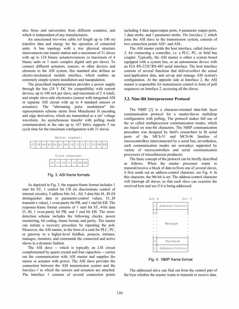
Master request: ┌──┬──┬──┬──┬──┬──┬──┬──┬──┬──┬──┬──┬──┬──┐ │ST│CB│A4│A3│A2│A1│A0│I4│I3│I2│I1│I0│PB│EB│ └──┴──┴──┴──┴──┴──┴──┴──┴──┴──┴──┴──┴──┴──┘
Slave response:
┌──┬──┬──┬──┬──┬──┬──┐ │ST│I3│I2│I1│I0│PB│EB│ └──┴──┴──┴──┴──┴──┴──┘
Fig. 3. ASI frame formats
As depicted in Fig. 3, the request-frame format includes 1
start bit ST, 1 control bit CB (to discriminate control of internal circuits), 5 address bits A4...A0, 5 data bits I4...I0 (I4 distinguishes data or parameter-control values, I3...I0 transmit a value), 1 even-parity bit PB, and 1 end bit EB. The response-frame format consists of 1 start bit ST, 4-bit data I3...I0, 1 even-parity bit PB, and 1 end bit EB. The error-detection scheme includes the following checks: power monitoring, bit coding, frame format, and parity. The master can initiate a recovery procedure by repeating the poll. Moreover, the ASI master, in the form of a card for PLC, PC, or gateway to a higher-level fieldbus, projects, initiates, manages, monitors, and commands the connected and active slaves in a dynamic fashion.
The ASI slave -- which is typically an LSI circuit complemented by quartz crystal and four capacitors -- carries out the communication with ASI master and supplies the sensor or actuator with power. The ASI slave provides the connection between the ASI transmission system and the Interface 1 to which the sensors and actuators are attached. The Interface 1 consists of several connection points
including 4 data input/output ports, 4 parameter output ports, 1 data strobe, and 1 parameter strobe. The Interface 2, which joins the ASI slave to the transmission system, consists of two connection points ASI+ and ASI-.
The ASI master yields the host interface, called Interface 3, for connecting a controller, i.e. a PLC, PC, or field bus coupler. Typically, the ASI master is either a system board equipped with a system bus, or an autonomous device with an EIA RS-232C/RS-485 serial interface. The host interface consists of several functions that deliver/collect the actual user/application data, and set-up and manage ASI system's configuration. At the opposite side at Interface 2, the ASI master is responsible for transmission control in form of poll sequences on Interface 2, accessing all the slaves. 3.2. Nine-Bit Interprocessor Protocol
The NBIP [2] is a character-oriented data-link layer communication protocol for a master/slaves multidrop configuration with polling. The protocol makes full use of the so called multiprocessor communication modes, which are based on nine-bit characters. The NBIP communication procedure was designed by Intel's researchers to fit serial ports of the MCS-51 and MCS-96 families of microcontrollers interconnected by a serial bus; nevertheless, such communication modes are nowadays supported by variety of microcontrollers and serial communication processors of miscellaneous producers.
The basic concept of the protocol can be briefly described as follows. When the master processor wants to transmit/receive a block of data to/from one of several slaves, it first sends out an address-control character, see Fig. 4. In this character, the 9th bit is set. The address-control character will interrupt all slaves, so that each slave can examine the received byte and see if it is being addressed.
bit 8 bit 0 ┌─┬────────────────┐ │1│ Address-Control│ ├─┼────────────────┤ │0│ │ . . . . . . . . Message . . . . . . . . . . ├─┼────────────────┤ │0│ Checksum │ ├─┼────────────────┤ │1│ Address-Control│ └─┴────────────────┘
Fig. 4. NBIP frame format
The addressed slave can find out from the control part of
the byte whether the master wants to transmit or receive data.
150
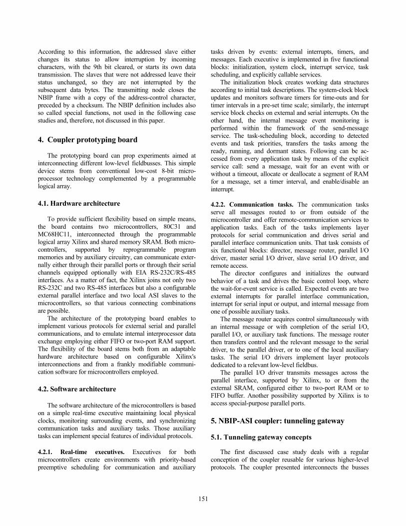
According to this information, the addressed slave either changes its status to allow interruption by incoming characters, with the 9th bit cleared, or starts its own data transmission. The slaves that were not addressed leave their status unchanged, so they are not interrupted by the subsequent data bytes. The transmitting node closes the NBIP frame with a copy of the address-control character, preceded by a checksum. The NBIP definition includes also so called special functions, not used in the following case studies and, therefore, not discussed in this paper. 4. Coupler prototyping board
The prototyping board can prop experiments aimed at interconnecting different low-level fieldbusses. This simple device stems from conventional low-cost 8-bit micro-processor technology complemented by a programmable logical array. 4.1. Hardware architecture
To provide sufficient flexibility based on simple means, the board contains two microcontrollers, 80C31 and MC68HC11, interconnected through the programmable logical array Xilinx and shared memory SRAM. Both micro-controllers, supported by reprogrammable program memories and by auxiliary circuitry, can communicate exter-nally either through their parallel ports or through their serial channels equipped optionally with EIA RS-232C/RS-485 interfaces. As a matter of fact, the Xilinx joins not only two RS-232C and two RS-485 interfaces but also a configurable external parallel interface and two local ASI slaves to the microcontrollers, so that various connecting combinations are possible.
The architecture of the prototyping board enables to implement various protocols for external serial and parallel communications, and to emulate internal interprocessor data exchange employing either FIFO or two-port RAM support. The flexibility of the board stems both from an adaptable hardware architecture based on configurable Xilinx's interconnections and from a frankly modifiable communi-cation software for microcontrollers employed. 4.2. Software architecture
The software architecture of the microcontrollers is based on a simple real-time executive maintaining local physical clocks, monitoring surrounding events, and synchronizing communication tasks and auxiliary tasks. Those auxiliary tasks can implement special features of individual protocols. 4.2.1. Real-time executives. Executives for both microcontrollers create environments with priority-based preemptive scheduling for communication and auxiliary
tasks driven by events: external interrupts, timers, and messages. Each executive is implemented in five functional blocks: initialization, system clock, interrupt service, task scheduling, and explicitly callable services.
The initialization block creates working data structures according to initial task descriptions. The system-clock block updates and monitors software timers for time-outs and for timer intervals in a pre-set time scale; similarly, the interrupt service block checks on external and serial interrupts. On the other hand, the internal message event monitoring is performed within the framework of the send-message service. The task-scheduling block, according to detected events and task priorities, transfers the tasks among the ready, running, and dormant states. Following can be ac-cessed from every application task by means of the explicit service call: send a message, wait for an event with or without a timeout, allocate or deallocate a segment of RAM for a message, set a timer interval, and enable/disable an interrupt. 4.2.2. Communication tasks. The communication tasks serve all messages routed to or from outside of the microcontroller and offer remote-communication services to application tasks. Each of the tasks implements layer protocols for serial communication and drives serial and parallel interface communication units. That task consists of six functional blocks: director, message router, parallel I/O driver, master serial I/O driver, slave serial I/O driver, and remote access.
The director configures and initializes the outward behavior of a task and drives the basic control loop, where the wait-for-event service is called. Expected events are two external interrupts for parallel interface communication, interrupt for serial input or output, and internal message from one of possible auxiliary tasks.
The message router acquires control simultaneously with an internal message or with completion of the serial I/O, parallel I/O, or auxiliary task functions. The message router then transfers control and the relevant message to the serial driver, to the parallel driver, or to one of the local auxiliary tasks. The serial I/O drivers implement layer protocols dedicated to a relevant low-level fieldbus.
The parallel I/O driver transmits messages across the parallel interface, supported by Xilinx, to or from the external SRAM, configured either to two-port RAM or to FIFO buffer. Another possibility supported by Xilinx is to access special-purpose parallel ports. 5. NBIP-ASI coupler: tunneling gateway 5.1. Tunneling gateway concepts
The first discussed case study deals with a regular conception of the coupler reusable for various higher-level protocols. The coupler presented interconnects the busses
151
based on ASI and NBIP, which is complemented in this case by the EIA RS-485 physical layer. In fact, that configuration exemplifies a special-purpose protocol coupler imple-mentation for ASI. This coupler is based on the tunneling conception: the host interface messages are carried between the NBIP Master Station, which plays the role of ASI Host, and the ASI Master by NBIP frames. 5.2. NBIP-ASI coupler implementation
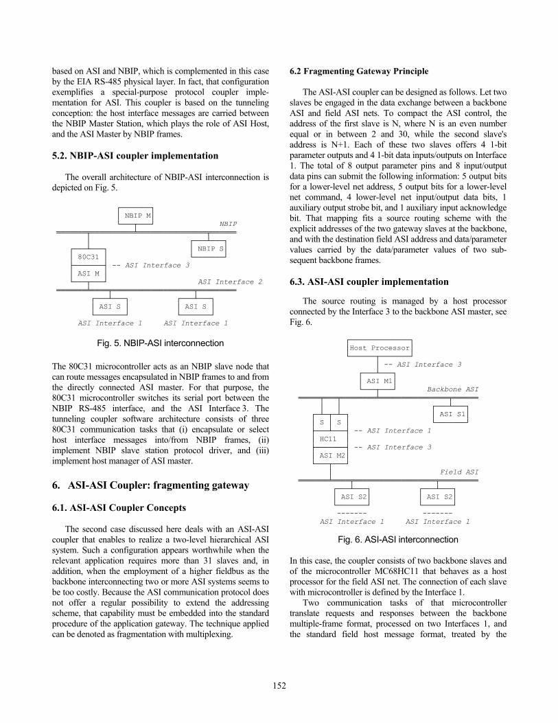
The overall architecture of NBIP-ASI interconnection is depicted on Fig. 5.
┌───────┐ │ NBIP M│ └───┬───┘ NBIP ═══════╤══════════╧════════════════╤══════ │ ┌───┴───┐ ┌───┴───┐ │ NBIP S│ │ 80C31 │ └───────┘ ├───────┤ -- ASI Interface 3 │ ASI M │ └───┬───┘ ASI Interface 2 ═══════╧════╤═══════════════════╤═════════ ┌───┴───┐ ┌───┴───┐ │ ASI S │ │ ASI S │ └───────┘ └───────┘
ASI Interface 1 ASI Interface 1
Fig. 5. NBIP-ASI interconnection The 80C31 microcontroller acts as an NBIP slave node that can route messages encapsulated in NBIP frames to and from the directly connected ASI master. For that purpose, the 80C31 microcontroller switches its serial port between the NBIP RS-485 interface, and the ASI Interface 3. The tunneling coupler software architecture consists of three 80C31 communication tasks that (i) encapsulate or select host interface messages into/from NBIP frames, (ii) implement NBIP slave station protocol driver, and (iii) implement host manager of ASI master. 6. ASI-ASI Coupler: fragmenting gateway 6.1. ASI-ASI Coupler Concepts
The second case discussed here deals with an ASI-ASI coupler that enables to realize a two-level hierarchical ASI system. Such a configuration appears worthwhile when the relevant application requires more than 31 slaves and, in addition, when the employment of a higher fieldbus as the backbone interconnecting two or more ASI systems seems to be too costly. Because the ASI communication protocol does not offer a regular possibility to extend the addressing scheme, that capability must be embedded into the standard procedure of the application gateway. The technique applied can be denoted as fragmentation with multiplexing.
6.2 Fragmenting Gateway Principle
The ASI-ASI coupler can be designed as follows. Let two slaves be engaged in the data exchange between a backbone ASI and field ASI nets. To compact the ASI control, the address of the first slave is N, where N is an even number equal or in between 2 and 30, while the second slave's address is N+1. Each of these two slaves offers 4 1-bit parameter outputs and 4 1-bit data inputs/outputs on Interface 1. The total of 8 output parameter pins and 8 input/output data pins can submit the following information: 5 output bits for a lower-level net address, 5 output bits for a lower-level net command, 4 lower-level net input/output data bits, 1 auxiliary output strobe bit, and 1 auxiliary input acknowledge bit. That mapping fits a source routing scheme with the explicit addresses of the two gateway slaves at the backbone, and with the destination field ASI address and data/parameter values carried by the data/parameter values of two sub-sequent backbone frames. 6.3. ASI-ASI coupler implementation
The source routing is managed by a host processor connected by the Interface 3 to the backbone ASI master, see Fig. 6. ┌──────────────┐ │Host Processor│ └──────┬───────┘ │ -- ASI Interface 3 ┌───┴───┐ │ ASI M1│ └───┬───┘ Backbone ASI ═════╤═══╤════════╧════════════════╤══════ │ │ ┌───┴───┐ ┌─┴─┬─┴─┐ │ ASI S1│ │ S │ S │ └───────┘ ├───┴───┤ -- ASI Interface 1 │ HC11 │ ├───────┤ -- ASI Interface 3 │ ASI M2│ └───┬───┘ │ Field ASI ═══════╧════╤═══════════════════╤═════════ ┌───┴───┐ ┌───┴───┐ │ ASI S2│ │ ASI S2│ └───────┘ └───────┘ ------- ------- ASI Interface 1 ASI Interface 1
Fig. 6. ASI-ASI interconnection In this case, the coupler consists of two backbone slaves and of the microcontroller MC68HC11 that behaves as a host processor for the field ASI net. The connection of each slave with microcontroller is defined by the Interface 1.
Two communication tasks of that microcontroller translate requests and responses between the backbone multiple-frame format, processed on two Interfaces 1, and the standard field host message format, treated by the
152
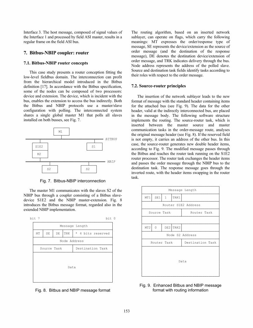
Interface 3. The host message, composed of signal values of the Interface 1 and processed by field ASI master, results in a regular frame on the field ASI bus. 7. Bitbus-NBIP coupler: router 7.1. Bitbus-NBIP router concepts
This case study presents a router conception fitting the low-level fieldbus domain. The interconnection can profit from the hierarchical model introduced in the Bitbus definition [17]. In accordance with the Bitbus specification, some of the nodes can be composed of two processors: device and extension. The device, which is incident with the bus, enables the extension to access the bus indirectly. Both the Bitbus and NBIP protocols use a master/slave configuration with polling. The interconnected system shares a single global master M1 that polls all slaves installed on both busses, see Fig. 7. ┌───────┐ │ M1 │ └───┬───┘ ═══════╤══════════╧════════════════╤════ BITBUS ┌───┴───┐ ┌───┴───┐ │ S1E2 │ │ S1 │ ├───────┤ └───────┘ │ M2 │ └───┬───┘ ═══════╧════╤═══════════════════╤════════ NBIP ┌───┴───┐ ┌───┴───┐ │ S2 │ │ S2 │ └───────┘ └───────┘
Fig. 7. Bitbus-NBIP interconnection
The master M1 communicates with the slaves S2 of the NBIP bus through a coupler consisting of a Bitbus slave-device S1E2 and the NBIP master-extension. Fig. 8 introduces the Bitbus message format, regarded also in the extended NBIP implementation.
bit 7 bit 0 ┌───────────────────────────────────────┐ │ Message Length │ ├────┬────┬────┬────┬───────────────────┤ │ MT │ SE │ DE │TRK │ * 4 bits reserved │ ├────┴────┴────┴────┴───────────────────┤ │ Node Address │ ├───────────────────┬───────────────────┤ │ Source Task │ Destination Task │ ├───────────────────┴───────────────────┤ │ │ │ │ │ │ │ Data │ │ │ │ │ │ │ └───────────────────────────────────────┘
Fig. 8. Bitbus and NBIP message format
The routing algorithm, based on an inserted network sublayer, can operate on flags, which carry the following meanings: MT expresses the order/response type of message, SE represents the device/extension as the source of order message (and the destination of the response message), DE denotes the destination device/extension of order message, and TRK indicates delivery through the bus. Node address represents the address of the polled slave. Source and destination task fields identify tasks according to their roles with respect to the order message. 7.2. Source-router principles
The insertion of the network sublayer leads to the new format of message with the standard header containing items for the attached bus (see Fig. 9). The data for the other header, valid at the indirectly interconnected bus, are placed in the message body. The following software structure implements the routing. The source-router task, which is inserted between the master source and master communication tasks in the order-message route, analyses the original message header (see Fig. 8). If the reserved field is not empty, it carries an address of the other bus. In this case, the source-router generates new double header items, according to Fig. 9. The modified message passes through the Bitbus and reaches the router task running on the S1E2 router processor. The router task exchanges the header items and passes the order message through the NBIP bus to the destination task. The response message goes through the inverted route, with the header items swapping in the router task.
┌──────────────────────────────────────┐ │ Message Length │ ├────┬────┬────┬────┬──────────────────┤ │ MT1│ SE1│ 1 │TRK1│ │ ├────┴────┴────┴────┴──────────────────┤ │ Router S1E2 Address │ ├───────────────────┬──────────────────┤ │ Source Task │ Router Task │ ├───────────────────┴──────────────────┤ │ │ ├────┬────┬────┬────┬──────────────────┤ │ MT2│ 0 │ DE2│TRK2│ │ ├────┴────┴────┴────┴──────────────────┤ │ Node S2 Address │ ├───────────────────┬──────────────────┤ │ Router Task │ Destination Task │ ├───────────────────┴──────────────────┤ │ │ │ │ │ │ │ Data │ │ │ │ │ │ │ └──────────────────────────────────────┘
Fig. 9. Enhanced Bitbus and NBIP message
format with routing information
153
7.3. Router implementation
The router implementation consists of the prototyping board connected to a standard Bitbus controller board. The microcontroller 8031 of the prototyping board and the Bitbus-enhanced microcontroller of the Bitbus controller board communicate through their parallel ports and a FIFO either emulated on the prototyping board or delivered by the Bitbus controller. The software configuration implements the specification from the previous subsection. 8. Bitbus-NBIP coupler: bridge 8.1. Bitbus-NBIP bridge principles
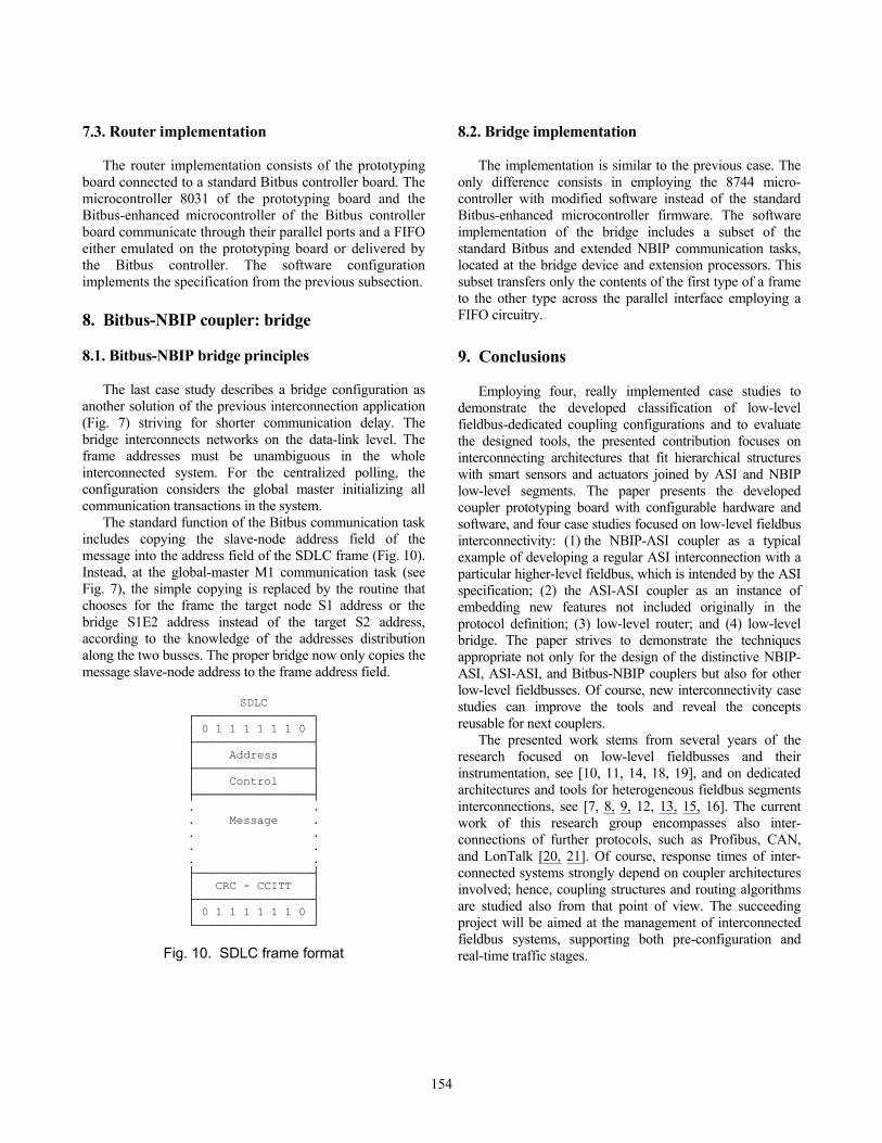
The last case study describes a bridge configuration as another solution of the previous interconnection application (Fig. 7) striving for shorter communication delay. The bridge interconnects networks on the data-link level. The frame addresses must be unambiguous in the whole interconnected system. For the centralized polling, the configuration considers the global master initializing all communication transactions in the system.
The standard function of the Bitbus communication task includes copying the slave-node address field of the message into the address field of the SDLC frame (Fig. 10). Instead, at the global-master M1 communication task (see Fig. 7), the simple copying is replaced by the routine that chooses for the frame the target node S1 address or the bridge S1E2 address instead of the target S2 address, according to the knowledge of the addresses distribution along the two busses. The proper bridge now only copies the message slave-node address to the frame address field.
SDLC
┌─────────────────┐ │ 0 1 1 1 1 1 1 0 │ ├─────────────────┤ │ Address │ ├─────────────────┤ │ Control │ ├─────────────────┤ . . . Message . . . . . . . ├─────────────────┤ │ CRC - CCITT │ ├─────────────────┤ │ 0 1 1 1 1 1 1 0 │ └─────────────────┘
Fig. 10. SDLC frame format
8.2. Bridge implementation
The implementation is similar to the previous case. The only difference consists in employing the 8744 micro-controller with modified software instead of the standard Bitbus-enhanced microcontroller firmware. The software implementation of the bridge includes a subset of the standard Bitbus and extended NBIP communication tasks, located at the bridge device and extension processors. This subset transfers only the contents of the first type of a frame to the other type across the parallel interface employing a FIFO circuitry. 9. Conclusions
Employing four, really implemented case studies to demonstrate the developed classification of low-level fieldbus-dedicated coupling configurations and to evaluate the designed tools, the presented contribution focuses on interconnecting architectures that fit hierarchical structures with smart sensors and actuators joined by ASI and NBIP low-level segments. The paper presents the developed coupler prototyping board with configurable hardware and software, and four case studies focused on low-level fieldbus interconnectivity: (1) the NBIP-ASI coupler as a typical example of developing a regular ASI interconnection with a particular higher-level fieldbus, which is intended by the ASI specification; (2) the ASI-ASI coupler as an instance of embedding new features not included originally in the protocol definition; (3) low-level router; and (4) low-level bridge. The paper strives to demonstrate the techniques appropriate not only for the design of the distinctive NBIP-ASI, ASI-ASI, and Bitbus-NBIP couplers but also for other low-level fieldbusses. Of course, new interconnectivity case studies can improve the tools and reveal the concepts reusable for next couplers.
The presented work stems from several years of the research focused on low-level fieldbusses and their instrumentation, see [10, 11, 14, 18, 19], and on dedicated architectures and tools for heterogeneous fieldbus segments interconnections, see [7, 8, 9, 12, 13, 15, 16]. The current work of this research group encompasses also inter-connections of further protocols, such as Profibus, CAN, and LonTalk [20, 21]. Of course, response times of inter-connected systems strongly depend on coupler architectures involved; hence, coupling structures and routing algorithms are studied also from that point of view. The succeeding project will be aimed at the management of interconnected fieldbus systems, supporting both pre-configuration and real-time traffic stages.
154
155
Acknowledgments
The authors appreciate contributions of their colleagues from the Department of Computer Science and Engineering, the Department of Microelectronics, and the Department of Automatic Control and Measurement Techniques at the Technical University of Brno, namely Pavel Legát, Milan Hrdlička, and Michal Jankovský, to the presented work.
This research, originally launched under the financial support by Grand Agency of the Czech Republic in frame of the contracts GACR 102/95/1365, 102/95/0875 and 102/97/K078, has been funded by Grand Agency of the Czech Republic under the contract No. GACR 102/00/0938.
References [1] P. Albertos and L. Foulloy, Eds., Preprints of the 3rd IFAC Symposium on Intelligent Components and Instruments for Control Applications SICICA'97. Annecy, France, 1997 [2] J. Dhuse and G.R. Hayek, "Standard Protocols are Needed for Distributed Microcontrollers", Data Communications, Vol.15, 1986, pp.171-175 [3] D. Dietrich and P. Neumann, Eds., Feldbus-technologie 1995 Tagungsband. ÖVE Wien, 1995 [4] F. Halsall, Data Communications, Computer Networks and Open Systems. Addison-Wesley, Wokingham, 1993 [5] J.N. Jain and A.K. Agrawala, Open Systems Interconnection: Its Architecture and Protocols. Elsevier, Amsterdam, 1990 [6] W.R. Kriesel and O.W. Madelung, Eds., ASI: The Actuator-Sensor-Interface for Automation. Carl Hanser Verlag, Munich, 1995 [7] P. Legát and R. Vrba, "A Contribution to the ASI Industrial Bus," Proceedings Electronic Devices and Systems Seminar, TU Brno, 1993, pp.287-289 [8] M. Švéda, "Small Area Network Interconnection," Micro-processing and Microprogramming, Vol.37, 1993, pp.193-196 [9] M. Švéda, "Routers and Bridges for Small Area Network Interconnection," Computers in Industry, Vol.22, No.1, 1993, pp.25-29
[10] M. Švéda, "Signaling Techniques with Industrial Communica-tion Controllers," Proceedings EDS'94, Vol.1, Technical University of Brno, 1994, pp.137-140 [11] M. Švéda and P. Bureš, "Real-Time Network Management Tools: Fieldbus Level and Below," Records of International Workshop on Requirements and Techniques for Network Management, IEEE and IFIP, Krakow, 1993, pp. 7.3:1-9 [12] M. Švéda and R. Vrba, "ASI Interconnectivity," Preprints 3rd IFAC Symposium SICICA'97, Annecy, France, 1997, pp.621-626 [13] M. Švéda and R. Vrba, "Actuator-Sensor-Interface Inter-connectivity," Control Engineering Practice, Vol.7, No.1, February 1999, pp.95-100 [14] M. Švéda and R. Vrba and P. Legát and F. Zezulka, "ASI Instrumentation," Microprocessing and Microprogramming, Vol.40, 1994, pp.879-882 [15] M. Švéda M. and F. Zezulka, "Interconnecting Low-Level Fieldbusses," Proceedings 23rd Euromicro'97 Conference, Buda-pest, IEEE Comp. Soc., 1997, pp.614-620 [16] M. Švéda and F. Zezulka, "Heterogeneous Inter-connections for Distributed Control Systems: An Interdisciplinary Approach," In: Lasker G.E., Ed.: Research in Progress-- Vol. IV, International Institute for Advanced Studies in Systems Research and Cybernetics, Baden-Baden, 1997, pp.6-10 [17] The BITBUS Interconnect Serial Control Bus Specification. Order Number 280645-001, Intel Corp., Hillsboro, Oregon, 1988. [18] R. Vrba and M. Švéda and J. Hubálek and I. Večeřa, "ASI Bus Operated Sensors and Actuators," In: Morabito F.C., Ed.: Advances in Intelligent Systems. IOS Press, Amsterdam, 1997, pp.56-62 [19] R. Vrba and P. Legát and M. Švéda and J. Kaderka, "Testing and Analyzing of the ASI Bus System," In: Morabito F.C., Ed.: Advances in Intelligent Systems, IOS Press, Amsterdam, 1997, pp.51-55 [20] F. Zezulka and M. Švéda, "Communication on the Control Level -- An Extension Phenomenon of Control," Proceedings 15th International Congress on Cybernetics, Namur, 1998, pp.312-317 [21] F. Zezulka and M. Švéda and M. Hrdlička, "Fieldbus Interconnections Testbed," Proceedings INNOCAP’99: Sensor Networks and Communications, Grenoble, 1999, pp.123-128
Related Documents