Coupled Thermo-Poro-Mechanical Finite Element Analysis of an Energy Foundation Centrifuge Experiment in Partially Saturated Silt W. Wang 1 , R.A. Regueiro 1 , J.S. McCartney 1 1 Department of Civil, Environmental, and Architectural Engineering University of Colorado, Boulder, 428 UCB, Boulder, CO, 80309 [email protected], [email protected], [email protected] ABSTRACT: This paper presents an axisymmetric fully coupled thermo-poro- mechanical (TPM) finite element analysis (FEA) of a single energy foundation centrifuge experiment in partially saturated silt conducted at the University of Col- orado, Boulder (UCB). The motivation is to explore thermo-mechanical effects on the foundation performance, and thermally-induced liquid and gas flow inside the surrounding soil. The paper compares modeling outcomes and experimental observa- tions regarding thermal strains and displacements of foundations due to heating. The coupled FE model predicts solid skeleton deformation, suction, and volumetric water contents of the soil, and analyzes the thermally-induced pore water vapor flow and liquid water flow. 1 Introduction Energy foundations have become more popular as an energy-saving and environmentally-friendly technology, compared with traditional energy systems. With adequate design and installation, energy foundations can fulfill not only the geotech- nical but also the thermal requirements of buildings without relying solely on con- ventional heating and cooling systems. Relevant investigations and studies in the past decade have indicated the feasibility of this innovative technology both technically and economically (Hepbasli, 2003; Laloui et al., 2006). A number of constitutive models have been developed to study the heat and mass transport problem in rigid porous media (Milly, 1982; Bear et al., 1991). Gawin et al. (1995); Thomas and Missoum (1999) considered the deformation of soil solid skeleton to enhance the coupled thermo-poro-mechanical effects by coupling elasticity theory with the state surface approach. Khalili and Loret (2001) proposed elasto-plastic mod- els to account for the nonlinear deformation behavior of solid skeleton and the variation of the yield surface with temperature and suction. Many attempts have been made to explore thermal effects on hydro-mechanical behavior of partially saturated soils ex- perimentally (Romero et al., 2001; Wu et al., 2004). Although some construction observations and relevant studies have been conducted, further research regarding geotechnical and thermal issues is still necessary in order to investigate the complex interactions among temperature change, induced effective stress, and pore fluid flow in partially saturated soils, and also to provide guidance for the design and installation of energy foundations. For example, thermal expansion and contraction of foundations together with thermally-induced consolidation of soil may 1

Welcome message from author
This document is posted to help you gain knowledge. Please leave a comment to let me know what you think about it! Share it to your friends and learn new things together.
Transcript
Coupled Thermo-Poro-Mechanical Finite Element Analysisof an Energy Foundation Centrifuge Experiment
in Partially Saturated Silt
W. Wang1, R.A. Regueiro1, J.S. McCartney1
1Department of Civil, Environmental, and Architectural EngineeringUniversity of Colorado, Boulder, 428 UCB, Boulder, CO, [email protected], [email protected], [email protected]
ABSTRACT: This paper presents an axisymmetric fully coupled thermo-poro-mechanical (TPM) finite element analysis (FEA) of a single energy foundationcentrifuge experiment in partially saturated silt conducted at the University of Col-orado, Boulder (UCB). The motivation is to explore thermo-mechanical effects onthe foundation performance, and thermally-induced liquidand gas flow inside thesurrounding soil. The paper compares modeling outcomes andexperimental observa-tions regarding thermal strains and displacements of foundations due to heating. Thecoupled FE model predicts solid skeleton deformation, suction, and volumetric watercontents of the soil, and analyzes the thermally-induced pore water vapor flow andliquid water flow.
1 Introduction
Energy foundations have become more popular as an energy-saving andenvironmentally-friendly technology, compared with traditional energy systems. Withadequate design and installation, energy foundations can fulfill not only the geotech-nical but also the thermal requirements of buildings without relying solely on con-ventional heating and cooling systems. Relevant investigations and studies in the pastdecade have indicated the feasibility of this innovative technology both technically andeconomically (Hepbasli, 2003; Laloui et al., 2006).
A number of constitutive models have been developed to studythe heat and masstransport problem in rigid porous media (Milly, 1982; Bear et al., 1991). Gawin et al.(1995); Thomas and Missoum (1999) considered the deformation of soil solid skeletonto enhance the coupled thermo-poro-mechanical effects by coupling elasticity theorywith the state surface approach. Khalili and Loret (2001) proposed elasto-plastic mod-els to account for the nonlinear deformation behavior of solid skeleton and the variationof the yield surface with temperature and suction. Many attempts have been made toexplore thermal effects on hydro-mechanical behavior of partially saturated soils ex-perimentally (Romero et al., 2001; Wu et al., 2004).
Although some construction observations and relevant studies have been conducted,further research regarding geotechnical and thermal issues is still necessary in orderto investigate the complex interactions among temperaturechange, induced effectivestress, and pore fluid flow in partially saturated soils, and also to provide guidance forthe design and installation of energy foundations. For example, thermal expansion andcontraction of foundations together with thermally-induced consolidation of soil may
1
lead to the loss of soil-foundation side shear resistance, thus affecting the mechanicalresponse of energy foundations and their structural performance.
This paper employs an axisymmetric fully coupled TPM finite element (FE) modelto simulate soil-structure interaction (SSI) in partiallysaturated silt for a centrifugeenergy foundation experiment conducted at the University of Colorado, Boulder(UCB). We present briefly the governing equations and implementation of a fullycoupled thermo-poro-elastic FE model. In this model, partially saturated soil is treatedas a three-phase mixture (solid, liquid and gas) or four constituent mixture (solid,liquid water, water vapor and dry air). The gas phase is considered to be a combinationof dry air and water vapor. The model is implemented for smallstrain analysis. Nodesof the energy foundation and soil meshes at the interface areassumed to have norelative displacement in this implementation (rigid connection), but this assumptionwill be relaxed in future work when considering a TPM interface element.
Notation: Bold-face letters denote matrices, tensors and vectors. Cylindrical coor-dinates are employed, with the vector of coordinatesr = [r,z]. Solid mechanics signconvention is used, i.e.,σ > 0 andε > 0 for tension;σ < 0 andε < 0 for compression.
2 Couple Finite Element Formulation
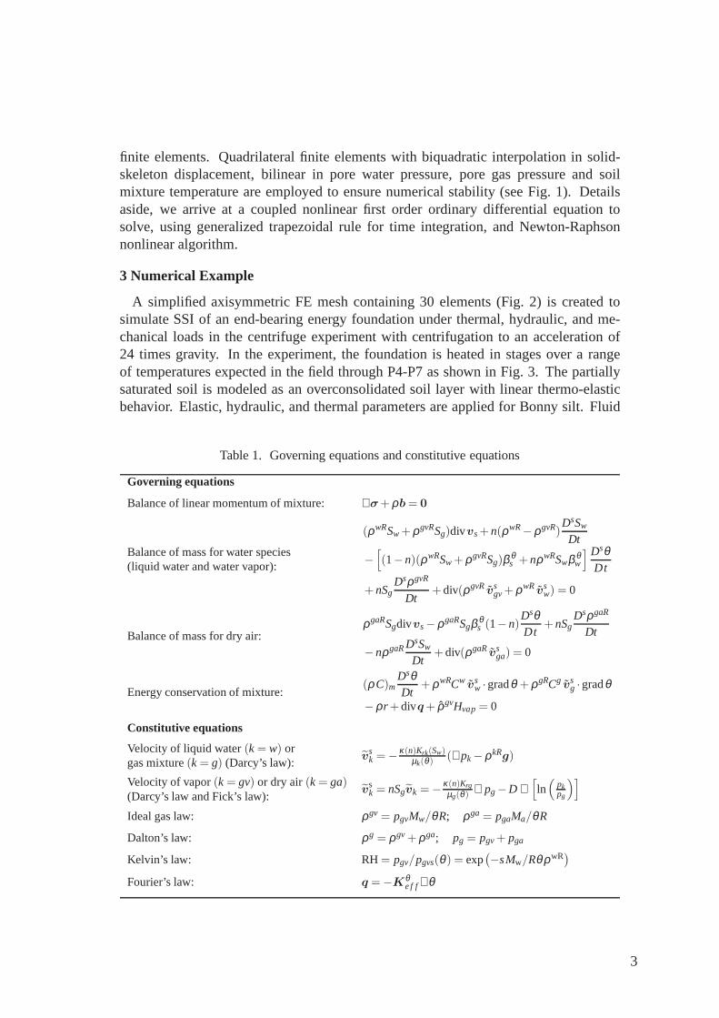
The governing equations are developed based on the mixture theory of porous media,and satisfy the balance of mass, linear momentum and energy conservation, as wellas reduced dissipation inequality derived from the second law of thermodynamics(de Boer, 2005). Solid and liquid water are assumed to be isotropic and mechanically-incompressible, yet the soil solid skeleton is compressible; individual constituentscan thermally expand or contract. With details omitted, Table 1 briefly summarizesthe governing equations and constitutive equations adopted in the model. The fieldvariables are soil solid-skeleton displacementu, pore water pressurepw, pore gaspressurepg and soil mixture temperatureθ .
Ωe
Ωh
uh
phw, ph
g, θh
1
2
3
4
7
89
5
6
Ωe
η
ξ
r
z
FIG. 1. Discretization into mixed quadrilateral elements.
A weighted residual method is used to formulate the coupled variational equationsfrom the coupled governing differential equations, which are then discretized using
2
finite elements. Quadrilateral finite elements with biquadratic interpolation in solid-skeleton displacement, bilinear in pore water pressure, pore gas pressure and soilmixture temperature are employed to ensure numerical stability (see Fig. 1). Detailsaside, we arrive at a coupled nonlinear first order ordinary differential equation tosolve, using generalized trapezoidal rule for time integration, and Newton-Raphsonnonlinear algorithm.
3 Numerical Example
A simplified axisymmetric FE mesh containing 30 elements (Fig. 2) is created tosimulate SSI of an end-bearing energy foundation under thermal, hydraulic, and me-chanical loads in the centrifuge experiment with centrifugation to an acceleration of24 times gravity. In the experiment, the foundation is heated in stages over a rangeof temperatures expected in the field through P4-P7 as shown in Fig. 3. The partiallysaturated soil is modeled as an overconsolidated soil layerwith linear thermo-elasticbehavior. Elastic, hydraulic, and thermal parameters are applied for Bonny silt. Fluid
Table 1. Governing equations and constitutive equations
Governing equations
Balance of linear momentum of mixture: ∇σ+ρb= 0
Balance of mass for water species(liquid water and water vapor):
(ρwRSw+ρgvRSg)divvs+n(ρwR−ρgvR)
DsSw
Dt
−
[(1−n)(ρwRSw+ρgvRSg)β θ
s +nρwRSwβ θw
] DsθDt
+nSgDsρgvR
Dt+div(ρgvRvs
gv+ρwRvsw) = 0
Balance of mass for dry air:ρgaRSgdivvs−ρgaRSgβ θ
s (1−n)DsθDt
+nSgDsρgaR
Dt
−nρgaRDsSw
Dt+div(ρgaRvs
ga) = 0
Energy conservation of mixture:(ρ C)m
DsθDt
+ρwRCw vsw ·gradθ +ρgRCg vs
g ·gradθ
−ρr +divq+ ρgvHvap= 0
Constitutive equations
Velocity of liquid water(k= w) orgas mixture(k= g) (Darcy’s law):
vsk =−
κ(n)Krk(Sw)µk(θ)
(∇pk−ρkRg)
Velocity of vapor(k= gv) or dry air(k= ga)(Darcy’s law and Fick’s law):
vsk = nSgvk =−
κ(n)Krgµg(θ) ∇ pg−D ∇
[ln(
pkpg
)]
Ideal gas law: ρgv = pgvMw/θR; ρga = pgaMa/θR
Dalton’s law: ρg = ρgv+ρga; pg = pgv+ pga
Kelvin’s law: RH= pgv/pgvs(θ ) = exp(−sMw/RθρwR
)
Fourier’s law: q =−Kθe f f∇θ
3
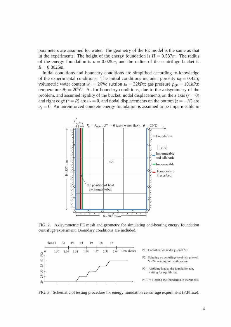
parameters are assumed for water. The geometry of the FE model is the same as thatin the experiments. The height of the energy foundation isH = 0.537m. The radiusof the energy foundation isa = 0.025m, and the radius of the centrifuge bucket isR= 0.3025m.
Initial conditions and boundary conditions are simplified according to knowledgeof the experimental conditions. The initial conditions include: porosityn0 = 0.425;volumetric water contentw0 = 26%; suctions0 = 32kPa; gas pressurepg0 = 101kPa;temperatureθ0 = 20oC. As for boundary conditions, due to the axisymmetry of theproblem, and assumed rigidity of the bucket, nodal displacements on thez axis (r = 0)and right edge (r = R) areur = 0, and nodal displacements on the bottom (z=−H) areuz = 0. An unreinforced concrete energy foundation is assumed tobe impermeable in
R=302.5mm
a
soil
z
r
Impermeable
and adiabatic
Impermeable
B.Cs
Temperature
Prescribed
, (zero water flux) ,
Foundation
H=
537 m
m
the position of heat
exchanger tubes
FIG. 2. Axisymmetric FE mesh and geometry for simulating end-bearing energy foundationcentrifuge experiment. Boundary conditions are included.
Time (hour)0 0.56 1.06 1.31 1.64 1.97 2.31 2.64
Phase 1 P2 P3 P4 P5 P6 P7
20 2
5 3
0 3
5 4
0
()
P1: Consolidation under g-level N =1
P2: Spinning up centrifuge to obtain g-level
N =24, waiting for equilibration
P3: Applying load at the foundation top,
waiting for equilibrium
P4-P7: Heating the foundation in increments
FIG. 3. Schematic of testing procedure for energy foundation centrifuge experiment (P:Phase).
4
this analysis. Also zero water fluxSw = 0 at the top of soil is assumed. The pore gaspressurepg on the top is held to be atmospheric pressurepatm. In the experiment orthe field, the temperature of the energy foundation is actually controlled by circulatingfluid with a known temperature through a series of three equally spaced “U” shapeheat exchanger tubes attached to the inside of the reinforcement cage atr = 0.02m.Technically, a 3-D model including a CFD analysis of the heated fluid flow throughthe tubes would be a more accurate estimate of the thermal boundary condition.However, for simplicity, we assume that temperature is prescribed along thez axis atr = 0.02m. During circulation of heated fluid through the heat exchange elements inthe foundation, energy foundations typically reach a relatively constant temperaturewith depth. This has been observed in several previous laboratory studies (Stewart andMcCartney, 2013). The constant temperature conditions were selected in the study toevaluate the thermo-mechanical soil-structure interaction behavior of the foundation,not to evaluate the transient heat transfer processes, which we agree would be bettersimulated with a heat flux boundary condition. The temperature at the top of the soilis held constant at room temperature (20C), and the other surfaces are adiabaticas indicated in Fig. 2. Axial load is exerted on the top of the energy foundationinstantaneously, and is kept constant during the test. Effective solid-skeleton tractiontσ ′
= [0 − tσ ′
], tσ ′
= 384kPa, is applied on the top of the energy foundation. Theparameters of the unreinforced concrete energy foundation(c) and soil (Table 2)are determined from experimental measurements and other references (Stewart andMcCartney, 2013).
Table 2. Parameters used in the FEA.
Parameter Symbol Value UnitLinear thermal expansion coefficient of concrete β θ
c 7.5×10⁻⁶ /KLinear thermal expansion coefficient of solid skeletonβ θ
skel 8.7×10⁻⁶ /KLinear thermal expansion coefficient of soil solid β θ
s 1.17×10⁻⁵ /KSpecific heat capacity of concrete Cc 855 J/(K ·kg)Specific heat capacity of soil solid Cs 1000 J/(K ·kg)Specific gravity of soil solid Gs 2.6Thermal conductivity of concrete Kθ
c 2.6 W/(m·K)Thermal conductivity of solid Kθ
s 1.24 W/(m·K)Young’s modulus of concrete foundation Ec 7.17×10⁹ PaPoisson’s ratio of concrete foundation νc 0.18 m/mLameparameter of soil solid skeleton λskel 2.9×10⁷ PaLameparameter of soil solid skeleton µskel 4.7×10⁷ Pavan Genutchen model parameter α 0.357×10⁻⁴ Pa−1
van Genutchen model parameter n 1.8Hydraulic conductivity of saturated soil ksat 1.3×10⁻⁷ m/s
4 Results
Fig. 4 - Fig. 15 are plotted contours of various results on thedeformed mesh with
5
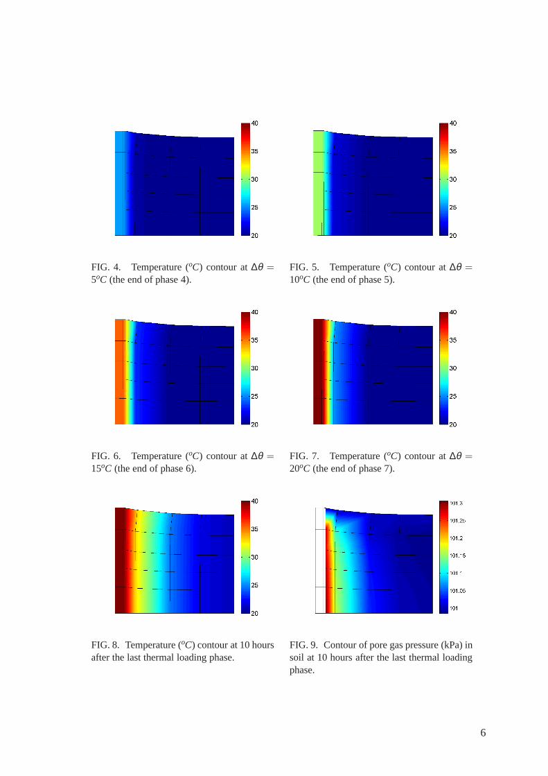
FIG. 4. Temperature (oC) contour at∆θ =5oC (the end of phase 4).
FIG. 5. Temperature (oC) contour at∆θ =10oC (the end of phase 5).
FIG. 6. Temperature (oC) contour at∆θ =15oC (the end of phase 6).
FIG. 7. Temperature (oC) contour at∆θ =20oC (the end of phase 7).
FIG. 8. Temperature (oC) contour at 10 hoursafter the last thermal loading phase.
FIG. 9. Contour of pore gas pressure (kPa) insoil at 10 hours after the last thermal loadingphase.
6
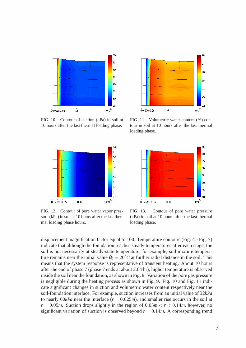
FIG. 10. Contour of suction (kPa) in soil at10 hours after the last thermal loading phase.
FIG. 11. Volumetric water content (%) con-tour in soil at 10 hours after the last thermalloading phase.
FIG. 12. Contour of pore water vapor pres-sure (kPa) in soil at 10 hours after the last ther-mal loading phase hours.
FIG. 13. Contour of pore water pressure(kPa) in soil at 10 hours after the last thermalloading phase.
displacement magnification factor equal to 100. Temperature contours (Fig. 4 - Fig. 7)indicate that although the foundation reaches steady temperatures after each stage, thesoil is not necessarily at steady-state temperature, for example, soil mixture tempera-ture remains near the initial valueθ0 = 20oC at further radial distance in the soil. Thismeans that the system response is representative of transient heating. About 10 hoursafter the end of phase 7 (phase 7 ends at about 2.64 hr), highertemperature is observedinside the soil near the foundation, as shown in Fig. 8. Variation of the pore gas pressureis negligible during the heating process as shown in Fig. 9. Fig. 10 and Fig. 11 indi-cate significant changes in suction and volumetric water content respectively near thesoil-foundation interface. For example, suction increases from an initial value of 32kPato nearly 60kPanear the interface (r = 0.025m), and smaller rise occurs in the soil atr = 0.05m. Suction drops slightly in the region of 0.05m< r < 0.14m, however, nosignificant variation of suction is observed beyondr = 0.14m. A corresponding trend
7
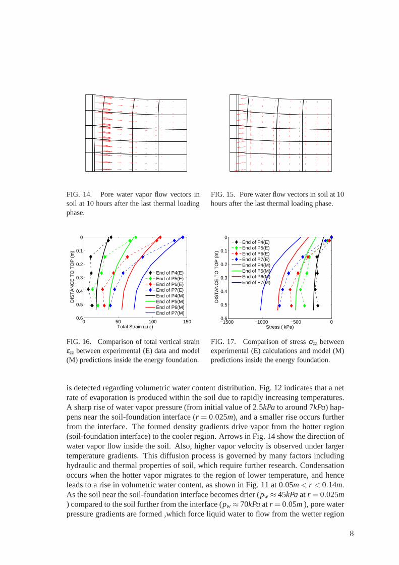
FIG. 14. Pore water vapor flow vectors insoil at 10 hours after the last thermal loadingphase.
FIG. 15. Pore water flow vectors in soil at 10hours after the last thermal loading phase.
0 50 100 150
0
0.1
0.2
0.3
0.4
0.5
0.6
Total Strain ( µ ε)
DIS
TA
NC
E T
O T
OP
(m
)
End of P4(E)End of P5(E)End of P6(E)End of P7(E)End of P4(M)End of P5(M)End of P6(M)End of P7(M)
FIG. 16. Comparison of total vertical strainεzz between experimental (E) data and model(M) predictions inside the energy foundation.
−1500 −1000 −500 0
0
0.1
0.2
0.3
0.4
0.5
0.6
Stress ( kPa)
DIS
TA
NC
E T
O T
OP
(m
)
End of P4(E)End of P5(E)End of P6(E)End of P7(E)End of P4(M)End of P5(M)End of P6(M)End of P7(M)
FIG. 17. Comparison of stressσzz betweenexperimental (E) calculations and model (M)predictions inside the energy foundation.
is detected regarding volumetric water content distribution. Fig. 12 indicates that a netrate of evaporation is produced within the soil due to rapidly increasing temperatures.A sharp rise of water vapor pressure (from initial value of 2.5kPato around 7kPa) hap-pens near the soil-foundation interface (r = 0.025m), and a smaller rise occurs furtherfrom the interface. The formed density gradients drive vapor from the hotter region(soil-foundation interface) to the cooler region. Arrows in Fig. 14 show the direction ofwater vapor flow inside the soil. Also, higher vapor velocityis observed under largertemperature gradients. This diffusion process is governedby many factors includinghydraulic and thermal properties of soil, which require further research. Condensationoccurs when the hotter vapor migrates to the region of lower temperature, and henceleads to a rise in volumetric water content, as shown in Fig. 11 at 0.05m< r < 0.14m.As the soil near the soil-foundation interface becomes drier (pw ≈ 45kPaat r = 0.025m) compared to the soil further from the interface (pw ≈ 70kPaat r = 0.05m), pore waterpressure gradients are formed ,which force liquid water to flow from the wetter region
8
15 20 25 30 35 40 450
0.01
0.02
0.03
0.04
0.05
0.06
Temperature (o C)
Dis
plac
emen
t at f
ound
atio
n to
p (m
m)
experimental datamodel predictions
FIG. 18. Plot of vertical displacement ver-sus temperature at the center of the foundationtop.
0 0.1 0.2 0.3 0.40
0.01
0.02
0.03
0.04
0.05
0.06
Distance from the center of the foundation (m)
Ver
tical
dis
plac
emen
t (m
m)
End of P4End of P5End of P6End of P7
FIG. 19. Vertical displacementdz of the topof the energy foundation and soil surface as afunction ofr at different Phases.
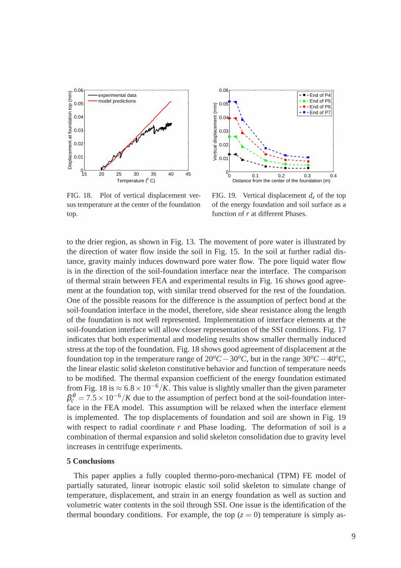
to the drier region, as shown in Fig. 13. The movement of pore water is illustrated bythe direction of water flow inside the soil in Fig. 15. In the soil at further radial dis-tance, gravity mainly induces downward pore water flow. The pore liquid water flowis in the direction of the soil-foundation interface near the interface. The comparisonof thermal strain between FEA and experimental results in Fig. 16 shows good agree-ment at the foundation top, with similar trend observed for the rest of the foundation.One of the possible reasons for the difference is the assumption of perfect bond at thesoil-foundation interface in the model, therefore, side shear resistance along the lengthof the foundation is not well represented. Implementation of interface elements at thesoil-foundation interface will allow closer representation of the SSI conditions. Fig. 17indicates that both experimental and modeling results showsmaller thermally inducedstress at the top of the foundation. Fig. 18 shows good agreement of displacement at thefoundation top in the temperature range of 20oC−30oC, but in the range 30oC−40oC,the linear elastic solid skeleton constitutive behavior and function of temperature needsto be modified. The thermal expansion coefficient of the energy foundation estimatedfrom Fig. 18 is≈ 6.8×10⁻⁶/K. This value is slightly smaller than the given parameterβ θ
c = 7.5×10⁻⁶/K due to the assumption of perfect bond at the soil-foundationinter-face in the FEA model. This assumption will be relaxed when the interface elementis implemented. The top displacements of foundation and soil are shown in Fig. 19with respect to radial coordinater and Phase loading. The deformation of soil is acombination of thermal expansion and solid skeleton consolidation due to gravity levelincreases in centrifuge experiments.
5 Conclusions
This paper applies a fully coupled thermo-poro-mechanical(TPM) FE model ofpartially saturated, linear isotropic elastic soil solid skeleton to simulate change oftemperature, displacement, and strain in an energy foundation as well as suction andvolumetric water contents in the soil through SSI. One issueis the identification of thethermal boundary conditions. For example, the top (z= 0) temperature is simply as-
9
sumed to be constant (room temperature). This boundary condition could be improvedby considering evaporation fluxes at the top of soil due to soil-atmosphere interaction.Also, the assumption of prescribed temperature along the directionz at r = 0.02m inthe model does not represent the experimental condition exactly. Extension of theaxisymmetric model to 3D and inclusion of a CFD analysis could resolve this issue.In addition, implementation of interface elements at the soil-foundation interface willallow us to better represent the interaction between soil and pile.
Acknowledgements
Funding for this research was provided by National Science Foundation grant CMMI-0928159. This funding is gratefully acknowledged.
References
Bear, J., Bensabat, J., and Nir, A. (1991). “Heat and mass transfer in unsaturated porousmedia at a hot boundary. i. one-dimensional analytical model.” Transport in PorousMedia, 6(3), 281 – 298.
de Boer, R. (2005).Trends in continuum mechanics of porous media, Vol. 18. Springer.Gawin, D., Baggio, P., and Schrefler, B. A. (1995). “Coupled heat, water and gas flow
in deformable porous media.”International Journal for numerical methods in fluids,20(8-9), 969–987.
Hepbasli, A. (2003). “Current status of geothermal energy applications in Turkey.”Energy Sources, 25(7), 667 – 77.
Khalili, N. and Loret, B. (2001). “An elasto-plastic model for non-isothermal analysisof flow and deformation in unsaturated porous media: formulation.” InternationalJournal of Solids and Structures, 38(46-47), 8305 – 30.
Laloui, L., Nuth, M., and Vulliet, L. (2006). “Experimentaland numerical investiga-tions of the behaviour of a heat exchanger pile.”International Journal for Numericaland Analytical Methods in Geomechanics, 30(8), 763–781.
Milly, P. (1982). “Moisture and heat transport in hysteretic, inhomogeneous porousmedia: a matrix head-based formulation and a numerical model.” Water ResourcesResearch, 18(3), 489 – 98.
Romero, E., Gens, A., and Lloret, A. (2001). “Temperature effects on the hydraulicbehaviour of an unsaturated clay.”Geotechnical and Geological Engineering, 19(3-4), 311 – 332.
Stewart, M. A. and McCartney, J. S. (2013). “Centrifuge modeling of soil-structureinteraction in energy foundations.”ASCE Journal of Geotechnical and Geoenviron-mental Engineering, in press.
Thomas, H. and Missoum, H. (1999). “Three-dimensional coupled heat, moisture, andair transfer in a deformable unsaturated soil.”International Journal for NumericalMethods in Engineering, 44(7), 919 – 43.
Wu, W., Li, X., Charlier, R., and Collin, F. (2004). “A thermo-hydro-mechanical con-stitutive model and its numerical modelling for unsaturated soils.” Computers andGeotechnics, 31(2), 155 – 167.
10
Related Documents