16.04 39 COUNTERBALANCE VALVES PARTS IN BODY

Welcome message from author
This document is posted to help you gain knowledge. Please leave a comment to let me know what you think about it! Share it to your friends and learn new things together.
Transcript
16.04 39
COUNTERBALANCE VALVES
PARTS IN BODY
16.0440
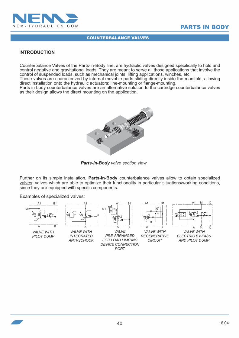
Counterbalance Valves of the Parts-in-Body line, are hydraulic valves designed specifically to hold and control negative and gravitational loads. They are meant to serve all those applications that involve the control of suspended loads, such as mechanical joints, lifting applications, winches, etc.These valves are characterized by internal movable parts sliding directly inside the manifold, allowing direct installation onto the hydraulic actuators: line-mounting or flange-mounting.Parts in body counterbalance valves are an alternative solution to the cartridge counterbalance valves as their design allows the direct mounting on the application.
Further on its simple installation, Parts-in-Body counterbalance valves allow to obtain specialized valves: valves which are able to optimize their functionality in particular situations/working conditions, since they are equipped with specific components.
Examples of specialized valves:
X
A1 B1
BA
M
A1
A
A1 B1
M1
A B
A1 B1
A B
A1 M X
A BL X
VALVE WITH PILOT DUMP
VALVE WITH INTEGRATED ANTI-SCHOCK
VALVE PRE-ARRANGED
FOR LOAD LIMITING DEVICE CONNECTION
PORT
VALVE WITH REGENERATIVE
CIRCUIT
VALVE WITH ELECTRIC BY-PASS AND PILOT DUMP
INTRODUCTION
Parts-in-Body valve section view
PARTS IN BODY
COUNTERBALANCE VALVES
16.04 41
NEM’S RANGE
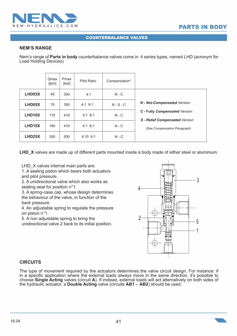
Nem’s range of Parts in body counterbalance valves come in 4 series types, named LHD (acronym for Load Holding Devices)
N - C
N - S - C
N - C
N - C
N - C
LHD_X valves are made up of different parts mounted inside a body made of either steel or aluminium.
LHD_X valves internal main parts are: 1. A sealing piston which bears both actuators and pilot pressure. 2. A unidirectional valve which also works as sealing seat for position n°1.3. A spring-case cap, whose design determines the behaviour of the valve, in function of the back pressure.4. An adjustable spring to regulate the pressure on piston n°1.5. A non adjustable spring to bring the unidirectional valve 2 back to its initial position.
CIRCUITS
The type of movement required by the actuators determines the valve circuit design. For instance: if in a specific application where the external loads always move in the same direction, it’s possible to choose Single Acting valves (circuit A). If instead, external loads will act alternatively on both sides of the hydraulic actuator, a Double Acting valve (circuits AB1 – AB2) should be used.
3
1
4
52
Qmax[lpm]
Pmax[bar]
Pilot Ratio Compensation*
LHD03X
LHD05X
LHD10X
LHD15X
40
70
110
180
350
350
410
410
4:1
4:1 9:1
4:1 8:1
4:1 8:1
N - Not-Compensated Version
C - Fully Compensated Version
S - Relief Compensated Version
(See Compensation Paragraph)
PARTS IN BODY
COUNTERBALANCE VALVES
LHD25X 350 500 4:10 6:1

16.0442
LHD_X double acting valves, can be designed in 2 different ways: the choice between them depends on the installation or on the type of compensation required:
• When the cavities are independent (Circuit AB1) we will have a double acting valve in which the 2 sections (A/A1 e B/B1) are completely independent from each other (crossed pilot line). This characteristic allows to install either Compensated and Not-Compensated types.
• With coaxial cavities (Circuit AB2), we will have a double acting valve in which the 2 sections (A/A1 e B/B1) are designed on the same axis, sharing part of the pilot circuit. This characteristic makes it possible to install either Partially-Compensated and Not-Compensated types.
For applications on cylinders, it’s possible to increase the actuators extension speed through a Regen-Block (R Circuit). This type of circuit is advisable for all those applications characterized by long stroke of the actuators with no loads or very small ones, for instance, truck mounted telescopic cranes, loaders, hook loaders, hydraulic presses, garbage trucks.
Regenerative circuits base their functioning on retrieving of the oil coming out of ring chamber during the differential-area cylinder extension. The oil coming from the ring chamber is driven into the cylinder cap to join with oil flow coming from the pump. In this way the cylinder outgoing speed corresponds to the pump flow related to the rod area, and not related to the cap area, creating a considerable speed increase.
More specifically, the counterbalance valves for regenerative circuits allow not only for the management of regenerated flow but also to control the speed and to lock the cylinders even in case of dragged loads.
A1
X
A A
A1
B
B1 B1
B
A1
A
A B
QB
QP
Single Acting Circuit (A) Double Acting Circuit with indipendent cavities (AB1)
Double Acting Circuit with coaxial cavities (AB2)
COUNTERBALANCE VALVES
QP + QBQA =
PARTS IN BODY
16.04 43
COMPENSATION
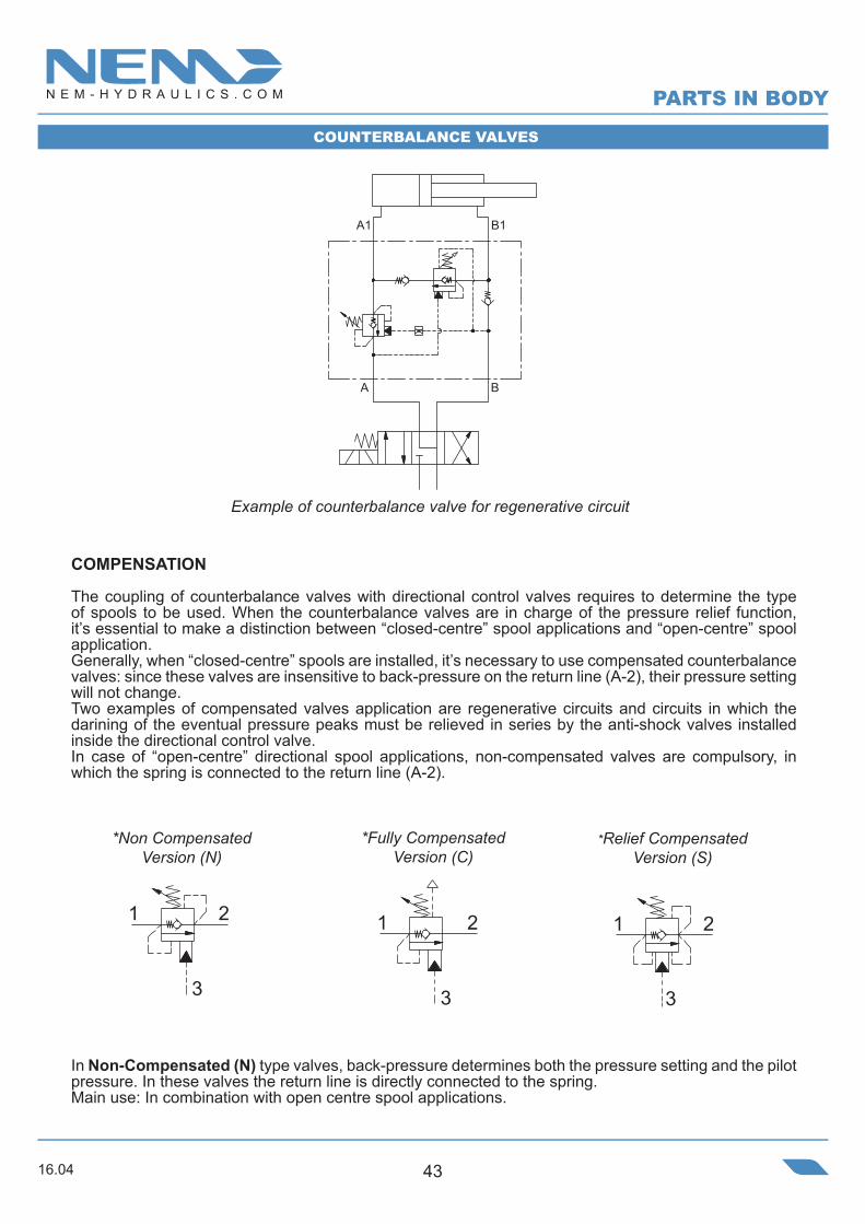
The coupling of counterbalance valves with directional control valves requires to determine the type of spools to be used. When the counterbalance valves are in charge of the pressure relief function, it’s essential to make a distinction between “closed-centre” spool applications and “open-centre” spool application.Generally, when “closed-centre” spools are installed, it’s necessary to use compensated counterbalance valves: since these valves are insensitive to back-pressure on the return line (A-2), their pressure setting will not change.Two examples of compensated valves application are regenerative circuits and circuits in which the darining of the eventual pressure peaks must be relieved in series by the anti-shock valves installed inside the directional control valve.In case of “open-centre” directional spool applications, non-compensated valves are compulsory, in which the spring is connected to the return line (A-2).
In Non-Compensated (N) type valves, back-pressure determines both the pressure setting and the pilotpressure. In these valves the return line is directly connected to the spring. Main use: In combination with open centre spool applications.
B
B1A1
A
21
3
21
3
2
3
1
Example of counterbalance valve for regenerative circuit
*Non Compensated Version (N)
*Fully Compensated Version (C)
*Relief Compensated Version (S)
COUNTERBALANCE VALVES
PARTS IN BODY
16.0444
In Fully compensated (C) type valves, back-pressure does not influence neither pressure setting nor pilot pressure. This valve type belongs the family of valves in which the adjustable spring is separated from return line (A-2) and is connected to a draining line or air-vented.In these valves, back-pressure (A-2) is balanced, so it will not find any area on which it can apply its force, so that both setting and pilot pressures are independent from pressure on return line (A).Main use: In combination with closed-centre spool applications, regenerative circuits.
In Relief-Compensated (S) type valves, only the pressure setting is independent from back-pressure, while the pilot pressure is influenced by back-pressures, which sometimes can be helpful in stabilizing the system. This valve type belongs to the family of valves in which only the areas subject to the load (A1-1) are balanced Vs the back pressure (A - 2). Main use: In combination with closed-centre spool applications.
SETTINGS
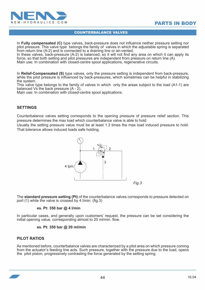
Counterbalance valves setting corresponds to the opening pressure of pressure relief section. This pressure determines the max load which counterbalance valve is able to hold. Usually the setting pressure value must be at least 1.3 times the max load induced pressure to hold. That tolerance allows induced loads safe holding.
Fig.3
The standard pressure setting (Pt) of the counterbalance valves corresponds to pressure detected on port (1) while the valve is crossed by 4 l/min. (fig.3)
es. Pt: 350 bar @ 4 l/min
In particular cases, and generally upon customers’ request, the pressure can be set considering the initial opening value, corresponding almost to 20 ml/min. flow.
es. Pt: 350 bar @ 20 ml/min
PILOT RATIOS
As mentioned before, counterbalance valves are characterized by a pilot area on which pressure coming from the actuator’s feeding line acts. Such pressure, together with the pressure due to the load, opens the pilot piston, progressively contrasting the force generated by the setting spring.
2
4 lpm
1
3
COUNTERBALANCE VALVES
PARTS IN BODY
16.04 45
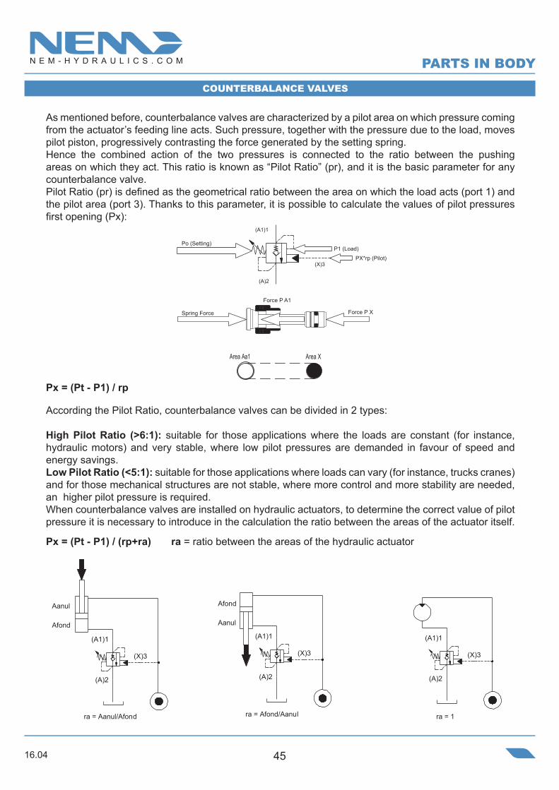
As mentioned before, counterbalance valves are characterized by a pilot area on which pressure coming from the actuator’s feeding line acts. Such pressure, together with the pressure due to the load, moves pilot piston, progressively contrasting the force generated by the setting spring.Hence the combined action of the two pressures is connected to the ratio between the pushing areas on which they act. This ratio is known as “Pilot Ratio” (pr), and it is the basic parameter for any counterbalance valve.Pilot Ratio (pr) is defined as the geometrical ratio between the area on which the load acts (port 1) and the pilot area (port 3). Thanks to this parameter, it is possible to calculate the values of pilot pressures first opening (Px):
Px = (Pt - P1) / rp
According the Pilot Ratio, counterbalance valves can be divided in 2 types:
High Pilot Ratio (>6:1): suitable for those applications where the loads are constant (for instance, hydraulic motors) and very stable, where low pilot pressures are demanded in favour of speed and energy savings. Low Pilot Ratio (<5:1): suitable for those applications where loads can vary (for instance, trucks cranes) and for those mechanical structures are not stable, where more control and more stability are needed, an higher pilot pressure is required.When counterbalance valves are installed on hydraulic actuators, to determine the correct value of pilot pressure it is necessary to introduce in the calculation the ratio between the areas of the actuator itself.
Px = (Pt - P1) / (rp+ra) ra = ratio between the areas of the hydraulic actuator
(A)2
(A1)1
(X)3
Afond
ra = Afond/Aanul
Aanul
(A)2
(A1)1
(X)3
Afond
Aanul
ra = Aanul/Afond
(A)2
(A1)1
(X)3
ra = 1
COUNTERBALANCE VALVES
(X)3
(A)2
(A1)1
Area Aa1 Area X
Po (Setting)P1 (Load)
PX*rp (Pilot)
Spring Force
Force P A1
Force P X
PARTS IN BODY

16.0446
Ordering code
50
23
=b
40,8
=
A1
A
c
35
37,8
a=
6,5
7,5
=
A1 A
A A1
X
A
X
A1
Steel Body
SINGLE ACTING COUNTERBALANCE VALVE
• Flow. . . . . . . . . . . . . . . . . . . . . . . . . . . . . . . . . 40 l/min• Max working pressure. . . . . . . . . . . . . . . . . . . 350 bar• Compensation. . . . . . . . . . . . . . . . Not Compensated• Weight G 1/4”. . . . . . . . . . . . . . . . . . . . . . . . . . . 0,8 Kg• Weight G 3/8”. . . . . . . . . . . . . . . . . . . . . . . . . . . . .1 Kg• Tamper proof cap. . . . . . . . . . . . . . . . cod. 9021030190
Note:- Pressure setting must be 30% higher than pressure induced by the load.- Back pressure can influence the opening pressure (LHD03X-C is recommended for circuits with high back pressure)
SPRINGSPILOT RATIO PORTS
Setting range min.-max.
[bar]
Pressure Increase[bar/turn]
Standard setting 4 l/min [bar]
(Pressure drop for G3/8” port)
Pres
sure
Dro
p [b
ar]
Flow [l/min]
H3001N

16.04 47
Ordering code
A1
X
A
a/2
21A
==
A1
X
h
25,6 47,6
a
8,5
==
52
46 91
49
b
Steel Body
SINGLE ACTING COUNTERBALANCE VALVE
• Flow. . . . . . . . . . . . . . . . . . . . . . . . . . . . . . . . . 70 l/min• Max working pressure. . . . . . . . . . . . . . . . . . . 350 bar• Compensation. . . . . . . . . . . . . . . . Not Compensated• Weight G 3/8”. . . . . . . . . . . . . . . . . . . . . . . . . . . 1,2 Kg• Weight G 1/2”. . . . . . . . . . . . . . . . . . . . . . . . . . . 1,5 Kg• Tamper proof cap. . . . . . . . . . . . . . . . cod. 9021030190
SPRINGSPILOT RATIO PORTS
Note:- Pressure setting must be 30% higher than pressure induced by the load.- Back pressure can influence the opening pressure (LHD05X-C is recommended for circuits with high back pressure)
Setting range min.-max.
[bar]
Pressure Increase[bar/turn]
Standard setting 4 l/min [bar]
Pres
sure
Dro
p [b
ar]
Flow [l/min]
A1 A
A A1
H5001N
16.0448
Ordering code
A,A1,X G 1/4” G 3/8”
a
45
50
b
25
30
c
84
900302
=
23
50
==
b
40,8
=
A
A1
X
23
c
a
35
6,5 7,5
37,8
A
X
A1
Steel Body
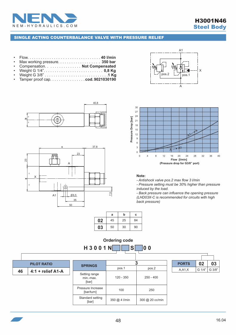
SINGLE ACTING COUNTERBALANCE VALVE WITH PRESSURE RELIEF
• Flow. . . . . . . . . . . . . . . . . . . . . . . . . . . . . . . . . 40 l/min• Max working pressure. . . . . . . . . . . . . . . . . . . 350 bar• Compensation. . . . . . . . . . . . . . . . Not Compensated• Weight G 1/4”. . . . . . . . . . . . . . . . . . . . . . . . . . . 0,8 Kg• Weight G 3/8” . . . . . . . . . . . . . . . . . . . . . . . . . . . . .1 Kg• Tamper proof cap. . . . . . . . . . . . . . . . cod. 9021030190
(Pressure drop for G3/8” port)
Note:- Antishock valve pos.2 max flow 3 l/min- Pressure setting must be 30% higher than pressure induced by the load.- Back pressure can influence the opening pressure (LHD03X-C is recommended for circuits with high back pressure)
SPRINGSPILOT RATIO PORTS
Setting range min.-max.
[bar]
Pressure Increase[bar/turn]
Standard setting [bar]
Pres
sure
Dro
p [b
ar]
Flow [l/min]
A1 A
A A1
4:1 + relief A1-A
350 @ 4 l/min 300 @ 20 cc/min
H3001N46

16.04 49
Ordering code
A,A1 G 3/8” G 1/2” 4:1 + relief A1-A
a
55
65
b
30
35
h
7
110403
X G 1/4” G 1/4”
pos.2pos.1
20,5
X
A1
A
==
28,2 47,6
8,5
a
h
23
==
92
49 52
46
b
A
X
A1
SINGLE ACTING COUNTERBALANCE VALVE WITH PRESSURE RELIEF
• Flow. . . . . . . . . . . . . . . . . . . . . . . . . . . . . . . . . 70 l/min• Max working pressure. . . . . . . . . . . . . . . . . . . 350 bar• Compensation. . . . . . . . . . . . . . . . Not Compensated• Weight G 3/8”. . . . . . . . . . . . . . . . . . . . . . . . . . . 1,2 Kg• Weight G 1/2”. . . . . . . . . . . . . . . . . . . . . . . . . . . 1,4 Kg• Tamper proof cap. . . . . . . . . . . . . . . . cod. 9021030190
Note:- Antishock valve pos.2 max flow 3 l/min- Pressure setting must be 30% higher than pressure induced by the load.- Back pressure can influence the opening pressure (LHD05X-C is recommended for circuits with high back pressure)
SPRINGSPILOT RATIO PORTS
Setting range min.-max.
[bar]
Pressure Increase[bar/turn]
Pres
sure
Dro
p [b
ar]
Flow [l/min]
Steel Body
A1 A
A A1
Standard setting [bar] 350 @ 4 l/min 300 @ 20 cc/min
H5001N46

16.0450
Ordering code
a
45
50
b
25
300302
c
84
95
d
23
30
50
23
d
=
40,8
b=
B1 A1
B A
c 37,8
a
35
6,5 7,5
SINGLE ACTING COUNTERBALANCE VALVE
• Flow. . . . . . . . . . . . . . . . . . . . . . . . . . . . . . . . . 40 l/min• Max working pressure. . . . . . . . . . . . . . . . . . . 350 bar• Compensation. . . . . . . . . . . . . . . . Not Compensated• Weight G 1/4”. . . . . . . . . . . . . . . . . . . . . . . . . . .0,75 Kg• Weight G 3/8” . . . . . . . . . . . . . . . . . . . . . . . . . . . 1,1 Kg• Tamper proof cap. . . . . . . . . . . . . . . . cod. 9021030190
Note:- Pressure setting must be 30% higher than pressure induced by the load.- Back pressure can influence the opening pressure (LHD03X-C is recommended for circuits with high back pressure)
(Pressure drop for G3/8” port)
SPRINGSPILOT RATIO PORTS
Setting range min.-max.
[bar]
Pressure Increase[bar/turn]
Standard setting 4 l/min [bar]
Pres
sure
Dro
p [b
ar]
Flow [l/min]
Steel Body
A1 A
A A1
H3004N
A1 B1
BA
16.04 51
Ordering code
A,A1,B,B1 G 3/8” G 1/2”
a
55
65
b
30
350403
M G 1/4” G 1/4”
20,5 70,5
==
45,5
48,5 52
b
39
110
B1A1
A
=
B
=
M
32 40
a
8
4,5
8,5
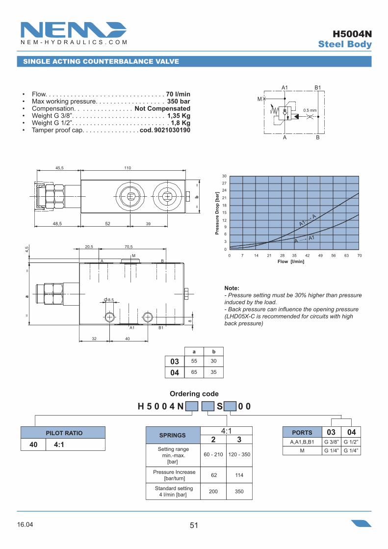
SINGLE ACTING COUNTERBALANCE VALVE
• Flow. . . . . . . . . . . . . . . . . . . . . . . . . . . . . . . . . 70 l/min• Max working pressure. . . . . . . . . . . . . . . . . . . 350 bar• Compensation. . . . . . . . . . . . . . . . Not Compensated• Weight G 3/8”. . . . . . . . . . . . . . . . . . . . . . . . . . 1,35 Kg• Weight G 1/2”. . . . . . . . . . . . . . . . . . . . . . . . . . . 1,8 Kg• Tamper proof cap. . . . . . . . . . . . . . . . cod. 9021030190
Note:- Pressure setting must be 30% higher than pressure induced by the load.- Back pressure can influence the opening pressure (LHD05X-C is recommended for circuits with high back pressure)
SPRINGSPILOT RATIO PORTS
Setting range min.-max.
[bar]
Pressure Increase[bar/turn]
Standard setting 4 l/min [bar]
Pres
sure
Dro
p [b
ar]
Flow [l/min]
Steel Body
A1 A
A A1
H5004N
M
A
A1
B
B1
0.5 mm
16.0452
Ordering code
65
70
35
40
117
130
59,7
60
39.3
47
40
47.6
39,7
36
8
11
70.5
78
M
A
A1
B
B1
0.5 mm
B
M
A
A1 B1
i
c 56,5
59,5
e
b
d
A1
AB
B1
M
a
f
4,5
h
8,5
g
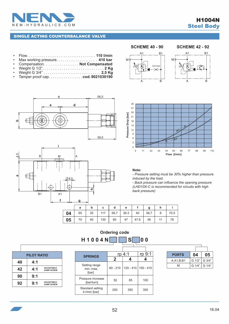
SINGLE ACTING COUNTERBALANCE VALVE
• Flow. . . . . . . . . . . . . . . . . . . . . . . . . . . . . . . . 110 l/min• Max working pressure. . . . . . . . . . . . . . . . . . . 410 bar• Compensation. . . . . . . . . . . . . . . . Not Compensated• Weight G 1/2”. . . . . . . . . . . . . . . . . . . . . . . . . . . . . 2 Kg• Weight G 3/4” . . . . . . . . . . . . . . . . . . . . . . . . . . . 2,5 Kg• Tamper proof cap. . . . . . . . . . . . . . . . cod. 9021030190
Note:- Pressure setting must be 30% higher than pressure induced by the load.- Back pressure can influence the opening pressure (LHD10X-C is recommended for circuits with high back pressure)
SCHEME 40 - 90 SCHEME 42 - 92
SPRINGSPILOT RATIO PORTS
Setting range min.-max.
[bar]
Pressure Increase[bar/turn]
Standard setting 4 l/min [bar]
ADJUSTABLE DUMP SCREW
ADJUSTABLE DUMP SCREW
Pres
sure
Dro
p [b
ar]
Flow [l/min]
Steel Body
A1 A
A A1
H1004N

16.04 53
Ordering code
A,A1,B,B1 G 1/2” G 3/4”
a
70
80
b
40
40
c
142
147
d
83
86
e
40
43
f
8,5
10,50504
M
A
A1
B
B1
0.5 mm
B
M
A
A1 B1
a
40
10
4,5
==
c48
==
60
40d
04=G1/2
05=G3/4
5183ef
b ==
A1B1
B AM
SCHEME 40 - 80 SCHEME 42 - 82
SINGLE ACTING COUNTERBALANCE VALVE
• Flow. . . . . . . . . . . . . . . . . . . . . . . . . . . . . . . . 180 l/min• Max working pressure. . . . . . . . . . . . . . . . . . . 410 bar• Compensation. . . . . . . . . . . . . . . . Not Compensated• Weight G 1/2”. . . . . . . . . . . . . . . . . . . . . . . . . . . . .3 Kg• Weight G 3/4”. . . . . . . . . . . . . . . . . . . . . . . . . . . 3,4 Kg• Tamper proof cap. . . . . . . . . . . . . . . . cod. 9021030190
(Pressure drop for G3/4” port)
Note:- Pressure setting must be 30% higher than pressure induced by the load.- Back pressure can influence the opening pressure (LHD15X-C is recommended for circuits with high back pressure)
SPRINGSPILOT RATIO PORTS
ADJUSTABLE DUMP SCREW
ADJUSTABLE DUMP SCREW
Setting range min.-max.
[bar]
Pressure Increase[bar/turn]
Standard setting 4 l/min [bar]
Pres
sure
Dro
p [b
ar]
Flow [l/min]
Steel Body
A1A
A A1
H1504N

16.0454
Ordering code
03G 3/8”41 4:1+dia.0,5mm
B1
B
A1
A
50
21,563,5
25
B1
A1
B A
105 37,8
50
8
35
6,5
30
40 ,8
30
SINGLE ACTING COUNTERBALANCE VALVE
• Flow. . . . . . . . . . . . . . . . . . . . . . . . . . . . . . . . . 40 l/min• Max working pressure. . . . . . . . . . . . . . . . . . . 350 bar• Compensation. . . . . . . . . . . . . . . . Not Compensated• Weight. . . . . . . . . . . . . . . . . . . . . . . . . . . . . . . 0,75 Kg• Tamper proof cap. . . . . . . . . . . . . . . . cod. 9021030190
(Pressure drop for G3/8” port)
Note:- Pressure setting must be 30% higher than pressure induced by the load.- Back pressure can influence the opening pressure (LHD03X-C is recommended for circuits with high back pressure)
SPRINGSPILOT RATIO PORTS
Setting range min.-max.
[bar]
Pressure Increase[bar/turn]
Standard setting 4 l/min [bar]
Pres
sure
Dro
p [b
ar]
Flow [l/min]
Steel Body
A1 A
A A1
H3004N41

16.04 55
Ordering code
e
37,8
A
A
50
40,8
d
A1
b
B1
B
M
c
a=
= =
28
4,5
28
8,5
=
O-RING 10.78x2.62
n°4 holes
a
45
50
b
24,5
29,5
c
90
95
d
54
60
e
23
200302
A,B,B1 G 1/4” G 3/8” A1 Ø 6 Ø 6M G 1/4” G 1/4”
B
A1
A
M
A
B1
SINGLE ACTING COUNTERBALANCE VALVE FLANGED 28x28
• Flow. . . . . . . . . . . . . . . . . . . . . . . . . . . . . . . . . 40 l/min• Max working pressure. . . . . . . . . . . . . . . . . . . 350 bar• Compensation. . . . . . . . . . . . . . . . Not Compensated• Weight G 1/4”. . . . . . . . . . . . . . . . . . . . . . . . . . .0,75 Kg• Weight G 3/8” . . . . . . . . . . . . . . . . . . . . . . . . . . . . .1 Kg• Tamper proof cap. . . . . . . . . . . . . . . . cod. 9021030190
SPRINGSPILOT RATIO PORTS
(Pressure drop for G3/8” port)
Setting range min.-max.
[bar]
Pressure Increase[bar/turn]
Standard setting 4 l/min [bar]
Note:- Pressure setting must be 30% higher than pressure induced by the load.- Back pressure can influence the opening pressure (LHD03X-C is recommended for circuits with high back pressure)
Pres
sure
Dro
p [b
ar]
Flow [l/min]
Steel Body
A1 A
A A1
H3005N40

16.0456
Ordering code
ed
50,5
A1
40,8
b
MB
AB M
A
37,8
30a=
= =
30
c
n°4 holes 8,5
4,5
=
O-RING 10.78x2.62
4,5
a
45
50
b
24,5
29,5
c
100
100
d
63,5
66
e
21,5
0302
G 1/4” G 3/8” A1 Ø 6 Ø 6M G 1/4” G 1/4”
SINGLE ACTING COUNTERBALANCE VALVE FLANGED 30x30
(Pressure drop for G3/8” port)
• Flow. . . . . . . . . . . . . . . . . . . . . . . . . . . . . . . . . 40 l/min• Max working pressure. . . . . . . . . . . . . . . . . . . 350 bar• Compensation. . . . . . . . . . . . . . . . Not Compensated• Weight G 1/4”. . . . . . . . . . . . . . . . . . . . . . . . . . . .0,8 Kg• Weight G 3/8” . . . . . . . . . . . . . . . . . . . . . . . . . . . . .1 Kg• Tamper proof cap. . . . . . . . . . . . . . . . cod. 9021030190
SPRINGSPILOT RATIO PORTS
Setting range min.-max.
[bar]
Pressure Increase[bar/turn]
Standard setting 4 l/min [bar]
Note:- Pressure setting must be 30% higher than pressure induced by the load.- Back pressure can influence the opening pressure (LHD03X-C is recommended for circuits with high back pressure)
Pres
sure
Dro
p [b
ar]
Flow [l/min]
A,B
19,5
M
M
A
B
BA1
A
Steel Body
A1 A
A A1
H3007N

16.04 57
Ordering code
20,5
20,5
39
71,5
A B
==
==
MB1A
A1
30
30
53
a
8,5
38
4,5
O-RING 10.78x2.62
45,5
b
48,5
110 4,5
A,B,B1 G 3/8” G 1/2”
a
55
65
b
29,5
34,50403
A1 Ø 9 Ø 9M G 1/4” G 1/4”
SINGLE ACTING COUNTERBALANCE VALVE FLANGED 30x30
• Flow. . . . . . . . . . . . . . . . . . . . . . . . . . . . . . . . . 70 l/min• Max working pressure. . . . . . . . . . . . . . . . . . . 350 bar• Compensation. . . . . . . . . . . . . . . . Not Compensated• Weight G 3/8”. . . . . . . . . . . . . . . . . . . . . . . . . . . 1,3 Kg• Weight G 1/2” . . . . . . . . . . . . . . . . . . . . . . . . . . 1,75 Kg• Tamper proof cap. . . . . . . . . . . . . . . . cod. 9021030190
Note:- Pressure setting must be 30% higher than pressure induced by the load.- Back pressure can influence the opening pressure (LHD05X-C is recommended for circuits with high back pressure)
SPRINGSPILOT RATIO PORTS
Setting range min.-max.
[bar]
Pressure Increase[bar/turn]
Standard setting 4 l/min [bar]
Pres
sure
Dro
p [b
ar]
Flow [l/min]
A1
A
0.5 mm
M
B1
BA
Steel Body
A1 A
A A1
H5005N
16.0458
Ordering code
A,B,B1 G 1/2” G 3/4”
A1 Ø 9 Ø 9
g
O-RING 10.78x2.6259,5
b
56,5
e
c
d
=
B1 A
AMB
==
= =
A1
=4,
5
h
f
a
8,5
A1
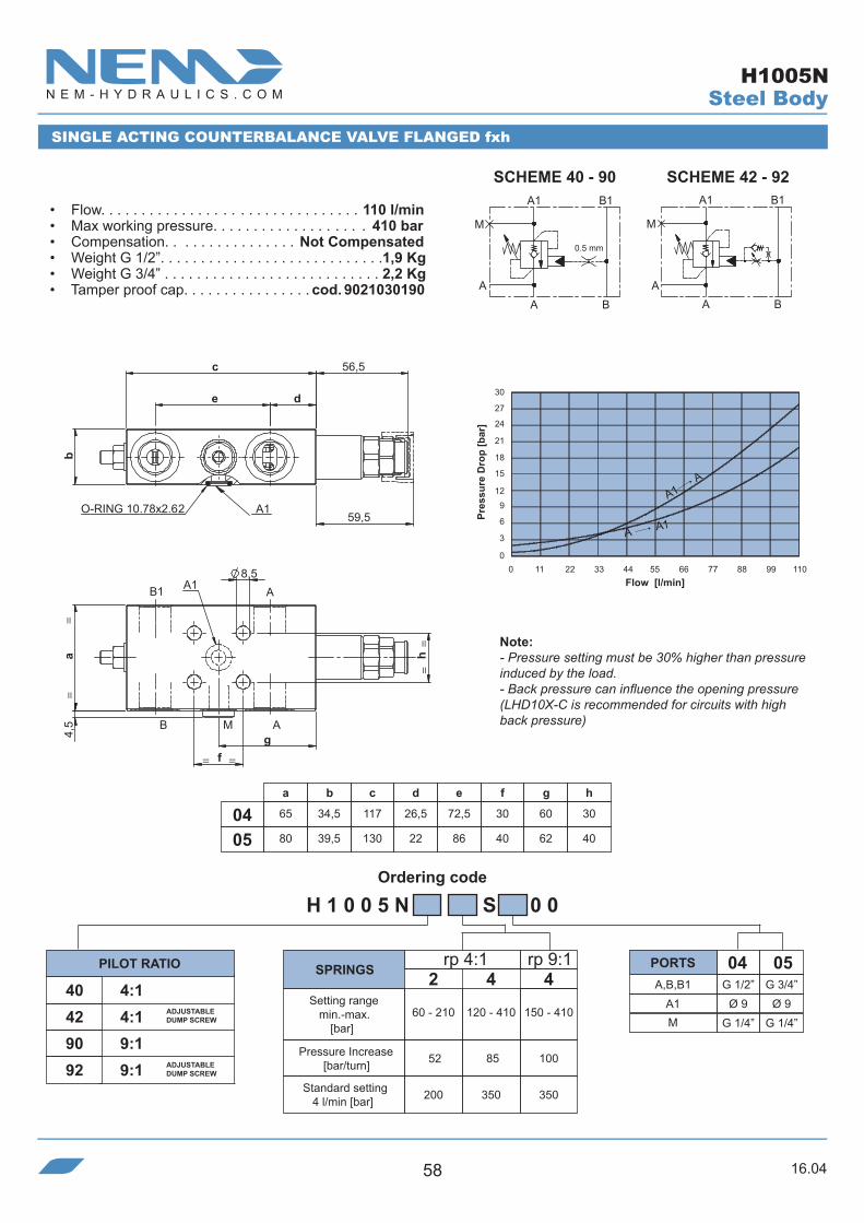
SINGLE ACTING COUNTERBALANCE VALVE FLANGED fxh
SCHEME 40 - 90 SCHEME 42 - 92
• Flow. . . . . . . . . . . . . . . . . . . . . . . . . . . . . . . . 110 l/min• Max working pressure. . . . . . . . . . . . . . . . . . . 410 bar• Compensation. . . . . . . . . . . . . . . . Not Compensated• Weight G 1/2”. . . . . . . . . . . . . . . . . . . . . . . . . . . .1,9 Kg• Weight G 3/4” . . . . . . . . . . . . . . . . . . . . . . . . . . . 2,2 Kg• Tamper proof cap. . . . . . . . . . . . . . . . cod. 9021030190
Note:- Pressure setting must be 30% higher than pressure induced by the load.- Back pressure can influence the opening pressure (LHD10X-C is recommended for circuits with high back pressure)
SPRINGSPILOT RATIO PORTS
Setting range min.-max.
[bar]
Pressure Increase[bar/turn]
Standard setting 4 l/min [bar]
ADJUSTABLE DUMP SCREW
ADJUSTABLE DUMP SCREW
Pres
sure
Dro
p [b
ar]
Flow [l/min]
M
A
A1
B
B1
0.5 mm
B
M
A
A1 B1
A A
Steel Body
A1 A
A A1
a
65
80
b
34,5
39,5
c
117
130
d
26,5
22
e
72,5
86
f
30
40
g
60
62
h
30
400504
H1005N

16.04 59
Ordering code
A,B,B1 G 1/2” G 3/4”M G 1/4” G 1/4”A1 Ø 12 Ø 12
a
70
80
b
39,5
39,5
c
142
147
d
83
86
e
10,5
10,50504
=
40d
83=
=
48
=40=a
=4,
5
c
40
A1 O-RING 17.12x2.62
51e
b
AB1
B AM
SINGLE ACTING COUNTERBALANCE VALVE FLANGED 40x40
SCHEME 40 - 80 SCHEME 42 - 82
• Flow. . . . . . . . . . . . . . . . . . . . . . . . . . . . . . . . 180 l/min• Max working pressure. . . . . . . . . . . . . . . . . . . 410 bar• Compensation. . . . . . . . . . . . . . . . Not Compensated• Weight G 1/2”. . . . . . . . . . . . . . . . . . . . . . . . . . . .2,9 Kg• Weight G 3/4” . . . . . . . . . . . . . . . . . . . . . . . . . . . 3,3 Kg• Tamper proof cap. . . . . . . . . . . . . . . . cod. 9021030190
Note:- Pressure setting must be 30% higher than pressure induced by the load.- Back pressure can influence the opening pressure (LHD15X-C is recommended for circuits with high back pressure)
SPRINGSPILOT RATIO PORTS
Setting range min.-max.
[bar]
Pressure Increase[bar/turn]
Standard setting 4 l/min [bar]
ADJUSTABLE DUMP SCREW
ADJUSTABLE DUMP SCREW
(Pressure drop for G3/4” port)
Pres
sure
Dro
p [b
ar]
Flow [l/min]
M
A
A1
B
B1
0.5 mm
B
M
A
A1 B1
A A
Steel Body
A1A
A A1
H1505N

16.0460
Ordering code
B
A1
A
M1
A
M
B1
ed
A
M
B1
AB
M1
==
28=
50
15
c
a4,
5
37,8
6,5
28
=
A1
40,8
b
a
45
50
b
24,5
29,5
c
90
95
d
54
59
e
23
210302
A,B,B1 G 1/4” G 3/8” A1 Ø 6 Ø 6M G 1/4” G 1/4”
O-RING 9.92x2.62
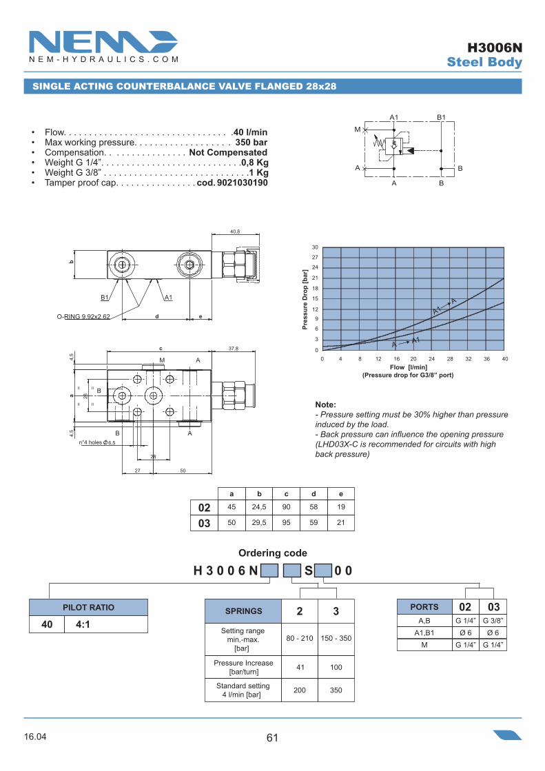
SINGLE ACTING COUNTERBALANCE VALVE FLANGED 28x28
• Flow. . . . . . . . . . . . . . . . . . . . . . . . . . . . . . . . . 40 l/min• Max working pressure. . . . . . . . . . . . . . . . . . . 350 bar• Compensation. . . . . . . . . . . . . . . . Not Compensated• Weight G 1/4”. . . . . . . . . . . . . . . . . . . . . . . . . . . .0,8 Kg• Weight G 3/8” . . . . . . . . . . . . . . . . . . . . . . . . . . . . .1 Kg• Tamper proof cap. . . . . . . . . . . . . . . . cod. 9021030190
(Pressure drop for G3/8” port)
Note:- Pressure setting must be 30% higher than pressure induced by the load.- Back pressure can influence the opening pressure (LHD03X-C is recommended for circuits with high back pressure)
SPRINGSPILOT RATIO PORTS
Setting range min.-max.
[bar]
Pressure Increase[bar/turn]
Standard setting 4 l/min [bar]
Pres
sure
Dro
p [b
ar]
Flow [l/min]
n°4 holes
Steel Body
A1 A
A A1
H 3 0 0 5 N S 0 0
H3005N43
16.04 61
Ordering code
a
45
50
b
24,5
29,5
c
90
95
d
58
59
e
19
210302
A,B G 1/4” G 3/8” A1,B1 Ø 6 Ø 6
M G 1/4” G 1/4”
B1 A1
b
e
40,8
d
B
A
A
B
M
28
50
==
37,8
4,5
28
4,5
=a
6,5
c
27
=
O-RING 9.92x2.62
SINGLE ACTING COUNTERBALANCE VALVE FLANGED 28x28
• Flow. . . . . . . . . . . . . . . . . . . . . . . . . . . . . . . . .40 l/min• Max working pressure. . . . . . . . . . . . . . . . . . . 350 bar• Compensation. . . . . . . . . . . . . . . . Not Compensated• Weight G 1/4”. . . . . . . . . . . . . . . . . . . . . . . . . . . .0,8 Kg• Weight G 3/8” . . . . . . . . . . . . . . . . . . . . . . . . . . . . .1 Kg• Tamper proof cap. . . . . . . . . . . . . . . . cod. 9021030190
(Pressure drop for G3/8” port)
Note:- Pressure setting must be 30% higher than pressure induced by the load.- Back pressure can influence the opening pressure (LHD03X-C is recommended for circuits with high back pressure)
SPRINGSPILOT RATIO PORTS
Setting range min.-max.
[bar]
Pressure Increase[bar/turn]
Standard setting 4 l/min [bar]
Pres
sure
Dro
p [b
ar]
Flow [l/min]
n°4 holes
B1
A
A1
B
B
A
M
Steel Body
A1 A
A A1
H3006N

16.0462
Ordering code
45
50
24,5
29,5
90
95
58
59
e
19
21
A,B G 1/4” G 3/8” A1,B1 Ø 6 Ø 6
M G 1/4” G 1/4”
B1 A1
b
e
40,8
d
B
A
A
B M
28
50
=
4,5
=
37,8
=28a
6,5
c
27
=
B
A1
M
B1
A
BA
O-RING 9.92x2.62
SINGLE ACTING COUNTERBALANCE VALVE FLANGED 28x28
• Flow. . . . . . . . . . . . . . . . . . . . . . . . . . . . . . . . . 40 l/min• Max working pressure. . . . . . . . . . . . . . . . . . . 350 bar• Compensation. . . . . . . . . . . . . . . . Not Compensated• Weight G 1/4”. . . . . . . . . . . . . . . . . . . . . . . . . . .0,75 Kg• Weight G 3/8” . . . . . . . . . . . . . . . . . . . . . . . . . . . . .1 Kg• Tamper proof cap. . . . . . . . . . . . . . . . cod. 9021030190
(Pressure drop for G3/8” port)
Note:- Pressure setting must be 30% higher than pressure induced by the load.- Back pressure can influence the opening pressure (LHD03X-C is recommended for circuits with high back pressure)
SPRINGSPILOT RATIO PORTS
Setting range min.-max.
[bar]
Pressure Increase[bar/turn]
Standard setting 4 l/min [bar]
Pres
sure
Dro
p [b
ar]
Flow [l/min]
n°4 holes
Steel Body
A1 A
A A1
H3008N

16.04 63
Ordering code
A,B G 3/8” G 1/2”
040340 4:1
62
200 350
60 - 210
2 3
120 - 350
a
55
65
b
29,5
34,50403
114
H 5 0 0 6 N S 0 0
A1,B1 Ø 9 Ø 9M G 1/4” G 1/4”
0.5 mm
B
M
A
B1A1
BA
20,5
20,5
39
71,5
B
==
AM
B
A1A
B1
30
4,5
53
38
a
8,5
36
O-RING 10.78x2.6248,5
45,5 110 4,5
b
==
30 27
24
21
18 15 12
9
6 3
00 7 14 21 28 35 42 49 56 63 70
SINGLE ACTING COUNTERBALANCE VALVE FLANGED 30x36
• Flow. . . . . . . . . . . . . . . . . . . . . . . . . . . . . . . . .70 l/min• Max working pressure. . . . . . . . . . . . . . . . . . . 350 bar• Compensation. . . . . . . . . . . . . . . . Not Compensated• Weight G 3/8”. . . . . . . . . . . . . . . . . . . . . . . . . . . .1,3 Kg• Weight G 1/2” . . . . . . . . . . . . . . . . . . . . . . . . . . . 1,7 Kg• Tamper proof cap. . . . . . . . . . . . . . . . cod. 9021030190
Note:- Pressure setting must be 30% higher than pressure induced by the load.- Back pressure can influence the opening pressure (LHD05X-C is recommended for circuits with high back pressure)
SPRINGSPILOT RATIO PORTS
Setting range min.-max.
[bar]
Pressure Increase[bar/turn]
Standard setting 4 l/min [bar]
Pres
sure
Dro
p [b
ar]
Flow [l/min]
Steel Body
A1 A
A A1
H5006N

16.0464
Ordering code
a
65
b
34,5
c
117
d
28,5
e
70,5
f
36
g
4504h
30
i
39
m
15
H 1 0 0 6 N S 0 0
A,B,B1 G 1/2”
M G 1/4”
0440 4:142 4:190 9:192 9:1
52 85 100
200 350 350
60 - 210
2 4
120 - 410
4
150 - 410A1,B1 Ø 9
rp 4:1 rp 9:1
0 11 22 33 44 55 66 77 88 99 110
30 27
24
21
18 15 12
9
6 3
0
O-RING 10.78x2.62
e
c 56,5
59,5
b
d
B
=
B A
AM
A1B1
=h
f
i
4,5
=
a
=
8,5m
g
B
M
0.5 mm
A
B1A1
BA
SINGLE ACTING COUNTERBALANCE VALVE FLANGED 30x36
SCHEME 40 - 90B1
B
M
A
A1
BA
SCHEME 42 - 92
• Flow. . . . . . . . . . . . . . . . . . . . . . . . . . . . . . . . 110 l/min• Max working pressure. . . . . . . . . . . . . . . . . . . 410 bar• Compensation. . . . . . . . . . . . . . . . Not Compensated• Weight. . . . . . . . . . . . . . . . . . . . . . . . . . . . . . . . 1,9 Kg• Tamper proof cap. . . . . . . . . . . . . . . . cod. 9021030190
Note:- Pressure setting must be 30% higher than pressure induced by the load.- Back pressure can influence the opening pressure (LHD10X-C is recommended for circuits with high back pressure)
SPRINGSPILOT RATIO PORTS
ADJUSTABLE DUMP SCREW
ADJUSTABLE DUMP SCREW
Setting range min.-max.
[bar]
Pressure Increase[bar/turn]
Standard setting 4 l/min [bar]
Pres
sure
Dro
p [b
ar]
Flow [l/min]
Steel Body
A1 A
A A1
H1006N

16.04 65
Ordering code
H 1 5 0 6 N S 0 0
40 4:142 4:180 8:182 8:1
40 72 72
200 350 350
80 - 210
2 4
80 - 410
4
140 - 410
A,B G 1/2” G 3/4”M G 1/4” G 1/4”
0504
A1,B1 Ø 12 Ø 12
a
70
80
b
39,5
39,5
c
142
147
d
83
860504
e
10,5
10,5
f
40
43
rp 4:1 rp 8:1
=
40d
=
f
=a
=
==
48
404,
5
c
40
O-RING 17.12x2.62A1B1
b
51e
83
AB
B AM
B
M
0.5 mm
A
B1A1
BA
B1
B
M
A
A1
BA
SINGLE ACTING COUNTERBALANCE VALVE FLANGED 40x40
SCHEME 40 - 80 SCHEME 42 - 82
• Flow. . . . . . . . . . . . . . . . . . . . . . . . . . . . . . . . 180 l/min• Max working pressure. . . . . . . . . . . . . . . . . . . 410 bar• Compensation. . . . . . . . . . . . . . . . Not Compensated• Weight G 1/2”. . . . . . . . . . . . . . . . . . . . . . . . . . . .2,9 Kg• Weight G 3/4” . . . . . . . . . . . . . . . . . . . . . . . . . . . 3,3 Kg• Tamper proof cap. . . . . . . . . . . . . . . . cod. 9021030190
Note:- Pressure setting must be 30% higher than pressure induced by the load.- Back pressure can influence the opening pressure (LHD15X-C is recommended for circuits with high back pressure)
SPRINGSPILOT RATIO PORTS
ADJUSTABLE DUMP SCREW
ADJUSTABLE DUMP SCREW
Setting range min.-max.
[bar]
Pressure Increase[bar/turn]
Standard setting 4 l/min [bar]
(Pressure drop for G3/4” port)
Pres
sure
Dro
p [b
ar]
Flow [l/min]
Steel Body
A1A
A A1
H1506N

16.0466
Ordering code
Pressure Increase[bar/turn]
• Flow. . . . . . . . . . . . . . . . . . . . . . . . . . . . . . . . . 40 l/min• Max working pressure. . . . . . . . . . . . . . . . . . . 350 bar• Compensation. . . . . . . . . . . . . . . . Not Compensated• Weight. . . . . . . . . . . . . . . . . . . . . . . . . . . . . . . . 1,3 Kg
Steel Body
SINGLE ACTING COUNTERBALANCE VALVE IN LINE WITH AXIAL DISCHARGE
9:1 A,A1 G 1/2”X G 1/4”
H 5 2 0 0 N S 0 0
04
235
350
130 - 450
490
Setting range min.-max.
[bar]
Standard setting 4 l/min [bar]
SPRINGSPILOT RATIO PORTS
Note:- Pressure setting must be 30% higher than pressure induced by the load.
30 25
20 15
10
5
0
Pres
sure
Dro
p [b
ar]
Flow [l/min]
A1 A
A A1
0 5 10 15 20 25 30 35 40
45,
9
145
115
Port APort A1
Port X Hex. 30Hex. 41
-
A1
A
X
H5200N
16.04 67
Ordering code
Pressure Increase[bar/turn]
A1
A
X
A1
A
X
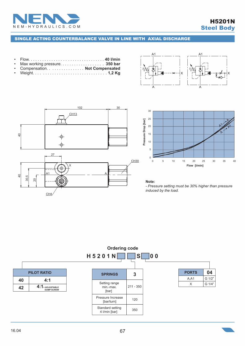
• Flow. . . . . . . . . . . . . . . . . . . . . . . . . . . . . . . . . 40 l/min• Max working pressure. . . . . . . . . . . . . . . . . . . 350 bar• Compensation. . . . . . . . . . . . . . . . Not Compensated• Weight. . . . . . . . . . . . . . . . . . . . . . . . . . . . . . . . 1,2 Kg
Steel Body
SINGLE ACTING COUNTERBALANCE VALVE IN LINE WITH AXIAL DISCHARGE
4:1 A,A1 G 1/2”X G 1/4”
H 5 2 0 1 N S 0 0
04
120
350
211 - 350
340
4:1+ ADJUSTABLE DUMP SCREW 42
Setting range min.-max.
[bar]
Standard setting 4 l/min [bar]
SPRINGSPILOT RATIO PORTS
Note:- Pressure setting must be 30% higher than pressure induced by the load.
30,5
27
40
20
AA1
XCH30
CH4
102 30
40
CH13 30 25
20 15
10
5
0
Pres
sure
Dro
p [b
ar]
Flow [l/min]
A1 A
A A1
0 5 10 15 20 25 30 35 40
H5201N
16.0468
Ordering code
504,
54,
5
38
41
38
25
M
B
A1A
93,5 30
39,5
41
10
28
10
10,5
X
O-Ring 13.94x2.62
CH30
N°4 Screws T.C.E.I M6X50
Standard setting 4 l/min [bar]
Pressure Increase[bar/turn]
Setting range min.-max.
[bar] Ø 8.5
A G 1/2” B,X,M G 1/4”
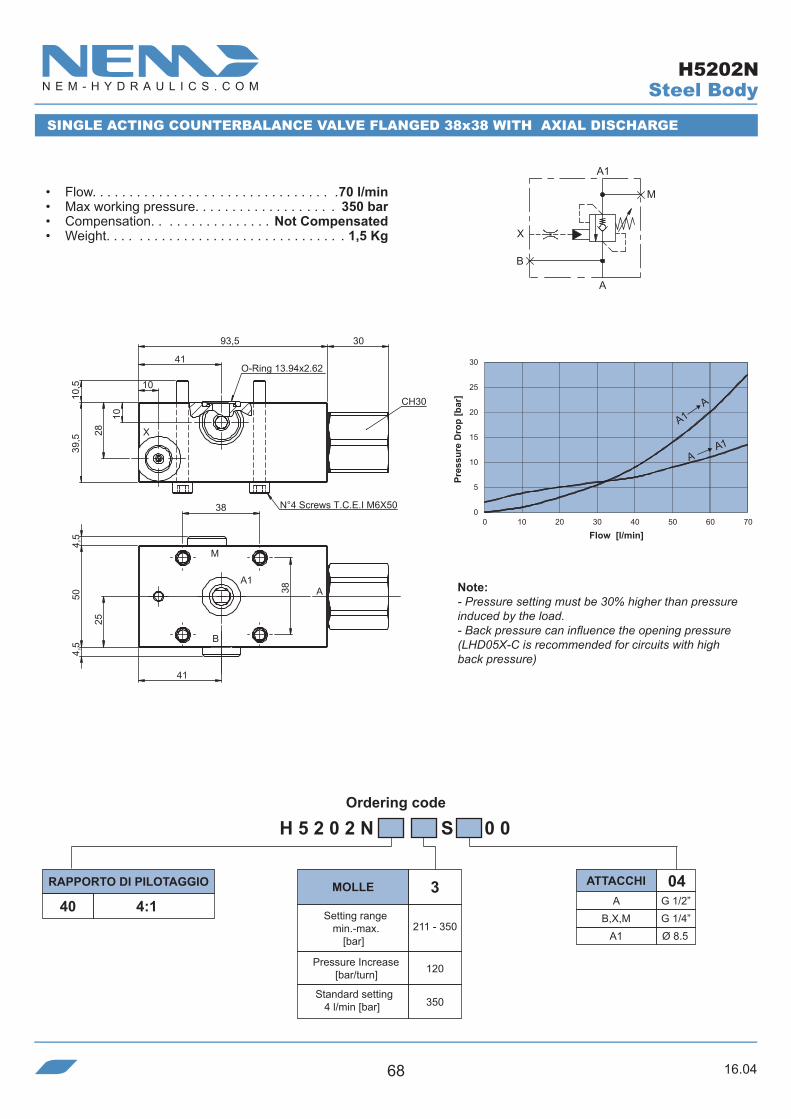
H 5 2 0 2 N S 0 0
ATTACCHIRAPPORTO DI PILOTAGGIO MOLLE4:1
04
120
350
211 - 350
3
A1
X
B
A
M
A1
A-A1
2
30
2
0 10 20 30 40 50 60 70
10
15
0
5
0
5
Pres
sure
Dro
p [b
ar]
Flow [l/min]
• Flow. . . . . . . . . . . . . . . . . . . . . . . . . . . . . . . . .70 l/min• Max working pressure. . . . . . . . . . . . . . . . . . . 350 bar• Compensation. . . . . . . . . . . . . . . . Not Compensated• Weight. . . . . . . . . . . . . . . . . . . . . . . . . . . . . . . . 1,5 Kg
SINGLE ACTING COUNTERBALANCE VALVE FLANGED 38x38 WITH AXIAL DISCHARGE
40
Steel Body
Note:- Pressure setting must be 30% higher than pressure induced by the load.- Back pressure can influence the opening pressure (LHD05X-C is recommended for circuits with high back pressure)
A1 A
A A1
H5202N

16.04 69
Ordering code
0
0
CH3
CH3
804
30
6
6
2222
A1
B1
A
B
N°2 M8
97 30
404
17,5
15
• Flow. . . . . . . . . . . . . . . . . . . . . . . . . . . . . . . . . 60 l/min• Max working pressure. . . . . . . . . . . . . . . . . . . 350 bar• Compensation. . . . . . . . . . . . . . . . Not Compensated• Weight. . . . . . . . . . . . . . . . . . . . . . . . . . . . . . . . 2,4 Kg
BA
A1 B1
DOUBLE ACTING COUNTERBALANCE VALVE IN LINE WITH AXIAL DISCHARGE
Steel Body
40 4:1 A,B,A1,B1 G 1/2”
H 5 2 3 0 N S 0 0
04
120
350
211 - 350
3
Pressure Increase[bar/turn]
Setting range min.-max.
[bar]
Standard setting 4 l/min [bar]
SPRINGSPILOT RATIO PORTS
A1 A
A A1
B1B
BB1
30 25
20 15
10
5
0
0 10 20 30 40 50 60
Pres
sure
Dro
p [b
ar]
Flow [l/min]
H5230N
Note:- Pressure setting must be 30% higher than pressure induced by the load.
16.0470
Ordering code
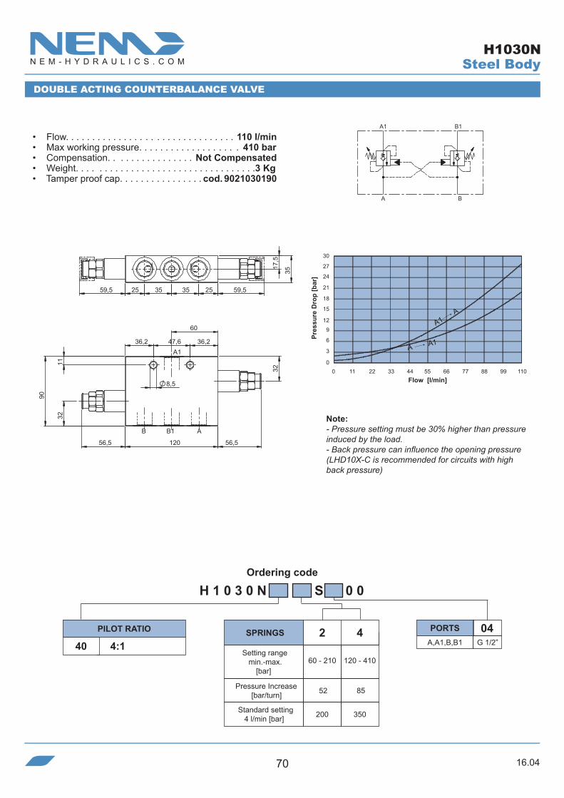
H 1 0 3 0 N S 0 0
40 4:1 A,A1,B,B1 G 1/2”
04
52 85
200 350
60 - 210
2 4
120 - 410
1B1A
BA
60
B1B A
32
36,2 47,6 36,2
120
11
56,556,5
90
32
8,5
3535
59,52559,5 25 35
17,5
0 11 22 33 44 55 66 77 88 99 110
30 27
24
21
18 15 12
9
6 3
0
A1
DOUBLE ACTING COUNTERBALANCE VALVE
• Flow. . . . . . . . . . . . . . . . . . . . . . . . . . . . . . . . 110 l/min• Max working pressure. . . . . . . . . . . . . . . . . . . 410 bar• Compensation. . . . . . . . . . . . . . . . Not Compensated• Weight. . . . . . . . . . . . . . . . . . . . . . . . . . . . . . . . . .3 Kg• Tamper proof cap. . . . . . . . . . . . . . . . cod. 9021030190
Note:- Pressure setting must be 30% higher than pressure induced by the load.- Back pressure can influence the opening pressure (LHD10X-C is recommended for circuits with high back pressure)
SPRINGSPILOT RATIO PORTS
Setting range min.-max.
[bar]
Pressure Increase[bar/turn]
Standard setting 4 l/min [bar]
Pres
sure
Dro
p [b
ar]
Flow [l/min]
Steel Body
A1 A
A A1
H1030N

16.04 71
Ordering code
H 1 0 3 0 N S 0 0
40 4:1 A,A1,B,B1 G 3/4”
05
52 85
200 350
60 - 210
2 4
120 - 410
1B1A
BA
0 11 22 33 44 55 66 77 88 99 110
30 27
24
21
18 15 12
9
6 3
0
40,3 22,359,5 59,5
21,5
30
20
21,525
40,350
62,5
A
A1
B1B
38
32
38,7
11
47,6 38,7
125 56,556,5
100
8,5
DOUBLE ACTING COUNTERBALANCE VALVE
• Flow. . . . . . . . . . . . . . . . . . . . . . . . . . . . . . . . 110 l/min• Max working pressure. . . . . . . . . . . . . . . . . . . 410 bar• Compensation. . . . . . . . . . . . . . . . Not Compensated• Weight. . . . . . . . . . . . . . . . . . . . . . . . . . . . . . . . 4,7 Kg• Tamper proof cap. . . . . . . . . . . . . . . . cod. 9021030190
Note:- Pressure setting must be 30% higher than pressure induced by the load.- Back pressure can influence the opening pressure (LHD10X-C is recommended for circuits with high back pressure)
SPRINGSPILOT RATIO PORTS
Setting range min.-max.
[bar]
Pressure Increase[bar/turn]
Standard setting 4 l/min [bar]
Pres
sure
Dro
p [b
ar]
Flow [l/min]
Steel Body
A1 A
A A1
H1030N
16.0472
Ordering code
5647 47
BA
B1 A1
11020
40,5 150 40,5
20
70
20
56
30
47
20
103
20
70
5892
THROUGH.43,5
20
43,5150N°2 8,5
30
34
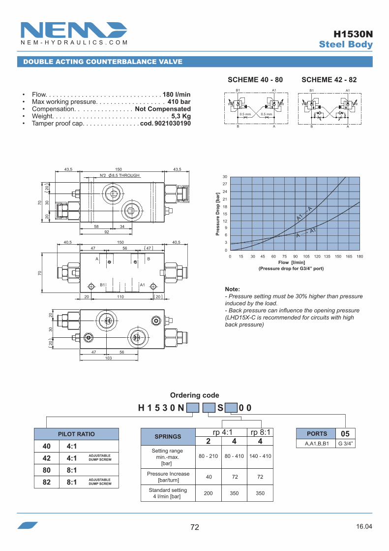
H 1 5 3 0 N S 0 0
A,A1,B,B1 G 3/4”
0540 4:142 4:180 8:182 8:1
40 72 72
200 350 350
80 - 210
2 4
80 - 410
4
140 - 410
rp 4:1 rp 8:1
DOUBLE ACTING COUNTERBALANCE VALVE
SCHEME 40 - 80 SCHEME 42 - 82
• Flow. . . . . . . . . . . . . . . . . . . . . . . . . . . . . . . . 180 l/min• Max working pressure. . . . . . . . . . . . . . . . . . . 410 bar• Compensation. . . . . . . . . . . . . . . . Not Compensated• Weight. . . . . . . . . . . . . . . . . . . . . . . . . . . . . . . . 5,3 Kg• Tamper proof cap. . . . . . . . . . . . . . . . cod. 9021030190
Note:- Pressure setting must be 30% higher than pressure induced by the load.- Back pressure can influence the opening pressure (LHD15X-C is recommended for circuits with high back pressure)
SPRINGSPILOT RATIO PORTS
ADJUSTABLE DUMP SCREW
ADJUSTABLE DUMP SCREW
Setting range min.-max.
[bar]
Pressure Increase[bar/turn]
Standard setting 4 l/min [bar]
(Pressure drop for G3/4” port)
Pres
sure
Dro
p [b
ar]
Flow [l/min]
B1
0.5 mm0.5 mm
AB
A1 B1
AB
A1
Steel Body
A1A
A A1
H1530N
16.04 73
Ordering code
A B
A1 B1
=
16,5
52,5
55
8032
,5
20
8,5
23
N°2 O-RING 10.78x2.62
49
a
46 105
2149,3 63 21
15
46
= N° 4 Ø 8.5 Trough
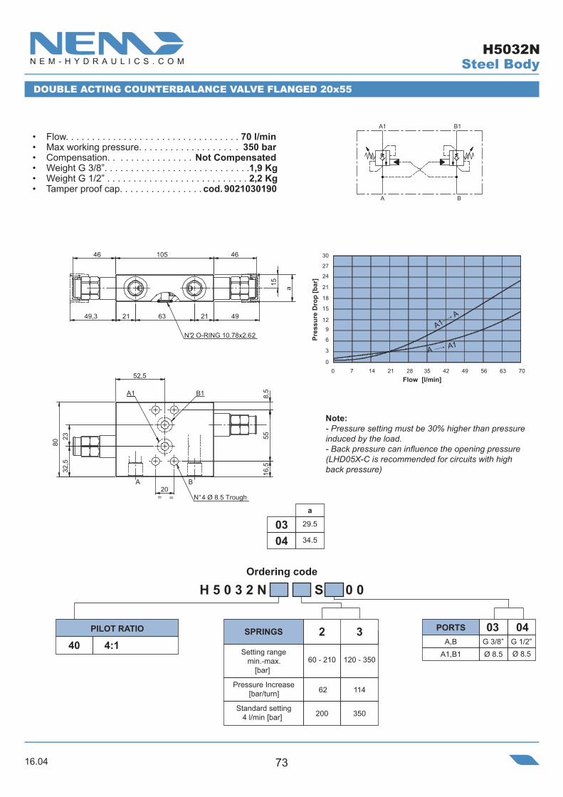
H 5 0 3 2 N S 0 0
40 4:1
62
200 350
60 - 210
2 3
120 - 350
114
1B1A
BA
30 27
24
21
18 15 12
9
6 3
00 7 14 21 28 35 42 49 56 63 70
DOUBLE ACTING COUNTERBALANCE VALVE FLANGED 20x55
• Flow. . . . . . . . . . . . . . . . . . . . . . . . . . . . . . . . . 70 l/min• Max working pressure. . . . . . . . . . . . . . . . . . . 350 bar• Compensation. . . . . . . . . . . . . . . . Not Compensated• Weight G 3/8”. . . . . . . . . . . . . . . . . . . . . . . . . . . .1,9 Kg• Weight G 1/2” . . . . . . . . . . . . . . . . . . . . . . . . . . . 2,2 Kg• Tamper proof cap. . . . . . . . . . . . . . . . cod. 9021030190
Note:- Pressure setting must be 30% higher than pressure induced by the load.- Back pressure can influence the opening pressure (LHD05X-C is recommended for circuits with high back pressure)
SPRINGSPILOT RATIO
Setting range min.-max.
[bar]
Pressure Increase[bar/turn]
Standard setting 4 l/min [bar]
Pres
sure
Dro
p [b
ar]
Flow [l/min]
Steel Body
A1 A
A A1
a
29.5
34.50403
A,BA1,B1 Ø 8.5
PORTS 0403
Ø 8.5G 3/8” G 1/2”
H5032N
16.0474
Ordering code
83,58740 39
82,5
N°2 O-RING 17.86x2.62
51=
16651
39,5
19,5
=
A M
B1
B
A1
7229
THROUGH
21,5
39,5
=
1810
100
10,535
=
n°4 holes
SCHEME 40 - 80 SCHEME 42 - 82
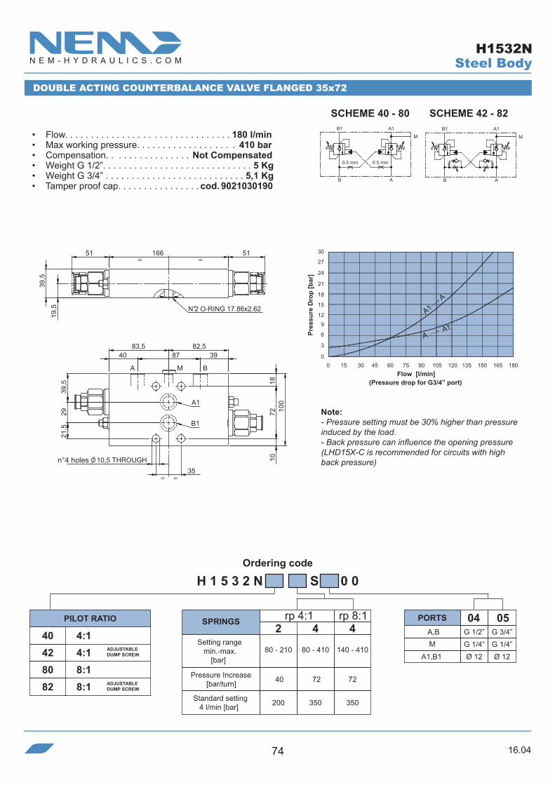
H 1 5 3 2 N S 0 0
40 4:142 4:180 8:182 8:1
40 72 72
200 350 350
80 - 210
2 4
80 - 410
4
140 - 410
A,B G 1/2” G 3/4”M G 1/4” G 1/4”
0504
A1,B1 Ø 12 Ø 12
rp 4:1 rp 8:1
B1
0.5 mm0.5 mm
AB
M
A1 B1
AB
M
A1
DOUBLE ACTING COUNTERBALANCE VALVE FLANGED 35x72
• Flow. . . . . . . . . . . . . . . . . . . . . . . . . . . . . . . . 180 l/min• Max working pressure. . . . . . . . . . . . . . . . . . . 410 bar• Compensation. . . . . . . . . . . . . . . . Not Compensated• Weight G 1/2”. . . . . . . . . . . . . . . . . . . . . . . . . . . . . 5 Kg• Weight G 3/4” . . . . . . . . . . . . . . . . . . . . . . . . . . . 5,1 Kg• Tamper proof cap. . . . . . . . . . . . . . . . cod. 9021030190
Note:- Pressure setting must be 30% higher than pressure induced by the load.- Back pressure can influence the opening pressure (LHD15X-C is recommended for circuits with high back pressure)
SPRINGSPILOT RATIO PORTS
ADJUSTABLE DUMP SCREW
ADJUSTABLE DUMP SCREW
Setting range min.-max.
[bar]
Pressure Increase[bar/turn]
Standard setting 4 l/min [bar]
(Pressure drop for G3/4” port)
Pres
sure
Dro
p [b
ar]
Flow [l/min]
Steel Body
A1A
A A1
H1532N

16.04 75
Ordering code
a
45
50
b
25
300302
H 3 0 6 0 N 4 0 S 0 0
40 4:1
41
200 350
80 - 210
2 3
150 - 350
100
0 4 8 12 16 20 24 28 32 36 40
30 27
24
21
18 15 12
9
6 3
0
A1
B
B1
A
=
==
92
38
=
BA
A1 B1
=28 =
= =37,8 37,8
=a
138
=b
40,8
6,540,8
DOUBLE ACTING COUNTERBALANCE VALVE WITH COAXIAL CAVITY
• Flow. . . . . . . . . . . . . . . . . . . . . . . . . . . . . . . . . 40 l/min• Max working pressure. . . . . . . . . . . . . . . . . . . 350 bar• Compensation. . . . . . . . . . . . . . . . Not Compensated• Weight G 1/4”. . . . . . . . . . . . . . . . . . . . . . . . . . . .1,3 Kg• Weight G 3/8” . . . . . . . . . . . . . . . . . . . . . . . . . . . 1,6 Kg• Tamper proof cap. . . . . . . . . . . . . . . . cod. 9021030190
(Pressure drop for G3/8” port)
Note:- Pressure setting must be 30% higher than pressure induced by the load.- Back pressure can influence the opening pressure (LHD03X-C is recommended for circuits with high back pressure)
SPRINGSPILOT RATIOA,B,A1,B1 G 1/4” G 3/8”
0302PORTS
Setting range min.-max.
[bar]
Pressure Increase[bar/turn]
Standard setting 4 l/min [bar]
Pres
sure
Dro
p [b
ar]
Flow [l/min]
n°2 holes
Steel Body
A1 A
A A1
H3060N

16.0476
Ordering code
H 5 0 6 0 N S 0 0
A,B,A1,B1 G 3/8” G 1/2”
040340 4:190 9:1
62 114
200 350
60 - 210
2 3
120 - 350
2
50
200
80 - 250
3
121
350
190 - 350
0403
a
55
65
b
30
35
c
38
43
h
8,5
11
rp 4:1 rp 9:1
30 27
24
21
18 15 12
9
6 3
00 7 14 21 28 35 42 49 56 63 70
A1
B
B1
A
52,5 48
==
A1 B1
=
BA
=
a
h
76,5
c8,5
==
= = 46
4911220,549
46 153
b
DOUBLE ACTING COUNTERBALANCE VALVE WITH COAXIAL CAVITY
• Flow. . . . . . . . . . . . . . . . . . . . . . . . . . . . . . . . .70 l/min• Max working pressure. . . . . . . . . . . . . . . . . . . 350 bar• Compensation. . . . . . . . . . . . . . . . Not Compensated• Weight G 3/8”. . . . . . . . . . . . . . . . . . . . . . . . . . . . . 2 Kg• Weight G 1/2” . . . . . . . . . . . . . . . . . . . . . . . . . . 2,65 Kg• Tamper proof cap. . . . . . . . . . . . . . . . cod. 9021030190
Note:- Pressure setting must be 30% higher than pressure induced by the load.- Back pressure can influence the opening pressure (LHD05X-C is recommended for circuits with high back pressure)
SPRINGSPILOT RATIO PORTS
Setting range min.-max.
[bar]
Pressure Increase[bar/turn]
Standard setting 4 l/min [bar]
Pres
sure
Dro
p [b
ar]
Flow [l/min]
Steel Body
A1 A
A A1
H5060N

16.04 77
Ordering code
Standard setting 4 l/min [bar]
Pressure Increase[bar/turn]
Setting range min.-max.
[bar]
SPRINGS
=
a
=
=
b =
76,5
c8,5
52,5 48
= 153 =
56
46 46
20,5 5648 48
30 27
24
21
18 15 12
9
6 3
0
Pres
sure
Dro
p [b
ar]
0 7 14 21 28 35 42 49 56 63 70
Note:- Antishock valve pos.2 max flow 3 l/min- Pressure setting must be 30% higher than pressure induced by the load.- Back pressure can influence the opening pressure (LHD05X-C is recommended for circuits with high back pressure)
Flow [l/min]
DOUBLE ACTING COUNTERBALANCE VALVE FOR HYDRAULIC MOTORS
• Flow. . . . . . . . . . . . . . . . . . . . . . . . . . . . . . . . .70 l/min• Max working pressure. . . . . . . . . . . . . . . . . . . 350 bar• Compensation. . . . . . . . . . . . . . . . Not Compensated• Weight G 3/8”. . . . . . . . . . . . . . . . . . . . . . . . . . . . . 2 Kg• Weight G 1/2” . . . . . . . . . . . . . . . . . . . . . . . . . . 2,65 Kg• Tamper proof cap. . . . . . . . . . . . . . . . cod. 9021030190 B
B1A1
A C
H 5 0 6 0 N S 0 0
A,B,A1,B1 G 3/8” G 1/2”
040395 9:1
0403
a
55
65
b
30
35
c
8,5
11
2
50
250
80 - 250
rp 9:1PILOT RATIO PORTS
Steel Body
A1 A
A A1
H5060N95

16.0478
Ordering code
H 1 0 6 0 N S 0 0
40 4:1 A,A1,B,B1 G 1/2”
04
52 85 100
200 350 350
60 - 210
2 4
120 - 410
4
150 - 41090 9:1
G 3/4”
05
a
65
70
b
35
400504
rp 4:1 rp 9:1
A1
B
B1
A
0 11 22 33 44 55 66 77 88 99 110
30 27
24
21
18 15 12
9
6 3
0
60,247,660,2
BA
==
B1A1
43a
8484
8,5
==
29 110 29 59,559,5
168 56,556,5
b
DOUBLE ACTING COUNTERBALANCE VALVE WITH COAXIAL CAVITY
• Flow. . . . . . . . . . . . . . . . . . . . . . . . . . . . . . . . 110 l/min• Max working pressure. . . . . . . . . . . . . . . . . . . 410 bar• Compensation. . . . . . . . . . . . . . . . Not Compensated• Weight G 1/2”. . . . . . . . . . . . . . . . . . . . . . . . . . . . . 3 Kg• Weight G 3/4” . . . . . . . . . . . . . . . . . . . . . . . . . . 3,55 Kg• Tamper proof cap. . . . . . . . . . . . . . . . cod. 9021030190
Note:- Pressure setting must be 30% higher than pressure induced by the load.- Back pressure can influence the opening pressure (LHD10X-C is recommended for circuits with high back pressure)
SPRINGSPILOT RATIO PORTS
Setting range min.-max.
[bar]
Pressure Increase[bar/turn]
Standard setting 4 l/min [bar]
Pres
sure
Dro
p [b
ar]
Flow [l/min]
Steel Body
A1 A
A A1
H1060N

16.04 79
Ordering code
H 5 0 6 0 N S 0 0
A,B,A1,B1 G 3/8” G 1/2”
040347 4:1+ relief A1-B
a
55
65
b
30
350403
c
38
43
114
350 bar or 4 l/min
120 - 350 250 - 400
3
250
300 bar or 20 cc/min
h
8,5
11
pos.1 pos.2
pos.1
B1
B
A1
A
pos.1 pos.2
52,5 80
B1
BA1
A
==
h
76,5
a 8,5
==
49
15346
b
49
46
8020,5
23
DOUBLE ACTING COUNTERBALANCE VALVE WITH COAXIAL CAVITY
• Flow. . . . . . . . . . . . . . . . . . . . . . . . . . . . . . . . .70 l/min• Max working pressure. . . . . . . . . . . . . . . . . . . 350 bar• Compensation. . . . . . . . . . . . . . . . Not Compensated• Weight G 3/8”. . . . . . . . . . . . . . . . . . . . . . . . . . . . . 2 Kg• Weight G 1/2” . . . . . . . . . . . . . . . . . . . . . . . . . . . 2,3 Kg• Tamper proof cap. . . . . . . . . . . . . . . . cod. 9021030190
SPRINGSPILOT RATIO PORTS
Setting range min.-max.
[bar]
Pressure Increase[bar/turn]
Standard setting 4 l/min [bar]
30 27
24
21
18 15 12
9
6 3
0
Pres
sure
Dro
p [b
ar]
0 7 14 21 28 35 42 49 56 63 70
Note:- Antishock valve pos.2 max flow 3 l/min- Pressure setting must be 30% higher than pressure induced by the load.- Back pressure can influence the opening pressure (LHD05X-C is recommended for circuits with high back pressure)
Flow [l/min]
Steel Body
A1 A
A A1
H5060N47
16.0480
Ordering code
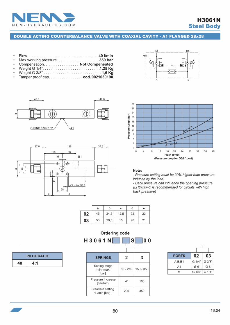
H 3 0 6 1 N 4 0 S 0 0
A,B,B1 G 1/4” G 3/8”
030240 4:1
41
200 350
80 - 210
2 3
150 - 350
100
A1 Ø 6 Ø 6M G 1/4” G 1/4”
a
45
50
b
24,5
29,5
c
12,5
15
d
92
960302
e
23
21
50 38
de
A1
40,840,8
b
M
BA
B1
=
a
=
=
28
13837,8 37,8
28
=
0 4 8 12 16 20 24 28 32 36 40
30 27
24
21
18 15 12
9
6 3
0
A
B1
B
A1
M
O-RING 9.92x2.62
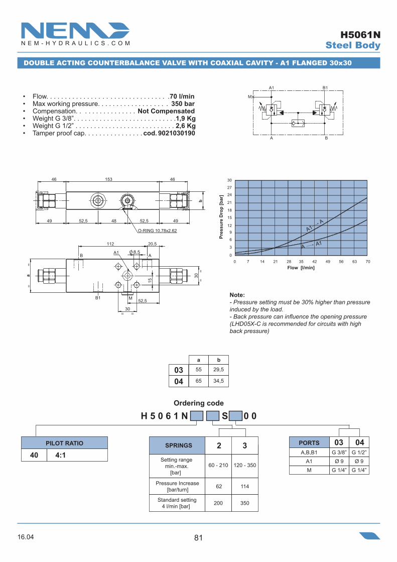
DOUBLE ACTING COUNTERBALANCE VALVE WITH COAXIAL CAVITY - A1 FLANGED 28x28
• Flow. . . . . . . . . . . . . . . . . . . . . . . . . . . . . . . . . 40 l/min• Max working pressure. . . . . . . . . . . . . . . . . . . 350 bar• Compensation. . . . . . . . . . . . . . . . Not Compensated• Weight G 1/4”. . . . . . . . . . . . . . . . . . . . . . . . . . .1,25 Kg• Weight G 3/8” . . . . . . . . . . . . . . . . . . . . . . . . . . . 1,6 Kg• Tamper proof cap. . . . . . . . . . . . . . . . cod. 9021030190
(Pressure drop for G3/8” port)
Note:- Pressure setting must be 30% higher than pressure induced by the load.- Back pressure can influence the opening pressure (LHD03X-C is recommended for circuits with high back pressure)
SPRINGSPILOT RATIO PORTS
Setting range min.-max.
[bar]
Pressure Increase[bar/turn]
Standard setting 4 l/min [bar]
Pres
sure
Dro
p [b
ar]
Flow [l/min]
n°4 holes Ø6,5
Steel Body
A1 A
A A1
H3061N
16.04 81
Ordering code
8,5
112 20,5
==
==
=
B
B1
AA1
=
30a
52,5
30
15
O-RING 10,78x2.62
4949
46 46153
52,5 48 52,5
b
M
H 5 0 6 1 N S 0 0
A,B,B1 G 3/8”
0340 4:1
62
200 350
60 - 210
2 3
120 - 350
114
A1M
Ø 9G 1/4”
G 1/2”
04
Ø 9G 1/4”
30 27
24
21
18 15 12
9
6 3
00 7 14 21 28 35 42 49 56 63 70
A
B1
B
A1
M
DOUBLE ACTING COUNTERBALANCE VALVE WITH COAXIAL CAVITY - A1 FLANGED 30x30
• Flow. . . . . . . . . . . . . . . . . . . . . . . . . . . . . . . . .70 l/min• Max working pressure. . . . . . . . . . . . . . . . . . . 350 bar• Compensation. . . . . . . . . . . . . . . . Not Compensated• Weight G 3/8”. . . . . . . . . . . . . . . . . . . . . . . . . . . .1,9 Kg• Weight G 1/2” . . . . . . . . . . . . . . . . . . . . . . . . . . . 2,6 Kg• Tamper proof cap. . . . . . . . . . . . . . . . cod. 9021030190
Note:- Pressure setting must be 30% higher than pressure induced by the load.- Back pressure can influence the opening pressure (LHD05X-C is recommended for circuits with high back pressure)
SPRINGSPILOT RATIO PORTS
Setting range min.-max.
[bar]
Pressure Increase[bar/turn]
Standard setting 4 l/min [bar]
Pres
sure
Dro
p [b
ar]
Flow [l/min]
a b
55 29,50365 34,504
Steel Body
A1 A
A A1
H5061N

16.0482
Ordering code
H 1 0 6 1 N S 0 0
A,B,B1 G 1/2” G 3/4”
050440 4:1
A1 Ø 9 Ø 9M G 1/4” G 1/4”
52
200 350
60 - 210
2 4
120 - 410
85 100
350
4
150 - 41090 9:1
a
65
70
b
34,5
39,5
c
27,5
240504
rp 4:1 rp 9:1
A
B1
B
A1
M
c111,5
O-RING 10.78x2.62
b
16856,5 56,5
59,560 48 6059,5
B
=
==
MB1
==
AA1
=
60
30
30
a
8,5
0 11 22 33 44 55 66 77 88 99 110
30 27
24
21
18 15 12
9
6 3
0
DOUBLE ACTING COUNTERBALANCE VALVE WITH COAXIAL CAVITY - A1 FLANGED 30x30
• Flow. . . . . . . . . . . . . . . . . . . . . . . . . . . . . . . . 110 l/min• Max working pressure. . . . . . . . . . . . . . . . . . . 410 bar• Compensation. . . . . . . . . . . . . . . . Not Compensated• Weight G 1/2”. . . . . . . . . . . . . . . . . . . . . . . . . . . . . 3 Kg• Weight G 3/4” . . . . . . . . . . . . . . . . . . . . . . . . . . . .3,3Kg• Tamper proof cap. . . . . . . . . . . . . . . . cod. 9021030190
Note:- Pressure setting must be 30% higher than pressure induced by the load.- Back pressure can influence the opening pressure (LHD10X-C is recommended for circuits with high back pressure)
SPRINGSPILOT RATIO PORTS
Setting range min.-max.
[bar]
Pressure Increase[bar/turn]
Standard setting 4 l/min [bar]
Pres
sure
Dro
p [b
ar]
Flow [l/min]
Steel Body
A1 A
A A1
H1061N
16.04 83
Ordering code
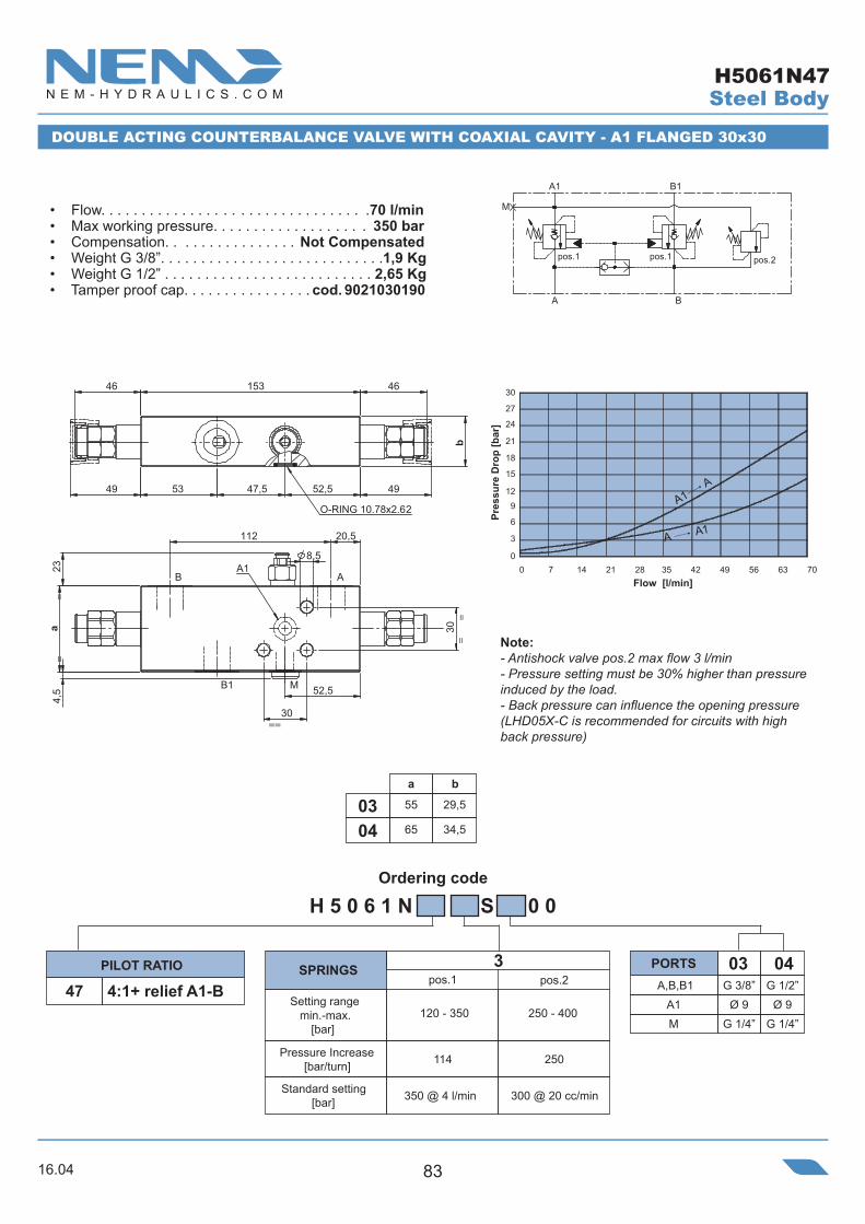
H 5 0 6 1 N S 0 0
A,B,B1 G 3/8” G 1/2”
040347 4:1+ relief A1-B
a
55
65
b
29,5
34,50403
114
120 - 350 250 - 400
3
250
A1M
Ø 9G 1/4”
Ø 9G 1/4”
pos.1 pos.2
20,5112
B1
=
==
==
AB
M
A1
=
52,5
30
a23
4,5
30
8,5
O-RING 10.78x2.62
47,5 52,5
46 153 46
4949 53
b
30 27
24
21
18 15 12
9
6 3
00 7 14 21 28 35 42 49 56 63 70
B
pos.2pos.1pos.1
M
A
1B1A
DOUBLE ACTING COUNTERBALANCE VALVE WITH COAXIAL CAVITY - A1 FLANGED 30x30
• Flow. . . . . . . . . . . . . . . . . . . . . . . . . . . . . . . . .70 l/min• Max working pressure. . . . . . . . . . . . . . . . . . . 350 bar• Compensation. . . . . . . . . . . . . . . . Not Compensated• Weight G 3/8”. . . . . . . . . . . . . . . . . . . . . . . . . . . .1,9 Kg• Weight G 1/2” . . . . . . . . . . . . . . . . . . . . . . . . . . 2,65 Kg• Tamper proof cap. . . . . . . . . . . . . . . . cod. 9021030190
Note:- Antishock valve pos.2 max flow 3 l/min- Pressure setting must be 30% higher than pressure induced by the load.- Back pressure can influence the opening pressure (LHD05X-C is recommended for circuits with high back pressure)
SPRINGSPILOT RATIO PORTS
Setting range min.-max.
[bar]
Pressure Increase[bar/turn]
Standard setting [bar]
Pres
sure
Dro
p [b
ar]
Flow [l/min]
Steel Body
A1 A
A A1
350 @ 4 l/min 300 @ 20 cc/min
H5061N47

16.0484
Ordering code
H 3 0 6 2 N 4 0 S 0 0
A,B G 1/4” G 3/8”
030240 4:1
41
200 350
80 - 210
2 3
150 - 350
100
A1,B1 Ø 6 Ø 6
a
45
50
b
24,5
29,50302
92
A1 B1
40,840,8
b
A B
=
38
=28
=a
138 37,837,8
38
50
=
0 4 8 12 16 20 24 28 32 36 40
30 27
24
21
18 15 12
9
6 3
0
B1
A
A1
B
O-RING 9.92x2.62
DOUBLE ACTING COUNTERBALANCE VALVE WITH COAXIAL CAVITY - A1/B1 FLANGED 28x38
• Flow. . . . . . . . . . . . . . . . . . . . . . . . . . . . . . . . . 40 l/min• Max working pressure. . . . . . . . . . . . . . . . . . . 350 bar• Compensation. . . . . . . . . . . . . . . . Not Compensated• Weight G 1/4”. . . . . . . . . . . . . . . . . . . . . . . . . . . .1,3 Kg• Weight G 3/8” . . . . . . . . . . . . . . . . . . . . . . . . . . . 1,6 Kg• Tamper proof cap. . . . . . . . . . . . . . . . cod. 9021030190
(Pressure drop for G3/8” port)
Note:- Pressure setting must be 30% higher than pressure induced by the load.- Back pressure can influence the opening pressure (LHD03X-C is recommended for circuits with high back pressure)
SPRINGSPILOT RATIO PORTS
Setting range min.-max.
[bar]
Pressure Increase[bar/turn]
Standard setting 4 l/min [bar]
Pres
sure
Dro
p [b
ar]
Flow [l/min]
n°4 holes Ø6,5
Steel Body
A1 A
A A1
H3062N

16.04 85
Ordering code
H 5 0 6 2 N S 0 0
A,B G 3/8” G 1/2”
040340 4:190 9:1
62 114
200 350
60 - 210
2 3
120 - 350
2
50
200
80 - 250
3
121
350
190 - 350
0403
a
55
65
b
29,5
34,5
A1,B1 Ø 9 Ø 9
rp 4:1 rp 9:1
BA
=
==
A1 B1
=
52,5 48 52,5
a 40
8,5
O-RING 10.78x2.62
153
4949
b
20,5
46 46
20,5112
30 27
24
21
18 15 12
9
6 3
00 7 14 21 28 35 42 49 56 63 70
1B1A
BA
DOUBLE ACTING COUNTERBALANCE VALVE WITH COAXIAL CAVITY - A1/B1 FLANGED 40x48
• Flow. . . . . . . . . . . . . . . . . . . . . . . . . . . . . . . . .70 l/min• Max working pressure. . . . . . . . . . . . . . . . . . . 350 bar• Compensation. . . . . . . . . . . . . . . . Not Compensated• Weight G 3/8”. . . . . . . . . . . . . . . . . . . . . . . . . . . . . 2 Kg• Weight G 1/2” . . . . . . . . . . . . . . . . . . . . . . . . . . 2,65 Kg• Tamper proof cap. . . . . . . . . . . . . . . . cod. 9021030190
SPRINGSPILOT RATIO PORTS
Setting range min.-max.
[bar]
Pressure Increase[bar/turn]
Standard setting 4 l/min [bar]
Note:- Pressure setting must be 30% higher than pressure induced by the load.- Back pressure can influence the opening pressure (LHD05X-C is recommended for circuits with high back pressure)
Pres
sure
Dro
p [b
ar]
Flow [l/min]
Steel Body
A1 A
A A1
H5062N

16.0486
Ordering code
H 1 0 6 2 N S 0 0
A,B G 1/2” G 3/4”
050440 4:1
A1,B1 Ø 9 Ø 9
52
200 350
60 - 210
2 4
120 - 410
85 100
350
4
150 - 41090 9:1
a
65
70
b
34,5
39,50504
rp 4:1 rp 9:1
1B1A
BA
O-RING 10.78x2.62
56,5
59,5 29 110 59,5
168 56,5
b
==
=
A B
A1 B1
=
60 48
a
8,5
40
0 11 22 33 44 55 66 77 88 99 110
30 27
24
21
18 15 12
9
6 3
0(60)
DOUBLE ACTING COUNTERBALANCE VALVE WITH COAXIAL CAVITY - A1/B1 FLANGED 40x48
• Flow. . . . . . . . . . . . . . . . . . . . . . . . . . . . . . . . 110 l/min• Max working pressure. . . . . . . . . . . . . . . . . . . 410 bar• Compensation. . . . . . . . . . . . . . . . Not Compensated• Weight G 1/2”. . . . . . . . . . . . . . . . . . . . . . . . . . . . . 3 Kg• Weight G 3/4” . . . . . . . . . . . . . . . . . . . . . . . . . . . 3,6 Kg• Tamper proof cap. . . . . . . . . . . . . . . . cod. 9021030190
Pres
sure
Dro
p [b
ar]
Flow [l/min]
Note:- Pressure setting must be 30% higher than pressure induced by the load.- Back pressure can influence the opening pressure (LHD10X-C is recommended for circuits with high back pressure)
SPRINGSPILOT RATIO PORTS
Setting range min.-max.
[bar]
Pressure Increase[bar/turn]
Standard setting 4 l/min [bar]
Steel Body
A1 A
A A1
H1062N

16.04 87
Ordering code
N°2 8,5 Through
=
55
=
47,6 17,8
7
39
A1
A
X
59,5 92 25
3071(44)
VENT
.
SINGLE ACTING RELIEF COMPENSATED COUNTERBALANCE VALVE
A1 A
A A1
30 27
24
21
18 15 12
9
6 3
00 7 14 21 28 35 42 49 56 63 70
Pres
sure
Dro
p [b
ar]
Flow [l/min]
Steel Body
• Flow. . . . . . . . . . . . . . . . . . . . . . . . . . . . . . . . .70 l/min• Max working pressure. . . . . . . . . . . . . . . . . . . 350 bar• Compensation. . . . . . . . . . . . . . .Relief Compensated• Weight. . . . . . . . . . . . . . . . . . . . . . . . . . . . . . . . 1,2 Kg• Tamper proof cap. . . . . . . . . . . . . . . . cod. 4029250280
A
A1
X0.5 mm
Note:- Pressure setting must be 30% higher than pressure induced by the load.
H 5 3 0 1 S S 0 0
A,A1,X40 4:1 G 3/8”
03PILOT RATIO PORTS
93
200 350
60 - 210
2 3
120 - 350
170
SPRINGS
Setting range min.-max.
[bar]
Pressure Increase[bar/turn]
Standard setting 4 l/min [bar]
H5301S40

16.0488
Ordering code
H 5 3 0 4 S S 0 0
A,A1,B,B140 4:1M
G 3/8”
03
G 1/4”
a b
55 300365 3504
G 1/2”
04
G 1/4”
0.5 mm
A
A1
B
B1
M
A
20,5 70,5
B1A1
A
=
B
=
M
32 40
4,5
a
8=
=
52
b
39
110)(41
58,6
VENT
SINGLE ACTING RELIEF COMPENSATED COUNTERBALANCE VALVE
• Flow. . . . . . . . . . . . . . . . . . . . . . . . . . . . . . . . .70 l/min• Max working pressure. . . . . . . . . . . . . . . . . . . 350 bar• Compensation. . . . . . . . . . . . . . .Relief Compensated• Weight G 3/8”. . . . . . . . . . . . . . . . . . . . . . . . . . . .1,3 Kg• Weight G 1/2” . . . . . . . . . . . . . . . . . . . . . . . . . . . 1,8 Kg• Tamper proof cap. . . . . . . . . . . . . . . . cod. 4029250280
30 27
24
21
18 15 12
9
6 3
00 7 14 21 28 35 42 49 56 63 70
Pres
sure
Dro
p [b
ar]
Flow [l/min]
Note:- Pressure setting must be 30% higher than pressure induced by the load.
PILOT RATIO PORTS
93
200 350
60 - 210
2 3
120 - 350
170
SPRINGS
Setting range min.-max.
[bar]
Pressure Increase[bar/turn]
Standard setting 4 l/min [bar]
Steel Body
A1 A
A A1
H5304S40

16.04 89
Ordering code
55
47,6 41,8
64
AB
VENT
A1
B1
30
11759,5
75 21(44)
N°2 8,5 Through.
30 27
24
21
18 15 12
9
6 3
00 7 14 21 28 35 42 49 56 63 70
Pres
sure
Dro
p [b
ar]
Flow [l/min]
B1
BA
A1
0.5 mm
Steel Body
SINGLE ACTING RELIEF COMPENSATED COUNTERBALANCE VALVE
• Flow. . . . . . . . . . . . . . . . . . . . . . . . . . . . . . . . . 70 l/min• Max working pressure. . . . . . . . . . . . . . . . . . . 210 bar• Compensation. . . . . . . . . . . . . . Relief Compensated• Weight. . . . . . . . . . . . . . . . . . . . . . . . . . . . . . . . 1,8 Kg• Tamper proof cap. . . . . . . . . . . . . . . . cod. 4029250280
41 A,A1,B,B1
PORTS
4:1
PILOT RATIOG 3/8”
03
Note:- Pressure setting must be 30% higher than pressure induced by the load.
H 5 3 0 4 S S 0 0
A1 A
A A1
93
200 350
60 - 210
2 3
120 - 350
170
SPRINGS
Setting range min.-max.
[bar]
Pressure Increase[bar/turn]
Standard setting 4 l/min [bar]
H5304S41

16.0490
Ordering code
0.5 mm
A
A1
B
B1
M
A
A,A1,B,B1 G 3/8” G 1/2”A1M
Ø 9G 1/4”
Ø 9G 1/4”
03 04
H 5 3 0 5 S S 0 0
40 4:1
a b
55 300365 3504
20,5
71,520,5
39
MB1
B
=
=
A
=
A1
=
a
53
30
4,5
38
8,5
30
O-RING 10.78x2.6258,6
(41) 110 4,5
b
A
VENT
30 27
24
21
18 15 12
9
6 3
00 7 14 21 28 35 42 49 56 63 70
SINGLE ACTING RELIEF COMPENSATED COUNTERBALANCE VALVE - A1 FLANGED 30x30
• Flow. . . . . . . . . . . . . . . . . . . . . . . . . . . . . . . . . 70 l/min• Max working pressure. . . . . . . . . . . . . . . . . . . 350 bar• Compensation. . . . . . . . . . . . . . .Relief Compensated• Weight G 3/8”. . . . . . . . . . . . . . . . . . . . . . . . . . . .1,4 Kg• Weight G 1/2” . . . . . . . . . . . . . . . . . . . . . . . . . . . 1,7 Kg• Tamper proof cap. . . . . . . . . . . . . . . . cod. 4029250280
Pres
sure
Dro
p [b
ar]
Flow [l/min]
Note:- Pressure setting must be 30% higher than pressure induced by the load.
PILOT RATIO PORTS
Steel Body
A1 A
A A1
93
200 350
60 - 210
2 3
120 - 350
170
SPRINGS
Setting range min.-max.
[bar]
Pressure Increase[bar/turn]
Standard setting 4 l/min [bar]
H5305S40

16.04 91
Ordering code
H 5 3 0 6 S S 0 0
A,B40 4:1
a b
55 29,503
G 3/8”
03
65 34,504
G 1/2”
04
A1,B1 Ø 9 Ø 9M G 1/4” G 1/4”
20,5
20,5
39
71,5
==
O-RING 10.78x2.6258,6
b
110 4,5(41)
A1
==
AM
B
BAB1
a4,
5
53
30
38
8,5
36
VENT
30 27
24
21
18 15 12
9
6 3
00 7 14 21 28 35 42 49 56 63 70
A1
A
0.5 mm
M
B
BA
B1
SINGLE ACTING RELIEF COMPENSATED COUNTERBALANCE VALVE - A1/B1 FLANGED 30x36
• Flow. . . . . . . . . . . . . . . . . . . . . . . . . . . . . . . . .70 l/min• Max working pressure. . . . . . . . . . . . . . . . . . . 350 bar• Compensation. . . . . . . . . . . . . . .Relief Compensated• Weight G 3/8”. . . . . . . . . . . . . . . . . . . . . . . . . . . .1,5 Kg• Weight G 1/2” . . . . . . . . . . . . . . . . . . . . . . . . . . . 1,8 Kg• Tamper proof cap. . . . . . . . . . . . . . . . cod. 4029250280
Pres
sure
Dro
p [b
ar]
Flow [l/min]
Note:- Pressure setting must be 30% higher than pressure induced by the load.
PILOT RATIO PORTS
Steel Body
A1 A
A A1
93
200 350
60 - 210
2 3
120 - 350
170
SPRINGS
Setting range min.-max.
[bar]
Pressure Increase[bar/turn]
Standard setting 4 l/min [bar]
H5306S40
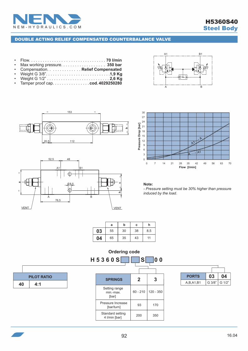
16.0492
Ordering code
H 5 3 6 0 S S 0 0
A,B,A1,B140 4:1 G 3/8”
03G 1/2”
04
a b
55 300365 3504
c h
38 8,5
43 11
52,5 48
=
==
=
11220,5
153
b
==
A1 B1
=
BA
=
a
h
76,5
c8,5
VENT VENT
30 27
24
21
18 15 12
9
6 3
00 7 14 21 28 35 42 49 56 63 70
1B1A
BA
DOUBLE ACTING RELIEF COMPENSATED COUNTERBALANCE VALVE
• Flow. . . . . . . . . . . . . . . . . . . . . . . . . . . . . . . . . 70 l/min• Max working pressure. . . . . . . . . . . . . . . . . . . 350 bar• Compensation. . . . . . . . . . . . . . Relief Compensated• Weight G 3/8”. . . . . . . . . . . . . . . . . . . . . . . . . . . .1,9 Kg• Weight G 1/2” . . . . . . . . . . . . . . . . . . . . . . . . . . . 2,6 Kg• Tamper proof cap. . . . . . . . . . . . . . . . cod. 4029250280
Pres
sure
Dro
p [b
ar]
Flow [l/min]
Note:- Pressure setting must be 30% higher than pressure induced by the load.
PILOT RATIO PORTS
Steel Body
A1 A
A A1
93
200 350
60 - 210
2 3
120 - 350
170
SPRINGS
Setting range min.-max.
[bar]
Pressure Increase[bar/turn]
Standard setting 4 l/min [bar]
H5360S40

16.04 93
Ordering code
A,B,B1 G 3/8” G 1/2”A1M
Ø 9G 1/4”
Ø 9G 1/4”
03 04
H 5 3 6 1 S S 0 0
40 4:1
a b
55 29,50365 34,504
112 20,5
O-RING 10,78x2.62
153
b
59,159,1
(41)
52,5 48 52,5
(41)
==
==
=
B
B1
AA1
=
52,5
30
a 30
M
VENT VENT
30 27
24
21
18 15 12
9
6 3
00 7 14 21 28 35 42 49 56 63 70
B
M
A
1B1A
DOUBLE ACTING RELIEF COMPENSATED COUNTERBALANCE VALVE - A1 FLANGED 30x30
• Flow. . . . . . . . . . . . . . . . . . . . . . . . . . . . . . . . .70 l/min• Max working pressure. . . . . . . . . . . . . . . . . . . 350 bar• Compensation. . . . . . . . . . . . . . Relief Compensated• Weight G 3/8”. . . . . . . . . . . . . . . . . . . . . . . . . . . .1,9 Kg• Weight G 1/2” . . . . . . . . . . . . . . . . . . . . . . . . . . . 2,6 Kg• Tamper proof cap. . . . . . . . . . . . . . . . cod. 4029250280
Pres
sure
Dro
p [b
ar]
Flow [l/min]
Note:- Pressure setting must be 30% higher than pressure induced by the load.
PILOT RATIO PORTS
Steel Body
A1 A
A A1
93
200 350
60 - 210
2 3
120 - 350
170
SPRINGS
Setting range min.-max.
[bar]
Pressure Increase[bar/turn]
Standard setting 4 l/min [bar]
H5361S40
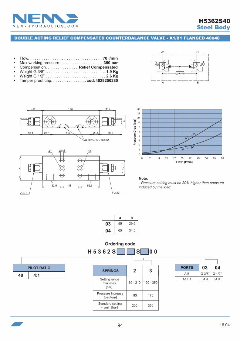
16.0494
Ordering code
H 5 3 6 2 S S 0 0
A,B G 3/8” G 1/2”
040340 4:1
A1,B1 Ø 9 Ø 9
a
55
65
b
29,5
34,50403
O-RING 10.78x2.62
20,5112 59,1
(41)
59,1
b
153
20,5
(41)
BA
=
==
A1 B1
=
52,5 48 52,5
a 40
8,5
VENT VENT
30 27
24
21
18 15 12
9
6 3
00 7 14 21 28 35 42 49 56 63 70
DOUBLE ACTING RELIEF COMPENSATED COUNTERBALANCE VALVE - A1/B1 FLANGED 40x48
• Flow. . . . . . . . . . . . . . . . . . . . . . . . . . . . . . . . . 70 l/min• Max working pressure. . . . . . . . . . . . . . . . . . . 350 bar• Compensation. . . . . . . . . . . . . . Relief Compensated• Weight G 3/8”. . . . . . . . . . . . . . . . . . . . . . . . . . . .1,9 Kg• Weight G 1/2” . . . . . . . . . . . . . . . . . . . . . . . . . . . 2,6 Kg• Tamper proof cap. . . . . . . . . . . . . . . . cod. 4029250280
Pres
sure
Dro
p [b
ar]
Flow [l/min]
Note:- Pressure setting must be 30% higher than pressure induced by the load.
PILOT RATIO PORTS
Steel Body
A1 A
A A1
93
200 350
60 - 210
2 3
120 - 350
170
SPRINGS
Setting range min.-max.
[bar]
Pressure Increase[bar/turn]
Standard setting 4 l/min [bar]
H5362S40
BA
1B1A

16.04 95
Ordering code
a
45
50
b
25
30
c
84
90
d
22,5
250302
H 3 0 0 1 C S 0 0
A,A1,X G 1/4” G 3/8”
030240 4:1
41
200 350
80 - 210
2 3
150 - 350
100
A1
A
X
0 4 8 12 16 20 24 28 32 36 40
30 27
24
21
18 15 12
9
6 3
050
23
=b
40,8
=
A1
A
X
35
a
c
=
d
6,5
7,5
37,8
=
VENT
SINGLE ACTING FULLY COMPENSATED COUNTERBALANCE VALVE
• Flow. . . . . . . . . . . . . . . . . . . . . . . . . . . . . . . . .40 l/min• Max working pressure. . . . . . . . . . . . . . . . . . . 350 bar• Compensation. . . . . . . . . . . . . . Fully Compensated• Weight G 1/4”. . . . . . . . . . . . . . . . . . . . . . . . . . .0,75 Kg• Weight G 3/8” . . . . . . . . . . . . . . . . . . . . . . . . . . . . .1 Kg• Tamper proof cap. . . . . . . . . . . . . . . . cod. 9021030190
Pres
sure
Dro
p [b
ar]
Flow [l/min]
Note:- Pressure setting must be 30% higher than pressure induced by the load.
-To be used only with A/B closed center spools.
(Pressure drop for G3/8” port)
SPRINGSPILOT RATIO PORTS
Setting range min.-max.
[bar]
Pressure Increase[bar/turn]
Standard setting 4 l/min [bar]
Steel Body
A1 A
A A1
H3001C

16.0496
Ordering code
H 5 0 0 1 C S 0 0
A,A140 4:1
a b
55 3003
XG 3/8”
03
G 1/4”
65 3504
G 1/2”
04
G 1/4”
h
7
11
21
a/2
==
b
91
49 52
46
A
==
A1
X
h
25,6 47,6
a
8,5
VENT
30 27
24
21
18 15 12
9
6 3
00 7 14 21 28 35 42 49 56 63 70
A1
A
X
90 9:1
62
200 350
60 - 210
2 3
120 - 350
rp 4:1
114 50
200 350
80 - 250
2 3
190 - 350
121
rp 9:1
SINGLE ACTING FULLY COMPENSATED COUNTERBALANCE VALVE
• Flow. . . . . . . . . . . . . . . . . . . . . . . . . . . . . . . . . 70 l/min• Max working pressure. . . . . . . . . . . . . . . . . . . 350 bar• Compensation. . . . . . . . . . . . . . . Fully Compensated• Weight G 3/8”. . . . . . . . . . . . . . . . . . . . . . . . . . .1,25 Kg• Weight G 1/2” . . . . . . . . . . . . . . . . . . . . . . . . . . 1,55 Kg• Tamper proof cap. . . . . . . . . . . . . . . . cod. 9021030190
Pres
sure
Dro
p [b
ar]
Flow [l/min]
Note:- Pressure setting must be 30% higher than pressure induced by the load.
-To be used only with A/B closed center spools.
SPRINGSPILOT RATIO PORTS
Setting range min.-max.
[bar]
Pressure Increase[bar/turn]
Standard setting 4 l/min [bar]
Steel Body
A1 A
A A1
H5001C

16.04 97
Ordering code
a
45
50
b
25
30
c
84
95
d
23
300302
H 3 0 0 4 C S 0 0
A,B,A1,B1 G 1/4” G 3/8”
030240 4:1
41
200 350
80 - 210
2 3
150 - 350
100
50
23
d
B1 A1
B A
c
a
35
6,5 7,5
37,8
=
40,8
b=
0 4 8 12 16 20 24 28 32 36 40
30 27
24
21
18 15 12
9
6 3
0
BA
A1 B1
VENT
SINGLE ACTING FULLY COMPENSATED COUNTERBALANCE VALVE
• Flow. . . . . . . . . . . . . . . . . . . . . . . . . . . . . . . . .40 l/min• Max working pressure. . . . . . . . . . . . . . . . . . . 350 bar• Compensation. . . . . . . . . . . . . . Fully Compensated• Weight G 1/4”. . . . . . . . . . . . . . . . . . . . . . . . . . .0,75 Kg• Weight G 3/8” . . . . . . . . . . . . . . . . . . . . . . . . . . . . .1 Kg• Tamper proof cap. . . . . . . . . . . . . . . . cod. 9021030190
Pres
sure
Dro
p [b
ar]
Flow [l/min]
Note:- Pressure setting must be 30% higher than pressure induced by the load.
-To be used only with A/B closed center spools.
(Pressure drop for G3/8” port)
SPRINGSPILOT RATIO PORTS
Setting range min.-max.
[bar]
Pressure Increase[bar/turn]
Standard setting 4 l/min [bar]
Steel Body
A1 A
A A1
H3004C

16.0498
Ordering code
H 3 0 0 4 C S 0 0
41
200 350
80 - 210
2 3
150 - 350
100
0 4 8 12 16 20 24 28 32 36 40
30 27
24
21
18 15 12
9
6 3
0
A1
B1
BA
41 4:1+dia.0,5mm03
G 3/8”
50
21,563,5
25
B1
A1
B
VENT
A
105
50
8
3530
6,5
37,8
40,8
30
SINGLE ACTING FULLY COMPENSATED COUNTERBALANCE VALVE
• Flow. . . . . . . . . . . . . . . . . . . . . . . . . . . . . . . . .40 l/min• Max working pressure. . . . . . . . . . . . . . . . . . . 350 bar• Compensation. . . . . . . . . . . . . . Fully Compensated• Weight. . . . . . . . . . . . . . . . . . . . . . . . . . . . . . . .0,75 Kg• Tamper proof cap. . . . . . . . . . . . . . . . cod. 9021030190
Pres
sure
Dro
p [b
ar]
Flow [l/min]
Note:- Pressure setting must be 30% higher than pressure induced by the load.
-To be used only with A/B closed center spools.
(Pressure drop for G3/8” port)
SPRINGSPILOT RATIO PORTS
Setting range min.-max.
[bar]
Pressure Increase[bar/turn]
Standard setting 4 l/min [bar]
Steel Body
A1 A
A A1
H3004C41

16.04 99
Ordering code
H 5 0 0 4 C S 0 0
A,A1,B,B140 4:1
62
200 350
60 - 210
2 3
120 - 350
a b
55 3003
114
MG 3/8”
03
G 1/4”
65 3504
G 1/2”
04
G 1/4”
0.5 mm
A
A1
B
B1
M
A
30 27
24
21
18 15 12
9
6 3
00 7 14 21 28 35 42 49 56 63 70
20,5 70,5
==
48,5 52
b
39
11045,5
B1A1
A
=
B
=
M
32 40
a
8
4,5
8,5
VENT
SINGLE ACTING FULLY COMPENSATED COUNTERBALANCE VALVE
• Flow. . . . . . . . . . . . . . . . . . . . . . . . . . . . . . . . . 70 l/min• Max working pressure. . . . . . . . . . . . . . . . . . . 350 bar• Compensation. . . . . . . . . . . . . . . Fully Compensated• Weight G 3/8”. . . . . . . . . . . . . . . . . . . . . . . . . . .1,35 Kg• Weight G 1/2” . . . . . . . . . . . . . . . . . . . . . . . . . . . 1,8 Kg• Tamper proof cap. . . . . . . . . . . . . . . . cod. 9021030190
Pres
sure
Dro
p [b
ar]
Flow [l/min]
Note:- Pressure setting must be 30% higher than pressure induced by the load.
-To be used only with A/B closed center spools.
SPRINGSPILOT RATIO PORTS
Setting range min.-max.
[bar]
Pressure Increase[bar/turn]
Standard setting 4 l/min [bar]
Steel Body
A1 A
A A1
H5004C

16.04100
Ordering code
H 1 0 0 4 C S 0 0
A,A1,B,B1 G 1/2” G 3/4”M G 1/4” G 1/4”
050440 4:142 4:190 9:192 9:1
ADJUSTABLE DUMP SCREW
ADJUSTABLE DUMP SCREW
52 85 100
200 350 350
60 - 210
2 4
120 - 410
4
150 - 410
a
65
70
b
35
40
c
117
130
d
59,7
60
e
39.3
47
f
40
47.6
g
39,7
36
h
8
11
i
70.5
780504
rp 4:1 rp 9:1
M
A
A1
B
B1
0.5 mm
B
M
A
A1 B1
0 11 22 33 44 55 66 77 88 99 110
30 27
24
21
18 15 12
9
6 3
0i
c
59,5
e
b
56,5
d
A1
AB
B1
M
a
f
4,5
h
8,5
g VENT
SINGLE ACTING FULLY COMPENSATED COUNTERBALANCE VALVE
• Flow. . . . . . . . . . . . . . . . . . . . . . . . . . . . . . . . 110 l/min• Max working pressure. . . . . . . . . . . . . . . . . . . 410 bar• Compensation. . . . . . . . . . . . . . Fully Compensated• Weight G 1/2”. . . . . . . . . . . . . . . . . . . . . . . . . . . . . 2 Kg• Weight G 3/4” . . . . . . . . . . . . . . . . . . . . . . . . . . . 2,6 Kg• Tamper proof cap. . . . . . . . . . . . . . . . cod. 9021030190
SCHEME 40 - 90 SCHEME 42 - 92
Pres
sure
Dro
p [b
ar]
Flow [l/min]
Note:- Pressure setting must be 30% higher than pressure induced by the load.
-To be used only with A/B closed center spools.
SPRINGSPILOT RATIO PORTS
Setting range min.-max.
[bar]
Pressure Increase[bar/turn]
Standard setting 4 l/min [bar]
Steel Body
A1 A
A A1
H1004C
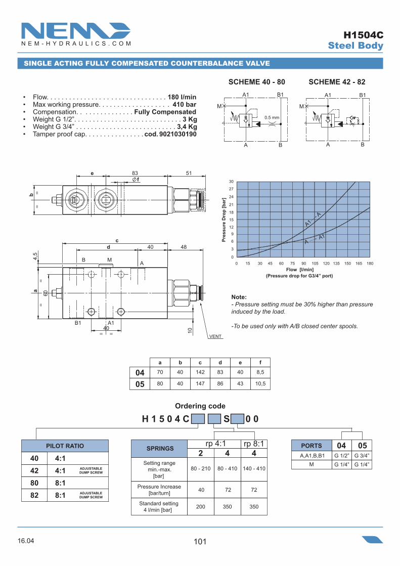
16.04 101
Ordering code
40
==
60
d
A1B1
B AM
a
40
=
10
=4,
5
c48
=
5183ef
b=
VENT
H 1 5 0 4 C S 0 0
A,A1,B,B1 G 1/2” G 3/4”M G 1/4” G 1/4”
050440 4:142 4:180 8:182 8:1
ADJUSTABLEDUMP SCREW
ADJUSTABLEDUMP SCREW
40 72 72
200 350 350
80 - 210
2 4
80 - 410
4
140 - 410
a
70
80
b
40
40
c
142
147
d
83
86
e
40
43
f
8,5
10,50504
rp 4:1 rp 8:1
M
A
A1
B
B1
0.5 mm
B
M
A
A1 B1
SINGLE ACTING FULLY COMPENSATED COUNTERBALANCE VALVE
• Flow. . . . . . . . . . . . . . . . . . . . . . . . . . . . . . . . 180 l/min• Max working pressure. . . . . . . . . . . . . . . . . . . 410 bar• Compensation. . . . . . . . . . . . . . . Fully Compensated• Weight G 1/2”. . . . . . . . . . . . . . . . . . . . . . . . . . . . . 3 Kg• Weight G 3/4” . . . . . . . . . . . . . . . . . . . . . . . . . . . 3,4 Kg• Tamper proof cap. . . . . . . . . . . . . . . . cod. 9021030190
SCHEME 40 - 80 SCHEME 42 - 82
Note:- Pressure setting must be 30% higher than pressure induced by the load.
-To be used only with A/B closed center spools.
SPRINGSPILOT RATIO PORTS
Setting range min.-max.
[bar]
Pressure Increase[bar/turn]
Standard setting 4 l/min [bar]
(Pressure drop for G3/4” port)
Pres
sure
Dro
p [b
ar]
Flow [l/min]
Steel Body
A1A
A A1
H1504C

16.04102
Ordering code
a
45
50
b
24,5
29,5
c
90
950302
d
54
59
H 3 0 0 5 C S 0 0
A,B,B1 G 1/4” G 3/8”
030240 4:1
41
200 350
80 - 210
2 3
150 - 350
100
e
23
21
A1M
Ø 6G 1/4”
Ø 6G 1/4”
ed
A1
b
40,8
B1
AB
M A
c
a=
=
=
28
4,5
28
50
6,5
37,8
=
VENT
0 4 8 12 16 20 24 28 32 36 40
30 27
24
21
18 15 12
9
6 3
0
A
B1
B
A
M
A1
O-RING 9.92x2.62
SINGLE ACTING FULLY COMPENSATED COUNTERBALANCE VALVE - A1 FLANGED 28x28
• Flow. . . . . . . . . . . . . . . . . . . . . . . . . . . . . . . . . 40 l/min• Max working pressure. . . . . . . . . . . . . . . . . . . 350 bar• Compensation. . . . . . . . . . . . . . . Fully Compensated• Weight G 1/4”. . . . . . . . . . . . . . . . . . . . . . . . . . .0,75 Kg• Weight G 3/8” . . . . . . . . . . . . . . . . . . . . . . . . . . . 0,9 Kg• Tamper proof cap. . . . . . . . . . . . . . . . cod. 9021030190
Pres
sure
Dro
p [b
ar]
Flow [l/min]
Note:- Pressure setting must be 30% higher than pressure induced by the load.
-To be used only with A/B closed center spools.
(Pressure drop for G3/8” port)
SPRINGSPILOT RATIO PORTS
Setting range min.-max.
[bar]
Pressure Increase[bar/turn]
Standard setting 4 l/min [bar]
n°4 holes
Steel Body
A1 A
A A1
H3005C
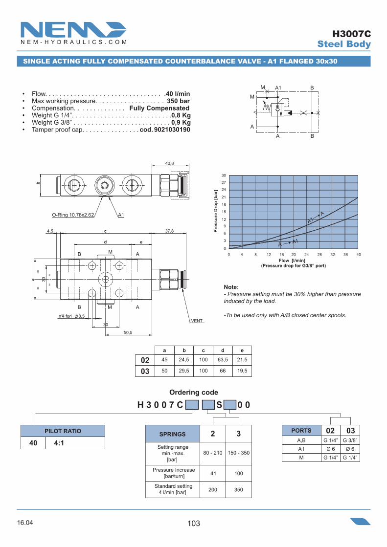
16.04 103
Ordering code
a
45
50
b
24,5
29,5
c
100
1000302
d
63,5
66
H 3 0 0 7 C S 0 0
A,B G 1/4” G 3/8”
030240 4:1
41
200 350
80 - 210
2 3
150 - 350
100
e
21,5
MØ 6
G 1/4ӯ 6
G 1/4”
0 4 8 12 16 20 24 28 32 36 40
30 27
24
21
18 15 12
9
6 3
0
SINGLE ACTING FULLY COMPENSATED COUNTERBALANCE VALVE - A1 FLANGED 30x30
• Flow. . . . . . . . . . . . . . . . . . . . . . . . . . . . . . . . .40 l/min• Max working pressure. . . . . . . . . . . . . . . . . . . 350 bar• Compensation. . . . . . . . . . . . . . Fully Compensated• Weight G 1/4”. . . . . . . . . . . . . . . . . . . . . . . . . . . .0,8 Kg• Weight G 3/8” . . . . . . . . . . . . . . . . . . . . . . . . . . . 0,9 Kg• Tamper proof cap. . . . . . . . . . . . . . . . cod. 9021030190
Pres
sure
Dro
p [b
ar]
Flow [l/min]
Note:- Pressure setting must be 30% higher than pressure induced by the load.
-To be used only with A/B closed center spools.
(Pressure drop for G3/8” port)
SPRINGSPILOT RATIO PORTS
Setting range min.-max.
[bar]
Pressure Increase[bar/turn]
Standard setting 4 l/min [bar]
A1
19,5
ed
50,5
A1O-Ring 10.78x2.62
40,8
b
M
MB
A
A
B
=
30
=
=
c
a 30
n°4 fori 8,5
4,5 37,8
=
VENT
A
M
B
A
M
A1 B
Steel Body
A1 A
A A1
H3007C

16.04104
Ordering code
H 5 0 0 5 C S 0 0
A,B,B140 4:1
62
200 350
60 - 210
2 3
120 - 350
a b
55 29,503
114
G 3/8”
03
65 34,504
G 1/2”
04
A1M
Ø 9G 1/4”
Ø 9G 1/4”
20,5
20,5
39
71,5
A B
==
==
MB1A
A1
38 30
30
53
8,5
a4,
5
O-RING 10.78x2.62
110
48,5
b
4,545,5
VENT
30 27
24
21
18 15 12
9
6 3
00 7 14 21 28 35 42 49 56 63 70
SINGLE ACTING FULLY COMPENSATED COUNTERBALANCE VALVE - A1 FLANGED 30x30
• Flow. . . . . . . . . . . . . . . . . . . . . . . . . . . . . . . . . 70 l/min• Max working pressure. . . . . . . . . . . . . . . . . . . 350 bar• Compensation. . . . . . . . . . . . . . . Fully Compensated• Weight G 3/8”. . . . . . . . . . . . . . . . . . . . . . . . . . . .1,3 Kg• Weight G 1/2” . . . . . . . . . . . . . . . . . . . . . . . . . . 1,75 Kg• Tamper proof cap. . . . . . . . . . . . . . . . cod. 9021030190
Pres
sure
Dro
p [b
ar]
Flow [l/min]
Note:- Pressure setting must be 30% higher than pressure induced by the load.
-To be used only with A/B closed center spools.
SPRINGSPILOT RATIO PORTS
Setting range min.-max.
[bar]
Pressure Increase[bar/turn]
Standard setting 4 l/min [bar]
0.5 mm
AA
A1
B
B1
M
Steel Body
A1 A
A A1
H5005C

16.04 105
Ordering code
H 1 0 0 5 C S 0 0
A,B,B1 G 1/2” G 3/4”
050440 4:142 4:190 9:192 9:1
ADJUSTABLEDUMP SCREW
ADJUSTABLEDUMP SCREW
52 85 100
200 350 350
60 - 210
2 4
120 - 410
4
150 - 410
a
65
80
b
34,5
39,5
c
117
130
d
26,5
22
e
72,5
86
f
30
40
g
45
62
h
30
400504
M G 1/4”A1 Ø 9 Ø 8,5
G 1/4”
rp 4:1 rp 9:1
g
O-RING 10.78x2.62
d
59,5
c
e
b
56,5
==
B
=
B1 A
AM
A1
=h
=
a
=4,
5
8,5
fVENT
0 11 22 33 44 55 66 77 88 99 110
30 27
24
21
18 15 12
9
6 3
0
0.5 mm
AA
A1
B
B1
M
AA
B1
B
A1
M
SINGLE ACTING FULLY COMPENSATED COUNTERBALANCE VALVE - A1 FLANGED fxh
SCHEME 40 - 90 SCHEME 42 - 92
• Flow. . . . . . . . . . . . . . . . . . . . . . . . . . . . . . . . 110 l/min• Max working pressure. . . . . . . . . . . . . . . . . . . 410 bar• Compensation. . . . . . . . . . . . . . Fully Compensated• Weight G 1/2”. . . . . . . . . . . . . . . . . . . . . . . . . . . 1,9 Kg• Weight G 3/4” . . . . . . . . . . . . . . . . . . . . . . . . . .2,85 Kg• Tamper proof cap. . . . . . . . . . . . . . . . cod. 9021030190
Pres
sure
Dro
p [b
ar]
Flow [l/min]
Note:- Pressure setting must be 30% higher than pressure induced by the load.
-To be used only with A/B closed center spools.
SPRINGSPILOT RATIO PORTS
Setting range min.-max.
[bar]
Pressure Increase[bar/turn]
Standard setting 4 l/min [bar]
Steel Body
A1 A
A A1
H1005C
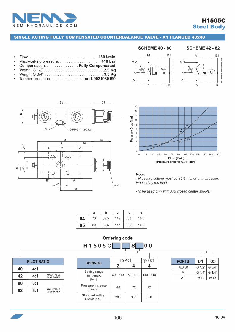
16.04106
Ordering code
H 1 5 0 5 C S 0 0
A,B,B1 G 1/2” G 3/4”M G 1/4” G 1/4”
050440 4:142 4:180 8:182 8:1
ADJUSTABLEDUMP SCREW
ADJUSTABLEDUMP SCREW
40 72 72
200 350 350
80 - 210
2 4
80 - 410
4
140 - 410
a
70
80
b
39,5
39,5
c
142
147
d
83
86
e
10,5
10,50504
A1 Ø 12 Ø 12
rp 4:1 rp 8:1
a
4,5
==
c
40=
=
40
4840d
83==
51e
b
A1
AB1
B AM
VENT
O-RING 17.12x2.62
SINGLE ACTING FULLY COMPENSATED COUNTERBALANCE VALVE - A1 FLANGED 40x40
SCHEME 40 - 80 SCHEME 42 - 82
• Flow. . . . . . . . . . . . . . . . . . . . . . . . . . . . . . . . 180 l/min• Max working pressure. . . . . . . . . . . . . . . . . . . 410 bar• Compensation. . . . . . . . . . . . . . . Fully Compensated• Weight G 1/2”. . . . . . . . . . . . . . . . . . . . . . . . . . . .2,9 Kg• Weight G 3/4” . . . . . . . . . . . . . . . . . . . . . . . . . . . 3,3 Kg• Tamper proof cap. . . . . . . . . . . . . . . . cod. 9021030190
Note:- Pressure setting must be 30% higher than pressure induced by the load.
-To be used only with A/B closed center spools.
SPRINGSPILOT RATIO PORTS
Setting range min.-max.
[bar]
Pressure Increase[bar/turn]
Standard setting 4 l/min [bar]
(Pressure drop for G3/4” port)
Pres
sure
Dro
p [b
ar]
Flow [l/min]
A1
0.5 mm
M
B1
BA A
B1
B
A1
M
A A
Steel Body
A1A
A A1
H1505C
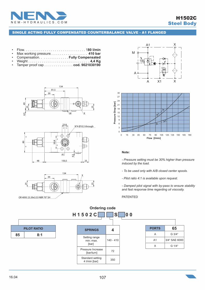
16.04 107
Ordering code
Pressure Increase[bar/turn]
• Flow. . . . . . . . . . . . . . . . . . . . . . . . . . . . . . . . 180 l/min• Max working pressure. . . . . . . . . . . . . . . . . . . 410 bar• Compensation. . . . . . . . . . . . . . . Fully Compensated• Weight . . . . . . . . . . . . . . . . . . . . . . . . . . . . . . . . 4,4 Kg• Tamper proof cap . . . . . . . . . . . . . . . cod. 9021030190
Steel Body
SINGLE ACTING FULLY COMPENSATED COUNTERBALANCE VALVE - A1 FLANGED
8:1
H 1 5 0 2 C S 0 0
72
350
140 - 410
485
Setting range min.-max.
[bar]
Standard setting 4 l/min [bar]
SPRINGSPILOT RATIO
H1502C
PORTS 65A G 3/4“
A1 3/4“ SAE 6000
X G 1/4“
39
134
49
4,5
81,5
25
25
M X
50,
8
23,8
48 150,5
80
4,5
25
N°4 Ø10.5 through
A1
39
134
25
25
X
OR 4093 23.39x3.53 NBR 70° SH
= =
===
=
A
XA1
X
M
A
X1
Note:
- Pressure setting must be 30% higher than pressure induced by the load.
- To be used only with A/B closed center spools.
- Pilot ratio 4:1 is available upon request.
- Damped pilot signal with by-pass to ensure stability and fast response time regarding oil viscosity.
PATENTED
Pres
sure
Dro
p [b
ar]
Flow [l/min]
A1A
A A1
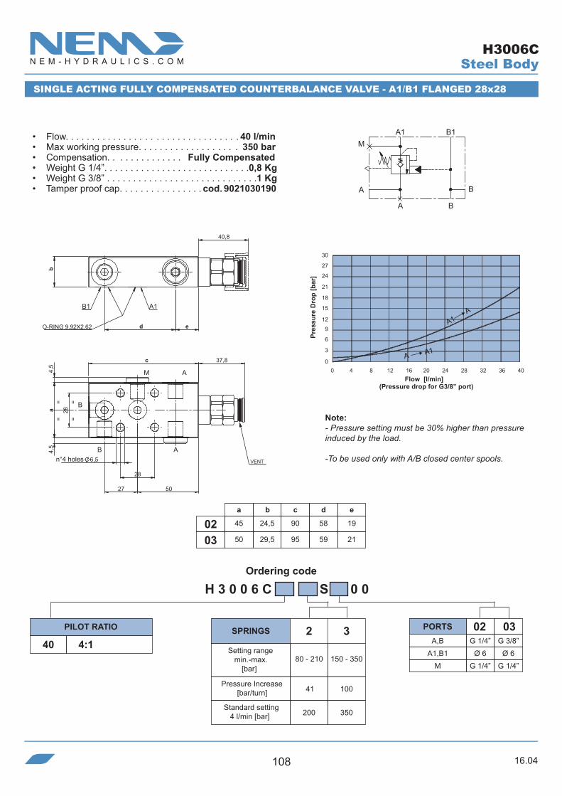
16.04108
Ordering code
a
45
50
b
24,5
29,5
c
90
950302
d
58
59
H 3 0 0 6 C S 0 0
A,B G 1/4” G 3/8”
030240 4:1
41
200 350
80 - 210
2 3
150 - 350
100
e
19
21
A1,B1M
Ø 6G 1/4”
Ø 6G 1/4”
0 4 8 12 16 20 24 28 32 36 40
30 27
24
21
18 15 12
9
6 3
0
A1M
B1
A
B
B
A
B1 A1
40,8
b
ed
B
B
A
A
M
==
5027
4,5
4,5
28=
a
28
6,5
8,73c
=
O-RING 9.92X2.62
VENT
SINGLE ACTING FULLY COMPENSATED COUNTERBALANCE VALVE - A1/B1 FLANGED 28x28
• Flow. . . . . . . . . . . . . . . . . . . . . . . . . . . . . . . . . 40 l/min• Max working pressure. . . . . . . . . . . . . . . . . . . 350 bar• Compensation. . . . . . . . . . . . . . Fully Compensated• Weight G 1/4”. . . . . . . . . . . . . . . . . . . . . . . . . . . .0,8 Kg• Weight G 3/8” . . . . . . . . . . . . . . . . . . . . . . . . . . . . .1 Kg• Tamper proof cap. . . . . . . . . . . . . . . . cod. 9021030190
Pres
sure
Dro
p [b
ar]
Flow [l/min]
Note:- Pressure setting must be 30% higher than pressure induced by the load.
-To be used only with A/B closed center spools.
(Pressure drop for G3/8” port)
SPRINGSPILOT RATIO PORTS
Setting range min.-max.
[bar]
Pressure Increase[bar/turn]
Standard setting 4 l/min [bar]
n°4 holes
Steel Body
A1 A
A A1
H3006C

16.04 109
Ordering code
a
45
50
b
24,5
29,5
c
90
950302
d
58
59
H 3 0 0 8 C 4 0 S 0 0
A,B G 1/4” G 3/8”
030240 4:1
41
200 350
80 - 210
2 3
150 - 350
100
e
19
21
A1,B1M
Ø 6G 1/4”
Ø 6G 1/4”
B
A
A
B M
28
50
=
4,5
=
27
=28a
n°4 fori 6,5
8,73c
=
B1 A1
b
e
40,8
dO-Ring 9.92X2.62VENT
0 4 8 12 16 20 24 28 32 36 40
30 27
24
21
18 15 12
9
6 3
0
B1
A
A1
B
B
A
M
O-RING 9.92X2.62
SINGLE ACTING FULLY COMPENSATED COUNTERBALANCE VALVE - A1/B1 FLANGED 28x28
• Flow. . . . . . . . . . . . . . . . . . . . . . . . . . . . . . . . . 40 l/min• Max working pressure. . . . . . . . . . . . . . . . . . . 350 bar• Compensation. . . . . . . . . . . . . . . Fully Compensated• Weight G 1/2”. . . . . . . . . . . . . . . . . . . . . . . . . . .0,75 Kg• Weight G 3/4” . . . . . . . . . . . . . . . . . . . . . . . . . . . 0,9 Kg• Tamper proof cap. . . . . . . . . . . . . . . . cod. 9021030190
Pres
sure
Dro
p [b
ar]
Flow [l/min]
Note:- Pressure setting must be 30% higher than pressure induced by the load.
-To be used only with A/B closed center spools.
(Pressure drop for G3/8” port)
SPRINGSPILOT RATIO PORTS
Setting range min.-max.
[bar]
Pressure Increase[bar/turn]
Standard setting 4 l/min [bar]
n°4 holes
Steel Body
A1 A
A A1
H3008C
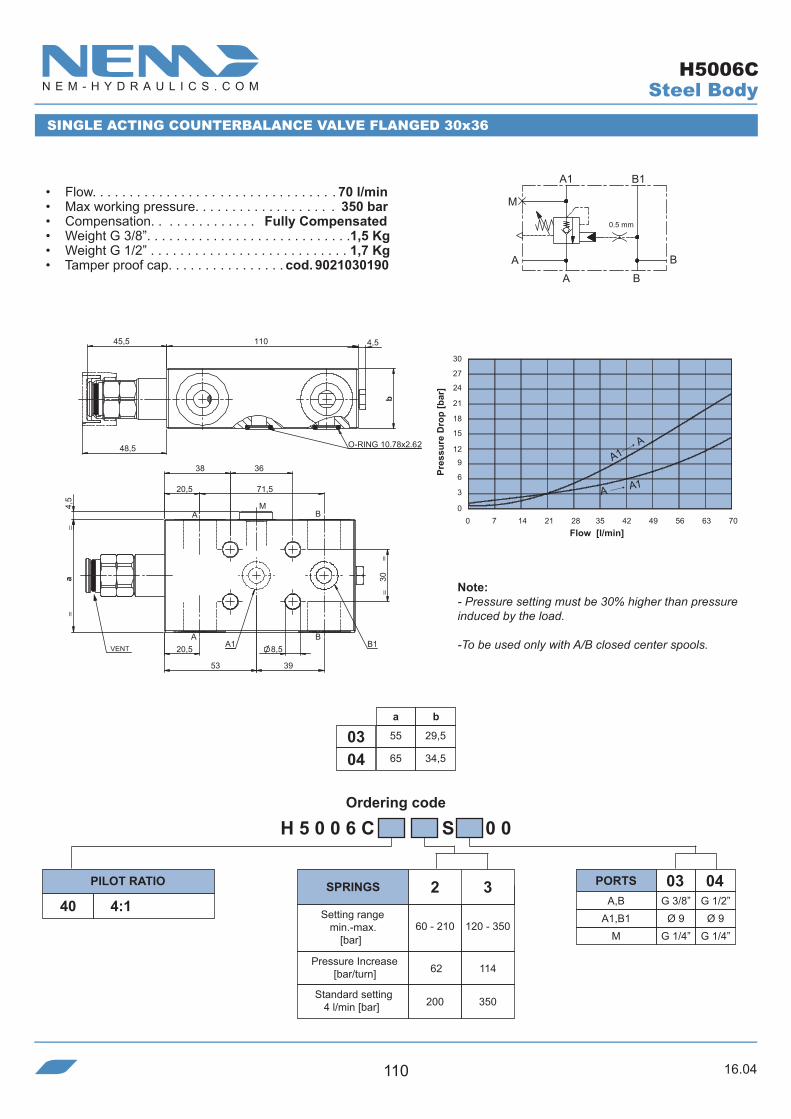
16.04110
Ordering code
H 5 0 0 6 C S 0 0
A,B40 4:1
62
200 350
60 - 210
2 3
120 - 350
a b
55 29,503
114
G 3/8”
03
65 34,504
G 1/2”
04
A1,B1M
Ø 9G 1/4”
Ø 9G 1/4”
20,5
20,5
39
71,5
A
==
AM
B
A1B
B1
4,5
53
30
38
a
8,5
36
==
O-RING 10.78x2.62
b
48,5
110 4,545,5
VENT
30 27
24
21
18 15 12
9
6 3
00 7 14 21 28 35 42 49 56 63 70
A1 B1
A
0.5 mm
M
B
BA
SINGLE ACTING COUNTERBALANCE VALVE FLANGED 30x36
• Flow. . . . . . . . . . . . . . . . . . . . . . . . . . . . . . . . . 70 l/min• Max working pressure. . . . . . . . . . . . . . . . . . . 350 bar• Compensation. . . . . . . . . . . . . . Fully Compensated• Weight G 3/8”. . . . . . . . . . . . . . . . . . . . . . . . . . . .1,5 Kg• Weight G 1/2” . . . . . . . . . . . . . . . . . . . . . . . . . . . 1,7 Kg• Tamper proof cap. . . . . . . . . . . . . . . . cod. 9021030190
Pres
sure
Dro
p [b
ar]
Flow [l/min]
Note:- Pressure setting must be 30% higher than pressure induced by the load.
-To be used only with A/B closed center spools.
SPRINGSPILOT RATIO PORTS
Setting range min.-max.
[bar]
Pressure Increase[bar/turn]
Standard setting 4 l/min [bar]
Steel Body
A1 A
A A1
H5006C

16.04 111
Ordering code
H 1 0 0 6 C S 0 0
A,B G 1/2”
0440 4:142 4:190 9:192 9:1
ADJUSTABLEDUMP SCREW
ADJUSTABLEDUMP SCREW
52 85 100
200 350 350
60 - 210
2 4
120 - 410
4
150 - 410
a
65
b
34,5
c
117
d
28,5
e
70,5
f
36
g
4504h
30
M G 1/4”A1,B1 Ø 9
i
39
m
15
rp 4:1 rp 9:1
=
AB
AMB
B1
=
A1
h
8,5
f
i
4,5
g
=
a
=
m
O-RING 10.78x2.62
e
c
59,5
b
56,5
d
VENT
0 11 22 33 44 55 66 77 88 99 110
30 27
24
21
18 15 12
9
6 3
0
A1
A
0.5 mm
M
B
BA
B1
M
A
B1
B
A1
AB
SINGLE ACTING FULLY COMPENSATED COUNTERBALANCE VALVE - A1/B1 FLANGED fxh
SCHEME 40 - 90 SCHEME 42 - 92
• Flow. . . . . . . . . . . . . . . . . . . . . . . . . . . . . . . . 110 l/min• Max working pressure. . . . . . . . . . . . . . . . . . . 410 bar• Compensation. . . . . . . . . . . . . . . Fully Compensated• Weight G 1/2”. . . . . . . . . . . . . . . . . . . . . . . . . . . .1,9 Kg• Weight G 3/4” . . . . . . . . . . . . . . . . . . . . . . . . . . . 2,2 Kg• Tamper proof cap. . . . . . . . . . . . . . . . cod. 9021030190
Pres
sure
Dro
p [b
ar]
Flow [l/min]
Note:- Pressure setting must be 30% higher than pressure induced by the load.
-To be used only with A/B closed center spools.
SPRINGSPILOT RATIO PORTS
Setting range min.-max.
[bar]
Pressure Increase[bar/turn]
Standard setting 4 l/min [bar]
Steel Body
A1 A
A A1
H1006C

16.04112
Ordering code
H 1 5 0 6 C S 0 0
A,B G 1/2” G 3/4”M G 1/4” G 1/4”
050440 4:142 4:180 8:182 8:1
ADJUSTABLEDUMP SCREW
ADJUSTABLEDUMP SCREW
40 72 72
200 350 350
80 - 210
2 4
80 - 410
4
140 - 410
4:1 8:1
a
70
80
b
39,5
39,5
c
142
147
d
83
860504
e
10,5
10,5
A1,A2 Ø 12 Ø 12
f
40
43
A1
0.5 mm
M
B1
BA A
B1
B
A1
M
==
d 40
f
a
c
==40=
=
40
48
AB
B AM
O-RING 17.12x2.62A1B1
51
b
e
83
VENT
4,5
SINGLE ACTING FULLY COMPENSATED COUNTERBALANCE VALVE - A1/B1 FLANGED 40x40
SCHEME 40 - 80 SCHEME 42 - 82
• Flow. . . . . . . . . . . . . . . . . . . . . . . . . . . . . . . . 180 l/min• Max working pressure. . . . . . . . . . . . . . . . . . . 410 bar• Compensation. . . . . . . . . . . . . . Fully Compensated• Weight G 1/2”. . . . . . . . . . . . . . . . . . . . . . . . . . . .2,9 Kg• Weight G 3/4” . . . . . . . . . . . . . . . . . . . . . . . . . . . 3,3 Kg• Tamper proof cap. . . . . . . . . . . . . . . . cod. 9021030190
Note:- Pressure setting must be 30% higher than pressure induced by the load.
-To be used only with A/B closed center spools.
SPRINGSPILOT RATIO PORTS
Setting range min.-max.
[bar]
Pressure Increase[bar/turn]
Standard setting 4 l/min [bar]
(Pressure drop for G3/4” port)
Pres
sure
Dro
p [b
ar]
Flow [l/min]
Steel Body
A1A
A A1
H1506C

16.04 113
Ordering code
56 4747
BA
B1 A1
40,5 150 40,5
20 110
70
20
30
5647
2020
103
THROUGH
34
N°2 8,5
3070
43,5150
20
58
43,5
20
92
VENT
VENT
H 1 5 3 0 C S 0 0
A,A1,B,B1 G 3/4”
0540 4:142 4:180 8:182 8:1
ADJUSTABLEDUMP SCREW
ADJUSTABLEDUMP SCREW
40 72 72
200 350 350
80 - 210
2 4
80 - 410
4
140 - 410
SCHEME 40 - 80 SCHEME 42 - 82
rp 4:1 rp 8:1
DOUBLE ACTING FULLY COMPENSATED COUNTERBALANCE VALVE
• Flow. . . . . . . . . . . . . . . . . . . . . . . . . . . . . . . . 180 l/min• Max working pressure. . . . . . . . . . . . . . . . . . . 410 bar• Compensation. . . . . . . . . . . . . . . Fully Compensated• Weight. . . . . . . . . . . . . . . . . . . . . . . . . . . . . . . . 5,3 Kg• Tamper proof cap. . . . . . . . . . . . . . . . cod. 9021030190
Note:- Pressure setting must be 30% higher than pressure induced by the load.
-To be used only with A/B closed center spools.
SPRINGSPILOT RATIO PORTS
Setting range min.-max.
[bar]
Pressure Increase[bar/turn]
Standard setting 4 l/min [bar]
(Pressure drop for G3/4” port)
Pres
sure
Dro
p [b
ar]
Flow [l/min]
0.5 mm
A1B1
AB
0.5 mm
B1
AB
A1
Steel Body
H 1 5 3 0 C S 0 0
A1A
A A1
H1530C
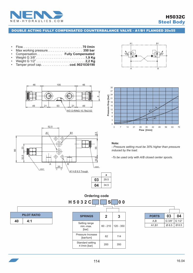
16.04114
Ordering code
N°2 O-RING 10.78x2.62
4963
a
4646
21
105
2149
=
BA
A1 B1
=
16,5
52,5
55
80
23
20
8,5
32,5
VENTN° 4 Ø 8.5 Trough
VENT
H 5 0 3 2 C S 0 0
40 4:1
62
200 350
60 - 210
2 3
120 - 350
114
30 27
24
21
18 15 12
9
6 3
00 7 14 21 28 35 42 49 56 63 70
BA
1B1A
DOUBLE ACTING FULLY COMPENSATED COUNTERBALANCE VALVE - A1/B1 FLANGED 20x55
• Flow. . . . . . . . . . . . . . . . . . . . . . . . . . . . . . . . . 70 l/min• Max working pressure. . . . . . . . . . . . . . . . . . . 350 bar• Compensation. . . . . . . . . . . . . . Fully Compensated• Weight G 3/8”. . . . . . . . . . . . . . . . . . . . . . . . . . . .1,9 Kg• Weight G 1/2” . . . . . . . . . . . . . . . . . . . . . . . . . . . 2,2 Kg• Tamper proof cap. . . . . . . . . . . . . . . . cod. 9021030190
Pres
sure
Dro
p [b
ar]
Flow [l/min]
Note:- Pressure setting must be 30% higher than pressure induced by the load.
-To be used only with A/B closed center spools.
SPRINGSPILOT RATIO
Setting range min.-max.
[bar]
Pressure Increase[bar/turn]
Standard setting 4 l/min [bar]
Steel Body
A1 A
A A1
a
29.5
34.50403
A,BA1,B1 Ø 8.5
PORTS 0403
Ø 8.5G 3/8” G 1/2”
H5032C

16.04 115
Ordering code
83,58740 39
82,5
M B
B1
A
A1
21,5
18
39,5
10
=
100
29 72
35
=
N°2 O-RING 17.86x2.62
51 166 51=
39,5
19,5
=
VENT
VENT
n°4 holes Ø10,5 Through.
H 1 5 3 2 C S 0 0
40 4:142 4:180 8:182 8:1
ADJUSTABLEDUMP SCREW
ADJUSTABLEDUMP SCREW
40 72 72
200 350 350
80 - 210
2 4
80 - 410
4
140 - 410
SCHEME 40 - 80 SCHEME 42 - 82
A,B G 1/2” G 3/4”
0504
A1,A2 Ø 12M G 1/4” G 1/4”
Ø 12
rp 4:1 rp 8:1
0.5 mm
A1B1
M
AB
0.5 mm
M
B1
AB
A1
DOUBLE ACTING FULLY COMPENSATED COUNTERBALANCE VALVE - A1/B1 FLANGED 35x72
• Flow. . . . . . . . . . . . . . . . . . . . . . . . . . . . . . . . 180 l/min• Max working pressure. . . . . . . . . . . . . . . . . . . 410 bar• Compensation. . . . . . . . . . . . . . . Fully Compensated• Weight G 1/2”. . . . . . . . . . . . . . . . . . . . . . . . . . . .5,1 Kg• Weight G 3/4” . . . . . . . . . . . . . . . . . . . . . . . . . . . 5,1 Kg• Tamper proof cap. . . . . . . . . . . . . . . . cod. 9021030190
Note:- Pressure setting must be 30% higher than pressure induced by the load.
-To be used only with A/B closed center spools.
SPRINGSPILOT RATIO PORTS
Setting range min.-max.
[bar]
Pressure Increase[bar/turn]
Standard setting 4 l/min [bar]
(Pressure drop for G3/4” port)
Pres
sure
Dro
p [b
ar]
Flow [l/min]
Steel Body
A1A
A A1
H1532C
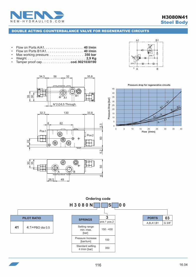
16.04116
Ordering code
B
pos.2
pos.1
B1A1
A11
Standard setting 4 l/min [bar]
Pressure Increase[bar/turn]
Setting range min.-max.
[bar]
• Flow on Ports A/A1. . . . . . . . . . . . . . . . . . . . . 40 l/min• Flow on Ports B1/A1. . . . . . . . . . . . . . . . . . . . 40 l/min• Max working pressure. . . . . . . . . . . . . . . . . . . 350 bar• Weight. . . . . . . . . . . . . . . . . . . . . . . . . . . . . . . . 2,9 Kg• Tamper proof cap. . . . . . . . . . . . . . . . cod. 9021030190
DOUBLE ACTING COUNTERBALANCE VALVE FOR REGENERATIVE CIRCUITS
Steel Body
Pres
sure
Dro
p [b
ar]
Flow [l/min]
45 40 35
30 25 20
15
10
5
00 5 10 15 20 25 30 35 40
H 3 0 8 0 N S 0 0
A,B,A1,B1 G 3/8”
03
41 4:1+PBO dia 0.5
SPRINGSPILOT RATIO PORTS
33,832,3
828
130
605,
2
228
5,3
PosPos
3035
56 32
N°2
34,3 35,8
4
5
0
28,5 49
3530
BA
B1A1
12
6,5 Through.
A1A
AA1
BB1B1
A1
350
150 - 430
3
100
pos.1 pos.2
Pressure drop for regenerative circuits
H3080N41

16.04 117
Ordering code
B
pos.2
pos.1
B1A1
A
B1
A1
A1 A
A A1
B B1
H 3 0 8 0 N S 0 0
A,B,A1,B1 G 1/2”
04
40 4:1 Pos 1
430 210
150 - 430 120 - 350
3
114100
pos.1 pos.2
A1
B1
27,5
13,5
8
33,5
48,5 26,35951
A B
50
21 62
16
4
Pos 1
48
45,5
45
8
90
129
8
7
23,3
Pos 2
4:1 Pos 2
Pres
sure
Dro
p [b
ar]
45 40 35
30 25 20
15
10
5
00 10 20 30 40 50 60
Flow [l/min]
Pressure drop for regenerative circuits
DOUBLE ACTING COUNTERBALANCE VALVE FOR REGENERATIVE CIRCUITS
• Flow on Ports A/A1. . . . . . . . . . . . . . . . . . . . . 70 l/min• Flow on Ports B1/A1. . . . . . . . . . . . . . . . . . . . 40 l/min• Max working pressure. . . . . . . . . . . . . . . . . . . 350 bar• Weight. . . . . . . . . . . . . . . . . . . . . . . . . . . . . . . . 4,3 Kg• Tamper proof cap. . . . . . . . . . . . . . . . cod. 9021030190
SPRINGSPILOT RATIO PORTS
Setting range min.-max.
[bar]
Pressure Increase[bar/turn]
Standard setting 4 l/min [bar]
n°2 holes Ø8,5
Steel BodyH3080N40
Note:- Available also G3/8” version with the damping screw for pos.1 (NEM code H3080N423S0300)

16.04118
Ordering code
B1
A1
A1 A
A A1
B B1
H 3 0 8 0 N S 0 0
A,B,A1,B1 G 3/8”
03
430 210
150 - 430 120 - 350
3
114100
pos.1 pos.2
Pres
sure
Dro
p [b
ar]
45 40 35
30 25 20
15
10
5
00 10 20 30 40 50 60
Flow [l/min]
Pressure drop for regenerative circuits
DOUBLE ACTING COUNTERBALANCE VALVE FOR REGENERATIVE CIRCUITS
• Flow on Ports A/A1. . . . . . . . . . . . . . . . . . . . . 70 l/min• Flow on Ports B1/A1. . . . . . . . . . . . . . . . . . . . 40 l/min• Max working pressure. . . . . . . . . . . . . . . . . . . 350 bar• Weight. . . . . . . . . . . . . . . . . . . . . . . . . . . . . . . . 4,3 Kg• Tamper proof cap. . . . . . . . . . . . . . . . cod. 9021030190
SPRINGS PORTS
Setting range min.-max.
[bar]
Pressure Increase[bar/turn]
Standard setting 4 l/min [bar]
Steel BodyH3080N42
Note:- Available also G1/2” version without the damping screw for pos.1 (NEM code H3080N403S0400)
42 4:1
PILOT RATIOADJUSTABLEDUMP SCREW
A B
A 1 B1
Pos.2
Pos.1
8
48
90
23,3
8 45
129
7
45,5
26,3 51 59 48,5
27,
5 3
3,5
n°2 holes 8,5
13,5
8
50
4
16
21 62
A B
A1 B1

16.04 119
Ordering code
7,5 7,5
5157
8,58,5
43,5
39,8
65
32 16,5
A1 B1
38,5
16,5
3224 24
59,5
14O-Ring 10.77x2.62
N°2 6,5 Through.
Pressure Increase[bar/turn]
SPRINGS42 4:1
H 3 0 8 1 N S 0 0
A,B, G 3/8”
03
350 350
120 - 350 120 - 350
3
100114
pos.1 pos.2
A1,B1 Ø 8.5
• Flow on Ports A/A1. . . . . . . . . . . . . . . . . . . . . 40 l/min• Flow on Ports B1/A1. . . . . . . . . . . . . . . . . . . . 40 l/min• Max working pressure. . . . . . . . . . . . . . . . . . . 350 bar• Weight. . . . . . . . . . . . . . . . . . . . . . . . . . . . . . . . 3,9 Kg• Tamper proof cap. . . . . . . . . . . . . . . . cod. 9021030190
A B
A1 B1
Pos.1
Pos.2
Steel Body
DOUBLE ACTING COUNTERBALANCE VALVE FOR REGENERATIVE CIRCUITS - A1/B1 FLANGED
PILOT RATIO PORTS
Setting range min.-max.
[bar]
Standard setting 4 l/min [bar]
A1 A
A A1
BB1B1A1
30 25 20
15
10
5
00 5 10 15 20 25 30 35 40
Pres
sure
Dro
p [b
ar]
Flow [l/min]
Pressure drop for regenerative circuits
ADJUSTABLEDUMP SCREW
H3081N42

16.04120
Ordering code
H 1 0 8 0 N S 0 0
40
430 210
250 - 430
pos.1
114 - 370
4
114116
04
2:1 Pos 2
45 40 35
30 25 20
15
10
5
00 10 20 30 40 50 60 70 80
pos.2 A,B,A1,B1 G 1/2”
B1
B
A1
A
90
8
51,5134
8
45
48
9
46
21
60
20 76
4,2
21
51,5
54,5
2259,5
395
60
13,5
49
DOUBLE ACTING COUNTERBALANCE VALVE FOR REGENERATIVE CIRCUITS
• Flow on Ports A/A1. . . . . . . . . . . . . . . . . . . . . 70 l/min• Flow on Ports B1/A1. . . . . . . . . . . . . . . . . . . 100 l/min• Max working pressure. . . . . . . . . . . . . . . . . . . 350 bar• Weight. . . . . . . . . . . . . . . . . . . . . . . . . . . . . . . . 5,3 Kg• Tamper proof cap. . . . . . . . . . . . . . . . cod. 9021030190
Pres
sure
Dro
p [b
ar]
Flow [l/min]
Pressure drop for regenerative circuits
SPRINGSPILOT RATIO PORTS
4:1 Pos 1 Setting range min.-max.
[bar]
Pressure Increase[bar/turn]
Standard setting 4 l/min [bar]
n°2 holes Ø8,5
Steel Body
B1A1
A1 A
A1A B B1
H1080N40
B
A1 B1
A
pos.2
pos.1
Related Documents