Couch, Digital and Analog Communication Systems, Seventh Edition ©2007 Pearson Education, Inc. All rights reserved. 0-13-142492-0 Figure 7–1 General binary communication system.

Couch, Digital and Analog Communication Systems, Seventh Edition ©2007 Pearson Education, Inc. All rights reserved. 0-13-142492-0 Figure 7–1 General binary.
Dec 17, 2015
Welcome message from author
This document is posted to help you gain knowledge. Please leave a comment to let me know what you think about it! Share it to your friends and learn new things together.
Transcript

Couch, Digital and Analog Communication Systems, Seventh Edition ©2007 Pearson Education, Inc. All rights reserved. 0-13-142492-0
Figure 7–1 General binary communication system.

Couch, Digital and Analog Communication Systems, Seventh Edition ©2007 Pearson Education, Inc. All rights reserved. 0-13-142492-0
Figure 7–2 Error probability for binary signaling.
Couch, Digital and Analog Communication Systems, Seventh Edition ©2007 Pearson Education, Inc. All rights reserved. 0-13-142492-0
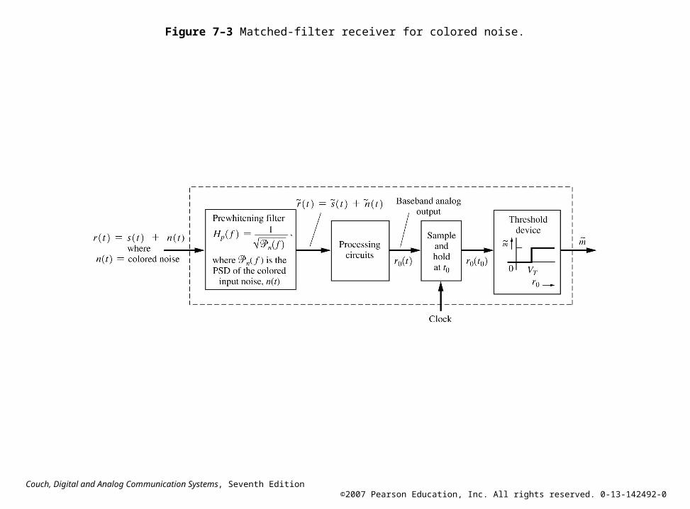
Figure 7–3 Matched-filter receiver for colored noise.

Couch, Digital and Analog Communication Systems, Seventh Edition ©2007 Pearson Education, Inc. All rights reserved. 0-13-142492-0
Figure 7–4 Receiver for baseband binary signaling.

Couch, Digital and Analog Communication Systems, Seventh Edition ©2007 Pearson Education, Inc. All rights reserved. 0-13-142492-0
Figure 7–5 Pe for matched-filter reception of several binary signalingschemes.
Couch, Digital and Analog Communication Systems, Seventh Edition ©2007 Pearson Education, Inc. All rights reserved. 0-13-142492-0
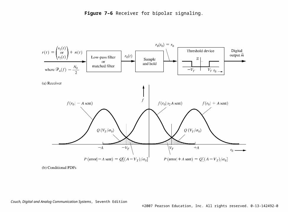
Figure 7–6 Receiver for bipolar signaling.

Couch, Digital and Analog Communication Systems, Seventh Edition ©2007 Pearson Education, Inc. All rights reserved. 0-13-142492-0
Figure 7–7 Coherent detection of OOK or BPSK signals.

Couch, Digital and Analog Communication Systems, Seventh Edition ©2007 Pearson Education, Inc. All rights reserved. 0-13-142492-0
Figure 7–8 Coherent detection of an FSK signal.

Couch, Digital and Analog Communication Systems, Seventh Edition ©2007 Pearson Education, Inc. All rights reserved. 0-13-142492-0
Figure 7–9 Noncoherent detection of OOK.

Couch, Digital and Analog Communication Systems, Seventh Edition ©2007 Pearson Education, Inc. All rights reserved. 0-13-142492-0
Figure 7–10 Conditional PDFs for noncoherent OOK reception.
Couch, Digital and Analog Communication Systems, Seventh Edition ©2007 Pearson Education, Inc. All rights reserved. 0-13-142492-0
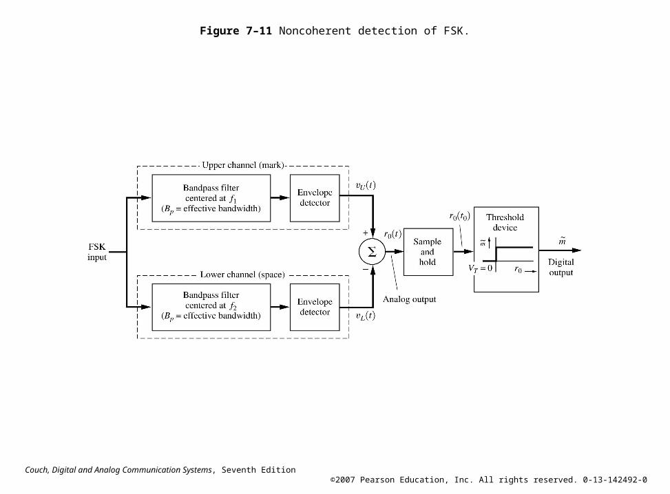
Figure 7–11 Noncoherent detection of FSK.

Couch, Digital and Analog Communication Systems, Seventh Edition ©2007 Pearson Education, Inc. All rights reserved. 0-13-142492-0
Figure 7–12 Demodulation of DPSK.
Couch, Digital and Analog Communication Systems, Seventh Edition ©2007 Pearson Education, Inc. All rights reserved. 0-13-142492-0
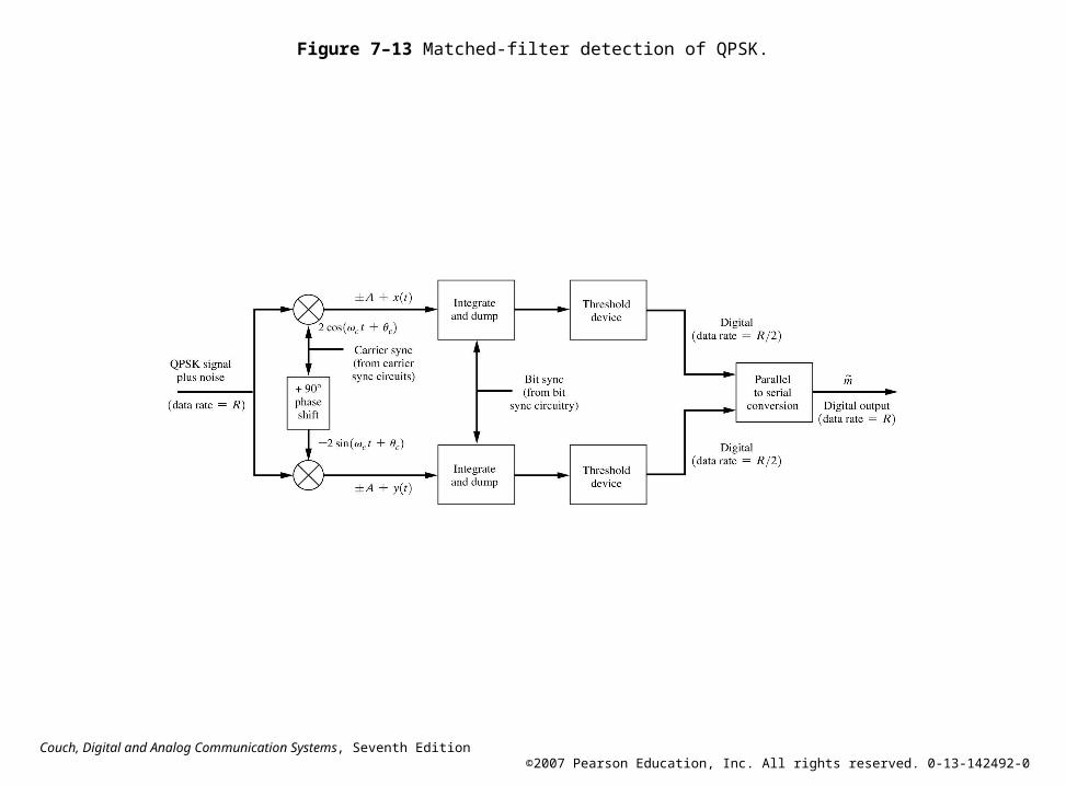
Figure 7–13 Matched-filter detection of QPSK.

Couch, Digital and Analog Communication Systems, Seventh Edition ©2007 Pearson Education, Inc. All rights reserved. 0-13-142492-0
Figure 7–14 Comparison of the probability of bit error for several digitalsignaling schemes.
Couch, Digital and Analog Communication Systems, Seventh Edition ©2007 Pearson Education, Inc. All rights reserved. 0-13-142492-0
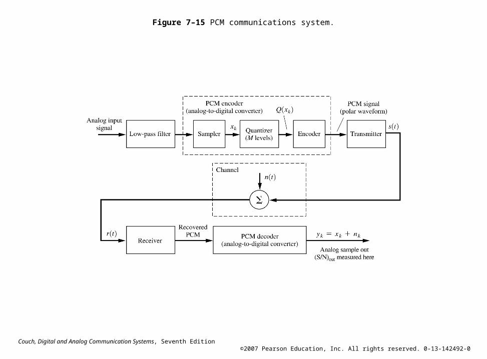
Figure 7–15 PCM communications system.

Couch, Digital and Analog Communication Systems, Seventh Edition ©2007 Pearson Education, Inc. All rights reserved. 0-13-142492-0
Figure 7–16 Uniform quantizer characteristic for M = 8(with n = 3 bits in each PCM word).
Couch, Digital and Analog Communication Systems, Seventh Edition ©2007 Pearson Education, Inc. All rights reserved. 0-13-142492-0
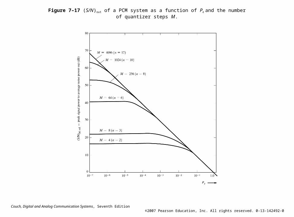
Figure 7–17 (S/N)out of a PCM system as a function of Pe and the numberof quantizer steps M.

Couch, Digital and Analog Communication Systems, Seventh Edition ©2007 Pearson Education, Inc. All rights reserved. 0-13-142492-0
Figure 7–18 Baseband system.

Couch, Digital and Analog Communication Systems, Seventh Edition ©2007 Pearson Education, Inc. All rights reserved. 0-13-142492-0
Figure 7–19 Coherent receiver.
Couch, Digital and Analog Communication Systems, Seventh Edition ©2007 Pearson Education, Inc. All rights reserved. 0-13-142492-0
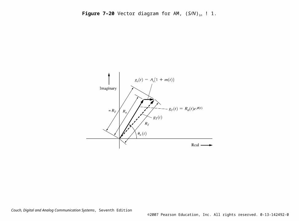
Figure 7–20 Vector diagram for AM, (S/N)in ! 1.

Couch, Digital and Analog Communication Systems, Seventh Edition ©2007 Pearson Education, Inc. All rights reserved. 0-13-142492-0
Figure 7–21 Receiver for angle-modulated signals.
Couch, Digital and Analog Communication Systems, Seventh Edition ©2007 Pearson Education, Inc. All rights reserved. 0-13-142492-0
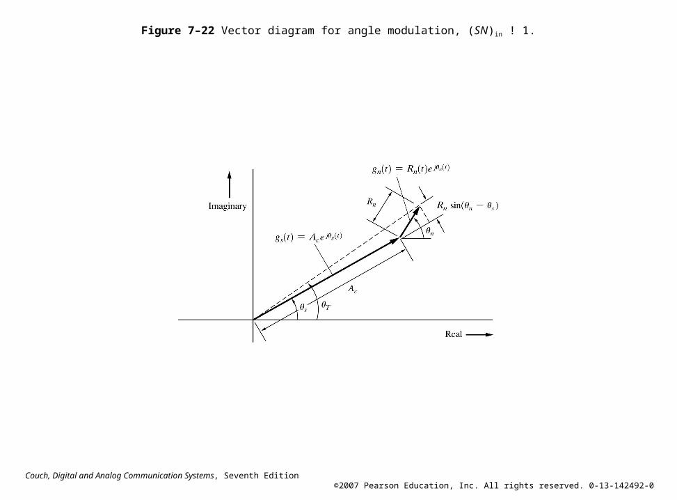
Figure 7–22 Vector diagram for angle modulation, (SN)in ! 1.

Couch, Digital and Analog Communication Systems, Seventh Edition ©2007 Pearson Education, Inc. All rights reserved. 0-13-142492-0
Figure 7–23 PSD for noise out of detectors for receivers of angle-modulatedsignals.

Couch, Digital and Analog Communication Systems, Seventh Edition ©2007 Pearson Education, Inc. All rights reserved. 0-13-142492-0
Figure 7–24 Noise performance of an FM discriminator for a sinusoidal modulatedFM signal plus Gaussian noise (no deemphasis).

Couch, Digital and Analog Communication Systems, Seventh Edition ©2007 Pearson Education, Inc. All rights reserved. 0-13-142492-0
Figure 7–25 FMFB receiver.

Couch, Digital and Analog Communication Systems, Seventh Edition ©2007 Pearson Education, Inc. All rights reserved. 0-13-142492-0
Figure 7–26 Noise performance of standard FM systems for sinusoidal modualtion.

Couch, Digital and Analog Communication Systems, Seventh Edition ©2007 Pearson Education, Inc. All rights reserved. 0-13-142492-0
Figure 7–27 Comparison of the noise performance of analog systems.

Couch, Digital and Analog Communication Systems, Seventh Edition ©2007 Pearson Education, Inc. All rights reserved. 0-13-142492-0
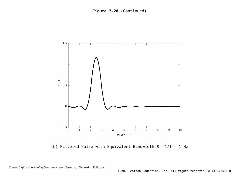
Figure 7–28 Solution for SA7–1 showing the effect of brickwall low-passfiltering.
(a) Unfiltered Pulse with Amplitude A = 1 and Pulse Width T = 1
Couch, Digital and Analog Communication Systems, Seventh Edition ©2007 Pearson Education, Inc. All rights reserved. 0-13-142492-0
Figure 7–28 (Continued)
(b) Filtered Pulse with Equivalent Bandwidth B = 1/T = 1 Hz
Couch, Digital and Analog Communication Systems, Seventh Edition ©2007 Pearson Education, Inc. All rights reserved. 0-13-142492-0
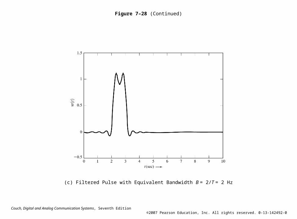
Figure 7–28 (Continued)
(c) Filtered Pulse with Equivalent Bandwidth B = 2/T = 2 Hz
Couch, Digital and Analog Communication Systems, Seventh Edition ©2007 Pearson Education, Inc. All rights reserved. 0-13-142492-0
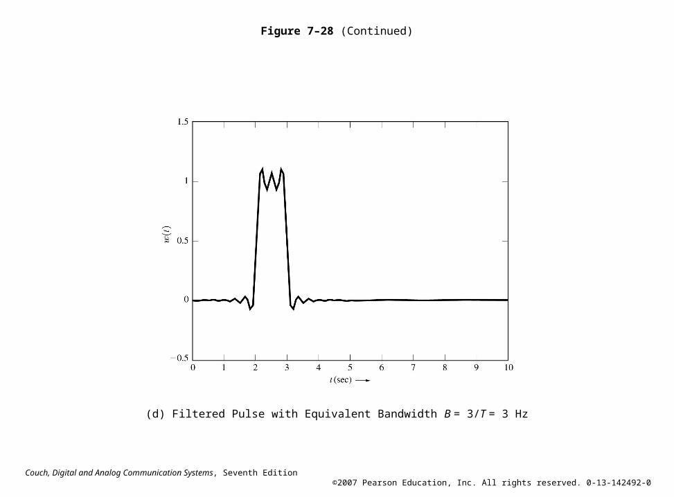
Figure 7–28 (Continued)
(d) Filtered Pulse with Equivalent Bandwidth B = 3/T = 3 Hz

Couch, Digital and Analog Communication Systems, Seventh Edition ©2007 Pearson Education, Inc. All rights reserved. 0-13-142492-0
Figure 7–29 Solution for SA7–2 showing the effect of RC low-pass filtering.
(a) Unfiltered Pulse with Amplitude A = 1 and Pulse Width T = 1

Couch, Digital and Analog Communication Systems, Seventh Edition ©2007 Pearson Education, Inc. All rights reserved. 0-13-142492-0
Figure 7–29 (Continued)
(b) Filtered Pulse with Equivalent Bandwidth B = 1/T = 1 Hz

Couch, Digital and Analog Communication Systems, Seventh Edition ©2007 Pearson Education, Inc. All rights reserved. 0-13-142492-0
Figure 7–29 (Continued)
(c) Filtered Pulse with Equivalent Bandwidth B = 2/T = 2 Hz

Couch, Digital and Analog Communication Systems, Seventh Edition ©2007 Pearson Education, Inc. All rights reserved. 0-13-142492-0
Figure 7–29 (Continued)
(d) Filtered Pulse with Equivalent Bandwidth B = 3/T = 3 Hz

Couch, Digital and Analog Communication Systems, Seventh Edition ©2007 Pearson Education, Inc. All rights reserved. 0-13-142492-0
Figure P7–4

Couch, Digital and Analog Communication Systems, Seventh Edition ©2007 Pearson Education, Inc. All rights reserved. 0-13-142492-0
Figure P7–36

Couch, Digital and Analog Communication Systems, Seventh Edition ©2007 Pearson Education, Inc. All rights reserved. 0-13-142492-0
Figure P7–38
Couch, Digital and Analog Communication Systems, Seventh Edition ©2007 Pearson Education, Inc. All rights reserved. 0-13-142492-0
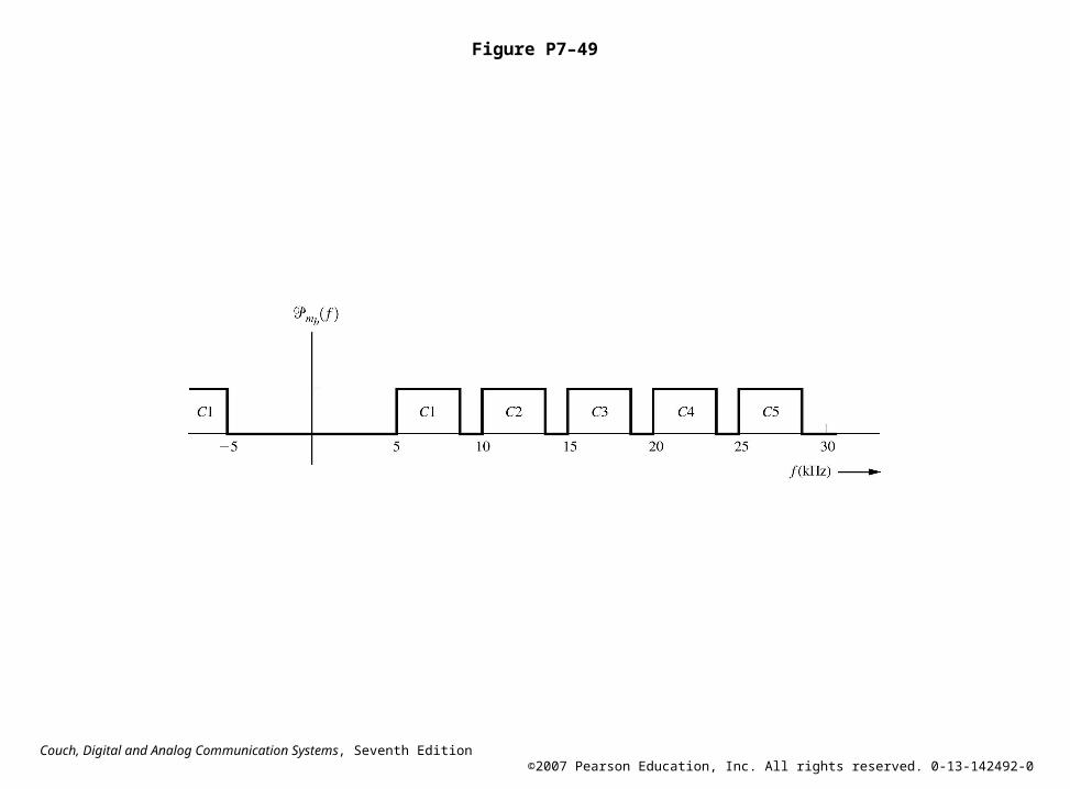
Figure P7–49
Related Documents