Cotswold Gliding Club Winch Launch System Operating Procedure

Welcome message from author
This document is posted to help you gain knowledge. Please leave a comment to let me know what you think about it! Share it to your friends and learn new things together.
Transcript
Cotswold Gliding Club
Winch Launch System
Operating Procedure
COTSWOLD GLIDING CLUB
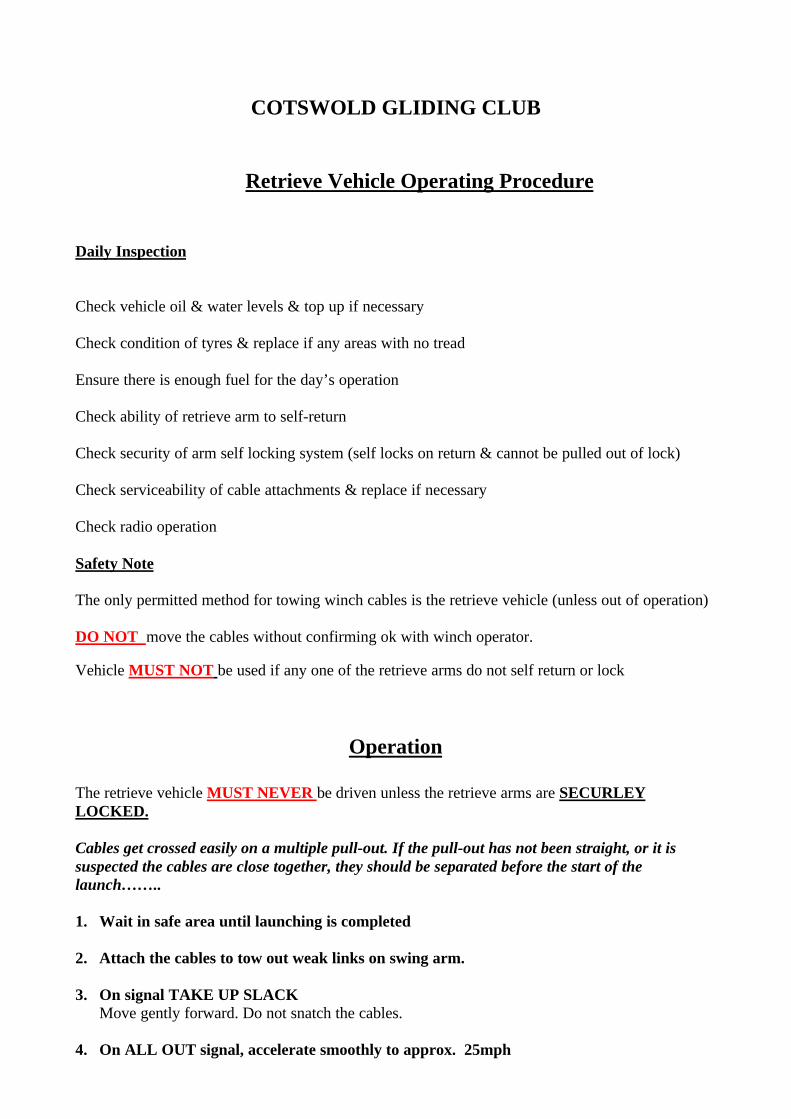
Retrieve Vehicle Operating Procedure
Daily Inspection
Check vehicle oil & water levels & top up if necessary
Check condition of tyres & replace if any areas with no tread
Ensure there is enough fuel for the day’s operation
Check ability of retrieve arm to self-return
Check security of arm self locking system (self locks on return & cannot be pulled out of lock)
Check serviceability of cable attachments & replace if necessary
Check radio operation
Safety Note
The only permitted method for towing winch cables is the retrieve vehicle (unless out of operation)
DO NOT move the cables without confirming ok with winch operator.
Vehicle MUST NOT be used if any one of the retrieve arms do not self return or lock
Operation
The retrieve vehicle MUST NEVER be driven unless the retrieve arms are SECURLEYLOCKED.
Cables get crossed easily on a multiple pull-out. If the pull-out has not been straight, or it issuspected the cables are close together, they should be separated before the start of thelaunch……..
1. Wait in safe area until launching is completed
2. Attach the cables to tow out weak links on swing arm.
3. On signal TAKE UP SLACKMove gently forward. Do not snatch the cables.
4. On ALL OUT signal, accelerate smoothly to approx. 25mph
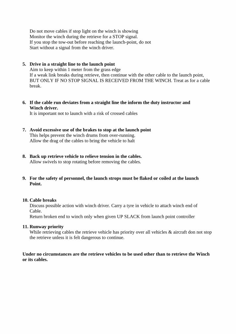
Do not move cables if stop light on the winch is showingMonitor the winch during the retrieve for a STOP signal.If you stop the tow-out before reaching the launch-point, do notStart without a signal from the winch driver.
5. Drive in a straight line to the launch pointAim to keep within 1 meter from the grass edgeIf a weak link breaks during retrieve, then continue with the other cable to the launch point,BUT ONLY IF NO STOP SIGNAL IS RECEIVED FROM THE WINCH. Treat as for a cablebreak.
6. If the cable run deviates from a straight line the inform the duty instructor andWinch driver.It is important not to launch with a risk of crossed cables
7. Avoid excessive use of the brakes to stop at the launch pointThis helps prevent the winch drums from over-running.Allow the drag of the cables to bring the vehicle to halt
8. Back up retrieve vehicle to relieve tension in the cables.Allow swivels to stop rotating before removing the cables.
9. For the safety of personnel, the launch strops must be flaked or coiled at the launchPoint.
10. Cable breaksDiscuss possible action with winch driver. Carry a tyre in vehicle to attach winch end ofCable.Return broken end to winch only when given UP SLACK from launch point controller
11. Runway priorityWhile retrieving cables the retrieve vehicle has priority over all vehicles & aircraft don not stopthe retrieve unless it is felt dangerous to continue.
Under no circumstances are the retrieve vehicles to be used other than to retrieve the Winchor its cables.

Winch Operating Procedure
The following section is taken directly from the BGA Winch operator’s guide
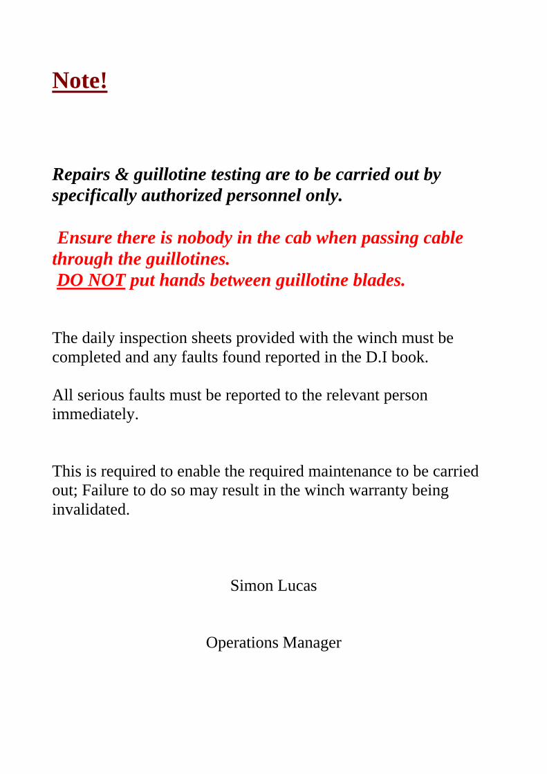
Note!
Repairs & guillotine testing are to be carried out byspecifically authorized personnel only.
Ensure there is nobody in the cab when passing cablethrough the guillotines. DO NOT put hands between guillotine blades.
The daily inspection sheets provided with the winch must becompleted and any faults found reported in the D.I book.
All serious faults must be reported to the relevant personimmediately.
This is required to enable the required maintenance to be carriedout; Failure to do so may result in the winch warranty beinginvalidated.
Simon Lucas
Operations Manager
Skylaunch Winch
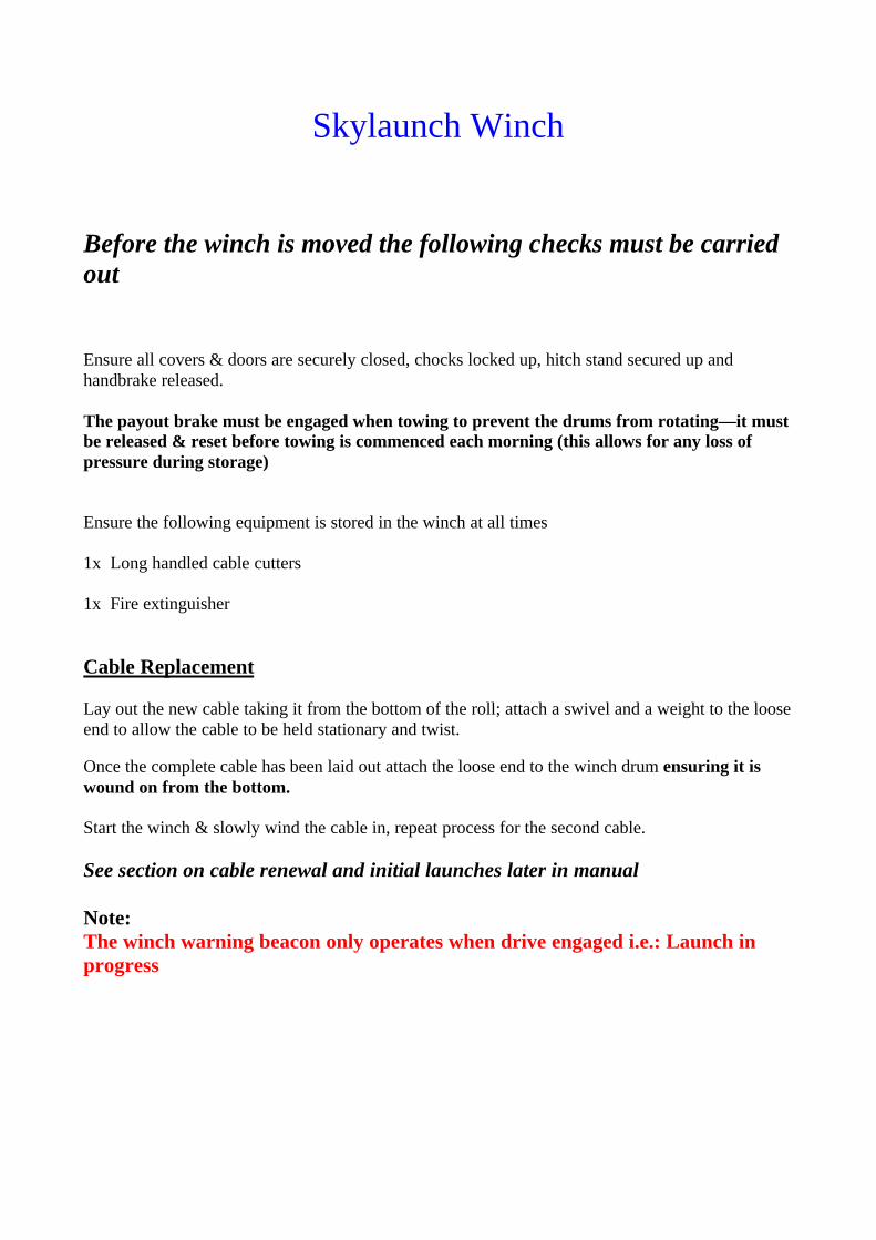
Before the winch is moved the following checks must be carriedout
Ensure all covers & doors are securely closed, chocks locked up, hitch stand secured up andhandbrake released.
The payout brake must be engaged when towing to prevent the drums from rotating—it mustbe released & reset before towing is commenced each morning (this allows for any loss ofpressure during storage)
Ensure the following equipment is stored in the winch at all times
1x Long handled cable cutters
1x Fire extinguisher
Cable Replacement
Lay out the new cable taking it from the bottom of the roll; attach a swivel and a weight to the looseend to allow the cable to be held stationary and twist.
Once the complete cable has been laid out attach the loose end to the winch drum ensuring it iswound on from the bottom.
Start the winch & slowly wind the cable in, repeat process for the second cable.
See section on cable renewal and initial launches later in manual
Note:The winch warning beacon only operates when drive engaged i.e.: Launch inprogress
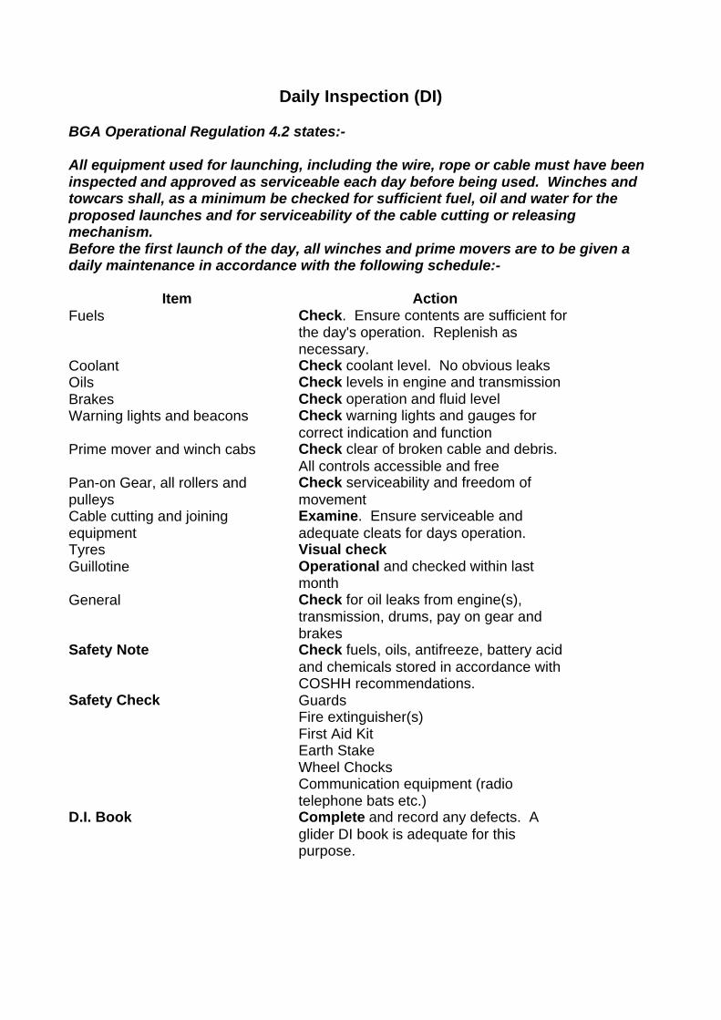
Daily Inspection (DI)
BGA Operational Regulation 4.2 states:-
All equipment used for launching, including the wire, rope or cable must have beeninspected and approved as serviceable each day before being used. Winches andtowcars shall, as a minimum be checked for sufficient fuel, oil and water for theproposed launches and for serviceability of the cable cutting or releasingmechanism.Before the first launch of the day, all winches and prime movers are to be given adaily maintenance in accordance with the following schedule:-
Item ActionFuels Check. Ensure contents are sufficient for
the day's operation. Replenish asnecessary.
Coolant Check coolant level. No obvious leaksOils Check levels in engine and transmissionBrakes Check operation and fluid levelWarning lights and beacons Check warning lights and gauges for
correct indication and functionPrime mover and winch cabs Check clear of broken cable and debris.
All controls accessible and freePan-on Gear, all rollers andpulleys
Check serviceability and freedom ofmovement
Cable cutting and joiningequipment
Examine. Ensure serviceable andadequate cleats for days operation.
Tyres Visual checkGuillotine Operational and checked within last
monthGeneral Check for oil leaks from engine(s),
transmission, drums, pay on gear andbrakes
Safety Note Check fuels, oils, antifreeze, battery acidand chemicals stored in accordance withCOSHH recommendations.
Safety Check GuardsFire extinguisher(s)First Aid KitEarth StakeWheel ChocksCommunication equipment (radiotelephone bats etc.)
D.I. Book Complete and record any defects. Aglider DI book is adequate for thispurpose.

SETTING UP THE WINCH
Safety Note:If cable runs are near to each other, such that it may be possible for cables to cross,then:-(a) Only one glider may be attached to a cable at any one time and(b) After every launch, the used cable must be draw in to the winch or cleared fromthe area before another cable is used.
1. Advise the Duty Instructor of the winch status and determine his requirementsregarding the positioning of the winch and condition of the airfield, before moving out.
2. Drive the winch slowly to site and align with the launch point3. Apply the hand brake firmly on the prime mover and select first gear.4. Securely position the wheel chocks5. Press the earth stake firmly into the ground in a position such that it will not be a
hazard.6. Connect and carry out functional communications check.7. Ensure the retrieve driver is fully aware of the pull-out and cable break procedures.8. Obtain Duty Instructor's permission to pull cables out to launch point.9. Carry out cable and parachute daily inspection. (See below)10. When cables have been pulled out:
a) Apply winch drum brakes(s)b) Ensure transmission is dis-engaged.c) Warm up winch engine to operating temperature.
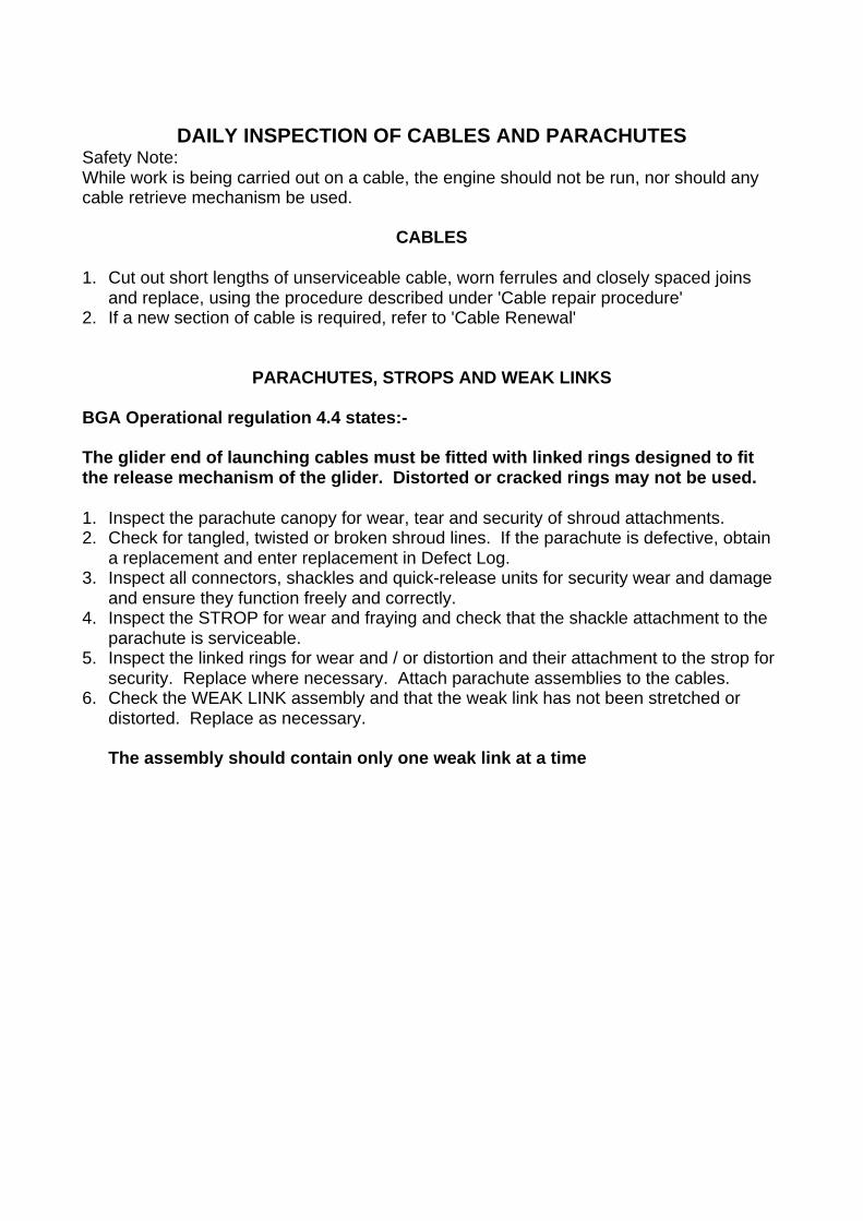
DAILY INSPECTION OF CABLES AND PARACHUTESSafety Note:While work is being carried out on a cable, the engine should not be run, nor should anycable retrieve mechanism be used.
CABLES
1. Cut out short lengths of unserviceable cable, worn ferrules and closely spaced joinsand replace, using the procedure described under 'Cable repair procedure'
2. If a new section of cable is required, refer to 'Cable Renewal'
PARACHUTES, STROPS AND WEAK LINKS
BGA Operational regulation 4.4 states:-
The glider end of launching cables must be fitted with linked rings designed to fitthe release mechanism of the glider. Distorted or cracked rings may not be used.
1. Inspect the parachute canopy for wear, tear and security of shroud attachments.2. Check for tangled, twisted or broken shroud lines. If the parachute is defective, obtain
a replacement and enter replacement in Defect Log.3. Inspect all connectors, shackles and quick-release units for security wear and damage
and ensure they function freely and correctly.4. Inspect the STROP for wear and fraying and check that the shackle attachment to the
parachute is serviceable.5. Inspect the linked rings for wear and / or distortion and their attachment to the strop for
security. Replace where necessary. Attach parachute assemblies to the cables.6. Check the WEAK LINK assembly and that the weak link has not been stretched or
distorted. Replace as necessary.
The assembly should contain only one weak link at a time
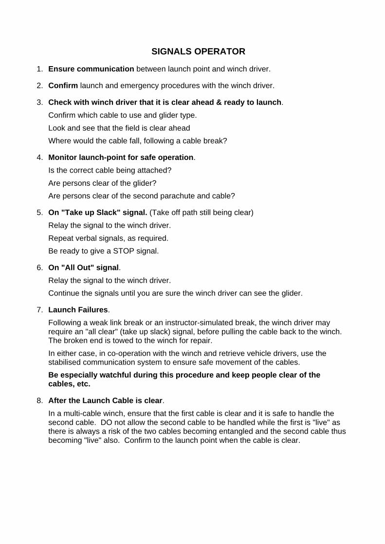
SIGNALS OPERATOR
1. Ensure communication between launch point and winch driver.
2. Confirm launch and emergency procedures with the winch driver.
3. Check with winch driver that it is clear ahead & ready to launch.
Confirm which cable to use and glider type.
Look and see that the field is clear ahead
Where would the cable fall, following a cable break?
4. Monitor launch-point for safe operation.
Is the correct cable being attached?
Are persons clear of the glider?
Are persons clear of the second parachute and cable?
5. On "Take up Slack" signal. (Take off path still being clear)
Relay the signal to the winch driver.
Repeat verbal signals, as required.
Be ready to give a STOP signal.
6. On "All Out" signal.
Relay the signal to the winch driver.
Continue the signals until you are sure the winch driver can see the glider.
7. Launch Failures.
Following a weak link break or an instructor-simulated break, the winch driver mayrequire an "all clear" (take up slack) signal, before pulling the cable back to the winch.The broken end is towed to the winch for repair.
In either case, in co-operation with the winch and retrieve vehicle drivers, use thestabilised communication system to ensure safe movement of the cables.
Be especially watchful during this procedure and keep people clear of thecables, etc.
8. After the Launch Cable is clear.
In a multi-cable winch, ensure that the first cable is clear and it is safe to handle thesecond cable. DO not allow the second cable to be handled while the first is "live" asthere is always a risk of the two cables becoming entangled and the second cable thusbecoming "live" also. Confirm to the launch point when the cable is clear.
LAUNCH PROCEDURES
Safety note:
If the is any jerk or hesitation in power at the commencement of the launch, thewinch or car driver must terminate the launch and wait for a fresh set of signalsbefore re-starting. If the pilot suspects over-running or other failure at the startof the launch, he should release the cable at once and treat as a launch failure
Introduction
The objective is to accelerate the glider smoothly and rapidly to its optimum launchairspeed whilst avoiding any snatching which over-stresses the cable or tail-bangingwhich over-stresses the glider.
Method
1. Ensure that the engine is warmed up, in accordance with the manufacturers manual.
2. Confirm with the launch controller which cable is to be used.
3. On receipt of TAKE UP SLACK -
Engage drive.
To take up slack in cable.
4. On receipt of ALL OUT -
Open the throttle smoothly and progressively to the MAXIMUM SETTING FOR THEGLIDER TYPE AND CONDITIONS.
5. Maintain the power setting until the glider is established in the climb and then adjustto suit glider type, signals from the glider and general impression of speed, rate ofclimb etc.
6. Reduce power as the glider approaches the top of the launch and close the throttlefully to ensure that the launch is terminated well before the vertical position is reached.
7. Immediately the glider is seen to release, smoothly increase power sufficiently todeploy the parachute, maintain a slight tension in the cable and prevent the cable fromtouching the ground. This ensures a clean wrap onto the drum with no loose looping.
8. Adjust the power to "fly" the parachute back to the winch, clear of the ground, theparachute may be drawn closer to the winch VERY SLOWLY.
9. Disengage drive.
10. Advise the launch controller CABLE CLEAR, if appropriate.
Note on engine handling: After winding in the cable, allow the engine to return tonormal operating temperature before switching off.
Repeat sequence for other cables.
Retrieve cables to launch-point.
EMERGENCY PROCEDURES
The winch driver is responsible for understanding how to use the emergency cablecutting equipment.
In certain circumstances an immediate reaction is essential to ensure the safety both ofpilots and glider. Emergencies can be considered under the following four categories:-
1. Launch Failures, including simulated launch failures.2. Failure of the glider to release on completion of the launch.3. Launch obstruction.4. Winch power failure.
1. Launch Failures
Provided that the cable daily inspection has been completed correctly and that there hasbeen no incident which has caused a cable fault, the majority of launch failures will be dueto failure of the weak link . This means that the parachute assembly will remain attached tothe "live" cable and will deploy when the break occurs. Some tension in the cable will bemaintained in the cable and the cable will lie straight.
A break elsewhere in the cable will mean that, due to spring back, there will be anunknown length of "dead" cable, complete with parachute that has floated downsomewhere between the launch-point and the winch. There will also be a length of "live"cable, still attached to the winch.
As subsequent actions are dependent upon where the break has occurred, it is importantthat this should be quickly identified.
If Possible, the launch point controller should advise if a simulated cable break exercise istop be carried out, especially if planned to occur below 200 feet.
Launch Failure Procedures
1. Because it is often difficult to determine whether the failure is a weak link or cablebreak, reduce power immediately to bring the cable to rest an avoid any possibleconflict between the glider and the cable / parachute assembly. On no accountshould the cable be winched in until it is safe to do so.
2. If a weak link has failed, the cable should be winched in for weak link replacement atthe winch.
3. If the cable has failed, the cable retrieve crew will retrieve the broken end and return itto the winch, for cable repair.
Note:It is strongly advised that following any cable break which involves cable looping orkinking - or if the second cable has been caught or fouled during a launch - a fullinspection should be carried out on the cable(s) in question. This may appear to be time-consuming but the delay ensures continuing cable integrity.
2. Failure of glider to release the cable
Providing that the throttle is closed to terminate the launch at the appropriate point, thecable should back-release before it is carried to the vertical position by the glider. Oncethe cable has reached or passed vertical, it may be assumed that the glider is unable torelease the cable. If this happens:-
Operate appropriate guillotineApply brakeDis-engage driveStop engineSTAY INSIDE CAB UNTIL EMERGENCY IS OVER
3. Launch Obstruction
If at any time there is reason to believe that the is an obstruction or the risk of anobstruction by people, animals or vehicles, the launch should immediately be stopped andno further cable movements made until confirmation is received from the launch controllerthat it is clear to proceed.
Safety Note
A Stationary or falling cable does little damage. A running cable is potentiallylethal.
4. Winch Power Failure
If any loss of power is experienced during a launch, the cause should be investigatedbefore another launch is attempted.
CABLE REPAIR PROCEDURES
Safety NoteShould the winch operator be required to carry out any work on the winch cablesystem with the cables laid out on the field, He must first.
1. Switch on the winch stop light2. Inform launch control to keep clear of cables.3. Confirm with retrieve driver that he is clear of the cables
The winch cables must not be moved if the winch stop light is on
To do so could result in serious injury
1. Cable repairs must be carried out at the winch, using Tallurit or Intall cleats orferrules and a hydraulic press.
2. Check that the press has been set up with the correct dies and the correct sizedferrules are stowed in the ferrule box.
Procedure
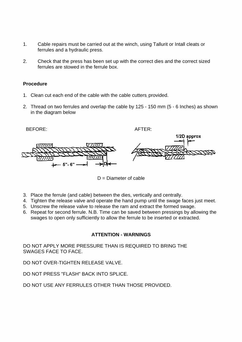
1. Clean cut each end of the cable with the cable cutters, provided.
2. Thread on two ferrules and overlap the cable by 125 - 150 mm (5 - 6 Inches) as shownin the diagram below
BEFORE: AFTER:
D = Diameter of cable
3. Place the ferrule (and cable) between the dies, vertically and centrally.4. Tighten the release valve and operate the hand pump until the swage faces just meet.5. Unscrew the release valve to release the ram and extract the formed swage.6. Repeat for second ferrule. N.B. Time can be saved between pressings by allowing the
swages to open only sufficiently to allow the ferrule to be inserted or extracted.
ATTENTION - WARNINGS
DO NOT APPLY MORE PRESSURE THAN IS REQUIRED TO BRING THESWAGES FACE TO FACE.
DO NOT OVER-TIGHTEN RELEASE VALVE.
DO NOT PRESS "FLASH" BACK INTO SPLICE.
DO NOT USE ANY FERRULES OTHER THAN THOSE PROVIDED.
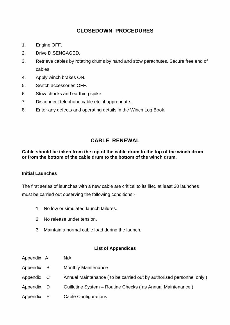
CLOSEDOWN PROCEDURES
1. Engine OFF.
2. Drive DISENGAGED.
3. Retrieve cables by rotating drums by hand and stow parachutes. Secure free end of
cables.
4. Apply winch brakes ON.
5. Switch accessories OFF.
6. Stow chocks and earthing spike.
7. Disconnect telephone cable etc. if appropriate.
8. Enter any defects and operating details in the Winch Log Book.
CABLE RENEWAL
Cable should be taken from the top of the cable drum to the top of the winch drumor from the bottom of the cable drum to the bottom of the winch drum.
Initial Launches
The first series of launches with a new cable are critical to its life;. at least 20 launches
must be carried out observing the following conditions:-
1. No low or simulated launch failures.
2. No release under tension.
3. Maintain a normal cable load during the launch.
List of Appendices
Appendix A N/A
Appendix B Monthly Maintenance
Appendix C Annual Maintenance ( to be carried out by authorised personnel only )
Appendix D Guillotine System – Routine Checks ( as Annual Maintenance )
Appendix F Cable Configurations

Appendix B
MONTHLY MAINTENANCE *
At the beginning of each calendar month1 all winches and prime movers are to be givenmonthly maintenance in accordance with the following schedule
Action ItemDaily maintenance Carry out daily inspection (See page 2)Guillotine operation Carry out monthly check (See Appendix D)Transmission Check bolts for securityBrakes Check operation. Adjust as necessary.Radiator Check cooling ducts freeBattery Check electrolyte level and replenish with
distilled water. Check battery stowagemounting and terminals.
General Clean winch thoroughly. General lubricationas necessary.
Prime mover ball joints Check all steering ball-joints for lift orexcessive free play. Rectify faults to ensuresafe vehicle handling
Prime mover wheel brake Check brake pads. Adjust and carry outfunctional checks.
* Or more frequently1 if specified by the manufacturers.

Appendix C
ANNUAL MAINTENANCE
All winches and prime movers are to be given annual maintenance, according to thefollowing schedule:-
Daily Maintenance Carry out daily inspection (DI). (See page 2)
Monthly Maintenance Carry out monthly maintenance ( appendix B)
Brakes Strip and Inspect. Adjust as required
Drum Check security of drum nuts. Tighten asnecessary.
Roller guides Clean complete unit. Check all roller guides forsmooth running. Replace all worn bearings andgrooved rollers. Lubricate.
Engine Oil and Air Systems(winch and prime mover)
Change engine oil and filter Service air filter.
Ignition system Check serviceability. Replace spark plugs orservice injectors.
Pay-on gear Check drive belt wear and tension.
Fuel system (winch and primemover)
Check the fuel filters. Clean or replace asnecessary.
Engine cooling system Check specific gravity of the antifreeze. Checkhoses, water pump and radiator ducts.
Belt drives Tension belts and renew as necessary.
Guillotine Carry out Guillotine Full Functional Check (Seeappendix D)
Structure and Bodywork Inspect body and chassis for damage,corrosion and loose paint. Restore paintsurface use primer) undercoat and finish coats.
Prime mover steering linkage Check steering linkage. Checking the amountof free play at the steering wheel will indicatethe degree of wear in the steering box andlinkage. Rectify faults to ensure safe vehiclehandling.
Appendix D
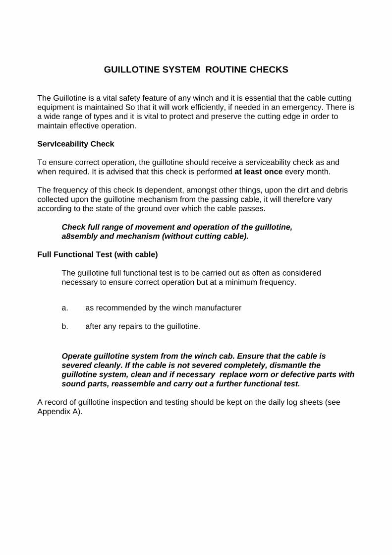
GUILLOTINE SYSTEM ROUTINE CHECKS
The Guillotine is a vital safety feature of any winch and it is essential that the cable cuttingequipment is maintained So that it will work efficiently, if needed in an emergency. There isa wide range of types and it is vital to protect and preserve the cutting edge in order tomaintain effective operation.
ServIceability Check
To ensure correct operation, the guillotine should receive a serviceability check as andwhen required. It is advised that this check is performed at least once every month.
The frequency of this check Is dependent, amongst other things, upon the dirt and debriscollected upon the guillotine mechanism from the passing cable, it will therefore varyaccording to the state of the ground over which the cable passes.
Check full range of movement and operation of the guillotine,a8sembly and mechanism (without cutting cable).
Full Functional Test (with cable)
The guillotine full functional test is to be carried out as often as considerednecessary to ensure correct operation but at a minimum frequency.
a. as recommended by the winch manufacturer
b. after any repairs to the guillotine.
Operate guillotine system from the winch cab. Ensure that the cable issevered cleanly. If the cable is not severed completely, dismantle theguillotine system, clean and if necessary replace worn or defective parts withsound parts, reassemble and carry out a further functional test.
A record of guillotine inspection and testing should be kept on the daily log sheets (seeAppendix A).

Appendix F
Cable Configuration
Notes on the correct attachment of parachutes, weak-links and towing strops.
General Principles
1. The relative position of the component parts is critical. The weak-link should alwaysbe positioned between the glider and the parachute, leaving the parachute attachedto the cable when the weak-link fails.
2. No part of the parachute assembly and strops should be capable of storing energy.Any elasticity in this assembly can result in damage to the glider.
3. The assembly should contain the minimum number of metal parts to reduce weightand potential impact damage.
4. The assembly must not be able to damage, obscure or become entangled with theglider at any time, especially following a cable-break or weak-link failure.
5. All sections should be capable of quick and easy assembly and detachment.
The Component Parts
Attachment to cable. The end of the cable is fashioned into an eye by swageing thecable round a thimble which protects the strands from wear.
A shackle-bolt passes through the thimble -eye
The shackle holds the ends of a fabric strop which gathers together the shrouds of theparachute. Fabric is employed to minimise friction and wear on the parachute shrouds.
The canopy of the parachute is attached to the week-link assembly, using another strop ofshroud material.
The weak-link assembly incorporates a link to suit the glider being launched (seeAppendix E) and this remains with the parachute assembly. (At some sites, a selection ofweak-links, suitable for launching each of the glider types in the club's fleet, may remainpermanently attached to the parachute assembly. This is convenient, but calls for extracare in ensuring that the correct link Is chosen for each launch.)
N.B. The Tost weak link system is designed for use either with a single link or withdouble links. If the double-link system is employed, it is essential that the links areof different design (the main link having round holes and the reserve link havingslotted holes). Using two weak links, each of the same design doubles the breakingload and renders the whole assembly Ineffective. Because of the risk of assemblingtwo weak links incorrectly, the single-link assembly is recommended as the morefoolproof system.

A quick-release coupling attaches the launch strop to the weak-link assembly.
The launch strop is constructed either of steel cable, shrouded in plastic hose or of heavyhemp rope. It is essential that the strop does not store energy or it may catapult back tothe glider, following a launch failure. The length of the strop must be such that it cannotfoul any of the control surfaces of the glider, following a failure of the cable or the weak-link.
The cable assembly is attached to the glider's release mechanism by means of a circularsteel link which is attached to the launch strop via a larger steel link. Any wear ordistortion of either the link or of the release mechanism renders the cable-releaseunserviceable. It is also desirable that the release mechanism and the attachment linksshould be of the same make.
The use of Ottfur cable rings Is no Ionger recommended due to the risk ofpermanent distortion or failure when employed at loads in excess of 1650 lbs.
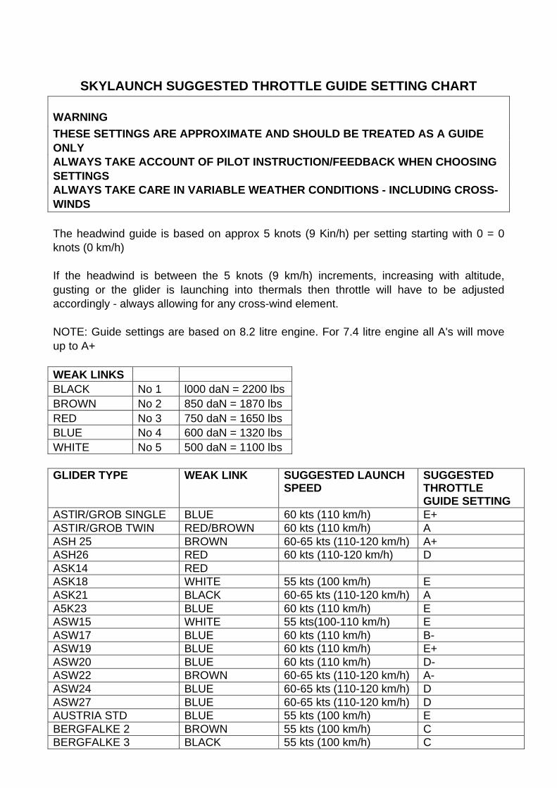
SKYLAUNCH SUGGESTED THROTTLE GUIDE SETTING CHART
WARNINGTHESE SETTINGS ARE APPROXIMATE AND SHOULD BE TREATED AS A GUIDEONLYALWAYS TAKE ACCOUNT OF PILOT INSTRUCTION/FEEDBACK WHEN CHOOSINGSETTINGSALWAYS TAKE CARE IN VARIABLE WEATHER CONDITIONS - INCLUDING CROSS-WINDS
The headwind guide is based on approx 5 knots (9 Kin/h) per setting starting with 0 = 0knots (0 km/h)
If the headwind is between the 5 knots (9 km/h) increments, increasing with altitude,gusting or the glider is launching into thermals then throttle will have to be adjustedaccordingly - always allowing for any cross-wind element.
NOTE: Guide settings are based on 8.2 litre engine. For 7.4 litre engine all A's will moveup to A+
WEAK LINKSBLACK No 1 l000 daN = 2200 lbsBROWN No 2 850 daN = 1870 lbsRED No 3 750 daN = 1650 lbsBLUE No 4 600 daN = 1320 lbsWHITE No 5 500 daN = 1100 lbs
GLIDER TYPE WEAK LINK SUGGESTED LAUNCHSPEED
SUGGESTEDTHROTTLEGUIDE SETTING
ASTlR/GROB SINGLE BLUE 60 kts (110 km/h) E+ASTIR/GROB TWIN RED/BROWN 60 kts (110 km/h) AASH 25 BROWN 60-65 kts (110-120 km/h) A+ASH26 RED 60 kts (110-120 km/h) DASK14 REDASK18 WHITE 55 kts (100 km/h) EASK21 BLACK 60-65 kts (110-120 km/h) AA5K23 BLUE 60 kts (110 km/h) EASW15 WHITE 55 kts(100-110 km/h) EASW17 BLUE 60 kts (110 km/h) B-ASW19 BLUE 60 kts (110 km/h) E+ASW20 BLUE 60 kts (110 km/h) D-ASW22 BROWN 60-65 kts (110-120 km/h) A-ASW24 BLUE 60-65 kts (110-120 km/h) DASW27 BLUE 60-65 kts (110-120 km/h) DAUSTRIA STD BLUE 55 kts (100 km/h) EBERGFALKE 2 BROWN 55 kts (100 km/h) CBERGFALKE 3 BLACK 55 kts (100 km/h) C
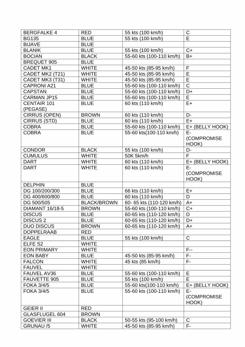
BERGFALKE 4 RED 55 kts (100 km/h) CBG135 BLUE 55 kts (100 km/h) EBIJAVE BLUEBLANIK BLUE 55 kts (100 km/h) C+BOCIAN BLACK 55-60 kts (100-110 km/h) B+BREQUET 905 BLUECADET MK1 WHITE 45-50 kts (85-95 km/h) FCADET MK2 (T21) WHITE 45-50 kts (85-95 km/h) ECADET MK3 (T31) WHITE 45-50 kts (85-95 km/h) ECAPRONI A21 BLUE 55-60 kts (100-110 km/h) CCAPSTAN BLUE 55-60 kts (100-110 km/h) D+CARMAN JP15 BLUE 55-60 kts (100-110 km/h) ECENTAIR 101(PEGASE)
BLUE 60 kts (110 km/h) E+
CIRRUS (OPEN) BROWN 60 kts (110 km/h) D-CIRRUS (STD) BLUE 60 kts (110 km/h) E+COBRA BLUE 55-60 kts (100-110 km/h) E+ (BELLY HOOK)COBRA BLUE 55-60 kts(100-110 km/h) E-
(COMPROMISEHOOK)
CONDOR BLACK 55 kts (100 km/h) D-CUMULUS WHITE 50K 5km/h FDART WHITE 60 kts (110 km/h) E+ (BELLY HOOK)DART WHITE 60 kts (110 km/h) E-
(COMPROMISEHOOK)
DELPHIN BLUEDG 100/200/300 BLUE 66 kts (110 km/h) E+DG 400/600/800 BLUE 60 kts (110 km/h) DDG 500/505 BLACK/BROWN 60- 65 kts (110-120 km/h) A+DIAMANT 16/18-5 BROWN 55-60 kts (100-110 km/h) C+DISCUS BLUE 60-65 kts (110-120 km/h) DDISCUS 2 BLUE 60-65 kts (110-120 km/h) D+DUO DISCUS BROWN 60-65 kts (110-120 km/h) A+DOPPELRAAB REDEAGLE BLUE 55 kts (100 km/h) CELFE S2 WHITEEON PRIMARY WHITE F--EON BABY BLUE 45-50 kts (85-95 km/h) F-FALCON WHITE 45 kts (85 km/h) F-FAUVEL WHITEFAUVEL AV36 BLUE 55-60 kts (100-110 km/h) EFAUVETTE 905 BLUE 55 kts (100 km/h) EFOKA 3/4/5 BLUE 55-60 kts(100-110 km/h) E+ (BELLY HOOK)FOKA 3/4/5 BLUE 55-60 kts (100-110 km/h) E-
(COMPROMISEHOOK)
GEIER II REDGLASFLUGEL 604 BROWNGOEVIER III BLACK 50-55 kts (95-100 km/h) CGRUNAU /5 WHITE 45-50 kts (85-95 km/h) F-

GULL 1/3/5 WHITE 45 kts (85 km/h) F-HARBINGER WHITEHORNET WHITE 60 kts (110 km/h) E+
WEAK LINK CANEASILY BREAK
HUTTER17 WHITEIRIS (D77) WHITEIS28 B2 BLUEIS29 BLUEIS30 BLUEIS32 BLUEJANTAR (STD) BLUE 60 kts (110 km/h) DJANTAR BLUE 60 kts (110 km/h) DJANUS B BLUE 60 kts (110 km/h) A
WEAK LINK CANEASILY BREAK
JANUS C RED 60 kts (110 km/h) AWEAK LINK CANEASILY BREAK
JASKOLKA WHITEJAVELOT WHITEJUNIOR BLUE 60 kts (110 km/h) EJP36A WHITEKA1/3 WHITEKA2 BLUEKA4 BROWNKA6 BLUE 50 kts (95 km/h) F+KA7 BLACK 55 kts (100 km/h) DKA8 BLUE 50-55 kts (95-100 km/h) FKA13 BLACK 55 kts (100 km/h) CKESTREL 17/19 BLUE 60 kts (110 km/h) DKITE 1/2B WHITEKRANICH 11/111 BROWNKRANJANEK WHITELAK12 BLUELIBELLE BLUE 55-60 kts (100-110 km/h) ELO-100 BLUELS1 WHITE 55-60 kts (100-110 km/h) E
WEAK LINK CANEASILY BREAK
LS3 BLUE 60 kts (110 km/h) E+LS 4/6/7 BLUE 60 kts (110 km/h) D-LS8 RED 60-65 kts (110-120 km/h) DM100 BLUE 55 kts (100 km/h) EM200 BLUEME7 WHITE 55 kts (100 km/h) FMEISE BLUEMISTRAL WHITE 60 kts (110 km/h) E+
WEAK LINK CANEASILY BREAK
MOSQUITO BLUE 60 kts (110 km/h) E+

MOSWEY BLUEMINIMOA WHITEMUCHA STD REDMU13 WHITENIMBUS 2 BLUE 60 kts (110 km/h) C+NIMBUS 3 RED 60-65 kts (110-120 km/h) ANIMBUS 3D (2 SEAT) BLACK 60-65 kts (110-120 km/h) A+NIMBUS 4 BIACK 60-65 kts (110-120 km/h) ANIMBUS 4D (2 SEAT) BROWN/BLACK 60-65 kts (110-120 km/h) A+NIMBUS MINI BLUE 60 kts (110 km/h)OLYMPIA 1 WHITEOLYMPIA 2 (B) WHITE 50 kts (95 km/h) F-OLYMPIA 460/463 WHITE 50-55 kts (95-100 km/h) F+
WEAK LINK CANEASILY BREAK
OLYMPIA 419 BLUE 50 kts (95 km/h)PEAK100 BLUEPETREL WHITEPHOEBUS BLACKPIK16 BLUEPIK20 BLUE 60 kts (110 km/h) DPIK20E BLUE 60 kts (110 km/h) DPILATUS B4 WHITE 55-60 kts (100-110 km/h) E+
WEAK LINK CANEASILY BREAK
PIRAT BLUE 55 kts (100 km/h)PREFECT WHITEPUCHACZ RED 55 kts (100 km/h) B
WEAK LINK CANEASILY BREAK
PW5 BLUE 55-60 kts (100-110 km/h) ERHEINLAND WHITERHONLANDER 2 WHITERHONLERCHE 2 BROWNRHONSPERBER WHITESAGITTA BLUESB5 BLUESF26 BLUE 55 kts (100 km/h) F+SF27 RED 55 kts (100 km/h) F+SF34 BLUESG38 WHITESHK BLUE 55 kts (100 km/h) ESIE 3 BLUE 55 kts (100 km/h) F+SILENE BLUE 55-60 kts (100-110 km/h) C+
WEAK LINK CANEASILY BREAK
SKY WHITE 50 kts (95 km/h) F+WEAK LINK CANEASILY BREAK
SkYLARKS BLUE 55-60 kts (100-110 km/h) ESPATZ WHITE

SPERBER BLACKSTEINADLER MG 19 A BROWN 50-55 kts (95-100 km/h) D-
(COMPROMISEHOOK)
SUID III WHITESWALLOW WHITE 50 kts (95 km/h) F
WEAK LINK CANEASILY BREAK
SWIFT WHITETS3/YS53 RED 55 kts (100 km/h) B-
WEAK LINK CANEASILY BREAK
T21 WHITE 45-50 kts (85-95 km/h) EWEAK LINK CANEASILY BREAK
T31 WHITE 45-50 kts (85-95 km/h) EWEAK UNK CANEASILY BREAK
TORVA WHITETUTOR WHITE 45-50 kts (85-95 km/h) FVEGA BLUE 60 kts (110 km/h) D-VENTUS/VENTUS 2 BLUE 60-65 kts (110-120 km/h) C-VIKING (VGC) WHITEWASSAMER WHITEWEIHE BLUEZUGVOGLEL BLUE
NOTE: Any glider listings not filled in have yet to be assessed by Skylaunch to completethe data.
Please note that Skylaunch endeavour to make settings as similar as possible betweenmachines, but this cannot be guaranteed. In consequence this table should be treated ASA GUIDE ONLY, and you should adjust it in the light of your own experience with yourmachine.
E&OE
Related Documents