II III 111111 111111111111111111111111 11111111111111111111111111111 3 1176 00161 4966 /7t..? NASA-CR-165176 19810003445 NASA CR-165176 AIRESEARCH 21-3663 COST/BENEFIT ANALYSIS (PART 2) OF ADVANCED MATERIAL TECHNOLOGY CANDIDATES FOR THE 1980'S by R. E. DENNIS H. F. MAERTINS AIRESEARCH MANUFACTURING COMPANY OF ARIZONA A DIVISION OF THE GARRETT CORPORATION AUGUST 1980 Prepared for National Aeronautics and Space Administration NASA-Lewis Research 1JV Contract NAS3-20073 DEC s ,joQ . 1111111111111 1111 1111111111111111111111111111 1\TQf"\ ") " -. ..... https://ntrs.nasa.gov/search.jsp?R=19810003445 2018-07-15T21:50:26+00:00Z

Welcome message from author
This document is posted to help you gain knowledge. Please leave a comment to let me know what you think about it! Share it to your friends and learn new things together.
Transcript
II III 111111 111111111111111111111111 11111111111111111111111111111
3 1176 00161 4966
_-----!.-N.~ASA Cl?-/~~~ /7t..?
NASA-CR-165176 19810003445
l-----~ NASA CR-165176 AIRESEARCH 21-3663
COST/BENEFIT ANALYSIS (PART 2)
OF ADVANCED MATERIAL TECHNOLOGY CANDIDATES
FOR THE 1980'S
by
R. E. DENNIS H. F. MAERTINS
AIRESEARCH MANUFACTURING COMPANY OF ARIZONA A DIVISION OF THE GARRETT CORPORATION
AUGUST 1980
Prepared for
National Aeronautics and Space Administration
NASA-Lewis Research cente\'~I~" 1JV rn~Y
Contract NAS3-20073 DEC s ,joQ .
1111111111111 1111 1111111111111111111111111111 1\TQf"\ ") " -. .....
https://ntrs.nasa.gov/search.jsp?R=19810003445 2018-07-15T21:50:26+00:00Z

AIRESEARCH MANUFACTURING COMPANY OF ARIZONA A DIVISION OF" THE GARRETT CORPORATION
111 SOUTH 34TH STREET • POBOX 5217 • PHOENIX ARIZONA 85010
To
TELEPHONE 1602] 267'"3011
December 21 1980
In reply refer to: PCFAU-0556-1202
: NASA-Lewis Research Center 21000 Brookpark Road Cleveland, Ohio 44135
Attention: Ms. S. Boyer Mail Stop 501-11
Subject Contract No. NAS3-20073
Reference: NASA Letter (B. Robinson) dated 21 October 1980
Enclosure: Cost/Benefit Analysis (Part 2) of Advanced Material Technology Candidates for the 1980's AiResearch Document No. 21-3663 NASA CR-165176 (One Copy)
The above enclosure is submitted pursuant to Section C -F~nal Reports of the "Reports of Work" clause of the subject contract.
Publication and d~stribution is in accordance with the above referenced letter. Should there be any questions concerning the above, please contact the writer.
AIRESEARCH MANUFACTURING COMPANY OF ARIZONA
FAU:mt Enclosure as stated
cc: Mr. So Grisaffe/M/S 105-1 Mr. T. DeWitt/Garrett/Dayton
Manager Propulsio
Corporation
SYSTEMS ANO COMPONENTS F"OR AIRCRAF"T MISSILE SPACECRAF"T ELECTRONIC NUCLEAR AND INDUSTRIAL APPLICATIONS

1 Report No 2 Government Accession No 3 RecIpient's Catalog No
CR-165176 4 Title and Subtitle 5 Report Date
Cost/Benef~t Analys~s (Part 2) of Advanced Material August 1980 Technology Candldates for the 1980's 6 Performmg Organization Code
7 Author(s) 8 Performmg Organization Report No R. E. Denn~s H. F. Maertins AiResearch 21-3663
11 10 Work Unit No 9 Performmg Organization Name and Address
AiResearch Manufactur~ng Company of Ar~zona 11 Contract or Grant No A D~vis~on of The Garrett Corporation
Phoenix, Arizona 85010 NAS3-20073 13 Type of Report and Period Covered
12 Sponsoring Agency Name and Address ProJect a Completlon National Aeronaut~cs and Space Adm~n~stratlon Report (Part 2) Washington, D.C. 20546 14 Sponsoring Agency Code
15 Supplementary Notes
ProJect Manager: S. Grlsaffe, Mater~als and Structures Div~s~on, NASA-Lew~s Research Center, Cleveland, ahlO
16 Abstract
The cost/benefit analys~s ~s an effort to evaluate nlne new advanced mater~al tech-nolog~es proJects cons~dered for general av~ation and turboprop commuter a~rcr:afts through estlmated l~fe-cycle costs, d~rect-operat~ng costs, development costs, r~sks, and relat~ve values. ThHl analysis ~ncluded the follow~ng actlvlt~es:
0 Selection of the cand~date technolog~es for future MATE Program proJects
0 Development of the property goals for the candidate technologies
0 Determ~nat~on of the lmpact of engine we~ght and fuel consumptlon on air-frame we~ght and cost
0 Development of the eng ~ne and airframe life-cycle and direct-operat~ng cost models
0 Calculation of the potential benefits (life-cycle and d~rect-operting cost lmprovements) to a selected engine and a~rframe based on changes ln the engine performance resulting from the proposed incorporatlon of each cand!-date technology
0 Est~mat~on of the development cost and r~sk for each cand~date technology
0 Ranking of each candidate technology bas~d on the relative benef~ts to the a~rcraft, as well as the assoc~ated investments and rlsks ~nvolved.
17 Key Words (Suggested by Author(s)) 18 Distribution Statement
Cost-Analysis Advanced-Materlal R&D
19 SecUrity Classlf (of thiS report) 20 Security Classlf (of thiS page) 21 No of Pages 22 Price·
Unclass~fied Unclassified 110
• For sale by the National Technical Information SerVice, Springfield. Virginia 22161
NASA-C-168 (Rev 10-75) N~\-\\~S3-#-
This Page Intentionally Left Blank

,.,
FOREWORD
This Cost/Benefit Analysis (Part 2) was prepared for the National Aeronautics and Space Administration, Lewis Research Center. It presents the results of a cost/benefit study conducted to evaluate costs, benefits, and risks for nine candidate material
technologies for general aviation aircraft plus small commuter aircraft. These technologies were compared through calculated life
cycle cost, direct-operating cost, and Relative Value. The study was conducted as part of the Materials for Advanced Turbine Engines
(MATE) Program under Contract NAS3-20073.
The authors wish to acknowledge the assistance and guidance of
C. Blankenship, S. Grisaffe, and R. L. Dreshfield of NASA-Lewis
Research Center.
iii

This Page Intentionally Left Blank
,.
"I
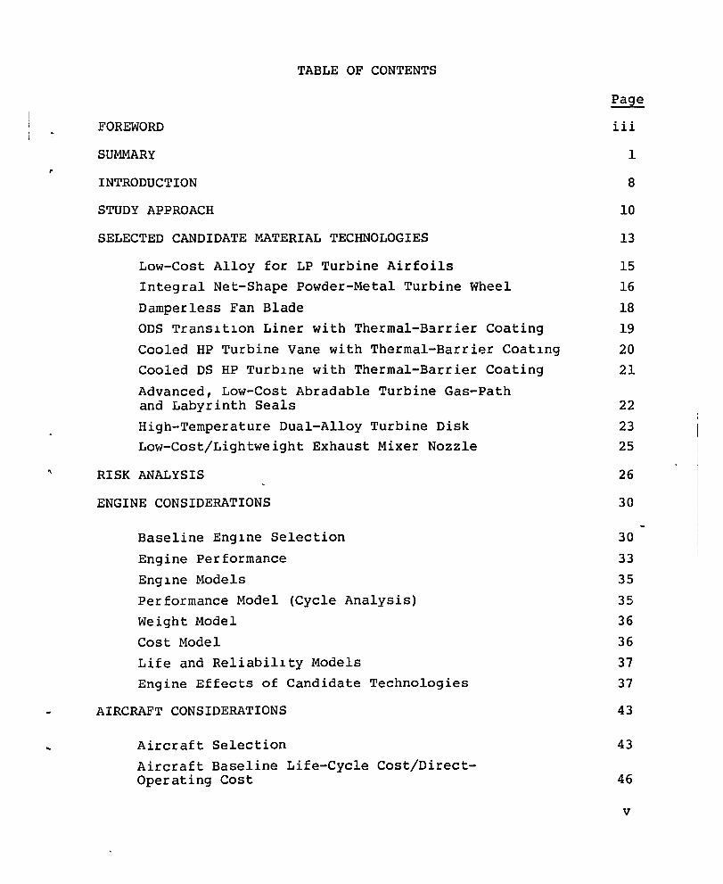
TABLE OF CONTENTS
FOREWORD iii
SUMMARY 1
INTRODUCTION 8
STUDY APPROACH 10
SELECTED CANDIDATE MATERIAL TECHNOLOGIES 13
Low-Cost Alloy for LP Turbine Airfoils 15
Integral Net-Shape Powder-Metal Turbine Wheel 16
Damperless Fan Blade 18
ODS Transition Liner with Thermal-B3rrier Coating 19
Cooled HP Turbine Vane with Thermal-Barrier Coating 20
Cooled DS HP Turbine with Thermal-Barrier Coating 21
Advanced, Low-Cost Abradable Turbine Gas-Path and Labyrinth Seals 22
High-Temperature Dual-Alloy Turbine Disk 23
Low-Cost/Lightweight Exhaust Mixer Nozzle 25
RISK ANALYSIS
ENGINE CONSIDERATIONS
Baseline Engine Selection
Engine Performance
Engine Models
Performance Model (Cycle Analysis)
Weight Model
Cost Model
Life and Reliability Models
Engine Effects of Candidate Technologies
AIRCRAFT CONSIDERATIONS
Aircraft Selection
Aircraft Baseline Life-Cycle Cost/DirectOperating Cost
26
30
30
33
35
35
36
36
37
37
43
43
46
v
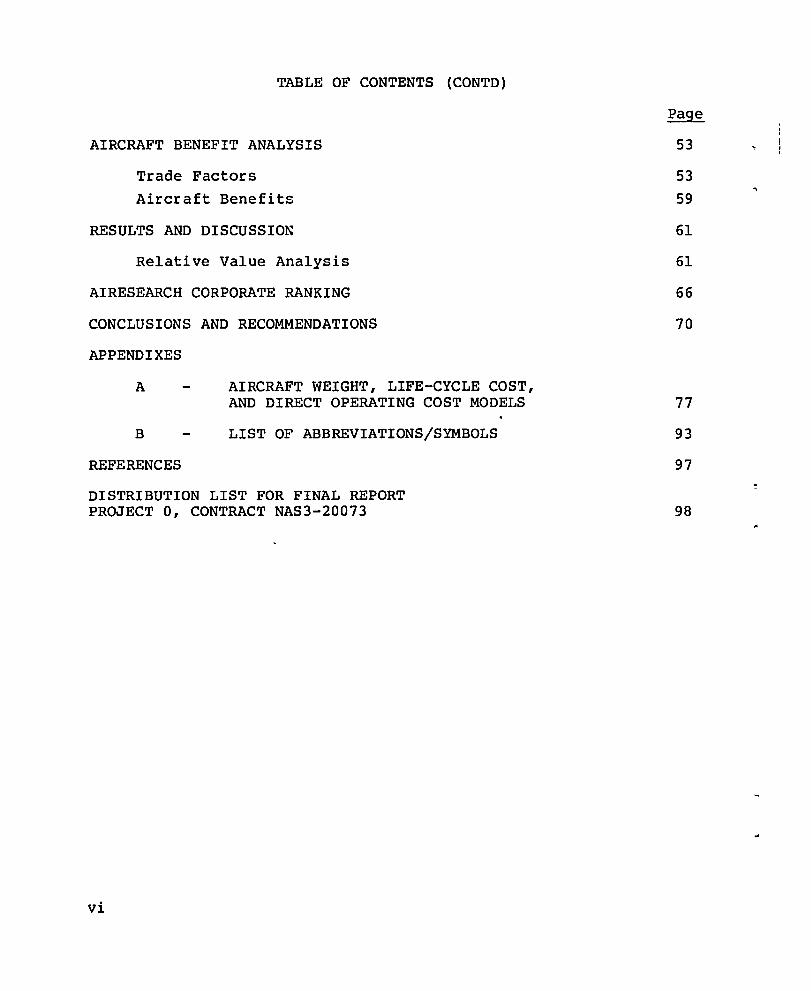
TABLE OF CONTENTS (CONTD)
AIRCRAFT BENEFIT ANALYSIS
Trade Factors Aircraft Benefits
RESULTS AND DISCUSSION
Relative Value Analysis
AIRESEARCH CORPORATE RANKING
CONCLUSIONS AND RECOMMENDATIONS
APPENDIXES
A
B
REFERENCES
AIRCRAFT WEIGHT, LIFE-CYCLE COST, AND DIRECT OPERATING COST MODELS
LIST OF ABBREVIATIONS/SYMBOLS
DISTRIBUTION LIST FOR FINAL REPORT PROJECT 0, CONTRACT NAS3-20073
vi
53
53
59
61
61
66
70
77
93
97
98

LIST OF ILLUSTRATIONS
Figure Title
1 Life-Cycle Cost Technologies
2 Turbofan Aircraft Relative Value anG ~LCC Ranking of the Material Technologies
3 Turboprop Business Aircraft Relative Value and ~LCC Ranking of the Material Technologies
4 Turboprop Commuter Aircraft Relative Value ~DOC Ranking of the Nine Material Technologies
5 Flow Chart of the Study Approach
6 Baseline MATE Turbofan Engine
7 Basellne MATE Turboprop Engine
8 Gates Lear]et 35/36
9 Turboprop Business Aircraft and Turboprop Commuter Aircraft
10 Sensltivlty Analysis for the Determination of the Effects of Fuel Prices on SFC and Engine Weight Sensltivity Coefflcients
Page
2
4
5
6
11
31
32
44
45
58
vii
Table
I.
II.
III.
IV.
V.
VI.
VII.
VIII.
IX.
X.
XI.
XII.
XIII.
XIV.
XV.
viil
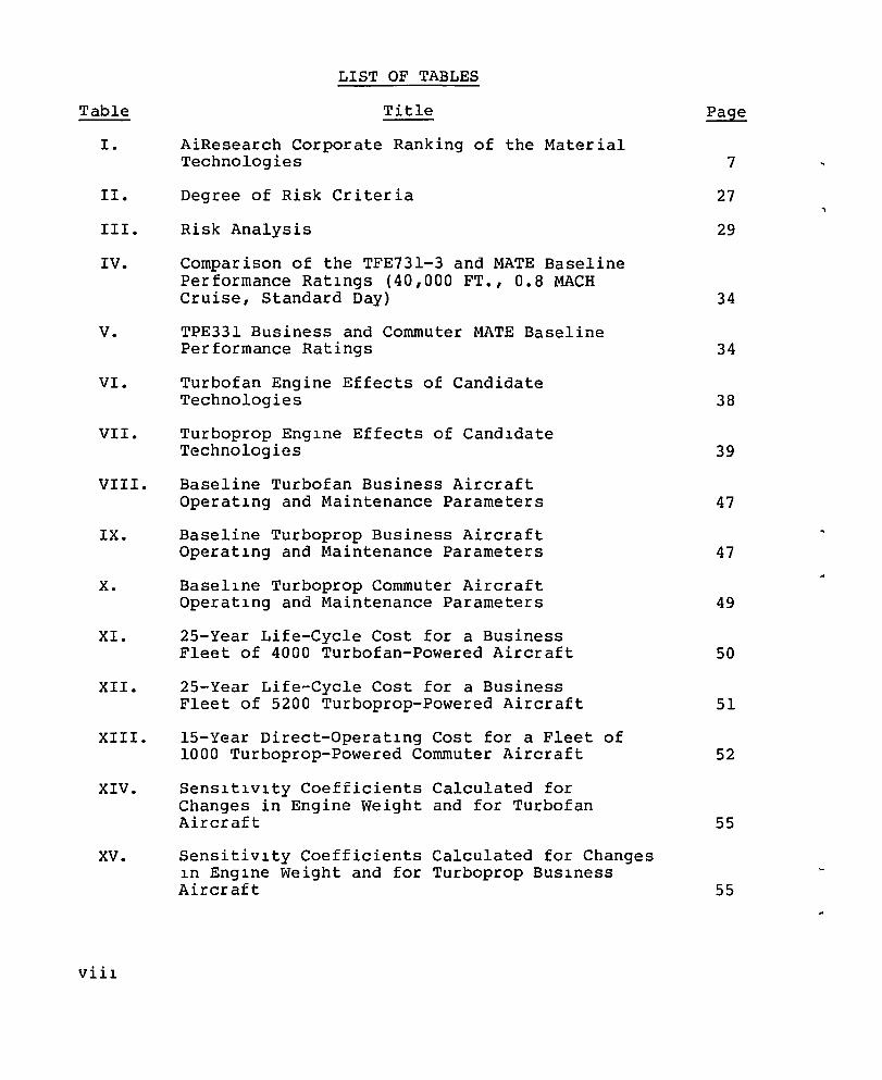
LIST OF TABLES
Title
AiResearch Corporate Ranking of the Material Technologies
Degree of Risk Criteria
Risk Analysis
Comparison of the TFE731-3 and MATE Baseline Performance Ratlngs (40,000 FT., 0.8 MACH Cruise, Standard Day)
TPE331 Business and Commuter MATE Baseline Performance Ratings
Turbofan Engine Effects of Candidate Technologies
Turboprop Englne Effects of Candldate Technologies
Baseline Turbofan Business Aircraft Operatlng and Maintenance Parameters
Baseline Turboprop Business Aircraft Operatlng and Maintenance Parameters
Basellne Turboprop Commuter Aircraft Operatlng and Maintenance Parameters
25-Year Life-Cycle Cost for a Business Fleet of 4000 Turbofan-Powered Aircraft
25-Year Life-Cycle Cost for a Business Fleet of 5200 Turboprop-Powered Aircraft
IS-Year Direct-Operatlng Cost for a Fleet of 1000 Turboprop-Powered Commuter Aircraft
Senslt~v~ty Coefficients Calculated for Changes in Engine weight and for Turbofan Aircraft
Sensitivlty Coefficients Calculated for Changes ~n Englne Weight and for Turboprop BUSlness Aircraft
7
27
29
34
34
38
39
47
47
49
50
51
52
55
55
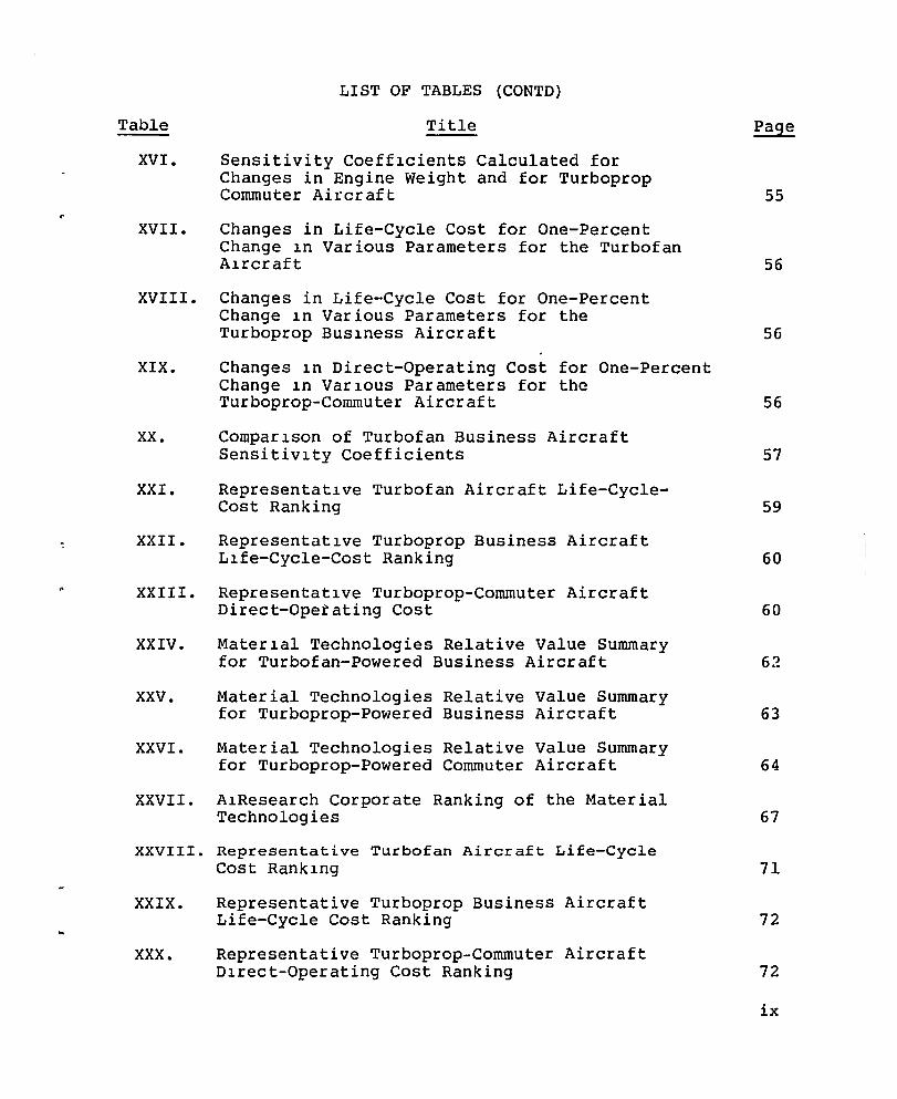
LIST OF TABLES (CONTD)
Table Title
XVI. Sensitivity Coefflcients Calculated for Changes in Engine Weight and for Turboprop Commuter Ai~craft
XVII. Changes in Life-Cycle Cost for One-Percent Change ln Various Parameters for the Turbofan Alrcraft
XVIII. Changes in Life-Cycle Cost for One-Percent Change ln Various Parameters for the Turboprop BUSlness Aircraft
XIX. Changes ln Direct-Operating Cost for One-Percent Change ln VarlOUS Parameters for the Turboprop-Commuter Aircraft
XX. Comparlson of Turbofan Business Aircraft Sensitivlty Coefficients
XXI. Representatlve Turbofan Aircraft Life-CycleCost Ranking
XXII. Representatlve Turboprop Business Aircraft Llfe-Cycle-Cost Ranking
XXIII. Representatlve Turboprop-Commuter Aircraft Direct-Operating Cost
XXIV. Materlal Technologies Relative Value Summary for Turbofan-Powered Business Aircraft
XXV. Material Technologies Relative Value Summary for Turboprop-Powered Business Airc~aft
XXVI. Material Technologies Relative Value Summary for Turboprop-Powered Commuter Aircraft
XXVII. A1Research Corporate Ranking of the Material Technologies
XXVIII. Representative Turbofan Aircraft Life-Cycle Cost Ranklng
XXIX.
XXX.
Representative Turboprop Business Aircraft Life-Cycle Cost Ranking
Representative Turboprop-Commuter Aircraft Dlrect-Operating Cost Ranking
55
56
56
56
57
59
60
60
62
63
64
67
71
72
72
ix
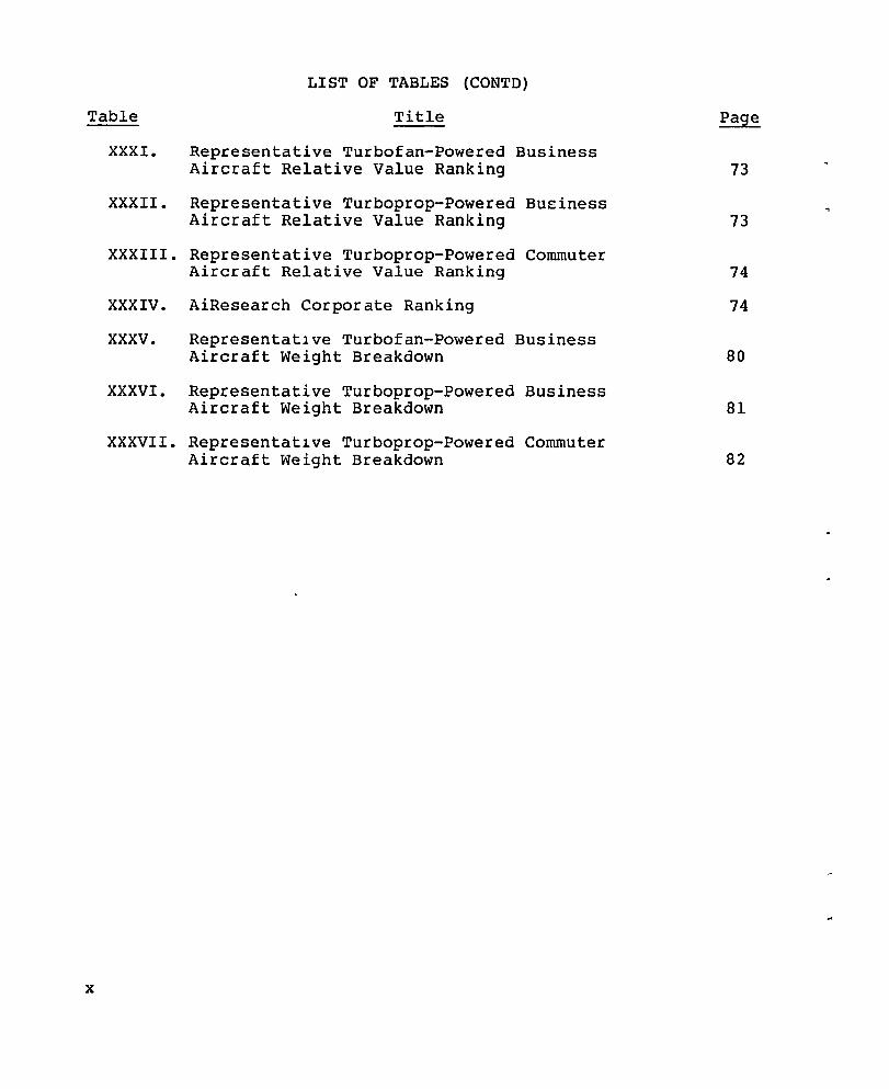
LIST OF TABLES (CONTD)
Table Title Page
XXXI. Representative Turbofan-Powered Business Aircraft Relative Value Ranking 73
XXXII. Representative Turboprop-Powered Bueiness Aircraft Relative Value Ranking 73
XXXIII. Representative Turboprop-Powered Commuter Aircraft Relative Value Ranking 74
XXXIV. AiResearch Corporate Ranking 74
XXXV. RepresentatIve Turbofan-Powered Business Aircraft Weight Breakdown 80
XXXVI. Representative Turboprop-Powered Business Aircraft Weight Breakdown 81
XXXVII. Representatlve Turboprop-Powered Commuter Aircraft Weight Breakdown 82
x
SUMMARY
This document summarizes the second phase of a two-part cost/ benefit analysis (Part 1 is complete, see ref. 1) conducted as part of the NASA Materials for Advanced Turbine Engines (MATE) Program.
The objective of this cost/benefit analysis is to analyze the
costs, benefits, and risks for each new candidate technology to be
considered for future projects. This analysis includes the selection of technolog ies to be evaluated ~ development of property goals~ assessment of candidate technologies on typical engines and
aircraft; sensitivity analysis of the changes in property goals on
performance and economics, cost and risk analysis for each technology; and ranking of each technology by Relative Value.
The cost/benefit analysis was applied to a domestic, non
revenue producing, business-type jet aircraft configured with two TFE731-3 turbofan engines, and to a domestic, nonrevenue producing, business-type turboprop aircraft configured with two TPE33l-l0 turboprop engines. In addition, a cost/benefit analysis was applied to a commercial turboprop aircraft configured with a growth version of the TPE33l-l0. The aircraft chosen for that analysis was simi
lar to the Gates Lear]et 35/36, the Rockwell 980 Commander, and a 30-passenger Fairchild commuter aircraft. (For the purposes of this study, the effects of the technologies that were developed in previous MATE programs conducted by AiResearch were included in the
engines analyzed.)
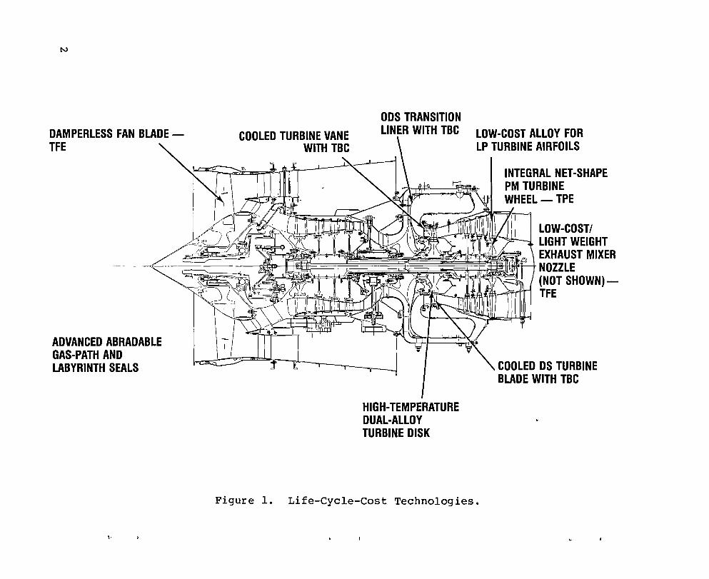
Cost benefits of nine candidate material technologies, shown in Figure 1, were evaluated. The material technologies were compared by both life-cycle cost and Relative Value. Relative value is a method of comparlng technologies by equating benefits (pay-
offs), development cost, and probability of success. Value is defined as follows:
Relative
1
N
DAMPERLESS FAN BLADETFE
COOLED TURBINE VANE WITH TBC
ODS TRANSITION LINER WITH TBC LOW-COST ALLOY FOR
LP TURBINE AIRFOILS
INTEGRAL NET-SHAPE PM TURBINE WHEEL- TPE
LOW-COST! LIGHT WEIGHT
~~il8IE~i!ii~~~I~~tJ!fM EXHAUST MIXER --;t NOZZLE ~!S~~ (NOT SHOWN)
ADVANCED ABRADABLE GAS-PATH AND LABYRINTH SEALS
HIGH-TEMPERATURE DUAL-ALLOY TURBINE DISK
Figure 1. Life-Cycle-Cost Technologies.
TFE
COOLED DS TURBINE BLADE WITH TBC
Relative Value = ~Life-Cycle Cost or ~Direct-Operating Cost X ~Development Cost
Probability of Success (1)
This approach should not be construed to represent the sole basis for selecting material technologies for engineering development and eng ine applications. Several other factors, such as engineering judgement or corporate priorities, may be as important
as Relati ve Value in the selection of mater ial technolog ies for
engine application.
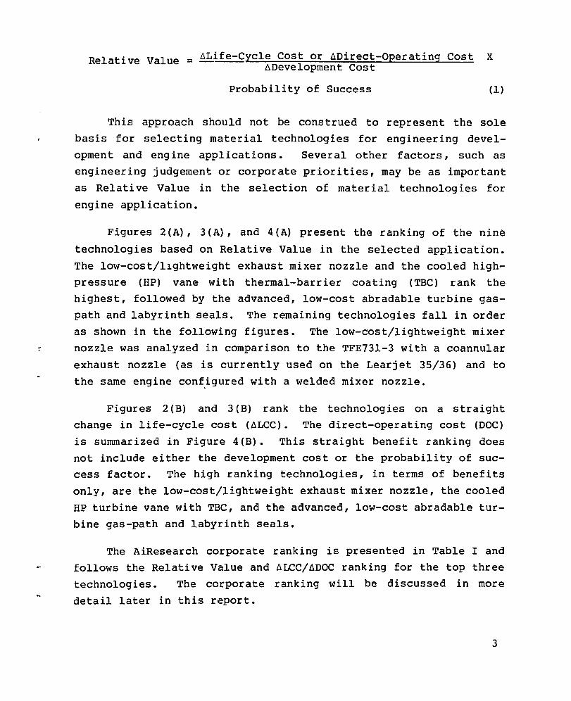
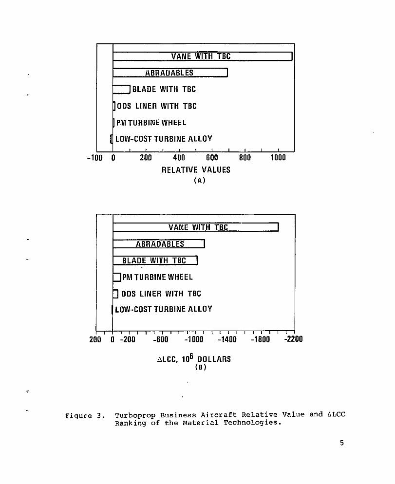
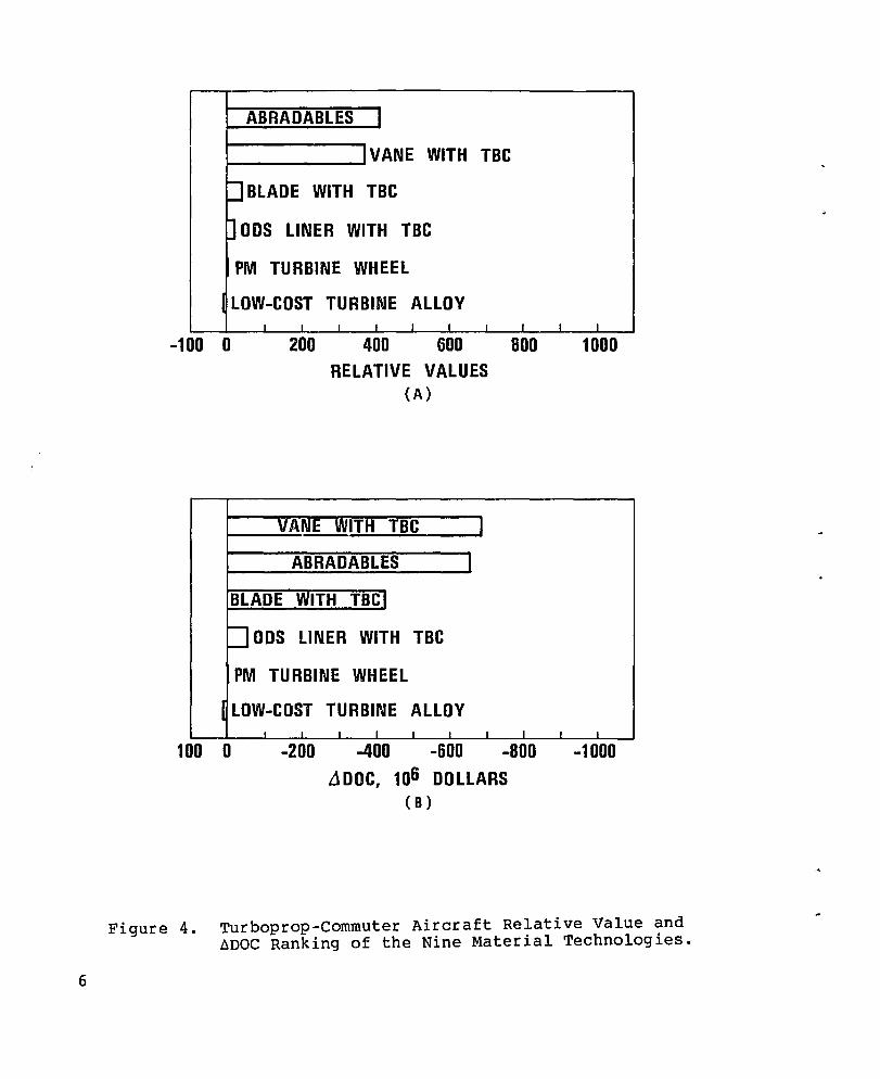
Figures 2(A), 3(A), and 4(A) present the ranking of the nine
technologies based on Relative Value in the selected application.
The low-cost/llghtweight exhaust mixer nozzle and the cooled highpressure (HP) vane with thermal-barrier coating (TBC) rank the highest, followed by the advanced, low-cost abradable turbine gaspath and labyrinth seals. The remaining technologies fall in order
as shown in the following figures. The low-cost/lightweight mixer ~ nozzle was analyzed in comparison to the TFE731-3 with a coannular
exhaust nozzle (as is currently used on the Learjet 35/36) and to
the same engine conf.igured wi th a welded mixer nozzle.
Figures 2 (B) and 3 (B) rank the technologies on a straight change in life-cycle cost (~LCC). The direct-operating cost (DOC)
is summarized in Figure 4(B). This straight benefit ranking does
not include either the development cost or the probability of success factor. The high ranking technologies, in terms of benefits
only, are the low-cost/lightweight exhaust mixer nozzle, the cooled
HP turbine vane with TBC, and the advanced, low-cost abradable turbine gas-path and labyrinth seals.
The AiResearch corporate ranking is presented in Table I and follows the Relative Value and ~LCC/~DOC ranking for the top three technologies. The corporate ranking will be discussed in more
detail later in this report.
3

MIXER NOZZLE (1) * VANE WITH TBC
ABRADABLES
DUAL-ALLOY DISK
DAMPERLESS FAN BLADE
BLADE WITH TBC
ODS LINER WITH TBC
LOW-COST TURBINE ALLOY
o 200 400 600 800 1000 1400
RELATIVE VALUES (A)
MIXER NOZZLE {1}*
V AN E WITH TBC
ABRADABLES 1 MIXER NOZZLE (2)+ I
1800
IDAMPERLESS FAN BLADE
I DUAL-ALLOY DISK
I BLADE WITH TBC
tJ ODS LINER WITH TBC
~ LOW-COST TURBINE ALLOY
I
2200
I
I
o -400 -800 -1200 -1600 -2000 -2400
~LCC, 106 DOLLARS (B )
* SUPERPLASTIC FORMED (SPF) MIXER + SUPERPLASTIC FORMED (SPF) MIXER
4
NOZZLE COMPARED TO CONVENTIONAL NOZZLE COMPARED TO CONVENTIONAL COANNULAR MIXER NOZZLE. WELDED MIXER NOZZLE.
Figure 2. Turbofan Aircraft Relative Value and 6LCC Ranking of the Material Technologies.
VANE WITH TBC
ABRAUABLES 1
P BLADE WITH TBC
~ODS LINER WITH TBC
g PM TURBINE WHEEL
I LOW-COST TURBINE ALLOY I I
-100 0 200 400 600 RELATIVE VALUES
(A)
VANE WITH TBC
ABRADABLES I
BLADE WITH TBC I -
:JPM TURBINE WHEEL
P ODS LINER WITH TBC
LOW-COST TURBINE ALLOY
I
BOO 1000
I
I I I 1 I I I III I -I I I I I I I I I I
I
200 0 -200 -600 -1000 -1400 -1BOO -2200
ALCC, 106 DOLLARS (B)
Figure 3. Turboprop Business Aircraft Relative Value and dLCC Ranking of the Material Technologies.
5
6
ABRADABLES 1
lVANE WITH TBC
PBLADE WITH TBC
) ODS LINER WITH TBC
PM TURBINE WHEEL
I LOW-COST TURBINE ALLOY I I I I I I
-100 0 200 400 600 RELATIVE VALUES
(A)
VANE WITH TBC I
ABRADABLES 1
BLADE WITH TBCl
:JODS LINER WITH TBC
PM TURBINE WHEEL
[ LOW-COST TURBINE ALLOY I I I I I I
I
800
I
100 0 -200 -400 -600 -BOO
Ll DOC, 106 DOLLARS ( B )
I I
1000
I I
-1000
Figure 4. Turboprop-commuter Aircraft Relative Value and ~DOC Ranking of the Nine Material Technologies.

TABLE I. AIRESEARCH CORPORATE RANKING OF THE MATERIAL TECHNOLOGIES
1. Low-cost/lightwelght exhaust mixer nozzle - TFE only.
2. Cooled HP turbine vane wlth TBC - TFE and TPE.
3. Advanced, low-cost abradable turbine gas-path and labyrinth seals - TFE and TPE.
4. Hlgh-temperature, dual-alloy turbine disk - TFE only.
5. Damperless fan blade - TFE only.
6. Cooled directionally- solidifed (OS) HP turbine blade with TBC - TFE and TPE.
7. Oxide-dispersion strengthened, (ODS) transi han liner with TBC - TFE and TPE.
8. Integral net-shape power-metal (PM) turbine wheel - TPE only.
9. Low-cost alloy for low-pressure airfoils - TFE and TPE.
(LP) turbine
7

INTRODUCTION
The NASA MATE Program is a cooperative effort with industry to
accelerate the introduction of new materials into aircraft turbine
engines. Nine material technologies, which are possible candidates
for future MATE projects, were assessed by AiResearch on a cost/
benefit basis for their potential benefits in small turbine
engines. These advanced technologies are all currently in the
exploratory development stage. However, after laboratory feasi
bili ty has been adequately demonstrated, their advancement would
occur through the improvement of present materials, designs, and
process and manufacturing techniques. The verificaiton of the
potential benefits of these technologies would be accomplished by
hardware fabrication followed by component testing in actual engine
environments.
The cost/benefit analysis reported here in is an effort to
evaluate each of the nine new material technologies projects con
sidered through estimated life-cycle costs, development costs,
risks, and Relative Values. This analysis included the following
activities that are described in detail in this report:
8
o Selection of the candidate technologies for future MATE
Program projects
o Development of the property goals for the candidate tech
nologies
o Determination of the impact of engine weight and fuel
consumption on airframe weight and cost
o Development of the eng ine and airframe life-cycle cost
models

o Calculation of the potential benefits (life-cycle cost
improvements) to a selected engine and airframe based on changes in the engine performance resulting from the pro
posed incorporation of each candidate technology
o Estimation of the development cost and risk for each can
didate technology
o Ranking of each candidate technology based on the relative benefits to the aircraft, as well as the associated investments and risks involved.
This report emphasizes cost/benefits of advanced material technologies for general aviation aircraft. In addition, a cost/
benefit analysis of a turboprop-powered commuter aircraft was included in this study because of the growing interest in this type
of aircraft.
9

STUDY APPROACH
The cost/benefit analysis consisted of an evaluation based on
Ilfe-cycle cost considerations of nine candidate material technol
ogies as posslble futur.e MATE projects. The ranking of these can
didates was accomplished through the modeling of all of the life
cycle cost factors involved in the acqulsi tion cost, operation
cost, and maintenance cost. Figure 5 presents d flow chart illus
trating the methodology for thlS analysis.
The cost/benefit analysis began with descriptions of the can
didate technologies which included the capabillty goals (critical
and noncritical property goals that will be feasible for 1990 pro
duction technology) for relatlve strengths, welghts, and component
life; the probability of success for each goal; the probability of
success for producing the component while satisfying all of the
goals; the comparisons to current production parts; and the devel
opment costs.
Development costs for the selected component technologies were
prepared using inpu~ from AiResearch materials engineers and
AiResearch cost experience with similar efforts. The costs encom
passed the effort required to demonstrate, in an engine test, the
technical objectlves of the new technology.
The technical risk: associated with the technical objectives,
was estlmated based on primary factors that considered the nature
of the material, design approach/application, and current goal
status. The effect of secondary factors--such as alternate appli
ca tions, required mater ial development tlme, and cr i ticali ty of
component--were also included in the technlcal risk analysis. An
over all probability of success for each technology project was
estimated from the risk analysis.
10

MATERIAL TECHNOLOGY BASELINE AIRPLANE SELECTION ENGINE SELECTION
t t DEVELOPMENT PROPERTY
COST PROJECTIONS AND GOALS
t RISK CYCLE TOGW MODEL ANALYSIS ANALYSIS , , l
PROBABILITY ENGINE LCC MODEL OF SUCCESS EFFECTS
J RELATIVE VALUE BENEFIT ANALYSIS
AND RANKING (ALCC)
Figure 5. Flow Chart of the Study Approach.
11

The TFE73l turbofan engine used in the cost/benefit analysis
utilizes a geared fan driven by the LP spool. The geared-fan
design offers an optimum approach to high-cycle efficiency. The engine cycle was varied, depending upon the nature of the component
technology being incorporated, to achieve minimum engine thrust
specific fuel consumption. This was accomplished by optimizing the bypass ratio and core pressure ratio, within practical limits, at a constant cruise thrust level. Turbine inlet temperature was varied
according to the technology being considered.
The TFE73l turboprop engine used in the cost/benefit analysis
is a lightweight single-shaft engine featuring modular design and an integral gearbox and inlet. The engine cycle was optimized for specific fuel consumption at constant shaft horsepower, depending upon the nature of the component technology being incorporated. This was accomplished by optimizing the core flow within the same engine frame size. Turbine inlet temperature was varied according to the technology being considered.
The potential benefits for both engines were assessed through
engine cycle analyses' (utilizing existing computer models): design
analysis for weight, size, and life effects: and cost analyses in the manufacturing and maintenance areas. The aircraft benefits were assessed with inputs from the engine benefits analysis and the life-cycle cost (LCC) models. The engine/aircraft LCC models were utilized to develop sensitivity coefficients for the effects of changes in selected engine parameters (weight, thrust specific fuel consumption, size, cost, life) on total system life-cycle costs.
The analysis results are expressed in terms of the benefits resul
ting from application of each component materi~l technology to the selected engine/aircraft combination. These benefits are expressed as changes in life-cycle cost.
12
The cost estimating models for the aircraft were based upon a
scaled aircraft and engine meeting a fixed payload and range for
changes in engine specific fuel consumpt~on and weight. The scala
bility of the aircraft was determined by utilizing a weight model
for the aircraft that partitions the aircraft takeoff gross weight
into airframe fixed, airframe variable, installed engine, and fuel
and tankage elements. The installed engine weight fract~on relates the engine thrust requirements and the thrust/weight ratio to gross
we~ght via the lift-drag ratio. The fuel and tankage fraction
relates thrust spec~fic fuel consumption, range, and thrust
requirements to gross weight with use of the Breguet range equation
(ref. 2).
The follow~ng sections present further details of the cost/
benefit analysis methodology and results. Appendix B provides a list of abbreviations/symbols used in the following sections.
13
SELECTED CANDIDATE MATERIALS TECHNOLOGIES
ThiS section provides descriptions, material property and cost
goals for each of the candidate material technologies selected for
the cost/benef it analysls. These advanced mater ial technolog ies
were chosen because of their potential benefits to the engine/
aircraft application. Sharp increases in the cost of fuel over the
last five years have led to increased emphasis on the potential of
the candidate technologies for reducing fuel consumption. The list
of nine technology candidates, as shown below, incorporates input
that was collected from vendors, purchasing, performance, stress
analysis, mater ials, etc" to develop the goals required for the
cost/benefi t analysis. The composite nacelle/inlet components
technology, which was or iginally included in the list, was eli
minated Since thiS type of component is already available from at
least one vendor as a production component.
14
o Low-cost allo~ for LP turbine airfoils
o Integral net-shape PM turbine wheel
o Damperless fan blade
o ODS transition liner with TBC
o Cooled HP turbine vane with TBC
o Cooled DS HP turbine blade with TBC
o Advanced, low-cost abradable turbine gas-path and laby
rinth seals
o High-temperature dual-alloy turbine disk
o Low-cost/lightweight exhaust mixer nozzle
The material property goals were established for each of these
candldate advanced mater ial technologies based on projections of
current alloy/process technology. The technical and cost goals
were established by AiResearch mater ial experts based on a 1990
productlon status. This assumes a go-forward decision within the
MATE II program schedule. The technical material goals are based
on two criteria: property goals that must be met to offer a benefit
to engine life and/or performance (critical goals), and property
goals that must be closely approached to meet the life and per
formance Ob]ectlves (noncrltlcal goals). The cost goals are meant
to reflect a realistic evaluation of future production costs based
on AiResearch experience and published data. A probability of suc
cess for each goal is presented to reflect AiResearch's subjective
evalua tion. A we ighing factor was also established for the cr i
tical material and cost goals indicating the relative importance of
these goals to the success of the technology. The weighing factors
and probabilities of success were used in a risk analysis to arrive
at a project probability of success for each technology. A sub
sequent section of th1s report gives a description of how the risk
analysis was performed.
Development costs were estimated for each technology. These
estimates are based on all of the costs required to take the can
didate technology from its present development status through fac
tory engine demonstration tests, including rig-test costs, and
those costs chargeable to incorporation of the technology into an
engine.
Brief descriptions and the projected goals for each technology
are summarized in the following sections.
15
Low-Cost Alloy for LP Turbine Airfoils (TFE and TPE)
This project would lead to the production of LP turbine blades
and/or stators from a new low-cost, lower temperature capability alloy. These uncooled turbine components would be substituted for
more costly, conventional alloy turbine hardware without any loss
in performance.
16
• Capability Goals
o Critical Goals
Creep-rupture
80 percent of Inco 7l3LC in
strength to be at least the creep-rupture strength of the 1000-1300 of range - 60-
percent probability of success (30-percent
weighing factor).
HCF strength to be at least 80 percent of Inco
7l3LC in the 1000-1300 o F range - 60-percent probability of success (2S-percent weighing factor) •
D. Tensile strength, ductility and impact resis
tance to be 80 percent of Inco 7l3LC in the
1000-1300 o F range - 60-percent probability of success (IO-percent weighing factor).
o Noncritical Goals
Density equivalent to Inco 7l3LC.
Oxidation/corrosion resistance to be at least
as good as Inco 7l3LC up to l300°F.
• Finished Part Co~t Goal - 90 percent of the uncooled LPT
blades and stators used in TFE731 and/or TPE331 (assuming
conventional Ni-base mater ial costs escalate sub
stantially in the 1990 time frame) - GO-percent pro
bability of success (35-percent weighting factor).
• Estlmated Development Cost - $1,500,000.
• Project Probability of Success - 50-percent.
Integral Net-Shape Powder-Metal Turbine Wheel (TPE)
This project would lead to the productlon of lntegral net
shape turbine wheels of PM superalloys for use in the 1000-1300°F
maximum temperature range where cast inserted blades and forged
dlSks are used today. Pr imary benefits of the project would be
improving the cyclic Ilfe and rellability of turboprop engine tur
bine wheels while reducing the overall cost and weight.
• Capability Goals
o Crltical Goals
The low-cycle-fatigue life of the rim area to
be ten times that of cast Inco 713LC -
90-percent probability of success (lO-percent
weighing factor).
Wheels will be produced with net-shape blades
requir ing no
probabili ty of
factor).
finish machining - 70-percent
success (30-percent weighing
17
18
Creep-rupture strength to be equal to that of
cast Inco 7l3LC in the lOOO-l300°F range-
90-percent probability of success (lO-percent
weighing factor).
HCF strength to be equal to that of cast
Inco 7l3LC in the lOOO-l300°F range-
90-percent probability of success (lO-percent
weighing factor).
weight of the integral wheel to be 20-percent
less than the inserted blades/disk assembly -
90-percent probability of success (la-percent
weighing factor).
o Noncritical Goals
Densi ty to be no greater than that of
Inco 7l3LC.
o Oxidation/corrosion resistance to be equal to
that of Inco 7l3LC up to l300oF.
• Finished Part Cost Goal - 70 percent of the cost of a
TPE331 blade/disk assembly using a forged disk and indi
vidual inserted blades - 50-percent probability of suc
cess (30-percent weighing factor).
• Estimated Development Cost - $2,500,000.
• Project Probability of Success - 15 percent.
Damper1ess Fan Blade (TFE)
This project would lead to the production of a hollow damper
less titanium fan blade for use in the new TFE76 engine. This candidate technology is more applicable to the new TFE76 low-aspect
ratio fan blade than the TFE731 blade. Therefore, the benefits and eng ine demonstration test are planned for the TFE76 while the cost/benefit study will utilize the TFE731 engine/aircraft model.
The incorporation of this technology would result in a one-percent increase in the fan-stage efficiency.
• Capability Goals
o Critical Goals
Weight of fan blade to be reduced at least 25 percent to avoid vibration problems with
damper1ess fan blade - 75-percent probability of success (35-percent weighing factor).
Fan to pass FAA required bird-strike test -
60-percent probability of success (40-percent
weighing factor).
o Noncritical Goals
Weight of fan stage to be reduced by at least
10 percent.
Part life to be equal to that of production TFE731 fan blade.
• Finished Part Cost Goal - Cost of the total fan stage would be equal to or less than the present TFE76
19

design - 60-percent probability of success (25-percent weighing factor).
• Estimated Development Cost - $2,800,000.
• Project Probability of Success - 45 percent.
ODS Transition Liner with TBC (TFE and TPE)
This project would lead to production of an oxide-dispersion
strengthened (ODS) material transition liner with a TBC. As part
of this technology, an appropriate design must be established to
facilitate, fabricate, and repair the ODS liner. This technology
would utilize less cooling air to produce a longer life component
with less thermal distortion.
30 percent.
Cooling airflow will be reduced
20
Capability Goals
o Critical Goals
TBC to provide thermal protection for at least
3000 hours without spallation - 70-percent
probability of success (30-percent weighing
factor).
Durability of the TBC ODS liner must be ade
quate for 3000 hours - 50-percent probability
of success (30-percent weighing factor).
• Finished Part Cost Goal - 200 percent of the cost of the
current production components in the TFE73l and TPE73l -60-percent probability of success (40-percent weighing
factor) •

• Estimated Development Costs - $l,SOO,OOO.
• Project Probability of Success - 60 percent.
Cooled HP Turbine Vane with TBC (TFE and TPE)
This project would lead to the production of a TBC air-cooled HP turbine vane that operates at a lSO°F higher turbine inlet temperature while maintaining metal temperatures comparable to those
in the current TFE731 and TPE33l. The key to this project is the
development of a TBC that can function in the vane environment for the required life of the component without spallation.
• Capability Goals
o Critical Goals
TBC to provide thermal protection for turbine
vanes for 3000 hours plus at least one
recoating - 70-percent probability of success (40-percent weighing factor).
TBC to provide oxidation and corrosion pro
tection for 3000-hours vane life - 70-percent probability of success (20-percent weighing factor).
o Noncritical Goal
Coating must be capable of withstanding minor FOD without disbonding.
• Finished Part Cost Goal - ISO percent of the current cooled cast vane segment in the TFE731 or the
21
TPE331 - 70-percent probability of success (40-percent
weighing factor).
• Estimated Development Cost - $1,200,000.
• Project Probability of Success - 65 percent.
Cooled DS HP Turbine Blade with TBC (TFE and TPE)
This project would lead to the productlon of a TBC air-cooled,
DS HP turbine blade that can operate at a higher turbine inlet tem
perature than an uncoated, cooled DS blade. Technology goal is to
develop a variable thickness coating application that will minimize
additional centrifugal streses, optimize aerodynamic effects, and
provide a TBC that can survive in the HPT blade environment for the
requlred life.
22
• Capability Goals
o Critical Goals
TBC to provide thermal protection which wlll
allow cooled turbine blade to operate at 40°
higher gas temperatures compared to uncoated
blade - 60-percent probability of success
(40-percent weighing factor).
TBC blade to exhibit adequate durability to
provide 3000-hour life - 50-percent pro
bablllty of success (30-percent weighing
factor).
o Noncritical Goals
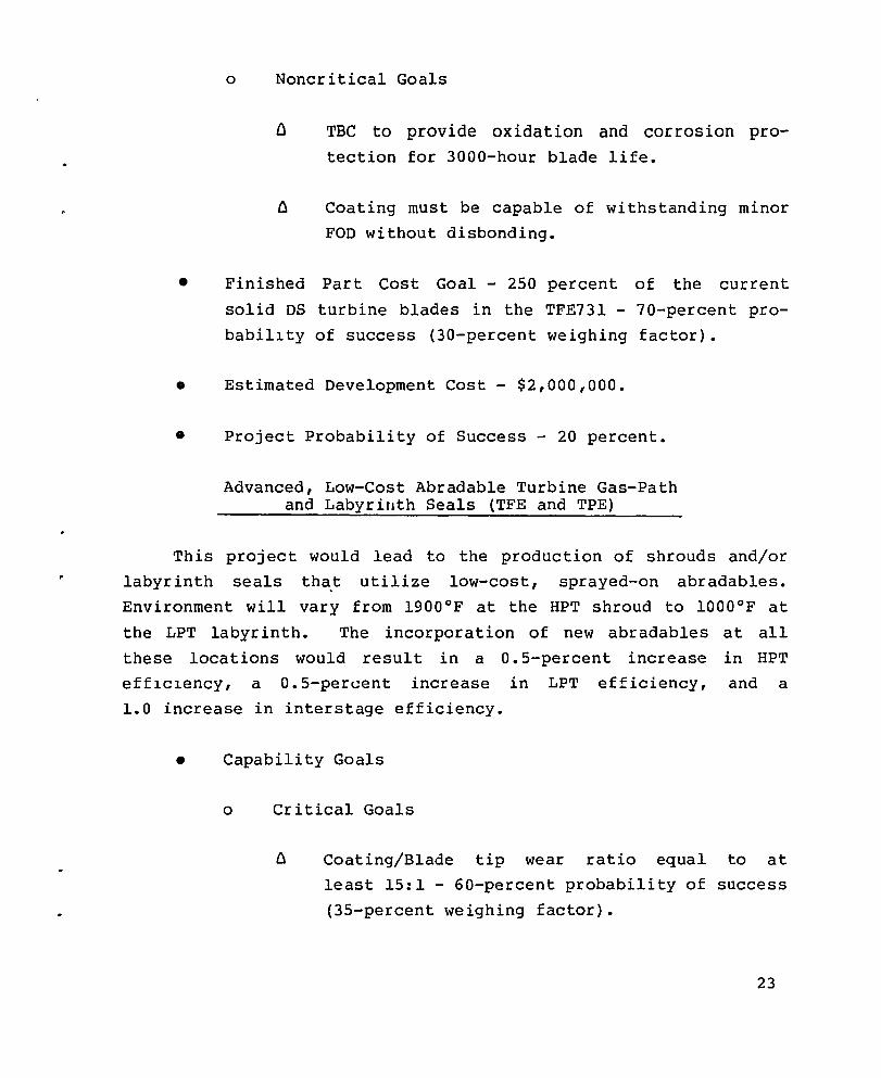
TBC to provide oxidation and corrosion protection for 3000-hour blade life.
Coating must be capable of withstanding minor
FOD without disbonding.
• Finished Part Cost Goal - 2S0 percent of the current
solid DS turbine blades in the TFE73l - 70-percent pro
babillty of success (30-percent weighing factor).
• Estimated Development Cost - $2,000,000.
• Project Probability of Success - 20 percent.
Advanced, Low-Cost Abradable Turbine Gas-Path and Labyrinth Seals (TFE and TPE)
This project would lead to the production of shrouds and/or
labyrinth seals that utilize low-cost, sprayed-on abradables.
Environment will vary from 1900°F at the HPT shroud to 10000F at
the LPT labyrinth. The incorporation of new abradables at all
these locations would result in a o. S-percent increase in HPT
efflclency, a O.S-percent increase in LPT efficiency, and a
1.0 increase in interstage efficiency.
• Capability Goals
o Critical Goals
Coating/Blade tip wear ratio equal to at
least IS:l - GO-percent probability of success
(3S-percent weighing factor).
23

Eroslon resistance adequate to meet 3000-hour part life - 50-percent probability of success (30-percent weighing factor).
o Noncritlcal Goal
Coating debris size less than 0.010 inch.
• Finished Part Cost Goal - Equal to current components with existing abradable coatings and a 10 percent or less cost
lncrease for LPT labyrinth and shroud components that are
not currently coated. A 25-percent cost increase over the
current HPT component (uncoated) would be anticipated -
60-percent probability of success (35-percent weighing fac
tor).
• Estlmated Development Cost - $800,000.
• Project Probabillty of Success - 50 percent.
High-Temperature Dual-Alloy Turbine Disk (TFE)
This project would lead to the production of a dual-alloy PM
turbine wheel with a high creep-resistant alloy rim and a high LCF
and tenslle strength alloy hub. The disk would be used in conjunction with high temperature uncooled inserted HP turbine blades.
This technology would allow the air required for rim cooling to be
reduced when uncooled turbine blades (OS, SC or ODS) replace con
ventional cooled blades. This reduction of cooling air is expected to increase HPT stage efficiency 0.6 percent.
24
• Capability Goals
o Critical Goals
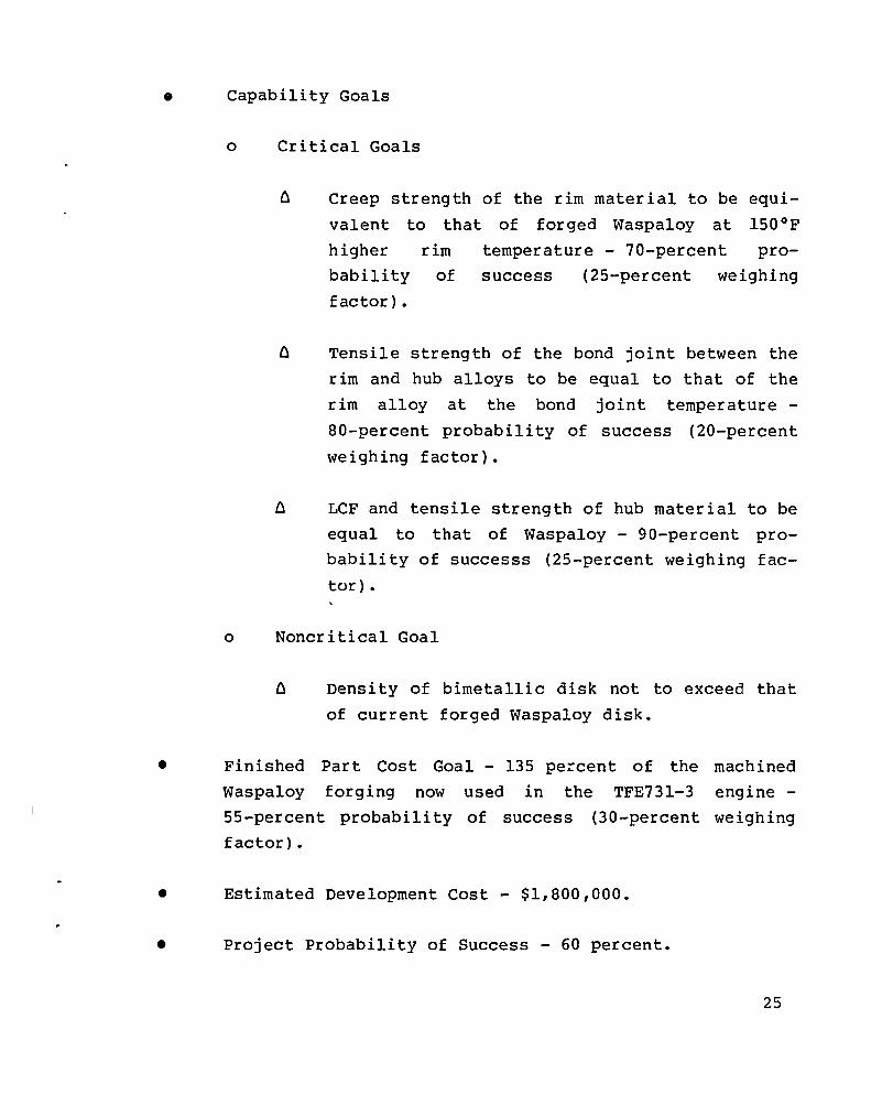
o Creep strength of the rim material to be equi
valent to that of forged Waspaloy at l500F
higher rim temperature - 70-percent pro
bability of success (25-percent weighing
factor) •
Tensile strength of the bond joint between the
rim and hub alloys to be equal to that of the
rim alloy at the bond joint temperature-
80-percent probability of success (20-percent
weighing factor).
LCF and tensile strength of hub material to be
equal to that of Waspaloy - 90-percent pro
bability of successs (25-percent weighing fac
tor).
o Noncritical Goal
Density of bimetallic disk not to exceed that
of current forged Waspa10y disk.
• Finished Part Cost Goal - 135 pe:'cent of the machined
Waspa10y forging now used in the TFE731-3 engine-
55-percent probability of success (30-percent weigh ing
factor).
• Estimated Development Cost - $1,800,000.
• Project Probability of Success - 60 percent.
25

Low-Cost/Llghtweight Exhaust Mixer Nozzle {TFE}
This project would lead to the productlon of a low-cost,
lightweight superplastic formed titanium mixer nozzle for the
TFE73l engine to lmprove the overall engine performance 4 percent.
ThlS component is to replace the current fabricated coannular steel
nozzle and will lncorporate demonstrated performance improvement
design concepts.
26
• Capability Goals
o Critical Goals
Performance improvement
mixer nozzle to be at
80-percent probability of
weighing factor}.
with the compound
least 4 percent -
success {40-percent
Mixer nozzle to add not more than 2 percent to
the overall weight of the engine - 80-percent
probablllty of success {35-percent weighing
factor}.
• Finished Part Cost Goal - Incorporating this mixer
nozzle to increase the cost of the engine not more than
2 percent - 70-percent probability of success {25-percent
weighing factor}.
o Estlmated Development Cost - $1,000,000.
• Project Probability of Success - 75 percent.

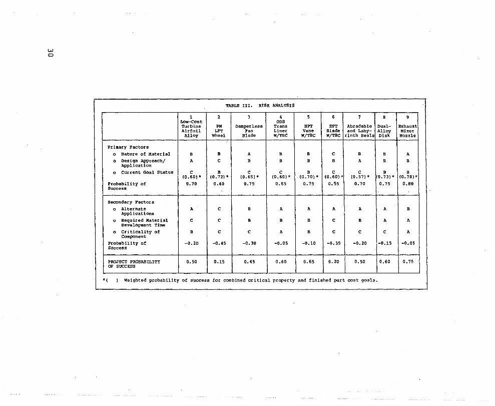
RISK ANALYSIS
The risk analysis method used is basically the method described in NASA Report CR-13470l (ref. 3) with the added feature
that individual probabilities of success and weighing factors have been assigned to each of the critical property goals and the fin
ished part cost goal for the nine candidate technologies.
Several factors were considered in the risk analysis. Those
factors that are considered primary factors address the nature of
the material, the design approach/application, and the current goa~ status. Secondary factors that address alternate applications, requi red mater ial development time, and cr i tical i ty of the com
ponent are also considered. Except for the current goal status, an
alphabetical value is assigned to the primary and secondary factors
based on the criteria presented in Table II.
The current goal status is determined by applying the weighing
factors to the probability of success for each of the critical pro
perty goals and finished part cost goals, and summing the weighted individual probabilities of success. An alphabetical value accor-
ding to the scale defined in Table II is then assigned to the current goal status. The following example shows how the current goal status was determined for the low-cost/lightweight exhaust mixer
.. nozzle technology.
Critical Goals
Cost Goal
Probability of Success
0.80
0.80
0.70
---------------------weighing
Factor
0.40
0.35
0.25
Current Goal
Weighted Probability of Success
0.32
0.28
0.18
Status 0.78
27
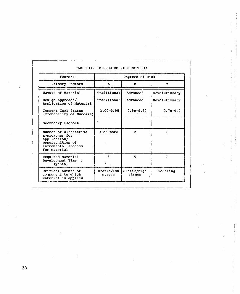
TABLE II. DEGREE OF RISK CRITERIA
Factors Degrees of Risk
Primary Factors A B C
Nature of Material Traditional Advanced Revolutionary
Design Approach/ Traditional Advanced Revolutionary Application of Material
Current Goal Status 1.00-0.90 0.90-0.70 0.70-0.0 (Probability of Success)
Secondary Factors
Number of alternative 3 or more 2 1 approaches for application/ opportunities of incremental success for material
Required material 3 5 7 Development Time ,
(years)
Critical nature of Static/low Static/high Rotating component to which stress stress Material is applied
28
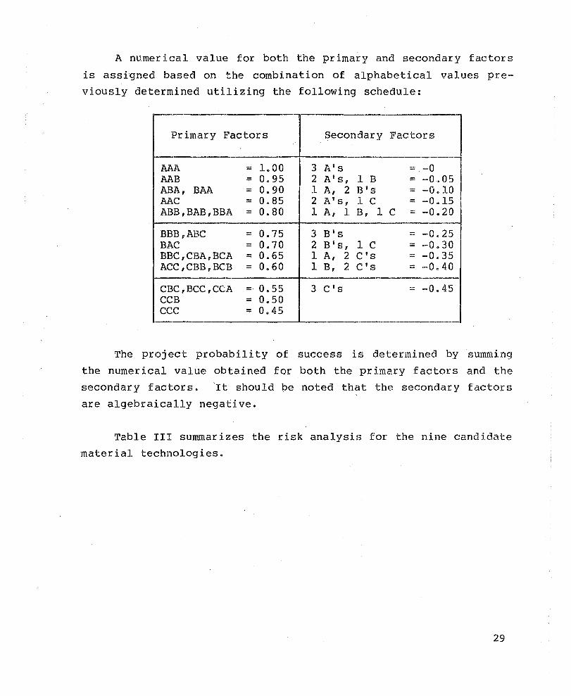
A numerical value for both the primary and secondary factors
is assigned based on the combination of alphabetical values pre
viously determined utilizing the following schedule:
Primary Factors Secondary Factors
-AAA == 1.00 3 A's :.:: -0 AAB == 0.95 2 A's, 1 B == -0.05 ABA, BAA == 0.90 1 A, 2 B's :: -0.10 MC == 0.85 2 A's, 1 C == -0.15 ABB,BAB,BBA == 0.80 1 A, 1 B, 1 C == -0.20
BBB,ABC == 0.75 3 B's == -0.25 BAC == 0.70 2 B's, 1 C = -0.30 BBC,CBA,BCA == 0.65 1 A, 2 CiS == -0.35 ACC,CBB,BCB == 0.60 1 B, 2 CiS == -0.40
CBC,BCC,CCA = 0.55 3 C's == -0.45 CCB == 0.50 CCC == 0.45
The project probabili ty of success is determined by summing
the numerical value obtained for both the primary factors and the
secondary factors. 'It should pe noted that the secondary factors
are algebraically negative.
Table III summarizes the risk analysis for the nine candidate
material technologies.
29
w o
TABLE III. RISK ANALYSIS
1 2 3 4 5 6 7 Low-Cost ODS Turbine PM Damperless Trans HPT HPT Abradable Airfoil LPT Fan Liner Vane Blade and Laby-Alloy Wheel Blade W/TBC W/TBC W!TBC rinth Seals
Primary Factors
0 Nature of Material B B A B B C B
0 Design Approach/ A C B B B B A Application
0 Current Goal Status C B C C B C C (0.60)* (0.72) * (0.65) .. (0.60)* (0.70) .. (0.60) * (0.57) "
Probability of 0.70 0.60 0.75 0.65 0.75 0.55 0.70 Success
Secondary Factors
0 Alternate A C B A A A A Applications
0 Required Material C C B B B C B Development Time
0 Criticality of B C C A B C C Component
Probability of -0.20 -0.45 -0.30 -0.05 -0.10 -0.35 -0.20 Success
PROJECT PROBABILITY 0.50 0.15 0.45 0.60 0.65 0.20 0.50 OF SUCCESS
*( Weighted probability of success for combined critical property and finished part cost goals.
8 9
Dual- Exhaust Alloy Mixer Disk Nozzle
B A B B
B B 0.73)* (0.78) ..
0.75 0.80
A B
A A
C A
-0.15 -0.05
0.60 0.75
ENGINE CONSIDERATIONS
Baseline Engine Selection
The AiResearch Model TFE731-3 engine (as illustrated in
Figure 6), upgraded to include the technology improvements from
AiResearch's MATE Projects 1 and 2, was selected as the baseline
engine for evaluating the candidate technology projects. The
TFE731 engine is currently the powerplant for four domestic air
craft and five foreign aircraft--one military and eight civil air
craft. As in the Cost/Benefit (Part 1) Analysis, a composite twin"":'
engine aircraft representative of the 6800- to 9100-kg (15,000- to
20,OOO-lb) class was selected as the vehicle for analysis of bene
fits that could be derived from the candidate projects.
The TFE73l-3 eng ine cons lsts of. a geared fan located at the forward end of the engine. The fan is gear-·driven by the LP spool.
The geared-fan design was selected as the optimum approach for
high-cycle efficiency, and it incorporates proven techniques for
reducing noise to levels appreciably lower than that of comparably
sized turbojets. Tne LP spool. consists of the single-stage fan, coupled through a planetary gearbox to a four-stage compressor and
three-stage turbine. The HP spool consists of a centrifugal com
pressor driven by a single-stage turbine; the accessory gearbox is
driven by the HP spool. The reverse-flow annular combustor employs
12 dual-or if ice fuel injectors and was designed for low smoke
emission levels below the threshold of visibility, in addition to
high-combustion efficiency, reliable ignition and stable operation, and high-durability characteristics over the engine oper
ating range.
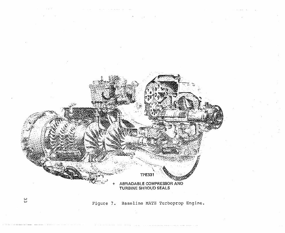
The AiResearch Model TPE33l engine (as illustrated in Figure 7) used for both the business and commuter aircraft LCC
analysis was upgraded to include the results of the MATE Project 2
31

32
\fP_I\O 1/, /,
TfE731
+ UNCOOLED DS MAR-M 247 HPT BLADES (PROJECT 1)
+ ABRADABLE COMPRESSOR AND TURBINE SHROUD SEALS (PROJECT 2)
+ INCREASED BYPASS RATIO AND PRESSURE RATIO
Figure 6. Baseline MATE Turbofan Engine.
w w
+ ABRADABLE COMPRESSOR AND TURBINE SHROUD SEALS
Figure 7e Baseline MATE Turboprop En9ine.
Abradable Seals Program. The TPE331 engine is currently the power
plant for thirteen aircraft. The engine was also modified for
military applications under the designation T76.
The TPE331 uses a high-pressure-ratio, two-stage centrifugal
compressor resulting in a more rugged, more reliable compressor
compared to a multistage axial-flow compressor. Added advantages
are lower cost and greater flexibility for growth. A three-stage,
axial-flow turbine with integral second- and third-stage blades and
disks provides a durable and highly efficient turbine. Use of a
reverse-flow, annular combustor results in a minimum engine length,
minimum weight, low combustor pressure loss, and efficient use of
space. The reverse-flow principle shields the turbine first-stage
nozzles from the radia~t heat transfer from the primary combustion
zone. The use of a two-bearing arrangement to support the rotating
group results in a compact, easy-to-assemble unit.
Engine Performance
The incorporation of the uncooled DS HP turbine blades devel
oped under project 1, 'and the abradable turbine and compressor gas
path seals developed under Project 2 of the MATE Program resulted
in a rematch of the TFE731-3 engine in order to achieve a minimum
engine thrust specific fuel consumption ('l'SFC) at the original
engine thrust rating (cruise). In addition, the TFE731-3 engine
baseline model was updated to include the latest cooling flows and
turbine efficiencies. The TPE331 baseline engine was modified to
include the effects of the Project 2 abradables by rematching the
engine at constant cruise horsepower in order to achieve minimum
SFC. The MATE baseline turbofan engine performance and the present
TFE731-3 pe'rformance are presented in Table IV. The MA'rE turboprop
baseline engine performance for the business and commuter appli
cation is shown in Table V.
34
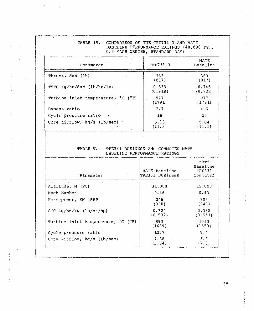
TABLE IV. COMPARISON OF THE TFE731-3 AND MATE BASELINE PERFORMANCE RATINGS (40,000 FT., 0.8 MACH CRUISE, STANDARD DAY)
Parameter TFE731-3
Thrust, daN (lb) 363 (817 )
TSFC kg/hr/daN (lb/hr /lb) 0.833 (0.818 )
Turbine inlet temperature, °c ( OF) 977 (1791)
Bypass ratio 2.7
Cycle pressure ratio 18
Core airflow, kg/s (lb/sec) 5.13 (ll. 3)
TABLE V. TPE331 BUSINESS AND COMMUTER MATE BASELINE PERFORMANCE RATINGS
MATE Baseline Parameter TPE331 Business
Altitude, M (Ft) 31,000
Mach Number 0.46
Horsepower, KW (SHP) 246 (330 )
SFC kg/hr/kw (lb/hr /hp) 0.324 (0.532)
Turbine inlet temperature, °c ( OF) 893 (1639)
Cycle pressure ratio 13.7
Core Air flow, kg/s (lb/sec) 1. 38 (3.04)
MATE Baseline
363 (817 )
0.745 (0.732)
977 (1791)
4.6 25
5.04 (ll.l)
MATE Baseline
TPE331 Commuter
15,000
0.43
703 (943)
0.338 (0.551)
1010 (1850)
8.4
3.3 (7.3)
35
Engine Models
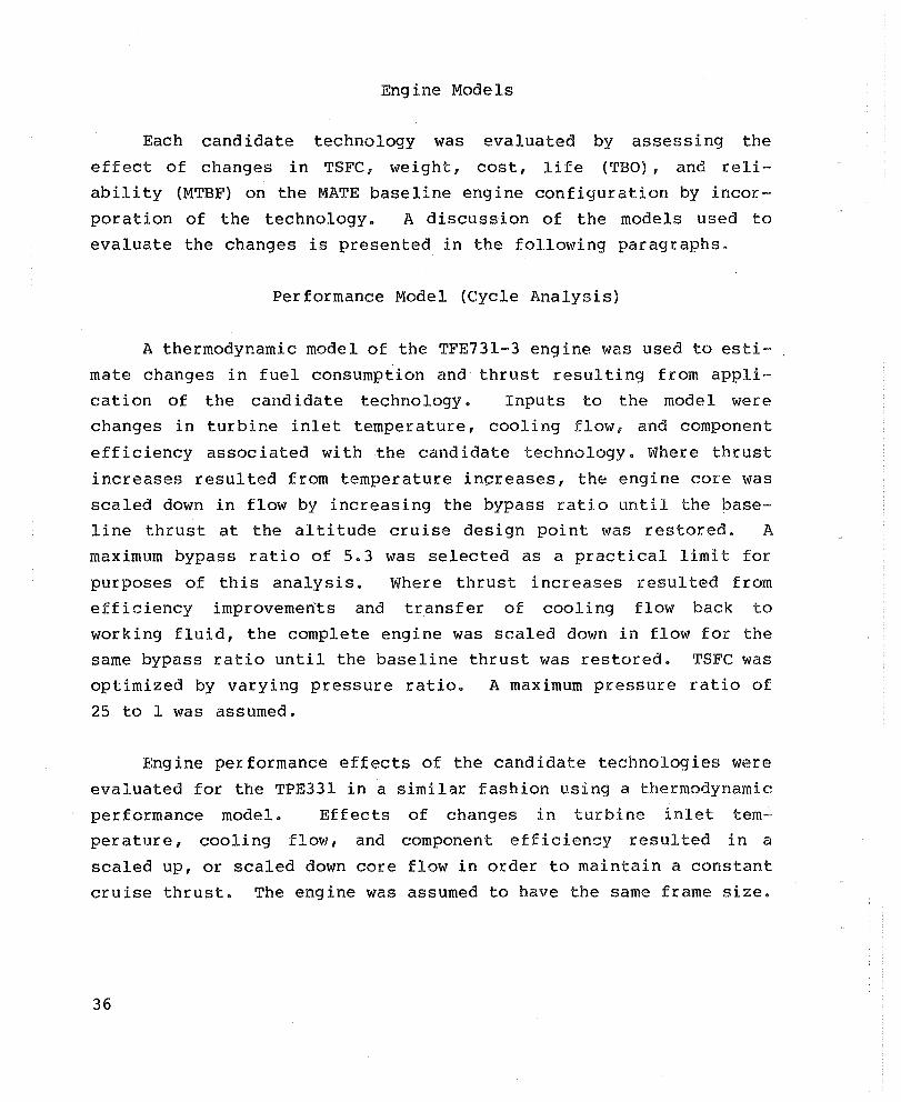
Each candidate technology was evaluated by assessing the
effect of changes in TSFC, weight, cost, life (TBO), and reli
ability (MTBF) on the MATE baseline engine configuration by incor
poration of the technology. A discussion of the models used to
evaluate the changes is presented in the following paragraphs.
Performance Model (Cycle Analysis)
A thermodynamic model of the TFE731-3 engine was used to esti
mate changes in fuel consumption and thrust resulting from appli
cation of the cand idate technology. Inputs to the model were
changes in turbine inlet temperature, cooling flow, and component
efficiency associated with the candidate technology. Where thrust
increases resulted from temperature increases, the engine core was
scaled down in flow by increasing the bypass ratio until the base
line thrust at the altitude cruise design point was restored. A
maximum bypass ratio of 5.3 was selected as a practical limit for
purposes of this analysis. Where thrust increases resulted from
efficiency improvements and transfer of cooling flow back to
working fluid, the complete engine was scaled down in flow for the
same bypass ratio until the baseline thrust was restored. TSFC was
optimized by varying pressure ratio. A maximum pressure ratio of
25 to 1 was assumed.
Engine performance effects of the candidate technologies were
evaluated for the TPE331 in a similar fashion using a thermodynamic
performance model. Effects of changes in turbine inlet tem
perature, cooling flow, and component efficiency resulted in a
scaled up, or scaled down core flow in order to maintain a constant
cruise thrust. The engine was assumed to have the same frame size.
36
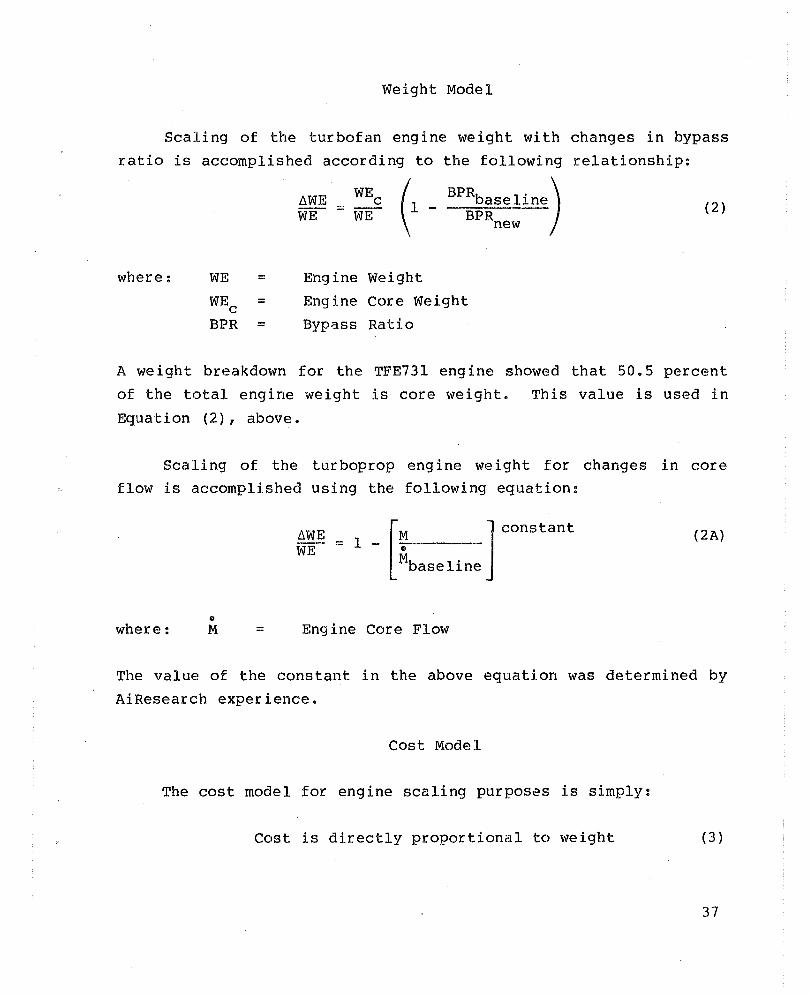
Weight Model
Scaling of the turbofan engine weight with changes in bypass
ratio is accomplished according to the following relationship:
where: WE
WEc BPR
= = =
AWE = WEc (1 _ BPRbaselin~) (2) WE WE BPRnew
Engine weight
Engine Core Weight
Byp3.sS Ratio
A we ight breakdown for the TFE731 eng ine showed that 50.5 percent
of the total engine weight is core weight. This value is used in
Equation (2), above.
Scaling of the turboprop engine weight for changes in core flow is accomplished using the following equation:
II
where: M =
LlWE WE
- [M J constant - 1 - ~.--------
Mbaseline
Engine Core Flow
( 2A)
The value of the constant in the above equation was determined by
AiResearch experience.
Cost Model
The cost model for engine scaling purposes is simply:
Cost is directly proportional to weight (3 )
37

The above approximation is based on very small weight changes for
the baseline engine previously described.
Life and Reliability Models
A quali tati ve approach was used to assess the effects of
changes in component life and reliability. Although it was pos-
sible to quantitatively estimate stress-rupture life for the rotor
and stators, this could not be done for corrosion life, creep
rupture life, and low-cycle-fatigue life because material property
data were not available.
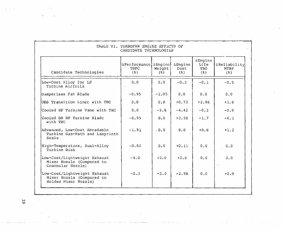
Engine Effects of Candidate Technologies
Tables VI and VII summarize the impact of each candidate tech
nology on engine TSFe, weight, cost, .life, and reliability uti
lizing the models previously described. Each technology was eval
uated individually; however, it was assumed that necessary changes
would be made to the engine in order that the full capability of the
technology could be utilized.
The material technology exhibiting the best improvement in SFC
is the low-cost/lightweight exhaust mixer nozzle. Performance pre
dictions are based on the NASA/AiResearch QCGAT test results of the
QCGAT engine mixer nozzle. Both one-third scale model tests and a
sea-level full-scale eng ine test were run for the QCGAT Program.
The 4.0-percent TSFC improvement is relative to the baseline
TFE731-3 engine configured with a coannular exhaust nozzle. Since
the mixer nozzle is longer and more complex than the coannular
exhaust model, weight and cost penalties were assessed to the mixer
nozzle. The mixer nozzle, produced by the superplastic forming
(SPF) method, was also compared to a mixer nozzle produced by con
ventional welding methods. This results in a comparison strictly
on a mater ials/manufactur ing point of view. Only a slight per
formance improvement is achieved due to improved contour control of
38
W I..D
TABLE VI. TURBOFAN ENGINE EFFECTS OF CANDIDATE TECHNOLOGIES
Candidate Technologies
Low-Cost Alloy for LP Turbine Air foils
Damperless Fan Blade
ODS Transition Liner with TBC
Cooled HP Turbine Vane with TBC
Cooled DS HP Turbine Blade with TBC
Advanced, Low-Cost Abradable Turbine Gas-Path and Labyrinth Seals
High-Temperature, Dual-Alloy Turbine Disk
Low-Cost/Lightweight Exhaust Mixer Nozzle (Compared to Coannular Nozzle)
Low-Cost/Lightweight Exhaust Mixer Nozzle (Compared to Welded Mixer Nozzle)
~Performance ~Engine TSFC Weight
(%) (%)
0.0
-0.95
0.0
0.0
-0.95
-1. 91
-0.82
-4.0
-0.3
0.0
-1. 05
0.0
-5.8
0.0
. 0.0
0.0
+2.0
-2.0
~Engine Cost
(% )
-0.2
0.0
+0.73
-4.42
+2.50
0.0
+0.11
+2.0
-2.98
~Engine Life ~Reliability TBO MTBF (%) (%)
-0.1 -0.5
0.0 0.0
+2.96 +1. 8
-0.3 -0.9
-1.7 -4.1
+0.6 +1. 2
0.0 0.0
0.0 0.0
0.0 +0.9
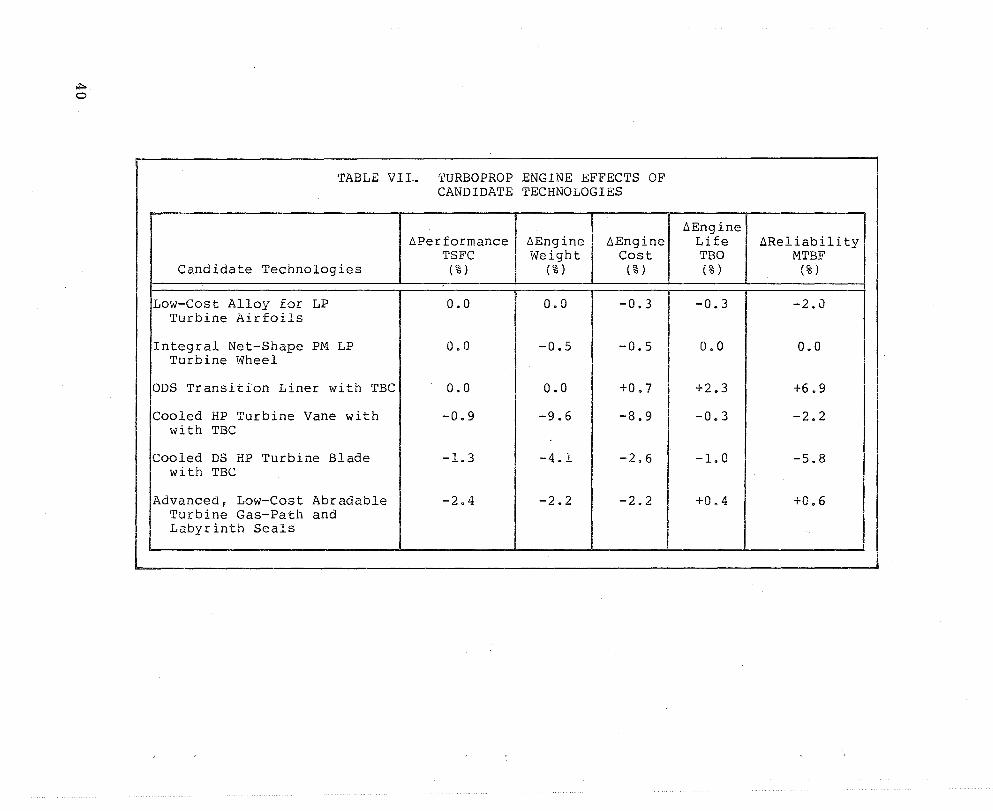
TABLE VII. TURBOPROP ENGINE EFFECTS OF CANDIDATE TECHNOLOGIES
llPerformance llEngine llEngine TSFC Weight Cost
Candidate Technologies (%) (%) (% )
Low-Cost Alloy for LP 0.0 0.0 -0.3 Turbine Air foils
Integral Net-Shape PM LP 0.0 -0.5 -0.5 Turbine Wheel
ODS Transition Liner with TBC 0.0 0.0 +0.7
Cooled HP Turbine Vane with -0.9 -9.6 -8.9 with TBC
Cooled DS HP Turbine Blade -1.3 -4.1 -2.6 with TBC
Advanced, Low-Cost Abradable -2.4 -2.2 -2.2 Turbine Gas-Path and Labyrinth Seals
llEngine Life llReliabili ty TBO MTBF (% ) (%)
-0.3 -2.0
0.0 0.0
+2.3 +6.9
-0.3 -2.2
-1.0 -5.8
+0.4 +0.6
the SPF technique.
through a reduction
improvement.
However, substantial benefits are realized
in weight and cost, and a reliability
The cooled HP turbine vane with TBC and the cooled DS HP tur
bine blade with TBC, offer a higher turbine stage temperature capa
bility to the TFE73l-3 and TPE331 baseline engines and, sub
sequently, a higher engine thrust and horsepower result. In the
case of the turbofan engine, the resultant engine thrust was
reduced to the baseline thrust at the altitude cruise design point
by scaling down the eng ine core flow by increasing the bypass
ratio. TSFC was optimized by varying the cycle-pressure ratio. A
pressure ratio of 25:1 was selected, as the maximum, for the cycle
analysis. In the case of the turboprop engine, the resul tant
increase in horsepower was reduced to the baseline level by scaling
down the engine based on core flow for a fixed engine frame size.
Both the vane and blade wi th 'l'BC were compared to the baseline com
ponents on a constant airfoil life basis. It was assumed that the
other turbine components would require minor redesigns, as well as
increased cooling, due to the increase in turbine gas temperature.
Performance penalties were also assessed because of the increased
surface roughness of the TBC. Because the turbofan baseline engine
has an uncooled DS, HP turbine blade, performance benefits of a
cooled DS blade were subtracted from the cooled DS blade with TBC
in order to properly evaluate the TBC technology for the turbine
blade. Increases in centr ifugal stresses due to the TBC on the
blade were taken into account for both the turbofan and turboprop
engines. The large reduction in engine cost. and weight for the
vane with TBC technology is primarily due to the increase in bypass ratio for the turbofan engine and the decrease in core flow for the
turboprop engine.
Performance improvements due to the advanced, low-cost abrad
able turbine gas-path and labyrinth seals are the result of reduced
turbine blade tip seal clearance and decreased cooling air leakage
41
through labyrinth seals. Both the turbofan and turboprop baseline
engines include MATE Project 2 abradable seal improvements.
The primary benefit of the ODS transition liner with TBe is an
improvement in life and reliability. This technology results in a
higher engine cost due to the anticipated increase in the tran
sition liner component cost.
The high-temperature dual-alloy turbine disk is used in con~
junction with uncooled inserted HP turbine blades. For this
reason, it is evaluated for the TFE73l-3 engine only, since the
baseline turboprop engine has cooled HP turbine blades. Per
formance improvements result from reduced cooling air to the disk.
A cost increase is expected relative to the current machined
forging.
The elimination of mid-span dampers for the fan blade tech
nology improves the aerodynamic efficiency of the fan, thereby pro
ducing an overall engine performance improvement. The low-aspect
ratio design reduces the fan blade weight and a corresponding
reduction in disk weight. This candidate technology is more appli
cable to the TFE76. Therefore, although the engine demonstration
test would be done on the TFE76, the cost benefit study utilizes
the TFE731-3 baseline engine model.
The integral net-shape PM turbine wheel reduces the overall
cost compared to an inserted blade/disk assembly. Weight would
also be reduced through the elimination of the blade/disk attach
ment. This technology would apply to the turboprop engine only.
42
The primary benefit of the low-cost alloy for LP turbine air
foils is a reduction in material cost. It was found, however, that
the mater ial cost of these components is small relative to the
overall manufacturing cost. Overall cost savings, therefore, are
minimal. Decreases in life and reliability are the result of the
lower temperature capability and the decrease in material strength.
43

AIRCRAFT CONSIDERATIONS
Aircraft Selection
The turbofan aircraft selected for the cost/benefit analysis
is a nonrevenue producing, business-type, twin-engine aircraft in
the 6800- to 9100-kg (15,000- to 20,000-lb) gross weight class (as
previously discussed in the baseline engine selection section).
The aircraft is an all new design based on a composite aircraft
similar to the Gates Learjet 35/36 (shown in Figure 8). The air
craft parameters set for the modeling were:
o 4000 potential aircraft
o 600-hours annual utilization
o 25-year service life
o 7710-kg (17,000-lb) takeoff gross weight
o 953-kg (2100-lb) payload
o 3700-km (2300-mi) range
The Rockwell Turbo Commander 980 (Figure 9) was chosen to be
representative of a TFE331-10 powered business-type aircraft. The
following aircraft parameters were set for the LCC analysis:
o 5200 potential aircraft
o 550-hours annual utilization
o 25-year service life
o 4683-kg (lO,325-lb) takeoff gross weight
o 410-kg (90S-lb) payload
o 4500-km (2800-mi) range
44

Figure 8. Gates Learjet 35/36.
45 MP-58990

46
ROCKWELL TURBO COMMANDER
FAIRCHILD/SAAB-SCANIA SFJOOO COMMUTER AIRCRAFT
Figure 9. Turboprop Business Aircraft and Turboprop Commuter Aircraft.
The turboprop-powered commuter aircraft used in the analysis
was assumed to be similar to the 30-passenger Fairchild/Saab
Scannia SF 3000 (Figure 9). The following summarizes the aircraft
parameters set for this aircraft:
o 1000 potential aircraft
o 3000-hours annual utilization
o 15-year service life
o 10,930-kg (24,100-lb) takeoff gross weight
o 2,721-kg (6000-lb) payload
o 1,590-km (990-mi) range
Aircraft Baseline Life-Cycle Cost/ Direct-Operating Cost
The baseline operating and maintenance parameters for the
selected twin-engine aircraft are shown in Tables VIII, IX, and X.
Operating costs are established from these parameters for one air
craft and extended for the entire fleet of aircraft and service
life, utilizing the Lee models for the business aircraft and the
direct-operating cos~ models for the commuter aircraft as described
in Appendix A. Tables XI and XII present the baseline Lee for the
turbofan and the turboprop business aircraft. Table XIII summa-
rizes the baseline direct-operating costs for the turboprop commuter
aircraft.
47

48
TABLE VIII. BASELINE TURBOFAN BUSINESS AIRCRAFT OPERA'rING AND MAIN'fENANCE PARAMETERS
~:~as~e~TR~eT17a~te~dr------------------------~------~---------------------------------
o Aircraft acquisition cost, $(10 6 )
Engine acquisition cost, $(10 6 ) o
o
o
Airframe fixed weight cost, $/kg ($/lb)
Airframe variable weight cost, $/kg ($/lb)
o Equity, %
o Loan interest rate, %
o Imputed interest, % o Insurance rate, %
o Property tax rate, %
Operation Related
o Annual crew wages, $
o Annual crew expenses, $
o Annual hanger cost, $
o Fuel weight, kg (lb)
o Annual landing/parking fees, $
o Annual miscellaneous costs, $
o Annual utilization, hrs
o Fuel price, ¢/liter (¢/gal)
o Flight Mach number
o
o
Maximum sea-level, static thrust, daN (lb)
Average cruise thrust, daN (lb)
o
o
o
o
o
Average cruise TSFC, kg/hr/daN (lb/hr/lb)
Average cruise L/D
Payload, kg (lb)
Cruise range, hrs
Service life, years
Maintenance Related
0 Annual preflight servicing cost, $
0 Engine inspection cost, S/flt-hr
0 Annual engine overhaul cost, S
0 Annual engine unscheduled repair cost, S
0 Airframe inspection cost, S/flt-hr
0 Annual airframe overhaul cost, S
0 Annual airframe unscheduled repair cost, $
2.63 (includes engine cost)
0.80 (two engines)
357 (162)
714 (324)
40
12
12 1
1
70,000
6,400
8,050
2,800 (6,172)
1,610
1,400
60(1
31.7 (120)
0.85
1,779 (4,000)
363 (817)
0.745 (0.732)
11.15
765 (1,686)
6.13
25
6,300
7
23,710
5,847
14.80
24,219
5,847
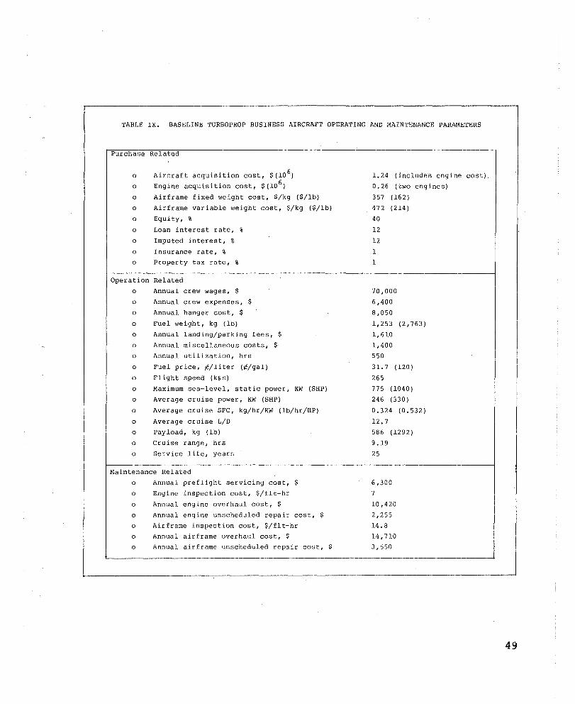
TABLE IX. BASELINE TURBOPROP BUSINESS AIRCRAFT OPERATING AND MAINTENANCE PARAMETERS
Purchase Related
o
o o
o
o
o
o
o
o
Aircraft acquisition cost, $(10 6)
Engine acquisition cost, $(10 6 )
Airframe fixed weight cost, $/kg ($/lb)
Airframe variable weight cost, $/kg ($/lb)
Equity, %
Loan interest rate, %
Imputed interest, %
Insurance rate, %
Property tax rate, %
Operation Related
o
o
o
o
o
o
o
o
o o
o
o
o
o
o
o
Annual crew wages, $
Annual crew expenses, $
Annual hanger cost, $
Fuel weight, kg (lb)
Annual landing/parking fees, $
Annual miscellaneous costs, $
Annual utilization, hrs
Fuel price, ¢/liter (¢/gal)
Flight speed (k&s)
Maximum sea-level, static power, KW (SHP)
Average cruise power, KW (SHP)
Average cruise SFC, kg/hr/KW (lb/hr/HP)
Average cruise L/D
Payload, kg (lb)
Cruise range, hrs
Service life, years
Maintenance Related
o
o
o
o
o
o
o
Annual preflight servicing cost, $
Engine inspection cost, $/flt-hr
Annual engine overhaul cost, $
Annual engine unscheduled repair cost, $
Airframe inspection cost, $/flt-hr
Annual airframe overhaul cost, $ Annual airframe unscheduled repair cost, $
1.24 (includes engine cost).
0.26 (cwo engines)
357 (162)
472 (214)
40
12
12
1
1
70,000
6,400
8,050
1,253 (2,763)
1,610
1,400
550
31. 7 (120)
265
775 (1040)
246 (330)
0.324 (0.532)
12.7 586 (1292)
9.19
25
6,300
7
10,420
2,255
14.8
14,710 3,55fl
49

50
TABLE X. BASELINE TURBOPROP COMMUTER AIRCRAFT OPERATING AND MAINTENANCE PARAMETERS
PurchaseR =-e--.l-a'7t-e-d,-----------------------------------------------------------
o
o
Aircraft acquisition cost, $(10 6 )
Engine acquisition cost, $(10 6 )
3.00 (include engine cost)
0.50 (two engines)
--------------------------------------------------------- ----------------\ Operation Related
o
o
o
o
o
o
o
o
o
o
o
o
o
o
o
o
o
o
Airframe depreciation, $/flt-hr
Engine depreciation, $/flt-hr_
Airframe insurance, $/flt-hr
Engine insurance $/flt-hr
Crew costs, $/flt-hr
Fuel costs, $/flt-hr
Oil costs, $/flt-hr
Fuel weight, kg (lb)
Annual utilization, hrs
Fuel prices, ¢/liter (¢/gal)
Flight speed, kts
Maximum sea-level, static power, KW (SHP)
Average cruise power, KW (SHP)
Average cruise SFC, kg/hr/KW (lb/hr/HP)
Average cruise, LID
Payload, kg (lb)
Cruise range, hrs
Service life, years
74.38
17.71
12.89
2.00
66.82
300.75
0.44
1,432 (3,157)
3,000
53 \200)
269
1,268 (1,700) 703 (943)
0.338 (0.551)
10.36
2.721 (6,000)
3.19
15
r-----------------------------------------------------------------------------~----~ Maintenance Related
o
o
o
o
o
o o
Airframe maintenance labor cost, $/flt-hr
Airframe maintenance parts cost, $/flt-hr
Engine repair labor, $/flt-hr
Engine repair and maintenance parts cost,
Engine refurbish labor cost, $/flt-hr
Engine refurbish parts cost, $/flt-hr
Engine inspection cost, $/flt-hr
18.65
36.25
0.76
$/fl t-hr 17.04 4.89
12.21
0.03 L-_________________________________________________________________ --___________ ~
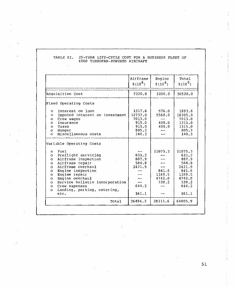
TABLE XI. 25-YEAR LIFE-CYCLE COST FOR A BUSINESS FLEET OF 4000 TJRBOFAN-POWERED AIRCRAFT
r---Airframe Engine Total
$ (10 6) $ (10 6) $ (10 6)
Acquisition Cost 7320.0 3200.0 10520.0
Fixed Operating Costs
0 Interest on loan 1317.6 576.0 1893.6 0 Imputed interest on investment 12737.0 5568.0 18305.0 0 Crew wages 7013.0 -- 7013.0 0 Insurance 915.0 400.0 1315.0 0 Taxes 915.0 400.0 1315.0 0 Hanger 805.3 -- 805.3 0 Miscellaneous costs 140.3 -- 140.3
Variable Operating Costs
0 Fuel -- 11075.3 11075.3 0 Preflight servicing 631. 2 -- 631. 2 0 Airframe inspection 887.9 -- 887.9 0 Airframe repair 584.8 -- 584.8 0 Airframe overhaul 2421. 9 -- 2421. 9 0 Engine inspection -- 841. 6 841. 6 0 Engine repair -- 1169.5 1169.5 0 Engine overhaul -- 4742.0 4742.0 0 Service bulletin incorporation -- 339.2 339.2 0 Crew expenses 644.2 -- 644.2 0 Land ing , parking, cater ing,
etc. 161.1 -- 161.1 r--
Total 36494.3 28311. 6 64805.9
51

52
TABLE XII. 25-YEAR LIFE-CYCLE COST FOR A BUSINESS FLEET OF 5200 TURBOPROP~POWERED AIRCRAFT
Airframe Engine Total
$(10 6 ) $(10 6 ) $(10 6 ) - - --
Acquisition Cost 5096.0 1352.0 6448.0
Fixed Operating Costs
0 Interest on loan 917.2 243.4 1160.6 0 Imputed interest on investment 6113.1 1621. 9 7735.0 0 Crew wages 9100.0 -- 9100.0 0 Insurance '637.0 169.0 806.0 0 Taxes 637.0 169.0 806.0 0 Hanger
}1228.5 1228.5 --0 Miscellaneous costs .--
Variable Operating Costs
0 Fuel -- 3793.5 3793.5 0 Preflight servicing 598.0 221. 0 819.0 0 Airframe inspection 1058.2 -- 1058.2 0 Airframe repair 461. 5 -- 461. 5 0 Airframe overhaul 1912.3 -- 1912.3 0 Engine inspection -- 1001. 0 1001. 0 0 Engine repair -- 586.3 586.3 0 Engine overhaul -- 2709.2 2709.2 0 Crew expenses 832.0 -- 832.0 0 Land ing , par king, cater ing,
etc. 209.3 -- 209.3
Total 28800.1 11866.3 40666.4
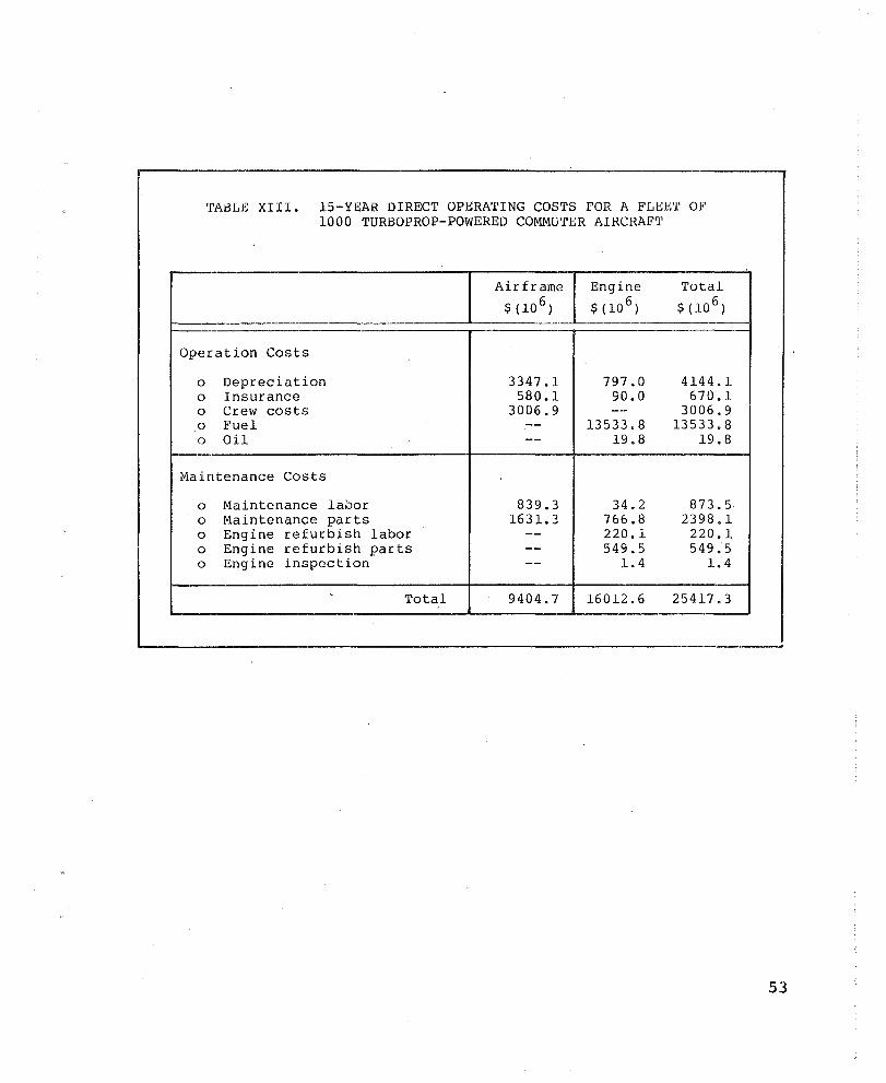
TABLE XIII. 15-YEAR DIRECT OPERATING COSTS FOR A FLEET OF 1000 TURBOPROP-POWERED COMMUTER AIRCRAFT
Airframe Engine Total
$ (10 6 ) $ (10 6 ) $(10 6 )
Operation Costs
0 Depreciation 3347.1 797.0 4144.1 0 Insurance 580.1 90.0 670.1 0 Crew costs 3006.9 -- 3006.9 0 Fuel -- 13533.8 13533.8 0 Oil -- 19.8 19.8
Maintenance Costs
0 Maintenance la00r 839.3 34.2 873.5 0 Maintenance parts 1631. :; 766.8 2398.1 0 Engine refurbish labor -- 220.1 220.1 0 Engine refurbish parts -- 549.5 549.5 0 Engine inspection -- 1.4 1.4
Total 9404.7 16012.6 25417.3
53

AIRCRAFT BENEFIT ANALYSIS
Trade Factors
AiResearch has developed a technique for determining aircraft
LCC that begins wi th the formulation of a takeoff gross weight (TOGW)
model for the aircr aft, and proceeds to the formulation of the cost models for development, acquisition, operation, and mainten
ance costs for both the airframe and eng ine. This technique allows airframe weight and cost to be evaluated as changes in
engine parameters, especially engine weight and fuel consumption,
are considered.
Chang ing the airplane si ze and, hence, eng ine si ze for the
turboprop-powered commuter aircraft requires a direct operating
cost (DOC) model. As in the LCC model, the DOC analysis begins
with the formulation of a TOGW model.
Sensitivity coefficients of the TOGW model are obtained for
changes in engine TSFC and weight. Then, cost models for develop
ment, acquisition, operation, ~nd maintenance are prepared, and
the baseline costs are formulated as previously noted. A LCC/DOC
model is assembled from these models based upon linearized effects
of various engine parameters, and LCe/DOC sensitivity coefficients
developed for eng ine TSFC, weight, cost, life (TBO), and reliability (MTBF). When applied to engine design changes, these
coefficients will project a change in LCC/DOC.
Descriptions of the aircraft weight models and the various cost models are included in Appendix A of this report.
Sensitivity coefficients for changes in engine weight and
fuel consumption are calculated by changing the appropriate ele
ments of the TOGW equation. For instance, sensitivity to changes
54
in engine weight is determined by changing the engine weight in the installed engine weight (lEW) element and calculating a new
takeoff gross weight. The aircraft fixed weight element is held
constant for the specific aircraft designs since this element
represents basically the payload. The new takeoff gross weight is portioned using the original weight f~actions established for the aircr aft, and. new we ights and thrust are calculated.
In a similar manner, sensitivity coefficients are calculated for changes in engine fuel consumption. The sensitivity coeffic
ients calculated for changes in engine weight and TSFC for the
analysis are tabulated in Tables XIV, XV, and XVI. The new
thrust, fuel weight, and other parameters listed in the above
tables are utili zed in the appropr i ate LCC and DOC models, presented in Appendix A, to obtain the sensitivity of engine weight
and TSFC changes on aircraft LCC and DOC.
In addition, sensitivity to engine cost, time-betweenoverhaul (TBO) , and mean-time-between-failure (MTBF) are also
calculated.
The change in· LCC and direct-operating C0St resulting from a
one-percent change in TSFC, engine weight, engine cost, TBO, and
MTBF are tabulated in Tables XVII, XVIII, and XIX.
55

TABLE XIV. SENSITIVITY COEFFICIENTS CALCULATED FOR CHANGES IN ENGINE WEIGHT (ATSFC) AND (AWE) FOR TURBOFAN AIRCRAFT
Parameter lITSFC :: -1% lIWE :: -1%
AThrust -1. 7% -0.7% lIFuel weight -2.5% -0.7% AEngine installed weight -1. 7% -1. 7% lIAirframe variable weight -1. 7% -0.7% AAircraft empty weight -1.8% -0.8%
TABLE XV. SENSITIVITY COEFFICIENTS CALCULATED FOR CHANGES IN ENGINE WEIGHT (ATSFC) AND (AWE) FOR TURBOPROP BUSINESS AIRCRAFT
Parameter ATSFC = -1% AWE'" -1%
AHorsepower -1.1% -0.6% AFuel weight -1.9% -0.6% AEngine installed weight -1.1% -1.5% LlAirframe variable weight -1.1% -0.6% AAircraft empty weiyht -1.1% -0.7%
TABLE XVI. SENSITIVITY COEFFICIENTS CALCULATED FOR CHANGES IN ENGINE WEIGHT (ATSFC) AND (LlWE) FOR TURBOPROP COMMUTER AIRCRAFT
Parameter LlTSFC '" -1% AWE :: -1%
AHorsepower -0.3% -0.1% AFuel weight -1.5% -0.1% LlEng ine installed weight -1.3% -1.1% AAirframe variable weight -0.3% -0.1% AAircraft empty weight -0.4% -0.2%
56
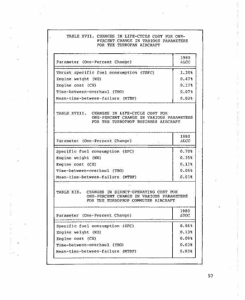
TABLE XVII. CHANGES IN LIFE-CYCLE COST FOR ONEPERCENT CHANGE IN VARIOUS PARAMETERS FOR THE TURBOFAN AIRCRAFT
1980 Parameter (One-Percent Change) L1LCC
Thrust specific fuel consumption (TSFC) 1. 20%
Engine weight (WE) 0.47 %
Eng ine cost (CE) 0.l7%
Time-between-overhaul (TBO) 0.07%
Mean-time-between-failure (MTBF) 0.02%
TABLE XVII I. CHANGES IN LIFE-CYCLE COST FOR ONE-PERCENT CHANGE IN VARIOUS PARAMETERS FOR THE TURBOPROP BUSINESS AIRCRAFT
1980 Parameter (One-Percent Change) L1LCC
Specific fuel consumption (SFC) 0.70%
Engine weight (WE) 0.35%
Engine cost (~E) 0.11%
Time-between-overhaul (TBO) 0.06%
Mean-time-between-failure (MTBF) 0.01%
'l'ABLE XIX. CHANGES IN DIRECT-OPERATING COST FOR ONE-PERCENT CHANGE IN VARIOUS PARAMETERS FOR THE TURBOPROP COMMUTER AIRCRAFT
1980 Parameter (One-Percent Change) L1DOC
Specific fuel consumption (SFC) 0.86%
Engine weight (WE) 0.13%
Engine cost (CE) 0.09 %
'l'ime-between -eve r hau 1 (TBO) 0.03%
Mean-time-between-failure (MTBF) 0.03%
57
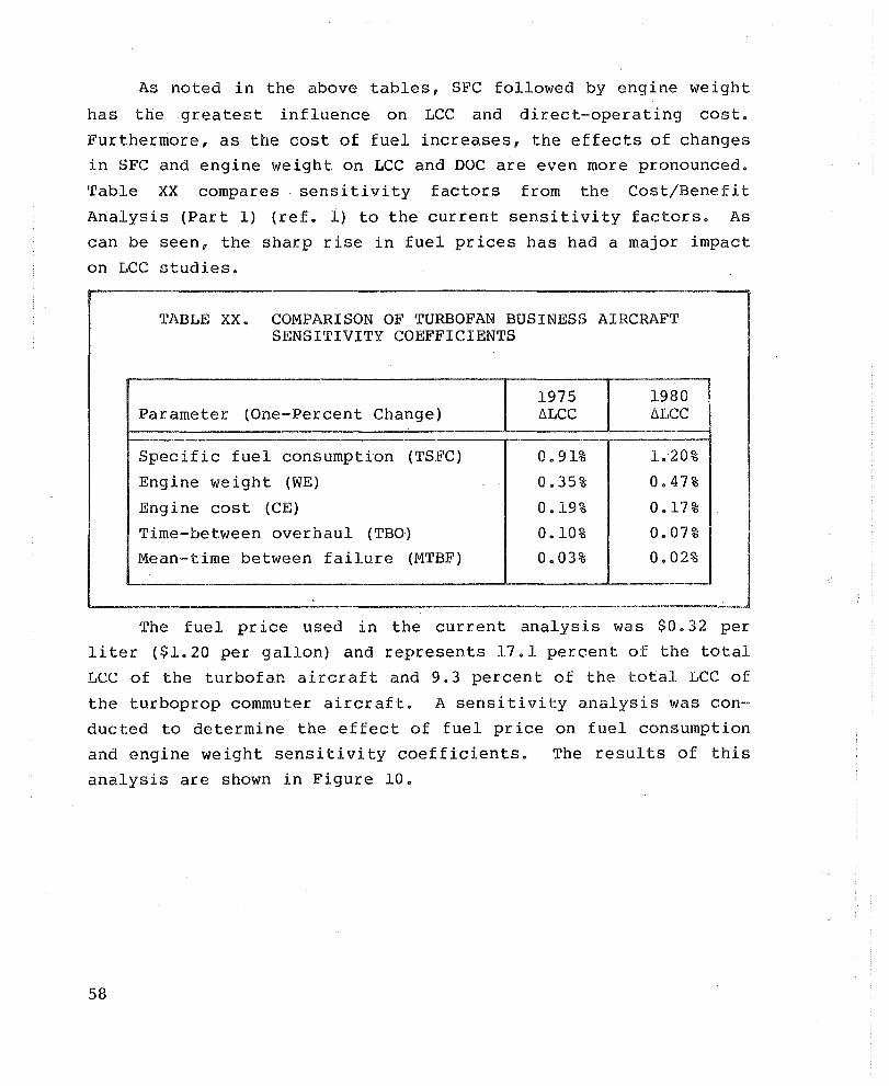
As noted in the above tables, SFC followed by engine weight
has the greatest influence on LCC and direct-operating cost.
Furthermore, as the cost of fuel increases, the effects of changes
in SFC and engine weight on LCC and DOC are even more pronounced.
Table XX compares sensitivity factors from the Cost/Benefit
Analysis (Part 1) (ref. 1) to the current sensitivity factors. As
can be seen, the sharp rise in fuel prices has had a major impact
on J ... CC studies.
TABLE XX. COMPARISON OF TURBOFAN BUSINESS AIRCRAFT SENSITIVITY COEFFICIENTS
1975 1980 Parameter (One-Percent Change) ilLCC 6LCC
Specific fuel consumption (TSFC) 0.91% 1. 20%
Engine weight (WE) 0.35% 0.47%
Engine cost (CE) 0.19% 0.17%
Time-between overhaul (TBO) 0.10% 0.07%
Mean-time between failure (lVITBF) 0.03% 0.02%
-
The fuel pr ice used in the cur rent analysis was $0.32 per
liter ($1.20 per gallon) and represents 17.1 percent of the total
LCC of the turbofan aircraft and 9.3 percent of the total LCC of
the turboprop commuter aircraft. A sensitivity analysis was con
ducted to determine the effect of fuel price on fuel consumption
and engine weight sensitivity coefficients. The results of this
analysis are shown in Figure 10.
58
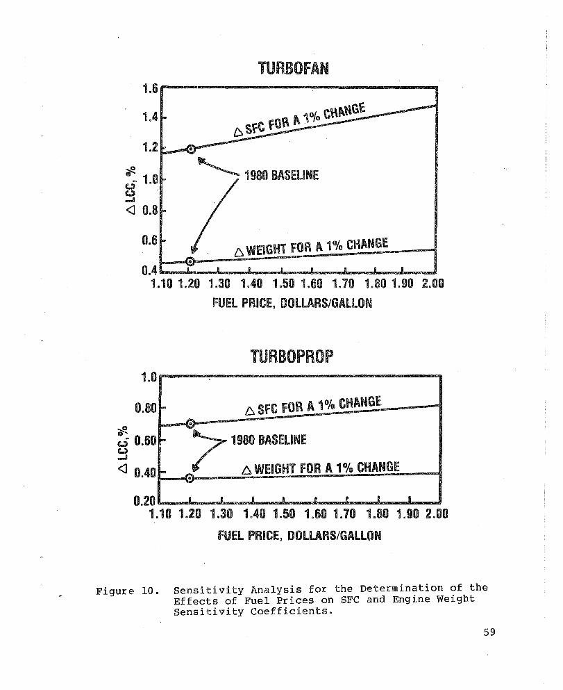
TURBOfAN
..
~ 1980 BASELINE
t::::. WEIGHT fOR A 1 % CHANGE
0.4 .................. _"""'-........I._"""""-_ ........... _L.......-J... ........... .L......-.i 1.10 1.20 1.30 1.40 1.50 1.60 1.70 1.80 1.90 2.00
fUEL PRICE, DOLLARS/GAllON
TURBOPROP 1.0
0.80 ~ 6. 8FC FOR Itt. 1 % CHANGE ...... .. """:.
... ~ 1980 BASELINE ~ c.;; 0.60 C'..) ..... <l 0.40
0.20
I- _ I::. WEIGHT FOR A 1% CHANGE .. -• m • R II 8 I 8
1.10 1.20 1.30 1.40 1.50 1.60 1.70 1.80 1.90 2.00
fUEL PRICE, DOLLARS/GALLON
Figure 10. Sensitivity Analysis for the Determination of the Effects of Fuel Prices on SFC and Engine Weight Sensitivity Coefficients.
59

Aircraft Benefits
The nine candidate material technologies were evaluated
against the baseline engine for TSFC, weight, cost, TBO, and MTBF
as previously shown. These engine results were then incorporated
in the aircraft LCC and DOC models using the factors previously
descr ibed. The results of this analysis, in terms of change in
aircraft LCC and DOC, are listed in Tables XXI, XXII, and XXIII.
60
TABLE XXI. REPRESENTATIVE TURBOFAN AIRCRAFT LIFE-CYCLE-COST RANKING
.-----.------------------------------~ ... ---LlLCC
Rank Technology $ (10 6 )
1 Low-cost/lightweight exhaust mixer nozzle (compared to coannular nozzle) -2281
2 Cooled turbine vane with TBC -2229
3 Advanced abradable gas-path and labyrinth seals -1529
4 Low-cost/lightweight exhaust mixer nozzle (compared to welded nozzle) -1186
5 Damperless fan blades -1056
6 High-temperature dual-alloy turbine disk -622
7 Cooled turbine blades with TBC -331
8 ODS transition liner with TBC -80
9 Low-cost alloy for LP turbine airfoils -8
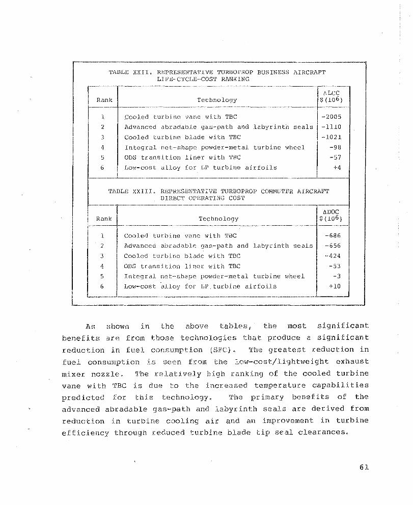
----------------"'-"'--------~-----------.--------'1
TABLE XXII. REPRESENTATIVg TURBOPROP BUSINESS AIRCRAFT LIFE-CYCLE-COST RANKING
Rank 'I'echnology llLCC
$ (10 6 )
1.
2
3
4
5
6
--------.----.---------.-~-
cooled turbine vane with TBC
Advanced abradable gas-path and labyrinth seals
Cooled turbine blade with TBC
Integral net-shape powder-metal turbine wheel
ODS transition liner with TBC
Low-cost alloy for LP turbine airfoils
-2005
-lllO
-1021
-98
-57 +4
---------- -------------------.----------.. -----------___ ---'-____ --1
TABLE XXIII, REPRESEN'I'ATIVE TURBOPROP COMMUTFR AIRCRAF'T DIREC'r OPERATING COST
----.----- _.-----------_.-._--_._----------------------------_.---~,
Rank
1
2
3
4
5
6
Technology ----_._._--_._---------_._--_._-----_._--
Cooled turbine vane with TBC
Advanced abradable gas-path and labyrinth seals
Cooled turbine blade with THC
ODS transition liner with THC
Integral net-shape powder-metal turbine wheel
Low-cost alloy for LPturbine airfoils
£lDGC $(10 6 )
--686
-·656
-424
-53
-3
+10
_._-_._._--------------_._--... ----_._--_._---_._--_._.-._-------_ .... _-----------'
As shown in the above tables f the most significant
benefits are from those technologies that produce a significant
reduction in fuel consumption (SFC). The greatest reduction in
fuel consumption is seen from the low~cost/lighbveight exhaust
mixer nozzle. The relatively high ranking of the cooled turbine
vane wi th crBe is due to the increased tempera lure capabili ties
predicted for this technology. The primary benefits of the
advanced abradable gas-path and labyrinth seals are derived from
reduction in turbine cooling aLe and an improvement in turbine
efficiency through reduced turbine blade tip seal clearances.
61
RESULTS AND DISCUSSION
Relative Value Analysis
Since the nine mater ial technologies studied here are cur
rently at different stages in their development cycles, the delta
life-cycle costs indicated for these technologies are not neces
sar ily repres~ntative of their current investment worth. The
indicated benefits need to be qualified by the current estimated
development costs and risks associated with each technology. One
method of accomplishing this is by utilizing a NASA-developed
parameter termed "Relative Value" as defined below:
6LCC or 6DOC . . Relative Value = Development Cost x ProbabIlIty of Success (4)
This parameter was calculated for each of the nine material tech
nologies using the project probability of success developed in the
risk analysis, the technology development cost, and the delta
life-cycle cost, and direct-operating cost calculated for each
technology. The resulting values are shown in Tables XXIV, XXV,
and XXVI with the technologies listed in order of decreasing Rela
tive Value.
The highest Relative Value ranking is the low-cost/lightweight
exhaust mixer nozzle. The mixer nozzle performance benefits far
outweigh the cost and weight penalties imposed comparing it to the
current coannular exhaust nozzle. The exhaust mixer nozzle tech
nology also enjoys the highest project probability of success.
The exhaust mixer nozzle technology is followed by the cooled tur
bine vane with TBC and the advanced abradable gas-path and laby
rinth seals in the Relative Value ranking. It is interesting to
note that the cooled turbine vane with TBC ranks first for the
turboprop-'powered business aircraft and the advanced abradable
gas-path and labyrinth seals ranks first for the turboprop-powered
commuter aircraft. This is pr imar ily due to two factors. The
62
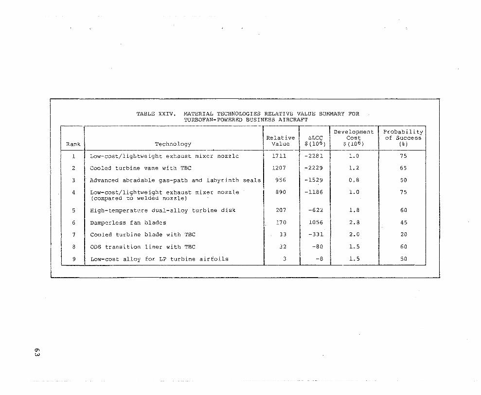
Rank
1
2
3
4
5
6
7
8
I 9
TABLE XXIV. MATERIAL TECHNOLOGIES RELATIVE VALUE SUMMARY FOR TURBOFAN-POWERED BUSINESS AIRCRAFT
Technology ~-----
Low-cost/lightweight exhaust mixer nozzle
Cooled turbine vane with TBC
Advanced abradable gas-path and labyrinth seals
Low-cost/lightweight exhaust mixer nozzle (compared to welded nozzle)
High-temperature dual-alloy turbine disk
Damperless fan blades
Cooled turbine blade with TBC
ODS transition liner with TBC
Low-cost alloy for LP turbine airfoils
--
I Relative
Value
1711
1207
956
890
207
170
33
32
3
I De
e:.LCC~ $ (10 6 )
-2281
-2229
-1529
-1186
-622
1056
-331
-80
-8
velopment Cost
$ (10 6 )
1.0
1.2
0.8
1.0
1.8
2.8
2.0
1.5
1.5
Probabili ty I of Success
(%)
75
65
50
75
60
45
20
60
50
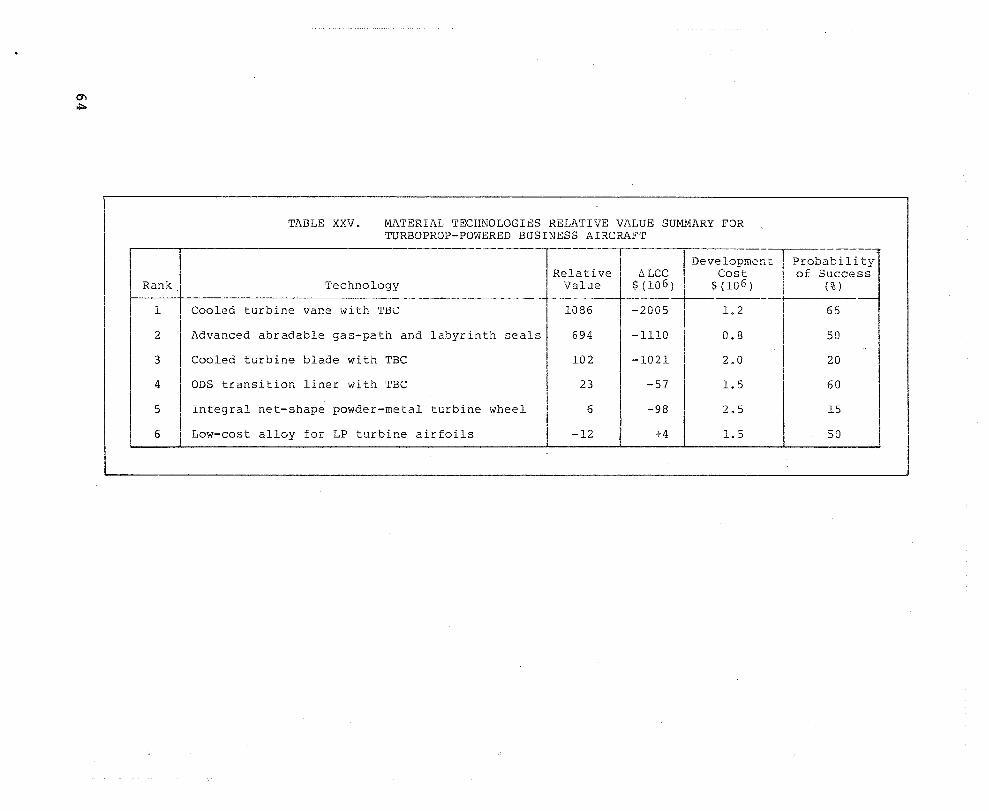
Rank.
1
2
3
4
5
6
TABLE XXV. MATERIAL TECHNOLOGIBS RELATIVE VALUE SUMMARY FOR TURBOPROP-POWERED BUSINESS AIRC~~FT
------r---~--~--;-.-De--ve-lo-p--me-nt---.----pr-ob-a-b·-n-i-t-; Technology ______ J~v-:a;uieve $1~~~) $ ~~~~) ___ +-_O_f_S_t_%c_)c_e_.s_.s __ _
Cooled turbine vane with TBC ~ I 1086 -2005 1. 2 65
Advanced abradable gas-path and labyrinth seals. 694 I -1110 I 0.8 50 !
Cooled turbine blade with TBC 102 -1021 2.0 20
ODS transition liner with TBC 23 -57 1.5 60
Integral net-shape powder-metal turbine wheel 6 -98 2.5 15
Low-cost alloy for LP turbine airfoils -12 +4 1.5 50
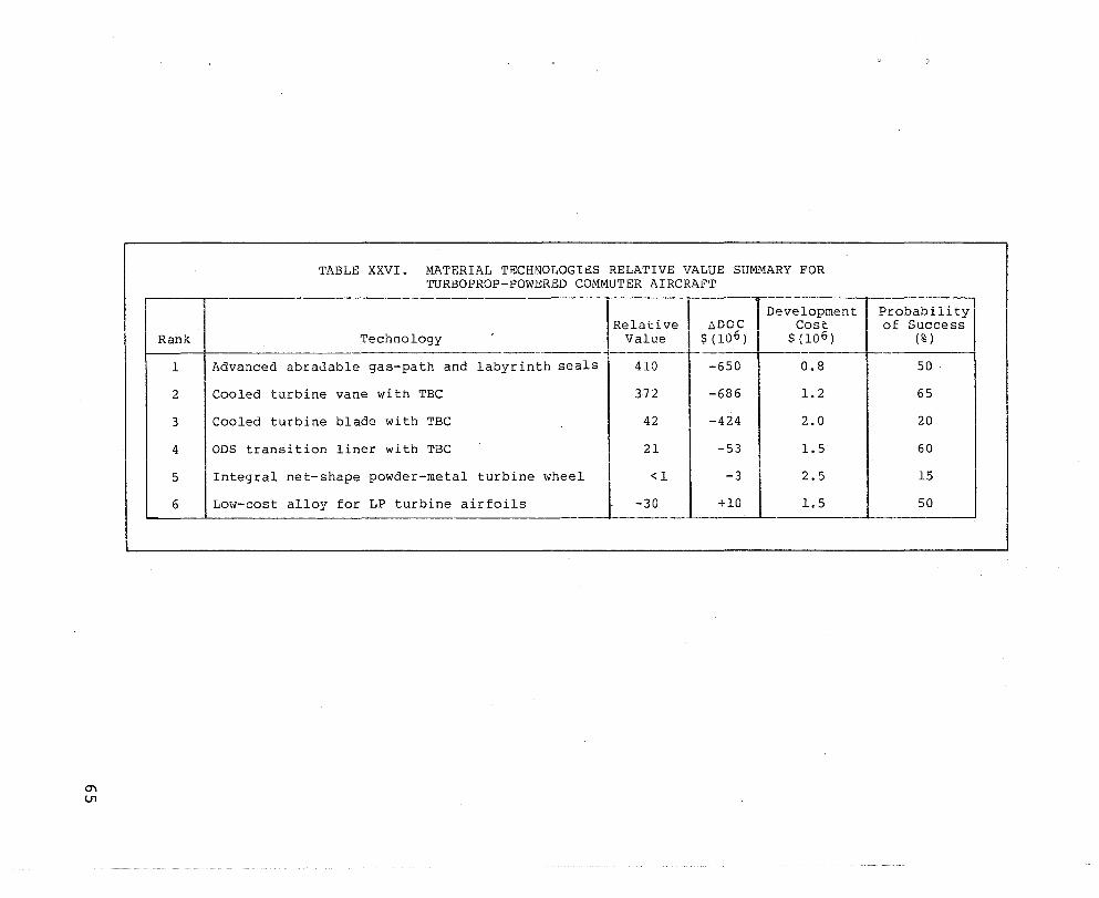
Rank
1
2
3
4
5
6
TABLE XXVI. MATERIAL TECHNOLOGIES RELATIVE VALUE SUMMARY FOR TURBOPROP-POWERED COMMUTER AIRCRAFT
Development
Technology
Advanced abraJable gas-path and labyrinth seals
Cooled turbine vane with TBC
Cooled turbine blade with TBC
ODS transition liner with TBC
Integral net-shape powder-metal turbine wheel
Low-cost alloy for LP turbine airfoils
Relative Value
-410
372
42
21
<1
-30
lIDOC Cost $ (10 6 ) $(10 6 )
-- ---650 0.8
-686 1.2
-424 2.0
-53 1.5
-3 2.5
+10 1.5
Probability of Success
(% ) r---
50
65
20
60
15
50

commuter aircraft is much more sensitive to SFC compared to engine weight and cost, and the MTBF sensitivity becomes more important
relative to the other sensitivity coefficients as shown in Tables XVIII and XIX.
66
AIRESEARCH CORPORATE RANKING
The low-cost/lightweight exhaust mixer nozzle, the cooled HP
turbine vane with TBe, and the advanced, low-cost abradable turbine
gas-path and labyrinth seals technologies that rank highest on the
Relative Value basis and showed the largest reduction in life-cycle cost and direct-operating cost were also highest in the AiResearch
priority ranking. The ranking for the ten candidate technologies
is presented in Table XXVII.
The low-cost/lightweight titanium exhaust mixer nozzle tech~ nology received the highest corporate ranking primarily because of
the potential performance improvement gains. Unlike technologies
which require higher turbine inlet temperatures (with a subsequent
engine redesign) to achieve their greatest performance improvement
potential, the exhaust mixer nozzle will replace the current
coannular nozzles wi thout any basic eng ine changes. The cost/
benefit analysis results also show that the mixer nozzle manufactured using the SPF method has substantial savings in weight and
cost compared to a mixer nozzle manufactured using conventional forming and welding techniques~
Cooled HP turbine vane durability has always been a prime con
cern in the design and development of high-temperature gas turbine
eng ines • The cooled HP turbine vane wi th TBC technology would
greatly enhance the cooling effectiveness of vanes designed for
high-temperature operation. This technology has the highest payoff
for vanes designed with sophisticated cooling schemes, since the
insulating effect of the TBe is more beneficIal with an increase in
heat flux through the airfoil wall.
The advanced, low-cost abradable turbine gas-path and labyrinth seals technology ranked high in the AiResearch priority
ranking due to the reduced cooling air and improved turbine effic-
iency benef i ts. rrurbine blade tip seal clearances have a very
67

68
TABLE XXVII. AIRESEARCH CORPORATE RANKING OF THE MATERIAL TECHNOLOGIES
1. Low-cost/lightweight exhaust mixer nozzle - TFE only.
2. Cooled HP turbine vane with TBC.
3. Advanced, low-cost abradable turbine gas-path and laby
rinth seals.
4. High-temperature dual-alloy turbine disk - TFE only.
5. Damperless fan blade - TFE only.
6. Cooled directionally solid if ied HP turbine blade with
TBC.
7. Oxide-dispersion strengthened transition liner with
TBC.
8. Integral net-shape power-metal turbine wheel - TPE only.
9. Low-cost alloy for LP turbine airfoils.
strong influence on turbine performance because of the short tur
bine blade length of small gas turbine engines. It is felt that
this technology would be especially well suited for the current
TPE33l-l0 engine.
A low-cost directionally-solidified (DS) turbine blade was
developed under the NASA MATE Project 1 and is currently in produc···
tion use on the TFE73l-3-l00 eng ine. Although the high--temper;3. ture;
dual-alloy turbine disk technology did not rank very high in the
Relative Value ranking, it would greatly reduce the amount of
cooling air required to cool the disk and blade attachment in ,
designs which incorporate an uncooled HP turbine blade, such as the
TFE73l-3-l00.
The damper less fan blade technology is applicable to new low
aspect-ratio fan blade designs that would not require a mid-span
damper. This type of design results in improved aerodynamics and
reduced fan stage weight.
The cooled DS HP turbine blade with TBC technology, like the
vane with TBC, has its highest payoff in a high-temperature appli
cation. The turbine blade with TBC, however, is less attractive
because of the higher centrifugal stresses in the blade due to the
TBC coating and the higher development risk.
The ODS transition liner with TBC technology would greatly
improve the life and reliability of the burner transition liner.
However, this technology ranks low, since there is no performance
improvement associated with this component and finished part cost
would be twice that of current transition liners.
The primary benefit of the integral net-shape PM turbine wheel
is to improve the material properties relative to Inco 73lLC. This
technology has a low ranking because of the high estimated develop
ment costs and the very low project probability of success.
69

The technology receiving the lowest ranking is the low-cost
alloy for LP turbine airfoils. This technology actually produces
an increase in life-cycle cost and direct-operating cost and would
not be a viable candidate unless there is a sharp increase in the
price of current nickel-base alloys.
70

CONCLUSIONS AND RECOMMENDATIONS
The conclusions of this study are summarized in Tables XXVII
through XXXIV. The highest ranking technology in both Relative
Value and company pr ior ity is the low-cost/lightwe ight exhaust
mixer nozzle. The following technologies are recommended for con
sideration as, future MATE projects:
o Low-cost/lightweight exhaust mixer nozzle
o Cooled HP turbine vane with TBC
a Advanced, low-cost abradable turbine gas-path and laby
rinth seals
o High-temperature dual-alloY,turbine disk
o Damperless fan blade
The remaining candidates, while generally having value, should
not be developed at the expense of any of the recommended technol
ogies.
71
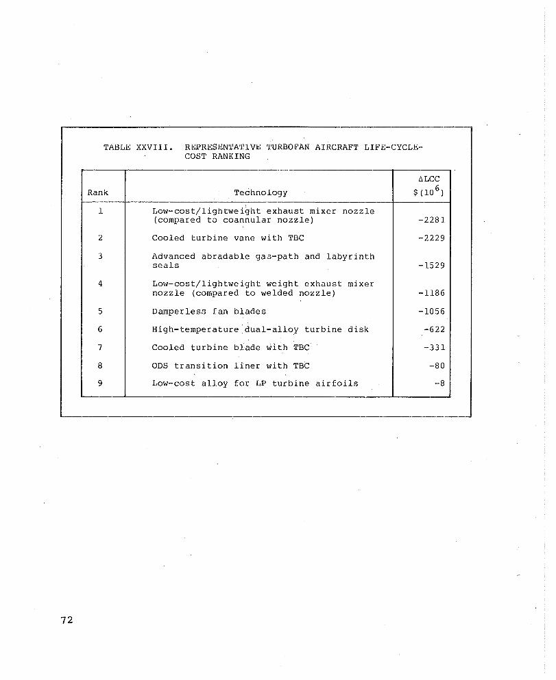
72
TABLE XXVIII. REPRESENTATIVE TURBOFAN AIRCRAFT LIFE-CYCLECOST RANKING
Rank Technology
1
2
3
4
5
6
7
8
9
Low-cost/lightweight exhaust mixer nozzle (compared to coannular nozzle)
Cooled turbine vane with TBC
Advanced abradable ga3-path and labyrinth seals
Low-cost/lightweight weight exhaust mixer nozzle (compared to welded nozzle)
DamperlesG fan blades
High-temperature dual-alloy turbine disk
Cooled turbine blade with TBC
ODS transition liner with TBC
Low-cost alloy for LP turbine airfoils
-2281
-2229
-1529
-1186
-1056
-622
-331
-80
-8
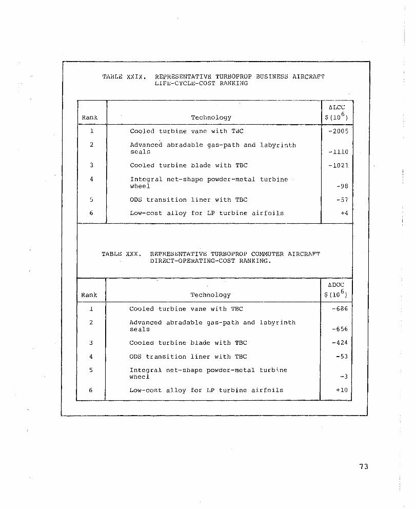
Rank
1
2
3
4
5
6
TABLE XXIX. REPRESENTATIVE TURBOPROP BUSINESS AIRCRAFT LIFE-CYCLE-COST RANKING
Technology
Cooled turbine vane with TBC
Advanced abradable gas-path and labyrinth seals
Cooled turbine blade with TBC
Integral net-shape powder-metal turbine wheel
ODS transition liner with TBC
Low-cost alloy for LP turbine airfoils
-2005
-1110
-1021
-98
-57
+4
----·--~--------,----------------------~---------------------L------4
TABLE XXX. REPRESENTATIVE TURBOPROP COMMUTER AIRCRAFT DIRECT-OPERATING-COST RANKING.
----.---r------------~--------------------------------------_,------_4
Rank
1
2
3
4
5
6
Technology
Cooled turbine vane with TBC
Advanced abradable gas-path and labyrinth seals
Cooled turbine blade with TBC
ODS transition liner with TBC
Integral net-shape powder-metal turb~ne wheel
Low-cost alloy for LP turbine airfoils
-686
-656
-424
-53
-3
+10
73
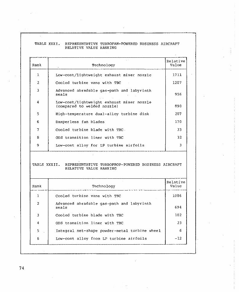
74
TABLE XXXI. REPRESENTATIVE TURBOFAN-POWERED BUSINESS AIRCRAFT RELATIVE VALUE RANKING
Rank
1
2
3
4
5
6
7
8
9
Technology
Low-cost/lightweight exhaust mixer nozzle
Cooled turbine vane with TBC
Advanced abradable gas-path and labyrinth seals
Low-cost/lightweight exhaust mixer nozzle (compared to welded nozzle)
High-temperature dual-alloy turbine disk
Damperless fan blades
Cooled turbine blade with TBC·
ODS transition liner with TBC
Low-cost alloy for LP turbine airfoils
Relative Value
1711
1207
956
890
207
170
33
32
3
TABLE XXXII. REPRESENTATIVE TURBOPROP-POWERED BUSINESS AIRCRAFT RELATIVE VALUE RANKING
Relative Rank Technology Value
1 Cooled turbine vane with TBC 1086
2 Advanced abradable gas-path and labyrinth seals 694
3 Cooled turbine blade with TBC 102
4 ODS transition liner with TBC 23
5 Integral net-shape powder-metal turbine wheel 6
6 Low-cost alloy from LP turbine airfoils -12
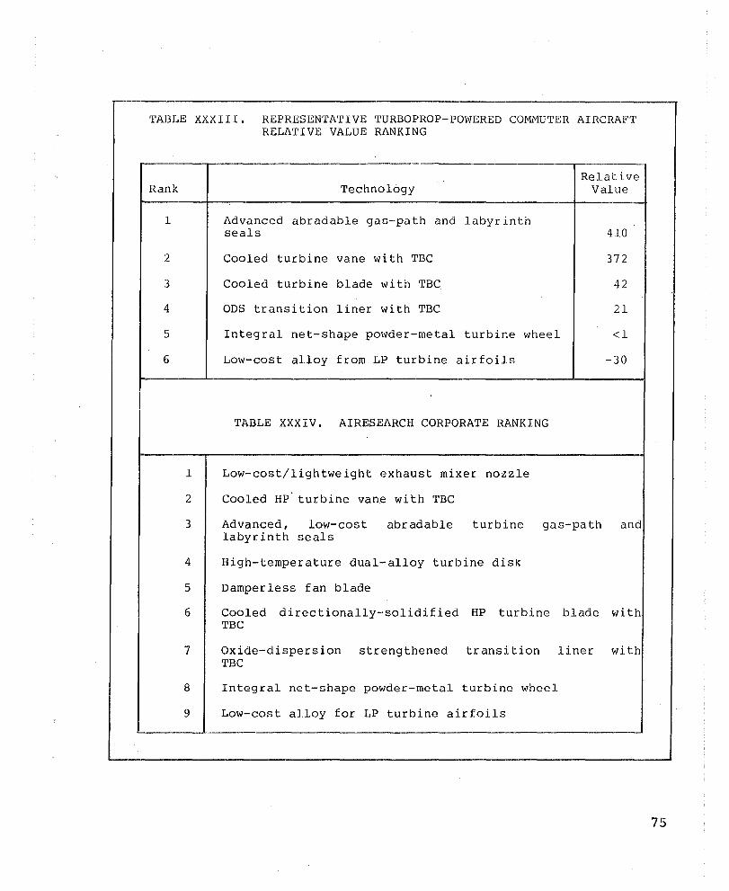
TABLE XXXIII. REPRESENTATIVE TURBOPROP-POWERED COMMUTER AIRCRAFT RELATIVE VALUE RANKING
Rank
1
2
3
4
5
6
Technology
Advanced abradable gas-path and labyrinth seals
Cooled turbine vane with TBC
Cooled turbine blade with TBC
ODS transition liner with TBC
Integral net-shape powder-metal turbir.e wheel
Low-cost alloy from LP turbine airfoils
TABLE XXXIV. AIRESEARCH CORPORATE RANKING
1 Low-cost/lightweight exhaust mixer nozzle
2 Cooled HP turbine vane with TBC
Relative Value
410
372
42
21
<1
-30
3 Advanced, low-cost labyrinth seals
abradable turbine gas-path and
4 High-temperature dual-alloy turbine disk
5 Damperless fan blade
6 Cooled directionally-solidified HP turbine blade with TBC
7 Oxide-dispersion strengthened transition liner with TBC
8 Integral net-shape powder-metal turbine wheel
9 Low-cost alloy for LP turbine airfoils L-_______ ~ ____________ ~ ________________________________________________ ~
75

This Page Intentionally Left Blank
APPENDIX A
AIRCRAFT WEIGHT LIFE-CYCLE COST,
AND DIRECT-OPERATING COST MODELS
APPENDIX A
AIRCRAFT WEIGHT, LIFE-CYCLE COST,
AND DIRECT-OPERATING COST MODELS
WEIGHT MODEL
In synthesi zing the total we ight of an aircr aft, it is con
venient to divide the weight into a number of major components.
The AiResearch LCC and DOC models make use of a TOGW model con
sisting of four major elements: airframe fixed weight (AFFW),
airframe variable weight (AFVW), installed engine weight (lEW), and'
fuel and tankage weight (FTW), all expressed as fractions of TOGW
(ref. 4).
The airframe fixed weight consists of the crew and support
systems, instruments, and avionics. These items are specified by
the aircraft operational requirements and, therefore, do not vary
with aircraft size.
The airframe var~able weight consists primarily of a structure
such as the fuselage, wings, empennage, and landing gear. System
weight is also included in the variable weight since system weight
tends to scale with structure weight because of the direct influ
ence of size on control actuation and hydraulic pump requirements,
lenghts of wiring, piping, etc.
The installed engine weight consists of the bare engine weight
and the addi tional weight due to the installation such as the
pylons, connections, and engine oil. Also included in this weight
is the starting system.
The fuel and tankage weight consists of the fuel and fuel
tanks including any auxiliary fuel tanks. The fuel pumps, pipes,
78
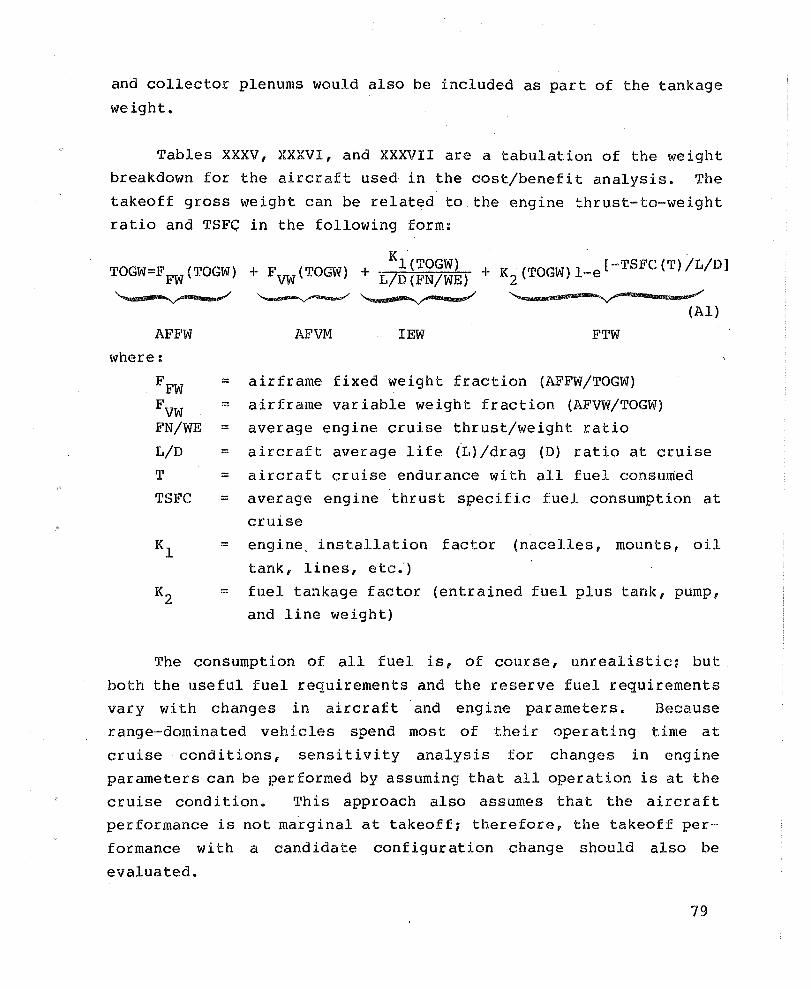
and collector plenums would also be included as part of the tankage
weight.
Tables XXXV, XXXVI, and XXXVII are a tabulation of the weight
breakdown for the aircraft used in the cost/benefit analysis. The
takeoff gross weight can be related to the engine thrust-to-weight
ratio and TSFG in the following form:
Kl ('l'OGW) TOGW=F FW (TOGW) + E'VW (TOGW) + L/D (FN/WE) + K {TOGW)l_e[-TSFC(T)/L/D]
2 ~ ~~-=....,.,/
AFFW
where:
FFW ::
FVW = FN/WE ::
L/D ::
T = TSFC ::
AFVM lEW FTW
airframe fixed weight fraction (AFFW/TOGW)
airframe variable weight fraction (AFVW/TOGW)
average engine cruise thrust/weight ratio
(Al)
aircraft average life (L)/drag (D) ratio at cruise
aircraft cruise endurance with all fuel consumed
average engine thrust specific fuel consumption at
cruise
Kl :: engine" installation factor (nacelles, mounts, oil
tank, lines, etc.')
K2 = fuel tankage factor (entrained fuel plus tank, pump, and line weight)
The consumption of all fuel is, of course, unrealistic; but
both the useful fuel requirements and the reserve fuel requirements
vary with changes in aircraft and engine parameters. Because
range-dominated vehicles spend most of their operating time at
cruise· conditions, sensitivity analysis for changes in engine
parameters can be performed by assuming that all operation is at the
cruise cond i tion. This approach also assumes that the aircraft
performance is not marginal at takeoff; therefore, the takeoff per
formance with a candidate configuration change should also be
evaluated.
79

80
TABLE XXXV. REPRESENTATIVE TURBOFAN-POWERED BUSINESS AIRCRAFT WEIGHT BREAKDOWN
,------ -------r Weight Parameter kg (lb)
-------------
-----
Airframe Fixed Weight
0 Instrumentation, Avionics 435 (959 ) Equipment, Furnishing
0 Crew Plus Baggage 176 (387 )
0 Payload 765 (1686) 1--- -- --
TOTAL l376 (3032) f-- -- - '--
Airframe Variable Weight
0 Fuselage 739 (1630 )
0 Landing Gear 245 (540 )
0 Wing 639 (1410 )
0 Empennage 141 (310 ) ,
0 Controls 590 (l300) f-----
TOTAL 2354 (5190) -------
Installed Eng ine Weight
0 Engines (2 ) 655 (1444)
0 Eng ine Installation 296 (652 )
TOTAL 951 (2096 )
Fuel and Tankage Weight
0 Fuel ( includes a 30-minute 2799 (6171 ) reserve)
0 Fuel System ( includes 122 (269 ) usable fuel)
0 Auxiliary Fuel Tanks 109 (240 )
TOTAL 3030 (6680 )
Takeoff Gross Weight (TOGW) 7711 (17,00 0)

TABLE XXXVI. REPRESENTATIVE TURBOPROP-POWERED BUSINESS AIRCRAFT WEIGHT BREAKDOWN
--- "-----
~ Weight Parameter kg (lb)
---
Airframe Fixed weight
0 Instrumentation, Avionics 366 (806) Equipment, Furnishing
0 Crew Plus Baggage 176 (387 )
0 Payload 410 (905 )
TOTAL 952 (2098 ) -- --
Airframe Variable Weight
0 Fuselage 585 (1290)
0 Landing Gear 150 (330 )
0 Wing 620 (l367 )
0 Empennage 95 (210 )
0 Controls 352 (775) f---
TOTAL 1802 (3972 )
Installed Engine Weight
0 Eng ines (2) 308 (680 )
0 Engine Installation 255 (563 )
TOTAL 563 (1243 )
Fuel and Tankage Weight
0 Fuel ( includes reserve) 1253 (2763 )
0 Fuel System ( includes 113 (249 ) usable fuel)
TOTAL 1366 (3012)
Takeoff Gross Weight (TOGW) 4583 (10,325)
81

82
TABLE XXXVII. REPRESENTATIVE TURBOPROP-POWERED COMMUTER AIRCRAFT WEIGHT BREAKDOWN
_c I
--Weight
Parameter kg (lb)
Airframe Fixed Weight
0 Instrumentation, Avionics 2206 (4863 ) Equipment,Furnishing
0 Crew plus Baggage 254 ( 560)
0 Payload 2721 (6000)
TOTAL 5181 (11,423)
Airframe Variable Weight
0 Fuselage 1742 (3840 )
0 Landing Gear 390 (860)
0 Wing 853 (1880 )
0 Empennage 204 (450 )
0 Controls 276 (610 )
TOTAL 3465 (7640)
Installed Eng ine Weight
0 Eng ines (2 ) 476 (1050 )
0 Engine Installation 295 (650)
TOTAL 771 (1700)
Fuel and Tankage Weight
0 Fuel ( includes reserve) 1432 (3157)
0 Fuel System ( includes 82 (180) usable fuel)
TOTAL 1514 (3337 )
Takeoff Gross Weight (TOGW) 10,931 (24,100)
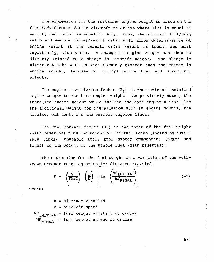
The expression for the installed engine weight is based on the
free-body diagram for an aircraft at cruise where life is equal to
weight, and thrust is equal to drag. Thus, the aircraft lift/drag
ratio and engine thrust/weight ratio will allow determination of engine weight if the takeoff gross weight is known, and most
importantly, vice versa. A change in engine weight can then be
directly related to a change in aircraft weight. The change in aircraft weight will be significantly greater than the change in
engine weight, because of multiplicative fuel and structural
effects.
The engine installation factor (K l ) is the ratio of installed engine weight to the bare engine weight. As previously noted, the
installed engine weight would include the bare engine weight plus
the additional weight for installation such as engine mounts, the
nacelle, oil tank, and the various service lines.
The fuel tankage factor (K2) is the ratio of the fuel weight
(with reserves) plus the weight of the fuel tanks (including auxiliary tanks), unusable fuel, fuel system components (pumps and
lines) to the weight Df the usable fuel (with reserves).
The expression for the fuel weight is a variation of the well-
known Breguet range equation for distance traveled:
R = (T~FC) (~) [in fF INITIAL) ] WFFINAL
(A2)
where:
R :: distance traveled
V :: aircraft speed
WFINITIAL :::: fuel weight at start of cruise
WFFINAL :: fuel weight at end of cruise
83
The above equation is based on a single-segment (all-cruise)
mission; however, multisegment missions can be easily incorporated
as Nicolai (ref. 2) has shown.
84
DIRECT-OPERATING COST SENSITIVITY MODEL
The changing commuter airplane size and, hence, engine size,
requires a DOC model sensitive to these changes, and their influ
ence on engine cost, life, and 'reliability.
The base,line direct operating costs are estimated and used in
a DOC model formulated in terms of airframe and engine weight,
engine performance, and mission parameters -- cruise speed, block
time, etc. This DOC model is then perturbed for the weight and per
formance changes from the weight model. The results are the DOC
sensitivities to engine para~eter perturbations.
The assumptions implicit in these models are:
o Wing loading = constant
o Power loading = constant
o SHP/Engine wt. = constant
o Nacelle and fuel system weights increase/decrease in
proportion to engine and fuel weights, respectively
o SFC and power changes are proportional throughout the
operating envelope (However, the baseline fuel was calcu
lated through mu1tisegment mission analysis.)
o Eng ine cost ex: HP constant
o Airframe DOC per Fairchild model
Although these assumptions may appear 1imi ting, they have
little or no deleterious effect on the use of the model for the
evaluation of differences (sensitivity analysis).
85
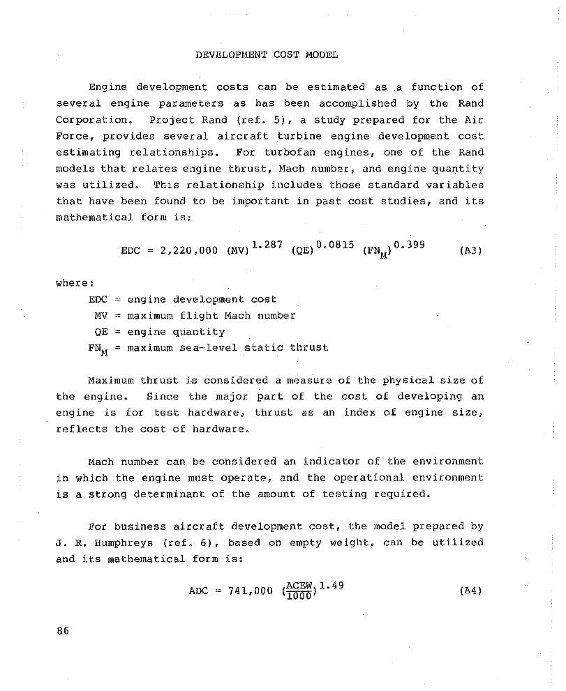
DEVELOPMENT COST MODEL
Engine development costs can be estimated as a function of
several engine parameters as has been accomplished by the Rand
Corporation. Project Rand (ref. 5), a study prepared for the Air
Force, provides several aircraft turbine engine development cost
estimating relationships. For turbofan engines, one of the Rand
models that relates engine thrust, Mach number, and engine quantity
was utilized. This relationship includes those standard variables
that have been found to be important in past cost studies, and its
mathematical form is:
where:
EDC ==
MV ::
QE :::
FNM ::
EDe == 2 f 220,000 (MV) 1. 287 (QE) 0.0815 {FN } 0.399 (A3) M
engine development cost
maximum flight Mach number
engine quantity
maximum sea-level static thrust
Maximum thrust i~ considered a measure of the physical size of
the engine. Since the major part of the cost of developing an
eng ine is for test hardware, thrust as an index of eng ine size,
reflects the cost of hardware.
Mach number can be considered an indicator of the environment
in which the engine must operate, and the operational environment
is a strong determinant of the amount of testing required.
For business aircraft development cost, the model prepared by
J. R. Humphreys (ref. 6), based on empty weight, can be utilized
and its mathematical form is:
ADC == 741,000 (~g~~)1.49 (A4)
86
where:
ADC = airframe development cost ACEW = aircraft empty weight
87
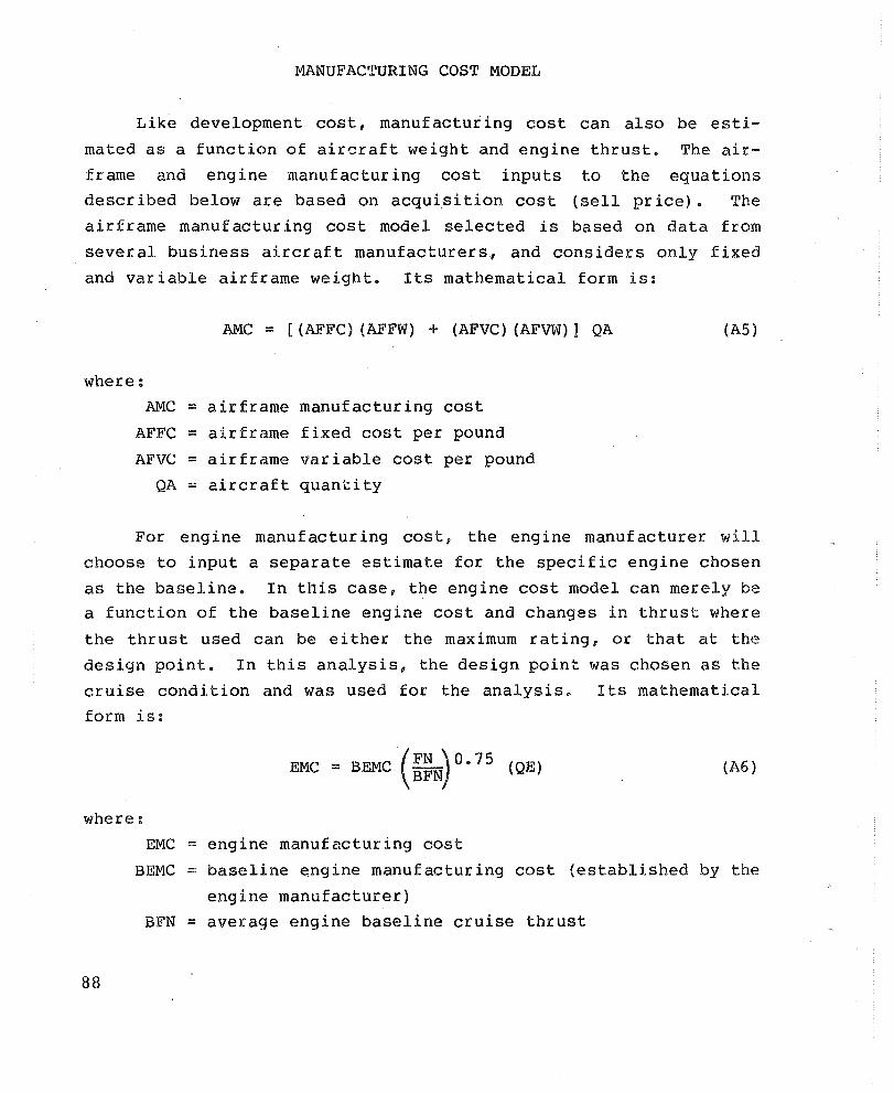
MANUFACTURING COST MODEL
Like development cost, manufacturing cost can also be esti
mated as a function of aircraft weight and engine thrust. The air
frame and engine manufacturing cost inputs to the equations described below are based on acquisition cost (sell price). The
airframe manufacturing cost model selected is based on data from
several business aircraft manufacturers, and considers only fixed
and variable airframe weight. Its mathematical form is:
AMC = [(AFFC) (AFFW) + (AFVC) (AFVW) 1 QA (AS)
where:
AMC = airframe manufacturing cost
AFFC = airframe fixed cost per pound
AFVC = airframe variable cost per pound
QA = aircraft quantity
For engine manufacturing cost, the engine manufacturer will
choose to input a separate estimate for the specific engine chosen
as the baseline. In this case, the engine cost model can merely be a function of the baseline engine cost and changes in thrust where
the thrust used can be either the maximum rating, or that at the
design point. In this analysis, the design point was chosen as the
cruise condition and was used for the analysis. Its mathematical
form is:
EMC = BEMC (FN \0.75 (QE) BFNJ
(A6)
where:
88
EMC = engine manufacturing cost
BEMC = baseline engine manufacturing cost (established by the
engine manufacturer)
BFN = average engine baseline cruise thrust

OPERATING COST MODEL
The annual cost of owning and operating the business jet air
cr aft can be structured into fixed and var iable costs as shown below:
Fixed Costs
Load interest Imputed interest on investment Depreciation Crew wages Insurance Taxes Hangar Miscellaneous costs
Variable Costs
Fuel Airframe maintenance Engine maintenance Crew expenses Landing, parking, catering, etc.
While these are fixed and variable with respect to aircraft usage, they must be recategorized for evaluation of changes in the engine.
Imputed interest on investment is not usually considered in revenue
operation because the analyst prefers to examine total return on investment. For nonrevenue operation, imputed interest on the
equity investment should be included at the internal rate of
return. Depreciatio~ drops out of LCC when acquisition cost is
introduced (except for tax effects when calculating cash flow).
The fuel-cost model utilizes the fuel-weight output of the
weight model and is:
FC = (WF) (~p) {TOH} (A7)
where: Fe = fuel cost WF = fuel weight
FP = fuel price per pound
TOH = total operating hours (for lifetime)
89

The life-cycle invariant and cost-sensitive fixed charges are
modeled as shown below:
CINT ::: (LYRS) (RINT) (l-EQ)[ AMC + FMC] (QA) 2 where:
CINT ::: interest cost
LYRS :: loan years
RINT ::: interest rate EQ ::: aircraft equity
EMC ::: engine manufacturing cost
CINS ::: (RINS) (AYRS) [ AMC + FMC] (QA) 2
where: CINS ::: insurance cost
RINS :: insurance rate
AYRS :: aircraft life
where:
CTAX = (RTAX) (AYRS) [ AMC ; FMC ] (QA)
CTAX ::: tax cost RTAX ::: tax rate
FOC :: (AYRS) (CHM) (QA)
where: Foe ::: fixed operating costs
CHM ::: crew, hanger, and miscellaneous costs
TOC :: CINT + CINS + CTAX + FOC
where: TOC ::: total operating cost
90
(A8)
(A9)
(AlO)
(All)
(A12)

MAINTENANCE COST MODEL
The engine maintenance cost model is comprised of preventive
maintenance (inspection), module overhaul, unscheduled maintenance (repair of failures), and incorporation of se~vice bulletins.
The base~ine costs for preventive maintenance, module overhaul, and unscheduled maintenance are established from experience on similar applications. The incorporation of service bulletins is assumed to be 5 percent of the sum of the engine preventive main
tenance cost, overhaul cost, and unscheduled maintenance cost.
The change in engine life (TBO) and the resultant effect in cost can be determined by using an engine overhaul cost model. The
overhaul cost model may bea composite for the whole engine, or it can have separate expressions for each module or component. The
basic model for engine overhaul cost (EOC) is:
EOC = MOd~le [(BMOC) (~~~~O) (1 + ~ [~:gJ)] (Al3)
where:
BMOC = Baseline module overhaul cost (assumed at one-third
BMTBO = MTBO =
MMC = BMMC =
manufacturing cost) Baseline module time-between-overhaul
Module time-between-overhaul
Module manufacturing cost
baseline module manufacturing cost
The module cost in the equation above is expressed as a fraction of
engine cost.
The effect of engine unscheduled maintenance on cost, resulting from changes in reliability (MTBF), can be determined by
91

using an engine repair cost modeL
repair cost (ERC) is:
The basic model for engine
EOC :::: L Module [(
BMMrrBI!) (BMRC) -----. MMTBF
BMRC:::: Baseline module r<~pair cost
BMM'rBF:::; Baseline module mean~·time-between-failure
MMTBl!' -- Module mean-time-betweeno-failure
(Al4 )
The airframe maintenance cost model is comprised of preventive
maintenance~ overhaul, and unscheduled maintenance costs. The
baseline costs for the airframe maintenance cost model are estab
lished from experience on similar applications. The following
overhaul cost model and repair cost model are used to show the
change in airframe maintenance life-cycle cost.
AOC ::: BAOC (
1 + 1: (liAMC)] 3 BAMC (AlS)
where:
AOC :::.: Airframe overhaul cost
BAOC ::::: Baseline airframe overhaul cost
BAMC :::: Baseline airframe manufacturing cost
and, ARC 2 UWC) .- J (Al6 )
where:
ARC ::: Airframe repair cost
The preflight servicing cost for the aircraft is established
based on similar applic~tion experience.
92

APPENDIX B
LIST OF ABBREVIATIONS/SYMBOLS
93

A
ACEW
ADC
AFFC
AFFW
AFVC
AFVW
AMC
AOC
ARC
AYRS
BAMC
BAOC
BEMC
BFN
BMMC
BMMTBF
BMOC
BMRC
BMTBO
BPR
CHM
CINS
CINT
CTAX
D
Delta
DOC
DS
EDC
EMC
EQ ERC
94
LIST OF ABBREVIATIONS/SYMBOLS
Change in a value
Aircraft empty weight
Airframe development cost
Airframe fixed cost
Airframe fixed weight
Airframe variable cost per
Airframe variable weight
Airframe manufacturing cost
Airframe overhaul cost
Airframe repair cost
Aircraft life
pound
Baseline airframe manufacturing cost
Baseline airframe overhaul cost
Baseline engine manufacturing cost
Baseline cruise thrust
Baseline module manufacturing cost
Baseline module mean-time-between-failure
Baseline module overhaul cost
Baseline module repair cost
Baseline module time-between-overhaul
Bypass ratio
Crew, hanger, and miscellaneous costs
Insurance cost
Interest cost
Tax cost
Drag
Change
Direct-operating cost
Directionally-solidified
Engine development cost
Engine manufacturing cost
Aircraft equity Engine repair cost

FFW FVW FC
FN
FNM FOC
FP
FTW
HCF HIP
HP
HPT
lEW
Kl
K2 L
L/D LCC
LCF
LP
LPC Lprr
LYHS
M
MATE
MMC
MMTBF
MTBO
MV
OC ODS
QA
LIST OF ABBREVIATIONS/SYMBOLS (CONTD)
Airframe fixed weight fraction (AFFW/TOGW)
Airframe variable weight fraction (AFVW/TOGW) E'uel cost
Average engine cruise thrust
Maximum sea-level static thrust
Fixed operating costs
Fuel price
Fuel and tankage weight
High-cycle fatigue
Hot-isostatically pressed
High pressure
High-pressure turbine
Installed engine weight
Engine installation factor
Fuel tankage factor
Lift
Lift/drag ratio
Life-cycle cost
Low-cycle fatigue
Low pressure
Low-pressure compressor Low-pressure turbine
Loan years
Engine core flow
Materials for Advanced Turbine Engines
Module manufacturing cost Module mean-time-between-failure
Module time-between-overhaul
Maximum flight Mach number
Overhaul cost Oxide-dispersion strengthened
Aircraft quantity
95

96
QE
PM
R
RINS
RINT
RTAX
T
'l'BC
TBO
TO
TOC
TOGW
LIST OF ABBREVIATIONS/SYMBOLS (CONTD)
Engine quantity
Powder-metal
Distance traveled
Insurance rate
,Interest rate
Tax rate
Aircraft cruise endurance with all fuel consumed (hours)
Thermal-barrier coating
Time-between-overhaul (engine life)
Takeoff
Total operating cost
Takeoff gross weight
TOH Total operating hours (for lifetime)
TSFC Average engine thrust specific fuel consumption
V Aircraft speed
WE Engine weight
WE Engine core weight c WF Fuel weight
WFINITIAL Fuel weight at start of cruise
WVFINAL Fuel weight at end of cruise

REFERENCES
1. Corney, D. H., "Cost/Benefit Analysis of Advanced Material Technologies," AiResearch Hanufacturing Company of Arizona, The Garrett Corporation; NASA Report CR-135265.
2. Nicolai, Leland M., "Fundamentals of Aircraft Design," University of Dayton School of Engineering, 1975, pp 5-1 to 5-24.
3. Bissett, J. W., "Cost/Benef it Study of Advanced Materials Technologies for Aircraft Turbine Engines~" Pratt & Whitney Aircraft Division, United Aircraft Corporation; NASA Report CR-134701. .
4. Burns, B. R. A., "The Design and Development of a Military Combat Aircraft - Part 2: Sizing the Aircraft," Interavia, May 1976, pp 448-450.
5. Nelson, J. R. and Timson, F. S., "Relating Technology to Acquisition Costs: Aircraft Turbine Engines," RAND Report R-1288-PR, March 1974, pp 20-35.
6. Humphreys, J. R., "Why So Few All-New Gener al Aviation Aircraft," Society of Experimental Test pilots Technical Review, Vol. 12, No.3, Spring 1975, pp 43-50.
97
REPORT DISTRIBUTION LIST FOR PROJECT 0,
CONTRACT NAS3-20073
NASA Headquarters Attn RTM-3/M. Greenfield 600 Independence Ave., SW Washington, DC, 20S46
NASA Headquarters Attn RA/W.S. Aiken 600 Independence Ave., SW Washington, DC 20546
NASA Headquarters Attn RLC/N.F. Rekos 600 Independence Ave., SW washington, DC 20546
NASA Lewis Research Center Attn R.L. Davies MS 105-1 21000 Brookpark Road Celveland, OH 44135
NASA Lewis Research Center Attn C.M. Scheuermann· MS 49-3 21000 Brookpark Road Cleveland, OH 44135
NASA Lewis Research Center Attn L. Berke, MS 49-6 2~000 Brookpark Road Cleveland, OH 44135
NASA Lewis Research Center Attn R.L. Ashbrook MS 49-3 21000 Brookpark Road Cleveland, OH 44135
NASA Lewis Research Center Attn C.E. Lowell MS 49-1 2~000 Brookpark Rd. Celveland, OH 44135
98
NASA Headquarters Attn RTP-3/R. Colladay 600 Independence Ave., SW Washington, DC 20546
NASA Headquarters Attn RX/G.G. Kay ten 600 Independence Ave., SW Washington, DC 20546
NASA Lewis Research Center Attn R.L. Dreshfield MS 105-1 21000 Brookpark Road Cleveland, OH 44135
(6 copie3)
NASA Lewis Research Center Attn S. Benford MS 49-1 21000 Brookpark Road Cleveland, OH 44135
NASA Lewis Research Center Attn H.B. Probst, MS 49-3 21000 Brookpark road Cleveland, eH 44135
NASA Lewis Research Center Attn S.J. Grisaffe MS 105-1 21000 Brookpark Road Cleveland, OH 44135
NASA Lewis Research Center Attn H.R. Gray, MS 49-3
R.V. Miner 21000 Brookpark Road Cleveland, OH 44135
NASA Lewis Research Center Attn S. Levine MS 49-1 21000 Brookpark Rd Cleveland, OH 44135
NASA Lewis Research Center Attn R.A. Signorelli MS 106-1 2~OOO Brookpark Road Cleveland, OH 44135
NASA Lewis Research Center Attn R.A. Rudey, MS 60-4 21000 Brookpark Road Cleveland, OH, 44135
NASA Lewis Research Center Attn K. Sievers MS 501.-7 2~00U Brookpark Road Cleveland, OH 44135
NASA Lewis Research Center Attn M. Hartmann, MS 5-3 2~OOO Brookpark Road Cleveland, OH 44135
NASA Lewis Research Center Attn Tech Utilization MS 3-19 2~OOO Brookpark Road Cleveland, OH 44135
NASA Lewis Research Center Attn AFSC Liaison Office MS 501-3 2~OOO Brookpark Road Cleveland, OH 44135
NASA Lewis Research Center Attn Report Control MS 5-5 2~OOO Brookpark Road Cleveland, OH 44135
NASA Ames Research Center Attn Library Moffett Field CA 9403!:>
NASA Langley Rsch Center Attn A.L. Nagel Langley Field, VA 23365
NASA Lewis Research Center Attn R. Weber MS 500-127 21000 Brookpark Road Cleveland, OH 44135
NASA Lewis Research Center Engine Systems Div. MS 501-5 21000 Brookpark Road Cleveland, OH 44135
NASA Lewis Research Center Attn R.C. Bill 23-2 21000 Brookpark Road Cleveland, OR 44135
NASA Lewis Research Center Attn Section 1431-SB MS 501-11 21000 Brookpark Road Cleveland, OH 44135
NASA Lewis Research Center Attn Library, MS 60-3 21000 Brookpark Road Cleveland, OH 44135
(2 copies)
NASA Lewis Research Center Attn AAMRDL, MS 106-2 21000 Brookpark Road Cleveland, OH 44135
NASA Ames Research Center Attn N. Kurkowski 210-10 Moffett Field CA 94035
NASA Langley Rsch Center Attn C.P. Blankenship MS 188M Langley Field, VA 23365
NASA Langley Rsch Center Attn Library Langley Field, VA 23365
99

NASA Flight Rsch Center Attn Library P.O. Box 273 Edwards, CA 93523
NASA MSFC Attn W.B. McPherson EH23 Huntsville, AL 35812
u.s. Air Force Attn AFML/LLM N. Geyer Wright-Patterson AFB OH 45433
U.S. Air Force Attn AFAPL/TBP I. Gershon Wright-Patterson AFB OH 45433
U.S. Air Force Attn AFAPL/CCN Chief Scientist Wright Patterson AFB OH 45433
u.S. Air Force Attn AP:/DO ASD E. Bailey Wright-Patterson AFB OH 45433
u.s. Air Force Attn ASD/XRHP R. Carmichael wright-Patterson AFB OH 45433
u.S. Air Force Attn AFML/LLM W. O'Har~ Wright-Patterson AFB OH 45433
u.S. Air Force AFWAL/POTC D. Corneille Wright-Patterson AFB OR 45433
100
NASA MSFC Attn R. Schwinghammer Huntsville, AL 35812
NASA MSFC Attn Library Huntsville, AL 35812
u.s. Air Force Attn AFWAL/MLLM H. Graham Wright-Patterson AFB OH 45433
U.S. Air Force Attn AFAPL/TBP P. Copp
T. Fecke Wright-Patterson AFB OH 45433
U.S. Air Force Attn AFML/LTM H. Johnson Wright-Patterson AFB OH 45433
u.S. Air Force Attn AFAPL/TBC C.W. Elrod
W. Tall Wright-Patterson AFB OH 45433
u.S. Air Force Attn AFML/LTM J.K. Elbaum Wright-Patterson AFB OH 45433
u.S. Air Force Attn AFML/LAM Library Wright-Patterson AFB OH 45433
u.S. Air Force Attn AFWAL S. Fujishiro Wright-Patterson AFB OH 45433

u.s. Air Force Attn A. Rosenstein AFOSR/NE-Bldg. 410 Bolling Air Force Base Washington, DC 20332
Eustis Directorate Applied Tech Lab Army Rsch and ,Tech Lab Attn J. Lane AVRADCOM Fort Eustis, VA 23604
Army Materials & Mechanics Research Center Attn S. Isserow DRXMR-KA
P. Smoot Watertown, MA 02172
Army Materials & Mechanics Research Center Attn Library Watertown, MA 02172
Inst. for Defense Analysis Attn J. Hove 400 Army Navy Drive Arlington, VA 22202
Navy Department Naval Air Systems Command Attn J.L. Byers Air-53602 Washington, D.C. 20361
Naval Air Dev. Center Attn S. Shapiro 3014 Warminster, PA 18974
Office of Naval Research Attn B. MacDonald Code 47l. 800 N. Quincy St Arlington, VA 22217
Naval Ship Eng. Ctr. Attn S.B. Shepard 6146B Washington, DC 20362
NASA STIF Attn Accessioning Dep't P.O. box 8757 BaIt-Wash Int1nat Airport Maryland 21240
(25 copies)
AVSCOM Attn W. McClane DRSAV-EQA P.O. Box 209 St. Louis, MO 63166
Army Materials & Mechanics Research Center Attn R. French DRXMR-EM Watertown, MA 02172
Defense Advanced Research Projects Agency ARPA/SMO Attn E.C. Van Reuth 1400 Wilson Blvd. Arlington, VA 22209
Navy Department Naval Air Systems Command Attn I. Machlin Air-52031B Washington, DC 20361
Naval Air Dev. Center Attn F.R. Johns 301 Warminister, PA 18974
Naval Air Dev. Center Attn F.S. Williams Warminister, PA 18974
Research & Technology Div. NAPTC Attn J. Glatz Trenton, NJ 08628
Navy Department Attn G.A. Wacker, Head Met. Div., Code 281 Naval Ship R&D Center Annapolis, MD 21402
101

DOE Attn S. Dapkunas 4203 20 Massachusetts Ave Washington, DC 20545
FAA Headquarters Attn T.G. Horeff AFS-140 800 Independence Ave., SW Washington, DC 20591
Nat'l Academy of Sciences Attn J.R. Lane 2~OL Constitution Ave. Washington, D.C. 20418
AVCO Lycoming Div. Attn Tzu-Guu Teng 550 S. Main St. Stratford, CT 06497
AVCO Lycoming Div. Attn P. Bania 550 S. Main St. Stratford, CT 06497
Curtiss-Wright Corp. Attn R. Yellin 1 Passaic St Wood Ridge, NJ 07075
Detroit Diesel Allison Attn B.A. Ewing P.O. Box 894 T-27 Indianapolis, IN 46206
Detroit Diesel Allison Attn M. Herman P.O. Box 894 Indianapolis, IN 46206
General Electric Co. Attn C. Sims, Bldg 53 Gas Turbine Prod. Div. Schenectady, NY 12345
General Electric Co. Material and Processing Attn E. Kerzicnik M82 Evandale, OH 452~5
102
FAA Headquarters Attn A. Broderick AEQ 10 800 Independence Ave., SW washington, DC 20591
FAA Headquarters Attn D. Winer AEE-200 800 Independence Ave., SW Washington, DC 20591
AVCO Lycoming Div. Attn J. Walters 550 S. Main St. Stratford, CT 06497
AVCO Lycoming Div. Attn L.J. Fiedler 550 S. Main SL Stratford, CT 06497
Curtiss-Wright Corp. Attn J. Mogul 1 Passaic St Wood Ridge, NJ 07075
Detroit Diesel Allison Attn G.L. Vonnegut W-13 2001 S. Tibbs Ave Indianapolis, IN 46206
Detroit Diesel Allison Attn J. Byrd sic U24 P.O. Box 894 Indianapolis, IN 46206
Detroit Diesel Allison Attn N. Provenzano U29A P.O. Box 894 Indianapolis, IN 46206
General Electric Co. Attn F.D. Lordi, Bldg 53 Gas Turbine Prod. Div. Schenectady, NY 12345
General Electric Co. Materials and Processing Attn R. Wojieszak M82 Evandale, OH 45215

General Electric Co. Material and Processing Technology Laboratory Attn L. Wilbers M87 Evandale, OH 452i5
General Electric Company Attn Tech Info Cntr N-32 Evandale, OH 45215
General Electric Co. Attn R. Warren AEG/GED 1000 Western Ave. Lynn, MA 01910
General Electric Co. Corporate R&D Center Attn Library P.o. Box 8 Schenectady, NY 12301
Pratt and Whitney Aircraft Commerc i al Produc ts Attn S. Blecherman Aircraft Road Bldg 140 Middletown, CT 06457
Pratt and Whitney Aircraft Commercial Products Attn F. Fennessy 400 Main St. East Hartford, CT 06108
Pratt and Whitney Aircraft Attn J. Moore Box 2691 West Palm Beach FL 33402
Solar Div of Int. Harvester Attn A. Metcalfe P.O. Box 80966 San Diego, CA 92i38
Williams Research Attn Wm. P. Schimmel 2280 W. Maple Walled Lake, MI 48088
General Electric Co. Material and Processing Technology Laboratory Attn J. Erickson M82 Evandale, OH 45215
General Electric Co. Attn J. Hsia AEG/GED 1000 western Ave. Lynn, MA 01910
General Electric Co. Attn R.W. Smashey 336 S. Woodward Ave., SE Albuquerque, NM 87102
Pratt and Whitney Aircraft Commercial Products Attn G.E. Stephens 400 Main St. East Hartford, CT 06108
Pratt and Whitney Aircraft Commercial Products Attn A. Hauser 400 Main St. East Hartford, CT 06108
Pratt and Whitney Aircraft Manufacturing Div. Attn J. Zubeckis 400 Main St. East Hartford, CT 06108
Solar Div of Int. Harvester Attn A. Stetson P.O. Box 80966 San Diego, CA 92138
Teledyne CAE Mat. Dev. and Manuf. Engr. Attn R. Beck P.O. Box 6971 Toledo, OH 43612
Williams Research Attn Library 2280 W. Maple Walled Lake, MI 48088
103

Williams Research Attn P. Nagy 2280 W. Maple Walled take, MI 48088
Aireo Temescal Attn L. Bianchi 2850 Seventh St. Berkeley, CA 94710
Battelle Memorial Inst. Attn Technical Library 505 King Ave. Columbus, OH 4320i
Boeing Comm. Airplane Co. Attn W. Blissell 9H-43 P.O. Box 3707 Seattle, WA 98124
The Boeing Co. Attn H.D. Kevin 41-SH P.O. Box 3999 Seattle, WA 98124
Boeing - Wichita Div. Attn W. Rohling Wichita, KS 67210
Brown Boveri Turbo. Inc. Attn A. Giammarise
L. Engel 71i Anderson Ave. N St. Cloud, MN 56301
Business & Commercial Aviation Magazine Attn G. Gilbert Hanger C--I Westchester Co. Airport NY J.0604
Cameron Iron Works Attn Library P.O. Box 12i2 Houston, TX 77001
104
Aerospace Corp. Attn S. Sokolsky P.O. Box 92957 Los Angeles, CA 90009
Battelle Memorial Inst Attn K. Meiners 505 King Ave. Columbus, OH 43201
Beech Aircraft Corporation Attn C.A. Rembleske 9709 E. Central Ave. Wichita, KS 67201
Boeing Comma Airplane Co. Attn F. Tolle 41-52 P.O. Box 3707 Seattle, WA 98124
Boeing Comma Airplane Co. Attn P. Johnson MS 40-53 P.O. Box 3707 Seattle, WA 98124
Boeing - Wichita Div. Attn Wm. F. Schmidt org. 75930 Propulsion Wichita, KS 67210
Brunswick Corp. Attn J. Kervin 2000 Brunswick Lane Deland, FL 32720
Cameron Iron Works Attn N. Wilkinson
J. Becker P.O. Box 1212 Houston, TX 77001
Cannon-Muskegon Corp. Attn R. Quigg P.O. Box 506 Muskegon, MI 49443

Carpenter Technology Corp. Attn G. DelCorso
A. Walsh RID Lab, Bldg. 68 Reading, PA 19603
Cessna Aircraft Co.' Attn A. Kavie (Turbofan) Wallace Division P.o. Box 7704 Wichita, KS 67277
Chromalloy-PMT Attn R. Elbert L3434 Floyd Circle Dallas, TX 75243
Colt Industries Attn E. Dulis Crucible Inc, Mat'ls Rsch P.O. Box 88 Pittsburgh, PA 15230
Convair Aerospace Div. General Dynamics Corp. Attn A.J.K. Carline P.o. Box 748 Ft. Worth, TX 76101
Defense Marketing Set vices Attn D. Franus 100 Northfield St. Greenwich, CT 06830
Douglas Aircraft Co. Attn Library Mcdonnell Douglas Corp 3855 Lakewood Blvd. Long Beach, CA 90846
Engelhard IndUstries Attn E. Grider Route 1!:)2 Plainville, MA 02762
Certified Alloys Products Attn M. Woulds 3245 Cherry Ave. Long Beach, CA 90807
Cessna Aircraft Co. Attn C. Gonzales (Turboprop) Wallace Division P.o. Box 7704 Wichita, KS 67277
Climax Molybdenum Co. Attn Wm. Hagel P.O. Box 1568 Ann Arbor, MI 48106
Colt Industries Attn J. Moll Crucible Inc, Mat'ls Rsch P.O. Box 88 Pittsburgh, PA 15230
DCI Inc. Attn R. Engdahl 318 Victory Drive Herndon, VA 22070
Delta Airlines Attn W.J. Overend Atlanta Airport Atlanta, GA 30320
Duradyne Tech. Inc. Attn R. Horton 8607 Tyler Blvd Mentor, OH 44060
Ford Motor Company Attn C. Feltner Metallurgical Dept. P.O. Box 2053 Dearborn, MI 48121
105

Gates Learjet Corp. Attn Don Baisden P.O. Box 7707 Wichita, KS 67277
Gates Learjet Corp. Attn A.M. Heinrich T. Reichenberger P.O. Box 7707 ' Wichita, KS 67207
General Motors Corp. Attn K. Bly 73-S 'fechnical Center Warren, MI 48090
Grumman Aerospace Corp. Attn C. Hoelzer C32-5 Bethpage, NY lL714
Howmet Turbine Compo Div. Attn W. Freeman 500 Terrace Plaza Muskegon, MI 49443
Howmet Corporation 'I'echnical Center Attn J. VanderSluis 699 Benston Rd. Whitehall, MI 49461
Huntington Alloys Div. International Nickel Co. Atnn D. Tillack 9S01 W. Devon Rosemont, IL 60018
lIT Research Institute Attn M.A. Howes 10 West 35th Street Chicago, IL 60616
International Nickel Corp. Attn L. Curwick Sterling Forest Suffern, NY 10901
106
Gates Learjet Corp. Attn W.J. Reese
C.L. King P.O. Box 7707 Wichita, KS 67277
General Atomics Co. Attn D.I. Roberts P.O. Box 81608 San Diego, CA 92138
Gould Inc. Attn R. Szafranski 17000 St. Clair Ave Cleveland, OH 44110
Hamilton Standard Attn W. Adamson Windsor Locks, CT 06096
Howmet Ccrporation Technical Center Attn L. Dardi 699 Benston Rd. Whitehall, MI 49461
Howmet Corporation Turbine Components Div. Attn E. Carozza
Mr. Burd Dover, NJ 07801
Huntington Alloys Div. International Nickel Co. Attn F. Perry Huntington, WV 25720
Intermetco Attn J. Siergiej 300 CondoJ:.'d Road Wayland, MA 01778
International Nickel Corp Attn Library Sterling Forest Suffern, NY 10901

Jetshapes, inc. Attn C. Phipps Rockleigh Industrial Park Rockleigh, NJ 07647
Kelsey Hayes Attn T. Miles
D. Weaver 7250 Whitmore Lake Road Brighton, MI 48LL6
Kelsey Hayes Co. Attn W.G. Koby Heintz Div. Front St. and Olney Ave. Philadelphia, PA L9120
Ladish Company Attn R. Daykin Cudahy, WI 53LLO
Lockheed-Georgia Co. Attn R.H. Lange Dept. D/72-79 Marietta, GA 30060
MCIC Battelle Memorial Inst. Attn H. Mindlin Columbus, OH 43201
METCO Inc. Attn V. Lanza 1L01 Prospect Ave. westbury, L.I., NY 11590
METCO Inc. Attn C. Lewis 3400 A Oak Cliff Rd. Atlanta, GA 30340
Rand Corp. Attn J. Richard Nelson Washington Research Div. 2LOO M st. Washington, DC 20037
Kawecki Berylco Ind. Attn R. Gower
E.R. Laich P.O. Box 1462 Reading, PA 19603
Kelsey Hayes Attn M. Ziobro Utica, NY 13503
Kelsey Hayes Co. Attn M. Lopacki Heintz Div. Front St. and Olney Ave; Philadelphia, PA 19120
Lockheed-California Co. Attn. T. Sedjwick Dept. 75-4, Bldg. 63 Plant A-I P.O. Box 551
'Burbank, CA 91503
McDonnell-Douglas East Attn R.A. Garrett Dept. E452, Bldg 106 P.O. Box 516 St. Louis, MO 63166
Martin Marietta Attn C.H. Lund 15 N. Windsor Rd Arlington Hts, IL 60004
METCO Inc. Attn J. Dailey 1101 Prospect Ave. westbury, L.I., NY 11590
Pan American World Airways Attn W.B. Hibbs Pan Am Building New York, NY 10017
Rocketdyne Division Attn J. Frandsen Rockwell International 6633 Canoga Ave. Canoga Park, CA 91304
107
Rockwell International Attn W.B. Palmer Columbus Aircraft Div. P.o. Box 1259 Columbus, OH 43209
Rockwell International Attn N. Paton Science Center Thousand Oaks, CA 91360
Rockwell International Atten LeL. McHughes General Aviation Div. 500L N. Rockwell Ave. Bethany, OK 73008
Sorcery Metals Attn P. Hanson Box 1600 Delray Beach, FL 33444
Special Metals, Inc. Attn. S. Reichman
C.J. Burton Middle Settlement Road New Hartford New York 13413
Stellite Division Cabot Corporation Attn E. Bickel 1020 West Park Ave. Kokomo, IN 46901
Sundstrand Attn D. Augustine 4747 Harrison Ave. Rockford, IL 61LOl
Teledyne Allvac Attn F. Elliott P.O. Box 759 Monroe, NC 28110
108
Rockwell International Columbus Aircraft Div. Attn E.E. Culp
D. Rosenbaum P.O. Box 1259 Columbus, OH 43216
Rockwell International Attn G.E. Mathwig General Aviation Div. 5001 N. Rockwell Ave. Bethany, OK 73008
SCM Glidden Metals Attn K.M. Kulkarni 11000 Cedar Ave. Cleveland, OH 44106
Special Metala, Inc. Attn J. Pridgeon Middle Settlement Road Hew Hartford 'New York 13413
Special Metals, Inc. Attn W. Castledyne Udimet Powder Division 2310 S. Industrial Hwy Ann Arbor, MI 48104
Sundstrand Attn N.C. Evans 9841 Airport Blvd. Los Angeles, CA 98045
Swearingen Aviation Corp. Attn J.E. Kirkpatrick Box 32486 San Antonio, TX 78284
Teledyne Allvac Attn R. Kennedy
Wm. Thomas P.O. Box 759 Monroe, NC 28110

TRW Inc. Attn 1. Toth 23555 Euclid Ave. Cleveland, OH 44117
TRW Inc. Attn D. Maxwell 235~5 Euclid Ave. Cleveland, OH 44117
'l'RW Inc. Attn. C. Cook 23555 Euclid Ave. Euclid, OH 44123
Turbine Support Co. Attn. M. Dean 4430 Director Drive P.O. Box 20148 San Antonio, TX 78220
Union Carbide Corporation ATTn L. Nelson Carbon Products Division P.O. Box 6116 Cleveland, OH 44101 . Union Carbide Corporation Attn R. Tucker Coatings Service Dept. 1500 Polco St. Indianapolis, IN 46224
United Airlines - SFOEG Attn J.Ke Curry San Francisco Airport CA 94J.28
United Airlines - SFOEG Attn J.K. Goodwine San Francisco Airport CA 941.28
United Tech Rsch Center Attn r ... ibrary East Hartford, CT 06108
TRW Inc. Attn. J. McCarthy 23555 Euclid Ave. Cleveland, OH 44117
TRW Inc. Attn T. Piwonka 23555 Euclid Ave. Cleveland, OH 44117
Turbine Support Co. Attn. K. Speirs 4430 Director Drive P.O. Box 20148 San Antonio, TX 78220
Union Carbide Corporation Attn. M.S. Wright Carbon ProdUcts Division P.O. Box 6116 Cleveland OH, 44101
Union Carbide Corporation . Attn H.J. Wilder Applications Mgr. P.O. Box 6087 Cleveland, OH 44101
United Airlines, Inc. Attn. MR. R.M. Brannon P.O. Box 66100 Chicago, IL 60666
United Airlines - SFOEG Attn ReE. Coykendall San Francisco Airport CA 94128
United Tech Rsch Center Attn B. Thomson East Hartford, CT 06108
Universal Cyclops Attn L. Lherbier Mayer St. Bridgevill, PA 15017
109

Universal Cyclops Attn. Wm. Kent Mayer St. Bridgeville, PA 15017
Vought Corp. Attn O.H. Cook 2-53400 P.O. Box 5907 Dallas TX 75222
Hampton Technical Center Attn W.A. Lovell 3221 No. Armistead Ave. Hampton, VA 23666
westinghouse Electric Co. Attn R.L. Ammon P.O. Box 10864 Pittsburgh, PA 15236
110
Vought Corp. Attn. W.R. Boruff 2-53220 P.O. Box 5907 Dallas TX 75222
Vought Corp. Attn Library 2-50370/TL 7-67 P.O. Box 5907 Dallas TX 75222
westinghouse R&D Center Attn D. Moon Beulah Rd. Pittsburgh, PA 15235
Westinghouse Electric Co. Attn E. Crombie C-210 P.O. Box 251 Concordville, PA 19331

End of Document
Related Documents


![Principles and Standards for Benefit–Cost Analysis] Introduction- Professionalizing Benefit–Cost Analysis](https://static.cupdf.com/doc/110x72/56d6beb21a28ab30169333bb/principles-and-standards-for-benefitcost-analysis-introduction-professionalizing.jpg)
