Cost-Effective Methods to Retrofit Metal Culverts Using Composites Project No. 17STUNM03 Lead University: University of New Mexico Final Report June 2019

Welcome message from author
This document is posted to help you gain knowledge. Please leave a comment to let me know what you think about it! Share it to your friends and learn new things together.
Transcript
Cost-Effective Methods to Retrofit Metal Culverts Using Composites
Project No. 17STUNM03
Lead University: University of New Mexico
Final Report
June 2019

i
Disclaimer
The contents of this report reflect the views of the authors, who are responsible for the facts and
the accuracy of the information presented herein. This document is disseminated in the interest
of information exchange. The report is funded, partially or entirely, by a grant from the U.S.
Department of Transportation’s University Transportation Centers Program. However, the U.S.
Government assumes no liability for the contents or use thereof.
Acknowledgments
The PIs would like sincerely to thank the contributions of our lab manager Mr. Kenny Martinez
for his immense help with conducting the testing.

ii
TECHNICAL DOCUMENTATION PAGE 1. Project No.
17STUNM03
2. Government Accession No.
3. Recipient’s Catalog No.
4. Title and Subtitle
Cost-Effective Methods to Retrofit Metal Culverts Using Composites
5. Report Date
June 2019
6. Performing Organization Code
7. Author(s)
PI: Mahmoud M. Reda Taha
Co-PI: Susan Bogus Halter
8. Performing Organization Report No.
9. Performing Organization Name and Address
Transportation Consortium of South-Central States (Tran-SET)
University Transportation Center for Region 6
3319 Patrick F. Taylor Hall, Louisiana State University, Baton Rouge, LA
70803
10. Work Unit No. (TRAIS)
11. Contract or Grant No.
69A3551747106
12. Sponsoring Agency Name and Address
United States of America
Department of Transportation
Research and Innovative Technology Administration
13. Type of Report and Period Covered
Final Research Report
Mar. 2018 – Mar. 2019
14. Sponsoring Agency Code
15. Supplementary Notes
Report uploaded and accessible at: http://transet.lsu.edu/
16. Abstract
One of the current pressing problems for all DOTs is the corrosion-oriented deterioration of existing metal culverts.
These metal culverts typically are designed for a life of 50 years. However, corrosion is making them last no longer
than 30 years. A Glass Fiber Reinforced Polymers (GFRP) pipe section has been evaluated as a fit-in GFRP profile
liner for complete repair and rehabilitation of the corroded metal culvert with an expected life of 75 years. This is
mainly because of the corrosion free nature of the GFRP material. A comprehensive rehabilitation methodology and
laboratory scale three-point bending test was conducted to test the composite action of the steel-GFRP section. A finite
element model was developed to provide inference on the mechanics of the GFRP-CMP section and the effect of
corrosion on the mechanics of the retrofitted pipe. The FE model was verified with experimental observations and will
be used to design GFRP section for retrofitting an existing culvert in the field. A Life Cycle Cost Analysis model was
developed to conduct a cost-benefit analysis of the proposed retrofitting technique and compare it with other existing
technologies.
17. Key Words
Culverts, Rehabilitation, GFRP, Composite action
18. Distribution Statement
No restrictions. This document is available through the
National Technical Information Service, Springfield, VA
22161.
19. Security Classif. (of this report)
Unclassified
20. Security Classif. (of this page)
Unclassified
21. No. of Pages
37
22. Price
Form DOT F 1700.7 (8-72) Reproduction of completed page authorized.

iii
SI* (MODERN METRIC) CONVERSION FACTORS APPROXIMATE CONVERSIONS TO SI UNITS
Symbol When You Know Multiply By To Find Symbol
LENGTH in inches 25.4 millimeters mm
ft feet 0.305 meters m yd yards 0.914 meters m mi miles 1.61 kilometers km
AREA in
2square inches 645.2 square millimeters mm
2
ft2
square feet 0.093 square meters m2
yd2
square yard 0.836 square meters m2
ac acres 0.405 hectares ha mi
2square miles 2.59 square kilometers km
2
VOLUME fl oz fluid ounces 29.57 milliliters mL
gal gallons 3.785 liters L ft
3 cubic feet 0.028 cubic meters m
3
yd3
cubic yards 0.765 cubic meters m3
NOTE: volumes greater than 1000 L shall be shown in m3
MASS oz ounces 28.35 grams g
lb pounds 0.454 kilograms kg
T short tons (2000 lb) 0.907 megagrams (or "metric ton") Mg (or "t")
TEMPERATURE (exact degrees) oF Fahrenheit 5 (F-32)/9 Celsius
oC
or (F-32)/1.8
ILLUMINATION fc foot-candles 10.76 lux lx fl foot-Lamberts 3.426 candela/m
2 cd/m
2
FORCE and PRESSURE or STRESS lbf poundforce 4.45 newtons N
lbf/in2
poundforce per square inch 6.89 kilopascals kPa
APPROXIMATE CONVERSIONS FROM SI UNITS
Symbol When You Know Multiply By To Find Symbol
LENGTHmm millimeters 0.039 inches in
m meters 3.28 feet ft m meters 1.09 yards yd
km kilometers 0.621 miles mi
AREA mm
2 square millimeters 0.0016 square inches in
2
m2 square meters 10.764 square feet ft
2
m2 square meters 1.195 square yards yd
2
ha hectares 2.47 acres ac
km2
square kilometers 0.386 square miles mi2
VOLUME mL milliliters 0.034 fluid ounces fl oz
L liters 0.264 gallons gal m
3 cubic meters 35.314 cubic feet ft
3
m3
cubic meters 1.307 cubic yards yd3
MASS g grams 0.035 ounces ozkg kilograms 2.202 pounds lbMg (or "t") megagrams (or "metric ton") 1.103 short tons (2000 lb) T
TEMPERATURE (exact degrees) oC Celsius 1.8C+32 Fahrenheit
oF
ILLUMINATION lx lux 0.0929 foot-candles fc
cd/m2
candela/m2
0.2919 foot-Lamberts fl
FORCE and PRESSURE or STRESS N newtons 0.225 poundforce lbf
kPa kilopascals 0.145 poundforce per square inch lbf/in2
*SI is the symbol for th International System of Units. Appropriate rounding should be made to comply with Section 4 of ASTM E380. e
(Revised March 2003)
iv
TABLE OF CONTENTS
LIST OF FIGURES ................................................................................................................ VI
LIST OF TABLES ................................................................................................................ VIII
ACRONYMS, ABBREVIATIONS, AND SYMBOLS ......................................................... IX
EXECUTIVE SUMMARY ...................................................................................................... X
1. INTRODUCTION .............................................................................................1
2. OBJECTIVES ....................................................................................................2
3. LITERATURE REVIEW ..................................................................................2
Corrugated metal culverts ............................................................................................. 2
Fiber-Reinforced Polymers ........................................................................................... 4
4. METHODOLOGY ............................................................................................5
Materials: ...................................................................................................................... 5
Corrugated Metal Pipe (CMP): ......................................................................... 5
Glass Fiber Reinforced Polymer Pipe: .............................................................. 5
Epoxy grout:...................................................................................................... 6
Material characterization .............................................................................................. 6
GFRP 6
Epoxy grout ....................................................................................................... 7
Design of Experimental Set-up ..................................................................................... 8
GFRP slip-line procedure ............................................................................................. 9
Grouting: ..................................................................................................................... 11
Testing CMP Retrofitted with GFRP Slip-Liner ........................................................ 12
Computational Methods .............................................................................................. 13
5. ANALYSIS AND FINDINGS ........................................................................17
Material characterization ............................................................................................ 17
CMP-GFRP composite pipe ....................................................................................... 18
Finite Element modeling results ................................................................................. 23
Life cycle cost analysis of proposed retrofitting technique ........................................ 29

v
Objective of Life cycle cost analysis: ............................................................. 30
Questionnaire for NMDOT officials of different districts: ............................. 30
Present Value Analysis ................................................................................... 32
6. CONCLUSIONS..............................................................................................32
REFERENCES ........................................................................................................................33

vi
LIST OF FIGURES
Figure 1: Different profiles for metal culverts [2] ............................................................... 3
Figure 2: Corroded metal culvert [5] .................................................................................... 4
Figure 3: Corrugated metal pipe ............................................................................................... 5
Figure 4: Filament wound GFRP pipes for slip-line ................................................................. 6
Figure 5: (a) Fiber orientation and samples location; (b) On-axis and off-axis tension
samples; (c) experimental setup for tension tests ..................................................................... 7
Figure 6: (a) Fiber orientation and samples location; (b) On-axis and off axis compression
samples; (c) experimental setup for compression tests ............................................................. 7
Figure 7: (a) Tension and compression test specimens prior to testing; (b) Tension test set-up
with a contact extensometer; (c) Compression testing setup. ................................................... 8
Figure 8: Bending of culvert in longitudinal direction due to settlement in soil ...................... 9
Figure 9: Truck wheel load transferred to the culvert ............................................................... 9
Figure 10: Surface preparation of GFRP pipe ........................................................................ 10
Figure 11: Wood spacer bonded to the corrugated metal section ........................................... 10
Figure 12: Post sliding the GFRP pipe into the corrugated metal pipe using wood spacer .... 11
Figure 13: Mixing and grouting procedure ............................................................................. 11
Figure 14: Experimental set-up for testing CMP retrofitted with GFRP profile liner under
three-point bending ................................................................................................................. 12
Figure 15: Figure showing the placement of LVDTs to measure midspan deflection and end
slip ........................................................................................................................................... 13
Figure 16: Experimental instrumentation used for testing ...................................................... 13
Figure 17: Lock seam joint of the corrugated metal pipe ....................................................... 14
Figure 18: 3D model of steel-grout-GFRP composite pipe .................................................... 17
Figure 19: Stress strain behavior of; (a) GFRP under tension; (b) Epoxy grout .................... 18
Figure 20: (a) Load versus deflection behavior of steel-GFRP composite beam; (b) Strain
profiles in GFRP at different load levels with corresponding loads in (a) at mid span; (c)
Strain profiles in GFRP at different load levels with corresponding loads in (a) at 15.0 in.
from the support. ..................................................................................................................... 19
Figure 21: Failure modes identified on the load-deflection curve of the CMP retrofitted using
GFRP profile liner and the corresponding loads. Figure insets show the behavior at different
loads. Inset (a) shows separation of steel at point (ii) of the load deflection curve. Inset (b)
shows the GFRP failure due to off-axis tension at point (iii) of the load-deflection curve .... 20
Figure 22: GFRP failure at the end of the test ........................................................................ 21
Figure 23: Corrugated steel pipe joint complete separation at the end of the test .................. 22
Figure 24: Deflected retrofitted CMP using GFRP profile liner at the end of the test with total
deflection of 3.52 in ................................................................................................................ 23
Figure 25: CMP-GFRP composite pipe numerical model showing (Units: psi) .................... 24
Figure 26: Composite layup of GFRP filament wound pipe .................................................. 26
Figure 27: Load vs displacement curve comparing numerical solution with the experimental
................................................................................................................................................. 27
Figure 28: Stress vs strain behavior of steel element in tension from the model ................... 27
vii
Figure 29: Idealized grout stress versus strain given as input for the model (Input) and grout
behavior from the model (FEA) .............................................................................................. 28
Figure 30: Stress vs strain behavior GFRP tension element from the model ......................... 28
Figure 31: stress vs time step behavior of steel and grout element in tension from the model
................................................................................................................................................. 29
Figure 32: Different phases of LCCA [29] ............................................................................. 29
Figure 33: Phases to be considered for LCC analysis in propose study [22] ......................... 30

viii
LIST OF TABLES
Table 1: Mechanical Properties of GFRP and Epoxy Grout................................................... 17
Table 2: CDPM parameters for grout material ....................................................................... 25
Table 3: GFRP laminate properties......................................................................................... 25

ix
ACRONYMS, ABBREVIATIONS, AND SYMBOLS
AASHTO American Association of State Highway and Transportation
Officials
FHWA Federal Highway Administration
NMDOT New Mexico Department of Transportation
GFRP Glass Fiber Reinforced Polymers

x
EXECUTIVE SUMMARY
Metal culverts have served as a common element in highway design since the mid 1950’s
because of their low initial cost, ease of fabrication and simple construction method. There has
been an epidemic of corrosion of metal culverts for the last decade. Such corrosion results in
loss of cross-section and occasionally leads to structural failure of the culvert. Numerous
failures have taken place imposing a high cost with the need to rebuild many culverts in
addition to significant indirect costs associated with highway closure. While the expected life
span of metal culverts is around 50 years, the literature reports that most metal culverts
survived no longer than 30 years before the need for repair and retrofit specifically because of
corrosion. Currently, corroded metal culverts are repaired using a corrugated steel liner with a
grouting material or using shotcrete. Both techniques are still prone to corrosion and
degradation as steel liners would start to corrode after coming in touch with the corroding metal
culverts and shotcrete will lose its roughness with water flow. Hence, there is an immediate
need to develop a cost-effective corrosion-free technique to retrofit corroded metal culverts.
The proposed technique would extend the service life of metal culverts to 75 years.
Glass fiber reinforced polymers (GFRP) have become a desirable material for structural
strengthening and rehabilitation in the last two decades. While corrosion free and of low
weight, GFRP cost has dropped significantly with manufacturing advances. In addition, GFRP
material does not require additional protective coatings or maintenance. Hence, we investigate
a fit-in GFRP profile liner to completely rehabilitate the existing corroded metal culvert.
Our investigations included conducting a literature search of rehabilitation materials for metal
culverts, developing a culvert database with the help of the New Mexico Department of
Transportation (NMDOT) including the characteristics of existing metal culverts in New
Mexico, and testing the use of GFRP for culvert rehabilitation. We examined bond issues
between GFRP and metal surfaces to identify optimal methods and adhesives to bond GFRP
to metal culverts. Furthermore, we conducted a laboratory load test of a full-scale metal culvert
retrofitted with fit-in GFRP profile liner. Finally, during the implementation phase, design and
field retrofit of a corroded metal culvert using GFRP will be conducted in collaboration with
NMDOT.

1
1. INTRODUCTION
Culverts are structures that facilitate the smooth conveyance of water without affecting the
flow of water into the surrounding ecosystem. Culverts are also critical for the stability of
highway infrastructure and storm sewers. Metal culverts have served as a common structural
element in highway design since the mid 1950’s because of their low initial cost, ease of
fabrication and simple construction methods. There has been an epidemic of corrosion of
metal culverts for the last decade. Such corrosion results in loss of cross-section and
occasionally leads to structural failure of the culvert. Numerous failures have taken place
thus imposing a high cost with the need to rebuild many culverts in addition to significant
indirect costs associated with highway closure. While the expected life span of metal culverts
is around 50 years, literature reports that most metal culverts survived no longer than 30
years before the need for repair and retrofit specifically because of corrosion. Currently,
corroded metal culverts are repaired using a corrugated steel liner with a grouting material or
using shotcrete material. Both techniques are still prone to corrosion and degradation as steel
liners start to corrode after getting in touch with the corroding metal culverts and shotcrete
cracks with water flow. Hence, there is an immediate need to develop a cost-effective
corrosion-free technique to retrofit corroding metal culverts. The proposed technique shall
enable extending the service life of metal culverts to 75-100 years.
Currently, culvert retrofits are carried out using two main techniques, i.e., slip lining and
spray on lining. Slip lining is currently performed by inserting poly vinyl chloride (PVC)
pipes or high-density polyethylene (HDPE) pipes with the help of slip rails and filling gaps
between the host pipe and the new pipe using a grout. Though inserting PVC and HDPE
pipes looks promising because of their corrosion resistance, the pipes are brittle in cold
temperatures and have relatively low structural capacity. This can be an issue for retrofitting
corroded metal culverts that have lost most of their structural capacity due to corrosion.
Furthermore, it is difficult to use PVC and HDPE pipes for retrofitting cross sections other
than those circular in shape.
Glass fiber reinforced polymer (GFRP) has become a desirable material for structural
strengthening and rehabilitation in the last two decades. GFRP is corrosion free, light weight
and the cost has dropped significantly with manufacturing advances. In addition, GFRP does
not require additional protective coatings or maintenance. Hence, we investigate fit in GFRP
profile liner to completely rehabilitate the existing corroded metal culvert. GFRP retrofitted
culverts might achieve 75–100 years of life expectancy. Unlike PVC and HDPE systems,
GFRP profile liner production uses filament-winding technology and thus can be fabricated
in many desired shapes not limited to circles and cross-sections, and with optimized fibers’
orientation to attain specific strengths. Full composite action between GFRP and steel is
critical to ensure that the forces applied to the steel culvert are transferred and resisted by
GFRP.
This research focuses on investigating GFRP as a potential material for retrofit of corroded
metal culverts. A full-scale laboratory test of metal culvert retrofitted with fit-in GFRP
profile liner is implemented. The objective of the full-scale laboratory test is to examine the
ability of the GFRP technology to develop full composite action with the corroded metal

2
culvert and thus provide an acceptable retrofitting technology. Material characterization is
conducted to allow developing a representative finite element model to simulate the
retrofitted metal culvert. The finite element model is then validated with the experimental
observation and then used further for future design of the retrofitting GFRP.
2. OBJECTIVES
The objective of this study is to design and test a cost-effective technique for retrofitting
corroded metal culverts using GFRP material. The desired outcome is that the retrofitting
technique should extend the life expectancy of retrofitted metal culverts beyond 75 years.
The study objective was achieved through analysis, design and mechanical testing of GFRP
retrofitting alternatives to ensure a safe and corrosion-free metal-GFRP composite culvert.
Furthermore, all tasks were conducted in close collaboration with the New Mexico
Department of Transportation (NMDOT) to ensure that the design of the GRFP retrofitting
technique meets New Mexico needs.
To achieve the above objectives, in the current study, a comprehensive laboratory full scale
retrofit technique methodology was developed using GFRP as slip lining material and an
epoxy-based grout to bond the GFRP profile to the metal culvert pipe. The retrofitted steel-
GFRP-grout section was tested under three-point bending configuration to test the composite
action. Furthermore, a complete material characterization of GFRP material and the epoxy
grout material was conducted. The GFRP was tested in two configurations, i.e., on-axis (0°
fiber orientation) and off-axis (45° fiber orientation) under direct tension and compression.
The epoxy grout was tested under direct tension and compression. The material properties of
both GFRP and epoxy grout were used to develop a finite element model developed to
simulate the behavior of the retrofitted metal culvert under realistic traffic loads. The finite
element model is then validated using experimental observations.
In the field, corroded culverts can be in different forms. Some of the sections may have
complete loss of cross section in the bottom flow path or a partial loss in cross section. Based
on the specific soil type in the field location, the straining actions on the culvert may vary.
Design shall therefore take the above into account. The finite element model can then be
updated with field conditions and used for the design of the GFRP system to be used for this
specific field retrofitting. The GFRP section may be optimized for the thickness to achieve an
economic design and on the lay-up to meet performance requirements.
3. LITERATURE REVIEW
Corrugated metal culverts Metal culverts are flexible long spanning piped structures that facilitate the smooth
conveyance of water bodies without affecting the structure of these water bodies and the
ecosystem. Typically, these structures are used for storm sewers, underpasses and railway
and highway bridges. These piped structures are prefabricated using curved metal plates and
3
connected using bolts [1]. Later, these piped structures are buried with a backfill for easy
transfer of loads and to provide stability for the culvert structure. Typically, metal culverts
are made of steel and aluminum. Because of ease of installation and low cost of fabrication,
metal culverts have gained wide acceptance since the mid 1950’s. Metal culverts also have
been fabricated in different desired shapes with constant radius circle, ellipse in horizontal or
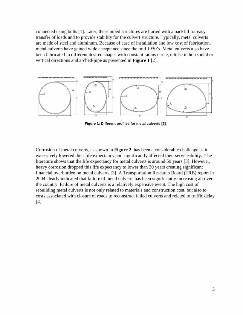
vertical directions and arched-pipe as presented in Figure 1 [2].
Figure 1: Different profiles for metal culverts [2]
Corrosion of metal culverts, as shown in Figure 2, has been a considerable challenge as it
excessively lowered their life expectancy and significantly affected their serviceability. The
literature shows that the life expectancy for metal culverts is around 50 years [3]. However,
heavy corrosion dropped this life expectancy to lower than 30 years creating significant
financial overburden on metal culverts [3]. A Transportation Research Board (TRB) report in
2004 clearly indicated that failure of metal culverts has been significantly increasing all over
the country. Failure of metal culverts is a relatively expensive event. The high cost of
rebuilding metal culverts is not only related to materials and construction cost, but also to
costs associated with closure of roads to reconstruct failed culverts and related to traffic delay
[4].

4
Figure 2: Corroded metal culvert [5]
Finally, engineers prefer to retrofit existing culverts rather than replace them because of the
complexity associated with un-backfilling, deconstruction and reconstruction and re-
backfilling. Two promising techniques listed in the literature are now used to retrofit metal
culverts. This includes using a metal liner inside the metal culvert and shotcrete lining [4].
The challenge is that the metal liner is still prone to corrosion and shotcrete loses cross-
section due to water flow abrasion. There is an urgent need to develop cost-effective
strategies to retrofit corroding metal culverts that are corrosion free and require minimal
maintenance.
Fiber-Reinforced Polymers Fiber reinforced polymers (FRP) are polymeric matrix typically polyester, vinyl ester, and
epoxy reinforced with synthetic fibers being glass, carbon, basalt or aramid fibers. With
improved manufacturing techniques and because of significant low cost, glass fiber
reinforced polymers (GFRP) have emerged as a desirable material for structural applications.
GFRP is essentially corrosion free as it has no electrochemical effect. This makes GFRP a
preferred material over steel under harsh environmental service conditions. A detailed review
of FRP materials for structures can be found elsewhere [6]. FRP currently gained wide
acceptance for retrofitting existing structures (bridges and buildings) because of the ease of
installation and high strength to weight ratio. Shear and flexural strengthening for structural
concrete using FRP has become a standard practice. Design guidelines for using FRP in
concrete structures have been detailed in the ACI-440-2R-08 [7]. However, using FRP to
retrofit metal culverts is relatively new and very few investigations have been completed.
There are no existing design guidelines to use FRP as a material for retrofitting metal
culverts.
On the other hand, FRP pipelines have become a common practice, and many drainage and
sewage systems and geothermal pipelines are being replaced using GFRP pipelines because
of the corrosion free nature of the material. Moreover, in the areas of harsh environment like
sea water piping, industrial waste and when a high purity of water is necessary GFRP has
5
become widely accepted because of the material ability to serve in harsh environment and to
resist corrosion [8]. These systems are mostly buried at a certain prescribed depth in the soil
and loads experienced are similar to the culvert systems. Typically, these pipeline systems
are designed for a life expectancy of 75 to 100 years.
Given the advantages of GFRP pipelines, this research evaluates the use of a fit-in GFRP
profile liner that can be placed inside a corroded metal culvert. It is expected that using
GFRP for retrofitting metal culverts when properly designed and implemented can achieve a
life of 75 to 100 years. Another advantage is that GFRP profiles can be manufactured in all
desired shapes hence using GFRP for metal culvert retrofit can be used for all profiles shown
in Figure 1.
4. METHODOLOGY
Materials:
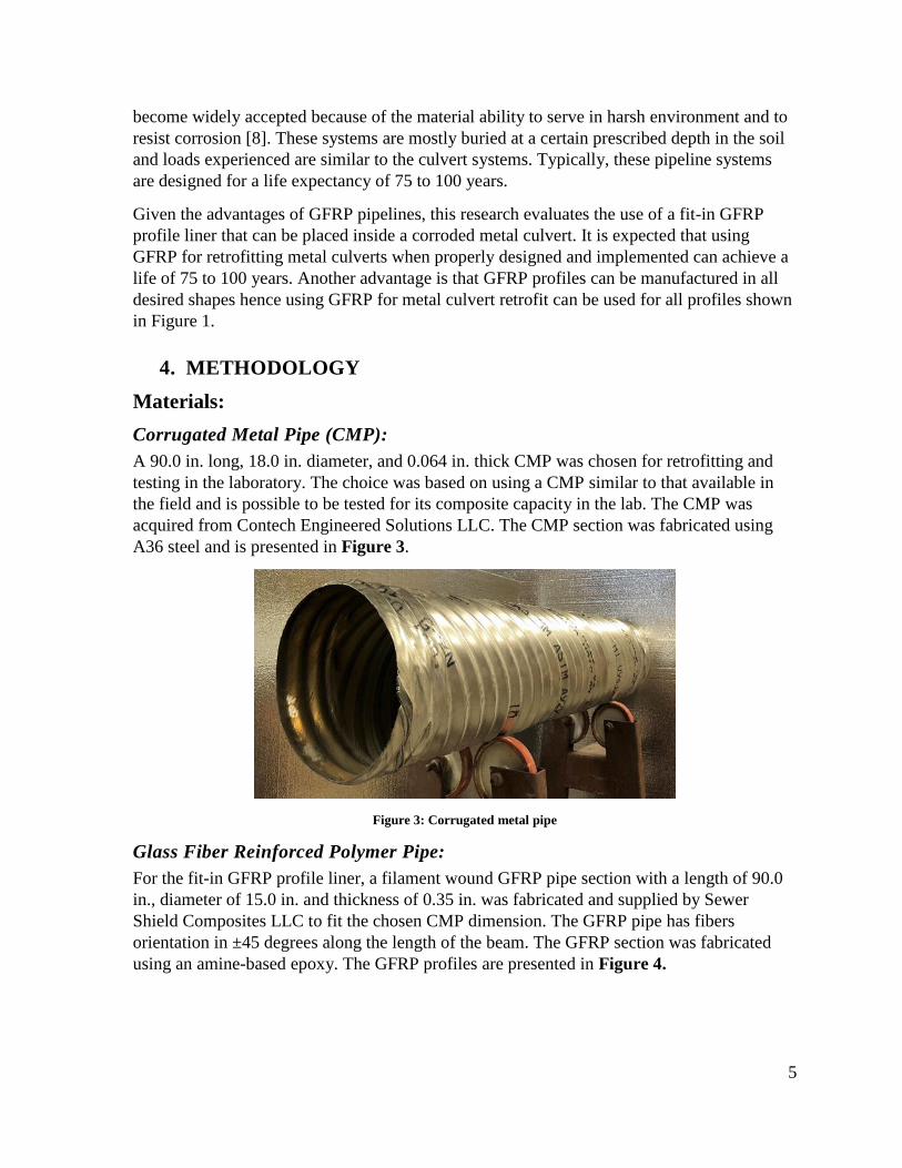
Corrugated Metal Pipe (CMP):
A 90.0 in. long, 18.0 in. diameter, and 0.064 in. thick CMP was chosen for retrofitting and
testing in the laboratory. The choice was based on using a CMP similar to that available in
the field and is possible to be tested for its composite capacity in the lab. The CMP was
acquired from Contech Engineered Solutions LLC. The CMP section was fabricated using
A36 steel and is presented in Figure 3.
Figure 3: Corrugated metal pipe
Glass Fiber Reinforced Polymer Pipe:
For the fit-in GFRP profile liner, a filament wound GFRP pipe section with a length of 90.0
in., diameter of 15.0 in. and thickness of 0.35 in. was fabricated and supplied by Sewer
Shield Composites LLC to fit the chosen CMP dimension. The GFRP pipe has fibers
orientation in ±45 degrees along the length of the beam. The GFRP section was fabricated
using an amine-based epoxy. The GFRP profiles are presented in Figure 4.

6
Figure 4: Filament wound GFRP pipes for slip-line
Epoxy grout:
To have the best bond between GFRP and grout material, an amine-based epoxy grout was
selected for the retrofit system. An amine based two-component epoxy system supplied by
U.S. Composite, Inc., Palm Beach, FL was used along with silica filler to produce the grout
material. The primary component of the epoxy system is a low viscous liquid epoxy resin
100% reactive based on Bisphenol-A. The second component is an epoxy-hardener
consisting of aliphatic amine. The resin to hardener mix ratio is 2:1 by weight. Silica based
aggregate supplied by Transpo Inc., NY, was used as the grout filler. Epoxy and filler
material were mixed at 1:1 ratio by volume.
Material characterization
GFRP
Bidirectional GFRP composites, cut from cylindrical GFRP shell, was tested under direct
axial compression and axial tension. For each of the compression and tension tests, samples
with two configurations, off-axis and on-axis, were tested. Off-axis samples refer to fibers
oriented in 45° with respect to the loading direction and on-axis refer to the fiber orientation
7
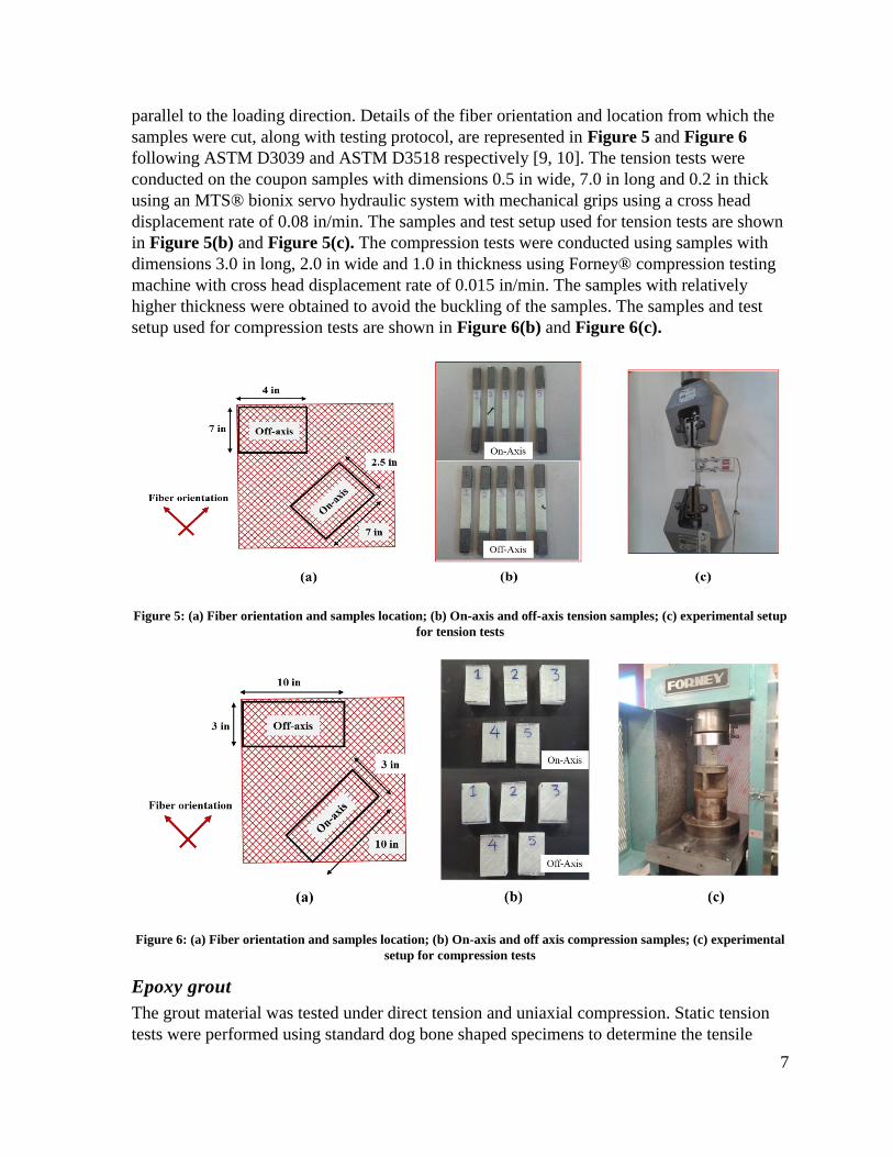
parallel to the loading direction. Details of the fiber orientation and location from which the
samples were cut, along with testing protocol, are represented in Figure 5 and Figure 6
following ASTM D3039 and ASTM D3518 respectively [9, 10]. The tension tests were
conducted on the coupon samples with dimensions 0.5 in wide, 7.0 in long and 0.2 in thick
using an MTS® bionix servo hydraulic system with mechanical grips using a cross head
displacement rate of 0.08 in/min. The samples and test setup used for tension tests are shown
in Figure 5(b) and Figure 5(c). The compression tests were conducted using samples with
dimensions 3.0 in long, 2.0 in wide and 1.0 in thickness using Forney® compression testing
machine with cross head displacement rate of 0.015 in/min. The samples with relatively
higher thickness were obtained to avoid the buckling of the samples. The samples and test
setup used for compression tests are shown in Figure 6(b) and Figure 6(c).
Figure 5: (a) Fiber orientation and samples location; (b) On-axis and off-axis tension samples; (c) experimental setup
for tension tests
Figure 6: (a) Fiber orientation and samples location; (b) On-axis and off axis compression samples; (c) experimental
setup for compression tests
Epoxy grout
The grout material was tested under direct tension and uniaxial compression. Static tension
tests were performed using standard dog bone shaped specimens to determine the tensile

8
strength and tensile Young’s modulus of the material based on ASTM D638 as shown in
Figure 7(a) [11]. A crosshead displacement rate of 0.04 in./min. has been used and the direct
tension test setup with contact extensometer is presented in Figure 7(b). The uniaxial
compression tests were conducted on 2.0 in. diameter, 4.0 in. long standard specimens based
on ASTM C469/C469M [12]. The compression test specimens are presented in Figure 7(a).
The compression tests were conducted using 0.04 in./min. crosshead displacement rate and a
120-kip Instron loading frame as shown in Figure 7(c). Strain gauges were used on two of
the five specimens to determine the compression Young’s modulus of elasticity of the grout
material.
Figure 7: (a) Tension and compression test specimens prior to testing; (b) Tension test set-up with a contact
extensometer; (c) Compression testing setup.
Design of Experimental Set-up
The loads experienced by culverts are self-weight, soil loads and live loads (traffic, train,
aircrafts). The primary objective of the study is to test the composite action of the steel-grout-
GFRP culvert. To investigate such an action, a simply supported beam action was chosen for
the pipe testing. Since differential settlements, shown in Figure 8, in soil is one of the
reasons for axial bending in pipeline area [14], the simply supported condition was a
reasonable protocol. The pipe section has a span length of 6 ft. which is typically the
tributary area under truck wheel load since highway lane width is 12ft as shown in Figure 9.
Consequently, live load effect was created by a point load application at the mid span
location simulating a truck wheel load.

9
Figure 8: Bending of culvert in longitudinal direction due to settlement in soil
Figure 9: Truck wheel load transferred to the culvert
To accommodate in the laboratory loading frame, a W12x96 section was acquired to ensure
negligible deflection of section under loading up to150-kip force. Two semicircular supports
were designed and fabricated to have a mechanical hinge used to bolt to the W beam section.
These semicircular supports were used to allow bending in the desired direction with one
support acting as a hinge and the other support acting as a roller to avoid any axial forces
within the section.
GFRP slip-line procedure
To fit in GFRP pipe in the metal corrugated pipe, surface grinding of GFRP pipe (Figure
10), using 80 grit sandpaper, was ensured. This maximizes the bond with the epoxy grout
GFRP pipe was thoroughly washed using a water jet to remove any debris present on the
surface. A wood spacer, as shown in Figure 11, was created and bonded to the steel pipe

10
using thick epoxy. The epoxy could completely seal the gap between the pipe and the wood
spacer. The GFRP pipe was then inserted into the corrugated metal pipe. The gap between
GFRP pipe and the spacer was then filled with a thick epoxy to completely seal any
remaining gaps. Figure 12 presents the section after GFRP pipe fit inside the corrugate metal
pipe.
Figure 10: Surface preparation of GFRP pipe
Figure 11: Wood spacer bonded to the corrugated metal section

11
Figure 12: Post sliding the GFRP pipe into the corrugated metal pipe using wood spacer
Grouting: An amine based two-component epoxy system supplied by U.S. Composite, Palm Beach, FL
was used as grout along with a filler material. The primary component is a low viscous liquid
epoxy resin 100% reactive based on Bisphenol-A. The second component is an epoxy-
hardener consisting of Aliphatic Amine. The resin to hardener mix ratio is 2:1 by weight of
the epoxy. T-48 polymer concrete filler supplied by Transpo, Inc., has been used. The epoxy
and filler material were mixed at 1:1 ratio by volume. The mixing procedure is outlined in
Figure 13. A manual grouting pump CG-050M has been acquired from ChemGrout, Inc.
Figure 13: Mixing and grouting procedure
12
Using grouting pump, the grout was pumped through one hose until it was expelled from the
other hose ensuring grout fill between GFRP and steel pipe. Extra grout was pumped anyway
until hose was overflowed thus ensuring complete fill.
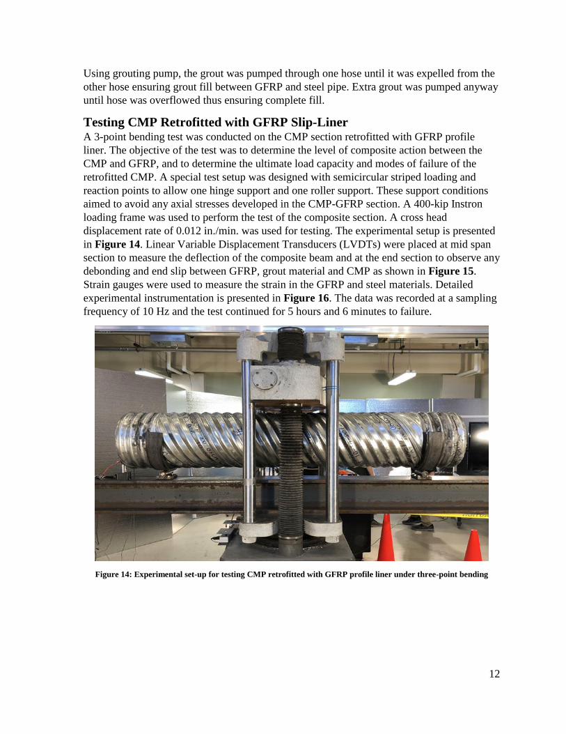
Testing CMP Retrofitted with GFRP Slip-Liner A 3-point bending test was conducted on the CMP section retrofitted with GFRP profile
liner. The objective of the test was to determine the level of composite action between the
CMP and GFRP, and to determine the ultimate load capacity and modes of failure of the
retrofitted CMP. A special test setup was designed with semicircular striped loading and
reaction points to allow one hinge support and one roller support. These support conditions
aimed to avoid any axial stresses developed in the CMP-GFRP section. A 400-kip Instron
loading frame was used to perform the test of the composite section. A cross head
displacement rate of 0.012 in./min. was used for testing. The experimental setup is presented
in Figure 14. Linear Variable Displacement Transducers (LVDTs) were placed at mid span
section to measure the deflection of the composite beam and at the end section to observe any
debonding and end slip between GFRP, grout material and CMP as shown in Figure 15.
Strain gauges were used to measure the strain in the GFRP and steel materials. Detailed
experimental instrumentation is presented in Figure 16. The data was recorded at a sampling
frequency of 10 Hz and the test continued for 5 hours and 6 minutes to failure.
Figure 14: Experimental set-up for testing CMP retrofitted with GFRP profile liner under three-point bending

13
Figure 15: Figure showing the placement of LVDTs to measure midspan deflection and end slip
Figure 16: Experimental instrumentation used for testing
Computational Methods
A commercial finite element software ABAQUS was used to model the CMP-GFRP
composite section. The model was created using 3D geometry toolbox in ABAQUS. The
model consists of steel circular pipe section, grout section and the GFRP pipe section. The
steel section was modelled assuming a noncorrugated A36 steel pipe section with a uniform
thickness of 0.064in. In reality, the corrugated pipe section behavior is different from
noncorrugated section. However, modelling corrugated section may create special problems
such as geometrical irregularities and issues with the mesh development for numerical
analysis of the system [13]. Therefore, a simplified section has been chosen for the analysis.
14
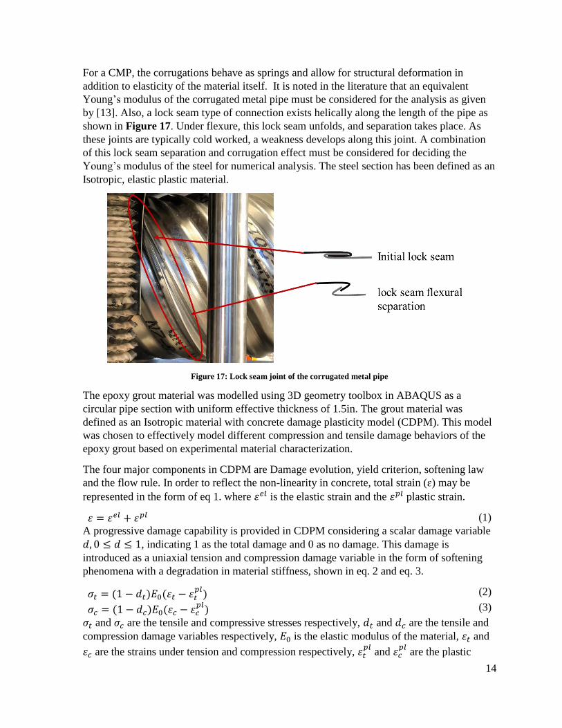
For a CMP, the corrugations behave as springs and allow for structural deformation in
addition to elasticity of the material itself. It is noted in the literature that an equivalent
Young’s modulus of the corrugated metal pipe must be considered for the analysis as given
by [13]. Also, a lock seam type of connection exists helically along the length of the pipe as
shown in Figure 17. Under flexure, this lock seam unfolds, and separation takes place. As
these joints are typically cold worked, a weakness develops along this joint. A combination
of this lock seam separation and corrugation effect must be considered for deciding the
Young’s modulus of the steel for numerical analysis. The steel section has been defined as an
Isotropic, elastic plastic material.
Figure 17: Lock seam joint of the corrugated metal pipe
The epoxy grout material was modelled using 3D geometry toolbox in ABAQUS as a
circular pipe section with uniform effective thickness of 1.5in. The grout material was
defined as an Isotropic material with concrete damage plasticity model (CDPM). This model
was chosen to effectively model different compression and tensile damage behaviors of the
epoxy grout based on experimental material characterization.
The four major components in CDPM are Damage evolution, yield criterion, softening law
and the flow rule. In order to reflect the non-linearity in concrete, total strain (ɛ) may be
represented in the form of eq 1. where 𝜀𝑒𝑙 is the elastic strain and the 𝜀𝑝𝑙 plastic strain.
𝜀 = 𝜀𝑒𝑙 + 𝜀𝑝𝑙 (1)
A progressive damage capability is provided in CDPM considering a scalar damage variable
𝑑, 0 ≤ 𝑑 ≤ 1, indicating 1 as the total damage and 0 as no damage. This damage is
introduced as a uniaxial tension and compression damage variable in the form of softening
phenomena with a degradation in material stiffness, shown in eq. 2 and eq. 3.
𝜎𝑡 = (1 − 𝑑𝑡)𝐸0(𝜀𝑡 − 𝜀𝑡𝑝𝑙) (2)
𝜎𝑐 = (1 − 𝑑𝑐)𝐸0(𝜀𝑐 − 𝜀𝑐𝑝𝑙) (3)
𝜎𝑡 and 𝜎𝑐 are the tensile and compressive stresses respectively, 𝑑𝑡 and 𝑑𝑐 are the tensile and
compression damage variables respectively, 𝐸0 is the elastic modulus of the material, 𝜀𝑡 and
𝜀𝑐 are the strains under tension and compression respectively, 𝜀𝑡𝑝𝑙
and 𝜀𝑐𝑝𝑙
are the plastic

15
strains in tension and compression respectively. More detailed explanation on CDPM can be
found elsewhere [14, 15].
The GFRP material was modelled using 3D geometry toolbox in ABAQUS as a circular pipe
section with a uniform effective thickness of 0.35in. Additionally, Helius progressive failure
analysis (PFA), developed based on the multi continuum theory (MCT) technique, considers
a representative volume element (RVE) developed to obtain the average stresses in a
homogenized composite. Subsequently, the average stresses are decomposed to the stresses
of fibers and the matrix discretely in an FEA simulation. This decomposition of stress will
help in simulating damage evolution analysis by predicting the failure of fibers and matrix of
the composite material.
To determine the constituent stresses and strains from composite stresses and strains, the
decomposition of matrix phase and fiber phase is conducted. Considering 𝜎(𝑥, 𝑦, 𝑧) as the
stress field of a homogenized RVE element with a volume “𝑉”, stress state of the
homogenized composite can be given by,
𝜎𝑐 =1
𝑉∫ 𝜎(𝑥, 𝑦, 𝑧)𝑑𝑉
𝐷
(4)
Similarly, the stress state in fibers and matrix is given by,
𝜎𝑓 =1
𝑉𝑓∫ 𝜎(𝑥, 𝑦, 𝑧)𝑑𝑉
𝐷𝑓
(5)
𝜎𝑚 =1
𝑉𝑚∫ 𝜎(𝑥, 𝑦, 𝑧)𝑑𝑉
𝐷𝑚
(6)
Where, 𝑉𝑓 and 𝑉𝑚 are the volume fractions of fibers and matrix respectively. Combining eqs.
4-6 yields,
𝜎𝑐 = 𝑉𝑓𝜎𝑓 + 𝑉𝑚𝜎𝑚 (7)
A similar set of expressions for the strain tensor (ɛ) can also be obtained as,
ɛ𝑐 =1
𝑉∫ ɛ(𝑥, 𝑦, 𝑧)𝑑𝑉
𝐷
(8)
ɛ𝑓 =1
𝑉𝑓∫ ɛ(𝑥, 𝑦, 𝑧)𝑑𝑉
𝐷𝑓
(9)
ɛ𝑚 =1
𝑉𝑚∫ ɛ(𝑥, 𝑦, 𝑧)𝑑𝑉
𝐷𝑚
(10)
ɛ𝑐 = 𝑉𝑓ɛ𝑓 + 𝑉𝑚ɛ𝑚 (11)
Based on all the above equations, following relation will yield,
𝜎𝑐 = 𝐶𝑐𝜀𝑐 (12)
𝜎𝑓 = 𝐶𝑓𝜀𝑓 (13)
𝜎𝑚 = 𝐶𝑚𝜀𝑚 (14)
Where, 𝐶𝑐, 𝐶𝑓 and 𝐶𝑚 represent 6 x 6 stiffness matrices of the homogenized composite,
fibers and matrix respectively. Substituting eqs. (12- 14) in eq. 7 yields,

16
𝐶𝑐𝜀𝑐 = 𝑉𝑓𝐶𝑓𝜀𝑓 + 𝑉𝑚𝐶𝑚𝜀𝑚 (15)
Using eq. 15 and eq. 11, the following relation is obtained,
𝐶𝑐(𝑉𝑓𝜀𝑓 + 𝑉𝑚𝜀𝑚) = 𝑉𝑓𝐶𝑓𝜀𝑓 + 𝑉𝑚𝐶𝑚𝜀𝑚 (16)
By simplification and multiplying both sides of the eq. 16 with (𝑉𝑓(𝐶𝑐 − 𝐶𝑓)−1
,
𝜀𝑓 = −𝑉𝑚
𝑉𝑓
(𝐶𝑐 − 𝐶𝑓)−1(𝐶𝑐 − 𝐶𝑚)−1𝜀𝑚 (17)
𝐴 ≡ −𝑉𝑚
𝑉𝑓(𝐶𝑐 − 𝐶𝑓)−1(𝐶𝑐 − 𝐶𝑚)−1 (18)
Then,
𝜀𝑓 = 𝐴𝜀𝑚 (17)
Using the above equation, the state of strain in the form of eq. 11,
𝜀𝑚 = (𝑉𝑚𝐼 + 𝑉𝑓𝐴)−1
𝜀𝑐 (18)
By using eq. 11 and eq. 18 the state of strain in fibers can be obtained as,
𝜀𝑓 =1
𝑉𝑓
(𝜀𝑐 − 𝑉𝑚𝜀𝑚) (19)
The above set of equations are valid for any type of constitutive behavior and any level of
deformation. There are no restrictions on the validity of these equations. The constituent
average stress and strain states (𝜎𝑓, 𝜎𝑚, 𝜀𝑓 , 𝜀𝑚) are more relevant to predict the evolution of
damage and material failure than the average states of a homogenized composite. This is the
fundamental argument of the MCT. Moreover, the damage evolution and failure are
primarily dominated by the stress and strain state of the matrix constituent materials rather
than the stress and strain in the fiber constituent material or the stress and strain states of the
composite itself [16]. A similar statement can be made for fiber constituent material as well.
A separate failure criterion for each constituent material is used along with the constituent
failure criteria on the constituent average stress state [16]. Moreover, an appropriate stiffness
degradation is applied to both fibers and matrix based on stress state and failure. More
detailed information on MCT is available elsewhere [16-19].
Semicircular solid 3D supports with a width of 4in, and a diameter of 18in were created as an
analytical rigid material. These supports were created to represent the experimental boundary
conditions for numerical analysis. Based on the experimental observations, all the three
materials were tie constrained assuming perfect bond between GFRP-grout and steel-grout. A
mesh size of approximately 2.0in. was used for the model. A C3D8R, an 8-node linear
hexahedron, with linear geometric order, was used for the analysis. The appropriate boundary
conditions were chosen to represent the experimental condition and provided to the two
supports. One support could rotate and translate along longitudinal direction of composite
pipe (roller) and the second support was allowed to rotate along the longitudinal direction of
the composite pipe (hinged) to avoid any axial forced in the section. The top semicircular

17
section was loaded under displacement control up to a displacement of 1.2 in. The complete
assembly and locations of the boundary conditions are shown in Figure 18.
Figure 18: 3D model of steel-grout-GFRP composite pipe
5. ANALYSIS AND FINDINGS
Material characterization The mechanical properties for GFRP and epoxy grout are presented in Table. 1. The
mechanical properties examined include Young’s modulus of elasticity, tensile strength and
modulus for on-axis (0°) and off-axis (45°) GFRP. The stress versus strain behavior of GFRP
under direct tension test is presented in Figure 19(a).
Table 1: Mechanical Properties of GFRP and Epoxy Grout
Parameter 0° GFRP 45° GFRP Grout
Tensile strength (psi) 54,289 ± 4033 5,479 ± 651 2,040 ± 350
Tensile modulus (ksi) 2,794 ± 107 1,088 ± 184 659 ± 142
Compressive strength (psi) 15240 ± 1200 10720 ± 200 8392 ± 421
Compressive Modulus (ksi) NA NA 1,590 ± 112
The stress versus strain behavior of the polymer grout material under axial compressive and
tensile stresses are presented in Figure 19(b). The polymer grout behavior represents a
18
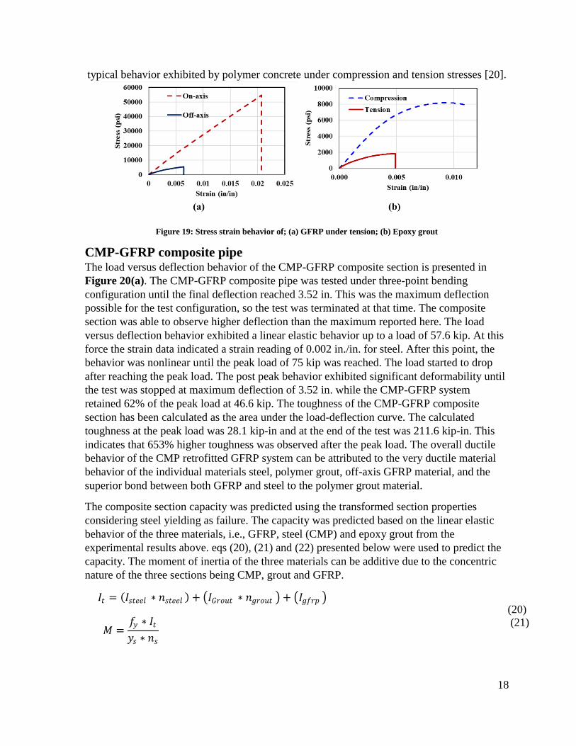
typical behavior exhibited by polymer concrete under compression and tension stresses [20].
Figure 19: Stress strain behavior of; (a) GFRP under tension; (b) Epoxy grout
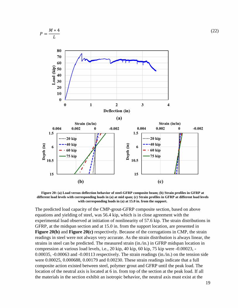
CMP-GFRP composite pipe The load versus deflection behavior of the CMP-GFRP composite section is presented in
Figure 20(a). The CMP-GFRP composite pipe was tested under three-point bending
configuration until the final deflection reached 3.52 in. This was the maximum deflection
possible for the test configuration, so the test was terminated at that time. The composite
section was able to observe higher deflection than the maximum reported here. The load
versus deflection behavior exhibited a linear elastic behavior up to a load of 57.6 kip. At this
force the strain data indicated a strain reading of 0.002 in./in. for steel. After this point, the
behavior was nonlinear until the peak load of 75 kip was reached. The load started to drop
after reaching the peak load. The post peak behavior exhibited significant deformability until
the test was stopped at maximum deflection of 3.52 in. while the CMP-GFRP system
retained 62% of the peak load at 46.6 kip. The toughness of the CMP-GFRP composite
section has been calculated as the area under the load-deflection curve. The calculated
toughness at the peak load was 28.1 kip-in and at the end of the test was 211.6 kip-in. This
indicates that 653% higher toughness was observed after the peak load. The overall ductile
behavior of the CMP retrofitted GFRP system can be attributed to the very ductile material
behavior of the individual materials steel, polymer grout, off-axis GFRP material, and the
superior bond between both GFRP and steel to the polymer grout material.
The composite section capacity was predicted using the transformed section properties
considering steel yielding as failure. The capacity was predicted based on the linear elastic
behavior of the three materials, i.e., GFRP, steel (CMP) and epoxy grout from the
experimental results above. eqs (20), (21) and (22) presented below were used to predict the
capacity. The moment of inertia of the three materials can be additive due to the concentric
nature of the three sections being CMP, grout and GFRP.
(20)
(21)
𝐼𝑡 = (𝐼𝑠𝑡𝑒𝑒𝑙 ∗ 𝑛𝑠𝑡𝑒𝑒𝑙 ) + (𝐼𝐺𝑟𝑜𝑢𝑡 ∗ 𝑛𝑔𝑟𝑜𝑢𝑡 ) + (𝐼𝑔𝑓𝑟𝑝 )
𝑀 =𝑓𝑦 ∗ 𝐼𝑡
𝑦𝑠 ∗ 𝑛𝑠
19
(22)
Figure 20: (a) Load versus deflection behavior of steel-GFRP composite beam; (b) Strain profiles in GFRP at
different load levels with corresponding loads in (a) at mid span; (c) Strain profiles in GFRP at different load levels
with corresponding loads in (a) at 15.0 in. from the support.
The predicted load capacity of the CMP-grout-GFRP composite section, based on above
equations and yielding of steel, was 56.4 kip, which is in close agreement with the
experimental load observed at initiation of nonlinearity of 57.6 kip. The strain distributions in
GFRP, at the midspan section and at 15.0 in. from the support location, are presented in
Figure 20(b) and Figure 20(c) respectively. Because of the corrugations in CMP, the strain
readings in steel were not always very accurate. As the strain distribution is always linear, the
strains in steel can be predicted. The measured strain (in./in.) in GFRP midspan location in
compression at various load levels, i.e., 20 kip, 40 kip, 60 kip, 75 kip were -0.00023, -
0.00035, -0.00063 and -0.00113 respectively. The strain readings (in./in.) on the tension side
were 0.00025, 0.000688, 0.00179 and 0.00230. These strain readings indicate that a full
composite action existed between steel, polymer grout and GFRP until the peak load. The
location of the neutral axis is located at 6 in. from top of the section at the peak load. If all
the materials in the section exhibit an isotropic behavior, the neutral axis must exist at the
𝑃 =𝑀 ∗ 4
𝐿

20
center. However, the non-symmetric neutral axis is mainly because of orthotropic behavior of
GFRP. Figure 21(b) shows the neutral axis shifting down as the load progressed to the peak
load. It is also important to note that the thickness of the grout material (1.5 in.) is higher
compared to that of the steel (0.064 in.) and GFRP (0.35 in.). Therefore, the grout material
will have a higher moment of inertia compared to both steel and GFRP. The results from
Table 1 also show that tensile modulus of epoxy grout is much lower compared with
compression modulus of the grout material. This justifies the downward shift of the neutral
axis. The strain readings from Figure 21(c) indicate that GFRP experienced strains at 15.0
in. location from the support.
Figure 21: Failure modes identified on the load-deflection curve of the CMP retrofitted using GFRP profile liner and
the corresponding loads. Figure insets show the behavior at different loads. Inset (a) shows separation of steel at
point (ii) of the load deflection curve. Inset (b) shows the GFRP failure due to off-axis tension at point (iii) of the
load-deflection curve
The modes of failure of the CMP-GFRP section to the corresponding peak loads were
identified and are shown in Figure 21. First, the point at which the steel yielded is shown.
Second, failure mode at the peak load is shown. Failure at the peak load occurred because of
separation of the CMP joint located exactly at the mid span section of the beam as shown in
Figure 21(a). For CMP-GFRP composite section, compression existed on top of the beam
and maximum tension existed below the neutral axis at the bottom farthest location. At the
peak load, the strains in GFRP reached -0.00113 in./in. in compression and 0.00230 in./in. in
tension, much lower than the failure strains of GFRP. Extrapolated strain in grout material in
compression was -0.00150 in./in. and in tension was 0.00301 in./in. indicating the grout
material reached its peak strain and may have failed. An inference can be made that failure of
grout and separation of joint occurred at the peak load. Beyond this point, the strains in
GFRP increased significantly. At point (iii), shown in Figure 21(b), GFRP on the tension
side started to fail as the strain in GFRP reached 0.036 in./in., which is very close to the

21
typical off-axis failure strain in GFRP. Nevertheless, no signs of failure in compression were
observed at this point of loading.
Figure 22: GFRP failure at the end of the test
Figure 22 shows the complete failure of GFRP at the end of the test. The separation of
corrugated steel pipe at the end of the test is presented in Figure 23. The deflected beam at
the end of the test is presented in Figure 24. The above results indicate that a full composite
action existed between GFRP, polymer grout and steel until the peak load was reached.
22
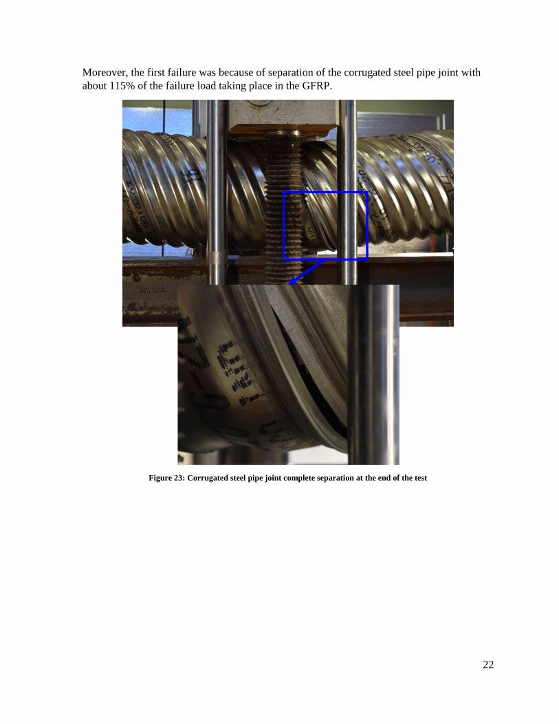
Moreover, the first failure was because of separation of the corrugated steel pipe joint with
about 115% of the failure load taking place in the GFRP.
Figure 23: Corrugated steel pipe joint complete separation at the end of the test

23
Figure 24: Deflected retrofitted CMP using GFRP profile liner at the end of the test with total deflection of 3.52 in
The above results prove that the fit-in GFRP profile liner was able to retrofit the CMP and a
full composite action was developed. The proposed method for sliding the liner and filling
the gap with a polymer grout worked very well. A limitation of the above study is that it has
been performed on a non-corroded CMP. The significance of CMP corrosion is its bond with
the polymer grout and the impact of corrosion on the composite action of the retrofitted
CMP. Finally, relatively high cost of GFRP compared with other techniques for retrofitting
can be justified by its significant structural capacity compared with all other retrofitting
systems. Furthermore, the use of filament winding technology will allow using this technique
with metal culverts with any dimension and cross-section and is not limited to circular
sections.
Finite Element modeling results A commercial finite element software ABAQUS was used to model the CMP-GFRP
composite section. The system was developed making use of the 3D geometry toolbox in
ABAQUS. The model consists of steel circular pipe section, grout section and the GFRP pipe
section. All the three materials were tie constrained by assuming perfect bond between
GFRP-grout and steel-grout. The corrugation of the steel pipe has been neglected for the
Finite Element Analysis (FEA) model. A mesh size of approximately 2.0 in was used for the
model. A C3D8R, an 8-node linear hexahedron, with linear geometric order was used for the
analysis. The FEA model was loaded using a ramped static displacement protocol up to a
deflection of 1.2in. The FEA model developed for the study is presented in Figure 25.
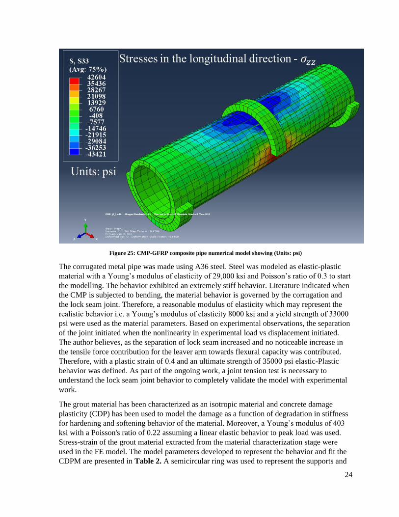
24
Figure 25: CMP-GFRP composite pipe numerical model showing (Units: psi)
The corrugated metal pipe was made using A36 steel. Steel was modeled as elastic-plastic
material with a Young’s modulus of elasticity of 29,000 ksi and Poisson’s ratio of 0.3 to start
the modelling. The behavior exhibited an extremely stiff behavior. Literature indicated when
the CMP is subjected to bending, the material behavior is governed by the corrugation and
the lock seam joint. Therefore, a reasonable modulus of elasticity which may represent the
realistic behavior i.e. a Young’s modulus of elasticity 8000 ksi and a yield strength of 33000
psi were used as the material parameters. Based on experimental observations, the separation
of the joint initiated when the nonlinearity in experimental load vs displacement initiated.
The author believes, as the separation of lock seam increased and no noticeable increase in
the tensile force contribution for the leaver arm towards flexural capacity was contributed.
Therefore, with a plastic strain of 0.4 and an ultimate strength of 35000 psi elastic-Plastic
behavior was defined. As part of the ongoing work, a joint tension test is necessary to
understand the lock seam joint behavior to completely validate the model with experimental
work.
The grout material has been characterized as an isotropic material and concrete damage
plasticity (CDP) has been used to model the damage as a function of degradation in stiffness
for hardening and softening behavior of the material. Moreover, a Young’s modulus of 403
ksi with a Poisson's ratio of 0.22 assuming a linear elastic behavior to peak load was used.
Stress-strain of the grout material extracted from the material characterization stage were
used in the FE model. The model parameters developed to represent the behavior and fit the
CDPM are presented in Table 2. A semicircular ring was used to represent the supports and

25
loading head with boundary conditions similar to those used in the testing. The model is
shown in Figure 18. The GFRP pipe has been modelled using composite layup tool box in
ABAQUS. The composite layup has been carried out in 60 layers and a local discrete
coordinate system has been assigned. The composite layup is presented in Figure 26 with a
repeated layup of 90°, +45°, -45°, +45°, -45°. The material properties for the GFRP pipe
section were defined based on the orthotropic elastic properties based on results from Table
3. The parameters for 0° direction were used from the experimental investigation and 45°
results were used to determine the shear modulus and shear strength. The 90° properties were
used from the literature which used GFRP with similar matrix and epoxy type [21].
Table 2: CDPM parameters for grout material
σt ɛck dt σc ɛin dc
psi in/in - psi in/in -
2100 0.0000 0.00 2500 0.0000 0.00
1500 0.0017 0.29 3000 0.0009 0.00
1300 0.0024 0.38 3500 0.0030 0.00
900 0.0045 0.57 4000 0.0045 0.00
300 0.0069 0.86 3921 0.0106 0.00
250 0.0089 0.88
200 0.0109 0.90
Table 3: GFRP laminate properties
E11 E22 G12 +S11 -S11 +S22 -S22 v12
ksi ksi ksi psi psi psi psi
2794 625 1088 54289 15240 2040 6816 0.16

26
Figure 26: Composite layup of GFRP filament wound pipe
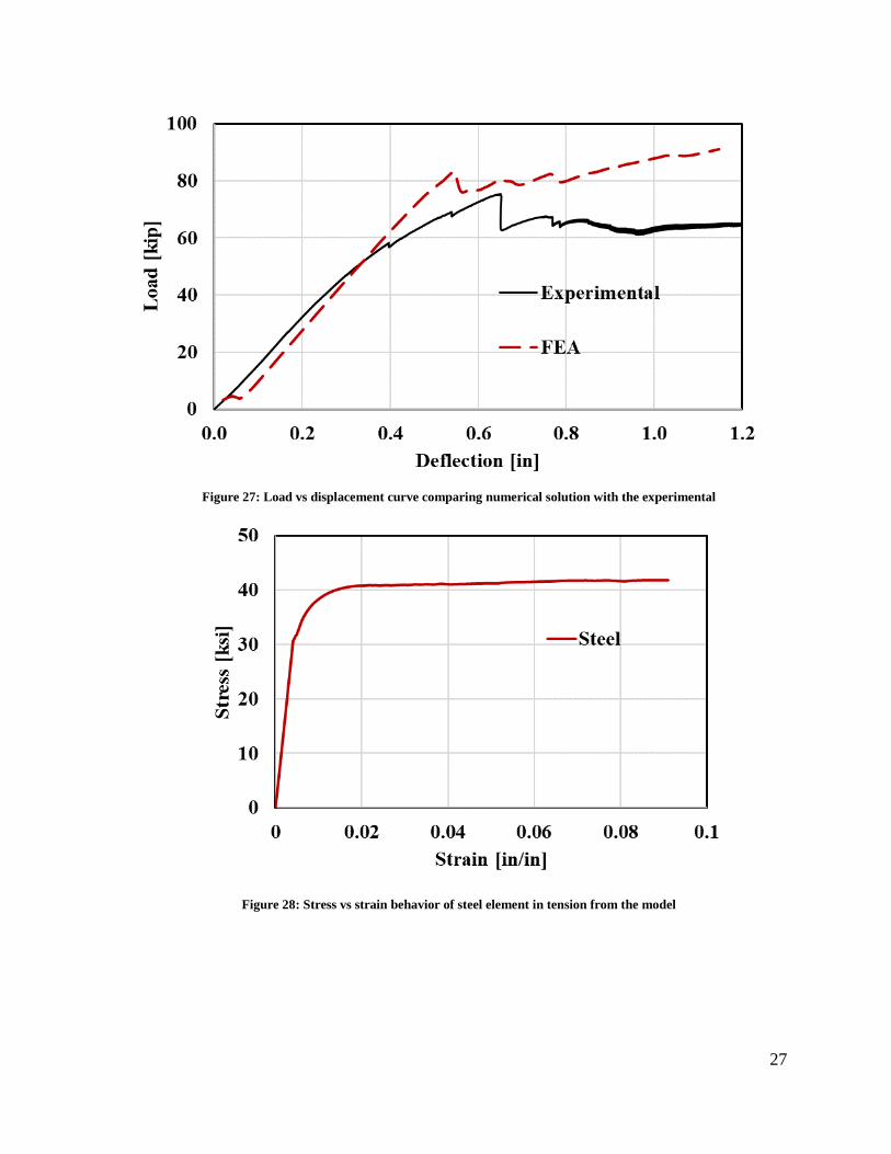
The load versus displacement behavior comparing experimental to the numerical analysis is
presented in Figure 27. The behavior from numerical analysis agrees well with the
experimental observations. This model is limited to the mesh size 2.0in only. Further
investigations are necessary by conducting the mesh sensitivity analysis to verify the model.
Stress strain behavior of the steel element is presented in Figure 28. The behavior agrees
reasonably well with the input parameters of elastic-plastic behavior of steel. Stress strain
behavior of the grout tension element is presented in Figure 29. The behavior agrees
reasonably well with the input tensile parameters of CDPM as shown in Figure 29. The
stress vs strain behavior of GFRP tension element is presented in Figure 30. With the stress
strain behavior, a drop can be observed at 1500 psi. As some of the laminate layers are in 90°
direction and corresponding tensile strength is 1500 psi and the rest of the fibers in 45° are
carrying the load. This can be represented by the change in stiffness after drop.
27
Figure 27: Load vs displacement curve comparing numerical solution with the experimental
Figure 28: Stress vs strain behavior of steel element in tension from the model

28
Figure 29: Idealized grout stress versus strain given as input for the model (Input) and grout behavior from the
model (FEA)
Figure 30: Stress vs strain behavior GFRP tension element from the model
The global behavior of the model represents an identical behavior to the experimental
behavior. An inference can be made that the drop-in load capacity after reaching 82 kip can
be attributed to the grout tension failure and steel not being able to take any more force
beyond max force and deform significantly to maintain the stress at 40000 psi. However, as
GFRP complete failure was not observed and carried the stress. Therefore, the load carrying
capacity further increased after the drop. Stress versus time step behavior is presented in
Figure 32. A clear observation can be made that when grout failure was achieved, a steep
climb in the stress can be observed with steel. At this point of the experiment a drop-in force
associated with significant joint separation was observed. Grout failure has increased the
stress significant for steel and this caused a sudden separation of steel. This inference can be
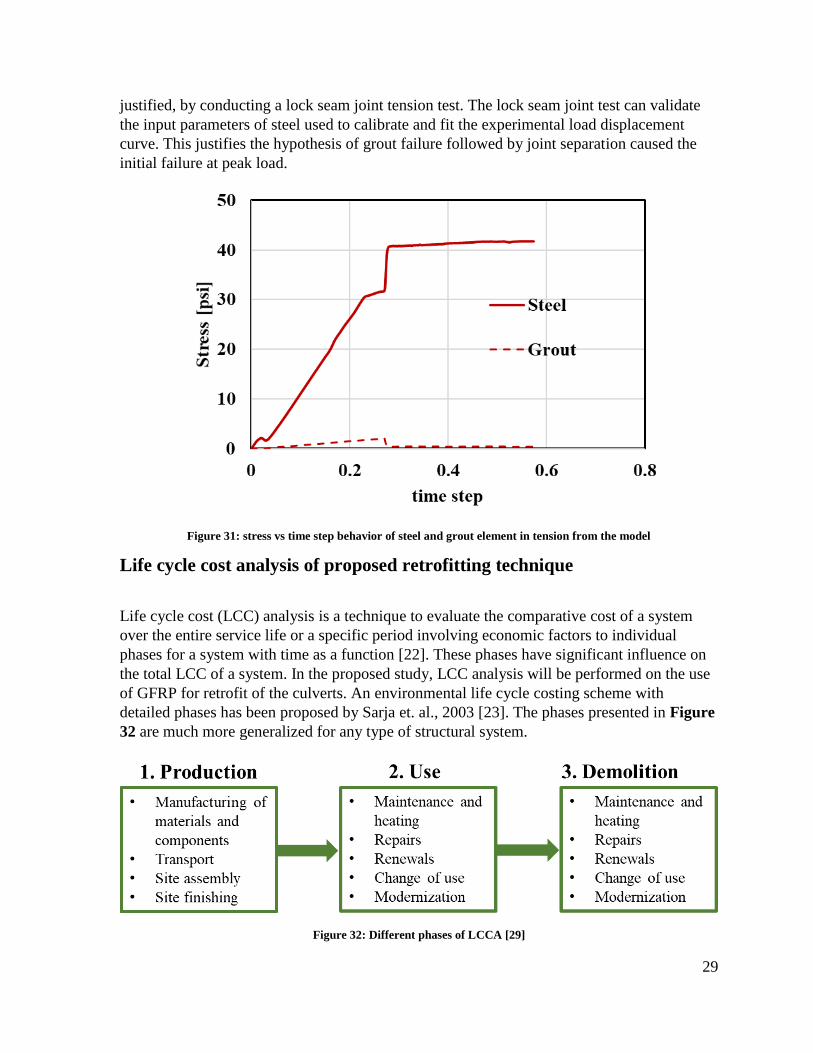
29
justified, by conducting a lock seam joint tension test. The lock seam joint test can validate
the input parameters of steel used to calibrate and fit the experimental load displacement
curve. This justifies the hypothesis of grout failure followed by joint separation caused the
initial failure at peak load.
Figure 31: stress vs time step behavior of steel and grout element in tension from the model
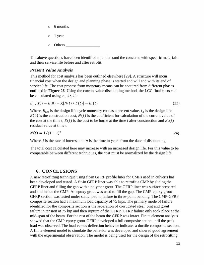
Life cycle cost analysis of proposed retrofitting technique
Life cycle cost (LCC) analysis is a technique to evaluate the comparative cost of a system
over the entire service life or a specific period involving economic factors to individual
phases for a system with time as a function [22]. These phases have significant influence on
the total LCC of a system. In the proposed study, LCC analysis will be performed on the use
of GFRP for retrofit of the culverts. An environmental life cycle costing scheme with
detailed phases has been proposed by Sarja et. al., 2003 [23]. The phases presented in Figure
32 are much more generalized for any type of structural system.
Figure 32: Different phases of LCCA [29]

30
Typically, total life cycle cost can be divided into two components; agency costs and social
costs [24]. Agency costs can be related to the direct costs associated with the three phases
described in Figure 32. Social costs refer to the indirect costs due to inconvenience caused to
people. For this current study, it can be referred to user delay cost, vehicle operating costs
and environmental costs. Environmental costs can be considered by conducting a Life-cycle
assessment.
Objective of Life cycle cost analysis:
Currently, three main materials, steel, PVC and HDPE are used for retrofitting the existing
corroded culverts. It is important to compare the LCC for these three materials with GFRP as
a material retrofitting. In New Mexico, steel culverts are corroding within 3 years of
installation in certain regions. A study reported that HDPE pipes have caused several types of
failures and service life is significantly lower compared to the design life of the culvert. PVC
is significantly brittle in cold climates. The proposed technology in this study, with a high
specific strength of GFRP, shows great potential to eliminate problems caused by both PVC
and HDPE systems and overcome the corrosion problem with steel. To estimate the
appropriate LCC for each material, the parameters presented in Figure 33 will be considered.
Figure 33: Phases to be considered for LCC analysis in propose study [22]
As part of the LCCA, a survey methodology is proposed with target population including but
not limited to NMDOT officials of different districts in New Mexico. A simple approach
based on the tools of generalization of the questionnaire and a deductive scale development is
used by providing a generalized set of options as explained by Hinikin, 1998 [25]. Five tasks
will be included in the survey process. They are,
1. Preparation of a questionnaire
2. Identifying NMDOT officials to exchange questionnaire
3. Exchanging conversations with NMDOT officials and collect answers
4. Documentation and analysis of the obtained answers
5. Scientific and statistical quantification of survey outcomes
Questionnaire for NMDOT officials of different districts:
1. What is the typical service life of a CMP in the corresponding district?
District name_________________
o 1-10 years

31
o 10-20 years
o 20-30 years
o Others_________________
2. What are the different materials presently used for slip lining a corroded CMP
culvert?
o Poly vinyl chloride (PVC)
o High density polyethylene (HDPE)
o Steel
o Others_________________
3. After retrofitting corroded CMP culvert in the corresponding district, what is the
typical service life?
District name_________________
o 1-10 years
o 10-20 years
o 20-30 years
o Others_________________
4. What are the issues with currently used materials for slip lining?
o Material _________________
o Specific issue _________________
5. Was there a CMP culvert failure in your district? Can you provide details of the
failure? (describe briefly)
6. What is the frequency of CMP culvert inspection over its life span?
o 3 months
32
o 6 months
o 1 year
o Others _________________
The above questions have been identified to understand the concerns with specific materials
and their service life before and after retrofit.
Present Value Analysis
This method for cost analysis has been outlined elsewhere [29]. A structure will incur
financial cost when the design and planning phase is started and will end with its end of
service life. The cost process from monetary means can be acquired from different phases
outlined in Figure 26. Using the current value discounting method, the LCC final costs can
be calculated using eq. 23,24:
𝐸𝑡𝑜𝑡(𝑡𝑑) = 𝐸(0) + ∑[𝑁(𝑡) ∗ 𝐸(𝑡)] − 𝐸𝑟(𝑡) (23)
Where, 𝐸𝑡𝑜𝑡 is the design life cycle monetary cost as a present value, 𝑡𝑑 is the design life,
𝐸(0) is the construction cost, 𝑁(𝑡) is the coefficient for calculation of the current value of
the cost at the time t, 𝐸(𝑡) is the cost to be borne at the time t after construction and 𝐸𝑟(𝑡)
residual value at time t.
𝑁(𝑡) = 1 (1 + 𝑖)𝑛⁄ (24)
Where, 𝑖 is the rate of interest and 𝑛 is the time in years from the date of discounting.
The total cost calculated here may increase with an increased design life. For this value to be
comparable between different techniques, the cost must be normalized by the design life.
6. CONCLUSIONS
A new retrofitting technique using fit-in GFRP profile liner for CMPs used in culverts has
been developed and tested. A fit-in GFRP liner was able to retrofit a CMP by sliding the
GFRP liner and filling the gap with a polymer grout. The GFRP liner was surface prepared
and slid inside the CMP. An epoxy grout was used to fill the gap. The CMP-epoxy grout-
GFRP section was tested under static load to failure in three-point bending. The CMP-GFRP
composite section had a maximum load capacity of 75 kips. The primary mode of failure
identified for the composite section is the separation of corrugated steel joint and grout
failure in tension at 75 kip and then rupture of the GFRP. GFRP failure only took place at the
mid-span of the beam. For the rest of the beam the GFRP was intact. Finite element analysis
showed that the CMP-epoxy grout-GFRP developed a full composite action until the peak
load was observed. The load versus deflection behavior indicates a ductile composite section.
A finite element model to simulate the behavior was developed and showed good agreement
with the experimental observation. The model is being used for the design of the retrofitting
33
system. GFRPs corrosion resistance and high specific strength to weight ratio can improve
service life expectancy of in-service CMP culverts to additional 75 years. Field
implementation of the GFRP retrofitting technology is being conducted through a new
project funded by New Mexico Department of Transportation. Field implementation of a 20
ft, 24” diameter corroded metal pipe is being design and is planned to take place at the end of
2019 and start of 2020.
REFERENCES
1. Sezen, H., K.Y. Yeau, and P.J. Fox, In-situ load testing of corrugated steel pipe-arch
culverts. Journal of Performance of Constructed Facilities, 2008. 22(4): p. 245-252.
2. Pettersson, L. and H. Sundquist, Design of soil steel composite bridges. 2014: KTH
Royal Institute of Technology.
3. Perrin Jr, J., C.S. Jhaveri, and J. Perrin Jr. The economic costs of culvert failures. in
Prepared for TRB 2004 Annual Meeting, Washington DC. 2004.
4. Wyant, D., Assessment and Rehabilitation of Existing Culverts. NCHRP Synthesis of
Highway Practice No. 303. Transportation Research Board, Washington DC, 2002.
5. Engineer, C.S. 2017, http://csengineermag.com/article/quick-culvert-repair/
6. Bakis, C., et al., Fiber-reinforced polymer composites for construction-state-of-the-art
review. Journal of Composites for Construction, 2002. 6(2): p. 73-87.
7. ACI-440, Guide for the Design and Construction of Externally Bonded FRP Systems
for Strengthening Concrete Structures. 2008: American Concrete Institute, 38800
Country Club Drive, Farmington Hills, MI 48331, U.S.A.
8. Hota, G. and R. Liang. Advanced fiber reinforced polymer composites for sustainable
civil infrastructures. in Proceedings of the International Symposium on Innovation &
Sustainability of Structures in Civil Engineering. 2011. Xiamen University.
9. D3039/3039M-14, A., Standard Test Method for Tensile Properties of Polymer Matrix
Composite Materials. 2014, ASTM International: West Conshohocken, PA, USA.
10. D3518/D3518M-18, A., Standard Test Method for In-Plane Shear Response of
Polymer Matrix Composite Materials by Tensile Test of a ±45° Laminate. 2018, ASTM
International: West Conshohocken, PA, USA.
11. D638-14, A., Standard Test Method for Tensile Properties of Plastics. 2014, ASTM
International: West Conshohocken, PA, USA.
12. C469/C469M-14, A., Standard Test Method for Static Modulus of Elasticity and
Poisson's Ratio of Concrete in Compression. 2014, ASTM International: West
Conshohocken, PA, USA.
13. Moser, A.P. and S.L. Folkman, Buried pipe design. 2001: McGraw-Hill New York.
14. Chi, Y., et al., Finite element modeling of steel-polypropylene hybrid fiber reinforced
concrete using modified concrete damaged plasticity. Engineering Structures, 2017.
148: p. 23-35.
15. Jankowiak, T. and T. Lodygowski, Identification of parameters of concrete damage
plasticity constitutive model. Foundations of civil and environmental engineering,
2005. 6(1): p. 53-69.

34
16. Autodesk Simulation Composite Design, software Package, Helius Ver. 2017.,
Autodesk, Inc., San Francisco, CA. https://knowledge.autodesk.com/support/helius-
pfa/learn-explore/caas/CloudHelp/cloudhelp/2019/ENU/ACMPAN/files/GUID-
1FEC4707-77A9-4FA4-BA2D-60B7444A1359-htm.html [cited 2019 01/31/2019].
17. Key, C.T., R.W. Six, and A.C. Hansen, A three-constituent multicontinuum theory for
woven fabric composite materials. Composites Science and Technology, 2003. 63(13):
p. 1857-1864.
18. Steven Mayes, A.C.H., J, Multicontinuum failure analysis of composite structural
laminates. Mechanics of Composite Materials and Structures, 2001. 8(4): p. 249-262.
19. Rao, S. and V. Sagar, Evaluation of mechanical properties of laminated composites
using Multi-Continuum Theory in ABAQUS. 2010, Wichita State University.
20. Douba, A., Mechanical Characterization of Polymer Concrete with Nanomaterials.
2017.
21. Genedy, M., et al., Improving shear strength of bolted joints in pultruded glass fiber
reinforced polymer composites using carbon nanotubes. Journal of Reinforced Plastics
and Composites, 2017. 36(13): p. 958-971.
28. Haghani, R., Preliminary Study on Using FRP Materials in Culvert Road Bridges, in
Department of Civil and Environmental Engineering. 2015, Chalmers University of
Technology: Sweden.
29. Sarja, A., Integrated life cycle design of structures. 2003: CRC Press.
30. Safi, M., LCC Applications for Bridges and Integration with BMS. 2012, KTH Royal
Institute of Technology.
31. Regier, C., I.D. Moore, and N.A. Hoult, Remaining strength of deteriorated corrugated
steel culverts. Journal of Pipeline Systems Engineering and Practice, 2018. 9(2): p.
04018002.
Related Documents