INTRODUCTION CORROSION MECHANISMS IN REFUSE-FIRED STEAM GENERATORS RELATED TO SUPERHEATER TUBE FAILURES by Zoltan E. Kerekes Richard W. Bryers Robert E. Soerland Research Division Foster Wheeler Energy Corporation The burning of refuse in waterwall-cooled steam generators to reduce its bulk and provide an inexpensive source of energy from a low-sulfur fuel has introduced potential, new corrosion and deposit problems. The cause for alarm that refuse might be a severe fouling and corrosive fuel originated from the European units placed into service in the mid-1960s. Much of the original tube wastage experienced in the European units has been minimized by improvements in design and operation. The progress of various investigation, comprising an extensive literature survey and comprehensive laboratory analyses, are described in this paper. [1] Also included is an investigation of a recent superheater tube that failed after less than 3000 hours of operation. Analysis indicates that the failure was caused not by alkali-chloride attack, but rather by such other minor constituents as lead (Pb) and zinc (Zn). REFUSE PROPERTIES , Predicting the extent of fouling and corrosion resulting from refuse firing is extremely difficult. Refuse is heterogeneous by nature and undoubtedly varies from time to time, as well as from location to location. Analyses of refuse, particularly its ash-forming constituents, are not frequently made. However, results reported by Wisely et al. [ 2] and later analyses at the St. Louis demostration facility provide a comprehensive analysis of prepared refuse. These results become useful when they can be interpreted in terms of past experience with other fuels. The past experience with Illinois coal, North American lignite, Australian brown coals, and East German salty coals indicates that moderate fouling can be expected if the combined alkali content (expressed as Na20 + K20) exceeds a range of 0.4 to 0. 7 percent on a dry-fuel basis. [3] Sodium and potassium are not only bad actors as deposit formers, but they are also known to be responsible for severe corrosion problems. This corrosion usually takes place in the furnace and convection passes because of the formation of pyrosulfates and complex alkali iron sulfates. Chloride and chlorine must be added to the list of potential problem elemets by virtue of the polyvinyl chloride (PVC) plastic and salted food residues. Cutler et al. [4] have indicated that the residence time up- stream of deposit formations is sufficient for flue gases to approach chemical equilibrium and that oxygen levels are sufficient to ensure that the bulk of the chloride is converted to gaseous hydrogen chloride (HC1) in the flue gas. The presence of chloride in a deposit on the tube surface can play an active role and accelerate the corrosion rate if the environment cycles between oxidizing and reducing conditions. During reducing conditions 120

Welcome message from author
This document is posted to help you gain knowledge. Please leave a comment to let me know what you think about it! Share it to your friends and learn new things together.
Transcript
INTRODUCTION
CORROSION MECHANISMS IN REFUSE-FIRED STEAM GENERATORS RELATED TO SUPERHEATER TUBE FAILURES
by
Zoltan E. Kerekes Richard W. Bryers
Robert E. Sommerland
Research Division Foster Wheeler Energy Corporation
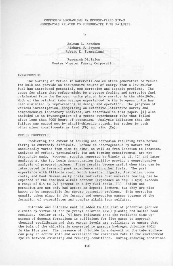
The burning of refuse in waterwall-cooled steam generators to reduce its bulk and provide an inexpensive source of energy from a low-sulfur fuel has introduced potential, new corrosion and deposit problems. The cause for alarm that refuse might be a severe fouling and corrosive fuel originated from the European units placed into service in the mid-1960s. Much of the original tube wastage experienced in the European units has been minimized by improvements in design and operation. The progress of various investigation, comprising an extensive literature survey and comprehensive laboratory analyses, are described in this paper. [1] Also included is an investigation of a recent superheater tube that failed after less than 3000 hours of operation. Analysis indicates that the failure was caused not by alkali-chloride attack, but rather by such other minor constituents as lead (Pb) and zinc (Zn).
REFUSE PROPERTIES ,
Predicting the extent of fouling and corrosion resulting from refuse firing is extremely difficult. Refuse is heterogeneous by nature and undoubtedly varies from time to time, as well as from location to location. Analyses of refuse, particularly its ash-forming constituents, are not frequently made. However, results reported by Wisely et al. [2] and later analyses at the St. Louis demoristration facility provide a comprehensive analysis of prepared refuse. These results become useful when they can be interpreted in terms of past experience with other fuels. The past experience with Illinois coal, North American lignite, Australian brown coals, and East German salty coals indicates that moderate fouling can be expected if the combined alkali content (expressed as Na20 + K20) exceeds a range of 0.4 to 0.7 percent on a dry-fuel basis. [3] Sodium and potassium are not only bad actors as deposit formers, but they are also known to be responsible for severe corrosion problems. This corrosion usually takes place in the furnace and convection passes because of the formation of pyrosulfates and complex alkali iron sulfates.
Chloride and chlorine must be added to the list of potential problem elemets by virtue of the polyvinyl chloride (PVC) plastic and salted food residues. Cutler et al. [4] have indicated that the residence time upstream of deposit formations is sufficient for flue gases to approach chemical equilibrium and that oxygen levels are sufficient to ensure that the bulk of the chloride is converted to gaseous hydrogen chloride (HC1) in the flue gas. The presence of chloride in a deposit on the tube surface can play an active role and accelerate the corrosion rate if the environment cycles between oxidizing and reducing conditions. During reducing conditions
120
the protective oxide layer is destroyed, while the chlorides are building up in the deposit. As conditions become oxidizing the metal surface opens to both reoxidation and chlorination.
INITIAL EXPERIENCE IN EUROPE
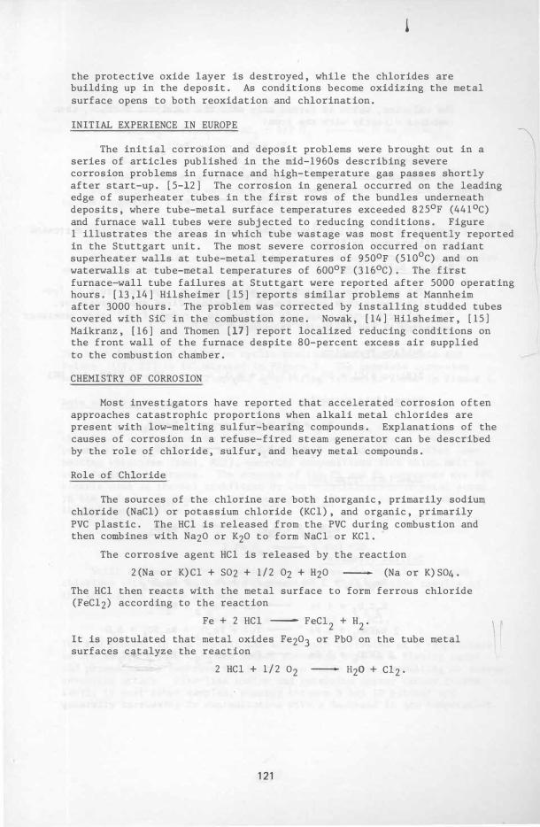
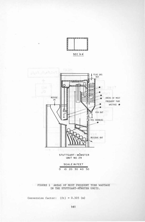
The initial corrosion and deposit problems were brought out in a series of articles published in the mid-1960s describing severe corrosion problems in furnace and high-temperature gas passes shortly after start-up. [5-12] The corrosion in general occurred on the leading edge of superheater tubes in the first rows of the bundles underneath deposits, where tube-metal surface temperatures exceeded 8250F (4410C) and furnace wall tubes were subjected to reducing conditions. Figure 1 illustrates the areas in which tube wastage was most frequently reported in the Stuttgart unit. The most severe corrosion occurred on radiant superheater walls at tube-metal temperatures of 9500F (510oC) and on waterwalls at tube-metal temperatures of 6000F (3160C). The first furnace-wall tube failures at Stuttgart were reported after 5000 operating hours. [13,14] Hilsheimer [15] reports similar problems at Mannheim after 3000 hours. The problem was corrected by installing studded tubes covered with SiC in the combustion zone. Nowak, [14] Hilsheimer, [15] Maikranz, [16] and Thomen [17] report localized reducing conditions on the front wall of the furnace despite 80-percent excess air supplied to the combustion chamber.
CHEMISTRY OF CORROSION
Most investigators have reported that accelerated corrosion often approaches catastrophic proportions when alkali metal chlorides are present with low-melting sulfur-bearing compounds. Explanations of the causes of corrosion in a refuse-fired steam generator can be described by the role of chloride, sulfur, and heavy metal compounds.
Role of Chloride
The sources of the chlorine are both inorganic, primarily sodium chloride (NaCl) or potassium chloride (KCl) , and organic, primarily PVC plastic. The HCl is released from the PVC during combustion and then combines with Na20 or K20 to form NaCl or KCl.
The corrosive agent HCl is released by the reaction
2(Na or K)Cl + S02 + 1/2 02 + H20 (Na or K)S04.
The Hel then reacts with the metal surface to form ferrous chloride (FeC12) according to the reaction
Fe + 2 HCl ----- FeC12 + H2.
It is postulated that metal oxides Fe203 or PbO on the tube metal surfaces catalyze the reaction
2 HCl + 1/2 02 H20 + C12·
12 1
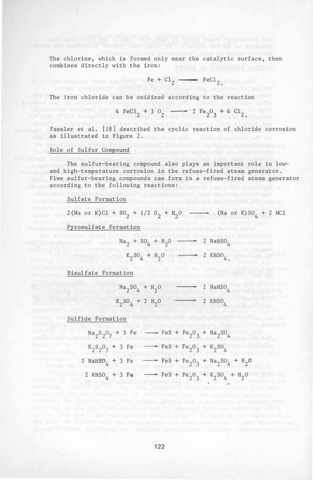
The chlorine, which is formed only near the catalytic surface, then combines directly with the iron:
Fe + C12 - FeCI2•
The iron chloride can be oxidized according to the reaction
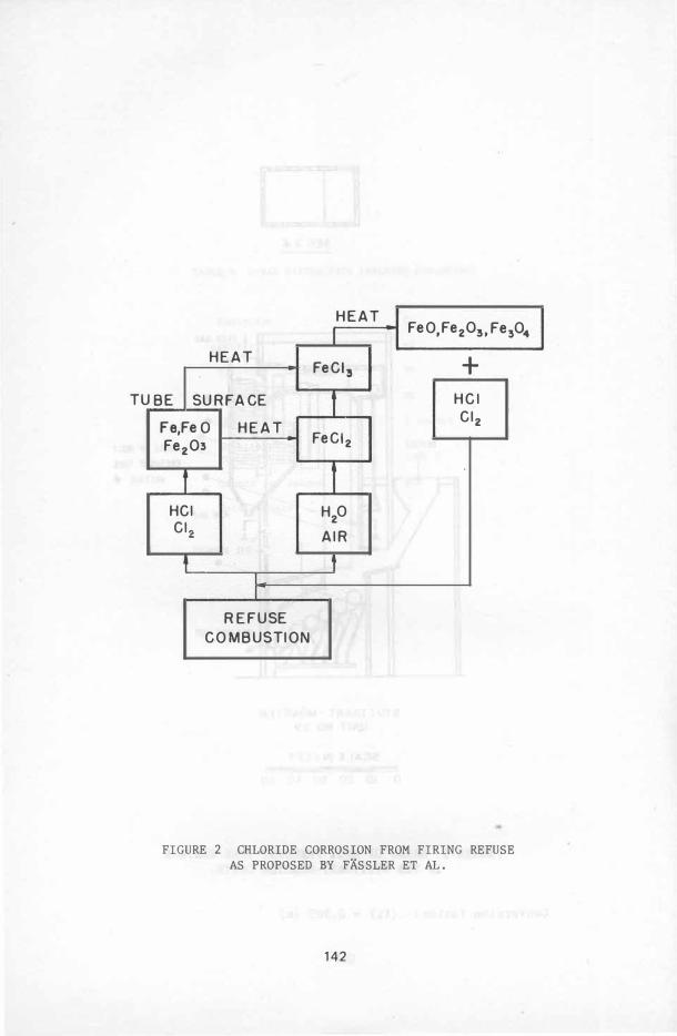
Fassler et al. [18] described the cyclic reaction of chloride corrosion as illustrated in Figure 2.
Role of Sulfur Compound
The sulfur-bearing compound also plays an important role in lowand high-temperature corrosion in the refuse-fired steam generator. Five sulfur-bearing compounds can form in a refuse-fired steam generator according to the following reactions:
Sulfate Formation
Pyrosulfate Formation
Na2 + S04 + H20
K2S04 + H20
Bisulfate Formation
Na2S04 + H20
K2S04 + 2 H20
Sulfide Formation
Na2S207 + 3 Fe - FeS
K2S207 + 3 Fe - FeS
2 NaHS04 + 3 Fe - FeS
2 KHS04 + 3 Fe - FeS
122
+ Fe20 3
+ Fe20 3
+ Fe203
+ Fe203
(Na or K)S04 + 2 HCI
2 NaHS04
2 KHS04.
2 NaHS04
2 KHS04
+ Na2S04
+ K2S04
+ Na2S04 + H2O
+ K2S04 + H2O
Complex Sulfate Formation
The molten complex sulfates attack the tube-metal surface according to the reaction
The iron sulfide can be oxidized in the refuse-fired steam generator according to the reaction
3 FeS + 5 O2
4 FeS + 7 O2
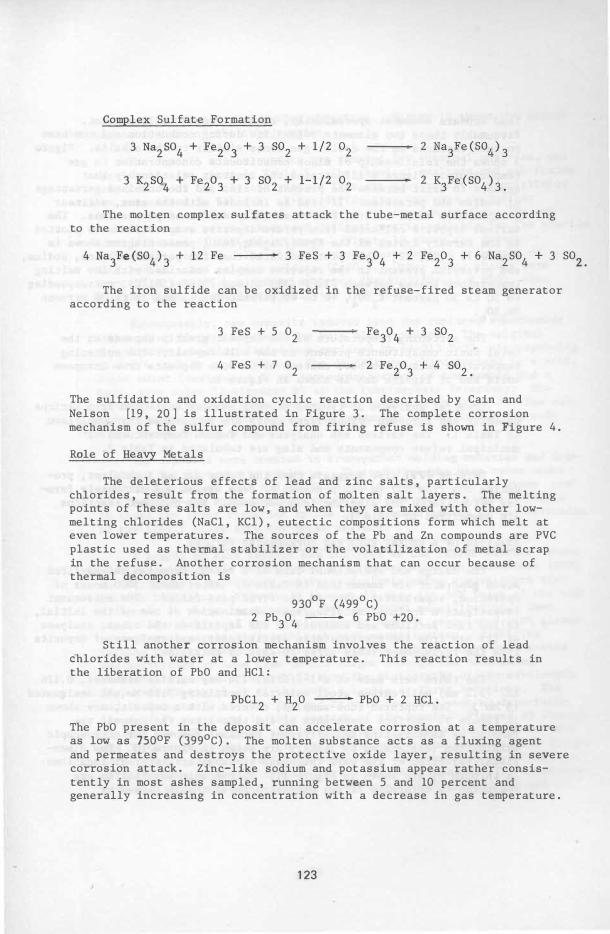
The sulfidation and oxidation cyclic reaction described by Cain and Nelson [19, 20] is illustrated in Figure 3. The complete corrosion mechariism of the sulfur compound from firing refuse is shown in Figure 4.
Role of Heavy Metals
The deleterious effects of lead and zinc salts, particularly chlorides, result from the formation of molten salt layers. The melting points of these salts are low, and when they are mixed with other lowmelting chlorides (NaCl, KCl), eutectic compositions form which melt at even lower temperatures. The sources of the Pb and Zn compounds are PVC plastic used as thermal stabilizer or the volatilization of metal scrap in the refuse. Another corrosion mechanism that can occur because of thermal decomposition is
9300F (4990C) 2 Pb
304 � 6 PbO +20.
Still another corrosion mechanism involves the reaction of lead chlorides with water at a lower temperature. This reaction results in the liberation of PbO and HCl:
The PbO present in the deposit can accelerate corrosion at a temperature as low as 7500F (3990C). The molten substance acts as a fluxing agent and permeates and destroys the protective oxide layer, resulting in severe corrosion attack. Zinc-like sodium and potassium appear rather consistently in most ashes sampled, running between 5 and 10 percent and generally increasing in cpncentration with a decrease in gas temperature.
123
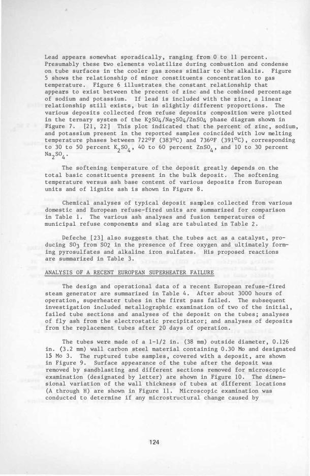
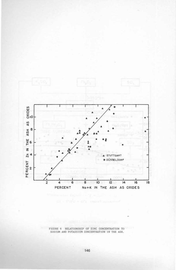
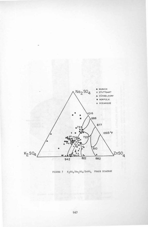
Lead appears somewhat sporadically, ranging from 0 to 11 percent. Presumably these two elements volatilize during combustion and condense on tube surfaces in the cooler gas zones similar to the alkalis. Figure 5 shows the relationship of minor constituents concentration to gas temperature. Figure 6 illustrates the constant relationship that appears to exist between the pre cent of zinc and the combined percentage of sodium and potassium. If lead is included with the zinc, a linear relationship still exists, but in slightly different proportions. The various deposits collected from refuse deposits composition were plotted in the ternary system of the K2S04/Na2S04/ZnS04 phase diagram shown in Figure 7. [21, 22] This plot indicated that the percent of zinc, sodium, and potassium present in the reported samples coincided with low melting temperature phases between 7220F (3830C) and 7360F (3910C), corresponding to 30 to 50 percent K2S04, 40 to 60 percent ZnS04, and 10 to 30 percent Na2S04·
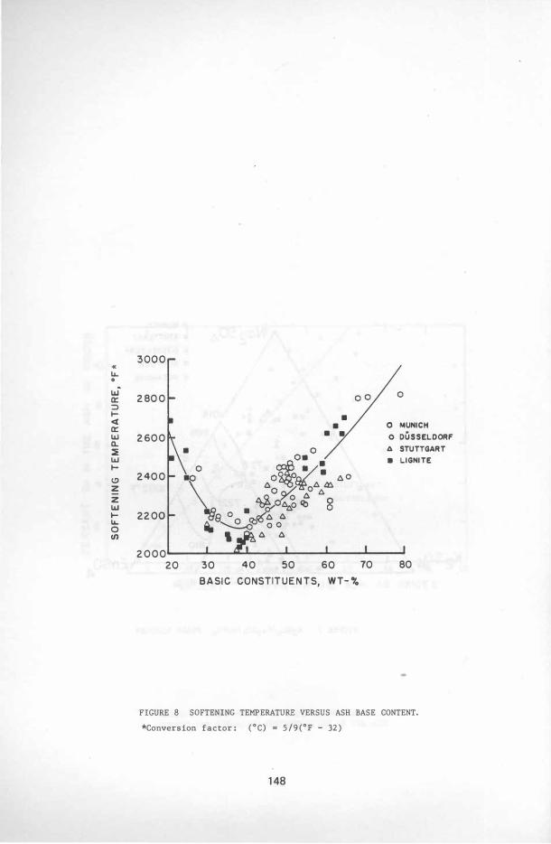
The softening temperature of the deposit greatly depends on the total basic constituents present in the bulk deposit. The softening temperature versus ash base content of various deposits from European units and of lignite ash is shown in Figure 8.
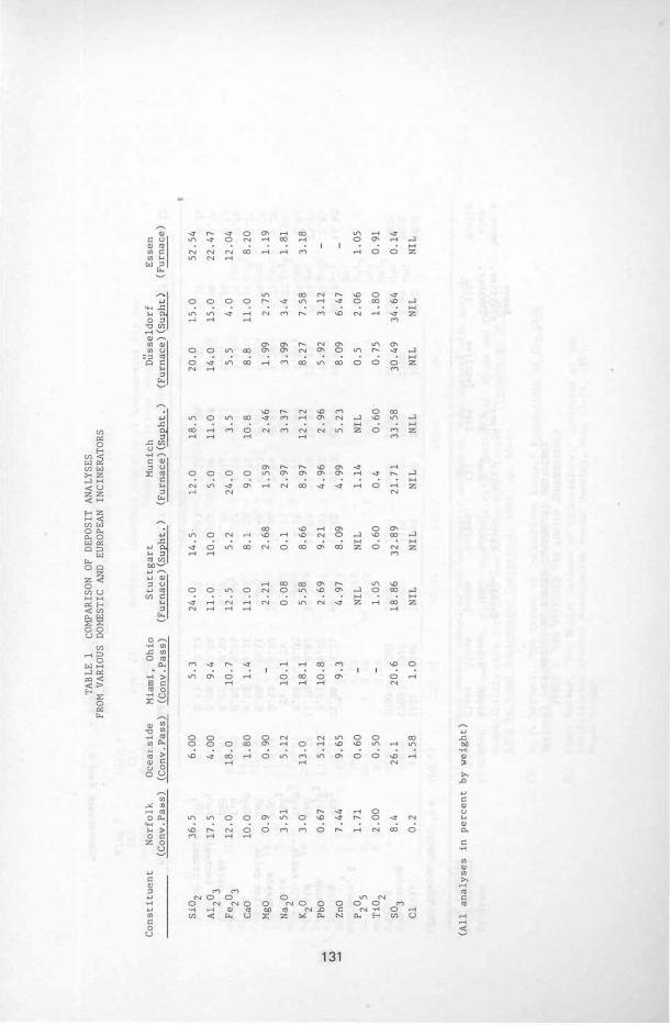
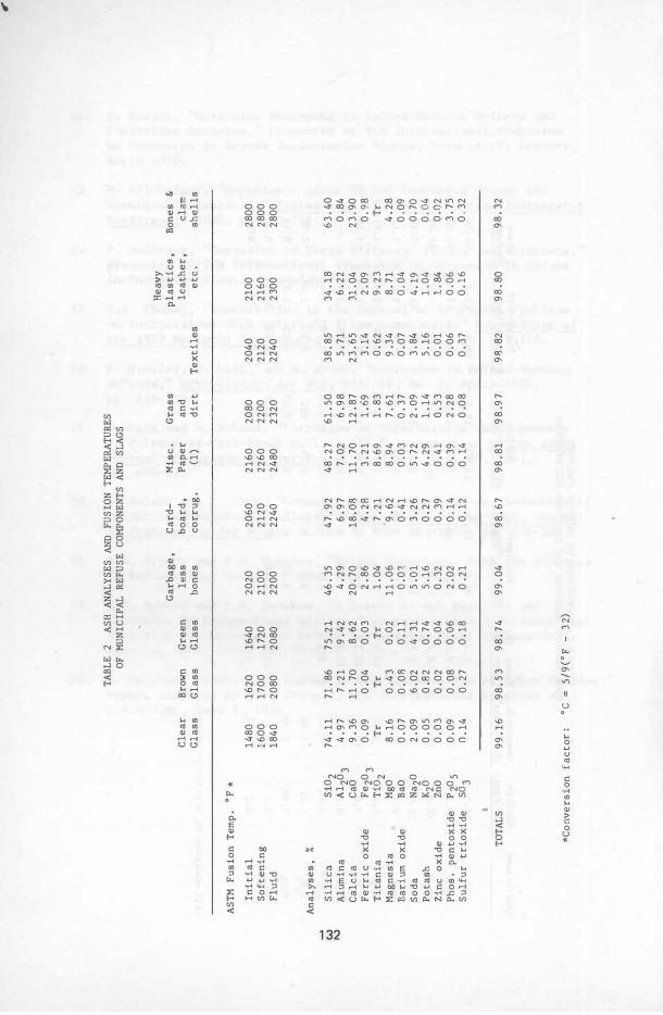
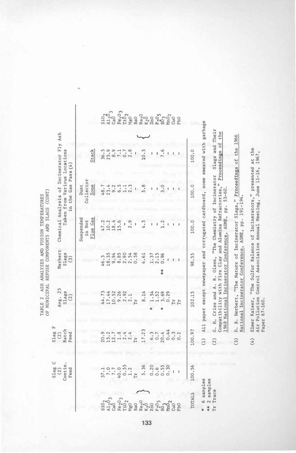
Chemical analyses of typical deposit samples collected from various domestic and European refuse-fired units are summarized for comparison in Table 1. The various ash analyses and fusion temperatures of municipal refuse components and slag are tabulated in Table 2.
Defeche [ 23] also suggests that the tubes act as a catalyst, producing S03 from S02 in the presence of free oxygen and ultimately forming pyrosulfates and alkaline iron sulfates. His proposed reactions are summarized in Table 3.
ANALYSIS OF A RECENT EUROPEAN SUPERHEATER FAILURE
The design and operational data of a recent European refuse-fired steam generator are summarized in Table 4. After about 3000 hours of operation, superheater tubes in the first pass failed. The subsequent investigation included metallographic examination of two of the initial, failed tube sections and analyses of the deposit on the tubes; analyses of fly ash from the electrostatic precipitator; and analyses of deposits from the replacement tubes after 20 days of operation.
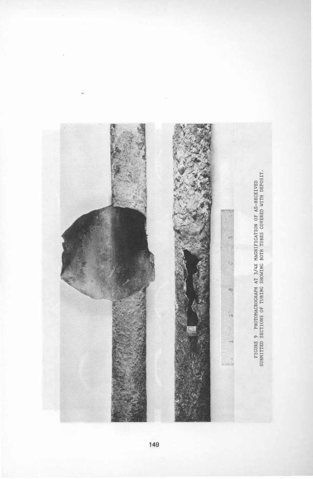
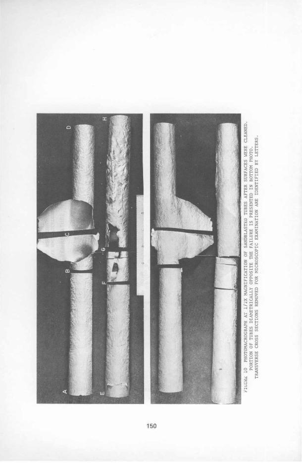
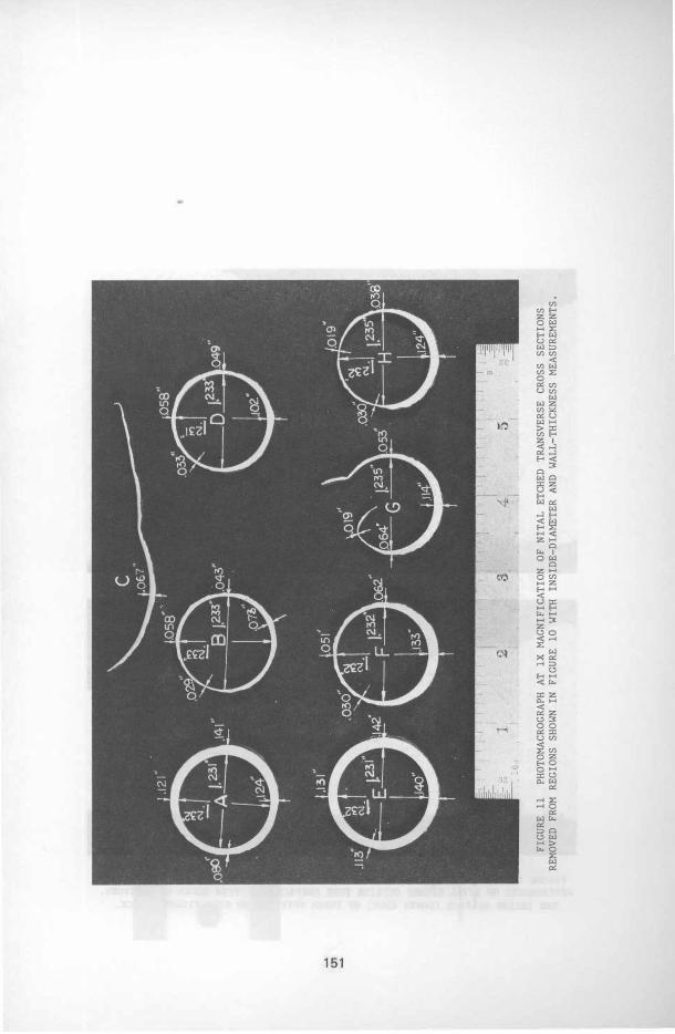
The tubes were made of a 1-1/2 in. (38 mm) outside diameter, 0. 126 in. (3. 2 mm) wall carbon steel material containing 0. 30 Mo and designated 15 Mo 3. The ruptured tube samples, covered with a deposit, are shown in Figure 9. Surface appearance of the tube after the deposit was removed by sandblasting and different sections removed for microscopic examination (designated by letter) are shown in Figure 10. The dimensional variation of the wall thickness of tubes at different locations (A through H) are shown in Figure 11. Microscopic examination was conducted to determine if any microstructural change caused by
124
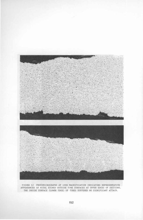
overheating had occurred during operation. Figure 12 shows the normal microstructure of the tube section.
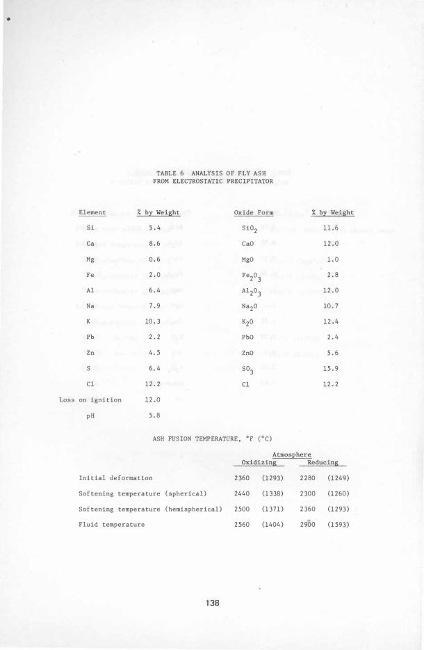
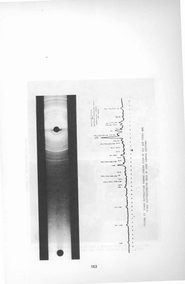
The deposit on the surface was removed for chemical analysis, and the results are given in Table 5. The chemical analysis and ash-fusion temperature of the fly ash removed from the electrostatic precipitator are summarized in Table 6. X-ray diffraction was used to further determine the various phases present in the fly-ash sample. The two techniques were power camera and diffractometric analysis for the precise identification of the minor phases. Figure 13 shows the X-ray diffraction results. The fly-ash sample was composed primarily of NaCl and KCl, and calcium sulfate (CaS04). Other minor phases were identified as sodium aluminum silicate (Na2Al2Si5014· 5. 4 H20), zinc sulfate (ZnS04), and leadoxychloride (PbO·PbCl2).
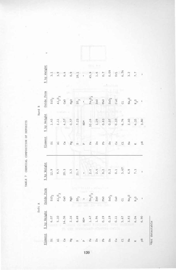
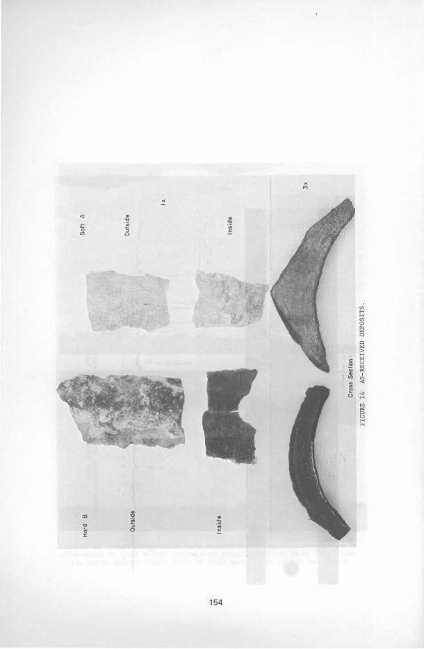
Subsequently, new deposits removed from the replaced superheater tubes after 20 days of operation were also examined. The original superheater tube that failed was replaced by SA-213 T-22, corresponding to 2-1/4 Cr-l Mo composition. The deposit was characterized by a soft, light color (designated A) at the outer portion of the sample and a hard, dark color (designated B) at the tube/deposit interface. The chemical analyses of these deposits are tabulated in Table 7. The outside, inside, and cross-sectional appearances of the hard B and soft A are shown in Figure 14.
The deposits were mounted in transparent molding material and drypolished for microscopic analysis. Photomicroghaphs were taken under polarized light at 100X and 1000X magnification. Figure 15 shows the sintered fly-ash multicomponent deposit of the soft A sample. Figure 16 shows the layer formation in the hard B scale caused by the diffusion of the liquid phase into the metal surface.
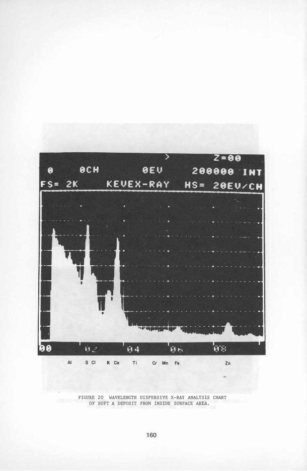
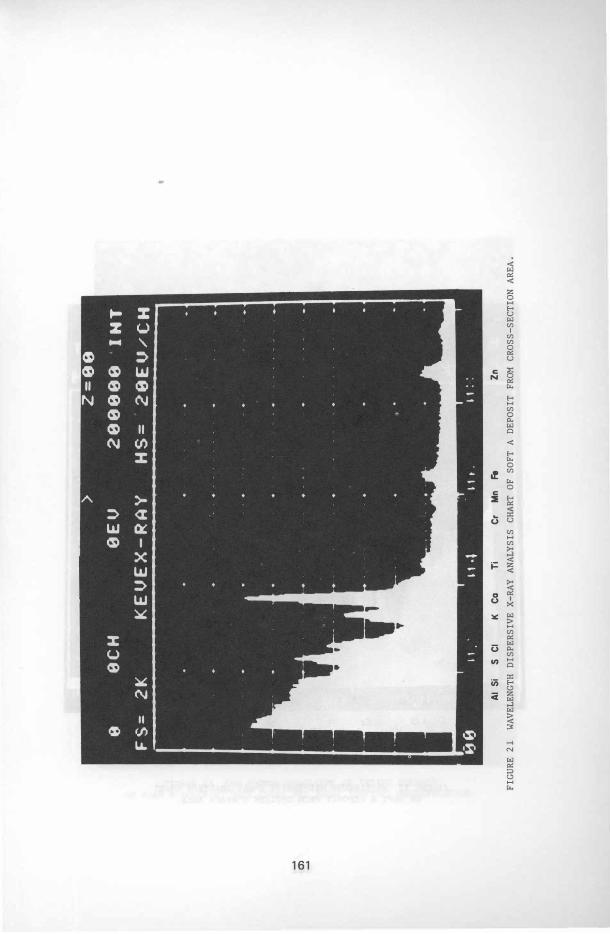
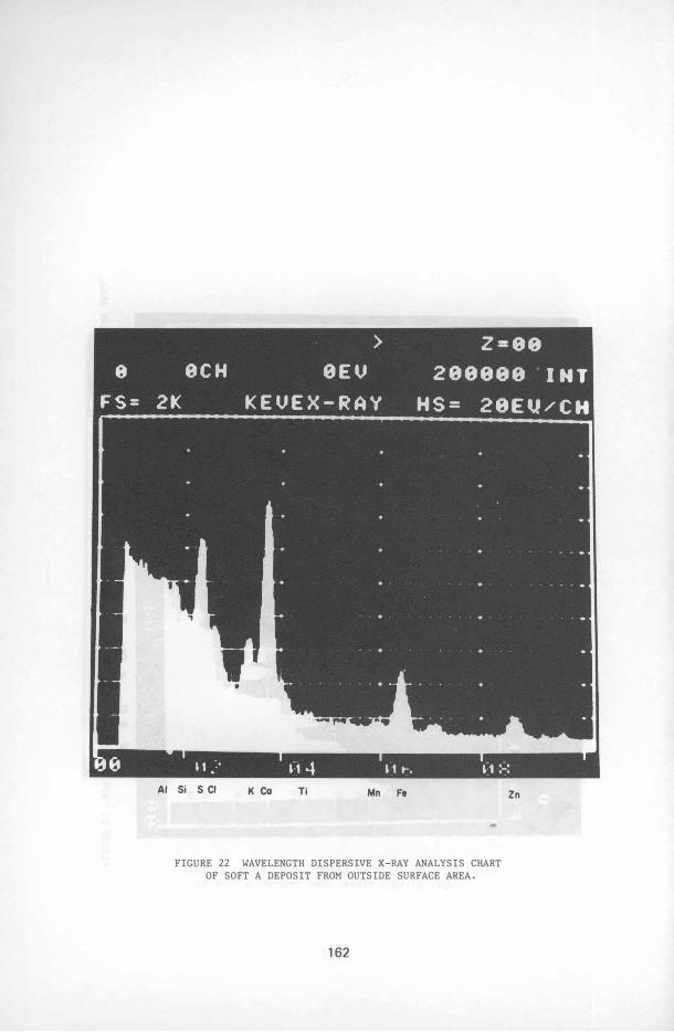
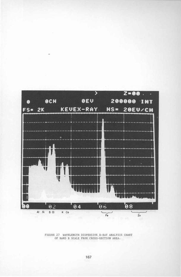
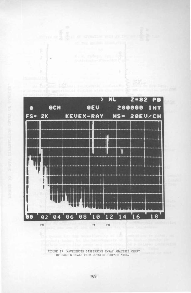
A sample of each deposit was analyzed at the inside surface, cross section, and outside surface with a scanning electron microscope (SEM) for microscopic appearance and X-ray analysis using a wavelength dispersive technique. Figures 17 through 19 show the SEM image of the soft A deposit at three locations at 300X and 3000X magnification. Some crystalline habits of the mUlticomponent deposit associated with glassy cenospheres are clearly visible at high magnification. Particles forming perfect spheroids indicate that the ash must have been molten and solidified at some time in its flight through the combustion chamber. Figures 20 through 22 show the photographs of the wavelength dispersive X-ray chart of the soft A sample at three locations. The major elements Al, S, Cl, Ca, and Zn were detected, but no detectable level of Pb was found. in this section of the sample. Figures 23 through 25 show the SEM image of the hard B deposit at three locations at 300X and 3000X magnification. The hard B deposit at the metal deposit interface reveals that the particles comprising the innermost layer show much greater signs of having reacted with other constituents. The spheroids were distorted and had a frosted appearance. Particles of fly ash at
125
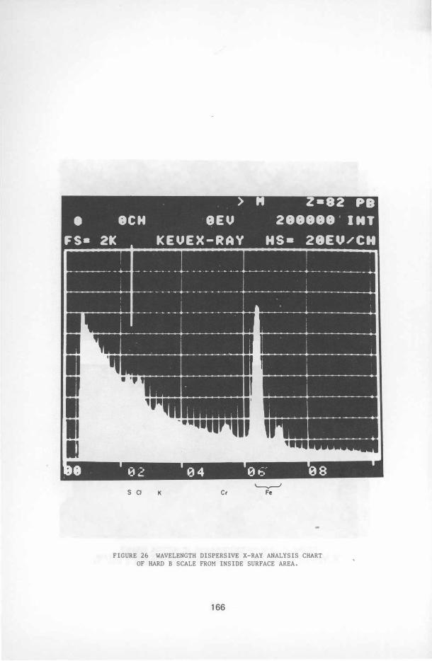
the outer surface exhibit some perfect spheroids of clear, unreacted material. Figures 26 through 29 represent the wavelength dispersive X-ray chart of the hard B deposit. The major elements S, Cl, Fe, Zn, and Pb were detected. The lead was concentrated on the outer surface of the deposit.
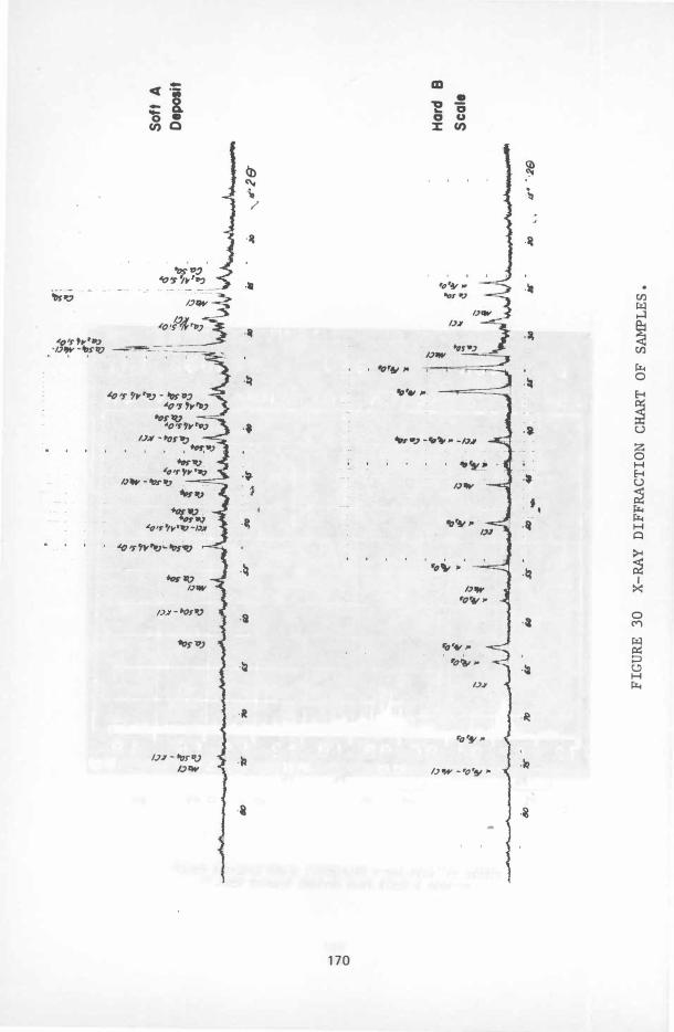
X-ray diffraction analysis using the diffractometric technique was conducted to determine the phases present of the two deposit types. The X-ray diffraction parameters are given in Table 8. The soft A deposit was composed primarily of CaS04 and Ca2Al2Si07; other minor phases were identified as NaCl and KCl. The hard B deposit was composed primarily of hematite ( Fe203) and CaS04; other minor phases were identified as NaCl and KCl. The X-ray diffraction analysis failed to identify any Zn or Pb compounds caused by low concentration on superimposition with other phases. Photographs of the X-ray diffraction chart are shown in Figure 30.
The results of the metallurgical and chemical analyses of the superheater tubes indicate that the samples contained a high level of NaCl and KCl, as well as CaS04. Some Zn and Pb were detected by chemical analysis, but the X-ray diffraction analysis failed to detect any Zn or Pb compounds caused by superimposition with other diffraction lines. The light-colored A deposit was primarily composed of CaS04 and calcium aluminum silicate (Ca2A12Si07) with a pH of 6.9, which indicates the neutrality of the deposit. The hard, dark-colored B deposit was primarily composed of iron oxide ( Fe203) and some secondary phases of NaCl and KCl and CaS04. The pH analysis of the dark B deposit indicates a 3.8 pH level, confirming the belief that sufficient quantities of acid (HCl, H 2S04) or hydroscopic salts are present in the deposit. In a refuse-fired steam generator the downtime period can be a critical stage to form hydroscopic salts on the tube surface if the gas-stream temperature cools below the dew point of the HCl or H2S04. Accelerated corrosion often approaches catastrophic proportions when alkali metal
� chlorides, as well as heavy metal oxides or chlorides with low-melting sulfur-bearing compounds, are present.
(
CONCLUSIONS
Review of the literarure, laboratory experiments, and field data suggest that fouling is probably due to the presence of alkalis in the refuse. Therefore, the furnace exit temperature should not be allowed to exceed 1800 to 185 00F (982 to 10100C). It is recommended that the total alkali (Na20 + K20, calculated as Na20) not exceed 0. 4 percent by weight on a dry-fuel basis. Metal temperatures should not exceed 900 to 9500F (482 to 5100C).
Corrosion occurs at metal temperatures over 9500F (5100C) under oxidizing conditions and about 680 to 7000F (360 to 3710C) under reducing conditions in the presence of ash. Although the mechanisms are not fully understood, they apparently depend on the presence of alkalis
126
and the heavy metals zinc and lead. It appears doubtful that corrosion is due to pyrosulfates or complex alkali from iron sulfates. The influence of the chlorides under oxidizing conditions is questionable.
Although refuse is a heterogeneous fuel, the problems appear to be similar in many steam generators. Differences are probably due to variations in internal environmental conditions and operational parameters and the occasional absence of corrosion-causing elements.
Not all experiences, however, are unfavorable. Others show that improved steam generator design and controlled operational procedures can be effectively applied to minimize the potential corrosion and deposit phenomenon attributed to reufse.
127
L
ACKNOWLEDGMENT
The authors wish to thank W . R. Apblett, Jr. , for reviewing this work. The metallographic analysis of the superheater tubes was conducted by J. Cocubinsky and is gratefully acknowledged.
128
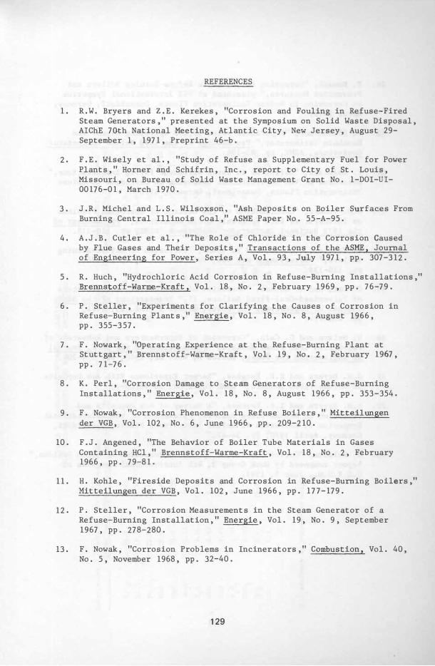
REFERENCES
1. R.W. Bryers and Z.E. Kerekes, "Corrosion and Fouling in Refuse-Fired Steam Generators," presented at the Symposium on Solid Waste Disposal, AIChE 70th National Meeting, Atlantic City, New Jersey, August 29-September 1, 1971, Preprint 46-b.
2. F.E. Wisely et al., "Study of Refuse as Supplementary Fuel for Power Plants, " Horner and Schifrin, Inc., report to City of St. Louis, Missouri, on Bureau of Solid Waste Management Grant No. 1-DOI-UI-00176-01, March 1970.
3. J.R. Michel and L.S. Wilsoxson, "Ash Deposits on Boiler Surfaces From Burning Central Illinois Coal," ASME Paper No. 55-A-95.
4. A.J.B. Cutler et al., "The Role of Chloride in the Corrosion Caused by Flue Gases and Their Deposits, " Transactions of the ASME, Journal of Engineering for Power, Series A, Vol. 93, July 1971, pp. 307-312.
5. R. Huch, "Hydrochloric Acid Corrosion in Refuse-Burning Installations," Brennstoff-Warme-Kraft, Vol. 18, No. 2, February 1969, pp. 76-79.
6. P. Steller, "Experiments for Clarifying the Causes of Corrosion in Refuse-Burning ·Plants," Energie, Vol. 18, No. 8, August 1966, pp. 355-357.
7. F. Nowark, "Operating Experience at the Refuse-Burning Plant at Stuttgart, " Brennstoff-Warme-Kraft, Vol. 19, No. 2, February 1967, pp. 71-76.
8. K. Perl, "Corrosion Damage to Steam Generators of Refuse-Burning Installations, " Energie, Vol. 18, No. 8, August 1966, pp. 353-354.
9. F. Nowak, "Corrosion Phenomenon in Refuse Boilers," Mitteilungen der VGB, Vol. 102, No. 6, June 1966, pp. 209-210.
10. F.J. Angened, "The Behavior of Boiler Tube Materials in Gases Containing HCl," Brennstoff-Warme-Kraft, Vol. 18, No. 2, February 1966, pp. 79-81.
11. H. Kohle, "Fireside Deposits and Corrosion in Refuse-Burning Boilers," Mitteilungen der VGB, Vol. 102, June 1966, pp. 177-179.
12. P. Steller, "Corrosion Measurements in the Steam Generator of a Refuse-Burning Installation, " Energie, Vol. 19, No. 9, September 1967, pp. 278-280.
13. F. Nowak, "Corrosion Problems in Incinerators," Combustion, Vol. 40, No. 5, November 1968, pp. 32-40.
129
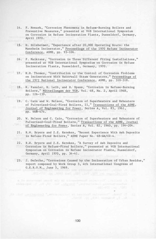
14. F. Nowark, "Corrosion Phenomena in Refuse-Burning Boilers and Preventive Measures, " presented at VGB International Symposium on Corrosion in Refuse Incineration Plants, Dusseldorf, Germany, April 1970.
15. H. Hilsheimer, "Experience after 20, 000 Operating Hours: the Mannheim Incinerator, " Proceedings of the 1970 Refuse Incinerator Conference, ASME, pp. 93-106.
16. F. Maikranz, "Corrosion in Three'Different Firing Installations, " presented at VGB International Symposium on Corrosion in Refuse Incineration Plants, Dusseldorf, Germany, 1970.
17. K. H. Thomen, "Contribution to the Control of Corrosion Problems on Incinerators With Waterwall Steam Generators, " Proceedings of the 1972 National Incinerator Conference, ASME, pp. 310-318.
18. K. Fassler, H. Leib, and H. Spann, "Corrosion in Refuse-Burning Boilers, " Mitteilungen der VGB, Vol. 48, No. 2, April 1968, pp. 126-139.
19. C. Cain and W. Nelson, "Corrosion of Superheaters and Reheaters of Pulverized-Coal-Fired Boilers, I I, " Transactions of the ASME, Journal of Engineering for Power, Series A, Vol. 83, 1961, pp. 468-474.
20. W. Nelson and C. Cain, "Corrosion of Superheaters and Reheaters of Pulverized-Coal-Fired Boilers, " Transactions of the ASME, Journal of Engineering for Power, Series A, Vol. 82, 1960, pp. 194-204.
21. R. W. Bryers and Z. E. Kerekes, "Recent Experience With Ash Deposits in Refuse-Fired Boilers, " ASME Paper No. 68-WA/CD-4.
22. R.W. Bryers and Z. E. Kerekes, "A Survey of Ash Deposits and Corrosion in Refuse-Fired Boilers, " presented at VGB International Symposium on Corrosion in Refuse Incinerator Plants, Dusseldorf, Germany, April 1970, pp. 34-41.
23. J. Defeche, "Corrosions Caused by the Incineration of Urban Residue, " report composed by Work Group 3, 4th International Congress of G. E. R. O.M. , June 5, 1969.
130
TAB
LE
1
CO
MPA
RI
SO
N
OF
DEP
OS
IT
ANAL
YSES
F
RO
M V
AR
IOU
S
DO
MES
TIC
AND
EU
RO
PEA
N
IN
CI
NERA
TO
RS
Co
ns
ti
tue
nt
N
orf
olk
O
cear
.si
de
Mi
ami,
O
hi
o
St
ut
tg
art
M
un
ic
h
D{!s
se
1do
rf
Es
se
n
(Co
nv
.P
ass
) (C
on
v.
Pas
s)
(Co
nv
.P
ass
) (F
ur
nac
e)
(Su
pht
. )
( Fu
rn
ace
) (S
uph
t.
) (F
urn
ace
) (S
uph
t)
(Fu
rnac
e)
Si
0 2 3
6.
5 6.
00
5.
3
24.
0
14
.5·
1
2.
0
18.
5 2
0.
0
15.
0
52.
54
A1
20 3
1
7.
5 4
.0
0
9.4
1
1.
0
10
.0
5.
0
11
.0
1
4.
0
15.
0
22
.47
Fe
20 3
1
2.0
1
8.0
1
0.
7
12.
5 5
.2
24.
0
3.
5 5.
5 4
.0
1
2.
04
CaO
10
.0
1.8
0
1.
4
11
.0
8.
1
9.0
1
0.
8 8.
8 1
1.
0
8.20
Mg
O
0.
9 0
.90
2.
21
2 .68
1
. 59
2.
46
1
. 99
2.
75
1.
19
Na
20
3
.51
5.
12
1
0.
1
0.
08
0.
1
2.
97
3.
37
3
.99
3
.4
1
. 81
K2
0
3.
0
13
.0
1
8.1
5.
58
8.6
6
8.
97
12
.1
2
8.2
7
7.
58
3.18
PbO
0.
67
5.12
1
0.
8 2.
69
9.2
1
4.
96
2.
96
5.
92
3.
12
w
7
.4
4
9.6
5
9.3
4
.97
8.
09
4.
99
5.
23
8
.09
6.
47
Z
nO
P2
05
1.
71
0
.6
0
NIL
NI
L
1.
14
NI
L
0.
5 2
.0
6
1.
05
Ti0 2
2.0
0
0.
50
1.
05
0.
60
0.4
0.
60
' 0
.75
1
.8
0
0.
91
S0 3
8.
4
26.
1
20
.6
1
8.86
3
2.8
9
21. 7
1
33
.58
3
0.
49
34
.6
4
0.14
Cl
0.
2 1
.58
1.
0
NIL
N
IL
NIL
N
IL
NIL
NI
L
NIL
(Al
l
anal
ys
es
i
n
pe
rce
nt
b
y w
ei
gh
t)
W
'"
TA
BL
E 2
AS
H AN
ALYS
ES
AND
FUS
IO
N
TEMP
ERA
TU
RES
OF
M
UNIC
IPA
L R
EF
US
E C
OMP
ON
ENT
S A
ND
S
LAGS
Cle
ar
Br
own
G
re
en
G
la
ss
G
la
ss
G
la
ss
AS
TM
Fu
si
on
T
em
p.
of *
Ini
ti
al
1
480
1
62
0
164
0 S
oft
en
in
g
16
00
1
70
0
172
0
Flu
id
184
0
20
80
2080
An
al
ys
es
, %
Si
li
ca
S
i0
2 7
4.
11
71
. 8
6
75
.21
A
lu
mi
na
A
120
3
4.
97
7
.21
9
.4
2 C
a1
da
C
aO
9
.3
6
11
. 70
8.
62
F
er
ri
c o
xi
de
Fe
203
0
.0
9
0.
04
0.03
Ti
tani
a
Ti0
2 T
r
Tr
T
r
Ma
gn
es
ia
M
gO
8.
16
0
.4
3
0.
02
B
ar
iu
m o
xi
de
Ba
O
0.
07
0
.0
8
0.
11
S
od
a
Na
20
2.0
9
6.
02
4.
31
P
ot
as
h K 20
0
.0
5
0.8
2
0.
74
Z
inc
ox
ide
Zn
O 0
.0
3
0.
02
0
.0
4
Ph
os.
pe
nt
oxi
de
P20
5 0
.0
9
0.
08
0.
06
S
ulf
ur
t
ri
oxi
de
5°3
0
.1
4
0.
27
0.
18
TOTA
LS
99
.1
6
98.
53
9
8.7
4
*Co
nv
er
si
on
fa
ctor
: °c
5
/9
(OF
-
32)
Ga
rb
ag
e,
Ca
rd-
Mi
sc
.
le
ss
b
oar
d,
Pa
pe
r b
on
es
co
rr
ug
. (1
)
20
20
2
06
0
21
60
2
10
0
21
20
2
26
0
220
0
224
0
24
80
46
.3
5 4
7.
92
48'
.2
7
4.
29
6
.9
7
7.
02
20.
70
1
8.0
8 1
1.
70
2
.86
4
.28
3
.2
1
1.
04
7.
21
8.
69
1
1.
06
' 9
.6
2 8.
94
0
.0
< 0
.4
1
0.
03
5
.01
3
.26
5.
72
5.1
6
0.
27
4
.29
0
.3
2 0
.3
9
0.4
1 2.
02
0.
14
0
.3
9
0.2
1
0.
12
0.
14
99
.0
4
98.
67
9
8.81
Gr
as
s
an
d d
ir
t
20
80
22
00
2
32
0
61
.50
6
.9
8 1
2.
87
1.6
9 1
. 8
3 7
.6
1
0.
37
2
.0
9
1.
14
0
.53
2.
28
0.0
8
98
.97
".
He
av
y p
la
st
ic
s,
Bon
es
&
le
at
her,
cl
am
Tex
til
es
et
c.
s
he1
ls
204
0
210
0
280
0
2120
21
60
28
00
22
40
23
00
280
0
38.
85
3
4.
18
63
.4
0
5.7
1
6.
22
0.
84
23
.6
5 31
.04
23
.9
0 3
.1
4 2.
09
0.
98
0.6
2 9.
23
Tr
9.3
4
8.7
1
4.
28
0.
07
0
.0
4
0.0
9
3.
84
4.19
0.
70
5.1
6
1.
04
0
.0
4
0.
01
1.
84
0.0
2 0
.0
6
0.0
6 3
.7
5 0
.3
7
0.
16
0
.3
2
9fl
.82
9
8.80
9
8.3
2
w
w
Si0
2
A1
20
3
CaO
Fe
Z03
Ti
OZ
M
gO
BaO
:.!a
ZO
K
ZO
ZnO
P
205
S
03
Mn
°Z
Cu
O
Pb
O
}
TO
TA
LS
Sl
ag
C
(Z)
Co
nt
in
o F
eed
37
.1
7.
0
7.7
4
0.
0
0.
55
1
.Z
Tr
5.
36
0.2
0
0.
6 0
.55
0.
30
10
0.
56
* 6
s
am
pl
es
**
2
s
am
pl
es
Tr
T
ra
ce
Sl
ag
F
(Z)
Ba
tc
h
Fe
ed
20
.9
15
.2
l
Z.
7
1.
8 2
.4
2
.4
Tr
17
.23
6.
3
0.
7
ZO
.4
0
.4
4
0.
3
O.
Z
100
.9
7
TA
BL
E Z
A
SH
A
NA
LY
SE
S AND
FU
SI
ON
T
EMPER
AT
UR
ES
OF
MU
NIC
IPA
L R
EFU
SE
CO
MP
ON
ENT
S AND
SL
AG
S
(CO
NT
)
Av
g.
25
S
la
gs
(Z)
44
.73
1
7.
44
1
0.
52
9
.Z6
2
.92
Z
.l
Tr
8.1
4
* 1
.5
4
1.5
Z
'" 3.
69
0.
Z9
Tr
Tr
10
2.1
5
He
rb
er
t
Sl
ag
s (3
)
46
.3
18.
35
9
.94
8.
85
Z.9
0
2.
54
0
.5
8
4.
61
1.
37
2
.1
5
"''''
0.
96
98.
55
Ch
em
ic
al
An
al
ys
iS
of
In
cin
era
to
r F
ly
As
h
Ta
ke
n f
ro
m V
ar
io
us
Loca
tio
ns
Sus
pe
nde
d i
n
Ho
t
Fl
ue
Ga
s
47
.2
10
.2
18.
4
15.6
2.9
4.5
1.2
10
0.
0
in
t
he
G
as
Pa
ss
(4)
Dus
t
Co
ll
ect
or
Zo
ne
48.
7
23
.4
9.
2
6.5
1
.1
Z.3
5.
8
3.
0
10
0.
0
St
ack
36.
5
25
.9
8.9
7
.1
0.
7
2.
8
10.
5
7.
6
10
0.0
{
SiO
A1
263
C
aO
F
e" 20
3
Ti0
2
MgO
Ba
O N
a 20
K2
0
ZnO
P
205
S
03
M
n0 2
Cu
O
PbO
(1)
Al
l p
ap
er
exce
pt
ne
ws
pa
pe
r a
nd
cor
rug
at
ed
car
dbo
ar
d,
so
me
sm
ea
red
wi
th
ga
rba
ge
(2)
G.
H.
Cr
iss
an
d A
. R
. O
lse
n,
"Th
e Ch
emi
str
y o
f In
cin
era
to
r
Sl
ag
s a
nd
Th
eir
Co
mp
ati
bil
ity
wi
th
Fi
re
Cl
ay
an
d Al
umi
na
Re
fra
cto
ri
es,"
Pr
oce
edi
ng
s o
f t
he
1
968
Na
ti
on
al
In
ci
ne
ra
to
r C
on
fer
en
ce,
ASME
, pp
. 5
3-
60.
(3)
D.
B.
Her
ber
t,
"Th
e N
atu
re
of
Inci
ner
ato
r S
la
gs,
" P
ro
ceed
in
gs
of
the
196
6
Na
ti
on
al
In
cin
era
tor
Co
nfe
re
nc
e,
AS
ME,
pp
. 1
91-
194
.
(4)
Elm
er K
ai
ser
, "
The
Sul
fur
B
al
an
ce
of
Inci
ner
ato
rs,
"
pr
esen
ted
a
t t
he
A
ir
Po
ll
uti
on
Co
nt
ro
l A
sso
cia
ti
on
An
nua
l M
eet
in
g,
Jun
e 1
1-
16,
1
967
, Pa
per
6
7-
16
0.
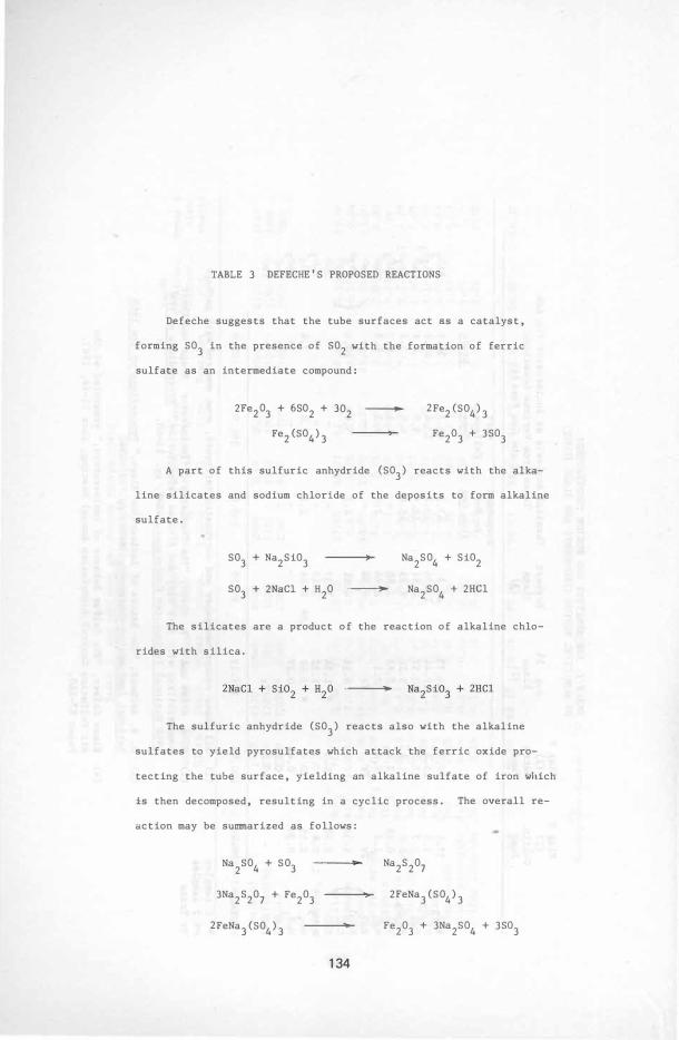
TABLE 3 DEFECHE'S PROPOSED REACTIONS
Defeche suggests that the tube surfaces act as a catalyst,
forming S03 in the presence of S02 with the formation of ferric
sulfate as an intermediate compound:
2Fe203 + 6S02 + 302 �
Fe2 (S04) 3
2Fe2 (S04) 3
Fe203 + 3S03
A part of this sulfuric anhydride (S03) reacts with the alka
line silicates and sodium chloride of the deposits to form alkaline
sulfate.
S03 + Na2Si03
S03 + 2NaCl + H20 --
Na2
S04 + Si02
Na2S04
+ 2HCl
The silicates are a product of the reaction of alkaline chlo
rides with silica.
.--
The sulfuric anhydride (S03) reacts also with the alkaline
sulfates to yield pyrosulfates which attack the ferric oxide pro
tecting the tube surface, yielding an alkaline sulfate of iron which
is then decomposed, resulting in a cyclic process. The overall re
action may be summarized as follows:
Na2
S04
+ S03
3Na2S207 + Fe203
2FeNa3 (S04
) 3
134
Na2S207
2FeNa3 (S04) 3
Fe203 + 3Na
2S04
+ 3S03
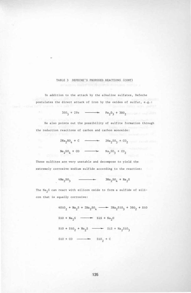
TABLE 3 DEFECHE'S PROPOSED REACTIONS (CONT)
In addition to the attack by the alkaline sulfates, Defeche
postulates the direct attack of iron by the oxides of sulfur, e. g. :
3S03
+ 2Fe ..
He also points out the possibility of sulfite formation through
the reduction reactions of carbon and carbon monoxide:
2Na2S03
+ CO2
Na2S03 + CO2
These sulfites are very unstable and decompose to yield the
extremely corrosive sodium sulfide according to the reaction:
•
The Na2S can react with silicon oxide to form a sulfide of sili
con that is equally corrosive:
SiO + CO
SiS + Na2Si03
Si02
+ C
135
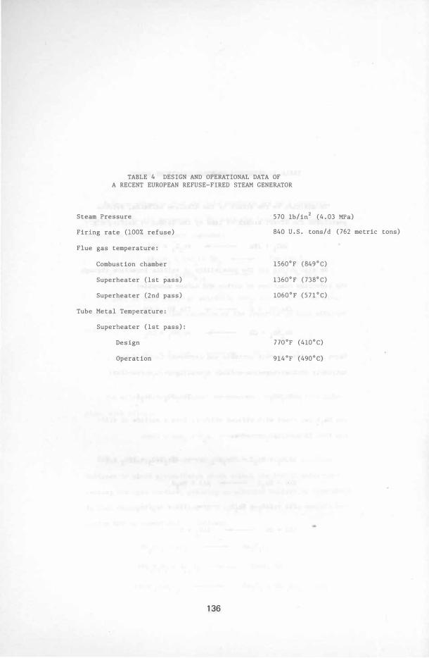
TABLE 4 DESIGN AND OPERATIONAL DATA OF A RECENT EUROPEAN REFUSE-FIRED STEAM GENERATOR
Steam Pressure
Firing rate (100% refuse)
Flue gas temperature:
Combustion chamber
Superheater (1st pass)
Superheater (2nd pass)
Tube Metal Temperature:
Superheater (1st pass) :
Design
Operation
136
570 Ib/in2 (4. 03 MPa)
840 U.S. tons/d (762 metric tons)
1560°F (849°C)
1360°F (738°C)
1060°F (57l°C)
no of (410°C)
914 of (490°C)
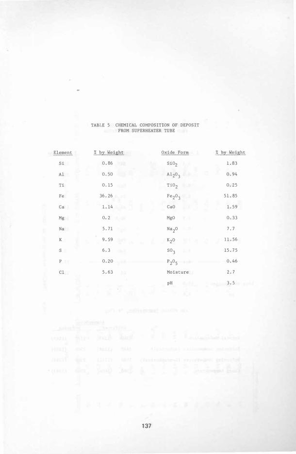
TABLE 5 CHEMICAL COMPOSITION OF DEPOSIT FROM SUPERHEATER TUBE
Element % by Weight Oxide Form % by Weight
Si 0.86 Si02 1.83
A1 0.50 A1203 0.94
Ti 0.15 Ti02 0. 25
Fe 36. 26 Fe203 51.85
Ca 1.14 CaO 1. 59
Mg 0. 2 MgO 0.33
Na 5.71 Na20 7.7
K 9. 59 K20 11. 56
S 6.3 S03 15. 75
P 0.20 P205 0. 46
C1 5. 63 Moisture 2. 7
pH 3. 5
137
•
Loss
Element % ---
Si
Ca
Mg
Fe
Al
Na
K
Pb
Zn
S
C1
on ignition
pH
TABLE 6 ANALYSIS OF FLY ASH FROM ELECTROSTATIC PRECIPITATOR
by Weight Oxide Form
5.4 Si02
8.6 CaO
0. 6 MgO
2.0 Fe203
6. 4 Al203
7. 9 Na20
10. 3 K20
2. 2 PbO
4. 5 ZnO
6. 4 S03
12. 2 C1
12. 0
5. 8
ASH FUSION TEMPERATURE, OF (OC)
Atmosphere
% by Weight
11. 6
12. 0
1. 0
2. 8
12. 0
10. 7
12.4
2. 4
5. 6
15.9
12.2
Oxidizing Reducing
Initial deformation
Softening temperature (spherical)
Softening temperature (hemispherical)
Fluid temperature
138
2360
2440
2500
2560
(1293)
(1338)
(1371)
(1404)
2280
2300
2360
2900
(1249)
(1260)
(1293)
(1593)
TAB
LE
7
C
HE
MI
CA
L C
OMP
OS
ITI
ON
O
F D
EP
OS
IT
S
So
ft A
H
ar
d B
El
em
en
t
% b
y W
eigh
t
Ox
ide
Fo
rm
% b
y W
eigh
t
Ele
men
t
% b
y W
eigh
t
Ox
ide
Fo
rm
% by
Wei
ght
Si
6
.0
7 S
i0 2
12.
9 S
i
1. 4
5 S
i0 2
3.1
Al
5.
10
A
1 20
3
9.
5 Al
2
.11
A
1 20
3
3.9
Ca
1
4.
56
Ca
O
20.
3
Ca
4.
57
C
aO
6.4
Mg
2 .
14
MgO
3.5
Mg
0
.57
M
gO
0
.9
S
B.6
9 S
03
21
. 7
S
7.
23
S
03
1B
.1
P N
D*
P N
D*
W
<0
Fe
1. 4
7
Fe
203
2
.1
Fe
32
.16
F
e20
3
45.
9
Zn
1.
94
Z
nO
2.
4
Zn
1.
29
Zn
O
1.6
Pb
0
.1
9 P
bO
0
.2
Pb
0.
63
P
bO
0
.7
Sn
0
.1
9 S
n0 2
0.
2 S
n
0.
07
Sn
0 2 0
.0
9
Cu
0
.11
C
uO
0.
1 C
u 0
.1
0
Cu
O
0.
1
Cl
5.67
C
1
5.67
C
1 6.
74
Cl
6.
74
Na
3.
63
N
a20
4.
9 N
a
2.4
0
Na
20
3.
2
K 6
.0
4
K20
7.
3
K 6.
35
K20
7.
7
pH
6.
90
pH
3.
BO
*Not
de
te
ct
ab
le
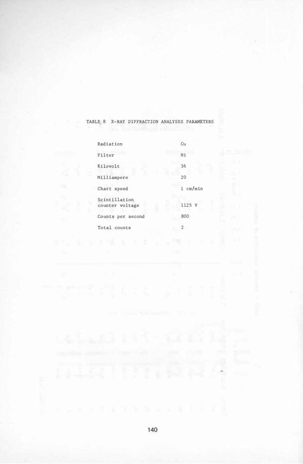
TABLE 8 X-RAY DIFFRACTION ANALYSES PARAMETERS
Radiation Cu
Filter Ni
Kilovolt 36
Milliampere 20
Chart speed 1 em/min
Scintillation counter voltage 1125 V
Counts per second 800
Total counts 2
140
[[] SEC 'A-A
STUTTGART- MUNSTER UNIT NO. 29
SCALE IN FEET o 10 20 30 40 50
AREAS OF MOST FREQUENT TUBE
WASTAGE •
FIGURE 1 AREAS OF MOST FREQUENT TUBE WASTAGE IN THE STUTTGART-MUNSTER UNITS.
Conversion factor: (ft) 0. 305 (m)
14 1
TU
HEAT
BE SURFA CE Fe,Fe ° HEAT Fe203
HCI CI2
, I r
R EFUSE C OMBUSTION
HEAT I
FeCI3
f FeCI2
t H2O AIR
t
FeO,Fe203, Fe 304
+
HCI CI2
FIGURE 2 CHLORIDE CORROSION FROM FIRING REFUSE
AS PROPOSED BY FASSLER ET AL.
142
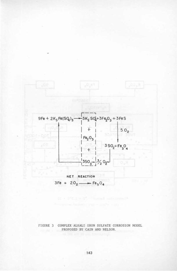
NET REACTION
FIGURE 3 COMPLEX ALKALI IRON SULFATE CORROSION MODEL PROPOSED BY CAIN AND NELSON.
143
(f) w 0 §IO (f) ct x8 (f) ct w x6 � �
�4 � Z �2 a: w a..
2
.. •
.. • .. ..
•• .. • . , t •
... .. •
• • STUTTGART • DUSSELDORF
4 PERCENT Na+K IN THE ASH
FIGURE 6 RELATIONSHIP OF ZINC CONCENTRATION TO SODIUM AND POTASSIUM CONCENTRATION IN THE ASH.
146
•
•
18
• MUNICH X STUTTGART • DUSSELDORF • NORFOLK • OCEANSIDE
942
147
"" I>-0
LIJ a: ::::l .... <l: a: LIJ a.. � LIJ .... � Z Z LIJ .... I>-0 (f)
2800
2600
2400
2200
2000 20
• •
• • 0
��. 0 � O · 6 0 \ 60 ro 60
66tt::.
� *06c.o � 8 o • 6 6
'" 9-.......£..o� 00 , 6 6
30 40 50 60
00
70 BASIC CONSTITUENTS, WT-'o
0
o MUNICH o DUSSELDORF
'" STUTTGART • LIGNITE
80
FIGURE 8 SOFTENING TEMPERATURE VERSUS ASH BASE CONTENT.
*Conversion factor: (OC) = 5/9(OF - 32)
148
�
co
, �
1 2
" :)
FI
GU
RE
9 PH
OTO
MAC
RO
GRAP
H A
T 3
/4
X
MAG
NIF
ICAT
ION
O
F A
S-
REC
EIV
ED
SU
BM
ITT
ED
SE
CTI
ON
S O
F
TUB
ING
S
HO
WI
NG
B
OTH
TU
BES
C
OV
ERED
WI
TH
DEP
OS
IT.
tTl
o
FIGU
RE 1
0 P
HO
TO
MA
CR
OG
RA
PH
A
T
1/2X
MA
GN
IF
IC
AT
IO
N
OF
S
AN
DB
LA
ST
ED
T
UB
ES
A
FT
ER
S
UR
FA
CE
S
WE
RE
C
LE
AN
ED
. P
OR
TI
ON
O
F
TU
BE
S
DI
AMET
RI
CA
LL
Y
OP
PO
SI
TE
T
HE
F
AI
LU
RE
I
S
PR
ES
EN
TE
D
IN
B
OT
TO
M
PH
OT
O.
TR
AN
SV
ER
SE
C
RO
SS
S
EC
TI
ON
S
RE
MO
VE
D
FO
R
MI
CR
OS
CO
PI
C
EX
AM
IN
AT
IO
N
AR
E
ID
EN
TI
FI
ED
B
Y
LE
TT
ER
S.
(J'1
FI
GU
RE
11
P
HO
TO
MA
CR
OG
RA
PH
A
T
IX
M
AG
NI
FI
CA
TI
ON
O
F
NI
TA
L
ET
CH
ED
T
RA
NS
VE
RS
E
CR
OS
S
SE
CT
IO
NS
R
EM
OV
ED
F
RO
M
RE
GI
ON
S
SH
OW
N
IN
F
IG
UR
E
10
WI
TH
I
NS
ID
E-
DI
AME
TE
R
AN
D
WA
LL
-T
HI
CK
NE
SS
M
EA
SU
RE
ME
NT
S.
.. ,' , , ' .
j� ,:'.!.� .� ;:� -:: , ... � i'
, I .) : .
FIGURE 12 PHOTOMICROGRAPHS AT 100X MAGNIFICATION INDICATING REPRESENTATIVE APPEARANCES OF NITAL ETCHED OUTSIDE TUBE SURFACES AT UPPER EDGES OF SECTIONS.
THE INSIDE SURFACE (LOWER EDGE) OF TUBES SUFFERED NO SIGNIFICANT ATTACK.
152
, " , � \ l
� � (;:-.. i "'I ...
�- � .� � H � }� � � � { ! '
'" :ii
o:-;�f1r.r'O"""·",t.J,, ... tff .. ;;:-
.... ., 0 to xi' til 0 "E-< E-<
'. ;><0 '"'''' ... �
""., ... '" 0,", 5� >-<tIl ...
;2� 'Of'" �: UO
Q.,., .. .,110.,..(." .. I:1 ..... J.l,I "''''
'''1'.'' "' ..
""...1 f,'J'J . ..,;,. ... """ §(J 0 "''''
'" ZE-< 0'" >-<>: E-<O UE-< ;2U .. ;2 .... >-< ... C>-<
; C
IX¥-I.J" �;>< ,;2 X , X M ,..,
� :=> t;) >-< ..
153
.q co ..., ';;; (; :; (I) 0
• CD ..., '.
� :; 0 0 %:
.:!
• ..., '; c:
154
co ..., ';; c:
" ..,
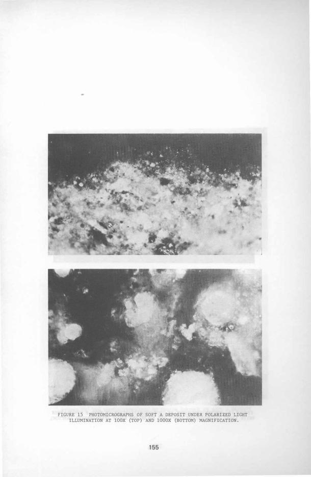
FIGURE 15 PHOTOMICROGRAPHS OF SOFT A DEPOSIT UNDER POLARIZED LIGHT ILLUMINATION AT 100X (TOP) AND 1000X (BOTTOM) MAGNIFICATION.
155
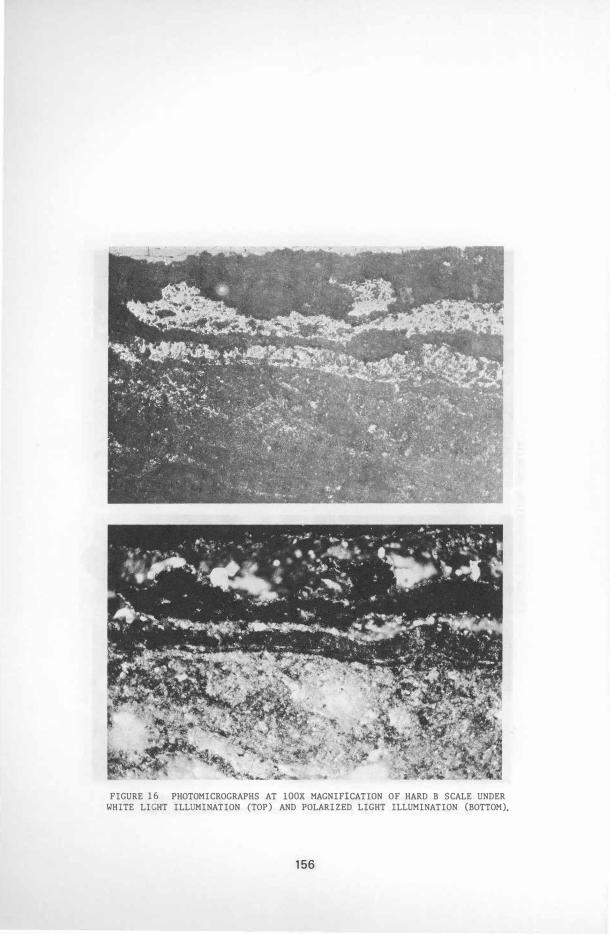
FIGURE 16 PHOTOMICROGRAPHS AT 100X MAGNIFICATION OF HARD B SCALE UNDER WHITE LIGHT ILLUMINATION (TOP) AND POLARIZED LIGHT ILLUMINATION (BOTTOM).
156
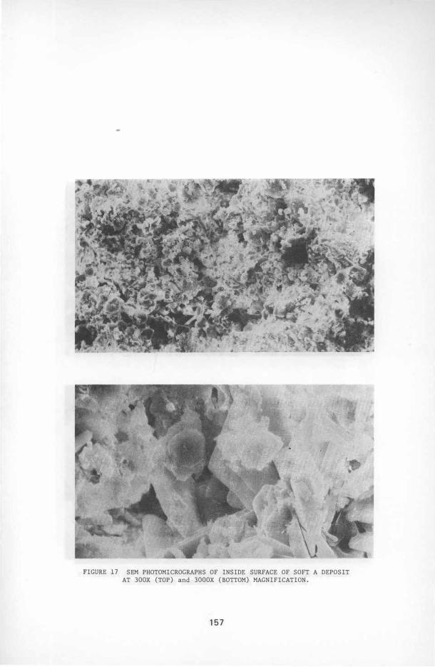
FIGURE 17 SEM PHOTOMICROGRAPHS OF INSIDE SURFACE OF SOFT A DEPOSIT AT 300X (TOP) and 3000X (BOTTOM) MAGNIFICATION.
157
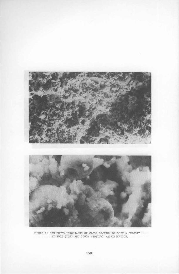
FIGURE 18 SEM PHOTOMICROGRAPHS OF CROSS SECTION OF SOFT A DEPOSIT
AT 300X (TOP) AND 3000X (BOTTOM) MAGNIFICATION.
158
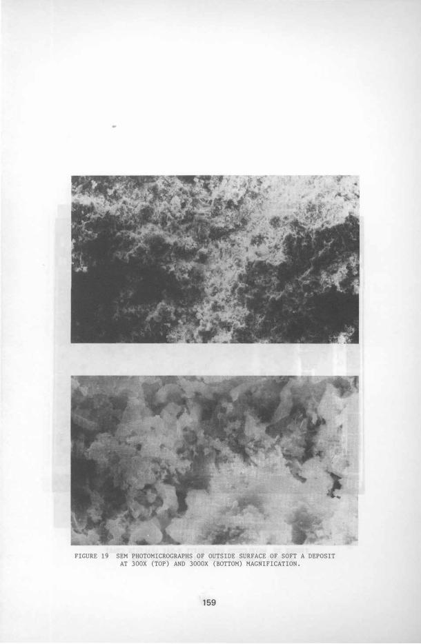
FIGURE 19 SEM PHOTOMICROGRAPHS OF OUTSIDE SURFACE OF SOFT A DEPOSIT AT 300X (TOP) AND 3000X (BOTTOM) MAGNIFICATION.
159
AI S CI I< Co Ti Cr Mn Fe Zn
FIGURE 20 WAVELENGTH DISPERSIVE X-RAY ANALYSIS CHART OF SOFT A DEPOSIT FROM INSIDE SURFACE AREA.
160
Ol
AI S
i 5
CI
K C
o Ti
C
r Mn
Fe
Zn
F
IG
UR
E
21
W
AV
EL
EN
GT
H
DI
SP
ER
SI
VE
X
-R
AY
A
NA
LY
SI
S
CH
AR
T
OF
S
OF
T
A
DE
PO
SI
T
FR
OM
C
RO
SS
-S
EC
TI
ON
A
RE
A.
AI Si SCI K Co Ti Mn Fe
FIGURE 22 WAVELENGTH DISPERSIVE X-RAY ANALYSIS CHART OF SOFT A DEPOSIT FROM OUTSIDE SURFACE AREA .
162
Zn
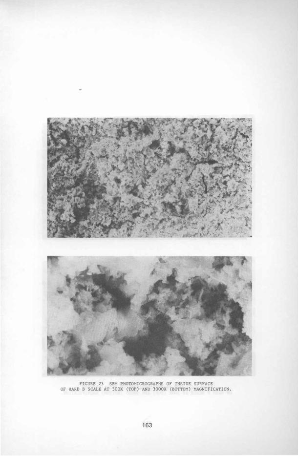
FIGURE 23 SEM PHOTOMICROGRAPHS OF INSIDE SURFACE OF HARD B SCALE AT 300X (TOP) AND 3000X (BOTTOM) MAGNIFICATION.
163
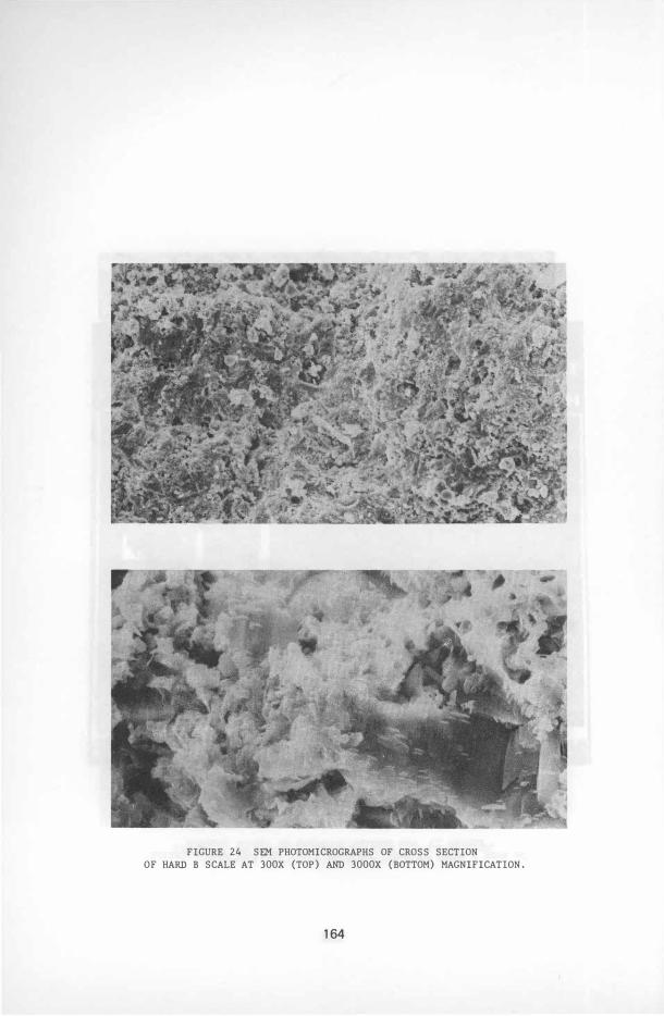
FIGURE 24 SEM PHOTOMICROGRAPHS OF CROSS SECTION OF HARD B SCALE AT 300X (TOP) AND 3000X (BOTTOM) MAGNIFICATION.
164
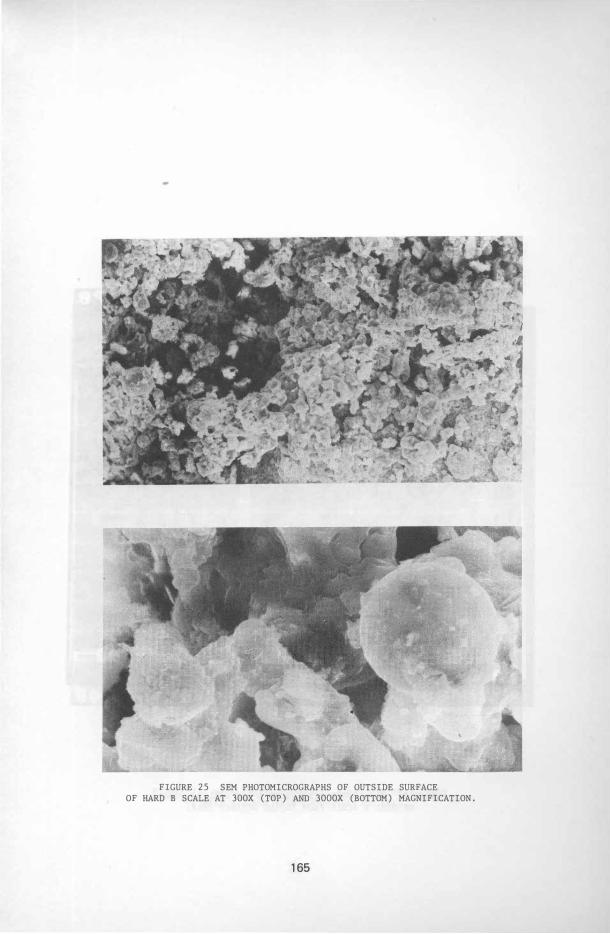
FIGURE 25 SEM PHOTOMICROGRAPHS OF OUTSIDE SURFACE OF HARD B SCALE AT 300X (TOP) AND 3000X (BOTTOM) MAGNIFICATION.
165
> " Z-82 P8
• 8CH lEU 2 ••••• ' INT
FS- 2k kEUEX-RAV MS- 2.EU/CH
S CI K Cr '--v---l
Fe
FIGURE 26 WAVELENGTH DISPERSIVE X-RAY ANALYSIS CHART
OF HARD B SCALE FROM INSIDE SURFACE AREA.
166
8 � 2 0 4 �t .; 0 8 AI Si SCI K Co '---v---J
Fe "----v---'
Zn
FIGURE 27 WAVELENGTH DISPERSIVE X-RAY ANALYSIS CHART
OF HARD B SCALE FROM CROSS-SECTION AREA.
167

e. 02 04 0 6 08
Mg Pb CI K Co Ti Mn
FIGURE 28 WAVELENGTH DISPERSIVE X-RAY ANALYSIS CHART
OF HARD B SCALE FROM OUTSIDE SURFACE AREA.
168
� Zn
> ML Z-82 P8
I 8eH 8EU 288888 ' INT
FS- 2K KEUEX-RAY HS- 2 8EU/CH
8 02 04 06 08 10 12 14 16 1 8
Pb Pb Pb
FIGURE 29 WAVELENGTH DISPERSIVE X-RAY ANALYSIS CHART
OF HARD B SCALE FROM OUTSIDE SURFACE AREA.
169
1 CD c( • - 'V a � 0 • a u CI) Q Z CI)
(0 � '" .- .� /
''1 .�
;,s.1O" ��'I".., •• 'D'¥ .. .\1 is;;
... � fitJ" .. ." CI.l / .. "W � H
loP4'JI, •• .1\ � Lo'r , ... '1>3 -�.-:� ... CI.l "'�"�rlO " .,., "Dr!( '" rx.. 0
.1:1 . -"Dr .. �.
� ·f •• U ... . , -",,, .. -I'" Z 0 H . �- ' . � U
, '-'OJ/! � , f. rx..
:,,' rx.. .� "''Y� . H Q
.� �,,'" � .1:1 � �
"-,, .. tor·., 0 ·8 ·1 C<)
� 1I7s''II'j 'ir"'� p::: P .:;, ·la Co!) H
1-'-" rx..
·It .� "o'§I"
1.:).7 - 'l7rJlJ ·R .IQ '"lit' /')'H' -'Ol'!.',.
-i .�
170
Related Documents