ARTICLE Corrosion engineering towards efficient oxygen evolution electrodes with stable catalytic activity for over 6000 hours Yipu Liu 1 , Xiao Liang 1 , Lin Gu 2 , Yu Zhang 3 , Guo-Dong Li 1 , Xiaoxin Zou 1 & Jie-Sheng Chen 4 Although a number of nonprecious materials can exhibit catalytic activity approaching (sometimes even outperforming) that of iridium oxide catalysts for the oxygen evolution reaction, their catalytic lifetimes rarely exceed more than several hundred hours under operating conditions. Here we develop an energy-efficient, cost-effective, scaled-up corrosion engineering method for transforming inexpensive iron substrates (e.g., iron plate and iron foam) into highly active and ultrastable electrodes for oxygen evolution reaction. This syn- thetic method is achieved via a desired corrosion reaction of iron substrates with oxygen in aqueous solutions containing divalent cations (e.g., nickel) at ambient temperature. This process results in the growth on iron substrates of thin film nanosheet arrays that consist of iron-containing layered double hydroxides, instead of rust. This inexpensive and simple manufacturing technique affords iron-substrate-derived electrodes possessing excellent catalytic activities and activity retention for over 6000 hours at 1000 mA cm -2 current densities. DOI: 10.1038/s41467-018-05019-5 OPEN 1 State Key Laboratory of Inorganic Synthesis and Preparative Chemistry, College of Chemistry, Jilin University, 130012 Changchun, China. 2 Institute of Physics, Chinese Academy of Sciences, 100190 Beijing, China. 3 School of Chemistry, Beihang University, 100191 Beijing, China. 4 School of Chemistry and Chemical Engineering, Shanghai Jiao Tong University, 200240 Shanghai, China. Correspondence and requests for materials should be addressed to X.Z. (email: [email protected]) NATURE COMMUNICATIONS | (2018)9:2609 | DOI: 10.1038/s41467-018-05019-5 | www.nature.com/naturecommunications 1 1234567890():,;

Welcome message from author
This document is posted to help you gain knowledge. Please leave a comment to let me know what you think about it! Share it to your friends and learn new things together.
Transcript
ARTICLE
Corrosion engineering towards efficient oxygenevolution electrodes with stable catalytic activityfor over 6000 hoursYipu Liu1, Xiao Liang1, Lin Gu2, Yu Zhang3, Guo-Dong Li1, Xiaoxin Zou 1 & Jie-Sheng Chen4
Although a number of nonprecious materials can exhibit catalytic activity approaching
(sometimes even outperforming) that of iridium oxide catalysts for the oxygen evolution
reaction, their catalytic lifetimes rarely exceed more than several hundred hours under
operating conditions. Here we develop an energy-efficient, cost-effective, scaled-up corrosion
engineering method for transforming inexpensive iron substrates (e.g., iron plate and iron
foam) into highly active and ultrastable electrodes for oxygen evolution reaction. This syn-
thetic method is achieved via a desired corrosion reaction of iron substrates with oxygen in
aqueous solutions containing divalent cations (e.g., nickel) at ambient temperature. This
process results in the growth on iron substrates of thin film nanosheet arrays that consist of
iron-containing layered double hydroxides, instead of rust. This inexpensive and simple
manufacturing technique affords iron-substrate-derived electrodes possessing excellent
catalytic activities and activity retention for over 6000 hours at 1000 mA cm-2 current
densities.
DOI: 10.1038/s41467-018-05019-5 OPEN
1 State Key Laboratory of Inorganic Synthesis and Preparative Chemistry, College of Chemistry, Jilin University, 130012 Changchun, China. 2 Institute ofPhysics, Chinese Academy of Sciences, 100190 Beijing, China. 3 School of Chemistry, Beihang University, 100191 Beijing, China. 4 School of Chemistry andChemical Engineering, Shanghai Jiao Tong University, 200240 Shanghai, China. Correspondence and requests for materials should be addressed toX.Z. (email: [email protected])
NATURE COMMUNICATIONS | (2018) 9:2609 | DOI: 10.1038/s41467-018-05019-5 |www.nature.com/naturecommunications 1
1234
5678
90():,;
The electrochemical water splitting has long been considereda promising approach to the production of clean hydrogenfuel by using renewable energy sources1, 2. The oxygen
evolution reaction (OER) and hydrogen evolution reaction (HER)are the primary half-reactions that occur at the anode andcathode respectively in the electrochemical water splitting reac-tion. Compared with HER, OER is a more energy-intensiveprocess in the water splitting reaction, due to intrinsically morecomplex, multiple proton/electron-coupled steps involved in thishalf-reaction3–5. As a consequence, efficient OER electrocatalysisis important for the overall efficiency of the water splittingreaction, and thus oxygen evolution electrodes (or electro-catalysts) with sufficient catalytic activity and stability areurgently demanded. Recently, a number of nonprecious materialshave been reported to exhibit catalytic activity approaching(sometimes even outperforming) that of the noble-metal-basedIrO2 catalysts for OER3–5. The promising nonprecious oxygenevolution electrocatalysts mainly include crystalline/amorphousmultimetallic oxides6–11, layered double hydroxides12–19, spinel-type oxides20–23, perovskite-type oxides24–26, etc.
Although some advances have been obtained in the improve-ment of catalytic activity for OER and in the mechanisticunderstanding of activity improvement3–26, there are still majorchallenges to employing these promising oxygen evolution elec-trodes for large-scale, practical applications27, 28. The main one isthe long-time operational stability: most of recently developedoxygen evolution electrodes are shown to only work well for a fewto several tens of hours at small current densities (e.g., 10 mA cm−2), and very few can last for several hundreds of hours6, 8. Thestability problem becomes even more severe when the oxygenevolution electrocatalysts are forced to deliver large catalyticcurrent densities (e.g., 1000 mA cm−2: a more practically-relevantvalue in water splitting devices11, 28–30.) Their deactivation duringOER can be caused by various adverse microstructural evolutionsof catalytic active phases, such as oxidative decomposition,structural reconstruction, metal leaching and irregular aggrega-tion. Another non-negligible stability problem is the peeling ofcatalytic active species from current collector during OER, espe-cially at large catalytic current densities. Therefore, developinghighly active oxygen evolution electrodes that can possess sig-nificantly prolonged catalytic lifetime (e.g., beyond thousands ofhours) still remains a great challenge.
Herein, we report the fabrication of efficient oxygen evolutionelectrodes that exhibit catalytic activity comparable to those of thestate-of-the-art, nonprecious ones, while remaining highly stablefor more than 6000 h (>8 months) at a current density of 1000mA cm−2. The electrodes are fabricated from inexpensive ironsubstrates through a corrosion engineering strategy without any
additional energy consumption. To the best of our knowledge,there is no example of efficient and stable OER electrocatalysis inthe time span of several months at large current densities.Notably also, an iron corrosion reaction that is usually consideredto be negative and unwanted has never been shown to be apositive and desired one for the fabrication of LDHs-based oxy-gen evolution electrodes.
ResultsFabrication of the electrodes via corrosion engineering strat-egy. Iron corrosion is a common phenomenon. When iron sub-strates are brought in contact with water and air, iron rust oftenunavoidably forms on the surface of iron substrates. Iron corro-sion has been usually looked upon as a bad reaction because itcauses functional deterioration of the material and big economiclosses. Here we show that iron corrosion is not necessarilyharmful for the properties of a material, and meticulous corrosionengineering can endow the material with useful functionalities(high catalytic activity and stability for OER herein) that are noteasily achievable by other methods.
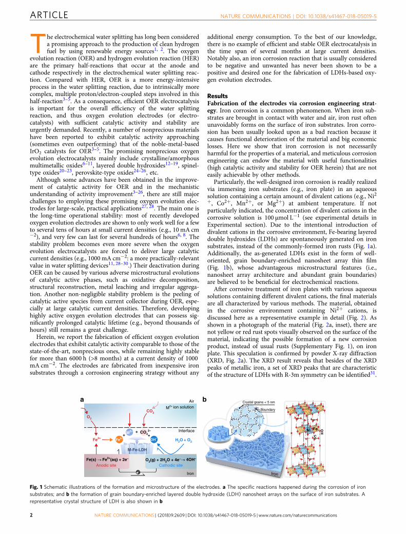
Particularly, the well-designed iron corrosion is readily realizedvia immersing iron substrates (e.g., iron plate) in an aqueoussolution containing a certain amount of divalent cations (e.g., Ni2+, Co2+, Mn2+, or Mg2+) at ambient temperature. If notparticularly indicated, the concentration of divalent cations in thecorrosive solution is 100 µmol L−1 (see experimental details inExperimental section). Due to the intentional introduction ofdivalent cations in the corrosive environment, Fe-bearing layereddouble hydroxides (LDHs) are spontaneously generated on ironsubstrates, instead of the commonly-formed iron rusts (Fig. 1a).Additionally, the as-generated LDHs exist in the form of well-oriented, grain boundary-enriched nanosheet array thin film(Fig. 1b), whose advantageous microstructural features (i.e.,nanosheet array architecture and abundant grain boundaries)are believed to be beneficial for electrochemical reactions.
After corrosive treatment of iron plates with various aqueoussolutions containing different divalent cations, the final materialsare all characterized by various methods. The material, obtainedin the corrosive environment containing Ni2+ cations, isdiscussed here as a representative example in detail (Fig. 2). Asshown in a photograph of the material (Fig. 2a, inset), there arenot yellow or red rust spots visually observed on the surface of thematerial, indicating the possible formation of a new corrosionproduct, instead of usual rusts (Supplementary Fig. 1), on ironplate. This speculation is confirmed by powder X-ray diffraction(XRD, Fig. 2a). The XRD result reveals that besides of the XRDpeaks of metallic iron, a set of XRD peaks that are characteristicof the structure of LDHs with R-3m symmetry can be identified31.
a
O2
CO2
O2(g) + 2H2O + 4e–Fe2+(aq) + 2e–Fe(s)
M-Fe-LDH
4OH–
H2O + O2
CO32–+++
Fe2+
M2+ ion solution
Interface Ni Fe
C
OH
Cathodic siteAnodic site
Air Crystal grains < 5 nm
Boundary
Iron Iron
M2+
Fe3+ OH–
e–
b
Fig. 1 Schematic illustrations of the formation and microstructure of the electrodes. a The specific reactions happened during the corrosion of ironsubstrates; and b the formation of grain boundary-enriched layered double hydroxide (LDH) nanosheet arrays on the surface of iron substrates. Arepresentative crystal structure of LDH is also shown in b
ARTICLE NATURE COMMUNICATIONS | DOI: 10.1038/s41467-018-05019-5
2 NATURE COMMUNICATIONS | (2018) 9:2609 | DOI: 10.1038/s41467-018-05019-5 | www.nature.com/naturecommunications
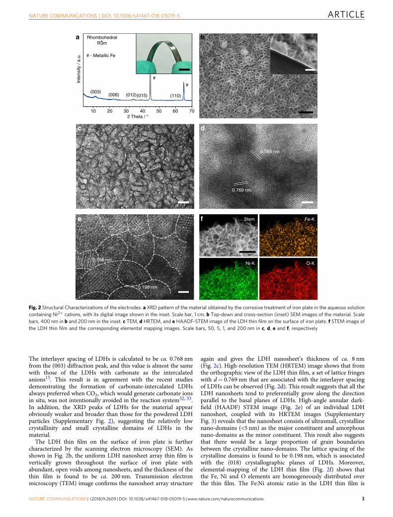
The interlayer spacing of LDHs is calculated to be ca. 0.768 nmfrom the (003) diffraction peak, and this value is almost the samewith those of the LDHs with carbonate as the intercalatedanions15. This result is in agreement with the recent studiesdemonstrating the formation of carbonate-intercalated LDHsalways preferred when CO2, which would generate carbonate ionsin situ, was not intentionally avoided in the reaction system32, 33.In addition, the XRD peaks of LDHs for the material appearobviously weaker and broader than those for the powdered LDHparticles (Supplementary Fig. 2), suggesting the relatively lowcrystallinity and small crystalline domains of LDHs in thematerial.
The LDH thin film on the surface of iron plate is furthercharacterized by the scanning electron microscopy (SEM). Asshown in Fig. 2b, the uniform LDH nanosheet array thin film isvertically grown throughout the surface of iron plate withabundant, open voids among nanosheets, and the thickness of thethin film is found to be ca. 200 nm. Transmission electronmicroscopy (TEM) image confirms the nanosheet array structure
again and gives the LDH nanosheet’s thickness of ca. 8 nm(Fig. 2c). High-resolution TEM (HRTEM) image shows that fromthe orthographic view of the LDH thin film, a set of lattice fringeswith d= 0.769 nm that are associated with the interlayer spacingof LDHs can be observed (Fig. 2d). This result suggests that all theLDH nanosheets tend to preferentially grow along the directionparallel to the basal planes of LDHs. High-angle annular dark-field (HAADF) STEM image (Fig. 2e) of an individual LDHnanosheet, coupled with its HRTEM images (SupplementaryFig. 3) reveals that the nanosheet consists of ultrasmall, crystallinenano-domains (<5 nm) as the major constituent and amorphousnano-domains as the minor constituent. This result also suggeststhat there would be a large proportion of grain boundariesbetween the crystalline nano-domains. The lattice spacing of thecrystalline domains is found to be 0.198 nm, which is associatedwith the (018) crystallographic planes of LDHs. Moreover,elemental-mapping of the LDH thin film (Fig. 2f) shows thatthe Fe, Ni and O elements are homogeneously distributed overthe thin film. The Fe:Ni atomic ratio in the LDH thin film is
302010
0.769 nm
0.769 nm
0.198 nm
0.198 nm
Stem Fe-K
Ni-K O-K
(003)
Inte
nsity
/ a.
u.
(006) (012)(015) (110)
#
#
# - Metallic Fe
a b
c d
e f
402 Theta / °
50 60 70
RhombohedralR3m
Fig. 2 Structural Characterizations of the electrodes. a XRD pattern of the material obtained by the corrosive treatment of iron plate in the aqueous solutioncontaining Ni2+ cations, with its digital image shown in the inset. Scale bar, 1 cm. b Top-down and cross-section (inset) SEM images of the material. Scalebars, 400 nm in b and 200 nm in the inset. c TEM, d HRTEM, and e HAADF-STEM image of the LDH thin film on the surface of iron plate. f STEM image ofthe LDH thin film and the corresponding elemental mapping images. Scale bars, 50, 5, 1, and 200 nm in c, d, e and f, respectively
NATURE COMMUNICATIONS | DOI: 10.1038/s41467-018-05019-5 ARTICLE
NATURE COMMUNICATIONS | (2018) 9:2609 | DOI: 10.1038/s41467-018-05019-5 |www.nature.com/naturecommunications 3
determined to be 1.1:1 by energy dispersive X-ray spectroscopy(EDS), and the Fe and Ni species in the LDH thin film exist in theform of Fe3+ and Ni2+, as revealed by X-ray photoelectronspectroscopy (XPS, Supplementary Fig. 4) 11.
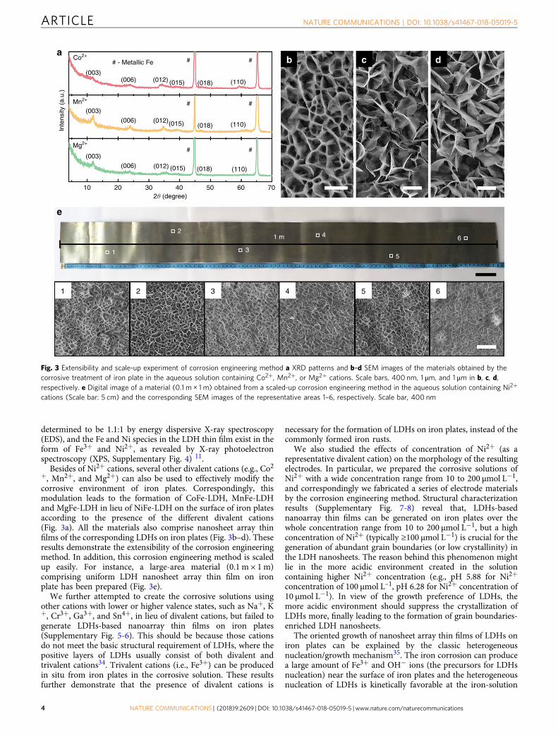
Besides of Ni2+ cations, several other divalent cations (e.g., Co2+, Mn2+, and Mg2+) can also be used to effectively modify thecorrosive environment of iron plates. Correspondingly, thismodulation leads to the formation of CoFe-LDH, MnFe-LDHand MgFe-LDH in lieu of NiFe-LDH on the surface of iron platesaccording to the presence of the different divalent cations(Fig. 3a). All the materials also comprise nanosheet array thinfilms of the corresponding LDHs on iron plates (Fig. 3b–d). Theseresults demonstrate the extensibility of the corrosion engineeringmethod. In addition, this corrosion engineering method is scaledup easily. For instance, a large-area material (0.1 m × 1m)comprising uniform LDH nanosheet array thin film on ironplate has been prepared (Fig. 3e).
We further attempted to create the corrosive solutions usingother cations with lower or higher valence states, such as Na+, K+, Cr3+, Ga3+, and Sn4+, in lieu of divalent cations, but failed togenerate LDHs-based nanoarray thin films on iron plates(Supplementary Fig. 5-6). This should be because those cationsdo not meet the basic structural requirement of LDHs, where thepositive layers of LDHs usually consist of both divalent andtrivalent cations34. Trivalent cations (i.e., Fe3+) can be producedin situ from iron plates in the corrosive solution. These resultsfurther demonstrate that the presence of divalent cations is
necessary for the formation of LDHs on iron plates, instead of thecommonly formed iron rusts.
We also studied the effects of concentration of Ni2+ (as arepresentative divalent cation) on the morphology of the resultingelectrodes. In particular, we prepared the corrosive solutions ofNi2+ with a wide concentration range from 10 to 200 µmol L−1,and correspondingly we fabricated a series of electrode materialsby the corrosion engineering method. Structural characterizationresults (Supplementary Fig. 7-8) reveal that, LDHs-basednanoarray thin films can be generated on iron plates over thewhole concentration range from 10 to 200 µmol L−1, but a highconcentration of Ni2+ (typically ≥100 µmol L−1) is crucial for thegeneration of abundant grain boundaries (or low crystallinity) inthe LDH nanosheets. The reason behind this phenomenon mightlie in the more acidic environment created in the solutioncontaining higher Ni2+ concentration (e.g., pH 5.88 for Ni2+
concentration of 100 µmol L–1, pH 6.28 for Ni2+ concentration of10 µmol L−1). In view of the growth preference of LDHs, themore acidic environment should suppress the crystallization ofLDHs more, finally leading to the formation of grain boundaries-enriched LDH nanosheets.
The oriented growth of nanosheet array thin films of LDHs oniron plates can be explained by the classic heterogeneousnucleation/growth mechanism35. The iron corrosion can producea large amount of Fe3+ and OH− ions (the precursors for LDHsnucleation) near the surface of iron plates and the heterogeneousnucleation of LDHs is kinetically favorable at the iron-solution
# - Metallic Fe # #
# #
# #
Co2+
Mn2+
Mg2+
(003)
a
e
b c d
(003)
Inte
nsity
(a.
u.)
(003)
(006)
(006)
(006)
10
1 2
1
2
3
41 m
5
6
3 4 5 6
20 30 402� (degree)
50 60 70
(012)
(012)
(012)
(015)
(015)
(015)
(018) (110)
(018) (110)
(018) (110)
Fig. 3 Extensibility and scale-up experiment of corrosion engineering method a XRD patterns and b–d SEM images of the materials obtained by thecorrosive treatment of iron plate in the aqueous solution containing Co2+, Mn2+, or Mg2+ cations. Scale bars, 400 nm, 1 μm, and 1 μm in b, c, d,respectively. e Digital image of a material (0.1 m × 1 m) obtained from a scaled-up corrosion engineering method in the aqueous solution containing Ni2+
cations (Scale bar: 5 cm) and the corresponding SEM images of the representative areas 1–6, respectively. Scale bar, 400 nm
ARTICLE NATURE COMMUNICATIONS | DOI: 10.1038/s41467-018-05019-5
4 NATURE COMMUNICATIONS | (2018) 9:2609 | DOI: 10.1038/s41467-018-05019-5 | www.nature.com/naturecommunications
interface. Due to the anisotropic crystal structure of LDHs, theirgrowth in the ab-direction is faster than that in the c-direction35,so that all the LDH nanosheets tend to preferentially grow alongthe direction parallel to the basal planes of LDHs.
Based on the above experimental data, the divalent cations inthe corrosion engineering process should play two importantroles in the growth of grain boundary-enriched nanosheet arraythin films of LDHs on iron substrates. On the one hand, thedivalent cations provide necessary components to meet the basicstructural requirement of LDHs, where the positive layers ofLDHs usually consist of both divalent and trivalent cations. Onthe other hand, the divalent cations, especially Ni2+, create asuitable, weak acidic solution that is crucial for the formation ofabundant grain boundaries in the LDH nanosheets.
Furthermore, we found that the presence of oxygen wasrequired for the formation of LDHs on iron, because the ironplates do not corrode without air (Supplementary Fig. 9).Moreover, further control experiment demonstrates that thepresence of CO2 (or CO3
2-) was not necessary for the formationof LDHs on the iron (Supplementary Fig. 10), although thecarbonate is identified as the charge-balancing anions between thelayers of LDHs in the materials we synthesize. By coupling all theabove results with previous studies on the rusting of iron36, apossible reaction mechanism is proposed based on a set ofelectrochemical reactions that may finally result in the generationof LDHs on iron plates (Fig. 1a). The inherent driving force of
iron corrosion is the electric potential difference between Fe/Fe2+
and OH–/O2, and several electrochemical reactions that shouldtake place simultaneously are described as below:
Fe ! Fe2þ þ 2e�
Fe2þ ! Fe3þþe�
O2 þ 2H2Oþ 4e� ! 4OH�
Fe3þ þM2þ þ OH� þ CO2�3 ! LDH M ¼ Ni;Co;MnorMgð Þ
It’s worth adding here that from the perspective of thepreparation of thin films of LDHs, the advantages of thecorrosion engineering method can be appreciated by comparingit with the methods developed recently (e.g., electrochemicaldeposition and hydrothermal synthesis)11–13, 37. Those methodsmust require thermal or electric energy to drive the formation ofthin films of LDHs. Those methods must require special reactionequipment and accessories, and they are difficultly scaled up. Andthose methods cannot use metallic iron as the substrates, becauseiron rusts are always the main reaction products under theseconditions. The above comparisons suggest, the corrosion
45
40
35
30
25
20
j (m
A c
m–2
)
15
10
5
0
0.6
0.5
0.4
0.3
0.2
0.0
1.0
2.0
3.0
4.0
5.0
5.5
b ca
e fd
0.5
1.5
2.5
Ele
ctro
chem
ical
act
ive
surf
ace
area
(cm
2 )
Spe
cific
act
ivity
(m
A c
m–2
)
–Im
(Z)
(Ohm
)3.5
4.5
0.00.0
0.1
0.2
0.3
0.4
0.5
0.6
1.0
2.0
3.0
4.0
0.5
1.5
2.5
3.5
4.5
1.2
–0.5 0.0 0.5 1.5
log( j ) (mA cm–2)
1.0 2.0 3.0 00.0
0.5
1.5
2.5
2.0
3.0
4.0
3.5
1.0
20 40
100 mA cm–2
Pot
entia
l (V
vs
RH
E)
O2
amou
nt (
μmol
)
1 M KOH 0
50
100
150
200
300
400 Measured valueTheorectical value
250
350
450
60
Time (h) Time (min)
80 100 0 50 100 150 200 250 3503002.5
1.3 1.4
E - iR (V vs RHE)
61.6 mV dec–1
48.3 mV dec–1
75.5 mV dec–1
iR-corrected � (V)iR
-cor
rect
ed �
(V
)
� = 269 mV � = 310 mV
� = 300 mVNi(II)
0.0 0.1 0.2 0.3 0.4
Ni(III)/Ni(IV)
Fe plate
IrO2
O2-Cat-2
O2-Cat-1
IrO2
O2-Cat-2
O2-Cat-1
O2-Cat-2
O2-Cat-1
O2-Cat-2
O2-Cat-1
0.43
0.42
0.86
0.33
(Ω cm2) Rs Rct
O2-Cat-2 O2-Cat-1 0.4 0.6 0.8 1.0
Re(Z ) (Ohm)
1.2 1.41.5 1.6 1.7
j = 100 mA cm–2
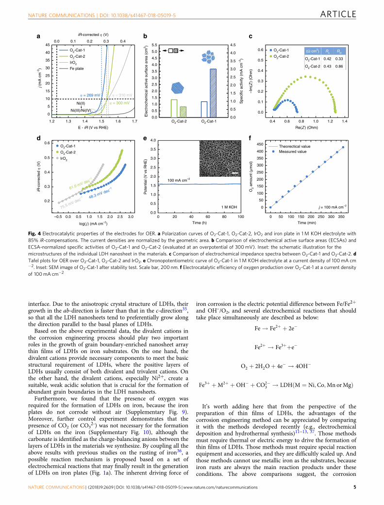
Fig. 4 Electrocatalytic properties of the electrodes for OER. a Polarization curves of O2-Cat-1, O2-Cat-2, IrO2 and iron plate in 1M KOH electrolyte with85% iR-compensations. The current densities are normalized by the geometric area. b Comparison of electrochemical active surface areas (ECSAs) andECSA-normalized specific activities of O2-Cat-1 and O2-Cat-2 (evaluated at an overpotential of 300mV). Inset: the schematic illustration for themicrostructures of the individual LDH nanosheet in the materials. c Comparison of electrochemical impedance spectra between O2-Cat-1 and O2-Cat-2. dTafel plots for OER over O2-Cat-1, O2-Cat-2 and IrO2. e Chronopotentiometric curve of O2-Cat-1 in 1 M KOH electrolyte at a current density of 100mA cm−2. Inset: SEM image of O2-Cat-1 after stability test. Scale bar, 200 nm. f Electrocatalytic efficiency of oxygen production over O2-Cat-1 at a current densityof 100mA cm−2
NATURE COMMUNICATIONS | DOI: 10.1038/s41467-018-05019-5 ARTICLE
NATURE COMMUNICATIONS | (2018) 9:2609 | DOI: 10.1038/s41467-018-05019-5 |www.nature.com/naturecommunications 5
engineering method is a simple, yet scalable and cost-effective,way to access this class of materials with multiple functions.
Electrocatalytic properties of the electrodes for OER. Next, theelectrocatalytic property for OER of the material from the cor-rosion engineering method (labeled as Route 1) in the aqueoussolution containing Ni2+ cations are investigated in a detailedway. This is because this particular material, denoted as O2-Cat-1hereafter, exhibits the highest catalytic activity among the mate-rials we synthesize (Supplementary Fig. 11). For comparativepurposes, electrochemical deposition (Route 2) as a prominentmethod is also applied to produce the corresponding LDH-basedelectrodes that have been proven to be highly active for OER. Theresulting material is correspondingly denoted as O2-Cat-2, and itscharacterizations are provided in SI (Supplementary Fig. 12-13).It is worth adding here that O2-Cat-2 is composed of LDHnanosheet array thin film on nickel plate (the morphology alike toO2-Cat-1), but their LDH nanosheets with a Ni:Fe atomic ratio of1.9:1 have relatively larger crystalline domains and less grainboundaries in comparison with those for O2-Cat-1.
Figure 4a shows the polarization curve of O2-Cat-1 for OER.There is an anodic peak at around 1.45 V vs. RHE, which isassociated with the redox process of Ni(II)/Ni(III or IV)14. Incontrast with iron plate’s inactivity, O2-Cat-1 exhibits aremarkable electrocatalytic activity for OER, clearly confirmingthe value-added transformation of inexpensive iron plate intohighly efficient electrode for OER. Additionally, O2-Cat-1’selectrocatalytic activity even surpasses that of the noble metal-based IrO2 electrocatalyst. More specifically, O2-Cat-1 requiresonly an overpotential (η) of 269 mV to achieve a current densityof 10 mA cm−2, whereas IrO2 needs a higher overpotential (310mV).
The electrocatalytic activity for OER of O2-Cat-1 is furtherevaluated by comparing it with O2-Cat-2 (Fig 4a, b). It is worthnoting that different from O2-Cat-1, O2-Cat-2 does not exhibitobvious the pre-oxidation peak of Ni. This result is in agreementwith that reported in the original study37. But different Ni:Featomic ratio in two materials (1.1:1 for O2-Cat-1 vs. 1.9:1 for O2-Cat-2) seems not explain why O2-Cat-2 does not exhibit the pre-oxidation peak of Ni. This is because Ni,Fe-based water oxidationcatalysts with a wide range of Ni:Fe atomic ratio usually can showthe pre-oxidation peak of Ni before the oxygen evolutionreaction7, 38. We speculate that this phenomenon should correlatewith the surface microenvironment of Ni species in O2-Cat-2,which ultimately originates from the particular electrochemicalsynthetic method. But the clear reason (or atomic basis) for thisphenomenon is still unclear at current stage.
As shown in Fig. 4a, O2-Cat-1 exhibits a higher geometric area-normalized electrocatalytic activity than O2-Cat-2. For example,at an overpotential of 300 mV, the current densities (normalizedby geometric area) of O2-Cat-1 and O2-Cat-2 are 40.2 and 10 mAcm−2, respectively. So the electrocatalytic activity of O2-Cat-1 canbe considered to be ca. four times as high as that of O2-Cat-2.Additionally, their specific electrocatalytic activities are alsoobtained by normalizing the measured currents with respect totheir electrochemical active surface areas (ECSAs). Because of thesimilar ECSAs of the two materials (Fig. 4b), their specificelectrocatalytic activities exhibit almost the same trend with theirgeometric area-normalized electrocatalytic activities. On the otherhand, the similar ECSAs of O2-Cat-1 and O2-Cat-2 indicate theirsimilar densities of catalytic active sites. By combining the higherelectrocatalytic activity of O2-Cat-1 compared with O2-Cat-2, itcan be concluded that the intrinsic activity of catalytic active sitesof O2-Cat-1 is higher than those of O2-Cat-2. The different Ni:Featomic ratio in two materials might not account for the better
catalytic activity of O2-Cat-1 because the composition of bothmaterials were in the optimal range for NiFe-based oxygenevolution electrocatalysts7, 39. The superior intrinsic catalyticactivity of O2-Cat-1 should be contributed to its unusualmicrostructure, owing to the grain boundary-enriched LDHnanosheets comprising ultrasmall crystalline domains. Such grainboundary-enriched LDH nanosheets can expose more edge sites,which generally have a higher degree of unsaturated coordinationand thus have been suggested as more active catalytic sites forOER15, 40. This claim is further supported by the activitycomparison of a series of electrodes fabricated by our corrosionengineering method in the corrosive environments containingdifferent Ni2+ concentrations (Supplementary Fig. 14). Theresults show that the electrodes fabricated with high Ni2+
concentrations have more abundant grain boundaries (or moredefects) and thereby better catalytic activities for OER.
Furthermore, the better electrocatalytic activity of O2-Cat-1 isalso reflected by its smaller charge transfer resistance (Rct; Fig. 4c)as well as the lower Tafel slope (48 mV dec−1) than that (61.6 mVdec−1) for O2-Cat-2 (Fig. 4d). A smaller Tafel slope indicates arapidly boosted current density with the increase of overpotential,and thus is commonly a good sign for electrocatalysts. In case ofO2-Cat-2, the oxygen evolution electrocatalysis is consideredlimiting by the first electron/proton reaction, i.e., adsorption andenergy optimization of OH reactants, (M+OH →M−OH+ e–
together with M−OH →M−OH*, where M represents thecatalytic active site) based on a Tafel slope around 60 mV dec-141.This result also indicates the kinetically sluggish for theassociation of OH reactants on electrocatalytic active sites inthe presence of O2-Cat-2. In case of O2-Cat-1, the oxygenevolution electrocatalysis would be determined by both the firstelectron/proton reaction and the second electron/proton reaction(M−OH+OH-
→M−O+H2O+ e–), which yields a Tafelslope near 40 mV dec−142. By comparing the respective rate-determining reactions during OER between O2-Cat-1 and O2-Cat-2, it’s inferred that the grain boundary-enriched O2-Cat-1efficiently expedites the electrocatalytic kinetics of OER byexposing more unsaturated edge sites that can facilitate theadsorption and activation of reactants 15, 40.
Besides of high electrocatalytic activity, O2-Cat-1 also has goodelectrocatalytic stability for OER. As shown in Fig. 4e, O2-Cat-1retains its electrocatalytic activity at a current density of 100 mAcm–2 for 100 h. After such long-time electrocatalysis, itsmorphology and microstructure also remain unchanged, asmanifested by the SEM (the inset in Fig. 4e) and TEM results(Supplementary Fig. 15). These results also demonstrate that theunderlying iron substrates do not further corroded by oxygenduring OER. This should be because the underlying ironsubstrates are covered with stable thin films of LDHs, protectingthe iron substrates against further corrosion. Additionally, O2-Cat-1 exhibits a nearly 100% Faradaic efficiency for OER (Fig. 4f),suggesting that the total electron transfer process duringelectrocatalysis is dominated by the desired OER.
The above results overall demonstrate the meliority of ourcorrosion engineering method over the electrochemical deposi-tion method and other methods reported recently (Supplemen-tary Table 1) in terms of making highly efficient oxygen evolutionelectrodes. O2-Cat-1’s excellent electrocatalytic performance canbe attributed to the following several facts. On the one hand, O2-Cat-1 has the common structural advantages of binder-freenanoarray electrodes and LDHs materials. The well-orientednanosheet array architecture is beneficial for avoiding theirregular aggregation of catalytic active phase, exposing thecatalytic active sites, and facilitating the mass transport duringOER (i.e., allowing better supply of reactants to get the active sitesand evacuation of gaseous products from the reaction system;
ARTICLE NATURE COMMUNICATIONS | DOI: 10.1038/s41467-018-05019-5
6 NATURE COMMUNICATIONS | (2018) 9:2609 | DOI: 10.1038/s41467-018-05019-5 | www.nature.com/naturecommunications
Supplementary Fig. 16 and Supplementary movie 1). The binder-free structural feature (i.e., binding its catalytically active LDHthin film to the underlying iron substrate without a polymerbinder) leads to the presence of an intimate contact between thecatalytically active LDH thin film and the current collector (i.e.,the underlying iron substrate), further eliminating the interfacialresistance between the two to a large extent. LDHs materialusually have good structural stability against oxidative decom-position, structural reconstruction and metal leaching in alkalinemedia. On the other hand, O2-Cat-1 possesses two particularstructural advantages that are not achieved by the electrodes fromother synthetic methods (e.g., electrochemical deposition). O2-Cat-1 comprises the LDH nanosheets with ultrasmall crystallinedomains and abundant grain boundaries, giving rise to a largeproportion of highly active catalytic sites. O2-Cat-1 has thecatalytically active LDH thin film that strongly adheres to the ironsubstrate, avoiding the peeling of catalytically active phases fromthe current collector during long-term electrocatalysis, even atlarge current densities (also see below).
As we search for nonprecious oxygen evolution electrodes thatmight be integrated into practical, large-scale water-splittingtechnology, they must be able to efficiently deliver large current
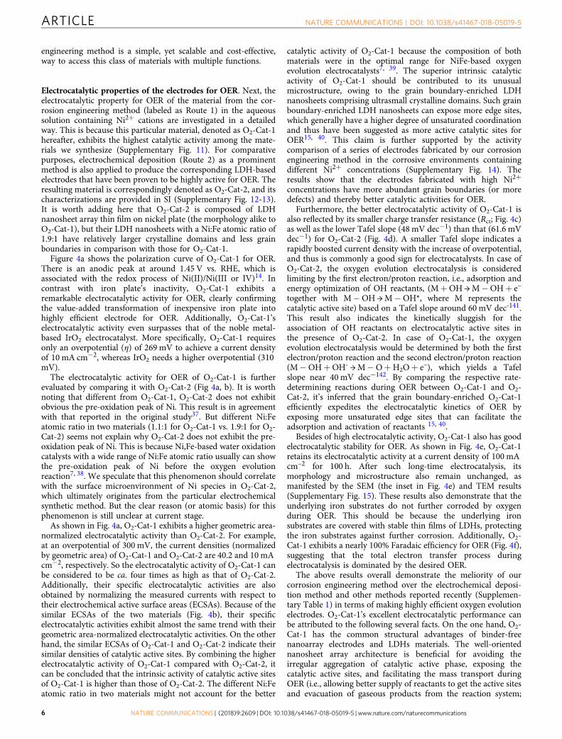
densities, in the order of 1000 mA cm−2 or more. Someresearchers even suggest a strict criterion: such electrodes shouldbe capable of achieving a current density of 500 mA cm−2 at anoverpotential of ≤300 mV27. In order to satisfy this requirement,our corrosion engineering method is extended to fabricate athree-dimensional O2-Cat-1 material (denoted as 3D-O2-Cat-1)by replacing iron plate with iron foam (see structural character-ization in Fig. 5a and Supplementary Fig. 17). Foam-likesubstrates with 3D macroporous architecture have been oftenused recently to increase exposed surface area and loadingamount of catalytic active species per geometric area9, 12. Forcomparison, three-dimensional O2-Cat-2 (denoted as 3D-O2-Cat-2) is also prepared according to the previously-reported method(see its digital and SEM images in Supplementary Fig. 18)37. Asexpected, 3D-O2-Cat-1 has a better electrocatalytic activity forOER than 3D-O2-Cat-2 (Supplementary Fig. 19).
As shown in Fig. 5b, 3D-O2-Cat-1 affords current densities of500 and 1000mA cm−2 at 300 and 340 mV in 1M KOH solution,respectively. The material requires smaller overpotentials of 257and 280mV to achieve the same current densities in 10M KOHsolution, which is employed as the electrolyte in current practicalwater-alkali electrolyzers43. These results demonstrate that the
1.2
3.0c
a
b
d
2.5
2.0
1.5
1.0
0.5
3.0
2.5
2.0
1.5
0.5
1.0
0
0 100 200 300 400 500
Time (h)
Time (h)
600 700 800 900 1000
500
Pot
entia
l (V
vs
RH
E)
Pot
entia
l (V
vs
RH
E)
50 h
1000 1500 2000 3000 4000 50002500 3500 4500
1200
1000
800
600
1 M KOH electrolyte10 M KOH electrolyte
400
200
0
1.3 1.4
E - iR (V vs RHE)
iR-corrected � (V)
� = 280 mV
� = 257 mV
� = 340 mV
� = 300 mV
1000 mA cm–2
1 M KOH
10 M KOH
1000 mA cm–2
3D-O2-Cat-2
3D-O2-Cat-1
0.0 0.1 0.2 0.3 0.4
1.5 1.6 1.7
j (m
A c
m–2
)
Fig. 5 Electrocatalytic properties for OER at large current densities. a Digital images and b iR-corrected polarization curves of 3D-O2-Cat-1 in 1 M (light blueline) and 10M (dark blue line) KOH electrolytes under an extended current window (0-1000mA cm−2). Scale bars, 1 mm and 0.5 cm (inset). cChronopotentiometric curves of 3D-O2-Cat-1 and 3D-O2-Cat-2 in 1 M KOH at a current density of 1000mA cm−2 (without iR-correction) dChronopotentiometric curve of 3D-O2-Cat-1 in 10M KOH at a current density of 1000mA cm−2 (without iR-correction)
NATURE COMMUNICATIONS | DOI: 10.1038/s41467-018-05019-5 ARTICLE
NATURE COMMUNICATIONS | (2018) 9:2609 | DOI: 10.1038/s41467-018-05019-5 |www.nature.com/naturecommunications 7
catalytic activity of 3D-O2-Cat-1 meets the activity requirementin practical water-splitting technology. In addition, to the best ofour knowledge, 3D-O2-Cat-1 is one of the most active oxygenevolution electrodes in alkaline media reported to date (Supple-mentary Table 1) 3–26.
To evaluate the stability of 3D-O2-Cat-1 at large currentdensities, the electrocatalytic OER is allowed to proceed for 5000h in 1M KOH solution (Fig. 5c), and then for 1050 h (Fig. 5d) in10M KOH solution at a current density of 1000 mA cm−2. Forcomparison, the catalytic stability of 3D-O2-Cat-2 is alsomeasured in 1M KOH solution at this current density. Theresults reveal that although 3D-O2-Cat-2 can retain their catalyticactivity at small current densities (Supplementary Fig. 20), thismaterial undergoes serious deactivation over 50 h at large currentdensities (Fig. 5c). The main cause of the observed seriousdeactivation is the peeling of catalytic active species (i.e., LDHthin film) from the metal substrates during the intense oxygenevolution process at large current densities (SupplementaryFig. 21). Similarly, the LDHs-based oxygen evolution electrode,fabricated by the hydrothermal deposition method13, also exhibitan observable deactivation at large current densities (Supplemen-tary Fig. 22). In contrast, 3D-O2-Cat-1 can keep its electro-catalytic activity unchanged for more than 6000 h (>8 months),suggesting the extraordinary structural and catalytic stability ofthe material for OER.
DiscussionIn summary, a corrosion engineering method has been presentedfor the value-added transformation of inexpensive iron substratesinto high-performance electrodes for OER. The key for themethod being successful is the introduction of suitable divalentcations in the corrosive environment, ultimately leading to thegeneration of nanosheet array thin films of layered doublehydroxides, instead of commonly-formed iron rusts, on ironsubstrates. The iron-substrate-derived electrodes exhibit goodcatalytic activity toward OER, and show remarkable catalyticstability for more than 6000 h (>8 months) at large currentdensities. Their excellent catalytic properties can be attributed totheir overall conducive structural features, including thenanosheet array architecture, ultrasmall crystalline domainswithin nanosheets and strongly coupled interface between LDHthin film and iron substrates. Overall, the electrodes presentedherein have great potential in large-scale commercial watersplitting technology, because they (i) are made from inexpensivestarting materials; (ii) are fabricated with easily scalable andenergy-efficient synthetic method; and (iii) can work well forlong-time OER at large current densities.
MethodsChemicals and reagents. Fe foam (FF) (thickness: 1.5 mm, bulk density: 0.45g cm-3, number of pores per inch: 90) was purchased from Kunshan Electronic Co.,Ltd. Fe plate (FP) (thickness: 0.3 mm) was purchased from Shanghai BaosteelGroup Corporation. Ni foam (NF) (thickness: 1.5 mm, bulk density: 0.23 g cm-3,number of pores per inch: 110) was purchased from Changsha Lyrun Material Co.,Ltd. Ni plate was purchased from Northeast Special Steel Refco Group Ltd. Nickelsulfate hexahydrate (NiSO4·6H2O), potassium hydroxide (KOH) and urea werepurchased from Beijing Chemical Factory. Nickel nitrate hexahydrate (Ni(NO3)2·6H2O), Ferric nitrate nonahydrate (Fe(NO3)3·9H2O) and Ferrous sulfateheptahydrate (Fe(SO4)2·7H2O) were purchased from Sinopharm Chemical ReagentCo., Ltd. Nickel chloride hexahydrate (NiCl2·6H2O) was purchased from TianjinHuadong Chemical Factory. Cobalt sulfate heptahydrate (CoSO4·7H2O) was pur-chased from Tianjin Guangfu Fine Chemical Research Institute. Manganese sulfatemonohydrate (MnSO4·H2O) was purchased from Xilong Chemical Reagent Co.,Ltd. Magnesium sulfate (MgSO4) was purchased from Tianjin Tianda ChemicalReagent Factory. Sodium hydroxide (NaOH) was purchased from SinopharmChemical Reagent Co., Ltd. Nafion® perfluorinated resin solution was purchasedfrom Sigma-Aldrich. Iridium dioxide (IrO2) was purchased from Shanghai MacklinBiochemical Co., Ltd. Highly purified water (>18 MΩ cm resistivity) was providedby a PALL PURELAB Plus system.
Corrosion engineering method. Iron substrates (iron plate or iron foam; 0.5 cm ×6 cm) were washed with acetone and ethanol several times to clean their surfacesfor further use. For the preparation of corrosive solution, a certain amount of nickelsalts (e.g., NiSO4·6H2O; 100 µmol) was added into 100 mL deionized water to makea transparent Ni2+ solution in a conical flask. The pH of the aqueous solutioncontaining NiSO4·6H2O is 5.88. And then the iron substrates were immersed in thecorrosive solution at room temperature (~25 °C) for 12 h. When iron plate wasused in the corrosion reaction, the resulting material was labeled as O2-Cat-1.When iron foam was used in the corrosion reaction, the resulting material waslabeled as 3D-O2-Cat-1. The loadings of LDH species for O2-Cat-1 and 3D-O2-Cat-1 were determined to be about 0.16 and 2.78 mg per geometric surface area.Moreover, a large-area O2-Cat-1 was prepared by immersing a rolled Fe plate (0.1m × 1 m) into 3000 mL of corrosive solution containing Ni2+ (0.1 mol L−1) atroom temperature for 12 h.
In addition, several other divalent cations (CoSO4·7H2O, MnSO4·H2O orMgSO4; 10 mmol) were also attempted to replace Ni2+ cations to generate thecorrosive solutions. The pH values of the aqueous solutions containingCoSO4·7H2O, MnSO4·H2O and MgSO4 are 5.90, 5.35, and 6.83, respectively.Correspondingly, the corrosion reactions resulted in the formation of the Co-containing, Mn-containing, or Mg-containing thin films on the iron substrates. Forcomparative purpose, we attempted to create the corrosive solutions using othercations with lower or higher valence states, such as Na+, K+, Cr3+, Ga3+, and Sn4+, in lieu of divalent cations.
Fabrication of control electrode materials. O2-Cat-2 and 3D-O2-Cat-2 wereprepared according to the previous report37. Briefly, the reaction electrolyte wasprepared by dissolving Ni(NO3)2·6H2O (2.18 g, 7.5 mmol) and Fe(SO4)2·7H2O(2.09 g, 7.5 mmol) into 50 mL of deionized water. After mixed under N2 flow, theelectrolyte was transferred into an electrochemical cell. For integrating three-electrode configuration, Ni-based substrates (Ni plate or Ni foam) were used as theworking electrode. And Pt wire and saturated calomel electrode (SCE) were used asthe counter and reference electrode, respectively. After a potentiostatic depositionat a potential of −1.0 V vs. SCE for 300 s, O2-Cat-2 and 3D-O2-Cat-2 were fab-ricated, depending on whether the use of Ni plate or Ni foam as the substrates.
The LDH-based electrode was synthesized from hydrothermal methodaccording to previous report13. Ni(NO3)2·6H2O (0.3 g, 1 mmol), Fe(NO3)3·9H2O(0.4 g, 1 mmol) and urea (0.3 g, 5 mmol) were dissolved into deionized water (80mL) under vigorous stirring. Then a piece of cleaned Ni foam (0.5 cm × 5 cm) andthe as-prepared solution was transferred into an autoclave and maintained at 120 °C for 12 h. The resulting material was washed with ethanol three times and dried invacuum at room temperature, giving the LDH-based electrode.
Characterizations. The powder X-ray diffraction (XRD) patterns were recordedon a Rigaku D/Max 2550 X-ray diffractometer with Cu Kα radiation (λ= 1.5418Å). The scanning electron microscope (SEM) images were obtained with a JEOLJSM 6700 F electron microscope. The transmission electron microscope (TEM)images were obtained with a Philips-FEI Tecnai G2S-Twin microscope equippedwith a field emission gun operating at 200 kV. High-resolution STEM measure-ments were performed on an atomic resolution analytical microscope (JEM-ARM200 F) operating at 200 kV. The X-ray photoelectron spectroscopy (XPS) wasperformed on an ESCALAB 250 X-ray photoelectron spectrometer with a mono-chromatic X-ray source (Al Kα hυ= 1486.6 eV). The energy scale of the spectro-meter was calibrated using Au 4f7/2, Cu 2p3/2 and Ag 3d5/2 peak positions. Thestandard deviation for the binding energy (BE) values was 0.1 eV. Inductivelycoupled plasma atomic emission spectroscopy (ICP-OES) was performed on aPerkin-Elmer Optima 3300DV ICP spectrometer.
Electrochemical measurements. All electrochemical measurements were con-ducted in a standard three-electrode configuration with a CH Instrument (Model660E). The materials (O2-Cat-1, O2-Cat-2, etc.) were used as working electrode.Hg/HgO electrode and Pt plate were used as reference and counter electrodes,respectively. Before the electrochemical measurements, a surface area of 0.09 cm2
on each electrode keeps exposed, with the rest of the electrode sealed with hot meltadhesives. In addition, the catalytic activity of powdered IrO2 was measured byloading it on the iron plate with optimal loading amount (0.4 mg for 0.09 cm2,Supplementary Fig. 23), and a polymer binder (Nafion) was also introduced for apurpose of fixation. Although IrO2 is widely used as the benchmark electrocatalystfor OER, this material is not catalytically stable enough in alkaline media. Thus, thelong-time stability of IrO2 for OER was not measured here. During the electro-chemical measurements, the electrolyte in electrochemical cell was continuouslybubbled with N2, and current densities were normalized with the geometric surfaceareas of the electrodes. For linear sweep voltammetry (LSV) measurements, thescan rate was set to 1 mV s−1, and the resistances of the test system were estimatedfrom corresponding single-point impedance measurements and compensated by85% iR-drop.
The Hg/HgO electrode was calibrated by the method reported by Boettcher andco-workers44. Briefly, two Pt electrodes were first polished and cycled in 0.5 MH2SO4 (about ±2 V for 2 h) for cleaning purpose, and then employed as workingelectrode (WE) and counter electrode (CE) in 10M KOH electrolyte. The
ARTICLE NATURE COMMUNICATIONS | DOI: 10.1038/s41467-018-05019-5
8 NATURE COMMUNICATIONS | (2018) 9:2609 | DOI: 10.1038/s41467-018-05019-5 | www.nature.com/naturecommunications
electrolyte was saturated by hydrogen before use, and continuous H2 was bubbledover the WE during the calibration. To perform the calibration, a series ofcontrolled-potential chronoamperometric curves were carried out around thepossible zero current potential (the interconversion between the hydrogenoxidation and hydrogen evolution reaction) determined by a wide-ranged LSVmeasurement swept in a cathode direction. In such chronoamperometricmeasurements, each potential is held constant for 300 s to reach a steady-statevalue, which is a more reliable value avoiding the possible polarization effects andthe contribution of capacitive current. As shown in Supplementary Fig. 24, theresult shows that the potential of zero net current can be estimated at −0.983 V vs.the Hg/HgO electrode, and the relation between the Hg/HgO reference and RHE in10M KOH solution can thus be established using the equation: ERHE= EHg/HgO+0.983 V. By using the same method, the relation between the Hg/HgO referenceand RHE in 1M KOH solution was also established using the equation: ERHE=EHg/HgO+ 0.926 V
Electrochemical impedance spectroscopy (EIS) was performed on the materialsunder the operating conditions for OER. The initial potential at the electrode wasset as 1.582 V vs. RHE. A sinusoidal voltage with an amplitude of 5 mV and ascanning frequency ranging from 10,000 to 0.01 Hz were applied to carry out themeasurements.
In order to get the effective electrochemical active surface area (ECSA) of amaterial, a series of cyclic voltammetry (CV) measurements were performed first atvarious scan rates (20, 40, 60 mV s−1, etc.) in the potential window between 1.112and 1.212 V vs. RHE. The sweep segments of the measurements were set to 10 toensure consistency. By plotting the difference of current density (J) between theanodic and cathodic sweeps (Janodic− Jcathodic) at 1.162 V vs. RHE against the scanrate, a linear trend was constructed. Then, the geometric double layer capacitance(Cdl) was easily calculated because Cdl is one half the slope value of the fitting line.Finally, the ECSA of catalyst is estimated from the double-layer capacitanceaccording to the equation:
ECSA ¼ Cdl
Cs´ASA;
where Cs is the specific capacitance of the sample, and ASA is the actual surfacearea of the electrode. In this work, the value of Cs is estimated to be 0.04 mF cm−2.
In order to determine the Faradic efficiency of an electrode in OER, the O2 gasgenerated by the electrochemical reaction was collected by a water drainagemethod and its amount (in mol) was calculated using the ideal gas law. Thetheoretical value was calculated by assuming that 100% of the current outputduring the reaction was originated from the OER. Faradic efficiency was thenobtained by calculating the ratio of the amount of O2 evolved during OER to theamount of O2 expected to generate based on theoretical considerations.
In order to determine whether Fe and Ni ions were leached in the electrolyte athigh current density, we used ICP-OES to detect the Fe and Ni ions in theelectrolyte during the long-time electrolysis process at 1000 mA cm-2 in thepresence of 3D-O2-Cat-1. The electrolyte was collected after 2, 4, 6, 8, 10, 34, and58 h during operation, and the results shown in Supplementary Table 2 reveal thatno detectable leached metallic species are present in the electrolyte.
Data availability. The authors declare that the data supporting the findings of thisstudy are available within the paper and its supplementary information files.
Received: 4 February 2018 Accepted: 11 June 2018
References1. Zou, X. & Zhang, Y. Noble metal-free hydrogen evolution catalysts for water
splitting. Chem. Soc. Rev. 44, 5148–5180 (2015).2. Seh, Z. W. et al. Combining theory and experiment in electrocatalysis: insights
into materials design. Science 355, 146–157 (2017).3. Hunter, B. M., Gray, H. B. & Müller, A. M. Earth-abundant heterogeneous
water oxidation catalysts. Chem. Rev. 116, 14120–14136 (2016).4. Suen, N. T. et al. Electrocatalysis for the oxygen evolution reaction: recent
development and future perspectives. Chem. Soc. Rev. 46, 337–365 (2017).5. Han, L., Dong, S. & Wang, E. Transition-metal (Co, Ni, and Fe)-based
electrocatalysts for the water oxidation reaction. Adv. Mater. 28, 9266–9291(2016).
6. Wang, H. et al. Bifunctional non-noble metal oxide nanoparticleelectrocatalysts through lithium-induced conversion for overall water splitting.Nat. Commun. 6, 7261 (2015).
7. Louie, M. W. & Bell, A. T. An investigation of thin-film Ni-Fe oxide catalystsfor the electrochemical evolution of oxygen. J. Am. Chem. Soc. 135,12329–12337 (2013).
8. Zhang, B. et al. Homogeneously dispersed multimetal oxygen-evolvingcatalysts. Science 352, 333–337 (2016).
9. Lu, X. & Zhao, C. Electrodeposition of hierarchically structured three-dimensional nickel-iron electrodes for efficient oxygen evolution at highcurrent densities. Nat. Commun. 6, 6616 (2015).
10. Guo, C. X. & Li, C. M. Room temperature-formed iron-doped nickelhydroxide on nickel foam as a 3D electrode for low polarized and high-current-density oxygen evolution. Chem. Commun. 54, 3262–3265 (2018).
11. Zou, X. et al. Ultrafast formation of amorphous bimetallic hydroxide films on3D conductive sulfide nanoarrays for large-current-density oxygen evolutionelectrocatalysis. Adv. Mater. 29, 1700404 (2017).
12. Lu, Z. et al. Three-dimensional NiFe layered double hydroxide film for high-efficiency oxygen evolution reaction. Chem. Commun. 50, 6479–6482 (2014).
13. Luo, J. et al. Water photolysis at 12.3% efficiency via perovskite photovoltaicsand Earth-abundant catalysts. Science 345, 1593–1596 (2014).
14. Gong, M. et al. An advanced Ni-Fe layered double hydroxide electrocatalystfor water oxidation. J. Am. Chem. Soc. 135, 8452–8455 (2013).
15. Song, F. & Hu, X. Exfoliation of layered double hydroxides for enhancedoxygen evolution catalysis. Nat. Commun. 5, 4477 (2014).
16. Wang, Y. et al. Layered double hydroxide nanosheets with multiple vacanciesobtained by dry exfoliation as highly efficient oxygen evolutionelectrocatalysts. Angew. Chem. Int. Ed. 56, 5867–5871 (2017).
17. Zou, X., Goswami, A. & Asefa, T. Efficient noble metal-free (electro)catalysisof water and alcohol oxidations by zinc-cobalt layered double hydroxide. J.Am. Chem. Soc. 135, 17242–17245 (2013).
18. Fan, K. et al. Nickel-vanadium monolayer double hydroxide for efficientelectrochemical water oxidation. Nat. Commun. 7, 11981 (2016).
19. Jia, Y. et al. A heterostructure coupling of exfoliated Ni-Fe hydroxidenanosheet and defective graphene as a bifunctional electrocatalyst for overallwater splitting. Adv. Mater. 29, 1700017 (2017).
20. Zhao, Q., Yan, Z., Chen, C. & Chen, J. Spinels: controlled preparation, oxygenreduction/evolution reaction application, and beyond. Chem. Rev. 117,10121–10211 (2017).
21. Ma, T. Y., Dai, S., Jaroniec, M. & Qiao, S. Z. Metal-organic framework derivedhybrid Co3O4-carbon porous nanowire arrays as reversible oxygen evolutionelectrodes. J. Am. Chem. Soc. 136, 13925–13931 (2014).
22. Cheng, F. et al. Rapid room-temperature synthesis of nanocrystalline spinelsas oxygen reduction and evolution electrocatalysts. Nat. Chem. 3, 79–84(2011).
23. Tang, T. et al. Electronic and morphological dual modulation of cobaltcarbonate hydroxides by Mn doping toward highly efficient and stablebifunctional electrocatalysts for overall water splitting. J. Am. Chem. Soc. 139,8320–8328 (2017).
24. Hwang, J. et al. Perovskites in catalysis and electrocatalysis. Science 358,751–756 (2017).
25. Suntivich, J., May, K. J., Gasteiger, H. A., Goodenough, J. B. & Shao-Horn, Y.A perovskite oxide optimized for oxygen evolution catalysis from molecularorbital principles. Science 334, 1383–1385 (2011).
26. Zhao, B. et al. A tailored double perovskite nanofiber catalyst enables ultrafastoxygen evolution. Nat. Commun. 8, 14586 (2017).
27. Smith, R. D. et al. Photochemical route for accessing amorphous metal oxidematerials for water oxidation catalysis. Science 340, 60–63 (2013).
28. Morales-Guio, C. G., Stern, L. A. & Hu, X. Nanostructured hydrotreatingcatalysts for electrochemical hydrogen evolution. Chem. Soc. Rev. 43,6555–6569 (2014).
29. Zhu, L. et al. A rhodium/silicon co-electrocatalyst design concept to surpassplatinum hydrogen evolution activity at high overpotentials. Nat. Commun. 7,12272 (2016).
30. Ritter, S. K. Fuel from the sun: cobalt water-oxidation catalysts benefit fromfederal initiatives to harness solar power to make fuel. Chem. Eng. News 88, 26(2010).
31. Xu, S.-M., Yan, H. & Wei, M. Band structure engineering of transition-metal-based layered double hydroxides toward photocatalytic oxygen evolution fromwater: a theoretical–experimental combination study. J. Phys. Chem. C 121,2683–2695 (2017).
32. He, J. et al. Preparation of layered double hydroxides. Struct. Bond 119,89–119 (2006).
33. Cavani, F., Trifirò, F. & Vaccari, A. Hydrotalcite-type anionic clays:preparation, properties and applications. Catal. Today 11, 173–301 (1991).
34. Wang, Q. & O’Hare, D. Recent advances in the synthesis and application oflayered double hydroxide (LDH) nanosheets. Chem. Rev. 112, 4124–4155(2012).
35. Guo, X., Zhang, F., Evans, D. G. & Duan, X. Layered double hydroxide films:synthesis, properties and applications. Chem. Commun. 46, 5197–5210 (2010).
36. Perez, N. Electrochemistry and Corrosion Science. Vol. 412 (Springer, NewYork, 2004).
37. Li, Z. et al. Fast electrosynthesis of Fe-containing layered double hydroxidearrays toward highly efficient electrocatalytic oxidation reactions. Chem. Sci. 6,6624–6631 (2015).
NATURE COMMUNICATIONS | DOI: 10.1038/s41467-018-05019-5 ARTICLE
NATURE COMMUNICATIONS | (2018) 9:2609 | DOI: 10.1038/s41467-018-05019-5 |www.nature.com/naturecommunications 9

38. Stevens, M. B., Trang, C. D. M., Enman, L. J., Deng, J. & Boettcher, S. W.Reactive Fe-sites in Ni/Fe (Oxy)hydroxide are responsible for exceptionaloxygen electrocatalysis activity. J. Am. Chem. Soc. 139, 11361–11364 (2017).
39. Friebel, D. et al. Identification of highly active Fe sites in (Ni,Fe)OOH forelectrocatalytic water splitting. J. Am. Chem. Soc. 137, 1305–1313 (2015).
40. Tang, C. et al. Spatially confined hybridization of nanometer-sized NiFehydroxides into nitrogen-doped graphene frameworks leading to superioroxygen evolution reactivity. Adv. Mater. 27, 4516–4522 (2015).
41. Park, J. et al. Iridium-based multimetallic nanoframe@nanoframe structure:an efficient and robust electrocatalyst toward oxygen evolution reaction. ACSNano 11, 5500–5509 (2017).
42. Burke, M. S., Kast, M. G., Trotochaud, L., Smith, A. M. & Boettcher, S. W.Cobalt-iron (oxy)hydroxide oxygen evolution electrocatalysts: the role ofstructure and composition on activity, stability, and mechanism. J. Am. Chem.Soc. 137, 3638–3648 (2015).
43. Hall, D. E. Alkaline water electrolysis anode materials. J. Electrochem. Soc. 132,41C (1985).
44. Stevens, M. B. et al. Measurement techniques for the study of thin filmheterogeneous water oxidation electrocatalysts. Chem. Mater. 29, 120–140(2016).
AcknowledgementsX.Z. acknowledges the financial support from the NSFC 21771079, National Key R&DProgram of China, Grant No. 2017YFA0207800, Jilin Province Science and TechnologyDevelopment Plan 20170101141JC, Young Elite Scientist Sponsorship Program byCAST, Program for JLU Science and Technology Innovative Research Team (JLUSTIRT)and Fok Ying Tung Education Foundation, Grant No.161011.
Author contributionsX.Z. conceived the idea, analyzed the data and wrote the manuscript. Y.L. synthesizedand characterized the materials, analyzed the data and wrote the manuscript. X.L., G.-D.L., Y.Z. and J.-S.C. assisted Y.L. with the materials synthesis, electrochemical
measurements and analysis. L.G. performed the TEM measurement. All of the authorshave read the manuscript and agree with its content.
Additional informationSupplementary Information accompanies this paper at https://doi.org/10.1038/s41467-018-05019-5.
Competing interests: The authors declare no competing interests.
Reprints and permission information is available online at http://npg.nature.com/reprintsandpermissions/
Publisher's note: Springer Nature remains neutral with regard to jurisdictional claims inpublished maps and institutional affiliations.
Open Access This article is licensed under a Creative CommonsAttribution 4.0 International License, which permits use, sharing,
adaptation, distribution and reproduction in any medium or format, as long as you giveappropriate credit to the original author(s) and the source, provide a link to the CreativeCommons license, and indicate if changes were made. The images or other third partymaterial in this article are included in the article’s Creative Commons license, unlessindicated otherwise in a credit line to the material. If material is not included in thearticle’s Creative Commons license and your intended use is not permitted by statutoryregulation or exceeds the permitted use, you will need to obtain permission directly fromthe copyright holder. To view a copy of this license, visit http://creativecommons.org/licenses/by/4.0/.
© The Author(s) 2018
ARTICLE NATURE COMMUNICATIONS | DOI: 10.1038/s41467-018-05019-5
10 NATURE COMMUNICATIONS | (2018) 9:2609 | DOI: 10.1038/s41467-018-05019-5 | www.nature.com/naturecommunications
Related Documents


![Research Article Inhibition of Mild Steel Corrosion in ...molecules [ , ]. Most prominent corrosion inhibitors are organic compounds containing nitrogen, sulphur, oxygen, and phosphorus](https://static.cupdf.com/doc/110x72/60fea18a3d9dd305112a482a/research-article-inhibition-of-mild-steel-corrosion-in-molecules-most.jpg)


