HAL Id: hal-01592775 https://hal.archives-ouvertes.fr/hal-01592775 Submitted on 25 Sep 2017 HAL is a multi-disciplinary open access archive for the deposit and dissemination of sci- entific research documents, whether they are pub- lished or not. The documents may come from teaching and research institutions in France or abroad, or from public or private research centers. L’archive ouverte pluridisciplinaire HAL, est destinée au dépôt et à la diffusion de documents scientifiques de niveau recherche, publiés ou non, émanant des établissements d’enseignement et de recherche français ou étrangers, des laboratoires publics ou privés. Correlation of the high and very high cycle fatigue response of ferrite based steels with strain rate-temperature conditions Noushin Torabian, Véronique Favier, Justin Dirrenberger, Frédéric Adamski, Saeed Ziaei-Rad, Nicolas Ranc To cite this version: Noushin Torabian, Véronique Favier, Justin Dirrenberger, Frédéric Adamski, Saeed Ziaei-Rad, et al.. Correlation of the high and very high cycle fatigue response of ferrite based steels with strain rate-temperature conditions. Acta Materialia, Elsevier, 2017, 134, pp.40-52. 10.1016/j.actamat.2017.05.064. hal-01592775

Welcome message from author
This document is posted to help you gain knowledge. Please leave a comment to let me know what you think about it! Share it to your friends and learn new things together.
Transcript

HAL Id: hal-01592775https://hal.archives-ouvertes.fr/hal-01592775
Submitted on 25 Sep 2017
HAL is a multi-disciplinary open accessarchive for the deposit and dissemination of sci-entific research documents, whether they are pub-lished or not. The documents may come fromteaching and research institutions in France orabroad, or from public or private research centers.
L’archive ouverte pluridisciplinaire HAL, estdestinée au dépôt et à la diffusion de documentsscientifiques de niveau recherche, publiés ou non,émanant des établissements d’enseignement et derecherche français ou étrangers, des laboratoirespublics ou privés.
Correlation of the high and very high cycle fatigueresponse of ferrite based steels with strain
rate-temperature conditionsNoushin Torabian, Véronique Favier, Justin Dirrenberger, Frédéric Adamski,
Saeed Ziaei-Rad, Nicolas Ranc
To cite this version:Noushin Torabian, Véronique Favier, Justin Dirrenberger, Frédéric Adamski, Saeed Ziaei-Rad,et al.. Correlation of the high and very high cycle fatigue response of ferrite based steelswith strain rate-temperature conditions. Acta Materialia, Elsevier, 2017, 134, pp.40-52.�10.1016/j.actamat.2017.05.064�. �hal-01592775�

Full length article
Correlation of the high and very high cycle fatigue response of ferritebased steels with strain rate-temperature conditions
Noushin Torabian a, b, *, V�eronique Favier a, Justin Dirrenberger a, Fr�ed�eric Adamski a,Saeed Ziaei-Rad b, Nicolas Ranc a
a Laboratoire PIMM, Arts et M�etiers Paris Tech, CNAM, CNRS, Paris 75013, Franceb Department of Mechanical Engineering, Isfahan University of Technology, Isfahan 84156-83111, Iran
a b s t r a c t
The discrepancies observed between conventional and ultrasonic fatigue testing are assessed throughthe mechanisms of dislocation mobility in BCC metals. The existence of a transition condition betweenthermally-activated and athermal regimes for screw dislocation mobility is studied under fatigue loadingbased on infrared thermography and microstructural characterization, here in the case of DP600 dual-phase steel. Evidence is obtained regarding the microstructural sources of crack initiation, which isfound to be consistent with the existence of a transition in the modes of deformation. From the analysisof the experimental data gathered in this work, guidelines are given regarding the comparison andinterpretation of S-N curves obtained from conventional and ultrasonic fatigue testing. The inevitabletemperature increases under ultrasonic fatigue at high stress amplitudes along with the rate dependentdeformation behavior of ferrite, as a BCC structure, were found as the key parameters explaining theobserved fatigue behavior and thermal response under low and ultrasonic frequencies. A transition mapwas produced using the experimental results for DP600 steel as well as data available in the literature forother ferrite based steels, showing the correlation between thermally-activated screw dislocationmovement and the absence of failure in very high cycle fatigue.
1. Introduction
The increased demand for material fatigue characterization ingigacycle regimes has provoked further use and development ofultrasonic fatigue testing systems. Owing to a high frequency ofusually 20 kHz, this loading technique allows to reach very highnumber of cycles up to N ¼ 109 in a reasonable time and at lowercosts compared to conventional low frequency loadings. However,this accelerated testing method has been always accompanied by amain question: are the fatigue properties obtained from ultrasonicloading similar to those measured by conventional low frequencytesting? The answer has remained unclear for most metallic ma-terials [1] and thus the so-called “frequency effect” has beencontroversial among researchers [2].
Generally, the influence of frequency stems from two mainsources: strain rate effects and time dependent influence of
environment. The former is the case for high ductility and strainrate sensitive materials such as low-carbon steels while the latterhas been reported for some FCC materials such as aluminum alloys[2e5]. Low- and medium-carbon ferritic steels exhibit cleardiscrepancy between fatigue life and fatigue strength, obtainedfrom ultrasonic loading and those measured from conventionalfatigue tests [2]. In this case, as a general trend, ultrasonic loadingsproduce higher fatigue lives than low frequency tests. The elevatedfatigue life and fatigue limit under ultrasonic loading has beenmostly attributed to the increase of yield strength due to increasingthe strain rate [2,4,6e10]. Tsutsumi et al. [6] reported that thelonger fatigue life and the higher fatigue limit of low-carbon steelsunder ultrasonic fatigue are due to a reduction in crack tip cyclicplasticity and subsequent lower crack growth rate during ultrasonicloading. A surface-to-internal-crack initiation transition has beenreported by Furuya et al. [11] as the cause of longer fatigue life ofultrafine-grain steel under ultrasonic fatigue testing.
Guennec et al. [10] attributed the higher fatigue life and fatiguestrength of low-carbon steel, under ultrasonic loading to transitionof crack initiation mode from the usual transgranular, often
* Corresponding author. Laboratoire PIMM, Arts et M�etiers Paris Tech, CNAM,CNRS, Paris 75013, France.
E-mail address: [email protected] (N. Torabian).

reported at lower loading frequencies, to intergranular crack initi-ation at ultrasonic frequencies. They [9,10] showed that under usualfrequencies of 0.2e140 Hz, dislocation dipoles as ladder or cellstructures are induced whereas in the case of 20-kHz ultrasonicloading, long segments of screw dislocations are produced. Theseresults revealed the fact that the screw dislocations were nearlyimmobile during the conducted ultrasonic tests.
The effect of frequency on fatigue properties of low- andmedium-carbon steels results from a particular behavior of BCC structure offerrite grains contained in these steels. In BCCmetals, the flow stressdepends strongly on temperature and strain rate at low tempera-tures. Itwasfirst proposed by Seeger [12] that for BCCmetals theflowstress, s, can be separated into an athermal component sG, and athermal or effective component s*, ass ¼ sG þ s*ð _ε; TÞ. The athermalcomponent is the stress that a gliding dislocation requires to over-come the long range elastic interaction with other dislocations. Thethermal or effective component is the stress required for screw dis-locations to overcome short obstacles by thermally-activated mech-anisms. This thermal component depends on temperature T , andstrain rate _ε and becomes negligible above a transition temperature,T0 (or below a transition strain rate, _ε0). For cyclic loading, Mughrabiet al. [13] defined two deformation regimes based on the transitiontemperature: (1) the thermally-activated mode (T < T0) where thescrew dislocations are immobile and edge dislocations move to-and-fro in a non-hardening quasi-recoverable manner (2) the athermalregime (T > T0) where the mobilities of screw and edge dislocationsare equivalent and screw dislocations can cross slip. In this regime,rearrangement of dislocations can take place and strain localizationcan occur in slip bands. The transition temperature T0 is highly strainrate dependent and can be shifted to higher values by increasing thestrain rate. Therefore, the thermally-activated regime can be reachedathigh temperatures providing that the strain rate is sufficiently high.
On the contrary to low and medium strength steels, high alloyand high strength steels (e.g. martensitic stainless steels) are lesssusceptible to frequency effects and often there is a good agree-ment between their fatigue life obtained from ultrasonic loadingsand that measured from low frequency fatigue tests [14e18]. Ac-cording to Mayer [2], why the fatigue properties of high strengthsteels are not sensitive to the loading frequency is due to the verysmall plastic strain rate involved in high-cycle-fatigue (HCF) andvery-high-cycle fatigue (VHCF) loadings of these materials.
As mentioned previously, strain rate and environmental effectsare considered as the main causes of frequency effects in ultrasonicfatigue loading. Because of the high frequency, significant tem-perature rises can occur under ultrasonic fatigue loading of metalsespecially at high stress amplitudes [19]. Thus, temperature can beconsidered as a third cause of frequency effect in ultrasonic testing[4,6]. Since heating can usually be avoided by cooling the specimenduring the test or by employing intermittent loadings, temperaturehas not been commonly considered as an effective factor on ma-terial fatigue response but is recognized as a rather fictitious effectwhich should be excluded by effective cooling or measuring bypulse-pause testing. However, the effect of heat generation cannotbe impeded for all materials under ultrasonic fatigue loading evenby cooling the specimen and using a pulse-pause mode [20e22].The presence of inevitable heating effects under ultrasonic tests athigh stress amplitudes has been already confirmed in a previouswork of the authors for ferritic-martensitic steel [23]. Peng et al.[21] stated that for structural steels with low tensile strength thespecimen is prone to heating and burning at high stress amplitudeseven by employing intermittent loading along with cooling sys-tems. Yu et al. [20] affirmed that for bainite-martensite steels underintermittent ultrasonic loading, when the stress level is high, thegenerated heat cannot be dissipated effectively in spite of maxi-mizing the interruption time and minimizing the oscillation time.
Ranc et al. [24] reported strong temperature increase up to fewhundreds of degrees for C45 steel under ultrasonic loading, in spiteof using cooling systems.
In a variety of research works on fatigue loading on BCC mate-rials, the temperature increase has been reported to be less than100 �C, therefore the effect of temperature increase on the fatigueand deformation of the material has not been studied (see forexample [4,10,24e26]). However, concerning the temperaturedependent flow behavior of BCC structures, even these limitedamounts of temperature increase should be taken into account.Moreover, studies involving ultrasonic frequency effects weremainly focused on the effect of frequency on fatigue lifetime, fa-tigue strength, crack initiation mechanisms, crack growth rate, anddislocation mechanisms. In spite of the importance of temperatureon fatigue response of BCC materials, there is a lack of investigationabout the mechanisms behind the temperature increase under fa-tigue loading and the influences which it imposes on fatiguebehavior of the material.
The present work aims at explaining the high and very highcycle fatigue behavior of BCC structures accounting for strain rateand temperature effects. DP600 dual-phase steel which consists ofa ferrite matrix containing martensite islands was investigatedunder 20-kHz ultrasonic loading as well as conventional low fre-quency fatigue tests. In both cases, the S-N curves were obtainedand the effect of frequency on fatigue life and fatigue limit wasstudied. Fractography studies were conducted and effect of fre-quency on crack initiation and material failure was investigated.Moreover, thermographic measurements were performed andmechanisms were proposed to explain the observed abnormalthermal response of the material under ultrasonic loading andcorrelate it to the fatigue and deformation behavior. A strain rate-temperature transition map was developed to correlate the fa-tigue response of the material to deformation mechanisms bygathering the results of the present paper and data from literaturefor ferrite based steels.
2. Material and experiments
The material studied in this research was a commercial DP600dual-phase steel. This ferritic-martensitic steel which contains15wt %martensitewas received as sheets of 3.6mm thickness fromArcelorMittal. The chemical composition and the mechanicalproperties of the material are presented in Tables 1 and 2, respec-tively. Ultrasonic and conventional low frequency fatigue testswere carried out by using a piezoelectric 20-kHz system and a 10-kN servo-hydraulic MTS machine, respectively. All fatigue testswere performed under fully reversed tension-compression condi-tions (R¼�1). Hourglass-shaped specimens with rectangular crosssection were used with the geometries shown in Fig. 1. The di-mensions of ultrasonic fatigue samples were obtained by solvingthe vibration equations in order to reach a resonant vibration fre-quency of 20 kHz for the specimen. The conventional fatiguespecimens were designed so that for the same displacementamplitude, the stress distribution in the neighborhood of thespecimen center is equivalent to that of ultrasonic specimen [27].Ultrasonic fatigue tests are displacement-controlled while con-ventional fatigue loadings are performed under load-controlledconditions. In both cases loading amplitude was low so that the
Table 1DP600 chemical composition [28].
Alloying element Mn Ni Si Cr C Al Nb% weight 0.933 0.020 0.213 0.727 0.0748 0.039 0.0425

specimen deformed elastically from the macroscopic viewpoint.Therefore the difference in loading conditions does not have astrong impact on the results [2,4]. All specimens were electro-polished aftermechanical polishing in order to remove any inducedresidual stresses and to minimize the size effects [9]. In the case ofultrasonic tests a continuous loading technique was employed(pulse-pause mode was not used) and an air-cooling system wasused to cool down the specimen. Moreover, in situ infrared ther-mography was employed to record the mean temperature on thespecimen surface under fatigue loadings. In all cases the tempera-ture was measured at the center of the gauge part of the specimenin a circular area with a diameter of ~1 mm. The details of tem-perature measurement method can be found in Ref. [23].
3. Experimental results
3.1. S-N curves
The S-N curves were obtained by 20-kHz ultrasonic loadingsalong with cooling the specimen with compressed air, and also by30-Hz conventional fatigue tests. The obtained S-N data is pre-sented in Fig. 2. It can be seen that for a given stress amplitude sa,the fatigue lifetimemeasured by ultrasonic loadingwas higher thanthat obtained from conventional tests. The number of cycles at theknee point obtained at 30 Hz was ~2 � 106 cycles, whereas thecorresponding value at 20 kHz was ~3 � 108 cycles. For a given
number of cycles ranging from 106 to 107, where the data exists forboth loading techniques, the fatigue strength is higher at 20 kHzthan at 30 Hz. However, both frequencies have resulted in the samefatigue limit of sD ¼ 260±5 MPa.
Based on infrared thermography measurements, in the case ofultrasonic loadings at stress amplitudes above the fatigue limit (allpoints in the S-N diagram excluding the run-out points), strongheating occurred in the early stages of cycling, leading to significanttemperature increases up to ~350 �C. However, at stress amplitudesbelow the fatigue limit, the temperature remained below 40 �C. Thehigh temperature increases at high stress amplitudes could not beavoided even by using air-cooling systems. In the case of 30-Hzfrequency, temperature increase was negligible (DT<15 �C) incomparison with ultrasonic loadings and no cooling system wasrequired.
3.2. Fractography studies
Fracture surfaces of all conventional and ultrasonic rupturedspecimens were investigated by Scanning Electron Microscopy(SEM) and representative results are presented in Figs. 3 and 4 forsome of the samples. For all specimens ruptured under 30-Hz fre-quency loading, the macroscopic fatigue crack initiated from thespecimen surface. In this case, both single and multiple crackinitiation sites were detected, as shown by yellow arrows in Fig. 3.The ductile relief of the surface without any trace of grain bound-aries suggests the occurrence of transgranular crack propagation.This observation is consistent with the observations of microcrackswithin some slip bands at the surface of the specimen (see Section3.3.).
Fig. 4 shows the fractography results for the 20-kHz loading.Under ultrasonic fatigue tests, the crack initiation leading to themacroscopic failure was mainly internal however some cases ofsurface crack initiation were also observed. In this case, crackinitiation was always inclusion-induced for both internal and sur-face crack initiations. For instance, Fig. 4(a) shows an inclusion-induced surface initiation sample for a specimen ruptured atN ¼ 6 � 106 cycles at stress amplitude of 286 MPa. Fig. 4(b) showsthe higher magnification of Fig. 4(a), in which inclusions can beseen on the specimen surface, as the cause of surface crack initia-tion. An internal inclusion-induced crack initiation leading to fish-eye fracture after N ¼ 6.1 � 107 cycles at sa ¼ 275 MPa is presentedin Fig. 4(c). A higher magnification of this image showing the in-clusion in the center of the fish-eye is depicted in Fig. 4(d). In mostcases, non-metallic inclusions such as Al2O3, SiO2, MgO, and CaO orsulfides are observed in the center of fish-eyes for structuralmetallic materials [16,29,30]. In our case, energy-dispersive spec-troscopy (EDS) analysis revealed that the inclusions consist mainlyof aluminum, magnesium and oxygen. Fig. 4(d) shows that particle-matrix debonding has occurred which can be a part of fatigue crackformation [30].
3.3. Surface observations
Interrupted fatigue tests were conducted and the surface of thespecimens was observed by SEM at different loading stages. Allobservations were made along the central axis of the specimenaround the center of the gauge part. Fig. 5 shows the SEM
Table 2Mechanical properties of DP600 steel [28].
Young’s Modulus (GPa) Yield strength (MPa) Ultimate tensile strength (MPa) Elongation (%)
210 440 650 20
(a)
(b)Fig. 1. (a) Ultrasonic fatigue specimen (b) Conventional fatigue specimen (dimensionsare in mm).

micrograph of a specimen loaded by 20-kHz frequency at stressamplitude of sa ¼ 260 MPa, corresponding to the obtained fatiguelimit, after N ¼ 1.6 � 109 cycles. The specimen was cooled duringthe test by an air-cooling system and the mean temperature wasbelow 40 �C. The same observations were carried out for a spec-imen loaded by 30-Hz frequency at sa ¼ 250MPa, below the fatiguelimit, after N¼ 2� 105 cycles and N¼ 107 cycles and the results arepresented in Fig. 6. In Fig. 5 the dark phase is ferrite and the brightphase is martensite. Since in the case of conventional 30-Hz fre-quency the experiment was long, the specimen surface was not soclean after loading. This is why the contrast in Fig. 6 is differentfrom Fig. 5 and ferrite and martensite phases cannot be easilydistinguished especially in Fig. 6 (b). In the case of ultrasonicloading no slip band (SB) was observed on the specimen surfaceeven after 109 cycles. On the other hand, for 30-Hz conventionalloading, SBs formed in ferrite grains on the specimen surface in theearly stages of loading (N~105 cycles) and were developed byincreasing the number of cycles. The slip bands are indicated byarrows in the micrographs. For ultrasonic loadings at stress am-plitudes above the fatigue limit, which were accompanied by hightemperature increases (~350 �C), SEM observations of the specimensurface revealed formation of many slip bands as well asmicrovoidsand microcracks along the slip bands in ferrite grains, as shown inFig. 7.
Moreover, observations were made on the surface of rupturedspecimens, in regions ~900 mm away from the final crack. Fig. 8shows the surface of two specimens ruptured under ultrasonicloading at different loading conditions. As shown in Fig. 8(a), manymicro-voids can be observed on the specimen surface. The micro-voids form and coalesce along the slip bands inside ferrite grains.No void was observed in grain boundaries and the voids prefer-entially formed in ferrite grains surrounded by several martensiteislands. Fig. 8(b) shows microcracks resulted from void coalescencealong the slip bands in ferrite grains for another ultrasonic spec-imen. The observations results for specimens ruptured underconventional fatigue tests were different as shown in Fig. 9. A lot ofslip bands can be observed as bright lines in ferrite grains, however,no void was detected, in contrary to the ultrasonic case. Micro-cracks are formed along the slip bands in some ferrite grains asshown in Fig. 9 (b) for a specimen ruptured at Nf ¼ 8.9 � 105 cyclesand sa ¼ 272 MPa. This fracture mode is consistent with the well-accepted model for the crack initiation in the conventional fatigueregime (N < 107 cycles), where the propagative fatigue cracksleading the specimen to the final fracture are caused by thepersistent slip bands on specimen surface [29,31]. In both, ultra-sonic and low frequency loading results, all observed cracks formedand propagated in a transgranular manner, no intergranular frac-ture was detected.
Fig. 2. S-N data of DP600 steel, obtained from 20-kHz and 30-Hz fatigue loadings.
(a) (b)Fig. 3. Fracture surface of the low frequency specimen ruptured at (a) sa ¼ 270 MPa and Nf ¼ 1 � 106 cycles (b) sa ¼ 300 MPa and Nf ¼ 2.3 � 105 cycles.

4. Discussion
The experimental observations presented in Section 3 revealedsome possible influences of the ultrasonic frequency on different
aspects of the fatigue response of the dual-phase steel, includingfatigue life, as well as deformation and fracture mechanisms. In thissection, complementary discussions are developed on potentialphenomena involved in ultrasonic frequency effect on fatigue andthermal responses of the ferritic-martensitic dual-phase steel.
4.1. Effect of frequency on deformation mechanisms
In dual-phase steel, since the hardness of martensite is muchhigher than ferrite, it can be assumed that dislocation motions andplastic deformation occur in ferrite grains, as the ductile phasewitha BCC structure. As mentioned earlier, the frequency effect on fa-tigue behavior of BCC metals results from strain rate sensitivity ofthese materials, based on which material deformation can occur inthermally-activated or athermal regime. For pure iron the transi-tion strain rate between these two regimes at room temperature is~10�4 s�1 [13]. However, in low-carbon steel, the presence of soluteatoms and precipitates inside ferrite phase decreases the discrep-ancies between screw and edge dislocations mobilities andconsequently results in increasing the transition strain rate at thesame temperature or equally decreasing the transition temperatureT0 at constant strain rate [10,13]. Recently, Guennec et al. [10] re-ported that the transition strain rate of low-carbon steel should liein the range of 1 s�1 to 10 s�1. Using experimental data for severallow carbon steels, in 1966, Rosenfield and Hahn [32] suggested an
(a) (b)
(c) (d)
inclusion
inclusion
Fig. 4. Fracture surface of an ultrasonic specimens: (a) surface initiation ( sa ¼ 286 MPa, Nf ¼ 6 � 106 cycles) (b) High magnification of the crack initiation zoon in (a) showing theinclusion (c) Fish-eye fracture (sa ¼ 275 MPa Nf ¼ 6.1 � 107 cycles) (d) High magnification of (c) showing the inclusion in the center of fish-eye.
Fig. 5. Surface of the specimen loaded under 20-kHz frequency at sa ¼ 260 MPa,N ¼ 1.6 � 109 cycles, T < 40 �C.

empirical equation representing the transition between athermalregime and thermally-activated regime for low carbon steels asfollows:
Logð _εÞ ¼ 1:39ffiffiffi
Tp
� 23:7 (1)
where _ε is the strain rate and T is temperature in Kelvin. Note thathere the mentioned strain rate is the total strain rate whereas itshould be the plastic strain rate as plastic deformation mechanisms
are concerned. In fatigue, since plastic deformation mechanismsare localized in slip bands, it is difficult to estimate the overallplastic strain rate. That is why in the following, we considered thetotal strain rate as commonly considered in the literature for fatigueanalyses.
In the present work, for conventional 30-Hz frequency fatiguetests with the stress amplitudes in the range of 260e330 MPa (asshown on Fig. 2) the maximum strain rate was estimated to rangefrom 0.233 s�1 to 0.296 s�1, considering elastic macroscopic
(a) (b)Fig. 6. Appearance of slip bands in ferrite grains on the surface of the specimen under 30-Hz fatigue loading at sa ¼ 250 MPa after (a) N ¼ 2 � 105 cycles (b) N ¼ 107 cycles,DT<15 �C.
V
V
S
(a) (b)V C
CC
V
C
Fig. 7. Surface of a specimen loaded under ultrasonic loading at sa ¼ 286 MPa, loading was stopped after N ¼ 106 cycles, and T~350 �C (a) Slip bands (arrows show the grainscontaining the slip bands) (b) microvoids and microcracks (S: slip bands, V: microvoids, and C: microcracks).
(a) (b)Fig. 8. (a) Microvoids initiation and coalescence inside ferrite grains on the surface of an ultrasonic specimen after failure (sa ¼ 292 MPa, Nf ¼ 6.8 � 107, cycles, T~350 �C) (b)Microcracks along the slip bands in ferrite grains on the surface of an ultrasonic specimen after failure ( sa ¼ 280 MPa, Nf ¼ 2.86 � 108 cycles, T~350 �C).

behavior. Thus for conventional fatigue tests at room temperaturethe strain rate is much smaller than the transition strain rate.Therefore, under conventional low frequency fatigue tests, materialdeformation is expected to occur in athermal regime.
For ultrasonic testing with 20-kHz frequency, the deformationregime depends on stress amplitude because of the presence ofstrong self-heating discussed in Ref. [23]. For the stress amplitudesbelow the fatigue limit (60 MPa< sa< 260 MPa), for which nostrong heating occurred (T < 40 �C), the maximum strain rateranges from 36 s�1 to 156 s�1. In these high strain rate conditions,the transition temperature ranges from 57 �C to 74 �C from Eq. (1),therefore material is expected to deform in thermally-activatedmode under ultrasonic loadings at low stress amplitudes. None-theless, for ultrasonic loading at higher stress amplitudes(260 MPa<sa < 305) MPa, which correspond to the maximumstrain rates in the range of 156 s�1 to 182 s�1, the specimen tem-perature increased to some hundreds of degrees, which is higherthan the transition temperature (73�C < T0 <76�C) at the corre-sponding strain rates so that the material deforms in the athermalregime.
The aforementioned deformation modes under differentloading conditions can be confirmed by the SEM observations onthe surface of specimens. As depicted in Fig. 5, under ultrasonicloading at low stress amplitudes, no slip band was formed on thespecimen surface. On the contrary, ultrasonic loading at high stressamplitudes (sa>260 MPa) resulted in formation of many slip bandson specimen surface (Fig. 7). Formation of slip bands proves thatdeformation occurs in the athermal regime. Therefore, it confirms atransition in deformation mode from thermally-activated (at lowstress amplitude) to athermal regime (for high stress levels) underultrasonic fatigue testing. In addition, Fig. 6 shows that underconventional low frequency fatigue tests slip bands were formed inthe early stages of cycling even for low stress amplitudes below thefatigue limit and the density of slip bands increased with thenumber of cycles. Thus, it can be concluded that deformation underlow frequency loading occurred in athermal mode for all ranges ofstress amplitude. The discussed deformation regimes under eachloading condition are summarized in Table 3.
Moreover, comparison of Figs. 8 and 9 reveals that many voidswere formed along the slip bands on the surface of ultrasonicspecimens, whereas no void was observed on the surface of spec-imens in the case of conventional fatigue tests. It is know that slipbands produce vacancies which result in formation of tiny voidswithin the slip bands [33,34]. In the present study, although in bothcases (ultrasonic loading at high stress amplitudes and
conventional fatigue tests) the DP600 steel deforms in athermalmode leading to formation of slip bands in ferrite grains, ultrasonicloading involves significant temperature increases. At high tem-peratures such as 350 �C, compared to room temperature, thegrowth of voids is accelerated by the increase in vacancies amountand their diffusion [34]. In this case voids preferentially form inferrite grains surrounded by several martensite islands. It could bedue to the high amount of localized deformation in these regionswhich stems from the inhomogeneity between the hardmartensiteand the soft ferrite phase, as already reported for the case ofmonotonic tensile loadings of dual-phase steels [35e38].
Nishijima and Kanazawa [39] results suggested that high tem-peratures induced the formation of an oxide film at the surface ofthe specimens which restrains the slip deformation at the surface.The dislocations cannot escape through the oxide film and soaccumulate in a harder subsurface layer which is also called“debris” layer [40]. This “debris” layer which contains a higherconcentration of dislocation promote the generation of vacanciesand cavities within slip bands [40,41]. This seems to be in goodagreement with the voids observed within the SBs in Fig. 8.
4.2. Effect of frequency on fatigue life
As mentioned earlier, the longer fatigue life under ultrasonicloading is usually related to the smaller plastic deformationinvolved at high frequency due to the higher strain rate [2,4,6e10].However, in our case, as the loading conditions (temperature andstrain rate) correspond to the athermal regime, no significant strainrate effect is expected. In the case of dual-phase steel under hightemperature cycling, dynamic strain aging is known to occur [23],which results in increasing the yield and tensile strengths of thematerial. In other words, in spite of the high mobility of screwdislocations in the athermal deformation regime, because of thehigh temperature, interstitial carbon atoms diffuse around thedislocations and restrict their movements temporarily. It is knownthat active slip bands are not effectively strengthened by strainaging [42,43]. Nevertheless, strain aging strengthens the sur-rounding ferrite matrix. Consequently, slip bands develop as easilyas at room temperature but the plastic zone at the crack tip issmaller and requires higher stresses to propagate. Subsequently,crack propagation in the matrix would be delayed, leading to anincrease in the fatigue life for a given stress amplitude. The effect ofstrain aging on increasing the fatigue life of low-carbon steels athigh temperatures have been already reported in the literature[39,44,45]. For instance, Nishijima et al. [39] conducted 10-Hz
(a) (b)Fig. 9. Specimen surface after failure under 30-Hz fatigue loading at sa ¼ 272 MPa, Nf ¼ 8.9 � 105 cycles, and DT<15 �C: (a) formation of many slip bands in ferrite grains (b)microcrack initiation along slip bands.
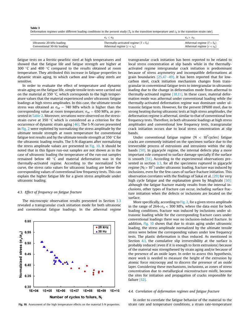
fatigue tests on a ferritic-pearlitic steel at high temperatures andshowed that the fatigue life and fatigue strength are higher at300 �C and 400 �C compared to the results obtained at roomtemperature. They attributed this increase in fatigue properties todynamic strain aging, to which carbon and lowealloy steels aresensitive.
In order to evaluate the effect of temperature and dynamicstrain aging on the fatigue life, simple tensile tests were carried outon the material at 350 �C, which corresponds to the high temper-ature values that the material experienced under ultrasonic fatigueloadings at high stress amplitudes. In this case, the ultimate tensilestress was obtained as sut ¼ 740 MPa which is higher than thecorresponding value at room temperature, sut ¼ 650 MPa, as pre-sented in Table 2. Moreover, serrations were observed on the stress-strain curve at 350 �C which is considered as a criterion for theoccurrence of dynamic strain aging [46]. The S-N curves presentedin Fig. 2 were replotted by normalizing the stress amplitude by theultimate tensile strength at room temperature for conventionalfatigue test results and by the ultimate tensile strength at 350 �C forthe ultrasonic loading results. The S-N diagrams after normalizingthe stress amplitude values are presented in Fig. 10. It should benoted that in this figure run-out samples are not shown as in thecase of ultrasonic loading the temperature of the run-out samplesremained below 40 �C and material deformation was in thethermally-activated regime. According to the normalized S-Ncurve, the stress ratio values for ultrasonic loading are below thecorresponding values of conventional low frequency tests. This canexplain the higher fatigue life for a given stress amplitude underultrasonic loading.
4.3. Effect of frequency on fatigue fracture
The microscopic observation results presented in Section 3.3revealed a transgranular crack initiation mode for both ultrasonicand conventional fatigue loadings. In the athermal regime
transgranular crack initiation has been reported to be related tolocal stress concentration at slip bands while in the thermally-activated regime intergranular crack initiation is predominantbecause of stress asymmetry and incompatible deformations atgrain boundaries [25,47e49]. It has been reported that for low-carbon steel, crack initiation mechanism changes from trans-granular in conventional fatigue tests to intergranular in ultrasonicloading due to the change in deformation mode from athermal tothermally-activated regime [10,11]. In these cases, material defor-mation mode was athermal under conventional loading while thethermally-activated deformation regime was dominant under ul-trasonic fatigue tests. However, for the present DP600 steel, due tostrong heating during ultrasonic tests at high stress amplitudes, thedeformation regime is athermal, similar to that of conventional lowfrequency tests. Therefore, in both ultrasonic loadings at high stressamplitudes and conventional low frequency tests, transgranularcrack initiation occurs due to local stress concentration at slipbands.
Under conventional fatigue regime (N < 107cycles) fatiguecracks are commonly initiated on the specimen surface due to theirreversible process of extrusions and intrusions within the slipbands [50]. In gigacycle regime, the internal defects play a moreimportant role compared to surface damage specially if the surfaceis smooth [51]. According to the experimental observations pre-sented in section 3.3, for all the specimens ruptured in gigacycleregime (Nf > 107) under ultrasonic loading, fracture was induced byinclusions, even for the few cases of surface fracture initiation. Thisobservation correlates with the findings of Sakai et al. [29] for veryhigh cycle fatigue and the explanation given by Mughrabi [50]:although the fatigue fracture mainly results from the internal in-clusions, other types of fracture can occur, including surface frac-ture initiation when the defects or inclusions are located on thesurface.
More specifically, according to Fig. 2, for a given stress amplitudein the range of 264<sa < 300 MPa, where the data exist for bothloading conditions, fracture was induced by inclusions under ul-trasonic loading while for the corresponding fracture cases underconventional loadings there was no inclusion-induced fracture. Inaddition, Fig. 10 shows that due to strain aging under ultrasonicloading, the stress amplitude normalized by the ultimate tensilestress were below the corresponding values under low frequencytests. The plastic deformation is thus reduced. As mentioned inSection 4.1, the cumulative slip irreversibility at the surface isprobably reduced (even if it is enough to form extrusions) becauseof the material was strengthened by strain aging and/or because ofthe presence of an oxide layer. In order to assess this hypothesis,more work is needed to measure the height of the extrusion byatomic force microcopy and to discern the presence of an oxidelayer. Considering these mechanisms, inclusions, as zones of stressconcentration due to metallurgical microstructure misfit, becomethe sites for initiation and propagation of cracks responsible forfailure [52].
4.4. Correlation of deformation regimes and fatigue fracture
In order to correlate the fatigue behavior of the material to thestrain rate and temperature conditions, a strain rate-temperature
Table 3Deformation regimes under different loading conditions in the present study (T0 is the transition temperature and _ε0 is the transition strain rate).
sa � sD sa > sD
Ultrasonic 20-kHz loading Thermally-activated regime (T < T0) Athermal regime (T > T0)Conventional 30-Hz loading Athermal regime ( _ε < _ε0) Athermal regime ( _ε < _ε0)
Fig. 10. Assessment of the high temperature effects on the material S-N properties.

map associated with deformation mechanisms was developedbased on the transition formulation proposed by Rosenfield andHahn [32] for BCC materials. The developed map is presented inFig.11. This map focuses on the transition between athermal regimeand thermally-activated regime, which are indicated as Region Iand Region II, respectively. The solid line representing the transi-tion boundary between these two deformation regimes was ob-tained from the empirical equation proposed by Rosenfield andHahn [32] (see Eq. (1)) for low carbon steels.
The data obtained in the present study for ultrasonic and lowfrequency fatigue tests of DP600 steel was plotted in this transitionmap. Moreover, in order to enrich the analysis, the data reported inthe literature for DP600 steel as well as several two-phase ferritic-pearlitic steels under 20-kHz and low frequency (f < 150 Hz) fatiguetests was also plotted in this map. The data for DP600 steel wereobtained from Munier et al. [53]. The mentioned ferritic-pearliticsteels whose data were extracted from literature are as follows:C15 steel (reported by Bach et al. [25] and by Guennec et al. [10]),C45 steel (Ranc et al. [24] and Bach et al. [25]), and finally Cr-Mosteels (Nishijima & Kanazawa [39] and Schneider et al. [4]). Inaddition to these ferritic-pearlitic steels, data reported for Armcoiron by Vincent et al. [54] and Wagner et al. [26] was also plotted.Armco iron is single-phase ferrite containing 80 wt ppm of carbon.Studying the pure iron is important since it is the main constituentof ferritic steels which mainly accommodates the deformation andalso it can be considered as a model material representing the fa-tigue characteristics of BCC metals.
It should be noted that concerning the data obtained from theliterature, only the information corresponding to longest fatigue
life (associated with the lowest stress amplitude) in the reported S-N curves was extracted and plotted in Fig. 11. Table 4 summarizesthe experimental information related to all data plotted in Fig. 11,including the material, testing frequency, stress amplitude associ-ated with the longest fatigue life, strain rate amplitude, and spec-imen temperature. The strain rate amplitude was calculated as_εa ¼ 2pf sa
E . Concerning the temperature, when self-heating devel-oped during ultrasonic tests, the temperature was considered asthe mean temperature before rupture [23,24,26]. In the case of lowfrequency tests, when no temperature information was provided,the tests were considered to be carried out at room temperature, RT(~22 �C) without any self-heating. This case includes the resultsrelated to Armco iron in Ref. [54], C15 and C45 steels in Ref. [25],and C15 steel in Ref. [10].
Concerning the largest fatigue life information available in thereferenced literature, the data plotted in Fig. 11 can be separatedinto two regimes:
1. The high cycle fatigue regime ranging from 2 � 105 to 4 � 107
cycles (open symbols and the region denoted by the blue hatch).2. The very high cycle regime for N� 2.5� 108 cycles (full symbols
and the region denoted by the red lattice pattern).
The data for HCF failure corresponds to temperatures around RTand are located close to the transition line; The HCF failures underlow frequency tests are just below the transition line (Region I)while those under 20 kHz loading are located just above this line(Region II). The difference between these results comes from thesites of microcracks which are located at SBs for plots in Region I
PSB microcracks GB microcraksno information on microcrack sites no macroscopic failureFerrite-Martensite Steel (DP600) Ferrite-Pearlite steel (C45)Ferrite-Pearlite Steel (C15) Armco ironTempered Martensite Steel
Fig. 11. Regions of the temperature strain-rate spectrum of ferrite base steels that reflect different crack initiation mechanisms and fatigue failure behavior.

whereas they are located at grain or phase boundaries for those inRegion II. These trends are consistent with the results reported bySommer et al. [48] for a-iron with small carbon content.
In Region I, screw and edge dislocations have similar mobilityallowing multiplication and rearrangement of dislocations tolocalize the deformation in SBs. Fatigue cracks initiate in a trans-granular way at these SBs leading to a surface failure mode. On theopposite, in Region II, screw dislocations are much less mobile thanedge dislocations preventing SBs from developing. As a result,cracks initiate at the grain and phase boundaries where the strainincompatibilities are the largest. In the thermally activated regimeconditions, the plastic deformation is very low but sufficient toproduce crack propagation in HCF regime. However, in the VHCFregime failure cannot occur since the stress amplitudes, which areeven lower, cannot produce enough plastic deformation for crackpropagation and fatigue failure. As shown in Fig. 11, the data pointsfor Armco iron loaded at 20 kHz are very close to the transition line.Interestingly, both transgranular at SBs as well as intergranularcracks were observed for this case [26]. These observations areconsistent with the location of the data points in the strain rate-etemperature map. Sommer et al. [48] showed that transgranularand intergranular crack initiations are competitive mechanismsdepending mainly on the amount of involved plastic strain. Largeplastic strain promotes transgranular cracks while small plasticdeformation promotes intergranular cracks. In the case of Armcoiron under 20 kHz loading, enough plastic deformation occurs to
produce failure in the VHCF regime (up to 5 � 109 cycles).The studied DP600 steel as well as the C45 steel in Ref. [24]
loaded in the thermally-activated mode did not exhibit any fail-ure, neither in the HCF nor in the VHCF regime. As expected, no slipband was detected on the surface of the specimens. For C45 steelapplying 260-MPa stress amplitude led to a non-avoidable strongself-heating, resulting in a change in strain rate-temperature con-ditions from the thermally-activated regime to the athermal mode[24]. This change in deformation regime occurred at ~ N ¼ 8 � 106
cycles, before the failure of the specimen (Nf ¼ 4 � 107 cycles). Theresults obtained in the present research for DP600 steel can be alsoexplained by the same argument. Specimens loaded at stress am-plitudes slightly above 260 MPa exhibited a strong self-heatingbefore reaching failure. As a result, fatigue failure is only possiblein the athermal regime.
From these findings, it can be concluded that as soon as thestrain rate and temperature conditions under fatigue loading aresuch that thermally-activated mechanisms are involved, cracksinitiate at grain or phase boundaries and result in failure in the HCFregime. No VHCF failure can take place in this case since failure inthe VHCF regime involves even lower stresses. Locally at micro-structural singularities, crack initiation could take place but in suchductile ferrite-based steels, in thermally-activated regime themobility of screw dislocations is too low to create multiplication ofdislocations and produce enough plastic deformation to causecrack propagation and macroscopic fatigue failure.
Table 4Material and experimental properties of the data plotted in Fig. 11.
Materials Frequency(Hz)
Fatigue life(cycles)
Stressamplitude (MPa)
Strain rate (s�1) Temperature (K) Reference Symbol in Fig. 11
DP600 30 3.2 � 106 265 0.2 295 (22 �C) Present work
DP600 20000 2.6 � 108 265 159 ~623 (350 �C) Present work
DP600 20000 Infinite 240 144 <313 (<40 �C) Torabian et al. [23]
DP600 10 1.2 � 106 250 0.07 295 (22 �C) Munier et al. [53]
50CrMo4 5e400 2 � 105 520 0.08e6.2 295 (22 �C) Schneider et al. [4]
50CrMo4 20000 1 � 106 560 335 <333 (60 �C) Schneider et al. [4]
1CrMo0.5 100 2.6 � 106 280 0.84 295 (22 �C) Schneider et al. [4]
1CrMo0.5 100 2 � 106 260 0.78 473 (200 �C) Nishijima & Kanazawa [39]
1CrMo0.5 100 2.5 � 108 290 0.87 573 (300 �C) Nishijima & Kanazawa [39]
1CrMo0.5 100 8 � 108 265 0.80 673 (400 �C) Nishijima & Kanazawa [39]
C45 steel 20000 Infinite 250 150 305 (32 �C) Ranc et al. [24]
C45 steel 20000 4 � 109 260 156 ~543 (270 �C) Ranc et al. [24]
C45 steel 20000 4 � 107 312 187 300 Bach et al. [25]
C45 steel 120 1.2 � 107 228 0.82 295 Bach et al. [25]
C15 steel 20000 1.2 � 107 290 174 295 Bach et al. [25]
C15 steel 120 1 � 107 200 0.72 295 Bach et al. [25]
C15 steel 20000 1.4 � 107 155 135 335 Guennec et al. [10]
C15 steel 140 1.5 � 106 210 0.88 295 Guennec et al. [10]
Armco iron 10 3 � 106 200 0.06 295 (22 �C) Vincent et al. [54]
Armco iron 20000 5 � 109 172 103 345 (77� 2 [67e87 �C)) Wagner et al. [26]

It is striking that the data corresponding to temperatures muchhigher than RT and typically above 200 �C belong all to the Region I(athermal regime) and exhibits inclusion-induced VHCF failure.Athermal regime is consistent with the presence of SBs andtransgranular microcracks at the surface of the specimens. Asmentioned earlier, at these temperatures, carbon steels are sensi-tive to strain aging. As a result, ferrite is strengthened by soluteatoms that segregate in the dislocations leading to impeding theirmotion. Since the ferrite matrix is strengthened by strain aging theplastic zone at the crack tip is smaller and requires higher stressesto propagate than at temperatures below 200 �C. These higherstress concentrations zone are preferentially found at inclusionsbecause they lead to a higher accumulation of dislocations. Thisscenario explains why inclusion induced crack initiation wereobserved for high temperature loadings which is consistent withthe discussions presented in Section 4.3. In addition, the increase infatigue life results from the reduction in plastic deformation at thecrack tip and the delay in crack growth in the strengthened ferritematrix [42], as previously mentioned in Section 4.2.
4.5. Effect of frequency on fatigue limit
Based on the experimental observations, for stress amplitudesbelow the HCF limit determined by 30-Hz fatigue tests, slip bandsand microcracks were also visible on the surface of the run-outspecimens. These observations demonstrated that the 260 MPaHCF fatigue limit is not related to slip activity and microcrackinitiation. Moreover, in the case of 20-kHz loading no slip band wasdetected on the surface of run-out samples. It is well supported inthe literature that the fatigue limit of steels corresponds to aslightly higher stress level at which an initiated microcrack stopspropagating at the first microstructural barrier [29,39,55]. In otherwords, the fatigue limit is related to the stress threshold required topropagate the trapped microcracks. Therefore, on the one hand,based on the previously mentioned strain aging effects instrengthening the ferrite matrix, it is expected that the fatigue limitis higher under ultrasonic loading. On the other hand, at hightemperatures, such as 350 �C compared to room temperature, thevacancy diffusion along the slip band is higher, leading to acceler-ating the voids growth. The presence of voids in the vicinity ofinclusions could decrease the cohesion strength of the material to apoint where crack propagation begins [56]. Consequently, micro-cracks propagate more easily at high than low temperatures lead-ing to decreasing the fatigue limit normalized by the ultimatetensile strength. These competitive mechanisms finally led to thesame absolute fatigue limit in ultrasonic loading and conventionaltests. However further investigations are required to confirm thishypothesis which is the subject of the future work of the authors.
To summarize, in the present case of the DP600 steels loadedusing continuous cycling at 30 Hz and 20 kHz, fatigue failure wasobserved only for strain rate-temperature conditions implyingathermal deformation mechanisms. Therefore, comparable screwand edge dislocation mobility constituted a necessary condition forfatigue failure. At 30 Hz, this condition is immediately satisfied andthe fatigue limit is associated with the stress threshold requires topropagate cracks. This threshold was found ~260 MPa. At 20 kHz,the fatigue limit of 260 MPa corresponds to the critical stressamplitude sc, necessary to produce enough dissipated energy to geta self-heating above ~75 �C. The origin of these two fatigue limitsseems thus to be different. However, the fact that the fatigue limitsare the same suggests that the self-heating above 75 �C, could bealso related to crack propagation; short cracks could be formed butstopped because of the strain aging strengthening, as previouslymentioned in Ref. [23]. Thus sc could be also the threshold stressrequired to crack propagation which is consistent with the
definition of fatigue limit.
5. Conclusions
The effect of frequency on fatigue behavior of ferritic-martensitic dual-phase steel was studied by carrying out ultra-sonic and conventional low frequency tension-compression fatiguetests along with temperature measurements and microscopic ob-servations. A clear discrepancy was observed in the S-N curvesobtained from conventional 30-Hz fatigue tests and that measuredfrom ultrasonic 20-kHz loadings. The rate- and temperature-dependent flow behavior of the ferrite phase, as a BCC structure,was found to be a decisive parameter explaining the effects offrequency on fatigue and thermal response of the material. More-over, the significant temperature increase under ultrasonic fatigueloading at high stress amplitudes was found to play an importantrole in the observed phenomena. The principal conclusions drawnfrom the results of this study can be summarized as follows:
� Under ultrasonic fatigue loading, there was a transition in ma-terial deformation mode from thermally-activated regime atstress amplitudes below the fatigue limit to athermal mode atstress amplitudes above the fatigue limit. Nonetheless, materialdeformation occurred in athermal regime under conventionallow frequency fatigue tests for all stress amplitude ranges.
� The higher fatigue life was attributed to the dynamic strainaging which resulted from the high temperature increases athigh stress amplitudes. However, the same fatigue limits remainas an open question to be investigated in a future work, even ifsome insights were proposed
� In both ultrasonic and low frequency tests transgranularcracking along the slip bands was observed and no intergranularcrack was detected. In the case of ultrasonic loading, manymicrovoids nucleated and coalesced along the slip bandsresulting in microcrack initiations. This microvoids initiationsand coalescences were not observed in the case of low fre-quency tests. Diffusion of vacancies due to high temperatureunder ultrasonic fatigue loading is thought to be the main causeof microvoids formation.
� Surface fracture initiation from slip bands was observed in lowand high cycle regimes under conventional tests, while underultrasonic loading fracture initiation was always inclusion-induced.
� The S-N curves were replotted by normalizing the stress am-plitudes by the ultimate tensile strengths at correspondingloading temperatures in order to consider the effect of dynamicstrain aging for ultrasonic loading. This replotting rationalizedthe S-N data, resulting in lower stress ratios for ultrasonicloading, which can explain the higher fatigue life and inclusion-induced crack initiations under 20-kHz ultrasonic tests.
� A strain rate-temperature transition map was developed basedon the experimental findings for DP600 steel and the data re-ported in the literature for several ferrite based steels. It wasshown that no VHCF failure occurs if material deforms inthermally-activated regime and in that condition, microcracksinitiated at grain or phase boundaries for HCF failure. VCHF fa-tigue failure was observed only for strain rate-temperatureconditions implying athermal deformation mechanisms asso-ciated with microcracks within slip bands.
Acknowledgement
The authors would like to acknowledge Mr. Bastien Weber fromArcelorMittal Maizi�eres Research& Development, for providing thematerial and for fruitful discussions.

References
[1] R. Ebara, The present situation and future problems inultrasonic fatigue testing -mainly reviewed on environmental effects and materials’ screening, Int. J. Fa-tigue 28 (2006) 1465e1470, http://dx.doi.org/10.1016/j.ijfatigue.2005.04.019.
[2] H. Mayer, Recent developments in ultrasonic fatigue, Fatigue Fract. Eng.Mater. Struct. 39 (2016) 3e29, http://dx.doi.org/10.1111/ffe.12365.
[3] B. Holper, H. Mayer, A.K. Vasudevan, S.E. Stanzl-Tschegg, Near threshold fa-tigue crack growth in aluminium alloys at low and ultrasonic frequency: in-fluences of specimen thickness, strain rate, slip behaviour and air humidity,Int. J. Fatigue 25 (2003) 397e411, http://dx.doi.org/10.1016/S0142-1123(02)00163-9.
[4] N. Schneider, J. Boddecker, C. Berger, M. Oechsner, Frequency effect and in-fluence of testing technique on the fatigue behaviour of quenched andtempered steel and aluminium alloy, Int. J. Fatigue 93 (2016) 224e231, http://dx.doi.org/10.1016/j.ijfatigue.2016.05.013.
[5] S. Stanzl-Tschegg, Very high cycle fatigue measuring techniques, Int. J. Fatigue60 (2014) 2e17, http://dx.doi.org/10.1016/j.ijfatigue.2012.11.016.
[6] N. Tsutsumi, Y. Murakami, V. Doquet, Effect of test frequency on fatiguestrength of low carbon steel, Fatigue Fract. Eng. Mater. Struct. 32 (2009)473e483, http://dx.doi.org/10.1111/j.1460-2695.2009.01350.x.
[7] I. Nonaka, S. Setowaki, Y. Ichikawa, Effect of load frequency on high cyclefatigue strength of bullet train axle steel, Int. J. Fatigue 60 (2014) 43e47,http://dx.doi.org/10.1016/j.ijfatigue.2013.08.020.
[8] H.Q. Liu, Q.Y. Wang, Z.Y. Huang, Z.J. Teng, High-cycle fatigue and thermaldissipation investigations for low carbon steel Q345, Key Eng. Mater. 664(2015) 305e313, http://dx.doi.org/10.4028/www.scientific.net/KEM.664.305.
[9] B. Guennec, A. Ueno, T. Sakai, M. Takanashi, Y. Itabashi, Effect of the loadingfrequency on fatigue properties of JIS S15C low carbon steel and some dis-cussions based on micro-plasticity behavior, Int. J. Fatigue 66 (2014) 29e38,http://dx.doi.org/10.1016/j.ijfatigue.2014.03.005.
[10] B. Guennec, A. Ueno, T. Sakai, M. Takanashi, Y. Itabashi, M. Ota, Dislocation-based interpretation on the effect of the loading frequency on the fatigueproperties of JIS S15C low carbon steel, Int. J. Fatigue 70 (2015) 328e341,http://dx.doi.org/10.1016/j.ijfatigue.2014.10.006.
[11] Y. Furuya, S. Torizuka, E. Takeuchi,M. Bacher-H€ochst,M.Kuntz, Ultrasonic fatiguetesting on notched and smooth specimens of ultrafine-grained steel, Mater. Des.37 (2012) 515e520, http://dx.doi.org/10.1016/j.matdes.2012.01.035.
[12] A. Seeger, The temperature dependence of the criticla shear stress and ofwork-hardening of metal crystals, Philos. Mag. Ser. 7 (45) (1954) 771e773,http://dx.doi.org/10.1080/14786440708520489.
[13] H. Mughrabi, K. Herz, X. Stark, Cyclic deformation and fatigue behaviour ofalpha-iron mono-and polycrystals, Int. J. Fract. 17 (1981) 193e220, http://dx.doi.org/10.1007/BF00053520.
[14] C. Bathias, Coupling effect of plasticity, thermal dissipation and metallurgicalstability in ultrasonic fatigue, Int. J. Fatigue 60 (2014) 18e22, http://dx.doi.org/10.1016/j.ijfatigue.2013.06.004.
[15] S. Schmid, M. Hahn, S. Issler, M. Bacher-Hoechst, Y. Furuya, A. Mehner,H. Bomas, H.W. Zoch, Effect of frequency and biofuel E85 on very high cyclefatigue behaviour of the high strength steel X90CrMoV18, Int. J. Fatigue 60(2014) 90e100, http://dx.doi.org/10.1016/j.ijfatigue.2013.06.005.
[16] Y. Furuya, S. Matsuoka, T. Abe, K. Yamaguchi, Gigacycle fatigue properties forhigh-strength low-alloy steel at 100 Hz, 600 Hz, and 20 kHz, Scr. Mater 46(2002) 157e162, http://dx.doi.org/10.1016/S1359-6462(01)01213-1.
[17] I. Marines, G. Dominguez, G. Baudry, J.F. Vittori, S. Rathery, J.P. Doucet,C. Bathias, Ultrasonic fatigue tests on bearing steel AISI-SAE 52100 at fre-quency of 20 and 30 kHz, Int. J. Fatigue 25 (2003) 1037e1046, http://dx.doi.org/10.1016/S0142-1123(03)00161-0.
[18] Q.Y. Wang, J.Y. Berard, A. Dubarre, G. Baudry, S. Rathery, C. Bathias, Gigacyclefatigue of ferrous alloys, Fatigue Fract. Eng. Mater. Struct. 22 (1999) 667e672,http://dx.doi.org/10.1046/j.1460-2695.1999.00185.x.
[19] N. Ranc, D. Wagner, P.C. Paris, Study of thermal effects associated with crackpropagation during very high cycle fatigue tests, Acta Mater 56 (2008)4012e4021, http://dx.doi.org/10.1016/j.actamat.2008.04.023.
[20] Y. Yu, J.L. Gu, L. Xu, F.L. Shou, B.Z. Bai, Y.B. Liu, Very high cycle fatigue be-haviors of Mn-Si-Cr series Bainite/Martensite dual phase steels, Mater. Des. 31(2010) 3067e3072, http://dx.doi.org/10.1016/j.matdes.2010.01.008.
[21] W.J. Peng, B.W. Qiu, R.F. Li, H. Xue, Ultrasonic fatigue tests on a high strengthsteel for welded structure, Adv. Mater. Res. 503e504 (2012) 714e717, http://dx.doi.org/10.4028/www.scientific.net/AMR.503-504.714.
[22] W. Peng, Y. Zhang, B. Qiu, H. Xue, A brief review of the application andproblems in ultrasonic fatigue testing, AASRI Procedia 2 (2012) 127e133,http://dx.doi.org/10.1016/j.aasri.2012.09.024.
[23] N. Torabian, V. Favier, S. Ziaei-Rad, J. Dirrenberger, F. Adamski, N. Ranc, Thermalresponse of DP600 dual-phase steel under ultrasonic fatigue loading,Mater. Sci.Eng. A 677 (2016) 97e105, http://dx.doi.org/10.1016/j.msea.2016.09.025.
[24] N. Ranc, V. Favier, B. Munier, F. Vales, G. Thoquenne, F. Lefebvre, Thermalresponse of C45 steel in high and very high cycle fatigue, Procedia Eng. 133(2015) 265e271, http://dx.doi.org/10.1016/j.proeng.2015.12.668.
[25] J. Bach, J.J. M€oller, M. G€oken, E. Bitzek, H.W. H€oppel, On the transition fromplastic deformation to crack initiation in the high- and very high-cycle fatigueregimes in plain carbon steels, Int. J. Fatigue 93 (2016) 281e291, http://dx.doi.org/10.1016/j.ijfatigue.2016.04.003.
[26] D. Wagner, C. Wang, Z. Huang, C. Bathias, Surface crack initiation mechanismfor body centered cubic materials in the gigacycle fatigue domain, Int. J. Fa-tigue 93 (2016) 292e300, http://dx.doi.org/10.1016/j.ijfatigue.2016.05.036.
[27] N. Marti, V. Favier, N. Saintier, F. Gregori, Investigating fatigue frequency ef-fects on single phase ductile materials, Procedia Eng. 133 (2015) 294e298,http://dx.doi.org/10.1016/j.proeng.2015.12.675.
[28] R. Munier, C. Doudard, S. Calloch, B. Weber, Determination of high cycle fa-tigue properties of a wide range of steel sheet grades from self-heatingmeasurements, Int. J. Fatigue 63 (2014) 46e61, http://dx.doi.org/10.1016/j.ijfatigue.2014.01.004.
[29] T. Sakai, A. Nakagawa, N. Oguma, Y. Nakamura, A. Ueno, S. Kikuchi, A. Sakaida,A review on fatigue fracture modes of structural metallic materials in veryhigh cycle regime, Int. J. Fatigue (2016) 1e13, http://dx.doi.org/10.1016/j.ijfatigue.2016.05.029.
[30] C.R. Sohar, A. Betzwar-Kotas, C. Gierl, B. Weiss, H. Danninger, Gigacycle fatiguebehavior of a high chromium alloyed cold work tool steel, Int. J. Fatigue 30(2008) 1137e1149, http://dx.doi.org/10.1016/j.ijfatigue.2007.09.012.
[31] P.J.E. Forsyth, Fatigue damage and crack growth in aluminium alloys, ActaMetall. 11 (1963) 703e715, http://dx.doi.org/10.1016/0001-6160(63)90008-7.
[32] A.R. Rosenfield, G.T. Hahn, Numerical descriptions of the ambient low-temperature and high-strain rate flow and fracture behavior of plain carbonsteel, Trans. Am. Soc. Mater 59 (1966) 962e977.
[33] U. Essmann, U. G€osele, H. Mughrabi, A model of extrusions and intrusions infatiguedmetals I. Point-defect production and the growth of extrusions, Philos.Mag. A 44 (1981) 405e426, http://dx.doi.org/10.1080/01418618108239541.
[34] J. Pol�ak,M. Sauzay,Growthofextrusions in localizedcyclic plastic straining,Mater.Sci. Eng. A 500 (2009) 122e129, http://dx.doi.org/10.1016/j.msea.2008.09.022.
[35] J.H. Kim, M.G. Lee, D. Kim, D.K. Matlock, R.H. Wagoner, Hole-expansionformability of dual-phase steels using representative volume elementapproach with boundary-smoothing technique, Mater. Sci. Eng. A 527 (2010)7353e7363, http://dx.doi.org/10.1016/j.msea.2010.07.099.
[36] A. Alaie, J. Kadkhodapour, S. Ziaei Rad, M. Asadi Asadabad, S. Schmauder,Formation and coalescence of strain localized regions in ferrite phase ofDP600 steels under uniaxial tensile deformation, Mater. Sci. Eng. A 623 (2015)133e144, http://dx.doi.org/10.1016/j.msea.2014.11.042.
[37] Q. Lai, O. Bouaziz, M. Goun�e, L. Brassart, M. Verdier, G. Parry, A. Perlade,Y. Br�echet, T. Pardoen, Damage and fracture of dual-phase steels: in fluence ofmartensite volume fraction, Mater. Sci. Eng. A 646 (2015) 322e331, http://dx.doi.org/10.1016/j.msea.2015.08.073.
[38] A. Pierman, O. Bouaziz, T. Pardoen, P.J. Jacques, L. Brassart, ScienceDirect theinfluence of microstructure and composition on the plastic behaviour of dual-phase steels, Acta Mater 73 (2014) 298e311, http://dx.doi.org/10.1016/j.actamat.2014.04.015.
[39] S. Nishijima, K. Kanazawa, Stepwise S-N curve and fish-eye failure in gigacyclefatigue, Fatigue Fract. Eng. Mater. Struct. 22 (1999) 601e607, http://dx.doi.org/10.1046/j.1460-2695.1999.00206.x.
[40] H. Shen, S.E. Podlaseck, I.R. Kramer, Effect of vacuum on the fatigue life ofaluminum, Acta Metall. 14 (1966) 341e346.
[41] W.A. Wood, K.R. Sargant, Systematic microstructural changes peculiar to fa-tigue deformation, Acta Metall. 11 (1963) 643e652.
[42] D.V. Wilson, J.K. Tromans, Effects of strain ageing on fatigue in low-carbonsteel, Acta Metall. 18 (1970) 1197e1208.
[43] K. V Jata, E.A. Starke, fatigue crack growth and fracture toughness behavior ofan AI-Li-Cu alloy, Metall. Trans. A 17 (1986) 1011e1026.
[44] K. Pohl, P. Mayr, E. Macherauch, Cyclic deformation behavior of a low carbonsteel in the temperature range between room temperature and 850 K, Int. J.Fract. 17 (1981) 221e233, http://dx.doi.org/10.1007/BF00053521.
[45] N. Thompson, N.J. Wadsworth, Metal fatigue, Adv. Phys. 7 (1958) 72e169,http://dx.doi.org/10.1080/00018735800101177.
[46] G. Schoeck, The portevin-le chatelier effect. A kinetic theory, Acta Metall. 32(1984) 1229e1234, http://dx.doi.org/10.1016/0001-6160(84)90129-9.
[47] T. Magnin, J.H. Driver, The influence of strain rate on the low cycle fatigueproperties of single crystals and polycrystals of two ferritic alloys, Mater. Sci.Eng. 39 (1979) 175e185, http://dx.doi.org/10.1016/0025-5416(79)90057-0.
[48] C. Sommer, H. Mughrabi, D. Lochner, Influence of temperature and carboncontent on the cyclic deformation and fatigue behaviour of a-iron. Part I.Cyclic deformation and stressebehaviour, Acta Mater 46 (1998) 1527e1536,http://dx.doi.org/10.1016/S1359-6454(97)00362-5.
[49] C. Sommer, H. Mughrabi, D. Lochner, Influence of temperature and carboncontent on the cyclic deformation and fatigue behaviour of a-iron. Part II:crack initiation and fatigue life, Acta Mater 46 (1998) 1537e1546, http://dx.doi.org/10.1016/S1359-6454(97)00363-7.
[50] H. Mughrabi, Specific features and mechanisms of fatigue in the ultrahigh-cycle regime, Int. J. Fatigue 28 (2006) 1501e1508, http://dx.doi.org/10.1016/j.ijfatigue.2005.05.018.
[51] C. Bathias, There is no infinite fatigue life in metallic materials, Fatigue Fract.Eng. Mater. Struct. 22 (1999) 559e565, http://dx.doi.org/10.1046/j.1460-2695.1999.00183.x.
[52] K. Tanaka, T. Mura, A dislocation model for fatigue crack initiation, J. Appl.Mech. 48 (1981) 97e103, http://dx.doi.org/10.1115/1.3157599.
[53] R. Munier, C. Doudard, S. Calloch, B. Weber, Towards a faster determination ofhigh cycle fatigue properties taking into account the influence of a plastic pre-

strain from selfheating measurements, Procedia Eng. 2 (2010) 1741e1750,http://dx.doi.org/10.1016/j.proeng.2010.03.187.
[54] M. Vincent, Y. Nadot, A. Dragon, Interaction between a surface defect and grainsize under high cycle fatigue loading: experimental approach forArmco iron, Int.J. Fatigue 87 (2016) 81e90, http://dx.doi.org/10.1016/j.ijfatigue.2016.01.013.
[55] G. Meneghetti, Analysis of the fatigue strength of a stainless steel based on the
energy dissipation, Int. J. Fatigue 29 (2007) 81e94, http://dx.doi.org/10.1016/j.ijfatigue.2006.02.043.
[56] G.M. Sinclair, C.E. Feltner, Fatigue strength of crystalline solids, in: AmericanSociety for Testing Materials, 1961, pp. 129e142. Spec. Tech. Publ. no. 283,Piladelphia.
Related Documents