Page 1 © 1997 Lennox Industries Inc. Litho U.S.A. Corp. 9709−L5 Revised 8−2004 HP29 Service Literature HP29 SERIES UNITS The HP29 is a residential split-system heat pump. Outdoor coil size, circuiting and air volume result in a minimum SEER rating of 10.0. All HP29 units are designed for use with thermal expansion valves. Some HP29 units (−211 through −650, −018 and −024) utilize a reciprocating compressor. These models are furnished with crankcase heaters. The heater prevents liquid from accumulating in the compressor. All compressors are hermetically sealed for trouble-free operation and long service life. Reciprocating compressor components are spring-mounted within the sealed housing. A built-in limit protects the compressor from excessive current and temperatures. Other HP29 units (−030 through −060) utilize a scroll compressor. The scroll operates like a standard heatpump, but is unique in the way that it compresses refrigerant. This manual is divided into sections which discuss major components, refrigerant system, charging procedures, maintenance, and operation sequence . All specifications in this manual are subject to change. SPECIFICATIONS Model No. HP29-211 HP29-261 HP29-311 Ntf ft ( 2 ) Outer coil 11.41 (1.06) 11.41 (1.06) 13.31 (1.24) Outdoor Net face area - sq. ft. (m 2 ) Inner coil - - - - - - - - - - - - Outdoor Coil Tube diameter ɦ in. (mm) & no. of rows 5/16 (7.9) ɦ 1 5/16 (7.9) ɦ 1 5/16 (7.9) ɦ 1 Coil Fins per inch (m) 22 (866) 22 (866) 22 (866) Diameter ɦ in. (mm) & no. of blades 18 (457) ɦ 3 18 (457) ɦ 3 18 (457) ɦ 4 Outdoor Motor hp (W) 1/6 (124) 1/6 (124) 1/6 (124) Outdoor Coil F Cfm (L/s) 2400 (1135) 2400 (1135) 2500 (1180) Coil Fan Rpm 1105 1105 1100 Watts 180 180 200 *Refrigerant charge furnished (HCFC-22) 4 lbs. 5 oz. (1.96 kg) 4 lbs. 4 oz. (1.92 kg) 4 lbs. 15 oz. (2.24 kg) Liquid line ɦ in. (mm) o.d. connection (sweat) **3/8 to 5/16 (8) **3/8 to 5/16 (8) **3/8 to 5/16 (8) Vapor line ɦ in. (mm) o.d. connection (sweat) 5/8 (15.9) 5/8 (15.9) 3/4 (19.1) Shipping weight ɦ lbs. (kg) 1 package 152 (69) 152 (69) 164 (74) *Refrigerant charge sufficient for 20 ft. (6.1 m) length of refrigerant lines. **5/16 to 3/8 reducer coupling supplied with unit. SPECIFICATIONS Model No. HP29-411/HP29-41 HP29-461/HP29-463 HP29-511/HP29-513 HP29-651/HP29-653 Net face area sq ft (m 2 ) Outer coil 15.21 (1.41) 15.21 (1.41) 15.21 (1.41) 15.21 (1.41) Outdoor Net face area - sq. ft. (m 2 ) Inner coil - - - - 5.44 (0.51) 5.44 (0.51) 14.50 (13.5) Outdoor Coil Tube diameter ɦ in. (mm) & no. of rows 5/16 (7.9) ɦ 1 5/16 (7.9) ɦ 1.37 5/16 (7.9) ɦ 1.37 5/16 (7.9) ɦ 2 Fins per inch (m) 22 (866) 22 (866) 22 (866) 22 (866) Diameter ɦ in. (mm) & no. of blades 18 (457) ɦ 4 18 (457) ɦ 4 18 (457) ɦ 4 18 (457) ɦ 4 Outdoor Motor hp (W) 1/6 (124) 1/6 (124) 1/3 (249) 1/3 (249) Outdoor Coil F Cfm (L/s) 2520 (1190) 2500 (1180) 2950 (1390) 2930 (1385) Coil Fan Rpm 1100 1100 1100 1100 Watts 200 200 310 310 *Refrigerant charge furnished (HCFC-22) 6 lbs. 3 oz. (2.81 kg) 7 lbs. 13 oz. (3.54 kg) 7 lbs. 1 oz. (3.20 kg) 9 lbs. 0 oz. (4.08 kg) Liquid line ɦ in. (mm) o.d. connection (sweat) 3/8 (9.5) 3/8 (9.5) 3/8 (9.5) 3/8 (9.5) Vapor line ɦ in. (mm) o.d. connection (sweat) 3/4 (19.1) 7/8 (22.2) 7/8 (22.2) 1-1/8 (28.6) Shipping weight ɦ lbs. (kg) 1 package 174 (79) 199 (90) 206 (93) 221 (100) *Refrigerant charge sufficient for 20 ft. (6.1 m) length of refrigerant lines.

Welcome message from author
This document is posted to help you gain knowledge. Please leave a comment to let me know what you think about it! Share it to your friends and learn new things together.
Transcript

Page 1© 1997 Lennox Industries Inc.
Litho U.S.A.
Corp. 9709−L5Revised 8−2004
HP29Service Literature
HP29 SERIES UNITSThe HP29 is a residential split-system heat pump. Outdoor coilsize, circuiting and air volume result in a minimum SEER ratingof 10.0. All HP29 units are designed for use with thermalexpansion valves.
Some HP29 units (−211 through −650, −018 and −024) utilize areciprocating compressor. These models are furnished withcrankcase heaters. The heater prevents liquid fromaccumulating in the compressor. All compressors arehermetically sealed for trouble-free operation and long servicelife. Reciprocating compressor components arespring-mounted within the sealed housing. A built-in limitprotects the compressor from excessive current andtemperatures. Other HP29 units (−030 through −060) utilize ascroll compressor. The scroll operates like a standardheatpump, but is unique in the way that it compressesrefrigerant.This manual is divided into sections which discuss majorcomponents, refrigerant system, charging procedures,maintenance, and operation sequence .
All specifications in this manual are subject to change.
SPECIFICATIONS
Model No. HP29-211 HP29-261 HP29-311
N t f ft ( 2)Outer coil 11.41 (1.06) 11.41 (1.06) 13.31 (1.24)
OutdoorNet face area - sq. ft. (m2) Inner coil - - - - - - - - - - - -Outdoor
Coil Tube diameter � in. (mm) & no. of rows 5/16 (7.9) � 1 5/16 (7.9) � 1 5/16 (7.9) � 1Coil
Fins per inch (m) 22 (866) 22 (866) 22 (866)
Diameter � in. (mm) & no. of blades 18 (457) � 3 18 (457) � 3 18 (457) � 4
Outdoor Motor hp (W) 1/6 (124) 1/6 (124) 1/6 (124)OutdoorCoilF
Cfm (L/s) 2400 (1135) 2400 (1135) 2500 (1180)CoilFan Rpm 1105 1105 1100
Watts 180 180 200
*Refrigerant charge furnished (HCFC-22) 4 lbs. 5 oz. (1.96 kg) 4 lbs. 4 oz. (1.92 kg) 4 lbs. 15 oz. (2.24 kg)
Liquid line � in. (mm) o.d. connection (sweat) **3/8 to 5/16 (8) **3/8 to 5/16 (8) **3/8 to 5/16 (8)
Vapor line � in. (mm) o.d. connection (sweat) 5/8 (15.9) 5/8 (15.9) 3/4 (19.1)
Shipping weight � lbs. (kg) 1 package 152 (69) 152 (69) 164 (74)*Refrigerant charge sufficient for 20 ft. (6.1 m) length of refrigerant lines.**5/16 to 3/8 reducer coupling supplied with unit.
SPECIFICATIONSModel No. HP29-411/HP29-41 HP29-461/HP29-463 HP29-511/HP29-513 HP29-651/HP29-653
Net face area sq ft (m2)Outer coil 15.21 (1.41) 15.21 (1.41) 15.21 (1.41) 15.21 (1.41)
OutdoorNet face area - sq. ft. (m2)
Inner coil - - - - 5.44 (0.51) 5.44 (0.51) 14.50 (13.5)OutdoorCoil Tube diameter � in. (mm) & no. of rows 5/16 (7.9) � 1 5/16 (7.9) � 1.37 5/16 (7.9) � 1.37 5/16 (7.9) � 2
Fins per inch (m) 22 (866) 22 (866) 22 (866) 22 (866)
Diameter � in. (mm) & no. of blades 18 (457) � 4 18 (457) � 4 18 (457) � 4 18 (457) � 4
Outdoor Motor hp (W) 1/6 (124) 1/6 (124) 1/3 (249) 1/3 (249)OutdoorCoilF
Cfm (L/s) 2520 (1190) 2500 (1180) 2950 (1390) 2930 (1385)CoilFan Rpm 1100 1100 1100 1100
Watts 200 200 310 310
*Refrigerant charge furnished (HCFC-22) 6 lbs. 3 oz. (2.81 kg) 7 lbs. 13 oz. (3.54 kg) 7 lbs. 1 oz. (3.20 kg) 9 lbs. 0 oz. (4.08 kg)
Liquid line � in. (mm) o.d. connection (sweat) 3/8 (9.5) 3/8 (9.5) 3/8 (9.5) 3/8 (9.5)
Vapor line � in. (mm) o.d. connection (sweat) 3/4 (19.1) 7/8 (22.2) 7/8 (22.2) 1-1/8 (28.6)
Shipping weight � lbs. (kg) 1 package 174 (79) 199 (90) 206 (93) 221 (100)*Refrigerant charge sufficient for 20 ft. (6.1 m) length of refrigerant lines.

Page 2
SPECIFICATIONSModel No. HP29-018 HP29-024 HP29-030 HP29-036−1ph HP29-036−3ph
Net face area Outer coil 11.41 (1.06) 11.41 (1.06) 15.21 (1.43) 15.21 (1.41) 15.21 (1.41)
Outdoor
Net face areasq. ft. (m2) Inner coil - - - - - - - - 5.44 (.51) 14.50 (1.35) 5.44 (.51)Outdoor
Coil Tube diam.−in. (mm) no. of rows 5/16 (7.9) � 1 5/16 (7.9) � 1 5/16 (7.9) � 1 5/16 (7.9) � 2 5/16 (7.9)−1.37Coil
Fins per inch (m) 22 (866) 22 (866) 18 (709) 18 (709) 22 (866)
Diameter−in. (mm) no. of blades 18 (457) � 3 18 (457) � 3 18 (457) � 4 18 (457) � 4 18 (457) − 4
Outdoor Motor hp (W) 1/6 (124) 1/6 (124) 1/6 (124) 1/6 (124) 1/6 (124)OutdoorCoilF
Cfm (L/s) 2400 (1135) 2400 (1135) 2550 (1203) 2530 (1193) 2500 (1180)CoilFan Rpm 1105 1105 1115 1110 1100
Watts 180 180 190 195 200
*Refrigerant charge furnished (HCFC-22) 4 lbs. 2 oz. (1.86 kg) 4 lbs. 1oz. (1.83 kg) 5 lbs.12 oz. (2.6 kg) 7 lbs.2 oz. (3.22kg) 6 lbs 0 0z. (2.72kg)
Liquid line � in. (mm) o.d. conn. (sweat) **3/8 to 5/16 (8) **3/8 to 5/16 (8) **3/8 to 5/16 (8) 3/8 (9.5) 3/8 (9.5)
Vapor line � in. (mm) o.d. conn. (sweat) 5/8 (15.9) 5/8 (15.9) 3/4 (19.1) 3/4 (19.1) 3/4 (19.1)
Shipping weight � lbs. (kg) 1 package 152 (69) 152 (69) 161 (73) 173 (78.5) 193 (88)*Refrigerant charge sufficient for 15 ft. (4.5 m) length of refrigerant lines.**5/16 to 3/8 reducer coupling supplied with unit.
SPECIFICATIONS
Model No. HP29-042−1ph HP29-042−3ph HP29-048 HP29-060
Net face area sq ft (m2)Outer coil 15.21 (1.41) 15.21 (1.41) 15.21 (1.41) 21.11 (1.96)
OutdoorNet face area - sq. ft. (m2)
Inner coil 14.50 (1.35) 5.44 (.51) 14.50 (1.35) 20.31 (1.9)OutdoorCoil Tube diameter � in. (mm) & no. of rows 5/16 (7.9) − 2 5/16 (7.9) − 1.37 5/16 (7.9) � 2 5/16 (7.9) � 2
Fins per inch (m) 18 (709) 22 (866) 18 (709) 18 (709)
Diameter � in. (mm) & no. of blades 18 (457) − 4 18 (457) − 4 18 (457) � 4 18 (457) � 4
Outdoor Motor hp (W) 1/3 (249) 1/6 (124) 1/3 (249) 1/3 (249)OutdoorCoilF
Cfm (L/s) 2975 (1403) 2500 (1180) 3020 (1425) 4330 (2043)CoilFan Rpm 1130 1100 1125 1075
Watts 310 200 330 420
*Refrigerant charge furnished (HCFC-22) 8 lbs. 5 0z. (3.76 kg) 7 lbs. 10 0z. (3.45 kg) 7 lbs. 12 oz. (3.51 kg) 11 lbs. 13 oz. (5.34kg)
Liquid line � in. (mm) o.d. connection (sweat) 3/8 (9.5) 3/8 (9.5) 3/8 (9.5) 3/8 (9.5)
Vapor line � in. (mm) o.d. connection (sweat) 7/8 (22.2) 7/8 22.2) 7/8 (22.2) 1-1/8 (28.6)
Shipping weight � lbs. (kg) 1 package 182 (83) 199 (90.3) 190 (86.2) 254 (115.2)*Refrigerant charge sufficient for 15 ft. (4.5 m) length of refrigerant lines.
ELECTRICAL DATA
Model No.HP29−211−
1HP29−211−
2HP29−261−
1HP29-261−
2HP29-311 HP29-411 HP29-413
Line voltage data � 60 hz208/230v
1ph208/230v
1ph208/230v
1ph208/230v
1ph208/230v
1ph208/230v
1ph208/23v
3ph460v3ph
Rated load amps 8.6 7.9 9.8 10.1 13.7 16.2 10.3 4.3
Compressor Power factor .97 .97 .96 .96 .92 .90 .83 .83
Locked rotor amps 49.0 49.0 56.0 60.0 75.0 96.0 75.0 40.0
Outdoor Coil Full load amps 1.1 1.1 1.1 1.1 1.1 1.1 1.1 0.55Outdoor CoilFan Motor Locked rotor amps 1.9 1.9 1.9 1.9 1.9 1.9 1.9 1.0
Rec. maximum fuse or circuit breaker size (amps) 20 15 20 20 30 35 20 10
*Minimum circuit ampacity 11.9 11.0 13.5 13.8 18.4 21.4 14.0 6.5
*Refer to National or Canadian Electrical Code manual to determine wire, fuse and disconnect size requirements.NOTE � Extremes of operating range are plus 10% and minus 5% of line voltage.
ELECTRICAL DATA
Model No. HP29-461 HP29-463 HP29-511 HP29-513 HP29-651 HP29-653
Line voltage data � 60 hz208/230v
1ph208/230v
3ph460v3ph
208/230v1ph
208/230v3ph
460v3ph
575v3ph
208/230v1ph
208/230v3ph
460v3ph
575v3ph
Rated load amps 17.5 12.8 6.4 23.4 14.0 7.1 5.8 26.9 17.3 9.0 7.1
Compressor Power factor .98 .93 .93 .98 .88 .88 .88 .98 .86 .86 .86
Locked rotor amps 92.0 87.0 44.0 110.0 91.0 46.0 37.0 123.0 128.0 64.0 51.0
Outdoor Coil Full load amps 1.1 1.1 0.55 1.9 1.9 0.90 0.90 1.9 1.9 0.90 0.90Outdoor CoilFan Motor Locked rotor amps 1.9 1.9 1.0 4.1 4.1 2.1 2.1 4.1 4.1 2.1 2.1
Rec. max. fuse or circuit breaker size (amps) 40 25 15 50 30 15 10 60 40 20 15
*Minimum circuit ampacity 23.0 17.1 8.6 31.2 19.4 9.8 8.2 35.5 23.5 12.2 9.8
*Refer to National or Canadian Electrical Code manual to determine wire, fuse and disconnect size requirements.NOTE � Extremes of operating range are plus 10% and minus 5% of line voltage.

Page 3
ELECTRICAL DATA
Model No. HP29-018 HP29-024 HP29-030 HP29-036
Line voltage data � 60 hz208/230v
1ph208/230v
1ph208/230v
1ph208/230v
1ph208/230v
3ph460v3ph
Rated load amps 7.9 10.1 14.7 16.0 11.0 5.6
Compressor Power factor .97 .96 .90 .91 .83 .83
Locked rotor amps 49.0 60.0 84.0 100 75.0 37.5
Outdoor Coil Full load amps 1.1 1.1 1.1 1.1 1.1 0.55Outdoor CoilFan Motor Locked rotor amps 1.9 1.9 1.9 1.9 1.9 1.0
Rec. maximum fuse or circuit breaker size (amps) 15 20 30 35 20 10
*Minimum circuit ampacity 11.0 13.8 19.5 21.1 14.0 6.5
*Refer to National or Canadian Electrical Code manual to determine wire, fuse and disconnect size requirements.NOTE � Extremes of operating range are plus 10% and minus 5% of line voltage.
ELECTRICAL DATA
Model No. HP29-042 HP29-048 HP29-060
Line voltage data � 60 hz208/230v
1ph208/230v
3ph460v3ph
208/230v1ph
208/230v3ph
460v3ph
575v3ph
208/230v1ph
208/230v3ph
460v3ph
575v3ph
Rated load amps 20.3 12.8 6.4 23.7 13.5 7.4 5.8 28.8 17.3 9.0 7.1
Compressor Power factor .84 .93 .93 .96 .88 .88 .88 .92 .86 .86 .86
Locked rotor amps 127 87.0 44.0 129.0 120.0 49.5 48.0 169.0 137.0 62.0 51.0
Outdoor Coil Full load amps 1.9 1.1 0.55 1.9 1.9 0.90 0.90 1.9 1.9 0.90 0.90Outdoor CoilFan Motor Locked rotor amps 4.1 1.9 1.0 4.1 4.1 2.1 2.1 4.1 4.1 2.1 2.1
Rec. maximum fuse or circuit breaker size (amps) 40 25 15 50 30 15 10 60 40 20 15
*Minimum circuit ampacity 27.3 17.1 8.6 31.5 18.8 10.2 8.2 37.4 23.5 12.2 9.8
*Refer to National or Canadian Electrical Code manual to determine wire, fuse and disconnect size requirements.NOTE � Extremes of operating range are plus 10% and minus 5% of line voltage.
I − UNIT INFORMATION
HP29 units are available in 1 -1/2, 2, 2 -1/2, 3, 3 -1/2, 4 and 5
ton capacities.
All major components (indoor blower/coil) must be matched
according to Lennox recommendations for the compressor to
be covered under warranty. Refer to the Engineering
Handbook for approved system matchups. A misapplied
system will cause erratic operation and can result in early
compressor failure.
II − UNIT COMPONENTSUnit components are illustrated in figure 2.
A − Control Box (Figures 3, 4 and 5)Electrical openings are provided under the control box
cover. Field thermostat wiring is made to color-coded
pigtail connections as illustrated in figure 1.
FIGURE 1
THERMOSTAT WIRING IDENTIFICATION
BLACK
BEIGE
ORANGE
YELLOW
RED
FRO
M O
UT
DO
OR
UN
IT
TO IN
DO
OR
UN
IT/
TH
ER
MO
STA
T
24V (POWER) INPUTTO OUTDOOR UNIT
(COMPRESSOR)
(REVERSING�VALVE)
(ELECTRICHEAT)
(COMMON)
INPUT
INPUT
DEFROST OUTPUT
COMPRESSOR CHECK/EXPANSIONVALVE
CONTROLBOX
REVERSINGVALVE
DISCHARGEMUFFLER
OUTDOORFAN/MOTOR
HP29 UNIT COMPONENTS
FIGURE 2
DEFROSTTHERMOSTAT
BI-FLOWFILTER DRIER
RECIPROCATING COMPRESSOR SHOWN

Page 4
1 − Transformer T5
Transformer T5 is used on all �J" voltage units. T5 is used as a
step-down transformer for the outdoor fan motor. The
transformer is located inside the unit control box (see figure 3).
The transformer is rated at 3.4 VA with a 575 volt primary and
a 460 volt secondary.
FIGURE 3
HP29 THREE-PHASE UNIT CONTROL BOX
TRANSFORMER(T5)�J" VOLTAGEUNITS ONLY
GROUNDINGLUG
COMPRESSORCONTACTOR
(K1)
DEFROSTCONTRO
L(CMC1)
RUN CAPACITOR (C1)
OUTDOOR FANRELAY (K10) �G"& �J" VOLTAGE
UNITS ONLY
FIGURE 4
DUAL CAPACITOR(C12)
STARTCAPACITOR
(C7)
COMPRESSORCONTACTOR
(K1)
HP29 SINGLE-PHASE UNIT CONTROL BOX WITHRECIPROCATING COMPRESSOR
GROUNDINGLUG
DEFROSTCONTROL
(CMC1)
POTENTIALRELAY (K31)
2 − Dual Capacitor C12
The compressor (scroll or reciprocating) and fan in
single-phase units use permanent split capacitor motors. The
capacitor is located inside the unit control box (see figure 4 and
5). A single �dual" capacitor (C12) is used for both the fan
motor and the compressor (see unit wiring diagram). The fan
side and the compressor side of the capacitor have different
MFD ratings. See table 1 for dual capacitor ratings.
FIGURE 5
DUAL CAPACITOR(C12)
COMPRESSORCONTACTOR
(K1)
HP29 SINGLE−PHASE UNIT CONTROL BOXWITH SCROLL COMPRESSOR
GROUNDINGLUG
DEFROSTCONTROL
(CMC1)
HP29−024
HP29−030
HP29−042
HP29−048
5305
35
7.5
370
7.540
60
FANHERMFAN
HERM
FANHERMFAN
HERM
440
HP29−018525
FANHERM
HP29−0365
40
FAN
HERM
370FAN
HERM
7.5
80HP29−060
Unit MFD VAC
HP29 (C12) DUAL CAPACITOR RATING
HP29−261
HP29−311
HP29−461/511
HP29−651
5305
35
7.5
370
7.550
70
Terminal
FANHERMFAN
HERM
FANHERMFAN
HERM 440
HP29−211525
FANHERM
HP29−4115
40
FAN
HERM
TABLE 1

Page 5
3 − Potential Relay K31 (Start)
All single-phase units with a reciprocating compressor,
use a potential relay which controls the operation of the
starting circuit. The potential relay is located inside the
unit control box (see figure 4). The relay is normally closed
when contactor K1 is de-energized. When K1 energizes,
the compressor immediately begins start-up. K31
remains closed during compressor start-up and start
capacitor C7 remains in the circuit. When the compressor
reaches approximately 75% of its speed, K31 is
energized. When K1 energizes, the contacts open and
start capacitor C7 is taken out of the circuit. Potential
relays are critically matched to the specific compressor
applied.
4 − Start Capacitor C7
All single-phase units with a reciprocating compressor,
use a start capacitor (C7). C7 is located inside the unit
control box (see figure 4). C7 is wired in parallel with the
compressor side of the dual capacitor.�See table 2 for
start�capacitor ratings.
Unit MFD VACHP29 START CAPACITOR RATING (C7)
HP29−211/261/311
HP29−461/511/651HP29−411 189−227 330
145−175 330
216176−216
HP29−018/024 145−175 330
TABLE 2
5 − Run Capacitor C1
The fan in all three−phase units uses a single-phase
permanent split capacitor motor. A single capacitor C1 is used
for the fan motor. C1 is located inside the unit control box (see
figure 3). Table 3 shows the ratings of C1.
Unit MFD VAC
HP29 RUN CAPACITOR RATING (C1)
HP29−413/463/513
7.5 370
5 370
HP29-653
HP29−036 5 370
HP29−042/048/060 7.5 370
TABLE 3
6 − Outdoor Fan Relay K10Outdoor fan relay K10 is used on all �G" and �J" voltage
units to energize the outdoor fan B4. The relay is located
in the control box and is a single-pole double-throw
relay. See figure 3. K10 is energized by the indoor
thermostat terminal Y1 (24V). When K10 is energized, a
set of N.O. contacts closes to energize the outdoor fan.
7 − Compressor Contactor K1The compressor is energized by a contactor located in the
control box. See figures 3, 4, and 5. Single−pole and
two-pole contactors are used in single-phase units and
three-pole contactors are used in three-phase units. See
wiring diagrams for specific unit. K1 is energized by the indoor
thermostat terminal Y1 (24V). Single−phase HP29 units are not
equipped with a 24V transformer. All 24 VAC controls are
powered by the indoor unit. Refer to unit wiring diagram. "J"
voltage units only are equipped with a 24V transformer. See
figure 3.
DANGERElectric Shock Hazard.
May cause injury or death.
Disconnect all remote electrical powersupplies berore opening unit panel. Unitmay have multiple power supplies.
Some units are equipped with single−pole contactors. When unit is equippedwith a single−pole contactor, line voltageis present at all components (even whenunit is not in operation).
8 − Defrost System HP29
Unit built prior to April 2002
The HP29 defrost system includes two components: a
defrost thermostat and a defrost control.
ELECTROSTATIC DISCHARGE (ESD)
Precautions and Procedures
CAUTIONElectrostatic discharge can affect electroniccomponents. Take precautions during unit instal-lation and service to protect the unit’s electroniccontrols. Precautions will help to avoid controlexposure to electrostatic discharge by puttingthe unit, the control and the technician at thesame electrostatic potential. Neutralize electro-static charge by touching hand and all tools on anunpainted unit surface before performing anyservice procedure.
Defrost Thermostat S6
The defrost thermostat is mounted on the liquid line
between the check/expansion valve and the distributor.
HP29−211 through −653 have a defrost setting of 35�F
(2�C) and HP29−018 through −060 have a defrost setting
of 42�F (5.5�C). When defrost thermostat senses the
setpoint or cooler, its contacts close and send a signal to
the defrost control board to start the defrost timing. It
also terminates defrost when the liquid line warms up to
70�F (21�C).
Defrost Control CMC1
The defrost control board in the HP29 series units has the
combined functions of a time/temperature defrost control,
defrost relay, diagnostic LEDs and field connection terminal
strip.
The control provides automatic switching from normal
heating operation to defrost mode and back. During
compressor cycle (room thermostat demand cyle), if the
�O" input is not on and the defrost thermostat is closed, the
control accumulates compressor run times at 30-, 60- or
90-minute field adjustable intervals. If the defrost
thermostat remains closed when the accumulated
compressor run time ends, the defrost relay is energized
and defrost begins.

Page 6
FIGURE 6
24V TERMINAL STRIPCONNECTIONS
DIAGNOSTIC LEDs
PRESSURE SWITCHSAFETY CIRCUITCONNECTIONS
S4
Optionalswitch
S4
CONNECTION FORONE OPTIONAL
SWITCH
CONNECTIONS FORTWO OPTIONAL
SWITCHES
DEFROST INTERVALTIMING PINS
FACTORY−INSTALLEDJUMPER
(Remove to addpressure switches)
24V TERMINAL STRIPCONNECTIONS
DIAGNOSTIC LEDsPRESSURE SWITCHSAFETY CIRCUITCONNECTIONS
DEFROSTINTERVAL
TIMING PINS
FACTORY−INSTALLEDJUMPER
(Remove to addpressure switches)
AMBIENTTHERMISTORCONNECTION
SERVICE LIGHTCONNECTION
High Pressure
Switch
High Pressure
Switch
NOTE − COMPONENT LOCATIONS WILL VARY WITH BOARD MANUFACTURER
Defrost Control Timing Pins
Each timing pin selection provides a differentaccumulated compressor run period during onethermostat run cycle. A defrost cycle is initiated at theend of this run period. The defrost interval can beadjusted to 30, 60 or 90 minutes. See figure 6. Thedefrost period is a maximum of 14 minutes and cannotbe adjusted. If no timing is selected, the control defaultsto 90 minutes.
A TEST option is provided for troubleshooting. When thejumper is placed across the TEST pins, the timing of allfunctions is reduced by a factor of 128. For example, a 30minute interval during TEST is 14 seconds and the 14minute defrost is reduced to 6.5 seconds.
The TEST mode may be started at any time. If the jumperis in the TEST position at power−up or for longer than fiveminutes, the control will ignore the TEST selection and willdefault to a 90 minute interval. In order to test defrostcycle, defrost thermostat must be closed or jumpered.Once defrost is initiated, remove jumper immediately.Failure to remove jumper will reduce defrost cycle toapproximately 3 seconds.
Pressure Switch Safety Circuit
The defrost control incorporates a pressure switch safetycircuit that allows the application of up to two safety devices:high pressure and/or loss of charge. See figure 6. When thepressure switch opens, unit operation is suspended untilpressure switch closes. If the pressure switch opens for a thirdtime during one thermostat demand, the board will lockout untillow voltage is reset. This can be done by breaking 24 voltpower to terminal �R" on the defrost control board.
When only one pressure switch is used, wire the switch to thetwo outside terminals of the pressure switch connections.
NOTE: If not using a pressure switch, the factory−installed
jumper wire must be connected.
Diagnostic LEDs
The defrost board uses two LEDs for diagnostics. The LEDsflash a specific sequence according to the condition.
TABLE 4
DEFROST CONTROL BOARD DIAGNOSTIC LED
MODE LED 1 LED 2
Normal Operation/Power to board
Flash together withLED 2
Flash together withLED 1
Pressure Switch Open Off On
Board Malfunction On On
Page 7
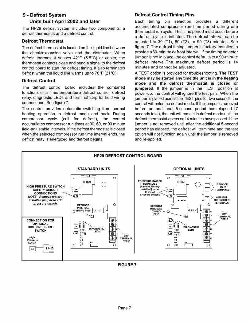
9 − Defrost System
Units built April 2002 and later
The HP29 defrost system includes two components: a
defrost thermostat and a defrost control.
Defrost Thermostat
The defrost thermostat is located on the liquid line between
the check/expansion valve and the distributor. When
defrost thermostat senses 42°F (5.5°C) or cooler, the
thermostat contacts close and send a signal to the defrost
control board to start the defrost timing. It also terminates
defrost when the liquid line warms up to 70°F (21°C).
Defrost Control
The defrost control board includes the combined
functions of a time/temperature defrost control, defrost
relay, diagnostic LEDs and terminal strip for field wiring
connections. See figure 7.
The control provides automatic switching from normal
heating operation to defrost mode and back. During
compressor cycle (call for defrost), the control
accumulates compressor run times at 30, 60, or 90 minute
field−adjustable intervals. If the defrost thermostat is closed
when the selected compressor run time interval ends, the
defrost relay is energized and defrost begins.
Defrost Control Timing Pins
Each timing pin selection provides a different
accumulated compressor run time period during one
thermostat run cycle. This time period must occur before
a defrost cycle is initiated. The defrost interval can be
adjusted to 30 (T1), 60 (T2), or 90 (T3) minutes. See
figure 7. The defrost timing jumper is factory−installed to
provide a 60−minute defrost interval. If the timing selector
jumper is not in place, the control defaults to a 90−minute
defrost interval.The maximum defrost period is 14
minutes and cannot be adjusted.
A TEST option is provided for troubleshooting. The TEST
mode may be started any time the unit is in the heating
mode and the defrost thermostat is closed or
jumpered. If the jumper is in the TEST position at
power-up, the control will ignore the test pins. When the
jumper is placed across the TEST pins for two seconds, the
control will enter the defrost mode. If the jumper is removed
before an additional 5−second period has elapsed (7
seconds total), the unit will remain in defrost mode until the
defrost thermostat opens or 14 minutes have passed. If the
jumper is not removed until after the additional 5−second
period has elapsed, the defrost will terminate and the test
option will not function again until the jumper is removed
and re−applied.
HP29 DEFROST CONTROL BOARD
FIGURE 7
24VTERMINAL
STRIP
HIGH PRESSURE SWITCHSAFETY CIRCUITCONNECTIONS
NOTE − Remove factory−installed jumper to add
pressure switch.
S4
CONNECTION FOROPTIONAL
HIGH PRESSURESWITCH
DEFROSTINTERVAL
TIMING PINS
High Pressure
Switch
DIAGNOSTICLEDs
DEFROSTINTERVAL
TIMINGPINS 24V
TERMINALSTRIP
PRESSURE SWITCHTERMINALS
(Remove factory−installed jumper
to installpressure switch.)
AMBIENTTHERMISTERTERMINALS
SERVICELIGHT
TERMINALS
DIAGNOSTICLEDs
OPTIONAL UNITSSTANDARD UNITS
CC
Y
CC
Y
Page 8
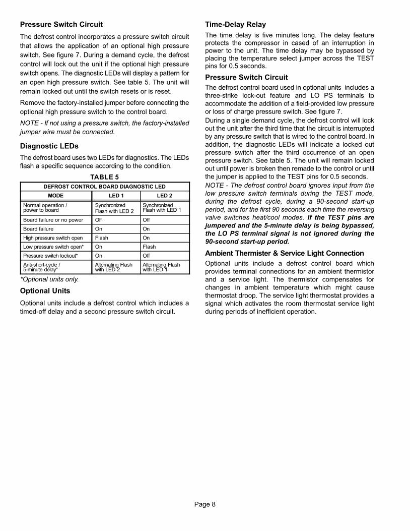
Pressure Switch Circuit
The defrost control incorporates a pressure switch circuit
that allows the application of an optional high pressure
switch. See figure 7. During a demand cycle, the defrost
control will lock out the unit if the optional high pressure
switch opens. The diagnostic LEDs will display a pattern for
an open high pressure switch. See table 5. The unit will
remain locked out until the switch resets or is reset.
Remove the factory-installed jumper before connecting the
optional high pressure switch to the control board.
NOTE − If not using a pressure switch, the factory-installed
jumper wire must be connected.
Diagnostic LEDs
The defrost board uses two LEDs for diagnostics. The LEDs
flash a specific sequence according to the condition.
TABLE 5
DEFROST CONTROL BOARD DIAGNOSTIC LED
MODE LED 1 LED 2
Normal operation / power to board
SynchronizedFlash with LED 2
SynchronizedFlash with LED 1
Board failure or no power Off Off
Board failure On On
High pressure switch open Flash On
Low pressure switch open* On Flash
Pressure switch lockout* On Off
Anti−short−cycle / 5−minute delay*
Alternating Flashwith LED 2
Alternating Flashwith LED 1
*Optional units only.
Optional Units
Optional units include a defrost control which includes a
timed−off delay and a second pressure switch circuit.
Time−Delay Relay
The time delay is five minutes long. The delay featureprotects the compressor in cased of an interruption inpower to the unit. The time delay may be bypassed byplacing the temperature select jumper across the TESTpins for 0.5 seconds.
Pressure Switch Circuit
The defrost control board used in optional units includes a
three−strike lock−out feature and LO PS terminals to
accommodate the addition of a field−provided low pressure
or loss of charge pressure switch. See figure 7.
During a single demand cycle, the defrost control will lock
out the unit after the third time that the circuit is interrupted
by any pressure switch that is wired to the control board. In
addition, the diagnostic LEDs will indicate a locked out
pressure switch after the third occurrence of an open
pressure switch. See table 5. The unit will remain locked
out until power is broken then remade to the control or until
the jumper is applied to the TEST pins for 0.5 seconds.
NOTE − The defrost control board ignores input from the
low pressure switch terminals during the TEST mode,
during the defrost cycle, during a 90−second start−up
period, and for the first 90 seconds each time the reversing
valve switches heat/cool modes. If the TEST pins are
jumpered and the 5−minute delay is being bypassed,
the LO PS terminal signal is not ignored during the
90−second start−up period.
Ambient Thermister & Service Light Connection
Optional units include a defrost control board which
provides terminal connections for an ambient thermistor
and a service light. The thermistor compensates for
changes in ambient temperature which might cause
thermostat droop. The service light thermostat provides a
signal which activates the room thermostat service light
during periods of inefficient operation.

Page 9
B − Compressor (Reciprocating & Scroll)
Make sure all power is disconnected beforebeginning electrical service procedures.
DANGER
Some HP29 units utilize a conventional reciprocatingcompressor. Table 6 shows the specifications of reciprocatingcompressors used in HP29 series units.
VoltageUnit Phase LRA RLA Oil fl.oz.
HP29−211
HP29−311
HP29−511
1
1
1
56
96
128
9.8
16.2
17.3
1 49 8.6
3
HP29−651
HP29−653
HP29−653
3
HP29−463
3 37 5.8
460 3
208/230
HP29−653
HP29−461
1
46 7.1
HP29−261
1 75 13.7
HP29−463
123 26.9
HP29−513
3 64 9.0
HP29−513
3 51 7.1
HP29−513
208/230
208/230
208/230
208/230
208/230
208/230
208/230
208/230
460
460
575
HP29 COMPRESSOR SPECIFICATIONS
3
HP29−413
3 87 12.8
460
HP29−413 3
92
54
17.51
40
54
4.3
208/230
44 6.4
110 23.4
91 14.0
HP29−411
75 4510.3208/230
3
575
45
45
45
45
45
54
54
54
54
54
54
54
54
54
MAN/MODEL
TEC/AV5558F
TEC/AV5558F
TEC/AV5558F
TEC/AV5558F
TEC/AV5545F
TEC/AV5545F
TEC/AV5545F
TEC/AV5545F
TEC/AV5540F
TEC/AV5540F
TEC/AV554OF
COP/CR35K6−TFD
COP/CR35K6−TF5
COP/CR34K6−PFV
COP/CR28K6−PFV
COP/CR22K6−PFV
COP/CR16K6−PFV
HP29−018 1 49208/230 45COP/CR16K6−PFV
HP29−024 1208/230 45COP/CR22K6−PFV
HP29−042 208/230 3 87 12.8
54
TEC/AV5540F
HP29−042 460 3 44 6.4
54
TEC/AV5540F
HP29−036
3 37.5 5.6
3 75208/230
460HP29−036 54
54
TEC/AVD5535EXG
TEC/AVD5535EXT
TABLE 6
7.9
60 10.1
10.3
HP29−211
HP29−261
208/230
208/230
1
1
TEC/AWD5516EXD 48.3 7.9 32
TEC/AWD5522EXD 60 3210.06
Some HP29 units utilize a scroll compressor. The scroll
compressor design is simple, efficient and requires few
moving parts. A cutaway diagram of the scroll compressor is
shown in figure 8. The scrolls are located in the top of the
compressor can and the motor is located just below. The oil
level is immediately below the motor.
FIGURE 8
SCROLL COMPRESSOR
DISCHARGE
SUCTION
The scroll is a simple compression concept centered around
the unique spiral shape of the scroll and its inherent properties.
Two identical scrolls are mated together forming concentric
spiral shapes. One scroll remains stationary, while the other is
allowed to "orbit." The orbiting scroll does not rotate or turn but
merely orbits the stationary scroll. Due to its efficiency, the
scroll compressor is capable of drawing a much deeper
vacuum than reciprocating compressors. Deep vacuum
operation can cause internal fusite arcing resulting in
damaged internal parts and will result in compressor
failure. Never use a scroll compressor for evacuating or
for deep vacuum operation (operating compressor at 0
psig or lower) on the system. Table 7 shows the
specifications of scroll compressors used in the HP29
series units.
VoltageUnit Phase LRA RLA Oil fl.oz.
HP29−030
HP29−060
1 100 16
1 84 14.7
3
3
HP29−048
3 50 7.1
575 3
208/230
HP29−048
1
62 9
HP29−036
HP29−048
HP29−060HP29−060
HP29−060
208/230
460
208/230
208/230
460
HP29 COMPRESSOR SPECIFICATIONS
3 49.5 7.4
HP29−042 1
120
72
13.5 72208/230
40 5.8
169 28.8
137 17.3
127 4220.3208/230
575
42
42
72
56
72
72
72
MAN/MODEL
COP/ZR61K3−TFE
COP/ZR61K3−TFD
COP/ZR61K3−TF5
COP/ZR61K3−PFV
COP/ZR46K3−TFE
COP/ZR46K3−TFD
COP/ZR46K3−TF5
COP/ZR42KC−PFV
COP/ZR36KC−PFV
COP/ZR30KC−PFV
HP29−048 COP/ZR46K3−PFV 208/230 1 129 23.7 66
3
TABLE 7
Three-Phase Compressor RotationThree-phase scroll compressors must be phased
sequentially to ensure correct compressor rotation and
operation. At compressor start-up, a rise in discharge and
drop in suction pressures indicates proper compressor
phasing and operation. If discharge and suction pressures
do not perform normally, follow the steps below to correctly
phase the unit.
1 − Disconnect power to the unit.
2 − Reverse any two field power leads to the unit.
3 − Reapply power to the unit.
Discharge and suction pressures should operate within
their normal start-up ranges.
NOTE − Compressor noise level may be significantly higher
when phasing is incorrect and the unit will not provide
cooling when compressor is operating backwards.
Continued backward operation will cause the compressor
to cycle on internal protector.

FIGURE 9
SNAPBUTTONS
SLIT FOR DISCHARGE LINE
SLIT FORSUCTION
LINE
COVER
COMPRESSOR
Page 10
1 − Compressor Cover (Figure 9)
A compressor cover
constructed of vinyl-faced
fiberglass is used on all
HP29 units. The cover
provides an acoustic barrier.
The cover slides over the
compressor and is held
secure with snap buttons.
Slits are provided for
installation around the
discharge and suction lines.
2 − Crankcase Heater
A crankcase heater is used on all HP29 units equipped witha reciprocating compressor. The well−mountedinsertion−type heater is self−regulating. See table 8 forcrankcase heater specifications.
Unit
HP29−211/-261/-311/-410
HP29 CRANKCASE HEATER RATINGS
Rating (Watts)
40 watts27 wattsHP29-460,-510�and�-65040 watts27 watts
HP29−018/−024/−030HP29−042
TABLE 8
C − Condenser Fan Motor
All units use single−phase PSC fan motors which require a run
capacitor. In all HP29 units, (except "G" and "J" voltage) the
outdoor fan is controlled by the CMCI defrost board.
ELECTRICAL DATA tables in this manual showspecifications for outdoor fans used in HP29s.Access to the outdoor fan motor on all units is gained byremoving the seven screws securing the fan assembly.See figure 10. The outdoor fan motor is removed fromthe fan guard by removing the four nuts found on the toppanel. If condenser fan motor must be replaced, alignfan hub flush with motor shaft.
FIGURE 10
FAN
CONDENSER FAN MOTORAND COMPRESSOR ACCESS
Remove (7) screws
REMOVE (7) SCREWSSECURING FAN GUARD.
REMOVE FAN GUARD/FAN ASSEMBLY.
FAN GUARD
WIRING DRIPLOOP
Remove (4) nuts
ALIGN FAN HUBFLUSH WITH
MOTOR SHAFT
D − Reversing Valve L1 and SolenoidA refrigerant reversing valve with electromechanicalsolenoid is used to reverse refrigerant flow during unitoperation. The reversing valve requires no maintenance.It is not repairable. If the reversing valve has failed, it mustbe replaced.If replacement is necessary, access reversing valve byremoving the outdoor fan motor. Refer to figure 10.III − REFRIGERANT SYSTEM
Refer to figure 11 for refrigerant flow in the cooling modes.The reversing valve is energized during cooling demandand during defrost.
A − Liquid and Vapor Line Service Valves
The liquid and vapor line service valves (figures 12 and 13)and gauge ports are accessible from outside the unit.Each valve is equipped with a service port. The service portsare used for leak testing, evacuating, charging and checkingcharge. A schrader valve is factory installed. A service port capis supplied to protect the schrader valve from contaminationand serve as the primary leak seal.
NOTE-Always keep valve stem caps clean.
OUTDOORCOIL
DEFROST THERMOSTAT
EXPANSION/CHECKVALVE BI-FLOW
FILTER / DRIER
TOHCFC22
DRUM
LOWPRESSURE
HIGHPRESSURE
COMPRESSOR
REVERSING VALVE
VAPORLINE
VALVE
MUFFLER
NOTE − ARROWS INDICATE DIRECTION OF REFRIGERANT FLOW
SERVICEPORT
SUCTION
EXPANSION/CHECKVALVE
INDOOR UNIT
OUTDOOR UNIT
LIQUID LINESERVICE PORT
THERMOMETERWELL
DISTRIBUTOR
INDOORCOIL
HEATING MODE
FIGURE 11

Page 11
IMPORTANTService valves are closed to the heat pump unitand open to line set connections. Do not open un-til refrigerant lines have been leak tested andevacuated. All precautions should be exercised tokeep the system free from dirt, moisture and air.
To Access Schrader Port:
1 − Remove service port cap with an adjustable wrench.
2 − Connect gauge to the service port.
3 − When testing is completed, replace service port cap.
Tighten finger tight, then an additional 1/6 turn.
To Open Liquid or Vapor Line Service Valve:
1 − Remove stem cap with an adjustable wrench.
2 − Using service wrench and hex head extension (5/16 for
vapor line and 3/16 for liquid line), back the stem out
counterclockwise until the valve stem just touches the
retaining ring.
3 − Replace stem cap tighten firmly. Tighten finger tight, then
tighten an additional 1/6 turn.
FIGURE 12
LIQUID LINE SERVICE VALVE (VALVE OPEN)
SCHRADERVALVE
SERVICEPORT
SERVICEPORTCAP
INSERT HEXWRENCH HERE
INLET (TOINDOOR COIL)
OUTLET (TOCOMPRESSOR)
STEM CAP
SCHRADER VALVE OPENTO LINE SET WHEN VALVE IS
CLOSED (FRONT SEATED)
SERVICEPORT
SERVICEPORT CAP
RETAINING RING STEM CAP
OUTLET (TOCOMPRESSOR)
INSERT HEXWRENCH HERE
LIQUID LINE SERVICE VALVE (VALVE CLOSED)
(VALVE FRONTSEATED)
INLET(TO INDOOR COIL)
Do not attempt to backseat this valve. Attempts tobackseat this valve will cause snap ring to explodefrom valve body under pressure of refrigerant.Personal injury and unit damage will result.
DANGER
To Close Liquid or Vapor Line Service Valve:
1 − Remove stem cap with an adjustable wrench.
2 − Using service wrench and hex head extension (5/16 forvapor line and 3/16 for liquid line), turn stem clockwise toseat the valve. Tighten firmly.
3 − Replace stem cap. Tighten finger tight, then tighten an
additional 1/6 turn.
FIGURE 13
VAPOR LINE SERVICE VALVE (VALVE OPEN)
SCHRADERVALVE
SERVICE PORT
SERVICE PORTCAP
INSERT HEXWRENCH HERE
INLET (TOINDOOR COIL)
OUTLET (TOCOMPRESSOR)
STEM CAP
SCHRADER VALVE OPENTO LINE SET WHEN VALVE IS
CLOSED (FRONT SEATED)
SERVICEPORT
SERVICE PORTCAP
RETAINING RING STEM CAP
INSERT HEXWRENCH HERE
VAPOR LINE SERVICE VALVE (VALVE CLOSED)
(VALVE FRONTSEATED)
INLET (TO
INDOOR COIL)
OUTLET (TOCOMPRESSOR)
Vapor Line (Ball Type) Service Valve(5 Ton Only)
A ball-type full service valve is used on HP29 5 ton units.These vapor line service valves function the same way,differences are in construction. Valves are not rebuildable.If a valve has failed it must be replaced. A ball valve isillustrated in figure 14.The ball valve is equipped with a service port. A schradervalve is factory installed. A service port cap is supplied toprotect the schrader valve from contamination and assure aleak free seal.

Page 12
VAPOR LINE (BALL TYPE) SERVICE VALVE(VALVE OPEN)
FIGURE 14
SCHRADER VALVE
SERVICE PORT
SERVICEPORTCAP
STEM CAP
INLET(FROM INDOOR COIL)
OUTLET(TO
COMPRESSOR)
STEM
USE ADJUSTABLE WRENCHROTATE STEM CLOCKWISE 90� TO CLOSE
ROTATE STEM COUNTER-CLOCKWISE 90� TO OPEN
BALL(SHOWN OPEN)
B − Plumbing
See figure 15 for unit refrigerant components. Field refrigerantpiping consists of liquid and vapor lines from the outdoor unit(sweat connections). Use Lennox L10 (flare) or L15 (sweat,non−flare) series line sets as shown in table 9 or usefield−fabricated refrigerant lines.
TABLE 9
OutdoorUnit
Line SetModel No.
Length ofLines
Liquid LineOutside Dia.
Vapor LineOutside Dia.
UnitModel No.
Model No.(L10 or L15) ft. m in. mm in. mm
HP29-211L10/15-21-20 20 6
HP29-211HP29-261 L10/15-21-25 25 8
5/16 7 9 5/8 15 9HP29-261HP29−018HP29 024
L10/15-21-35 35 115/16 7.9 5/8 15.9
HP29−024L10/15-21-50 50 15
L15-31-20 20 6
HP29-311 L15-31-30 30 95/16 7 9 3/4 19
HP29-311HP29−030 L15-31-40 40 12
5/16 7.9 3/4 19
L15-31-50 50 15
L10/15-41-20 20 6
HP29-410 L10/15-41-30 30 93/8 9 5 3/4 19
HP29-410HP29−036 L10/15-41-40 40 12
3/8 9.5 3/4 19
L10/15-41-50 50 15
HP29-460HP29 510
L10/15-65-30 30 9
HP29-510HP29−042
L10/15-65-40 40 12 3/8 9.5 7/8 22.2HP29−042HP29−048 L10/15-65-50 50 15
HP29-650HP29−060
*Field fabricated 3/8 9.5 1-1/8 28.5
*Field fabricate.
VAPOR LINESERVICE
VALVE
MUFFLER
DISTRIBUTOR
FILTER/DRIER
REVERSINGVALVE
CHECK/EXPANSIONVALVE
FIGURE 15
HP29 REFRIGERATION COMPONENTS
LIQUID LINESERVICE VALVE
DISCHARGELINE
PRESSURE TAPFITTING
DEFROSTTHERMOSTAT
PROCESSCOUPLING
SUCTION LINE
DISCHARGELINE
SUCTION LINE

Page 13
IV − CHARGING
Unit charge is based on a matching indoor coil and
outdoor coil with a 15 foot (4.5 m) line set. For varying
lengths of line set, refer to table 10.
Liquid LineSet Diameter
5/16 in. (8mm)
3/8 in. (10 mm)
Ounce per 5 foot (ml per mm) adjust from15 ft. (4.5 m)*
*If line set is greater than 15 ft. (4.5m) add this amount. If line set is less than15 ft. (4.5m) subtract this amount
2 ounce per 5 feet (60 ml per 1524 mm)
3 ounce per 5 feet (90 ml per 1524 mm)
TABLE 10
A − Pumping Down System
CAUTIONDeep vacuum operation (operating compressor at 0psig or lower) can cause internal fusite arcingresulting in a damaged or failed compressor. Thistype of damage will result in denial of warranty claim.
The system may be pumped down when leak checking
the line set and indoor coil or making repairs to the line
set or indoor coil.
1 − Attach gauge manifold.
2 − Front seat (close) liquid line valve.
3 − Start outdoor unit in cooling mode.
4 − Monitor suction gauge. Stop unit when 0 psig is
reached.
5 − Front seat (close) suction line valve.
B − Leak Testing (To Be Done
Before Evacuating)
1 − Add small amount of refrigerant (3 to 5 psig) to the
system.
2 − Attach gauge manifold and connect a drum of dry
nitrogen to center port of gauge manifold.
3 − Pressurize the system to 150 psig.
CAUTIONWhen using dry nitrogen, a pressure reducingregulator must be used to prevent excessivepressure in gauge manifold, connecting hoses, andwithin the system. Regulator setting must notexceed 150 psig (1034 kpa). Failure to use a regulatorcan cause equipment failure resulting in injury.
NOTE−Electronic leak or Halide detector should be
used. Add a small amount of HCFC22 (3 to 5 psig
(20kPa to 34kPa)) then pressurize with nitrogen to 150
psig.
C − Evacuating the System
IMPORTANTThe compressor should never be used toevacuate a refrigeration or air conditioningsystem.
1 − Attach gauge manifold. Connect vacuum pump (with
vacuum gauge) to center port of gauge manifold. With
both manifold service valves open, start pump and
evacuate indoor coil and refrigerant lines.
IMPORTANTA temperature vacuum gauge, mercury vacuum(U−tube), or thermocouple gauge should be used.The usual Bourdon tube gauges are not accurateenough in the vacuum range.
2 − Evacuate the system to 29 inches (737mm) vacuum.
During the early stages of evacuation, it is desirable to
stop the vacuum pump at least once to determine if there
is a rapid loss of vacuum. A rapid loss of vacuum would
indicate a leak in the system and a repeat of the leak
testing section would be necessary.
3 − After evacuating system to 29 inches (737mm), close
gauge manifold valves to center port, stop vacuum pump
and disconnect from gauge manifold. Attach an upright
nitrogen drum to center port of gauge manifold and open
drum valve slightly to purge line at manifold. Break
vacuum in system with nitrogen pressure by opening
manifold high pressure valve. Close manifold high
pressure valve to center port.
4 − Close nitrogen drum valve and disconnect from
gauge manifold center port. Release nitrogen
pressure from system.
5 − Connect vacuum pump to gauge manifold center
port. Evacuate system through manifold service
valves until vacuum in system does not rise above
.5mm of mercury absolute pressure or 500 microns
within a 20−minute period after stopping vacuum
pump.
6 − After evacuation is complete, close manifold center port,
and connect refrigerant drum. Pressurize system slightly
with refrigerant to break vacuum.
D − ChargingCharging must be done in the cooling mode.�If system iscompletely void of refrigerant, the recommended and mostaccurate method of charging is to weigh the refrigerant intothe unit according to the total amount shown on the unitnameplate.
If weighing facilities are not available or if unit is just low on
charge, the following procedure applies.
Separate discharge and vapor line service ports are
provided outside the unit for connection of gauge manifold
during charging procedure as well as a suction line service
port.

Page 14
IMPORTANTThe following procedures require accuratereadings of ambient (outdoor) temperature, liquidtemperature and liquid pressure for propercharging. Use a thermometer with accuracy of+2°F( + 1.1°C) and a pressure gauge with accuracyof +5PSIG ( + 34.5kPa)
1 − Expansion Valve Systems
The following procedures are intended as a general guide
for use with expansion valve systems only. For best results,
indoor temperature should be between 70 °F and 80 °F(21.1 °C and 26.6 °C) . If outdoor temperature is 60 °F (16
°C) or above the approach method of charging is used. If
outdoor temperature is less than 60 °F (16 °C) the
subcooling method of charging is used. Slight variations in
charging temperature and pressure should be expected.
Large variations may indicate a need for further servicing.
APPROACH METHOD (TXV SYSTEMS)
(Ambient Temperature of 60�F [16�C] or Above)
1 − Connect gauge manifold. Connect an upright
HCFC22 drum to center port of gauge manifold.
2 − Record outdoor air (ambient) temperature.
3 − Operate indoor and outdoor units in cooling mode.
Allow outdoor unit to run until system pressures
stabilize.
4 − Make sure thermometer well is filled with mineral oil
before checking liquid line temperature.
5 − Place thermometer in well and read liquid line
temperature. Liquid line temperature should be
warmer than the outdoor air temperature. Tables 11
and 12 shows how many degrees warmer the liquid
line temperature should be.
Add refrigerant to lower the liquid line temperature.
Recover refrigerant to raise the liquid line
temperature.
Add refrigerant slowly as the unit approaches the
correct temperature. This will allow refrigerant to
stabilize allowing the correct temperature to be read.
HP29−411
ModelLiquid Line °F Warmer Than Outside
(Ambient) Temperature
HP29−261HP29−311
HP29−461
APPROACH METHODAMBIENT TEMPERATURE OF 60 �F (16 �C) OR
ABOVE
13°F (7.2°C)16°F (8.9°C)
13°F (7.2°C)
HP29−211 10°F (5.6°C)
HP29−511 16°F (8.9°C)HP29−651 18°F (10°C)
12°F (6.6°C)
TABLE 11
TABLE 12
8�F (4.4�C)
15�F (8.3�C)
HP29−018
HP29−036
HP29−042
HP29−030
HP29−024
HP29−048
HP29−060
APPROACH METHODAMBIENT TEMPERATURE OF 60 �F (16 �C) OR
ABOVEModel Liquid Line °F Warmer Than Outside(Ambient) Temperature
10°F (5.6°C)
13°F (7.2°C)
13°F (7.2°C)13°F (7.2°C)
8�F (4.4�C)
SUBCOOLING METHOD (TXV SYSTEMS)
(Ambient Temperature Below 60�F [16�C]
NOTE- It may be necessary to restrict air flow in order to
reach liquid pressures in the 200-250 psig range which
are required for checking charge. The indoor temperature
should be above 70�F(21�C). Block equal sections of air
intake panels as shown in figure 16, moving obstructions
sideways until liquid pressures in the 200-250 psig range
are reached.
Block outdoor coil one side at a timewith cardboard or plastic sheets untilproper testing pressures are reached.
BLOCKING OUTDOOR COIL
FIGURE 16
CARDBOARD OR PLASTIC SHEET
1 − Connect gauge manifold. Connect an upright
HCFC22 drum to center port of gauge manifold.
2 − Operate indoor and outdoor units in cooling mode.
Allow outdoor unit to run until system pressures
stabilize.
3 − Make sure thermometer well is filled with mineral oil
before checking liquid line temperature.
4 − Read liquid line pressure and convert to condensing
temperature using temperature/ pressure
conversion chart.
Condensing temperature (read from gauges) should
be warmer than the liquid line temperature.
5 − Place thermometer in well and read liquid line
temperature. Tables 13 and 14 shows how much
warmer the condensing temperature should be.
Add refrigerant to lower liquid line temperature.
Recover refrigerant to raise liquid line temperature.
6 − When unit is properly charged liquid line
pressures should approximate those given in
tables 15 and 16 .

Page 15
Model Condensing Temp°F Warmer Than Liquid Line
HP29−261
HP29−311
HP29−461
HP29−211
HP29−511
HP29−651
SUBCOOLING METHODAMBIENT TEMPERATURE BELOW 60 �F (16 �C)
8°F (4.4°C)
6°F (3.3°C)
10°F (5.6°C)
12°F (6.7°C)
13°F (7.2°C)
5°F (2.8°C)
HP29−411 8°F (4.4°C)
TABLE 13
TABLE 14
HP29−018
HP29−036HP29−042
HP29−030HP29−024
HP29−048HP29−060
4�F (2.2�C)11�F (6.1)
7�F (3.9�C)
Model Condensing Temp°F Warmer Than Liquid Line
SUBCOOLING METHODAMBIENT TEMPERATURE BELOW 60 �F (16 �C)
8°F (4.4°C)
12°F (6.7°C)
10°F (5.6°C)
10°F (5.6°C)
71
PSIG
HP29 NORMAL OPERATING PRESSURES*
OUTDOOR�COILENTERING�AIRTEMPERATURE
HP29−261 HP29−311 HP29−411
65° F (TXV)
75° F (TXV)
85° F (TXV)
95° F (TXV)
LIQ.+ 10 + 10
PSIG PSIG
LIQ.+ 10 + 10
PSIG PSIG
LIQ.+ 10 + 10
PSIG PSIG
105° F (TXV)
LIQ.+ 10 + 10
PSIG PSIG
HP29−211 HP29−461 HP29−511 HP29−651
LIQ.+ 10 + 10
PSIG PSIG
LIQ.+ 10
PSIG
+ 10VAP.+ 10
PSIG
LIQ.+ 10
PSIG
148
171
200230
263
71
74
7678
81
156
182
210241
275
70
72
7475
78
165
195
220254
292
73
75
7779
81
171
197
228261
299
68
70
7274
77
173
203
267
307
69
71
7375
77
163
191
225259
295
74
75
7678
79
166
195
227261
302
73
7476
78
233
VAP. VAP. VAP. VAP. VAP. VAP.
*These are typical pressures only. Indoor evaporator match up, indoor air quality and evaporator load will cause the pressures to vary.
TABLE 15
TABLE 16
HP29 NORMAL OPERATING PRESSURES
OUTDOORCOIL AIR
HP29-018 HP29-024 HP29-030 HP29−036 HP29-042 HP29-048 HP29-060
MODE
COIL AIRENTERING
TEMP.�F (�C)
LIQ.+10
PSIG
SUC.+5
PSIG
LIQ.+10
PSIG
SUC.+5
PSIG
LIQ.+10
PSIG
SUC.+5
PSIG
LIQ.+10
PSIG
SUC.+5
PSIG
LIQ.+10
PSIG
SUC.+5
PSIG
LIQ.+10
PSIG
SUC.+5
PSIG
LIQ.+10
PSIG
SUC.+5
PSIG
75 (24) 171 74 182 72 184 71 184 74 180 71 180 70 183 72Cooling
TXV85 (29) 200 76 210 74 214 72 215 75 205 74 210 70 214 73g
TXVOnly 95 (35) 230 78 241 75 246 74 249 76 245 75 240 71 248 75Only
105 (41) 263 81 275 78 282 45 285 76 280 76 280 72 285 77
20 (−7) 166 33 170 28 186 28 170 27 180 30 175 25 186 25
Heating30 (−1) 177 42 184 36 198 36 180 38 190 40 185 35 200 32
Heating40 (4) 188 51 194 42 210 43 230 50 195 47 195 43 212 42
50 (10) 200 61 212 56 218 53 240 55 205 54 206 52 224 50
* These are typical pressures only. Indoor evaporator match up, indoor air quality and evaporator load will cause the pressures to vary.
IMPORTANTUse tables 15 and 16 as a general guide forperforming maintenance checks. Table is not aprocedure for charging the system. Minor variationsin pressures may be expected due to differences ininstallations. Significant deviations may mean thesystem is not properly charged or that a problemexists with some component in the system. Usedprudently, tables 15 and 16 could serve as a usefulservice guide.
E − Oil Charge
Refer to tables 6 and 7 on page 7.
V − MAINTENANCEAt the beginning of each heating or cooling season, the
system should be cleaned as follows:
A − Outdoor Unit 1 − Clean and inspect outdoor coil. (Coil may be
flushed with a water hose).
2 − Visually inspect all connecting lines, joints and
coils for evidence of oil leaks.
IMPORTANTIf insufficient heating or cooling occurs, the unitshould be gauged and refrigerant chargechecked.
B − Indoor Coil
1 − Clean coil if necessary.
2 − Check connecting lines and coil for evidence of oil
leaks.
3 − Check condensate line and clean if necessary.
C − Indoor Unit
1 − Clean or change filters.
2 − Bearings are pre-lubricated and need no further
oiling.
3 − Check all wiring for loose connections.
4 − Check for correct voltage at unit.
5 − Check amp−draw on blower motor.Unit nameplate_________Actual_________.

Page 16
VI − REFRIGERANT LINE NOISE
It is important to properly isolate the refrigerant lines toprevent unnecessary vibration. Line set contact with thestructure (wall,ceiling or floor) causes some objectionablenoise when vibration is translated into sound.
The following illustrations demonstrates procedures which
ensure proper refrigerant line set isolation. Figure 17shows how to install line sets on vertical runs. Figure 18shows how to install line sets on horizontal runs. Figure 19shows how to make a transition from horizontal to vertical.Finally, figure 20 shows how to place the outdoor unit andline set.
REFRIGERANT LINE SETS HOW TO INSTALL VERTICAL RUNS
(new construction shown)
PVC Pipe Fiber GlassInsulation
Caulk
Outside Wall
Vapor Line (wrappedwith Armaflex)
Liquid Line
IMPORTANT-Refrigerantlines must
not contact structure.
Outside Wall
Inside Wall
Liquid LineVapor LineIMPORTANT-Refrigerant lines
must not contact wall.
Wood BlockBetween Studs
Strap
Sleeve
Wood Block
Strap
Sleeve
Wire Tie
Wire Tie
Wire Tie
NOTE-Similar installation practices should be used if lineset is to be installed on exterior of outside wall.
FIGURE 17

Page 17
REFRIGERANT LINE SETS:HOW TO INSTALL HORIZONTAL RUNS
FIGURE 18
8 feet
8 feet
Metal Sleeve
Strapping Material (around vapor line only)
Tape or Wire Tie
Wire Tie(around vapor line only)
Floor Joist orRoof Rafter
Tape or Wire Tie
Strap the vapor line to the joist or rafter at 8 ft.intervals then strap the liquid line to the vapor line.
To hang line set from joist or rafter,use either metal strapping materialor anchored heavy nylon wire ties.
Floor Joist or Roof Rafter
WallStud
LiquidLine
Vapor Line Wrappedin Armaflex
StrapLiquid LineTo Vapor
Line
MetalSleeve
Anchored Heavy NylonWire Tie or AutomotiveMuffler-Type Hanger
HOW TO MAKE TRANSITION FROMVERTICAL TO HORIZONTAL
FIGURE 19 FIGURE 20
OUTSIDE UNIT PLACEMENT AND INSTALLATION
Install Unit Away From Win-dows and Away FromNeighbors’ Windows
Two 90° Elbows Installed in Line SetWill Help Reduce Line Set Vibration

Page 18
VII − WIRING DIAGRAMS AND SEQUENCE OF OPERATION
HP29 SINGLE-PHASE WITH RECIPROCATING COMPRESSOR
HP29−1 / −2 UNITS
1
2
3
5
6
4
7
8
9
10
11
12
15
14
16
17
18
19
20
1
19
19

Page 19
HP29 SINGLE-PHASE WITH RECIPROCATING
COMPRESSOR
1
2
3
5
6
4
7
8
9
10
11
12
15
14
16
17
18
19
20
1
19
19

Page 20
HP29 SINGLE-PHASE WITH RECIPROCATING
COMPRESSOR
1
2
3
5
6
4
7
8
9
10
11
12
15
14
16
17
18 20
1
19
19

Page 21
HP29 SINGLE−PHASE WITH SCROLL COMPRESSORHP29−1 / −2 UNITS
1
2
3
6
4
7
8
9
10
11
12
15
14
16
17
18
19
20
1
19
19
4

Page 22
HP29 SINGLE−PHASE WITH SCROLLCOMPRESSOR
1
2
3
6
4
7
8
9
10
11
12
15
14
16
17
18
19
20
1
19
19
4

Page 23
HP29 SINGLE−PHASE WITH SCROLLCOMPRESSOR
1
2
3
6
4
7
8
9
10
11
12
15
14
16
17
18 20
1
19
19
4

Page 24
HP29 SINGLE-PHASE OPERATING SEQUENCE
a−HP29 P Voltage Operation Sequence
This is the sequence of operation for HP29 �P" voltage
units. This sequence applies to HP29 models equipped
with either a reciprocating, or scroll compressor. The
sequence is outlined by numbered steps which correspond
to circled numbers on the adjacent diagram.
NOTE− The thermostat used may be electromechanical or
electronic.
NOTE− Transformer in indoor unit supplies power (24
VAC) to the thermostat and outdoor unit controls.
COOLING:
1 − Internal thermostat wiring energizes terminal O by
cooling mode selection, energizing the reversing valve
L1. Cooling demand initiates at Y1 in the thermostat.
2 − 24VAC energizes compressor contactor K1.
3 − K1-1 N.O. closes energizing terminal �C" of compressor
(B1) and outdoor fan motor (B4).
4 − Outdoor fan motor (B4) begins immediate
operation. Scroll compressor (B1) begins
immediate operation.
5 − Reciprocating compressor (B1) begins start-up. Hard
start contactor K31 remains closed during start-up and
start capacitor C7 remains in the circuit. As the
compressor gains speed, K31 is energized. When K31
is energized, the contacts open and start capacitor C7 is
taken out of the circuit.
END OF COOLING DEMAND:
6 − Cooling demand is satisfied. Terminal Y1 is
de-energized.
7 − Compressor contactor K1 is de-energized.
8 − K1-1 opens and compressor (B1) and outdoor fan motor
(B4) are de-energized and stop immediately.
9 − Terminal O is de−energized when internal thermostat is
out of cooling mode, de−energizing reversing vale L1.
FIRST STAGE HEAT:
10 − Heating demand initiates at Y1.
11 − 24VAC energizes compressor contactor K1.
12 − K1-1 N.O. closes energizing compressor and
outdoor fan motor.
13 − See step 4 or 5.
END OF FIRST STAGE HEAT:
14 − Heating demand is satisfied. Terminal Y1 is
de-energized.
15 − Compressor contactor K1 is de-energized.
16 − K1-1 opens and compressor (B1) and outdoor
fan motor (B4) are de-energized and stop
immediately.
DEFROST MODE:
17 − During heating operation when outdoor coil
temperature drops below 35�F (2�C) or 42�(5.5�C)
(see defrost system description for specific unit dash
number) unit defrost switch (thermostat) S6 closes.
18 − Defrost control CMC1 begins timing. If defrost
thermostat (S6) remains closed at the end of the
30,60 or 90 minute period, defrost relay energizes
and defrost begins.
19 − During defrost CMC1 energizes the reversing valve
and W1 on the terminal strip (operating indoor unit on
the first stage heat mode), while de-energizing outdoor
fan motor B4.
20 − Defrost continues 14 + 1 minutes or until thermostat
switch (S6) opens. When defrost thermostat opens,
defrost control timer loses power and resets.
21 − When CMC1 resets, the reversing valve and W1 on the
terminal strip are de-energized, while the outdoor fan
motor B4 is energized.

Page 25
HP29 THREE−PHASE WITH RECIPROCATINGOR SCROLL COMPRESSOR HP29−1/−2
1
2
3
5
6
47
8
9
10
11
13
15
14
16
17
18
19
1
4
18
18
18
NOTE−Scroll three−phase compressors must be phased correctly. Compressor noise may be significantly
higher indicating phasing is incorrect. Compressor operating backwards will not provide cooling. Contin-
ued backard operation will cause compressor to cylce on internal protector.
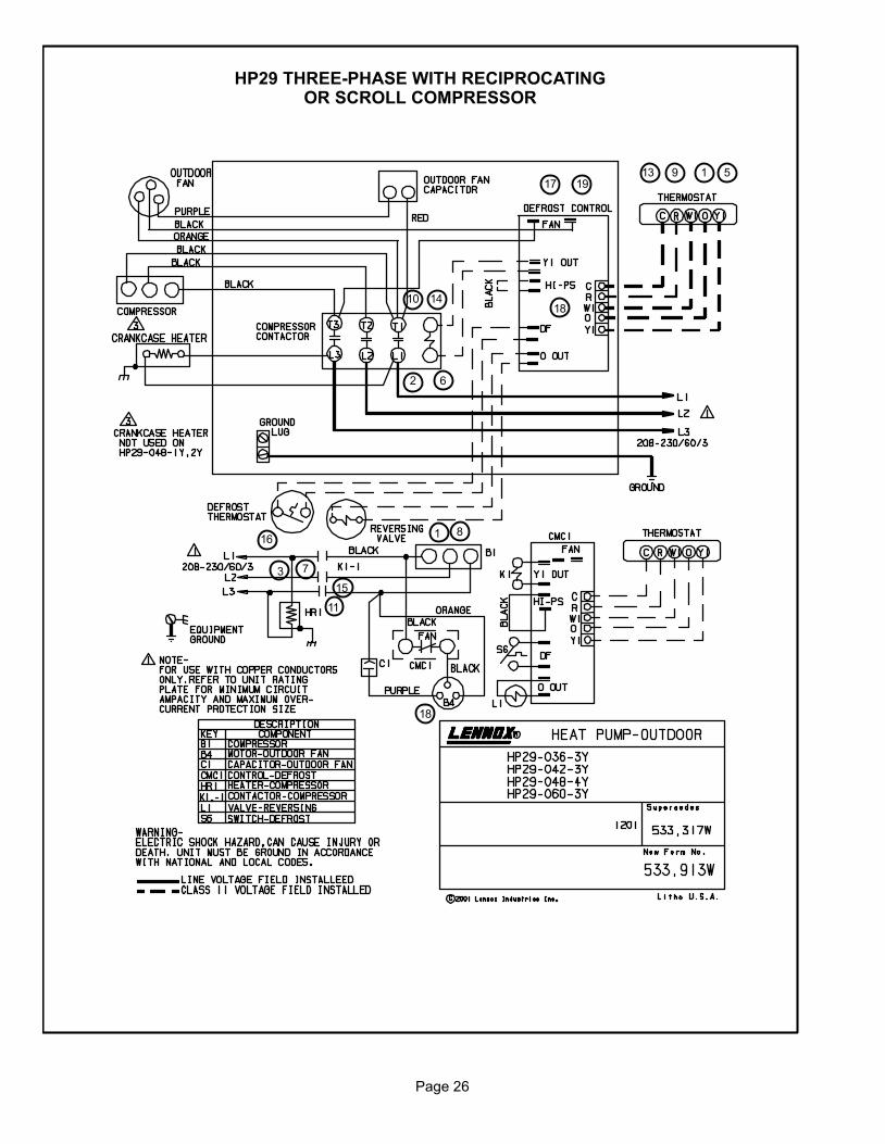
Page 26
HP29 THREE−PHASE WITH RECIPROCATINGOR SCROLL COMPRESSOR
1
2
3
5
6
7
8
9
10
11
13
15
14
16
17
18
19
1
18
Page 27
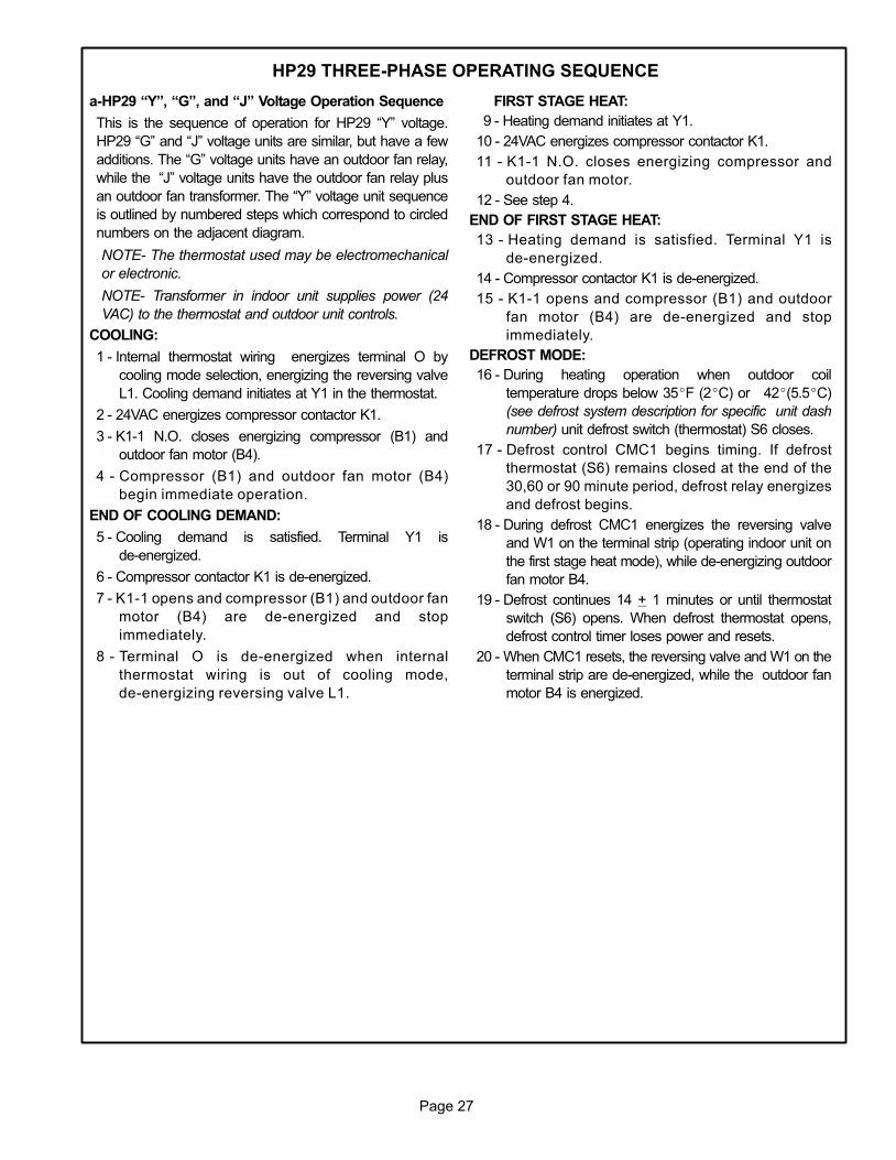
HP29 THREE-PHASE OPERATING SEQUENCE
a−HP29 �Y", �G", and �J" Voltage Operation Sequence
This is the sequence of operation for HP29 �Y" voltage.
HP29 �G" and �J" voltage units are similar, but have a few
additions. The �G" voltage units have an outdoor fan relay,
while the �J" voltage units have the outdoor fan relay plus
an outdoor fan transformer. The �Y" voltage unit sequence
is outlined by numbered steps which correspond to circled
numbers on the adjacent diagram.
NOTE− The thermostat used may be electromechanical
or electronic.
NOTE− Transformer in indoor unit supplies power (24
VAC) to the thermostat and outdoor unit controls.
COOLING:
1 − Internal thermostat wiring energizes terminal O by
cooling mode selection, energizing the reversing valve
L1. Cooling demand initiates at Y1 in the thermostat.
2 − 24VAC energizes compressor contactor K1.
3 − K1-1 N.O. closes energizing compressor (B1) and
outdoor fan motor (B4).
4 − Compressor (B1) and outdoor fan motor (B4)
begin immediate operation.
END OF COOLING DEMAND:
5 − Cooling demand is satisfied. Terminal Y1 is
de-energized.
6 − Compressor contactor K1 is de-energized.
7 − K1-1 opens and compressor (B1) and outdoor fan
motor (B4) are de-energized and stop
immediately.
8 − Terminal O is de−energized when internal
thermostat wiring is out of cooling mode,
de−energizing reversing valve L1.
FIRST STAGE HEAT:
9 − Heating demand initiates at Y1.
10 − 24VAC energizes compressor contactor K1.
11 − K1-1 N.O. closes energizing compressor and
outdoor fan motor.
12 − See step 4.
END OF FIRST STAGE HEAT:
13 − Heating demand is satisfied. Terminal Y1 is
de-energized.
14 − Compressor contactor K1 is de-energized.
15 − K1-1 opens and compressor (B1) and outdoor
fan motor (B4) are de-energized and stop
immediately.
DEFROST MODE:
16 − During heating operation when outdoor coil
temperature drops below 35�F (2�C) or 42�(5.5�C)
(see defrost system description for specific unit dash
number) unit defrost switch (thermostat) S6 closes.
17 − Defrost control CMC1 begins timing. If defrost
thermostat (S6) remains closed at the end of the
30,60 or 90 minute period, defrost relay energizes
and defrost begins.
18 − During defrost CMC1 energizes the reversing valve
and W1 on the terminal strip (operating indoor unit on
the first stage heat mode), while de-energizing outdoor
fan motor B4.
19 − Defrost continues 14 + 1 minutes or until thermostat
switch (S6) opens. When defrost thermostat opens,
defrost control timer loses power and resets.
20 − When CMC1 resets, the reversing valve and W1 on the
terminal strip are de-energized, while the outdoor fan
motor B4 is energized.
Related Documents