SPE 119918 CORING UNCONSOLIDATED FORMATION -LOWER FARS: A CASE STUDY Ibrahim Al-Sammak, SPE; K. Ahmed, SPE; Santanu De, SPE; Faisal Al-Bous; Fatma Ahmad and Faisal Abbas - Kuwait Oil Company Copyright 2009, Society of Petroleum Engineers This paper was prepared for presentation at the 2009 SPE Middle East Oil & Gas Show and Conference held in the Bahrain International Exhibition Centre, Kingdom of Bahrain, 15–18 March 2009. This paper was selected for presentation by an SPE program committee following review of information contained in an abstract submitted by the author(s). Contents of the paper have not been reviewed by the Society of Petroleum Engineers and are subject to correction by the author(s). The material does not necessarily reflect any position of the Society of Petroleum Engineers, its officers, or members. Electronic reproduction, distribution, or storage of any part of this paper without the written consent of the Society of Petroleum Engineers is prohibited. Permission to reproduce in print is restricted to an abstract of not more than 300 words; illustrations may not be copied. The abstract must contain conspicuous acknowledgment of SPE copyright. Abstract Lower Fars is a shallow unconsolidated sandstone reservoir with high inter-granular porosity filled with heavy oil in southern part of Ratqa Field in Kuwait. The shallow depth (500’ to 800’), friable sand laminated with shale and high viscosity heavy oil in pores have made coring this sand quite challenging. Last recovered core with rubber-sleeved core barrel in the eighties was only up to 60%. This paper describes how thoughtful mix-up of technology, innovative techniques and proper coordination by aligning all concerned has helped in meeting the challenge of coring unconsolidated sand and it's processing. Using low invasive core fluid, shorter core length, Aluminum inner core barrel, separate core bit to cut major sand / shale, full core catcher system, vertical slabbing at well mouth and on-site freezing have improved core recovery in excess of 85%. While low-solid content coring fluid with a pH of 9 resulted in low mud invasion, reduced WOB, ROP and SPM ensured fewer washouts during coring. Low abrasive core head with clam shell full closure core catcher produced good recovery. Core barrel length was reduced from standard 30' to 10’, which was slabbed to 3' size keeping barrel vertically at well mouth. At well site it was frozen vertically with foam on top to minimise lateral movement and transported in freezer. At Core Lab it was kept frozen with dry ice, slabbed and plugged with liquid N2. It is expected that the obtained core plugs from similarly cored 6 wells shall lead to meaningful Routine and Special Core Analysis, which was suspected in old cores. This would help in developing the depositional geological model in conjunction with the image logs.

Welcome message from author
This document is posted to help you gain knowledge. Please leave a comment to let me know what you think about it! Share it to your friends and learn new things together.
Transcript
SPE 119918
CORING UNCONSOLIDATED FORMATION -LOWER FARS: A CASE STUDY
Ibrahim Al-Sammak, SPE; K. Ahmed, SPE; Santanu De, SPE; Faisal Al-Bous; Fatma Ahmad and Faisal Abbas - Kuwait Oil Company Copyright 2009, Society of Petroleum Engineers This paper was prepared for presentation at the 2009 SPE Middle East Oil & Gas Show and Conference held in the Bahrain International Exhibition Centre, Kingdom of Bahrain, 15–18 March 2009. This paper was selected for presentation by an SPE program committee following review of information contained in an abstract submitted by the author(s). Contents of the paper have not been reviewed by the Society of Petroleum Engineers and are subject to correction by the author(s). The material does not necessarily reflect any position of the Society of Petroleum Engineers, its officers, or members. Electronic reproduction, distribution, or storage of any part of this paper without the written consent of the Society of Petroleum Engineers is prohibited. Permission to reproduce in print is restricted to an abstract of not more than 300 words; illustrations may not be copied. The abstract must contain conspicuous acknowledgment of SPE copyright.
Abstract
Lower Fars is a shallow unconsolidated sandstone reservoir with high inter-granular porosity filled with heavy oil in southern part of Ratqa Field in Kuwait. The shallow depth (500’ to 800’), friable sand laminated with shale and high viscosity heavy oil in pores have made coring this sand quite challenging. Last recovered core with rubber-sleeved core barrel in the eighties was only up to 60%.
This paper describes how thoughtful mix-up of technology, innovative techniques and proper coordination by aligning all concerned has helped in meeting the challenge of coring unconsolidated sand and it's processing.
Using low invasive core fluid, shorter core length, Aluminum inner core barrel, separate core bit to cut major sand / shale, full core catcher system, vertical slabbing at well mouth and on-site freezing have improved core recovery in excess of 85%.
While low-solid content coring fluid with a pH of 9 resulted in low mud invasion, reduced WOB, ROP and SPM ensured fewer washouts during coring. Low abrasive core head with clam shell full closure core catcher produced good recovery. Core barrel length was reduced from standard 30' to 10’, which was slabbed to 3' size keeping barrel vertically at well mouth. At well site it was frozen vertically with foam on top to minimise lateral movement and transported in freezer. At Core Lab it was kept frozen with dry ice, slabbed and plugged with liquid N2. It is expected that the obtained core plugs from similarly cored 6 wells shall lead to meaningful Routine and Special Core Analysis, which was suspected in old cores. This would help in developing the depositional geological model in conjunction with the image logs.
2 [SPE 119918]
Introduction The success of core analysis depends largely on how good the coring operation and well site core
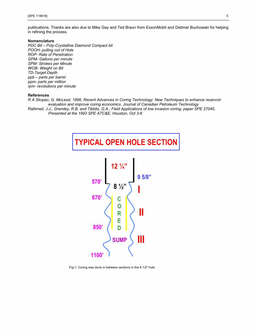
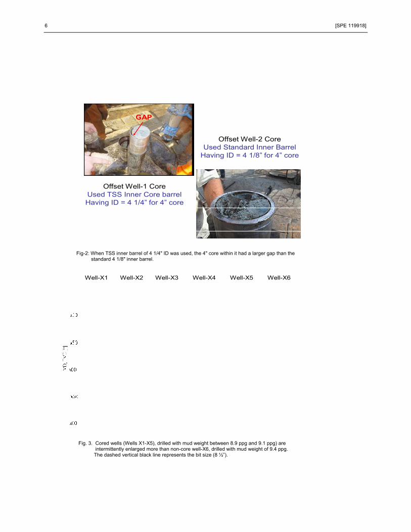
preservation are made. Conventional Coring in the unconsolidated formation is always problematic. The shallow sandstone reservoir filled with heavy oil in southern Ratqa Field of Kuwait is a challenge by itself. Earlier attempts in the eighties with rubber-sleeved core barrel had resulted in maximum recovery only up to 60%. When new wells were drilled as part of development plan, it was decided to core some early wells using modern coring technology. Low invasive core fluid, shorter core barrel length, Aluminum inner core barrel, separate core bit to cut major sand / shale and full core catcher system had helped in core recovery in excess of 85%. While low-solid content coring fluid resulted in low mud invasion, reduced WOB, ROP and SPM ensured fewer washouts during coring. Low abrasive core head with clam shell full closure core catcher resulted in better recovery. Core barrel length was reduced from standard 30' to 10’, which was slabbed to 3' size keeping barrel vertically at well mouth. At well site it was frozen vertically with foam on top to minimise lateral movement before it was transferred to a chest freezer. The freezer was transported in running condition to Core Lab where it was kept frozen with dry ice for atleast 2 weeks. Core slabbing and plugging were performed using liquid N2. The obtained core plugs helped in meaningful Routine and Special Core Analysis, which was suspected in old cores. The good core recovery had also helped in characterization of depositional facies leading to the geological model in conjunction with the image logs. Unconsolidated sand coring- a new ball game The main areas of concern for unconsolidated formation coring are: a) minimising mud invasion b) using proper coring assembly so as not to lose low strength rock capture during coring c) core handling process so as not to jeopardize core preservation and d) non-reactive preservation material. Good old days coring had neither a dedicated mud system nor appropriate coring assembly. Normal drilling mud with low solid was used for coring. Core heads were not designed to minimize the washout of rock due to jetting effect. Rubber sleeve core barrel was used to collect the core. Lack of a dedicated coring system for the unconsolidated sand generally resulted in poor recovery and rock with suspected quality. Most of the pay sands were either not recovered or recovery used to be too low to design any robust core analysis programme later on. Low invasive mud with low fluid loss properties help to reduce any invasion either ahead of core bit or inside core head. Keeping pH of the mud quite low helps in maintaining the wettability characteristics of the cored rock. Low invasive core heads with on face discharge ports help to reduce any washout in close vicinity of coring. Double-tube core barrel ensures effectively much improved recovery in unconsolidated formation. Using non-reactive foam on top to stabilize the core against lateral movement and on-site freezing helps to maintain good core integrity. Offset well Coring In 2005, first such coring was attempted in one of the offset wells. The recovery was marginal. Main reasons for the poor recovery could be attributed to: i) longer core barrel size (20' / 40') ii) larger inner barrel diameter (4 1/4" for 4"-dia core) iii) improper core catcher (soft core catcher with retainer) iv) wrong slabbing method at well mouth (bottom to top – which forced slumping of core standing above due to gravity) and v) improper mud and mud programme (not freshly prepared, higher weight mud was used to drill up to coring depth, changed to coring fluid during coring and again changed to higher weight mud up to TD). In 2006 another offset well was drilled, where the entire coring programme was modified based on the lessons learnt from the first offset well. The mud system was changed to a low invasive, zero-solid coring fluid for the entire open hole section (pre, post and during coring). Core barrel size was reduced to 10' from earlier 20'/ 40' long; inner core barrel diameter was reduced to 4 1/8" for the 4" core. Clam-shell full-closure core catcher was used and drilling parameters like WOB, ROP and SPM were reduced to the practical limit without compromising the well safety. Different core heads were used to core predominantly sand and shale sections. Core slabbing at well mouth was done from top to bottom using a thinner and sharp-edged blade. All these changes resulted in dramatically improved core recovery. Fig-1 shows a schematic of the 8 1/2" section where coring was done mid-way thru the formation. Fig-2 shows the gap inside the 4 1/4" inner barrel used in the first offset well. The success of this offset well coring helped in developing a coring protocol for future wells. Coring Protocol The three main aspects of coring are: i)cutting the core ii) getting the core and iii) retaining the core. Though objectively speaking, the same facets are also valid for coring in unconsolidated formation; the focus in each gets accentuated due to the strength of the rock. More than cutting the core, cutting it with minimum fluid invasion, not only getting the core but getting it inside the inner barrel and retaining the core through a non-intrusive catcher system became more important. The Coring Protocol while emphsising these important parameters, laid out a detailed work plan for the coring and drilling company during the coring process to get representative formation samples. The entire process was designed indigenously, including the small core barrel size of 10'- which is rarely practiced in the industry. It includes the main features of the core head (Low invasive), core catcher (Full closure), core barrel (dual tube), coring fluid (Low density, low pH KCl Polymer); coring process- including equipment layout,
[SPE 119918] 3
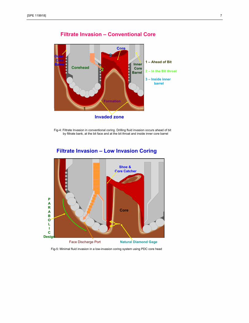
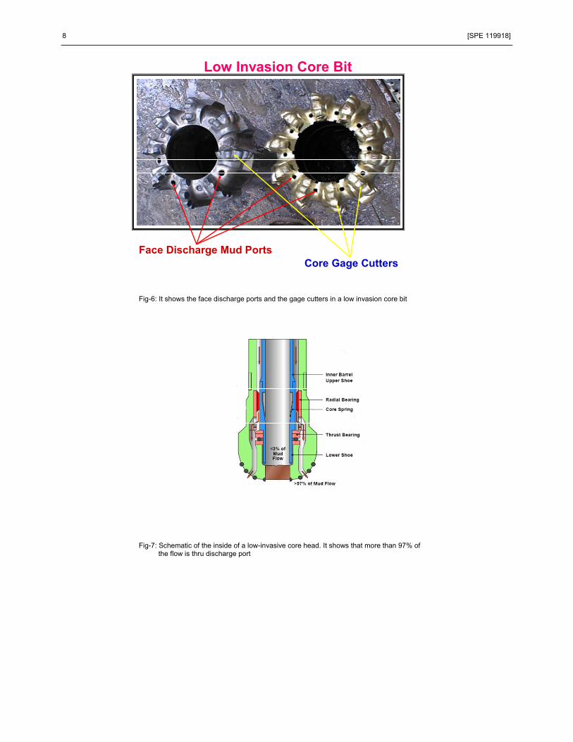
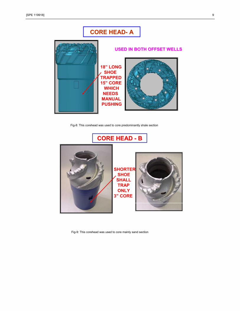
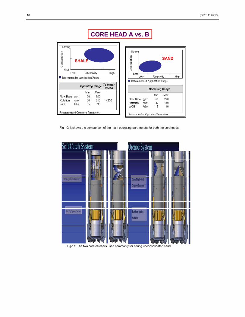
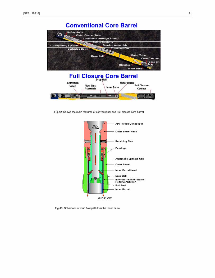
rig floor procedure and core handling at site. It is a comprehensive document which is a guide to all major equipments and processes required to obtain good recovery. Coring Fluid In general, the acceptable additives for a coring fluid include bentonite, barite, calcium carbonate, XC, XCA, PHPA polymers, potassium chloride, sodium and potassium hydroxide, modified starch and any bacteride or polyglycerols. The unacceptable additives may include high pH agents, surfactants, lignosulphates, lubricants, corrosion inhibitor, emulsifier, de-emulsifier, defoaming agents and deflocculants. The designed coring fluid in Ratqa was a low density, low pH KCl Polymer mud with a concentration of nearly 50 ppb with no barite or diesel in it. Typical values of density, viscosity, yield point, gel strength and pH of the fluid were 8.9 ppg, 35 – 45 s, 14 -18 lb/100ft2, 10 - 18 and 8.5 respectively. When the same fluid was maintained during post-coring drilling to TD, caliper log showed quite a bit of hole enlargement against comparatively low compressive strength sands. When the mud weight was raised to 9.3 ppg in the TD section in a non-core well, the hole condition dramatically improved through build up of filter cake due to presence of solids in the mud (Fig-3) Drilling Fluid Invasion During coring, drilling fluid filtrate invasion occurs when the mud filtrate is forced in to the formation by differential pressure. The amount of invasion depends on i) rock & fluid properties iii) drilling parameters and drilling fluid filtration characteristics. In conventional coring drilling fluid invasion occurs in three main areas: i) ahead of the bit when drilling fluid filtrate forms a fluid bank resulting total invasion in the core ii) at the bit face and in the bit throat and iii) inside the inner core barrel due to static filtration (Fig-4). Low invasion coring system with PDC core heads greatly reduces filtrate invasion due to its: i) parabolic bit profile with cutters set on ribs, as opposed to random set, helps to reduce damage to filter cake ii) improved cutter design with less number of cutters to increase cutting depth at higher rates iii) less number of gage cutters which reduces contact time of gage cutters with the core iv) elimination of throat cutters, hence preserving the filter cake. The biggest improvement is the introduction of face discharge ports which forces the mud flow away from core centre (Fig-5). Fig-6 shows more clearly the face discharge ports and the gage cutters. Fig-7 shows schematic of inside of the core head and how the mud flows thru the discharge port. Core Head The low invasion core head with PDC bit is the definite choice for the unconsolidated formation. However, in Ratqa a single core head could not core both predominantly sand or shale sections. It was observed excessive washout in sand when used the shale bit and jamming when sand bit was used to core shale section. Fig-8 & 9 shows the core heads used for shale and sand section coring. Fig-10 shows the more aggressive operating parameters for the shale core head compared to the sand one. Core Catcher There are many types of core catchers- collate/ slip ring, basket, slip dog and full closure system. The full closure system works best for the unconsolidated sand. Fig-11 shows two types of full closure systems- the soft catch system which was used in the first offset well whereas the Orenoc clam-shell type full closure system was used in all wells thereafter. In the soft catch system, the core is retained by hydraulically deforming the core retainer. The retainer has a stainless steel cage located between two sliding sleeves at the lower end of the inner barrel. When a hydraulic pressure is applied, the sliding portions move together and the cage is deformed in an inward direction to penetrate and retain the sample. The Orenoc system is activated hydraulically and is insensitive to pressure fluctuation. The activation system has a sealed oil column which holds the weight of the inner barrel during the coring time. To activate the retainer, a ball is dropped to sit on a piston. An increase in pressure forces the piston down the inner barrel opening a flow path for the oil to escape, thereby moving down the inner barrel. This causes the clamshells to close and securely retain the core inside the barrel. A back-up spring catcher is used to ensure core retention in case a harder formation is encountered which can not be retained by either of the above two soft catchers. Core Barrel Full closure system works on the dual tube principle, where the inner barrel stabilization is of utmost importance. The stabilizer helps the inner barrel to be non-rotating, prevents inner barrel wobble and most importantly prevents induced fracturing of the core when removed from the outer barrel. All coring in Ratqa unconsolidated sand was performed with the full closure core barrel. Fig-12 shows the main features of a conventional core barrel vs. full closure core barrel. Fig-13 shows the schematic of the mud flow path thru the inner barrel. Operating Process: In soft formation, core cutting needs to be conducted with minimum flow rate (GPM), reasonable weight-on-bit
4 [SPE 119918]
(WOB), minimum rotary speed (RPM), moderate rate of penetration (ROP). In a Ratqa unconsolidated formation coring, typical values for ROP are between 5 ft/min (shale) to 35 ft/min (sand), flowrate between 80 to 90 gpm, weight on bit between 60 70 Klb, rotary speed between 50 to 60 rpm. At the beginning of coring, the rotary (RPM) and the pump (SPM) are maintained at slowest possible values. These are adjusted depending on the formation to be cored. While the pump is switched off in the last 1/2' to 1' to prevent any washout due to circulation, the rotation (RPM) is continued till the TD of coring. A typical job sequence is as follows:
1. At the start of the coring, tag bottom & pull up minimum 5’ from TD. 2. Circulate. Break Kelly and drop 1st Ball to close the inner barrel. 3. Start RPM & Pump at lowest SPM (50 SPM / 80 GPM) 4. Go to TD and start coring. 5. Just before reaching the bottom-most coring depth- in 10’ core barrel a depth of 9 to 9.5’- STOP Pump 6. At the bottom-most coring depth- when the core barrel reached 10’ STOP RPM. 7. Drop 2nd Ball. Allow it to fall freely for atleast 10 min at the depth of 600 to 700’. 8. Start pump to activate catcher. Increase to higher SPM/ GPM, as per requirement. 9. Start to POOH.
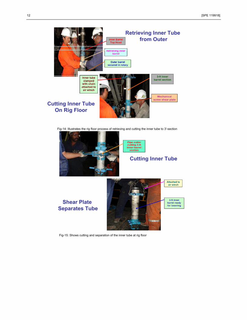
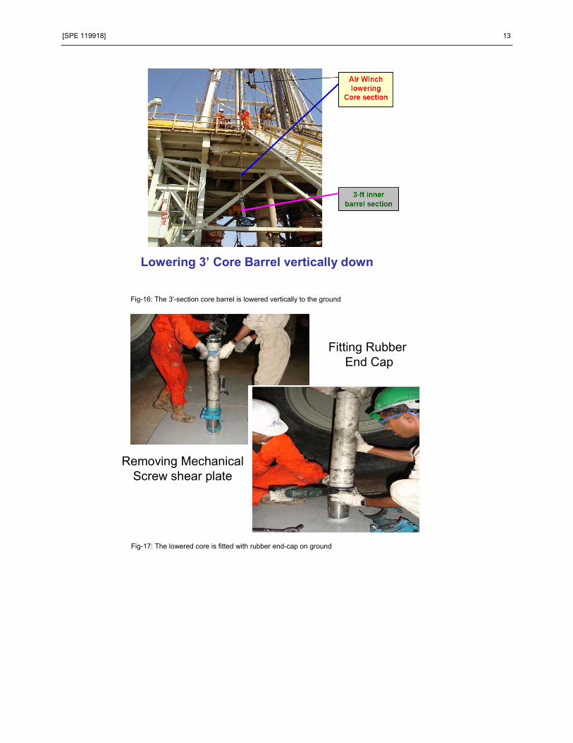
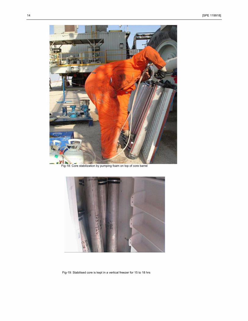
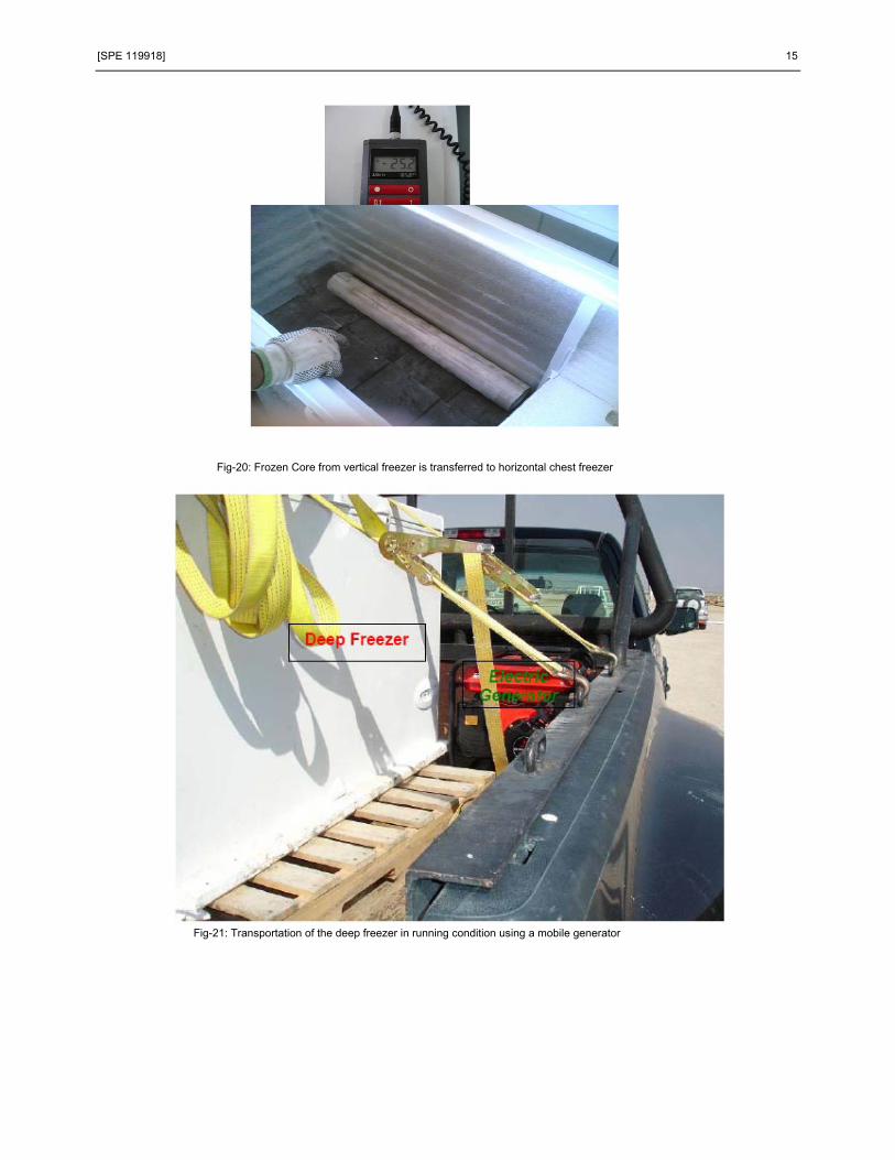
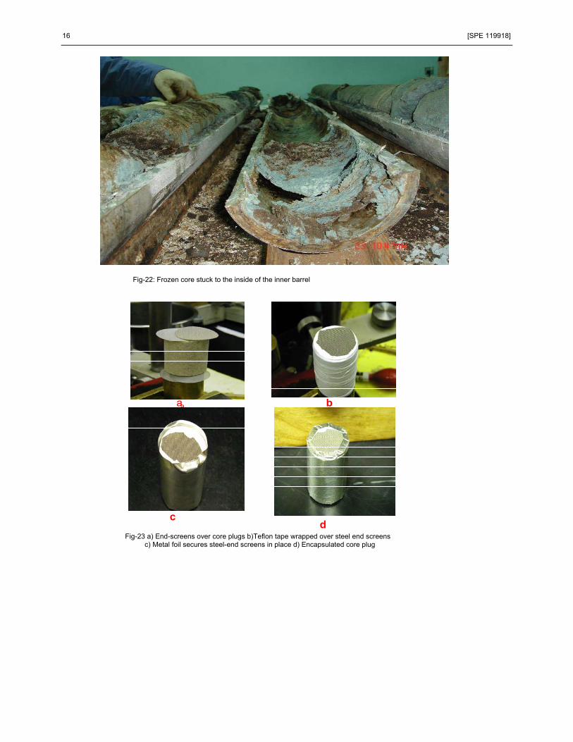
Fig-14 to 17 illustrates the handling of the core at rig floor and on the ground. The key thing during all these operation is to keep the core barrel near vertical so as not to disturb the soft formation core. Core Stabilisation and Preservation at site The 3' section was stabilized by pumping foam (Fig-18) at the top section. In order that the foam does not exert higher pressure on the core, 1 or 2 small holes are drilled on the core barrel prior to pumping. For Ratqa unconsolidated formation coring, foam was chosen over epoxy for the reasons that it is easy to pump, less toxic and no heat was built up during pumping process. Foam due to its high porosity may absorb fluids from the core and may affect wettability of oil-wet rock. To minimize this risk, foam is placed only at the top part of the core. The core was then kept in a vertical freezer (Fig-19) for 15 to 18 hrs to be frozen and then it was transferred to a horizontal chest freezer (fig-20) where it is kept for a minimum of 36 hrs before moving the freezer to core Lab for processing. During the transportation process, the freezer was kept running using a mobile generator (fig-21). Core Processing Once the cores are transported to Core lab, they are kept in the chest freezer with dry ice for atleast two weeks before it is slabbed. Cores of the second offset well were slabbed in such a way that only the core barrel is cut in to half, without cutting the core. When the two halves of the barrel were opened, parts of the frozen core remain stuck to inside of the barrel (Fig-22). This affected the plugging process. To get stable frozen core, it was decided to cut the entire core 1/3rd & 2/3rd. the regular diamond cutter did not cut the core evenly. When the core was cut with a band saw cooled with liquid nitrogen, the cut was smooth and even. Core Plugging The frozen core once thawed can not be used to take a good plug. Therefore, closely-spaced plugs were taken from the oil bearing sands. Most plugs are plunge cut. Wrapping and mounting of the plugs were meticulously performed. Two screens, one fine mesh and the other course mesh are placed at the ends to prevent solids from moving into or out of the core and facilitates fluid dispersion during core floods. The plug is insulated first with Teflon tape and then wrapped with metal like tin or nickel. Teflon helps to confine fluids in the rock, where as the metal provides a hard surface for repeated testing (Fig-23). A nominal overburden pressure is applied to the core plug and wrapping (~400psig). This ‘seats’ the Teflon tape and metal foil to the core plug removing air gaps and filling small surface voids. Conclusions
• The coring process as defined in the coring protocol has helped to successfully core 24 wells so far, with over 85% core recovery
• The low invasive core head and drilling fluid has helped to get achieve this high order of recovery • The on-site core stabilization and preservation has helped to maintain good core integrity • The slabbing process, plugging and plug mounting has helped to get good quality plugs, which were later
ascertained thru their CT Scan • The obtained good quality plugs have helped in Routine as well as Special core Analysis
Acknowledgements The authors express their sincere appreciation to Manmagmnet of Kuwait Oil Company and the Ministry of Oil, Kuwait for encouragement and granting necessary permissions to present and publish this paper in external
[SPE 119918] 5
publications. Thanks are also due to Mike Gay and Ted Braun from ExxonMobil and Dietmar Buchowski for helping in refining the process.
Nomenclature PDC Bit – Poly-Crystalline Diamond Compact bit POOH- pulling out of Hole ROP- Rate of Penetration GPM- Gallons per minute SPM- Strokes per Minute WOB- Weight on Bit TD-Target Depth ppb – parts per barrel ppm- parts per million rpm- revolutions per minute References R A Skopec, G. McLeod, 1996. Recent Advances in Coring Technology: New Techniques to enhance reservoir
evaluation and improve coring economics. Journal of Canadian Petroleum Technology Rathmeil, J.J., Gremley, R.B. and Tibbits, G.A.: Field Applications of low invasion coring, paper SPE 27045,
Presented at the 1993 SPE ATC&E, Houston, Oct 3-6
TYPICAL OPEN HOLE SECTION
12 ¼”9 5/8”
8 ½”CORED
SUMP
570570’’
670670’’
850850’’
11001100’’
II
IIII
IIIIII
Fig-1: Coring was done in between sections in the 8 1/2" hole.
6 [SPE 119918]
GAP
Offset Well-1 CoreUsed TSS Inner Core barrelHaving ID = 4 1/4” for 4” core
Offset Well-2 CoreUsed Standard Inner Barrel
Having ID = 4 1/8” for 4” core
Fig-2: When TSS inner barrel of 4 1/4" ID was used, the 4" core within it had a larger gap than the standard 4 1/8" inner barrel.
Well-X1 Well-X2 Well-X3 Well-X4 Well-X5 Well-X6
Fig. 3. Cored wells (Wells X1-X5), drilled with mud weight between 8.9 ppg and 9.1 ppg) are intermittently enlarged more than non-core well-X6, drilled with mud weight of 9.4 ppg. The dashed vertical black line represents the bit size (8 ½”).
[SPE 119918] 7
Invaded zone
1
2
3
2 – In the Bit throat
3 – Inside inner barrel
1 – Ahead of Bit
Core
Filtrate Invasion – Conventional Core
Corehead
Outer Core
Barrel InnerCore
Barrel
Formation
Fig-4: Filtrate Invasion in conventional coring. Drilling fluid invasion occurs ahead of bit by filtrate bank, at the bit face and at the bit throat and inside inner core barrel
Core
Filtrate Invasion – Low Invasion Coring
PARABOLIC
DesignNatural Diamond GageFace Discharge Port
Shoe & Core Catcher
Fig-5: Minimal fluid invasion in a low-invasion coring system using PDC core head
8 [SPE 119918]
Face Discharge Mud PortsCore Gage Cutters
Low Invasion Core Bit
Fig-6: It shows the face discharge ports and the gage cutters in a low invasion core bit
Fig-7: Schematic of the inside of a low-invasive core head. It shows that more than 97% of the flow is thru discharge port
[SPE 119918] 9
CORE HEADCORE HEAD-- AA
USED IN BOTH OFFSET WELLSUSED IN BOTH OFFSET WELLS
18” LONGSHOE
TRAPPED15” CORE
WHICH NEEDS
MANUAL PUSHING
Fig-8: This corehead was used to core predominantly shale section
CORE HEAD CORE HEAD -- BB
SHORTERSHOESHALLTRAPONLY
3” CORE
Fig-9: This corehead was used to core mainly sand section
10 [SPE 119918]
SHALESHALE SANDSAND
CORE HEAD A vs. BCORE HEAD A vs. B
Fig-10: It shows the comparison of the main operating parameters for both the coreheads
Fig-11: The two core catchers used commonly for coring unconsolidated sand
[SPE 119918] 11
Conventional Core Barrel
Full Closure Core Barrel
Fig-12: Shows the main features of conventional and Full closure core barrel
Fig-13: Schematic of mud flow path thru the inner barrel
12 [SPE 119918]
Retrieving Inner Tube from Outer
Cutting Inner TubeOn Rig Floor
Fig-14: Illustrates the rig floor process of retrieving and cutting the inner tube to 3'-section
Cutting Inner Tube
Shear Plate Separates Tube
Fig-15: Shows cutting and separation of the inner tube at rig floor
[SPE 119918] 13
Lowering 3’ Core Barrel vertically down
Fig-16: The 3'-section core barrel is lowered vertically to the ground
Removing MechanicalScrew shear plate
Fitting Rubber End Cap
Fig-17: The lowered core is fitted with rubber end-cap on ground
14 [SPE 119918]
Fig-18: Core stabilization by pumping foam on top of core barrel
Fig-19: Stabilised core is kept in a vertical freezer for 15 to 18 hrs
[SPE 119918] 15
Fig-20: Frozen Core from vertical freezer is transferred to horizontal chest freezer
Fig-21: Transportation of the deep freezer in running condition using a mobile generator
16 [SPE 119918]
Fig-22: Frozen core stuck to the inside of the inner barrel
aa b
cd
Fig-23 a) End-screens over core plugs b)Teflon tape wrapped over steel end screens c) Metal foil secures steel-end screens in place d) Encapsulated core plug
Related Documents