L8542644 12/2011 rev 4 UNIONE NAZIONALE COSTRUTTORI AUTOMATISMI PER CANCELLI, PORTE SERRANDE ED AFFINI CORE

Welcome message from author
This document is posted to help you gain knowledge. Please leave a comment to let me know what you think about it! Share it to your friends and learn new things together.
Transcript
L854264412/2011 rev 4
UNIONE NAZIONALE COSTRUTTORIAUTOMATISMI PER CANCELLI, PORTE
SERRANDE ED AFFINI
CORE
2
DL1
DL2
N GNDL
LAMP 115/230Vac40W max
CO
M
MC
SCA 24Vac
3W max 24Va
c20
0mA
max
P.P.
STOP
SWO
SWC
PHO
T
CO
M
P1 P2
SW
1 6
TW
ENC1
TCA
ANT
SH
IELD
AN
T
U2
F3
F2
F3 CORE 230: F6,3AF3 CORE 115: F10A
F2: F315 mA
1
3
Dichiarazione CE di conformità
Fabbricante: Automatismi Benincà SpA.Indirizzo: Via Capitello, 45 - 36066 Sandrigo (VI) - Italia
Dichiara che: la centrale di comando CORE.è conforme alle seguenti disposizioni pertinenti:Direttiva sulla compatibilità elettromagnetica: 89/336/CCE, 93/68/CEEDirettiva sulla bassa tensione: 73/23/CEE, 93/68/CEE
Benincà Luigi, Responsabile legale.Sandrigo, 10/11/2011.
DATI TECNICIAlimentazione di rete 230 Vac 50/60 Hz (115 Vac 50/60Hz CORE 115)
Uscita Motore 1 motore 230 Vac (115Vac CORE 115)
Potenza massima motore 750 W
Uscita alimentazione accessori 24Vdc 200mA max.
Grado di protezione Versione nel box LB: IP55 - Versione BULL:IP30
Temp. funzionamento -20°C / +70°C
Ricevitore radio 433,92 MHz incorporato e confgurabile (rolling-code o fisso+rolling-code + ARC Advanced Rolling Code)
N° codici memorizzabili 64
AVVERTENZE Questo manuale è destinato esclusivamente a personale qualificato per l’installazione e la manutenzione di aperture automatiche.
Nessuna informazione qui presente è di interesse o di utilità per l’utente finale.
Conservare questo manuale per futuri utilizzi.
L’installatore deve fornire tutte le informazioni relative al funzionamento automatico, manuale e di emergenza dell’automazione, e consegnare all’utilizzatore dell’impianto le istruzioni d’uso.
•Prevedere sulla rete di alimentazione un inter-ruttore/sezionatore onnipolare con distanza d’apertura dei contatti uguale o superiore a 3 mm.
Verificare che a monte dell’impianto elettrico vi sia un interrut-tore differenziale e una protezione di sovracorrente adeguati. Alcune tipologie di installazione richiedono il collegamento dell’anta ad un impianto di messa a terra rispondente alle vigenti norme di sicurezza.
L’installazione elettrica e la logica di funzionamento devono essere in accordo con le normative vigenti.
I conduttori alimentati con tensioni diverse, devono essere fisicamente separati, oppure devono essere adeguatamente isolati con isolamento supplementare di almeno 1 mm.
I conduttori devono essere vincolati da un fissaggio supple-mentare in prossimità dei morsetti.
Durante gli interventi di installazione, manutenzione e ri-parazione, togliere l’alimentazione prima di accedere alle parti elettriche.
Ricontrollare tutti i collegamenti fatti prima di dare tensione.
Gli ingressi N.C. non utilizzati devono essere ponticellati.
Le descrizioni e le illustrazioni presenti in questo manuale non sono impegnative. Lasciando inalterate le caratteristiche essenziali del prodotto il fabbricante si riserva il diritto di apportare qualsiasi modifica di carattere tecnico, costruttivo o commerciale senza impegnarsi ad aggiornare la presente pubblicazione.
4
CENTRALE DI ComANDo CoRE
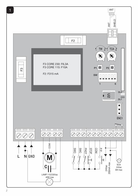
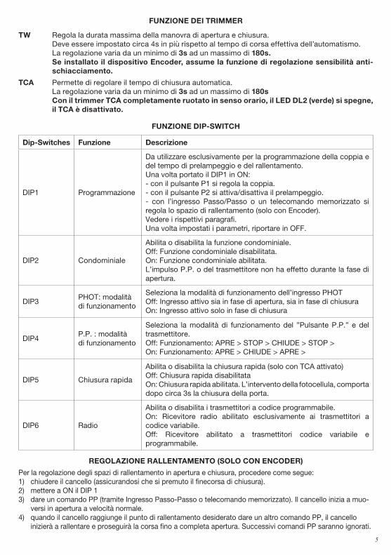
CoLLEGAmENTI ELETTRICINella seguente tabella sono descritti i collegamenti elettrici rappresentati in Fig. 1:
morsetti Funzione Descrizione
L-N-GND AlimentazioneIngresso 230Vac 50/60Hz (CORE)Ingresso 115Vac 50/60Hz (CORE 115V))(1-Fase/2-Neutro/GND-Collegamento di terra)
MOT-COM-MOT MotoreCollegamento al motore: (MOT-marcia/COM-Comune/MOT-marcia)
N-BLINK LAMPUscita collegamento Lampeggiante CORE: 230 Vac 40W max.CORE 115V: 115 Vac 40W max.
SWO SWO Ingresso finecorsa APERTURA (contatto N.C.)
SWC SWC Ingresso finecorsa CHIUSURA (contatto N.C.)
PHOT (CHIUDE) PHOT
Ingresso collegamento dispositivi di sicurezza, contatto N.C. (ad es. fotocellule): comportamento configurabile tramite DIP3).In modalità “Uomo Presente” assume la funzione comando CHIU-DE, collegare in questo caso un pulsante N.O.
STOP STOP Ingresso pulsante STOP (contatto N.C.)
COM COM Comune per tutti gli ingressi di comando.
P.P. (APRE) Passo-PassoIngresso pulsante passo-passo (contatto N.O.).In modalità “Uomo Presente” assume la funzione comando APRE.
24 VAC 24Vac Uscita alimentazione accessori 24Vac/200mA max.
SCA SCA
Contatto libero da tensione non isolato per collegamento spia cancella aperto.Contatto aperto ad anta chiusa, intermittente durante il movimento dell’anta, chiuso ad anta aperta.
ENC1 ENCODERIngresso collegamento encoder. Vedi paragrafo REGOLAZIONE RALLENTAMENTO
SHIELD-ANT AntennaCollegamento antenna scheda radioricevente incorporata (SHIELD-schermo/ANT-segnale).
Nota: La centrale dispone di un pulsante “P2” con la medesima funzionalità del pulsante Passo-Passo, utile per comandare l’automazione durante la fase di installazione (solo con DIP2:OFF).
VERIFICA CoLLEGAmENTI:
1) Togliere alimentazione.2) Sbloccare manualmente la porta, portarla a circa metà della corsa e ribloccarla.3) Ripristinare l’alimentazione.4) Dare un comando di passo-passo mediante pulsante P2, ingresso P.P. o radiocomando. 5) La porta deve muoversi in apertura. Nel caso ciò non avvenisse, a motore fermo, è sufficiente invertire
tra loro i fili di marcia (MOT/MOT) del motore e dei finecorsa (SWO/SWC).6) Procedere con la regolazione dei Tempi e delle Logiche di funzionamento .
5
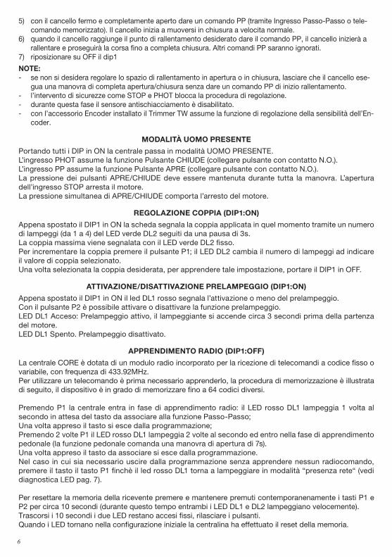
FUNZIoNE DEI TRImmER
TW Regola la durata massima della manovra di apertura e chiusura. Deve essere impostato circa 4s in più rispetto al tempo di corsa effettiva dell’automatismo. La regolazione varia da un minimo di 3s ad un massimo di 180s. Se installato il dispositivo Encoder, assume la funzione di regolazione sensibilità anti-
schiacciamento.
TCA Permette di regolare il tempo di chiusura automatica. La regolazione varia da un minimo di 3s ad un massimo di 180s Con il trimmer TCA completamente ruotato in senso orario, il LED DL2 (verde) si spegne,
il TCA è disattivato.
FUNZIoNE DIP-SWITCH
Dip-Switches Funzione Descrizione
DIP1 Programmazione
Da utilizzare esclusivamente per la programmazione della coppia e del tempo di prelampeggio e del rallentamento. Una volta portato il DIP1 in ON:- con il pulsante P1 si regola la coppia.- con il pulsante P2 si attiva/disattiva il prelampeggio.- con l’ingresso Passo/Passo o un telecomando memorizzato si regola lo spazio di rallentamento (solo con Encoder).Vedere i rispettivi paragrafi.Una volta impostati i parametri, riportare in OFF.
DIP2 Condominiale
Abilita o disabilita la funzione condominiale. Off: Funzione condominiale disabilitata. On: Funzione condominiale abilitata. L’impulso P.P. o del trasmettitore non ha effetto durante la fase di apertura.
DIP3PHOT: modalitàdi funzionamento
Seleziona la modalità di funzionamento dell’ingresso PHOTOff: Ingresso attivo sia in fase di apertura, sia in fase di chiusuraOn: Ingresso attivo solo in fase di chiusura
DIP4P.P. : modalità di funzionamento
Seleziona la modalità di funzionamento del ”Pulsante P.P.” e del trasmettitore.Off: Funzionamento: APRE > STOP > CHIUDE > STOP >On: Funzionamento: APRE > CHIUDE > APRE >
DIP5 Chiusura rapida
Abilita o disabilita la chiusura rapida (solo con TCA attivato)Off: Chiusura rapida disabilitataOn: Chiusura rapida abilitata. L’intervento della fotocellula, comporta dopo circa 3s la chiusura della porta.
DIP6 Radio
Abilita o disabilita i trasmettitori a codice programmabile. On: Ricevitore radio abilitato esclusivamente ai trasmettitori a codice variabile. Off: Ricevitore abilitato a trasmettitori codice variabile e programmabile.
REGoLAZIoNE RALLENTAmENTo (SoLo CoN ENCoDER)
Per la regolazione degli spazi di rallentamento in apertura e chiusura, procedere come segue:1) chiudere il cancello (assicurandosi che si premuto il finecorsa di chiusura).2) mettere a ON il DIP 13) dare un comando PP (tramite Ingresso Passo-Passo o telecomando memorizzato). Il cancello inizia a muo-
versi in apertura a velocità normale.4) quando il cancello raggiunge il punto di rallentamento desiderato dare un altro comando PP, il cancello
inizierà a rallentare e proseguirà la corsa fino a completa apertura. Successivi comandi PP saranno ignorati.
6
5) con il cancello fermo e completamente aperto dare un comando PP (tramite Ingresso Passo-Passo o tele-comando memorizzato). Il cancello inizia a muoversi in chiusura a velocita normale.
6) quando il cancello raggiunge il punto di rallentamento desiderato dare il comando PP, il cancello inizierà a rallentare e proseguirà la corsa fino a completa chiusura. Altri comandi PP saranno ignorati.
7) riposizionare su OFF il dip1
NoTE: - se non si desidera regolare lo spazio di rallentamento in apertura o in chiusura, lasciare che il cancello ese-
gua una manovra di completa apertura/chiusura senza dare un comando PP di inizio rallentamento.- l’intervento di sicurezze come STOP e PHOT blocca la procedura di regolazione.- durante questa fase il sensore antischiacciamento è disabilitato.- con l’accessorio Encoder installato il Trimmer TW assume la funzione di regolazione della sensibilità dell’En-
coder.
moDALITÀ Uomo PRESENTE
Portando tutti i DIP in ON la centrale passa in modalità UOMO PRESENTE.L’ingresso PHOT assume la funzione Pulsante CHIUDE (collegare pulsante con contatto N.O.).L’ingresso PP assume la funzione Pulsante APRE (collegare pulsante con contatto N.O.).La pressione dei pulsanti APRE/CHIUDE deve essere mantenuta durante tutta la manovra. L’apertura dell’ingresso STOP arresta il motore.La pressione simultanea di APRE/CHIUDE comporta l’arresto del motore.
REGoLAZIoNE CoPPIA (DIP1:oN)
Appena spostato il DIP1 in ON la scheda segnala la coppia applicata in quel momento tramite un numero di lampeggi (da 1 a 4) del LED verde DL2 seguiti da una pausa di 3s.La coppia massima viene segnalata con il LED verde DL2 fisso. Per incrementare la coppia premere il pulsante P1; il LED DL2 cambia il numero di lampeggi ad indicare il valore di coppia selezionato.Una volta selezionata la coppia desiderata, per apprendere tale impostazione, portare il DIP1 in OFF.
ATTIVAZIoNE/DISATTIVAZIoNE PRELAmPEGGIo (DIP1:oN)
Appena spostato il DIP1 in ON il led DL1 rosso segnala l’attivazione o meno del prelampeggio.Con il pulsante P2 è possibile attivare o disattivare la funzione prelampeggio.LED DL1 Acceso: Prelampeggio attivo, il lampeggiante si accende circa 3 secondi prima della partenza del motore.LED DL1 Spento. Prelampeggio disattivato.
APPRENDImENTo RADIo (DIP1:oFF)
La centrale CORE è dotata di un modulo radio incorporato per la ricezione di telecomandi a codice fisso o variabile, con frequenza di 433.92MHz.Per utilizzare un telecomando è prima necessario apprenderlo, la procedura di memorizzazione è illustrata di seguito, il dispositivo è in grado di memorizzare fino a 64 codici diversi.
Premendo P1 la centrale entra in fase di apprendimento radio: il LED rosso DL1 lampeggia 1 volta al secondo in attesa del tasto da associare alla funzione Passo-Passo;Una volta appreso il tasto si esce dalla programmazione;Premendo 2 volte P1 il LED rosso DL1 lampeggia 2 volte al secondo ed entro nella fase di apprendimento pedonale (la funzione pedonale comanda una manovra di apertura di 7s).Una volta appreso il tasto da associare si esce dalla programmazione.Nel caso in cui sia necessario uscire dalla programmazione senza apprendere nessun radiocomando, premere il tasto il tasto P1 finchè il led rosso DL1 torna a lampeggiare in modalità “presenza rete“ (vedi diagnostica LED pag. 7).
Per resettare la memoria della ricevente premere e mantenere premuti contemporanenamente i tasti P1 e P2 per circa 10 secondi (durante questo tempo entrambi i LED DL1 e DL2 lampeggiano velocemente).Trascorsi i 10 secondi i due LED restano accesi fissi, rilasciare i pulsanti.Quando i LED tornano nella configurazione iniziale la centralina ha effettuato il reset della memoria.
7
NoTA: I trasmettitori vengono memorizzati su un memoria EPROM (U2) che può essere rimossa dalla centrale e reinserita in una nuova centrale CORE in caso di sostituzione.Per motivi di sicurezza, non è possibile memorizzare trasmettitori durante le fasi apertura/chiusura del motore.
APPRENDImENTo REmoTo TRASmETTIToRI
Se si dispone di un trasmettitore già memorizzato nella ricevente è possibile effettuare l’apprendimento radio remoto (senza necessità di accedere alla centrale).ImPoRTANTE: La procedura deve essere eseguita con ante in apertura durante la pausa TCA.Procedere come segue:1 Premere il tasto nascosto del trasmettitore già memorizzato.2 Premere, entro 5s, il tasto del trasmettitore già memorizzato corrispondente al canale da associare al
nuovo trasmettitore. Il lampeggiante si accende.3 Premere entro 10s il tasto nascosto del nuovo trasmettitore.4 Premere, entro 5s, il tasto del nuovo trasmettitore da associare al canale scelto al punto 2. Il lampeggiante
si spegne.5 La ricevente memorizza il nuovo trasmettitore ed esce immediatamente dalla programmazione.
DIAGNoSTICA LED
Il LED DL1 rosso segnala l’attivazione degli ingressi, secondo questa legenda:STOP acceso fissoPHOT lampeggio veloceSWO 1 lampeggio con pausa di 2 secondiSWC 2 lampeggi con pausa di 2 secondiOPEN+CLOSE 3 lampeggi con pausa di 2 secondi
Il LED DL1 rosso segnala anche la presenza di rete con lampeggio lento.
Il LED DL2 verde segnala la direzione del movimento del motore e lo stato del cancello, secondo questa legenda:APERTURA 1 lampeggio con pausa di 1 secondoCHIUSURA 2 lampeggi con pausa di 1 secondoCancello aperto senza TCA acceso fissoCancello aperto con TCA lampeggio veloceCancello chiuso led spento
SmALTImENTo
Qualora il prodotto venga posto fuori servizio, è necessario seguire le disposizioni legislative in vigore al momento per quanto riguarda lo smaltimento differenziato ed il riciclaggio dei vari componenti (metalli, plastiche, cavi elettrici, ecc.); è consigliabile contattare il vostro installatore o una ditta specializzata ed abilitata allo scopo.
8
EC declaration of confirmity Manufacturer: Automatismi Benincà SpA.Address: Via Capitello, 45 - 36066 Sandrigo (VI) - Italia
Herewith declares that: control unit CORE.complies with the following relevant provisions:EMC guidelines: 89/336/CCE, 93/68/CEELow voltage guidelines: 73/23/CEE, 93/68/CEE
Benincà Luigi, Legal responsible.Sandrigo, 10/11/2011.
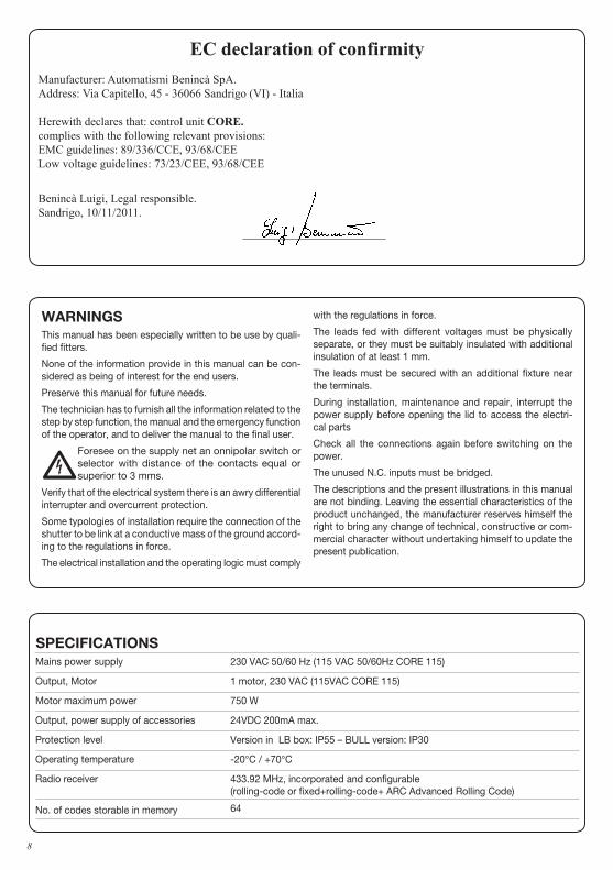
SPECIFICATIoNSMains power supply 230 VAC 50/60 Hz (115 VAC 50/60Hz CORE 115)
Output, Motor 1 motor, 230 VAC (115VAC CORE 115)
Motor maximum power 750 W
Output, power supply of accessories 24VDC 200mA max.
Protection level Version in LB box: IP55 – BULL version: IP30
Operating temperature -20°C / +70°C
Radio receiver 433.92 MHz, incorporated and configurable (rolling-code or fixed+rolling-code+ ARC Advanced Rolling Code)
No. of codes storable in memory 64
WARNINGSThis manual has been especially written to be use by quali-fied fitters.
None of the information provide in this manual can be con-sidered as being of interest for the end users.
Preserve this manual for future needs.
The technician has to furnish all the information related to the step by step function, the manual and the emergency function of the operator, and to deliver the manual to the final user.
•Foresee on the supply net an onnipolar switch or selector with distance of the contacts equal or superior to 3 mms.
Verify that of the electrical system there is an awry differential interrupter and overcurrent protection.
Some typologies of installation require the connection of the shutter to be link at a conductive mass of the ground accord-ing to the regulations in force.
The electrical installation and the operating logic must comply
with the regulations in force.
The leads fed with different voltages must be physically separate, or they must be suitably insulated with additional insulation of at least 1 mm.
The leads must be secured with an additional fixture near the terminals.
During installation, maintenance and repair, interrupt the power supply before opening the lid to access the electri-cal parts
Check all the connections again before switching on the power.
The unused N.C. inputs must be bridged.
The descriptions and the present illustrations in this manual are not binding. Leaving the essential characteristics of the product unchanged, the manufacturer reserves himself the right to bring any change of technical, constructive or com-mercial character without undertaking himself to update the present publication.
9
CoNTRoL PANEL CoRE
WIRE DIAGRAm
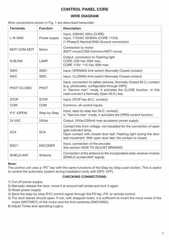
Wire connections shown in Fig. 1 are described hereunder:
Terminals Function Description
L-N-GND Power supplyInput, 230VAC 50Hz (CORE)Input, 115VAC 50/60Hz (CORE 115V))(1-Phase/2-Neutral/GND-Ground connection)
MOT-COM-MOT MotorConnection to motor: (MOT-move/COM-Common/MOT-move)
N-BLINK LAMPOutput, connection to Flashing light CORE: 230 Vac 40W max.CORE 115V: 115 Vac 40W max.
SWO SWO Input, OPENING limit switch (Normally Closed contact)
SWC SWC Input, CLOSING limit switch (Normally Closed contact)
PHOT (CLOSE) PHOT
Input, connection to safety devices, Normally Closed (N.C.) contact (e.g. photocells): configurable through DIP3).In “Service man” mode, it activates the CLOSE function. In this case connect a Normally Open (N.O.) key.
STOP STOP Input, STOP key (N.C. contact)
COM COM Common, all control inputs.
P.P. (OPEN) Step-by-StepInput, step-by-step key (N.O. contact).In “Service man” mode, it activates the OPEN control function.
24 VAC 24Vac Output, 24Vac/200mA max accessory power supply.
SCA SCA
Contact free from voltage, not insulated for the connection of open gate indicator lamp.Open contact with closed door leaf. Flashing light during the door leaf movement. With open door leaf, the contact is closed.
ENC1 ENCODERInput, connection of the encoder. See section HOW TO ADJUST BRAKING
SHIELD-ANT AntennaConnection of the antenna to the incorporated radio-receiver module (SHIELD-screen/ANT-signal).
Note: The control unit uses a “P2” key with the same functions of the Step-by-Step push-button. This is useful to control the automatic system during installation (only with DIP2: OFF).
CHECKING CoNNECTIoNS:
1) Cut off power supply.2) Manually release the door, move it at around half stroke and lock it again.3) Reset power supply.4) Send the step-by-step (P.P.) control signal through the P2 key, P.P. or remote control. 5) The door leaves should open. If not, with stopped motor, it is sufficient to invert the move wires of the
motor (MOT/MOT) of the motor and the limit switches (SWO/SWC).6) Adjust Times and operating Logics.
10
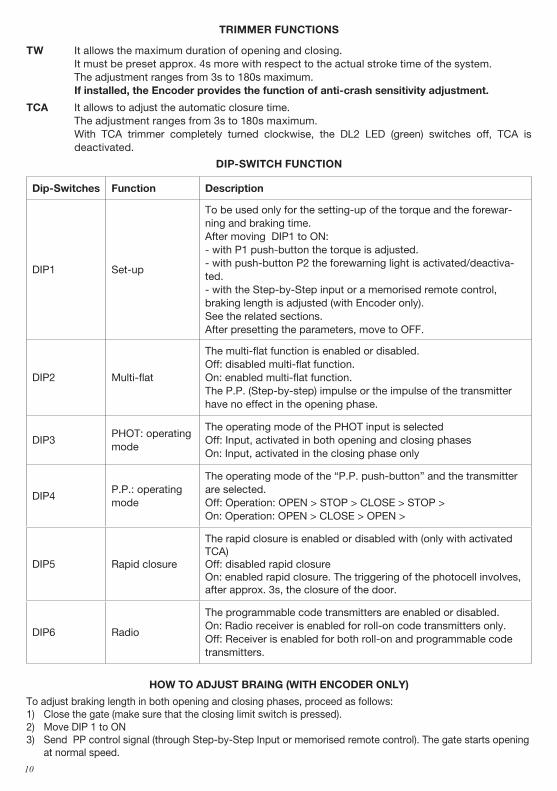
TRImmER FUNCTIoNS
TW It allows the maximum duration of opening and closing. It must be preset approx. 4s more with respect to the actual stroke time of the system. The adjustment ranges from 3s to 180s maximum. If installed, the Encoder provides the function of anti-crash sensitivity adjustment.
TCA It allows to adjust the automatic closure time. The adjustment ranges from 3s to 180s maximum. With TCA trimmer completely turned clockwise, the DL2 LED (green) switches off, TCA is
deactivated.
DIP-SWITCH FUNCTIoN
Dip-Switches Function Description
DIP1 Set-up
To be used only for the setting-up of the torque and the forewar-ning and braking time. After moving DIP1 to ON:- with P1 push-button the torque is adjusted.- with push-button P2 the forewarning light is activated/deactiva-ted.- with the Step-by-Step input or a memorised remote control, braking length is adjusted (with Encoder only).See the related sections.After presetting the parameters, move to OFF.
DIP2 Multi-flat
The multi-flat function is enabled or disabled. Off: disabled multi-flat function. On: enabled multi-flat function. The P.P. (Step-by-step) impulse or the impulse of the transmitter have no effect in the opening phase.
DIP3PHOT: operating mode
The operating mode of the PHOT input is selected Off: Input, activated in both opening and closing phases On: Input, activated in the closing phase only
DIP4P.P.: operating mode
The operating mode of the “P.P. push-button” and the transmitter are selected.Off: Operation: OPEN > STOP > CLOSE > STOP >On: Operation: OPEN > CLOSE > OPEN >
DIP5 Rapid closure
The rapid closure is enabled or disabled with (only with activated TCA)Off: disabled rapid closure On: enabled rapid closure. The triggering of the photocell involves, after approx. 3s, the closure of the door.
DIP6 Radio
The programmable code transmitters are enabled or disabled. On: Radio receiver is enabled for roll-on code transmitters only. Off: Receiver is enabled for both roll-on and programmable code transmitters.
HoW To ADJUST BRAING (WITH ENCoDER oNLY)
To adjust braking length in both opening and closing phases, proceed as follows:1) Close the gate (make sure that the closing limit switch is pressed).2) Move DIP 1 to ON3) Send PP control signal (through Step-by-Step Input or memorised remote control). The gate starts opening
at normal speed.
11
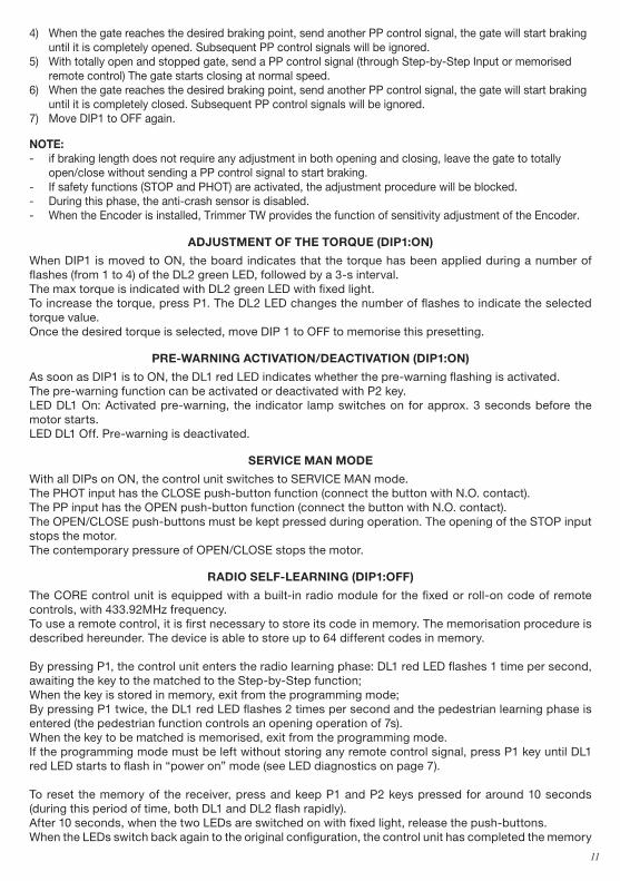
4) When the gate reaches the desired braking point, send another PP control signal, the gate will start braking until it is completely opened. Subsequent PP control signals will be ignored.
5) With totally open and stopped gate, send a PP control signal (through Step-by-Step Input or memorised remote control) The gate starts closing at normal speed.
6) When the gate reaches the desired braking point, send another PP control signal, the gate will start braking until it is completely closed. Subsequent PP control signals will be ignored.
7) Move DIP1 to OFF again.
NoTE: - if braking length does not require any adjustment in both opening and closing, leave the gate to totally
open/close without sending a PP control signal to start braking.- If safety functions (STOP and PHOT) are activated, the adjustment procedure will be blocked.- During this phase, the anti-crash sensor is disabled.- When the Encoder is installed, Trimmer TW provides the function of sensitivity adjustment of the Encoder.
ADJUSTmENT oF THE ToRQUE (DIP1:oN)
When DIP1 is moved to ON, the board indicates that the torque has been applied during a number of flashes (from 1 to 4) of the DL2 green LED, followed by a 3-s interval.The max torque is indicated with DL2 green LED with fixed light. To increase the torque, press P1. The DL2 LED changes the number of flashes to indicate the selected torque value.Once the desired torque is selected, move DIP 1 to OFF to memorise this presetting.
PRE-WARNING ACTIVATIoN/DEACTIVATIoN (DIP1:oN)
As soon as DIP1 is to ON, the DL1 red LED indicates whether the pre-warning flashing is activated.The pre-warning function can be activated or deactivated with P2 key.LED DL1 On: Activated pre-warning, the indicator lamp switches on for approx. 3 seconds before the motor starts.LED DL1 Off. Pre-warning is deactivated.
SERVICE mAN moDE
With all DIPs on ON, the control unit switches to SERVICE MAN mode.The PHOT input has the CLOSE push-button function (connect the button with N.O. contact).The PP input has the OPEN push-button function (connect the button with N.O. contact).The OPEN/CLOSE push-buttons must be kept pressed during operation. The opening of the STOP input stops the motor.The contemporary pressure of OPEN/CLOSE stops the motor.
RADIo SELF-LEARNING (DIP1:oFF)
The CORE control unit is equipped with a built-in radio module for the fixed or roll-on code of remote controls, with 433.92MHz frequency.To use a remote control, it is first necessary to store its code in memory. The memorisation procedure is described hereunder. The device is able to store up to 64 different codes in memory.
By pressing P1, the control unit enters the radio learning phase: DL1 red LED flashes 1 time per second, awaiting the key to the matched to the Step-by-Step function;When the key is stored in memory, exit from the programming mode;By pressing P1 twice, the DL1 red LED flashes 2 times per second and the pedestrian learning phase is entered (the pedestrian function controls an opening operation of 7s).When the key to be matched is memorised, exit from the programming mode.If the programming mode must be left without storing any remote control signal, press P1 key until DL1 red LED starts to flash in “power on” mode (see LED diagnostics on page 7).
To reset the memory of the receiver, press and keep P1 and P2 keys pressed for around 10 seconds (during this period of time, both DL1 and DL2 flash rapidly).After 10 seconds, when the two LEDs are switched on with fixed light, release the push-buttons.When the LEDs switch back again to the original configuration, the control unit has completed the memory
12
reset.
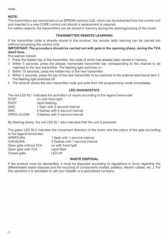
NoTE: The transmitters are memorised on an EPROM memory (U2), which can be extracted from the control unit and inserted in a new CORE control unit should a replacement is required.For safety reasons, the transmitters can be stored in memory during the opening/closing of the motor.
TRANSmITTER REmoTE LEARNING
If the transmitter code is already stored in the receiver, the remote radio learning can be carried out (without accessing the control unit).ImPoRTANT: The procedure should be carried out with gate in the opening phase, during the TCA dwell time.Proceed as follows:1 Press the hidden key of the transmitter, the code of which has already been stored in memory.2 Within 5 seconds, press the already memorised transmitter key corresponding to the channel to be
matched to the new transmitter. The flashing light switches on.3 Within 10 seconds, press the hidden key of the new transmitter.4 Within 5 seconds, press the key of the new transmitter to be matched to the channel selected at item 2.
The flashing light switches off.5 The receiver stores the new transmitter code and exits from the programming mode immediately.
LED DIAGNoSTICS
The red LED DL1 indicates the activation of inputs according to the legend hereunder:STOP on with fixed light PHOT rapid flashing SWO 1 flash with 2-second interval SWC 2 flashes with 2-second intervalOPEN+CLOSE 3 flashes with 2-second interval
By flashing slowly, the red LED DL1 also indicates that the unit is powered.
The green LED DL2 indicates the movement direction of the motor and the status of the gate according to the legend hereunder:APERTURA 1 flash with 1-second intervalCHIUSURA 2 flashes with 1-second intervalOpen gate without TCA on with fixed lightOpen gate with TCA rapid flash Closed gate LED off
WASTE DISPoSALIf the product must be dismantled, it must be disposed according to regulations in force regarding the differentiated waste disposal and the recycling of components (metals, plastics, electric cables, etc..). For this operation it is advisable to call your installer or a specialised company.
13
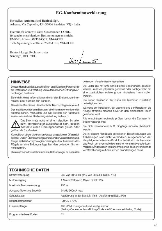
EG-Konformitatserklarung
Hersteller: Automatismi Benincà SpA.Adresse: Via Capitello, 45 - 36066 Sandrigo (VI) - Italia
Hiermit erklaren wir, dass: Steuereinheit CORE.folgenden einschlagigen Bestimmungen entspricht:EMV-Richtlinie: 89/336/CCE, 93/68/CEETiefe Spannung Richtlinie: 73/23/CEE, 93/68/CEE
Benincà Luigi, RechtsvertreterSandrigo, 10/11/2011.
TECHNISCHE DATENStromversorgung 230 Vac 50/60 Hz (115 Vac 50/60Hz CORE 115)
Motorausgang 1 Motor 230 Vac (115Vac CORE 115)
Maximale Motorenleistung 750 W
Ausgang Speisung Zubehör 24Vdc 200mA max.
Schutzklasse Ausführung in der Box LB: IP55 - Ausführung BULL:IP30
Betriebstemperatur -20°C / +70°C
Funkempfänger 433,92 MHz eingebaut und konfigurierbar (Rolling-Code oder fest+Rolling-Code + ARC Advanced Rolling Code)
Programmierbare Codes 64
HINWEISE Dieses Handbuch ist ausschließlich qualifiziertem Personal für die Installation und Wartung von automatischen Öffnungsvor-richtungen bestimmt.
Es enthält keine Informationen die für den Endbenutzer inte-ressant oder nützlich sein könnten.
Bewahren Sie dieses Handbuch für Nachschlagzwecke auf.
Der Installateur hat dem Benutzer alle Informationen über den automatischen, manuellen und Not-Betrieb der Automatik zusammen mit der Bedienungsanleitung zu liefern.
•Das Stromnetz muss mit einem allpoligen Schalter bzw. Trennschalter ausgestattet sein, dessen Kontakte einen Öffnungsabstand gleich oder
größer als 3 aufweisen.
Kontrollieren ob der elektrischen Anlage ein geeigneter Differential-schalter und ein Überspannungsschutzschalter vorgeschaltet sind. Einige Installationstypologien verlangen den Anschluss des Flügels an eine Erdungsanlage laut den geltenden Sicher-heitsnormen.
Die elektrische Installation und die Betriebslogik müssen den
geltenden Vorschriften entsprechen.
Die Leiter die mit unterschiedlichen Spannungen gespeist werden, müssen physisch getrennt oder sachgerecht mit einer zusätzlichen Isolierung von mindestens 1 mm isoliert werden.
Die Leiter müssen in der Nähe der Klemmen zusätzlich befestigt werden.
Während der Installation, der Wartung und der Reparatur, die Anlage stromlos machen bevor an den elektrischen Teilen gearbeitet wird.
Alle Anschlüsse nochmals prüfen, bevor die Zentrale mit Strom versorgt wird.
Die nicht verwendeten N.C. Eingänge müssen überbrückt werden.
Die in diesem Handbuch enthaltenen Beschreibungen und Abbildungen sind nicht verbindlich. Ausgenommen der Haupteigenschaften des Produkts, behält sich der Hersteller das Recht vor eventuelle technische, konstruktive oder kom-merzielle Änderungen vorzunehmen ohne dass er vorliegende Veröffentlichung auf den letzten Stand bringen muss.
14
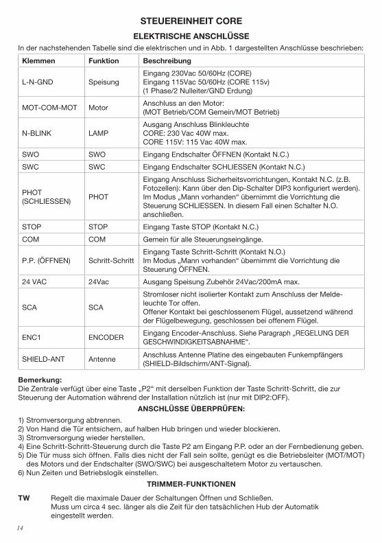
STEUEREINHEIT CoRE
ELEKTRISCHE ANSCHLÜSSEIn der nachstehenden Tabelle sind die elektrischen und in Abb. 1 dargestellten Anschlüsse beschrieben:
Klemmen Funktion Beschreibung
L-N-GND SpeisungEingang 230Vac 50/60Hz (CORE)Eingang 115Vac 50/60Hz (CORE 115v)(1 Phase/2 Nulleiter/GND Erdung)
MOT-COM-MOT MotorAnschluss an den Motor: (MOT Betrieb/COM Gemein/MOT Betrieb)
N-BLINK LAMPAusgang Anschluss Blinkleuchte CORE: 230 Vac 40W max.CORE 115V: 115 Vac 40W max.
SWO SWO Eingang Endschalter ÖFFNEN (Kontakt N.C.)
SWC SWC Eingang Endschalter SCHLIESSEN (Kontakt N.C.)
PHOT (SCHLIESSEN)
PHOT
Eingang Anschluss Sicherheitsvorrichtungen, Kontakt N.C. (z.B. Fotozellen): Kann über den Dip-Schalter DIP3 konfiguriert werden).Im Modus „Mann vorhanden“ übernimmt die Vorrichtung die Steuerung SCHLIESSEN. In diesem Fall einen Schalter N.O. anschließen.
STOP STOP Eingang Taste STOP (Kontakt N.C.)
COM COM Gemein für alle Steuerungseingänge.
P.P. (ÖFFNEN) Schritt-SchrittEingang Taste Schritt-Schritt (Kontakt N.O.)Im Modus „Mann vorhanden“ übernimmt die Vorrichtung die Steuerung ÖFFNEN.
24 VAC 24Vac Ausgang Speisung Zubehör 24Vac/200mA max.
SCA SCA
Stromloser nicht isolierter Kontakt zum Anschluss der Melde-leuchte Tor offen.Offener Kontakt bei geschlossenem Flügel, aussetzend während der Flügelbewegung, geschlossen bei offenem Flügel.
ENC1 ENCODEREingang Encoder-Anschluss. Siehe Paragraph „REGELUNG DER GESCHWINDIGKEITSABNAHME“.
SHIELD-ANT AntenneAnschluss Antenne Platine des eingebauten Funkempfängers (SHIELD-Bildschirm/ANT-Signal).
Bemerkung: Die Zentrale verfügt über eine Taste „P2“ mit derselben Funktion der Taste Schritt-Schritt, die zur Steuerung der Automation während der Installation nützlich ist (nur mit DIP2:OFF).
ANSCHLÜSSE ÜBERPRÜFEN:
1) Stromversorgung abtrennen.2) Von Hand die Tür entsichern, auf halben Hub bringen und wieder blockieren.3) Stromversorgung wieder herstellen.4) Eine Schritt-Schritt-Steuerung durch die Taste P2 am Eingang P.P. oder an der Fernbedienung geben. 5) Die Tür muss sich öffnen. Falls dies nicht der Fall sein sollte, genügt es die Betriebsleiter (MOT/MOT)
des Motors und der Endschalter (SWO/SWC) bei ausgeschaltetem Motor zu vertauschen.6) Nun Zeiten und Betriebslogik einstellen.
TRImmER-FUNKTIoNEN
TW Regelt die maximale Dauer der Schaltungen Öffnen und Schließen. Muss um circa 4 sec. länger als die Zeit für den tatsächlichen Hub der Automatik
eingestellt werden.
15
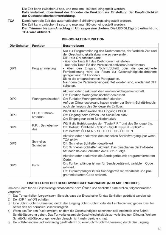
Die Zeit kann zwischen 3 sec. und maximal 180 sec. eingestellt werden. Falls installiert, übernimmt der Encoder die Funktion zur Einstellung der Empfindlichkeit
der Quetschsicherheitsvorrichtung.
TCA Damit kann die Zeit des automatischen Schließvorgangs eingestellt werden. Die Zeit kann zwischen 3 sec. und maximal 180 sec. eingestellt werden. Den Trimmer bis zum Anschlag im Uhrzeigersinn drehen. Die LED DL2 (grün) erlischt und
TCA wird aktiviert.
DIP-SCHALTER-FUNKTIoN
Dip-Schalter Funktion Beschreibung
DIP1 Programmierung
Nur zur Programmierung des Drehmoments, der Vorblink-Zeit und der Geschwindigkeitsabnahme zu verwenden. DIP1 auf ON schalten und:- über die Taste P1 das Drehmoment einstellen- über die Taste P2 das Vorblinken aktivieren/deaktivieren- über den Eingang Schritt/Schritt oder die gespeicherte Fernbedienung wird der Raum zur Geschwindigkeitsabnahme geregelt (nur mit Encoder)Siehe die entsprechenden Paragraphen.Nachdem die Parameter eingerichtet worden sind, wieder auf OFF schalten.
DIP2 Wohngemeinschaft
Aktiviert oder deaktiviert die Funktion Wohngemeinschaft. Off: Funktion Wohngemeinschaft deaktiviert. On: Funktion Wohngemeinschaft aktiviert. Auf den Öffnungsvorgang haben weder der Schritt-Schritt-Impuls noch der Impuls des Sendegeräts Einfluss.
DIP3PHOT: Betrieb-smodus
Wählt die Betriebsweise des Eingangs PHOT.Off: Eingang beim Öffnen und Schließen aktivOn: Eingang nur beim Schließen aktiv
DIP4P.P. : Betriebsmo-dus
Wählt die Betriebsweise der “Taste P.P.” und des Sendegeräts.Off: Betrieb: ÖFFNEN > STOP > SCHLIESSEN > STOP >On: Betrieb: ÖFFNEN > SCHLIESSEN > ÖFFNEN
DIP5Schnelles Schließen
Aktiviert oder deaktiviert den schnellen Schließvorgang.(nur wenn TCA aktiv)Off: Schnelles Schließen deaktiviertOn: Schnelles Schließen aktiviert. Das Einschalten der Fotozelle hat nach 3s das Schließen der Tür zur Folge.
DIP6 Funk
Aktiviert oder deaktiviert die Sendegeräte mit programmierbarem Code. On: Funkempfänger ist nur für Sendegeräte mit variablem Code aktiviert. Off: Funkempfänger ist für Sendegeräte mit variablem und pro-grammierbarem Code aktiviert.
EINSTELLUNG DER GESCHWINDIGKEITSABNAHmE (NUR mIT ENCoDER)
Um den Raum für die Geschwindigkeitsabnahme beim Öffnen und Schließen einzustellen, folgendermaßen vorgehen:1) Das Tor schließen (vergewissern Sie sich, dass der Endschalter für das Schließen gedrückt worden ist)2) Den DIP 1 auf ON schalten3) Eine Schritt-Schritt-Steuerung durch den Eingang Schritt-Schritt oder die Fernbedienung geben. Das Tor
öffnet sich bei normaler Geschwindigkeit.4) Wenn das Tor den Punkt erreicht, an dem die Geschwindigkeit abnehmen soll, nochmals eine Schritt-
Schritt-Steuerung geben. Das Tor verlangsamt die Geschwindigkeit bis zur vollständigen Öffnung. Weitere Schritt-Schritt-Steuerungen werden danach nicht mehr berücksichtigt.
5) Bei stillstehendem und vollständig geöffnetem Tor, eine Schritt-Schritt-Steuerung durch den Eingang
16
Schritt-Schritt oder die Fernbedienung geben. Das Tor schließt sich bei normaler Geschwindigkeit.6) Wenn das Tor den Punkt erreicht, an dem die Geschwindigkeit abnehmen soll, nochmals eine Schritt-
Schritt-Steuerung geben. Das Tor verlangsamt die Geschwindigkeit bis es vollständig geschlossen ist. Weitere Schritt-Schritt-Steuerungen werden danach nicht mehr berücksichtigt.
7) Den DIP1 wieder auf OFF schalten.
BEmERKUNGEN: - Falls das Tor beim Öffnen oder Schließen seine Geschwindigkeit nicht verlangsamen soll, lassen Sie die
Bewegung durchführen ohne die Schritt-Schritt-Steuerung zu geben.- Das Einschalten der Sicherheiten STOPP und PHOT blockieren die Regelungsprozedur.- Während dieser Phase ist der Quetschsicherheitssensor deaktiviert.- Wenn der Encoder (Zubehör) installiert ist, übernimmt der Trimmer TW die Einstellung der Encoder-Emp-
findlichkeit.
DREHmomENT EINSTELLEN (DIP1: oN)
Nachdem der Dip-Schalter DIP1 auf ON geschaltet worden ist, wird das verwendete Drehmoment durch die Anzahl der Blinksignale (1 bis 4) der grünen LED DL2 (mit jeweils einer Pause von 3s) angezeigt.Das maximale Drehmoment wird durch die fest leuchtende grüne LED DL2 angezeigt. Um das Drehmoment zu erhöhen, die Taste P1 drücken; die LED DL2 wechselt die Anzahl der Blinksignale, um das gewählte Drehmoment anzuzeigen.Nachdem das gewünschte Drehmoment angezeigt worden ist, DIP1 auf OFF schalten, um die Lernfunktion zu aktivieren.
VoRBLINKEN AKTIVIEREN/DEAKTIVIEREN (DIP1: oN)
Nachdem der Dip-Schalter DIP1 auf ON geschaltet worden ist, meldet die rote LED DL1 die Aktivierung oder Deaktivierung des Vorblinkens.Über die Taste P2 kann das Vorblinken aktiviert oder deaktiviert werden.LED DL1 ein: Das Vorblinken ist aktiv, die Blinkleuchte schaltet circa 3 Sekunden vor dem Einschalten des Motors ein.LED DL1 aus: Vorblinken deaktiviert.
BETRIEB Im moDUS „mANN VoRHANDEN“
Wenn alle DIP-Schalter auf ON geschaltet sind, schaltet die Zentrale auf den Modus „Mann vorhanden“.Der Eingang PHOT übernimmt in diesem Fall die Funktion des Schalters SCHLIESSEN (Schalter mit Kontakt N.O. anschließen).Der Eingang PP übernimmt in diesem Fall die Funktion ÖFFNEN (Schalter mit Kontakt N.O. anschließen).Die Tasten ÖFFNEN/SCHLIESSEN müssen während der gesamten Dauer der Steuerung gedrückt bleiben. Das Öffnen des Eingangs STOP hält den Motor an.Das gleichzeitige Drücken der Tasten ÖFFNEN/SCHLIESSEN hält den Motor an.
FUNKmoDUL UND SELBSTLERNFUNKTIoN (DIP1:oFF)
Die Zentrale CORE ist mit einem eingebauten Funkmodul zum Empfang von Fernbedienungen mit festem oder variablen Code und einer Frequenz von 433.92MHz ausgestattet.Um eine Fernbedienung verwenden zu können, muss sie zuerst erlernt werden; die Speicherungsprozedur ist nachstehend beschrieben; die Vorrichtung kann bis zu 64 verschiedene Codes speichern.
Um die Zentrale auf die Lernfunktion zu schalten, Taste P1 drücken. Die rote LED DL1 blinkt 1 Mal pro Sekunde bis die Taste gedrückt wird, die der Funktion Schritt-Schritt zugeordnet werden soll.Nachdem die Taste gespeichert worden ist, wird die Programmierung beendet.Um die Zentrale auf die Fußgängerfunktion zu schalten, die Taste P1 2 Mal drücken. Die rote LED DL1 blinkt 2 Mal pro Sekunde und die Funktion ist abgerufen (die Fußgängerfunktion steuert einen Öffnungsvorgang, der 7s dauert).Nachdem die Taste gespeichert worden ist, wird die Programmierung beendet.Falls man die Programmierung beenden möchte, ohne eine Funkbedienung zu speichern, die Taste P1 drücken bis die rote LED DL1 wieder im Modus „Strom vorhanden“ blinkt (siehe LED-Diagnostik auf Seite 7).
Um den Speicher des Empfängers zurückzusetzen, die Tasten P1 und P2 circa 10 Sekunden lang gleichzeitig drücken und gedrückt halten (dabei blinken beide LEDS DL1 und DL2 schnell).
17
Nach 10 Sekunden leuchten die beiden LEDS fest auf. Danach die Tasten loslassen.Der Speicher ist zurückgesetzt, wenn die LEDS wieder auf die ursprüngliche Konfiguration zurückgeschaltet worden sind.
BEmERKUNG: Die Sendegeräte werden in einem Speicher EPROM (U2) gespeichert, der aus der Zentrale genommen und in eine neue Zentrale CORE eingebaut werden kann, wenn diese ausgewechselt werden soll.Aus Sicherheitsgründen können keine Sendegeräte beim Öffnen/Schließen des Motors gespeichert werden.
LERNFUNKTIoN VoN FERN DER SENDEGERÄTE
Wenn man über ein Sendegerät verfügt, das schon im Empfänger gespeichert ist, kann man die Lernfunktion über Funk von Fern vornehmen (ohne auf die Zentrale verwenden zu müssen).WICHTIG: Der Vorgang muss vorgenommen werden, wenn die Torflügel beim Öffnen auf die TCA Pause geschaltet sind.Folgendermaßen vorgehen:1 Versteckte Taste des schon gespeicherten Sendegeräts drücken.2 nnerhalb von 5s die Taste des schon gespeicherten Sendegeräts drücken, die dem Kanal entspricht, der
dem neuen Sendegerät zugeteilt werden soll. Die Leuchte beginnt zu blinken.3 Innerhalb von 10s , die versteckte Taste des neuen Sendegeräts drücken.4 Innerhalb von 5s die Taste des neuen Sendegeräts drücken, die dem Kanal entspricht, der unter Punkt
2 gewählt wurde. Die Leuchte beginnt zu blinken.5 Der Empfänger speichert das neue Sendegerät und beendet sofort die Programmierung.
LED-DIAGNoSTIK
Die rote LED DL1 meldet die Aktivierung der Eingänge folgendermaßen:STOP Leuchtet festPHOT Blinkt schnellSWO Blinkt 1 Mal mit einer Pause von 2 SekundenSWC Blinkt 2 Mal mit einer Pause von 2 SekundenOPEN+CLOSE Blinkt 3 Mal mit einer Pause von 2 Sekunden
Die rote LED DL1 meldet auch die vorhandene Stromversorgung durch ein langsames Blinken.
Die grüne LED DL2 meldet folgendermaßen die Bewegungsrichtung des Motors und den Status des Tors:ÖFFNEN Blinkt 1 Mal mit einer Pause von 1 SekundeSCHLIESSEN Blinkt 2 Mal mit einer Pause von 1 SekundeOffenes Tor ohne TCA Leuchtet festOffenes Tor mit TCA Blinkt schnellGeschlossenes Tor Led aus
ENTSoRGUNG
Wird das Gerät außer Betrieb gesetzt, müssen die gültigen Gesetzesvorschriften zur differenzierten Entsorgung und Wiederverwendung der Einzelkomponenten, wie Metall, Plastik, Elektrokabel, usw., beachtet werden. Rufen Sie Ihren Installateur oder eine Entsorgungsfirma.
18
Déclaration CE de conformité
Fabricant: Automatismi Benincà SpA.Adresse: Via Capitello, 45 - 36066 Sandrigo (VI) - Italia
Déclaire ci-apres que: control unit CORE.complies with the following relevant provisions:Directive EMV: 89/336/CCE, 93/68/CEE (Compatibilité électromagnétique)Directive bas voltage 73/23/CEE, 93/68/CEE
Benincà Luigi, Responsable légal.Sandrigo, 10/11/2011.
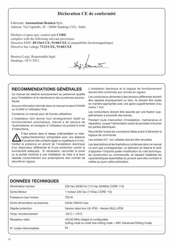
DoNNÉES TECHNIQUESAlimentation secteur 230 Vac 50/60 Hz (115 Vac 50/60Hz CORE 115)
Sortie Moteur 1 moteur 230 Vac (115Vac CORE 115)
Puissance maxi moteur 750 W
Sortie alimentation accessoires 24Vdc 200mA max.
Dégrée protection Version dans box LB: IP55 - Version BULL:IP30
Temp. fonctionnement -20°C / +70°C
Récepteur radio 433,92 MHz intégré et configurable (rolling-code ou code fixe+rolling-code + ARC Advanced Rolling Code)
N° codes mémorisables 64
RECommENDATIoNS GÉNÉRALES Ce manuel est destiné exclusivement au personnel qualifié pour l’installation et la maintenance des ouvertures automa-tiques.
Aucune information donnée dans ce manuel ne sera d’intérêt ou d’utilité a l’utilisateur final.
Conservez ce manuel pour de futures utilisations.
L’installateur doit donner tout renseignement relatif au fonctionnement automatique, manuel e de secours de l’automatisme, et consigner à l’utilisateur du produit le livret d’instructions.
•Il faut prévoir dans le réseau d’alimentation un inter-rupteur/sectionneur omnipolaire avec une distance d’ouverture des contacts égale ou supérieure à 3 mm.
Vérifier la présence en amont de l’installation électrique d’un disjoncteur différentiel et d’une protection contre la surintensité adéquats. Si nécessaire, raccorder la porte ou le portail motorisé à une installation de mise à la terre réalisée conformément aux prescriptions des normes de sécurité en vigueur.
L’installation électrique et la logique de fonctionnement doivent être conformes aux normes en vigueur.
Les conducteurs alimentés à des tensions différentes doivent être séparés physiquement ou bien, ils doivent être isolés en manière appropriée avec une gaine supplémentaire d’au moins 1 mm.
Les conducteurs doivent être assurés par une fixation sup-plémentaire à proximité des bornes.
Pendant toute intervention d’installation, maintenance et réparation, couper l’alimentation avant de procéder à toucher les parties électriques.
Recontrôler toutes les connexions faites avant d’alimenter la logique de commande.
Les entrées N.F. non utilisées doivent être shuntées
Les descriptions et les illustrations contenues dans ce manuel ne sont pas contraignantes. Le fabricant se réserve le droit d’apporter n’importe quelle modification du coté technique, de construction ou commerciale, en laissant inaltérées les caractéristiques essentielles du produit sans être contraint à mettre au jours cette publication.
19
CENTRALE DE CommANDE CoRE
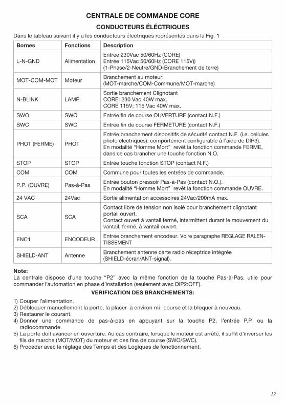
CoNDUCTEURS ÉLÉCTRIQUES Dans le tableau suivant il y a les conducteurs électriques représentés dans la Fig. 1
Bornes Fonctions Description
L-N-GND AlimentationEntrée 230Vac 50/60Hz (CORE)Entrée 115Vac 50/60Hz (CORE 115V))(1-Phase/2-Neutre/GND-Branchement de terre)
MOT-COM-MOT MoteurBranchement au moteur: (MOT-marche/COM-Commune/MOT-marche)
N-BLINK LAMPSortie branchement ClignotantCORE: 230 Vac 40W max.CORE 115V: 115 Vac 40W max.
SWO SWO Entrée fin de course OUVERTURE (contact N.F.)
SWC SWC Entrée fin de course FERMETURE (contact N.F.)
PHOT (FERME) PHOT
Entrée branchement dispositifs de sécurité contact N.F. (i.e. cellules photo électriques): comportement configurable à l’aide de DIP3).En modalité “Homme Mort” revêt la fonction commande FERME, dans ce cas brancher une touche fonction N.O.
STOP STOP Entrée touche fonction STOP (contact N.F.)
COM COM Commune pour toutes les entrées de commande.
P.P. (OUVRE) Pas-à-PasEntrée bouton pressoir Pas-à-Pas (contact N.O.).En modalité “Homme Mort” revêt la fonction commande OUVRE.
24 VAC 24Vac Sortie alimentation accessoires 24Vac/200mA max.
SCA SCA
Contact libre de tension non isolé pour branchement clignotant portail ouvert.Contact ouvert à vantail fermé, intermittent durant le mouvement du vantail, fermé, à vantail ouvert.
ENC1 ENCODEUREntrée branchement encodeur. Voire paragraphe REGLAGE RALEN-TISSEMENT
SHIELD-ANT AntenneBranchement antenne carte radio réceptrice intégrée (SHIELD-écran/ANT-signal).
Note: La centrale dispose d’une touche “P2” avec la même fonction de la touche Pas-à-Pas, utile pour commander l’automation en phase d’installation (seulement avec DIP2:OFF).
VERIFICATIoN DES BRANCHEmENTS:
1) Couper l’alimentation.2) Débloquer manuellement la porte, la placer à environ mi- course et la bloquer à nouveau.3) Restaurer le courant.4) Donner une commande de pas-à-pas en appuyant sur la touche P2, l’entrée P.P. ou la
radiocommande. 5) La porte doit avancer en ouverture. Au cas contraire, lorsque le moteur est arrêté, il suffit d’inverser les
fils de marche (MOT/MOT) du moteur et des fins de course (SWO/SWC).6) Procéder avec le réglage des Temps et des Logiques de fonctionnement.
20
FoNCTIoN DES TRImmERS
TW Règle la durée maximale de la manœuvre d’ouverture et de fermeture. Il doit être affiché environ 4s en plus par rapport au temps de course effective de
l’automatisme. Le réglage varie d’un minimum de 3s à un maximum de 180s Si le dispositif Encodeur est installé, il devient régulateur de sensibilité anti-écrasement.
TCA Permet de régler le temps de fermeture automatique. Le réglage varie d’un minimum de 3s à un maximum de 180s Avec le trimmer TCA complètement tourné dans le sens des aiguilles d’une montre, la
LED DL2 (vert) s’éteint, le TCA est désactivé.
FoNCTIoNS DIP-SWITCH
Dip-Switches Fonction Description
DIP1 Programmation
A’ utiliser exclusivement pour la programmation du couple ainsi que du temps de pré-clignotement et du ralentissement. Une fois le DIP1 sur ON:- avec la touche P1 on règle le couple.- avec la touche P2 on active/désactive le pré-clignotement.- avec l’entrée Pas-à-Pas ou une télécommande mémorisée on règle l’espace de ralentissement (uniquement avec Encodeur).Voir les paragraphes respectifs.Une fois les paramètres saisis, ramener sur OFF.
DIP2 Fonction Copro-priété
Valide ou invalide la fonction copropriété. Off: Fonction copropriété invalidée. On: Fonction copropriété validée. L’impulsion P.P. ou du transmetteur n’a aucun effet durant la phase d’ouverture.
DIP3 PHOT: modalitéde fonctionnement
Sélectionne la modalité de fonctionnement de l’entrée PHOTOff: Entrée active soit en phase d’ouverture qu’en phase de fermetureOn: Entrée active uniquement en phase de fermeture
DIP4 P.P. : modalité de fonctionnement
Sélectionne la modalité de fonctionnement de la ”Touche P.P.” et du transmetteur.Off: Fonctionnement: OUVRE > STOP > FERME > STOP >On: Fonctionnement: OUVRE > FERME > OUVRE >
DIP5 Fermeture rapide
Active ou désactive la fermeture rapide (seulement avec TCA validé)Off: Fermeture rapide invalidée On: Fermeture rapide validée. L’intervention de la cellule pho-toélectrique entraîne après 3s environ, la fermeture de la porte.
DIP6 Radio
Valide ou invalide les transmetteurs à code programmable. On: Récepteur radio validé exclusivement aux transmetteurs à code variable radio. Off: Récepteur validé aux transmetteurs à code variable et programmable.
RÉGLAGE RALENTISSEmENT (SEULEmENT AVEC ENCoDEUR)
Pour régler les espaces de ralentissement en ouverture et en fermeture, procéder comme suit:1) fermer le portail (en s’assurant que le fin de course est activé).2) ramener le DIP 1 sur ON3) donner une commande PP (à l’aide de l’entrée Pas-à-Pas ou de la télécommande mémorisée). Le portail
commence à bouger en ouverture à vitesse normale.4) lorsque le portail arrive au point de ralentissement désiré donner une ultérieure commande PP, le portail va
21
ralentir pour continuer sa course jusqu’à ce qu’il soit complètement ouvert. Toute commande PP qui suit sera ignorée.
5) avec le portail arrêté donner une commande PP (avec l’entrée Pas-à-Pas ou une télécommande mémori-sée). Le portail commence à bouger à vitesse normale.
6) lorsque le portail arrive au point de ralentissement désiré donner la commande PP, le portail commence à ralentir et il va continuer sa course jusqu’à ce qu’il soit complètement fermé. Toute commande PP qui suit sera ignorée.
5) avec le portail arrêté donner une commande PP (à l’aide de l’entrée Pas-à-Pas ou de la télécommande mémorisée). Le portail commence à bouger en fermeture à vitesse normale
7) ramener le dip1 sur OFF
NoTES: - si on ne veut pas régler l’espace de ralentissement en ouverture ou en fermeture, laisser le portail exécuter
une manœuvre d’ouverture / fermeture complète sans donner une commande PP de début de ralentisse-ment.
- l’intervention des systèmes de sécurité comme STOP et PHOT bloque la procédure de réglage.- durant cette phase le capteur anti-écrasement est désactivé.- avec l’accessoire Encodeur installé le Trimmer TW devient le régulateur de sensibilité de l’Encodeur.
REGLAGE CoUPLE (DIP1:oN)
Dès qu’on déplace le DIP1 sur ON la carte signale le couple appliqué dans cet instant à l’aide d’un certain nombre de clignotements (de 1 à 4) de la LED verte DL2 suivis par une pause 3s.Le couple maxi est signalé avec la LED verte DL2 fixe. Pour incrémenter le couple appuyer sur la touche P1; l LED DL2 change le numéro des clignotements indiquant la valeur du couple sélectionné.Après avoir sélectionné le couple désiré, porter le DIP sur OFF pour l’apprentissage de cet affichage.
ACTIVATIoN/DESACTIVATIoN PRE-CLIGNoTEmENT (DIP1:oN)
Dès qu’on déplace le DIP1 sur ON la Led rougeDL1 signale l’activation ou la non activation du pré-clignotement.Avec la touche P2 il est possible de valider ou invalider la fonction de pré-clignotement.LED DL1 Allumée: Pré-clignotement actif, le clignotant s’allume pendant 3 secondes environ avant la mise en marche du moteur.LED DL1 Eteinte. Pré-clignotement désactivé.
moDALITE’ HommE moRT
En ramenant tous les DIPS sur ON la centrale passe en modalité HOMME MORT.L’entrée PHOT revêt la fonction de la Touche FERME (brancher la touche avec contact N.O.).L’entrée PP revêt la fonction de la Touche OUVRE (brancher la touche avec contact N.O.).La pression sur les touches OUVRE/FERME doit être gardée pendant toute la manœuvre. L’ouverture de l’entrée STOP arrête le moteur.La pression simultanée des touches OUVRE/FERME comporte l’arrêt du moteur.
APPRENTISSAGE RADIo (DIP1:oFF)
La centrale CORE est équipée avec un module radio incorporé pour la réception des télécommandes à code fixe ou variable avec fréquence de 433.92MHz.Pour utiliser une télécommande il faut l’apprendre à l’avance, la procédure de mémorisation est illustrée ci de suite, le dispositif est à même de mémoriser jusqu’à 64 codes différents.
En appuyant sur P1 la centrale entre en phase d’apprentissage radio: la LED rouge DL1 clignote 1 fois par seconde dans l’attente de la touche à associer à la fonction Pas-à-Pas;Une fois apprise la touche sort de la programmation;En appuyant 2 fois sur P1 la LED rouge DL1 clignote 2 fois par seconde et on entre dans la phase d’apprentissage accès piéton (la fonction accès piéton commande une manœuvre d’ouverture de 7s).Une fois apprise la touche à associer sort de la programmation.Si l’on veut sortir de la programmation sans apprendre aucune radiocommande, il suffit d’appuyer sur la touche P1 jusqu’à ce que la Led rouge DL1 clignote à nouveau en modalité “présence secteur“ (voir diagnostique LED page 7).Pour restaurer la mémoire du récepteur appuyer et maintenir appuyés simultanément les touches P1 et
22
P2 pendant environ 10 secondes (durant e temps les deux LEDS DL1 et DL2 clignotent rapidement).Après 10 secondes les deux LEDS s’allument fixes, relâcher les touches.Lorsque les LEDS reviennent à leur configuration initiale la centrale aura effectué la restauration de la mémoire.
NoTE: Les transmetteurs sont mémorisés sur une mémoire EPROM (U2) qui peut être retirée d’une centrale pour être réinsérée dans une nouvelle centrale CORE en cas de substitution.Pour des raisons de sécurité, on ne peut pas mémoriser les transmetteurs durant les phases d’ouverture / fermeture du moteur.
APPRENTISSAGE à DISTANCE DES TRANSmETTEURS
Si l’on dispose d’un transmetteur déjà mémorisé dans le récepteur il est possible d’effectuer l’apprentissage radio à distance (sans nécessairement accéder à la centrale).ImPoRTANT: La procédure doit être exécutée avec les portails en ouverture durant la pause TCA.Procéder comme il suit:1 Appuyer sur la touche cachée du transmetteur déjà mémorisé.2 Appuyer, dans 5s, la touche du transmetteur déjà mémorisé correspondant au canal à associer au
nouveau transmetteur. Le clignotant s’allume.3 Appuyer dans 10s la touche cachée du nouveau transmetteur.4 Appuyer, dans 5s, la touche du nouveau transmetteur à associer au canal choisi au point 2, le clignotant
s’éteint.5 Le récepteur mémoriser le nouveau transmetteur et sort immédiatement de la programmation.
DIAGNoSTIQUE LED
La LED DL1 rouge indique l’activation des entrées, voilà la légende:STOP accès fixePHOT clignotement rapideSWO 1 clignotement avec pause de 2 secondesSWC 2 clignotements avec pause de 2 secondesOPEN+CLOSE 3 clignotements avec pause de 2 secondes
Avec un clignotement lent la LED DL1 rouge indique aussi la présence de secteur.
La LED DL2 verte indique la direction du mouvement du moteur et la position du portail, voilà la légende:OUVERTURE 1 clignotement avec pause de 1 second FERMETURE 2 clignotements avec pause de 1 secondPortail ouvert sans TCA accès fixePortail ouvert avec TCA clignotement rapidePortail fermé Led éteinte
DÉmoLITIoNAu cas où le produit serait mis hors service, il est impératif de se conformer aux lois en vigueur pour ce qui concerne l’élimination différenciée et le recyclage des différents composants (métaux, matières plastiques câbles électriques, etc...) contactez votre installateur ou une firme spécialisée autorisée à cet effet.
23
Declaración CE de conformidad
Fabricante: Automatismi Benincà SpA.
Dirección: Via Capitello, 45 - 36066 Sandrigo (VI) - Italia
Declara que: la central de mando CORE.satisface las disposiciones pertinentes siguientes:Reglamento de compatibilidad electromagnética: (89/336/MCE, 93/68/MCE)Reglamento de bajo Voltaje: (73/23/MCE, 93/68/MCE)
Benincà Luigi, Responsable legal.Sandrigo, 10/11/2011.
DAToS TÉCNICoSAlimentación de red 230 Vac 50/60 Hz (115 Vac 50/60Hz CORE 115)
Salida Motor 1 motor 230 Vac (115Vac CORE 115)
Potencia máxima motor 750 W
Salida alimentación accesorios 24Vdc 200mA máx.
Grado de protección Versión en la caja LB: IP55 - Versión BULL:IP30
Temp. de funcionamiento -20°C / +70°C
Receptor radio 433,92 MHz incorporado y configurable (rolling-code o fijo+rolling-code + ARC Advanced Rolling Code)
N° de códigos memorizables 64
ADVERTENCIASEste manual está destinado exclusivamente a personal cuali-ficado para la instalación y el mantenimiento de aperturas automáticas.
Ninguna información de las aquí presentadas es de interés o de utilidad para el usuario final.
Guardar este manual para futuras consultas.
El instalador debe proporcionar todas las informaciones rela-tivas al funcionamiento automático, manual y de emergencia de la automatización y entregar al usuario de la instalación las instrucciones de uso.
•Prever en la red de alimentación un interruptor/cortacircuitos omnipolar con distancia de aper-tura de los contactos igual o mayor que 3 mm.
Comprobar que entre el aparato y la red eléctri-ca genera l haya un in ter ruptor d i ferenc ia l y una protección contra sobrecorriente adecuados. Algunos tipos de instalación requieren que se conecte la hoja con una instalación de puesta a tierra conforme a las vigentes normas de seguridad.
La instalación eléctrica y la lógica de funcionamiento deben cumplir las normas vigentes.
Los conductores alimentados con tensiones distintas deben estar físicamente separados, o bien deben estar adecu-adamente aislados con aislamiento suplementario de por lo menos 1 mm.
Los conductores deben estar vinculados por una fijación suplementaria cerca de los bornes.
Durante las operaciones de instalación, mantenimiento y reparación, cortar la alimentación antes de acceder a las partes eléctricas.
Comprobar todas las conexiones efectuadas antes de dar la tensión.
Las entradas N.C. no utilizadas deben estar puenteadas.
Las descripciones y las ilustraciones presentadas en este manual no son vinculantes. Sin cambiar las características esenciales del producto, el fabricante se reserva el derecho de aportar cualquier modificación de carácter técnico, con-structivo o comercial sin obligación de actualizar la presente publicación.
24
CENTRAL DE mANDo CoRE
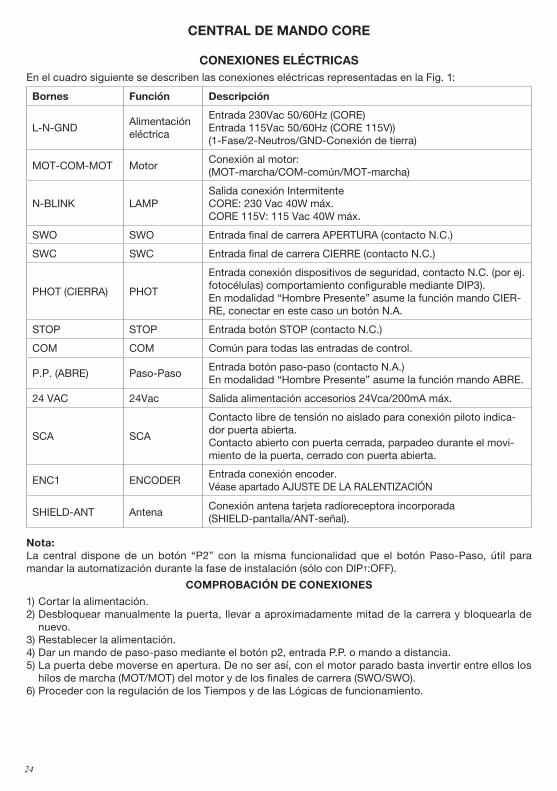
CoNEXIoNES ELÉCTRICASEn el cuadro siguiente se describen las conexiones eléctricas representadas en la Fig. 1:
Bornes Función Descripción
L-N-GNDAlimentación eléctrica
Entrada 230Vac 50/60Hz (CORE)Entrada 115Vac 50/60Hz (CORE 115V))(1-Fase/2-Neutros/GND-Conexión de tierra)
MOT-COM-MOT MotorConexión al motor: (MOT-marcha/COM-común/MOT-marcha)
N-BLINK LAMPSalida conexión Intermitente CORE: 230 Vac 40W máx.CORE 115V: 115 Vac 40W máx.
SWO SWO Entrada final de carrera APERTURA (contacto N.C.)
SWC SWC Entrada final de carrera CIERRE (contacto N.C.)
PHOT (CIERRA) PHOT
Entrada conexión dispositivos de seguridad, contacto N.C. (por ej. fotocélulas) comportamiento configurable mediante DIP3).En modalidad “Hombre Presente” asume la función mando CIER-RE, conectar en este caso un botón N.A.
STOP STOP Entrada botón STOP (contacto N.C.)
COM COM Común para todas las entradas de control.
P.P. (ABRE) Paso-PasoEntrada botón paso-paso (contacto N.A.)En modalidad “Hombre Presente” asume la función mando ABRE.
24 VAC 24Vac Salida alimentación accesorios 24Vca/200mA máx.
SCA SCA
Contacto libre de tensión no aislado para conexión piloto indica-dor puerta abierta.Contacto abierto con puerta cerrada, parpadeo durante el movi-miento de la puerta, cerrado con puerta abierta.
ENC1 ENCODEREntrada conexión encoder. Véase apartado AJUSTE DE LA RALENTIZACIÓN
SHIELD-ANT AntenaConexión antena tarjeta radioreceptora incorporada (SHIELD-pantalla/ANT-señal).
Nota: La central dispone de un botón “P2” con la misma funcionalidad que el botón Paso-Paso, útil para mandar la automatización durante la fase de instalación (sólo con DIP2:OFF).
ComPRoBACIÓN DE CoNEXIoNES
1) Cortar la alimentación.2) Desbloquear manualmente la puerta, llevar a aproximadamente mitad de la carrera y bloquearla de
nuevo.3) Restablecer la alimentación.4) Dar un mando de paso-paso mediante el botón p2, entrada P.P. o mando a distancia. 5) La puerta debe moverse en apertura. De no ser así, con el motor parado basta invertir entre ellos los
hilos de marcha (MOT/MOT) del motor y de los finales de carrera (SWO/SWO).6) Proceder con la regulación de los Tiempos y de las Lógicas de funcionamiento.
25
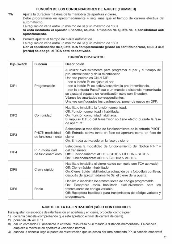
FUNCIÓN DE LoS CoNDENSADoRES DE AJUSTE (TRImmER)
TW Ajusta la duración máxima de la maniobra de apertura y cierre. Debe programarse en aproximadamente 4 seg. más que el tiempo de carrera efectiva del
automatismo. La regulación varía entre un mínimo de 3s y un máximo de 180s Si está instalado el aparato Encoder, asume la función de ajuste de la sensibilidad anti
aplastamiento.
TCA Permite ajustar el tiempo de cierre automático. La regulación varía entre un mínimo de 3s y un máximo de 180s Con el condensador de ajuste TCA completamente girado en sentido horario, el LED DL2
(verde) se apaga, el TCA está desactivado.
FUNCIÓN DIP-SWITCH
Dip-Switch Función Descripción
DIP1 Programación
A utilizar exclusivamente para programar el par y el tiempo de pre-intermitencia y de la ralentización. Una vez puesto en ON el DIP1:- con el botón P1 se ajusta el par.- con el botón P2 se activa/desactiva la pre-intermitencia.- con la entrada Paso/Paso o un mando a distancia memorizado se ajusta el espacio de ralentización (sólo con Encoder).Véanse los apartados correspondientes.Una vez configurados los parámetros, poner de nuevo en OFF.
DIP2 Comunidad
Habilita o inhabilita la función comunidad. Off: Función comunidad inhabilitada. On: Función comunidad habilitada. El impulso P.P. o del transmisor no tiene efecto durante la fase de apertura.
DIP3PHOT: modalidadde funcionamiento
Selecciona la modalidad de funcionamiento de la entrada PHOT.Off: Entrada activa tanto en fase de apertura como en fase de cierreOn: Entrada activa sólo en la fase de cierre
DIP4P.P. modalidad de funcionamiento
Selecciona la modalidad de funcionamiento del ”Botón P.P.” y del transmisor.Off: Funcionamiento: ABRE > STOP > CIERRA > STOP >On: Funcionamiento: ABRE > CIERRA > ABRE >
DIP5 Cierre rápido
Habilita o inhabilita el cierre rápido con (sólo con TCA activado)Off: Cierre rápido inhabilitadoOn: Cierre rápido habilitado. La actuación de la fotocélula conlleva, después de aproximadamente 3s, el cierre de la puerta.
DIP6 Radio
Habilita o inhabilita los transmisores de código programable On: Receptora radio habilitada exclusivamente para los transmisores de código variable. Off: Receptora habilitada para transmisores de código variable y programable.
AJUSTE DE LA RALENTIZACIÓN (SÓLo CoN ENCoDER)
Para ajustar los espacios de ralentización en apertura y en cierre, proceder como sigue:1) cerrar la cancela (comprobando que esté apretado el final de carrera de cierre).2) poner en ON el DIP 13) dar un comando PP (mediante la entrada Paso-Paso o un mando a distancia memorizado). La cancela
empieza a moverse en apertura a velocidad normal.4) cuando la cancela llega al punto de ralentización que se desea dar otro comando PP, la cancela empezará
26
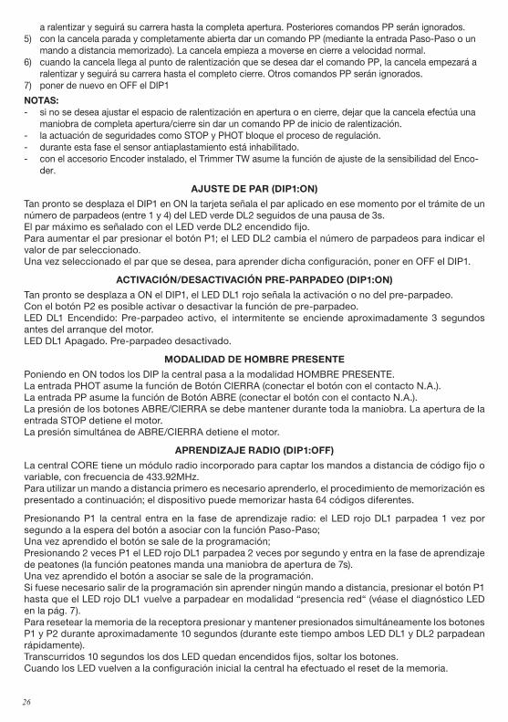
a ralentizar y seguirá su carrera hasta la completa apertura. Posteriores comandos PP serán ignorados.5) con la cancela parada y completamente abierta dar un comando PP (mediante la entrada Paso-Paso o un
mando a distancia memorizado). La cancela empieza a moverse en cierre a velocidad normal.6) cuando la cancela llega al punto de ralentización que se desea dar el comando PP, la cancela empezará a
ralentizar y seguirá su carrera hasta el completo cierre. Otros comandos PP serán ignorados.7) poner de nuevo en OFF el DIP1
NoTAS: - si no se desea ajustar el espacio de ralentización en apertura o en cierre, dejar que la cancela efectúa una
maniobra de completa apertura/cierre sin dar un comando PP de inicio de ralentización.- la actuación de seguridades como STOP y PHOT bloque el proceso de regulación.- durante esta fase el sensor antiaplastamiento está inhabilitado.- con el accesorio Encoder instalado, el Trimmer TW asume la función de ajuste de la sensibilidad del Enco-
der.
AJUSTE DE PAR (DIP1:oN)
Tan pronto se desplaza el DIP1 en ON la tarjeta señala el par aplicado en ese momento por el trámite de un número de parpadeos (entre 1 y 4) del LED verde DL2 seguidos de una pausa de 3s.El par máximo es señalado con el LED verde DL2 encendido fijo. Para aumentar el par presionar el botón P1; el LED DL2 cambia el número de parpadeos para indicar el valor de par seleccionado.Una vez seleccionado el par que se desea, para aprender dicha configuración, poner en OFF el DIP1.
ACTIVACIÓN/DESACTIVACIÓN PRE-PARPADEo (DIP1:oN)
Tan pronto se desplaza a ON el DIP1, el LED DL1 rojo señala la activación o no del pre-parpadeo.Con el botón P2 es posible activar o desactivar la función de pre-parpadeo.LED DL1 Encendido: Pre-parpadeo activo, el intermitente se enciende aproximadamente 3 segundos antes del arranque del motor.LED DL1 Apagado. Pre-parpadeo desactivado.
moDALIDAD DE HomBRE PRESENTE
Poniendo en ON todos los DIP la central pasa a la modalidad HOMBRE PRESENTE.La entrada PHOT asume la función de Botón CIERRA (conectar el botón con el contacto N.A.).La entrada PP asume la función de Botón ABRE (conectar el botón con el contacto N.A.).La presión de los botones ABRE/CIERRA se debe mantener durante toda la maniobra. La apertura de la entrada STOP detiene el motor.La presión simultánea de ABRE/CIERRA detiene el motor.
APRENDIZAJE RADIo (DIP1:oFF)
La central CORE tiene un módulo radio incorporado para captar los mandos a distancia de código fijo o variable, con frecuencia de 433.92MHz.Para utilizar un mando a distancia primero es necesario aprenderlo, el procedimiento de memorización es presentado a continuación; el dispositivo puede memorizar hasta 64 códigos diferentes.
Presionando P1 la central entra en la fase de aprendizaje radio: el LED rojo DL1 parpadea 1 vez por segundo a la espera del botón a asociar con la función Paso-Paso;Una vez aprendido el botón se sale de la programación;Presionando 2 veces P1 el LED rojo DL1 parpadea 2 veces por segundo y entra en la fase de aprendizaje de peatones (la función peatones manda una maniobra de apertura de 7s).Una vez aprendido el botón a asociar se sale de la programación.Si fuese necesario salir de la programación sin aprender ningún mando a distancia, presionar el botón P1 hasta que el LED rojo DL1 vuelve a parpadear en modalidad “presencia red“ (véase el diagnóstico LED en la pág. 7).Para resetear la memoria de la receptora presionar y mantener presionados simultáneamente los botones P1 y P2 durante aproximadamente 10 segundos (durante este tiempo ambos LED DL1 y DL2 parpadean rápidamente).Transcurridos 10 segundos los dos LED quedan encendidos fijos, soltar los botones.Cuando los LED vuelven a la configuración inicial la central ha efectuado el reset de la memoria.
27
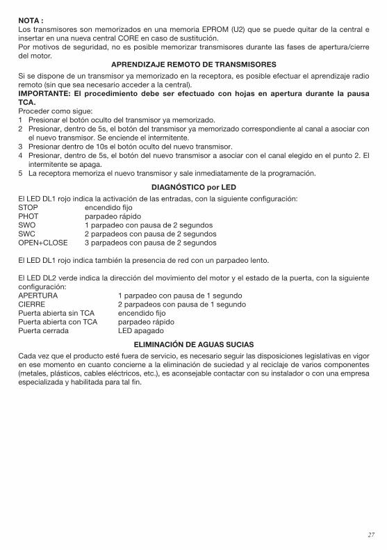
NoTA : Los transmisores son memorizados en una memoria EPROM (U2) que se puede quitar de la central e insertar en una nueva central CORE en caso de sustitución.Por motivos de seguridad, no es posible memorizar transmisores durante las fases de apertura/cierre del motor.
APRENDIZAJE REmoTo DE TRANSmISoRES
Si se dispone de un transmisor ya memorizado en la receptora, es posible efectuar el aprendizaje radio remoto (sin que sea necesario acceder a la central).ImPoRTANTE: El procedimiento debe ser efectuado con hojas en apertura durante la pausa TCA.Proceder como sigue:1 Presionar el botón oculto del transmisor ya memorizado.2 Presionar, dentro de 5s, el botón del transmisor ya memorizado correspondiente al canal a asociar con
el nuevo transmisor. Se enciende el intermitente.3 Presionar dentro de 10s el botón oculto del nuevo transmisor.4 Presionar, dentro de 5s, el botón del nuevo transmisor a asociar con el canal elegido en el punto 2. El
intermitente se apaga.5 La receptora memoriza el nuevo transmisor y sale inmediatamente de la programación.
DIAGNÓSTICo por LED
El LED DL1 rojo indica la activación de las entradas, con la siguiente configuración:STOP encendido fijoPHOT parpadeo rápidoSWO 1 parpadeo con pausa de 2 segundosSWC 2 parpadeos con pausa de 2 segundosOPEN+CLOSE 3 parpadeos con pausa de 2 segundos
El LED DL1 rojo indica también la presencia de red con un parpadeo lento.
El LED DL2 verde indica la dirección del movimiento del motor y el estado de la puerta, con la siguiente configuración:APERTURA 1 parpadeo con pausa de 1 segundoCIERRE 2 parpadeos con pausa de 1 segundoPuerta abierta sin TCA encendido fijoPuerta abierta con TCA parpadeo rápidoPuerta cerrada LED apagado
ELImINACIÓN DE AGUAS SUCIAS
Cada vez que el producto esté fuera de servicio, es necesario seguir las disposiciones legislativas en vigor en ese momento en cuanto concierne a la eliminación de suciedad y al reciclaje de varios componentes (metales, plásticos, cables eléctricos, etc.), es aconsejable contactar con su instalador o con una empresa especializada y habilitada para tal fin.
28
Deklaracja UE o zgodności Producent: Automatismi Benincà SpA.Adres: Via Capitello, 45 - 36066 Sandrigo (VI) - Italia
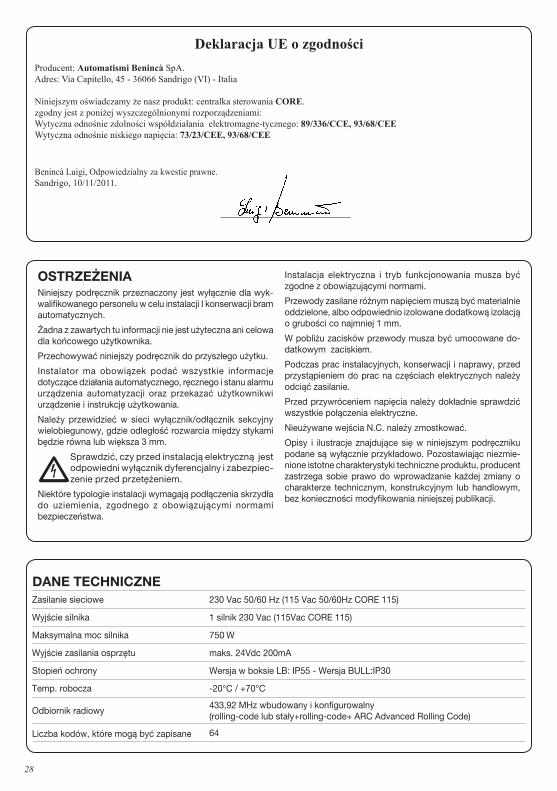
Niniejszym oświadczamy że nasz produkt: centralka sterowania CORE.zgodny jest z poniżej wyszczególnionymi rozporządzeniami:Wytyczna odnośnie zdolności współdziałania elektromagne-tycznego: 89/336/CCE, 93/68/CEEWytyczna odnośnie niskiego napięcia: 73/23/CEE, 93/68/CEE
Benincà Luigi, Odpowiedzialny za kwestie prawne.Sandrigo, 10/11/2011.
DANE TECHNICZNEZasilanie sieciowe 230 Vac 50/60 Hz (115 Vac 50/60Hz CORE 115)
Wyjście silnika 1 silnik 230 Vac (115Vac CORE 115)
Maksymalna moc silnika 750 W
Wyjście zasilania osprzętu maks. 24Vdc 200mA
Stopień ochrony Wersja w boksie LB: IP55 - Wersja BULL:IP30
Temp. robocza -20°C / +70°C
Odbiornik radiowy433,92 MHz wbudowany i konfigurowalny (rolling-code lub stały+rolling-code+ ARC Advanced Rolling Code)
Liczba kodów, które mogą być zapisane 64
oSTRZEŻENIANiniejszy podręcznik przeznaczony jest wyłącznie dla wyk-walifikowanego personelu w celu instalacji I konserwacji bram automatycznych.
Żadna z zawartych tu informacji nie jest użyteczna ani celowa dla końcowego użytkownika.
Przechowywać niniejszy podręcznik do przyszłego użytku.
Instalator ma obowiązek podać wszystkie informacje dotyczące działania automatycznego, ręcznego i stanu alarmu urządzenia automatyzacji oraz przekazać użytkownikwi urządzenie i instrukcję użytkowania.
Należy przewidzieć w sieci wyłącznik/odłącznik sekcyjny wielobiegunowy, gdzie odległość rozwarcia między stykami będzie równa lub większa 3 mm.
•Sprawdzić, czy przed instalacją elektryczną jest odpowiedni wyłącznik dyferencjalny i zabezpiec-zenie przed przetężeniem.
Niektóre typologie instalacji wymagają podłączenia skrzydła do uziemienia, zgodnego z obowiązującymi normami bezpieczeństwa.
Instalacja elektryczna i tryb funkcjonowania musza być zgodne z obowiązującymi normami.
Przewody zasilane różnym napięciem muszą być materialnie oddzielone, albo odpowiednio izolowane dodatkową izolacją o grubości co najmniej 1 mm.
W pobliżu zacisków przewody musza być umocowane do-datkowym zaciskiem.
Podczas prac instalacyjnych, konserwacji i naprawy, przed przystąpieniem do prac na częściach elektrycznych należy odciąć zasilanie.
Przed przywróceniem napięcia należy dokładnie sprawdzić wszystkie połączenia elektryczne.
Nieużywane wejścia N.C. należy zmostkować.
Opisy i ilustracje znajdujące się w niniejszym podręczniku podane są wyłącznie przykładowo. Pozostawiając niezmie-nione istotne charakterystyki techniczne produktu, producent zastrzega sobie prawo do wprowadzanie każdej zmiany o charakterze technicznym, konstrukcyjnym lub handlowym, bez konieczności modyfikowania niniejszej publikacji.
29
CENTRALKA STERoWANIA CoRE
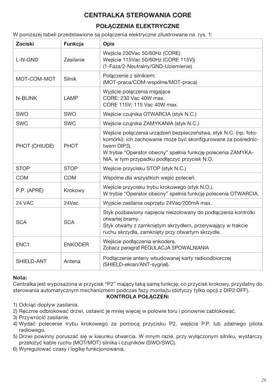
PoŁĄCZENIA ELEKTRYCZNEW poniższej tabeli przedstawione są połączenia elektryczne zilustrowane na rys. 1:
Zaciski Funkcja opis
L-N-GND ZasilanieWejście 230Vac 50/60Hz (CORE)Wejście 115Vac 50/60Hz (CORE 115V))(1-Faza/2-Neutralny/GND-Uziemienie)
MOT-COM-MOT SilnikPołączenie z silnikiem: (MOT-praca/COM-wspólne/MOT-praca)
N-BLINK LAMPWyjście połączenia migające CORE: 230 Vac 40W max.CORE 115V: 115 Vac 40W max.
SWO SWO Wejście czujnika OTWARCIA (styk N.C.)
SWC SWC Wejście czujnika ZAMYKANIA (styk N.C.)
PHOT (CHIUDE) PHOT
Wejście połączenia urządzeń bezpieczeństwa, styk N.C. (np. foto-komórki): ich zachowanie może być skonfigurowane za pośrednic-twem DIP3).W trybie “Operator obecny” spełnia funkcję polecenia ZAMYKA-NIA, w tym przypadku podłączyć przycisk N.O.
STOP STOP Wejście przycisku STOP (styk N.C.)
COM COM Wspólne dla wszystkich wejść poleceń.
P.P. (APRE) KrokowyWejście przycisku trybu krokowego (styk N.O.).W trybie “Operator obecny” spełnia funkcję polecenia OTWARCIA.
24 VAC 24Vac Wyjście zasilania osprzętu 24Vac/200mA max.
SCA SCA
Styk pozbawiony napięcia nieizolowany do podłączenia kontrolki otwartej bramy.Styk otwarty z zamkniętym skrzydłem, przerywający w trakcie ruchu skrzydła, zamknięty przy otwartym skrzydle.
ENC1 ENKODERWejście podłączenia enkodera. Zobacz paragraf REGULACJA SPOWALNIANIA
SHIELD-ANT AntenaPodłączenie anteny wbudowanej karty radioodbiorczej (SHIELD-ekran/ANT-sygnał).
Nota: Centralka jest wyposażona w przycisk “P2” mający taką samą funkcję, co przycisk krokowy, przydatny do sterowania automatycznym mechanizmem podczas fazy montażu (dotyczy tylko opcji z DIP2:OFF).
KoNTRoLA PoŁĄCZEŃ:
1) Odciąć dopływ zasilania.2) Ręcznie odblokować drzwi, ustawić je mniej więcej w połowie toru i ponownie zablokować.3) Przywrócić zasilanie.4) Wydać polecenie trybu krokowego za pomocą przycisku P2, wejścia P.P. lub zdalnego pilota
radiowego. 5) Drzwi powinny poruszać się w kieunku otwarcia. W innym razie, przy wyłączonym silniku, wystarczy
przełożyć kable ruchu (MOT/MOT) silnika i czujników (SWO/SWC).6) Wyregulować czasy i logikę funkcjonowania.
30
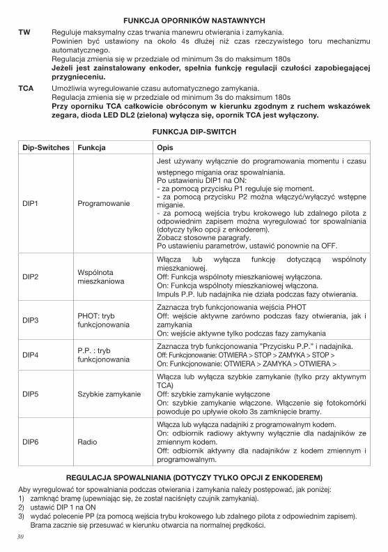
FUNKCJA oPoRNIKÓW NASTAWNYCH
TW Reguluje maksymalny czas trwania manewru otwierania i zamykania. Powinien być ustawiony na około 4s dłużej niż czas rzeczywistego toru mechanizmu
automatycznego. Regulacja zmienia się w przedziale od minimum 3s do maksimum 180s Jeżeli jest zainstalowany enkoder, spełnia funkcję regulacji czułości zapobiegającej
przygnieceniu.
TCA Umożliwia wyregulowanie czasu automatycznego zamykania. Regulacja zmienia się w przedziale od minimum 3s do maksimum 180s Przy oporniku TCA całkowicie obróconym w kierunku zgodnym z ruchem wskazówek
zegara, dioda LED DL2 (zielona) wyłącza się, opornik TCA jest wyłączony.
FUNKCJA DIP-SWITCH
Dip-Switches Funkcja opis
DIP1 Programowanie
Jest używany wyłącznie do programowania momentu i czasu
wstępnego migania oraz spowalniania. Po ustawieniu DIP1 na ON:- za pomocą przycisku P1 reguluje się moment.- za pomocą przycisku P2 można włączyć/wyłączyć wstępne miganie.- za pomocą wejścia trybu krokowego lub zdalnego pilota z odpowiednim zapisem można wyregulować tor spowalniania (dotyczy tylko opcji z enkoderem).Zobacz stosowne paragrafy.Po ustawieniu parametrów, ustawić ponownie na OFF.
DIP2Wspólnota mieszkaniowa
Włącza lub wyłącza funkcję dotyczącą wspólnoty mieszkaniowej. Off: Funkcja wspólnoty mieszkaniowej wyłączona. On: Funkcja wspólnoty mieszkaniowej włączona. Impuls P.P. lub nadajnika nie działa podczas fazy otwierania.
DIP3PHOT: trybfunkcjonowania
Zaznacza tryb funkcjonowania wejścia PHOTOff: wejście aktywne zarówno podczas fazy otwierania, jak i zamykaniaOn: wejście aktywne tylko podczas fazy zamykania
DIP4P.P. : trybfunkcjonowania
Zaznacza tryb funkcjonowania ”Przycisku P.P.” i nadajnika.Off: Funkcjonowanie: OTWIERA > STOP > ZAMYKA > STOP >On: Funkcjonowanie: OTWIERA > ZAMYKA > OTWIERA >
DIP5 Szybkie zamykanie
Włącza lub wyłącza szybkie zamykanie (tylko przy aktywnym TCA)Off: szybkie zamykanie wyłączoneOn: szybkie zamykanie włączone. Włączenie się fotokomórki powoduje po upływie około 3s zamknięcie bramy.
DIP6 Radio
Włącza lub wyłącza nadajniki z programowalnym kodem. On: odbiornik radiowy aktywny wyłącznie dla nadajników ze zmiennym kodem. Off: odbiornik aktywny dla nadajników z kodem zmiennym i programowalnym.
REGULACJA SPoWALNIANIA (DoTYCZY TYLKo oPCJI Z ENKoDEREm)
Aby wyregulować tor spowalniania podczas otwierania i zamykania należy postępować, jak poniżej:1) zamknąć bramę (upewniając się, że został naciśnięty czujnik zamykania).2) ustawić DIP 1 na ON3) wydać polecenie PP (za pomocą wejścia trybu krokowego lub zdalnego pilota z odpowiednim zapisem).
Brama zacznie się przesuwać w kierunku otwarcia na normalnej prędkości.
31
4) w chwili, gdy brama osiągnie żądany punkt spowalniania, wydać polecenie PP, brama zacznie zwalniać i zakończy swój tor do pełnego otwarcia. Kolejne polecenia PP będą ignorowane.
5) przy nieruchomej i całkowicie otwartej bramie wydać polecenie PP (za pomocą wejścia trybu krokowego lub zdalnego pilota z odpowiednim zapisem). Brama zacznie się przesuwać w kierunku zamykania na normalnej prędkości.
6) w chwili, gdy brama osiągnie żądany punkt spowalniania, wydać polecenie PP, brama zacznie zwalniać i zakończy swój tor do całkowitego zamknięcia. Kolejne polecenia PP będą ignorowane.
7) ustawić dip1 ponownie na OFF
UWAGI: - jeżeli nie chce się regulować toru spowalniania na otwieraniu i zamykaniu, pozwolić bramie na wykonanie
pełnego manewru otwierania/zamykania bez wydawania polecenia PP na początku spowalniania.- uruchomienie się zabezpieczeń STOP i PHOT powoduje zablokowanie procedury regulacji.- podczas tej fazy czujnik zapobiegający przygnieceniu jest wyłączony.- jeżeli jest zainstalowany enkoder, Trimmer TW spełnia funkcję regulacji czułości enkodera.
REGULACJA momENTU (DIP1:oN)
Po ustawieniu DIP1 w położeniu ON karta sygnalizuje moment stosowany w danej chwili za pośrednictwem liczby migań (od 1 do 4) diody LED zielonej DL2, po których następuje pauza trwająca 3s.Maksymalny moment jest sygnalizowany przez stałe świecenie diody LED zielonej DL2. Aby zwiększyć moment nacisnąć przycisk P1; dioda LED DL2 zmienia liczbę migań informując o zaznaczonej wartości momentu.Po zaznaczeniu żądanego momentu, aby zapisać ustawienie, ustawić DIP1 w położeniu OFF.
AKTYWACJA/WYŁĄCZENIE WSTĘPNEGo mIGANIA (DIP1:oN)
Po ustawieniu DIP1 w położeniu ON dioda led DL1 czerwona sygnalizuje włączenie wstępnego migania.Za pomocą przycisku P2 można włączyć lub wyłączyć funkcję wstępnego migania.DIODA LED DL1 włączona: wstępne miganie jest aktywne, migające światło uruchamia się na około 3 sekundy przed startem silnika.DIODA LED DL1 wyłączona. wstępne miganie wyłączone.
TRYB oPERAToR oBECNY
Ustawiając wszystkie DIP w położeniu ON centralka przechodzi na tryb OPERATOR OBECNY.Wejście PHOT spełnia funkcję Przycisku ZAMYKANIA (połączyć przycisk ze stykiem N.O.).Wejście PP spełnia funkcję Przycisku OTWIERANIA (połączyć przycisk ze stykiem N.O.).Naciśnięcie przycisków OTWIERANIA/ZAMYKANIA powinno być podtrzymane przez cały czas manewru. Otwarcie wejścia STOP powoduje zatrzymanie silnika.Równoczesne naciśnięcie przycisków OTWIERANIA/ZAMYKANIA powoduje zatrzymanie silnika.
USTAWIANIE moDUŁU RADIoWEGo (DIP1:oFF)
Centralka CORE jest wyposażona w wbudowany moduł radiowy służący do odbioru zdalnych pilotów z kodem stałym lub zmiennym, o częstotliwości 433.92MHz.Aby można było używać zdalnego pilota należy go najpierw odpowiednio ustawić, procedura zapisywania jest opisana poniżej, urządzenie jest w stanie zapamiętać do 64 różnych kodów.
Po naciśnięciu P1 centralka przechodzi do fazy ustawienia radiowego: dioda LED czerwona DL1 miga 1 raz w ciągu sekundy w oczekiwaniu na klawisz do przypisania do funkcji krokowej;Po ustawieniu klawisza wychodzi się z trybu programowania;Naciskając 2-krotnie P1 dioda LED czerwona DL1 miga 2 razy w ciągu sekundy i wchodzi w fazę regulacji pieszej (funkcja piesza steruje manewrem otwierania 7s).Po ustawieniu klawisza wychodzi się z trybu programowania.W razie konieczności opuszczenia trybu programowania bez ustawiania żadnego zdalnego pilota radiowego, należy nacisnąć klawisz P1 do chwili, gdy czerwona dioda DL1 zacznie znowu migać w trybie “obecności sieci“ (zob. diagnostyka LED str. 7).
Aby skasować pamięć odbiornika należy podtrzymać równocześnie na wciśniętej pozycji klawisze P1 i P2 przez około 10 sekund (w trakcie tego czasu obydwie diody LED DL1 i DL2 szybko migają).Po upływie 10 sekund, dwie diody LED świecą stałym światłem, można zwolnić klawisze.
AUTomATISmI BENINCÀ SpA - Via Capitello, 45 - 36066 Sandrigo (VI) - Tel. 0444 751030 r.a. - Fax 0444 759728
32
Kiedy diody LED wrócą do początkowej konfiguracji, oznacza to, że centralka wykonała kasowanie pamięci.
NoTA: Nadajniki są zapisywane w pamięci EPROM (U2), która może być usunięta z centralki i umieszczona w nowej centralce CORE w przypadku zamiany.Z powodów bezpieczeństwa, nie jest możliwe zapisanie nadajników podczas faz otwierania/zamykania silnika.
ZDALNE USTAWIANIE NADAJNIKÓWJeżeli dysponuje się już zapisanym w odbiorniku nadajnikiem można wykonać zdalne ustawianie radiowe (bez konieczności uzyskania dostępu do centralki).UWAGA WAŻNE: Procedura powinna być wykonana przy skrzydłach bramy w położeniu otwarcia podczas pauzy TCA.Postępować w następujący sposób:1 Nacisnąć ukryty klawisz uprzednio zapisanego nadajnika.2 W ciągu 5s nacisnąć klawisz uprzednio zapisanego nadajnika odpowiadający kanałowi do przypisania
do nowego nadajnika. Włącza się sygnalizator świetlny.3 W ciągu 10s nacisnąć ukryty klawisz nowego nadajnika.4 W ciągu 5s nacisnąć klawisz nowego nadajnika do przypisania do kanału wybranego w punkcie 2.
Sygnalizator świetlny wyłącza się.5 Odbiornik zapisuje nowy nadajnik i natychmiast wychodzi z trybu programowania.
DIAGNoSTYKA DIoD LED
Dioda LED DL1 czerwona sygnalizuje aktywację wejść, zgodnie z poniższą legendą:STOP świeci stałym światłemPHOT szybkie miganieSWO 1 miganie z 2-sekundową pauząSWC 2 miganie z 2-sekundową pauząOPEN+CLOSE 3 miganie z 2-sekundową pauzą
Czerwona dioda LED DL1 sygnalizuje również obecność sieci za pomocą wolnego migania.
Zielona dioda LED DL2 sygnalizuje kierunek ruchu silnika i stan bramy, zgodnie z poniższą legendą:OTWARCIE 1 miganie z 1-sekundową pauząZAMYKANIE 2 miganie z 1-sekundową pauząBrama otwarta bez TCA świeci stałym światłemBrama otwarta z TCA szybkie miganieBrama zamknięta dioda led wyłączona
ELImINACJA I DEmoLoWANIE
W przypadku gdy urządzenie nie nadaje się już do dalszego użytkowania, w celu pozbycia się go należy ściśle przestrzegać obowiązujących w danym momencie norm prawnych regulujących zróżnicowany rozkład na części i odzyskiwanie niektórych elementów składowych (metale, plastyk, kable elektryczne, itp.); wskazane jest skontaktowanie się z instalatorem lub wyspecjalizowaną firmą, autoryzowaną do tego rodzaju prac.
Related Documents

![AUTOMATYKA DO BRAM PRZESUWNYCH - … · Ditex Sp. z o.o. info@ditec.com.pl Tel. 71 325 38 89 Zasilanie / zasilanie silnika [V] Siła [N] Użytkowanie Temperatura pracy Stopień ochrony](https://static.cupdf.com/doc/110x72/5b77cdf17f8b9a3b7e8e6bf0/automatyka-do-bram-przesuwnych-ditex-sp-z-oo-infoditeccompl-tel-71.jpg)