Coral IPx Office Installation Procedure and Hardware Reference Manual The flexible way to communicate DRAFT 5

Welcome message from author
This document is posted to help you gain knowledge. Please leave a comment to let me know what you think about it! Share it to your friends and learn new things together.
Transcript
Coral
IPx Office
Installation Procedure
and Hardware Reference
Manual
The flexible way to communicate
DRAFT 5


© Copyright by TADIRAN TELECOM LTD., 2003-2006. All rights reserved worldwide.
The Coral is Protected by U.S. Patents 6,594,255; 6,598,098; 6,608,895; 6,615,404
All trademarks contained herein are the property of their respective holders.
The information contained in this document is proprietary and is subject to all relevant copyright, patent and other laws protecting intellectual property, as well as any specific agreement protecting TADIRAN TELECOM LTD.'s (herein referred to as the “Manufacturer”) rights in the aforesaid information. Neither this document nor the information contained herein may be published, reproduced or disclosed to third parties, in whole or in part, without the express, prior, written permission of the Manufacturer. In addition, any use of this document or the information contained herein for any purposes other than those for which it was disclosed is strictly forbidden.
The Manufacturer reserves the right, without prior notice or liability, to make changes in equipment design or specifications.
Information supplied by the Manufacturer is believed to be accurate and reliable. However, no responsibility is assumed by the Manufacturer for the use thereof nor for the rights of third parties which may be effected in any way by the use thereof.
Any representation(s) in this document concerning performance of the Manufacturer's product(s) are for informational purposes only and are not warranties of future performance, either express or implied. The Manufacturer's standard limited warranty, stated in its sales contract or order confirmation form, is the only warranty offered by the Manufacturer in relation thereto.
This document may contain flaws, omissions or typesetting errors; no warranty is granted nor liability assumed in relation thereto unless specifically undertaken in the Manufacturer's sales contract or order confirmation. Information contained herein is periodically updated and changes will be incorporated into subsequent editions. If you have encountered an error, please notify the Manufacturer. All specifications are subject to change without prior notice.


Federal Communications Commission
Rules Part 68 Compliance Statement
This equipment complies with Part 68 of the FCC rules. On this equipment is a label that contains, among other information, the FCC registration number and ringer equivalence number (REN) for this equipment. If requested, this information must be provided to the telephone company.
The REN is used to determine the quantity of devices which may be connected to the telephone line. Excessive REN's on the telephone line may result in the devices not ringing in response to an incoming call. In most, but not all areas, the sum of the REN's should not exceed five (5.0). To be certain of the number of devices that may be connected to the line, as determined by the total REN's contact the telephone company to determine the maximum REN for the calling area.
An FCC compliant telephone cord and modular plug is provided with this equipment. This equipment is designed to be connected to the telephone network or premises wiring using a compatible modular jack which is Part 68 compliant.
This equipment cannot be used on telephone company-provided coin service. Connection to Party Line Service is subject to state tariffs.
If this equipment causes harm to the telephone network, the telephone company will notify you in advance that temporary discontinuance of service may be required. If advance notice is not practical, the telephone company will notify the customer as soon as possible. Also, you will be advised of your right to file a complaint with the FCC if you believe it is necessary.
The telephone company may make changes in its facilities, equipment, operations, or procedures that could affect the operation of the equipment. If this happens, the telephone company will provide advance notice in order for you to make the necessary modifications in order to maintain uninterrupted service.
If trouble is experienced with this equipment, please contact the supplier at (516)-632-7200 for repair and/or warranty information. If the trouble is causing harm to the telephone network, the telephone company may request you remove the equipment from the network until the problem is resolved.
The following repairs can be done by the customer: No repairs allowed.
This equipment is hearing-aid compatible.
It is recommended that the customer install an AC surge arrestor in the AC outlet to which this device is connected. This is to avoid damaging the equipment caused by local lightning strikes and other electrical surges.
This equipment is capable of providing user's access to interstate providers of operator services through the use of equal access codes. Modifications by aggregators to alter these capabilities may be a violation of the telephone operator consumer services improvement act of 1990 and part 68 of the FCC Rules.
i
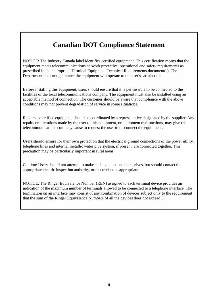
Canadian DOT Compliance Statement
NOTICE: The Industry Canada label identifies certified equipment. This certification means that the equipment meets telecommunications network protective, operational and safety requirements as prescribed in the appropriate Terminal Equipment Technical Requirements document(s). The Department does not guarantee the equipment will operate to the user's satisfaction.
Before installing this equipment, users should ensure that it is permissible to be connected to the facilities of the local telecommunications company. The equipment must also be installed using an acceptable method of connection. The customer should be aware that compliance with the above conditions may not prevent degradation of service in some situations.
Repairs to certified equipment should be coordinated by a representative designated by the supplier. Any repairs or alterations made by the user to this equipment, or equipment malfunctions, may give the telecommunications company cause to request the user to disconnect the equipment.
Users should ensure for their own protection that the electrical ground connections of the power utility, telephone lines and internal metallic water pipe system, if present, are connected together. This precaution may be particularly important in rural areas.
Caution: Users should not attempt to make such connections themselves, but should contact the appropriate electric inspection authority, or electrician, as appropriate.
NOTICE: The Ringer Equivalence Number (REN) assigned to each terminal device provides an indication of the maximum number of terminals allowed to be connected to a telephone interface. The termination on an interface may consist of any combination of devices subject only to the requirement that the sum of the Ringer Equivalence Numbers of all the devices does not exceed 5.
ii

UL Safety of Information Technology Equipment Compliance
This equipment has been tested and complied with the following:
USL Compliance
USL indicates Listing to U.S. Standard for Information Technology Equipment Including Electrical Business Equipment, UL60950, Third Edition.
CNL Compliance
CNL indicates Certification to Canadian Standard for Information Technology Equipment Including Electrical Business Equipment, CSA C22.2 No.60950-00.
CE Compliance Statement
The Coral system complies with the requirements of the following standards:
EN60950-1 ACA-TS001 AS/NZS 3260 AS/NZS 60950
The Coral system may include a CLASS I laser product.
All laser transmitters integrated within the Coral systems are approved CLASS I laser units. Coral systems that include such laser transmitters comply with EN60825-1.
EN55022 EN55024 AS/NZS 3548 CISPR22
iii

Federal Communications CommissionPart 15
The FCC Wants you to KnowThis equipment has been tested and found to comply with the limits for a Class B digital device, pursuant to Part 15 of the FCC rules. These limits are designed to provide reasonable protection against harmful interference in a residential installation. This equipment generates, uses and can radiate radio frequency energy and, if not installed and used in accordance with the instructions, may cause harmful interference to radio communications. However, there is no guarantee that interference will not occur in a particular installation. If this equipment does cause harmful interference to radio or television reception, which can be determined by turning the equipment off and on, the user is encouraged to try to correct the interference by one or more of the following measures:
a) Reorient or relocate the receiving antenna.
b) Increase the separation between the equipment and the receiver.
c) Connect the equipment on an outlet on a circuit different from that to which the receiver is connected.
d) Consult with the dealer or an experienced radio/TV technician.
To ensure continued compliance with specified radio energy emissions limits of FCC Rules, the following precautions must be observed while installing and operating the equipment:1. Install the equipment in strict accordance with the manufacturer's instructions.2. Verify that the power supply and associated A.C. powered equipment are connected to a properly
grounded electrical supply, and that power cords, if used, are unmodified.3. Verify that the system grounding, including Master Ground, D.C. power system, and equipment
cabinets, is in accordance with the manufacturer's instructions and connected to an approved earth ground source.
4. Always replace the factory-supplied cover or keep the cabinet doors closed when not servicing the equipment.
5. Make no modification to the equipment that would affect its compliance with the specified limits of FCC Rules.
6. Maintain the equipment in a satisfactory state of repair.7. Verify that emissions limiting devices, such as ferrite blocks and radio frequency interference mod-
ules, are properly installed and functional.
If necessary the operator should consult their supplier, or an experienced radio/television engineer for additional suggestions. The following booklet prepared by the Federal Communications Commission (FCC) may be of assistance: "How to Identify and Resolve Radio-TV Interference Problems." This booklet is available from the U.S. Government Printing Office, Washington, D.C. 20402, Stock No. 004-000-00345-4.
FCC WarningModifications not expressly approved by the manufacturer could void the user authority to operate the equipment under FCC rules.
iv
Table of Contents
Chapter 1: Introduction
1.1 About this Manual..................................................................................................................... 1-1Document Description ............................................................................................................ 1-1Related Documentation .......................................................................................................... 1-3Special Symbols Used in this Document ................................................................................ 1-4List of Abbreviations................................................................................................................ 1-5
1.2 About the Coral IPx Office ........................................................................................................ 1-7System Description ................................................................................................................. 1-7
Capacity................................................................................................................................ 1-7VoIP ...................................................................................................................................... 1-7Circuitry................................................................................................................................. 1-8Major Features...................................................................................................................... 1-9
Recommended Tools .............................................................................................................. 1-11
Chapter 2: Hardware Installation Procedure
2.1 Site Inspection .......................................................................................................................... 2-1Installation Environment.......................................................................................................... 2-1Space Requirements .............................................................................................................. 2-2Electrical Requirements .......................................................................................................... 2-5
General Requirements.......................................................................................................... 2-5DC Electrical Requirements.................................................................................................. 2-5
2.2 Equipment Installation .............................................................................................................. 2-7Introduction ............................................................................................................................. 2-7Unpacking the Shipping Container ......................................................................................... 2-8Preparing the Unit for Installation............................................................................................ 2-10
Checking the Space and Positioning Requirements............................................................. 2-10Checking the Electrical Requirements.................................................................................. 2-10Power Test............................................................................................................................ 2-10
Installing the Control and NTU Office cards............................................................................ 2-11Opening the Unit Cover ........................................................................................................ 2-11Installing the Main Resources Card...................................................................................... 2-11Installing the DBM-X Card .................................................................................................... 2-11Installing the NTU Office Card .............................................................................................. 2-11Installing the Internal LAN Cable .......................................................................................... 2-11Installing the WiFi Card and Antenna ................................................................................... 2-11Removing the Battery Insulator ............................................................................................ 2-11Closing the Unit Cover.......................................................................................................... 2-11
Installing the External Components ........................................................................................ 2-12Installing the IMC-8 or IMC-16 Flash Card ........................................................................... 2-12Installing the Compact Flash Disk ........................................................................................ 2-12Installing the Software Authorization Unit ............................................................................. 2-12Assembling the WiFi Antennas............................................................................................. 2-12
v
Mounting Table Units .............................................................................................................. 2-13Mounting Rack Units............................................................................................................... 2-14
Preparing the Unit for Mounting onto the Rack..................................................................... 2-14Preparing the Rack for Unit Mounting................................................................................... 2-14Mounting the Unit onto the Rack .......................................................................................... 2-14Dismounting the IPx Office Unit from the Rack .................................................................... 2-16
Ground Wiring......................................................................................................................... 2-18Connecting the Ground Wire to the Unit............................................................................... 2-19Grounding the MDF Unit....................................................................................................... 2-20
Strapping the Configuration Jumpers ..................................................................................... 2-23Peripheral Card Installation..................................................................................................... 2-24
Inserting a Coral Peripheral Card ......................................................................................... 2-24Interconnecting the IPx Office and the Expansion Cages....................................................... 2-33
Interconnecting the IPx Office Unit and the Expansion Cage............................................... 2-33Interconnecting the 1st Expansion cage and 2nd Expansion Cage ..................................... 2-33Defining Expansion Cage Numbers...................................................................................... 2-33
Installing the DC Power Supply .............................................................................................. 2-34Connecting the Power Wires .................................................................................................. 2-35
AC Powered Systems........................................................................................................... 2-35DC Powered Systems........................................................................................................... 2-36
2.3 Program Interface Device Connection...................................................................................... 2-39
Chapter 3: Initial Power-up Tests
3.1 Power Supply Test.................................................................................................................... 3-1AC Powered Systems ............................................................................................................. 3-1DC Powered Systems............................................................................................................. 3-3
3.2 Common Control Test............................................................................................................... 3-5Control Card Initialization........................................................................................................ 3-5Memory Lithium Battery Condition Test .................................................................................. 3-8
3.3 Peripheral Interface Card Initialization...................................................................................... 3-9Introduction ............................................................................................................................. 3-9
Rules for Inserting a Coral Circuit Card ................................................................................ 3-10System Initialization ................................................................................................................ 3-13
Preparing for Initialization ..................................................................................................... 3-13IPx Office Unit Initialization ................................................................................................... 3-13First Expansion Cage Initialization........................................................................................ 3-14Second Expansion Cage Initialization .................................................................................. 3-14
3.4 I/O Cable Installation ................................................................................................................ 3-15
3.5 Installation Wrap-up.................................................................................................................. 3-17
Chapter 4: Software Installation Procedure
4.1 Generic Feature Software ........................................................................................................ 4-1
vi
Introduction ............................................................................................................................. 4-1Upgrading Using the FMprog-Utility........................................................................................ 4-2Installing an Upgraded IMC8 / IMC16 Card ............................................................................ 4-3
Creating a Binary Backup of the Database........................................................................... 4-3Installing the IMC8 / IMC16 Card.......................................................................................... 4-3
Upgrading the UGW Software ................................................................................................ 4-4
4.2 System Database Control......................................................................................................... 4-5Accessing the Database Flash Menu ..................................................................................... 4-5Saving to IMC8 or IMC16........................................................................................................ 4-6Loading (Restoring) from IMC8 or IMC16............................................................................... 4-8Show File Information ............................................................................................................. 4-10Automatic Daily Backup .......................................................................................................... 4-11Erasing Flash Memory ............................................................................................................ 4-12Backing up the Hard Disk onto the Compact Flash Card ....................................................... 4-13Loading (Restoring) from the Compact Flash Card ................................................................ 4-13
Chapter 5: External Connections
5.1 Main Distribution Frame (MDF) ................................................................................................ 5-1
5.2 External Equipment .................................................................................................................. 5-5Station Equipment................................................................................................................... 5-5
Wired Stations ...................................................................................................................... 5-5Wireless and VoIP Stations .................................................................................................. 5-8Related Documentation ........................................................................................................ 5-8
Trunk Circuits .......................................................................................................................... 5-9Auxiliary Connections ............................................................................................................. 5-10
5.3 Protection Devices.................................................................................................................... 5-11Introduction to Primary and Secondary Protection Devices.................................................... 5-11Surge Arrestor Magazine ........................................................................................................ 5-14
5.4 Power Fail (PF) Transfer Circuits ............................................................................................. 5-15Physical Connection ............................................................................................................... 5-15
Stations................................................................................................................................. 5-15Trunks................................................................................................................................... 5-15
Database Programming .......................................................................................................... 5-16Power Failure Trunk Definition (Route: TRK, 4) ................................................................... 5-16
5.5 Data Communication Ports....................................................................................................... 5-17
5.6 I/O Card Connections ............................................................................................................... 5-19Peripheral Cards Index ........................................................................................................... 5-19Champ Connections ............................................................................................................... 5-22
Direct Pinout of the Champ/Card Connection....................................................................... 5-23Direct Pinout of the MDF Connection ................................................................................... 5-25
RJ-45 Connections ................................................................................................................. 5-27Peripheral Cards Index ......................................................................................................... 5-274T Office and 4T-CID Office Cards....................................................................................... 5-288T Office and 8T-CID Office Cards....................................................................................... 5-294TBR Office Card ................................................................................................................. 5-30
vii
UDT Office (T1 or PRI-23) .................................................................................................... 5-31PRI-30 Office ........................................................................................................................ 5-3230T Office Card .................................................................................................................... 5-33
5.7 LAN, WAN, and Printer Connections........................................................................................ 5-35Connecting to the LAN............................................................................................................ 5-36
Connecting to the LAN when an NTU Office Card is Supplied............................................. 5-36Connecting to the LAN when an NTU Office Card is not Supplied....................................... 5-36
Connecting to the WAN .......................................................................................................... 5-36Connecting to the WAN when an NTU Office Card is Supplied ........................................... 5-36Connecting to the WAN when an NTU Office Card is not Supplied ..................................... 5-36
Connecting to a Printer ........................................................................................................... 5-37Connecting to a Printer when an NTU Office Card is Supplied ............................................ 5-37Connecting to a Printer when an NTU Office Card is not Supplied ...................................... 5-37
LAN/WAN Pinout .................................................................................................................... 5-38
Chapter 6: Cage Description
6.1 General System Description..................................................................................................... 6-1Unit Exterior ............................................................................................................................ 6-1
Front Panel ........................................................................................................................... 6-3Rear Side.............................................................................................................................. 6-5Side Panels........................................................................................................................... 6-6Top Side ............................................................................................................................... 6-6Bottom Panel ........................................................................................................................ 6-6Installation Kit ....................................................................................................................... 6-6
Unit Cover ............................................................................................................................... 6-7Opening the Unit Cover ........................................................................................................ 6-8Closing the Unit Cover.......................................................................................................... 6-10
Unit Interior - Front Section..................................................................................................... 6-12MCB Office Card................................................................................................................... 6-13DBM-X Card ......................................................................................................................... 6-13Hard Disk .............................................................................................................................. 6-13MRC Card............................................................................................................................. 6-13IMC8 / IMC16 Flash Card ..................................................................................................... 6-13Compact Flash Disk.............................................................................................................. 6-13Networking Card ................................................................................................................... 6-13WiFi Card.............................................................................................................................. 6-13
Unit Interior - Rear Section ..................................................................................................... 6-14Card Slots ............................................................................................................................. 6-14Power Supply Unit ................................................................................................................ 6-14Peripheral Cards................................................................................................................... 6-15Configuration Jumpers.......................................................................................................... 6-15I/O Connectors...................................................................................................................... 6-15Expansion Connector ........................................................................................................... 6-15Cage Ground Terminal ......................................................................................................... 6-15Blank Panels......................................................................................................................... 6-16
Heat Removal ......................................................................................................................... 6-18Cooling Fans......................................................................................................................... 6-19
Safety Labels .......................................................................................................................... 6-21Nameplate Label................................................................................................................... 6-21UL Label ............................................................................................................................... 6-21
viii
ESD Label............................................................................................................................. 6-22
6.2 System Configuration Options.................................................................................................. 6-23General Description ................................................................................................................ 6-23
Main Unit (IPx Office)............................................................................................................ 6-24Expansion Cage (IPx 500X) ................................................................................................. 6-24Expansion Cage (IPx 800X) ................................................................................................. 6-24
Interconnecting the IPx Office Unit and the Expansion Cage ................................................. 6-30Suggestions for Peripheral Card Distribution.......................................................................... 6-34
Main Unit............................................................................................................................... 6-34Expansion Cages.................................................................................................................. 6-34
Optional Coral IPx 500X Expansion Cage .............................................................................. 6-36General ................................................................................................................................. 6-36Card Slots ............................................................................................................................. 6-36Port Capacity ........................................................................................................................ 6-36Power Supply........................................................................................................................ 6-36MDFipx ................................................................................................................................. 6-36Setting the Configuration Jumpers ....................................................................................... 6-36Connecting the IPx 500X Cage to the IPx Office Unit .......................................................... 6-37Related Documentation ........................................................................................................ 6-37
Optional Coral IPx 800X Expansion Cage .............................................................................. 6-38General ................................................................................................................................. 6-38Card Slots ............................................................................................................................. 6-38Port Capacity ........................................................................................................................ 6-38Power Supply........................................................................................................................ 6-38PX Card ................................................................................................................................ 6-38When an IPx 800X Expansion Cage is Used in an IPx Office System ................................. 6-39Setting the Configuration Jumpers ....................................................................................... 6-39Connecting the IPx 800X Cage to the IPx Office Unit .......................................................... 6-39Related Documentation ........................................................................................................ 6-39
Chapter 7: Power Supply
7.1 PS Office AC Power Supply Unit.............................................................................................. 7-1General Description ................................................................................................................ 7-1
Power Source ....................................................................................................................... 7-1PS Office AC Front Panel ..................................................................................................... 7-1PS Office AC Card Layout .................................................................................................... 7-2
Circuit Description................................................................................................................... 7-4DC Output Power.................................................................................................................. 7-4Normal Operation ................................................................................................................. 7-4Disconnecting the AC Power Cord from the AC Power Mains ............................................. 7-5Turning the Power Switch OFF............................................................................................. 7-5Monitoring Circuitry............................................................................................................... 7-5
Installation and Operation ...................................................................................................... 7-6Installing the Power Supply .................................................................................................. 7-6Operating the PS Office AC.................................................................................................. 7-7Removing the Power Supply ................................................................................................ 7-9
Troubleshooting ...................................................................................................................... 7-9Replacing the PS Office AC Fuses ......................................................................................... 7-10
Diagnosing the IPx Office LED Indicators............................................................................. 7-10
ix
Specifications.......................................................................................................................... 7-12
7.2 PS Office DC Power Supply Unit.............................................................................................. 7-13General Description ................................................................................................................ 7-13
PS Office DC Front Panel..................................................................................................... 7-13PS Office DC Card Layout.................................................................................................... 7-15
Circuit Description................................................................................................................... 7-17Power Input Section.............................................................................................................. 7-17DC Output Power.................................................................................................................. 7-17-48VDC Output Power .......................................................................................................... 7-17
Installation and Operation ...................................................................................................... 7-19Installing the Power Supply .................................................................................................. 7-19Operating the PS Office DC.................................................................................................. 7-20Removing the Power Supply ................................................................................................ 7-21
Troubleshooting ...................................................................................................................... 7-22Replacing the PS Office DC Power Fuse ............................................................................... 7-22Specifications.......................................................................................................................... 7-23
Chapter 8: Common Control Cards
8.1 Control Cards ........................................................................................................................... 8-1General Description ................................................................................................................ 8-1Card Handling Procedures...................................................................................................... 8-4
Control Card Installation ....................................................................................................... 8-4
8.2 MCB Office Card ...................................................................................................................... 8-5General Information ................................................................................................................ 8-5Card Components................................................................................................................... 8-5Main Control Processor .......................................................................................................... 8-8
Port Management ................................................................................................................. 8-8Memory Management........................................................................................................... 8-8The Program Interface Facility.............................................................................................. 8-9
Internet Protocol Gateway ...................................................................................................... 8-9Group Controller Circuit .......................................................................................................... 8-10
Voice Switching and Time Slot Configuration....................................................................... 8-10Circuit Description................................................................................................................. 8-13Using Time Slots................................................................................................................... 8-13
Software Authorization Management ...................................................................................... 8-14SAU Unique Serial Numbers ................................................................................................ 8-15
Front Panel Features .............................................................................................................. 8-16IMC8/16 Memory Card............................................................................................................ 8-17KB0 RS-232E Programming Port ........................................................................................... 8-18
KB0 Setup............................................................................................................................. 8-18UGW RS-232E Programming Port ......................................................................................... 8-19
UGW Setup........................................................................................................................... 8-19Installing the DBM-X Memory Card ........................................................................................ 8-20Lithium Battery Condition Testing ........................................................................................... 8-21Specifications - MCB Office .................................................................................................... 8-23
8.3 LED Card.................................................................................................................................. 8-25
x
General Information ................................................................................................................ 8-25Disconnecting the LED Office Card from the MCB Office Card .............................................. 8-26Replacing the LED Office Card............................................................................................... 8-26
8.4 MRC Card................................................................................................................................. 8-27General Information ................................................................................................................ 8-27
Functional Description .......................................................................................................... 8-27Layout ................................................................................................................................... 8-28
Installing the MRC................................................................................................................... 8-29Preparing for Installation....................................................................................................... 8-29Installing the MRC Card........................................................................................................ 8-29
Removing the MRC................................................................................................................. 8-31
8.5 IMC8 and IMC16 Flash Cards .................................................................................................. 8-33General Information ................................................................................................................ 8-33Installing the IMC8/16 ............................................................................................................. 8-34Removing the IMC8/16 ........................................................................................................... 8-35Specifications.......................................................................................................................... 8-36
8.6 Compact Flash Disk ................................................................................................................. 8-39Introduction ............................................................................................................................. 8-39Inserting the CFD.................................................................................................................... 8-39
8.7 DBM-X Card ............................................................................................................................. 8-41General Information ................................................................................................................ 8-41
When is a DBM-X card required? ......................................................................................... 8-42Installing the DBM-X ............................................................................................................... 8-43
Preparing for Installation....................................................................................................... 8-43Installing the DBM-X Card .................................................................................................... 8-43
Removing the DBM-X ............................................................................................................. 8-45Specifications - DBM-X ........................................................................................................... 8-46
Chapter 9: Shared Service Cards
9.1 Shared Service Circuitry........................................................................................................... 9-1General Description ................................................................................................................ 9-1Shared Service Cards in the Main Unit................................................................................... 9-1Card Handling Procedures...................................................................................................... 9-1MRC Cards ............................................................................................................................. 9-1U-RMI, U-MR, RMI and MR Office Cards ............................................................................... 9-2Shared Service Features in the Main Unit .............................................................................. 9-2Additional Shared Service Cards in the Expansion Cages ..................................................... 9-3
9.2 MRC-8, 16, 32, 64 Modules...................................................................................................... 9-5General Description ................................................................................................................ 9-5
Card Location ....................................................................................................................... 9-5Database Programming........................................................................................................ 9-5
Layout and Installation ............................................................................................................ 9-6
9.3 U-RMI / U-MR / RMI / MR Office Cards.................................................................................... 9-7General Description ................................................................................................................ 9-7
Card Location ....................................................................................................................... 9-7
xi
Database Programming........................................................................................................ 9-7Features.................................................................................................................................. 9-8Configuration Jumpers............................................................................................................ 9-15Indicators ................................................................................................................................ 9-16External Connectors ............................................................................................................... 9-17MR/RMI-F EPROM (U60) ....................................................................................................... 9-18
MR/RMI-F Features .............................................................................................................. 9-18MR and RMI-F Database Programming ............................................................................... 9-19
URC PROM (U73) .................................................................................................................. 9-21Features................................................................................................................................ 9-22URC2 Database Programming (U-RMI Office and U-MR Office cards) ............................... 9-23
9.4 Three-Way Conference (3-Way)............................................................................................... 9-35General Description ................................................................................................................ 9-35Database Programming .......................................................................................................... 9-35Additional 3-Way Circuits ........................................................................................................ 9-37Specifications - 3-Way Conference......................................................................................... 9-37
9.5 Multi-Party Conference (CONF) ............................................................................................... 9-39General Description ................................................................................................................ 9-39Feature Descriptions............................................................................................................... 9-40
URC Chained Meet Me Groups............................................................................................ 9-40URC Meet Me Conference Modes........................................................................................ 9-40
Database Programming .......................................................................................................... 9-41Additional Multi-Party Conference Circuits ............................................................................. 9-44Specifications - Multi-Party Conference.................................................................................. 9-44
9.6 DTMF Receiver (DTR).............................................................................................................. 9-45General Description ................................................................................................................ 9-45How many DTMF receiver circuits (DTRs) are required? ....................................................... 9-46Additional DTR Circuits ........................................................................................................... 9-46Database Programming .......................................................................................................... 9-47Specifications - DTR ............................................................................................................... 9-48
9.7 Dial Tone Detector (DTD) ......................................................................................................... 9-49General Description ................................................................................................................ 9-49Database Programming .......................................................................................................... 9-50Additional DTD Circuits ........................................................................................................... 9-51Specifications - DTD ............................................................................................................... 9-51
9.8 Caller ID for SLT (iDSP) ........................................................................................................... 9-53General Description ................................................................................................................ 9-53Database Programming .......................................................................................................... 9-54Additional CID Circuits ............................................................................................................ 9-55Specifications - CID ................................................................................................................ 9-55
9.9 MFC Receiver (MFR) ............................................................................................................... 9-57General Description ................................................................................................................ 9-57Available MFR Circuits............................................................................................................ 9-57Specifications.......................................................................................................................... 9-57
9.10 VoIP Media Gateway (MG)..................................................................................................... 9-59
xii
General Description ................................................................................................................ 9-59Additional Media Channel Circuits .......................................................................................... 9-59
9.11 Remote Maintenance (Modem) .............................................................................................. 9-61General Description ................................................................................................................ 9-61Modem Jumpers - Enable/Disable.......................................................................................... 9-61Database Programming .......................................................................................................... 9-63Additional Modem in the Optional IPx 800X Cage.................................................................. 9-65Specifications - Modem........................................................................................................... 9-65
9.12 Data Serial Ports (RS-232E) .................................................................................................. 9-67General Description ................................................................................................................ 9-67RS-232E ports in the Optional IPx 800X Cage ....................................................................... 9-68Specifications - RS-232E ........................................................................................................ 9-68
9.13 Music ...................................................................................................................................... 9-69Introduction ............................................................................................................................. 9-69Circuit Description................................................................................................................... 9-69
M1 Internal/External music ................................................................................................... 9-69M2/P Paging/External music................................................................................................. 9-69
Configuring the Music M1 Jumper to External or Internal....................................................... 9-70Configuring the Music M2/P Jumper to Music ........................................................................ 9-71Database Programming .......................................................................................................... 9-72External Connections.............................................................................................................. 9-74Additional Music Interfaces in the Optional IPx 800X Cage.................................................... 9-75Specifications - Music ............................................................................................................. 9-75
9.14 Voice Paging (Public Address) and Relay-1........................................................................... 9-77Introduction ............................................................................................................................. 9-77Circuit Description................................................................................................................... 9-77
M2/P Paging/External music................................................................................................. 9-77Relay Contacts 1-2 Paging/Relay......................................................................................... 9-78
Configuring the Paging M2/P Jumper to Paging..................................................................... 9-79Configuring the Relay Contacts 1-2 Jumper to Paging ........................................................... 9-80Database Programming .......................................................................................................... 9-81External Connections.............................................................................................................. 9-82Relay Electrical Limitations ..................................................................................................... 9-83Additional Paging Interface in the optional IPx 800X Cage .................................................... 9-83Specifications - Paging ........................................................................................................... 9-84
9.15 UNA/Bell and Relay-2............................................................................................................. 9-85Introduction ............................................................................................................................. 9-85Circuit Description................................................................................................................... 9-85Configuring the Relay Contacts 3-4 Jumper to Bell ................................................................ 9-86Database Programming .......................................................................................................... 9-87External Connections.............................................................................................................. 9-88Relay Electrical Limitations ..................................................................................................... 9-89Additional UNA and Relay Contacts in the Optional IPx 800X Cage ...................................... 9-89Specifications - BELL/UNA ..................................................................................................... 9-90
9.16 Accessory or Alarm Relay-3 ................................................................................................... 9-91Introduction ............................................................................................................................. 9-91
Dial Operated Accessory ...................................................................................................... 9-91Major/Minor Alarm Relay ...................................................................................................... 9-91
xiii
Circuit Description................................................................................................................... 9-92Configuring the Relay Contacts 1-2 Jumper to RLY3 ............................................................. 9-93Configuring the Relay Contacts 3-4 Jumper to RLY3 ............................................................. 9-94Database Programming .......................................................................................................... 9-95
Dial Operated Accessory ...................................................................................................... 9-95Major/Minor Alarm Relay ...................................................................................................... 9-96
External Connections.............................................................................................................. 9-97Dial Operated Accessory ...................................................................................................... 9-97Major/Minor Alarm Relays .................................................................................................... 9-97
Relay Electrical Limitations ..................................................................................................... 9-98Additional RLY3 Contacts in the Optional IPx 800X Cage ...................................................... 9-98Specifications - RELAY ........................................................................................................... 9-98
9.17 Relay Contacts ....................................................................................................................... 9-99General Information ................................................................................................................ 9-99Configuring the Relay Contacts Jumper ................................................................................. 9-101Specifications - Relays............................................................................................................ 9-102
Chapter 10: Peripheral Cards
10.1 Peripheral Card Installation .................................................................................................... 10-1General Information ................................................................................................................ 10-1Card Handling Procedures...................................................................................................... 10-1General Installation Procedure ............................................................................................... 10-2Diagnostic LED Indication....................................................................................................... 10-2
LED Constantly Lit ................................................................................................................ 10-3LED Flashing ........................................................................................................................ 10-3
10.2 Peripheral Card Description ................................................................................................... 10-5General Description ................................................................................................................ 10-5
XXX Office Cards.................................................................................................................. 10-5Peripheral Card types ........................................................................................................... 10-5
10.3 Digital Trunk Synchronization ................................................................................................. 10-9Slave Clock Mode Operation .................................................................................................. 10-9
How The System Derives The External Clock Signal........................................................... 10-9Synchronization Slots in the Main and Expansion Cages....................................................... 10-10
Synchronization Slot Selection ............................................................................................. 10-10Conditions for Slave Clock Mode Operation......................................................................... 10-10System Switch from Slave Clock Mode to Master Clock Mode ............................................ 10-10
Choosing the Best Synchronization Source............................................................................ 10-12Optional Synchronization Cards ........................................................................................... 10-12Order of Preference .............................................................................................................. 10-13
Synchronization Instructions ................................................................................................... 10-14
10.4 Service and Peripheral Cards................................................................................................. 10-19
Chapter 11: System Networking
11.1 NTU Office Card Description .................................................................................................. 11-3
xiv
Introduction ............................................................................................................................. 11-3System Operation without an NTU Office Card ...................................................................... 11-3
Media Stream from the Digital World to the LAN and WAN ................................................. 11-3Media Stream from the LAN and WAN to the Digital World ................................................. 11-4
System Operation with an NTU Office Card ........................................................................... 11-5Media Stream from the LAN and WAN to the Digital World ................................................. 11-5
NTU Office Card Components ................................................................................................ 11-7
11.2 NTU Office Card Installation ................................................................................................... 11-9Introduction ............................................................................................................................. 11-9Installing the NTU Office Card ................................................................................................ 11-10Replacing the NTU Office Card .............................................................................................. 11-12Installing the WiFi Card ........................................................................................................... 11-13Assembling the WiFi Antennas ............................................................................................... 11-15Configuring the Networking Software ..................................................................................... 11-16Specifications.......................................................................................................................... 11-17
11.3 Connecting to the Network without an NTU Office Card......................................................... 11-21
xv

xvi
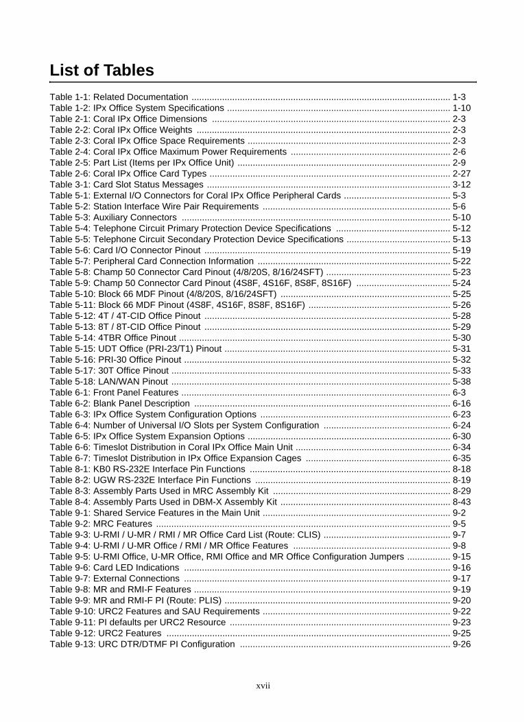
List of TablesTable 1-1: Related Documentation ...................................................................................................... 1-3Table 1-2: IPx Office System Specifications ........................................................................................ 1-10Table 2-1: Coral IPx Office Dimensions .............................................................................................. 2-3Table 2-2: Coral IPx Office Weights .................................................................................................... 2-3Table 2-3: Coral IPx Office Space Requirements ................................................................................ 2-3Table 2-4: Coral IPx Office Maximum Power Requirements ............................................................... 2-6Table 2-5: Part List (Items per IPx Office Unit) .................................................................................... 2-9Table 2-6: Coral IPx Office Card Types ............................................................................................... 2-27Table 3-1: Card Slot Status Messages ................................................................................................ 3-12Table 5-1: External I/O Connectors for Coral IPx Office Peripheral Cards .......................................... 5-3Table 5-2: Station Interface Wire Pair Requirements .......................................................................... 5-6Table 5-3: Auxiliary Connectors .......................................................................................................... 5-10Table 5-4: Telephone Circuit Primary Protection Device Specifications ............................................. 5-12Table 5-5: Telephone Circuit Secondary Protection Device Specifications ......................................... 5-13Table 5-6: Card I/O Connector Pinout ................................................................................................. 5-19Table 5-7: Peripheral Card Connection Information ............................................................................ 5-22Table 5-8: Champ 50 Connector Card Pinout (4/8/20S, 8/16/24SFT) ................................................. 5-23Table 5-9: Champ 50 Connector Card Pinout (4S8F, 4S16F, 8S8F, 8S16F) ..................................... 5-24Table 5-10: Block 66 MDF Pinout (4/8/20S, 8/16/24SFT) ................................................................... 5-25Table 5-11: Block 66 MDF Pinout (4S8F, 4S16F, 8S8F, 8S16F) ........................................................ 5-26Table 5-12: 4T / 4T-CID Office Pinout ................................................................................................. 5-28Table 5-13: 8T / 8T-CID Office Pinout ................................................................................................. 5-29Table 5-14: 4TBR Office Pinout ........................................................................................................... 5-30Table 5-15: UDT Office (PRI-23/T1) Pinout ......................................................................................... 5-31Table 5-16: PRI-30 Office Pinout ......................................................................................................... 5-32Table 5-17: 30T Office Pinout .............................................................................................................. 5-33Table 5-18: LAN/WAN Pinout .............................................................................................................. 5-38Table 6-1: Front Panel Features .......................................................................................................... 6-3Table 6-2: Blank Panel Description ..................................................................................................... 6-16Table 6-3: IPx Office System Configuration Options ........................................................................... 6-23Table 6-4: Number of Universal I/O Slots per System Configuration .................................................. 6-24Table 6-5: IPx Office System Expansion Options ................................................................................ 6-30Table 6-6: Timeslot Distribution in Coral IPx Office Main Unit ............................................................. 6-34Table 6-7: Timeslot Distribution in IPx Office Expansion Cages ......................................................... 6-35Table 8-1: KB0 RS-232E Interface Pin Functions ............................................................................... 8-18Table 8-2: UGW RS-232E Interface Pin Functions ............................................................................. 8-19Table 8-3: Assembly Parts Used in MRC Assembly Kit ...................................................................... 8-29Table 8-4: Assembly Parts Used in DBM-X Assembly Kit ................................................................... 8-43Table 9-1: Shared Service Features in the Main Unit .......................................................................... 9-2Table 9-2: MRC Features .................................................................................................................... 9-5Table 9-3: U-RMI / U-MR / RMI / MR Office Card List (Route: CLIS) .................................................. 9-7Table 9-4: U-RMI / U-MR Office / RMI / MR Office Features .............................................................. 9-8Table 9-5: U-RMI Office, U-MR Office, RMI Office and MR Office Configuration Jumpers ................. 9-15Table 9-6: Card LED Indications ......................................................................................................... 9-16Table 9-7: External Connections ......................................................................................................... 9-17Table 9-8: MR and RMI-F Features ..................................................................................................... 9-19Table 9-9: MR and RMI-F PI (Route: PLIS) ......................................................................................... 9-20Table 9-10: URC2 Features and SAU Requirements .......................................................................... 9-22Table 9-11: PI defaults per URC2 Resource ....................................................................................... 9-23Table 9-12: URC2 Features ................................................................................................................ 9-25Table 9-13: URC DTR/DTMF PI Configuration ................................................................................... 9-26
xvii
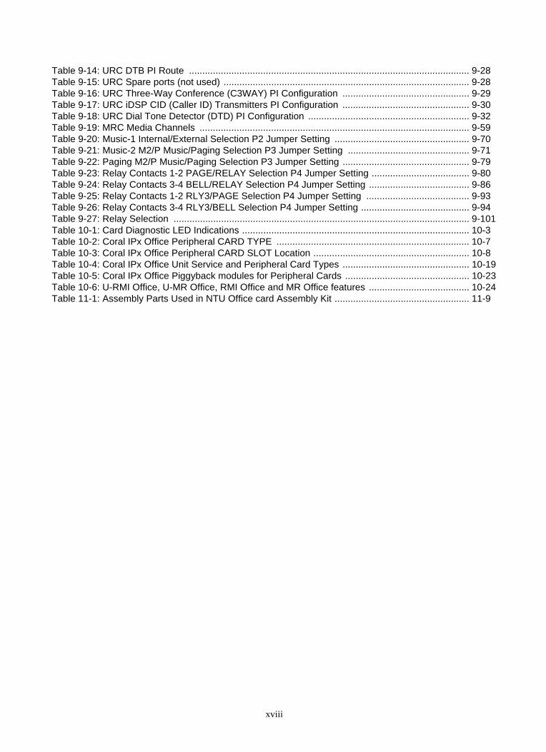
Table 9-14: URC DTB PI Route .......................................................................................................... 9-28Table 9-15: URC Spare ports (not used) ............................................................................................. 9-28Table 9-16: URC Three-Way Conference (C3WAY) PI Configuration ................................................ 9-29Table 9-17: URC iDSP CID (Caller ID) Transmitters PI Configuration ................................................ 9-30Table 9-18: URC Dial Tone Detector (DTD) PI Configuration ............................................................. 9-32Table 9-19: MRC Media Channels ...................................................................................................... 9-59Table 9-20: Music-1 Internal/External Selection P2 Jumper Setting ................................................... 9-70Table 9-21: Music-2 M2/P Music/Paging Selection P3 Jumper Setting .............................................. 9-71Table 9-22: Paging M2/P Music/Paging Selection P3 Jumper Setting ................................................ 9-79Table 9-23: Relay Contacts 1-2 PAGE/RELAY Selection P4 Jumper Setting ..................................... 9-80Table 9-24: Relay Contacts 3-4 BELL/RELAY Selection P4 Jumper Setting ...................................... 9-86Table 9-25: Relay Contacts 1-2 RLY3/PAGE Selection P4 Jumper Setting ....................................... 9-93Table 9-26: Relay Contacts 3-4 RLY3/BELL Selection P4 Jumper Setting ......................................... 9-94Table 9-27: Relay Selection ................................................................................................................ 9-101Table 10-1: Card Diagnostic LED Indications ...................................................................................... 10-3Table 10-2: Coral IPx Office Peripheral CARD TYPE ......................................................................... 10-7Table 10-3: Coral IPx Office Peripheral CARD SLOT Location ........................................................... 10-8Table 10-4: Coral IPx Office Unit Service and Peripheral Card Types ................................................ 10-19Table 10-5: Coral IPx Office Piggyback modules for Peripheral Cards ............................................... 10-23Table 10-6: U-RMI Office, U-MR Office, RMI Office and MR Office features ...................................... 10-24Table 11-1: Assembly Parts Used in NTU Office card Assembly Kit ................................................... 11-9
xviii
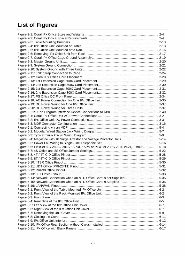
List of FiguresFigure 2-1: Coral IPx Office Sizes and Weights .................................................................................. 2-4Figure 2-2: Coral IPx Office Space Requirements .............................................................................. 2-4Figure 2-3: Table Mounting Bumpers .................................................................................................. 2-13Figure 2-4: IPx Office Unit Mounted on Table ..................................................................................... 2-13Figure 2-5: IPx Office Unit Mounted onto Rack ................................................................................... 2-15Figure 2-6: Removing IPx Office Unit from Rack................................................................................. 2-17Figure 2-7: Coral IPx Office Cage Ground Assembly.......................................................................... 2-19Figure 2-8: Master Ground Unit........................................................................................................... 2-20Figure 2-9: System Ground Connection .............................................................................................. 2-21Figure 2-10: System Ground with Three Units .................................................................................... 2-22Figure 2-11: ESD Strap Connection to Cage ...................................................................................... 2-24Figure 2-12: Coral IPx Office Card Placement .................................................................................... 2-28Figure 2-13: 1st Expansion Cage 500X Card Placement.................................................................... 2-29Figure 2-14: 2nd Expansion Cage 500X Card Placement................................................................... 2-30Figure 2-15: 1st Expansion Cage 800X Card Placement.................................................................... 2-31Figure 2-16: 2nd Expansion Cage 800X Card Placement................................................................... 2-32Figure 2-17: PS Office DC Front Panel ............................................................................................... 2-34Figure 2-18: AC Power Connection for One IPx Office Unit................................................................ 2-35Figure 2-19: DC Power Wiring for One IPx Office Unit........................................................................ 2-37Figure 2-20: DC Power Wiring for Three Units.................................................................................... 2-37Figure 2-21: 9-Pin Program Interface Device Connections to KB0 ..................................................... 2-40Figure 3-1: Coral IPx Office Unit AC Power Connections ................................................................... 3-2Figure 3-2: IPx Office Unit DC Power Connections............................................................................. 3-3Figure 3-3: MDF Connector Configuration .......................................................................................... 3-16Figure 5-1: Connecting via an MDF..................................................................................................... 5-4Figure 5-2: Modular Wired Station Jack Wiring Diagram .................................................................... 5-7Figure 5-3: Typical Trunk Circuit Wiring Diagram................................................................................ 5-9Figure 5-4: Magazine with 10 Surge Arrestor and Voltage Protector Units......................................... 5-14Figure 5-5: Power Fail Wiring to Single-Line Telephone Set............................................................... 5-16Figure 5-6: FlexSet 80 / 280S / 281S / APDL / APA or PEX+APA RS-232E (v.24) Pinout ................. 5-18Figure 5-7: 4S Office and 8S Office Jumper Settings.......................................................................... 5-22Figure 5-8: 4T / 4T-CID Office Pinout.................................................................................................. 5-28Figure 5-9: 8T / 8T-CID Office Pinout.................................................................................................. 5-29Figure 5-10: 4TBR Office Pinout ......................................................................................................... 5-30Figure 5-11: UDT Office (PRI-23/T1) Pinout ....................................................................................... 5-31Figure 5-12: PRI-30 Office Pinout ....................................................................................................... 5-32Figure 5-13: 30T Office Pinout ............................................................................................................ 5-33Figure 5-14: Network Connection when an NTU Office Card is not Supplied ..................................... 5-35Figure 5-15: Network Connection when an NTU Office Card is Supplied ........................................... 5-35Figure 5-16: LAN/WAN Pinout............................................................................................................. 5-38Figure 6-1: Front View of the Table-Mounted IPx Office Unit .............................................................. 6-2Figure 6-2: Front View of the Rack-Mounted IPx Office Unit............................................................... 6-2Figure 6-3: Front Panel........................................................................................................................ 6-3Figure 6-4: Rear Side of the IPx Office Unit ........................................................................................ 6-5Figure 6-5: Left View of the IPx Office Unit Cover............................................................................... 6-7Figure 6-6: Right View of the IPx Office Unit Cover ............................................................................ 6-7Figure 6-7: Removing the Unit Cover .................................................................................................. 6-9Figure 6-8: Closing the Cover.............................................................................................................. 6-11Figure 6-9: IPx Office Unit Interior ....................................................................................................... 6-12Figure 6-10: IPx Office Rear Section without Cards Installed ............................................................. 6-14Figure 6-11: IPx Office with Blank Panels ........................................................................................... 6-17
xix
Figure 6-12: Heat Flow Schematic ...................................................................................................... 6-18Figure 6-13: Fan Dismounting ............................................................................................................. 6-19Figure 6-14: Fan Installation................................................................................................................ 6-20Figure 6-15: Bottom Panel Labels ....................................................................................................... 6-21Figure 6-16: ESD and Ground Labels ................................................................................................. 6-22Figure 6-17: System with One Unit (IPx Office)................................................................................... 6-25Figure 6-18: System with Two Units (IPx Office and IPx 500X) .......................................................... 6-25Figure 6-19: System with Three Units (IPx Office and Two IPx 500X Cages) .................................... 6-26Figure 6-20: System with Two Units (IPx Office and IPx 800X) .......................................................... 6-27Figure 6-21: System with Three Units (IPx Office, IPx 500X, and IPx 800X) ...................................... 6-28Figure 6-22: System with Three Units (IPx Office and Two IPx 800X Cages) .................................... 6-29Figure 6-23: Connection between the IPx Office and 500X ................................................................ 6-31Figure 6-24: Connection between the IPx Office unit and two 500X ................................................... 6-31Figure 6-25: Connection between the IPx Office Unit and the 800X Cage ......................................... 6-32Figure 6-26: Connection between the IPx Office Unit, 500X and 800X Cages ................................... 6-32Figure 6-27: Connection between the IPx Office Unit and two 800X Cages ....................................... 6-33Figure 6-28: IPx Office System PCM Timeslot Distribution ................................................................. 6-35Figure 7-1: PS Office AC Front Panel ................................................................................................. 7-2Figure 7-2: PS Office AC Card Layout ................................................................................................ 7-3Figure 7-3: PS Office AC Card Rear View........................................................................................... 7-3Figure 7-4: PS Office AC Block Diagram............................................................................................. 7-4Figure 7-5: IPx Office AC Power Connections .................................................................................... 7-8Figure 7-6: PS Office DC Front Panel ................................................................................................. 7-14Figure 7-7: PS Office DC Card Layout ................................................................................................ 7-16Figure 7-8: DC Power Supply Rear View ............................................................................................ 7-16Figure 7-9: PS Office DC Block Diagram ............................................................................................ 7-18Figure 7-10: IPx Office PS Office DC Connection ............................................................................... 7-20Figure 8-1: MCB Office Card Layout ................................................................................................... 8-3Figure 8-2: MCB Office Card Layout ................................................................................................... 8-7Figure 8-3: Coral IPx Office Voice Switching....................................................................................... 8-11Figure 8-4: Coral system PCM Highway Distribution for Group Control.............................................. 8-12Figure 8-5: Software Authorization Unit (SAU) Detail.......................................................................... 8-15Figure 8-6: KB0 Pin Assignment ......................................................................................................... 8-18Figure 8-7: UGW Pin Assignment ....................................................................................................... 8-19Figure 8-8: MCB Office Card Battery Insulator Release...................................................................... 8-22Figure 8-9: LED Office Card ................................................................................................................ 8-25Figure 8-10: Description of MRC ......................................................................................................... 8-27Figure 8-11: MRC Card Layout - Bottom View .................................................................................... 8-28Figure 8-12: MRC Assembly onto MCB Office .................................................................................... 8-30Figure 8-13: IMC8 Flash Memory Card - Left side .............................................................................. 8-33Figure 8-14: DBM-X Card Layout ........................................................................................................ 8-41Figure 8-15: DBM-X Assembly onto MCB Office................................................................................. 8-44Figure 9-1: MRC Card Layout ............................................................................................................. 9-6Figure 9-2: U-RMI / U-MR / RMI MR Office Architecture..................................................................... 9-9Figure 9-3: U-RMI Office Card Circuits Layout, Front Panel and Jumpers ......................................... 9-11Figure 9-4: RMI Office Card Circuits Layout, Front Panel and Jumpers ............................................. 9-12Figure 9-5: U-MR Office Card Circuits Layout, Front Panel and Jumpers .......................................... 9-13Figure 9-6: MR Office Card Circuits Layout, Front Panel and Jumpers .............................................. 9-14Figure 9-7: Card LED Indications ........................................................................................................ 9-16Figure 9-8: External Connections (Front View) ................................................................................... 9-17Figure 9-9: Music and Paging Plugs Connection ................................................................................ 9-17Figure 9-10: MR/RMI-F Features ........................................................................................................ 9-18Figure 9-11: Modem - Jumper Configuration....................................................................................... 9-62Figure 9-12: Music-1 Simplified Diagram ............................................................................................ 9-70
xx

Figure 9-13: Music-1 Internal/External Selection P2 Jumper Setting .................................................. 9-70Figure 9-14: Music-2 Simplified Diagram ............................................................................................ 9-71Figure 9-15: Music-2 M2/P Music/Paging Selection P3 Jumper Setting ............................................. 9-71Figure 9-16: Music - Wiring to External Music Source ........................................................................ 9-74Figure 9-17: Paging & Relay Contacts 1-2 Simplified Diagram........................................................... 9-78Figure 9-18: Paging Simplified Diagram.............................................................................................. 9-79Figure 9-19: Paging M2/P Music/Paging Selection P3 Jumper Setting............................................... 9-79Figure 9-20: Paging Relay Simplified Diagram.................................................................................... 9-80Figure 9-21: Relay Contacts 1-2 PAGE/RELAY Selection P4 Jumper Setting ................................... 9-80Figure 9-22: Page - Wiring To Paging Amplifier .................................................................................. 9-82Figure 9-23: Page - Wiring To Amplified Speakers ............................................................................. 9-82Figure 9-24: UNA & Relay Contacts 3-4 Simplified Diagram .............................................................. 9-85Figure 9-25: Bell Relay Simplified Diagram......................................................................................... 9-86Figure 9-26: Relay Contacts 3-4 BELL/RELAY Selection P4 Jumper Setting..................................... 9-86Figure 9-27: UNA Bell - Wiring to Tone Generator.............................................................................. 9-88Figure 9-28: UNA Bell - Wiring to Mechanical Bell .............................................................................. 9-88Figure 9-29: RLY3 Simplified Diagram ................................................................................................ 9-92Figure 9-30: RLY3 Contacts 1-2 Simplified Diagram........................................................................... 9-93Figure 9-31: Relay Contacts 1-2 RLY3/PAGE Selection P4 Jumper Setting ...................................... 9-93Figure 9-32: RLY3 Contacts 3-4 Simplified Diagram........................................................................... 9-94Figure 9-33: Relay Contacts 3-4 RLY3/BELL Selection P4 Jumper Setting ....................................... 9-94Figure 9-34: Dial Operated Relay (RLY3) Connections ...................................................................... 9-97Figure 9-35: Alarm Relay (RLY3) Connections ................................................................................... 9-97Figure 9-36: DC Arc Suppression for U-RMI / U-MR / RMI / MR Office Card Relays ......................... 9-100Figure 9-37: Simplified Relay Diagram................................................................................................ 9-101Figure 10-1: Coral IPx Office Peripheral Card Slot Location ............................................................... 10-6Figure 10-2: Coral IPx Office Peripheral Card Types .......................................................................... 10-6Figure 10-3: Digital Trunk Cards Jumper Settings for Synchronization............................................... 10-16Figure 10-4: ESIM Office Card Jumper Settings for Synchronization ................................................. 10-17Figure 10-5: 30T Office Card............................................................................................................... 10-25Figure 10-6: 4TBR Office Card............................................................................................................ 10-26Figure 10-7: PRI-30 Office Card.......................................................................................................... 10-27Figure 10-8: UDT Office Card.............................................................................................................. 10-28Figure 10-9: 4T Office Card................................................................................................................. 10-29Figure 10-10: 4T-CID Office Card ...................................................................................................... 10-30Figure 10-11: 8SFT Office Card .......................................................................................................... 10-31Figure 10-12: 16SFT Office Card ........................................................................................................ 10-32Figure 10-13: 24SFT Office Card ........................................................................................................ 10-33Figure 10-14: 4S Office Card............................................................................................................... 10-34Figure 10-15: 8S Office Card............................................................................................................... 10-35Figure 10-16: 12Sx Office Card - Top Side ......................................................................................... 10-36Figure 10-17: 12Sx Office Card - Rear Side........................................................................................ 10-37Figure 10-18: 20S Office Card............................................................................................................. 10-38Figure 10-19: 4S8F, 4S16F , 8S8F and 8S16F Office Card................................................................ 10-39Figure 10-20: 8T Office Card............................................................................................................... 10-40Figure 10-21: 8T-CID Office Card ....................................................................................................... 10-41Figure 10-22: IPC Office Card ............................................................................................................. 10-42Figure 10-23: 4CID Office Card........................................................................................................... 10-43Figure 10-24: 8CID Card ..................................................................................................................... 10-44Figure 10-25: 8Fx Office and 16Fx Office Card................................................................................... 10-45Figure 11-1: System Operation without an NTU Office Card .............................................................. 11-4Figure 11-2: System Operation with an NTU Office Card ................................................................... 11-6Figure 11-3: NTU Office Card.............................................................................................................. 11-7Figure 11-4: NTU Office Card Fasteners............................................................................................. 11-11
xxi

Figure 11-5: NTU Office Card Assembly ............................................................................................. 11-11Figure 11-6: WiFi Card Assembly........................................................................................................ 11-14Figure 11-7: WiFi Antenna Assembly .................................................................................................. 11-15Figure 11-8: Networking Connection without an NTU Office Card ...................................................... 11-21
xxii

Coral IPx Office Installation Manual
Chapter
1Introduction
1.1 About this Manual ........................................................................1-1
1.2 About the Coral IPx Office ...........................................................1-7

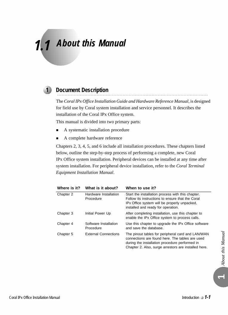
C
1.1
oral IPx Office Installation Ma
About this Manual
Abou
t thi
s M
anua
l 1
The Coral IPx Office Installation Guide and Hardware Reference Manual, is designed for field use by Coral system installation and service personnel. It describes the installation of the Coral IPx Office system.This manual is divided into two primary parts:
A systematic installation procedure
A complete hardware reference
Chapters 2, 3, 4, 5, and 6 include all installation procedures. These chapters listed below, outline the step-by-step process of performing a complete, new Coral IPx Office system installation. Peripheral devices can be installed at any time after system installation. For peripheral device installation, refer to the Coral Terminal Equipment Installation Manual.
...................................................................................................1 Document Description
Where is it? What is it about? When to use it?Chapter 2 Hardware Installation
ProcedureStart the installation process with this chapter. Follow its instructions to ensure that the Coral IPx Office system will be properly unpacked, installed and ready for operation.
Chapter 3 Initial Power Up After completing installation, use this chapter to enable the IPx Office system to process calls.
Chapter 4 Software Installation Procedure
Use this chapter to upgrade the IPx Office software and save the database.
Chapter 5 External Connections The pinout tables for peripheral card and LAN/WAN connections are found here. The tables are used during the installation procedure performed in Chapter 2. Also, surge arrestors are installed here.
nual Introduction 1-1
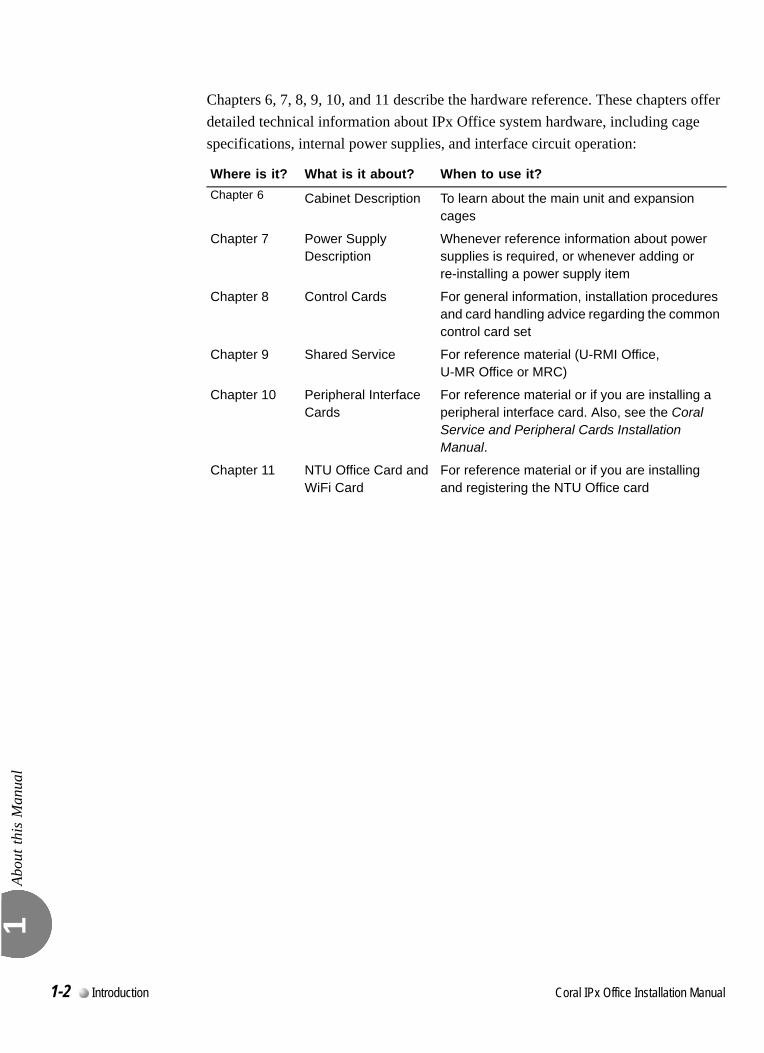
Abou
t thi
s M
anua
l 1
Chapters 6, 7, 8, 9, 10, and 11 describe the hardware reference. These chapters offer detailed technical information about IPx Office system hardware, including cage specifications, internal power supplies, and interface circuit operation:
Where is it? What is it about? When to use it?Chapter 6 Cabinet Description To learn about the main unit and expansion
cages
Chapter 7 Power Supply Description
Whenever reference information about power supplies is required, or whenever adding or re-installing a power supply item
Chapter 8 Control Cards For general information, installation procedures and card handling advice regarding the common control card set
Chapter 9 Shared Service For reference material (U-RMI Office, U-MR Office or MRC)
Chapter 10 Peripheral Interface Cards
For reference material or if you are installing a peripheral interface card. Also, see the Coral Service and Peripheral Cards Installation Manual.
Chapter 11 NTU Office Card and WiFi Card
For reference material or if you are installing and registering the NTU Office card
1-2 Introduction Coral IPx Office Installation Manual
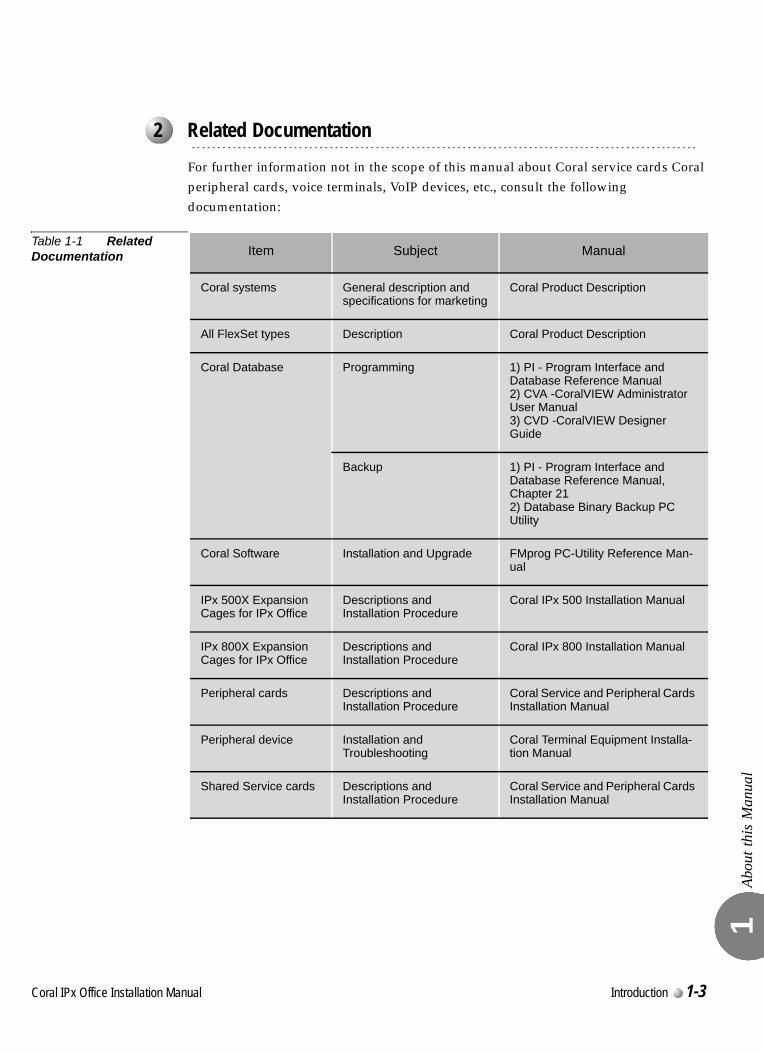
Abou
t thi
s M
anua
l 1
For further information not in the scope of this manual about Coral service cards Coral peripheral cards, voice terminals, VoIP devices, etc., consult the following documentation:
Table 1-1 Related Documentation
...................................................................................................2 Related Documentation
Item Subject Manual
Coral systems General description and specifications for marketing
Coral Product Description
All FlexSet types Description Coral Product Description
Coral Database Programming 1) PI - Program Interface and Database Reference Manual2) CVA -CoralVIEW Administrator User Manual3) CVD -CoralVIEW Designer Guide
Backup 1) PI - Program Interface and Database Reference Manual, Chapter 212) Database Binary Backup PC Utility
Coral Software Installation and Upgrade FMprog PC-Utility Reference Man-ual
IPx 500X Expansion Cages for IPx Office
Descriptions and Installation Procedure
Coral IPx 500 Installation Manual
IPx 800X Expansion Cages for IPx Office
Descriptions and Installation Procedure
Coral IPx 800 Installation Manual
Peripheral cards Descriptions and Installation Procedure
Coral Service and Peripheral Cards Installation Manual
Peripheral device Installation and Troubleshooting
Coral Terminal Equipment Installa-tion Manual
Shared Service cards Descriptions and Installation Procedure
Coral Service and Peripheral Cards Installation Manual
Coral IPx Office Installation Manual Introduction 1-3
Abou
t thi
s M
anua
l 1
This manual includes information that requires special attention, or is distinguished from the main texts in some significant way. These are indicated by the use of symbols and text formatting. This is illustrated in the following examples:
Indicates important information demanding special attention.
Tip:Advice that makes it easier to follow the steps of a procedure.
This manual includes information for the Coral configurations in all geographic market areas. Much of the information is relevant for all hardware configurations and all market areas.
...................................................................................................3 Special Symbols Used in this Document
There is a risk of danger to life or personal injury.
There is a risk of damage to Coral system.
NOTES:
A page that is intentionally left blank, and may be used for reader information.
1-4 Introduction Coral IPx Office Installation Manual
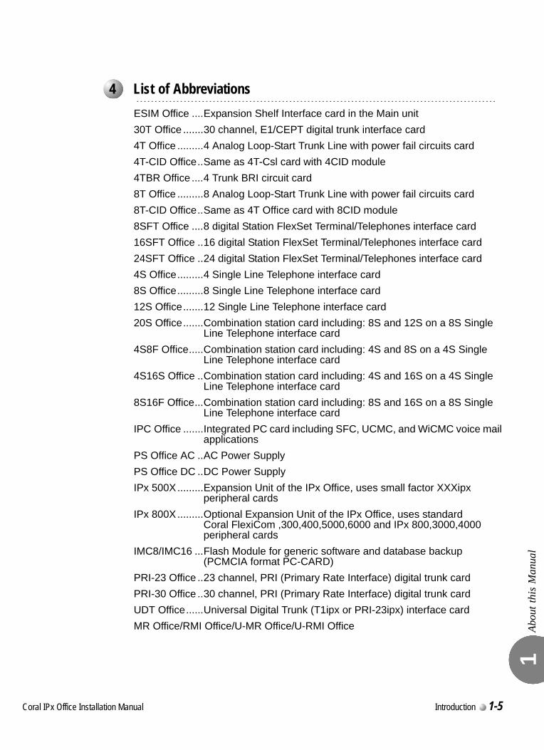
Abou
t thi
s M
anua
l 1
0
ESIM Office ....Expansion Shelf Interface card in the Main unit30T Office .......30 channel, E1/CEPT digital trunk interface card4T Office .........4 Analog Loop-Start Trunk Line with power fail circuits card4T-CID Office..Same as 4T-Csl card with 4CID module4TBR Office ....4 Trunk BRI circuit card8T Office .........8 Analog Loop-Start Trunk Line with power fail circuits card8T-CID Office..Same as 4T Office card with 8CID module8SFT Office ....8 digital Station FlexSet Terminal/Telephones interface card16SFT Office ..16 digital Station FlexSet Terminal/Telephones interface card24SFT Office ..24 digital Station FlexSet Terminal/Telephones interface card4S Office.........4 Single Line Telephone interface card8S Office.........8 Single Line Telephone interface card12S Office.......12 Single Line Telephone interface card20S Office.......Combination station card including: 8S and 12S on a 8S Single
Line Telephone interface card4S8F Office.....Combination station card including: 4S and 8S on a 4S Single
Line Telephone interface card4S16S Office ..Combination station card including: 4S and 16S on a 4S Single
Line Telephone interface card8S16F Office...Combination station card including: 8S and 16S on a 8S Single
Line Telephone interface cardIPC Office .......Integrated PC card including SFC, UCMC, and WiCMC voice mail
applicationsPS Office AC ..AC Power SupplyPS Office DC ..DC Power SupplyIPx 500X.........Expansion Unit of the IPx Office, uses small factor XXXipx
peripheral cardsIPx 800X.........Optional Expansion Unit of the IPx Office, uses standard
Coral FlexiCom ,300,400,5000,6000 and IPx 800,3000,4000 peripheral cards
IMC8/IMC16 ...Flash Module for generic software and database backup (PCMCIA format PC-CARD)
PRI-23 Office ..23 channel, PRI (Primary Rate Interface) digital trunk cardPRI-30 Office ..30 channel, PRI (Primary Rate Interface) digital trunk cardUDT Office......Universal Digital Trunk (T1ipx or PRI-23ipx) interface cardMR Office/RMI Office/U-MR Office/U-RMI Office
...................................................................................................4 List of Abbreviations
Coral IPx Office Installation Manual Introduction 1-5

Abou
t thi
s M
anua
l 1
NOTES:
1-6 Introduction Coral IPx Office Installation Manual
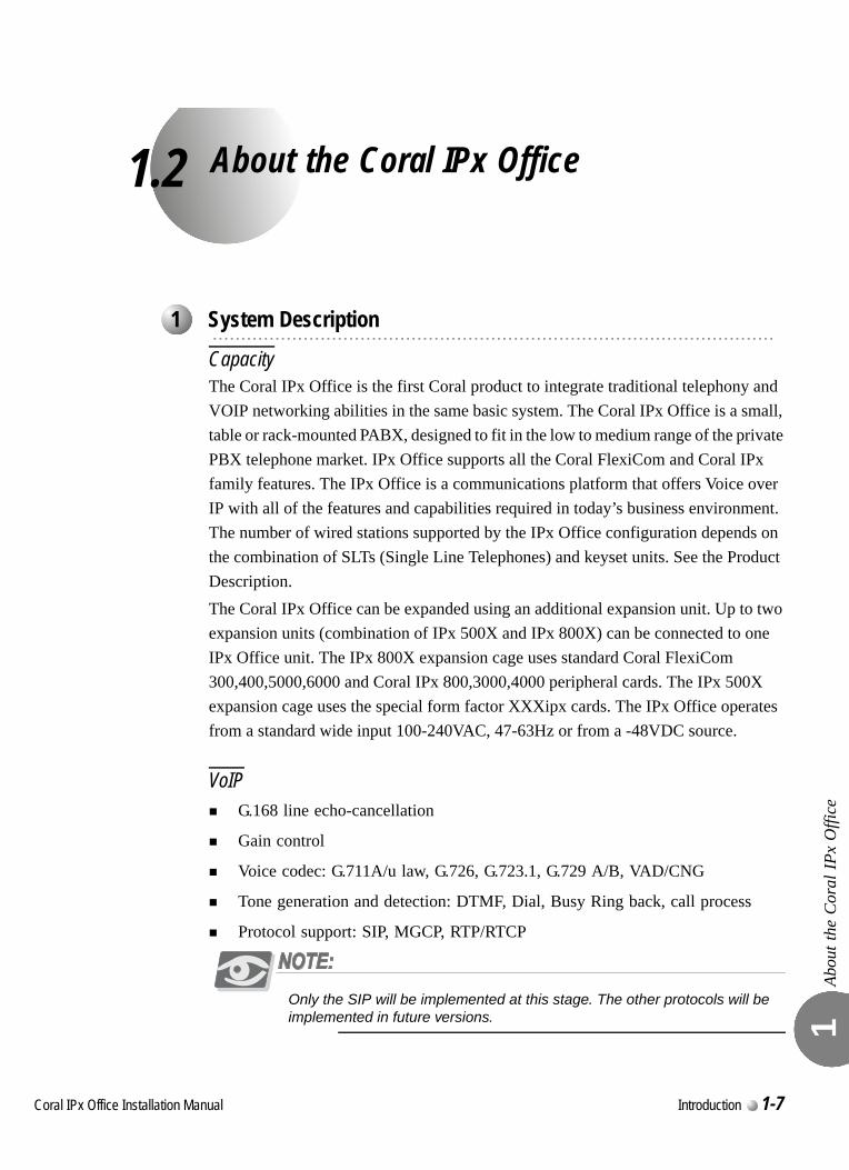
C
1.2
oral IPx Office Installation Ma
About the Coral IPx Office
Abou
t the
Cor
al IP
x O
ffice
1
0
CapacityThe Coral IPx Office is the first Coral product to integrate traditional telephony and VOIP networking abilities in the same basic system. The Coral IPx Office is a small, table or rack-mounted PABX, designed to fit in the low to medium range of the private PBX telephone market. IPx Office supports all the Coral FlexiCom and Coral IPx family features. The IPx Office is a communications platform that offers Voice over IP with all of the features and capabilities required in today’s business environment. The number of wired stations supported by the IPx Office configuration depends on the combination of SLTs (Single Line Telephones) and keyset units. See the Product Description.The Coral IPx Office can be expanded using an additional expansion unit. Up to two expansion units (combination of IPx 500X and IPx 800X) can be connected to one IPx Office unit. The IPx 800X expansion cage uses standard Coral FlexiCom 300,400,5000,6000 and Coral IPx 800,3000,4000 peripheral cards. The IPx 500X expansion cage uses the special form factor XXXipx cards. The IPx Office operates from a standard wide input 100-240VAC, 47-63Hz or from a -48VDC source.
VoIPG.168 line echo-cancellation
Gain control
Voice codec: G.711A/u law, G.726, G.723.1, G.729 A/B, VAD/CNG
Tone generation and detection: DTMF, Dial, Busy Ring back, call process
Protocol support: SIP, MGCP, RTP/RTCP
Only the SIP will be implemented at this stage. The other protocols will be implemented in future versions.
...................................................................................................1 System Description
nual Introduction 1-7
Abou
t the
Cor
al IP
x O
ffice
1
Circuitry
The Coral IPx Office includes digital communications switching based on Pulse Code Modulation (PCM) switching technology. The active circuitry of the system is contained on the MCB Office card and removable cards.The active circuitry of the IPx Office system is divided into two major functions: common control and peripheral. The common control circuitry directs call traffic through the system, establishing audio connections between peripheral ports and an outlet to the IP world. The peripheral circuitry provides the hardware necessary to establish those connections. Instructions from the common control to the peripheral circuitry, and status information from the peripheral circuitry to the common control are passed through the group controller, which provides driver and time slot interchange functions for the PCM highways and the HDLC channels.The common control is further divided into shared service, the group controller, the main central processor, connection to the IP and the MRC.The shared service circuitry is integrated into the MR / RMI / U-MR / U-RMI Office peripheral card, which provides the equipment necessary to establish calls between peripheral interfaces.The peripheral interface circuitry provides standardized electrical connections to external telephone station equipment and network facilities.
1-8 Introduction Coral IPx Office Installation Manual
Abou
t the
Cor
al IP
x O
ffice
1
Major Features
The unit houses all hardware components of the Coral IPx Office system, including the power supply unit, control cards, peripheral cards, service cards, and I/O connections. In addition, the unit:
Provides all the features, capabilities, interfaces, and terminals of the Coral communication server
Provides built-in voice/data convergence
Provides built-in functions. See The Coral Service and Peripheral Cards Installation Manual.
Optimizes space utilization through extensive configuration flexibility
Fits into 19" and 23" racks, including racks designed to earthquake specifications
Can be mounted on a table. See Mounting Table Units, page 2-13
Enables installation into standard racks. See Mounting Rack Units, page 2-14.
Enables AC or DC input power supply in every cage. See Chapter 7, Power Supply.
Enables connection to the IP world via interface through the NTU Office card.
Enables full communication between digital and IP stations.
Includes simple Input/Output (I/O) cable routing directly from the peripheral cards on the rear panel of the unit
Includes simple assembly procedures
Can be mounted on the same rack as customer-supplied cages
Includes up to two expansion cages per system. See System Configuration Options, page 6-23.
Includes forced ventilation supported by internal fans within the unit
Includes full RFI protection
Supports the insertion of peripheral cards under power conditions
Coral IPx Office Installation Manual Introduction 1-9
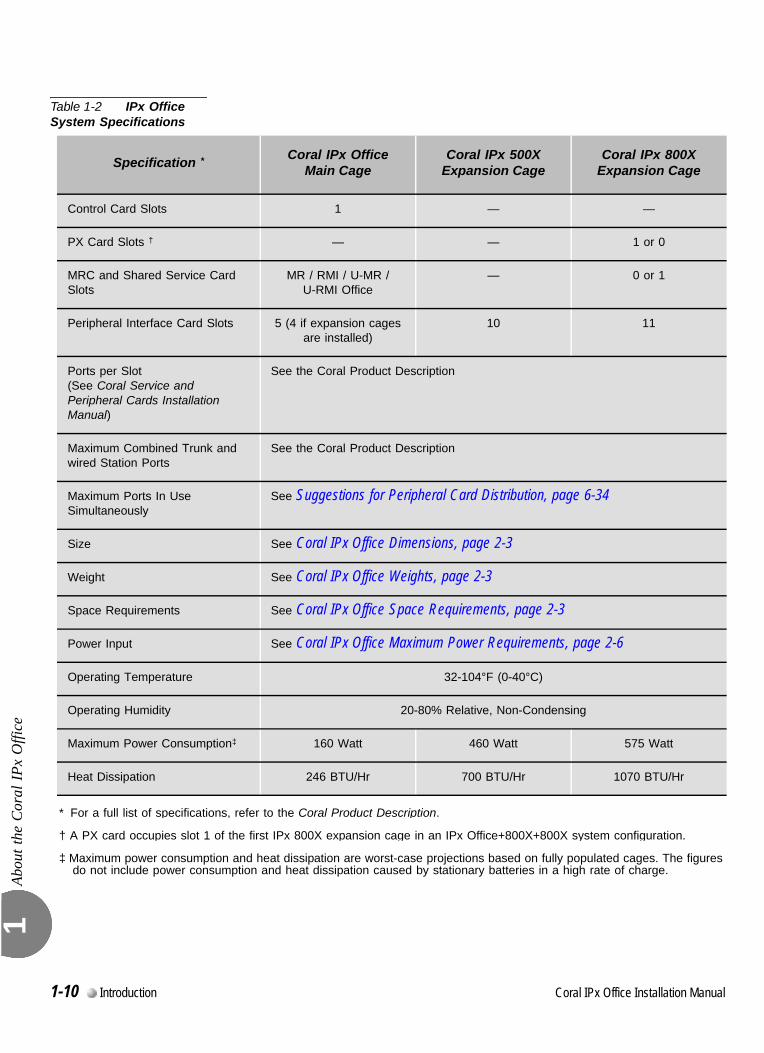
Abou
t the
Cor
al IP
x O
ffice
1
Table 1-2 IPx Office System Specifications
Specification * Coral IPx Office Main Cage
Coral IPx 500X Expansion Cage
Coral IPx 800XExpansion Cage
Control Card Slots 1 — —
PX Card Slots † — — 1 or 0
MRC and Shared Service Card Slots
MR / RMI / U-MR / U-RMI Office
— 0 or 1
Peripheral Interface Card Slots 5 (4 if expansion cages are installed)
10 11
Ports per Slot (See Coral Service and Peripheral Cards Installation Manual)
See the Coral Product Description
Maximum Combined Trunk and wired Station Ports
See the Coral Product Description
Maximum Ports In Use Simultaneously
See Suggestions for Peripheral Card Distribution, page 6-34
Size See Coral IPx Office Dimensions, page 2-3
Weight See Coral IPx Office Weights, page 2-3
Space Requirements See Coral IPx Office Space Requirements, page 2-3
Power Input See Coral IPx Office Maximum Power Requirements, page 2-6
Operating Temperature 32-104°F (0-40°C)
Operating Humidity 20-80% Relative, Non-Condensing
Maximum Power Consumption‡ 160 Watt 460 Watt 575 Watt
Heat Dissipation 246 BTU/Hr 700 BTU/Hr 1070 BTU/Hr
* For a full list of specifications, refer to the Coral Product Description.
† A PX card occupies slot 1 of the first IPx 800X expansion cage in an IPx Office+800X+800X system configuration.
‡ Maximum power consumption and heat dissipation are worst-case projections based on fully populated cages. The figures do not include power consumption and heat dissipation caused by stationary batteries in a high rate of charge.
0
1-10 Introduction Coral IPx Office Installation Manual
Abou
t the
Cor
al IP
x O
ffice
1
0
The following tools are needed in order to install and maintain the Coral IPx Office system:
Require d Tools:4 mm (max.) flat blade screwdriver for installation and removal of the door
3/16", 1/4", and 5/16" straight-blade screwdrivers
#1 and #2 Phillips screwdrivers
Diagonal wire cutters
Long-nosed pliers
Electrician's pliers
Slip-joint pliers
Adjustable wrench
Wrench for ground cable hex nuts (3.2 mm x 7 mm)
Telephone cable cutters
Standard crimping tool
Telephone cable insulation strippers
16 ft (5m) measuring tape
Punch tool matching all telephone cable terminal blocks used at the installation site
Digital Volt/Ohm/Amp meter
Telephone line test set capable of pulse and DTMF dialling
Static dissipating wrist strap
Portable (laptop) personal computer with a PCMCIA slot, capable of emulating an asynchronous ASCII data terminal and approved by the manufacturer to run the binary database save and restore utility, portable asynchronous ASCII data terminal, or permanently installed on-site personal computer or ASCII data terminal.
...................................................................................................2 Recommended Tools
Coral IPx Office Installation Manual Introduction 1-11
Abou
t the
Cor
al IP
x O
ffice
1
Optional Tools:Modular line polarity tester
Flashlight
Tone/continuity/talk battery generator
Tone detector/amplifier probe
Telephone line test set with MF tone signalling capability
Alligator clip leads
AMP™ Champ™ installation tool
Soldering iron and high quality, rosin-core solder
3/16" and 1/2" cable staple gun
Analog line transmission analyzer
Portable DS1/E1 analyzer, Bit Error Rate tester, and channel demultiplexer
1-12 Introduction Coral IPx Office Installation Manual
Coral IPx Office Installation Manual
Chapter
2 2Hardware Installation Procedure
2.1 Site Inspection ...................................................................................2-1
2.2 Equipment Installation .......................................................................2-7
2.3 Program Interface Device Connection.............................................2-39

C
2.1
oral IPx Office Installation Ma
Site Inspection
Site
Insp
ectio
n 2
0
The Coral IPx Office system should be installed in restricted access areas (dedicated equipment rooms, equipment closets, or the like) in accordance with articles 110-16, 110-17, and 110-18 of the national electric code, ANSI/NFPA 70.Access to the system should be limited and controlled to prevent unauthorized tampering. The system uses hazardous working voltages and extremely high short circuit currents, and the area must be protected against damage by, and injury to, unqualified personnel.Due to these considerations, an installation area must be chosen in accordance with the following guidelines:
1. Verify that the installation area is clean, dry, and protected from weather extremes.
2. Verify that the floor of the installation area is covered with linoleum, vinyl, ceramic, wooden flooring, or polished sealed concrete. Carpeting is not acceptable.
3. Verify that the ceiling of the installation area is finished or treated to prevent particle discharge.
4. Verify that the installation area is well lit, and that the light is uniformly diffused without shadows. Adequate lighting should provide a comfortable reading level and allow wire insulator color identification without undue eye fatigue.
Lighting should be comparable to an office work environment, with a minimum level of 70 foot-candles at each work surface. As a general rule, in a room with an 8 ft (2.5m) ceiling, one 48 inch fluorescent tube provides sufficient illumination for 20-25 sq. ft. (1.9-2.4 m2).
...................................................................................................1 Installation Environment
nual Hardware Installation Procedure 2-1
Site
Insp
ectio
n 2
5. Verify that ventilation of the installation area is capable of maintaining an ambient temperature of 32°-104°F (0°-40°C), and a relative humidity of 20-80% non-condensing, considering the system nominal heat dissipation 700 BTU/hr. (These figures are for each cage only, and do not take into account heat generated by other equipment.)
6. Verify that the installation area is free of caustic or corrosive liquids, substances, or materials. Check local building codes for additional requirements.
7. Verify that the installation area is located no closer than 20 ft (6.1m) from electric devices that produce large electro-magnetic fields or high levels of radio frequency energy. Possible sources are radio transmitters, electric arc welding machines, copying machines, electric motors, refrigeration units, power transformers, electric load centers, and main circuit breaker panels.
8. Verify that the installation area provides reasonable security to the system. Room construction should include solid, reinforced walls and a locking door.
0
This section describes the Coral IPx Office space requirements.
1. Verify that there is sufficient space for the Coral IPx Office system components.
2. The dimensions and weights of the various components are provided in Figure 2-1, Table 2-1 and Table 2-2.
3. A minimum clearance, as detailed in Table 2-3, must be provided around the the various components. For more detailed information, see Figure 2-2 and Figure 2-2 on page 2-4.
4. Figure 2-2 displays a schematic diagram of all installation orientation options.
5. The cage must be mounted horizontally.
6. It is recommended to mount the first expansion cage above the main cage. However, any position around the main cage is acceptable.
7. It is recommended to mount the second expansion cage above the first expansion cage. However, any position around the first expansion cage is acceptable.
8. The mounting of an optional expansion cage should be taken into consideration when mounting the Coral IPx Office equipment.
...................................................................................................2 Space Requirements
2-2 Hardware Installation Procedure Coral IPx Office Installation Manual
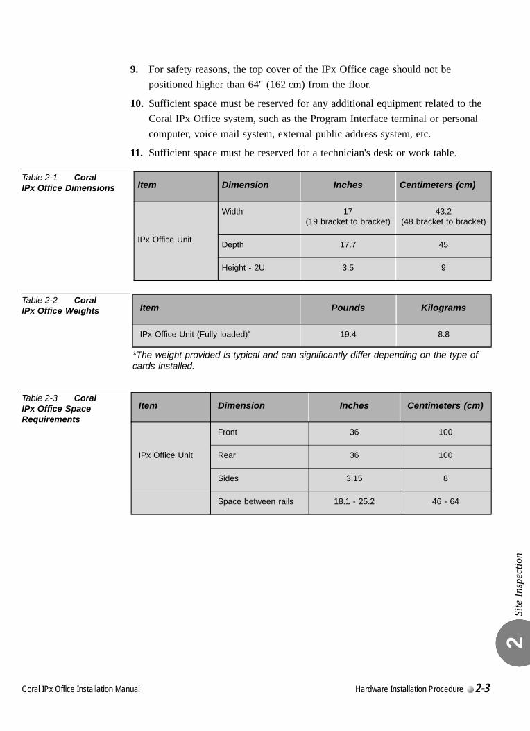
Site
Insp
ectio
n 2
9. For safety reasons, the top cover of the IPx Office cage should not be positioned higher than 64" (162 cm) from the floor.
10. Sufficient space must be reserved for any additional equipment related to the Coral IPx Office system, such as the Program Interface terminal or personal computer, voice mail system, external public address system, etc.
11. Sufficient space must be reserved for a technician's desk or work table.
Table 2-1 Coral IPx Office Dimensions
Table 2-2 Coral IPx Office Weights
Table 2-3 Coral IPx Office Space Requirements
Item Dimension Inches Centimeters (cm)
IPx Office Unit
Width 17(19 bracket to bracket)
43.2(48 bracket to bracket)
Depth 17.7 45
Height - 2U 3.5 9
Item Pounds Kilograms
IPx Office Unit (Fully loaded)*
*The weight provided is typical and can significantly differ depending on the type of cards installed.
19.4 8.8
Item Dimension Inches Centimeters (cm)
IPx Office Unit
Front 36 100
Rear 36 100
Sides 3.15 8
Space between rails 18.1 - 25.2 46 - 64
Coral IPx Office Installation Manual Hardware Installation Procedure 2-3
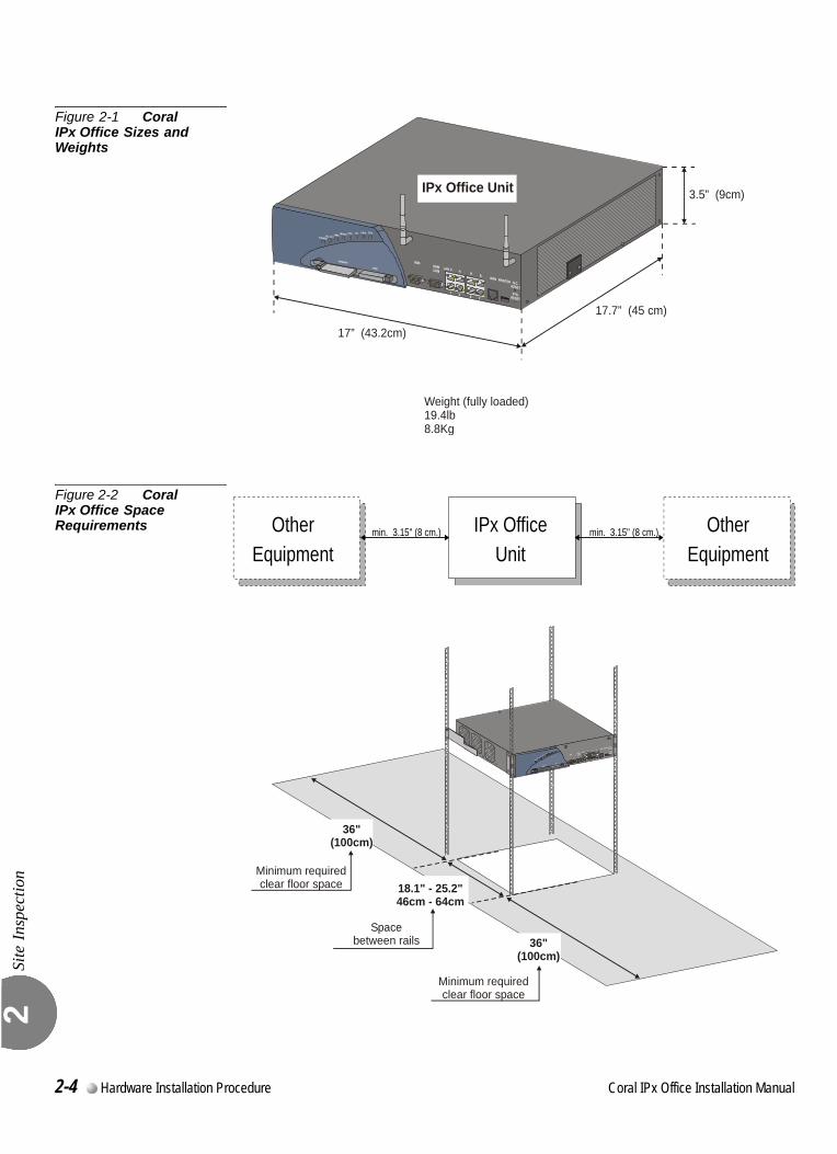
Site
Insp
ectio
n 2
Figure 2-1 Coral IPx Office Sizes and Weights
Figure 2-2 Coral IPx Office Space Requirements
17” (43.2cm)
17.7” (45 cm)
3.5” (9cm)
Weight (fully loaded)19.4lb8.8Kg
IPx Office Unit
IPx OfficeUnit
min. 3.15" (8 cm.)OtherEquipment
min. 3.15" (8 cm.) OtherEquipment
36"(100cm)
36"(100cm)
Minimum requiredclear floor space
Minimum requiredclear floor space
18.1" - 25.2"46cm - 64cm
Spacebetween rails
2-4 Hardware Installation Procedure Coral IPx Office Installation Manual
Site
Insp
ectio
n 2
00
General Requirements
The Coral IPx Office operates from a standard wide input 100 to 240VAC, 47 to 63Hz source or from a –40 to –56VDC source.
1. Verify that electrical service is sufficient and located in close proximity to the system. Coral IPx Office system requires at least one dedicated branch circuit with at least two receptacles: one for the cage, and one for ancillary equipment such as data terminals or personal computers, external paging equipment, or test instruments, etc.
2. For 115VAC or 230VAC power, a 1.85mm2 or 14AWG wire must be used in the circuit branch.
3. Each branch circuit must be independently protected by a fuse or circuit breaker, and must not be controlled by a switch. C-type fuses should be used where required by local authorities.
4. The receptacle for the Coral system branch circuit must be located within 4 feet (1.2m) of the cage for AC operated systems, or within 4 feet (1.2m) of the 48VDC power supply for DC operated systems.
5. Auxiliary branch circuit receptacles should be located conveniently for ancillary equipment, and should allow data terminals, personal computers, or test instruments to be operated near the system.
6. Table 2-4 lists the voltages and current requirements for each cabinet.
DC Electrical Requirements
DC powered units must comply with the following instructions:
1. Restricted Access Area: The DC powered equipment should only be installed in a Restricted Access Area.
2. Installation Codes: The equipment must be installed according to country national electrical codes. For North America, equipment must be installed in accordance with the US National Electrical Code, Articles 110-16, 110-17 and 110-18 and the Canadian Electrical Code, Section 12.
3. Overcurrent Protection: A readily accessible listed branch circuit overcurrent protective device rated "30A/60VDC minimum slow blow" must be incorporated in the building wiring for every three units.
...................................................................................................3 Electrical Requirements
Coral IPx Office Installation Manual Hardware Installation Procedure 2-5
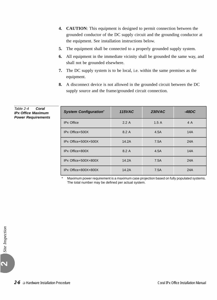
Site
Insp
ectio
n 2
4. CAUTION: This equipment is designed to permit connection between the grounded conductor of the DC supply circuit and the grounding conductor at the equipment. See installation instructions below.
5. The equipment shall be connected to a properly grounded supply system.
6. All equipment in the immediate vicinity shall be grounded the same way, and shall not be grounded elsewhere.
7. The DC supply system is to be local, i.e. within the same premises as the equipment.
8. A disconnect device is not allowed in the grounded circuit between the DC supply source and the frame/grounded circuit connection.
Table 2-4 Coral IPx Office Maximum Power Requirements
System Configuration*
* Maximum power requirement is a maximum case projection based on fully populated systems. The total number may be defined per actual system.
115VAC 230VAC -48DC
IPx Office 2.2 A 1.5 A 4 A
IPx Office+500X 8.2 A 4.5A 14A
IPx Office+500X+500X 14.2A 7.5A 24A
IPx Office+800X 8.2 A 4.5A 14A
IPx Office+500X+800X 14.2A 7.5A 24A
IPx Office+800X+800X 14.2A 7.5A 24A
2-6 Hardware Installation Procedure Coral IPx Office Installation Manual
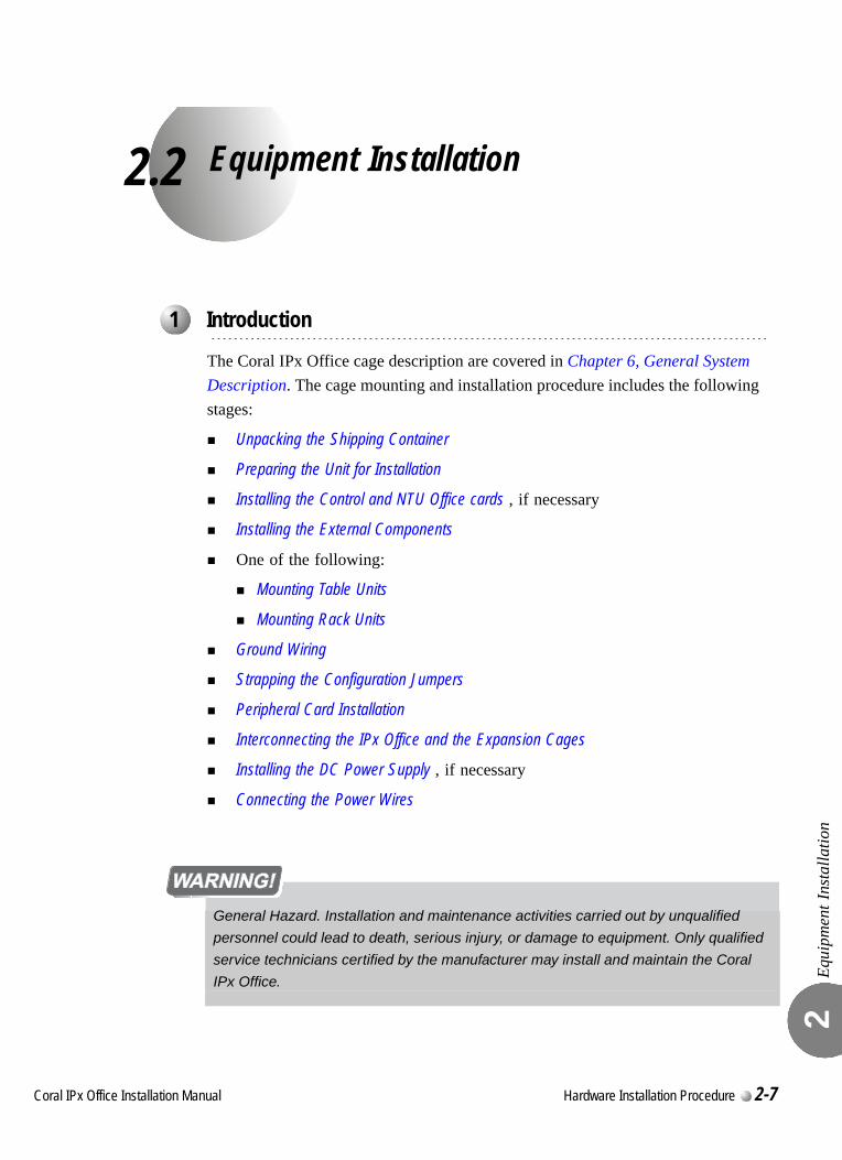
C
2.2
oral IPx Office Installation Ma
Equipment Installation
Equi
pmen
t Ins
talla
tion
2
The Coral IPx Office cage description are covered in Chapter 6, General System Description. The cage mounting and installation procedure includes the following stages:
Unpacking the Shipping Container
Preparing the Unit for Installation
Installing the Control and NTU Office cards , if necessary
Installing the External Components
One of the following:
Mounting Table Units
Mounting Rack Units
Ground Wiring
Strapping the Configuration Jumpers
Peripheral Card Installation
Interconnecting the IPx Office and the Expansion Cages
Installing the DC Power Supply , if necessary
Connecting the Power Wires
...................................................................................................1 Introduction
General Hazard. Installation and maintenance activities carried out by unqualified
personnel could lead to death, serious injury, or damage to equipment. Only qualified
service technicians certified by the manufacturer may install and maintain the Coral
IPx Office.
nual Hardware Installation Procedure 2-7
Equi
pmen
t Ins
talla
tion
2
0
1. Inspect the shipping container for evidence of physical damage or mishandling. Report any damage to the carrier immediately.
2. If it is necessary to make a damage claim to the carrier, do not move the container until it has been examined by a representative of the carrier. Otherwise, before opening, move the container as close as possible to the installation area.
3. Using a utility knife, carefully cut the tape securing the top flaps of the container and open the flaps.
4. Remove any parts in the depressions of the top foam insert.
5. Remove the top foam insert and set aside.
6. Using an assistant to prevent personal injury, grasp the ends of the cage and lift it out of the container. Place the cage on a stable surface.
7. Inspect the cage and covers for shipping damage.
8. Check the part list and verify that all the items are present. Table 2-5 lists the components that are supplied with the Coral IPx Office system.
9. Remove any other items from the shipping container, and move the container so that it does not interfere with the remaining installation procedures.
...................................................................................................2 Unpacking the Shipping Container
2-8 Hardware Installation Procedure Coral IPx Office Installation Manual
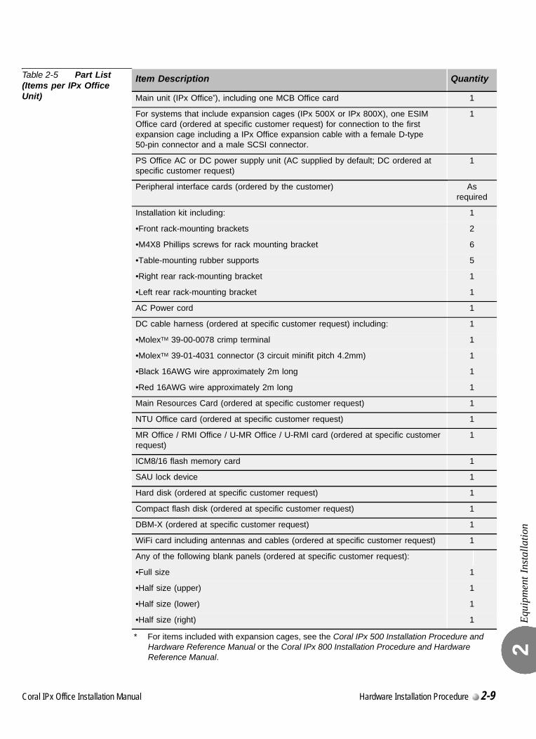
Equi
pmen
t Ins
talla
tion
2
Table 2-5 Part List (Items per IPx Office Unit)
Item Description Quantity
Main unit (IPx Office*), including one MCB Office card
* For items included with expansion cages, see the Coral IPx 500 Installation Procedure and Hardware Reference Manual or the Coral IPx 800 Installation Procedure and Hardware Reference Manual.
1
For systems that include expansion cages (IPx 500X or IPx 800X), one ESIM Office card (ordered at specific customer request) for connection to the first expansion cage including a IPx Office expansion cable with a female D-type 50-pin connector and a male SCSI connector.
1
PS Office AC or DC power supply unit (AC supplied by default; DC ordered at specific customer request)
1
Peripheral interface cards (ordered by the customer) As required
Installation kit including: 1
•Front rack-mounting brackets 2
•M4X8 Phillips screws for rack mounting bracket 6
•Table-mounting rubber supports 5
•Right rear rack-mounting bracket 1
•Left rear rack-mounting bracket 1
AC Power cord 1
DC cable harness (ordered at specific customer request) including: 1
•MolexTM 39-00-0078 crimp terminal 1
•MolexTM 39-01-4031 connector (3 circuit minifit pitch 4.2mm) 1
•Black 16AWG wire approximately 2m long 1
•Red 16AWG wire approximately 2m long 1
Main Resources Card (ordered at specific customer request) 1
NTU Office card (ordered at specific customer request) 1
MR Office / RMI Office / U-MR Office / U-RMI card (ordered at specific customer request)
1
ICM8/16 flash memory card 1
SAU lock device 1
Hard disk (ordered at specific customer request) 1
Compact flash disk (ordered at specific customer request) 1
DBM-X (ordered at specific customer request) 1
WiFi card including antennas and cables (ordered at specific customer request) 1
Any of the following blank panels (ordered at specific customer request):
•Full size 1
•Half size (upper) 1
•Half size (lower) 1
•Half size (right) 1
Coral IPx Office Installation Manual Hardware Installation Procedure 2-9
Equi
pmen
t Ins
talla
tion
2
0
The process of mounting and installing the unit includes the following stages:
Checking the Space and Positioning Requirements
Checking the Electrical Requirements
Opening the Unit Cover
Checking the Space and Positioning RequirementsVerify that the Coral IPx Office system will be positioned in accordance with local and system space and positioning requirements. The spacing requirements as described in Space Requirements on page 2-2 ensure system operation and maintenance.
Checking the Electrical RequirementsVerify that the Coral IPx Office system installation meets all electrical requirements. The electrical requirements as described in Electrical Requirements on page 2-5 ensure safe operation and maintenance.
Power TestCheck the functionality of the power supply to the IPx Office system as follows:
1. Place an anti-static sheet over a desk or a table top that can support 19.4lb (8.8kg) (a plastic shipping bag will do).
2. Connect a ground wire between the IPx Office unit and the master ground as described in Connecting the Ground Wire to the Unit, page 2-19.
3. Connect the power cable(s) as described in Connecting the Power Wires, page 2-35.
4. If necessary, install the DC power supply. See Installing the DC Power Supply, page 2-34.
5. Turn ON the PS Office ON/OFF switch.
6. Verify that the LED indicators on the front panel light as described in Chapter 2, Hardware Installation Procedure.
7. Turn OFF the PS Office ON/OFF switch.
8. Disconnect the power cable(s).
9. Disconnect the ground wire.
...................................................................................................3 Preparing the Unit for Installation
2-10 Hardware Installation Procedure Coral IPx Office Installation Manual
Equi
pmen
t Ins
talla
tion
2
0
The control and NTU Office cards are installed in the front section of the system.
Opening the Unit Cover
Remove the unit cover. See Opening the Unit Cover, page 6-8.
Installing the Main Resources Card
Install the Main Resources Card (MRC), if supplied. See Installing the MRC, page 8-29.
Installing the DBM-X Card
Install the (DBM-X) card, if supplied. See Installing the DBM-X, page 8-43 .
Installing the NTU Office Card
Install the main NTU Office card, if supplied. See Installing the NTU Office Card, page 11-10.
Installing the Internal LAN Cable
Install the internal LAN cable, if an NTU Office card is not supplied. See Connecting to the Network without an NTU Office Card, page 11-21.
Installing the WiFi Card and Antenna
Install the optional WiFi NTU Office card and antenna, if supplied. See Installing the WiFi Card, page 11-13.
Removing the Battery Insulator
Carefully remove the battery insulator from underneath the lithium battery on the MCB Office card. See Figure 8-8 on page 8-22.
Closing the Unit Cover
Close the unit cover. See Closing the Unit Cover, page 6-10.
...................................................................................................4 Installing the Control and NTU Office cards
Coral IPx Office Installation Manual Hardware Installation Procedure 2-11
Equi
pmen
t Ins
talla
tion
2
0
Installing the IMC-8 or IMC-16 Flash Card
Install the IMC-8 or IMC-16 flash card. See IMC8 and IMC16 Flash Cards, page 8-33.
Installing the Compact Flash Disk
Install the compact flash disk. See Compact Flash Disk, page 8-39.
Installing the Software Authorization Unit
Install the Software Authorization Unit (SAU). See Installing the Software Authorization Unit, page 2-12.
Assembling the WiFi Antennas
Install the WiFi antennas. See Assembling the WiFi Antennas, page 11-15.
...................................................................................................5 Installing the External Components
2-12 Hardware Installation Procedure Coral IPx Office Installation Manual
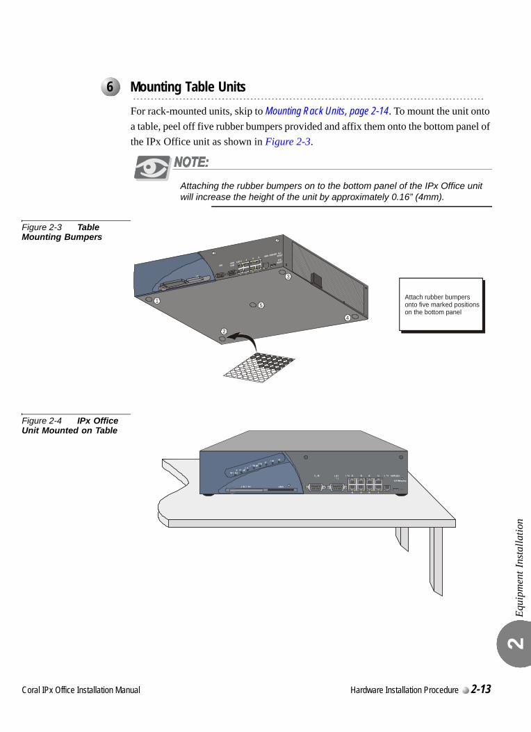
Equi
pmen
t Ins
talla
tion
2
0
For rack-mounted units, skip to Mounting Rack Units, page 2-14. To mount the unit onto a table, peel off five rubber bumpers provided and affix them onto the bottom panel of the IPx Office unit as shown in Figure 2-3.
Attaching the rubber bumpers on to the bottom panel of the IPx Office unit will increase the height of the unit by approximately 0.16” (4mm).
Figure 2-3 Table Mounting Bumpers
Figure 2-4 IPx Office Unit Mounted on Table
...................................................................................................6 Mounting Table Units
5
4
2
3
1 Attach rubber bumpersonto five marked positionson the bottom panel
Coral IPx Office Installation Manual Hardware Installation Procedure 2-13
Equi
pmen
t Ins
talla
tion
2
0
0000
Preparing the Unit for Mounting onto the Rack
1. Align a front rack-mounting bracket such that the three holes are adjacent with the holes on the unit.
2. Insert three of the M4X8 screws provided into the three holes and fasten the right bracket to the unit.
3. Repeat Step 1 through Step 2 for the other front rack-mounting bracket.
Preparing the Rack for Unit Mounting
The IPx Office unit is supported from the rear by two brackets that are attached to the rack. To install the support brackets (see Figure 2-5):
1. Fasten the left rear rack-mounting bracket to the rack.
2. Fasten the right rear rack-mounting bracket to the rack.
The fasteners that are secured to the rack are not included.
Mounting the Unit onto the Rack
1. Verify the unit mounting position on the rack. See Space Requirements, page 2-2.
2. Grasp each end of the unit and lift it to the mounting position on the rack.
3. Rest the unit on the support brackets installed, while continuing to support the unit from the front and fasten the left and right bracket to the rack.
...................................................................................................7 Mounting Rack Units
Weight Hazard. The weight is provided in Table 2-2 on page 2-3. Serious injury could
result due to improper handling. Use proper techniques to mount and secure to the rack.
2-14 Hardware Installation Procedure Coral IPx Office Installation Manual
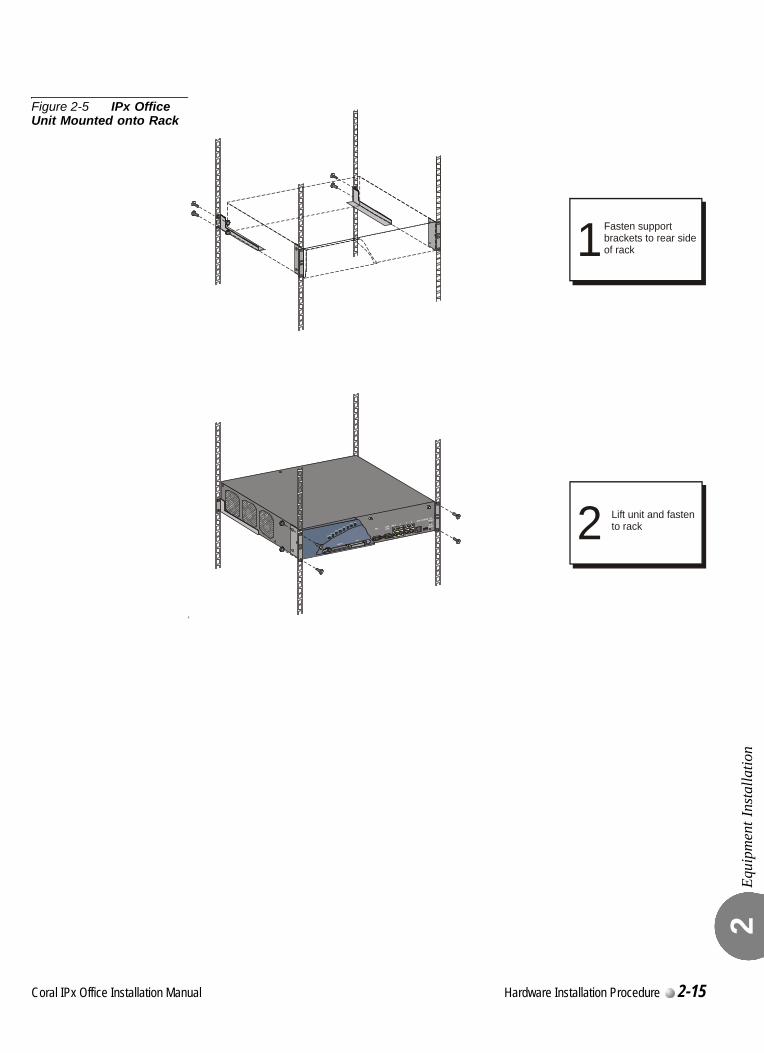
Equi
pmen
t Ins
talla
tion
2
Figure 2-5 IPx Office Unit Mounted onto Rack
L
1Fasten supportbrackets to rear sideof rack
2 Lift unit and fastento rack
Coral IPx Office Installation Manual Hardware Installation Procedure 2-15

Equi
pmen
t Ins
talla
tion
2
Dismounting the IPx Office Unit from the Rack
1. Turn OFF the ON/OFF switch on the PS Office unit.
2. Do one of the following:
For DC powered systems, shut down the facilities power supply unit that supplies power to the system and disconnect the DC power connector from the PS Office DC power supply unit.
For AC powered systems, disconnect the AC power cable.
3. Disconnect all I/O cables from the rear panel.
4. Disconnect the ground wire from the unit ground terminal. Do not disconnect the ground connection from the master ground.
5. Unfasten the four screws that secure the unit to the rack on each side of the unit.
6. Remove the unit from the rack using proper lifting techniques.
Electrical Hazard. This procedure requires handling power wires. Contact with live
cables could cause shock, burn, or death. Verify that no power cables are connected to
the system before handling and that the power switch is OFF.
Ergonomic Hazard. The cage weights are provided in Table 2-2 on page 2-3. Serious
back injury could result as a result of improper handling. Use proper lifting techniques to
remove the unit from the rack.
2-16 Hardware Installation Procedure Coral IPx Office Installation Manual
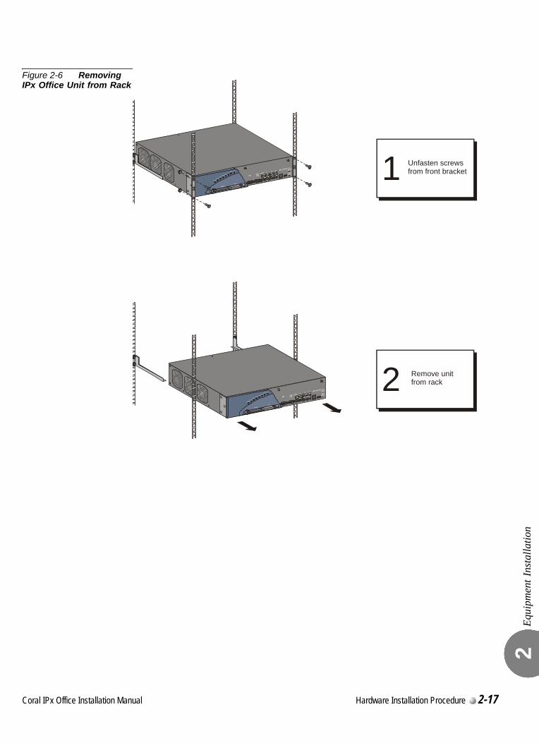
Equi
pmen
t Ins
talla
tion
2
Figure 2-6 Removing IPx Office Unit from Rack
2
1 Unfasten screwsfrom front bracket
Remove unitfrom rack
Coral IPx Office Installation Manual Hardware Installation Procedure 2-17
Equi
pmen
t Ins
talla
tion
2
0
Proper system grounding is critical to reliable system operation. System grounding is only as effective as the ground point itself. To ensure adequate protection from interference by radio frequency energy, electrical impulse noise, and lightening or power line surge, the building electrical ground point must comply with grounding recommendations of the National Area Code, Article 800, and/or applicable local building and electrical codes.The object of ground circuit design is to establish a low resistance path to the ground, and to conduct a multitude of currents in such a way as to minimize the interaction of any two or more currents. In essence, the ground connection is used as a common conductor for many circuits: some carrying wanted signals, and others carrying unwanted signals. The same ground that carries small networking currents must also carry unwanted radio frequency energy, impulse noise, and lightening surges that might otherwise interfere with system operation.The ground connection includes an M4 threaded terminal pole that is fixed onto the surface of the rear panel (by the manufacturer), a serrated washer between each terminal connection, a flat washer, and an M4 nut.
...................................................................................................8 Ground Wiring
Electrical Hazard. Incorrect ground wire connections to the system can cause shock,
burn, or death.
•Verify that the ground wires are 10 AWG stranded conductor.
•Verify that all ground connections are made directly from the cage ground connection to
the master ground.
•Do not interconnect cage ground terminals between the Coral units.
•Ring terminals retain wires onto the terminal lug when the connection is loosened.
Verify that all ground wires include ring terminals at both ends.
•Connect only a Protective Earth (PE) to the Coral system.
Do not connect a separate Telecommunications Reference Conductor (TRC).
•Resistance from the master ground to the building electrical ground should never
exceed 1.0 ohm. The master ground bar should be located in the switching room as
close as possible to the Coral system. Any ground connection of equipment related to
the switching Coral system should ultimately connect to the master ground.
2-18 Hardware Installation Procedure Coral IPx Office Installation Manual
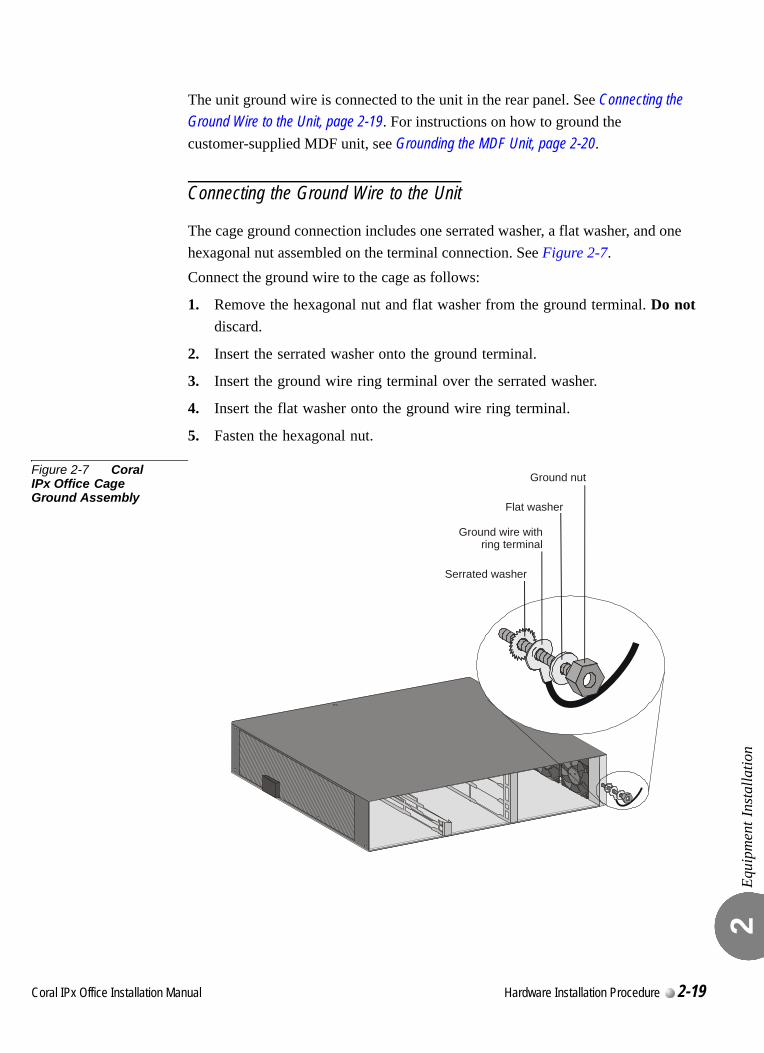
Equi
pmen
t Ins
talla
tion
2
The unit ground wire is connected to the unit in the rear panel. See Connecting the Ground Wire to the Unit, page 2-19. For instructions on how to ground the customer-supplied MDF unit, see Grounding the MDF Unit, page 2-20.
Connecting the Ground Wire to the Unit
The cage ground connection includes one serrated washer, a flat washer, and one hexagonal nut assembled on the terminal connection. See Figure 2-7.Connect the ground wire to the cage as follows:
1. Remove the hexagonal nut and flat washer from the ground terminal. Do not discard.
2. Insert the serrated washer onto the ground terminal.
3. Insert the ground wire ring terminal over the serrated washer.
4. Insert the flat washer onto the ground wire ring terminal.
5. Fasten the hexagonal nut.
Figure 2-7 Coral IPx Office Cage Ground Assembly
Ground nut
Flat washer
Ground wire withring terminal
Serrated washer
Coral IPx Office Installation Manual Hardware Installation Procedure 2-19
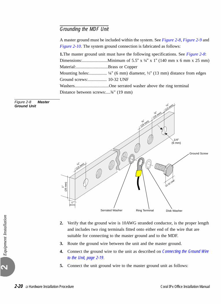
Equi
pmen
t Ins
talla
tion
2
Grounding the MDF Unit
A master ground must be included within the system. See Figure 2-8, Figure 2-9 and Figure 2-10. The system ground connection is fabricated as follows:
1.The master ground unit must have the following specifications. See Figure 2-8:Dimensions:.......................Minimum of 5.5” x ¼” x 1” (140 mm x 6 mm x 25 mm)Material:.............................Brass or CopperMounting holes:................ ¼” (6 mm) diameter, ½” (13 mm) distance from edgesGround screws:................. 10-32 UNFWashers...............................One serrated washer above the ring terminalDistance between screws:....¾" (19 mm)
Figure 2-8 Master Ground Unit
2. Verify that the ground wire is 10AWG stranded conductor, is the proper length and includes two ring terminals fitted onto either end of the wire that are suitable for connecting to the master ground and to the MDF.
3. Route the ground wire between the unit and the master ground.
4. Connect the ground wire to the unit as described on Connecting the Ground Wire to the Unit, page 2-19.
5. Connect the unit ground wire to the master ground unit as follows:
Ring TerminalSerrated Washer Disk Washer
1"(2
5 m
m)
¾"
(19 mm)
¼"(6mm)
¾"
(19 mm)
½"
(13 mm)
½"
(13 mm)
1/4"(6 mm)
10-32 UNF
Ground Screw
2-20 Hardware Installation Procedure Coral IPx Office Installation Manual
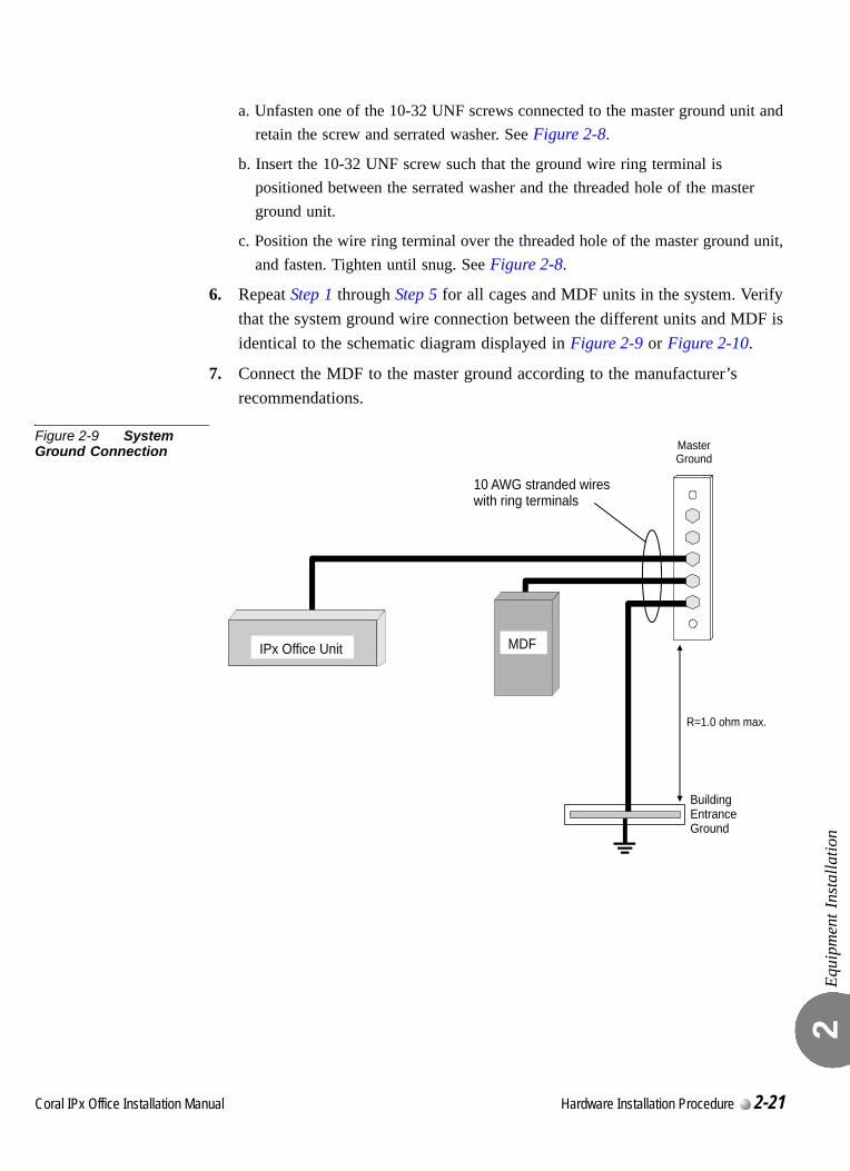
Equi
pmen
t Ins
talla
tion
2
a. Unfasten one of the 10-32 UNF screws connected to the master ground unit and retain the screw and serrated washer. See Figure 2-8.
b. Insert the 10-32 UNF screw such that the ground wire ring terminal is positioned between the serrated washer and the threaded hole of the master ground unit.
c. Position the wire ring terminal over the threaded hole of the master ground unit, and fasten. Tighten until snug. See Figure 2-8.
6. Repeat Step 1 through Step 5 for all cages and MDF units in the system. Verify that the system ground wire connection between the different units and MDF is identical to the schematic diagram displayed in Figure 2-9 or Figure 2-10.
7. Connect the MDF to the master ground according to the manufacturer’s recommendations.
Figure 2-9 System Ground Connection
IPx Office Unit MDF
MasterGround
R=1.0 ohm max.
BuildingEntranceGround
10 AWG stranded wireswith ring terminals
Coral IPx Office Installation Manual Hardware Installation Procedure 2-21
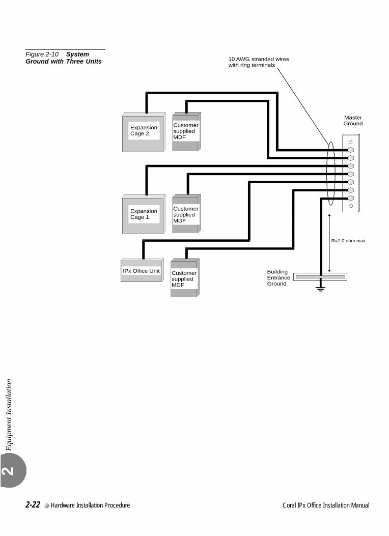
Equi
pmen
t Ins
talla
tion
2
Figure 2-10 System Ground with Three Units
MasterGround
R=1.0 ohm max.
BuildingEntranceGround
IPx Office Unit
CustomersuppliedMDF
ExpansionCage 1
10 AWG stranded wireswith ring terminals
CustomersuppliedMDF
CustomersuppliedMDF
ExpansionCage 2
2-22 Hardware Installation Procedure Coral IPx Office Installation Manual
Equi
pmen
t Ins
talla
tion
2
0
This section describes how to remove and insert the shorting plugs of the various jumpers. In the Coral IPx Office system, some of the peripheral cards include jumpers that configure the shared service functions. For a specific card description, see Chapter 9, Shared Service Cards and Chapter 10, Peripheral Cards. For a specific description of these cards, see the Peripheral and Shared Service Cards Installation Manual. This must be done before inserting the peripheral cards.To set the configuration jumpers:
1. Connect the static dissipating wrist strap connector to the cage and put on the strap.
Synchronization JumpersDefining different cards or cages by the same synchronization classification could lead to system disruption. Verify that the synchronization jumpers are strapped as described in Chapter 10, Peripheral Cards.Expansion Cage Identification JumpersDefining two expansion cages by the same cage number could lead to system disruption. Verify that the cage numbering jumpers are strapped as described in Chapter 6 of the Coral IPx 500 Installation and Hardware Reference Manual and/or the Coral IPx 800 Installation and Hardware Reference Manual.
2. In the IPx Office unit, configure the peripheral card jumpers as described in Peripheral and Shared Service Cards Installation Manual.
3. For IPx 500X expansion cages, configure the jumpers as described in Figure 2-13 and Figure 2-14.
4. For IPx 800X expansion cages, configure the jumpers as described in Figure 2-15 and Figure 2-16.
...................................................................................................9 Strapping the Configuration Jumpers
Circuit cards contain static-sensitive circuitry and may be damaged or destroyed by
electro-static discharge (ESD). Always wear the static dissipating wrist strap connected
to the cage while handling circuit cards. See Figure 2-11 on page 2-24. Hold circuit
cards by their edges and avoid touching contact surfaces. Handle with care and do not
drop.
Coral IPx Office Installation Manual Hardware Installation Procedure 2-23
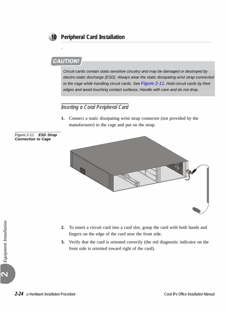
Equi
pmen
t Ins
talla
tion
2
0.0
.
Inserting a Coral Peripheral Card
1. Connect a static dissipating wrist strap connector (not provided by the manufacturer) to the cage and put on the strap.
Figure 2-11 ESD Strap Connection to Cage
2. To insert a circuit card into a card slot, grasp the card with both hands and fingers on the edge of the card near the front side.
3. Verify that the card is oriented correctly (the red diagnostic indicator on the front side is oriented toward right of the card).
...................................................................................................10 Peripheral Card Installation
Circuit cards contain static-sensitive circuitry and may be damaged or destroyed by
electro-static discharge (ESD). Always wear the static dissipating wrist strap connected
to the cage while handling circuit cards. See Figure 2-11. Hold circuit cards by their
edges and avoid touching contact surfaces. Handle with care and do not drop.
2-24 Hardware Installation Procedure Coral IPx Office Installation Manual
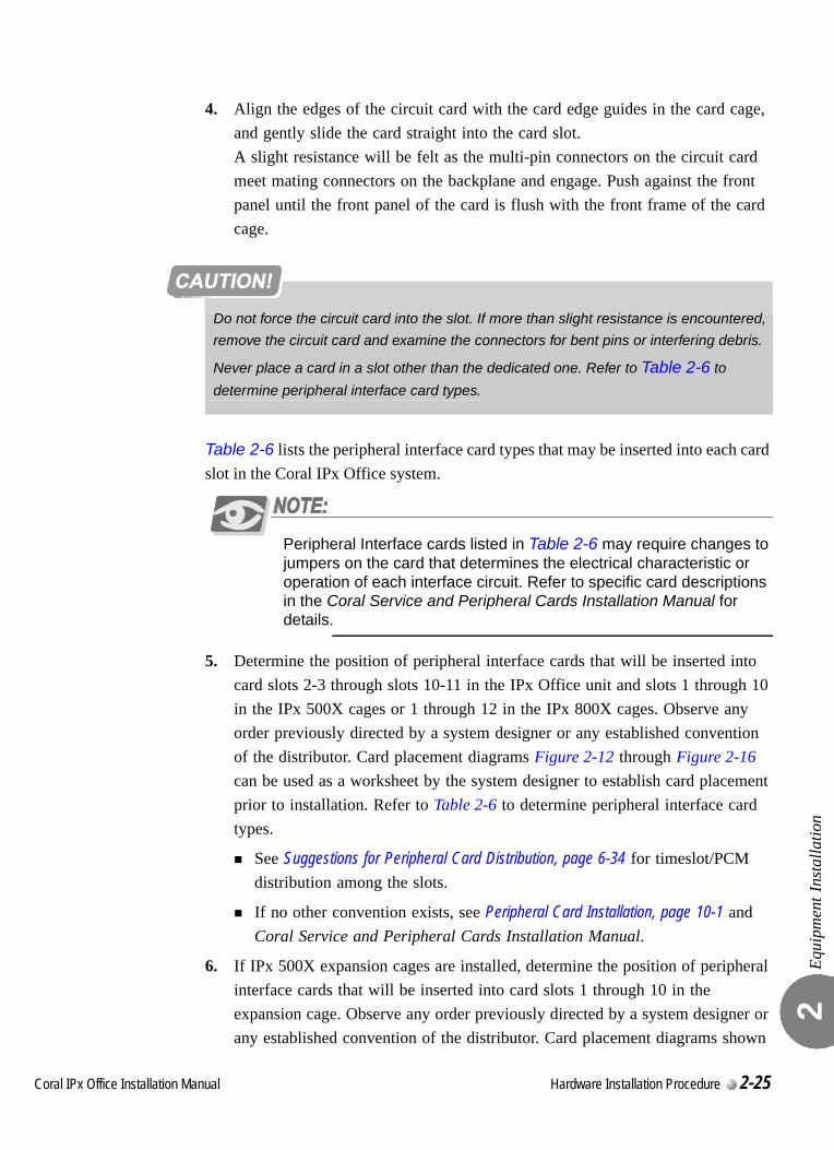
Equi
pmen
t Ins
talla
tion
2
4. Align the edges of the circuit card with the card edge guides in the card cage, and gently slide the card straight into the card slot.A slight resistance will be felt as the multi-pin connectors on the circuit card meet mating connectors on the backplane and engage. Push against the front panel until the front panel of the card is flush with the front frame of the card cage.
Table 2-6 lists the peripheral interface card types that may be inserted into each card slot in the Coral IPx Office system.
Peripheral Interface cards listed in Table 2-6 may require changes to jumpers on the card that determines the electrical characteristic or operation of each interface circuit. Refer to specific card descriptions in the Coral Service and Peripheral Cards Installation Manual for details.
5. Determine the position of peripheral interface cards that will be inserted into card slots 2-3 through slots 10-11 in the IPx Office unit and slots 1 through 10 in the IPx 500X cages or 1 through 12 in the IPx 800X cages. Observe any order previously directed by a system designer or any established convention of the distributor. Card placement diagrams Figure 2-12 through Figure 2-16 can be used as a worksheet by the system designer to establish card placement prior to installation. Refer to Table 2-6 to determine peripheral interface card types.
See Suggestions for Peripheral Card Distribution, page 6-34 for timeslot/PCM distribution among the slots.
If no other convention exists, see Peripheral Card Installation, page 10-1 and Coral Service and Peripheral Cards Installation Manual.
6. If IPx 500X expansion cages are installed, determine the position of peripheral interface cards that will be inserted into card slots 1 through 10 in the expansion cage. Observe any order previously directed by a system designer or any established convention of the distributor. Card placement diagrams shown
Do not force the circuit card into the slot. If more than slight resistance is encountered,
remove the circuit card and examine the connectors for bent pins or interfering debris.
Never place a card in a slot other than the dedicated one. Refer to Table 2-6 to
determine peripheral interface card types.
Coral IPx Office Installation Manual Hardware Installation Procedure 2-25
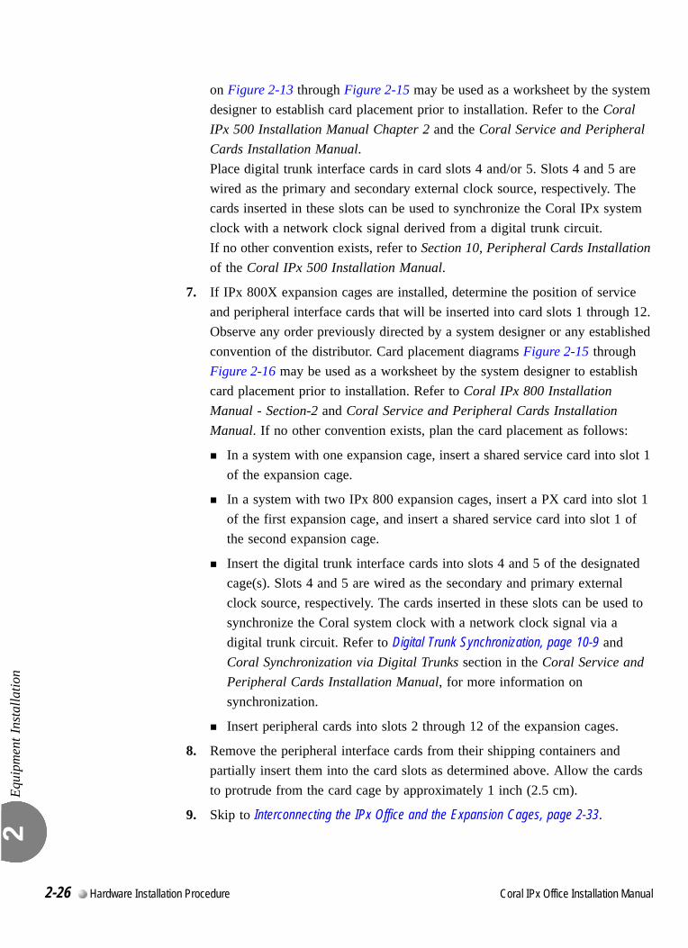
Equi
pmen
t Ins
talla
tion
2
on Figure 2-13 through Figure 2-15 may be used as a worksheet by the system designer to establish card placement prior to installation. Refer to the Coral IPx 500 Installation Manual Chapter 2 and the Coral Service and Peripheral Cards Installation Manual.Place digital trunk interface cards in card slots 4 and/or 5. Slots 4 and 5 are wired as the primary and secondary external clock source, respectively. The cards inserted in these slots can be used to synchronize the Coral IPx system clock with a network clock signal derived from a digital trunk circuit.If no other convention exists, refer to Section 10, Peripheral Cards Installation of the Coral IPx 500 Installation Manual.
7. If IPx 800X expansion cages are installed, determine the position of service and peripheral interface cards that will be inserted into card slots 1 through 12. Observe any order previously directed by a system designer or any established convention of the distributor. Card placement diagrams Figure 2-15 through Figure 2-16 may be used as a worksheet by the system designer to establish card placement prior to installation. Refer to Coral IPx 800 Installation Manual - Section-2 and Coral Service and Peripheral Cards Installation Manual. If no other convention exists, plan the card placement as follows:
In a system with one expansion cage, insert a shared service card into slot 1 of the expansion cage.
In a system with two IPx 800 expansion cages, insert a PX card into slot 1 of the first expansion cage, and insert a shared service card into slot 1 of the second expansion cage.
Insert the digital trunk interface cards into slots 4 and 5 of the designated cage(s). Slots 4 and 5 are wired as the secondary and primary external clock source, respectively. The cards inserted in these slots can be used to synchronize the Coral system clock with a network clock signal via a digital trunk circuit. Refer to Digital Trunk Synchronization, page 10-9 and Coral Synchronization via Digital Trunks section in the Coral Service and Peripheral Cards Installation Manual, for more information on synchronization.
Insert peripheral cards into slots 2 through 12 of the expansion cages.
8. Remove the peripheral interface cards from their shipping containers and partially insert them into the card slots as determined above. Allow the cards to protrude from the card cage by approximately 1 inch (2.5 cm).
9. Skip to Interconnecting the IPx Office and the Expansion Cages, page 2-33.
2-26 Hardware Installation Procedure Coral IPx Office Installation Manual
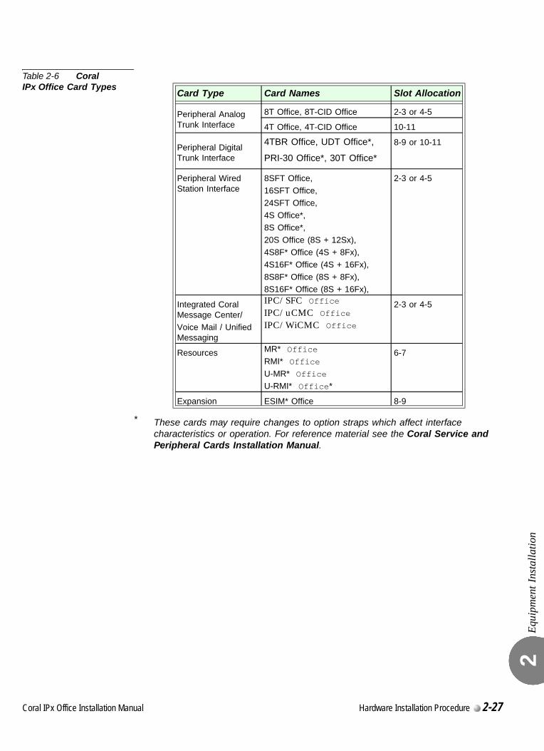
Equi
pmen
t Ins
talla
tion
2
Table 2-6 Coral IPx Office Card Types
* These cards may require changes to option straps which affect interface characteristics or operation. For reference material see the Coral Service and Peripheral Cards Installation Manual.
Card Type Card Names Slot Allocation
Peripheral Analog Trunk Interface
8T Office, 8T-CID Office 2-3 or 4-5
4T Office, 4T-CID Office 10-11
Peripheral Digital Trunk Interface
4TBR Office, UDT Office*,
PRI-30 Office*, 30T Office*
8-9 or 10-11
Peripheral Wired Station Interface
8SFT Office,
16SFT Office,
24SFT Office,4S Office*,
8S Office*,
20S Office (8S + 12Sx),4S8F* Office (4S + 8Fx),
4S16F* Office (4S + 16Fx),
8S8F* Office (8S + 8Fx),8S16F* Office (8S + 16Fx),
2-3 or 4-5
Integrated Coral Message Center/
Voice Mail / Unified Messaging
IPC/SFC OfficeIPC/uCMC OfficeIPC/WiCMC Office
2-3 or 4-5
Resources MR* Office
RMI* Office
U-MR* Office
U-RMI* Office*
6-7
Expansion ESIM* Office 8-9
Coral IPx Office Installation Manual Hardware Installation Procedure 2-27
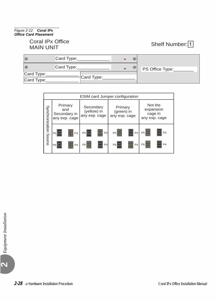
Equi
pmen
t Ins
talla
tion
2
Figure 2-12 Coral IPx Office Card Placement
slots #4 & 5
slots #6 & 7slots #10 & 11Card Type:_____________
Card Type:_____________Card Type:_____________
Card Type:_____________
Card Type:_____________
Coral IPx OfficeMAIN UNIT Shelf Number:
Synchronization Source
Not theexpansion
cage inany exp. cage
Primary(green) in
any exp. cage
P3P3 P5P5
P4P4 P6P6
Secondary(yellow) in
any exp. cage
Primaryand
Secondary inany exp. cage
P3P5
P4P6
P3P5
P4P6
ESIM card Jumper configuration
PS Office Type:________
2-28 Hardware Installation Procedure Coral IPx Office Installation Manual
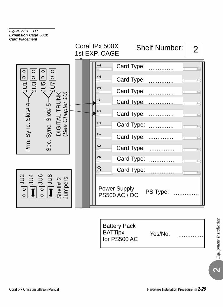
Equi
pmen
t Ins
talla
tion
2
Figure 2-13 1st Expansion Cage 500X Card Placement
16
27
38
49
510
Card Type:
Card Type:
Card Type:
Card Type:
Card Type:
Card Type:
Card Type:
..............
..............
..............
..............
..............
..............
..............
..............
Card Type:
Card Type:
Card Type: ..............
..............
Power SupplyPS500 AC / DC PS Type: ..............
Yes/No: ..............
Coral IPx 500X1st EXP. CAGE
Shelf Number: 2
Battery PackBATTipxfor PS500 AC
She
lf# 2
Jum
persJU
2JU
4JU
6JU
8
Prm
. Syn
c. S
lot#
4
Sec
. Syn
c. S
lot#
5
JU1
JU3
JU5
JU7
DIG
ITA
L TR
UN
K(S
ee C
hapt
er 1
0)
Coral IPx Office Installation Manual Hardware Installation Procedure 2-29
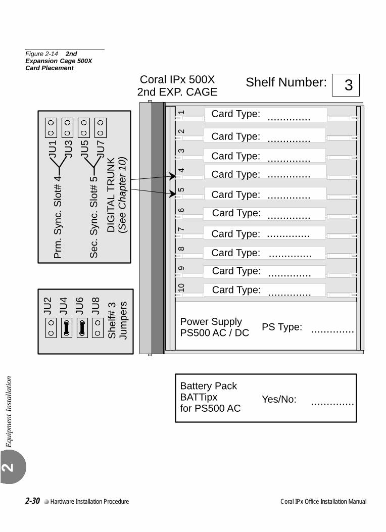
Equi
pmen
t Ins
talla
tion
2
Figure 2-14 2nd Expansion Cage 500X Card Placement
16
27
38
49
510
Card Type:
Card Type:
Card Type:
Card Type:
Card Type:
Card Type:
Card Type:
..............
..............
..............
..............
..............
..............
..............
..............
Card Type:
Card Type:
Card Type: ..............
..............
Power SupplyPS500 AC / DC PS Type: ..............
Yes/No: ..............
Coral IPx 500X2nd EXP. CAGE
Shelf Number: 3
Battery PackBATTipxfor PS500 AC
She
lf# 3
Jum
persJU
2JU
4JU
6JU
8
Prm
. Syn
c. S
lot#
4
Sec
. Syn
c. S
lot#
5
JU1
JU3
JU5
JU7
DIG
ITA
L TR
UN
K(S
ee C
hapt
er 1
0)
2-30 Hardware Installation Procedure Coral IPx Office Installation Manual
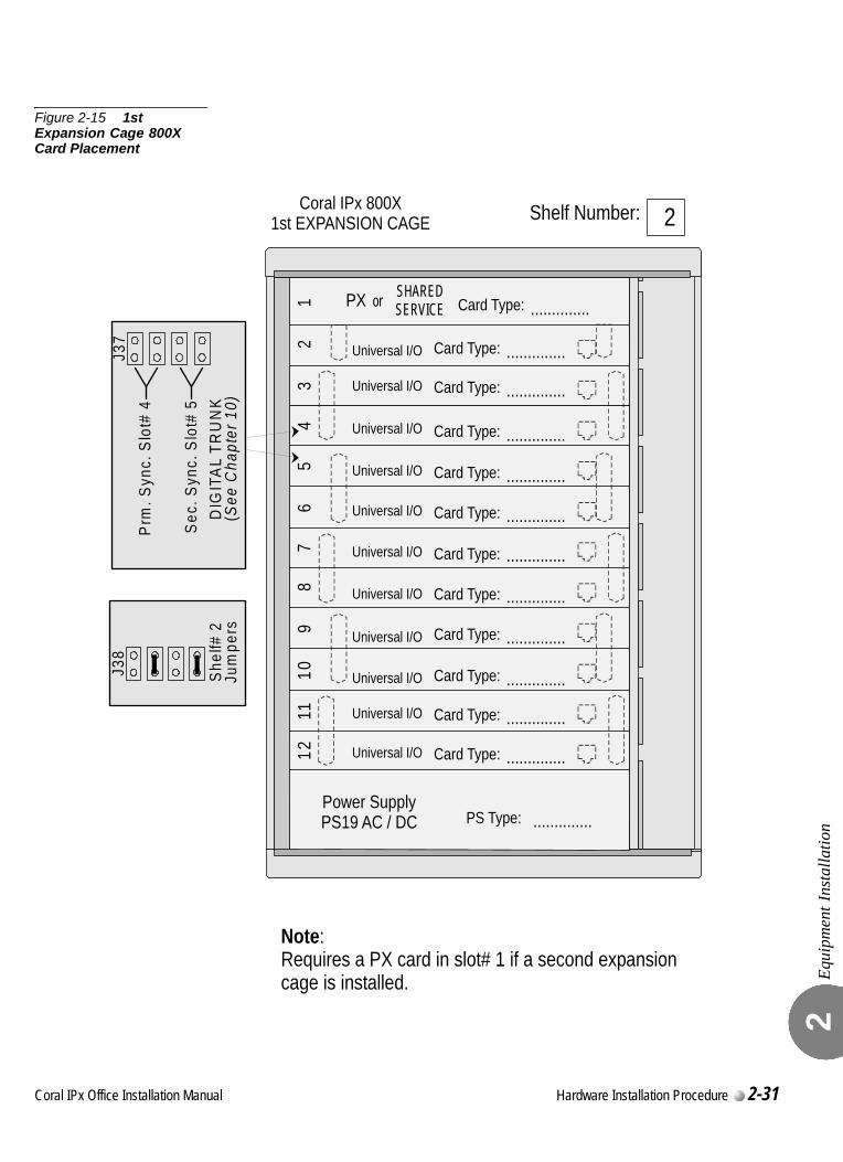
Equi
pmen
t Ins
talla
tion
2
Figure 2-15 1st Expansion Cage 800X Card Placement
She
lf# 2
Jum
pers
Prm
. Syn
c. S
lot#
4
Sec
. Syn
c. S
lot#
5
J37
DIG
ITA
L TR
UN
K(S
ee C
hapt
er 1
0)
12
34
56
78
910
1112
Coral IPx 800X1st EXPANSION CAGE
Card Type:
Card Type:
Card Type:
Card Type:
Card Type:
Card Type:
Card Type:
Card Type: ..............
..............
..............
..............
..............
..............
..............
..............
Universal I/O
Universal I/O
Universal I/O
Universal I/O
Universal I/O
Universal I/O
Universal I/O
Universal I/O
Card Type:
Card Type: ..............
..............
Universal I/O
Universal I/O
Card Type: ..............Universal I/O
Power SupplyPS19 AC / DC PS Type: ..............
PX or
SHARED SERVICE Card Type: ..............
Note: Requires a PX card in slot# 1 if a second expansion cage is installed.
Shelf Number: 2
J38
Coral IPx Office Installation Manual Hardware Installation Procedure 2-31
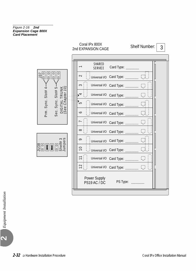
Equi
pmen
t Ins
talla
tion
2
Figure 2-16 2nd Expansion Cage 800X Card Placement
12
34
56
78
910
1112
Card Type:
Card Type:
Card Type:
Card Type:
Card Type:
Card Type:
Card Type:
Card Type: ..............
..............
..............
..............
..............
..............
..............
..............
Universal I/O
Universal I/O
Universal I/O
Universal I/O
Universal I/O
Universal I/O
Universal I/O
Universal I/O
Card Type:
Card Type: ..............
..............
Universal I/O
Universal I/O
Card Type: ..............Universal I/O
Power SupplyPS19 AC / DC PS Type: ..............
SHARED SERVICE Card Type: ..............
Coral IPx 800X2nd EXPANSION CAGE Shelf Number: 3
She
lf# 3
Jum
pers
JU38
Prm
. Syn
c. S
lot#
4
Sec
. Syn
c. S
lot#
5
J37
DIG
ITAL
TR
UN
K(S
ee C
hapt
er 1
0)
2-32 Hardware Installation Procedure Coral IPx Office Installation Manual
Equi
pmen
t Ins
talla
tion
2
0
This section describes how to interconnect the units within the Coral IPx Office system. For a full description of the different system configurations, see Interconnecting the IPx Office Unit and the Expansion Cage, page 6-30.A IPx Office expansion cable is supplied with the ESIM card and is used to connect the backplane of the cage to the IPx Office unit. The IPx Office expansion cable has one female D-Type 50-pin connector at one end and a a SCSI female connector at the other end. When the IPx Office system includes expansion cages, the ESIM Office card is installed into the IPx Office unit in slot 8-9 and the IPx Office expansion cable is attached to the SCSI female connector on the front panel of the ESIM Office card.
Interconnecting the IPx Office Unit and the Expansion Cage
1. Verify that the ESIM Office peripheral card is installed in slot 8-9 of the IPx Office unit.
2. Plug the male end of the IPx Office expansion cable into the female SCSI connector on the front panel of the ESIM Office peripheral card.
3. Plug the female, D-type connector of the cable into the connector labeled FROM CONTROL UNIT OR FIRST EXPANSION UNIT on the the first expansion cage.
4. Tighten the screws on both sides of the cable to secure it.
Interconnecting the 1st Expansion cage and 2nd Expansion Cage
1. Plug the male end of the H500-1 cable into the female D-type connector labeled TO SECOND EXPANSION UNIT located in the top section of the first expansion cage.
2. Plug the female end of the H500-1 cable into the male D-type connector labeled FROM CONTROL UNIT OR FIRST EXPANSION UNIT located in the top section of the second expansion cage.
3. Tighten the screws on both sides of the cable to secure it.
Defining Expansion Cage Numbers
Skip to Strapping the Configuration Jumpers, page 2-23.
...................................................................................................11 Interconnecting the IPx Office and the Expansion Cages
Coral IPx Office Installation Manual Hardware Installation Procedure 2-33

Equi
pmen
t Ins
talla
tion
2
0
This section describes how to insert the DC power supply card into its slot. The IPx Office unit is shipped from the manufacturer with the AC power supply installed. If a DC power supply is to be installed, remove the existing AC power supply and insert the DC power supply in its place. See Figure 2-17 and Figure 2-18 for power supply placement in the IPx Office unit.
1. Verify that the IPx Office is properly grounded. See Ground Wiring, page 2-18.
2. Verify that the power switch is turned OFF (downwards). See Figure 2-17.
3. Grasp the power supply horizontally with both hands, fingers near the left and right of the power supply near the front panel.
4. Align the two guide ridges located on the bottom panel of the power supply (right and left) in the card edge guides. Slide the power supply gently but firmly, until fully inserted into the unit.
5. Fasten the two M3 screws located on the top and bottom of the power supply front panel, thus securing the card to the cage as well as grounding the unit
.
Figure 2-17 PS Office DC Front Panel
...................................................................................................12 Installing the DC Power Supply
Circuit cards contain static-sensitive circuitry and may be damaged or destroyed by
electro-static discharge (ESD). Always wear a static dissipating wrist strap connected to
the unit while handling circuit cards. See Figure 2-11 on page 2-24. Hold circuit cards
by their edges and avoid touching contact surfaces. Handle with care and do not drop.
Do not proceed until the screws have been fastened. If the screws are not fastened, the
power supply unit will not be grounded and could be subject to hazardous voltages.
ON
+ -
OFF
PS Office DCCat. No. 77440950300
OUTPUT:+5V 6A
+3.3V 6ADCDCDC-48V 1A
Removable screws
2-34 Hardware Installation Procedure Coral IPx Office Installation Manual
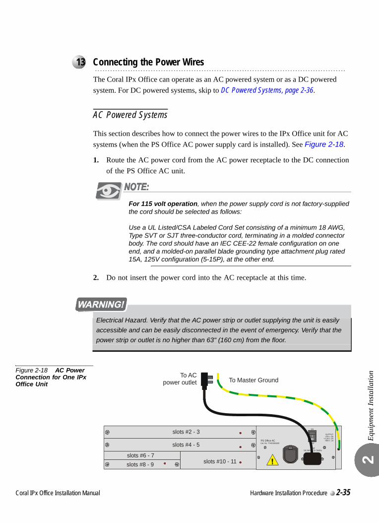
Equi
pmen
t Ins
talla
tion
2
0
The Coral IPx Office can operate as an AC powered system or as a DC powered system. For DC powered systems, skip to DC Powered Systems, page 2-36.
AC Powered Systems
This section describes how to connect the power wires to the IPx Office unit for AC systems (when the PS Office AC power supply card is installed). See Figure 2-18.
1. Route the AC power cord from the AC power receptacle to the DC connection of the PS Office AC unit.
For 115 volt operation, when the power supply cord is not factory-supplied the cord should be selected as follows:
Use a UL Listed/CSA Labeled Cord Set consisting of a minimum 18 AWG, Type SVT or SJT three-conductor cord, terminating in a molded connector body. The cord should have an IEC CEE-22 female configuration on one end, and a molded-on parallel blade grounding type attachment plug rated 15A, 125V configuration (5-15P), at the other end.
2. Do not insert the power cord into the AC receptacle at this time.
Figure 2-18 AC Power Connection for One IPx Office Unit
...................................................................................................13 Connecting the Power Wires
Electrical Hazard. Verify that the AC power strip or outlet supplying the unit is easily
accessible and can be easily disconnected in the event of emergency. Verify that the
power strip or outlet is no higher than 63" (160 cm) from the floor.
slots #2 - 3
slots #4 - 5
slots #6 - 7slots #8 - 9 slots #10 - 11
PS Office ACCat. No. 77440950200
OUTPUT:+5V 6A
+3.3V 6ADCDCDC-48V 1A
INPUT:100-240V 2.2A 50/60HzAC
ON
OFF
To Master GroundTo AC
power outlet
Coral IPx Office Installation Manual Hardware Installation Procedure 2-35
Equi
pmen
t Ins
talla
tion
2
DC Powered Systems
This section describes how to connect the power wires to the Coral IPx Office unit for DC powered systems (that is, when the PS Office DC power supply card is installed in the unit).Figure 2-19 shows one IPx Office unit installed in the system, and Figure 2-20 shows three units installed within the system.
The DC power wires provided with the system are 6.6ft (2m) long. Verify that the connection to the facilities power source is made according to local requirements.
1. The PS Office DC power supply unit is supplied with a 6.6ft (2m) long pair of 16 AWG wires (one red and one black). If this is not long enough to connect the facilities power source to the cage, fabricate an extension at the customer’s site with two wires that are identical to the ones above.
2. Route each power wire to the DC connection on the front panel of the PS Office DC. Take care not to let the free end of the cable cause damage by swinging loose or making contact with another electrical connection.
3. Do not insert the DC power input connector at this time. Leave the DC power input connector unplugged.
4. Connect the other ends of the wires to the –48VDC facilities power source and a circuit breaker as shown in Figure 2-19 and Figure 2-20 and according to local regulatory requirements.
Negative (black) wire to the circuit breaker or –48V busbar panel
Positive (red) wire to the +48VDC terminal or +48V busbar panel
5. Skip to Chapter 3, Initial Power-up Tests.
2-36 Hardware Installation Procedure Coral IPx Office Installation Manual
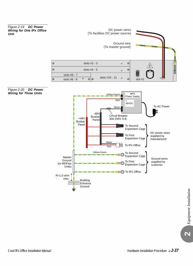
Equi
pmen
t Ins
talla
tion
2
Figure 2-19 DC Power Wiring for One IPx Office Unit
Figure 2-20 DC Power Wiring for Three Units
slots #2 - 3
slots #4 - 5
slots #6 - 7slots #8 - 9 slots #10 - 11 slot #1
ON
+ -OFF
DC power wires(To facilities DC power source)
Ground wire(To master ground)
Circuit Breaker30A 250V S.B.
To SecondExpansion Cage
To SecondExpansion Cage
-48V Busbar
Panel+48V Busbar
Panel
R=1.0 ohm max. Building
EntranceGround
To FirstExpansion Cage
To FirstExpansion Cage
To IPx Office
To IPx OfficeBlack
To AC Power
MasterGround
(or MDFipxUnits)
DC power wiressupplied bymanufacturer
Ground wiressupplied bycustomer
Yellow-Green
MPSPower Supply
+48VDC-
Yellow-Green
Red
Black
Red
Coral IPx Office Installation Manual Hardware Installation Procedure 2-37

Equi
pmen
t Ins
talla
tion
2
2-38 Hardware Installation Procedure Coral IPx Office Installation Manual
C
2.3
oral IPx Office Installation Ma
Program Interface Device Connection
Prog
ram
Inte
rfac
e D
evic
e C
onne
ctio
n 2
The data terminal or personal computer that will be used as the Program Interface (PI) device must be equipped with an RS-232E asynchronous serial data interface that can be configured for a data rate of 19200, 9600, 4800, 1200, or 300 bps, 8 data bits, 1stop bit, and no parity bit or EVEN, ODD, mark, space, and parity. The PI device must use the ASCII character set. The ground connection to the PI device must be the same ground connection supplied to the Coral system.
1. Unpack the PI device and prepare it for operation. Set the interface for a data rate of 9600 bps, 8 data bits, 1 stop bit, and no parity bit. These are the default settings for all serial programming ports of the Coral system.
2. Determine the connector type and pin assignments for the data interface of the PI device. Figure 2-21 shows the connections for using personal computers with a DA-9P connector for the serial interface.
3. Obtain or prepare a serial data cable to connect the PI device to the KB0 serial programming port on the front side of the unit. The KB0 port end of the serial programming cable requires a male DA-9P style connector, wired as shown in Figure 2-21.
4. If the PI device is a personal computer equipped with a DA-9P connector, wire the connectors according to Figure 2-21.
5. For installations with a permanent PI device, route the serial data cable from the PI device to the front panel of the unit and connect it to the KB0 connector.
nual Hardware Installation Procedure 2-39
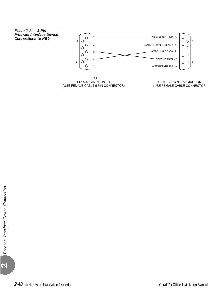
Prog
ram
Inte
rfac
e D
evic
e C
onne
ctio
n 2
Figure 2-21 9-Pin Program Interface Device Connections to KB0
KB0PROGRAMMING PORT
(USE FEMALE CABLE 9 PIN CONNECTOR)
DATA TERMINAL READY - 4
6
9
CARRIER DETECT - 1
RECEIVE DATA - 2
TRANSMIT DATA - 3
SIGNAL GROUND - 5
9 PIN PC ASYNC. SERIAL PORT(USE FEMALE CABLE CONNECTOR)
4
1
2
3
5
6
9
2-40 Hardware Installation Procedure Coral IPx Office Installation Manual
Coral IPx Office Installation Manual
Chapter
3Initial Power-up Tests
3.1 Power Supply Test .......................................................................3-1
3.2 Common Control Test ..................................................................3-5
3.3 Peripheral Interface Card Initialization.........................................3-9
3.4 I/O Cable Installation .................................................................3-15
3.5 Installation Wrap-up...................................................................3-17

3
3-0 Initial Power-up Tests Coral IPx Office Installation Manual

C
3.1
oral IPx Office Installation Ma
Power Supply Test
Pow
er S
uppl
y Te
st
3
This chapter provides information about connecting the power supply to the facilities power supply.
The IPx Office can operate as an AC powered system or as a DC powered system.
For AC powered systems, see AC Powered Systems, page 3-1, below.
For DC powered systems, skip to DC Powered Systems, page 3-3.0
1. Verify that the cage ground wire is connected and the ground nut is tightened. See Ground Wiring, page 2-18.
2. Verify that the power supply unit has been installed and the two removable screws on the left and right side of the PS Office AC front panel are tightened.
3. Verify that the PS Office AC power switch is turned OFF (downwards).
4. Verify that the female connector of the AC power cord has been inserted into the front panel socket of the PS Office AC power supply. See Figure 3-1.
5. Insert the male plug of the AC power cord into the line outlet or primary power receptacle designated for the system.
6. Perform the AC power supply test for expansion cages as described in Chapter 3 of the Coral IPx 500 Installation Procedure and Hardware Reference Manual or Coral IPx 800 Installation Procedure and Hardware Reference Manual.
7. Skip to Common Control Test, page 3-5.
Before proceeding, verify that the peripheral cards in the expansion cages of the
IPx Office system are only partially inserted into their respective card slots, with the
front side protruding approximately 1 inch (2.5 cm) from the front of the card cage.
...................................................................................................1 AC Powered Systems
nual Initial Power-up Tests 3-1
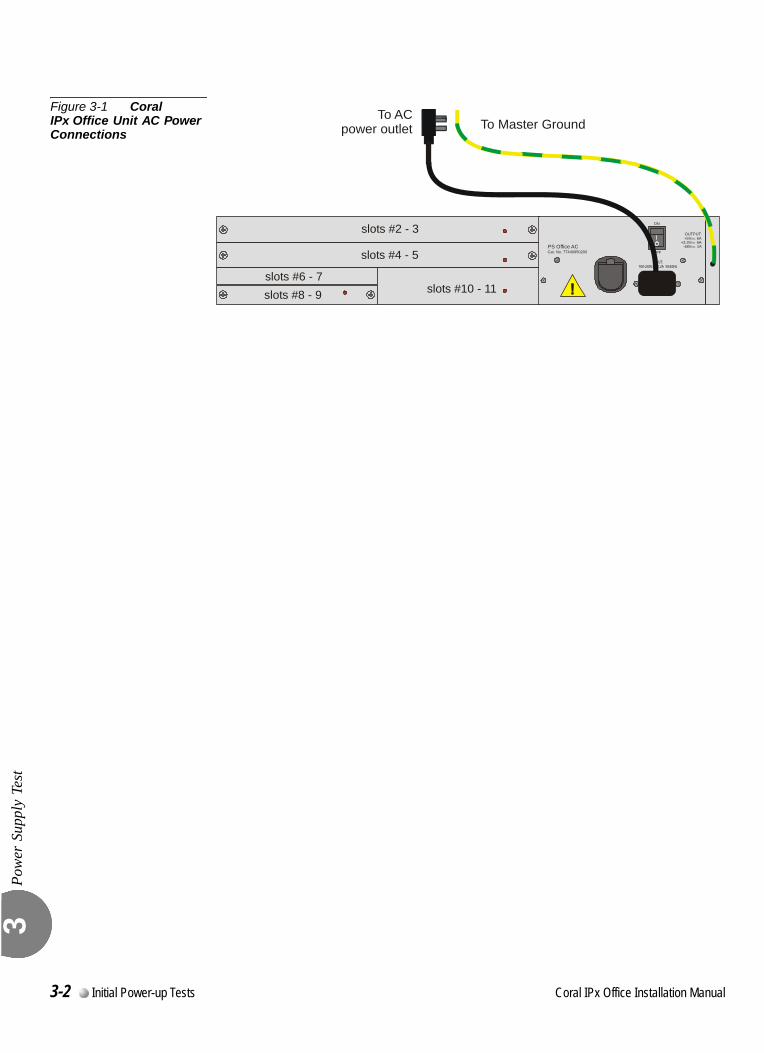
Pow
er S
uppl
y Te
st
3
Figure 3-1 Coral IPx Office Unit AC Power Connections
slots #2 - 3
slots #4 - 5
slots #6 - 7slots #8 - 9 slots #10 - 11
PS Office ACCat. No. 77440950200
OUTPUT:+5V 6A
+3.3V 6ADCDCDC-48V 1A
INPUT:100-240V 2.2A 50/60HzAC
ON
OFF
To Master GroundTo AC
power outlet
3-2 Initial Power-up Tests Coral IPx Office Installation Manual
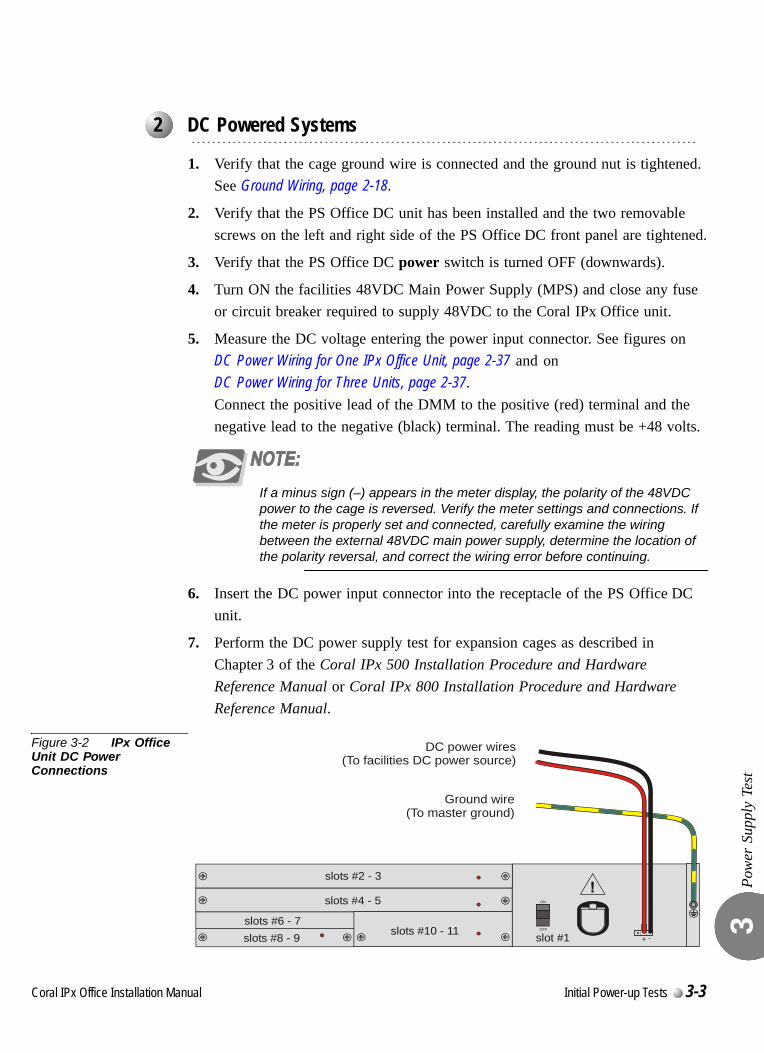
Pow
er S
uppl
y Te
st
3
0
1. Verify that the cage ground wire is connected and the ground nut is tightened. See Ground Wiring, page 2-18.
2. Verify that the PS Office DC unit has been installed and the two removable screws on the left and right side of the PS Office DC front panel are tightened.
3. Verify that the PS Office DC power switch is turned OFF (downwards).
4. Turn ON the facilities 48VDC Main Power Supply (MPS) and close any fuse or circuit breaker required to supply 48VDC to the Coral IPx Office unit.
5. Measure the DC voltage entering the power input connector. See figures onDC Power Wiring for One IPx Office Unit, page 2-37 and onDC Power Wiring for Three Units, page 2-37.Connect the positive lead of the DMM to the positive (red) terminal and the negative lead to the negative (black) terminal. The reading must be +48 volts.
If a minus sign (–) appears in the meter display, the polarity of the 48VDC power to the cage is reversed. Verify the meter settings and connections. If the meter is properly set and connected, carefully examine the wiring between the external 48VDC main power supply, determine the location of the polarity reversal, and correct the wiring error before continuing.
6. Insert the DC power input connector into the receptacle of the PS Office DC unit.
7. Perform the DC power supply test for expansion cages as described in Chapter 3 of the Coral IPx 500 Installation Procedure and Hardware Reference Manual or Coral IPx 800 Installation Procedure and Hardware Reference Manual.
Figure 3-2 IPx Office Unit DC Power Connections
...................................................................................................2 DC Powered Systems
slots #2 - 3
slots #4 - 5
slots #6 - 7slots #8 - 9 slots #10 - 11 slot #1
ON
+ -OFF
DC power wires(To facilities DC power source)
Ground wire(To master ground)
Coral IPx Office Installation Manual Initial Power-up Tests 3-3

Pow
er S
uppl
y Te
st
3
NOTES:
3-4 Initial Power-up Tests Coral IPx Office Installation Manual

C
3.2
oral IPx Office Installation Ma
Common Control Test
Com
mon
Con
trol T
est
3
This section deals with the Common Control Test.
0
The MCB Office control card layout is shown in Figure 8-1.
1. In the main cage and in the expansion cages, verify that the PS Office power switch is in the OFF position (turned downwards).
2. Verify that all peripheral cards in the IPx Office unit are completely installed.
3. Verify that all peripheral cards in the expansion cages protrude from the cage by approximately 1 inch (2.5 cm).
4. Verify that the the SAU is attached to the connector on the right side of the IPx Office unit. See Chapter 8.
5. Verify that the IMC8/IMC16 flash memory card and the compact flash memory disk have been inserted into their respective drives located on the front panel of the IPx Office unit. See IMC8 and IMC16 Flash Cards, page 8-33.
6. Attach the Program Interface (PI) device cable to the KB0 programming port connector on the front panel of the IPx Office unit. Verify that the PI device is configured to match the data rate, word length, parity, and stop bits of KB0. Default settings for KB0 are 9600 bps, 8 data bit, no parity, and 1 stop bit, respectively.
7. Turn ON the power switch on the PS Office power supply on the rear panel of the IPx Office unit.
8. On the front panel of the IPx Office unit (see Figure 6-3 on page 6-3), verify that the indicators illuminate as follows:
The green POWER indicator turns ON.
Red GC indicator turns ON until the system initializes and then turns OFF.
Red UGW indicator turns ON until the system initializes and then turns OFF.
...................................................................................................1 Control Card Initialization
nual Initial Power-up Tests 3-5
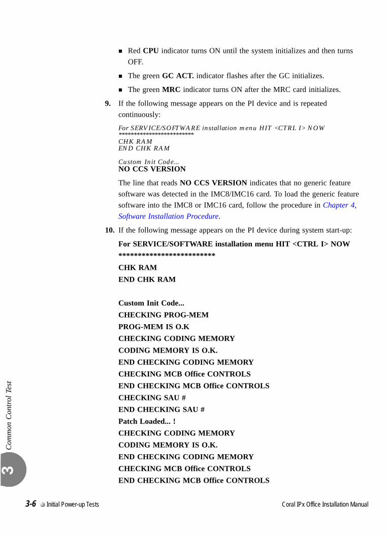
Com
mon
Con
trol T
est
3
Red CPU indicator turns ON until the system initializes and then turns OFF.
The green GC ACT. indicator flashes after the GC initializes.
The green MRC indicator turns ON after the MRC card initializes.
9. If the following message appears on the PI device and is repeated continuously:
For SERVICE/SOFTWARE installation menu HIT <CTRL I> NOW*************************CHK RAMEND CHK RAM
Custom Init Code...NO CCS VERSION
The line that reads NO CCS VERSION indicates that no generic feature software was detected in the IMC8/IMC16 card. To load the generic feature software into the IMC8 or IMC16 card, follow the procedure in Chapter 4, Software Installation Procedure.
10. If the following message appears on the PI device during system start-up:
For SERVICE/SOFTWARE installation menu HIT <CTRL I> NOW*************************CHK RAMEND CHK RAM
Custom Init Code...CHECKING PROG-MEMPROG-MEM IS O.KCHECKING CODING MEMORYCODING MEMORY IS O.K.END CHECKING CODING MEMORYCHECKING MCB Office CONTROLSEND CHECKING MCB Office CONTROLSCHECKING SAU #END CHECKING SAU #Patch Loaded... !CHECKING CODING MEMORYCODING MEMORY IS O.K.END CHECKING CODING MEMORYCHECKING MCB Office CONTROLSEND CHECKING MCB Office CONTROLS
3-6 Initial Power-up Tests Coral IPx Office Installation Manual
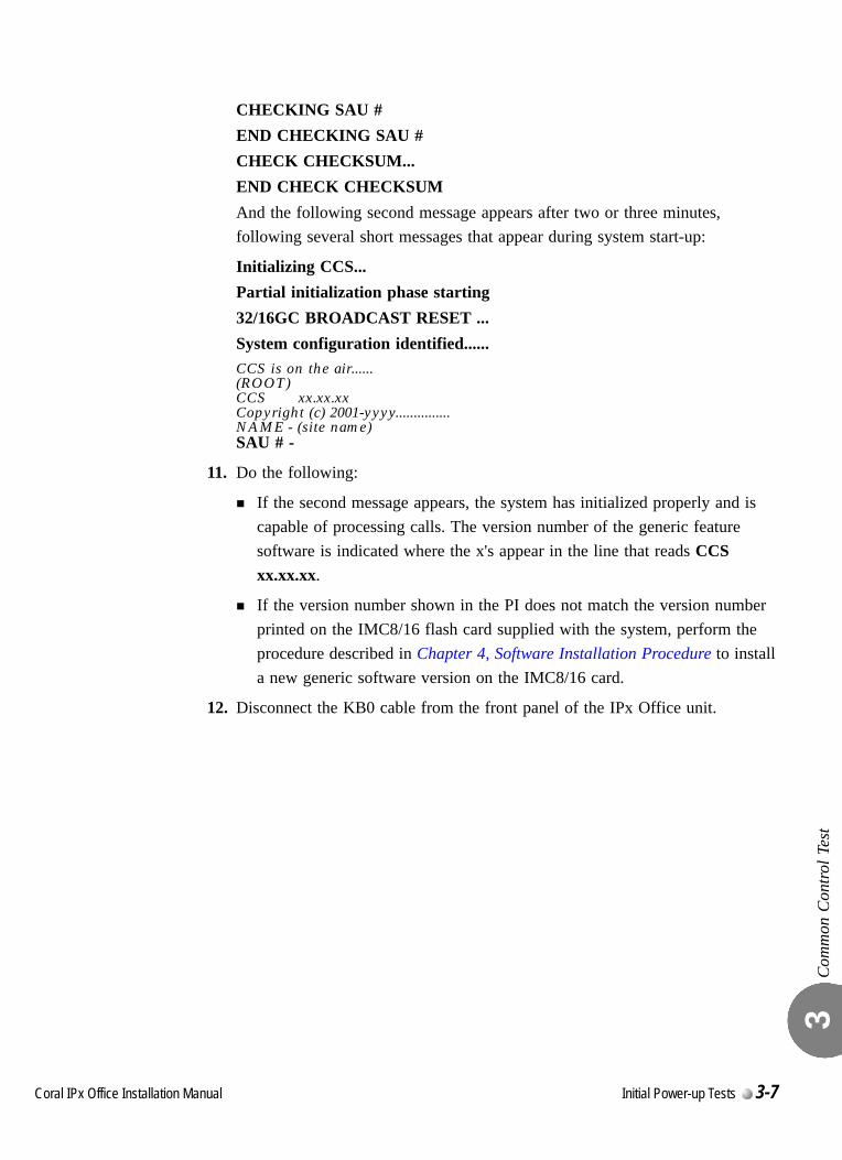
Com
mon
Con
trol T
est
3
CHECKING SAU #END CHECKING SAU #CHECK CHECKSUM...END CHECK CHECKSUMAnd the following second message appears after two or three minutes, following several short messages that appear during system start-up:
Initializing CCS...Partial initialization phase starting32/16GC BROADCAST RESET ...System configuration identified......CCS is on the air......(ROOT)CCS xx.xx.xxCopyright (c) 2001-yyyy...............NAME - (site name)SAU # -
11. Do the following:
If the second message appears, the system has initialized properly and is capable of processing calls. The version number of the generic feature software is indicated where the x's appear in the line that reads CCS xx.xx.xx.
If the version number shown in the PI does not match the version number printed on the IMC8/16 flash card supplied with the system, perform the procedure described in Chapter 4, Software Installation Procedure to install a new generic software version on the IMC8/16 card.
12. Disconnect the KB0 cable from the front panel of the IPx Office unit.
Coral IPx Office Installation Manual Initial Power-up Tests 3-7

Com
mon
Con
trol T
est
3
0
If the start-up tests detect that the voltage level of a lithium backup battery on the MCB Office is insufficient to reliably maintain the memory contents in the event of power failure, the following messages will appear:
MCB Office - BATTERY LOW
This message indicates that the MCB Office card battery has an insufficient voltage level. In this event, the Coral system database is in jeopardy of being lost during a power failure. If this message appears, the database should be saved and the battery replaced at the first opportunity.To ensure that the system database is not lost, save the database to the IMC8/IMC16 card via the database controls branch of the system database (ROUTE: ROOT, 0, 10, 2, 2, 0). For details, see System Database Control, page 4-5. If the system loses power or is reset for any reason and the database is lost from memory, the system will copy the database from the IMC8 card into database memory as the system restarts.Once the system database is safely saved on the IMC8 card, power to the Coral system may be turned off at a time that will cause the least disruption of service to the user. At that time, the battery on the MCB Office may be replaced and the system restarted.
To replace the lithium battery, carefully raise the battery holder clip and then insert the new battery with the + (positive) symbol appearing on top. Do not apply too much pressure to the battery holder clip as this could cause the clip to snap.
...................................................................................................2 Memory Lithium Battery Condition Test
Explosion and Environmental Hazards.
There is a danger of explosion if the battery is replaced incorrectly.
Replace the battery only with the same or equivalent type recommended by the
manufacturer.
Dispose of used batteries according to requirements specified by the battery
manufacturer and/or local regulatory agencies.
3-8 Initial Power-up Tests Coral IPx Office Installation Manual
C
3.3
oral IPx Office Installation Ma
Peripheral Interface Card Initialization
Peri
pher
al In
terf
ace
Car
d In
itial
izat
ion
3
This section describes how to initialize the peripheral cards. Perform this section only after the MCB Office control card in the IPx Office has been initialized properly. If the peripheral cards are inserted before the IPx Office system has initialized, they will not initialize properly, either.The card installation is described on Rules for Inserting a Coral Circuit Card, page 3-10.The IPx Office system peripheral cards installation and initialization procedure includes the following steps:
1. Preparing for Initialization
2. IPx Office Unit Initialization
3. First Expansion Cage Initialization
4. Second Expansion Cage Initialization
...................................................................................................1 Introduction
nual Initial Power-up Tests 3-9

Peri
pher
al In
terf
ace
Car
d In
itial
izat
ion
3
Rules for Inserting a Coral Circuit Card
1. Connect a static dissipating wrist strap connector to the cage and put on the strap. See Figure 2-11 on page 2-24.
2. To insert a circuit card completely into its slot, gently slide the card straight into the card slot. A slight resistance will be felt as the multi-pin connectors on the circuit card meet mating connectors on the backplane and engage.
3. Push against the front panel of the card until it is flush with the front frame of the card cage.
4. On the front panel of the peripheral card, verify that the red diagnostic LED(s) (near the right side of the card) illuminates. The LED remains illuminated continuously until the card receives its database from the system. After a few seconds, verify that the LED extinguishes. An extinguished diagnostic LED indicates that the card has initialized properly.
If the LED remains illuminated continuously for more than two or three minutes, either there is a conflict between the system database and its authorizations, or the card may be faulty. See Table 6-1 on page 6-3, or refer to the Coral Service and Peripheral Cards Installation Manual for further details.
Circuit cards contain static-sensitive circuitry and may be damaged or destroyed by
electro-static discharge (ESD). Always wear a static dissipating wrist strap connected to
the unit while handling circuit cards. Hold circuit cards by their edges and avoid touching
contact surfaces. Handle with care and do not drop.
Do not force the circuit card into the slot. If more than slight resistance is encountered,
remove the circuit card and examine the connectors for bent pins or interfering debris.
Never place a card in a slot other than the dedicated one. Refer to Table 2-6 on page 2-27 to determine peripheral interface card types.
3-10 Initial Power-up Tests Coral IPx Office Installation Manual
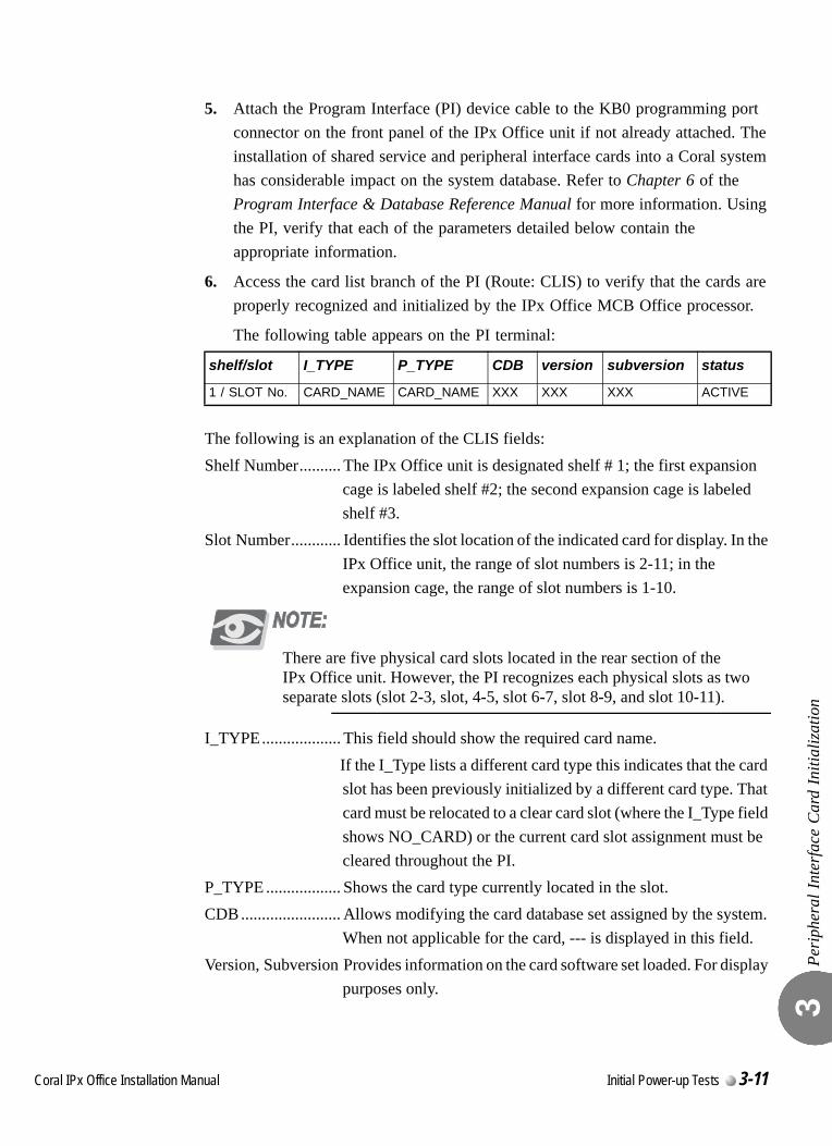
Peri
pher
al In
terf
ace
Car
d In
itial
izat
ion
3
5. Attach the Program Interface (PI) device cable to the KB0 programming port connector on the front panel of the IPx Office unit if not already attached. The installation of shared service and peripheral interface cards into a Coral system has considerable impact on the system database. Refer to Chapter 6 of the Program Interface & Database Reference Manual for more information. Using the PI, verify that each of the parameters detailed below contain the appropriate information.
6. Access the card list branch of the PI (Route: CLIS) to verify that the cards are properly recognized and initialized by the IPx Office MCB Office processor.
The following table appears on the PI terminal:
The following is an explanation of the CLIS fields:Shelf Number.......... The IPx Office unit is designated shelf # 1; the first expansion
cage is labeled shelf #2; the second expansion cage is labeled shelf #3.
Slot Number............ Identifies the slot location of the indicated card for display. In the IPx Office unit, the range of slot numbers is 2-11; in the expansion cage, the range of slot numbers is 1-10.
There are five physical card slots located in the rear section of the IPx Office unit. However, the PI recognizes each physical slots as two separate slots (slot 2-3, slot, 4-5, slot 6-7, slot 8-9, and slot 10-11).
I_TYPE................... This field should show the required card name.If the I_Type lists a different card type this indicates that the card slot has been previously initialized by a different card type. That card must be relocated to a clear card slot (where the I_Type field shows NO_CARD) or the current card slot assignment must be cleared throughout the PI.
P_TYPE .................. Shows the card type currently located in the slot.CDB ........................ Allows modifying the card database set assigned by the system.
When not applicable for the card, --- is displayed in this field.Version, Subversion Provides information on the card software set loaded. For display
purposes only.
shelf/slot I_TYPE P_TYPE CDB version subversion status
1 / SLOT No. CARD_NAME CARD_NAME XXX XXX XXX ACTIVE
Coral IPx Office Installation Manual Initial Power-up Tests 3-11
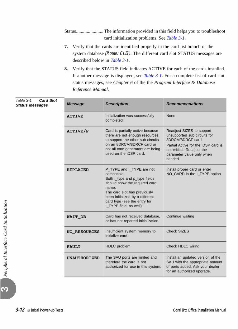
Peri
pher
al In
terf
ace
Car
d In
itial
izat
ion
3
Status....................... The information provided in this field helps you to troubleshoot card initialization problems. See Table 3-1.
7. Verify that the cards are identified properly in the card list branch of the system database (Route: CLIS). The different card slot STATUS messages are described below in Table 3-1.
8. Verify that the STATUS field indicates ACTIVE for each of the cards installed. If another message is displayed, see Table 3-1. For a complete list of card slot status messages, see Chapter 6 of the the Program Interface & Database Reference Manual.
Table 3-1 Card Slot Status Messages
.
Message Description Recommendations
ACTIVE Initialization was successfully completed.
None
ACTIVE/P Card is partially active because there are not enough resources to support the other sub circuits on an 8DRCM/8DRCF card or not all tone generators are being used on the iDSP card.
Readjust SIZES to support unsupported sub circuits for 8DRCM/8DRCF card.
Partial Active for the iDSP card is not critical. Readjust the parameter value only when needed.
REPLACED P_TYPE and I_TYPE are not compatible.Both i_type and p_type fields should show the required card name.The card slot has previously been initialized by a different card type (see the entry for I_TYPE field, as well).
Install proper card or enter NO_CARD in the I_TYPE option.
WAIT_DB Card has not received database, or has not reported initialization.
Continue waiting
NO_RESOURCES Insufficient system memory to initialize card.
Check SIZES
FAULT HDLC problem Check HDLC wiring
UNAUTHORIZED The SAU ports are limited and therefore the card is not authorized for use in this system.
Install an updated version of the SAU with the appropriate amount of ports added. Ask your dealer for an authorized upgrade.
3-12 Initial Power-up Tests Coral IPx Office Installation Manual

Peri
pher
al In
terf
ace
Car
d In
itial
izat
ion
3
0
Preparing for Initialization
After the software has been installed and initialized:
1. In the expansion cages, verify that the PS Office power switch is in the OFF position (turned downwards).
Before proceeding, verify that all power supply units within the expansion cages are turned OFF. If the expansion cages are turned ON before the IPx Office unit, the peripheral cards within the expansion cages will not initialize properly.
2. Check the position of shared service and peripheral interface cards that will be inserted into the system card cage. Observe any order previously directed or any established convention of the distributor. See Inserting a Coral Peripheral Card, page 2-24 and use the following card placement diagrams:
Coral IPx Office Card Placement, page 2-28
1st Expansion Cage 500X Card Placement, page 2-29
2nd Expansion Cage 500X Card Placement, page 2-30
1st Expansion Cage 800X Card Placement, page 2-31
2nd Expansion Cage 800X Card Placement, page 2-32
3. Verify that all peripheral cards in the expansion cages protrude from the cage by approximately 1 inch (2.5 cm).
4. Attach the Program Interface (PI) device cable to KB0 programming port connector on the front side of the IPx Office unit.
IPx Office Unit Initialization
1. Verify that the MCB Office control card has been initialized properly.
2. Insert the peripheral cards completely into their card slots. See Rules for Inserting a Coral Circuit Card, page 3-10. Insert the cards fully, one by one, in sequential order (slot 2-3 through slot 10-11) in adjacent card slots, so that the installation corresponds with the uniform numbering plan. See Figure 2-12 for the location of each peripheral card slot.
...................................................................................................2 System Initialization
Coral IPx Office Installation Manual Initial Power-up Tests 3-13

Peri
pher
al In
terf
ace
Car
d In
itial
izat
ion
3
First Expansion Cage Initialization
1. Turn ON the power supply unit in the first expansion cage.
Turn on the power supply unit within the expansion cage only after powering the IPx Office unit and verifying that the control card has initialized properly, otherwise the cards in the expansion cages may not initialize properly.
2. Insert the peripheral cards completely into their card slots. See Rules for Inserting a Coral Circuit Card, page 3-10.Insert the cards fully, one by one, from right to left (slot #1-10) in adjacent card slots, so that the installation corresponds with the uniform numbering plan.
3. On the front panel of the power supply unit, verify that the green power indicator is lit, while the red alarm indicator is not lit.
Second Expansion Cage Initialization
1. Turn ON the power supply unit in the second expansion cage.
Turn on the power supply unit within the expansion cage only after powering the IPx Office unit and the first expansion cage and verifying that the control cards have initialized properly, otherwise the cards in the second expansion cage may not initialize.
2. Insert the peripheral cards completely into their card slots. See Rules for Inserting a Coral Circuit Card, page 3-10.Insert the cards fully, one by one, from right to left (slot# 1-10) in adjacent card slots, so that the installation corresponds with the uniform numbering plan.
3. On the front panel of the power supply unit, verify that the green power indicator is lit, while the red alarm indicator is not lit.
3-14 Initial Power-up Tests Coral IPx Office Installation Manual
C
3.4
oral IPx Office Installation Ma
I/O Cable Installation
I/O C
able
Inst
alla
tion
3
The I/O cables are connected to the cage after all the corresponding cards are in place.
1. Determine the route of Input/Output (I/O) cables from the MDF to the I/O connectors of the relevant peripheral cards. If required, measure the longest distance from an I/O connector on the card cage to the corresponding cable punch block (if such blocks are installed) on the MDF.
2. For each peripheral card that includes a ChampTM connector, fabricate cables of the length determined above with a male 25 pair connector on one end, for each I/O connector on the cards.
Each I/O cable must be fabricated such that it is long enough to reach its designated card connection on the rear panel of the unit. Verify that each cable is attached to the correct connection.
3. For each connector used on the peripheral cards, fabricate cables of the length determined above with a suitable connector on one end.
4. Carefully route the connector end of the first cable to the rear panel of the unit. For each installed card, insert the cable connector firmly onto the IPx Office I/O connector on the peripheral card. See Figure 3-3 for the cage-MDF connection.
5. Connect the the I/O connections to the MDF in accordance with the instructions provided by your MDF manufacturer.
6. For information on external connections for peripheral card connection information (pinouts), refer to:
Direct Pinout of the Champ/Card Connection, page 5-23or
Direct Pinout of the MDF Connection, page 5-25.
7. For information on protection devices, refer to Protection Devices, page 5-11 for the surge arrestor mounting procedure.
nual Initial Power-up Tests 3-15
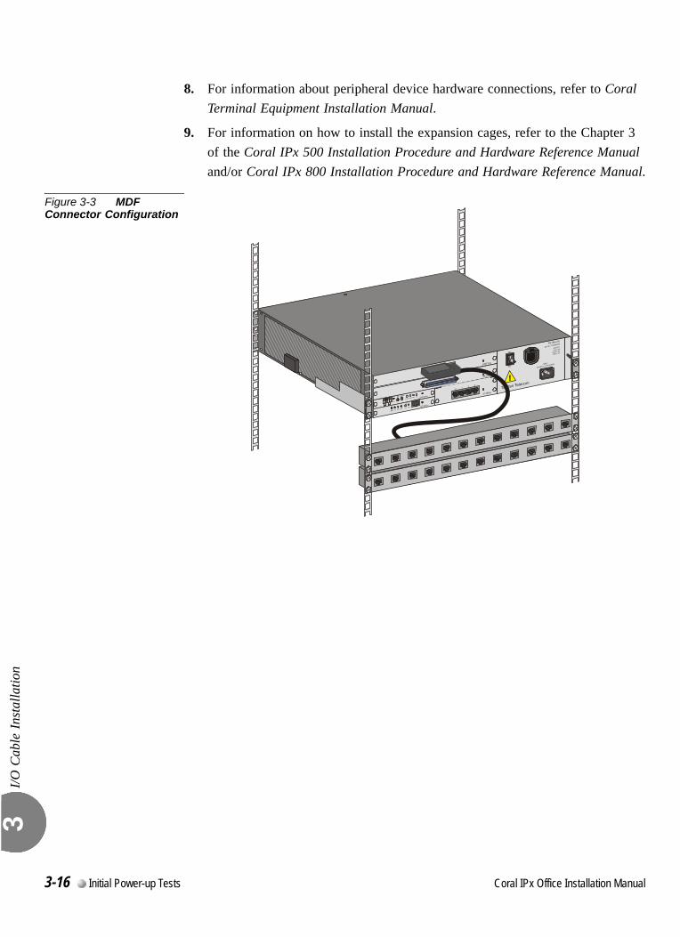
I/O C
able
Inst
alla
tion
3
8. For information about peripheral device hardware connections, refer to Coral Terminal Equipment Installation Manual.
9. For information on how to install the expansion cages, refer to the Chapter 3 of the Coral IPx 500 Installation Procedure and Hardware Reference Manual and/or Coral IPx 800 Installation Procedure and Hardware Reference Manual.
Figure 3-3 MDF Connector Configuration
3-16 Initial Power-up Tests Coral IPx Office Installation Manual
C
3.5
oral IPx Office Installation Ma
Installation Wrap-up
Inst
alla
tion
Wra
p-up
3
1. Remove any other items from the shipping containers.
2. Remove all empty packages, crates, and debris.
3. Verify that you have provided all of the necessary instructions and documentation to the system operator.
Once the system is completely installed and operating, it is no longer necessary to keep the shipping containers.
nual Initial Power-up Tests 3-17

Inst
alla
tion
Wra
p-up
3
NOTES:
3-18 Initial Power-up Tests Coral IPx Office Installation Manual
Coral IPx Office Installation Manual
Chapter
4Software Installation Procedure
4.1 Generic Feature Software ...........................................................4-1
4.2 System Database Control............................................................4-5

C
4.1
oral IPx Office Installation Ma
Generic Feature SoftwareUpgrade
Gen
eric
Fea
ture
Sof
twar
e U
pgra
de4
0
The Coral IPx Office is delivered to the site with factory-loaded software on the IMC8 or IMC16 card. The IMC8 card is an 8MB flash memory card. The IMC16 card is a 16MB flash memory card. See IMC8 and IMC16 Flash Cards, page 8-33 for details. The IMC8 card is installed on the front panel of the IPx Office system.The software initialization procedure is described in Common Control Test, page 3-5.The IMC8 and IMC16 cards contain three types of data:
Generic Feature Software Version and Boot Code
Authorization
Database Backup
The IMC8 or IMC16 card can be inserted into a PC slot using any PCMCIA application adapter for loading a new Coral software version.Whenever an updated version of the IPx Office software is released, the upgrade is delivered to the sites either on 3.5” diskettes, via e-mail, or via other electronic media file transfer applications. The upgrade is contained in a self-extracting compressed file that is specific for the site.The upgraded generic feature software must be extracted by a PC using the FMprog tool, and then written from the PC hard disk onto the IMC8 and IMC16 cards. The FMprog is a tool for Coral dealers who install, upgrade and maintain Coral systems using flash memory cards. See the FMprog PC-Utility Reference Manual. This reference manual describes how to install and operate the FMprog-Utility.
...................................................................................................1 Introduction
nual Software Installation Procedure 4-1
Gen
eric
Fea
ture
Sof
twar
e U
pgra
de4
0
0
Use FMprog version 5.xx and above. Otherwise, the Coral will not initialize.
The upgrade of the generic feature software involves the following main steps:
Installing the FMprog-Utility (version 5.xx and later)
Extracting the new Coral generic feature software file into the PC hard disk
Programming the new generic software upgrade to the IMC8 or IMC16 card
The FMprog-utility can be used to backup the Coral software into PCMCIA cards. The backup file is in a binary format and includes all the software components of the specific Coral system from which it was copied, including the Coral generic software version, the switch authorization, and the database. Copies should be made and maintained at every customer site. Each site has its unique software configuration, including its main software version, switch authorization and database, as well as its specific Software Authorization Unit (SAU) information. Copies of all system files exist and are available for use via the FMprog-Utility, if they are needed.Use the FMprog-Utility to:
Manage your new database versions
Load the Coral generic version, authorization and database information on to flash memory cards
Extract version, authorization, and database information from source files
Removing the IMC8 / IMC16 Card
To remove the IMC8/IMC16 card from the IPx Office unit:
1. Press the Reset button on the front panel of the IPx Office unit.
1. Press the Release button on the front panel of the IPx Office unit to remove the IMC8/IMC16 card.
...................................................................................................2 Upgrading Using the FMprog-Utility
Before each installation or removal of an IMC8 card from the IPx Office unit, press the
RESET button on the front panel of the IPx Office unit.
4-2 Software Installation Procedure Coral IPx Office Installation Manual
Gen
eric
Fea
ture
Sof
twar
e U
pgra
de4
0
This section provides instructions on inserting the IMC8 / IMC16 flash memory card after it has been programmed with a new or upgraded software version.
Creating a Binary Backup of the Database
Before installing an IMC8 or IMC16 card with a new generic software version, it is strongly recommended that you make a binary backup of the database. The binary backup must be done by a PC using the Binary Backup PC-Utility. The Binary Backup is a tool for Coral technicians who install, upgrade and maintain Coral systems. See the Database Binary Backup PC Utility Reference Manual for further details.
Installing the IMC8 / IMC16 Card
1. Press the Release button on the PCMCIA drive of the PC to remove the new IMC8/IMC16 card.
2. Press the Reset button on the on the front panel of the IPx Office unit.
3. Press the Release button on the front panel of the IPx Office unit to remove the old IMC8/IMC16 card.
4. Insert the new IMC8/IMC16 card containing the upgraded generic software version.
5. Press the Reset button on the front panel of the IPx Office unit.
6. Verify that the following two messages appear on the PI device:
For SERVICE/SOFTWARE installation menu HIT <CTRL I> NOW*************************CHK RAMEND CHK RAMCustom Init Code.....
The second message may appear after two or three minutes, following several short messages that appear during system start-up:
CCS is on the air......
...................................................................................................3 Installing an Upgraded IMC8 / IMC16 Card
Before each installation or removal of an IMC8/IMC16 card from the IPx Office unit,
press the RESET button on the front panel of the IPx Office unit.
Coral IPx Office Installation Manual Software Installation Procedure 4-3

Gen
eric
Fea
ture
Sof
twar
e U
pgra
de4
(ROOT)CCS xx.xx.xxCopyright (c) 2001-xxxx...............NAME - (site name)SAU # -
After the second message appears, the system has initialized properly and is capable of processing calls. After entering the password, the version level of the generic feature software is indicated where the x's appear in the line that reads CCS xx.xx.xx.
7. The new IMC8 card does not include a backup of the current database. To make a backup of the database, perform the procedure described in Saving to IMC8 or IMC16, page 4-6.
The program contained on the IMC8 permits the generic software to function even if the serial number of the SAU is incorrect, or the SAU is absent entirely. If, however, the Coral determines that the SAU is missing or not correct, a message appears during the procedure warning that the system will not operate without the proper SAU. This provision allows the generic feature software and/or feature authorizations to be upgraded on an IMC8 card in another distant system, then installed at the proper system by replacing the existing IMC8 card from the other distant system containing the upgrade.
The Universal GateWay (UGW) software is embedded on the MCB Office card. To upgrade the UGW software, see TBD?????
The Coral system automatically ceases call processing after 14 days for any of the
following reasons:
•The SAU serial number does not match the corresponding CFD SAU serial number.
•The Coral generic version contained in the CFD is higher than the version that is
authorized by the SAU.
•An SAU is removed from the IPx Office side panel.
Relevant system messages appear on the PI automatically warning that the system will
not operate without the proper SAU.
...................................................................................................4 Upgrading the UGW Software
4-4 Software Installation Procedure Coral IPx Office Installation Manual
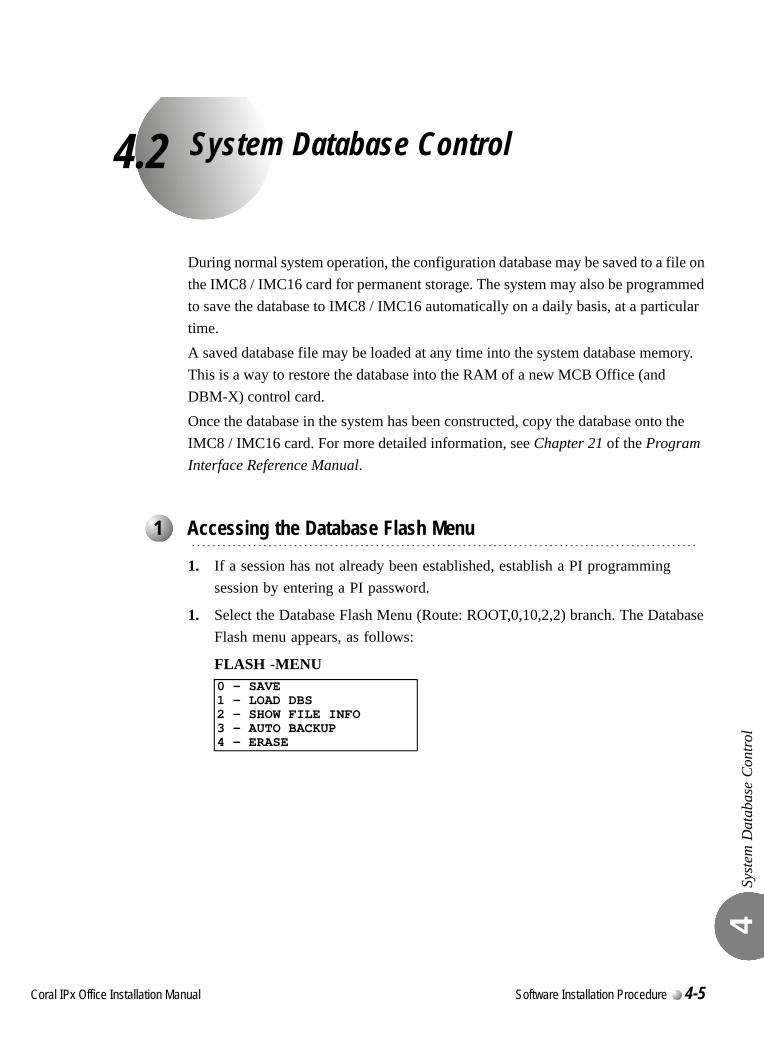
C
4.2
oral IPx Office Installation Ma
System Database Control
Syst
em D
atab
ase
Con
trol
4
During normal system operation, the configuration database may be saved to a file on the IMC8 / IMC16 card for permanent storage. The system may also be programmed to save the database to IMC8 / IMC16 automatically on a daily basis, at a particular time.A saved database file may be loaded at any time into the system database memory. This is a way to restore the database into the RAM of a new MCB Office (and DBM-X) control card.Once the database in the system has been constructed, copy the database onto the IMC8 / IMC16 card. For more detailed information, see Chapter 21 of the Program Interface Reference Manual.
1. If a session has not already been established, establish a PI programming session by entering a PI password.
1. Select the Database Flash Menu (Route: ROOT,0,10,2,2) branch. The Database Flash menu appears, as follows:
FLASH -MENU
...................................................................................................1 Accessing the Database Flash Menu
0 - SAVE1 - LOAD DBS2 - SHOW FILE INFO3 - AUTO BACKUP4 - ERASE
nual Software Installation Procedure 4-5
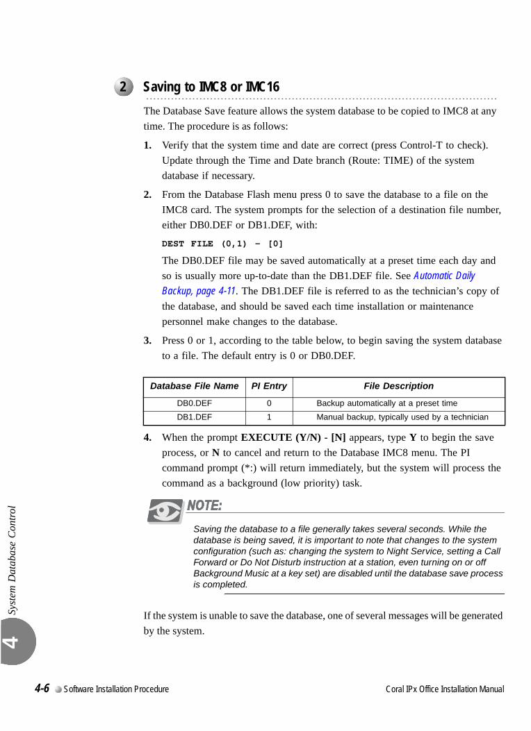
Syst
em D
atab
ase
Con
trol
4
0
The Database Save feature allows the system database to be copied to IMC8 at any time. The procedure is as follows:
1. Verify that the system time and date are correct (press Control-T to check). Update through the Time and Date branch (Route: TIME) of the system database if necessary.
2. From the Database Flash menu press 0 to save the database to a file on the IMC8 card. The system prompts for the selection of a destination file number, either DB0.DEF or DB1.DEF, with:
DEST FILE (0,1) - [0]
The DB0.DEF file may be saved automatically at a preset time each day and so is usually more up-to-date than the DB1.DEF file. See Automatic Daily Backup, page 4-11. The DB1.DEF file is referred to as the technician’s copy of the database, and should be saved each time installation or maintenance personnel make changes to the database.
3. Press 0 or 1, according to the table below, to begin saving the system database to a file. The default entry is 0 or DB0.DEF.
4. When the prompt EXECUTE (Y/N) - [N] appears, type Y to begin the save process, or N to cancel and return to the Database IMC8 menu. The PI command prompt (*:) will return immediately, but the system will process the command as a background (low priority) task.
Saving the database to a file generally takes several seconds. While the database is being saved, it is important to note that changes to the system configuration (such as: changing the system to Night Service, setting a Call Forward or Do Not Disturb instruction at a station, even turning on or off Background Music at a key set) are disabled until the database save process is completed.
If the system is unable to save the database, one of several messages will be generated by the system.
...................................................................................................2 Saving to IMC8 or IMC16
Database File Name PI Entry File Description
DB0.DEF 0 Backup automatically at a preset time
DB1.DEF 1 Manual backup, typically used by a technician
4-6 Software Installation Procedure Coral IPx Office Installation Manual
Syst
em D
atab
ase
Con
trol
4
When the flash memory space is insufficient for saving the database (DBS), the following message will appear:
NO SPACE FOR SAVING DATA BASE
When at least one of the flags cannot be recognized, the following message will appear:
CORRUPTEDDBS
5. When the backup is valid, the save operation continues with:
Caution: Previous backup will be lost:Proceed with backup (Y/N) [N]
Type Y to continue the save operation. The following message appears:
SAVING........
If the backup file is saved successfully, the following message appears:
SAVE OK.....
If the backup file save operation fails, the following message appears:
SAVE FAILED!!
During the save operation, no database updating will occur.
Coral IPx Office Installation Manual Software Installation Procedure 4-7
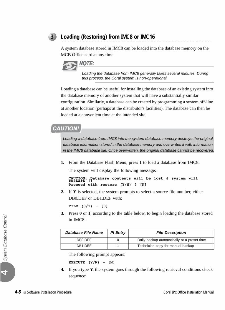
Syst
em D
atab
ase
Con
trol
4
0
A system database stored in IMC8 can be loaded into the database memory on the MCB Office card at any time.
Loading the database from IMC8 generally takes several minutes. During this process, the Coral system is non-operational.
Loading a database can be useful for installing the database of an existing system into the database memory of another system that will have a substantially similar configuration. Similarly, a database can be created by programming a system off-line at another location (perhaps at the distributor's facilities). The database can then be loaded at a convenient time at the intended site.
1. From the Database Flash Menu, press 1 to load a database from IMC8.
The system will display the following message:
CAUTION: Database contents will be lost & system will restart !!!Proceed with restore (Y/N) ? [N]
2. If Y is selected, the system prompts to select a source file number, either DB0.DEF or DB1.DEF with:
FILE (0/1) - [0]
3. Press 0 or 1, according to the table below, to begin loading the database stored in IMC8.
The following prompt appears:
EXECUTE (Y/N) - [N]
4. If you type Y, the system goes through the following retrieval conditions check sequence:
...................................................................................................3 Loading (Restoring) from IMC8 or IMC16
Loading a database from IMC8 into the system database memory destroys the original
database information stored in the database memory and overwrites it with information
in the IMC8 database file. Once overwritten, the original database cannot be recovered.
Database File Name PI Entry File Description
DB0.DEF 0 Daily backup automatically at a preset time
DB1.DEF 1 Technician copy for manual backup
4-8 Software Installation Procedure Coral IPx Office Installation Manual
Syst
em D
atab
ase
Con
trol
4
a. Verify that the internal flags are present in the database to be loaded.
b. Verify that the database is not corrupted (the system executes the checksum test procedure).
If the procedure checking the database ( DBS) retrieval conditions found the above conditions fulfilled, the following message will appear:
Restore DBS.......
Upon finishing the restoring procedure, the system reports:
Restore Successful
Next, the system will execute the partial initialization.
If the conditions mentioned above were not met, one of the following messages will be displayed:
Operation denied DB0.DEF is not O.K.
or
Operation denied DB1.DEF is not O.K.
If only one backup file was present when the technician requested DB1.DEF retrieval, the following message appears:
Operation denied, Load DBS available only to DB0.DEF
5. Press Y to begin loading the database, or press N to return to the Database menu.
Loading the database from a file generally takes several minutes. When the database has been loaded, the system performs a partial initialization and begins processing calls.
Coral IPx Office Installation Manual Software Installation Procedure 4-9

Syst
em D
atab
ase
Con
trol
4
0
This option displays the list of backed up files stored on the IMC8 card.From the Database Flash menu, press 2 to display the list of backed up files. The following prompt appears:
Execute (Y/N)? - [N]
Type Y. A report appears with the following columns:File Name Displays a list of the DB0.DEF and DB1.DEF files
If only one file is present, DB0.DEF will appearVersion File versionLast Date Last backup dateLast-Time Last backup timeFile-Status OK - the backed up file is valid
Invalid - the backed up file is invalid
...................................................................................................4 Show File Information
4-10 Software Installation Procedure Coral IPx Office Installation Manual

Syst
em D
atab
ase
Con
trol
4
0
The system configuration database can be automatically saved to a database file on the IMC8 at a preset time each day. Use AutoBackup to automatically save the database. During automatic daily backup the database is saved to DB0.DEF.
1. From the Database Menu, press 3 to set the Auto Backup time. The following prompt appears:
NUMBER OF DAYS BETWEEN BACKUPS [1..to..255, N]
Set the number of days between automatic backups. The default is set to 7 days between backups, so that an automatic backup file is created every week. If no automatic backups are needed, enter N for creating manual backups.
Selection of the backup type is required; either a manual backup performed by the technician or an automatic daily backup. The default after First Initialization is automatic daily backup every week.
6. Enter N to enable the manual backup or number between 1 to 255 to enable a daily backup.
The system prompts for the time of day with:
SET AUTO BACKUP TIME:TIME:
7. Enter the time of day to automatically save the system database in the 24 hour, military time format. Use 24:00 for midnight and 24:01 to 24:59 for times between midnight and 1:00 a.m. The default time is 01:30, or 1:30 a.m.
8. The system will return to the Database Backup menu. Press 0 to return to the Database menu.
...................................................................................................5 Automatic Daily Backup
Coral IPx Office Installation Manual Software Installation Procedure 4-11

Syst
em D
atab
ase
Con
trol
4
0
This function enables erasing of backed up files stored on the IMC8 card:
1. From the Database menu, press 4 to erase the flash memory.
The following prompt appears:
Proceed with Erase (0/1/A/N/) ? [N]
9. Specify one of the options, as follows:
0 - erases DB0.DEF.
1 - erases DB1.DEF.
A - erases both DB0.DEF and DB1.DEF.
N - cancels the operation.
After you specify 0, 1, or A, the following message appears:
Erasing ..
Upon completion of the erasing the following message appears:
Erase Completed ....
If the erasing operation was not successful the following message appears:
Erase failed !!
...................................................................................................6 Erasing Flash Memory
Performing the following procedure will erase the Flash DBS backup. Before erasing, verify that the database is no longer needed.
4-12 Software Installation Procedure Coral IPx Office Installation Manual
Syst
em D
atab
ase
Con
trol
4
In the future, IPx Office systems will include an optional hard disk that is installed onto the MCB Office card. The hard disk will be backed up with the compact flash card.
TBD
...................................................................................................7 Backing up the Hard Disk onto the Compact Flash Card
...................................................................................................8 Loading (Restoring) from the Compact Flash Card
Coral IPx Office Installation Manual Software Installation Procedure 4-13

Syst
em D
atab
ase
Con
trol
4
4-14 Software Installation Procedure Coral IPx Office Installation Manual
Coral IPx Office Installation Manual
Chapter
5External Connections
Cora
lC
or
5.1 Main Distribution Frame (MDF) ...................................................5-1
5.2 External Equipment .....................................................................5-5
5.3 Protection Devices..................................................................... 5-11
5.4 Power Fail (PF) Transfer Circuits ..............................................5-15
5.5 Data Communication Ports........................................................5-17
5.6 I/O Card Connections ................................................................5-19
5.7 LAN, WAN, and Printer Connections.........................................5-35

5.1
Main Distribution Frame (MDF)Mai
n D
istr
ibut
ion
Fram
e (M
DF)
5
This chapter describes the MDF and the pinout connections to the cage and external equipment. For hardware installation instructions, refer to Hardware Installation Procedure, page 2-1.
This chapter describes connections between the Coral IPx Office unit and the customer-supplied MDF. Some of these connections can be made directly from the Coral IPx Office unit and the facilities’ infrastructure, without the use of an MDF. It is the customer’s responsibility to decide when to do so.For information on connections between the IPx 500X expansion cage and the MDF see the Coral IPX 500 Installation Procedure and Hardware Manual. For information on the Coral IPx 800X expansion cage and the MDF, see the Coral IPx 800 Installation Procedure and Hardware Manual.
The MDF is often located adjacent to other signaling systems, such as:
Paging and public address systems
Voice messaging systems
Alarm and monitoring systems
Closed circuit television
Property management systems
Building and energy management systems
External Connections 5-1
Mai
n D
istr
ibut
ion
Fram
e (M
DF)
5
Therefore, care should be taken to plan the MDF layout before fastening components to the rack or table-mounted surface, such as:
Network (LAN/WAN) Connection
Trunk circuits
Wired and wireless station equipment
Database programming terminals
Report printers
Music and/or audio sources
External public address or paging equipment
Recording devices
Connections to most telecommunications interfaces of the Coral IPx Office unit are made via:
Standard 25 pair Input/Output (I/O) Champ (telco) connectors located on the front panel of the full size peripheral cards. See Table 5-1 and Figure 5-1
RJ-45 connectors located on the front panel of full and half size peripheral cards. See Table 5-1 and Figure 5-1.
For information on LAN/WAN connections, see Chapter 11, System Networking.
Tip:It is recommended to terminate all the I/O connectors available in the
system on punch blocks at the MDF even if some cables are not initially
used. This saves time and effort when the system expands.
5-2 Coral IPx Office Installation Manual
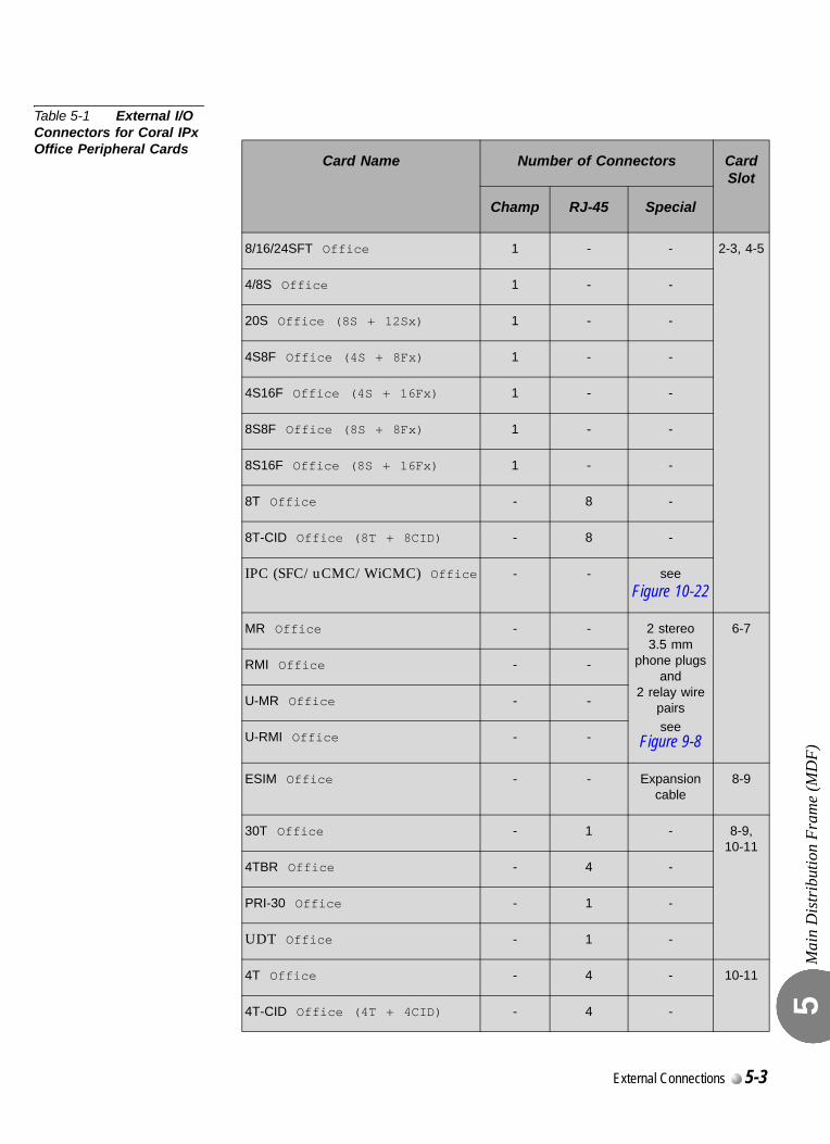
Mai
n D
istr
ibut
ion
Fram
e (M
DF)
5
Table 5-1 External I/O Connectors for Coral IPx Office Peripheral Cards
Card Name Number of Connectors Card Slot
Champ RJ-45 Special
8/16/24SFT Office 1 - - 2-3, 4-5
4/8S Office 1 - -
20S Office (8S + 12Sx) 1 - -
4S8F Office (4S + 8Fx) 1 - -
4S16F Office (4S + 16Fx) 1 - -
8S8F Office (8S + 8Fx) 1 - -
8S16F Office (8S + 16Fx) 1 - -
8T Office - 8 -
8T-CID Office (8T + 8CID) - 8 -
IPC (SFC/uCMC/WiCMC) Office - - see
Figure 10-22
MR Office - - 2 stereo 3.5 mm
phone plugs and
2 relay wire pairs
see Figure 9-8
6-7
RMI Office - -
U-MR Office - -
U-RMI Office - -
ESIM Office - - Expansion cable
8-9
30T Office - 1 - 8-9, 10-11
4TBR Office - 4 -
PRI-30 Office - 1 -
UDT Office - 1 -
4T Office - 4 - 10-11
4T-CID Office (4T + 4CID) - 4 -
External Connections 5-3
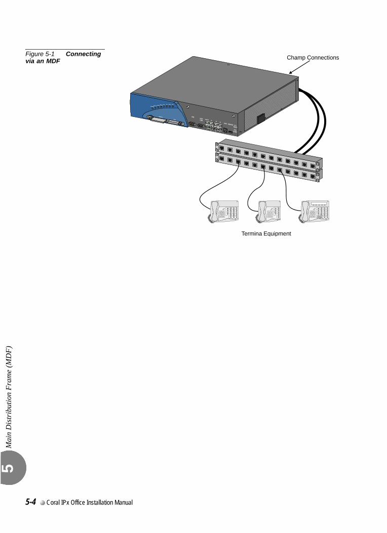
Mai
n D
istr
ibut
ion
Fram
e (M
DF)
5
Figure 5-1 Connecting via an MDF Champ Connections
Termina Equipment
5-4 Coral IPx Office Installation Manual
5.2
External EquipmentExte
rnal
Equ
ipm
ent
5
0
Wired Stations
Each station peripheral card provides an I/O ChampTM connector.Connections to Coral IPx Office system station equipment are established by cross-connecting the station circuit from the appropriate Coral IPx Office I/O cable punch block to the corresponding station wiring punch block.Table 5-2 lists the various station interface cards available for the Coral IPx Office system, the type of station equipment that the card supports, and the number of wire pairs required by the station interface.Station wiring between the Coral IPx Office system MDF and the station equipment should contain at least two, and preferably three wire pairs to ensure adequate wiring capacity. At the station location, the station wiring should be terminated with a modular, six position, telephone jack, containing at least four conductors (pins 2, 3, 4, and 5).Figure 5-2 illustrates typical jack configurations with wire designations for four station types:
2-wire single-line telephones SLT and digital station sets (FlexSet, APDL, CPA) need only connect Tip [T] and Ring [R] or <UpA> and <UpB> as shown.
FlexSet 280 series or FlexSet APDL units with PEX or PEX+APA need an extra 2 wires when power is supplied through the line connector. The polarity of this connection is irrelevant. When using the TPS (single unit Telephone Power Supply), no additional wires are required.
For peripheral device installation, refer to the Coral Terminal Equipment Installation Manual”.To prevent a potential shock hazard to station users and damage to the system, make sure that station circuits extended over cables that exit the building are adequately
...................................................................................................1 Station Equipment
External Connections 5-5
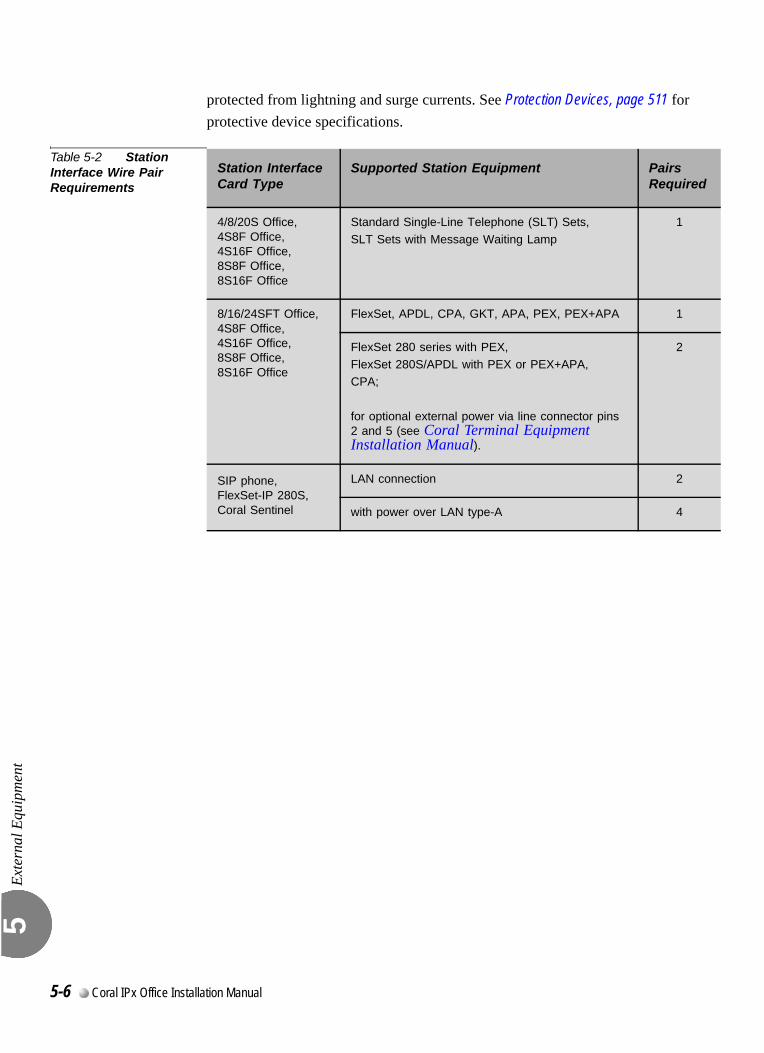
Exte
rnal
Equ
ipm
ent
5
protected from lightning and surge currents. See Protection Devices, page 511 for protective device specifications.
Table 5-2 Station Interface Wire Pair Requirements
Station InterfaceCard Type
Supported Station Equipment PairsRequired
4/8/20S Office,4S8F Office,4S16F Office, 8S8F Office, 8S16F Office
Standard Single-Line Telephone (SLT) Sets,
SLT Sets with Message Waiting Lamp
1
8/16/24SFT Office,4S8F Office,4S16F Office, 8S8F Office, 8S16F Office
FlexSet, APDL, CPA, GKT, APA, PEX, PEX+APA 1
FlexSet 280 series with PEX,
FlexSet 280S/APDL with PEX or PEX+APA,CPA;
for optional external power via line connector pins 2 and 5 (see Coral Terminal Equipment Installation Manual).
2
SIP phone,FlexSet-IP 280S,Coral Sentinel
LAN connection 2
with power over LAN type-A 4
5-6 Coral IPx Office Installation Manual
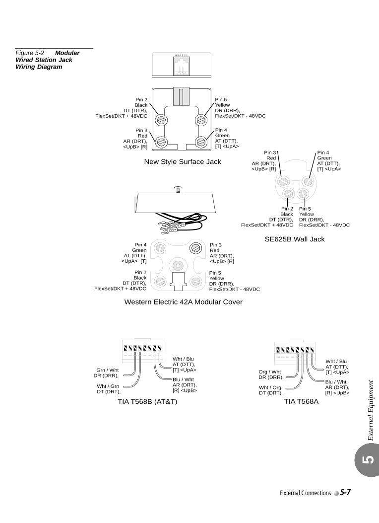
Exte
rnal
Equ
ipm
ent
5
Figure 5-2 Modular Wired Station Jack Wiring Diagram
6 5 4 3 2 1
Pin 2Black
DT (DTR),FlexSet/DKT + 48VDC
Pin 2Black
DT (DTR),FlexSet/DKT + 48VDC
Pin 2Black
DT (DTR),FlexSet/DKT + 48VDC
Pin 3Red
AR (DRT),<UpB> [R]
Pin 3Red
AR (DRT),<UpB> [R]
Pin 3RedAR (DRT),<UpB> [R]
Blu / WhtAR (DRT),
<UpB>[R]
Blu / WhtAR (DRT),[R] <UpB>
Pin 4GreenAT (DTT),[T] <UpA>
Pin 4Green
AT (DTT),<UpA> [T]
Wht / BluAT (DTT),[T] <UpA>
Wht / BluAT (DTT),[T] <UpA>
Pin 4GreenAT (DTT),[T] <UpA>
Pin 5YellowDR (DRR),FlexSet/DKT - 48VDC
Pin 5YellowDR (DRR),FlexSet/DKT - 48VDC
Pin 5YellowDR (DRR),FlexSet/DKT - 48VDC
Org / WhtDR (DRR),
Grn / WhtDR (DRR),
Wht / OrgDT (DRT),
Wht / GrnDT (DRT),
TIA T568ATIA T568B (AT&T)
Western Electric 42A Modular Cover
SE625B Wall Jack
New Style Surface Jack
External Connections 5-7
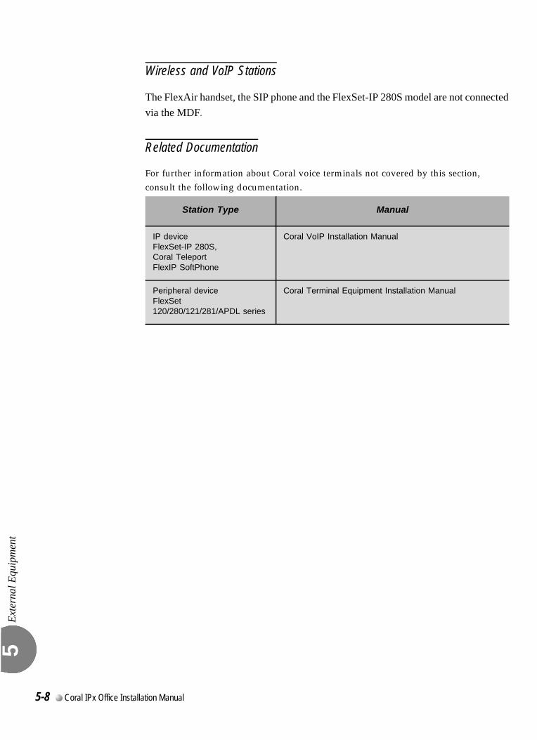
Exte
rnal
Equ
ipm
ent
5
Wireless and VoIP Stations
The FlexAir handset, the SIP phone and the FlexSet-IP 280S model are not connected via the MDF.
Related Documentation
For further information about Coral voice terminals not covered by this section, consult the following documentation.
Station Type Manual
IP device FlexSet-IP 280S,Coral TeleportFlexIP SoftPhone
Coral VoIP Installation Manual
Peripheral deviceFlexSet 120/280/121/281/APDL series
Coral Terminal Equipment Installation Manual
5-8 Coral IPx Office Installation Manual
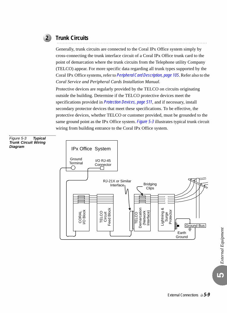
Exte
rnal
Equ
ipm
ent
5
Generally, trunk circuits are connected to the Coral IPx Office system simply by cross-connecting the trunk interface circuit of a Coral IPx Office trunk card to the point of demarcation where the trunk circuits from the Telephone utility Company (TELCO) appear. For more specific data regarding all trunk types supported by the Coral IPx Office systems, refer to Peripheral Card Description, page 105. Refer also to the Coral Service and Peripheral Cards Installation Manual.Protective devices are regularly provided by the TELCO on circuits originating outside the building. Determine if the TELCO protective devices meet the specifications provided in Protection Devices, page 511, and if necessary, install secondary protector devices that meet these specifications. To be effective, the protective devices, whether TELCO or customer provided, must be grounded to the same ground point as the IPx Office system. Figure 5-3 illustrates typical trunk circuit wiring from building entrance to the Coral IPx Office system.
Figure 5-3 Typical Trunk Circuit Wiring Diagram
...................................................................................................2 Trunk Circuits
IPx Office System
I/O RJ-45Connector
RJ-21X or SimilarInterface Bridging
Clips
EarthGround
Ground Bus
Ground Terminal
Ligh
tnin
g &
Sur
geP
rote
ctor
TELC
OD
emar
catio
n(N
etw
ork
Inte
rface
)
TELC
OC
ircui
tFe
ed B
lock
CO
RA
LI/O
Blo
ck
External Connections 5-9
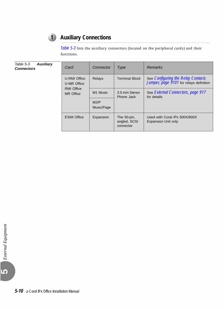
Exte
rnal
Equ
ipm
ent
5
Table 5-3 lists the auxiliary connectors (located on the peripheral cards) and their functions.
Table 5-3 Auxiliary Connectors
...................................................................................................1 Auxiliary Connections
Card Connector Type Remarks
U-RMI Office
U-MR OfficeRMI Office
MR Office
Relays Terminal Block See Configuring the Relay Contacts Jumper, page 9101 for relays definition
M1 Music 3.5 mm Stereo Phone Jack
See External Connectors, page 917 for details
M2/PMusic/Page
ESIM Office Expansion The 50-pin, angled, SCSI connector
Used with Coral IPx 500X/800X Expansion Unit only
5-10 Coral IPx Office Installation Manual
5.3
Protection DevicesProt
ectio
n D
evic
es
5
0
.
Lightning and over-voltage arrestors are used to protect the user and the system from lightning and other electrical hazards that may occur on external circuits connected to the system.
Any cable that passes through open air, under open ground (i.e. across parking lots, fields, road beds, etc.), across a bridge, or along the exterior or under the non-metallic roof of a building, is exposed to lightning and electrical hazards.
Telephone circuit protection devices fall into two distinct design categories:
Primary (lightning) protection devices that limit voltages on a telephone circuit below levels which do not present a hazard to the user. (Table 5-4 lists minimum specifications).
Secondary (surge and impulse) protectors that further limit voltages on a telephone circuit to prevent damage to electronic equipment. Table 5-5 lists the specifications.
Primary protection absorbs the major impact of infrequent, but dangerous, catastrophic surges, while secondary protection suppresses constantly occurring
...................................................................................................1 Introduction to Primary and Secondary Protection Devices
Any circuit connected to the Coral system that is exposed to lightning or electrical
hazards must be protected with approved lightning and surge protection devices to
avoid potentially lethal hazards to all users.
Secondary protection devices should be installed on any circuit requiring primary
lightning protection, which connects electrically to an interface of the Coral system.
External Connections 5-11
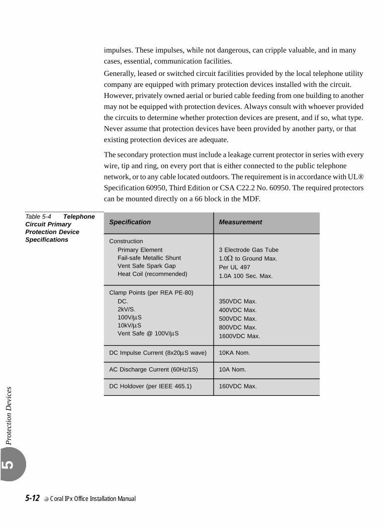
Prot
ectio
n D
evic
es
5
impulses. These impulses, while not dangerous, can cripple valuable, and in many cases, essential, communication facilities.Generally, leased or switched circuit facilities provided by the local telephone utility company are equipped with primary protection devices installed with the circuit. However, privately owned aerial or buried cable feeding from one building to another may not be equipped with protection devices. Always consult with whoever provided the circuits to determine whether protection devices are present, and if so, what type. Never assume that protection devices have been provided by another party, or that existing protection devices are adequate.
The secondary protection must include a leakage current protector in series with every wire, tip and ring, on every port that is either connected to the public telephone network, or to any cable located outdoors. The requirement is in accordance with UL® Specification 60950, Third Edition or CSA C22.2 No. 60950. The required protectors can be mounted directly on a 66 block in the MDF.
Table 5-4 Telephone Circuit Primary Protection Device Specifications
Specification Measurement
ConstructionPrimary ElementFail-safe Metallic ShuntVent Safe Spark GapHeat Coil (recommended)
3 Electrode Gas Tube
1.0Ω to Ground Max.
Per UL 497
1.0A 100 Sec. Max.
Clamp Points (per REA PE-80)
DC.2kV/S.100V/µS10kV/µSVent Safe @ 100V/µS
350VDC Max.
400VDC Max.500VDC Max.
800VDC Max.
1600VDC Max.
DC Impulse Current (8x20µS wave) 10KA Nom.
AC Discharge Current (60Hz/1S) 10A Nom.
DC Holdover (per IEEE 465.1) 160VDC Max.
5-12 Coral IPx Office Installation Manual
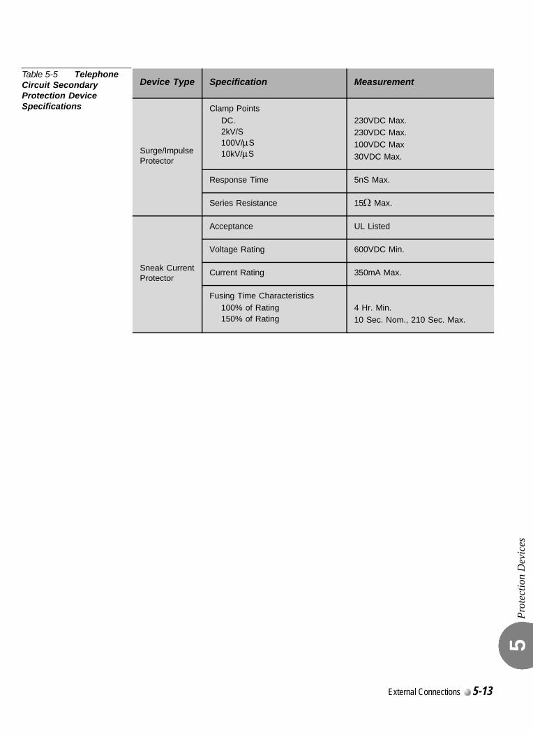
Prot
ectio
n D
evic
es
5
Table 5-5 Telephone Circuit Secondary Protection Device Specifications
Device Type Specification Measurement
Surge/ImpulseProtector
Clamp Points
DC.2kV/S100V/µS10kV/µS
230VDC Max.230VDC Max.
100VDC Max
30VDC Max.
Response Time 5nS Max.
Series Resistance 15Ω Max.
Sneak CurrentProtector
Acceptance UL Listed
Voltage Rating 600VDC Min.
Current Rating 350mA Max.
Fusing Time Characteristics100% of Rating150% of Rating
4 Hr. Min.
10 Sec. Nom., 210 Sec. Max.
External Connections 5-13

Prot
ectio
n D
evic
es
5
To prevent serious damage to the Coral IPx Office system, the analog trunk and station circuits whose cables are laid outside the building, must be protected from the electrical peaks caused by lightning. Magazine 10 surge arrestors must be mounted on the MDF where telephone circuits are cross-connected.
Figure 5-4 Magazine with 10 Surge Arrestor and Voltage Protector Units
The mounting procedure is as follows:
1. Identify the MDF disconnecting strips used for telephone connections.
2. Place a magazine 10 surge arrestor (catalog no. 7244-3190009) on each MDF strip used for telephone.
3. Identify the MDF cross connection points that are used for each telephone. The connecting cables will be visible.
4. Insert a surge voltage protector (catalog no. 7244-2350001) in the magazine 10 surge arrestor where a telephone is connected.
...................................................................................................2 Surge Arrestor Magazine
1 2 3 4 5 6 7 8 9 10
KroneBlock
Magazine 10Surge Arrestor
Surge VoltageProtector
5-14 Coral IPx Office Installation Manual
5.4
Power Fail (PF) Transfer CircuitsPow
er F
ail (
PF) T
rans
fer C
ircui
ts
5
With the installation of trunk cards to support the PF (Power Fail) transfer option, four trunks per trunk card may be directed to station sets if power to the Coral IPx Office system is interrupted. This arrangement, referred to as power failure transfer, completely bypasses the system, allowing specific stations to originate outgoing calls and/or continue answering incoming calls.0
StationsThe SLT (single line telephone) set can be used as a power failure station. Figure 5-5 illustrates wiring interconnections between the trunk card, station card, and a single line station set.
Coral FlexSet cannot be used as power failure stations.
TrunksIn the Coral IPx Office system, the following analog trunk peripheral cards support power fail transfer:
The following four-trunk cards each provide four (4) ports with PF transfer connections:4T Office and 4T-CID Office (in slots 10-11)
The following eight-trunk cards each provide four (4) ports with PF transfer connections:8T Office and 8T-CID Office (in slots 2-3 and 4-5)NOTE: only circuits 2, 3, 4, and 5 support power failure transfer connections.
0
...................................................................................................1 Physical Connection
External Connections 5-15
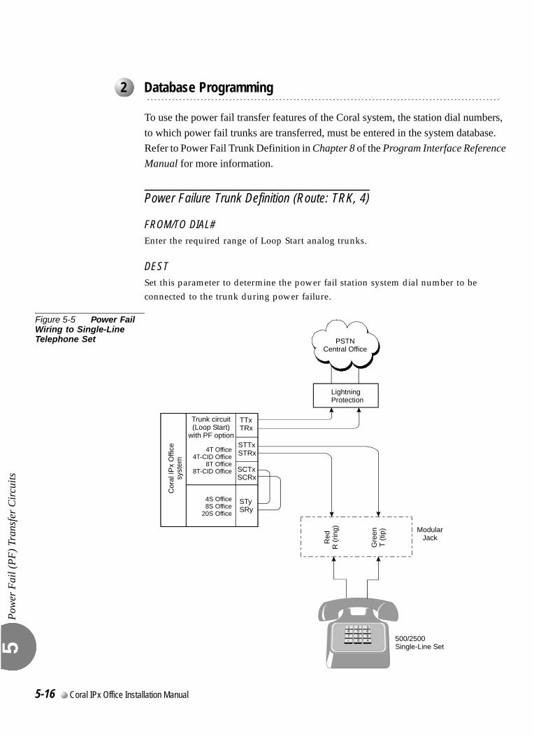
Pow
er F
ail (
PF) T
rans
fer C
ircui
ts
5
0
To use the power fail transfer features of the Coral system, the station dial numbers, to which power fail trunks are transferred, must be entered in the system database. Refer to Power Fail Trunk Definition in Chapter 8 of the Program Interface Reference Manual for more information.
Power Failure Trunk Definition (Route: TRK, 4)
FROM/TO DIAL#Enter the required range of Loop Start analog trunks.
DESTSet this parameter to determine the power fail station system dial number to be connected to the trunk during power failure.
Figure 5-5 Power Fail Wiring to Single-Line Telephone Set
...................................................................................................2 Database Programming
Lightning Protection
Trunk circuit(Loop Start)
with PF option
4T Office4T-CID
8T8T-CID
Office Office Office
Cor
al IP
x O
ffice
syst
em
Red
R (r
ing)
Gre
enT
(tip) Modular
Jack
500/2500Single-Line Set
4S Office8S Office
20S Office
STySRy
SCTxSCRx
STTxSTRx
TTxTRx
1 2 34 5 67 8 9* 0 #
PSTNCentral Office
5-16 Coral IPx Office Installation Manual
5.5
Data Communication PortsRS-232EDat
a C
omm
unic
atio
n Po
rts R
S-23
2E5
The Coral IPx Office switching system is capable of switching digital data information as well as voice signals. Coral IPx Office system data communication devices are available for packet switched data for low volume applications. The packet data communication devices are provided using the APA (Application Processor Adapter) or APDL (Applications Processor Data Link). The data communication devices provide a serial interface wired as Data Communication Equipment (DCE). That is, transmit data is data that is sent to the APA/APDL, and receive data is data that is received from the device.The APA provides a proprietary data link to an external applications processor. The link uses an asynchronous RS-232E (V.24) serial data interface, operating at a data rate of up to 19.2Kbps. The interface appears at an RJ-45 jack connector on the rear panel of the and FlexSet 280S/281S/APDL with APA or PEX+APA.Through the link, a proprietary signaling protocol allows the Coral system master processor to send call status messages to the applications processor, and the applications processor to send call control instructions to the APA/APDL. Application processors available for the Coral system include the Computerized Attendant Position (CAP), the ACD group supervisor and management position, Coral CallMaster (CCM), Coral World Wide Office (WWO), TAPIdriver, GKT PC-Utility, or any other application that complies with proprietary API products.Use the following RS-232 cables:
Catalog no. 7244-6914055 for FlexSet 280S/281S/APDL with APA or PEX+APA with APA or FlexSet 80 (GKT).
Figure 5-6 lists the pin designations for the RS-232 interface of the APA/APDL.For more information, refer to the Coral Terminal Equipment - Installation Manual.
External Connections 5-17
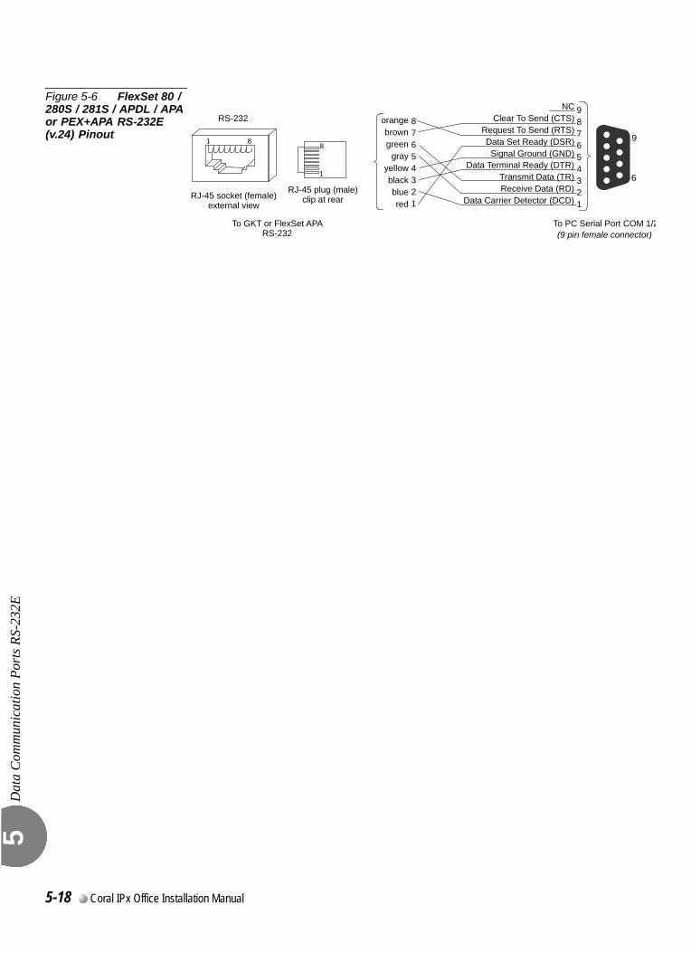
Dat
a C
omm
unic
atio
n Po
rts R
S-23
2E5
Figure 5-6 FlexSet 80 / 280S / 281S / APDL / APA or PEX+APA RS-232E (v.24) Pinout 9
6
87654321
987654321
Data Terminal Ready (DTR)Transmit Data (TR) Receive Data (RD)
Data Carrier Detector (DCD)
NCClear To Send (CTS)
Request To Send (RTS)Data Set Ready (DSR)Signal Ground (GND)
To PC Serial Port COM 1/2To GKT or FlexSet APA RS-232 (9 pin female connector)
1
RS-232
88
1
RJ-45 socket (female)external view
RJ-45 plug (male)clip at rear
orangebrowngreen
grayyellowblackbluered
5-18 Coral IPx Office Installation Manual
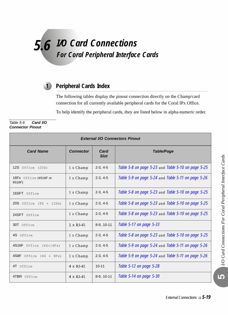
5.6
I/O Card ConnectionsFor Coral Peripheral Interface CardsI/O C
ard
Con
nect
ions
For
Cor
al P
erip
hera
l Int
erfa
ce C
ards
5
0
The following tables display the pinout connection directly on the Champ/card connection for all currently available peripheral cards for the Coral IPx Office.
To help identify the peripheral cards, they are listed below in alpha-numeric order.
Table 5-6 Card I/O Connector Pinout
...................................................................................................1 Peripheral Cards Index
External I/O Connectors Pinout
Card Name Connector Card Slot
Table/Page
12S Office (20S) 1 x Champ 2-3, 4-5 Table 5-8 on page 5-23 and Table 5-10 on page 5-25
16Fx Office (4S16F or 8S16F)
1 x Champ 2-3, 4-5 Table 5-9 on page 5-24 and Table 5-11 on page 5-26
16SFT Office 1 x Champ 2-3, 4-5 Table 5-8 on page 5-23 and Table 5-10 on page 5-25
20S Office (8S + 12Sx) 1 x Champ 2-3, 4-5 Table 5-8 on page 5-23 and Table 5-10 on page 5-25
24SFT Office 1 x Champ 2-3, 4-5 Table 5-8 on page 5-23 and Table 5-10 on page 5-25
30T Office 1 x RJ-45 8-9, 10-11 Table 5-17 on page 5-33
4S Office 1 x Champ 2-3, 4-5 Table 5-8 on page 5-23 and Table 5-10 on page 5-25
4S16F Office (4S+16Fx) 1 x Champ 2-3, 4-5 Table 5-9 on page 5-24 and Table 5-11 on page 5-26
4S8F Office (4S + 8Fx) 1 x Champ 2-3, 4-5 Table 5-9 on page 5-24 and Table 5-11 on page 5-26
4T Office 4 x RJ-45 10-11 Table 5-12 on page 5-28
4TBR Office 4 x RJ-45 8-9, 10-11 Table 5-14 on page 5-30
External Connections 5-19
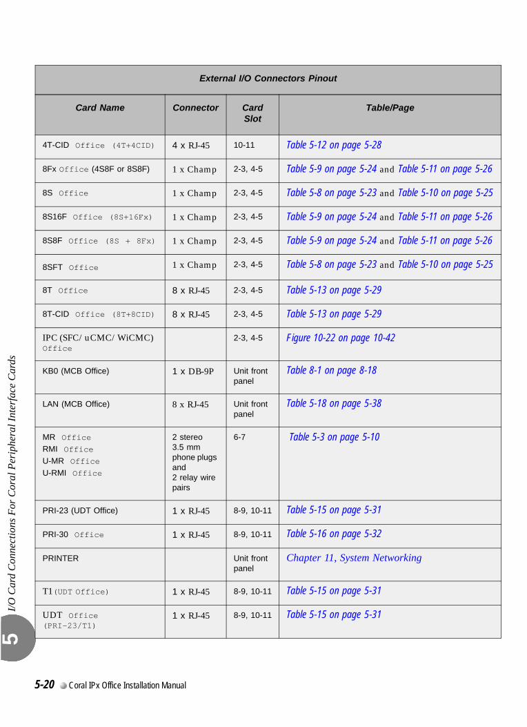
I/O C
ard
Con
nect
ions
For
Cor
al P
erip
hera
l Int
erfa
ce C
ards
5
4T-CID Office (4T+4CID) 4 x RJ-45 10-11 Table 5-12 on page 5-28
8Fx Office (4S8F or 8S8F) 1 x Champ 2-3, 4-5 Table 5-9 on page 5-24 and Table 5-11 on page 5-26
8S Office 1 x Champ 2-3, 4-5 Table 5-8 on page 5-23 and Table 5-10 on page 5-25
8S16F Office (8S+16Fx) 1 x Champ 2-3, 4-5 Table 5-9 on page 5-24 and Table 5-11 on page 5-26
8S8F Office (8S + 8Fx) 1 x Champ 2-3, 4-5 Table 5-9 on page 5-24 and Table 5-11 on page 5-26
8SFT Office 1 x Champ 2-3, 4-5 Table 5-8 on page 5-23 and Table 5-10 on page 5-25
8T Office 8 x RJ-45 2-3, 4-5 Table 5-13 on page 5-29
8T-CID Office (8T+8CID) 8 x RJ-45 2-3, 4-5 Table 5-13 on page 5-29
IPC (SFC/uCMC/WiCMC) Office
2-3, 4-5 Figure 10-22 on page 10-42
KB0 (MCB Office) 1 x DB-9P Unit front panel
Table 8-1 on page 8-18
LAN (MCB Office) 8 x RJ-45 Unit front panel
Table 5-18 on page 5-38
MR OfficeRMI Office
U-MR Office
U-RMI Office
2 stereo 3.5 mm phone plugs and 2 relay wire pairs
6-7 Table 5-3 on page 5-10
PRI-23 (UDT Office) 1 x RJ-45 8-9, 10-11 Table 5-15 on page 5-31
PRI-30 Office 1 x RJ-45 8-9, 10-11 Table 5-16 on page 5-32
PRINTER Unit front panel
Chapter 11, System Networking
T1(UDT Office) 1 x RJ-45 8-9, 10-11 Table 5-15 on page 5-31
UDT Office (PRI-23/T1)
1 x RJ-45 8-9, 10-11 Table 5-15 on page 5-31
External I/O Connectors Pinout
Card Name Connector Card Slot
Table/Page
5-20 Coral IPx Office Installation Manual
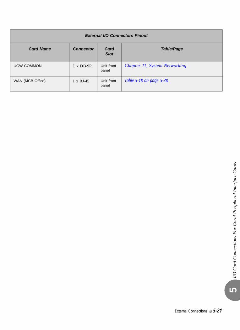
I/O C
ard
Con
nect
ions
For
Cor
al P
erip
hera
l Int
erfa
ce C
ards
5
UGW COMMON 1 x DB-9P Unit front panel
Chapter 11, System Networking
WAN (MCB Office) 1 x RJ-45 Unit front panel
Table 5-18 on page 5-38
External I/O Connectors Pinout
Card Name Connector Card Slot
Table/Page
External Connections 5-21
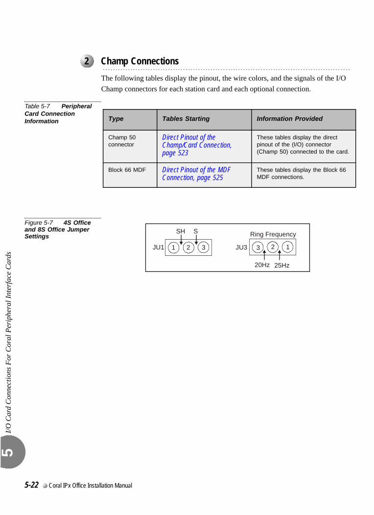
I/O C
ard
Con
nect
ions
For
Cor
al P
erip
hera
l Int
erfa
ce C
ards
5
0
The following tables display the pinout, the wire colors, and the signals of the I/O Champ connectors for each station card and each optional connection.
Table 5-7 Peripheral Card Connection Information
Figure 5-7 4S Office and 8S Office Jumper Settings
...................................................................................................2 Champ Connections
Type Tables Starting Information Provided
Champ 50 connector
Direct Pinout of the Champ/Card Connection, page 523
These tables display the direct pinout of the (I/O) connector (Champ 50) connected to the card.
Block 66 MDF Direct Pinout of the MDF Connection, page 525
These tables display the Block 66 MDF connections.
SH S
JU1 1 2 3
20Hz
JU3
Ring Frequency
25Hz
123
5-22 Coral IPx Office Installation Manual
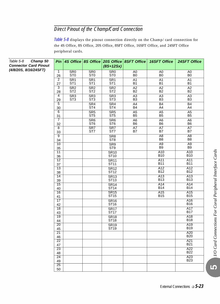
I/O C
ard
Con
nect
ions
For
Cor
al P
erip
hera
l Int
erfa
ce C
ards
5
Direct Pinout of the Champ/Card Connection
Table 5-8 displays the pinout connection directly on the Champ/card connection for the 4S Office, 8S Office, 20S Office, 8SFT Office, 16SFT Office, and 24SFT Office peripheral cards.
Table 5-8 Champ 50 Connector Card Pinout (4/8/20S, 8/16/24SFT)
Pin 4S Office 8S Office 20S Office(8S+12Sx)
8SFT Office 16SFT Office 24SFT Office
126
SR0ST0
SR0ST0
SR0ST0
A0B0
A0B0
A0B0
227
SR1ST1
SR1ST1
SR1ST1
A1B1
A1B1
A1B1
328
SR2ST2
SR2ST2
SR2ST2
A2B2
A2B2
A2B2
429
SR3ST3
SR3ST3
SR3ST3
A3B3
A3B3
A3B3
530
SR4ST4
SR4ST4
A4B4
B4A4
B4A4
631
SR5ST5
SR5ST5
A5B5
A5B5
A5B5
732
SR6ST6
SR6ST6
A6B6
A6B6
A6B6
833
SR7ST7
SR7ST7
A7B7
A7B7
A7B7
934
SR8ST8
A8B8
A8B8
1035
SR9ST9
A9B9
A9B9
1136
SR10ST10
A10B10
A10B10
1237
SR11ST11
A11B11
A11B11
1338
SR12ST12
A12B12
A12B12
1439
SR13ST13
A13B13
A13B13
1540
SR14ST14
A14B14
A14B14
1641
SR15ST15
A15B15
A15B15
1742
SR16ST16
A16B16
1843
SR17ST17
A17B17
1944
SR18ST18
A18B18
2045
SR19ST19
A19B19
2146
A20B20
2247
A21B21
2348
A22B22
2449
A23B23
2550
External Connections 5-23
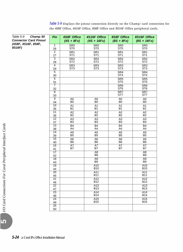
I/O C
ard
Con
nect
ions
For
Cor
al P
erip
hera
l Int
erfa
ce C
ards
5
Table 5-9 displays the pinout connection directly on the Champ/card connection for the 4S8F Office, 4S16F Office, 8S8F Office and 8S16F Office peripheral cards.
Table 5-9 Champ 50 Connector Card Pinout (4S8F, 4S16F, 8S8F, 8S16F)
Pin 4S8F Office(4S + 8Fx)
4S16F Office(4S + 16Fx)
8S8F Office(8S + 8Fx)
8S16F Office(8S + 16Fx)
126
SR0ST0
SR0ST0
SR0ST0
SR0ST0
227
SR1ST1
SR1ST1
SR1ST1
SR1ST1
328
SR2ST2
SR2ST2
SR2ST2
SR2ST2
429
SR3ST3
SR3ST3
SR3ST3
SR3ST3
530
SR4ST4
SR4ST4
631
SR5ST5
SR5ST5
732
SR6ST6
SR6ST6
833
SR7ST7
SR7ST7
934
A0B0
A0B0
A0B0
A0B0
1035
A1B1
A1B1
A1B1
A1B1
1136
A2B2
A2B2
A2B2
A2B2
1237
A3B3
A3B3
A3B3
A3B3
1338
B4A4
B4A4
B4A4
B4A4
1439
A5B5
A5B5
A5B5
A5B5
1540
A6B6
A6B6
A6B6
A6B6
1641
A7B7
A7B7
A7B7
A7B7
1742
A8B8
A8B8
1843
A9B9
A9B9
1944
A10B10
A10B10
2045
A11B11
A11B11
2146
A12B12
A12B12
2247
A13B13
A13B13
2348
A14B14
A14B14
2449
A15B15
A15B15
2550
5-24 Coral IPx Office Installation Manual
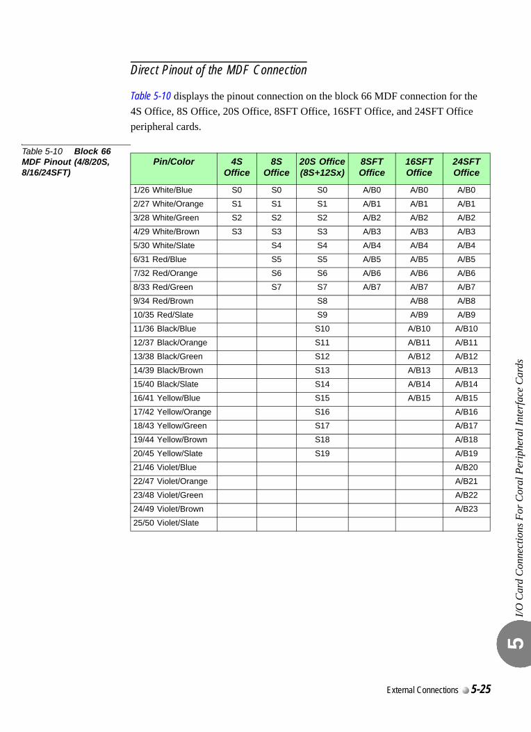
I/O C
ard
Con
nect
ions
For
Cor
al P
erip
hera
l Int
erfa
ce C
ards
5
Direct Pinout of the MDF Connection
Table 5-10 displays the pinout connection on the block 66 MDF connection for the 4S Office, 8S Office, 20S Office, 8SFT Office, 16SFT Office, and 24SFT Office peripheral cards.
Table 5-10 Block 66 MDF Pinout (4/8/20S, 8/16/24SFT)
Pin/Color 4S Office
8S Office
20S Office(8S+12Sx)
8SFT Office
16SFT Office
24SFT Office
1/26 White/Blue S0 S0 S0 A/B0 A/B0 A/B0
2/27 White/Orange S1 S1 S1 A/B1 A/B1 A/B1
3/28 White/Green S2 S2 S2 A/B2 A/B2 A/B2
4/29 White/Brown S3 S3 S3 A/B3 A/B3 A/B3
5/30 White/Slate S4 S4 A/B4 A/B4 A/B4
6/31 Red/Blue S5 S5 A/B5 A/B5 A/B5
7/32 Red/Orange S6 S6 A/B6 A/B6 A/B6
8/33 Red/Green S7 S7 A/B7 A/B7 A/B7
9/34 Red/Brown S8 A/B8 A/B8
10/35 Red/Slate S9 A/B9 A/B9
11/36 Black/Blue S10 A/B10 A/B10
12/37 Black/Orange S11 A/B11 A/B11
13/38 Black/Green S12 A/B12 A/B12
14/39 Black/Brown S13 A/B13 A/B13
15/40 Black/Slate S14 A/B14 A/B14
16/41 Yellow/Blue S15 A/B15 A/B15
17/42 Yellow/Orange S16 A/B16
18/43 Yellow/Green S17 A/B17
19/44 Yellow/Brown S18 A/B18
20/45 Yellow/Slate S19 A/B19
21/46 Violet/Blue A/B20
22/47 Violet/Orange A/B21
23/48 Violet/Green A/B22
24/49 Violet/Brown A/B23
25/50 Violet/Slate
External Connections 5-25
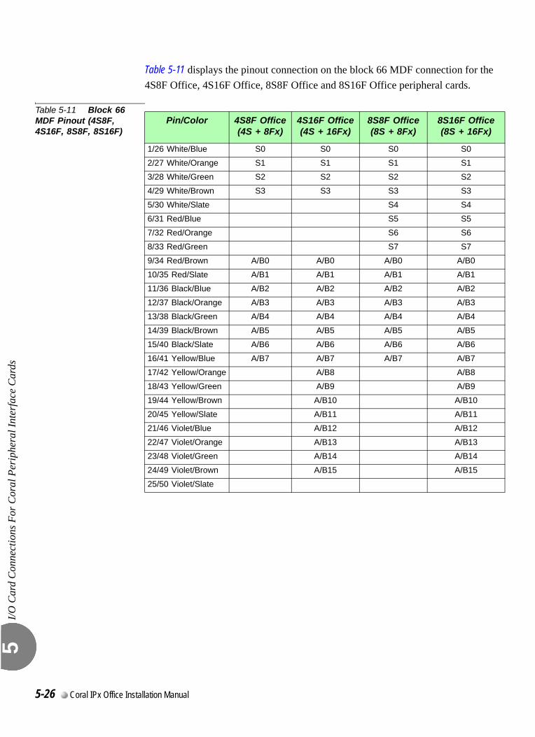
I/O C
ard
Con
nect
ions
For
Cor
al P
erip
hera
l Int
erfa
ce C
ards
5
Table 5-11 displays the pinout connection on the block 66 MDF connection for the 4S8F Office, 4S16F Office, 8S8F Office and 8S16F Office peripheral cards.
Table 5-11 Block 66 MDF Pinout (4S8F, 4S16F, 8S8F, 8S16F)
Pin/Color 4S8F Office(4S + 8Fx)
4S16F Office(4S + 16Fx)
8S8F Office(8S + 8Fx)
8S16F Office(8S + 16Fx)
1/26 White/Blue S0 S0 S0 S0
2/27 White/Orange S1 S1 S1 S1
3/28 White/Green S2 S2 S2 S2
4/29 White/Brown S3 S3 S3 S3
5/30 White/Slate S4 S4
6/31 Red/Blue S5 S5
7/32 Red/Orange S6 S6
8/33 Red/Green S7 S7
9/34 Red/Brown A/B0 A/B0 A/B0 A/B0
10/35 Red/Slate A/B1 A/B1 A/B1 A/B1
11/36 Black/Blue A/B2 A/B2 A/B2 A/B2
12/37 Black/Orange A/B3 A/B3 A/B3 A/B3
13/38 Black/Green A/B4 A/B4 A/B4 A/B4
14/39 Black/Brown A/B5 A/B5 A/B5 A/B5
15/40 Black/Slate A/B6 A/B6 A/B6 A/B6
16/41 Yellow/Blue A/B7 A/B7 A/B7 A/B7
17/42 Yellow/Orange A/B8 A/B8
18/43 Yellow/Green A/B9 A/B9
19/44 Yellow/Brown A/B10 A/B10
20/45 Yellow/Slate A/B11 A/B11
21/46 Violet/Blue A/B12 A/B12
22/47 Violet/Orange A/B13 A/B13
23/48 Violet/Green A/B14 A/B14
24/49 Violet/Brown A/B15 A/B15
25/50 Violet/Slate
5-26 Coral IPx Office Installation Manual
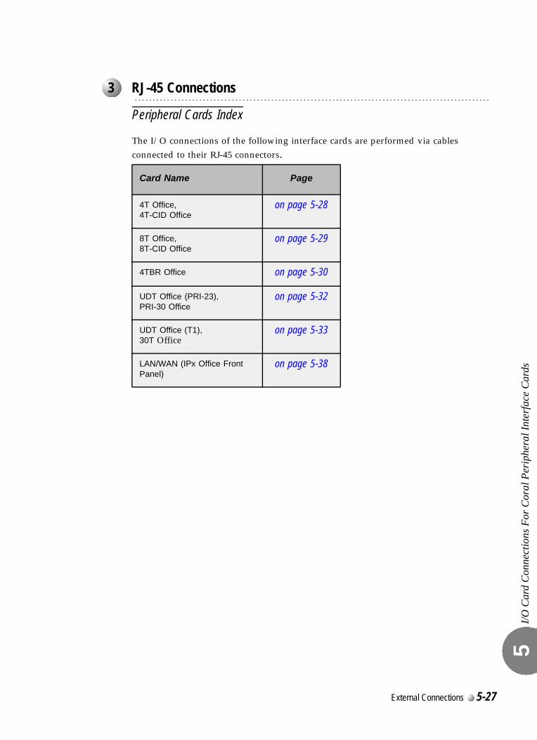
I/O C
ard
Con
nect
ions
For
Cor
al P
erip
hera
l Int
erfa
ce C
ards
5
0
Peripheral Cards Index
The I/O connections of the following interface cards are performed via cables connected to their RJ-45 connectors.
...................................................................................................3 RJ-45 Connections
Card Name Page
4T Office, 4T-CID Office
on page 5-28
8T Office, 8T-CID Office
on page 5-29
4TBR Office on page 5-30
UDT Office (PRI-23), PRI-30 Office
on page 5-32
UDT Office (T1), 30T Office
on page 5-33
LAN/WAN (IPx Office Front Panel)
on page 5-38
External Connections 5-27
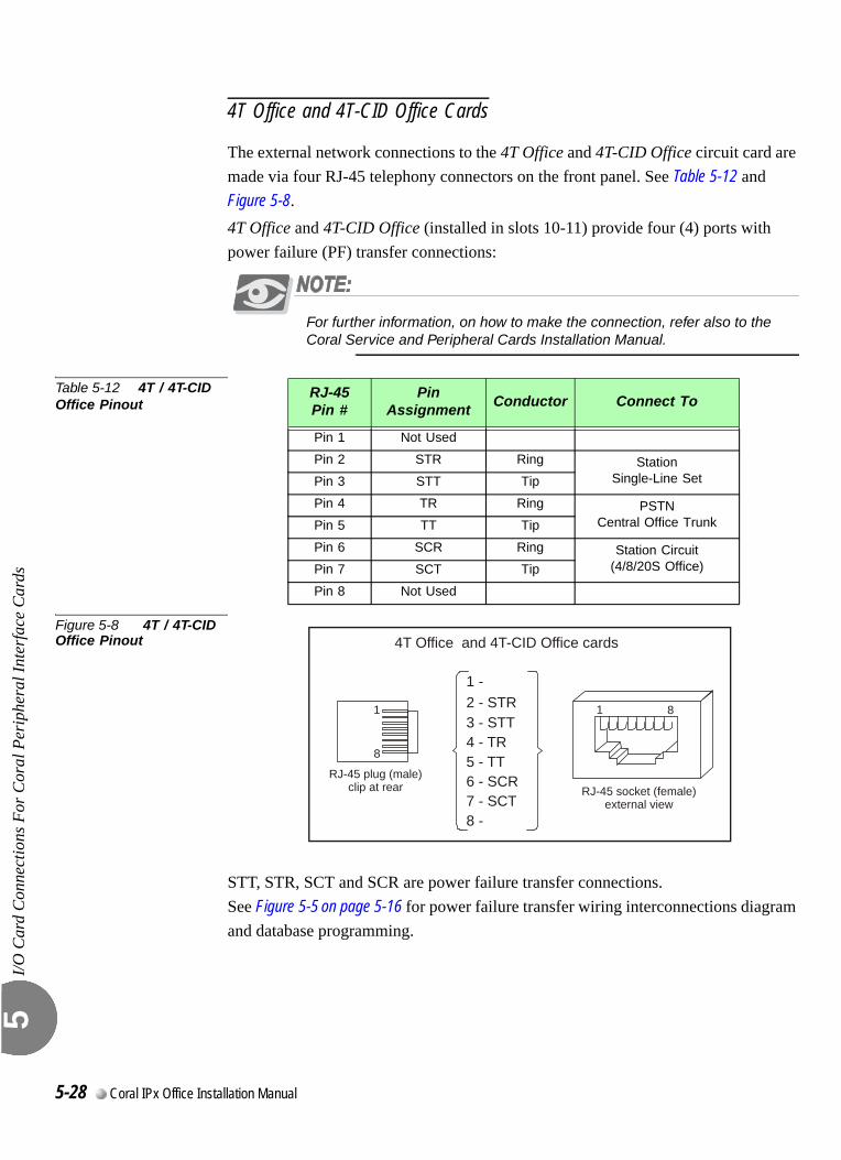
I/O C
ard
Con
nect
ions
For
Cor
al P
erip
hera
l Int
erfa
ce C
ards
5
4T Office and 4T-CID Office Cards
The external network connections to the 4T Office and 4T-CID Office circuit card are made via four RJ-45 telephony connectors on the front panel. See Table 5-12 and Figure 5-8.4T Office and 4T-CID Office (installed in slots 10-11) provide four (4) ports with power failure (PF) transfer connections:
For further information, on how to make the connection, refer also to the Coral Service and Peripheral Cards Installation Manual.
Table 5-12 4T / 4T-CID Office Pinout
Figure 5-8 4T / 4T-CID Office Pinout
STT, STR, SCT and SCR are power failure transfer connections. See Figure 5-5 on page 5-16 for power failure transfer wiring interconnections diagram and database programming.
RJ-45Pin #
Pin Assignment
Conductor Connect To
Pin 1 Not Used
Pin 2 STR Ring StationSingle-Line SetPin 3 STT Tip
Pin 4 TR Ring PSTNCentral Office TrunkPin 5 TT Tip
Pin 6 SCR Ring Station Circuit(4/8/20S Office)Pin 7 SCT Tip
Pin 8 Not Used
1 1
RJ-45 socket (female)external view
RJ-45 plug (male)clip at rear
4T Office and 4T-CID Office cards
8
8
12 STR3 - STT4 - TR5 - TT6 - SCR7 - SCT8 -
- -
5-28 Coral IPx Office Installation Manual
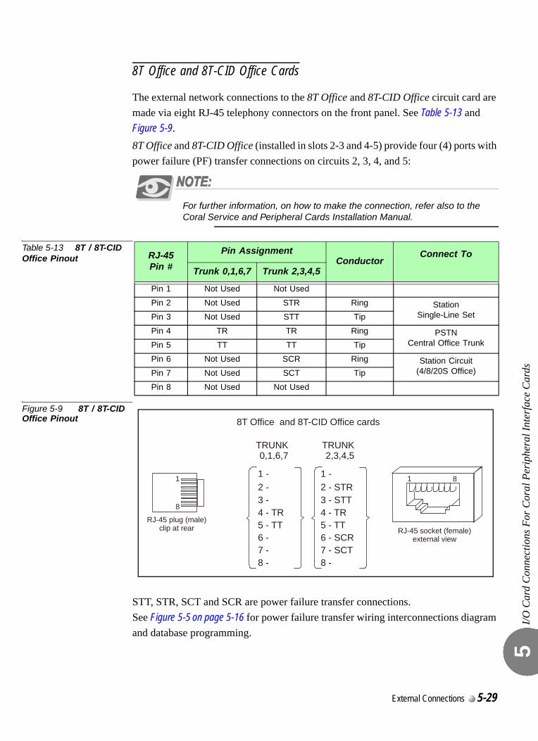
I/O C
ard
Con
nect
ions
For
Cor
al P
erip
hera
l Int
erfa
ce C
ards
5
8T Office and 8T-CID Office Cards
The external network connections to the 8T Office and 8T-CID Office circuit card are made via eight RJ-45 telephony connectors on the front panel. See Table 5-13 and Figure 5-9.8T Office and 8T-CID Office (installed in slots 2-3 and 4-5) provide four (4) ports with power failure (PF) transfer connections on circuits 2, 3, 4, and 5:
For further information, on how to make the connection, refer also to the Coral Service and Peripheral Cards Installation Manual.
Table 5-13 8T / 8T-CID Office Pinout
Figure 5-9 8T / 8T-CID Office Pinout
STT, STR, SCT and SCR are power failure transfer connections. See Figure 5-5 on page 5-16 for power failure transfer wiring interconnections diagram and database programming.
RJ-45Pin #
Pin AssignmentConductor
Connect To
Trunk 0,1,6,7 Trunk 2,3,4,5
Pin 1 Not Used Not Used
Pin 2 Not Used STR Ring StationSingle-Line SetPin 3 Not Used STT Tip
Pin 4 TR TR Ring PSTNCentral Office TrunkPin 5 TT TT Tip
Pin 6 Not Used SCR Ring Station Circuit(4/8/20S Office)Pin 7 Not Used SCT Tip
Pin 8 Not Used Not Used
1 1
RJ-45 socket (female)external view
RJ-45 plug (male)clip at rear
8T Office and 8T-CID Office cards
8
812 STR3 - STT4 - TR5 - TT6 - SCR7 - SCT8 -
- -
TRUNK2,3,4,5
TRUNK0,1,6,7
1
4 - TR5 - TT
8 -
- 2 - 3 -
6 - 7 -
External Connections 5-29
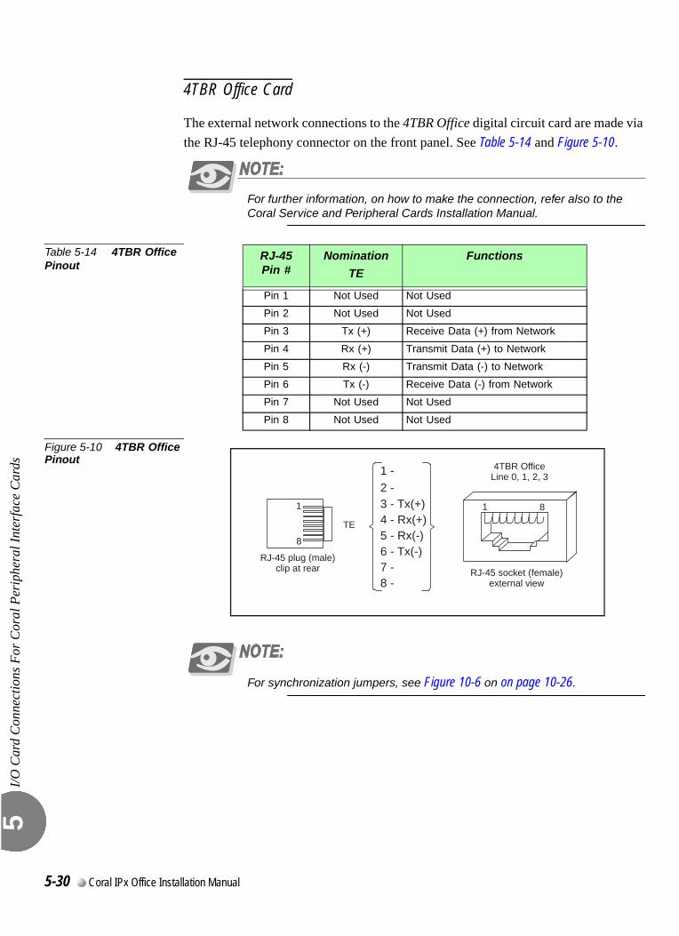
I/O C
ard
Con
nect
ions
For
Cor
al P
erip
hera
l Int
erfa
ce C
ards
5
4TBR Office Card
The external network connections to the 4TBR Office digital circuit card are made via the RJ-45 telephony connector on the front panel. See Table 5-14 and Figure 5-10.
For further information, on how to make the connection, refer also to the Coral Service and Peripheral Cards Installation Manual.
Table 5-14 4TBR Office Pinout
Figure 5-10 4TBR Office Pinout
For synchronization jumpers, see Figure 10-6 on on page 10-26.
RJ-45Pin #
Nomination
TE
Functions
Pin 1 Not Used Not Used
Pin 2 Not Used Not Used
Pin 3 Tx (+) Receive Data (+) from Network
Pin 4 Rx (+) Transmit Data (+) to Network
Pin 5 Rx (-) Transmit Data (-) to Network
Pin 6 Tx (-) Receive Data (-) from Network
Pin 7 Not Used Not Used
Pin 8 Not Used Not Used
1 1
4TBR OfficeLine 0, 1, 2, 3
RJ-45 socket (female)external view
RJ-45 plug (male)clip at rear
8
8
1
3 - Tx(+)4 - R5 - R6 - T78 -
-2 -
x(+)x(-)x(-)
-
TE
5-30 Coral IPx Office Installation Manual
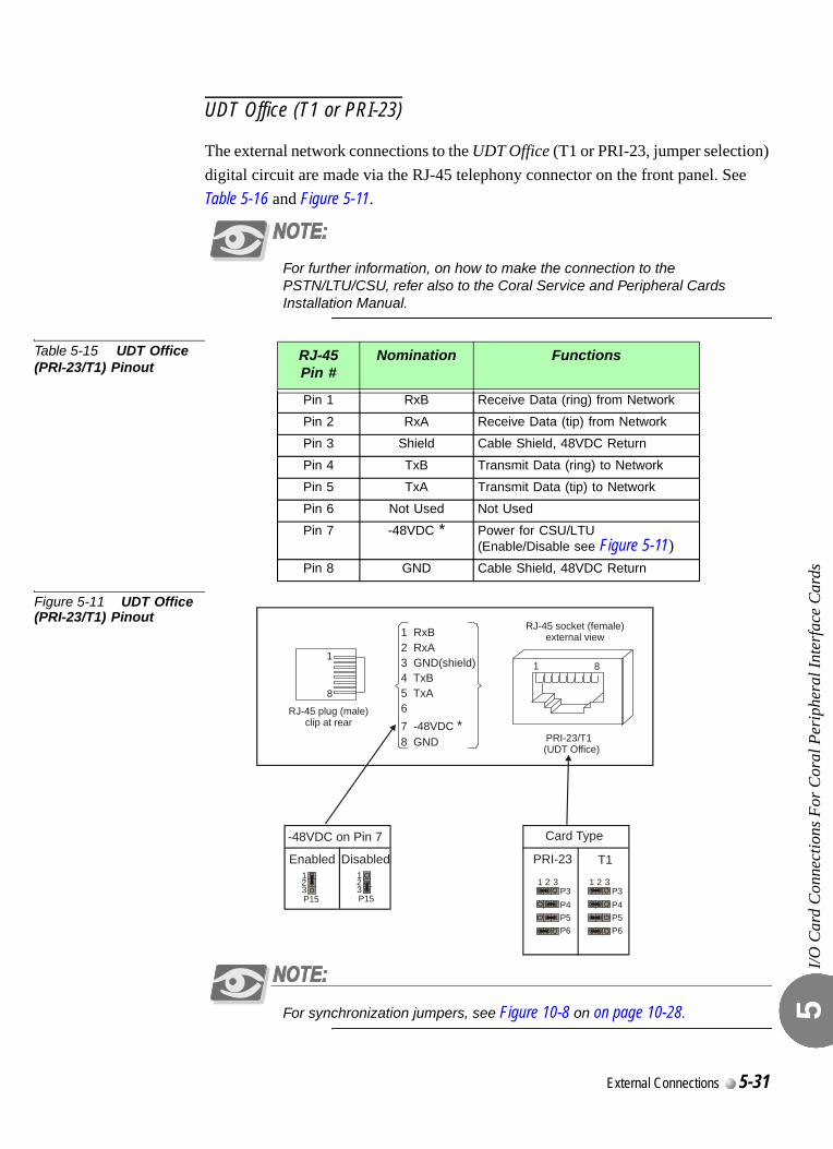
I/O C
ard
Con
nect
ions
For
Cor
al P
erip
hera
l Int
erfa
ce C
ards
5
UDT Office (T1 or PRI-23)
The external network connections to the UDT Office (T1 or PRI-23, jumper selection) digital circuit are made via the RJ-45 telephony connector on the front panel. See Table 5-16 and Figure 5-11.
For further information, on how to make the connection to the PSTN/LTU/CSU, refer also to the Coral Service and Peripheral Cards Installation Manual.
Table 5-15 UDT Office (PRI-23/T1) Pinout
Figure 5-11 UDT Office (PRI-23/T1) Pinout
For synchronization jumpers, see Figure 10-8 on on page 10-28.
RJ-45Pin #
Nomination Functions
Pin 1 RxB Receive Data (ring) from Network
Pin 2 RxA Receive Data (tip) from Network
Pin 3 Shield Cable Shield, 48VDC Return
Pin 4 TxB Transmit Data (ring) to Network
Pin 5 TxA Transmit Data (tip) to Network
Pin 6 Not Used Not Used
Pin 7 -48VDC * Power for CSU/LTU (Enable/Disable see Figure 5-11)
Pin 8 GND Cable Shield, 48VDC Return
1
RJ-45 plug (male)clip at rear
8
1 RxB2 RxA3 GND(shield)4 TxB5 TxA
6 7 -48VDC 8 GND
*
1
PRI-23/T1 (UDT Office)
RJ-45 socket (female)external view
8
P5P6
P4P3
1 2 3
P5P6
P4P3
1 2 3
Card Type
PRI-23 T1123P15
123P15
-48VDC on Pin 7
Enabled Disabled
External Connections 5-31
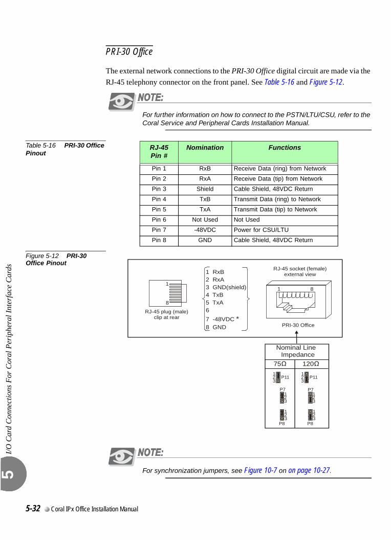
I/O C
ard
Con
nect
ions
For
Cor
al P
erip
hera
l Int
erfa
ce C
ards
5
PRI-30 Office
The external network connections to the PRI-30 Office digital circuit are made via the RJ-45 telephony connector on the front panel. See Table 5-16 and Figure 5-12.
For further information on how to connect to the PSTN/LTU/CSU, refer to the Coral Service and Peripheral Cards Installation Manual.
Table 5-16 PRI-30 Office Pinout
Figure 5-12 PRI-30 Office Pinout
For synchronization jumpers, see Figure 10-7 on on page 10-27.
RJ-45Pin #
Nomination Functions
Pin 1 RxB Receive Data (ring) from Network
Pin 2 RxA Receive Data (tip) from Network
Pin 3 Shield Cable Shield, 48VDC Return
Pin 4 TxB Transmit Data (ring) to Network
Pin 5 TxA Transmit Data (tip) to Network
Pin 6 Not Used Not Used
Pin 7 -48VDC Power for CSU/LTU
Pin 8 GND Cable Shield, 48VDC Return
1
RJ-45 plug (male)clip at rear
8
1 RxB2 RxA3 GND(shield)4 TxB5 TxA
6 7 -48VDC 8 GND
*
1
PRI-30 Office
RJ-45 socket (female)external view
8
1
1
1
2
2
2
3
3
3
P11
P7
P8
1
1
1
2
2
2
3
3
3
P11
P7
P8
Nominal Line Impedance
75 120
5-32 Coral IPx Office Installation Manual
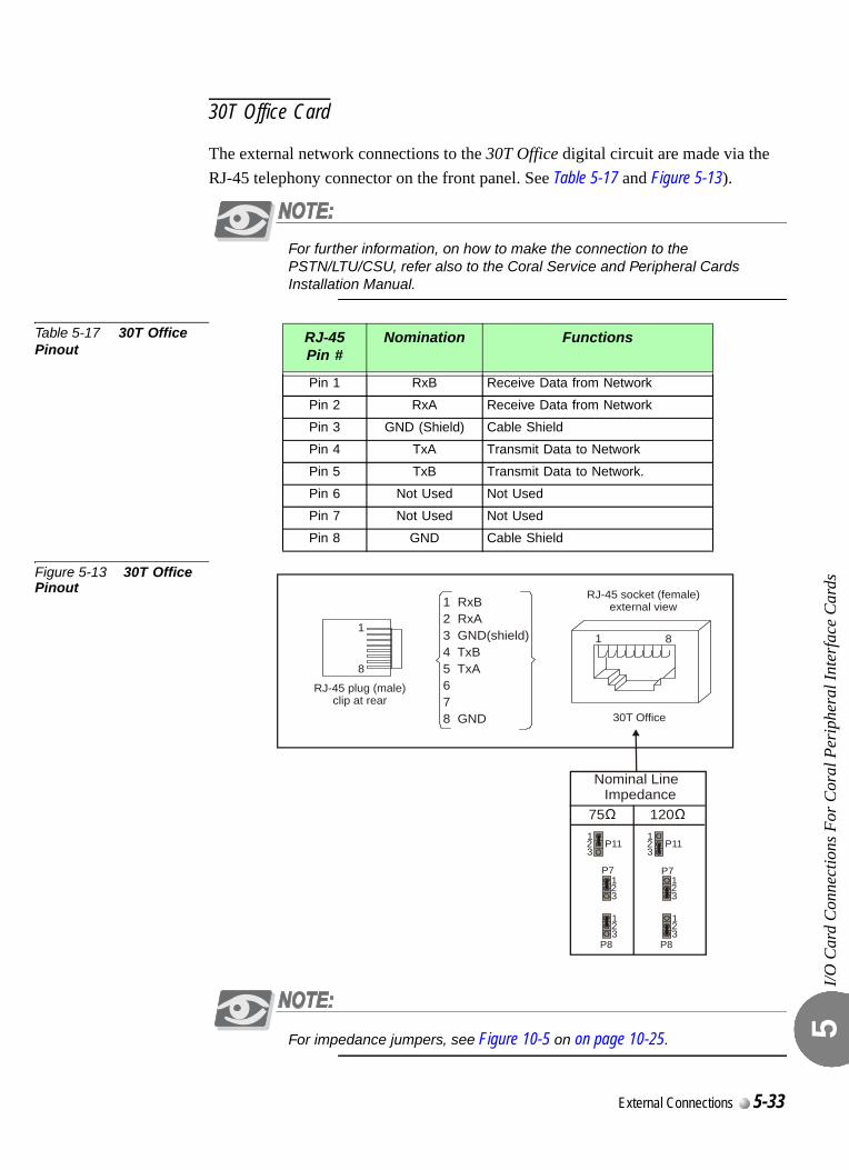
I/O C
ard
Con
nect
ions
For
Cor
al P
erip
hera
l Int
erfa
ce C
ards
5
30T Office Card
The external network connections to the 30T Office digital circuit are made via the RJ-45 telephony connector on the front panel. See Table 5-17 and Figure 5-13).
For further information, on how to make the connection to the PSTN/LTU/CSU, refer also to the Coral Service and Peripheral Cards Installation Manual.
Table 5-17 30T Office Pinout
Figure 5-13 30T Office Pinout
For impedance jumpers, see Figure 10-5 on on page 10-25.
RJ-45Pin #
Nomination Functions
Pin 1 RxB Receive Data from Network
Pin 2 RxA Receive Data from Network
Pin 3 GND (Shield) Cable Shield
Pin 4 TxA Transmit Data to Network
Pin 5 TxB Transmit Data to Network.
Pin 6 Not Used Not Used
Pin 7 Not Used Not Used
Pin 8 GND Cable Shield
1
RJ-45 plug (male)clip at rear
8
1
30T Office
RJ-45 socket (female)external view
8
1
1
1
2
2
2
3
3
3
P11
P7
P8
1
1
1
2
2
2
3
3
3
P11
P7
P8
Nominal Line Impedance
75 120
1 RxB2 RxA3 GND(shield)4 TxB5 TxA
6 7 8 GND
External Connections 5-33

I/O C
ard
Con
nect
ions
For
Cor
al P
erip
hera
l Int
erfa
ce C
ards
5
5-34 Coral IPx Office Installation Manual
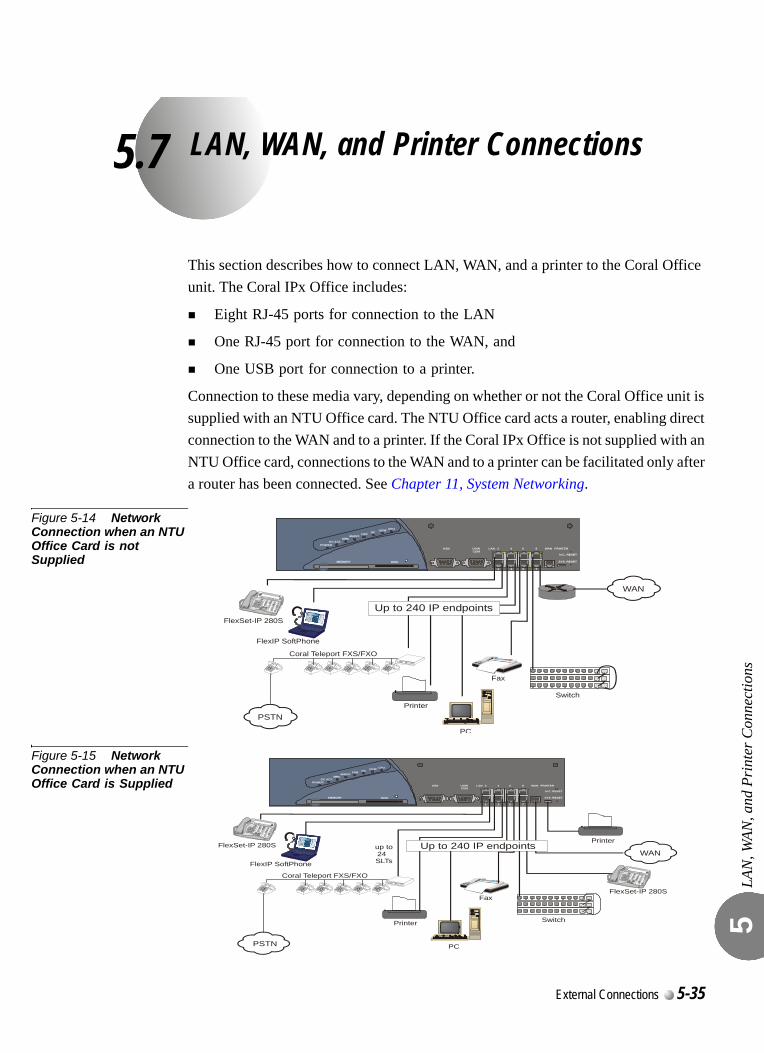
5.7
LAN, WAN, and Printer ConnectionsLAN
, WAN
, and
Pri
nter
Con
nect
ions
5
0
This section describes how to connect LAN, WAN, and a printer to the Coral Office unit. The Coral IPx Office includes:
Eight RJ-45 ports for connection to the LAN
One RJ-45 port for connection to the WAN, and
One USB port for connection to a printer.
Connection to these media vary, depending on whether or not the Coral Office unit is supplied with an NTU Office card. The NTU Office card acts a router, enabling direct connection to the WAN and to a printer. If the Coral IPx Office is not supplied with an NTU Office card, connections to the WAN and to a printer can be facilitated only after a router has been connected. See Chapter 11, System Networking.
Figure 5-14 Network Connection when an NTU Office Card is not Supplied
Figure 5-15 Network Connection when an NTU Office Card is Supplied
KB0 WAN PRINTER
SYS. RESET
LANUGWCOM
2
1
4
3
6
5
8
7
MEMORY DISK
CPUUGWGCFAN
MAINT.MRC
GC ACT.POWER
N.C. RESET
Fax
PC
FlexIP SoftPhone
Coral Teleport FXS/FXO
FlexSet-IP 280S
Printer
WAN
Switch
PSTN
Up to 240 IP endpoints
KB0 WAN PRINTER
SYS. RESET
LANUGWCOM
2
1
4
3
6
5
8
7
MEMORY DISK
CPUUGWGCFAN
MAINT.MRC
GC ACT.POWER
N.C. RESET
up to24 SLTs
Fax
PC
FlexIP SoftPhone
Coral Teleport FXS/FXO
FlexSet-IP 280S
FlexSet-IP 280S
Printer
Printer
WAN
Switch
PSTN
Up to 240 IP endpoints
External Connections 5-35
LAN
, WAN
, and
Pri
nter
Con
nect
ions
5
0
The Coral IPx Office connects directly to the LAN whether or not a NTU Office card is supplied with the system. See Chapter 11, System Networking, for more information.A switching device device can be added, allowing additional IP endpoints to be cascaded within the system (up to 240 altogether). See Figure 5-14 and Figure 5-15.
Connecting to the LAN when an NTU Office Card is Supplied
When an NTU Office card is supplied with the system, the dynamic IP addresses can be provided either by the NTU Office card or by the DHCP server at the customer’s site.
Connecting to the LAN when an NTU Office Card is not Supplied
When an NTU Office card is not supplied with the system, the dynamic IP addresses are provided by the customer’s DHCP server. In addition, the LAN can be accessed from the WAN port when configured to do so. See Chapter 11, Connecting to the Network without an NTU Office Card, for further information.0
The Coral IPx Office can connect to the WAN whether or not an NTU Office card is supplied with the system. See Chapter 11, System Networking, for more information.
Connecting to the WAN when an NTU Office Card is Supplied
If an NTU Office card is supplied with the system, the Coral IPx Office connects directly to the WAN without a router. In this case, the dynamic IP addresses can be provided either by the NTU Office card or by the DHCP server at the customer’s site.
Connecting to the WAN when an NTU Office Card is not Supplied
If an NTU Office card has not been supplied, connecting to the WAN is possible only after a router has been added between one of the LAN ports and the WAN. In this case, the dynamic IP addresses are provided by the customer’s DHCP server. The WAN port
...................................................................................................1 Connecting to the LAN
...................................................................................................2 Connecting to the WAN
5-36 Coral IPx Office Installation Manual
LAN
, WAN
, and
Pri
nter
Con
nect
ions
5
itself can function as an additional, ninth LAN port. (However, the WAN port does not include any LED indicators).0
The Coral IPx Office can connect to a printer whether or not an NTU Office card is supplied with the system.
Connecting to a Printer when an NTU Office Card is Supplied
If an NTU Office card is supplied, a printer can be connected via the USB port. In this case, the dynamic IP addresses can provided either by the NTU Office card or by the DHCP server at the customer’s site.
Connecting to a Printer when an NTU Office Card is not Supplied
If no NTU Office card is provided, a printer can be connected to any of the LAN RJ-45 ports as any other ethernet device. In this case, the dynamic IP addresses are provided by the customer’s DHCP server. See Chapter 11, System Networking, for more information.
...................................................................................................3 Connecting to a Printer
External Connections 5-37
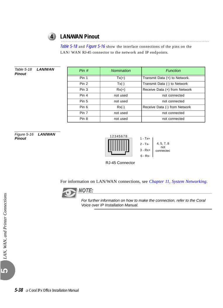
LAN
, WAN
, and
Pri
nter
Con
nect
ions
5
00
Table 5-18 and Figure 5-16 show the interface connections of the pins on the LAN/WAN RJ-45 connector to the network and IP endpoints.
Table 5-18 LAN/WAN Pinout
Figure 5-16 LAN/WAN Pinout
For information on LAN/WAN connections, see Chapter 11, System Networking.
For further information on how to make the connection, refer to the Coral Voice over IP Installation Manual.
...................................................................................................4 LAN/WAN Pinout
Pin # Nomination Function
Pin 1 Tx(+) Transmit Data (+) to Network.
Pin 2 Tx(-) Transmit Data (-) to Network
Pin 3 Rx(+) Receive Data (+) from Network
Pin 4 not used not connected
Pin 5 not used not connected
Pin 6 Rx(-) Receive Data (-) from Network
Pin 7 not used not connected
Pin 8 not used not connected
4, 5, 7, 8not
connected
1 2 345 6 7 81 - Tx+
2 - Tx-
3 - Rx+
6 - Rx-
RJ-45 Connector
5-38 Coral IPx Office Installation Manual
Coral IPx Office Installation Manual
Chapter00
6
Cage Description
6.1 General System Description..............................................................6-1
6.2 System Configuration Options.........................................................6-23

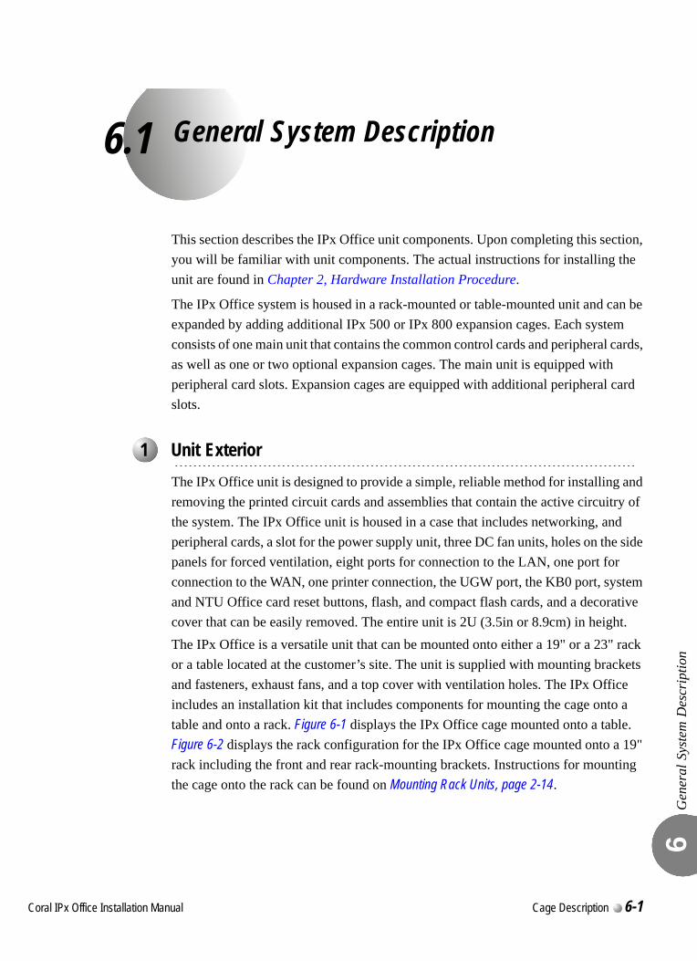
C
6.1
oral IPx Office Installation Ma
General System Description
Gen
eral
Sys
tem
Des
crip
tion
6
This section describes the IPx Office unit components. Upon completing this section, you will be familiar with unit components. The actual instructions for installing the unit are found in Chapter 2, Hardware Installation Procedure.0
The IPx Office system is housed in a rack-mounted or table-mounted unit and can be expanded by adding additional IPx 500 or IPx 800 expansion cages. Each system consists of one main unit that contains the common control cards and peripheral cards, as well as one or two optional expansion cages. The main unit is equipped with peripheral card slots. Expansion cages are equipped with additional peripheral card slots.0
The IPx Office unit is designed to provide a simple, reliable method for installing and removing the printed circuit cards and assemblies that contain the active circuitry of the system. The IPx Office unit is housed in a case that includes networking, and peripheral cards, a slot for the power supply unit, three DC fan units, holes on the side panels for forced ventilation, eight ports for connection to the LAN, one port for connection to the WAN, one printer connection, the UGW port, the KB0 port, system and NTU Office card reset buttons, flash, and compact flash cards, and a decorative cover that can be easily removed. The entire unit is 2U (3.5in or 8.9cm) in height.The IPx Office is a versatile unit that can be mounted onto either a 19" or a 23" rack or a table located at the customer’s site. The unit is supplied with mounting brackets and fasteners, exhaust fans, and a top cover with ventilation holes. The IPx Office includes an installation kit that includes components for mounting the cage onto a table and onto a rack. Figure 6-1 displays the IPx Office cage mounted onto a table. Figure 6-2 displays the rack configuration for the IPx Office cage mounted onto a 19" rack including the front and rear rack-mounting brackets. Instructions for mounting the cage onto the rack can be found on Mounting Rack Units, page 2-14.
...................................................................................................1 Unit Exterior
nual Cage Description 6-1
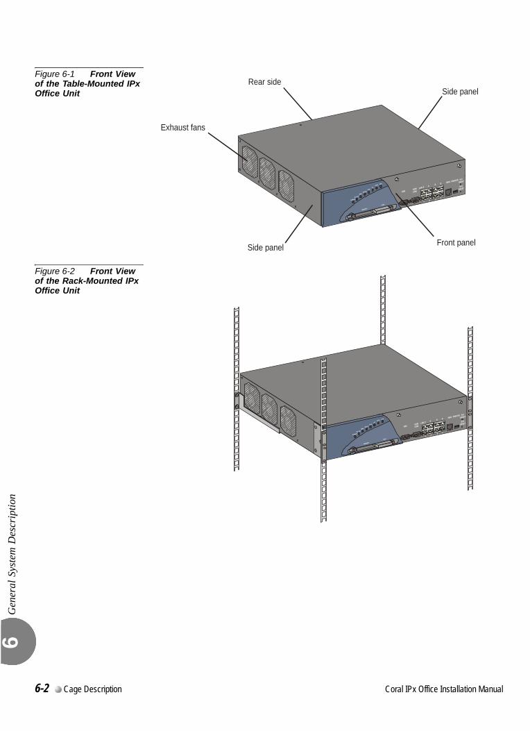
Gen
eral
Sys
tem
Des
crip
tion
6
Figure 6-1 Front View of the Table-Mounted IPx Office Unit
Figure 6-2 Front View of the Rack-Mounted IPx Office Unit
Exhaust fans
Front panel
Rear sideSide panel
Side panel
6-2 Cage Description Coral IPx Office Installation Manual
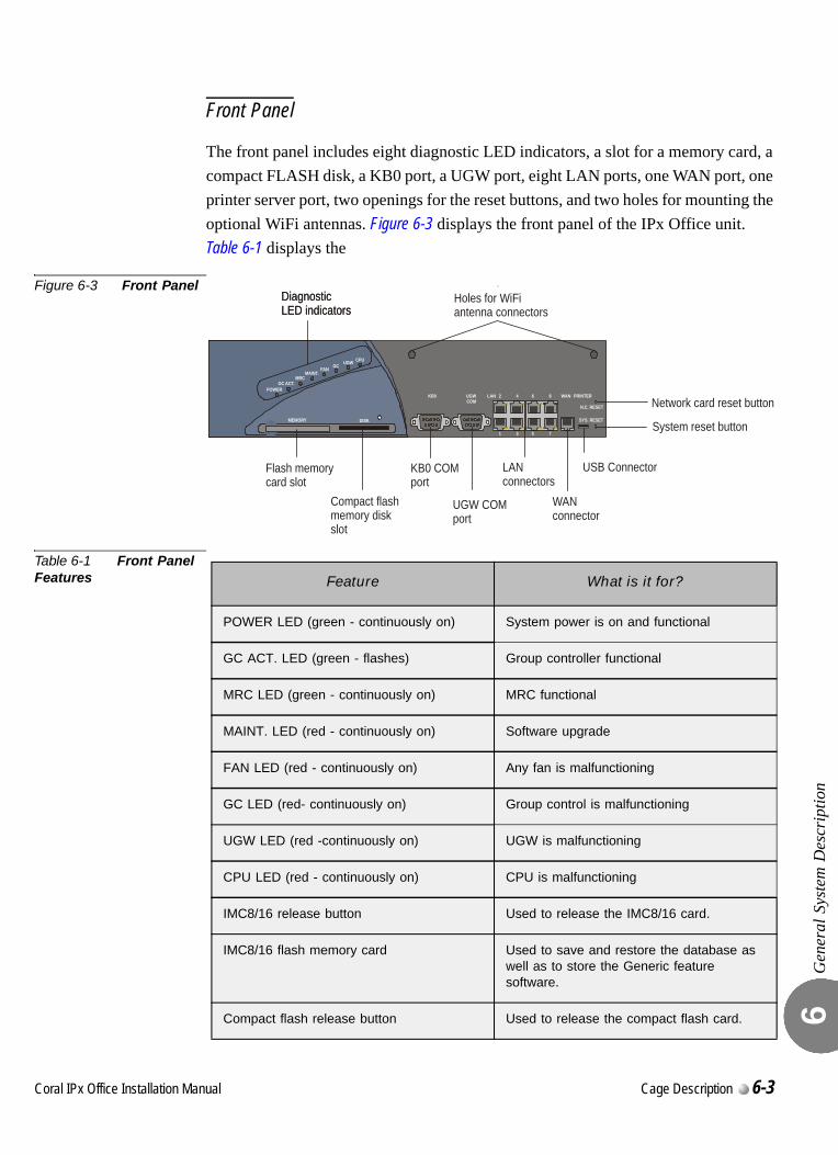
Gen
eral
Sys
tem
Des
crip
tion
6
Front Panel
The front panel includes eight diagnostic LED indicators, a slot for a memory card, a compact FLASH disk, a KB0 port, a UGW port, eight LAN ports, one WAN port, one printer server port, two openings for the reset buttons, and two holes for mounting the optional WiFi antennas. Figure 6-3 displays the front panel of the IPx Office unit. Table 6-1 displays the
Figure 6-3 Front Panel
Table 6-1 Front Panel Features
KB0 WAN PRINTER
SYS. RESET
LANUGWCOM
2
1
4
3
6
5
8
7
MEMORY DISK
CPUUGWGCFAN
MAINT.MRC
GC ACT.POWER
DiagnosticLED indicators
Holes for WiFiantenna connectors
DiagnosticLED indicators
Flash memorycard slot
Compact flashmemory diskslot
KB0 COMport
UGW COMport
LANconnectors
WANconnector
N.C. RESET
System reset button
USB Connector
Network card reset button
Feature What is it for?
POWER LED (green - continuously on) System power is on and functional
GC ACT. LED (green - flashes) Group controller functional
MRC LED (green - continuously on) MRC functional
MAINT. LED (red - continuously on) Software upgrade
FAN LED (red - continuously on) Any fan is malfunctioning
GC LED (red- continuously on) Group control is malfunctioning
UGW LED (red -continuously on) UGW is malfunctioning
CPU LED (red - continuously on) CPU is malfunctioning
IMC8/16 release button Used to release the IMC8/16 card.
IMC8/16 flash memory card Used to save and restore the database as well as to store the Generic feature software.
Compact flash release button Used to release the compact flash card.
Coral IPx Office Installation Manual Cage Description 6-3
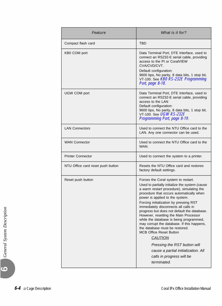
Gen
eral
Sys
tem
Des
crip
tion
6
Compact flash card TBD
KB0 COM port Data Terminal Port, DTE Interface, used to connect an RS232-E serial cable, providing access to the PI or CoralVIEW CVA/CVD/CVT.
Default configuration:9600 bps, No parity, 8 data bits, 1 stop bit, VT-100. See KB0 RS-232E Programming Port, page 8-18.
UGW COM port Data Terminal Port, DTE Interface, used to connect an RS232-E serial cable, providing access to the LANDefault configuration:9600 bps, No parity, 8 data bits, 1 stop bit, VT-100. See UGW RS-232E Programming Port, page 8-19.
LAN Connectors Used to connect the NTU Office card to the LAN. Any one connector can be used.
WAN Connector Used to connect the NTU Office card to the WAN.
Printer Connector Used to connect the system to a printer.
NTU Office card reset push button Resets the NTU Office card and restores factory default settings.
Reset push button Forces the Coral system to restart.
Used to partially initialize the system (cause a warm restart procedure), simulating the procedure that occurs automatically when power is applied to the system.
Forcing initialization by pressing RST immediately disconnects all calls in progress but does not default the database. However, resetting the Main Processor while the database is being programmed, may corrupt the database. If this happens, the database must be restored.MCB Office Reset Button
CAUTION
Pressing the RST button will
cause a partial initialization. All
calls in progress will be
terminated.
Feature What is it for?
6-4 Cage Description Coral IPx Office Installation Manual
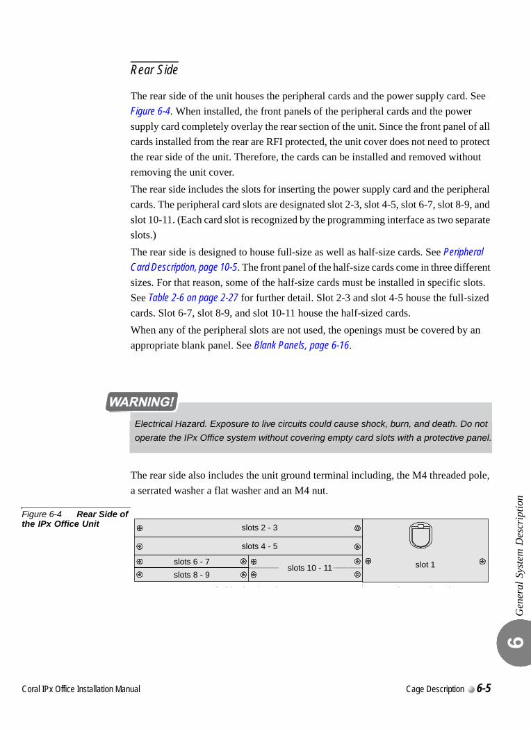
Gen
eral
Sys
tem
Des
crip
tion
6
Rear Side
The rear side of the unit houses the peripheral cards and the power supply card. See Figure 6-4. When installed, the front panels of the peripheral cards and the power supply card completely overlay the rear section of the unit. Since the front panel of all cards installed from the rear are RFI protected, the unit cover does not need to protect the rear side of the unit. Therefore, the cards can be installed and removed without removing the unit cover.The rear side includes the slots for inserting the power supply card and the peripheral cards. The peripheral card slots are designated slot 2-3, slot 4-5, slot 6-7, slot 8-9, and slot 10-11. (Each card slot is recognized by the programming interface as two separate slots.)The rear side is designed to house full-size as well as half-size cards. See Peripheral Card Description, page 10-5. The front panel of the half-size cards come in three different sizes. For that reason, some of the half-size cards must be installed in specific slots. See Table 2-6 on page 2-27 for further detail. Slot 2-3 and slot 4-5 house the full-sized cards. Slot 6-7, slot 8-9, and slot 10-11 house the half-sized cards.When any of the peripheral slots are not used, the openings must be covered by an appropriate blank panel. See Blank Panels, page 6-16.
The rear side also includes the unit ground terminal including, the M4 threaded pole, a serrated washer a flat washer and an M4 nut.
Figure 6-4 Rear Side of the IPx Office Unit
Electrical Hazard. Exposure to live circuits could cause shock, burn, and death. Do not
operate the IPx Office system without covering empty card slots with a protective panel.
slots 2 - 3
slots 4 - 5
slots 6 - 7slots 8 - 9
slot 1
P i h l d ti P l ti
slots 10 - 11
Coral IPx Office Installation Manual Cage Description 6-5
Gen
eral
Sys
tem
Des
crip
tion
6
Side Panels
The side panels of the IPx Office cover include perforations that allow the flow of cool ambient air to the system with the aid of three convection fans. See Figure 6-5 and Figure 6-6. The right side panel also includes the Software Authorization Unit (SAU) connector. See Software Authorization Management, page 8-14.
Top Side
The top side is part of the cover. No space needs to be maintained above the unit cover for maintenance purposes; the IPx Office unit can be positioned directly below other equipment.
Bottom Panel
The bottom panel includes five circular indentations that mark where the five rubber supports are to be affixed when the unit is mounted onto a table. See Mounting Table Units, page 2-13. No space needs to be maintained beneath the bottom panel; the IPx Office unit can be positioned directly above other equipment.
Installation Kit
The cage is supplied with a kit that includes components for mounting the cage onto a table or a rack. For table-mounted systems, five rubber supports are affixed to the bottom panel of the IPx Office unit. See Figure 6-1 on page 6-2. For more information, see Mounting Table Units, page 2-13.For rack-mounted units, two bracket are attached to the unit cover and the unit itself. The bracket and unit assembly are then attached to the rack. Two additional brackets are mounted onto the rack and provide additional support from below. See Figure 6-2 on page 6-2. For more information, see Mounting Rack Units, page 2-14.
6-6 Cage Description Coral IPx Office Installation Manual
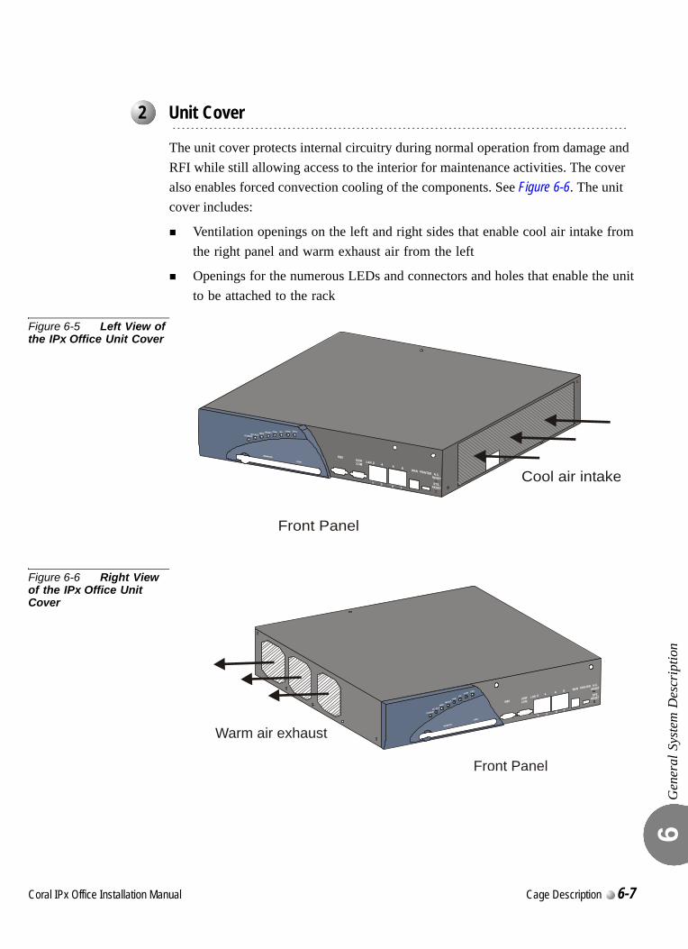
Gen
eral
Sys
tem
Des
crip
tion
6
0
The unit cover protects internal circuitry during normal operation from damage and RFI while still allowing access to the interior for maintenance activities. The cover also enables forced convection cooling of the components. See Figure 6-6. The unit cover includes:
Ventilation openings on the left and right sides that enable cool air intake from the right panel and warm exhaust air from the left
Openings for the numerous LEDs and connectors and holes that enable the unit to be attached to the rack
Figure 6-5 Left View of the IPx Office Unit Cover
Figure 6-6 Right View of the IPx Office Unit Cover
...................................................................................................2 Unit Cover
Cool air intake
Front Panel
Front Panel
Warm air exhaust
Coral IPx Office Installation Manual Cage Description 6-7
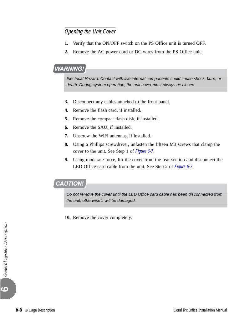
Gen
eral
Sys
tem
Des
crip
tion
6
Opening the Unit Cover
1. Verify that the ON/OFF switch on the PS Office unit is turned OFF.
2. Remove the AC power cord or DC wires from the PS Office unit.
3. Disconnect any cables attached to the front panel.
4. Remove the flash card, if installed.
5. Remove the compact flash disk, if installed.
6. Remove the SAU, if installed.
7. Unscrew the WiFi antennas, if installed.
8. Using a Phillips screwdriver, unfasten the fifteen M3 screws that clamp the cover to the unit. See Step 1 of Figure 6-7.
9. Using moderate force, lift the cover from the rear section and disconnect the LED Office card cable from the unit. See Step 2 of Figure 6-7.
10. Remove the cover completely.
Electrical Hazard. Contact with live internal components could cause shock, burn, or
death. During system operation, the unit cover must always be closed.
Do not remove the cover until the LED Office card cable has been disconnected from
the unit, otherwise it will be damaged.
6-8 Cage Description Coral IPx Office Installation Manual
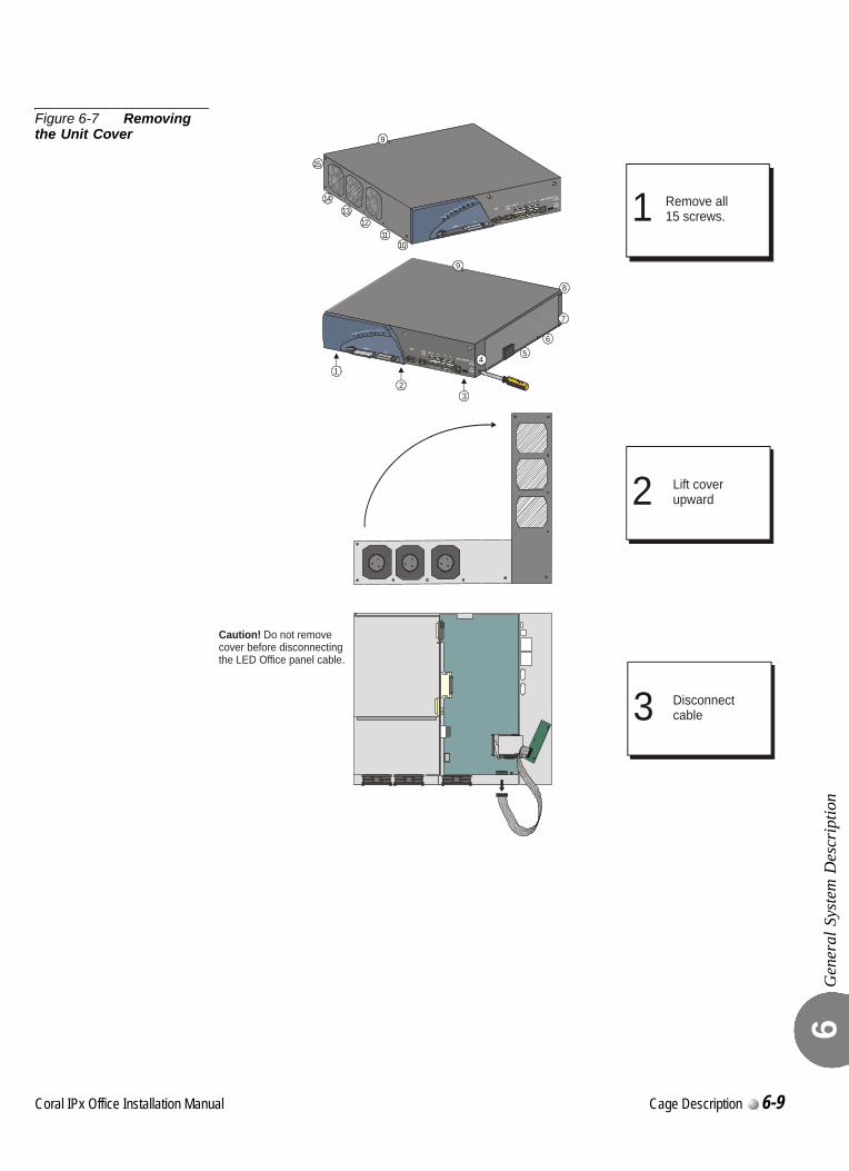
Gen
eral
Sys
tem
Des
crip
tion
6
Figure 6-7 Removing the Unit Cover
5
6
3
4
9
8
7
12
1011
1213
14
15
1 Remove all15 screws.
Lift coverupward
Disconnectcable
Caution! Do not remove cover before disconnectingthe LED Office panel cable.
2
3
9
Coral IPx Office Installation Manual Cage Description 6-9
Gen
eral
Sys
tem
Des
crip
tion
6
Closing the Unit Cover
1. Verify that the MCB Office battery protective strip has been removed, all control and NTU Office cards are properly installed, that all internal cables are properly connected, and that the NTU Office card ON/OFF switch is turned ON.
2. Verify that the internal space within the unit is free of foreign objects.
3. Position the internal side of the front panel adjacent to the front side of the IPx Office unit and lift the rear side of the cover upward.
4. From the rear panel of the unit, attach the LED panel cable to the IPx Office unit.
5. Close the unit cover.
6. Fasten the fifteen M3 screws with a Phillips screwdriver.
6-10 Cage Description Coral IPx Office Installation Manual
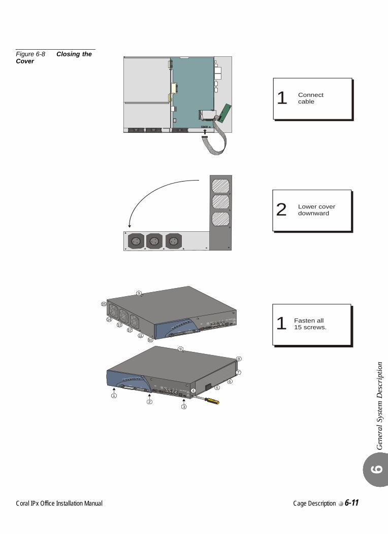
Gen
eral
Sys
tem
Des
crip
tion
6
Figure 6-8 Closing the Cover
5
6
3
4
9
8
7
12
1011
1213
14
15
1 Fasten all15 screws.
Lower coverdownward
Connectcable
2
1
9
Coral IPx Office Installation Manual Cage Description 6-11
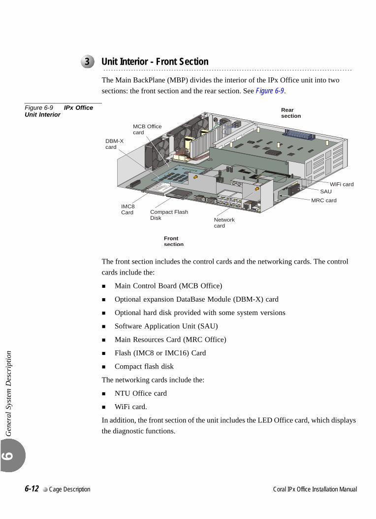
Gen
eral
Sys
tem
Des
crip
tion
6
0000
0
The Main BackPlane (MBP) divides the interior of the IPx Office unit into two sections: the front section and the rear section. See Figure 6-9.
Figure 6-9 IPx Office Unit Interior
The front section includes the control cards and the networking cards. The control cards include the:
Main Control Board (MCB Office)
Optional expansion DataBase Module (DBM-X) card
Optional hard disk provided with some system versions
Software Application Unit (SAU)
Main Resources Card (MRC Office)
Flash (IMC8 or IMC16) Card
Compact flash disk
The networking cards include the:
NTU Office card
WiFi card.
In addition, the front section of the unit includes the LED Office card, which displays the diagnostic functions.
...................................................................................................3 Unit Interior - Front Section
Rearsection
WiFi card
IMC8Card Compact Flash
Disk Networkcard
SAU
Frontsection
DBM-Xcard
MCB Officecard
MRC card
6-12 Cage Description Coral IPx Office Installation Manual
Gen
eral
Sys
tem
Des
crip
tion
6
MCB Office Card
The MCB Office card is the main control card of the IPx Office unit. It is attached to the IPx Office case at the floor of the front section and is connected to the MBP Office. The MCB Office integrates MCP, IPI, and GC circuitry and performs HDLC, synchronization. For further information see MCB Office Card, page 8-5.
DBM-X Card
The DBM-X card provides 2MB, 4MB, or 8MB of SRAM (Static Random Access Memory). The optional DBM-X card expands the SRAM of the IPx Office system. For more information, see DBM-X Card, page 8-41.
Hard Disk
The optional hard disk provides an additional 20GB - 80GB of memory. The hard disk is supplied only with some system versions.
MRC Card
The optional MRC (Main Resources Card) converts PCM signals to IP packets and vice versa. See MRC Card, page 8-27.
IMC8 / IMC16 Flash Card
The optional IMC8 or IMC16 flash card includes the Coral software. See IMC8 and IMC16 Flash Cards, page 8-33.
Compact Flash Disk
The optional flash disk provides TBD. See Compact Flash Disk, page 8-39.
Networking Card
The networking card integrates full networking capabilities within the IPx Office. For further information, see Chapter 11, System Networking.
WiFi Card
The WiFi card integrates full WiFi capabilities within the IPx Office. For further information, see Chapter 11, System Networking.
Coral IPx Office Installation Manual Cage Description 6-13
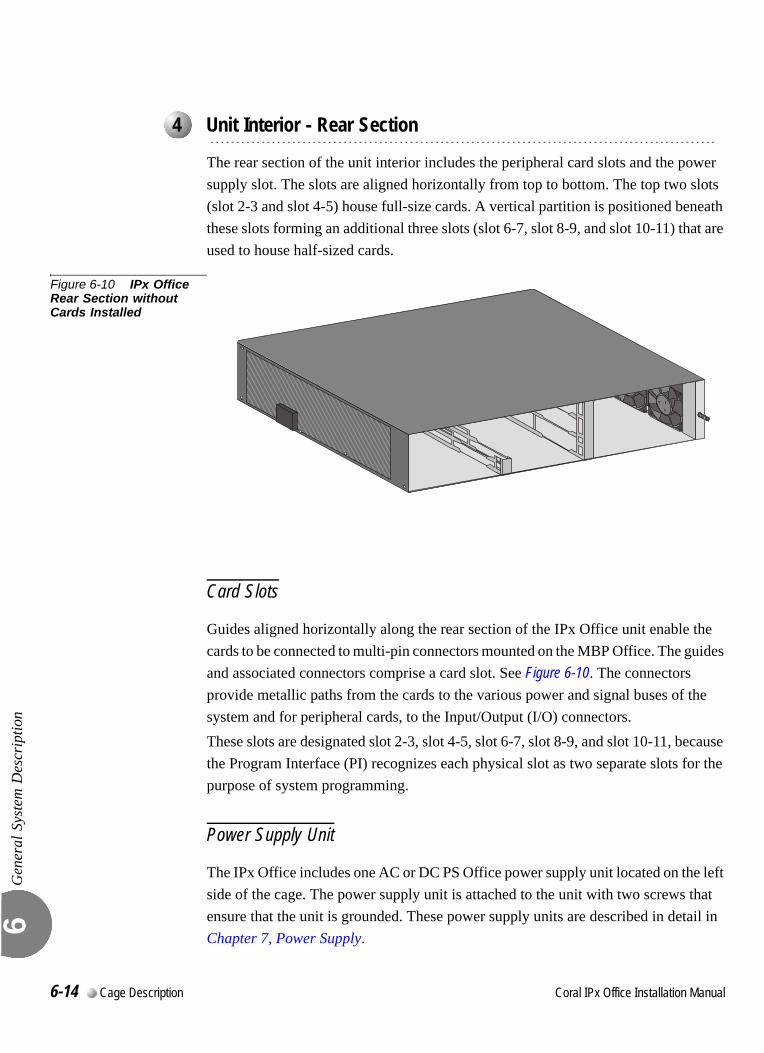
Gen
eral
Sys
tem
Des
crip
tion
6
0
0
The rear section of the unit interior includes the peripheral card slots and the power supply slot. The slots are aligned horizontally from top to bottom. The top two slots (slot 2-3 and slot 4-5) house full-size cards. A vertical partition is positioned beneath these slots forming an additional three slots (slot 6-7, slot 8-9, and slot 10-11) that are used to house half-sized cards.
Figure 6-10 IPx Office Rear Section without Cards Installed
Card Slots
Guides aligned horizontally along the rear section of the IPx Office unit enable the cards to be connected to multi-pin connectors mounted on the MBP Office. The guides and associated connectors comprise a card slot. See Figure 6-10. The connectors provide metallic paths from the cards to the various power and signal buses of the system and for peripheral cards, to the Input/Output (I/O) connectors.These slots are designated slot 2-3, slot 4-5, slot 6-7, slot 8-9, and slot 10-11, because the Program Interface (PI) recognizes each physical slot as two separate slots for the purpose of system programming.
Power Supply Unit
The IPx Office includes one AC or DC PS Office power supply unit located on the left side of the cage. The power supply unit is attached to the unit with two screws that ensure that the unit is grounded. These power supply units are described in detail in Chapter 7, Power Supply.
...................................................................................................4 Unit Interior - Rear Section
6-14 Cage Description Coral IPx Office Installation Manual
Gen
eral
Sys
tem
Des
crip
tion
6
Peripheral Cards
The IPx Office unit includes five peripheral card slots in the rear section. These card types are described in Chapter 10, Peripheral Cards, and in greater detail in the Coral Service and Peripheral Card Manual.
Configuration Jumpers
The jumpers of the IPx Office unit that are configured at the customer’s site are located in the peripheral cards. For further information, see The Service and Peripheral Card Installation Manual.000
I/O Connectors
Every peripheral card includes an I/O connector to interface with the MDF. The I/O connections for each peripheral card slot are provided directly from the front panel of the card to the MDF. The I/O connectors are either Champ or RJ-45:
Champ connectors include female, 25 pair AMP™ Champ™, or Amphenol® Microribbon® type connectors that appear on the front panel of many peripheral cards (for example, 8SLS Office, 16SFT Office, etc.)
RJ-45 jacks are mounted on the front panel of many of the peripheral cards (for example, the UDT Office, T1 Office, PRI-30 Office cards, etc.) Mating male RJ-45 connectors should be industry standard.
Refer to the specific card tables in Chapter 5, External Connections for I/O connector pin assignments.
Expansion Connector
The expansion connector is positioned on the ESIM Office card. The IPx Office expansion cable can be connected to an expansion cage only if the ESIM Office card is inserted in slot 8-9. See Interconnecting the IPx Office Unit and the Expansion Cage, page 6-30.
Cage Ground Terminal
The ground connection is used to connect the cage to the master ground unit. See Figure 6-10 for more details.
Coral IPx Office Installation Manual Cage Description 6-15
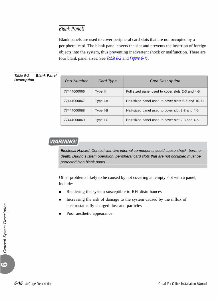
Gen
eral
Sys
tem
Des
crip
tion
6
Blank Panels
Blank panels are used to cover peripheral card slots that are not occupied by a peripheral card. The blank panel covers the slot and prevents the insertion of foreign objects into the system, thus preventing inadvertent shock or malfunction. There are four blank panel sizes. See Table 6-2 and Figure 6-11.
Table 6-2 Blank Panel Description
Other problems likely to be caused by not covering an empty slot with a panel, include:
Rendering the system susceptible to RFI disturbances
Increasing the risk of damage to the system caused by the influx of electrostatically charged dust and particles
Poor aesthetic appearance
Part Number Card Type Card Description
77444000066 Type II Full sized panel used to cover slots 2-3 and 4-5
77444000067 Type I-A Half-sized panel used to cover slots 6-7 and 10-11
77444000068 Type I-B Half-sized panel used to cover slot 2-3 and 4-5
77444000069 Type I-C Half-sized panel used to cover slot 2-3 and 4-5
Electrical Hazard. Contact with live internal components could cause shock, burn, or
death. During system operation, peripheral card slots that are not occupied must be
protected by a blank panel.
6-16 Cage Description Coral IPx Office Installation Manual
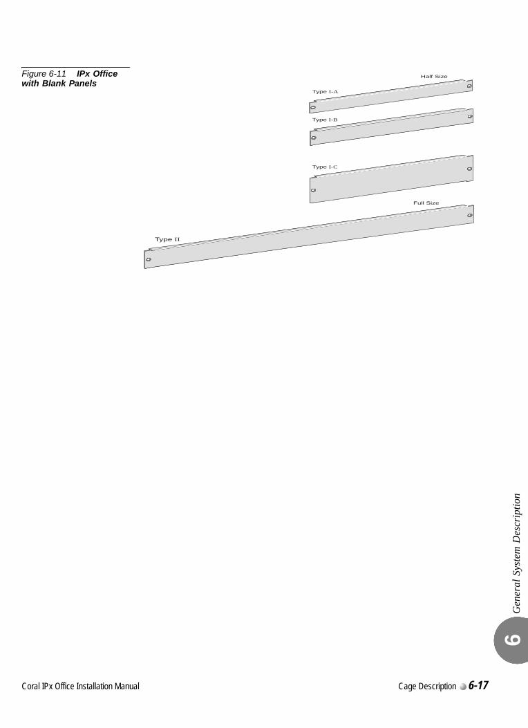
Gen
eral
Sys
tem
Des
crip
tion
6
Figure 6-11 IPx Office with Blank Panels
Type I-C
Type I-B
Half Size
Type I-A
Type II
Full Size
Coral IPx Office Installation Manual Cage Description 6-17
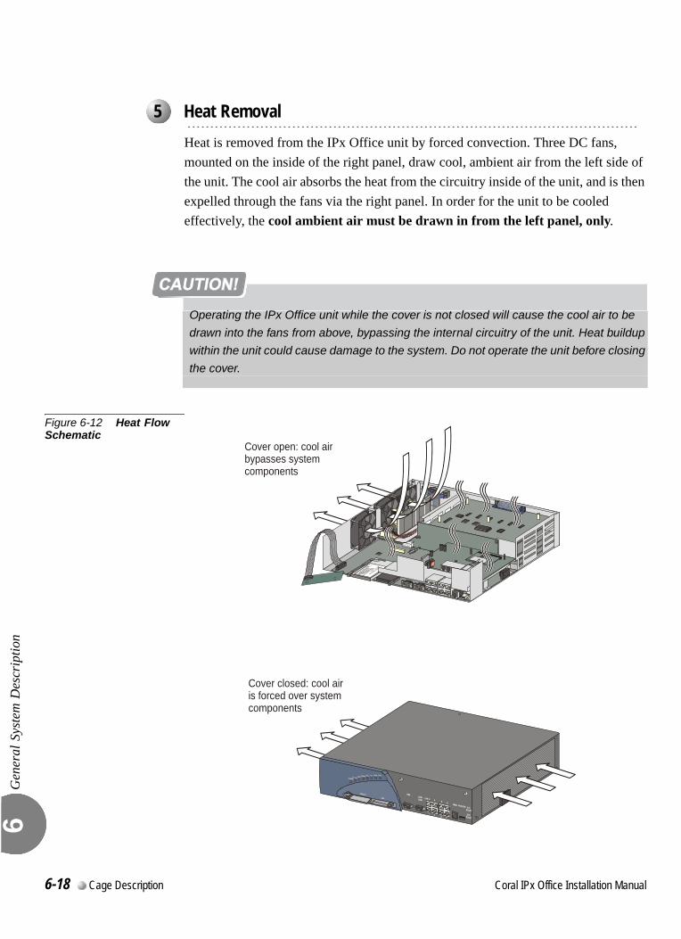
Gen
eral
Sys
tem
Des
crip
tion
6
0
Heat is removed from the IPx Office unit by forced convection. Three DC fans, mounted on the inside of the right panel, draw cool, ambient air from the left side of the unit. The cool air absorbs the heat from the circuitry inside of the unit, and is then expelled through the fans via the right panel. In order for the unit to be cooled effectively, the cool ambient air must be drawn in from the left panel, only.
Figure 6-12 Heat Flow Schematic
...................................................................................................5 Heat Removal
Operating the IPx Office unit while the cover is not closed will cause the cool air to be
drawn into the fans from above, bypassing the internal circuitry of the unit. Heat buildup
within the unit could cause damage to the system. Do not operate the unit before closing
the cover.
Cover open: cool airbypasses systemcomponents
Cover closed: cool airis forced over systemcomponents
6-18 Cage Description Coral IPx Office Installation Manual
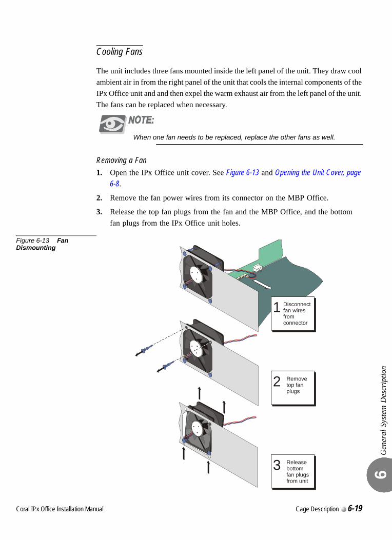
Gen
eral
Sys
tem
Des
crip
tion
6
Cooling Fans
The unit includes three fans mounted inside the left panel of the unit. They draw cool ambient air in from the right panel of the unit that cools the internal components of the IPx Office unit and and then expel the warm exhaust air from the left panel of the unit. The fans can be replaced when necessary.
When one fan needs to be replaced, replace the other fans as well.
Removing a Fan1. Open the IPx Office unit cover. See Figure 6-13 and Opening the Unit Cover, page
6-8.
2. Remove the fan power wires from its connector on the MBP Office.
3. Release the top fan plugs from the fan and the MBP Office, and the bottom fan plugs from the IPx Office unit holes.
Figure 6-13 Fan Dismounting
1 Disconnectfan wiresfrom
connector
2 Removetop fanplugs
3 Releasebottomfan plugsfrom unit
Coral IPx Office Installation Manual Cage Description 6-19
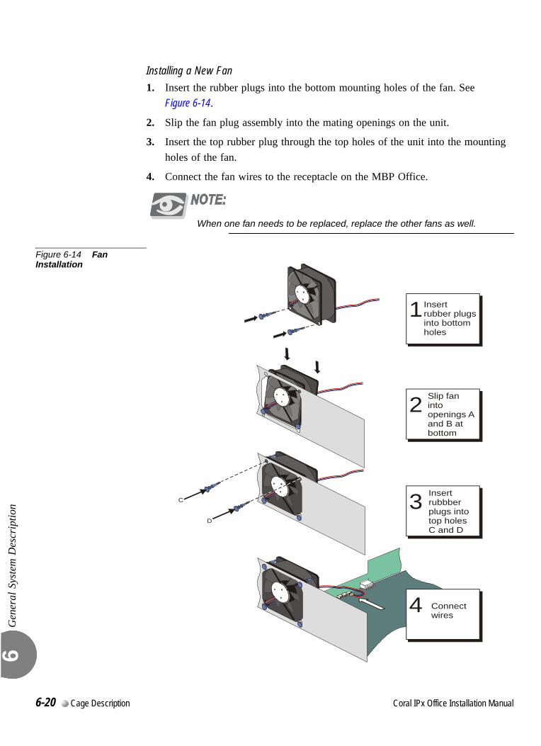
Gen
eral
Sys
tem
Des
crip
tion
6
Installing a New Fan1. Insert the rubber plugs into the bottom mounting holes of the fan. See
Figure 6-14.
2. Slip the fan plug assembly into the mating openings on the unit.
3. Insert the top rubber plug through the top holes of the unit into the mounting holes of the fan.
4. Connect the fan wires to the receptacle on the MBP Office.
When one fan needs to be replaced, replace the other fans as well.
Figure 6-14 Fan Installation
C
D
1 Insert rubber plugsinto bottom holes
2 Slip fanintoopenings Aand B atbottom
3 Insert rubbberplugs intotop holesC and D
4 Connectwires
6-20 Cage Description Coral IPx Office Installation Manual
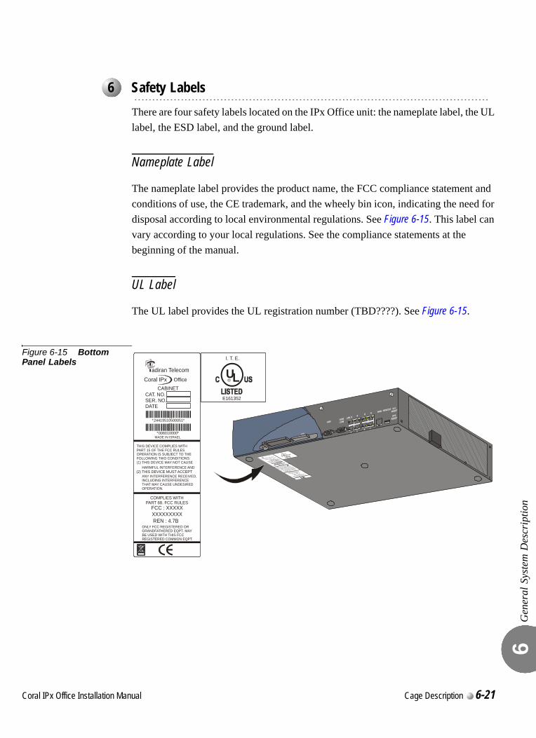
Gen
eral
Sys
tem
Des
crip
tion
6
0
There are four safety labels located on the IPx Office unit: the nameplate label, the UL label, the ESD label, and the ground label.
Nameplate Label
The nameplate label provides the product name, the FCC compliance statement and conditions of use, the CE trademark, and the wheely bin icon, indicating the need for disposal according to local environmental regulations. See Figure 6-15. This label can vary according to your local regulations. See the compliance statements at the beginning of the manual.
UL Label
The UL label provides the UL registration number (TBD????). See Figure 6-15.
Figure 6-15 Bottom Panel Labels
...................................................................................................6 Safety Labels
adiran TelecomCoral IPx Office
CABINETCAT. NO.SER. NO.DATE
244244*24419510500051*
244244*006010000*MADE IN ISRAEL
FCC : XXXXXXXXXXXXXXREN : 4.7B
COMPLIES WITHPART 68. FCC RULES
THIS DEVICE COMPLIES WITHPART 15 OF THE FCC RULES.OPERATION IS SUBJECT TO THEFOLLOWING TWO CONDITIONS:(1) THIS DEVICE MAY NOT CAUSE
ONLY FCC REGISTERED ORGRANDFATHERED EQPT. MAYBE USED WITH THIS FCCREGISTERED COMMON EQPT.
HARMFUL INTERFERENCE AND
ANY INTERFERENCE RECEIVED,INCLUDING INTERFERENCETHAT MAY CAUSE UNDESIREDOPERATION.
(2) THIS DEVICE MUST ACCEPT
UL
I. T. E.
E161352
R
Coral IPx Office Installation Manual Cage Description 6-21
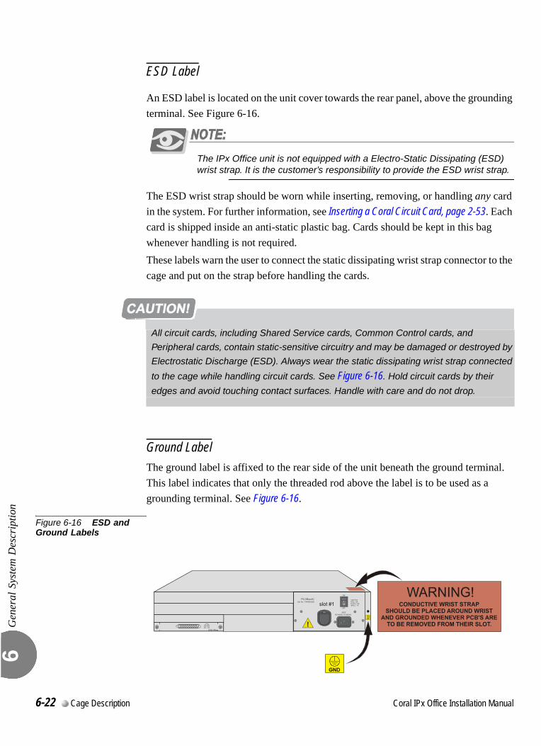
Gen
eral
Sys
tem
Des
crip
tion
6
ESD Label
An ESD label is located on the unit cover towards the rear panel, above the grounding terminal. See Figure 6-16.
The IPx Office unit is not equipped with a Electro-Static Dissipating (ESD) wrist strap. It is the customer’s responsibility to provide the ESD wrist strap.
The ESD wrist strap should be worn while inserting, removing, or handling any card in the system. For further information, see Inserting a Coral Circuit Card, page 2-53. Each card is shipped inside an anti-static plastic bag. Cards should be kept in this bag whenever handling is not required.These labels warn the user to connect the static dissipating wrist strap connector to the cage and put on the strap before handling the cards.
Ground LabelThe ground label is affixed to the rear side of the unit beneath the ground terminal. This label indicates that only the threaded rod above the label is to be used as a grounding terminal. See Figure 6-16.
Figure 6-16 ESD and Ground Labels
All circuit cards, including Shared Service cards, Common Control cards, and
Peripheral cards, contain static-sensitive circuitry and may be damaged or destroyed by
Electrostatic Discharge (ESD). Always wear the static dissipating wrist strap connected
to the cage while handling circuit cards. See Figure 6-16. Hold circuit cards by their
edges and avoid touching contact surfaces. Handle with care and do not drop.
6-22 Cage Description Coral IPx Office Installation Manual
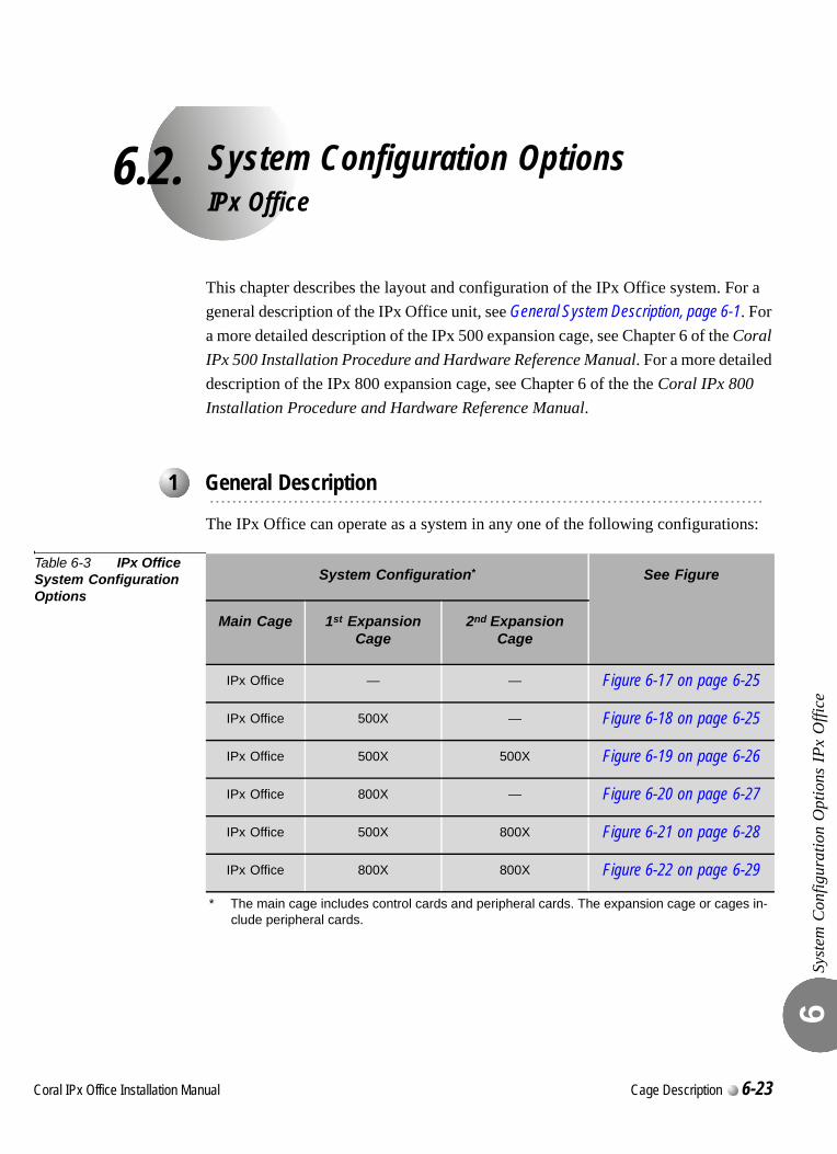
C
6.2.
oral IPx Office Installation Ma
System Configuration OptionsIPx Office
Syst
em C
onfig
urat
ion
Opt
ions
IPx
Offi
ce6
This chapter describes the layout and configuration of the IPx Office system. For a general description of the IPx Office unit, see General System Description, page 6-1. For a more detailed description of the IPx 500 expansion cage, see Chapter 6 of the Coral IPx 500 Installation Procedure and Hardware Reference Manual. For a more detailed description of the IPx 800 expansion cage, see Chapter 6 of the the Coral IPx 800 Installation Procedure and Hardware Reference Manual.
The IPx Office can operate as a system in any one of the following configurations:
Table 6-3 IPx Office System Configuration Options
...................................................................................................1 General Description
System Configuration*
* The main cage includes control cards and peripheral cards. The expansion cage or cages in-clude peripheral cards.
See Figure
Main Cage 1st Expansion Cage
2nd Expansion Cage
IPx Office — — Figure 6-17 on page 6-25
IPx Office 500X — Figure 6-18 on page 6-25
IPx Office 500X 500X Figure 6-19 on page 6-26
IPx Office 800X — Figure 6-20 on page 6-27
IPx Office 500X 800X Figure 6-21 on page 6-28
IPx Office 800X 800X Figure 6-22 on page 6-29
nual Cage Description 6-23
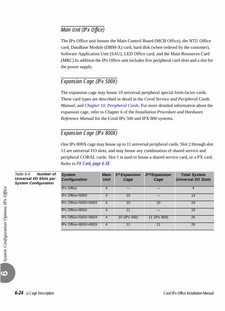
Syst
em C
onfig
urat
ion
Opt
ions
IPx
Offi
ce6
Main Unit (IPx Office)
The IPx Office unit houses the Main Control Board (MCB Office), the NTU Office card, DataBase Module (DBM-X) card, hard disk (when ordered by the customer), Software Application Unit (SAU), LED Office card, and the Main Resources Card (MRC).In addition the IPx Office unit includes five peripheral card slots and a slot for the power supply.
Expansion Cage (IPx 500X)
The expansion cage may house 10 universal peripheral special form-factor cards. These card types are described in detail in the Coral Service and Peripheral Cards Manual, and Chapter 10, Peripheral Cards. For more detailed information about the expansion cage, refer to Chapter 6 of the Installation Procedure and Hardware Reference Manual for the Coral IPx 500 and IPX 800 systems.
Expansion Cage (IPx 800X)
One IPx 800X cage may house up to 11 universal peripheral cards. Slot 2 through slot 12 are universal I/O slots, and may house any combination of shared service and peripheral CORAL cards. Slot 1 is used to house a shared service card, or a PX card. Refer to PX Card, page 6-38.
Table 6-4 Number of Universal I/O Slots per System Configuration
System Configuration
Main Unit
1st Expansion Cage
2nd Expansion Cage
Total System Universal I/O Slots
IPx Office 4 — — 4
IPx Office+500X 4 10 — 14
IPx Office+500X+500X 4 10 10 24
IPx Office+800X 4 11 — 15
IPx Office+500X+800X 4 10 (IPx 500) 11 (IPx 800) 25
IPx Office+800X+800X 4 11 11 26
6-24 Cage Description Coral IPx Office Installation Manual
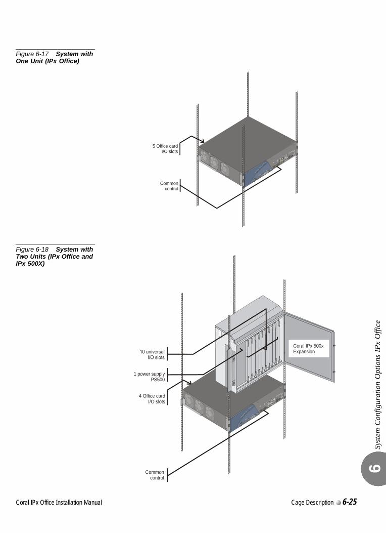
Syst
em C
onfig
urat
ion
Opt
ions
IPx
Offi
ce6
Figure 6-17 System with One Unit (IPx Office)
Figure 6-18 System with Two Units (IPx Office and IPx 500X)
5 Office cardI/O slots
Common control
4 Office cardI/O slots
Common control
1 power supplyPS500
Coral IPx 500xExpansion
Coral IPx Office Installation Manual Cage Description 6-25
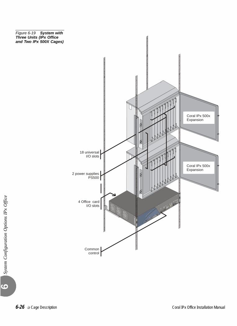
Syst
em C
onfig
urat
ion
Opt
ions
IPx
Offi
ce6
Figure 6-19 System with Three Units (IPx Office and Two IPx 500X Cages)
4 Office cardI/O slots
2 power suppliesPS500
Coral IPx 500xExpansion
Common control
Coral IPx 500xExpansion
18 universalI/O slots
6-26 Cage Description Coral IPx Office Installation Manual
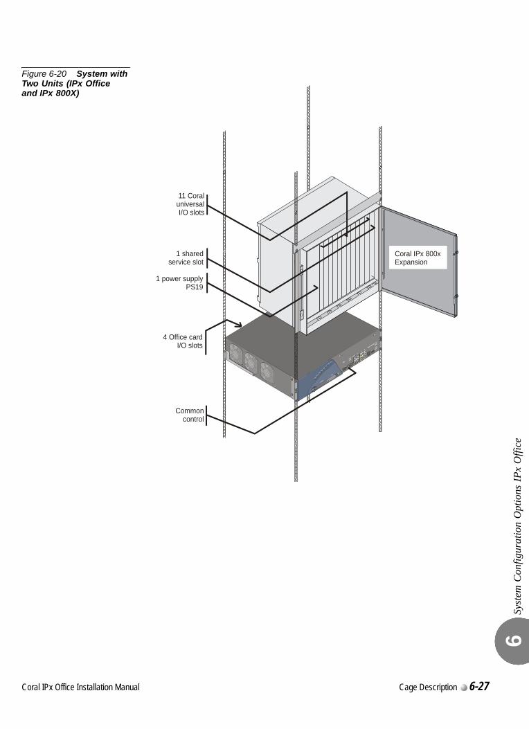
Syst
em C
onfig
urat
ion
Opt
ions
IPx
Offi
ce6
Figure 6-20 System with Two Units (IPx Office and IPx 800X)
4 Office cardI/O slots
Coral IPx 800xExpansion
11 CoraluniversalI/O slots
1 sharedservice slot
1 power supplyPS19
Common control
Coral IPx Office Installation Manual Cage Description 6-27
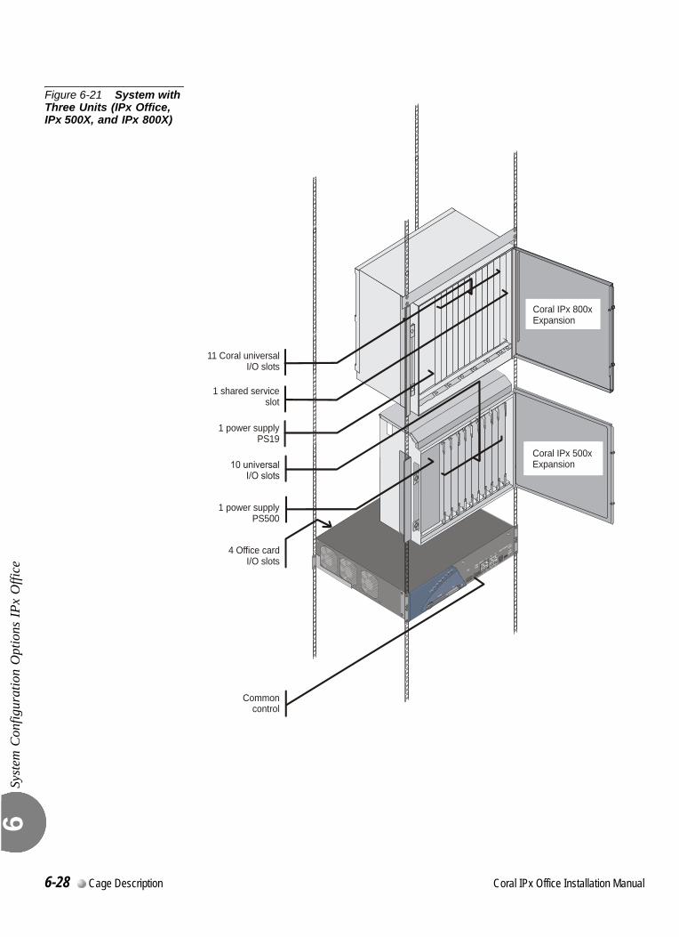
Syst
em C
onfig
urat
ion
Opt
ions
IPx
Offi
ce6
Figure 6-21 System with Three Units (IPx Office, IPx 500X, and IPx 800X)
1 power supplyPS19
4 Office cardI/O slots
Common control
1 power supplyPS500
Coral IPx 500xExpansion
Coral IPx 800xExpansion
11 Coral universalI/O slots
1 shared serviceslot
6-28 Cage Description Coral IPx Office Installation Manual
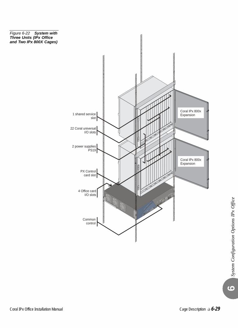
Syst
em C
onfig
urat
ion
Opt
ions
IPx
Offi
ce6
Figure 6-22 System with Three Units (IPx Office and Two IPx 800X Cages)
Coral IPx 800xExpansion
PX Controlcard slot
4 Office cardI/O slots
Coral IPx 800xExpansion
Common control
2 power suppliesPS19
22 Coral universalI/O slots
1 shared serviceslot
Coral IPx Office Installation Manual Cage Description 6-29
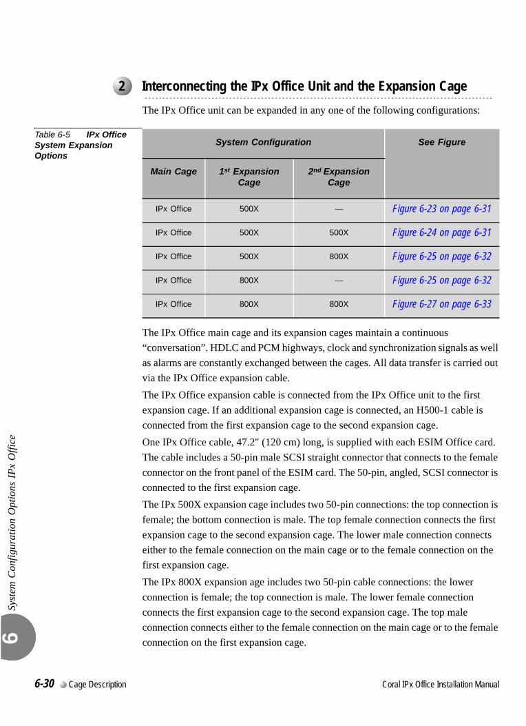
Syst
em C
onfig
urat
ion
Opt
ions
IPx
Offi
ce6
0
The IPx Office unit can be expanded in any one of the following configurations:
Table 6-5 IPx Office System Expansion Options
The IPx Office main cage and its expansion cages maintain a continuous “conversation”. HDLC and PCM highways, clock and synchronization signals as well as alarms are constantly exchanged between the cages. All data transfer is carried out via the IPx Office expansion cable.The IPx Office expansion cable is connected from the IPx Office unit to the first expansion cage. If an additional expansion cage is connected, an H500-1 cable is connected from the first expansion cage to the second expansion cage.One IPx Office cable, 47.2" (120 cm) long, is supplied with each ESIM Office card. The cable includes a 50-pin male SCSI straight connector that connects to the female connector on the front panel of the ESIM card. The 50-pin, angled, SCSI connector is connected to the first expansion cage.The IPx 500X expansion cage includes two 50-pin connections: the top connection is female; the bottom connection is male. The top female connection connects the first expansion cage to the second expansion cage. The lower male connection connects either to the female connection on the main cage or to the female connection on the first expansion cage.The IPx 800X expansion age includes two 50-pin cable connections: the lower connection is female; the top connection is male. The lower female connection connects the first expansion cage to the second expansion cage. The top male connection connects either to the female connection on the main cage or to the female connection on the first expansion cage.
...................................................................................................2 Interconnecting the IPx Office Unit and the Expansion Cage
System Configuration See Figure
Main Cage 1st Expansion Cage
2nd Expansion Cage
IPx Office 500X — Figure 6-23 on page 6-31
IPx Office 500X 500X Figure 6-24 on page 6-31
IPx Office 500X 800X Figure 6-25 on page 6-32
IPx Office 800X — Figure 6-25 on page 6-32
IPx Office 800X 800X Figure 6-27 on page 6-33
6-30 Cage Description Coral IPx Office Installation Manual
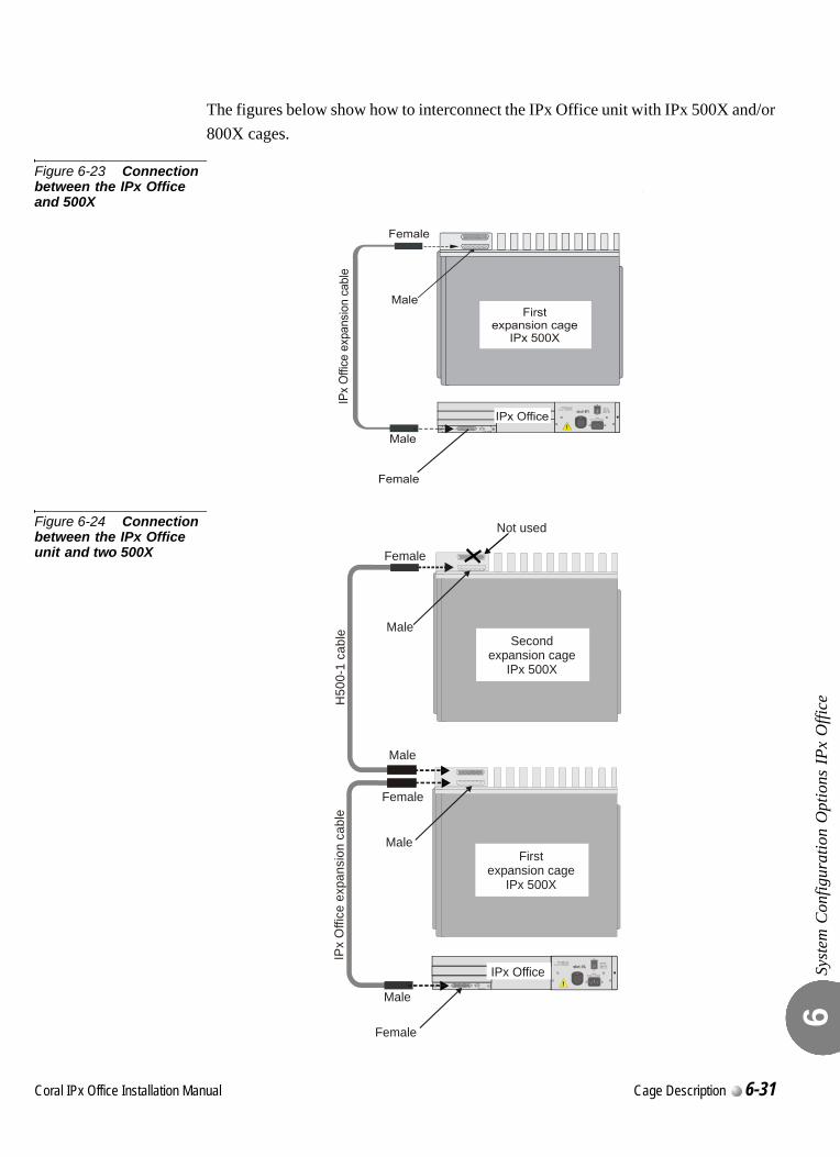
Syst
em C
onfig
urat
ion
Opt
ions
IPx
Offi
ce6
The figures below show how to interconnect the IPx Office unit with IPx 500X and/or 800X cages.
Figure 6-23 Connection between the IPx Office and 500X
Figure 6-24 Connection between the IPx Office unit and two 500X
SYNC
SEC PRM
ESIM Office
IPx OfficePS Office AC
Cat. No. 77440950200OUTPUT:
+5V 6A+3.3V 6A
DCDC
DC-48V 1A
INPUT:
ON
OFF
100-240VAC 2.2A 50/60Hz
slot #1
Male
MaleFirst
expansion cageIPx 500X
IPx
Offi
ce e
xpa n
sio n
cab
le
Female
Female
Male
Male
Not used
Secondexpansion cage
IPx 500X
H50
0-1
c ab l
e
Female
Coral IPx Office Installation Manual Cage Description 6-31
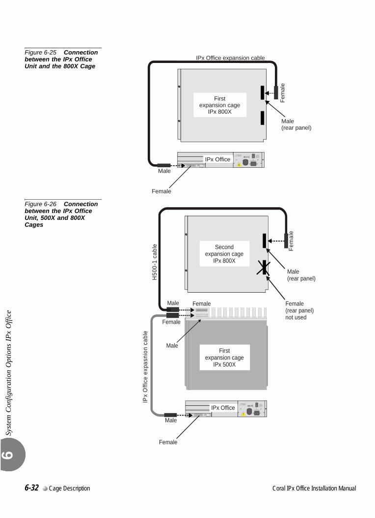
Syst
em C
onfig
urat
ion
Opt
ions
IPx
Offi
ce6
Figure 6-25 Connection between the IPx Office Unit and the 800X Cage
Figure 6-26 Connection between the IPx Office Unit, 500X and 800X Cages
SYNC
SEC PRM
ESIM Office
IPx OfficePS Office AC
Cat. No. 77440950200OUTPUT:
+5V 6A+3.3V 6A
DCDC
DC-48V 1A
INPUT:
ON
OFF
100-240VAC 2.2A 50/60Hz
slot #1
Fem
ale
Male(rear panel)
IPx Office expansion cable
Firstexpansion cage
IPx 800X
Male
Female
SYNC
SEC PRM
ESIM Office
PS Office ACCat. No. 77440950200
OUTPUT:+5V 6A+3.3V 6A
DCDC
DC-48V 1A
INPUT:
ON
OFF
100-240VAC 2.2A 50/60Hz
slot #1
Secondexpansion cage
IPx 800X
MaleFirst
expansion cageIPx 500X
Male
Male
Male(rear panel)
Female(rear panel)not used
Female
Fem
ale
Female
Female
IPx
Offi
ce e
xpas
nion
cab
le
IPx Office
H50
0-1
cabl
e
6-32 Cage Description Coral IPx Office Installation Manual
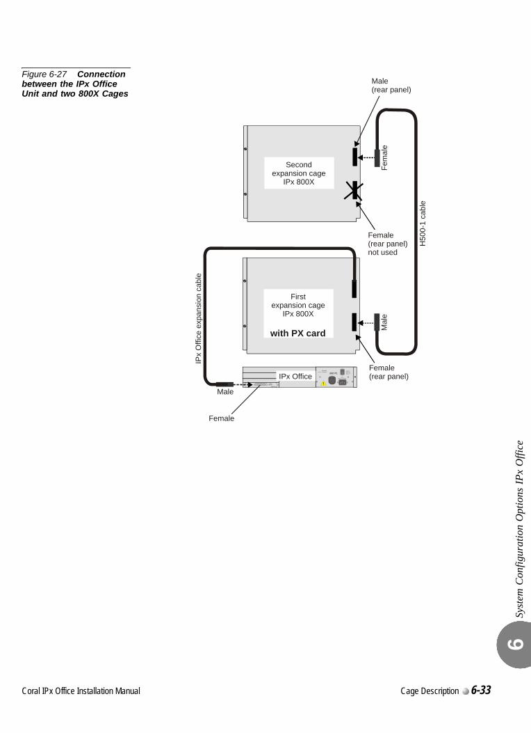
Syst
em C
onfig
urat
ion
Opt
ions
IPx
Offi
ce6
Figure 6-27 Connection between the IPx Office Unit and two 800X Cages
SYNC
SEC PRM
ESIM Office
IPx OfficePScsxAC
Cat. No. 77440950200OUTPUT:+5V 6A+3.3V 6A
DCDC
DC-48V 1A
INPUT:
ON
OFF
100-240VAC 2.2A 50/60Hz
slot #1
IPx
Offi
ce e
x pan
sion
cab
le
H50
0-1
cabl
e
Female(rear panel)
Male(rear panel)
Female(rear panel)not used
Mal
e
Firstexpansion cage
IPx 800X
Secondexpansion cage
IPx 800X
Male
Female
with PX card
Fem
ale
Coral IPx Office Installation Manual Cage Description 6-33
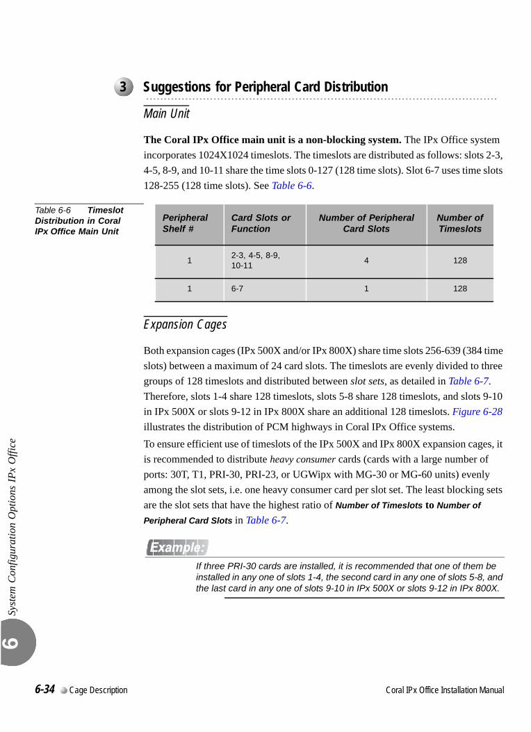
Syst
em C
onfig
urat
ion
Opt
ions
IPx
Offi
ce6
0
Main Unit
The Coral IPx Office main unit is a non-blocking system. The IPx Office system incorporates 1024X1024 timeslots. The timeslots are distributed as follows: slots 2-3, 4-5, 8-9, and 10-11 share the time slots 0-127 (128 time slots). Slot 6-7 uses time slots 128-255 (128 time slots). See Table 6-6.
Table 6-6 Timeslot Distribution in Coral IPx Office Main Unit
Expansion Cages
Both expansion cages (IPx 500X and/or IPx 800X) share time slots 256-639 (384 time slots) between a maximum of 24 card slots. The timeslots are evenly divided to three groups of 128 timeslots and distributed between slot sets, as detailed in Table 6-7. Therefore, slots 1-4 share 128 timeslots, slots 5-8 share 128 timeslots, and slots 9-10 in IPx 500X or slots 9-12 in IPx 800X share an additional 128 timeslots. Figure 6-28 illustrates the distribution of PCM highways in Coral IPx Office systems.To ensure efficient use of timeslots of the IPx 500X and IPx 800X expansion cages, it is recommended to distribute heavy consumer cards (cards with a large number of ports: 30T, T1, PRI-30, PRI-23, or UGWipx with MG-30 or MG-60 units) evenly among the slot sets, i.e. one heavy consumer card per slot set. The least blocking sets are the slot sets that have the highest ratio of Number of Timeslots to Number of
Peripheral Card Slots in Table 6-7.
If three PRI-30 cards are installed, it is recommended that one of them be installed in any one of slots 1-4, the second card in any one of slots 5-8, and the last card in any one of slots 9-10 in IPx 500X or slots 9-12 in IPx 800X.
...................................................................................................3 Suggestions for Peripheral Card Distribution
Peripheral Shelf #
Card Slots or Function
Number of Peripheral Card Slots
Number of Timeslots
12-3, 4-5, 8-9, 10-11
4 128
1 6-7 1 128
6-34 Cage Description Coral IPx Office Installation Manual
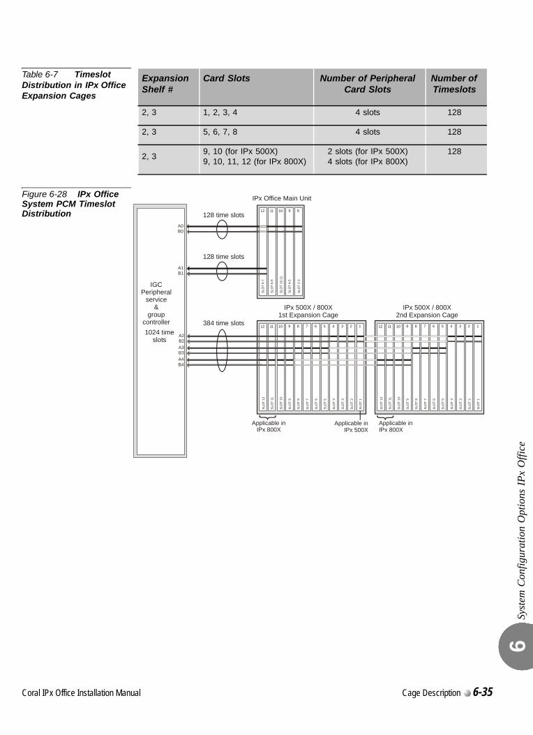
Syst
em C
onfig
urat
ion
Opt
ions
IPx
Offi
ce6
Table 6-7 Timeslot Distribution in IPx Office Expansion Cages
Figure 6-28 IPx Office System PCM Timeslot Distribution
Expansion Shelf #
Card Slots Number of Peripheral Card Slots
Number of Timeslots
2, 3 1, 2, 3, 4 4 slots 128
2, 3 5, 6, 7, 8 4 slots 128
2, 39, 10 (for IPx 500X)9, 10, 11, 12 (for IPx 800X)
2 slots (for IPx 500X)4 slots (for IPx 800X)
128
128 time slots
IPx Office Main Unit
IPx 500X / 800X1st Expansion Cage
IPx 500X / 800X2nd Expansion Cage
Applicable inIPx 800X
Applicable inIPx 800X
128 time slots
384 time slots
SLO
T 12
SLO
T 11
SLO
T 10
SLO
T 9
SLO
T 8
SLO
T 7
SLO
T 6
SLO
T 5
SLO
T 4
SLO
T 3
SLO
T 2
SLO
T 1
12 11 10 9 8 7 6 5 4 3 2 1
SLO
T 2-
3
SLO
T 4-
5
SLO
T 10
-11
SLO
T 8-
9
SLO
T 6-
7
12 11 10 9 8
SLO
T 12
SLO
T 11
SLO
T 10
SLO
T 9
SLO
T 8
SLO
T 7
SLO
T 6
SLO
T 5
SLO
T 4
SLO
T 3
SLO
T 2
SLO
T 1
12 11 10 9 8 7 6 5 4 3 2 1
IGCPeripheral
service&
groupcontroller1024 time
slotsA2
A0
A3
A4
B2
B0
B3
B4
A1B1
Applicable inIPx 500X
Coral IPx Office Installation Manual Cage Description 6-35
Syst
em C
onfig
urat
ion
Opt
ions
IPx
Offi
ce6
0
General
The Coral IPx 500X expansion cage is a small, rack or wall-mounted extension to the IPx Office, Coral IPx 500M or Coral IPx 800M cage. It supports any of the Coral FlexiCom 200 and IPx 500 family small factor and peripheral cards. Any combination of up to two IPx 500X and IPx 800X expansion cages can be connected to one IPx Office unit. The key features of the IPx 500X cage capacity and functions are described below.
Card Slots
One IPx 500X cage may house ten peripheral special form-factor “ipx” cards. These card types are described in detail in Chapter 10 of the Coral IPx 500 Hardware and Installation Manual.
Port Capacity
One IPx 500X cage supports up to 160 combined trunk and wired station ports.
Power Supply
The expansion unit is compatible with 48VDC or 115/230VAC power. The expansion cage is either powered by the PS500 AC or PS500 DC power supply unit. There is also an option to install a backup battery for the IPx 500X cage. This battery pack, known as the BATTipx, can be ordered at specific customer request.
MDFipx
An MDF may be supplied with the IPx 500X cage at specific customer request. Whenever an MDFipx unit is included with an IPx 500X cage, it can function as a master ground and be connected directly to the building master ground. For further information, see Chapter 6 of the Coral IPx 500 Installation Procedure and Hardware Reference Manual.
Setting the Configuration Jumpers
For information on setting the configuration jumpers on Coral IPx 500X cages, refer to the Coral IPx 500 Installation Manual, Section 6.3.
...................................................................................................4 Optional Coral IPx 500X Expansion Cage
6-36 Cage Description Coral IPx Office Installation Manual

Syst
em C
onfig
urat
ion
Opt
ions
IPx
Offi
ce6
Connecting the IPx 500X Cage to the IPx Office Unit
All IPx Office and IPx 500 cages are interconnected with a IPx Office expansion cable.For systems that include one IPx 500X cage and one IPx 800X cage, always connect the IPx 500X cage directly to the IPx Office unit. If an IPx 800X cage is installed between the IPx Office unit and an IPx 500X cage, a PX card will have to be installed in slot 1 of the IPx 800X cage. This slot could otherwise be used for a service card.
Related Documentation
Coral IPx 500 Hardware and Installation Manual
Coral FlexiCom and IPx Product Description
Coral IPx Office Installation Manual Cage Description 6-37
Syst
em C
onfig
urat
ion
Opt
ions
IPx
Offi
ce6
0
General
The Coral IPx 800X expansion cage is a small, rack-mounted extension to the IPx Office, IPx 800M, or Coral IPx 500M cage. It supports any of the FlexiCom 300,400,5000,6000 and IPx 800,3000,4000 family standard shared service and peripheral cards (iDSP, 8DRCF, 24SLS, 24SFT, 30T, etc.). Any combination of up to two IPx 500X and IPx 800X expansion cages can be connected to one IPx Office unit. The key features of the IPx 800X cage capacity and functions are described below.
Card Slots
One IPx 800X cage can hold up to twelve cards. Slot 2 through slot 12 are universal I/O slots, and may house any combination of shared service and peripheral cards. Slot 1 is used either to house a shared service card if there is only one expansion cage in the system, or a PX card if the IPx 800X cage supports a second expansion cage.These card types are described in detail in the Coral Service and Peripheral Cards Manual.
Port Capacity
One IPx 800X cage supports up to 264 combined trunk and wired station ports.
Power Supply
The expansion unit is compatible with 48VDC or 115/230VAC power. The expansion cage is either powered by the PS19 AC, PS19 DC, or PS19 DC-D power supply unit. There is no option to install a backup battery for the IPx 800X cage.
PX Card
The PX (Peripheral eXpansion) buffer card occupies slot 1 of the first IPx 800X expansion cage in an IPx Office+IPx 800X+IPx 800X system configuration.
...................................................................................................5 Optional Coral IPx 800X Expansion Cage
6-38 Cage Description Coral IPx Office Installation Manual
Syst
em C
onfig
urat
ion
Opt
ions
IPx
Offi
ce6
When an IPx 800X Expansion Cage is Used in an IPx Office System
There are situations where it is worthwhile to include an IPx 800X cage in an IPx 500 system:
To allow the use of Coral features not supported by IPx Office unit interface cards (XXX Office), such as iDSP, IPG, 8DRCF, magneto stations (8SM), Long Loop SLT, VIC, etc.
To allow the use of IPx 800X cages or standard CORAL cards that are already in stock.
See Additional Shared Service Cards in the Expansion Cages, page 9-3.
Setting the Configuration Jumpers
For information on setting the configuration jumpers on Coral IPx 800X cages, refer to the Coral IPx 800 Installation Manual, Chapter 6.
Connecting the IPx 800X Cage to the IPx Office Unit
All IPx Office units and IPx 800 cages are interconnected with an IPx Office expansion cable.For systems that include one IPx 500X cage and one IPx 800X cage, always connect the IPx 500X cage directly to the IPx Office unit. If an IPx 800X cage is installed between the IPx 500M cage and an IPx 500X cage, a PX card will have to be installed in slot 1 of the IPx 800X cage. This slot could otherwise be used for a service card.
Related Documentation
Coral IPx 500 Installation Procedure and Hardware Reference Manual
Coral IPx 800 Installation Procedure and Hardware Reference Manual
Coral FlexiCom and IPx Product Description
Coral IPx Office Installation Manual Cage Description 6-39

Syst
em C
onfig
urat
ion
Opt
ions
IPx
Offi
ce6
NOTES:
6-40 Cage Description Coral IPx Office Installation Manual
Coral IPx Office Installation Manual
Chapter
7Power Supply
7.1 PS Office AC Power Supply Unit .................................................7-1
7.2 PS Office DC Power Supply Unit...............................................7-13

C
7.1
oral IPx Office Installation Ma
PS Office AC Power Supply Unit
PS O
ffice
AC
Pow
er S
uppl
y U
nit
7
0
The PS Office AC power supply unit provides operating voltages for the Coral IPx Office system.
Power Source
The PS Office AC operates from a nominal input of 100-240VAC/47-63Hz.
PS Office AC Front Panel
Figure 7-1 displays the front panel of the PS Office AC. The components located on the front panel are described in the following table:
...................................................................................................1 General Description
Feature Description
Power Switch Turns the unit ON or OFF.
WARNING!
Contact with live wires in the power supply unit could cause shock, burn, or death. Do not remove the power supply from the IPx Office system when the Power switch is turned ON and power is connected.
Handle Used to pull the unit out of the card cage
Left and Right Removable Screws
Used to secure the power supply to the unit. These screws also ground the unit to the cage and safeguard the unit against malfunction.
100-240VAC Power Outlet
Male connector used to connect the female AC power cord from the mains.
nual Power Supply 7-1
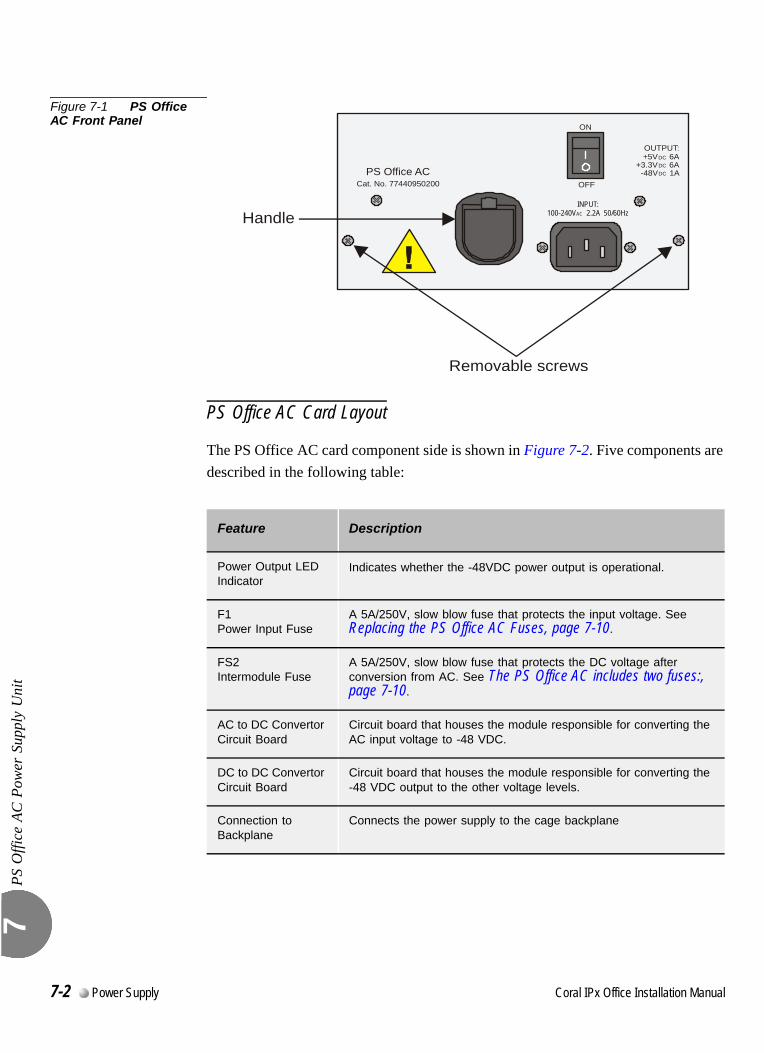
PS O
ffice
AC
Pow
er S
uppl
y U
nit
7
Figure 7-1 PS Office AC Front Panel
PS Office AC Card Layout
The PS Office AC card component side is shown in Figure 7-2. Five components are described in the following table:
Feature Description
Power Output LED Indicator
Indicates whether the -48VDC power output is operational.
F1Power Input Fuse
A 5A/250V, slow blow fuse that protects the input voltage. See Replacing the PS Office AC Fuses, page 7-10.
FS2Intermodule Fuse
A 5A/250V, slow blow fuse that protects the DC voltage after conversion from AC. See The PS Office AC includes two fuses:, page 7-10.
AC to DC Convertor Circuit Board
Circuit board that houses the module responsible for converting the AC input voltage to -48 VDC.
DC to DC Convertor Circuit Board
Circuit board that houses the module responsible for converting the -48 VDC output to the other voltage levels.
Connection to Backplane
Connects the power supply to the cage backplane
PS Office ACCat. No. 77440950200
OUTPUT:+5V 6A
+3.3V 6ADCDCDC-48V 1A
INPUT:100-240V 2.2A 50/60HzAC
ON
OFF
Removable screws
Handle
7-2 Power Supply Coral IPx Office Installation Manual
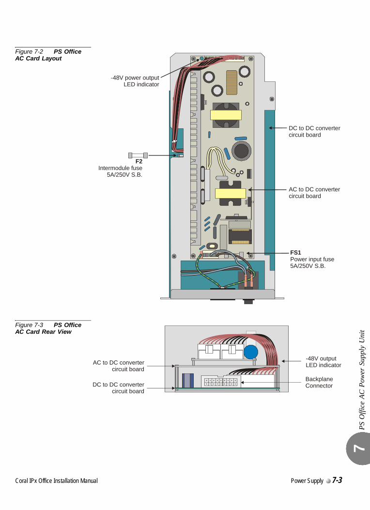
PS O
ffice
AC
Pow
er S
uppl
y U
nit
7
Figure 7-2 PS Office AC Card Layout
Figure 7-3 PS Office AC Card Rear View
FS1Power input fuse5A/250V S.B.
F2Intermodule fuse
5A/250V S.B.
-48V power outputLED indicator
AC to DC convertercircuit board
DC to DC convertercircuit board
BackplaneConnector
AC to DC convertercircuit board
DC to DC convertercircuit board
-48V outputLED indicator
Coral IPx Office Installation Manual Power Supply 7-3
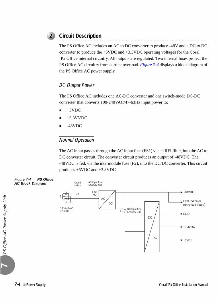
PS O
ffice
AC
Pow
er S
uppl
y U
nit
7
0
The PS Office AC includes an AC to DC converter to produce -48V and a DC to DC converter to produce the +5VDC and +3.3VDC operating voltages for the Coral IPx Office internal circuitry. All outputs are regulated. Two internal fuses protect the PS Office AC circuitry from current overload. Figure 7-4 displays a block diagram of the PS Office AC power supply.
DC Output Power
The PS Office AC includes one AC-DC converter and one switch-mode DC-DC converter that converts 100-240VAC/47-63Hz input power to:
+5VDC
+3.3VVDC
-48VDC
Normal Operation
The AC input passes through the AC input fuse (FS1) via an RFI filter, into the AC to DC converter circuit. The converter circuit produces an output of -48VDC. The -48VDC is fed, via the intermodule fuse (F2), into the DC/DC converter. This circuit produces +5VDC and +3.3VDC.
Figure 7-4 PS Office AC Block Diagram
...................................................................................................2 Circuit Description
AC Input fuse5A/250V S.B.
DC Input fuse5A/250V S.B.
-48VDC
DC100-240VAC47-63Hz
LE
FS1
F2
On/offswitch
NAC
GND
+3.3VDC
+5VDC
DC
DC
LED Indicator(on circuit board)
7-4 Power Supply Coral IPx Office Installation Manual

PS O
ffice
AC
Pow
er S
uppl
y U
nit
7
Disconnecting the AC Power Cord from the AC Power Mains
Disconnecting the AC power cord from the AC power mains will cause normal operation to discontinue. However, the best way to disable the output voltages is by turning OFF the power switch.
Turning the Power Switch OFF
Turning the power switch OFF allows you to shut down all power to the Coral IPx Office system. It is used for maintenance purposes.
Monitoring Circuitry
The PS Office AC also limits the -48VDC output to feed the peripheral card slots.
Coral IPx Office Installation Manual Power Supply 7-5
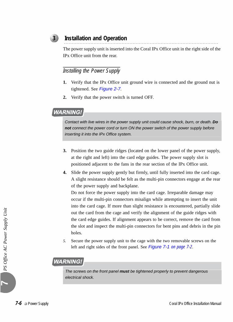
PS O
ffice
AC
Pow
er S
uppl
y U
nit
7
0
The power supply unit is inserted into the Coral IPx Office unit in the right side of the IPx Office unit from the rear.
Installing the Power Supply
1. Verify that the IPx Office unit ground wire is connected and the ground nut is tightened. See Figure 2-7.
2. Verify that the power switch is turned OFF.
3. Position the two guide ridges (located on the lower panel of the power supply, at the right and left) into the card edge guides. The power supply slot is positioned adjacent to the fans in the rear section of the IPx Office unit.
4. Slide the power supply gently but firmly, until fully inserted into the card cage. A slight resistance should be felt as the multi-pin connectors engage at the rear of the power supply and backplane.Do not force the power supply into the card cage. Irreparable damage may occur if the multi-pin connectors misalign while attempting to insert the unit into the card cage. If more than slight resistance is encountered, partially slide out the card from the cage and verify the alignment of the guide ridges with the card edge guides. If alignment appears to be correct, remove the card from the slot and inspect the multi-pin connectors for bent pins and debris in the pin holes.
5. Secure the power supply unit to the cage with the two removable screws on the left and right sides of the front panel. See Figure 7-1 on page 7-2.
...................................................................................................3 Installation and Operation
Contact with live wires in the power supply unit could cause shock, burn, or death. Do
not connect the power cord or turn ON the power switch of the power supply before
inserting it into the IPx Office system.
The screws on the front panel must be tightened properly to prevent dangerous
electrical shock.
7-6 Power Supply Coral IPx Office Installation Manual
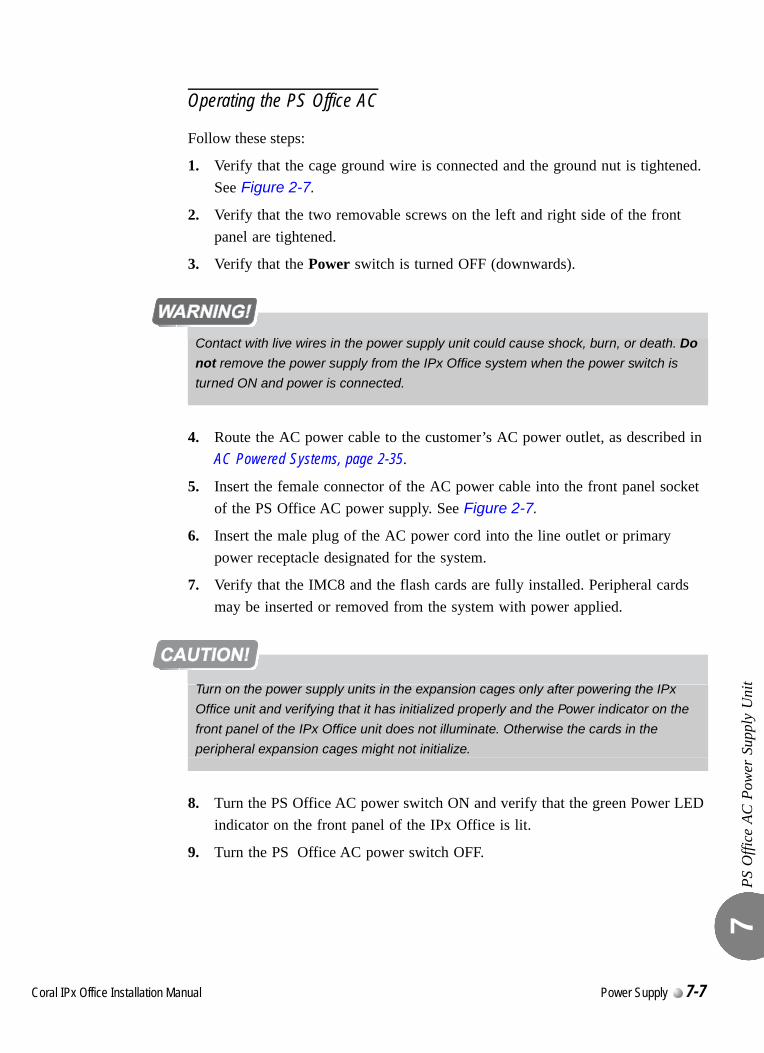
PS O
ffice
AC
Pow
er S
uppl
y U
nit
7
Operating the PS Office AC
Follow these steps:
1. Verify that the cage ground wire is connected and the ground nut is tightened. See Figure 2-7.
2. Verify that the two removable screws on the left and right side of the front panel are tightened.
3. Verify that the Power switch is turned OFF (downwards).
4. Route the AC power cable to the customer’s AC power outlet, as described in AC Powered Systems, page 2-35.
5. Insert the female connector of the AC power cable into the front panel socket of the PS Office AC power supply. See Figure 2-7.
6. Insert the male plug of the AC power cord into the line outlet or primary power receptacle designated for the system.
7. Verify that the IMC8 and the flash cards are fully installed. Peripheral cards may be inserted or removed from the system with power applied.
8. Turn the PS Office AC power switch ON and verify that the green Power LED indicator on the front panel of the IPx Office is lit.
9. Turn the PS Office AC power switch OFF.
Contact with live wires in the power supply unit could cause shock, burn, or death. Do
not remove the power supply from the IPx Office system when the power switch is
turned ON and power is connected.
Turn on the power supply units in the expansion cages only after powering the IPx
Office unit and verifying that it has initialized properly and the Power indicator on the
front panel of the IPx Office unit does not illuminate. Otherwise the cards in the
peripheral expansion cages might not initialize.
Coral IPx Office Installation Manual Power Supply 7-7
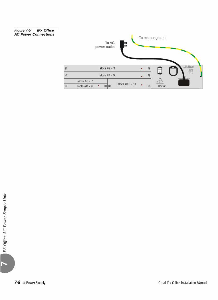
PS O
ffice
AC
Pow
er S
uppl
y U
nit
7
Figure 7-5 IPx Office AC Power Connections
slots #2 - 3
slots #4 - 5
slots #6 - 7slots #8 - 9 slots #10 - 11 slot #1
PS Office ACCat. No. 77440950200
OUTPUT:
+3.3V 6A+5V 6ADC
DCDC-48V 1A
ON
INPUT:100-240V 2.2A 50/60HzAC
OFF
To ACpower outlet
To master ground
7-8 Power Supply Coral IPx Office Installation Manual
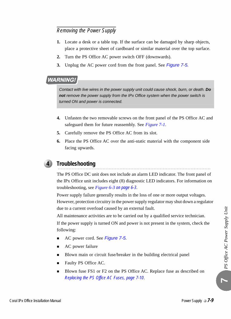
PS O
ffice
AC
Pow
er S
uppl
y U
nit
7
Removing the Power Supply
1. Locate a desk or a table top. If the surface can be damaged by sharp objects, place a protective sheet of cardboard or similar material over the top surface.
2. Turn the PS Office AC power switch OFF (downwards).
3. Unplug the AC power cord from the front panel. See Figure 7-5.
4. Unfasten the two removable screws on the front panel of the PS Office AC and safeguard them for future reassembly. See Figure 7-1.
5. Carefully remove the PS Office AC from its slot.
6. Place the PS Office AC over the anti-static material with the component side facing upwards.
0.
The PS Office DC unit does not include an alarm LED indicator. The front panel of the IPx Office unit includes eight (8) diagnostic LED indicators. For information on troubleshooting, see Figure 6-3 on page 6-3.Power supply failure generally results in the loss of one or more output voltages. However, protection circuitry in the power supply regulator may shut down a regulator due to a current overload caused by an external fault.All maintenance activities are to be carried out by a qualified service technician.If the power supply is turned ON and power is not present in the system, check the following:
AC power cord. See Figure 7-5.
AC power failure
Blown main or circuit fuse/breaker in the building electrical panel
Faulty PS Office AC.
Blown fuse FS1 or F2 on the PS Office AC. Replace fuse as described on Replacing the PS Office AC Fuses, page 7-10.
Contact with live wires in the power supply unit could cause shock, burn, or death. Do
not remove the power supply from the IPx Office system when the power switch is
turned ON and power is connected.
...................................................................................................4 Troubleshooting
Coral IPx Office Installation Manual Power Supply 7-9
PS O
ffice
AC
Pow
er S
uppl
y U
nit
7
0
The PS Office AC includes two fuses:
If the FS1 fuse blows, replace it with an identical fuse with the same rating. See Specifications, page 7-12.
If the F2 fuse blows, replace it with an identical fuse with the same rating. See Specifications, page 7-12.
To replace a fuse within the PS Office AC:
1. Turn the PS Office AC power switch OFF (downwards).
2. Unplug the AC power cord from the front panel. See Figure 7-5.
3. Remove the power supply unit from its slot and place it over the anti-static material with the component side facing upwards. See Removing the Power Supply, page 7-9.
4. Replace only with the same type and rating of fuse. See the PS Office AC card layout in Figure 7-2 on page 7-3.
5. Re-install the power supply unit as described on Installing the Power Supply, page 7-6.
Diagnosing the IPx Office LED Indicators
Refer to Front Panel, page 6-3, for a complete description of the LED indicators on the front panel of the IPx Office unit.
The IPx Office system does not include an alarm LED indicator.
1. Turn the PS Office AC power switch OFF (turn the switch downwards).
...................................................................................................5 Replacing the PS Office AC Fuses
Do not remove the power supply unit from the cage when turned ON. Sudden power
surges could damage system components. Before extracting the PS Office AC card,
verify that the power switch is turned OFF.
7-10 Power Supply Coral IPx Office Installation Manual
PS O
ffice
AC
Pow
er S
uppl
y U
nit
7
2. Remove all peripheral cards from the IPx Office unit or control and peripheral cards from the relevant cage so that they protrude from the cage by approximately 1 inch (2.5 cm).
3. Turn ON the PS Office AC. Either the PS Office AC is malfunctioning (replace as described on Installation and Operation, page 7-6) or the problem is caused by the backplane, control cards, peripheral, or NTU Office cards within the IPx Office unit. (Contact the manufacturer.)
4. To determine which peripheral card is causing the problem, insert the cards into their appropriate slots, one at a time, beginning from the right side of the cage. Ensure that the card’s rear panel connectors engage properly with the backplane and that they initialize properly.
Coral IPx Office Installation Manual Power Supply 7-11
PS O
ffice
AC
Pow
er S
uppl
y U
nit
7
0
PS Office AC Power Supply
Coral system: ................................... IPx Office
Input:...........................................................100-240VAC 47-63Hz
Power Rating: .............................................115VAC / 60Hz / 6A (Range: 98 to 126VAC)230VAC / 50Hz / 3A (Range: 198 to 253VAC)
Power Consumption (from mains): ............Continuous 130W
Outputs:.......................................................+5VDC nom. regulated 6.0A max.+3.3VDC nom. regulated 6.0A max.+48VDC nom. regulated 1.0A max.
Fuses:Input (AC)....................FS1 - 5A/250V S.B. replaceableIntermodule ..................F2 - 5A/250V S.B. replaceableOutput ..........................None
Controls and Adjustments: .........................power switch
Weight:........................................................1.2 kg
External AC Input Connection: ..................straight connector
...................................................................................................6 Specifications
7-12 Power Supply Coral IPx Office Installation Manual
C
7.2
oral IPx Office Installation Ma
PS Office DC Power Supply Unit
PS O
ffice
DC
Pow
er S
uppl
y U
nit
7
0
The PS Office DC card’s component side power supply unit provides internal operating voltages for the Coral IPx Office system. The PS Office DC operates from a nominal input of –48VDC, typically supplied by an external 48VDC rectifier or stationary battery plant. Actual input may vary from –40VDC to –56VDC, allowing operation:
From a battery power source while the batteries are charged at an equalized charge rate
Under power failure, until the batteries are completely discharged
PS Office DC Front Panel
Figure 7-6 displays the front panel of the PS Office DC. The components located on the front panel are described in the following table:
...................................................................................................1 General Description
Feature Description
Power Switch Turns the unit ON or OFF.
WARNING!
Contact with live wires in the power supply unit could cause shock, burn, or death. Do not remove the power supply from the IPx Office system when the power switch is turned ON and power is connected.
Handle Used to pull the unit out of the card cage
Right and LeftRemovable Screws
Used to secure the unit to the cage. These screws also ground the unit to the cage and safeguard the unit against malfunction.
nual Power Supply 7-13

PS O
ffice
DC
Pow
er S
uppl
y U
nit
7
Figure 7-6 PS Office DC Front Panel ON
+ -
OFF
PS Office DCCat. No. 77440950300
OUTPUT:+5V 6A
+3.3V 6ADCDCDC-48V 1A
Removable screws
7-14 Power Supply Coral IPx Office Installation Manual
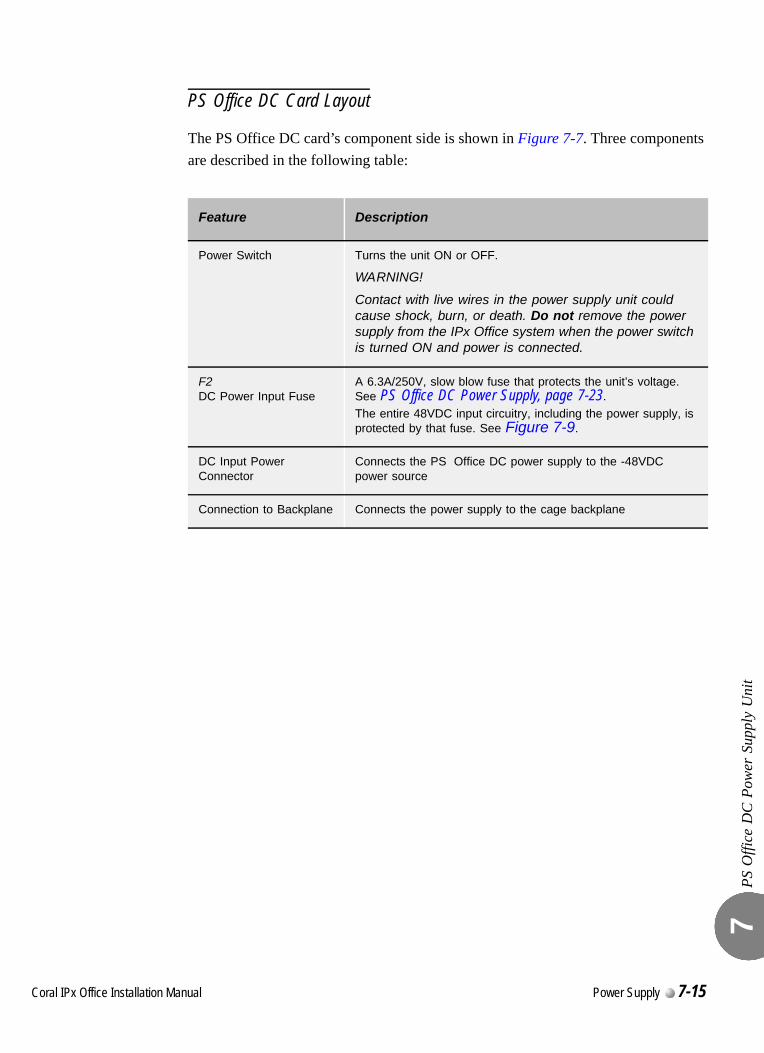
PS O
ffice
DC
Pow
er S
uppl
y U
nit
7
PS Office DC Card Layout
The PS Office DC card’s component side is shown in Figure 7-7. Three components are described in the following table:
Feature Description
Power Switch Turns the unit ON or OFF.
WARNING!
Contact with live wires in the power supply unit could cause shock, burn, or death. Do not remove the power supply from the IPx Office system when the power switch is turned ON and power is connected.
F2DC Power Input Fuse
A 6.3A/250V, slow blow fuse that protects the unit’s voltage. See PS Office DC Power Supply, page 7-23.The entire 48VDC input circuitry, including the power supply, is protected by that fuse. See Figure 7-9.
DC Input Power Connector
Connects the PS Office DC power supply to the -48VDC power source
Connection to Backplane Connects the power supply to the cage backplane
Coral IPx Office Installation Manual Power Supply 7-15
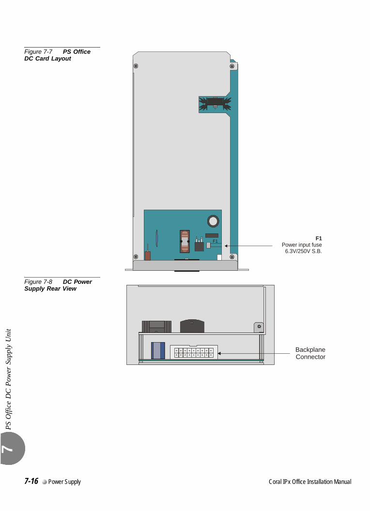
PS O
ffice
DC
Pow
er S
uppl
y U
nit
7
Figure 7-7 PS Office DC Card Layout
Figure 7-8 DC Power Supply Rear View
F1 F1Power input fuse
6.3V/250V S.B.
BackplaneConnector
7-16 Power Supply Coral IPx Office Installation Manual
PS O
ffice
DC
Pow
er S
uppl
y U
nit
7
0
Figure 7-9 presents a block diagram of the PS Office DC power supply.
Power Input Section
The DC input includes a passive filter, inrush current, and a power switch. The DC input is protected against reverse polarity.
DC Output Power
The DC to DC converters convert the –48VDC power to the following outputs:
+5VDC
3.3VDC
-48VDC
-48VDC Output Power
The PS Office DC also filters and limits the -48VDC input to feed the peripheral card slots.
Ripple and NoiseFiltering circuitry minimizes ripple and noise on the –48VDC feed to the peripheral cards. The filtering circuitry produces an output voltage that is approximately 0.5V to 1.0V lower than the input voltage -VIN to the PS Office DC.If the voltage input is less than –38±0.5VDC or greater than –58±0.5VDC, then the power supply shuts down. The power supply will turn on when the voltage is less than –58±0.5VDC or greater than –45±0.5VDC.
...................................................................................................2 Circuit Description
Coral IPx Office Installation Manual Power Supply 7-17
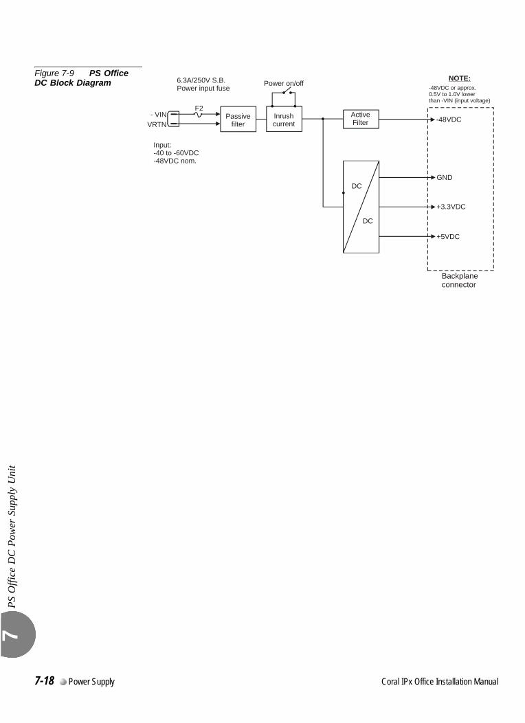
PS O
ffice
DC
Pow
er S
uppl
y U
nit
7
Figure 7-9 PS Office DC Block Diagram 6.3A/250V S.B.
Power input fusePower on/off
ActiveFilter
Passivefilter
- VIN
Input:-40 to -60VDC-48VDC nom.
VRTNInrushcurrent
NOTE:
GND
Backplaneconnector
+3.3VDC
+5VDC
-48VDC
-48VDC or approx.0.5V to 1.0V lowerthan -VIN (input voltage)
DC
DC
F2
7-18 Power Supply Coral IPx Office Installation Manual
PS O
ffice
DC
Pow
er S
uppl
y U
nit
7
0
The power supply unit is inserted into the IPx Office unit in slot 1. See Figure 7-10.
Installing the Power Supply
1. Verify that the cage ground wire is connected and the ground nut is tightened. See Figure 7-10.
2. Verify that the power switch is turned OFF.
3. Position the two guide ridges (located on the right panel of the power supply, at the right and left) into the card edge guides. The power supply slot is positioned adjacent to the fans in the rear section of the IPx Office unit.
4. Slide the power supply gently but firmly, until fully inserted into the card cage. A slight resistance should be felt as the multi-pin connectors engage at the rear of the power supply and backplane.Do not force the power supply into the card cage. Irreparable damage may occur if the multi-pin connectors misalign while attempting to insert the unit into the card cage. If more than slight resistance is encountered, partially slide out the card from the cage and verify the alignment of the guide ridges with the card edge guides. If alignment appears to be correct, remove the card from the slot and inspect the multi-pin connectors for bent pins and debris in the pin holes.
5. Secure the power supply unit to the cage with the two removable screws on the right and left of the front panel. See Figure 7-6.
...................................................................................................3 Installation and Operation
Contact with live wires in the power supply unit could cause shock, burn, or death. Do
not remove the power supply from the IPx Office system when the power switch is
turned ON and power is connected..
The screws on the front panel must be tightened properly to prevent dangerous
electrical shock.
Coral IPx Office Installation Manual Power Supply 7-19
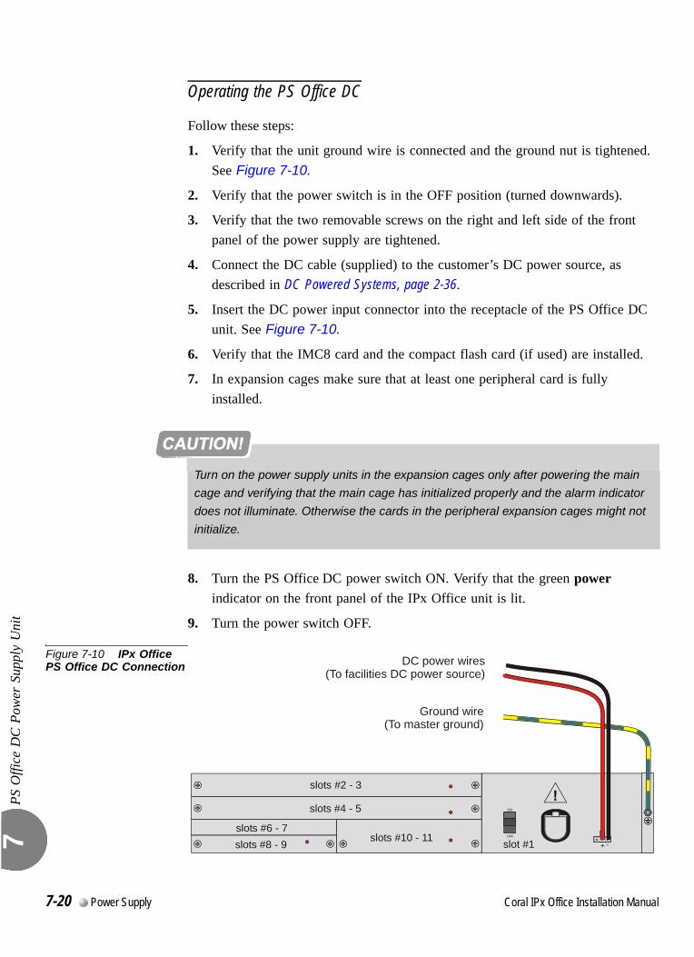
PS O
ffice
DC
Pow
er S
uppl
y U
nit
7
Operating the PS Office DC
Follow these steps:
1. Verify that the unit ground wire is connected and the ground nut is tightened. See Figure 7-10.
2. Verify that the power switch is in the OFF position (turned downwards).
3. Verify that the two removable screws on the right and left side of the front panel of the power supply are tightened.
4. Connect the DC cable (supplied) to the customer’s DC power source, as described in DC Powered Systems, page 2-36.
5. Insert the DC power input connector into the receptacle of the PS Office DC unit. See Figure 7-10.
6. Verify that the IMC8 card and the compact flash card (if used) are installed.
7. In expansion cages make sure that at least one peripheral card is fully installed.
8. Turn the PS Office DC power switch ON. Verify that the green power indicator on the front panel of the IPx Office unit is lit.
9. Turn the power switch OFF.
Figure 7-10 IPx Office PS Office DC Connection
Turn on the power supply units in the expansion cages only after powering the main
cage and verifying that the main cage has initialized properly and the alarm indicator
does not illuminate. Otherwise the cards in the peripheral expansion cages might not
initialize.
slots #2 - 3
slots #4 - 5
slots #6 - 7slots #8 - 9 slots #10 - 11 slot #1
ON
+ -OFF
DC power wires(To facilities DC power source)
Ground wire(To master ground)
7-20 Power Supply Coral IPx Office Installation Manual

PS O
ffice
DC
Pow
er S
uppl
y U
nit
7
Removing the Power Supply
1. Locate a desk or table top. If the surface can be damaged by sharp objects, place a protective sheet of cardboard or similar material over the top surface.
1. Turn the PS Office DC power switch OFF (turn the switch downwards).
2. Remove the DC power input connector. See Figure 7-10.
3. Unfasten the two captive screws located at the top and bottom of the unit’s front panel and set aside.
4. Carefully remove the PS Office DC from its slot.
5. Place the PS Office DC over the anti-static material with the component side facing upwards.
Do not remove the power supply unit from the cage when turned ON. Sudden power
surges could damage system components. Before extracting the PS Office AC card,
verify that the power switch is turned OFF.
Coral IPx Office Installation Manual Power Supply 7-21
PS O
ffice
DC
Pow
er S
uppl
y U
nit
7
0.
The PS Office DC unit does not include an alarm LED indicator. The front panel of the IPx Office unit includes eight (8) diagnostic LED indicators. For information on troubleshooting, see Front Panel, page 6-3.Power supply failure generally results in the loss of one or more output voltages. However, protection circuitry in the power supply regulator may shut down a regulator due to a current overload caused by an external fault.All maintenance activities are to be carried out by a qualified service technician.If the power supply is turned ON and power is not present in the system, check the following:
DC power wires. See Figure 7-10.
DC power failure
Blown main or circuit fuse/breaker in the building electrical panel
Faulty PS Office DC
Blown fuse FS1 or on the PS Office DC. Replace fuse as described on Replacing the PS Office DC Power Fuse, page 7-22.
0
The PS Office DC employs one fuse (F2) to protect the DC main input. To replace the DC Power Input Fuse:
1. Remove the power supply unit from its slot and place it over the anti-static material with the component side facing upwards, as described on Removing the Power Supply, page 7-21.
6. Replace only with the same type and rating of fuse. See the PS Office DC card layout in Figure 7-7 on page 7-16.
7. Reinstall the power supply unit as described on Installation and Operation, page 7-19.
...................................................................................................4 Troubleshooting
...................................................................................................5 Replacing the PS Office DC Power Fuse
Do not remove the power supply unit from the cage when turned ON. Sudden power
surges could damage system components. Before extracting the PS Office AC card,
verify that the power switch is turned OFF.
7-22 Power Supply Coral IPx Office Installation Manual
PS O
ffice
DC
Pow
er S
uppl
y U
nit
7
0 max.
PS Office DC Power Supply
Coral systems:.................................. IPx Office
Power rating:.................................... -40VDC to -56VDC, 10A max.
Power Consumption (from mains): ............Continuous 160W
Outputs: ......................................................+5VDC nom. regulated 6.0A max.+3.3VDC nom. regulated 6.0A max.-48VDC nom. regulated 1.0A max.
Fuses:Intermodule .................. F2 - 6.3A/250V S.B. replaceableOutput ..........................None
Controls and Adjustments: .........................Power switch
Weight:........................................................0.8 kg
External DC Input Connection: ..................MolexTM 39-01-4031 connector (3 circuit minifit pitch 4.2mm)
...................................................................................................6 Specifications
Coral IPx Office Installation Manual Power Supply 7-23

PS O
ffice
DC
Pow
er S
uppl
y U
nit
7
NOTES:
7-24 Power Supply Coral IPx Office Installation Manual
Coral IPx Office Installation Manual
Chapter
8Common Control Cards
8.1 Control Cards ..............................................................................8-1
8.2 MCB Office Card..........................................................................8-5
8.3 LED Card...................................................................................8-25
8.4 MRC Card..................................................................................8-27
8.5 IMC8 and IMC16 Flash Cards ...................................................8-33
8.6 Compact Flash Disk ..................................................................8-39
8.7 DBM-X Card ..............................................................................8-41

8
8-0 Common Control Cards Coral IPx Office Installation Manual
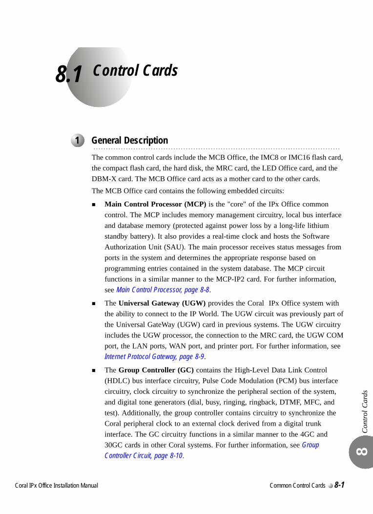
C
8.1
oral IPx Office Installation Ma
Control Cards
Con
trol C
ards
8
0
The common control cards include the MCB Office, the IMC8 or IMC16 flash card, the compact flash card, the hard disk, the MRC card, the LED Office card, and the DBM-X card. The MCB Office card acts as a mother card to the other cards.The MCB Office card contains the following embedded circuits:
Main Control Processor (MCP) is the "core" of the IPx Office common control. The MCP includes memory management circuitry, local bus interface and database memory (protected against power loss by a long-life lithium standby battery). It also provides a real-time clock and hosts the Software Authorization Unit (SAU). The main processor receives status messages from ports in the system and determines the appropriate response based on programming entries contained in the system database. The MCP circuit functions in a similar manner to the MCP-IP2 card. For further information, see Main Control Processor, page 8-8.
The Universal Gateway (UGW) provides the Coral IPx Office system with the ability to connect to the IP World. The UGW circuit was previously part of the Universal GateWay (UGW) card in previous systems. The UGW circuitry includes the UGW processor, the connection to the MRC card, the UGW COM port, the LAN ports, WAN port, and printer port. For further information, see Internet Protocol Gateway, page 8-9.
The Group Controller (GC) contains the High-Level Data Link Control (HDLC) bus interface circuitry, Pulse Code Modulation (PCM) bus interface circuitry, clock circuitry to synchronize the peripheral section of the system, and digital tone generators (dial, busy, ringing, ringback, DTMF, MFC, and test). Additionally, the group controller contains circuitry to synchronize the Coral peripheral clock to an external clock derived from a digital trunk interface. The GC circuitry functions in a similar manner to the 4GC and 30GC cards in other Coral systems. For further information, see Group Controller Circuit, page 8-10.
...................................................................................................1 General Description
nual Common Control Cards 8-1
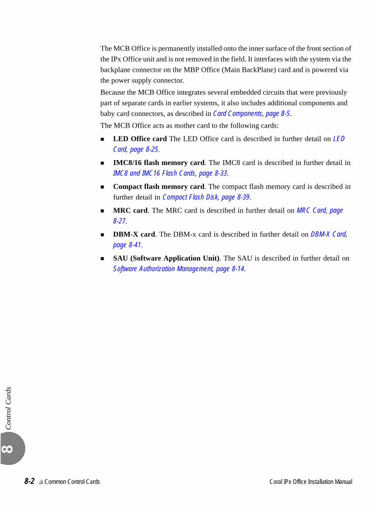
Con
trol C
ards
8
The MCB Office is permanently installed onto the inner surface of the front section of the IPx Office unit and is not removed in the field. It interfaces with the system via the backplane connector on the MBP Office (Main BackPlane) card and is powered via the power supply connector.Because the MCB Office integrates several embedded circuits that were previously part of separate cards in earlier systems, it also includes additional components and baby card connectors, as described in Card Components, page 8-5.The MCB Office acts as mother card to the following cards:
LED Office card The LED Office card is described in further detail on LED Card, page 8-25.
IMC8/16 flash memory card. The IMC8 card is described in further detail in IMC8 and IMC16 Flash Cards, page 8-33.
Compact flash memory card. The compact flash memory card is described in further detail in Compact Flash Disk, page 8-39.
MRC card. The MRC card is described in further detail on MRC Card, page 8-27.
DBM-X card. The DBM-x card is described in further detail on DBM-X Card, page 8-41.
SAU (Software Application Unit). The SAU is described in further detail on Software Authorization Management, page 8-14.
8-2 Common Control Cards Coral IPx Office Installation Manual
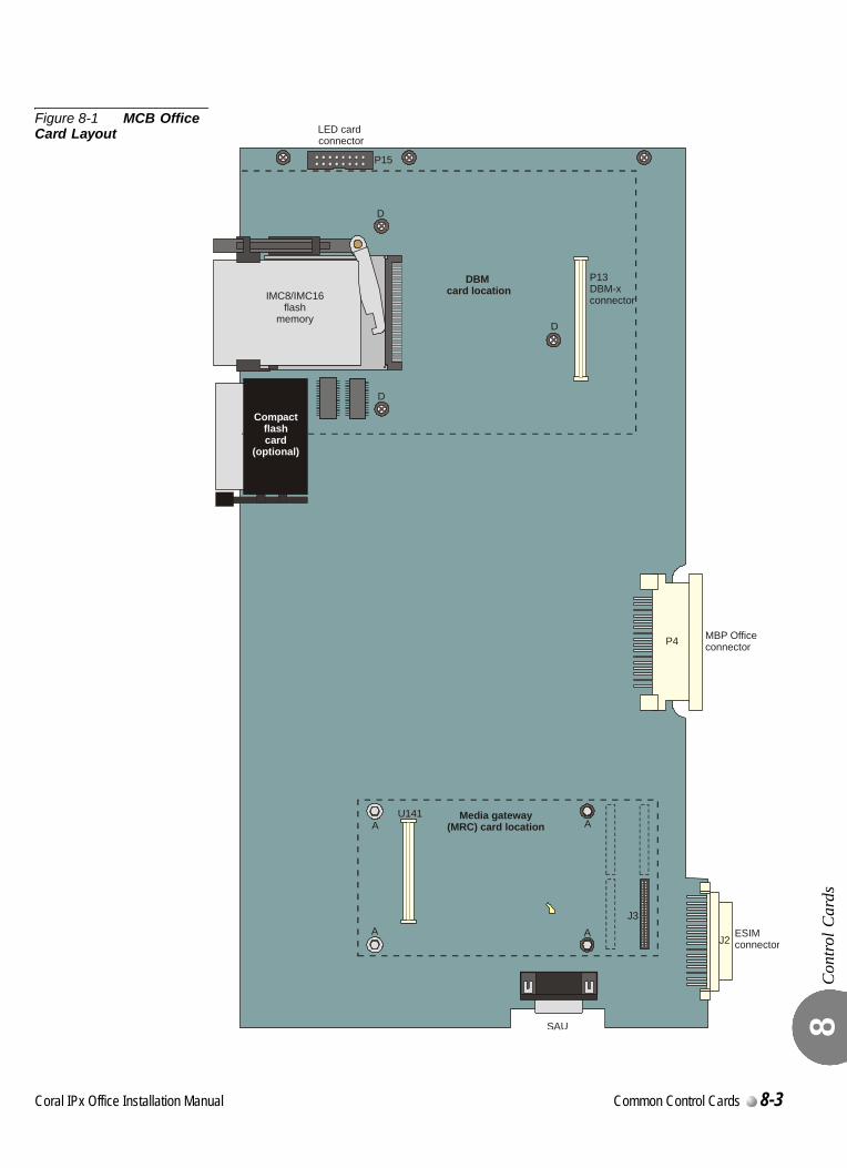
Con
trol C
ards
8
Figure 8-1 MCB Office Card Layout
P4
P13DBM-x connector
DBM card location
U141 Media gateway(MRC) card location
MBP Officeconnector
J3
SAU
J2ESIMconnector
A
D
D
D
A
A A
IMC8/IMC16flash
memory
P15
LED card connector
Compactflashcard
(optional)
Coral IPx Office Installation Manual Common Control Cards 8-3
Con
trol C
ards
8
00
Control Card Installation
Install control cards as described below:
Installing the MRC, page 8-29
Installing the IMC8/16, page 8-34
Installing the DBM-X, page 8-43
...................................................................................................2 Card Handling Procedures
Circuit cards contain static-sensitive circuitry and may be damaged or destroyed by
electro-static discharge (ESD). Always wear the static dissipating wrist strap connected
to the cage while handling circuit cards. See Figure 2-11. Hold circuit cards by their
edges and avoid touching contact surfaces. Handle with care and do not drop.
Do not attach a control card to any connector other than the one designated.
Irreparable damage may occur to a control card that is attached to the wrong connector
if power is applied.
8-4 Common Control Cards Coral IPx Office Installation Manual
C
8.2
oral IPx Office Installation Ma
MCB Office CardMain Control Board
MC
B O
ffice
Car
d M
ain
Con
trol B
oard
8
00
This section describes the features and functions of the MCB Office main control card. The MCB Office card is the control processor card for Coral IPx Office systems. The MCB Office includes the following embedded circuits:
Main Control Processor (MCP), which is a separate card in other Coral products MCP card.
Universal GateWay (UGW) embedded circuitry, which is part of a separate card in other Coral products known as the UGW (Universal GateWay) card.
Group Controller (GC) embedded circuitry, which is part of a separate card in other Coral products (4GC or 30GC, for example).
The MCB Office contains multi-pin connectors and support circuitry for the addition of DBM-X and MRC baby cards and a hard disk that will be available for future system versions. 0
The MCB Office includes components that are part of the MCP, the UGW, or GC:
Main control processor including a the MCP, CPU processor, the KB0, RS-232 connector, and the SAU. The MCP is described in further detail on Main Control Processor, page 8-8.
LED Office card connector P15. The LED Office card is described in further detail on LED Card, page 8-23.
IMC8/16 flash memory card slot. The IMC8 card is described in further detail in IMC8 and IMC16 Flash Cards, page 8-31.
Compact flash memory card slot. The compact flash memory card is described in further detail in Compact Flash Disk, page 8-37.
DBM-X card components including connector P13 and threaded holes D. The DBM-X card is described in further detail on DBM-X Card, page 8-39.
...................................................................................................1 General Information
...................................................................................................3 Card Components
nual Common Control Cards 8-5

MC
B O
ffice
Car
d M
ain
Con
trol B
oard
8
Hard disk components including connector P17 and threaded holes B. The hard disk will be provided in future versions of this product.
Universal GateWay including the UGW processor and the RS-232 connector. The UGW is described in further detail in Internet Protocol Gateway, page 8-9. Other components that belong to this circuit include:
Networking components including LAN ports, the WAN port, printer port and connector P16, and connectors J9 and J8. The networking components are described in further detail on Chapter 11, Networking.
MRC card connectors J3 and J4 and threaded holes A. The MRC card is described in further detail on MRC Card, page 8-25.
Group Controller circuit including the GC processor and replaceable software chips. The group controller circuit is described in further detail on Group Controller Circuit, page 8-10.
Rest Button used to reset the IPx Office unit including all telephony and IP applications.The reset button is described in further detail on Front Panel, page 6-3.
Backup Battery used to backup the database during power failure. The backup battery is described in further detail on Lithium Battery Condition Testing, page 8-21.
Rear connectors including the J2, ESIM connector, P4, MCB Office connector, and the P5, power supply connector.
PS Office card connector supplies power from the PS Office power supply card to the MCB Office card.
MBP Office connector connects the MCB Office card to the backplane.
ESIM connector provides an interface between the MCB Office and the first expansion cage. The MCB Office card includes a 50-pin, female connector that can facilitate an ESIM card.
8-6 Common Control Cards Coral IPx Office Installation Manual
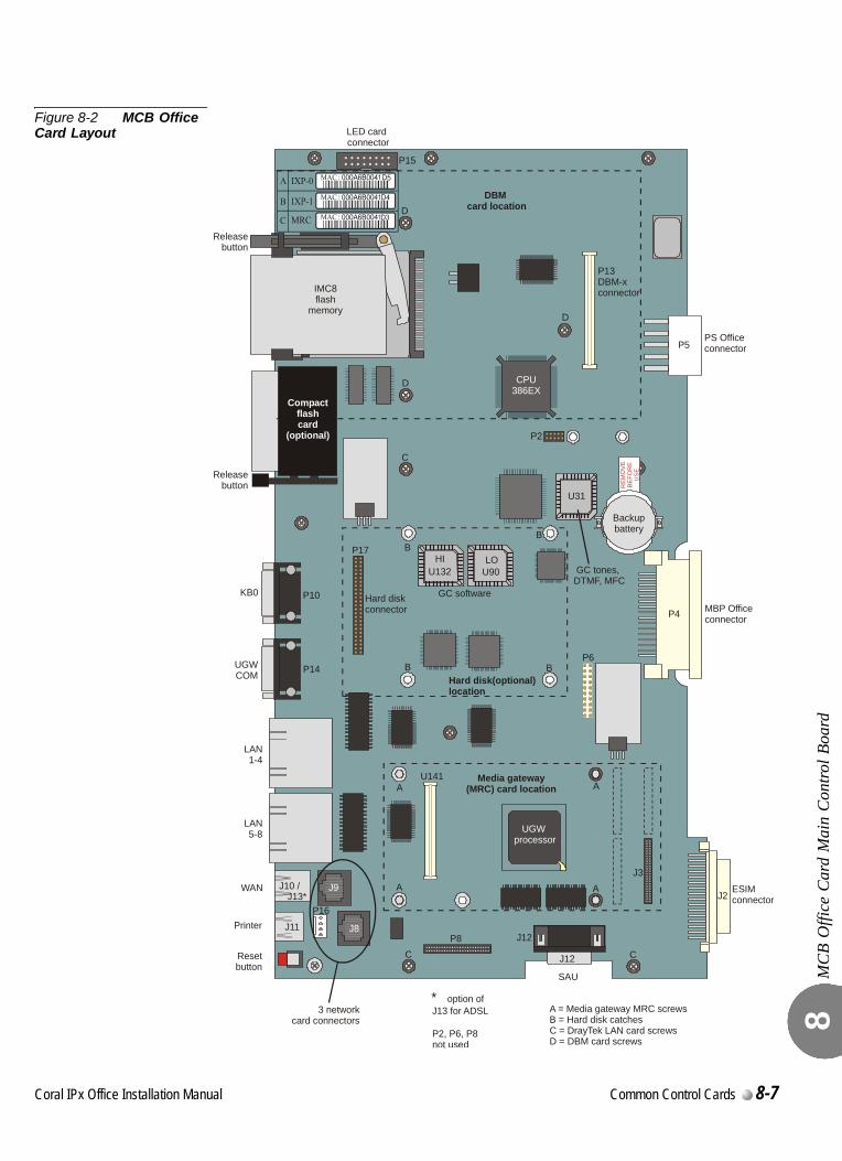
MC
B O
ffice
Car
d M
ain
Con
trol B
oard
8
Figure 8-2 MCB Office Card Layout
CPU 386EX
UGW processor
Hard diskconnector
KB0
Releasebutton
Releasebutton
UGWCOM Hard disk(optional)
location
U90
U31
P5
P2
P4
P13 DBM-x connector
PS Office connector
DBM card location
P17
P6
P10
P14
U141 Media gateway(MRC) card location
GC software
HI
LO GC tones,DTMF, MFC
MBP Officeconnector
J3
J12
SAU
J2ESIMconnector
J12Printer
P16
J9
J8
WAN J10 /J13*
J11P8
Resetbutton
3 networkcard connectors
P2, P6, P8 not used
A
C C
A = Media gateway MRC screwsB = Hard disk catchesC = DrayTek LAN card screwsD = DBM card screws
B
C
D
D
D
B
B
B
A
A A
U132
IMC8flash
memory
P15
LED card connector
LAN1-4
LAN5-8
RE
MO
VE
BE
FOR
EU
SE
Backupbattery
* option of J13 for ADSL
Compactflashcard
(optional)
Coral IPx Office Installation Manual Common Control Cards 8-7
MC
B O
ffice
Car
d M
ain
Con
trol B
oard
8
0
The Main Control Processor (MCP) provides RS-232E KB0 programming and maintenance interface, RS-232 UGW programming and maintenance interface, a SAU connection, and an IMC8/16 interface. It integrates the main processor, memory management circuitry, local bus interface, real-time clock, generic feature software memory, and database memory.The MCP supervises overall system operation by executing system-wide processes. These processes include port connection management, feature management, generic feature software installation, feature authorization, configuration database management, database backup and restoration, program interface input/output and diagnostic testing.
Port Management
In order to manage port connections and feature operation, the main control processor embedded circuit communicates through the MBP Office (backplane) card via the HDLC buses. Communication is enabled with the local card processors on every peripheral card both in the main and in the expansion units.The main processor receives status messages from the card processors regarding port activity. It determines the appropriate response based on the programming entries contained in the system database. The main processor then instructs the appropriate card processor what action to take with each port.
Memory Management
All system memory resides on the MCP embedded circuitry. RAM is located directly on the MCB Office card. The MCB Office also acts as a mother card to the DBM-X memory card and the MRC resources card. The DBM-X contains 2MB, 4MB, or 8 MB of Static Random Access Memory (SRAM) expansion memory.
Flash memory, located on the IMC8/16 card, stores the generic feature software, which determines the operation of the system. RAM, both on the MCB Office and on the DBM-X expansion cards, stores the system configuration database, and is used as a run memory for general purposes.
Database memory and real-time clock functions in the Coral system are protected against power loss by a long-life lithium backup battery installed on the MCB Office. A monitoring circuit on the card constantly measures the voltage level of the battery. It signals the main processor when the remaining energy stored in the battery is reduced to the level that it can no longer provide sufficient power to maintain the memory circuitry.
...................................................................................................4 Main Control Processor
8-8 Common Control Cards Coral IPx Office Installation Manual
MC
B O
ffice
Car
d M
ain
Con
trol B
oard
8
The generic feature software and feature authorization information is installed and updated into the IMC8/16 using FMprog PC-utility. Similarly, the system database is regularly backed up to, and may be transferred and restored from, an IMC8/16 card housed in the IMC8/16 drive.
The Program Interface Facility
The PI (Program Interface) and CoralVIEW CVA/CVD provides a text-based facility for reviewing and changing the system configuration and database. It enables the performance and monitor of diagnostic routines. The PI can be accessed either via a simple data terminal or by a personal computer.
The PI and CoralVIEW CVA/CVD/CVT can be accessed via an RS-232E data terminal port (KB0) provided on the MCB Office front panel. See Figure 8-2.0
The internet protocol gateway embedded circuit provides the Coral IPx Office system with the ability to connect to the IP World. All Coral IP stations (FlexSet-IP 280S, FlexIP SoftPhone, SIP) and external telephony gateways (Coral Teleport for analog SLTs and Loop-Start/Ground-Start trunks) receive their Coral signalling from the internet protocol gateway circuit.The internet protocol gateway is the main Coral gateway to services offered on the enterprise network. Voice calls maintained therein, although controlled by the Coral, are carried out entirely on the network when both ports involved are IP ports, thereby allowing heavy traffic configurations.The internet protocol gateway circuit is a Coral integrated gateway for IP phones, trunks and keysets (SLTs and trunks require a Coral Teleport). It provides the capacity to drive up to 240 Coral IP ports, regardless of their physical location, and provides full Coral services to these sets.Certain Coral features require the intervention of the Media Resources Card (MRC). The MRC is mounted on the MCB Office in piggyback fashion. It provides media channels used to convert PCM calls to IP Packets and vice versa. Media channels are also needed when one of the calling parties is not an IP host. No media channels are needed for pure IP-to-IP connections (direct-connects). See MRC Card, page 8-27 for further information.
...................................................................................................5 Internet Protocol Gateway
Coral IPx Office Installation Manual Common Control Cards 8-9
MC
B O
ffice
Car
d M
ain
Con
trol B
oard
8
000
The group controller embedded circuit serves as the communication link in the Coral IPx Office system, between the MCB Office and the peripheral cards via the MBP Office backplane.The group controller circuit contains the High-Level Data Link Control (HDLC) bus interface circuitry, Pulse Code Modulation (PCM) bus interface circuitry, clock circuitry to synchronize the peripheral section of the system, and digital tone generators (dial, busy, ringing, ringback, DTMF, MFC, and test). Additionally, the group controller contains circuitry to synchronize the Coral peripheral clock to an external clock derived from a digital trunk interface. The group controller circuit supports two HDLC highways and sixteen PCM streams (including one stream reserved for the MRC), and up to two expansion cages. It is capable of establishing a maximum of 1000 time slots on its maximum peripheral shelf capacity. This matrix allows for a constant frame delay operation mode.The time slot distribution is described in Figure 8-4.
Voice Switching and Time Slot Configuration
The group controller supports up to two HDLC highways, 16 PCM streams, and up to two expansion cages.Each PCM stream includes 64 Time Slots. Each shelf unit (one or two expansion cages) receives 384 Time Slots, divided into three groups of 128 Time Slots.The Coral IPx Office supports 1024 PCM time slots. The shelf unit requires only 384 of the entire 1024 time slots. The remaining time slots are used for the main unit, the tone generator, and the MRC. See Figure 8-4.
...................................................................................................1 Group Controller Circuit
8-10 Common Control Cards Coral IPx Office Installation Manual
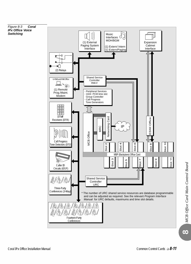
MC
B O
ffice
Car
d M
ain
Con
trol B
oard
8
Figure 8-3 Coral IPx Office Voice Switching
- Peripheral Services- 1024 PCM time slot Group Controller- Call Progress Tone Generators
Shared ServiceController
RMI-F
ExpansionCabinetInterface
MC
B O
ffice
MR
C
* The number of URC shared service resources are database programmable and can be adjusted as required. See the relevant
for URC defaults, maximums and time slot details.Program Interface
Manual
Shared ServiceController
URC
Net
wor
king
Car
dDTMFReceivers (DTR)
1 2 3
4 5 6
7 8 9
* 0 #
Call ProgressTone Detectors (DTD)
Caller ID Circuits (iDSP)
Three-PartyConferences (3-Way)
Fourteen-PartyConferences
(1) Extern/ Intern(1) Extern/Paging
Music
MOH/BGMInterfaces
(1) Paging System
Interface
External
(1) RemoteProg./Maint.
Modem
U-RMI and RMI Office
IP
Coral IPx Office Installation Manual Common Control Cards 8-11
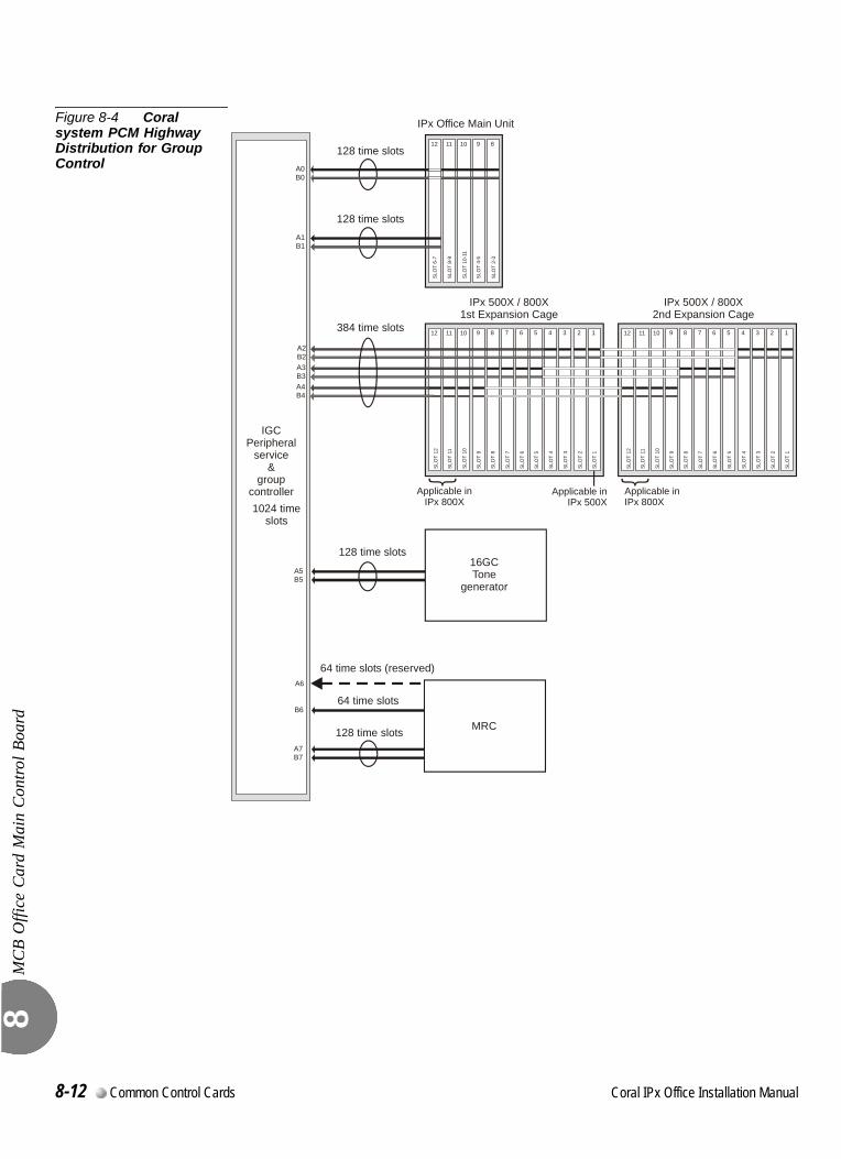
MC
B O
ffice
Car
d M
ain
Con
trol B
oard
8
Figure 8-4 Coral system PCM Highway Distribution for Group Control
128 time slots
128 time slots
64 time slots
64 time slots (reserved)
128 time slots
IPx Office Main Unit
IPx 500X / 800X1st Expansion Cage
IPx 500X / 800X2nd Expansion Cage
Applicable inIPx 800X
Applicable inIPx 800X
128 time slots
384 time slots
SLO
T 12
SLO
T 11
SLO
T 10
SLO
T 9
SLO
T 8
SLO
T 7
SLO
T 6
SLO
T 5
SLO
T 4
SLO
T 3
SLO
T 2
SLO
T 1
12 11 10 9 8 7 6 5 4 3 2 1
SLO
T 2-
3
SLO
T 4-
5
SLO
T 10
-11
SLO
T 8-
9
SLO
T 6-
7
12 11 10 9 8
SLO
T 12
SLO
T 11
SLO
T 10
SLO
T 9
SLO
T 8
SLO
T 7
SLO
T 6
SLO
T 5
SLO
T 4
SLO
T 3
SLO
T 2
SLO
T 1
12 11 10 9 8 7 6 5 4 3 2 1
16GCTone
generator
MRC
IGCPeripheral
service&
groupcontroller1024 time
slots
A2
A5
A0
A3
A4
A7
B2
B5
B0
B3
B6
A6
B4
B7
A1B1
Applicable inIPx 500X
8-12 Common Control Cards Coral IPx Office Installation Manual
MC
B O
ffice
Car
d M
ain
Con
trol B
oard
8
Circuit Description
Clock SelectionThe external clock synchronization selector monitors the two inputs for the presence of an 8.0 kHz clock signal which may be derived from a digital trunk card. A primary and secondary clock source may be defined in the system database, to synchronize the PCM clock of the group controller to the digital trunk. In the absence of an external clock source, the group controller always reverts to an internal clock. Clock failure is reported in the Program Interface.
Digital Tone GeneratorThe digital tone generator generates the audio call progress tones used to notify the caller of the status of the call. The stored tone patterns are output directly to the digital PCM bus when required.
PCM StreamingEach PCM stream operates at a data rate of 4.096 bps. Each PCM stream consists of transmit and receive signals, each of which are divided into 128 time slots. Each time slot is eight bits wide, sampled every 125 µs, or 8,000 times per second. This rate matches both A/µ law PCM voice transmission rates to facilitate complete digital integration with the local telephone network.The time switching matrix, acting on command by the system processor, is responsible for forwarding PCM voice samples from an incoming transmit time slot assigned to one port to a complementary outgoing receive time slot for the recipient port.
Using Time Slots
A call between two ports requires one transmit and one receive time slot on a single peripheral highway. Therefore, the group controller is capable of establishing calls between any 1000 time slots and any other 1000 time slots. This switching matrix allows for a Constant Frame Delay operation mode.
Coral IPx Office Installation Manual Common Control Cards 8-13
MC
B O
ffice
Car
d M
ain
Con
trol B
oard
8
0
The MCB Office supervises the feature authorization using the SAU (Software Authorization Unit) lock device. The SAU is a small, encapsulated device that is plugged into a connector on the left side of the MCB Office. Figure 8-5 illustrates four views of the SAU.
The SAU enables a set of permissions and feature authorizations associated with its unique identification number. The Coral software detects and verifies the permission settings of the SAU on the control card (MCB Office), enabling the system to function properly.
The SAU provides the system identification number (i.e. a serial number). Each system identification number is unique. In addition, the SAU stores a market identification number, which indicates the general geographical area in which the Coral system is installed. The system identification number is used to identify a particular Coral system installation site.
During software installation, the SAU serial number is compared with the features authorization data, to verify the authorized use of enhanced Coral system features. During regular system operation, the SAU is checked to ensure that it remains attached to the MCB Office card. However, if necessary, the SAU can be removed for short periods (a maximum of two weeks) without interrupting system operation. If the SAU is removed for more than two weeks, the system ceases to process calls.
Replacing an MCB Office card necessitates removing the SAU from the old card and installing it onto the replaced MCB Office card.
...................................................................................................2 Software Authorization Management
The Coral system automatically ceases call processing after 14 days for any of the
following reasons:
The SAU serial number does not match the corresponding IMC8/16 SAU serial number.
The Coral generic version contained in the IMC8/16 is higher than is authorized by the SAU.
An SAU device is removed from the MCB Office front panel.
Relevant system messages appear on the PI, warning that the system will not operate
without the proper SAU.
8-14 Common Control Cards Coral IPx Office Installation Manual
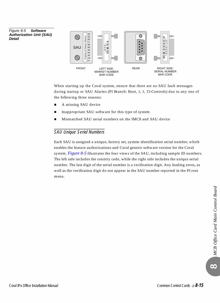
MC
B O
ffice
Car
d M
ain
Con
trol B
oard
8
Figure 8-5 Software Authorization Unit (SAU) Detail
When starting up the Coral system, ensure that there are no SAU fault messages during startup or SAU Alarms (PI Branch: Root, 1, 1, 15-Controls) due to any one of the following three reasons:
A missing SAU device
Inappropriate SAU software for this type of system
Mismatched SAU serial numbers on the IMC8 and SAU device
SAU Unique Serial Numbers
Each SAU is assigned a unique, factory set, system identification serial number, which enables the feature authorizations and Coral generic software version for the Coral system. Figure 8-5 illustrates the four views of the SAU, including sample ID numbers. The left side includes the country code, while the right side includes the unique serial number. The last digit of the serial number is a verification digit. Any leading zeros, as well as the verification digit do not appear in the SAU number reported in the PI root menu.
Pro
perty
of T
adira
n Te
leco
m
SAU
72
44
09
97
00
0
*01
5*
72
44
09
97
00
0
*0
00
07
19
*
FRONT LEFT SIDE: MARKET NUMBER
BAR CODE
RIGHT SIDE:SERIAL NUMBER
BAR CODE
REAR
Coral IPx Office Installation Manual Common Control Cards 8-15

MC
B O
ffice
Car
d M
ain
Con
trol B
oard
8
0
The front panel of the MCB Office card contains various elements that are accessed via the front panel. These elements, including LED indicators, buttons, connectors, and disk card slots. Because they are accessed directly from the front panel of the unit, they are described fully in Front Panel, page 6-3.
...................................................................................................3 Front Panel Features
8-16 Common Control Cards Coral IPx Office Installation Manual
MC
B O
ffice
Car
d M
ain
Con
trol B
oard
8
0
The IMC8/16 is an integrated memory card with a 8 or 16 MB flash memory capacity. It contains the generic software of the Coral and is used to store the system database. See IMC8 and IMC16 Flash Cards, page 8-33 for details.
The IMC8/16 is used by the main control during run-time. The memory management on the MCP-IPx allows part of the code to use portions of the IMC8/16 memory for run-time. Therefore, the IMC8/16 card must not be removed from its drive during system operation. If removed, the system will crash.
...................................................................................................4 IMC8/16 Memory Card
Do not Remove the IMC8/16 card form its drive during system operation. Removing the
IMC8 while the system is ON AIR will cause the system to shut down.
Coral IPx Office Installation Manual Common Control Cards 8-17
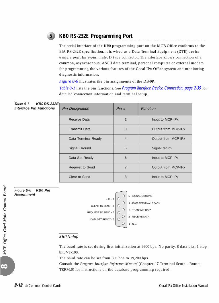
MC
B O
ffice
Car
d M
ain
Con
trol B
oard
8
0
The serial interface of the KB0 programming port on the MCB Office conforms to the EIA RS-232E specification. It is wired as a Data Terminal Equipment (DTE) device using a popular 9-pin, male, D type connector. The interface allows connection of a common, asynchronous, ASCII data terminal, personal computer or external modem for programming the various features of the Coral IPx Office system and monitoring diagnostic information.
Figure 8-6 illustrates the pin assignments of the DB-9P.
Table 8-1 lists the pin functions. See Program Interface Device Connection, page 2-39 for detailed connection information and terminal setup.
Table 8-1 KB0 RS-232E Interface Pin Functions
Figure 8-6 KB0 Pin Assignment
KB0 Setup
The baud rate is set during first initialization at 9600 bps, No parity, 8 data bits, 1 stop bit, VT-100. The baud rate can be set from 300 bps to 19,200 bps. Consult the Program Interface Reference Manual (Chapter-17 Terminal Setup - Route: TERM,0) for instructions on the database programming required.
...................................................................................................5 KB0 RS-232E Programming Port
Pin Designation Pin # Function
Receive Data 2 Input to MCP-IPx
Transmit Data 3 Output from MCP-IPx
Data Terminal Ready 4 Output from MCP-IPx
Signal Ground 5 Signal return
Data Set Ready 6 Input to MCP-IPx
Request to Send 7 Output from MCP-IPx
Clear to Send 8 Input to MCP-IPx
4 - DATA TERMINAL READY
2 - RECEIVE DATA
3 - TRANSMIT DATA
5 - SIGNAL GROUND
CLEAR TO SEND - 8
REQUEST TO SEND - 7
DATA SET READY - 6
N.C. - 9
1 - N.C.
8-18 Common Control Cards Coral IPx Office Installation Manual
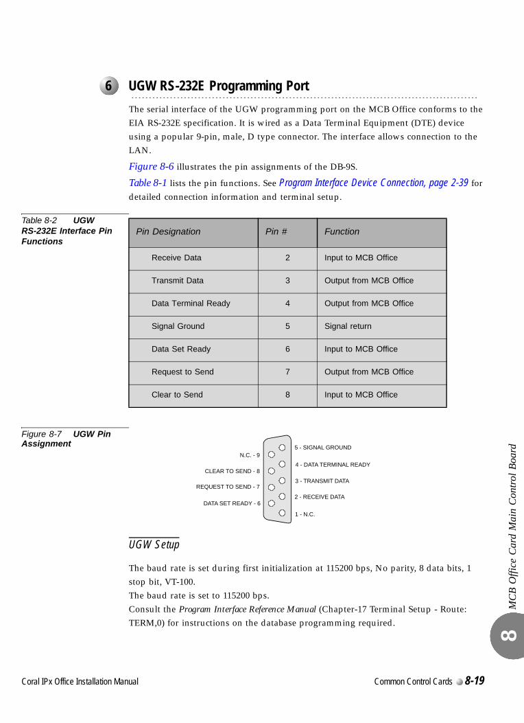
MC
B O
ffice
Car
d M
ain
Con
trol B
oard
8
0
The serial interface of the UGW programming port on the MCB Office conforms to the EIA RS-232E specification. It is wired as a Data Terminal Equipment (DTE) device using a popular 9-pin, male, D type connector. The interface allows connection to the LAN.
Figure 8-6 illustrates the pin assignments of the DB-9S.
Table 8-1 lists the pin functions. See Program Interface Device Connection, page 2-39 for detailed connection information and terminal setup.
Table 8-2 UGW RS-232E Interface Pin Functions
Figure 8-7 UGW Pin Assignment
UGW Setup
The baud rate is set during first initialization at 115200 bps, No parity, 8 data bits, 1 stop bit, VT-100. The baud rate is set to 115200 bps. Consult the Program Interface Reference Manual (Chapter-17 Terminal Setup - Route: TERM,0) for instructions on the database programming required.
...................................................................................................6 UGW RS-232E Programming Port
Pin Designation Pin # Function
Receive Data 2 Input to MCB Office
Transmit Data 3 Output from MCB Office
Data Terminal Ready 4 Output from MCB Office
Signal Ground 5 Signal return
Data Set Ready 6 Input to MCB Office
Request to Send 7 Output from MCB Office
Clear to Send 8 Input to MCB Office
4 - DATA TERMINAL READY
2 - RECEIVE DATA
3 - TRANSMIT DATA
5 - SIGNAL GROUND
CLEAR TO SEND - 8
REQUEST TO SEND - 7
DATA SET READY - 6
N.C. - 9
1 - N.C.
Coral IPx Office Installation Manual Common Control Cards 8-19

MC
B O
ffice
Car
d M
ain
Con
trol B
oard
8
0
The DBM-X card is an expansion memory card. It adds an additional 2, 6, or 8 MB SRAM to the Coral main control. The card is equipped with an extension connector on its top side. However, only one DBM-X connector ca be installed in the IPx Office unit. There is no battery installed on the DBM-X card. In the event of a power failure, the DBM-X is powered from the lithium battery installed on the MCB Office. For further information, see DBM-X Card, page 8-41.
...................................................................................................7 Installing the DBM-X Memory Card
8-20 Common Control Cards Coral IPx Office Installation Manual
MC
B O
ffice
Car
d M
ain
Con
trol B
oard
8
0
A new lithium battery can maintain power to the MCB Office memory circuitry and real-time clock for approximately 90 days. The battery is not recharged by the system power. Thus, if the battery has powered the memory and real-time clock for an extended period and is almost depleted, the contents of the memory must be backed up, and the battery must be replaced.
The battery voltage, tested under load, can be used to determine its state of charge. Voltage measured across an unused battery connected to the memory circuitry should fall between 3.30 and 3.35 volts. If the voltage measured across a battery is less than 2.50 volts, the battery must be replaced.
For first time use, release the protective battery insulator. See Figure 8-8.
Replacing the Lithium BatteryIn the following procedure, do not apply too much pressure to the battery clasp as this could cause it to snap.
1. Carefully raise the battery clasp.
2. Insert the new battery with the + (positive) symbol appearing on top.
...................................................................................................8 Lithium Battery Condition Testing
Do not use any metal tool to release or insert the battery. Doing so could result in a
short circuit and damage the battery.
Explosion and Environmental Hazards.
There is a danger of explosion if the battery is replaced incorrectly.
Replace the battery only with the same or equivalent type recommended by the
manufacturer.
Dispose of used batteries according to requirements specified by the battery
manufacturer and/or local regulatory agencies.
Coral IPx Office Installation Manual Common Control Cards 8-21
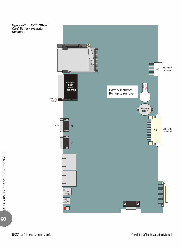
MC
B O
ffice
Car
d M
ain
Con
trol B
oard
8
Figure 8-8 MCB Office Card Battery Insulator Release
KB0
Releasebutton
P5
P4
PS Officeconnector
P10
P14
MBP Officconnector
J10 /J13*
J11
RE
MO
VE
BE
FOR
EU
SE
Backupbattery
Compactflashcard
(optional) Battery InsulatorPull up to remove
8-22 Common Control Cards Coral IPx Office Installation Manual
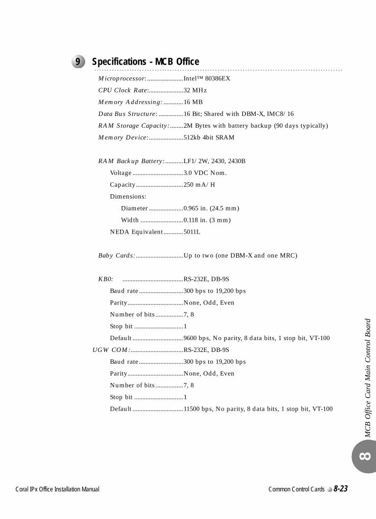
MC
B O
ffice
Car
d M
ain
Con
trol B
oard
8
00
Microprocessor: ......................Intel™ 80386EX
CPU Clock Rate:.....................32 MHz
Memory Addressing: ............16 MB
Data Bus Structure: ...............16 Bit; Shared with DBM-X, IMC8/16
RAM Storage Capacity: ........2M Bytes with battery backup (90 days typically)
Memory Device: .....................512kb 4bit SRAM
RAM Backup Battery: ...........LF1/2W, 2430, 2430B
Voltage ...............................3.0 VDC Nom.
Capacity.............................250 mA/H
Dimensions:
Diameter .....................0.965 in. (24.5 mm)
Width ..........................0.118 in. (3 mm)
NEDA Equivalent............5011L
Baby Cards: .............................Up to two (one DBM-X and one MRC)
KB0: .....................................RS-232E, DB-9S
Baud rate ...........................300 bps to 19,200 bps
Parity..................................None, Odd, Even
Number of bits .................7, 8
Stop bit ..............................1
Default ...............................9600 bps, No parity, 8 data bits, 1 stop bit, VT-100
UGW COM: ................................RS-232E, DB-9S
Baud rate ...........................300 bps to 19,200 bps
Parity..................................None, Odd, Even
Number of bits .................7, 8
Stop bit ..............................1
Default ...............................11500 bps, No parity, 8 data bits, 1 stop bit, VT-100
...................................................................................................9 Specifications - MCB Office
Coral IPx Office Installation Manual Common Control Cards 8-23

MC
B O
ffice
Car
d M
ain
Con
trol B
oard
8
8-24 Common Control Cards Coral IPx Office Installation Manual
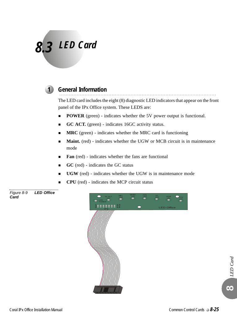
C
8.3
oral IPx Office Installation Ma
LED Card
LED
Car
d 8
0
The LED card includes the eight (8) diagnostic LED indicators that appear on the front panel of the IPx Office system. These LEDS are:
POWER (green) - indicates whether the 5V power output is functional.
GC ACT. (green) - indicates 16GC activity status.
MRC (green) - indicates whether the MRC card is functioning
Maint. (red) - indicates whether the UGW or MCB circuit is in maintenance mode
Fan (red) - indicates whether the fans are functional
GC (red) - indicates the GC status
UGW (red) - indicates whether the UGW is in maintenance mode
CPU (red) - indicates the MCP circuit status
Figure 8-9 LED Office Card
...................................................................................................1 General Information
P1LED Office
LD8POWER
GC ACT.LD7
GC LD3
MRCLD6
MAINT.LD5
FANLD4 UGW
LD2 CPULD1
131142
nual Common Control Cards 8-25
LED
Car
d 8
00
The LED Office card is attached to the MCB Office main control card and to the Coral IPx Office cover. If the cover is removed without disconnecting the flat cable from the MCB Office card first, the cable will tear and the LED Office card will not function.
This section describes how to remove the LED Office card from the unit cover and replace it with a new one.To replace the LED Office card:
1. Open the unit cover. See Opening the Unit Cover, page 6-8.
2. Position the unit cover upright, such that the front panel is resting on a flat surface.
3. Unfasten the three M3X6 screws that connect the LED Office card to the unit cover and safeguard for re-assembly.
4. Remove the LED Office card.
5. Position the new LED Office card such that the holes in the LED Office card are aligned with the threaded holes on the unit cover.
6. Fasten the LED Office card to the unit cover with the three M3X6 screws.
7. Close the unit cover. See Closing the Unit Cover, page 6-10.
...................................................................................................2 Disconnecting the LED Office Card from the MCB Office Card
Verify that the cable is detached prior to removing the unit cover. See Opening the Unit Cover, page 6-8.
...................................................................................................3 Replacing the LED Office Card
8-26 Common Control Cards Coral IPx Office Installation Manual
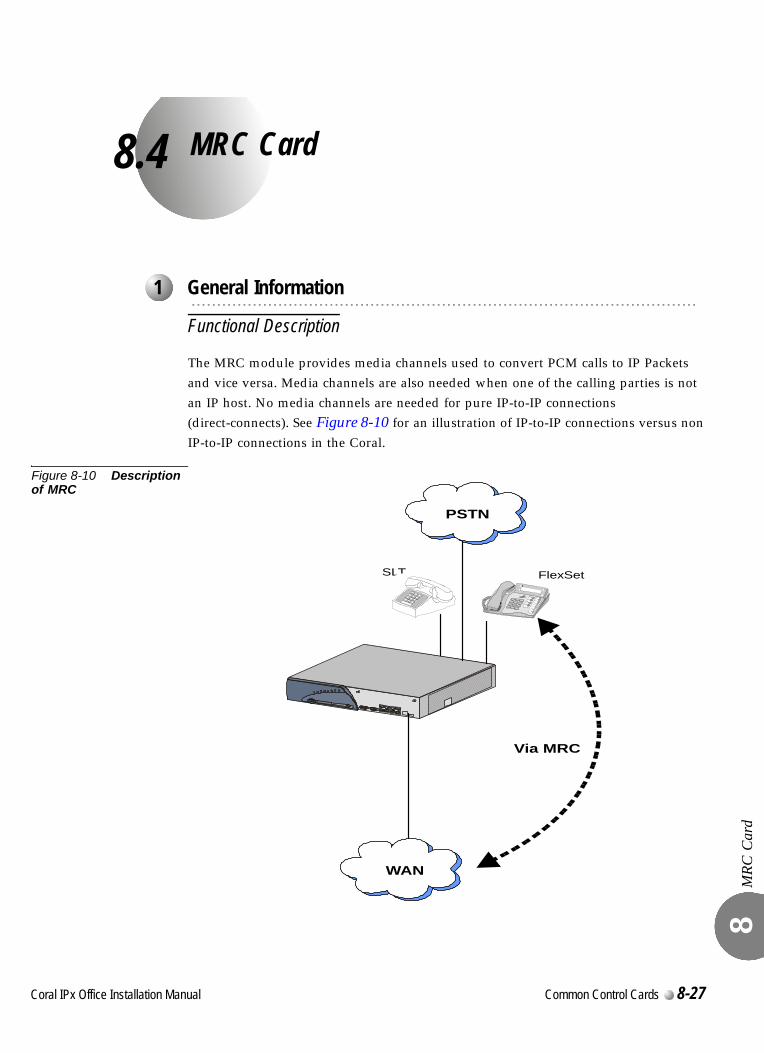
C
8.4
oral IPx Office Installation Ma
MRC Card
MRC
Car
d 8
0
Functional Description
The MRC module provides media channels used to convert PCM calls to IP Packets and vice versa. Media channels are also needed when one of the calling parties is not an IP host. No media channels are needed for pure IP-to-IP connections (direct-connects). See Figure 8-10 for an illustration of IP-to-IP connections versus non IP-to-IP connections in the Coral.
Figure 8-10 Description of MRC
...................................................................................................1 General Information
SLT FlexSet
Via MRC
WAN
PSTN
nual Common Control Cards 8-27
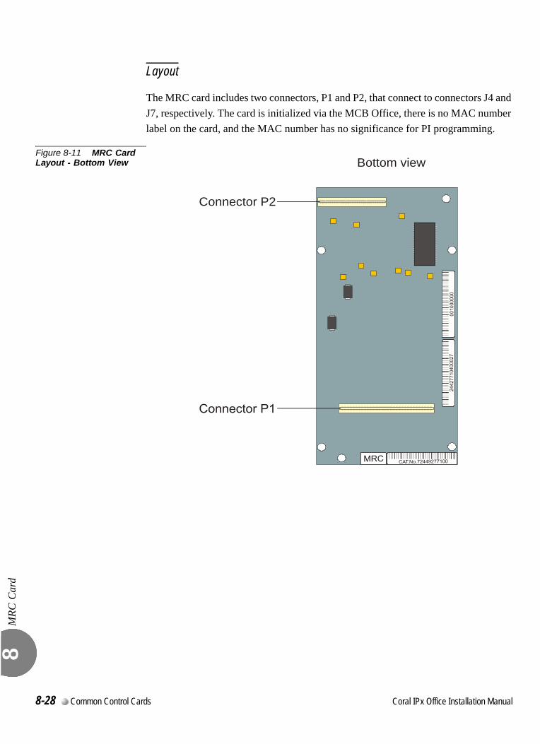
MRC
Car
d 8
Layout
The MRC card includes two connectors, P1 and P2, that connect to connectors J4 and J7, respectively. The card is initialized via the MCB Office, there is no MAC number label on the card, and the MAC number has no significance for PI programming.
Figure 8-11 MRC Card Layout - Bottom View Bottom view
Connector P2
8-28 Common Control Cards Coral IPx Office Installation Manual
MRC
Car
d 8
0
The MRC card is secured to the MCB Office by a threaded spacer. The parts used to attach the spacer to the MCB Office are listed below.
The MRC assembly kit includes additional parts. However, you only need to use the parts listed below.
Table 8-3 Assembly Parts Used in MRC Assembly Kit
Preparing for Installation
1. Locate a desk or table top that will support 20 lb (9.1 kg). If the surface can be damaged by sharp objects, place a protective sheet of cardboard or similar material over the top surface.
2. Place an anti-static sheet over the desk or table top. (The card's plastic shipping bag will suffice.)
3. Remove power from the IPx Office system by turning OFF the power switch on the front panel of the PS Office unit.
4. Disconnect the power cord or wires from the PS Office unit.
5. If necessary, disconnect the ground wire from the IPx Office unit.
6. If necessary, dismount the IPx Office unit from the rack. See Dismounting the IPx Office Unit from the Rack, page 2-16.
Installing the MRC Card
1. Open the IPx Office unit. See Opening the Unit Cover, page 6-8.
2. Fasten the four hex M3X10 standoff spacers into the three holes displayed in Figure 8-15.
3. Position the MRC card on top of the MCB Office card and align the four fastening holes on top of the standoff spacers.
...................................................................................................2 Installing the MRC
Part Quantity
Phillips screw M3X6 4
Lock washer M3 4
Male-female spacer hex M3X10 4
Coral IPx Office Installation Manual Common Control Cards 8-29
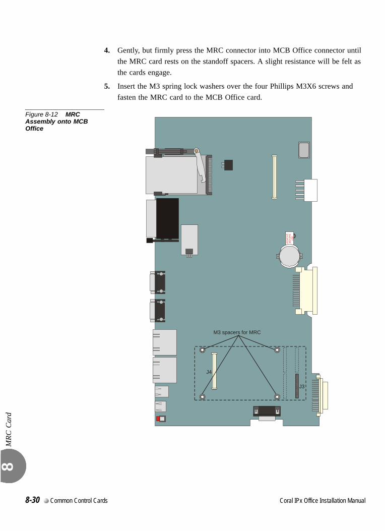
MRC
Car
d 8
4. Gently, but firmly press the MRC connector into MCB Office connector until the MRC card rests on the standoff spacers. A slight resistance will be felt as the cards engage.
5. Insert the M3 spring lock washers over the four Phillips M3X6 screws and fasten the MRC card to the MCB Office card.
Figure 8-12 MRC Assembly onto MCB Office
REM
OVE
BEF
OR
EU
SE
J4
M3 spacers for MRC
J3
8-30 Common Control Cards Coral IPx Office Installation Manual
MRC
Car
d 8
0
1. Repeat Preparing for Installation, page 8-43.
2. Remove the M3X6 Phillips screws and washers that secure the MRC card to the standoff spacers of the MCB Office card and safeguard for future re-assembly.
3. Place your thumbs on the MCB Office card, on either side of the MRC card near the MCB Office front side. Use your fingers to lift the edge of the MRC card on both sides and gently disengage the multi-pin connector P1 on the MRC from MCB Office connector J4 and multi-pin connector P2 on the MRC from MCB Office connector J7.
...................................................................................................3 Removing the MRC
Coral IPx Office Installation Manual Common Control Cards 8-31

MRC
Car
d 8
NOTES:
8-32 Common Control Cards Coral IPx Office Installation Manual
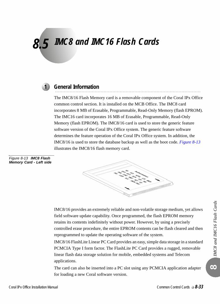
C
8.5
oral IPx Office Installation Ma
IMC8 and IMC16 Flash Cards
IMC
8 an
d IM
C16
Fla
sh C
ards
8
The IMC8/16 Flash Memory card is a removable component of the Coral IPx Office common control section. It is installed on the MCB Office. The IMC8 card incorporates 8 MB of Erasable, Programmable, Read-Only Memory (flash EPROM). The IMC16 card incorporates 16 MB of Erasable, Programmable, Read-Only Memory (flash EPROM). The IMC8/16 card is used to store the generic feature software version of the Coral IPx Office system. The generic feature software determines the feature operation of the Coral IPx Office system. In addition, the IMC8/16 is used to store the database backup as well as the boot code. Figure 8-13 illustrates the IMC8/16 flash memory card.
Figure 8-13 IMC8 Flash Memory Card - Left side
IMC8/16 provides an extremely reliable and non-volatile storage medium, yet allows field software update capability. Once programmed, the flash EPROM memory retains its contents indefinitely without power. However, by using a precisely controlled erase procedure, the entire EPROM contents can be flash cleared and then reprogrammed to update the operating software of the system.IMC8/16 FlashLite Linear PC Card provides an easy, simple data storage in a standard PCMCIA Type I form factor. The FlashLite PC Card provides a rugged, removable linear flash data storage solution for mobile, embedded systems and Telecom applications.The card can also be inserted into a PC slot using any PCMCIA application adapter for loading a new Coral software version.
...................................................................................................1 General Information
nual Common Control Cards 8-33
IMC
8 an
d IM
C16
Fla
sh C
ards
8
0
The IMC8/16 does not occupy a card slot within the Coral IPx Office system. It is installed on the PCM-CIA connector on the MCB Office. The IMC8/16 release button enables the removal of the IMC8/16 card. An arrow on the foil attached to the front side of the IMC8/16 card indicates the insertion direction. The IMC8/16 card position on the MCB Office card is shown in Figure 8-13.
Insert the IMC8/16 card with its label side facing left, as shown in Figure 8-13.
The IMC8/16 card contains three types of data:
Generic Feature Software Version
Database Backup
Boot Code
When replacing an IMC8/16 card with another card that contains upgraded software, the new card will not contain a database. It is therefore important to make a binary backup of the database before removing the card. See the Database Binary Backup PC
Utility Reference Manual for further details.
Make sure that the IMC8/16 card being installed is not write-protected.
After a new card is installed, verify that the PI starts up properly, and then save the database in accordance with the procedure provided in System Database Control, page 4-5.
...................................................................................................2 Installing the IMC8/16
In order to avoid damage to the IMC8/16 card, press very gently during the card
insertion.
Before each installation or removal of an IMC8/16 card, press the RESET button.
8-34 Common Control Cards Coral IPx Office Installation Manual
IMC
8 an
d IM
C16
Fla
sh C
ards
8
The IMC8/16 release button enables the removal of the IMC8/16 card.
When replacing an IMC8/16 card with another card that contains upgraded software, the new card will not contain a database. It is therefore important to make a binary backup of the database before removing the card. See the Database Binary Backup PC
Utility Reference Manual for further details.
...................................................................................................3 Removing the IMC8/16
Before each removal of an IMC8/16 card, press the RESET button.
Coral IPx Office Installation Manual Common Control Cards 8-35

IMC
8 an
d IM
C16
Fla
sh C
ards
8
0
Storage Capacity:....................... 8,388,608 Bytes (8MB)
Memory Configuration: ........... 16 bits
PCMCIA:..................................... Standard Compatible
...................................................................................................4 Specifications
8-36 Common Control Cards Coral IPx Office Installation Manual

IMC
8 an
d IM
C16
Fla
sh C
ards
8
NOTES:
Coral IPx Office Installation Manual Common Control Cards 8-37

IMC
8 an
d IM
C16
Fla
sh C
ards
8
8-38 Common Control Cards Coral IPx Office Installation Manual
C
8.6
oral IPx Office Installation Ma
Compact Flash Disk
Com
pact
Fla
sh D
isk
8
0
An ATA-type PCMCIA connector houses the Compact Flash Disk (CFD) memory. The CFD contains the TBD??? software and TBD??? files. The CFD disk has an erasable memory capacity of 64MB or more. The appropriate memory capacity is dependent on ?????? the Coral system configuration.The ATA type PCMCIA slot is housed on the MCB Office card side edge.0
The CFD card is inserted with the front side facing up.
...................................................................................................1 Introduction
...................................................................................................2 Inserting the CFD
nual Common Control Cards 8-39

Com
pact
Fla
sh D
isk
8
8-40 Common Control Cards Coral IPx Office Installation Manual
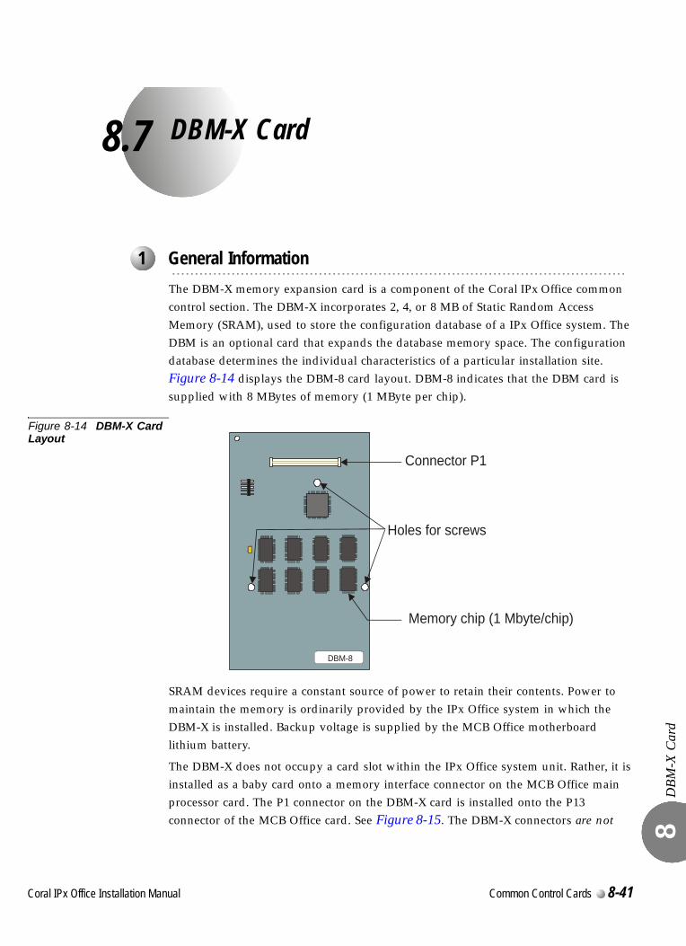
C
8.7
oral IPx Office Installation Ma
DBM-X Card
DBM
-X C
ard
8
0
The DBM-X memory expansion card is a component of the Coral IPx Office common control section. The DBM-X incorporates 2, 4, or 8 MB of Static Random Access Memory (SRAM), used to store the configuration database of a IPx Office system. The DBM is an optional card that expands the database memory space. The configuration database determines the individual characteristics of a particular installation site. Figure 8-14 displays the DBM-8 card layout. DBM-8 indicates that the DBM card is supplied with 8 MBytes of memory (1 MByte per chip).
Figure 8-14 DBM-X Card Layout
SRAM devices require a constant source of power to retain their contents. Power to maintain the memory is ordinarily provided by the IPx Office system in which the DBM-X is installed. Backup voltage is supplied by the MCB Office motherboard lithium battery.
The DBM-X does not occupy a card slot within the IPx Office system unit. Rather, it is installed as a baby card onto a memory interface connector on the MCB Office main processor card. The P1 connector on the DBM-X card is installed onto the P13 connector of the MCB Office card. See Figure 8-15. The DBM-X connectors are not
...................................................................................................1 General Information
DBM-8
Holes for screws
Connector P1
Memory chip (1 Mbyte/chip)
nual Common Control Cards 8-41

DBM
-X C
ard
8
compatible with the DBM-X connectors. Only one DBM-X card can be installed in the IPx Office unit.
When is a DBM-X card required?
A DBM-X card is required when:
The Coral Directory, Traffic, and Call Log features are used.
The CoraLINK Adapter circuitry is relevant to your system version.
Consult the Program Interface Reference Manual (Chapter-4 Size Definition, Route: SIZ, CHECK MEMORY?) to display the database memory status.
8-42 Common Control Cards Coral IPx Office Installation Manual
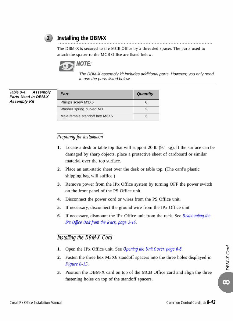
DBM
-X C
ard
8
0
The DBM-X is secured to the MCB Office by a threaded spacer. The parts used to attach the spacer to the MCB Office are listed below.
The DBM-X assembly kit includes additional parts. However, you only need to use the parts listed below.
Table 8-4 Assembly Parts Used in DBM-X Assembly Kit
Preparing for Installation
1. Locate a desk or table top that will support 20 lb (9.1 kg). If the surface can be damaged by sharp objects, place a protective sheet of cardboard or similar material over the top surface.
2. Place an anti-static sheet over the desk or table top. (The card's plastic shipping bag will suffice.)
3. Remove power from the IPx Office system by turning OFF the power switch on the front panel of the PS Office unit.
4. Disconnect the power cord or wires from the PS Office unit.
5. If necessary, disconnect the ground wire from the IPx Office unit.
6. If necessary, dismount the IPx Office unit from the rack. See Dismounting the IPx Office Unit from the Rack, page 2-16.
Installing the DBM-X Card
1. Open the IPx Office unit. See Opening the Unit Cover, page 6-8.
2. Fasten the three hex M3X6 standoff spacers into the three holes displayed in Figure 8-15.
3. Position the DBM-X card on top of the MCB Office card and align the three fastening holes on top of the standoff spacers.
...................................................................................................2 Installing the DBM-X
Part Quantity
Phillips screw M3X6 6
Washer spring curved M3 3
Male-female standoff hex M3X6 3
Coral IPx Office Installation Manual Common Control Cards 8-43
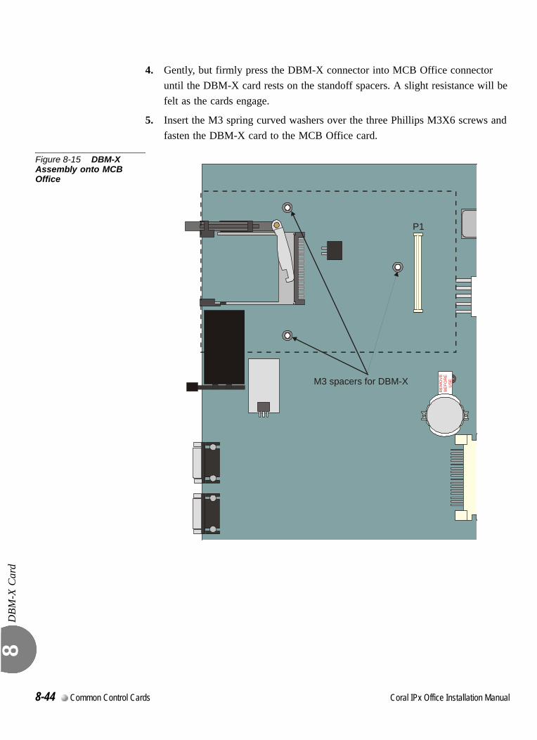
DBM
-X C
ard
8
4. Gently, but firmly press the DBM-X connector into MCB Office connector until the DBM-X card rests on the standoff spacers. A slight resistance will be felt as the cards engage.
5. Insert the M3 spring curved washers over the three Phillips M3X6 screws and fasten the DBM-X card to the MCB Office card.
Figure 8-15 DBM-X Assembly onto MCB Office
RE
MO
VEB
EFO
RE
USEM3 spacers for DBM-X
P1
8-44 Common Control Cards Coral IPx Office Installation Manual
DBM
-X C
ard
8
0
1. Repeat Step 1 through Step 1 on Preparing for Installation, page 8-43.
2. Remove the M3X6 Phillips screws and washers that secure the DBM-X card to the standoff spacers of the MCB Office card and safeguard for future re-assembly.
3. Place your thumbs on the MCB Office card, on either side of the DBM-X card near the MCB Office front side. Use your fingers to lift the edge of the DBM-X card on both sides and gently disengage the multi-pin connector P1 on the DBM-X from MCB Office connector P13.
...................................................................................................3 Removing the DBM-X
Coral IPx Office Installation Manual Common Control Cards 8-45
DBM
-X C
ard
8
0
Storage capacity per microprocessor:1,048,576 Bytes (1.0MB)
Memory configuration:...... 524,288 16 bits
Memory device: ................... 128kb 8 bit SRAM
Operating voltage: .............. 3.3VDC Nom.
...................................................................................................3 Specifications - DBM-X
8-46 Common Control Cards Coral IPx Office Installation Manual
Coral IPx Office Installation Manual
Chapter
9Shared Service Cards
Cora
lC
or
9.1 Shared Service Circuitry.............................................................9-1
9.2 MRC-8, 16, 32, 64 Modules........................................................9-5
9.3 U-RMI / U-MR / RMI / MR Office Cards......................................9-7
9.4 Three-Way Conference (3-Way)...............................................9-35
9.5 Multi-Party Conference (CONF) ...............................................9-39
9.6 DTMF Receiver (DTR)..............................................................9-45
9.7 Dial Tone Detector (DTD) .........................................................9-49
9.8 Caller ID for SLT (iDSP)............................................................9-53
9.9 MFC Receiver (MFR) ...............................................................9-57
9.10 VoIP Media Gateway (MG) ....................................................9-59
9.11 Remote Maintenance (Modem)..............................................9-61
9.12 Data Serial Ports (RS-232E) ..................................................9-67
9.13 Music......................................................................................9-69
9.14 Voice Paging (Public Address) and Relay-1 ..........................9-77
9.15 UNA/Bell and Relay-2 ............................................................9-85
9.16 Accessory or Alarm Relay-3...................................................9-91
9.17 Relay Contacts.......................................................................9-99

9.1
Shared Service CircuitryInstallationShar
ed S
ervi
ce C
ircui
try
Inst
alla
tion
9
0
The shared service circuits provide functions such as media gateway (MG) channels, dial and call progress detection, MF tone dialing reception, multi-party conferencing, and more. Shared service circuits reside on the peripheral bus, but do not provide a physical interface to external devices such as stations and trunks.
The Coral IPx Office main unit is equipped with the following shared service cards:
One MRC module (optional)
One of the following four OFFICE cards: U-RMI Office, U-MR Office, RMI Office or MR Office
The main shared service functions of these cards are described in Table 9-1.0
For card handling procedures and general installation procedure, see Peripheral Card Installation, page 10-1.0
Shared service circuits in the MRC cards are embedded in DSP units.The MRC module is a daughter board installed on the MCB Office card in a piggyback fashion. See Section 9, MRC-8, 16, 32, 64 Modules on page 9-5.
...................................................................................................1 General Description
...................................................................................................2 Shared Service Cards in the Main Unit
...................................................................................................3 Card Handling Procedures
...................................................................................................4 MRC Cards
Shared Service Cards 9-1
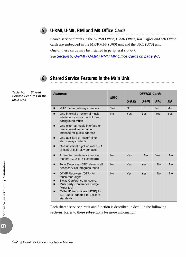
Shar
ed S
ervi
ce C
ircui
try
Inst
alla
tion
9
00
Shared service circuits in the U-RMI Office, U-MR Office, RMI Office and MR Office cards are embedded in the MR/RMI-F (U60) unit and the URC (U73) unit. One of these cards may be installed in peripheral slot 6-7. See Section 9, U-RMI / U-MR / RMI / MR Office Cards on page 9-7.
0
Table 9-1 Shared Service Features in the Main Unit
Each shared service circuit and function is described in detail in the following sections. Refer to these subsections for more information.
...................................................................................................5 U-RMI, U-MR, RMI and MR Office Cards
...................................................................................................6 Shared Service Features in the Main Unit
FeaturesMRC
OFFICE Cards
U-RMI U-MR RMI MR
VoIP media gateway channels Yes No No No Mo
One internal or external music interface for music on hold and background music
One external music interface or one external voice paging interface for public address
One auxiliary or major/minor alarm relay contacts
One universal night answer UNA or central bell relay contacts
No Yes Yes Yes Yes
A remote maintenance access modem (V.92 ITU-T standard)
No Yes No Yes No
Tone Detectors (DTD) detects all necessary call progress tones.
No Yes Yes No No
DTMF Receivers (DTR) for touch-tone digits3-way Conference functions.Multi party Conference Bridge (Meet Me)Caller ID transmitters (iDSP) for SLT users, adapted to Bellcore standards
No Yes Yes No No
9-2 Coral IPx Office Installation Manual
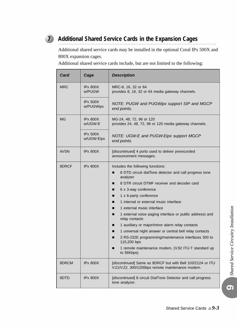
Shar
ed S
ervi
ce C
ircui
try
Inst
alla
tion
9
0
Additional shared service cards may be installed in the optional Coral IPx 500X and 800X expansion cages.Additional shared service cards include, but are not limited to the following:
...................................................................................................7 Additional Shared Service Cards in the Expansion Cages
Card Cage Description
MRC IPx 800Xw/PUGW
MRC-8, 16, 32 or 64provides 8, 16, 32 or 64 media gateway channels.
NOTE: PUGW and PUGWipx support SIP and MGCP end points.
IPx 500Xw/PUGWipx
MG IPx 800Xw/UGW-E
MG-24, 48, 72, 96 or 120 provides 24, 48, 72, 96 or 120 media gateway channels.
NOTE: UGW-E and PUGW-Eipx support MGCP end points.
IPx 500Xw/UGW-Eipx
4VSN IPx 800X [discontinued] 4 ports used to deliver prerecorded announcement messages.
8DRCF IPx 800X Includes the following functions:
8 DTD circuit dialTone detector and call progress tone analyzer
8 DTR circuit DTMF receiver and decoder card
6 x 3-way conference
1 x 6-party conference
1 internal or external music interface
1 external music interface
1 external voice paging interface or public address) and relay contacts
1 auxiliary or major/minor alarm relay contacts
1 universal night answer or central bell relay contacts
3 RS-232E programming/maintenance interfaces 300 to 115,200 bps
1 remote maintenance modem, (V.92 ITU-T standard up to 56Kbps)
8DRCM IPx 800X [discontinued] Same as 8DRCF but with Bell 103/212A or ITU V.21/V.22, 300/1200bps remote maintenance modem.
8DTD IPx 800X [discontinued] 8 circuit DialTone Detector and call progress tone analyzer.
Shared Service Cards 9-3
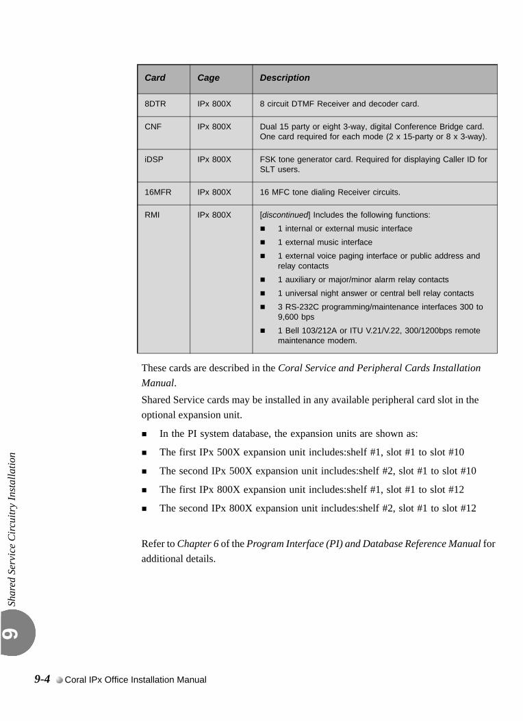
Shar
ed S
ervi
ce C
ircui
try
Inst
alla
tion
9
These cards are described in the Coral Service and Peripheral Cards Installation Manual.Shared Service cards may be installed in any available peripheral card slot in the optional expansion unit.
In the PI system database, the expansion units are shown as:
The first IPx 500X expansion unit includes:shelf #1, slot #1 to slot #10
The second IPx 500X expansion unit includes:shelf #2, slot #1 to slot #10
The first IPx 800X expansion unit includes:shelf #1, slot #1 to slot #12
The second IPx 800X expansion unit includes:shelf #2, slot #1 to slot #12
Refer to Chapter 6 of the Program Interface (PI) and Database Reference Manual for additional details.
8DTR IPx 800X 8 circuit DTMF Receiver and decoder card.
CNF IPx 800X Dual 15 party or eight 3-way, digital Conference Bridge card. One card required for each mode (2 x 15-party or 8 x 3-way).
iDSP IPx 800X FSK tone generator card. Required for displaying Caller ID for SLT users.
16MFR IPx 800X 16 MFC tone dialing Receiver circuits.
RMI IPx 800X [discontinued] Includes the following functions:
1 internal or external music interface
1 external music interface
1 external voice paging interface or public address and relay contacts
1 auxiliary or major/minor alarm relay contacts
1 universal night answer or central bell relay contacts
3 RS-232C programming/maintenance interfaces 300 to 9,600 bps
1 Bell 103/212A or ITU V.21/V.22, 300/1200bps remote maintenance modem.
Card Cage Description
9-4 Coral IPx Office Installation Manual
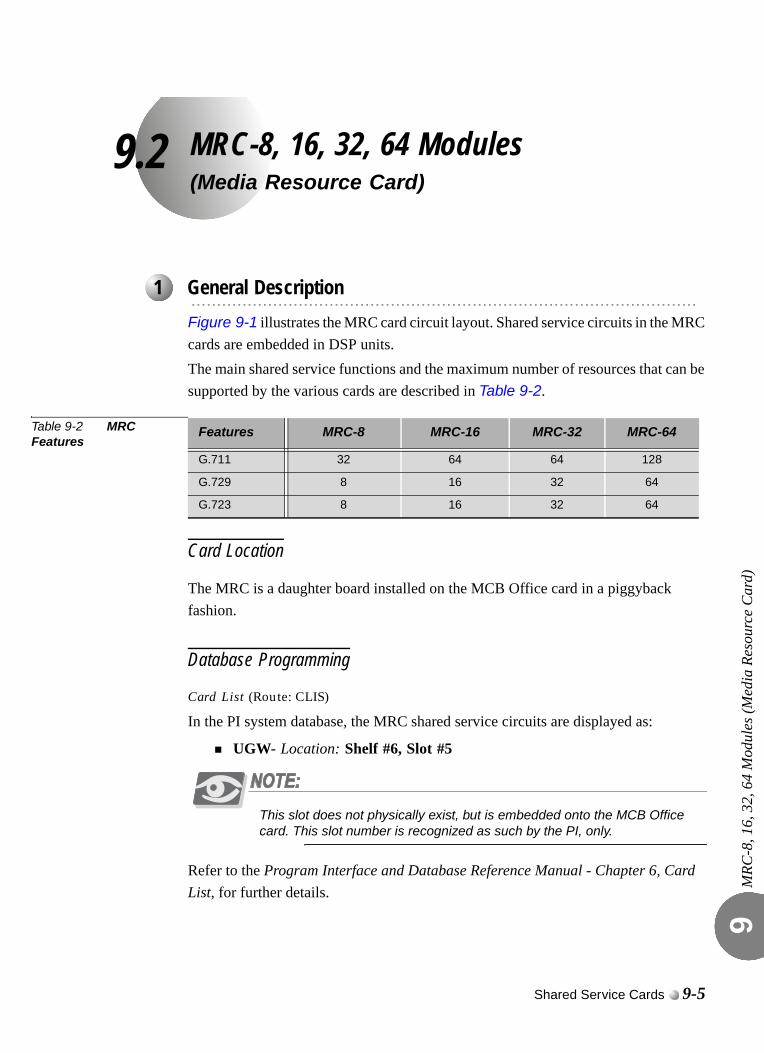
9.2
MRC-8, 16, 32, 64 Modules(Media Resource Card)MRC
-8, 1
6, 3
2, 6
4 M
odul
es (M
edia
Res
ourc
e C
ard)
9
0
Figure 9-1 illustrates the MRC card circuit layout. Shared service circuits in the MRC cards are embedded in DSP units.The main shared service functions and the maximum number of resources that can be supported by the various cards are described in Table 9-2.
Table 9-2 MRC Features
Card Location
The MRC is a daughter board installed on the MCB Office card in a piggyback fashion.
Database Programming
Card List (Route: CLIS)
In the PI system database, the MRC shared service circuits are displayed as:
UGW- Location: Shelf #6, Slot #5
This slot does not physically exist, but is embedded onto the MCB Office card. This slot number is recognized as such by the PI, only.
Refer to the Program Interface and Database Reference Manual - Chapter 6, Card List, for further details.
...................................................................................................1 General Description
Features MRC-8 MRC-16 MRC-32 MRC-64
G.711 32 64 64 128
G.729 8 16 32 64
G.723 8 16 32 64
Shared Service Cards 9-5
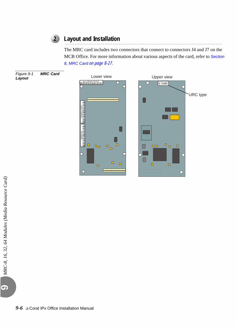
MRC
-8, 1
6, 3
2, 6
4 M
odul
es (M
edia
Res
ourc
e C
ard)
9
0
The MRC card includes two connectors that connect to connectors J4 and J7 on the MCB Office. For more information about various aspects of the card, refer to Section
8, MRC Card on page 8-27.
Figure 9-1 MRC Card Layout
...................................................................................................2 Layout and Installation
Upper viewLower view
URC type
9-6 Coral IPx Office Installation Manual
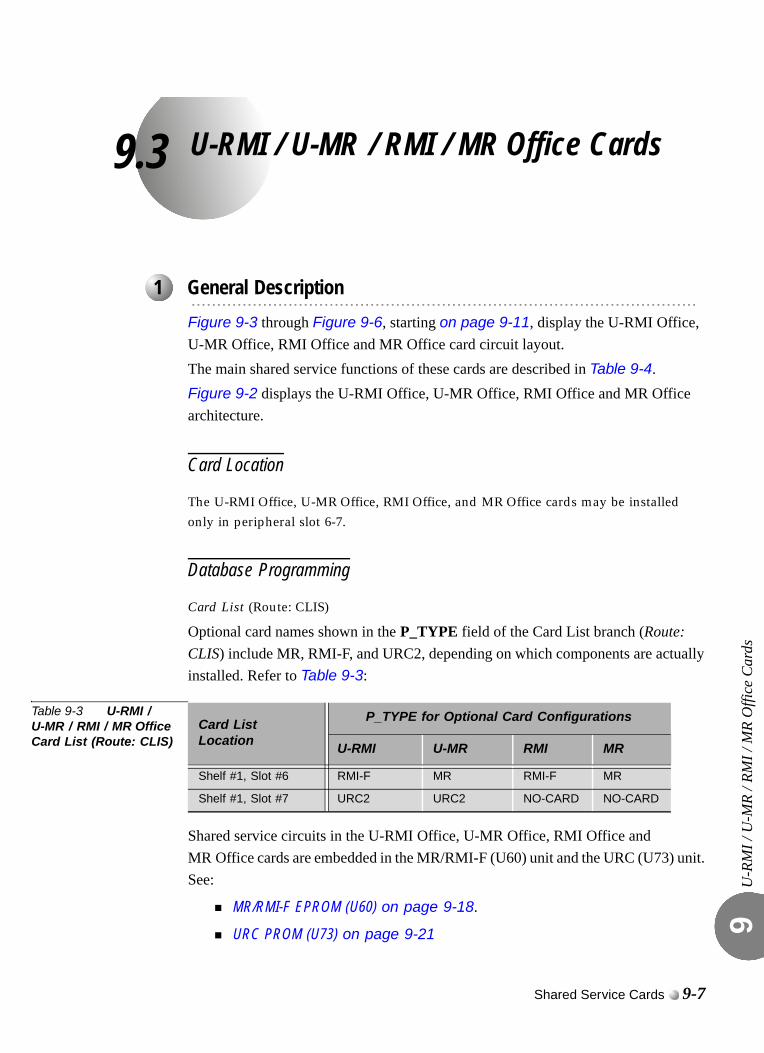
9.3
U-RMI / U-MR / RMI / MR Office CardsU-R
MI /
U-M
R / R
MI /
MR
Offi
ce C
ards
9
0
Figure 9-3 through Figure 9-6, starting on page 9-11, display the U-RMI Office, U-MR Office, RMI Office and MR Office card circuit layout. The main shared service functions of these cards are described in Table 9-4.Figure 9-2 displays the U-RMI Office, U-MR Office, RMI Office and MR Office architecture.
Card Location
The U-RMI Office, U-MR Office, RMI Office, and MR Office cards may be installed only in peripheral slot 6-7.
Database Programming
Card List (Route: CLIS)
Optional card names shown in the P_TYPE field of the Card List branch (Route: CLIS) include MR, RMI-F, and URC2, depending on which components are actually installed. Refer to Table 9-3:
Table 9-3 U-RMI / U-MR / RMI / MR Office Card List (Route: CLIS)
Shared service circuits in the U-RMI Office, U-MR Office, RMI Office and MR Office cards are embedded in the MR/RMI-F (U60) unit and the URC (U73) unit. See:
MR/RMI-F EPROM (U60) on page 9-18.
URC PROM (U73) on page 9-21
...................................................................................................1 General Description
Card List Location
P_TYPE for Optional Card Configurations
U-RMI U-MR RMI MR
Shelf #1, Slot #6 RMI-F MR RMI-F MR
Shelf #1, Slot #7 URC2 URC2 NO-CARD NO-CARD
Shared Service Cards 9-7
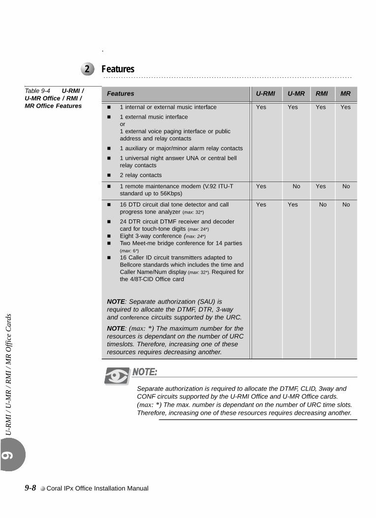
U-R
MI /
U-M
R / R
MI /
MR
Offi
ce C
ards
9
.
Table 9-4 U-RMI / U-MR Office / RMI / MR Office Features
Separate authorization is required to allocate the DTMF, CLID, 3way and CONF circuits supported by the U-RMI Office and U-MR Office cards.(max: *) The max. number is dependant on the number of URC time slots. Therefore, increasing one of these resources requires decreasing another.
...................................................................................................2 Features
Features U-RMI U-MR RMI MR
1 internal or external music interface
1 external music interface or 1 external voice paging interface or public address and relay contacts
1 auxiliary or major/minor alarm relay contacts
1 universal night answer UNA or central bell relay contacts
2 relay contacts
Yes Yes Yes Yes
1 remote maintenance modem (V.92 ITU-T standard up to 56Kbps)
Yes No Yes No
16 DTD circuit dial tone detector and call progress tone analyzer (max: 32*)
24 DTR circuit DTMF receiver and decoder card for touch-tone digits (max: 24*)
Eight 3-way conference (max: 24*)
Two Meet-me bridge conference for 14 parties
(max: 6*)
16 Caller ID circuit transmitters adapted to Bellcore standards which includes the time and Caller Name/Num display (max: 32*). Required for the 4/8T-CID Office card
NOTE: Separate authorization (SAU) is required to allocate the DTMF, DTR, 3-way and conference circuits supported by the URC.
NOTE: (max: *) The maximum number for the resources is dependant on the number of URC timeslots. Therefore, increasing one of these resources requires decreasing another.
Yes Yes No No
9-8 Coral IPx Office Installation Manual
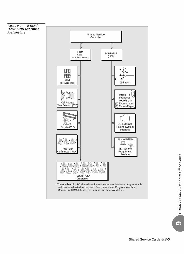
U-R
MI /
U-M
R / R
MI /
MR
Offi
ce C
ards
9
Figure 9-2 U-RMI / U-MR / RMI MR Office Architecture
DTMFReceivers (DTR)
1 2 34 5 6
7 8 9
* 0 #
Call ProgressTone Detectors (DTD)
Fourteen-PartyConferences
Caller ID Circuits (iDSP)
Three-PartyConferences (3-Way)
* The number of URC shared service resources are database programmable and can be adjusted as required. See the relevant
for URC defaults, maximums and time slot details.Program Interface
Manual
(1) Paging System
Interface
External
(2) Relays
(1) RemoteProg./Maint.
Modem
U-RMI and RMI Office
MR/RMI-F(U60)
Shared ServiceController
Music
MOH/BGMInterfaces
(1) Extern/ Intern(1) Extern/Paging
URC(U73)
U-RMI and U-MR Office
Shared Service Cards 9-9
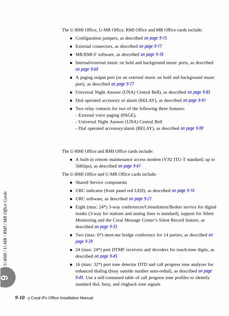
U-R
MI /
U-M
R / R
MI /
MR
Offi
ce C
ards
9
The U-RMI Office, U-MR Office, RMI Office and MR Office cards include:
Configuration jumpers, as described on page 9-15
External connectors, as described on page 9-17
MR/RMI-F software, as described on page 9-18
Internal/external music on hold and background music ports, as described on page 9-69
A paging output port (or an external music on hold and background music port), as described on page 9-77
Universal Night Answer (UNA) Central Bell), as described on page 9-85
Dial operated accessory or alarm (RELAY), as described on page 9-91
Two relay contacts for two of the following three features: - External voice paging (PAGE),- Universal Night Answer (UNA) Central Bell- Dial operated accessory/alarm (RELAY), as described on page 9-99
The U-RMI Office and RMI Office cards include:
A built-in remote maintenance access modem (V.92 ITU-T standard; up to 56Kbps), as described on page 9-61
The U-RMI Office and U-MR Office cards include:
Shared Service components
URC indicator (front panel red LED), as described on page 9-16
URC software, as described on page 9-21
Eight (max: 24*) 3-way conferences/Consultation/Broker service for digital trunks (3-way for stations and analog lines is standard), support for Silent Monitoring and the Coral Message Center’s Silent Record feature, as described on page 9-35
Two (max: 6*) meet-me bridge conference for 14 parties, as described on page 9-39
24 (max: 24*) port DTMF receivers and decoders for touch-tone digits, as described on page 9-45
16 (max: 32*) port tone detector DTD and call progress tone analyzer for enhanced dialing (busy outside number auto-redial), as described on page 9-49. Use a self-contained table of call progress tone profiles to identify standard dial, busy, and ringback tone signals
9-10 Coral IPx Office Installation Manual
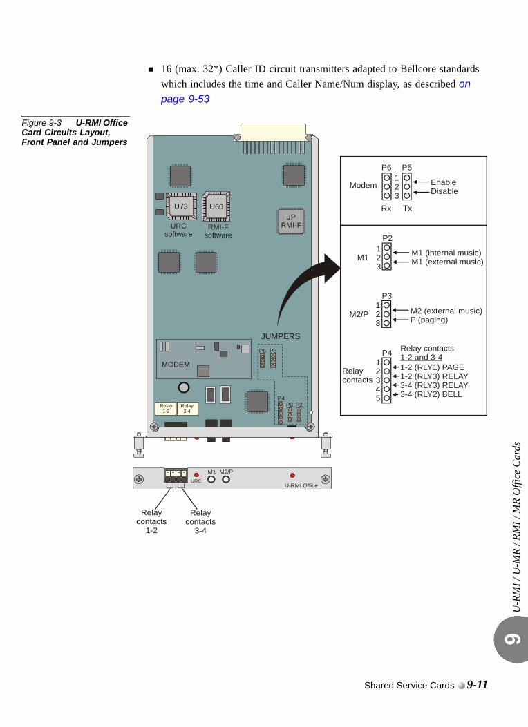
U-R
MI /
U-M
R / R
MI /
MR
Offi
ce C
ards
9
16 (max: 32*) Caller ID circuit transmitters adapted to Bellcore standards which includes the time and Caller Name/Num display, as described on page 9-53
Figure 9-3 U-RMI Office Card Circuits Layout, Front Panel and Jumpers
URCU-RMI Office
M2/PM1
U73 U60
MODEM
RMI-Fsoftware
URCsoftware
PRMI-F
Relaycontacts
1-2
Relaycontacts
3-4
P4
P6 P5
P3 P2
123
M1 (internal music)M1 (external music)M1
P2
123
M2 (external music)P (paging)
P3
M2/P
12345
1-2 (RLY1) PAGE1-2 (RLY3) RELAY3-4 (RLY3) RELAY3-4 (RLY2) BELL
P4
Relaycontacts
Rx Tx
EnableDisable
P6 P5
Modem123
JUMPERSRelay contacts1-2 and 3-4
Relay1-2
Relay3-4
Shared Service Cards 9-11
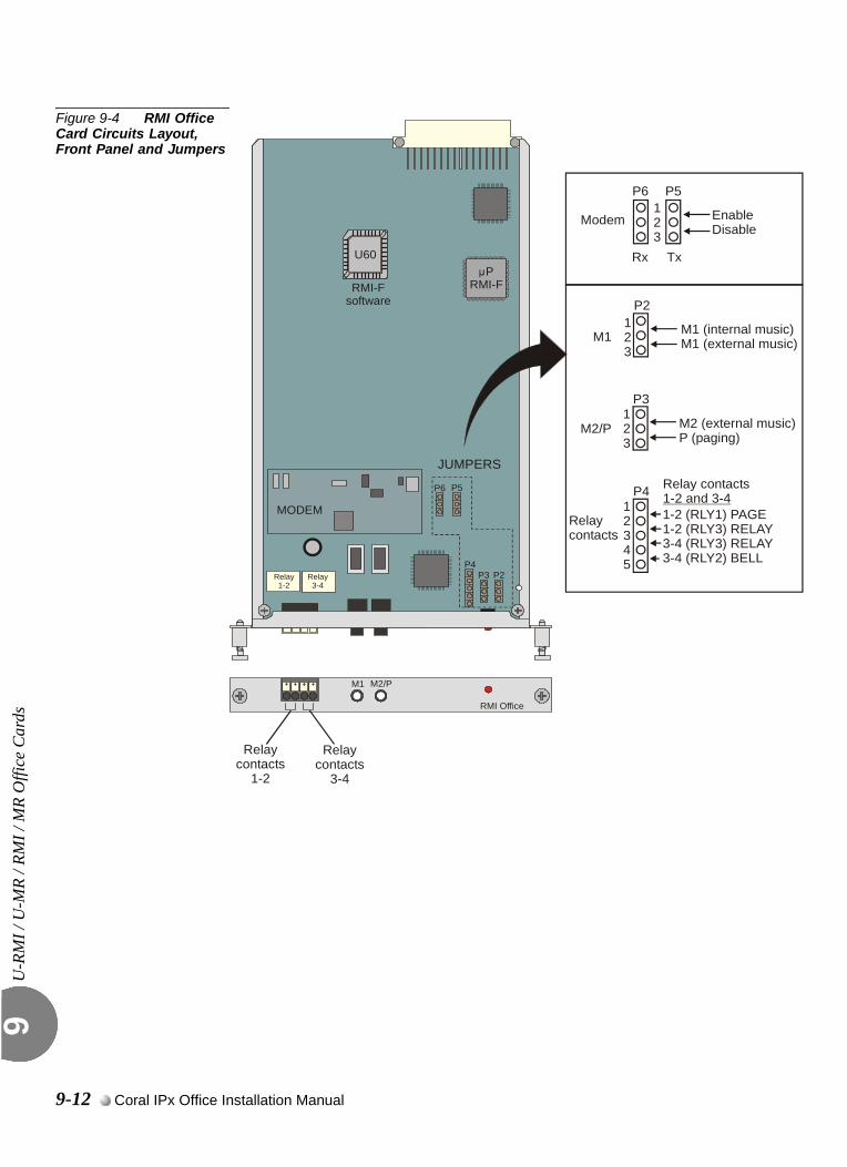
U-R
MI /
U-M
R / R
MI /
MR
Offi
ce C
ards
9
Figure 9-4 RMI Office Card Circuits Layout, Front Panel and Jumpers
RMI Office
M2/PM1
U60
MODEM
RMI-Fsoftware
PRMI-F
P4
P6 P5
P3 P2
123
M1 (internal music)M1 (external music)M1
P2
123
M2 (external music)P (paging)
P3
M2/P
Rx Tx
EnableDisable
P6 P5
Modem123
JUMPERS
Relay1-2
Relay3-4
12345
P4
Relaycontacts
Relaycontacts
1-2
Relaycontacts
3-4
Relay contacts1-2 and 3-41-2 (RLY1) PAGE1-2 (RLY3) RELAY3-4 (RLY3) RELAY3-4 (RLY2) BELL
9-12 Coral IPx Office Installation Manual
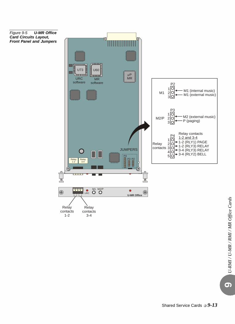
U-R
MI /
U-M
R / R
MI /
MR
Offi
ce C
ards
9
Figure 9-5 U-MR Office Card Circuits Layout, Front Panel and Jumpers
URCU-MR Office
M2/PM1
U73 U60
MRsoftware
URCsoftware
PMR
P4P3 P2
123
M1 (internal music)M1 (external music)M1
P2
123
M2 (external music)P (paging)
P3
M2/P
JUMPERS
12345
P4
Relaycontacts
Relaycontacts
1-2
Relaycontacts
3-4
Relay contacts1-2 and 3-41-2 (RLY1) PAGE1-2 (RLY3) RELAY3-4 (RLY3) RELAY3-4 (RLY2) BELL
Relay1-2
Relay3-4
Shared Service Cards 9-13
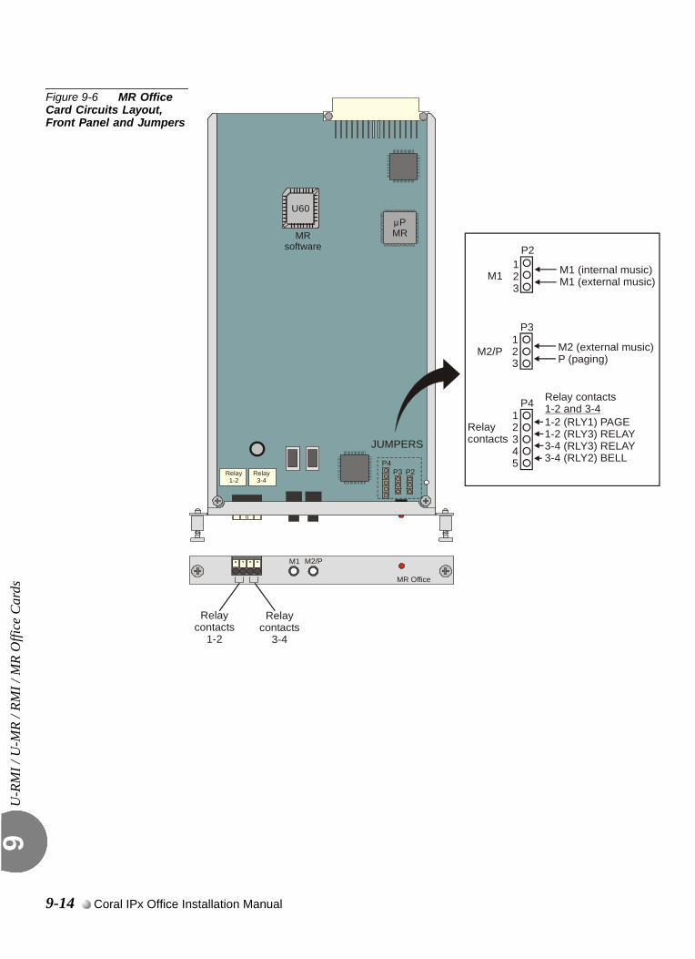
U-R
MI /
U-M
R / R
MI /
MR
Offi
ce C
ards
9
Figure 9-6 MR Office Card Circuits Layout, Front Panel and Jumpers
MR Office
M2/PM1
U60
MRsoftware
PMR
P4P3 P2
123
M1 (internal music)M1 (external music)M1
P2
123
M2 (external music)P (paging)
P3
M2/P
JUMPERS
12345
P4
Relaycontacts
Relaycontacts
1-2
Relaycontacts
3-4
Relay contacts1-2 and 3-41-2 (RLY1) PAGE1-2 (RLY3) RELAY3-4 (RLY3) RELAY3-4 (RLY2) BELL
Relay1-2
Relay3-4
9-14 Coral IPx Office Installation Manual
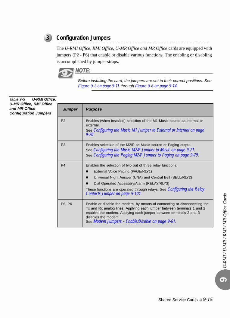
U-R
MI /
U-M
R / R
MI /
MR
Offi
ce C
ards
9
0
The U-RMI Office, RMI Office, U-MR Office and MR Office cards are equipped with jumpers (P2 - P6) that enable or disable various functions. The enabling or disabling is accomplished by jumper straps.
Before installing the card, the jumpers are set to their correct positions. See Figure 9-3 on page 9-11 through Figure 9-6 on page 9-14.
Table 9-5 U-RMI Office, U-MR Office, RMI Office and MR Office Configuration Jumpers
...................................................................................................3 Configuration Jumpers
Jumper Purpose
P2 Enables (when installed) selection of the M1-Music source as internal or external.See Configuring the Music M1 Jumper to External or Internal on page 9-70.
P3 Enables selection of the M2/P as Music source or Paging output.
See Configuring the Music M2/P Jumper to Music on page 9-71.
See Configuring the Paging M2/P Jumper to Paging on page 9-79.
P4 Enables the selection of two out of three relay functions:
External Voice Paging (PAGE/RLY1)
Universal Night Answer (UNA) and Central Bell (BELL/RLY2)
Dial Operated Accessory/Alarm (RELAY/RLY3)
These functions are operated through relays. See Configuring the Relay Contacts Jumper on page 9-101.
P5, P6 Enable or disable the modem, by means of connecting or disconnecting the Tx and Rx analog lines. Applying each jumper between terminals 1 and 2 enables the modem. Applying each jumper between terminals 2 and 3 disables the modem.See Modem Jumpers - Enable/Disable on page 9-61.
Shared Service Cards 9-15
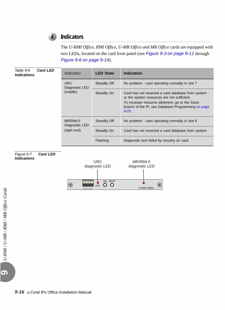
U-R
MI /
U-M
R / R
MI /
MR
Offi
ce C
ards
9
0
The U-RMI Office, RMI Office, U-MR Office and MR Office cards are equipped with two LEDs, located on the card front panel (see Figure 9-3 on page 9-11 through Figure 9-6 on page 9-14).
Table 9-6 Card LED Indications
Figure 9-7 Card LED Indications
...................................................................................................4 Indicators
Indicator LED State Indication
URCDiagnostic LED(middle)
Steadily Off No problem - card operating normally in slot 7
Steadily On Card has not received a card database from system or the system resources are not sufficient. To increase resource allotment, go to the Sizes branch of the PI, see Database Programming on page 9-23.
MR/RMI-FDiagnostic LED
(right end)
Steadily Off No problem - card operating normally in slot 6
Steadily On Card has not received a card database from system
Flashing Diagnostic test failed by circuitry on card.
URCU-RMI Office
M2/PM1
URCdiagnostic LED
MR/RMI-Fdiagnostic LED
9-16 Coral IPx Office Installation Manual
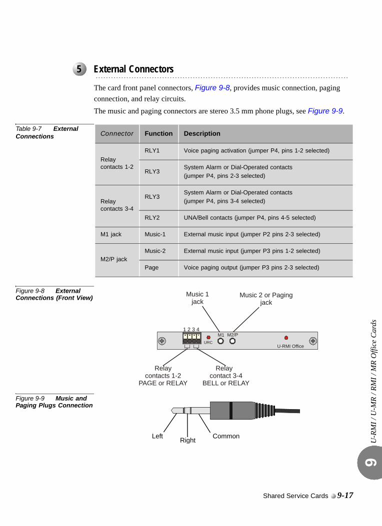
U-R
MI /
U-M
R / R
MI /
MR
Offi
ce C
ards
9
The card front panel connectors, Figure 9-8, provides music connection, paging connection, and relay circuits.The music and paging connectors are stereo 3.5 mm phone plugs, see Figure 9-9.
Table 9-7 External Connections
Figure 9-8 External Connections (Front View)
Figure 9-9 Music and Paging Plugs Connection
...................................................................................................5 External Connectors
Connector Function Description
Relay contacts 1-2
RLY1 Voice paging activation (jumper P4, pins 1-2 selected)
RLY3System Alarm or Dial-Operated contacts(jumper P4, pins 2-3 selected)
Relay contacts 3-4
RLY3System Alarm or Dial-Operated contacts
(jumper P4, pins 3-4 selected)
RLY2 UNA/Bell contacts (jumper P4, pins 4-5 selected)
M1 jack Music-1 External music input (jumper P2 pins 2-3 selected)
M2/P jackMusic-2 External music input (jumper P3 pins 1-2 selected)
Page Voice paging output (jumper P3 pins 2-3 selected)
URCU-RMI Office
M2/PM1
Relaycontacts 1-2
PAGE or RELAY
Relay contact 3-4
BELL or RELAY
Music 1jack
Music 2 or Pagingjack
1 2 3 4
Left Right Common
Shared Service Cards 9-17
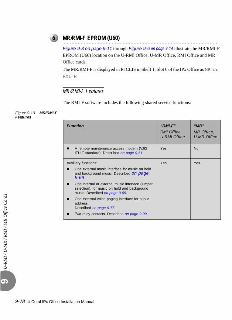
U-R
MI /
U-M
R / R
MI /
MR
Offi
ce C
ards
9
0
Figure 9-3 on page 9-11 through Figure 9-6 on page 9-14 illustrate the MR/RMI-F EPROM (U60) location on the U-RMI Office, U-MR Office, RMI Office and MR Office cards. The MR/RMI-F is displayed in PI CLIS in Shelf 1, Slot 6 of the IPx Office as MR or RMI-F.
MR/RMI-F Features
The RMI-F software includes the following shared service functions:
Figure 9-10 MR/RMI-F Features
...................................................................................................6 MR/RMI-F EPROM (U60)
Function “RMI-F”
RMI Office, U-RMI Office
“MR”
MR Office, U-MR Office
A remote maintenance access modem (V.92 ITU-T standard). Described on page 9-61.
Yes No
Auxiliary functions:
One external music interface for music on hold and background music. Described on page 9-69.
One internal or external music interface (jumper selection), for music on hold and background music. Described on page 9-69.
One external voice paging interface for public address. Described on page 9-77.
Two relay contacts. Described on page 9-99.
Yes Yes
9-18 Coral IPx Office Installation Manual
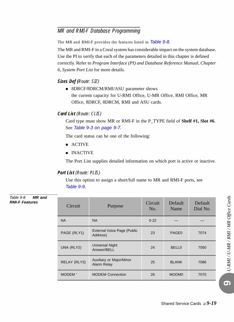
U-R
MI /
U-M
R / R
MI /
MR
Offi
ce C
ards
9
MR and RMI-F Database Programming
The MR and RMI-F provides the features listed in Table 9-8.
The MR and RMI-F in a Coral system has considerable impact on the system database. Use the PI to verify that each of the parameters detailed in this chapter is defined correctly. Refer to Program Interface (PI) and Database Reference Manual, Chapter 6, System Port List for more details.
Sizes Def (Route: SIZ) 8DRCF/8DRCM/RMI/ASU parameter shows the current capacity for U-RMI Office, U-MR Office, RMI Office, MR Office, 8DRCF, 8DRCM, RMI and ASU cards.
Card List (Route: CLIS)Card type must show MR or RMI-F in the P_TYPE field of Shelf #1, Slot #6. See Table 9-3 on page 9-7.
The card status can be one of the following:
ACTIVE
INACTIVE
The Port List supplies detailed information on which port is active or inactive.
Port List (Route: PLIS)Use this option to assign a short/full name to MR and RMI-F ports, see Table 9-9.
Table 9-8 MR and RMI-F Features
Circuit Purpose Circuit No.
Default Name
Default Dial No.
NA NA 0-22 — —
PAGE (RLY1)External Voice Page (Public Address)
23 PAGE0 7074
UNA (RLY2)Universal Night Answer/BELL
24 BELL0 7050
RELAY (RLY3)Auxiliary or Major/Minor Alarm Relay
25 BLANK 7086
MODEM * MODEM Connection 26 MODM0 7070
Shared Service Cards 9-19
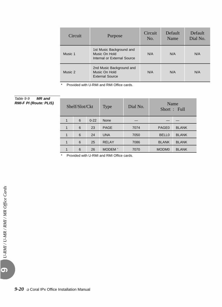
U-R
MI /
U-M
R / R
MI /
MR
Offi
ce C
ards
9
Table 9-9 MR and RMI-F PI (Route: PLIS)
Music 11st Music Background and Music On Hold Internal or External Source
N/A N/A N/A
Music 22nd Music Background and Music On Hold External Source
N/A N/A N/A
* Provided with U-RMI and RMI Office cards.
Circuit Purpose Circuit No.
Default Name
Default Dial No.
Shelf/Slot/Ckt Type Dial No. NameShort : Full
1 6 0-22 None — — —
1 6 23 PAGE 7074 PAGE0 BLANK
1 6 24 UNA 7050 BELL0 BLANK
1 6 25 RELAY 7086 BLANK BLANK
1 6 26 MODEM *
* Provided with U-RMI and RMI Office cards.
7070 MODM0 BLANK
9-20 Coral IPx Office Installation Manual
U-R
MI /
U-M
R / R
MI /
MR
Offi
ce C
ards
9
0
Figure 9-3 on page 9-11 and Figure 9-5 on page 9-13 illustrate the URC PROM (U73) location on the U-RMI Office and U-MR Office cards. The URC (Universal Resource Card) unit software is provided with U-RMI Office and U-MR Office cards.The URC is displayed in PI CLIS in Shelf 1, Slot 7 of the IPx Office as URC2.
Tip:Separate authorization is required to allocate the DTMF, CLID, 3way and
CONF circuits supported by the U-RMI Office and U-MR Office cards. See
Table 9-10 on page 9-22.
...................................................................................................7 URC PROM (U73)
Shared Service Cards 9-21
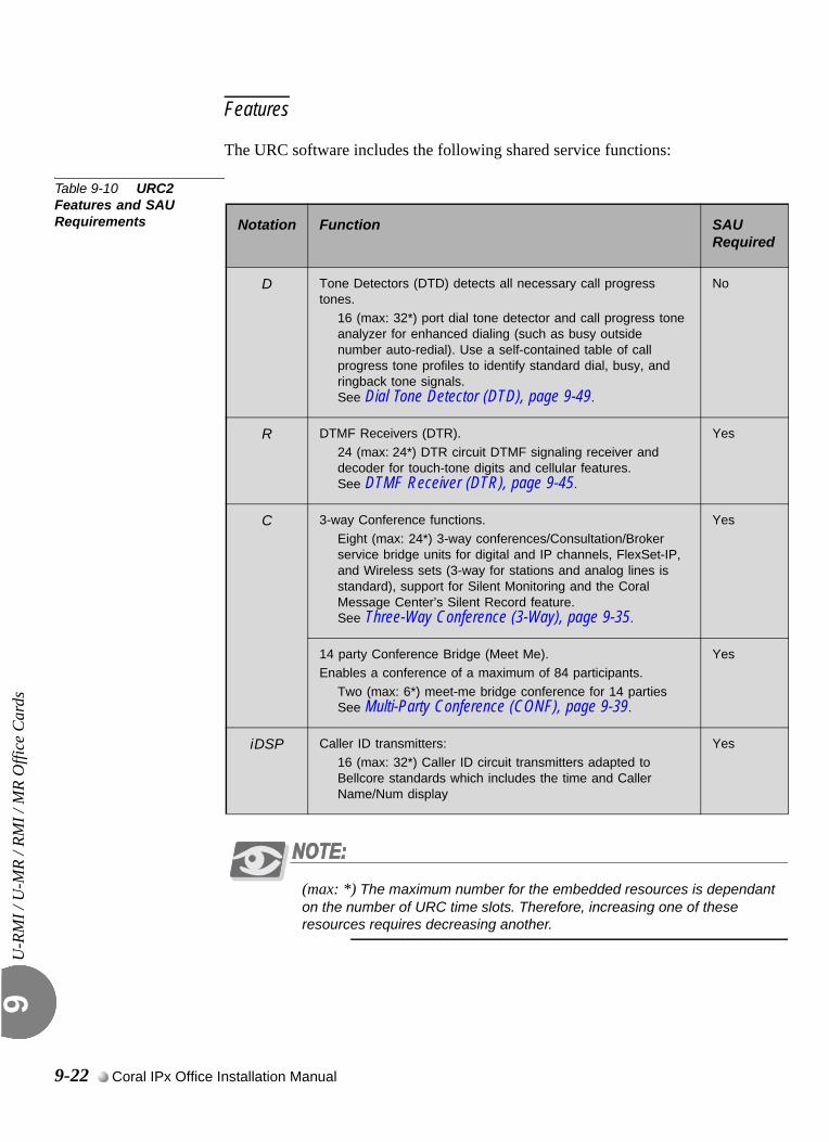
U-R
MI /
U-M
R / R
MI /
MR
Offi
ce C
ards
9
Features
The URC software includes the following shared service functions:
Table 9-10 URC2 Features and SAU Requirements
(max: *) The maximum number for the embedded resources is dependant on the number of URC time slots. Therefore, increasing one of these resources requires decreasing another.
Notation Function SAU Required
D Tone Detectors (DTD) detects all necessary call progress tones.
16 (max: 32*) port dial tone detector and call progress tone analyzer for enhanced dialing (such as busy outside number auto-redial). Use a self-contained table of call progress tone profiles to identify standard dial, busy, and ringback tone signals. See Dial Tone Detector (DTD), page 9-49.
No
R DTMF Receivers (DTR).
24 (max: 24*) DTR circuit DTMF signaling receiver and decoder for touch-tone digits and cellular features. See DTMF Receiver (DTR), page 9-45.
Yes
C 3-way Conference functions.
Eight (max: 24*) 3-way conferences/Consultation/Broker service bridge units for digital and IP channels, FlexSet-IP, and Wireless sets (3-way for stations and analog lines is standard), support for Silent Monitoring and the Coral Message Center’s Silent Record feature. See Three-Way Conference (3-Way), page 9-35.
Yes
14 party Conference Bridge (Meet Me).Enables a conference of a maximum of 84 participants.
Two (max: 6*) meet-me bridge conference for 14 partiesSee Multi-Party Conference (CONF), page 9-39.
Yes
iDSP Caller ID transmitters:
16 (max: 32*) Caller ID circuit transmitters adapted to Bellcore standards which includes the time and Caller Name/Num display
Yes
9-22 Coral IPx Office Installation Manual
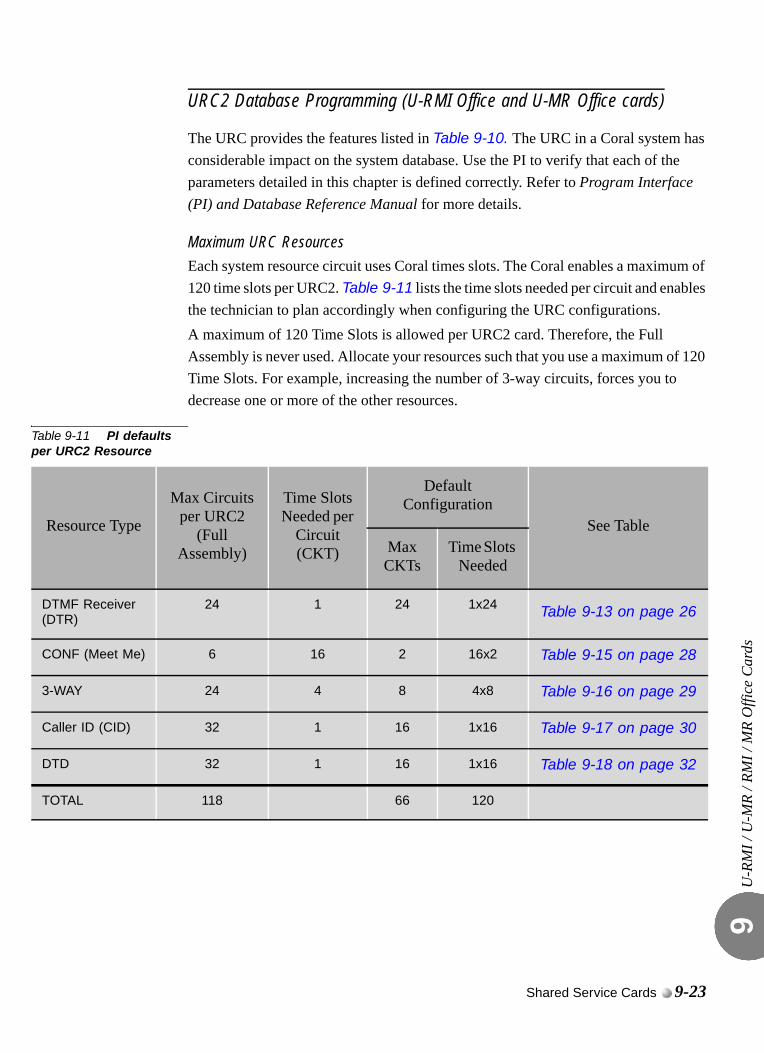
U-R
MI /
U-M
R / R
MI /
MR
Offi
ce C
ards
9
URC2 Database Programming (U-RMI Office and U-MR Office cards)
The URC provides the features listed in Table 9-10. The URC in a Coral system has considerable impact on the system database. Use the PI to verify that each of the parameters detailed in this chapter is defined correctly. Refer to Program Interface (PI) and Database Reference Manual for more details.
Maximum URC ResourcesEach system resource circuit uses Coral times slots. The Coral enables a maximum of 120 time slots per URC2. Table 9-11 lists the time slots needed per circuit and enables the technician to plan accordingly when configuring the URC configurations.A maximum of 120 Time Slots is allowed per URC2 card. Therefore, the Full Assembly is never used. Allocate your resources such that you use a maximum of 120 Time Slots. For example, increasing the number of 3-way circuits, forces you to decrease one or more of the other resources.
Table 9-11 PI defaults per URC2 Resource
Resource Type
Max Circuits per URC2
(Full Assembly)
Time Slots Needed per
Circuit (CKT)
DefaultConfiguration
See TableMax CKTs
Time Slots Needed
DTMF Receiver (DTR)
24 1 24 1x24 Table 9-13 on page 26
CONF (Meet Me) 6 16 2 16x2 Table 9-15 on page 28
3-WAY 24 4 8 4x8 Table 9-16 on page 29
Caller ID (CID) 32 1 16 1x16 Table 9-17 on page 30
DTD 32 1 16 1x16 Table 9-18 on page 32
TOTAL 118 66 120
Shared Service Cards 9-23
U-R
MI /
U-M
R / R
MI /
MR
Offi
ce C
ards
9
Feature Authorization (Route: FEAT,1) URC DTMF
URC CLID
URC 3WAY
URC CONF
Separate Software Authorization is required to allocate the URC resources. Refer to Program Interface (PI) and Database Reference Manual, Chapter 3, Feature Authorization.
URC Configuration - NUMBER OF RESOURCES (Route: CDB,11) DTMF
Meet Me
3WAY
CID
DTD
URC Card DB - GAIN (Route: CDB,11,2) The Gains may be adjusted in this branch and not in the Feature Control branch as with other cards.
DTMF GAIN
DTD GAIN
URC Card DB - Meet Me Conference (Route: CDB,11,2) CONF MEMBERS
CONF SWITCH DELAY
Sizes Def (Route: SIZ) CONF_CKTS parameter. Between 1 to 6 ports required for the URC.
Sizes TAB (Route: SYSGEN,2)RESOURCES parameter. Between 64 to112 ports required for the URC.
9-24 Coral IPx Office Installation Manual
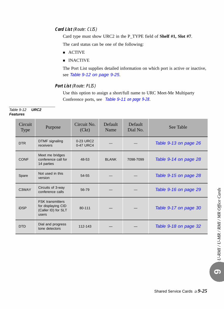
U-R
MI /
U-M
R / R
MI /
MR
Offi
ce C
ards
9
Card List (Route: CLIS)Card type must show URC2 in the P_TYPE field of Shelf #1, Slot #7.
The card status can be one of the following:
ACTIVE
INACTIVE
The Port List supplies detailed information on which port is active or inactive, see Table 9-12 on page 9-25.
Port List (Route: PLIS)Use this option to assign a short/full name to URC Meet-Me Multiparty Conference ports, see Table 9-11 on page 9-28.
Table 9-12 URC2 Features
Circuit Type Purpose Circuit No.
(Ckt)Default Name
Default Dial No. See Table
DTRDTMF signaling receivers
0-23 URC20-47 URC4
— — Table 9-13 on page 26
CONFMeet me bridges conference call for 14 parties
48-53 BLANK 7098-7099 Table 9-14 on page 28
SpareNot used in this version
54-55 — — Table 9-15 on page 28
C3WAYCircuits of 3-way conference calls
56-79 — — Table 9-16 on page 29
iDSP
FSK transmitters for displaying CID (Caller ID) for SLT users
80-111 — — Table 9-17 on page 30
DTDDial and progress tone detectors
112-143 — — Table 9-18 on page 32
Shared Service Cards 9-25
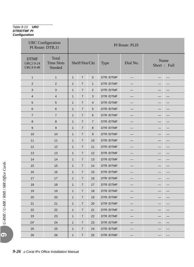
U-R
MI /
U-M
R / R
MI /
MR
Offi
ce C
ards
9
Table 9-13 URC DTR/DTMF PI Configuration
URC ConfigurationPI Route: DTB,11 PI Route: PLIS
DTMFURC2 0-24URC4 0-48
TotalTime Slots
NeededShelf/Slot/Ckt Type Dial No. Name
Short : Full
1 1 1 7 0 DTR /DTMF — — —
2 2 1 7 1 DTR /DTMF — — —
3 3 1 7 2 DTR /DTMF — — —
4 4 1 7 3 DTR /DTMF — — —
5 5 1 7 4 DTR /DTMF — — —
6 6 1 7 5 DTR /DTMF — — —
7 7 1 7 6 DTR /DTMF — — —
8 8 1 7 7 DTR /DTMF — — —
9 9 1 7 8 DTR /DTMF — — —
10 10 1 7 9 DTR /DTMF — — —
11 11 1 7 10 DTR /DTMF — — —
12 12 1 7 11 DTR /DTMF — — —
13 13 1 7 12 DTR /DTMF — — —
14 14 1 7 13 DTR /DTMF — — —
15 15 1 7 14 DTR /DTMF — — —
16 16 1 7 15 DTR /DTMF — — —
17 17 1 7 16 DTR /DTMF — — —
18 18 1 7 17 DTR /DTMF — — —
19 19 1 7 18 DTR /DTMF — — —
20 20 1 7 19 DTR /DTMF — — —
21 21 1 7 20 DTR /DTMF — — —
22 22 1 7 21 DTR /DTMF — — —
23 23 1 7 22 DTR /DTMF — — —
24* 24 1 7 23 DTR /DTMF — — —
25 25 1 7 24 DTR /DTMF — — —
26 26 1 7 25 DTR /DTMF — — —
9-26 Coral IPx Office Installation Manual
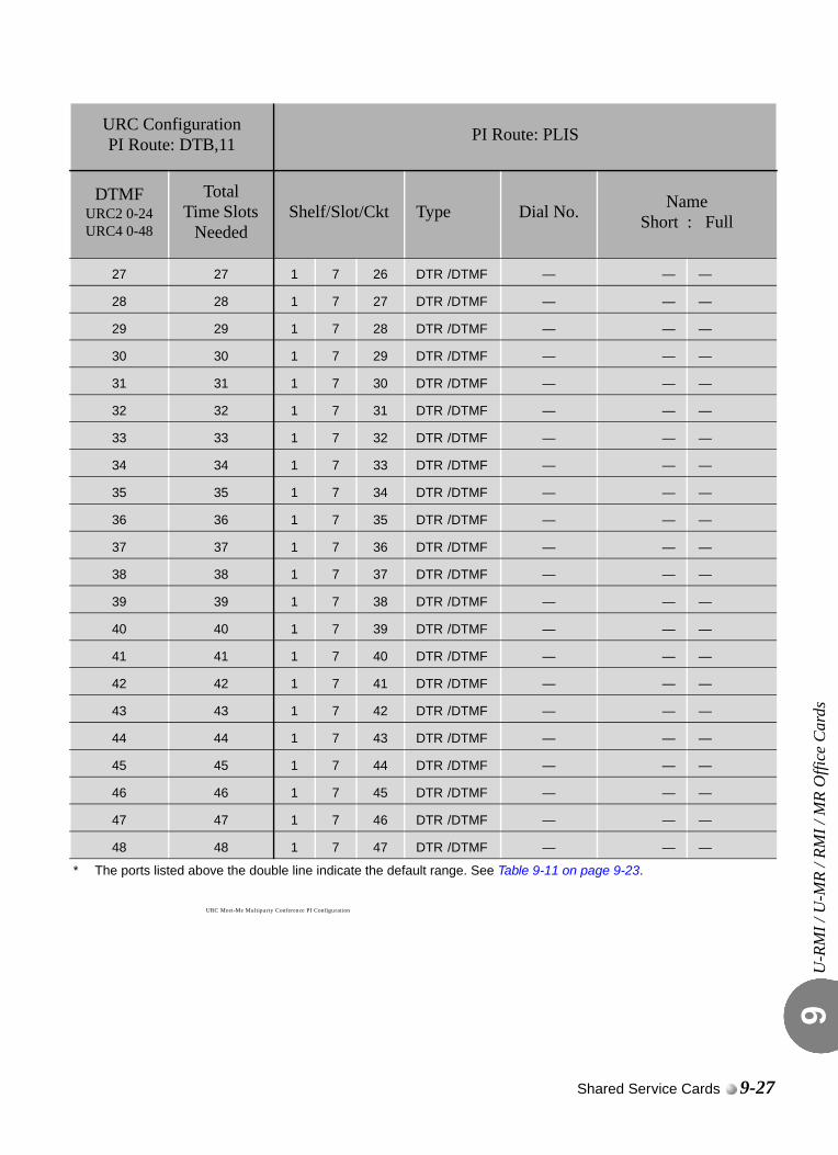
U-R
MI /
U-M
R / R
MI /
MR
Offi
ce C
ards
9
URC Meet-Me Multiparty Conference PI Configuration
27 27 1 7 26 DTR /DTMF — — —
28 28 1 7 27 DTR /DTMF — — —
29 29 1 7 28 DTR /DTMF — — —
30 30 1 7 29 DTR /DTMF — — —
31 31 1 7 30 DTR /DTMF — — —
32 32 1 7 31 DTR /DTMF — — —
33 33 1 7 32 DTR /DTMF — — —
34 34 1 7 33 DTR /DTMF — — —
35 35 1 7 34 DTR /DTMF — — —
36 36 1 7 35 DTR /DTMF — — —
37 37 1 7 36 DTR /DTMF — — —
38 38 1 7 37 DTR /DTMF — — —
39 39 1 7 38 DTR /DTMF — — —
40 40 1 7 39 DTR /DTMF — — —
41 41 1 7 40 DTR /DTMF — — —
42 42 1 7 41 DTR /DTMF — — —
43 43 1 7 42 DTR /DTMF — — —
44 44 1 7 43 DTR /DTMF — — —
45 45 1 7 44 DTR /DTMF — — —
46 46 1 7 45 DTR /DTMF — — —
47 47 1 7 46 DTR /DTMF — — —
48 48 1 7 47 DTR /DTMF — — —
* The ports listed above the double line indicate the default range. See Table 9-11 on page 9-23.
URC ConfigurationPI Route: DTB,11 PI Route: PLIS
DTMFURC2 0-24URC4 0-48
TotalTime Slots
NeededShelf/Slot/Ckt Type Dial No. Name
Short : Full
Shared Service Cards 9-27
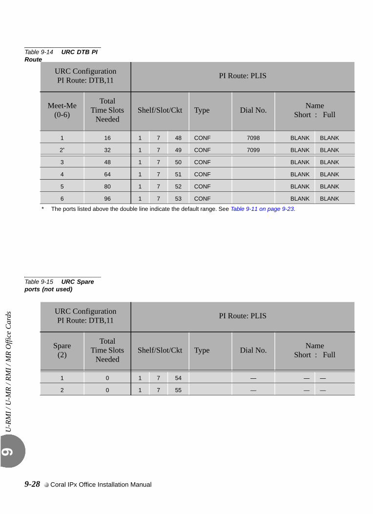
U-R
MI /
U-M
R / R
MI /
MR
Offi
ce C
ards
9
Table 9-14 URC DTB PI Route
Table 9-15 URC Spare ports (not used)
URC ConfigurationPI Route: DTB,11 PI Route: PLIS
Meet-Me(0-6)
TotalTime Slots
NeededShelf/Slot/Ckt Type Dial No. Name
Short : Full
1 16 1 7 48 CONF 7098 BLANK BLANK
2* 32 1 7 49 CONF 7099 BLANK BLANK
3 48 1 7 50 CONF BLANK BLANK
4 64 1 7 51 CONF BLANK BLANK
5 80 1 7 52 CONF BLANK BLANK
6 96 1 7 53 CONF BLANK BLANK
* The ports listed above the double line indicate the default range. See Table 9-11 on page 9-23.
URC ConfigurationPI Route: DTB,11 PI Route: PLIS
Spare(2)
TotalTime Slots
NeededShelf/Slot/Ckt Type Dial No. Name
Short : Full
1 0 1 7 54 — — —
2 0 1 7 55 — — —
9-28 Coral IPx Office Installation Manual
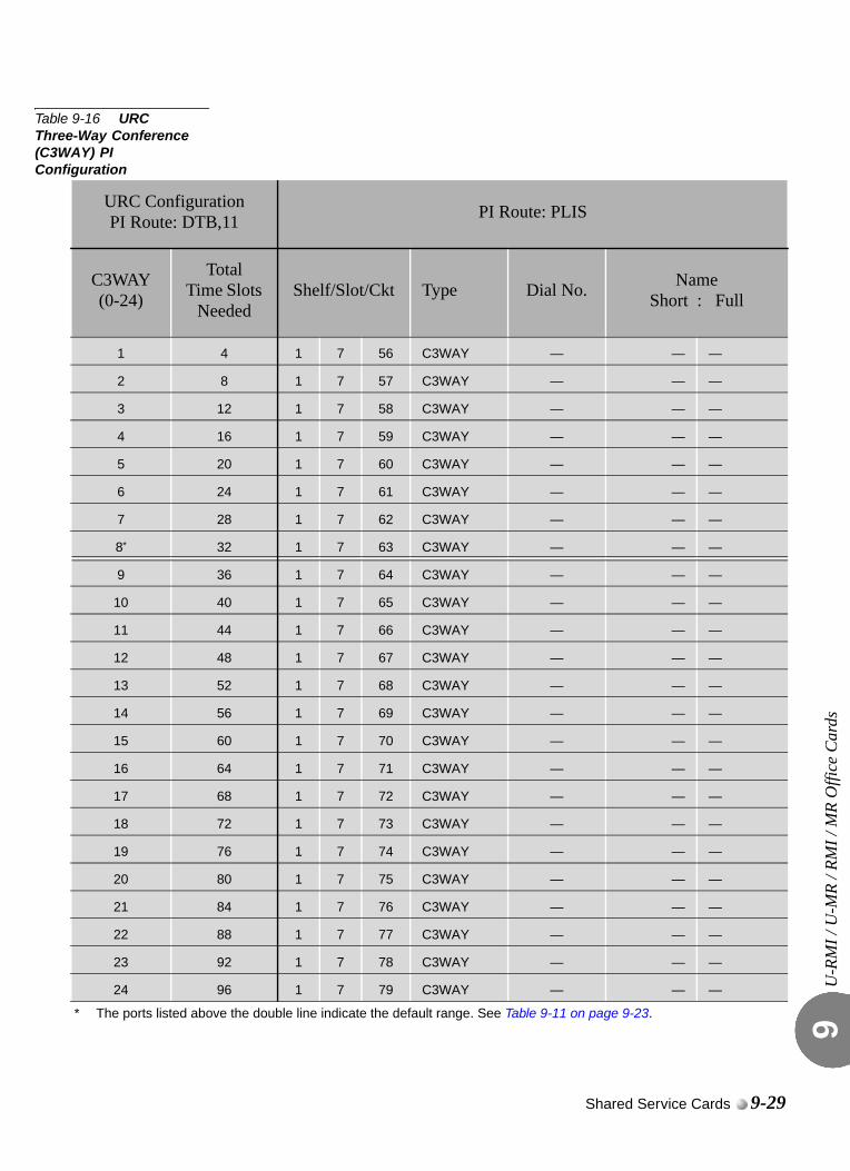
U-R
MI /
U-M
R / R
MI /
MR
Offi
ce C
ards
9
Table 9-16 URC Three-Way Conference (C3WAY) PI Configuration
URC ConfigurationPI Route: DTB,11 PI Route: PLIS
C3WAY(0-24)
TotalTime Slots
NeededShelf/Slot/Ckt Type Dial No. Name
Short : Full
1 4 1 7 56 C3WAY — — —
2 8 1 7 57 C3WAY — — —
3 12 1 7 58 C3WAY — — —
4 16 1 7 59 C3WAY — — —
5 20 1 7 60 C3WAY — — —
6 24 1 7 61 C3WAY — — —
7 28 1 7 62 C3WAY — — —
8* 32 1 7 63 C3WAY — — —
9 36 1 7 64 C3WAY — — —
10 40 1 7 65 C3WAY — — —
11 44 1 7 66 C3WAY — — —
12 48 1 7 67 C3WAY — — —
13 52 1 7 68 C3WAY — — —
14 56 1 7 69 C3WAY — — —
15 60 1 7 70 C3WAY — — —
16 64 1 7 71 C3WAY — — —
17 68 1 7 72 C3WAY — — —
18 72 1 7 73 C3WAY — — —
19 76 1 7 74 C3WAY — — —
20 80 1 7 75 C3WAY — — —
21 84 1 7 76 C3WAY — — —
22 88 1 7 77 C3WAY — — —
23 92 1 7 78 C3WAY — — —
24 96 1 7 79 C3WAY — — —
* The ports listed above the double line indicate the default range. See Table 9-11 on page 9-23.
Shared Service Cards 9-29
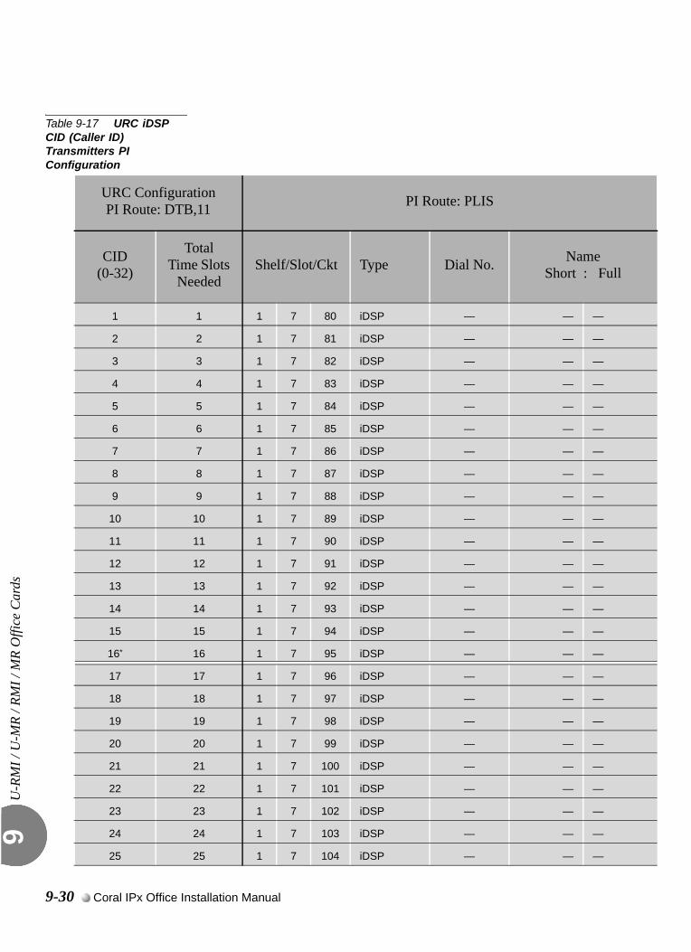
U-R
MI /
U-M
R / R
MI /
MR
Offi
ce C
ards
9
Table 9-17 URC iDSP CID (Caller ID) Transmitters PI Configuration
URC ConfigurationPI Route: DTB,11 PI Route: PLIS
CID(0-32)
TotalTime Slots
NeededShelf/Slot/Ckt Type Dial No. Name
Short : Full
1 1 1 7 80 iDSP — — —
2 2 1 7 81 iDSP — — —
3 3 1 7 82 iDSP — — —
4 4 1 7 83 iDSP — — —
5 5 1 7 84 iDSP — — —
6 6 1 7 85 iDSP — — —
7 7 1 7 86 iDSP — — —
8 8 1 7 87 iDSP — — —
9 9 1 7 88 iDSP — — —
10 10 1 7 89 iDSP — — —
11 11 1 7 90 iDSP — — —
12 12 1 7 91 iDSP — — —
13 13 1 7 92 iDSP — — —
14 14 1 7 93 iDSP — — —
15 15 1 7 94 iDSP — — —
16* 16 1 7 95 iDSP — — —
17 17 1 7 96 iDSP — — —
18 18 1 7 97 iDSP — — —
19 19 1 7 98 iDSP — — —
20 20 1 7 99 iDSP — — —
21 21 1 7 100 iDSP — — —
22 22 1 7 101 iDSP — — —
23 23 1 7 102 iDSP — — —
24 24 1 7 103 iDSP — — —
25 25 1 7 104 iDSP — — —
9-30 Coral IPx Office Installation Manual
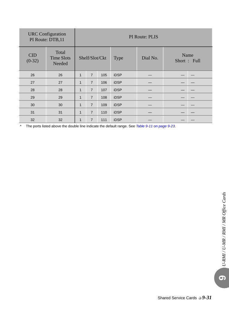
U-R
MI /
U-M
R / R
MI /
MR
Offi
ce C
ards
9
26 26 1 7 105 iDSP — — —
27 27 1 7 106 iDSP — — —
28 28 1 7 107 iDSP — — —
29 29 1 7 108 iDSP — — —
30 30 1 7 109 iDSP — — —
31 31 1 7 110 iDSP — — —
32 32 1 7 111 iDSP — — —
* The ports listed above the double line indicate the default range. See Table 9-11 on page 9-23.
URC ConfigurationPI Route: DTB,11 PI Route: PLIS
CID(0-32)
TotalTime Slots
NeededShelf/Slot/Ckt Type Dial No. Name
Short : Full
Shared Service Cards 9-31
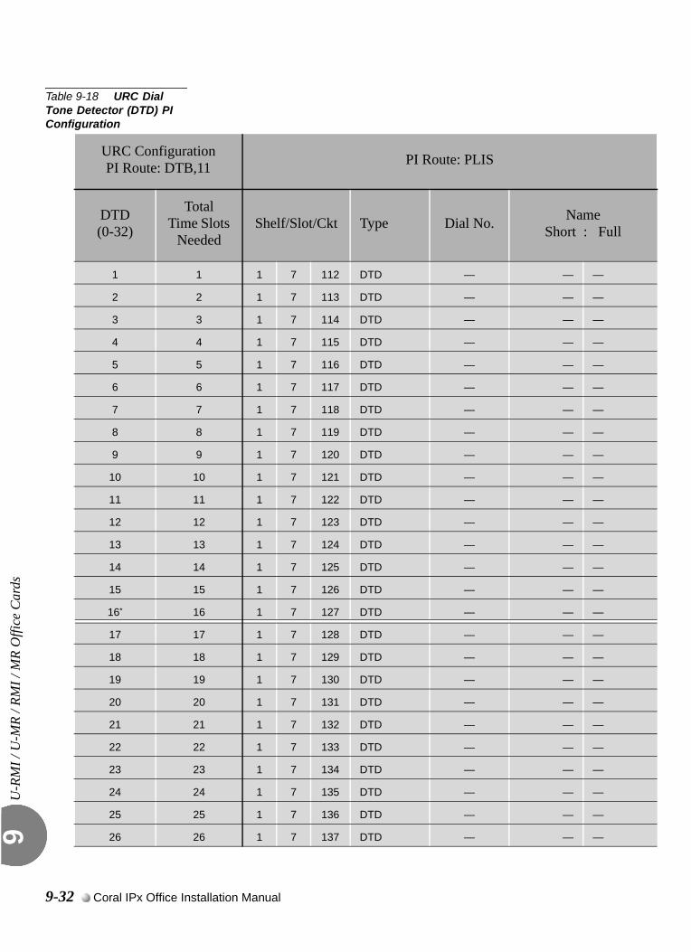
U-R
MI /
U-M
R / R
MI /
MR
Offi
ce C
ards
9
Table 9-18 URC Dial Tone Detector (DTD) PI Configuration
URC ConfigurationPI Route: DTB,11 PI Route: PLIS
DTD(0-32)
TotalTime Slots
NeededShelf/Slot/Ckt Type Dial No. Name
Short : Full
1 1 1 7 112 DTD — — —
2 2 1 7 113 DTD — — —
3 3 1 7 114 DTD — — —
4 4 1 7 115 DTD — — —
5 5 1 7 116 DTD — — —
6 6 1 7 117 DTD — — —
7 7 1 7 118 DTD — — —
8 8 1 7 119 DTD — — —
9 9 1 7 120 DTD — — —
10 10 1 7 121 DTD — — —
11 11 1 7 122 DTD — — —
12 12 1 7 123 DTD — — —
13 13 1 7 124 DTD — — —
14 14 1 7 125 DTD — — —
15 15 1 7 126 DTD — — —
16* 16 1 7 127 DTD — — —
17 17 1 7 128 DTD — — —
18 18 1 7 129 DTD — — —
19 19 1 7 130 DTD — — —
20 20 1 7 131 DTD — — —
21 21 1 7 132 DTD — — —
22 22 1 7 133 DTD — — —
23 23 1 7 134 DTD — — —
24 24 1 7 135 DTD — — —
25 25 1 7 136 DTD — — —
26 26 1 7 137 DTD — — —
9-32 Coral IPx Office Installation Manual
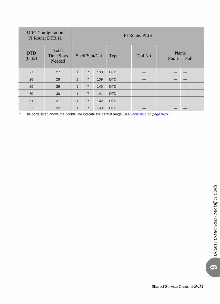
U-R
MI /
U-M
R / R
MI /
MR
Offi
ce C
ards
9
27 27 1 7 138 DTD — — —
28 28 1 7 139 DTD — — —
29 29 1 7 140 DTD — — —
30 30 1 7 141 DTD — — —
31 31 1 7 142 DTD — — —
32 32 1 7 143 DTD — — —
* The ports listed above the double line indicate the default range. See Table 9-11 on page 9-23.
URC ConfigurationPI Route: DTB,11 PI Route: PLIS
DTD(0-32)
TotalTime Slots
NeededShelf/Slot/Ckt Type Dial No. Name
Short : Full
Shared Service Cards 9-33

U-R
MI /
U-M
R / R
MI /
MR
Offi
ce C
ards
9
9-34 Coral IPx Office Installation Manual
9.4
Three-Way Conference (3-Way)Conference CircuitryThre
e-W
ay C
onfe
renc
e (3
-Way
) Con
fere
nce
Circ
uitr
y9
0
The U-RMI Office and U-MR Office cards provide eight (max: 24*) independent 3-way (conferences/Consultation/Broker service) conversation circuits. They can be used for:
Digital voice ports, such as SKK, IPG, UGW, PRI-23, PRI-30, 4TBR, 8TBR, 8TBRP, T1 or 30T/x; to participate in a 3-way conference call (3-way for SLT stations and analog lines is standard)
The Silent Monitor feature
The Coral Message Center’s Silent Record feature
Separate authorization is required to allocate the 3way circuits supported by the U-RMI Office and U-MR Office cards.(max: *) The max. number is dependant on the number of URC time slots.
The 3-way conference circuitry is completely digital. During the conferencing session, each participant hears the voices of other participants.
0
The 3-WAY circuit requires some database settings. Consult the Program Interface (PI) and Database Reference Manual for instructions on the database programming required for C3WAY.The following parameters must be set for 3-way conference and Silent Monitoring.
Sizes TAB (Route: SYSGEN)RESOURCES
...................................................................................................1 General Description
...................................................................................................2 Database Programming
Shared Service Cards 9-35
Thre
e-W
ay C
onfe
renc
e (3
-Way
) Con
fere
nce
Circ
uitr
y9
Class of Service (Route: COS,0)BROKER/CONSULT/3-WAY/ALL
SILENT_MONITOR
Numbering Plan (Route: NPL,0)SILENT_MONITOR - field 9, index 171
URC Feature Authorization (Route: FEAT,1) URC 3WAY
URC Configuration (Route: CDB,11,1) 3WAY
Defines the maximum number of 3-way Conference bridge resources to be enabled by the system URC cards. Each 3-way conference circuit requires 4 card time slots (therefore, eight 3-way circuits require 32 TS).
When the 3-way conference exists and is initialized, the PI shows:
Card List (Route: CLIS)Card type (see Table 9-3 on page 9-7) must show:
RMI-F or MR in the P_TYPE field of Shelf #1, Slot #6.
URC2 in the P_TYPE field of Shelf #1, Slot #7.
Port List (Route: PLIS,0)Port type must show:
C3WAY in the TYPE field of Shelf #1, Slot #7, Ckt #56-79(max.).
See Table 9-16 URC Three-Way Conference (C3WAY) PI Configuration, page 9-29.
Refer to Program Interface (PI) and Database Reference Manual, Chapter 6, System Port List for more details.
9-36 Coral IPx Office Installation Manual
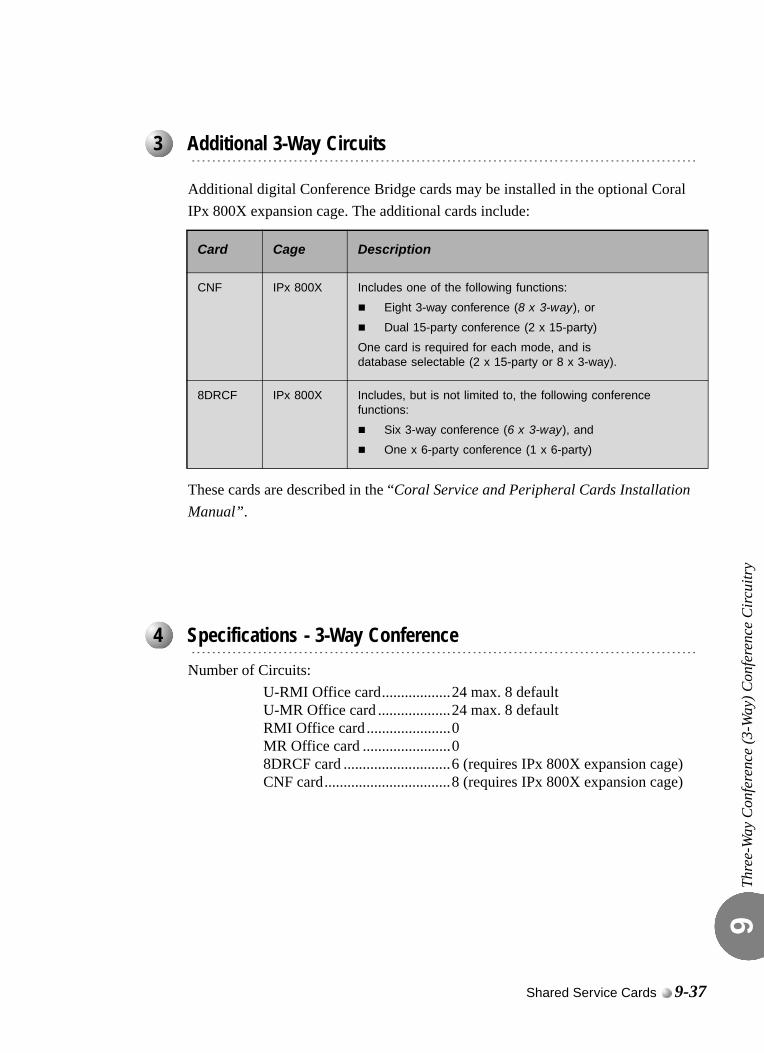
Thre
e-W
ay C
onfe
renc
e (3
-Way
) Con
fere
nce
Circ
uitr
y9
Additional digital Conference Bridge cards may be installed in the optional Coral IPx 800X expansion cage. The additional cards include:
These cards are described in the “Coral Service and Peripheral Cards Installation Manual”.
0
Number of Circuits:U-RMI Office card..................24 max. 8 defaultU-MR Office card ...................24 max. 8 defaultRMI Office card ......................0MR Office card .......................08DRCF card ............................6 (requires IPx 800X expansion cage)CNF card.................................8 (requires IPx 800X expansion cage)
...................................................................................................3 Additional 3-Way Circuits
Card Cage Description
CNF IPx 800X Includes one of the following functions:
Eight 3-way conference (8 x 3-way), or
Dual 15-party conference (2 x 15-party)
One card is required for each mode, and isdatabase selectable (2 x 15-party or 8 x 3-way).
8DRCF IPx 800X Includes, but is not limited to, the following conference functions:
Six 3-way conference (6 x 3-way), and
One x 6-party conference (1 x 6-party)
...................................................................................................4 Specifications - 3-Way Conference
Shared Service Cards 9-37

Thre
e-W
ay C
onfe
renc
e (3
-Way
) Con
fere
nce
Circ
uitr
y9
NOTES:
9-38 Coral IPx Office Installation Manual
9.5
Multi-Party Conference (CONF)Meet Me Conference CircuitryMul
ti-Pa
rty
Con
fere
nce
(CO
NF)
Mee
t Me
Con
fere
nce
Circ
uitr
y9
0
The U-RMI Office and U-MR Office cards provide two (max: 6*) meet-me bridge conference for 14 parties.
Separate authorization is required to allocate the CONF circuits supported by the U-RMI Office and U-MR Office cards.(max: *) The max. number is dependant on the number of URC time slots.
The Meet Me bridge manages conferences talk for up to 14/84 participants. Any combination of trunks or stations can participate. The circuitry is completely digital. During the conferencing session, each participant hears the voices of other participants as their amplitude voices are added.The Meet Me bridge allows the establishment of a conference call at an appointed hour by dialing a special conference destination number.The multi-party conference feature allows a conference of up 14/84 simultaneous conversations in a conference mode.The conference bridge is a Meet Me feature. Station users can dial the programmable access code and/or transfer or be transferred to the conference call.Access to the conference bridge may be defined through the Tenant feature.
...................................................................................................1 General Description
Shared Service Cards 9-39
Mul
ti-Pa
rty
Con
fere
nce
(CO
NF)
Mee
t Me
Con
fere
nce
Circ
uitr
y9
0
The Meet Me Bridge Conference Circuit (CONF) in the Coral IPx Office system enables:
Group Call
Multiparty conference
URC Chained Meet Me Groups
The URC has 6 circuits that may be allocated as Conference ports. Each of these ports can enable one conference of 14 participants. Alternatively, these conference ports can be chained together internally by the URC, without using extra time slots, so that a conference with a maximum of 84 participants can be created. The “chain” definition is created via the PDB branch, see Special Port Facilities (Route: PDB,3), page 9-43.
84 participants requires URC Software Versions 2.xx or higher.The conference number is displayed on the user’s keyset. However, different members in the same chained conference may see different conference numbers on their display.
URC Meet Me Conference Modes
The Meet-Me conference can be defined to operate in one of two different modes:
Summation: Enables all conference participants to be heard simultaneously during the conference.
Strongest Win: Enables only the loudest speaker to be heard during the conference.
The technician is able to define a maximum number of participants when using the Summation mode. When this maximum is exceeded, the system automatically switches the conference to the Strongest Win mode (see PI Branch: CDB,11,2; CONF MEMBERS, page 9-43 and CONF SWITCH DELAY, page 9-43 on URC Card DB - Meet Me Conference (Route: CDB,11,2), page 9-43.
...................................................................................................2 Feature Descriptions
9-40 Coral IPx Office Installation Manual
Mul
ti-Pa
rty
Con
fere
nce
(CO
NF)
Mee
t Me
Con
fere
nce
Circ
uitr
y9
0
The Meet Me Bridge Conference Circuit (CONF) requires the appropriate definitions in the database. Consult the Program Interface (PI) and Database Reference Manual for instructions on the database programming required for CONF.The following parameters must be set, to enable Multi-party conferencing and Group Calls.
Special Port Facilities (Route: PDB,3)Use this field for the following:
To assign this port to a specific tenant group.
To determine whether the conference participants will be notified when a member joins or leaves the conversation.
Refer to Chapter 23 - Conference in the Program Interface and Database Reference Manual for details.
Class of Service (Route: COS,0)CONF
CONF_RELEASE
CONF_LOCK
Feature Timers (Route: FE.T)This branch may be used to determine time intervals for multi-party conference call features. The related parameters are:
CONF_SUPV_RECALL
GRP_CALL_RING
Refer to Chapter 6 - System Features in the Program Interface and Database Reference Manual for details.
Group Calls (Route: CALL)This branch may be used to assign various multi-party conference call features. Refer to Chapter 10 - Groups, in the Program Interface and Database Reference Manual for details.
Feature Timers (Route: FE.T)GRP_CALL_RING
...................................................................................................3 Database Programming
Shared Service Cards 9-41
Mul
ti-Pa
rty
Con
fere
nce
(CO
NF)
Mee
t Me
Con
fere
nce
Circ
uitr
y9
Gains Table (Route: ROOT,0,1,3)Entry #12 of the gains table can be used to set gain parameters to the conference. For more information see Chapter 19 in the Program Interface (PI) and Database Reference manual.
Feature Authorization (Route: FEAT,1) URC CONF
CONF
Separate Software Authorization is required to allocate the URC resources. Refer to Program Interface (PI) and Database Reference Manual, Chapter 3, Feature Authorization for more details.
Sizes (Route: SIZ)CONF_CKTS parameter - enter 1 to 6 ports as required.
URC Configuration (Route: CDB,11,1) 3WAY - defines the maximum number of 3-way Conference bridge resources to be enabled by the system URC cards. Each 3-way conference circuit requires 4 card time slots (therefore, eight 3-way circuits require 32 TS).
Card List (Route: CLIS)Card type (see Table 9-3 on page 9-7) must show:
RMI-F or MR in the P_TYPE field of Shelf #1, Slot #6.
URC2 in the P_TYPE field of Shelf #1, Slot #7.
Port List (Route: PLIS,0)Port type must show:
CONF in the TYPE field of Shelf #1, Slot #7, Ckt #48-53(max.).
See URC Meet-Me Multiparty Conference PI Configuration, page 9-27.
Use the NAME fields to assign a short/full name to the authorized CONF ports.
If you choose 0 - Physical Location, type (Shelf #1, Slot #7, Ckt #48-53).
If you choose 1 - Dial Number, select field [All].
Refer to Program Interface (PI) and Database Reference Manual, Chapter 6, System Port List for more details.
9-42 Coral IPx Office Installation Manual
Mul
ti-Pa
rty
Con
fere
nce
(CO
NF)
Mee
t Me
Con
fere
nce
Circ
uitr
y9
Numbering Plan (Route: NPL,0)CONFERENCE RELEASE - field 9, index 173.
CONFERENCE LOCK - field 9, index 190.
CONFERENCE DIAL NUMBERS - field 30 (Shelf #1, Slot #7, Ckt #48-53).
URC Configuration (Route: CDB,11,1) Meet Me - defines the maximum number of Multi-Party (Meet-Me) conference bridge resources to be enabled by the system URC cards. Each Meet Me conference circuit requires 16 card time slots.
URC Card DB - Meet Me Conference (Route: CDB,11,2) CONF MEMBERS
CONF SWITCH DELAY
Special Port Facilities (Route: PDB,3) LINKED TO CONF DIAL# -
Refer to Chapter 23 - Conference in the Program Interface and Database Reference Manual for details.
Shared Service Cards 9-43
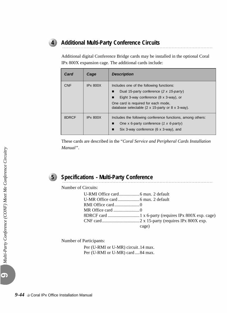
Mul
ti-Pa
rty
Con
fere
nce
(CO
NF)
Mee
t Me
Con
fere
nce
Circ
uitr
y9
Additional digital Conference Bridge cards may be installed in the optional Coral IPx 800X expansion cage. The additional cards include:
These cards are described in the “Coral Service and Peripheral Cards Installation Manual”.
0
Number of Circuits:U-RMI Office card..................6 max. 2 defaultU-MR Office card ...................6 max. 2 defaultRMI Office card ......................0MR Office card .......................08DRCF card ............................1 x 6-party (requires IPx 800X exp. cage)CNF card.................................2 x 15-party (requires IPx 800X exp.
cage)
Number of Participants:Per (U-RMI or U-MR) circuit.14 max.Per (U-RMI or U-MR) card ....84 max.
...................................................................................................4 Additional Multi-Party Conference Circuits
Card Cage Description
CNF IPx 800X Includes one of the following functions:
Dual 15-party conference (2 x 15-party)
Eight 3-way conference (8 x 3-way), or
One card is required for each mode, database selectable (2 x 15-party or 8 x 3-way).
8DRCF IPx 800X Includes the following conference functions, among others:
One x 6-party conference (1 x 6-party)
Six 3-way conference (6 x 3-way), and
...................................................................................................5 Specifications - Multi-Party Conference
9-44 Coral IPx Office Installation Manual
9.6
DTMF Receiver (DTR)DTM
F Re
ceiv
er (D
TR)
9
0
The U-RMI Office and U-MR Office cards provide 24 (max: 24*) port DTMF receivers and decoders for touch-tone digits.
Separate authorization is required to allocate the DTMF circuits supported by the U-RMI Office and U-MR Office cards.(max: *) The max. number is dependant on the number of URC time slots.
The U-RMI Office and U-MR Office cards include the DTR circuits. The DTR provides up to 24 circuits, which receive and decode Dual Tone Multi-Frequency (DTMF) dialing tones. The DTR is required to support telephone station apparatus or trunks that send DTMF tones to the Coral IPx Office system to activate system features or select other ports.DTMF signaling is commonly used by industry standard, single line telephone (SLT) sets, as well as E&M tie trunks and Direct Inward Dialing (DID) central office trunks. Loop-start and ground-start central office trunks, which are defined in the system database as IRSS (Freedom) or DISA, require a DTR to be installed in the system.The DTR uses industry standard DTMF receiver circuitry to decode DTMF dialing tones. The audio side of each DTMF receiver circuit is directly coupled through a CODEC to the Pulse Code Modulation (PCM) switching matrix of the Coral IPx Office system. Decoded digital data is passed through the peripheral bus to the system processor.
...................................................................................................1 General Description
Shared Service Cards 9-45
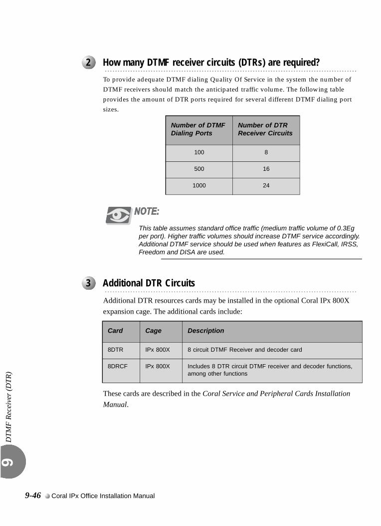
DTM
F Re
ceiv
er (D
TR)
9
0
To provide adequate DTMF dialing Quality Of Service in the system the number of DTMF receivers should match the anticipated traffic volume. The following table provides the amount of DTR ports required for several different DTMF dialing port sizes.
This table assumes standard office traffic (medium traffic volume of 0.3Eg per port). Higher traffic volumes should increase DTMF service accordingly. Additional DTMF service should be used when features as FlexiCall, IRSS, Freedom and DISA are used.
0
Additional DTR resources cards may be installed in the optional Coral IPx 800X expansion cage. The additional cards include:
These cards are described in the Coral Service and Peripheral Cards Installation Manual.
...................................................................................................2 How many DTMF receiver circuits (DTRs) are required?
Number of DTMF Dialing Ports
Number of DTR Receiver Circuits
100 8
500 16
1000 24
...................................................................................................3 Additional DTR Circuits
Card Cage Description
8DTR IPx 800X 8 circuit DTMF Receiver and decoder card
8DRCF IPx 800X Includes 8 DTR circuit DTMF receiver and decoder functions, among other functions
9-46 Coral IPx Office Installation Manual

DTM
F Re
ceiv
er (D
TR)
9
0
The DTR requires the appropriate definitions in the database. Consult the Program Interface (PI) and Database Reference Manual for instructions on the database programming required for the DTR. The following parameters must be set, to enable the DTR:
Sizes TAB (Route: SYSGEN)RESOURCES
URC Feature Authorization (Route: FEAT,1) URC DTMF
Separate Software Authorization is required to allocate the URC resources. Refer to Program Interface (PI) and Database Reference Manual, Chapter 3, Feature Authorization for more details.
URC Configuration (Route: CDB,11,1) DTMF
Defines the maximum number of DTMF Receiver (DTR) resources to be enabled by the system URC cards. Each DTMF receiver requires one card time slot.
URC Card Database (Route: CDB,11,2) DTMF GAIN
The gain may be adjusted in this branch and not in the Feature Control branch as with other cards.
Card List (Route: CLIS)Card type (see Table 9-3 on page 9-7) must show:
RMI-F or MR in the P_TYPE field of Shelf #1, Slot #6.
URC2 in the P_TYPE field of Shelf #1, Slot #7.
Port List (Route: PLIS,0)Port type must show:
DTR in the TYPE field of Shelf #1, Slot #7, Ckt #0-23(max. for URC2) or 0-47(max. for URC4)
See Table 9-13 URC DTR/DTMF PI Configuration, page 9-26.
...................................................................................................4 Database Programming
Shared Service Cards 9-47
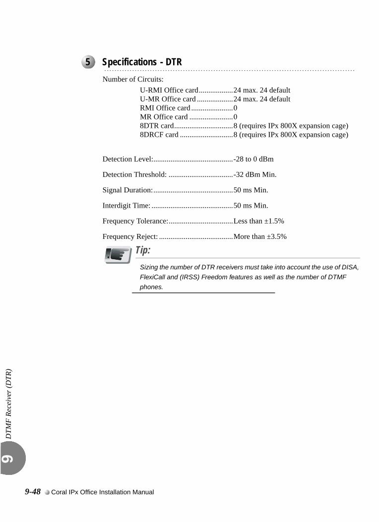
DTM
F Re
ceiv
er (D
TR)
9
0
Number of Circuits:U-RMI Office card..................24 max. 24 defaultU-MR Office card ...................24 max. 24 defaultRMI Office card ......................0MR Office card .......................08DTR card...............................8 (requires IPx 800X expansion cage)8DRCF card ............................8 (requires IPx 800X expansion cage)
Detection Level:..........................................-28 to 0 dBm
Detection Threshold: ..................................-32 dBm Min.
Signal Duration:..........................................50 ms Min.
Interdigit Time: ...........................................50 ms Min.
Frequency Tolerance:..................................Less than ±1.5%
Frequency Reject: .......................................More than ±3.5%
Tip:Sizing the number of DTR receivers must take into account the use of DISA,
FlexiCall and (IRSS) Freedom features as well as the number of DTMF
phones.
...................................................................................................5 Specifications - DTR
9-48 Coral IPx Office Installation Manual
9.7
Dial Tone Detector (DTD)Dia
l Ton
e D
etec
tor (
DTD
) 9
0
The U-RMI Office and U-MR Office cards provide 16 (max: 32*) port DTD (Dial Tone Detector) circuits for enhanced dialing, such as busy outside number auto-redial.
(max: *) The max. number is dependant on the number of URC time slots.
The DTD circuits are used to detect and identify standard call progress tones such as dial tone, busy tone, reorder (fast busy) tone and ringback tone. The DTD is required to support system features such as Automatic Called Number Redial (ACNR, also called Scanner).The DTD may also be utilized to force a station user to wait for a dial tone before dialing to the central office. This increases the effectiveness of the toll restriction by prohibiting users from dialing an unrestricted code before the central office is ready, and then making a toll call when the dial tone is heard.Each tone detection circuit of the DTD consists of a sophisticated audio noise level detector. This circuit monitors audio signals and determines a constant or ambient level, and then determines the presence of noise above ambient.During operation, the system passes digitized voice signals from a port to be monitored, through the Pulse Code Modulation (PCM) switching matrix to one of the noise level detection circuits of the DTD. The presence of a call progress tone is typically characterized by a sustained, non-fluctuating noise level.The DTD then multiplies the periods that the tone is present and the periods of silence. The durations of tone and silence are assembled to form a cadence (or rhythm pattern) that is compared with an internal list of call progress tones and their associated cadence. By matching the cadence of the monitored tone with the one contained in the list, the DTD identifies the tone and reports the tone type via the peripheral bus to the system processor.
...................................................................................................1 General Description
Shared Service Cards 9-49
Dia
l Ton
e D
etec
tor (
DTD
) 9
The DTD requires the appropriate definitions in the database. Consult the Program Interface (PI) and Database Reference Manual for instructions on the database programming required.The following parameters must be set, to enable DTD.
Sizes TAB (Route: SYSGEN)RESOURCES
URC Configuration (Route: CDB,11,1) DTD
Defines the maximum number of Dial Tone Detector (DTD) resources to be enabled by the system URC cards. Each DTD circuit requires 1 card time slot.
URC Card Database (Route: CDB,11,2) DTD GAIN
The gain may be adjusted in this branch and not in the Feature Control branch as with other cards.
When the DTD exists and is initialized, the PI shows:
Card List (Route: CLIS)Card type (see Table 9-3 on page 9-7) must show:
RMI-F or MR in the P_TYPE field of Shelf #1, Slot #6.
URC2 in the P_TYPE field of Shelf #1, Slot #7.
Port List (Route: PLIS,0)Port type must show:
DTD in the TYPE field of Shelf #0, Slot #7, Ckt #112-143(max.)
See Table 9-18 URC Dial Tone Detector (DTD) PI Configuration, page 9-32.
Refer to Program Interface (PI) and Database Reference Manual, Chapter 6, System Port List for more details.
...................................................................................................2 Database Programming
9-50 Coral IPx Office Installation Manual
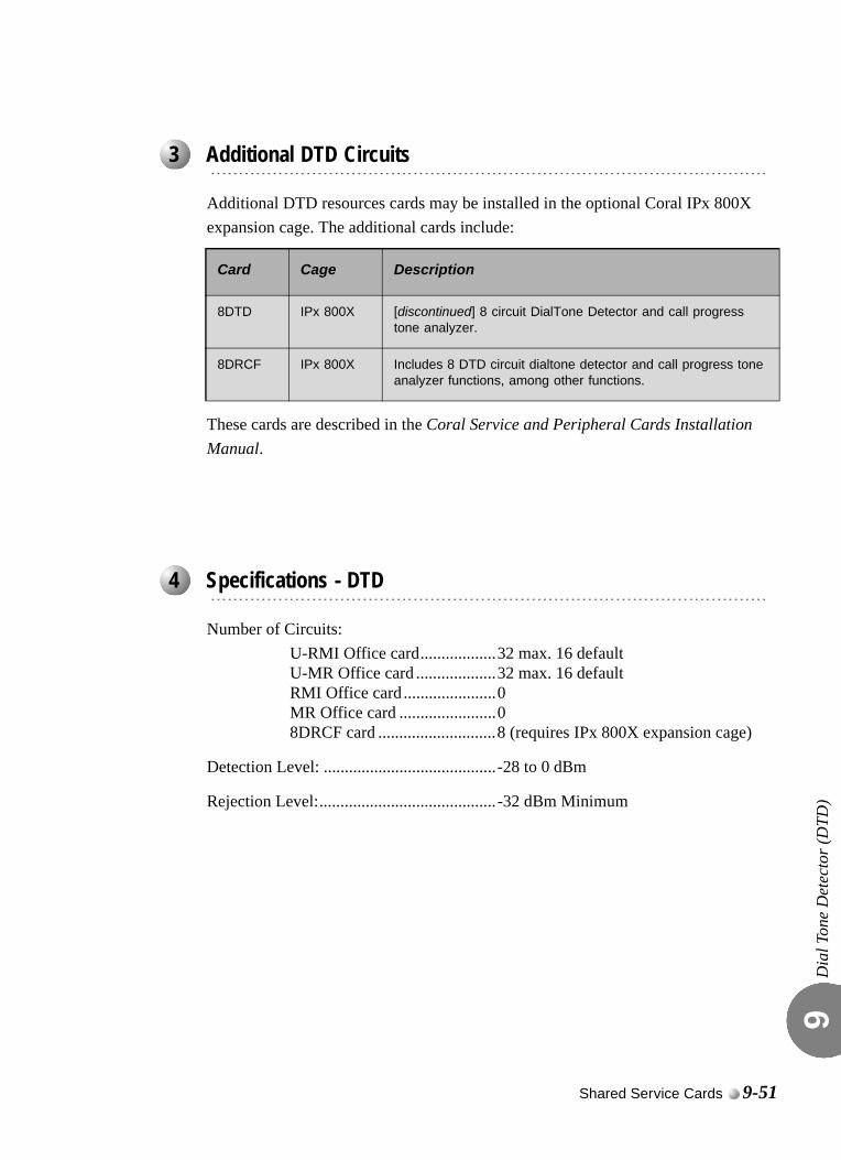
Dia
l Ton
e D
etec
tor (
DTD
) 9
Additional DTD resources cards may be installed in the optional Coral IPx 800X expansion cage. The additional cards include:
These cards are described in the Coral Service and Peripheral Cards Installation Manual.
Number of Circuits:U-RMI Office card..................32 max. 16 defaultU-MR Office card ...................32 max. 16 defaultRMI Office card ......................0MR Office card .......................08DRCF card ............................8 (requires IPx 800X expansion cage)
Detection Level: .........................................-28 to 0 dBm
Rejection Level:..........................................-32 dBm Minimum
...................................................................................................3 Additional DTD Circuits
Card Cage Description
8DTD IPx 800X [discontinued] 8 circuit DialTone Detector and call progress tone analyzer.
8DRCF IPx 800X Includes 8 DTD circuit dialtone detector and call progress tone analyzer functions, among other functions.
...................................................................................................4 Specifications - DTD
Shared Service Cards 9-51

Dia
l Ton
e D
etec
tor (
DTD
) 9
NOTES:
9-52 Coral IPx Office Installation Manual
9.8
Caller ID for SLT (iDSP)Cal
ler I
D fo
r SLT
(iD
SP)
9
0
The U-RMI Office and U-MR Office cards provide 16 (max: 32*) iDSP ports.
Separate authorization is required to allocate the iDSP circuits supported by the U-RMI Office and U-MR Office cards.(max: *) The max. number is dependant on the number of URC time slots.
The iDSP is required for displaying CID (Caller ID) for SLT users. The iDSP application converts ASCII text information, received from the Coral main processor, into FSK tone:
BellCore GR-30, or
ETSI 300-659-1 para. 6.1.1
The FSK tones are supplied for direct injection onto the Coral PCM highways. The iDSP application provides up to 32 individual FSK tones simultaneously, each on a different PCM channel and call.The CID display feature for SLT requires Authorization for SLT-CID, and an FSK compatible display unit installed on the SLT port.The following information modulated in FSK is sent to an SLT interface by the iDSP application, between the 1st and 2nd ring:
Date,
Time,
Number (the last 10 digits),
Name (the first 15 characters); enabled through programming in the configuration database.
The CID display unit detects this information and transforms it back into ASCII codes. Up to 32 SLT sets can receive CID information simultaneously from a single URC iDSP application. Multi-appearance and waiting call’s information is not supported.
...................................................................................................1 General Description
Shared Service Cards 9-53
Cal
ler I
D fo
r SLT
(iD
SP)
9
The CID requires the appropriate definitions in the database. Consult the Program Interface (PI) and Database Reference Manual for instructions on the database programming required.The following parameters must be set, to enable CID.
URC Feature Authorization (Route: FEAT,1) URC CLID
SLT-CID
URC Configuration (Route: CDB,11) CID
Defines the maximum number of Caller ID (CID) transmitter resources to be enabled by the system URC cards. Each CID transmitter circuit requires 1 card time slot.
When the CID exists and is initialized, the PI shows:
Card List (Route: CLIS)Card type (see Table 9-3 on page 9-7) must show:
RMI-F or MR in the P_TYPE field of Shelf #1, Slot #6.
URC2 in the P_TYPE field of Shelf #1, Slot #7.
Port List (Route: PLIS,0)Port type must show:
CID in the TYPE field of Shelf #1, Slot #7, Ckt #80-111(max.)
See Table 9-17 URC iDSP CID (Caller ID) Transmitters PI Configuration, page 9-30.
Refer to Program Interface (PI) and Database Reference Manual, Chapter 6, System Port List for more details.
...................................................................................................2 Database Programming
9-54 Coral IPx Office Installation Manual
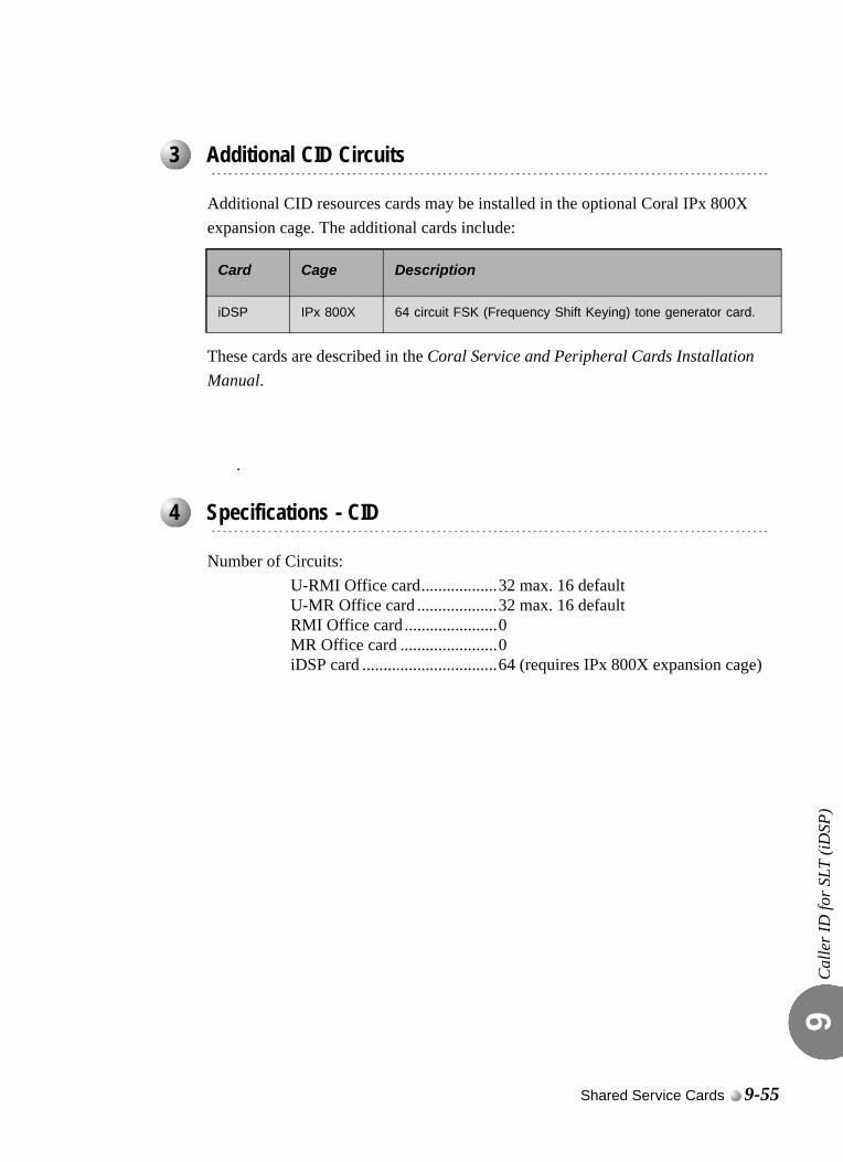
Cal
ler I
D fo
r SLT
(iD
SP)
9
Additional CID resources cards may be installed in the optional Coral IPx 800X expansion cage. The additional cards include:
These cards are described in the Coral Service and Peripheral Cards Installation Manual.
.
Number of Circuits:U-RMI Office card..................32 max. 16 defaultU-MR Office card ...................32 max. 16 defaultRMI Office card ......................0MR Office card .......................0iDSP card ................................64 (requires IPx 800X expansion cage)
...................................................................................................3 Additional CID Circuits
Card Cage Description
iDSP IPx 800X 64 circuit FSK (Frequency Shift Keying) tone generator card.
...................................................................................................4 Specifications - CID
Shared Service Cards 9-55

Cal
ler I
D fo
r SLT
(iD
SP)
9
NOTES:
9-56 Coral IPx Office Installation Manual
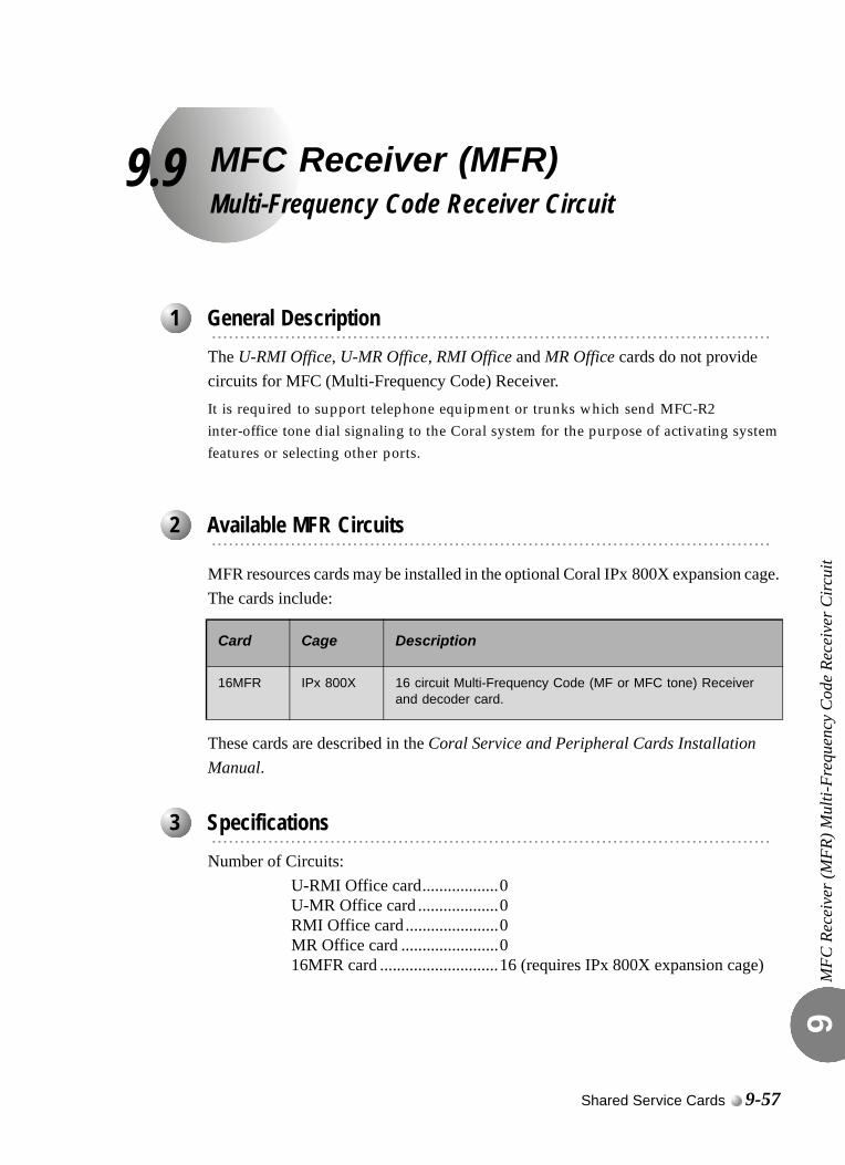
9.9
MFC Receiver (MFR)Multi-Frequency Code Receiver CircuitMFC
Rec
eive
r (M
FR) M
ulti-
Freq
uenc
y C
ode
Rece
iver
Circ
uit
9
0
The U-RMI Office, U-MR Office, RMI Office and MR Office cards do not provide circuits for MFC (Multi-Frequency Code) Receiver.It is required to support telephone equipment or trunks which send MFC-R2 inter-office tone dial signaling to the Coral system for the purpose of activating system features or selecting other ports.
MFR resources cards may be installed in the optional Coral IPx 800X expansion cage. The cards include:
These cards are described in the Coral Service and Peripheral Cards Installation Manual. 0
Number of Circuits:U-RMI Office card..................0U-MR Office card ...................0RMI Office card ......................0MR Office card .......................016MFR card ............................16 (requires IPx 800X expansion cage)
...................................................................................................1 General Description
...................................................................................................2 Available MFR Circuits
Card Cage Description
16MFR IPx 800X 16 circuit Multi-Frequency Code (MF or MFC tone) Receiver and decoder card.
...................................................................................................3 Specifications
Shared Service Cards 9-57

MFC
Rec
eive
r (M
FR) M
ulti-
Freq
uenc
y C
ode
Rece
iver
Circ
uit
9
NOTES:
9-58 Coral IPx Office Installation Manual
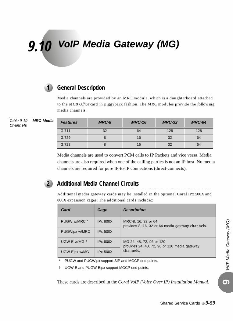
9.10
VoIP Media Gateway (MG)VoIP
Med
ia G
atew
ay (M
G)
9
0
Media channels are provided by an MRC module, which is a daughterboard attached to the MCB Office card in piggyback fashion. The MRC modules provide the following media channels.
Table 9-19 MRC Media Channels
Media channels are used to convert PCM calls to IP Packets and vice versa. Media channels are also required when one of the calling parties is not an IP host. No media channels are required for pure IP-to-IP connections (direct-connects). 0
Additional media gateway cards may be installed in the optional Coral IPx 500X and 800X expansion cages. The additional cards include::
These cards are described in the Coral VoIP (Voice Over IP) Installation Manual.
...................................................................................................1 General Description
Features MRC-8 MRC-16 MRC-32 MRC-64
G.711 32 64 128 128
G.729 8 16 32 64
G.723 8 16 32 64
...................................................................................................2 Additional Media Channel Circuits
Card Cage Description
PUGW w/MRC *
* PUGW and PUGWipx support SIP and MGCP end points.
IPx 800X MRC-8, 16, 32 or 64provides 8, 16, 32 or 64 media gateway channels.
PUGWipx w/MRC IPx 500X
UGW-E w/MG †
† UGW-E and PUGW-Eipx support MGCP end points.
IPx 800X MG-24, 48, 72, 96 or 120 provides 24, 48, 72, 96 or 120 media gateway channels.UGW-Eipx w/MG IPx 500X
Shared Service Cards 9-59

VoIP
Med
ia G
atew
ay (M
G)
9
NOTES:
9-60 Coral IPx Office Installation Manual
9.11
Remote Maintenance (Modem)Rem
ote
Mai
nten
ance
(Mod
em)
9
0
The U-RMI Office and RMI Office cards provide an auto-answer data modem. A full duplex, asynchronous, ASCII modem, for remote programming the system database, diagnostics and system maintenance, and/or for displaying various reports. The modem operates at up to 56Kbps, using the ITU-T V.92 standard.The modem answers an incoming call in Originate mode (no answer tone). To establish a connection, the originating modem must initiate the call in answer mode (by sending answer tone). This feature may be used as an added security measure to protect the system database from intrusions.0
The U-RMI Office and RMI Office cards are equipped with jumper straps P5 and P6 (see Figure 9-3 on page 9-11) that enable and disable the modem. These jumpers, when removed, disable the on-board modem, without affecting the other programming interfaces. Thus, a local programming terminal or an external modem incorporating more sophisticated security features may be operated while the modem is disabled.The modem requires no external connections to function. The data side of the modem circuitry directly accesses the peripheral data bus to communicate with the system processor. The audio side of the modem circuitry directly accesses the switching matrix, is assigned a dial number in the system database and may answer incoming calls in virtually the same manner as any other port in the system.The modem can be configured to transmit or receive data. This is useful when maintenance from a remote workstation is necessary. During normal system operation, it is advisable to set the modem transmit and receive function to “Off” for more secure system operation. Figure 9-11 displays the jumper settings for the modem.
...................................................................................................1 General Description
...................................................................................................2 Modem Jumpers - Enable/Disable
Shared Service Cards 9-61
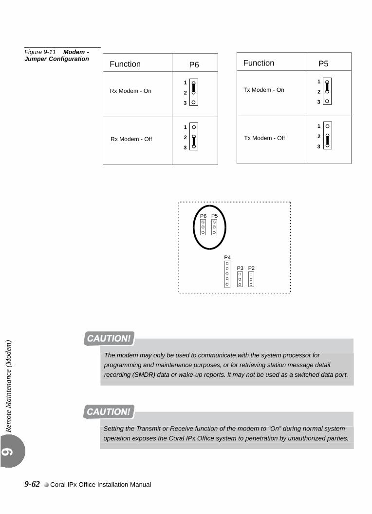
Rem
ote
Mai
nten
ance
(Mod
em)
9
Figure 9-11 Modem - Jumper Configuration
Function
Rx Modem - On
Rx Modem - Off
P6
P5
P2
2
1
3
2
1
3
Function
Tx Modem - On
Tx Modem - Off
P5
2
1
3
2
1
3
P6
P3
P4
The modem may only be used to communicate with the system processor for
programming and maintenance purposes, or for retrieving station message detail
recording (SMDR) data or wake-up reports. It may not be used as a switched data port.
Setting the Transmit or Receive function of the modem to “On” during normal system
operation exposes the Coral IPx Office system to penetration by unauthorized parties.
9-62 Coral IPx Office Installation Manual

Rem
ote
Mai
nten
ance
(Mod
em)
9
0
This function requires installation of an additional jumpers (P5 and P6, pins 1 and 2 must be connected) on the U-RMI Office and RMI Office cards. Described on page 9-61.
The Modem requires the appropriate definitions in the database. Consult the Program Interface (PI) and Database Reference Manual for instructions on the database programming required for the modem.When the modem exists and is initialized, the PI shows:
1. Card List (Route: CLIS)
Card type must show RMI-F in the P_TYPE field of Shelf #1, Slot #6.
1. Port List (Route: PLIS)
Port type must show MODEM in the TYPE field of Shelf #1, Slot #6, Ckt #26.
Use this field to assign a short/full name to this port.
If you choose 0 - Physical Location, type (Shelf #1, Slot #6, Ckt #26).
If you choose 1 - Dial Number, choose field [5] MODEM.
Refer to Chapter 6 - System Port List, in the Program Interface (PI) and Database Reference Manual, for more details.
2. General Numbering Plan (Route: NPL,0) [13] (Ckt #26)
Use the 13-MODEM field of the Update Menu, to designate dial numbers to the modem ports in the system. Refer to Chapter 5 - Numbering Plan, in the Program Interface (PI) and Database Reference Manual, for more details.
2. Special Port Facilities (Route: PDB,6)
Use this field to assign this port to a specific tenant group.
Refer to Chapter 23 - RMI Modem, in the Program Interface (PI) and Database Reference Manual, for more details.
3. Class Of Service (Route: COS,0) [MODEM]
Use the MODEM parameter to determine whether a specific station user is allowed to dial to the MODEM. Refer to Chapter 7 - Station and Trunk COS, in the Program Interface (PI) and Database Reference Manual, for more details.
...................................................................................................3 Database Programming
Shared Service Cards 9-63

Rem
ote
Mai
nten
ance
(Mod
em)
9
4. Terminal Setup (Route: TERM,0)
Use this field to set up the communication parameters for the data applications.
Refer to Chapter 17 in the Program Interface (PI) and Database Reference Manual for more details.
5. Gains Table (Route: ROOT,0,1,3)
Entry #10 of the gains table can be used to set gain parameters to the modem. These parameters set the transmission value levels of the modem while in CONNECT state with any possible port in the system. For more information see Chapter 19 in the Program Interface (PI) and Database Reference And Database Manual.
9-64 Coral IPx Office Installation Manual
Rem
ote
Mai
nten
ance
(Mod
em)
9
Additional modem ports may be installed in the optional Coral IPx 800X expansion cage. The additional cards include:
These cards are described in the Coral Service and Peripheral Cards Installation Manual. Shared service cards may be installed in any available peripheral card slot in the optional Coral IPx 800X expansion unit.
0
Number of Circuits:U-RMI Office card..................1RMI Office card ......................1U-MR Office card ...................0MR Office card .......................08DRCF card ............................1 (requires IPx 800X expansion cage)
Modem Operating Modes: (V.92 ITU-T) up to 56KbpsClient-to-Server.......................DataComm: supports V.92 or K56flexModem Compatibility.............ITU V.92, K56flex
Data communications via the modem use the 7 bit, American Standard Code for Information Interchange (ASCII) character set, although each port may be programmed to send and receive a “dummy” 8th character bit. Data is exchanged in asynchronous character transmission mode.
...................................................................................................4 Additional Modem in the Optional IPx 800X Cage
Card Description
8DRCF Includes the ITU-T V.92 (up to 56Kbps) remote maintenance modem, among other functions.
...................................................................................................5 Specifications - Modem
Shared Service Cards 9-65

Rem
ote
Mai
nten
ance
(Mod
em)
9
NOTES:
9-66 Coral IPx Office Installation Manual
9.12
Data Serial Ports (RS-232E)KB0, KB1, KB2, KB3Dat
a Se
rial
Por
ts (R
S-23
2E) K
B0, K
B1, K
B2, K
B39
0
The U-RMI Office, U-MR Office, RMI Office and MR Office cards do not provide Serial ports.The Coral IPx Office provides one EIA RS-232E Asynchronous, ASCII serial data interfaces (KB0) via the MCB Office, for the following functions:
System database programming
Diagnostics and system maintenance
See KB0 RS-232E Programming Port, page 8-18
...................................................................................................1 General Description
Shared Service Cards 9-67
Dat
a Se
rial
Por
ts (R
S-23
2E) K
B0, K
B1, K
B2, K
B39
0
RS-232E Serial ports may be installed in the optional Coral IPx 800X expansion cage. The additional cards include:
This card is described in the Coral Service and Peripheral Cards Installation Manual. 8DRCF cards may be installed in any available peripheral card slot in the optional Coral IPx 800X expansion unit.The 8DRCF card provides three EIA RS-232E Asynchronous, ASCII serial data interfaces (KB1, KB2 and KB3), for the following functions:
System database programming
Diagnostics and system maintenance
Displaying reports such as station message detail recording (SMDR)
Displaying wake-up reports
Displaying call charge
Printing the Malicious Call Trace reports
0
Number of Circuits:U-RMI Office card..................0U-MR Office card ...................0RMI Office card ......................0MR Office card .......................08DRCF card ............................3 (requires IPx 800X expansion cage)
...................................................................................................2 RS-232E ports in the Optional IPx 800X Cage
Card Cage Description
8DRCF IPx 800X Includes three RS-232E programming/maintenance interfaces (300 to 115,200 bps), among other functions.
The KB1, KB2 and KB3 data ports may only be used to communicate with the system
processor for programming and maintenance purposes, or for retrieving station
message detail recording (SMDR) data or wake-up reports. It may not be used as
switched data ports.
...................................................................................................3 Specifications - RS-232E
9-68 Coral IPx Office Installation Manual
9.13
MusicBackground and Music-On-Hold (M1/M2)Mus
ic B
ackg
roun
d an
d M
usic
-On-
Hol
d (M
1/M
2)9
0
The U-RMI Office, U-MR Office, RMI Office and MR Office cards provide the following common system functions:
Two music inputs, one of which can be internal.
Music-on-hold interface (two ports).
Key telephone background music interface (two different sources)
Figure 9-12 and Figure 9-14 are simplified circuit diagrams of the two Music Interfaces. The external music (M1,M2) interfaces are electrically identical. Audio signals to the system are passed through the audio coupling transformer to the interface. A direct current (DC) blocking capacitor protects the secondary winding of the audio coupling transformer from conducting DC energy. As a music input the circuit operates as an input only, and so it can be used to play but not record music.
M1 Internal/External music
Internal music (M1) is available in all cards. The selection between the internal or external source is accomplished by P2 jumper located on the U-RMI Office, U-MR Office, RMI Office and MR Office cards. See Figure 9-13. Table 9-20 defines the position of P2 for the music selection.
M2/P Paging/External music
External music (M2/P) connector can be used as voice paging output. The selection between the external music source or voice paging output is accomplished by P3 jumper located on the U-RMI Office, U-MR Office, RMI Office and MR Office cards. See Figure 9-15. Table 9-21 defines the position of P3 for the music selection.
...................................................................................................1 Introduction
...................................................................................................2 Circuit Description
Shared Service Cards 9-69
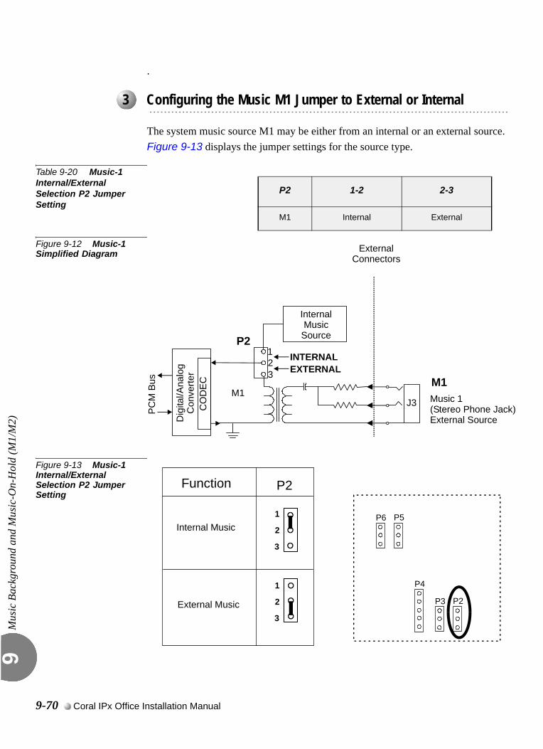
Mus
ic B
ackg
roun
d an
d M
usic
-On-
Hol
d (M
1/M
2)9
.
The system music source M1 may be either from an internal or an external source. Figure 9-13 displays the jumper settings for the source type.
Table 9-20 Music-1 Internal/External Selection P2 Jumper Setting
Figure 9-12 Music-1 Simplified Diagram
Figure 9-13 Music-1 Internal/External Selection P2 Jumper Setting
...................................................................................................3 Configuring the Music M1 Jumper to External or Internal
P2 1-2 2-3
M1 Internal External
321
P2
M1
InternalMusic
Source
INTERNALEXTERNAL
PCM
Bus
ExternalConnectors
Dig
ital/A
nalo
gC
onve
rter
CO
DE
C M1
J3 Music 1(Stereo Phone Jack)External Source
Function
Internal Music
External Music
P2
2
1
3
2
1
3
P5
P2
P6
P3
P4
9-70 Coral IPx Office Installation Manual
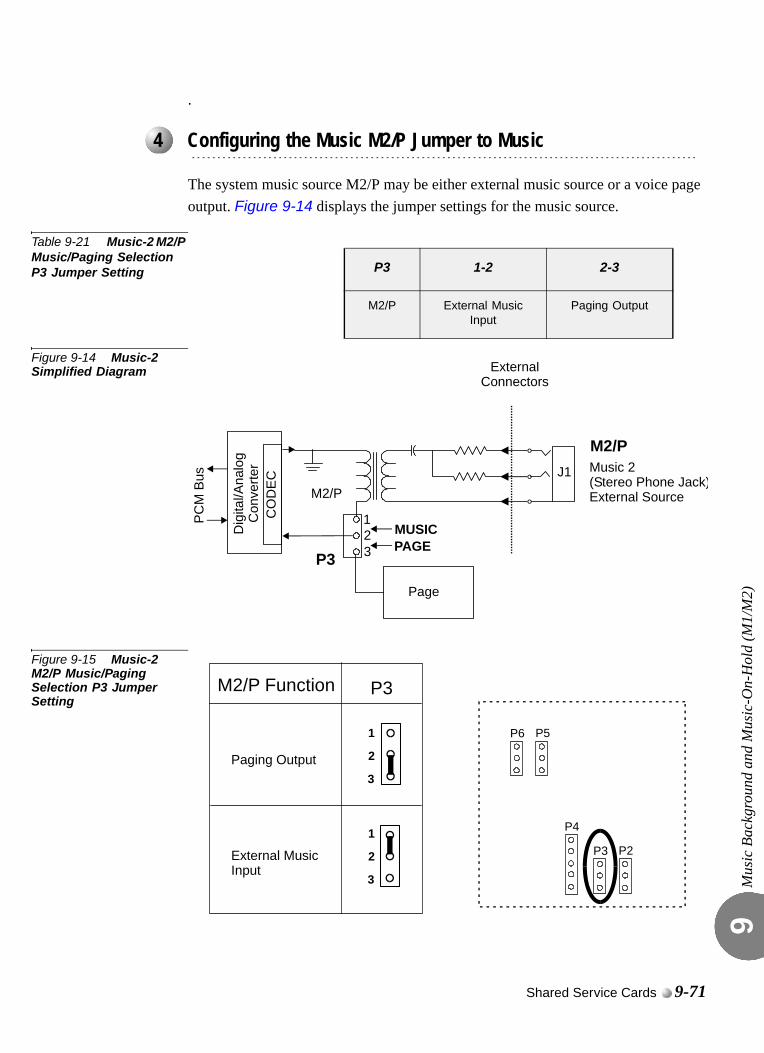
Mus
ic B
ackg
roun
d an
d M
usic
-On-
Hol
d (M
1/M
2)9
.
The system music source M2/P may be either external music source or a voice page output. Figure 9-14 displays the jumper settings for the music source.
Table 9-21 Music-2 M2/P Music/Paging Selection P3 Jumper Setting
Figure 9-14 Music-2 Simplified Diagram
Figure 9-15 Music-2 M2/P Music/Paging Selection P3 Jumper Setting
...................................................................................................4 Configuring the Music M2/P Jumper to Music
P3 1-2 2-3
M2/P External Music Input
Paging Output
P3
M2/P
Page
PCM
Bus
ExternalConnectors
Dig
ital/A
nalo
gC
onve
rter
CO
DE
C
MUSICPAGE3
21
M2/P J1 Music 2
(Stereo Phone Jack)External Source
M2/P Function P3
Paging Output 2
1
3
P5
P2
P6
P3
P4
2
1
3
External MusicInput
Shared Service Cards 9-71

Mus
ic B
ackg
roun
d an
d M
usic
-On-
Hol
d (M
1/M
2)9
0
Each U-RMI Office, U-MR Office, RMI Office or MR Office card provides two music sources; M1 (External/Internal selectable) and M2 (External). The Music feature requires the appropriate definitions in the database. Consult the Program Interface (PI) and Database Reference Manual for instructions on the database programming required for Music.The following parameters must be set, to enable the Music feature.
1. Card List (Route: CLIS)
Card type must show RMI-F or MR in the P_TYPE field of Shelf #1, Slot #6.
1. Music Sources (Route: SYSGEN,4)
Use this field to determine the number and the location of music sources in the system. Refer to Chapter 4 - Music Sources, in the Program Interface and Database Reference Manual, for more details.
2. Page-Q (Route: ROOT,0,7)
Use this field to determine which music source will be used when a call is placed on a specific queue. Refer to Chapter 23 - Page_Q Music, in the Program Interface (PI) and Database Reference Manual, for more details.
3. SLT_Def (Route: SLT)
Use the MUSIC_ON_HOLD/TRANSFER field to determine which music source will be used when a call is placed on hold by the relevant port.
4. E&M_Def (Route: TRK,1)
Use the MUSIC_ON_HOLD/TRANSFER field to determine which music source will be used when a call is placed on hold by the relevant port.
5. KEYSET_Def (Route: KEY)
Use the MUSIC field to activate or cancel background music for a specific keyset.
Use the MUSIC_NUM field to determine which music source will sounded.
Use the MUSIC_ON_HOLD/TRANSFER field to determine which music source will be used when a call is placed on hold by the relevant port.
6. Hunt Group (Route: HUNT)
Use the MUSIC_SOURCE field to determine which music source will sounded for callers that queue on the group.
...................................................................................................5 Database Programming
9-72 Coral IPx Office Installation Manual

Mus
ic B
ackg
roun
d an
d M
usic
-On-
Hol
d (M
1/M
2)9
Use the RETAIN_HUNT_MUSIC_SOURCE field as described in Chapter 9, in the Program Interface (PI) and Database Reference Manual.
7. Gains Table (Route: ROOT,0,1,3)
Entry #11 of the gains table can be used to set gain parameters to the music sources. These parameters set the transmission value levels of the music while in CONNECT state with any possible port in the system. For more information see Chapter 19 in the Program Interface (PI) and Database Reference manual.
8. WAIT_QUE (Route: ROOT, 7, 3)
The following three fields MUSIC/TONE, MUSIC_SOURCE# and RETAIN_WAIT_Q__SOURCE are used to activate WAIT_Q features. For more information see Chapter 27 - CoraLINK in the Program Interface (PI) and Database Reference manual.
Shared Service Cards 9-73
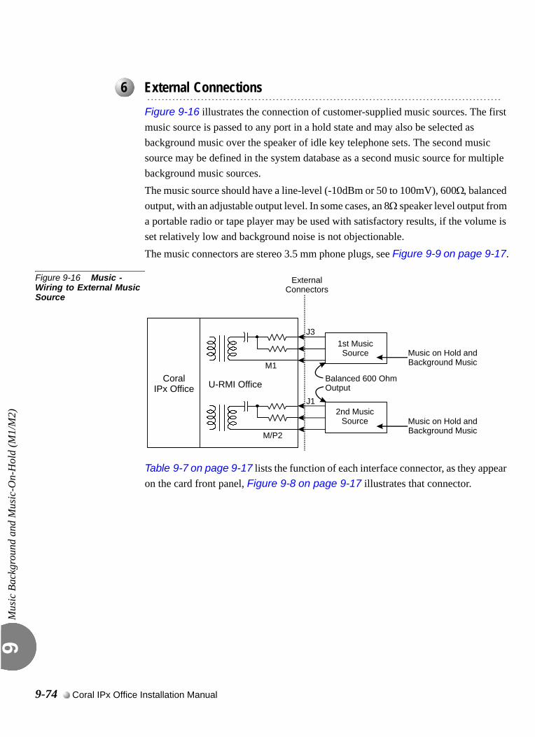
Mus
ic B
ackg
roun
d an
d M
usic
-On-
Hol
d (M
1/M
2)9
0
Figure 9-16 illustrates the connection of customer-supplied music sources. The first music source is passed to any port in a hold state and may also be selected as background music over the speaker of idle key telephone sets. The second music source may be defined in the system database as a second music source for multiple background music sources.The music source should have a line-level (-10dBm or 50 to 100mV), 600Ω, balanced output, with an adjustable output level. In some cases, an 8Ω speaker level output from a portable radio or tape player may be used with satisfactory results, if the volume is set relatively low and background noise is not objectionable.The music connectors are stereo 3.5 mm phone plugs, see Figure 9-9 on page 9-17.
Figure 9-16 Music - Wiring to External Music Source
Table 9-7 on page 9-17 lists the function of each interface connector, as they appear on the card front panel, Figure 9-8 on page 9-17 illustrates that connector.
...................................................................................................6 External Connections
U-RMI OfficeCoralIPx Office
ExternalConnectors
Music on Hold andBackground Music
Music on Hold andBackground Music
Balanced 600 OhmOutput
M1
M/P2
J1
J31st MusicSource
2nd MusicSource
9-74 Coral IPx Office Installation Manual
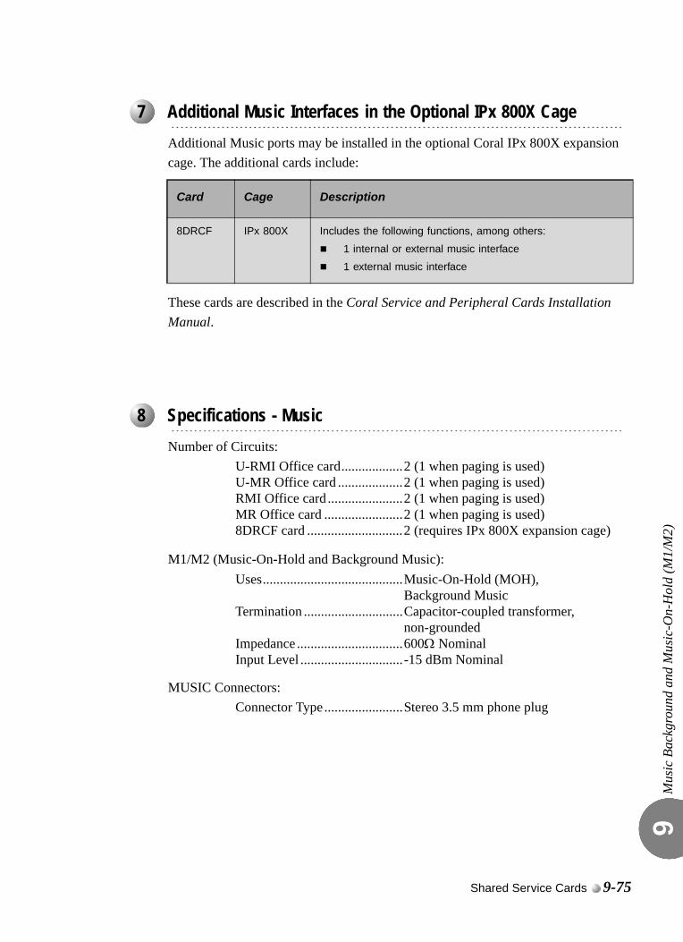
Mus
ic B
ackg
roun
d an
d M
usic
-On-
Hol
d (M
1/M
2)9
0
Additional Music ports may be installed in the optional Coral IPx 800X expansion cage. The additional cards include:
These cards are described in the Coral Service and Peripheral Cards Installation Manual.
0
Number of Circuits:U-RMI Office card..................2 (1 when paging is used)U-MR Office card ...................2 (1 when paging is used)RMI Office card ......................2 (1 when paging is used)MR Office card .......................2 (1 when paging is used)8DRCF card ............................2 (requires IPx 800X expansion cage)
M1/M2 (Music-On-Hold and Background Music):Uses.........................................Music-On-Hold (MOH),
Background MusicTermination .............................Capacitor-coupled transformer,
non-groundedImpedance ...............................600Ω NominalInput Level ..............................-15 dBm Nominal
MUSIC Connectors:Connector Type.......................Stereo 3.5 mm phone plug
...................................................................................................7 Additional Music Interfaces in the Optional IPx 800X Cage
Card Cage Description
8DRCF IPx 800X Includes the following functions, among others:
1 internal or external music interface
1 external music interface
...................................................................................................8 Specifications - Music
Shared Service Cards 9-75

Mus
ic B
ackg
roun
d an
d M
usic
-On-
Hol
d (M
1/M
2)9
NOTES:
9-76 Coral IPx Office Installation Manual

9.14
Voice Paging (Public Address) and Relay-1Public AddressVoic
e Pa
ging
(Pub
lic A
ddre
ss) a
nd R
elay
-1 P
ublic
Add
ress
9
0
The U-RMI Office, U-MR Office, RMI Office and MR Office cards provide one external paging interface (public address, one port). Station users can access an external voice paging system connected to the Coral IPx Office by dialing access code.
Figure 9-17 is a simplified circuit diagram of the Paging Interfaces and the relay contacts.Each U-RMI Office, U-MR Office, RMI Office or MR Office card provides one paging output: the external voice paging port operates by using both the relay circuit (RLY1) and the PAGE circuit. The PAGE circuit is used for public address.The External Paging (PAGE) Interface is electrically identical to the Music interfaces. Audio signals from the system are passed through the audio coupling transformer to the interface. A direct current (DC) blocking capacitor protects the secondary winding of the audio coupling transformer from conducting DC energy. As a music input the circuit operates as an input only, and so it can be used to play but not record music.The relay provides form A (single pole, single throw and normally open) contacts for activating external circuitry and devices. Contacts RLY1 are designated to operate in conjunction with audio interface PAGE for external paging applications. Care must be taken not to exceed the contact ratings listed in the specifications.
M2/P Paging/External music
Page (M2/P) connector can be used as a music source. The selection between the music source or voice paging output is accomplished by P3 jumper located on the U-RMI Office, U-MR Office, RMI Office and MR Office cards. See Figure 9-18. Table 9-22 defines the position of P3 for the music selection.
...................................................................................................1 Introduction
...................................................................................................2 Circuit Description
Shared Service Cards 9-77
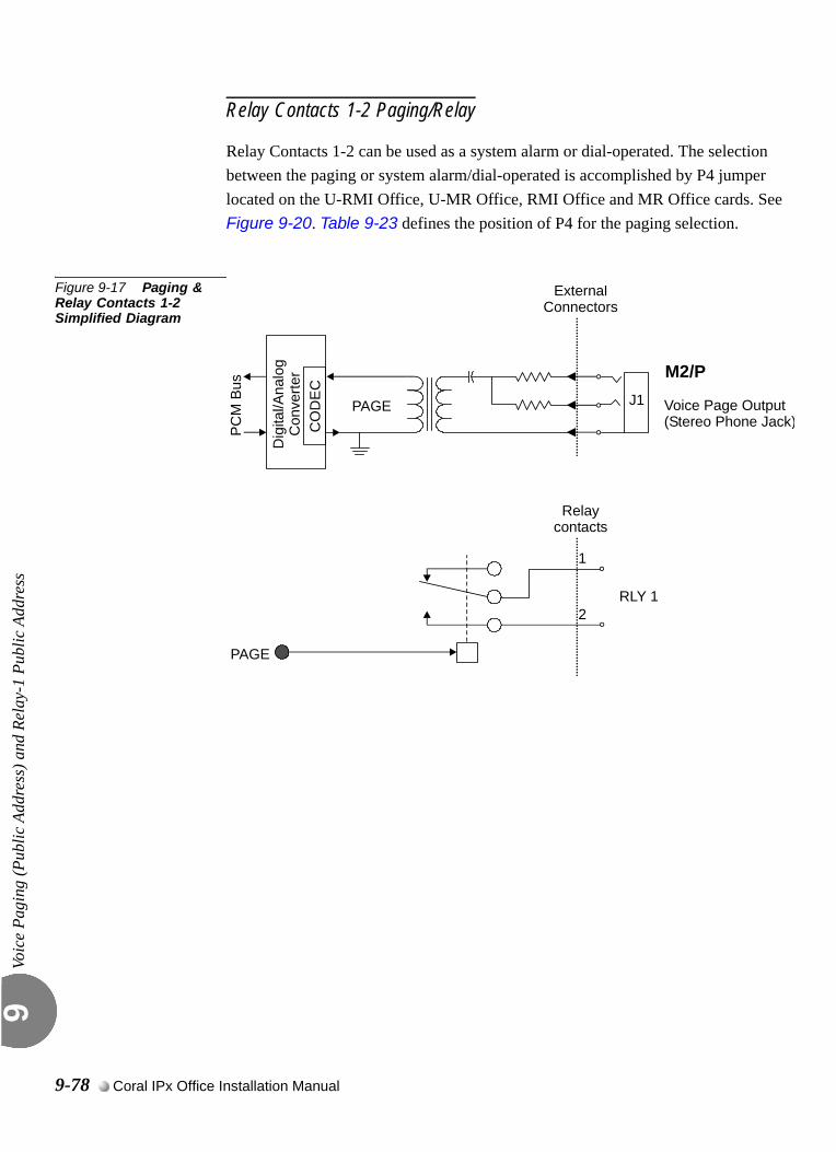
Voic
e Pa
ging
(Pub
lic A
ddre
ss) a
nd R
elay
-1 P
ublic
Add
ress
9
Relay Contacts 1-2 Paging/Relay
Relay Contacts 1-2 can be used as a system alarm or dial-operated. The selection between the paging or system alarm/dial-operated is accomplished by P4 jumper located on the U-RMI Office, U-MR Office, RMI Office and MR Office cards. See Figure 9-20. Table 9-23 defines the position of P4 for the paging selection.
Figure 9-17 Paging & Relay Contacts 1-2 Simplified Diagram
PAGE
PC
M B
us
Dig
ital/A
nalo
gC
onve
rter
ExternalConnectors
RLY 1
PAGE
1
2
CO
DE
C
M2/P J1 Voice Page Output
(Stereo Phone Jack)
Relaycontacts
9-78 Coral IPx Office Installation Manual
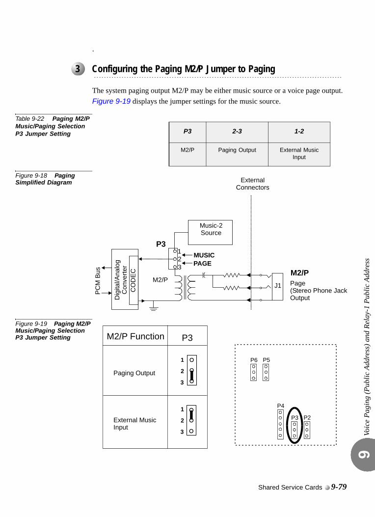
Voic
e Pa
ging
(Pub
lic A
ddre
ss) a
nd R
elay
-1 P
ublic
Add
ress
9
.
The system paging output M2/P may be either music source or a voice page output. Figure 9-19 displays the jumper settings for the music source.
Table 9-22 Paging M2/P Music/Paging Selection P3 Jumper Setting
Figure 9-18 Paging Simplified Diagram
Figure 9-19 Paging M2/P Music/Paging Selection P3 Jumper Setting
...................................................................................................3 Configuring the Paging M2/P Jumper to Paging
P3 2-3 1-2
M2/P Paging Output External Music Input
321
P3
M2/P
Music-2Source
MUSICPAGE
PC
M B
us
ExternalConnectors
Dig
ital/A
nalo
gC
onve
rter
CO
DE
C M2/P J1 Page
(Stereo Phone JackOutput
M2/P Function P3
Paging Output 2
1
3
P5
P2
P6
P3
P4
2
1
3
External MusicInput
Shared Service Cards 9-79
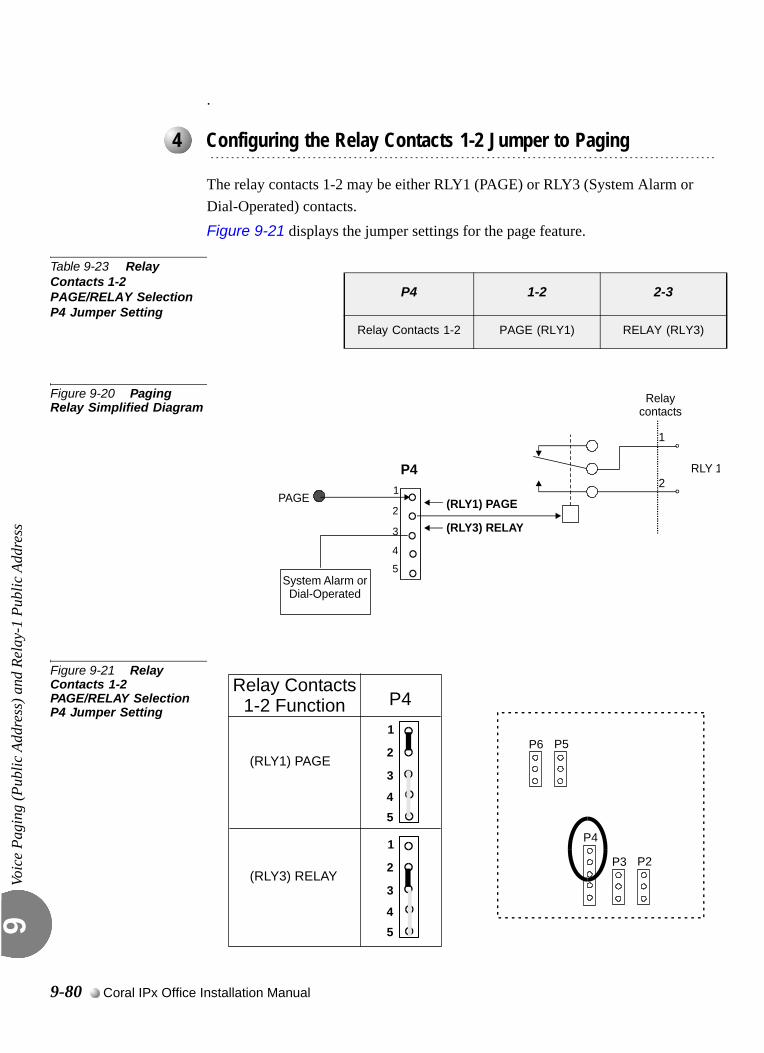
Voic
e Pa
ging
(Pub
lic A
ddre
ss) a
nd R
elay
-1 P
ublic
Add
ress
9
.
The relay contacts 1-2 may be either RLY1 (PAGE) or RLY3 (System Alarm or Dial-Operated) contacts. Figure 9-21 displays the jumper settings for the page feature.
Table 9-23 Relay Contacts 1-2 PAGE/RELAY Selection P4 Jumper Setting
Figure 9-20 Paging Relay Simplified Diagram
Figure 9-21 Relay Contacts 1-2 PAGE/RELAY Selection P4 Jumper Setting
...................................................................................................4 Configuring the Relay Contacts 1-2 Jumper to Paging
P4 1-2 2-3
Relay Contacts 1-2 PAGE (RLY1) RELAY (RLY3)
RLY 1
PAGE
1
2
Relaycontacts
P4
System Alarm orDial-Operated
(RLY1) PAGE
(RLY3) RELAY2
1
3
4
5
Relay Contacts1-2 Function
(RLY3) RELAY
P4
2
1
3
P5
P2
P6
P3
P4
(RLY1) PAGE
45
2
1
3
45
9-80 Coral IPx Office Installation Manual

Voic
e Pa
ging
(Pub
lic A
ddre
ss) a
nd R
elay
-1 P
ublic
Add
ress
9
0
Each U-RMI Office, U-MR Office, RMI Office or MR Office card provides one paging output: the external voice paging port operates by using both the relay circuit (RLY1) and the PAGE circuit.The paging feature requires the appropriate definitions in the database. Consult the Program Interface (PI) and Database and Database Reference Manual for instructions on the database programming required for Paging.
The following parameters must be set, to enable the paging feature.
1. Card List (Route: CLIS)
Card type must show RMI-F or MR in the P_TYPE field of Shelf #1, Slot #6.
1. General Numbering Plan (Route: NPL,0) [12] (Ckt #23)
Use the 12-Page field of the PI in the Update Menu to designate dial numbers to the Public Address Page in the system. Refer to Chapter 5 - Numbering Plan, in the Program Interface (PI) and Database Reference Manual, for more details.
2. Port List (Route: PLIS)
Port type must show PAGE in the TYPE field of Shelf #1, Slot #6, Ckt #23.
Use this field to assign a short/full name to this port.
If you choose 0 - Physical Location, type (Shelf # 1, Slot # 6, Ckt # 23).
If you choose 1 - Dial Number, choose field [6] PAGE.
Refer to Chapter 6 - System Port List, in the Program Interface and Database Reference Manual, for more details.
3. Special Port Facilities (Route: PDB,5)
Use this field to assign this port to a specific tenant group.
Refer to Chapter 23 - Public Address/Page, in the Program Interface and Database Reference Manual, for more details.
4. Class Of Service (Route: COS,0) [PAGE]
Use the PAGE parameter to determine whether a specific station user is allowed to dial and access the External Voice Paging system. Refer to Chapter 7 - Station and Trunk COS, in the Program Interface and Database Reference Manual, for more details.
...................................................................................................5 Database Programming
Shared Service Cards 9-81
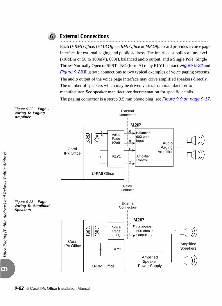
Voic
e Pa
ging
(Pub
lic A
ddre
ss) a
nd R
elay
-1 P
ublic
Add
ress
9
0
Each U-RMI Office, U-MR Office, RMI Office or MR Office card provides a voice page interface for external paging and public address. The interface supplies a line-level (-10dBm or 50 to 100mV), 600Ω, balanced audio output, and a Single Pole, Single Throw, Normally Open or SPST - NO (form A) relay RLY1 contact. Figure 9-22 and Figure 9-23 illustrate connections to two typical examples of voice paging systems.The audio output of the voice page interface may drive amplified speakers directly. The number of speakers which may be driven varies from manufacturer to manufacturer. See speaker manufacturer documentation for specific details.The paging connector is a stereo 3.5 mm phone plug, see Figure 9-9 on page 9-17.
Figure 9-22 Page - Wiring To Paging Amplifier
Figure 9-23 Page - Wiring To Amplified Speakers
...................................................................................................6 External Connections
Voice Page(Out)
AmplifierControl
Balanced 600 ohmInput
RLY1
U-RMI Office
CoralIPx Office
1
2
Audio Paging
Amplifierx
ExternalConnectors
J1
J1
M2/P
RelayContacts
AmplifiedSpeaker
Power Supply
Balanced 600 ohmOutput
xAmplifiedSpeakers
CoralIPx Office
U-RMI Office
RLY1
Voice Page(Out)
ExternalConnectors
J1
J1
M2/P
9-82 Coral IPx Office Installation Manual
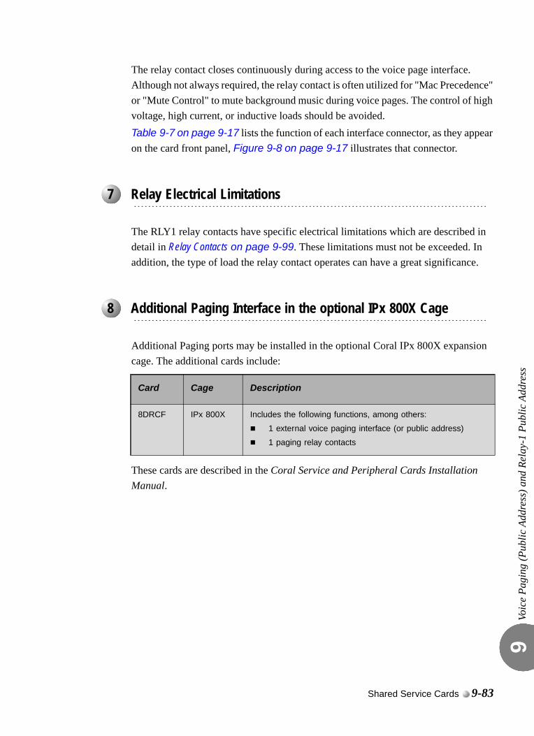
Voic
e Pa
ging
(Pub
lic A
ddre
ss) a
nd R
elay
-1 P
ublic
Add
ress
9
The relay contact closes continuously during access to the voice page interface. Although not always required, the relay contact is often utilized for "Mac Precedence" or "Mute Control" to mute background music during voice pages. The control of high voltage, high current, or inductive loads should be avoided.Table 9-7 on page 9-17 lists the function of each interface connector, as they appear on the card front panel, Figure 9-8 on page 9-17 illustrates that connector.
The RLY1 relay contacts have specific electrical limitations which are described in detail in Relay Contacts on page 9-99. These limitations must not be exceeded. In addition, the type of load the relay contact operates can have a great significance.
Additional Paging ports may be installed in the optional Coral IPx 800X expansion cage. The additional cards include:
These cards are described in the Coral Service and Peripheral Cards Installation Manual.
...................................................................................................7 Relay Electrical Limitations
...................................................................................................8 Additional Paging Interface in the optional IPx 800X Cage
Card Cage Description
8DRCF IPx 800X Includes the following functions, among others:
1 external voice paging interface (or public address)
1 paging relay contacts
Shared Service Cards 9-83
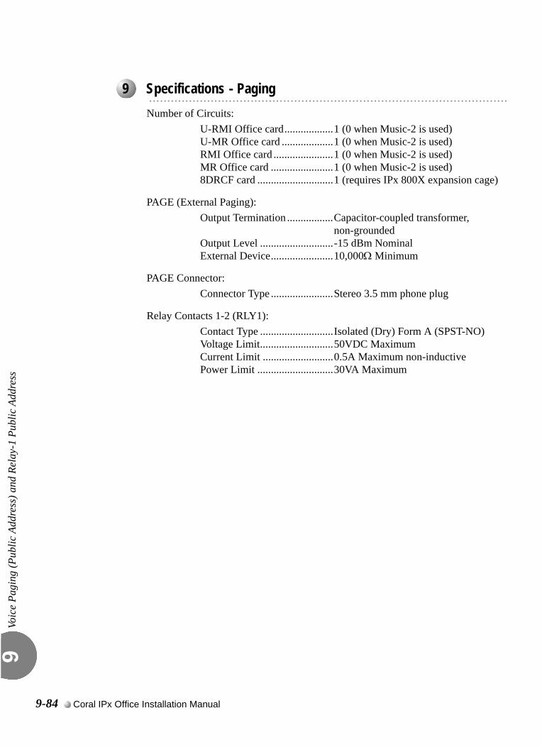
Voic
e Pa
ging
(Pub
lic A
ddre
ss) a
nd R
elay
-1 P
ublic
Add
ress
9
0
Number of Circuits:U-RMI Office card..................1 (0 when Music-2 is used)U-MR Office card ...................1 (0 when Music-2 is used)RMI Office card ......................1 (0 when Music-2 is used)MR Office card .......................1 (0 when Music-2 is used)8DRCF card ............................1 (requires IPx 800X expansion cage)
PAGE (External Paging):Output Termination .................Capacitor-coupled transformer,
non-groundedOutput Level ...........................-15 dBm NominalExternal Device.......................10,000Ω Minimum
PAGE Connector:Connector Type .......................Stereo 3.5 mm phone plug
Relay Contacts 1-2 (RLY1):Contact Type ...........................Isolated (Dry) Form A (SPST-NO)Voltage Limit...........................50VDC MaximumCurrent Limit ..........................0.5A Maximum non-inductivePower Limit ............................30VA Maximum
...................................................................................................9 Specifications - Paging
9-84 Coral IPx Office Installation Manual
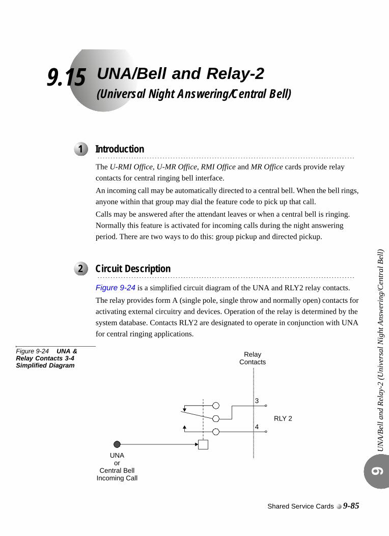
9.15
UNA/Bell and Relay-2(Universal Night Answering/Central Bell)UN
A/Be
ll an
d Re
lay-
2 (U
nive
rsal
Nig
ht A
nsw
erin
g/C
entr
al B
ell)
9
0
The U-RMI Office, U-MR Office, RMI Office and MR Office cards provide relay contacts for central ringing bell interface.An incoming call may be automatically directed to a central bell. When the bell rings, anyone within that group may dial the feature code to pick up that call.Calls may be answered after the attendant leaves or when a central bell is ringing. Normally this feature is activated for incoming calls during the night answering period. There are two ways to do this: group pickup and directed pickup.
Figure 9-24 is a simplified circuit diagram of the UNA and RLY2 relay contacts.The relay provides form A (single pole, single throw and normally open) contacts for activating external circuitry and devices. Operation of the relay is determined by the system database. Contacts RLY2 are designated to operate in conjunction with UNA for central ringing applications.
Figure 9-24 UNA & Relay Contacts 3-4 Simplified Diagram
...................................................................................................1 Introduction
...................................................................................................2 Circuit Description
RLY 2
UNAor
Central BellIncoming Call
3
4
RelayContacts
Shared Service Cards 9-85
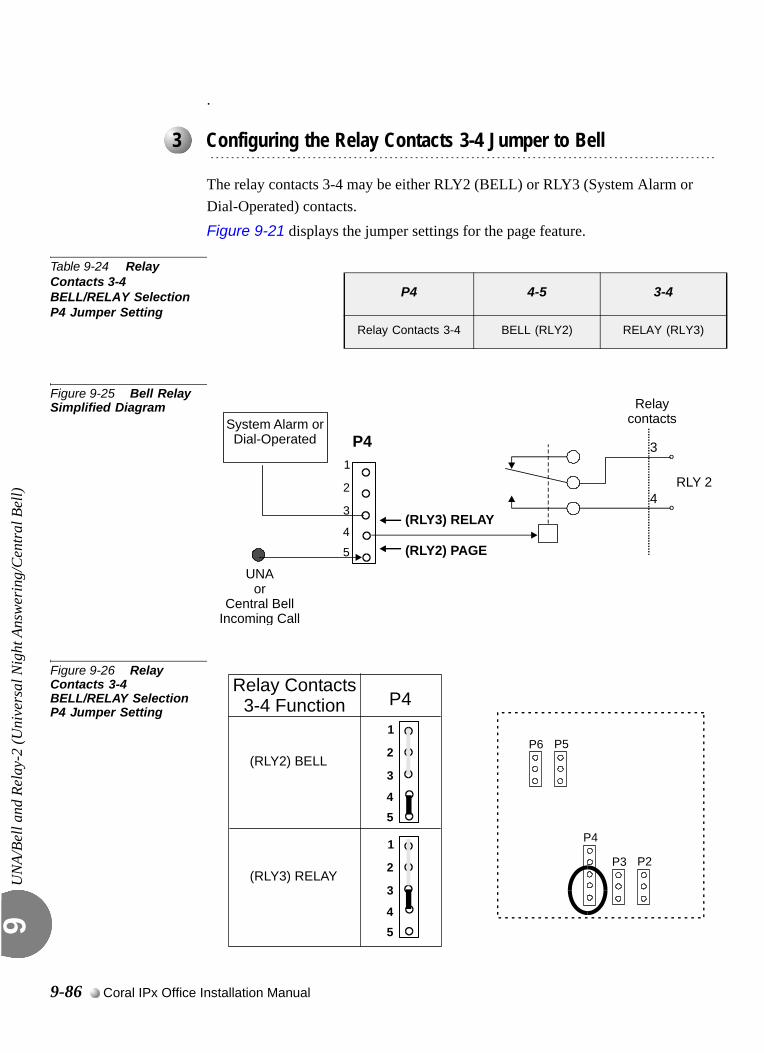
UN
A/Be
ll an
d Re
lay-
2 (U
nive
rsal
Nig
ht A
nsw
erin
g/C
entr
al B
ell)
9
.
The relay contacts 3-4 may be either RLY2 (BELL) or RLY3 (System Alarm or Dial-Operated) contacts. Figure 9-21 displays the jumper settings for the page feature.
Table 9-24 Relay Contacts 3-4 BELL/RELAY Selection P4 Jumper Setting
Figure 9-25 Bell Relay Simplified Diagram
Figure 9-26 Relay Contacts 3-4 BELL/RELAY Selection P4 Jumper Setting
...................................................................................................3 Configuring the Relay Contacts 3-4 Jumper to Bell
P4 4-5 3-4
Relay Contacts 3-4 BELL (RLY2) RELAY (RLY3)
RLY 2
3
4
Relaycontacts
P4System Alarm orDial-Operated
(RLY2) PAGE
(RLY3) RELAY
2
1
3
4
5
UNAor
Central BellIncoming Call
Relay Contacts3-4 Function
(RLY3) RELAY
P4
2
1
3
P5
P2
P6
P3
P4
(RLY2) BELL
45
2
1
3
45
9-86 Coral IPx Office Installation Manual
UN
A/Be
ll an
d Re
lay-
2 (U
nive
rsal
Nig
ht A
nsw
erin
g/C
entr
al B
ell)
9
0
The Central Bell (UNA) requires the appropriate definitions in the database. Consult the Program Interface (PI) and Database Reference Manual for instructions on the database programming required for the feature.
The following parameters must be set, to enable the paging feature.
1. Card List (Route: CLIS)
Card type must show RMI-F or MR in the P_TYPE field of Shelf #1, Slot #6.
5. General Numbering Plan (Route: NPL,0) [11] (Ckt #24)
Use the field 11-Bell of the Update menu to designate dial numbers to the UNA bell ports in the system.
Refer to Chapter 5 - Numbering Plan, in the Program Interface (PI) and Database Reference Manual, for more details.
6. Port List (Route: PLIS)
Port type must show UNA in the TYPE field of Shelf #1, Slot #6, Ckt #24.
Use this field to assign a short/full name to this port.
If you choose 0 - Physical Location, type (Shelf # 1, Slot # 6, Ckt # 24).
If you choose 1- Dial Number, choose field [7] BELL.
Refer to Chapter 6 - System Port List, in the Program Interface (PI) and Database Reference Manual, for more details.
7. Special Port Facilities (Route: PDB,7)
Use this field to assign this port to a specific tenant group.
Refer to Chapter 23 - Bell/UNA, in the Program Interface (PI) and Database Reference Manual, for more details.
8. Class Of Service (Route: COS,0) [UNA]
Use the UNA parameter to determine whether a specific station user is allowed to dial the Bell port.
Refer to Chapter 7 - Station and Trunk COS, in the Program Interface (PI) and Database Reference Manual, for more details.
9. Sizes Def (Route: SIZ) [BELL/UNA]
Use the BELL/UNA parameter to determine the number of Bell/Universal Night Answering (UNA) groups.
...................................................................................................4 Database Programming
Shared Service Cards 9-87
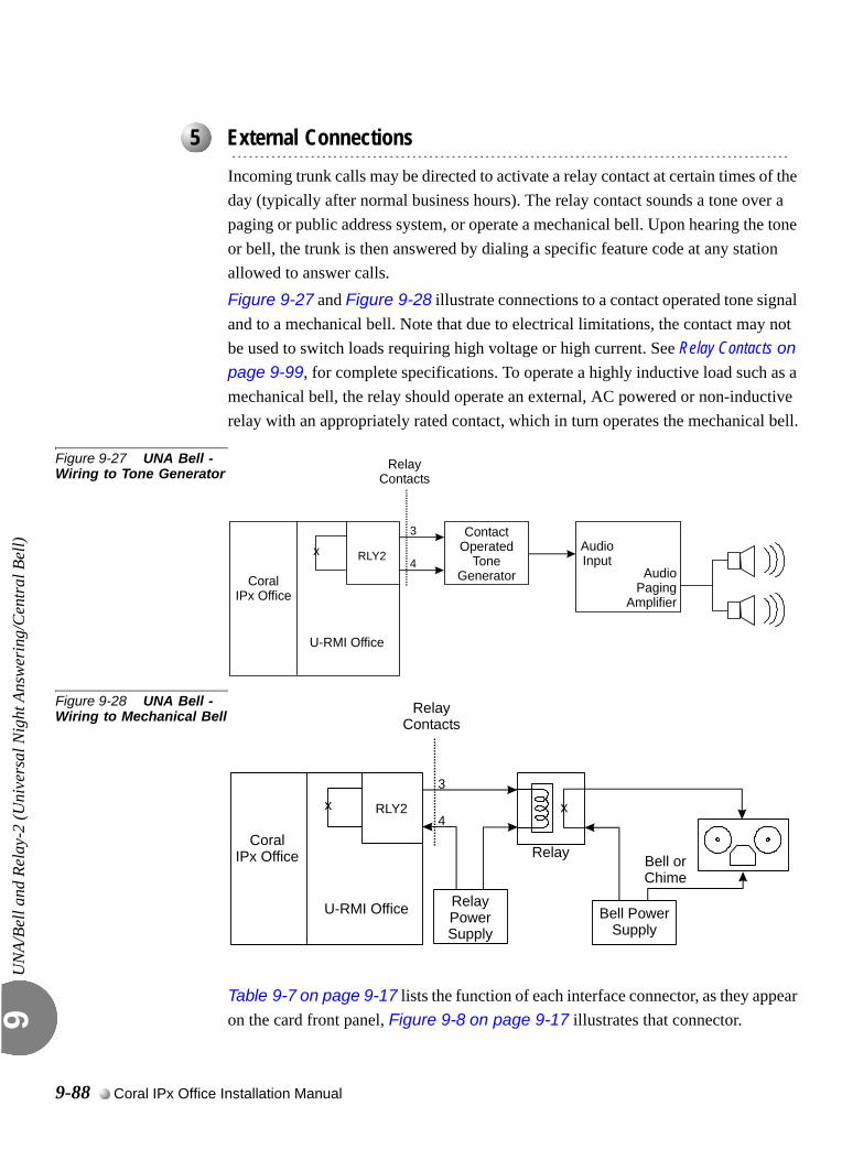
UN
A/Be
ll an
d Re
lay-
2 (U
nive
rsal
Nig
ht A
nsw
erin
g/C
entr
al B
ell)
9
0
Incoming trunk calls may be directed to activate a relay contact at certain times of the day (typically after normal business hours). The relay contact sounds a tone over a paging or public address system, or operate a mechanical bell. Upon hearing the tone or bell, the trunk is then answered by dialing a specific feature code at any station allowed to answer calls.Figure 9-27 and Figure 9-28 illustrate connections to a contact operated tone signal and to a mechanical bell. Note that due to electrical limitations, the contact may not be used to switch loads requiring high voltage or high current. See Relay Contacts on page 9-99, for complete specifications. To operate a highly inductive load such as a mechanical bell, the relay should operate an external, AC powered or non-inductive relay with an appropriately rated contact, which in turn operates the mechanical bell.
Figure 9-27 UNA Bell - Wiring to Tone Generator
Figure 9-28 UNA Bell - Wiring to Mechanical Bell
Table 9-7 on page 9-17 lists the function of each interface connector, as they appear on the card front panel, Figure 9-8 on page 9-17 illustrates that connector.
...................................................................................................5 External Connections
xContact
OperatedTone
Generator
AudioInput
Audio Paging
Amplifier
U-RMI Office
CoralIPx Office
RLY2
3
4
RelayContacts
U-RMI Office
CoralIPx Office
x RLY2
3
4
RelayPowerSupply
Bell PowerSupply
Bell orChime
Relay
x
RelayContacts
9-88 Coral IPx Office Installation Manual
UN
A/Be
ll an
d Re
lay-
2 (U
nive
rsal
Nig
ht A
nsw
erin
g/C
entr
al B
ell)
9
0
The relay contacts have specific electrical limitations. For further detail, see Relay Contacts on page 9-99. These limitations must not be exceeded. In addition, the type of load the relay contact operates can have a great significance. Do not exceed the contact ratings listed in the specifications.
Additional relay contacts for central ringing bell interface may be installed in the optional Coral IPx 800X expansion cage. The additional cards include:
These cards are described in the Coral Service and Peripheral Cards Installation Manual.
...................................................................................................6 Relay Electrical Limitations
7 Additional UNA and Relay Contacts in the Optional IPx 800X ...................................................................................................Cage
Card Cage Description
8DRCF IPx 800X Includes the following functions, among others:
1 universal night answer or central bell
1 bell relay contacts
Shared Service Cards 9-89
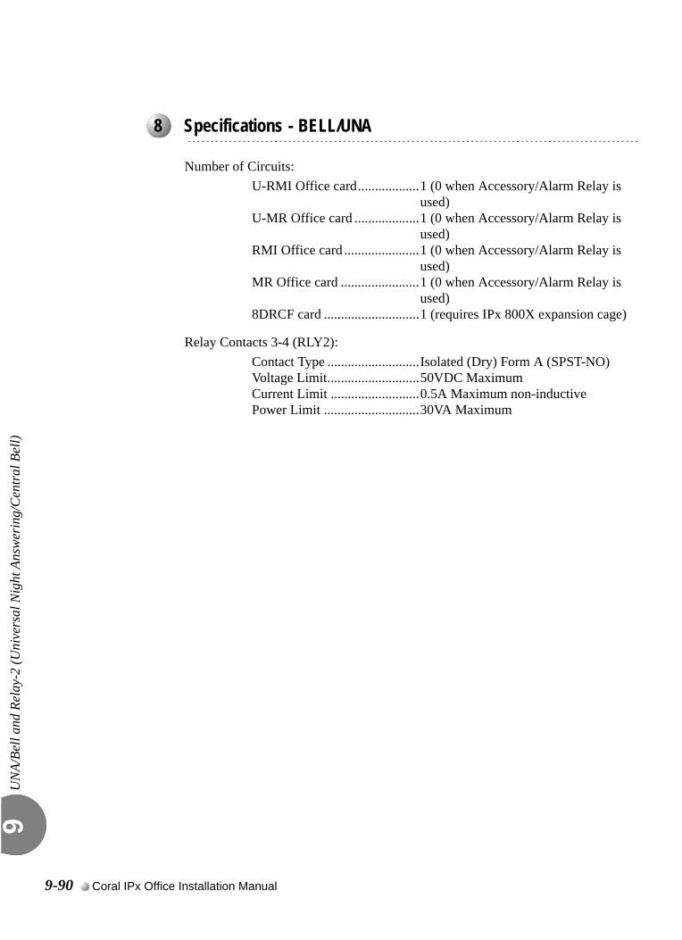
UN
A/Be
ll an
d Re
lay-
2 (U
nive
rsal
Nig
ht A
nsw
erin
g/C
entr
al B
ell)
9
Number of Circuits:U-RMI Office card..................1 (0 when Accessory/Alarm Relay is
used)U-MR Office card ...................1 (0 when Accessory/Alarm Relay is
used)RMI Office card ......................1 (0 when Accessory/Alarm Relay is
used)MR Office card .......................1 (0 when Accessory/Alarm Relay is
used)8DRCF card ............................1 (requires IPx 800X expansion cage)
Relay Contacts 3-4 (RLY2):Contact Type ...........................Isolated (Dry) Form A (SPST-NO)Voltage Limit...........................50VDC MaximumCurrent Limit ..........................0.5A Maximum non-inductivePower Limit ............................30VA Maximum
...................................................................................................8 Specifications - BELL/UNA
9-90 Coral IPx Office Installation Manual
9.16
Accessory or Alarm Relay-3Major/Minor AlarmAcce
ssor
y or
Ala
rm R
elay
-3 M
ajor
/Min
or A
larm
9
0
The U-RMI Office, U-MR Office, RMI Office and MR Office cards provide one relay contact for major/minor alarm or accessory interface.Each U-RMI Office, U-MR Office, RMI Office or MR Office card provides a multipurpose relay contact that can function as an On/Off control of external equipment such as a door latch or light control. It can also be programmed to operate during an alarm condition of the system, signaling a malfunction.
Dial Operated Accessory
The Coral IPx Office system can operate the relay contacts assigned by a specific dialed number. Users can use this feature to switch external devices on and off.A station user can switch the relay On or Off in order to activate certain external devices, such as external alarm or electric locks.
Major/Minor Alarm Relay
The Coral IPx Office system reports failures, as they occur, on the PI screen. A list of alarms can be retrieved by the Coral technician when needed.A major or a minor system alarm can be programmed to appear on designated display telephones and/or operate a relay and hence an external alert device.
...................................................................................................1 Introduction
Shared Service Cards 9-91

Acce
ssor
y or
Ala
rm R
elay
-3 M
ajor
/Min
or A
larm
9
0
Figure 9-29 is a simplified circuit diagram of the relay contacts.The relay provide form A (single pole, single throw and normally open) contacts for activating external circuitry and devices. Operation of the relays is configured at the PI system database.Contacts RLY3 are designated for use as either a major or minor system alarm, signal, or an auxiliary dial-operated relay contact. Do not exceed the contact ratings listed in the specifications.
Figure 9-29 RLY3 Simplified Diagram
...................................................................................................2 Circuit Description
RLY 3
Major/MinorAlarm Signal
orAuxiliary
Dial OperatedAccessory
Relay Contacts:(1/2) when P4 is connected between legs 2/3(3/4) when P4 is connected between legs 3/4
*
*
*
9-92 Coral IPx Office Installation Manual
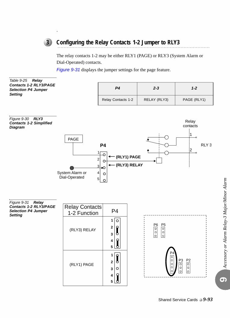
Acce
ssor
y or
Ala
rm R
elay
-3 M
ajor
/Min
or A
larm
9
.
The relay contacts 1-2 may be either RLY1 (PAGE) or RLY3 (System Alarm or Dial-Operated) contacts. Figure 9-31 displays the jumper settings for the page feature.
Table 9-25 Relay Contacts 1-2 RLY3/PAGE Selection P4 Jumper Setting
Figure 9-30 RLY3 Contacts 1-2 Simplified Diagram
Figure 9-31 Relay Contacts 1-2 RLY3/PAGE Selection P4 Jumper Setting
...................................................................................................3 Configuring the Relay Contacts 1-2 Jumper to RLY3
P4 2-3 1-2
Relay Contacts 1-2 RELAY (RLY3) PAGE (RLY1)
RLY 3PAGE
1
2
Relaycontacts
P4
System Alarm orDial-Operated
(RLY1) PAGE
(RLY3) RELAY2
1
3
4
5
Relay Contacts1-2 Function P4
P5
P2
P6
P3
P4
2
1
3(RLY1) PAGE
45
(RLY3) RELAY2
1
3
45
Shared Service Cards 9-93
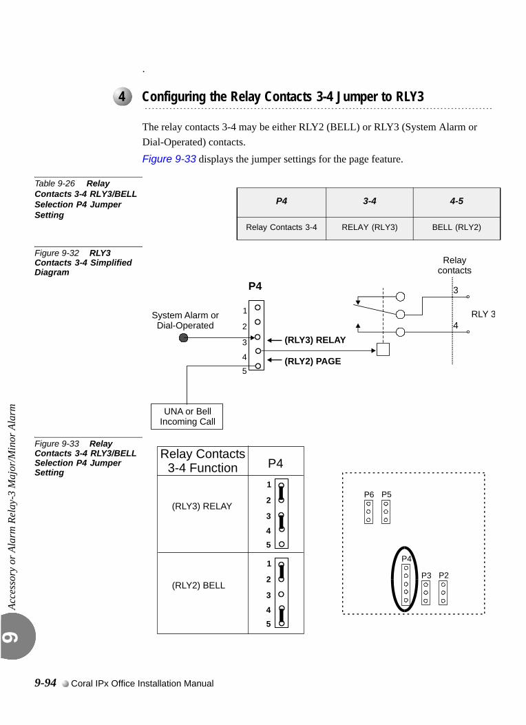
Acce
ssor
y or
Ala
rm R
elay
-3 M
ajor
/Min
or A
larm
9
.
The relay contacts 3-4 may be either RLY2 (BELL) or RLY3 (System Alarm or Dial-Operated) contacts. Figure 9-33 displays the jumper settings for the page feature.
Table 9-26 Relay Contacts 3-4 RLY3/BELL Selection P4 Jumper Setting
Figure 9-32 RLY3 Contacts 3-4 Simplified Diagram
Figure 9-33 Relay Contacts 3-4 RLY3/BELL Selection P4 Jumper Setting
...................................................................................................4 Configuring the Relay Contacts 3-4 Jumper to RLY3
P4 3-4 4-5
Relay Contacts 3-4 RELAY (RLY3) BELL (RLY2)
RLY 3
3
4
Relaycontacts
P4
System Alarm orDial-Operated
(RLY2) PAGE
(RLY3) RELAY2
1
3
4
5
UNA or BellIncoming Call
Relay Contacts3-4 Function
(RLY3) RELAY
P4
2
1
3
P5
P2
P6
P3
P4
(RLY2) BELL
45
2
1
3
45
9-94 Coral IPx Office Installation Manual
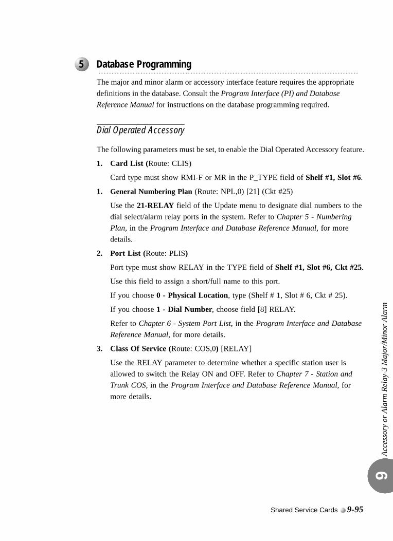
Acce
ssor
y or
Ala
rm R
elay
-3 M
ajor
/Min
or A
larm
9
0
The major and minor alarm or accessory interface feature requires the appropriate definitions in the database. Consult the Program Interface (PI) and Database Reference Manual for instructions on the database programming required.
Dial Operated Accessory
The following parameters must be set, to enable the Dial Operated Accessory feature.
1. Card List (Route: CLIS)
Card type must show RMI-F or MR in the P_TYPE field of Shelf #1, Slot #6.
1. General Numbering Plan (Route: NPL,0) [21] (Ckt #25)
Use the 21-RELAY field of the Update menu to designate dial numbers to the dial select/alarm relay ports in the system. Refer to Chapter 5 - Numbering Plan, in the Program Interface and Database Reference Manual, for more details.
2. Port List (Route: PLIS)
Port type must show RELAY in the TYPE field of Shelf #1, Slot #6, Ckt #25.
Use this field to assign a short/full name to this port.
If you choose 0 - Physical Location, type (Shelf # 1, Slot # 6, Ckt # 25).
If you choose 1 - Dial Number, choose field [8] RELAY.
Refer to Chapter 6 - System Port List, in the Program Interface and Database Reference Manual, for more details.
3. Class Of Service (Route: COS,0) [RELAY]
Use the RELAY parameter to determine whether a specific station user is allowed to switch the Relay ON and OFF. Refer to Chapter 7 - Station and Trunk COS, in the Program Interface and Database Reference Manual, for more details.
...................................................................................................5 Database Programming
Shared Service Cards 9-95
Acce
ssor
y or
Ala
rm R
elay
-3 M
ajor
/Min
or A
larm
9
Major/Minor Alarm Relay
1. System Features - Diagnostics (Route: SFE, 9)
MINOR_RLY
Use this parameter to define the relay dial number as the minor alarm situation destination.
MAJOR_RLY
Use this parameter to define the relay dial number as the major alarm situation destination.
9-96 Coral IPx Office Installation Manual
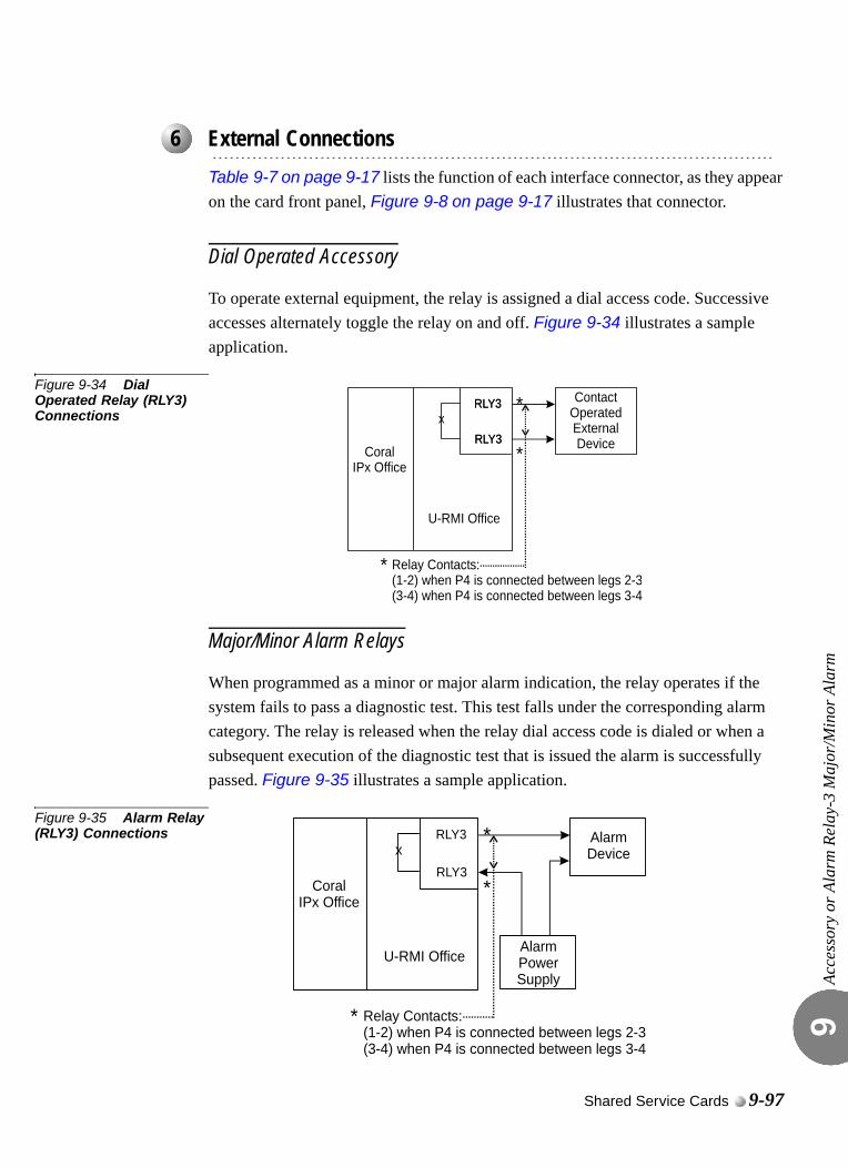
Acce
ssor
y or
Ala
rm R
elay
-3 M
ajor
/Min
or A
larm
9
0
Table 9-7 on page 9-17 lists the function of each interface connector, as they appear on the card front panel, Figure 9-8 on page 9-17 illustrates that connector.
Dial Operated Accessory
To operate external equipment, the relay is assigned a dial access code. Successive accesses alternately toggle the relay on and off. Figure 9-34 illustrates a sample application.
Figure 9-34 Dial Operated Relay (RLY3) Connections
Major/Minor Alarm Relays
When programmed as a minor or major alarm indication, the relay operates if the system fails to pass a diagnostic test. This test falls under the corresponding alarm category. The relay is released when the relay dial access code is dialed or when a subsequent execution of the diagnostic test that is issued the alarm is successfully passed. Figure 9-35 illustrates a sample application.
Figure 9-35 Alarm Relay (RLY3) Connections
...................................................................................................6 External Connections
xRLY3
RLY3
ContactOperatedExternalDevice
U-RMI Office
Relay Contacts:(1-2) when P4 is connected between legs 2-3(3-4) when P4 is connected between legs 3-4
CoralIPx Office
RLY3 *
*
RLY3*
U-RMI Office
Relay Contacts:(1-2) when P4 is connected between legs 2-3(3-4) when P4 is connected between legs 3-4
CoralIPx Office
xRLY3 *
*
RLY3
AlarmDevice
AlarmPowerSupply
*
Shared Service Cards 9-97
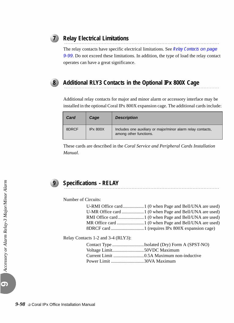
Acce
ssor
y or
Ala
rm R
elay
-3 M
ajor
/Min
or A
larm
9
0
The relay contacts have specific electrical limitations. See Relay Contacts on page 9-99. Do not exceed these limitations. In addition, the type of load the relay contact operates can have a great significance.
Additional relay contacts for major and minor alarm or accessory interface may be installed in the optional Coral IPx 800X expansion cage. The additional cards include:
These cards are described in the Coral Service and Peripheral Cards Installation Manual.
0
Number of Circuits:U-RMI Office card..................1 (0 when Page and Bell/UNA are used)U-MR Office card ...................1 (0 when Page and Bell/UNA are used)RMI Office card ......................1 (0 when Page and Bell/UNA are used)MR Office card .......................1 (0 when Page and Bell/UNA are used)8DRCF card ............................1 (requires IPx 800X expansion cage)
Relay Contacts 1-2 and 3-4 (RLY3):Contact Type ...........................Isolated (Dry) Form A (SPST-NO)Voltage Limit...........................50VDC MaximumCurrent Limit ..........................0.5A Maximum non-inductivePower Limit ............................30VA Maximum
...................................................................................................7 Relay Electrical Limitations
...................................................................................................8 Additional RLY3 Contacts in the Optional IPx 800X Cage
Card Cage Description
8DRCF IPx 800X Includes one auxiliary or major/minor alarm relay contacts, among other functions.
...................................................................................................9 Specifications - RELAY
9-98 Coral IPx Office Installation Manual
9.17
Relay ContactsRLY1, RLY2, RLY3Rela
y C
onta
cts R
LY1,
RLY
2, R
LY3
9
0
The U-RMI Office, U-MR Office, RMI Office and MR Office cards incorporate two relay contacts (1-2 and 3-4) for two of the following three features:
External voice paging (PAGE). Described on page 9-77.
Universal Night Answer (UNA) Central Bell. Described on page 9-85.
Dial operated accessory/alarm (RELAY). Described on page 9-91.
The applications described in the sections above describe several examples of the control of external devices through relay contacts on the U-RMI Office, U-MR Office, RMI Office or MR Office cards. A limited description of most of the external devices is listed herein. In each application, however, several important factors should be considered.The relays provide form A (single pole, single throw, normally open, or SPST-NO) contacts for activating external circuitry and devices. Operation of the relays is determined by the system database.
Contacts RLY1 are designated to operate in conjunction with audio interface M2/P for external paging applications.
Contacts RLY2 are designated as a UNA Bell destination.
Contacts RLY3 are also designated for use as either a major or minor system alarm signal, or an auxiliary dial-operated relay contact.
The relay contacts provided on the U-RMI Office, U-MR Office, RMI Office and MR Office cards have specific electrical limitations. See Specifications - Relays below. Do not exceed these limitations. In addition, the type of load the relay contact operates can have a great significance.Ideally, the contact should operate a low voltage, low current, non-inductive load such as a light bulb or solid state device. When the voltage or current increases, or when an inductive load such as a relay coil or solenoid is connected, the likelihood of arching across the contact increases. Contact arching occurs while the contact is opening and burns away the precious metal surface, increasing the chance of the contact being
...................................................................................................1 General Information
Shared Service Cards 9-99
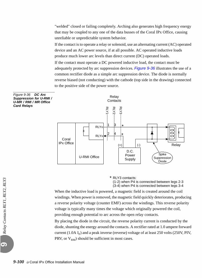
Rela
y C
onta
cts R
LY1,
RLY
2, R
LY3
9
"welded" closed or failing completely. Arching also generates high frequency energy that may be coupled to any one of the data busses of the Coral IPx Office, causing unreliable or unpredictable system behavior.If the contact is to operate a relay or solenoid, use an alternating current (AC) operated device and an AC power source, if at all possible. AC operated inductive loads produce much lower arc levels than direct current (DC) operated loads.If the contact must operate a DC powered inductive load, the contact must be adequately protected by arc suppression devices. Figure 9-36 illustrates the use of a common rectifier diode as a simple arc suppression device. The diode is normally reverse biased (not conducting) with the cathode (top side in the drawing) connected to the positive side of the power source.
Figure 9-36 DC Arc Suppression for U-RMI / U-MR / RMI / MR Office Card Relays
When the inductive load is powered, a magnetic field is created around the coil windings. When power is removed, the magnetic field quickly deteriorates, producing a reverse polarity voltage (counter EMF) across the windings. This reverse polarity voltage is typically many times the voltage which originally powered the coil, providing enough potential to arc across the open relay contacts.By placing the diode in the circuit, the reverse polarity current is conducted by the diode, shunting the energy around the contacts. A rectifier rated at 1.0 ampere forward current (1.0A IF) and a peak inverse (reverse) voltage of at least 250 volts (250V, PIV, PRV, or VRM) should be sufficient in most cases.
U-RMI Office
CoralIPx Office
x x
RLYx
RLY1
RLYx
D.C.PowerSupply
Relay
SpikeSuppression
Diode
(+) (-)
RelayContacts
3
4
1
2
RLY3 contacts:(1-2) when P4 is connected between legs 2-3(3-4) when P4 is connected between legs 3-4
*
*
*
RLY2
RLY3
9-100 Coral IPx Office Installation Manual
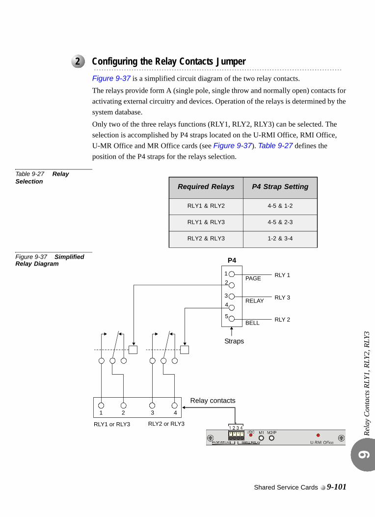
Rela
y C
onta
cts R
LY1,
RLY
2, R
LY3
9
0
Figure 9-37 is a simplified circuit diagram of the two relay contacts.The relays provide form A (single pole, single throw and normally open) contacts for activating external circuitry and devices. Operation of the relays is determined by the system database. Only two of the three relays functions (RLY1, RLY2, RLY3) can be selected. The selection is accomplished by P4 straps located on the U-RMI Office, RMI Office, U-MR Office and MR Office cards (see Figure 9-37). Table 9-27 defines the position of the P4 straps for the relays selection.
Table 9-27 Relay Selection
Figure 9-37 Simplified Relay Diagram
...................................................................................................2 Configuring the Relay Contacts Jumper
Required Relays P4 Strap Setting
RLY1 & RLY2 4-5 & 1-2
RLY1 & RLY3 4-5 & 2-3
RLY2 & RLY3 1-2 & 3-4
RLY 1
RLY1 or RLY3 RLY2 or RLY3
1 2 3 4
1
3
2
4
5
P4
Straps
PAGE
RELAY
BELL
RLY 3
RLY 2
Relay contacts
Shared Service Cards 9-101
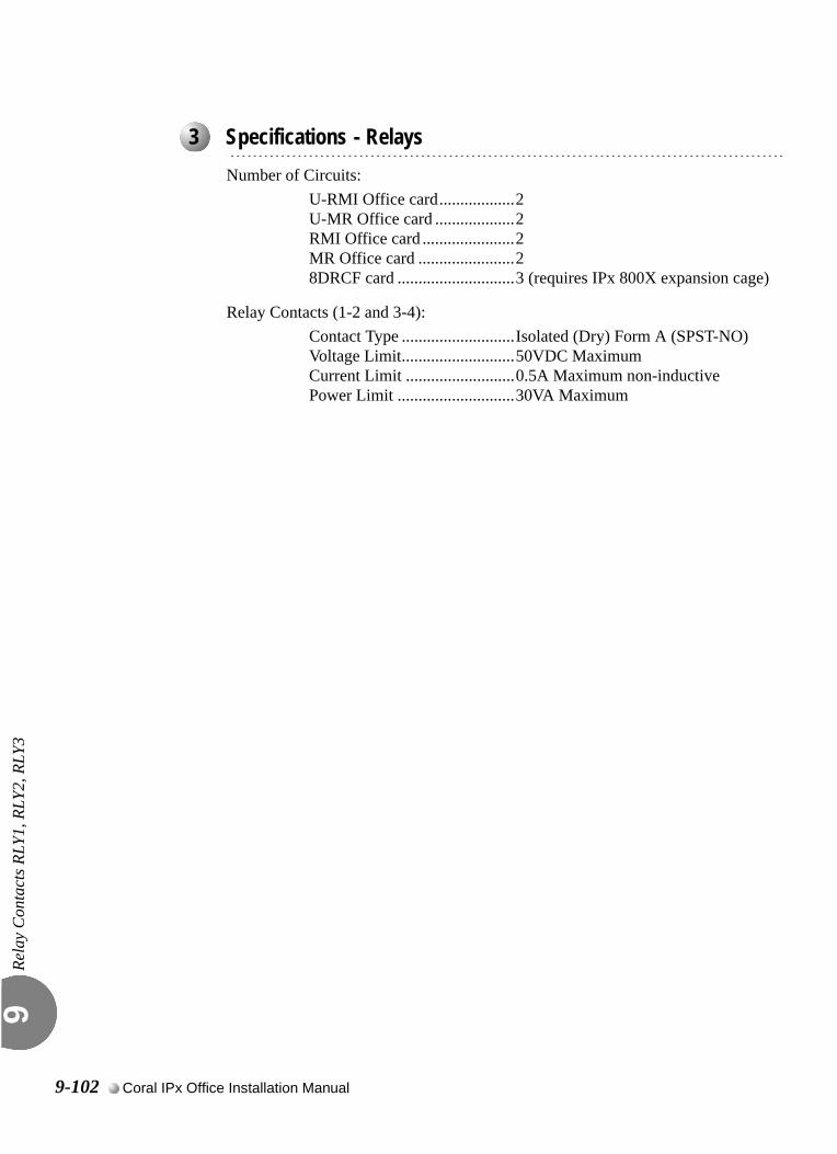
Rela
y C
onta
cts R
LY1,
RLY
2, R
LY3
9
0
Number of Circuits:U-RMI Office card..................2U-MR Office card ...................2RMI Office card ......................2MR Office card .......................28DRCF card ............................3 (requires IPx 800X expansion cage)
Relay Contacts (1-2 and 3-4):Contact Type ...........................Isolated (Dry) Form A (SPST-NO)Voltage Limit...........................50VDC MaximumCurrent Limit ..........................0.5A Maximum non-inductivePower Limit ............................30VA Maximum
...................................................................................................3 Specifications - Relays
9-102 Coral IPx Office Installation Manual

Coral IPx Office Installation Manual
Chapter
10Peripheral Cards
10.1 Peripheral Card Installation .....................................................10-1
10.2 Peripheral Card Description ....................................................10-5
10.3 Digital Trunk Synchronization ..................................................10-9
10.4 Service and Peripheral Cards................................................10-19

C
10.1
oral IPx Office Installation Ma
Peripheral Card Installation
Peri
pher
al C
ard
Inst
alla
tion
10
0
The Coral IPx Office system divides peripheral interface functions among several different station and trunk card types. Each card contains 4, 8, 16, 20, or 24 circuits.Some analog trunk peripheral cards support power fail transfer, as described on Power Fail (PF) Transfer Circuits, page 5-15.Coral IPx Office systems convention suggests that peripheral interface cards are installed in specific card slots, as described in Table 10-4 on page 10-19.Each Peripheral card is described in detail in the Coral Service and Peripheral Cards Installation Manual.0
Each of the Coral IPx Office cards contains circuitry sensitive to electrostatic discharge (ESD). Failure to observe safe handling procedures for static-sensitive circuitry may result in permanent damage to a card.An anti-static wrist strap, connected to the ground terminal pole and tightened with the wing nut should be worn while inserting, removing, or handling any card in the system. Each card is shipped inside an anti-static plastic bag. Cards should be kept in this bag whenever handling is not required.
After a peripheral card is removed, wait for at least 2 seconds before re-inserting the card. If not, the card will not function properly.
...................................................................................................1 General Information
...................................................................................................2 Card Handling Procedures
Before removing a peripheral card, disconnect the I/O connectors.
nual Peripheral Cards 10-1
Peri
pher
al C
ard
Inst
alla
tion
10
0
Peripheral card installation and initialization are done through automatic identification by the hardware application called "Plug and Play" (plug in and start working). All the technician has to do is to install the card into the required slot and connect its respective I/O cable. The MCB Office card will identify the peripheral card, define it for the system and display all details on the PI screen. The PI Card List branch (Route: CLIS), Snap Mode, shows details of every new peripheral card that is installed or removed. There is a short delay between installation/removal of the card and PI screen display.All peripheral cards may be inserted into a card slot only if the card slot has not been previously initialized by another card type. Before installing the card into a card slot that has been initialized by another card type, the previous card name must be cleared first.To clear an initialized card slot:
1. Select the Card List branch (Route: CLIS) in the system database.
2. If the I_TYPE for the card slot shows a card type other than the card currently installed, enter NO_CARD to clear the slot. Refer to Program Interface and Database Reference Manual - Chapter 6, for further details.
0
Each plug-in Office service and peripheral card is equipped with one or two red diagnostic indication LEDs on the front side, near the right side of the card1. These LEDs can assume one of three states of illumination: OFF, ON, or FLASHING. The illumination state of the LED indicates the card's operating condition. Table 10-1 lists the indication provided by each of the three LED states.During normal operation, the card diagnostic LED should be extinguished. However, the LED routinely illuminates steadily whenever power is first applied to the system, the entire system is initializing, or the card is first inserted into a card slot. The LED remains illuminated steadily until the card receives a card database from the system.
...................................................................................................3 General Installation Procedure
...................................................................................................4 Diagnostic LED Indication
1. In the U-RMI Office and U-MR Office card a second LED is located in the middle of the card. In the 4S8F Office, 4S16F Office, 8S8F Office and 8S16F Office cards a second LED is located in the right side of the card.
10-2 Peripheral Cards Coral IPx Office Installation Manual
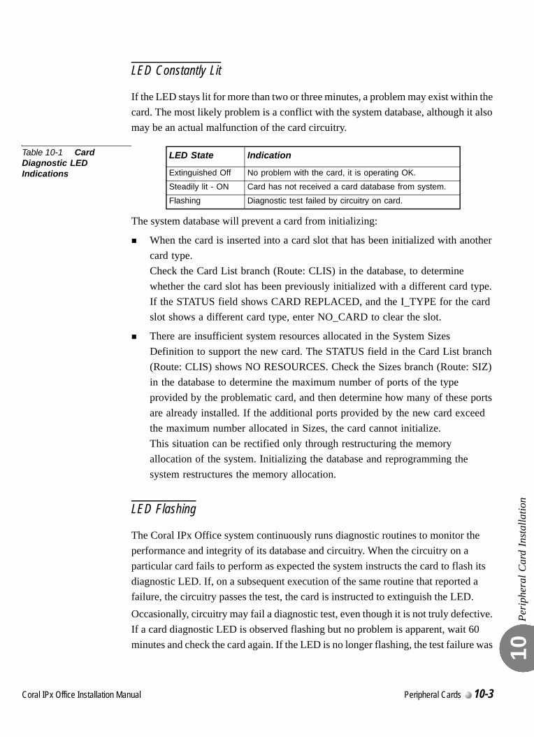
Peri
pher
al C
ard
Inst
alla
tion
10
LED Constantly Lit
If the LED stays lit for more than two or three minutes, a problem may exist within the card. The most likely problem is a conflict with the system database, although it also may be an actual malfunction of the card circuitry.
Table 10-1 Card Diagnostic LED Indications
The system database will prevent a card from initializing:
When the card is inserted into a card slot that has been initialized with another card type.Check the Card List branch (Route: CLIS) in the database, to determine whether the card slot has been previously initialized with a different card type. If the STATUS field shows CARD REPLACED, and the I_TYPE for the card slot shows a different card type, enter NO_CARD to clear the slot.
There are insufficient system resources allocated in the System Sizes Definition to support the new card. The STATUS field in the Card List branch (Route: CLIS) shows NO RESOURCES. Check the Sizes branch (Route: SIZ) in the database to determine the maximum number of ports of the type provided by the problematic card, and then determine how many of these ports are already installed. If the additional ports provided by the new card exceed the maximum number allocated in Sizes, the card cannot initialize.This situation can be rectified only through restructuring the memory allocation of the system. Initializing the database and reprogramming the system restructures the memory allocation.
LED Flashing
The Coral IPx Office system continuously runs diagnostic routines to monitor the performance and integrity of its database and circuitry. When the circuitry on a particular card fails to perform as expected the system instructs the card to flash its diagnostic LED. If, on a subsequent execution of the same routine that reported a failure, the circuitry passes the test, the card is instructed to extinguish the LED.Occasionally, circuitry may fail a diagnostic test, even though it is not truly defective. If a card diagnostic LED is observed flashing but no problem is apparent, wait 60 minutes and check the card again. If the LED is no longer flashing, the test failure was
LED State Indication
Extinguished Off No problem with the card, it is operating OK.
Steadily lit - ON Card has not received a card database from system.
Flashing Diagnostic test failed by circuitry on card.
Coral IPx Office Installation Manual Peripheral Cards 10-3

Peri
pher
al C
ard
Inst
alla
tion
10
probably insignificant. If the flashing continues however, the card is likely to be malfunctioning, even if no problem can be identified.
10-4 Peripheral Cards Coral IPx Office Installation Manual
C
10.2
oral IPx Office Installation Ma
Peripheral Card DescriptionXXX Office Cards
Peri
pher
al C
ard
Des
crip
tion
XXX
Offi
ce C
ards
10
0
Peripheral interface cards are described in the Coral Service and Peripheral Cards Installation Manual. Table 10-4 on page 10-19 lists the Peripheral Interface card types that can be inserted into each card slot in the Coral_IPx Office unit.
XXX Office Cards
Peripheral cards with the suffix “ Office” are special form-factor cards for use in the Coral IPx Office system. These cards come in four sizes as shown in Table 10-4.
Peripheral Card types
Peripheral card slots in the Coral IPx Office unit are not universal. Slot 1 is reserved for the power supply
Slots 2-3 and 4-5 house full size cards (Type II)
Slots 6-7, 8-9, and 10-11 house half-size cards (Type I)
Cards type I-A may be installed in slots 6-7
Cards type I-B may be installed in slots 8-9, 10-11 (ESIM Office in slot 8-9 only)
Cards type I-C may be installed in slots 10-11
See Figure 10-1 and Table 10-2 Coral IPx Office Peripheral CARD TYPE.See Figure 10-2 and Table 10-3 Coral IPx Office Peripheral CARD SLOT Location.
...................................................................................................1 General Description
nual Peripheral Cards 10-5
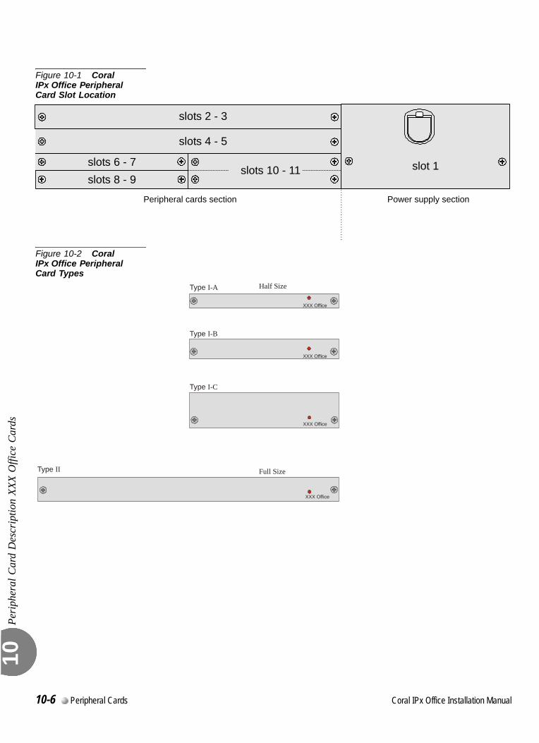
Peri
pher
al C
ard
Des
crip
tion
XXX
Offi
ce C
ards
10
Figure 10-1 Coral IPx Office Peripheral Card Slot Location
Figure 10-2 Coral IPx Office Peripheral Card Types
slots 2 - 3
slots 4 - 5
slots 6 - 7slots 8 - 9
slot 1
Peripheral cards section Power supply section
slots 10 - 11
Type I-B
XXX Office
XXX Office
XXX Office
Type I-C
Type II Full Size
Half SizeType I-A
XXX Office
10-6 Peripheral Cards Coral IPx Office Installation Manual
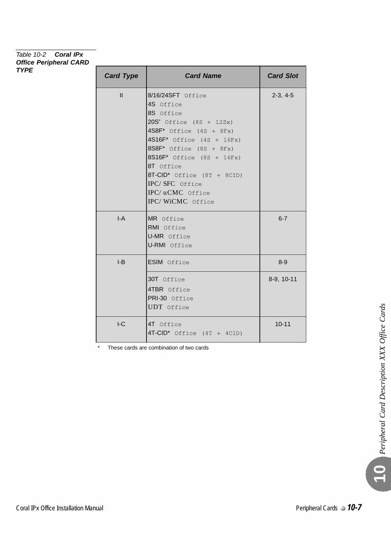
Peri
pher
al C
ard
Des
crip
tion
XXX
Offi
ce C
ards
10
Table 10-2 Coral IPx Office Peripheral CARD TYPE
Card Type Card Name Card Slot
II 8/16/24SFT Office
4S Office
8S Office20S* Office (8S + 12Sx)
4S8F* Office (4S + 8Fx)
4S16F* Office (4S + 16Fx)8S8F* Office (8S + 8Fx)
8S16F* Office (8S + 16Fx)
8T Office8T-CID* Office (8T + 8CID)
IPC/SFC OfficeIPC/uCMC OfficeIPC/WiCMC Office
* These cards are combination of two cards
2-3, 4-5
I-A MR Office
RMI OfficeU-MR Office
U-RMI Office
6-7
I-B ESIM Office 8-9
30T Office
4TBR OfficePRI-30 Office
UDT Office
8-9, 10-11
I-C 4T Office4T-CID* Office (4T + 4CID)
10-11
Coral IPx Office Installation Manual Peripheral Cards 10-7
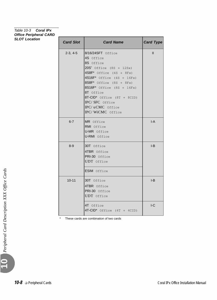
Peri
pher
al C
ard
Des
crip
tion
XXX
Offi
ce C
ards
10
Table 10-3 Coral IPx Office Peripheral CARD SLOT Location
Card Slot Card Name Card Type
2-3, 4-5 8/16/24SFT Office
4S Office
8S Office20S* Office (8S + 12Sx)
4S8F* Office (4S + 8Fx)
4S16F* Office (4S + 16Fx)8S8F* Office (8S + 8Fx)
8S16F* Office (8S + 16Fx)
8T Office8T-CID* Office (8T + 8CID)
IPC/SFC OfficeIPC/uCMC OfficeIPC/WiCMC Office
* These cards are combination of two cards
II
6-7 MR Office
RMI OfficeU-MR Office
U-RMI Office
I-A
8-9 30T Office
4TBR Office
PRI-30 OfficeUDT Office
I-B
ESIM Office
10-11 30T Office
4TBR OfficePRI-30 Office
UDT Office
I-B
4T Office4T-CID* Office (4T + 4CID)
I-C
10-8 Peripheral Cards Coral IPx Office Installation Manual
C
10.3
oral IPx Office Installation Ma
Digital Trunk Synchronization
Dig
ital T
runk
Syn
chro
niza
tion
10
0
The Coral IPx Office system is capable of operating in either master clock mode or slave clock mode. The selection between modes is made via the PI software.
How The System Derives The External Clock Signal
The Coral IPx Office uses digital trunk interface cards to synchronize its internal clock with the PSTN clock or with another switching system clock. When operating in slave-clock mode, the data stream transferred on the digital trunk is fed into the MCB Office (Main Control Board), incorporating the external clock rate into the Coral IPx Office internal clock.To allow the clock signal to be fed into the Coral IPx Office internal clock, the ESIM and the digital trunk interface cards are properly strapped to accept those signals.Two synchronization sources can be defined for a system. One serves as the primary source and the other serves as a secondary synchronization signal source.The following digital trunk cards can retrieve synchronization signals in the Coral IPx Office main unit: UDT Office (PRI-23 or T1), 30T Office, PRI-30 Office, and 4TBR Office.The following digital trunk cards can retrieve synchronization signals in the Coral IPx 500X expansion cages: UDTipx (PRI-23 or T1), 30Tipx, PRI-23ipx, PRI-30ipx, 4TBRipx and 8TBRipx. More Coral FlexiCom 300,400,5000,6000 and IPx 800,3000,4000 digital trunk cards (UDT, 30T, T1, PRI-23, PRI-30, 4TBR, 8TBR) are available for synchronization purposes through the Coral IPx 800X expansion cages.
...................................................................................................1 Slave Clock Mode Operation
nual Peripheral Cards 10-9
Dig
ital T
runk
Syn
chro
niza
tion
10
0
Two slots, located in the Coral IPx Office main unit, are set to accept the digital trunk cards: slot # 8-9 and slot # 10-11. Each card can be installed into either slot. See Figure 10-3 below.
Synchronization Slot Selection
Any combination of primary and secondary synchronization sources, either in the main unit or in the expansion cage is valid.The hardware selection between the Coral IPx Office unit and the expansion cages synchronization slots is determined by:
In the Coral IPx Office main unit, jumper settings on the ESIM Office and on the digital trunk cards.
In the expansion cages, jumper settings on the backplane card.
In addition, a software selection must take place. The system must be notified, via the PI facility, of the synchronization cards shelf/slot location. See Choosing the Best Synchronization Source, page 10-12.
Conditions for Slave Clock Mode Operation
The following conditions are necessary for the Coral IPx Office to retrieve external clock signals:
The jumpers must be strapped accordingly on the digital trunk cards and on the ESIM Office card.
The digital trunk synchronization cards must be installed in the synchronization slots of the expansion cages (IPx 500X and IPx 800X).
The PI parameters must be properly set.
System Switch from Slave Clock Mode to Master Clock Mode
When a digital trunk card is initialized in the appropriate slot, the jumpers properly set, and the shelf/slot combination has been entered as a primary external clock source, the system determines if the digital trunk card in the indicated position is properly synchronized with the network. If the system is functioning properly, it locks onto the primary external clock source.
...................................................................................................2 Synchronization Slots in the Main and Expansion Cages
10-10 Peripheral Cards Coral IPx Office Installation Manual

Dig
ital T
runk
Syn
chro
niza
tion
10
If the primary digital trunk card issues a LOS or Red alarm, and a secondary external clock source is defined, the system determines whether the secondary digital trunk card is functioning properly. If it is, the system then locks onto the secondary external clock source.If no secondary clock source is defined, or the secondary clock is also in LOS or Red alarm, the Coral IPx Office system uses its internal clock source, and the system free runs.
Coral IPx Office Installation Manual Peripheral Cards 10-11
Dig
ital T
runk
Syn
chro
niza
tion
10
0
Optional Synchronization Cards
In the Coral IPx Office main unit:
PRI - PRI-30 Office, UDT Office (PRI-23)
T1 - UDT Office (T1)
E1 - 30T Office
BRI - 4TBR Office
In the Coral IPx 500X expansion cage:
PRI-23ipx, PRI-30ipx, UDTipx(PRI-23)
T1 - T1ipx, UDTipx(T1)
E1 - 30Tipx
BRI - 4TBRipx, 8TBRipx
In the Coral IPx 800X expansion cage:
PRI-23, PTRI-30, UDT(PRI-23)
T1 - T1, UDT(T1)
E1 - 30T/x
BRI - 4TBR, 8TBR
If an IPx 500X Expansion cage is installed and UDTipx (PRI-23 or T1), 30Tipx, PRI-23ipx, PRI-30ipx, 4TBRipx and 8TBRipx digital trunk interface cards are available, refer to the Coral IPx 500 Installation Guide.
If an IPx 800X Expansion cage is installed and UDT (PRI-23 or T1), 30T, T1, PRI-23, PRI-30, 4TBR and 8TBR digital trunk interface cards are available, refer to the Coral IPx 800 Installation Guide.
.
...................................................................................................3 Choosing the Best Synchronization Source
4TBRP, 8TBRP, 4TBRPipx, and 8TBRPipx cards (with Power supply) cannot be used in
the synchronization slots.
10-12 Peripheral Cards Coral IPx Office Installation Manual
Dig
ital T
runk
Syn
chro
niza
tion
10
BRI Lines for Synchronization
1) BRI lines used for synchronization must be defined in the PI (Route:DTDB, 4) SYNC - YES. See PI Manual Chapter 26 - ISDN for moreinformation.
2) It is not recommended to use BRI lines defined asPERMANENTLY_ACTIVE_CHANNEL - NO as synchronization sources.
It is not recommended to use a PRI card with IPAT IC (hardware issue 4) chip as a synchronization source.
Order of Preference
The possible digital trunk synchronization sources are listed in order of preference:
1. PRI or T1/E1 card (all types) connected to PSTN type stratum #3 - TANDEM switch (North America only).
2. PRI or T1/E1 card (all types) connected to PSTN type stratum # 4 (End office).
3. PRI or T1/E1 card (all types) connected to a private network. There are three
possibilities listed in order of preference.
a. The network is synchronized on PSTN stratum #4 (or less).
b. The private network contains a stable internal clock.
c. The private network is synchronized to the Coral - do not use for
synchronization.
4. 4TBR and 8TBR card (all types) connected to the PSTN.
5. 4TBR and 8TBR card (all types) connected to a private network. The three
possibilities are the same as listed in order of preference in possibilities
3.a - 3.c above.
When the Coral operates in Master Clock mode and the private network is synchronized
by the Coral, it is prohibited to insert Digital Trunk cards in the synchronization slots.
Coral IPx Office Installation Manual Peripheral Cards 10-13
Dig
ital T
runk
Syn
chro
niza
tion
10
0
1. See the selection of the digital trunk cards available at the Coral site, given on Choosing the Best Synchronization Source, page 10-12 above, to determine which cards will be used as the primary and secondary synchronization sources.
2. Determine into which slots the card chosen in Step 1 should be inserted. See Figure 10-3 on page 10-16.
3. Verify that the digital trunk cards are properly strapped. See Figure 10-3 on page 10-16.
4. When expansion cages are installed, verify that the ESIM Office card is properly strapped. See Figure 10-4 on page 10-17.
5. Verify that the backplane of the expansion cages are properly strapped. See Chapter 6 of the Coral IPx 500 Installation Procedure and Hardware Reference Manual or Coral IPx 800 Installation Procedure and Hardware Reference Manual.
6. Use the PI facility to inform the system of the synchronization slot selection.
Access the synchronization branch (Route: DTDB, 3) to set the following parameters:
ADDR - PRM, SECEnter the appropriate (shelf, slot) combination of your choice:
IPx Office main unit: PRM (shelf#1,slot#8/10), SEC (shelf#1,slot#8/10)
IPx 500X/800X first expansion cage: PRM (shelf#2,slot#4), SEC (shelf#2,slot#5)
IPx 500X/800X second expansion cage: PRM (shelf#3,slot#4), SEC (shelf#3,slot#5)
For more information, refer to Chapter 8 of the Program Interface reference Manual.
...................................................................................................4 Synchronization Instructions
If an IPx 500X Expansion cage is installed and if straps must be changed, verify that the
cage power is OFF before removing the PS500 power supply unit. Refer to the Coral
IPx 500 Installation Guide.
10-14 Peripheral Cards Coral IPx Office Installation Manual
Dig
ital T
runk
Syn
chro
niza
tion
10
7. If BRI lines are used for synchronization, access the ISDN branch (Route: DTDB, 4) to set the following parameters:
SYNCSet this parameter to YES.
PERMANENTLY active ChannelSet this parameter to YES.
For more information, refer to Chapter 26 of the Program Interface reference Manual.
8. Verify that the system is synchronized upon your settings:
Access the PI Synchronization branch (Route DTDB, 3), check the following parameter:
CURR_CLKVerify that the value 1 is displayed, indicating that the system is synchronized by the primary synchronization source.
Coral IPx Office Installation Manual Peripheral Cards 10-15
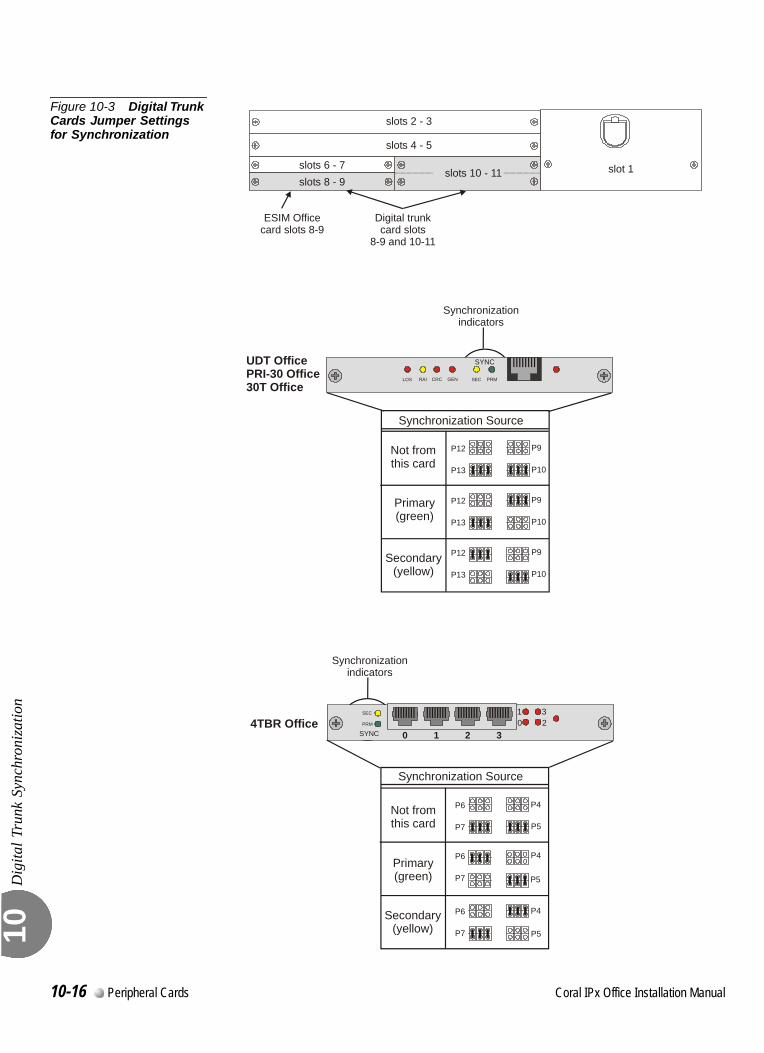
Dig
ital T
runk
Syn
chro
niza
tion
10
Figure 10-3 Digital Trunk Cards Jumper Settings for Synchronization
LOS RAI CRC GEN SEC PRM
SYNC
Synchronization Source
P9P12
P10P13
P9P12
P10P13
P9P12
P10P13
Not fromthis card
Primary(green)
Secondary(yellow)
UDT OfficePRI-30 Office30T Office
SEC 123
0PRM
SYNC
Synchronization Source
Not fromthis card
P4P6
P5P7
P4P6
P5P7
P4P6
P5P7
Primary(green)
Secondary(yellow)
0 1 2 3
slots 2 - 3
slots 4 - 5
slots 6 - 7slots 8 - 9
slot 1
Digital trunkcard slots
8-9 and 10-11
Synchronizationindicators
slots 10 - 11
4TBR Office
Synchronizationindicators
ESIM Officecard slots 8-9
10-16 Peripheral Cards Coral IPx Office Installation Manual
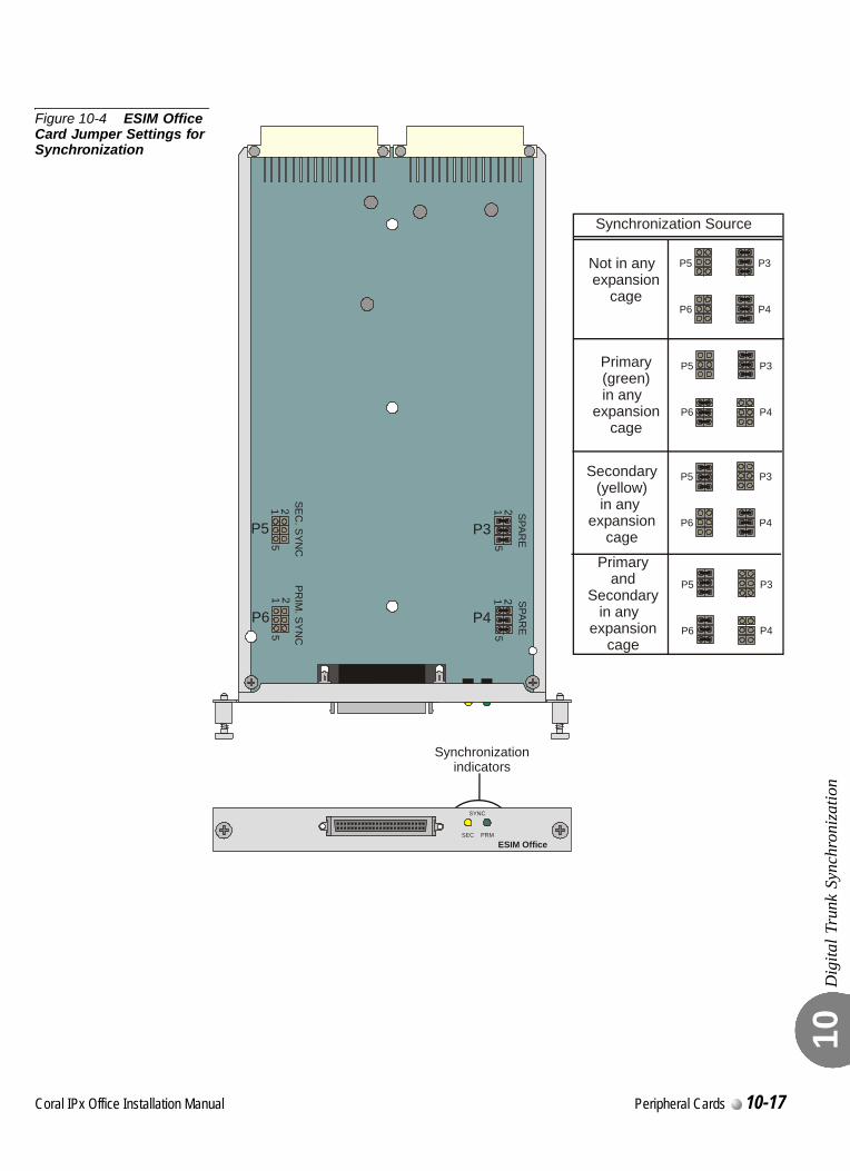
Dig
ital T
runk
Syn
chro
niza
tion
10
Figure 10-4 ESIM Office Card Jumper Settings for Synchronization
SEC PRM
SYNC
ESIM Office
155
55
111 S
PAR
ES
PAR
E
SEC
. SY
NC
PR
IM. SY
NC
Synchronization Source
Not in any expansion
cage
Primary(green)in any
expansioncage
P3
P3
P5
P5
P4
P4
P6
P6
Secondary(yellow) in any
expansioncage
Primaryand
Secondaryin any
expansioncage
P3P5
P4P6
P3P5
P4P6
P5
P6
P3
P4
Synchronizationindicators
Coral IPx Office Installation Manual Peripheral Cards 10-17

Dig
ital T
runk
Syn
chro
niza
tion
10
NOTES:
10-18 Peripheral Cards Coral IPx Office Installation Manual
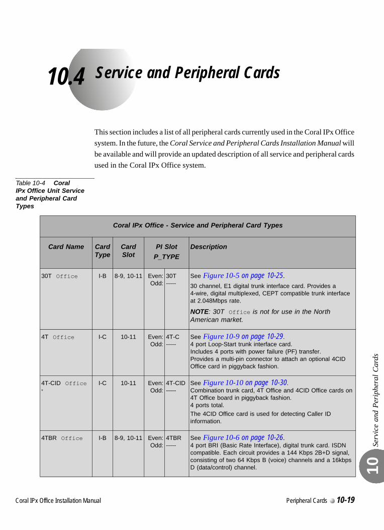
C
10.4
oral IPx Office Installation Ma
Service and Peripheral Cards
Serv
ice
and
Peri
pher
al C
ards
10
This section includes a list of all peripheral cards currently used in the Coral IPx Office system. In the future, the Coral Service and Peripheral Cards Installation Manual will be available and will provide an updated description of all service and peripheral cards used in the Coral IPx Office system.
Table 10-4 Coral IPx Office Unit Service and Peripheral Card Types
Coral IPx Office - Service and Peripheral Card Types
Card Name Card Type
Card Slot
PI Slot
P_TYPE
Description
30T Office I-B 8-9, 10-11 Even:Odd:
30T-----
See Figure 10-5 on page 10-25.30 channel, E1 digital trunk interface card. Provides a 4-wire, digital multiplexed, CEPT compatible trunk interface at 2.048Mbps rate.
NOTE: 30T Office is not for use in the North American market.
4T Office I-C 10-11 Even:Odd:
4T-C-----
See Figure 10-9 on page 10-29.4 port Loop-Start trunk interface card. Includes 4 ports with power failure (PF) transfer. Provides a multi-pin connector to attach an optional 4CID Office card in piggyback fashion.
4T-CID Office*
I-C 10-11 Even:Odd:
4T-CID-----
See Figure 10-10 on page 10-30.Combination trunk card, 4T Office and 4CID Office cards on 4T Office board in piggyback fashion. 4 ports total.The 4CID Office card is used for detecting Caller ID information.
4TBR Office I-B 8-9, 10-11 Even:Odd:
4TBR-----
See Figure 10-6 on page 10-26.4 port BRI (Basic Rate Interface), digital trunk card. ISDN compatible. Each circuit provides a 144 Kbps 2B+D signal, consisting of two 64 Kbps B (voice) channels and a 16kbps D (data/control) channel.
nual Peripheral Cards 10-19
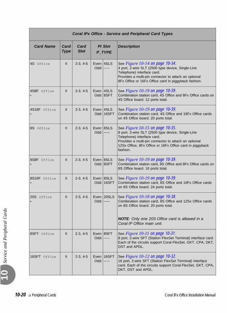
Serv
ice
and
Peri
pher
al C
ards
10
4S Office II 2-3, 4-5 Even:Odd:
4SLS-----
See Figure 10-14 on page 10-34.4 port, 2-wire SLT (2500 type device, Single-Line Telephone) interface card. Provides a multi-pin connector to attach an optional 8Fx Office or 16Fx Office card in piggyback fashion.
4S8F Office
*
II 2-3, 4-5 Even:Odd:
4SLS8SFT
See Figure 10-19 on page 10-39.Combination station card, 4S Office and 8Fx Office cards on 4S Office board. 12 ports total.
4S16F Office*
II 2-3, 4-5 Even:Odd:
4SLS16SFT
See Figure 10-19 on page 10-39.Combination station card, 4S Office and 16Fx Office cards on 4S Office board. 20 ports total.
8S Office II 2-3, 4-5 Even:Odd:
8SLS-----
See Figure 10-15 on page 10-35.8 port, 2-wire SLT (2500 type device, Single-Line Telephone) interface card. Provides a multi-pin connector to attach an optional 12Sx Office, 8Fx Office or 16Fx Office card in piggyback fashion.
8S8F Office*
II 2-3, 4-5 Even:Odd:
8SLS8SFT
See Figure 10-19 on page 10-39.Combination station card, 8S Office and 8Fx Office cards on 8S Office board. 16 ports total.
8S16F Office
*
II 2-3, 4-5 Even:Odd:
8SLS16SFT
See Figure 10-19 on page 10-39.Combination station card, 8S Office and 16Fx Office cards on 8S Office board. 24 ports total.
20S Office
*
II 2-3, 4-5 Even:Odd:
20SLS-----
See Figure 10-18 on page 10-38.Combination station card, 8S Office and 12Sx Office cards on 8S Office board. 20 ports total.
NOTE: Only one 20S Office card is allowed in a Coral IP Office main unit.
8SFT Office II 2-3, 4-5 Even:Odd:
8SFT-----
See Figure 10-11 on page 10-31.8 port, 2-wire SFT (Station FlexSet Terminal) interface card. Each of the circuits support Coral FlexSet, GKT, CPA, DKT, DST and APDL.
16SFT Office II 2-3, 4-5 Even:Odd:
16SFT-----
See Figure 10-12 on page 10-32.16 port, 2-wire SFT (Station FlexSet Terminal) interface card. Each of the circuits support Coral FlexSet, GKT, CPA, DKT, DST and APDL.
Coral IPx Office - Service and Peripheral Card Types
Card Name Card Type
Card Slot
PI Slot
P_TYPE
Description
10-20 Peripheral Cards Coral IPx Office Installation Manual
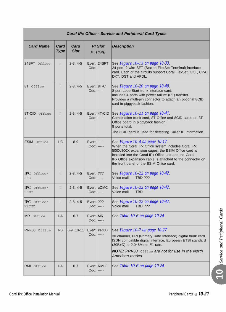
Serv
ice
and
Peri
pher
al C
ards
10
24SFT Office II 2-3, 4-5 Even:Odd:
24SFT-----
See Figure 10-13 on page 10-33.24 port, 2-wire SFT (Station FlexSet Terminal) interface card. Each of the circuits support Coral FlexSet, GKT, CPA, DKT, DST and APDL.
8T Office II 2-3, 4-5 Even:Odd:
8T-C-----
See Figure 10-20 on page 10-40.8 port Loop-Start trunk interface card. Includes 4 ports with power failure (PF) transfer.Provides a multi-pin connector to attach an optional 8CID card in piggyback fashion.
8T-CID Office
*
II 2-3, 4-5 Even:Odd:
4T-CID-----
See Figure 10-21 on page 10-41.Combination trunk card, 8T Office and 8CID cards on 8T Office board in piggyback fashion. 8 ports total.
The 8CID card is used for detecting Caller ID information.
ESIM Office I-B 8-9 Even:Odd:
----------
See Figure 10-4 on page 10-17.When the Coral IPx Office system includes Coral IPx 500X/800X expansion cages, the ESIM Office card is installed into the Coral IPx Office unit and the Coral IPx Office expansion cable is attached to the connector on the front panel of the ESIM Office card.
IPC Office/SFC
II 2-3, 4-5 Even:Odd:
???-----
See Figure 10-22 on page 10-42.Voice mail. TBD ???
IPC Office/uCMC
II 2-3, 4-5 Even:Odd:
uCMC-----
See Figure 10-22 on page 10-42.Voice mail. TBD
IPC Office/WiCMC
II 2-3, 4-5 Even:Odd:
???-----
See Figure 10-22 on page 10-42.Voice mail. TBD ???
MR Office I-A 6-7 Even:Odd:
MR-----
See Table 10-6 on page 10-24
PRI-30 Office I-B 8-9, 10-11 Even:Odd:
PRI30-----
See Figure 10-7 on page 10-27.30 channel, PRI (Primary Rate Interface) digital trunk card. ISDN compatible digital interface, European ETSI standard (30B+D) at 2.048Mbps E1 rate.
NOTE: PRI-30 Office are not for use in the North American market.
RMI Office I-A 6-7 Even:Odd:
RMI-F-----
See Table 10-6 on page 10-24
Coral IPx Office - Service and Peripheral Card Types
Card Name Card Type
Card Slot
PI Slot
P_TYPE
Description
Coral IPx Office Installation Manual Peripheral Cards 10-21
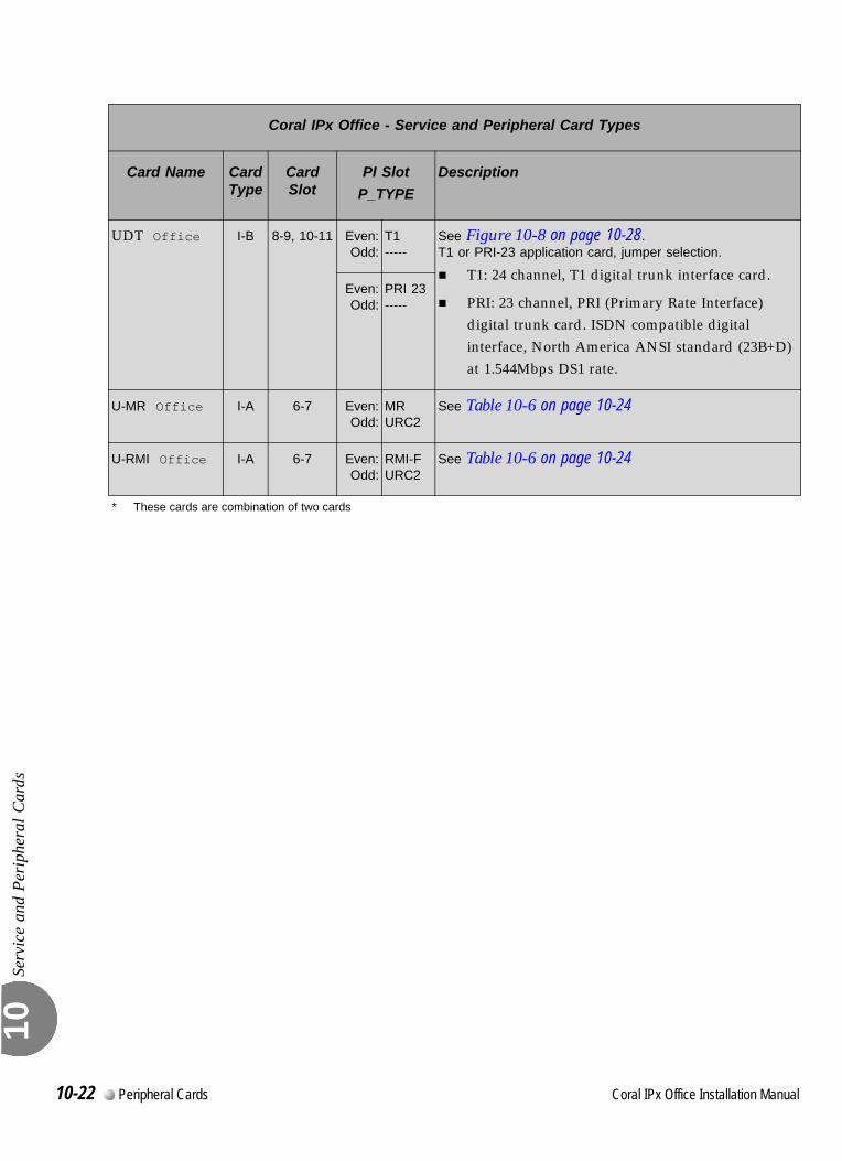
Serv
ice
and
Peri
pher
al C
ards
10
UDT Office I-B 8-9, 10-11 Even:Odd:
T1-----
See Figure 10-8 on page 10-28.T1 or PRI-23 application card, jumper selection.
T1: 24 channel, T1 digital trunk interface card.
PRI: 23 channel, PRI (Primary Rate Interface) digital trunk card. ISDN compatible digital interface, North America ANSI standard (23B+D) at 1.544Mbps DS1 rate.
Even:Odd:
PRI 23-----
U-MR Office I-A 6-7 Even:Odd:
MRURC2
See Table 10-6 on page 10-24
U-RMI Office I-A 6-7 Even:Odd:
RMI-FURC2
See Table 10-6 on page 10-24
* These cards are combination of two cards
Coral IPx Office - Service and Peripheral Card Types
Card Name Card Type
Card Slot
PI Slot
P_TYPE
Description
10-22 Peripheral Cards Coral IPx Office Installation Manual
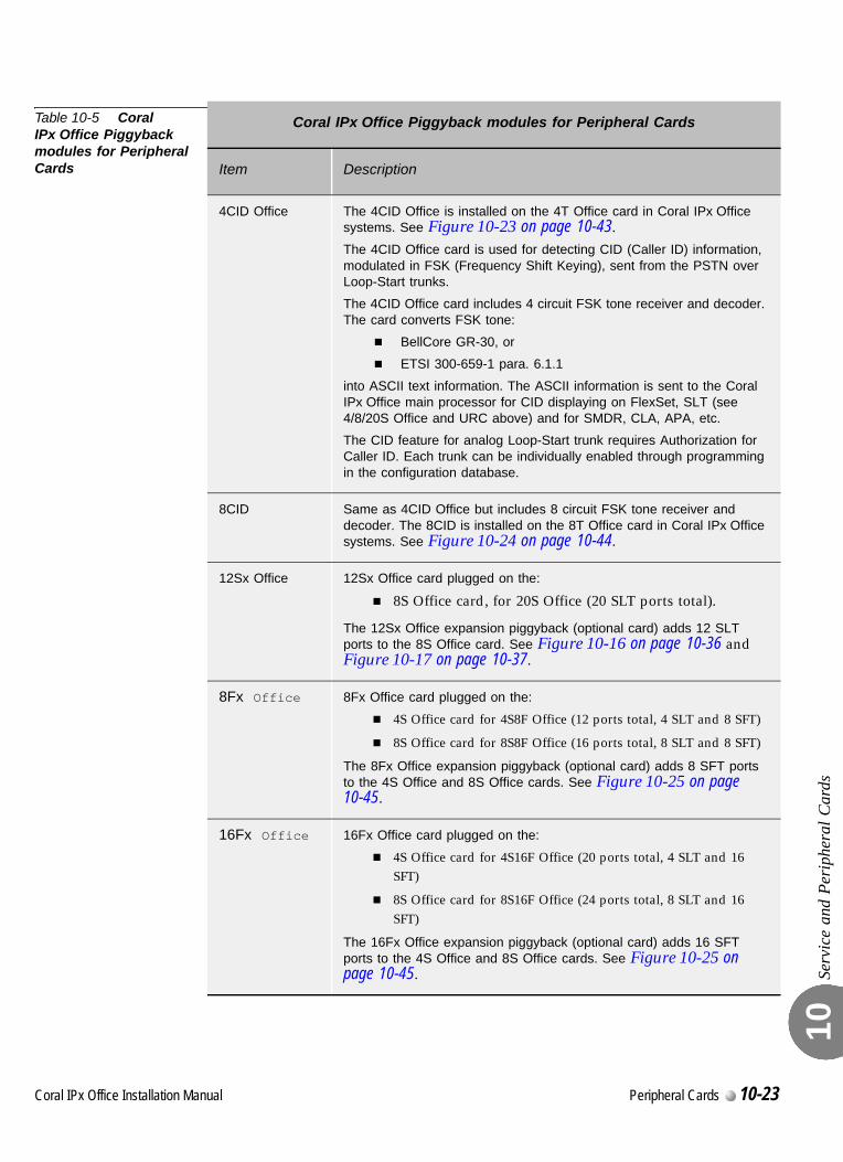
Serv
ice
and
Peri
pher
al C
ards
10
Table 10-5 Coral IPx Office Piggyback modules for Peripheral Cards
Coral IPx Office Piggyback modules for Peripheral Cards
Item Description
4CID Office The 4CID Office is installed on the 4T Office card in Coral IPx Office systems. See Figure 10-23 on page 10-43.The 4CID Office card is used for detecting CID (Caller ID) information, modulated in FSK (Frequency Shift Keying), sent from the PSTN over Loop-Start trunks.
The 4CID Office card includes 4 circuit FSK tone receiver and decoder. The card converts FSK tone:
BellCore GR-30, or
ETSI 300-659-1 para. 6.1.1
into ASCII text information. The ASCII information is sent to the Coral IPx Office main processor for CID displaying on FlexSet, SLT (see 4/8/20S Office and URC above) and for SMDR, CLA, APA, etc.
The CID feature for analog Loop-Start trunk requires Authorization for Caller ID. Each trunk can be individually enabled through programming in the configuration database.
8CID Same as 4CID Office but includes 8 circuit FSK tone receiver and decoder. The 8CID is installed on the 8T Office card in Coral IPx Office systems. See Figure 10-24 on page 10-44.
12Sx Office 12Sx Office card plugged on the:
8S Office card, for 20S Office (20 SLT ports total).
The 12Sx Office expansion piggyback (optional card) adds 12 SLT ports to the 8S Office card. See Figure 10-16 on page 10-36 and Figure 10-17 on page 10-37.
8Fx Office 8Fx Office card plugged on the:
4S Office card for 4S8F Office (12 ports total, 4 SLT and 8 SFT)
8S Office card for 8S8F Office (16 ports total, 8 SLT and 8 SFT)
The 8Fx Office expansion piggyback (optional card) adds 8 SFT ports to the 4S Office and 8S Office cards. See Figure 10-25 on page 10-45.
16Fx Office 16Fx Office card plugged on the:
4S Office card for 4S16F Office (20 ports total, 4 SLT and 16 SFT)
8S Office card for 8S16F Office (24 ports total, 8 SLT and 16 SFT)
The 16Fx Office expansion piggyback (optional card) adds 16 SFT ports to the 4S Office and 8S Office cards. See Figure 10-25 on page 10-45.
Coral IPx Office Installation Manual Peripheral Cards 10-23
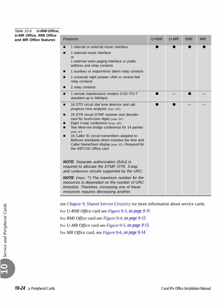
Serv
ice
and
Peri
pher
al C
ards
10
Table 10-6 U-RMI Office, U-MR Office, RMI Office and MR Office features
see Chapter 9, Shared Service Circuitry for more information about service cards.
For U-RMI Office card see Figure 9-3, on page 9-11.
For RMI Office card see Figure 9-4, on page 9-12.
For U-MR Office card see Figure 9-5, on page 9-13.
For MR Office card, see Figure 9-6, on page 9-14.
Features U-RMI U-MR RMI MR
1 internal or external music interface
1 external music interface or 1 external voice paging interface or public address and relay contacts
1 auxiliary or major/minor alarm relay contacts
1 universal night answer UNA or central bell relay contacts
2 relay contacts
1 remote maintenance modem (V.92 ITU-T standard up to 56Kbps)
— —
16 DTD circuit dial tone detector and call progress tone analyzer (max: 32*)
24 DTR circuit DTMF receiver and decoder card for touch-tone digits (max: 24*)
Eight 3-way conference (max: 24*)
Two Meet-me bridge conference for 14 parties
(max: 6*)
16 Caller ID circuit transmitters adapted to Bellcore standards which includes the time and Caller Name/Num display (max: 32*). Required for the 4/8T-CID Office card
NOTE: Separate authorization (SAU) is required to allocate the DTMF, DTR, 3-way and conference circuits supported by the URC.
NOTE: (max: *) The maximum number for the resources is dependant on the number of URC timeslots. Therefore, increasing one of these resources requires decreasing another.
— —
10-24 Peripheral Cards Coral IPx Office Installation Manual
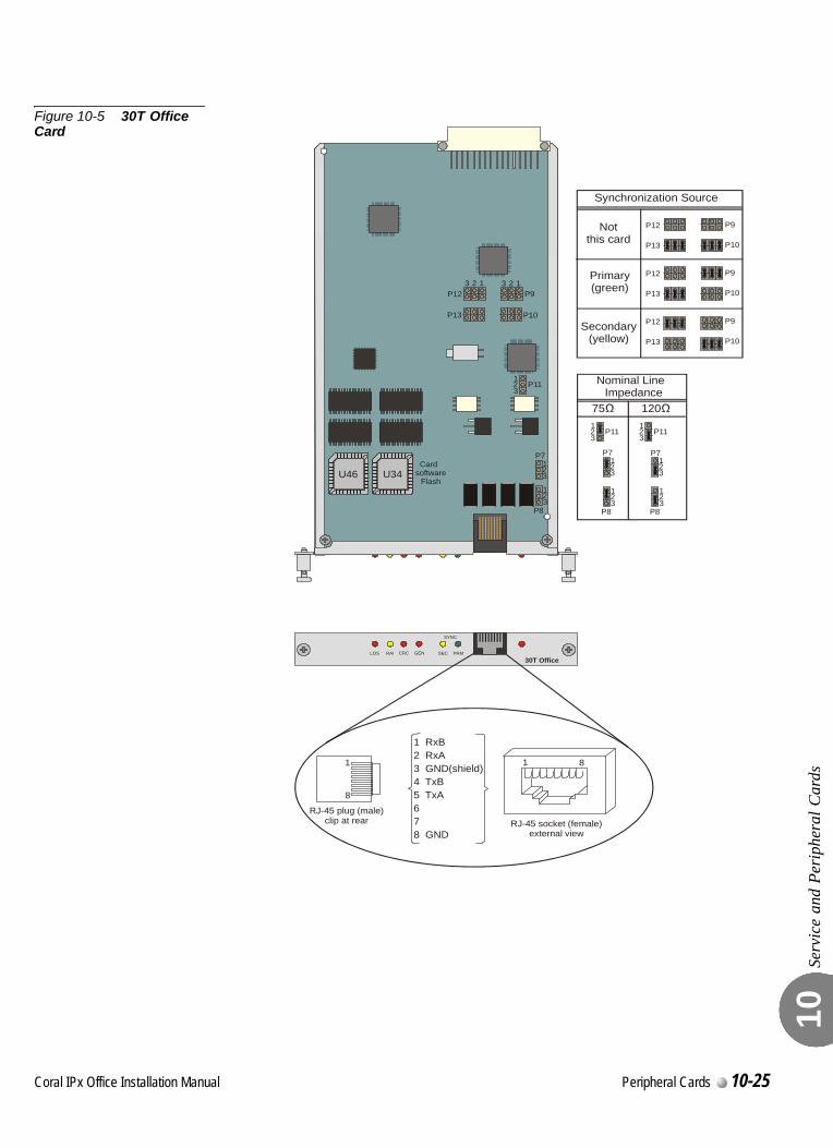
Serv
ice
and
Peri
pher
al C
ards
10
Figure 10-5 30T Office Card
LOS RAI CRC GEN SEC PRM
SYNC
30T Office
U46 U34
1 1
RJ-45 socket (female)external view
RJ-45 plug (male)clip at rear
8
8
1 RxB2 RxA3 GND(shield)4 TxB5 TxA
6 7
8 GND
1 1
1
1
1
2 2
2
2
2
3 3
3
3
3
P9
P10
P11
P7Card
softwareFlash
P8
P12
P13
Synchronization Source
P9P12
P10P13
P9P12
P10P13
P9P12
P10P13
1
1
1
2
2
2
3
3
3
P11
P7
P8
1
1
1
2
2
2
3
3
3
P11
P7
P8
Nominal Line Impedance
75 120
Notthis card
Primary(green)
Secondary(yellow)
Coral IPx Office Installation Manual Peripheral Cards 10-25
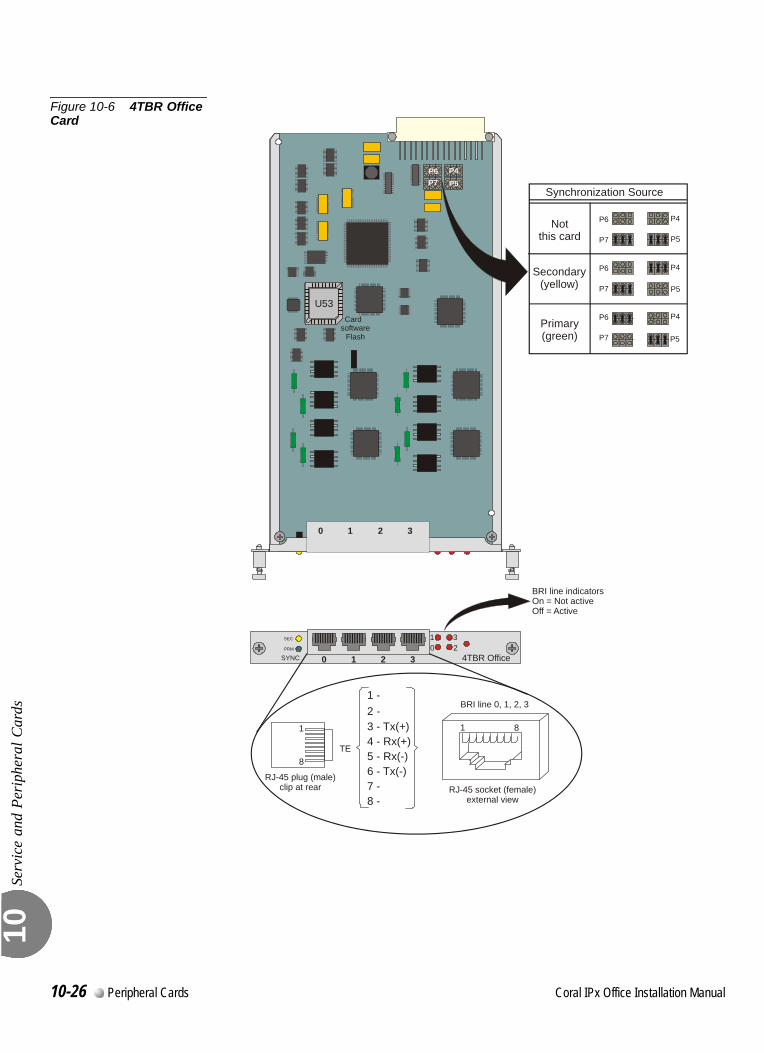
Serv
ice
and
Peri
pher
al C
ards
10
Figure 10-6 4TBR Office Card
SEC 123
0PRM
SYNC
Synchronization Source
Notthis card
P4P6
P5P7
P4P6
P5P7
P4P6
P5P7
Primary(green)
Secondary(yellow)
4TBR Office
1 1
BRI line 0, 1, 2, 3
RJ-45 socket (female)external view
RJ-45 plug (male)clip at rear
8
8
0 1 2 3
0 1 2 3
Card software
Flash
U53
BRI line indicatorsOn = Not activeOff = Active
P4P5
P6P7
1
3 - Tx(+)4 - R5 - R6 - T78 -
-2 -
x(+)x(-)x(-)
-
TE
10-26 Peripheral Cards Coral IPx Office Installation Manual
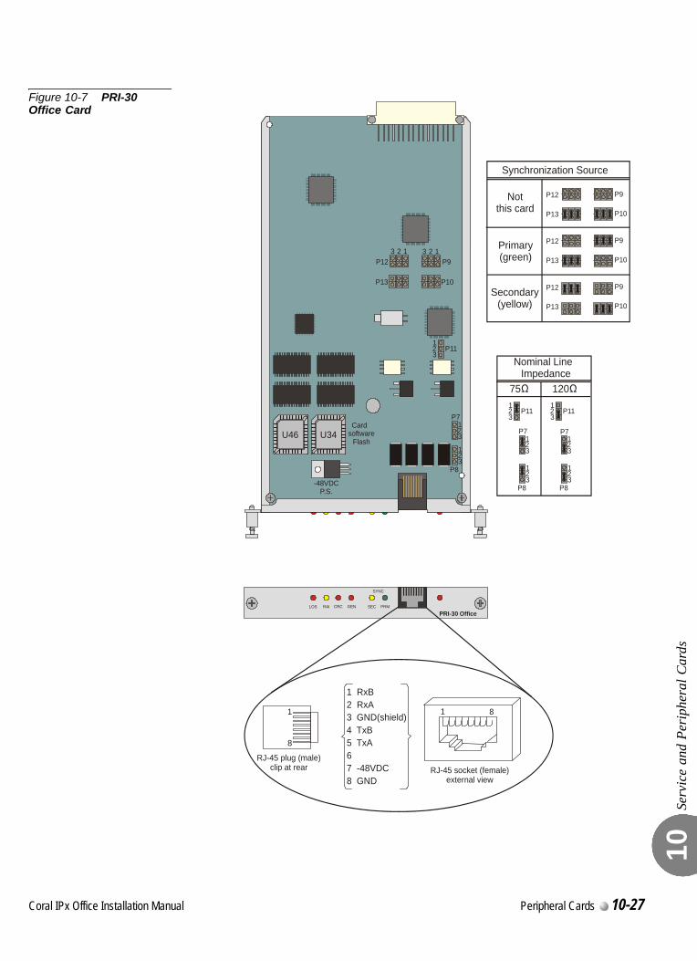
Serv
ice
and
Peri
pher
al C
ards
10
Figure 10-7 PRI-30 Office Card
LOS RAI CRC GEN SEC PRM
SYNC
PRI-30 Office
U46 U34
1 1
RJ-45 socket (female)external view
RJ-45 plug (male)clip at rear
8
8
1 RxB2 RxA3 GND(shield)4 TxB5 TxA
6 7 -48VDC8 GND
1 1
1
1
1
2 2
2
2
2
3 3
3
3
3
P9
P10
P11
P7Card
softwareFlash
P8
P12
P13
Synchronization Source
P9P12
P10P13
P9P12
P10P13
P9P12
P10P13
1
1
1
2
2
2
3
3
3
P11
P7
P8
1
1
1
2
2
2
3
3
3
P11
P7
P8
Nominal Line Impedance
75 120
-48VDCP.S.
Secondary(yellow)
Notthis card
Primary(green)
Coral IPx Office Installation Manual Peripheral Cards 10-27
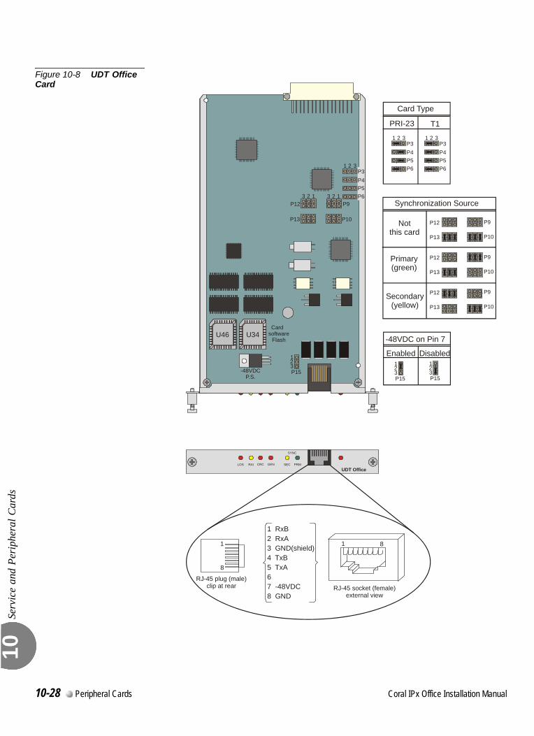
Serv
ice
and
Peri
pher
al C
ards
10
Figure 10-8 UDT Office Card
LOS RAI CRC GEN SEC PRM
SYNC
UDT Office
U46 U34
1 1
RJ-45 socket (female)external view
RJ-45 plug (male)clip at rear
8
8
1 RxB2 RxA3 GND(shield)4 TxB5 TxA67 -48VDC8 GND
P5P6
P4P3
1
1 1
1
2
2 2
2
3
3 3
3
P9
P10
Card software
Flash
-48VDCP.S.
P15
P12
P13
P5P6
P4P3
1 2 3
P5P6
P4P3
1 2 3
Card Type
PRI-23 T1
123P15
123P15
-48VDC on Pin 7
Enabled Disabled
Synchronization Source
P9P12
P10P13
P9P12
P10P13
P9P12
P10P13
Primary(green)
Secondary(yellow)
Notthis card
10-28 Peripheral Cards Coral IPx Office Installation Manual
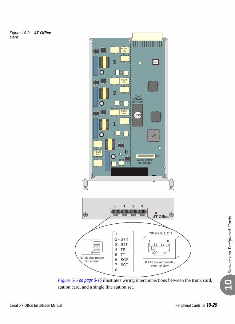
Serv
ice
and
Peri
pher
al C
ards
10
Figure 10-9 4T Office Card
Figure 5-5 on page 5-16 illustrates wiring interconnections between the trunk card, station card, and a single line station set.
4T Office
0 1 2 3
P
U33
CardsoftwareEPROM
4CID Officeconnector
PowerFail
PowerFail
PowerFail
PowerFail
0
1
2
3
1 1
TRUNK 0, 1, 2, 3
RJ-45 socket (female)external view
RJ-45 plug (male)clip at rear
8
8
12 STR3 - STT4 - TR5 - TT6 - SCR7 - SCT8 -
- -
P2
U83-WAY
Coral IPx Office Installation Manual Peripheral Cards 10-29
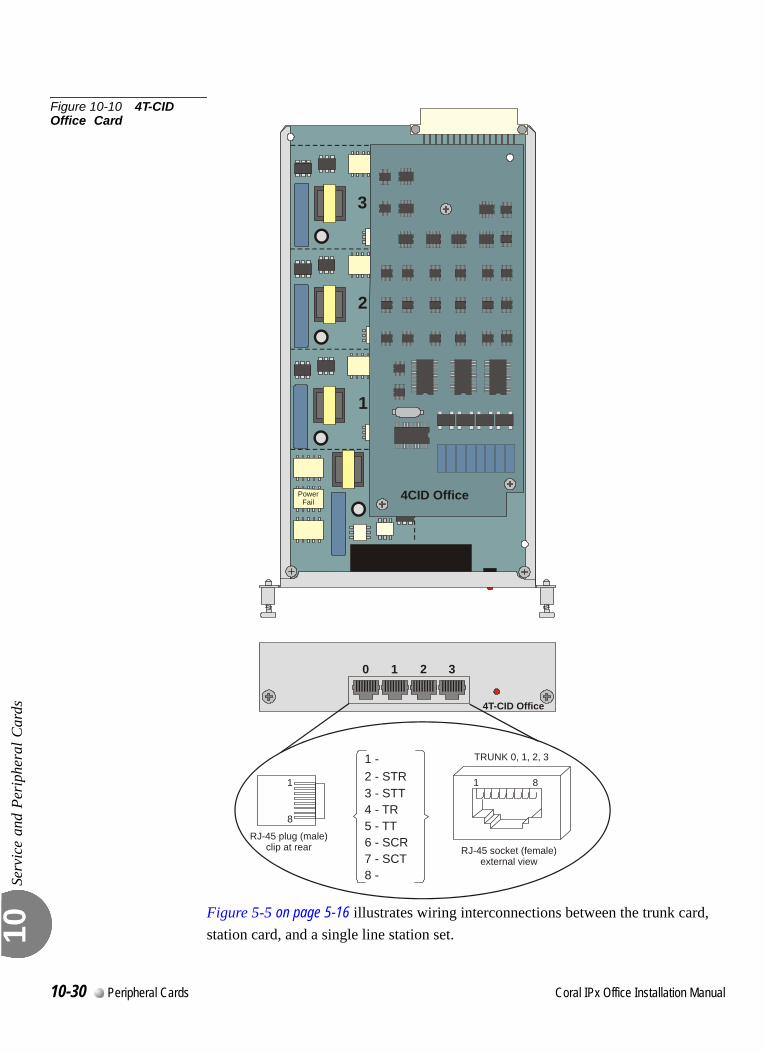
Serv
ice
and
Peri
pher
al C
ards
10
Figure 10-10 4T-CID Office Card
Figure 5-5 on page 5-16 illustrates wiring interconnections between the trunk card, station card, and a single line station set.
4T-CID Office
0 1 2 3
PowerFail
1
2
3
1 1
TRUNK 0, 1, 2, 3
RJ-45 socket (female)external view
RJ-45 plug (male)clip at rear
8
8
12 STR3 - STT4 - TR5 - TT6 - SCR7 - SCT8 -
- -
4CID Office
10-30 Peripheral Cards Coral IPx Office Installation Manual
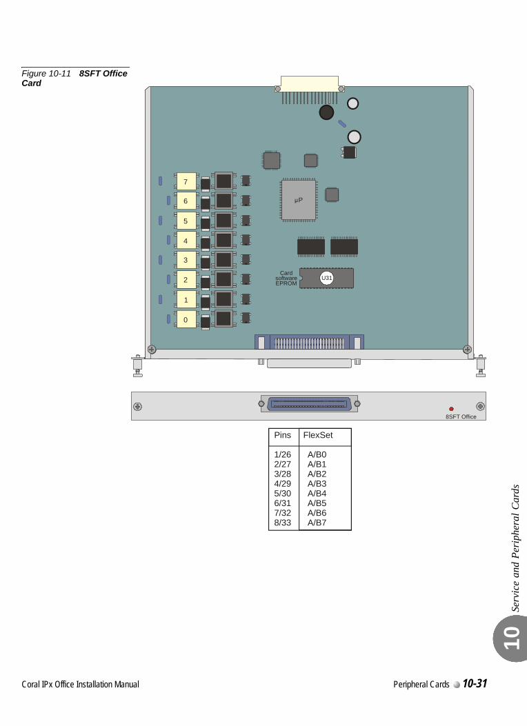
Serv
ice
and
Peri
pher
al C
ards
10
Figure 10-11 8SFT Office Card
8SFT Office
U31
P
7
5
3
1
6
4
2
0
CardsoftwareEPROM
Pins FlexSet
1/26 A/B02/27 A/B13/28 A/B24/29 A/B35/30 A/B46/31 A/B57/32 A/B68/33 A/B7
Coral IPx Office Installation Manual Peripheral Cards 10-31
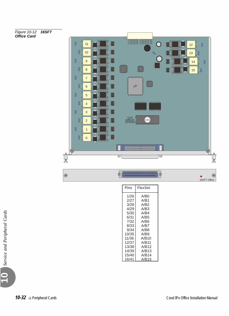
Serv
ice
and
Peri
pher
al C
ards
10
Figure 10-12 16SFT Office Card
16SFT Office
U31
P
15
9
7
5
3
1
14
10
11
8
6
4
2
0
13
12
CardsoftwareEPROM
Pins FlexSet
1/26 A/B0 2/27 A/B1 3/28 A/B2 4/29 A/B3 5/30 A/B4 6/31 A/B5 7/32 A/B6 8/33 A/B7 9/34 A/B810/35 A/B911/36 A/B1012/37 A/B1113/38 A/B1214/39 A/B1315/40 A/B1416/41 A/B15
10-32 Peripheral Cards Coral IPx Office Installation Manual
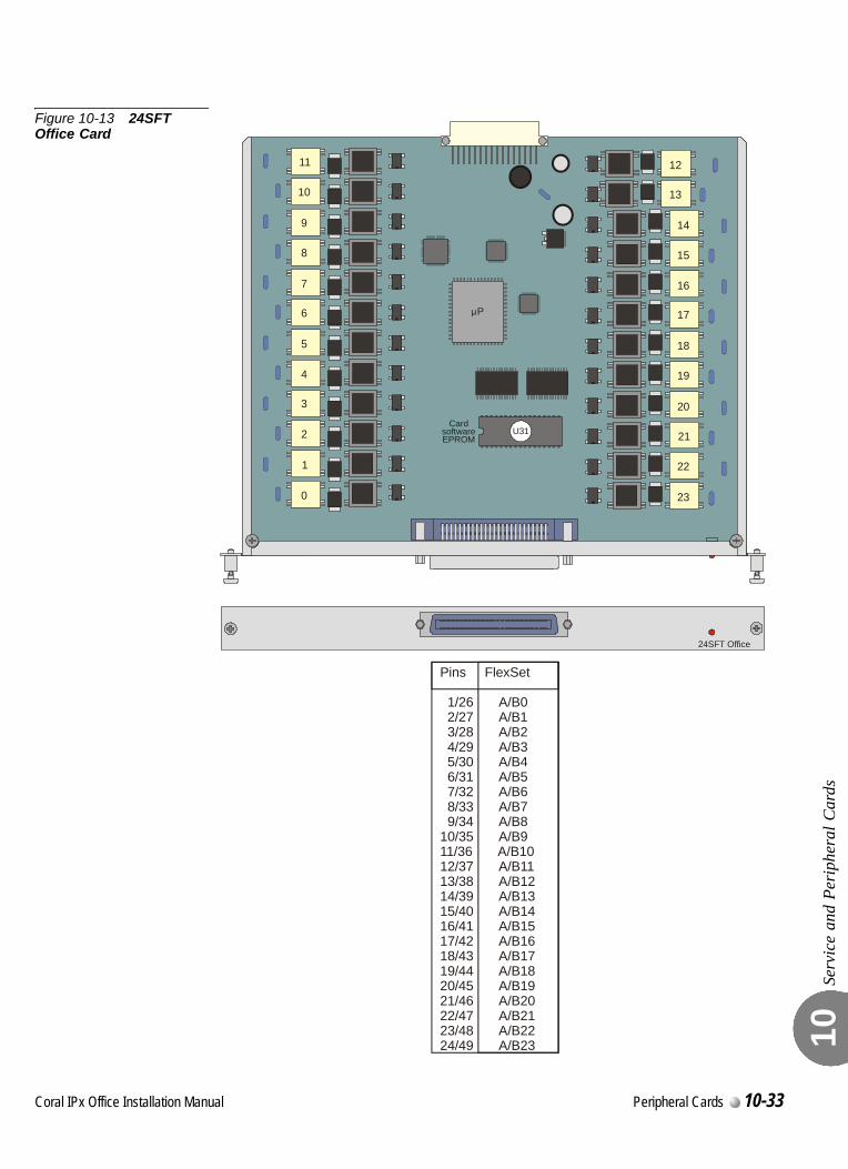
Serv
ice
and
Peri
pher
al C
ards
10
Figure 10-13 24SFT Office Card
24SFT Office
U31
P
15
9
17
7
19
5
21
3
23
1
14
10
11
16
8
18
6
20
4
22
2
0
13
12
CardsoftwareEPROM
Pins FlexSet
1/26 A/B0 2/27 A/B1 3/28 A/B2 4/29 A/B3 5/30 A/B4 6/31 A/B5 7/32 A/B6 8/33 A/B7 9/34 A/B810/35 A/B911/36 A/B1012/37 A/B1113/38 A/B1214/39 A/B1315/40 A/B1416/41 A/B1517/42 A/B1618/43 A/B1719/44 A/B1820/45 A/B1921/46 A/B2022/47 A/B2123/48 A/B2224/49 A/B23
Coral IPx Office Installation Manual Peripheral Cards 10-33
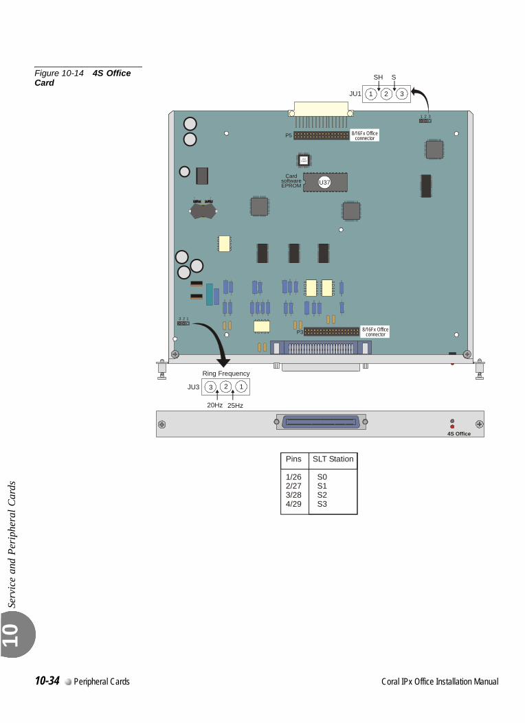
Serv
ice
and
Peri
pher
al C
ards
10
Figure 10-14 4S Office Card
4S Office
U37Card
softwareEPROM
1
1
2
2
3
3
U123-WAY
20Hz
JU3
Ring Frequency
25Hz
123
SH S
JU1 1 2 3
P3
P5 8/16Fx Officeconnector
8/16Fx Officeconnector
Pins SLT Station
1/26 S02/27 S13/28 S24/29 S3
10-34 Peripheral Cards Coral IPx Office Installation Manual
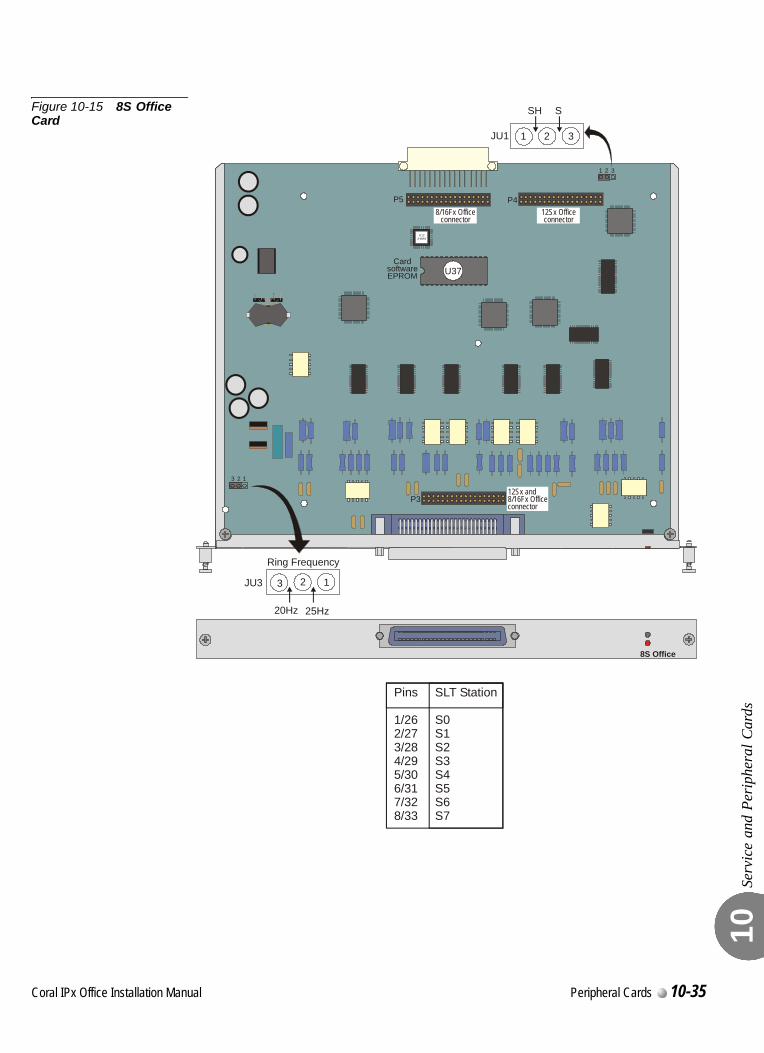
Serv
ice
and
Peri
pher
al C
ards
10
Figure 10-15 8S Office Card
8S Office
U37Card
softwareEPROM
P4
P3
1
1
2
2
3
3
P5
U123-WAY
20Hz
JU3
Ring Frequency
25Hz
123
SH S
JU1 1 2 3
8/16Fx Officeconnector
12Sx and8/16Fx Officeconnector
12Sx Officeconnector
Pins SLT Station
1/26 S02/27 S13/28 S24/29 S35/30 S46/31 S57/32 S68/33 S7
Coral IPx Office Installation Manual Peripheral Cards 10-35
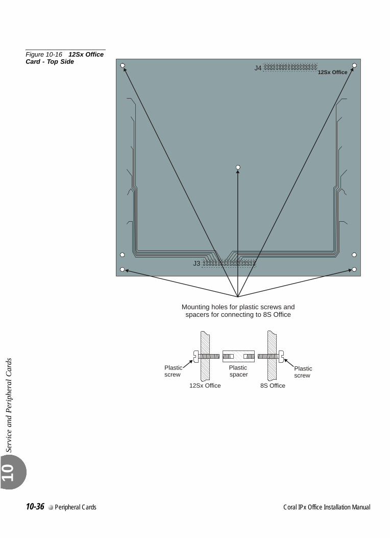
Serv
ice
and
Peri
pher
al C
ards
10
Figure 10-16 12Sx Office Card - Top Side
12Sx OfficeJ4
J3
Mounting holes for plastic screws andspacers for connecting to 8S Office
Plastic spacer
12Sx Office
Plasticscrew
8S Office
Plasticscrew
10-36 Peripheral Cards Coral IPx Office Installation Manual
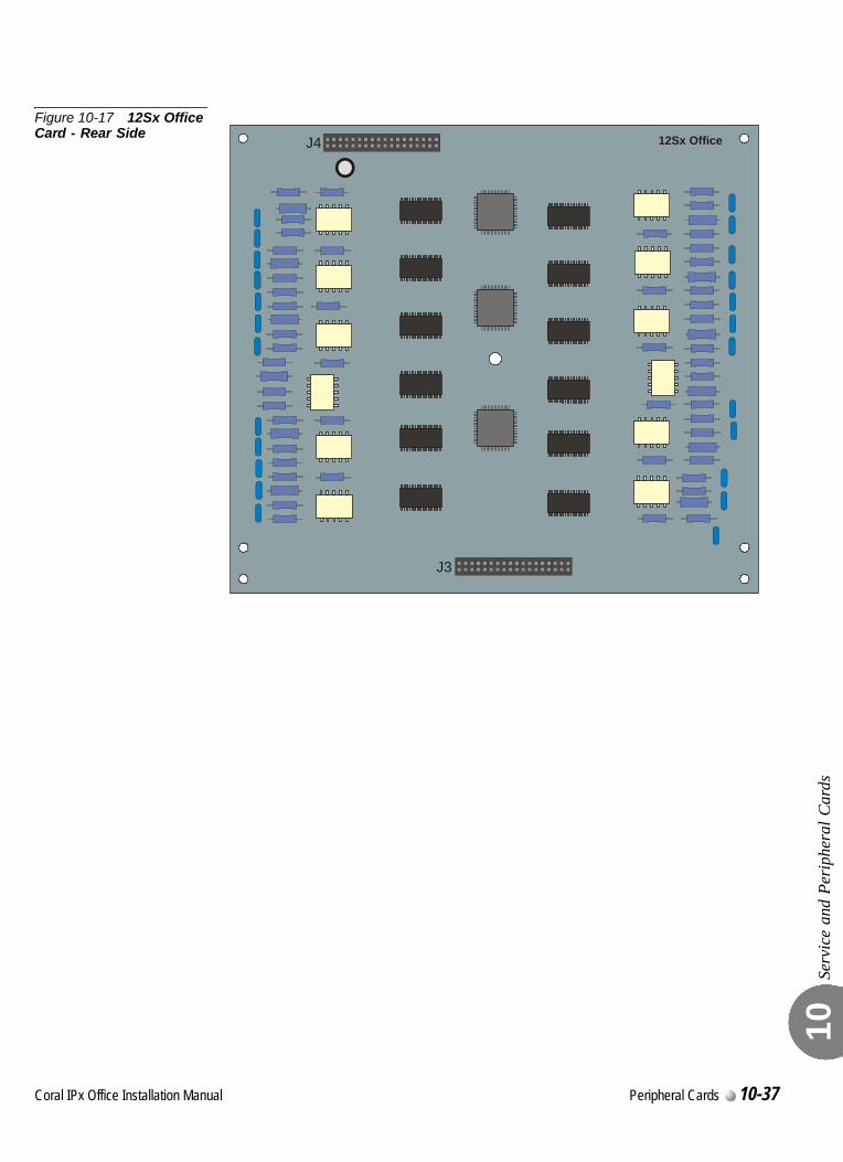
Serv
ice
and
Peri
pher
al C
ards
10
Figure 10-17 12Sx Office Card - Rear Side 12Sx OfficeJ4
J3
Coral IPx Office Installation Manual Peripheral Cards 10-37
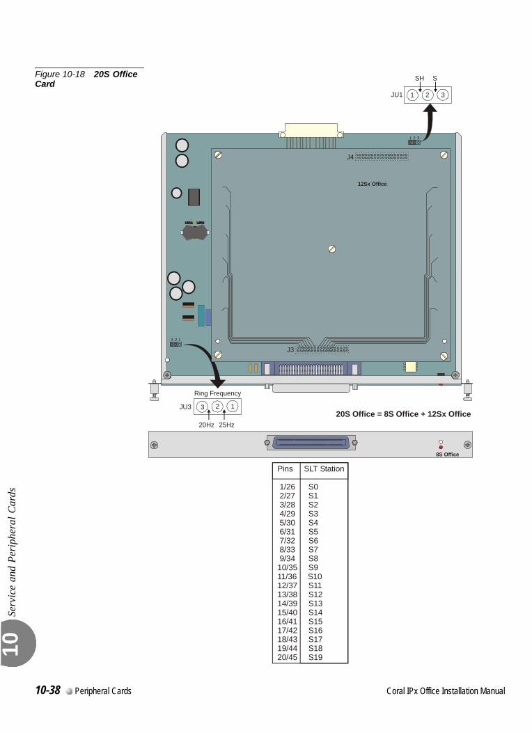
Serv
ice
and
Peri
pher
al C
ards
10
Figure 10-18 20S Office Card
8S Office
1
1
2
2
3
3
SH S
JU1 1 2 3
20Hz
JU3
Ring Frequency
25Hz20S Office = 8S Office + 12Sx Office
123
12Sx Office
J4
J3
Pins SLT Station
1/26 S0 2/27 S1 3/28 S2 4/29 S3 5/30 S4 6/31 S5 7/32 S6 8/33 S7 9/34 S810/35 S911/36 S1012/37 S1113/38 S1214/39 S1315/40 S1416/41 S1517/42 S1618/43 S1719/44 S1820/45 S19
10-38 Peripheral Cards Coral IPx Office Installation Manual
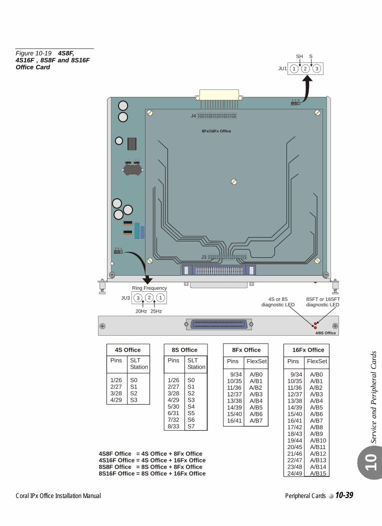
Serv
ice
and
Peri
pher
al C
ards
10
Figure 10-19 4S8F, 4S16F , 8S8F and 8S16F Office Card
1
1
2
2
3
3
SH S
JU1 1 2 3
20Hz
8SFT or 16SFTdiagnostic LED
JU3
Ring Frequency
25Hz
123
8Fx/16Fx Office
J4
J3
4S or 8S diagnostic LED
4/8S Office
4S8F Office = 4S + 8Fx Office Office Office Office Office
Office Office Office Office Office Office
4S16F = 4S + 16Fx8S8F = 8S + 8Fx8S16F = 8S + 16Fx
4S Office
Pins SLT Station
1/26 S02/27 S13/28 S24/29 S3
Pins SLT Station
1/26 S02/27 S13/28 S24/29 S35/30 S46/31 S57/32 S68/33 S7
8S Office
Pins FlexSet
9/34 A/B010/35 A/B111/36 A/B212/37 A/B313/38 A/B414/39 A/B515/40 A/B616/41 A/B7
8Fx Office
Pins FlexSet
9/34 A/B010/35 A/B111/36 A/B212/37 A/B313/38 A/B414/39 A/B515/40 A/B616/41 A/B717/42 A/B818/43 A/B919/44 A/B1020/45 A/B1121/46 A/B1222/47 A/B1323/48 A/B1424/49 A/B15
16Fx Office
Coral IPx Office Installation Manual Peripheral Cards 10-39
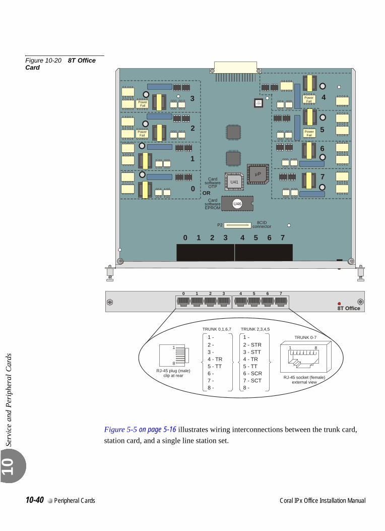
Serv
ice
and
Peri
pher
al C
ards
10
Figure 10-20 8T Office Card
Figure 5-5 on page 5-16 illustrates wiring interconnections between the trunk card, station card, and a single line station set.
0 1 2 3 4 5 6 7
8T Office
8CIDconnectorP2
PowerFail
PowerFail
CardsoftwareEPROM
Cardsoftware
OTP
U46
U41
P
1
RJ-45 plug (male)clip at rear
8
1
TRUNK 0-7
RJ-45 socket (female)external view
8
OR
PowerFail
PowerFail
07
16
2 5
3 4U12
3-WAY
0 1 2 3 4 5 6 7
12 STR3 - STT4 - TR5 - TT6 - SCR7 - SCT8 -
- -
TRUNK 2,3,4,5TRUNK 0,1,6,7
1
4 - TR5 - TT
8 -
- 2 - 3 -
6 - 7 -
10-40 Peripheral Cards Coral IPx Office Installation Manual
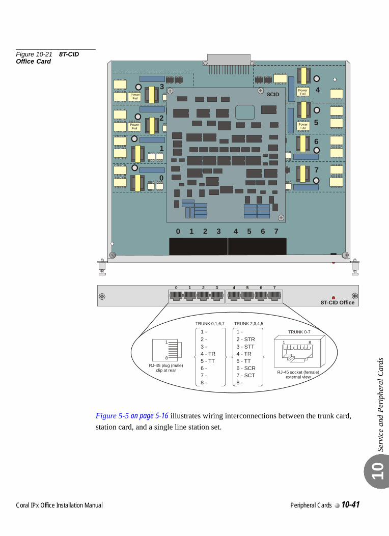
Serv
ice
and
Peri
pher
al C
ards
10
Figure 10-21 8T-CID Office Card
Figure 5-5 on page 5-16 illustrates wiring interconnections between the trunk card, station card, and a single line station set.
0 1 2 3 4 5 6 7
PowerFail
PowerFail
PowerFail
PowerFail
07
16
2 5
3 4
J1
8CID8CID
0 1 2 3 4 5 6 7
8T-CID Office
1
RJ-45 plug (male)clip at rear
8
1
TRUNK 0-7
RJ-45 socket (female)external view
8
12 STR3 - STT4 - TR5 - TT6 - SCR7 - SCT8 -
- -
TRUNK 2,3,4,5TRUNK 0,1,6,7
1
4 - TR5 - TT
8 -
- 2 - 3 -
6 - 7 -
Coral IPx Office Installation Manual Peripheral Cards 10-41
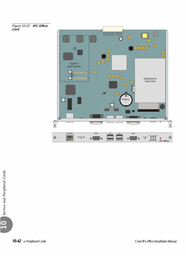
Serv
ice
and
Peri
pher
al C
ards
10
Figure 10-22 IPC Office Card
IPC Office
HDD
USB1 USB2
RESET
COM 1VIDEONETWORK
PWR
DSP2
DSP1
BUSY
APP
ApplicationsHard Disk
Fax/PCIcard location
Battery+
SHUTDOWN
10-42 Peripheral Cards Coral IPx Office Installation Manual
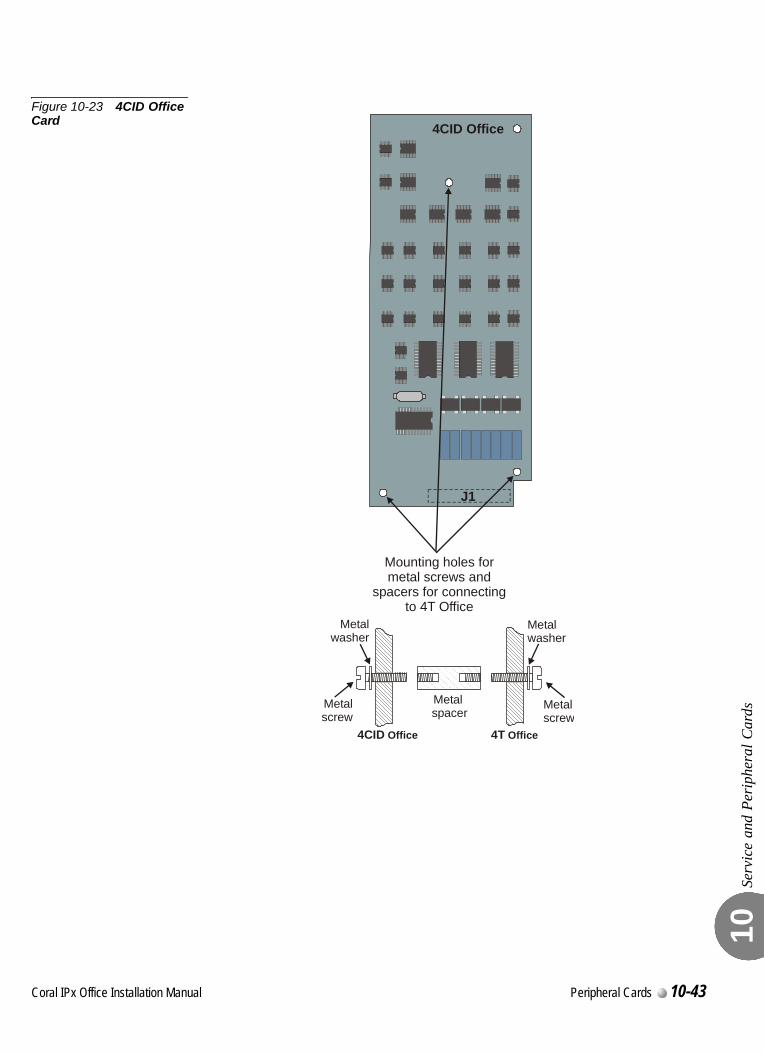
Serv
ice
and
Peri
pher
al C
ards
10
Figure 10-23 4CID Office Card 4CID Office
J1
Mounting holes formetal screws and
spacers for connectingto 4T Office
Metal spacer
4CID Office
Metalscrew
4T Office
Metalscrew
Metalwasher
Metalwasher
Coral IPx Office Installation Manual Peripheral Cards 10-43
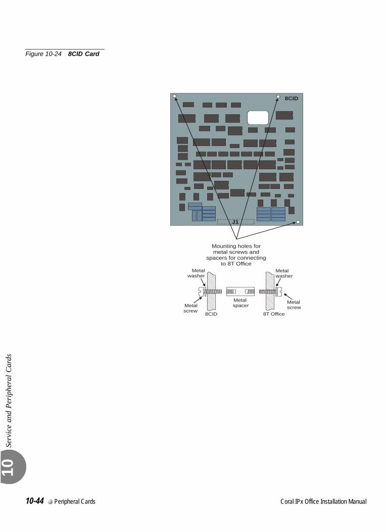
Serv
ice
and
Peri
pher
al C
ards
10
Figure 10-24 8CID Card
8CID
J1
Mounting holes formetal screws and
spacers for connectingto 8T Office
Metal spacer
8CID
Metalscrew
8T Office
Metalscrew
Metalwasher
Metalwasher
10-44 Peripheral Cards Coral IPx Office Installation Manual
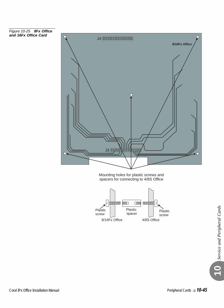
Serv
ice
and
Peri
pher
al C
ards
10
Figure 10-25 8Fx Office and 16Fx Office Card
8/16Fx OfficeJ4
J3
Mounting holes for plastic screws andspacers for connecting to 4/8S Office
Plastic spacer
8/16Fx Office
Plasticscrew
4/8S Office
Plasticscrew
Coral IPx Office Installation Manual Peripheral Cards 10-45

Serv
ice
and
Peri
pher
al C
ards
10
NOTES:
10-46 Peripheral Cards Coral IPx Office Installation Manual
Coral IPx Office Installation Manual
Chapter00
11
System Networking
11.1 NTU Office Card Description ........................................................... 11-3
11.2 NTU Office Card Installation ............................................................ 11-9
11.3 Connecting to the Network without an NTU Office Card................ 11-21

11
11-2 System Networking Coral IPx Office Installation Manual
C
11.1
oral IPx Office Installation Ma
NTU Office Card Description
NTU
Offi
ce C
ard
Des
crip
tion
11
00
This section describes the networking functions of the Coral IPx Office system. For a description on how to install the networking card and components, see NTU Office Card Installation, page 11-9.Coral IPx Office offers a complete integration of traditional telephony and VoIP networking abilities. Connection to the WAN is facilitated without installing an additional UGW card or router. The Coral IPx Office includes UGW circuitry embedded on the MCB Office control card as well as the NTU Office (Network Unit) card that is installed within the system at specific customer request. The NTU card functions as a router, enabling direct connection to the WAN. A WiFi card can be installed upon the NTU card supplied at specific customer request. In addition, it also enables direct connection to a printer via a USB port.0
The Coral IPx Office system enables seamless connection to the digital and IP world with or without an NTU Office card. Without an NTU Office card, the Coral IPx Office can connect to the WAN only after an external, customer-supplied router has been connected. See Figure 11-1.
Media Stream from the Digital World to the LAN and WAN
PCM streams are directed from the Coral to the MRC, which converts the PCM streams into RTP packets. See MRC Card, page 8-27 for more information. The RTP packets are directed through the UGW internal switch. The switches direct the packets to LAN ports 1-8. The DHCP server provides the dynamic IP address to the devices, enabling connection to the endpoints on the LAN. An external, customer-supplied router directs the packets to their destination over the WAN.
...................................................................................................1 Introduction
...................................................................................................2 System Operation without an NTU Office Card
nual System Networking 11-3
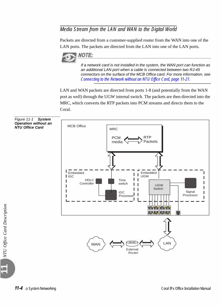
NTU
Offi
ce C
ard
Des
crip
tion
11
Media Stream from the LAN and WAN to the Digital World
Packets are directed from a customer-supplied router from the WAN into one of the LAN ports. The packets are directed from the LAN into one of the LAN ports.
If a network card is not installed in the system, the WAN port can function as an additional LAN port when a cable is connected between two RJ-45 connectors on the surface of the MCB Office card. For more information, see Connecting to the Network without an NTU Office Card, page 11-21.
LAN and WAN packets are directed from ports 1-8 (and potentially from the WAN port as well) through the UGW internal switch. The packets are then directed into the MRC, which converts the RTP packets into PCM streams and directs them to the Coral.
Figure 11-1 System Operation without an NTU Office Card
LANExternal
Router
EmbeddedUGW
UGWSwitch
EmbeddediGC
Timeswitch
iGCProcessor
HDLCController
MCB Office
SignalProcessor
MRC
RTPPackets
PCMmedia
WAN
11-4 System Networking Coral IPx Office Installation Manual
NTU
Offi
ce C
ard
Des
crip
tion
11
0
The Coral IPx Office system enables seamless integration between the digital and IP world with or without an NTU Office card. With an NTU Office card, the Coral IPx Office can connect to the WAN directly from the WAN port without any additional external router. See Figure 11-2.
Media Stream from the Digital World to the LAN and WANPCM streams are directed from the Coral to the MRC, which converts the PCM streams into RTP packets. See MRC Card, page 8-27, for more information.RTP packets designated for the LAN are directed through the UGW internal switch. The UGW switch directs the media stream to LAN ports 1-8. The dynamic IP addresses are either provided by the NTU Office card or the DHCP server, enabling connection to the endpoints on the LAN.RTP packets designated for the WAN are directed to the NTU Office card, which then directs them through the external WAN port on the front panel to their destination on the WAN.
Media Stream from the LAN and WAN to the Digital World
WAN Packets are directed from the WAN port directly to the NTU Office card. The NTU Office card redirects the RTP packets to the MRC card, where they are translated into PCM streams. Finally, the PCM streams are directed to the digital network.LAN packets are directed from the LAN ports 1-8 through the internal UGW switch, which is embedded on the MCB Office card. The packets are then directed into the MRC, which converts the RTP packets into PCM streams. Finally, the PCM streams are directed to the digital network.
...................................................................................................3 System Operation with an NTU Office Card
Coral IPx Office Installation Manual System Networking 11-5
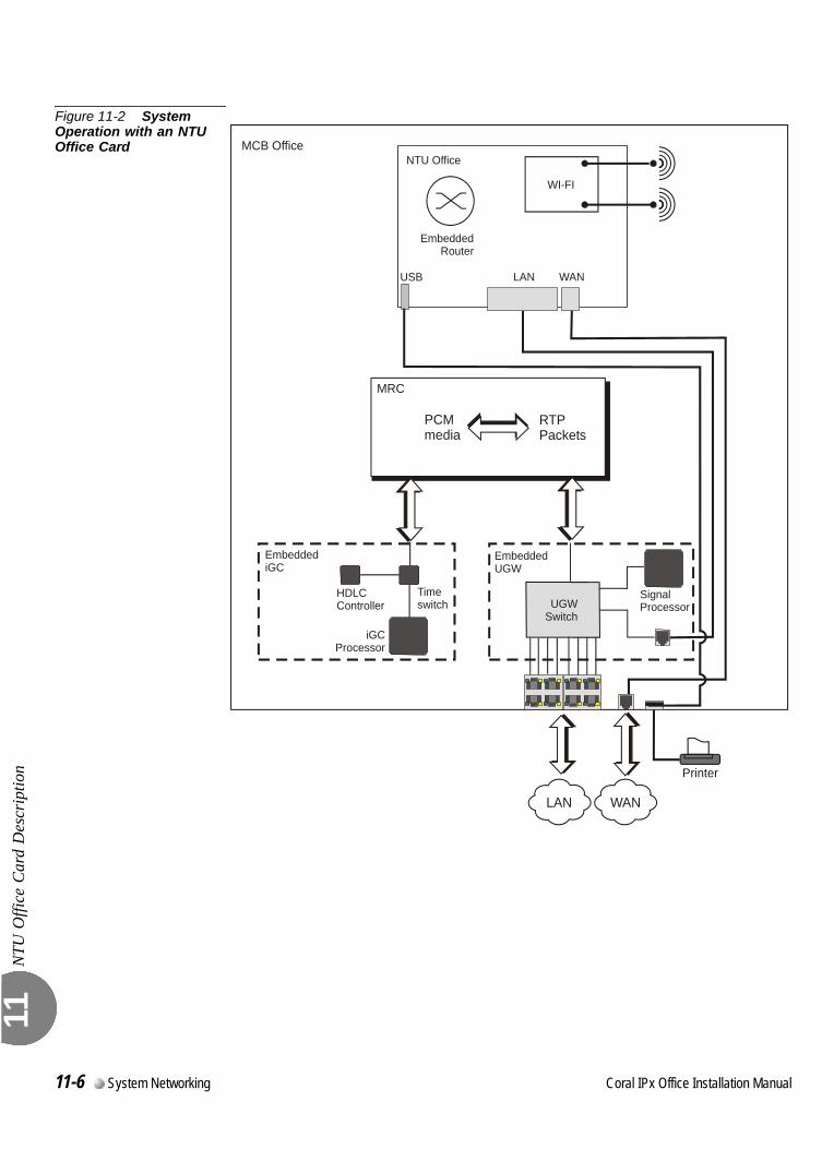
NTU
Offi
ce C
ard
Des
crip
tion
11
Figure 11-2 System Operation with an NTU Office Card
LAN
SignalProcessor
EmbeddedUGW
EmbeddediGC
MRC
UGWSwitch
EmbeddedRouter
WI-FI
LANUSB WAN
NTU Office
RTPPackets
PCMmedia
Timeswitch
iGCProcessor
HDLCController
MCB Office
Printer
WAN
11-6 System Networking Coral IPx Office Installation Manual
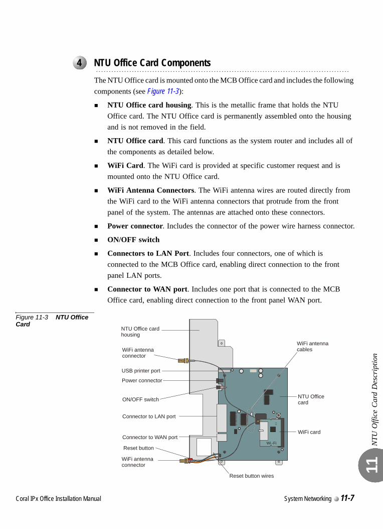
NTU
Offi
ce C
ard
Des
crip
tion
11
0
The NTU Office card is mounted onto the MCB Office card and includes the following components (see Figure 11-3):
NTU Office card housing. This is the metallic frame that holds the NTU Office card. The NTU Office card is permanently assembled onto the housing and is not removed in the field.
NTU Office card. This card functions as the system router and includes all of the components as detailed below.
WiFi Card. The WiFi card is provided at specific customer request and is mounted onto the NTU Office card.
WiFi Antenna Connectors. The WiFi antenna wires are routed directly from the WiFi card to the WiFi antenna connectors that protrude from the front panel of the system. The antennas are attached onto these connectors.
Power connector. Includes the connector of the power wire harness connector.
ON/OFF switch
Connectors to LAN Port. Includes four connectors, one of which is connected to the MCB Office card, enabling direct connection to the front panel LAN ports.
Connector to WAN port. Includes one port that is connected to the MCB Office card, enabling direct connection to the front panel WAN port.
Figure 11-3 NTU Office Card
...................................................................................................4 NTU Office Card Components
Wi.-Fi
WiFi antennacables
Power connector
ON/OFF switch
Connector to WAN port
Connector to LAN port
WiFi card
USB printer port
WiFi antennaconnector
WiFi antennaconnector
NTU Office cardhousing
NTU Officecard
Reset button
Reset button wires
Coral IPx Office Installation Manual System Networking 11-7

NTU
Offi
ce C
ard
Des
crip
tion
11
NOTES:
11-8 System Networking Coral IPx Office Installation Manual
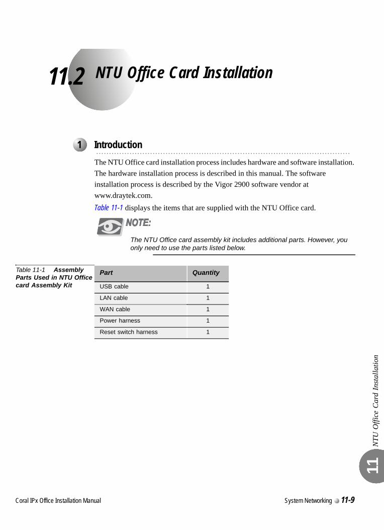
C
11.2
oral IPx Office Installation Ma
NTU Office Card Installation
NTU
Offi
ce C
ard
Inst
alla
tion
11
0
The NTU Office card installation process includes hardware and software installation. The hardware installation process is described in this manual. The software installation process is described by the Vigor 2900 software vendor at www.draytek.com.Table 11-1 displays the items that are supplied with the NTU Office card.
The NTU Office card assembly kit includes additional parts. However, you only need to use the parts listed below.
Table 11-1 Assembly Parts Used in NTU Office card Assembly Kit
...................................................................................................1 Introduction
Part Quantity
USB cable 1
LAN cable 1
WAN cable 1
Power harness 1
Reset switch harness 1
nual System Networking 11-9
NTU
Offi
ce C
ard
Inst
alla
tion
11
0
This section describes how to install the NTU Office card assembly (including the card chassis). See Figure 11-5.
1. If necessary, unplug the power cord that supplies the Coral IPx Office system.
2. If necessary, remove the unit cover. See Opening the Unit Cover, page 6-8.
3. Verify that the hard disk (if supplied) and the MRC card are installed.
4. Unfasten the three three M3 screws and remove the washers that are already on the MCB Office card. Safeguard them for re-assembly. See Figure 11-4.
5. Mount the NTU Office card onto the MCB Office.
6. Fasten the NTU Office card to the MCB Office with the three screws and washers removed in Step 4.
7. Connect all cables connected to the NTU Office card, including the line harness, the USB cable, the reset button harness, and the power harness.
8. Turn ON the NTU Office card ON/OFF switch.
For a description of external LAN/WAN/printer connections, see LAN, WAN, and Printer Connections, page 5-35.
...................................................................................................2 Installing the NTU Office Card
Electrical Hazard. Contact with live wires could cause shock, burn, and death. Do not
open the Coral IPx Office cover before removing power from the system.
11-10 System Networking Coral IPx Office Installation Manual
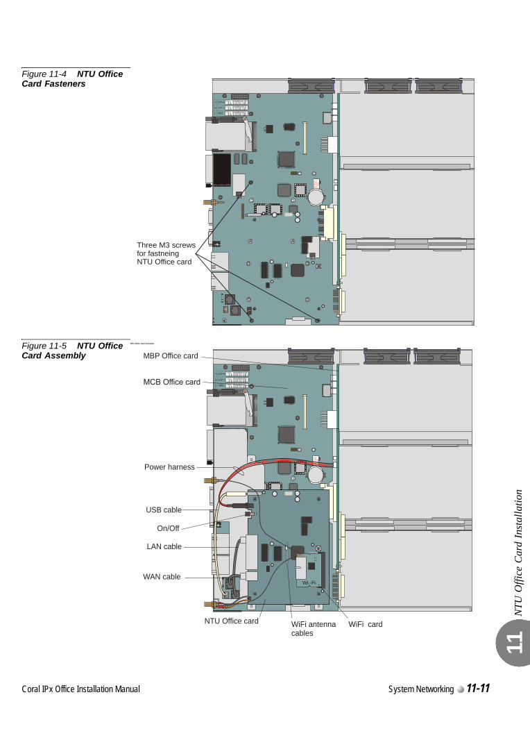
NTU
Offi
ce C
ard
Inst
alla
tion
11
Figure 11-4 NTU Office Card Fasteners
Figure 11-5 NTU Office Card Assembly
NTU Office Card Assembly
RE
MO
VEB
EFO
RE
US
E
Three M3 screwsfor fastneingNTU Office card
REM
OVE
BEFO
RE
USE
Wi.-Fi
On/Off
Power harness
USB cable
LAN cable
WAN cable
MBP Office card
NTU Office card WiFi cardWiFi antennacables
Coral IPx Office Installation Manual System Networking 11-11
NTU
Offi
ce C
ard
Inst
alla
tion
11
0
This section describes how to replace the NTU Office card (without replacing the card chassis).
1. Unplug the power cord that supplies the Coral IPx Office system.
2. Remove the unit cover. See Opening the Unit Cover, page 6-8.
3. Disconnect all cables connected to the NTU Office card, including the two line harnesses, the USB harness, the power harness, the reset switch harness, and the WiFi cables, if installed.
4. Unfasten the three M3 screws and washers and safeguard them for future reassembly.
5. Replace the NTU Office card.
6. Fasten the three M3 screws and washers.
7. Reconnect all cables to the NTU Office card, including the two RJ-45 cables, the USB cable, the power harness, and the reset button harness,
8. If a WiFi card is installed, skip to Installing the WiFi Card, page 11-13.
9. Close the unit cover. See Closing the Unit Cover, page 6-10.
10. Reconnect the power cable.
...................................................................................................3 Replacing the NTU Office Card
Electrical Hazard. Contact with live wires could cause shock, burn, and death. Do not
open the Coral IPx Office cover before removing power from the system.
11-12 System Networking Coral IPx Office Installation Manual
NTU
Offi
ce C
ard
Inst
alla
tion
11
0
1. Remove the two protective plugs that cover the holes for the antennas on the front panel of the system.
2. Unplug the power cord that supplies the Coral IPx Office system.
3. Remove the unit cover. See Opening the Unit Cover, page 6-8.
4. Insert the antenna cables through the front panel of the Coral IPx Office unit.
5. Install the WiFi card as shown in Figure 11-6.
6. Connect the cables to the WiFi card as shown in Figure 11-6.
...................................................................................................4 Installing the WiFi Card
Electrical Hazard. Contact with live wires could cause shock, burn, and death. Do not
open the Coral IPx Office cover before removing power from the system.
Coral IPx Office Installation Manual System Networking 11-13
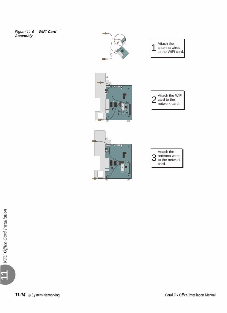
NTU
Offi
ce C
ard
Inst
alla
tion
11
Figure 11-6 WiFi Card Assembly
Wi.-Fi
Attach theantenna wiresto the WiFi card.1
Attach the WiFicard to thenetwork card.2
AB
Attach theantenna wiresto the networkcard.
3
11-14 System Networking Coral IPx Office Installation Manual
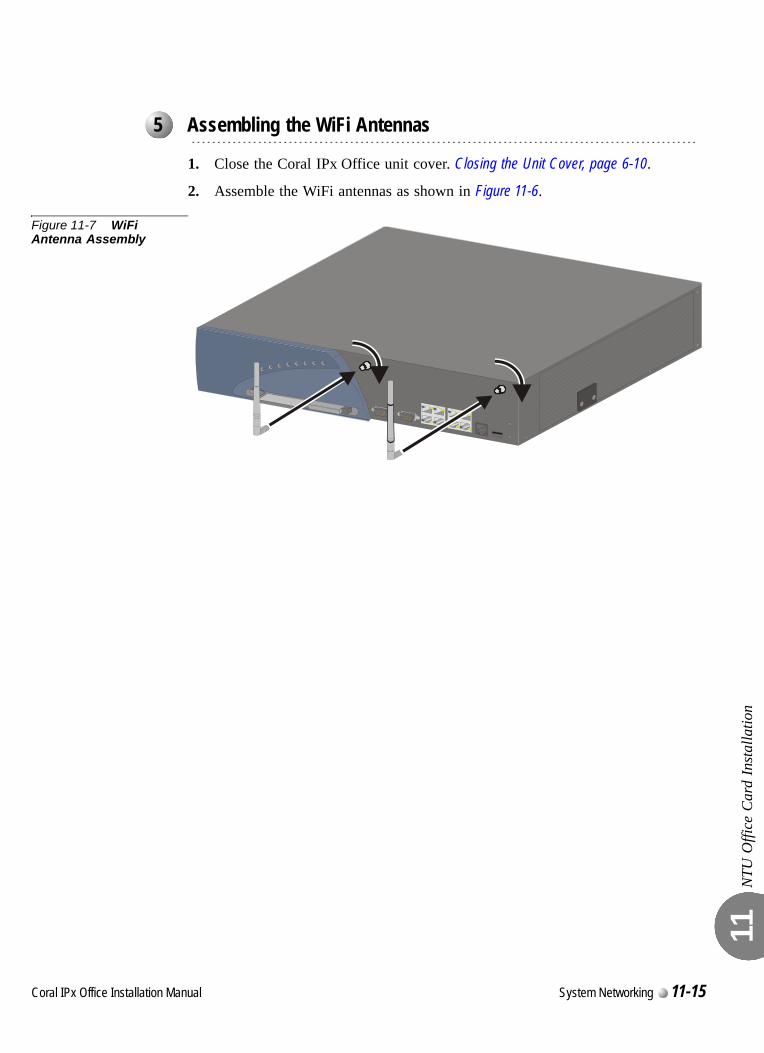
NTU
Offi
ce C
ard
Inst
alla
tion
11
0
1. Close the Coral IPx Office unit cover. Closing the Unit Cover, page 6-10.
2. Assemble the WiFi antennas as shown in Figure 11-6.
Figure 11-7 WiFi Antenna Assembly
0
...................................................................................................5 Assembling the WiFi Antennas
Coral IPx Office Installation Manual System Networking 11-15
NTU
Offi
ce C
ard
Inst
alla
tion
11
0
Configure the networking software as described in the documentation provided by the NTU Office card software vendor at http://www.draytek.com. The NTU Office card is called the Vigor 2900 by the vendor.
...................................................................................................6 Configuring the Networking Software
11-16 System Networking Coral IPx Office Installation Manual
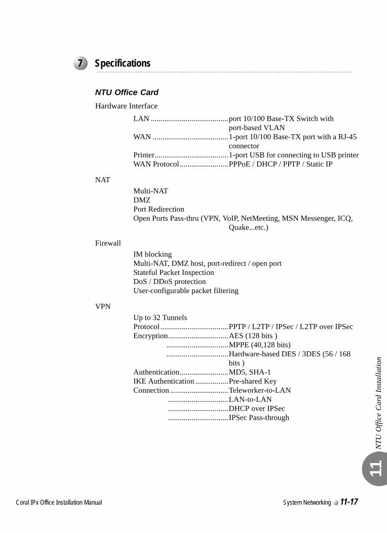
NTU
Offi
ce C
ard
Inst
alla
tion
11
0
NTU Office Card
Hardware InterfaceLAN ........................................port 10/100 Base-TX Switch with
port-based VLANWAN .......................................1-port 10/100 Base-TX port with a RJ-45
connectorPrinter......................................1-port USB for connecting to USB printerWAN Protocol.........................PPPoE / DHCP / PPTP / Static IP
NATMulti-NATDMZPort RedirectionOpen Ports Pass-thru (VPN, VoIP, NetMeeting, MSN Messenger, ICQ,
Quake...etc.)
FirewallIM blockingMulti-NAT, DMZ host, port-redirect / open portStateful Packet InspectionDoS / DDoS protectionUser-configurable packet filtering
VPNUp to 32 TunnelsProtocol ...................................PPTP / L2TP / IPSec / L2TP over IPSecEncryption...............................AES (128 bits )
................................MPPE (40,128 bits)
................................Hardware-based DES / 3DES (56 / 168 bits )
Authentication.........................MD5, SHA-1IKE Authentication .................Pre-shared KeyConnection ..............................Teleworker-to-LAN
...............................LAN-to-LAN
...............................DHCP over IPSec
...............................IPSec Pass-through
...................................................................................................7 Specifications
Coral IPx Office Installation Manual System Networking 11-17
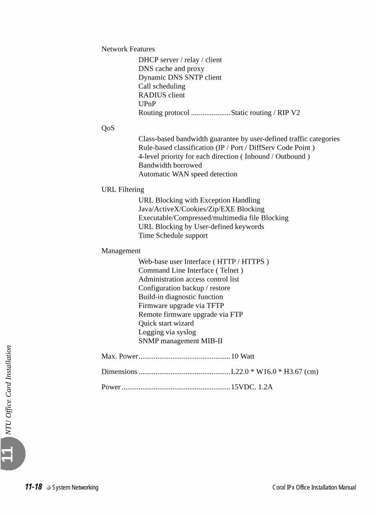
NTU
Offi
ce C
ard
Inst
alla
tion
11
Network FeaturesDHCP server / relay / clientDNS cache and proxyDynamic DNS SNTP clientCall schedulingRADIUS clientUPnPRouting protocol .....................Static routing / RIP V2
QoSClass-based bandwidth guarantee by user-defined traffic categoriesRule-based classification (IP / Port / DiffServ Code Point )4-level priority for each direction ( Inbound / Outbound )Bandwidth borrowedAutomatic WAN speed detection
URL FilteringURL Blocking with Exception HandlingJava/ActiveX/Cookies/Zip/EXE BlockingExecutable/Compressed/multimedia file BlockingURL Blocking by User-defined keywordsTime Schedule support
ManagementWeb-base user Interface ( HTTP / HTTPS )Command Line Interface ( Telnet )Administration access control listConfiguration backup / restoreBuild-in diagnostic functionFirmware upgrade via TFTPRemote firmware upgrade via FTPQuick start wizardLogging via syslogSNMP management MIB-II
Max. Power.................................................10 Watt
Dimensions .................................................L22.0 * W16.0 * H3.67 (cm)
Power ..........................................................15VDC. 1.2A
11-18 System Networking Coral IPx Office Installation Manual
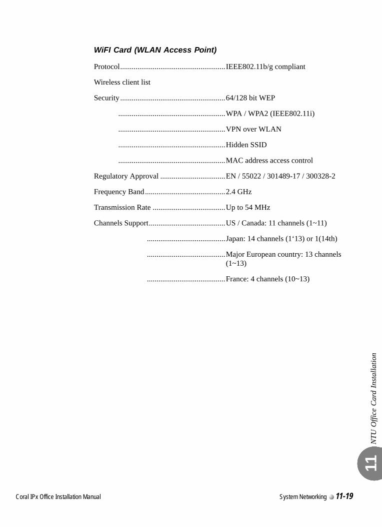
NTU
Offi
ce C
ard
Inst
alla
tion
11
WiFI Card (WLAN Access Point)
Protocol.......................................................IEEE802.11b/g compliant
Wireless client list
Security .......................................................64/128 bit WEP
........................................................WPA / WPA2 (IEEE802.11i)
........................................................VPN over WLAN
........................................................Hidden SSID
........................................................MAC address access control
Regulatory Approval ..................................EN / 55022 / 301489-17 / 300328-2
Frequency Band..........................................2.4 GHz
Transmission Rate ......................................Up to 54 MHz
Channels Support........................................US / Canada: 11 channels (1~11)
.........................................Japan: 14 channels (1‘13) or 1(14th)
.........................................Major European country: 13 channels (1~13)
.........................................France: 4 channels (10~13)
Coral IPx Office Installation Manual System Networking 11-19

NTU
Offi
ce C
ard
Inst
alla
tion
11
11-20 System Networking Coral IPx Office Installation Manual
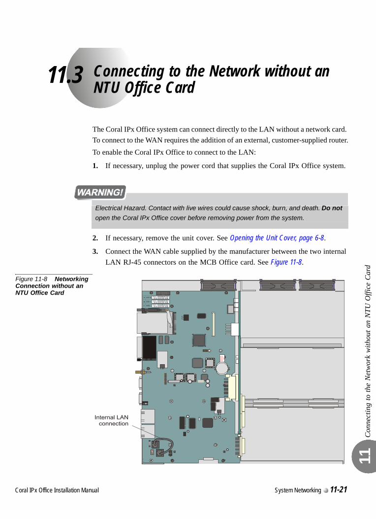
C
11.3
oral IPx Office Installation Ma
Connecting to the Network without an NTU Office Card
Con
nect
ing
to th
e N
etw
ork
with
out a
n N
TU O
ffice
Car
d 11
The Coral IPx Office system can connect directly to the LAN without a network card. To connect to the WAN requires the addition of an external, customer-supplied router.To enable the Coral IPx Office to connect to the LAN:
1. If necessary, unplug the power cord that supplies the Coral IPx Office system.
2. If necessary, remove the unit cover. See Opening the Unit Cover, page 6-8.
3. Connect the WAN cable supplied by the manufacturer between the two internal LAN RJ-45 connectors on the MCB Office card. See Figure 11-8.
Figure 11-8 Networking Connection without an NTU Office Card
Electrical Hazard. Contact with live wires could cause shock, burn, and death. Do not
open the Coral IPx Office cover before removing power from the system.R
EM
OV
EB
EFO
RE
US
E
nual System Networking 11-21


International HeadquartersTadiran Telecom Ltd.18 Hasivim Street P.O.Box 7607Petach Tikva 49170 IsraelTel. +972-3-9262000, Fax. +972-3-9262310
Visit us at our website http://www.tadirantele.comEmail: [email protected]
USA HeadquartersTadiran Telecom, Inc.4 Tri Harbor CourtPort Washington, NY 11050Tel. +1-516-632-7200, Fax. +1-516-632-7210
Cora l IPx Of f i ce
Ins ta l l a t ion Procedure and Hardware Re fe rence Manua l
1s t Ed i t ion 2006
Related Documents